JP2019217543A - Temperature measurement device and hot processing system and temperature measurement method - Google Patents
Temperature measurement device and hot processing system and temperature measurement method Download PDFInfo
- Publication number
- JP2019217543A JP2019217543A JP2018118292A JP2018118292A JP2019217543A JP 2019217543 A JP2019217543 A JP 2019217543A JP 2018118292 A JP2018118292 A JP 2018118292A JP 2018118292 A JP2018118292 A JP 2018118292A JP 2019217543 A JP2019217543 A JP 2019217543A
- Authority
- JP
- Japan
- Prior art keywords
- temperature
- steel material
- rolling
- transport
- rough
- Prior art date
- Legal status (The legal status is an assumption and is not a legal conclusion. Google has not performed a legal analysis and makes no representation as to the accuracy of the status listed.)
- Granted
Links
Images
Landscapes
- Measuring Temperature Or Quantity Of Heat (AREA)
- Metal Rolling (AREA)
Abstract
【課題】スケールの影響を受けにくくするとともに鋼材の表面に温度ムラを生じさせることなく、鋼材の表面温度を正確に測定することが可能な温度測定装置、熱間加工システム及び温度測定方法を提供する。【解決手段】温度測定装置1は、熱間温度の鋼材R1を搬送する複数の搬送ローラ111の間に設けられ、鋼材R1を下方から支持する当接面32aを有する複数の支持部材10と、支持部材10を搬送ローラ111に対して上下方向に相対移動させて、支持部材10の当接面32aを搬送ローラ111の上端111aよりも上方に配置させる駆動部20とを備え、複数の支持部材10に少なくとも一つは、鋼材R1の表面温度を測定する温度測定部30を有する。【選択図】図2PROBLEM TO BE SOLVED: To provide a temperature measuring device, a hot working system and a temperature measuring method capable of accurately measuring the surface temperature of a steel material without being easily affected by scale and causing temperature unevenness on the surface of the steel material. do. SOLUTION: A temperature measuring device 1 is provided between a plurality of transport rollers 111 for transporting a steel material R1 having a hot temperature, and has a plurality of support members 10 having a contact surface 32a for supporting the steel material R1 from below. A plurality of support members include a drive unit 20 that moves the support member 10 relative to the transfer roller 111 in the vertical direction and arranges the contact surface 32a of the support member 10 above the upper end 111a of the transfer roller 111. At least one in 10 has a temperature measuring unit 30 for measuring the surface temperature of the steel material R1. [Selection diagram] Fig. 2
Description
本発明は、温度測定装置、熱間加工システム及び温度測定方法に関する。 The present invention relates to a temperature measuring device, a hot working system, and a temperature measuring method.
鋼材の熱間圧延では、搬送ローラで搬送しながら一または複数回の圧延プロセスを行うことで、所望のサイズの鋼材を製造する。各圧延プロセスでは圧延機に鋼材を進入させていく前に、搬送ローラによって搬送されてきた鋼材の表面温度を測定する。そして、測定された鋼材の表面温度に基づいて、圧下率、圧延温度などの圧延条件を設定し圧延機で圧延を行う。従来、このような温度測定には放射温度計が用いられてきた(例えば、特許文献1〜3参照)。このような放射温度計では、搬送ローラによって搬送されてきた鋼材の放射熱を検出し、当該放射熱に基づいて鋼材の表面の温度を求める。 In the hot rolling of a steel material, one or a plurality of rolling processes are performed while being transported by transport rollers, thereby producing a steel material having a desired size. In each rolling process, before the steel material enters the rolling mill, the surface temperature of the steel material transported by the transport rollers is measured. Then, rolling conditions such as a rolling reduction and a rolling temperature are set based on the measured surface temperature of the steel material, and rolling is performed by a rolling mill. Conventionally, a radiation thermometer has been used for such temperature measurement (for example, see Patent Documents 1 to 3). Such a radiation thermometer detects radiant heat of a steel material conveyed by a conveying roller, and obtains a temperature of a surface of the steel material based on the radiant heat.
一般に熱間圧延などの熱間加工において、鋼材の表面温度は鋼材の品質に影響を及ぼすパラメータであるため、鋼材の表面温度を正確に測定することが求められている。鋼材の表面温度は、放射温度計や接触式温度計を用いて測定されることが従来から知られている。 Generally, in hot working such as hot rolling, since the surface temperature of a steel material is a parameter that affects the quality of the steel material, it is required to accurately measure the surface temperature of the steel material. It is conventionally known that the surface temperature of a steel material is measured using a radiation thermometer or a contact thermometer.
放射温度計は、鋼材の表面からの放射熱を測定して鋼材の表面温度を測定するためのものである。熱間圧延などの熱間加工では、鋼材の表面温度が例えば800〜1300℃に達するため、時間の経過とともに鋼材の表面にスケール(酸化鉄)が生成される。鋼材の表面にスケールが生じていると、鋼材の表面からの放射熱がスケールの影響を受けるため、放射温度計を用いて鋼材の表面温度を正確に測定することができない。そのため、熱間圧延などの熱間加工では、デスケーリング装置によって鋼材の表面に発生したスケールを除去した後に熱間圧延を行い、その直後に鋼材の表面温度を測定することで、スケールの影響を受けにくくしている。しかしながら、デスケーリング装置によって鋼材の表面に発生したスケールを除去した場合であっても、鋼材を搬送ローラ上で一定時間待機させてしまうと鋼材の表面には再度スケールが発生してしまうことになる。そのため、デスケーリング装置によって鋼材の表面に発生したスケールを除去しても、放射温度計では鋼材の表面温度を正確に測定することができない場合がある。なお、鋼材を搬送ローラ上で一定時間待機させる場合として、前後の工程でトラブルが発生した場合等が想定される。 The radiation thermometer measures the radiant heat from the surface of the steel material to measure the surface temperature of the steel material. In hot working such as hot rolling, since the surface temperature of a steel material reaches, for example, 800 to 1300 ° C., scale (iron oxide) is generated on the surface of the steel material with the passage of time. If scale is formed on the surface of the steel material, radiant heat from the surface of the steel material is affected by the scale, so that the surface temperature of the steel material cannot be accurately measured using a radiation thermometer. Therefore, in hot working such as hot rolling, the scale generated on the surface of the steel material is removed by a descaling device, hot rolling is performed, and immediately after that, the surface temperature of the steel material is measured to reduce the influence of the scale. It is hard to receive. However, even when the scale generated on the surface of the steel material is removed by the descaling device, the scale is generated again on the surface of the steel material if the steel material is kept on standby for a predetermined time on the transport roller. . Therefore, even if the scale generated on the surface of the steel material is removed by the descaling device, the radiation thermometer may not be able to accurately measure the surface temperature of the steel material. In addition, as a case where the steel material is made to stand by on the transport roller for a certain period of time, a case where a trouble occurs in a preceding or subsequent process is assumed.
接触式温度計は、鋼材の表面に接触式温度計を当接させて鋼材の表面温度を測定するためのものであるため、放射温度計よりもスケールの影響を受けにくい。しかしながら、接触式温度計を用いて鋼材の表面温度を測定しようとすると、接触式温度計と鋼材の表面とを当接させるために、鋼材を搬送ローラで一定時間待機させなければならない。鋼材を搬送ローラで一定時間待機させると、鋼材の表面の搬送ローラに接触した部分と、鋼材の表面の搬送ローラに接触しない部分とでは温度ムラが生じてしまう。鋼材の表面に温度ムラが生じてしまうと、接触式温度計によっては鋼材の表面温度を正確に測定することはできない。 Since the contact thermometer is for measuring the surface temperature of the steel material by bringing the contact thermometer into contact with the surface of the steel material, the contact thermometer is less affected by the scale than the radiation thermometer. However, when trying to measure the surface temperature of a steel material using a contact thermometer, the steel material must be kept on standby for a certain period of time by a transport roller in order to bring the contact thermometer into contact with the surface of the steel material. If the steel material is kept on standby by the transport roller for a certain period of time, temperature unevenness occurs between a portion of the surface of the steel material that contacts the transport roller and a portion of the surface of the steel material that does not contact the transport roller. If temperature unevenness occurs on the surface of the steel material, the contact-type thermometer cannot accurately measure the surface temperature of the steel material.
すなわち、鋼材を一定時間待機させた後に鋼材の表面温度を測定しようとする際、放射温度計は待機中に生じたスケールの影響によって鋼材の表面温度を正確に測定できない。また、鋼材を一定時間待機させた後に鋼材の表面温度を測定しようとする際、接触式温度計を用いて測定しようとすると、一定時間待機中に鋼材の表面に温度ムラが生じてしまい、鋼材の表面温度を正確に測定できない。 That is, when trying to measure the surface temperature of a steel material after the steel material has been on standby for a certain period of time, the radiation thermometer cannot accurately measure the surface temperature of the steel material due to the influence of the scale generated during the standby. In addition, when trying to measure the surface temperature of a steel material after the steel material has been on standby for a certain period of time, if the measurement is to be performed using a contact-type thermometer, the temperature of the steel material will be uneven during the standby for a certain period of time. Surface temperature cannot be measured accurately.
そこで、本発明は、上述した事情に鑑みてなされたものであって、スケールの影響を受けにくくするとともに鋼材の表面に温度ムラを生じさせることなく鋼材の表面温度を正確に測定することが可能な温度測定装置、熱間加工システム及び温度測定方法を提供するものである。 Therefore, the present invention has been made in view of the above circumstances, and makes it possible to accurately measure the surface temperature of a steel material without causing the temperature of the steel material to be uneven while making it less susceptible to scale. The present invention provides a temperature measuring device, a hot working system, and a temperature measuring method.
上記の課題を解決するために、本発明は以下の手段を採用している。
すなわち、本発明の一態様に係る温度測定装置は、熱間温度の鋼材を搬送する複数の搬送ローラの間に配され、鋼材の下面に当接する当接面を有する複数の支持部材と、前記支持部材を前記搬送ローラに対して上下方向に相対移動させて、前記支持部材の前記当接面を前記搬送ローラの上端よりも上方に配置させる駆動部とを備え、複数の前記支持部材の少なくとも一つは、前記鋼材の表面温度を測定する温度測定部を有する。
この構成によれば、駆動部により搬送ローラに対して支持部材を上下方向に相対移動させて支持部材の当接面を搬送ローラよりも上方まで移動させることができる。鋼材が搬送ローラと当接することなく支持部材によって支持される。複数の支持部材のうち少なくとも一つの支持部材は鋼材の表面温度を測定する温度測定部を有している。そのため、鋼材を搬送ローラと当接させることなく、鋼材の表面温度を測定することができる。鋼材の表面温度を測定する際に、鋼材と搬送ローラが接触しないため、温度測定中に鋼材から搬送ローラへ熱伝導し鋼材に温度ムラが生じてしまうことがない。そのため、鋼材の表面温度を正確に測定することができる。また、鋼材の下面に温度測定部を接触させて鋼材の表面温度を測定することができる。鋼材の下面は、鋼材の上面と比べてスケールが発生しにくいため、鋼材の上面の温度を測定するよりも、鋼材の表面温度を正確に測定できる。さらに、鋼材の表面に温度測定部を当接させているため、鋼材の表面温度を測定している際に、表面温度を測定する部分でスケールが成長することを防止することができる。
In order to solve the above problems, the present invention employs the following solutions.
That is, the temperature measurement device according to one embodiment of the present invention is disposed between a plurality of transport rollers that transport a steel material having a hot temperature, and a plurality of support members having a contact surface that abuts on a lower surface of the steel material, A drive unit for vertically moving the support member relative to the transport roller and disposing the contact surface of the support member above the upper end of the transport roller; and at least one of the plurality of support members One has a temperature measurement part which measures the surface temperature of the said steel material.
According to this configuration, the driving unit can move the support member relative to the transport roller in the up-down direction and move the contact surface of the support member above the transport roller. The steel material is supported by the support member without contacting the transport roller. At least one of the plurality of support members has a temperature measuring unit for measuring the surface temperature of the steel material. Therefore, the surface temperature of the steel material can be measured without bringing the steel material into contact with the transport roller. When the surface temperature of the steel material is measured, the steel material does not come into contact with the transport roller. Therefore, heat is not conducted from the steel material to the transport roller during the temperature measurement, and the temperature of the steel material does not become uneven. Therefore, the surface temperature of the steel material can be accurately measured. Further, the surface temperature of the steel material can be measured by bringing the temperature measurement unit into contact with the lower surface of the steel material. Since the scale of the lower surface of the steel material is less likely to be generated than the upper surface of the steel material, the surface temperature of the steel material can be measured more accurately than the temperature of the upper surface of the steel material. Further, since the temperature measurement section is in contact with the surface of the steel material, it is possible to prevent the scale from growing at the portion where the surface temperature is measured when measuring the surface temperature of the steel material.
また、上記温度測定装置において、前記支持部材は、前記鋼材を支持する基部を有し、前記温度測定部は、前記基部の上方に配され、前記当接面を有するものとしても良い。
この構成によれば、温度測定部は、基部の上方で当接面によって鋼材の下面に当接した状態で温度を測定することで、より正確に鋼材の表面温度を測定することができる。
Further, in the temperature measuring device, the support member may have a base for supporting the steel material, and the temperature measuring unit may be disposed above the base and have the contact surface.
According to this configuration, the temperature measurement unit can measure the temperature in a state where the temperature is in contact with the lower surface of the steel material by the contact surface above the base, so that the surface temperature of the steel material can be measured more accurately.
また、上記温度測定装置において、前記温度測定部は、温度を測定する熱電対と、前記熱電対の上方に配されて前記当接面を有する保護部とを有するものとしても良い。
この構成によれば、温度を測定する熱電対を保護部で保護することができる。
Further, in the above temperature measuring device, the temperature measuring section may include a thermocouple for measuring a temperature, and a protection section disposed above the thermocouple and having the contact surface.
According to this configuration, the thermocouple for measuring the temperature can be protected by the protection unit.
また、本発明の一態様に係る熱間加工システムは、上記温度測定装置と、互いに間隔を有して複数配され、前記鋼材を搬送する搬送ローラを備え、前記支持部材は、隣り合う前記搬送ローラ同士の間である搬送ローラ間にそれぞれ配されているとともに、前記搬送ローラ間に、前記搬送ローラの幅方向に複数配されているものとしても良い。
この構成によれば、鋼材の搬送方向及び搬送方向に直交する搬送ローラの幅方向に平行な面状に分布する複数の支持部材によって、搬送ローラによって搬送された鋼材を支持することができる。このため、より温度ムラを抑制し、また、支持部材からの反力によって鋼材に生じる応力をより均一として鋼材を支持することができる。
Further, the hot working system according to an aspect of the present invention includes the temperature measuring device, and a plurality of transport rollers that transport the steel material, the plurality of transport rollers being disposed at an interval from each other, and the support member is configured to transport the steel material adjacent thereto. A plurality of rollers may be arranged between the transport rollers between the rollers, and a plurality of rollers may be arranged between the transport rollers in the width direction of the transport rollers.
According to this configuration, the steel material transported by the transport roller can be supported by the plurality of support members distributed in a plane parallel to the width direction of the transport roller perpendicular to the transport direction and the transport direction of the steel material. For this reason, temperature unevenness can be further suppressed and the steel material can be supported with more uniform stress generated in the steel material due to the reaction force from the support member.
また、上記熱間加工システムにおいて、前記搬送ローラの幅方向に複数配されている前記支持部材の位置は、前記搬送ローラ間毎に異なっているものとしても良い。
この構成によれば、支持部材の搬送ローラの幅方向の位置が、搬送ローラ間毎に異なっているため、支持部材は所謂千鳥上に配置され、より温度ムラを抑制することができる。
In the hot working system, the positions of the plurality of support members arranged in the width direction of the transport roller may be different for each of the transport rollers.
According to this configuration, since the position of the support member in the width direction of the transport roller is different for each transport roller, the support members are arranged in a so-called staggered manner, so that temperature unevenness can be further suppressed.
また、上記熱間加工システムにおいて、前記鋼材を熱間温度に加熱する加熱炉と、前記加熱炉で加熱された前記熱間温度の前記鋼材に対して圧延して第一圧延材を製造する第一の圧延装置と、前記第一圧延材に対して圧延して第二圧延材を製造する第二の圧延装置とを備え、前記温度測定装置及び前記搬送ローラは、前記第一の圧延装置と前記第二の圧延装置との間に配されているものとしても良い。
この構成によれば、鋼材を加熱炉で加熱し第一の圧延装置で圧延して第一圧延材を製造する。そして、熱間温度の鋼材に対して第二の圧延装置で圧延する前に上記温度測定装置で温度を測定する。この際、上記のとおり鋼材に温度ムラが生じてしまうことなく、また、スケールの影響を受けにくい状態で鋼材の表面温度を測定することができる。そして温度測定装置によって測定された温度に基づいて第二の圧延装置で第一圧延材を圧延して第二圧延材を製造することができる。
Further, in the hot working system, a heating furnace for heating the steel material to a hot temperature, and rolling the steel material at the hot temperature heated by the heating furnace to produce a first rolled material. One rolling device, comprising a second rolling device to produce a second rolled material by rolling the first rolled material, the temperature measuring device and the transport roller, the first rolling device and It may be arranged between the second rolling device.
According to this configuration, the steel material is heated in the heating furnace and rolled by the first rolling device to produce a first rolled material. The temperature is measured by the temperature measuring device before the hot rolling of the steel material is performed by the second rolling device. At this time, the surface temperature of the steel material can be measured without causing temperature unevenness in the steel material as described above and in a state where the steel material is not easily affected by scale. Then, the first rolled material can be rolled by the second rolling device based on the temperature measured by the temperature measuring device to produce the second rolled material.
また、本発明の一態様に係る鋼材の温度測定方法は、熱間温度の鋼材を、複数の搬送ローラで搬送する搬送工程と、前記搬送ローラに対して支持部材を上下方向に相対移動させることで、前記搬送工程で搬送された前記鋼材を、前記支持部材で支持して前記搬送ローラの上方に持ち上げる支持工程と、前記支持工程で持ち上げられた前記鋼材の表面温度を測定する温度測定工程とを備える。
この方法によれば、搬送ローラに対して支持部材を上下方向に相対移動させて支持部材の当接面を搬送ローラよりも上方まで移動させることができる。そのため、鋼材は、搬送ローラに接触することなく、支持部材によって支持された状態となる。この状態で、温度測定部により鋼材の表面温度を測定することができる。すなわち、鋼材は搬送ローラと接触することなく、鋼材の表面温度を測定することができるため、温度測定中に鋼材から搬送ローラに熱伝導して鋼材に温度ムラが生じてしまうことがない。したがって、鋼材の表面温度を正確に測定することができる。また、鋼材の下面は鋼材の上面よりもスケールが発生しにくいため、鋼材の下面の表面温度を測定することで、スケールの影響を受けにくくなり、鋼材の表面温度を正確に測定できる。さらに、温度測定中、鋼材の表面と温度測定部は接触しているため、鋼材の表面と温度測定部の間ではスケールが成長しにくくなる。そのため、スケールの影響を受けにくくなり、鋼材の表面温度を正確に測定できる。
Further, in the method for measuring the temperature of a steel material according to one embodiment of the present invention, the steel material having a hot temperature is transported by a plurality of transport rollers, and the support member is relatively moved in a vertical direction with respect to the transport rollers. In, the steel material transported in the transporting step, a supporting step of supporting the support member and lifting the transporting roller above, and a temperature measuring step of measuring the surface temperature of the steel material lifted in the supporting step Is provided.
According to this method, the support member can be moved up and down relative to the transport roller to move the contact surface of the support member above the transport roller. Therefore, the steel material is in a state of being supported by the support member without contacting the transport roller. In this state, the surface temperature of the steel material can be measured by the temperature measurement unit. That is, since the surface temperature of the steel material can be measured without the steel material coming into contact with the transport roller, the steel material does not conduct heat to the transport roller during the temperature measurement, so that the temperature unevenness does not occur in the steel material. Therefore, the surface temperature of the steel material can be accurately measured. Further, since scale is less likely to be generated on the lower surface of the steel material than on the upper surface of the steel material, by measuring the surface temperature of the lower surface of the steel material, the lower surface of the steel material is less affected by the scale, and the surface temperature of the steel material can be accurately measured. Further, during temperature measurement, the surface of the steel material and the temperature measurement portion are in contact with each other, so that scale does not easily grow between the surface of the steel material and the temperature measurement portion. Therefore, it is hardly affected by the scale, and the surface temperature of the steel material can be accurately measured.
本発明によれば、スケールの影響を受けにくくするとともに鋼材の表面に温度ムラを生じさせることなく鋼材の表面温度を正確に測定することができる。 ADVANTAGE OF THE INVENTION According to this invention, it is made hard to be influenced by a scale and the surface temperature of a steel material can be measured accurately, without causing the temperature unevenness on the surface of a steel material.
以下、本発明に係る一の実施形態について図1から図5を参照して説明する。なお、本実施形態において、第一の圧延装置として粗圧延装置102を適用し、第二の圧延装置として仕上圧延装置103を適用した場合について示す。そのため、第一圧延材は粗圧延材R1であって、第二圧延材は仕上圧延材R2である。図1は、本実施形態の熱間加工システム100を示している。図1に示すように、本実施形態の熱間加工システム100は、連続鋳造などによって製造されたスラブSに熱間圧延を行い、所望のサイズの圧延材を製造するものである。なお、熱間加工システム100で行われる熱間加工としては熱間圧延に限られず、ホットプレス、熱間鍛造など、少なくとも熱間温度で行われる鋼材の加工が含まれる。ここで、熱間温度とは、鋼材の材質によっても異なるが、例えば800〜1300℃である。
Hereinafter, an embodiment of the present invention will be described with reference to FIGS. In addition, in this embodiment, the case where the
図1に示すとおり、熱間加工システム100は、加熱炉101と、粗圧延装置102と、仕上圧延装置103と、冷却設備104と、コイラー105と、複数の搬送装置110とを備える。搬送装置110は、加熱炉101と粗圧延装置102との間に配置されると共に、加熱炉101から排出されたスラブSを粗圧延装置102に搬送する第一のローラ群110Aと、粗圧延装置102と仕上圧延装置103との間に配置されると共に、粗圧延装置102から排出された粗圧延材R1を仕上圧延装置103に搬送する第二のローラ群110Bと、仕上圧延装置103とコイラー105との間に配置され、仕上圧延装置103から排出された仕上圧延材R2を冷却設備104に搬送するとともに、冷却設備104から排出された仕上圧延材R2をコイラー105に搬送する第三のローラ群110Cとを備えている。各ローラ群110A、110B、110Cは各々複数の搬送ローラ111を有しており、複数の搬送ローラ111は、搬送方向Xに等間隔に配置されている。図示しないが、さらに、搬送装置110は、搬送ローラ111を回転駆動する搬送駆動部と、搬送駆動部を制御して搬送ローラ111による搬送速度を調整する搬送制御部とを備える。また、加熱炉101は、上流工程で製造され搬送装置110によって搬送されたスラブSを熱間温度に加熱し、熱間圧延可能な温度まで昇温させる。熱間圧延可能な温度としては、例えば800〜1300℃である。
As shown in FIG. 1, the hot working system 100 includes a
本実施形態において、粗圧延装置102は、加熱炉101で加熱されたスラブSに対して粗圧延を行い粗圧延材R1を製造する。粗圧延装置102は、搬送方向X(圧延方向)に沿って配された複数の圧延機102aを有し、各圧延機102aの上流には、後述するデスケーリング装置106a、106bが配置されており、各圧延機102aの下流には、後述する放射温度計107が配置されている。各圧延機102aは、鋼材を上下方向に挟んで圧下する一対のワークロール102bと、ワークロール102bに外周同士が接するように配されたバックアップロール102cとを有する。各圧延機102aは、図示しないが、さらに一対のワークロール102bの間隔を調整して圧下率を調整可能な調整機構と、一対のワークロール102bを回転駆動する圧延駆動部と、調整機構及び圧延駆動部を制御する圧延制御部とを有する。なお、粗圧延装置102は、ワークロール102bとバックアップロール102cとを備える複数の各圧延機102aを有する場合について示したが、これに限られない。たとえば、各圧延機102aはワークロール102bのみを有していてもよいし、複数の圧延機のうち一部の圧延機102aは、後述する仕上圧延装置103と同様に連続して配置された複数の圧延スタンド102aであってもよい。
In the present embodiment, the
仕上圧延装置103は、本実施形態では、粗圧延材R1に対して仕上圧延を行い、第二圧延材として仕上圧延材R2を製造する。仕上圧延装置103は、搬送方向X(圧延方向)に沿って配された複数の圧延スタンド103aを有する。各圧延スタンド103aは、粗圧延装置102の圧延機102aと同様に、粗圧延材R1を上下方向に挟んで圧下する一対のワークロール103bと、ワークロール103bに外周同士が接するように配されたバックアップロール103cとを有する。各圧延スタンド103aは、図示しないが、さらに一対のワークロール103bの間隔を調整して圧下率を調整可能な調整機構と、一対のワークロール103bを回転駆動する圧延駆動部と、調整機構及び圧延駆動部を制御する圧延制御部とを有する。冷却設備104は、仕上圧延材R2を所定の温度まで冷却する。コイラー105は、冷却設備104で冷却された仕上圧延材R2を巻取り、コイルを形成する。
In the present embodiment, the
本実施形態の熱間加工システム100は、さらに粗圧延装置102の各圧延機102aに送られるスラブSの上面SaのスケールCを除去するデスケーリング装置106aと、粗圧延装置102の各圧延機102aに送られるスラブSの下面SbのスケールCを除去するデスケーリング装置106bと、粗圧延装置102での圧延直後の粗圧延材R1の表面温度を測定する放射温度計107と、仕上圧延装置103での圧延直前の粗圧延材R1の表面温度を測定する温度測定装置1とを備える。さらに、本実施形態の熱間加工システム100は、粗圧延装置102と仕上圧延装置103との間に設けられて粗圧延材R1の位置を検出する位置検出装置109を備える。位置検出装置109は、例えばレーザ光の反射光の検出の有無や、画像処理により鋼材の前端を検出するセンサを備えている。また、位置検出装置109は、粗圧延材R1が温度測定装置1で温度測定可能な温度測定範囲Aに到達したことを検出する。
The hot working system 100 of the present embodiment further includes a
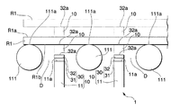
図2に示すように、デスケーリング装置106aはスラブSの上面Saに対向して配置される。デスケーリング装置106aは粗圧延装置102の圧延機102aに搬送されるスラブSの上面Saに高圧水を吹き付けるノズルを有する。同様にして、デスケーリング装置106bはスラブSの下面Sbに対向して配置される。デスケーリング装置106bは粗圧延装置102の圧延機102aに搬送されるスラブSの下面Sbに高圧水を吹き付けるノズルを有する。このため、粗圧延装置102の各圧延機102aにはスラブSの上面Saおよび下面SbのスケールCが除去された状態のスラブSが搬送され、粗圧延装置102は、当該スラブSを粗圧延して、製造された粗圧延材R1を送り出す。粗圧延装置102の各圧延機102aの搬送方向Xの上流側にはデスケーリング装置106a、106bがそれぞれ配置されている。そのため、各圧延機102aに搬送されるスラブSの上面Sa、下面SbのスケールCは、デスケーリング装置106a、106bによって除去されている。各圧延機102aに搬送される直前でスラブSの上面Sa、下面SbのスケールCが除去されているため、各圧延機102aによってスラブSを圧延加工する際、ワークロール102bの回転によってスケールCがスラブSの上面Sa、下面Sbへ押し付けられ、スラブSの上面Sa、下面Sbに疵を形成してしまうことを防ぐことができる。放射温度計107は、粗圧延装置102の各圧延機102aの搬送方向Xの下流側に配されている。そのため、粗圧延装置102による圧延加工の直前でデスケーリング装置106a、106bによって粗圧延材R1の表面のスケールCは除去され、粗圧延装置102による圧延加工の直後で放射温度計107によって粗圧延材R1の表面温度は測定される。
As shown in FIG. 2, the
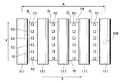
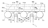
図2及び図3に示すように、温度測定装置1は、粗圧延材R1を支持する支持機構2と、支持機構2を上下方向に移動させる駆動部20とを備えている。支持機構2は、複数の支持部材10と、複数の支持部材10を連結する連結部15とを有する。複数の支持部材10は、第二のローラ群110Bの複数の搬送ローラ111の間に配されており、複数の支持部材10が配された領域が温度測定範囲Aとなる。各支持部材10は、粗圧延材R1を支持する基部11と、基部11の上方に配された温度測定部30とを有する。温度測定部30は、粗圧延材R1の温度を測定する熱電対31と、熱電対31を保護する保護部32とを備えており、熱電対31は基部11の上端に配されている。なお、温度測定部30は、接触した部材から伝導する熱を検出し温度を求めるものである。保護部32は粗圧延材R1の下面R1bに当接する当接面32aを備えている。また、保護部32は粗圧延材R1の下面R1bに当接する当接面32aを備えている。
As shown in FIGS. 2 and 3, the temperature measuring device 1 includes a
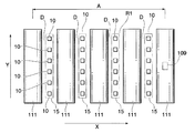
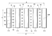
本実施形態では、連結部15は板形状であって、駆動部20は連結部15の略中央に設けられている。また、支持部材10は、搬送ローラ111の回転軸に沿う幅方向Yおよび幅方向Yに直交する搬送方向Xに複数設けられている。なお、支持部材10及び連結部15の形状はこれに限られない。すなわち、複数の支持部材10が粗圧延材R1の全面を支持するよう配置され、連結部15は複数の支持部材10を連結し、駆動部20の駆動力を複数の支持部材10に伝達できればよく、上述の実施形態に限られない。例えば、連結部15が棒状であって、駆動部20が連結部15の略中央に設けられており、支持部材10は連結部15の延在方向に沿って複数配置されていてもよい。例えば、図6に示すように、連結部15が搬送ローラ111の幅方向Yに沿うように配置され、複数の支持部材10を各搬送ローラ間Dに配置することで支持部材10が粗圧延材R1の全面を支持するよう配置してもよい。また、図7に示すように、連結部15が搬送方向Xに沿うように配置され、各支持部材10が搬送ローラ間Dに配置されるように、複数の支持部材10を幅方向Yに配置することで支持部材10が粗圧延材R1の全面を支持するよう配置してもよい。本実施形態では、仕上圧延前の粗圧延材R1、すなわち熱間温度の鋼材の表面温度を測定するため、800〜1300℃程度の温度を測定できる熱電対31を採用している。このような熱電対としては例えばK熱電対、N熱電対、R熱電対が挙げられる。
In the present embodiment, the connecting
各基部11は、支持する粗圧延材R1の負担重量分の荷重に対して十分な剛性を有する断面形状、材料で構成されている。基部11を形成する材料としては、例えばクロム鋼やステンレス鋼などが挙げられる。
Each
温度測定部30のうち保護部32が粗圧延材R1に接触する。熱電対31は保護部32を介して粗圧延材R1から伝導する熱によって粗圧延材R1の表面温度を測定するため、保護部32は、基部11に比較して熱伝導率が高い材質であることが好ましい。このように保護部32は、直接粗圧延材R1に接触して支持することから、熱間強度が基部11と比較して高いことが好ましい。保護部32を形成する材料としては、例えば白金合金やなどが挙げられる。ここで、熱間強度とは、熱間加工を行う熱間温度における強度をいう。対象となる熱間温度の範囲としては、加工対象となる鋼材の種類によっても異なるが例えば800〜1300℃程度である。また、強度は、鋼材の種類、使用目的によっても異なるが、降伏応力や引張強さをいう。
The
なお、上述した実施形態では、基部11、連結部15、駆動部20は、断熱材で形成されている。しかしながら図8に示すように、基部11と温度測定部30の間に断熱部13を設けてもよい。断熱部13は、粗圧延材R1から温度測定部30に伝導した熱が基部11に伝導することを抑制する。このように断熱部13は、熱の伝導を抑制することから、熱伝導率が基部11と比較して低い断熱材からなることが好ましい。
In the above-described embodiment, the
駆動部20の駆動源としては、油圧、空気圧、モータなど様々な駆動源が適用可能である。また、駆動部20と連結部15との間に減速機を設けても良い。制御部23は、位置検出装置109による検出結果に基づいて駆動部20を制御する。また、制御部23は、温度測定部30の熱電対31での検出信号を取得し、検出信号に基づいて測定対象である粗圧延材R1の表面温度を演算し温度測定データを出力する。
Various driving sources such as a hydraulic pressure, a pneumatic pressure, and a motor are applicable as the driving source of the driving
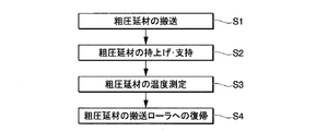
次に、図2、図4及び図5に基づいて、熱間加工システム100における温度測定装置1での温度測定方法及び作用効果について説明する。まず、図2及び図5に示すように、搬送工程S1として、粗圧延装置102で製造された粗圧延材R1を、第二のローラ群110Bの搬送ローラ111によって温度測定装置1による温度測定範囲Aまで搬送する。なお、搬送の際、支持部材10の当接面32aは、第二のローラ群110Bの搬送ローラ111の上端111aよりも下方に位置している。粗圧延材R1の前端が温度測定範囲Aの下流端近傍まで移動すると、位置検出装置109で粗圧延材R1の前端が検出される。そして、位置検出装置109で粗圧延材R1が検出されたことに基づいて第二のローラ群110Bの搬送ローラ111を停止させる。これにより粗圧延材R1は、前端から後端までが温度測定範囲Aに含まれて、全体を支持部材10で支持可能な状態となる。
Next, a temperature measurement method and an effect of the temperature measurement device 1 in the hot working system 100 will be described with reference to FIGS. First, as shown in FIG. 2 and FIG. 5, in the transporting step S1, the rough rolled material R1 manufactured by the
次に、図2、図4及び図5に示すように、支持工程S2として、粗圧延材R1を支持部材10で支持して第二のローラ群110Bの搬送ローラ111の上方に持ち上げる。すなわち、制御部23は、駆動部20を駆動させて連結部材21を介して支持部材10を上昇させる。支持部材10の当接面32aは第二のローラ群110Bの搬送ローラ111の上端111aと同じ高さとなることで、粗圧延材R1の下面R1bに接した状態となる。さらに、支持部材10が上昇すると、粗圧延材R1は支持部材10によって持ち上げられて、支持部材10によって支持された状態となるとともに第二のローラ群110Bの搬送ローラ111から離間して上方となる位置に配されることとなる。
Next, as shown in FIGS. 2, 4 and 5, in a supporting step S2, the rough rolled material R1 is supported by the
次に、図4及び図5に示すように、温度測定工程S3として、粗圧延材R1の表面温度を測定する。粗圧延材R1を支持部材10で支持した状態では、粗圧延材R1の熱は、保護部32を介して温度測定部30に伝導する。このため、温度測定部30は、保護部32に接して保護部32の温度を測定することで粗圧延材R1の表面温度を求めることができる。ここで、支持部材10によって第二のローラ群110Bの搬送ローラ111よりも上方に持ち上げて粗圧延材R1の表面温度を測定することで、温度測定中に粗圧延材R1から第二のローラ群110Bの搬送ローラ111に熱が伝導して粗圧延材R1に温度ムラが生じてしまうことなく、粗圧延材R1の表面温度を測定することができる。さらに、粗圧延材R1の搬送方向X及び幅方向Yに平行な面状に分布する複数の支持部材10によって、第二のローラ群110Bの搬送ローラ111によって搬送された粗圧延材R1は支持される。このため、より温度ムラを抑制することができる。また、粗圧延材R1の下面R1bは、粗圧延材R1の上面R1aよりもスケールCが発生しにくいため、粗圧延材R1の下面R1bで温度を測定することで、スケールCの影響をより受けにくい状態で粗圧延材R1の表面温度を測定することができる。さらに、粗圧延材R1における表面温度を測定する部分は、温度測定中支持部材10の当接面32aに接触している。このため、温度測定部30の熱電対31で温度を測定している間、温度を測定する部分でスケールCが成長することを防止することができる。
Next, as shown in FIG. 4 and FIG. 5, as the temperature measuring step S3, the surface temperature of the rough rolled material R1 is measured. In a state where the rough rolled material R1 is supported by the
また、本実施形態では、熱電対31によって保護部32を介して粗圧延材R1の表面温度を測定することができるとともに、熱電対31を保護部32によって保護している。このため、熱電対31が粗圧延材R1の荷重及び熱の影響を直接受けることを防止することができる。さらに、保護部32を熱伝導率が高い材料で形成することで、保護部32を熱伝導率が低い材料で形成した場合と比較して、粗圧延材R1の熱を、温度勾配を抑制して熱電対31に伝導させることができる。したがって、測定対象である粗圧延材R1に対する熱電対31の温度追従性を高め、熱電対31によってより正確に粗圧延材R1の表面温度を測定することができる。また、基部11は断熱材によって形成されているため、支持部材10の熱容量が大きくなって粗圧延材R1の温度が低下してしまうことを抑制しつつ粗圧延材R1の温度を測定することができる。
In the present embodiment, the
温度測定工程における粗圧延材R1の温度測定が完了したら、図4及び図5に示すように、次に復帰工程S4として、粗圧延材R1を搬送ローラ111上で搬送可能な状態に戻す。すなわち、駆動部20は、支持部材10を、当接面32aが第二のローラ群110Bの搬送ローラ111の上端111aよりも下方に位置するまで下降させる。これにより、粗圧延材R1は第二のローラ群110Bの搬送ローラ111に支持された状態となる。そして、第二のローラ群110Bの搬送ローラ111を駆動させると、粗圧延材R1は再び搬送方向Xに移動し、仕上圧延装置103によって熱電対31による温度測定結果に基づいた仕上圧延が実施される。
When the temperature measurement of the rough rolled material R1 in the temperature measurement step is completed, as shown in FIGS. 4 and 5, the rough rolled material R1 is returned to a state where it can be transported on the
以上のように本実施形態の熱間加工システム100及び温度測定装置1では、支持部材10によって粗圧延材R1を持ち上げて粗圧延材R1の表面温度を測定している。そのため、温度を測定する際に、粗圧延材R1と搬送ローラ111が接触しておらず、温度測定中に粗圧延材R1から搬送ローラ111に熱が伝導して粗圧延材R1に温度ムラが生じてしまうことがない。したがって、本実施形態の熱間加工システム100及び温度測定装置1を用いることで、粗圧延材R1の表面温度を正確に測定することができる。温度測定部30は、粗圧延材R1の下面R1bの表面温度を測定する。粗圧延材R1の下面R1bは、スケールCが発生しにくいため、温度測定の際にスケールCの影響を受けにくい。さらに、温度測定部30は、粗圧延材R1と当接した状態で温度を測定するので、温度測定の際にスケールCの影響を受けにくい。
As described above, in the hot working system 100 and the temperature measuring device 1 of the present embodiment, the rough rolled material R1 is lifted by the
なお、本実施形態では、保護部32を介して熱電対31により粗圧延材R1の表面温度を測定するものとしたがこれに限られるものではない。熱電対31を直接粗圧延材R1に接して温度を測定するものとしても良い。また、支持部材10の側面などに温度測定部30の熱電対31を設けて、支持部材10の温度を温度測定部30で測定することで間接的に粗圧延材R1の表面温度を測定するものとしても良い。また、温度測定部30は、全ての支持部材10に設けられているものとしたがこれに限ることなく、一部の支持部材10のみに設けられるものとしても良い。
In the present embodiment, the surface temperature of the rough rolled material R1 is measured by the
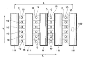
また、支持部材10は、各搬送ローラ間Dに設けられているとともに、隣り合う搬送ローラ間D同士で幅方向Yの位置が一致するように支持部材10が格子状に配列しているものとしたがこれに限られるものではない。例えば、図9に示すように、支持部材10は、搬送方向Xに隣り合う搬送ローラ間Dに設けられており、支持部材10の搬送ローラ111の幅方向Yの位置を搬送ローラ間Dごとにずらして、所謂千鳥上に配置されているものとしても良い。このように配列することで、温度ムラをより抑制することができる。また、支持部材10は、各搬送ローラ間Dにおいて、搬送方向Xに複数設けても良いし、一部の搬送ローラ間Dのみに設けられるようにしても良い。
The
また、本実施形態では、駆動部20は支持部材10を上昇させて、搬送ローラ111の上端111aよりも支持部材10の当接面32aを上方に配置させるものとしたが、これに限られるものではない。搬送ローラ111を下降、または、搬送ローラ111及び支持部材10の両方を移動させて搬送ローラ111の上端111aよりも温度測定部30の当接面32aを上方に配置させるものとしても良い。少なくとも、支持部材10を搬送ローラ111に対して上下方向に相対移動させて、温度測定部30の当接面32aを前記搬送ローラ111の上端111aよりも上方に配置させることが可能な構成であれば良い。
Further, in the present embodiment, the
また、本実施形態では、粗圧延材R1を仕上圧延する直前の温度測定に温度測定装置1を適用する例について説明したが、これに限られるものではない。例えば、放射温度計107に代えて温度測定装置1を適用して粗圧延直後の粗圧延材R1の表面温度を測定しても良い。また、仕上圧延後の仕上圧延材R2の温度測定や、粗圧延前のスラブSの温度測定に、温度測定装置1を適用しても良い。すなわち、本実施形態の温度測定装置1は、熱間加工を実施する直前及び熱間加工の途中を含む熱間加工工程中の温度測定、また、熱間加工工程を完了した後の温度測定など、熱間温度の鋼材に対する温度測定に適用可能である。
Further, in the present embodiment, the example in which the temperature measuring device 1 is applied to the temperature measurement immediately before finish rolling the rough rolled material R1 has been described, but the present invention is not limited to this. For example, the surface temperature of the rough rolled material R1 immediately after the rough rolling may be measured by applying the temperature measuring device 1 instead of the
1 温度測定装置
2 支持機構
10 支持部材
11 基部
20 駆動部
30 温度測定部
32 保護部
32a 当接面
100 熱間加工システム
101 加熱炉
102 粗圧延装置(第一の圧延装置)
103 仕上圧延装置(第二の圧延装置)
111 搬送ローラ
D 搬送ローラ間
R1 粗圧延材(鋼材)
S1 搬送工程
S2 支持工程
S3 温度測定工程
DESCRIPTION OF SYMBOLS 1
103 Finish rolling machine (second rolling machine)
111 Transport rollers D Between transport rollers R1 Roughly rolled material (steel)
S1 transport process S2 support process S3 temperature measurement process
Claims (7)
Priority Applications (1)
| Application Number | Priority Date | Filing Date | Title |
|---|---|---|---|
| JP2018118292A JP7095432B2 (en) | 2018-06-21 | 2018-06-21 | Temperature measuring device, hot working system and temperature measuring method |
Applications Claiming Priority (1)
| Application Number | Priority Date | Filing Date | Title |
|---|---|---|---|
| JP2018118292A JP7095432B2 (en) | 2018-06-21 | 2018-06-21 | Temperature measuring device, hot working system and temperature measuring method |
Publications (2)
| Publication Number | Publication Date |
|---|---|
| JP2019217543A true JP2019217543A (en) | 2019-12-26 |
| JP7095432B2 JP7095432B2 (en) | 2022-07-05 |
Family
ID=69095210
Family Applications (1)
| Application Number | Title | Priority Date | Filing Date |
|---|---|---|---|
| JP2018118292A Active JP7095432B2 (en) | 2018-06-21 | 2018-06-21 | Temperature measuring device, hot working system and temperature measuring method |
Country Status (1)
| Country | Link |
|---|---|
| JP (1) | JP7095432B2 (en) |
Cited By (1)
| Publication number | Priority date | Publication date | Assignee | Title |
|---|---|---|---|---|
| CN113319123A (en) * | 2021-06-07 | 2021-08-31 | 燕山大学 | Novel roll surface temperature measuring device |
Citations (3)
| Publication number | Priority date | Publication date | Assignee | Title |
|---|---|---|---|---|
| JPH0446014U (en) * | 1990-08-22 | 1992-04-20 | ||
| JP2004179355A (en) * | 2002-11-27 | 2004-06-24 | Ulvac Japan Ltd | Vacuum equipment and heat treatment equipment |
| JP2012529648A (en) * | 2010-02-26 | 2012-11-22 | ヒュンダイ スチール カンパニー | Material temperature measuring apparatus and method |
Family Cites Families (1)
| Publication number | Priority date | Publication date | Assignee | Title |
|---|---|---|---|---|
| KR101321696B1 (en) | 2007-03-09 | 2013-10-23 | 제이에프이 스틸 가부시키가이샤 | Hot rolling equipment and method for manufacturing steel product using the hot rolling equipment |
-
2018
- 2018-06-21 JP JP2018118292A patent/JP7095432B2/en active Active
Patent Citations (3)
| Publication number | Priority date | Publication date | Assignee | Title |
|---|---|---|---|---|
| JPH0446014U (en) * | 1990-08-22 | 1992-04-20 | ||
| JP2004179355A (en) * | 2002-11-27 | 2004-06-24 | Ulvac Japan Ltd | Vacuum equipment and heat treatment equipment |
| JP2012529648A (en) * | 2010-02-26 | 2012-11-22 | ヒュンダイ スチール カンパニー | Material temperature measuring apparatus and method |
Cited By (1)
| Publication number | Priority date | Publication date | Assignee | Title |
|---|---|---|---|---|
| CN113319123A (en) * | 2021-06-07 | 2021-08-31 | 燕山大学 | Novel roll surface temperature measuring device |
Also Published As
| Publication number | Publication date |
|---|---|
| JP7095432B2 (en) | 2022-07-05 |
Similar Documents
| Publication | Publication Date | Title |
|---|---|---|
| CN105934286B (en) | Cold-rolling equipment and cold rolling process | |
| WO2001036122A1 (en) | Metal plate flatness controlling method and device | |
| US5927118A (en) | Method for making hot-rolled steel sheet and apparatus therefor | |
| JP2010537046A (en) | Method and apparatus for controlling flatness in cooling stainless steel strips | |
| KR20150093802A (en) | Flatness measuring and measuring of residual stresses for a metallic flat product | |
| CN101384382A (en) | Application of Induction Heating in Cold Rolling Mills to Control Sheet Flatness | |
| CN102784804A (en) | Manufacture method and rolling device for difference thickness plate | |
| CN106994466A (en) | The control method that steel edge portion heater is symmetrically heated | |
| CN106914494A (en) | The plat control system and method for hot-strip | |
| JP6915737B2 (en) | Manufacturing method of hat-shaped steel sheet pile | |
| JP7095432B2 (en) | Temperature measuring device, hot working system and temperature measuring method | |
| JP4786375B2 (en) | Hot rolling apparatus and method | |
| JP4585465B2 (en) | Steel rolling equipment | |
| KR101592741B1 (en) | Temperature distribution prediction apparatus | |
| JP3329186B2 (en) | Hot-rolled steel strip rolling method and apparatus | |
| JP5673370B2 (en) | Method for cooling hot-rolled steel sheet | |
| CN103998154B (en) | Steel plate manufacturing method | |
| JP3284913B2 (en) | Hot rolled steel strip rolling method | |
| JP2013180335A (en) | Method of straightening steel sheet with roller leveler and roller leveler straightener | |
| JP5867498B2 (en) | Bending correction method for shape steel | |
| JPS629704A (en) | Hot rolling method | |
| KR101176004B1 (en) | Moving type apparatus for measuring temperature and moving type apparatus for measuring temperature for strip mill | |
| JP4998731B2 (en) | Rolling roll grinding method | |
| JP5407698B2 (en) | Manufacturing method and equipment for thick steel plate | |
| JP6544339B2 (en) | Hot-slab width reduction method |
Legal Events
| Date | Code | Title | Description |
|---|---|---|---|
| A621 | Written request for application examination |
Free format text: JAPANESE INTERMEDIATE CODE: A621 Effective date: 20210203 |
|
| A977 | Report on retrieval |
Free format text: JAPANESE INTERMEDIATE CODE: A971007 Effective date: 20211207 |
|
| A131 | Notification of reasons for refusal |
Free format text: JAPANESE INTERMEDIATE CODE: A131 Effective date: 20211214 |
|
| A521 | Request for written amendment filed |
Free format text: JAPANESE INTERMEDIATE CODE: A523 Effective date: 20220125 |
|
| TRDD | Decision of grant or rejection written | ||
| A01 | Written decision to grant a patent or to grant a registration (utility model) |
Free format text: JAPANESE INTERMEDIATE CODE: A01 Effective date: 20220524 |
|
| A61 | First payment of annual fees (during grant procedure) |
Free format text: JAPANESE INTERMEDIATE CODE: A61 Effective date: 20220606 |
|
| R151 | Written notification of patent or utility model registration |
Ref document number: 7095432 Country of ref document: JP Free format text: JAPANESE INTERMEDIATE CODE: R151 |


