JP2019211237A - Measurement instrument and machining device - Google Patents
Measurement instrument and machining device Download PDFInfo
- Publication number
- JP2019211237A JP2019211237A JP2018104917A JP2018104917A JP2019211237A JP 2019211237 A JP2019211237 A JP 2019211237A JP 2018104917 A JP2018104917 A JP 2018104917A JP 2018104917 A JP2018104917 A JP 2018104917A JP 2019211237 A JP2019211237 A JP 2019211237A
- Authority
- JP
- Japan
- Prior art keywords
- light
- optical system
- light beam
- measuring instrument
- distance
- Prior art date
- Legal status (The legal status is an assumption and is not a legal conclusion. Google has not performed a legal analysis and makes no representation as to the accuracy of the status listed.)
- Pending
Links
- 238000005259 measurement Methods 0.000 title claims abstract description 104
- 238000003754 machining Methods 0.000 title description 2
- 230000003287 optical effect Effects 0.000 claims abstract description 177
- 238000006073 displacement reaction Methods 0.000 claims abstract description 81
- 238000001514 detection method Methods 0.000 claims abstract description 26
- 230000004907 flux Effects 0.000 claims abstract description 14
- 230000001678 irradiating effect Effects 0.000 claims abstract description 4
- 238000012545 processing Methods 0.000 claims description 19
- 230000008859 change Effects 0.000 claims description 6
- 238000012937 correction Methods 0.000 claims description 5
- 238000006243 chemical reaction Methods 0.000 claims description 3
- 230000007423 decrease Effects 0.000 claims description 3
- 238000007493 shaping process Methods 0.000 claims description 3
- 238000000926 separation method Methods 0.000 claims description 2
- 230000007246 mechanism Effects 0.000 description 26
- 238000000034 method Methods 0.000 description 5
- 230000001902 propagating effect Effects 0.000 description 4
- 230000035559 beat frequency Effects 0.000 description 3
- 230000008569 process Effects 0.000 description 3
- 230000000644 propagated effect Effects 0.000 description 3
- 239000000284 extract Substances 0.000 description 2
- CNQCVBJFEGMYDW-UHFFFAOYSA-N lawrencium atom Chemical compound [Lr] CNQCVBJFEGMYDW-UHFFFAOYSA-N 0.000 description 2
- 238000012886 linear function Methods 0.000 description 2
- 230000009471 action Effects 0.000 description 1
- 230000008901 benefit Effects 0.000 description 1
- 238000004364 calculation method Methods 0.000 description 1
- 238000013461 design Methods 0.000 description 1
- 239000004744 fabric Substances 0.000 description 1
- 238000005286 illumination Methods 0.000 description 1
- 238000009434 installation Methods 0.000 description 1
- 230000002452 interceptive effect Effects 0.000 description 1
- 230000004044 response Effects 0.000 description 1
- 230000009466 transformation Effects 0.000 description 1
Images

Classifications
-
- G—PHYSICS
- G01—MEASURING; TESTING
- G01B—MEASURING LENGTH, THICKNESS OR SIMILAR LINEAR DIMENSIONS; MEASURING ANGLES; MEASURING AREAS; MEASURING IRREGULARITIES OF SURFACES OR CONTOURS
- G01B11/00—Measuring arrangements characterised by the use of optical techniques
- G01B11/14—Measuring arrangements characterised by the use of optical techniques for measuring distance or clearance between spaced objects or spaced apertures
-
- G—PHYSICS
- G01—MEASURING; TESTING
- G01P—MEASURING LINEAR OR ANGULAR SPEED, ACCELERATION, DECELERATION, OR SHOCK; INDICATING PRESENCE, ABSENCE, OR DIRECTION, OF MOVEMENT
- G01P5/00—Measuring speed of fluids, e.g. of air stream; Measuring speed of bodies relative to fluids, e.g. of ship, of aircraft
- G01P5/26—Measuring speed of fluids, e.g. of air stream; Measuring speed of bodies relative to fluids, e.g. of ship, of aircraft by measuring the direct influence of the streaming fluid on the properties of a detecting optical wave
-
- G—PHYSICS
- G01—MEASURING; TESTING
- G01B—MEASURING LENGTH, THICKNESS OR SIMILAR LINEAR DIMENSIONS; MEASURING ANGLES; MEASURING AREAS; MEASURING IRREGULARITIES OF SURFACES OR CONTOURS
- G01B11/00—Measuring arrangements characterised by the use of optical techniques
- G01B11/02—Measuring arrangements characterised by the use of optical techniques for measuring length, width or thickness
- G01B11/026—Measuring arrangements characterised by the use of optical techniques for measuring length, width or thickness by measuring distance between sensor and object
-
- G—PHYSICS
- G01—MEASURING; TESTING
- G01B—MEASURING LENGTH, THICKNESS OR SIMILAR LINEAR DIMENSIONS; MEASURING ANGLES; MEASURING AREAS; MEASURING IRREGULARITIES OF SURFACES OR CONTOURS
- G01B11/00—Measuring arrangements characterised by the use of optical techniques
- G01B11/02—Measuring arrangements characterised by the use of optical techniques for measuring length, width or thickness
- G01B11/04—Measuring arrangements characterised by the use of optical techniques for measuring length, width or thickness specially adapted for measuring length or width of objects while moving
- G01B11/043—Measuring arrangements characterised by the use of optical techniques for measuring length, width or thickness specially adapted for measuring length or width of objects while moving for measuring length
-
- G—PHYSICS
- G01—MEASURING; TESTING
- G01P—MEASURING LINEAR OR ANGULAR SPEED, ACCELERATION, DECELERATION, OR SHOCK; INDICATING PRESENCE, ABSENCE, OR DIRECTION, OF MOVEMENT
- G01P3/00—Measuring linear or angular speed; Measuring differences of linear or angular speeds
- G01P3/36—Devices characterised by the use of optical means, e.g. using infrared, visible, or ultraviolet light
- G01P3/366—Devices characterised by the use of optical means, e.g. using infrared, visible, or ultraviolet light by using diffraction of light
-
- G—PHYSICS
- G01—MEASURING; TESTING
- G01S—RADIO DIRECTION-FINDING; RADIO NAVIGATION; DETERMINING DISTANCE OR VELOCITY BY USE OF RADIO WAVES; LOCATING OR PRESENCE-DETECTING BY USE OF THE REFLECTION OR RERADIATION OF RADIO WAVES; ANALOGOUS ARRANGEMENTS USING OTHER WAVES
- G01S17/00—Systems using the reflection or reradiation of electromagnetic waves other than radio waves, e.g. lidar systems
- G01S17/02—Systems using the reflection of electromagnetic waves other than radio waves
- G01S17/06—Systems determining position data of a target
- G01S17/08—Systems determining position data of a target for measuring distance only
-
- G—PHYSICS
- G01—MEASURING; TESTING
- G01S—RADIO DIRECTION-FINDING; RADIO NAVIGATION; DETERMINING DISTANCE OR VELOCITY BY USE OF RADIO WAVES; LOCATING OR PRESENCE-DETECTING BY USE OF THE REFLECTION OR RERADIATION OF RADIO WAVES; ANALOGOUS ARRANGEMENTS USING OTHER WAVES
- G01S17/00—Systems using the reflection or reradiation of electromagnetic waves other than radio waves, e.g. lidar systems
- G01S17/02—Systems using the reflection of electromagnetic waves other than radio waves
- G01S17/50—Systems of measurement based on relative movement of target
- G01S17/58—Velocity or trajectory determination systems; Sense-of-movement determination systems
-
- G—PHYSICS
- G01—MEASURING; TESTING
- G01S—RADIO DIRECTION-FINDING; RADIO NAVIGATION; DETERMINING DISTANCE OR VELOCITY BY USE OF RADIO WAVES; LOCATING OR PRESENCE-DETECTING BY USE OF THE REFLECTION OR RERADIATION OF RADIO WAVES; ANALOGOUS ARRANGEMENTS USING OTHER WAVES
- G01S7/00—Details of systems according to groups G01S13/00, G01S15/00, G01S17/00
- G01S7/48—Details of systems according to groups G01S13/00, G01S15/00, G01S17/00 of systems according to group G01S17/00
- G01S7/4808—Evaluating distance, position or velocity data
-
- G—PHYSICS
- G01—MEASURING; TESTING
- G01S—RADIO DIRECTION-FINDING; RADIO NAVIGATION; DETERMINING DISTANCE OR VELOCITY BY USE OF RADIO WAVES; LOCATING OR PRESENCE-DETECTING BY USE OF THE REFLECTION OR RERADIATION OF RADIO WAVES; ANALOGOUS ARRANGEMENTS USING OTHER WAVES
- G01S7/00—Details of systems according to groups G01S13/00, G01S15/00, G01S17/00
- G01S7/48—Details of systems according to groups G01S13/00, G01S15/00, G01S17/00 of systems according to group G01S17/00
- G01S7/481—Constructional features, e.g. arrangements of optical elements
- G01S7/4811—Constructional features, e.g. arrangements of optical elements common to transmitter and receiver
-
- G—PHYSICS
- G01—MEASURING; TESTING
- G01S—RADIO DIRECTION-FINDING; RADIO NAVIGATION; DETERMINING DISTANCE OR VELOCITY BY USE OF RADIO WAVES; LOCATING OR PRESENCE-DETECTING BY USE OF THE REFLECTION OR RERADIATION OF RADIO WAVES; ANALOGOUS ARRANGEMENTS USING OTHER WAVES
- G01S7/00—Details of systems according to groups G01S13/00, G01S15/00, G01S17/00
- G01S7/48—Details of systems according to groups G01S13/00, G01S15/00, G01S17/00 of systems according to group G01S17/00
- G01S7/483—Details of pulse systems
- G01S7/486—Receivers
- G01S7/4861—Circuits for detection, sampling, integration or read-out
- G01S7/4863—Detector arrays, e.g. charge-transfer gates
Abstract
Description
本発明は光を用いた計測器、特に非接触変位計(速度計)、及びそれを用いた加工装置に関する。 The present invention relates to a measuring instrument using light, in particular, a non-contact displacement meter (velocimeter), and a processing apparatus using the same.
従来の非接触変位計として、被測定物体の移動方向の速度あるいは長さを測定する速度計(測長計)が、特許文献1のように提案されている。
As a conventional non-contact displacement meter, a speedometer (length measuring device) that measures the speed or length of the object to be measured in the moving direction has been proposed as disclosed in
特許文献1は、光源から出力された光を二つに分岐し、その二光束を測定対象上で重ね合わせるレーザードップラー変位計を記載している。測定対象に向かって互いに異なる方向から照射された二光束が重なり合った領域を測定対象が通過すると、二光束に基づく散乱光が発生する。この散乱光による干渉光を検出器で検出することによって、測定対象の変位(速度)を検出することが可能となる。
しかしながら、この特許文献1に記載された速度計は、二光束が重なり合っている領域のみでしか測定対象の変位を測定できない。このため、二光束を重ね合わせることができる領域、つまり測定可能領域を大きくしようとすると、照射光学系が相当大きくなってしまう、という課題があった。
However, the speedometer described in
そこで、本発明は、測定可能領域を大きくすることが可能な変位計(速度計)、特に計測装置からの距離方向に測定可能領域が広い変位計(速度計)を提供することを目的とする。 SUMMARY OF THE INVENTION Accordingly, an object of the present invention is to provide a displacement meter (velocimeter) capable of enlarging a measurable region, and in particular, a displacement meter (velocimeter) having a wide measurable region in a distance direction from a measuring device. .
本発明の計測器は、測定対象の変位量又は速度を計測する計測器であって、光源からの光を整形して照射光束とし、該照射光束で前記測定対象を照射する照射光学系と、前記測定対象から出射する第一光束と、前記第一光束とは異なる方向に出射する第二光束とを、重ね合わせるように集光させる集光光学系と、前記集光光学系から出射した出射光束のうち、前記第一光束と前記第二光束とが重ね合わせられた重畳光を検出する第一検出器と、前記集光光学系から出射した出射光束の一部の光束を検出する第二検出器と、を備えており、前記第二検出器による検出結果は、前記計測器と前記測定対象との間の距離に応じて変化するものであり、前記計測器は、前記第一検出器による検出結果と、前記第二検出器による検出結果とに基づいて、前記変位量又は前記速度のいずれかを出力する、ことを特徴としている。 The measuring instrument of the present invention is a measuring instrument for measuring the amount of displacement or speed of a measurement object, shaping the light from the light source into an irradiation light beam, and irradiating the measurement object with the irradiation light beam, A condensing optical system that condenses the first light beam emitted from the measurement object and the second light beam emitted in a direction different from the first light beam so as to overlap each other, and the light emitted from the light collecting optical system A first detector for detecting a superposed light in which the first light flux and the second light flux are superimposed, and a second light for detecting a part of the outgoing light flux emitted from the condensing optical system. A detection result by the second detector changes according to a distance between the measuring instrument and the measurement object, and the measuring instrument is the first detector. Based on the detection result by and the detection result by the second detector, Serial outputs one of the displacement amount or the velocity is characterized by.
本発明によれば、測定装置と被測定対象との距離に関する許容範囲の広い変位計、又は速度計を提供することができる。 ADVANTAGE OF THE INVENTION According to this invention, the displacement meter or speedometer with a wide tolerance | permissible_range regarding the distance of a measuring apparatus and a to-be-measured object can be provided.
レーザードップラー法では、移動する物体に光源から発せられた光を照射光束に整形して照射する(光源からの光を用いて移動する物体を照明する)。移動する物体によって散乱した光がドップラー周波数シフトによって光周波数が変化することで、干渉信号にビート周波数が生じる。その周波数成分を観測することで、移動する物体の移動速度を算出する。 In the laser Doppler method, a moving object is irradiated with light emitted from a light source after being shaped into an irradiation light beam (illuminating the moving object using light from the light source). The light frequency of the light scattered by the moving object changes due to the Doppler frequency shift, thereby generating a beat frequency in the interference signal. By observing the frequency component, the moving speed of the moving object is calculated.
レーザードップラー法に基づく速度計の原理を、従来のレーザードップラー変位計(光を用いた速度計、計測器)の構成を用いて説明する。 The principle of the speedometer based on the laser Doppler method will be described using the configuration of a conventional laser Doppler displacement meter (speedometer using light, measuring instrument).
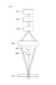
従来のレーザードップラー変位計の構成の概要を図1に示す。 An outline of the structure of a conventional laser Doppler displacement meter is shown in FIG.
光源101から出力される光は、コリメータレンズ102を伝搬し、平行光となる。ここでは、光源からの光(光束)をコリメータレンズの作用によって平行光束に変換しているが、その限りではなく収斂光束に変換しても構わない。光源から出力される光の波長をλとする。その後、回折格子やビームスプリッタのような光分岐素子103によって二光束に分岐される。それぞれの光束は、集光光学系104によってある位置に集光される。この時、集光される角度をψとする。二光束が重なり合う位置に被測定対象105がある場合、干渉光が散乱され、受光光学系106を介して受光器107によって散乱された光の干渉光が検出される。この時、被測定対象105の移動速度をVとし、検出される信号の周波数をFとすると、以下の関係式(1)となる。式(1)より、検出された信号の周波数から、被測定対象の移動速度Vが求まる。移動速度Vを時間積分することで、被測定対象の移動変位を算出できる。これにより、変位計として機能する。
The light output from the
また、光分岐素子103と二光束が重なり合う集光位置までの間に、光音響光学素子(AOM)や電気光変調素子(EOM)や光路長変化素子などのような光の周波数を変調する機構を入れても良い。このことで、二光束間で異なる光周波数を有することとなり、測定対象物が静止していても、検出信号がビート周波数の周波数成分を有し、速度0を検出することが可能となる。
Further, a mechanism that modulates the frequency of light, such as a photoacoustic optical element (AOM), an electro-optical modulation element (EOM), or an optical path length changing element, between the
式(1)より、干渉し合う散乱光について、移動する物体からの散乱光の伝搬角度と、波長を正確に決定することで精度の高い速度計測が可能となる。 From Equation (1), it is possible to accurately measure the velocity of the interfering scattered light by accurately determining the propagation angle and wavelength of the scattered light from the moving object.
特許文献1に示される従来のレーザードップラー変位計では、二光束の照射角度が光学設計によっており、さらに受光器の位置が固定されているため、散乱光の伝搬角度が決定されている。そのことによって、速度を算出できる。
In the conventional laser Doppler displacement meter disclosed in
本発明では、照射光を一光束とし、被測定対象までの距離を測定する(距離情報を得る)距離計測機構を有していることを特徴とする。被測定対象に照射された光は様々な方向に散乱され、受光光学系を伝搬したのち、受光器で受光される。受光器は式(1)のFに相当する周波数を有した電気信号を出力する。照射光は一光束であるので光路は決定されており、距離測定機構によって装置と被測定対象との距離が測定される(距離情報が得られる)ので、受光される散乱光の角度が分かる。照射光の波長は光源の仕様によって決定され、上述のように受光器からの電気信号が有する周波数Fと距離測定機構から算出された参考の角度を式(1)に代入することにより、被測定対象の移動速度を算出することが可能となる。 The present invention is characterized by having a distance measuring mechanism that measures the distance to the object to be measured (obtains distance information) with the irradiation light as one light flux. The light irradiated to the object to be measured is scattered in various directions, propagates through the light receiving optical system, and is received by the light receiver. The light receiver outputs an electrical signal having a frequency corresponding to F in Formula (1). Since the irradiation light is one light beam, the optical path is determined, and the distance between the apparatus and the object to be measured is measured by the distance measurement mechanism (distance information is obtained), so that the angle of the received scattered light can be known. The wavelength of the irradiating light is determined by the specification of the light source. As described above, the frequency F of the electrical signal from the light receiver and the reference angle calculated from the distance measuring mechanism are substituted into the equation (1) to measure It is possible to calculate the moving speed of the target.
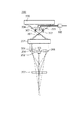
図2を用いて本発明のレーザードップラー変位計(光ドップラー変位計、レーザードップラー速度計、光ドップラー速度計)の概要を説明する。各構成素子の番号を図2a)で示し、以下の原理説明で用いる式のキャプションを図2b)で示す。本実施例の計測器は、被測定対象(被測定物、移動物体)203の、図2の左右方向(通常は左方向、右方向のうち1つの方向)の移動量(変位量)、或いは移動速度を検出することが目的である。この中で、被測定対象が左右方向に移動する際、被測定対象自体が若干上下方向(図2の紙面上下方向、計測器との距離が変化する方向)に移動してしまうケースがある。この被測定対象の上下方向の移動によって、計測結果に誤差が発生してしまうため、この誤差を低減することが本実施例の計測器の目的となっている。 The outline of the laser Doppler displacement meter (optical Doppler displacement meter, laser Doppler velocimeter, optical Doppler velocimeter) of the present invention will be described with reference to FIG. The number of each component is shown in FIG. 2a), and the caption of the formula used in the following description of the principle is shown in FIG. 2b). The measuring instrument of the present embodiment is a moving amount (displacement amount) of the measurement target (measurement object, moving object) 203 in the left-right direction (usually one of the left direction and the right direction) in FIG. The purpose is to detect the moving speed. Among these, when the measurement target moves in the left-right direction, there is a case where the measurement target itself moves slightly in the vertical direction (the vertical direction in FIG. 2, the direction in which the distance from the measuring instrument changes). An error occurs in the measurement result due to the vertical movement of the object to be measured. Therefore, it is an object of the measuring instrument of this embodiment to reduce this error.
まず、コリメータレンズ(照射光学系、照明光学系)202は、光源201から出力された光を平行光(略平行光)に変換した(整形した)上で、この平行光(照射光束)を被測定対象203に照射する(照明する)。このとき、この平行光と、被測定対象の被照射面の法線方向とのなす角度(平行光の被測定対象への入射角度)の絶対値は10度未満(好ましくは5度未満)であることが望ましい。ここで、この被測定対象の被小斜面の法線方向は、被測定対象の移動方向と垂直な方向、と読み替えても構わない。
First, a collimator lens (irradiation optical system, illumination optical system) 202 converts (shapes) the light output from the
被測定対象203によって散乱された光(被測定対象を介した光、被測定対象から出射した光)の一部は、第一の光路上の第一の受光光学系204に入射し、別の一部は第二の光路上の第二の受光光学系205に入射する。そして、集光光学素子(集光光学系、重畳光学系)206は、第一、第二の受光光学系から射出した光束同士を重ね合わせる(1点で重ね合わせる)ような屈折力(光学的パワー、焦点距離)を有している。但し、集光光学素子206は、第一、第二の受光光学系から出射した光束同士を実際に重なり合う必要は無く、集光光学素子の後に何も光学系が無ければ第一、第二の受光光学系を出射した光束同士が重なり合うような屈折力を持っていれば良い。
Part of the light scattered by the measurement target 203 (light through the measurement target, light emitted from the measurement target) enters the first light receiving
集光光学素子(集光光学系)206から出射した光束(出射光束)のうち一部の光束は分離され、第一の受光光学系から出射した光束と第二の受光光学系から出射した光束とが重なり合った状態で、受光素子208に入射する。この受光素子208は、被測定対象から別々の方向に散乱した光束(第一、第二の受光光学系に入射した光束)同士が重なった状態の光束(重畳光束、重なり合って干渉が発生している状態の光束)を検出している。この実施例では、光分岐素子207は、集光光学素子206の直後で2つの光束が重なり合う前の光路上に配置されているがその限りではなく、2つの光束が重なり合う位置、或いは重なり合った後に分離した位置に配置しても構わない。
A part of the light beam (emitted light beam) emitted from the condensing optical element (condensing optical system) 206 is separated, and the light beam emitted from the first light receiving optical system and the light beam emitted from the second light receiving optical system. Are incident on the
また、集光光学素子から出射した光束のうち、別の一部の光束は、第一、第二の受光光学系からの光束のいずれも1点に集光しない位置(集光光学素子の焦点位置とは異なる位置)に配置された距離測定機構(受光素子)209に入射する。この距離測定機構(受光素子)209は、被測定対象203の位置(計測器からの距離、或いは第一、第二受光光学系からの距離)に応じて、被測定対象からの散乱光の入射位置が異なるように構成されている。別の言い方をすれば、測定対象のz方向の位置が変化すると、測定対象からの散乱光の距離測定機構の中の受光素子(光電変換素子)への入射位置(この検出器内での光の入射位置)が変化する。従って、この距離測定機構209の検出結果から、被測定対象までの距離、或いは後述するθcを得ることができる。ここで、θcとは、被測定対象で散乱された後、第一、第二の受光光学系の焦点位置を通過して互いに平行な光線となる2つの光線同士の、被測定対象で散乱された直後になす角度の半分のことである。
In addition, among the light beams emitted from the condensing optical element, another part of the light beams is a position at which neither of the light beams from the first and second light receiving optical systems is condensed at one point (the focal point of the condensing optical element). It enters the distance measuring mechanism (light receiving element) 209 disposed at a position different from the position. The distance measuring mechanism (light receiving element) 209 is configured to receive scattered light from the measurement target according to the position of the measurement target 203 (distance from the measuring instrument or distance from the first and second light receiving optical systems). It is comprised so that a position may differ. In other words, when the position in the z direction of the measurement object changes, the incident position of the scattered light from the measurement object to the light receiving element (photoelectric conversion element) in the distance measurement mechanism (light in this detector) (Incident position) changes. Therefore, from the detection result of the
ここで、受光素子208からの光出力信号は被測定対象203の移動速度に応じたビート周波数を有する。一方で、光分岐素子207において反射せずに透過した光は距離測定機構209で検出され、変位計200と被測定対象203との距離が算出される。算出された変位計200と被測定対象203との距離から、照射光の光軸に対する散乱光の角度θiが算出され、式(1)のψに代入し、光源出力波長λと、観測される周波数Fを用いて被測定対象の移動速度Vが求まる。
Here, the light output signal from the
受光光学系204、205と被測定対象203間の距離をz、受光光学系204、205の焦点距離をfiとし、受光光学系の位置を距離の基準z=0とする。照射光の光軸中心から受光光学系204あるいは205の中心までの距離をDciとし、散乱光が伝搬する光束の中心が受光光学系204あるいは205を伝搬する位置と照射光の光軸中心との距離をDとする。第一と第二の光路を伝搬した光を重ね合わせる集光光学素子206から、重ね合わせ位置までの距離をfc、重ね合わせ位置から距離測定機構のセンサとして用いられるラインセンサ209までの距離をlLSとする。第一と第二の光路を伝搬した光を重ね合わせる際のそれぞれの光の光軸の角度をθcとする。ラインセンサ209の中心から散乱光が検出される位置までの長さをxLSとすると、
The distance between the light receiving
となり、受光光学系と被測定対象203間の距離zは
The distance z between the light receiving optical system and the
となる。ラインセンサ209のピクセルサイズをΔxLS、ピクセル番号をk=−N/2〜N/2として数式(2)、(3)を書き直すと
It becomes. When the pixel size of the
xLS=k×ΔxLS (4) x LS = k × Δx LS (4)
が得られる。したがって、ピクセルサイズによる距離方向の不確かさは Is obtained. Therefore, the uncertainty in the distance direction due to the pixel size is
となる。 It becomes.
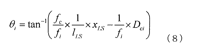
被測定対象からの散乱光の角度θiについて説明する。ラインセンサ209の中心から散乱光が検出される位置までの長さをxLSは、
The angle θi of scattered light from the measurement target will be described. XLS is the length from the center of the
であり、θiは And θi is
である。ピクセルサイズΔxLSとピクセル番号kを用いて式(8)を書き直すと It is. Rewriting equation (8) using pixel size ΔxLS and pixel number k
となり、角度の不確かさは The angle uncertainty is
となる。 It becomes.
算出される速度は式(1)に基づいているため、角度の不確かさに応じて速度も不確かとなる。 Since the calculated speed is based on the equation (1), the speed is also uncertain according to the uncertainty of the angle.
<第1実施形態>
図2を用いて第1実施形態のレーザードップラー変位計(速度計)を説明する。ここで、図2の紙面左右方向がx方向(右側が+)であり、同じく紙面上下方向がz方向(上側が+)であり、その両者と直交する紙面と垂直な方向がy方向(奥側が+)である。つまり、本実施形態の計測器は、x方向の変位、速度を検出することを主目的としている。このx方向は別の言い方をすれば、第一受光光学系(第一光学系)の光軸と第二受光光学系(第二光学系)の光軸の両者を含む平面内で、これらの光軸の少なくとも一方に対して垂直な方向のことである。また、z方向は、第一、二受光光学系(第一、二光学系)の光軸方向のことであり、y方向はその両者に対して垂直な方向、つまり前述の第一、二受光光学系の2つの光軸を含む平面と垂直な方向、のことである。このx方向の変位や速度の検出精度向上のために、被測定対象のz方向の位置検出を行いその結果を用いて被測定対象のx方向の変位や速度の検出精度を向上させている。
<First Embodiment>
The laser Doppler displacement meter (velocimeter) of the first embodiment will be described with reference to FIG. Here, the left-right direction in FIG. 2 is the x direction (+ on the right side), the up-and-down direction on the page is the z direction (+ on the upper side), and the direction perpendicular to the plane perpendicular to both is the y direction (back). The side is +). That is, the measuring instrument of this embodiment is mainly intended to detect the displacement and speed in the x direction. In other words, the x direction is a plane including both the optical axis of the first light receiving optical system (first optical system) and the optical axis of the second light receiving optical system (second optical system). A direction perpendicular to at least one of the optical axes. The z direction is the optical axis direction of the first and second light receiving optical systems (first and second optical systems), and the y direction is the direction perpendicular to both of them, that is, the first and second light receiving processes described above. The direction perpendicular to the plane including the two optical axes of the optical system. In order to improve the detection accuracy of the displacement and speed in the x direction, the position of the measurement target in the z direction is detected, and the detection accuracy of the displacement and speed in the x direction of the measurement target is improved.
光源201には波長650nmを有するレーザーダイオードを用いた。出力光はコリメータレンズ202を通して平行光束となり被測定対象203へ照射される。第一の受光光学系204および第二の受光光学系205は直径10mmで、焦点距離10mmのレンズを用いた。受光光学系のレンズは、照射光の光軸から10mm離れた位置にレンズの中心を持つように配置した。集光光学素子206は直径25mmで、焦点距離25mmのレンズを用いた。集光光学素子206のレンズと焦点位置の間に光分岐素子207としてハーフミラー(分離光学系、重畳光学系)を挿入し、散乱光の一部が受光素子208へ伝搬するようにした。受光素子208は直径1mmのセンサを有するフォトディテクタであり、応答速度は10MHzのものを用いた。距離測定機構209にはラインセンサを用いた。ハーフミラー207を透過した光の集光位置から20mmの距離で、第一の光路を伝搬する散乱光を受光するようにラインセンサ209を配置した。ラインセンサ209はピクセルサイズ10μmで、2048ピクセルを有している。したがってセンササイズはおよそ20mmである。
As the
上述の構成とすることで、測定可能深度レンジである変位計200と被測定対象203との距離は30mm〜無限遠となる。測定可能速度は、遠方になればなるほど高速となり、1m遠方ではおよそ162m/secの速度まで測定可能となる。しかしながら、速度分解能は劣化し、不確かさが増大し、1m遠方では12.5%程度の不確かさとなる。本実施形態では、変位計200と被測定対象203との距離が100mm程度としている。この場合、測定可能な最大速度は14.7m/sec程度であり、±10mmの範囲で誤差は1%程度である。
By setting it as the above-mentioned structure, the distance of the
なお、本実施形態では、上述のような光学素子を用いた構成としたが、同様の機能を有する素子であれば上述の光学素子に限らない。また、数値も目的に応じて変更しても良い。例えば、光源はレーザーダイオードに限らず、波長も被測定対象に応じて選択しても良い。また、受光光学系や集光光学系も単レンズの光学系に限らず複数のレンズを用いても良いし、ミラー等を用いても良い。光分岐素子もハーフミラーに限らず、回折格子等を用いても良い。 In the present embodiment, the optical element as described above is used. However, the optical element is not limited to the optical element as long as the element has a similar function. Also, the numerical value may be changed according to the purpose. For example, the light source is not limited to the laser diode, and the wavelength may be selected according to the measurement target. The light receiving optical system and the condensing optical system are not limited to a single lens optical system, and a plurality of lenses may be used, or a mirror or the like may be used. The optical branching element is not limited to a half mirror, and a diffraction grating or the like may be used.
<第2実施形態>
図3を用いて第2実施形態のレーザードップラー変位計(速度計)を説明する。座標系は第1実施形態(図1)と同じである。
Second Embodiment
A laser Doppler displacement meter (velocimeter) of the second embodiment will be described with reference to FIG. The coordinate system is the same as in the first embodiment (FIG. 1).
第1の実施形態と異なり、干渉用ハーフミラー301を集光光学素子206によって散乱光が集光され重ね合わされる位置に配置する。干渉用ハーフミラー301を透過することで、第一の干渉光と第二の干渉光が生成される。第一と第二のそれぞれの干渉光は、第一と第二の光分岐素子であるハーフミラー302と303により、一部が反射され、第一と第二の受光器304と305によって受光され第一と第二の干渉信号に変換される。差動検出器306により第一と第二の干渉信号の差動検出を行い、DC成分を打消し振動成分のみを取り出す。なお、第一と第二の受光器304と305にて効率良く検出するために、ハーフミラー302と受光器304およびハーフミラー303と受光器305の間に光学系を入れて波面を補正しても良い。
Unlike the first embodiment, the
本実施形態によって、DC成分を取り除き、ドップラー周波数成分のみを取り出すことが可能となり、SN比が高まる。 According to the present embodiment, it becomes possible to remove the DC component and extract only the Doppler frequency component, and the SN ratio is increased.
測距用に光を分岐するハーフミラー207は、集光光学素子206と干渉用ハーフミラー301との間でも良いし、干渉用ハーフミラー301と受光器302あるいは303との間でも良い。
The
<第3実施形態>
第3実施形態のレーザードップラー変位計(速度計)では、受光光学系204および205と被測定対象203の間の焦点位置にアパーチャを挿入する。
<Third Embodiment>
In the laser Doppler displacement meter (velocimeter) of the third embodiment, an aperture is inserted at the focal position between the light receiving
本実施形態では散乱光の光路を限定するため、散乱光の角度が制限され、測距および速度の精度を高めることが可能となる。 In this embodiment, since the optical path of the scattered light is limited, the angle of the scattered light is limited, and the accuracy of distance measurement and speed can be improved.
<第4実施形態>
第4実施形態のレーザードップラー変位計(速度計)では、照射光を平行光(コリメート光)ではなく特定の距離で集光点を持つように、光源と被束測定対象との間に照射レンズを挿入する。レーザー光は直線性が良く、平行光のまま遠方まで伝搬するが、実際にはわずかに発散している。そのため、変位計と被測定対象との距離が遠くなると、照射光のビーム径が拡がり、受光される散乱角度の広がりが大きくなる。そのため、速度精度が劣化する。本実施形態によって遠方でもビーム径が限定され、受光される散乱光の角度拡がりが抑制され、速度精度を高めることが可能となる。
<Fourth embodiment>
In the laser Doppler displacement meter (velocimeter) of the fourth embodiment, the irradiation lens is arranged between the light source and the bundle measurement target so that the irradiation light has a condensing point at a specific distance instead of parallel light (collimated light). Insert. The laser beam has good linearity and propagates to a distant place as parallel light, but actually diverges slightly. Therefore, when the distance between the displacement meter and the object to be measured is increased, the beam diameter of the irradiation light is expanded, and the spread of the received scattering angle is increased. Therefore, the speed accuracy is deteriorated. According to the present embodiment, the beam diameter is limited even at a distance, the angular spread of the received scattered light is suppressed, and the speed accuracy can be improved.
本実施形態では、10mの距離で集光されるようにした。照射レンズの入射するビーム径は4mmであり、10m遠方でのビーム径は2mmである。 In the present embodiment, light is collected at a distance of 10 m. The beam diameter incident on the irradiation lens is 4 mm, and the beam diameter at a distance of 10 m is 2 mm.
<第5実施形態>
第5実施形態のレーザードップラー変位計(速度計)では、計測器から被測定対象までの距離を測定する距離測定機構で用いるラインセンサ209の前に拡大光学系を挿入する。本実施形態の計測器による距離測定は、距離の違いが散乱光の光学系への入射角度の違いとなり、結果としてラインセンサへの入射位置の違いに反映される。従って、拡大光学系を挿入することで、ラインセンサ上の位置の違いが大きくなり、距離および角度分解能を向上させることができる。このことで、算出される速度分解能も向上する。
<Fifth Embodiment>
In the laser Doppler displacement meter (velocimeter) of the fifth embodiment, an expansion optical system is inserted in front of the
<第6実施形態>
第6実施形態のレーザードップラー変位計(速度計)では、距離測定機構で用いるラインセンサ209の前に補正光学系を挿入する。式(3)あるいは式(8)のように距離zあるいは角度θiと、ラインセンサで受光される散乱光の位置は一次関数の関係ではない。そのため、変位計と被測定対象との距離が大きくなると、距離zあるいは角度θiの分解能(検出分解能)が劣化する(低下する)という課題があった。
<Sixth Embodiment>
In the laser Doppler displacement meter (velocimeter) of the sixth embodiment, a correction optical system is inserted in front of the
そこで、本実施形態では、補正光学系によって、ある距離範囲内(本実施形態では100mm±10mmの範囲)で距離zあるいは角度θiとラインセンサで受光される散乱光位置xLSがほぼ一次関数の関係となるようにする。 Therefore, in the present embodiment, the relationship between the distance z or the angle θi and the scattered light position xLS received by the line sensor within a certain distance range (in this embodiment, a range of 100 mm ± 10 mm) by the correction optical system is almost linear function. To be.
本実施形態により、変位計と被測定対象との距離が変化しても距離zあるいは角度θiの分解能が変化せず(無い場合に比べて分解能の変化量の低減が可能な、或いは分解能の変化を抑制することが可能な)、一様の精度で変位を測定できるようになる。 According to the present embodiment, the resolution of the distance z or the angle θi does not change even if the distance between the displacement meter and the object to be measured changes. The displacement can be measured with uniform accuracy.
<第7実施形態>
第7実施形態のレーザードップラー変位計(速度計)では、距離測定機構で用いるラインセンサ209の前に範囲内補正光学系を挿入する。範囲内補正光学系は、ある距離範囲内(本実施形態では100mm±10mmの範囲)で距離zあるいは角度θiの分解能が高まるようにし、狙った距離範囲外の分解能(検出分解能)は劣化させる。つまり、変位計と測定対象物体の距離が所定範囲内における両者の距離の検出分解能が、所定範囲外における距離の検出分解能よりも高くなるように(高分解能になるように)構成している。
<Seventh embodiment>
In the laser Doppler displacement meter (velocimeter) of the seventh embodiment, an in-range correction optical system is inserted in front of the
本実施形態により、ラインセンサのピクセルサイズやピクセル数が限られていても、特定の距離範囲内で高精度な変位測定が可能となる。 According to the present embodiment, even if the pixel size and the number of pixels of the line sensor are limited, highly accurate displacement measurement can be performed within a specific distance range.
<第8実施形態>
第8実施形態のレーザードップラー変位計(速度計)について説明する。ここでは、受光光学系204および受光光学系205が、被測定対象との間に集光点を有している単レンズのような光学系の場合を想定している。この場合、照射光軸に対して受光光学系の単レンズの外側(2つの光学系の光軸の間の領域の外側)を伝搬する光しか受光されない。そこで、第8実施形態では、照射光軸に対して受光光学系の単レンズの内側(2つの光学系の光軸の間の領域)を削ったレンズを用いる。
<Eighth Embodiment>
A laser Doppler displacement meter (speed meter) of the eighth embodiment will be described. Here, it is assumed that the light receiving
本実施形態によって、変位計を小型・軽量化できる。 According to this embodiment, the displacement meter can be reduced in size and weight.
<第9実施形態>
これまでの実施形態では、距離測定機構で用いるラインセンサ(光電変換素子)209で検出された散乱光の波形データ(強度分布、データ波形)の中で、光強度が最大となるピクセルの位置を用いていた。つまり、光強度が最大となるピクセルの位置に基づいて、そのピクセルの位置(ピクセルの中心位置)に基づいて、計測器と被測定対象までの距離あるいは被測定対象からの散乱光の入射角度を算出していた。具体的には、式(3)あるいは式(8)に基づいて、上記の演算を行っていた。
<Ninth Embodiment>
In the embodiments so far, the position of the pixel having the maximum light intensity in the waveform data (intensity distribution, data waveform) of the scattered light detected by the line sensor (photoelectric conversion element) 209 used in the distance measurement mechanism is determined. I used it. In other words, based on the position of the pixel where the light intensity is maximum, based on the position of the pixel (the center position of the pixel), the distance between the measuring instrument and the measurement target or the incident angle of the scattered light from the measurement target is determined. It was calculated. Specifically, the above calculation is performed based on Expression (3) or Expression (8).
この第9実施形態のレーザードップラー変位計(速度計)では、距離測定機構で用いるラインセンサ209で検出された(取得された)散乱光の波形データ(光強度分布)に対して、データ処理(加工)を行う。
In the laser Doppler displacement meter (velocimeter) of the ninth embodiment, data processing (light intensity distribution) is performed on the waveform data (light intensity distribution) of scattered light detected (acquired) by the
補間やフィッティング(或いはその両方)などのデータ処理を行う。このようなデータ処理を行うことによって、ピーク検出精度(光強度分布のピーク位置の検出精度)を高めることができ、被測定対象までの距離や被測定対象からの散乱光の入射角度の精度が高めることができる。そして、最終的に、測定対象の測定方向(図2の左右方向)の変位量の検出精度や速度の検出精度を向上させることが可能となる。 Data processing such as interpolation and fitting (or both) is performed. By performing such data processing, the peak detection accuracy (detection accuracy of the peak position of the light intensity distribution) can be increased, and the accuracy of the distance to the measurement target and the incident angle of scattered light from the measurement target can be improved. Can be increased. Finally, it becomes possible to improve the detection accuracy of the displacement amount and the detection accuracy of the speed in the measurement direction of the measurement target (the left-right direction in FIG. 2).
<第10実施形態>
第10実施形態のレーザードップラー変位計(速度計)では、第一と第二の散乱光光路を伝搬するそれぞれの光を、距離測定機構でそれぞれ検出する。距離および角度は、それぞれの検出データから算出して平均化して算出する。あるいは、二つのピーク位置の距離から算出しても良い。
<Tenth embodiment>
In the laser Doppler displacement meter (velocimeter) of the tenth embodiment, each light propagating in the first and second scattered light optical paths is detected by a distance measuring mechanism. The distance and angle are calculated from each detection data and averaged. Or you may calculate from the distance of two peak positions.
本実施形態のように2つの信号を用いることで、第一と第二の散乱光の光路の違いを平均化し、調整の負荷を下げることが可能となる。 By using two signals as in the present embodiment, it is possible to average the difference between the optical paths of the first and second scattered light and reduce the adjustment load.
<第11実施形態>
第11実施形態のレーザードップラー変位計(速度計)では、受光素子がマルチセンサである。レーザードップラー変位計では、散乱光のランダムな重なりにより、光が打ち消し合い、干渉信号強度が0となってしまうドロップアウトという現象が起き得る。本実施形態では、受光素子が複数あるため、いずれかの受光部で0となっても他の受光部で信号を出力する。そのため、ドロップアウトを回避することが可能となる。
<Eleventh embodiment>
In the laser Doppler displacement meter (velocimeter) of the eleventh embodiment, the light receiving element is a multi-sensor. In a laser Doppler displacement meter, a phenomenon called dropout in which light cancels out due to random overlap of scattered light and the interference signal intensity becomes zero may occur. In the present embodiment, since there are a plurality of light receiving elements, even if one of the light receiving units becomes 0, the other light receiving unit outputs a signal. Therefore, it becomes possible to avoid dropout.
<第12実施形態>
第12実施形態は計測システムに関する。この計測システムでは、前述のレーザードップラー変位計(速度計)が持つ機構のうち距離測定機構をなくし、別体の測距センサ(距離情報を取得できる装置)を用いる。本実施形態では、レーザーを用いた三角測量に基づく測距センサを用いた。測距センサで用いたレーザー光の波長は、変位計で用いる波長(650nm)と異なる532nmとし、100nm以上(波長が長い方の波長が短い方の105%以上、より好ましくは110%以上)波長を異ならせることにより両者の干渉を回避した。
<Twelfth embodiment>
The twelfth embodiment relates to a measurement system. In this measurement system, the distance measuring mechanism is eliminated from the mechanisms of the laser Doppler displacement meter (velocimeter) described above, and a separate distance measuring sensor (device capable of acquiring distance information) is used. In the present embodiment, a distance measuring sensor based on triangulation using a laser is used. The wavelength of the laser beam used in the distance measuring sensor is 532 nm, which is different from the wavelength (650 nm) used in the displacement meter, and is 100 nm or more (105% or more, more preferably 110% or more of the shorter wavelength is longer). The interference between the two was avoided by making them different.
本実施形態により、距離測定精度をより高精度化でき、散乱光角度の精度を高め、測定される速度の精度を高めることが可能となる。 According to this embodiment, the distance measurement accuracy can be further increased, the accuracy of the scattered light angle can be increased, and the accuracy of the measured speed can be increased.
なお、測距センサはレーザーを用いた三角測量に基づくものでなくても良く、パターン投影やマイケルソン干渉計に基づくものでも良い。また、非接触に限らず、接触式のものでも良い。 The distance measuring sensor may not be based on triangulation using a laser, but may be based on pattern projection or a Michelson interferometer. Moreover, not only a non-contact but a contact type may be used.
<第13実施形態>
第13実施形態のレーザードップラー変位計(速度計)では、第一と第二の受光光学系が計測する変位方向(x方向)に対して直交するy方向における測定対象の変位(速度)を計測する。ここで、y方向とは、第一、二受光光学系の2つの光軸が形成する平面に垂直な方向(照射光軸の方向と垂直な方向)である。このy方向における測定対象の変位(速度)を計測する第三と第四の受光光学系および第二の受光素子を有する点がこの実施形態の特徴である。ここで、図と照らし合わせると、x方向は紙面左右方向、z方向は紙面上下方向、y方向は紙面奥行き方向である。
<13th Embodiment>
In the laser Doppler displacement meter (velocimeter) of the thirteenth embodiment, the displacement (velocity) of the measurement object in the y direction orthogonal to the displacement direction (x direction) measured by the first and second light receiving optical systems is measured. To do. Here, the y direction is a direction perpendicular to a plane formed by the two optical axes of the first and second light receiving optical systems (a direction perpendicular to the direction of the irradiation optical axis). This embodiment is characterized by having third and fourth light receiving optical systems and a second light receiving element for measuring the displacement (velocity) of the measurement object in the y direction. Here, in comparison with the figure, the x direction is the left-right direction of the paper surface, the z direction is the vertical direction of the paper surface, and the y direction is the depth direction of the paper surface.
被測定対象が一様に光を散乱する表面を有するとすると、散乱光は全方位に伝搬する。これまでの実施形態では、第一と第二の受光光学系により、第一の方向(x方向)の変位を測定していた。本実施形態では、さらに第三と第四の受光光学系と第二の受光素子を有することで、第一の方向(x方向)とは直交する第二の方向(y方向)の変位を測定することが可能となる。 If the object to be measured has a surface that uniformly scatters light, the scattered light propagates in all directions. In the embodiments so far, the displacement in the first direction (x direction) has been measured by the first and second light receiving optical systems. In this embodiment, the displacement in the second direction (y direction) perpendicular to the first direction (x direction) is measured by further including the third and fourth light receiving optical systems and the second light receiving element. It becomes possible to do.
さらに、第一と第二の変位から、斜め方向の変位を算出することが可能となる。 Furthermore, it is possible to calculate a displacement in an oblique direction from the first and second displacements.
<第14実施形態>
第14実施形態のレーザードップラー変位計(速度計)では、第10実施形態と同じ構成である。第一と第二の散乱光光路をそれぞれ伝搬して距離測定機構で測定された第一と第二のデータの強度値を比較し、照射光軸に対する被測定対象の傾きを判定する。
<Fourteenth embodiment>
The laser Doppler displacement meter (velocimeter) of the fourteenth embodiment has the same configuration as that of the tenth embodiment. The first and second scattered light paths are respectively propagated and the intensity values of the first and second data measured by the distance measuring mechanism are compared to determine the inclination of the measurement target with respect to the irradiation optical axis.
一般的に散乱光の光量は直接反射光軸を中心に減少していく。そのため、被測定対象が傾いている場合には、第一と第二の散乱光光路を伝搬する光量が異なる。そのため、距離測定機構で測定された第一と第二のデータの強度値を比較することで、照射光軸に対して被測定対象の測定面が傾いているかどうか判断することが可能となる。 In general, the amount of scattered light decreases around the directly reflected optical axis. Therefore, when the measurement target is tilted, the amount of light propagating through the first and second scattered light optical paths is different. Therefore, by comparing the intensity values of the first and second data measured by the distance measuring mechanism, it is possible to determine whether the measurement surface of the measurement target is inclined with respect to the irradiation optical axis.
本実施形態によって、変位計を設置する際に、第一の受光光学系を介して距離測定機構に到達した光の強度を示す第一のデータと、第二の受光光学系を介して距離測定機構に到達した光の強度を示す第二のデータと、を比較する。この比較の結果、バランスが崩れている場合には、自動的に照射光軸、或いは第一、二受光光学系の光軸を調整する駆動機構を制御する。 According to this embodiment, when installing the displacement meter, first data indicating the intensity of light reaching the distance measuring mechanism via the first light receiving optical system, and distance measurement via the second light receiving optical system. The second data indicating the intensity of light reaching the mechanism is compared. As a result of this comparison, when the balance is lost, the drive mechanism for automatically adjusting the irradiation optical axis or the optical axes of the first and second light receiving optical systems is controlled.
このようにすれば、変位測定中に被測定対象の測定面が傾いたかどうかを判定し、搬送系あるいは被測定対象の歪みを検出することが可能となる。ここで、第一のデータ(第一散乱光路を介した光強度)と第二のデータ(第二散乱光路を介した光強度)とを比較し、大きい方が小さい方の120%以上(好ましくは105%以上)の場合、照射光学系(の光軸)の傾きを自動的に調整することが望ましい。 In this way, it is possible to determine whether the measurement surface of the measurement target is tilted during the displacement measurement, and to detect the distortion of the transport system or the measurement target. Here, the first data (light intensity through the first scattering light path) and the second data (light intensity through the second scattering light path) are compared, and the larger one is 120% or more (preferably Is 105% or more), it is desirable to automatically adjust the inclination of the irradiation optical system (its optical axis).
また、初期の設置の段階で、この両者の強度値のバランスの測定結果に基づいて、光学系の傾きを調整するようにしても良い。 Further, at the initial installation stage, the inclination of the optical system may be adjusted based on the measurement result of the balance between the intensity values of the two.
<第15実施形態>
第15実施形態のレーザードップラー変位計(速度計)では、変位計により測定される移動方向の変位xと、距離測定機構により測定される距離変位zを用い、測定対象の長さlを以下の式(11)を用いて算出する。
<Fifteenth embodiment>
In the laser Doppler displacement meter (velocimeter) of the fifteenth embodiment, the displacement x in the moving direction measured by the displacement meter and the distance displacement z measured by the distance measuring mechanism are used. It calculates using Formula (11).
さらに第13実施形態での変位計を用いることで、xともzとも直交する変位yを計測でき、測定対象の長さlを Furthermore, by using the displacement meter in the thirteenth embodiment, the displacement y orthogonal to both x and z can be measured, and the length l of the object to be measured can be determined.
により算出することが可能となる。 It is possible to calculate by
本実施形態により、被測定対象が移動方向以外に振動した場合でも、正確な長さを算出することが可能となる。特に、布や線材などでは振動しやすいため、変位誤差が大きくなりやすい。本実施形態により、誤差を小さくすることが可能となる。 According to the present embodiment, an accurate length can be calculated even when the measurement target vibrates in a direction other than the moving direction. In particular, since a cloth or a wire easily vibrates, a displacement error tends to increase. According to this embodiment, the error can be reduced.
<第16実施形態>
第16実施形態は、第1〜15実施形態のレーザードップラー変位計(速度計)の中のいずれかの変位計を用いた加工装置の例である。この加工装置は、被加工対象物(被測定対象)を加工する加工部と、この加工部を制御する制御部と、この制御部に制御信号を入力する入力装置とを備えている。この加工装置では、加工部によって加工された被加工対象物の長さが予め設定した長さになった場合、或いは被加工対象物が予め設定した距離を移動した(加工された上で移動した)場合を検知(検出)している。この検知をきっかけにして、加工部による被加工対象物の成形(或いは移動)動作を停止させたり、或いは被加工対象物を切断したりするための制御信号を、入力部から制御部に送信している。
<Sixteenth Embodiment>
The sixteenth embodiment is an example of a processing apparatus using any one of the displacement meters in the laser Doppler displacement meter (velocimeter) of the first to fifteenth embodiments. This processing apparatus includes a processing unit that processes an object to be processed (measurement target), a control unit that controls the processing unit, and an input device that inputs a control signal to the control unit. In this processing apparatus, when the length of the workpiece processed by the processing section reaches a preset length, or the workpiece has moved a preset distance (moved after being processed) ) The case is detected (detected). Using this detection as a trigger, a control signal for stopping the forming (or moving) operation of the workpiece by the machining unit or cutting the workpiece is sent from the input unit to the control unit. ing.
本実施形態により、正確な長さで被測定対象を停止させたり、切断したりすることが可能となるため、高精度で素早く加工を実施することができる。 According to the present embodiment, it becomes possible to stop or cut the object to be measured with an accurate length, so that it is possible to perform processing with high accuracy and quickly.
<第17実施形態>
第17実施形態の加工装置では、被測定対象のx、y、zの変位をフィードバックし、オンザフライで加工する場合に同期を取って加工可能とする。
<Seventeenth Embodiment>
In the processing apparatus of the seventeenth embodiment, the x, y, and z displacements of the measurement target are fed back, and processing can be performed synchronously when processing on the fly.
本実施形態により、被測定対象が搬送方向とは異なる方向に移動した場合にも精度の高い加工を行うことが可能となる。 According to this embodiment, it is possible to perform highly accurate processing even when the object to be measured moves in a direction different from the conveyance direction.
以上、本発明の好ましい実施形態について説明したが、本発明は、これらの実施形態に限定されず、その要旨の範囲内で種々の変形及び変更が可能である。 As mentioned above, although preferable embodiment of this invention was described, this invention is not limited to these embodiment, A various deformation | transformation and change are possible within the range of the summary.
200 本発明による変位計
201 光源
202 コリメータレンズ
203 被測定対象
204 第一の光路上の第一の受光光学系
205 第二の光路上の第二の受光光学系
206 集光光学素子
207 光分岐素子
208 受光素子
209 距離測定機構
200 Displacement meter according to the
Claims (19)
光源からの光を整形して照射光束とし、該照射光束で前記測定対象を照射する照射光学系と、
前記測定対象から出射する第一光束と、前記第一光束とは異なる方向に出射する第二光束とを、重ね合わせるように集光させる集光光学系と、
前記集光光学系から出射した出射光束のうち、前記第一光束と前記第二光束とが重ね合わせられた重畳光を検出する第一検出器と、
前記集光光学系から出射した出射光束の一部の光束を検出する第二検出器と、
を備えており、
前記第二検出器による検出結果は、前記計測器と前記測定対象との間の距離に応じて変化するものであり、
前記計測器は、前記第一検出器による検出結果と、前記第二検出器による検出結果とに基づいて、前記変位量又は前記速度のいずれかを出力する、
ことを特徴とする計測器。 A measuring instrument that measures the amount of displacement or speed of a measurement object,
An irradiation optical system that shapes light from a light source to form an irradiation light beam, and irradiates the measurement object with the irradiation light beam;
A condensing optical system that condenses the first light beam emitted from the measurement object and the second light beam emitted in a direction different from the first light beam so as to overlap each other;
A first detector that detects superposed light in which the first light flux and the second light flux are superposed among the emitted light fluxes emitted from the condensing optical system;
A second detector for detecting a part of the emitted light beam emitted from the condensing optical system;
With
The detection result by the second detector changes according to the distance between the measuring instrument and the measurement object,
The measuring device outputs either the displacement amount or the speed based on a detection result by the first detector and a detection result by the second detector.
A measuring instrument characterized by that.
前記照射光学系は、前記1つの光束で前記測定対象を照射する、
ことを特徴とする請求項1に記載の計測器。 The irradiation light beam is one light beam,
The irradiation optical system irradiates the measurement object with the one light beam.
The measuring instrument according to claim 1.
前記第一光学系と前記測定対象との間の焦点の位置と、前記第二光学系と前記測定対象との間の焦点の位置とのそれぞれに配置された絞りを備える、
ことを特徴とする請求項8に記載の計測器。 The first and second optical systems are arranged such that a focal point is located between the first and second optical systems and the measurement target,
A diaphragm disposed at each of a focal position between the first optical system and the measurement object and a focal position between the second optical system and the measurement object;
The measuring instrument according to claim 8.
ことを特徴とする請求項8又は9に記載の計測器。 A third optical system for detecting a displacement amount or speed of the measurement object in a direction perpendicular to a plane including both the optical axis of the first optical system and the optical axis of the second optical system; ,
The measuring instrument according to claim 8 or 9, wherein
ことを特徴とする請求項1乃至14いずれか1項に記載の計測器。 Based on the detection result of the second detector, the resolution of the distance between the measuring instrument and the measurement object is to suppress a decrease due to an increase in the distance between the measuring instrument and the measurement object. With correction optics,
The measuring instrument according to any one of claims 1 to 14, wherein:
ことを特徴とする請求項1乃至15いずれか1項に記載の計測器。 The detection resolution of the distance between the measuring instrument and the measurement object is higher when the distance between the measuring instrument and the measurement object is within a predetermined range than when the distance is outside the predetermined range. It has an optical system that
The measuring instrument according to any one of claims 1 to 15, wherein:
前記測定対象と前記計測器との距離を測定する測距センサと、
を備えており、
前記測距センサが出力する距離情報を用いて、前記計測器が出力する前記変位量又は前記速度を補正することによって、前記測定対象の変位量又は速度を出力する、
ことを特徴とする計測システム。 A measuring instrument for measuring the amount of displacement or speed of a measurement target, shaping light from a light source into an irradiation light beam, an irradiation optical system for irradiating the measurement target with the irradiation light beam, and a first light emitted from the measurement target A condensing optical system that condenses one light beam and a second light beam that is emitted in a direction different from the first light beam, and the first light beam among the emitted light beams emitted from the condensing optical system. A detector that detects superimposed light in which a light beam and the second light beam are superimposed, and a measuring instrument,
A distance measuring sensor for measuring a distance between the measurement object and the measuring instrument;
With
Using the distance information output by the distance measuring sensor, the displacement amount or speed of the measurement object is output by correcting the displacement amount or the speed output by the measuring instrument.
A measurement system characterized by this.
前記加工対象物の変位量又は速度を計測する、請求項1乃至17いずれか1項に記載の計測器と、
前記計測器の計測結果に応じて、前記加工部を制御する制御部と、
を備えることを特徴とする加工装置。 A processing section for processing a workpiece;
The measuring instrument according to any one of claims 1 to 17, which measures a displacement amount or a speed of the workpiece.
According to the measurement result of the measuring instrument, a control unit that controls the processing unit;
A processing apparatus comprising:
Priority Applications (4)
| Application Number | Priority Date | Filing Date | Title |
|---|---|---|---|
| JP2018104917A JP2019211237A (en) | 2018-05-31 | 2018-05-31 | Measurement instrument and machining device |
| EP19174475.4A EP3575740A1 (en) | 2018-05-31 | 2019-05-14 | Measuring device and processing device |
| US16/422,721 US20190369136A1 (en) | 2018-05-31 | 2019-05-24 | Measuring device and processing device |
| CN201910449727.0A CN110554402A (en) | 2018-05-31 | 2019-05-28 | Measuring device and processing device |
Applications Claiming Priority (1)
| Application Number | Priority Date | Filing Date | Title |
|---|---|---|---|
| JP2018104917A JP2019211237A (en) | 2018-05-31 | 2018-05-31 | Measurement instrument and machining device |
Publications (1)
| Publication Number | Publication Date |
|---|---|
| JP2019211237A true JP2019211237A (en) | 2019-12-12 |
Family
ID=66554183
Family Applications (1)
| Application Number | Title | Priority Date | Filing Date |
|---|---|---|---|
| JP2018104917A Pending JP2019211237A (en) | 2018-05-31 | 2018-05-31 | Measurement instrument and machining device |
Country Status (4)
| Country | Link |
|---|---|
| US (1) | US20190369136A1 (en) |
| EP (1) | EP3575740A1 (en) |
| JP (1) | JP2019211237A (en) |
| CN (1) | CN110554402A (en) |
Cited By (1)
| Publication number | Priority date | Publication date | Assignee | Title |
|---|---|---|---|---|
| JP7408416B2 (en) | 2020-01-28 | 2024-01-05 | キヤノン株式会社 | Displacement meter and article manufacturing method |
Families Citing this family (2)
| Publication number | Priority date | Publication date | Assignee | Title |
|---|---|---|---|---|
| CN111735398A (en) * | 2020-05-22 | 2020-10-02 | 共享智能铸造产业创新中心有限公司 | Device for measuring length of linear object |
| CN112904040B (en) * | 2021-01-25 | 2023-07-21 | 上海兰宝传感科技股份有限公司 | Laser Doppler speed measuring device |
Family Cites Families (7)
| Publication number | Priority date | Publication date | Assignee | Title |
|---|---|---|---|---|
| JP2934066B2 (en) * | 1991-08-07 | 1999-08-16 | 三菱電機株式会社 | Laser doppler velocimeter |
| JP3423396B2 (en) | 1994-02-15 | 2003-07-07 | キヤノン株式会社 | Speedometer |
| EP0770219B1 (en) * | 1994-07-08 | 1999-10-20 | Forskningscenter Riso | An optical measurement method and apparatus |
| JP3501529B2 (en) * | 1994-11-16 | 2004-03-02 | キヤノン株式会社 | Optical displacement measuring device |
| FR2872920B1 (en) * | 2004-07-06 | 2006-09-22 | Commissariat Energie Atomique | OPTICAL DEVICE FOR MEASURING THE SPEED OF MOVING A FIRST MOBILE ELEMENT IN RELATION TO A SECOND ELEMENT |
| JP2015087216A (en) * | 2013-10-30 | 2015-05-07 | キヤノン株式会社 | Optical type displacement information measurement device |
| TW201743074A (en) * | 2016-06-01 | 2017-12-16 | 原相科技股份有限公司 | Measurement device and operation method thereof |
-
2018
- 2018-05-31 JP JP2018104917A patent/JP2019211237A/en active Pending
-
2019
- 2019-05-14 EP EP19174475.4A patent/EP3575740A1/en not_active Withdrawn
- 2019-05-24 US US16/422,721 patent/US20190369136A1/en not_active Abandoned
- 2019-05-28 CN CN201910449727.0A patent/CN110554402A/en active Pending
Cited By (1)
| Publication number | Priority date | Publication date | Assignee | Title |
|---|---|---|---|---|
| JP7408416B2 (en) | 2020-01-28 | 2024-01-05 | キヤノン株式会社 | Displacement meter and article manufacturing method |
Also Published As
| Publication number | Publication date |
|---|---|
| CN110554402A (en) | 2019-12-10 |
| US20190369136A1 (en) | 2019-12-05 |
| EP3575740A1 (en) | 2019-12-04 |
Similar Documents
| Publication | Publication Date | Title |
|---|---|---|
| US7723657B2 (en) | Focus detection apparatus having extended detection range | |
| JP5931225B2 (en) | Method for calculating distance change using an interferometer | |
| EP2104833B1 (en) | Partial coherence interferometer with measurement ambiguity resolution | |
| JP2019211237A (en) | Measurement instrument and machining device | |
| JP6363660B2 (en) | Laser processing apparatus and laser processing system | |
| EP2306144A1 (en) | Surface shape measurement apparatus | |
| CN104154882B (en) | Dual-beam device for detecting parallelism and method based on differential confocal measurement | |
| JPWO2013084557A1 (en) | Shape measuring device | |
| KR101085014B1 (en) | Optical surface measuring apparatus and method | |
| US20150077759A1 (en) | Compact, Slope Sensitive Optical Probe | |
| KR101628761B1 (en) | surface shape measuring appatstus using asymmetric interferometer | |
| US5870199A (en) | Method and apparatus for highly accurate distance measurement with respect to surfaces | |
| US20190285398A1 (en) | Method and device for determining the spatial position of an object by means of interferometric length measurement | |
| JP2001264036A (en) | Measuring apparatus and measuring method for surface shape | |
| JP2020071414A (en) | Measuring device for collimation adjustment and method for adjusting collimation optical system | |
| JP2021518582A (en) | Optics and methods for detecting light beam drift | |
| US20230128231A1 (en) | Device for determining the speed and/or the length of a product | |
| JP2009186254A (en) | Beam angle detector | |
| JP2005147703A (en) | Device and method for measuring surface distance | |
| JPH0469508A (en) | Method and instrument for optical contactless shape measurement | |
| JP2008309652A (en) | Dimension measuring device and dimension measuring method | |
| JP4936287B2 (en) | Inner diameter measuring device | |
| JPH06109435A (en) | Surface displacement meter | |
| JP5188377B2 (en) | Method for measuring sphericity of sphere and method for measuring radius of curvature of sphere | |
| KR20100020001A (en) | Length measuring apparatus |