JP2019205104A - Information processing apparatus, information processing method, and program - Google Patents
Information processing apparatus, information processing method, and program Download PDFInfo
- Publication number
- JP2019205104A JP2019205104A JP2018100158A JP2018100158A JP2019205104A JP 2019205104 A JP2019205104 A JP 2019205104A JP 2018100158 A JP2018100158 A JP 2018100158A JP 2018100158 A JP2018100158 A JP 2018100158A JP 2019205104 A JP2019205104 A JP 2019205104A
- Authority
- JP
- Japan
- Prior art keywords
- image
- projection
- information processing
- projector
- target
- Prior art date
- Legal status (The legal status is an assumption and is not a legal conclusion. Google has not performed a legal analysis and makes no representation as to the accuracy of the status listed.)
- Pending
Links
Images


Classifications
-
- H—ELECTRICITY
- H04—ELECTRIC COMMUNICATION TECHNIQUE
- H04N—PICTORIAL COMMUNICATION, e.g. TELEVISION
- H04N9/00—Details of colour television systems
- H04N9/12—Picture reproducers
- H04N9/31—Projection devices for colour picture display, e.g. using electronic spatial light modulators [ESLM]
- H04N9/3179—Video signal processing therefor
-
- H—ELECTRICITY
- H04—ELECTRIC COMMUNICATION TECHNIQUE
- H04N—PICTORIAL COMMUNICATION, e.g. TELEVISION
- H04N9/00—Details of colour television systems
- H04N9/12—Picture reproducers
- H04N9/31—Projection devices for colour picture display, e.g. using electronic spatial light modulators [ESLM]
- H04N9/3141—Constructional details thereof
- H04N9/3147—Multi-projection systems
-
- G—PHYSICS
- G03—PHOTOGRAPHY; CINEMATOGRAPHY; ANALOGOUS TECHNIQUES USING WAVES OTHER THAN OPTICAL WAVES; ELECTROGRAPHY; HOLOGRAPHY
- G03B—APPARATUS OR ARRANGEMENTS FOR TAKING PHOTOGRAPHS OR FOR PROJECTING OR VIEWING THEM; APPARATUS OR ARRANGEMENTS EMPLOYING ANALOGOUS TECHNIQUES USING WAVES OTHER THAN OPTICAL WAVES; ACCESSORIES THEREFOR
- G03B33/00—Colour photography, other than mere exposure or projection of a colour film
- G03B33/10—Simultaneous recording or projection
-
- H—ELECTRICITY
- H04—ELECTRIC COMMUNICATION TECHNIQUE
- H04N—PICTORIAL COMMUNICATION, e.g. TELEVISION
- H04N9/00—Details of colour television systems
- H04N9/12—Picture reproducers
- H04N9/31—Projection devices for colour picture display, e.g. using electronic spatial light modulators [ESLM]
- H04N9/3141—Constructional details thereof
- H04N9/315—Modulator illumination systems
-
- H—ELECTRICITY
- H04—ELECTRIC COMMUNICATION TECHNIQUE
- H04N—PICTORIAL COMMUNICATION, e.g. TELEVISION
- H04N9/00—Details of colour television systems
- H04N9/12—Picture reproducers
- H04N9/31—Projection devices for colour picture display, e.g. using electronic spatial light modulators [ESLM]
- H04N9/3179—Video signal processing therefor
- H04N9/3182—Colour adjustment, e.g. white balance, shading or gamut
-
- H—ELECTRICITY
- H04—ELECTRIC COMMUNICATION TECHNIQUE
- H04N—PICTORIAL COMMUNICATION, e.g. TELEVISION
- H04N9/00—Details of colour television systems
- H04N9/12—Picture reproducers
- H04N9/31—Projection devices for colour picture display, e.g. using electronic spatial light modulators [ESLM]
- H04N9/3191—Testing thereof
- H04N9/3194—Testing thereof including sensor feedback
-
- G—PHYSICS
- G03—PHOTOGRAPHY; CINEMATOGRAPHY; ANALOGOUS TECHNIQUES USING WAVES OTHER THAN OPTICAL WAVES; ELECTROGRAPHY; HOLOGRAPHY
- G03B—APPARATUS OR ARRANGEMENTS FOR TAKING PHOTOGRAPHS OR FOR PROJECTING OR VIEWING THEM; APPARATUS OR ARRANGEMENTS EMPLOYING ANALOGOUS TECHNIQUES USING WAVES OTHER THAN OPTICAL WAVES; ACCESSORIES THEREFOR
- G03B21/00—Projectors or projection-type viewers; Accessories therefor
- G03B21/13—Projectors for producing special effects at the edges of picture, e.g. blurring
-
- G—PHYSICS
- G03—PHOTOGRAPHY; CINEMATOGRAPHY; ANALOGOUS TECHNIQUES USING WAVES OTHER THAN OPTICAL WAVES; ELECTROGRAPHY; HOLOGRAPHY
- G03B—APPARATUS OR ARRANGEMENTS FOR TAKING PHOTOGRAPHS OR FOR PROJECTING OR VIEWING THEM; APPARATUS OR ARRANGEMENTS EMPLOYING ANALOGOUS TECHNIQUES USING WAVES OTHER THAN OPTICAL WAVES; ACCESSORIES THEREFOR
- G03B21/00—Projectors or projection-type viewers; Accessories therefor
- G03B21/14—Details
- G03B21/26—Projecting separately subsidiary matter simultaneously with main image
Abstract
Description
本発明は、複数のデバイスそれぞれから出力された画像を組み合わせることによって1つの画像を生成するための情報処理技術に関する。 The present invention relates to an information processing technique for generating one image by combining images output from a plurality of devices.
近年、プロジェクタなどの複数のデバイスを用いて複数の画像を重畳させることによって、画像の解像度を向上させたり、表現できる輝度レンジを拡大させたりすることが行われている。特許文献1には、プロジェクタによって投影された画像における任意の部分に、別のプロジェクタを用いて画像を投影する技術が記載されている。
In recent years, by superimposing a plurality of images using a plurality of devices such as a projector, the resolution of the image is improved or the luminance range that can be expressed is expanded.
しかしながら、特許文献1のような従来技術においては、画像を重畳することによって再現目標の画像を再現するために、投影対象の画像において部分的な投影を行う領域を決定することができなかった。
However, in the conventional technique such as
そこで本発明は、投影対象の画像における部分的な領域に画像を投影する際に、投影対象の画像において部分的な投影を行う領域を決定するための処理を提供することを目的とする。 Accordingly, an object of the present invention is to provide a process for determining a region to be partially projected in a projection target image when an image is projected onto a partial region in the projection target image.
上記課題を解決するために、本発明に係る情報処理装置は、投影対象の画像において投影画像が投影される領域を決定する情報処理装置であって、前記投影対象の画像における一部の領域であって、目標の輝度に達していない領域を指定するための情報を取得する取得手段と、前記情報に基づいて、前記投影画像が投影される前記一部の領域を決定する決定手段と、を有することを特徴とする。 In order to solve the above problems, an information processing apparatus according to the present invention is an information processing apparatus that determines a region on a projection target image on which a projection image is projected, and is a partial region in the projection target image. An acquisition means for acquiring information for designating an area that has not reached the target luminance; and a determination means for determining the partial area on which the projection image is projected based on the information. It is characterized by having.
本発明によれば、投影対象の画像における部分的な領域に画像を投影する際に、投影対象の画像において部分的な投影を行う領域を決定することができる。 ADVANTAGE OF THE INVENTION According to this invention, when projecting an image on the partial area | region in the image of a projection object, the area | region which performs a partial projection in the image of a projection object can be determined.
以下、本発明の実施形態について、図面を参照して説明する。尚、以下の実施形態は本発明を必ずしも限定するものではない。また、本実施形態において説明されている特徴の組み合わせの全てが本発明の解決手段に必須のものとは限らない。 Hereinafter, embodiments of the present invention will be described with reference to the drawings. The following embodiments do not necessarily limit the present invention. In addition, not all combinations of features described in the present embodiment are essential for the solving means of the present invention.
[第1実施形態]
本実施形態においては、輝度レンジが広い画像を再現するために、複数のデバイスから出力される画像を重畳する。具体的には、プリンタによって出力されたプリント物に対して、プロジェクタによって投影される画像(以下、投影画像と呼ぶ)を重畳する。尚、本実施形態における投影対象となるプリント物として印刷された画像は、プリント画像と呼ぶ。このように複数の異なるデバイスから出力される画像を重畳することによって、単独のデバイスが表現できる輝度レンジを拡大できることについて、図2を用いて説明する。
[First Embodiment]
In this embodiment, in order to reproduce an image with a wide luminance range, images output from a plurality of devices are superimposed. Specifically, an image projected by a projector (hereinafter referred to as a projected image) is superimposed on a printed matter output by a printer. Note that an image printed as a printed matter to be projected in the present embodiment is called a print image. The fact that the luminance range that can be expressed by a single device can be expanded by superimposing images output from a plurality of different devices in this way will be described with reference to FIG.
まず、一般的な照明下におけるプリント画像の輝度レンジを図2(a)に示す。一般的な照明下におけるプリント画像は、最高輝度が約100cd/m2の輝度レンジとなる。プリンタは、画像における暗部領域の輝度を再現するのに好適なデバイスである。一方、一般的な照明下における投影画像の輝度レンジを図2(b)に示す。尚、図2(b)に示す投影画像は、画像がプリントされていない白いスクリーンに対して投影された画像である。一般的な照明下における投影画像は、最高輝度が1000cd/m2以上、かつ、最低輝度が約100cd/m2の輝度レンジとなる。つまり、プロジェクタは、画像における明部領域の輝度を再現するのに好適なデバイスである。 First, FIG. 2A shows the luminance range of a print image under general illumination. A printed image under general illumination has a luminance range with a maximum luminance of about 100 cd / m 2 . The printer is a device suitable for reproducing the brightness of a dark area in an image. On the other hand, FIG. 2B shows the luminance range of a projected image under general illumination. The projected image shown in FIG. 2B is an image projected on a white screen on which no image is printed. A projection image under general illumination has a luminance range in which the maximum luminance is 1000 cd / m 2 or more and the minimum luminance is about 100 cd / m 2 . In other words, the projector is a device suitable for reproducing the brightness of the bright area in the image.
上述したように、暗部領域の輝度を再現するのに好適なプリンタの出力画像と、暗部領域の輝度を再現するのに好適なプロジェクタの出力画像とを重畳することによって、暗部と明部との両方の再現精度を高めることができる。一般的な照明下における、プリント画像に投影画像を重畳させて得られる画像(以下、重畳画像と呼ぶ)の輝度レンジを図2(c)に示す。一般的な照明下における重畳画像は、プリント画像、又は投影画像単独による出力画像よりも広い輝度レンジとなることがわかる。しかしながら、再現目標の画像の輝度レンジが図2(c)に示す輝度レンジに含まれない高輝度領域を含む場合、プリント画像に対して図2(b)に示す輝度レンジのプロジェクタ1台による投影画像を投影するだけでは、再現目標の画像を再現することができない。そこで、本実施形態においては、プリント画像に複数のプロジェクタによる投影画像を投影することによって、再現目標の画像を再現する。 As described above, by superimposing the output image of the printer suitable for reproducing the luminance of the dark region and the output image of the projector suitable for reproducing the luminance of the dark region, the dark portion and the bright portion are superimposed. Both reproduction accuracy can be improved. FIG. 2C shows a luminance range of an image obtained by superimposing a projected image on a print image (hereinafter referred to as a superimposed image) under general illumination. It can be seen that a superimposed image under general illumination has a wider luminance range than a printed image or an output image based on a projection image alone. However, when the luminance range of the reproduction target image includes a high luminance region that is not included in the luminance range shown in FIG. 2C, projection by one projector having the luminance range shown in FIG. The projection target image cannot be reproduced simply by projecting the image. Therefore, in the present embodiment, the image to be reproduced is reproduced by projecting projection images from a plurality of projectors onto the print image.
図3は、複数のプロジェクタを用いて重畳画像を生成する方法を説明するための図である。図3(a)は、再現目標の画像301の輝度分布を示しており、図3(d)の直線3011は最高輝度部3001における入力輝度と出力輝度との関係を示している。再現目標の画像301における最大の入力輝度に対する出力輝度は約3000cd/m2である。図3(b)は、一般的な照明下におけるプリント画像302の輝度分布を示しており、図3(d)の曲線3012は最高輝度部3002における入力輝度と出力輝度との関係を示している。プリント画像302における最大の入力輝度に対する出力輝度は約100cd/m2である。図3(c)は、重畳画像303の輝度分布を示しており、図3(d)の曲線3013は最高輝度部3003における入力輝度と出力輝度との関係を示している。重畳画像303における最大の入力輝度に対する出力輝度は約800cd/m2である。この例において、プリント画像にプロジェクタ1台による投影画像を重畳するのみでは、最高輝度部3003において目標とする輝度に達していない。
FIG. 3 is a diagram for explaining a method of generating a superimposed image using a plurality of projectors. 3A shows the luminance distribution of the
そこで、本実施形態においては、図3(e)に示すように、プリント画像全体に画像を投影する第1プロジェクタ1131に加えて、プリント画像の一部の領域に画像を投影する第2プロジェクタ1132を利用する。第1プロジェクタ1131及び第2プロジェクタ1132はいずれも、図3(c)に示す輝度分布および曲線3012を出力特性とするプロジェクタである。一般的に、プロジェクタは、その配置やズームレンズ等を利用して投影面積を小さくすることにより、単位面積あたりの明るさ、すなわち照度を大きくすることができる。そこで第2プロジェクタ1132には、プリント画像全体よりも面積の小さい部分領域に投影させる。これにより、最高輝度部3003において、第2プロジェクタ1132はより高い照度で画像を投影することができ、目標とする最高輝度部3001の輝度を実現することができる。本実施形態においては、図3(e)に示すように、第1プロジェクタ1131を用いてプリント画像のサイズと同じサイズの投影画像を投影する。さらに、目標とする輝度に達していない領域に対して、第2プロジェクタ1132を用いて部分的に投影画像を投影する。尚、ここでは説明を簡易にするため、部分投影を行う第2プロジェクタ1132を1台のプロジェクタとしたが、複数のプロジェクタであってもよい。
Therefore, in the present embodiment, as shown in FIG. 3E, in addition to the
<情報処理装置1のハードウェア構成>
図1(a)は、情報処理装置1のハードウェア構成を示すブロック図である。情報処理装置1は、CPU101、ROM102、RAM103を備える。また、情報処理装置1は、VC(ビデオカード)104、汎用I/F(インターフェース)105、SATA(シリアルATA)I/F106、NIC(ネットワークインターフェースカード)107を備える。CPU101は、RAM103をワークメモリとして、ROM102、HDD(ハードディスクドライブ)114などに格納されたOS(オペレーティングシステム)や各種プログラムを実行する。また、CPU101は、システムバス108を介して各構成を制御する。尚、後述するフローチャートによる処理は、ROM102やHDD114などに格納されたプログラムコードがRAM103に展開され、CPU101によって実行される。VC104には、ディスプレイ116が接続される。汎用I/F105には、シリアルバス109を介して、マウスやキーボードなどの入力デバイス110やプリンタ111、プロジェクタ群112が接続される。SATAI/F106には、シリアルバス113を介して、HDD114や各種記録メディアの読み書きを行う汎用ドライブ115が接続される。NIC107は、外部装置との間で情報の入力及び出力を行う。CPU101は、HDD114や汎用ドライブ115にマウントされた各種記録メディアを各種データの格納場所として使用する。CPU101は、プログラムによって提供されるGUI(グラフィカルユーザインターフェース)をディスプレイ116に表示し、入力デバイス110を介して受け付けるユーザ指示などの入力を受信する。尚、本実施形態におけるプリンタ111は、インクを用いて記録媒体上にプリント画像を形成するインクジェット方式のプリンタである。
<Hardware Configuration of
FIG. 1A is a block diagram illustrating a hardware configuration of the
<情報処理装置1の論理構成>
図1(b)は、本実施形態における情報処理装置1の論理構成を示す図である。CPU101は、ROM103又はHDD114に格納されたプログラムを読み出してRAM102をワークエリアとして実行することによって、図1(b)に示す論理構成として機能する。尚、以下に示す処理の全てがCPU101によって実行される必要はなく、処理の一部または全てがCPU101以外の一つまたは複数の処理回路によって行われるように情報処理装置1が構成されていてもよい。
<Logical Configuration of
FIG. 1B is a diagram illustrating a logical configuration of the
情報処理装置1は、第1取得部201、第1変換部202、第2取得部203、第2変換部204、算出部205、特定部206、第3取得部207、生成部208を有する。第1取得部201は、ユーザからの指示入力に応じて、プリント画像と投影画像との重畳によって再現したい目標となる画像(以下、目標画像と呼ぶ)を表す目標画像データと、目標画像の最大輝度値(目標輝度値)と、を取得する。具体的には、ディスプレイ116に表示された図5に示すGUIにおける領域501及びスライドボックス502に対するユーザの指示入力に応じて、目標画像データ及び最大輝度値をHDD114からRAM103等の記憶装置に読み込む。第1変換部202は、目標画像の画素値を、線形な色空間上において定義される値に変換する。目標画像の画素値はsRGB空間上において定義されるRGB値であり、線形な色空間上において定義される値はCIE1913XYZ色空間上において定義される三刺激値(XYZ値)である。つまり、第1変換部202は、RGB値をXYZ値に変換する。第2取得部203は、ユーザからの指示入力に応じて、プリンタ111がプリント画像を形成するために用いるプリント画像データを取得する。具体的には、ディスプレイ116に表示された図5に示すGUIにおける領域503に対するユーザの指示入力に応じて、プリント画像データをHDD114からRAM103等の記憶装置に読み込む。第2変換部204は、プリント画像の画素値を、線形な色空間上において定義される値に変換する。この変換は、RGB値からXYZ値への変換である。
The
算出部205は、第1変換部202における変換後の目標画像データと、第2変換部204における変換後のプリント画像データとに基づいて、投影画像が出力すべき画像(目標投影画像)を表す目標投影画像データを生成する。本実施形態におけるプリント画像は1枚の印刷物である。また、プリント画像は領域ごとに反射率が一定であり、観察する環境が固定されていれば表現できる輝度レンジも一定である。算出部205は目標画像からプリント画像が表現する輝度を除算することによって、1台以上のプロジェクタの組み合わせによって投影画像のみで再現すべき目標投影画像を算出する。特定部206は、目標投影画像を再現するために、目標投影画像に対して不足しているXYZ値を特定する。第3取得部207は、プロジェクタ群112に含まれるプロジェクタが出力可能な明るさと、投影する面積と、プリント画像における投影位置と、プロジェクタの入力RGB値と出力XYZ値との関係を示す変換行列と、を表す投影情報を取得する。生成部208は、特定部206が特定したXYZ値と、第3取得部207が取得した投影情報と、に基づいて、プロジェクタ群112のプロジェクタそれぞれが投影する投影画像を表す投影画像データを生成する。
The
<情報処理装置1が実行する処理>
図4は、情報処理装置1が実行する処理の流れを示すフローチャートである。以下、各ステップ(工程)は符号の前にSをつけて表す。図5に示すGUIにおける領域501、スライドボックス502、領域503に対して情報が入力され、処理開始ボタン505が押下されるとS401の処理を開始する。
<Processing executed by
FIG. 4 is a flowchart showing a flow of processing executed by the
まず、S401において、第1取得部201は、HDD114から目標画像を表す目標画像データと、目標画像の最大輝度値と、を取得する。以下、目標画像における画素位置(x,y)の画素値をRGBT(x,y)とし、最大輝度値をCdTとする。目標画像はR(レッド)値、G(グリーン)値、B(ブルー)値の各色16ビット、計48ビットの色情報を画素ごとに有する画像である。本実施形態における目標画像の画素値はsRGB空間上において定義されるRGB値である。尚、画素位置(x,y)は、画素の横方向の座標をx、画素の縦方向の座標をyとした場合の画像における画素位置を示す。
First, in step S <b> 401, the
次に、S402において、第1算出部202は、RGB値である画素値RGBT(x,y)を、CIE1913XYZ色空間上において定義される三刺激値(XYZ値)に変換する。具体的には、式(1)に基づいて、変換後の画素値XYZT(x,y)を算出する。
Next, in S402, the
ここで、R、G、BはそれぞれRGBT(x,y)を構成するR値、G値、B値である。X、Y、ZはそれぞれXYZT(x,y)を構成するX値、Y値、Z値である。Mは、sRGB空間上において定義されるRGB値をCIE1913XYZ色空間上において定義されるXYZ値に変換する変換行列である。 Here, R, G, and B are the R value, G value, and B value that constitute RGB T (x, y), respectively. X, Y, and Z are an X value, a Y value, and a Z value that constitute XYZ T (x, y), respectively. M is a conversion matrix for converting RGB values defined on the sRGB space into XYZ values defined on the CIE 1913XYZ color space.
このS402におけるRGB値からXYZ値の変換によって、プロジェクタ群112が投影する投影画像の画素値を決める計算を容易にすることができる。具体的に、RGB値をXYZ値に変換する効果について説明する。例えば、プロジェクタ2台による投影画像を重畳して重畳画像を生成する際、非線形のsRGB空間において2つの投影画像の画素値の和が同じ値になる場合であっても、重畳される画素の画素値の比率によって表現される色が異なる。RGB値を(R,G,B)と表現するものとする。例えば、第1投影画像における画素I1の画素値を(0,0,0)とし、第2投影画像における画素I2の画素値を(128,128,128)とする。また、第1投影画像における画素J1の画素値を(64,64,64)とし、第2投影画像における画素J2の画素値を(64,64,64)とする。
By converting the RGB values into the XYZ values in S402, the calculation for determining the pixel values of the projection image projected by the
第1投影画像と第2投影画像とを重畳する際に、画素I1と画素I2との重畳によって表現される色は、画素J1と画素J2との重畳によって表現される色と異なる。一方、線形なXYZ空間においては、重畳される2つの投影画像における各画素のXYZ値がどのような組み合わせであっても、画素値の和が同じであれば重畳された投影画像において表現される色は同じものとして扱うことができる。よって、目標画像のXYZ値と1つの投影画像のXYZ値との差を算出することによって、残りの投影画像によって再現すべきXYZ値を容易に得ることができる。 When superimposing the first projection image and the second projection image, the color expressed by the superimposition of the pixel I 1 and the pixel I 2 is different from the color expressed by the superposition of the pixel J 1 and the pixel J 2. . On the other hand, in a linear XYZ space, any combination of XYZ values of each pixel in two superimposed projection images is expressed in the superimposed projection image as long as the sum of the pixel values is the same. Colors can be treated the same. Therefore, by calculating the difference between the XYZ value of the target image and the XYZ value of one projection image, the XYZ values to be reproduced from the remaining projection images can be easily obtained.
次に、S403において、第2取得部203は、プリント画像データと、プリント画像の縦のサイズと、プリント画像の横のサイズと、プリンタ111の色再現特性を表す変換行列と、を取得する。尚、縦のサイズ及び横のサイズの単位はともにメートル(m)とする。以下、プリント画像における画素位置(x,y)の画素値をRGBPrint(x,y)、プリント画像の縦のサイズをHPrint、プリント画像の横のサイズをWPrint、プリンタ111の色再現特性を表す変換行列をMPとする。プリント画像はR(レッド)値、G(グリーン)値、B(ブルー)値の各色16ビット、計48ビットの色情報を画素ごとに有する画像である。本実施形態におけるプリント画像の画素値はsRGB空間上において定義されるRGB値である。
In step S <b> 403, the
一般的に、sRGB空間において表現できる色域とプリンタが再現できる色域とは異なるため、RGB値を上述した式(1)で変換した値とプリント画像を測色して得られる値とは一致しない。そこで、本実施形態においては、プリンタ111へ入力するRGB値と、入力したRGB値に基づいて形成されたプリント画像を測色して得られるXYZ値と、の関係を記述した変換行列MPを予め作成してHDD114などの記憶装置に記憶させておく。S403においては、予め作成しておいた変換行列MPを第2取得部203がHDD114から取得する。尚、本実施形態のS403において取得するプリント画像データが表すプリント画像は、S401において取得する目標画像データが表す目標画像と同じ画像とする。
In general, since the color gamut that can be expressed in the sRGB space is different from the color gamut that can be reproduced by the printer, the value obtained by converting the RGB value by the above equation (1) and the value obtained by measuring the color of the print image match do not do. Therefore, in the present embodiment, the RGB values to be input to the printer 111, the XYZ values obtained by colorimetry printed image formed on the basis of the RGB value entered, the transformation matrix M P which describes the relationship between Created in advance and stored in a storage device such as the
次に、S404において、第2変換部204は、式(2)に基づいて、RGB値である画素値RGBPrint(x,y)を、CIE1913XYZ色空間上において定義される三刺激値(XYZ値)に変換する。具体的には、式(2)に基づいて、変換後の画素値XYZPrint(x,y)を算出する。
Next, in S404, the
ここで、R、G、BはそれぞれRGBPrint(x,y)を構成するR値、G値、B値である。X、Y、ZはそれぞれXYZPrint(x,y)を構成するX値、Y値、Z値である。 Here, R, G, and B are an R value, a G value, and a B value that constitute RGB Print (x, y), respectively. X, Y, and Z are an X value, a Y value, and a Z value that constitute XYZ Print (x, y), respectively.
次に、S405において、算出部205は、S402における変換後の目標画像データと、S404における変換後のプリント画像データとに基づいて、目標投影画像データを生成する。具体的には、目標画像の画素値XYZT(x,y)と、プリント画像の画素値XYZPrint(x,y)と、を用いて、式(3)に基づいて目標投影画像の画素値XYZTProject(x,y)を算出する。
In step S405, the
XTProject=XT/XPrint
YTProject=YT/YPrint・・・式(3)
ZTProject=ZT/ZPrint
ここで、XT、YT、ZTはそれぞれXYZT(x,y)を構成するX値、Y値、Z値である。XPrint、YPrint、ZPrintはそれぞれXYZPrint(x,y)を構成するX値、Y値、Z値である。例えば、プリント画像におけるある画素Aと投影画像におけるある画素Bとが重畳する場合、画素AのXYZ値と画素BのXYZ値との積が重畳画像において対応する位置におけるXYZ値になる。このため、画素AのXYZ値と画素BのXYZ値との積が目標画像において対応する画素の画素値になるように、画素BのXYZ値を算出する。S405において算出部205は、各画素について目標画像の画素値から対応するプリント画像の画素値を除算することにより、目標投影画像の画素値を算出する。
X TProject = X T / X Print
Y TProject = Y T / Y Print (3)
Z TProject = Z T / Z Print
Here, X T, Y T, X values each Z T constituting the XYZ T (x, y), Y value, and Z value. X Print , Y Print , and Z Print are an X value, a Y value, and a Z value that constitute XYZ Print (x, y), respectively. For example, when a certain pixel A in the print image and a certain pixel B in the projection image are superimposed, the product of the XYZ value of the pixel A and the XYZ value of the pixel B becomes the XYZ value at the corresponding position in the superimposed image. Therefore, the XYZ value of the pixel B is calculated so that the product of the XYZ value of the pixel A and the XYZ value of the pixel B becomes the pixel value of the corresponding pixel in the target image. In step S405, the
以降の処理(S406〜S409)は、後述するS407の条件を満たすまで繰り返す。S406〜S409の繰り返し処理によって、目標投影画像を再現するために必要な台数のプロジェクタそれぞれに対応する投影画像データを生成することができる。 The subsequent processes (S406 to S409) are repeated until a condition of S407 described later is satisfied. By repeating the processes of S406 to S409, it is possible to generate projection image data corresponding to each of the number of projectors necessary for reproducing the target projection image.
次に、S406において、特定部206は、目標投影画像を再現するために不足しているXYZ値を特定する。具体的には、式(4)に基づいて、不足する画素値XYZDiffを算出する。
In step S <b> 406, the specifying
ここで、XDiff、YDiff、ZDiffはそれぞれXYZDiff(x,y)を構成するX値、Y値、Z値である。nは、プロジェクタ群112のうちn番目のプロジェクタの番号を示す。尚、nの初期値は1である。ΣXPkは、重畳画像を生成するために画像を投影するn−1番目までのプロジェクタそれぞれに対応する投影画像のX値の積算値である。ΣYPk、ΣZPkも同様に、それぞれY値、Z値の積算値である。また、XP、YP、ZPそれぞれは使用するプロジェクタの最大輝度値CdPとS401において取得した目標画像の最大輝度値CdTとの比CdP/CdTによって正規化される。例えば、最大輝度値CdP=100cd/m2のプロジェクタのXYZ値が(1,1,1)であり、これを目標画像の最大輝度値CdT=200cd/m2によって正規化する場合を考える。正規化の結果、XYZ値は(1,1,1)×100/200=(0.5,0.5,0.5)となる。CdPは、S408において式(5)により算出される。
Here, X Diff , Y Diff , and Z Diff are an X value, a Y value, and a Z value that constitute XYZ Diff (x, y), respectively. n indicates the number of the nth projector in the
尚、n=1の場合には、XYZDiff(x,y)はプリント画像のみの場合の目標画像に対する不足分であるため、環境光がなければXYZTProject(x,y)と同じ値である。このため、XP0、YP0、ZP0はそれぞれ0である。本実施形態においては、説明を簡易にするため、環境光は無視できるものとする。このため、n=1の場合にはCdP/CdTによる正規化は行わないものとする。 When n = 1, XYZ Diff (x, y) is insufficient for the target image in the case of only the print image, and therefore has the same value as XYZ TProject (x, y) if there is no ambient light. . For this reason, X P0 , Y P0 and Z P0 are each 0. In the present embodiment, it is assumed that ambient light can be ignored in order to simplify the description. For this reason, when n = 1, normalization by Cd P / Cd T is not performed.
次に、S407において、特定部206は、処理を終了する条件を満たすか否かを判定し、条件を満たさない場合はS408に進む。条件を満たす場合は処理を終了する。ここで、処理を終了する条件は、S406において算出したXYZDiffのうち、輝度の不足分であるYDiffが全ての画素で0以下となることである。
Next, in S407, the specifying
次に、S408において、第3取得部207は、上述した投影情報を取得する。具体的に、投影情報は、プロジェクタ群112のうち対象となるn番目のプロジェクタの明るさLmPn(単位はlm)を表す。また、投影情報は、プリント画像における投影位置を示す座標(xPn,yPn)と、投影領域の縦のサイズHPnと、投影領域の横のサイズWPnと、n番目のプロジェクタの入力RGB値と出力XYZ値との関係を示す変換行列MPJnとを表す。投影領域の縦のサイズHPnと、投影領域の横のサイズWPnと、の単位はどちらもメートル(m)である。ここで座標(xPn,yPn)は、プリント画像の座標系における投影領域の左上端の座標である。尚、説明を簡易にするため、プリント画像に対して投影領域の回転や歪み等はないものとする。
Next, in S408, the
さらに、S408において、第3取得部207は、n番目のプロジェクタの投影により得られる最高輝度値CdPn(単位はcd/m2)を以下の式(5)に基づいて算出する。
Further, in S408, the
CdPn={LmPn/(HPn・WPn)}・k・・・式(5)
ここで、kは、プリント画像の表面における照度と観察される輝度との比率を示す係数であり、プリント画像の形成に用いる記録媒体の反射率や変角反射特性などに依存する。kは、予めプリント画像を測定することによって算出し、記録媒体の種類毎にHDD114などの記憶装置に記憶させておく。尚、入射光がプリント画像の表面において等方的に拡散するものと仮定して、k=(記録媒体の反射率R/円周率π)としてもよい。
Cd Pn = {Lm Pn / (H Pn · W Pn )} · k (5)
Here, k is a coefficient indicating the ratio between the illuminance on the surface of the print image and the observed luminance, and depends on the reflectivity and variable reflection characteristics of the recording medium used to form the print image. k is calculated in advance by measuring a print image, and is stored in a storage device such as the
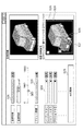
以下においてS408における処理の詳細を説明する。図7(a)は、S408における処理の流れを示すフローチャートである。S801において、第3取得部207は、図5に示すGUIにおけるウィンドウ506に、目標画像の画素値のうち輝度を示すY値を各画素に有する目標輝度画像を表示する。ウィンドウ506は、目標画像に対して輝度が不足している領域を示すとともに、プロジェクタ指定ボックス504において指定された機種のプロジェクタがプリント画像に対して投影する範囲を指定するためのウィンドウである。プロジェクタ指定ボックス504は、プルダウンメニューとテキスト入力フォームとを兼ねたオブジェクトであり、ユーザがプロジェクタの機種を指定するためのものである。プロジェクタの機種は、プロジェクタの明るさ、投影領域のアスペクト比、投影可能な最小画像サイズ、最大画像サイズ、変換行列と対応づけられてHDD114などの記憶装置に記憶されている。
Details of the processing in S408 will be described below. FIG. 7A is a flowchart showing the flow of processing in S408. In step S <b> 801, the
S802において、第3取得部207は、ウィンドウ506に表示されている目標輝度画像において、S406において特定した輝度が不足している領域をハッチング表示する。輝度が不足している領域は、YDiffがそれぞれ0以下でない領域である。領域507は、輝度が不足している領域における表示の一例である。輝度不足の領域をハッチングしたり点滅させたりするように表示制御を行うことによって、指定された機種のプロジェクタがどこに画像を投影すべきかをユーザに提示することができる。
In step S <b> 802, the
S803において、第3取得部207は、n番目のプロジェクタ指定ボックス504において指定された機種のプロジェクタの明るさ、投影領域のアスペクト比、投影可能な最小画像サイズ、最大画像サイズをHDD114から取得する。枠508は、プロジェクタ指定ボックス504において指定された機種のプロジェクタの投影領域を示す枠である。枠508のサイズや位置は、投影可能な画像サイズの範囲内においてユーザにより入力デバイス110を用いて変更又は指定される。説明を簡易にするため、本実施形態における、1番目のプロジェクタはプリント画像と同じアスペクト比および面積であるものとする。つまり、1番目のプロジェクタは、プリント画像と同じサイズの画像をプリント画像全体に投影する。
In step S <b> 803, the
S804において、第3取得部207は、n番目のプロジェクタについて、ウィンドウ506においてユーザにより指定された投影領域の縦のサイズHPn(単位はm)、投影領域の横のサイズWPn(単位はm)、投影位置(xPn,yPn)を取得する。
In step S804, for the nth projector, the
S805において、第3取得部207は、n番目のプロジェクタの投影により得られる最高輝度値CdPn(単位はcd/m2)を式(5)に基づいて算出する。S805の処理が終わると、処理をS409に移行する。
In step S805, the
次に、S409において、生成部208は、n番目のプロジェクタが投影する投影画像を表す投影画像データを生成する。具体的には、投影画像の各画素の画素値XPn、YPn、ZPnを式(6)に基づいて算出する。
Next, in S409, the
XPn=clip(XDiff,CdPn/CdT)
YPn=clip(YDiff,CdPn/CdT)・・・式(6)
ZPn=clip(ZDiff,CdPn/CdT)
ここで、clip(P,Q)は、引数Pのうち、引数Qの値を超えるものを引数Qに置き換える関数である。つまり、式(6)は、不足しているXYZ値に対して、n番目のプロジェクタによって補うことのできるXYZ値の最大値を算出する式である。尚、n番目のプロジェクタが投影する投影画像は、目標画像と同じ画素数である。また、n番目のプロジェクタが投影する投影画像は、S408において取得された投影位置(xPn,yPn)と、投影領域の縦のサイズHPnと、投影領域の横のサイズWPnと、によって決定される投影領域の範囲内のみ画素値を有する。範囲外の画素値は0を保持するものとする。
X Pn = clip (X Diff , Cd Pn / Cd T )
Y Pn = clip (Y Diff , Cd Pn / Cd T ) (6)
Z Pn = clip (Z Diff , Cd Pn / Cd T )
Here, clip (P, Q) is a function that replaces the argument P that exceeds the value of the argument Q with the argument Q. That is, Expression (6) is an expression for calculating the maximum value of the XYZ values that can be compensated by the nth projector for the insufficient XYZ values. Note that the projection image projected by the nth projector has the same number of pixels as the target image. The projection image n-th projector is projected, acquired projection position in S408 (x Pn, y Pn) and the size H Pn of the vertical projection area, the size W Pn next to the projection area, the It has pixel values only within the determined projection area. It is assumed that pixel values outside the
さらに、S409において、生成部208は、算出したXPn、YPn、ZPnにCdT/CdPを乗算することによって、XPn、YPn、ZPnをS406において行った正規化処理前の輝度レンジに戻す。
Further, in S409, the
さらに、S409において、生成部208は、n番目のプロジェクタが投影する投影領域の範囲内を投影画像から切り抜き、式(7)に基づいて切り抜かれた投影画像の画素値(XYZ値)をRGB値に変換する。尚、投影画像から切り抜かれ、画素値がRGB値に変換された投影画像をn番目のプロジェクタに出力する出力用投影画像とし、出力用投影画像を表すデータを出力用投影画像データとする。
Further, in S409, the
ここで、X,Y、ZはそれぞれXPn、YPn、ZPnである。変換行列M(Project)nは、プロジェクタの機種に対応付けられてHDD114に保持されている変換行列であり、n番目のプロジェクタの入力RGB値を出力XYZ値に変換するための行列である。ここでは、XYZ値をRGB値を変換するため、M(Project)nの逆行列を用いる。生成された出力用投影画像データは、n番目のプロジェクタに出力される。出力用投影画像データの出力後、nに1を加えて、処理をS406に戻す。
Here, X, Y, and Z are XPn , YPn , and ZPn , respectively. The conversion matrix M (Project) n is a conversion matrix that is associated with the projector model and is held in the
<第1実施形態の効果>
以上説明したように、本実施形態における情報処理装置は、投影対象の画像において投影画像が投影される領域を決定する装置である。具体的に、本実施形態における情報処理装置は、投影対象の画像における一部の領域であって、目標の輝度に達していない領域を指定するための情報を取得する。取得した情報に基づいて、投影画像が投影される、投影対象の画像における一部の領域を決定する。これにより、投影対象の画像における部分的な領域に画像を投影する際に、投影対象の画像において部分的な投影を行う領域を決定することができる。また、本実施形態においては、投影対象の画像における輝度が不足する部分的な領域に対して画像の投影を行うことができるため、全体に投影するよりも少ないプロジェクタで高輝度な領域を実現することができる。全体に投影するよりも少ないプロジェクタで高輝度な領域を実現することについて、図6を用いて説明する。図6は、プロジェクタの投影領域と輝度レンジとの関係を示す模式図である。図6(a)は部分投影を行わない場合の投影領域の例を示しており、枠601がプロジェクタ4台の投影領域を示している。図6(d)は部分投影を行う場合の投影領域の例を示しており、枠602が全体投影を行うプロジェクタ1131の投影領域であり、枠603が部分投影を行うプロジェクタ1132の投影領域である。図6(b),(c)は部分投影を行わない場合の、目標輝度に達するために各プロジェクタが補う輝度レンジを示す模式図である。図6(e)は部分投影を行う場合の、目標輝度に達するために各プロジェクタが補う輝度レンジを示す模式図である。尚、各プロジェクタが補う輝度レンジを簡易に説明するため、図6(b),(c),(e)のグラフは、対数スケールではなく線形スケールとしている。
<Effects of First Embodiment>
As described above, the information processing apparatus according to the present embodiment is an apparatus that determines an area in which a projection image is projected in an image to be projected. Specifically, the information processing apparatus according to the present embodiment acquires information for designating a partial area in the projection target image that does not reach the target luminance. Based on the acquired information, a partial region in the projection target image on which the projection image is projected is determined. As a result, when an image is projected onto a partial area in the projection target image, it is possible to determine an area where partial projection is performed in the projection target image. Further, in the present embodiment, since the image can be projected onto a partial area where the brightness of the image to be projected is insufficient, a high brightness area can be realized with fewer projectors than the whole image is projected. be able to. The realization of a high-brightness area with fewer projectors than the whole image will be described with reference to FIG. FIG. 6 is a schematic diagram showing the relationship between the projection area of the projector and the luminance range. FIG. 6A shows an example of a projection area when partial projection is not performed, and a
図3において例示したように、1台のプロジェクタを用いて全体投影した場合の最大輝度が約800cd/m2であるとする。部分投影をせずに目標輝度3000cd/m2を得るためには、図6(b)の輝度レンジが示すように、同じ全体投影の画像を4台のプロジェクタで重畳する方法が考えられる。もしくは、図6(c)の輝度レンジが示すように、それぞれのプロジェクタが可能な範囲で不足分を最大限に補うように投影を行い、それらを重畳する方法も考えられる。図6(b),(c)の方法を組み合わせた方法も考えられるが、全体投影の場合ではいずれにしても目標輝度を実現するために4台のプロジェクタを要する。一方、本実施形態における処理により生成した投影画像を用いて、図6(d)の輝度レンジが示すように部分投影を行う場合を考える。この場合、例えば枠603が枠602の1/4の面積であるとすると、枠603に部分投影を行う場合は、枠602に全体投影を行う場合よりも4倍の輝度を実現することができる。このため、図6(e)の輝度レンジが示すように、全体投影を行うプロジェクタのみでは不足する輝度を、部分投影を行うプロジェクタ1台で補うことができる。つまり、部分投影を利用することによって、全体投影のみを行うよりも少ないプロジェクタを用いて所望の輝度を実現することができる。これにより、数多くのプロジェクタを用意したり、照射する光量が多いプロジェクタを用意したりすることができない場合であっても、画像の重畳によって所望の輝度レンジを有する画像を生成することができる。
As illustrated in FIG. 3, it is assumed that the maximum luminance when the entire projection is performed using one projector is about 800 cd / m 2 . In order to obtain the target luminance of 3000 cd / m 2 without performing partial projection, as shown in the luminance range of FIG. 6B, a method of superimposing images of the same overall projection with four projectors can be considered. Alternatively, as shown in the luminance range of FIG. 6C, a method is also conceivable in which projection is performed so as to compensate for the shortage to the maximum extent possible by each projector, and these are superimposed. A method combining the methods of FIGS. 6B and 6C is also conceivable, but in the case of full projection, in any case, four projectors are required to realize the target luminance. On the other hand, let us consider a case where partial projection is performed using the projection image generated by the processing in the present embodiment as indicated by the luminance range in FIG. In this case, for example, assuming that the
[第2実施形態]
上述した実施形態においては、GUIにおいて輝度が不足している領域を表示することによって、どの位置に部分的な投影を行うべきかをユーザに提示した。本実施形態においては、ユーザによって指定された投影領域に基づいて、画像の重畳によって生成される重畳画像の輝度分布を予測し表示する。尚、本実施形態における情報処理装置の構成は第1実施形態のものと同様であるため、説明を省略する。以下において、本実施形態と第1実施形態とで異なる部分を主に説明する。尚、同一の構成については、同じ符号を付して説明する。
[Second Embodiment]
In the above-described embodiment, the region where the luminance is insufficient in the GUI is displayed to indicate to the user which position to perform partial projection. In the present embodiment, the luminance distribution of the superimposed image generated by image superimposition is predicted and displayed based on the projection area specified by the user. Note that the configuration of the information processing apparatus in the present embodiment is the same as that of the first embodiment, and a description thereof will be omitted. In the following, differences between the present embodiment and the first embodiment will be mainly described. In addition, about the same structure, the same code | symbol is attached | subjected and demonstrated.
<情報処理装置1が実行する処理>
以下、本実施形態における情報処理装置1が実行する処理の流れについて、図7(b)のフローチャートを用いて説明する。尚、S401〜S407、S409は、第1実施形態におけるS401〜S407、S409と同じ処理であるため説明を省略する。図7(b)は、S408における処理の流れを示すフローチャートである。
<Processing executed by
Hereinafter, the flow of processing executed by the
S811において、第3取得部207は、プリント画像の各画素におけるY値(YPrint)と、n−1番目までのプロジェクタに対応する投影画像の各画素におけるY値の積算値(ΣYP)と、に基づいて、重畳画像の輝度分布を予測する。具体的には、式(8)に基づいて、予測される重畳画像の輝度分布である予測輝度画像の画素値YPrevを算出する。
In S811, the
上述したように、重畳画像のXYZ値は、投影対象の画像のXYZ値と投影画像のXYZ値との積によって表現することができる。ここでは、プリント画像の各画素におけるY値と投影画像の各画素におけるY値の積算値との積を算出することによって、重畳画像の輝度値を予測する。さらに、第3取得部207は、算出した予測輝度画像をウィンドウ506に表示する。
As described above, the XYZ value of the superimposed image can be expressed by the product of the XYZ value of the projection target image and the XYZ value of the projection image. Here, the luminance value of the superimposed image is predicted by calculating the product of the Y value at each pixel of the print image and the integrated value of the Y value at each pixel of the projection image. Further, the
S812において、第3取得部207は、n番目のプロジェクタ指定ボックス504において指定された機種のプロジェクタの明るさ、投影領域のアスペクト比、投影可能な最小画像サイズ、最大画像サイズをHDD114から取得する。
In step S812, the
S813において、第3取得部207は、n番目のプロジェクタについて、ウィンドウ506においてユーザにより指定された投影領域の縦のサイズHPn(単位はm)、投影領域の横のサイズWPn(単位はm)、投影位置(xPn,yPn)を取得する。
In S813, for the nth projector, the
S814において、第3取得部207は、n番目のプロジェクタの投影により得られる最高輝度値CdPn(単位はcd/m2)を式(5)に基づいて算出する。
In S814, the
S815において、第3取得部207は、第1実施形態におけるS409と同様に、n番目のプロジェクタに対応する投影画像の画素値YPnを算出し、式(9)に基づいて、予測される重畳画像の輝度分布である予測輝度画像の画素値YPrevを算出する。
In S815, the
さらに、第3取得部207は、算出した予測輝度画像をウィンドウ506に表示する。S811とS815とにおける表示によって、n−1番目までのプロジェクタの投影により得られる重畳画像と、n番目までのプロジェクタの投影により得られる重畳画像と、を比較し輝度の変化を確認することができる。図8(a),(b)は、本実施形態におけるGUIの領域指定ウィンドウ506の例を示す模式図である。図8の例においては、説明を簡易にするため、使用するプロジェクタは1台のみであるものとし、全体投影は行わないものとする。図8(a)は、画像の最高輝度部1001周辺に比較的小さい面積で投影領域が指定されている例を示している。図8(b)は、プリント画像におけるオブジェクトのほとんどを覆うように投影領域が指定されている例を示している。図8(a)において指定された領域の方が図8(b)において指定された領域より明るく表示されることがわかる。尚、S811とS815とにおける表示はどちらもウィンドウ506において行ったが、別のウィンドウに表示することによって比較しやすくしてもよい。
Further, the
S816において、第3取得部207は、n番目のプロジェクタが投影する投影領域は、S813において取得した情報によって決まる領域とする否かを判定する。具体的には、n番目のプロジェクタが投影する投影領域がS813において取得した情報によって決まる領域とする否かをユーザに指定させるGUIをディスプレイ116に表示し、ユーザからの入力情報を受け取る。ユーザからの入力情報に基づいて判定を行う。n番目のプロジェクタが投影する投影領域がS813において取得した情報によって決まる領域とすると判定した場合は、S409に進む。n番目のプロジェクタが投影する投影領域がS813において取得した情報によって決まる領域としないと判定した場合は、S813に戻る。
In S816, the
<第2実施形態の効果>
以上説明したように、本実施形態における情報処理装置は、ユーザによって指定された投影領域に基づいて、画像の重畳によって生成される重畳画像の輝度分布を予測し表示する。これにより、プロジェクタを追加することによる重畳画像の変化を容易に確認することができる。したがって、投影対象の画像におけるどの位置に部分的な投影を行うべきかをユーザは容易に知ることができる。
<Effects of Second Embodiment>
As described above, the information processing apparatus according to the present embodiment predicts and displays the luminance distribution of the superimposed image generated by the image superimposition based on the projection area designated by the user. Thereby, it is possible to easily confirm the change in the superimposed image due to the addition of the projector. Therefore, the user can easily know at which position in the projection target image the partial projection should be performed.
[第3実施形態]
上述した実施形態においては、画像を表示することによって、投影対象の画像におけるどの位置に部分的な投影を行うべきかをユーザに提示した。本実施形態においては、ユーザによって指定された投影領域に基づいて、目標がどの程度達成されているかを表す評価値をユーザに提示する。尚、本実施形態における情報処理装置の構成は第1実施形態のものと同様であるため、説明を省略する。以下において、本実施形態と第1実施形態とで異なる部分を主に説明する。尚、同一の構成については、同じ符号を付して説明する。
[Third Embodiment]
In the above-described embodiment, by displaying an image, the user is presented at which position in the projection target image to perform partial projection. In this embodiment, based on the projection area designated by the user, an evaluation value representing how much the target has been achieved is presented to the user. Note that the configuration of the information processing apparatus in the present embodiment is the same as that of the first embodiment, and a description thereof will be omitted. In the following, differences between the present embodiment and the first embodiment will be mainly described. In addition, about the same structure, the same code | symbol is attached | subjected and demonstrated.
<情報処理装置1が実行する処理>
以下、本実施形態における情報処理装置1が実行する処理の流れについて、図7(c)のフローチャートを用いて説明する。尚、本実施形態における処理は、第2実施形態における処理とS815のみが異なるため、本実施形態におけるS815について説明する。
<Processing executed by
Hereinafter, the flow of processing executed by the
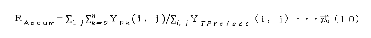
S815において、第3取得部207は、n番目までのプロジェクタによる投影画像の重畳が目標投影画像をどの程度実現しているかの指標となる目標達成率RAccumを算出し、算出した目標達成率RAccumをGUIに表示する。目標達成率RAccumは以下の式(10)に基づいて算出する。
In S815, the
ここで、目標達成率RAccumは、n番目までのプロジェクタによる投影画像の全画素値の総和と目標投影画像の全画素値の総和と、の比である。 Here, the target achievement rate R Accum is a ratio of the total sum of all pixel values of the projection image by the nth projector to the total sum of all pixel values of the target projection image.
さらに、第3取得部207は、n番目のプロジェクタ単体が目標に対してどの程度寄与しているかを示す寄与率RPnを算出し、算出した寄与率RPnをGUIに表示する。寄与率RPnは以下の式(11)に基づいて算出する。
Further, the
RPn=Σi,jYPn(i,j)/Σi,jYTProject(i,j)・・・式(11)
ここで、目標達成率RAccumは、n番目のプロジェクタによる投影画像の全画素値の総和と目標投影画像の全画素値の総和と、の比である。図8(c)に、目標達成率と寄与率とを表示する場合の領域指定ウィンドウの例を示す。尚、本実施形態においては、輝度の比を評価値として表示したが、例えば、L*a*b*空間における色差を評価値として表示してもよい。
R Pn = Σ i, j Y Pn (i, j) / Σ i, j Y TProject (i, j) (11)
Here, the target achievement rate R Accum is the ratio of the sum of all pixel values of the projection image by the nth projector to the sum of all pixel values of the target projection image. FIG. 8C shows an example of the area designation window when the target achievement rate and the contribution rate are displayed. In the present embodiment, the luminance ratio is displayed as the evaluation value. However, for example, a color difference in the L * a * b * space may be displayed as the evaluation value.
<第3実施形態の効果>
以上説明したように、本実施形態における情報処理装置は、投影領域が指定されているプロジェクタによってどの程度目標を達成されているかを示す評価値をユーザに提示する。これにより、ユーザは投影対象の画像におけるどの位置に部分的な投影を行うかを容易に決めることができる。
<Effect of the third embodiment>
As described above, the information processing apparatus according to the present embodiment presents to the user an evaluation value indicating how much the target has been achieved by the projector in which the projection area is designated. Thereby, the user can easily determine at which position in the projection target image partial projection is to be performed.
[第4実施形態]
第3実施形態においては、どの程度目標が達成されているかを表す評価値を算出し、評価値をユーザに提示した。本実施形態においては、上述した評価値を用いて投影領域の候補を算出し、ユーザに提示する。尚、本実施形態における情報処理装置の構成は第1実施形態のものと同様であるため、説明を省略する。以下において、本実施形態と第1実施形態とで異なる部分を主に説明する。尚、同一の構成については、同じ符号を付して説明する。
[Fourth Embodiment]
In the third embodiment, an evaluation value representing how much the target has been achieved is calculated, and the evaluation value is presented to the user. In the present embodiment, projection area candidates are calculated using the evaluation values described above and presented to the user. Note that the configuration of the information processing apparatus in the present embodiment is the same as that of the first embodiment, and a description thereof will be omitted. In the following, differences between the present embodiment and the first embodiment will be mainly described. In addition, about the same structure, the same code | symbol is attached | subjected and demonstrated.
<情報処理装置1が実行する処理>
以下、本実施形態における情報処理装置1が実行する処理の流れについて、図7(d)のフローチャートを用いて説明する。尚、S401〜S407、S409は、第1実施形態におけるS401〜S407、S409と同じ処理であるため説明を省略する。図7(d)は、S408における処理の流れを示すフローチャートである。
<Processing executed by
Hereinafter, the flow of processing executed by the
S821において、第3取得部207は、n番目のプロジェクタ指定ボックス504において指定された機種のプロジェクタの明るさ、投影領域のアスペクト比、投影可能な最小画像サイズ、最大画像サイズをHDD114から取得する。
In step S <b> 821, the
S822において、第3取得部207は、投影領域のアスペクト比と投影可能な画像サイズとによって決まる複数の領域の中から投影領域の候補を決定する。具体的には、プロジェクタの投影位置を示す座標(xPn,yPn)の全候補と、プロジェクタの投影サイズを示す変数の1つである横のサイズWPnの全候補と、に対して、寄与率RPn(xPn,yPn,WPn)を式(11)に基づいてそれぞれ算出する。さらに、第3取得部207は、寄与率RPnが上位m番目までに対応する変数(xPn,yPn,WPn)を記憶する。ここで、mは予め決められた定数である。
In step S822, the
S823において、第3取得部207は、S822において記憶されたm個の候補(xPn,yPn,WPn)をリスト表示などによってユーザに提示する。さらに、第3取得部207は、ユーザから受け取った選択指示に基づいて、投影領域を決定する。
In S823, the
<第4実施形態の効果>
以上説明したように、本実施形態における情報処理装置は、投影領域が指定されているプロジェクタによってどの程度目標を達成されているかを示す評価値に基づいて、投影領域の候補を算出し、ユーザに提示する。これにより、ユーザは投影対象の画像におけるどの位置に部分的な投影を行うかを容易に決めることができる。
<Effects of Fourth Embodiment>
As described above, the information processing apparatus according to the present embodiment calculates a projection area candidate based on the evaluation value indicating how much the target has been achieved by the projector for which the projection area is designated, and prompts the user. Present. Thereby, the user can easily determine at which position in the projection target image partial projection is to be performed.
[その他の実施形態]
上述した実施形態においては、重畳画像を生成するためにプロジェクタ群112が投影する画像の投影対象の画像はプリント画像であったが、投影対象の画像は上記一例に限定されない。例えば、投影対象の画像もプロジェクタによって投影された画像であってもよい。また、投影対象の画像はディスプレイによって表示された画像であってもよい。
[Other Embodiments]
In the embodiment described above, the projection target image of the image projected by the
また、上述した実施形態においては、入力デバイス110とディスプレイ116とを別々のデバイスとしたが、入力デバイス110とディスプレイ116とが一体化したタッチパネルディスプレイを代わりに用いてもよい。
In the above-described embodiment, the
また、上述した実施形態においては、情報処理装置1とプリンタ111とプロジェクタ群112とを別々のデバイスとしたシステムを用いたが、システム構成は上記一例に限定されない。例えば、情報処理装置1は、プリンタ111やプロジェクタ群112に含まれていてもよい。
In the above-described embodiment, a system in which the
また、上述した実施形態においては、プリンタ111が形成するプリント画像に、プロジェクタ群112のプロジェクタが投影する投影画像を投影することによって重畳画像を生成する例を説明したが、重畳画像を生成する方法は上記一例に限定されない。例えば、プロジェクタ群112のプロジェクタの代わりにディスプレイ116を用いてもよい。この場合、プリント画像は透明な記録媒体の上に画像を形成することによって得られたものとし、ディスプレイ116はプリント画像の背面に設置される。
In the above-described embodiment, the example in which the superimposed image is generated by projecting the projection image projected by the projectors of the
また、上述した実施形態においては、プリンタ111をインクジェット方式のプリンタとしたが、プリンタ111は上記一例に限定されない。例えば、記録材としてトナーを用いる電子写真方式のプリンタであってもよい。 In the above-described embodiment, the printer 111 is an inkjet printer, but the printer 111 is not limited to the above example. For example, an electrophotographic printer using toner as a recording material may be used.
また、上述した実施形態のS402においては、式(1)に示す変換行列を用いてRGB値をXYZ値に変換したが、RGB値とXYZ値との対応関係が記述されたルックアップテーブル(LUT)を用いて変換を行ってもよい。 In S402 of the above-described embodiment, the RGB values are converted into XYZ values using the conversion matrix shown in Expression (1), but a lookup table (LUT) in which the correspondence between RGB values and XYZ values is described. ) May be used for conversion.
また、上述した実施形態における目標画像とプリント画像とは、色情報として、各画素にsRGB空間上において定義されるRGB値を有する画像であったが、目標画像とプリンタ画像とは上記一例に限定されない。例えば、各画素にAdobeRGB空間上で定義されるRGB値を有する画像であってもよいし、各画素にL*a*b*空間上で定義されるL*a*b*値を有する画像であってもよい。この場合は、各画素の画素値をXYZ値に変換するためのLUTや変換マトリクスを予め作成しておく。 The target image and the print image in the above-described embodiment are images having RGB values defined in the sRGB space for each pixel as color information. However, the target image and the printer image are limited to the above example. Not. For example, each pixel may be an image having an RGB value defined on the AdobeRGB space, or each pixel may have an L * a * b * value defined on the L * a * b * space. There may be. In this case, an LUT or conversion matrix for converting the pixel value of each pixel into an XYZ value is created in advance.
また、上述した実施形態における目標画像とプリント画像とは同じ画像であったが、同じコンテンツを表現するものであれば、同じ画像でなくてもよい。例えば、プリント画像単体での見栄えを向上するために、目標画像の彩度や鮮鋭度が強調された画像であってもよい。尚、目標画像とプリント画像との解像度やサイズが異なる場合は、解像度変換などの処理を行って解像度やサイズを一致させる処理を追加する。 In addition, the target image and the print image in the above-described embodiment are the same image, but may not be the same image as long as they represent the same content. For example, in order to improve the appearance of a single printed image, the image may be an image in which the saturation and sharpness of the target image are emphasized. When the resolution and size of the target image and the print image are different, processing such as resolution conversion is performed and processing for matching the resolution and size is added.
また、上述した実施形態のS406においては、環境光を無視できるものとして目標画像に対して不足するXYZ値を算出したが、環境光の明るさを加味してもよい。例えば、予め環境光の明るさを測定しておき、プリント画像全体に環境光の明るさで画像を投影していると仮定して式(4)の計算を行ってもよい。 In S406 of the above-described embodiment, the XYZ values that are insufficient with respect to the target image are calculated assuming that the ambient light can be ignored. However, the brightness of the ambient light may be taken into account. For example, the brightness of the ambient light may be measured in advance, and the calculation of Expression (4) may be performed on the assumption that the image is projected on the entire print image with the brightness of the ambient light.
また、上述した実施形態のS407においては、処理を終了する条件を、S406において算出した各画素のXYZDiffが全て0以下となるとしたが、処理を終了する条件は上記一例に限定されない。例えば、各画素のXYZDiffが全て所定の閾値以下となることを処理の終了条件としてもよい。また、GUIを介してユーザからの終了指示を受け取ることを処理の終了条件としてもよい。また、予め準備できるプロジェクタの数をHDD114等の記憶装置に記憶させておき、使用するプロジェクタの数n−1がその数を超えることを処理の終了条件としてもよい。
In S407 of the above-described embodiment, the condition for ending the process is set such that all the XYZ Diff of each pixel calculated in S406 is 0 or less, but the condition for ending the process is not limited to the above example. For example, the processing end condition may be that all XYZ Diff of each pixel is equal to or less than a predetermined threshold. In addition, receiving the end instruction from the user via the GUI may be a process end condition. Alternatively, the number of projectors that can be prepared in advance may be stored in a storage device such as the
また、上述した実施形態においては、出力用投影画像データを対応するプロジェクタに出力したが、プリント画像データをプリンタ111に出力する処理を加えてもよい。例えば、プリント画像の画素値をプリンタ111が搭載するインクの記録量に変換してから、プリント画像データをプリンタ111に出力してもよい。また、プリント画像にハーフトーン処理及びパス分解処理を行ってから、プリント画像データをプリンタ111に出力してもよい。 In the embodiment described above, the output projection image data is output to the corresponding projector. However, a process of outputting the print image data to the printer 111 may be added. For example, the print image data may be output to the printer 111 after converting the pixel value of the print image into the recording amount of the ink mounted on the printer 111. Alternatively, the print image data may be output to the printer 111 after halftone processing and pass separation processing are performed on the print image.
また、上述した実施形態における特定部206は、投影を行うべき領域を特定するために、輝度が不足している領域を特定したが、投影を行うべき領域を他の方法によって特定してもよい。例えば、記録媒体上に形成されたプリント画像を撮像することによって得られた画像をディスプレイ116に表示し、ユーザに投影を行う領域を指定させてもよい。ユーザが指定した投影領域を表す情報を受け取ることによって、投影を行うべき領域を特定する。
In addition, although the specifying
また、上述した実施形態においては、投影領域を決定し、投影領域に基づいて投影画像を表す投影画像データを生成したが、投影画像データは予め生成されていてもよい。この場合は、予め生成された投影画像データに基づいて、投影対象の画像におけるどの位置に投影を行うべきかをユーザに提示する。 In the embodiment described above, the projection area is determined and the projection image data representing the projection image is generated based on the projection area. However, the projection image data may be generated in advance. In this case, based on the projection image data generated in advance, the user is presented with which position in the projection target image should be projected.
また、第4実施形態においては、投影領域の候補を寄与率が上位m番目となる領域としてユーザに提示したが、最も寄与率が高い領域を投影領域として決定してもよい。 In the fourth embodiment, the candidate for the projection area is presented to the user as the area with the highest contribution ratio, but the area with the highest contribution ratio may be determined as the projection area.
また、第4実施形態においては、具体的には、座標(xPn,yPn)と横のサイズWPnとによって決まる全ての領域において寄与率を算出したが、処理を簡素化するために、所定の離散する位置ごとに寄与率を算出してもよい。例えば、投影対象となるプリント画像を縦横それぞれ16分割し、16×16個の領域について評価値を算出してもよい。さらに、評価値の高い領域を中心とした近傍領域から候補となる領域を探索してもよい。 In the fourth embodiment, specifically, the contribution ratio is calculated in all regions determined by the coordinates (x Pn , y Pn ) and the horizontal size W Pn , but in order to simplify the processing, The contribution rate may be calculated for each predetermined discrete position. For example, the print image to be projected may be divided into 16 in each of the vertical and horizontal directions, and the evaluation value may be calculated for 16 × 16 areas. Further, a candidate area may be searched from a neighboring area centered on an area having a high evaluation value.
また、第4実施形態においては、投影領域の候補をリスト表示してユーザに提示したが、各変数を軸とした3次元のヒートマップを用いてユーザに投影領域の候補を提示してもよい。 In the fourth embodiment, projection area candidates are displayed as a list and presented to the user. However, projection area candidates may be presented to the user using a three-dimensional heat map with each variable as an axis. .
また、第4実施形態においては、指定されたプロジェクタの機種について、投影領域の候補を探索したが、使用可能な複数のプロジェクタ機種も変数として扱い、適した機種のプロジェクタを選択してもよい。この場合、評価値として、上述した目標達成率や寄与率の他に、該当するプロジェクタを使用するためにかかるコストを用いてもよい。 In the fourth embodiment, the candidate for the projection area is searched for the designated projector model. However, a plurality of usable projector models may be handled as variables, and a suitable projector type may be selected. In this case, as the evaluation value, in addition to the target achievement rate and the contribution rate described above, the cost for using the corresponding projector may be used.
また、投影領域において輝度が不足していない領域が含まれる場合、光量を0にできないために黒浮きが生じてしまう。この黒浮きを抑制するために、他のプロジェクタの投影画像において重畳される領域の画素値から黒浮き領域の画素値を減算してもよい。また、プリント画像の画素値を補正して黒浮きを抑制してもよい。 In addition, if the projection area includes an area where the luminance is not insufficient, the amount of light cannot be reduced to 0, and black floating occurs. In order to suppress this black floating, the pixel value of the black floating region may be subtracted from the pixel value of the region superimposed in the projection image of another projector. Further, the black value may be suppressed by correcting the pixel value of the print image.
本発明は、上述の実施形態の1以上の機能を実現するプログラムを、ネットワーク又は記憶媒体を介してシステム又は装置に供給し、そのシステム又は装置のコンピュータにおける1つ以上のプロセッサーがプログラムを読出し実行する処理でも実現可能である。また、1以上の機能を実現する回路(例えば、ASIC)によっても実現可能である。 The present invention supplies a program that realizes one or more functions of the above-described embodiments to a system or apparatus via a network or a storage medium, and one or more processors in a computer of the system or apparatus read and execute the program This process can be realized. It can also be realized by a circuit (for example, ASIC) that realizes one or more functions.
1 情報処理装置
207 第3取得部
DESCRIPTION OF
Claims (16)
前記投影対象の画像における一部の領域であって、目標の輝度に達していない領域を指定するための情報を取得する取得手段と、
前記情報に基づいて、前記投影画像が投影される前記一部の領域を決定する決定手段と、
を有することを特徴とする情報処理装置。 An information processing apparatus that determines an area in which a projection image is projected in an image to be projected,
An acquisition means for acquiring information for designating a partial area in the projection target image that does not reach a target luminance;
Determining means for determining the partial area onto which the projection image is projected based on the information;
An information processing apparatus comprising:
前記決定手段は、前記選択手段によって選択されたプロジェクタを表す情報に基づいて、前記一部の領域を決定することを特徴とする請求項8に記載の情報処理装置。 The image processing apparatus further includes a selection unit that selects a projector that projects the projection image based on information representing a region that does not reach the target luminance in the projection target image and information representing a usable projector model. ,
The information processing apparatus according to claim 8, wherein the determination unit determines the partial area based on information representing a projector selected by the selection unit.
前記表示制御手段は、前記評価値を表示手段に表示させることを特徴とする請求項3に記載の情報処理装置。 A calculation means for calculating an evaluation value indicating how much the luminance value of the projection image has reached the target luminance value;
The information processing apparatus according to claim 3, wherein the display control unit causes the display unit to display the evaluation value.
前記決定手段は、前記評価値に基づいて、前記一部の領域を決定することを特徴とする請求項1に記載の情報処理装置。 A calculation means for calculating an evaluation value indicating how much the luminance value of the projection image has reached the target luminance value;
The information processing apparatus according to claim 1, wherein the determination unit determines the partial area based on the evaluation value.
前記投影対象の画像における一部の領域であって、目標の輝度に達していない領域を指定するための情報を取得する取得ステップと、
前記情報に基づいて、前記投影画像が投影される前記一部の領域を決定する決定ステップと、
を有することを特徴とする情報処理方法。 An information processing method for determining a region on a projection target image on which a projection image is projected,
An acquisition step of acquiring information for designating a partial area in the projection target image that does not reach the target luminance;
A determination step of determining the partial area onto which the projection image is projected based on the information;
An information processing method characterized by comprising:
Priority Applications (2)
| Application Number | Priority Date | Filing Date | Title |
|---|---|---|---|
| JP2018100158A JP2019205104A (en) | 2018-05-25 | 2018-05-25 | Information processing apparatus, information processing method, and program |
| US16/411,777 US11128848B2 (en) | 2018-05-25 | 2019-05-14 | Information processing apparatus, method, and storage medium |
Applications Claiming Priority (1)
| Application Number | Priority Date | Filing Date | Title |
|---|---|---|---|
| JP2018100158A JP2019205104A (en) | 2018-05-25 | 2018-05-25 | Information processing apparatus, information processing method, and program |
Publications (1)
| Publication Number | Publication Date |
|---|---|
| JP2019205104A true JP2019205104A (en) | 2019-11-28 |
Family
ID=68613592
Family Applications (1)
| Application Number | Title | Priority Date | Filing Date |
|---|---|---|---|
| JP2018100158A Pending JP2019205104A (en) | 2018-05-25 | 2018-05-25 | Information processing apparatus, information processing method, and program |
Country Status (2)
| Country | Link |
|---|---|
| US (1) | US11128848B2 (en) |
| JP (1) | JP2019205104A (en) |
Families Citing this family (2)
| Publication number | Priority date | Publication date | Assignee | Title |
|---|---|---|---|---|
| JP2021022894A (en) * | 2019-07-30 | 2021-02-18 | セイコーエプソン株式会社 | Image processing method, image processing device, and information system |
| US11575837B2 (en) * | 2020-04-27 | 2023-02-07 | Canon Kabushiki Kaisha | Method, apparatus and computer program for generating and displaying a heatmap based on video surveillance data |
Family Cites Families (7)
| Publication number | Priority date | Publication date | Assignee | Title |
|---|---|---|---|---|
| JP2004070257A (en) | 2002-08-01 | 2004-03-04 | Susumu Shiroyama | Superimposed multi-projection system |
| CN101828202A (en) * | 2007-10-17 | 2010-09-08 | 三菱电机株式会社 | Image processing device |
| JP5179537B2 (en) * | 2010-04-09 | 2013-04-10 | 株式会社ソニー・コンピュータエンタテインメント | Information processing device |
| JP6013178B2 (en) * | 2012-12-28 | 2016-10-25 | 株式会社東芝 | Image processing apparatus and image processing method |
| WO2017212653A1 (en) * | 2016-06-10 | 2017-12-14 | オリンパス株式会社 | Image processing device, image processing method, and image processing program |
| CN110114798A (en) * | 2016-12-28 | 2019-08-09 | 株式会社理光 | Image processing equipment, image processing system, image capture system, image processing method and recording medium |
| CN106991645B (en) * | 2017-03-22 | 2018-09-28 | 腾讯科技(深圳)有限公司 | Image split-joint method and device |
-
2018
- 2018-05-25 JP JP2018100158A patent/JP2019205104A/en active Pending
-
2019
- 2019-05-14 US US16/411,777 patent/US11128848B2/en active Active
Also Published As
| Publication number | Publication date |
|---|---|
| US20190364252A1 (en) | 2019-11-28 |
| US11128848B2 (en) | 2021-09-21 |
Similar Documents
| Publication | Publication Date | Title |
|---|---|---|
| US8711171B2 (en) | Image processing apparatus, method, and storage medium for performing soft proof processing | |
| JP5153566B2 (en) | Image processing system, image processing apparatus, and image processing method | |
| JP2017046045A (en) | Image processing system | |
| US20120057785A1 (en) | Method and system to modify a color lookup table | |
| US20190037085A1 (en) | Image processing apparatus, image processing method and storage medium | |
| JP2015011585A (en) | Image processing apparatus, image forming apparatus, image forming system, image processing method, and program | |
| US11825245B2 (en) | Image processing device, image display system, image processing method, and program | |
| JP6028527B2 (en) | Display processing apparatus, display processing method, and program | |
| JP2009130461A (en) | Image processing apparatus and image processing method | |
| JP2019205104A (en) | Information processing apparatus, information processing method, and program | |
| JP2019205103A (en) | Information processing apparatus, information processing method, and program | |
| US11716433B2 (en) | Image processing apparatus, image processing method, storage medium, and image forming apparatus | |
| JP5474113B2 (en) | Image processing apparatus and image processing method | |
| JP2018136654A (en) | Image processing apparatus and image processing program | |
| US8363267B2 (en) | Image forming apparatus and color converting method thereof | |
| JP4066334B2 (en) | Video signal processing device | |
| JP5235551B2 (en) | Image processing apparatus and method | |
| JP2005311900A (en) | Image processing apparatus and its method | |
| JP2009069451A (en) | Color chart display device, color chart generation and display method, and color chart generation and display program | |
| JP7427423B2 (en) | Image processing device, image processing method and program | |
| JP7366689B2 (en) | Image processing device, image processing method and program | |
| EP2938059A2 (en) | Color processing apparatus and color processing method | |
| JP2011239320A (en) | Perceptual color predictor, device apparatus using the same, and perceptual color prediction method | |
| JP2019028738A (en) | Image processing apparatus, image processing method and program | |
| US20200177769A1 (en) | Apparatus, method, and storage medium |