JP2019201687A - Firefighting equipment - Google Patents
Firefighting equipment Download PDFInfo
- Publication number
- JP2019201687A JP2019201687A JP2018096749A JP2018096749A JP2019201687A JP 2019201687 A JP2019201687 A JP 2019201687A JP 2018096749 A JP2018096749 A JP 2018096749A JP 2018096749 A JP2018096749 A JP 2018096749A JP 2019201687 A JP2019201687 A JP 2019201687A
- Authority
- JP
- Japan
- Prior art keywords
- pipe
- valve
- pressure
- primary
- water
- Prior art date
- Legal status (The legal status is an assumption and is not a legal conclusion. Google has not performed a legal analysis and makes no representation as to the accuracy of the status listed.)
- Granted
Links
Images


Landscapes
- Fire-Extinguishing By Fire Departments, And Fire-Extinguishing Equipment And Control Thereof (AREA)
Abstract
Description
本発明は、スプリンクラー設備や泡消火設備等の消火設備に関するものである。 The present invention relates to fire extinguishing equipment such as sprinkler equipment and foam fire extinguishing equipment.
スプリンクラー設備や泡消火設備等の消火設備は、水源からスプリンクラーヘッド(または泡ヘッド)に続く配管上に流水検知装置が設置されている。流水検知装置は逆止弁構造をしており水源からスプリンクラーヘッドへの一方向の通水のみを許容している。スプリンクラーヘッドが設置されている二次側配管は季節の温度差によって内部に充填された水が膨張・収縮する。特に夏季においては二次側配管内の水が膨張して圧力が上がり、スプリンクラーヘッドを破損することがある。また、冬季は二次側配管内の水の凍結によって体積が膨張すると配管内の水が圧縮して圧力が上昇し、上記と同様な被害が発生することがある。 In fire-extinguishing equipment such as sprinkler equipment and foam fire-extinguishing equipment, a water flow detector is installed on a pipe that extends from a water source to a sprinkler head (or foam head). The water flow detection device has a check valve structure and allows only one-way water flow from the water source to the sprinkler head. The secondary pipe where the sprinkler head is installed expands and contracts due to seasonal temperature differences. Especially in the summer, the water in the secondary side pipe expands and the pressure increases, and the sprinkler head may be damaged. In winter, when the volume expands due to freezing of water in the secondary side pipe, the water in the pipe is compressed and the pressure rises, and damage similar to the above may occur.
これに対して特許文献1では、流水検知装置の一次側と二次側をバイパスするバイパス流路を設置して、バイパス流路上に差圧弁を設置している。差圧弁は二次側の圧力が一次側の圧力よりも所定以上に高くなったときに開弁して、二次側配管から一次側配管へ水を逃がしてスプリンクラーヘッドの破損を防止する。
On the other hand, in
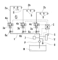
上記の差圧弁のようなリリーフ機構を備えた図1の消火設備において火災が発生した場合、スプリンクラーヘッドSが作動して二次側配管内2aの水が放出される。これにより二次側配管2aの圧力は一次側配管1の圧力を下回り、流水検知装置3aの弁体が開放して作動信号が出力される。流水検知装置3aが開放すると一次側配管1の水が二次側配管2aに供給され、一次側配管1の圧力が低下する。
When a fire occurs in the fire extinguishing equipment of FIG. 1 having a relief mechanism such as the above-described differential pressure valve, the sprinkler head S operates to discharge water in the
一次側配管1は他系統の流水検知装置3b、3cとも接続されていることから、火災が発生していない系統のリリーフ弁4b、4cにおいて一次側配管1と二次側配管2b、2cの間に差圧が生じる。この差圧が所定以上になると非火災系統のリリーフ弁4b、4cが開放されてしまい、非火災系統の二次側配管2b、2cから一次側配管1へ水が流れる。
Since the
非火災系統の二次側配管2b、2cから一次側配管1へ水が供給されることで、一次側配管1の圧力降下が緩慢になり、一次側配管1に設置されたポンプ起動スイッチ5が作動する規定の圧力に達するまでに時間を要するおそれがある。これによりスプリンクラーヘッドSは作動したものの、十分な送水が行われずに初期消火に支障をきたすおそれがある。
By supplying water from the
そこで本発明では、上記問題に鑑み、二次側配管から一次側配管へのリリーフ機構が設置された消火設備において、火災時においてポンプの起動が遅滞なく行われる消火設備を提供することを目的としている。 Therefore, in view of the above problems, the present invention aims to provide a fire extinguishing facility in which a pump is started without delay in the event of a fire in a fire extinguishing facility in which a relief mechanism from a secondary side pipe to a primary side pipe is installed. Yes.
上記の目的を達成するために、本発明は以下の消火設備を提供する。
すなわち、水源の水を配管へ送水するポンプと、ポンプと配管により接続された流水検知装置と、流水検知装置の二次側配管に接続されているスプリンクラーヘッドと、流水検知装置の一次側配管に設置されたポンプ起動スイッチとを備えており、流水検知装置は防護領域毎に複数設置され一次側配管はポンプへと続いており、流水検知装置の一次側と二次側をバイパスするバイパス配管上に設置されたリリーフ弁は一次側の圧力に対して二次側の圧力差が所定以上のときに開放し、防護領域毎に分岐された一次側配管上には電動弁が設置されており、火災が発生した防護領域の流水検知装置が作動したとき、その他の防護領域の電動弁を閉動作させる消火設備である。
In order to achieve the above object, the present invention provides the following fire extinguishing equipment.
That is, a pump that feeds water from the water source to the pipe, a running water detector connected by the pump and the pipe, a sprinkler head connected to the secondary pipe of the running water detector, and a primary pipe of the running water detector There are installed pump start switches, multiple water flow detectors are installed for each protection area, and the primary piping continues to the pump, on the bypass piping that bypasses the primary and secondary sides of the water flow detector. The relief valve installed in is opened when the pressure difference on the secondary side with respect to the pressure on the primary side is greater than or equal to a predetermined value, and an electric valve is installed on the primary side pipe branched for each protection area, It is a fire extinguishing facility that closes the motorized valves in other protection areas when the water flow detection device in the protection area where a fire has occurred is activated.
上記によれば、火災発生時において作動信号を出力した防護領域を除いた一次側配管上に設置してある電動弁を閉動作させることで、火災が発生していない防護領域のリリーフ弁が開放しないように構成できる。電動弁は防護領域毎に分岐された一次側配管上に設置されるか、あるいはバイパス配管上におけるリリーフ弁の流出側に設置しても同様の効果を得ることができる。 According to the above, the relief valve in the protection area where no fire has occurred is opened by closing the motor-operated valve installed on the primary piping excluding the protection area that output the activation signal in the event of a fire. Can be configured not to. The same effect can be obtained even if the motor-operated valve is installed on the primary side pipe branched for each protection area or on the outlet side of the relief valve on the bypass pipe.
電動弁は、閉動作により完全に閉止させてもよいし、別な防護領域で火災が発生することを想定して、ある程度の通水ができるように微開や半開の状態にすることもできる。電動弁が微開や半開の場合は、火災が発生していない防護領域のリリーフ弁が開放して二次側配管から一次側配管へ水が供給されるが、一次側配管への流入量を抑制することができる。また、一つの防護領域内において電動弁が微開や半開状態にあるときに、同じ防護領域に設置された流水検知装置が作動信号を出力した場合、電動弁は開放状態に戻る。
The motor-operated valve may be completely closed by a closing operation, or may be in a slightly open state or a half-open state so that a certain amount of water can be passed on the assumption that a fire may occur in another protection area. . When the motorized valve is slightly open or half open, the relief valve in the protection area where no fire has occurred is opened and water is supplied from the secondary side piping to the primary side piping, but the amount of inflow to the primary side piping is reduced. Can be suppressed. In addition, when the water valve installed in the same protection region outputs an operation signal when the motor-operated valve is in a slightly open or half-open state within one protection region, the motor-operated valve returns to the open state.
以上、説明したように本発明によれば、二次側配管から一次側配管へのリリーフ機構が設置された消火設備において、火災時において非火災防護領域の一次側に設置された電動弁を閉動作させて非火災防護領域のリリーフ弁を開放させないことでポンプの起動が遅滞なく行われる消火設備を実現可能である。
As described above, according to the present invention, in the fire extinguishing equipment provided with the relief mechanism from the secondary side pipe to the primary side pipe, the motor-operated valve installed on the primary side of the non-fire protection area is closed in the event of a fire. By operating and not opening the relief valve in the non-fire protection area, it is possible to realize a fire extinguishing facility in which the pump is started without delay.
以下、図面を元に本発明について説明する。図1に示す消火設備はスプリンクラー設備であり、水源W、ポンプP、一次側配管1、二次側配管2、流水検知装置3、スプリンクラーヘッドSを備えている。
The present invention will be described below with reference to the drawings. The fire extinguishing equipment shown in FIG. 1 is a sprinkler equipment, and includes a water source W, a pump P, a
水源Wは消火に用いられる水が蓄えられた貯水槽であり、一般的に建物の地下に設置されている。水源Wの付近にはポンプPが設置されており、ポンプPによって水源Wの水を一次側配管1に送水可能である。
The water source W is a water tank in which water used for fire extinguishing is stored, and is generally installed in the basement of a building. A pump P is installed in the vicinity of the water source W, and the water from the water source W can be sent to the
一次側配管1には流水検知装置3が設置されている。流水検知装置3は防護領域毎に設置されおり、そのため一次側配管1は途中で分岐されており、分岐管上にはそれぞれ流水検知装置3a、3b、3cが設置されている。また分岐した一次側配管1と流水検知装置3の間には常時において開放状態にある電動弁6(6a、6b、6c)が設置されている。流水検知装置3および電動弁6はコントロール装置Cと電気的に接続している。
A flowing
流水検知装置3とポンプPの間には圧力タンクTが設置されており、圧力タンクTにはポンプ起動スイッチ5が設置されている。ポンプ起動スイッチ5は一次側配管1の圧力が所定圧力以下になったときに作動してポンプPを起動させる。本実施形態ではポンプ起動スイッチ5の設定圧力を0.6MPaとする。
A pressure tank T is installed between the flowing
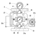
図2から図4に示す流水検知装置3は、筒状の本体31の内部にスイングチャッキ構造の弁体32を備えている。弁体32は円盤状であり常時は閉止しており、一次側配管1から二次側配管2への通水のみを許容する。流水検知装置3は、弁体32の開放による変位を検出して信号を出力する作動弁型の流水検知装置である。具体的には、本体31の外部に設置された流水検知機構31bと接続されたステム32aが弁体32の開放動作とともに変位して、その変位を流水検知機構31b内に備えたリミットスイッチ(図示しない)にて検知して信号を出力する。このような構造の流水検知装置の一例として、特開2010-5429号や、特開2016-135451号に記載されたものがある。ここでは、流水検知装置3の構造についての詳細な説明は省略する。
The flowing
流水検知装置3は、正面側にカバー31aによって覆われた開口部が設けられている。流水検知装置3の一方の側面には流水検知機構31bが配置され、もう一方の側面には排水弁31cが配置されている。
The flowing
本体31の正面側には配管34、35が設置されている。配管34は本体31において弁体32よりも一次側配管1側に設置された穴34aに接続されており、配管35は本体31において弁体32よりも二次側配管2側に設置された穴35aに接続されている。配管34、35の先は三方継手36に接続されており、図中において三方継手36の上側の接続口には圧力計33が設置される。また三方継手36の左側の接続口は、コ字型に屈曲した配管37と接続される。配管34から配管37を経由して配管35までがバイパス配管となる。
バイパス配管は上記のように流水検知装置3の本体31に設置してもよいし、または配管34と一次側配管1および配管35と二次側配管2をダイレクトに接続して構成可能である。また、前述の電動弁6をバイパス配管上に設置することも可能であり、その際電動弁6はリリーフ弁4と配管34の間に設置できる。
The bypass pipe may be installed in the
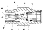
配管37の一端側と一方の三方継手36の間にはリリーフ弁4が設置されている。リリーフ弁4は二次側配管2から一次側配管1への通水が可能であり、筒状をした本体40内部に設置された弁体41はバネ42によって弁座43に付勢されており、弁体41は常時において閉止されている。
A relief valve 4 is installed between one end of the
リリーフ弁4の本体40は弁座43が設置された側の端が配管35(二次側配管2)へと続いており、筒状をしたホルダー44が設置された側の端が配管34(一次側配管1)へと続いている。本体40は、流水検知装置3の流れ方向(図2、図4において下から上)と交差する位置に配置されている。このような構成により本体40を図中において横長に設置できる。特に作動弁型の流水検知装置3は一般的に面間寸法が狭いことから、上記構成によって本体31に設置されたバイパス配管上にリリーフ弁4を設置できる。
The
バネ42は、弁体41とホルダー44の間に設置されている。バネ42は配管35(二次側配管2)の圧力が配管34(一次側配管1)の圧力に対して0.3〜0.4MPa程度上回ると弁体41に加わる二次側配管2の圧力により収縮して弁体41が開放される。
The
バネ42が弁体41に作用する力はホルダー44の位置により調整可能である。弁体41は前述のように一次側配管1の圧力と二次側配管2の圧力との差圧が所定の値よりも上回った際に開放動作する。差圧が生じるケースとして、弁体41が閉止している状態において、流入側(二次側配管2)の流体圧力が上昇して流出側(一次側配管1)の流体圧力との差が生じた状態と、流出側(一次側配管1)の流体圧力が降下して流入側(二次側配管2)の流体圧力との差が生じた状態の2つがある。いずれの場合においても僅かな差圧では弁体41は開放せず、ある程度以上の差圧が発生してから弁体41が開放するように、バネ42によって弁体41を弁座43へ押圧保持している。
The force acting on the
具体的には、流水検知装置3の最高使用圧力が1.4MPaであり、二次側配管2内部に充填された水の圧力が1MPaであるとき、流水検知装置3の最高使用圧力を超える前の段階で弁体41が開放するように、差圧が0.4MPaに達する前に弁体41が開放するように設定する。好ましくは、差圧が0.15MPaから0.4MPaの範囲にて設定する。本実施形態では差圧が0.3MPaから0.4MPaの範囲内で弁体41が開放するように設定されている。
Specifically, when the maximum working pressure of the flowing
弁座43は円筒形状をしており、材質としてフッ素樹脂が用いられている。弁座43と接触する弁体41に設置されたOリング45の材質はフッ素ゴムである。これにより長期間に渡って閉止状態にある弁体41と弁座43が固着するのを防止している。弁座43の材質としてフッ素樹脂の他に、金属製の弁座43の表面にフッ素樹脂をコーティングしたものを用いることも可能である。あるいは弁体41と当接する面のみにフッ素樹脂のコーティングを施してもよい。
The
弁座43の内側は穴となっている。リリーフ弁4において弁材43の内側の穴の断面積が「最小流通口径部の断面積」であり、これはリリーフ弁4の本体40の中心軸に対して垂直に交差する仮想平面上において流体が通過可能な部分の断面積が最小となる部分である。
The inside of the
ホルダー44は本体40の内周面に設置された牝ネジと螺合される牡ネジを外周面に有している。これによりホルダー44の位置を変更可能であり、バネ42が弁体41を押圧する力を調整できる。ホルダー44は中心穴46と、その周囲に複数形成された流通穴47が設置されている。本実施形態において流通穴47は4箇所設置されている。
The
中心穴46には弁体41からホルダー44側に伸びた弁棒41aが挿通される。中心穴64は弁体41が開閉する際に弁棒41aをガイドする作用を有する。弁体41が開放されると二次側配管2の内部に充填されていた水が流通穴47を通過して一次側配管1へと流れていく。
A
スプリンクラーヘッドSは、二次側配管2に設置されており、火災の熱を感知して自動的に作動する。スプリンクラーヘッドSの構造については公知であり、ここでは内部構造の詳細な説明は省略する。スプリンクラーヘッドSは内部に二次側配管2と接続されたノズルを有しており、ノズルの出口側の口径は、放水量が80L/minとなるように設定されている。ノズルの出口は常時、弁により閉鎖されており、弁は感熱分解部によって支持されている。感熱分解部は火災の熱により分解作動するものであり、感熱分解部として特開平7−284545号や特開2015−37678号に記載のものがある。
The sprinkler head S is installed in the
ここで、スプリンクラーヘッドSのノズルの出口の断面積よりもリリーフ弁4の最小流通口径部の断面積は小さく、スプリンクラーヘッドSのノズル出口の断面積とリリーフ弁4の最小流通口径部の断面積の比は、1:0.3以下とする。この比の値が小さくなり過ぎるとリリーフ弁4の内部にゴミが詰まりやすくなるので、より好ましくは0.2〜0.03の範囲内にするとよい。 Here, the cross-sectional area of the minimum flow port of the relief valve 4 is smaller than the cross-sectional area of the outlet of the nozzle of the sprinkler head S, and the cross-sectional area of the nozzle outlet of the sprinkler head S and the cross-sectional area of the minimum flow port of the relief valve 4. The ratio is set to 1: 0.3 or less. If the value of this ratio becomes too small, dust is likely to be clogged inside the relief valve 4, so that the ratio is more preferably in the range of 0.2 to 0.03.
また、上記のリリーフ弁4においては弁座43の内側の穴が最小流通口径部の断面積となっていたが、これよりもホルダー44の全ての流通穴47(4箇所)の断面積の総和のほうが小さい場合には、流通穴47の断面積の総和が最小流通口径部の断面積となる。
Further, in the relief valve 4 described above, the inner hole of the
次に、上記構成の消火設備における火災時の動作を説明する。 Next, the operation | movement at the time of the fire in the fire extinguishing equipment of the said structure is demonstrated.
図1に示す消火設備は、平時(非火災時)において一次側配管1の圧力よりも二次側配管2の圧力の方が高く設定されている。例えば二次側配管2の圧力が1MPaのとき一次側配管1の圧力はそれよりも低い0.8MPaとする。ポンプ起動スイッチ5の作動圧力は前述のように0.6MPaとする。
In the fire extinguishing equipment shown in FIG. 1, the pressure of the
流水検知装置3aの防護領域内で火災が発生すると、流水検知装置3aの二次側配管2aに接続されたスプリンクラーヘッドSが作動する。作動したスプリンクラーヘッドSのノズル61は開放され、二次側配管2aに充填されていた水が室内に散布させるので二次側配管2aの圧力は低下してくる。
When a fire occurs in the protection area of the flowing
二次側配管2aの減圧により流水検知装置3aの弁体32が開いて一次側配管1から二次側配管2へ給水が行われる。また弁体32の開放動作により流水検知装置3aが作動信号を出力する。作動信号を受信したコントロール装置Cは、火災が発生していない防護領域に設置された電動弁6b、6cを閉動作させる。これにより電動弁6は閉止して一次側配管1の圧力が0.7MPaよりも低くなった場合に非火災区画のリリーフ弁4b、4cの弁体41が開放するのを防止している。
Due to the decompression of the
一次側配管の圧力が0.6MPaに達すると、ポンプ起動スイッチ5が作動してポンプPが起動する。ポンプPから水源Wの水が連続して送られ、作動したスプリンクラーヘッドSから十分な量の水が散布され火災を鎮圧する。
When the pressure of the primary side pipe reaches 0.6 MPa, the
上記において、流水検知装置3aが作動信号を出力したときに、電動弁6を微開または半開にすると、一次側配管1の圧力が0.7MPaよりも低くなると非火災区画のリリーフ弁4b、4cの弁体41が開放するが、二次側配管2b、2cから一次側配管1に供給される流水量は、作動したスプリンクラーヘッドSから放出される流水量よりも少ないので一次側配管1はさらに減圧する。これにより遅滞なくポンプ起動スイッチ5が作動してポンプPが起動する。
In the above description, when the electric valve 6 is slightly opened or half-opened when the flowing
続いて、上記に説明した以外の本発明の消火設備の構成について説明する。 Then, the structure of the fire-extinguishing equipment of this invention other than having demonstrated above is demonstrated.
一次側配管1において、ポンプPと流水検知装置3の間には補助加圧ポンプ7が設置されている。補助加圧ポンプ7は先に説明したポンプPよりも吐出量が小さく、動作に必要な電力も小さく済む。例えば冬季において二次側配管2の圧力が減少して流水検知装置3の弁体32が微量に開いて一次側配管1から二次側配管2に充水されたような非火災時における一次側配管1の減圧時に補助加圧ポンプ7が用いられる。ポンプPの起動時の一次側配管1の圧力を0.6MPaに設定し、補助加圧ポンプ7が起動する一次側配管1の圧力を0.7MPaとした場合に、ポンプPが起動する前に補助加圧ポンプ7が起動して送水を行い、減少した配管内の圧力を回復させる。尚、補助加圧ポンプ7の吐出量よりもリリーフ弁4が開放した際の流水量のほうが小さい。
In the
補助加圧ポンプ7に関して、常時における二次側配管内の水の圧力と補助加圧ポンプが作動するときの一次側配管内の水の圧力との差よりもリリーフ弁が開放するときの圧力差のほうが大きくなるように設定している。より詳しく説明すると、二次側配管2内の水の圧力を1MPaとし補助加圧ポンプ7の起動圧力を0.7MPaとした場合、その差圧は0.3MPaであり、先に説明したリリーフ弁4が開放する際の差圧(0.3〜0.4MPa)よりも小さい。このため、非火災時に一次側配管1内の水が漏れて減圧した場合、補助加圧ポンプ7が起動して水源Wから一次側配管1へ給水が行われる。補助加圧ポンプ7は一次側配管1が所定の圧力に達すると運転を停止する。このように非火災時において一次側配管1から漏れが発生してもリリーフ弁4が開放することは無い。
Regarding the
また一次側配管1において、ポンプPと流水検知装置3の間に安全弁8が設置されている。安全弁8は一次側配管1の圧力が高くなり過ぎて所定の圧力を超えたときに、一次側配管1の水を外部に逃がす作用を有する。安全弁8が開放する圧力は補助加圧ポンプ7が作動する圧力よりも高い値に設定する。
In the
一方、大型倉庫や工場等の建物において折板屋根構造の建物がある。折板屋根は、金属から形成された折板が軽量・安価であり、工期が短くて済むというメリットを有しているが、建物の完成後において、夏の暑さ、冬の寒さなど外気温から熱の伝達を受けやすい。このため折板屋根の屋根裏付近に配設された二次側配管2の内部の水が夏季においては異常昇圧したり、冬季は凍結しやすくスプリンクラーヘッドSがダメージを受けやすい状況にある。本発明によれば折板屋根の付近に配置された二次側配管2内の水の異常昇圧や凍結によるスプリンクラーヘッドSの破損を防ぐことができ、火災時においてはポンプPの起動が遅滞なく行われて迅速に消火が可能である。
On the other hand, some buildings such as large warehouses and factories have a folded-plate roof structure. Folded plate roofs have the advantage that folded plates made of metal are lightweight and inexpensive and require a shorter construction period. However, after the building is completed, the outside temperature such as the summer heat and the winter cold Easy to receive heat from. For this reason, the water inside the
先に説明した実施形態ではスプリンクラー設備を例に説明したが、消火水に薬剤が含まれる泡消火設備等にも本発明は適用可能である。泡消火設備は図6に示すように薬剤タンク9aと混合器9bが設置されており、火災時にスプリンクラーヘッドSが作動してポンプPが起動すると薬剤タンク9a内の薬剤(泡原液)が混合器9bに送られ、水源Wの水と所定の割合で混合された泡水溶液が流水検知装置3へと送られる。流水検知装置3を経て一斉開放弁9cを通過した泡水溶液は泡ヘッド9dから散布される。
In the embodiment described above, the sprinkler facility has been described as an example. However, the present invention is also applicable to a foam fire extinguishing facility in which a chemical is contained in the fire extinguishing water. As shown in FIG. 6, the foam fire extinguishing equipment is provided with a
特に泡消火設備は駐車場に設置されるので二次側配管2の全部または一部が屋外に設置される場合もある。本発明により泡消火設備において流水検知装置の二次側(二次側配管2)に設置されているスプリンクラーヘッドS(感知ヘッド)や一斉開放弁9cが、二次側配管内部の水の異常昇圧や凍結によって破損することを防止できる。さらに、火災時においてはポンプPの起動が遅滞なく行われて迅速に消火が可能である。尚、一斉開放弁9cと接続しておりスプリンクラーヘッドSが設置されている感知ライン配管と、一斉開放弁9cの一次側配管をバイパスする配管(図示しない)に前述のリリーフ弁4を設置することも可能である。
In particular, since the foam fire-extinguishing equipment is installed in a parking lot, all or part of the
図1および図6に示す消火設備にはコントロール装置Cが設置されており、流水検知装置3、ポンプ起動スイッチ5、電動弁6、ポンプP、補助加圧ポンプ7が電気的に接続している。図中においてコントロール装置Cは1箇所のみに記載されているが、これ以外にポンプP、補助加圧ポンプ7等の構成機器の付近に別途設置することも可能である。コントロール装置Cの設定により、流水検知装置3の作動信号出力後に直ちにポンプPを起動させることも可能である。
The fire extinguishing equipment shown in FIGS. 1 and 6 is provided with a control device C, and a flowing
上記の消火設備は、水源の水を配管へ送水するポンプと、ポンプと配管により接続された流水検知装置と、流水検知装置の二次側配管に接続されているスプリンクラーヘッドとを備えており、流水検知装置は防護領域毎に複数設置され一次側配管はポンプへと続いており、ポンプは流水検知装置の作動信号により起動され、流水検知装置の一次側と二次側をバイパスするバイパス配管上に設置されたリリーフ弁は一次側の圧力に対して二次側の圧力差が所定以上のときに開放し、リリーフ弁の最小流通口径部の断面積はスプリンクラーヘッドのノズル出口の断面積よりも小さく構成される。
The fire extinguishing equipment includes a pump for supplying water from a water source to a pipe, a flowing water detection device connected by the pump and the piping, and a sprinkler head connected to a secondary side pipe of the flowing water detection device. A number of water flow detectors are installed in each protection area, and the primary pipe is connected to the pump. The pump is activated by the operation signal of the water flow detector and bypasses the primary and secondary sides of the water flow detector. The relief valve installed in the valve is opened when the pressure difference on the secondary side with respect to the pressure on the primary side exceeds a predetermined value, and the sectional area of the minimum flow port of the relief valve is larger than the sectional area of the nozzle outlet of the sprinkler head. Configured to be small.
1 一次側配管
2(2a、2b、2c) 二次側配管
3(3a、3b、3c) 流水検知装置
4(4a、4b、4c) リリーフ弁
5 ポンプ起動スイッチ
6(6a、6b、6c) 電動弁
7 補助加圧ポンプ
8 安全弁
9a 薬剤タンク
9b 混合器
9c 一斉開放弁
9d 泡ヘッド
31 流水検知装置の本体
32 流水検知装置の弁体
33 圧力計
34、35、37 配管
36 三方継手
40 リリーフ弁の本体
41 リリーフ弁の弁体
42 バネ
43 弁座
44 ホルダー
P ポンプ
S スプリンクラーヘッド
T 圧力タンク
W 水源
1 Primary piping
2 (2a, 2b, 2c) Secondary piping
3 (3a, 3b, 3c) Flowing water detection device
4 (4a, 4b, 4c) relief valve
5 Pump start switch
6 (6a, 6b, 6c) Motorized valve
7 Auxiliary pressurizing pump
8 Safety valve
9a Drug tank
9b mixer
9c Simultaneous release valve
9d foam head
31 Main body of the running water detector
32 Valve body of flowing water detector
33 Pressure gauge
34, 35, 37 piping
36 Three-way fittings
40 Relief valve body
41 Relief valve disc
42 Spring
43 Valve seat
44 holder
P pump
S sprinkler head
T pressure tank
W Water source
Claims (15)
ポンプと配管により接続された流水検知装置と、
流水検知装置の二次側配管に接続されているスプリンクラーヘッドと、
流水検知装置の一次側配管に設置されたポンプ起動スイッチとを備えており、
流水検知装置は防護領域毎に複数設置され一次側配管はポンプへと続いており、
流水検知装置の一次側と二次側をバイパスするバイパス配管上に設置されたリリーフ弁は一次側の圧力に対して二次側の圧力差が所定以上のときに開放し、防護領域毎に分岐された一次側配管上には電動弁が設置されており、火災が発生した防護領域の流水検知装置が作動したとき、その他の防護領域の電動弁を閉動作させることを特徴とする消火設備。 A pump that feeds water from the water source to the pipe;
A running water detector connected to the pump by piping;
A sprinkler head connected to the secondary pipe of the water flow detector;
And a pump start switch installed in the primary pipe of the running water detector,
A number of water flow detectors are installed in each protection area, and the primary piping continues to the pump.
The relief valve installed on the bypass pipe that bypasses the primary and secondary sides of the water flow detector opens when the pressure difference on the secondary side exceeds the primary pressure, and branches for each protection area. A fire extinguishing system is characterized in that a motorized valve is installed on the primary side pipe, and when the water flow detection device in the protected area where the fire has occurred is activated, the motorized valve in the other protected area is closed.
When the relief valve opens, the difference between the water pressure in the secondary pipe at normal time and the water pressure in the primary pipe when the auxiliary pressure pump installed on the primary pipe is activated The fire extinguishing equipment according to claim 1, wherein the pressure difference is larger.
Priority Applications (5)
| Application Number | Priority Date | Filing Date | Title |
|---|---|---|---|
| JP2018096749A JP7058555B2 (en) | 2018-05-21 | 2018-05-21 | Fire extinguishing equipment |
| TW108112463A TWI798415B (en) | 2018-05-21 | 2019-04-10 | fire extinguishing equipment |
| KR1020190055397A KR20190132925A (en) | 2018-05-21 | 2019-05-13 | Fire extinguishing equipment |
| US16/413,182 US20190351270A1 (en) | 2018-05-21 | 2019-05-15 | Fire Extinguishing Equipment |
| CN201910405269.0A CN110507937B (en) | 2018-05-21 | 2019-05-15 | Fire extinguishing device |
Applications Claiming Priority (1)
| Application Number | Priority Date | Filing Date | Title |
|---|---|---|---|
| JP2018096749A JP7058555B2 (en) | 2018-05-21 | 2018-05-21 | Fire extinguishing equipment |
Publications (2)
| Publication Number | Publication Date |
|---|---|
| JP2019201687A true JP2019201687A (en) | 2019-11-28 |
| JP7058555B2 JP7058555B2 (en) | 2022-04-22 |
Family
ID=68725241
Family Applications (1)
| Application Number | Title | Priority Date | Filing Date |
|---|---|---|---|
| JP2018096749A Active JP7058555B2 (en) | 2018-05-21 | 2018-05-21 | Fire extinguishing equipment |
Country Status (1)
| Country | Link |
|---|---|
| JP (1) | JP7058555B2 (en) |
Citations (8)
| Publication number | Priority date | Publication date | Assignee | Title |
|---|---|---|---|---|
| JPH08131574A (en) * | 1994-11-09 | 1996-05-28 | Yamato Protec Co | Fire extinguishing facility provided with automatic alarm valve |
| JPH0928828A (en) * | 1995-07-14 | 1997-02-04 | Daifuku Co Ltd | Construction method of warehouse facility with fire extinguisher |
| JPH105365A (en) * | 1996-06-25 | 1998-01-13 | Hochiki Corp | Sprinkler fire extinguishing equipment |
| JP2007252771A (en) * | 2006-03-24 | 2007-10-04 | Nohmi Bosai Ltd | Fire extinguishing equipment |
| US20110108290A1 (en) * | 2009-09-10 | 2011-05-12 | The Viking Corporation | Trim Manifold Assembly For A Sprinkler System |
| JP2016080123A (en) * | 2014-10-21 | 2016-05-16 | 能美防災株式会社 | Relief valve and fire-extinguishing apparatus |
| JP2016179058A (en) * | 2015-03-24 | 2016-10-13 | 能美防災株式会社 | Fire-fighting equipment |
| JP2017140076A (en) * | 2016-02-08 | 2017-08-17 | ヤマトプロテック株式会社 | Flowing water detection device |
-
2018
- 2018-05-21 JP JP2018096749A patent/JP7058555B2/en active Active
Patent Citations (8)
| Publication number | Priority date | Publication date | Assignee | Title |
|---|---|---|---|---|
| JPH08131574A (en) * | 1994-11-09 | 1996-05-28 | Yamato Protec Co | Fire extinguishing facility provided with automatic alarm valve |
| JPH0928828A (en) * | 1995-07-14 | 1997-02-04 | Daifuku Co Ltd | Construction method of warehouse facility with fire extinguisher |
| JPH105365A (en) * | 1996-06-25 | 1998-01-13 | Hochiki Corp | Sprinkler fire extinguishing equipment |
| JP2007252771A (en) * | 2006-03-24 | 2007-10-04 | Nohmi Bosai Ltd | Fire extinguishing equipment |
| US20110108290A1 (en) * | 2009-09-10 | 2011-05-12 | The Viking Corporation | Trim Manifold Assembly For A Sprinkler System |
| JP2016080123A (en) * | 2014-10-21 | 2016-05-16 | 能美防災株式会社 | Relief valve and fire-extinguishing apparatus |
| JP2016179058A (en) * | 2015-03-24 | 2016-10-13 | 能美防災株式会社 | Fire-fighting equipment |
| JP2017140076A (en) * | 2016-02-08 | 2017-08-17 | ヤマトプロテック株式会社 | Flowing water detection device |
Also Published As
| Publication number | Publication date |
|---|---|
| JP7058555B2 (en) | 2022-04-22 |
Similar Documents
| Publication | Publication Date | Title |
|---|---|---|
| AU2007258308B2 (en) | Pre-primed preaction sprinkler system | |
| TWI798415B (en) | fire extinguishing equipment | |
| JP4912827B2 (en) | Fire extinguishing equipment | |
| CN217130476U (en) | Pilot actuator and fire suppression system | |
| JP7058555B2 (en) | Fire extinguishing equipment | |
| JP7058554B2 (en) | Fire extinguishing equipment | |
| JP7058553B2 (en) | Fire extinguishing equipment | |
| JP3079441B2 (en) | Fire extinguishing equipment | |
| JP5707469B1 (en) | Flowing water detection device | |
| JP3217867B2 (en) | Test equipment for pre-actuated sprinkler fire extinguishing equipment | |
| JP2008253299A (en) | Sprinkler fire-extinguishing equipment | |
| JP3220251B2 (en) | Pre-actuated sprinkler fire extinguishing equipment | |
| JP3016039B2 (en) | Sprinkler fire extinguishing equipment | |
| JP3291605B2 (en) | Fire extinguisher with automatic alarm valve | |
| JP2979253B2 (en) | Sprinkler fire extinguishing equipment | |
| JP3941004B2 (en) | Sprinkler device for small buildings such as houses | |
| JP3066581B2 (en) | Sprinkler fire extinguishing equipment | |
| JP3010503B2 (en) | Sprinkler fire extinguishing equipment | |
| JP3013107B2 (en) | Sprinkler fire extinguishing equipment | |
| JP5922276B2 (en) | Fire extinguishing equipment | |
| JP2007117166A (en) | Pre-operation type sprinkler system | |
| SU1727858A1 (en) | Device for automatic control of drainage fire-fighting plant | |
| JP2006255101A (en) | Manual starting device | |
| JP2012200359A (en) | Fire extinguishing equipment | |
| JPH04300565A (en) | Pre-operation type sprinkler fire extinguishing device for apartment-house |
Legal Events
| Date | Code | Title | Description |
|---|---|---|---|
| A711 | Notification of change in applicant |
Free format text: JAPANESE INTERMEDIATE CODE: A711 Effective date: 20180726 |
|
| RD02 | Notification of acceptance of power of attorney |
Free format text: JAPANESE INTERMEDIATE CODE: A7422 Effective date: 20180726 |
|
| A621 | Written request for application examination |
Free format text: JAPANESE INTERMEDIATE CODE: A621 Effective date: 20210408 |
|
| A977 | Report on retrieval |
Free format text: JAPANESE INTERMEDIATE CODE: A971007 Effective date: 20220308 |
|
| TRDD | Decision of grant or rejection written | ||
| A01 | Written decision to grant a patent or to grant a registration (utility model) |
Free format text: JAPANESE INTERMEDIATE CODE: A01 Effective date: 20220315 |
|
| A61 | First payment of annual fees (during grant procedure) |
Free format text: JAPANESE INTERMEDIATE CODE: A61 Effective date: 20220412 |
|
| R150 | Certificate of patent or registration of utility model |
Ref document number: 7058555 Country of ref document: JP Free format text: JAPANESE INTERMEDIATE CODE: R150 |