JP2019197475A - Flight device guide system - Google Patents

Flight device guide system Download PDF

Info

Publication number
JP2019197475A
JP2019197475A JP2018092203A JP2018092203A JP2019197475A JP 2019197475 A JP2019197475 A JP 2019197475A JP 2018092203 A JP2018092203 A JP 2018092203A JP 2018092203 A JP2018092203 A JP 2018092203A JP 2019197475 A JP2019197475 A JP 2019197475A
Authority
JP
Japan
Prior art keywords
flying device
flight
unit
lost
tracking
Prior art date
Legal status (The legal status is an assumption and is not a legal conclusion. Google has not performed a legal analysis and makes no representation as to the accuracy of the status listed.)
Pending
Application number
JP2018092203A
Other languages
Japanese (ja)
Other versions
JP2019197475A5 (en
Inventor
覚 吉川
Satoru Yoshikawa
覚 吉川
武典 松江
Takenori Matsue
武典 松江
徹治 光田
Tetsuharu Mitsuta
徹治 光田
平井雅尊
Masataka Hirai
雅尊 平井
Current Assignee (The listed assignees may be inaccurate. Google has not performed a legal analysis and makes no representation or warranty as to the accuracy of the list.)
Denso Corp
Soken Inc
Original Assignee
Denso Corp
Soken Inc
Priority date (The priority date is an assumption and is not a legal conclusion. Google has not performed a legal analysis and makes no representation as to the accuracy of the date listed.)
Filing date
Publication date
Application filed by Denso Corp, Soken Inc filed Critical Denso Corp
Priority to JP2018092203A priority Critical patent/JP2019197475A/en
Priority to PCT/JP2019/014969 priority patent/WO2019194277A1/en
Publication of JP2019197475A publication Critical patent/JP2019197475A/en
Publication of JP2019197475A5 publication Critical patent/JP2019197475A5/ja
Priority to US17/060,414 priority patent/US20210026375A1/en
Pending legal-status Critical Current

Links

Images

Abstract

To provide a flight device guide system which makes it easy for a surveying part to track a flight device again even when tracking is lost.SOLUTION: A flight system 10 includes: a flight device 11 having a retroreflective member 15; a surveying part 12 tracking the flight device 11 based on light reflected on the retroreflective member 15 to acquire flight data; and a ground base 13 controlling flight of the flight device 11 based on the flight data acquired at the surveying part 12. A tracking determination part 71 determines whether or not the surveying part 12 maintains the tracking of the retroreflective member 15. Upon lost determination, a lost position definition part 72 defines the flight position as a lost position. Upon the lost determination, a search control part 73 drives the surveying part 12 to search the retroreflective member 15 focusing on the lost position. Upon the lost determination, a stop control part 74 performs control of stopping the movement made following the flight of the flight device 11 and stopping the flight device 11 at the current position.SELECTED DRAWING: Figure 1

Description

本発明は、飛行装置誘導システムに関する。   The present invention relates to a flying device guidance system.

近年、いわゆるドローンと称される飛行装置が普及している。飛行装置は、主に地上の操作者による無線または有線での遠隔操作によって飛行する。このように飛行装置を遠隔操作する場合、飛行装置の現在位置を同期的に取得する必要がある。特許文献1の場合、飛行装置の周囲に存在する障害物の情報を取得し、取得した情報に基づいて飛行装置の安全な飛行が確保される安全飛行範囲を設定している。そして、地上に設けられた測量部は、安全飛行範囲を飛行する飛行装置を追尾する。   In recent years, so-called drones have become popular. The flying device flies mainly by wireless or wired remote operation by an operator on the ground. When remotely operating the flying device in this way, it is necessary to acquire the current position of the flying device synchronously. In the case of patent document 1, the information of the obstacle which exists around a flight apparatus is acquired, and the safe flight range in which the safe flight of a flight apparatus is ensured based on the acquired information is set. Then, the surveying unit provided on the ground tracks the flying device flying in the safe flight range.

しかしながら、このように測量部で飛行装置を追尾する場合、飛行装置の飛行姿勢や飛行経路によっては、測量部が飛行装置を見失ってしまういわゆるトラッキングロストが生じることがある。トラッキングロストが生じると、飛行装置は地上の設備から誘導を受けることができず、飛行装置の飛行の不安定化を招くという問題がある。   However, when the surveying unit tracks the flying device in this way, depending on the flight posture and flight path of the flying device, a so-called tracking lost that causes the surveying unit to lose sight of the flying device may occur. When the tracking lost occurs, the flying device cannot receive guidance from the facilities on the ground, and there is a problem that the flying of the flying device becomes unstable.

特許第5882951号明細書Japanese Patent No. 5882951

そこで、本発明の目的は、トラッキングロストが生じたときでも、測量部による飛行装置の再追尾を容易にする飛行装置誘導システムを提供することにある。   Therefore, an object of the present invention is to provide a flying device guidance system that facilitates re-tracking of a flying device by a surveying unit even when tracking loss occurs.

請求項1記載の発明では、追尾判定部は、飛行装置の飛行中に測量部による追尾が維持されているか否かを判定する。ロスト位置定義部は、追尾判定部において追尾が維持できていないとき、つまりトラッキングロストによるロスト判定がなされたとき、ロスト位置を定義する。ロスト位置は、このロスト判定がなされたときの飛行装置の飛行位置である。そして、探索制御部は、ロスト判定がなされたとき、ロスト位置を中心に飛行装置に設けられている再帰反射部材を探索する。これとともに、停止制御部は、飛行装置の自立飛行を停止し、飛行装置をその場に停止させる。ここで、飛行装置の停止とは、飛行を継続しつつ位置や高度を変化しない状態を意味する。このように、ロスト判定がなされたとき、飛行装置はその場に停止するとともに、測量部は探索制御部によってロスト位置を中心とした飛行装置の探索を行なう。これにより、飛行装置は、測量部によって速やかに探索される。したがって、トラッキングロストが生じたときでも、測量部による飛行装置の再追尾を容易にすることができる。   In the first aspect of the invention, the tracking determination unit determines whether tracking by the surveying unit is maintained during the flight of the flying device. The lost position definition unit defines the lost position when tracking is not maintained by the tracking determination unit, that is, when the lost determination is made by tracking lost. The lost position is the flight position of the flying device when this lost determination is made. Then, when the lost determination is made, the search control unit searches for the retroreflective member provided in the flying device around the lost position. At the same time, the stop control unit stops the independent flight of the flying device and stops the flying device on the spot. Here, the stop of the flying device means a state in which the position and altitude are not changed while continuing the flight. As described above, when the lost determination is made, the flying device stops on the spot, and the surveying unit searches the flying device around the lost position by the search control unit. Thereby, the flying device is quickly searched by the surveying unit. Therefore, even when tracking loss occurs, re-tracking of the flying device by the surveying unit can be facilitated.

また、請求項2記載の発明では、追尾判定部は、飛行装置の飛行中に測量部による追尾が維持されているか否かを判定する。ロスト位置定義部は、追尾判定部において追尾が維持できていないとき、つまりトラッキングロストによるロスト判定がなされたとき、ロスト位置を定義する。ロスト位置は、このロスト判定がなされたときの飛行装置の飛行位置である。そして、探索制御部は、ロスト判定がなされたとき、ロスト位置を中心に飛行装置に設けられている再帰反射部材を探索する。これとともに、停止制御部は、飛行装置を、移動を考慮したロスト位置に戻して停止させる。飛行装置は、飛行を継続することによって、トラッキングロストが生じてからロスト判定がなされるまでの間に位置が変化するおそれがある。そこで、停止制御部は、ロスト判定がなされたとき、位置が変化した飛行装置をロスト位置まで戻して停止させる。ここで、飛行装置の停止とは、飛行を継続しつつ位置や高度を変化しない状態を意味する。このように、ロスト判定がなされたとき、飛行装置はロスト位置に復帰して停止するとともに、測量部は探索制御部によってロスト位置を中心とした飛行装置の探索を行なう。これにより、飛行装置は、測量部によって速やかに探索される。したがって、トラッキングロストが生じたときでも、測量部による飛行装置の再追尾を容易にすることができる。   In the second aspect of the invention, the tracking determination unit determines whether tracking by the surveying unit is maintained during the flight of the flying device. The lost position definition unit defines the lost position when tracking is not maintained by the tracking determination unit, that is, when the lost determination is made by tracking lost. The lost position is the flight position of the flying device when this lost determination is made. Then, when the lost determination is made, the search control unit searches for the retroreflective member provided in the flying device around the lost position. At the same time, the stop control unit returns the flying device to the lost position in consideration of the movement and stops it. By continuing the flight, the flying device may change its position after the tracking loss occurs until the lost determination is made. Therefore, when the lost determination is made, the stop control unit returns the flying device whose position has changed to the lost position and stops it. Here, the stop of the flying device means a state in which the position and altitude are not changed while continuing the flight. In this way, when the lost determination is made, the flying device returns to the lost position and stops, and the surveying unit searches the flying device around the lost position by the search control unit. Thereby, the flying device is quickly searched by the surveying unit. Therefore, even when tracking loss occurs, re-tracking of the flying device by the surveying unit can be facilitated.

請求項4記載の発明では、追尾判定部は、飛行装置の飛行中に測量部による追尾が維持されているか否かを判定する。通信部は、追尾判定部において追尾が維持できていないとき、つまりトラッキングロストによるロスト判定がなされたとき、位置取得部で取得した飛行装置の飛行位置を測量部へ伝達する。飛行位置は、このロスト判定がなされたときの飛行装置の飛行位置である。そして、探索制御部は、ロスト判定がなされたとき、伝達された飛行装置の飛行位置を中心に飛行装置に設けられている再帰反射部材を探索する。このように、ロスト判定がなされたとき、飛行装置は飛行位置を測量部に伝達する。これとともに、測量部は、ロスト位置に加え、探索制御部によって飛行装置から伝達された飛行位置を中心として飛行装置の探索を行なう。これにより、飛行装置は、測量部によって速やかに探索される。したがって、トラッキングロストが生じたときでも、測量部による飛行装置の再追尾を容易にすることができる。   In the invention according to claim 4, the tracking determination unit determines whether or not tracking by the surveying unit is maintained during the flight of the flying device. The communication unit transmits the flight position of the flying device acquired by the position acquisition unit to the surveying unit when tracking is not maintained in the tracking determination unit, that is, when the lost determination is made by tracking lost. The flight position is the flight position of the flying device when this lost determination is made. Then, when the lost determination is made, the search control unit searches for the retroreflective member provided in the flying device around the transmitted flight position of the flying device. As described above, when the lost determination is made, the flying device transmits the flight position to the surveying unit. At the same time, the surveying unit searches for the flying device around the flying position transmitted from the flying device by the search control unit in addition to the lost position. Thereby, the flying device is quickly searched by the surveying unit. Therefore, even when tracking loss occurs, re-tracking of the flying device by the surveying unit can be facilitated.

第1実施形態による飛行装置誘導システムを示すブロック図1 is a block diagram showing a flying device guidance system according to a first embodiment. 第1実施形態による飛行装置誘導システムの構成を示す模式図The schematic diagram which shows the structure of the flight apparatus guidance system by 1st Embodiment. 第1実施形態による飛行装置誘導システムの処理の流れを示す概略図Schematic which shows the flow of a process of the flying device guidance system by 1st Embodiment. 第2実施形態による飛行装置誘導システムの処理の流れを示す概略図Schematic which shows the flow of a process of the flying device guidance system by 2nd Embodiment. 第3実施形態による飛行装置誘導システムの処理の流れを示す概略図Schematic which shows the flow of a process of the flying device guidance system by 3rd Embodiment. 第3実施形態の変形例による飛行装置誘導システムの処理の流れを示す概略図Schematic which shows the flow of a process of the flying device guidance system by the modification of 3rd Embodiment. 実施形態による飛行装置誘導システムにおける復帰処理の流れを示す概略図Schematic showing the flow of return processing in the flying device guidance system according to the embodiment

以下、飛行装置誘導システムの複数の実施形態を図面に基づいて説明する。なお、複数の実施形態において実質的に同一の構成部位には同一の符号を付し、説明を省略する。
(第1実施形態)
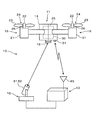
図1および図2に示すように第1実施形態による飛行装置誘導システム10は、飛行装置11、測量部12および地上基地13を備える。飛行装置11は、図2に示すように本体14、再帰反射部材15およびスラスタ16を備えている。飛行装置11は、測量部12から照射された光を再帰反射部材15で反射する。測量部12は、再帰反射部材15で反射した光を用いて飛行装置11を追尾するとともに、飛行装置11の飛行データを取得する。
Hereinafter, a plurality of embodiments of a flying device guidance system will be described with reference to the drawings. Note that, in a plurality of embodiments, substantially the same components are denoted by the same reference numerals, and description thereof is omitted.
(First embodiment)
As shown in FIGS. 1 and 2, the flying device guidance system 10 according to the first embodiment includes a flying device 11, a surveying unit 12, and a ground base 13. As shown in FIG. 2, the flying device 11 includes a main body 14, a retroreflective member 15, and a thruster 16. The flying device 11 reflects the light emitted from the surveying unit 12 with the retroreflective member 15. The surveying unit 12 tracks the flying device 11 using the light reflected by the retroreflective member 15 and acquires flight data of the flying device 11.

飛行装置11は、本体14に設けられている複数のスラスタ16を備えている。スラスタ16は、放射状または円環状に形成されている本体14に設けられている。スラスタ16は、いずれもモータ21、軸部材22、プロペラ23およびピッチ変更機構部24を有している。モータ21は、プロペラ23を駆動する駆動源である。モータ21は、本体14に収容されているバッテリ25などの電源から供給される電力によって駆動される。モータ21の回転は、図示しない回転子と一体になった軸部材22を通してプロペラ23に伝達される。プロペラ23は、モータ21によって回転駆動される。ピッチ変更機構部24は、サーボモータ26が発生する駆動力によって、プロペラ23のピッチを変更する。サーボモータ26は、バッテリ25から供給される電力によって駆動される。スラスタ16は、モータ21でプロペラ23を駆動することによって推進力を発生する。このとき、スラスタ16から発生する推進力の大きさおよび推進力の向きは、モータ21の回転数およびプロペラ23のピッチを変更することによって制御される。   The flying device 11 includes a plurality of thrusters 16 provided on the main body 14. The thruster 16 is provided in the main body 14 formed in a radial or annular shape. Each of the thrusters 16 includes a motor 21, a shaft member 22, a propeller 23, and a pitch changing mechanism 24. The motor 21 is a drive source that drives the propeller 23. The motor 21 is driven by electric power supplied from a power source such as a battery 25 housed in the main body 14. The rotation of the motor 21 is transmitted to the propeller 23 through a shaft member 22 integrated with a rotor (not shown). The propeller 23 is rotationally driven by the motor 21. The pitch changing mechanism unit 24 changes the pitch of the propeller 23 by the driving force generated by the servo motor 26. The servo motor 26 is driven by electric power supplied from the battery 25. The thruster 16 generates a propulsive force by driving the propeller 23 with the motor 21. At this time, the magnitude of the thrust generated from the thruster 16 and the direction of the thrust are controlled by changing the rotation speed of the motor 21 and the pitch of the propeller 23.

再帰反射部材15は、飛行装置11の本体14に設けられている。再帰反射部材15は、例えば重力方向において本体14の下方など、測量部12から視認が容易な位置に設けられている。再帰反射部材15は、測量部12から照射された光を、この測量部12に向けて反射する。すなわち、再帰反射部材15は、測量部12から照射された光を、光源である測量部12に向けて反射する。   The retroreflective member 15 is provided on the main body 14 of the flying device 11. The retroreflective member 15 is provided at a position that is easily visible from the surveying unit 12, such as below the main body 14 in the direction of gravity. The retroreflective member 15 reflects the light emitted from the surveying unit 12 toward the surveying unit 12. That is, the retroreflective member 15 reflects the light emitted from the surveying unit 12 toward the surveying unit 12 that is a light source.

飛行装置11は、制御ユニット30および通信部31を備えている。制御ユニット30は、図1に示すように制御演算部32および記憶部33を有している。制御演算部32は、CPU、ROMおよびRAMを有するマイクロコンピュータで構成されている。制御演算部32は、CPUでROMに記憶されているコンピュータプログラムを実行することにより、飛行装置11の全体を制御する。制御演算部32は、コンピュータプログラムを実行することにより、状態取得部34および飛行制御部35をソフトウェア的に実現している。なお、状態取得部34および飛行制御部35は、ソフトウェア的に限らず、ハードウェア的、あるいはソフトウェアとハードウェアとの協働によって実現してもよい。記憶部33は、例えば不揮発性メモリなどを有している。記憶部33は、予め設定された飛行計画をデータとして記憶している。飛行計画は、例えば飛行装置11が飛行する飛行ルートや飛行高度などが含まれている。通信部31は、地上基地13との間で無線または有線で通信する。   The flying device 11 includes a control unit 30 and a communication unit 31. The control unit 30 includes a control calculation unit 32 and a storage unit 33 as shown in FIG. The control calculation unit 32 is configured by a microcomputer having a CPU, a ROM, and a RAM. The control arithmetic unit 32 controls the entire flying device 11 by executing a computer program stored in the ROM by the CPU. The control calculation unit 32 implements the state acquisition unit 34 and the flight control unit 35 by software by executing a computer program. The state acquisition unit 34 and the flight control unit 35 are not limited to software, and may be realized by hardware or by cooperation between software and hardware. The storage unit 33 has, for example, a nonvolatile memory. The storage unit 33 stores a preset flight plan as data. The flight plan includes, for example, a flight route on which the flying device 11 flies and a flight altitude. The communication unit 31 communicates with the ground base 13 by radio or wire.

状態取得部34は、本体14の傾きや本体14に加わる加速度などから飛行装置11の飛行状態を取得する。具体的には、状態取得部34は、GPSセンサ41、加速度センサ42、角速度センサ43、地磁気センサ44および高度センサ45などと接続している。GPSセンサ41は、GPS衛星から出力されるGPS信号を受信する。また、加速度センサ42は、3次元の3つの軸方向において本体14に加わる加速度を検出する。角速度センサ43は、3次元の3つの軸方向において本体14に加わる角速度を検出する。地磁気センサ44は、3次元の3つの軸方向における地磁気を検出する。高度センサ45は、天地方向における高度を検出する。各種センサのうち、GPSセンサ41は、飛行装置11の外界からの情報によって飛行装置11の位置を取得する外界センサである。一方、加速度センサ42、角速度センサ43、地磁気センサ44および高度センサ45は、飛行装置11の外界からの情報に依存することなく飛行装置11の位置を取得する内界センサである。   The state acquisition unit 34 acquires the flight state of the flying device 11 from the tilt of the main body 14 and the acceleration applied to the main body 14. Specifically, the state acquisition unit 34 is connected to the GPS sensor 41, the acceleration sensor 42, the angular velocity sensor 43, the geomagnetic sensor 44, the altitude sensor 45, and the like. The GPS sensor 41 receives a GPS signal output from a GPS satellite. The acceleration sensor 42 detects acceleration applied to the main body 14 in the three-dimensional three axial directions. The angular velocity sensor 43 detects the angular velocity applied to the main body 14 in the three-dimensional three axial directions. The geomagnetic sensor 44 detects the geomagnetism in the three-dimensional three axial directions. The altitude sensor 45 detects the altitude in the vertical direction. Among the various sensors, the GPS sensor 41 is an external sensor that acquires the position of the flying device 11 based on information from the outside of the flying device 11. On the other hand, the acceleration sensor 42, the angular velocity sensor 43, the geomagnetic sensor 44, and the altitude sensor 45 are internal sensors that acquire the position of the flying device 11 without depending on information from the outside of the flying device 11.

状態取得部34は、これらGPSセンサ41で受信したGPS信号、加速度センサ42で検出した加速度、角速度センサ43で検出した角速度、地磁気センサ44で検出した地磁気などから本体14の飛行姿勢、飛行方向および飛行速度を検出する。また、状態取得部34は、GPSセンサ41で検出したGPS信号と各種のセンサによる検出値から本体14の飛行位置を外部に依存することなく自立的に検出する。さらに、状態取得部34は、GPSセンサ41で受信したGPS信号、および高度センサ45で検出した高度から本体14の飛行高度を検出する。このように、状態取得部34は、本体14の飛行姿勢、飛行位置および飛行高度など、飛行装置11の飛行に必要な情報を飛行状態として検出する。状態取得部34は、飛行装置11の位置を取得する位置取得部として機能する。状態取得部34は、これらに加え、可視的な画像を取得する図示しないカメラ、あるいは周囲の物体までの距離を測定する図示しないLIDAR(Light Detection And Ranging)などに接続してもよい。   The state acquisition unit 34 uses the GPS signal received by the GPS sensor 41, the acceleration detected by the acceleration sensor 42, the angular velocity detected by the angular velocity sensor 43, the geomagnetism detected by the geomagnetic sensor 44, etc. Detect flight speed. In addition, the state acquisition unit 34 independently detects the flight position of the main body 14 from the GPS signal detected by the GPS sensor 41 and the detection values obtained by various sensors without depending on the outside. Further, the state acquisition unit 34 detects the flight altitude of the main body 14 from the GPS signal received by the GPS sensor 41 and the altitude detected by the altitude sensor 45. Thus, the state acquisition unit 34 detects information necessary for the flight of the flying device 11 such as the flight posture, the flight position, and the flight altitude of the main body 14 as the flight state. The state acquisition unit 34 functions as a position acquisition unit that acquires the position of the flying device 11. In addition to these, the state acquisition unit 34 may be connected to a camera (not shown) that acquires a visible image, a LIDAR (Light Detection And Ranging) (not shown) that measures the distance to a surrounding object, or the like.

飛行制御部35は、飛行装置11の飛行を、自動制御モードまたは手動制御モードによって制御する。飛行制御部35は、位置制御部に相当する。自動制御モードは、操作者の操作によらずに、飛行装置11を自動的に飛行させるモードである。自動制御モードのとき、飛行制御部35は、記憶部33に記憶されている、または地上基地13から送信される飛行計画に沿って、飛行装置11の飛行を自動的に制御する。すなわち、飛行制御部35は、この自動制御モードのとき、状態取得部34で検出した本体14の飛行状態に基づいて、スラスタ16の推進力を制御する。これにより、飛行制御部35は、操作者の操作によらず、飛行装置11を記憶部33に記憶された飛行計画または地上基地13から送信される飛行計画に沿って自動的に飛行させる。   The flight control unit 35 controls the flight of the flying device 11 in an automatic control mode or a manual control mode. The flight control unit 35 corresponds to a position control unit. The automatic control mode is a mode for automatically flying the flying device 11 regardless of the operation of the operator. In the automatic control mode, the flight control unit 35 automatically controls the flight of the flying device 11 in accordance with the flight plan stored in the storage unit 33 or transmitted from the ground base 13. That is, the flight control unit 35 controls the thrust force of the thruster 16 based on the flight state of the main body 14 detected by the state acquisition unit 34 in this automatic control mode. Thereby, the flight control unit 35 automatically causes the flight device 11 to fly along the flight plan stored in the storage unit 33 or the flight plan transmitted from the ground base 13, regardless of the operation of the operator.

手動制御モードは、操作者の操作にしたがって飛行装置11を飛行させる飛行モードである。手動制御モードのとき、操作者は、飛行装置11と遠隔に設けられている地上基地13を通して飛行装置11の飛行状態を制御する。飛行制御部35は、地上基地13を通して操作者が入力した操作、および状態取得部34で取得した飛行状態に基づいてスラスタ16の推進力を制御する。これにより、飛行制御部35は、操作者の意思に沿って飛行装置11の飛行を制御する。   The manual control mode is a flight mode in which the flying device 11 is caused to fly according to the operation of the operator. In the manual control mode, the operator controls the flight state of the flying device 11 through the ground base 13 provided remotely from the flying device 11. The flight control unit 35 controls the thrust of the thruster 16 based on the operation input by the operator through the ground base 13 and the flight state acquired by the state acquisition unit 34. Thereby, the flight control unit 35 controls the flight of the flying device 11 in accordance with the intention of the operator.

測量部12は、照射部51、受光部52およびデータ処理部53を有している。照射部51は、例えばレーザ光などの光を照射する。照射部51は、連続的または所定の間隔で定期的にレーザ光を照射する。受光部52は、飛行装置11に設けられている再帰反射部材15で反射した光を受光する。すなわち、受光部52は、照射部51から照射され、飛行装置11の再帰反射部材15で反射した光を受光する。   The surveying unit 12 includes an irradiation unit 51, a light receiving unit 52, and a data processing unit 53. The irradiation unit 51 irradiates light such as laser light. The irradiation unit 51 irradiates the laser beam continuously or periodically at a predetermined interval. The light receiving unit 52 receives light reflected by the retroreflective member 15 provided in the flying device 11. That is, the light receiving unit 52 receives the light emitted from the irradiation unit 51 and reflected by the retroreflective member 15 of the flying device 11.

地上基地13は、測量部12と有線または無線によって通信可能に接続している。地上基地13は、制御演算部61、測量制御部62、記憶部64および地上通信部65を有している。制御演算部61は、CPU、ROMおよびRAMを有するマイクロコンピュータで構成されている。制御演算部61は、CPUでROMに記憶されたコンピュータプログラムを実行することにより、測量部12および地上基地13を制御する。制御演算部61は、コンピュータプログラムを実行することにより、測量部12に設けられているデータ処理部53および測量制御部62をソフトウェア的に実現している。なお、これらデータ処理部53および測量制御部62は、ソフトウェア的に限らず、ハードウェア的、あるいはソフトウェアとハードウェアとの協働によって実現してもよい。また、測量部12と地上基地13とは、図2に示すように別体に構成するだけでなく、一体に構成してもよい。   The ground base 13 is communicably connected to the surveying unit 12 by wire or wireless. The ground base 13 includes a control calculation unit 61, a survey control unit 62, a storage unit 64, and a ground communication unit 65. The control calculation unit 61 is composed of a microcomputer having a CPU, a ROM, and a RAM. The control calculation unit 61 controls the surveying unit 12 and the ground base 13 by executing a computer program stored in the ROM by the CPU. The control calculation unit 61 implements the data processing unit 53 and the surveying control unit 62 provided in the surveying unit 12 by software by executing a computer program. The data processing unit 53 and the surveying control unit 62 are not limited to software, and may be realized by hardware or by cooperation between software and hardware. Further, the surveying unit 12 and the ground base 13 are not only configured separately as shown in FIG.

測量制御部62は、測量部12の制御を実行する。具体的には、測量制御部62は、例えば図示しないモータやアクチュエータを用いて測量部12を任意の方向へ駆動し、飛行する飛行装置11へ向けて測量部12を追尾させる。これとともに、測量制御部62は、照射部51を制御して光の照射を実行するとともに、受光部52を制御して光の受光を実行する。このように、測量制御部62は、飛行装置11へ向けて測量部12を追尾させながら、飛行装置11への光の照射および反射した光の受光を制御する。データ処理部53は、受光部52で受光した光から、飛行装置11の飛行データを取得する。この飛行データは、測量部12から飛行装置11までの距離、および測量部12に対する飛行装置11の角度を少なくとも含んでいる。すなわち、データ処理部53は、受光部52で受光した光から、飛行装置11までの距離と、飛行装置11の角度とを飛行データとして取得する。ここで、飛行装置11の角度とは、測量部12を基準点とし、基準点を中心とする水平方向の角度および垂直方向の角度である。つまり、測量部12を基準点としたとき、水平方向には0〜360°の水平角度が設定され、垂直方向には0〜90°の垂直角度が設定される。この場合、水平角度の基準となる「0°」は、例えば地図座標における「北」などのように任意に設定される。また、垂直角度の基準となる「0°」は、例えば地面と平行な面に設定される。データ処理部53は、受光部52で受光した光から、飛行装置11の水平角度および垂直角度を取得する。また、データ処理部53は、上述の飛行データに飛行装置11の位置座標を含めて送信データを作成する。ここで、測量部12が設置されている位置は、例えばGPS信号などに基づいて地球上の絶対的な位置が特定されている。データ処理部53は、この測量部12の絶対的な位置と測量部12で取得した飛行データとに基づいて、飛行装置11の位置座標を特定する。そして、データ処理部53は、これら飛行データおよび位置座標を用いて送信データを作成する。   The survey control unit 62 executes control of the survey unit 12. Specifically, the surveying control unit 62 drives the surveying unit 12 in an arbitrary direction using, for example, a motor or an actuator (not shown), and tracks the surveying unit 12 toward the flying device 11 that flies. At the same time, the surveying control unit 62 controls the irradiation unit 51 to execute light irradiation, and controls the light receiving unit 52 to receive light. In this way, the surveying control unit 62 controls the irradiation of the light to the flying device 11 and the reception of the reflected light while tracking the surveying unit 12 toward the flying device 11. The data processing unit 53 acquires flight data of the flying device 11 from the light received by the light receiving unit 52. This flight data includes at least the distance from the surveying unit 12 to the flying device 11 and the angle of the flying device 11 with respect to the surveying unit 12. That is, the data processing unit 53 acquires the distance to the flying device 11 and the angle of the flying device 11 from the light received by the light receiving unit 52 as flight data. Here, the angle of the flying device 11 is an angle in the horizontal direction and an angle in the vertical direction around the reference point with the surveying unit 12 as a reference point. That is, when the surveying unit 12 is used as a reference point, a horizontal angle of 0 to 360 ° is set in the horizontal direction, and a vertical angle of 0 to 90 ° is set in the vertical direction. In this case, “0 °” as a reference for the horizontal angle is arbitrarily set, for example, “north” in map coordinates. Further, “0 °” as a reference for the vertical angle is set to a plane parallel to the ground, for example. The data processing unit 53 acquires the horizontal angle and the vertical angle of the flying device 11 from the light received by the light receiving unit 52. Further, the data processing unit 53 creates transmission data by including the position coordinates of the flying device 11 in the above-described flight data. Here, as the position where the surveying unit 12 is installed, an absolute position on the earth is specified based on, for example, a GPS signal. The data processing unit 53 specifies the position coordinates of the flying device 11 based on the absolute position of the surveying unit 12 and the flight data acquired by the surveying unit 12. Then, the data processing unit 53 creates transmission data using these flight data and position coordinates.

上述のようにデータ処理部53は、取得した飛行データおよび位置座標を送信データとして作成する。すなわち、データ処理部53は、取得した飛行データに、位置座標を加えて送信データを作成する。地上通信部65は、データ処理部53で作成された送信データを、飛行装置11へ送信する。このとき、地上通信部65は、送信データに加え、記憶部64に記憶された飛行計画も飛行装置11へ送信する。すなわち、データ処理部53で作成された送信データは、地上通信部65から飛行装置11の通信部31へ送信される。通信部31において送信データを受信した飛行装置11の飛行制御部35は、地上基地13から送信された送信データを参照してスラスタ16を制御する。これにより、飛行装置11は、地上基地13で取得された飛行データおよび位置座標を含む飛行データ、ならびに地上基地13から送信された飛行計画を参照しながら、飛行制御部35による制御よって自立的に飛行する。記憶部64は、例えば不揮発性のメモリなどを有している。記憶部64は、飛行装置11の飛行経路を設定した飛行計画を記憶している。この飛行計画は、飛行装置11の記憶部33に記憶されている飛行計画と同一であってもよく、異なっていてもよい。また、地上基地13から飛行装置11へ飛行計画を送信することにより、飛行装置11は時々刻々と地上基地13で変更される飛行計画に沿って柔軟な飛行を実行することができる。   As described above, the data processing unit 53 creates the acquired flight data and position coordinates as transmission data. That is, the data processing unit 53 adds the position coordinates to the acquired flight data and creates transmission data. The ground communication unit 65 transmits the transmission data created by the data processing unit 53 to the flying device 11. At this time, the ground communication unit 65 transmits the flight plan stored in the storage unit 64 to the flying device 11 in addition to the transmission data. That is, the transmission data created by the data processing unit 53 is transmitted from the ground communication unit 65 to the communication unit 31 of the flying device 11. The flight control unit 35 of the flying device 11 that has received the transmission data in the communication unit 31 controls the thruster 16 with reference to the transmission data transmitted from the ground base 13. Thereby, the flying device 11 is autonomously controlled by the flight control unit 35 while referring to the flight data acquired at the ground base 13 and the flight data including the position coordinates and the flight plan transmitted from the ground base 13. To fly. The storage unit 64 includes, for example, a nonvolatile memory. The storage unit 64 stores a flight plan in which the flight path of the flying device 11 is set. This flight plan may be the same as or different from the flight plan stored in the storage unit 33 of the flying device 11. In addition, by transmitting the flight plan from the ground base 13 to the flying device 11, the flying device 11 can execute a flexible flight along the flight plan that is changed at the ground base 13 every moment.

飛行装置誘導システム10は、追尾判定部71、ロスト位置定義部72、探索制御部73および停止制御部74を備えている。具体的には、飛行装置11または地上基地13は、制御演算部32または制御演算部61でコンピュータプログラムを実行することにより、追尾判定部71、ロスト位置定義部72、探索制御部73および停止制御部74をソフトウェア的に実現している。なお、これら追尾判定部71、ロスト位置定義部72、探索制御部73および停止制御部74は、ソフトウェア的に限らず、ハードウェア的、あるいはソフトウェアとハードウェアとの協働によって実現してもよい。第1実施形態の場合、追尾判定部71、ロスト位置定義部72および探索制御部73は地上基地13に設けられ、停止制御部74は飛行装置11に設けられている。これら追尾判定部71、ロスト位置定義部72、探索制御部73および停止制御部74は、飛行装置11または地上基地13のいずれかまたは両方に任意の組み合わせで設けてもよく、別途の機器としてもよい。   The flying device guidance system 10 includes a tracking determination unit 71, a lost position definition unit 72, a search control unit 73, and a stop control unit 74. Specifically, the flying device 11 or the ground base 13 executes a computer program in the control calculation unit 32 or the control calculation unit 61, thereby allowing the tracking determination unit 71, the lost position definition unit 72, the search control unit 73, and the stop control. The unit 74 is realized by software. Note that the tracking determination unit 71, the lost position definition unit 72, the search control unit 73, and the stop control unit 74 are not limited to software, and may be realized by hardware or by cooperation of software and hardware. . In the case of the first embodiment, the tracking determination unit 71, the lost position definition unit 72, and the search control unit 73 are provided in the ground base 13, and the stop control unit 74 is provided in the flying device 11. The tracking determination unit 71, the lost position definition unit 72, the search control unit 73, and the stop control unit 74 may be provided in any combination or both of the flying device 11 and the ground base 13, or as a separate device. Good.

追尾判定部71は、測量部12が飛行装置11の追尾を維持しているか否かを判定する。具体的には、追尾判定部71は、飛行装置11が飛行しているとき、測量部12の照射部51から照射し、飛行装置11の再帰反射部材15で反射した光が受光部52で受光できているか否かを判定する。測量部12は、測量制御部62を通して駆動されることにより、照射部51から照射して再帰反射部材15で反射する光を用いて、飛行装置11を追尾する。つまり、測量部12の照射部51から照射された光は、飛行装置11の再帰反射部材15との間を往復する。このとき、飛行装置11の飛行姿勢や飛行装置11の周囲に存在する障害物によって、測量部12と飛行装置11との間の光の往復が妨げられると、受光部52は照射部51から照射された光を受光できない。このように、測量部12は、測量部12と飛行装置11との間の光の往復が妨げられたとき、飛行装置11を認識できず、飛行装置11の追尾ができない状態となる。すなわち、測量部12は、飛行装置11を見失ったトラッキングロストの状態となる。追尾判定部71は、測量部12が飛行装置11を認識できないとき、トラッキングロストが生じたとして、「ロスト判定」を行なう。   The tracking determination unit 71 determines whether or not the surveying unit 12 maintains the tracking of the flying device 11. Specifically, the tracking determination unit 71 receives light from the irradiation unit 51 of the surveying unit 12 and reflected by the retroreflective member 15 of the flying device 11 by the light receiving unit 52 when the flying device 11 is flying. It is determined whether or not it is possible. The surveying unit 12 is driven through the surveying control unit 62 to track the flying device 11 using the light irradiated from the irradiation unit 51 and reflected by the retroreflective member 15. That is, the light emitted from the irradiation unit 51 of the surveying unit 12 reciprocates between the retroreflective member 15 of the flying device 11. At this time, if the flight posture of the flying device 11 and obstacles around the flying device 11 prevent the light from traveling back and forth between the surveying unit 12 and the flying device 11, the light receiving unit 52 emits light from the irradiation unit 51. The received light cannot be received. Thus, the surveying unit 12 cannot recognize the flying device 11 and cannot track the flying device 11 when the reciprocation of light between the surveying unit 12 and the flying device 11 is hindered. That is, the surveying unit 12 is in a tracking lost state in which the flying device 11 is lost. When the surveying unit 12 cannot recognize the flying device 11, the tracking determination unit 71 performs “lost determination” on the assumption that tracking lost has occurred.

ロスト位置定義部72は、追尾判定部71において「ロスト判定」がされたとき、この「ロスト判定」がされたときの飛行装置11の位置をロスト位置P0と定義する。すなわち、ロスト位置定義部72は、測量部12で取得した飛行データを用いて、ロスト判定がされたときの飛行装置11の飛行位置をロスト位置P0と定義する。ロスト位置定義部72は、定義したロスト位置P0を記憶部64に記憶する。   When the tracking determination unit 71 performs “lost determination”, the lost position definition unit 72 defines the position of the flying device 11 when the “lost determination” is performed as the lost position P0. That is, the lost position definition unit 72 defines the flight position of the flying device 11 when the lost determination is made using the flight data acquired by the surveying unit 12 as the lost position P0. The lost position definition unit 72 stores the defined lost position P0 in the storage unit 64.

ロスト位置定義部72で「ロスト判定」がされたとき、飛行制御部35は、飛行装置11の位置を推定可能であるか否かを判定する。すなわち、飛行制御部35は、GPSセンサ41によって飛行装置11の飛行位置を推定可能であるか否かを判定する。飛行装置11がGPSセンサ41を有しているとき、飛行装置11の飛行位置はGPSセンサ41でGPS信号を受信することによって推定可能である。そのため、飛行制御部35は、GPSセンサ41がGPS信号を受信できる状態であれば、飛行装置11の飛行位置を推定可能であると判定する。一方、飛行装置11がGPSセンサ41を有していても、GPSセンサ41でGPS信号が受信できないとき、飛行装置11の飛行位置の推定は困難である。例えば飛行装置11が橋梁やトンネルなどの構造物の内部を飛行するとき、GPSセンサ41はGPS信号の受信が困難である。飛行制御部35は、GPSセンサ41がGPS信号を受信困難な状態であれば、飛行装置11の飛行位置を推定できないと判定する。また、本実施形態と異なり飛行装置11がGPSセンサ41を有していない場合もある。このように飛行装置11がGPSセンサ41を有していないとき、飛行制御部35は飛行装置11の飛行位置を推定できないと判定する。   When “lost determination” is made in the lost position definition unit 72, the flight control unit 35 determines whether or not the position of the flying device 11 can be estimated. That is, the flight control unit 35 determines whether the flight position of the flying device 11 can be estimated by the GPS sensor 41. When the flying device 11 has the GPS sensor 41, the flight position of the flying device 11 can be estimated by receiving a GPS signal with the GPS sensor 41. Therefore, the flight control unit 35 determines that the flight position of the flying device 11 can be estimated if the GPS sensor 41 can receive a GPS signal. On the other hand, even if the flying device 11 has the GPS sensor 41, when the GPS signal cannot be received by the GPS sensor 41, it is difficult to estimate the flight position of the flying device 11. For example, when the flying device 11 flies inside a structure such as a bridge or a tunnel, it is difficult for the GPS sensor 41 to receive a GPS signal. The flight control unit 35 determines that the flight position of the flying device 11 cannot be estimated if it is difficult for the GPS sensor 41 to receive a GPS signal. Unlike the present embodiment, the flying device 11 may not have the GPS sensor 41. Thus, when the flying device 11 does not have the GPS sensor 41, the flight control unit 35 determines that the flight position of the flying device 11 cannot be estimated.

探索制御部73は、測量制御部62を通して測量部12を駆動する。探索制御部73は、ロスト位置P0を中心に測量部12を駆動する。これにより、測量部12は、ロスト位置P0を中心として、飛行装置11に設けられている再帰反射部材15を探索する。   The search control unit 73 drives the surveying unit 12 through the surveying control unit 62. The search control unit 73 drives the surveying unit 12 around the lost position P0. Thereby, the surveying unit 12 searches for the retroreflective member 15 provided in the flying device 11 around the lost position P0.

飛行制御部35は、ロスト判定がされたとき、飛行装置11に設定された飛行計画に沿った飛行を停止する。すなわち、飛行装置11は、自動制御モードで飛行計画に沿った制御されているとき、ロスト判定がされると、飛行計画に沿った飛行を停止する。そして、停止制御部74は、飛行装置11をその場に停止する停止制御を行なう。すなわち、停止制御部74は、ロスト判定がされた後、速やかに飛行装置11の飛行を停止して、その場でのホバリングなどのように飛行装置11の飛行位置や飛行高度の変更を制限する。停止制御部74は、飛行制御部35において飛行装置11の飛行位置を推定可能であると判定されたとき、GPSセンサ41で受信したGPS信号に基づいて停止制御を行なう。   When the lost determination is made, the flight control unit 35 stops the flight along the flight plan set in the flight device 11. That is, when the flight apparatus 11 is controlled in accordance with the flight plan in the automatic control mode and the lost determination is made, the flight apparatus 11 stops the flight along the flight plan. And the stop control part 74 performs stop control which stops the flight apparatus 11 on the spot. In other words, after the lost determination is made, the stop control unit 74 immediately stops the flight of the flying device 11 and restricts the change of the flight position and the flight altitude of the flying device 11 such as hovering on the spot. . The stop control unit 74 performs stop control based on the GPS signal received by the GPS sensor 41 when it is determined by the flight control unit 35 that the flight position of the flying device 11 can be estimated.

一方、停止制御部74は、飛行制御部35において飛行装置11の飛行位置を推定困難であると判定されたとき、飛行装置11に設けられている加速度センサ42、角速度センサ43および地磁気センサ44で検出した検出値に基づいて停止制御を行なう。すなわち、GPSセンサ41でGPS信号の受信が困難なとき、飛行装置11の飛行位置はGPS信号による特定が困難である。そのため、停止制御部74は、外界センサであるGPSセンサ41に代えて、内界センサである加速度センサ42、角速度センサ43および地磁気センサ44を用いて停止制御を行なう。このとき、停止制御部74は、GPSセンサ41でGPS信号を受信可能なとき、および受信が困難なときのいずれも、高度センサ45で検出した高度を用いて飛行装置11の高度についても停止制御を行なう。また、停止制御部74は、GPSセンサ41でGPS信号を受信可能であるときでも、GPS信号に基づく位置の推定に加えて、内界センサである加速度センサ42、角速度センサ43および地磁気センサ44も用いて停止制御を行なってもよい。   On the other hand, when the flight control unit 35 determines that the flight position of the flying device 11 is difficult to estimate, the stop control unit 74 uses the acceleration sensor 42, the angular velocity sensor 43, and the geomagnetic sensor 44 provided in the flying device 11. Stop control is performed based on the detected value. That is, when it is difficult for the GPS sensor 41 to receive a GPS signal, it is difficult to specify the flight position of the flying device 11 using the GPS signal. Therefore, the stop control unit 74 performs stop control using the acceleration sensor 42, the angular velocity sensor 43, and the geomagnetic sensor 44, which are inner sensors, instead of the GPS sensor 41, which is an outer sensor. At this time, the stop control unit 74 performs stop control on the altitude of the flying device 11 using the altitude detected by the altitude sensor 45 both when the GPS sensor 41 can receive the GPS signal and when it is difficult to receive the GPS signal. To do. Further, even when the GPS sensor 41 can receive a GPS signal, the stop control unit 74 also includes an acceleration sensor 42, an angular velocity sensor 43, and a geomagnetic sensor 44, which are internal sensors, in addition to the estimation of the position based on the GPS signal. It may be used to perform stop control.

測量部12が飛行装置11を追尾できないロスト判定がされたとき、飛行装置11はロスト位置P0の近辺に存在する可能性が高い。仮にロスト判定がされたにもかかわらず飛行装置11が飛行を継続すると、測量部12の追尾は時間の経過とともに難易度が高まる。そこで、停止制御部74は、ロスト判定がされたとき、飛行装置11の飛行を停止し、飛行装置11の飛行位置や飛行高度の変更を制限する。そして、探索制御部73は、測量部12によって、このロスト位置P0を中心に、飛行装置11に設けられている再帰反射部材15の探索を行なう。これにより、測量部12は、ロスト位置P0の近辺で停止している飛行装置11を探索することとなり、飛行装置11の発見および飛行装置11の追尾の再開が容易になる。   When the determination that the surveying unit 12 cannot track the flying device 11 is made, the flying device 11 is likely to exist in the vicinity of the lost position P0. If the flying device 11 continues to fly despite the lost determination, the difficulty of tracking the surveying unit 12 increases with time. Therefore, the stop control unit 74 stops the flight of the flying device 11 when the lost determination is made, and restricts the change of the flight position and the flight altitude of the flying device 11. Then, the search control unit 73 uses the surveying unit 12 to search for the retroreflective member 15 provided in the flying device 11 around the lost position P0. As a result, the surveying unit 12 searches for the flying device 11 that is stopped in the vicinity of the lost position P0, so that the discovery of the flying device 11 and the resumption of tracking of the flying device 11 are facilitated.

停止制御部74は、飛行装置11または地上基地13のいずれに設けてもよい。すなわち、停止制御部74は、飛行装置11に設けることにより、地上基地13との通信を行なうことなく自立的に、飛行装置11をロスト位置P0の近辺で停止させる。また、停止制御部74は、地上基地13に設けることにより、通信部31および地上通信部65を通した通信によって、飛行装置11をロスト位置P0の近辺で停止させる。   The stop control unit 74 may be provided in either the flying device 11 or the ground base 13. That is, the stop control unit 74 is provided in the flying device 11, and autonomously stops the flying device 11 in the vicinity of the lost position P <b> 0 without performing communication with the ground base 13. Further, the stop control unit 74 is provided in the ground base 13 to stop the flying device 11 in the vicinity of the lost position P0 through communication through the communication unit 31 and the ground communication unit 65.

以下、上記の構成による飛行装置誘導システム10における処理の流れを図3に基づいて説明する。
飛行装置11が飛行を開始すると、追尾判定部71は、ロスト判定が行なわれたか否かを判定する(S101)。すなわち、追尾判定部71は、測量部12が飛行装置11の追尾を維持しているか否かを判定するとともに、トラッキングロスが生じていればロスト判定を行なう。飛行制御部35は、追尾判定部71でロスト判定が行なわれると(S101:Yes)、飛行計画に沿った飛行を中止する(S102)。すなわち、飛行制御部35は、ロスト判定が行なわれると、自動制御モードによる飛行計画に沿った飛行を停止する。地上通信部65は、追尾判定部71においてロスト判定が行なわれると、その旨を飛行装置11へ送信する。飛行制御部35は、通信部31において地上通信部65からロスト判定が行なわれた旨を受信すると、飛行計画に沿った飛行を中止する。
Hereinafter, the flow of processing in the flying device guidance system 10 configured as described above will be described with reference to FIG.
When the flying device 11 starts flying, the tracking determination unit 71 determines whether or not lost determination has been performed (S101). That is, the tracking determination unit 71 determines whether or not the surveying unit 12 maintains the tracking of the flying device 11, and performs a lost determination if a tracking loss has occurred. When the tracking determination unit 71 performs the lost determination (S101: Yes), the flight control unit 35 stops the flight according to the flight plan (S102). That is, when the lost determination is made, the flight control unit 35 stops the flight according to the flight plan in the automatic control mode. When the tracking determination unit 71 performs the lost determination, the ground communication unit 65 transmits a message to that effect to the flying device 11. The flight control unit 35 stops the flight according to the flight plan when the communication unit 31 receives a notification that the lost determination has been made from the ground communication unit 65.

ロスト位置定義部72は、S102において飛行計画に沿った飛行が停止されると、ロスト位置P0を定義する(S103)。すなわち、ロスト位置定義部72は、ロスト判定がされたときの飛行装置11の飛行位置をロスト位置P0と定義する。そして、停止制御部74は、飛行装置11をロスト位置P0で停止する停止制御を行なう(S104)。すなわち、地上通信部65は、ロスト判定が行なわれると、ロスト位置定義部72で定義されたロスト位置P0を飛行装置11へ送信する。停止制御部74は、通信部31を通して地上通信部65からロスト位置P0を取得する。そして、停止制御部74は、ロスト判定を受信すると、飛行装置11をロスト位置P0に維持した状態でホバリングへ移行させる。追尾判定部71は、S101においてロスト判定が行なわれていないと(S101:No)、ロスト判定が行なわれるまでS101の処理を繰り返す。   When the flight according to the flight plan is stopped in S102, the lost position definition unit 72 defines the lost position P0 (S103). That is, the lost position definition unit 72 defines the flight position of the flying device 11 when the lost determination is made as the lost position P0. Then, the stop control unit 74 performs stop control for stopping the flying device 11 at the lost position P0 (S104). That is, when the lost determination is performed, the ground communication unit 65 transmits the lost position P0 defined by the lost position definition unit 72 to the flying device 11. The stop control unit 74 acquires the lost position P0 from the ground communication unit 65 through the communication unit 31. And the stop control part 74 will transfer to the hovering in the state which maintained the flying apparatus 11 in the lost position P0, if a lost determination is received. If the lost determination is not performed in S101 (S101: No), tracking determination unit 71 repeats the process of S101 until the lost determination is performed.

飛行制御部35は、S104において停止制御に移行すると、飛行装置11の飛行位置を推定可能であるか否かを判定する(S105)。すなわち、飛行制御部35は、GPSセンサ41で受信したGPS信号によって飛行装置11の飛行位置が推定可能であるか否かを判定する。停止制御部74は、S105において飛行位置が推定可能であると判定されたとき(S105:Yes)、GPSセンサ41で受信したGPS信号に基づいて飛行装置11をロスト位置P0に停止させる制御を行なう(S106)。この場合、停止制御部74は、GPS信号に加えて、内界センサである加速度センサ42、角速度センサ43および地磁気センサ44の検出値も用いて飛行装置11の停止を制御してもよい。一方、停止制御部74は、S105において飛行位置が推定困難であると判定されたとき(S105:No)、内界センサである加速度センサ42、角速度センサ43および地磁気センサ44の検出値に基づいて飛行装置11をロスト位置P0に停止させる制御を行なう(S107)。   When the flight control unit 35 shifts to the stop control in S104, the flight control unit 35 determines whether or not the flight position of the flying device 11 can be estimated (S105). That is, the flight control unit 35 determines whether or not the flight position of the flying device 11 can be estimated based on the GPS signal received by the GPS sensor 41. When it is determined in S105 that the flight position can be estimated (S105: Yes), the stop control unit 74 performs control to stop the flying device 11 at the lost position P0 based on the GPS signal received by the GPS sensor 41. (S106). In this case, the stop control unit 74 may control the stop of the flying device 11 using the detected values of the acceleration sensor 42, the angular velocity sensor 43, and the geomagnetic sensor 44, which are internal sensors, in addition to the GPS signal. On the other hand, when it is determined in S105 that the flight position is difficult to estimate (S105: No), the stop control unit 74 is based on the detection values of the acceleration sensor 42, the angular velocity sensor 43, and the geomagnetic sensor 44 that are internal sensors. Control is performed to stop the flying device 11 at the lost position P0 (S107).

探索制御部73は、S106またはS107において停止制御が行なわれているとき、測量部12を駆動して再帰反射部材15を探索する(S108)。すなわち、探索制御部73は、停止制御によって停止している飛行装置11に設けられている再帰反射部材15を探索する。これにより、探索制御部73は、停止している飛行装置11を、ロスト位置P0を中心として探索する。   When the stop control is performed in S106 or S107, the search control unit 73 drives the surveying unit 12 to search for the retroreflective member 15 (S108). That is, the search control unit 73 searches for the retroreflective member 15 provided in the flying device 11 stopped by the stop control. As a result, the search control unit 73 searches for the flying device 11 that is stopped centering on the lost position P0.

以上説明した第1実施形態では、追尾判定部71は、飛行装置11の飛行中に測量部12による追尾が維持されているか否かを判定する。ロスト位置定義部72は、追尾判定部71においてロスト判定がなされたとき、ロスト位置P0を定義する。そして、探索制御部73は、ロスト判定がなされたとき、ロスト位置P0を中心に飛行装置11に設けられている再帰反射部材15を探索する。これとともに、停止制御部74は、飛行装置11の飛行計画に沿った飛行を停止し、飛行装置11をその場に停止させる。これにより、飛行装置11は、測量部12によって速やかに探索される。したがって、トラッキングロストが生じたときでも、測量部12による飛行装置11の再追尾を容易にすることができる。   In the first embodiment described above, the tracking determination unit 71 determines whether tracking by the surveying unit 12 is maintained during the flight of the flying device 11. The lost position definition unit 72 defines the lost position P0 when the tracking determination unit 71 makes a lost determination. Then, when the lost determination is made, the search control unit 73 searches for the retroreflective member 15 provided in the flying device 11 around the lost position P0. At the same time, the stop control unit 74 stops the flight according to the flight plan of the flying device 11 and stops the flying device 11 on the spot. Thereby, the flying device 11 is quickly searched by the surveying unit 12. Therefore, even when tracking loss occurs, re-tracking of the flying device 11 by the surveying unit 12 can be facilitated.

(第2実施形態)
第2実施形態による飛行装置誘導システムについて説明する。
第2実施形態による飛行装置誘導システム10は、ロスト位置定義部72における処理の流れが第1実施形態と異なる。第2実施形態のロスト位置定義部72は、追尾判定部71において「ロスト判定」がされたとき、この「ロスト判定」がされた時刻を時刻T1として取得する。これに加え、ロスト位置定義部72は、時刻T1から飛行制御部35によって飛行計画に沿った制御が中止される時刻T2までの期間Tdを取得する。すなわち、期間Tdは、Td=T2-T1である。ロスト位置定義部72は、例えば制御演算部61に設けられている図示しないタイマなどに基づいて時刻T1、時刻T2を検出し、期間Tdを算出する。さらに、ロスト位置定義部72は、この時刻T1から時刻T2までの期間Tdにおける飛行装置11の飛行速度Vを取得する。
(Second Embodiment)
A flying device guidance system according to a second embodiment will be described.
The flying device guidance system 10 according to the second embodiment differs from the first embodiment in the processing flow in the lost position definition unit 72. When the tracking determination unit 71 performs “lost determination”, the lost position definition unit 72 according to the second embodiment acquires the time when the “lost determination” is performed as time T1. In addition, the lost position definition unit 72 acquires a period Td from time T1 to time T2 when the flight control unit 35 stops control according to the flight plan. That is, the period Td is Td = T2-T1. The lost position definition unit 72 detects time T1 and time T2 based on, for example, a timer (not shown) provided in the control calculation unit 61, and calculates a period Td. Further, the lost position definition unit 72 acquires the flight speed V of the flying device 11 in the period Td from time T1 to time T2.

ロスト位置定義部72は、測量部12で取得した飛行データ、または飛行装置11の加速度センサ42および角速度センサ43の検出値から、飛行装置11の飛行速度Vを取得する。この場合、ロスト位置定義部72は、測量部12および状態取得部34の双方から飛行速度Vを取得してもよく、いずれか一方から飛行速度Vを取得してもよい。ロスト位置定義部72は、これら期間Tdおよび飛行速度Vに基づいて、ロスト判定が行なわれた時刻T1における飛行装置11の飛行位置を算出する。そして、この時刻T1における飛行装置11の飛行位置をロスト位置P0と定義する。   The lost position definition unit 72 acquires the flight speed V of the flying device 11 from the flight data acquired by the surveying unit 12 or the detection values of the acceleration sensor 42 and the angular velocity sensor 43 of the flying device 11. In this case, the lost position definition unit 72 may acquire the flight speed V from both the surveying unit 12 and the state acquisition unit 34, or may acquire the flight speed V from either one. The lost position definition unit 72 calculates the flight position of the flying device 11 at the time T1 when the lost determination is performed based on the period Td and the flight speed V. And the flight position of the flying device 11 at this time T1 is defined as the lost position P0.

飛行装置11は、常に速度の変化をともなって飛行するとともに、気流といった外乱の影響などを受けて時々刻々と飛行位置が変化する。そのため、飛行装置11の飛行位置は、ロスト判定が行なわれてから飛行計画に沿った飛行を中止するまでの間に、移動していることが考えられる。その結果、停止制御によって飛行装置11の飛行を停止しても、その位置はロスト位置P0から移動していることも考えられる。そこで、ロスト位置定義部72は、時刻T1における飛行装置11の飛行位置を算出し、これをロスト位置P0と定義する。停止制御部74は、ロスト位置定義部72で定義されたロスト位置P0に基づいて飛行装置11の停止制御を行なう。   The flying device 11 always flies with a change in speed, and the flight position changes from moment to moment due to the influence of disturbance such as airflow. Therefore, it is conceivable that the flight position of the flying device 11 is moving from when the lost determination is performed until the flight according to the flight plan is stopped. As a result, even if the flight of the flying device 11 is stopped by the stop control, the position may be moved from the lost position P0. Therefore, the lost position definition unit 72 calculates the flight position of the flying device 11 at time T1, and defines this as the lost position P0. The stop control unit 74 performs stop control of the flying device 11 based on the lost position P0 defined by the lost position defining unit 72.

以下、図4に基づいて第2実施形態による飛行装置誘導システム10における処理の流れを説明する。なお、第1実施形態と共通する処理については、説明を省略する。
飛行装置11が飛行を開始すると、追尾判定部71は、ロスト判定が行なわれたか否かを判定する(S201)。追尾判定部71でロスト判定が行なわれると(S201:No)、飛行制御部35は飛行計画に沿った飛行を中止する(S202)。
Hereinafter, based on FIG. 4, the flow of processing in the flying device guidance system 10 according to the second embodiment will be described. Note that description of processing that is common to the first embodiment is omitted.
When the flying device 11 starts flying, the tracking determination unit 71 determines whether or not the lost determination has been performed (S201). When the tracking determination unit 71 performs the lost determination (S201: No), the flight control unit 35 stops the flight according to the flight plan (S202).

そして、ロスト位置定義部72は、S201でロスト判定が行なわれた時刻T1を取得する(S203)。また、ロスト位置定義部72は、S202で飛行計画に沿った飛行を停止した時刻T2を取得する(S204)。さらに、ロスト位置定義部72は、S203で取得した時刻T1からS204で取得した時刻T2までの期間Tdにおける飛行装置11の飛行速度Vを取得する(S205)。ロスト位置定義部72は、測量部12で取得した飛行データ、または状態取得部34で取得した飛行装置11の加速度や角速度に基づいて、飛行速度Vを取得する。ロスト位置定義部72は、これら時刻T1、時刻T2および飛行速度Vに基づいて、時刻T1における飛行位置をロスト位置P0に定義する(S206)。停止制御部74は、S206で定義されたロスト位置P0に基づいて、飛行装置11を停止させる停止制御を行なう(S207)。   Then, the lost position definition unit 72 acquires time T1 when the lost determination is performed in S201 (S203). In addition, the lost position definition unit 72 acquires time T2 when the flight according to the flight plan is stopped in S202 (S204). Further, the lost position definition unit 72 acquires the flight speed V of the flying device 11 in the period Td from the time T1 acquired in S203 to the time T2 acquired in S204 (S205). The lost position definition unit 72 acquires the flight speed V based on the flight data acquired by the surveying unit 12 or the acceleration and angular velocity of the flying device 11 acquired by the state acquisition unit 34. The lost position definition unit 72 defines the flight position at the time T1 as the lost position P0 based on the time T1, the time T2, and the flight speed V (S206). The stop control unit 74 performs stop control for stopping the flying device 11 based on the lost position P0 defined in S206 (S207).

飛行制御部35は、S207において停止制御に移行すると、飛行装置11の飛行位置を推定可能であるか否かを判定する(S208)。停止制御部74は、飛行位置が推定可能であると判定されたとき(S208:Yes)、GPSセンサ41で受信したGPS信号に基づいて飛行装置11をロスト位置P0に停止させる制御を行なう(S209)。一方、停止制御部74は、飛行位置が推定困難であると判定されたとき(S208:No)、内界センサの検出値に基づいて飛行装置11をロスト位置P0に停止させる制御を行なう(S210)。探索制御部73は、S209またはS210において停止制御が行なわれているとき、測量部12を駆動して再帰反射部材15を探索する(S211)。これにより、探索制御部73は、停止している飛行装置11を、ロスト位置P0を中心として探索する。   When the flight control unit 35 shifts to the stop control in S207, the flight control unit 35 determines whether or not the flight position of the flying device 11 can be estimated (S208). When it is determined that the flight position can be estimated (S208: Yes), the stop control unit 74 performs control to stop the flying device 11 at the lost position P0 based on the GPS signal received by the GPS sensor 41 (S209). ). On the other hand, when it is determined that the flight position is difficult to estimate (S208: No), the stop control unit 74 performs control to stop the flying device 11 at the lost position P0 based on the detection value of the internal sensor (S210). ). When the stop control is performed in S209 or S210, the search control unit 73 drives the surveying unit 12 to search for the retroreflective member 15 (S211). As a result, the search control unit 73 searches for the flying device 11 that is stopped centering on the lost position P0.

第2実施形態では、ロスト位置定義部72は、時間の経過にともなう飛行装置11の移動も考慮してロスト位置P0を定義する。そして、停止制御部74は、飛行装置11を、移動を考慮したロスト位置P0に戻して停止させる。飛行装置11は、飛行を継続することによって、トラッキングロストが生じてからロスト判定がなされるまで、ロスト判定がなされてから飛行計画に沿った飛行を停止するまでの間に位置が変化するおそれがある。そこで、停止制御部74は、ロスト判定がなされたとき、飛行装置11の位置の変化を算出し、位置が変化した飛行装置11をロスト位置P0まで戻した上で停止させる。このように、ロスト判定がなされたとき、飛行装置11はロスト位置P0に復帰して停止するとともに、測量部12は探索制御部73によってロスト位置P0を中心とした飛行装置11の探索を行なう。これにより、飛行装置11は、測量部12によって速やかに探索される。したがって、トラッキングロストが生じたときでも、測量部12による飛行装置11の再追尾を容易にすることができる。   In the second embodiment, the lost position definition unit 72 defines the lost position P0 in consideration of the movement of the flying device 11 over time. And the stop control part 74 returns the flying device 11 to the lost position P0 which considered the movement, and stops it. By continuing the flight, the flying device 11 may change its position between the time when the lost determination is made and the time when the flight according to the flight plan is stopped until the time when the lost determination is made. is there. Accordingly, when the lost determination is made, the stop control unit 74 calculates a change in the position of the flying device 11, stops the flying device 11 whose position has changed to the lost position P0. As described above, when the lost determination is made, the flying device 11 returns to the lost position P0 and stops, and the surveying unit 12 searches the flying device 11 around the lost position P0 by the search control unit 73. Thereby, the flying device 11 is quickly searched by the surveying unit 12. Therefore, even when tracking loss occurs, re-tracking of the flying device 11 by the surveying unit 12 can be facilitated.

(第3実施形態)
第3実施形態による飛行装置誘導システムについて説明する。
第3実施形態による飛行装置誘導システム10は、構成が図1および図2に示す第1実施形態と共通する。第3実施形態による飛行装置誘導システム10の場合、通信部31は、追尾判定部71においてロスト判定が行なわれたとき、状態取得部34で取得した飛行装置11の飛行位置を、地上基地13を通して測量部12へ伝達する。すなわち、状態取得部34は、追尾判定部71においてロスト判定が行なわれると、そのときの飛行位置を取得する。そして、通信部31は、状態取得部34で取得された飛行位置を地上基地13へ送信する。測量部12を駆動する探索制御部73は、地上基地13を通して飛行装置11から取得した飛行位置を参照して、飛行装置11の再帰反射部材15を探索する。これにより、探索制御部73は、ロスト位置P0に加え、ロスト判定が行なわれたときの飛行装置11の飛行位置も参照して再帰反射部材15の探索を行なう。その結果、トラッキングロストが生じたときでも、測量部12による飛行装置11の再追尾がより容易になる。
(Third embodiment)
A flying device guidance system according to a third embodiment will be described.
The flying device guidance system 10 according to the third embodiment is common in configuration to the first embodiment shown in FIGS. 1 and 2. In the case of the flying device guidance system 10 according to the third embodiment, the communication unit 31 uses the ground base 13 to indicate the flight position of the flying device 11 acquired by the state acquisition unit 34 when the tracking determination unit 71 performs the lost determination. This is transmitted to the surveying unit 12. That is, when the tracking determination unit 71 performs the lost determination, the state acquisition unit 34 acquires the flight position at that time. Then, the communication unit 31 transmits the flight position acquired by the state acquisition unit 34 to the ground base 13. The search control unit 73 that drives the surveying unit 12 searches the retroreflective member 15 of the flying device 11 with reference to the flight position acquired from the flying device 11 through the ground base 13. As a result, the search control unit 73 searches for the retroreflective member 15 with reference to the flight position of the flying device 11 when the lost determination is performed in addition to the lost position P0. As a result, even when tracking lost occurs, the re-tracking of the flying device 11 by the surveying unit 12 becomes easier.

以下、図5に基づいて第3実施形態による飛行装置誘導システム10における処理の流れを説明する。なお、第2実施形態と共通する処理については、説明を省略する。
飛行装置11が飛行を開始すると、追尾判定部71は、ロスト判定が行なわれたか否かを判定する(S301)。追尾判定部71でロスト判定が行なわれると(S301:No)、飛行制御部35は飛行計画に沿った飛行を中止する(S302)。そして、ロスト位置定義部72は、S301でロスト判定が行なわれた時刻T1を取得する(S303)。また、ロスト位置定義部72は、S302で飛行計画に沿った飛行を停止した時刻T2を取得する(S304)。さらに、ロスト位置定義部72は、S303で取得した時刻T1からS304で取得した時刻T2までの期間Tdにおける飛行装置11の飛行速度Vを取得する(S305)。ロスト位置定義部72は、これら時刻T1、時刻T2および飛行速度Vに基づいて、時刻T1における飛行位置をロスト位置P0に定義する(S306)。停止制御部74は、S306で定義されたロスト位置P0に基づいて、飛行装置11を停止させる停止制御を行なう(S307)。
Hereinafter, a flow of processing in the flying device guidance system 10 according to the third embodiment will be described with reference to FIG. Note that description of processing that is common to the second embodiment is omitted.
When the flying device 11 starts flying, the tracking determination unit 71 determines whether or not lost determination has been performed (S301). When the tracking determination unit 71 performs the lost determination (S301: No), the flight control unit 35 stops the flight according to the flight plan (S302). Then, the lost position definition unit 72 acquires the time T1 when the lost determination is performed in S301 (S303). In addition, the lost position definition unit 72 acquires time T2 when the flight according to the flight plan is stopped in S302 (S304). Further, the lost position definition unit 72 acquires the flight speed V of the flying device 11 in the period Td from the time T1 acquired in S303 to the time T2 acquired in S304 (S305). The lost position defining unit 72 defines the flight position at the time T1 as the lost position P0 based on the time T1, the time T2, and the flight speed V (S306). The stop control unit 74 performs stop control for stopping the flying device 11 based on the lost position P0 defined in S306 (S307).

飛行制御部35は、S307において停止制御に移行すると、飛行装置11の飛行位置を推定可能であるか否かを判定する(S308)。停止制御部74は、飛行位置が推定可能であると判定されたとき(S308:Yes)、GPSセンサ41で受信したGPS信号に基づいて飛行装置11をロスト位置P0に停止させる制御を行なう(S309)。そして、通信部31は、GPSセンサ41で受信したGPS信号に基づく飛行装置11の飛行位置を地上基地13へ送信する(S310)。すなわち、状態取得部34は、GPSセンサ41で受信したGPS信号に基づいて飛行装置11の飛行位置を取得する。通信部31は、状態取得部34で取得した飛行装置11の飛行位置を地上基地13へ送信する。   When the flight control unit 35 shifts to the stop control in S307, the flight control unit 35 determines whether or not the flight position of the flying device 11 can be estimated (S308). When it is determined that the flight position can be estimated (S308: Yes), the stop control unit 74 performs control to stop the flying device 11 at the lost position P0 based on the GPS signal received by the GPS sensor 41 (S309). ). Then, the communication unit 31 transmits the flight position of the flying device 11 based on the GPS signal received by the GPS sensor 41 to the ground base 13 (S310). That is, the state acquisition unit 34 acquires the flight position of the flying device 11 based on the GPS signal received by the GPS sensor 41. The communication unit 31 transmits the flight position of the flying device 11 acquired by the state acquisition unit 34 to the ground base 13.

一方、停止制御部74は、飛行位置が推定困難であると判定されたとき(S308:No)、内界センサの検出値に基づいて飛行装置11をロスト位置P0に停止させる制御を行なう(S311)。探索制御部73は、S309またはS310において停止制御が行なわれているとき、測量部12を駆動して再帰反射部材15を探索する(S311)。このとき、探索制御部73は、S310において通信部31から送信された飛行装置11の飛行位置も参照して再帰反射部材15を探索する。これにより、探索制御部73は、停止している飛行装置11を、ロスト位置P0を中心とした最新の飛行位置も用いて探索する。   On the other hand, when it is determined that the flight position is difficult to estimate (S308: No), the stop control unit 74 performs control to stop the flying device 11 at the lost position P0 based on the detection value of the internal sensor (S311). ). When the stop control is performed in S309 or S310, the search control unit 73 drives the surveying unit 12 to search for the retroreflective member 15 (S311). At this time, the search control unit 73 searches the retroreflective member 15 with reference to the flight position of the flying device 11 transmitted from the communication unit 31 in S310. As a result, the search control unit 73 searches the flying device 11 that has stopped using the latest flight position centered on the lost position P0.

第3実施形態では、通信部31は、追尾判定部71において追尾が維持できていないとき、つまりトラッキングロストによるロスト判定がなされたとき、状態取得部34で取得した飛行装置11の飛行位置を、地上基地13を通して測量部12へ伝達する。そして、探索制御部73は、ロスト判定がなされたとき、ロスト位置P0に加え、伝達された飛行装置11の飛行位置を中心に飛行装置11に設けられている再帰反射部材15を探索する。このように、ロスト判定がなされたとき、飛行装置11は飛行位置を測量部12に伝達するとともに、測量部12は探索制御部73によって飛行装置11から伝達された飛行位置を中心として飛行装置11の探索を行なう。これにより、飛行装置11は、測量部12によって速やかに探索される。したがって、トラッキングロストが生じたときでも、測量部12による飛行装置11の再追尾をより容易にすることができる。   In the third embodiment, the communication unit 31 determines the flight position of the flying device 11 acquired by the state acquisition unit 34 when tracking is not maintained by the tracking determination unit 71, that is, when the lost determination is made by tracking lost. The information is transmitted to the surveying unit 12 through the ground base 13. Then, when the lost determination is made, the search control unit 73 searches the retroreflective member 15 provided in the flying device 11 around the transmitted flight position of the flying device 11 in addition to the lost position P0. In this way, when the lost determination is made, the flying device 11 transmits the flight position to the surveying unit 12, and the surveying unit 12 centers on the flight position transmitted from the flying device 11 by the search control unit 73. Search for. Thereby, the flying device 11 is quickly searched by the surveying unit 12. Therefore, even when tracking lost occurs, re-tracking of the flying device 11 by the surveying unit 12 can be made easier.

(第3実施形態の変形例)
第3実施形態では、通信部31は、状態取得部34で取得された飛行位置のうち、GPSセンサ41で取得したGPS信号に基づく飛行装置11の飛行位置を送信する例について説明した。ここで、通信部31は、GPS信号に基づく飛行装置11の飛行位置だけでなく、内界センサである加速度センサ42、角速度センサ43および地磁気センサ44の検出値に基づく飛行位置を地上基地13へ送信してもよい。
(Modification of the third embodiment)
In 3rd Embodiment, the communication part 31 demonstrated the example which transmits the flight position of the flying apparatus 11 based on the GPS signal acquired by the GPS sensor 41 among the flight positions acquired by the state acquisition part 34. FIG. Here, the communication unit 31 transmits not only the flight position of the flying device 11 based on the GPS signal but also the flight position based on the detected values of the acceleration sensor 42, the angular velocity sensor 43, and the geomagnetic sensor 44, which are internal sensors, to the ground base 13. You may send it.

以下、図6に基づいて第3実施形態の変形例による飛行装置誘導システム10における処理の流れを説明する。なお、第3実施形態と共通する処理については、説明を省略する。
S401からS411までの処理は、図5に示す第3実施形態におけるS301からSS311までの処理と共通である。第4実施形態の場合、停止制御部74は、飛行位置が推定困難であると判定されたとき(S408:No)、内界センサの検出値に基づいて飛行装置11をロスト位置P0に停止させる制御を行なう(S411)。そして、通信部31は、内界センサで検出した検出値に基づく飛行装置11の飛行位置を地上基地13へ送信する(S412)。すなわち、状態取得部34は、加速度センサ42、角速度センサ43および地磁気センサ44などの内界センサで検出した検出値に基づいて飛行装置11の飛行位置を取得する。通信部31は、状態取得部34の内界センサで取得した飛行装置11の飛行位置を地上基地13へ送信する。
Hereinafter, the flow of processing in the flying device guidance system 10 according to a modification of the third embodiment will be described with reference to FIG. Note that a description of processes common to the third embodiment will be omitted.
The processing from S401 to S411 is common to the processing from S301 to SS311 in the third embodiment shown in FIG. In the case of the fourth embodiment, when it is determined that the flight position is difficult to estimate (S408: No), the stop control unit 74 stops the flying device 11 at the lost position P0 based on the detected value of the internal sensor. Control is performed (S411). And the communication part 31 transmits the flight position of the flying apparatus 11 based on the detected value detected by the internal sensor to the ground base 13 (S412). That is, the state acquisition unit 34 acquires the flight position of the flying device 11 based on detection values detected by internal sensors such as the acceleration sensor 42, the angular velocity sensor 43, and the geomagnetic sensor 44. The communication unit 31 transmits the flight position of the flying device 11 acquired by the internal sensor of the state acquisition unit 34 to the ground base 13.

探索制御部73は、S409またはS411において停止制御が行なわれているとき、測量部12を駆動して再帰反射部材15を探索する(S413)。このとき、探索制御部73は、S410またはS412において通信部31から送信された飛行装置11の飛行位置も参照して再帰反射部材15を探索する。これにより、探索制御部73は、停止している飛行装置11を、ロスト位置P0を中心とした最新の飛行位置も用いて探索する。したがって、トラッキングロストが生じたときでも、測量部12による飛行装置11の再追尾をより容易にすることができる。   When the stop control is being performed in S409 or S411, the search control unit 73 drives the surveying unit 12 to search for the retroreflective member 15 (S413). At this time, the search control unit 73 searches the retroreflective member 15 with reference to the flight position of the flying device 11 transmitted from the communication unit 31 in S410 or S412. As a result, the search control unit 73 searches the flying device 11 that has stopped using the latest flight position centered on the lost position P0. Therefore, even when tracking lost occurs, re-tracking of the flying device 11 by the surveying unit 12 can be made easier.

(トラッキングロストからの復帰処理)
上述の第1実施形態から第3実施形態においてトラッキングロストが生じた後、測量部12による飛行装置11の追尾が復帰するまでの復帰処理について説明する。この復帰処理は、第1実施形態から第3実施形態による再帰反射部材15の探索(S108、S211、S312、S413)の後に実行される。復帰処理は、飛行装置11または地上基地13に設けられている図示しない復帰制御部によって実行される。この復帰制御部は、飛行装置11の制御演算部32または地上基地13の制御演算部61によってコンピュータプログラムを実行することにより、ソフトウェア的に実現されている。なお、復帰制御部は、ハードウェア的、またはソフトウェアとハードウェアとの協働によって実現してもよい。
(Return processing from tracking lost)
A return process until tracking of the flying device 11 by the surveying unit 12 returns after tracking loss has occurred in the first to third embodiments will be described. This return processing is executed after searching for the retroreflective member 15 (S108, S211, S312 and S413) according to the first to third embodiments. The return process is executed by a return control unit (not shown) provided in the flying device 11 or the ground base 13. The return control unit is realized in software by executing a computer program by the control calculation unit 32 of the flying device 11 or the control calculation unit 61 of the ground base 13. Note that the return control unit may be realized by hardware or by cooperation of software and hardware.

以下、復帰処理の流れを図7に基づいて説明する。
復帰制御部は、飛行装置11の追尾が再開されたか否かを判定する(S501)。すなわち、復帰制御部は、追尾判定部71を通して測量部12による飛行装置11のトラッキングロストが解消され、測量部12による飛行装置11の追尾が再開されたか否かを判定する。復帰制御部は、飛行装置11の追尾が再開されると(S501:Yes)、GPS信号を利用可能であるか否かを判定する(S502)。すなわち、復帰制御部は、GPSセンサ41でGPS信号を受信し、受信したGPS信号に基づいて飛行装置11の飛行位置を推定可能であるか否かを判定する。
Hereinafter, the flow of the return process will be described with reference to FIG.
The return control unit determines whether tracking of the flying device 11 has been resumed (S501). That is, the return control unit determines whether or not the tracking lost of the flying device 11 by the surveying unit 12 is canceled through the tracking determination unit 71 and the tracking of the flying device 11 by the surveying unit 12 is resumed. When the tracking of the flying device 11 is resumed (S501: Yes), the return control unit determines whether the GPS signal can be used (S502). That is, the return control unit receives the GPS signal by the GPS sensor 41 and determines whether or not the flight position of the flying device 11 can be estimated based on the received GPS signal.

復帰制御部は、GPS信号を利用可能であると判定すると(S502:Yes)、GPS信号に基づく飛行装置11の飛行位置を取得するとともに(S503)、測量部12により飛行装置11の飛行データを取得する(S504)。そして、復帰制御部は、これらGPS信号に基づく飛行位置と飛行データとの差分を算出する(S505)。すなわち、復帰制御部は、飛行装置11の状態取得部34からGPS信号を取得し、このGPS信号に基づいて飛行装置11の飛行位置を取得する。これとともに、復帰制御部は、飛行装置11を追尾する測量部12により飛行データを取得する。復帰制御部は、これらGPS信号に基づく飛行位置と測量部12で取得した飛行データとの差分を算出する。   When the return control unit determines that the GPS signal can be used (S502: Yes), it acquires the flight position of the flying device 11 based on the GPS signal (S503), and the surveying unit 12 obtains the flight data of the flying device 11 from the surveying unit 12. Obtain (S504). Then, the return control unit calculates the difference between the flight position and flight data based on these GPS signals (S505). That is, the return control unit acquires a GPS signal from the state acquisition unit 34 of the flying device 11 and acquires the flight position of the flying device 11 based on the GPS signal. At the same time, the return control unit acquires flight data by the surveying unit 12 that tracks the flying device 11. The return control unit calculates the difference between the flight position based on these GPS signals and the flight data acquired by the surveying unit 12.

復帰制御部は、S505で算出した差分が予め設定した設定範囲内であるか否かを判定する(S506)。復帰制御部は、S506において差分が設定範囲内であると判定すると(S506:Yes)、飛行装置11の制御モードを自動制御モードに変更する(S507)。すなわち、復帰制御部は、差分が設定範囲内であるとき、測量部12による飛行装置11の追尾が遠隔操作可能な程度に復帰したと判定し、自動制御モードによる飛行に変更する。これにより、飛行装置11の飛行制御部35は、自動操作モードによる飛行装置11の制御へ移行する。その結果、飛行装置11は、地上基地13からの送信データを参考にして自立的に飛行する。ここで、設定範囲は、飛行装置11をはじめとする飛行装置誘導システム10の性能に応じて任意に設定することができる。   The return control unit determines whether or not the difference calculated in S505 is within a preset setting range (S506). When the return control unit determines in S506 that the difference is within the set range (S506: Yes), the return control unit changes the control mode of the flying device 11 to the automatic control mode (S507). That is, when the difference is within the set range, the return control unit determines that the tracking of the flying device 11 by the surveying unit 12 has returned to the extent that it can be remotely operated, and changes the flight to the automatic control mode. Thereby, the flight control unit 35 of the flying device 11 shifts to control of the flying device 11 in the automatic operation mode. As a result, the flying device 11 flies autonomously with reference to transmission data from the ground base 13. Here, the setting range can be arbitrarily set according to the performance of the flying device guidance system 10 including the flying device 11.

一方、復帰制御部は、S502においてGPS信号を利用できない(S502:No)、またはS506において差分が設定範囲外であると判定すると(S506:No)、飛行装置11の飛行において許容される速度および加速度を制限する(S508)。すなわち、復帰制御部は、GPS信号が利用できない、または差分が設定範囲外のとき、飛行装置11の速度および加速度の最大値を低下させる。この場合、復帰制御部は、飛行装置11の速度および加速度の最大値のいずれか一方だけを低下させてもよく、双方を低下させてもよい。復帰制御部は、このように飛行装置11に許容する速度および加速度の最大値を低下した状態で飛行装置11の制御モードを自動制御モードに変更する(S509)。これにより、飛行装置11の飛行制御部35は、速度および加速度の最大値を低下した状態で自動制御モードによる飛行装置11の制御へ移行する。その結果、飛行装置11は、速度および加速度が制限された状態で自立的に飛行する。   On the other hand, when the return control unit determines that the GPS signal cannot be used in S502 (S502: No), or the difference is outside the set range in S506 (S506: No), the speed allowed in the flight of the flying device 11 and The acceleration is limited (S508). That is, the return control unit reduces the maximum values of the speed and acceleration of the flying device 11 when the GPS signal cannot be used or the difference is out of the setting range. In this case, the return control unit may reduce only one of the maximum values of the speed and acceleration of the flying device 11, or may decrease both. The return control unit changes the control mode of the flying device 11 to the automatic control mode in a state where the maximum values of the speed and acceleration allowed for the flying device 11 are lowered in this way (S509). Thereby, the flight control unit 35 of the flying device 11 shifts to the control of the flying device 11 in the automatic control mode in a state where the maximum values of the speed and the acceleration are lowered. As a result, the flying device 11 flies independently with limited speed and acceleration.

測量部12が飛行装置11を追尾しているとき、GPS信号に基づく飛行位置と測量部12で取得した飛行データとは一致または差分が小さくなる。すなわち、測量部12が飛行装置11を追尾しているとき、飛行装置11は測量部12によって捕捉されている。そのため、GPS信号に基づく飛行位置と測量部12で取得した飛行データとの間には、大きなずれが生じていないと考えられる。一方、GPS信号を用いることができないとき、測量部12が飛行装置11を追尾していても、測量部12で把握する飛行データと飛行装置11の実際の飛行位置とが一致しているか否かを判定できない。すなわち、測量部12が確実に飛行装置11を追尾しているか否かは判定できない。同様に、飛行位置と飛行データとの差分が設定範囲外のときも、測量部12が確実に飛行装置11を追尾しているか否かは判定できない。その結果、飛行装置11に大きな機動、つまり高速での飛行や高加速度での飛行位置の変化が生じると、測量部12は容易に飛行装置11を見失う、つまりトラッキングロストを生じるおそれがある。そこで、復帰制御部は、GPS信号を用いることができない、または飛行位置と飛行データとの差分が設定範囲外のとき、飛行装置11に許容される速度および加速度の最大値を低下させる。これにより、飛行装置11は短時間で大きな機動を生じることがない。したがって、自動制御モードに移行しても、測量部12はトラッキングロストを低減することができる。   When the surveying unit 12 is tracking the flying device 11, the flight position based on the GPS signal and the flight data acquired by the surveying unit 12 match or become smaller. That is, when the surveying unit 12 is tracking the flying device 11, the flying device 11 is captured by the surveying unit 12. Therefore, it is considered that there is no significant difference between the flight position based on the GPS signal and the flight data acquired by the surveying unit 12. On the other hand, when the GPS signal cannot be used, even if the surveying unit 12 tracks the flying device 11, whether or not the flight data grasped by the surveying unit 12 matches the actual flight position of the flying device 11. Cannot be determined. That is, it cannot be determined whether or not the surveying unit 12 is tracking the flying device 11 reliably. Similarly, even when the difference between the flight position and the flight data is outside the set range, it cannot be determined whether or not the surveying unit 12 is tracking the flying device 11 reliably. As a result, when the flying device 11 has a large maneuver, that is, a flight at high speed or a change in flight position at high acceleration, the surveying unit 12 may easily lose sight of the flying device 11, that is, may cause tracking loss. Therefore, when the GPS signal cannot be used, or when the difference between the flight position and the flight data is outside the set range, the return control unit decreases the maximum speed and acceleration allowed by the flying device 11. Thereby, the flying device 11 does not cause a large maneuver in a short time. Therefore, the surveying unit 12 can reduce tracking loss even when the automatic control mode is entered.

以上説明した本発明は、上記実施形態に限定されるものではなく、その要旨を逸脱しない範囲で種々の実施形態に適用可能である。
例えば、上記の複数の実施形態の場合、飛行装置11はGPS信号を受信するGPSセンサ41を有する例について説明した。しかし、飛行装置11は、GPSセンサ41を有していなくてもよい。この場合、飛行装置11は、外界センサであるGPSセンサ41を使用できない。このことから、停止制御部74は、複数の実施形態で説明したように内界センサである加速度センサ42、角速度センサ43および地磁気センサ44を用いて停止制御を行なうことができる。
The present invention described above is not limited to the above-described embodiment, and can be applied to various embodiments without departing from the gist thereof.
For example, in the case of the above embodiments, the flying device 11 has been described as having the GPS sensor 41 that receives GPS signals. However, the flying device 11 may not have the GPS sensor 41. In this case, the flying device 11 cannot use the GPS sensor 41 that is an external sensor. From this, the stop control part 74 can perform stop control using the acceleration sensor 42, the angular velocity sensor 43, and the geomagnetic sensor 44 which are internal sensors as demonstrated by several embodiment.

本開示は、実施例に準拠して記述されたが、本開示は当該実施例や構造に限定されるものではないと理解される。本開示は、様々な変形例や均等範囲内の変形をも包含する。加えて、様々な組み合わせや形態、さらには、それらに一要素のみ、それ以上、あるいはそれ以下、を含む他の組み合わせや形態をも、本開示の範疇や思想範囲に入るものである。   Although the present disclosure has been described with reference to the embodiments, it is understood that the present disclosure is not limited to the embodiments and structures. The present disclosure includes various modifications and modifications within the equivalent range. In addition, various combinations and forms, as well as other combinations and forms including only one element, more or less, are within the scope and spirit of the present disclosure.

図面中、10は飛行装置誘導システム、11は飛行装置、12は測量部、13は地上基地、15は再帰反射部材、31は通信部、34は状態取得部(位置取得部)、35は飛行制御部、71は追尾判定部、72はロスト位置定義部、73は探索制御部、74は停止制御部を示す。   In the drawings, 10 is a flying device guidance system, 11 is a flying device, 12 is a surveying unit, 13 is a ground base, 15 is a retroreflective member, 31 is a communication unit, 34 is a state acquisition unit (position acquisition unit), and 35 is a flight. A control unit, 71 is a tracking determination unit, 72 is a lost position definition unit, 73 is a search control unit, and 74 is a stop control unit.

Claims (5)

光を照射元へ反射する再帰反射部材(15)を有する飛行装置(11)と、
前記飛行装置(11)へ光を照射するとともに、前記再帰反射部材(15)で反射した光から、前記飛行装置(11)を追尾して、前記飛行装置(11)までの距離および前記飛行装置(11)の飛行角度を飛行データとして取得する測量部(12)と、
前記測量部(12)で取得した飛行データに基づいて、前記飛行装置(11)の飛行を制御する地上基地(13)と、を備える飛行装置誘導システムにおいて、
前記飛行装置(11)の飛行中に、前記測量部(12)が前記再帰反射部材(15)の追尾を維持しているか否かを判定する追尾判定部(71)と、
前記追尾判定部(71)において前記再帰反射部材(15)の追尾が維持されていないロスト判定がされたとき、前記ロスト判定がなされた前記飛行装置(11)の飛行位置をロスト位置と定義するロスト位置定義部(72)と、
前記ロスト判定がされたとき、前記測量部(12)を駆動して、前記ロスト位置を中心に前記再帰反射部材(15)を探索する探索制御部(73)と、
前記ロスト判定がされたとき、前記飛行装置(11)の飛行にともなう移動を停止し、前記飛行装置(11)をその場に停止する制御を行なう停止制御部(74)と、
を備える飛行装置誘導システム。
A flying device (11) having a retroreflective member (15) for reflecting light to the irradiation source;
While irradiating light to the flying device (11) and tracking the flying device (11) from the light reflected by the retroreflective member (15), the distance to the flying device (11) and the flying device A surveying unit (12) for acquiring the flight angle of (11) as flight data;
In a flying device guidance system comprising: a ground base (13) that controls flight of the flying device (11) based on flight data acquired by the surveying unit (12);
A tracking determination unit (71) for determining whether the surveying unit (12) maintains tracking of the retroreflective member (15) during the flight of the flying device (11);
When the tracking determination unit (71) makes a lost determination that the tracking of the retroreflective member (15) is not maintained, the flight position of the flying device (11) for which the lost determination has been made is defined as a lost position. A lost position definition section (72);
A search control unit (73) for driving the surveying unit (12) to search for the retroreflective member (15) around the lost position when the lost determination is made;
A stop control unit (74) for controlling the stop of the flying device (11) on the spot by stopping the movement of the flying device (11) when the lost determination is made;
A flying device guidance system comprising:
光を照射元へ反射する再帰反射部材(15)を有する飛行装置(11)と、
前記飛行装置(11)へ光を照射するとともに、前記再帰反射部材(15)で反射した光から、前記飛行装置(11)を追尾して、前記飛行装置(11)までの距離および前記飛行装置(11)の飛行角度を飛行データとして取得する測量部(12)と、
前記測量部(12)で取得した飛行データに基づいて、前記飛行装置(11)の飛行を制御する地上基地(13)と、を備える飛行装置誘導システムにおいて、
前記飛行装置(11)の飛行中に、前記測量部(12)が前記再帰反射部材(15)の追尾を維持しているか否かを判定する追尾判定部(71)と、
前記追尾判定部(71)において前記再帰反射部材(15)の追尾が維持されていないロスト判定がされたとき、前記ロスト判定がなされた位置をロスト位置と定義するロスト位置定義部(72)と、
前記ロスト判定がされたとき、前記測量部(12)を駆動して、前記ロスト位置を中心に前記再帰反射部材(15)を探索する探索制御部(73)と、
前記ロスト判定がされたとき、前記飛行装置(11)の飛行にともなう移動を停止し、前記ロスト判定がされた前記飛行装置(11)を、前記ロスト位置に戻して停止する制御を行なう停止制御部(74)と、
を備える飛行装置誘導システム。
A flying device (11) having a retroreflective member (15) for reflecting light to the irradiation source;
While irradiating light to the flying device (11) and tracking the flying device (11) from the light reflected by the retroreflective member (15), the distance to the flying device (11) and the flying device A surveying unit (12) for acquiring the flight angle of (11) as flight data;
In a flying device guidance system comprising: a ground base (13) that controls flight of the flying device (11) based on flight data acquired by the surveying unit (12);
A tracking determination unit (71) for determining whether the surveying unit (12) maintains tracking of the retroreflective member (15) during the flight of the flying device (11);
A lost position defining unit (72) for defining a position where the lost determination is made as a lost position when the tracking determination unit (71) makes a lost determination that the tracking of the retroreflective member (15) is not maintained; ,
A search control unit (73) for driving the surveying unit (12) to search for the retroreflective member (15) around the lost position when the lost determination is made;
When the lost determination is made, stop control is performed to stop the movement of the flying device (11) along with the flight and return the lost flying device (11) to the lost position and stop the flying device (11). Part (74);
A flying device guidance system comprising:
前記飛行装置(11)に設けられ、自身の飛行位置を自立的に取得する位置取得部(34)と、
前記飛行装置(11)に設けられ、前記ロスト判定がされたとき、前記位置取得部(34)で取得した前記飛行位置に基づいて飛行を制御する位置制御部(35)と、
をさらに備える請求項1または2記載の飛行装置誘導システム。
A position acquisition unit (34) provided in the flying device (11) for independently acquiring its own flight position;
A position control unit (35) that is provided in the flight device (11) and controls flight based on the flight position acquired by the position acquisition unit (34) when the lost determination is made;
The flying device guidance system according to claim 1, further comprising:
光を照射元へ反射する再帰反射部材(15)を有する飛行装置(11)と、
前記飛行装置(11)へ光を照射するとともに、前記再帰反射部材(15)で反射した光から、前記飛行装置(11)を追尾して、前記飛行装置(11)までの距離および前記飛行装置(11)の飛行角度を飛行データとして取得する測量部(12)と、
前記測量部(12)で取得した飛行データに基づいて、前記飛行装置(11)の飛行を制御する地上基地(13)と、を備える飛行装置誘導システムにおいて、
前記飛行装置(11)に設けられ、自身の飛行位置を自立的に取得する位置取得部(34)と、
前記飛行装置(11)の飛行中に、前記測量部(12)が前記再帰反射部材(15)の追尾を維持しているか否かを判定する追尾判定部(71)と、
前記追尾判定部(71)において前記再帰反射部材(15)の追尾が維持されていないロスト判定がされたとき、前記位置取得部(34)で取得した前記飛行位置を前記測量部(12)へ伝達する通信部(31)と、
前記測量部(12)を駆動して、前記通信部(31)を通して前記測量部(12)へ伝達された前記飛行位置を中心に前記再帰反射部材(15)を探索する探索制御部(73)と、
を備える飛行装置誘導システム。
A flying device (11) having a retroreflective member (15) for reflecting light to the irradiation source;
While irradiating light to the flying device (11) and tracking the flying device (11) from the light reflected by the retroreflective member (15), the distance to the flying device (11) and the flying device A surveying unit (12) for acquiring the flight angle of (11) as flight data;
In a flying device guidance system comprising: a ground base (13) that controls flight of the flying device (11) based on flight data acquired by the surveying unit (12);
A position acquisition unit (34) provided in the flying device (11) for independently acquiring its own flight position;
A tracking determination unit (71) for determining whether the surveying unit (12) maintains tracking of the retroreflective member (15) during the flight of the flying device (11);
When the tracking determination unit (71) performs a lost determination that the tracking of the retroreflective member (15) is not maintained, the flight position acquired by the position acquisition unit (34) is sent to the surveying unit (12). A communication unit (31) for transmitting;
A search control unit (73) for driving the surveying unit (12) to search for the retroreflective member (15) around the flight position transmitted to the surveying unit (12) through the communication unit (31). When,
A flying device guidance system comprising:
前記飛行装置(11)に設けられ、前記ロスト判定がされたとき、前記位置取得部(34)で取得した前記飛行位置に基づいて、前記飛行装置(11)の飛行を継続する飛行制御部(35)をさらに備える請求項4記載の飛行装置誘導システム。   A flight control unit (11) that is provided in the flight device (11) and continues the flight of the flight device (11) based on the flight position acquired by the position acquisition unit (34) when the lost determination is made. 35. The flying device guidance system according to claim 4, further comprising: 35).
JP2018092203A 2018-04-05 2018-05-11 Flight device guide system Pending JP2019197475A (en)

Priority Applications (3)

Application Number Priority Date Filing Date Title
JP2018092203A JP2019197475A (en) 2018-05-11 2018-05-11 Flight device guide system
PCT/JP2019/014969 WO2019194277A1 (en) 2018-04-05 2019-04-04 Flying device and flying device guidance system
US17/060,414 US20210026375A1 (en) 2018-04-05 2020-10-01 Aircraft and aircraft guidance system

Applications Claiming Priority (1)

Application Number Priority Date Filing Date Title
JP2018092203A JP2019197475A (en) 2018-05-11 2018-05-11 Flight device guide system

Publications (2)

Publication Number Publication Date
JP2019197475A true JP2019197475A (en) 2019-11-14
JP2019197475A5 JP2019197475A5 (en) 2020-07-30

Family

ID=68537961

Family Applications (1)

Application Number Title Priority Date Filing Date
JP2018092203A Pending JP2019197475A (en) 2018-04-05 2018-05-11 Flight device guide system

Country Status (1)

Country Link
JP (1) JP2019197475A (en)

Cited By (2)

* Cited by examiner, † Cited by third party
Publication number Priority date Publication date Assignee Title
WO2021100152A1 (en) * 2019-11-20 2021-05-27 日本電気株式会社 Moving body control system, moving body control device, and moving body control method
JP2022185210A (en) * 2021-06-02 2022-12-14 空撮サービス株式会社 Unmanned aerial vehicle position measurement system, and position measurement method

Families Citing this family (1)

* Cited by examiner, † Cited by third party
Publication number Priority date Publication date Assignee Title
JP7421396B2 (en) 2020-03-27 2024-01-24 株式会社Nttデータ Autonomous flying vehicle and flight control method

Citations (3)

* Cited by examiner, † Cited by third party
Publication number Priority date Publication date Assignee Title
JP2006284385A (en) * 2005-03-31 2006-10-19 Nec Toshiba Space Systems Ltd Reference station system for gps satellite
JP2017151008A (en) * 2016-02-26 2017-08-31 株式会社トプコン Flight vehicle tracking method, flight vehicle image acquisition method, flight vehicle display method, and flight vehicle guide system
JP2017173254A (en) * 2016-03-25 2017-09-28 東京電力ホールディングス株式会社 Radiation dosimetry device

Patent Citations (3)

* Cited by examiner, † Cited by third party
Publication number Priority date Publication date Assignee Title
JP2006284385A (en) * 2005-03-31 2006-10-19 Nec Toshiba Space Systems Ltd Reference station system for gps satellite
JP2017151008A (en) * 2016-02-26 2017-08-31 株式会社トプコン Flight vehicle tracking method, flight vehicle image acquisition method, flight vehicle display method, and flight vehicle guide system
JP2017173254A (en) * 2016-03-25 2017-09-28 東京電力ホールディングス株式会社 Radiation dosimetry device

Cited By (3)

* Cited by examiner, † Cited by third party
Publication number Priority date Publication date Assignee Title
WO2021100152A1 (en) * 2019-11-20 2021-05-27 日本電気株式会社 Moving body control system, moving body control device, and moving body control method
JPWO2021100152A1 (en) * 2019-11-20 2021-05-27
JP2022185210A (en) * 2021-06-02 2022-12-14 空撮サービス株式会社 Unmanned aerial vehicle position measurement system, and position measurement method

Similar Documents

Publication Publication Date Title
WO2018218516A1 (en) Unmanned aerial vehicle return route planning method and apparatus
JP5882951B2 (en) Aircraft guidance system and aircraft guidance method
JP6235213B2 (en) Autonomous flying robot
JP6682381B2 (en) Unmanned aerial vehicle, flight control method and flight control program
US11714406B2 (en) Method, device, and unmanned aerial vehicle for controlling movable object
US20190346562A1 (en) Systems and methods for radar control on unmanned movable platforms
CN111295627B (en) Underwater piloting unmanned aerial vehicle system
JP2019197475A (en) Flight device guide system
JP6527726B2 (en) Autonomous mobile robot
JP6509599B2 (en) Flight robot control system and flight robot
JP7123774B2 (en) flight control system
JP6831274B2 (en) Flight equipment
JP2017182692A (en) Autonomous Mobile Robot
JP2019064280A (en) Flight device
KR101758453B1 (en) Unmanned aerial vehicle and flying method of the same
JP2020118641A (en) Multi-copter
US20210034052A1 (en) Information processing device, instruction method for prompting information, program, and recording medium
JP2009080527A (en) Autonomous mobile device
JP6469492B2 (en) Autonomous mobile robot
CN117836737A (en) Unmanned aerial vehicle return method and device, unmanned aerial vehicle, remote control equipment, system and storage medium
JP2016181178A (en) Autonomous mobile robot
JP5314788B2 (en) Autonomous mobile device
JP6946865B2 (en) Navigation control device and navigation control method
WO2019194277A1 (en) Flying device and flying device guidance system
JP7450431B2 (en) Autonomous flying vehicle and flight control method

Legal Events

Date Code Title Description
A521 Request for written amendment filed

Free format text: JAPANESE INTERMEDIATE CODE: A523

Effective date: 20200615

A621 Written request for application examination

Free format text: JAPANESE INTERMEDIATE CODE: A621

Effective date: 20200615

A131 Notification of reasons for refusal

Free format text: JAPANESE INTERMEDIATE CODE: A131

Effective date: 20210323

A02 Decision of refusal

Free format text: JAPANESE INTERMEDIATE CODE: A02

Effective date: 20211005