JP2019186972A - Permanent magnet motor - Google Patents
Permanent magnet motor Download PDFInfo
- Publication number
- JP2019186972A JP2019186972A JP2018070432A JP2018070432A JP2019186972A JP 2019186972 A JP2019186972 A JP 2019186972A JP 2018070432 A JP2018070432 A JP 2018070432A JP 2018070432 A JP2018070432 A JP 2018070432A JP 2019186972 A JP2019186972 A JP 2019186972A
- Authority
- JP
- Japan
- Prior art keywords
- outer peripheral
- peripheral surface
- rotor
- axis
- surface portion
- Prior art date
- Legal status (The legal status is an assumption and is not a legal conclusion. Google has not performed a legal analysis and makes no representation as to the accuracy of the status listed.)
- Granted
Links
- 230000002093 peripheral effect Effects 0.000 claims abstract description 145
- 238000003780 insertion Methods 0.000 claims abstract description 79
- 230000037431 insertion Effects 0.000 claims abstract description 79
- 238000004804 winding Methods 0.000 claims abstract description 32
- 238000000034 method Methods 0.000 claims abstract description 18
- XEEYBQQBJWHFJM-UHFFFAOYSA-N Iron Chemical compound [Fe] XEEYBQQBJWHFJM-UHFFFAOYSA-N 0.000 description 29
- 229910052742 iron Inorganic materials 0.000 description 14
- RYGMFSIKBFXOCR-UHFFFAOYSA-N Copper Chemical compound [Cu] RYGMFSIKBFXOCR-UHFFFAOYSA-N 0.000 description 12
- 229910052802 copper Inorganic materials 0.000 description 12
- 239000010949 copper Substances 0.000 description 12
- 230000004907 flux Effects 0.000 description 9
- 230000007423 decrease Effects 0.000 description 8
- 229910001172 neodymium magnet Inorganic materials 0.000 description 7
- 229910052761 rare earth metal Inorganic materials 0.000 description 6
- 150000002910 rare earth metals Chemical class 0.000 description 6
- 239000011347 resin Substances 0.000 description 6
- 229920005989 resin Polymers 0.000 description 6
- 229910052692 Dysprosium Inorganic materials 0.000 description 3
- 229910052771 Terbium Inorganic materials 0.000 description 3
- KBQHZAAAGSGFKK-UHFFFAOYSA-N dysprosium atom Chemical compound [Dy] KBQHZAAAGSGFKK-UHFFFAOYSA-N 0.000 description 3
- GZCRRIHWUXGPOV-UHFFFAOYSA-N terbium atom Chemical compound [Tb] GZCRRIHWUXGPOV-UHFFFAOYSA-N 0.000 description 3
- 229910000831 Steel Inorganic materials 0.000 description 2
- 238000010030 laminating Methods 0.000 description 2
- 239000010959 steel Substances 0.000 description 2
- 229910000859 α-Fe Inorganic materials 0.000 description 2
- 229910052779 Neodymium Inorganic materials 0.000 description 1
- 238000007792 addition Methods 0.000 description 1
- 239000012141 concentrate Substances 0.000 description 1
- 238000012217 deletion Methods 0.000 description 1
- 230000037430 deletion Effects 0.000 description 1
- 238000000691 measurement method Methods 0.000 description 1
- QEFYFXOXNSNQGX-UHFFFAOYSA-N neodymium atom Chemical compound [Nd] QEFYFXOXNSNQGX-UHFFFAOYSA-N 0.000 description 1
Images


Landscapes
- Permanent Field Magnets Of Synchronous Machinery (AREA)
Abstract
Description
本発明は、回転子に形成された磁石挿入孔に永久磁石が挿入されている永久磁石電動機に関する。 The present invention relates to a permanent magnet motor in which a permanent magnet is inserted into a magnet insertion hole formed in a rotor.
圧縮機、空調器、車載機器等の駆動装置として永久磁石電動機が用いられている。例えば、特許文献1(特開2001−211582号公報)に開示されている永久磁石電動機が知られている。特許文献1に開示されている永久磁石電動機は、固定子と回転子を備え、回転子は、磁石挿入孔に挿入されている永久磁石を有している。永久磁石としては、安価なフェライト磁石や、フェライト磁石より高価であるが、残留磁束密度や保持力が大きい希土類磁石、例えば、ネオジウム(Nd)と鉄(Fe)を含むネオジウム磁石が用いられる。
永久磁石電動機のトルクTは、永久磁石による磁束量をΦ、q軸電流をIq、d軸電流をId、q軸インダクタンスをLq、d軸インダクタンスをLd、回転子の極対数をPとすると、以下の式で表される。
T=P[Φ・Iq+(Ld−Lq)Id・Iq]
上式の右辺の第1項は、永久磁石の磁束によるマグネットトルクを示し、第2項は、回転子の突極性(d軸インダクタンスLdとq軸インダクタンスLqとの差)によるリラクタンストルクを示している。
ここで、(Lq>Ld)に設定するとともに、固定子巻線の電流を進角制御することによってリラクタンストルクが正となり、マグネットトルクとリラクタンストルクの和であるトルクTが増加する。
このため、従来の永久磁石電動機では、リラクタンストルクを有効に利用して永久磁石電動機のトルクTを増加させるために、q軸インダクタンスLqがd軸インダクタンスLdより大きくなるように構成されている。
Permanent magnet motors are used as drive devices for compressors, air conditioners, in-vehicle devices, and the like. For example, a permanent magnet motor disclosed in Patent Document 1 (Japanese Patent Laid-Open No. 2001-211152) is known. The permanent magnet motor disclosed in
The torque T of the permanent magnet motor is Φ, the q-axis current is Iq, the d-axis current is Id, the q-axis inductance is Lq, the d-axis inductance is Ld, and the number of pole pairs of the rotor is P. It is expressed by the following formula.
T = P [Φ · Iq + (Ld−Lq) Id · Iq]
The first term on the right side of the above equation indicates the magnet torque due to the magnetic flux of the permanent magnet, and the second term indicates the reluctance torque due to the saliency of the rotor (the difference between the d-axis inductance Ld and the q-axis inductance Lq). Yes.
Here, by setting (Lq> Ld) and controlling the advance of the current of the stator winding, the reluctance torque becomes positive, and the torque T, which is the sum of the magnet torque and the reluctance torque, increases.
For this reason, the conventional permanent magnet motor is configured such that the q-axis inductance Lq is larger than the d-axis inductance Ld in order to increase the torque T of the permanent magnet motor by effectively using the reluctance torque.
従来の永久磁石電動機では、リラクタンストルクを利用して、永久磁石の使用量を低減するために、q軸インダクタンスLqがd軸インダクタンスLdより大きくなるように構成されている。
ここで、本発明者は、d軸インダクタンスLdに対するq軸インダクタンスLqの比(Lq/Ld)と永久磁石電動機の効率(鉄損や銅損)との関係について検討した。その結果、比(Lq/Ld)が大きくなると、すなわち、q軸インダクタンスLqがd軸インダクタンスLdに較べて大きくなると、鉄損が増加して、効率が低下することが分かった。なお、比(Lq/Ld)を小さくすると、リラクタンストルクが小さくなる。
また、近年、希土類磁石の性能を高める技術が開発されている。例えば、特開2008−263179号公報や特開2009−289994号公報に、ネオジウム磁石の外周面からディスプロシウム(Dy)やテルビウム(Tb)を拡散させることによってネオジウム磁石の保持力を高める技術が開示されている。
このような高性能の永久磁石を用いることにより、マグネットトルクによって所望のトルク全部あるいは大部分を確保することができるようになった。一方、このような場合において、比(Lq/Ld)が大きいと、鉄損が増加して効率を向上させることができない。
本発明は、このような点に鑑みて創案されたものであり、効率の向上に重点をおき、リラクタンストルクの低下を許容しながら、効率を向上させることができる技術を提供することを目的とする。
The conventional permanent magnet motor is configured such that the q-axis inductance Lq is larger than the d-axis inductance Ld in order to reduce the amount of permanent magnet used by utilizing reluctance torque.
Here, the inventor examined the relationship between the ratio (Lq / Ld) of the q-axis inductance Lq to the d-axis inductance Ld and the efficiency (iron loss or copper loss) of the permanent magnet motor. As a result, it was found that when the ratio (Lq / Ld) increases, that is, when the q-axis inductance Lq increases compared to the d-axis inductance Ld, the iron loss increases and the efficiency decreases. If the ratio (Lq / Ld) is reduced, the reluctance torque is reduced.
In recent years, techniques for improving the performance of rare earth magnets have been developed. For example, Japanese Patent Application Laid-Open No. 2008-263179 and Japanese Patent Application Laid-Open No. 2009-289994 disclose a technique for increasing the holding power of a neodymium magnet by diffusing dysprosium (Dy) or terbium (Tb) from the outer peripheral surface of the neodymium magnet. It is disclosed.
By using such a high-performance permanent magnet, it has become possible to secure all or most of the desired torque with the magnet torque. On the other hand, in such a case, if the ratio (Lq / Ld) is large, the iron loss increases and the efficiency cannot be improved.
The present invention was devised in view of these points, and aims to provide a technique capable of improving efficiency while emphasizing improvement in efficiency and allowing a decrease in reluctance torque. To do.
本発明の永久磁石電動機は、固定子と回転子を備えている。
固定子は、周方向に隣接して配置されている複数のティースと、複数のティースに巻き付けられている固定子巻線と、固定子内側空間を形成する固定子内周面を有している。好適には、固定子は、周方向に沿って延在するヨークと、ヨークから径方向に沿って径方向内側に延在する複数のティースを有し、各ティースの先端側のティース先端面によって固定子内側空間が形成される。また、本発明の永久磁石電動機では、固定子巻線が集中巻き方式で各ティースに巻き付けられている集中巻き永久磁石電動機として構成されている。固定子巻線を集中巻方式で巻き付けることにより、分布巻方式で巻き付ける場合に比べて巻線作業が容易であり、銅損が少なく、また、小型に製造することができる。
回転子は、固定子内側空間内に回転可能に配置されている。また、回転子は、周方向に沿って主磁極と補助磁極が交互に配置されているとともに、主磁極に、軸方向に沿って延在する磁石挿入孔が形成されている。そして、磁石挿入孔に永久磁石が挿入されている。永久磁石としては、好適には、性能が高められた希土類磁石、例えば、ディスプロシウム(Dy)やテルビウム(Tb)が拡散されたネオジウム磁石が用いられる。もちろん、ネオジウム磁石等の高性能の希土類磁石を用いることもできる。磁石挿入孔に挿入された永久磁石によって、主磁極と補助磁極が規定され、また、主磁極のd軸と補助磁極のq軸が規定される。なお、d軸は、回転子の中心と主磁極の周方向中央を結ぶ線として規定され、q軸は、回転子の中心と補助磁極の周方向中央を結ぶ線として規定される。
回転子の外周面は、主磁極のd軸と交差する第1外周面部分と、補助磁極のq軸と交差する第2外周面部分を有している。第2外周面部分は、第1の外周面部分より径方向内側に配置されている。第1外周面部分と第2外周面部分は、好適には、回転子の中心を中心点とする、異なる半径の円弧形状を有している。もちろん、第1外周面部分や第2外周面部分の形状は、これに限定されない。
本発明は、直径Dが[45mm≦D≦90mm]の範囲内に設定されている回転子を備える永久磁石電動機として構成される。
また、第1外周面部分と固定子内周面との間の距離(エアギャップ)Gが、[0.45mm≦G≦0.65mm]の範囲内に設定されている。距離Gが0.45mmより短い場合には、エアギャップ中の空間高調波が増加する。このため、鉄損が増加する。距離Gが0.65mmより長い場合には、エアギャップの磁気抵抗が増大する。このため、固定子巻線に流す電流を増大させる必要があり、銅損が増大する。
また、回転子の中心に対する第1外周面部分の開角度θ1が、[(50/P)度≦θ1≦(60/P)度](P:回転子の極対数)の範囲内に設定されている。回転子の直径Dが[45mm≦D≦90mm]の範囲内に設定されている集中巻き方式の永久磁石電動機では、第1外周面部分の開角度θ1が、(50/P)度より小さい場合、あるいは、(60/P)度より大きい場合には、コギングトルクが増加し、騒音や振動が増大する。
そして、距離G、磁石挿入孔の幅Wおよび第1外周面部分と第2外周面部分との間のq軸上の距離(第2外周面部分の、q軸上の深さ)Hは、d軸インダクタンスLdに対するq軸インダクタンスLqの比(Lq/Ld)が、[0.9≦(Lq/Ld)≦1.1]の範囲内となるように設定されている。(Lq/Ld)が0.9より小さい場合には、鉄損および銅損が増加して効率が低下する。(Lq/Ld)が1.1より大きい場合には、鉄損が増大して効率が低下する。すなわち、(Lq/Ld)が、0.9と1.1の範囲内に設定されていることにより、永久磁石電動機の効率を向上させることができる。
本発明では、リラクタンストルクの低下を許容しながら、効率を向上させることができる。
本発明の他の形態では、回転子の外周面は、第1外周面部分と第2外周面部分との間に、直線状に延在する接続部分を有する。接続部分は、好適には、d軸に平行(「略平行」を含む)に直線状に延在するように形成されるが、径方向に平行(「略平行」を含む)に直線状に延在するように形成することもできる。接続部分が直線状に延在していると、第1外周面部分と第2外周面部分との間の磁気抵抗が大きく変化する。これにより、磁束が第1外周面部分に集中し、効率が向上する。
本形態では、第2外周面部分を容易に形成することができる。
The permanent magnet motor of the present invention includes a stator and a rotor.
The stator has a plurality of teeth arranged adjacent to each other in the circumferential direction, a stator winding wound around the plurality of teeth, and a stator inner peripheral surface forming a stator inner space. . Preferably, the stator has a yoke extending along the circumferential direction, and a plurality of teeth extending radially inward from the yoke along the radial direction, and is formed by a tooth tip surface on the tip side of each tooth. A stator inner space is formed. Further, the permanent magnet motor of the present invention is configured as a concentrated winding permanent magnet motor in which the stator winding is wound around each tooth by the concentrated winding method. By winding the stator winding by the concentrated winding method, the winding work is easier than in the case of winding by the distributed winding method, the copper loss is small, and it can be manufactured in a small size.
The rotor is rotatably arranged in the stator inner space. In the rotor, main magnetic poles and auxiliary magnetic poles are alternately arranged along the circumferential direction, and a magnet insertion hole extending along the axial direction is formed in the main magnetic pole. A permanent magnet is inserted into the magnet insertion hole. As the permanent magnet, a rare earth magnet with improved performance, for example, a neodymium magnet in which dysprosium (Dy) or terbium (Tb) is diffused is preferably used. Of course, high performance rare earth magnets such as neodymium magnets can also be used. The permanent magnet inserted into the magnet insertion hole defines the main magnetic pole and the auxiliary magnetic pole, and also defines the d axis of the main magnetic pole and the q axis of the auxiliary magnetic pole. The d axis is defined as a line connecting the center of the rotor and the center of the main magnetic pole in the circumferential direction, and the q axis is defined as a line connecting the center of the rotor and the center of the auxiliary magnetic pole in the circumferential direction.
The outer peripheral surface of the rotor has a first outer peripheral surface portion that intersects with the d-axis of the main magnetic pole and a second outer peripheral surface portion that intersects with the q-axis of the auxiliary magnetic pole. The second outer peripheral surface portion is disposed radially inward from the first outer peripheral surface portion. The first outer peripheral surface portion and the second outer peripheral surface portion preferably have arc shapes having different radii with the center of the rotor as the center point. Of course, the shape of a 1st outer peripheral surface part and a 2nd outer peripheral surface part is not limited to this.
The present invention is configured as a permanent magnet motor including a rotor having a diameter D set in a range of [45 mm ≦ D ≦ 90 mm].
Further, the distance (air gap) G between the first outer peripheral surface portion and the stator inner peripheral surface is set in a range of [0.45 mm ≦ G ≦ 0.65 mm]. When the distance G is shorter than 0.45 mm, spatial harmonics in the air gap increase. For this reason, iron loss increases. When the distance G is longer than 0.65 mm, the magnetic resistance of the air gap increases. For this reason, it is necessary to increase the current flowing through the stator winding, and the copper loss increases.
Further, the opening angle θ1 of the first outer peripheral surface portion with respect to the center of the rotor is set within a range of [(50 / P) degrees ≦ θ1 ≦ (60 / P) degrees] (P: the number of pole pairs of the rotor). ing. In the concentrated winding type permanent magnet motor in which the rotor diameter D is set within the range of [45 mm ≦ D ≦ 90 mm], the opening angle θ1 of the first outer peripheral surface portion is smaller than (50 / P) degrees. Or, when it is larger than (60 / P) degrees, the cogging torque increases, and noise and vibration increase.
The distance G, the width W of the magnet insertion hole, and the distance on the q axis between the first outer peripheral surface portion and the second outer peripheral surface portion (the depth of the second outer peripheral surface portion on the q axis) H are: The ratio of the q-axis inductance Lq to the d-axis inductance Ld (Lq / Ld) is set to be in the range of [0.9 ≦ (Lq / Ld) ≦ 1.1]. When (Lq / Ld) is smaller than 0.9, the iron loss and the copper loss increase, and the efficiency decreases. When (Lq / Ld) is greater than 1.1, the iron loss increases and the efficiency decreases. That is, by setting (Lq / Ld) within the range of 0.9 and 1.1, the efficiency of the permanent magnet motor can be improved.
In the present invention, the efficiency can be improved while allowing a decrease in the reluctance torque.
In another embodiment of the present invention, the outer peripheral surface of the rotor has a connecting portion extending linearly between the first outer peripheral surface portion and the second outer peripheral surface portion. The connecting portion is preferably formed to extend linearly in parallel to the d-axis (including “substantially parallel”), but linearly parallel to the radial direction (including “substantially parallel”). It can also be formed to extend. When the connecting portion extends linearly, the magnetic resistance between the first outer peripheral surface portion and the second outer peripheral surface portion changes greatly. Thereby, magnetic flux concentrates on the 1st outer peripheral surface portion, and efficiency improves.
In the present embodiment, the second outer peripheral surface portion can be easily formed.
本発明の永久磁石電動機では、リラクタンストルクの低下を許容しながら、効率を向上させることができる。 In the permanent magnet motor of the present invention, the efficiency can be improved while allowing a decrease in reluctance torque.
以下に、本発明の実施形態を、図面を参照して説明する。
なお、本明細書中では、「軸方向」という記載は、回転子が固定子に対して回転可能に配置されている状態において、回転子の中心(回転中心)を通る回転中心線の延在方向を示す。「周方向」という記載は、回転子が固定子に対して回転可能に配置されている状態において、軸方向に直交する方向から見て、回転子の中心を中心点とする円周方向を示す。「径方向」という記載は、回転子が固定子に対して回転可能に配置されている状態において、軸方向に直交する方向から見て、回転子の中心を通る方向を示す。
Embodiments of the present invention will be described below with reference to the drawings.
In this specification, the term “axial direction” refers to the extension of the rotation center line passing through the center (rotation center) of the rotor in a state where the rotor is rotatably arranged with respect to the stator. Indicates direction. The description “circumferential direction” indicates a circumferential direction with the center of the rotor as the center point when viewed from the direction orthogonal to the axial direction in a state where the rotor is rotatably arranged with respect to the stator. . The description “radial direction” indicates a direction passing through the center of the rotor when viewed from the direction orthogonal to the axial direction in a state where the rotor is rotatably arranged with respect to the stator.
本発明の永久磁石電動機の第1実施形態100を、図1、図2を参照して説明する。図1は、第1実施形態の永久磁石電動機100の断面図であり、図2は、図1の要部拡大図である。
永久磁石電動機100は、固定子110と、固定子110に対して回転可能に支持されている回転子120により構成されている。
固定子110は、板状の電磁鋼板を複数枚積層して形成された固定子コアにより構成されている。固定子110は、周方向に沿って延在するヨーク111と、ヨーク111から径方向に沿って回転中心O側(径方向内側)に延在するティース112を有している。ティース112は、径方向に沿って延在するティース基部113と、ティース基部113の径方向内側に連設され、周方向に沿って延在するティース先端部114により形成されている。ティース先端部114の径方向内側には、ティース先端面114aが形成されている。ティース先端面114aは、回転中心Oを中心点とする円弧形状に形成されている。各ティース112のティース先端面114aによって、固定子110の内側に固定子内側空間が形成される。ティース先端面114aが、本発明の「固定子内周面」に対応する。
周方向に隣接するティース112によりスロット115が形成されている。
本実施形態の永久磁石電動機100では、ティース112(スロット115)が6個設けられている(6スロット)。そして、固定子巻線(図示省略)は、集中巻き方式で各ティース112(詳しくは、ティース基部113)に巻き付けられている。
固定子巻線を集中巻き方式で巻き付ける方法としては、種々の方法を用いることができる。例えば、固定子110の軸方向両側に、絶縁特性を有する樹脂により形成された樹脂ボビンを配置する。樹脂ボビンは、周方向および軸方向に沿って延在する外壁部、外壁部より径方向内側に配置され、周方向および軸方向に沿って延在する複数の内壁部、外壁部と各内壁部を連結するように径方向に沿って延在する複数の連結部、外壁部、内壁部および連結部により形成される凹部を有する。樹脂ボビンは、外壁部、連結部および内壁部が、それぞれ固定子110のヨーク111、ティース基部113およびティース先端部114に対向する位置に配置される。そして、樹脂ボビンを固定子110の軸方向両側に配置した状態で、樹脂ボビンの各連結部を介して固定子110の各ティース112(ティース基部113)に固定子巻線を巻き付ける。
固定子巻線を集中巻方式で巻き付けることにより、分布巻方式で巻き付ける場合に比べて、巻線作業が容易であり、銅損が少なく、また、小型に製造することができる。
A permanent magnet motor according to a
The
In the
Various methods can be used as a method of winding the stator winding by the concentrated winding method. For example, resin bobbins formed of a resin having insulating properties are arranged on both sides in the axial direction of the
By winding the stator winding by the concentrated winding method, the winding work is easier than in the case of winding by the distributed winding method, the copper loss is small, and it can be manufactured in a small size.
回転子120は、板状の電磁鋼板を複数枚積層して形成された回転子コアにより構成されている。回転子120は、内周面210により形成される回転軸挿入孔に回転軸(図示省略)が挿入され、固定子110の固定子内側空間内に回転可能に配置されている。本実施形態では、回転子120は、第1外周面部分120a(後述する)とティース先端面114a(固定子内周面)との間に空隙(エアギャップ)Gが保持されるように配置されている。
回転子120は、周方向に沿って主磁極[A]〜[D]と補助磁極[AB]〜[DA]が交互に配置されている。本実施形態では、回転子120の主磁極の数(極数)が4に設定されている。すなわち、4極構造の回転子120を有している。
各主磁極には磁石挿入孔131、132が形成され、磁石挿入孔131、132には永久磁石141、142が挿入されている。永久磁石141、142としては、好適には、性能が高められた希土類磁石、例えば、ディスプロシウム(Dy)やテルビウム(Tb)が拡散されたネオジウム磁石が用いられる。もちろん、所望のトルクに応じて、ネオジウム磁石等の希土類磁石を用いることもできる。
永久磁石141、142によって、主磁極[A]〜[D]と補助磁極[AB]〜[DA]が規定され、また、主磁極[A]〜[D]のd軸と補助磁極[AB]〜[DA]のq軸が規定される。
d軸は、回転中心Oと主磁極[A]〜[D]の周方向中心を結ぶ線として規定され、q軸は、回転中心Oと補助磁極[AB]〜[DA]の周方向中心を結ぶ線として規定される。
The
In the
Magnet insertion holes 131 and 132 are formed in each main magnetic pole, and
The
The d-axis is defined as a line connecting the rotation center O and the center in the circumferential direction of the main magnetic poles [A] to [D], and the q-axis is defined as the center in the circumferential direction of the rotation center O and the auxiliary magnetic poles [AB] to [DA]. Defined as a connecting line.
回転子120の外周面は、d軸と交差する第1外周面部分120a、q軸と交差し、第1外周面部分120aより径方向内側に配置されている第2外周面部分120b、第1外周面部分120aと第2外周面部分120bを接続する接続部分120cおよび120dを有している。
本実施形態では、第1外周面部分120aは、回転中心Oを中心点とする半径R1の円弧形状を有し、第2外周面部分120bは、回転中心Oを中心点とする半径R2(<R1)の円弧形状を有している。また、接続部分120c、120dは、d軸に平行(「略平行」を含む)に直線状に延在している。接続部分120c、120dは、回転中心Oを通る径方向に平行(「略平行」を含む)に直線状に延在するように形成することもできる。なお、第1外周面部分120a、第2外周面部分120b、接続部分120c、120dの形状は、これに限定されない。
The outer peripheral surface of the
In the present embodiment, the first outer
本実施形態では、主磁極[A]〜[D]には、直線状に延在する第1磁石挿入孔131と第2磁石挿入孔132が、d軸を挟んで両側に、回転中心O側に飛び出ているV字を構成するように形成されている。
第1磁石挿入孔131は、内周側壁部131a、外周側壁部131b、内周側端壁部131c、外周側端壁部131d、連結用端壁部131eを有している。第2磁石挿入孔132は、内周側壁部132a、外周側壁部132b、内周側端壁部121c、外周側端壁部132d、連結用端壁部132eを有している。
第1磁石挿入孔131と第2磁石挿入孔132の間には、d軸に平行(「略平行」を含む)に延在する内周側端壁部131cと132cによって中央ブリッジ部125が形成されている。また、第1磁石挿入孔131と第2外周面部分120bの間には、外周ブリッジ部126が形成され、第2磁石挿入孔132と第2外周面部分120bの間には、外周ブリッジ部127が形成されている。また、q軸に平行(「略平行」を含む)に延在する第1磁石挿入孔131の連結用端壁部131eと第2磁石挿入孔132の連結用端壁部132eによって、第1磁石挿入孔131と第2磁石挿入孔132の間に通路が形成されている。
第1磁石挿入孔131と第2磁石挿入孔132には、第1永久磁石141と第2永久磁石142が挿入されている。
第1永久磁石141は、内周壁141a、外周壁141b、内周側端壁141c、外周側端壁141dにより、断面が四角形状に形成されている。第1永久磁石141の内周側端壁141cと第1磁石挿入孔131の内周側端壁部131cとの間に空隙部131fが形成され、第1永久磁石141の外周側端壁141dと第1磁石挿入孔131の外周側端壁部131dとの間に空隙部131gが形成されている。第2永久磁石142は、内周壁142a、外周壁142b、内周側端壁142c、外周側端壁142dにより、断面が四角形状に形成されている。第2永久磁石142の内周側端壁142cと第2磁石挿入孔132の内周側端壁部132cとの間に空隙部132fが形成され、第2永久磁石142の外周側端壁142dと第2磁石挿入孔132の外周側端壁部132dとの間に空隙部132gが形成されている。
In the present embodiment, the main magnetic poles [A] to [D] have a first
The first
Between the first
A first
The first
本実施形態の永久磁石電動機100の回転子120は、直径Dが、[45mm≦D≦90mm]の範囲内に設定されている。
また、第1外周面部分120aとティース先端面114a(固定子内周面)との間の距離(エアギャップ)Gが、[0.45mm≦G≦0.65mm]の範囲内に設定されている。距離Gが0.45mmより短い場合には、エアギャップ中の空間高調波が増加する。このため、鉄損が増加する。距離Gが0.65mmより長い場合には、エアギャップの磁気抵抗が増大する。このため、固定子巻線に流す電流を増大させる必要があり、銅損が増大する。
また、回転中心Oに対する第1外周面部分120aの開角度θ1が、[(50/P)度≦θ1≦(60/P)度]の範囲内に設定されている。なお、Pは、回転子120の極対数(本実施形態では「2」)である。第1外周面部分120aの開角度θ1は、第1外周面部分120aと周方向一方側の接続部分120cとの接続点Mと、第1外周面部分120aと周方向他方側の接続部分120dとの接続点Nの間の角度である。回転中心Oに対する第2外周面部分120bの開角度θ2は、回転子120の極対数Pと第1外周面部分120aの開角度θ1によって定まる。回転子の直径Dが[45mm≦D≦90mm]の範囲内に設定されている集中巻き方式の永久磁石電動機では、第1外周面部分120aの開角度θ1が、(50/P)度より小さい場合、あるいは、(60/P)度より大きい場合には、コギングトルクが増加し、騒音や振動が増大する。
The
Further, the distance (air gap) G between the first outer
Further, the opening angle θ1 of the first outer
ここで、回転子120におけるd軸磁束およびq軸磁束の流れについて、図2を参照して説明する。
なお、図2において、Gは、回転子120の第1外周面部分120aとティース先端面114a(固定子内周面)との間の距離、すなわち、回転子120と固定子110との間のエアギャップを示している。また、Wは、第1磁石挿入孔131および第2磁石挿入孔132の幅(内周側壁部と外周側壁部との間の間隔)を示している。磁石挿入孔の幅は、磁石挿入孔の内周側壁部と外周側壁部の間の距離で表される。また、Hは、第1外周面部分120aと第2外周面部分120bとの間の、q軸上の距離、すなわち、第2外周面部分120bの、q軸上の深さを示している。
回転子120では、図2に太い実線矢印で示されている経路でd軸磁束が流れ、太い破線矢印で示されている経路でq軸磁束が流れる。
d軸磁束が流れる通路のd軸インダクタンスLdは、[エアギャップG+第1磁石挿入孔131の幅W+第2磁石挿入孔132の幅W+エアギャップG]によって、すなわち、[2G+2W]によって規定される。
また、q軸磁束が流れる通路のq軸インダクタンスLqは、[エアギャップG+第2外周面部分120bの深さH+第2外周面部分120bの深さH+エアギャップG]によって、すなわち、[2G+2H]によって規定される。
以上のことから、d軸インダクタンスLdに対するq軸インダクタンスLqの比(Lq/Ld)は、[エアギャップG+磁石挿入孔(第1の磁石挿入孔131、第2の磁石挿入孔132)の幅W]に対する[エアギャップG+第2外周面部分120bの深さH]の比によって、すなわち、エアギャップG、磁石挿入孔の幅Wおよび第2外周面部の深さHによって規定されることが分かる。
Here, the flow of the d-axis magnetic flux and the q-axis magnetic flux in the
In FIG. 2, G is the distance between the first outer
In the
The d-axis inductance Ld of the passage through which the d-axis magnetic flux flows is defined by [air gap G + width W of the first
Further, the q-axis inductance Lq of the passage through which the q-axis magnetic flux flows is [air gap G + depth H of the second outer
From the above, the ratio (Lq / Ld) of the q-axis inductance Lq to the d-axis inductance Ld is [width W of air gap G + magnet insertion hole (first
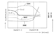
次に、第2外周面部分の深さHと、d軸インダクタンスLd、q軸インダクタンスLq、鉄損、銅損、効率の関係を、図3のグラフを参照して説明する。図3において、横軸は深さH(mm)を示し、縦軸は、インダクタンス(H)、鉄損(W)、銅損(W)および効率(%)が示されている。
図3から、d軸インダクタンスLdは、第2外周面部分120bの深さHに関係なくほぼ一定である。また、q軸インダクタンスLqは、深さHが深くなるに従って非線形に減少していく。また、銅損は、深さHが浅い領域では少ないが、深い領域において急激に増大する。また、鉄損は、中間領域において減少し、中間領域に前後において増大する。
ここで、d軸インダクタンスLdに対するq軸インダクタンスLqの比(Lq/Ld)と、銅損、鉄損および損失との関係を把握することができる。すなわち、比(Lq/Ld)が1.1より大きい領域では、鉄損が多いため、効率はよくない。そして、比(Lq/Ld)が1.1以下になると、銅損はほぼ同じであるが、鉄損が減少するため、効率が良くなっている。さらに、比(Lq/Ld)が、0.9より小さくなると、鉄損が増加するとともに、銅損も増加するため、効率が悪くなっている。
以上のことから、比(Lq/Ld)が、[0.9≦(Lq/Ld)≦1.1]の範囲内となるように設定することによって、効率を向上させることができることが理解できる。
Next, the relationship between the depth H of the second outer peripheral surface portion, the d-axis inductance Ld, the q-axis inductance Lq, the iron loss, the copper loss, and the efficiency will be described with reference to the graph of FIG. In FIG. 3, the horizontal axis indicates the depth H (mm), and the vertical axis indicates the inductance (H), iron loss (W), copper loss (W), and efficiency (%).
From FIG. 3, the d-axis inductance Ld is substantially constant regardless of the depth H of the second outer
Here, the relationship between the ratio of the q-axis inductance Lq to the d-axis inductance Ld (Lq / Ld) and the copper loss, iron loss, and loss can be grasped. That is, in the region where the ratio (Lq / Ld) is larger than 1.1, the iron loss is large, so the efficiency is not good. When the ratio (Lq / Ld) is 1.1 or less, the copper loss is substantially the same, but the iron loss is reduced, and the efficiency is improved. Furthermore, when the ratio (Lq / Ld) is smaller than 0.9, the iron loss increases and the copper loss also increases, resulting in poor efficiency.
From the above, it can be understood that the efficiency can be improved by setting the ratio (Lq / Ld) to be in the range of [0.9 ≦ (Lq / Ld) ≦ 1.1]. .
以上のように、d軸インダクタンスLdに対するq軸インダクタンスLqの比(Lq/Ld)は、[エアギャップG]、[磁石挿入孔(第1の磁石挿入孔131、第2の磁石挿入孔132)の幅W]および[第2外周面部分120bの深さH]によって規定されることが分かった。
また、d軸インダクタンスLdに対するq軸インダクタンスLqの比(Lq/Ld)が、[0.9≦(Lq/Ld)≦1.1]の範囲内となるように設定することによって、効率を向上させることができることが分かった。
したがって、[エアギャップG]、[磁石挿入孔(第1の磁石挿入孔131、第2の磁石挿入孔132)の幅W]と[第2外周面部分120bの深さH]を、d軸インダクタンスLdに対するq軸インダクタンスLqの比(Lq/Ld)が、[0.9≦(Lq/Ld)≦1.1]の範囲内となるよう設定することによって、効率を向上させることができる。
[エアギャップG]、[磁石挿入孔の幅W]と[第2外周面部分120bの深さH]を、(Lq/Ld)が[0.9≦(Lq/Ld)≦1.1]の範囲内となるように設定する方法としては、適宜の方法を用いることができる。例えば、先ず、エアギャップGを設定し、その後、(Lq/Ld)が[0.9≦(Lq/Ld)≦1.1]の範囲内となるように[磁石挿入孔の幅W]と[第2外周面部分120bの深さH]を設定する方法を用いることができる。
As described above, the ratio (Lq / Ld) of the q-axis inductance Lq to the d-axis inductance Ld is [air gap G], [magnet insertion hole (first
Further, the efficiency is improved by setting the ratio (Lq / Ld) of the q-axis inductance Lq to the d-axis inductance Ld to be in the range of [0.9 ≦ (Lq / Ld) ≦ 1.1]. I found out that
Therefore, [air gap G], [width W of magnet insertion hole (first
[Air gap G], [Width W of magnet insertion hole] and [Depth H of second outer
なお、永久磁石電動機のd軸インダクタンスLdやq軸インダクタンスLqを測定する方法としては、公知の種々の測定方法を用いることができる。例えば、「電気学会誌・論文誌D,第113巻,第11号,頁1330−1331,1993年」に記載されている測定方法を用いることができる。 In addition, as a method for measuring the d-axis inductance Ld and the q-axis inductance Lq of the permanent magnet motor, various known measurement methods can be used. For example, the measuring method described in “The Journal of the Institute of Electrical Engineers of Japan, Journal D, Vol. 113, No. 11, pages 1330-1331, 1993” can be used.
第1実施形態の永久磁石電動機100では、4極構造(極対数P=2)で、主磁極に、回転中心側に飛び出ているV字を構成するように磁石挿入孔を形成した回転子120を用いたが、回転子の極数や、主磁極に形成する磁石挿入孔の配置形状は種々変更可能である。
In the
第2実施形態の永久磁石電動機の回転子220が、図4に示されている。
図4に示されている回転子220は、6極構造(極対数P=3)で、主磁極に、回転中心側に飛び出ているV字を構成するように磁石挿入孔が形成されている。
回転子220の外周面は、d軸と交差する第1外周面部分220a、q軸と交差する第2外周面部分220b、接続部分220c、220dを有している。
回転子220には、第1実施形態の回転子120と同様に、直線状に延在する第1磁石挿入孔231と第2磁石挿入孔232が、d軸を挟んで両側に、回転中心O側に飛び出ているV字を構成するように形成されている。また、第1磁石挿入孔231と第2磁石挿入孔232に、断面が四角形状を有する第1永久磁石241と第2永久磁石242が挿入されている。また、第1実施形態の回転子120と同様に、中央に中央ブリッジ部が形成され、外周側に外周ブリッジ部が形成され、磁石挿入孔の両端部に空隙が形成されている。
The
The
The outer peripheral surface of the
Similar to the
第3実施形態の永久磁石電動機の回転子320が、図5に示されている。
図5に示されている回転子320は、4極構造(極対数P=2)で、主磁極に、d軸と交差する方向に直線状に延在するように磁石挿入孔が形成されている。
回転子320の外周面は、d軸と交差する第1外周面部分320a、q軸と交差する第2外周面部分320b、接続部分320c、320dを有している。
回転子320には、d軸と交差する方向、好適には、d軸と直交(「略直交」を含む)する方向に直線状に延在するように磁石挿入孔331が形成されている。また、磁石挿入孔331に、断面が四角形状を有する永久磁石341が挿入されている。また、外周側に外周ブリッジ部が形成され、磁石挿入孔の両端部に空隙が形成されている。
The
The
The outer peripheral surface of the
The
第4実施形態の永久磁石電動機の回転子420が、図6に示されている。
図6に示されている回転子420は、4極構造(極対数P=2)で、主磁極に、d軸と交差し、回転中心側に飛び出ている円弧形状に沿って延在するように磁石挿入孔が形成されている。
回転子420の外周面は、d軸と交差する第1外周面部分420a、q軸と交差する第2外周面部分420b、接続部分420c、420dを有している。
回転子420には、d軸と交差し、d軸上に中心点を有するとともに、回転中心側に飛び出ている円弧形状に沿って延在するように磁石挿入孔431が形成されている。また、磁石挿入孔431に、断面が円弧形状を有する永久磁石441が挿入されている。また、外周側に外周ブリッジ部が形成され、磁石挿入孔の両端部に空隙が形成されている。
The
The
The outer peripheral surface of the
In the
第5実施形態の永久磁石電動機の回転子520が、図7に示されている。
図7に示されている回転子520は、4極構造(極対数P=2)で、主磁極に、d軸と交差し、回転中心側に飛び出ている台形形状を構成するように磁石挿入孔が形成されている。
回転子520の外周面は、d軸と交差する第1外周面部分520a、q軸と交差する第2外周面部分350b、接続部分520c、520dを有している。
回転子520には、直線状に延在する第1〜第3磁石挿入孔541〜543が、d軸と交差し、回転中心側の飛び出ている台形形状を構成するように形成されている。また、第1〜第3磁石挿入孔531〜533に、断面が四角形状を有する第1〜第3永久磁石541〜543が挿入されている。また、第2磁石挿入孔542と第1磁石挿入孔541および第3磁石挿入孔543の間に中央ブリッジ部が形成され、外周側に外周ブリッジ部が形成され、第1磁石挿入孔531および第3磁石挿入孔533の両端部に空隙が形成されている。
The
The
The outer peripheral surface of the
In the
本発明は、実施形態で説明した構成に限定されず、種々の変更、追加、削除が可能である、
固定子のスロット数や回転子の極対数(極数)は、適宜変更可能である。
回転子の主磁極に形成される磁石挿入孔の形状、数や配置位置、磁石挿入孔に挿入される永久磁石の形状、数や挿入位置等は適宜変更可能である。
実施形態で説明した各構成は、単独で用いることもできるし、適宜選択した複数の構成を組み合わせて用いることもできる、
The present invention is not limited to the configuration described in the embodiment, and various changes, additions and deletions are possible.
The number of slots of the stator and the number of pole pairs (number of poles) of the rotor can be changed as appropriate.
The shape, number and arrangement position of the magnet insertion holes formed in the main magnetic pole of the rotor, the shape, number and insertion position of the permanent magnets inserted into the magnet insertion holes can be appropriately changed.
Each configuration described in the embodiment can be used alone, or a plurality of appropriately selected configurations can be used in combination.
100 電動機
110 固定子
111 ヨーク
112 ティース
113 ティース基部
114 ティース先端部
114a ティース先端面(固定子内周面)
115 スロット
120、220、320、420、520 回転子
120a、220a、320a、420a、520a 第1外周面部分
120b、220b、320b、420b、520b 第2外周面部分
120c、120d、220c、220d、320c、320d、420c、420d、520c、520d 接続部分
125 中央ブリッジ部
126、127 外周ブリッジ部
131、132、231、232、331、431、531、532、533 磁石挿入孔
131a、132a 内周側壁部
131b、132b 外周側壁部
131c、132c 内周側端壁部
131d、132d 外周側端壁部
131e、132e 連結用端壁部
131f、131g、132f、132g 空隙
141、142、241、242、341、441、541、542、543 永久磁石
141a、142a 内周壁
141b、142b 外周壁
141c、142c 内周側端壁
141d、142d 外周側端壁
210 内周面(回転子内周面)
D 回転子の直径
G 空隙(エアギャップ)
H 第2外周面部分のq軸上の深さ
W 磁石挿入孔の幅
DESCRIPTION OF
D Rotor diameter G Air gap
H Depth on q-axis of second outer peripheral surface portion W Width of magnet insertion hole
Claims (2)
前記固定子巻線は、前記複数のティースに集中巻き方式で巻き付けられており、
前記回転子の外周面は、前記主磁極のd軸と交差する第1外周面部分と、前記補助磁極のq軸と交差し、前記第1の外周面部分より径方向内側に形成されている第2外周面部分を有し、
前記回転子の直径Dは、[45mm≦D≦90mm]を満足するように設定され、
前記第1外周面部分と前記固定子内周面との間の距離Gは、[0.45mm≦G≦0.65mm]を満足するように設定され、
前記回転子の中心に対する前記第1外周面部分の開角度θ1は、[(50/P)度≦θ1≦(60/P)度](P:回転子の極対数)を満足するように設定され、
前記距離G、前記磁石挿入孔の幅Wおよび前記第1外周面部分と前記第2外周面部分との間のq軸上の距離Hは、d軸インダクタンスLdとq軸インダクタンスLqが、[0.9≦(Lq/Ld)≦1.1]を満足するように設定されていることを特徴とする永久磁石電動機。 The stator includes a stator and a rotor, and the stator includes a stator winding wound around a plurality of teeth arranged adjacent to each other in a circumferential direction, and a stator inner peripheral surface forming a stator inner space. And the rotor is rotatably arranged in the stator inner space, and main magnetic poles and auxiliary magnetic poles are alternately arranged along the circumferential direction, and a magnet insertion hole is formed in the main magnetic pole. A permanent magnet motor in which a permanent magnet is inserted into the magnet insertion hole,
The stator winding is wound around the plurality of teeth by a concentrated winding method,
The outer peripheral surface of the rotor intersects with the first outer peripheral surface portion intersecting the d-axis of the main magnetic pole and the q-axis of the auxiliary magnetic pole, and is formed radially inward from the first outer peripheral surface portion. Having a second outer peripheral surface portion;
The diameter D of the rotor is set to satisfy [45 mm ≦ D ≦ 90 mm],
A distance G between the first outer peripheral surface portion and the stator inner peripheral surface is set to satisfy [0.45 mm ≦ G ≦ 0.65 mm],
The opening angle θ1 of the first outer peripheral surface portion with respect to the center of the rotor is set so as to satisfy [(50 / P) degrees ≦ θ1 ≦ (60 / P) degrees] (P: the number of pole pairs of the rotor). And
The distance G, the width W of the magnet insertion hole, and the distance H on the q-axis between the first outer peripheral surface portion and the second outer peripheral surface portion are set such that the d-axis inductance Ld and the q-axis inductance Lq are [0 .9 ≦ (Lq / Ld) ≦ 1.1], the permanent magnet motor is characterized in that it is set.
前記回転子の外周面は、前記第1外周面部分と前記第2外周面部分との間に、直線状に延在する接続部分を有することを特徴とする永久磁石電動機。 The permanent magnet motor according to claim 1,
The outer peripheral surface of the rotor has a connecting portion extending linearly between the first outer peripheral surface portion and the second outer peripheral surface portion.
Priority Applications (1)
| Application Number | Priority Date | Filing Date | Title |
|---|---|---|---|
| JP2018070432A JP6869918B2 (en) | 2018-03-30 | 2018-03-30 | Permanent magnet motor |
Applications Claiming Priority (1)
| Application Number | Priority Date | Filing Date | Title |
|---|---|---|---|
| JP2018070432A JP6869918B2 (en) | 2018-03-30 | 2018-03-30 | Permanent magnet motor |
Publications (2)
| Publication Number | Publication Date |
|---|---|
| JP2019186972A true JP2019186972A (en) | 2019-10-24 |
| JP6869918B2 JP6869918B2 (en) | 2021-05-12 |
Family
ID=68341794
Family Applications (1)
| Application Number | Title | Priority Date | Filing Date |
|---|---|---|---|
| JP2018070432A Active JP6869918B2 (en) | 2018-03-30 | 2018-03-30 | Permanent magnet motor |
Country Status (1)
| Country | Link |
|---|---|
| JP (1) | JP6869918B2 (en) |
Cited By (1)
| Publication number | Priority date | Publication date | Assignee | Title |
|---|---|---|---|---|
| JP2022535245A (en) * | 2019-12-11 | 2022-08-05 | 安徽美芝精密制造有限公司 | motors, compressors and refrigerators |
Citations (5)
| Publication number | Priority date | Publication date | Assignee | Title |
|---|---|---|---|---|
| JP2001211582A (en) * | 2000-01-26 | 2001-08-03 | Fujitsu General Ltd | Permanent magnet motor |
| JP2007159197A (en) * | 2005-12-01 | 2007-06-21 | Aichi Elec Co | Permanent magnet rotating machine |
| WO2013065275A1 (en) * | 2011-11-01 | 2013-05-10 | パナソニック株式会社 | Rotor for motor and motor provided with same |
| JP2016015819A (en) * | 2014-07-02 | 2016-01-28 | 株式会社ミツバ | Electric power steering system |
| US20170294813A1 (en) * | 2016-04-12 | 2017-10-12 | Samsung Electronics Co., Ltd. | Interior permanent magnet motor |
-
2018
- 2018-03-30 JP JP2018070432A patent/JP6869918B2/en active Active
Patent Citations (5)
| Publication number | Priority date | Publication date | Assignee | Title |
|---|---|---|---|---|
| JP2001211582A (en) * | 2000-01-26 | 2001-08-03 | Fujitsu General Ltd | Permanent magnet motor |
| JP2007159197A (en) * | 2005-12-01 | 2007-06-21 | Aichi Elec Co | Permanent magnet rotating machine |
| WO2013065275A1 (en) * | 2011-11-01 | 2013-05-10 | パナソニック株式会社 | Rotor for motor and motor provided with same |
| JP2016015819A (en) * | 2014-07-02 | 2016-01-28 | 株式会社ミツバ | Electric power steering system |
| US20170294813A1 (en) * | 2016-04-12 | 2017-10-12 | Samsung Electronics Co., Ltd. | Interior permanent magnet motor |
Cited By (1)
| Publication number | Priority date | Publication date | Assignee | Title |
|---|---|---|---|---|
| JP2022535245A (en) * | 2019-12-11 | 2022-08-05 | 安徽美芝精密制造有限公司 | motors, compressors and refrigerators |
Also Published As
| Publication number | Publication date |
|---|---|
| JP6869918B2 (en) | 2021-05-12 |
Similar Documents
| Publication | Publication Date | Title |
|---|---|---|
| JP5757281B2 (en) | Rotating electrical machine rotor | |
| US9444295B2 (en) | Rotor of permanent magnet motor | |
| US8502430B2 (en) | Rotor and motor | |
| CN109716633B (en) | Rotor and reluctance motor | |
| EP2903138B1 (en) | Rotor and rotary electric machine | |
| US20150069874A1 (en) | Rotating electric machine rotor | |
| CN108777520B (en) | Alternating-pole motor | |
| US10862357B2 (en) | Permanent-magnet-embedded electric motor, blower, and refrigerating air conditioner | |
| JP2017050965A (en) | Rotor structure for rotary electric machine | |
| JP6869918B2 (en) | Permanent magnet motor | |
| JP2017055560A (en) | Permanent magnet type rotary electric machine | |
| JP2011199946A (en) | Permanent magnet embedded rotor for rotary electric machine, and rotary electric machine | |
| JP2015171272A (en) | Permanent magnet embedded motor and hermetic electric compressor using the same | |
| JP7180992B2 (en) | permanent magnet motor | |
| JP6428458B2 (en) | Embedded magnet type motor | |
| KR102532060B1 (en) | Rotors, Motors and Compressors | |
| JP7401380B2 (en) | permanent magnet electric motor | |
| JP7401381B2 (en) | permanent magnet electric motor | |
| JPH0720050U (en) | Permanent magnet type synchronous motor rotor | |
| JP6886994B2 (en) | Permanent magnet motor | |
| US11404925B2 (en) | Permanent magnet motor | |
| US10581286B2 (en) | Permanent-magnet-embedded electric motor and compressor | |
| JP6585974B2 (en) | Permanent magnet motor | |
| JP2015070768A (en) | Permanent magnet type electric rotating machine | |
| JP2021164325A (en) | Permanent magnet motor |
Legal Events
| Date | Code | Title | Description |
|---|---|---|---|
| A621 | Written request for application examination |
Free format text: JAPANESE INTERMEDIATE CODE: A621 Effective date: 20200323 |
|
| RD02 | Notification of acceptance of power of attorney |
Free format text: JAPANESE INTERMEDIATE CODE: A7422 Effective date: 20200323 |
|
| A711 | Notification of change in applicant |
Free format text: JAPANESE INTERMEDIATE CODE: A712 Effective date: 20200630 |
|
| A977 | Report on retrieval |
Free format text: JAPANESE INTERMEDIATE CODE: A971007 Effective date: 20210120 |
|
| A131 | Notification of reasons for refusal |
Free format text: JAPANESE INTERMEDIATE CODE: A131 Effective date: 20210202 |
|
| A521 | Request for written amendment filed |
Free format text: JAPANESE INTERMEDIATE CODE: A523 Effective date: 20210329 |
|
| TRDD | Decision of grant or rejection written | ||
| A01 | Written decision to grant a patent or to grant a registration (utility model) |
Free format text: JAPANESE INTERMEDIATE CODE: A01 Effective date: 20210406 |
|
| A61 | First payment of annual fees (during grant procedure) |
Free format text: JAPANESE INTERMEDIATE CODE: A61 Effective date: 20210414 |
|
| R150 | Certificate of patent or registration of utility model |
Ref document number: 6869918 Country of ref document: JP Free format text: JAPANESE INTERMEDIATE CODE: R150 |
|
| R250 | Receipt of annual fees |
Free format text: JAPANESE INTERMEDIATE CODE: R250 |