JP2019184002A - Ball valve, beverage supply system with ball valve and cleaning method for pipe conduit connected to ball valve - Google Patents
Ball valve, beverage supply system with ball valve and cleaning method for pipe conduit connected to ball valve Download PDFInfo
- Publication number
- JP2019184002A JP2019184002A JP2018077622A JP2018077622A JP2019184002A JP 2019184002 A JP2019184002 A JP 2019184002A JP 2018077622 A JP2018077622 A JP 2018077622A JP 2018077622 A JP2018077622 A JP 2018077622A JP 2019184002 A JP2019184002 A JP 2019184002A
- Authority
- JP
- Japan
- Prior art keywords
- valve
- ball valve
- inlet
- beverage
- outlet
- Prior art date
- Legal status (The legal status is an assumption and is not a legal conclusion. Google has not performed a legal analysis and makes no representation as to the accuracy of the status listed.)
- Granted
Links
Images


Abstract
Description
本発明は、液体流路の開閉に適したボール弁、ボール弁を含む飲料供給システム及びボール弁に接続された管路の洗浄方法に関する。 The present invention relates to a ball valve suitable for opening and closing a liquid flow path, a beverage supply system including the ball valve, and a method for cleaning a pipe line connected to the ball valve.
従来、特許文献1で示されるような、流路の開閉に用いられるボール弁が知られている。ボール弁は、主要構成要素として、内部に貫通流路を有する球状の弁体、弁体を収容する弁箱、弁体と弁箱との間のシールのためのリング状弁座、及び弁体を回転させるためのステムやハンドル等を具備する。弁体には、流路を構成する、直線状、L字状、又はT字状の貫通穴が設けられる。 Conventionally, a ball valve used for opening and closing a flow path as shown in Patent Document 1 is known. The ball valve includes, as main components, a spherical valve body having a through-flow passage therein, a valve box that accommodates the valve body, a ring-shaped valve seat for sealing between the valve body and the valve body, and a valve body A stem, a handle, and the like for rotating the handle are provided. The valve body is provided with a straight, L-shaped, or T-shaped through hole that constitutes the flow path.
ボール弁のリング状弁座が摩耗あるいは破損したりして、弁体と弁箱との間のシールが不完全になると、流路が閉鎖されるべきときにも、流体がボール弁の上流側から下流側に漏れ出てしまう。流れるべきでないときに流体がボール弁の下流側の管路に流れると、当然、様々な問題が引き起こされる。例えば、下流側の管路に他の種類の流体用の管路が合流するような場合、漏出した流体が他の種類の流体に混入するという問題が起こる。また、流体の漏れ量が少ない場合には、漏出および混入の発見が遅れるという問題も抱えている。 If the ring valve seat of the ball valve is worn or damaged and the seal between the valve disc and the valve box is incomplete, fluid will flow upstream of the ball valve even when the flow path should be closed. Leaks to the downstream side. Naturally, various problems are caused when fluid flows into the conduit downstream of the ball valve when it should not flow. For example, when a pipe line for another type of fluid joins the pipe line on the downstream side, there arises a problem that the leaked fluid is mixed into another type of fluid. In addition, when the amount of fluid leakage is small, there is a problem that discovery of leakage and contamination is delayed.
本発明は、上述の事情に鑑みてなされたものであって、弁座等の不良による閉弁時の下流側への流体の流出を防止するとともに、弁座等の不良の検知を容易にするボール弁を提供することを目的とする。 The present invention has been made in view of the above-described circumstances, and prevents outflow of fluid to the downstream side when the valve is closed due to a failure of the valve seat or the like, and facilitates detection of a failure of the valve seat or the like. An object is to provide a ball valve.
前述の目的を達成するために、本発明の第1の態様によれば、ボール弁であって、貫通流路を有する球状の弁体と、開弁時に弁体の貫通流路に整列される流入口及び流出口を有するとともに、弁体を収容する内部空間を画成する弁箱と、流入口を取り囲む入口弁座と、流出口を取り囲む出口弁座と、を具備し、弁箱が、内部空間に連通するとともに入口弁座と出口弁座との間に配置されたドレン孔を更に有するボール弁が提供される。 In order to achieve the above-mentioned object, according to the first aspect of the present invention, a ball valve, which is a spherical valve body having a through passage, is aligned with the through passage of the valve body when the valve is opened. A valve box having an inlet and an outlet and defining an internal space for accommodating the valve body; an inlet valve seat surrounding the inlet; and an outlet valve seat surrounding the outlet; A ball valve is provided that further communicates with the interior space and further has a drain hole disposed between the inlet valve seat and the outlet valve seat.
更に、本発明の第2の態様によれば、弁箱が流出口の下流側に更に第2の流入口を有する第1の態様によるボール弁と、ボール弁の流入口の上流側に流体接続される洗浄液供給源と、発泡性飲料の貯蔵容器と、発泡性飲料の貯蔵容器に装着されるディスペンスヘッドであって、ボール弁の第2の流入口に連結される発泡性飲料の吐出端を有するディスペンスヘッドと、ボール弁及びディスペンスヘッドの下流側に延びる飲料供給管路と、飲料供給管路の末端出口を開閉する弁を有する飲料ディスペンサとを具備する発泡性飲料供給システムが提供される。 Further, according to the second aspect of the present invention, the ball valve according to the first aspect in which the valve box further has the second inlet on the downstream side of the outlet, and the fluid connection on the upstream side of the inlet of the ball valve. A cleaning liquid supply source, a sparkling beverage storage container, and a dispensing head attached to the sparkling beverage storage container, the discharge end of the sparkling beverage connected to the second inlet of the ball valve There is provided a sparkling beverage supply system comprising: a dispensing head having a ball valve and a beverage supply line extending downstream of the dispense head; and a beverage dispenser having a valve for opening and closing a terminal outlet of the beverage supply line.
更に、本発明の第3の態様によれば、ボール弁の流出口の下流側に接続される管路を洗浄する方法であって、ボール弁を閉弁する段階と、洗浄スポンジを閉弁状態のボール弁の弁体の貫通流路に挿入する段階と、ボール弁を開弁する段階と、ボール弁の流入口に洗浄液を供給する段階と、を含んでおり、洗浄液を供給する段階において、洗浄スポンジが管路内を洗浄液とともに移動することによって管路を洗浄する、管路を洗浄する方法が提供される。 Furthermore, according to the third aspect of the present invention, there is provided a method of cleaning a pipe line connected to the downstream side of the outlet of the ball valve, the step of closing the ball valve, and the cleaning sponge being closed The step of inserting into the through passage of the valve body of the ball valve, the step of opening the ball valve, and the step of supplying the cleaning liquid to the inlet of the ball valve, and the step of supplying the cleaning liquid, A method is provided for cleaning a conduit, wherein the cleaning sponge moves the interior of the conduit along with the cleaning liquid to clean the conduit.
本発明の第1の態様によると、ドレン孔を介して、入口弁座及び/又は出口弁座の摩耗あるいは破損等によって弁箱の内部空間に侵入した流体の外部への排出が促進される。そして、流体が液体である場合には、ドレン孔から排出される液体は、人が視認可能であるので、それによりボール弁の異常を察知することが可能になる。 According to the first aspect of the present invention, the drainage of the fluid that has entered the internal space of the valve box due to wear or damage of the inlet valve seat and / or the outlet valve seat through the drain hole is promoted. When the fluid is a liquid, the liquid discharged from the drain hole can be visually recognized by the person, so that it is possible to detect an abnormality of the ball valve.
また、入口弁座と出口弁座の両方に摩耗や破損等の問題が生じていた場合でも、上流側の流体が、閉弁時に、流出口から下流側に流出することは、回避されるかあるいは従来タイプのボール弁に比較して少なくとも低減される。それは、通常は大気圧より高い圧力を有するボール弁の上流側及び下流側に存在する流体はドレン孔から低圧の外部へ流出するからである。 Also, even if problems such as wear or damage occur in both the inlet valve seat and the outlet valve seat, is it possible to prevent the upstream fluid from flowing out from the outlet when the valve is closed? Or it is reduced at least compared with the ball valve of the conventional type. This is because the fluid existing on the upstream side and the downstream side of the ball valve that normally has a pressure higher than the atmospheric pressure flows out from the drain hole to the low pressure outside.
本発明の第2の態様によると、本発明の第1の態様による効果に加えて、洗浄のためにディスペンスヘッドやボール弁を管路から取り外すことなく、換言すると、ディスペンスヘッドやボール弁の操作レバーを切り替えるだけで、飲料供給管路の水等による洗浄及びスポンジ洗浄が可能になるという効果が得られる。 According to the second aspect of the present invention, in addition to the effect according to the first aspect of the present invention, the dispensing head and the ball valve are not removed from the pipe line for cleaning, in other words, the operation of the dispensing head and the ball valve. By simply switching the lever, the beverage supply line can be washed with water or the like and sponge washed.
本発明の第3の態様によると、本発明の第1の態様による効果に加えて、スポンジ洗浄のためにボール弁を管路から取り外すことなく、換言すると、ボール弁の操作レバーを切り替えるだけで、ボール弁に接続された管路のスポンジ洗浄が可能になるという効果が得られる。 According to the third aspect of the present invention, in addition to the effect of the first aspect of the present invention, the ball valve is not removed from the conduit for cleaning the sponge, in other words, only by switching the operation lever of the ball valve. In addition, it is possible to obtain an effect that the sponge connected to the ball valve can be cleaned.
本発明の第1の実施形態によるボール弁10について、図1を参照して以下に説明する。図1の(a)はボール弁10の閉弁状態を示し、図1の(b)は、閉弁状態から弁体12が90度回動した開弁状態を示している。
A
ボール弁10は、真っ直ぐに伸びる貫通流路11を有する球状の弁体12と、流入口13及び流出口14を有すると共に弁体12を収容する内部空間15を画成する弁箱16と、流入口13を取り囲むリング状の入口弁座17と、流出口14を取り囲むリング状の出口弁座18と、図示しないハンドルとを有する。弁体12は、図1の紙面に垂直な方向に延びる回転軸線Axを中心に90度の範囲で回動可能に弁箱16によって支持されて、その回動はハンドルの操作によって行われる。
The
弁箱16の流入口13及び流出口14は、それぞれ入口弁座17及び出口弁座18に隣接する部分を指している。流入口13よりも上流側に弁箱16の入口端部21が、及び流出口14よりも下流側に弁箱16の出口端部22が設けられている。入口端部21及び出口端部22は、他の管路やホースの継手との接続が可能な継手として形成されている。
The
本実施形態によるボール弁10の弁箱16は更に、弁箱16の内部空間15を外部に連通させるドレン孔19を、入口弁座17と出口弁座18との間の上面に有する。ドレン孔19は、閉弁時の弁体12の貫通流路11に整列するように配置されている。また、ドレン孔19と弁体12との間にはリング状の弁座やパッキンが配置されることはなく、したがって隙間が生じている。
The
このようなドレン孔19が設けられているので、第1の実施形態によるボール弁においては、入口弁座17及び/又は出口弁座18の摩耗あるいは破損等が生じた場合には、流入口あるいは流出口から弁箱16の内部空間15に侵入した流体がドレン孔19を介して外部へ速やかに排出される。そして、流体が液体である場合には、ドレン孔19から排出される液体を人が視認できるので、それによりボール弁10の異常を察知することが可能になる。
Since such a
また、入口弁座17と出口弁座18の両方に摩耗や破損等の問題が生じていた場合でも、上流側の流体が、閉弁時に、流出口14から下流側に流出することは、回避されるか、あるいは従来タイプのボール弁に比較して少なくとも低減される。それは、通常は大気圧より高い圧力を有するボール弁10の上流側及び下流側に存在する流体はドレン孔19から低圧の外部へ流出するからである。
Further, even when problems such as wear or breakage occur in both the
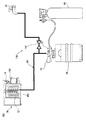
次に、第1の実施形態によるボール弁10に類似のボール弁110を構成要素として含む、第2の実施形態による飲料供給システム100について図2、図3A、図3B、及び図4を参照して以下に説明する。この飲料供給システム100は、ガスの圧力を利用して飲料貯蔵容器30内の飲料を注出するように、及び飲料供給管路の洗浄を可能とするように構成されている。そのため、飲料供給システム100は、ボール弁110と、飲料貯蔵容器30と、飲料貯蔵容器30の口部の内部に固定されたスピアバルブ40(図3A、図3Bでその一部が示される)と、スピアバルブ40に外部から連結されたディスペンスヘッド50と、飲料貯蔵容器30にガスを供給するガスボンベ60と、飲料貯蔵容器30からの飲料をグラス等に注出する飲料ディスペンサ70と、ボール弁110の上流側に流体接続される洗浄液供給源80と、ボール弁110及びディスペンスヘッド50の下流側に接続される飲料供給管路90とを主要構成要素として具備する。洗浄液供給源80はこの例では水道の給水栓80であり、したがって後述する洗浄時には水道水が洗浄液として供給される。
Next, referring to FIG. 2, FIG. 3A, FIG. 3B, and FIG. 4, a
図2の飲料供給システム100においては、供給される飲料がビールであり、そのためガスボンベ60に充填されるガスは炭酸ガスであり、飲料貯蔵容器30はビール樽として例示され、また飲料ディスペンサ70はビールディスペンサとして例示されている。ただし、本発明の実施形態による飲料供給システム100は、ビール以外の任意の炭酸飲料、例えば発泡酒、麦芽以外の原料から作成されていて別のアルコール飲料が混入されたビール風味の発泡アルコール飲料(第三のビール)、ノンアルコールビール、チューハイ、ハイボール、あるいは非アルコール系炭酸飲料を供給するものであってもよい。また、飲料供給システム100により供給される飲料が、炭酸ガス以外の例えば窒素ガスや圧縮空気を利用して供給される飲料であってもよく、その場合、ガスボンベ60内には窒素ガスあるいは圧縮空気が充填される。
In the
ところで、特に供給すべき飲料がビールである場合、飲料供給システム100はその飲料供給管路90を比較的頻繁に、例えば毎日1回、洗浄することが求められる。そのため、第2の実施形態による飲料供給システム100は、飲料供給管路90の水洗浄、及び指先程の大きさの円錐台状のスポンジ片である洗浄スポンジ105(図4)を併用した水・スポンジ洗浄(以下、「スポンジ洗浄」という)が可能であるように構成されている。詳しくは後述するが、第2の実施形態におけるボール弁110は、飲料供給管路90の水洗浄及びスポンジ洗浄を容易にするように配置構成されている。
By the way, especially when the beverage to be supplied is beer, the
第2の実施形態におけるボール弁110は、図3A、Bに示されるように、その弁箱116が、流出口14から下流側に延びる下流側管路116aを一体的に有していることにおいて第1の実施形態によるボール弁10と異なっているが、その他の構成については第1の実施形態によるボール弁10と同様である。即ち、第2の実施形態におけるボール弁110は、第1の実施形態によるボール弁10と同様の弁体12、入口弁座17,出口弁座18,流入口13,流出口14、ドレン孔19を具備する。下流側管路116aの図の右端部に出口端部22が形成される。下流側管路116aには第2の流入口123が設けられている。第2の流入口123にはディスペンスヘッド50の吐出端51が接続される。
As shown in FIGS. 3A and 3B, the
ただし、第2の実施形態による飲料供給システム100に第1の実施形態によるボール弁10を用いることも可能である。その場合、下流側管路116aに替えて、別個のT字継手が用いられ、それにより図3A等と同様の流路が構成可能である。
However, it is also possible to use the
飲料ディスペンサ70は、公知の一般的なものであって、飲料供給管路90の末端出口を開閉するコック式の飲料注出弁(以下「コック弁」という)71を有する。飲料注出時にはコック弁71の吐出口の下方にグラス等(不図示)が、あるいは洗浄時にはバケツ108が準備される。飲料供給管路90は、飲料ディスペンサ70内での冷却のために円筒コイル状に成形された螺旋巻回部90aを有する。螺旋巻回部90aは、飲料ディスペンサ70の冷却装置72を使って冷却される。
The
ディスペンスヘッド50及びスピアバルブ40も、公知の一般的なものであるので、その作用のみを簡単に説明するに留める。なお、スピアバルブ40は、その上端部のみが図3A及び図3Bに示されている。ディスペンスヘッド50は開放位置と閉鎖位置を取ることができる操作レバー52を有している。ディスペンスヘッド50は、操作レバー52が開放位置に配置されたとき、スピアバルブ40と協働して炭酸ガスボンベ60から炭酸ガスを飲料貯蔵容器30内に導入すると共に、飲料(ビール)の吐出流路を開放する。したがって、その状態のとき飲料ディスペンサ70のコック弁71が開弁されると、飲料が、炭酸ガスの圧力に押されて飲料貯蔵容器30からディスペンスヘッド50の吐出端51及び飲料供給管路90をとおって飲料ディスペンサ70に供給される(図3A)。またこのときには、給水栓80からの水道水が飲料供給管路90に流入することがないように、ボール弁110は閉弁されている。
Since the dispensing
ディスペンスヘッド50は、操作レバー52が閉鎖位置に配置されたとき、スピアバルブ40と協働して飲料貯蔵容器30内に通じるガス流路を閉鎖すると共に、飲料(ビール)の吐出流路も閉鎖する。飲料供給管路90を水洗浄するときには、ディスペンスヘッド50の操作レバー52を閉鎖位置に配置してからボール弁110及び飲料ディスペンサ70のコック弁71を開弁する。そうすると、給水栓80からの水がボール弁110を経由して飲料供給管路90に流入してそれが洗浄される(図3B参照)。洗浄水は、ディスペンスヘッド50の操作レバー52が閉鎖位置に配置されているので飲料貯蔵容器30内へ流入することはない。なお、本実施形態では、ディスペンスヘッド50は逆流防止用の弁体53も備えているので洗浄水の飲料貯蔵容器30内への流入は二重に阻止される。
The dispensing
飲料供給管路90のスポンジ洗浄を実施するときには、やはりディスペンスヘッド50の操作レバー52を閉鎖位置に配置し、次いで洗浄スポンジ105を閉弁状態のボール弁110のドレン孔19から弁体12の貫通流路11に挿入して、ボール弁110を開弁する(図4の(a)、(b)参照)。最後に飲料ディスペンサ70のコック弁71を開弁する。すると、ボール弁110の流入口13に作用する水の圧力によって、洗浄スポンジ105がボール弁110から水と共に下流側に押し出され飲料供給管路90を通って最終的にはコック弁71から、その下に準備された洗浄用のバケツに排出される。洗浄スポンジ105は、飲料供給管路90の内壁に付着した汚れ等をこすり落とせるように、その外径が飲料供給管路90の内径よりも若干大きく作られている。また、ボール弁110のドレン孔19及び貫通流路11の内径は洗浄スポンジ105の挿入が可能な大きさで作られている。
When performing the sponge cleaning of the
水洗浄あるいはスポンジ洗浄が終わった後にガスボンベ60からのガスを利用して飲料供給管路90の乾燥を行う実施形態も可能である。その場合のディスペンスヘッド50は、操作レバー52を開放位置と、閉鎖位置と、その間の中間位置とに選択的に配置することができるように構成される。操作レバー52が中間位置に配置されると、ガスボンベ60からのガスは、飲料貯蔵容器30内に導入されることなく、つまり飲料貯蔵容器30を迂回してディスペンスヘッド50から吐出される。
An embodiment in which the
ところで、従来公知の飲料供給システムでは、その飲料供給管路を水洗浄やスポンジ洗浄する場合には、ディスペンスヘッドを飲料貯蔵容器から外して洗浄用の加圧可能な水容器に付け替え、洗浄後に飲料貯蔵容器にまた付け替える必要があり、そのため洗浄実施者に大きな負担が生じていた。そのようなディスペンスヘッドの付け替えを不要にした飲料供給システムも従来知られているが、それは電気的なセンサーやコントローラを含んだ複雑なシステムであるため一般に普及しているとは言い難い。 By the way, in a conventionally known beverage supply system, when the beverage supply line is washed with water or sponge, the dispensing head is removed from the beverage storage container and replaced with a pressurizable water container for washing. It was necessary to replace the storage container again, which caused a heavy burden on the cleaning operator. A beverage supply system that eliminates the need for changing the dispense head is also known in the art, but it is difficult to say that it is generally popular because it is a complex system that includes an electrical sensor and a controller.
これに対して、第2の実施形態による飲料供給システム100によると、ボール弁110を利用した簡易な構成であるものの、ディスペンスヘッド50を飲料貯蔵容器30から取り外すことなく飲料供給管路90を水洗浄及びスポンジ洗浄をすることが可能になる。また、閉弁状態のボール弁110のドレン孔19を介して洗浄スポンジ105を装填可能であることも特筆される。これにより、飲料供給システム100では、ディスペンスヘッド50及びボール弁110の操作レバーを切り替えるだけで、飲料供給モードと洗浄モードとを切り替えることが可能になる。
On the other hand, according to the
さらに、ボール弁110の入口弁座17及び/又は出口弁座18の摩耗や破損が生じた場合には、ディスペンスヘッド50に一体的に連結されたボール弁110のドレン孔19から水あるいは飲料が漏れ出るので、ディスペンスヘッド50の操作者はボール弁110の異常を容易に発見できるであろう。
Furthermore, when the
また、ボール弁110の入口弁座17及び/又は出口弁座18の摩耗や破損が生じた場合でも、ボール弁110の閉弁状態において、その上流側の流体である水が下流側の流体である飲料(ビール)に混入することはない。というのも、ガスボンベ60の炭酸ガスによって加圧された飲料は、上流側の水よりも通常は高い圧力を有するので、上流側の水は、ドレン孔19を介して相対的に低圧の周囲環境へ流れ出るからである。
Even when the
その他の実施形態
第1の実施形態によるボール弁110は二方弁であったが、ボール弁が三方弁からなる実施形態も本発明において可能である。その場合にも、ドレン孔19は一箇所設ければよい。
Other Embodiments Although the
本発明のボール弁の効果を、飲料供給システムを例にして説明した。しかし、本発明のボール弁は、飲料供給システムに限らず、従来のボール弁が適用される場面において活用することも可能であることは言うまでもない。例えば、飲料の生産設備において適用した場合においても、弁座等の不良による閉弁時の下流側への流体の流出を防止するとともに、弁座等の不良の検知を容易にする効果が発揮されるため、迅速なメンテナンスと設備トラブルの防止に繋がる。 The effect of the ball valve of the present invention has been described using a beverage supply system as an example. However, it goes without saying that the ball valve of the present invention can be used not only in a beverage supply system but also in a scene where a conventional ball valve is applied. For example, even when applied to a beverage production facility, it is possible to prevent the outflow of fluid to the downstream side when the valve is closed due to a failure of the valve seat or the like, and to easily detect the failure of the valve seat or the like. Therefore, it leads to quick maintenance and prevention of equipment troubles.
10 ボール弁
11 貫通流路
12 弁体
13 流入口
14 流出口
15 内部空間
16 弁箱
17 入口弁座
18 出口弁座
19 ドレン孔
21 入口端部
22 出口端部
DESCRIPTION OF
Claims (6)
貫通流路を有する球状の弁体と、
開弁時に前記弁体の前記貫通流路に整列される流入口及び流出口を有するとともに、前記弁体を収容する内部空間を画成する弁箱と、
前記流入口を取り囲む入口弁座と、前記流出口を取り囲む出口弁座と、
を具備し、
前記弁箱が、前記内部空間に連通するとともに前記入口弁座と前記出口弁座との間に配置されたドレン孔を更に有することを特徴とするボール弁。 A ball valve,
A spherical valve body having a through channel;
A valve box having an inlet and an outlet aligned with the through-flow passage of the valve body when the valve is opened, and defining an internal space for accommodating the valve body;
An inlet valve seat surrounding the inlet, an outlet valve seat surrounding the outlet,
Comprising
The valve valve further includes a drain hole that communicates with the internal space and is disposed between the inlet valve seat and the outlet valve seat.
前記ボール弁の前記流入口の上流側に流体接続される洗浄液供給源と、
発泡性飲料の貯蔵容器と、
前記発泡性飲料の前記貯蔵容器に装着されるディスペンスヘッドであって、前記ボール弁の前記第2の流入口に連結される前記発泡性飲料の吐出端を有するディスペンスヘッドと、
前記ボール弁及び前記ディスペンスヘッドの下流側に延びる飲料供給管路と、
前記飲料供給管路の末端出口を開閉する弁を有する飲料ディスペンサと、
を具備する発泡性飲料供給システム。 A ball valve according to claim 3;
A cleaning liquid supply source fluidly connected to the upstream side of the inlet of the ball valve;
A storage container for sparkling beverages;
A dispensing head attached to the storage container for the sparkling beverage, the dispensing head having a discharge end for the sparkling beverage connected to the second inlet of the ball valve;
A beverage supply line extending downstream of the ball valve and the dispensing head;
A beverage dispenser having a valve for opening and closing the end outlet of the beverage supply line;
A sparkling beverage supply system comprising:
前記ボール弁の前記弁箱の前記ドレン孔及び前記弁体の前記貫通流路は、前記洗浄スポンジの挿入を可能にする内径を有する、請求項4に記載の発泡性飲料供給システム。 It further comprises as an accessory a cleaning sponge that is inserted into the beverage supply line when cleaning the beverage supply line,
5. The sparkling beverage supply system according to claim 4, wherein the drain hole of the valve box of the ball valve and the through passage of the valve body have an inner diameter that allows the cleaning sponge to be inserted.
前記ボール弁を閉弁する段階と、
洗浄スポンジを閉弁状態の前記ボール弁の弁体の貫通流路に挿入する段階と、
前記ボール弁を開弁する段階と、
前記ボール弁の流入口に洗浄液を供給する段階と、を含んでおり、
前記洗浄液を供給する前記段階において、前記洗浄スポンジが前記管路内を洗浄液とともに移動することによって前記管路を洗浄する、管路を洗浄する方法。 A method for cleaning a pipe connected to a downstream side of an outlet of a ball valve,
Closing the ball valve;
Inserting a cleaning sponge into the through passage of the valve body of the ball valve in a closed state;
Opening the ball valve;
Supplying a cleaning liquid to the inlet of the ball valve,
A method for cleaning a pipe line, wherein, in the step of supplying the cleaning liquid, the cleaning sponge moves the inside of the pipe line together with the cleaning liquid to clean the pipe line.
Priority Applications (1)
| Application Number | Priority Date | Filing Date | Title |
|---|---|---|---|
| JP2018077622A JP7018813B2 (en) | 2018-04-13 | 2018-04-13 | A ball valve, a beverage supply system including a ball valve, and a method for cleaning a pipeline connected to the ball valve. |
Applications Claiming Priority (1)
| Application Number | Priority Date | Filing Date | Title |
|---|---|---|---|
| JP2018077622A JP7018813B2 (en) | 2018-04-13 | 2018-04-13 | A ball valve, a beverage supply system including a ball valve, and a method for cleaning a pipeline connected to the ball valve. |
Publications (2)
| Publication Number | Publication Date |
|---|---|
| JP2019184002A true JP2019184002A (en) | 2019-10-24 |
| JP7018813B2 JP7018813B2 (en) | 2022-02-14 |
Family
ID=68340483
Family Applications (1)
| Application Number | Title | Priority Date | Filing Date |
|---|---|---|---|
| JP2018077622A Active JP7018813B2 (en) | 2018-04-13 | 2018-04-13 | A ball valve, a beverage supply system including a ball valve, and a method for cleaning a pipeline connected to the ball valve. |
Country Status (1)
| Country | Link |
|---|---|
| JP (1) | JP7018813B2 (en) |
Cited By (2)
| Publication number | Priority date | Publication date | Assignee | Title |
|---|---|---|---|---|
| CN113983193A (en) * | 2021-08-16 | 2022-01-28 | 凯斯通阀门有限公司 | Novel ball valve |
| WO2023176990A1 (en) * | 2022-03-15 | 2023-09-21 | 강성하 | Easily cleanable draft beer dispensing system |
Citations (6)
| Publication number | Priority date | Publication date | Assignee | Title |
|---|---|---|---|---|
| JPS62166373U (en) * | 1986-04-11 | 1987-10-22 | ||
| JPH0266774U (en) * | 1988-11-02 | 1990-05-21 | ||
| JPH0281974U (en) * | 1988-12-13 | 1990-06-25 | ||
| JPH0559061U (en) * | 1991-04-18 | 1993-08-03 | 株式会社ケイヴイシー | Ball valve |
| JPH09156698A (en) * | 1995-12-06 | 1997-06-17 | Fuji Electric Co Ltd | Beverage supply device |
| JP2001233398A (en) * | 2000-02-23 | 2001-08-28 | Tsuneaki Yoshimura | Dispenser for draft beer |
Family Cites Families (1)
| Publication number | Priority date | Publication date | Assignee | Title |
|---|---|---|---|---|
| NL1032098C2 (en) | 2006-06-30 | 2008-01-02 | Heineken Supply Chain Bv | Tapping device, beverage container, coupling device and method with cleaning element. |
-
2018
- 2018-04-13 JP JP2018077622A patent/JP7018813B2/en active Active
Patent Citations (6)
| Publication number | Priority date | Publication date | Assignee | Title |
|---|---|---|---|---|
| JPS62166373U (en) * | 1986-04-11 | 1987-10-22 | ||
| JPH0266774U (en) * | 1988-11-02 | 1990-05-21 | ||
| JPH0281974U (en) * | 1988-12-13 | 1990-06-25 | ||
| JPH0559061U (en) * | 1991-04-18 | 1993-08-03 | 株式会社ケイヴイシー | Ball valve |
| JPH09156698A (en) * | 1995-12-06 | 1997-06-17 | Fuji Electric Co Ltd | Beverage supply device |
| JP2001233398A (en) * | 2000-02-23 | 2001-08-28 | Tsuneaki Yoshimura | Dispenser for draft beer |
Cited By (3)
| Publication number | Priority date | Publication date | Assignee | Title |
|---|---|---|---|---|
| CN113983193A (en) * | 2021-08-16 | 2022-01-28 | 凯斯通阀门有限公司 | Novel ball valve |
| CN113983193B (en) * | 2021-08-16 | 2023-10-24 | 凯斯通阀门有限公司 | Novel ball valve |
| WO2023176990A1 (en) * | 2022-03-15 | 2023-09-21 | 강성하 | Easily cleanable draft beer dispensing system |
Also Published As
| Publication number | Publication date |
|---|---|
| JP7018813B2 (en) | 2022-02-14 |
Similar Documents
| Publication | Publication Date | Title |
|---|---|---|
| JP6808030B2 (en) | How to clean the dispense head and the beverage discharge path using it | |
| JP7018813B2 (en) | A ball valve, a beverage supply system including a ball valve, and a method for cleaning a pipeline connected to the ball valve. | |
| WO1994016984A1 (en) | Dispenser head for soft drink and cleaning device for soft drink pouring system | |
| ITFI20100138A1 (en) | TAP FOR DEVICES FOR DISPENSING DRINKS FROM CONTAINERS SUCH AS BOTTLES AND THE LIKE. | |
| JP2010528950A (en) | Closure for beverage containers and method for closing an opening of a container | |
| JP2007015766A (en) | Dispense head and sparkling beverage feeder using the same | |
| US932284A (en) | System for dispensing beverages. | |
| US3115149A (en) | Tapping valve for beer kegs | |
| US11806739B2 (en) | Hose assembly | |
| WO2020138103A1 (en) | Dispensing head | |
| JP5964551B2 (en) | Cleaning system for dispenser and beverage dispenser | |
| US876724A (en) | Controlling stop-cock for beer apparatus. | |
| JP7215799B2 (en) | A joint member for inspection and a leak test method for piping using the joint member for inspection. | |
| CN108351033B (en) | Valve fitting for a top-loading valve in a cryogenic plant | |
| JPS632704Y2 (en) | ||
| JP3534868B2 (en) | Channel switching device | |
| JPH11198994A (en) | Cleaning water feeding device for beverage dispensing apparatus | |
| JPH06129558A (en) | Emergency shut-off valve | |
| US725152A (en) | Self-closing nozzle. | |
| US3455327A (en) | Valve | |
| JPH01131871A (en) | Drink flow-path washing method of drink dispenser | |
| US608874A (en) | Draft-cock | |
| JPH0516160Y2 (en) | ||
| US3509906A (en) | Tapping faucet | |
| KR20070096109A (en) | A cold & hot water supplier for connecting spring water bottle |
Legal Events
| Date | Code | Title | Description |
|---|---|---|---|
| A621 | Written request for application examination |
Free format text: JAPANESE INTERMEDIATE CODE: A621 Effective date: 20200817 |
|
| A977 | Report on retrieval |
Free format text: JAPANESE INTERMEDIATE CODE: A971007 Effective date: 20210721 |
|
| A131 | Notification of reasons for refusal |
Free format text: JAPANESE INTERMEDIATE CODE: A131 Effective date: 20210803 |
|
| A601 | Written request for extension of time |
Free format text: JAPANESE INTERMEDIATE CODE: A601 Effective date: 20211004 |
|
| A521 | Request for written amendment filed |
Free format text: JAPANESE INTERMEDIATE CODE: A523 Effective date: 20211202 |
|
| TRDD | Decision of grant or rejection written | ||
| A01 | Written decision to grant a patent or to grant a registration (utility model) |
Free format text: JAPANESE INTERMEDIATE CODE: A01 Effective date: 20220104 |
|
| A61 | First payment of annual fees (during grant procedure) |
Free format text: JAPANESE INTERMEDIATE CODE: A61 Effective date: 20220201 |
|
| R150 | Certificate of patent or registration of utility model |
Ref document number: 7018813 Country of ref document: JP Free format text: JAPANESE INTERMEDIATE CODE: R150 |