JP2019179984A - Base station device, terminal device, communication method, and integrated circuit - Google Patents
Base station device, terminal device, communication method, and integrated circuit Download PDFInfo
- Publication number
- JP2019179984A JP2019179984A JP2018067286A JP2018067286A JP2019179984A JP 2019179984 A JP2019179984 A JP 2019179984A JP 2018067286 A JP2018067286 A JP 2018067286A JP 2018067286 A JP2018067286 A JP 2018067286A JP 2019179984 A JP2019179984 A JP 2019179984A
- Authority
- JP
- Japan
- Prior art keywords
- bwp
- srs
- uplink
- serving cell
- downlink
- Prior art date
- Legal status (The legal status is an assumption and is not a legal conclusion. Google has not performed a legal analysis and makes no representation as to the accuracy of the status listed.)
- Pending
Links
- 238000004891 communication Methods 0.000 title claims description 41
- 238000000034 method Methods 0.000 title claims description 36
- 230000005540 biological transmission Effects 0.000 claims abstract description 224
- 230000001960 triggered effect Effects 0.000 claims abstract description 28
- 238000012545 processing Methods 0.000 description 36
- 230000000737 periodic effect Effects 0.000 description 20
- 230000011664 signaling Effects 0.000 description 20
- 238000005259 measurement Methods 0.000 description 19
- 230000007274 generation of a signal involved in cell-cell signaling Effects 0.000 description 12
- 238000013468 resource allocation Methods 0.000 description 12
- 238000010586 diagram Methods 0.000 description 9
- 238000007726 management method Methods 0.000 description 9
- 238000005516 engineering process Methods 0.000 description 7
- 230000006870 function Effects 0.000 description 7
- 230000001174 ascending effect Effects 0.000 description 5
- 125000004122 cyclic group Chemical group 0.000 description 5
- 238000013507 mapping Methods 0.000 description 5
- 238000011084 recovery Methods 0.000 description 5
- 230000007774 longterm Effects 0.000 description 4
- 230000008569 process Effects 0.000 description 4
- 230000004913 activation Effects 0.000 description 3
- 230000009977 dual effect Effects 0.000 description 3
- 230000004044 response Effects 0.000 description 3
- 238000001228 spectrum Methods 0.000 description 3
- 230000002776 aggregation Effects 0.000 description 2
- 238000004220 aggregation Methods 0.000 description 2
- 230000003321 amplification Effects 0.000 description 2
- 239000000969 carrier Substances 0.000 description 2
- 230000001413 cellular effect Effects 0.000 description 2
- 239000000284 extract Substances 0.000 description 2
- 230000006872 improvement Effects 0.000 description 2
- 238000012544 monitoring process Methods 0.000 description 2
- 238000003199 nucleic acid amplification method Methods 0.000 description 2
- 230000010363 phase shift Effects 0.000 description 2
- 239000004065 semiconductor Substances 0.000 description 2
- 230000008054 signal transmission Effects 0.000 description 2
- 210000000707 wrist Anatomy 0.000 description 2
- 241000490229 Eucephalus Species 0.000 description 1
- 230000003213 activating effect Effects 0.000 description 1
- 238000004378 air conditioning Methods 0.000 description 1
- 238000003491 array Methods 0.000 description 1
- 238000006243 chemical reaction Methods 0.000 description 1
- 238000004140 cleaning Methods 0.000 description 1
- 230000009849 deactivation Effects 0.000 description 1
- 238000013461 design Methods 0.000 description 1
- 238000001514 detection method Methods 0.000 description 1
- 230000000694 effects Effects 0.000 description 1
- 230000010354 integration Effects 0.000 description 1
- 230000003287 optical effect Effects 0.000 description 1
- 230000002093 peripheral effect Effects 0.000 description 1
- 238000000926 separation method Methods 0.000 description 1
- 238000001774 stimulated Raman spectroscopy Methods 0.000 description 1
- 238000005406 washing Methods 0.000 description 1
Images


Classifications
-
- H—ELECTRICITY
- H04—ELECTRIC COMMUNICATION TECHNIQUE
- H04L—TRANSMISSION OF DIGITAL INFORMATION, e.g. TELEGRAPHIC COMMUNICATION
- H04L5/00—Arrangements affording multiple use of the transmission path
- H04L5/0091—Signaling for the administration of the divided path
- H04L5/0094—Indication of how sub-channels of the path are allocated
-
- H—ELECTRICITY
- H04—ELECTRIC COMMUNICATION TECHNIQUE
- H04W—WIRELESS COMMUNICATION NETWORKS
- H04W72/00—Local resource management
- H04W72/20—Control channels or signalling for resource management
- H04W72/23—Control channels or signalling for resource management in the downlink direction of a wireless link, i.e. towards a terminal
-
- H—ELECTRICITY
- H04—ELECTRIC COMMUNICATION TECHNIQUE
- H04L—TRANSMISSION OF DIGITAL INFORMATION, e.g. TELEGRAPHIC COMMUNICATION
- H04L5/00—Arrangements affording multiple use of the transmission path
- H04L5/0001—Arrangements for dividing the transmission path
- H04L5/0003—Two-dimensional division
- H04L5/0005—Time-frequency
- H04L5/0007—Time-frequency the frequencies being orthogonal, e.g. OFDM(A), DMT
- H04L5/001—Time-frequency the frequencies being orthogonal, e.g. OFDM(A), DMT the frequencies being arranged in component carriers
-
- H—ELECTRICITY
- H04—ELECTRIC COMMUNICATION TECHNIQUE
- H04L—TRANSMISSION OF DIGITAL INFORMATION, e.g. TELEGRAPHIC COMMUNICATION
- H04L5/00—Arrangements affording multiple use of the transmission path
- H04L5/003—Arrangements for allocating sub-channels of the transmission path
- H04L5/0048—Allocation of pilot signals, i.e. of signals known to the receiver
-
- H—ELECTRICITY
- H04—ELECTRIC COMMUNICATION TECHNIQUE
- H04L—TRANSMISSION OF DIGITAL INFORMATION, e.g. TELEGRAPHIC COMMUNICATION
- H04L5/00—Arrangements affording multiple use of the transmission path
- H04L5/0091—Signaling for the administration of the divided path
- H04L5/0096—Indication of changes in allocation
- H04L5/0098—Signalling of the activation or deactivation of component carriers, subcarriers or frequency bands
-
- H—ELECTRICITY
- H04—ELECTRIC COMMUNICATION TECHNIQUE
- H04L—TRANSMISSION OF DIGITAL INFORMATION, e.g. TELEGRAPHIC COMMUNICATION
- H04L5/00—Arrangements affording multiple use of the transmission path
- H04L5/003—Arrangements for allocating sub-channels of the transmission path
- H04L5/0048—Allocation of pilot signals, i.e. of signals known to the receiver
- H04L5/0051—Allocation of pilot signals, i.e. of signals known to the receiver of dedicated pilots, i.e. pilots destined for a single user or terminal
Abstract
Description
本発明は、基地局装置、端末装置、通信方法、および、集積回路に関する。 The present invention relates to a base station device, a terminal device, a communication method, and an integrated circuit.
現在、第5世代のセルラーシステムに向けた無線アクセス方式および無線ネットワーク技術として、第三世代パートナーシッププロジェクト(3GPP: The Third Generation Partnership Project)において、LTE(Long Term Evolution)-Advanced Pro及びNR(New Radio technology)の技術検討及び規格策定が行われている(非特許文献1)。 Currently, LTE (Long Term Evolution) -Advanced Pro and NR (New Radio) are part of the Third Generation Partnership Project (3GPP) as a wireless access method and wireless network technology for the fifth generation cellular system. technology) and standards are being developed (Non-Patent Document 1).
第5世代のセルラーシステムでは、高速・大容量伝送を実現するeMBB(enhanced Mobile BroadBand)、低遅延・高信頼通信を実現するURLLC(Ultra-Reliable and Low Latency
Communication)、IoT(Internet of Things)などマシン型デバイスが多数接続するmMTC(massive Machine Type Communication)の3つがサービスの想定シナリオとして要求されている。
In the fifth generation cellular system, eMBB (enhanced Mobile BroadBand) that realizes high-speed and large-capacity transmission, URLLC (Ultra-Reliable and Low Latency) that realizes low-latency and high-reliability communication
There are three service scenarios that are expected to be used, such as massive machine type communication (mMTC), which connects many machine-type devices such as Communication (IoT) and Internet of Things (IoT).
本発明の目的は、上記のような無線通信システムにおいて、基地局装置と端末装置が、効率的に端末装置、基地局装置、通信方法、および、集積回路を提供することを目的とする。 An object of the present invention is to provide a terminal device, a base station device, a communication method, and an integrated circuit in which the base station device and the terminal device efficiently in the wireless communication system as described above.
(1)上記の目的を達成するために、本発明の態様は、以下のような手段を講じた。すなわち、本発明の一態様における端末装置は、第1の情報フィールドを含む下りリンク制御情報を運ぶ物理下りリンク制御チャネルを受信する受信部と、サウンディング参照信号(SRS)を送信する送信部と、を備え、第1の情報フィールドは、第1の情報を示し、前記第1の情報は、複数の状態の内の一つを示し、前記複数の状態の各々の状態は、サービングセルごとに設定され、1つまたは複数のSRSリソースセットに関する設定、およ
び、各サービングセルにおける上りリンク帯域部分(BWP)インデックスに関連付けられ、各サービングセルにおいて、1つまたは複数の下りリンクBWPが設定され、各サービングセルにおいて、1つまたは複数の上りリンクBWPが設定され、1つまたは複数の下りリンクBWPのそれぞれのBWPは、下りリンクBWPインデックスで識別され、1つまたは複数の上りリンクBWPのそれぞれのBWPは、上りリンクBWPインデックスで識別され、各サービングセルにおいて、設定された1つまたは複数の下りリンクBWPのうち1つが活性化され、各サービングセルにおいて、設定された1つまたは複数の上りリンクBWPのうち1つが活性化され、1つまたは複数のサービングセルにおけるSRS送信がトリガされた場合に、活性化されている上りリンクBWPインデックスが示すBWPのSRSを送信する。
(1) In order to achieve the above-described object, the aspect of the present invention takes the following means. That is, a terminal apparatus according to an aspect of the present invention includes a receiving unit that receives a physical downlink control channel that carries downlink control information including a first information field, a transmitting unit that transmits a sounding reference signal (SRS), The first information field indicates first information, the first information indicates one of a plurality of states, and each state of the plurality of states is set for each serving cell. , Configuration for one or more SRS resource sets, and associated with an uplink band part (BWP) index in each serving cell, one or more downlink BWPs are configured in each serving cell, and 1 in each serving cell One or more uplink BWPs are configured, and one or more downlink BWPs each The BWP is identified by a downlink BWP index, each BWP of one or more uplink BWPs is identified by an uplink BWP index, and each of the configured one or more downlink BWPs is configured in each serving cell. One of them is activated and activated in each serving cell when one of the configured uplink BWPs is activated and SRS transmission in one or more serving cells is triggered The BRS SRS indicated by the existing uplink BWP index is transmitted.
(2)また、本発明の一態様における基地局装置は、第1の情報フィールドを含む下りリンク制御情報を運ぶ物理下りリンク制御チャネルを送信する送信部と、サウンディング参照信号(SRS)を受信する受信部と、を備え、第1の情報フィールドは、第1の情報
を示し、前記第1の情報は、複数の状態の内の一つを示し、前記複数の状態の各々の状態は、サービングセルごとに設定され、1つまたは複数のSRSリソースセットに関する設
定、および、各サービングセルにおける上りリンク帯域部分(BWP)インデックスに関連付けられ、各サービングセルにおいて、1つまたは複数の下りリンクBWPが設定され、各サービングセルにおいて、1つまたは複数の上りリンクBWPが設定され、1つまたは複数の下りリンクBWPのそれぞれのBWPは、下りリンクBWPインデックスで識別され、1つまたは複数の上りリンクBWPのそれぞれのBWPは、上りリンクBWPインデックスで識別され、各サービングセルにおいて、設定された1つまたは複数の下りリンクBWPのうち1つが活性化され、各サービングセルにおいて、設定された1つまたは複数の上りリンクBWPのうち1つが活性化され、1つまたは複数のサービングセルにおけるSRS送信がトリガされた場合に、活性化されている上りリンクBWPインデックスが示すBWPのSRSを受信する。
(2) Moreover, the base station apparatus in 1 aspect of this invention receives the sounding reference signal (SRS) and the transmission part which transmits the physical downlink control channel which carries the downlink control information containing a 1st information field. A reception unit, wherein the first information field indicates first information, the first information indicates one of a plurality of states, and each state of the plurality of states is a serving cell. Configured for each one or more SRS resource sets, and associated with an uplink bandwidth portion (BWP) index in each serving cell, and in each serving cell, one or more downlink BWPs are configured, In the serving cell, one or more uplink BWPs are configured and that of one or more downlink BWPs Each BWP is identified by a downlink BWP index, and each BWP of one or more uplink BWPs is identified by an uplink BWP index, and is configured with one or more downlinks configured in each serving cell. Activated when one of the BWPs is activated and in each serving cell, one of the configured one or more uplink BWPs is activated and SRS transmission in one or more serving cells is triggered The SRS of the BWP indicated by the uplink BWP index being received is received.
(3)また、本発明の一態様における通信方法は、端末装置の通信方法であって、第1の情報フィールドを含む下りリンク制御情報を運ぶ物理下りリンク制御チャネルを受信し、サウンディング参照信号(SRS)を送信し、第1の情報フィールドは、第1の情報を示し、前記第1の情報は、複数の状態の内の一つを示し、前記複数の状態の各々の状態は、サービングセルごとに設定され、1つまたは複数のSRSリソースセットに関する設定
、および、各サービングセルにおける上りリンク帯域部分(BWP)インデックスに関連付けられ、各サービングセルにおいて、1つまたは複数の下りリンクBWPが設定され、各サービングセルにおいて、1つまたは複数の上りリンクBWPが設定され、1つまたは複数の下りリンクBWPのそれぞれのBWPは、下りリンクBWPインデックスで識別され、1つまたは複数の上りリンクBWPのそれぞれのBWPは、上りリンクBWPインデックスで識別され、各サービングセルにおいて、設定された1つまたは複数の下りリンクBWPのうち1つが活性化され、各サービングセルにおいて、設定された1つまたは複数の上りリンクBWPのうち1つが活性化され、1つまたは複数のサービングセルにおけるSRS送信がトリガされた場合に、活性化されている上りリンクBWPインデックスが示すBWPのSRSを送信する。
(3) Moreover, the communication method in 1 aspect of this invention is a communication method of a terminal device, Comprising: The physical downlink control channel which carries the downlink control information containing a 1st information field is received, and a sounding reference signal ( SRS), the first information field indicates first information, the first information indicates one of a plurality of states, and each state of the plurality of states is per serving cell. Configured for one or more SRS resource sets, and associated with an uplink band part (BWP) index in each serving cell, and in each serving cell, one or more downlink BWPs are configured, and each serving cell In this case, one or a plurality of uplink BWPs are set, and each of one or a plurality of downlink BWPs is configured. Each BWP is identified by a downlink BWP index, and each BWP of one or more uplink BWPs is identified by an uplink BWP index, and one or more downlink BWPs configured in each serving cell. Activated when one of the configured one or more uplink BWPs is activated in each serving cell and an SRS transmission in one or more serving cells is triggered. The BRS SRS indicated by the uplink BWP index is transmitted.
(4)また、本発明の一態様における通信方法は、基地局装置の通信方法であって、第1の情報フィールドを含む下りリンク制御情報を運ぶ物理下りリンク制御チャネルを送信し、サウンディング参照信号(SRS)を受信し、第1の情報フィールドは、第1の情報を示し、前記第1の情報は、複数の状態の内の一つを示し、前記複数の状態の各々の状態は、サービングセルごとに設定され、1つまたは複数のSRSリソースセットに関する設
定、および、各サービングセルにおける上りリンク帯域部分(BWP)インデックスに関連付けられ、各サービングセルにおいて、1つまたは複数の下りリンクBWPが設定され、各サービングセルにおいて、1つまたは複数の上りリンクBWPが設定され、1つまたは複数の下りリンクBWPのそれぞれのBWPは、下りリンクBWPインデックスで識別され、1つまたは複数の上りリンクBWPのそれぞれのBWPは、上りリンクBWPインデックスで識別され、各サービングセルにおいて、設定された1つまたは複数の下りリンクBWPのうち1つが活性化され、各サービングセルにおいて、設定された1つまたは複数の上りリンクBWPのうち1つが活性化され、1つまたは複数のサービングセルにおけるSRS送信がトリガされた場合に、活性化されている上りリンクBWPインデックスが示すBWPのSRSを受信する。
(4) Moreover, the communication method in 1 aspect of this invention is a communication method of a base station apparatus, transmits a physical downlink control channel carrying downlink control information including a first information field, and a sounding reference signal (SRS) is received, the first information field indicates first information, the first information indicates one of a plurality of states, and each state of the plurality of states is a serving cell. Configured for each one or more SRS resource sets, and associated with an uplink bandwidth portion (BWP) index in each serving cell, and in each serving cell, one or more downlink BWPs are configured, In the serving cell, one or more uplink BWPs are configured and that of one or more downlink BWPs Each BWP is identified by a downlink BWP index, and each BWP of one or more uplink BWPs is identified by an uplink BWP index, and is configured with one or more downlinks configured in each serving cell. Activated when one of the BWPs is activated and in each serving cell, one of the configured one or more uplink BWPs is activated and SRS transmission in one or more serving cells is triggered The SRS of the BWP indicated by the uplink BWP index being received is received.
(5)また、本発明の一態様における集積回路は、端末装置に実装される集積回路であって、第1の情報フィールドを含む下りリンク制御情報を運ぶ物理下りリンク制御チャネルを受信する受信手段と、サウンディング参照信号(SRS)を送信する送信手段と、を備え、第1の情報フィールドは、第1の情報を示し、前記第1の情報は、複数の状態の内の一つを示し、前記複数の状態の各々の状態は、サービングセルごとに設定され、1つま
たは複数のSRSリソースセットに関する設定、および、各サービングセルにおける上りリンク帯域部分(BWP)インデックスに関連付けられ、各サービングセルにおいて、1つまたは複数の下りリンクBWPが設定され、各サービングセルにおいて、1つまたは複数の上りリンクBWPが設定され、1つまたは複数の下りリンクBWPのそれぞれのBWPは、下りリンクBWPインデックスで識別され、1つまたは複数の上りリンクBWPのそれぞれのBWPは、上りリンクBWPインデックスで識別され、各サービングセルにおいて、設定された1つまたは複数の下りリンクBWPのうち1つが活性化され、各サービングセルにおいて、設定された1つまたは複数の上りリンクBWPのうち1つが活性化され、1つまたは複数のサービングセルにおけるSRS送信がトリガされた場合に、活性化されている上りリンクBWPインデックスが示すBWPのSRSを送信する。
(5) Moreover, the integrated circuit in 1 aspect of this invention is an integrated circuit mounted in a terminal device, Comprising: The receiving means to receive the physical downlink control channel which carries the downlink control information containing a 1st information field And transmitting means for transmitting a sounding reference signal (SRS), the first information field indicates first information, and the first information indicates one of a plurality of states, Each state of the plurality of states is configured for each serving cell, is associated with a configuration for one or more SRS resource sets, and an uplink bandwidth portion (BWP) index in each serving cell, one for each serving cell. Alternatively, a plurality of downlink BWPs are configured, and one or a plurality of uplink BWPs are configured in each serving cell. Each BWP of one or more downlink BWPs is identified by a downlink BWP index, and each BWP of one or more uplink BWPs is identified by an uplink BWP index, and is configured in each serving cell. One of the configured one or more downlink BWPs is activated, and in each serving cell, one of the configured one or more uplink BWPs is activated and the SRS transmission in one or more serving cells Is triggered, the BWP SRS indicated by the activated uplink BWP index is transmitted.
(6)また、本発明の一態様における集積回路は、基地局装置に実装される集積回路であって、第1の情報フィールドを含む下りリンク制御情報を運ぶ物理下りリンク制御チャネルを送信する送信手段と、サウンディング参照信号(SRS)を受信する受信手段と、を備え、第1の情報フィールドは、第1の情報を示し、前記第1の情報は、複数の状態の内の一つを示し、前記複数の状態の各々の状態は、サービングセルごとに設定され、1つ
または複数のSRSリソースセットに関する設定、および、各サービングセルにおける上りリンク帯域部分(BWP)インデックスに関連付けられ、各サービングセルにおいて、1つまたは複数の下りリンクBWPが設定され、各サービングセルにおいて、1つまたは複数の上りリンクBWPが設定され、1つまたは複数の下りリンクBWPのそれぞれのBWPは、下りリンクBWPインデックスで識別され、1つまたは複数の上りリンクBWPのそれぞれのBWPは、上りリンクBWPインデックスで識別され、各サービングセルにおいて、設定された1つまたは複数の下りリンクBWPのうち1つが活性化され、各サービングセルにおいて、設定された1つまたは複数の上りリンクBWPのうち1つが活性化され、1つまたは複数のサービングセルにおけるSRS送信がトリガされた場合に、活性化されている上りリンクBWPインデックスが示すBWPのSRSを受信する。
(6) Moreover, the integrated circuit in 1 aspect of this invention is an integrated circuit mounted in a base station apparatus, Comprising: Transmission which transmits the physical downlink control channel which carries the downlink control information containing a 1st information field Means for receiving a sounding reference signal (SRS), the first information field indicates first information, and the first information indicates one of a plurality of states. Each state of the plurality of states is configured for each serving cell, is associated with a configuration for one or more SRS resource sets, and an uplink bandwidth portion (BWP) index in each serving cell, and in each serving cell, 1 One or more downlink BWPs are configured, and one or more uplink BWPs are configured in each serving cell. Each BWP of one or more downlink BWPs is identified by a downlink BWP index, and each BWP of one or more uplink BWPs is identified by an uplink BWP index, and in each serving cell, One of the configured one or more downlink BWPs is activated, and in each serving cell, one of the configured one or more uplink BWPs is activated and the SRS in one or more serving cells When transmission is triggered, the SRS of the BWP indicated by the activated uplink BWP index is received.
この発明によれば、基地局装置と端末装置が、効率的に通信することができる。 According to this invention, a base station apparatus and a terminal device can communicate efficiently.
以下、本発明の実施形態について説明する。 Hereinafter, embodiments of the present invention will be described.
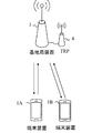
図1は、本実施形態における無線通信システムの概念図である。図1において、無線通信システムは、端末装置1A、端末装置1B、および基地局装置3を具備する。以下、端
末装置1A、および、端末装置1Bを、端末装置1とも称する。
FIG. 1 is a conceptual diagram of a wireless communication system in the present embodiment. In FIG. 1, the wireless communication system includes a terminal device 1A, a
端末装置1は、ユーザ端末、移動局装置、通信端末、移動機、端末、UE(User Equipment)、MS(Mobile Station)とも称される。基地局装置3は、無線基地局装置、基地局、無線基地局、固定局、NB(Node B)、eNB(evolved Node B)、BTS(Base Transceiver Station)、BS(Base Station)、NR NB(NR Node B)、NNB、T
RP(Transmission and Reception Point)、gNBとも称される。基地局装置3は、コアネットワーク装置を含んでも良い。また、基地局装置3は、1つまたは複数の送受信点4(transmission reception point)を具備しても良い。以下で説明する基地局装置3の機能/処理の少なくとも一部は、該基地局装置3が具備する各々の送受信点4における機能/処理であってもよい。基地局装置3は、基地局装置3によって制御される通信可能範囲(通信エリア)を1つまたは複数のセルとして端末装置1をサーブしてもよい。また、基地局装置3は、1つまたは複数の送受信点4によって制御される通信可能範囲(通信エリア)を1つまたは複数のセルとして端末装置1をサーブしてもよい。また、1つのセルを複数の部分領域(Beamed area)にわけ、それぞれの部分領域において端末装置1をサーブしてもよい。ここで、部分領域は、ビームフォーミングで使用されるビームのインデックスあるいはプリコーディングのインデックスに基づいて識別されてもよい。
The
Also called RP (Transmission and Reception Point), gNB. The
基地局装置3から端末装置1への無線通信リンクを下りリンクと称する。端末装置1から基地局装置3への無線通信リンクを上りリンクと称する。
A wireless communication link from the
図1において、端末装置1と基地局装置3の間の無線通信では、サイクリックプレフィックス(CP: Cyclic Prefix)を含む直交周波数分割多重(OFDM: Orthogonal Frequency Division Multiplexing)、シングルキャリア周波数多重(SC-FDM: Single-Carrier Frequency Division Multiplexing)、離散フーリエ変換拡散OFDM(DFT-S-OFDM: Discrete Fourier Transform Spread OFDM)、マルチキャリア符号分割多重(MC-CDM: Multi-Carrier Code Division Multiplexing)が用いられてもよい。
In FIG. 1, in wireless communication between a
また、図1において、端末装置1と基地局装置3の間の無線通信では、ユニバーサルフィルタマルチキャリア(UFMC: Universal-Filtered Multi-Carrier)、フィルタOFDM(F-OFDM: Filtered OFDM)、窓関数が乗算されたOFDM(Windowed OFDM)、フィルタバンクマルチキャリア(FBMC: Filter-Bank Multi-Carrier)が用いられてもよい。
In FIG. 1, in wireless communication between the
なお、本実施形態ではOFDMを伝送方式としてOFDMシンボルで説明するが、上述の他の伝送方式の場合を用いた場合も本発明に含まれる。 In this embodiment, OFDM is described as an OFDM transmission system, but the case of using the other transmission systems described above is also included in the present invention.
また、図1において、端末装置1と基地局装置3の間の無線通信では、CPを用いない、あるいはCPの代わりにゼロパディングをした上述の伝送方式が用いられてもよい。また、CPやゼロパディングは前方と後方の両方に付加されてもよい。
In FIG. 1, in the wireless communication between the
図1において、端末装置1と基地局装置3の無線通信では、以下の物理チャネルが用いられる。
・PBCH(Physical Broadcast CHannel)
・PDCCH(Physical Downlink Control CHannel)
・PDSCH(Physical Downlink Shared CHannel)
・PUCCH(Physical Uplink Control CHannel)
・PUSCH(Physical Uplink Shared CHannel)
・PRACH(Physical Random Access CHannel)
PBCHは、端末装置1が必要な重要なシステム情報を含む重要情報ブロック(MIB: M
aster Information Block、EIB: Essential Information Block、BCH:Broadcast Channel)を報知するために用いられる。
In FIG. 1, the following physical channels are used in wireless communication between the
・ PBCH (Physical Broadcast CHannel)
・ PDCCH (Physical Downlink Control CHannel)
・ PDSCH (Physical Downlink Shared CHannel)
・ PUCCH (Physical Uplink Control CHannel)
・ PUSCH (Physical Uplink Shared CHannel)
・ PRACH (Physical Random Access CHannel)
The PBCH is an important information block (MIB: M) containing important system information required by the
It is used to broadcast an aster information block, EIB: Essential Information Block, BCH (Broadcast Channel).
また、PBCHは、同期信号のブロック(SS/PBCHブロックとも称する)の周期内の時間インデックスを報知するために用いられてよい。ここで、時間インデックスは、セル内の同期信号およびPBCHのインデックスを示す情報である。例えば、3つの送信ビーム(送信フィルタ設定、受信空間パラメータに関する擬似同位置(QCL:Quasi Co-Location)、または空間ドメイン送信フィルタと称される場合もある)の想定を用いて
SS/PBCHブロックを送信する場合、予め定められた周期内または設定された周期内の時間順を示してよい。また、端末装置は、時間インデックスの違いを送信ビームの違いと認識してもよい。
The PBCH may be used for reporting a time index within a period of a block of a synchronization signal (also referred to as an SS / PBCH block). Here, the time index is information indicating the synchronization signal and PBCH index in the cell. For example, an SS / PBCH block is assumed using the assumption of three transmit beams (sometimes referred to as transmit filter settings, pseudo-co-location (QCL) with respect to receive spatial parameters, or spatial domain transmit filter). When transmitting, the time order within a predetermined period or a set period may be indicated. In addition, the terminal device may recognize a difference in time index as a difference in transmission beam.
PDCCHは、下りリンクの無線通信(基地局装置3から端末装置1への無線通信)において、下りリンク制御情報(Downlink Control Information: DCI)を送信する(また
は運ぶ)ために用いられる。ここで、下りリンク制御情報の送信に対して、1つまたは複数のDCI(DCIフォーマットと称してもよい)が定義される。すなわち、下りリンク制御情報に対するフィールドがDCIとして定義され、情報ビットへマップされる。
The PDCCH is used to transmit (or carry) downlink control information (Downlink Control Information: DCI) in downlink wireless communication (wireless communication from the
例えば、以下のDCIフォーマットが定義されてよい。 For example, the following DCI format may be defined.
・DCIフォーマット0_0
・DCIフォーマット0_1
・DCIフォーマット1_0
・DCIフォーマット1_1
・DCIフォーマット2_0
・DCIフォーマット2_1
・DCIフォーマット2_2
・DCIフォーマット2_3
DCIフォーマット0_0は、PUSCHのスケジューリング情報(周波数領域リソース割当及び時間領域リソース割当)を示す情報を含んでよい。
DCI format 0_0
DCI format 0_1
DCI format 1_0
DCI format 1_1
DCI format 2_0
DCI format 2_1
DCI format 2_2
DCI format 2_3
The DCI format 0_0 may include information indicating PUSCH scheduling information (frequency domain resource allocation and time domain resource allocation).
DCIフォーマット0_1は、PUSCHのスケジューリング情報(周波数領域リソース割当及び時間領域リソース割当)を示す情報、帯域部分(BWP:BandWidth Part)を示す情報、チャネル状態情報(CSI:Channel State Information)リクエスト、サウ
ンディング参照信号(SRS:Sounding Reference Signal)リクエスト、アンテナポー
トに関する情報を含んでよい。
The DCI format 0_1 includes information indicating PUSCH scheduling information (frequency domain resource allocation and time domain resource allocation), information indicating a band part (BWP), channel state information (CSI) request, and sounding reference. A signal (SRS: Sounding Reference Signal) request and information on the antenna port may be included.
DCIフォーマット1_0は、PDSCHのスケジューリング情報(周波数領域リソース割当及び時間領域リソース割当)を示す情報を含んでよい。 The DCI format 1_0 may include information indicating PDSCH scheduling information (frequency domain resource allocation and time domain resource allocation).
DCIフォーマット1_1は、PDSCHのスケジューリング情報(周波数領域リソース割当及び時間領域リソース割当)を示す情報、帯域部分(BWP)を示す情報、送信設定指示(TCI:Transmission Configuration Indication)、アンテナポートに関する
情報を含んでよい。
The DCI format 1_1 includes information indicating PDSCH scheduling information (frequency domain resource allocation and time domain resource allocation), information indicating a band part (BWP), a transmission configuration instruction (TCI: Transmission Configuration Indication), and information regarding an antenna port. It's okay.
DCIフォーマット2_0は、1つまたは複数のスロットのスロットフォーマットを通知するために用いられる。スロットフォーマットは、スロット内の各OFDMシンボルが下りリンク、フレキシブル、上りリンクのいずれかに分類されたものとして定義される。例えば、スロットフォーマットが28の場合、スロットフォーマット28が指示されたスロット内の14シンボルのOFDMシンボルに対してDDDDDDDDDDDDFUが適
用される。ここで、Dが下りリンクシンボル、Fがフレキシブルシンボル、Uが上りリンクシンボルである。なお、スロットについては後述する。
The DCI format 2_0 is used to notify the slot format of one or a plurality of slots. The slot format is defined as each OFDM symbol in the slot classified as one of downlink, flexible, and uplink. For example, when the slot format is 28, DDDDDDDDDDDDFU is applied to 14 OFDM symbols in the slot in which the slot format 28 is indicated. Here, D is a downlink symbol, F is a flexible symbol, and U is an uplink symbol. The slot will be described later.
DCIフォーマット2_1は、端末装置1に対して、送信がないと想定してよい物理リソースブロックとOFDMシンボルを通知するために用いられる。なお、この情報はプリエンプション指示(間欠送信指示)と称してよい。
The DCI format 2_1 is used to notify the
DCIフォーマット2_2は、PUSCHおよびPUSCHのための送信電力制御(TPC:Transmit Power Control)コマンドの送信のために用いられる。 The DCI format 2_2 is used for transmission of a transmission power control (TPC) command for PUSCH and PUSCH.
DCIフォーマット2_3は、1または複数の端末装置1によるサウンディング参照信号(SRS)送信のためのTPCコマンドのグループを送信するために用いられる。また、TPCコマンドとともに、SRSリクエストが送信されてもよい。また、DCIフォーマット2_3に、PUSCHおよびPUCCHのない上りリンク、またはSRSの送信電力制御がPUSCHの送信電力制御と紐付いていない上りリンクのために、SRSリクエストとTPCコマンドが定義されてよい。
The DCI format 2_3 is used to transmit a group of TPC commands for sounding reference signal (SRS) transmission by one or a plurality of
下りリンクに対するDCIを、下りリンクグラント(downlink grant)、または、下りリンクアサインメント(downlink assignment)とも称する。ここで、上りリンクに対す
るDCIを、上りリンクグラント(uplink grant)、または、上りリンクアサインメント(Uplink assignment)とも称する。
The DCI for the downlink is also referred to as a downlink grant or a downlink assignment. Here, the DCI for the uplink is also referred to as an uplink grant or an uplink assignment.
PUCCHは、上りリンクの無線通信(端末装置1から基地局装置3の無線通信)において、上りリンク制御情報(Uplink Control Information: UCI)を送信するために用い
られる。ここで、上りリンク制御情報には、下りリンクのチャネルの状態を示すために用いられるチャネル状態情報(CSI: Channel State Information)が含まれてもよい。また、上りリンク制御情報には、UL−SCHリソースを要求するために用いられるスケジューリング要求(SR: Scheduling Request)が含まれてもよい。また、上りリンク制御情報には、HARQ−ACK(Hybrid Automatic Repeat request ACKnowledgement)が含ま
れてもよい。HARQ−ACKは、下りリンクデータ(Transport block, Medium Access
Control Protocol Data Unit: MAC PDU, Downlink-Shared Channel: DL-SCH)に対する
HARQ−ACKを示してもよい。
The PUCCH is used for transmitting uplink control information (UPCI) in uplink wireless communication (wireless communication from the
HARQ-ACK for Control Protocol Data Unit (MAC PDU, Downlink-Shared Channel: DL-SCH) may be indicated.
PDSCHは、媒介アクセス(MAC: Medium Access Control)層からの下りリンクデータ(DL-SCH: Downlink Shared CHannel)の送信に用いられる。また、下りリンクの場合
にはシステム情報(SI: System Information)やランダムアクセス応答(RAR: Random Access Response)などの送信にも用いられる。
The PDSCH is used for transmission of downlink data (DL-SCH: Downlink Shared CHannel) from a medium access control (MAC) layer. In the case of downlink, it is also used for transmission of system information (SI: System Information), random access response (RAR: Random Access Response) and the like.
PUSCHは、MAC層からの上りリンクデータ(UL-SCH: Uplink Shared CHannel)
または上りリンクデータと共にHARQ−ACKおよび/またはCSIを送信するために用いられてもよい。また、CSIのみ、または、HARQ−ACKおよびCSIのみを送信するために用いられてもよい。すなわち、UCIのみを送信するために用いられてもよい。
PUSCH is uplink data from the MAC layer (UL-SCH: Uplink Shared CHannel)
Alternatively, it may be used to transmit HARQ-ACK and / or CSI together with uplink data. Moreover, it may be used to transmit only CSI or only HARQ-ACK and CSI. That is, it may be used to transmit only UCI.
ここで、基地局装置3と端末装置1は、上位層(higher layer)において信号をやり取り(送受信)する。例えば、基地局装置3と端末装置1は、無線リソース制御(RRC: Radio Resource Control)層において、RRCシグナリング(RRC message: Radio Resource
Control message、RRC information: Radio Resource Control informationとも称され
る)を送受信してもよい。また、基地局装置3と端末装置1は、MAC(Medium Access Control)層において、MACコントロールエレメントを送受信してもよい。ここで、R
RCシグナリング、および/または、MACコントロールエレメントを、上位層の信号(higher layer signaling)とも称する。ここでの上位層は、物理層から見た上位層を意味するため、MAC層、RRC層、RLC層、PDCP層、NAS(Non Access Stratum)層などの一つまたは複数を含んでもよい。例えば、MAC層の処理において上位層とは、RRC層、RLC層、PDCP層、NAS層などの一つまたは複数を含んでもよい。
Here, the
Control message, RRC information: also called Radio Resource Control information) may be transmitted and received. Further, the
RC signaling and / or MAC control elements are also referred to as higher layer signaling. Here, the upper layer means an upper layer viewed from the physical layer, and may include one or more of a MAC layer, an RRC layer, an RLC layer, a PDCP layer, a NAS (Non Access Stratum) layer, and the like. For example, in the processing of the MAC layer, the upper layer may include one or a plurality of RRC layers, RLC layers, PDCP layers, NAS layers, and the like.
PDSCHまたはPUSCHは、RRCシグナリング、および、MACコントロールエレメントを送信するために用いられてもよい。ここで、PDSCHにおいて、基地局装置3から送信されるRRCシグナリングは、セル内における複数の端末装置1に対して共通のシグナリングであってもよい。また、基地局装置3から送信されるRRCシグナリングは、ある端末装置1に対して専用のシグナリング(dedicated signalingとも称する)で
あってもよい。すなわち、端末装置固有(UEスペシフィック)の情報は、ある端末装置1に対して専用のシグナリングを用いて送信されてもよい。また、PUSCHは、上りリンクにおいてUEの能力(UE Capability)の送信に用いられてもよい。
PDSCH or PUSCH may be used to transmit RRC signaling and MAC control elements. Here, in the PDSCH, RRC signaling transmitted from the
図1において、下りリンクの無線通信では、以下の下りリンク物理信号が用いられる。ここで、下りリンク物理信号は、上位層から出力された情報を送信するために使用されないが、物理層によって使用される。
・同期信号(Synchronization signal: SS)
・参照信号(Reference Signal: RS)
同期信号は、プライマリ同期信号(PSS:Primary Synchronization Signal)およびセカンダリ同期信号(SSS)を含んでよい。PSSとSSSを用いてセルIDが検出されてよい。
In FIG. 1, the following downlink physical signals are used in downlink wireless communication. Here, the downlink physical signal is not used for transmitting information output from the upper layer, but is used by the physical layer.
・ Synchronization signal (SS)
・ Reference signal (RS)
The synchronization signal may include a primary synchronization signal (PSS) and a secondary synchronization signal (SSS). The cell ID may be detected using PSS and SSS.
同期信号は、端末装置1が下りリンクの周波数領域および時間領域の同期をとるために用いられる。ここで、同期信号は、端末装置1が基地局装置3によるプリコーディングまたはビームフォーミングにおけるプリコーディングまたはビームの選択に用いられて良い。なお、ビームは、送信または受信フィルタ設定、あるいは空間ドメイン送信フィルタまたは空間ドメイン受信フィルタと呼ばれてもよい。
The synchronization signal is used for the
参照信号は、端末装置1が物理チャネルの伝搬路補償を行うために用いられる。ここで、参照信号は、端末装置1が下りリンクのCSIを算出するためにも用いられてよい。また、参照信号は、無線パラメータやサブキャリア間隔などのヌメロロジーやFFTの窓同期などができる程度の細かい同期(Fine synchronization)に用いられて良い。
The reference signal is used for the
本実施形態において、以下の下りリンク参照信号のいずれか1つまたは複数が用いられる。 In the present embodiment, any one or more of the following downlink reference signals are used.
・DMRS(Demodulation Reference Signal)
・CSI−RS(Channel State Information Reference Signal)
・PTRS(Phase Tracking Reference Signal)
・TRS(Tracking Reference Signal)
DMRSは、変調信号を復調するために使用される。なお、DMRSには、PBCHを復調するための参照信号と、PDSCHを復調するための参照信号の2種類が定義されてもよいし、両方をDMRSと称してもよい。CSI−RSは、チャネル状態情報(CSI:Channel State Information)の測定およびビームマネジメントに使用され、周期的ま
たはセミパーシステントまたは非周期のCSI参照信号の送信方法が適用される。CSI−RSには、ノンゼロパワー(NZP:Non−Zero Power)CSI−RSと、送信電力(または受信電力)がゼロである(ゼロパワー(ZP:Zero Power)CSI−RSが定義されてよい。ここで、ZP CSI−RSは送信電力がゼロまたは
送信されないCSI−RSリソースと定義されてよい。PTRSは、位相雑音に起因する周波数オフセットを保証する目的で、時間軸で位相をトラックするために使用される。TRSは、高速移動時におけるドップラーシフトを保証するために使用される。なお、TRSはCSI−RSの1つの設定として用いられてよい。例えば、1ポートのCSI−RSがTRSとして無線リソースが設定されてもよい。
DMRS (Demodulation Reference Signal)
・ CSI-RS (Channel State Information Reference Signal)
・ PTRS (Phase Tracking Reference Signal)
・ TRS (Tracking Reference Signal)
DMRS is used to demodulate the modulated signal. In DMRS, two types of reference signals for demodulating PBCH and reference signals for demodulating PDSCH may be defined, or both may be referred to as DMRS. CSI-RS is used for channel state information (CSI) measurement and beam management, and a periodic, semi-persistent, or non-periodic CSI reference signal transmission method is applied. The CSI-RS may be defined as a non-zero power (NZP) CSI-RS and a zero transmission power (or reception power) CSI-RS (zero power (ZP) CSI-RS). Here, ZP CSI-RS may be defined as a CSI-RS resource with zero or no transmission power, and PTRS is used to track the phase on the time axis in order to guarantee a frequency offset due to phase noise. TRS is used to guarantee Doppler shift during high speed movement, and TRS may be used as one setting of CSI-RS, for example, 1 port CSI-RS as TRS A radio resource may be set.
本実施形態において、以下の上りリンク参照信号のいずれか1つまたは複数が用いられる。 In the present embodiment, any one or more of the following uplink reference signals are used.
・DMRS(Demodulation Reference Signal)
・PTRS(Phase Tracking Reference Signal)
・SRS(Sounding Reference Signal)
DMRSは、変調信号を復調するために使用される。なお、DMRSには、PUCCHを復調するための参照信号と、PUSCHを復調するための参照信号の2種類が定義されてもよいし、両方をDMRSと称してもよい。SRSは、上りリンクチャネル状態情報(CSI)の測定、チャネルサウンディング、およびビームマネジメントに使用される。PTRSは、位相雑音に起因する周波数オフセットを保証する目的で、時間軸で位相をトラックするために使用される。
DMRS (Demodulation Reference Signal)
・ PTRS (Phase Tracking Reference Signal)
・ SRS (Sounding Reference Signal)
DMRS is used to demodulate the modulated signal. In DMRS, two types of reference signals for demodulating PUCCH and reference signals for demodulating PUSCH may be defined, or both may be referred to as DMRS. SRS is used for uplink channel state information (CSI) measurement, channel sounding, and beam management. PTRS is used to track the phase on the time axis in order to guarantee a frequency offset due to phase noise.
下りリンク物理チャネルおよび/または下りリンク物理シグナルを総称して、下りリンク信号と称する。上りリンク物理チャネルおよび/または上りリンク物理シグナルを総称して、上りリンク信号と称する。下りリンク物理チャネルおよび/または上りリンク物理チャネルを総称して、物理チャネルと称する。下りリンク物理シグナルおよび/または上りリンク物理シグナルを総称して、物理シグナルと称する。 A downlink physical channel and / or a downlink physical signal are collectively referred to as a downlink signal. Uplink physical channels and / or uplink physical signals are collectively referred to as uplink signals. A downlink physical channel and / or an uplink physical channel are collectively referred to as a physical channel. A downlink physical signal and / or an uplink physical signal are collectively referred to as a physical signal.
BCH、UL−SCHおよびDL−SCHは、トランスポートチャネルである。媒体アクセス制御(MAC:Medium Access Control)層で用いられるチャネルをトランスポー
トチャネルと称する。MAC層で用いられるトランスポートチャネルの単位を、トランスポートブロック(TB:transport block)および/またはMAC PDU(Protocol Data Unit)とも称する。MAC層においてトランスポートブロック毎にHARQ(Hybrid Automatic Repeat reQuest)の制御が行われる。トランスポートブロックは、MAC層が物理層に渡す(deliver)データの単位である。物理層において、トランスポートブロッ
クはコードワードにマップされ、コードワード毎に符号化処理が行われる。
BCH, UL-SCH and DL-SCH are transport channels. A channel used in a medium access control (MAC) layer is referred to as a transport channel. The unit of the transport channel used in the MAC layer is also referred to as a transport block (TB) and / or a MAC PDU (Protocol Data Unit). In the MAC layer, HARQ (Hybrid Automatic Repeat reQuest) control is performed for each transport block. The transport block is a unit of data that the MAC layer delivers to the physical layer. In the physical layer, the transport block is mapped to a code word, and an encoding process is performed for each code word.
また、参照信号は、無線リソース測定(RRM:Radio Resource Measurement)に用いられてよい。また、参照信号は、ビームマネジメントに用いられてよい。 Further, the reference signal may be used for radio resource measurement (RRM). The reference signal may be used for beam management.
ビームマネジメントは、送信装置(下りリンクの場合は基地局装置3であり、上りリンクの場合は端末装置1である)におけるアナログおよび/またはディジタルビームと、受信装置(下りリンクの場合は端末装置1、上りリンクの場合は基地局装置3である)におけるアナログおよび/またはディジタルビームの指向性を合わせ、ビーム利得を獲得するための基地局装置3および/または端末装置1の手続きであってよい。
Beam management includes analog and / or digital beams in a transmitting device (
なお、ビームペアリンクを構成、設定または確立する手続きとして、下記の手続きを含んでよい。
・ビーム選択(Beam selection)
・ビーム改善(Beam refinement)
・ビームリカバリ(Beam recovery)
例えば、ビーム選択は、基地局装置3と端末装置1の間の通信においてビームを選択する手続きであってよい。また、ビーム改善は、さらに利得の高いビームの選択、あるいは
端末装置1の移動によって最適な基地局装置3と端末装置1の間のビームの変更をする手続きであってよい。ビームリカバリは、基地局装置3と端末装置1の間の通信において遮蔽物や人の通過などにより生じるブロッケージにより通信リンクの品質が低下した際にビームを再選択する手続きであってよい。
Note that the following procedure may be included as a procedure for configuring, setting or establishing the beam pair link.
・ Beam selection
・ Beam refinement
・ Beam recovery
For example, the beam selection may be a procedure for selecting a beam in communication between the
ビームマネジメントには、ビーム選択、ビーム改善が含まれてよい。ビームリカバリには、下記の手続きを含んでよい。
・ビーム失敗(beam failure)の検出
・新しいビームの発見
・ビームリカバリリクエストの送信
・ビームリカバリリクエストに対する応答のモニタ
例えば、端末装置1における基地局装置3の送信ビームを選択する際にCSI−RSまたはSS/PBCHブロックに含まれるSSSのRSRP(Reference Signal Received Power)を用いてもよいし、CSIを用いてもよい。また、基地局装置3への報告として
CSI−RSリソースインデックス(CRI:CSI-RS Resource Index)を用いてもよい
し、SS/PBCHブロックに含まれるPBCHおよび/またはPBCHの復調に用いられる復調用参照信号(DMRS)の系列で指示されるインデックスを用いてもよい。
Beam management may include beam selection, beam improvement. Beam recovery may include the following procedures.
-Detection of beam failure-Discovery of new beam-Transmission of beam recovery request-Monitoring of response to beam recovery request For example, when selecting a transmission beam of the
また、基地局装置3は、端末装置1へビームを指示する際にCRIまたはSS/PBCHの時間インデックスを指示し、端末装置1は、指示されたCRIまたはSS/PBCHの時間インデックスに基づいて受信する。このとき、端末装置1は指示されたCRIまたはSS/PBCHの時間インデックスに基づいて空間フィルタを設定し、受信してよい。また、端末装置1は、疑似同位置(QCL:Quasi Co-Location)の想定を用いて受信し
てもよい。ある信号(アンテナポート、同期信号、参照信号など)が別の信号(アンテナポート、同期信号、参照信号など)と「QCLである」または、「QCLの想定が用いられる」とは、ある信号が別の信号と関連付けられていると解釈できる。
Further, the
もしあるアンテナポートにおけるあるシンボルが搬送されるチャネルの長区間特性(Long Term Property)が他方のアンテナポートにおけるあるシンボルが搬送されるチャネルから推論されうるなら、2つのアンテナポートはQCLであるといわれる。チャネルの長区間特性は、遅延スプレッド、ドップラースプレッド、ドップラーシフト、平均利得、及び平均遅延の1つまたは複数を含む。例えば、アンテナポート1とアンテナポート2が平均遅延に関してQCLである場合、アンテナポート1の受信タイミングからアンテナポート2の受信タイミングが推論されうることを意味する。
Two antenna ports are said to be QCL if the Long Term Property of the channel on which one symbol at one antenna port is carried can be inferred from the channel on which one symbol at the other antenna port is carried. . The long-term characteristics of the channel include one or more of delay spread, Doppler spread, Doppler shift, average gain, and average delay. For example, when
このQCLは、ビームマネジメントにも拡張されうる。そのために、空間に拡張したQCLが新たに定義されてもよい。例えば、空間ドメインのQCLの想定におけるチャネルの長区間特性(Long term property)として、無線リンクあるいはチャネルにおける到来角(AoA(Angle of Arrival), ZoA(Zenith angle of Arrival)など)および/または
角度広がり(Angle Spread、例えばASA(Angle Spread of Arrival)やZSA(Zenith angle Spread of Arrival))、送出角(AoD, ZoDなど)やその角度広がり(Angle Spread、
例えばASD(Angle Spread of Departure)やZSD(Zenith angle Spread of Departure)
)、空間相関(Spatial Correlation)、受信空間パラメータであってもよい。
This QCL can also be extended to beam management. Therefore, a QCL extended to a space may be newly defined. For example, the long term property of a channel in the assumption of spatial domain QCL is the arrival angle (AoA (Angle of Arrival), ZoA (Zenith angle of Arrival), etc.) and / or angular spread in a radio link or channel (Angle Spread, eg ASA (Angle Spread of Arrival) or ZSA (Zenith angle Spread of Arrival)), send angle (AoD, ZoD, etc.) and its angular spread (Angle Spread,
For example, ASD (Angle Spread of Departure) and ZSD (Zenith angle Spread of Departure)
), Spatial correlation, and reception spatial parameters.
例えば、アンテナポート1とアンテナポート2の間で受信空間パラメータに関してQCLであるとみなせる場合、アンテナポート1からの信号を受信する受信ビーム(受信空間フィルタ)からアンテナポート2からの信号を受信する受信ビームが推論されうることを意味する。
For example, when it can be considered that the reception space parameter is QCL between the
QCLタイプとして、QCLであるとみなしてよい長区間特性の組み合わせが定義され
てよい。例えば、以下のタイプが定義されてよい。
As the QCL type, a combination of long interval characteristics that may be regarded as QCL may be defined. For example, the following types may be defined:
・タイプA:ドップラーシフト、ドップラースプレッド、平均遅延、遅延スプレッド
・タイプB:ドップラーシフト、ドップラースプレッド
・タイプC:平均遅延、ドップラーシフト
・タイプD:受信空間パラメータ
上述のQCLタイプは、RRCおよび/またはMAC層および/またはDCIで1つまたは2つの参照信号とPDCCHやPDSCH DMRSとのQCLの想定を送信設定指示(TCI:Transmission Configuration Indication)として設定および/または指示
してもよい。例えば、端末装置1がPDCCHを受信する際のTCIの1つの状態として、PBCH/SSブロックのインデックス#2とQCLタイプA+QCLタイプBが設定および/または指示された場合、端末装置1は、PDCCH DMRSを受信する際、PBCH/SSブロックインデックス#2の受信におけるドップラーシフト、ドップラースプレッド、平均遅延、遅延スプレッド、受信空間パラメータとチャネルの長区間特性とみなしてPDCCHのDMRSを受信して同期や伝搬路推定をしてもよい。このとき、TCIにより指示される参照信号(上述の例ではPBCH/SSブロック)をソース参照信号、ソース参照信号を受信する際のチャネルの長区間特性から推論される長区間特性の影響を受ける参照信号(上述の例ではPDCCH DMRS)をターゲット参照信号と称してよい。また、TCIは、RRCで複数のTCI状態と各状態に対してソース参照信号とQCLタイプの組み合わせが設定され、MAC層またはDCIにより端末装置1に指示されてよい。
-Type A: Doppler shift, Doppler spread, average delay, delay spread-Type B: Doppler shift, Doppler spread-Type C: Average delay, Doppler shift-Type D: Reception spatial parameters The above mentioned QCL types are RRC and / or The QCL assumption of one or two reference signals and PDCCH or PDSCH DMRS may be set and / or indicated as a transmission configuration indication (TCI) in the MAC layer and / or DCI. For example, when one of the TCI states when the
この方法により、ビームマネジメントおよびビーム指示/報告として、空間ドメインのQCLの想定と無線リソース(時間および/または周波数)によりビームマネジメントと等価な基地局装置3、端末装置1の動作が定義されてもよい。
By this method, even if the operations of the
以下、サブフレームについて説明する。本実施形態ではサブフレームと称するが、リソースユニット、無線フレーム、時間区間、時間間隔などと称されてもよい。 Hereinafter, subframes will be described. Although referred to as a subframe in this embodiment, it may be referred to as a resource unit, a radio frame, a time interval, a time interval, or the like.
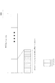
図2は、本発明の第1の実施形態に係る上りリンクおよび下りリンクスロットの概略構成の一例を示す図である。無線フレームのそれぞれは、10ms長である。また、無線フレームのそれぞれは10個のサブフレームおよびW個のスロットから構成される。また、1スロットは、X個のOFDMシンボルで構成される。つまり、1サブフレームの長さは1msである。スロットのそれぞれは、サブキャリア間隔によって時間長が定義される。例えば、OFDMシンボルのサブキャリア間隔が15kHz、NCP(Normal Cyclic Prefix)の場合、X=7あるいはX=14であり、それぞれ0.5msおよび1msである。また、サブキャリア間隔が60kHzの場合は、X=7あるいはX=14であり、それぞれ0.125msおよび0.25msである。また、例えば、X=14の場合、サブキャリア間隔が15kHzの場合はW=10であり、サブキャリア間隔が60kHzの場合はW=40である。図2は、X=7の場合を一例として示している。なお、X=14の場合にも同様に拡張できる。また、上りリンクスロットも同様に定義され、下りリンクスロットと上りリンクスロットは別々に定義されてもよい。また、図2のセルの帯域幅は帯域の一部(BWPであってよい)として定義されてもよい。また、スロットは、送信時間間隔(TTI:Transmission Time Interval)と定義されてもよい。スロットは、TTIとして定義されなくてもよい。TTIは、トランスポートブロックの送信期間であってもよい。 FIG. 2 is a diagram illustrating an example of a schematic configuration of uplink and downlink slots according to the first embodiment of the present invention. Each radio frame is 10 ms long. Each radio frame includes 10 subframes and W slots. One slot is composed of X OFDM symbols. That is, the length of one subframe is 1 ms. Each slot has a time length defined by a subcarrier interval. For example, when the subcarrier interval of the OFDM symbol is 15 kHz and NCP (Normal Cyclic Prefix), X = 7 or X = 14, which is 0.5 ms and 1 ms, respectively. When the subcarrier interval is 60 kHz, X = 7 or X = 14, which are 0.125 ms and 0.25 ms, respectively. For example, when X = 14, W = 10 when the subcarrier interval is 15 kHz, and W = 40 when the subcarrier interval is 60 kHz. FIG. 2 shows an example where X = 7. Note that the same extension can be made when X = 14. Further, the uplink slot is defined in the same manner, and the downlink slot and the uplink slot may be defined separately. Also, the bandwidth of the cell of FIG. 2 may be defined as part of the bandwidth (which may be BWP). A slot may be defined as a transmission time interval (TTI). A slot may not be defined as a TTI. The TTI may be a transmission period of the transport block.
スロットのそれぞれにおいて送信される信号または物理チャネルは、リソースグリッドによって表現されてよい。リソースグリッドは、複数のサブキャリアと複数のOFDMシンボルによって定義される。1つのスロットを構成するサブキャリアの数は、セルの下り
リンクおよび上りリンクの帯域幅にそれぞれ依存する。リソースグリッド内のエレメントのそれぞれをリソースエレメントと称する。リソースエレメントは、サブキャリアの番号とOFDMシンボルの番号とを用いて識別されてよい。
The signal or physical channel transmitted in each of the slots may be represented by a resource grid. The resource grid is defined by a plurality of subcarriers and a plurality of OFDM symbols. The number of subcarriers constituting one slot depends on the downlink and uplink bandwidths of the cell. Each element in the resource grid is referred to as a resource element. Resource elements may be identified using subcarrier numbers and OFDM symbol numbers.
リソースグリッドは、ある物理下りリンクチャネル(PDSCHなど)あるいは上りリンクチャネル(PUSCHなど)のリソースエレメントのマッピングを表現するために用いられる。例えば、サブキャリア間隔が15kHzの場合、サブフレームに含まれるOFDMシンボル数X=14で、NCPの場合には、1つの物理リソースブロックは、時間領域において14個の連続するOFDMシンボルと周波数領域において12*Nmax個の連続するサブキャリアとから定義される。Nmaxは、後述するサブキャリア間隔設定μにより決定されるリソースブロックの最大数である。つまり、リソースグリッドは、(14*12*Nmax,μ)個のリソースエレメントから構成される。ECP(Extended CP)の場合、サブキャリア間隔60kHzにおいてのみサポートされるので、1つの物理
リソースブロックは、例えば、時間領域において12(1スロットに含まれるOFDMシンボル数)*4(1サブフレームに含まれるスロット数)=48個の連続するOFDMシンボルと、周波数領域において12*Nmax,μ個の連続するサブキャリアとにより定義される。つまり、リソースグリッドは、(48*12*Nmax,μ)個のリソースエレメントから構成される。
The resource grid is used to express a mapping of resource elements of a certain physical downlink channel (PDSCH or the like) or uplink channel (PUSCH or the like). For example, when the subcarrier interval is 15 kHz, the number of OFDM symbols included in the subframe is X = 14. In the case of NCP, one physical resource block is 14 consecutive OFDM symbols in the time domain and the frequency domain. It is defined from 12 * Nmax consecutive subcarriers. Nmax is the maximum number of resource blocks determined by subcarrier interval setting μ described later. That is, the resource grid is composed of (14 * 12 * Nmax, μ) resource elements. In the case of ECP (Extended CP), since it is supported only at a subcarrier interval of 60 kHz, one physical resource block is, for example, 12 (the number of OFDM symbols included in one slot) * 4 (included in one subframe) in the time domain. Number of slots) = 48 consecutive OFDM symbols and 12 * Nmax, μ consecutive subcarriers in the frequency domain. That is, the resource grid is composed of (48 * 12 * Nmax, μ) resource elements.
リソースブロックとして、共通リソースブロック、物理リソースブロック、仮想リソースブロックが定義される。1リソースブロックは、周波数領域で連続する12サブキャリアとして定義される。共通リソースブロックインデックス0におけるサブキャリアインデックス0は、参照ポイントと称されてよい( ポイントA”と称されてもよい)。共通リ
ソースブロックは、参照ポイントAから各サブキャリア間隔設定μにおいて0から昇順で番号が付されるリソースブロックである。上述のリソースグリッドはこの共通リソースブロックにより定義される。物理リソースブロックは、後述する帯域部分(BWP)の中に含まれる0から昇順で番号が付されたリソースブロックであり、物理リソースブロックは、帯域部分(BWP)の中に含まれる0から昇順で番号が付されたリソースブロックである。ある物理上りリンクチャネルは、まず仮想リソースブロックにマップされる。その後、仮想リソースブロックは、物理リソースブロックにマップされる。
Common resource blocks, physical resource blocks, and virtual resource blocks are defined as resource blocks. One resource block is defined as 12 subcarriers continuous in the frequency domain. The
次に、サブキャリア間隔設定μについて説明する。上述のようにNRでは、複数のOFDMヌメロロジーがサポートされる。あるBWPにおいて、サブキャリア間隔設定μ(μ=0,1,...,5)と、サイクリックプレフィックス長は、下りリンクのBWPに対して上位レイヤ(上位層)で与えられ、上りリンクのBWPにおいて上位レイヤで与えられる。ここで、μが与えられると、サブキャリア間隔Δfは、Δf=2^μ・15(kHz)で与えられる。 Next, the subcarrier interval setting μ will be described. As described above, NR supports a plurality of OFDM numerologies. In a certain BWP, the subcarrier interval setting μ (μ = 0, 1,..., 5) and the cyclic prefix length are given by the upper layer (upper layer) with respect to the downlink BWP. It is given by the upper layer in BWP. Here, when μ is given, the subcarrier interval Δf is given by Δf = 2 ^ μ · 15 (kHz).
サブキャリア間隔設定μにおいて、スロットは、サブフレーム内で0からN^{subframe,μ}_{slot}-1に昇順に数えられ、フレーム内で0からN^{frame,μ}_{slot}-1に昇順に
数えられる。スロット設定およびサイクリックプレフィックスに基づいてN^{slot}_{symb}の連続するOFDMシンボルがスロット内にある。N^{slot}_{symb}は14である。サブフレーム内のスロットn^{μ}_{s}のスタートは、同じサブフレーム内のn^{μ}_{s} N^{slot}_{symb}番目のOFDMシンボルのスタートと時間でアラインされている。
In the subcarrier interval setting μ, slots are counted in ascending order from 0 to N ^ {subframe, μ} _ {slot} -1 within the subframe, and from 0 to N ^ {frame, μ} _ {slot within the frame. } -1 is counted in ascending order. There are N ^ {slot} _ {symb} consecutive OFDM symbols in the slot based on slot configuration and cyclic prefix. N ^ {slot} _ {symb} is 14. The start of slot n ^ {μ} _ {s} in a subframe is the start and time of the n ^ {μ} _ {s} N ^ {slot} _ {symb} th OFDM symbol in the same subframe. Aligned.
次に、サブフレーム、スロット、ミニスロットについて説明する。図3は、サブフレーム、スロット、ミニスロットの時間領域における関係を示した図である。同図のように、3種類の時間ユニットが定義される。サブフレームは、サブキャリア間隔によらず1msであり、スロットに含まれるOFDMシンボル数は7または14であり、スロット長はサブキャリア間隔により異なる。ここで、サブキャリア間隔が15kHzの場合、1サブフ
レームには14OFDMシンボル含まれる。下りリンクスロットはPDSCHマッピングタイプAと称されてよい。上りリンクスロットはPUSCHマッピングタイプAと称されてよい。
Next, subframes, slots, and minislots will be described. FIG. 3 is a diagram illustrating the relationship in the time domain between subframes, slots, and minislots. As shown in the figure, three types of time units are defined. The subframe is 1 ms regardless of the subcarrier interval, the number of OFDM symbols included in the slot is 7 or 14, and the slot length varies depending on the subcarrier interval. Here, when the subcarrier interval is 15 kHz, 14 OFDM symbols are included in one subframe. The downlink slot may be referred to as PDSCH mapping type A. The uplink slot may be referred to as PUSCH mapping type A.
ミニスロット(サブスロットと称されてもよい)は、スロットに含まれるOFDMシンボル数よりも少ないOFDMシンボルで構成される時間ユニットである。同図はミニスロットが2OFDMシンボルで構成される場合を一例として示している。ミニスロット内のOFDMシンボルは、スロットを構成するOFDMシンボルタイミングに一致してもよい。なお、スケジューリングの最小単位はスロットまたはミニスロットでよい。また、ミニスロットを割り当てることを、ノンスロットベースのスケジューリングと称してもよい。また、ミニスロットをスケジューリングされることを参照信号とデータのスタート位置の相対的な時間位置が固定であるリソースがスケジュールされたと表現されてもよい。下りリンクミニスロットはPDSCHマッピングタイプBと称されてよい。上りリンクミニスロットはPUSCHマッピングタイプBと称されてよい。 A mini-slot (which may be referred to as a sub-slot) is a time unit configured with fewer OFDM symbols than the number of OFDM symbols included in the slot. This figure shows an example in which a minislot is composed of 2 OFDM symbols. The OFDM symbols in the minislot may coincide with the OFDM symbol timing that constitutes the slot. The minimum scheduling unit may be a slot or a minislot. Also, allocating minislots may be referred to as non-slot based scheduling. Further, scheduling a minislot may be expressed as a resource having a fixed relative time position between the reference signal and the start position of the data. The downlink minislot may be referred to as PDSCH mapping type B. The uplink minislot may be referred to as PUSCH mapping type B.
図4は、スロットフォーマットの一例を示す図である。ここでは、サブキャリア間隔15kHzにおいてスロット長が1msの場合を例として示している。同図において、Dは下りリンク、Uは上りリンクを示している。同図に示されるように、ある時間区間内(例えば、システムにおいて1つのUEに対して割り当てなければならない最小の時間区間)においては、
・下りリンクシンボル
・フレキシブルシンボル
・上りリンクシンボル
のうち1つまたは複数を含んでよい。なお、これらの割合はスロットフォーマットとして予め定められてもよい。また、スロット内に含まれる下りリンクのOFDMシンボル数またはスロット内のスタート位置および終了位置で定義されてもよい。また、スロット内に含まれる上りリンクのOFDMシンボルまたはDFT−S−OFDMシンボル数またはスロット内のスタート位置および終了位置で定義されてよい。なお、スロットをスケジューリングされることを参照信号とスロット境界の相対的な時間位置が固定であるリソースがスケジュールされたと表現されてもよい。
FIG. 4 is a diagram illustrating an example of a slot format. Here, a case where the slot length is 1 ms at a subcarrier interval of 15 kHz is shown as an example. In the figure, D indicates the downlink and U indicates the uplink. As shown in the figure, within a certain time interval (for example, the minimum time interval that must be allocated to one UE in the system),
One or more of a downlink symbol, a flexible symbol, and an uplink symbol may be included. These ratios may be determined in advance as a slot format. Also, it may be defined by the number of downlink OFDM symbols included in the slot or the start position and end position in the slot. Further, it may be defined by the number of uplink OFDM symbols or DFT-S-OFDM symbols included in the slot or the start position and end position in the slot. Note that scheduling a slot may be expressed as scheduling a resource whose relative time position between the reference signal and the slot boundary is fixed.
端末装置1は、下りリンクシンボルまたはフレキシブルシンボルで下りリンク信号または下りリンクチャネルを受信してよい。端末装置1は、上りリンクシンボルまたはフレキシブルシンボルで上りリンク信号または下りリンクチャネルを送信してよい。
The
図4(a)は、ある時間区間(例えば、1UEに割当可能な時間リソースの最小単位、またはタイムユニットなどとも称されてよい。また、時間リソースの最小単位を複数束ねてタイムユニットと称されてもよい。)で、全て下りリンク送信に用いられている例であり、図4(b)は、最初の時間リソースで例えばPDCCHを介して上りリンクのスケジューリングを行い、PDCCHの処理遅延及び下りから上りの切り替え時間、送信信号の生成を含むフレキシブルシンボルを介して上りリンク信号を送信する。図4(c)は、最初の時間リソースでPDCCHおよび/または下りリンクのPDSCHの送信に用いられ、処理遅延及び下りから上りの切り替え時間、送信信号の生成のためのギャップを介してPUSCHまたはPUCCHの送信に用いられる。ここで、一例としては、上りリンク信号はHARQ−ACKおよび/またはCSI、すなわちUCIの送信に用いられてよい。図4(d)は、最初の時間リソースでPDCCHおよび/またはPDSCHの送信に用いられ、処理遅延及び下りから上りの切り替え時間、送信信号の生成のためのギャップを介して上りリンクのPUSCHおよび/またはPUCCHの送信に用いられる。ここで、一例としては、上りリンク信号は上りリンクデータ、すなわちUL−SCHの送信に用いられてもよい。図4(e)は、全て上りリンク送信(PUSCHまたはPUCCH)に用い
られている例である。
4A may be referred to as a certain time interval (for example, a minimum unit of time resources that can be allocated to one UE, or a time unit, etc. In addition, a plurality of minimum units of time resources are bundled to be referred to as a time unit. 4 (b) is an example used for downlink transmission, and FIG. 4 (b) performs uplink scheduling via the PDCCH, for example, using the first time resource, and the processing delay and downlink of the PDCCH. Uplink signal is transmitted through a flexible symbol including uplink switching time and transmission signal generation. FIG.4 (c) is used for transmission of PDCCH and / or downlink PDSCH by the first time resource, and it is PUSCH or PUCCH through the processing delay and the downlink to uplink switching time, and the gap for transmission signal generation. Used to send Here, as an example, the uplink signal may be used for transmission of HARQ-ACK and / or CSI, that is, UCI. FIG. 4 (d) is used for transmission of PDCCH and / or PDSCH in the first time resource, and the PUSCH and / or uplink PUSCH and / or through the processing delay and the downlink to uplink switching time, and the gap for transmission signal generation. Or it is used for transmission of PUCCH. Here, as an example, the uplink signal may be used for transmission of uplink data, that is, UL-SCH. FIG. 4 (e) is an example in which all are used for uplink transmission (PUSCH or PUCCH).
上述の下りリンクパート、上りリンクパートは、LTEと同様複数のOFDMシンボルで構成されてよい。 The downlink part and uplink part described above may be composed of a plurality of OFDM symbols as in LTE.
図5は、ビームフォーミングの一例を示した図である。複数のアンテナエレメントは1つの送信ユニット(TXRU: Transceiver unit)10に接続され、アンテナエレメント毎の位相シフタ11によって位相を制御し、アンテナエレメント12から送信することで送信信号に対して任意の方向にビームを向けることができる。典型的には、TXRUがアンテナポートとして定義されてよく、端末装置1においてはアンテナポートのみが定義されてよい。位相シフタ11を制御することで任意の方向に指向性を向けることができるため、基地局装置3は端末装置1に対して利得の高いビームを用いて通信することができる。
FIG. 5 is a diagram showing an example of beam forming. A plurality of antenna elements are connected to one transmission unit (TXRU: Transceiver unit) 10, controlled in phase by a
以下、帯域部分(BWP)について説明する。BWPは、キャリアBWPとも称される。BWPは、下りリンクと上りリンクのそれぞれに設定されてよい。BWPは、共通リソースブロックの連続するサブセットから選択された連続する物理リソースの集合として定義される。端末装置1は、ある時間に1つの下りリンクキャリアBWPが活性化される4つまでのBWPを設定されうる。端末装置1は、ある時間に1つの上りリンクキャリアBWPが活性化される4つまでのBWPを設定されうる。キャリアアグリゲーションの場合には、BWPは各サービングセルで設定されてもよい。このとき、あるサービングセルにおいてBWPが1つ設定されていることを、BWPが設定されていないと表現されてもよい。また、BWPが2つ以上設定されていることをBWPが設定されていると表現されてもよい。
<MAC entity動作>
活性化されたサービングセルにおいて、常に一つのアクティブな(活性化された)BWPがある。あるサービングセルに対するBWP切り替え(BWP switching)は、インアク
ティブな(非活性化された)BWPを活性化(activate)し、アクティブな(活性化された)BWPを非活性化(deactivate)するために使用される。あるサービングセルに対するBWP切り替え(BWP switching)は、下りリンク割り当てまたは上りリンクグラントを
示すPDCCHによって制御される。あるサービングセルに対するBWP切り替え(BWP switching)は、さらに、BWPインアクティブタイマー(BWP inactivity timer)や、
ランダムアクセスプロシージャの開始時にMACエンティティ自身によって制御されてもよい。SpCell(PCellまたはPSCell)の追加または、SCellの活性化において
、一つのBWPが、下りリンク割り当てまたは上りリンクグラントを示すPDCCHを受信することなしに初期的にアクティブである。初期的にアクティブなBWPは、基地局装置3から端末装置1に送られるRRCメッセージで指定されるかもしれない。あるサービングセルに対するアクティブなBWPは、基地局装置3から端末装置1に送られるRRCまたはPDCCHで指定される。アンペアードスペクトラム(Unpaired spectrum)(T
DD(Time Division Duplex)バンドなど)では、下りリンクBWP(DL BWP)と上りリンクBWP(UL BWP)はペアにされていて、BWP切り替えは、ULとDLに対して共通である。BWPが設定されているアクティベートされたサービングセルのそれぞれに対する、アクティブなBWPにおいて、端末装置1のMACエンティティは、ノーマル処理を適用する。ノーマル処理には、UL−SCHを送信する、RACHを送信する、PDCCHをモニタする、PUCCHを送信する、SRSを送信する、およびDL−SCHを受信することを含む。BWPが設定されているアクティベートされたサービングセルのそれぞれに対する、インアクティブなBWPにおいて、端末装置1のMACエンティティは、UL−SCHを送信しない、RACHを送信しない、PDCCHをモニタしない、PUCCHを送信しない、SRSを送信しない、およびDL−SCHを受信しない。あるサービングセルが非活性化された場合、アクティブなBWPは、存在しないようにしてもよい(例えば、アクティブなBWPは非活性化される)。
<RRC動作>
RRCメッセージ(報知されるシステム情報や、専用RRCメッセージで送られる情報)に含まれるBWPインフォメーションエレメント(IE: Information Element)は、B
WPを設定するために使われる。基地局装置3から送信されたRRCメッセージは、端末装置1によって受信される。それぞれのサービングセルに対して、ネットワーク(基地局装置3など)は、少なくとも下りリンクのBWPと1つ(もしサービングセルが上りリンクの設定された場合など)または2つ(付録のアップリンク(supplementary uplink)が使われる場合など)の上りリンクBWPを含む少なくとも初期BWP(initial BWP)を
、端末装置1に対して、設定する。さらに、ネットワークは、追加の上りリンクBWPや下りリンクBWPをあるサービングセルに対して設定するかもしれない。BWP設定は、上りリンクパラメータと下りリンクパラメータに分けられる。また、BWP設定は、共通(common)パラメータと専用(dedicated)パラメータに分けられる。共通パラメータ(
BWP上りリンク共通IEやBWP下りリンク共通IEなど)は、セル特有である。プライマリ
セルの初期BWPの共通パラメータは、システム情報でも提供される。他のすべてのサービ
ングセルに対しては、ネットワークは専用信号で共通パラメータを提供する。BWPは、BWP IDで識別される。初期BWPは、BWP IDが0である。他のBWPのBWP IDは、1から4までの値を取る。
Hereinafter, the band portion (BWP) will be described. BWP is also referred to as carrier BWP. BWP may be set for each of the downlink and the uplink. A BWP is defined as a set of contiguous physical resources selected from a contiguous subset of common resource blocks. The
<MAC entity operation>
There is always one active (activated) BWP in the activated serving cell. BWP switching for a serving cell is used to activate an inactive (deactivated) BWP and deactivate an active (activated) BWP Is done. BWP switching (BWP switching) for a serving cell is controlled by PDCCH indicating downlink assignment or uplink grant. BWP switching (BWP switching) for a certain serving cell is further performed by a BWP inactivity timer,
It may be controlled by the MAC entity itself at the start of the random access procedure. In adding SpCell (PCell or PSCell) or activating SCell, one BWP is initially active without receiving a PDCCH indicating a downlink assignment or an uplink grant. The initially active BWP may be specified by the RRC message sent from the
In a DD (Time Division Duplex) band, etc., downlink BWP (DL BWP) and uplink BWP (UL BWP) are paired, and BWP switching is common to UL and DL. In the active BWP for each activated serving cell in which BWP is set, the MAC entity of the
<RRC operation>
The BWP information element (IE: Information Element) included in the RRC message (system information to be broadcast or information sent in a dedicated RRC message) is B
Used to set WP. The RRC message transmitted from the
BWP uplink common IE, BWP downlink common IE, etc.) are cell specific. Common parameters of the primary BWP's initial BWP are also provided in the system information. For all other serving cells, the network provides common parameters with dedicated signals. The BWP is identified by a BWP ID. The initial BWP has a BWP ID of 0. The BWP IDs of other BWPs take values from 1 to 4.
上りリンクBWPの専用パラメータは、SRS設定を含む。上りリンクBWPの専用パラメータに対応する上りリンクBWPが、その上りリンクBWPの専用パラメータに含まれるSRS設定に対応する一つまたは複数のSRSに関連付けられる。 The dedicated parameters for uplink BWP include SRS settings. The uplink BWP corresponding to the dedicated parameter of the uplink BWP is associated with one or a plurality of SRSs corresponding to the SRS setting included in the dedicated parameter of the uplink BWP.
端末装置1は、1つのプライマリセルと15までのセカンダリセルが設定されてよい。
In the
端末装置1により使用されるSRSを送信する時間及び周波数リソースは、基地局装置3により制御される。より具体的には、前述のBWPに関し上位レイヤにより付与される設定は、SRSに関する設定を含む。SRSに関する設定は、SRSリソースの設定と、SRSリソースセットに関する設定と、トリガ状態の設定を含む。以下、それぞれについて説明する。
The time and frequency resources for transmitting the SRS used by the
一つまたは複数のSRSリソースが設定された場合について説明する。基地局装置3は、端末装置1に対して複数のSRSリソースを設定する。複数のSRSリソースは、上りリンクスロットの後方の複数シンボルに関連付けられる。例えば、4つSRSリソースが設定され、スロットの後方の4シンボルのうち、それぞれのシンボルに各SRSリソースが関連付けられているとする。端末装置1は、SRSシンボルに送信ビーム(送信フィルタ)を用いて送信する。ただし、SRSシンボルに送信ビームを用いずに送信する場合が含まれてもよい。
A case where one or a plurality of SRS resources are set will be described. The
図6は、4つのSRSリソースが設定された場合のSRSシンボルの例を示す。S1がSRSリソース#1に関連付けられたSRSリソース、S2がSRSリソース#2に関連付けられたSRSリソース、S3がSRSリソース#3に関連付けられたSRSリソース、S4がSRSリソース#4に関連付けられたSRSリソースである。端末装置1は、この設定に基づいてそれぞれのリソースでそれぞれ送信ビームを適用してSRSを送信する。
FIG. 6 shows an example of the SRS symbol when four SRS resources are set. S1 is an SRS resource associated with
端末装置1は、SRSリソース毎に異なる送信アンテナポートを用いて送信してよい。例えば、S1ではアンテナポート10、S2ではアンテナポート11、S3ではアンテナポート12、S4ではアンテナポート13を用いてSRSを送信してよい。
The
端末装置1は、SRSリソース毎に複数の送信アンテナポートまたは送信アンテナポー
トグループを用いて送信してよい。例えば、S1ではアンテナポート10および11、S2ではアンテナポート12および13を用いて送信してよい。
The
SRSリソースの設定には、空間関係情報(Spatial Relation Info)を含む。空間関
係情報は、別途適用した受信または送信フィルタ設定を、サウンディング参照信号の送信フィルタに適用し、ビーム利得を獲得するための情報である。別途適用した受信または送信フィルタ設定の特定のため、受信または送信する信号として同期信号のブロック、CSI参照信号、サウンディング参照信号、のいずれかを設定する。
The setting of the SRS resource includes spatial relation information (Spatial Relation Info). The spatial relationship information is information for acquiring a beam gain by applying a separately applied reception or transmission filter setting to the transmission filter of the sounding reference signal. In order to specify a reception or transmission filter setting applied separately, a block of a synchronization signal, a CSI reference signal, or a sounding reference signal is set as a signal to be received or transmitted.
またSRSリソースの設定には、空間関係情報に加え、下記の情報エレメントの少なくとも1つまたは複数を含んでよい。
(1)サウンディング参照信号を送信するシンボルに関する情報またはインデックス
(2)サウンディング参照信号を送信するアンテナポートに関する情報
(3)サウンディング参照信号の周波数ホッピングパターン
端末装置1は、1つまたは複数のSRSリソース設定を含むSRSリソースセットが設定されても良い。
SRSリソースセット設定は、セットに含まれるSRSリソースに適用する送信電力制御に関する情報に加え、対応CSI参照信号(associatedCSI-RS)の情報を含んでも良い。
The SRS resource setting may include at least one or more of the following information elements in addition to the spatial relationship information.
(1) Information about a symbol for transmitting a sounding reference signal or index (2) Information about an antenna port for transmitting the sounding reference signal (3) Frequency hopping pattern of the sounding reference signal An SRS resource set including
The SRS resource set setting may include information on the corresponding CSI reference signal (associated CSI-RS) in addition to information on transmission power control applied to the SRS resource included in the set.
SRSリソース設定および/またはSRSリソースセット設定には、時間領域の動作を設定する情報を含んでも良い。時間領域の動作を設定する情報は、周期的(periodic)、セミパーシステント(semi-persistent)、非周期(aperiodic)のいずれかを設定する。 The SRS resource setting and / or the SRS resource set setting may include information for setting a time domain operation. Information that sets the operation in the time domain is set to one of periodic, semi-persistent, and aperiodic.
基地局装置3は、設定した各SRSリソースのうち、1つまたは複数を選択してPUSCHの送信のためにSRI(SRS Resource Indicator)、SRSリソースに関連付けられたインデックス、またはSRIに関連付けられたインデックスをDCIまたはMAC CE(Control Element)、RRCシグナリングにより端末装置1に指示してよい。端末装
置1は、設定された各SRSリソースのうち、SRI、SRSリソースに関連付けられたインデックス、またはSRIに関連付けられたインデックスをDCIまたはMAC CE、RRCシグナリングにより基地局装置3から受信してもよい。端末装置1は、指定されたSRSリソースに関連付けられたDMRS(Demodulation Reference Signal)の一つ
または複数のアンテナポート、および/またはPUSCHの一つまたは複数のアンテナポートを用いて、PUSCH送信を行う。例えば、端末装置1は4つのSRSリソースで送信ビーム#1〜#4を用いてSRSを送信し、基地局装置3からSRIとしてSRSリソース#2が指示された場合、端末装置1は、送信ビーム#2を用いてPUSCHを送信してもよい。また、複数のSRSリソースが指示された場合には、指示されたSRIに関連付けられたSRSリソースで用いた複数の送信ビームを用いてMIMO空間多重(MIMO SM:Multiple Input Multiple Output Spatial Multiplexing)によりPUSCHを送信し
てもよい。
The
基地局装置3は、設定した各SRSリソースのうち、1つまたは複数を選択してPUCCHの送信のためにSRI、SRSリソースに関連付けられたインデックス、またはSRIに関連付けられたインデックスをDCIまたはMAC CE、RRCシグナリングにより端末装置1に指示してよい。PUCCHに関連付けられたSRSリソースを特定するための情報が、下りリンクリソース割り当てを行うDCIに含められる。端末装置1は、下りリンクリソース割り当てを行うDCIに基づいて、PDSCHをデコードし、下りリンクリソース割り当てを行うDCIで示されたPUCCHリソースで、HARQ−ACKを送信する。端末装置1は、設定された各SRSリソースのうち、SRI、SRSリソースに関連付けられたインデックス、またはSRIに関連付けられたインデックスをDCIまたはMAC CE、RRCシグナリングにより基地局装置3から受信してもよい。端末装
置1は、指定されたSRSリソースに関連付けられたDMRSの一つまたは複数のアンテナポート、および/またはPUCCHの一つまたは複数のアンテナポートを用いて、PUCCH送信を行う。
The
基地局装置3は、各SRSリソースのうち時間領域の動作を周期的と設定したSRSリソースにつき、周期およびオフセットの情報を関連付け、DCIまたはMAC CE、RRCシグナリングにより端末装置1に指示してよい。端末装置1は、各SRSリソースのうち時間領域の動作を周期的と設定したSRSリソースにつき、SRSリソースに関連付けられた、送信周期およびオフセットの情報を用いて、周期的にSRS送信を行う。
The
基地局装置3は、各SRSリソースのうち時間領域の動作をセミパーシステントと設定したSRSリソースにつき、周期およびオフセットの情報を関連付け、DCIまたはMAC CE、RRCシグナリングにより端末装置1に指示してよい。基地局装置3は、各SRSリソースのうち時間領域の動作をセミパーシステントと設定したSRSリソースにつき、SRSリソースの活性化/非活性化をDCIまたはMAC CE、RRCシグナリングにより端末装置1に指示してよい。端末装置1は、設定された各SRSリソースのうち時間領域の動作をセミパーシステントと設定したSRSリソースにつき、SRSリソースの活性化/非活性化をDCIまたはMAC CE、RRCシグナリングにより基地局装置3から受信してもよい。端末装置1は活性化の指示を受信した際、指定されたSRSリソースに関連づけられた、SRSを送信するシンボルに関する情報またはインデックス、および/またはSRSを送信するアンテナポートに関する情報、および/またはSRSの周波数ホッピングパターンの情報を用いて、指定されたSRSリソースに関連付けられた、周期およびオフセットの情報を用いて、周期的にSRS送信を行う。端末装置1は非活性化の指示を受信した際、指定されたSRSリソースのSRS送信を停止する。
The
基地局装置3は、各SRSリソースのうち時間領域の動作を非周期的と設定したSRSリソースにつき、SRS送信要求(SRSリクエスト)をDCIまたはMAC CE、RRCシグナリングにより端末装置1に指示してよい。端末装置1は、設定された各SRSリソースのうち時間領域の動作を非周期的と設定したSRSリソースにつき、SRS送信要求(SRSリクエスト)をDCIまたはMAC CE、RRCシグナリングにより基地局装置3から受信してもよい。端末装置1はSRS送信要求(SRSリクエスト)を受信した際、指定されたSRSリソースに関連づけられた、SRSを送信するシンボルに関する情報またはインデックス、および/またはSRSを送信するアンテナポートに関する情報、および/またはSRSの周波数ホッピングパターンの情報を用いて、指定されたSRSリソースに関連付けられた、周期およびオフセットの情報を用い、SRS送信を行う。SRS送信要求(SRSリクエスト)は、1つまたは複数のトリガ状態を含み、各SRSリソース設定および/または各SRSリソースセット設定のうち時間領域の動作を非周期的と設定した、各SRSリソース設定および/または各SRSリソースセット設定は、1つまたは複数のトリガ状態に関連付けられる。
The
次に、トリガ状態の設定を説明する。各トリガ状態は、1つまたは複数のSRSリソースセットに関する設定に関連付けられている。 Next, the setting of the trigger state will be described. Each trigger state is associated with a setting for one or more SRS resource sets.
時間領域の動作が非周期であるSRSリソースセットのために、1つまたは複数のコンポーネントキャリアでの上りリンクチャネル状態情報(CSI)および/またはチャネルサウンディングおよび/またはビームマネジメントのための、1つまたは複数のSRSリ
ソースセットにおけるSRS送信のためのトリガ状態が上位レイヤで設定される。非周期のSRSリソースセットにおけるSRS送信のトリガのために、1つのSRSトリガ状態のセットが上位レイヤのパラメータで設定される。各トリガ状態は、DCI(例えば、DCIフォーマット0_1、DCIフォーマット1_1、DCIフォーマット2_3)に含
まれるSRSリクエストフィールドを用いて指示される。
One or more for uplink channel state information (CSI) and / or channel sounding and / or beam management on one or more component carriers for an SRS resource set with non-periodic operation in the time domain A trigger state for SRS transmission in a plurality of SRS resource sets is set in an upper layer. For triggering SRS transmission in an aperiodic SRS resource set, one set of SRS trigger states is configured with higher layer parameters. Each trigger state is indicated using an SRS request field included in DCI (for example, DCI format 0_1, DCI format 1_1, DCI format 2_3).
このとき、端末装置は、下記の動作を行う。 At this time, the terminal device performs the following operation.
・SRSリクエストフィールドの値が0の場合、SRS送信はリクエストされない
・SRSリクエストフィールドの値が1または2または3の場合、対応するトリガ状態に関連付けられたSRSリソースセットに関する設定に基づいて、SRS送信を行う。このとき端末装置は、SRSリソースセットから、SRSリソースに関する設定に含まれる設定情報に基づいてSRSを送信する。
-If the value of the SRS request field is 0, SRS transmission is not requested.-If the value of the SRS request field is 1, 2 or 3, SRS transmission is based on the settings related to the SRS resource set associated with the corresponding trigger state. I do. At this time, the terminal device transmits the SRS from the SRS resource set based on the setting information included in the setting regarding the SRS resource.
各SRSリソースセットに関する設定には、時間領域の動作を設定する情報、空間関係情報に関する信号のインデックスまたはアイデンティティを含む。 The settings related to each SRS resource set include information for setting operation in the time domain, and a signal index or identity related to spatial relation information.
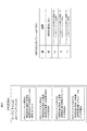
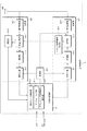
図7は、あるサービングセル#1におけるSRSに関するRRCの設定およびSRSリクエストフィールドの一例を示している。ここではサービングセルに設定されているBWPの数が2であるとしている。図7に示されるように、サービングセル#1のSRSに関する情報に、サービングセル#1におけるBWPインデックス#1に関する設定のリストが設定されており、リスト内に、SRSリソースセットに関する設定が4つ設定されている。そのうち、非周期なSRSリソースセットの設定は、SRSリソースセットに関する設定#1〜#3である。
FIG. 7 shows an example of RRC setting and SRS request field related to SRS in a serving
SRSリソースセットに関する設定#1は、トリガ状態#1に関連付けられ、SRSリソースセットに関する設定#2は、トリガ状態#2に関連付けられ、SRSリソースセットに関する設定#3は、トリガ状態#3に関連付けられている。図7に示されるように、SRSリクエストフィールドの“00”はSRSを送信しない。“01”にトリガ状態#0、“10”にトリガ状態#1、“11”にトリガ状態#2がそれぞれ関連付けられている。
The
端末装置1は、RRCで設定されたSRSに関する設定と、DCIに含まれるSRSリクエストフィールドの値に基づいて関連付けられたSRSリソースセットに関する設定に基づいて、SRSを送信する。このとき、端末装置1は、SRSに関する設定に関連付けられたSRSリソースセットに関する設定から、SRSに関する設定に含まれる設定情報に基づいてSRSを送信する。
The
また、各SRSに関する設定は、サービングセル内のBWPと関連付けられている。図6において、SRS設定#1は、BWPインデックス#1に関連付けられている。
Moreover, the setting regarding each SRS is linked | related with BWP in a serving cell. In FIG. 6,
ここで、上述の例ではSRSリクエストフィールドの1つの値に、1つのSRSリソースセットに関する設定が設定されたが、複数のSRSリソースセットが関連付けられるようにしてもよい。 Here, in the above-described example, the setting related to one SRS resource set is set to one value of the SRS request field, but a plurality of SRS resource sets may be associated.
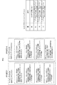
図8に、ある2つのサービングセルにおけるRRCで設定されるSRSの設定およびSRSリクエストフィールドの例を示す。図8の例も図7と同様に時間動作が非周期であるSRSリソースセットに関する設定の各々は、トリガ状態が関連付けられている。 FIG. 8 shows an example of SRS settings and SRS request fields set by RRC in two serving cells. In the example of FIG. 8 as well, the trigger state is associated with each of the settings related to the SRS resource set whose time operation is non-periodic as in FIG.
端末装置1は、SRSリクエストフィールドの値として10が指示された場合には、サービングセル#1におけるSRSリソースセットを送信する。すなわち、SRSリクエストフィールドの値(情報)は複数のトリガ状態のうちの1つを示し、複数のトリガ状態の各々は、サービングセルごとに設定され、1つまたは複数のSRSリソースセットの設定
に関連付けられる。なお、SRSリクエストフィールドの値はSRSリクエストフィール
ドに含まれる情報と換言されてもよい。
When 10 is designated as the value of the SRS request field, the
ここで、SRS設定#2のBWPインデックスとして、設定されたBWPの実際のインデックスではなく“active”が設定されている。これは、活性化されたBWPと関連付けられていることを意味する。例えば、端末装置1に対して、あるスロットにおいてBWPインデックス#1を示すBWPが活性化されている場合、SRS設定#2は活性化されているBWPインデックス#1に対応する設定であり、端末装置1は対応するBWP#1のSRSリソースセットを送信する。すなわち、PDCCHのDCIに含まれるSRSリクエストフィールドは、トリガ状態を含み、各トリガ状態は1つまたは複数のSRSリソースセットに関する設定に関連付けられ、SRS設定は、サービングセルcの活性化されたBWPに関連付けられるように設定されてもよい。
Here, “active” is set as the BWP index of
図8は、2つのサービングセルが設定された場合の例を示す。ここでは、サービングセル数として2つが設定され、各セルで、非周期のSRSリソースセットに関する設定にトリガ状態が割り当てられる例を示している。同図のように、SRSリクエストフィールドには複数の非周期のSRSリソースセットに関する設定が関連付けられる。例えば、サービングセル#1のトリガ状態#0と、サービングセル#2のトリガ状態#0がコードポイント“01”に設定されている。
FIG. 8 shows an example when two serving cells are set. Here, two are set as the number of serving cells, and an example is shown in which a trigger state is assigned to a setting related to an aperiodic SRS resource set in each cell. As shown in the figure, settings related to a plurality of non-periodic SRS resource sets are associated with the SRS request field. For example, the
ここで、あるスロットにおいて、端末装置1に対してSRSリクエストフィールドの値として“10”が指示された場合、端末装置1はサービングセル#1のBWP#1のSRSリソースセットと、サービングセル#2のBWP#1のSRSリソースセットを送信する。このとき、サービングセル#1のBWP#1とサービングセル#2のBWP#1がともに活性化されている場合、端末装置1はサービングセル#1のBWP#1とサービングセル#2のBWP#1のSRSリソースセットを送信する。
Here, in a certain slot, when “10” is instructed to the
また、サービングセル#1のBWP#1が活性化されており、サービングセル#2のBWP#2が活性化されている場合、末装置1はサービングセル#1のBWP#1のCSIを報告する。このように、複数のサービングセルが設定され、SRSリクエストフィールドの値により指示された各サービングセルのSRSリソースセットを送信する。すなわち、端末装置1は、SRSリクエストフィールドを含むDCIを運ぶPDCCHを受信し、SRSリクエストフィールドに基づいて複数のサービングセルにおけるBWPのSRS送信要求がトリガされた場合に、活性化されているBWPインデックスが示すBWPのCSI報告を送信する。このとき、SRSリクエストフィールドはトリガ状態を示し、トリガ状態は、複数の状態のうち1つを示す。複数の状態の各々の状態は、サービングセル毎に設定され、1つまたは複数のSRSリソースセットに関する設定および1つまたは複数のSRSリソースセットに関する設定および各サービングセルにおけるBWPインデックスに関連付けられる。
Further, when
上述の例では、各サービングセルのSRSリソースセットに関する設定がBWPインデックスに関する設定に常に関連付けられている場合を示したが、BWPが1つの場合には関連付ける情報が設定されなくてよい。この場合、サービングセルの帯域幅に基づいてSRSリソースセットを送信してよい。 In the above-described example, the case where the setting related to the SRS resource set of each serving cell is always associated with the setting related to the BWP index is shown. However, when there is one BWP, the related information may not be set. In this case, the SRS resource set may be transmitted based on the serving cell bandwidth.
また、上述の例ではSRSリソースセットに関する設定にトリガ状態のインデックスを示す情報を含んだが、SRSリソースセットに関する設定がトリガ状態のリストを含み、各トリガ状態がどのSRSリソースセットに関する設定を含むかが設定されてもよい。 In the above example, the setting regarding the SRS resource set includes information indicating the index of the trigger state. However, the setting regarding the SRS resource set includes a list of trigger states, and which SRS resource set includes each trigger state. It may be set.
以下、サウンディング参照信号送信に適用する空間ドメイン送信フィルタについて説明する。 Hereinafter, a spatial domain transmission filter applied to sounding reference signal transmission will be described.
前述のように、基地局装置3は端末装置1に対し、あるSRSリソースの設定に空間関係情報(Spatial Relation Info)を同期信号のブロックとして設定することができる。
空間関係情報(Spatial Relation Info)を同期信号のブロックとして設定された端末装
置1は、各種下りリンク信号を受信する。端末装置1は、各種下りリンク信号のうち、SRSの設定によりSRSリソースに関連づけられた同期信号のブロックを特定し、当該の同期信号ブロックを受信した際に適用した空間ドメイン受信フィルタを特定する。さらに端末装置1は、当該のSRSリソースを送信する際に、前記空間ドメイン受信フィルタを空間ドメイン送信フィルタとして適用し、SRSリソースを送信する。
As described above, the
The
次に、BWP切り替えを勘案した空間ドメイン受信フィルタの特定およびSRSリソース送信について説明する。BWP切り替えに伴い、SRS設定で端末装置1に設定した同期信号のブロックおよび/またはSRSリソースが、インアクティブBWPとなりえる。具体的には、SRS設定を通知した際にはインアクティブBWPに対応したSRSリソースが、BWP切り替えに伴いSRSリソースの送信タイミング以前にアクティブBWPとなる。または、SRS設定を通知した際にはアクティブBWPに対応した同期信号のブロックが、BWP切り替えに伴いSRSリソースの送信タイミング以前にインアクティブBWPとなる。
Next, the identification of the spatial domain reception filter and the SRS resource transmission taking into account BWP switching will be described. Along with the BWP switching, the block of the synchronization signal and / or the SRS resource set in the
端末装置1は、SRS設定を通知した際にはインアクティブBWPに対応したSRSリソースが、BWP切り替えに伴いSRSリソースの送信タイミング以前にアクティブBWPとなった場合、設定された同期信号のブロックがアクティブなDL BWPで送信された際に適用した、空間ドメイン受信フィルタを特定する。さらに端末装置1は、アクティブとなったUL BWPで、前述の空間ドメイン受信フィルタを空間ドメイン送信フィルタとして用い、SRSリソースを送信する。また端末装置1は、前述の同期信号のブロックの受信タイミングよりも早い時点で当該SRSリソースの送信タイミングとなった場合にはSRSリソースの送信を行わず、同期信号ブロックの受信タイミング以降にSRSリソースを送信することとしてもよい。
When the
端末装置1は、SRS設定を通知した際にはアクティブBWPに対応した同期信号のブロックが、BWP切り替えに伴いSRSリソースの送信タイミング以前にインアクティブなDL BWPに対応した信号となった場合、当該SRSリソースの送信を行わない。
When the
また、上述の例ではSRS設定で通知されアクティブなDL BWPで送信された同期信号のブロックを受信する際に適用した空間ドメイン受信フィルタを特定することとしたが、SRS設定で他のSRSリソースに対し設定された同期信号のブロックを受信する際に適用した、空間ドメイン受信フィルタをSRSリソースの送信に適用する空間ドメイン送信フィルタとしてもよい。 In the above example, the spatial domain reception filter applied when receiving the block of the synchronization signal notified by the SRS setting and transmitted by the active DL BWP is specified, but other SRS resources are set by the SRS setting. On the other hand, the spatial domain reception filter applied when receiving the set block of the synchronization signal may be a spatial domain transmission filter applied to the transmission of the SRS resource.
前述のように、基地局装置3は端末装置1に対し、あるSRSリソースの設定に空間関係情報(Spatial Relation Info)をCSI参照信号として設定することができる。空間
関係情報(Spatial Relation Info)をCSI参照信号として設定された端末装置1は、
各種下りリンク信号を受信する。端末装置1は、各種下りリンク信号のうち、SRSの設定によりSRSリソースに関連づけられたCSI参照信号を特定し、当該のCSI参照信号を受信した際に適用した空間ドメイン受信フィルタを特定する。さらに端末装置1は、当該のSRSリソースを送信する際に、前記空間ドメイン受信フィルタを空間ドメイン送信フィルタとして適用し、SRSリソースを送信する。
As described above, the
Various downlink signals are received. The
次に、BWP切り替えを勘案した空間ドメイン受信フィルタの特定およびSRSリソース送信について説明する。BWP切り替えに伴い、SRS設定で端末装置1に設定したC
SI参照信号および/またはSRSリソースが、インアクティブBWPとなりえる。具体的には、SRS設定を通知した際にはインアクティブBWPに対応したSRSリソースが、BWP切り替えに伴いSRSリソースの送信タイミング以前にアクティブBWPとなる。または、SRS設定を通知した際にはアクティブBWPに対応したCSI参照信号が、BWP切り替えに伴いSRSリソースの送信タイミング以前にインアクティブBWPとなる。
Next, identification of a spatial domain reception filter and SRS resource transmission taking into account BWP switching will be described. C set in the
SI reference signals and / or SRS resources can be inactive BWPs. Specifically, when the SRS setting is notified, the SRS resource corresponding to the inactive BWP becomes the active BWP before the transmission timing of the SRS resource in accordance with the BWP switching. Alternatively, when the SRS setting is notified, the CSI reference signal corresponding to the active BWP becomes the inactive BWP before the transmission timing of the SRS resource in accordance with the BWP switching.
端末装置1は、SRS設定を通知した際にはインアクティブBWPに対応したSRSリソースが、BWP切り替えに伴いSRSリソースの送信タイミング以前にアクティブBWPとなった場合、設定されたCSI参照信号がアクティブなDL BWPで送信された際に適用した、空間ドメイン受信フィルタを特定する。さらに端末装置1は、アクティブとなったUL BWPで、前述の空間ドメイン受信フィルタを空間ドメイン送信フィルタとして用い、SRSリソースを送信する。また端末装置1は、前述のCSI参照信号の受信タイミングよりも早い時点で当該SRSリソースの送信タイミングとなった場合にはSRSリソースの送信を行わず、CSI参照信号の受信タイミング以降にSRSリソースを送信することとしてもよい。また端末装置1は、前述のCSI参照信号の受信タイミングよりも早い時点で当該SRSリソースの送信タイミングとなった場合にはSRSリソースの送信を行わないこととしたが、CSI参照信号の受信タイミングより早い時点で送信されるCSI参照信号がアクティブなDL BWPで送信された際に適用した、空間ドメイン受信フィルタを特定することとしてもよい。
When the
端末装置1は、SRS設定を通知した際にはアクティブBWPに対応したCSI参照信号が、BWP切り替えに伴いSRSリソースの送信タイミング以前にインアクティブなDL BWPに対応した信号となった場合、当該SRSリソースの送信を行わない。
When the
また、上述の例ではSRS設定で通知されアクティブなDL BWPで送信されたCSI参照信号を受信する際に適用した空間ドメイン受信フィルタを特定することとしたが、SRS設定で他のSRSリソースに対し設定されたCSI参照信号を受信する際に適用した、空間ドメイン受信フィルタをSRSリソースの送信に適用する空間ドメイン送信フィルタとしてもよい。 In the above example, the spatial domain reception filter applied when receiving the CSI reference signal notified by the SRS setting and transmitted by the active DL BWP is specified. However, for the other SRS resources, the SRS setting is used. The spatial domain reception filter applied when receiving the set CSI reference signal may be a spatial domain transmission filter applied to SRS resource transmission.
前述のように、基地局装置3は端末装置1に対し、あるSRSリソースの設定に空間関係情報(Spatial Relation Info)を上りリンク参照信号(SRSリソース)として設定
することができる。以下、区別のため前者のSRSリソースを着目SRSリソース、後者のSRSリソースを参照SRSリソースと称する。空間関係情報(Spatial Relation Info)を参照SRSリソースとして設定された端末装置1は、各種上りリンク信号を送信す
る。端末装置1は、各種上りリンク信号のうち、SRSの設定により着目SRSリソースに関連づけられた参照SRSリソースを特定し、参照SRSリソースを送信した際に適用した空間ドメイン送信フィルタを特定する。さらに端末装置1は、着目SRSリソースを送信する際に、前記空間ドメイン送信フィルタを適用し、着目SRSリソースを送信する。
As described above, the
次に、BWP切り替えを勘案した空間ドメイン送信フィルタの特定およびSRSリソース送信について説明する。BWP切り替えに伴い、SRS設定で端末装置1に設定した着目SRSリソースが、インアクティブBWPとなりえる。具体的には、SRS設定を通知した際にはインアクティブBWPに対応した着目SRSリソースが、BWP切り替えに伴い着目SRSリソースの送信タイミング以前にアクティブBWPとなる。または、SRS設定を通知した際にはアクティブBWPに対応した着目SRSリソースが、BWP切り替えに伴い着目SRSリソースの送信タイミング以前にインアクティブBWPとなる。
Next, identification of a spatial domain transmission filter and SRS resource transmission taking into account BWP switching will be described. Along with the BWP switching, the SRS resource of interest set in the
端末装置1は、SRS設定を通知した際にはインアクティブBWPに対応した着目SRSリソースが、BWP切り替えに伴い着目SRSリソースの送信タイミング以前にアクティブBWPとなった場合、設定された参照SRSリソースをアクティブなUL BWPで送信した際に適用した、空間ドメイン送信フィルタを特定する。さらに端末装置1は、アクティブとなったUL BWPで、前述の空間ドメイン送信フィルタを用い、着目SRSリソースを送信する。また端末装置1は、前述の参照SRSリソースの送信タイミングよりも早い時点で着目SRSリソースの送信タイミングとなった場合には着目SRSリソースの送信を行わず、参照SRSリソースの送信タイミング以降に着目SRSリソースを送信することとしてもよい。
When the
端末装置1は、SRS設定を通知した際にはアクティブBWPに対応した参照SRSリソースが、BWP切り替えに伴い着目SRSリソースの送信タイミング以前にインアクティブなUL BWPに対応した信号となった場合、着目SRSリソースの送信を行わない。
When the
また、上述の例ではSRS設定で通知されアクティブなUL BWPで送信された参照SRSリソースを送信する際に適用した空間ドメイン送信フィルタを特定することとしたが、SRS設定で他のSRSリソースに対し設定された参照SRSリソースを送信する際に適用した、空間ドメイン送信フィルタをSRSリソースの送信に適用してもよい。 In the above example, the spatial domain transmission filter applied when transmitting the reference SRS resource notified by the SRS setting and transmitted by the active UL BWP is specified. A spatial domain transmission filter applied when transmitting the set reference SRS resource may be applied to the transmission of the SRS resource.
前述のように、基地局装置3は端末装置1に対し、あるSRSリソースセットの設定に対応CSI参照信号(associatedCSI-RS)を設定することができる。あるCSI参照信号を対応CSI参照信号として設定された端末装置1は、各種下りリンク信号を受信する。端末装置1は、各種下りリンク信号のうち、SRSの設定によりSRSリソースセットに関連づけられた対応CSI参照信号を特定し、対応CSI参照信号を受信した際に適用した空間ドメイン受信フィルタを特定する。さらに端末装置1は、当該のSRSリソースセットを送信する際に、前記空間ドメイン受信フィルタを空間ドメイン送信フィルタとして適用し、SRSリソースセットを送信する。
As described above, the
次に、BWP切り替えを勘案した空間ドメイン受信フィルタの特定およびSRSリソースセット送信について説明する。BWP切り替えに伴い、SRS設定で端末装置1に設定した対応CSI参照信号および/またはSRSリソースセットが、インアクティブBWPとなりえる。具体的には、SRS設定を通知した際にはインアクティブBWPに対応したSRSリソースセットが、BWP切り替えに伴いSRSリソースセットの送信タイミング以前にアクティブBWPとなる。または、SRS設定を通知した際にはアクティブBWPに対応したCSI参照信号が、BWP切り替えに伴いSRSリソースセットの送信タイミング以前にインアクティブBWPとなる。
Next, identification of a spatial domain reception filter and SRS resource set transmission taking into account BWP switching will be described. Along with the BWP switching, the corresponding CSI reference signal and / or SRS resource set set in the
端末装置1は、SRS設定を通知した際にはインアクティブBWPに対応したSRSリソースセットが、BWP切り替えに伴いSRSリソースセットの送信タイミング以前にアクティブBWPとなった場合、設定された対応CSI参照信号がアクティブなDL BWPで送信された際に適用した、空間ドメイン受信フィルタを特定する。さらに端末装置1は、アクティブとなったUL BWPで、前述の空間ドメイン受信フィルタを空間ドメイン送信フィルタとして用い、SRSリソースセットを送信する。また端末装置1は、前述の対応CSI参照信号の受信タイミングよりも早い時点で当該SRSリソースセットの送信タイミングとなった場合にはSRSリソースセットの送信を行わず、対応CSI参照信号の受信タイミング以降にSRSリソースセットを送信することとしてもよい。また端末装置1は、前述の対応CSI参照信号の受信タイミングよりも早い時点で当該SRSリソースセットの送信タイミングとなった場合にはSRSリソースセットの送信を行わないこととしたが、対応CSI参照信号の受信タイミングより早い時点で送信される対応CSI
参照信号がアクティブなDL BWPで送信された際に適用した、空間ドメイン受信フィルタを特定することとしてもよい。
When the
The spatial domain reception filter applied when the reference signal is transmitted by the active DL BWP may be specified.
端末装置1は、SRS設定を通知した際にはアクティブBWPに対応した対応CSI参照信号が、BWP切り替えに伴いSRSリソースセットの送信タイミング以前にインアクティブなDL BWPに対応した信号となった場合、当該SRSリソースセットの送信を行わない。
When the
また、上述の例ではSRS設定で通知されアクティブなDL BWPで送信された対応CSI参照信号を受信する際に適用した空間ドメイン受信フィルタを特定することとしたが、SRS設定で他のSRSリソースセットに対し設定された対応CSI参照信号を受信する際に適用した、空間ドメイン受信フィルタをSRSリソースセットの送信に適用する空間ドメイン送信フィルタとしてもよい。 In the above example, the spatial domain reception filter applied when receiving the corresponding CSI reference signal notified by the SRS setting and transmitted by the active DL BWP is specified. However, other SRS resource sets are set by the SRS setting. The spatial domain reception filter applied when receiving the corresponding CSI reference signal set for the SRS may be used as a spatial domain transmission filter applied to the transmission of the SRS resource set.
非周期(Aperiodic)SRSの例について説明する。1つまたは複数のSRSリソース
設定が設定され、SRSリソース設定に関する時間領域の動作(SRSリソース設定のタイプ、SRSの送信タイプ、送信の方法などと換言されてもよい)が“非周期”と設定された端末装置1は、下記の動作をしてよい。
・1つまたは複数のSRSリソースセットの設定を受信する
・下りリンクDCIまたはグループ共通DCIまたは上りリンクDCIに基づく活性化(Activation)コマンドを受信する。ただし、DCIのコードポイントは1つまたは複数のSRSリソースセットを活性化してよい。DCIのコードポイントは、CSIリクエストフィールドの値であってよい。
・もし上位レイヤのSRS送信のための空間ドメイン送信フィルタ(QCLや送信ビームに関する設定などと称されてもよい)パラメータSRS-SpatialRelationInfoが”SSB/PBCH
”に設定されていれば、端末装置1はSS/PBCHブロック(SSB/PBCHと表現されてもよい)の受信のために使われる空間ドメイン送信フィルタと同じ空間ドメイン送信フィルタでSRSリソースを送信する(SRSリソースによりSRSを送信すると表現されてもよい)。また、もし上位レイヤのSRS送信のための空間ドメイン送信フィルタ(QCLや送信ビームに関する設定などと称されてもよい)パラメータSRS-SpatialRelationInfo
が”CSI-RS”に設定されていれば、端末装置1は周期的またはセミパーシステントまたは非周期CSI−RSの受信のために使われる空間ドメイン送信フィルタと同じ空間ドメイン送信フィルタでSRSリソースを送信する(SRSリソースによりSRSを送信すると表現されてもよい)。また、もし上位レイヤのSRS送信のための空間ドメイン送信フィルタ(QCLや送信ビームに関する設定などと称されてもよい)パラメータSRS-SpatialRelationInfoが”SRS”に設定されていれば、端末装置1は周期的またはセミパーシステントまたは非周期SRSの受信のために使われる空間ドメイン送信フィルタと同じ空間ドメイン送信フィルタでSRSリソースを送信する(SRSリソースによりSRSを送信すると表現されてもよい)。
An example of an aperiodic SRS will be described. One or a plurality of SRS resource settings are set, and the operation in the time domain related to SRS resource settings (may be rephrased as SRS resource setting type, SRS transmission type, transmission method, etc.) is set as “non-periodic” The
Receive configuration of one or more SRS resource sets. Receive an activation command based on downlink DCI, group common DCI or uplink DCI. However, the DCI code point may activate one or more SRS resource sets. The DCI code point may be the value of the CSI request field.
-Spatial domain transmission filter for higher layer SRS transmission (may be referred to as QCL or setting related to transmission beam) Parameter SRS-SpatialRelationInfo is "SSB / PBCH
If it is set to “,” the
Is set to “CSI-RS”, the
非周期SRSのために、DCIフィールドの少なくとも1つの状態が設定されたSRSリソースセットから少なくとも1つを選択するために用いられる。 For aperiodic SRS, at least one state of the DCI field is used to select at least one from the configured SRS resource set.
DCIフォーマット0_1または1_1内の2ビットSRSリクエストフィールドは、トリガされたSRSリソースセットを指示する。DCIフォーマット2_3での2ビットSRSリクエストフィールドはトリガされたSRSリソースセットを指示する。 A 2-bit SRS request field in DCI format 0_1 or 1_1 indicates the triggered SRS resource set. The 2-bit SRS request field in DCI format 2_3 indicates the triggered SRS resource set.
DCIフォーマット0_1または1_1内の2ビットSRSリクエストフィールドは、下記のようなSRSリクエストフィールドの値と説明(description)が定義されてよい
。
・SRSリクエストフィールドの値’00’:(説明)非周期SRSをトリガしない
・SRSリクエストフィールドの値’01’:(説明)上位レイヤで設定された第1の1つまたは複数のSRSリソースセット
・SRSリクエストフィールドの値’10’:(説明)上位レイヤで設定された第2の1つまたは複数のSRSリソースセット
・SRSリクエストフィールドの値’11’:(説明)上位レイヤで設定された第3の1つまたは複数のSRSリソースセット
DCIフォーマット2_3内の2ビットSRSリクエストフィールドは、下記のようなSRSリクエストフィールドの値と説明(description)が定義されてよい。
・SRSリクエストフィールドの値’00’:(説明)非周期SRSをトリガしない
・SRSリクエストフィールドの値’01’:(説明)上位レイヤで設定されたサービングセルの第1のセットのための非周期SRSをトリガする
・SRSリクエストフィールドの値’10’:(説明)上位レイヤで設定されたサービングセルの第2のセットのための非周期SRSをトリガする
・SRSリクエストフィールドの値’11’:(説明)上位レイヤで設定されたサービングセルの第3のセットのための非周期SRSをトリガする
なお、周期的なSRSまたはセミパーシステントSRSをタイプ0 SRS、下りリンクDCIによりトリガされる非周期SRSをタイプ1 SRSと称してもよい。
In the 2-bit SRS request field in the DCI format 0_1 or 1_1, the value and description of the SRS request field as described below may be defined.
SRS request field value '00': (Explanation) Aperiodic SRS is not triggered. SRS request field value '01': (Explanation) First one or more SRS resource sets set in the upper layer. SRS request field value '10': (Explanation) Second one or more SRS resource sets set in the upper layer · SRS request field value '11': (Explanation) Third set in the upper layer One or a plurality of SRS resource sets in the 2-bit SRS request field in the DCI format 2_3 may be defined with the following SRS request field values and descriptions.
-SRS request field value '00': (Explanation) Aperiodic SRS is not triggered-SRS request field value '01': (Explanation) Aperiodic SRS for the first set of serving cells configured in higher layers SRS request field value '10': (description) Triggers aperiodic SRS for the second set of serving cells configured in higher layers. SRS request field value '11': (description) Trigger aperiodic SRS for the third set of serving cells configured in higher layers Note that periodic SRS or semi-persistent SRS is
もし端末装置1が上位レイヤパラメータでSRSとCSI−RSの関連付けが設定されており、送信方法に関する設定がノンコードブック(NonCodebook)に設定されている場
合には、NZP CSI−RSのアイデンティティがあるSRSリソースセットが関連付けられている1つのNZP CSI−RSリソースが設定されてよい。
If the
次に、非周期SRSのための状態の設定について説明する。DCIに含まれる情報フィールド(SRSリクエストフィールド)の値が示す複数の状態は、RRC層で設定されてよい。 Next, setting of a state for aperiodic SRS will be described. A plurality of states indicated by the value of the information field (SRS request field) included in the DCI may be set in the RRC layer.
SRS設定は、各サービングセルの上りリンクBWP毎に設定される。SRS設定は、SRSリソースセットに関する設定のリストと、そのSRSリソースセットのアイデンティティのリストを含んでいる。また、SRSリソースに関する設定のリストと、そのSRSリソースのアイデンティティのリストを含んでもよい。SRSリソースセットに関する設定のリストに含まれる各SRSリソースセットに関する設定は、SRSリソースセットのアイデンティティと、そのSRSリソースセットに含まれる1つまたは複数のSRSリソースのアイデンティティを含んでいる。また、各SRSリソースセットに関する設定は、SRSの送信方法として”非周期(Aperiodic)”、”セミパーシステント(Semi-persistent)”または”周期的(Periodic)”のいずれかを示す設定(リソースタイプと称してもよい)を含んでいる。例えば、”非周期”と設定されている場合にはそのSRSリソースセットは非周期SRSの送信が設定されている。 The SRS setting is set for each uplink BWP of each serving cell. The SRS settings include a list of settings related to the SRS resource set and a list of identities of the SRS resource set. Moreover, you may include the list | wrist of the setting regarding SRS resource, and the list | wrist of the identity of the SRS resource. The setting for each SRS resource set included in the list of settings for the SRS resource set includes the identity of the SRS resource set and the identities of one or more SRS resources included in the SRS resource set. Moreover, the setting regarding each SRS resource set is a setting (resource type) indicating any one of “Aperiodic”, “Semi-persistent”, and “Periodic” as the SRS transmission method. May be called). For example, when “non-periodic” is set, the SRS resource set is set to transmit non-periodic SRS.
SRSの送信方法として、”非周期”と設定された場合には、そのSRSリソースセットがどのコードポイントに対応するかを示す情報(aperiodicSRS-ResourceTrigger)、トリガしたスロットからSRS送信までのオフセット(単位はスロット数、OFDMシンボル数でもよい)が”非周期”を指示する情報に含まれる。例えば、あるSRSリソースセットの設定が”非周期”と設定する情報を含みどのコードポイントに対応するかを示す情報が0である場合、第1のSRSリソースセットに対応する。この場合、SRSリクエストフィールドの値が01でこのSRSリソースセットに含まれるSRSリソースでSRS送信がトリガされる。 When “non-periodic” is set as the SRS transmission method, information indicating which code point the SRS resource set corresponds to (aperiodicSRS-ResourceTrigger), offset from the triggered slot to SRS transmission (unit) May be the number of slots and the number of OFDM symbols) is included in the information indicating “non-periodic”. For example, when the setting of a certain SRS resource set includes information set as “non-periodic” and the information indicating which code point corresponds to 0, this corresponds to the first SRS resource set. In this case, the value of the SRS request field is 01, and SRS transmission is triggered by the SRS resource included in this SRS resource set.
次に、複数のサービングセルが設定された場合の例を説明する。複数のサービングセル
が設定された場合、サービングセル毎に上りリンクBWPが設定される。各サービングセルにおける各上りリンクBWPについて、上述の方法と同様に、SRS設定が設定される。ここで、サービングセル#0の上りリンクBWP#1のアイデンティティ#0(またはインデックス0)のSRSリソースセットが第1のSRSリソースセットに関連付けられ、サービングセル#1の上りリンクBWP#0のアイデンティティ#0のSRSリソースセットが第1のSRSリソースセットに関連付けられているとすると、DCIに含まれるSRSリクエストフィールドの値が“01”である場合、端末装置1はサービングセル0の上りリンクBWP#1のアイデンティティ#0のSRSリソースセットのSRSリソースと、サービングセル1の上りリンクBWP#0のアイデンティティ#0のSRSリソースセットのSRSリソースでSRSを送信する。あるSRSリクエストフィールドの値に対応する1つの状態に関連付けられた上りリンクBWPでその状態に関連付けられたSRSリソースセットのSRSリソースでSRSを送信することを、SRSリクエストフィールドの値に対応するサービングセルの上りリンクBWPでのSRS送信と記述する。また、SRSリクエストフィールドの値に対応するサービングセルおよび上りリンクBWPアイデンティティを持つ上りリンクBWPを、SRSリクエストフィールドの値に対応するサービングセルの上りリンクBWPと記述する。
Next, an example when a plurality of serving cells are set will be described. When a plurality of serving cells are set, an uplink BWP is set for each serving cell. For each uplink BWP in each serving cell, the SRS configuration is set in the same manner as described above. Here, the SRS resource set of the identity # 0 (or index 0) of the
ここで、周波数分割復信(FDD:Frequency Division Duplex、ペアードスペクトル
(paired spectrum)またはキャリアまたは周波数と称されてもよい)の場合は、DCI
フォーマット1_0または1_1で下りリンクBWPが1つ活性化または切り替えが行われてよく、DCIフォーマット0_0または0_1で上りリンクBWPが1つ活性化または切り替えが行われてよい。時分割復信(TDD:Time Division Duplex、アンペアードスペクトルまたはキャリアまたは周波数と称されてもよい)の場合は、DCIフォーマット0_0または0_1または1_0または1_1で下りリンクBWPと上りリンクBWPが同じタイミングで活性化または切り替えが行われてよい。また、下りリンクBWPまたは上りリンクBWPはRRC層で切り替えてもよい。
Here, in the case of frequency division duplex (FDD: Frequency Division Duplex, which may be referred to as a paired spectrum or a carrier or frequency), DCI
One downlink BWP may be activated or switched in the format 1_0 or 1_1, and one uplink BWP may be activated or switched in the DCI format 0_0 or 0_1. In the case of time division duplex (TDD: Time Division Duplex, may also be referred to as unpaired spectrum or carrier or frequency), downlink BWP and uplink BWP are active at the same timing in DCI format 0_0, 0_1, 1_0, or 1_1. Or switching may be performed. Also, downlink BWP or uplink BWP may be switched at the RRC layer.
また、1つまたは複数の下りリンクBWPのそれぞれのBWPは、下りリンクBWPインデックス(またはアイデンティティ)で識別され、1つまたは複数の上りリンクBWPのそれぞれのBWPは、上りリンクBWPインデックス(またはアイデンティティ)で識別されてよい。 Also, each BWP of one or more downlink BWPs is identified by a downlink BWP index (or identity), and each BWP of one or more uplink BWPs is an uplink BWP index (or identity). May be identified.
複数のサービングセルが設定された場合、SRSリクエストフィールドの値に対応する複数の状態の各々は、上述のRRC設定に基づいて1つまたは複数の上りリンクBWPに関連付けられたSRSリソースセットに対応する。このとき、2つのサービングセルが設定されている場合、SRSリクエストフィールドのある値が対応する1つの状態に関連付けられているSRSリソースセットの上りリンクBWPの活性化の状況として、下記の4つの状況があり得る。なお、下記の状況における上りリンクBWPは、DCIのSRSリクエストフィールドの値に対応する状態に関連付けられた1つまたは複数のサービングセルの上りリンクBWPのアイデンティティ(インデックス)に関連付けられた上りリンクBWPであってよい。
・状況1
1.SRSリクエストフィールドの値に対応するサービングセル#0の上りリンクBWPが活性化されている
2.SRSリクエストフィールドの値に対応するサービングセル#1の上りリンクBWPが活性化されている
・状況2
1.SRSリクエストフィールドの値に対応するサービングセル#0の上りリンクBWPが活性化されている
2.SRSリクエストフィールドの値に対応するサービングセル#1の上りリンクB
WPが活性化されていない
・状況3
1.SRSリクエストフィールドの値に対応するサービングセル#0の上りリンクBWPが活性化されていない
2.SRSリクエストフィールドの値に対応するサービングセル#1の上りリンクBWPが活性化されている
・状況4
1.SRSリクエストフィールドの値に対応するサービングセル#0の上りリンクBWPが活性化されていない
2.SRSリクエストフィールドの値に対応するサービングセル#1の上りリンクBWPが活性化されていない
状況1の場合は、SRSリクエストフィールドの値に対応する状態に関連付けられたサービングセル#0とサービングセル#1の上りリンクBWPが活性化されているため、それぞれのSRS設定に基づいてSRSを送信する。
When multiple serving cells are configured, each of the multiple states corresponding to the value of the SRS request field corresponds to an SRS resource set associated with one or more uplink BWPs based on the RRC configuration described above. At this time, when two serving cells are set, the following four situations are available as the uplink BWP activation status of the SRS resource set associated with one state corresponding to a certain value of the SRS request field. possible. The uplink BWP in the following situation is an uplink BWP associated with the identity (index) of the uplink BWP of one or more serving cells associated with the state corresponding to the value of the SRS request field of DCI. It's okay.
・
1. 1. The uplink BWP of serving
1. 1. The uplink BWP of serving
WP is not activated ・
1. 1. The uplink BWP of serving
1. 1. The uplink BWP of serving
状況2の場合は、SRSリクエストフィールドの値に対応する状態に関連付けられたサービングセル#0の上りリンクBWPが活性化されており、SRSリクエストフィールドの値に対応する状態に関連付けられたサービングセル#1の上りリンクBWPが活性化されていないため、サービングセル#0のSRS設定に基づいてサービングセル#0の上りリンクBWPでSRSを送信する。このとき、サービングセル#1の上りリンクBWPでのSRS送信はドロップされてもよい。
In the case of the
状況3の場合は、SRSリクエストフィールドの値に対応する状態に関連付けられたサービングセル#1の上りリンクBWPが活性化されており、SRSリクエストフィールドの値に対応する状態に関連付けられたサービングセル#0の上りリンクBWPが活性化されていないため、サービングセル#0のSRS設定に基づいてサービングセル#1の上りリンクBWPでSRSを送信する。このとき、サービングセル#0の上りリンクBWPでのSRS送信はドロップされてもよい。
In the case of the
状況4の場合は、SRSリクエストフィールドの値に対応する状態に関連付けられたサービングセル#0とサービングセル#1の上りリンクBWPが活性化されていないため、端末装置1はこの状況、すなわち活性化されていない上りリンクBWPの非周期SRSのトリガを期待しなくてよい。また、基地局装置3は、SRSリクエストフィールドの値として00(または0)でない値を指示する場合、SRSリクエストフィールドの値は少なくともSRSリクエストフィールドの値に対応するサービングセルの上りリンクBWPの少なくとも1つは活性化されている状態に対応する値にする。
In the case of the
このように、本発明では各サービングセルにおいて、設定された1つまたは複数の上りリンクBWPのうち1つが活性化され、1つまたは複数のサービングセルにおけるSRS送信がトリガされた場合に、活性化されている上りリンクBWPインデックスが示すBWPのSRSを送信してよい。上述の例では、2つのサービングセルの場合の例を示したが、3つ以上のサービングセルが設定された場合でも、活性化された上りリンクBWPのSRSを送信するという点で同様に適用可能である。 Thus, in the present invention, each serving cell is activated when one of the configured one or more uplink BWPs is activated and SRS transmission in one or more serving cells is triggered. The BRS SRS indicated by the existing uplink BWP index may be transmitted. In the above-described example, an example in the case of two serving cells has been shown, but even when three or more serving cells are set, the present invention can be similarly applied in that an SRS of an activated uplink BWP is transmitted. .
また、本発明では、SRSリクエストフィールドは、SRSリクエストフィールドの値を示し、SRSリクエストフィールドの値の各々は、複数の状態の内の一つを示し、複数の状態の各々の状態はサービングセル毎に設定される。 In the present invention, the SRS request field indicates a value of the SRS request field, each of the values of the SRS request field indicates one of a plurality of states, and each state of the plurality of states is for each serving cell. Is set.
また、本発明では、上述のように、各サービングセルにおいて、設定された1つまたは複数の下りリンクBWPのうち1つが活性化され、各サービングセルにおいて、設定され
た1つまたは複数の上りリンクBWPのうち1つが活性化され、1つまたは複数のサービングセルにおけるSRS送信がトリガされた場合に、活性化されている上りリンクBWPインデックスが示すBWPのSRSを送信する。
Further, in the present invention, as described above, one of one or more downlink BWPs set in each serving cell is activated, and one or more uplink BWPs set in each serving cell are activated. When one of them is activated and SRS transmission in one or more serving cells is triggered, the SRS of the BWP indicated by the activated uplink BWP index is transmitted.
本実施形態の一態様は、LTEやLTE−A/LTE−A Proといった無線アクセス技術(RAT: Radio Access Technology)とのキャリアアグリゲーションまたはデュアルコネクティビティにおいてオペレーションされてもよい。このとき、一部またはすべてのセルまたはセルグループ、キャリアまたはキャリアグループ(例えば、プライマリセル(PCell: Primary Cell)、セカンダリセル(SCell: Secondary Cell)、プライマリセカンダリセル(PSCell)、MCG(Master Cell Group)、SCG(Secondary Cell Group)
など)で用いられてもよい。また、単独でオペレーションするスタンドアローンで用いられてもよい。デュアルコネクティビティオペレーションにおいては、SpCell(Special Cell)は、MACエンティティがMCGに関連付けられているか、SCGに関連付けられているかに応じて、それぞれ、MCGのPCellまたは、SCGのPSCellと称する。デュアルコネクティビティオペレーションでなければ、SpCell(Special Cell)は、PCellと称する。SpCell(Special Cell)は、PUCCH送信と、競合ベースランダム
アクセスをサポートする。
One aspect of this embodiment may be operated in carrier aggregation or dual connectivity with a radio access technology (RAT) such as LTE or LTE-A / LTE-A Pro. At this time, some or all cells or cell groups, carriers or carrier groups (for example, primary cell (PCell: Primary Cell), secondary cell (SCell: Secondary Cell), primary secondary cell (PSCell), MCG (Master Cell Group) ), SCG (Secondary Cell Group)
Etc.). It may also be used in a stand-alone operation. In the dual connectivity operation, the SpCell (Special Cell) is referred to as an MCG PCell or an SCG PSCell, depending on whether the MAC entity is associated with the MCG or the SCG, respectively. If it is not dual connectivity operation, the SpCell (Special Cell) is called PCell. SpCell (Special Cell) supports PUCCH transmission and contention based random access.
以下、本実施形態における装置の構成について説明する。ここでは、下りリンクの無線伝送方式として、CP−OFDM、上りリンクの無線伝送方式としてCP−OFDMまたはDFTS−OFDM(SC−FDM)を適用する場合の例を示している。 Hereinafter, the configuration of the apparatus according to the present embodiment will be described. Here, an example is shown in which CP-OFDM is applied as the downlink radio transmission scheme, and CP-OFDM or DFTS-OFDM (SC-FDM) is applied as the uplink radio transmission scheme.
図9は、本実施形態の端末装置1の構成を示す概略ブロック図である。図示するように、端末装置1は、上位層処理部101、制御部103、受信部105、送信部107と送受信アンテナ109を含んで構成される。また、上位層処理部101は、無線リソース制御部1011、スケジューリング情報解釈部1013、および、サウンディング参照信号制御部1015を含んで構成される。また、受信部105は、復号化部1051、復調部1053、多重分離部1055、無線受信部1057と測定部1059を含んで構成される。また、送信部107は、符号化部1071、変調部1073、多重部1075、無線送信部1077と上りリンク参照信号生成部1079を含んで構成される。
FIG. 9 is a schematic block diagram illustrating a configuration of the
上位層処理部101は、ユーザの操作等により生成された上りリンクデータ(トランスポートブロック)を、送信部107に出力する。また、上位層処理部101は、媒体アクセス制御(MAC: Medium Access Control)層、パケットデータ統合プロトコル(Packet Data Convergence Protocol: PDCP)層、無線リンク制御(Radio Link Control: RLC)層
、無線リソース制御(Radio Resource Control: RRC)層の処理を行う。
The upper
上位層処理部101が備える無線リソース制御部1011は、自装置の各種設定情報の管理をする。また、無線リソース制御部1011は、上りリンクの各チャネルに配置される情報を生成し、送信部107に出力する。
The radio
上位層処理部101が備えるスケジューリング情報解釈部1013は、受信部105を介して受信したDCI(スケジューリング情報)の解釈をし、前記DCIを解釈した結果に基づき、受信部105、および送信部107の制御を行うために制御情報を生成し、制御部103に出力する。
The scheduling
サウンディング参照信号制御部1015は、上りリンク参照信号生成部1079に、SRSリソース設定に関連する情報を導き出すよう指示する。サウンディング参照信号制御部1015は、送信部107に、SRSリソースを送信するよう指示をする。サウンディング参照信号制御部1015は、上りリンク参照信号生成部1079がSRSを生成する
際に用いる設定をセットする。またサウンディング参照信号制御部1015は、制御部103に、空間関係情報および/または対応CSI参照信号の情報を出力する。またサウンディング参照信号制御部1015は、受信部105より入力された空間ドメイン受信フィルタを、送信部107に出力する。
The sounding reference
制御部103は、上位層処理部101からの制御情報に基づいて、受信部105、および送信部107の制御を行う制御信号を生成する。制御部103は、生成した制御信号を受信部105、および送信部107に出力して受信部105、および送信部107の制御を行う。また制御部103は、サウンディング参照信号制御部1015から入力された空間関係情報および/または対応CSI参照信号の情報を、受信部105および/または送信部107に出力する。受信部105は、制御部103から入力された空間関係情報および/または対応CSI参照信号の情報に対応する下りリンク信号を受信する際に用いた空間ドメイン受信フィルタを、サウンディング参照信号制御部1015に出力する。
The
無線受信部1057は、送受信アンテナ109を介して受信した下りリンクの信号を、中間周波数に変換し(ダウンコンバート: down covert)、不要な周波数成分を除去し、
信号レベルが適切に維持されるように増幅レベルを制御し、受信した信号の同相成分および直交成分に基づいて、直交復調し、直交復調されたアナログ信号をディジタル信号に変換する。無線受信部1057は、変換したディジタル信号からガードインターバル(Guard Interval: GI)に相当する部分を除去し、ガードインターバルを除去した信号に対して高速フーリエ変換(Fast Fourier Transform: FFT)を行い、周波数領域の信号を抽出す
る。
The radio reception unit 1057 converts a downlink signal received via the transmission /
The amplification level is controlled so that the signal level is properly maintained, quadrature demodulation is performed based on the in-phase component and the quadrature component of the received signal, and the analog signal that has been demodulated is converted into a digital signal. The radio reception unit 1057 removes a portion corresponding to a guard interval (GI) from the converted digital signal, performs a fast Fourier transform (FFT) on the signal from which the guard interval has been removed, and performs frequency conversion. Extract the region signal.
多重分離部1055は、抽出した信号を下りリンクのPDCCH、PDSCH、および下りリンク参照信号に、それぞれ分離する。また、多重分離部1055は、測定部1059から入力された伝搬路の推定値から、PDCCHおよびPUSCHの伝搬路の補償を行う。また、多重分離部1055は、分離した下りリンク参照信号を測定部1059に出力する。
The
復調部1053は、下りリンクのPDCCHに対して、復調を行い、復号化部1051へ出力する。復号化部1051は、PDCCHの復号を試み、復号に成功した場合、復号した下りリンク制御情報と下りリンク制御情報が対応するRNTIとを上位層処理部101に出力する。
復調部1053は、PDSCHに対して、QPSK(Quadrature Phase Shift Keying
)、16QAM(Quadrature Amplitude Modulation)、64QAM、256QAM等の
下りリンクグラントで通知された変調方式の復調を行い、復号化部1051へ出力する。復号化部1051は、下りリンク制御情報で通知された伝送または原符号化率に関する情報に基づいて復号を行い、復号した下りリンクデータ(トランスポートブロック)を上位層処理部101へ出力する。
The
), 16QAM (Quadrature Amplitude Modulation), 64QAM, 256QAM, etc., are demodulated using the modulation scheme notified by the downlink grant, and output to the
測定部1059は、多重分離部1055から入力された下りリンク参照信号から、下りリンクのパスロスの測定、チャネル測定、および/または、干渉測定を行う。測定部1059は、測定結果に基づいて算出したCSI、および、測定結果を上位層処理部101へ出力する。また、測定部1059は、下りリンク参照信号から下りリンクの伝搬路の推定値を算出し、多重分離部1055へ出力する。
The
送信部107は、制御部103から入力された制御信号に従って、上りリンク参照信号を生成し、上位層処理部101から入力された上りリンクデータ(トランスポートブロック)を符号化および変調し、PUCCH、PUSCH、および生成した上りリンク参照信
号を多重し、送受信アンテナ109を介して基地局装置3に送信する。また、送信部107は、サウンディング参照信号制御部1015から入力された空間ドメイン受信フィルタを、多重部1075へ出力する。
The
符号化部1071は、上位層処理部101から入力された上りリンク制御情報、および、上りリンクデータを符号化する。変調部1073は、符号化部1071から入力された符号化ビットをBPSK、QPSK、16QAM、64QAM、256QAM等の変調方式で変調する。
The
上りリンク参照信号生成部1079は、基地局装置3を識別するための物理セル識別子(physical cell identity: PCI、Cell IDなどと称する。)、上りリンク参照信号を配置する帯域幅、上りリンクグラントで通知されたサイクリックシフト、DMRSシーケンスの生成に対するパラメータの値などを基に、予め定められた規則(式)で求まる系列を生成する。また、上りリンク参照信号生成部は、SRSリソースの送信に際し適用した空間ドメイン送信フィルタを、多重部1075に出力する。
The uplink reference
多重部1075は、PUSCHのスケジューリングに用いられる情報に基づき、空間多重されるPUSCHのレイヤの数を決定し、MIMO空間多重(MIMO SM: Multiple Input Multiple Output Spatial Multiplexing)を用いることにより同一のPUSCHで送信される複数の上りリンクデータを、複数のレイヤにマッピングし、このレイヤに対してプレコーディング(precoding)を行う。 Multiplexer 1075 determines the number of PUSCH layers to be spatially multiplexed based on information used for PUSCH scheduling and uses the same PUSCH by using MIMO SM (Multiple Input Multiple Output Spatial Multiplexing). A plurality of uplink data to be transmitted is mapped to a plurality of layers, and precoding is performed on the layers.
多重部1075は、制御部103から入力された制御信号に従って、PUSCHの変調シンボルを離散フーリエ変換(Discrete Fourier Transform: DFT)する。また、多重部
1075は、PUCCHおよび/またはPUSCHの信号と生成した上りリンク参照信号を送信アンテナポート毎に多重する。つまり、多重部1075は、PUCCHおよび/またはPUSCHの信号と生成した上りリンク参照信号を送信アンテナポート毎にリソースエレメントに配置する。また、多重部1075は、送信部107より入力された空間ドメイン受信フィルタまたは上りリンク参照信号生成部1079より入力された空間ドメイン送信フィルタを用い、上りリンクデータおよび上りリンク参照信号に対してプレコーディング(precoding)を行う。
Multiplexer 1075 performs discrete Fourier transform (DFT) on the PUSCH modulation symbols in accordance with the control signal input from
無線送信部1077は、多重された信号を逆高速フーリエ変換(Inverse Fast Fourier
Transform: IFFT)して、SC−FDM方式の変調を行い、SC−FDM変調されたSC−FDMシンボルにガードインターバルを付加し、ベースバンドのディジタル信号を生成し、ベースバンドのディジタル信号をアナログ信号に変換し、アナログ信号から中間周波数の同相成分および直交成分を生成し、中間周波数帯域に対する余分な周波数成分を除去し、中間周波数の信号を高周波数の信号に変換(アップコンバート: up convert)し、余分な周波数成分を除去し、電力増幅し、送受信アンテナ109に出力して送信する。
The
Transform: IFFT) to perform SC-FDM modulation, add a guard interval to the SC-FDM modulated SC-FDM symbol, generate a baseband digital signal, and convert the baseband digital signal to an analog signal To generate an in-phase and quadrature component of the intermediate frequency from the analog signal, remove the excess frequency component for the intermediate frequency band, and convert the intermediate frequency signal to a high-frequency signal (up convert) The excess frequency component is removed, the power is amplified, and output to the transmission /
図10は、本実施形態の基地局装置3の構成を示す概略ブロック図である。図示するように、基地局装置3は、上位層処理部301、制御部303、受信部305、送信部307、および、送受信アンテナ309、を含んで構成される。また、上位層処理部301は、無線リソース制御部3011、スケジューリング部3013、および、サウンディング参照信号制御部3015を含んで構成される。また、受信部305は、復号化部3051、復調部3053、多重分離部3055、無線受信部3057と測定部3059を含んで構成される。また、送信部307は、符号化部3071、変調部3073、多重部3075、無線送信部3077と下りリンク参照信号生成部3079を含んで構成される。
FIG. 10 is a schematic block diagram illustrating the configuration of the
上位層処理部301は、媒体アクセス制御(MAC: Medium Access Control)層、パケッ
トデータ統合プロトコル(Packet Data Convergence Protocol: PDCP)層、無線リンク制御(Radio Link Control: RLC)層、無線リソース制御(Radio Resource Control: RRC)層の処理を行う。また、上位層処理部301は、受信部305、および送信部307の制御を行うために制御情報を生成し、制御部303に出力する。
The upper
上位層処理部301が備える無線リソース制御部3011は、下りリンクのPDSCHに配置される下りリンクデータ(トランスポートブロック)、システムインフォメーション、RRCメッセージ、MAC CE(Control Element)などを生成し、又は上位ノー
ドから取得し、送信部307に出力する。また、無線リソース制御部3011は、端末装置1各々の各種設定情報の管理をする。
The radio
上位層処理部301が備えるスケジューリング部3013は、受信したCSIおよび測定部3059から入力された伝搬路の推定値やチャネルの品質などから、物理チャネル(PDSCHまたはPUSCH)を割り当てる周波数およびサブフレーム、物理チャネル(PDSCHまたはPUSCH)の伝送符号化率および変調方式および送信電力などを決定する。スケジューリング部3013は、スケジューリング結果に基づき、受信部305、および送信部307の制御を行うために制御情報を生成し、制御部303に出力する。スケジューリング部3013は、スケジューリング結果に基づき、物理チャネル(PDSCHまたはPUSCH)のスケジューリングに用いられる情報(例えば、DCI(フォーマット))を生成する。
The
上位層処理部301が備えるサウンディング参照信号制御部3015は、端末装置1のSRS送信を制御する。サウンディング参照信号制御部3015は、端末装置1がSRSを生成する際に用いる設定を、送信部307を介して、端末装置1に送信する。
A sounding reference
制御部303は、上位層処理部301からの制御情報に基づいて、受信部305、および送信部307の制御を行う制御信号を生成する。制御部303は、生成した制御信号を受信部305、および送信部307に出力して受信部305、および送信部307の制御を行う。
The
受信部305は、制御部303から入力された制御信号に従って、送受信アンテナ309を介して端末装置1から受信した受信信号を分離、復調、復号し、復号した情報を上位層処理部301に出力する。無線受信部3057は、送受信アンテナ309を介して受信された上りリンクの信号を、中間周波数に変換し(ダウンコンバート: down covert)、
不要な周波数成分を除去し、信号レベルが適切に維持されるように増幅レベルを制御し、受信された信号の同相成分および直交成分に基づいて、直交復調し、直交復調されたアナログ信号をディジタル信号に変換する。
The receiving
Eliminate unnecessary frequency components, control the amplification level so that the signal level is properly maintained, perform quadrature demodulation based on the in-phase and quadrature components of the received signal, and digitally convert the quadrature demodulated analog signal Convert to signal.
無線受信部3057は、変換したディジタル信号からガードインターバル(Guard Interval: GI)に相当する部分を除去する。無線受信部3057は、ガードインターバルを除去した信号に対して高速フーリエ変換(Fast Fourier Transform: FFT)を行い、周波数
領域の信号を抽出し多重分離部3055に出力する。
The
多重分離部1055は、無線受信部3057から入力された信号をPUCCH、PUSCH、上りリンク参照信号などの信号に分離する。尚、この分離は、予め基地局装置3が無線リソース制御部3011で決定し、各端末装置1に通知した上りリンクグラントに含まれる無線リソースの割り当て情報に基づいて行われる。また、多重分離部3055は、測定部3059から入力された伝搬路の推定値から、PUCCHとPUSCHの伝搬路の補償を行う。また、多重分離部3055は、分離した上りリンク参照信号を測定部3059に出力する。
The
復調部3053は、PUSCHを逆離散フーリエ変換(Inverse Discrete Fourier Transform: IDFT)し、変調シンボルを取得し、PUCCHとPUSCHの変調シンボルそれぞれに対して、BPSK(Binary Phase Shift Keying)、QPSK、16QAM、64
QAM、256QAM等の予め定められた、または自装置が端末装置1各々に上りリンクグラントで予め通知した変調方式を用いて受信信号の復調を行う。復調部3053は、端末装置1各々に上りリンクグラントで予め通知した空間多重される系列の数と、この系列に対して行うプリコーディングを指示する情報に基づいて、MIMO SMを用いることにより同一のPUSCHで送信された複数の上りリンクデータの変調シンボルを分離する。
The
The received signal is demodulated using a predetermined modulation scheme such as QAM, 256QAM or the like, or the modulation scheme notified by the own device in advance to each
復号化部3051は、復調されたPUCCHとPUSCHの符号化ビットを、予め定められた符号化方式の、予め定められた、又は自装置が端末装置1に上りリンクグラントで予め通知した伝送または原符号化率で復号を行い、復号した上りリンクデータと、上りリンク制御情報を上位層処理部101へ出力する。PUSCHが再送信の場合は、復号化部3051は、上位層処理部301から入力されるHARQバッファに保持している符号化ビットと、復調された符号化ビットを用いて復号を行う。測定部3059は、多重分離部3055から入力された上りリンク参照信号から伝搬路の推定値、チャネルの品質などを測定し、多重分離部3055および上位層処理部301に出力する。
The
送信部307は、制御部303から入力された制御信号に従って、下りリンク参照信号を生成し、上位層処理部301から入力された下りリンク制御情報、下りリンクデータを符号化、および変調し、PDCCH、PDSCH、および下りリンク参照信号を多重または別々の無線リソースで、送受信アンテナ309を介して端末装置1に信号を送信する。
The
符号化部3071は、上位層処理部301から入力された下りリンク制御情報、および下りリンクデータを符号化する。変調部3073は、符号化部3071から入力された符号化ビットをBPSK、QPSK、16QAM、64QAM、256QAM等の変調方式で変調する。
The
下りリンク参照信号生成部3079は、基地局装置3を識別するための物理セル識別子(PCI)などを基に予め定められた規則で求まる、端末装置1が既知の系列を下りリンク参照信号として生成する。
The downlink reference
多重部3075は、空間多重されるPDSCHのレイヤの数に応じて、1つのPDSCHで送信される1つまたは複数の下りリンクデータを、1つまたは複数のレイヤにマッピングし、該1つまたは複数のレイヤに対してプレコーディング(precoding)を行う。多
重部3075は、下りリンク物理チャネルの信号と下りリンク参照信号を送信アンテナポート毎に多重する。多重部3075は、送信アンテナポート毎に、下りリンク物理チャネルの信号と下りリンク参照信号をリソースエレメントに配置する。
The
無線送信部3077は、多重された変調シンボルなどを逆高速フーリエ変換(Inverse Fast Fourier Transform: IFFT)して、OFDM方式の変調を行い、OFDM変調されたOFDMシンボルにガードインターバルを付加し、ベースバンドのディジタル信号を生成し、ベースバンドのディジタル信号をアナログ信号に変換し、アナログ信号から中間周波数の同相成分および直交成分を生成し、中間周波数帯域に対する余分な周波数成分を除去し、中間周波数の信号を高周波数の信号に変換(アップコンバート: up convert)し、余分な周波数成分を除去し、電力増幅し、送受信アンテナ309に出力して送信する。
The
(1)より具体的には、本発明の第1の態様における端末装置1は、第1の情報フィー
ルドを含む下りリンク制御情報を運ぶ物理下りリンク制御チャネルを受信する受信部と、サウンディング参照信号(SRS)を送信する送信部と、を備え、第1の情報フィールドは、第1の情報を示し、前記第1の情報は、複数の状態の内の一つを示し、前記複数の状態の各々の状態は、サービングセルごとに設定され、1つまたは複数のSRSリソースセ
ットに関する設定、および、各サービングセルにおける上りリンク帯域部分(BWP)インデックスに関連付けられ、各サービングセルにおいて、1つまたは複数の下りリンクBWPが設定され、各サービングセルにおいて、1つまたは複数の上りリンクBWPが設定され、1つまたは複数の下りリンクBWPのそれぞれのBWPは、下りリンクBWPインデックスで識別され、1つまたは複数の上りリンクBWPのそれぞれのBWPは、上りリンクBWPインデックスで識別され、各サービングセルにおいて、設定された1つまたは複数の下りリンクBWPのうち1つが活性化され、各サービングセルにおいて、設定された1つまたは複数の上りリンクBWPのうち1つが活性化され、1つまたは複数のサービングセルにおけるSRS送信がトリガされた場合に、活性化されている上りリンクBWPインデックスが示すBWPのSRSを送信する。
(1) More specifically, the
(2)本発明の第2の態様における基地局装置3は、第1の情報フィールドを含む下りリンク制御情報を運ぶ物理下りリンク制御チャネルを送信する送信部と、サウンディング参照信号(SRS)を受信する受信部と、を備え、第1の情報フィールドは、第1の情報を示し、前記第1の情報は、複数の状態の内の一つを示し、前記複数の状態の各々の状態は、サービングセルごとに設定され、1つまたは複数のSRSリソースセットに関する設
定、および、各サービングセルにおける上りリンク帯域部分(BWP)インデックスに関連付けられ、各サービングセルにおいて、1つまたは複数の下りリンクBWPが設定され、各サービングセルにおいて、1つまたは複数の上りリンクBWPが設定され、1つまたは複数の下りリンクBWPのそれぞれのBWPは、下りリンクBWPインデックスで識別され、1つまたは複数の上りリンクBWPのそれぞれのBWPは、上りリンクBWPインデックスで識別され、各サービングセルにおいて、設定された1つまたは複数の下りリンクBWPのうち1つが活性化され、各サービングセルにおいて、設定された1つまたは複数の上りリンクBWPのうち1つが活性化され、1つまたは複数のサービングセルにおけるSRS送信がトリガされた場合に、活性化されている上りリンクBWPインデックスが示すBWPのSRSを受信する。
(2) The
(3)本発明の第3の態様における通信方法は、端末装置の通信方法であって、第1の情報フィールドを含む下りリンク制御情報を運ぶ物理下りリンク制御チャネルを受信し、サウンディング参照信号(SRS)を送信し、第1の情報フィールドは、第1の情報を示し、前記第1の情報は、複数の状態の内の一つを示し、前記複数の状態の各々の状態は、サービングセルごとに設定され、1つまたは複数のSRSリソースセットに関する設定、
および、各サービングセルにおける上りリンク帯域部分(BWP)インデックスに関連付けられ、各サービングセルにおいて、1つまたは複数の下りリンクBWPが設定され、各サービングセルにおいて、1つまたは複数の上りリンクBWPが設定され、1つまたは複数の下りリンクBWPのそれぞれのBWPは、下りリンクBWPインデックスで識別され、1つまたは複数の上りリンクBWPのそれぞれのBWPは、上りリンクBWPインデックスで識別され、各サービングセルにおいて、設定された1つまたは複数の下りリンクBWPのうち1つが活性化され、各サービングセルにおいて、設定された1つまたは複数の上りリンクBWPのうち1つが活性化され、1つまたは複数のサービングセルにおけるSRS送信がトリガされた場合に、活性化されている上りリンクBWPインデックスが示すBWPのSRSを送信する。
(3) A communication method according to a third aspect of the present invention is a communication method of a terminal device, which receives a physical downlink control channel carrying downlink control information including a first information field, and receives a sounding reference signal ( SRS), the first information field indicates first information, the first information indicates one of a plurality of states, and each state of the plurality of states is per serving cell. Configured for one or more SRS resource sets,
In addition, one or more downlink BWPs are set in each serving cell, and one or more uplink BWPs are set in each serving cell, which are associated with an uplink band part (BWP) index in each serving cell. Each BWP of one or more downlink BWPs is identified by a downlink BWP index, and each BWP of one or more uplink BWPs is identified by an uplink BWP index and configured in each serving cell One of the one or more downlink BWPs is activated, and in each serving cell, one of the configured one or more uplink BWPs is activated and SRS transmission in one or more serving cells is triggered If , And transmits the SRS in the BWP indicated uplink BWP index being activated.
(4)本発明の第4の態様における通信方法は、基地局装置の通信方法であって、第1の情報フィールドを含む下りリンク制御情報を運ぶ物理下りリンク制御チャネルを送信し、サウンディング参照信号(SRS)を受信し、第1の情報フィールドは、第1の情報を
示し、前記第1の情報は、複数の状態の内の一つを示し、前記複数の状態の各々の状態は、サービングセルごとに設定され、1つまたは複数のSRSリソースセットに関する設定
、および、各サービングセルにおける上りリンク帯域部分(BWP)インデックスに関連付けられ、各サービングセルにおいて、1つまたは複数の下りリンクBWPが設定され、各サービングセルにおいて、1つまたは複数の上りリンクBWPが設定され、1つまたは複数の下りリンクBWPのそれぞれのBWPは、BWPインデックスで識別され、1つまたは複数の上りリンクBWPのそれぞれのBWPは、上りリンクBWPインデックスで識別され、各サービングセルにおいて、設定された1つまたは複数の下りリンクBWPのうち1つが活性化され、各サービングセルにおいて、設定された1つまたは複数の上りリンクBWPのうち1つが活性化され、1つまたは複数のサービングセルにおけるSRS送信がトリガされた場合に、活性化されている上りリンクBWPインデックスが示すBWPのSRSを受信する。
(4) A communication method according to a fourth aspect of the present invention is a communication method of a base station apparatus, which transmits a physical downlink control channel carrying downlink control information including a first information field, and a sounding reference signal (SRS) is received, the first information field indicates first information, the first information indicates one of a plurality of states, and each state of the plurality of states is a serving cell. Configured for each one or more SRS resource sets, and associated with an uplink bandwidth portion (BWP) index in each serving cell, and in each serving cell, one or more downlink BWPs are configured, In the serving cell, one or more uplink BWPs are configured, and each of the one or more downlink BWPs. Each BWP is identified by a BWP index, and each BWP of one or more uplink BWPs is identified by an uplink BWP index, and is set in one or more downlink BWPs configured in each serving cell. One is activated and activated in each serving cell when one of the configured uplink BWP (s) is activated and SRS transmission in one or more serving cells is triggered The BRS SRS indicated by the uplink BWP index is received.
(5)本発明の第5の態様における集積回路は、端末装置に実装される集積回路であって、第1の情報フィールドを含む下りリンク制御情報を運ぶ物理下りリンク制御チャネルを受信する受信手段と、サウンディング参照信号(SRS)を送信する送信手段と、を備え、第1の情報フィールドは、第1の情報を示し、前記第1の情報は、複数の状態の内の一つを示し、前記複数の状態の各々の状態は、サービングセルごとに設定され、1つまた
は複数のSRSリソースセットに関する設定、および、各サービングセルにおける上りリンク帯域部分(BWP)インデックスに関連付けられ、各サービングセルにおいて、1つまたは複数の下りリンクBWPが設定され、各サービングセルにおいて、1つまたは複数の上りリンクBWPが設定され、1つまたは複数の下りリンクBWPのそれぞれのBWPは、BWPインデックスで識別され、1つまたは複数の上りリンクBWPのそれぞれのBWPは、上りリンクBWPインデックスで識別され、各サービングセルにおいて、設定された1つまたは複数の下りリンクBWPのうち1つが活性化され、各サービングセルにおいて、設定された1つまたは複数の上りリンクBWPのうち1つが活性化され、1つまたは複数のサービングセルにおけるSRS送信がトリガされた場合に、活性化されている上りリンクBWPインデックスが示すBWPのSRSを送信する。
(5) An integrated circuit according to a fifth aspect of the present invention is an integrated circuit mounted on a terminal device, and receives a physical downlink control channel carrying downlink control information including a first information field. And transmitting means for transmitting a sounding reference signal (SRS), wherein the first information field indicates first information, and the first information indicates one of a plurality of states, Each state of the plurality of states is configured for each serving cell, is associated with a configuration for one or more SRS resource sets, and an uplink bandwidth portion (BWP) index in each serving cell, one for each serving cell. Alternatively, a plurality of downlink BWPs are configured, and in each serving cell, one or a plurality of uplink BWPs are configured, Each BWP of one or more downlink BWPs is identified by a BWP index, and each BWP of one or more uplink BWPs is identified by an uplink BWP index and is set in each serving cell. One of the one or more downlink BWPs is activated, and in each serving cell, one of the configured one or more uplink BWPs is activated and an SRS transmission in one or more serving cells is triggered In this case, the BRS SRS indicated by the activated uplink BWP index is transmitted.
(6)本発明の第6の態様における集積回路は、基地局装置に実装される集積回路であって、第1の情報フィールドを含む下りリンク制御情報を運ぶ物理下りリンク制御チャネルを送信する送信手段と、サウンディング参照信号(SRS)を受信する受信手段と、を備え、第1の情報フィールドは、第1の情報を示し、前記第1の情報は、複数の状態の内の一つを示し、前記複数の状態の各々の状態は、サービングセルごとに設定され、1つま
たは複数のSRSリソースセットに関する設定、および、各サービングセルにおける上りリンク帯域部分(BWP)インデックスに関連付けられ、各サービングセルにおいて、1つまたは複数の下りリンクBWPが設定され、各サービングセルにおいて、1つまたは複数の上りリンクBWPが設定され、1つまたは複数の下りリンクBWPのそれぞれのBWPは、下りリンクBWPインデックスで識別され、1つまたは複数の上りリンクBWPのそれぞれのBWPは、上りリンクBWPインデックスで識別され、各サービングセルにおいて、設定された1つまたは複数の下りリンクBWPのうち1つが活性化され、各サービングセルにおいて、設定された1つまたは複数の上りリンクBWPのうち1つが活性化され、1つまたは複数のサービングセルにおけるSRS送信がトリガされた場合に、活性化されている上りリンクBWPインデックスが示すBWPのSRSを受信する。
(6) An integrated circuit according to a sixth aspect of the present invention is an integrated circuit mounted on a base station apparatus, and transmits a physical downlink control channel carrying downlink control information including a first information field. Means for receiving a sounding reference signal (SRS), the first information field indicates first information, and the first information indicates one of a plurality of states. Each state of the plurality of states is configured for each serving cell, is associated with a configuration for one or more SRS resource sets, and an uplink bandwidth portion (BWP) index in each serving cell, and in each serving cell, 1 One or more downlink BWPs are configured, and one or more uplink BWPs are configured in each serving cell. Each BWP of one or more downlink BWPs is identified by a downlink BWP index, and each BWP of one or more uplink BWPs is identified by an uplink BWP index, and is configured in each serving cell. One of the configured one or more downlink BWPs is activated, and in each serving cell, one of the configured one or more uplink BWPs is activated and the SRS transmission in one or more serving cells Is triggered, the SRS of the BWP indicated by the activated uplink BWP index is received.
本発明に関わる装置で動作するプログラムは、本発明に関わる実施形態の機能を実現するように、Central Processing Unit(CPU)等を制御してコンピュータを機能させるプログラムであっても良い。プログラムあるいはプログラムによって取り扱われる情報は、一時的にRandom Access Memory(RAM)などの揮発性メモリあるいはフラッシュメモリなどの不揮発性メモリやHard Di
sk Drive(HDD)、あるいはその他の記憶装置システムに格納される。
The program that operates in the apparatus related to the present invention may be a program that controls the central processing unit (CPU) and the like to function the computer so as to realize the functions of the embodiments related to the present invention. The program or the information handled by the program is temporarily stored in a volatile memory such as a random access memory (RAM), a nonvolatile memory such as a flash memory, or a hard dice.
It is stored in a sk drive (HDD) or other storage device system.
尚、本発明に関わる実施形態の機能を実現するためのプログラムをコンピュータが読み取り可能な記録媒体に記録しても良い。この記録媒体に記録されたプログラムをコンピュータシステムに読み込ませ、実行することによって実現しても良い。ここでいう「コンピュータシステム」とは、装置に内蔵されたコンピュータシステムであって、オペレーティングシステムや周辺機器等のハードウェアを含むものとする。また、「コンピュータが読み取り可能な記録媒体」とは、半導体記録媒体、光記録媒体、磁気記録媒体、短時間動的にプログラムを保持する媒体、あるいはコンピュータが読み取り可能なその他の記録媒体であっても良い。 Note that a program for realizing the functions of the embodiments according to the present invention may be recorded on a computer-readable recording medium. You may implement | achieve by making a computer system read and run the program recorded on this recording medium. The “computer system” here is a computer system built in the apparatus, and includes hardware such as an operating system and peripheral devices. The “computer-readable recording medium” refers to a semiconductor recording medium, an optical recording medium, a magnetic recording medium, a medium that dynamically holds a program for a short time, or other recording medium that can be read by a computer. Also good.
また、上述した実施形態に用いた装置の各機能ブロック、または諸特徴は、電気回路、たとえば、集積回路あるいは複数の集積回路で実装または実行され得る。本明細書で述べられた機能を実行するように設計された電気回路は、汎用用途プロセッサ、デジタルシグナルプロセッサ(DSP)、特定用途向け集積回路(ASIC)、フィールドプログラマブルゲートアレイ(FPGA)、またはその他のプログラマブル論理デバイス、ディスクリートゲートまたはトランジスタロジック、ディスクリートハードウェア部品、またはこれらを組み合わせたものを含んでよい。汎用用途プロセッサは、マイクロプロセッサであってもよいし、従来型のプロセッサ、コントローラ、マイクロコントローラ、またはステートマシンであっても良い。前述した電気回路は、ディジタル回路で構成されていてもよいし、アナログ回路で構成されていてもよい。また、半導体技術の進歩により現在の集積回路に代替する集積回路化の技術が出現した場合、本発明の一又は複数の態様は当該技術による新たな集積回路を用いることも可能である。 In addition, each functional block or various features of the apparatus used in the above-described embodiments can be implemented or executed by an electric circuit, for example, an integrated circuit or a plurality of integrated circuits. Electrical circuits designed to perform the functions described herein can be general purpose processors, digital signal processors (DSPs), application specific integrated circuits (ASICs), field programmable gate arrays (FPGAs), or others Programmable logic devices, discrete gate or transistor logic, discrete hardware components, or combinations thereof. A general purpose processor may be a microprocessor or a conventional processor, controller, microcontroller, or state machine. The electric circuit described above may be configured with a digital circuit or an analog circuit. In addition, when an integrated circuit technology that replaces the current integrated circuit appears due to progress in semiconductor technology, one or more aspects of the present invention can use a new integrated circuit based on the technology.
なお、本発明に関わる実施形態では、基地局装置と端末装置で構成される通信システムに適用される例を記載したが、D2D(Device to Device)のような、端末同士が通信を行うシステムにおいても適用可能である。 In the embodiment according to the present invention, an example applied to a communication system including a base station device and a terminal device has been described. However, in a system such as D2D (Device to Device) in which terminals communicate with each other. Is also applicable.
なお、本願発明は上述の実施形態に限定されるものではない。実施形態では、装置の一例を記載したが、本願発明は、これに限定されるものではなく、屋内外に設置される据え置き型、または非可動型の電子機器、たとえば、AV機器、キッチン機器、掃除・洗濯機器、空調機器、オフィス機器、自動販売機、その他生活機器などの端末装置もしくは通信装置に適用出来る。 In addition, this invention is not limited to the above-mentioned embodiment. In the embodiment, an example of the apparatus has been described. However, the present invention is not limited to this, and a stationary or non-movable electronic device installed indoors or outdoors, such as an AV device, a kitchen device, It can be applied to terminal devices or communication devices such as cleaning / washing equipment, air conditioning equipment, office equipment, vending machines, and other daily life equipment.
以上、この発明の実施形態に関して図面を参照して詳述してきたが、具体的な構成はこの実施形態に限られるものではなく、この発明の要旨を逸脱しない範囲の設計変更等も含まれる。また、本発明は、請求項に示した範囲で種々の変更が可能であり、異なる実施形態にそれぞれ開示された技術的手段を適宜組み合わせて得られる実施形態についても本発明の技術的範囲に含まれる。また、上記各実施形態に記載された要素であり、同様の効果を奏する要素同士を置換した構成も含まれる。 The embodiment of the present invention has been described in detail with reference to the drawings. However, the specific configuration is not limited to this embodiment, and includes design changes and the like without departing from the gist of the present invention. The present invention can be modified in various ways within the scope of the claims, and embodiments obtained by appropriately combining technical means disclosed in different embodiments are also included in the technical scope of the present invention. It is. Moreover, it is the element described in each said embodiment, and the structure which substituted the element which has the same effect is also contained.
1(1A、1B) 端末装置
3 基地局装置
10 TXRU
11 位相シフタ
12 アンテナ
101 上位層処理部
103 制御部
105 受信部
107 送信部
109 アンテナ
301 上位層処理部
303 制御部
305 受信部
307 送信部
1011 無線リソース制御部
1013 スケジューリング情報解釈部
1015 サウンディング参照信号制御部
1051 復号化部
1053 復調部
1055 多重分離部
1057 無線受信部
1059 測定部
1071 符号化部
1073 変調部
1075 多重部
1077 無線送信部
1079 上りリンク参照信号生成部
3011 無線リソース制御部
3013 スケジューリング部
3015 サウンディング参照信号制御部
3051 復号化部
3053 復調部
3055 多重分離部
3057 無線受信部
3059 測定部
3071 符号化部
3073 変調部
3075 多重部
3077 無線送信部
3079 下りリンク参照信号生成部
1 (1A, 1B)
11
Claims (6)
第1の情報フィールドを含む下りリンク制御情報を運ぶ物理下りリンク制御チャネルを受信する受信部と、
サウンディング参照信号(SRS)を送信する送信部と、を備え、
第1の情報フィールドは、第1の情報を示し、
前記第1の情報は、複数の状態の内の一つを示し、
前記複数の状態の各々の状態は、
サービングセルごとに設定され、
1つまたは複数のSRSリソースセットに関する設定、および、各サービングセルにお
ける上りリンク帯域部分(BWP)インデックスに関連付けられ、
各サービングセルにおいて、1つまたは複数の下りリンクBWPが設定され、
各サービングセルにおいて、1つまたは複数の上りリンクBWPが設定され、
1つまたは複数の下りリンクBWPのそれぞれのBWPは、下りリンクBWPインデックスで識別され、
1つまたは複数の上りリンクBWPのそれぞれのBWPは、上りリンクBWPインデックスで識別され、
各サービングセルにおいて、設定された1つまたは複数の下りリンクBWPのうち1つが活性化され、
各サービングセルにおいて、設定された1つまたは複数の上りリンクBWPのうち1つが活性化され、
1つまたは複数のサービングセルにおけるSRS送信がトリガされた場合に、活性化されている上りリンクBWPインデックスが示すBWPのSRSを送信する、
端末装置。 A terminal device,
A receiver for receiving a physical downlink control channel carrying downlink control information including a first information field;
A transmission unit for transmitting a sounding reference signal (SRS),
The first information field indicates the first information,
The first information indicates one of a plurality of states;
Each state of the plurality of states is:
Set for each serving cell,
Associated with a configuration for one or more SRS resource sets and an uplink bandwidth portion (BWP) index in each serving cell;
In each serving cell, one or more downlink BWPs are configured,
In each serving cell, one or more uplink BWPs are configured,
Each BWP of one or more downlink BWPs is identified by a downlink BWP index;
Each BWP of one or more uplink BWPs is identified by an uplink BWP index;
In each serving cell, one of the configured one or more downlink BWPs is activated,
In each serving cell, one of the configured one or more uplink BWPs is activated,
When SRS transmission in one or more serving cells is triggered, the SRS of the BWP indicated by the activated uplink BWP index is transmitted.
Terminal device.
第1の情報フィールドを含む下りリンク制御情報を運ぶ物理下りリンク制御チャネルを送信する送信部と、
サウンディング参照信号(SRS)を受信する受信部と、を備え、
第1の情報フィールドは、第1の情報を示し、
前記第1の情報は、複数の状態の内の一つを示し、
前記複数の状態の各々の状態は、
サービングセルごとに設定され、
1つまたは複数のSRSリソースセットに関する設定、および、各サービングセルにお
ける上りリンク帯域部分(BWP)インデックスに関連付けられ、
各サービングセルにおいて、1つまたは複数の下りリンクBWPが設定され、
各サービングセルにおいて、1つまたは複数の上りリンクBWPが設定され、
1つまたは複数の下りリンクBWPのそれぞれのBWPは、BWPインデックスで識別され、
1つまたは複数の上りリンクBWPのそれぞれのBWPは、BWPインデックスで識別され、
各サービングセルにおいて、設定された1つまたは複数の下りリンクBWPのうち1つが活性化され、
各サービングセルにおいて、設定された1つまたは複数の上りリンクBWPのうち1つが活性化され、
1つまたは複数のサービングセルにおけるSRS送信がトリガされた場合に、活性化されている上りリンクBWPインデックスが示すBWPのSRSを受信する、
基地局装置。 A base station device,
A transmitter for transmitting a physical downlink control channel carrying downlink control information including a first information field;
A receiving unit for receiving a sounding reference signal (SRS),
The first information field indicates the first information,
The first information indicates one of a plurality of states;
Each state of the plurality of states is:
Set for each serving cell,
Associated with a configuration for one or more SRS resource sets and an uplink bandwidth portion (BWP) index in each serving cell;
In each serving cell, one or more downlink BWPs are configured,
In each serving cell, one or more uplink BWPs are configured,
Each BWP of one or more downlink BWPs is identified by a BWP index;
Each BWP of one or more uplink BWPs is identified by a BWP index;
In each serving cell, one of the configured one or more downlink BWPs is activated,
In each serving cell, one of the configured one or more uplink BWPs is activated,
Receiving an SRS of a BWP indicated by an activated uplink BWP index when SRS transmission in one or more serving cells is triggered;
Base station device.
第1の情報フィールドを含む下りリンク制御情報を運ぶ物理下りリンク制御チャネルを受信し、
サウンディング参照信号(SRS)を送信し、
第1の情報フィールドは、第1の情報を示し、
前記第1の情報は、複数の状態の内の一つを示し、
前記複数の状態の各々の状態は、
サービングセルごとに設定され、
1つまたは複数のSRSリソースセットに関する設定、および、各サービングセルにお
ける上りリンク帯域部分(BWP)インデックスに関連付けられ、
各サービングセルにおいて、1つまたは複数の下りリンクBWPが設定され、
各サービングセルにおいて、1つまたは複数の上りリンクBWPが設定され、
1つまたは複数の下りリンクBWPのそれぞれのBWPは、BWPインデックスで識別され、
1つまたは複数の上りリンクBWPのそれぞれのBWPは、BWPインデックスで識別され、
各サービングセルにおいて、設定された1つまたは複数の下りリンクBWPのうち1つが活性化され、
各サービングセルにおいて、設定された1つまたは複数の上りリンクBWPのうち1つが活性化され、
1つまたは複数のサービングセルにおけるSRS送信がトリガされた場合に、活性化されている上りリンクBWPインデックスが示すBWPのSRSを送信する、
通信方法。 A communication method for a terminal device,
Receiving a physical downlink control channel carrying downlink control information including a first information field;
Send a sounding reference signal (SRS)
The first information field indicates the first information,
The first information indicates one of a plurality of states;
Each state of the plurality of states is:
Set for each serving cell,
Associated with a configuration for one or more SRS resource sets and an uplink bandwidth portion (BWP) index in each serving cell;
In each serving cell, one or more downlink BWPs are configured,
In each serving cell, one or more uplink BWPs are configured,
Each BWP of one or more downlink BWPs is identified by a BWP index;
Each BWP of one or more uplink BWPs is identified by a BWP index;
In each serving cell, one of the configured one or more downlink BWPs is activated,
In each serving cell, one of the configured one or more uplink BWPs is activated,
When SRS transmission in one or more serving cells is triggered, the SRS of the BWP indicated by the activated uplink BWP index is transmitted.
Communication method.
第1の情報フィールドを含む下りリンク制御情報を運ぶ物理下りリンク制御チャネルを送信し、
サウンディング参照信号(SRS)を受信し、
第1の情報フィールドは、第1の情報を示し、
前記第1の情報は、複数の状態の内の一つを示し、
前記複数の状態の各々の状態は、
サービングセルごとに設定され、
1つまたは複数のSRSリソースセットに関する設定、および、各サービングセルにお
ける上りリンク帯域部分(BWP)インデックスに関連付けられ、
各サービングセルにおいて、1つまたは複数の下りリンクBWPが設定され、
各サービングセルにおいて、1つまたは複数の上りリンクBWPが設定され、
1つまたは複数の下りリンクBWPのそれぞれのBWPは、下りリンクBWPインデックスで識別され、
1つまたは複数の上りリンクBWPのそれぞれのBWPは、上りリンクBWPインデックスで識別され、
各サービングセルにおいて、設定された1つまたは複数の下りリンクBWPのうち1つが活性化され、
各サービングセルにおいて、設定された1つまたは複数の上りリンクBWPのうち1つが活性化され、
1つまたは複数のサービングセルにおけるSRS送信がトリガされた場合に、活性化されている上りリンクBWPインデックスが示すBWPのSRSを受信する、
通信方法。 A communication method of a base station apparatus,
Transmitting a physical downlink control channel carrying downlink control information including a first information field;
Receiving a sounding reference signal (SRS);
The first information field indicates the first information,
The first information indicates one of a plurality of states;
Each state of the plurality of states is:
Set for each serving cell,
Associated with a configuration for one or more SRS resource sets and an uplink bandwidth portion (BWP) index in each serving cell;
In each serving cell, one or more downlink BWPs are configured,
In each serving cell, one or more uplink BWPs are configured,
Each BWP of one or more downlink BWPs is identified by a downlink BWP index;
Each BWP of one or more uplink BWPs is identified by an uplink BWP index;
In each serving cell, one of the configured one or more downlink BWPs is activated,
In each serving cell, one of the configured one or more uplink BWPs is activated,
Receiving an SRS of a BWP indicated by an activated uplink BWP index when SRS transmission in one or more serving cells is triggered;
Communication method.
第1の情報フィールドを含む下りリンク制御情報を運ぶ物理下りリンク制御チャネルを
受信する受信手段と、
サウンディング参照信号(SRS)を送信する送信手段と、を備え、
第1の情報フィールドは、第1の情報を示し、
前記第1の情報は、複数の状態の内の一つを示し、
前記複数の状態の各々の状態は、
サービングセルごとに設定され、
1つまたは複数のSRSリソースセットに関する設定、および、各サービングセルにお
ける上りリンク帯域部分(BWP)インデックスに関連付けられ、
各サービングセルにおいて、1つまたは複数の下りリンクBWPが設定され、
各サービングセルにおいて、1つまたは複数の上りリンクBWPが設定され、
1つまたは複数の下りリンクBWPのそれぞれのBWPは、BWPインデックスで識別され、
1つまたは複数の上りリンクBWPのそれぞれのBWPは、BWPインデックスで識別され、
各サービングセルにおいて、設定された1つまたは複数の下りリンクBWPのうち1つが活性化され、
各サービングセルにおいて、設定された1つまたは複数の上りリンクBWPのうち1つが活性化され、
1つまたは複数のサービングセルにおけるSRS送信がトリガされた場合に、活性化されている上りリンクBWPインデックスが示すBWPのSRSを送信する、
集積回路。 An integrated circuit mounted on a terminal device,
Receiving means for receiving a physical downlink control channel carrying downlink control information including a first information field;
Transmitting means for transmitting a sounding reference signal (SRS),
The first information field indicates the first information,
The first information indicates one of a plurality of states;
Each state of the plurality of states is:
Set for each serving cell,
Associated with a configuration for one or more SRS resource sets and an uplink bandwidth portion (BWP) index in each serving cell;
In each serving cell, one or more downlink BWPs are configured,
In each serving cell, one or more uplink BWPs are configured,
Each BWP of one or more downlink BWPs is identified by a BWP index;
Each BWP of one or more uplink BWPs is identified by a BWP index;
In each serving cell, one of the configured one or more downlink BWPs is activated,
In each serving cell, one of the configured one or more uplink BWPs is activated,
When SRS transmission in one or more serving cells is triggered, the SRS of the BWP indicated by the activated uplink BWP index is transmitted.
Integrated circuit.
第1の情報フィールドを含む下りリンク制御情報を運ぶ物理下りリンク制御チャネルを送信する送信部と、
サウンディング参照信号(SRS)を受信する受信部と、を備え、
第1の情報フィールドは、第1の情報を示し、
前記第1の情報は、複数の状態の内の一つを示し、
前記複数の状態の各々の状態は、
サービングセルごとに設定され、
1つまたは複数のSRSリソースセットに関する設定、および、各サービングセルにお
ける上りリンク帯域部分(BWP)インデックスに関連付けられ、
各サービングセルにおいて、1つまたは複数の下りリンクBWPが設定され、
各サービングセルにおいて、1つまたは複数の上りリンクBWPが設定され、
1つまたは複数の下りリンクBWPのそれぞれのBWPは、下りリンクBWPインデックスで識別され、
1つまたは複数の上りリンクBWPのそれぞれのBWPは、上りリンクBWPインデックスで識別され、
各サービングセルにおいて、設定された1つまたは複数の下りリンクBWPのうち1つが活性化され、
各サービングセルにおいて、設定された1つまたは複数の上りリンクBWPのうち1つが活性化され、
1つまたは複数のサービングセルにおけるSRS送信がトリガされた場合に、活性化されている上りリンクBWPインデックスが示すBWPのSRSを受信する、
集積回路。
An integrated circuit mounted on a base station device,
A transmitter for transmitting a physical downlink control channel carrying downlink control information including a first information field;
A receiving unit for receiving a sounding reference signal (SRS),
The first information field indicates the first information,
The first information indicates one of a plurality of states;
Each state of the plurality of states is:
Set for each serving cell,
Associated with a configuration for one or more SRS resource sets and an uplink bandwidth portion (BWP) index in each serving cell;
In each serving cell, one or more downlink BWPs are configured,
In each serving cell, one or more uplink BWPs are configured,
Each BWP of one or more downlink BWPs is identified by a downlink BWP index;
Each BWP of one or more uplink BWPs is identified by an uplink BWP index;
In each serving cell, one of the configured one or more downlink BWPs is activated,
In each serving cell, one of the configured one or more uplink BWPs is activated,
Receiving an SRS of a BWP indicated by an activated uplink BWP index when SRS transmission in one or more serving cells is triggered;
Integrated circuit.
Priority Applications (6)
| Application Number | Priority Date | Filing Date | Title |
|---|---|---|---|
| JP2018067286A JP2019179984A (en) | 2018-03-30 | 2018-03-30 | Base station device, terminal device, communication method, and integrated circuit |
| PCT/JP2019/013981 WO2019189751A1 (en) | 2018-03-30 | 2019-03-29 | Base station device, terminal device, communication method, and integrated circuit |
| EP19776022.6A EP3780807B1 (en) | 2018-03-30 | 2019-03-29 | Base station device, terminal device, communication method, and integrated circuit |
| CN201980023946.0A CN111937462B (en) | 2018-03-30 | 2019-03-29 | Base station device, terminal device, and communication method |
| AU2019242360A AU2019242360B2 (en) | 2018-03-30 | 2019-03-29 | Base station apparatus, terminal apparatus, communication method, and integrated circuit |
| US17/042,905 US11317400B2 (en) | 2018-03-30 | 2019-03-29 | Base station apparatus, terminal apparatus, communication method, and integrated circuit |
Applications Claiming Priority (1)
| Application Number | Priority Date | Filing Date | Title |
|---|---|---|---|
| JP2018067286A JP2019179984A (en) | 2018-03-30 | 2018-03-30 | Base station device, terminal device, communication method, and integrated circuit |
Publications (1)
| Publication Number | Publication Date |
|---|---|
| JP2019179984A true JP2019179984A (en) | 2019-10-17 |
Family
ID=68061868
Family Applications (1)
| Application Number | Title | Priority Date | Filing Date |
|---|---|---|---|
| JP2018067286A Pending JP2019179984A (en) | 2018-03-30 | 2018-03-30 | Base station device, terminal device, communication method, and integrated circuit |
Country Status (6)
| Country | Link |
|---|---|
| US (1) | US11317400B2 (en) |
| EP (1) | EP3780807B1 (en) |
| JP (1) | JP2019179984A (en) |
| CN (1) | CN111937462B (en) |
| AU (1) | AU2019242360B2 (en) |
| WO (1) | WO2019189751A1 (en) |
Families Citing this family (12)
| Publication number | Priority date | Publication date | Assignee | Title |
|---|---|---|---|---|
| US11096219B2 (en) * | 2018-04-13 | 2021-08-17 | Asustek Computer Inc. | Method and apparatus for beam indication for data transmission in a wireless communication system |
| US11083001B2 (en) | 2018-08-06 | 2021-08-03 | Industry-Academic Cooperation Foundatio | Data transmission method for ultra low-latency, highly-reliable communication in wireless communication system, and device therefor |
| JP2020047983A (en) * | 2018-09-14 | 2020-03-26 | シャープ株式会社 | Base station device, terminal device, and communication method |
| EP4236227A3 (en) * | 2018-10-26 | 2023-11-01 | Telefonaktiebolaget LM Ericsson (publ) | Implicit sounding reference signal aperiodic triggering offset |
| EP3906728A4 (en) * | 2019-02-01 | 2022-04-06 | Huawei Technologies Co., Ltd. | Device, network, and method for sounding reference signal transmission and reception |
| CN112804692B (en) * | 2019-11-14 | 2023-01-03 | 中国移动通信有限公司研究院 | Signal processing method and device |
| EP4150834A1 (en) * | 2020-05-15 | 2023-03-22 | Telefonaktiebolaget LM Ericsson (publ.) | Signaling support for enhanced frequency hopping for ap srs |
| CN116235590A (en) * | 2020-08-04 | 2023-06-06 | 株式会社Ntt都科摩 | Terminal, wireless communication method and base station |
| US20220045884A1 (en) * | 2020-08-06 | 2022-02-10 | Samsung Electronics Co., Ltd. | Methods and apparatuses for uplink channel sounding between bwps |
| WO2022047615A1 (en) * | 2020-09-01 | 2022-03-10 | Qualcomm Incorporated | Media access control (mac) control element (ce) based activation for user equipment (ue) initiated reference signal requests |
| CN114666890A (en) * | 2020-12-23 | 2022-06-24 | 维沃移动通信有限公司 | PRS processing method and device and user equipment |
| WO2023077396A1 (en) * | 2021-11-05 | 2023-05-11 | Qualcomm Incorporated | Techniques for determining a beam failure detection reference signal set and resetting a beam after a beam failure recovery |
Family Cites Families (6)
| Publication number | Priority date | Publication date | Assignee | Title |
|---|---|---|---|---|
| US9559820B2 (en) * | 2011-02-18 | 2017-01-31 | Qualcomm Incorporated | Feedback reporting based on channel state information reference signal (CSI-RS) groups |
| JP2018041999A (en) * | 2015-01-28 | 2018-03-15 | シャープ株式会社 | Terminal device, base station device, communication method, and integrated circuit |
| US20180020430A1 (en) * | 2015-01-28 | 2018-01-18 | Sharp Kabushiki Kaisha | Terminal device, base station device, communication method, and integrated circuit |
| EP3312783A1 (en) | 2016-10-18 | 2018-04-25 | Mu Sigma Business Solutions Pvt. Ltd. | Model validation system and method |
| US10863494B2 (en) * | 2018-01-22 | 2020-12-08 | Apple Inc. | Control signaling for uplink multiple input multiple output, channel state information reference signal configuration and sounding reference signal configuration |
| US11316562B2 (en) * | 2018-03-26 | 2022-04-26 | Yeongmoon SON | Method and apparatus to activate and deactivate CSI reporting on PUCCH in a mobile communication system |
-
2018
- 2018-03-30 JP JP2018067286A patent/JP2019179984A/en active Pending
-
2019
- 2019-03-29 CN CN201980023946.0A patent/CN111937462B/en active Active
- 2019-03-29 AU AU2019242360A patent/AU2019242360B2/en active Active
- 2019-03-29 EP EP19776022.6A patent/EP3780807B1/en active Active
- 2019-03-29 US US17/042,905 patent/US11317400B2/en active Active
- 2019-03-29 WO PCT/JP2019/013981 patent/WO2019189751A1/en active Application Filing
Also Published As
| Publication number | Publication date |
|---|---|
| AU2019242360A1 (en) | 2020-10-22 |
| CN111937462B (en) | 2024-01-09 |
| US11317400B2 (en) | 2022-04-26 |
| EP3780807A4 (en) | 2022-01-05 |
| WO2019189751A1 (en) | 2019-10-03 |
| US20210058910A1 (en) | 2021-02-25 |
| AU2019242360B2 (en) | 2024-02-08 |
| CN111937462A (en) | 2020-11-13 |
| EP3780807A1 (en) | 2021-02-17 |
| EP3780807B1 (en) | 2023-03-01 |
Similar Documents
| Publication | Publication Date | Title |
|---|---|---|
| CN110214466B (en) | Base station device, terminal device, communication method, and integrated circuit | |
| EP3780807B1 (en) | Base station device, terminal device, communication method, and integrated circuit | |
| WO2018143402A1 (en) | Base station device, terminal device, communication method, and integrated circuit | |
| WO2018123468A1 (en) | Base station device, terminal device, communication method, and integrated circuit | |
| WO2019049938A1 (en) | Terminal device and communication method | |
| US11303365B2 (en) | Base station apparatus, terminal apparatus, communication method, and integrated circuit | |
| US11943169B2 (en) | Base station apparatus, terminal apparatus, communication method, and integrated circuit | |
| WO2019189397A1 (en) | Base station device, terminal device, communication method, and integrated circuit | |
| WO2020031701A1 (en) | Base station device, terminal device, communication method and integrated circuit | |
| JP2019050472A (en) | Base station device, terminal device, communication method, and integrated circuit | |
| JP2020072421A (en) | Base station device, terminal device, communication method and integrated circuit | |
| WO2020066852A1 (en) | Base station device, terminal device, communication method and integrated circuit | |
| WO2020031700A1 (en) | Base station device, terminal device, communication method, and integrated circuit | |
| WO2019189396A1 (en) | Base station device, terminal device, communication method, and integrated circuit | |
| WO2019189395A1 (en) | Base station device, terminal device, communication method, and integrated circuit | |
| WO2020066853A1 (en) | Base station device, terminal device, communication method and integrated circuit |