JP2019174403A - Position detection system, receiving device, position detector, receiving method, position detection method, and computer program - Google Patents
Position detection system, receiving device, position detector, receiving method, position detection method, and computer program Download PDFInfo
- Publication number
- JP2019174403A JP2019174403A JP2018065747A JP2018065747A JP2019174403A JP 2019174403 A JP2019174403 A JP 2019174403A JP 2018065747 A JP2018065747 A JP 2018065747A JP 2018065747 A JP2018065747 A JP 2018065747A JP 2019174403 A JP2019174403 A JP 2019174403A
- Authority
- JP
- Japan
- Prior art keywords
- receiver
- transmitter
- unit
- signal
- transmitter signal
- Prior art date
- Legal status (The legal status is an assumption and is not a legal conclusion. Google has not performed a legal analysis and makes no representation as to the accuracy of the status listed.)
- Pending
Links
Images


Abstract
Description
本発明は、位置検出システム、受信装置、位置検出装置、受信方法、位置検出方法及びコンピュータプログラムに関する。 The present invention relates to a position detection system, a reception device, a position detection device, a reception method, a position detection method, and a computer program.
無線発信機を所持するユーザの位置を、無線発信機が発した無線信号を受信機が受信したか否かによって検出する位置検出システム(非特許文献1参照)がある。このシステムは、受信機が無線信号を受信した場合に、受信機の近傍にユーザがいることはわかったが、受信機から見てどの方向にいるのかまではわからなかった。このシステムはGPS(Global Positioning System)が使えない建物内や地下において、Wi−Fi(登録商標)を用いた三辺測量方式よりも測位精度が高い位置検出システムである。しかしながら、従来このシステムでは、受信機から見てどの方向にユーザがいるのかがわからなかった。このような課題は、ユーザの位置検出に限らず、移動体の位置検出全般に共通する課題である。 There is a position detection system (see Non-Patent Document 1) that detects the position of a user who owns a wireless transmitter based on whether or not a receiver has received a wireless signal emitted by the wireless transmitter. In this system, when the receiver receives a radio signal, it was found that there was a user in the vicinity of the receiver, but it was not known in which direction it was seen from the receiver. This system is a position detection system with higher positioning accuracy than a trilateral survey method using Wi-Fi (registered trademark) in a building or underground where GPS (Global Positioning System) cannot be used. Conventionally, however, in this system, it has not been known in which direction the user is seen from the receiver. Such a problem is not limited to the position detection of the user, but is a problem common to the general position detection of the moving body.
上記事情に鑑み、本発明は、移動体の位置をより高い精度で検出可能な位置検出システムを提供することを目的としている。 In view of the above circumstances, an object of the present invention is to provide a position detection system capable of detecting the position of a moving body with higher accuracy.
本発明の一態様は、発信機が発信した発信機信号を受信し、前記発信機信号を受信したことを示す受信機信号を出力する受信機と、前記発信機信号を透過させる透過部と前記発信機信号を遮蔽する遮蔽部とを有し、前記透過部は、所定の方向から前記受信機に入射する前記発信機信号を透過させる箇所に位置し、前記遮蔽部は、前記所定の方向以外の方向から前記受信機に入射する前記発信機信号を遮蔽する箇所に位置する遮蔽部材と、前記受信機の位置と、前記受信機から見た前記透過部の見込み角と、前記受信機から見た前記透過部の方向とに基づいて予め定められた所定の広さの空間を示す情報と、前記受信機信号とに基づいて、前記発信機の位置を示す情報を取得する位置情報取得部と、を備える、位置検出システムである。 One aspect of the present invention includes a receiver that receives a transmitter signal transmitted from a transmitter and outputs a receiver signal indicating that the transmitter signal has been received; a transmission unit that transmits the transmitter signal; and A shielding portion that shields the transmitter signal, and the transmission portion is located at a location that transmits the transmitter signal incident on the receiver from a predetermined direction, and the shielding portion is other than the predetermined direction. A shielding member located at a location that shields the transmitter signal incident on the receiver from the direction of, a position of the receiver, a prospective angle of the transmission portion seen from the receiver, and a view from the receiver. A position information acquisition unit that acquires information indicating a space having a predetermined area based on the direction of the transmission unit and information indicating the position of the transmitter based on the receiver signal; , A position detection system.
本発明の一態様は、上記の位置検出システムであって、前記受信機と前記遮蔽部材とを同じ数だけ備え、前記遮蔽部材は、前記受信機をひとつだけ収容する筐体であって、前記位置情報取得部は、前記発信機信号を受信したことを示す受信機信号を少なくとも二つの前記受信機から取得した場合に、前記受信機と前記透過部との距離に対する前記透過部の広さを示す情報と、前記受信機に対する前記透過部が位置する箇所の方向とに基づいて予め定められた所定の広さの空間を示す情報と、前記受信機信号とに基づいて、前記発信機の位置を示す情報を取得する。 One aspect of the present invention is the above-described position detection system, which includes the same number of the receivers and the shielding members, and the shielding members are housings that accommodate only one of the receivers, When the position information acquisition unit acquires a receiver signal indicating that the transmitter signal has been received from at least two of the receivers, the position information acquisition unit determines the width of the transmission unit relative to the distance between the receiver and the transmission unit. The transmitter position based on the receiver signal and the information indicating the space of a predetermined area determined in advance based on the information indicating, the direction of the location where the transmission unit is located with respect to the receiver Get information indicating
本発明の一態様は、上記の位置検出システムであって、前記所定の方向から前記透過部に入射する前記発信機信号の一部を吸収する吸収部材をさらに備える。 One aspect of the present invention is the above-described position detection system, further including an absorbing member that absorbs part of the transmitter signal incident on the transmission unit from the predetermined direction.
本発明の一態様は、上記の位置検出システムであって、前記吸収部材は、前記透過部の近傍に位置する。 One aspect of the present invention is the above-described position detection system, wherein the absorption member is positioned in the vicinity of the transmission portion.
本発明により、移動体の位置をより高い精度で検出可能な位置検出システムを提供することが可能となる。 According to the present invention, it is possible to provide a position detection system capable of detecting the position of a moving body with higher accuracy.
図1は実施形態における位置検出システム100の具体的なシステム構成を示す図である。
位置検出システム100は、受信ユニット1−1〜1−N(Nは整数)及び集計サーバ2を備える。
FIG. 1 is a diagram illustrating a specific system configuration of a
The
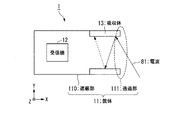
受信ユニット1−M(Mは1〜Nの整数)は、所定の箇所に位置する発信機9が発信した電波によって伝送される信号であって、所定の方向から入射する信号(以下「発信機信号」という。)を受信する。発信機信号は、発信機9の識別子を示す信号である。受信ユニット1−Mは、発信機信号を受信すると、発信機信号を受信したことを示す信号(以下「受信機信号」という。)を出力する。内部に位置する発信機9が発信した発信機信号を受信ユニット1−Mが受信可能な空間を、第M受信可能空間という。例えば、発信機9が位置することができる空間であって、内部に位置する発信機9が発信した発信機信号を受信ユニット1−1が受信可能な空間を第1受信可能空間という。また、発信機9が位置することができる空間であって、内部に位置する発信機9が発信した発信機信号を受信ユニット1−3が受信可能な空間を第3受信可能空間という。受信可能空間は、受信ユニット1の位置に基づいて、その位置が決まる空間である。受信可能空間の重なりを重なり空間という。受信ユニット1−Mは、筐体11−M、受信機12−M及び吸収体13−Mを備える。
The receiving unit 1-M (M is an integer of 1 to N) is a signal transmitted by radio waves transmitted from a transmitter 9 located at a predetermined location, and is a signal incident from a predetermined direction (hereinafter “transmitter”). Signal "). The transmitter signal is a signal indicating the identifier of the transmitter 9. When receiving the transmitter signal, the receiving unit 1-M outputs a signal indicating that the transmitter signal has been received (hereinafter referred to as “receiver signal”). A space in which the receiving unit 1-M can receive a transmitter signal transmitted from the transmitter 9 located inside is referred to as an Mth receivable space. For example, a space in which the transmitter 9 can be located, and a space in which the receiving unit 1-1 can receive a transmitter signal transmitted from the transmitter 9 located inside is referred to as a first receivable space. A space in which the transmitter 9 can be located and in which the receiving unit 1-3 can receive the transmitter signal transmitted by the transmitter 9 located inside is called a third receivable space. The receivable space is a space whose position is determined based on the position of the receiving
筐体11−Mは、発信機信号を遮蔽する。筐体11−Mは、受信機12−Mを収容する。受信機12−Mは、第M受信可能空間に位置する発信機9が発信した発信機信号を受信して、受信機信号を出力する。受信ユニット1−Mが発信機信号を受信するとは、具体的には、受信機12−Mが発信機信号を受信することである。また、受信ユニット1−Mが受信機信号を出力するとは、具体的には、受信機12−Mが受信機信号を出力することである。吸収体13−Mは、発信機9が発信した信号を吸収する。
以下、受信ユニット1−1〜1−Mをそれぞれ区別しない場合、受信ユニット1という。以下、筐体11−1〜11−Mをそれぞれ区別しない場合、筐体11という。以下、受信機12−1〜12−Mをそれぞれ区別しない場合、受信機12という。以下、吸収体13−1〜13−Mをそれぞれ区別しない場合、吸収体13という。以下、第1受信可能領域〜第M受信可能領域をそれぞれ区別しない場合、受信可能領域という。
The housing 11-M shields the transmitter signal. The casing 11-M accommodates the receiver 12-M. The receiver 12-M receives a transmitter signal transmitted from the transmitter 9 located in the Mth receivable space and outputs a receiver signal. The reception unit 1-M receiving the transmitter signal specifically means that the receiver 12-M receives the transmitter signal. Further, the reception unit 1-M outputting a receiver signal specifically means that the receiver 12-M outputs a receiver signal. The absorber 13-M absorbs the signal transmitted from the transmitter 9.
Hereinafter, when the receiving units 1-1 to 1-M are not distinguished from each other, they are referred to as receiving
集計サーバ2は、受信ユニット1−Mが出力した受信機信号を、通信網を介して取得し、取得した受信機信号に基づいて、発信機9の位置を示す情報を取得する。
The
図2〜図6によって、受信ユニット1が受信しない発信機信号と、受信ユニット1が受信する発信機信号とを説明する。
図2は、実施形態における筐体11、受信機12及び吸収体13の具体的な形状及び配置を示す図である。図2の側面図は、受信ユニット1の側面図である。図2の正面図は、受信ユニット1の側面に垂直な方向から見た受信ユニット1の図である。図2の側面図及び正面図が示すように、筐体11は、円形状の底を有する筒状の部材である。筐体11は、側面及び底面が発信機信号を遮蔽し、上端が発信機信号を透過させる。以下、側面及び底面を遮蔽部110という。以下、上端を透過部111という。筐体11は、受信機12を囲むように配置される。なお、筐体11は、受信機12を囲むような形状であって、開口を有する形状であれば、必ずしも円形状の底を有する筒状の部材である必要はない。筐体11は、例えば、上端が透過部111であって、四角形の形状の底を有する筒状の部材であってもよいし、上端が透過部111であって、台形の形状の底を有する筒状の部材であってもよい。吸収体13は、筐体11の透過部111の近傍に位置する。
The transmitter signal that is not received by the
FIG. 2 is a diagram illustrating specific shapes and arrangements of the housing 11, the
図3は、実施形態における筐体11の遮蔽部110に入射した発信機信号を受信ユニット1が受信しないことを、受信ユニット1の側面図を用いて説明する説明図である。
受信ユニット1の外部から筐体11の遮蔽部110に入射した電波80は、遮蔽部110によって反射される。そのため、電波80は、受信機12に到達できない。なお、図3において遮蔽部110は、電波80を反射することで、電波80を遮蔽したが、遮蔽部110は、電波80を吸収することで電波80を遮蔽してもよい。なお、電波80は発信機信号の具体例である。
このように、受信ユニット1の外部から遮蔽部110に入射した発信機信号を、受信ユニット1は受信しない。
FIG. 3 is an explanatory diagram for explaining that the receiving
The radio wave 80 that has entered the shielding unit 110 of the housing 11 from the outside of the receiving
Thus, the receiving
図4は、実施形態における吸収体13に入射した発信機信号を受信ユニット1が受信しないことを、受信ユニット1の側面図を用いて説明する説明図である。
電波81は、筐体11の透過部111から受信ユニット1に入射する。電波81は、受信機12に到達する前に、吸収体13に入射する。吸収体13に入射した電波81は、吸収体13によって吸収される。もし受信ユニット1が吸収体13を有さない場合、電波81は、筐体11の遮蔽部110によって反射されることで受信機12に到達する。しかしながら、受信ユニット1が吸収体13を有するため、電波81は、受信機12に到達しない。そのため、電波81は、受信機12によって受信されない。なお、電波81は発信機信号の具体例である。
このように、吸収体13を有する受信ユニット1は、吸収体13に入射する方向から入射する発信機信号を受信しない。
FIG. 4 is an explanatory diagram for explaining that the receiving
The radio wave 81 enters the receiving
Thus, the receiving
図5は、実施形態における発信機信号を受信ユニット1が受信することを、受信ユニット1の側面図を用いて説明する説明図である。
電波82は、筐体11の透過部111から受信ユニット1に入射する。電波82は、吸収体13に入射することなく受信機12に到達する。そのため、電波82は、受信機12によって受信される。なお、電波82は発信機信号の具体例である。
このように、受信ユニット1は、透過部111を通過して受信機12に直接入射する発信機信号を受信する。
FIG. 5 is an explanatory diagram for explaining that the receiving
The radio wave 82 enters the receiving
Thus, the receiving
図6は、実施形態における受信ユニット1が受信可能な発信機信号の、受信ユニット1への入射方向を説明する説明図である。
電波83は、受信ユニット1の外部から透過部111に入射し、吸収体13のX軸正方向の端である端点H1を通過して受信機12に入射する。電波84は、受信ユニット1の外部から透過部111に入射し、吸収体13のX軸正方向の端である端点H2を通過して受信機12に入射する。以下、電波83又は電波84と受信ユニット1の中心軸とのなす角をθとする。
受信ユニット1の中心軸とのなす角がθよりも大きな角度となる電波は吸収体13に入射するため、受信機12に到達しない。そのため、受信ユニット1は、受信ユニット1の中心軸とのなす角がθよりも大きな角度となる電波を受信しない。なお、受信ユニット1の中心軸とは、筐体11である筒状の部材の中心軸であって、図6において、X軸に平行な軸である。
なお、電波83及び電波84は発信機信号の具体例である。
FIG. 6 is an explanatory diagram for explaining the incident direction of the transmitter signal that can be received by the receiving
The radio wave 83 enters the transmission unit 111 from the outside of the
A radio wave whose angle formed with the central axis of the receiving
The radio wave 83 and the radio wave 84 are specific examples of transmitter signals.
このように、受信ユニット1は、受信ユニット1の中心軸とのなす角がθ以下の角度となる方向から受信ユニット1の透過部111に入射する発信機信号のみを受信する。
Thus, the receiving
図7は、実施形態における受信可能空間を説明する説明図である。
図2〜図6によって説明したように、受信ユニット1は、受信ユニット1の中心軸とのなす角がθよりも小さな角度となる方向から受信ユニット1の透過部111に入射する発信機信号のみを受信する。また、信号は一般的に伝送距離が長くなるほど強度が減衰する。そのため、発信機信号は、発信機9から所定の距離までしか受信機12が受信可能な強度で伝送しない。このことは、受信機12との距離が所定の距離(以下「受信可能距離」という。)以内である発信機9が発信した発信機信号でなければ受信機12は、受信できないことを意味する。そのため、受信可能空間は、受信機12と端点H1とを結ぶ直線と、受信機12と端点H2とを結ぶ直線とによって囲まれる空間であって、受信機12との距離が受信可能距離以内である有限の大きさの空間である。
このように、受信可能空間は、受信ユニット1の位置だけでなく、さらに、受信機12から見た透過部111の見込み角と、受信機12が透過部111を見る方向とに基づいて、その広さと位置とが決まる空間である。
FIG. 7 is an explanatory diagram illustrating a receivable space in the embodiment.
As described with reference to FIG. 2 to FIG. 6, the receiving
Thus, the receivable space is not only based on the position of the receiving
図8は、実施形態における受信機12の機能構成の具体例を示す図である。受信機12は、バスで接続されたCPU(Central Processing Unit)やメモリや補助記憶装置122などを備え、プログラムを実行する。受信機12は、プログラムの実行によって、受信機121、受信機信号生成部123及び送信部124を備える装置として機能する。
FIG. 8 is a diagram illustrating a specific example of a functional configuration of the
受信機12を発信機9が発信した発信機信号を受信するためのインタフェースを含んで構成される。受信機121は、発信機9が発信した発信機信号を受信する。
補助記憶装置122は、磁気ハードディスク装置や半導体記憶装置などの記憶装置を用いて構成される。補助記憶装置122は受信機121の識別子を記憶する。
受信機信号生成部123は、発信機信号を取得して受信機信号を生成する。受信機信号は、取得した発信機信号の発信元の発信機9の識別子と、受信機12の識別子とを示す。
送信部124は、受信機12を集計サーバ2に接続するための通信インタフェースを含んで構成される。送信部124は、通信網を介して、集計サーバ2と通信する。
The
The
The receiver
The
図9は、実施形態における集計サーバ2の機能構成の具体例を示す図である。集計サーバ2は、バスで接続されたCPU(Central Processing Unit)やメモリや補助記憶装置202などを備え、プログラムを実行する。集計サーバ2は、プログラムの実行によって、受信部201及び位置情報取得部203を備える装置として機能する。
FIG. 9 is a diagram illustrating a specific example of a functional configuration of the
受信部201は、集計サーバ2を受信機12に接続するための通信インタフェースを含んで構成される。受信部201は、通信網を介して、受信機12が送信した受信機信号を受信する。
The receiving unit 201 includes a communication interface for connecting the
補助記憶装置202は、磁気ハードディスク装置や半導体記憶装置などの記憶装置を用いて構成される。補助記憶装置202はアクティブ受信機情報と、受信機情報と、所属グループ情報とを記憶する。アクティブ受信機情報は、アクティブ受信機を示す。アクティブ受信機とは、発信機信号を取得した受信機12であって、発信機信号を取得した時刻を開始時刻とした所定の期間(以下「アクティブ期間」という。)中の受信機12である。以下、受信機12がアクティブ受信機である場合、受信機12はアクティブである、という。受信機情報は、受信機12が設置された位置と、受信機12が所属するグループ(以下「所属グループ」という。)を示す情報と、受信機12がアクティブ受信機である時間の長さ(以下「アクティブ時間」という。)を示す情報と、を含む。所属グループは、所定の条件を満たす受信機12の集合である。集計サーバ2は、所属グループ内の受信機12が全てアクティブ受信機である時に、発信機9の位置を示す情報を取得する。所属グループ情報は、所属グループに関する情報を示す。
The
図10は、実施形態におけるアクティブ受信機情報の具体例を示す図である。アクティブ受信機情報は、例えば、図10に示すアクティブ受信機情報テーブルD110として、補助記憶装置202に記憶される。アクティブ受信機情報テーブルD110は、“発信機ID”ごとにレコードをもつ。各レコードは、“JSN−1”、“JSN−2”・・・、“JSN−N”の各値をもつ。“発信機ID”は、発信機9の識別子を表す。“JSN−1”は、識別子がJSN−1である受信機12が、“発信機ID”が表す発信機9が発信した発信機信号を受信したアクティブ受信機であるか否かを表す。“JSN−1”は、“Active”及び“NonActive”を表す値をもつ。“Active”は、識別子がJSN−1である受信機12が、“発信機ID”が表す発信機9が発信した発信機信号を受信したアクティブ受信機であることを表す。“NonActive”は、識別子がJSN−1である受信機12がアクティブ受信機ではないことを表す。“JSN−2”から“JSN−N”についても同様である。すなわち、“JSN−M”は、識別子がJSN−Mである受信機12が、“発信機ID”が表す発信機9が発信した発信機信号を受信したアクティブ受信機であるか否かを表す。“JSN−M”は、“Active”及び“NonActive”を表す値をもつ。“Active”は、識別子がJSN−Mである受信機12が、“発信機ID”が表す発信機9が発信した発信機信号を受信したアクティブ受信機であることを表す。“NonActive”は、識別子がJSN−Mである受信機12がアクティブ受信機ではないことを表す。
なお、識別子が“JSN−1”である受信機12は、例えば、受信機12−1であってもよい。識別子が“JSN−2”である受信機12は、例えば、受信機12−2であってもよい。
例えば、レコードD111は、識別子がJSN−1である受信機12−1が、識別子がHSN1である発信機9が発した発信機信号を受信したアクティブ受信機であることを表す。また、レコードD111は、識別子がJSN−2である受信機12と、識別子がJSN−3である受信機12と、識別子がJSN−Nである受信機12とがアクティブ受信機ではないことを表す。
FIG. 10 is a diagram illustrating a specific example of the active receiver information in the embodiment. The active receiver information is stored in the
Note that the
For example, the record D111 indicates that the receiver 12-1 having the identifier JSN-1 is an active receiver that has received the transmitter signal transmitted from the transmitter 9 having the identifier HSN1. The record D111 indicates that the
図11は、実施形態における受信機情報の具体例を示す図である。受信機情報は、例えば、図11に示す受信機情報テーブルD120として、補助記憶装置202に記憶される。受信機情報テーブルD120は、“受信機ID”ごとにレコードをもつ。各レコードは、“受信機ID”、“位置情報”、“所属グループ”及び“アクティブ時間”の各値をもつ。“受信機ID”は、受信機12の識別子を表す。
“位置情報”は、“受信機ID”が表す受信機12が設置された位置を示す。“所属グループ”は、“受信機ID”が表す受信機12が所属する所属グループを表す。“アクティブ時間”は、受信機12のアクティブ時間を表す。
例えば、レコードD121は、識別子が“JSN−1”である受信機12は、北1東3で表される場所に位置し、グループG1という所属グループに所属し、発信機信号を受信してから1分の間アクティブ受信機であることを表す。
FIG. 11 is a diagram illustrating a specific example of receiver information in the embodiment. The receiver information is stored in the
“Position information” indicates the position where the
For example, in the record D121, the
図12は、実施形態における所属グループ情報の具体例を示す図である。所属グループ情報は、例えば、図12に示す所属グループ情報テーブルD130として、補助記憶装置202に記憶される。所属グループ情報テーブルD130は、“グループ名”ごとにレコードをもつ。各レコードは、“グループ名”、“所属受信機”及び“グループ重なり空間”の各値をもつ。“グループ名”は、所属グループの名称を表す。
“所属受信機”は、“グループ名”が表す所属グループに所属する受信機12を表す。例えば、“所属受信機”は、受信機12の識別子によって受信機12を表してもよい。
“グループ重なり空間”は、所属グループに属する受信機12の受信可能空間が重なる重なり空間(以下「グループ重なり空間」という。)を表す。
例えば、レコードD131は、グループ名が“グループG1”である所属グループに所属する受信機12は、識別子がJSN−1の受信機12と識別子がJSN−2の受信機12とであることを表す。また、レコード131は、重なり空間がAREA1という空間であることを表す。
FIG. 12 is a diagram illustrating a specific example of belonging group information in the embodiment. The belonging group information is stored in the
“Affiliated receiver” represents the
The “group overlap space” represents an overlap space (hereinafter referred to as “group overlap space”) where the receivable spaces of the
For example, the record D131 indicates that the
図9の説明に戻る。位置情報取得部203は、受信部201が受信した受信機信号に基づいて発信機9の位置を示す情報を取得する。位置情報取得部203は、アクティブ管理部204、アクティブグループ判定部205及び重なり空間情報取得部206を備える。
Returning to the description of FIG. The position
アクティブ管理部204は、受信機信号に基づいて、アクティブ化処理を実行する。アクティブ化処理は、受信機信号が示す受信機12が、受信機信号が示す発信機9が発信した発信機信号を受信したアクティブ受信機であることを補助記憶装置202に記録する処理である。また、アクティブ管理部204は、受信機信号を受信してから受信機信号が示す受信機12のアクティブ時間が経過した時に、非アクティブ化処理を実行する。非アクティブ化処理は、受信機信号が示す発信機9から発信された発信機信号を取得した受信機12を、アクティブ受信機ではない受信機12であるとして補助記憶装置202に記録する処理である。受信機信号が示す受信機12は、受信機信号を送信した送信元の受信機12である。以下、受信機信号が示す受信機12を信号送信元受信機という。受信機信号が示す発信機9は、受信機信号を送信した送信元の受信機12が受信した発信機信号を発信した発信元の発信機9である。以下、受信機信号が示す発信機9を発信元発信機という。
The
アクティブグループ判定部205は、受信機信号に基づいて、信号送信元受信機が所属する所属グループがアクティブであるか否かを判定する。所属グループがアクティブであるとは、所属グループに属する受信機12が全て、発信元発信機が同じアクティブ受信機であることを意味する。
Based on the receiver signal, the active
重なり空間情報取得部206は、アクティブグループ判定部205の判定結果に基づいて、グループ重なり空間を示す情報(以下「グループ重なり空間情報」という。)を取得する。具体的には、重なり空間情報取得部206は、アクティブグループ判定部205が、アクティブであると判定した所属グループのグループ重なり空間情報を取得する。
The overlap space
図13は、実施形態における集計サーバ2が発信機9の位置を示す情報を取得する具体的な処理の流れを示すフローチャートである。
受信部201が受信機信号を受信する(ステップS101)。アクティブ管理部204は、信号送信元受信機を、発信元発信機が発信した発信機信号を受信したアクティブ受信機として補助記憶装置202に記録する(ステップS102)。具体的には、次の処理を実行することで、アクティブ管理部204は、信号送信元受信機を、発信元発信機が発信した発信機信号を受信したアクティブ受信機として補助記憶装置202に記録する。アクティブ管理部204は、補助記憶装置202に記憶されたアクティブ受信機情報テーブルD110を参照する。アクティブ管理部204は、“発信機ID”が発信元発信機の識別子を表すレコードを選択する。アクティブ管理部204は、信号送信元受信機の識別子がJSN−Mである場合に、選択したレコードの“JSN−M”の項目の値を“Active”を示す値に書き換える。
FIG. 13 is a flowchart illustrating a specific processing flow in which the
The receiving unit 201 receives a receiver signal (step S101). The
アクティブグループ判定部205は、信号送信元受信機が所属する所属グループがアクティブであるか否かを判定する(ステップS103)。具体的には、次の処理によって、アクティブグループ判定部205は、信号送信元受信機が所属する所属グループがアクティブであるか否かを判定する。アクティブグループ判定部205は、補助記憶装置202に記憶された受信機情報テーブルD120を参照する。アクティブグループ判定部205は、“受信機ID”の値に信号送信元受信機の識別子を示す値をもつレコードを選択する。アクティブグループ判定部205は、選択したレコードの“所属グループ”の項目の値を取得する。アクティブグループ判定部205は、所属グループ情報を参照する。アクティブグループ判定部205は、“グループ名”の値が、“所属グループ”の項目の値が表す所属グループを表すレコードを選択する。アクティブグループ判定部205は、選択したレコードの“所属受信機”の項目の値を取得する。アクティブグループ判定部205は、アクティブ受信機情報テーブルD110を参照する。アクティブグループ判定部205は、“発信機ID”が発信元発信機の識別子を表すレコードを選択する。アクティブグループ判定部205は、取得した“所属受信機”の項目の値が示す識別子がJSN−Mである場合に、選択したレコードの“JSN−M”の項目の値を取得する。アクティブグループ判定部205は、取得した“JSN−M”の項目の値が全て、“Active”を示す場合に、所属グループがアクティブであると判定する。アクティブグループ判定部205は、取得した“JSN−M”の項目の値の少なくともひとつが、“NonActive”を示す場合に、所属グループがアクティブではないと判定する。
The active
所属グループがアクティブである場合(ステップS103:YES)、重なり空間情報取得部206は、所属グループのグループ重なり空間情報を取得する(ステップS104)。具体的には、次の処理によって、重なり空間情報取得部206は、所属グループのグループ重なり空間情報を取得する。重なり空間情報取得部206は、所属グループ情報テーブルD130を参照する。重なり空間情報取得部206は、“グループ名”の値が所属グループを表すレコードを選択する。重なり空間情報取得部206は、選択したレコードの“グループ重なり空間”の項目の値を取得する。取得した“グループ重なり空間”の項目の値が示す空間が、発信機9が位置する空間(すなわちユーザが位置する空間)である。
When the belonging group is active (step S103: YES), the overlapping space
所属グループがアクティブでない場合(ステップS103:NO)、集計サーバ2は、図13に示す制御を繰り返す。
If the belonging group is not active (step S103: NO), the
図14は、実施形態の位置検出システム100が発信機9の位置を検出する具体的な処理の流れを示すシーケンス図である。
発信機9が発信した発信機信号を第一受信機が受信する(ステップS201)。第一受信機は、受信機12の具体例であって、例えば、受信機12−1である。第一受信機は、受信機信号を通信網に送信する(ステップS202)。集計サーバ2は、通信網を介してステップS202における受信機信号を受信する(ステップS203)。集計サーバ2は、受信機信号が示す受信機(すなわち、第一受信機)を、アクティブ受信機として補助記憶装置202に記録する(ステップS204)。集計サーバ2は、第一受信機が所属する所属グループがアクティブではないと判定する(ステップS205)。
発信機9が発信した発信機信号を第二受信機が受信する(ステップS206)。第二受信機は、第一受信機と同じ所属グループに所属する受信機12の具体例であって、例えば、受信機12−2である。図14において、第一受信機及び第二受信機が所属する所属グループには、第一受信機及び第二受信機のみが所属するとする。
第二受信機は、受信機信号を通信網に送信する(ステップS207)。集計サーバ2は、通信網を介してステップS207における受信機信号を受信する(ステップS208)。集計サーバ2は、受信機信号が示す受信機(すなわち、第二受信機)を、アクティブ受信機として補助記憶装置202に記録する(ステップS209)。集計サーバ2は、第二受信機が所属する所属グループがアクティブであると判定する(ステップS210)。集計サーバ2は、グループ重なり空間情報を取得する(ステップS211)。集計サーバ2は、表示部(不図示)に、グループ重なり空間情報を出力する(ステップS212)。
FIG. 14 is a sequence diagram illustrating a specific processing flow in which the
The first receiver receives the transmitter signal transmitted from the transmitter 9 (step S201). The first receiver is a specific example of the
The second receiver receives the transmitter signal transmitted from the transmitter 9 (step S206). The second receiver is a specific example of the
The second receiver transmits a receiver signal to the communication network (step S207). The
このように構成された実施形態の位置検出システム100は、発信機信号を遮蔽する筐体11を備えるため、受信機12は、所定の方向から透過部111に入射する発信機信号のみを受信し、遮蔽部110に入射する発信機信号を遮蔽する。そのため、位置検出システム100のユーザは、発信機信号の送信元である発信機9が位置する方向を知ることができる。
Since the
また、このように構成された実施形態の位置検出システム100は、複数の受信機12を備え、複数の受信機12の受信可能空間の重なりの空間に発信機9が位置するか否かによって、発信機9の位置を示す情報を取得する。そのため、位置検出システム100は、発信機信号の送信元である発信機9の位置をより高い精度で検出できる。
Further, the
また、このように構成された実施形態の位置検出システム100は、吸収体13を備える。そのため、位置検出システム100のユーザは、筐体11を変えることなく、吸収体13を変えるだけで、受信機12の受信可能空間の大きさを制御することができる。
The
(変形例)
位置検出システム100は、必ずしも複数の受信ユニット1を備えなくてもよく、ひとつの受信ユニット1を備えてもよい。この場合、受信可能空間と重なり空間とは一致する。
(Modification)
The
(適用例)
本実施形態の位置検出システム100は、例えば、展示会場に設置される。この場合、展示会場の入場者が発信機9をつけることで、位置検出システム100のユーザはどの展示物に多くの人が集まっているのかを知ることができる。
(Application example)
The
なお、筐体11は遮蔽部材の一例である。なお、吸収体13は、吸収部材の一例である。なお、電波80及び電波81が入射する方向は、所定の方向以外の方向の一例である。なお、“グループ重なり空間”は、所定の広さの空間を示す情報の一例である。なお、なす角θは、受信機と透過部との距離に対する透過部の広さを示す情報の一例である。なお、受信機12は受信部の一例である。なお、受信ユニット1は、受信装置の一例である。なお、集計サーバ2は、位置検出装置の一例である。
The housing 11 is an example of a shielding member. The absorber 13 is an example of an absorbing member. The direction in which the radio wave 80 and the radio wave 81 are incident is an example of a direction other than a predetermined direction. The “group overlap space” is an example of information indicating a space having a predetermined area. The angle θ formed is an example of information indicating the width of the transmission part with respect to the distance between the receiver and the transmission part. The
なお、実施形態の受信機12及び集計サーバ2の各機能の全て又は一部は、ASIC(Application Specific Integrated Circuit)やPLD(Programmable Logic Device)やFPGA(Field Programmable Gate Array)等のハードウェアを用いて実現されてもよい。プログラムは、コンピュータ読み取り可能な記録媒体に記録されてもよい。コンピュータ読み取り可能な記録媒体とは、例えばフレキシブルディスク、光磁気ディスク、ROM、CD−ROM等の可搬媒体、コンピュータシステムに内蔵されるハードディスク等の記憶装置である。プログラムは、電気通信回線を介して送信されてもよい。
以上、この発明の実施形態について図面を参照して詳述してきたが、具体的な構成はこの実施形態に限られるものではなく、この発明の要旨を逸脱しない範囲の設計等も含まれる。
Note that all or some of the functions of the
The embodiment of the present invention has been described in detail with reference to the drawings. However, the specific configuration is not limited to this embodiment, and includes designs and the like that do not depart from the gist of the present invention.
1…受信ユニット、2…集計サーバ、11…筐体、12…受信機、13…吸収体、110…遮蔽部、111…透過部、121…受信機、122…補助記憶装置、123…受信機信号生成部、124…送信部、201…受信部、202…補助記憶装置、203…位置情報取得部、204…アクティブ管理部、205…アクティブグループ判定部、206…重なり空間情報取得部
DESCRIPTION OF
Claims (8)
前記受信部の位置と、前記受信部から見た前記透過部の見込み角と、前記受信部から見た前記透過部の方向とに基づいて予め定められた所定の広さの空間を示す情報と、前記受信機信号とに基づいて、前記発信機の位置を示す情報を取得する位置検出装置と、
を備える、
位置検出システム。 A receiver that receives a transmitter signal transmitted from a transmitter and outputs a receiver signal indicating that the transmitter signal has been received; a transmission unit that transmits the transmitter signal; and a shield that blocks the transmitter signal. The transmission unit is located at a location that transmits the transmitter signal incident on the reception unit from a predetermined direction, and the shielding unit is directed to the reception unit from a direction other than the predetermined direction. A receiving device comprising: a shielding member positioned at a location that shields the incident transmitter signal;
Information indicating a space of a predetermined area determined in advance based on the position of the receiving unit, the angle of view of the transmitting unit viewed from the receiving unit, and the direction of the transmitting unit viewed from the receiving unit; A position detection device for acquiring information indicating a position of the transmitter based on the receiver signal;
Comprising
Position detection system.
前記位置検出装置は、前記発信機信号を受信したことを示す受信機信号を少なくとも二つの前記受信装置から取得した場合に、前記受信部と前記透過部との距離に対する前記透過部の広さを示す情報と、前記受信部に対する前記透過部が位置する箇所の方向とに基づいて予め定められた所定の広さの空間を示す情報と、前記受信機信号とに基づいて、前記発信機の位置を示す情報を取得する、
請求項1に記載の位置検出システム。 Comprising at least two receiving devices;
When the position detection device acquires a receiver signal indicating that the transmitter signal has been received from at least two of the reception devices, the position detection device determines the width of the transmission unit relative to the distance between the reception unit and the transmission unit. Position of the transmitter based on the receiver signal and information indicating a space of a predetermined area determined in advance based on the information indicating, the direction of the location where the transmission unit is located with respect to the receiver Get information indicating
The position detection system according to claim 1.
前記発信機信号を透過させる透過部と前記発信機信号を遮蔽する遮蔽部とを有し、前記透過部は、所定の方向から前記受信部に入射する前記発信機信号を透過させる箇所に位置し、前記遮蔽部は、前記所定の方向以外の方向から前記受信部に入射する前記発信機信号を遮蔽する箇所に位置する遮蔽部材と、
を備える、
受信装置。 A receiver that receives a transmitter signal transmitted by a transmitter and outputs a receiver signal indicating that the transmitter signal has been received;
The transmission unit includes a transmission unit that transmits the transmitter signal and a shielding unit that blocks the transmitter signal, and the transmission unit is located at a position that transmits the transmitter signal incident on the reception unit from a predetermined direction. The shielding unit is a shielding member located at a location that shields the transmitter signal incident on the receiving unit from a direction other than the predetermined direction;
Comprising
Receiver device.
を備える位置検出装置。 A receiver that receives a transmitter signal transmitted from a transmitter and outputs a receiver signal indicating that the transmitter signal has been received, a transmission unit that transmits the transmitter signal, and a shielding unit that shields the transmitter signal And the transmission unit is located at a location that transmits the transmitter signal incident on the reception unit from a predetermined direction, and the shielding unit is incident on the reception unit from a direction other than the predetermined direction. Receiving the receiver signal output from a receiving device including a shielding member positioned at a location where the transmitter signal is shielded, and receiving the position of the receiving unit, the expected angle of the transmitting unit viewed from the receiving unit, and the reception Position information for acquiring information indicating the position of the transmitter based on information indicating a space of a predetermined area determined in advance based on the direction of the transmission part viewed from a part and the receiver signal Acquisition department,
A position detection device comprising:
前記受信部の位置と、前記受信部から見た前記透過部の見込み角と、前記受信部から見た前記透過部の方向とに基づいて予め定められた所定の広さの空間を示す情報と、前記受信機信号とに基づいて、前記発信機の位置を示す情報を取得する位置検出ステップと、
を有する、
位置検出方法。 A receiver that receives a transmitter signal transmitted from a transmitter and outputs a receiver signal indicating that the transmitter signal has been received; a transmission unit that transmits the transmitter signal; and a shield that blocks the transmitter signal. And the transmission unit is located at a location that transmits the transmitter signal incident on the reception unit from a predetermined direction, and the shielding unit is incident on the reception unit from a direction other than the predetermined direction. A receiving unit that receives the transmitter signal incident from the predetermined direction on the transmitting portion of a shielding member located at a location that shields the transmitter signal, and an output step of outputting the receiver signal;
Information indicating a space of a predetermined area determined in advance based on the position of the receiving unit, the angle of view of the transmitting unit viewed from the receiving unit, and the direction of the transmitting unit viewed from the receiving unit; A position detecting step for obtaining information indicating a position of the transmitter based on the receiver signal;
Having
Position detection method.
前記受信部が、前記発信機が発信した前記発信機信号を受信し、前記受信機信号を出力する受信ステップと、
前記遮蔽部が、前記発信機信号を遮蔽する遮蔽ステップと、
を有する、
受信方法。 A receiver that receives a transmitter signal transmitted from a transmitter and outputs a receiver signal indicating that the transmitter signal has been received; a transmission unit that transmits the transmitter signal; and a shield that blocks the transmitter signal. The transmission unit is located at a location that transmits the transmitter signal incident on the reception unit from a predetermined direction, and the shielding unit is directed to the reception unit from a direction other than the predetermined direction. A receiving method comprising: a shielding member positioned at a location where the incident transmitter signal is shielded;
The receiving unit receives the transmitter signal transmitted by the transmitter, and outputs the receiver signal;
A shielding step in which the shielding unit shields the transmitter signal; and
Having
Receiving method.
を有する、
位置検出方法。 A receiver that receives a transmitter signal transmitted from a transmitter and outputs a receiver signal indicating that the transmitter signal has been received, a transmission unit that transmits the transmitter signal, and a shielding unit that shields the transmitter signal And the transmission unit is located at a location that transmits the transmitter signal incident on the reception unit from a predetermined direction, and the shielding unit is incident on the reception unit from a direction other than the predetermined direction. Receiving the receiver signal output from a receiving device including a shielding member positioned at a location where the transmitter signal is shielded, and receiving the position of the receiving unit, the expected angle of the transmitting unit viewed from the receiving unit, and the reception Position information for acquiring information indicating the position of the transmitter based on information indicating a space of a predetermined area determined in advance based on the direction of the transmission part viewed from a part and the receiver signal Acquisition step,
Having
Position detection method.
Priority Applications (1)
| Application Number | Priority Date | Filing Date | Title |
|---|---|---|---|
| JP2018065747A JP2019174403A (en) | 2018-03-29 | 2018-03-29 | Position detection system, receiving device, position detector, receiving method, position detection method, and computer program |
Applications Claiming Priority (1)
| Application Number | Priority Date | Filing Date | Title |
|---|---|---|---|
| JP2018065747A JP2019174403A (en) | 2018-03-29 | 2018-03-29 | Position detection system, receiving device, position detector, receiving method, position detection method, and computer program |
Publications (1)
| Publication Number | Publication Date |
|---|---|
| JP2019174403A true JP2019174403A (en) | 2019-10-10 |
Family
ID=68170335
Family Applications (1)
| Application Number | Title | Priority Date | Filing Date |
|---|---|---|---|
| JP2018065747A Pending JP2019174403A (en) | 2018-03-29 | 2018-03-29 | Position detection system, receiving device, position detector, receiving method, position detection method, and computer program |
Country Status (1)
| Country | Link |
|---|---|
| JP (1) | JP2019174403A (en) |
Citations (7)
| Publication number | Priority date | Publication date | Assignee | Title |
|---|---|---|---|---|
| JPH05157825A (en) * | 1991-12-07 | 1993-06-25 | Susumu Sakuma | Guard method utilizing emergency signal by radio wave |
| JP2001112047A (en) * | 1999-10-04 | 2001-04-20 | Ntt Docomo Inc | Method and system for measuring position of mobile unit in mobile communication system, and mobile unit |
| US20080024365A1 (en) * | 2006-07-31 | 2008-01-31 | Holmes Kevin C | Position finding system and method used with an emergency beacon |
| JP2009243988A (en) * | 2008-03-29 | 2009-10-22 | Brother Ind Ltd | Position detection system |
| US20110019611A1 (en) * | 2009-07-27 | 2011-01-27 | Raytheon Company | Systems and methods for detecting spread spectrum signals in an area of interest |
| WO2011043377A1 (en) * | 2009-10-09 | 2011-04-14 | オプテックス株式会社 | Object detecting device |
| JP2018044854A (en) * | 2016-09-14 | 2018-03-22 | 株式会社デンソーウェーブ | Radio wave transmission source position estimation system |
-
2018
- 2018-03-29 JP JP2018065747A patent/JP2019174403A/en active Pending
Patent Citations (7)
| Publication number | Priority date | Publication date | Assignee | Title |
|---|---|---|---|---|
| JPH05157825A (en) * | 1991-12-07 | 1993-06-25 | Susumu Sakuma | Guard method utilizing emergency signal by radio wave |
| JP2001112047A (en) * | 1999-10-04 | 2001-04-20 | Ntt Docomo Inc | Method and system for measuring position of mobile unit in mobile communication system, and mobile unit |
| US20080024365A1 (en) * | 2006-07-31 | 2008-01-31 | Holmes Kevin C | Position finding system and method used with an emergency beacon |
| JP2009243988A (en) * | 2008-03-29 | 2009-10-22 | Brother Ind Ltd | Position detection system |
| US20110019611A1 (en) * | 2009-07-27 | 2011-01-27 | Raytheon Company | Systems and methods for detecting spread spectrum signals in an area of interest |
| WO2011043377A1 (en) * | 2009-10-09 | 2011-04-14 | オプテックス株式会社 | Object detecting device |
| JP2018044854A (en) * | 2016-09-14 | 2018-03-22 | 株式会社デンソーウェーブ | Radio wave transmission source position estimation system |
Similar Documents
| Publication | Publication Date | Title |
|---|---|---|
| US11778417B2 (en) | System and method for detecting and locating contraband devices in a secure environment | |
| EP2680039B1 (en) | Indoor/outdoor differentiation using radio frequency (RF) transmitters | |
| US9625567B2 (en) | Positioning system using sound waves | |
| Huang et al. | Swadloon: Direction finding and indoor localization using acoustic signal by shaking smartphones | |
| US20160291124A1 (en) | Determining a location of a transmitter device | |
| CN105227261A (en) | There is provided safely to receiving element and copy Pseudo-Random Noise Code | |
| CN108700668A (en) | Detect method, the unmanned plane of the positioning device of unmanned plane | |
| JP2019174407A (en) | Position detection system, receiving system, position detector, receiving method, position detection method, and computer program | |
| CN103813361A (en) | Wireless device, control method, and display method | |
| JP2019174403A (en) | Position detection system, receiving device, position detector, receiving method, position detection method, and computer program | |
| Carranza et al. | Performance of a network‐based earthquake early warning system in the Ibero‐Maghrebian region | |
| Kim et al. | Imaging volcanic infrasound sources using time reversal mirror algorithm | |
| US10557932B1 (en) | Clock oscillator detection | |
| KR101231799B1 (en) | System for calculating self position information | |
| CN106537176A (en) | Two-pass detection technique for non-echo pulsed ranging | |
| JP6311198B2 (en) | White space detection device, white space detection method, and program | |
| US11835635B2 (en) | System for selecting the tracking technique for tracking a user device based on user device proximity to location beacons | |
| KR101536002B1 (en) | Location based system and method for providing location information of wearable device using thereof | |
| JP2016206047A (en) | Navigation supporting apparatus and method for navigation support | |
| Patton et al. | Designing and Implementing a Retrospective Earthquake Detection Framework at the US Geological Survey National Earthquake Information Center | |
| Thelen et al. | Broadband Seismometer to Tilt Conversion for Monitoring Kīlauea Volcano | |
| Polkowski et al. | Unexpected non seismic signals recorded by broadband seismic stations during geomagnetic storms | |
| KR20120045195A (en) | Apparatus and method for management satellite signal | |
| KR20190053636A (en) | Method for providing information based on location and apparatus therefor | |
| JP2018105637A (en) | Information terminal position estimation system |
Legal Events
| Date | Code | Title | Description |
|---|---|---|---|
| A621 | Written request for application examination |
Free format text: JAPANESE INTERMEDIATE CODE: A621 Effective date: 20180329 |
|
| A131 | Notification of reasons for refusal |
Free format text: JAPANESE INTERMEDIATE CODE: A131 Effective date: 20190319 |
|
| A02 | Decision of refusal |
Free format text: JAPANESE INTERMEDIATE CODE: A02 Effective date: 20191023 |