JP2019172017A - Control device of vehicle and control method - Google Patents
Control device of vehicle and control method Download PDFInfo
- Publication number
- JP2019172017A JP2019172017A JP2018061298A JP2018061298A JP2019172017A JP 2019172017 A JP2019172017 A JP 2019172017A JP 2018061298 A JP2018061298 A JP 2018061298A JP 2018061298 A JP2018061298 A JP 2018061298A JP 2019172017 A JP2019172017 A JP 2019172017A
- Authority
- JP
- Japan
- Prior art keywords
- vehicle
- braking
- control
- acceleration
- torque
- Prior art date
- Legal status (The legal status is an assumption and is not a legal conclusion. Google has not performed a legal analysis and makes no representation as to the accuracy of the status listed.)
- Pending
Links
Images


Abstract
Description
本発明は、車両の制御装置および制御方法に関する。 The present invention relates to a vehicle control device and a control method.
近年、車両の運転支援技術の開発が進められている。例えば、特許文献1には、前方車両の追い越しを想定し、運転者のアクセル操作に基づいてダウンシフトを行うことで、加速の遅れを少なくした車両の制御装置が開示されている。 In recent years, development of vehicle driving support technology has been promoted. For example, Patent Document 1 discloses a vehicle control device that reduces the delay in acceleration by assuming a passing vehicle ahead and downshifting based on the driver's accelerator operation.
また、特許文献2には、近い将来、運転者が車両を加減速させる可能性が高いと判断した場合、加減速する可能性が低いと判断した場合に比べ、変速比LO側を通る動作線を選択して、目標駆動力は同一のまま変速機の変速比をLO側にシフトする事前変速手段を設けた車両の制御装置が開示されている。 Further, Patent Document 2 discloses an operation line that passes through the gear ratio LO side when it is determined that the driver is highly likely to accelerate / decelerate the vehicle in the near future, compared to a case where the driver is unlikely to accelerate / decelerate. And a vehicle control device provided with a prior transmission means for shifting the transmission gear ratio to the LO side while maintaining the same target driving force.
しかしながら、この種の車両の制御装置では、車両が一定速度で走行している状態(以下、加速前状態と言うこともある)では、大きな駆動力を発生させる必要がないため、変速比をあまりLO側に変化させることができない。一定速度で走行している車両では、変速比をLO側に変化させるほど、低い目標駆動力を維持させるためエンジントルクを低減させる必要があり、次に加速する場合、エンジントルクの立ち上がり遅れが発生し、必要な加速応答性が得られない。 However, in this type of vehicle control device, when the vehicle is traveling at a constant speed (hereinafter sometimes referred to as a pre-acceleration state), it is not necessary to generate a large driving force. It cannot be changed to the LO side. In a vehicle traveling at a constant speed, the engine torque needs to be reduced to maintain a lower target drive force as the gear ratio is changed to the LO side. However, the required acceleration response cannot be obtained.
そのため、車両の加速前状態において、変速比をLO側に変化させても、適切な加速応答性を得られるように車両を制御する必要がある。 Therefore, it is necessary to control the vehicle so that an appropriate acceleration response can be obtained even if the gear ratio is changed to the LO side in the state before the vehicle is accelerated.
したがって、本発明は、上記の課題に着目してなされたもので、車両の加速前状態において、変速比をLO側に変化させても、適切な加速応答性を得られるように車両を制御することを目的とする。 Therefore, the present invention has been made paying attention to the above-described problem, and controls the vehicle so that an appropriate acceleration response can be obtained even when the gear ratio is changed to the LO side in a state before acceleration of the vehicle. For the purpose.
上記課題を解決するため、車両を駆動させる駆動力を発生する原動機と前記車両を制動させる制動力を発生する制動装置を有する車両の制御装置であって、車両が加速準備状態か否かを判定する加速準備判定部と、加速準備判定部により車両が加速準備状態であると判定された場合、車両の変速比をLO側に変化させる変速機制御部と、変速機制御部により車両の変速比がLO側に変化する場合、原動機により車両を駆動させる駆動力を増加させると共に、当該増加させた駆動力と制動装置により車両を制動させる制動力との差分が目標値となるように、原動機及び制動装置を制御する制御部と、を有する構成とした。 In order to solve the above-described problem, a vehicle control device having a prime mover that generates a driving force for driving a vehicle and a braking device that generates a braking force for braking the vehicle, and determines whether or not the vehicle is ready for acceleration. A transmission control unit that changes the gear ratio of the vehicle to the LO side when the vehicle is determined to be in an acceleration preparation state by the acceleration preparation determination unit and the acceleration preparation determination unit, and a gear ratio of the vehicle by the transmission control unit. Is changed to the LO side, the driving force for driving the vehicle by the prime mover is increased, and the difference between the increased driving force and the braking force for braking the vehicle by the braking device becomes a target value. And a control unit that controls the braking device.
本発明によれば、車両の加速前状態において、変速比をLO側に変化させても、適切な加速応答性を得られるように車両を制御することができる。 According to the present invention, it is possible to control the vehicle so that appropriate acceleration response can be obtained even when the gear ratio is changed to the LO side in the state before acceleration of the vehicle.
以下、実施の形態にかかる車両の制御装置(以下、制御装置1と表記する)の一例を、図面を用いて説明する。 Hereinafter, an example of a vehicle control device (hereinafter referred to as a control device 1) according to an embodiment will be described with reference to the drawings.
[車両の要部構成]
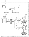
図1は、実施の形態にかかる制御装置1が設けられた車両CA1の要部構成を説明する模式図である。
[Vehicle configuration]
FIG. 1 is a schematic diagram illustrating a main configuration of a vehicle CA1 provided with a control device 1 according to an embodiment.
車両CA1には、車両CA1を走行させるための駆動源となるエンジン10が設けられている。この車両CA1を走行させるための駆動源は、車両CA1を加減速させることができるものであれば、エンジン10に限定されるものではない。例えば、エンジン10とモータとを組み合わせたハイブリッドタイプの駆動源でもよく、モータのみでもよい。
The vehicle CA1 is provided with an
エンジン10の出力軸11には、トルクコンバータやクラッチなどの発進装置20が接続され、この発進装置20は、ベルト式無段変速機構30(Continuously Variable Transmission:CVT)の変速機入力軸31に接続されている。ベルト式無段変速機構30に接続された変速機出力軸32は、差動装置40(Differential gear:DEF)に接続され、右ドライブシャフト41と左ドライブシャフト42とに動力分割されて、右タイヤ45と左タイヤ46とを駆動することで、車両CA1が走行する。
A
また、車両CA1には、この車両CA1を制御する制御装置1が設けられている。制御装置1は、エンジン10の運転を制御するエンジン制御部(Engine Control Unit:ECU)100と、ベルト式無段変速機構30を制御する変速機制御部(Transmission Control Unit:TCU)110と、摩擦ブレーキ43、44などの制動装置を制御する制動制御部120と、車両CA1の加速準備状態の予測を行う加速準備判定部130と、を有する。
The vehicle CA1 is provided with a control device 1 that controls the vehicle CA1. The control device 1 includes an engine control unit (ECU) 100 that controls the operation of the
エンジン制御装置100と、変速機制御部110と、制動制御部120と、加速準備判定部130とは、CAN(Controller Area Network)などの通信線を介して相互に接続されており、種々の情報が通信線により各制御部で共有される。
The
加速準備判定部130は、車載カメラ又はレーダなど、車両CA1の周囲情報を取得する外界認識装置50や、GPS(GlobalPositioning System)又はカーナビゲーションシステムなど、車両CA1の現在位置情報(緯度や経度の情報)を取得する位置情報入力装置51に、CANなどの通信線を介して接続されている。また、加速準備判定部130には、車両CA1の方向指示器(図示せず)の操作情報や、ステアリング(図示せず)の操作角(舵角)情報、アクセル(図示せず)の操作情報が入力されるようになっている。
The acceleration
制御装置1では、外界認識装置50で取得した車両CA1の現在位置情報、位置情報入力装置51で取得した車両CA1の現在位置情報、方向指示器(図示せず)の操作情報、ハンドル(図示せず)の操作角(舵角)情報、アクセル(図示せず)の操作情報など、各種情報を加速準備判定部130に入力して、車両CA1の加速準備状態であるか否かの判定を行うと共に、前方車両や側方、後方車両の状況と車速から、今後の加減速予測を行う。ここで、加速準備状態とは、図2に示すように、車両CA1が、前方車両CA2などに追いつき、走行レーンAから追い越しレーンBにレーン変更を行い、追い越しレーンBから前方車両CA2を追い越すために、急加速の準備をする状態をいう。また、方向指示器(図示せず)や、ハンドル(図示せず)や、アクセル(図示せず)など、車両CA1に設けられている各種装置を車両装置と言う。
In the control device 1, the current position information of the vehicle CA1 acquired by the external
制御装置1では、加速準備判定部130による加速準備状態であるという判定に基づいて、車両CA1の加速度を算出し、この加速度に応じた変速比を変速機制御部110により実現することで目標とする加速準備状態のための変速を適切に行うことができる。
In the control device 1, the acceleration of the vehicle CA 1 is calculated based on the determination that the acceleration
また、制御装置1は、エンジン制御部100及び制動制御部120にも指令を行うことで、エンジン制御部100によりエンジン10を制御して車両CA1を駆動させる駆動力を発生させると共に、制動制御部120により摩擦ブレーキ43、44などの制動装置を制御して車両CA1を制動させる制動力を発生させる。なお、制動制御部120が制御対象とする制動装置は、前述した摩擦ブレーキ43、44に限定されるものではなく、例えば、電動のエネルギー回生装置などであってもよい。前述したエンジン制御部100と制動制御部120とを合わせて制御部と言ってもよい。この制御部により、エンジン100及び摩擦ブレーキ43、44が制御される。
The control device 1 also issues commands to the
[車両の運動制御]
次に、制御装置1による車両CA1の運動制御の一例を説明する。
[Vehicle motion control]
Next, an example of motion control of the vehicle CA1 by the control device 1 will be described.
図2は、実施の形態にかかる制御装置による車両の運動制御の一例を説明する図である。 FIG. 2 is a diagram for explaining an example of vehicle motion control by the control device according to the embodiment.
図2に示すように、車両CA1(自車両)が、走行レーンAを走行しているシーンであり、車両CA1(自車両)が、前方車両CA2(他車両)への接近などで追い越しを行う場合、その時点での車両CA1(自車両)の車速と周囲状況とによって、大きな加速度を要求される場合がある。例えば、追い越しレーンBにおいて、車両CA1(自車両)の後方に後方車両CA3(他車両)が走行中で、車両CA1(自車両)が追い越しを開始した後に、後方車両CA3(他車両)が加速した(又は加速する可能性がある)場合などである。この場合、車両CA1(自車両)の安全を確保するために、出来るだけ瞬発力を上げて急加速して追い越しを完了する必要がある。 As shown in FIG. 2, the vehicle CA1 (host vehicle) is a scene in which the vehicle lane A is traveling, and the vehicle CA1 (host vehicle) overtakes the vehicle by approaching the forward vehicle CA2 (other vehicle). In this case, a large acceleration may be required depending on the vehicle speed of the vehicle CA1 (host vehicle) at that time and the surrounding situation. For example, in the overtaking lane B, the rear vehicle CA3 (other vehicle) is running behind the vehicle CA1 (own vehicle), and after the vehicle CA1 (own vehicle) starts passing, the rear vehicle CA3 (other vehicle) accelerates. Such as when (or may accelerate). In this case, in order to ensure the safety of the vehicle CA1 (own vehicle), it is necessary to increase the instantaneous force as much as possible and accelerate rapidly to complete the overtaking.
そこで、制御装置1は、車両CA1(自車両)が急加速して追い越しできるように、レーンチェンジ前の加速準備期間T1において、エンジン10によるエンジントルクと、ベルト式無段変速機構30による変速比と、摩擦ブレーキ43、44によるブレーキトルクと、を制御して、適切な加速応答性が得られるようにしている。
Therefore, the control device 1 allows the engine torque by the
以下、制御装置1による、エンジントルク、変速比、ブレーキトルクの制御の一例を説明する。 Hereinafter, an example of control of the engine torque, the gear ratio, and the brake torque by the control device 1 will be described.
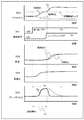
図3は、制御装置1により制御された車両CA1のエンジントルク等の状態の一例を説明する図である。図3では、上段から、車両CA1の、エンジントルク300、制御信号301、車速302、変速比303、ブレーキトルク304の経時変化を示している。
FIG. 3 is a diagram illustrating an example of the state of the engine torque and the like of the vehicle CA1 controlled by the control device 1. FIG. 3 shows changes over time of the
図3に示すように、変速機制御部110は、制御信号301としての追い越しフラグがONになったタイミングで、ベルト式無段変速機構30を制御して、変速比303が徐々に高くなるように変化させる(変速比をLO側に変化させる)と共に、エンジン制御部100は、変速比の変化に追従するように、エンジン10を制御して、エンジントルク300を徐々に高くして、最終的に目標駆動トルクを超えるように変化させる。ここで、制御装置1は、例えば、運転者による車両CA1の方向指示器(図示せず)の操作や、運転者によるハンドル(図示せず)の操作に基づいて追い越しを予測することで、制御信号301としての追い越しフラグをONにする。
As shown in FIG. 3, the
また、制動制御部120は、エンジントルク300の上昇に応じて摩擦ブレーキ43、44を制御して、ブレーキトルク304を上昇させることで、エンジントルク300(駆動トルク)とブレーキトルク304(制動トルク)との差分が、目標駆動トルクとなるようにする。ここで、目標駆動トルクは、車両CA1のアクセル踏み込み量や周囲状況に基づいて、別の制御装置により演算されるものでもよい。
Further, the
これにより、制御装置1では、車両CA1の加速に必要な目標駆動トルクを維持しつつ、車速を加速前状態の一定速度に保持することができる。そして、制御装置1では、制御信号301のレーンチェンジフラグがONになったタイミングで、制動制御部120により摩擦ブレーキ43、44を制御して、ブレーキトルク304を減少させる。
Thereby, in the control apparatus 1, it can hold | maintain a vehicle speed to the constant speed of the state before acceleration, maintaining the target drive torque required for acceleration of vehicle CA1. Then, in the control device 1, at the timing when the lane change flag of the
制御装置1では、制御信号301の追い越しフラグがONになってからレーンチェンジフラグがONになるまでの加速準備期間T1に、エンジントルク300とブレーキトルク304を両方同時に加えることで、車両CA1の加速準備を行うことができる。この結果、本制御を用いた車両CA1の加速度は、本制御がない場合に比べて、ブレーキトルク304の減少と共に急激に大きくなり、追い越し時の車速302を早くすることができる。ここで、制御装置1は、例えば、車両CA1のレーンチェンジの開始タイミング、又は車両CA1のレーンチェンジの終了タイミングでレーンチェンジフラグをONにする。
The control device 1 accelerates the vehicle CA1 by simultaneously applying both the
前述した、エンジントルク(駆動トルク)と、変速比と、ブレーキトルク(制動トルク)とは、以下のように算出する。 The engine torque (drive torque), the gear ratio, and the brake torque (braking torque) described above are calculated as follows.
[変速比の算出方法]
初めに、変速比は、以下のように算出できる。
目標駆動トルク=Fcar_cmd、エンジントルク=Te、変速比=Ratio、最終減速比=Gdef、ブレーキトルク=Tb、タイヤ半径=Rtire、とすると、目標駆動トルクFcar_cmdは、以下の数式(1)を用いて算出できる。
[Gear ratio calculation method]
First, the gear ratio can be calculated as follows.
Assuming that target drive torque = Fcar_cmd, engine torque = Te, gear ratio = Ratio, final reduction ratio = Gdef, brake torque = Tb, tire radius = Rtire, the target drive torque Fcar_cmd is expressed by the following equation (1). Can be calculated.
Fcar_cmd=(Te×Ratio×Gdef―Tb)×Rtire ・・・ (1) Fcar_cmd = (Te × Ratio × Gdef−Tb) × Rtire (1)
ここで、目標駆動トルクFcar_cmdは、車両CA1の何れかの制御部により演算された目標値であり、最終減速比Gdef及びタイヤ半径Rtireは、車両CA1により決まる固有値である。よって、エンジントルクTe、ブレーキトルクTb、変速比Ratioを、前述した数式(1)に適した値とする必要がある。 Here, the target drive torque Fcar_cmd is a target value calculated by any control unit of the vehicle CA1, and the final reduction ratio Gdef and the tire radius Rtire are eigenvalues determined by the vehicle CA1. Therefore, it is necessary to set the engine torque Te, the brake torque Tb, and the gear ratio Ratio to values suitable for the above-described equation (1).
そのため、まず、変速比Ratioは、加速開始後に発生させたい車両CA1のエンジントルクTe(駆動トルク)が、最大エンジントルク以下となるように、変速比RatioをLo側に変化させなければならないため、目標駆動トルクFcar_cmdと、最大エンジントルクとに基づいて算出することができる。例えば、最大エンジントルクをTe_maxとすると、前述した数式(1)のTeをTe_maxに置き換えて、ブレーキトルクTbは加速中を想定しているため0(ゼロ)とすると、変速比Ratioは、下記の数式(2)で算出することができる。算出した変速比Ratioを、Ratio_accとする。 Therefore, first, the gear ratio Ratio must be changed to the Lo side so that the engine torque Te (drive torque) of the vehicle CA1 to be generated after the start of acceleration is equal to or less than the maximum engine torque. It can be calculated based on the target drive torque FCar_cmd and the maximum engine torque. For example, assuming that the maximum engine torque is Te_max, the Te in the above formula (1) is replaced with Te_max, and the brake torque Tb is assumed to be accelerating. It can be calculated by Equation (2). The calculated gear ratio Ratio is defined as Ratio_acc.
Ratio_acc=Fcar_cmd/(Te_max×Gdef×Rtire) ・・・ (2) Ratio_acc = Fcar_cmd / (Te_max × Gdef × Rtire) (2)
ここで、最大エンジントルクTe_maxは、物理的なエンジン10の最大トルクである必要はなく、車両CA1の加速時に出力させたエンジントルクの最大値でもよい。
Here, the maximum engine torque Te_max does not need to be the maximum torque of the
[ブレーキトルクの算出方法]
次に、ブレーキトルクTbは、エンジントルクTeの応答性に基づいて算出することができる。エンジントルクTeの応答性を維持できる最低エンジントルクをTe_minとして決めておくことで、前述した数式(1)のTeをTe_minに置き換えて、すでに算出した変速比Ratio_accを用いて、ブレーキトルクTbを、下記の数式(3)で算出することができる。このように算出したブレーキトルクTbをTb_accとする。
[Brake torque calculation method]
Next, the brake torque Tb can be calculated based on the response of the engine torque Te. By determining the minimum engine torque that can maintain the responsiveness of the engine torque Te as Te_min, the Te in the formula (1) described above is replaced with Te_min, and the brake torque Tb is calculated using the already calculated gear ratio Ratio_acc. It can be calculated by the following mathematical formula (3). The brake torque Tb calculated in this way is defined as Tb_acc.
Tb_acc=(Fcar_cmd/Rtire)−Te_min×Ratio_acc×Gdef ・・・ (3) Tb_acc = (Fcar_cmd / Rtire) −Te_min × Ratio_acc × Gdef (3)
ここで、最低エンジントルクTe_minは、エンジン10の物理的な最低エンジントルクではなく、事前にエンジン10単体の実験などにより取得したエンジン10の応答特性より算出した値である。
Here, the minimum engine torque Te_min is not a physical minimum engine torque of the
[エンジントルクの算出方法]
そして、前述した数式(1)に、算出した変速比Ratio_accと、ブレーキトルクTb_accとを代入することで、エンジントルクTeを、下記の数式(4)で算出することができる。ここで、車両CA1の加速中のエンジントルクTeをTe_accとする。
[Calculation method of engine torque]
Then, by substituting the calculated transmission ratio Ratio_acc and brake torque Tb_acc into the above-described equation (1), the engine torque Te can be calculated by the following equation (4). Here, it is assumed that the engine torque Te during acceleration of the vehicle CA1 is Te_acc.
Te_acc=(Fcar_cmd/(Rtire×Ratio_acc×Gdef))+(Tb_acc/(Ratio_acc×Gdef)) ・・・ (4) Te_acc = (Fcar_cmd / (Rtire × Ratio_acc × Gdef)) + (Tb_acc / (Ratio_acc × Gdef)) (4)
前述で算出した、エンジントルクTe_acc,変速比Ratio_acc、ブレーキトルクTb_accの値を、加速準備期間T1での車両CA1の加速準備に用いることで、車両CA1の目標駆動トルクを実現することができる。 By using the values of the engine torque Te_acc, the gear ratio Ratio_acc, and the brake torque Tb_acc calculated as described above for acceleration preparation of the vehicle CA1 in the acceleration preparation period T1, the target drive torque of the vehicle CA1 can be realized.
このようにすると、制御装置1では、エンジントルクTeとブレーキトルクTbを用いて駆動トルクを目標駆動トルクに近づけられるため、変速比をLo側に変速させた加速準備期間T1の低い目標駆動トルク時でも、エンジン10の加速応答性を高めることができる。
In this way, in the control device 1, the drive torque can be brought close to the target drive torque using the engine torque Te and the brake torque Tb. However, the acceleration response of the
[車両の制御方法]
次に、制御装置1による車両CA1の制御方法を説明する。
[Vehicle control method]
Next, a method for controlling the vehicle CA1 by the control device 1 will be described.
図4は、制御装置1による車両CA1の制御方法を説明するフローチャートである。 FIG. 4 is a flowchart illustrating a method for controlling vehicle CA1 by control device 1.
ステップS101において、加速準備判定部130は、車両CA1が加速準備状態であるか否かを判定する。加速準備判定部130は、車両CA1が加速準備状態であると判定した場合(ステップS101:Yes)、ステップS103に進み、車両CA1が加速準備状態でないと判定した場合(ステップS101:No)、ステップS102に進む。
In step S101, the acceleration
ステップS102において、加速準備判定部130により、車両CA1が加速準備状態でない(例えば、方向指示器やハンドルの操作がなく、追い越しフラグがOFFとなっている)と判定された場合(ステップS101:No)、制御装置1は、エンジン制御装置100によるエンジン10の通常の運転制御を行う。
In step S102, when the acceleration
ステップS103において、加速準備判定部130により、車両CA1が加速準備状態であると判定された場合(ステップS102:Yes)、制御装置1は、車両CA1の走行レーンAから追い越しレーンBへのレーンチェンジが開始されているか否かをさらに判定し、すでに追い越しレーンBへのレーンチェンジが開始されていると判定した場合(ステップS103:Yes)、ステップS102に進み、エンジン制御部100によるエンジン10の通常の運転制御を行う。制御装置1は、まだ追い越しレーンBへのレーンチェンジが開始されていないと判定した場合(ステップS103:No)、ステップS104に進み、本発明にかかる制御を行う。この車両CA1による追い越しレーンBへのレーンチェンジの開始を解除条件と言うことがある。なお、前述した実施の形態では、解除条件は、例えば、車両CA1の追い越しレーンBへのレーンチェンジが開始されたことを条件とした場合を例示して説明したが、これに限定されるものではなく、車両CA1の追い越しレーンBへのレーンチェンジが終了したことを条件としてもよい。
In step S103, when the acceleration
ステップS104において、車両CA1による追い越しレーンBへのレーンチェンジが開始されていない(解除条件が未達成)と判定した場合、変速機制御部110は、前述した数式(2)を用いて、変速比Ratio_accを算出する。
In step S104, when it is determined that the lane change to the overtaking lane B by the vehicle CA1 has not been started (the release condition has not been achieved), the
ステップS105において、制動制御部120は、車両CA1の速度、運転者によるアクセルの踏み込み量、周囲状況などに基づいて、目標駆動トルクを実現するためのブレーキトルクTb_acc(目標制動力)を、前述した数式(3)を用いて算出する。
In step S105, the
ステップS106において、エンジン制御部100は、車両CA1の速度、運転者によるアクセルの踏み込み量、周囲状況などに基づいて、目標駆動トルクを実現するためのエンジントルクTe_acc(制動力)を、前述した数式(4)を用いて算出する。
In step S106, the
ステップS107において、制御装置1は、ステップS105、106で算出したブレーキトルクTb_acc、エンジントルクTe_accを実現するための制御値を、エンジン10や摩擦ブレーキ43、44に対して出力する。
In step S107, the control device 1 outputs control values for realizing the brake torque Tb_acc and the engine torque Te_acc calculated in steps S105 and 106 to the
以上説明した通り、実施の形態では、
(1)車両CA1を駆動させるエンジントルクTe(駆動力)を発生するエンジン10(原動機)と車両CA1を制動させるブレーキトルクTb(制動力)を発生する摩擦ブレーキ43、44(制動装置)とを有する車両CA1の制御装置1であって、車両CA1が加速準備状態か否かを判定する加速準備判定部130と、加速準備判定部130により車両CA1が加速準備状態であると判定された場合、車両CA1の変速比をLO側に変化させる変速機制御部110と、変速機制御部110により車両CA1の変速比がLO側に変化する場合、エンジン10により車両CA1を駆動させるエンジントルクTeを増加させると共に、当該増加させたエンジントルクTeと摩擦ブレーキ43、44により車両CA1を制動させるブレーキトルクTbとの差分(Te−Tb)が目標駆動トルクFcar_cmdとなるように、エンジン10及び摩擦ブレーキ43、44を制御する制御部(エンジン制御部100及び制動制御部120)と、を有する構成とした。
As described above, in the embodiment,
(1) An engine 10 (prime mover) that generates an engine torque Te (driving force) that drives the vehicle CA1 and
また、前述したように、車両CA1を駆動させるエンジントルクTe(駆動力)を発生するエンジン10と車両CA1を制動させるブレーキトルクTb(制動力)を発生する摩擦ブレーキ43、44とを有する車両CA1の制御方法であって、車両CA1が加速準備状態か否かを判定する加速準備判定ステップ(S101)を有し、加速準備判定ステップ(S101)により車両CA1が加速準備状態であると判定された場合、車両CA1の変速比303をLO側に変化させる変速機制御ステップ(S104)と、変速機制御ステップ(S104)により車両CA1の変速比がLO側に変化する場合、エンジン10により車両CA1を駆動させるエンジントルクTeを増加させると共に、当該増加させたエンジントルクTeと摩擦ブレーキ43、44により車両CA1を制動させるブレーキトルクTbとの差分(Te−Tb)が目標駆動トルクFcar_cmdとなるように、エンジン10及び摩擦ブレーキ43、44を制御する制御ステップ(S107)と、を有する構成とした。
Further, as described above, the vehicle CA1 having the
このように構成すると、制御装置1では、車両CA1の変速比をLO側に変化さると共に、エンジン10のエンジントルクTeを増加させる制御を行いつつ、摩擦ブレーキ43、44のブレーキトルクTbを作用させることで、エンジン10のエンジントルクTeが目標駆動トルクFcar_cmdとなるように制御することができる。よって、変速比をLO側に変化させても、ブレーキトルクTbを作用させることで、エンジントルクTeを増加させて目標駆動トルクFcar_cmdに近づくように制御することができ、加速が必要なタイミングで、ブレーキトルクTbを所定の速度で減少させることで、必要な加速応答性を得ることができる。
With this configuration, the control device 1 changes the gear ratio of the vehicle CA1 to the LO side, and controls the brake torque Tb of the
(2)また、加速準備判定部130は、車両CA1の周囲状況または車両装置の動作に基づいて、車両CA1の加速準備状態か否かの判定を行う構成とした。
(2) Further, the acceleration
このように構成すると、加速準備判定部130は、外界認識装置50や位置情報入力装置51による車両CA1の周囲状況や、ハンドル(図示せず)などの車両装置の動作に基づいて、車両CA1の加速準備状態か否かの判定を行うので、車両CA1の加速準備状態を事前に正確に検知することができる。
If comprised in this way, the acceleration
(3)また、制動制御部120は、車両CA1の運動状況または車両装置の動作を契機に生成された制御信号301の追い越しフラグONに基づいて摩擦ブレーキ43、44によるブレーキトルクTbを増加させる制御を開始し、車両CA1の運動状況または車両装置の動作を契機に生成された制御信号301のレーンチェンジフラグONに基づいて摩擦ブレーキ43、44によるブレーキトルクTbを減少させる制御を行う構成とした。
(3) Further, the
このように構成すると、制動制御部120は、制御信号301の追い越しフラグONからレーンチェンジフラグONまでの加速準備期間T1に、摩擦ブレーキ43、44の駆動制御を行うので、車両CA1の加速前の加速準備期間T1に適切な加速準備を行うことができる。
If comprised in this way, since the
(4)なお、前述した制動制御部120は、車両CA1を制動させる摩擦ブレーキ43、44の制動時間が、所定時間taを超えないように、摩擦ブレーキ43、44を制御する構成としてもよい(図5参照)。制動制御部120は、摩擦ブレーキ43、44の制動時間が、所定時間taを超えたと判定した場合、その時点で、摩擦ブレーキ43、44によるブレーキトルク304を減少させる(図5のブレーキトルク304の破線参照)。
(4) The above-described
図6に示すように、制動制御部120は、ブレーキトルクTbを前述した数式(3)を用いて算出し(ステップS201)、算出したブレーキトルクTbの制動時間が、摩擦ブレーキ43、44などの制動装置の特性から予め決められた所定時間ta以下であるか否かを判定し(ステップS202)、所定時間ta以下である場合、算出したブレーキトルクTbの制御値を摩擦ブレーキ43、44に出力し(ステップS203)、所定時間taを超えている場合、算出した車両CA1を制動させるブレーキトルクTbの制動時間を、所定時間taを超えないように、ブレーキトルクTbを減少させる制御を行う制御値を摩擦ブレーキ43、44に出力する(ステップS204)。
As shown in FIG. 6, the
このように構成すると、制動制御部120による摩擦ブレーキ43、44の制動時間を、摩擦ブレーキ43、44などの制動装置の特性などから予め設定された所定時間ta以下とすることができ、摩擦ブレーキ43、44などの制動装置の摩耗の促進などを抑えることができる。
With this configuration, the braking time of the
(5)なお、制動制御部120は、車両CA1を制動させるブレーキトルクTbを所定時間範囲tbで、徐々に減少させるように、摩擦ブレーキ43、44を制御する構成としてもよい(図7の破線参照)。
(5) The
図8に示すように、制動制御部120は、ブレーキトルクTbを前述した数式(3)を用いて算出し(ステップS301)、算出したブレーキトルクTbの制動時間が、摩擦ブレーキ43、44などの制動装置の特性から予め決められた所定時間範囲tb以下であるか否かを判定し(ステップS302)、所定時間範囲tb以下である場合、車両CA1を制動させるブレーキトルクTbを徐々に減少させる制御値を摩擦ブレーキ43、44に出力し(ステップS303)、所定時間範囲tbを超えている場合、ブレーキトルクTbを急激に減少させる制御値を摩擦ブレーキ43、44に出力する(ステップS304)。
As shown in FIG. 8, the
このように構成すると、制動制御部120は、摩擦ブレーキ43、44の摩耗に支障がない所定時間範囲tb内で、ブレーキトルクTbを徐々に減少させるので、所定時間範囲tb内で、車両CA1の急なレーン変更などで加速が必要になった場合でも、目標駆動トルクに近いエンジントルクTeが維持されているので、長い時間、加速応答性が維持される。
With this configuration, the
(6)なお、制動制御部120は、車両CA1のエンジン10のエンジントルクTeが、所定の閾値Tth以下となった場合、摩擦ブレーキ43、44によりブレーキトルクTbを発生させる構成としてもよい(図9参照)。
(6) The
図10に示すように、制動制御部120は、ブレーキトルクTbを前述した数式(3)を用いて算出し(ステップS401)、エンジントルクTeが所定の閾値Tth以下であるか否かを判定し(ステップS402)、エンジントルクTeが、閾値Tth以下である場合(ステップS402:Yes)、摩擦ブレーキ43、44によりブレーキトルクTbを発生させる制御値を摩擦ブレーキ43、44に出力し(ステップS403)、エンジントルクTeが閾値Tth以上である場合(ステップS402:No)、ステップS401に戻って、エンジントルクTeが、所定の閾値Tth以下となるまで待つ。
As shown in FIG. 10, the
このように構成すると、制動制御部120は、エンジントルクTeが、所定の閾値Tth以下となった場合に、ブレーキトルクTbを発生させるので、加速応答性を維持しつつ、ブレーキトルクTbの発生タイミングを遅らせることができ、摩擦ブレーキ43、44の摩耗の促進を防止することができる。
With this configuration, the
以上、本発明の実施の形態の一例を説明したが、本発明は、前述した実施の形態を全て組み合わせてもよく、何れか2つ以上の実施の形態を任意に組み合わせても好適である。 As mentioned above, although an example of embodiment of this invention was demonstrated, all the embodiment mentioned above may be combined and this invention is suitable also combining any two or more embodiment arbitrarily.
また、本発明は、前述した実施の形態の全ての構成を備えているものに限定されるものではなく、前述した実施の形態の構成の一部を、他の実施の形態の構成に置き換えてもよく、また、前述した実施の形態の構成を、他の実施の形態の構成に置き換えてもよい。 Further, the present invention is not limited to the one having all the configurations of the above-described embodiment, and a part of the configuration of the above-described embodiment is replaced with the configuration of another embodiment. In addition, the configuration of the above-described embodiment may be replaced with the configuration of another embodiment.
また、前述した実施の形態の一部の構成について、他の実施の形態の構成に追加、削除、置換をしてもよい。 Further, a part of the configuration of the above-described embodiment may be added to, deleted from, or replaced with the configuration of another embodiment.
1:制御装置、10:エンジン、11:出力軸、20:発進装置、30:ベルト式無段変速機構、31:変速機入力軸、32:変速機出力軸、40:差動装置、41:右ドライブシャフト、42:左ドライブシャフト、43、44:摩擦ブレーキ、45:右タイヤ、46:左タイヤ、50:外界認識装置、51:位置情報入力装置、100:エンジン制御部、110:変速機制御部、120:制動制御部、130:加速判定部、CA1:車両(自車両)、CA2、CA3:車両(他車両) 1: control device, 10: engine, 11: output shaft, 20: starting device, 30: belt-type continuously variable transmission mechanism, 31: transmission input shaft, 32: transmission output shaft, 40: differential device, 41: Right drive shaft, 42: Left drive shaft, 43, 44: Friction brake, 45: Right tire, 46: Left tire, 50: External recognition device, 51: Position information input device, 100: Engine control unit, 110: Transmission Control unit, 120: braking control unit, 130: acceleration determination unit, CA1: vehicle (own vehicle), CA2, CA3: vehicle (other vehicle)
Claims (10)
前記車両が加速準備状態か否かを判定する加速準備判定部と、
前記加速準備判定部により前記車両が加速準備状態であると判定された場合、前記車両の変速比をLO側に変化させる変速機制御部と、
前記変速機制御部により前記車両の変速比がLO側に変化する場合、前記原動機により前記車両を駆動させる駆動力を増加させると共に、当該増加させた駆動力と前記制動装置により前記車両を制動させる制動力との差分が目標値となるように、前記原動機及び前記制動装置を制御する制御部と、を有する車両の制御装置。 A vehicle control device having a prime mover for generating a driving force for driving the vehicle and a braking device for generating a braking force for braking the vehicle,
An acceleration preparation determination unit for determining whether the vehicle is in an acceleration preparation state;
When the acceleration preparation determination unit determines that the vehicle is in an acceleration preparation state, a transmission control unit that changes the gear ratio of the vehicle to the LO side;
When the gear ratio of the vehicle is changed to the LO side by the transmission control unit, the driving force for driving the vehicle by the prime mover is increased and the vehicle is braked by the increased driving force and the braking device. A control device for a vehicle, comprising: a controller that controls the prime mover and the braking device such that a difference from a braking force becomes a target value.
前記車両が加速準備状態か否かを判定する加速準備判定ステップと、
前記加速準備判定ステップにより前記車両が加速準備状態であると判定された場合、前記車両の変速比をLO側に変化させる変速機制御ステップと、
前記変速機制御ステップにより前記車両の変速比がLO側に変化する場合、前記原動機により前記車両を駆動させる駆動力を増加させると共に、当該増加させた駆動力と前記制動装置により前記車両を制動させる制動力との差分が目標値となるように、前記原動機及び前記制動装置を制御する制御ステップと、を有する車両の制御方法。 A vehicle control method comprising a prime mover for generating a driving force for driving a vehicle and a braking device for generating a braking force for braking the vehicle,
An acceleration preparation determination step for determining whether or not the vehicle is in an acceleration preparation state;
A transmission control step for changing the gear ratio of the vehicle to the LO side when the acceleration preparation determination step determines that the vehicle is in an acceleration preparation state;
When the gear ratio of the vehicle changes to the LO side by the transmission control step, the driving force for driving the vehicle by the prime mover is increased, and the vehicle is braked by the increased driving force and the braking device. And a control step of controlling the prime mover and the braking device such that a difference from the braking force becomes a target value.
Priority Applications (1)
| Application Number | Priority Date | Filing Date | Title |
|---|---|---|---|
| JP2018061298A JP2019172017A (en) | 2018-03-28 | 2018-03-28 | Control device of vehicle and control method |
Applications Claiming Priority (1)
| Application Number | Priority Date | Filing Date | Title |
|---|---|---|---|
| JP2018061298A JP2019172017A (en) | 2018-03-28 | 2018-03-28 | Control device of vehicle and control method |
Publications (1)
| Publication Number | Publication Date |
|---|---|
| JP2019172017A true JP2019172017A (en) | 2019-10-10 |
Family
ID=68169930
Family Applications (1)
| Application Number | Title | Priority Date | Filing Date |
|---|---|---|---|
| JP2018061298A Pending JP2019172017A (en) | 2018-03-28 | 2018-03-28 | Control device of vehicle and control method |
Country Status (1)
| Country | Link |
|---|---|
| JP (1) | JP2019172017A (en) |
-
2018
- 2018-03-28 JP JP2018061298A patent/JP2019172017A/en active Pending
Similar Documents
| Publication | Publication Date | Title |
|---|---|---|
| EP3521594B1 (en) | Vehicle control device | |
| JP6048457B2 (en) | Vehicle travel control device | |
| KR101679273B1 (en) | Speed control method and system | |
| JP6308167B2 (en) | Vehicle control device | |
| JP2017001485A (en) | Vehicular drive support apparatus | |
| JP6553469B2 (en) | Vehicle control device | |
| CN110871795A (en) | Driving support device | |
| JP6265191B2 (en) | Vehicle control device | |
| WO2018173966A1 (en) | Travel control device, vehicle, and travel control method | |
| JP2016169685A (en) | Control device of vehicle | |
| US20220203988A1 (en) | Method for driving a vehicle platoon | |
| JP2018135003A (en) | Travel control device, vehicle, and travel control method | |
| JP2017137053A (en) | Hybrid vehicle control device | |
| JP2010241245A (en) | Driving power controller for vehicle | |
| JP2014236567A (en) | Control device for vehicle | |
| JP2021133892A (en) | Drive support device and drive support method | |
| JP2011116177A (en) | Vehicle control device | |
| JP2019172017A (en) | Control device of vehicle and control method | |
| WO2021172502A1 (en) | Driving assistance method and driving assistance device | |
| JP2019093807A (en) | Vehicular control apparatus | |
| JP7070450B2 (en) | Vehicle travel control device | |
| WO2020085040A1 (en) | Vehicle drive control device, vehicle drive control method, and program | |
| JP2021109558A (en) | Vehicle travel control device | |
| WO2018173964A1 (en) | Travel control device, vehicle, and travel control method | |
| JP7327210B2 (en) | Driving support device |