JP2019166322A - Rotary tissue cutting device - Google Patents
Rotary tissue cutting device Download PDFInfo
- Publication number
- JP2019166322A JP2019166322A JP2019053198A JP2019053198A JP2019166322A JP 2019166322 A JP2019166322 A JP 2019166322A JP 2019053198 A JP2019053198 A JP 2019053198A JP 2019053198 A JP2019053198 A JP 2019053198A JP 2019166322 A JP2019166322 A JP 2019166322A
- Authority
- JP
- Japan
- Prior art keywords
- cutting
- cutting member
- tissue
- distal end
- cylindrical body
- Prior art date
- Legal status (The legal status is an assumption and is not a legal conclusion. Google has not performed a legal analysis and makes no representation as to the accuracy of the status listed.)
- Granted
Links
- 0 CCC(C1CC1)*1C(C2)(C3)C2C3C1 Chemical compound CCC(C1CC1)*1C(C2)(C3)C2C3C1 0.000 description 2
Images

Classifications
-
- A—HUMAN NECESSITIES
- A61—MEDICAL OR VETERINARY SCIENCE; HYGIENE
- A61B—DIAGNOSIS; SURGERY; IDENTIFICATION
- A61B17/00—Surgical instruments, devices or methods
- A61B17/32—Surgical cutting instruments
- A61B17/3205—Excision instruments
- A61B17/32053—Punch like cutting instruments, e.g. using a cylindrical or oval knife
-
- A—HUMAN NECESSITIES
- A61—MEDICAL OR VETERINARY SCIENCE; HYGIENE
- A61B—DIAGNOSIS; SURGERY; IDENTIFICATION
- A61B17/00—Surgical instruments, devices or methods
- A61B17/32—Surgical cutting instruments
- A61B17/320016—Endoscopic cutting instruments, e.g. arthroscopes, resectoscopes
- A61B17/32002—Endoscopic cutting instruments, e.g. arthroscopes, resectoscopes with continuously rotating, oscillating or reciprocating cutting instruments
-
- A—HUMAN NECESSITIES
- A61—MEDICAL OR VETERINARY SCIENCE; HYGIENE
- A61B—DIAGNOSIS; SURGERY; IDENTIFICATION
- A61B17/00—Surgical instruments, devices or methods
- A61B17/32—Surgical cutting instruments
- A61B17/3201—Scissors
-
- A—HUMAN NECESSITIES
- A61—MEDICAL OR VETERINARY SCIENCE; HYGIENE
- A61B—DIAGNOSIS; SURGERY; IDENTIFICATION
- A61B17/00—Surgical instruments, devices or methods
- A61B17/32—Surgical cutting instruments
- A61B17/3205—Excision instruments
- A61B17/3207—Atherectomy devices working by cutting or abrading; Similar devices specially adapted for non-vascular obstructions
- A61B17/320758—Atherectomy devices working by cutting or abrading; Similar devices specially adapted for non-vascular obstructions with a rotating cutting instrument, e.g. motor driven
-
- A—HUMAN NECESSITIES
- A61—MEDICAL OR VETERINARY SCIENCE; HYGIENE
- A61B—DIAGNOSIS; SURGERY; IDENTIFICATION
- A61B17/00—Surgical instruments, devices or methods
- A61B17/32—Surgical cutting instruments
- A61B17/3209—Incision instruments
-
- A—HUMAN NECESSITIES
- A61—MEDICAL OR VETERINARY SCIENCE; HYGIENE
- A61B—DIAGNOSIS; SURGERY; IDENTIFICATION
- A61B17/00—Surgical instruments, devices or methods
- A61B2017/00367—Details of actuation of instruments, e.g. relations between pushing buttons, or the like, and activation of the tool, working tip, or the like
-
- A—HUMAN NECESSITIES
- A61—MEDICAL OR VETERINARY SCIENCE; HYGIENE
- A61B—DIAGNOSIS; SURGERY; IDENTIFICATION
- A61B17/00—Surgical instruments, devices or methods
- A61B17/32—Surgical cutting instruments
- A61B17/320016—Endoscopic cutting instruments, e.g. arthroscopes, resectoscopes
- A61B17/32002—Endoscopic cutting instruments, e.g. arthroscopes, resectoscopes with continuously rotating, oscillating or reciprocating cutting instruments
- A61B2017/320032—Details of the rotating or oscillating shaft, e.g. using a flexible shaft
Landscapes
- Health & Medical Sciences (AREA)
- Surgery (AREA)
- Life Sciences & Earth Sciences (AREA)
- Medical Informatics (AREA)
- Animal Behavior & Ethology (AREA)
- Engineering & Computer Science (AREA)
- Biomedical Technology (AREA)
- Heart & Thoracic Surgery (AREA)
- Veterinary Medicine (AREA)
- Molecular Biology (AREA)
- Nuclear Medicine, Radiotherapy & Molecular Imaging (AREA)
- General Health & Medical Sciences (AREA)
- Public Health (AREA)
- Orthopedic Medicine & Surgery (AREA)
- Vascular Medicine (AREA)
- Pathology (AREA)
- Surgical Instruments (AREA)
Abstract
【課題】新規な回転型組織切断デバイスの提供。【解決手段】開示される実施形態は組織壁における開口部を切断するための装置、システム及び方法を含む。本装置は遠位端部において少なくとも1つの第1切削面を支持する第1円筒形本体を有する内側切削部材を含む。第1切削面は第1円筒形本体の軸に対して第1の回転方向に面し、かつ第1円筒形本体の外側周囲にて第1切削端部を有する。本装置はまた第1円筒形本体の周囲に同心状に配置され、かつ遠位端部にて少なくとも1つの第2切削面を支持する第2円筒形本体を有する外側切削部材をも含む。第2切削面は軸線に対して第2の回転方向に面し、かつ第2円筒形本体の内側周囲にて第2切削端部を有する。組織は組織に対する装置の遠位端部の適用並びに内側切削部材及び外側切削部材を逆回転させることに応答して、内側切削部材の第1切削縁部と外側切削部材の第2切削縁部との間で回転可能に切断可能である。【選択図】図1A novel rotary tissue cutting device is provided. The disclosed embodiments include devices, systems and methods for cutting an opening in a tissue wall. The device includes an inner cutting member having a first cylindrical body supporting at least one first cutting surface at a distal end. The first cutting surface faces in a first rotational direction with respect to the axis of the first cylindrical body and has a first cutting end around an outer periphery of the first cylindrical body. The apparatus also includes an outer cutting member having a second cylindrical body disposed concentrically about the first cylindrical body and supporting at least one second cutting surface at a distal end. The second cutting surface faces in a second direction of rotation with respect to the axis and has a second cutting end around an inner periphery of the second cylindrical body. The tissue is responsive to application of the distal end of the device to the tissue and reversing the inner and outer cutting members and the first and second cutting edges of the inner and outer cutting members. It can be rotatably cut between. [Selection diagram] Fig. 1
Description
[関連出願の相互参照]
本出願は、本明細書にて出願された、代理人整理番号ORA0107US1号、「ROTATIONAL TISSUE CUTTING CONTROL DEVICE」の同時係属出願に関連し、その内容が全体として本明細書に参考として組み込まれる。
[Cross-reference of related applications]
The present application is related to the co-pending application filed in the present specification of the agent docket No. ORA0107US1, “ROTATIONAL TISSUE CUTING CONTROL DEVICE”, the contents of which are incorporated herein by reference in their entirety.
本開示は、組織壁における開口部を切断するための装置、システム、及び方法に関する。 The present disclosure relates to devices, systems, and methods for cutting an opening in a tissue wall.
この項目における記述は、単に、本開示に関する背景情報を提供するのみであり、先行技術を構成しない場合もある。 The statements in this section merely provide background information related to the present disclosure and may not constitute prior art.
侵襲的な外科手術を行うことなく患者の体内の組織にアクセスする能力により、疼痛の低減、回復時間の短縮、及び合併症のリスクの低減を伴う、継続的な向上を伴う種類の分析、診断、及び処置が可能である。2つの例として、内視鏡撮像及びカテーテル法(catherization)処置は、侵襲的な外科手術を行うことなく、多数の内部病変の診断及び処置を可能にしてきた。 The ability to access tissue in the patient's body without performing invasive surgery, a type of analysis and diagnosis with continuous improvement, with reduced pain, reduced recovery time, and reduced risk of complications And treatment is possible. As two examples, endoscopic imaging and catherization procedures have enabled the diagnosis and treatment of numerous internal lesions without invasive surgery.
場合によっては、患者の体内の組織を遠隔で切断するために、薄いプローブ様の装置を挿入することが望ましい場合がある。例えば、胆管が閉塞された場合に患者に苦痛の緩和を提供するために、食道(gastronomical tract)内へとプローブを挿入して開口部を切断し、胆嚢が十二指腸内に胆汁を放出することを可能にして、胆嚢の痛みのある膨潤を緩和することが望ましい。しかし、プローブを所望の位置に到達させることが可能であり得るにもかかわらず、小さな切断を遠隔で行うことが非常に困難であることが、判明し得る。切断を行う際に組織を後方で反対方向に押す構造が存在しない場合、組織は、穿孔又は切断するには柔軟過ぎる場合がある。 In some cases, it may be desirable to insert a thin probe-like device to remotely cut tissue within a patient's body. For example, to provide pain relief to the patient when the bile duct is obstructed, insert a probe into the gastronomical tract to cut the opening and allow the gallbladder to release bile into the duodenum. It would be desirable to alleviate the painful swelling of the gallbladder. However, it may prove very difficult to make small cuts remotely, even though it may be possible to get the probe to the desired position. If there is no structure that pushes tissue backwards in the opposite direction when making a cut, the tissue may be too pliable to puncture or cut.
開示される実施形態は、組織壁における開口部を切断するための装置、システム、及び方法を含む。 The disclosed embodiments include devices, systems, and methods for cutting openings in tissue walls.
例示的実施形態では、装置は、遠位端部において少なくとも1つの第1切削面を支持する第1円筒形本体を有する内側切削部材を含む。第1切削面は、第1円筒形本体の軸に対して第1の回転方向に面し、かつ第1円筒形本体の外側周囲にて第1切削端部を有する。本装置はまた、第1円筒形本体の周囲に同心状に配置され、かつ遠位端部にて少なくとも1つの第2切削面を支持する第2円筒形本体を有する、外側切削部材をも含む。第2切削面は、軸線に対して第2の回転方向に面し、かつ第2円筒形本体の内側周囲にて第2切削端部を有する。組織は、組織に対する装置の遠位端部の適用並びに内側切削部材及び外側切削部材を逆回転させることに応答して、内側切削部材の第1切削縁部と外側切削部材の第2切削縁部との間で回転可能に切断可能である。 In an exemplary embodiment, the apparatus includes an inner cutting member having a first cylindrical body that supports at least one first cutting surface at the distal end. The first cutting surface faces in the first rotational direction with respect to the axis of the first cylindrical body and has a first cutting end around the outside of the first cylindrical body. The apparatus also includes an outer cutting member having a second cylindrical body disposed concentrically around the first cylindrical body and supporting at least one second cutting surface at the distal end. . The second cutting surface faces in the second rotational direction with respect to the axis and has a second cutting end around the inside of the second cylindrical body. In response to application of the distal end of the device to the tissue and reverse rotation of the inner and outer cutting members, the first cutting edge of the inner cutting member and the second cutting edge of the outer cutting member And can be cut in a rotatable manner.
別の例示的実施形態では、装置は、装置の遠位端部において2つ以上の第1切削面を支持する第1円筒形本体を有する内側切削部材を含む。第1切削面は、第1円筒形本体の軸線に対して、第1の回転方向に面する。第1切削面は、第1円筒形本体の外側周囲に存在し、かつ内側切削部材の軸に対して傾斜している第1切削縁部を含む。第1切削面はまた、遠位端部を越えて外側に延在し、かつ組織を貫通するように構成されたアンカー先端部を含む。本装置はまた、第1円筒形本体の周囲に同心状に配置され、かつ装置の遠位端部にて少なくとも1つの第2切削面を支持する第2円筒形本体を有する、外側切削部材を含む。第2切削面は、軸線に対して第2の回転方向に面し、かつ第2円筒形本体の内側周囲にて第2切削端部を有する。組織は、アンカー先端部により貫通可能であり、かつ組織に対する装置の遠位端部の適用並びに内側切削部材及び外側切削部材を逆回転させることに応答して、内側切削部材の第1切削縁部と外側切削部材の第2切削縁部との間で回転可能に切断可能である。 In another exemplary embodiment, the device includes an inner cutting member having a first cylindrical body that supports two or more first cutting surfaces at a distal end of the device. The first cutting surface faces the first rotational direction with respect to the axis of the first cylindrical body. The first cutting surface includes a first cutting edge that exists around the outer periphery of the first cylindrical body and is inclined with respect to the axis of the inner cutting member. The first cutting surface also includes an anchor tip that extends outward beyond the distal end and is configured to penetrate tissue. The apparatus also includes an outer cutting member having a second cylindrical body disposed concentrically around the first cylindrical body and supporting at least one second cutting surface at the distal end of the apparatus. Including. The second cutting surface faces in the second rotational direction with respect to the axis and has a second cutting end around the inside of the second cylindrical body. The tissue is piercable by the anchor tip and in response to application of the distal end of the device to the tissue and reverse rotation of the inner and outer cutting members, the first cutting edge of the inner cutting member And a second cutting edge of the outer cutting member so as to be rotatable.
更なる例示的実施形態では、方法は、組織に対する内側切削部材及び同心性の外側切削部材を有する円筒形の切断装置を、延在させることを含む。内側切削部材及び同心性の外側切削部材は、内側切削部材及び同心性の外側切削部材の軸線に直交して組織を放射状に切断するように構成された、対向する切削面を有する。内側切削部材は移動して、内側切削部材の遠位端部でアンカー先端部に組織を貫通させる。内側切削部材及び同心性の外側切削部材は、組織を放射状に切断するように互いに対して回転する。 In a further exemplary embodiment, the method includes extending a cylindrical cutting device having an inner cutting member and a concentric outer cutting member for tissue. The inner cutting member and the concentric outer cutting member have opposing cutting surfaces configured to radially cut tissue perpendicular to the axis of the inner cutting member and the concentric outer cutting member. The inner cutting member moves to penetrate tissue through the anchor tip at the distal end of the inner cutting member. The inner cutting member and the concentric outer cutting member rotate relative to each other to cut tissue radially.
別の例示的実施形態では、逆回転可能な切断装置を制御するための装置は、第1駆動シャフトに係合するように構成された第1放射状アクチュエータを含む。第2放射状アクチュエータは、第2駆動シャフトと係合するように構成され、第2駆動シャフトは、第1駆動シャフトと同軸状に配置されている。ハウジングは、第1放射状アクチュエータ及び第2放射状アクチュエータを支持し、第1駆動シャフト及び第2駆動シャフトがそれを通って延在することを可能にし、第1駆動シャフト及び第2駆動シャフトは、第1放射状アクチュエータ及び第2放射状アクチュエータの少なくとも一方の回転に応じて、相対的に逆回転可能である。 In another exemplary embodiment, an apparatus for controlling a counter-rotatable cutting device includes a first radial actuator configured to engage a first drive shaft. The second radial actuator is configured to engage with the second drive shaft, and the second drive shaft is disposed coaxially with the first drive shaft. The housing supports the first radial actuator and the second radial actuator and allows the first drive shaft and the second drive shaft to extend therethrough, the first drive shaft and the second drive shaft being the first In accordance with the rotation of at least one of the first radial actuator and the second radial actuator, they can be rotated in the reverse direction relatively.
更なる例示的実施形態では、逆回転可能な切断装置を制御するための装置は、第1駆動シャフトに係合するように構成された第1放射状アクチュエータを含む。第2放射状アクチュエータは、第2駆動シャフトと係合するように構成され、第2駆動シャフトは、第1駆動シャフトと同軸状に配置されている。逆回転機構は、第1放射状アクチュエータ及び第2放射状アクチュエータを機械的に連結させ、逆回転機構は、第1放射状アクチュエータが第1方向に回転する場合に、第2放射状アクチュエータを第2方向に回転させるように構成される。ハウジングは、第1放射状アクチュエータ及び第2放射状アクチュエータを支持し、第1駆動シャフト及び第2駆動シャフトがそこを通って延在することを可能にする。回転制御装置は第1放射状アクチュエータと機械的に連結して、第1放射状アクチュエータの回転を可能にし、第1駆動シャフト及び第2駆動シャフトが、第1回転制御装置の回転に応じて同時に逆回転することを可能にする。 In a further exemplary embodiment, an apparatus for controlling a counter-rotatable cutting device includes a first radial actuator configured to engage a first drive shaft. The second radial actuator is configured to engage with the second drive shaft, and the second drive shaft is disposed coaxially with the first drive shaft. The reverse rotation mechanism mechanically connects the first radial actuator and the second radial actuator, and the reverse rotation mechanism rotates the second radial actuator in the second direction when the first radial actuator rotates in the first direction. Configured to let The housing supports the first radial actuator and the second radial actuator and allows the first drive shaft and the second drive shaft to extend therethrough. The rotation control device is mechanically connected to the first radial actuator to enable rotation of the first radial actuator, and the first drive shaft and the second drive shaft are simultaneously reversely rotated according to the rotation of the first rotation control device. Make it possible to do.
更に別の例示的実施形態では、組織壁内の開口部を切断するためのシステムは、第1駆動シャフト、第1駆動シャフトの周囲において同軸上に配設され、かつ第1駆動シャフトとは独立して回転するように構成された第2駆動シャフト、並びに第1駆動シャフト及び第2駆動シャフトを収容するシースを含む、駆動シャフト組立体を含む。第1放射状アクチュエータは、第1駆動シャフトと係合するように構成される。第2放射状アクチュエータは、第2駆動シャフトと係合するように構成される。ハウジングは、第1放射状アクチュエータ及び第2放射状アクチュエータを支持し、かつ第1駆動シャフト及び第2駆動シャフトを収容するシースがハウジングを通って延在することを可能にする。回転制御装置は、第1放射状アクチュエータと機械的に連結して、第2放射状アクチュエータに対する第1放射状アクチュエータの回転を可能にする。切断装置は、カッターの遠位端部にて少なくとも1つの第1切削面を支持する第1円筒形本体を有する内側切削部材を含み、第1駆動シャフトに機械的に連結しており、第1切削面は、第1円筒形本体の軸線に対する第1回転方向に面しており、第1円筒形本体の外側周囲において第1切削端部を有する。第2円筒形本体を有する外側切削部材は、第1円筒形本体の周囲に同心状に配置され、第2駆動シャフトと機械的に連結しており、外側切断部材は、装置の遠位端部において少なくとも1つの第2切削面を支持し、また第2切削面は、軸線に対する第2回転方向に面し、かつ第2円筒形本体の内側周囲において、第2切削端部を有する。組織は、装置の遠位端部の適用及び回転制御装置の回転に応答して、内側切削部材の第1切削縁部と外側切削部材の第2切削縁部との間で回転可能に切断可能である。 In yet another exemplary embodiment, a system for cutting an opening in a tissue wall is disposed coaxially around a first drive shaft, around the first drive shaft, and independent of the first drive shaft. A drive shaft assembly including a second drive shaft configured to rotate and a sheath that houses the first drive shaft and the second drive shaft. The first radial actuator is configured to engage the first drive shaft. The second radial actuator is configured to engage the second drive shaft. The housing supports the first and second radial actuators and allows a sheath that houses the first and second drive shafts to extend through the housing. The rotation control device is mechanically coupled to the first radial actuator to allow rotation of the first radial actuator relative to the second radial actuator. The cutting device includes an inner cutting member having a first cylindrical body that supports at least one first cutting surface at a distal end of the cutter, and is mechanically coupled to the first drive shaft, The cutting surface faces in the first rotation direction with respect to the axis of the first cylindrical body and has a first cutting end around the outside of the first cylindrical body. An outer cutting member having a second cylindrical body is disposed concentrically around the first cylindrical body and is mechanically coupled to the second drive shaft, the outer cutting member being a distal end of the device. Supporting at least one second cutting surface, the second cutting surface facing in a second rotational direction with respect to the axis and having a second cutting edge at the inner periphery of the second cylindrical body. Tissue can be rotatably cut between the first cutting edge of the inner cutting member and the second cutting edge of the outer cutting member in response to application of the distal end of the device and rotation of the rotation control device. It is.
更なる特徴、利点、及び適用分野は、本明細書に提供される説明から明らかになるであろう。説明及び具体的な例は、単に例示目的のために意図され、本開示の範囲を限定することは意図されないことを理解されたい。 Further features, advantages, and areas of application will become apparent from the description provided herein. It should be understood that the description and specific examples are intended for purposes of illustration only and are not intended to limit the scope of the present disclosure.
本明細書に説明される図面は、単に例示目的のためであり、決して本開示の範囲を制限することは意図されない。図面における構成要素は、必ずしも一定の縮尺ではなく、開示された実施形態の原理を例示することに重点を置かれる。 The drawings described herein are for illustrative purposes only and are not intended to limit the scope of the present disclosure in any way. The components in the drawings are not necessarily to scale, emphasis instead being placed upon illustrating the principles of the disclosed embodiments.
以下の説明は、本質的に単に例示的なものであり、本開示、適用、又は使用を限定することは意図されない。3桁の参照番号のうちの最初の桁及び4桁の参照番号のうちの最初の2桁は、その要素が最初に現れる1桁の図番号のうちの最初の桁及び図番号のうちの最初の2桁にそれぞれ対応することが留意されるだろう。 The following description is merely exemplary in nature and is not intended to limit the present disclosure, application, or use. The first digit of the three-digit reference number and the first two digits of the four-digit reference number are the first digit of the one-digit figure number in which the element first appears and the first of the figure numbers. It will be noted that each corresponds to two digits.
以下の説明は、限定することなく単に例示として、組織を切断するための装置、システム、及び方法の種々の実施形態を説明する。以下に詳細に記載されるように、逆回転可能な回転要素を有する切断装置は組織へと延在し、組織を貫通して切断するように互いに対して回転を引き起こす。 The following description describes, by way of example and not limitation, various embodiments of devices, systems, and methods for cutting tissue. As described in detail below, cutting devices having counter-rotatable rotating elements extend into tissue and cause rotation relative to each other to cut through the tissue.
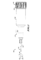
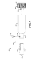
図1を参照すると、患者の解剖学的領域(図1に図示せず)の組織壁における開口部を切断するために、例示的システム100が提供される。種々の実施形態では、システム100は、一般に、切断装置111、切断装置111を制御するための制御装置150、及び切断装置111を制御装置150に連結させる駆動シャフト組立体140を含む。以下で詳細に説明するように、切断装置111は、図2、3A〜3C、4A〜4C、5A〜5C、及び6に関連して以下に更に説明するように、軸線101の周囲で方向103又は105にて回転するように構成された切削部材を有する、逆回転可能な切断装置である。駆動シャフト組立体140は、第1駆動シャフト及び第2駆動シャフトを含み、第2駆動シャフトは、いくつかの実施形態では、第1駆動シャフトの周囲で同軸状に配置された中空シャフトを含む。第1駆動シャフト及び第2駆動シャフトは、図11に関連して以下に更に説明するように、切断装置111の部材と連結可能であり、外装内に収容される。いくつかの実施形態では、第1駆動シャフト及び第2駆動シャフトは、可撓性の、逆回転可能なケーブルを含む。制御装置150は、位置調整装置170及び少なくとも1つの回転把持部180を支持するハウジング160を含み、これらはそれぞれ、図7、8、及び/又は9に関連して、以下に更に説明される。
Referring to FIG. 1, an
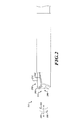
図2を参照すると、切断装置111は、内側切削部材211及び外側切削部材251を含む、2つの逆回転可能部材を含む。図3A〜3C及び5A〜5Cに関連して、以下で更に説明するように、内側切削部材211は、切断装置211において遠位端部290にて組織を貫通及び/又は固定するように構成され、次に、内側切削部材211における内側切削面241と外側切削部材251における外側切削面271との間の対向する切削面との間の切削領域292へと組織を引き入れる。したがって、内側切削部材211及び外側切削部材251の回転により、組織が鋏まれ、組織内に開口部を形成する。
Referring to FIG. 2, the
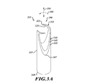
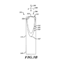
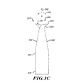
図3A〜3Cを参照すると、内側切削部材211は、図11に関連して以下で更に説明する、駆動シャフト組立体140(図1。図3A〜3Cには示さず)と係合する近位端部349を有する本体315を含む。内側切削部材211は、遠位端部290に向かって長手方向に延在し、かつ軸線101の周囲で方向103にて放射状に湾曲する1つ以上のアンカー先端部321を含む。アンカー先端部321は、1つ以上の内側切削面241の前方へと遠位端部290に向かって延在するように、角度づけられている。アンカー先端部321は、内側切削部材211の遠位端部290に存在する組織壁(図3A〜3Cには示さず)を貫通するように構成された、貫通端部323を有する。いくつかの実施形態では、図2、3A〜3C、及び6にて示すように、アンカー先端部321は螺旋形状を描写する。いくつかの他の実施形態では、アンカー先端部321はまた、遠位端部290から離れる方向に面する平坦な固定表面325を含んでもよい。
With reference to FIGS. 3A-3C, the
内側切削部材211はまた、1つ以上の内側切削面241を含む。内側切削面241は、先導切削縁部343から後続切削縁部345まで傾斜している。いくつかの実施形態では、内側切削面241の先導切削縁部343は、以下で更に説明するように、外側切削部材251の外側切削面271の先導縁部と係合する、内側切削部材の外側縁部にある。いくつかの実施形態では、1つ以上の内側切削面241は、軸線101に対して鋭角で傾斜している。1つ以上の内側切削面241は、切削領域292(図2)において、内側切削部材の1つ以上の内側切削面241及び外側切削部材251の1つ以上の内側切削面271が、一対の鋏の対向するブレードのように、遠位端部290に面する鋭角で合流し、それにより、組織の切り取りを促進するように、非常に角度づけられている。内側切削部材211の内側切削面241は放物線状の形状であり、下方端部347にて終端して、内側切削面241と外側切削面271との間に鋏形状を形成するのに役立つ。
Inner cutting
引き続き図3A〜3Cを参照すると、アンカー先端321を組織壁に対して存在させ、かつ内側切削部材211を軸線101の周囲で方向103にて回転させることにより、アンカー先端部321の貫通端323が組織を貫通させ得る。軸線101の周囲の方向103での継続的な回転は、平坦化された固定表面325が、遠位端部290から組織壁を離して、切削領域292内へと引き離すようにさせ得る。切削領域において、内側切削面241は、前述のように、図6に関連して以下で更に説明するように、外側切削面271(図2)に対して組織を鋏む。
With continued reference to FIGS. 3A-3C, by causing the
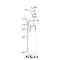
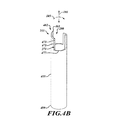
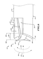
図4A〜4Cを参照すると、外側切削部材251は、図11に関連して以下で更に説明する、駆動シャフト組立体140(図1。図4A〜4Cには示さず)と係合する近位端部499を有する本体455を含む。外側切削部材251は、いくつかの実施形態では、遠位端部290に向かって長手方向に延在する尖った端部463を含む、先導縁部461を含む。いくつかの実施形態では、先導縁部461は、遠位端部290において、尖った端部463から離れる方向に角度を成し、図6に関連して以下で更に説明するように、組織壁内への貫通を促進する。外側切削部材251はまた、1つ以上の外側切削面271を含む。外側切削面271は、先導切削縁部473から後続切削縁部475まで傾斜している。いくつかの実施形態では、外側切削面271の先導切削縁部473は、図6に関連して以下で更に説明するように、内側切削部材221の内側切削面241の先導縁部343と係合する、外側切削部材251の内側縁部にある。
Referring to FIGS. 4A-4C, the
いくつかの実施形態では、外側切削部材251の外側切削面271は、一般にU字形であり、下方端部477で終端する。図4A〜4Cにて示されるように、いくつかの実施形態では、外側切削面271は、軸線101と実質的に平行である。組織壁に対して、外側切削部材251を内側切削部材に沿って存在させ(図2及び3A〜3C)、また内側切削部材211に対して、外側切削部材251を第2方向105にて軸線101の周囲で逆回転させることで、図6に関連して以下で更に説明するように、外側切削部材251の外側切削面271と内側切削部材211の内側切削面241との間の組織を切り取り得る。
In some embodiments, the
いくつかの実施形態では、図3A〜3C及び図4A〜4Cにて示すように、内側切削面241は、軸線101に対して鋭角に傾斜しており、外側切削面271は、軸線101と実質的に平行であり、組織の切り取りを促進するように鋭角で交差する、対向する切削面を存在させる。しかし、内側切削部材211の内側切削面241を軸線101と実質的に平行に配置することにより、対向する切削面との間で同一の鋭角が形成され得るが、一方で、軸線101に対して外側切削面271を鋭角に角度づけて、切削面241と271との間に鋭角の切削角度が形成される、と理解されよう。更に、いくつかの他の実施形態では、内側切削部材211の内側切削面214及び外側切削部材251の外側切削面271は両方とも、−対向する方向にて−、軸線101から角度づけられて、対向する切削面241と271との間で鋭角の切削角度を形成し得る。同様に、図3A〜3C及び4A〜4Cに関連して前述したように、内側切削部材221の内側切削面241の先導縁部343は、内側切削部材221の外側表面にあり、また外側切削部材251の外側切削面471の前方縁部473は、外側切削部材251の内側表面にあり、これにより、先導縁部343及び473は、鋏ブレードの先導縁部のように一緒になり、それらの間で組織を切り取ることを促進する。
In some embodiments, as shown in FIGS. 3A-3C and FIGS. 4A-4C, the
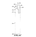
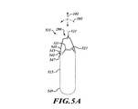
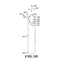
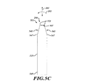
図5A〜5Cを参照すると、いくつかの実施形態では、内側切削部材511は、図10に関連して以下で更に説明する、駆動シャフト組立体140(図1。図3A〜3Cには示さず)と係合する近位端部549を有する本体515を含む。図2及び3A〜3Cにて示すような内側切削部材211の角度づけられたアンカー先端部321の代わりに、内側切削部材511は、一方の端部において一対の貫通端部523を有する窪んだアンカー先端部521を含む。貫通端部523は、内側切削部材511の遠位端部290に存在する組織壁(図5A〜5Cには示さず)を貫通するように構成される。アンカー先端部521は、したがって、外側切削部材251が内側切削部材511に対して逆回転する際に、組織を保持し得る。内側切削部材511及び外側切削部材(図示せず)は、次に、内側切削面間の組織を鋏んで切断するために、相対的に逆回転し得る。いくつかの実施形態では、先導縁部543、後続縁部545、及び下方端部547にて終了する、一般的な放物線状の形状を含む内側切断面541は、図2及び3A〜3Cにて示すように、先導縁部343、後続縁部345、及び内側切削部材211の下方端部347にて終了する、一般的な放物線状の形状に対応する、同等のものである。しかし、内側切削面541は、図4A〜4Cに関連して前述されたように、外側切削面271の角度に対応して、軸線101に対して異なって角度づけられて、内側切削面541と外側切削面271との間で鋏型の形状を形成し得る、ということに留意されたい。
Referring to FIGS. 5A-5C, in some embodiments, the
種々の実施形態で、図6を参照すると、内側切削部材211及び外側切削部材251を含む切断装置111は、組織を貫通し、かつ切断するように、位置つけられかつ操作される。切断装置111は、破線で表される組織壁601に位置づけられる。内側切削部材211及び外側切削部材251は、軸線101の周囲で第1方向130にて内側切削部材211と相対的に逆回転し、また外側切削部材251は、軸線101の周囲で第2方向105にて相対的に逆回転しながら、相対的に逆回転する。第1方向103での内側切削部材321の回転により、アンカー先端部321の穿孔端部323は組織壁601の貫通を引き起こす。内側切削部材211を更に相対的に逆回転させることにより、切断装置111の遠位端部290から離れる方向に面する平坦な固定表面325が、組織壁601において方向607にて、組織を切削領域292内へと引き込む。
In various embodiments, referring to FIG. 6, a
切断装置111の切削部材211及び251が互いに対して移動する際、組織壁601は、内側切削部材211の内側切削面241と外側切削部材251の外側切削面271との間に引き込まれる。内側切削部材211及び外側切削部材251が軸線101の周囲で相対的に逆回転する際、内側切削面241及び外側切削面271は、切断装置111の周辺部の周囲で組織601を鋏んで切断し、組織壁601内に開口部を形成する。
When the cutting
内側切削部材が図5A〜5Cにて示すような内側切削部材511などの切断装置111を含む、いくつかのその他の実施形態では内側切削部材511のアンカー先端部521は、内側切削部材211のアンカー先端部221と同様に、切削面との間の切削領域内へと組織を引き込むようには構成され得ない(図2、3A〜3C、及び6)。しかし、組織壁601に対して、切断装置111の遠位端部290に向かって、切断装置111により適用される圧力は、切断装置111の組織壁601内への穿孔、及び切断装置111の組織壁内への移動をもたらし、内側切削部材511の内側切削面541と外側切削部材251の外側切削面271との間の切削領域292内へと、組織を運び得る。
In some other embodiments, where the inner cutting member includes a
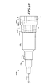
図7を参照すると、種々の実施形態では、制御装置150は、切断装置111(図7に図示せず)を位置決めし、かつ相対的に逆回転させるために使用され得る構成要素を含む。位置調節装置170は駆動シャフト組立体140(図7に図示せず)のシースに固定可能に接合されるスリーブ772を含み、続いて駆動シャフト組立体は切断装置111が配置される方向に面するスリーブ772の第1端部779から延在する。スリーブ772は、制御装置150のハウジング160の第1端部774内へと摺動可能に受容可能である。スリーブ772は、シースロック776を受容するロック溝777を含み、次に、ハウジング160内のシースロックポート778を介して受容される。
Referring to FIG. 7, in various embodiments, the
図7にて示すように、いくつかの実施形態では、シースロック776は、スリーブ772内のロック溝777と機械的かつ選択的に係合する、刻み付きロックねじの形態である。シースロック776を回転させて、ロック溝777からシースロック776を緩めて、スリーブ772、ひいては駆動シャフト組立体140の移動を可能にし得る。スリーブ772は、スリーブ772をハウジング160に対して摺動させることにより、操作される。次に、一度切断装置111が所望の位置に配置されると、シースロック776が回転して、シースロック776をスリーブ772内のロック溝777に係合させて、駆動シャフト組立体140をロックし、したがって、切断装置111(同様に、図7に図示せず)を所望の位置にて駆動シャフト組立体140と連結させることができる。例えば、スリーブ772を所定の位置にロックするためのレバー又はラッチを含む、位置調節装置170のその他の形態を使用してよい、と理解するべきである。また、その他の形態の位置調節装置170が、気管支鏡のハウジング又は切断装置111を方向付けるために使用されるその他の装置のハウジングに固定可能に連結されてもよく、これにより、ハウジングの移動が、駆動シャフト組立体140の移動をもたらす、とも理解するべきである。本開示の実施形態は、位置調整装置170の任意の特定の形態の使用に限定されない。
As shown in FIG. 7, in some embodiments, the
更に図7を参照すると、いくつかの実施形態では、回転把持部180は、刻み付き把持部などのユーザ把持部781、及び、図8に関連して以下に記載されるような、回転機構に係合するために使用されるインターフェース782を含んでよい。
Still referring to FIG. 7, in some embodiments, the
図8を参照すると、いくつかの実施形態では、制御装置150は逆回転機構802を含む。逆回転機構802は、駆動シャフト組立体140の第1駆動シャフト(図8に図示せず)と係合するように構成された第1放射状アクチュエータ812を含み、これは次に、切断装置111の内側切削部材211(どちらも図8に図示せず)と連結されてよい。逆回転機構802は、駆動シャフト組立体140の第2駆動シャフト(図8に図示せず)と係合するように構成された第2放射状アクチュエータ852を含み、これは次に、切断装置111の外側切削部材251と連結されてよい。駆動シャフト組立体140の構成は、図11に関連して以下で更に説明される。
Referring to FIG. 8, in some embodiments, the
駆動シャフト組立体140の駆動シャフトを逆回転させるために、第1放射状アクチュエータ812及び第2放射状アクチュエータ852は機械的に連結されて、一方又は他方が回転する場合に、放射状アクチュエータ812及び852を反対方向に回転させる。図8にて示す逆回転機構802では、第1放射状アクチュエータ812は、ハウジング160の第1端部801に面する第1かさ歯車814を含み、また第2放射状アクチュエータ852は、ハウジング160の第1端部801から離れる方に面する第2かさ歯車854を含む。第1かさ歯車814及び第2かさ歯車854のそれぞれと機械的に連結されるのは、差動かさ歯車894を含む伝達歯車892である。第1かさ歯車814の回転は、第2かさ歯車854に対向する回転を引き起こす差動かさ歯車894に、回転を付与する。逆回転機構802はまた、差動アクチュエータ812及び854、並びに伝達歯車892を支持するためのシャシ896を含んでよい。図8にて示すように、第1差動アクチュエータ812は、回転把持部180が一方向に回転すると、第1差動アクチュエータ812が同じ方向に回転し、第2差動アクチュエータ852が反対方向に回転するように、回転把持部180上でインターフェース782を受容する。結果として、駆動シャフト組立体140の駆動シャフトが相対的に逆回転し、切断装置111の切断部材211及び251を逆回転させる。
The first
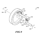
図9を参照すると、駆動シャフト組立体140の駆動シャフト及び切断装置111(どちらも図9に図示せず)の逆回転を促進するための逆回転機構902の別の実施形態は、図8の逆回転機構802において使用されるようなかさ歯車の代わりに、平歯車を使用する。逆回転機構902は、第1放射状アクチュエータ812(図9に図示せず)と連結されたベース歯車914を含んで、図8に関連して記載されるように、第1放射状アクチュエータ812が回転する場合に、ベース歯車914に回転を付与する。ベース歯車914は、軸線101の周囲で回転するように構成された内向きの平歯車である。ベース歯車914は、軸992と係合する。軸992は、外向きの平歯車を含み得る、第1伝達歯車915を含む。ベース歯車914は、第1伝達歯車915と係合して、図9にて示すような方向103などの、ベース歯車914の回転と同じ向きで、第1伝達歯車915に回転を付与する。第1放射状アクチュエータ812、ベース歯車914、又は軸992は、第1駆動シャフト又は第2駆動シャフト(図9に図示せず)のうちの1つに連結されて、第1駆動シャフトに回転を付与してよい。
Referring to FIG. 9, another embodiment of a
軸992はまた、第2伝達歯車919へと延在する第1シャフト907を含んでよく、これは同様に、外向きの平歯車を含んでよい。第1シャフト907は、図9にて示すその他の要素と共に、クレードル(図9に図示せず)内に回転可能に取り付けられてよい。第1軸907及び第2伝達歯車919の両方は、第1伝達歯車915と同じ方向で回転する。第2伝達歯車919は、クレードル(図9に図示せず)内に回転可能に取り付けられ得る逆回転歯車954に係合する。逆回転歯車954及び第2伝達歯車919との係合は、逆回転歯車954を軸992の第2伝達歯車919とは反対の向きで、回転させる。したがって、例えば、ベース歯車914が方向103にて回転する場合、逆回転歯車954は方向105に回転し得る。逆回転歯車954は第2シャフト957に連結されてよく、これは第2駆動シャフトに連結されてよく(第1駆動シャフトが第1放射状アクチュエータ812又はベース歯車914に連結されている場合)、又は第1駆動シャフトに連結されてよい(第2駆動シャフトが第1放射状アクチュエータ812又はベース歯車914に連結されている場合)。いずれの場合も、第1方向における第1放射状アクチュエータ812及びベース歯車914の回転は、逆回転歯車954の逆方向への回転をもたらし得て、切断装置の切削部材(図9に図示せず)に逆回転を付与する。
The
逆回転機構902は、ベース歯車914が、逆回転歯車954から異なる角速度にて回転することを可能にする、歯車差動を含んでよい、と理解するべきである。例えば、ベース歯車914の半径及びそこから延在する多数のスパー(spur)に対する、第1伝達歯車915の半径及びそこから延在する多数のスパーは、ベース歯車914に対する軸992の回転速度を変化させる。代替的に又は追加的に、逆回転歯車954の半径及びそこから延在する多数のスパーに対する、第2伝達歯車919の半径及びそこから延在する多数のスパーは、第2伝達歯車919に対する逆回転歯車954の逆回転速度を変化させる。結果として、駆動シャフト(図9に図示せず)は、異なる速度で逆回転し、切断装置の切削部材(同様に、図9に図示せず)を異なる速度にて逆回転させることを引き起こし得る。同様に、図9が、平歯車の周辺長さの周囲で部分的に延在して、スパー及び関連する平歯車の相互係合を強調するスパーを示すのみである、と理解するべきである一方、スパーは、平歯車の周辺長さの周囲にて完全に延在し得る、と理解するべきである。
It should be understood that the
図10を参照すると、いくつかの他の実施形態では、制御機構950は、ハウジング160、並びに図7及び8にて示すような制御装置等の位置調整装置170を含む。しかし、制御装置150とは異なり、制御装置1050は、2つの回転把持部1082及び1084を含む。回転把持部のそれぞれは、駆動シャフト組立体140の駆動シャフトと別個に連結されて、切断装置111(図10に図示せず)の関連する切削部材211及び251の個々の回転に影響を及ぼし得る。回転把持部1082及び1084のそれぞれは、例えば、第1回転把持部1082を第1方向1083にて回転させ、また第2回転把持部1084を第2方向1085に回転させることにより、別個に回転させて、駆動シャフト組立体140の駆動シャフト、及び切断装置111の関連する切削部材211及び251の個々の回転を選択的に可能にし得る、又は切断装置111の関連する切削部材211及び251の同時に逆回転可能にし得る。
Referring to FIG. 10, in some other embodiments, the control mechanism 950 includes a
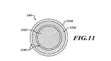
図11を参照すると、種々の実施形態では、駆動シャフト組立体140は、切断装置111の内側切削部材211(図10に図示せず)と連結可能な第1駆動シャフト1142を含む。駆動シャフト組立体140はまた、切断装置111の外側切削部材251と連結可能な第2駆動シャフト1144を含む。第1駆動シャフト1142は、中実であっても中空であってもよく、第2駆動シャフト1144は、第1駆動シャフト1142の周囲で同軸状に配置された中空部材である。第1駆動シャフト1142及び第2駆動シャフト1144は、駆動シャフト組立体140の伸長及び後退を可能にするように、スリーブ772(図7及び8)と固定可能に連結され得るシース1146内に、配置される。第1駆動シャフト1142は、第1駆動シャフト1142の回転を妨げないように、間隙1148により第2駆動シャフト1144から分離されてよい。同様に、第2駆動シャフト1144は、外装1146により第2駆動シャフト1144の回転を妨げないように、間隙1148によりシース1146から分離されてよい。
Referring to FIG. 11, in various embodiments, the
図12を参照すると、組織切断の例示的方法1200が提供されている。方法1200は、ブロック1205にて開始する。ブロック1210では、内側切削部材及び同心性の外側切削部材を有する円筒形の切断装置は、組織に対して延在する。内側切削部材及び同心性の外側切削部材は、内側切削部材及び同心性の外側切削部材の軸線に直交して組織を放射状に切断するように構成された、対向する切削面を有する。切削部材の構成及びその位置決めは、図2、3A〜3C、4A〜4C、5A〜5C、及び6に関連して前述されている。
Referring to FIG. 12, an
ブロック1220では、図3A〜3C、5A〜5C、及び6に関連して前述したように、内側切削部材が移動して、内側切削部材の遠位端部にあるアンカー先端部に組織を貫通させる。ブロック1230では、図6に関連して前述したように、内側切削部材及び同心性の外側切削部材は、組織を放射状に切断するように、互いに対して回転する。方法1200は、ブロック1235にて終了する。
At
切断装置及び制御装置の本発明の記述、並びに組織壁内の穴を切断するために使用されるものとして本明細書に記載されるシステム及び方法は、身体の異なる部分における組織を切断するために使用されてよく、また内視鏡、気管支鏡、腹腔鏡、又はその他の装置により案内されてよい、と理解されよう。 The description of the present invention of a cutting device and control device, and the system and method described herein as being used to cut a hole in a tissue wall, is used to cut tissue in different parts of the body. It will be appreciated that it may be used and guided by an endoscope, bronchoscope, laparoscope, or other device.
上に示した発明を実施するための形態は、本質的に単に例示的なものであり、請求項に係る主題の主旨及び/又は趣旨から逸脱しない変形が、請求項の範囲内にあることが意図される、と理解されよう。このような変形は、請求項に係る主題の趣旨及び範囲から逸脱するものとしてみなされない。 The forms for carrying out the invention described above are merely exemplary in nature and modifications that do not depart from the spirit and / or spirit of the claimed subject matter are within the scope of the claims. It will be understood as intended. Such variations are not to be regarded as a departure from the spirit and scope of the claimed subject matter.
100 システム
101 軸線
103 第1方向
105 第2方向
111 切断装置
130 第1方向
140 駆動シャフト組立体
150 制御装置
160 ハウジング
170 位置調節装置
180 回転把持部
211 切削部材
214 内側切削面
221 内側切削部材
241 内側切削面
251 外側切削部材
271 外側切削面
290 遠位端部
292 切削領域
315 本体
321 アンカー先端部
323 貫通端部
325 固定表面
343 先導切削縁部
345 後続切削縁部
347 下方端部
349 近位端部
455 本体
461 先導縁部
463 端部
471 外側切削面
473 先導切削縁部
475 後続切削縁部
477 下方端部
499 近位端部
511 内側切削部材
515 本体
521 アンカー先端部
523 貫通端部
541 内側切削面
543 先導縁部
545 後続縁部
547 下方端部
549 近位端部
601 組織
772 スリーブ
774 第1端部
776 シースロック
777 ロック溝
778 シースロックポート
779 第1端部
781 ユーザ把持部
782 インターフェース
801 第1端部
802 逆回転機構
812 第1差動アクチュエータ
814 歯車
852 第2差動アクチュエータ
854 歯車
892 伝達歯車
894 歯車
896 シャシ
902 逆回転機構
907 第1シャフト
914 ベース歯車
915 第1伝達歯車
919 第2伝達歯車
950 制御機構
954 逆回転歯車
957 第2シャフト
992 軸
1050 制御装置
1082 第1回転把持部
1083 第1方向
1084 第2回転把持部
1085 第2方向
1142 第1駆動シャフト
1144 第2駆動シャフト
1146 シース
1148 間隙
DESCRIPTION OF SYMBOLS 100 System 101 Axis 103 1st direction 105 2nd direction 111 Cutting device 130 1st direction 140 Drive shaft assembly 150 Control device 160 Housing 170 Position adjustment device 180 Rotation grip part 211 Cutting member 214 Inner cutting surface 221 Inner cutting member 241 Inner Cutting surface 251 Outer cutting member 271 Outer cutting surface 290 Distal end 292 Cutting region 315 Main body 321 Anchor tip 323 Through end 325 Fixed surface 343 Leading cutting edge 345 Subsequent cutting edge 347 Lower end 349 Proximal end 455 Main body 461 Leading edge 463 End 471 Outer cutting surface 473 Leading cutting edge 475 Subsequent cutting edge 477 Lower end 499 Proximal end 511 Inner cutting member 515 Main body 521 Anchor tip 523 Through end 541 Inner cutting surface 54 Leading edge 545 Trailing edge 547 Lower end 549 Proximal end 601 Tissue 772 Sleeve 774 First end 776 Sheath lock 777 Lock groove 778 Sheath lock port 779 First end 781 User gripping part 782 Interface 801 First end 802 Reverse rotation mechanism 812 First differential actuator 814 Gear 852 Second differential actuator 854 Gear 892 Transmission gear 894 Gear 896 Chassis 902 Reverse rotation mechanism 907 First shaft 914 Base gear 915 First transmission gear 919 Second transmission gear 950 Control mechanism 954 Reverse rotation gear 957 Second shaft 992 Axis 1050 Control device 1082 First rotation gripping portion 1083 First direction 1084 Second rotation gripping portion 1085 Second direction 1142 First drive shaft 1144 Second drive shaft 1ft 1146 sheath 1148 gap
Claims (20)
前記第1円筒形本体の周囲で同心状に配置され、前記遠位端部において少なくとも1つの第2切削面を支持する第2円筒形本体を有する外側切削部材であって、前記第2切削面が、前記軸線に対して第2回転方向に面し、かつ前記第2円筒形本体の内周において第2切削端部を有し、組織に対する前記装置の前記遠位端部の適用及び前記内側切削部材及び前記外側切削部材を逆回転させることに応答して、前記内側切削部材の前記第1切削端部と前記外側切削部材の前記第2切削端部との間で組織は回転可能に切り取り可能である、外側切削部材とを含む、装置。 An inner cutting member having a first cylindrical body that supports at least one first cutting surface at a distal end, wherein the first cutting surface is in a first rotational direction relative to an axis of the first cylindrical body. An inner cutting member having a first cutting end around the outer periphery of the first cylindrical body;
An outer cutting member having a second cylindrical body disposed concentrically around the first cylindrical body and supporting at least one second cutting surface at the distal end, the second cutting surface Facing the axis in a second rotational direction and having a second cutting end at the inner circumference of the second cylindrical body, and applying the distal end of the device to the tissue and the inner side In response to reverse rotation of the cutting member and the outer cutting member, the tissue is rotatably cut between the first cutting end of the inner cutting member and the second cutting end of the outer cutting member. An apparatus comprising an outer cutting member that is possible.
前記第1円筒形本体の外側周囲において、かつ前記内側切削部材の前記軸線に対して傾斜する第1切削縁部と、
前記遠位端部を越えて外側に延在し、かつ前記組織を貫通するように構成されたアンカー先端部とを含み、
前記第1円筒形本体の周囲で同心状に配置され、前記装置の前記遠位端部において少なくとも1つの第2切削面を支持する第2円筒形本体を有する外側切削部材であって、前記第2切削面が、前記軸線に対して第2回転方向に面し、かつ前記第2円筒形本体の内周において第2切削端部を有し、組織に対する前記装置の前記遠位端部の適用並びに前記内側切削部材及び前記外側切削部材を逆回転させることに応答して、前記内側切削部材の前記第1切削端部と前記外側切削部材の前記第2切削端部との間で、組織は、前記アンカー先端部により貫通可能であり、かつ回転可能に切り取り可能である、外側切削部材とを含む、装置。 An inner cutting member having a first cylindrical body that supports two or more first cutting surfaces at a distal end of the device, wherein the first cutting surface is relative to an axis of the first cylindrical body. Facing the first rotation direction, the first cutting surface is
A first cutting edge that is inclined about the outer periphery of the first cylindrical body and with respect to the axis of the inner cutting member;
An anchor tip extending outwardly beyond the distal end and configured to penetrate the tissue;
An outer cutting member having a second cylindrical body disposed concentrically around the first cylindrical body and supporting at least one second cutting surface at the distal end of the device, Application of the distal end of the device to tissue with two cutting surfaces facing in the second rotational direction relative to the axis and having a second cutting end at the inner circumference of the second cylindrical body And in response to reversely rotating the inner cutting member and the outer cutting member, the tissue is between the first cutting end of the inner cutting member and the second cutting end of the outer cutting member. An outer cutting member that is piercable by the anchor tip and that can be rotatably cut.
内側切削部材を移動させて、前記内側切削部材の遠位端部において、アンカー先端部を前記組織に貫通させることと、
前記内側切削部材及び前記同心性の外側切削部材を、前記組織を放射状に切断するように互いに対して回転させることと、を含む、方法。 Extending a cylindrical cutting device having an inner cutting member and a concentric outer cutting member to the tissue, wherein the inner cutting member and the concentric outer cutting member are the inner cutting member and the concentric outer cutting member. Having opposing cutting surfaces configured to cut the tissue radially perpendicular to the axis of
Moving an inner cutting member to penetrate an anchor tip through the tissue at a distal end of the inner cutting member;
Rotating the inner cutting member and the concentric outer cutting member relative to each other to cut the tissue radially.
Priority Applications (1)
| Application Number | Priority Date | Filing Date | Title |
|---|---|---|---|
| JP2023172894A JP7684365B2 (en) | 2018-03-22 | 2023-10-04 | Rotary tissue cutting device |
Applications Claiming Priority (2)
| Application Number | Priority Date | Filing Date | Title |
|---|---|---|---|
| US15/933,359 US10813659B2 (en) | 2018-03-22 | 2018-03-22 | Rotational tissue cutting device |
| US15/933,359 | 2018-03-22 |
Related Child Applications (1)
| Application Number | Title | Priority Date | Filing Date |
|---|---|---|---|
| JP2023172894A Division JP7684365B2 (en) | 2018-03-22 | 2023-10-04 | Rotary tissue cutting device |
Publications (2)
| Publication Number | Publication Date |
|---|---|
| JP2019166322A true JP2019166322A (en) | 2019-10-03 |
| JP7362275B2 JP7362275B2 (en) | 2023-10-17 |
Family
ID=66381264
Family Applications (2)
| Application Number | Title | Priority Date | Filing Date |
|---|---|---|---|
| JP2019053198A Active JP7362275B2 (en) | 2018-03-22 | 2019-03-20 | Rotary tissue cutting device |
| JP2023172894A Active JP7684365B2 (en) | 2018-03-22 | 2023-10-04 | Rotary tissue cutting device |
Family Applications After (1)
| Application Number | Title | Priority Date | Filing Date |
|---|---|---|---|
| JP2023172894A Active JP7684365B2 (en) | 2018-03-22 | 2023-10-04 | Rotary tissue cutting device |
Country Status (5)
| Country | Link |
|---|---|
| US (2) | US10813659B2 (en) |
| JP (2) | JP7362275B2 (en) |
| CN (1) | CN110292418B (en) |
| DE (1) | DE102019105514A1 (en) |
| GB (1) | GB2573866B (en) |
Cited By (2)
| Publication number | Priority date | Publication date | Assignee | Title |
|---|---|---|---|---|
| JP2023538739A (en) * | 2020-08-31 | 2023-09-11 | ベーレント・スヴェン | surgical shaver |
| US11779365B2 (en) | 2018-03-22 | 2023-10-10 | Gyrus Acmi, Inc. | Rotational tissue cutting device |
Families Citing this family (8)
| Publication number | Priority date | Publication date | Assignee | Title |
|---|---|---|---|---|
| WO2019189078A1 (en) * | 2018-03-29 | 2019-10-03 | テルモ株式会社 | Medical device |
| US20210298725A1 (en) * | 2020-03-31 | 2021-09-30 | Gyrus Acmi, Inc. D/B/A Olympus Surgical Technologies America | Rotatable tissue sampling device |
| US11805998B2 (en) * | 2020-04-20 | 2023-11-07 | Covidien Lp | Devices and methods for obtaining adenomyosis and other biopsy samples |
| DE102021001608B4 (en) * | 2021-03-26 | 2025-01-23 | Mimeo Medical Gmbh | surgical drilling instrument |
| US11806222B2 (en) * | 2021-08-06 | 2023-11-07 | John Baeke | Apparatus for cutting a material and a method for cutting a negative pressure wound therapy dressing |
| CN117224201B (en) * | 2023-11-16 | 2024-01-30 | 湖南金柏威医疗科技有限公司 | Tissue rotary cutting device |
| CN118319561B (en) * | 2024-05-09 | 2025-09-19 | 中国医学科学院阜外医院 | Valve clip recovery device |
| CN120501503B (en) * | 2025-05-22 | 2026-01-23 | 武汉大学 | A tunnel-type minimally invasive lung nodule resection instrument |
Citations (4)
| Publication number | Priority date | Publication date | Assignee | Title |
|---|---|---|---|---|
| JPH06502562A (en) * | 1990-10-25 | 1994-03-24 | ディバイシズ フォー バスキュラー インターベンション,インコーポレイティド | Atherectomy catheter with axially oriented cutting edge |
| JP2005512631A (en) * | 2001-12-17 | 2005-05-12 | スミス アンド ネフュー インコーポレーテッド | Cutting device |
| JP2008155033A (en) * | 2006-12-22 | 2008-07-10 | Spectranetics Corp | Tissue separating system and method |
| JP2012520726A (en) * | 2009-03-16 | 2012-09-10 | シー・アール・バード・インコーポレーテッド | Biological tissue examination apparatus having rotational cutting |
Family Cites Families (12)
| Publication number | Priority date | Publication date | Assignee | Title |
|---|---|---|---|---|
| US4306570A (en) * | 1980-08-20 | 1981-12-22 | Matthews Larry S | Counter rotating biopsy needle |
| US5007917A (en) * | 1990-03-08 | 1991-04-16 | Stryker Corporation | Single blade cutter for arthroscopic surgery |
| US20050222598A1 (en) * | 2004-04-05 | 2005-10-06 | Manoa Medical, Inc., A Delaware Corporation | Tissue cutting device |
| US20070016101A1 (en) * | 2005-07-13 | 2007-01-18 | Feldman Dennis D | Core Biopsy Device |
| US8097012B2 (en) * | 2005-07-27 | 2012-01-17 | The Spectranetics Corporation | Endocardial lead removing apparatus |
| DE102007023207A1 (en) * | 2007-05-18 | 2008-11-20 | Wisap Gesellschaft für wissenschaftlichen Apparatebau mbH | Device for cutting and removing tissue cylinder from tissue, comprises cutting elements arranged in one another and rotated relative to each other, which surround distal end |
| DE102008036420A1 (en) * | 2008-08-05 | 2010-02-11 | Wisap Gesellschaft für wissenschaftlichen Apparatebau mbH | Tissue cylinders cutting and removing apparatus for e.g. laparascopic for treatment of myomas of patient, has drive accommodated by housing, where drive is brought in mutual engagement with driving device by coupling device |
| EP2698116A1 (en) * | 2012-08-16 | 2014-02-19 | AprioMed AB | Biopsy assembly for obtaining a tissue sample |
| US9498246B2 (en) * | 2013-03-14 | 2016-11-22 | Saphena Medical, Inc. | Unitary endoscopic vessel harvesting devices |
| WO2017001960A1 (en) * | 2015-06-30 | 2017-01-05 | Koninklijke Philips N.V | Coaxial contra-rotating cutting assembly |
| ES2949144T3 (en) * | 2016-11-23 | 2023-09-26 | Corit Medical Llc | Tissue reduction apparatus |
| US10813659B2 (en) | 2018-03-22 | 2020-10-27 | Spiration, Inc. | Rotational tissue cutting device |
-
2018
- 2018-03-22 US US15/933,359 patent/US10813659B2/en active Active
-
2019
- 2019-03-05 DE DE102019105514.8A patent/DE102019105514A1/en active Pending
- 2019-03-20 JP JP2019053198A patent/JP7362275B2/en active Active
- 2019-03-21 GB GB1903857.9A patent/GB2573866B/en active Active
- 2019-03-21 CN CN201910218381.3A patent/CN110292418B/en active Active
-
2020
- 2020-09-24 US US17/030,944 patent/US11779365B2/en active Active
-
2023
- 2023-10-04 JP JP2023172894A patent/JP7684365B2/en active Active
Patent Citations (4)
| Publication number | Priority date | Publication date | Assignee | Title |
|---|---|---|---|---|
| JPH06502562A (en) * | 1990-10-25 | 1994-03-24 | ディバイシズ フォー バスキュラー インターベンション,インコーポレイティド | Atherectomy catheter with axially oriented cutting edge |
| JP2005512631A (en) * | 2001-12-17 | 2005-05-12 | スミス アンド ネフュー インコーポレーテッド | Cutting device |
| JP2008155033A (en) * | 2006-12-22 | 2008-07-10 | Spectranetics Corp | Tissue separating system and method |
| JP2012520726A (en) * | 2009-03-16 | 2012-09-10 | シー・アール・バード・インコーポレーテッド | Biological tissue examination apparatus having rotational cutting |
Cited By (3)
| Publication number | Priority date | Publication date | Assignee | Title |
|---|---|---|---|---|
| US11779365B2 (en) | 2018-03-22 | 2023-10-10 | Gyrus Acmi, Inc. | Rotational tissue cutting device |
| JP2023538739A (en) * | 2020-08-31 | 2023-09-11 | ベーレント・スヴェン | surgical shaver |
| JP7670810B2 (en) | 2020-08-31 | 2025-04-30 | ベーレント・スヴェン | Surgical Shaver |
Also Published As
| Publication number | Publication date |
|---|---|
| US20190290312A1 (en) | 2019-09-26 |
| JP2023168554A (en) | 2023-11-24 |
| US10813659B2 (en) | 2020-10-27 |
| US11779365B2 (en) | 2023-10-10 |
| CN110292418B (en) | 2025-03-04 |
| CN110292418A (en) | 2019-10-01 |
| US20210000496A1 (en) | 2021-01-07 |
| GB201903857D0 (en) | 2019-05-08 |
| JP7362275B2 (en) | 2023-10-17 |
| JP7684365B2 (en) | 2025-05-27 |
| DE102019105514A1 (en) | 2019-09-26 |
| GB2573866B (en) | 2022-06-22 |
| GB2573866A (en) | 2019-11-20 |
Similar Documents
| Publication | Publication Date | Title |
|---|---|---|
| JP2019166322A (en) | Rotary tissue cutting device | |
| US20250204946A1 (en) | Surgical devices and systems with rotating end effector assemblies having an ultrasonic blade assembly | |
| US5984939A (en) | Multifunctional grasping instrument with cutting member and operating channel for use in endoscopic and non-endoscopic procedures | |
| US5374277A (en) | Surgical instrument | |
| JP2020044347A (en) | Surgical instrument | |
| EP2777661B1 (en) | Reverse seam ripper dissector | |
| US20160303743A1 (en) | Wrist and jaw assemblies for robotic surgical systems | |
| EP3334489B1 (en) | System for manipulating an elongate medical device | |
| KR101447266B1 (en) | Appratus for laparoscpoic surgery | |
| US5472451A (en) | Endoscopic surgical instrument with acute angle orientation | |
| JP2004154164A (en) | Multi-degree-of-freedom type treating instrument | |
| JP7361480B2 (en) | Rotary tissue cutting control device | |
| JP2016507342A (en) | Replaceable debrider blade module with latch mechanism | |
| WO2022253065A1 (en) | Portable manual surgical robot | |
| JP4542362B2 (en) | Endoscopic treatment system | |
| JPH02503999A (en) | tendon stripping device | |
| CN204181688U (en) | A kind of multiple degrees of freedom laparoscopic surgical instruments | |
| JP5710079B1 (en) | Endoscopic surgical instrument | |
| US10265063B1 (en) | Deep cavity suture device | |
| CN111166402A (en) | An endoscope breast augmentation retractor | |
| WO2016107584A1 (en) | Suturing and cutting apparatus for endoscopic surgery | |
| CN112932618A (en) | Cutter bar for ultrasonic scalpel and ultrasonic scalpel | |
| JP2003299665A (en) | Ultrasonic treatment device | |
| CN120284386A (en) | A multi-degree-of-freedom flexible arthroscopic forceps | |
| CN121265236A (en) | Multifunctional surgical electric forceps and use method thereof |
Legal Events
| Date | Code | Title | Description |
|---|---|---|---|
| A711 | Notification of change in applicant |
Free format text: JAPANESE INTERMEDIATE CODE: A712 Effective date: 20201005 |
|
| A621 | Written request for application examination |
Free format text: JAPANESE INTERMEDIATE CODE: A621 Effective date: 20220322 |
|
| A977 | Report on retrieval |
Free format text: JAPANESE INTERMEDIATE CODE: A971007 Effective date: 20230222 |
|
| A131 | Notification of reasons for refusal |
Free format text: JAPANESE INTERMEDIATE CODE: A131 Effective date: 20230306 |
|
| A521 | Request for written amendment filed |
Free format text: JAPANESE INTERMEDIATE CODE: A523 Effective date: 20230602 |
|
| TRDD | Decision of grant or rejection written | ||
| A01 | Written decision to grant a patent or to grant a registration (utility model) |
Free format text: JAPANESE INTERMEDIATE CODE: A01 Effective date: 20230904 |
|
| A61 | First payment of annual fees (during grant procedure) |
Free format text: JAPANESE INTERMEDIATE CODE: A61 Effective date: 20231004 |
|
| R150 | Certificate of patent or registration of utility model |
Ref document number: 7362275 Country of ref document: JP Free format text: JAPANESE INTERMEDIATE CODE: R150 |
|
| S111 | Request for change of ownership or part of ownership |
Free format text: JAPANESE INTERMEDIATE CODE: R313113 |
|
| R350 | Written notification of registration of transfer |
Free format text: JAPANESE INTERMEDIATE CODE: R350 |