JP2019166047A - Game machine - Google Patents
Game machine Download PDFInfo
- Publication number
- JP2019166047A JP2019166047A JP2018056187A JP2018056187A JP2019166047A JP 2019166047 A JP2019166047 A JP 2019166047A JP 2018056187 A JP2018056187 A JP 2018056187A JP 2018056187 A JP2018056187 A JP 2018056187A JP 2019166047 A JP2019166047 A JP 2019166047A
- Authority
- JP
- Japan
- Prior art keywords
- medal
- game
- control board
- time
- sensor
- Prior art date
- Legal status (The legal status is an assumption and is not a legal conclusion. Google has not performed a legal analysis and makes no representation as to the accuracy of the status listed.)
- Pending
Links
Images


Abstract
Description
本発明は、遊技機に関するものである。 The present invention relates to a gaming machine.
従来より、遊技機の1つとして、スロットマシンが知られている(たとえば、特許文献1参照)。 Conventionally, a slot machine is known as one of gaming machines (see, for example, Patent Document 1).
本発明が解決しようとする課題は、遊技機としての性能を向上させることである。 The problem to be solved by the present invention is to improve the performance as a gaming machine.
本発明は、以下の解決手段によって上述の課題を解決する(かっこ書きで、対応する実施形態の構成を示す。)。なお、本願の当初請求項に係る発明は、後述する当初発明1〜4のうち、当初発明1に相当する。
本発明は、
遊技媒体投入口(メダル投入口47)と、
遊技媒体投入口から投入された遊技媒体(メダル)の通路(メダル通路)中に設けられ、遊技媒体の通過を許可する状態(オン状態)又は遊技媒体の通過を不許可にする状態(オフ状態)に制御可能なブロッカ(45)と、
遊技媒体投入口から投入された遊技媒体の通路中に設けられ、遊技媒体を検知可能な検知手段A(投入センサ44a)及びB(投入センサ44b)(検知手段Bは、検知手段Aより下流側に位置する)と
を備え、
遊技媒体の通過を許可する状態に前記ブロッカを制御している状況にて電源の供給が遮断される事象が発生した時から、当該電源の供給が遮断される事象を検知して、遊技媒体の通過を不許可にする状態に前記ブロッカを制御するまでの時間をT1(図2及び図3中、T1)とし、
遊技媒体の通過を許可する状態に前記ブロッカを制御している状況にて遊技媒体が前記遊技媒体投入口から遊技機内部に向けて放たれる場合において、当該遊技媒体が遊技機正面から視認不可能となった時(図2中、M2の位置)から、当該遊技媒体を検知手段Bが検知して、当該遊技媒体を検知手段Bが検知しなくなるまで(図2中、M4の位置)の時間をT2(図2及び図3中、T2)としたとき、
T1<T2
となるようにする
ことを特徴とする。
The present invention solves the above-mentioned problems by the following solution means (the configuration of the corresponding embodiment is shown in parentheses). The invention according to the initial claim of the present application corresponds to the
The present invention
Game media slot (medal slot 47),
A state that is provided in the passage (medal passage) of the game medium (medal) inserted from the game medium insertion port, and that allows passage of the game medium (ON state) or does not permit passage of the game medium (OFF state) ) A controllable blocker (45),
Detection means A (
When an event occurs in which the supply of power is cut off in a situation where the blocker is controlled to allow the passage of game media, the event that the supply of power is cut off is detected, and Let T1 (T1 in FIGS. 2 and 3) the time to control the blocker in a state where passage is not permitted,
In the situation where the blocker is controlled to allow passage of gaming media, when the gaming media is released from the gaming media slot into the gaming machine, the gaming media is not visible from the front of the gaming machine. From when it becomes possible (position M2 in FIG. 2) until the detection means B detects the game medium and until the detection means B no longer detects the game medium (position M4 in FIG. 2). When the time is T2 (T2 in FIGS. 2 and 3),
T1 <T2
It is characterized by becoming.
本発明によれば、遊技機としての性能を向上させることができる。 According to the present invention, the performance as a gaming machine can be improved.
本明細書において、用語の意味は、以下の通りである。
「ベット」とは、遊技を行うためにメダル(遊技媒体)を賭けることをいう。メダルをベットするには、メダル投入口47から実際のメダルを手入れ投入するか、又は貯留されているメダルをベットするためにベットスイッチ40を操作する。
一方、「クレジット」とは、上記「ベット」とは異なり、スロットマシン10内部にメダルを貯留することをいう。本明細書では、「クレジット」というときは、「ベット」を含まない意味で使用する。
さらに、「投入」とは、メダルをベット又はクレジットすることをいう。
In the present specification, the meanings of terms are as follows.
“Bet” refers to betting a medal (game medium) to play a game. In order to bet a medal, an actual medal is maintained and inserted from the medal slot 47, or the bet switch 40 is operated to bet a stored medal.
On the other hand, “credit” refers to storing medals in the slot machine 10, unlike the “bet”. In this specification, “credit” is used in a meaning that does not include “bet”.
Furthermore, “insertion” means betting or crediting a medal.
「手入れ」とは、遊技者が、メダル投入口47(後述)からメダルを投入することをいう。
「手入れベット」とは、遊技者が、メダル投入口47からメダルを手入れすることにより、メダルをベットすることをいう。
「手入れクレジット」とは、遊技者が、メダル投入口47からメダルを手入れすることにより、メダルをクレジットすること(クレジットを加算する)ことをいう。
「ベットメダル」とは、ベットされているメダルをいう。
「貯留メダル」とは、クレジット(貯留)されているメダルをいう。
“Care” means that a player inserts a medal from a medal slot 47 (described later).
The “care bet” means that the player bets medals by cleaning the medals from the medal slot 47.
“Maintenance credit” means that a player credits a medal (adds credit) by cleaning the medal from the medal insertion slot 47.
“Bet medal” means a bet medal.
“Stored medal” means a medal that is credited (stored).
「貯留ベット」とは、遊技者がベットスイッチ40(後述)を操作することにより、当該遊技でベット可能な範囲内において、クレジットされているメダルの一部又は全部を、遊技を行うためにベットすることをいう。
「自動ベット」とは、リプレイが入賞したときに、スロットマシン10の制御処理により、前回遊技でベットされていた数のメダルを自動でベットすることをいう。
「精算」とは、ベットメダル及び/又は貯留メダルを遊技者に対して払い出すことをいう。本実施形態では、精算スイッチ43(後述)が操作されたときに精算処理を実行する。
A “reserved bet” means that a player operates a bet switch 40 (described later) to bet a part or all of the credited medals within a range in which the player can bet. To do.
“Automatic betting” refers to automatically betting the number of medals bet in the previous game by the control process of the slot machine 10 when the replay wins.
“Checkout” refers to paying out a bet medal and / or a stored medal to a player. In the present embodiment, a settlement process is executed when a settlement switch 43 (described later) is operated.
「払出し」とは、役の入賞に基づきメダルを遊技者に払い出すこと、又は上記精算によりメダルを払い出すことをいう。役の入賞に基づきメダルを遊技者に払い出すときは、クレジットとして貯留すること(貯留メダルを加算すること、換言すれば、RWM53(後述)に記憶された電子データを更新すること)、及び払出し口(図示せず)から実際のメダルを払い出すことの双方を含む。メダルの払出しは、たとえば「50」枚を限界枚数としてクレジットし、クレジット数が「50」を超えた分のメダルは、遊技者に対して実際に払い出すように制御する。 “Payout” means that a medal is paid out to a player based on a winning combination, or a medal is paid out by the above-described payment. When paying out a medal to the player based on the winning of the winning combination, storing it as a credit (adding the stored medal, in other words, updating electronic data stored in the RWM 53 (described later)), and paying out This includes both paying out actual medals from the mouth (not shown). The medals are paid out by crediting, for example, “50” as the limit number, and medals for which the credit number exceeds “50” are actually paid out to the player.
「遊技媒体」は、本実施形態ではメダルであるが、たとえば封入式(ECO)遊技機のような場合には、遊技媒体として電子情報(電子メダル、電子データ)が用いられる。なお、「電子情報」とは、たとえば貸出し機に金銭(紙幣)を投入すると、その金銭に対応する分の電子情報に変換されるとともに、その電子情報の一部又は全部を、遊技機で遊技を行うための遊技媒体として遊技機にクレジット可能となるものである。 The “game medium” is a medal in the present embodiment, but electronic information (electronic medal, electronic data) is used as a game medium in the case of an encapsulated (ECO) game machine, for example. “Electronic information” means, for example, when money (banknotes) is inserted into a lending machine, it is converted into electronic information corresponding to the money, and part or all of the electronic information is played on a gaming machine. The game machine can be credited as a game medium for performing the game.
また、遊技媒体が電子情報である場合において、「メダルの払出し」とは、遊技機に備えられた遊技媒体クレジット装置にクレジット(加算)することを意味する。したがって、「メダルの払出し」とは、実際にメダルをホッパー35(後述)から払い出すことのみを意味するものではなく、遊技媒体クレジット装置に、入賞役に対応する配当分の電子情報をクレジット(加算)する処理も含まれる。 Further, when the game medium is electronic information, “medal payout” means to credit (add) to the game medium credit device provided in the gaming machine. Therefore, “medal payout” does not mean that the medals are actually paid out from the hopper 35 (described later), but the game medium credit device is credited with electronic information for the payout corresponding to the winning combination ( (Adding) is also included.
「N−1」遊技目、「N」遊技目、「N+1」遊技目、・・・(「N」は、2以上の整数)と遊技が進行する場合において、現在の遊技が「N」遊技目であるとき、「N」遊技目の遊技を「今回遊技」と称する。また、「N−1」遊技目の遊技を「前回遊技」と称する。さらにまた、「N+1」遊技目の遊技を「次回遊技」と称する。 In the case where the game progresses as “N−1” game, “N” game, “N + 1” game,... (“N” is an integer of 2 or more), the current game is “N” game. When it is an eye, the game of the “N” game is referred to as “current game”. Further, the game of the “N-1” game is referred to as “previous game”. Furthermore, the game of the “N + 1” game is referred to as “next game”.
以下、図面等を参照して、本発明の一実施形態について説明する。
図1は、本実施形態における遊技機の一例であるスロットマシン10の制御の概略を示すブロック図である。本実施形態は、第1実施形態〜第5実施形態からなる。そして、図1は、第1実施形態〜第5実施形態に共通するブロック図である。
スロットマシン10に設けられた代表的な制御基板として、メイン制御基板50とサブ制御基板80とを備える。
メイン制御基板50は、入力ポート51及び出力ポート52を有し、RWM53、ROM54、メインCPU55等を備える(図1で図示したもののみを備える意味ではない)。メイン制御基板50の外観や、メイン制御基板50が基板ケース56に収納されていることについては、第2実施形態(図9及び図10)で説明する。
Hereinafter, an embodiment of the present invention will be described with reference to the drawings.
FIG. 1 is a block diagram showing an outline of control of a slot machine 10 which is an example of a gaming machine in the present embodiment. This embodiment consists of 1st Embodiment-5th Embodiment. FIG. 1 is a block diagram common to the first to fifth embodiments.
A main control board 50 and a sub control board 80 are provided as typical control boards provided in the slot machine 10.
The main control board 50 includes an input port 51 and an output port 52, and includes an RWM 53, a ROM 54, a main CPU 55, and the like (not necessarily including only those illustrated in FIG. 1). The appearance of the main control board 50 and the fact that the main control board 50 is housed in the board case 56 will be described in the second embodiment (FIGS. 9 and 10).
図1において、メイン制御基板50と、ベットスイッチ40等の操作スイッチを含む遊技進行用の周辺機器とは、入力ポート51又は出力ポート52を介して電気的に接続されている。入力ポート51は、操作スイッチ等の信号が入力される接続部であり、出力ポート52は、モータ32等の周辺機器に対して信号を送信する接続部である。
図1中、入力用の周辺機器は、その周辺機器からの信号がメイン制御基板50に向かう矢印で表示しており、出力用の周辺機器は、メイン制御基板50からその周辺機器に向かう矢印で示している(サブ制御基板80も同様である)。
In FIG. 1, a main control board 50 and peripheral devices for game progress including operation switches such as a bet switch 40 are electrically connected via an input port 51 or an output port 52. The input port 51 is a connection unit to which signals such as operation switches are input, and the output port 52 is a connection unit that transmits signals to peripheral devices such as the motor 32.
In FIG. 1, the peripheral device for input is indicated by an arrow from the peripheral device to the main control board 50, and the peripheral device for output is indicated by an arrow from the main control board 50 to the peripheral device. It is shown (the same applies to the sub-control board 80).
RWM53は、遊技の進行等に基づいた各種データ(変数)を記憶(更新)可能な記憶媒体である。
ROM54は、遊技の進行に必要なプログラムや各種データ(たとえば、データテーブル)等を記憶しておく記憶媒体である。
メインCPU55は、メイン制御基板50上に設けられたCPU(演算機能を備えるIC)を指し、遊技の進行に必要なプログラムの実行、演算等を行い、具体的には、役の抽選、リール31の駆動制御、及び入賞時の払出し等を実行する。
The RWM 53 is a storage medium that can store (update) various data (variables) based on the progress of the game.
The ROM 54 is a storage medium that stores programs necessary for the progress of the game, various data (for example, a data table), and the like.
The main CPU 55 indicates a CPU (IC having a calculation function) provided on the main control board 50, and executes a program necessary for the progress of the game, performs calculations, and the like. Drive control and payout at the time of winning a prize.
また、メイン制御基板50上には、RWM53、ROM54、メインCPU55及びレジスタを含むMPUが搭載される。なお、RWM53及びROM54は、MPU内部に搭載されるもの以外に、外部に備えていてもよい。
なお、後述するサブ制御基板80上においても、RWM83、ROM84、及びサブCPU85を含むMPUが搭載される。なお、RWM83及びROM84は、MPU内部に搭載されるもの以外に、外部に備えてもよい。
An MPU including an RWM 53, a ROM 54, a main CPU 55, and a register is mounted on the main control board 50. Note that the RWM 53 and the ROM 54 may be provided outside the MPU inside the MPU.
Note that an MPU including an RWM 83, a ROM 84, and a sub CPU 85 is also mounted on a sub control board 80 described later. Note that the RWM 83 and the ROM 84 may be provided outside the one installed in the MPU.
図1において、メダル投入口47から投入されたメダルは、メダルセレクタ内部に送られる。
なお、メダル投入口47から投入されたメダルのメダルセレクタ内での移動については、後述する図2等で説明する。
メダルセレクタ内には、図1に示すように、通路センサ46、ブロッカ45、投入センサ44(一対の投入センサ44a及び44b)が設けられており(ただし、これらに限定されるものではない)、これらは、メイン制御基板50と電気的に接続されている。
メダル投入口47から投入されたメダルは、最初に、通路センサ46に検知されるように構成されている。
In FIG. 1, medals inserted from the medal insertion slot 47 are sent into the medal selector.
The movement of medals inserted from the medal insertion slot 47 in the medal selector will be described with reference to FIG.
In the medal selector, as shown in FIG. 1, a passage sensor 46, a blocker 45, and a closing sensor 44 (a pair of
The medal inserted from the medal insertion slot 47 is first configured to be detected by the passage sensor 46.
さらに、通路センサ46の下流側には、ブロッカ45が設けられている。ブロッカ45は、メダルの投入を許可/不許可にするためのものであり、メダルの投入が不許可状態のときは、メダル投入口47から投入されたメダルを払出し口から返却するメダル通路を形成する。これに対し、メダルの投入が許可状態のときは、メダル投入口47から投入されたメダルをホッパー35に案内するメダル通路を形成する。ブロッカ45は、たとえば、メダルセレクタ内のメダル通路の一部に形成された開口部(メダル返却口に通じる開口部)を塞いでメダルをホッパー35側に案内するためのメダル通路を形成する切替え部材と、その切替え部材を駆動するためのアクチュエータ等とから構成されている。
Further, a blocker 45 is provided on the downstream side of the passage sensor 46. The blocker 45 is for permitting / disallowing the insertion of medals, and forms a medal passage for returning the medals inserted from the medal insertion slot 47 from the payout slot when the insertion of medals is not permitted. To do. On the other hand, when the insertion of medals is permitted, a medal passage for guiding medals inserted from the medal insertion port 47 to the
ここで、ブロッカ45は、遊技中(リール31の回転開始時から、全リール31が停止し、役の入賞時には入賞役に対応する払出しの終了時まで)は、メダルの投入を不許可状態とする。すなわち、ブロッカ45がメダルの投入を許可するのは、少なくとも遊技が行われていないときである。 Here, the blocker 45 is in a state where the insertion of medals is not permitted during the game (from the start of the rotation of the reels 31 until all the reels 31 are stopped and the payout corresponding to the winning combination is completed at the time of winning the winning combination). To do. That is, the blocker 45 permits the insertion of medals at least when a game is not being performed.
メダルセレクタ内において、ブロッカ45のさらに下流側には、投入センサ(光学センサ)44が設けられている。投入センサ44は、本実施形態では所定距離を隔てて配置された一対の投入センサ44a及び44bからなり、メダルが一方の投入センサ44aにより検知されてから所定時間を経過した後に他方の投入センサ44bにより検知されるように構成されている。そして、一対の投入センサ44がそれぞれオン/オフとなるタイミングに基づいて、正しいメダルが投入されたか否かを判断する。
In the medal selector, an insertion sensor (optical sensor) 44 is provided further downstream of the blocker 45. The insertion sensor 44 includes a pair of
また、図1に示すように、メイン制御基板50には、遊技者が操作する操作スイッチとして、ベットスイッチ40(40a又は40b)、スタートスイッチ41、(左、中、右)ストップスイッチ42、及び精算スイッチ43が電気的に接続されている。
ここで、「操作スイッチ(又は、単に、「スイッチ」)」とは、遊技者(操作者)による操作体の操作に基づいて(外部からの力を受け)、電気信号のオン/オフを切り替える装置(電気回路及び/又は電気部品を含む)を指し、遊技者が操作する操作体の形状を限定するものではない。
Further, as shown in FIG. 1, the main control board 50 includes a bet switch 40 (40a or 40b), a start switch 41, a (left, middle, right) stop
Here, the “operation switch (or simply“ switch ”)” switches on / off of an electric signal based on the operation of the operation body by the player (operator) (in response to external force). It refers to a device (including an electric circuit and / or an electric component), and does not limit the shape of an operating body operated by a player.
操作スイッチがオフ状態であるときは、たとえば発光素子からの光が受光素子に入射し続けている(受光素子が光を検知し続けているときは、操作スイッチはオフ状態にある。)。そして、遊技者等により操作スイッチ(の操作体)が操作されると、発光素子からの光が受光素子に入射しない状態となる。この状態を検知したときに、操作スイッチがオン状態になったことを示す電気信号をメイン制御基板50に送信する。なお、上記とは逆に、操作スイッチがオフ状態であるときは発光素子からの光が受光素子に入射せず、発光素子からの光が受光素子に入射したときにオン状態となるように構成してもよい。 When the operation switch is in the OFF state, for example, light from the light emitting element continues to enter the light receiving element (when the light receiving element continues to detect light, the operation switch is in the OFF state). When the operation switch (operating body thereof) is operated by a player or the like, the light from the light emitting element does not enter the light receiving element. When this state is detected, an electric signal indicating that the operation switch is turned on is transmitted to the main control board 50. Contrary to the above, when the operation switch is in the OFF state, the light from the light emitting element does not enter the light receiving element, and is turned on when the light from the light emitting element enters the light receiving element. May be.
本実施形態では、スタートスイッチ41の操作体は、レバー(棒)状であり(このため、「スタートレバー(スイッチ)41」とも称される。)、ベットスイッチ40、ストップスイッチ42、及び精算スイッチ43の操作体は、押しボタン状である(このため、「ベットボタン(スイッチ)40」、「停止(ストップ)ボタン(スイッチ)42」、「精算ボタン(スイッチ)43」とも称される)。なお、後述する第4実施形態では、ストップスイッチ42の操作体(遊技者が押し込む部分)を「停止ボタン42a」と称する。
In the present embodiment, the operating body of the start switch 41 has a lever (bar) shape (which is also referred to as “start lever (switch) 41”), the bet switch 40, the
また、図1では図示しないが、操作スイッチの操作体及び/又はその周囲若しくは近傍には、LED(発光手段)が設けられている。そして、その操作スイッチの操作受付けが許可状態にあるときは、たとえばその操作スイッチに対応するLED等を青色発光し、その操作スイッチの操作受付けが不許可状態にあるときは、たとえばその操作スイッチのLED等を赤色発光することにより、その操作スイッチの許可/不許可状態を遊技者に示すようにしている。 Although not shown in FIG. 1, LEDs (light emitting means) are provided on the operation body of the operation switch and / or around or near the operation body. When the operation acceptance of the operation switch is in the permitted state, for example, the LED corresponding to the operation switch emits blue light, and when the operation acceptance of the operation switch is in the unauthorized state, for example, the operation switch The LED or the like emits red light to indicate to the player whether the operation switch is permitted or not.
具体的には、たとえば全リール31が回転中であり、ストップスイッチ42の操作が受付け可能な状態であるときは、すべてのストップスイッチ42のLEDを青色発光させ、操作可能であることを遊技者に示す。そして、1つのストップスイッチ42が操作されると、操作されたストップスイッチ42に対応するリール31が停止制御される。その後、残りのストップスイッチ42が操作可能となるのは、停止制御されたリール31に対応するモータ32の励磁状態が終了し、かつ、操作されたストップスイッチ42の検知センサ42e(後述する第4実施形態)がオフになった後である。したがって、その間は、すべてのストップスイッチ42のLEDを赤色発光する。そして、操作されたストップスイッチ42に対応するモータ32の励磁状態が終了し、かつ、そのストップスイッチ42に対応する検知センサ42eがオフになったときは、すでに操作されたストップスイッチ42のLEDは赤色発光のままであるが、未だ操作されていないストップスイッチ42のLEDについては青色発光させる。
Specifically, for example, when all the reels 31 are rotating and the operation of the
ベットスイッチ40は、貯留されたメダルを今回遊技のためにベットするときに遊技者に操作される操作スイッチである。本実施形態では、1枚のメダルを投入するための1ベットスイッチ40aと、3枚(最大数、規定数)のメダルを投入するための3ベットスイッチ40bとを備える。
なお、これに限らず、2枚ベット用のベットスイッチを設けてもよい。
The bet switch 40 is an operation switch operated by the player when betting the stored medals for the current game. In the present embodiment, a 1-bet switch 40a for inserting one medal and a 3-bet switch 40b for inserting three (maximum number, prescribed number) medals are provided.
However, the present invention is not limited to this, and a bet switch for two bets may be provided.
なお、規定数は、たとえば、役物非作動時/作動時に応じて予め定められている。具体的には、役物非作動時、SB作動時、1BB作動時は3枚、2BB作動時は2枚、等のように設定されている。1ベットスイッチ40aを2回操作すると2枚のメダルを投入可能であり、3回操作すると3枚のメダルを投入可能である。また、規定数が3枚であるときは、3ベットスイッチ40bを操作すれば一時に3枚のメダルを投入可能であり、規定数が2枚であるときは、3ベットスイッチ40bを操作すれば一時に2枚のメダルを投入可能である。規定数未満がすでにベットされている状態で3ベットスイッチ40bを操作すれば、ベット数が3枚となるようにベット処理が行われる。 The prescribed number is determined in advance according to, for example, when the accessory is not in operation / at the time of operation. Specifically, the number is set to 3 when the accessory is not operating, when the SB is operating, when the 1BB is operating, and when the 2BB is operating. When the 1-bet switch 40a is operated twice, two medals can be inserted, and when operated three times, three medals can be inserted. Further, when the specified number is 3, three medals can be inserted at a time by operating the 3-bet switch 40b, and when the specified number is 2, the 3-bet switch 40b can be operated. Two medals can be inserted at a time. If the 3-bet switch 40b is operated in a state where less than the prescribed number has already been bet, bet processing is performed so that the number of bets is three.
また、スタートスイッチ41は、(左、中、右のすべての)リール31を始動させるときに遊技者に操作される操作スイッチである。
さらにまた、ストップスイッチ42は、3つ(左、中、右)のリール31に対応して3つ設けられ、対応するリール31を停止させるときに遊技者に操作される操作スイッチである。
さらに、精算スイッチ43は、スロットマシン10内部にベット及び/又は貯留(クレジット)されたメダルを払い戻す(ペイアウトする)ときに遊技者に操作される操作スイッチである。
The start switch 41 is an operation switch operated by the player when starting the reels 31 (all of left, middle, and right).
Furthermore, three
Further, the settlement switch 43 is an operation switch operated by the player when paying out (pays out) a medal that has been bet and / or stored (credited) in the slot machine 10.
また、図1に示すように、メイン制御基板50には、表示基板75が電気的に接続されている。なお、実際には、メイン制御基板50と表示基板75との間には、中継基板が設けられ、メイン制御基板50と中継基板、及び中継基板と表示基板75とが接続されているが、図1では中継基板の図示を省略している。このように、メイン制御基板50と表示基板75とは、直接ハーネス等で接続されていてもよいが、両者間に別の基板が介在してもよい。
さらに、制御基板同士が直接ハーネス等で接続されていることに限らず、他の別基板(中継基板等)を介して接続されていてもよい。たとえば、メイン制御基板50とサブ制御基板80との間に1つ以上の他の別基板(中継基板等)が介在してもよい。
Further, as shown in FIG. 1, a display substrate 75 is electrically connected to the main control substrate 50. In practice, a relay board is provided between the main control board 50 and the display board 75, and the main control board 50 and the relay board, and the relay board and the display board 75 are connected. In FIG. 1, the illustration of the relay board is omitted. Thus, the main control board 50 and the display board 75 may be directly connected by a harness or the like, but another board may be interposed therebetween.
Furthermore, the control boards are not limited to being directly connected by a harness or the like, but may be connected via another separate board (such as a relay board). For example, one or more other boards (such as relay boards) may be interposed between the main control board 50 and the sub control board 80.
表示基板75には、クレジット数表示LED76、及び獲得数表示LED78が搭載されている。
クレジット数表示LED76は、スロットマシン10内部に貯留(クレジット)されたメダル枚数を表示するLEDであり、上位桁及び下位桁の2桁から構成されている。
The display board 75 is equipped with a credit number display LED 76 and an acquired number display LED 78.
The credit number display LED 76 is an LED for displaying the number of medals stored (credited) in the slot machine 10 and is composed of two digits, an upper digit and a lower digit.
また、獲得数表示LED78は、役の入賞時に、払出し数(遊技者の獲得数)を表示するLEDであり、クレジット数表示LED76と同様に、上位桁及び下位桁の2桁から構成されている。
なお、獲得数表示LED78は、払い出されるメダルがないときは、消灯するように制御してもよい。あるいは、上位桁を消灯し、下位桁のみを「0」表示してもよい。
The acquisition number display LED 78 is an LED for displaying the number of payouts (player acquisition number) at the time of winning a winning combination. Like the credit number display LED 76, the acquisition number display LED 78 is composed of two upper and lower digits. .
The acquired number display LED 78 may be controlled to be turned off when there are no medals to be paid out. Alternatively, the upper digit may be turned off and only the lower digit may be displayed as “0”.
また、獲得数表示LED78は、通常は獲得数を表示するが、エラー発生時にはエラーの内容(種類)を表示するLEDとして機能する。
さらにまた、獲得数表示LED78は、AT中に押し順を報知する遊技では、押し順指示情報を表示する(有利な押し順を報知する)LEDとして機能する。よって、本実施形態における獲得数表示LED78は、獲得数、エラー内容、及び押し順指示情報の表示を兼ねるLEDである。ただし、これに限らず、押し順指示情報を表示する専用のLED等を設けてもよいのはもちろんである。
なお、AT中において、有利な押し順の報知は、サブ制御基板80に接続された画像表示装置23によっても実行される。
The acquisition number display LED 78 normally displays the acquisition number, but functions as an LED that displays the content (type) of the error when an error occurs.
Furthermore, the acquired number display LED 78 functions as an LED that displays push order instruction information (notifies an advantageous push order) in a game that informs the push order during AT. Therefore, the acquisition number display LED 78 in the present embodiment is an LED that also serves to display the acquisition number, error contents, and push order instruction information. However, the present invention is not limited to this, and it is needless to say that a dedicated LED or the like for displaying push order instruction information may be provided.
Note that during the AT, an advantageous notification of the pressing order is also executed by the
図1において、メイン制御基板50には、図柄表示装置のモータ(本実施形態ではステッピングモータ)32等が電気的に接続されている。
図柄表示装置は、図柄を表示する(本実施形態では3つの)リール31と、各リール31をそれぞれ駆動するモータ32と、リール31の位置を検出するためのリールセンサ33とを含む。
In FIG. 1, a main control board 50 is electrically connected to a motor (stepping motor in this embodiment) 32 of a symbol display device.
The symbol display device includes reels 31 (three in this embodiment) for displaying symbols, motors 32 for driving the reels 31, and a reel sensor 33 for detecting the position of the reels 31.
モータ32は、リール31を回転させるための駆動手段となるものであり、各リール31の回転中心部に連結され、後述するリール制御手段65によって制御される。ここで、リール31は、左リール31、中リール31、右リール31からなり、左リール31を停止させるときに操作するストップスイッチ42が左ストップスイッチ42であり、中リール31を停止させるときに操作するストップスイッチ42が中ストップスイッチ42であり、右リール31を停止させるときに操作するストップスイッチ42が右ストップスイッチ42である。
The motor 32 serves as a driving unit for rotating the reels 31, is connected to the rotation center of each reel 31, and is controlled by a reel control unit 65 described later. Here, the reel 31 includes a left reel 31, a middle reel 31, and a right reel 31, and a
リール31は、リング状のものであって、その外周面には複数種類の図柄(役に対応する図柄組合せを構成している図柄)を印刷したリールテープを貼付したものである。
また、各リール31には、1個(2個以上であってもよい)のインデックスが設けられている。インデックスは、リール31のたとえば周側面に凸状に設けられており、リール31が所定位置を通過したか否かや、1回転したか否か等を検出するときに用いられる。そして、各インデックスは、リールセンサ33により検知される。リールセンサ33の信号は、メイン制御基板50に電気的に接続されている。そして、インデックスがリールセンサ33を検知する(切る)と、その入力信号がメイン制御基板50に入力され、そのリール31が所定位置を通過したことが検知される。
The reel 31 has a ring shape, and a reel tape on which a plurality of types of symbols (designs that constitute symbol combinations corresponding to roles) are attached is attached to the outer peripheral surface thereof.
Each reel 31 is provided with one (or two or more) index. The index is provided in a convex shape on, for example, the peripheral side surface of the reel 31 and is used when detecting whether the reel 31 has passed a predetermined position, whether it has rotated one time, or the like. Each index is detected by the reel sensor 33. The signal of the reel sensor 33 is electrically connected to the main control board 50. When the index detects (cuts) the reel sensor 33, the input signal is input to the main control board 50, and it is detected that the reel 31 has passed a predetermined position.
また、リールセンサ33がリール31のインデックスを検知した瞬間の基準位置上の図柄を予めROM54に記憶している。これにより、インデックスを検知した瞬間の基準位置上の図柄を検知することができる。さらに、リールセンサ33がリール31のインデックスを検知した瞬間から、(ステッピング)モータ32を何パルス駆動すれば、前記基準位置上の図柄から数えて何図柄先の図柄を有効ライン上に停止させることができるかを識別可能となる。 Further, a symbol on the reference position at the moment when the reel sensor 33 detects the index of the reel 31 is stored in the ROM 54 in advance. Thereby, the symbol on the reference position at the moment when the index is detected can be detected. Further, from the moment the reel sensor 33 detects the index of the reel 31, how many pulses of the (stepping) motor 32 are driven, and how many symbols ahead of the symbol on the reference position are stopped on the effective line. Can be identified.
また、メイン制御基板50には、メダル払出し装置が電気的に接続されている。メダル払出し装置は、メダルを溜めておくためのホッパー35と、ホッパー35のメダルを払出し口から払い出すときに駆動するホッパーモータ36と、ホッパーモータ36から払い出されたメダルを検出するための払出しセンサ37を備える。
In addition, a medal payout device is electrically connected to the main control board 50. The medal payout device includes a
メダル投入口47から手入れされ、受け付けられた(正常であると判断された)メダルは、ホッパー35内に収容されるように形成されている。
払出しセンサ(光学センサ)37は、本実施形態では、所定距離を隔てて配置された一対の払出しセンサ37a及び37bからなる。そして、メダルが払い出されるときには、そのメダルにより所定の移動部材(後述する図7の可動片39a)が移動する。所定の移動部材の移動によって、払出しセンサ37a及び37bがオン/オフされる。所定時間の範囲内で払出しセンサ37a及び37bがそれぞれオン/オフされたか否かに基づいて、メダルが正しく払い出されたか否かを判断する。
A medal that has been cleaned and received from the medal slot 47 (determined to be normal) is formed so as to be accommodated in the
In the present embodiment, the payout sensor (optical sensor) 37 includes a pair of payout sensors 37a and 37b arranged at a predetermined distance. When the medal is paid out, a predetermined moving member (a movable piece 39a in FIG. 7 described later) moves by the medal. The payout sensors 37a and 37b are turned on / off by the movement of a predetermined moving member. Based on whether or not the payout sensors 37a and 37b are turned on / off within a predetermined time range, it is determined whether or not the medal has been paid out correctly.
たとえば、ホッパーモータ36が駆動しているにもかかわらず、一対の払出しセンサ37のオンを検知しないときは、メダルが払い出されていないと判断し、ホッパーエラー(メダルなし)と検知される。
一方、払出しセンサ37の少なくとも1つがオン信号を出力し続けたままとなったときは、メダル詰まりが生じたと検知する。
なお、これらの動作の詳細については、後述する図6〜図8で説明する。
For example, when the pair of payout sensors 37 are not detected to be turned on even though the hopper motor 36 is driven, it is determined that no medal has been paid out, and a hopper error (no medal) is detected.
On the other hand, when at least one of the payout sensors 37 continues to output the ON signal, it is detected that a medal jam has occurred.
Details of these operations will be described with reference to FIGS.
遊技者は、遊技を開始するときは、ベットスイッチ40の操作により予めクレジットされたメダルを投入するか(貯留ベット)、又はメダル投入口47からメダルを手入れ投入する(手入れベット)。当該遊技の規定数のメダルがベットされた状態でスタートスイッチ41が操作されると、そのときに発生する信号がメイン制御基板50に入力される。メイン制御基板50(具体的には、後述するリール制御手段65)は、この信号を受信すると、役抽選手段61による抽選を行うとともに、すべてのモータ32を駆動制御して、すべてのリール31を回転させるように制御する。このようにしてリール31がモータ32によって回転されることで、リール31上の図柄は、所定の速度で表示窓内で上下方向に移動表示される。 When starting the game, the player inserts a medal that has been credited in advance by operating the bet switch 40 (storage bet), or cleans and inserts a medal from the medal insertion port 47 (manual bet). When the start switch 41 is operated in a state where a prescribed number of medals for the game are bet, a signal generated at that time is input to the main control board 50. When receiving this signal, the main control board 50 (specifically, the reel control means 65 described later) performs lottery by the hand lottery means 61 and drives all the motors 32 to control all the reels 31. Control to rotate. As the reel 31 is rotated by the motor 32 in this way, the symbols on the reel 31 are moved and displayed in the vertical direction in the display window at a predetermined speed.
そして、遊技者は、ストップスイッチ42を押すことで、そのストップスイッチ42に対応するリール31(たとえば、左ストップスイッチ42に対応する左リール31)の回転を停止させる。ストップスイッチ42が操作されると、そのときに発生する信号がメイン制御基板50に入力される。メイン制御基板50(具体的には、後述するリール制御手段65)は、この信号を受信すると、そのストップスイッチ42に対応するモータ32を駆動制御して、役抽選手段61の抽選結果(内部抽せん手段により決定した結果)に対応するように、そのモータ32に係るリール31の停止制御を行う。
Then, the player presses the
そして、すべてのリール31の停止時における図柄組合せにより、今回遊技の遊技結果を表示する。さらに、いずれかの役に対応する図柄組合せが有効ラインに停止したとき(その役の入賞となったとき)は、入賞した役に対応するメダルの払出し等が行われる。 The game result of the current game is displayed based on the symbol combination when all the reels 31 are stopped. Further, when the symbol combination corresponding to any of the winning combinations stops on the active line (when the winning combination of the winning combination), a medal corresponding to the winning combination is paid out.
次に、メイン制御基板50の具体的構成について説明する。
図1に示すように、メイン制御基板50のメインCPU55は、以下の役抽選手段61等を備える。本実施形態における以下の各手段は例示であり、本実施形態で示した手段に限定されるものではない。
Next, a specific configuration of the main control board 50 will be described.
As shown in FIG. 1, the main CPU 55 of the main control board 50 includes the following role lottery means 61 and the like. The following means in the present embodiment are exemplifications and are not limited to the means shown in the present embodiment.
役抽選手段61は、当選番号の抽選(決定、選択)を行う。ここで、「役抽選手段61による当選番号の抽選」は、風営法規則(遊技機の認定及び型式の検定等に関する規則。以下、単に「規則」という。)における「内部抽せん」と同じであり、役抽選手段61による抽選結果は、規則における「内部抽せんにより決定した結果」と同じである。したがって、役抽選手段61を、規則に合わせた表現で、「内部抽せん手段61」とも称する。
役抽選手段61により当選番号が決定されると、その当選番号に基づいて、入賞及びリプレイ条件装置番号、並びに役物条件装置番号が決定され、当該遊技で作動可能となる入賞及びリプレイ条件装置、並びに役物条件装置が定まることとなる。このため、役抽選手段61は、条件装置番号の決定(抽選又は選択)手段、当選役決定(抽選又は選択)手段等とも称される。
The role lottery means 61 performs lottery (decision, selection) of winning numbers. Here, “the lottery of the winning number by the role lottery means 61” is the same as the “internal lottery” in the rules of the wind management law (rules relating to the recognition of the gaming machine and the examination of the type, etc .; hereinafter simply referred to as “rules”), The lottery result by the role lottery means 61 is the same as the “result determined by the internal lottery” in the rules. Therefore, the role lottery means 61 is also referred to as “internal lottery means 61” in an expression according to the rules.
When the winning number is determined by the winning lottery means 61, based on the winning number, the winning and replay condition device number and the accessory condition device number are determined, and the winning and replaying condition device that is operable in the game, In addition, the accessory condition device is determined. Therefore, the role lottery means 61 is also referred to as a condition device number determination (lottery or selection) means, a winning combination determination (lottery or selection) means, and the like.
役抽選手段61は、たとえば、抽選用の乱数発生手段(ハードウェア乱数等)と、この乱数発生手段が発生する乱数を抽出する乱数抽出手段と、乱数抽出手段が抽出した乱数値に基づいて、当選番号を決定する当選番号決定手段とを備えている。 The role lottery means 61 includes, for example, a lottery random number generation means (hardware random number, etc.), a random number extraction means for extracting a random number generated by the random number generation means, and a random value extracted by the random number extraction means. A winning number determining means for determining a winning number;
乱数発生手段は、所定の領域(たとえば10進数で「0」〜「65535」)の乱数を発生させる。乱数は、たとえば200n(ナノ)secで1カウントを行うカウンターが「0」〜「65535」の範囲を1サイクルとしてカウントし続ける乱数であり、スロットマシン10の電源が投入されている間は、乱数をカウントし続ける。 The random number generation means generates random numbers in a predetermined area (for example, “0” to “65535” in decimal numbers). The random number is, for example, a random number for which a counter that performs 1 count at 200 n (nano) sec continues to count as a cycle in a range of “0” to “65535”. While the slot machine 10 is powered on, the random number Keep counting.
乱数抽出手段は、乱数発生手段によって発生した乱数を、所定の時、本実施形態では遊技者によりスタートスイッチ41が操作(オン)された時に抽出する。判定手段は、乱数抽出手段により抽出された乱数値を、後述する抽選テーブルと照合することにより、その乱数値が属する領域に対応する当選番号を決定する。 The random number extraction means extracts the random number generated by the random number generation means at a predetermined time, in the present embodiment, when the start switch 41 is operated (turned on) by the player. The judging means collates the random number value extracted by the random number extracting means with a lottery table to be described later, thereby determining a winning number corresponding to the area to which the random value belongs.
当選フラグ制御手段62は、役抽選手段61による抽選結果に基づいて、各役に対応する当選フラグのオン/オフを制御するものである。本実施形態では、すべての役について、役ごとに当選フラグを備える。そして、役抽選手段61による抽選においていずれかの役の当選となったときは、その役の当選フラグをオンにする(当選フラグを立てる)。なお、役の当選には、当選役が1つである場合(単独当選)と、当選役が複数ある場合(重複当選)とが挙げられる。 The winning flag control means 62 controls on / off of winning flags corresponding to each combination based on the lottery result by the combination lottery means 61. In this embodiment, a winning flag is provided for each combination for all combinations. When any of the winning combinations is won in the lottery performed by the winning lottery means 61, the winning flag for the winning combination is turned on (the winning flag is set). In addition, the winning of a combination includes a case where there is one winning combination (single winning) and a case where there are a plurality of winning combinations (double winning).
押し順指示番号選択手段63は、役抽選手段61による当選番号の抽選結果(押し順ベル、又は押し順リプレイ当選時)に基づいて、押し順指示番号(正解押し順に相当する番号)の選択(決定)を行うものである。
ここで選択される押し順指示番号の「押し順」とは、遊技者にとって有利な押し順(正解押し順)を意味する。たとえば押し順ベルの当選時には、高目ベルを入賞させる押し順(正解押し順)を指す。また、リプレイ重複当選時は、有利なRTに昇格させる押し順又は不利なRTに転落させない押し順を指す。
The push order instruction number selection means 63 selects a push order instruction number (a number corresponding to the correct answer push order) based on the lottery result of the winning number by the combination lottery means 61 (at the time of push order bell or push order replay win). Decision).
The “push order” of the push order instruction numbers selected here means a push order that is advantageous to the player (correct answer push order). For example, when a push order bell is selected, it indicates a push order (correct answer push order) for winning a high-order bell. In addition, when replay overlap is won, it refers to a push order that promotes to an advantageous RT or a push order that does not fall to an unfavorable RT.
本実施形態では、当選番号ごとに、それぞれ固有の押し順指示番号を備える。
そして、AT中に、押し順ベル又は押し順リプレイに当選したときは、メイン制御基板50は、上述した獲得数表示LED78に、押し順指示番号に対応する押し順指示情報、具体的には「=*」(「*」=1、2、・・)のような情報を表示する。このように、有利な押し順を有する条件装置の作動時に、押し順指示情報を表示する機能は、指示機能とも称される。
また、AT中に、押し順ベル又は押し順リプレイに当選したときは、メイン制御基板50は、遊技の開始時(スタートスイッチ41が操作され、当選番号が決定された後)に、サブ制御基板80に対し、押し順指示番号に対応するコマンドを送信する。
サブ制御基板80は、当該コマンドを受信したときは、正解押し順を画像表示装置23で画像表示する。
In this embodiment, each winning number is provided with a unique push order instruction number.
During the AT, when winning the push order bell or push order replay, the main control board 50 displays the push order instruction information corresponding to the push order instruction number, specifically “ = * ”(“ * ”= 1, 2,...) Is displayed. As described above, the function of displaying the pressing order instruction information when the condition device having an advantageous pressing order is operated is also referred to as an instruction function.
In addition, during the AT, when the push order bell or push order replay is won, the main control board 50 is the sub control board at the start of the game (after the start switch 41 is operated and the winning number is determined). A command corresponding to the pressing order instruction number is transmitted to 80.
When receiving the command, the sub control board 80 displays the correct pressing order in the
なお、メイン制御基板50が選択した押し順指示番号をサブ制御基板80に送信することができるのは、有利区間(AT)中に限られる。したがって、通常区間において押し順指示番号選択手段63により押し順指示番号が選択されたとしても、その押し順指示番号がサブ制御基板80に送信されることはない。なお、通常区間では、押し順指示番号を選択しなくてもよい。 Note that the push order instruction number selected by the main control board 50 can be transmitted to the sub-control board 80 only during the advantageous section (AT). Therefore, even if the push order designation number is selected by the push order designation number selection means 63 in the normal section, the push order designation number is not transmitted to the sub-control board 80. In the normal section, it is not necessary to select the push order instruction number.
演出グループ番号選択手段64は、当選番号に対応する演出グループ番号であって、サブ制御基板80に送信するための番号を選択するものである。
ここで、当選番号に対応する演出グループ番号が予め定められている。そして、演出グループ番号選択手段64は、スタートスイッチ41が操作されることにより当選番号が決定すると、当該遊技の当選番号に対応する演出グループ番号を選択し、メイン制御基板50は、選択した演出グループ番号をサブ制御基板80に送信する。サブ制御基板80は、受信した演出グループ番号に基づいて、当選役に関する演出を出力する。演出グループ番号は、上記の押し順指示番号と異なり、毎遊技選択され、メイン制御基板50からサブ制御基板80に送信される。
The effect group number selection means 64 is an effect group number corresponding to the winning number and selects a number to be transmitted to the sub control board 80.
Here, the production group number corresponding to the winning number is predetermined. Then, when the winning number is determined by operating the start switch 41, the effect group number selecting means 64 selects an effect group number corresponding to the winning number of the game, and the main control board 50 selects the selected effect group. The number is transmitted to the sub control board 80. The sub control board 80 outputs an effect related to the winning combination based on the received effect group number. The production group number is selected for each game and transmitted from the main control board 50 to the sub-control board 80, unlike the above-mentioned push order instruction number.
また、メイン制御基板50は、サブ制御基板80に対し、当該遊技の当選番号を送信しない。このため、サブ制御基板80は、当該遊技の当選番号を知ることはできない。ただし、サブ制御基板80は、毎遊技、演出ブループ番号を受信するので、受信した演出グループ番号に基づいて、演出を出力可能となる。ただし、押し順ベル又は押し順リプレイの当選時であっても、演出グループ番号から正解押し順を判断できないので、サブ制御基板80は、演出グループ番号に基づいて正解押し順を報知することはない。これに対し、AT中は、押し順ベル又は押し順リプレイの当選時は、メイン制御基板50からサブ制御基板80に対し、押し順指示番号を送信する。これにより、サブ制御基板80は、受信した押し順指示番号に基づいて、正解押し順を報知可能となる。 Further, the main control board 50 does not transmit the winning number of the game to the sub control board 80. For this reason, the sub-control board 80 cannot know the winning number of the game. However, since the sub-control board 80 receives each game and effect group number, the effect can be output based on the received effect group number. However, even when the push order bell or push order replay is won, the correct push order cannot be determined from the production group number, so the sub control board 80 does not notify the correct push order based on the production group number. . On the other hand, during AT, when the push order bell or push order replay is selected, a push order instruction number is transmitted from the main control board 50 to the sub-control board 80. As a result, the sub-control board 80 can notify the correct pressing order based on the received pressing order instruction number.
リール制御手段65は、リール31の回転開始命令を受けたとき、特に本実施形態ではスタートスイッチ41の操作を検知したときに、すべて(3つ)のリール31の回転を開始するように制御する。
さらに、リール制御手段65は、役抽選手段61により当選番号の決定が行われた後、今回遊技における当選フラグのオン/オフを参照して、当選フラグのオン/オフに対応する停止位置決定テーブルを選択するとともに、ストップスイッチ42が操作されたときに、ストップスイッチ42の操作を検知したときのタイミングに基づいて、そのストップスイッチ42に対応するリール31の停止位置を決定するとともに、モータ32を駆動制御して、その決定した位置にそのリール31を停止させるように制御する。
The reel control means 65 controls to start the rotation of all (three) reels 31 when receiving the rotation start command of the reels 31, particularly when detecting the operation of the start switch 41 in this embodiment. .
Further, after the winning number is determined by the winning lottery means 61, the reel control means 65 refers to the ON / OFF of the winning flag in the current game, and the stop position determining table corresponding to ON / OFF of the winning flag. When the
たとえば、リール制御手段65は、少なくとも1つの当選フラグがオンである遊技では、リール31の停止制御の範囲内において、当選役(当選フラグがオンになっている役)に対応する図柄組合せを有効ラインに停止可能にリール31を停止制御するとともに、当選役以外の役(当選フラグがオフになっている役)に対応する図柄組合せを有効ラインに停止させないようにリール31を停止制御する。 For example, in a game in which at least one winning flag is turned on, the reel control means 65 validates the symbol combination corresponding to the winning combination (the combination with the winning flag turned on) within the range of the stop control of the reel 31. The reel 31 is controlled so as to be able to stop on the line, and the reel 31 is controlled so as not to stop the symbol combination corresponding to the combination other than the winning combination (the combination for which the winning flag is off) on the effective line.
ここで、「リール31の停止制御の範囲内」とは、ストップスイッチ42が操作された瞬間からリール31が実際に停止するまでの時間又はリール31の回転量(移動図柄(コマ)数)の範囲内を意味する。
本実施形態では、リール31は、定速時は1分間で約80回転する速度で回転される。
そして、ストップスイッチ42が操作されたときは、MB作動中の所定のリール31(たとえば、中リール31)を除き、ストップスイッチ42が操作された瞬間からリール31を停止させるまでの時間が190ms以内に設定されている。これにより、本実施形態では、MB作動中の所定のリール31を除き、ストップスイッチ42が操作された瞬間の図柄からリール31が停止するまでの最大移動図柄数が4図柄に設定されている。
Here, “within the range of stop control of the reel 31” means the time from the moment when the
In this embodiment, the reel 31 is rotated at a speed of about 80 rotations per minute at a constant speed.
When the
一方、MB作動中の所定のリール31については、ストップスイッチ42が操作された瞬間からリール31を停止させるまでの時間が75ms以内に設定されている。これにより、MB作動中の所定のリール31については、ストップスイッチ42が操作された瞬間の図柄からリール31が停止するまでの最大移動図柄数が1図柄に設定されている。
On the other hand, for a predetermined reel 31 that is operating in MB, the time from when the
そして、ストップスイッチ42の操作を検知した瞬間に、リール31の停止制御の範囲内にある図柄のいずれかが所定の有効ラインに停止させるべき図柄であるときは、ストップスイッチ42が操作されたときに、その図柄が所定の有効ラインに停止するように制御される。
すなわち、ストップスイッチ42が操作された瞬間に直ちにリール31を停止させると、当選番号に対応する役の図柄が所定の有効ラインに停止しないときには、リール31を停止させるまでの間に、リール31の停止制御の範囲内においてリール31を回転移動制御することで、当選番号に対応する役の図柄をできる限り所定の有効ラインに停止させるように制御する(引込み停止制御)。
At the moment when the operation of the
That is, if the reel 31 is immediately stopped at the moment when the
また逆に、ストップスイッチ42が操作された瞬間に直ちにリール31を停止させると、当選番号に対応しない役の図柄組合せが有効ラインに停止してしまうときは、リール31の停止時に、リール31の停止制御の範囲内においてリール31を回転移動制御することで、当選番号に対応しない役の図柄組合せを有効ラインに停止させないように制御する(蹴飛ばし停止制御)。
さらに、複数の役に当選している遊技(たとえば、押し順ベル当選時)では、ストップスイッチ42の押し順や、ストップスイッチ42の操作タイミングに応じて、入賞させる役の優先順位が予め定められており、所定の優先順位によって、最も優先する役に係る図柄の引込み停止制御を行う。
Conversely, if the reel 31 is stopped immediately at the moment when the
Furthermore, in a game in which a plurality of winning combinations are won (for example, when a pressing order bell is won), the priority order of winning combinations is determined in advance according to the pressing order of the
入賞判定手段66は、リール31の停止時に、有効ラインに停止したリール31の図柄組合せが、いずれかの役に対応する図柄組合せであるか否かを判断するものである。
ここで、入賞判定手段66は、実際に、役に対応する図柄組合せが有効ラインに停止したか否かを検知することはない。具体的には、当該遊技で作動した条件装置と、ストップスイッチ42の押し順及び/又はストップスイッチ42の操作タイミングとから、リール31が実際に停止する前に有効ラインに停止する図柄組合せを予め判断するか、又はリール31の停止後に有効ラインに停止した図柄組合せを予め判断する。
The winning determination unit 66 determines whether or not the symbol combination of the reel 31 stopped on the active line is a symbol combination corresponding to any combination when the reel 31 is stopped.
Here, the winning determination means 66 does not actually detect whether or not the symbol combination corresponding to the combination has stopped on the active line. Specifically, based on the condition device operated in the game, the pressing order of the
制御コマンド送信手段71は、サブ制御基板80に対し、サブ制御基板80で出力する演出に必要な情報(制御コマンド)を送信する。
制御コマンドとしては、たとえばベットスイッチ40が操作されたときの情報、スタートスイッチ41が操作されたときの情報、押し順指示番号(AT中、かつ正解押し順を有する当選番号に当選したときのみ)、演出グループ番号、RT(遊技状態)情報、ストップスイッチ42が操作されたときの情報、入賞した役の情報等が挙げられる。
The control command transmission means 71 transmits information (control command) necessary for the effect output from the sub control board 80 to the sub control board 80.
As control commands, for example, information when the bet switch 40 is operated, information when the start switch 41 is operated, and a pressing order instruction number (only when a winning number that is in AT and has a correct pressing order is won) , Production group number, RT (game state) information, information when the
図1において、サブ制御基板80は、遊技中及び遊技待機中における演出(情報)の選択や出力等を制御するものである。
ここで、メイン制御基板50とサブ制御基板80とは、電気的に接続されており、メイン制御基板50(制御コマンド送信手段71)は、パラレル通信によってサブ制御基板80に一方向で、演出の出力に必要な情報(制御コマンド)を送信する。
なお、メイン制御基板50とサブ制御基板80とは、電気的に接続されることに限らず、光通信手段を用いた接続であってもよい。さらに、電気的接続及び光通信接続のいずれも、パラレル通信に限らず、シリアル通信であってもよく、シリアル通信とパラレル通信とを併用してもよい。
In FIG. 1, the sub-control board 80 controls the selection and output of effects (information) during the game and during the game standby.
Here, the main control board 50 and the sub control board 80 are electrically connected, and the main control board 50 (control command transmission means 71) is directed to the sub control board 80 in one direction by parallel communication. Sends information (control command) necessary for output.
The main control board 50 and the sub control board 80 are not limited to being electrically connected, and may be connected using optical communication means. Furthermore, both the electrical connection and the optical communication connection are not limited to parallel communication, but may be serial communication, and serial communication and parallel communication may be used in combination.
サブ制御基板80は、メイン制御基板50と同様に、入力ポート81、出力ポート82、RWM83、ROM84、及びサブCPU85等を備える。
サブ制御基板80には、入力ポート81又は出力ポート82を介して、図1に示すような以下の演出ランプ21等の演出用周辺機器が電気的に接続されている。ただし、演出用の周辺機器は、これらに限られるものではない。
RWM83は、サブCPU85が演出を制御するときに取り込んだデータ等を一時的に記憶可能な記憶媒体である。
また、ROM84は、演出用データとして、演出に係る抽選を行うとき等のプログラムや各種データ等を記憶しておく記憶媒体である。
Similar to the main control board 50, the sub control board 80 includes an input port 81, an output port 82, an RWM 83, a ROM 84, a sub CPU 85, and the like.
An effect peripheral device such as the following effect lamp 21 as shown in FIG. 1 is electrically connected to the sub-control board 80 via an input port 81 or an output port 82. However, the peripheral device for production is not limited to these.
The RWM 83 is a storage medium capable of temporarily storing data and the like captured when the sub CPU 85 controls the production.
The ROM 84 is a storage medium that stores programs such as a lottery for production, various data, and the like as production data.
演出ランプ21は、たとえばLED等からなり、所定の条件を満たしたときに、それぞれ所定のパターンで点灯する。なお、演出ランプ21には、各リール31の内周側に配置され、リール31に表示された図柄(表示窓から見える上下に連続する3図柄)を背後から照らすためのバックランプ、リール31の上部からリール31上の図柄を照光する蛍光灯、スロットマシン10のフロントドア前面に配置され、役の入賞時等に点滅する枠ランプ等が含まれる。 The effect lamp 21 is made of an LED, for example, and lights up in a predetermined pattern when a predetermined condition is satisfied. The effect lamp 21 is arranged on the inner peripheral side of each reel 31, and a back lamp for illuminating from behind the symbols displayed on the reel 31 (three symbols that are continuously visible from the display window). Fluorescent lamps that illuminate the symbols on the reel 31 from the top, a frame lamp that is arranged on the front face of the front door of the slot machine 10 and blinks when winning a winning combination, etc.
また、スピーカ22は、遊技中に各種の演出を行うべく、所定の条件を満たしたときに、所定のサウンドを出力するものである。
さらにまた、画像表示装置23は、液晶ディスプレイ、有機ELディスプレイ、ドットディスプレイ等からなるものであり、遊技中に各種の演出画像(正解押し順、当該遊技で作動する条件装置に対応する演出等)や、遊技情報(役物作動時や有利区間(AT)中の遊技回数や獲得枚数等)等を表示するものである。
The speaker 22 outputs a predetermined sound when a predetermined condition is satisfied in order to perform various effects during the game.
Furthermore, the
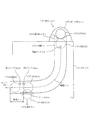
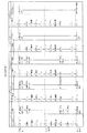
図2は、メダル投入口47から投入されたメダルMが投入センサ44a及び44bを通過するまでの様子を示す図であって、正面から見た模式図である。図2では、メダルセレクタの内部が見えるように図示している。また、メダルMは、その位置に応じて、M1〜M4を示している。M1の位置は、メダルMがメダル投入口47のメダル置き部47bに置かれている状態(放たれる前の状態)を示す。すなわち、M1の位置では、正面から見て、メダルMの外周縁の最下点とメダル置き部47bの上面とが当接している。
なお、図2(及び後述する図4)において、投入センサ44a及び44bとして表示した略正方形の部分全体が、それぞれ投入センサ44a及び44bの受発光範囲(センサの目)であるものとする(それぞれ投入センサ44a及び44bの筐体ではない。)。
FIG. 2 is a diagram showing a state until the medal M inserted from the medal insertion port 47 passes through the
In FIG. 2 (and FIG. 4 described later), it is assumed that the substantially square portions displayed as the
また、M2の位置は、正面から見てメダルMが見えなくなった瞬間の位置を示している。すなわち、M2の位置では、メダルMの外周縁の最上点とメダル置き部47bの上面とが重なる位置である。たとえば、メダルMがM1の位置にあるときに遊技者がメダルMから手を離すと仮定すると、メダルMは、M1の位置から落下する。したがって、M2の位置では、遊技者の手から放れている状態であって下流側に落下(移動)している状態である。
なお、「上流側」とはメダル投入口47側を示し、「下流側」とは投入センサ44b側(ホッパー35側)を指すものとする。メダルMの位置でいえば、上流側から下流側に向かって、M1→M2→M3→M4となる。
Further, the position of M2 indicates the position at the moment when the medal M is not visible when viewed from the front. In other words, at the position of M2, the uppermost point of the outer periphery of the medal M and the upper surface of the medal placement portion 47b overlap. For example, assuming that the player releases his hand from the medal M when the medal M is at the position M1, the medal M falls from the position M1. Therefore, at the position of M2, it is in a state of being released from the player's hand and falling (moving) downstream.
“Upstream side” indicates the medal insertion port 47 side, and “downstream side” indicates the
図2の例では、メダルMがM2に位置しているときには、通路センサ46によってメダルMが検知されるように通路センサ46を配置している。
さらに、M3の位置は、投入センサ44aによってメダルMが検知された瞬間(オン)の位置を示す。また、M4の位置は、投入センサ44bによってメダルMが検知されなくなった瞬間(オフ)の位置を示している。
In the example of FIG. 2, the passage sensor 46 is arranged so that the medal M is detected by the passage sensor 46 when the medal M is positioned at M <b> 2.
Further, the position of M3 indicates the position (ON) at the moment when the medal M is detected by the
メダル投入口47は、遊技者が遊技媒体としてのメダルMをベット又はクレジットするときに、メダルMをスロットマシン10内部(メダルセレクタ)に投入する部分である。メダル投入口47は、メダルガード部47aと、メダル置き部47bとを備える。メダル置き部47bは、複数枚(最大で10枚程度)の重ねたメダルMを同時に載置可能に、図面の紙面に対して垂直方向に伸びる略湾曲面(メダルMの周縁よりもやや大きな曲率を有する曲面)を有する。 The medal insertion slot 47 is a portion for inserting the medal M into the slot machine 10 (medal selector) when the player bets or credits the medal M as a game medium. The medal slot 47 includes a medal guard part 47a and a medal holder 47b. The medal holder 47b has a substantially curved surface (curvature slightly larger than the periphery of the medal M) extending in a direction perpendicular to the paper surface of the drawing so that a plurality of (up to about ten) medals M can be placed simultaneously. Curved surface).
メダル置き部47bの前記略湾曲面と、メダルガード部47aのメダルMが接触する面(図2で見えている面)は、略垂直に交差するように形成されている。
さらに、図2では表れていないが、メダル置き部47bとメダルガード部47aとが交差する部分には、1枚のメダルMを流下可能な開口部を有している。2枚のメダルMを重ねた状態では前記開口部からメダルMが落下しないが、1枚のメダルMの厚みのときは前記開口部からメダルMが流下するように形成されている。このため、遊技者は、たとえば重ねた複数枚のメダルMをメダル置き部47b上に載置し、その複数枚のメダルMをメダルガード部47aの方向に押し当てつつ、押し当て力を強めたり弱めたりすることで、メダル置き部47b上に載置したメダルMを1枚ずつ前記開口部からメダルセレクタ内に落とし込むことが可能となっている。
The substantially curved surface of the medal placement portion 47b and the surface (the surface visible in FIG. 2) where the medal M of the medal guard portion 47a contacts are formed so as to intersect substantially vertically.
Further, although not shown in FIG. 2, the portion where the medal placing portion 47 b and the medal guard portion 47 a intersect has an opening through which one medal M can flow down. In the state where two medals M are stacked, the medal M does not fall from the opening, but when the thickness of one medal M is, the medal M flows from the opening. For this reason, for example, the player places a plurality of stacked medals M on the medal placement part 47b and increases the pressing force while pressing the plurality of medals M in the direction of the medal guard part 47a. By weakening, the medals M placed on the medal placement portion 47b can be dropped into the medal selector from the opening one by one.
メダル投入口47からメダルMが投入される(下方に放たれる)と、そのメダルMは、メダルセレクタ内の通路を流下する。メダルセレクタ内には、上流側から、通路センサ46、投入センサ44a、投入センサ44bが設けられている。さらに、通路センサ46と、投入センサ44aとの間(図2では、投入センサ44aの下側)には、上述したブロッカ45が設けられている。
When the medal M is inserted from the medal insertion port 47 (released downward), the medal M flows down the passage in the medal selector. In the medal selector, a passage sensor 46, an
メダルMがメダルセレクタ内に入ると、最初に、通路センサ46によって検知される。通路センサ46は、メダル詰まりやゴト行為の有無判断するため等に設けられたセンサであり、通路センサ46がメダルMを検知した時から、(予め定めた)所定時間、メダルMを検知し、さらに所定時間の経過後はメダルMを検知しなくなったときは、正常であると判断する。これに対し、通路センサ46がメダルを検知した後、所定時間を経過してもメダルMを検知し続けているときは、メダル滞留エラーと判断する。また、通路センサ46がメダルMを検知した後、所定時間を経過する前にメダルMを検知しなくなったときは、メダルMの不正通過であると判断する。 When the medal M enters the medal selector, it is first detected by the passage sensor 46. The passage sensor 46 is a sensor provided for determining the presence or absence of a medal clogging or a goto action. The passage sensor 46 detects the medal M for a predetermined time (predetermined) from when the passage sensor 46 detects the medal M. Further, when the medal M is no longer detected after a predetermined time has elapsed, it is determined that it is normal. On the other hand, if the medal M continues to be detected after a predetermined time has elapsed after the passage sensor 46 detects the medal, it is determined that a medal retention error has occurred. Further, when the medal M is not detected after the passage sensor 46 detects the medal M and before a predetermined time has elapsed, it is determined that the medal M has been illegally passed.
メダルMがメダル通路内を流下すると、ブロッカ45の位置に到達する。ブロッカ45は、メダル通路において下面側に配置されている。ブロッカ45は、オン状態(出力ポート52のうち、ブロッカ45に係る出力ポートがオン)であるときは、メダルMが投入センサ44a及び44bによって検知可能となるようにメダル流路を形成する。換言すれば、上流側から移動してきたメダルMを、メダル通路外に送出することなく、投入センサ44a及び44b側に送る役目を持っている。
When the medal M flows down in the medal passage, the position of the blocker 45 is reached. The blocker 45 is disposed on the lower surface side in the medal passage. When the blocker 45 is in the ON state (the output port related to the blocker 45 among the output ports 52 is ON), the medal flow path is formed so that the medal M can be detected by the
これに対し、オフ状態(出力ポート52のうち、ブロッカ45に係る出力ポートがオフ)であるときは、ブロッカ45は、図2中、図面の紙面に対して垂直方向にずれるように移動することにより、メダル通路に開口部(落とし穴)を形成する。これにより、ブロッカ45がオフ状態では、メダルMは、M3に到達する直前に、この開口部から落下し、メダル通路外に送られる(図2中、M5)。この開口部から落下したメダルMは、投入センサ44aに検知されることなく、メダル返却口(図示せず)に戻される。
On the other hand, when the output port 52 is in the off state (the output port related to the blocker 45 among the output ports 52 is off), the blocker 45 moves so as to be shifted in the direction perpendicular to the paper surface of the drawing in FIG. Thus, an opening (pit) is formed in the medal passage. Thereby, when the blocker 45 is in the OFF state, the medal M is dropped from this opening immediately before reaching the M3 and is sent out of the medal passage (M5 in FIG. 2). The medal M dropped from the opening is returned to the medal return port (not shown) without being detected by the
たとえば、当該遊技の規定数がすでにベットされており、かつクレジット数が上限値に到達しているときは、それ以上のメダルのベット及びクレジットができないので、ブロッカ45はオフ状態に制御される。これにより、その状態においてメダルMがメダル投入口47から投入されても、前記開口部から落下してメダル返却口に戻される。
これに対し、ブロッカ45がオン状態であるときは、前記開口部がブロッカ45によって塞がれているので、メダル通路内を流下するメダルMは、ブロッカ45上を通過し、投入センサ44a及び44b側に移動可能となる。
For example, when the specified number of the game has already been betted and the number of credits has reached the upper limit, no more medals can bet or credit, so the blocker 45 is controlled to be in the off state. Thereby, even if the medal M is inserted from the medal insertion port 47 in this state, it falls from the opening and is returned to the medal return port.
On the other hand, when the blocker 45 is in the on state, the opening is blocked by the blocker 45, so that the medal M flowing down in the medal passage passes over the blocker 45 and enters the
なお、本実施形態では、図2のようにブロッカ45を配置したが、この配置に限られるものではない。ブロッカ45のオン状態/オフ状態にかかわらず、通路センサ46によってメダルMを検知することができ、ブロッカ45がオン状態であるときはメダルMを投入センサ44a及び44bに案内することができ、かつ、ブロッカ45がオフ状態であるときはメダルMが投入センサ44a及び44bに検知されることなくメダル返却口に送ることができればよい。換言すれば、通路センサ46と投入センサ44aとの間にブロッカ45が位置すればよい。
In this embodiment, the blocker 45 is arranged as shown in FIG. 2, but the arrangement is not limited to this. Regardless of the on / off state of the blocker 45, the medal M can be detected by the passage sensor 46. When the blocker 45 is in the on state, the medal M can be guided to the
また、通路センサ46は、ブロッカ45よりも上流側に位置していればよく、ブロッカ45がオフ状態であっても、メダル投入口47から投入されたメダルMを検知可能な位置に配置されていればよい。また、図2では、通路センサ46は、メダルMがM2に位置したときは、メダルMを検知できるように配置しているが、これに限らず、メダルMがM2の位置よりもさらに下流側に移動したときにメダルMを検知するように通路センサ46を配置することも可能である。 Further, the passage sensor 46 only needs to be positioned upstream of the blocker 45 and is disposed at a position where the medal M inserted from the medal insertion port 47 can be detected even when the blocker 45 is in the OFF state. Just do it. In FIG. 2, the passage sensor 46 is arranged so that the medal M can be detected when the medal M is positioned at M2, but the present invention is not limited thereto, and the medal M is further downstream than the position of M2. It is also possible to arrange the passage sensor 46 so as to detect the medal M when it is moved to.
投入センサ44a及び44bは、ブロッカ45を通過したメダルMを検知するためのセンサであり、これら2つのセンサは、所定距離を隔てて設置されている。まず、メダルMがM3の位置に到達したときは、上流側の投入センサ44aがメダルMを検知可能となる(オフからオンになる)。さらにメダルMが流下すると、次に投入センサ44bがメダルMを検知する(オフからオンになる)。これら2つの投入センサ44a及び44bのオン/オフのタイミングを判断することにより、投入されたメダルMが正常であるか否かを判断する。メダルMがM4の位置に到達すると、投入センサ44a及び44bに検知されなくなる。投入センサ44a及び44bを通過したメダルMは、ホッパー35に送られる。
The
図2において、メダルセレクタは、以下のように設計されている。
まず、メダルMがM2の位置、すなわちメダルセレクタを正面から見たときに、メダルMが視認不可能となった瞬間から、メダルMがM4の位置、すなわち投入センサ44bに検知されなくなる瞬間の位置に到達するまで(図2中、点線で移動軌跡を示す。)の時間を、時間T2に設定している。なお、メダルMがM1に位置しているときにそのメダルMから(初速度「0」で)手を離し、下方に放った場合の値である。よって、メダルMがM2に位置するときの速度は、「0」を超える。
In FIG. 2, the medal selector is designed as follows.
First, the position of the medal M is M2, that is, the position where the medal M is not detected by the
また、メダルMの加速度は、M2の位置からさらに下方に移動するに従って大きくなる。一方、図2中、メダル通路が垂直方向から水平方向に曲がった部分には、衝撃部材(図2では図示せず)が設けられている。この衝撃部材にメダルMが接触すると、メダルMの速度が減速されて、投入センサ44a及び44bに向かうようになっている。
そして、メダルMがM3に位置する瞬間(投入センサ44aに検知された瞬間)から、M4に位置する瞬間(投入センサ44bに検知されなくなった瞬間)までの時間を、時間T3に設定している。
Further, the acceleration of the medal M increases as it moves further downward from the position of M2. On the other hand, an impact member (not shown in FIG. 2) is provided at a portion where the medal passage is bent from the vertical direction to the horizontal direction in FIG. When the medal M comes into contact with the impact member, the speed of the medal M is decelerated and is directed toward the
The time from the moment when the medal M is positioned at M3 (the moment when it is detected by the
<第1実施形態(A)>
図3は、本実施形態のうち、第1実施形態(A)を説明するためのタイムチャートを示す図である。
図3は、スロットマシン10の電源がオフにされたとき(たとえば、電源スイッチ11がオフにされたときや、停電が発生したとき)の電圧レベルを示すものである。
図3において、電源が正常にオン状態になっているときの電圧を供給レベルV0とする。供給レベルV0の状態では、スロットマシン10は、正常に作動する。
<First Embodiment (A)>
FIG. 3 is a diagram illustrating a time chart for explaining the first embodiment (A) of the present embodiment.
FIG. 3 shows a voltage level when the power of the slot machine 10 is turned off (for example, when the power switch 11 is turned off or when a power failure occurs).
In FIG. 3, the voltage when the power supply is normally turned on is assumed to be the supply level V0. In the state of the supply level V0, the slot machine 10 operates normally.
図3では、時刻S11のときに、電源断が発生した(電源の供給が遮断される事象が発生した)例を示している。本実施形態では、電源断が発生すると、時間T0で、電圧が電源断検知レベルV1まで低下する。
電源断が発生したとき(時刻S11;供給レベルV0)から、電源断を検知するまで(時刻S12;電源断検知レベルV1)までの時間T0は、少なくとも20割込み(1割込み時間2.235ms×20割込み=44.7ms)以上となるように設計されている。
メイン制御基板50上には、(図示しない)電圧監視装置(電源断検出回路)が設けられている。そして、電源電圧が所定値である電源断検知レベルV1以下になったときには、入力ポート51における所定のビットに電源断検知信号が入力され、その信号の入力があったか否かを検知することにより電源断を検知する。
FIG. 3 shows an example in which a power interruption has occurred at time S11 (an event in which the supply of power has been interrupted has occurred). In the present embodiment, when a power interruption occurs, the voltage drops to the power interruption detection level V1 at time T0.
The time T0 from when the power interruption occurs (time S11; supply level V0) until the power interruption is detected (time S12; power interruption detection level V1) is at least 20 interrupts (one interruption time 2.235 ms × 20 (Interrupt = 44.7 ms) or more.
On the main control board 50, a voltage monitoring device (power-off detection circuit) (not shown) is provided. When the power supply voltage falls below a predetermined value of power-off detection level V1, a power-off detection signal is input to a predetermined bit in the input port 51, and the power supply is detected by detecting whether or not the signal has been input. Detect disconnection.
電圧が電源断検知レベルV1からさらに低下していき、メインCPU55の駆動電圧限界V2未満になると、メインCPU55を駆動することができなくなる(メインCPU55の動作を保証できなくなる)。
図3の例では、時刻S13で、電圧レベルがメインCPU55の駆動電圧限界V2となり、その後、Lowに低下する例を示している。メイン制御基板50は、電圧が駆動電圧限界V2未満になると電源断処理を実行することができないので、電源断が時刻S11で発生したときは、少なくとも時刻S13までに、電源断処理を終了できるように設定している。
When the voltage further decreases from the power-off detection level V1 and falls below the drive voltage limit V2 of the main CPU 55, the main CPU 55 cannot be driven (the operation of the main CPU 55 cannot be guaranteed).
In the example of FIG. 3, at time S13, the voltage level reaches the drive voltage limit V2 of the main CPU 55 and then decreases to Low. Since the main control board 50 cannot execute the power-off process when the voltage becomes lower than the drive voltage limit V2, when the power-off occurs at time S11, the power-off process can be completed at least by time S13. Is set.
また、電源断の検知は、2.235msごとに実行される割込み処理内で実行するが、2割込み連続で電源断を検知したときは、次の割込み処理で電源断処理を実行する。したがって、図3中、時刻S12は、2回連続で割込み処理で電圧が電源断検知レベルV1以下であると判断され、電源断が発生したと検知したタイミングである。そして、次の割込み処理で、電源断処理を実行する。
なお、割込み処理では、以下のような処理を実行する。まず、電源断を検知したか否かを判断し、電源断を検知したときは、(通常の割込み処理に移行せずに)電源断処理に移行する。電源断処理では、まず、出力ポート52をオフにする。出力ポート52をオフにする処理により、ブロッカ45がオフとなる。さらに、スタックポインタの保存処理、電源断処理済みフラグ(正常な電源断が行われたか否かを判断するためのフラグ)のセット処理、RWM53のチェックサムの実行処理、RWM53の書き込み禁止処理等を順次実行した後、リセット待ち状態(ループ処理状態)となる。このリセット待ち状態は、設計上、何も処理を行わない状態となっている。
したがって、図3に示すように、電源断を検知した割込み処理(時刻S12)の次の割込み処理で、電源断処理が実行され、ブロッカ45がオフにされる。
なお、電源断を検知した割込み処理の次の割込み処理で電源断処理を実行することに限らず、電源断を検知した割込み処理内で電源断処理を実行してもよい。この場合には、「T1=S12−S11」となる。
Further, detection of power interruption is executed in interrupt processing executed every 2.235 ms. However, when power interruption is detected continuously for two interrupts, power interruption processing is executed in the next interruption processing. Therefore, in FIG. 3, time S12 is a timing at which it is determined that the voltage is lower than the power-off detection level V1 in the interruption process twice in succession and the power-off is detected. Then, power-off processing is executed in the next interrupt processing.
In the interrupt process, the following process is executed. First, it is determined whether or not a power-off is detected. When a power-off is detected, the process proceeds to a power-off process (without moving to a normal interrupt process). In the power-off process, first, the output port 52 is turned off. By the process of turning off the output port 52, the blocker 45 is turned off. Furthermore, stack pointer saving processing, power-off processing completion flag (flag for determining whether or not normal power-off has been performed) setting processing, RWM53 checksum execution processing, RWM53 write-protection processing, etc. After the sequential execution, a reset waiting state (loop processing state) is entered. This reset waiting state is a state in which no processing is performed by design.
Therefore, as shown in FIG. 3, the power-off process is executed in the interrupt process following the interrupt process (time S12) in which the power-off is detected, and the blocker 45 is turned off.
Note that the power-off process is not limited to the interrupt process that is performed after the interrupt process in which the power-off is detected. In this case, “T1 = S12−S11”.
一方、図3では、メダルが投入された後のメダル位置(M2、M4)を併せて図示している。図2において、メダルMがM1の位置にある状態で、遊技者がメダルMから手を離したと仮定する。なお、この場合には、メダルMは、初速度「0」で落下する。これにより、メダルMは、メダルセレクタ内に放たれる。そして、図3では、電源断が発生した時刻S11と、メダルMがM2の位置に到達した時刻とを一致させている。 On the other hand, FIG. 3 also illustrates the medal positions (M2, M4) after the medal is inserted. In FIG. 2, it is assumed that the player releases his hand from the medal M in a state where the medal M is at the position M1. In this case, the medal M falls at the initial speed “0”. Thereby, the medal M is released into the medal selector. In FIG. 3, the time S11 at which the power cut occurs and the time at which the medal M reaches the position of M2 are matched.
図2で示したように、メダルMがM2に位置する瞬間からM4に位置する瞬間までの時間をT2としたが、図3においても同様に、メダルMがM2に位置する瞬間から時間T2経過後に、メダルMがM4に位置するものとする。
この場合、本実施形態では、「T2>T1」の関係を満たすように設計している。
As shown in FIG. 2, the time from the moment when the medal M is located at M2 to the moment when the medal M is located at M4 is T2, but in FIG. Later, it is assumed that the medal M is positioned at M4.
In this case, the present embodiment is designed to satisfy the relationship of “T2> T1”.
したがって、メダルMがM2に位置する瞬間に電源断が発生すると、メダルMがM4に到達する前に電源断処理が実行され、投入センサ44bがメダルMを検知しなくなる。よって、メダルMがM2に位置する瞬間に電源断が発生したときは、そのメダルMは、投入センサ44bに検知されることなくメダル返却口(下皿)に送られる。このため、そのメダルMは、投入センサ44a及び44bを正常に通過することにはならない。よって、そのメダルMについては、飲み込みが発生してしまうが、電源断の発生後(時刻S11の後)に、メダルMの「1」加算(ベット又はクレジットへの「1」加算)処理が実行されない。これにより、電源断の発生後にベット又はクレジット処理が実行されてしまう可能性をなくすことができる。
Therefore, if the power interruption occurs at the moment when the medal M is positioned at M2, the power interruption process is executed before the medal M reaches M4, and the
たとえば、メダルMがM2に位置する瞬間に電源断が発生した場合において、時間T1が経過したとき(電源断処理時)に、図2中、メダルMがM4の直前に位置するとき(メダルMがM3の位置を通過した後のとき)は、そのメダルMは、投入センサ44aには検知されるが、投入センサ44bには検知されることなく、電源がオフになる。
また、メダルMがM2に位置する瞬間に電源断が発生した場合において、時間T1が経過したとき(電源断処理時)に、図2中、メダルMがM3の位置よりも上流側に位置するときは、そのメダルMは、投入センサ44a及び投入センサ44bのいずれにも検知されることなく、電源がオフになる。
For example, in a case where the power interruption occurs at the moment when the medal M is positioned at M2, when the time T1 has elapsed (during power-off processing), the medal M is positioned immediately before M4 in FIG. Is after the passage of the position M3), the medal M is detected by the
Further, in the case where the power is cut off at the moment when the medal M is positioned at M2, when the time T1 has elapsed (during power-off processing), the medal M is positioned upstream of the position of M3 in FIG. At that time, the medal M is not detected by either the
また、図2において、メダルMがM2に位置する瞬間から、M3に位置する瞬間までの時間を、時間T2’とする。
この場合、「T2’>T1」の関係を満たすように設計することが好ましい。
上記の関係に設計した場合において、メダルMがM2に位置する瞬間に電源断が発生すると、メダルMがM3に到達した時点では、電源断処理が実行されることによりブロッカ45がオフ状態となっている。したがって、そのメダルMは、投入センサ44aに検知されることなくメダル通路外に送出され、メダル返却口に送られるようになる。
In FIG. 2, the time from the moment when the medal M is located at M2 to the moment when the medal is located at M3 is defined as time T2 ′.
In this case, it is preferable to design so as to satisfy the relationship of “T2 ′> T1”.
In the case of designing in the above relationship, if the power interruption occurs at the moment when the medal M is positioned at M2, the blocker 45 is turned off by executing the power interruption process when the medal M reaches M3. ing. Therefore, the medal M is sent out of the medal passage without being detected by the
ここで、従来技術と第1実施形態(A)との相違について説明する。
従来は、メダルMがM2に位置する瞬間に電源断が発生すると、その電源断を検知してブロッカ45をオフにしたときには、メダルMは、すでに投入センサ44bの位置を通過していた。したがって、電源断が発生した後に、メダルの「1」加算処理(ベット処理又はクレジット処理)が実行されていた。しかし、電源断が発生した後にメダル加算処理を実行することは好ましくない。電源断の発生後は、遊技の進行に係るすべての処理を速やかに停止すべきだからである。
そこで、第1実施形態(A)のように構成すれば、遊技者がメダル投入口47からメダルMを投入し、メダルMがM2に位置する瞬間(投入直後)に電源断が発生したとしても、メダルの「1」加算処理が実行されないようにしたので、スロットマシン10の機能を高めることができる。
Here, the difference between the prior art and the first embodiment (A) will be described.
Conventionally, when a power interruption occurs at the moment when the medal M is positioned at M2, the medal M has already passed the position of the
Therefore, if configured as in the first embodiment (A), even if the player inserts the medal M from the medal insertion slot 47 and the power is cut off at the moment when the medal M is positioned at M2 (immediately after the insertion). Since the medal “1” addition process is not executed, the function of the slot machine 10 can be enhanced.
<第1実施形態(B)>
第1実施形態(B)は、投入センサ44a及び44bと、電源断との関係を定めたものである。
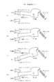
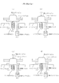
図4は、メダルMが投入センサ44aにより検知されてから、投入センサ44bにより検知されなくなるまでの過程を示す正面図である。図4中、矢印方向は、メダルMの進行(流下)方向を示している。
図4(a)は、メダルMが投入センサ44aにより検知された瞬間の図を示している。このとき、投入センサ44aはオフからオンになった瞬間であり、投入センサ44bはオフのままである。なお、この位置は、図2中、M3に相当する。
<First Embodiment (B)>
The first embodiment (B) defines the relationship between the
FIG. 4 is a front view showing a process from when the medal M is detected by the
FIG. 4A shows a diagram at the moment when the medal M is detected by the
次に、メダルMが図4中、左側に進行し、図4(b)に示す状態になると、投入センサ44aはメダルMを検知した状態のままであり、投入センサ44bがメダルMを検知するようになる。よって、図4(b)では、投入センサ44aはオンであり、投入センサ44bはオフからオンになった瞬間である。
なお、図4では、投入センサ44a及び44bとメダルMとが重なった場合であっても、投入センサ44a及び44bとメダルMとの双方を実線で示しているが、メダルMと投入センサ44a及び44bの位置関係を表すものではない。投入センサ44a及び44bは、メダルMに対し、図4の紙面の垂直方向において手前側に配置されていてもよく、奥側に配置されていてもよい。
Next, when the medal M advances to the left in FIG. 4 and enters the state shown in FIG. 4B, the
In FIG. 4, even when the
メダルMがさらに進行し、図4(c)の状態になると、投入センサ44a及び44bの双方によってメダルMが検知されている状態となる。よって、この場合の投入センサ44aはオンであり、かつ投入センサ44bもオンである。
ここで、メダルMの直径は、たとえば、一般仕様では25ミリメートル(いわゆる25パイ(φ))であり、特殊仕様では30ミリメートル(いわゆる30パイ(φ))である。したがって、図4(c)の状態になることが可能に、投入センサ44aと44bとの間の距離を設定する必要がある。ここで、後述するように、図4(c)の状態、すなわち投入センサ44a及び44bの双方がオンとなっている(メダルMを検知している)時間が所定の範囲内であるか否かにより、メダル投入エラーと判定するか否かを定めている。よって、投入センサ44aと44bとの間の距離は、投入センサ44a及び44bの双方がオンとなっている時間をどのように設定するかによっても異なる。
When the medal M further advances and enters the state of FIG. 4C, the medal M is detected by both the
Here, the diameter of the medal M is, for example, 25 millimeters (so-called 25 pie (φ)) in the general specification, and 30 millimeters (so-called 30 pie (φ)) in the special specification. Therefore, it is necessary to set the distance between the making
図4(c)の状態からメダルMがさらに進むと、図4(d)に示すように、投入センサ44aは、メダルMを検知しなくなる。この場合、投入センサ44aはオンからオフになった瞬間であり、投入センサ44bはオンのままである。さらにメダルMが進行すると、図4(e)に示すように、投入センサ44bがメダルMを検知しなくなる。よって、この場合には、投入センサ44aはオフのままであり、投入センサ44bはオンからオフになった瞬間である。なお、図4(e)のメダルMの位置は、図2中、M4に相当する。
When the medal M further advances from the state of FIG. 4C, the
図5は、投入センサ44a及び44bのオン/オフをタイムチャートで示す図である。図5において、時刻S21は、投入センサ44aがオフからオンになった瞬間(投入センサ44bのはオフのまま)であり、図4(a)のタイミングに相当する。
次に、投入センサ44bがメダルMを検知した(オフからオンになった)瞬間(図4(b))の時刻をS22とする。さらにまた、投入センサ44aがメダルMを検知しなくなった(オンからオフになった)瞬間(図4(d))の時刻をS23とする。さらに、投入センサ44bがメダルMを検知しなくなった(オンからオフになった)瞬間(図4(e))の時刻をS24とする。
FIG. 5 is a time chart showing on / off of the
Next, let S22 be the time at which the
ここで、投入センサ44aがメダルMを検知している時間Ta(時刻S21からS23までの間)が、6.705ms(3割込み)以上、185.505ms(83割込み)未満の範囲内であれば(条件1)、メイン制御基板50は、正常なメダルMの通過であると判断し、この範囲から外れているときは、メダル通過エラーと判断する。
Here, if the time Ta during which the
また、投入センサ44a及び44bの双方がメダルMを検知している時間Tb(時刻S22からS23までの間)が、4.47ms(2割込み)以上、118.455ms(53割込み)未満の範囲内であれば(条件2)、メイン制御基板50は、正常なメダルMの通過であると判断し、この範囲から外れているときは、メダル通過エラーと判断する。
Further, the time Tb (between time S22 and S23) in which both the
さらにまた、投入センサ44bがメダルMを検知している時間Tc(時刻S22からS24までの間)が、6.705ms(3割込み)以上、185.505ms(83割込み)未満の範囲内であれば(条件3)、メイン制御基板50は、正常なメダルMの通過であると判断し、この範囲から外れているときは、メダル通過エラーとする。
上述した条件1〜条件3のすべてを満たす場合には、メダルMの通過は正常であると判断し、少なくとも1つの条件を満たさないときは、メダル通過エラーとする。
Furthermore, if the time Tc during which the
When all of the
また、図5に示すように、投入センサ44a及び44bの双方がオフになったとき(時刻S24)は、投入監視カウンタを「1」減算する。
ここで、投入監視カウンタは、上述した通路センサ46がメダルMを検知したときに「+1」となり、投入センサ44a及び44bをメダルが正常に通過したとき(投入センサ44a及び44bの双方が、オフ→オン→オフとなったとき。よって時刻S24のとき。)に「−1」されるカウンタである。すなわち、正常時には、「1」と「0」とを繰り返す。
一方、通路センサ46がメダルMを検知せず、投入センサ44a及び44bのみがメダルの通過を検知したときは、投入監視カウンタは「−1」となり、メイン制御基板50は、メダル通過エラーと判断する。
Further, as shown in FIG. 5, when both the
Here, the insertion monitoring counter becomes “+1” when the above-described passage sensor 46 detects the medal M, and when the medal normally passes the
On the other hand, when the passage sensor 46 does not detect the medal M and only the
また、通路センサ46がメダルMを検知し(投入監視カウンタ=「+1」)、かつ、投入センサ44a及び44bがメダルMの通過を検知しなかった場合において、通路センサ46がさらにメダルMを検知し、投入監視カウンタが「2」以上の所定値になると、メイン制御基板50は、メダル詰まりエラーと判断する。たとえば投入監視カウンタの正常値を「0」〜「2」に設定した場合には、投入監視カウンタが「3」以上となったときは、メイン制御基板50がメダル詰まりエラーと判断することが挙げられる。
なお、投入監視カウンタは、ブロッカ45がオフ状態からオン状態になるときは、クリアされる。
When the passage sensor 46 detects the medal M (insertion monitoring counter = “+ 1”) and the
The input monitoring counter is cleared when the blocker 45 changes from the off state to the on state.
図5において、時刻S24で、投入センサ44bがオンからオフになり、投入監視カウンタが「1」減算され、メダルMが正常に通過したと判断されたときは、メイン制御基板50は、メダル投入処理(ベット処理又はクレジット処理)を実行する。たとえばその時点で、ベット数が規定数未満であるときは、ベット数の「1」加算処理を実行する。具体的には、当該遊技での規定数が「3」であり、その時点でのベット数が「0」であるときは、ベット数の「1」加算処理により、ベット数を「0」から「1」に更新する。
In FIG. 5, when the
また、その時点で、ベット数が既に規定数に到達している場合において、クレジット数が最大数の「50」に到達していないときは、クレジット数の「1」加算処理を実行する。たとえば、その時点でのクレジット数が「10」であるときは、クレジット数を「11」に更新する。
なお、ベット数が規定数となり、かつ、クレジット数が最大数の「50」に到達したときは、メイン制御基板50は、ブロッカ45をオフ状態にする。これにより、メダル投入口47からメダルMが投入されても、そのメダルMは返却される。換言すれば、その場合には、メダルMが投入されても投入センサ44a及び44bに検知されることはない。
At that time, if the bet number has already reached the prescribed number and the credit number has not reached the maximum number “50”, the credit number “1” addition process is executed. For example, when the number of credits at that time is “10”, the number of credits is updated to “11”.
When the bet number reaches the specified number and the maximum number of credits reaches “50”, the main control board 50 turns off the blocker 45. Thereby, even if the medal M is inserted from the medal insertion slot 47, the medal M is returned. In other words, in that case, even if the medal M is inserted, the
図5では、投入センサ44a及び44bのオン/オフに加えて、電源断発生時と電源断検知時のタイミングを表示している。図5では、例1及び例2を示し、いずれも、投入センサ44aがオフからオンになったタイミング(時刻S21)で電源断が発生した場合を例に挙げている。
そして、例1では、電源断が発生した時刻S21から、時間T1経過後に電源断を検知している。ここで、例1では、「T1>T3」に設定されている。したがって、電源断が発生した瞬間に投入センサ44aがメダルMを検知した場合において、電源断処理を開始するときは、すでにメダルMの「1」加算処理を実行した後である。
In FIG. 5, in addition to turning on / off the
In Example 1, the power-off is detected after the time T1 has elapsed since the time S21 when the power-off occurred. Here, in Example 1, “T1> T3” is set. Therefore, when the
ここで、時刻S21からS24までの時間T3は、「Ta+Tc−Tb」で表すことができる。したがって、時間T3の最小時間は、4割込みに相当し、「8.94ms」である。
また、時間T3の最大時間は、113割込みに相当し、「252.555ms」である。
そして、例1では、必ず、時刻S24の経過後に電源断処理が実行されるように設定する。このため、たとえば、電源断の発生(時刻S21)から電源断処理が実行されるまでの時間T1は、114割込み以上となるように設定する。
Here, the time T3 from the time S21 to S24 can be represented by “Ta + Tc−Tb”. Therefore, the minimum time of the time T3 corresponds to 4 interrupts and is “8.94 ms”.
The maximum time T3 corresponds to 113 interrupts and is “252.555 ms”.
And in Example 1, it sets so that a power-off process must be performed after progress of time S24. For this reason, for example, the time T1 from the occurrence of power interruption (time S21) to the execution of the power interruption processing is set to be 114 interrupts or more.
以上のように設定すれば、投入センサ44aがメダルMを検知した瞬間(時刻S21)に電源断が発生しても、メダルMの「1」加算処理の実行後に電源断処理が実行されるので、そのメダルMは、正常にベット又はクレジットされる。よって、メダルMの飲み込みを防止することができる。
If the setting is made as described above, even if the power-off occurs at the moment (time S21) when the
また、例2は、例1とは逆に、メダルMの「1」加算処理が実行される前に電源断処理を実行する例である。すなわち、例2では、「T1<T3」の関係となるように設定する。
時刻S21からS24までの時間T3は、上述したように、最小時間で4割込みに相当する。したがって、「T1<T3」の関係を満たすためには、電源断の発生から3割込み以内で電源断処理を実行する必要がある。しかし、電源断の発生から3割込み以内で電源断処理を実行するように設定することは困難であるので、時間Tcの最小時間が4割込みよりも長くなるように設定する。たとえば時間Tcの最小時間を15割込みに設定することが挙げられる。そして、電源断の発生(時刻S21)から電源断処理までの時間T1を10割込み程度に設定すれば、時刻S21で電源断が発生したときに、時刻S24になる前に電源断処理を実行することが可能となる。
Also, in the example 2, contrary to the example 1, the power-off process is executed before the “1” addition process for the medal M is executed. That is, in Example 2, it sets so that it may become the relationship of "T1 <T3".
As described above, the time T3 from the time S21 to S24 corresponds to 4 interrupts in the minimum time. Therefore, in order to satisfy the relationship of “T1 <T3”, it is necessary to execute the power-off process within three interrupts from the occurrence of the power-off. However, since it is difficult to set the power-off process to be executed within 3 interrupts from the occurrence of the power-off, the minimum time Tc is set to be longer than 4 interrupts. For example, the minimum time of the time Tc can be set to 15 interrupts. If the time T1 from the occurrence of power interruption (time S21) to the power interruption process is set to about 10 interrupts, the power interruption process is executed before time S24 when the power interruption occurs at time S21. It becomes possible.
電源断処理が実行されると、その後にメダルMの「1」加算(ベット又はクレジット)処理は実行されない。したがって、例2では、時刻S21の時点で(電源断の発生時に)投入センサ44aがメダルMを検知したとしても、メダルM1の「1」加算処理は実行されない。その結果、メダルMを飲み込んでしまうというデメリットを有するが、第1実施形態(A)で説明したように、電源断が発生した後は、メダルMの「1」加算処理等を実行することなく、できる限り速やかに電源断処理を実行することができる。
When the power-off process is executed, the medal M “1” addition (bet or credit) process is not executed thereafter. Therefore, in Example 2, even if the
<第1実施形態(C)>
第1実施形態(C)は、払出しセンサ37a及び37bと電源断との関係を定めたものである。
払い出すべきメダルをクレジットに加算するときはホッパーモータ36を駆動せずに、メイン制御基板50のRWM53内に設けられたクレジット数の記憶領域を更新する。さらに、当該記憶領域に記憶されたクレジット数に対応する数となるように、クレジット数表示LED76で示す値を更新する。
<First Embodiment (C)>
In the first embodiment (C), the relationship between the payout sensors 37a and 37b and the power interruption is defined.
When adding the medals to be paid out to the credits, the storage area for the number of credits provided in the RWM 53 of the main control board 50 is updated without driving the hopper motor 36. Further, the value indicated by the credit number display LED 76 is updated so that the number corresponds to the credit number stored in the storage area.
そして、クレジット数が上限値「50」に到達した後にメダルを払い出すときは、ホッパーモータ36を駆動して、ホッパー35からメダルを払い出す(払出し口から排出する)。この場合、メダルが1枚払い出されるごとに払出しセンサ37a及び37bがオン/オフを検知するように構成されている。払出しセンサ37a及び37bによるオン/オフの検知結果が正常の範囲内であるときは、メダルMが1枚正しく払い出されたと判断し、当該検知結果が正常の範囲内にないときは、メダルMが正しく払い出されていないと判断し、メイン制御基板50は、メダル払出しエラーと判断する。 Then, when paying out medals after the number of credits reaches the upper limit “50”, the hopper motor 36 is driven to pay out medals from the hopper 35 (discharge from the payout port). In this case, each time a medal is paid out, the payout sensors 37a and 37b are configured to detect on / off. When the on / off detection results by the payout sensors 37a and 37b are within the normal range, it is determined that one medal M has been correctly paid out, and when the detection result is not within the normal range, the medal M Are not paid out correctly, and the main control board 50 determines that a medal payout error has occurred.
図6は、メダル払出し装置からメダルMが払い出されるときの動作を説明する平面図である。図6では図示していないが、ホッパー35の底面部には、ホッパーディスク(略円板状の回転ディスク)が取り付けられており、このホッパーディスクは、ホッパーモータ36の駆動により回転される。このホッパーディスクには、メダルMを保持可能な開口部がホッパーディスクの外周に沿って複数形成されている。そして、ホッパー35内のメダルMがホッパーディスクの開口部内に入り込むように構成されている。この状態でホッパーモータ36が駆動すると、ホッパーディスクが回転するとともに、ホッパーディスクの開口部に保持されているメダルMが1枚ずつ排出されるように構成されている。メダルMが排出され、空になった開口部には、ホッパー35内の新たなメダルMが入り込む。
FIG. 6 is a plan view for explaining the operation when the medal M is paid out from the medal payout device. Although not shown in FIG. 6, a hopper disk (substantially disk-shaped rotating disk) is attached to the bottom surface of the
図6において、M1に位置するメダルMは、ホッパーディスクの開口部から排出された直後のものを示している。固定軸38a及び可動軸38bは、いずれも、メダル払出し装置を構成する部品である。固定軸38aは、メダルMの払出し時に移動しない軸である。これに対し、可動軸38bは、メダルMが1枚払い出されるごとに往復移動する軸である。可動軸38bは、無負荷状態では、図中、実線で示す位置に配置されており、かつ、ばね(図6では図示せず。後述する図7中、ばね39bに相当する。)によって固定軸38a側に付勢されている。ホッパーディスクの開口部から排出された直後のメダルM(M1)は、固定軸38a及び可動軸38bの双方に接する状態となる。
なお、メダルMが、図6中、実線で示す位置(M1)に配置され、固定軸38a及び可動軸38bの双方に接する状態では、固定軸38aと可動軸38bとの間は、メダルMの直径よりも狭い。よって、この時点では、メダルMは、固定軸38aと可動軸38bとの間を通り抜けることはできない。
In FIG. 6, the medal M located at M <b> 1 indicates the one immediately after being ejected from the opening of the hopper disk. Both the fixed shaft 38a and the movable shaft 38b are parts that constitute a medal payout device. The fixed shaft 38a is a shaft that does not move when the medal M is paid out. On the other hand, the movable shaft 38b is a shaft that reciprocates each time one medal M is paid out. The movable shaft 38b is disposed at a position indicated by a solid line in the drawing in a no-load state, and is fixed by a spring (not shown in FIG. 6 and corresponding to a spring 39b in FIG. 7 described later). 38a is biased. The medal M (M1) immediately after being discharged from the opening of the hopper disk comes into contact with both the fixed shaft 38a and the movable shaft 38b.
In the state where the medal M is disposed at the position (M1) indicated by the solid line in FIG. 6 and is in contact with both the fixed shaft 38a and the movable shaft 38b, the medal M is between the fixed shaft 38a and the movable shaft 38b. Narrower than diameter. Therefore, at this time, the medal M cannot pass between the fixed shaft 38a and the movable shaft 38b.
ホッパーディスクの開口部から排出されたメダルMには、図6中、F1方向への押出し力が作用している。そして、メダルMにF1方向の押出し力が作用すると、メダルMはF1方向に移動可能となり、その押出し力によって、可動軸38bは、図中、F2方向に押される。なお、固定軸38aは移動しない。この結果、可動軸38bは、メダルMと接触した状態を維持したままで、図中、F2方向に移動する。さらに、可動軸38bは、固定軸38aと可動軸38bとの間をメダルMが通過可能となる位置まで移動する。換言すれば、固定軸38aと可動軸38bとの隙間がメダルMの直径よりも広くなる。このときの可動軸38bの位置を、図中、2点鎖線で示す。 The pushing force in the direction F1 in FIG. 6 acts on the medal M discharged from the opening of the hopper disk. When the pushing force in the F1 direction acts on the medal M, the medal M can move in the F1 direction, and the pushing shaft pushes the movable shaft 38b in the F2 direction. The fixed shaft 38a does not move. As a result, the movable shaft 38b moves in the direction F2 in the figure while maintaining the state in contact with the medal M. Further, the movable shaft 38b moves to a position where the medal M can pass between the fixed shaft 38a and the movable shaft 38b. In other words, the gap between the fixed shaft 38a and the movable shaft 38b is wider than the diameter of the medal M. The position of the movable shaft 38b at this time is indicated by a two-dot chain line in the figure.
これにより、メダルMは、固定軸38aと可動軸38bとの間を通り抜けて、図中、F1方向(メダル払出し口側)に排出される。このときのメダルMを、図6中、2点鎖線で示す(M2)。メダルMが排出されると、可動軸38bをF2方向に押す力が解除される。その結果、可動軸38bは、前記ばねの力によって、再度、図6中、実線で示す位置まで戻される。 Thereby, the medal M passes between the fixed shaft 38a and the movable shaft 38b and is discharged in the direction F1 (medal payout port side) in the drawing. The medal M at this time is indicated by a two-dot chain line in FIG. 6 (M2). When the medal M is discharged, the force that pushes the movable shaft 38b in the F2 direction is released. As a result, the movable shaft 38b is returned again to the position indicated by the solid line in FIG. 6 by the force of the spring.
図7は、メダル払出し装置において、上記のようにメダルMが払いされたときの払出しセンサ37a及び37bのオン(検知)/オフ(非検知)状態を説明する平面図である。図7では、メダルMが1枚払い出されるごとに、(a)→(b)→(c)→(d)→(a)の順に可動片39aが動く様子を示している。 FIG. 7 is a plan view for explaining an on (detected) / off (non-detected) state of the payout sensors 37a and 37b when the medal M is paid as described above in the medal payout device. FIG. 7 shows a state where the movable piece 39a moves in the order of (a) → (b) → (c) → (d) → (a) every time one medal M is paid out.
図7(a)は、図6中、可動軸38bが実線で示す位置(初期位置)に配置されているときの可動片39aの状態を示している。可動片39aは、図中、中心軸回りに回転移動可能に取り付けられているとともに、ばね39bによって、時計回りに付勢されている。
可動片39aが図中、時計回りに付勢されると、図6の可動軸38bは、図中、固定軸38a側に付勢される。
可動片39aがばね39bによって図7中、時計回りに付勢され、かつ可動片39aにばね39bの引張力以外の力が作用していない状態では、可動片39aは、所定のストッパ(図示せず)により、図7(a)の位置で停止している。
FIG. 7A shows the state of the movable piece 39a when the movable shaft 38b is disposed at the position (initial position) indicated by the solid line in FIG. The movable piece 39a is attached so as to be rotatable around the central axis in the drawing, and is urged clockwise by a spring 39b.
When the movable piece 39a is urged clockwise in the drawing, the movable shaft 38b in FIG. 6 is urged toward the fixed shaft 38a in the drawing.
In a state where the movable piece 39a is urged clockwise in FIG. 7 by the spring 39b and no force other than the tensile force of the spring 39b acts on the movable piece 39a, the movable piece 39a has a predetermined stopper (not shown). To stop at the position of FIG.
図7(a)に示すように、可動片39aの図中、左側には、払出しセンサ37a(図中、上側)及び37b(図中、下側)が配置されている。可動片39aは、払出しセンサ37a及び37b側に伸びるように形成されており、図7(a)の位置で停止しているときは、その先端部が払出しセンサ37aによって検知されている状態となっている。
なお、図7中、払出しセンサ37a及び37bは、いずれも、センサの筐体を図示しており、受発光部(センサの目)については図示を省略する。この点において、受発光部(センサの目)のみを図示した図2及び図4の投入センサ44a及び44bと相違する。
As shown in FIG. 7A, on the left side of the movable piece 39a, a payout sensor 37a (upper side in the figure) and 37b (lower side in the figure) are arranged. The movable piece 39a is formed so as to extend toward the payout sensors 37a and 37b. When the movable piece 39a is stopped at the position shown in FIG. 7 (a), the leading end is detected by the payout sensor 37a. ing.
In FIG. 7, each of the payout sensors 37a and 37b shows the sensor housing, and the illustration of the light emitting / receiving section (sensor eye) is omitted. This is different from the making
ここで、払出しセンサ37aは、可動片39aを検知している状態がオン状態(たとえば図7(a))であり、可動片39aを検知しなくなるとオフ状態(たとえば図7(b))となるように設定されている。
同様に、払出しセンサ37bは、可動片39aを検知していない状態がオフ状態(たとえば図7(a))であり、可動片39aを検知するとオン状態(たとえば図7(c))となるように設定されている。
図7(a)の状態では、払出しセンサ37aは可動片39aを検知しておりオンの状態であり、かつ、払出しセンサ37bは可動片39aを検知しておらずオフの状態である。
Here, the state where the payout sensor 37a is detecting the movable piece 39a is in the on state (for example, FIG. 7A), and when the movable piece 39a is not detected, it is in the off state (for example, FIG. 7B). It is set to be.
Similarly, the state where the movable piece 39a is not detected is the off state (for example, FIG. 7A), and the payout sensor 37b is turned on when the movable piece 39a is detected (for example, FIG. 7C). Is set to
In the state of FIG. 7A, the payout sensor 37a detects the movable piece 39a and is in an on state, and the payout sensor 37b does not detect the movable piece 39a and is in an off state.
図6で説明したように、メダルMに対し、図6中、F1方向の押出し力が作用すると、可動軸38bが、図6中、F2方向に移動し始めるが、可動軸38bがこのように移動すると、図7(a)中、可動片39aがばね39bの付勢力に抗して反時計回りに回転を開始する。そして、図7(b)の位置まで可動片39aが移動すると、可動片39aの先端は払出しセンサ37a内から外に出る。これにより、払出しセンサ37aは可動片39aを検知しなくなるので、オフ状態となる。また、図7(b)の位置まで可動片39aが回転しても、可動片39aの先端は払出しセンサ37bには到達しない。よって、図7(b)の状態では、払出しセンサ37aがオフ状態であり、かつ、払出しセンサ37bはオフ状態である。 As illustrated in FIG. 6, when the pushing force in the F1 direction in FIG. 6 acts on the medal M, the movable shaft 38b starts to move in the F2 direction in FIG. 6, but the movable shaft 38b is thus When moved, in FIG. 7A, the movable piece 39a starts to rotate counterclockwise against the biasing force of the spring 39b. Then, when the movable piece 39a moves to the position shown in FIG. 7B, the tip of the movable piece 39a goes out of the dispensing sensor 37a. As a result, the payout sensor 37a does not detect the movable piece 39a, and is turned off. Even if the movable piece 39a rotates to the position shown in FIG. 7B, the tip of the movable piece 39a does not reach the dispensing sensor 37b. Accordingly, in the state of FIG. 7B, the payout sensor 37a is in an off state, and the payout sensor 37b is in an off state.
図6において、可動軸38bがさらにF2方向に移動し、図6中、2点鎖線部の位置(メダルMが固定軸38aと可動軸38bとの隙間を通過可能な位置)に到達すると、図7中、可動片39aがさらに反時計回りに回転し、図7(c)の位置に到達する。これにより、可動片39aの先端が払出しセンサ37b内に入り込み、払出しセンサ37bによって可動片39aが検知される。よって、図7(c)の状態では、払出しセンサ37aはオフ状態であり、かつ、払出しセンサ37bはオン状態となる。 In FIG. 6, when the movable shaft 38b further moves in the F2 direction and reaches the position of the two-dot chain line portion in FIG. 6 (the position where the medal M can pass through the gap between the fixed shaft 38a and the movable shaft 38b). 7, the movable piece 39 a further rotates counterclockwise and reaches the position of FIG. Thereby, the tip of the movable piece 39a enters the dispensing sensor 37b, and the dispensing piece 37a detects the movable piece 39a. Therefore, in the state of FIG. 7C, the payout sensor 37a is in an off state, and the payout sensor 37b is in an on state.
図6において、メダルMがM2の位置からさらに排出されると、可動軸38bを図6中、F2方向に付勢する力がなくなるので、可動軸38bは、図6中、実線で示す位置に戻る。このときの戻り力は、図7のばね39bの力によるものである。これにより、図7中、可動片39aは、時計回りに回転し、可動片39aの先端が払出しセンサ37b外に出て、払出しセンサ37bは可動片39bを検知しなくなる。図7(d)はこのときの状態を示している。図7(d)の状態では、払出しセンサ37aはオフ状態であり、払出しセンサ37bはオフ状態である。 In FIG. 6, when the medal M is further ejected from the position of M2, the force for urging the movable shaft 38b in the direction F2 in FIG. 6 disappears, so the movable shaft 38b is at the position indicated by the solid line in FIG. Return. The return force at this time is due to the force of the spring 39b in FIG. Thereby, in FIG. 7, the movable piece 39a rotates clockwise, the tip of the movable piece 39a goes out of the dispensing sensor 37b, and the dispensing sensor 37b does not detect the movable piece 39b. FIG. 7D shows the state at this time. In the state of FIG. 7D, the payout sensor 37a is in an off state, and the payout sensor 37b is in an off state.
そして、さらに可動片39aが時計回りに回転すると、可動片39aの先端部が払出しセンサ37a内に入り込み、払出しセンサ37aにより可動片39aが検知される。これにより、図7(a)の状態(初期状態)に戻る。図7(a)の状態では、上述したように、払出しセンサ37aはオン状態であり、払出しセンサ37bはオフ状態である。また、この位置に戻ったときは、図6中、可動軸38bは、実線の位置に戻る。 When the movable piece 39a further rotates clockwise, the tip of the movable piece 39a enters the dispensing sensor 37a, and the dispensing sensor 37a detects the movable piece 39a. Thereby, it returns to the state (initial state) of Fig.7 (a). In the state of FIG. 7A, as described above, the payout sensor 37a is in the on state, and the payout sensor 37b is in the off state. Moreover, when it returns to this position, the movable shaft 38b returns to the position of a continuous line in FIG.
図8は、払出しセンサ37a及び37bのオン/オフをタイムチャートで示す図である。
図8では、メダルの払出し処理が開始されており、ホッパーモータ駆動信号がオン状態であるものとする。
図8において、時刻S31より前は、図7(a)に示す状態である。時刻S31に到達すると、図7(b)に示す状態となり、払出しセンサ37aがオフ状態となる(払出しセンサ37bはオフ状態である。)。次に、時刻S32に到達すると、払出しセンサ37bがオン状態となる。この状態は、図7(c)に示す状態である。図8中、時刻S31からS32までの時間をTdとする。
FIG. 8 is a diagram showing on / off of the payout sensors 37a and 37b in a time chart.
In FIG. 8, it is assumed that the medal payout process is started and the hopper motor drive signal is in the ON state.
In FIG. 8, the state before time S31 is the state shown in FIG. When time S31 is reached, the state shown in FIG. 7B is entered, and the payout sensor 37a is turned off (the payout sensor 37b is in the off state). Next, when time S32 is reached, the payout sensor 37b is turned on. This state is the state shown in FIG. In FIG. 8, the time from time S31 to S32 is Td.
払出しセンサ37aがオフ状態であり、払出しセンサ37bがオン状態は、時刻S33まで続き、時刻S33のときに払出しセンサ37bがオフ状態となる。この状態は、図7(d)に示す状態である。図8中、時刻S32からS33までの時間をTeとする。そして、時刻S34に到達すると、図7(a)の状態(初期位置)に戻り、払出しセンサ37aがオン状態となる。図8中、時刻S32からS34までの時間をTfとする。 The payout sensor 37a is off and the payout sensor 37b is on until time S33. At time S33, the payout sensor 37b is off. This state is the state shown in FIG. In FIG. 8, the time from time S32 to S33 is assumed to be Te. Then, when time S34 is reached, the state returns to the state (initial position) of FIG. 7A and the payout sensor 37a is turned on. In FIG. 8, the time from time S32 to S34 is Tf.
メイン制御基板50は、払出し処理において、払出しセンサ37a及び37bのオン/オフ状態の時間を監視し、予め定めた時間の範囲内にないときは、メダル払出しエラーと判断する。
たとえば、図8において、時間Tdは、29.055ms(13割込み)未満に設定している。したがって、払出しセンサ37aがオフ状態となった後、12割込み目までに払出しセンサ37bがオン状態となったときは正常であると判断するが、12割込み目までに払出しセンサ37bがオン状態とならなかったときは、メダル払出しエラーとする。
In the payout process, the main control board 50 monitors the time during which the payout sensors 37a and 37b are in an on / off state, and determines that it is a medal payout error if it is not within a predetermined time range.
For example, in FIG. 8, the time Td is set to less than 29.055 ms (13 interrupts). Accordingly, when the payout sensor 37b is turned on by the 12th interrupt after the payout sensor 37a is turned off, it is determined to be normal, but if the payout sensor 37b is turned on by the 12th interrupt. If not, a medal payout error is assumed.
また、払出しセンサ37aがオフ状態であり、払出しセンサ37bがオン状態となっている時間Teは、11.175ms(5割込み)以上、かつ62.58ms(28割込み)未満に設定されている。よって、時刻S32となったとき(払出しセンサ37bがオン状態となったとき)は、払出しセンサ37bがオフ状態となるまでの時間Teを監視し、時間Teが上記所定時間の範囲内でないときは、メイン制御基板50は、メダル払出しエラーと判断する。 The time Te during which the payout sensor 37a is in the off state and the payout sensor 37b is in the on state is set to 11.175 ms (5 interrupts) or more and less than 62.58 ms (28 interrupts). Therefore, when the time S32 is reached (when the payout sensor 37b is turned on), the time Te until the payout sensor 37b is turned off is monitored, and when the time Te is not within the predetermined time range. The main control board 50 determines a medal payout error.
さらに、払出しセンサ37bがオン状態となった(時刻S32)後、払出しセンサ37bがオフ状態となり、かつ払出しセンサ37aがオン状態となるまで(時刻S34)の時間Tfは、11.175ms(5割込み)以上、かつ62.58ms(28割込み)未満に設定されている。よって、時刻S32となったとき(払出しセンサ37bがオン状態となったとき)は、払出しセンサ37bがオフ状態となり、かつ払出しセンサ37aがオン状態となるまでの時間Tfを監視し、時間Tfが上記所定時間の範囲内でないときは、メイン制御基板50は、メダル払出しエラーと判断する。 Further, after the payout sensor 37b is turned on (time S32), the time Tf until the payout sensor 37b is turned off and the payout sensor 37a is turned on (time S34) is 11.175 ms (5 interrupts). ) And less than 62.58 ms (28 interrupts). Therefore, when time S32 is reached (when the payout sensor 37b is turned on), the time Tf until the payout sensor 37b is turned off and the payout sensor 37a is turned on is monitored. When it is not within the predetermined time range, the main control board 50 determines that a medal payout error has occurred.
また、図8では、図3や図5と同様に、電源断の発生から電源断処理までの時間を併せて表示している。
まず、時刻S31のタイミング、すなわち払出しセンサ37aがオフ状態になったタイミングで電源断が発生したと仮定する。この場合、図3の例では、20割込みで電源断を検知する例を説明したが、図8の例(第1実施形態(C))では、少なくとも時刻S34を経過した後(時刻S31から時間T1の経過時)に電源断を検知し、電源断処理を実行するように設定する。
Further, in FIG. 8, as in FIGS. 3 and 5, the time from the occurrence of power interruption to the power interruption processing is also displayed.
First, it is assumed that the power is cut off at the time S31, that is, at the timing when the payout sensor 37a is turned off. In this case, in the example of FIG. 3, the example in which the power interruption is detected by 20 interrupts has been described. However, in the example of FIG. 8 (first embodiment (C)), at least after time S34 has elapsed (from time S31 to time It is set so that the power-off is detected and the power-off process is executed at the time T1 elapses).
ここで、時間「Td+Tf」の最大時間(正常時)は、「12+27=39」割込みであるので、電源断から電源断処理を実行するまでの時間T1を、たとえば40割込み(89.4ms)に設定する。このように設定すれば、払出しセンサ37aがオフ状態になった瞬間に電源断が発生しても、メダル1枚の払出し処理を正常に終了した後に電源断処理を開始することができる。すなわち、「(Td+Tf)<T1」に設定することができる。 Here, since the maximum time (Td + Tf) of time “Td + Tf” is “12 + 27 = 39” interrupt, the time T1 from the power-off to the execution of the power-off processing is set to 40 interrupts (89.4 ms), for example. Set. By setting in this way, even if the power cut occurs at the moment when the payout sensor 37a is turned off, the power cut-off process can be started after the payout process for one medal is normally completed. That is, “(Td + Tf) <T1” can be set.
従来より、メダル払出し処理中に電源断(停電等)が発生する場合があった。この場合に、メダル払出し処理と電源断との発生タイミングによっては、メダルが払い出されていないにもかかわらず、メダルが払い出されたと判断され、遊技者に損失を与えるおそれがあった。
これに対し、第1実施形態(C)では、メダルの払出し処理中に電源断が発生しても、メダルを正しく払い出すことができる。
Conventionally, there has been a case where a power interruption (such as a power failure) occurs during the medal payout process. In this case, depending on the occurrence timing of the medal payout process and the power interruption, it is determined that the medal has been paid out even though the medal has not been paid out, and there is a possibility that the player may be lost.
On the other hand, in the first embodiment (C), even if the power is cut off during the medal payout process, the medal can be paid out correctly.
特に、メダル払出し処理が開始された時、すなわち図8中、時刻S31のタイミングで電源断が発生しても、1枚のメダル払出し処理を終了した後に電源断を検知し、電源断処理に移行するので、たとえば払出しセンサ37aがオフ状態になっているときや、払出しセンサ37bがオン状態になっているタイミングで電源断処理が実行されることはない。これにより、メダル払出し処理の途中で電源断処理が実行され、(1枚の)メダル払出し処理が正常終了する前に当該メダル払出し処理が中止されてしまうことをなくすことができる。 In particular, when the medal payout process is started, that is, even when the power is cut off at the timing of time S31 in FIG. 8, the power-off is detected after the completion of one medal payout process, and the process proceeds to the power-off process. Therefore, for example, the power-off process is not executed when the payout sensor 37a is in an off state or when the payout sensor 37b is in an on state. Accordingly, it is possible to prevent the power-off process from being performed in the middle of the medal payout process and the medal payout process from being interrupted before the (single) medal payout process ends normally.
なお、時間T1を必要以上に長く設定すると、次のメダルの払出し処理が実行されてしまうおそれがある。そこで、少なくとも次のメダルの払出し処理が実行される前までに、電源断処理を実行するようにする。図8において、たとえば、1枚のメダル払出し処理の周期を時間T4とし、時刻S35のタイミングで払出しセンサ37aがオン状態からオフ状態になると仮定すると、「T1<T4」となるように設定する。 If the time T1 is set longer than necessary, the next medal payout process may be executed. Therefore, the power-off process is executed at least before the next medal payout process is executed. In FIG. 8, for example, assuming that the period of the single medal payout process is time T4 and the payout sensor 37a is changed from the on state to the off state at the timing of time S35, the setting is made such that “T1 <T4”.
<第2実施形態>
第2実施形態は、メイン制御基板50の基板ケースに形成されるゲート跡に関するものである。
従来技術では、基板ケースのゲート跡の形状、大きさ、及び位置等は、金型製作時に金型設計者によって、専ら、金型製造上の都合から決定されていた。
しかし、ゲート跡は、凹凸面となるため、たとえばゲート跡を狙って穴が開けられても、目視では判別できない(気づかない)場合があった。
Second Embodiment
The second embodiment relates to a gate mark formed on the substrate case of the main control substrate 50.
In the prior art, the shape, size, position, and the like of the gate trace of the substrate case have been determined exclusively by the mold designer at the time of mold manufacture for the convenience of mold manufacture.
However, since the gate trace is an uneven surface, even if a hole is made aiming at the gate trace, for example, there are cases where it cannot be visually recognized (not noticed).
そして、ゲート跡の真下にメイン制御基板50のメインCPU55が配置されていると、ゲート跡に穴を開けて、その穴から針金を通す等して、メインCPU55にアクセスされてしまう(ゴト行為が行われる)おそれがあった。特に、ゲート跡が他の部分よりも肉厚が薄くなる形状とした場合には、他の部分よりも穴をあけやすくなってしまう。
そこで、第2実施形態では、基板ケースのゲート跡を利用してゴト行為が行われてしまうことを防止する。
If the main CPU 55 of the main control board 50 is arranged directly under the gate mark, a hole is made in the gate mark and the wire is passed through the hole, and the main CPU 55 is accessed (a goto action is performed). There was a risk of being done. In particular, when the gate mark has a shape that is thinner than the other part, it becomes easier to make a hole than the other part.
Therefore, in the second embodiment, it is possible to prevent the goto action from being performed using the gate trace of the substrate case.
図9は、メイン制御基板50と、基板ケース56(上カバー57及び下カバー58)とを分解して示す外観斜視図である。
基板ケース56は、上カバー57と下カバー58とから構成され、いずれも、透明樹脂による(射出)成型品である。よって、内部にメイン制御基板50を収容したときは、基板ケース56の外側から、メイン制御基板50の状態を、目視で鮮明に確認することができる。
FIG. 9 is an external perspective view showing the main control board 50 and the board case 56 (the upper cover 57 and the lower cover 58) in an exploded manner.
The substrate case 56 includes an upper cover 57 and a lower cover 58, both of which are (injection) molded products made of a transparent resin. Therefore, when the main control board 50 is housed inside, the state of the main control board 50 can be clearly and visually confirmed from the outside of the board case 56.
メイン制御基板50上には、上述したメインCPU55、管理情報表示LED74(4桁のLED。「役比モニタ」とも称される。)、設定値表示LED73等の電子部品が搭載されている。なお、メイン制御基板50上には、上述したRWM53、ROM54等の多くの電子部品が搭載されているが、図9では図示を省略する。さらに、図9では図示しないが、メイン制御基板50には、ベットスイッチ40a及び40b、スタートスイッチ41、ストップスイッチ42、メダルセレクタ内の通路センサ46、投入センサ44a及び44bの故障確認用LEDが実装されている。なお、故障確認用LEDは、これだけに限られるものではない。
たとえば、スタートスイッチ41の故障確認用LEDは、スタートスイッチ41がオフのときは消灯しており、スタートスイッチ41が操作されたとき(スタートスイッチ41が操作されてセンサがオンを検知しているとき)に、オン(点灯)となるLEDである。
On the main control board 50, electronic components such as the main CPU 55, the management information display LED 74 (four-digit LED, also referred to as “role monitor”), and the set value display LED 73 are mounted. Although many electronic components such as the RWM 53 and the ROM 54 described above are mounted on the main control board 50, illustration is omitted in FIG. Further, although not shown in FIG. 9, the main control board 50 is mounted with bet switches 40a and 40b, a start switch 41, a
For example, the failure confirmation LED of the start switch 41 is extinguished when the start switch 41 is off, and when the start switch 41 is operated (when the start switch 41 is operated and the sensor detects on). ) Are turned on (lighted).
なお、スタートスイッチ41の故障確認用LED及び後述する他の操作スイッチやセンサの故障確認用LEDは、操作スイッチが操作されたとき(センサがオンを検知したとき)に消灯し、オフのときに点灯するように構成してもよい。 Note that the failure confirmation LED of the start switch 41 and other operation switches and failure detection LEDs of sensors described later are turned off when the operation switch is operated (when the sensor detects that the sensor is turned on), and are turned off when the operation switch is turned off. You may comprise so that it may light.
また、ベットスイッチ40a及び40bの故障確認用LEDは、ベットスイッチ40a用と40b用との2個設けられ、ベットスイッチ40が操作されていないときは消灯しており、ベットスイッチ40が操作され、そのときの電気信号を受信すると、点灯するLEDである。
さらにまた、通路センサ46、投入センサ44a及び44bの故障確認用LEDは、各センサごとに合計で3個設けられ、メダルを検知していないときは消灯しており、メダルを検知すると、点灯するLEDである。
そして、管理者は、たとえばスタートスイッチ41を操作し、メイン制御基板50に実装されたスタートスイッチ41の故障確認用LEDの点灯/消灯を確認することで、スタートスイッチ41の故障(通電)の有無を確認することができる。他のスイッチ又センサについても同様である。
Moreover, two failure confirmation LEDs for the bet switches 40a and 40b are provided for the bet switch 40a and for the bet switch 40b, and are turned off when the bet switch 40 is not operated, and the bet switch 40 is operated, When the electric signal at that time is received, the LED is turned on.
Furthermore, a total of three failure confirmation LEDs for the passage sensor 46 and the
Then, for example, the administrator operates the start switch 41 and confirms whether or not the failure confirmation LED of the start switch 41 mounted on the main control board 50 is turned on / off. Can be confirmed. The same applies to other switches or sensors.
なお、上記の故障確認用LEDは、通常中(設定変更中でなく、かつ設定確認中でもない)において、フロントドアを開放したときには、スタートスイッチ41の操作等により点灯/消灯するようにしてもよい。あるいは、フロントドアを開放し、ドアオープンエラーとなった後、所定の操作を実行することにより、故障確認を実行できるようにしてもよい。さらに、常時(設定変更中や設定確認中であっても)、スタートスイッチ41の操作等により点灯/消灯するようにしてもよい。 The failure confirmation LED may be turned on / off by operating the start switch 41 or the like when the front door is opened during normal operation (setting is not being changed and setting is not being confirmed). . Alternatively, the failure confirmation may be executed by opening a front door and executing a predetermined operation after a door open error occurs. Further, it may be turned on / off by operation of the start switch 41 or the like at all times (even during setting change or setting confirmation).
また、メイン制御基板50上には、基板の型番が表示(印刷等)されている。なお、図9では図示しないが、RWM53やROM54の上面にも同様に、型番等が表示されている。
さらにまた、メイン制御基板50の四隅には、ねじを通すためのねじ穴50aが形成されている。
一方、下カバー58の下面内側の四隅には、ねじ止めするためのボス58cが形成されている。メイン制御基板50が下カバー58に載置されると、ねじ穴50aとボス58cとが重なり、ねじ穴50aからねじを通してボス58cにねじ止めすることで、メイン制御基板50を下ケース58に固定することができる。
On the main control board 50, the model number of the board is displayed (printed or the like). Although not shown in FIG. 9, the model number and the like are also displayed on the upper surfaces of the RWM 53 and the ROM 54.
Furthermore, screw holes 50a for passing screws are formed in the four corners of the main control board 50.
On the other hand, bosses 58c for screwing are formed at the four corners inside the lower surface of the lower cover 58. When the main control board 50 is placed on the lower cover 58, the screw hole 50a and the boss 58c overlap, and the main control board 50 is fixed to the lower case 58 by screwing the screw hole 50a through the screw to the boss 58c. can do.
この状態で上カバー57を下カバー58に重ねると、上カバー57と下カバー58とが嵌合する形状に形成されている(図9では、嵌合部分の具体的形状については図示を省略している。)さらに、上カバー57の図中左右両側にはかしめ部57aが設けられている。同様に、下カバー58の図中左右行側にはかしめ部58aが設けられている。なお、図9では、かしめ部57a及び58bの具体的形状、及び詳細な形状については図示を省略する。 When the upper cover 57 is overlaid on the lower cover 58 in this state, the upper cover 57 and the lower cover 58 are formed to fit with each other (in FIG. 9, the specific shape of the fitting portion is not shown). Further, caulking portions 57a are provided on the left and right sides of the upper cover 57 in the drawing. Similarly, caulking portions 58a are provided on the left and right rows of the lower cover 58 in the drawing. In addition, in FIG. 9, illustration is abbreviate | omitted about the specific shape and detailed shape of the crimping parts 57a and 58b.
上カバー57と下カバー58とを嵌合させ、かしめ部57aと58aとを用いてかしめを行うと、その後は、かしめ部57a及び58aの少なくとも一部を破壊しないと(塑性変形させないと)上カバー57と下カバー58とを開放できないようになる。
これにより、メイン制御基板50のセキュリティ性を担保することができる。
When the upper cover 57 and the lower cover 58 are fitted together and caulking is performed using the caulking portions 57a and 58a, after that, the caulking portions 57a and 58a must be destroyed at least partly (unless they are plastically deformed). The cover 57 and the lower cover 58 cannot be opened.
Thereby, the security of the main control board 50 can be ensured.
また、図9に示すように、上カバー57の上面外側には、2か所に、ゲート跡57bが設けられている。なお、基板ケース56(上カバー57と下カバー58とを嵌合させた状態)において、メイン制御基板50が収容される側を「内側」と称し、外部に露出する側を「外側」と称する。
図9では、ゲート跡57bは、2か所に設けているが、これに限らず、何か所に設けてもよい。
As shown in FIG. 9, gate traces 57 b are provided at two locations outside the upper surface of the upper cover 57. In the substrate case 56 (in a state where the upper cover 57 and the lower cover 58 are fitted), the side in which the main control board 50 is accommodated is referred to as “inside”, and the side exposed to the outside is referred to as “outside”. .
In FIG. 9, the gate traces 57b are provided at two places, but the present invention is not limited to this, and may be provided at some places.
ここで、「ゲート」とは、樹脂成型の際に、金型内に樹脂(湯)を流し込むときの湯口であり、ゲート跡は、樹脂成型後に、ゲートと成型品との境目に残る跡である。
基板ケース56(上カバー57、下カバー58)が図9に示すような形状である場合、その金型は、図9中、上下方向に分割する金型とすることが低コストである。また、多数個取りの金型とする場合には、ピンゲートを用いることが好ましく、樹脂(湯)の流動性の観点から、成型品の中央寄りにゲートを設けることが好ましい。したがって、第2実施形態において、上カバー57や下カバー58のゲート位置は、図9中、側面ではなく、上面に形成している。
Here, the “gate” is a gate for pouring resin (hot water) into the mold during resin molding, and the gate trace is a trace that remains at the boundary between the gate and the molded product after resin molding. is there.
When the substrate case 56 (the upper cover 57 and the lower cover 58) has a shape as shown in FIG. 9, it is low cost to use a die that is divided in the vertical direction in FIG. Further, when a multi-cavity mold is used, it is preferable to use a pin gate, and from the viewpoint of resin (hot water) fluidity, it is preferable to provide a gate closer to the center of the molded product. Therefore, in the second embodiment, the gate positions of the upper cover 57 and the lower cover 58 are formed not on the side surface but on the upper surface in FIG.
さらに、成型時におけるゲート跡の突起の切断を考えると、ゲート跡は、外側に設けることが好ましい。
以上のことから、上カバー57のゲート跡57bは、上面外側に設けている。
また、上記と同様の理由により、下カバー58のゲート跡58bについても、下面の外側(図9中、見えている面と反対側の面)に設けている。なお、図9では、下カバー58のゲート跡58bは、上カバー57のゲート跡57bと同様に2か所に設けているが、1か所に設けてもよく、あるいは3か所以上設けてもよい。
Furthermore, considering the cutting of the gate trace protrusion at the time of molding, the gate trace is preferably provided outside.
From the above, the gate mark 57b of the upper cover 57 is provided outside the upper surface.
For the same reason as described above, the gate mark 58b of the lower cover 58 is also provided on the outer side of the lower surface (the surface opposite to the visible surface in FIG. 9). In FIG. 9, the gate mark 58b of the lower cover 58 is provided at two places like the gate mark 57b of the upper cover 57. However, it may be provided at one place or at three or more places. Also good.
また、ゲートから金型内に樹脂(湯)を流す場合において、金型内における樹脂(湯)の広がりが均一でなく、冷却時間差が生じると、成型品に反り変形が生じるおそれがある。そこで、成型品のゲート位置は、金型内における樹脂(湯)の広がりが均一となる位置に配置することが好ましい。さらにまた、ゲートを複数箇所に設ける場合には、成型品の末端部からゲートまでの距離と、ゲート間の距離についても、できるだけ均等にすることが好ましい。 Further, when resin (hot water) flows from the gate into the mold, the spread of the resin (hot water) in the mold is not uniform, and if there is a difference in cooling time, the molded product may be warped and deformed. Therefore, the gate position of the molded product is preferably arranged at a position where the spread of the resin (hot water) in the mold is uniform. Furthermore, when providing gates at a plurality of locations, it is preferable to make the distance from the end of the molded product to the gate and the distance between the gates as uniform as possible.
図10において、(a)は、基板ケース56の上カバー57のゲート跡57b及び下カバー58のゲート跡58bと、メイン制御基板50との位置関係を示す平面図である。図10(a)は、メイン制御基板50が基板ケース56内に収容された状態(メイン制御基板50を下カバー58に固定し、かつ、上カバー57と下カバー58とを嵌合させた状態を意味する。)を上から見た平面図である。また、上カバー57の上面側から、メイン制御基板50を透視して図示している。 10A is a plan view showing the positional relationship between the gate trace 57b of the upper cover 57 and the gate trace 58b of the lower cover 58 and the main control board 50. FIG. 10A shows a state in which the main control board 50 is accommodated in the board case 56 (a state in which the main control board 50 is fixed to the lower cover 58 and the upper cover 57 and the lower cover 58 are fitted together). It is a plan view seen from above. Further, the main control board 50 is seen through from the upper surface side of the upper cover 57.
さらにまた、(b)は、図(a)中、A−Aの矢視断面図の例1を示し、(c)は、図(a)中、A−Aの矢視断面図の例2を示す。なお、これらの断面図では、図面の見やすさの観点から、ハッチングを省略する。
図10(a)に示すように、メイン制御基板50を基板ケース56内に収容した状態では、2つのゲート跡57bから上カバー57の垂直方向(メイン制御基板50側)(真下)には、型番表示、管理情報表示LED74、設定値表示LED73、メインCPU55(ソケット)が位置しないように設定している。なお、上述したように、メイン制御基板50上には、RWM53、ROM54、故障確認用LEDも搭載されるが、これらの真上にもゲート跡57bが位置しないようにすることが好ましい。
Furthermore, (b) shows Example 1 of the arrow sectional view of AA in FIG. (A), and (c) shows Example 2 of the arrow sectional view of AA in FIG. Indicates. In these sectional views, hatching is omitted from the viewpoint of easy viewing of the drawings.
As shown in FIG. 10A, in a state where the main control board 50 is accommodated in the board case 56, the vertical direction of the upper cover 57 from the two gate marks 57b (on the main control board 50 side) (below directly) The model number display, management information display LED 74, set value display LED 73, and main CPU 55 (socket) are set so as not to be located. As described above, the RWM 53, the ROM 54, and the failure confirmation LED are also mounted on the main control board 50, but it is preferable that the gate mark 57b is not positioned directly above them.
上記のようにゲート跡57を配置するのは、以下の理由による。
メイン制御基板50は、スロットマシン10が市場に設置された後も、不正改造等が行われていないかどうかを目視により確認する必要がある。特に、メインCPU55等(RWM53、ROM54を含む。以下同じ。)が適合しているものであるか否かや、ゴト行為によって改変されていないかどうか等を確認する必要がある。さらに、メイン制御基板50は、基板ケース56内に収容され、かつ、基板ケース56は、上述したように封印されているため、基板ケース56の外側から目視でメイン制御基板50を確認する必要がある。
そして、メイン制御基板50を内部に収容した基板ケース56は、スロットマシン10の筐体内部において、たとえば背面内側などに取り付けられる。設定値表示LED73や管理情報表示LED74によって表示されている数値が見やすい位置に取り付けるためである。
The reason why the gate trace 57 is arranged as described above is as follows.
The main control board 50 needs to visually confirm whether or not unauthorized modification or the like has been performed after the slot machine 10 is installed in the market. In particular, it is necessary to confirm whether or not the main CPU 55 and the like (including the RWM 53 and the ROM 54; the same applies hereinafter) are compatible and whether or not they have been altered by the goto action. Further, since the main control board 50 is accommodated in the board case 56 and the board case 56 is sealed as described above, it is necessary to visually confirm the main control board 50 from the outside of the board case 56. is there.
The board case 56 that houses the main control board 50 is attached to the inside of the housing of the slot machine 10, for example, inside the back surface. This is because the numerical values displayed by the set value display LED 73 and the management information display LED 74 are attached at positions where they can be easily seen.
このため、スロットマシン10の管理者は、上カバー57の上面に対して垂直方向から基板ケース56(メイン制御基板50)を目視すると考えられる。すなわち、図10(a)に示すように基板ケース56(メイン制御基板50)を目視すると考えられる。このため、ゲート跡57bの垂直方向(真下)に、メインCPU55等が配置されていると、ゲート跡57によってその視認性の妨げになる可能性があるからである。特に、メインCPU55等の上面に表示(印刷等)された情報についても、視認性が妨げられることなく目視できるようにする。 Therefore, it is considered that the administrator of the slot machine 10 looks at the board case 56 (main control board 50) from the direction perpendicular to the upper surface of the upper cover 57. That is, it is considered that the substrate case 56 (main control substrate 50) is visually observed as shown in FIG. For this reason, if the main CPU 55 or the like is arranged in the vertical direction (directly below) the gate mark 57b, the gate mark 57 may hinder the visibility thereof. In particular, information displayed (printed or the like) on the upper surface of the main CPU 55 or the like is also made visible without hindering visibility.
なお、上カバー57全体が透明樹脂から成型されたものであるので、ゲート跡57bの真下であっても、視認性を完全に阻害するわけではない。しかし、図10中、(b)や(c)に示すように、ゲート跡57bの断面は凹凸面になってしまうので、ゲート跡57bの真下の視認性を低下させる(平面よりは悪くなる)ことはたしかである。また、図10(b)の断面図において、突起57dの上端面は切断面であるので、樹脂の切断時の応力により白化等する場合がある。したがって、この場合にもゲート跡57bの真下の視認性を妨げる。 Since the entire upper cover 57 is molded from a transparent resin, even if it is directly under the gate mark 57b, the visibility is not completely hindered. However, as shown in FIG. 10B and FIG. 10C, the cross section of the gate trace 57b becomes an uneven surface, so that the visibility just below the gate trace 57b is lowered (becomes worse than the plane). That is true. In the cross-sectional view of FIG. 10B, since the upper end surface of the protrusion 57d is a cut surface, whitening may occur due to the stress at the time of cutting the resin. Therefore, also in this case, the visibility just below the gate mark 57b is hindered.
また、上カバー57の上面は、ゲート跡57bを除き、透明で凹凸のない平滑面であるので、たとえばゴト行為により穴が開けられても、目視で容易に気づくことができる。
これに対し、ゲート跡57bは、樹脂を切断した凹凸面である。このため、ゲート穴57bに穴を開けられ、その後にたとえば樹脂材料などによってその穴が封止されると、ゲート跡57bに穴が開けられたか否かを目視で容易に判別できない場合がある。このため、ゲート跡57bを利用したゴト行為が行われる可能性がある。
Further, since the upper surface of the upper cover 57 is a smooth surface with no irregularities except for the gate trace 57b, even if a hole is made by a goto action, it can be easily noticed visually.
On the other hand, the gate trace 57b is an uneven surface obtained by cutting the resin. For this reason, if a hole is formed in the gate hole 57b and then the hole is sealed with, for example, a resin material, it may be difficult to visually determine whether or not the hole is formed in the gate mark 57b. For this reason, there is a possibility that a goto action using the gate mark 57b is performed.
一方、ゲート跡57bに穴を開けた場合、ゲート跡57bの垂直方向(真下)にメインCPU55等が位置すると、ゴト行為がしやすくなる。したがって、ゲート跡57bの垂直方向(真下)にメインCPU55等が配置されていなければ、メインCPU55等にアクセスしにくくなり、ゴト行為を困難にすることができる。 On the other hand, when the hole is made in the gate mark 57b, the goto action is easily performed if the main CPU 55 or the like is positioned in the vertical direction (below the gate mark 57b). Therefore, if the main CPU 55 or the like is not arranged in the vertical direction (directly below) the gate mark 57b, it becomes difficult to access the main CPU 55 and the like, and it is possible to make the goto action difficult.
また、メイン制御基板50の表面上に表示(印刷等)される型番も、不正の有無をチェックする上で重要な情報であるから、型番を確認しやすく(読みやすく)するために、型番表示領域の真上にはゲート跡57bが配置されないようにした。さらに、型番表示の真上にゲート跡57bが存在したときに、そのゲート跡57bに穴を開けて基板ケース56内にアクセスし、型番表示を不正に改変されることを防止するためにも、型番表示の真上にはゲート跡57bが配置されないようにする。 In addition, the model number displayed (printed, etc.) on the surface of the main control board 50 is also important information for checking the presence or absence of fraud, so that the model number is displayed for easy confirmation (easy to read). The gate trace 57b is not arranged immediately above the region. Furthermore, when the gate mark 57b exists directly above the model number display, a hole is made in the gate mark 57b to access the inside of the substrate case 56, and to prevent the model number display from being tampered with, The gate mark 57b is not arranged directly above the model number display.
さらに、設定値表示LED73についても、設定変更時や設定確認時に、表示された数値を見る必要がある。また、管理情報表示LED74についても、有利区間比率や役物比率等が適正な範囲内に収まっているかどうかを確認するために、表示された数値を見る必要がある。よって、これらのLEDの真上にゲート跡57bが配置されないようにした。さらに、上記と同様に、ゲート跡57bを利用してゲート跡57bに穴を開け、そこから基板ケース56内のLEDにアクセスされ、ゴト行為が行われにくくするためにも、これらのLEDの真上にゲート跡57bが配置されないようにする。 Further, for the set value display LED 73, it is necessary to see the displayed numerical value when the setting is changed or when the setting is confirmed. Further, regarding the management information display LED 74, it is necessary to look at the displayed numerical value in order to confirm whether the advantageous section ratio, the accessory ratio, etc. are within an appropriate range. Therefore, the gate trace 57b is not arranged directly above these LEDs. Further, in the same manner as described above, the gate trace 57b is used to make a hole in the gate trace 57b, from which the LED in the substrate case 56 is accessed, and it is difficult to perform the goto action. The gate mark 57b is not arranged on the upper side.
また、上述した故障確認用LEDについても、スロットマシン10の管理者は、操作スイッチを操作してその操作スイッチに対応する故障確認用LEDが点灯するか否かを確認するので、視認性向上のためにも、故障確認用LEDの真上にゲート跡57bが位置しないことが好ましい。ゲート跡57bの垂直方向(真下)に故障確認用LEDが配置されないようにして、ゴト行為が行われにくくすることも、上記と同様である。 In addition, with respect to the failure confirmation LED described above, the administrator of the slot machine 10 operates the operation switch to confirm whether or not the failure confirmation LED corresponding to the operation switch is lit. Therefore, it is preferable that the gate mark 57b is not located directly above the failure confirmation LED. As described above, the failure confirmation LED is not arranged in the vertical direction (directly below) the gate mark 57b to make it difficult for the goto action to be performed.
図10において、(b)に示す例1及び(c)に示す例2の各断面図は、ゲート跡57bの外側形状は同一である。そして、(b)の例1では、ゲート跡57bの上面内側は、平坦面のままとしている。これに対し、(c)の例2では、ゲート跡57bの上面内側を、突起状に(肉厚に)形成している。
ゲート跡57bの外側は、その中心部に突起57dを有し、その外周部に、円筒状に沈み込むように形成されたくぼみ部57cを有する。ゲートと成型品との境目は、成型時には繋がっており、成形品を金型から切り離すときに、この境目をカッターで切断する。よって、突起57dの上端面は、カッターによる切断面である。ゲートと成型品との境目の切断は、成型機により射出時に自動で切断する方法と、後工程で切断する方法とがある。
In FIG. 10, the cross-sectional views of Example 1 shown in (b) and Example 2 shown in (c) have the same outer shape of the gate trace 57 b. In Example 1 of (b), the inner surface of the upper surface of the gate mark 57b remains a flat surface. On the other hand, in Example 2 of (c), the inner surface of the upper surface of the gate mark 57b is formed in a protruding shape (thick).
The outside of the gate mark 57b has a protrusion 57d at the center thereof, and a recess 57c formed so as to sink into a cylindrical shape on the outer periphery thereof. The boundary between the gate and the molded product is connected at the time of molding, and when the molded product is separated from the mold, this boundary is cut with a cutter. Therefore, the upper end surface of the protrusion 57d is a cut surface by a cutter. There are two methods for cutting the boundary between the gate and the molded product: a method of automatically cutting at the time of injection by a molding machine and a method of cutting in a subsequent process.
ここで、ゲートと成型品との境目の切断時に、切断面を完全に平滑面に加工すること、換言すれば、突起57dの高さをほぼ「0」にした平滑面とすることは、コスト高となり、困難である。そこで、多少、突起57dに高さが残っても、上カバー57の上面外側より上に突出しないように、くぼみ部57cを形成している。これにより、たとえば組立をする作業者が、上カバー57に触ったときに、突起57dによってけがをすることを防止することができる。 Here, at the time of cutting the boundary between the gate and the molded product, it is costly to process the cut surface into a completely smooth surface, in other words, to make the smooth surface with the height of the protrusion 57d substantially “0”. It becomes high and difficult. Therefore, the recessed portion 57c is formed so as not to protrude above the outer surface of the upper cover 57 even if the height of the protrusion 57d remains. Thereby, for example, when the worker who assembles touches the upper cover 57, it is possible to prevent the projection 57d from being injured.
図10(b)に示すように、ゲート跡57にくぼみ部57cを設けたときは、その分だけ、上カバー57の肉厚が薄くなる。このように、一部分でも肉厚が薄い部分があると、くぼみ部57cに穴を開け、基板ケース56内にアクセスするというゴト行為が容易になるおそれがある。
そこで、図10(c)の例2では、ゲート跡57bを設けた上面外側の反対側(内側)に、突部57eを設け、くぼみ部57cの部分だけ肉厚が薄くなることを防止している。突部57eを設けて肉厚が薄くなる部分を設けなければ、くぼみ部57cに穴を開けるというゴト行為を困難にすることができる。
As shown in FIG. 10B, when the recessed portion 57c is provided in the gate mark 57, the thickness of the upper cover 57 is reduced accordingly. As described above, if there is a portion with a small thickness, there is a risk that a go-to action of opening a hole in the recessed portion 57c and accessing the inside of the substrate case 56 may be facilitated.
Therefore, in Example 2 of FIG. 10C, a protrusion 57e is provided on the opposite side (inside) of the upper surface outside where the gate mark 57b is provided to prevent the thickness of only the recessed portion 57c from being reduced. Yes. Unless the protrusion 57e is provided and the portion where the thickness is reduced is not provided, it is possible to make it difficult to perform the gore action of making a hole in the recessed portion 57c.
また、突部57eは、ゲート跡57bの肉厚の一部が薄くならないようにして不正対策に寄与するだけでなく、成型時に、ディンプル(湯溜まり)としても機能する。図10((b))において、金型のゲート(突起57dに相当する位置)から樹脂(湯)が注入されたときに、その樹脂(湯)が上面内側に衝突すると、樹脂(湯)の流れが急激に変化し、安定して流動できなくなるおそれがある。そこで、ゲートの先端と対向する位置にディンプル(湯溜まり)を設けることにより、ゲートから樹脂(湯)が注入された際に、樹脂(湯)の流れが急激に変化することを少なくし、樹脂(湯)が安定して流動できるようになる。突部57eは、断面四角形状、断面三角形状、断面台形状(図10(c)の場合)、断面ドーム状等、種々の形状が挙げられ、くぼみ部57cを設けたことにより肉薄となることを防止できる形状であれば、どのような形状であってもよい。 Further, the protrusion 57e not only contributes to fraud countermeasures by preventing a part of the thickness of the gate mark 57b from being thinned, but also functions as a dimple (hot water pool) during molding. In FIG. 10B, when resin (hot water) is injected from the mold gate (position corresponding to the protrusion 57d) and the resin (hot water) collides with the inside of the upper surface, the resin (hot water) There is a risk that the flow will change suddenly and will not be able to flow stably. Therefore, by providing a dimple (hot water reservoir) at a position facing the tip of the gate, the flow of the resin (hot water) is less likely to change suddenly when the resin (hot water) is injected from the gate. (Hot water) can flow stably. The protrusion 57e may have various shapes such as a square cross section, a triangular cross section, a trapezoidal cross section (in the case of FIG. 10C), a dome shape, and the like, and the protrusion 57e becomes thin by providing the recess 57c. Any shape may be used as long as the shape can be prevented.
なお、ゲート跡57bの垂直方向(真下)の視認性については、ゲート跡57の下側が平滑である方が凹凸形状よりも優れている。したがって、ゲート跡57bの真下の視認性については、図10の(b)の形状の方が図10(c)の形状よりも優れている。また、図10(b)の形状は、図10(c)の形状と比較して、突部57eに相当する部分を金型に形成する必要がないので、金型の形状を簡素化する(コストを低くする)ことができる。 In addition, regarding the visibility in the vertical direction (directly below) of the gate trace 57b, the smoother the lower side of the gate trace 57 is superior to the uneven shape. Therefore, regarding the visibility directly under the gate mark 57b, the shape of FIG. 10B is superior to the shape of FIG. 10C. In addition, the shape of FIG. 10B simplifies the shape of the mold because it is not necessary to form a portion corresponding to the protrusion 57e in the mold as compared with the shape of FIG. 10C. Cost).
また、下カバー58のゲート跡58bについても、外側(図9中、下側)に設けるようにする。さらにまた、外側に、図10(b)に示す突起57d及びくぼみ部57cが形成されるようにする。上述したように、成型品の外側に、突起57dやくぼみ部57cを設ける方が、成型加工上、都合がよいからである。
そして、メイン制御基板50を下カバー58に固定したときに、下カバー58のゲート跡58bの垂直方向に、メイン制御基板50のメインCPU55等のピン位置が位置しないように設定する。下カバー58のゲート跡58bに穴を開けて、メインCPU55等のピンにアクセスできないようにするためである。
なお、下カバー58のゲート跡58bを、図10(c)に示す形状とした場合に、図10(c)の突部57eは、メイン制御基板50のピン側を向くことになるが、メイン制御基板50の下面側から突出するピンと突部57eとが干渉(接触)しないように形成することは、勿論である。
Further, the gate mark 58b of the lower cover 58 is also provided on the outer side (lower side in FIG. 9). Furthermore, a protrusion 57d and a recess 57c shown in FIG. 10B are formed on the outside. This is because, as described above, it is more convenient in terms of molding process to provide the protrusions 57d and the recessed portions 57c outside the molded product.
Then, when the main control board 50 is fixed to the lower cover 58, setting is made so that the pin positions of the main CPU 55 and the like of the main control board 50 are not positioned in the vertical direction of the gate mark 58b of the lower cover 58. This is because a hole is made in the gate mark 58b of the lower cover 58 so that the pins such as the main CPU 55 cannot be accessed.
When the gate mark 58b of the lower cover 58 has the shape shown in FIG. 10C, the protrusion 57e in FIG. 10C faces the pin side of the main control board 50. It goes without saying that the pins protruding from the lower surface side of the control board 50 and the protrusions 57e are formed so as not to interfere (contact).
また、図10(a)に示すように、上カバー57と下カバー58とを嵌合させた際、上カバー57のゲート跡57bと、下カバー58のゲート跡58bとは、垂直方向において重ならないように配置する(ずらす)ことが好ましい。特に、図10(b)に示すゲート跡57b及び58bとした場合には、ゲート跡57b及び58bの一部(くぼみ部57c)の肉厚が薄くなるが、肉厚が薄くなる部分が上カバー57と下カバー58とで重なっていない位置に配置することで、狙われやすい部分が重ならないようにすることができる。
また、上カバー57のゲート跡57bと、下カバー58のゲート跡58bとが垂直方向において重なっている場合には、一方のカバーを見るだけで、他方のカバーのゲート跡の位置がわかるようになってしまう。これを防止するためにも、上カバー57のゲート跡57bと、下カバー58のゲート跡58bとが垂直方向において重ならないようにしている。
Further, as shown in FIG. 10A, when the upper cover 57 and the lower cover 58 are fitted, the gate trace 57b of the upper cover 57 and the gate trace 58b of the lower cover 58 are overlapped in the vertical direction. It is preferable to arrange (shift) so as not to become. In particular, in the case of the gate traces 57b and 58b shown in FIG. 10B, the thickness of a part of the gate traces 57b and 58b (recessed portion 57c) is reduced, but the portion where the thickness is reduced is the upper cover. By disposing at a position where 57 and the lower cover 58 do not overlap, it is possible to prevent portions that are easily targeted from overlapping.
Further, when the gate mark 57b of the upper cover 57 and the gate mark 58b of the lower cover 58 are overlapped in the vertical direction, the position of the gate mark of the other cover can be known only by looking at one cover. turn into. In order to prevent this, the gate mark 57b of the upper cover 57 and the gate mark 58b of the lower cover 58 do not overlap in the vertical direction.
<第3実施形態>
第3実施形態は、メイン制御基板50からサブ制御基板80に対してコマンドを送信する場合において、メイン制御基板50とサブ制御基板80との間の通信が一時的に不能となったとき(断線後、通信が復帰したときや、ノイズの影響で通信が失敗したとき等)の処理に関するものである。
上述したように、メイン制御基板50の制御コマンド送信手段71は、サブ制御基板80に対し、押し順指示番号や、操作されたストップスイッチ42の情報等のコマンドを送信する。そして、サブ制御基板80は、メイン制御基板50から受信したコマンドに基づいて、演出を出力し、遊技中は、操作スイッチの操作に合わせて演出を更新していく。
<Third Embodiment>
In the third embodiment, when a command is transmitted from the main control board 50 to the sub control board 80, communication between the main control board 50 and the sub control board 80 is temporarily disabled (disconnection). Later, when communication is restored or communication fails due to the influence of noise, etc.).
As described above, the control command transmission means 71 of the main control board 50 transmits a command such as a push order instruction number and information on the operated
ここで、メイン制御基板50とサブ制御基板80との間が断線し、通信不能になる可能性がある。その原因としては、接触不良や電波ゴト等が挙げられる。サブ制御基板80は、メイン制御基板50からコマンドを受信しなくなったときは、演出が現在の状態でストップする。また、メイン制御基板50及びサブ制御基板80のいずれも、両者間の通信における断線の有無を判別することは行わない。このため、メイン制御基板50は、メイン制御基板50とサブ制御基板80との間で断線が発生した場合であっても、遊技の進行(ベットスイッチ40、スタートスイッチ41、及びストップスイッチ42の操作等)に応じてサブ制御基板80に対し、コマンドの送信処理を継続する。一方、サブ制御基板80は、メイン制御基板50からコマンドを受信しないときは、その時点での演出状態を維持する。
なお、メイン制御基板50とサブ制御基板80との間が断線したときであっても、たとえばAT中であれば、メイン制御基板50は、指示機能の作動により、獲得数表示LED78に、押し順指示情報を表示する。これにより、遊技者は、サブ制御基板80が正常に機能していない場合であっても、押し順指示情報見て、正解押し順でストップスイッチ42を操作することができる。
さらに、遊技者は、獲得数表示LED78に表示された押し順指示情報と、画像表示装置23に画像表示された演出内容(正解押し順)とを対比することができるので、両者の情報が矛盾しているときは、サブ制御基板80による画像表示に不具合が発生していることを知ることができる。
Here, there is a possibility that the main control board 50 and the sub control board 80 are disconnected, and communication becomes impossible. The cause includes poor contact and radio wave goto. When the sub control board 80 stops receiving a command from the main control board 50, the production stops in the current state. In addition, neither the main control board 50 nor the sub control board 80 determines whether or not there is a disconnection in communication between them. For this reason, even if the main control board 50 is a case where a disconnection occurs between the main control board 50 and the sub control board 80, the progress of the game (the operation of the bet switch 40, the start switch 41, and the
Even when the main control board 50 and the sub control board 80 are disconnected, for example, during AT, the main control board 50 pushes the acquired number display LED 78 in the order of pushing by the operation of the instruction function. Display instruction information. Thereby, even if the sub-control board 80 is not functioning normally, the player can operate the
Furthermore, since the player can compare the push order instruction information displayed on the acquisition number display LED 78 with the effect contents (correct answer push order) displayed on the
たとえば「N」遊技目の途中で断線が発生し、「N+1」遊技目の途中で通信が復帰したような場合において、メイン制御基板50から送信するコマンドをサブ制御基板80で受信可能になったときに、突然、演出を「N+1」遊技目に切り替えることはできない。サブ制御基板80は、通信が復帰したときであっても、スタートスイッチ41の操作に係るコマンド(遊技開始を知らせるコマンド)を受信していないときは、「N+1」遊技目が開始されたことを判別できないからである。このため、メイン制御基板50とサブ制御基板80との間の通信が断線した後、復帰したときは、演出の内容によっては、遊技者に誤解を与えるおそれがある。
そこで、第3実施形態では、メイン制御基板50とサブ制御基板80との間の通信が断線した後、復帰したときは、極力、遊技者に誤解を与えないようにしつつ、演出に違和感を与えないような演出を出力する。
For example, when the disconnection occurs in the middle of the “N” game and the communication is restored in the middle of the “N + 1” game, the sub control board 80 can receive the command transmitted from the main control board 50. Sometimes, the production cannot be suddenly switched to the “N + 1” game. Even when the communication is restored, the sub-control board 80 does not receive a command related to the operation of the start switch 41 (a command for informing a game start), so that the “N + 1” game is started. This is because it cannot be determined. For this reason, when communication between the main control board 50 and the sub control board 80 is disconnected and then returned, depending on the contents of the production, there is a risk of misunderstanding the player.
Therefore, in the third embodiment, when the communication between the main control board 50 and the sub control board 80 is disconnected and then restored, the production is given a sense of incongruity while avoiding misunderstandings to the player as much as possible. A production that does not exist is output.
図11は、第3実施形態におけるメイン制御基板50の動作(図11中、「メイン動作」と記載する。)とサブ制御基板80による演出の表示(図11中、「サブ表示」と記載する。)との関係を示す図であり、パターン1(例1)〜パターン5(例5)からなる5つの例を図示している。
パターン1〜パターン5では、いずれも、「N」遊技目の途中で通信不能となり(断線が生じ)、「N+1」遊技目の途中で通信が復帰した例を示している。
また、図11のメイン動作において、「ベット」とは、ベットスイッチ40が操作され、規定数が有効にベットされたときを意味する。また、「スタート」とは、規定数がベットされた後、スタートスイッチ41が操作されることにより遊技を開始したことを意味する。さらにまた、たとえば「右停止」とは、右ストップスイッチ42が操作されたこと(右リール31が停止すること)を意味する。
FIG. 11 shows the operation of the main control board 50 in the third embodiment (described as “main operation” in FIG. 11) and the effect display by the sub control board 80 (described as “sub display” in FIG. 11). .), And illustrates five examples including pattern 1 (example 1) to pattern 5 (example 5).
In the main operation of FIG. 11, “bet” means that the bet switch 40 is operated and a specified number is bet effectively. “Start” means that the game is started by operating the start switch 41 after a specified number of bets have been placed. Furthermore, for example, “right stop” means that the
さらに、サブ表示において、「押し順演出」とは、たとえば押し順ベルや押し順リプレイに当選した遊技において、正解押し順を画像表示する演出を意味する。具体的には、たとえば「右左中表示」とは、正解押し順が「右左中」の順であることを報知する演出を意味する。なお、たとえば「左中表示」とは、左ストップスイッチ42が操作された後の演出であって、2番目に操作するストップスイッチが左、3番目に操作するストップスイッチ42が中であることを報知する演出を意味する。
さらにまた、たとえば「右停止演出」とは、右ストップスイッチ42が操作された旨のコマンドを受信したときに、右ストップスイッチ42が操作された(右リール31が停止した)ことについての演出を意味する。
Further, in the sub-display, the “push order effect” means an effect of displaying an image of the correct push order in a game won for the push order bell or the push order replay, for example. Specifically, for example, “middle right display” means an effect that informs that the correct answer pressing order is “middle right”. For example, “middle left display” is an effect after the
Furthermore, for example, “right stop effect” is an effect that the
パターン1において、「N」遊技目でスタートスイッチ41が操作されると、上述したように、メイン制御基板50は、役の抽選を行う。当該遊技では、「右左中」が正解押し順となる押し順ベルに当選した例である。この場合、メイン制御基板50は、AT中であれば、サブ制御基板80に対し、正解押し順「右左中」に対応する押し順指示番号(コマンド)を送信する。サブ制御基板80は、このコマンドを受信すると、画像表示装置23に、「右左中」の正解押し順を表示する押し順演出を出力する。
なお、図示しないが、メイン制御基板50は、獲得数表示LED78に、正解押し順「右左中」に対応する押し順指示情報を表示する(指示機能の作動)。
In the
Although not shown, the main control board 50 displays the push order instruction information corresponding to the correct push order “middle right” on the acquired number display LED 78 (operation of the instruction function).
次に、遊技者が、正解押し順を見て、第一停止として右ストップスイッチ42を操作したものとする(右停止)。これにより、右リール31が停止するとともに、その旨のコマンドをサブ制御基板80に送信する。サブ制御基板80は、当該コマンドを受信すると、右ストップスイッチ42が操作された(右リール31が停止した)演出(右停止演出)を出力し、右左中表示を、左中表示(なお、他の表示として、「−左中」、「×左中」等の表示が挙げられる。)に更新する。
そして、パターン1では、右リール31が停止した後、断線が発生し、メイン制御基板50とサブ制御基板80との間の通信が不能になった例を示している(サブ断線)。すなわち、遊技の途中で通信が不能になった例である。
Next, it is assumed that the player operates the
メイン制御基板50は、メイン制御基板50とサブ制御基板80との間の通信が不能になっても(サブ制御基板80が機能していなくても)、遊技の進行が可能である。パターン1の例では、「N」遊技目において、断線の発生後、左、及び中ストップスイッチ42がそれぞれ操作された(左、及び中リール31が停止した)例を示している(左中停止)。
Even if communication between the main control board 50 and the sub-control board 80 becomes impossible (even if the sub-control board 80 is not functioning), the main control board 50 can proceed with the game. The example of
次に、「N+1」遊技目のためのベット操作が行われ、スタートスイッチ41が操作されたものとする。「N+1」遊技目では、「N」遊技目と同様に、「右左中」が正解押し順である押し順ベル(又は押し順リプレイ)に当選した例を示している。なお、「N+1」遊技目では、「N」遊技目と同様に、右左中の押し順でストップスイッチ42を操作した例を示しているが、右左中の正解押し順を有する役に当選した場合に限らず、いかなる役抽選結果でもよい。
Next, it is assumed that a bet operation for the “N + 1” game is performed and the start switch 41 is operated. In the “N + 1” game, as in the case of the “N” game, an example is shown in which “right / middle left” wins the push order bell (or push order replay), which is the correct push order. In the “N + 1” game, as in the “N” game, an example is shown in which the
なお、「N+1」遊技目で正解押し順を有する押し順ベル(又は押し順リプレイ)に当選したときは、メイン制御基板50は、獲得数表示LED78に押し順指示情報を表示する。このため、遊技者は、画像表示装置23に正解押し順が画像表示されない場合であっても、獲得数表示LED78に表示された押し順指示情報により、正解押し順でストップスイッチ42を操作可能となる。
When the “N + 1” game is won with the push order bell (or push order replay) having the correct push order, the main control board 50 displays the push order instruction information on the acquired number display LED 78. Therefore, the player can operate the
「N+1」遊技目では、遊技者は、最初に右ストップスイッチ42を操作した例を示している。その後、2番目の左ストップスイッチ42を操作する前に、メイン制御基板50とサブ制御基板80との通信が復帰したもとする。
これにより、遊技者が2番目のストップスイッチ42である左ストップスイッチ42を操作すると、そのコマンドがサブ制御基板80に送信される。サブ制御基板80は、このコマンドを受信すると、受信したコマンドに対応するように画像表示を更新する。すなわち、左停止が行われた旨を画像表示する(左停止演出)。ここで、サブ制御基板80は、既に表示していた演出の続き、すなわち「N」遊技目の演出として更新を行う。
In the “N + 1” game, an example is shown in which the player first operates the
Thereby, when the player operates the
したがって、実際には、「N+1」遊技目の2番目のストップスイッチ42(左)が操作されているが、サブ制御基板80は、「N」遊技目の2番目のストップスイッチ42(左)が操作されたときの演出を出力する。「N」遊技目における2番目の正解押し順は左であるので、この例では、正解押し順で操作されたこととなる。よって、サブ制御基板80は、左停止演出(押し順正解演出)を出力し、最後の中表示の演出を出力する。 Accordingly, the second stop switch 42 (left) of the “N + 1” game is actually operated, but the second stop switch 42 (left) of the “N” game is operated on the sub control board 80. Outputs the effect when operated. Since the second correct push order in the “N” game is on the left, in this example, it is operated in the correct push order. Therefore, the sub-control board 80 outputs the left stop effect (push order correct answer effect) and outputs the last medium display effect.
そして、「N+1」遊技目において、最後の中ストップスイッチ42が操作されると、その旨のコマンドがサブ制御基板80に送信される。サブ制御基板80は、このコマンドを受信すると、「N」遊技目の第3停止に対応する演出、すなわち中停止演出を出力する。
なお、「N+1」遊技目に、正解押し順を有する役に当選し、かつ、その正解押し順が右左中以外の場合であっても、パターン1の状況下では、上記のように演出が出力される。すなわち、「N+1」遊技目において、遊技者が操作した押し順が右左中であるときは、その押し順が不正解押し順に相当する場合であっても、後述するパターン2のような押し順失敗演出は出力されない。
Then, in the “N + 1” game, when the last
In the case of “N + 1” game, even if the winning combination with the correct pressing order is won and the correct pressing order is other than the right / left middle, the effect is output as described above under the
さらにまた、「N+1」遊技目で、正解押し順を有さない役に当選した場合、又は役に非当選の場合であっても、遊技者が操作した押し順が右左中であれば、上記と同じ演出が出力される。すなわち、「N+1」遊技目が正解押し順を有さない場合であっても、サブ制御基板80は、(パターン1の例では、)通信が復帰した後に左ストップスイッチ42が操作された旨のコマンドを受信したときは、左停止演出(押し順正解演出)を出力し、さらに、中表示を出力することとなる。
Furthermore, in the case of the “N + 1” game, even if the winning combination that does not have the correct pressing order is won, or even if the winning combination is not won, if the pressing order operated by the player is right / left middle, The same production is output. That is, even if the “N + 1” game does not have the correct answer pressing order, the sub-control board 80 indicates that the
次に、「N+2」遊技目のためのベットが行われ、スタートスイッチ41が操作されることにより「N+2」遊技目が開始されると、メイン制御基板50は、サブ制御基板80に対し、「N+2」遊技目が開始されたことに対応するコマンドを送信する。これにより、サブ制御基板80は、「N+2」遊技目の開始時の演出を出力する。具体的には、スタートスイッチ41の操作時に演出グループ番号や押し順指示番号のコマンドをサブ制御基板80に送信する。サブ制御基板80は、これらのコマンドを受信すると、「N」遊技目の開始時のように、押し順演出や、正解押し順の表示を行う。 Next, when the bet for the “N + 2” game is made and the “N + 2” game is started by operating the start switch 41, the main control board 50 makes a “ A command corresponding to the start of the “N + 2” game is transmitted. Thereby, the sub-control board 80 outputs the effect at the start of the “N + 2” game. Specifically, when the start switch 41 is operated, the command of the effect group number and the push order instruction number is transmitted to the sub control board 80. Upon receipt of these commands, the sub control board 80 displays the push order effect and the correct answer push order as at the start of the “N” game.
以上より、パターン1では、「N+1」遊技目の第三停止時まで、サブ制御基板80は、メイン制御基板50から受信した(「N+1」遊技目の)コマンドに基づいて、「N」遊技目の演出を継続して出力し続け、「N+2」遊技目を開始したときに、「N+2」遊技目の演出に更新する。
また、メイン制御基板50からサブ制御基板80に対し、遊技終了時に、獲得枚数のコマンドを送信し、サブ制御基板80は、AT中の獲得枚数を併せて画像表示する場合がある。このような場合には、サブ制御基板80は、「N」遊技目の終了時、すなわち断線中には獲得枚数のコマンドを受信できないので、「N」遊技目の終了時は、「N−1」遊技目終了時の獲得枚数を表示したままとなる。そして、通信が復帰し、「N+1」遊技目の終了時に獲得枚数のコマンドを受信したときは、サブ制御基板80は、「N+1」遊技目終了時の獲得枚数となるように画像表示を更新する。
As described above, in the
Further, at the end of the game, the main control board 50 transmits a command for the acquired number to the sub-control board 80, and the sub-control board 80 may display an image of the acquired number in AT together. In such a case, the sub-control board 80 cannot receive the acquired number of commands at the end of the “N” game, that is, during the disconnection, so at the end of the “N” game, “N−1” “The number of games acquired at the end of the game remains displayed. Then, when the communication is restored and the command for the number acquired at the end of the “N + 1” game is received, the sub-control board 80 updates the image display so that the number acquired at the end of the “N + 1” game is reached. .
パターン2では、メイン動作は、パターン1と同一である。また、断線したタイミングはパターン1と同一であるが、通信が復帰したタイミングがパターン2と異なる。パターン2では、「N+1」遊技目において、第二停止である左停止後に通信が復帰した例である。
パターン2において、「N」遊技目におけるメイン動作及びサブ表示は、パターン1と同様であるので説明を省略する。
次に、「N+1」遊技目では、右左中の順でストップスイッチ42を操作するが、左第二停止後に、通信が復帰するものとする。
In
In
Next, in the “N + 1” game, the
通信が復帰する直前では、サブ制御基板80は、「N」遊技目の右停止演出、及び左中表示を出力中である。この状態において通信が復帰し、遊技者が「N+1」遊技目の中ストップスイッチ42(第三停止)を操作すると、そのコマンドがサブ制御基板80に送信される。サブ制御基板80は、左中表示をしているときに中停止のコマンドを受信したときは、不正解押し順であると判断し、押し順失敗演出を出力する。なお、第3実施形態では、押し順失敗演出を出力した後は、その後の押し順演出等は出力しない。 Immediately before the communication is restored, the sub-control board 80 is outputting the right stop effect and the middle left display for the “N” game. In this state, when communication is restored and the player operates the stop switch 42 (third stop) in the “N + 1” game, the command is transmitted to the sub-control board 80. When the sub control board 80 receives the middle stop command while displaying the left middle, it determines that the order is incorrect and the push order failure effect is output. In the third embodiment, after the push order failure effect is output, the subsequent push order effect is not output.
なお、「N+1」遊技で、中左右の押し順でストップスイッチ42を操作すると仮定したとき、中左停止後に通信が復帰し、その後に右停止が行われたことによって右停止のコマンドがサブ制御基板80に送信されたときも、上記と同様に、押し順失敗演出を出力する。サブ制御基板80は、右停止演出及び左中表示を出力している最中であるので、この時点で右停止のコマンドを受信すると、1遊技で同一の停止コマンドを2回受信したことになる。このような場合であっても、エラー報知等を行うことなく、押し順失敗として処理し、その演出を出力する。
そして、パターン1と同様に「N+2」遊技目を開始すると、「N+2」遊技目の開始時のコマンドがサブ制御基板80に送信される。これにより、サブ制御基板80は、「N+2」遊技目の演出を開始する。
In the “N + 1” game, when it is assumed that the
When the “N + 2” game is started as in the case of the
パターン3では、「N」遊技目のメイン動作及びサブ表示は、パターン1と同一である。
パターン3は、「N+1」遊技目において、第一停止右、第二停止中の後、通信が復帰した例を示している。したがって、「N+1」遊技目において、通信が復帰した後は、第三停止である左停止のコマンドをサブ制御基板80に送信する。サブ制御基板80は、「N」遊技目の「左中表示」を出力しているので、この状態で左停止のコマンドを受信すると、正解押し順と判断する。したがって、サブ制御基板80は、左停止演出(押し順正解演出)を出力し、次に、中表示を出力する。
In
しかし、メイン制御基板50側では、「N+1」遊技目は、左第三停止で遊技を終了する。次に、「N+2」遊技目に移行し、「N+2」遊技目の開始時のコマンドがサブ制御基板80に送信されると、サブ制御基板80は、当該コマンドを受信すると、「N+2」遊技目開始時の演出に切り替える。よって、それまで出力していた左停止演出及び中表示をキャンセルする。また、中表示の出力中に、「N+2」遊技目の開始時のコマンドを受信しても、エラー報知等は行わず、受信したコマンドに従って、「N+2」遊技目の開始時の演出を出力する。 However, on the main control board 50 side, the “N + 1” game ends the game with the third left stop. Next, the game proceeds to the “N + 2” game, and when the command at the start of the “N + 2” game is transmitted to the sub-control board 80, the sub-control board 80 receives the command and receives the “N + 2” game. Switch to the start effect. Therefore, the left stop effect and middle display that have been output are canceled. Also, even if a command at the start of the “N + 2” game is received while the middle display is being output, an error notification is not performed, and an effect at the start of the “N + 2” game is output according to the received command. .
パターン4は、サブ表示において、AT中の残り遊技回数を表示する例である。また、パターン4において、メイン動作、断線タイミング、及び通信復帰タイミングは、パターン3と同一である。
メイン制御基板50は、毎遊技、遊技開始時に、ATの残り遊技回数のコマンドをサブ制御基板80に送信する。サブ制御基板80は、メイン制御基板50から、ATの残り遊技回数のコマンドを受信すると、ATの残り遊技回数の表示を更新する。なお、AT中において、残り遊技回数の表示は、単独で行われるものではなく、パターン3の押し順演出とともに出力される。
Pattern 4 is an example of displaying the number of remaining games during AT in the sub display. In pattern 4, the main operation, disconnection timing, and communication return timing are the same as in
The main control board 50 transmits a command of the remaining number of games of the AT to the sub control board 80 at every game and game start. When the sub control board 80 receives a command of the remaining number of games of AT from the main control board 50, the display of the remaining number of games of AT is updated. In addition, during AT, the display of the number of remaining games is not performed independently, but is output together with the push order effect of the
パターン4において、メイン制御基板50は、スタートスイッチ41が操作されたとき(遊技開始時)に、サブ制御基板80に対し、AT中の残り遊技回数のコマンドを送信する。ここで、「N」遊技目では、ATの残り遊技回数が10ゲームであるものとする。
サブ制御基板80は、「N」遊技目の開始時に、メイン制御基板50から受信したコマンドに基づいて、AT中の残り遊技回数(残り10ゲーム)を表示する。
そして、「N」遊技目の途中で断線し、その断線状態が「N+1」遊技目の開始時も継続すると、メイン制御基板50は、「N+1」遊技目の開始時(スタート時)に、サブ制御基板80に対し、AT中の残り遊技回数(9ゲーム)のコマンドを送信するための処理を実行するものの、サブ制御基板80は、(断線のために)当該コマンドを受信できない。このため、「N+1」遊技目では、「N」遊技目の「残り10ゲーム」を表示したままとなる。
In Pattern 4, when the start switch 41 is operated (at the start of the game), the main control board 50 transmits a command of the remaining number of games during AT to the sub control board 80. Here, in the “N” game, the remaining number of games of the AT is 10 games.
The sub-control board 80 displays the remaining number of games during the AT (remaining 10 games) based on the command received from the main control board 50 at the start of the “N” game.
When the “N” game is disconnected and the disconnection state continues at the start of the “N + 1” game, the main control board 50 performs the sub-control at the start (start) of the “N + 1” game. Although a process for transmitting a command of the remaining number of games (9 games) in the AT is executed to the control board 80, the sub-control board 80 cannot receive the command (due to disconnection). For this reason, in the “N + 1” game, “the remaining 10 games” of the “N” game remain displayed.
そして、「N+1」遊技目の途中(左中停止後)に通信が復帰し、「N+2」遊技目に移行すると、「N+2」遊技目の開始時に、メイン制御基板50は、サブ制御基板80に対し、AT中の残り遊技回数(8ゲーム)のコマンドを送信する。サブ制御基板80は、このコマンドを受信すると、残り10ゲームの表示から、残り8ゲームの表示に更新する。 When the communication returns to the middle of the “N + 1” game (after the middle left stop) and shifts to the “N + 2” game, the main control board 50 transfers to the sub-control board 80 at the start of the “N + 2” game. In contrast, a command of the remaining number of games (8 games) in the AT is transmitted. When receiving this command, the sub control board 80 updates the display of the remaining 10 games to the display of the remaining 8 games.
パターン5は、メイン動作、断線タイミング、及び通信復帰タイミングはパターン4と同一であるが、「N」遊技目がATの残り1ゲームであるときの例である。
メイン制御基板50は、「N」遊技目の開始時(スタートスイッチ41が操作されたとき)に、サブ制御基板80に対し、AT中の残り遊技回数(残り1ゲーム)のコマンドを送信する。サブ制御基板80は、このコマンドを受信すると、(それまでの残り2ゲームの表示から)残り1ゲームの表示に更新する。
「N」遊技目の右停止後に断線が発生した場合において、メイン制御基板50は、「N+1」遊技目の開始時(スタートスイッチ41が操作されたとき)に、AT中の残り遊技回数が0ゲームである旨のコマンドをサブ制御基板80に送信するが、サブ制御基板80は、当該コマンドを受信できない(パターン4と同じ)。よって、「N+1」遊技目の開始時には、ATの残り1ゲームである旨の表示が継続される。
Pattern 5 is an example in which the main operation, disconnection timing, and communication return timing are the same as pattern 4, but the “N” game is the remaining one game of AT.
When the “N” game starts (when the start switch 41 is operated), the main control board 50 transmits a command of the remaining number of games during AT (1 game remaining) to the sub control board 80. When receiving this command, the sub control board 80 updates the display of the remaining one game (from the display of the remaining two games so far).
When a disconnection occurs after the right stop of the “N” game, the main control board 50 sets the remaining number of games during the AT to 0 at the start of the “N + 1” game (when the start switch 41 is operated). A command indicating that the game is a game is transmitted to the sub-control board 80, but the sub-control board 80 cannot receive the command (same as pattern 4). Therefore, at the start of the “N + 1” game, the display indicating that the remaining AT game is one is continued.
また、サブ制御基板80は、ATを終了するときは、AT終了演出を出力する。AT終了演出は、AT中の残り遊技回数が0ゲームである旨のコマンドを(遊技開始時に)受信したことに基づいて、当該遊技の終了時に実行する。
しかし、パターン5の例では、サブ制御基板80は、AT中の残り遊技回数が0ゲームである旨のコマンドを受信していないので、AT終了演出は出力されない。したがって、「N+1」遊技終了時も、ATの残り1ゲームである旨の演出が出力された状態となる。
Further, the sub control board 80 outputs an AT end effect when the AT ends. The AT end effect is executed at the end of the game based on the reception of the command indicating that the remaining number of games in the AT is 0 game (at the start of the game).
However, in the example of pattern 5, since the sub-control board 80 has not received a command indicating that the number of remaining games in the AT is 0, no AT end effect is output. Therefore, even when the “N + 1” game ends, an effect indicating that the game is the remaining one of the AT is output.
そして、「N+1」遊技目が終了し、「N+2」遊技目に移行すると、「N+2」遊技目の開始時には、メイン制御基板50は、通常遊技(非AT)を示すコマンドをサブ制御基板80に送信する。サブ制御基板80は、このコマンドの受信に基づいて、「残り1ゲーム」の表示を消去し、通常(非AT)演出を出力する。
なお、AT終了時には、のめり込み防止のため、「パチンコ・パチスロは適度に楽しむ遊技機です。」等の画像表示を行う。しかし、パターン5の場合は、「N+1」遊技目の終了時にサブ表示が正常に復帰していないので、当該画像表示を行うことができない。そこで、この対策としては、サブ制御基板80側で遊技履歴を管理しておき、ATの終了をまたいで次回遊技(図11の例では、「N+2」遊技目)に移行したときは、その遊技のスタート時に、当該画像表示を行うことが挙げられる。
When the “N + 1” game ends and the “N + 2” game is started, the main control board 50 sends a command indicating a normal game (non-AT) to the sub-control board 80 at the start of the “N + 2” game. Send. Based on the reception of this command, the sub-control board 80 erases the display of “1 remaining game” and outputs a normal (non-AT) effect.
At the end of the AT, an image display such as “Pachinko / pachislot is a game machine that can be enjoyed moderately” is performed to prevent sinking. However, in the case of the pattern 5, since the sub display is not normally restored at the end of the “N + 1” game, the image display cannot be performed. Therefore, as a countermeasure, the game history is managed on the sub-control board 80 side, and when the next game (“N + 2” game in the example of FIG. 11) is entered across the end of AT, the game The image display may be performed at the start of the operation.
以上のパターン1〜5において、「N」遊技目に断線が発生したときは、サブ制御基板80は、通信復帰時まで、「N」遊技目の断線発生直前の演出を出力し続け、「N+1」遊技目の途中で通信が復帰したときは、「N+1」遊技目で受信したコマンドに基づいて、「N」遊技目として出力している演出の続きを出力する。したがって、たとえば、パターン1において、「N+1」遊技目で、通信が復帰した後に左停止のコマンドを受信したときは、実際に正解押し順でストップスイッチ42が操作されたか否かにかかわらず、正解押し順演出が出力されることとなる。
In the
これに対し、たとえばパターン1において、「N+1」遊技目で、通信復帰後に、仮に中停止のコマンドを受信したときは、その時点で出力している演出の押し順、すなわち「N」遊技目の左中表示に対しては不正解押し順となるので、実際に正解押し順でストップスイッチ42が操作されたか否かにかかわらず、押し順失敗演出が出力されることとなる。ただし、「N+1」遊技目で押し順失敗演出が出力されたとしても、「N+1」遊技目の正解押し順通りに遊技者がストップスイッチ42を操作していれば、遊技者に有利となる図柄組合せが停止表示されるので、遊技者に不利益となることはない。
On the other hand, in
以上のように、「N+1」遊技目で通信が復帰したときは、「N+1」遊技目では、断線前の(「N」遊技目の)演出を引き継ぐ演出を出力し、「N+2」遊技目の開始時に演出をリセットする(正しい演出に戻す)。これにより、断線が発生した遊技、及び通信が復帰した遊技のいずれも、不自然な演出が出力されることを最小限に抑え、遊技者にできるだけ誤解を与えないようにすることができる。 As described above, when the communication returns in the “N + 1” game, the “N + 1” game outputs the effect that takes over the effect before the disconnection (“N” game), and the “N + 2” game. Reset the production at the start (return to the correct production). Thereby, it is possible to minimize the output of an unnatural effect in both the game in which the disconnection has occurred and the game in which the communication has been restored, and to prevent the player from being misunderstood as much as possible.
また、図11の例では、「N」遊技目に断線が発生した後、「N+1」遊技目に通信が復帰した例を示したが、断線発生後、2遊技以上経過したときに通信が復帰しても、図11と同様である。
たとえば「N」遊技目に断線が発生し、「N+a」遊技目(a=「2」以上)に通信が復帰したときは、「N+a−1」遊技目までは、「N」遊技目の断前直前の演出が出力され続ける。そして、通信が復帰する「N+a」遊技目では、通信が復帰した後に受信したコマンドに基づいて、出力を継続していた「N」遊技目の演出の続きを実行する。次に、「N+a+1」遊技目の開始時に、「N+a+1」遊技目の開始時の演出(正しい演出)に更新する。
Further, in the example of FIG. 11, an example is shown in which the communication is restored to the “N + 1” game after the disconnection occurs in the “N” game. Even so, it is the same as FIG.
For example, when a break occurs in the “N” game and communication returns to the “N + a” game (a = “2” or more), the “N + a-1” game will be interrupted until the “N + a-1” game. The last previous production continues to be output. Then, in the “N + a” game in which the communication is restored, the continuation of the performance of the “N” game that has been continuously output is executed based on the command received after the communication is restored. Next, at the start of the “N + a + 1” game, the effect at the start of the “N + a + 1” game (correct effect) is updated.
<第4実施形態>
モータ32は、リール31の回転及び停止を行う場合に、加速、定速、減速、及び停止処理を行うが、これらは、いずれも励磁状態である。そして、モータ32の回転を停止させたときに、所定時間(後述する時間T11)、4相同時に励磁をかけた状態(以下、「4相励磁状態」という。)とする。
第4実施形態は、ストップスイッチ42の停止ボタン42aの動作と、モータ32の停止時における4相励磁状態との時間関係に関するものである。
図12は、第4実施形態において、停止ボタン42aの動作と検知センサ42eとの関係を示す断面図である。なお、図12は、図面の見やすさの観点から、ハッチングを省略している。また、図12は、第4実施形態を説明するための模式図であり、実際の製品が図12のような構造になっていることを意味するものではない。図12では、停止ボタン42aが押し込まれてから元に戻るまでの過程を(a)→(b)→(c)→(d)の順で図示している。図中、上側が遊技者側であり、下側がスロットマシン10の内側である。図中、フロントドア12よりも上方が遊技者から見える側である。
さらにまた、検知センサ42eが移動片42dを検知するラインを、点線で示している。移動片42dの先端が当該点線と接触した瞬間が、検知センサ42eが移動片42dを検知した瞬間であるものとする。
<Fourth embodiment>
The motor 32 performs acceleration, constant speed, deceleration, and stop processing when rotating and stopping the reel 31, and these are all in an excited state. Then, when the rotation of the motor 32 is stopped, a predetermined time (time T11 described later) is set to a state in which excitation is performed simultaneously for four phases (hereinafter referred to as “four-phase excitation state”).
The fourth embodiment relates to the time relationship between the operation of the stop button 42a of the
FIG. 12 is a cross-sectional view showing the relationship between the operation of the stop button 42a and the detection sensor 42e in the fourth embodiment. In FIG. 12, hatching is omitted from the viewpoint of easy viewing of the drawing. FIG. 12 is a schematic diagram for explaining the fourth embodiment, and does not mean that an actual product has a structure as shown in FIG. In FIG. 12, the process from when the stop button 42a is pushed in until it returns to the original state is illustrated in the order of (a) → (b) → (c) → (d). In the figure, the upper side is the player side, and the lower side is the inside of the slot machine 10. In the figure, the upper side from the front door 12 is the side visible to the player.
Furthermore, a line where the detection sensor 42e detects the moving piece 42d is indicated by a dotted line. It is assumed that the moment when the tip of the moving piece 42d contacts the dotted line is the moment when the detection sensor 42e detects the moving piece 42d.
図12(a)において、停止ボタン42aは、ストップスイッチ42の操作体であり、遊技者がストップスイッチ42をオンにするときに操作する(スロットマシン10の内側に押し込む)ものである。停止ボタン42aの遊技者側は、スロットマシン10の筐体前面に設けられたフロントドア12から数ミリメートル程度、突出するように配置されている。この部分を遊技者側の正面から見ると、略円筒状となっている。停止ボタン42aは、無負荷状態では、(圧縮)コイルばね42cのばね力により、図(a)中、F3方向(外方向、遊技者方向)に付勢されており、この付勢力によって停止ボタン42aの遊技者側の端部がフロントドア12から突出している。この状態では、停止ボタン42aの図中、下面部(以下、「フランジ状部分」という。)とフロントドア12とが当接している。
一方、ストッパ42bは、フロントドア12の内側(筐体内部)に設けられており、停止ボタン42aが押し込まれたときに停止ボタン42aと当接し、それ以上の停止ボタン42aの移動を禁止する部分である。
In FIG. 12A, a stop button 42a is an operating body of the
On the other hand, the stopper 42b is provided on the inner side of the front door 12 (inside the housing), and abuts the stop button 42a when the stop button 42a is pushed in, and prohibits further movement of the stop button 42a. It is.
停止ボタン42aの図中、下面側には、停止ボタン42aと一体で移動可能な移動片42dが設けられている。さらに、移動片42dの真下には、移動片42dの動きを検知するための検知センサ42eが配置されている。図中、(a)に示す無負荷状態において、コイルばね42cの付勢力によって停止ボタン42aがフロントドア12側に付勢されている状態では、移動片42dの先端(図中、下端)は、検知センサ42eから離れた位置に配置されている。よって、図中(a)の状態では、検知センサ42eは、移動片42dを検知しておらず、オフ状態となっている。 A moving piece 42d that can move integrally with the stop button 42a is provided on the lower surface side of the stop button 42a. Further, a detection sensor 42e for detecting the movement of the moving piece 42d is disposed directly below the moving piece 42d. In the figure, in the unloaded state shown in (a), when the stop button 42a is urged toward the front door 12 by the urging force of the coil spring 42c, the tip (lower end in the figure) of the moving piece 42d is It arrange | positions in the position away from the detection sensor 42e. Therefore, in the state of (a) in the figure, the detection sensor 42e does not detect the moving piece 42d and is in the off state.
次に、図中(b)に示すように、遊技者は、リール31の回転を停止させるときは、停止ボタン42aを、F4方向に押し込む。これにより、コイルばね42cの付勢力に抗して、停止ボタン42aは、図中、下方向に移動する。停止ボタン42aが図中、下方向に移動すると、停止ボタン42aと一体である移動片42dもまた、図中、下方向に移動する。これにより、移動片42dの先端が検知センサ42e内に入り込む。そして、移動片42dの先端が検知センサ42eの点線に接触すると、検知センサ42eは、オフ状態からオン状態になる。図12(b)は、検知センサ42eがオフ状態からオン状態になった瞬間の各部材の位置を示している。検知センサ42eがオン状態になった瞬間は、停止ボタン42aのフランジ状部分は、ストッパ42bとは未だ当接しておらず、停止ボタン42aとストッパ42bとの間には隙間がある。 Next, as shown in (b) in the figure, when the player stops the rotation of the reel 31, the player pushes the stop button 42a in the F4 direction. Thereby, the stop button 42a moves downward in the figure against the urging force of the coil spring 42c. When the stop button 42a moves downward in the drawing, the moving piece 42d integrated with the stop button 42a also moves downward in the drawing. Thereby, the tip of the moving piece 42d enters the detection sensor 42e. And if the front-end | tip of the moving piece 42d contacts the dotted line of the detection sensor 42e, the detection sensor 42e will be in an ON state from an OFF state. FIG. 12B shows the position of each member at the moment when the detection sensor 42e is turned on from the off state. At the moment when the detection sensor 42e is turned on, the flange-shaped portion of the stop button 42a is not yet in contact with the stopper 42b, and there is a gap between the stop button 42a and the stopper 42b.
図12(b)の状態からさらに停止ボタン42aが押し込まれると、図12(c)に示すように、停止ボタン42aのフランジ状部分がストッパ42cと当接する。この位置が、停止ボタン42aを押し込んだときの最深部となる。また、図12(c)の状態では、移動片42dの先端が検知センサ42eによって検知されている状態が維持されているので、検知センサ42eはオン状態である。 When the stop button 42a is further pushed in from the state of FIG. 12B, the flange-shaped portion of the stop button 42a comes into contact with the stopper 42c as shown in FIG. 12C. This position is the deepest part when the stop button 42a is pushed. Further, in the state of FIG. 12C, since the state in which the tip of the moving piece 42d is detected by the detection sensor 42e is maintained, the detection sensor 42e is in the on state.
図12(c)の状態から、遊技者が停止ボタン42aの押し込みを解除すると(図12(c)中、F4方向の力を除くと)、コイルばね42cの付勢力F3によって、停止ボタン42aを初期位置に戻す力が作用する。これにより、停止ボタン42a及び停止ボタン42aと一体である移動片42dは、図中、上方向に移動する。その結果、移動片42dの先端が検知センサ42eの点線と接触しなくなり、検知センサ42eは、オン状態からオフ状態となる(図12(d))。 When the player releases the push of the stop button 42a from the state of FIG. 12C (excluding the force in the direction F4 in FIG. 12C), the stop button 42a is moved by the biasing force F3 of the coil spring 42c. A force to return to the initial position is applied. As a result, the stop button 42a and the moving piece 42d integral with the stop button 42a move upward in the figure. As a result, the tip of the moving piece 42d does not contact the dotted line of the detection sensor 42e, and the detection sensor 42e changes from the on state to the off state (FIG. 12 (d)).
図12(d)は、検知センサ42eがオン状態からオフ状態になった瞬間の各部材の配置を示している。図12(d)の状態では、停止ボタン42aは、最終位置まで戻っていない。図12(d)の状態からさらに停止ボタン42aが戻されると、停止ボタン42aのフランジ状部分フロントドア12と当接し、この位置で停止ボタン42aが停止する。この状態が、図12(a)の状態であり、停止ボタン42aの無負荷状態である。
なお、検知センサ42eがオフ状態からオン状態になるタイミングを示す図12(b)の状態と、検知センサ42eがオン状態からオフ状態になるタイミングを示す図12(d)の状態は、一般には同一であるが、わずかにズレが生じても特に問題はない。
FIG. 12D shows the arrangement of each member at the moment when the detection sensor 42e changes from the on state to the off state. In the state of FIG. 12D, the stop button 42a has not returned to the final position. When the stop button 42a is further returned from the state shown in FIG. 12D, the stop button 42a comes into contact with the flange-shaped front door 12 of the stop button 42a, and the stop button 42a stops at this position. This state is the state shown in FIG. 12A, which is a no-load state of the stop button 42a.
The state of FIG. 12B showing the timing when the detection sensor 42e is turned on from the off state and the state of FIG. 12d showing the timing when the detection sensor 42e is turned off from the on state are generally Although it is the same, there is no particular problem even if a slight deviation occurs.
図13は、第4実施形態において、停止ボタン42aの動作とモータ32の励磁状態との関係等をタイムチャートで示す図であり、(a)は例1を示し、(b)は例2を示す。
図13(a)において、停止ボタン42aが無負荷状態の初期位置(図12(a))にあり、停止ボタン42aの押し込みを開始した瞬間の時刻をS41とする。停止ボタン42aが押し込まれ、検知センサ42eがオフからオンになったとき、すなわち図12(b)の状態になったときの時刻をS42とする。さらにその位置から停止ボタン42aが押し込まれ、停止ボタン42aが最深部に到達したとき(図12(c)の状態となったとき)の時刻をS43とする。以上の時刻S41、S42、及びS43は、遊技者の押し込み速度に依存するものであり、一定ではない。停止ボタン42aをゆっくりと押し込めば、時刻S41からS43までの時間は長くなり、停止ボタン42aを早く押し込めば、時刻S41からS43までの時間は短くなる。
FIG. 13 is a time chart showing the relationship between the operation of the stop button 42a and the excitation state of the motor 32 in the fourth embodiment, where (a) shows Example 1 and (b) shows Example 2. Show.
In FIG. 13A, the time when the stop button 42a is in the initial position (FIG. 12A) in the no-load state and the stop button 42a is started to be pushed is S41. The time when the stop button 42a is pushed and the detection sensor 42e is turned on from off, that is, when the state becomes the state of FIG. Furthermore, the time when the stop button 42a is pushed in from the position and the stop button 42a reaches the deepest part (when the state shown in FIG. 12C is reached) is set to S43. The above times S41, S42 and S43 depend on the player's pushing speed and are not constant. If the stop button 42a is pushed slowly, the time from the time S41 to S43 becomes longer, and if the stop button 42a is pushed earlier, the time from the time S41 to S43 becomes shorter.
次に、時刻S44のときに、停止ボタン42aの押し込みを解除するものとする。なお、時刻S44の時点では、停止ボタン42aは、最深部に位置しているものとする。
停止ボタン42aの押し込みが解除されると、上述したように、コイルばね42cのばね力によって停止ボタン42aが初期位置に戻ろうとする力が作用する。なお、停止ボタン42aの押し込みを解除した瞬間から、停止ボタン42aの操作者は、停止ボタン42aに接触しないものとする。
そして、検知センサ42eがオンからオフになった時、すなわち図12(d)の状態となったときの時刻をS45とする。ここで、時刻S44からS45になるまでの時間をT11とする。
Next, it is assumed that pressing of the stop button 42a is released at time S44. It is assumed that the stop button 42a is located at the deepest part at the time S44.
When the pushing of the stop button 42a is released, as described above, a force is applied to the stop button 42a to return to the initial position by the spring force of the coil spring 42c. It is assumed that the operator of the stop button 42a does not touch the stop button 42a from the moment when the push of the stop button 42a is released.
Then, the time when the detection sensor 42e is turned off from on, that is, when the detection sensor 42e is in the state of FIG. Here, the time from time S44 to S45 is T11.
時間T11は、コイルばね42cのばね力(ばね定数)と、最深部位置から検知センサ42eがオフになる位置までの停止ボタン42aのストローク(移動距離)とによって定まる変数である。(a)の例1では、時間T11が100msとなるように、コイルばね42cのばね力(ばね定数)及び停止ボタン42aのストロークが設計されている。 The time T11 is a variable determined by the spring force (spring constant) of the coil spring 42c and the stroke (movement distance) of the stop button 42a from the deepest position to the position where the detection sensor 42e is turned off. In Example 1 of (a), the spring force (spring constant) of the coil spring 42c and the stroke of the stop button 42a are designed so that the time T11 is 100 ms.
一方、ストップスイッチ42のオン(具体的には、検知センサ42eのオン)が検知されると(図12(b)の状態になると)、リール制御手段65は、そのストップスイッチ42に対応するリール31の停止制御を実行し、役抽選手段による役抽選結果(内部抽せん手段により決定した結果)に対応する位置でそのリール31を停止させる。リール31の停止制御を開始してから(検知センサ42eのオンを検知してから)リール31が停止するまでの時間は、上述したように、(MB遊技中の所定のリール31を除き、)190ms以内(リール31の図柄数が21図柄の場合は移動コマ数が5コマ以内、20図柄の場合は移動コマ数が4コマ以内)に設定されている。したがって、役抽選結果やストップスイッチ42が操作された瞬間のリール31の位置によって異なるので、リール31の減速を開始してからリール31が停止するまでの時間は、一定ではない。
On the other hand, when the
さらに、リール制御手段65は、リール31を所定位置に移動させた後は、モータ32を、所定時間、4相同時に励磁をかけている(ブレーキをかけている)状態(上述した4相励磁状態)とする。
ここで、本実施形態におけるモータ32は、4相ステッピングモータであり、モータ32(リール31)の回転中は、たとえば1・2相励磁を行う(なお、1・2相励磁に限られるものではない)。したがって、モータ32の回転中も、1つの励磁状態である。そして、モータ32の回転駆動を停止させるときは、4相励磁状態とする。
なお、リール31を所定位置に移動させた後に、バウンドストップを行う場合(停止位置でリール31が振動するように見せる場合)には、4相励磁状態ではなく、たとえば3相励磁状態とすることも可能である。
Further, after moving the reel 31 to a predetermined position, the reel control means 65 is in a state where the motor 32 is energized (brake is applied) simultaneously for a predetermined period of time for four phases (the above-described four-phase excitation state). ).
Here, the motor 32 in the present embodiment is a four-phase stepping motor. For example, the motor 32 (reel 31) is rotated during the first / two-phase excitation (not limited to the first / two-phase excitation). Absent). Therefore, even during rotation of the motor 32, one excitation state is maintained. And when stopping the rotation drive of the motor 32, it is set as a four-phase excitation state.
In addition, when a bound stop is performed after moving the reel 31 to a predetermined position (when the reel 31 is made to vibrate at the stop position), for example, a three-phase excitation state is used instead of a four-phase excitation state. Is also possible.
モータ32の回転駆動を停止した瞬間は、モータ32やリール31の回転時の慣性によって、停止させたい位置からオーバーするおそれがあるため、リール31を所定位置で停止させた瞬間に、モータ32を4相励磁状態とし、静止トルクを発生させることで、停止位置から慣性によって動かないようにする。モータ32が4相励磁状態であるときは、次のストップスイッチ42の操作受付けは許可されない。第一又は第二停止時に、次のストップスイッチ42の操作受付けが許可されるのは、操作されたストップスイッチ42の検知センサ42eがオン状態からオフ状態となり(図12(d)の状態まで戻り)、かつ、回転駆動を停止したモータ32の4相励磁状態が終了したときである。
The moment when the rotational drive of the motor 32 is stopped may exceed the position at which the motor 32 or the reel 31 is to be stopped due to the inertia at the time of rotation of the motor 32 or the reel 31. A four-phase excitation state is set, and a static torque is generated so as not to move by inertia from the stop position. When the motor 32 is in the four-phase excitation state, the next operation acceptance of the
このように制御するのは、以下の理由による。
リール31の停止位置を保持するために、モータ32を4相励磁状態に制御するが、そのように制御しているときは、通常時より多くの負荷がかかるため、スロットマシン10全体の負荷が大きくなってしまう。そこで、この負荷を下げるために、1つのモータ32の4相励磁状態を終了した後、次の停止ボタン42aの操作受付けを可能とするためである。
The reason for this control is as follows.
In order to hold the stop position of the reel 31, the motor 32 is controlled to a four-phase excitation state. When controlled in such a manner, more load is applied than usual, so the load of the entire slot machine 10 is reduced. It gets bigger. Therefore, in order to reduce this load, the operation of the next stop button 42a can be accepted after the four-phase excitation state of one motor 32 is completed.
図13(a)の例1では、役抽選手段による役抽選結果(内部抽せん手段により決定した結果)が所定の結果であったとき(たとえば、押し順ベル当選時)は、4相励磁状態の開始から終了までの励磁時間T12を、90割込み(2.235×90=201.15ms)に設定している。ここで、役抽選結果が所定の結果であったときに、4相励磁状態の励磁時間T12が「90割込み」に設定するのは、いずれの役抽選結果であっても励磁時間T12は常に一定とは限らない、という意味である。 In Example 1 of FIG. 13A, when the result lottery result by the role lottery means (result determined by the internal lottery means) is a predetermined result (for example, at the time of pushing order bell winning), the four-phase excitation state is set. The excitation time T12 from the start to the end is set to 90 interrupts (2.235 × 90 = 201.15 ms). Here, when the combination lottery result is a predetermined result, the excitation time T12 in the four-phase excitation state is set to “90 interrupt”. The excitation time T12 is always constant regardless of the combination lottery result. It does not necessarily mean.
よって、第4実施形態の例1では、「T11<T12」となるように設定している。
ここで、時刻S42の時点からリール31の停止制御が開始されると、190ms以内でリール31が停止する。上述したように、リール31の図柄数が「21」であるときの停止制御時における移動コマ数数が5コマ以内(最小1コマ)、又はリール31の図柄数が「20」であるときの停止制御時における移動コマ数が4コマ以内(最小1コマ)であるので、時刻S42の時点から、約「40」〜「190」ms以内でリール31が停止する。
一方、検知センサ42eがオフ状態からオン状態になった時点から、停止ボタン42eが最深部に到達し、停止ボタン42eの押し込み力が解除されるまでの時間(時刻S42からS44までの時間)は、「40」〜「180」ms程度である。このため、モータ32の4相励磁状態が開始される時刻と、停止ボタン42aの押し込みが解除される時刻S44とは、近い時刻(ほぼ同時刻)である。
Therefore, in Example 1 of the fourth embodiment, the setting is such that “T11 <T12”.
Here, when the stop control of the reel 31 is started from the time S42, the reel 31 stops within 190 ms. As described above, the number of moving frames during stop control when the number of symbols on the reel 31 is “21” is within 5 frames (
On the other hand, the time from when the detection sensor 42e changes from the off state to the on state until the stop button 42e reaches the deepest portion and the pushing force of the stop button 42e is released (time from time S42 to S44) is , “40” to “180” ms. For this reason, the time when the four-phase excitation state of the motor 32 is started and the time S44 when the push of the stop button 42a is released are close (substantially the same time).
そこで、例1では、停止ボタン42aの押し込みが解除されるタイミング(時刻S44)で4相励磁状態が開始されるものとし、検知センサ42eがオン状態からオフ状態になった(時刻S45)後に、モータ32の4相励磁状態が終了する(時間T12が経過する)ように設計した。このため、モータ32の4相励磁状態を終了した時には、次の停止ボタン42aの操作受付け可能となるように設定可能である。
このように、4相励磁状態の終了前に検知センサ42eがオフ状態になるように設計すれば、4相励磁状態を終了した時点で、次の停止ボタン42aの操作受付けを許可することができる。これにより、遊技を高速で進行することが可能となる。
Therefore, in Example 1, it is assumed that the four-phase excitation state is started at the timing when release of the stop button 42a is released (time S44), and after the detection sensor 42e is turned off from the on state (time S45), The motor 32 is designed so that the four-phase excitation state ends (time T12 elapses). For this reason, when the four-phase excitation state of the motor 32 is finished, it can be set so that the operation of the next stop button 42a can be accepted.
In this way, if the detection sensor 42e is designed to be turned off before the end of the four-phase excitation state, the next stop button 42a can be accepted for operation when the four-phase excitation state ends. . Thereby, it becomes possible to advance a game at high speed.
これに対し、図13(b)の例2では、最深部に到達している停止ボタン42aの押し込みを解除した瞬間(時刻S44)から、検知センサ42eがオンからオフになるまで(時刻S45に到達するまで)の時間T11が、300msに設定されている例である。したがって、例1よりも、停止ボタン42aの戻り時間が3倍となっている。上述したように、停止ボタン42aの戻り時間は、コイルばね42cのばね力(ばね定数)と、停止ボタン42aのストロークとによって設定(調節)可能である。 On the other hand, in Example 2 of FIG. 13B, from the moment (time S44) when the pressing of the stop button 42a reaching the deepest part is released until the detection sensor 42e is turned off (from time S45). This is an example in which the time T11 (until it reaches) is set to 300 ms. Therefore, the return time of the stop button 42a is three times that of Example 1. As described above, the return time of the stop button 42a can be set (adjusted) by the spring force (spring constant) of the coil spring 42c and the stroke of the stop button 42a.
一方、例2では、4相励磁状態を開始してから終了するまでの時間T12は、45割込み(100.575ms)に設定されている。
そして、例2では、例1と同様に、最深部に到達している停止ボタン42aの押し込みが解除される瞬間(時刻S44)から4相励磁状態が開始されるものとし、モータ32の4相励磁状態が終了した後に、検知センサ42eがオフになるように設計した。このため、検知センサ42eがオフになった時は、次の停止ボタン42aの操作受付け可能となるように設定可能である。
On the other hand, in Example 2, the time T12 from the start to the end of the four-phase excitation state is set to 45 interrupts (100.575 ms).
Then, in Example 2, as in Example 1, the four-phase excitation state is started from the moment (time S44) when the pressing of the stop button 42a reaching the deepest portion is released, and the four-phase of the motor 32 is started. The sensor 42e is designed to be turned off after the excitation state is finished. For this reason, when the detection sensor 42e is turned off, it can be set so that the operation of the next stop button 42a can be accepted.
このように、検知センサ42eがオフになった時には4相励磁状態が終了しているように設計することで、検知センサ42eがオフになった時点で、次の停止ボタン42aの操作受付けを許可することができる。これにより、遊技を高速で進行することが可能となる。
以上のように、例1及び例2のいずれも、それぞれ制御上のメリットを有する。
なお、図13の例1及び例2では、4相励磁状態の開始から終了までの時間T12が異なる例を示した。しかし、たとえば4相励磁時間T12が一定値である場合には、「T11<T12」とすれば、4相励磁状態を終了した時点で次の停止ボタン42aの受付けが可能となる。よって、4相励磁時間T12が一定値である場合には、例1の方がより高速で遊技を消化可能となる。
As described above, when the detection sensor 42e is turned off, the design is such that the four-phase excitation state is completed, so that the operation of the next stop button 42a is permitted when the detection sensor 42e is turned off. can do. Thereby, it becomes possible to advance a game at high speed.
As described above, both Example 1 and Example 2 have control advantages.
In Example 1 and Example 2 in FIG. 13, an example is shown in which the time T12 from the start to the end of the four-phase excitation state is different. However, for example, when the four-phase excitation time T12 is a constant value, if “T11 <T12”, the next stop button 42a can be received when the four-phase excitation state is completed. Therefore, when the four-phase excitation time T12 is a constant value, the game in Example 1 can be digested at a higher speed.
<第5実施形態>
第5実施形態は、電源のオン/オフと、プログラムの起動等との関係に関するものである。
図14は、第5実施形態における制御の概略をタイムチャートで示す図である。
図14中、(a)は、メインプログラム(メイン制御基板50のプログラム)の起動後に電源断が発生したときの状態を示す図である。電源は、時刻S51の時にオンとなり、その後、時刻S55の時にオフになるものとする。
時刻S51で電源が投入されると(図1中、電源スイッチ11がオンにされると)、メイン制御基板50及びサブ制御板80のいずれにも電源の供給が開始され、メイン制御基板50及びサブ制御板80の電圧レベルが徐々に高くなり、供給レベルV0(電源がオンであるときのレベル)に到達する。なお、図14中、電圧の供給レベルV0、電源断検知レベルV1、駆動電圧限界V2は、図3(第1実施形態(A))と同様である。
<Fifth Embodiment>
The fifth embodiment relates to the relationship between power on / off and program activation.
FIG. 14 is a time chart illustrating an outline of control in the fifth embodiment.
In FIG. 14, (a) is a diagram showing a state when a power interruption occurs after the main program (the program of the main control board 50) is started. The power supply is turned on at time S51 and then turned off at time S55.
When power is turned on at time S51 (when the power switch 11 is turned on in FIG. 1), supply of power to both the main control board 50 and the sub control board 80 is started, and the main control board 50 and The voltage level of the sub control plate 80 gradually increases and reaches the supply level V0 (level when the power is on). In FIG. 14, the voltage supply level V0, the power-off detection level V1, and the drive voltage limit V2 are the same as those in FIG. 3 (first embodiment (A)).
時刻S51で電源が投入された後、メイン制御基板50及びサブ制御板80の電圧レベルが供給レベルV0に到達したときの時刻をS52とする。その後、時刻S52から時間T22が経過した時刻S53から、サブ制御基板80によるサブプログラムが起動する。その後、時刻S52から時間T23(T23>T22)が経過した時刻S54から、メイン制御基板50によるメインプログラムが起動する。このように、サブプログラムが先に起動し、その後にメインプログラムが起動するようにしているのは、メイン制御基板50からサブ制御基板80に対して電源投入後の最初のコマンドを送信するときに、サブ制御基板80側で、そのコマンドを受信可能な状態にしておくためである。 After the power is turned on at time S51, the time when the voltage levels of the main control board 50 and the sub control board 80 reach the supply level V0 is S52. Thereafter, the sub-program by the sub-control board 80 starts from time S53 when time T22 has elapsed from time S52. Thereafter, the main program by the main control board 50 is started from time S54 when time T23 (T23> T22) has elapsed from time S52. In this way, the subprogram is started first, and then the main program is started when the first command after power-on is transmitted from the main control board 50 to the sub control board 80. This is because the command can be received on the sub-control board 80 side.
次に、時刻S55の時に電源断(電源スイッチ11のオフ、又は停電等)が発生すると、メイン制御基板50及びサブ制御基板80の電圧レベルは徐々に低下する。電圧レベルが低下しても、駆動電圧限界V2以上の電圧であれば、メイン制御基板50及びサブ制御基板80は、電源断処理を実行可能である。
また、時刻S55で電源断が発生したときは、図3と同様に時間T0(20割込み)で電圧が電源断検知レベルV1となり、電源断が検知される(時刻S56)。さらに、電源断の検知後、図3と同様に、たとえば1割込み後に、電源断処理が実行される。電源断処理は、時刻S57で終了するものとする。
その後、時刻S58に達すると、電圧が駆動電圧限界V2を下回り、プログラム(処理)を実行できない。このため、時刻S58に達する前に、電源断処理が終了するように制御する。
Next, when the power is cut off (the power switch 11 is turned off or a power failure occurs) at time S55, the voltage levels of the main control board 50 and the sub control board 80 are gradually lowered. Even if the voltage level decreases, the main control board 50 and the sub control board 80 can execute the power-off process if the voltage is equal to or higher than the drive voltage limit V2.
Further, when the power interruption occurs at time S55, the voltage becomes the power interruption detection level V1 at time T0 (20 interrupt) as in FIG. 3, and the power interruption is detected (time S56). Further, after detecting the power-off, the power-off processing is executed after, for example, one interruption, as in FIG. The power-off process is assumed to end at time S57.
Thereafter, when time S58 is reached, the voltage falls below the drive voltage limit V2, and the program (processing) cannot be executed. For this reason, control is performed so that the power-off process is completed before the time S58 is reached.
時刻S54でメインプログラムが起動すると、メインCPU55の設定、RWM53のチェック、前回の電源断が正常であったか否かの確認、設定キースイッチの状態の確認等を実行し、その後、割込み処理を起動する。設定キースイッチがオフであるときは、割込み処理の起動後に、電源断復帰処理(RWM53の所定範囲の初期化等)を実行する。これに対し、設定キースイッチがオンであるときは、割込み処理の起動後に、設定変更処理に移行する。
そして、図14(a)に示すように、メインプログラムを起動した後に電源断が発生した場合において、設定キースイッチがオフであるときは、電源断復帰処理を完遂した後に、電源断処理を実行する。これにより、正常にプログラムを終了することができる。
これに対し、メインプログラムを起動した後に電源断が発生した場合において、設定キースイッチがオンであるときは、設定変更処理を開始することなく電源断処理を実行する。電源断が発生した後に設定変更処理を実行すると、不具合が発生するおそれがあるためである。
When the main program is started at time S54, the main CPU 55 is set, the RWM 53 is checked, whether the previous power-off is normal, the setting key switch is checked, etc., and then interrupt processing is started. . When the setting key switch is off, power-off recovery processing (initialization of a predetermined range of the RWM 53, etc.) is executed after starting the interrupt processing. On the other hand, when the setting key switch is on, the process proceeds to the setting change process after the interruption process is started.
Then, as shown in FIG. 14A, when the power cut occurs after starting the main program, if the setting key switch is OFF, the power cut-off process is executed after completing the power cut-off recovery process. To do. As a result, the program can be terminated normally.
On the other hand, when the power cut occurs after starting the main program, if the setting key switch is on, the power cut process is executed without starting the setting change process. This is because if the setting change process is executed after the power interruption, a problem may occur.
また、メインプログラムを正常に実行するためには、メインプログラムの起動と同時に電源断を検知した場合であっても、メインCPU55の設定と、RWM53のチェックは、必ず実行する。
さらにまた、メインプログラムの起動後は、その後に電源断が発生したとしても、割込み起動までは必ず実行する。割込み処理において電源断を検知するためである。なお、第1実施形態(A)と同様に、たとえば「N」割込み目に、電源断が発生したと判断される電圧低下(電源断検知レベルV1)を検知し、次の「N+1」遊技目でも当該電圧低下を検知したときは、「N+1」割込み目で電源断を検知する(電源断と判断する)。そして、「N+2」割込み目から、電源断処理を実行する。
In order to execute the main program normally, the setting of the main CPU 55 and the check of the RWM 53 are always executed even when the power supply is detected simultaneously with the activation of the main program.
Furthermore, after the main program is started, even if a power interruption occurs after that, it is always executed until the interrupt is started. This is to detect a power interruption in the interrupt process. As in the first embodiment (A), for example, at the “N” interrupt, a voltage drop (power-off detection level V1) that is determined to be a power-off is detected, and the next “N + 1” game However, when the voltage drop is detected, the power-off is detected at the “N + 1” interrupt (determined that the power is cut off). Then, the power-off process is executed from the “N + 2” interrupt.
図14(a)の例では、時刻S54のときにメイングログラムが起動し、その後の時刻S55で電源断が発生している。しかし、時刻S54(メインプログラムの起動)と同時に電源断が発生しても、電圧が駆動電圧限界V2になる前に、電源断処理を完遂することができるように設定されている。
なお、図14(a)において、電源投入(時刻S51)から、電圧が供給レベルV0に到達するまで(時刻S52)までの時間T21は、電源断の発生(時刻S55)から電圧がLowレベルになるまでの時間T24よりも短くなるように設定されている。
また、時間T23(電圧が供給レベルV0に達した時からメインプログラムが起動するまでの時間)は、時間T24よりも短くなるように設定されている。
In the example of FIG. 14A, the main program is activated at time S54, and the power is cut off at time S55 thereafter. However, it is set so that the power-off process can be completed before the voltage reaches the drive voltage limit V2 even if the power is cut off at the same time as the time S54 (activation of the main program).
In FIG. 14 (a), the time T21 from when the power is turned on (time S51) until the voltage reaches the supply level V0 (time S52) is the voltage from the occurrence of power interruption (time S55) to the low level. It is set so as to be shorter than the time T24 to become.
The time T23 (the time from when the voltage reaches the supply level V0 until the main program starts) is set to be shorter than the time T24.
図14(b)は、メイン制御基板50によるメインプログラムの起動前に電源断が発生したときの例である。図14(b)の例では、時刻S51で電源がオンにされ、時刻S59で電源がオフにされる。ここで、時刻S59は、図14(a)の時刻S54よりも前である。すなわち、メインプログラムの起動に必要な電源(供給レベルV0)が供給された後、所定時間(時間T23)を経過する前(時刻S54に到達する前)に電源断が発生し、電圧が低下した例である。このような場合には、メインプログラムは起動しない。よって、その後、電圧が徐々に低下し、最終的には電源がLowレベルとなる。
なお、図14(b)の例において、再度、電源が投入されたときは、正常に起動することができる。
また、図14では図示していないが、サブプログラムが起動した直後(時刻S53の後)であって、時刻S54より前(メインプログラムが起動する前)のタイミングで電源断が発生することが考えられる。
上記タイミングで電源断が発生した場合には、サブプログラムは、サブプログラムの電源断処理を実行する。そして、サブ制御基板80に供給される電圧が駆動電圧限界V2になる前にサブプログラムの電源断処理を終了することが可能となっている。
また、上記タイミングでの電源断は、メインプログラムの起動前の電源断であるので、上述したようにメインプログラムは起動しない。
FIG. 14B is an example when a power interruption occurs before the main program is started by the main control board 50. In the example of FIG. 14B, the power is turned on at time S51, and the power is turned off at time S59. Here, time S59 is before time S54 in FIG. That is, after the power (supply level V0) necessary for starting the main program is supplied, the power is cut off before the predetermined time (time T23) elapses (before reaching time S54), and the voltage decreases. It is an example. In such a case, the main program is not started. Therefore, after that, the voltage gradually decreases, and finally the power supply becomes a low level.
In the example of FIG. 14B, when the power is turned on again, it can be normally started.
Further, although not shown in FIG. 14, it is considered that a power interruption occurs immediately after the subprogram is started (after time S53) and before time S54 (before the main program is started). It is done.
When the power interruption occurs at the above timing, the sub program executes the power interruption process of the sub program. Then, before the voltage supplied to the sub-control board 80 reaches the drive voltage limit V2, it is possible to finish the power-off process of the sub-program.
Further, since the power interruption at the above timing is a power interruption before the main program is activated, the main program is not activated as described above.
以上、本発明の実施形態について説明したが、本発明は、上述した内容に限定されるものではなく、たとえば以下のような種々の変形が可能である。
(1)本実施形態では、通路センサ46を設けている。通路センサ46は、メダル投入判定の精度をより高めるとともに、不正対策としても有効だからである。しかし、通路センサ46を設けなくてもよく、一対の投入センサ44a及び44bのみを設けてもよい。
Although the embodiment of the present invention has been described above, the present invention is not limited to the above-described content, and various modifications such as the following are possible.
(1) In this embodiment, the passage sensor 46 is provided. This is because the passage sensor 46 increases the accuracy of the medal insertion determination and is also effective as a countermeasure against fraud. However, the passage sensor 46 may not be provided, and only the pair of
(2)図2において、投入センサ44a及び44bは、略水平方向に移動するメダルMを検知するように構成したが、これに限られるものではない。たとえばメダルMが略垂直下方に落下しているときに、そのメダルMを投入センサ44a及び44bが検知する構成としてもよい。
(3)図2において、ブロッカ45は、メダル通路の下面側に配置したが、これに限られるものではない。投入センサ44aによってメダルMが検知される前に、メダルMをメダル通路外に送出することができる機能を有するものであればよい。
また、図2に示すように、投入センサ44a及び44bは、正面から見て、メダルMの中心位置よりもやや上部を検知するように図示したが、実際の製品がこのようになっていることを意味するものではない。投入センサ44a及び44bは、通過するメダルMを確実に検知できるように配置されていれば、どのように配置されていてもよい。
(2) In FIG. 2, the
(3) In FIG. 2, the blocker 45 is disposed on the lower surface side of the medal passage, but is not limited thereto. Any function may be used as long as the medal M is sent out of the medal path before the medal M is detected by the
Further, as shown in FIG. 2, the
(4)図3において、時間T2は、メダルMがM2に位置する瞬間からM4に位置する瞬間までの時間としたが、これに限られない。たとえば、メダルMが、図2中、M1の位置にあり、手を離した瞬間からM4に到達するまでの時間をT2とし、かつ「T2>T1」に設定してもよい。あるいは、メダルMが、M1とM2との間のいずれかの所定位置からM4に到達するまでの時間をT2とし、かつ「T2>T1」に設定してもよい。 (4) In FIG. 3, the time T2 is the time from the moment when the medal M is positioned at M2 to the moment when the medal M is positioned at M4, but is not limited thereto. For example, the time until the medal M is at the position M1 in FIG. 2 and reaches M4 from the moment when the hand is released may be set to T2, and “T2> T1” may be set. Alternatively, the time until the medal M reaches M4 from any predetermined position between M1 and M2 may be set as T2, and “T2> T1” may be set.
(5)第1実施形態(A)では、メダルMがM2に位置する瞬間に電源断が発生したときは、メダルMがM4に到達するまでに電源断処理を実行するようにした。しかし、これに限らず、たとえば、メダルMがM2に位置する瞬間に電源断が発生したときは、メダルMがM3に到達するまでに電源断処理を実行するようにしてもよい。すなわち、この場合には、電源断処理により、メダルMは、投入センサ44aに検知されない。
あるいは、メダルMがM2に位置する瞬間に電源断が発生したときは、メダルMが投入センサ44bに到達するまでに電源断処理を実行するようにしてもよい。この場合には、メダルMは、投入センサ44aには検知されるが、投入センサ44bには検知されずに電源断処理が実行される。
(5) In the first embodiment (A), when the power interruption occurs at the moment when the medal M is positioned at M2, the power interruption process is executed until the medal M reaches M4. However, the present invention is not limited to this. For example, when a power interruption occurs at the moment when the medal M is positioned at M2, the power interruption process may be executed before the medal M reaches M3. That is, in this case, the medal M is not detected by the
Alternatively, when the power interruption occurs at the moment when the medal M is positioned at M2, the power interruption process may be executed before the medal M reaches the
(6)さらにまた、第1実施形態(A)において、メダルMがM2に位置する瞬間に電源断が発生し、その電源断を検知して電源断処理(ブロッカオフ)を実行するまでの時間T1を、メダルMがM2の位置からブロッカ45が設置されている位置に到達するまでの時間(この時間を「T2’」とする。)よりも短く設定することが挙げられる。このように設定すれば、メダルMがM2に位置する瞬間に電源断が発生した場合において、メダルMがM2の位置からブロッカ45の位置に到達したときは、すでにブロッカ45はオフにされているので、そのメダルを投入センサ44a及び44b側に通さないようにすることができる。
なお、上記において、メダルM2の位置を、M1の位置で手を離した瞬間、又はM1とM2との間の所定位置としてもよい。
(6) Furthermore, in the first embodiment (A), the time T1 from when the power failure occurs at the moment when the medal M is positioned at M2, until the power failure is detected and the power failure process (blocker off) is executed. Is set shorter than the time until the medal M reaches the position where the blocker 45 is installed from the position of M2 (this time is referred to as “T2 ′”). With this setting, when the power interruption occurs at the moment when the medal M is positioned at M2, the blocker 45 is already turned off when the medal M reaches the position of the blocker 45 from the position of M2. Therefore, it is possible to prevent the medal from passing through the
In the above description, the position of the medal M2 may be the moment when the hand is released at the position M1 or a predetermined position between M1 and M2.
(7)図3に示すように、第1実施形態(A)では、電源断を検知した割込み処理の次の割込み処理で電源断処理(ブロッカオフ)を実行した。しかし、これに限らず、電源断を検知した割込み処理から数えて、たとえば「2」〜「5」割込み処理後に電源断処理(ブロッカオフ)が実行されるように設定してもよい。あるいは、電源断を検知した割込み処理で電源断処理(ブロッカオフ)を実行してもよい。
(8)図3の第1実施形態(A)において、電源断が発生したときに、電圧が供給レベルV0から維持レベルV1に到達するまでの時間T0を20割込みとしたが、これに限られることなく、電源の性能によって、種々設定することが可能である。
(7) As shown in FIG. 3, in the first embodiment (A), the power-off process (blocker off) is executed in the interrupt process following the interrupt process in which the power-off is detected. However, the present invention is not limited to this, and it may be set such that the power-off process (blocker off) is executed after, for example, “2” to “5” interrupt processes, counting from the interrupt process that detected the power-off. Or you may perform a power-off process (blocker off) by the interruption process which detected the power-off.
(8) In the first embodiment (A) of FIG. 3, when the power interruption occurs, the time T0 until the voltage reaches the sustain level V1 from the supply level V0 is set to 20 interrupts. Without limitation, various settings can be made depending on the performance of the power source.
(9)図7の第1実施形態(C)において、メダル払出し装置によりメダルMが払い出されるときは、払出しセンサ37a及び37bが可動片39aを検知する構造とした。しかし、これに限らず、払い出されるメダルM自体を、払出しセンサ37a及び37bが検知するようにしてもよい。たとえば、払出しセンサ37a及び37を、図4に示す投入センサ44a及び44bのように配置して、(払い出される)メダルMの通過を検知してもよい。
(9) In the first embodiment (C) of FIG. 7, when the medal M is paid out by the medal payout device, the payout sensors 37a and 37b detect the movable piece 39a. However, the present invention is not limited to this, and the payout sensors 37a and 37b may detect the medal M itself to be paid out. For example, the payout sensors 37a and 37 may be arranged like the
また、そのように払出しセンサ37a及び37bを配置した場合において、メダルMが払出しセンサ37a及び37bを通過するときは、
払出しセンサ37aオン、払出しセンサ37bオフ(時刻S31’)
払出しセンサ37aオン、払出しセンサ37bオン(時刻S32’)
払出しセンサ37aオフ、払出しセンサ37bオン(時刻S33’)
払出しセンサ37aオフ、払出しセンサ37bオフ(時刻S34’)
の経過をたどる。
そして、時刻S31’からS34’までの時間が、時間T1(電源断の発生から電源断処理を実行するまでの時間)より短くなるように設定する。
Further, when the payout sensors 37a and 37b are arranged in this way, when the medal M passes through the payout sensors 37a and 37b,
Dispensing sensor 37a on, dispensing sensor 37b off (time S31 ')
Dispensing sensor 37a on, dispensing sensor 37b on (time S32 ')
Dispensing sensor 37a off, dispensing sensor 37b on (time S33 ')
Dispensing sensor 37a off, dispensing sensor 37b off (time S34 ')
Follow the course of
Then, the time from time S31 ′ to S34 ′ is set to be shorter than time T1 (time from occurrence of power interruption to execution of power interruption processing).
(10)第2実施形態において、ゲート跡57bは、突起57dやくぼみ部57cが外側にあるように形成したが、これとは逆に、突起57dやくぼみ部57cが内側にあるように形成することも可能である。下カバー58のゲート跡58bも同様である。この場合、ゲート跡57bを、図10(b)の形状にすれば、上カバー57又は下カバー58の外側は平滑面となる。一方、図10(c)の形状にすれば、上カバー57又は下カバー58の外側に突部57eが形成される。 (10) In the second embodiment, the gate mark 57b is formed so that the protrusion 57d and the recessed portion 57c are on the outside, but conversely, the gate mark 57b is formed so that the protrusion 57d and the recessed portion 57c are on the inside. It is also possible. The same applies to the gate mark 58b of the lower cover 58. In this case, if the gate mark 57b has the shape shown in FIG. 10B, the outer surface of the upper cover 57 or the lower cover 58 becomes a smooth surface. On the other hand, if it is made into the shape of FIG.10 (c), the protrusion 57e will be formed in the outer side of the upper cover 57 or the lower cover 58. FIG.
(11)第2実施形態では、基板ケース56の例として、メイン制御基板50を内部に収容した例を挙げた。しかし、メイン制御基板50に限らず、不正を防止したい他の制御基板、例えばサブ制御基板80の基板ケースにも第2実施形態を適用することが可能である。図1に示すように、サブ制御基板80においても、RWM83、ROM54、サブCPU85等を備えるが、サブ制御基板80の基板ケースにおける上カバーの上面において、ゲート跡の垂直方向(真下)に少なくともサブCPU85を配置しないようにし、さらには、RWM83やROM54も配置しないようにすることが挙げられる。同様に、ゲート跡の垂直方向(真下)に、サブ制御基板80の型番表示領域が重ならないようにすることが挙げられる。 (11) In the second embodiment, as an example of the substrate case 56, an example in which the main control substrate 50 is accommodated inside is given. However, the second embodiment can be applied not only to the main control board 50 but also to other control boards that are desired to prevent fraud, for example, the board case of the sub-control board 80. As shown in FIG. 1, the sub-control board 80 also includes the RWM 83, the ROM 54, the sub-CPU 85, etc., but at least the sub-control board 80 in the vertical direction (directly below) on the upper surface of the upper cover in the board case of the sub-control board 80. For example, the CPU 85 is not disposed, and the RWM 83 and the ROM 54 are not disposed. Similarly, it is possible to prevent the model number display area of the sub-control board 80 from overlapping in the vertical direction (directly below) the gate mark.
(12)第3実施形態では、AT中における押し順演出及び操作されたストップスイッチ42(停止したリール31)の表示や、AT中における残り遊技回数を例に挙げたが、たとえばAT中や特別遊技(BB遊技等)の獲得枚数、残り獲得可能枚数を表示する場合であっても、第3実施形態を適用することができる。
たとえば、「N」遊技目開始時の獲得枚数が「200」枚であり、「N+1」遊技目開始時の獲得枚数が「209」枚であり、「N+2」遊技目開始時の獲得枚数が「218」枚であったと仮定する。また、メイン制御基板50は、サブ制御基板80に対し、毎遊技の開始時に、獲得枚数に関するコマンドを送信するものとする。
そして、図11に示す例と同様に、「N」遊技目の途中で断線が発生し、「N+1」遊技目の途中で通信が復帰したと仮定する。
(12) In the third embodiment, the push order effect during AT and the display of the operated stop switch 42 (stopped reel 31) and the number of remaining games during AT are given as examples. The third embodiment can be applied even when displaying the number of games (BB game, etc.) acquired and the remaining number of games that can be acquired.
For example, the number acquired at the start of the “N” game is “200”, the number acquired at the start of the “N + 1” game is “209”, and the number acquired at the start of the “N + 2” game is “ Assume that there were 218 ". In addition, the main control board 50 transmits a command related to the acquired number to the sub-control board 80 at the start of each game.
Similarly to the example shown in FIG. 11, it is assumed that a disconnection occurs in the middle of the “N” game, and communication is restored in the middle of the “N + 1” game.
この場合、サブ制御基板80は、「N」遊技目では、獲得枚数として「200」枚と表示する。また、「N+1」遊技目の開始時には、獲得枚数に関するコマンドを(断線のために)受信しないので、「N+1」遊技目も、獲得枚数「200」枚の表示を維持する。次に、サブ制御基板80は、「N+2」遊技目の開始時に、獲得枚数に関するコマンドを受信すると、そのコマンドに基づいて、獲得枚数「218」枚の表示に更新する。 In this case, the sub-control board 80 displays “200” as the acquired number in the “N” game. At the start of the “N + 1” game, since the command related to the acquired number is not received (due to disconnection), the “N + 1” game also maintains the display of the acquired number “200”. Next, when the sub-control board 80 receives a command related to the acquired number at the start of the “N + 2” game, it updates the display of the acquired number “218” based on the command.
(13)第3実施形態の図11では、「N+2」遊技目のスタート時に画像表示を正常に復帰させる例を示した。しかし、これに限らず、「N+1」遊技目の全停後や、その後にベット操作が行われたときに、画像表示を正常に復帰させてもよい。あるいは、全停時や全停後にサブ制御基板80に送信されるコマンドに基づいて、所定のタイミングで画像表示を正常に復帰させることも可能である。 (13) FIG. 11 of the third embodiment shows an example in which the image display is returned to normal at the start of the “N + 2” game. However, the present invention is not limited to this, and the image display may be returned to normal after all stop of the “N + 1” game or after a betting operation is performed. Alternatively, it is possible to return the image display to normal at a predetermined timing based on a command transmitted to the sub-control board 80 at the time of full stop or after full stop.
(14)第3実施形態において、たとえば断線している「N+1」遊技目の途中で、AT中の獲得可能枚数や遊技回数の上乗せ(加算)抽選に当選する場合がある。この場合に、「N+1」遊技目は断線中であるため、サブ制御基板80は、上乗せ抽選に当選したことに基づくコマンドを受信することができない。したがって、この場合には、たとえば「N+2」遊技目のスタート時に、メイン制御基板50が上乗せ(加算)抽選後の結果を示すコマンドを送信し、「N+2」遊技目のスタート時に、サブ制御基板80が上乗せ後の遊技情報(獲得可能枚数や遊技回数)の表示を行うことが挙げられる。 (14) In the third embodiment, for example, in the middle of the disconnected “N + 1” game, there may be a case where an acquirable number of games in AT or an additional (addition) lottery is won. In this case, since the “N + 1” game is disconnected, the sub-control board 80 cannot receive a command based on winning the extra lottery. Therefore, in this case, for example, at the start of the “N + 2” game, the main control board 50 transmits a command indicating the result after the addition (addition) lottery, and at the start of the “N + 2” game, the sub control board 80 Display the game information (the number of obtainable games and the number of games) after the game is added.
(15)第3実施形態(図11)において、たとえば「N」遊技目の右第一停止後に断線し、「N+1」遊技目の最初のストップスイッチ42が操作される前に通信が復帰する場合が考えられる。そして、「N+1」遊技目では、遊技者が右第一停止を行ったと仮定する。この場合、サブ制御基板80は、「N+1」遊技目で右第一停止のコマンドを受信したときは、すでに操作されたストップスイッチ42の停止コマンドを受信したことになるので、押し順失敗演出を出力する。そして、「N+1」遊技目の全停後のベット操作時や、「N+2」遊技目のスタート時に、画像表示を正常なものに復帰させることが挙げられる。
(15) In the third embodiment (FIG. 11), for example, a disconnection occurs after the first right stop of the “N” game, and communication returns before the
(16)第3実施形態(図11)で、AT中に獲得枚数を画像表示する場合において、断線前後における獲得枚数の画像表示の更新処理としては、たとえば以下の方法が挙げられる。
メイン制御基板50は、払出し処理があったときは、サブ制御基板80に対し、獲得枚数を示すコマンドを送信する。ここで、「N」遊技目の途中で断線が発生したときは、サブ制御基板80は、「N」遊技目の獲得枚数を受信することができない。「N」遊技目の断線直前では、サブ制御基板80は、AT中の獲得枚数として「100」と表示していたものとする。また、AT中の「N」遊技目及び「N+1」遊技目は、いずれも10枚を獲得するものとする。
この場合、「N」遊技目の終了時におけるAT中の獲得枚数は、本来は「110」となるはずであるが、「100」のままである(断線しているため)。そして、「N+1」遊技目の途中に通信が復帰したと仮定する。これにより、サブ制御基板80は、「N+1」遊技目の払出し処理時に受信した獲得枚数のコマンドに基づいて、AT中の獲得枚数を正常な値に戻すことが可能となる。ここで、「N+1」遊技目の払出し処理時に正常な値に戻してもよく、あるいは、図11の例と同様に、「N+2」遊技目のスタート時に正常な値に戻してもよい。さらには、「N+1」遊技目の払出し処理時に「110」に更新し、「N+2」遊技目のスタート時に「120」に更新してもよい。
(16) In the third embodiment (FIG. 11), when the acquired number of images is displayed during AT, the following method can be given as an example of the update processing of the acquired number of images before and after disconnection.
When the payout process is performed, the main control board 50 transmits a command indicating the acquired number to the sub control board 80. Here, when a disconnection occurs in the middle of the “N” game, the sub-control board 80 cannot receive the acquired number of “N” games. Immediately before the disconnection of the “N” game, the sub-control board 80 is assumed to have displayed “100” as the acquired number during AT. In addition, it is assumed that the “N” game and the “N + 1” game in the AT both acquire 10 cards.
In this case, the number acquired in the AT at the end of the “N” game should be “110” originally, but remains “100” (because it is disconnected). Then, it is assumed that communication has returned in the middle of the “N + 1” game. As a result, the sub control board 80 can return the acquired number in the AT to a normal value based on the acquired number command received during the payout process of the “N + 1” game. Here, the normal value may be returned at the time of the payout process of the “N + 1” game, or may be returned to the normal value at the start of the “N + 2” game as in the example of FIG. Further, it may be updated to “110” at the time of payout processing of the “N + 1” game, and may be updated to “120” at the start of the “N + 2” game.
(17)本実施形態では、遊技機の一例としてスロットマシン10を例示したが、たとえば、ぱちんこ遊技機についても本発明を適用可能である。パチンコ遊技機では、始動口(図柄変動表示装置による図柄変動を開始し、大当たり抽選のための乱数を取得する契機となる入賞口)、電チュー入賞口(遊技球が入賞すると、次の入賞を容易にするために一定時間開いてから閉じる役物を設けた入賞口。なお、電チューは、チューリップ形状に限られない。)、アタッカー(大当たり時に開放する大入賞口)等の各種入賞口が設けられる。そして、これらの入賞口において、第1実施形態(B)を適用することが可能である。 (17) In the present embodiment, the slot machine 10 is illustrated as an example of a gaming machine, but the present invention can also be applied to pachinko gaming machines, for example. In pachinko machines, the starting opening (the winning opening that triggers the changing of symbols by the symbol changing display device and acquiring random numbers for the big win lottery), the electric chew winning opening (when the game ball wins, the next winning is To make it easier, a prize opening with an accessory that opens for a certain period of time and closes.The electric chews are not limited to the tulip shape.) Provided. And it is possible to apply 1st Embodiment (B) in these winning a prize mouths.
具体的には、たとえば始動口には、入賞センサ(始動口に入賞した遊技球を最初に検知されるセンサ)と排出センサ(入賞センサによって検知された後、遊技球を検知するセンサ)とが設けられている。また、アタッカーには、V入賞センサ(アタッカーに入賞した遊技球を最初に検知されるセンサ)と排出センサ(V入賞センサによって検知された後、遊技球を検知するセンサ)とが設けられている。
たとえば、始動口の場合、遊技球が入賞センサに検知された瞬間に電源断が発生したときは、電源断処理が実行される前に、排出センサによって遊技球を検知できるように設定する。これにより、遊技球が入賞センサに検知された瞬間に電源断が発生しても、賞球を正しくカウントすることができる。よって、入賞口に遊技球が入賞したにもかかわらず、賞球が払い出されないことを防止することができる。アタッカーのV入賞センサと排出センサとについても上記と同様である。
Specifically, for example, at the start port, there are a winning sensor (a sensor that first detects a game ball won at the starting port) and a discharge sensor (a sensor that detects a game ball after being detected by the winning sensor). Is provided. Also, the attacker is provided with a V winning sensor (a sensor that first detects a game ball won by the attacker) and a discharge sensor (a sensor that detects a gaming ball after being detected by the V winning sensor). .
For example, in the case of the start port, when a power failure occurs at the moment when the game ball is detected by the winning sensor, the game ball is set to be detected by the discharge sensor before the power-off process is executed. As a result, even if a power failure occurs at the moment when the game ball is detected by the winning sensor, the winning ball can be counted correctly. Therefore, it is possible to prevent a prize ball from being paid out even though a game ball has won a prize opening. The same applies to the attacker's V winning sensor and the discharge sensor.
(18)本実施形態では、遊技機の1つとしてスロットマシン10を例に挙げたが、スロットマシン10は、風営法の適用を受ける第4号営業店に設置される「回胴式遊技機」(いわゆる「パチスロ遊技機」)に限られるものではなく、たとえばカジノマシンや、遊技の用に供するメダルを遊技媒体として使用しない封入式遊技機(メダルレス遊技機)にも適用することができる。 (18) In the present embodiment, the slot machine 10 is taken as an example of one of the gaming machines. However, the slot machine 10 is a “rotor-type gaming machine” installed in a fourth sales office that is subject to the wind management law. The present invention is not limited to (so-called “pachislot gaming machines”), and can also be applied to, for example, casino machines and enclosed gaming machines (medalless gaming machines) that do not use medals for gaming as gaming media.
ここで、封入式遊技機(メダルレス遊技機)は、たとえば、図1中、メダル払出し装置(ホッパー35、ホッパーモータ36、及び払出しセンサ37を含むユニット)をなくすることが可能となる。また、メダル投入口47やメダルセレクタも不要にすることができる。そして、役の入賞により付与された電子メダル(電子遊技媒体)は、すべて、クレジット数表示LED76に貯留されるようにする。この場合、クレジット数表示LED76は、たとえば5桁から構成する(最高で「99,999」枚の電子メダルを貯留可能とする)ことが考えられる。
このようなカジノマシンや封入式遊技機(メダルレス遊技機)であっても、第1実施形態を除き、本願発明を適用することができる。
Here, the enclosed game machine (medalless game machine) can eliminate, for example, the medal payout device (unit including the
The present invention can be applied to such a casino machine or an enclosed game machine (medalless game machine) except for the first embodiment.
<付記>
本願の当初明細書等に記載した発明(当初発明)は、たとえば以下の当初発明1〜4を挙げることができ、それぞれ、当初発明が解決しようとする課題、当初発明に係る課題を解決するための手段及び当初発明の効果は、以下の通りである。ただし、本明細書に記載した発明は、当初発明1〜4に限ることを意味するものではない。
<Appendix>
The invention (initial invention) described in the initial specification of the present application can include, for example, the following
1.当初発明1
(a)当初発明1が解決しようとする課題
当初発明は、電源断が発生した後に、遊技媒体に係る処理を実行しないようにした遊技機に関するものである。
従来の遊技機において、電源断処理としてバックアップ処理を実行する前にブロッカをオフにすることで、バックアップ処理の実行中にメダルが投入されても、そのメダルをブロッカを介して遊技者に返却することで、そのメダルの加算処理を行わないようにした技術が知られている(たとえば、特開2015−173832号公報)。
しかし、たとえばメダル投入口からメダルが投入された瞬間に電源断が発生したような場合には、電源断処理が実行される前にメダルがブロッカを通過してしまい、そのメダルがカウントされてしまう可能性があった。なお、電源断の発生後に、メダルの加算処理(メダルベット処理やメダルクレジット処理)を実行することは、制御上、好ましくない。
当初発明が解決しようとする課題は、遊技媒体投入口から遊技媒体が投入されたときと略同時に電源断が発生したときであっても、遊技媒体の加算処理が実行されないようにすることである。
1.
(A) Problem to be Solved by
In a conventional gaming machine, by turning off the blocker before executing the backup process as a power-off process, even if a medal is inserted during the execution of the backup process, the medal is returned to the player via the blocker. Therefore, a technique is known in which the medal addition process is not performed (for example, Japanese Patent Application Laid-Open No. 2015-173832).
However, for example, when a power interruption occurs at the moment the medal is inserted from the medal insertion slot, the medal passes through the blocker before the power interruption process is executed, and the medal is counted. There was a possibility. Note that it is not preferable in terms of control to execute the medal addition process (medal bet process or medal credit process) after the power interruption occurs.
The problem to be solved by the invention is to prevent the addition processing of the game media from being executed even when the power is cut off at the same time as the game media is inserted from the game media insertion slot. .
(b)当初発明1の課題を解決するための手段(なお、かっこ書きで、対応する実施形態を記載する。)
当初発明(第1実施形態(A))は、
遊技媒体投入口(メダル投入口47)と、
遊技媒体投入口から投入された遊技媒体(メダル)の通路(メダル通路)中に設けられ、遊技媒体の通過を許可する状態(オン状態)又は遊技媒体の通過を不許可にする状態(オフ状態)に制御可能なブロッカ(45)と、
遊技媒体投入口から投入された遊技媒体の通路中に設けられ、遊技媒体を検知可能な検知手段A(投入センサ44a)及びB(投入センサ44b)(検知手段Bは、検知手段Aより下流側に位置する)と
を備え、
遊技媒体の通過を許可する状態に前記ブロッカを制御している状況にて電源の供給が遮断される事象が発生した時から、当該電源の供給が遮断される事象を検知して、遊技媒体の通過を不許可にする状態に前記ブロッカを制御するまでの時間をT1(図2及び図3中、T1)とし、
遊技媒体の通過を許可する状態に前記ブロッカを制御している状況にて遊技媒体が前記遊技媒体投入口から遊技機内部に向けて放たれる場合において、当該遊技媒体が遊技機正面から視認不可能となった時(図2中、M2の位置)から、当該遊技媒体を検知手段Bが検知して、当該遊技媒体を検知手段Bが検知しなくなるまで(図2中、M4の位置)の時間をT2(図2及び図3中、T2)としたとき、
T1<T2
となるようにする
ことを特徴とする。
(B) Means for solving the problem of the first invention 1 (the corresponding embodiment will be described in parentheses)
The initial invention (first embodiment (A))
Game media slot (medal slot 47),
A state that is provided in the passage (medal passage) of the game medium (medal) inserted from the game medium insertion port, and that allows passage of the game medium (ON state) or does not permit passage of the game medium (OFF state) ) A controllable blocker (45),
Detection means A (
When an event occurs in which the supply of power is cut off in a situation where the blocker is controlled to allow the passage of game media, the event that the supply of power is cut off is detected, and Let T1 (T1 in FIGS. 2 and 3) the time to control the blocker in a state where passage is not permitted,
In the situation where the blocker is controlled to allow passage of gaming media, when the gaming media is released from the gaming media slot into the gaming machine, the gaming media is not visible from the front of the gaming machine. From when it becomes possible (position M2 in FIG. 2) until the detection means B detects the game medium and until the detection means B no longer detects the game medium (position M4 in FIG. 2). When the time is T2 (T2 in FIGS. 2 and 3),
T1 <T2
It is characterized by becoming.
(c)当初発明1の効果
当初発明によれば、遊技媒体が遊技媒体投入口から遊技機内部に向けて放たれ、その遊技媒体が遊技機正面から視認不可能となった時に電源断が発生した場合に、その遊技媒体を検知手段Bが検知しなくなるまでに、電源の供給が遮断される事象を検知して遊技媒体の通過を不許可にする状態にブロッカを制御するので、遊技媒体は、少なくとも検知手段Bに検知されることはない。
よって、その遊技媒体は、検知手段A及びBによって正常に検知されないので、遊技媒体の加算処理(ベット処理やクレジット処理)は実行されない。したがって、遊技媒体が遊技機正面から視認不可能となった時に電源断が発生した場合、すなわち、遊技機内部に遊技媒体が放たれた直後に電源断が発生した場合であっても、その遊技媒体を受け付けないようにすることができる。これにより、電源断の発生後に、遊技媒体の加算処理が実行されないようにすることができる。
(C) Effect of
Therefore, since the game medium is not normally detected by the detection means A and B, the game medium addition process (bet process or credit process) is not executed. Therefore, even if the power is cut off when the game medium becomes invisible from the front of the gaming machine, that is, even when the power is cut off immediately after the game medium is released inside the gaming machine, It is possible to prevent media from being accepted. Thereby, it is possible to prevent the game media addition process from being executed after the power interruption.
2.当初発明2
(a)当初発明2が解決しようとする課題
当初発明は、制御基板を内部に収容した基板ケースを備える遊技機において、基板ケースのゲート跡に関するものである。
従来の遊技機において、メイン制御基板を内部に収容した基板ケースが知られている。ここで、基板ケースは、一般に、成型によって形成されているので、基板ケースにはゲート跡が残る。そして、このゲート跡を目印とする技術が提案されている(たとえば、特開2017−042270号公報)。
しかし、基板ケースのゲート跡は、樹脂の切断部分を有することから、外部から見て不鮮明である。このため、ゲート跡を開口し、メイン制御基板の内部にアクセスされるおそれがあるという問題がある。
当初発明が解決しようとする課題は、基板ケースのゲート跡を利用したゴト行為を抑制することである。
2.
(A) Problem to be Solved by
In a conventional gaming machine, a board case in which a main control board is housed is known. Here, since the substrate case is generally formed by molding, a gate mark remains on the substrate case. And the technique which uses this gate mark as a mark is proposed (for example, Unexamined-Japanese-Patent No. 2017-042270).
However, since the gate trace of the substrate case has a resin cut portion, it is unclear when viewed from the outside. For this reason, there is a problem that the gate trace may be opened and the inside of the main control board may be accessed.
The problem to be solved by the invention at first is to suppress the goto action using the gate trace of the substrate case.
(b)当初発明2の課題を解決するための手段(なお、かっこ書きで、対応する実施形態を記載する。)
当初発明(第2実施形態)は、
演算機能を備えた所定のIC(メインCPU55)と、
一方の面(上カバー57の上面と対向する面)に前記所定のICを搭載した制御基板(メイン制御基板50)と、
複数の面(上面、側面等)を有しており、前記制御基板を収容する基板ケース(上カバー57及び下カバー58からなる基板ケース56)と
を備え、
前記基板ケースは、内部が視認可能に形成され、
前記基板ケースの外側であり、かつ前記制御基板の前記一方の面と対向している面(上カバー57の上面外側)に、前記基板ケースの成型時のゲート跡(57b)を配置し、
前記ゲート跡から前記対向している面の垂直方向には、前記制御基板の前記所定のICが位置しないようにする
ことを特徴とする。
(B) Means for Solving the Problem of the Initial Invention 2 (Note that the corresponding embodiment is described in parentheses)
The initial invention (second embodiment)
A predetermined IC (main CPU 55) having a calculation function;
A control board (main control board 50) on which the predetermined IC is mounted on one surface (the surface facing the upper surface of the upper cover 57);
A plurality of surfaces (upper surface, side surface, etc.), and a substrate case (substrate case 56 comprising an upper cover 57 and a lower cover 58) for accommodating the control substrate;
The substrate case is formed so that the inside is visible,
A gate mark (57b) at the time of molding the substrate case is disposed on a surface that is outside the substrate case and faces the one surface of the control substrate (the upper surface outside the upper cover 57).
The predetermined IC of the control board is not positioned in a direction perpendicular to the facing surface from the gate mark.
(c)当初発明2の効果
当初発明によれば、基板ケースのゲート跡の垂直方向には、制御基板の所定のICが位置しないので、ゲート跡を不正に開口し、所定のICにアクセスすることを防止することができる。
また、制御基板の所定のICの垂直方向には、基板ケースのゲート跡が存在しないので、ゲート跡に遮られることなく所定のICを目視で確認することができる。これにより、所定のICに対して不正が行われていないか否かを目視で容易に確認することができる。
(C) Effect of
Further, since the gate trace of the substrate case does not exist in the vertical direction of the predetermined IC on the control board, the predetermined IC can be visually confirmed without being blocked by the gate trace. As a result, it is possible to easily confirm visually whether or not the predetermined IC is illegal.
3.当初発明3
(a)当初発明3が解決しようとする課題
当初発明は、メイン制御基板とサブ制御基板との間の通信において、断線が発生した後、断線から通信が復帰したときの処理に関するものである。
従来の遊技機において、メイン制御基板からサブ制御基板に対してコマンドを送信し、サブ制御基板は、受信したコマンドに基づいて、画像表示装置等を制御する遊技機が知られている。
ここで、サブ制御基板は、前回受信したコマンドと今回受信したコマンドとを対比し、受信したこれらのコマンドの整合性に基づいて、コマンド受信異常と判断する技術が知られている(たとえば、特開2014−226503号公報)。
しかし、メイン制御基板からサブ制御基板にコマンドを送信する場合において、メイン制御基板とサブ制御基板との間で断線が発生する場合があった。そして、通信が復帰したときに、サブ制御基板が正常な演出を出力できなくなるおそれがある。
当初発明が解決しようとする課題は、メイン制御基板とサブ制御基板との間で断線が発生した後、通信が復帰したときの演出を適正なものとすることである。
3.
(A) Problem to be Solved by
In a conventional gaming machine, a gaming machine is known in which a command is transmitted from a main control board to a sub control board, and the sub control board controls an image display device or the like based on the received command.
Here, a technique is known in which the sub-control board compares the command received last time with the command received this time, and determines that the command reception is abnormal based on the consistency of these received commands (for example, the special control board). No. 2014-226503).
However, when a command is transmitted from the main control board to the sub control board, a disconnection may occur between the main control board and the sub control board. When the communication is restored, the sub control board may not be able to output a normal effect.
The problem to be solved by the invention at first is to make an effect when communication is restored after a disconnection occurs between the main control board and the sub control board.
(b)当初発明3の課題を解決するための手段(なお、かっこ書きで、対応する実施形態を記載する。)
当初発明(第3実施形態)は、
メイン制御基板(50)と、
前記メイン制御基板から受信した情報に基づいて、演出を制御するサブ制御基板(80)と
を備え、
前記サブ制御基板は、前記メイン制御基板から、操作されたストップスイッチ(42)の情報を受信可能とし、
前記サブ制御基板は、所定の遊技状態(AT)では、操作されたストップスイッチの情報を受信したことに基づいて、そのストップスイッチの操作に対応する演出を出力可能とし、
前記サブ制御基板は、
前記所定の遊技状態における「N」遊技目で所定のストップスイッチが操作された場合において、当該所定のストップスイッチが操作された情報を受信したときは、当該所定のストップスイッチの操作に対応する所定演出(所定のストップスイッチに対応するリールが停止時の演出)を出力し、その後、「N」遊技目における残りすべてのストップスイッチが操作される前に前記メイン制御基板からの情報が受信不能となり、その後、「N+a」遊技目で前記メイン制御基板からの情報が受信可能となり、その後、「N+a」遊技目で、前記所定のストップスイッチとは異なる特定のストップスイッチが操作された情報を受信したときは、当該特定のストップスイッチの操作に対応する演出であって前記所定演出に関連する演出(所定演出に続く演出であって、特定のストップスイッチに対応するリールが停止時の演出)を出力し、その後、「N+a+1」遊技目で所定の情報を受信したときは、当該所定の情報に基づいて、「N+a+1」遊技目の演出を出力する
ことを特徴とする。
(B) Means for Solving the Problem of the Initial Invention 3 (Note that the corresponding embodiment is described in parentheses)
The initial invention (third embodiment)
A main control board (50);
A sub-control board (80) for controlling the production based on the information received from the main control board,
The sub control board can receive information of the operated stop switch (42) from the main control board,
The sub-control board can output an effect corresponding to the operation of the stop switch based on receiving information of the operated stop switch in a predetermined gaming state (AT),
The sub-control board is
In a case where a predetermined stop switch is operated in the “N” game in the predetermined gaming state, when information on the operation of the predetermined stop switch is received, a predetermined corresponding to the operation of the predetermined stop switch Production (production when the reel corresponding to the predetermined stop switch is stopped) is output, and then information from the main control board becomes unreceivable before all remaining stop switches in the “N” game are operated. Thereafter, the information from the main control board can be received in the “N + a” game, and then the information that the specific stop switch different from the predetermined stop switch is operated in the “N + a” game is received. Is an effect corresponding to the operation of the specific stop switch, and an effect related to the predetermined effect (for the predetermined effect) When the predetermined information is received in the “N + a + 1” game after that, the output corresponding to the specific stop switch is output. N + a + 1 ”game output is output.
(c)当初発明3の効果
当初発明によれば、「N+a」遊技目の途中で通信が復帰したときは、それまで出力していた「N」遊技目の所定演出に関連する演出を出力するので、「N+a」遊技目では、「N」遊技目に続く演出を出力することができる。そして、「N+a+1」遊技目に移行したときに正常な演出に復帰するので、「N+a」遊技目の途中で、通信の復帰によって演出が突然変化することをなくすことができる。これにより、断線の発生前後において、違和感のない演出を出力することができる。
(C) Effect of
4.当初発明4
(a)当初発明4が解決しようとする課題
当初発明は、ストップスイッチを高速で操作可能とする遊技機に関するものである。
従来の遊技機では、ストップスイッチが操作されると、そのストップスイッチに対応するリールを、抽選結果に対応する所定位置に停止させる。また、リールを所定位置に停止させた後、所定時間、モータを励磁状態とする。ここで、操作したストップスイッチがオン状態であるときや、モータを励磁状態にしているときは、次のストップスイッチの操作を受け付けないようにしている。
ここで、最初のストップスイッチが操作されてから、リールステータスが停止状態となるまでは、2番目のストップスイッチが操作されても、その停止操作を受け付けないようにした技術が知られている(たとえば、特開2017−093576号公報参照)。
しかし、前述の従来の技術において、ストップスイッチが操作された後、次のストップスイッチの操作が受付け可能となるまでの時間が長いと、遊技を高速で消化することができないという問題がある。
当初発明が解決しようとする課題は、ストップスイッチを高速で操作可能とすることである。
4). Initial invention 4
(A) Problem to be Solved by Initial Invention 4 The initial invention relates to a gaming machine capable of operating a stop switch at high speed.
In a conventional gaming machine, when a stop switch is operated, a reel corresponding to the stop switch is stopped at a predetermined position corresponding to a lottery result. Further, after the reel is stopped at a predetermined position, the motor is brought into an excited state for a predetermined time. Here, when the operated stop switch is in the ON state or when the motor is in the excited state, the operation of the next stop switch is not accepted.
Here, a technique is known in which the stop operation is not accepted even if the second stop switch is operated after the first stop switch is operated until the reel status becomes the stop state ( For example, refer to JP 2017-093576 A).
However, in the above-described conventional technology, there is a problem that a game cannot be digested at high speed if a long time is required after the stop switch is operated until the next stop switch can be operated.
The problem to be solved by the invention is to make the stop switch operable at high speed.
(b)当初発明4の課題を解決するための手段(なお、かっこ書きで、対応する実施形態を記載する。)
当初発明(第4実施形態)は、
リール(31)と、
前記リールを回転させるためのモータ(32)と、
ストップボタン(停止ボタン42a)の操作が検知されたことに基づいて、前記モータを駆動制御して前記リールの回転を停止させるリール制御手段(65)と、
内部抽せん手段(役抽選手段61)と
を備え、
前記ストップボタンを最深部(図12(c)に示す位置)まで押し込むまでの間に前記ストップボタンの操作を検知するセンサ(検知センサ42e)がオンとなり、前記ストップボタンの押し込みを解除すると前記ストップボタンが付勢力によって初期位置(図12(a)に示す位置)に移動可能とし、かつ、前記ストップボタンが初期位置に移動するまでの間に前記センサがオフとなるように構成されており、
前記内部抽せん手段が所定の結果を決定した遊技において、前記リール制御手段によりすべてのリールが回転している状況下で、所定のタイミングで所定のリールに対する前記ストップボタンの操作がなされ、当該所定のリールに対する前記ストップボタンの前記センサのオンを検知した後、当該所定のリールを停止させるための励磁状態(4相励磁状態)とし、当該励磁状態としてから所定時間(図13中、T12)が経過したときは、当該励磁状態を終了するように構成されており、
最深部まで押し込まれた前記ストップボタンの押し込みが解除された瞬間から前記センサがオフになるまでの時間をT1(図13中、T11)とし、前記所定時間をT2としたとき、
T1<T2
となるようにする
ことを特徴とする。
(B) Means for Solving the Problem of the Initial Invention 4 (Note that the corresponding embodiment is described in parentheses)
The initial invention (fourth embodiment)
Reel (31);
A motor (32) for rotating the reel;
Reel control means (65) for driving the motor to stop rotation of the reel based on detection of an operation of a stop button (stop button 42a);
Internal lottery means (role lottery means 61),
A sensor (detection sensor 42e) for detecting the operation of the stop button is turned on until the stop button is pushed down to the deepest portion (position shown in FIG. 12C), and when the stop button is released, the stop is stopped. The button is configured to be movable to an initial position (position shown in FIG. 12A) by an urging force, and the sensor is turned off until the stop button moves to the initial position.
In a game in which the internal lottery means has determined a predetermined result, the stop button for the predetermined reel is operated at a predetermined timing in a situation where all reels are rotated by the reel control means, After detecting that the sensor of the stop button with respect to the reel is turned on, an excitation state (four-phase excitation state) for stopping the predetermined reel is entered, and a predetermined time (T12 in FIG. 13) has elapsed since the excitation state. Is configured to end the excitation state,
When the time until the sensor is turned off from the moment when the push of the stop button pushed to the deepest part is released is T1 (T11 in FIG. 13), and the predetermined time is T2,
T1 <T2
It is characterized by becoming.
(c)当初発明4の効果
当初発明によれば、リールの停止時におけるモータの励磁状態の開始と、最深部まで押し込まれたストップボタンの押し込みが解除された瞬間とが同時であると仮定したときに、センサがオフになった後に励磁状態が終了する。したがって、モータの励磁状態が終了したタイミングで、次のストップボタンの操作を受付け可能にすることができる。
(C) Effect of Initial Invention 4 According to the initial invention, it was assumed that the start of the excitation state of the motor when the reel was stopped and the moment when the push of the stop button pushed to the deepest part was released simultaneously. Sometimes the excitation state ends after the sensor is turned off. Therefore, it is possible to accept the operation of the next stop button at the timing when the excitation state of the motor is completed.
10 スロットマシン(遊技機)
11 電源スイッチ
21 演出ランプ
22 スピーカ
23 画像表示装置
31 リール
32 モータ
33 リールセンサ
35 ホッパー
36 ホッパーモータ
37a、37b 払出しセンサ
38a 固定軸
38b 可動軸
39a 可動片
39b ばね
40a 1ベットスイッチ
40b 3ベットスイッチ
41 スタートスイッチ
42 ストップスイッチ
42a 停止ボタン
42b ストッパ
42c コイルばね
42d 移動片
42e 検知センサ
43 精算スイッチ
44a、44b 投入センサ
45 ブロッカ
46 通路センサ
47 メダル投入口
47a メダルガード部
47b メダル置き部
50 メイン制御基板(メイン制御手段)
50a ねじ穴
51 入力ポート
52 出力ポート
53 RWM
54 ROM
55 メインCPU
56 基板ケース
57 上カバー
57a かしめ部
57b ゲート跡
57c くぼみ部
57d 突起
57e 突部
58 下カバー
58a かしめ部
58b ゲート跡
58c ボス
61 役抽選手段
62 当選フラグ制御手段
63 押し順指示番号選択手段
64 演出グループ番号選択手段
65 リール制御手段
66 入賞判定手段
67 払出し手段
71 制御コマンド送信手段
73 設定値表示LED
74 管理情報表示LED
75 表示基板
76 クレジット数表示LED
78 獲得数表示LED
80 サブ制御基板(サブ制御手段)
81 入力ポート
82 出力ポート
83 RWM
84 ROM
85 サブCPU
91 演出出力制御手段
10 Slot machines (gaming machines)
DESCRIPTION OF SYMBOLS 11 Power switch 21 Effect lamp 22
50a Screw hole 51 Input port 52 Output port 53 RWM
54 ROM
55 Main CPU
56 Substrate case 57 Upper cover 57a Caulking portion 57b Gate trace 57c Recessed portion 57d Protrusion 57e Protrusion 58 Lower cover 58a Caulking portion 58b Gate trace 58c Boss 61 Role selection means 62 Winning flag control means 63 Push order instruction number selection means 64 Production group Number selection means 65 Reel control means 66 Winning judgment means 67 Payout means 71 Control command transmission means 73 Set value display LED
74 Management information display LED
75 Display board 76 Credit number display LED
78 Acquisition number display LED
80 Sub-control board (sub-control means)
81 Input port 82 Output port 83 RWM
84 ROM
85 Sub CPU
91 Production output control means
Claims (1)
遊技媒体投入口から投入された遊技媒体の通路中に設けられ、遊技媒体の通過を許可する状態又は遊技媒体の通過を不許可にする状態に制御可能なブロッカと、
遊技媒体投入口から投入された遊技媒体の通路中に設けられ、遊技媒体を検知可能な検知手段A及びB(検知手段Bは、検知手段Aより下流側に位置する)と
を備え、
遊技媒体の通過を許可する状態に前記ブロッカを制御している状況にて電源の供給が遮断される事象が発生した時から、当該電源の供給が遮断される事象を検知して、遊技媒体の通過を不許可にする状態に前記ブロッカを制御するまでの時間をT1とし、
遊技媒体の通過を許可する状態に前記ブロッカを制御している状況にて遊技媒体が前記遊技媒体投入口から遊技機内部に向けて放たれる場合において、当該遊技媒体が遊技機正面から視認不可能となった時から、当該遊技媒体を検知手段Bが検知して、当該遊技媒体を検知手段Bが検知しなくなるまでの時間をT2としたとき、
T1<T2
となるようにする
ことを特徴とする遊技機。 A game media slot,
A blocker which is provided in a passage of game media inserted from a game media insertion port and which can be controlled to permit passage of game media or disallow passage of game media;
Provided in the passage of the game medium thrown from the game medium insertion port, the detection means A and B (detection means B is located downstream from the detection means A) capable of detecting the game medium,
When an event occurs in which the supply of power is cut off in a situation where the blocker is controlled to allow the passage of game media, the event that the supply of power is cut off is detected, and Let T1 be the time to control the blocker in a state where passage is not permitted,
In the situation where the blocker is controlled to allow passage of gaming media, when the gaming media is released from the gaming media slot into the gaming machine, the gaming media is not visible from the front of the gaming machine. When the time from when the detection means B detects the game medium until the detection means B no longer detects the game medium from when the game medium becomes possible is T2,
T1 <T2
A gaming machine characterized by that.
Priority Applications (1)
| Application Number | Priority Date | Filing Date | Title |
|---|---|---|---|
| JP2018056187A JP2019166047A (en) | 2018-03-23 | 2018-03-23 | Game machine |
Applications Claiming Priority (1)
| Application Number | Priority Date | Filing Date | Title |
|---|---|---|---|
| JP2018056187A JP2019166047A (en) | 2018-03-23 | 2018-03-23 | Game machine |
Related Child Applications (1)
| Application Number | Title | Priority Date | Filing Date |
|---|---|---|---|
| JP2020148622A Division JP2020192450A (en) | 2020-09-04 | 2020-09-04 | Game machine |
Publications (2)
| Publication Number | Publication Date |
|---|---|
| JP2019166047A true JP2019166047A (en) | 2019-10-03 |
| JP2019166047A5 JP2019166047A5 (en) | 2019-11-14 |
Family
ID=68107756
Family Applications (1)
| Application Number | Title | Priority Date | Filing Date |
|---|---|---|---|
| JP2018056187A Pending JP2019166047A (en) | 2018-03-23 | 2018-03-23 | Game machine |
Country Status (1)
| Country | Link |
|---|---|
| JP (1) | JP2019166047A (en) |
Citations (9)
| Publication number | Priority date | Publication date | Assignee | Title |
|---|---|---|---|---|
| JPH06304299A (en) * | 1993-04-28 | 1994-11-01 | Yamasa Kk | Slot machine |
| JP2009130283A (en) * | 2007-11-27 | 2009-06-11 | Alps Electric Co Ltd | External case for electronic apparatus, and manufacturing method thereof |
| JP2015050275A (en) * | 2013-08-30 | 2015-03-16 | 株式会社ケーヒン | Substrate housing case |
| JP2015181764A (en) * | 2014-03-25 | 2015-10-22 | 株式会社三共 | Game machine |
| JP2016064069A (en) * | 2014-09-25 | 2016-04-28 | 株式会社大都技研 | Game machine |
| JP2016198221A (en) * | 2015-04-09 | 2016-12-01 | 株式会社三共 | Game machine and device for game |
| JP2018019841A (en) * | 2016-08-02 | 2018-02-08 | 株式会社平和 | Game machine |
| JP2018042809A (en) * | 2016-09-15 | 2018-03-22 | 株式会社三共 | Device for games |
| JP2019092917A (en) * | 2017-11-24 | 2019-06-20 | 株式会社三共 | Game machine |
-
2018
- 2018-03-23 JP JP2018056187A patent/JP2019166047A/en active Pending
Patent Citations (9)
| Publication number | Priority date | Publication date | Assignee | Title |
|---|---|---|---|---|
| JPH06304299A (en) * | 1993-04-28 | 1994-11-01 | Yamasa Kk | Slot machine |
| JP2009130283A (en) * | 2007-11-27 | 2009-06-11 | Alps Electric Co Ltd | External case for electronic apparatus, and manufacturing method thereof |
| JP2015050275A (en) * | 2013-08-30 | 2015-03-16 | 株式会社ケーヒン | Substrate housing case |
| JP2015181764A (en) * | 2014-03-25 | 2015-10-22 | 株式会社三共 | Game machine |
| JP2016064069A (en) * | 2014-09-25 | 2016-04-28 | 株式会社大都技研 | Game machine |
| JP2016198221A (en) * | 2015-04-09 | 2016-12-01 | 株式会社三共 | Game machine and device for game |
| JP2018019841A (en) * | 2016-08-02 | 2018-02-08 | 株式会社平和 | Game machine |
| JP2018042809A (en) * | 2016-09-15 | 2018-03-22 | 株式会社三共 | Device for games |
| JP2019092917A (en) * | 2017-11-24 | 2019-06-20 | 株式会社三共 | Game machine |
Similar Documents
| Publication | Publication Date | Title |
|---|---|---|
| JP6679149B2 (en) | Amusement machine | |
| JP6730637B2 (en) | Amusement machine | |
| JP6674109B2 (en) | Gaming machine | |
| JP6674110B2 (en) | Gaming machine | |
| JP6712064B2 (en) | Amusement machine | |
| JP6712065B2 (en) | Amusement machine | |
| JP6933812B2 (en) | Pachinko machine | |
| JP7045763B2 (en) | Pachinko machine | |
| JP7045762B2 (en) | Pachinko machine | |
| JP6730638B2 (en) | Amusement machine | |
| JP6820482B2 (en) | Game machine | |
| JP6820483B2 (en) | Game machine | |
| JP6683364B2 (en) | Amusement machine | |
| JP2019166058A (en) | Game machine | |
| JP2019166064A (en) | Game machine | |
| JP2019166057A (en) | Game machine | |
| JP2019166060A (en) | Game machine | |
| JP6836079B2 (en) | Game machine | |
| JP6820481B2 (en) | Game machine | |
| JP6856872B2 (en) | Game machine | |
| JP2019166047A (en) | Game machine | |
| JP2019166046A (en) | Game machine | |
| JP2019166059A (en) | Game machine | |
| JP2019166068A (en) | Game machine | |
| JP2019166066A (en) | Game machine |
Legal Events
| Date | Code | Title | Description |
|---|---|---|---|
| A521 | Request for written amendment filed |
Free format text: JAPANESE INTERMEDIATE CODE: A523 Effective date: 20190822 |
|
| A621 | Written request for application examination |
Free format text: JAPANESE INTERMEDIATE CODE: A621 Effective date: 20190905 |
|
| A871 | Explanation of circumstances concerning accelerated examination |
Free format text: JAPANESE INTERMEDIATE CODE: A871 Effective date: 20190906 |
|
| A977 | Report on retrieval |
Free format text: JAPANESE INTERMEDIATE CODE: A971007 Effective date: 20200117 |
|
| A975 | Report on accelerated examination |
Free format text: JAPANESE INTERMEDIATE CODE: A971005 Effective date: 20200122 |
|
| A131 | Notification of reasons for refusal |
Free format text: JAPANESE INTERMEDIATE CODE: A131 Effective date: 20200204 |
|
| A521 | Request for written amendment filed |
Free format text: JAPANESE INTERMEDIATE CODE: A523 Effective date: 20200317 |
|
| A02 | Decision of refusal |
Free format text: JAPANESE INTERMEDIATE CODE: A02 Effective date: 20200609 |