JP2019158043A - Flow rate adjustment device - Google Patents

Flow rate adjustment device Download PDF

Info

Publication number
JP2019158043A
JP2019158043A JP2018047127A JP2018047127A JP2019158043A JP 2019158043 A JP2019158043 A JP 2019158043A JP 2018047127 A JP2018047127 A JP 2018047127A JP 2018047127 A JP2018047127 A JP 2018047127A JP 2019158043 A JP2019158043 A JP 2019158043A
Authority
JP
Japan
Prior art keywords
storage chamber
valve body
pump
cooling water
thermal expansion
Prior art date
Legal status (The legal status is an assumption and is not a legal conclusion. Google has not performed a legal analysis and makes no representation as to the accuracy of the status listed.)
Pending
Application number
JP2018047127A
Other languages
Japanese (ja)
Inventor
和人 ▲吉▼田
和人 ▲吉▼田
Kazuto Yoshida
祥平 中井
Shohei Nakai
祥平 中井
田中 直樹
Naoki Tanaka
直樹 田中
Current Assignee (The listed assignees may be inaccurate. Google has not performed a legal analysis and makes no representation or warranty as to the accuracy of the list.)
Aisin Corp
Original Assignee
Aisin Seiki Co Ltd
Priority date (The priority date is an assumption and is not a legal conclusion. Google has not performed a legal analysis and makes no representation as to the accuracy of the date listed.)
Filing date
Publication date
Application filed by Aisin Seiki Co Ltd filed Critical Aisin Seiki Co Ltd
Priority to JP2018047127A priority Critical patent/JP2019158043A/en
Publication of JP2019158043A publication Critical patent/JP2019158043A/en
Pending legal-status Critical Current

Links

Images

Abstract

To provide a flow rate adjustment device capable of reducing the number of components of an amount adjustment valve.SOLUTION: A flow rate adjustment device comprises: a water pump 2 configured to pump cooling water; a pump housing 14 through which cooling water passes and which has a storage chamber 13; a valve body 33 disposed in the storage chamber 13 to adjust a pumping amount of cooling water with an impeller 15 by moving forward and backward from the storage chamber 13; a coil spring 34 disposed in the storage chamber 13 and configured to energize the valve body 33 so as to protrude from the storage chamber 13; and a thermal expansion body 35 disposed in the storage chamber 13 and configured to energize the valve body 33 so as to be stored in the storage chamber 13. The thermal expansion body 35 increases the energization force as the temperature of the cooling water increases, and stores the valve body 33 in the storage chamber 13 against the energization force of the coil spring 34.SELECTED DRAWING: Figure 3

Description

本発明は、流量調整装置に関する。   The present invention relates to a flow rate adjusting device.

従来から、流量調整装置の一例として、流体を圧送するウォータポンプと、流体が流動する流体経路と、流体経路に設けられ、冷却水の温度の上昇及び下降により、圧送された流体の流量を調整する流量調整装置と、を備えたものが知られている。(特許文献1)
このような流量調整装置においては、モータの駆動力により弁体が進退することで流体の圧送量を調整するゲート式を用いている。
Conventionally, as an example of a flow rate adjusting device, a water pump that pumps fluid, a fluid path through which the fluid flows, and a fluid path that adjusts the flow rate of the pumped fluid by increasing and decreasing the temperature of the cooling water There is known a device including a flow rate adjusting device. (Patent Document 1)
In such a flow rate adjusting device, a gate type is used in which the valve body is advanced and retracted by the driving force of the motor to adjust the fluid pumping amount.

特開2017−67016号公報JP 2017-67016 A

しかし、特許文献1の流量調整装置では、弁体を進退させる駆動源として、モータを使用している。一般的にモータは、ロータやステータ等の多くの部品により構成されており、また、モータの回転力を弁体の進退方向に変換するための機構も必要となる。そのため、駆動源としてモータを使用した流量調整装置は、部品点数が増加する恐れがある。   However, in the flow rate adjusting device of Patent Document 1, a motor is used as a drive source for moving the valve body back and forth. Generally, a motor is composed of many parts such as a rotor and a stator, and a mechanism for converting the rotational force of the motor into the advancing and retracting direction of the valve body is also required. For this reason, the flow rate adjusting device using a motor as a drive source may increase the number of parts.

本発明はこうした実情に鑑みてなされたものであり、その目的は、流量調整装置の部品点数を低減させる流量調整装置を提供することにある。   This invention is made | formed in view of such a situation, The objective is to provide the flow volume adjusting device which reduces the number of parts of a flow volume adjusting device.

上記の課題を解決するポンプは、流体を圧送するポンプと、前記流体が通過し、収納室を有するハウジングと、前記収納室内に配設され、前記収納室から進退することで前記ポンプによる前記流体の圧送量を調整する弁体と、前記収納室内に配設され、前記弁体を前記収納室から突出するように付勢する第1付勢部材と、前記収納室内に配設され、前記弁体を前記収納室へと収納するよう付勢する第2付勢部材と、を備え、前記第2付勢部材は、温度の上昇に伴い付勢力が増大し、前記第1付勢部材の付勢力に抗して前記弁体を前記収納室に収納する。   A pump that solves the above-described problems is a pump that pumps fluid, a housing that passes the fluid and that has a storage chamber, and is disposed in the storage chamber, and advances and retreats from the storage chamber so that the fluid by the pump A valve body that adjusts the pumping amount of the gas, a first biasing member that is disposed in the storage chamber and biases the valve body so as to protrude from the storage chamber, and is disposed in the storage chamber. A second urging member for urging the body to be stored in the storage chamber, and the urging force of the second urging member increases as the temperature rises, and the urging force of the first urging member is increased. The valve body is stored in the storage chamber against the force.

上記構成によれば、ポンプから流体を圧送する際、弁体が収納室から進退することで、流体の圧送量を調整する。そして、弁体は、第1付勢部材の付勢力により収納室から突出し、第2付勢部材の付勢力により収納室へ収納される。なお、第2付勢部材は、流体の温度の上昇及び下降に伴い付勢力が増減する。このように、弁体の進退にモータを使用しないため、流量調整装置の部品点数を低減することができる。   According to the above configuration, when the fluid is pumped from the pump, the valve body moves forward and backward from the storage chamber to adjust the fluid pumping amount. The valve body protrudes from the storage chamber by the biasing force of the first biasing member, and is stored in the storage chamber by the biasing force of the second biasing member. Note that the urging force of the second urging member increases or decreases as the temperature of the fluid rises and falls. Thus, since a motor is not used for the advance and retreat of the valve body, the number of parts of the flow rate adjusting device can be reduced.

上記構成において、前記第1付勢部材及び前記第2付勢部材は、全体が収納室内に配設されることが好ましい。   The said structure WHEREIN: It is preferable that the said 1st biasing member and the said 2nd biasing member are arrange | positioned entirely in a storage chamber.

上記構成によれば、第1付勢部材及び第2付勢部材の全体が収納室に配設されるため、第1付勢部材及び第2付勢部材は、流体の経路上に弁体が存在しない。そのため、流体が圧送される際、第1付勢部材及び第2付勢部材が流体の流動に対する障害になることを抑制できる。   According to the above configuration, since the entirety of the first urging member and the second urging member is disposed in the storage chamber, the first urging member and the second urging member have valve bodies on the fluid path. not exist. Therefore, when the fluid is pumped, the first urging member and the second urging member can be prevented from becoming an obstacle to the fluid flow.

上記構成において、前記弁体は、全開時において、前記収納室に全体が収納されることが好ましい。   The said structure WHEREIN: It is preferable that the said valve body is entirely accommodated in the said storage chamber at the time of full opening.

上記構成によれば、弁体の全体が収納室に収納されることで、流体の経路上に弁体が存在しないため、流量調整装置は、流体が圧送される際の弁体による抵抗を抑制することができる。そのため、弁体が全開時における流体の圧送効率が向上する。   According to the above configuration, since the entire valve body is stored in the storage chamber, the valve body does not exist on the path of the fluid, and thus the flow rate adjusting device suppresses resistance by the valve body when the fluid is pumped. can do. Therefore, the fluid pumping efficiency is improved when the valve body is fully open.

上記構成において、第2付勢部材は、温度の上昇に伴い体積が増大する熱膨張体であることが好ましい。   The said structure WHEREIN: It is preferable that a 2nd biasing member is a thermal expansion body from which a volume increases with a raise in temperature.

上記構成によれば、熱膨張体の温度の上昇に伴い、熱膨張体の体積が増大することで第1付勢部材の付勢力に抗して弁体を付勢し、弁体を収納室へと収納していく。   According to the above configuration, as the temperature of the thermal expansion body increases, the volume of the thermal expansion body increases to urge the valve body against the urging force of the first urging member, and the valve body is stored in the storage chamber. I will store it.

上記構成において、前記ハウジングは、前記ポンプのポンプハウジングであり、前記ポンプハウジングは、収納室及びポンプ室を有し、前記ポンプ室内には、流体を圧送するインペラを有することが好ましい。   The said structure WHEREIN: It is preferable that the said housing is a pump housing of the said pump, and the said pump housing has a storage chamber and a pump chamber, and has an impeller which pumps a fluid in the said pump chamber.

上記構成によれば、流量調整装置をポンプハウジングに一体化するため、小型化することができる。   According to the above configuration, since the flow rate adjusting device is integrated with the pump housing, the size can be reduced.

上記構成において、前記収納室は、前記ポンプ室に沿うようにして形成されることが好ましい。   The said structure WHEREIN: It is preferable that the said storage chamber is formed so that the said pump chamber may be followed.

上記構成によれば、収納室がポンプ室に沿って形成されるため、ポンプ自体を小型化することができる。   According to the said structure, since a storage chamber is formed along a pump chamber, pump itself can be reduced in size.

上記構成において、前記弁体は、切欠きを有することが好ましい。   The said structure WHEREIN: It is preferable that the said valve body has a notch.

上記構成によれば、流体は、弁体の切欠きから流体が流動していくことが可能である。そのため、切欠き部は、弁体の開度の他に流体の圧送量を調整できる。その結果、流量調整装置は、要求に応じた量の流体を圧送しやすくなる。   According to the said structure, the fluid can flow from the notch of a valve body. Therefore, the notch part can adjust the pumping amount of the fluid in addition to the opening degree of the valve body. As a result, the flow rate adjusting device can easily pump the amount of fluid according to the demand.

本発明のウォータポンプが適用される冷却システムのブロック図である。It is a block diagram of the cooling system to which the water pump of this invention is applied. ウォータポンプの構成を示す断面図である。It is sectional drawing which shows the structure of a water pump. (a)は、図2のIII−III断面図であり、(b)は、図3(a)のA部の拡大図である。(A) is III-III sectional drawing of FIG. 2, (b) is an enlarged view of the A section of Fig.3 (a). 図3(a)の弁体が収納された断面図である。It is sectional drawing in which the valve body of Fig.3 (a) was accommodated. 図3の(a)における第2実施形態のウォータポンプの構成を示す要所部分断面図である。It is a fragmentary fragmentary sectional view which shows the structure of the water pump of 2nd Embodiment in (a) of FIG. 図5のVI−VI断面図である。It is VI-VI sectional drawing of FIG. 図3の(a)における第3実施形態のウォータポンプの構成を示す要所部分断面図である。It is a principal part fragmentary sectional view which shows the structure of the water pump of 3rd Embodiment in (a) of FIG. 図3の(a)における第4実施形態のウォータポンプの構成を示す要所部分断面図である。It is principal part fragmentary sectional drawing which shows the structure of the water pump of 4th Embodiment in (a) of FIG. 図3の(a)における第5実施形態のウォータポンプの構成を示す要所部分断面図である。It is a principal part fragmentary sectional view which shows the structure of the water pump of 5th Embodiment in (a) of FIG. 図3の(a)における第6実施形態のウォータポンプの構成を示す要所部分断面図である。It is a principal part fragmentary sectional view which shows the structure of the water pump of 6th Embodiment in (a) of FIG. 図10の流量調整装置が開弁した構成を示す要所部分断面図である。It is a principal part sectional view which shows the structure which the flow regulating device of FIG. 10 opened. 図10の流量調整装置及び第2流量調整装置が開弁した構成を示す要所部分断面図である。It is a fragmentary fragmentary sectional view which shows the structure which the flow regulating device of FIG. 10 and the 2nd flow regulating device opened. 図3の(a)における第7実施形態のウォータポンプの構成を示す要所部分断面図である。It is a principal part fragmentary sectional view which shows the structure of the water pump of 7th Embodiment in (a) of FIG. (a)図13のXIVa−XIVa断面における第8実施形態の構成を示す要所部分断面図であり、(b)は、図13のXIVb−XIVb断面における第8実施形態の構成を示す要所部分断面図である。(A) The principal part sectional drawing which shows the structure of 8th Embodiment in the XIVa-XIVA cross section of FIG. 13, (b) is the important part which shows the structure of 8th Embodiment in the XIVb-XIVb cross section of FIG. It is a fragmentary sectional view. (a)図14(a)における第9実施形態の構成を示す要所部分断面図であり、(b)は、図14(b)における第9実施形態の構成を示す要所部分断面図である。(A) It is a principal part sectional view showing composition of a 9th embodiment in Drawing 14 (a), and (b) is a principal part sectional view showing a composition of a 9th embodiment in Drawing 14 (b). is there.

以下、図面を参照しながら、本発明の実施形態について詳細に説明する。   Hereinafter, embodiments of the present invention will be described in detail with reference to the drawings.

シリンダヘッド9とシリンダブロック17を有するエンジン1は、ガソリン等の燃料を燃焼させて動力を出力する。そして、エンジン1は、駆動時において、燃焼により高温になるため冷却を行う必要がある。   The engine 1 having the cylinder head 9 and the cylinder block 17 outputs power by burning fuel such as gasoline. And since the engine 1 becomes high temperature by combustion at the time of a drive, it needs to cool.

以下に示すウォータポンプ2(ポンプの一例)は、エンジン1の冷却用に使用される。   A water pump 2 (an example of a pump) shown below is used for cooling the engine 1.

図1は、本発明のウォータポンプ2が適用される冷却システムのブロック図である。   FIG. 1 is a block diagram of a cooling system to which a water pump 2 of the present invention is applied.

図1に示すように、冷却システムは、冷却水(流体の一例)を圧送するウォータポンプ2と、冷却水が流れる冷却水路3と、冷却水の放熱を行うラジエータ4と、冷却水の温度により冷却水路3の切り替えを行うサーモスタット5と、を備える。   As shown in FIG. 1, the cooling system includes a water pump 2 that pumps cooling water (an example of a fluid), a cooling water passage 3 through which the cooling water flows, a radiator 4 that radiates cooling water, and a temperature of the cooling water. And a thermostat 5 for switching the cooling water channel 3.

冷却水路3は、エンジン1の内部を通るように形成されている。そして、冷却水路3は、ウォータポンプ2からエンジン1内部を通る第1流路6と、第1流路6とサーモスタット5をつなぐ第2流路7と、第1流路6とラジエータ4を通過した後にサーモスタット5とをつなぐ第3流路8と、を有している。   The cooling water channel 3 is formed so as to pass through the inside of the engine 1. The cooling water passage 3 passes through the first flow passage 6 passing through the engine 1 from the water pump 2, the second flow passage 7 connecting the first flow passage 6 and the thermostat 5, the first flow passage 6 and the radiator 4. After that, a third flow path 8 that connects the thermostat 5 is provided.

エンジン1は、内部に形成された第1流路6に冷却水が供給されることで、冷却水と熱交換を行うことで冷却される。   The engine 1 is cooled by exchanging heat with the cooling water by supplying cooling water to the first flow path 6 formed inside.

サーモスタット5は、冷却水が低温の際、冷却水が第2流路7を流れるようにしている。その後、サーモスタット5は、エンジン1と熱交換(冷却)することで冷却水の温度が所定の温度に達した場合、冷却水が第3流路8を流れるように切り替える。そして、第3流路8を流れる冷却水は、ラジエータ4により冷却される。   The thermostat 5 allows the cooling water to flow through the second flow path 7 when the cooling water is at a low temperature. Thereafter, the thermostat 5 switches so that the cooling water flows through the third flow path 8 when the temperature of the cooling water reaches a predetermined temperature by exchanging heat (cooling) with the engine 1. The cooling water flowing through the third flow path 8 is cooled by the radiator 4.

次に、ウォータポンプ2について図2を参照にして説明する。   Next, the water pump 2 will be described with reference to FIG.

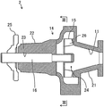
図2は、ウォータポンプ2の構成を示す断面図である。   FIG. 2 is a cross-sectional view showing the configuration of the water pump 2.

図2に示すように、ウォータポンプ2は、主として、吸入口11と吐出口12(図3(a)に記載)と収納室13(図3(a)に記載)とを有するポンプハウジング14(ハウジングの一例)と、冷却水を圧送するインペラ15と、インペラ15と一体回転するシャフト16と、を有する。   As shown in FIG. 2, the water pump 2 mainly includes a pump housing 14 (having a suction port 11, a discharge port 12 (described in FIG. 3A), and a storage chamber 13 (described in FIG. 3A). An example of a housing), an impeller 15 that pumps cooling water, and a shaft 16 that rotates integrally with the impeller 15.

ウォータポンプ2は、ポンプハウジング14が例えばエンジン1のシリンダブロック17の一側面に固定される。   As for the water pump 2, the pump housing 14 is fixed to one side surface of the cylinder block 17 of the engine 1, for example.

図2に示すように、ポンプハウジング14は、シリンダブロック17に固定される第1ハウジング部材21と、第1ハウジング部材21に固定される第2ハウジング部材22と、を有する。   As shown in FIG. 2, the pump housing 14 has a first housing member 21 fixed to the cylinder block 17 and a second housing member 22 fixed to the first housing member 21.

第1ハウジング部材21には、冷却水を吸入するための吸入口11が形成される。   The first housing member 21 is formed with a suction port 11 for sucking cooling water.

第2ハウジング部材22には、シャフト16を回転可能に支持する軸受部23が形成される。   The second housing member 22 is formed with a bearing portion 23 that rotatably supports the shaft 16.

軸受部23は、第2ハウジング部材22の略中央部に円柱状空間を呈する貫通孔である。そして、シャフト16は、略円柱状に形成され、外径が軸受部23の内径と略同じである。   The bearing portion 23 is a through-hole that presents a cylindrical space at a substantially central portion of the second housing member 22. The shaft 16 is formed in a substantially cylindrical shape, and the outer diameter is substantially the same as the inner diameter of the bearing portion 23.

なお、以降の説明では、特段の記載がない場合には、シャフト16の回転軸方向を単に軸方向と称し、シャフト16の径方向を単に径方向と称す。   In the following description, unless otherwise specified, the rotational axis direction of the shaft 16 is simply referred to as an axial direction, and the radial direction of the shaft 16 is simply referred to as a radial direction.

また、図2に示すように、第1ハウジング部材21と第2ハウジング部材22を固定することで、第1ハウジング部材21と第2ハウジング部材22の間にインペラ15を配設するためのポンプ室24が形成される。言い換えると、インペラ15は、ポンプ室24に配設される。   Further, as shown in FIG. 2, a pump chamber for disposing the impeller 15 between the first housing member 21 and the second housing member 22 by fixing the first housing member 21 and the second housing member 22. 24 is formed. In other words, the impeller 15 is disposed in the pump chamber 24.

ポンプ室24は、略円錐状に形成され、吸入口11と連通するように形成されている。そして、ポンプ室24は、軸方向から投影した際、内壁が略インボリュート曲線を呈する。   The pump chamber 24 is formed in a substantially conical shape and is formed so as to communicate with the suction port 11. And when the pump chamber 24 projects from an axial direction, an inner wall exhibits a substantially involute curve.

シャフト16の第1ハウジング部材21側の一方の端部には、シャフト16と一体回転するインペラ15が圧入されている。そして、シャフト16の他方の端部には、プーリシート25が圧入されている。   An impeller 15 that rotates integrally with the shaft 16 is press-fitted into one end portion of the shaft 16 on the first housing member 21 side. A pulley sheet 25 is press-fitted into the other end of the shaft 16.

インペラ15は、略円環板状を呈し、第1ハウジング部材21側の面に放射状に並べられた羽部26を有する。   The impeller 15 has a substantially annular plate shape and includes wing portions 26 arranged radially on the surface on the first housing member 21 side.

プーリシート25には、駆動プーリ(図示しない)が固定されている。そして、駆動プーリには、動力を伝達するタイミングベルト(図示しない)が装着される。   A driving pulley (not shown) is fixed to the pulley sheet 25. A timing belt (not shown) for transmitting power is attached to the drive pulley.

エンジン1の回転駆動力は、図示しないタイミングベルト、駆動プーリ、プーリシート25を介してシャフト16まで伝達される。これにより、エンジン1の駆動時において、ウォータポンプ2インペラ15がシャフト16と共に一体回転することで、ウォータポンプ2は、エンジン1に対して冷却水の圧送を行い、冷却水路3の冷却水を循環させる。   The rotational driving force of the engine 1 is transmitted to the shaft 16 through a timing belt, a driving pulley, and a pulley sheet 25 (not shown). Thereby, when the engine 1 is driven, the water pump 2 impeller 15 rotates together with the shaft 16 so that the water pump 2 pumps the cooling water to the engine 1 and circulates the cooling water in the cooling water passage 3. Let

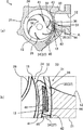
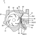
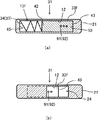
図3(a)は、図2のIII−III断面図である。   Fig.3 (a) is III-III sectional drawing of FIG.

図3(a)に示すように、第1ハウジング部材21は、冷却水を吐出する吐出口12と、流量調整装置31と、をさらに有する。   As shown in FIG. 3A, the first housing member 21 further includes a discharge port 12 that discharges cooling water and a flow rate adjusting device 31.

インペラ15は、シャフト16の回転に伴い、図3(a)の矢印Wに示すように、時計回りに回転する。   As the shaft 16 rotates, the impeller 15 rotates clockwise as indicated by an arrow W in FIG.

ポンプ室24は、インペラ15に沿うように形成され、インペラ15により流動する冷却水を吐出口12へ導く水切り部32が内壁に形成される。   The pump chamber 24 is formed along the impeller 15, and a draining portion 32 that guides cooling water flowing by the impeller 15 to the discharge port 12 is formed on the inner wall.

水切り部32は、径方向においてインペラ15に最も近接している。さらに、ポンプ室24の内壁は、径方向において水切り部32でインペラ15に最も近接し、インペラ15の回転方向に進むにつれて、インペラ15から離れるインボリュート曲線を呈する。   The draining portion 32 is closest to the impeller 15 in the radial direction. Further, the inner wall of the pump chamber 24 is closest to the impeller 15 at the draining portion 32 in the radial direction, and exhibits an involute curve that moves away from the impeller 15 as the impeller 15 rotates.

吐出口12は、一方がポンプ室24と連通し、他方が冷却水路3の第1流路6と連通する。   One of the discharge ports 12 communicates with the pump chamber 24, and the other communicates with the first flow path 6 of the cooling water channel 3.

次に、流量調整装置31について図3(a)、(b)を用いて説明する。   Next, the flow rate adjusting device 31 will be described with reference to FIGS.

流量調整装置31は、収納室13と、収納室13から進退することで冷却水の圧送量を調整する弁体33と、収納室13に配設され、弁体33を収納室13から突出するよう付勢するコイルバネ34(第1付勢部材の一例)と、収納室13に配設され、弁体33を収納室13へと収納するよう付勢する熱膨張体35(第2付勢部材の一例)と、を有する。   The flow rate adjusting device 31 is disposed in the storage chamber 13, the valve body 33 that adjusts the pumping amount of the cooling water by moving forward and backward from the storage chamber 13, and the valve body 33 protrudes from the storage chamber 13. A coil spring 34 (an example of a first urging member) that urges in such a manner, and a thermal expansion body 35 (a second urging member) that is disposed in the storage chamber 13 and urges the valve body 33 to be stored in the storage chamber 13. Example).

図3(a)に示すように、第1ハウジング部材21には、ポンプ室24の外径側において水切り部32の近傍に略板状の空間を有する収納室13が形成される。詳しくは、収納室13は、第1ハウジング部材21において吐出口12とポンプ室24の境界位置に形成される。そして、収納室13は、軸方向から見た際、ポンプ室24に沿う弧状空間を呈する。   As shown in FIG. 3A, the first housing member 21 is formed with a storage chamber 13 having a substantially plate-like space near the draining portion 32 on the outer diameter side of the pump chamber 24. Specifically, the storage chamber 13 is formed at the boundary position between the discharge port 12 and the pump chamber 24 in the first housing member 21. The storage chamber 13 presents an arcuate space along the pump chamber 24 when viewed from the axial direction.

ここで、収納室13のポンプ室24に沿う方向を長手方向とし、長手方向と交差する方向を短手方向とする。そして、収納室13の軸方向の長さは、吐出口12の軸方向の長さと略同じである。   Here, let the direction along the pump chamber 24 of the storage chamber 13 be a longitudinal direction, and let the direction which cross | intersect a longitudinal direction be a transversal direction. The axial length of the storage chamber 13 is substantially the same as the axial length of the discharge port 12.

さらに、収納室13には、収納室13と吐出口12とを連通する連通部36が形成される。   Further, a communication portion 36 that connects the storage chamber 13 and the discharge port 12 is formed in the storage chamber 13.

連通部36は、第1ハウジング部材21において、吐出口12とポンプ室24との境界位置に形成おける、収納室13おいて吐出口12側の端部に形成される。   The communication portion 36 is formed at the end portion on the discharge port 12 side in the storage chamber 13 that can be formed at the boundary position between the discharge port 12 and the pump chamber 24 in the first housing member 21.

ここで、熱膨張体35は、ワックスやバイメタル等を用いることができる。   Here, the thermal expansion body 35 can use wax, bimetal, or the like.

そして、収納室13には、弁体33と、コイルバネ34の全体と、熱膨張体35の全体と、が収納される。ここで、弁体33は、収納室13に対して進退可能に収納される。また、熱膨張体35は、温度の上昇により体積が膨張し、温度の下降により体積が収縮する。   And in the storage chamber 13, the valve body 33, the whole coil spring 34, and the whole thermal expansion body 35 are accommodated. Here, the valve element 33 is accommodated in the accommodating chamber 13 so as to be able to advance and retract. Further, the thermal expansion body 35 expands in volume as the temperature rises, and contracts in volume as the temperature falls.

弁体33は、収納室13側の基端42(後述する)に突出部41を有し、軸方向から見た際、収納室13に沿う弧状である。また、弁体33は、金属で形成される。そして、弁体33の長手方向の長さは、収納室13の長手方向の長さより短く、弁体33の短手方向の長さは、連通部36の径方向の長さと略同じであり、弁体33の軸方向の長さは、収納室13の軸方向の長さと略同じである。   The valve body 33 has a protruding portion 41 at a base end 42 (described later) on the storage chamber 13 side, and has an arc shape along the storage chamber 13 when viewed from the axial direction. The valve body 33 is made of metal. The length in the longitudinal direction of the valve body 33 is shorter than the length in the longitudinal direction of the storage chamber 13, and the length in the short direction of the valve body 33 is substantially the same as the length in the radial direction of the communication portion 36. The axial length of the valve body 33 is substantially the same as the axial length of the storage chamber 13.

突出部41は、弁体33の長手方向における収納室13側の基端42に形成され、インペラ15側(内径側)に向かって突出する。そして、突出部41の径方向の長さは、収納室13の短手方向と略同じである。   The protruding portion 41 is formed at the base end 42 on the storage chamber 13 side in the longitudinal direction of the valve body 33 and protrudes toward the impeller 15 side (inner diameter side). The length of the protruding portion 41 in the radial direction is substantially the same as the short direction of the storage chamber 13.

ここで、弁体33は、突出部41が形成される一方の端部を基端42とし、他方の端部を先端43とする。また、基端42から先端43に向かう方向を第1方向とし、先端43から基端42に向かう方向を第2方向とする。   Here, in the valve body 33, one end where the protrusion 41 is formed is a base end 42, and the other end is a front end 43. In addition, a direction from the base end 42 toward the tip end 43 is a first direction, and a direction from the tip end 43 toward the base end 42 is a second direction.

図3(b)は、図3(a)のA部の拡大図である。   FIG.3 (b) is an enlarged view of the A section of Fig.3 (a).

図3(b)に示すように、弁体33を収納室13内に配設すると、突出部41が収納室13の周方向の内壁と当接する。そのため、収納室13は、弁体33の突出部41により吐出口12側の第1収納部44と、第2収納部45と、に区画される。また、第1収納部44及び第2収納部45は、弁体33が周方向に沿うように形成された収納室13の内壁にガイドされ、周方向に移動することで体積が増減する。そして、第1収納部44の体積が増加すると第2収納部45の体積が減少し、第1収納部44の体積が減少すると第2収納部の体積が増加する。   As shown in FIG. 3B, when the valve body 33 is disposed in the storage chamber 13, the protruding portion 41 comes into contact with the inner wall in the circumferential direction of the storage chamber 13. Therefore, the storage chamber 13 is partitioned into a first storage portion 44 on the discharge port 12 side and a second storage portion 45 by the protruding portion 41 of the valve body 33. Further, the first storage portion 44 and the second storage portion 45 are guided by the inner wall of the storage chamber 13 formed so that the valve body 33 extends along the circumferential direction, and the volume increases or decreases by moving in the circumferential direction. And if the volume of the 1st storage part 44 increases, the volume of the 2nd storage part 45 will decrease, and if the volume of the 1st storage part 44 decreases, the volume of the 2nd storage part will increase.

図3(a)に示すように、第2収納部45には、弾性変形された状態でコイルバネ34が配設される。そのため、コイルバネ34は、弾性力により突出部41を第1方向に向かって付勢する。その結果、弁体33は、第1方向に突出し、先端43が吐出口12の内壁と当接することで閉弁状態になる。   As shown in FIG. 3A, the second storage portion 45 is provided with a coil spring 34 in an elastically deformed state. Therefore, the coil spring 34 biases the protrusion 41 toward the first direction by an elastic force. As a result, the valve element 33 protrudes in the first direction, and the tip end 43 comes into contact with the inner wall of the discharge port 12 to be in a closed state.

図3(b)に示すように、第1収納部44には、合成ゴム等の弾性体で形成される皮膜46に包まれるようにして熱膨張体35が配設される。   As shown in FIG. 3B, a thermal expansion body 35 is disposed in the first storage portion 44 so as to be wrapped in a film 46 formed of an elastic body such as synthetic rubber.

熱膨張体35は、温度の上昇に伴い体積を増大させ、温度の下降に伴い体積を減少させる性質を持つ。そして、常温の熱膨張体35の体積は、弁体33が閉弁している場合の第1収納部44の体積以下になるよう設定されている。また、熱膨張体35は、所定の温度以上になると体積が閉弁している場合の第1収納部44の体積以上になるよう設定される。   The thermal expansion body 35 has a property of increasing the volume with increasing temperature and decreasing the volume with decreasing temperature. And the volume of the thermal expansion body 35 of normal temperature is set so that it may become below the volume of the 1st accommodating part 44 in case the valve body 33 is valve-closing. Moreover, the thermal expansion body 35 is set so that when it becomes more than predetermined temperature, it will become more than the volume of the 1st accommodating part 44 in the case where the volume is closed.

弾性変形しない状態において皮膜46の内部の体積は、常温の熱膨張体35の体積と略同じである。そして、温度の上昇に伴い熱膨張体35の体積が増加した場合、皮膜46の内部体積は、熱膨張対35の体積と略同じになるように弾性変形する。   In the state where the elastic deformation does not occur, the volume inside the coating 46 is substantially the same as the volume of the thermal expansion body 35 at room temperature. When the volume of the thermal expansion body 35 increases as the temperature rises, the internal volume of the coating 46 is elastically deformed so as to be substantially the same as the volume of the thermal expansion pair 35.

皮膜46は、熱膨張体35を包むように配設される。そのため、冷却水が連通部36を介して収納室13に侵入しても、熱膨張体(ワックス等の液体)35は、冷却水等と混合することが防がれる。   The film 46 is disposed so as to wrap the thermal expansion body 35. Therefore, even if the cooling water enters the storage chamber 13 through the communication portion 36, the thermal expansion body (liquid such as wax) 35 is prevented from being mixed with the cooling water or the like.

次に、本実施形態のウォータポンプ2の動作を説明する。   Next, operation | movement of the water pump 2 of this embodiment is demonstrated.

エンジン1が駆動を始めると、エンジン1の回転駆動力は、タイミングベルトと、駆動プーリと、プーリシート25と、を介してシャフト16に伝達される。そして、シャフト16の回転に伴いインペラ15が矢印W方向に回転する。ここで、インペラ15は、エンジン1駆動時は、常に同期して回転を続ける。   When the engine 1 starts driving, the rotational driving force of the engine 1 is transmitted to the shaft 16 via the timing belt, the driving pulley, and the pulley seat 25. As the shaft 16 rotates, the impeller 15 rotates in the arrow W direction. Here, the impeller 15 always keeps rotating in synchronism when the engine 1 is driven.

インペラ15が回転を始めると、インペラ15は、ポンプ室24の冷却水を径方向外側に向かって圧送する。さらに、径方向外側に向かって圧送された冷却水は、ポンプ室24の水切り部32により、ポンプ室24の内壁に沿うようにして、吐出口12に導かれる。   When the impeller 15 starts rotating, the impeller 15 pumps the cooling water in the pump chamber 24 outward in the radial direction. Furthermore, the cooling water pumped toward the outside in the radial direction is guided to the discharge port 12 along the inner wall of the pump chamber 24 by the draining portion 32 of the pump chamber 24.

また、図2に示す吸入口11の冷却水をインペラ15の回転によりポンプ室24に圧送するため、ポンプ室24は、冷却水の圧力が上昇する。   Further, since the cooling water in the suction port 11 shown in FIG. 2 is pumped to the pump chamber 24 by the rotation of the impeller 15, the pressure of the cooling water in the pump chamber 24 increases.

次に、本実施形態の流量調整装置31の動作を説明する。   Next, operation | movement of the flow volume adjustment apparatus 31 of this embodiment is demonstrated.

図3(a)に示すように、エンジン1が始動直後等でシリンダブロック17の温度が比較的低い場合、弁体33は、コイルバネ34が突出部41を第1方向に付勢することにより、収納室13から突出しており、弁体33の先端43が吐出口12の内壁に当接した状態である。そのため、流量調整装置31は、弁体33が吐出口12とポンプ室24とを分断することで閉弁状態となる。   As shown in FIG. 3A, when the temperature of the cylinder block 17 is relatively low immediately after the engine 1 is started, the valve body 33 is configured such that the coil spring 34 biases the protruding portion 41 in the first direction. It protrudes from the storage chamber 13, and the tip 43 of the valve element 33 is in contact with the inner wall of the discharge port 12. Therefore, the flow rate adjusting device 31 is in a closed state by the valve body 33 dividing the discharge port 12 and the pump chamber 24.

その結果、ポンプ室24内の冷却水は、弁体33により吐出口12から吐出しないため圧力が上昇する。   As a result, the cooling water in the pump chamber 24 is not discharged from the discharge port 12 by the valve body 33, so the pressure rises.

エンジン1が駆動することで、シリンダブロック17の温度が上昇し、シリンダブロック17の熱が第1ハウジング部材21を介して熱膨張体35に伝達する。そして、熱膨張体35の温度が上昇することで、第1収納部44内の熱膨張体35の体積が増大する。   When the engine 1 is driven, the temperature of the cylinder block 17 rises, and the heat of the cylinder block 17 is transmitted to the thermal expansion body 35 via the first housing member 21. And the volume of the thermal expansion body 35 in the 1st accommodating part 44 increases because the temperature of the thermal expansion body 35 rises.

図4は、図3(a)の弁体33が収納された断面図である。   FIG. 4 is a cross-sectional view in which the valve element 33 of FIG.

図4に示すように、弁体33が閉弁時の第1収納部44の体積より、熱膨張体35の体積が大きくなる場合、熱膨張体35は、コイルバネ34の付勢力に抗して弁体33を第2方向に付勢する。言い換えると、熱膨張体35は、温度の上昇に伴い体積が増大することで付勢力が増大し、コイルバネ34の付勢力に抗して弁体33を第2方向に付勢する。   As shown in FIG. 4, when the volume of the thermal expansion body 35 is larger than the volume of the first storage portion 44 when the valve body 33 is closed, the thermal expansion body 35 resists the biasing force of the coil spring 34. The valve body 33 is urged in the second direction. In other words, the thermal expansion body 35 increases in volume as the temperature rises, so that the urging force increases, and urges the valve body 33 in the second direction against the urging force of the coil spring 34.

この際、弁体33が第2方向に移動することで、第1収納部44の体積は、熱膨張体35の体積と略同じになるまで増加する。そして、第2収納部45の体積は、第1収納部44の増大した体積と略同じ体積が減少する。   At this time, when the valve body 33 moves in the second direction, the volume of the first storage portion 44 increases until it becomes substantially the same as the volume of the thermal expansion body 35. And the volume of the 2nd accommodating part 45 decreases substantially the same volume as the volume where the 1st accommodating part 44 increased.

詳しくは、第1収納部44は、収納室13の内壁と弁体33により構成されている。そして、弁体33が収納室13に進退可能に収納されているため、第1収納部44内の熱膨張体35の体積が増加した場合、第1収納部44は、弁体33が第2方向に動くことで体積を増大させる。   Specifically, the first storage portion 44 is configured by the inner wall of the storage chamber 13 and the valve body 33. And since the valve body 33 is stored in the storage chamber 13 so as to be able to advance and retract, when the volume of the thermal expansion body 35 in the first storage section 44 increases, the first storage section 44 has the valve body 33 in the second storage section. Increase volume by moving in the direction.

言い換えると、熱膨張体35は、温度の上昇に伴い体積が増大することで第2方向への付勢力が増大し、弁体33を収納室13に収納を開始する。   In other words, the thermal expansion body 35 increases in volume as the temperature rises, so that the urging force in the second direction increases, and the valve body 33 starts to be stored in the storage chamber 13.

そして、弁体33は、熱膨張体35の第2方向の付勢力により開弁を始める。   Then, the valve body 33 starts to open by the urging force of the thermal expansion body 35 in the second direction.

そして、インペラ15により圧力が高まった冷却水は、弁体33が開弁を開始したため、吐出口12からの吐出が開始する。言い換えると、冷却水は、ポンプハウジング14内を通過していき、吐出口12から圧送されていく。   The cooling water whose pressure has been increased by the impeller 15 starts to be discharged from the discharge port 12 because the valve element 33 has started to open. In other words, the cooling water passes through the pump housing 14 and is pumped from the discharge port 12.

さらに、ウォータポンプ2から圧送された冷却水は、冷却水路3をとおりエンジン1と熱交換を行う。   Further, the cooling water pumped from the water pump 2 exchanges heat with the engine 1 through the cooling water passage 3.

そのため、冷却水は、エンジン1と熱交換することで温度が上昇する。   Therefore, the temperature of the cooling water rises by exchanging heat with the engine 1.

流量調整装置31が開弁し、冷却水が流れ始めると、熱膨張体35は、ポンプ室24内の冷却水と熱交換を行う。そのため、冷却水の温度の上昇に伴い熱膨張体35の温度が上昇するため、熱膨張体35の体積の増大していき、弁体33の開弁度が大きくなっていく。その結果、ウォータポンプ2は、冷却水の圧送する量が増大する。   When the flow rate adjusting device 31 is opened and the cooling water starts to flow, the thermal expansion body 35 exchanges heat with the cooling water in the pump chamber 24. Therefore, since the temperature of the thermal expansion body 35 rises with the rise in the temperature of the cooling water, the volume of the thermal expansion body 35 increases and the valve opening degree of the valve body 33 increases. As a result, the water pump 2 increases the amount of cooling water pumped.

図4に示すように、弁体33の開弁度が大きくなり全開状態になった場合、弁体33は、全体が収納室13に完全に収納される。   As shown in FIG. 4, when the valve opening degree of the valve body 33 is increased and the valve body 33 is fully opened, the entire valve body 33 is completely stored in the storage chamber 13.

上記実施形態によれば、以下に示す効果を得ることができる。
(1)上記構成によれば、弁体33が全閉状態の場合、弁体33によりポンプ室24と吐出口12とを分断しているため、ウォータポンプ2は、冷却水を吐出しない。そのため、エンジン1は、冷却水による熱交換が抑制されるため、エンジン1の暖機を促進することができる
(2)上記構成によれば、弁体33が全開状態の場合、弁体33は、収納室13に全体が完全に収納されるため、冷却水は、インペラ15が冷却水を圧送する際、弁体33からうける流動抵抗を低減することができる。そのため、ウォータポンプ2の圧送効率が向上する。
(3)上記構成によれば、収納室13は、略円錐形のポンプ室24に沿うようにして形成される。そして、ポンプ室24に沿うように形成された収納室13は、収納室13が略直方体に形成された場合と比べて、ポンプ室24との距離が近くなる。そのため、第1ハウジング部材21は、ポンプ室24と収納室13との距離が小さくなるため小型化することができる。
(4)上記構成によれば、弁体33は、熱膨張体35の温度の上昇と下降に合わせて開弁度が調整される。そして、熱膨張体35は、冷却水と熱交換により温度が上昇及び下降する。さらに、冷却水の温度は、エンジン1の温度に合わせて上昇する。加えて、ポンプ室24に沿うように形成された収納室13内に配設された熱膨張体35は、収納室13が略直方体に形成された場合と比べて、ポンプ室24内の冷却水との距離が近くなるため、冷却水と熱交換がしやすくなる。
According to the above embodiment, the following effects can be obtained.
(1) According to the above configuration, when the valve body 33 is in the fully closed state, the water pump 2 does not discharge cooling water because the pump chamber 24 and the discharge port 12 are separated by the valve body 33. Therefore, since the heat exchange by the cooling water is suppressed, the engine 1 can promote the warm-up of the engine 1 (2) According to the above configuration, when the valve body 33 is fully opened, Since the whole is completely stored in the storage chamber 13, the cooling water can reduce the flow resistance received from the valve element 33 when the impeller 15 pumps the cooling water. Therefore, the pumping efficiency of the water pump 2 is improved.
(3) According to the above configuration, the storage chamber 13 is formed along the substantially conical pump chamber 24. The storage chamber 13 formed along the pump chamber 24 is closer to the pump chamber 24 than the storage chamber 13 is formed in a substantially rectangular parallelepiped. Therefore, the first housing member 21 can be reduced in size because the distance between the pump chamber 24 and the storage chamber 13 is reduced.
(4) According to the above configuration, the valve opening degree of the valve body 33 is adjusted in accordance with the rise and fall of the temperature of the thermal expansion body 35. And the temperature of the thermal expansion body 35 rises and falls by heat exchange with cooling water. Further, the temperature of the cooling water rises in accordance with the temperature of the engine 1. In addition, the thermal expansion body 35 disposed in the storage chamber 13 formed along the pump chamber 24 has cooling water in the pump chamber 24 as compared with the case where the storage chamber 13 is formed in a substantially rectangular parallelepiped. Therefore, heat exchange with the cooling water is facilitated.

それらのため、熱膨張体35は、エンジン1の温度の上昇に合わせて、温度が上昇した冷却水と熱交換がしやすい。その結果、エンジン1の温度の上昇に合わせて、熱膨張体35が追従して温度が上昇するため、弁体33は、熱膨張体35により開弁度を応答性よく調整できる。
(5)上記構成によれば、収納室13内に弁体33の移動を行うコイルバネ34と、熱膨張体35と、が配設される。そのため、収納室13は、外部と連通する部位を必要としない。そのため、冷却水が外部に漏れるのを抑制するためのシール部材等が必要ない。
Therefore, the thermal expansion body 35 easily exchanges heat with the cooling water whose temperature has increased in accordance with the increase in the temperature of the engine 1. As a result, as the temperature of the engine 1 rises, the thermal expansion body 35 follows and the temperature rises. Therefore, the valve body 33 can adjust the valve opening degree with high responsiveness by the thermal expansion body 35.
(5) According to the above configuration, the coil spring 34 that moves the valve body 33 and the thermal expansion body 35 are disposed in the storage chamber 13. Therefore, the storage chamber 13 does not require a portion communicating with the outside. Therefore, there is no need for a seal member or the like for suppressing cooling water from leaking to the outside.

また、収納室13内にコイルバネ34の全体と熱膨張体35の全体が配設されるため、コイルバネ34及び熱膨張体35は、冷却水が流れる際に、冷却水の障害になることを抑制することができる。
(6)上記構成によれば、熱膨張体が皮膜に包まれているため、熱膨張体が冷却水と混合することを抑制することができる。
(第2実施形態)
以下、ウォータポンプ2の第2実施形態について、図5及び図6を参照して説明する。なお、第2実施形態は、第1実施形態と比較したときに、吐出口12aと、流量調整装置31aの構成が異なる。このため、第1実施形態と共通する部材構成については、同一の符号を付し、説明を省略又は簡略するものとする。
Moreover, since the whole coil spring 34 and the whole thermal expansion body 35 are arrange | positioned in the storage chamber 13, the coil spring 34 and the thermal expansion body 35 suppress that it becomes the obstruction | occlusion of cooling water when cooling water flows. can do.
(6) According to the said structure, since a thermal expansion body is wrapped in the membrane | film | coat, it can suppress that a thermal expansion body mixes with cooling water.
(Second Embodiment)
Hereinafter, 2nd Embodiment of the water pump 2 is described with reference to FIG.5 and FIG.6. The second embodiment differs from the first embodiment in the configuration of the discharge port 12a and the flow rate adjusting device 31a. For this reason, about the member structure which is common in 1st Embodiment, the same code | symbol is attached | subjected and description shall be abbreviate | omitted or simplified.

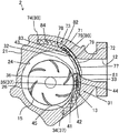
図5は、図3の(a)における第2実施形態のウォータポンプの構成を示す要所部分断面図である。   FIG. 5 is a fragmentary partial cross-sectional view showing the configuration of the water pump according to the second embodiment in FIG.

収納室13aは、第1実施形態と略同じ形状をし、収納室13aの軸方向の長さは、吐出口12aの軸方向の長さよりも長い。また、弁体33aの軸方向の長さは、収納室13aの軸方向の長さと略同じである。   The storage chamber 13a has substantially the same shape as that of the first embodiment, and the axial length of the storage chamber 13a is longer than the axial length of the discharge port 12a. The axial length of the valve element 33a is substantially the same as the axial length of the storage chamber 13a.

図5に示すように、第1ハウジング部材の吐出口12aとポンプ室24との境界位置には、軸方向において弁体33aの移動の軌跡上と重なり合う第1溝部51と、弁体33aの先端43と当接する第2溝部52と、が形成される。   As shown in FIG. 5, at the boundary position between the discharge port 12a of the first housing member and the pump chamber 24, the first groove portion 51 that overlaps the locus of movement of the valve body 33a in the axial direction, and the tip of the valve body 33a The second groove portion 52 is formed in contact with the second groove portion 52.

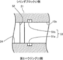
図6は、図5のVI−VI断面図である。   6 is a cross-sectional view taken along the line VI-VI in FIG.

図6に示すように、第1溝部51は、第2ハウジング部材22側の第1溝部51aと、シリンダブロック17側の第1溝部51bと、を有する。   As shown in FIG. 6, the first groove 51 includes a first groove 51 a on the second housing member 22 side and a first groove 51 b on the cylinder block 17 side.

第1溝部51の軸方向の長さは、弁体33aの軸方向の長さから吐出口12aの軸方向の長さを引いた長さである。言い換えると、第1溝部51の軸方向の長さと吐出口12aの軸方向の長さを足した長さは、弁体33aの軸方向の長さと略同じである。   The length of the first groove 51 in the axial direction is a length obtained by subtracting the length of the discharge port 12a in the axial direction from the length of the valve body 33a in the axial direction. In other words, the length obtained by adding the axial length of the first groove 51 and the axial length of the discharge port 12a is substantially the same as the axial length of the valve element 33a.

そのため、収納室13aから突出している弁体33aは、軸方向における両端部が第1溝部51内にガイドされ移動する。   Therefore, the valve body 33a protruding from the storage chamber 13a moves while being guided in the first groove 51 at both ends in the axial direction.

第2溝部52は、吐出口12aとポンプ室24の境界位置において、弁体33aの先端43が当接する領域に形成される。そして、第2溝部52は、軸方向の長さが弁体33aの軸方向の長さと略同じである。   The second groove portion 52 is formed in a region where the tip 43 of the valve element 33a contacts at the boundary position between the discharge port 12a and the pump chamber 24. The second groove 52 has an axial length that is substantially the same as the axial length of the valve element 33a.

そのため、弁体33aは、先端43が第2溝部52内に到達することで閉弁状態となる。   Therefore, the valve body 33a is closed when the tip 43 reaches the second groove 52.

上記実施形態によれば、第1実施形態の(1)から(6)の効果に加えて以下に示す効果を得ることができる。   According to the said embodiment, in addition to the effect of (1) to (6) of 1st Embodiment, the effect shown below can be acquired.

(7)上記構成によれば、収納室13aから突出した弁体33aは、軸方向の両端が第1溝部51にガイドされている。そのため、弁体33aは、安定して進退し、動作することができる。また、弁体33aは、ポンプ室24の高圧の冷却水から受ける力を第1溝部51により受けることができる。その結果、弁体33aは、冷却水から受ける負荷を軽減することができる。   (7) According to the above configuration, both ends in the axial direction of the valve body 33 a protruding from the storage chamber 13 a are guided by the first groove portion 51. Therefore, the valve body 33a can move forward and backward stably and operate. Further, the valve body 33 a can receive the force received from the high-pressure cooling water in the pump chamber 24 by the first groove portion 51. As a result, the valve body 33a can reduce the load received from the cooling water.

(8)上記構成によれば、弁体33aは、先端43が第2溝部52に当接し閉弁状態となる。そのため、弁体33aは、ポンプ室24の高圧の冷却水から受ける力を第2溝部52により受けることができる。その結果、弁体33aは、冷却水から受ける負荷を軽減することができる。
(第3実施形態)
以下、ウォータポンプ2の第3実施形態について、図7を参照して説明する。なお、第3実施形態は、第1実施形態と比較したときに、弁体33bと、収納室13bと、の構成が異なる。このため、第1実施形態と共通する部材構成については、同一の符号を付し、説明を省略又は簡略するものとする。
(8) According to the above configuration, the valve element 33a is in the closed state with the tip 43 abutting against the second groove 52. Therefore, the valve body 33 a can receive the force received from the high-pressure cooling water in the pump chamber 24 by the second groove portion 52. As a result, the valve body 33a can reduce the load received from the cooling water.
(Third embodiment)
Hereinafter, a third embodiment of the water pump 2 will be described with reference to FIG. In addition, when compared with 1st Embodiment, 3rd Embodiment differs in the structure of the valve body 33b and the storage chamber 13b. For this reason, about the member structure which is common in 1st Embodiment, the same code | symbol is attached | subjected and description shall be abbreviate | omitted or simplified.

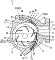
図7は、図3の(a)における第3実施形態のウォータポンプの構成を示す要所部分断面図である。   FIG. 7 is a partial fragmentary sectional view showing the configuration of the water pump of the third embodiment in FIG.

図7に示すように、弁体33bは、弁体33bの先端43には、径方向においてインペラ15側(内径側)に向かって突出している第2突出部61が形成されているが第1実施形態と略同様の形状を有する。   As shown in FIG. 7, in the valve body 33b, the tip 43 of the valve body 33b is formed with a second protrusion 61 that protrudes toward the impeller 15 side (inner diameter side) in the radial direction. It has substantially the same shape as the embodiment.

収納室13bは、連通部36に隣接して形成され、全開時に第2突出部61を収納するための凹部62を有する。   The storage chamber 13 b is formed adjacent to the communication portion 36 and has a recess 62 for storing the second protrusion 61 when fully opened.

凹部62は、径方向、周方向、軸方向の長さが第2突出部61の径方向、周方向、軸方向の長さと略同じである。   The recess 62 has substantially the same length in the radial direction, the circumferential direction, and the axial direction as the length of the second protrusion 61 in the radial direction, the circumferential direction, and the axial direction.

全開時において、第2突出部61は、収納室13bの凹部62に配設される。そのため、弁体33bは、全開時に全体が完全に収納室13bに収納される。   When fully opened, the second protrusion 61 is disposed in the recess 62 of the storage chamber 13b. Therefore, the entire valve body 33b is completely stored in the storage chamber 13b when fully opened.

上記実施形態によれば、第1実施形態の(1)から(6)の効果に加えて以下に示す効果を得ることができる。
(9)上記構成によれば、ポンプ室24の内壁に沿うように流れる冷却水が第2突出部61をインペラ15の回転方向に押圧するため、弁体33bは、冷却水の水圧により第2方向の力を受ける。そのため、弁体33bは、コイルバネ34の付勢力及び熱膨張体35の付勢力以外の水圧を用いて開弁のための付勢力が付与される。その結果、弁体33bを付勢する付勢要素が増えるため、弁体33bの開度の調整において、自由度があがる。
According to the said embodiment, in addition to the effect of (1) to (6) of 1st Embodiment, the effect shown below can be acquired.
(9) According to the above configuration, the cooling water flowing along the inner wall of the pump chamber 24 presses the second protrusion 61 in the rotation direction of the impeller 15, so that the valve body 33 b is Receive direction force. Therefore, the valve body 33b is given a biasing force for opening the valve using water pressure other than the biasing force of the coil spring 34 and the biasing force of the thermal expansion body 35. As a result, the number of urging elements for urging the valve body 33b increases, so that the degree of freedom increases in adjusting the opening degree of the valve body 33b.

(第4実施形態)
以下、ウォータポンプ2の第4実施形態について、図8を参照して説明する。なお、第4実施形態は、第3実施形態と比較したときに、収納室13cと、弁体33cと、の構成が異なる。このため、第3実施形態と共通する部材構成については、同一の符号を付し、説明を省略又は簡略するものとする。
(Fourth embodiment)
Hereinafter, 4th Embodiment of the water pump 2 is described with reference to FIG. In addition, when compared with 3rd Embodiment, 4th Embodiment differs in the structure of the storage chamber 13c and the valve body 33c. For this reason, about the member structure which is common in 3rd Embodiment, the same code | symbol is attached | subjected and description shall be abbreviate | omitted or simplified.

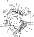
図8は、図3の(a)における第4実施形態のウォータポンプの構成を示す要所部分断面図である。   FIG. 8 is a fragmentary partial cross-sectional view showing the configuration of the water pump of the fourth embodiment in FIG.

図8に示すように、第1ハウジング部材には、ポンプ室24の外径側において、ポンプ室24の内壁とインペラ15が最も離れた領域に収納室13cが形成される。詳しくは、収納室13cは、第1ハウジング部材21において吐出口12とポンプ室24の境界位置で、第1実施形態と対向する位置に形成される。   As shown in FIG. 8, in the first housing member, a storage chamber 13 c is formed in a region where the inner wall of the pump chamber 24 and the impeller 15 are farthest from each other on the outer diameter side of the pump chamber 24. Specifically, the storage chamber 13c is formed at a position facing the first embodiment at the boundary between the discharge port 12 and the pump chamber 24 in the first housing member 21.

そして、連通部36は、収納室13cの吐出口側に形成される。そして、収納室13cが第1実施形態と対向する位置に形成されるため、弁体33cは、第1実施形態とは、反対方向に進退する。その結果、弁体33cにおいては、基端42から先端43に向かう方向を第2方向とし、先端43から基端42に向かう方向を第1方向とする。   And the communication part 36 is formed in the discharge outlet side of the storage chamber 13c. And since the storage chamber 13c is formed in the position facing 1st Embodiment, the valve body 33c advances and retreats in the opposite direction with respect to 1st Embodiment. As a result, in the valve body 33c, the direction from the proximal end 42 toward the distal end 43 is defined as a second direction, and the direction from the distal end 43 toward the proximal end 42 is defined as a first direction.

第1実施形態と同様に収納室13cには、弁体33cが配設される。   Similar to the first embodiment, a valve body 33c is disposed in the storage chamber 13c.

そして、弁体33cの先端43には、径方向においてインペラ15側(内径側)に向かって突出している第2突出部61cが形成されている。   And the 2nd protrusion part 61c which protrudes toward the impeller 15 side (inner diameter side) in the radial direction is formed in the front-end | tip 43 of the valve body 33c.

収納室13cには、全開時に第2突出部61cを収納するための凹部62cが形成される。   The storage chamber 13c is formed with a recess 62c for storing the second protrusion 61c when fully opened.

凹部62cは、収納部13cの連通部36の近傍に形成され、径方向、周方向、軸方向の長さが第2突出部61cの径方向、周方向、軸方向の長さと略同じである。   The concave portion 62c is formed in the vicinity of the communication portion 36 of the storage portion 13c, and the lengths in the radial direction, the circumferential direction, and the axial direction are substantially the same as the lengths in the radial direction, the circumferential direction, and the axial direction of the second protrusion 61c. .

全開時において、第2突出部61cは、収納室13cの凹部62cに配設される。そのため、弁体33cは、全開時に全体が完全に収納室13cに収納される。   When fully opened, the second protrusion 61c is disposed in the recess 62c of the storage chamber 13c. Therefore, the entire valve body 33c is completely stored in the storage chamber 13c when fully opened.

上記実施形態によれば、第1実施形態の(1)から(6)の効果に加えて以下に示す効果を得ることができる。
(10)上記構成によれば、ポンプ室24の内壁に沿うように流れる冷却水が第2突出部61cをインペラ15の回転方向に押圧するため、弁体33cは、冷却水の水圧により第1方向の付勢力を受ける。
According to the said embodiment, in addition to the effect of (1) to (6) of 1st Embodiment, the effect shown below can be acquired.
(10) According to the above configuration, the cooling water flowing along the inner wall of the pump chamber 24 presses the second projecting portion 61c in the rotation direction of the impeller 15, so that the valve body 33c has the first pressure due to the water pressure of the cooling water. Receive direction bias.

つまり、弁体33cは、コイルバネ34の付勢力及び熱膨張体35の付勢力以外の水圧を用いて開弁のための付勢力が付与される。その結果、弁体33cを付勢する付勢要素が増えるため、弁体33cの開度の調整において、自由度があがる。
(第5実施形態)
以下、ウォータポンプ2の第5実施形態について、図9を参照して説明する。なお、第5実施形態は、第1実施形態と比較したときに、弁体33dと、収納室13dと、の構成が異なる。このため、第1実施形態と共通する部材構成については、同一の符号を付し、説明を省略又は簡略するものとする。
That is, the urging force for valve opening is applied to the valve body 33c using water pressure other than the urging force of the coil spring 34 and the urging force of the thermal expansion body 35. As a result, the number of urging elements that urge the valve body 33c is increased, and the degree of freedom is increased in adjusting the opening degree of the valve body 33c.
(Fifth embodiment)
Hereinafter, 5th Embodiment of the water pump 2 is described with reference to FIG. The fifth embodiment differs from the first embodiment in the configuration of the valve body 33d and the storage chamber 13d. For this reason, about the member structure which is common in 1st Embodiment, the same code | symbol is attached | subjected and description shall be abbreviate | omitted or simplified.

図9は、図3の(a)における第5実施形態のウォータポンプの構成を示す要所部分断面図である。   FIG. 9 is a partial fragmentary sectional view showing the configuration of the water pump of the fifth embodiment in FIG.

図9に示すように、収納室13dは、水切り部32の近傍に形成され、軸方向から見た際、ポンプ室24に沿わない弧状である。ここで、収納室13dの弧状方向を長手方向とし、長手方向と交差する方向を短手方向とする。   As shown in FIG. 9, the storage chamber 13 d is formed in the vicinity of the draining portion 32 and has an arc shape that does not follow the pump chamber 24 when viewed from the axial direction. Here, the arcuate direction of the storage chamber 13d is a longitudinal direction, and the direction intersecting the longitudinal direction is a short direction.

連通部36は、収納室13dにおいて吐出口12側の端部に形成される。そして、連通部36の軸方向の長さは、吐出口12及び収納室13dの軸方向の長さと略同じである。   The communication portion 36 is formed at the end on the discharge port 12 side in the storage chamber 13d. The axial length of the communication portion 36 is substantially the same as the axial length of the discharge port 12 and the storage chamber 13d.

弁体33dは、弾性体で形成され、軸方向から見た際、収納室13dに沿う弧状である。そして、弁体33dは、長手方向の長さが収納室13dの長手方向の長さより短く、短手方向の長さが連通部36の径方向の長さと略同じであり、軸方向の長さが収納室13dの軸方向の長さと略同じである。   The valve body 33d is formed of an elastic body and has an arc shape along the storage chamber 13d when viewed from the axial direction. The valve body 33d has a length in the longitudinal direction shorter than the length in the longitudinal direction of the storage chamber 13d, the length in the short direction is substantially the same as the length in the radial direction of the communication portion 36, and the length in the axial direction. Is substantially the same as the axial length of the storage chamber 13d.

また、弁体33dは、突出部41を有する。   Further, the valve body 33 d has a protruding portion 41.

そして、突出部41は、弁体33dの長手方向における収納室13d側の端部に形成され、径方向外側に向かって突出する。そして、突出部41の径方向の長さは、収納室13dの短手方向と略同じである。   And the protrusion part 41 is formed in the edge part by the side of the storage chamber 13d in the longitudinal direction of the valve body 33d, and protrudes toward a radial direction outer side. And the length of the radial direction of the protrusion part 41 is substantially the same as the transversal direction of the storage chamber 13d.

次に、本実施形態の流量調整装置31の動作を説明する。   Next, operation | movement of the flow volume adjustment apparatus 31 of this embodiment is demonstrated.

図9に示すように、エンジン1駆動直後等のシリンダブロック17の温度が低い場合、コイルバネ34は、突出部41を第1方向に付勢する。そのため、弁体33dは、図9の点線ILのように、先端43が吐出口12の内壁に当接し、吐出口12とポンプ室24とを分断することで閉弁する。その結果、ポンプ室24の冷却水は、吐出口12から吐出されず、弁体33dによりポンプ室24内に留められるため圧力が上昇する。   As shown in FIG. 9, when the temperature of the cylinder block 17 is low, such as immediately after the engine 1 is driven, the coil spring 34 biases the protrusion 41 in the first direction. Therefore, the valve element 33d is closed by the tip 43 abutting against the inner wall of the discharge port 12 and dividing the discharge port 12 and the pump chamber 24 as indicated by the dotted line IL in FIG. As a result, the cooling water in the pump chamber 24 is not discharged from the discharge port 12 and is retained in the pump chamber 24 by the valve body 33d, so that the pressure increases.

ここで、ポンプ室24の冷却水の圧力が所定の圧力以上になった際、弾性体で形成されている弁体33dは、水圧により冷却水の流動方向に向かって弾性変形する。そのため、ポンプ室24内の冷却水は、吐出口12から圧送され、圧力が下降する。   Here, when the pressure of the cooling water in the pump chamber 24 becomes equal to or higher than a predetermined pressure, the valve body 33d formed of an elastic body is elastically deformed toward the flow direction of the cooling water by the water pressure. Therefore, the cooling water in the pump chamber 24 is pumped from the discharge port 12 and the pressure drops.

また、エンジン1が駆動し、シリンダブロック17の温度が上昇した際の動作は、第1実施形態と同様である。   The operation when the engine 1 is driven and the temperature of the cylinder block 17 rises is the same as in the first embodiment.

上記実施形態によれば、第1実施形態の(1)、(2)、(5)、(6)の効果に加えて以下に示す効果を得ることができる。   According to the said embodiment, in addition to the effect of (1), (2), (5), (6) of 1st Embodiment, the effect shown below can be acquired.

(11)インペラ15は、冷却水が高圧な状態で回転すると、冷却水から受ける負荷が大きくなる。上記構成によれば、インペラ15によりポンプ室24の冷却水の圧力が所定の圧力以上になった際、弾性体である弁体33dが変形することで、ポンプ室24の冷却水は、吐出口12から吐出される。そのため、ポンプ室24の冷却水が所定の圧力以上になることを抑制することができる。その結果、インペラ15は、冷却水が所定の圧力以下の状態で駆動するため、回転する際受ける負荷を軽減することができる。
(第6実施形態)
以下、ウォータポンプ2の第6実施形態について、図10から図12を参照して説明する。なお、第6実施形態は、第1実施形態と比較したときに、新たに第2流量調整装置71が配設される構成が異なる。このため、第1実施形態と共通する部材構成については、同一の符号を付し、説明を省略又は簡略するものとする。
(11) When the impeller 15 rotates while the cooling water is at a high pressure, the load received from the cooling water increases. According to the above configuration, when the pressure of the cooling water in the pump chamber 24 becomes equal to or higher than the predetermined pressure by the impeller 15, the valve body 33d, which is an elastic body, is deformed so that the cooling water in the pump chamber 24 12 is discharged. Therefore, it can suppress that the cooling water of the pump chamber 24 becomes more than predetermined pressure. As a result, since the impeller 15 is driven in a state where the cooling water is equal to or lower than a predetermined pressure, it is possible to reduce the load received when rotating.
(Sixth embodiment)
Hereinafter, a sixth embodiment of the water pump 2 will be described with reference to FIGS. 10 to 12. The sixth embodiment is different from the first embodiment in the configuration in which the second flow rate adjusting device 71 is newly provided. For this reason, about the member structure which is common in 1st Embodiment, the same code | symbol is attached | subjected and description shall be abbreviate | omitted or simplified.

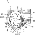
図10は、図3の(a)における第6実施形態のウォータポンプの構成を示す要所部分断面図である。   FIG. 10 is a partial fragmentary sectional view showing the configuration of the water pump of the sixth embodiment in FIG.

図10に示すように、第1ハウジング部材21は、第1実施形態と略同様の流量調整装置31と、第2流量調整装置71と、を有する。   As shown in FIG. 10, the first housing member 21 includes a flow rate adjustment device 31 and a second flow rate adjustment device 71 that are substantially the same as those in the first embodiment.

次に、第2流量調整装置71について図10を用いて説明する。   Next, the second flow rate adjusting device 71 will be described with reference to FIG.

第2流量調整装置71は、第2収納室73と、第2収納室73から進退することで冷却水の圧送量を調整する第2弁体72と、第2収納室73に配設され、第2弁体72を第2収納室73から突出するよう付勢する第2コイルバネ74と、第2収納室73に配設され、第2弁体72を第2収納室73へと収納するよう付勢する第2熱膨張体75と、を有する。   The second flow rate adjusting device 71 is disposed in the second storage chamber 73, the second valve body 72 that adjusts the pumping amount of the cooling water by moving forward and backward from the second storage chamber 73, and the second storage chamber 73. A second coil spring 74 that urges the second valve body 72 to project from the second storage chamber 73 and the second storage chamber 73 are disposed so that the second valve body 72 is stored in the second storage chamber 73. And a second thermal expansion body 75 to be energized.

図10に示すように、第1ハウジング部材21には、ポンプ室24の外径側において、インペラ15とポンプ室24の内壁が最も離れた領域に第2収納室73が形成される。詳しくは、第2収納室73は、第1ハウジング部材21において吐出口12とポンプ室24の境界位置で、収納室13と対向する位置に形成される。そして、第2収納室73は、軸方向から見た際、ポンプ室24に沿う弧状である。   As shown in FIG. 10, the second housing chamber 73 is formed in the first housing member 21 in a region where the impeller 15 and the inner wall of the pump chamber 24 are farthest from each other on the outer diameter side of the pump chamber 24. Specifically, the second storage chamber 73 is formed at a position facing the storage chamber 13 at the boundary position between the discharge port 12 and the pump chamber 24 in the first housing member 21. The second storage chamber 73 has an arc shape along the pump chamber 24 when viewed from the axial direction.

ここで、第2収納室73のポンプ室24に沿う方向を第2長手方向とし、第2長手方向と交差する方向を第2短手方向とする。そして、第2収納室73の軸方向の長さは、吐出口12の軸方向の長さと略同じである。   Here, a direction along the pump chamber 24 of the second storage chamber 73 is defined as a second longitudinal direction, and a direction intersecting the second longitudinal direction is defined as a second short direction. The axial length of the second storage chamber 73 is substantially the same as the axial length of the discharge port 12.

さらに、第2収納室73は、第1ハウジング部材21において、吐出口12とポンプ室24との境界位置に形成され、吐出口12と連通する第2連通部79を有する。   Further, the second storage chamber 73 includes a second communication portion 79 that is formed at the boundary position between the discharge port 12 and the pump chamber 24 in the first housing member 21 and communicates with the discharge port 12.

第2連通部79は、第2収納室73における吐出口12側の端部において、吐出口12と第2収納室73とを連通させる。そして、第2連通部79の軸方向の長さは、吐出口12及び第2収納室73の軸方向の長さと略同じである。   The second communication part 79 communicates the discharge port 12 and the second storage chamber 73 at the end of the second storage chamber 73 on the discharge port 12 side. The length in the axial direction of the second communication portion 79 is substantially the same as the length in the axial direction of the discharge port 12 and the second storage chamber 73.

そして、第2収納室73には、第2弁体72と、第2コイルバネ74の全体と、第2熱膨張体75の全体と、が収納される。   In the second storage chamber 73, the second valve body 72, the entire second coil spring 74, and the entire second thermal expansion body 75 are stored.

第2弁体72は、第3突出部78と、貫通部77(切欠き部の一例)と、を有し、軸方向から見た際、第2収納室73に沿う弧状である。そして、第2弁体72は、第2長手方向の長さが第2収納室73の第2長手方向の長さより短く、第2短手方向の長さが第2連通部79の径方向の長さと略同じであり、軸方向の長さが第2収納室73の軸方向の長さと略同じである。   The 2nd valve body 72 has the 3rd protrusion part 78 and the penetration part 77 (an example of a notch part), and is arc shape along the 2nd storage chamber 73, when it sees from an axial direction. The second valve body 72 has a length in the second longitudinal direction shorter than a length in the second longitudinal direction of the second storage chamber 73, and a length in the second short direction in the radial direction of the second communication portion 79. The length in the axial direction is substantially the same as the length in the axial direction of the second storage chamber 73.

貫通部77は、径方向から見た際、略中央部に形成される。そして、貫通部77は、第2弁体72が閉弁状態の場合でも、ポンプ室24と吐出口12を連通させる。   The penetration part 77 is formed in a substantially central part when viewed from the radial direction. The penetrating portion 77 allows the pump chamber 24 and the discharge port 12 to communicate with each other even when the second valve body 72 is closed.

第3突出部78は、第2弁体72の第2長手方向における第2収納室73側の端部に形成され、インペラ15側(内径側)に向かって突出する。そして、第3突出部78の径方向の長さは、第2収納室73の第2短手方向と略同じである。   The 3rd protrusion part 78 is formed in the edge part by the side of the 2nd storage chamber 73 in the 2nd longitudinal direction of the 2nd valve body 72, and protrudes toward the impeller 15 side (inner diameter side). The length of the third protrusion 78 in the radial direction is substantially the same as the second short direction of the second storage chamber 73.

ここで、第2弁体72は、第3突出部78が形成される一方の端部を第2基端82とし、他方の端部を第2先端81とする。   Here, the second valve body 72 has one end where the third protrusion 78 is formed as a second base end 82 and the other end as a second tip 81.

ここで、弁体33の第1方向及び第2方向と同様に、第2先端81から第2基端82に向かう方向を第1方向とし、第2基端82から第2先端81に向かう方向を第2方向とする。   Here, similarly to the first direction and the second direction of the valve body 33, the direction from the second distal end 81 toward the second proximal end 82 is defined as the first direction, and the direction from the second proximal end 82 toward the second distal end 81. Is the second direction.

第2弁体72を第2収納室73内に配設すると、第3突出部78が第2収納室73の内壁と当接する。そのため、第2収納室73は、第2弁体72の第3突出部78により吐出口12側の第3収納部83と、第4収納部84と、に区画される。また、第3収納部83及び第4収納部84は、第2弁体72が移動することで体積が増減する。   When the second valve body 72 is disposed in the second storage chamber 73, the third protrusion 78 comes into contact with the inner wall of the second storage chamber 73. Therefore, the second storage chamber 73 is partitioned into a third storage portion 83 on the discharge port 12 side and a fourth storage portion 84 by the third protrusion 78 of the second valve body 72. Further, the volume of the third storage portion 83 and the fourth storage portion 84 increases or decreases as the second valve body 72 moves.

そして、第3収納部83の体積が増加すると第4収納部84の体積が減少し、第3収納部83の体積が減少すると第4収納部84の体積が増加する。ここで、弁体33及び第2弁体72が閉弁している場合、第1収納部44と第3収納部83は、略同じ体積であり、第2収納部45と第4収納部84は、略同じ体積である。   And if the volume of the 3rd storage part 83 increases, the volume of the 4th storage part 84 will decrease, and if the volume of the 3rd storage part 83 decreases, the volume of the 4th storage part 84 will increase. Here, when the valve body 33 and the second valve body 72 are closed, the first storage portion 44 and the third storage portion 83 have substantially the same volume, and the second storage portion 45 and the fourth storage portion 84. Are substantially the same volume.

図10に示すように、第4収納部84には、弾性変形された状態で第2コイルバネ74が配設される。そのため、第2コイルバネ74は、弾性力により第3突出部78を第1方向に向かって付勢する。その結果、第2流量調整装置71の第2弁体72は、第2方向に突出し、第2先端81が吐出口12の内壁と当接することで閉弁状態になる。   As shown in FIG. 10, a second coil spring 74 is disposed in the fourth storage portion 84 in an elastically deformed state. Therefore, the second coil spring 74 urges the third protrusion 78 toward the first direction by an elastic force. As a result, the second valve body 72 of the second flow rate adjusting device 71 protrudes in the second direction, and the second tip 81 comes into contact with the inner wall of the discharge port 12 so that the valve is closed.

第3収納部83には、第1実施形態と略同様に、弾性体である第2皮膜(図示しない)に包まれるようにして第2熱膨張体75が配設される。そのため、冷却水が進入しても第2熱膨張体は、第2皮膜により冷却水等と混合することが防がれる。   As in the first embodiment, a second thermal expansion body 75 is disposed in the third storage portion 83 so as to be wrapped in a second film (not shown) that is an elastic body. Therefore, even if cooling water enters, the second thermal expansion body is prevented from being mixed with cooling water or the like by the second film.

第2熱膨張体75は、温度の上昇と下降に伴い体積を大きく増減させる性質を持つ。そして、常温の第2熱膨張体75の体積は、第2弁体72が閉弁している場合の第3収納部83の体積以下及び熱膨張体35の体積以下に設定されている。   The second thermal expansion body 75 has a property of greatly increasing or decreasing the volume as the temperature rises and falls. And the volume of the 2nd thermal expansion body 75 of normal temperature is set to the volume below the volume of the 3rd accommodating part 83 in case the 2nd valve body 72 is valve-closing, and the volume of the thermal expansion body 35.

ウォータポンプ2は、第1実施形態と同様の動作を行う。   The water pump 2 performs the same operation as in the first embodiment.

次に、本実施形態の流量調整装置31及び第2流量調整装置71の動作について説明する。   Next, operations of the flow rate adjusting device 31 and the second flow rate adjusting device 71 of the present embodiment will be described.

図10に示すように、エンジン1駆動直後等のシリンダブロック17の温度が比較的低い場合、弁体33は、コイルバネ34が突出部41を第1方向に付勢することにより、収納室13から突出する。そして、流量調整装置31は、弁体33の先端43が吐出口12の内壁に当接し、吐出口12とポンプ室24とを分断することで閉弁状態となる。   As shown in FIG. 10, when the temperature of the cylinder block 17 is relatively low, such as immediately after the engine 1 is driven, the valve body 33 is moved from the storage chamber 13 by the coil spring 34 urging the protruding portion 41 in the first direction. Protruding. And the front-end | tip 43 of the valve body 33 contact | abuts to the inner wall of the discharge port 12, and the flow volume adjusting device 31 will be in a valve closing state by dividing the discharge port 12 and the pump chamber 24. FIG.

同様に、第2流量調整装置71も、第2弁体72の第2先端81が吐出口12の内壁に当接し、吐出口12とポンプ室24とを分断することで閉弁する。   Similarly, the second flow rate adjusting device 71 is also closed by the second tip 81 of the second valve body 72 contacting the inner wall of the discharge port 12 and dividing the discharge port 12 and the pump chamber 24.

その結果、ポンプ室24の冷却水は、弁体33及び第2弁体71により吐出口12から吐出しないため圧力が上昇する。   As a result, the cooling water in the pump chamber 24 is not discharged from the discharge port 12 by the valve body 33 and the second valve body 71, so the pressure rises.

エンジン1が駆動することで、シリンダブロック17の温度が上昇し、シリンダブロック17の熱が第1ハウジング部材21を介して熱膨張体35及び第2熱膨張体75に伝達する。そして、熱膨張体35の温度が上昇することで、第1収納部44内熱膨張体35の体積が増大する。同様に第2熱膨張体75の温度が上昇することで、第3収納部83内の第2熱膨張体75の体積が増大する。   When the engine 1 is driven, the temperature of the cylinder block 17 rises, and the heat of the cylinder block 17 is transmitted to the thermal expansion body 35 and the second thermal expansion body 75 via the first housing member 21. And the volume of the thermal expansion body 35 in the 1st accommodating part 44 increases because the temperature of the thermal expansion body 35 rises. Similarly, when the temperature of the second thermal expansion body 75 increases, the volume of the second thermal expansion body 75 in the third storage portion 83 increases.

熱膨張体35の体積が増大することで、弁体33が第1実施形態と同様に開弁を始める。ここで、第2熱膨張体75は、熱膨張体35より体積が小さいため、熱膨張を行っても第2弁体72が閉弁時の第3収納部83より大きくならない。そのため、第2弁体72は、閉弁状態のままである。   As the volume of the thermal expansion body 35 increases, the valve body 33 starts to open as in the first embodiment. Here, since the volume of the second thermal expansion body 75 is smaller than that of the thermal expansion body 35, the second valve body 72 does not become larger than the third storage portion 83 when the valve is closed even if thermal expansion is performed. Therefore, the second valve body 72 remains in a closed state.

図11は、図10の流量調整装置31が全開になった状態の断面図である。   FIG. 11 is a sectional view of the state in which the flow rate adjusting device 31 of FIG. 10 is fully opened.

図11に示すように、第2弁体72が閉弁状態のまま、弁体33が収納室13に収納され、弁体33の先端43が貫通部77を超えた際、ポンプ室24の冷却水は、貫通部77を介して吐出口12から吐出される。そして、ウォータポンプ2から圧送された冷却水は、冷却水路3をとおりエンジン1と熱交換を行い温度が上昇する。   As shown in FIG. 11, when the valve body 33 is stored in the storage chamber 13 while the second valve body 72 is closed, the pump chamber 24 is cooled when the tip 43 of the valve body 33 exceeds the penetrating portion 77. Water is discharged from the discharge port 12 through the penetrating portion 77. The cooling water pumped from the water pump 2 exchanges heat with the engine 1 through the cooling water passage 3 and rises in temperature.

流量調整装置31が開弁し、貫通部77から冷却水が流れ始めると、熱膨張体35及び第2熱膨張体75は、ポンプ室24内の冷却水との熱交換により温度が上昇する。そして、第2熱膨張体75の温度が上昇に伴い、第2熱膨張体75の体積の増大し、第2弁体72が開弁を始める。   When the flow rate adjusting device 31 is opened and cooling water begins to flow from the through portion 77, the temperature of the thermal expansion body 35 and the second thermal expansion body 75 rises due to heat exchange with the cooling water in the pump chamber 24. Then, as the temperature of the second thermal expansion body 75 increases, the volume of the second thermal expansion body 75 increases, and the second valve body 72 starts to open.

その後、熱膨張体35及び第2熱膨張体75の温度がさらに上昇に伴い、熱膨張体35及び第2熱膨張体75の体積の増大し、弁体33及び第2弁体72の開弁度が大きくなる。その結果、ウォータポンプ2は、冷却水の圧送する量が増大する。   Thereafter, as the temperature of the thermal expansion body 35 and the second thermal expansion body 75 further increases, the volume of the thermal expansion body 35 and the second thermal expansion body 75 increases, and the valve body 33 and the second valve body 72 are opened. The degree is increased. As a result, the water pump 2 increases the amount of cooling water pumped.

図12は、図10の流量調整装置31及び第2流量調整装置71が全開になった状態の断面図である。   FIG. 12 is a cross-sectional view of the state in which the flow rate adjustment device 31 and the second flow rate adjustment device 71 of FIG. 10 are fully opened.

図12に示すように、弁体33及び第2弁体72の開弁度が大きくなり全開状態になった場合、弁体33及び第2弁体72は、全体が収納室13及び第2収納室73に完全に収納される。   As shown in FIG. 12, when the valve opening degree of the valve body 33 and the second valve body 72 is increased and the valve body 33 and the second valve body 72 are fully opened, the whole of the valve body 33 and the second valve body 72 is the storage chamber 13 and the second storage. It is completely stored in the chamber 73.

上記実施形態によれば、第1実施形態の(1)から(6)の効果に加えて以下に示す効果を得ることができる。
(12)流量調整装置31及び第2流量調整装置71は、熱膨張体35及び第2熱膨張体75の体積の増大に伴って、弁体33及び第2弁体72の開度が決定される。そのため、弁体33及び第2弁体72の開度は、熱膨張体35及び第2熱膨張体75の温度に略比例する。上記構成によれば、弁体33の開度が第2弁体72の貫通部77を超えるまで、冷却水が流れ始めない。
According to the said embodiment, in addition to the effect of (1) to (6) of 1st Embodiment, the effect shown below can be acquired.
(12) In the flow rate adjusting device 31 and the second flow rate adjusting device 71, the opening degree of the valve body 33 and the second valve body 72 is determined as the volumes of the thermal expansion body 35 and the second thermal expansion body 75 increase. The Therefore, the opening degree of the valve body 33 and the second valve body 72 is substantially proportional to the temperature of the thermal expansion body 35 and the second thermal expansion body 75. According to the above configuration, the cooling water does not begin to flow until the opening degree of the valve body 33 exceeds the penetrating portion 77 of the second valve body 72.

すなわち、流量調整装置31及び第2流量調整装置71を組み合わせることで、冷却水の流量を調整することができる。その結果、エンジン1の温度の上昇に伴い変化する冷却水の適正量に対して、ウォータポンプ2は、流量調整装置31及び第2流量調整装置71により冷却水の流量を適正量に近似させやすくなる。
(第7実施形態)
以下、ウォータポンプ2の第7実施形態について、図13を参照して説明する。なお、第7実施形態は、第1実施形態と比較したときに、収納室13f及び弁体33fの構成が異なる。このため、第1実施形態と共通する部材構成については、同一の符号を付し、説明を省略又は簡略するものとする。
That is, the flow rate of the cooling water can be adjusted by combining the flow rate adjustment device 31 and the second flow rate adjustment device 71. As a result, the water pump 2 can easily approximate the flow rate of the cooling water to the appropriate amount by the flow rate adjusting device 31 and the second flow rate adjusting device 71 with respect to the appropriate amount of the cooling water that changes as the temperature of the engine 1 increases. Become.
(Seventh embodiment)
Hereinafter, 7th Embodiment of the water pump 2 is described with reference to FIG. The seventh embodiment differs from the first embodiment in the configuration of the storage chamber 13f and the valve body 33f. For this reason, about the member structure which is common in 1st Embodiment, the same code | symbol is attached | subjected and description shall be abbreviate | omitted or simplified.

図13は、図3の(a)における第7実施形態のウォータポンプの構成を示す要所部分断面図である。   FIG. 13 is a partial fragmentary sectional view showing the configuration of the water pump of the seventh embodiment in FIG.

図13に示すように、流量調整装置31は、弁体33fと、弁体33fを収納する収納室13fと、弁体33fを収納室13fから突出するよう付勢するコイルバネ34と、弁体33fを収納室13fへと収納するよう付勢する熱膨張体35と、を有する。   As shown in FIG. 13, the flow rate adjusting device 31 includes a valve body 33f, a storage chamber 13f that stores the valve body 33f, a coil spring 34 that urges the valve body 33f to protrude from the storage chamber 13f, and a valve body 33f. And a thermal expansion body 35 that urges the storage chamber 13f to store the thermal expansion body 35f.

第1ハウジング部材21には、ポンプ室24の水切り部32の近傍に略直方体状空間を呈する収納室13fが形成される。そして、収納室13fは、径方向を短手方向とし、当該径方向と直交する方向を長手方向とする。   In the first housing member 21, a storage chamber 13 f that forms a substantially rectangular parallelepiped space is formed in the vicinity of the draining portion 32 of the pump chamber 24. The storage chamber 13f has a radial direction as a short direction and a direction perpendicular to the radial direction as a long direction.

収納室13fの軸方向の長さは、吐出口12の軸方向の長さと略同じである。さらに、収納室13fは、収納室13fと吐出口12とを連通する連通部36を有する。   The axial length of the storage chamber 13f is substantially the same as the axial length of the discharge port 12. Furthermore, the storage chamber 13f includes a communication portion 36 that allows the storage chamber 13f and the discharge port 12 to communicate with each other.

連通部36は、第1ハウジング部材21において、吐出口12とポンプ室24との境界位置における、収納室13において吐出口12側の端部に形成される。そして、連通部36の軸方向の長さは、吐出口12及び収納室13fの軸方向の長さと略同じである。   The communication portion 36 is formed at the end portion on the discharge port 12 side in the storage chamber 13 at the boundary position between the discharge port 12 and the pump chamber 24 in the first housing member 21. The axial length of the communication portion 36 is substantially the same as the axial length of the discharge port 12 and the storage chamber 13f.

そして、収納室13fには、弁体33fと、コイルバネ34と、熱膨張体35と、が収納される。   And the valve body 33f, the coil spring 34, and the thermal expansion body 35 are accommodated in the storage chamber 13f.

弁体33fは、突出部41を有し、略直方体状を呈する。そして、弁体33f長手方向の長さは、収納室13fの長手方向の長さより短く、弁体33fの短手方向の長さは、連通部36の径方向の長さと略同じであり、弁体33の軸方向の長さは、収納室13fの軸方向の長さと略同じである。   The valve body 33f has a protrusion 41 and has a substantially rectangular parallelepiped shape. The length in the longitudinal direction of the valve body 33f is shorter than the length in the longitudinal direction of the storage chamber 13f, and the length in the short direction of the valve body 33f is substantially the same as the length in the radial direction of the communicating portion 36. The axial length of the body 33 is substantially the same as the axial length of the storage chamber 13f.

そして、第1実施形態と略同様に、第1収納部44には、弾性体で形成される皮膜46に包まれるようにして熱膨張体35が配設され、第2収納部45には、弾性変形された状態でコイルバネ34配設される。   As in the first embodiment, a thermal expansion body 35 is disposed in the first storage portion 44 so as to be wrapped in a film 46 formed of an elastic body, and in the second storage portion 45, The coil spring 34 is disposed in an elastically deformed state.

図3(a)に示すように、第2収納部45には、弾性変形された状態でコイルバネ34が配設される。そのため、コイルバネ34は、弾性力により突出部41を第1方向に向かって付勢する。   As shown in FIG. 3A, the second storage portion 45 is provided with a coil spring 34 in an elastically deformed state. Therefore, the coil spring 34 biases the protrusion 41 toward the first direction by an elastic force.

図13に示すように、第1ハウジング部材21には、閉弁時に弁体33fの先端43と当接する領域に第3溝部53が形成される。   As shown in FIG. 13, the first housing member 21 is formed with a third groove portion 53 in a region that comes into contact with the tip 43 of the valve element 33 f when the valve is closed.

コイルバネ34は、弾性力により突出部41を第1方向に向かって付勢する。その結果、流量調整装置31は、弁体33fの先端43が吐出口12の内壁の第3溝部53と当接し閉弁する。   The coil spring 34 biases the protrusion 41 toward the first direction by an elastic force. As a result, in the flow rate adjusting device 31, the tip 43 of the valve body 33f comes into contact with the third groove portion 53 on the inner wall of the discharge port 12 to close the valve.

熱膨張体35は、温度が上昇することで体積を増大し、温度の下降により体積が減少する性質を持つ。そして、常温の熱膨張体35の体積は、弁体33fが閉弁している場合の第1収納部44の体積以下である。   The thermal expansion body 35 has the property that the volume increases as the temperature rises, and the volume decreases as the temperature falls. And the volume of the thermal expansion body 35 of normal temperature is below the volume of the 1st accommodating part 44 in case the valve body 33f is valve-closing.

ウォータポンプ2及び流量調整装置31の動作は、第1実施形態と同様である。   The operations of the water pump 2 and the flow rate adjusting device 31 are the same as in the first embodiment.

上記実施形態によれば、第1実施形態の(1)(2)(5)及び第2実施形態(7)の効果を得ることができる。
(第8実施形態)
以下、ウォータポンプ2の第8実施形態について、図14を参照して説明する。なお、第8実施形態は、第7実施形態と比較したときに、弁体33gの構成が異なる。このため、第7実施形態と共通する部材構成については、同一の符号を付し、説明を省略又は簡略するものとする。
According to the said embodiment, the effect of (1) (2) (5) and 2nd Embodiment (7) of 1st Embodiment can be acquired.
(Eighth embodiment)
Hereinafter, an eighth embodiment of the water pump 2 will be described with reference to FIG. In addition, when compared with 7th Embodiment, 8th Embodiment differs in the structure of the valve body 33g. For this reason, about the member structure which is common in 7th Embodiment, the same code | symbol is attached | subjected and description shall be abbreviate | omitted or simplified.

図14(a)は、図13のXIVa−XIVa断面における第8実施形態の構成を示す要所部分断面図である。   FIG. 14A is a fragmentary partial cross-sectional view showing the configuration of the eighth embodiment in the XIVa-XIVa cross section of FIG.

図14(a)に示すように、弁体33gは、先端43に切欠き部91が形成される。   As shown in FIG. 14A, the valve body 33 g has a notch 91 formed at the tip 43.

切欠き部91は、弁体33gの先端43において、弁体33gの角を切り取るように形成される。そして、切欠き部91の長手方向の長さは、第3溝部53の深さと略同じである。そのため、切欠き部91は、弁体33gが全閉時において第3溝部53内に配設される。   The notch 91 is formed at the tip 43 of the valve body 33g so as to cut off the corner of the valve body 33g. The length in the longitudinal direction of the notch 91 is substantially the same as the depth of the third groove 53. Therefore, the notch 91 is disposed in the third groove 53 when the valve element 33g is fully closed.

次に、本実施形態の流量調整装置31の動作を説明する。   Next, operation | movement of the flow volume adjustment apparatus 31 of this embodiment is demonstrated.

エンジン1駆動直後等のシリンダブロック17の温度が低い場合、弁体33gが閉弁するため、ポンプ室24の冷却水は、吐出口12から吐出されない。
エンジン1が駆動することで、シリンダブロック17の温度が上昇し、シリンダブロック17の熱が熱膨張体35に伝導し、熱膨張体35の体積が増大することで弁体33gが開弁を始める。
When the temperature of the cylinder block 17 is low, such as immediately after the engine 1 is driven, the valve body 33g is closed, so that the cooling water in the pump chamber 24 is not discharged from the discharge port 12.
When the engine 1 is driven, the temperature of the cylinder block 17 rises, the heat of the cylinder block 17 is conducted to the thermal expansion body 35, and the volume of the thermal expansion body 35 increases, so that the valve body 33g starts to open. .

図14(b)は、図13のXIVb−XIVb断面における第8実施形態の構成を示す要所部分断面図である。   FIG. 14B is a partial fragmentary cross-sectional view showing the configuration of the eighth embodiment in the XIVb-XIVb cross section of FIG. 13.

図14(b)に示すように、弁体33gが開弁を始めるとポンプ室24の冷却水は、切欠き部91を介して吐出口12から吐出される。そのため、冷却水は、エンジン1と熱交換を行うことで温度が上昇する。   As shown in FIG. 14B, when the valve element 33 g starts to open, the cooling water in the pump chamber 24 is discharged from the discharge port 12 through the notch 91. Therefore, the temperature of the cooling water rises by exchanging heat with the engine 1.

そして、切欠き部91を介して冷却水が流れ始めると、熱膨張体35は、ポンプ室24内の冷却水と熱交換を行う。そのため、冷却水の温度の上昇に伴い熱膨張体35の温度が上昇し、熱膨張体35の体積の増大し、弁体33gの開弁度が大きくなる。その結果、ウォータポンプ2は、冷却水の圧送する量が増大する。   When the cooling water begins to flow through the notch 91, the thermal expansion body 35 exchanges heat with the cooling water in the pump chamber 24. Therefore, the temperature of the thermal expansion body 35 rises with an increase in the temperature of the cooling water, the volume of the thermal expansion body 35 increases, and the valve opening degree of the valve body 33g increases. As a result, the water pump 2 increases the amount of cooling water pumped.

その後、弁体33gの開弁度が大きくなっていき全開状態になった場合、弁体33gは、切欠き部91を含む全体が収納室13fに完全に収納されるため、冷却水の経路上に配設されない。   Thereafter, when the opening degree of the valve body 33g increases and the valve body 33g is fully opened, the entire valve body 33g including the notch 91 is completely stored in the storage chamber 13f. Is not arranged.

上記実施形態によれば、第1実施形態の(1)(2)(5)(6)及び第2実施形態(8)の効果に加えて次の効果を得ることができる。
(13)第7実施形態の場合、弁体33gが開弁を始めた際、弁体33gの先端43が第3溝部53内に配設されているため、冷却水は、弁体33gの先端43が第3溝部53から出てくるまで、流れ始めない。
According to the said embodiment, in addition to the effect of (1) (2) (5) (6) and 2nd Embodiment (8) of 1st Embodiment, the following effect can be acquired.
(13) In the case of the seventh embodiment, when the valve element 33g starts to open, the distal end 43 of the valve element 33g is disposed in the third groove 53, so that the cooling water is supplied to the distal end of the valve element 33g. It does not begin to flow until 43 comes out of the third groove 53.

上記構成によれば、切欠き部91により、弁体33gが開弁を始めるとすぐに冷却水が流れ始める。つまり、切欠き部91を形成することで、弁体33gの開度以外で冷却水の流量を制御することができる。   According to the above configuration, the coolant starts to flow as soon as the valve element 33g starts to open due to the notch 91. That is, by forming the notch 91, the flow rate of the cooling water can be controlled except for the opening degree of the valve element 33g.

その結果、エンジン1の温度の上昇に伴い変化する冷却水の適正量に対して、ウォータポンプ2は、切欠き部91により冷却水の流量を適正量に近似させやすくなる。
(第9実施形態)
以下、ウォータポンプ2の第9実施形態について、図15を参照して説明する。なお、第9実施形態は、第8実施形態と比較したときに、弁体33hの構成が異なる。このため、第8実施形態と共通する部材構成については、同一の符号を付し、説明を省略又は簡略するものとする。
As a result, the water pump 2 can easily approximate the flow rate of the cooling water to the appropriate amount by the notch portion 91 with respect to the appropriate amount of the cooling water that changes as the temperature of the engine 1 increases.
(Ninth embodiment)
Hereinafter, a ninth embodiment of the water pump 2 will be described with reference to FIG. The ninth embodiment differs from the eighth embodiment in the configuration of the valve element 33h. For this reason, about the member structure which is common in 8th Embodiment, the same code | symbol is attached | subjected and description shall be abbreviate | omitted or simplified.

図15(a)は、図14(a)における第9実施形態の構成を示す要所部分断面図である。   Fig.15 (a) is principal part fragmentary sectional view which shows the structure of 9th Embodiment in Fig.14 (a).

図15(a)に示すように、弁体33hには、切欠き部91hが形成される。   As shown in FIG. 15 (a), a notch 91h is formed in the valve body 33h.

切欠き部91hは、全閉時に吐出口12の略中央部に形成される複数の孔部92(切欠き部の一例)である。   The notch portion 91h is a plurality of hole portions 92 (an example of a notch portion) formed at a substantially central portion of the discharge port 12 when fully closed.

次に、本実施形態の流量調整装置31の動作を説明する。   Next, operation | movement of the flow volume adjustment apparatus 31 of this embodiment is demonstrated.

図15(b)は、図14(b)における第9実施形態の構成を示す要所部分断面図である。   FIG.15 (b) is principal part fragmentary sectional view which shows the structure of 9th Embodiment in FIG.14 (b).

図15(b)に示すように、エンジン1駆動直後等のシリンダブロック17の温度が比較的低い場合、弁体33hが閉弁する。しかし、弁体33hに形成される切欠き部91hから、冷却水が吐出される。そのため、冷却水は、エンジン1と熱交換を行うため、温度が上昇する。   As shown in FIG. 15B, when the temperature of the cylinder block 17 is relatively low, such as immediately after the engine 1 is driven, the valve element 33h is closed. However, cooling water is discharged from the notch 91h formed in the valve body 33h. Therefore, since the cooling water exchanges heat with the engine 1, the temperature rises.

切欠き部91hの孔部92を介して冷却水が流れるため、熱膨張体35は、ポンプ室24内の冷却水と熱交換を行う。そして、冷却水の温度の上昇に伴い熱膨張体35の温度が上昇するため、熱膨張体35の体積の増大し、弁体33hの開弁度が大きくなる。その結果、ウォータポンプ2は、冷却水の圧送する量が増大する。   Since the cooling water flows through the hole 92 of the notch 91 h, the thermal expansion body 35 exchanges heat with the cooling water in the pump chamber 24. And since the temperature of the thermal expansion body 35 rises with a raise of the temperature of a cooling water, the volume of the thermal expansion body 35 increases and the valve opening degree of the valve body 33h becomes large. As a result, the water pump 2 increases the amount of cooling water pumped.

また、弁体33hの開弁度が大きくなっていき全開状態になった場合、弁体33hは、全体が収納室13fに完全に収納されるため、冷却水の経路上に配設されない。   In addition, when the valve body 33h is opened and the valve body 33h is fully opened, the entire valve body 33h is not stored on the cooling water path because it is completely stored in the storage chamber 13f.

上記実施形態によれば、第1実施形態の(2)(5)(6)及び第2実施形態(8)の効果に加えて次の効果を得ることができる。
(14)上記構成によれば、弁体33hが全閉時の場合、冷却水は、切欠き部91hを介して吐出口12から吐出される。そして、流量調整装置31は、エンジン1の始動直後から熱膨張体35が冷却水と熱交換を行う。
According to the said embodiment, in addition to the effect of (2) (5) (6) and 2nd Embodiment (8) of 1st Embodiment, the following effect can be acquired.
(14) According to the above configuration, when the valve element 33h is fully closed, the cooling water is discharged from the discharge port 12 through the notch 91h. In the flow rate adjusting device 31, the thermal expansion body 35 exchanges heat with the cooling water immediately after the engine 1 is started.

そして、熱膨張体35は、シリンダブロック17の熱が第1ハウジング部材21を介して熱膨張体35に伝える場合と比べて、エンジン1の熱が冷却水を介して熱膨張体35に伝えるほうが、早く温度を伝達されることができる。   The thermal expansion body 35 is more likely to transmit the heat of the engine 1 to the thermal expansion body 35 via the cooling water than when the heat of the cylinder block 17 is transmitted to the thermal expansion body 35 via the first housing member 21. The temperature can be transmitted quickly.

そのため、冷却水を介してシリンダブロック17の熱を伝えられる熱膨張体35は、シリンダブロック17の温度に合わせて応答性よく温度が上昇する。その結果、流量調整装置31は、エンジン1の温度の上昇に合わせて応答性よく開弁する。
(変形例)
第1実施形態から第9実施形態の全ての実施形態では、熱膨張体35を第2付勢部材としたが、バイメタルを用いてもよい。
Therefore, the temperature of the thermal expansion body 35 that can transmit the heat of the cylinder block 17 via the cooling water rises with high responsiveness according to the temperature of the cylinder block 17. As a result, the flow rate adjusting device 31 opens with good responsiveness as the temperature of the engine 1 increases.
(Modification)
In all the embodiments from the first embodiment to the ninth embodiment, the thermal expansion body 35 is the second urging member, but a bimetal may be used.

第1実施形態では、流量調整装置31及び吐出口12は、1つずつ配設されたが、吐出口12を複数形成し、流量調整装置31を複数配設してもよい。なお、他の実施形態でも同様である。   In the first embodiment, the flow rate adjusting device 31 and the discharge port 12 are arranged one by one, but a plurality of the discharge ports 12 may be formed, and a plurality of the flow rate adjusting devices 31 may be arranged. The same applies to other embodiments.

第8実施形態及び第9実施形態の切欠き部91は、第1実施形態から第7実施形態にも適用することができる。   The cutout portion 91 of the eighth embodiment and the ninth embodiment can also be applied to the first to seventh embodiments.

第1実施形態から第9実施形態の全ての実施形態では、第1収納部44に熱膨張体35を配設したが、全閉時の第1収納部44と連通するように形成された熱膨張体室を設けてもよい。そして、常温の熱膨張体35の体積は、熱膨張体室の体積と第1収納部44の体積を足した体積より小さい。さらに、熱膨張体室を設けたことにより熱膨張体35の体積が増大するため、熱膨張体35は、温度の上昇に伴う体積の増大量も増加する。そのため、弁体33の開度を調整することができる。   In all the embodiments from the first embodiment to the ninth embodiment, the thermal expansion body 35 is disposed in the first storage portion 44, but the heat formed so as to communicate with the first storage portion 44 when fully closed. An expansion chamber may be provided. The volume of the thermal expansion body 35 at room temperature is smaller than the volume obtained by adding the volume of the thermal expansion chamber and the volume of the first storage unit 44. Furthermore, since the volume of the thermal expansion body 35 increases due to the provision of the thermal expansion body chamber, the thermal expansion body 35 also increases in volume when the temperature rises. Therefore, the opening degree of the valve body 33 can be adjusted.

第1実施形態から第9実施形態の全ての実施形態では、熱膨張体35を皮膜46に包むことで冷却水と混合することを抑制したが、皮膜46を無くし、収納室13と弁体33との間にシール部材を設けることで、熱膨張体35と冷却水が混合することを抑制してもよい。   In all the embodiments from the first embodiment to the ninth embodiment, the thermal expansion body 35 is wrapped in the film 46 to suppress mixing with the cooling water, but the film 46 is eliminated, and the storage chamber 13 and the valve body 33 are removed. The sealing member may be provided between the thermal expansion body 35 and the cooling water.

全ての実施形態において、先端42の形状は、連通部36の形状と略対応する形状にしての良い。そして、弁体33は、全開時において、吐出口12及びポンプ室24の境界位置の内壁と略同一面を形成する。そのため、ウォータポンプ2は、全開時の冷却水を圧送する際の抵抗を抑制することができるため、全開時のポンプ効率を向上させることができる。   In all the embodiments, the shape of the tip 42 may be a shape substantially corresponding to the shape of the communication portion 36. The valve body 33 forms substantially the same surface as the inner wall of the boundary position between the discharge port 12 and the pump chamber 24 when fully opened. Therefore, the water pump 2 can suppress the resistance when the cooling water at the time of full opening is pumped, so that the pump efficiency at the time of full opening can be improved.

全ての実施形態において、コイルバネ34及び熱膨張体35は、収納室13に全体を収納しなくてもよい。   In all the embodiments, the coil spring 34 and the thermal expansion body 35 may not be stored entirely in the storage chamber 13.

1 エンジン
2 ウォータポンプ(ポンプの一例)
13 収納室
14 ポンプハウジング(ハウジングの一例)
15 インペラ
16 シャフト
24 ポンプ室
31 流量調整装置
33 弁体
34 コイルバネ(第1付勢部材の一例)
35 熱膨張体(第2付勢部材の一例)
77 貫通部(切欠き部の一例)
91 切欠き部
92 孔部(切欠き部の一例)
1 Engine 2 Water pump (an example of a pump)
13 Storage chamber 14 Pump housing (an example of housing)
15 Impeller 16 Shaft 24 Pump chamber 31 Flow rate adjusting device 33 Valve element 34 Coil spring (an example of a first urging member)
35 thermal expansion body (an example of a second urging member)
77 Penetration part (an example of a notch)
91 Notch 92 Hole (an example of a notch)

Claims (8)

流体を圧送するポンプと、
前記流体が通過し、収納室を有するハウジングと、
前記収納室内に配設され、前記収納室から進退することで前記ポンプによる前記流体の圧送量を調整する弁体と、
前記収納室内に配設され、前記弁体を前記収納室から突出するように付勢する第1付勢部材と、
前記収納室内に配設され、前記弁体を前記収納室へと収納するよう付勢する第2付勢部材と、を備え、
前記第2付勢部材は、温度の上昇に伴い付勢力が増大し、前記第1付勢部材の付勢力に抗して前記弁体を前記収納室に収納する
流量調整装置。
A pump for pumping fluid,
A housing through which the fluid passes and having a storage chamber;
A valve body that is disposed in the storage chamber and adjusts the pumping amount of the fluid by the pump by moving forward and backward from the storage chamber;
A first biasing member disposed in the storage chamber and biasing the valve body so as to protrude from the storage chamber;
A second biasing member disposed in the storage chamber and biasing the valve body so as to be stored in the storage chamber;
The second biasing member increases the biasing force as the temperature rises, and stores the valve body in the storage chamber against the biasing force of the first biasing member.
前記第1付勢部材は、全体が収納室内に配設される
請求項1に記載の流量調整装置。
The flow rate adjustment device according to claim 1, wherein the first urging member is entirely disposed in the storage chamber.
前記第2付勢部材は、全体が収納室内に配設される
請求項1又は請求項2に記載の流量調整装置。
The flow rate adjusting device according to claim 1, wherein the second urging member is entirely disposed in the storage chamber.
前記弁体は、全開時において、前記収納室に全体が収納される
請求項1から請求項3のいずれか一項に記載の流量調整装置。
The flow control device according to any one of claims 1 to 3, wherein the valve body is entirely stored in the storage chamber when fully opened.
第2付勢部材は、温度の上昇に伴い体積が増大する熱膨張体である
請求項1から請求項4のいずれか一項に記載の流量調整装置。
The flow regulating device according to any one of claims 1 to 4, wherein the second urging member is a thermal expansion body whose volume increases with an increase in temperature.
前記ハウジングは、前記ポンプのポンプハウジングであり、
前記ポンプハウジングは、前記収納室及びポンプ室を有し、
前記ポンプ室内には、流体を圧送するインペラを有する
請求項1から請求項5のいずれか一項に記載の流量調整装置。
The housing is a pump housing of the pump;
The pump housing has the storage chamber and the pump chamber,
The flow rate adjusting device according to any one of claims 1 to 5, further comprising an impeller that pumps fluid in the pump chamber.
前記収納室は、前記ポンプ室に沿うようにして形成される
請求項6に記載の流量調整装置。
The flow rate adjusting device according to claim 6, wherein the storage chamber is formed along the pump chamber.
前記弁体は、切欠きを有する
請求項1から請求項7のいずれか一項に記載の流量調整装置。
The flow regulating device according to any one of claims 1 to 7, wherein the valve body has a notch.
JP2018047127A 2018-03-14 2018-03-14 Flow rate adjustment device Pending JP2019158043A (en)

Priority Applications (1)

Application Number Priority Date Filing Date Title
JP2018047127A JP2019158043A (en) 2018-03-14 2018-03-14 Flow rate adjustment device

Applications Claiming Priority (1)

Application Number Priority Date Filing Date Title
JP2018047127A JP2019158043A (en) 2018-03-14 2018-03-14 Flow rate adjustment device

Publications (1)

Publication Number Publication Date
JP2019158043A true JP2019158043A (en) 2019-09-19

Family

ID=67996108

Family Applications (1)

Application Number Title Priority Date Filing Date
JP2018047127A Pending JP2019158043A (en) 2018-03-14 2018-03-14 Flow rate adjustment device

Country Status (1)

Country Link
JP (1) JP2019158043A (en)

Citations (3)

* Cited by examiner, † Cited by third party
Publication number Priority date Publication date Assignee Title
JPS6130777U (en) * 1984-07-30 1986-02-24 愛三工業株式会社 thermo valve
JP2007138717A (en) * 2005-11-14 2007-06-07 Aisin Seiki Co Ltd Water pump
JP2016151222A (en) * 2015-02-17 2016-08-22 愛三工業株式会社 Vehicular engine induction system hot water heating device

Patent Citations (3)

* Cited by examiner, † Cited by third party
Publication number Priority date Publication date Assignee Title
JPS6130777U (en) * 1984-07-30 1986-02-24 愛三工業株式会社 thermo valve
JP2007138717A (en) * 2005-11-14 2007-06-07 Aisin Seiki Co Ltd Water pump
JP2016151222A (en) * 2015-02-17 2016-08-22 愛三工業株式会社 Vehicular engine induction system hot water heating device

Similar Documents

Publication Publication Date Title
KR102496255B1 (en) Flow control valve
JP6679718B2 (en) Coolant pump for internal combustion engine
JP5585501B2 (en) Fuel supply device
US8807964B2 (en) Variable oil pump
KR102487184B1 (en) Coolant pump and cooling system provided with the same for vehicle
WO2019117151A1 (en) Cooling water control valve device and engine cooling system using same
JP2009264192A (en) Variable displacement vane pump
JP6647540B2 (en) Regulating unit for a mechanically adjustable coolant pump of an internal combustion engine
JP2008255868A (en) Fuel feeder
JP2016027253A (en) Oil circuit relief device for engine
US10900408B2 (en) Cooling water control valve device
US20150377097A1 (en) Relief device for oil circuit of engine
JP2006057635A (en) Mounting arrangement for electric water pump
JP2019158043A (en) Flow rate adjustment device
JP6664465B2 (en) Variable displacement pump
JP6584665B2 (en) Method for adjusting a mechanically adjustable coolant pump for an internal combustion engine
JP2019157783A (en) Cooling system
JP6094077B2 (en) Oil pump system
JP2007127002A (en) Fuel injection device
US20080217132A1 (en) Viscous Fluid Coupling Device
US20210140555A1 (en) Valve device
JP5412342B2 (en) Vane pump
EP3597925B1 (en) Adjustable coolant pump
JP2005330825A (en) Complete seal type reserve tank
JP2007278231A (en) Pump and fuel cell system

Legal Events

Date Code Title Description
A621 Written request for application examination

Free format text: JAPANESE INTERMEDIATE CODE: A621

Effective date: 20210212

A977 Report on retrieval

Free format text: JAPANESE INTERMEDIATE CODE: A971007

Effective date: 20220304

A131 Notification of reasons for refusal

Free format text: JAPANESE INTERMEDIATE CODE: A131

Effective date: 20220405

A02 Decision of refusal

Free format text: JAPANESE INTERMEDIATE CODE: A02

Effective date: 20221025