JP2019157556A - Roof structure and its water guide plate - Google Patents

Roof structure and its water guide plate Download PDF

Info

Publication number
JP2019157556A
JP2019157556A JP2018047789A JP2018047789A JP2019157556A JP 2019157556 A JP2019157556 A JP 2019157556A JP 2018047789 A JP2018047789 A JP 2018047789A JP 2018047789 A JP2018047789 A JP 2018047789A JP 2019157556 A JP2019157556 A JP 2019157556A
Authority
JP
Japan
Prior art keywords
ridge
eaves
guide plate
water guide
water
Prior art date
Legal status (The legal status is an assumption and is not a legal conclusion. Google has not performed a legal analysis and makes no representation as to the accuracy of the status listed.)
Pending
Application number
JP2018047789A
Other languages
Japanese (ja)
Inventor
栗田 真彦
Masahiko Kurita
真彦 栗田
和宏 寺山
Kazuhiro Terayama
和宏 寺山
太田 智之
Tomoyuki Ota
智之 太田
信博 田井
Nobuhiro Tai
信博 田井
森 周一
Shuichi Mori
周一 森
Current Assignee (The listed assignees may be inaccurate. Google has not performed a legal analysis and makes no representation or warranty as to the accuracy of the list.)
Panasonic Corp
KMEW Co Ltd
Original Assignee
Panasonic Corp
KMEW Co Ltd
Priority date (The priority date is an assumption and is not a legal conclusion. Google has not performed a legal analysis and makes no representation as to the accuracy of the date listed.)
Filing date
Publication date
Application filed by Panasonic Corp, KMEW Co Ltd filed Critical Panasonic Corp
Priority to JP2018047789A priority Critical patent/JP2019157556A/en
Publication of JP2019157556A publication Critical patent/JP2019157556A/en
Pending legal-status Critical Current

Links

Images

Landscapes

  • Roof Covering Using Slabs Or Stiff Sheets (AREA)

Abstract

To provide a roof structure and a water guide plate which can realize omission of eaves and can easily construct a compact and excellent aesthetic structure.SOLUTION: A roof structure 1 arranged on the upper side of the building comprises a water guide plate 10 having one or more ridges 15 extending substantially in an orthogonal direction perpendicular to the eaves ridge direction and installed on the eaves top side, and an eaves drainer 25 installed on the eaves side of the ridge 15 located closest to the eaves side in the water guide plate 10. In this way, rainwater is allowed to flow in the orthogonal direction on the ridge-side surface of the ridge 15 instead of the eaves, and the eaves are omitted.SELECTED DRAWING: Figure 3

Description

本開示は、建築物の屋根構造、及びそれに含まれる導水板に関する。   The present disclosure relates to a roof structure of a building and a water guide plate included therein.

従来、屋根構造としては、特許文献1に記載されているものがある。この屋根構造は、屋根本体と、軒樋を備え、屋根本体は、棟から軒に行くにしたがって下側に移動するように水平面に対して傾斜する。また、軒樋は、軒に沿うように屋根本体の軒先外側に配置される。軒樋は、屋根本体の上面を軒側に流れる雨水等を集めて地上又は下水に導くために設けられる。   Conventionally, there exists a thing described in patent document 1 as a roof structure. This roof structure includes a roof body and an eaves wall, and the roof body is inclined with respect to a horizontal plane so as to move downward as it goes from the ridge to the eaves. In addition, the eaves wall is arranged outside the eaves of the roof main body along the eaves. The eaves trap is provided to collect rainwater and the like flowing on the eave side on the upper surface of the roof main body and guide it to the ground or sewage.

特開2000−8559号公報JP 2000-8559 A

軒樋を省略できれば、建築物を、スタイリッシュで美観に優れるものにでき、コンパクトに構成できる。そこで、本開示の目的は、軒樋の省略を実現でき、コンパクトで美観に優れる建築物を構築し易い屋根構造及び導水板を提供することにある。   If the eaves can be omitted, the building can be made stylish and aesthetically pleasing and compact. Therefore, an object of the present disclosure is to provide a roof structure and a water guide plate that can realize omission of eaves and can easily construct a compact and excellent aesthetic building.

上記課題を解決するため、本開示に係る屋根構造は、建築物の上側に配置される屋根構造において、軒棟方向に直交する直交方向に略延在する1以上の突条部を有し、軒先上側に設置される導水板と、最も軒側に位置する突条部よりも軒側に設置される軒先水切りと、を備える。   In order to solve the above problems, a roof structure according to the present disclosure has one or more ridges extending substantially in an orthogonal direction perpendicular to the eaves ridge direction in a roof structure arranged on the upper side of a building, A water guide plate installed on the eaves upper side, and an eaves drainer installed on the eaves side with respect to the ridges located closest to the eaves side.

また、本開示に係る導水板は、建築物の上側に位置する屋根下地材上に設置される導水板であって、屋根下地材上に設置されている状態において軒棟方向に直交する直交方向に略延在する1以上の突条部を有し、軒棟方向の軒側に設置される。   Further, the water guide plate according to the present disclosure is a water guide plate installed on the roof base material located on the upper side of the building, and is orthogonal to the eaves ridge direction in a state of being installed on the roof base material. It has one or more ridges extending substantially on the eaves, and is installed on the eaves side in the eaves building direction.

なお、導水板が屋根下地材上に配置された状態で、導水板の棟側端部が上側に折り返されて、導水板の棟側端部に水切り片が設けられることがある。この水切り片は、突条部に含まないものとする。   In addition, in the state where the water guide plate is arranged on the roof base material, the ridge side end portion of the water guide plate may be folded upward and a drain piece may be provided at the ridge side end portion of the water guide plate. This draining piece shall not be included in the protrusion.

本開示に係る屋根構造及び導水板によれば、軒樋の省略を実現でき、コンパクトで美観に優れる建築物を構築し易い。   According to the roof structure and the water guide plate according to the present disclosure, the eaves can be omitted, and it is easy to construct a compact and excellent building.

第1実施形態に係る屋根構造の部分斜視図であり、屋根材を葺く前の屋根構造の部分斜視図である。It is a fragmentary perspective view of the roof structure concerning a 1st embodiment, and is a fragmentary perspective view of the roof structure before spreading a roofing material. 図1の部分拡大斜視図であり、屋根構造における集水桝付近の部分拡大斜視図である。FIG. 2 is a partially enlarged perspective view of FIG. 1, and is a partially enlarged perspective view in the vicinity of a water collecting basin in a roof structure. 屋根構造の部分斜視図であり、導水板の断面を視認可能とした部分斜視図である。It is a fragmentary perspective view of a roof structure, and is a fragmentary perspective view which enabled visual recognition of the section of a water guide plate. 屋根構造の一部を、直交方向に垂直な平面で切断したときの模式断面図である。It is a schematic cross section when a part of roof structure is cut | disconnected by the plane perpendicular | vertical to an orthogonal direction. 第2実施形態に係る屋根構造の一部の分解斜視図である。It is a partial exploded perspective view of the roof structure concerning a 2nd embodiment. 組み立てられた屋根構造における図5にA−A線で示す断面での部分断面図である。It is a fragmentary sectional view in the section shown by the AA line in Drawing 5 in the assembled roof structure. 組み立てられた屋根構造における図5にB−B線で示す断面での部分模式断面図である。It is a partial schematic cross section in the cross section shown by the BB line in FIG. 5 in the assembled roof structure. 第2実施形態において、導水板の突条部に沿って流れる雨水の水位について説明する直交方向に垂直な模式断面図である。In 2nd Embodiment, it is a schematic cross section perpendicular | vertical to the orthogonal direction explaining the water level of the rainwater which flows along the protrusion part of a water guide plate. 第2実施形態において、棟側突条部の有無と、導水板側屋根材の位置との関係を示す模式断面図である。In 2nd Embodiment, it is a schematic cross section which shows the relationship between the presence or absence of a ridge side protrusion and the position of a water guide plate side roof material. 第2実施形態の導水板を野地板の法線方向の上側から見たときの模式平面図である。It is a schematic plan view when the water guide plate of 2nd Embodiment is seen from the upper side of the normal direction of a field plate. 変形例の導水板における図10に対応する模式平面図である。It is a schematic plan view corresponding to FIG. 10 in the water guide plate of a modification.

以下に、本開示に係る実施の形態について添付図面を参照しながら詳細に説明する。なお、以下において複数の実施形態や変形例などが含まれる場合、それらの特徴部分を適宜に組み合わせて新たな実施形態を構築することは当初から想定されている。また、以下の実施例の説明及び図面において、X方向は、直交方向であり、例えば、軒の延在方向に一致する。また、Y方向は、軒棟方向を示し、例えば、軒の延在方向に直交する方向であって屋根下地材において平面で構成される上面に含まれる方向として定義される。また、Z方向は、法線方向を示し、後で説明する導水板の上面の法線方向として定義され、上記屋根下地材の上面の法線方向に一致する。X方向、Y方向、及びZ方向は、互いに直交する。また、以下の実施例では、図面において同一構成に同一符号を付し、重複する説明を省略する。また、複数の図面には、模式図が含まれ、異なる図間において、各部材における、縦、横、高さの寸法比は、必ずしも一致しない。   Hereinafter, embodiments according to the present disclosure will be described in detail with reference to the accompanying drawings. In the following, when a plurality of embodiments and modifications are included, it is assumed from the beginning that a new embodiment is constructed by appropriately combining those characteristic portions. Further, in the following description of the embodiments and drawings, the X direction is an orthogonal direction, and, for example, coincides with the eaves extending direction. The Y direction indicates the eaves-ridge direction, and is defined as, for example, a direction that is perpendicular to the eaves extending direction and is included in the upper surface that is configured by a plane in the roof base material. The Z direction indicates the normal direction, is defined as the normal direction of the upper surface of the water guide plate described later, and coincides with the normal direction of the upper surface of the roof base material. The X direction, the Y direction, and the Z direction are orthogonal to each other. Further, in the following embodiments, the same reference numerals are given to the same components in the drawings, and duplicate descriptions are omitted. Further, the drawings include schematic diagrams, and the vertical, horizontal, and height dimension ratios of the respective members do not necessarily match between the different drawings.

(第1実施形態)
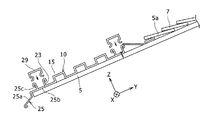
図1は、第1実施形態に係る屋根構造1の部分斜視図であり、屋根材を葺く前の屋根構造1の部分斜視図である。また、図2は、図1の部分拡大斜視図であり、屋根構造1における集水桝35付近の部分拡大斜視図である。図1に示すように、屋根構造1は、屋根下地材としての野地板5、導水板10、化粧部材30、及び集水桝35を備える。野地板5は、平板構造を有し、例えば、木造、鉄骨、又は鉄筋コンクリート等で構成される。また、導水板10は、金属材料等で構成され、板状の形状を有する。導水板10は、野地板5の平面状の上面5aにおけるY方向の軒先上側に、締結部材、例えば、釘、ねじ、又はビス等で取り付けられる。
(First embodiment)
Drawing 1 is a fragmentary perspective view of roof structure 1 concerning a 1st embodiment, and is a fragmentary perspective view of roof structure 1 before rolling a roofing material. FIG. 2 is a partially enlarged perspective view of FIG. 1, and is a partially enlarged perspective view of the vicinity of the water collecting basin 35 in the roof structure 1. As shown in FIG. 1, the roof structure 1 includes a field plate 5, a water guide plate 10, a decorative member 30, and a water collecting bowl 35 as a roof base material. The field board 5 has a flat plate structure and is made of, for example, a wooden structure, a steel frame, or reinforced concrete. The water guide plate 10 is made of a metal material or the like and has a plate shape. The water guide plate 10 is attached to the upper side of the eaves in the Y direction on the flat upper surface 5a of the base plate 5 with a fastening member such as a nail, a screw, or a screw.

化粧部材30は、例えば金属材料で構成され、屋根構造1のX方向一方側の側端部に配置され、軒側端部から棟側端部までY方向に延在し、Z方向において屋根構造1の下端から上端まで延在する。その結果、屋根構造1を一方側の側方から見たとき、主に化粧部材30が視認される。化粧部材30は、主に美観を良好にするために設けられる。化粧部材30は、締結部材、例えば、釘、ねじ、又はビス等で野地板5に固定される。   The decorative member 30 is made of, for example, a metal material, is disposed at a side end portion on one side in the X direction of the roof structure 1, extends in the Y direction from the eave side end portion to the ridge side end portion, and has a roof structure in the Z direction. 1 extends from the lower end to the upper end. As a result, when the roof structure 1 is viewed from one side, the decorative member 30 is mainly visually recognized. The decorative member 30 is provided mainly for improving the beauty. The decorative member 30 is fixed to the base plate 5 with a fastening member such as a nail, a screw, or a screw.

図2に示すように、導水板10は、略同一平面上に位置する上面11を有し、その法線方向であるZ方向から見たときの平面視で略矩形の形状を有する。導水板10は、上面11からZ方向に突出する複数の突条部15を含む。複数の突条部15は、導水板10の幅方向に間隔をおいて配置され、各突条部15は、導水板10の長手方向に一端から他端まで延在する。導水板10は、長手方向がX方向に一致すると共に幅方向がY方向に一致している状態で、野地板5(図1参照)に固定される。その結果、複数の突条部15は、Y方向に間隔をおいて位置し、各突条部15は、X方向に延在する。Y方向に隣り合う突条部15の間には、溝16が存在する。溝16は、導水板10のX方向の一端から他端までX方向に延在する。   As shown in FIG. 2, the water guide plate 10 has an upper surface 11 located on substantially the same plane, and has a substantially rectangular shape when viewed from the Z direction that is the normal direction. The water guide plate 10 includes a plurality of protrusions 15 protruding from the upper surface 11 in the Z direction. The plurality of protrusions 15 are arranged at intervals in the width direction of the water guide plate 10, and each protrusion 15 extends from one end to the other end in the longitudinal direction of the water guide plate 10. The water guide plate 10 is fixed to the base plate 5 (see FIG. 1) in a state where the longitudinal direction coincides with the X direction and the width direction coincides with the Y direction. As a result, the plurality of ridge portions 15 are positioned at intervals in the Y direction, and each ridge portion 15 extends in the X direction. A groove 16 is present between the ridges 15 adjacent in the Y direction. The groove 16 extends in the X direction from one end to the other end of the water guide plate 10 in the X direction.

屋根構造1は、更に排水路38を備える。詳しくは、屋根構造1は、長尺状の板材39を備え、その板材39は、野地板5のX方向一方側にY方向に延在するように締結部材、例えば、釘、ねじ、又はビス等で固定される。X方向に関し、板材39は、化粧部材30と導水板10で隙間なく挟持される。板材39の上面は、排水路38を構成する。排水路38のZ方向高さは、導水板10の上面11のZ方向高さと一致するか、又は導水板10の上面11のZ方向高さよりも僅かに低い。このようにして、雨水が、導水板10の溝16から排水路38に円滑に流動するようにしている。   The roof structure 1 further includes a drainage channel 38. Specifically, the roof structure 1 includes a long plate member 39, and the plate member 39 is a fastening member such as a nail, a screw, or a screw so as to extend in the Y direction on one side of the field plate 5 in the X direction. Fixed with etc. With respect to the X direction, the plate member 39 is sandwiched between the decorative member 30 and the water guide plate 10 without a gap. The upper surface of the plate material 39 constitutes a drainage channel 38. The height of the drainage channel 38 in the Z direction coincides with the height of the upper surface 11 of the water guide plate 10 in the Z direction or is slightly lower than the height of the upper surface 11 of the water guide plate 10 in the Z direction. In this way, rainwater smoothly flows from the groove 16 of the water guide plate 10 to the drainage channel 38.

集水桝35は、化粧部材30の下端部に締結部材、例えば、釘、ねじ、又はビス等で固定され、化粧部材30と一体に構成される。集水桝35は、化粧部材30よりもX方向他方側に位置し、集水桝35のY方向の軒側の端は、化粧部材30のY方向の軒側の端よりも棟側に位置する。このようにして、集水桝35が化粧部材30の陰に隠れるようにして、集水桝35が目立たなくなるようにすることで、屋根構造1の美観を優れたものにしている。   The water collecting bowl 35 is fixed to a lower end portion of the decorative member 30 with a fastening member such as a nail, a screw, or a screw, and is configured integrally with the decorative member 30. The water collecting bowl 35 is located on the other side in the X direction from the decorative member 30, and the end of the water collecting bowl 35 on the eave side in the Y direction is located on the ridge side of the end of the decorative member 30 on the eave side in the Y direction. To do. In this way, the water collecting bowl 35 is hidden behind the decorative member 30, and the water collecting bowl 35 is made inconspicuous, thereby making the roof structure 1 have an excellent aesthetic appearance.

排水路38の延在方向であるY方向に関して、集水桝35の集水口37の少なくとも一部は、排水路38の下端部に隣接するように排水路38よりも下側に配置される。また、集水口37の鉛直方向の高さは、排水路38の下端の鉛直方向高さと同一か又は排水路38の下端の鉛直方向高さよりも低い。このようにして、雨水が、排水路38を下側に流れた後、集水口37に効率的かつ円滑に流動するようにしている。なお、詳述しないが、集水桝35の下側には、竪樋(図示せず)が接続される。雨水は、例えば、集水桝35、及び竪樋を通過した後、下水の方に流れるようになっている。   With respect to the Y direction, which is the extending direction of the drainage channel 38, at least a part of the water collection port 37 of the drainage basin 35 is disposed below the drainage channel 38 so as to be adjacent to the lower end of the drainage channel 38. The vertical height of the water collection port 37 is the same as the vertical height at the lower end of the drainage channel 38 or lower than the vertical height at the lower end of the drainage channel 38. In this manner, rainwater flows efficiently and smoothly to the water collection port 37 after flowing down the drainage channel 38. Although not described in detail, a basin (not shown) is connected to the lower side of the water collection basin 35. The rainwater flows, for example, toward the sewage after passing through the water collecting basin 35 and the basin.

図3は、屋根構造1の部分斜視図であり、導水板10の断面を視認可能とした部分斜視図である。また、図4は、屋根構造1の一部を、YZ平面で切断したときの模式断面図である。なお、図3においては、図面を分かり易くするため、野地板5の上面5aを斜線で示している。図3に示すように、Y方向に垂直な断面において、突条部15は、2箇所の屈曲部を有して略矩形状のスペース8の3方向を画定する一体の屈曲板部で構成される。詳しくは、突条部15は、軒側壁部15a、上側板部15b、及び棟側壁部15cを有し、軒側壁部15aは、上面11を含む底側板部18のY方向の棟側端部からZ方向に延在する。また、上側板部15bは、軒側壁部15aの上端部からY方向の棟側に延在し、棟側壁部15cは、上側板部15bのY方向の棟側端部からZ方向下側に延在する。棟側壁部15cのZ方向の下側端部は、底側板部18のY方向の軒側端部に繋がる。底側板部18の底面は、野地板5の上面5aに当接している。突条部15を、2箇所の屈曲部を有する屈曲板部で構成することで、突条部15の剛性を大きくし、外力が作用しても突条部15を破損しにくいようにしている。   FIG. 3 is a partial perspective view of the roof structure 1 and is a partial perspective view in which the cross section of the water guide plate 10 is visible. FIG. 4 is a schematic cross-sectional view when a part of the roof structure 1 is cut along the YZ plane. In FIG. 3, the upper surface 5 a of the field board 5 is indicated by diagonal lines for easy understanding of the drawing. As shown in FIG. 3, in the cross section perpendicular to the Y direction, the ridge portion 15 is formed by an integral bent plate portion having two bent portions and defining three directions of a substantially rectangular space 8. The Specifically, the protrusion 15 has an eaves side wall 15a, an upper side plate 15b, and a ridge side wall 15c, and the eaves side wall 15a is a ridge side end of the bottom side plate 18 including the upper surface 11 in the Y direction. Extends in the Z direction. Further, the upper side plate portion 15b extends from the upper end portion of the eaves side wall portion 15a to the ridge side in the Y direction, and the ridge side wall portion 15c extends from the ridge side end portion in the Y direction of the upper side plate portion 15b to the lower side in the Z direction. Extend. The lower end of the ridge side wall 15c in the Z direction is connected to the eaves end of the bottom plate 18 in the Y direction. The bottom surface of the bottom side plate portion 18 is in contact with the upper surface 5 a of the field plate 5. By configuring the ridge portion 15 with a bent plate portion having two bent portions, the rigidity of the ridge portion 15 is increased so that the ridge portion 15 is not easily damaged even when an external force is applied. .

図3に示すように、屋根構造1は、更に軒先水切り25を備える。軒先水切り25は、導水板10の複数の突条部15において最も軒側に位置する突条部15よりも軒側に設置される。軒先水切り25は、導水板10の下側端部に接続され、野地板5の軒先から斜め下側に延在する傾斜部25aを含む。軒先水切り25は、例えば、次のように導水板10に取り付けられる。詳しくは、図4に示すように、軒先水切り25は、野地板5の上面5aに載置される板状部25bと、板状部25bからZ方向に突出する固定部25cを有し、固定部25cは、X方向に延在する。また、導水板10は、Y方向の軒側端部にZ方向に突出する固定部23を有し、固定部23は、X方向に延在する。また、導水板10は、更に長尺状のキャップ29を備える。キャップ29の一対の内側面が、固定部25cの外側面と固定部23の外側面に接触するように、キャップ29を固定部25c及び固定部23に嵌め込むことで、軒先水切り25を、導水板10に取り付ける。軒先水切り25は、導水板10を伝った雨水が、野地板5側に流動するのを防止するために設けられ、水が野地板5を介して建築物の内部に浸入することを防止するために設けられる。なお、軒先水切り25が、導水板10と別部材であって、軒先水切り25が導水板10に固定される場合について説明した。しかし、軒先水切りは、導水板と一体に構成されてもよい。   As shown in FIG. 3, the roof structure 1 further includes an eaves drainer 25. The eaves tip drainer 25 is installed on the eaves side of the plurality of ridges 15 of the water guide plate 10 with respect to the ridges 15 located closest to the eaves. The eaves tip drainer 25 is connected to the lower end portion of the water guide plate 10, and includes an inclined portion 25 a extending obliquely downward from the eaves tip of the field plate 5. The eaves drainer 25 is attached to the water guide plate 10 as follows, for example. Specifically, as shown in FIG. 4, the eaves tip drainer 25 has a plate-like portion 25b placed on the upper surface 5a of the base plate 5 and a fixing portion 25c protruding from the plate-like portion 25b in the Z direction. The part 25c extends in the X direction. Moreover, the water guide plate 10 has the fixing | fixed part 23 which protrudes in a Z direction in the eaves side edge part of a Y direction, and the fixing | fixed part 23 is extended in the X direction. Further, the water guide plate 10 further includes a long cap 29. By fitting the cap 29 into the fixing portion 25c and the fixing portion 23 so that the pair of inner side surfaces of the cap 29 are in contact with the outer surface of the fixing portion 25c and the outer surface of the fixing portion 23, the eaves drainer 25 is guided to the water. Attach to plate 10. The eaves drainer 25 is provided to prevent rainwater that has traveled through the water guide plate 10 from flowing toward the base plate 5, and to prevent water from entering the inside of the building via the base plate 5. Provided. The eaves drainer 25 is a separate member from the water guide plate 10 and the eaves tip drainer 25 is fixed to the water guide plate 10. However, the eaves drainer may be formed integrally with the water guide plate.

以上、屋根構造1は、建築物の上側に配置され、X方向に略延在する1以上の突条部15を有し、軒先上側に設置される導水板10を備える。また、屋根構造1は、最も軒側に位置する突条部15よりも軒側に設置される軒先水切り25を備える。   As described above, the roof structure 1 includes the water guide plate 10 that is disposed on the upper side of the building, has one or more protrusions 15 that extend substantially in the X direction, and is installed on the upper side of the eaves. Moreover, the roof structure 1 is provided with the eaves tip draining 25 installed in the eaves side rather than the protrusion part 15 located in the eaves side most.

本構成によれば、導水板10が、軒棟方向(Y方向)に直交する直交方向(X方向)に延在する突条部15を備える。したがって、Y方向に下側に流れる雨水を突条部15で堰き止めることができ、堰き止めた雨水を、突条部15を伝わせるようにX方向に流すことができ、雨水を屋根構造1の一方側の側方端部に集めることができる。そして、一方側の側方端部に集めた雨水を、一方側の側方端部の適切な箇所に設けた集水桝を介して下側に導くことができる。よって、突条部15に軒樋の役割を担わせることができるので、軒樋を省略することができ、建築物を、スタイリッシュで美観に優れるものにでき、コンパクトに構成できる。   According to this structure, the water guide plate 10 is provided with the protrusion 15 extended in the orthogonal direction (X direction) orthogonal to the eaves-ridge direction (Y direction). Therefore, the rainwater flowing downward in the Y direction can be blocked by the ridges 15, and the rainwater blocked can be allowed to flow in the X direction so as to travel along the ridges 15. Can be collected at the side end of one side. And the rain water collected at the side edge part of one side can be guide | induced to the lower side through the water catchment provided in the appropriate location of the side edge part of one side. Therefore, since the eaves part 15 can be made to play the role of the eaves part 15, an eaves can be abbreviate | omitted, a building can be made stylish and excellent in aesthetics, and can be comprised compactly.

また、屋根構造1が、Y方向の軒側に配置される軒先水切り25を有するので、導水板10上の雨水を、軒先水切り25を介して確実に地面側に流すことができ、導水板10上の雨水が野地板5側に流動するのを略防止できる。よって、導水板10上の雨水が野地板5を介して建築物の内部に浸入することを略防止できる。   Moreover, since the roof structure 1 has the eaves edge drainer 25 arrange | positioned at the eaves side of a Y direction, the rain water on the water guide board 10 can be reliably flowed through the eaves edge drainer 25 to the ground side, and the water guide board 10 It is possible to substantially prevent the upper rainwater from flowing to the base plate 5 side. Therefore, it is possible to substantially prevent rainwater on the water guide plate 10 from entering the inside of the building via the field plate 5.

また、屋根構造1は、側端部に棟側から軒先側に延在するように配置される化粧部材30と、Y方向に関して化粧部材30と導水板10の間に配置され、棟側から軒先側に延在する排水路38を備えてもよい。また、屋根構造1は、化粧部材30の下端部と一体に構成されると共に、排水路38の延在方向に関して、集水口37の少なくとも一部が排水路38の下端部に隣接するように排水路38よりも下側に配置され、下側に竪樋が接続される集水桝35を備えてもよい。   Moreover, the roof structure 1 is arrange | positioned between the decorative member 30 and the water guide plate 10 regarding the Y direction, and the decorative member 30 arrange | positioned so that it may extend from the ridge side to the eaves side at a side edge part, A drainage channel 38 extending to the side may be provided. The roof structure 1 is configured integrally with the lower end portion of the decorative member 30, and drains so that at least a part of the water collection port 37 is adjacent to the lower end portion of the drainage channel 38 in the extending direction of the drainage channel 38. There may be provided a water collecting rod 35 that is disposed below the path 38 and to which a rod is connected.

上記構成によれば、突条部15を伝わせるようにして一方側の側方端部に集めた雨水を、排水路38を介してY方向に軒先まで流動させることができ、その後、集水桝35を介して地上等に下側に流動させることができる。よって、雨水を円滑に地上側に流動させることができる。   According to the above configuration, the rainwater collected at the side end portion on one side so as to be transmitted through the ridge portion 15 can flow to the eaves in the Y direction via the drainage channel 38, and then the water collection It can be made to flow downward on the ground or the like through the ridge 35. Therefore, rainwater can flow smoothly to the ground side.

また、集水桝35が、軒先近傍まで延在する排水路38の下端部に隣接するように排水路38よりも軒側に配置されるので、突条部15を軒側端部まで形成しても、その突条部15を伝った雨水を集水桝35側に流動させることができる。よって、より多くの雨水を集水桝35に集めることができる。   Further, since the catchment basin 35 is arranged on the eaves side with respect to the drainage channel 38 so as to be adjacent to the lower end of the drainage channel 38 extending to the vicinity of the eaves end, the protrusion 15 is formed to the eaves side end. However, it is possible to cause the rainwater that has traveled through the ridges 15 to flow toward the catchment basin 35. Therefore, more rainwater can be collected in the catchment bar 35.

更には、YZ平面における断面において、突条部15は、2箇所の屈曲部を有して略矩形状のスペースの3方向を画定する屈曲板部で構成されてもよい。   Furthermore, in the cross section in the YZ plane, the protrusion 15 may be formed of a bent plate portion having two bent portions and defining three directions of a substantially rectangular space.

上記構成によれば、突条部15が2箇所の屈曲部を有するので、突条部15の剛性を大きくできる。よって、外力が突条部15に作用しても突条部15が変形等の損傷を起こしにくくなる。なお、図3を参照して、軒側壁部15aと底側板部18を湾曲板部で接続すると共に、棟側壁部15cと底側板部18を湾曲板部で接続してもよい。このように、軒側壁部15a及び棟側壁部15cと、底側板部18との間にアールを設けると、突条部15の剛性を更に高くできて好ましい。   According to the said structure, since the protrusion part 15 has two bending parts, the rigidity of the protrusion part 15 can be enlarged. Therefore, even if an external force acts on the ridge portion 15, the ridge portion 15 is unlikely to be damaged such as deformation. In addition, with reference to FIG. 3, while the eaves side wall part 15a and the bottom side board part 18 may be connected by a curved board part, the ridge side wall part 15c and the bottom side board part 18 may be connected by a curved board part. Thus, it is preferable to provide a radius between the eaves side wall part 15a and the ridge side wall part 15c and the bottom side plate part 18 because the rigidity of the ridge part 15 can be further increased.

(第2実施形態)
次に、集水桝135の配置構造が第1実施形態と異なる第2実施形態について説明する。なお、第2実施形態では、第1実施形態と同一の構成に第1実施形態と同一の参照番号を付して説明を省略する。また、第2実施形態では、第1実施形態と同様の作用効果についての説明を省略する。
(Second Embodiment)
Next, a second embodiment in which the arrangement structure of the water collecting trough 135 is different from the first embodiment will be described. In the second embodiment, the same reference numerals as those in the first embodiment are assigned to the same components as those in the first embodiment, and the description thereof is omitted. In the second embodiment, description of the same function and effect as in the first embodiment is omitted.

図5は、第2実施形態に係る屋根構造101の一部の分解斜視図であり、図6は、組み立てられた屋根構造101における図5にA−A線で示す断面での部分断面図である。図5に示すように、屋根構造101は、屋根下地材としての野地板5、導水板110、軒先水切り125、下側水切り127、化粧部材130、及び集水桝135を備える。軒先水切り125は、導水板110の軒側端部に繋がり、導水板110と、軒先水切り125は、一体に構成される。   FIG. 5 is an exploded perspective view of a part of the roof structure 101 according to the second embodiment, and FIG. 6 is a partial cross-sectional view taken along the line AA in FIG. 5 in the assembled roof structure 101. is there. As shown in FIG. 5, the roof structure 101 includes a base plate 5, a water guide plate 110, an eaves drainer 125, a lower drainer 127, a decorative member 130, and a water collecting rod 135 as a roof base material. The eaves edge drainer 125 is connected to the eaves side end of the water guide plate 110, and the water guide plate 110 and the eaves edge drainer 125 are integrally formed.

導水板110は、複数の突条部115を有する。複数の突条部115は、Y方向に互いに間隔をおいて位置し、各突条部115は、X方向に延在する。導水板110は、Y方向に隣り合う突条部115間に存在する溝部116を有する。導水板110の底板部140において溝部116に対応する箇所のX方向一方側端部は、斜め下側に切り起こされている。この斜め下側に傾斜する切起部171は、突条部115に沿って溝部116内を流れる水を集水桝135の集水口137側に導く導水部を構成する。切起部171は、例えば、プレス成形で、底板部140に突条部115に沿って切り込みを入れた後、切り込みを入れた部分を折り曲げることで形成される。   The water guide plate 110 has a plurality of protrusions 115. The plurality of ridges 115 are spaced from each other in the Y direction, and each ridge 115 extends in the X direction. The water guide plate 110 has a groove portion 116 that exists between the ridge portions 115 adjacent in the Y direction. In the bottom plate portion 140 of the water guide plate 110, one end portion in the X direction of the portion corresponding to the groove portion 116 is cut obliquely downward. The cut-and-raised part 171 inclined obliquely below constitutes a water guide part that guides the water flowing in the groove part 116 along the ridge part 115 to the water collecting port 137 side of the water collecting bar 135. The cut-and-raised part 171 is formed by, for example, press forming, by cutting the bottom plate part 140 along the ridge 115 and then bending the cut part.

下側水切り127は、金属等で構成される一体の板部材である。下側水切り127は、導水板110の裏側に配置され、その上面に到達した水を集水桝135の集水口137に導水する。詳しくは、図6に示すように、下側水切り127は、X方向一方側端部にX方向に行くにしたがって下方に移動するように傾斜する傾斜板部127aを有する。傾斜板部127aの下側端部は、鉛直方向から見たとき集水桝135の集水口137に重なる。このことから、傾斜板部127aに達した水を、集水口137に円滑に流動させることができる。   The lower drainer 127 is an integral plate member made of metal or the like. The lower drainer 127 is disposed on the back side of the water guide plate 110 and guides the water that has reached the upper surface thereof to the water collecting port 137 of the water collecting bowl 135. Specifically, as shown in FIG. 6, the lower drainer 127 has an inclined plate portion 127 a that is inclined so as to move downward as it goes in the X direction at one end portion in the X direction. The lower end portion of the inclined plate portion 127a overlaps the water collecting port 137 of the water collecting rod 135 when viewed from the vertical direction. Thus, the water that has reached the inclined plate portion 127a can be smoothly flowed to the water collecting port 137.

下側水切り127のY方向存在範囲は、複数の切起部171のY方向存在範囲を含み、下側水切り127の傾斜板部127aは、複数の切起部171よりもX方向他方側に位置する。下側水切り127は、切起部171の裏面を伝って野地板5側に向かう水が野地板5に達するのを防止し、当該水が野地板5を介して建築物の内部に浸入することを防止する。   The Y direction existence range of the lower drainer 127 includes the Y direction existence range of the plurality of cut and raised portions 171, and the inclined plate portion 127 a of the lower drainer 127 is positioned on the other side in the X direction from the plurality of cut and raised portions 171. To do. The lower drainer 127 prevents water that travels along the back surface of the cut-and-raised part 171 toward the field plate 5 from reaching the field plate 5 and the water enters the inside of the building via the field plate 5. To prevent.

化粧部材130は、屋根構造101のX方向一方側の端部に設けられ、Y方向の軒側端部から棟側端部までY方向に延在する。図6に示すように、Z方向から見たとき野地板5に重なる領域において、化粧部材130は、下側水切り127と導水板110との間に配置される。化粧部材130は、一体部材であり、取付板部131と、水切り部132を含む。取付板部131は、平板形状を有し、野地板5にZ方向に対向する。取付板部131は、野地板5に締結部材、例えば、釘、ねじ、又はビス等で取り付けられ、水切り部132は、取付板部131のX方向一方側端部から斜め下方に傾斜し、その先端部は、内側に折り返されている。取付板部131は、Z方向の両側とX方向他方側が開口する凹部155を有する。凹部155のY方向の存在範囲は、複数の切起部171のY方向存在範囲を含む。各切起部171は、化粧部材130の上側から凹部155内に延在する。   The decorative member 130 is provided at an end portion on one side in the X direction of the roof structure 101, and extends in the Y direction from the eave side end portion in the Y direction to the ridge side end portion. As shown in FIG. 6, the decorative member 130 is disposed between the lower drainer 127 and the water guide plate 110 in a region overlapping the base plate 5 when viewed from the Z direction. The decorative member 130 is an integral member, and includes a mounting plate portion 131 and a draining portion 132. The mounting plate portion 131 has a flat plate shape and faces the base plate 5 in the Z direction. The mounting plate portion 131 is attached to the base plate 5 with a fastening member such as a nail, a screw, or a screw, and the draining portion 132 is inclined obliquely downward from one end portion in the X direction of the mounting plate portion 131. The tip is folded inward. The mounting plate portion 131 has recesses 155 that open on both sides in the Z direction and on the other side in the X direction. The existence range of the recess 155 in the Y direction includes the existence direction of the plurality of cut-and-raised parts 171 in the Y direction. Each cut-and-raised part 171 extends into the recess 155 from above the decorative member 130.

図6に示すように、集水桝135は、化粧部材130の側壁部を構成する水切り部132よりも内側に位置し、水切り部132よりもX方向他方側に位置する。また、集水桝135の下端は、化粧部材130の下端よりも上側に位置する。その結果、集水桝135は、化粧部材130によって隠され、外部から視認しにくくなっている。集水桝135は、例えば、公知の係止構造で建築物の側壁部180に固定される。この固定について簡潔に説明すると、集水桝135は、内側壁部の上端部に下側に開口する係合凹部183を有し、外側壁部の上端部に下側に開口する係合凹部184を有する。また、複数の一体の係合片(図示せず)が、側壁部180と一体に構成され、Y方向に間隔をおいて側壁部180から外側に突出する。また、各係合片は、内側係合爪部と、外側係合爪部を有する。各係合片の内側係合爪部を、係合凹部183に嵌入し、各係合片の内側係合爪部を、係合凹部184に嵌入することで、集水桝135を側壁部180に固定する。集水桝135の下側には、竪樋159が接続される。   As shown in FIG. 6, the water collecting bowl 135 is located on the inner side of the draining portion 132 that constitutes the side wall portion of the decorative member 130, and is located on the other side in the X direction from the draining portion 132. Further, the lower end of the water collecting bowl 135 is located above the lower end of the decorative member 130. As a result, the water collecting bowl 135 is hidden by the decorative member 130 and is difficult to visually recognize from the outside. The catchment 135 is fixed to the side wall 180 of the building with a known locking structure, for example. Briefly describing this fixing, the water collecting trough 135 has an engaging recess 183 that opens downward at the upper end of the inner wall portion, and an engaging recess 184 that opens downward at the upper end of the outer wall portion. Have A plurality of integral engagement pieces (not shown) are integrally formed with the side wall part 180 and protrude outward from the side wall part 180 at intervals in the Y direction. Each engagement piece has an inner engagement claw portion and an outer engagement claw portion. The inner engagement claw portion of each engagement piece is fitted into the engagement recess 183, and the inner engagement claw portion of each engagement piece is fitted into the engagement recess 184, whereby the water collecting rod 135 is moved to the side wall portion 180. To fix. A basin 159 is connected to the lower side of the water collection basin 135.

化粧部材130は、主に、X方向一方側からの側方視における美観を優れたものにするために設けられる。更には、第2実施形態では、集水桝135が、化粧部材130で覆われ、外部から視認しにくくなっている。よって、この理由からも、化粧部材130の設置で、建築物の美観が優れたものになる。   The decorative member 130 is mainly provided in order to make the appearance beautiful in the side view from the one side in the X direction. Furthermore, in the second embodiment, the water collecting bowl 135 is covered with the decorative member 130 and is difficult to visually recognize from the outside. Therefore, also from this reason, the installation of the decorative member 130 provides an excellent aesthetic appearance of the building.

以上、図5及び図6に示すように、屋根構造101は、側端部に棟側から軒先側に延在するように配置される化粧部材130と、X方向に関して化粧部材130の側端よりも内側に配置され、下側に竪樋159が接続される集水桝135を備える。また、導水板110が、突条部115に沿って流れる水を集水桝135の集水口137に導く切起部(導水部)171を有する。   As described above, as shown in FIGS. 5 and 6, the roof structure 101 includes the decorative member 130 disposed on the side end portion so as to extend from the ridge side to the eaves side, and the side end of the decorative member 130 in the X direction. Is also provided on the inner side, and has a water collecting tub 135 to which a basin 159 is connected. Further, the water guide plate 110 has a cut-and-raised part (water guide part) 171 that guides the water flowing along the ridge part 115 to the water collection port 137 of the water catchment 135.

したがって、突条部115に沿って流れる水を直接集水桝135に流動させることができるので、第1実施形態との比較において軒棟方向に延在する排水路を省略でき、屋根構造101をコンパクトに構成できる。また、集水桝135が、化粧部材130の側端よりも内側に配置されるので、集水桝135を、化粧部材130で覆い隠すことができる。よって、美観に優れる建築物を実現できる。   Therefore, since the water flowing along the ridge 115 can be directly flowed to the catchment 135, the drainage channel extending in the eaves direction can be omitted in comparison with the first embodiment, and the roof structure 101 can be removed. Can be configured compactly. Further, since the water collecting bowl 135 is disposed on the inner side than the side end of the decorative member 130, the water collecting bowl 135 can be covered with the decorative member 130. Therefore, the building which is excellent in aesthetics can be realized.

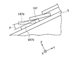
次に、複数の突条部115の高さについて説明する。図7は、組み立てられた屋根構造における図5にB−B線で示す断面での部分模式断面図である。図7に示すように、屋根構造101は、複数の屋根材187を備える。屋根材187は、例えば、瓦や鋼板屋根材等で構成される。   Next, the height of the plurality of protrusions 115 will be described. FIG. 7 is a partial schematic cross-sectional view taken along line BB in FIG. 5 in the assembled roof structure. As shown in FIG. 7, the roof structure 101 includes a plurality of roof materials 187. The roof material 187 is made of, for example, a tile, a steel plate roof material, or the like.

導水板110は、Y方向に間隔をおいて配置される複数の突条部115を有する。各突条部115は、導水板110において略同一平面上に位置する上面111からその法線方向であるZ方向に突出する。複数の突条部115に関して、突条部115のZ方向の高さは、突条部115がY方向の軒側に配置されるにしたがって高くなっている。また、複数の突条部115に関して、突条部115の先端における鉛直方向の高さは、突条部115がY方向の軒側に配置されるにしたがって低くなっている。   The water guide plate 110 has a plurality of protrusions 115 arranged at intervals in the Y direction. Each protrusion 115 protrudes in the Z direction, which is the normal direction, from the upper surface 111 located on substantially the same plane in the water guide plate 110. Regarding the plurality of protrusions 115, the height of the protrusions 115 in the Z direction increases as the protrusions 115 are arranged on the eaves side in the Y direction. Further, regarding the plurality of protrusions 115, the height in the vertical direction at the tip of the protrusions 115 becomes lower as the protrusions 115 are arranged on the eaves side in the Y direction.

図8は、突条部115に沿って流れる雨水の水位について説明する模式断面図である。図8を参照して、棟側から移動してきた雨水(雪)は、先ず、屋根材187に接触していない複数の突条部115のうちで最も棟側に位置する突条部115aに堰き止められる。そして、雨水等の水位が、Lで示す突条部115aの上端に達すると、雨水の一部が軒側にこぼれる。   FIG. 8 is a schematic cross-sectional view illustrating the level of rainwater flowing along the ridge 115. Referring to FIG. 8, rainwater (snow) that has moved from the ridge side is first dammed to the ridge 115 a that is located closest to the ridge among the plurality of ridges 115 that are not in contact with the roof material 187. It can be stopped. And when the water level of rainwater etc. reaches the upper end of the protrusion 115a shown by L, a part of rainwater will spill to the eaves side.

このような背景において、本構成によれば、複数の突条部115に関して、突条部115のZ方向の高さが、突条部115がY方向の軒側に配置されるにしたがって高くなっている。したがって、上記軒側にこぼれた雨水は、突条部115aよりも1つ棟側の突条部115bを通過することがなく、当該突条部115bで確実に堰き止められる。   In such a background, according to this configuration, with respect to the plurality of protrusions 115, the height of the protrusions 115 in the Z direction increases as the protrusions 115 are arranged on the eaves side in the Y direction. ing. Therefore, the rain water spilled on the eaves side does not pass through the ridge 115b that is one ridge side of the ridge 115a, and is reliably dammed by the ridge 115b.

すなわち、各突条部115から零れ落ちた雨水を、その突条部115よりも1つ軒側の突条部115で確実に堰き止めることができる。よって、導水板110により多くの雨水を溜めることができるので、大量の雨水が一気に集水桝135に流れ込むことを抑制でき、雨水が集水桝135からこぼれることを抑制できる。   That is, the rain water that has fallen from each ridge 115 can be reliably dammed by the ridge 115 on one eave side from the ridge 115. Therefore, since a large amount of rainwater can be stored in the water guide plate 110, a large amount of rainwater can be prevented from flowing into the catchment basin 135 at a stretch, and rainwater can be prevented from spilling from the catchment basin 135.

更には、複数の突条部115に関して、突条部115の先端における鉛直方向の高さは、突条部115がY方向の軒側に配置されるにしたがって低くなっている。したがって、突条部115のZ方向高さが軒側に行くにしたがって高くなっていることを目立ちにくくできる。よって、導水板110の美観を良好なものにできる。   Furthermore, with respect to the plurality of protrusions 115, the vertical height at the tip of the protrusion 115 decreases as the protrusion 115 is arranged on the eaves side in the Y direction. Therefore, it can be made inconspicuous that the Z direction height of the protrusion part 115 becomes high as it goes to the eaves side. Therefore, the beauty of the water guide plate 110 can be improved.

また、図7に示すように、屋根構造101は、導水板110よりも棟側に配置される複数の屋根材187aを備える。また、複数の突条部115は、先端がその複数の屋根材187aに接する接平面PよりもZ(法線)方向上側に位置する高突条部115cを含む。   In addition, as shown in FIG. 7, the roof structure 101 includes a plurality of roofing materials 187 a arranged on the ridge side with respect to the water guide plate 110. In addition, the plurality of ridges 115 include a high ridge 115c positioned at the upper side in the Z (normal line) direction with respect to the tangential plane P that is in contact with the plurality of roof materials 187a.

本構成によれば、屋根材187aから接平面Pに吹き飛ばされた雨水等を高突条部115cで堰き止めることができる。よって、雨水をより確実に集水桝135に流動させることができる。   According to this configuration, rainwater or the like blown off from the roof material 187a to the tangential plane P can be dammed up by the high ridge 115c. Therefore, rainwater can be made to flow into the water collecting tank 135 more reliably.

また、図7に示すように、屋根構造101は、複数の突条部115のうちで最も棟側に位置する棟側突条部115dに接触する導水板側屋根材187bを備える。より詳しくは、導水板側屋根材187bの軒側端部は、棟側突条部115dの上部に支持される。導水板側屋根材187bは、棟側突条部115dによる支持でY方向から傾いている。また、導水板110は、導水板側屋根材187bの裏側に位置する箇所に、棟側突条部115dに対して間隔をおいて棟側に位置して上側に突出すると共に、Y方向に延在する水返し片191を有する。   As shown in FIG. 7, the roof structure 101 includes a water guide plate-side roof material 187 b that contacts the ridge-side ridge 115 d positioned closest to the ridge among the plurality of ridges 115. More specifically, the eaves side end of the water guide plate side roofing material 187b is supported by the upper part of the ridge side ridge 115d. The water guide plate-side roof material 187b is inclined from the Y direction by the support by the ridge-side protrusion 115d. Further, the water guide plate 110 is located on the back side of the water guide plate-side roof material 187b at a distance from the ridge-side ridge 115d and protrudes upward and extends in the Y direction. It has the water return piece 191 which exists.

本構成によれば、導水板側屋根材187bが、棟側突条部115dによる支持により傾く。すなわち、棟側突条部115dによる支持で、導水板側屋根材187bの軒側端部を上側に持ち上げることができ、導水板側屋根材187bの位置を、図9に実線で示す位置から点線で示す位置に移動させることができる。したがって、導水板側屋根材187bと、それよりも1つ棟側の屋根材187がなす角度θを小さくできる。よって、導水板側屋根材187bと、それよりも1つ棟側の屋根材187の隙間から野地板5に浸入する雨水を抑制でき、雨水が野地板5を介して建築物の内部に浸入することを防止する。   According to this configuration, the water guide plate-side roof material 187b is inclined by the support by the ridge-side protrusion 115d. That is, the eaves side end of the water guide plate side roof material 187b can be lifted upward by the support by the ridge side ridge 115d, and the position of the water guide plate side roof material 187b is indicated by a dotted line from the position shown by a solid line in FIG. It can be moved to the position indicated by. Therefore, the angle θ formed by the water guide plate side roofing material 187b and the roofing material 187 on the one building side than that can be reduced. Therefore, it is possible to suppress rainwater entering the field plate 5 from the gap between the water guide plate side roofing material 187b and the roof material 187 on the one side of the roof, and rainwater enters the inside of the building through the field plate 5. To prevent that.

また、導水板110が、導水板側屋根材187bの裏側に位置する箇所に、棟側突条部115dに対して間隔をおいて棟側に位置して上側に突出すると共に、Y方向に延在する水返し片191を有する。したがって、仮に、雨水が、導水板側屋根材187bと、それよりも1つ棟側の屋根材187の隙間から導水板側屋根材187bの裏側に浸入したとしても、その雨水を、水返し片191で堰き止めることができる。よって、その雨水が、野地板5まで達することを抑制でき、雨水が野地板5を介して建築物の内部に浸入することを更に確実に防止できる。なお、水返し片191が、導水板110のX方向一端部から他端部までX方向に延在すると、雨水が野地板5に到達するのを、X方向の広範囲な領域で抑制できて好ましい。また、最も軒側に位置する突条部115eの軒側に軒先水切り125の上面を覆い、且つ軒側先端部が軒先水切り125よりも軒側に僅かに突出するよう配置される軒先屋根材187cを設けても良い。これにより、軒先の意匠性が向上する。   In addition, the water guide plate 110 is located on the back side of the water guide plate side roofing material 187b at a distance from the ridge side ridge 115d and protrudes upward and extends in the Y direction. It has the water return piece 191 which exists. Therefore, even if rainwater enters the back side of the water guide plate side roofing material 187b from the gap between the water guide plate side roofing material 187b and the roof material 187 on the one side of the roof, the rainwater is returned to the water return piece. 191 can be dammed up. Therefore, the rainwater can be prevented from reaching the base plate 5, and the rain water can be further reliably prevented from entering the inside of the building via the base plate 5. In addition, when the water return piece 191 extends in the X direction from one end portion in the X direction to the other end portion of the water guide plate 110, it is preferable that rainwater can reach the field plate 5 in a wide area in the X direction. . Also, the eaves roofing material 187c is arranged so as to cover the upper surface of the eaves drainer 125 on the eave side of the ridge 115e located closest to the eaves side, and the eaves side tip portion slightly protrudes toward the eaves side than the eaves drainer 125. May be provided. Thereby, the designability of the eaves is improved.

なお、本開示は、上記実施形態およびその変形例に限定されるものではなく、本願の特許請求の範囲に記載された事項およびその均等な範囲において種々の改良や変更が可能である。   Note that the present disclosure is not limited to the above-described embodiment and the modifications thereof, and various improvements and modifications can be made within the matters described in the claims of the present application and the equivalent scope thereof.

例えば、上記第1及び第2実施形態では、導水板10,110が、複数の突条部15,115を備える場合について説明したが、導水板は、X方向に延在する1つのみの突条部を有してもよい。   For example, in the first and second embodiments, the case where the water guide plates 10 and 110 include the plurality of protrusions 15 and 115 has been described. However, the water guide plate has only one protrusion extending in the X direction. You may have a section.

また、図10、すなわち、第2実施形態の導水板110をZ方向上側から見たときの模式平面図に示すように、導水部を、斜め下側に傾斜する切起部171で構成する場合について説明した。しかし、図11、すなわち、変形例の導水板210における図10に対応する模式平面図に示すように、導水板210は、Y方向に間隔をおいて配置される複数の突条部215を有してもよく、Y方向に隣り合う突条部215の間に溝部216を有してもよい。そして、導水部を、溝部216のX方向一方側端部に設けた貫通孔271で構成してもよい。この変形例によれば、導水部をプレス成形のパンチングで容易に形成でき、導水板210の製造コストを低減できる。   Further, as shown in FIG. 10, that is, a schematic plan view when the water guide plate 110 of the second embodiment is viewed from the upper side in the Z direction, the water guide portion is configured by a cut and raised portion 171 that is inclined obliquely downward. Explained. However, as shown in FIG. 11, that is, a schematic plan view corresponding to FIG. 10 in the modified water guide plate 210, the water guide plate 210 has a plurality of protrusions 215 arranged at intervals in the Y direction. Alternatively, a groove 216 may be provided between the protrusions 215 adjacent in the Y direction. And you may comprise a water conveyance part by the through-hole 271 provided in the X direction one side edge part of the groove part 216. FIG. According to this modification, the water guide part can be easily formed by punching of press molding, and the manufacturing cost of the water guide plate 210 can be reduced.

また、第1及び第2実施形態では、屋根構造1,101が軒棟方向のみに傾いている場合について説明した。しかし、屋根構造1,101は、軒棟方向に加えて、それ以外の方向にも傾いてもよい。この場合、例えば、軒先が、水平面に対して傾斜してもよい。この変形例によれば、導水板において、突条部が水平面に対して傾斜する方向に延在し、隣り合う突条部の間に設けられる溝部が傾くことになる。よって、雨水が溝部を下側に向けて流れることになり、雨水を集水桝に効率的に集めることができる。また、方形屋根の場合は、屋根頂部を通る軒との垂線方向を軒棟方向とみなすことができる。また、第1及び第2実施形態では、防水シートなど通常屋根構造に必要な部材について、一部省略している場合があり、これら省略している部材を付加することを妨げるものではない。   Moreover, 1st and 2nd embodiment demonstrated the case where the roof structures 1 and 101 inclined only in the eaves-and-ridge direction. However, the roof structure 1,101 may be inclined in other directions in addition to the eaves-ridge direction. In this case, for example, the eaves may be inclined with respect to the horizontal plane. According to this modified example, in the water guide plate, the protruding portion extends in a direction inclined with respect to the horizontal plane, and the groove portion provided between the adjacent protruding portions is inclined. Therefore, rainwater flows toward the lower side of the groove, and rainwater can be efficiently collected in the catchment. In the case of a square roof, the direction perpendicular to the eave passing through the roof top can be regarded as the eaves ridge direction. In the first and second embodiments, some members necessary for the normal roof structure, such as waterproof sheets, may be omitted, and this does not prevent the addition of these omitted members.

1,101 屋根構造、 10,110,210 導水板、 11,111 導水板の上面、 15,115,215 突条部、 25,125 軒先水切り、 30,130 化粧部材、 35,135 集水桝、 37,137 集水口、 38 排水路、 115c 高突条部、 115d 棟側突条部、 127 下側水切り、 159 竪樋、 171 切起部、 187a 導水板よりも棟側に配置される屋根材、 187b 導水板側屋根材、 191 水返し片、 271 貫通孔、 P 接平面、 X方向 直交方向、 Y方向 軒棟方向、 Z方向 法線方向。   1,101 roof structure, 10,110,210 water guide plate, 11,111 upper surface of water guide plate, 15,115,215 ridge, 25,125 water drainer, 30,130 decorative member, 35,135 water collecting trough, 37,137 Drainage port, 38 drainage channel, 115c high ridge, 115d ridge-side ridge, 127 lower drainage, 159 17, 171 cut-up portion, 187a Roof material arranged on the ridge side from the water guide plate , 187b Water guide plate side roofing material, 191 water return piece, 271 through hole, P tangential plane, X direction orthogonal direction, Y direction eaves ridge direction, Z direction normal direction.

Claims (12)

建築物の上側に配置される屋根構造において、
軒棟方向に直交する直交方向に略延在する1以上の突条部を有し、軒先上側に設置される導水板と、
最も軒側に位置する前記突条部よりも軒側に設置される軒先水切りと、
を備える、屋根構造。
In the roof structure placed on the upper side of the building,
A water guide plate having one or more protrusions extending substantially in an orthogonal direction perpendicular to the eaves ridge direction,
Eaves tip drainer installed on the eaves side than the ridges located on the most eaves side,
With a roof structure.
前記導水板は、前記軒棟方向に間隔をおいて配置される複数の前記突条部を有し、
前記各突条部は、前記導水板において略同一平面上に位置する上面からその上面の法線方向に突出し、
前記複数の突条部に関して、前記突条部の前記法線方向の高さは、前記突条部が前記軒棟方向の軒側に配置されるにしたがって高くなり、
前記複数の突条部に関して、前記突条部の先端における鉛直方向の高さは、前記突条部が前記軒棟方向の軒側に配置されるにしたがって低くなる、請求項1に記載の屋根構造。
The water guide plate has a plurality of the protrusions arranged at intervals in the eaves ridge direction,
Each of the protrusions protrudes in a normal direction of the upper surface from an upper surface located on substantially the same plane in the water guide plate,
Regarding the plurality of ridges, the height of the ridges in the normal direction increases as the ridges are arranged on the eaves side in the eaves ridge direction,
2. The roof according to claim 1, wherein the vertical height at the tip of the ridge portion becomes lower as the plurality of ridge portions are arranged on the eave side in the eaves ridge direction. Construction.
前記導水板よりも棟側に配置される複数の屋根材を備え、
前記1以上の突条部には、前記先端が、前記複数の屋根材に接する接平面よりも法線方向上側に位置する高突条部が含まれる、請求項1又は2に記載の屋根構造。
A plurality of roofing materials arranged on the ridge side from the water guide plate,
The roof structure according to claim 1 or 2, wherein the one or more ridge portions include a high ridge portion, the tip of which is located on the upper side in the normal direction with respect to a tangential plane in contact with the plurality of roof materials. .
前記直交方向の側端部に棟側から軒先側に延在するように配置される化粧部材と、
前記直交方向に関して前記化粧部材と前記導水板の間に配置され、前記棟側から前記軒先側に延在する排水路と、
前記化粧部材の下端部と一体に構成されると共に、前記排水路の延在方向に関して、集水口の少なくとも一部が前記排水路の下端部に隣接するように前記排水路よりも下側に配置され、下側に竪樋が接続される集水桝と、
を備える、請求項1乃至3のいずれか1つに記載の屋根構造。
A decorative member arranged to extend from the ridge side to the eaves side at the side end in the orthogonal direction;
A drainage channel disposed between the decorative member and the water guide plate with respect to the orthogonal direction and extending from the ridge side to the eaves side;
Constructed integrally with the lower end portion of the decorative member, and arranged below the drainage channel so that at least a part of the water collection port is adjacent to the lower end of the drainage channel with respect to the extending direction of the drainage channel. And a drainage basin connected to the lower side,
The roof structure according to claim 1, comprising:
前記直交方向の側端部に棟側から軒先側に延在するように配置される化粧部材と、
前記直交方向に関して前記化粧部材の側端よりも内側に配置され、下側に竪樋が接続される集水桝と、
を備え、
前記導水板は、前記突条部に沿って流れる水を前記集水桝の集水口に導く導水部を有する、請求項1乃至3のいずれか1つに記載の屋根構造。
A decorative member arranged to extend from the ridge side to the eaves side at the side end in the orthogonal direction;
A water collecting tub that is disposed on the inner side of the side edge of the decorative member with respect to the orthogonal direction, and a tub is connected to the lower side,
With
The roof structure according to any one of claims 1 to 3, wherein the water guide plate has a water guide portion that guides water flowing along the protruding portion to a water collection port of the catchment basin.
前記導水部が前記導水板に設けられた貫通孔である、請求項5に記載の屋根構造。   The roof structure according to claim 5, wherein the water guide portion is a through hole provided in the water guide plate. 前記1以上の突条部のうちで最も棟側に位置する棟側突条部の上部に支持される軒側端部を有し、前記棟側突条部による支持により前記軒棟方向から傾いている導水板側屋根材を備え、
前記導水板は、前記導水板側屋根材の裏側に位置する箇所に、前記棟側突条部に対して間隔をおいて棟側に位置して上側に突出すると共に、前記直交方向に延在する水返し片を有する、請求項1乃至6のいずれか1つに記載の屋根構造。
It has an eaves side edge part supported by the upper part of the ridge side ridge part located in the most ridge side among the one or more ridge parts, and it inclines from the eaves ridge direction by support by the ridge side ridge part. It has a water guide plate side roofing material,
The water guide plate is located on the back side of the water guide plate side roof material at a position spaced from the ridge side ridge portion and protrudes upward from the ridge side and extends in the orthogonal direction. The roof structure according to any one of claims 1 to 6, further comprising a water return piece.
前記導水板の裏側に配置され、前記集水口に導水する水切りを備える、請求項5又は6に記載の屋根構造。   The roof structure according to claim 5 or 6, comprising a drainer disposed on the back side of the water guide plate and configured to guide water to the water collection port. 前記突条部は、水平面に対して傾斜する方向に延在している、請求項1乃至8のいずれか1つに記載の屋根構造。   The roof structure according to any one of claims 1 to 8, wherein the protruding portion extends in a direction inclined with respect to a horizontal plane. 前記直交方向に垂直な断面において、前記突条部は、2箇所の屈曲部を有して略矩形状のスペースの3方向を画定する屈曲板部で構成される、請求項1乃至9のいずれか1つに記載の屋根構造。   10. The device according to claim 1, wherein, in a cross section perpendicular to the orthogonal direction, the protruding portion includes a bent plate portion having two bent portions and defining three directions of a substantially rectangular space. The roof structure as described in one. 建築物の上側に位置する屋根下地材上に設置される導水板であって、
前記屋根下地材上に設置されている状態において軒棟方向に直交する直交方向に略延在する1以上の突条部を有し、前記軒棟方向の軒先上側に設置される、導水板。
A water guide plate installed on the roof base material located on the upper side of the building,
A water guide plate having one or more ridges extending substantially in an orthogonal direction perpendicular to the eave ridge direction in a state of being installed on the roof base material, and installed on the eaves upper side in the eave ridge direction.
略同一平面上に位置する上面と、
前記軒棟方向に間隔をおいて配置される複数の前記突条部と、を備え、
前記各突条部は、前記上面の法線方向に突出し、
前記複数の突条部に関して、前記突条部が前記軒棟方向の軒側に位置するにしたがって前記突条部の前記法線方向の高さが高くなるように前記屋根下地材上に配置され、
前記複数の突条部に関して、前記突条部が前記軒棟方向の軒側に位置するにしたがって前記突条部の先端における鉛直方向の高さが低くなるように前記屋根下地材上に配置される、請求項11に記載の導水板。
An upper surface located on substantially the same plane;
A plurality of the protrusions arranged at intervals in the eaves ridge direction,
Each of the protrusions protrudes in the normal direction of the upper surface,
With respect to the plurality of protrusions, the protrusions are arranged on the roof base material so that the height of the protrusions in the normal direction increases as the protrusions are positioned on the eaves side in the eaves ridge direction. ,
With respect to the plurality of protrusions, the protrusions are arranged on the roof base material so that the height in the vertical direction at the tip of the protrusions becomes lower as the protrusions are positioned on the eaves side in the eaves ridge direction. The water guide plate according to claim 11.
JP2018047789A 2018-03-15 2018-03-15 Roof structure and its water guide plate Pending JP2019157556A (en)

Priority Applications (1)

Application Number Priority Date Filing Date Title
JP2018047789A JP2019157556A (en) 2018-03-15 2018-03-15 Roof structure and its water guide plate

Applications Claiming Priority (1)

Application Number Priority Date Filing Date Title
JP2018047789A JP2019157556A (en) 2018-03-15 2018-03-15 Roof structure and its water guide plate

Publications (1)

Publication Number Publication Date
JP2019157556A true JP2019157556A (en) 2019-09-19

Family

ID=67995793

Family Applications (1)

Application Number Title Priority Date Filing Date
JP2018047789A Pending JP2019157556A (en) 2018-03-15 2018-03-15 Roof structure and its water guide plate

Country Status (1)

Country Link
JP (1) JP2019157556A (en)

Citations (7)

* Cited by examiner, † Cited by third party
Publication number Priority date Publication date Assignee Title
JP2000064520A (en) * 1998-08-17 2000-02-29 Enzo Komiya Plural-gutter roof plate device and plural-gutter roof plate
JP2002146972A (en) * 2000-11-13 2002-05-22 Sumitomo Forestry Co Ltd Eave end roof tile and structure of edge of eaves, and structure of edge of eaves and wing
JP2002227346A (en) * 2001-01-29 2002-08-14 Matsushita Electric Works Ltd Eaves edge structure
US20040031222A1 (en) * 2000-12-08 2004-02-19 Ofer Porat Roofing tiles
JP3166276U (en) * 2010-12-15 2011-02-24 有限会社鉢屋 Building with gutter
JP2011208382A (en) * 2010-03-29 2011-10-20 Otis:Kk Eaves edge cover for solar battery panel
JP2015017475A (en) * 2013-07-12 2015-01-29 パナソニック株式会社 Eaves edge structure of verge decorative material

Patent Citations (7)

* Cited by examiner, † Cited by third party
Publication number Priority date Publication date Assignee Title
JP2000064520A (en) * 1998-08-17 2000-02-29 Enzo Komiya Plural-gutter roof plate device and plural-gutter roof plate
JP2002146972A (en) * 2000-11-13 2002-05-22 Sumitomo Forestry Co Ltd Eave end roof tile and structure of edge of eaves, and structure of edge of eaves and wing
US20040031222A1 (en) * 2000-12-08 2004-02-19 Ofer Porat Roofing tiles
JP2002227346A (en) * 2001-01-29 2002-08-14 Matsushita Electric Works Ltd Eaves edge structure
JP2011208382A (en) * 2010-03-29 2011-10-20 Otis:Kk Eaves edge cover for solar battery panel
JP3166276U (en) * 2010-12-15 2011-02-24 有限会社鉢屋 Building with gutter
JP2015017475A (en) * 2013-07-12 2015-01-29 パナソニック株式会社 Eaves edge structure of verge decorative material

Similar Documents

Publication Publication Date Title
US7950187B2 (en) Roof gutter cover section with water draining upper surface
CA2783834C (en) Eavestrough cover
EP2752531B1 (en) A gutter-like flashing member and a roof structure including such a flashing member
EP1865117B1 (en) Drain with upright edge
US20050210758A1 (en) Roof gutter cover section with water draining upper surface
JP2019157556A (en) Roof structure and its water guide plate
JP2018105016A (en) Eaves drainage structure
JP5722666B2 (en) Building structure
KR101179735B1 (en) Lid for Waterway
JP7292082B2 (en) Roof structure and its water guide plate
JP7289490B2 (en) Eaves structure
JP4078609B2 (en) Parapet and flat roof structure
JP4754368B2 (en) End cap for tube
JP7007211B2 (en) Fascia and roof
JP2004225476A (en) Roof structure of constructing metallic roof tile and metallic roof tile
JP2006316532A (en) Rain gutter catchment basin
JP5019998B2 (en) Eaves mounting structure
KR100852086B1 (en) Grating assembly
KR20130080514A (en) Root tile, roof structure and construction method of the roof
JP6265465B2 (en) Keraba drainage, ridged drainage structure on different roofs, and water guide plate
JP2023123926A (en) Vertically roofed exterior structure
JP7043554B2 (en) Unit house eaves gutter structure
JP2534150B2 (en) Roof daylighting frame
JP4270388B2 (en) Residential roof structure
KR200373039Y1 (en) A gutter at the rainwater eaves for zinc roof

Legal Events

Date Code Title Description
A621 Written request for application examination

Free format text: JAPANESE INTERMEDIATE CODE: A621

Effective date: 20210301

A977 Report on retrieval

Free format text: JAPANESE INTERMEDIATE CODE: A971007

Effective date: 20211206

A131 Notification of reasons for refusal

Free format text: JAPANESE INTERMEDIATE CODE: A131

Effective date: 20211214

A02 Decision of refusal

Free format text: JAPANESE INTERMEDIATE CODE: A02

Effective date: 20220614