JP2019152308A - Braking power control device - Google Patents
Braking power control device Download PDFInfo
- Publication number
- JP2019152308A JP2019152308A JP2018039612A JP2018039612A JP2019152308A JP 2019152308 A JP2019152308 A JP 2019152308A JP 2018039612 A JP2018039612 A JP 2018039612A JP 2018039612 A JP2018039612 A JP 2018039612A JP 2019152308 A JP2019152308 A JP 2019152308A
- Authority
- JP
- Japan
- Prior art keywords
- braking force
- vehicle
- braking power
- line pressure
- control device
- Prior art date
- Legal status (The legal status is an assumption and is not a legal conclusion. Google has not performed a legal analysis and makes no representation as to the accuracy of the status listed.)
- Pending
Links
Images


Classifications
-
- Y—GENERAL TAGGING OF NEW TECHNOLOGICAL DEVELOPMENTS; GENERAL TAGGING OF CROSS-SECTIONAL TECHNOLOGIES SPANNING OVER SEVERAL SECTIONS OF THE IPC; TECHNICAL SUBJECTS COVERED BY FORMER USPC CROSS-REFERENCE ART COLLECTIONS [XRACs] AND DIGESTS
- Y02—TECHNOLOGIES OR APPLICATIONS FOR MITIGATION OR ADAPTATION AGAINST CLIMATE CHANGE
- Y02T—CLIMATE CHANGE MITIGATION TECHNOLOGIES RELATED TO TRANSPORTATION
- Y02T10/00—Road transport of goods or passengers
- Y02T10/60—Other road transportation technologies with climate change mitigation effect
Abstract
Description
本発明は、車両等に搭載される制動力制御装置に関する。 The present invention relates to a braking force control device mounted on a vehicle or the like.
車両においては、ユーザーが望むとおりの加減速を遅延なく行うことが、運転しやすさのために重要であり、そのための各種技術が提案されている。特許文献1は、自動変速機の制御装置において、自動変速機内の各種の係合摩擦要素に提供する作動油の油圧であるライン圧を、通常は抑制し、変速時に十分な作動圧が得られないおそれがある場合は高くすることで、燃費と変速応答性とを両立させることを開示している。特許文献2は、燃料カット制御装置において、触媒高温時の触媒劣化防止のため減速時の燃料カットを禁止する場合、オルタネーター、エアコン、ブレーキ、ギアシフト等により、減速力を補完することを開示している。特許文献3は、車両統合制御装置において、ドライバーの操作量に応じて決定される制御目標を、駆動系システム、制御系システムに、受け持ち割合に応じて分配する一方で、安定化システムには分配前の制御目標を送信して補正処理を算出させることで、安定化システムによる制御目標の分配値の同期を不要とし、フェールセーフ性を維持しつつ、遅延を低減することを開示している。 In a vehicle, it is important for ease of driving to perform acceleration / deceleration as desired by a user without delay, and various techniques have been proposed. Japanese Patent Application Laid-Open No. 2004-133867 is a control device for an automatic transmission, which normally suppresses the line pressure, which is the hydraulic pressure of hydraulic oil provided to various engagement friction elements in the automatic transmission, to obtain a sufficient operating pressure at the time of shifting. It is disclosed that the fuel efficiency and the shift response can be made compatible by increasing the value when there is a possibility of not being present. Patent Document 2 discloses that in a fuel cut control device, when the fuel cut at the time of deceleration is prohibited to prevent catalyst deterioration at a high catalyst temperature, the deceleration force is supplemented by an alternator, an air conditioner, a brake, a gear shift, and the like. Yes. Patent Document 3 distributes a control target determined according to an operation amount of a driver to a driving system and a control system according to a handling ratio in a vehicle integrated control device, while distributing it to a stabilization system. It discloses that the delay is reduced while transmitting the previous control target and calculating the correction process, thereby making it unnecessary to synchronize the distribution value of the control target by the stabilization system and maintaining the fail-safe property.
車両の低燃費化の要求に応え、エンジンの低フリクション化が進んでいる。特許文献1が開示するように、自動変速機のライン圧を抑制すると、エンジンブレーキの効果が小さくなり、ユーザーが要求する制動力が得られなくなるおそれがある。 In response to the demand for lower fuel consumption in vehicles, the engine friction has been reduced. As disclosed in Patent Document 1, if the line pressure of the automatic transmission is suppressed, the effect of engine braking is reduced, and the braking force requested by the user may not be obtained.
本発明は、上記課題に鑑み、ユーザーが要求する制動力を好適に得ることができる、車両用の制動力制御装置を提供することを目的とする。 In view of the above problems, an object of the present invention is to provide a vehicle braking force control device that can suitably obtain a braking force requested by a user.
上記課題を解決するために、本発明の一局面は、車両用の制動力制御装置であって、車両の走行中に、アクセル操作が行われず、かつブレーキ操作が行われていない状態である惰行状態が成立したことを検知する惰行状態検知部と、惰行状態検知部が、惰行状態が成立したことを検知すると、ユーザーが要求する制動力である要求制動力を推定する制動力推定部と、制動力推定部が推定した要求制動力が、所定の閾値以上であれば、閾値未満の場合に比べて、車両の自動変速機のライン圧を、高い値に設定して、車両の制動力を発生させるライン圧設定部とを備える制動力制御装置である。 In order to solve the above-described problem, an aspect of the present invention is a braking force control device for a vehicle, which is in a state where an accelerator operation is not performed and a brake operation is not performed while the vehicle is traveling. A coasting state detection unit that detects that the state is established, and a coasting state detection unit that detects that the coasting state is established, and a braking force estimation unit that estimates a requested braking force that is a braking force requested by the user; If the required braking force estimated by the braking force estimation unit is greater than or equal to a predetermined threshold, the line pressure of the automatic transmission of the vehicle is set to a higher value and the braking force of the vehicle A braking force control device including a line pressure setting unit to be generated.
これにより、惰行状態が成立した時点におけるユーザーが要求する要求制動力を推定し、推定結果に応じて、ライン圧を高く設定し、制動力を発生させる。これにより、ユーザーが要求する制動力を好適に得ることができる。 Thereby, the required braking force requested by the user when the coasting state is established is estimated, and the line pressure is set high according to the estimation result to generate the braking force. Thereby, it is possible to suitably obtain the braking force requested by the user.
本発明によれば、上述のように、惰行状態が成立した時点におけるユーザーが要求する制動力を推定し、これに応じてライン圧を高くすることで、ユーザーが要求する制動力を好適に得ることができる、車両用の制動力制御装置を提供することができる。 According to the present invention, as described above, the braking force requested by the user at the time when the coasting state is established is estimated, and the braking force requested by the user is suitably obtained by increasing the line pressure accordingly. A braking force control device for a vehicle that can be provided can be provided.
(概要)
本発明に係る制動力制御装置においては、惰行状態におけるユーザーからの要求制動力を各種センサからの情報に基づいて推定する。推定した要求制動力が閾値より大きい場合は、そうでない場合より、自動変速機のライン圧を高くして、ユーザーの要求に応じた制動力を発生させる。
(Overview)
In the braking force control apparatus according to the present invention, the required braking force from the user in the coasting state is estimated based on information from various sensors. When the estimated required braking force is larger than the threshold value, the line pressure of the automatic transmission is increased to generate the braking force according to the user's request, as compared to the case where it is not.
(実施形態)
以下、本発明の一実施形態について、図面を参照しながら詳細に説明する。
(Embodiment)
Hereinafter, an embodiment of the present invention will be described in detail with reference to the drawings.
<構成>
図1に、本実施形態に係る制動力制御装置100およびその周辺部の機能ブロック図を示す。制動力制御装置100は、惰行状態検知部11、制動力推定部12、ライン圧設定部13を備える。制動力制御装置100は車両に搭載され、各種のセンサ群200、自動変速機300と接続される。制動力制御装置100は、センサ群200が検知する車両や車両周辺の各種状態を表す情報を取得し、これに基づいて、自動変速機300を制御する。
<Configuration>
FIG. 1 shows a functional block diagram of the braking
<処理>
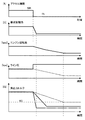
以下に、制動力制御装置100の各部が実行する処理を説明する。図2は、処理を説明するシーケンス図である。また、図3は、本処理に係る各種状態量、制御量である、アクセル開度、要求制動力、エンジン回転数、ライン圧、実出力トルクの時間変化の一例を示す図である。本処理は、ユーザーがアクセル操作を行わず、かつ、ブレーキ操作を行わない、惰行運転を行うことにより開始される。
<Processing>
Below, the process which each part of the braking
(ステップS101):惰行状態検知部11は、センサ群200に含まれる、アクセル開度センサ、ブレーキペダルセンサから、それぞれアクセル開度、ブレーキ踏み込み量が0であることを表す情報を取得し、惰行状態が成立したことを検知する。
(Step S101): The coasting
(ステップS102):制動力推定部12は、センサ群200から取得する状態に基づいて、ユーザーが要求する制動力である要求制動力を推定する。センサ群から取得する状態としては、ユーザーのアクセルおよびブレーキの操作量の変化および変化速度、エンジンの状態、車速、加速度、車両位置情報、ミリ波レーダーによる車両周囲の障害物情報、ドライブモードの選択状態が挙げられるが、これらに限定されない。また、これらに加えて、自動変速機300のシフトポジション等の状態を用いてもよい。
(Step S102): Based on the state acquired from the
ステップS102の処理の一例として、ユーザーによるアクセル操作に基づいて、要求制動力を推定する方法を説明する。制動力推定部12は、図3に示すように、アクセル開度が50%から0%に、所定以上の速さで減少した場合、ユーザーの要求制動力が大きいと推定する。なお、図3に示す要求制動力は、縦軸が車両進行方向を正の向きとする要求加速度を表すグラフにマップされ、負の向きが、要求制動力が大きくなる向きである。図3に示す例は、アクセル開度が0%になった時点から、推定される要求制動力が大きくなることを表す。
As an example of the processing in step S102, a method for estimating the required braking force based on the accelerator operation by the user will be described. As shown in FIG. 3, the braking
また、エンジンの回転数は、図3に示すように、アクセル開度が0%になった時点から、これに応じて徐々に低下し、一定値に収束する。 Further, as shown in FIG. 3, the engine speed gradually decreases in response to the accelerator opening being 0% and converges to a constant value.
(ステップS103):ライン圧設定部13は、要求制動力の大きさと所定の正の閾値とを比較する。要求制動力が閾値より小さい場合、ステップS104に進み、要求制動力が閾値以上である場合、ステップS105に進む。
(Step S103): The line
(ステップS104):ライン圧設定部13は、自動変速機300のライン圧を第1の設定値に設定する。ライン圧とは、自動変速機300内のクラッチやブレーキ等の係合摩擦要素に提供する作動油の油圧である。一般に高車速時や、高トルク時ほど高いライン圧が要求されるが、ライン圧を高くすると、エンジン負荷や自動変速機300内での損失トルクが増えるので惰行運転時の制動力が大きくなる。本ステップでは、ライン圧設定部13は、ライン圧を、例えば、エンジン回転数等に応じて、自動変速機300の動作に十分で、かつ、低燃費を実現できる油圧を第1の設定値として適宜設定する。第1の設定値は固定値でもよく、可変値でもよい。本ステップ後、処理はステップS106に進む。
(Step S104): The line
(ステップS105):ライン圧設定部13は、要求制動力が閾値以上である場合、ライン圧を要求制動力に応じて第1の設定値より高い第2の設定値に設定する。図3には、第2の設定値の一例として、ライン圧を第1の設定値より高い一定値に設定した場合を実線で示す。なお、比較のため、エンジン回転数の低下に応じてライン圧を低下させる通常の制御を行った例を点線で示す。点線で示すライン圧は、エンジン回転数の低下にともなって徐々に低下し一定値に収束する。
(Step S105): When the required braking force is greater than or equal to the threshold, the line
(ステップS106):ライン圧設定部13は、設定したライン圧に基づいて、自動変速機300を制御する。図3には、ライン圧を要求制動力に応じて第2の設定値に設定した場合の実出力トルクを実線で示す。また、比較のために、上述の点線で示すライン圧に設定した場合の実出力トルクを点線で示す。また、上述の要求制動力に対応する実出力トルクを一点鎖線で示す。図3に示す実出力トルクは、縦軸が車両進行方向を正の向きとする加速度を表すグラフにマップされ、負の向きが、実出力トルクが小さくなる向きであり、0Gを下回ることで制動力が発生する。図3に示す例では、ライン圧を高く設定した場合、実出力トルクが急峻に0G以下まで低下し、ユーザーの要求制動力に近い制動力制御が可能となる。この制御は、例えば、ユーザーがアクセル操作またはブレーキ操作を行うこと、または、車速が所定の速度まで減速すること等の所定の条件が成立することにより終了する。再び惰行状態の成立を検出するとステップS101からの処理が再度実行される。
(Step S106): The line
以上の処理は、適宜変更して実施してもよい。例えば、制動力制御装置100は、自動変速機300のライン圧の制御だけでなく、車両に搭載されたエンジン、エアコン、ブレーキ、オルタネーター等の制御も可能な構成とし、ステップS106において、エンジンのトルク出力、自動変速機300の変速、エアコン、ブレーキ、オルタネーターの使用等を組み合わせることにより制動力を発生させてもよい。また、ライン圧設定部13は、要求制動力と実際に得られた制動力の差異を取得し、これに基づいて、ライン圧の設定値を修正する、フィードバック制御を行ってもよい。また、ライン圧設定部13は、自動変速機300になんらかの異常が発生したことを検知できるようにして、異常発生時にはライン圧を最高にするよう制御して、制動力が大きくなるようにしてもよい。
The above processing may be implemented with appropriate changes. For example, the braking
<効果>
本発明によれば、惰行状態が成立した時点におけるユーザーからの要求制動力を推定し、推定した要求制動力が閾値より大きい場合は、そうでない場合より、自動変速機のライン圧を高くすることにより制動力を発生させる。これにより、ユーザーが要求する制動力を好適に得ることができる。
<Effect>
According to the present invention, the required braking force from the user at the time when the coasting state is established is estimated, and when the estimated required braking force is greater than the threshold, the line pressure of the automatic transmission is increased as compared with the case where the estimated required braking force is not greater. To generate a braking force. Thereby, it is possible to suitably obtain the braking force requested by the user.
なお、本発明は、車両用の制動力制御装置として捉えるだけでなく、制動力制御装置のコンピューターが実行する方法、プログラムまたは制動力制御装置を含む制御システム、車両として捉えることも可能である。 Note that the present invention can be understood not only as a braking force control device for a vehicle but also as a method executed by a computer of the braking force control device, a program or a control system including the braking force control device, and a vehicle.
本発明は、変速機等を備えた車両等に有用である。 The present invention is useful for a vehicle equipped with a transmission or the like.
11 惰行状態検知部
12 制動力推定部
13 ライン圧設定部
100 制動力制御装置
200 センサ群
300 自動変速機
11 coasting
Claims (1)
前記車両の走行中に、アクセル操作が行われず、かつブレーキ操作が行われていない状態である惰行状態が成立したことを検知する惰行状態検知部と、
前記惰行状態検知部が、前記惰行状態が成立したことを検知すると、ユーザーが要求する制動力である要求制動力を推定する制動力推定部と、
前記制動力推定部が推定した前記要求制動力が、所定の閾値以上であれば、前記閾値未満の場合に比べて、前記車両の自動変速機のライン圧を、高い値に設定して、前記車両の制動力を発生させるライン圧設定部とを備える、制動力制御装置。 A braking force control device for a vehicle,
A coasting state detection unit that detects that a coasting state in which the accelerator operation is not performed and the brake operation is not performed is established while the vehicle is traveling,
When the coasting state detection unit detects that the coasting state is established, a braking force estimation unit that estimates a requested braking force that is a braking force requested by a user;
If the required braking force estimated by the braking force estimation unit is greater than or equal to a predetermined threshold, the line pressure of the automatic transmission of the vehicle is set to a higher value than when the required braking force is less than the threshold, A braking force control device comprising: a line pressure setting unit that generates a braking force of a vehicle.
Priority Applications (1)
| Application Number | Priority Date | Filing Date | Title |
|---|---|---|---|
| JP2018039612A JP2019152308A (en) | 2018-03-06 | 2018-03-06 | Braking power control device |
Applications Claiming Priority (1)
| Application Number | Priority Date | Filing Date | Title |
|---|---|---|---|
| JP2018039612A JP2019152308A (en) | 2018-03-06 | 2018-03-06 | Braking power control device |
Publications (1)
| Publication Number | Publication Date |
|---|---|
| JP2019152308A true JP2019152308A (en) | 2019-09-12 |
Family
ID=67948683
Family Applications (1)
| Application Number | Title | Priority Date | Filing Date |
|---|---|---|---|
| JP2018039612A Pending JP2019152308A (en) | 2018-03-06 | 2018-03-06 | Braking power control device |
Country Status (1)
| Country | Link |
|---|---|
| JP (1) | JP2019152308A (en) |
Cited By (1)
| Publication number | Priority date | Publication date | Assignee | Title |
|---|---|---|---|---|
| CN114655270A (en) * | 2022-03-23 | 2022-06-24 | 中国铁道科学研究院集团有限公司 | Air brake variable architecture control system of motor train unit |
-
2018
- 2018-03-06 JP JP2018039612A patent/JP2019152308A/en active Pending
Cited By (2)
| Publication number | Priority date | Publication date | Assignee | Title |
|---|---|---|---|---|
| CN114655270A (en) * | 2022-03-23 | 2022-06-24 | 中国铁道科学研究院集团有限公司 | Air brake variable architecture control system of motor train unit |
| CN114655270B (en) * | 2022-03-23 | 2023-07-25 | 中国铁道科学研究院集团有限公司 | Variable architecture control system for air brake of motor train unit |
Similar Documents
| Publication | Publication Date | Title |
|---|---|---|
| JP7439869B2 (en) | Braking force control device | |
| JP5720701B2 (en) | Vehicle control device | |
| JP4419331B2 (en) | Vehicle travel control device | |
| JP6048457B2 (en) | Vehicle travel control device | |
| US9937925B2 (en) | Shift control method for hybrid vehicle with DCT | |
| USRE49777E1 (en) | Braking force control system, device, and method | |
| JP2005036824A (en) | Vehicle controller | |
| WO2018168459A1 (en) | Gearbox control device for vehicle | |
| JP4645378B2 (en) | Vehicle control device | |
| JP4243155B2 (en) | Method and apparatus for limiting vehicle speed | |
| JP2010241245A (en) | Driving power controller for vehicle | |
| JP2019152308A (en) | Braking power control device | |
| US11192546B2 (en) | Vehicle control apparatus | |
| MXPA02011827A (en) | Diesel engine speed control to prevent under-run. | |
| JP2023001144A (en) | Controller, method, and program | |
| US9618063B2 (en) | Method for controlling creep driving of vehicle | |
| JP6929335B2 (en) | Control device | |
| JP2019137138A (en) | Transmission control device | |
| JP2007113527A (en) | Driving force controller for vehicle | |
| JP2011226640A (en) | Control method of drive train of automobile having automatic clutch | |
| JP2006142963A (en) | Driving force control device for vehicle | |
| JP7172456B2 (en) | gear control device | |
| JP2020157984A (en) | Vehicle driving system | |
| JP7163800B2 (en) | Braking/driving force control system | |
| KR101478988B1 (en) | Clutch control device |