JP2019146365A - Piezoelectric actuator, piezoelectric drive device, robot, electronic component transfer device, printer, and projector - Google Patents

Piezoelectric actuator, piezoelectric drive device, robot, electronic component transfer device, printer, and projector Download PDF

Info

Publication number
JP2019146365A
JP2019146365A JP2018028549A JP2018028549A JP2019146365A JP 2019146365 A JP2019146365 A JP 2019146365A JP 2018028549 A JP2018028549 A JP 2018028549A JP 2018028549 A JP2018028549 A JP 2018028549A JP 2019146365 A JP2019146365 A JP 2019146365A
Authority
JP
Japan
Prior art keywords
piezoelectric
electrode
piezoelectric actuator
diaphragm
actuator according
Prior art date
Legal status (The legal status is an assumption and is not a legal conclusion. Google has not performed a legal analysis and makes no representation as to the accuracy of the status listed.)
Withdrawn
Application number
JP2018028549A
Other languages
Japanese (ja)
Other versions
JP2019146365A5 (en
Inventor
大介 中西
Daisuke Nakanishi
大介 中西
智明 ▲高▼橋
智明 ▲高▼橋
Tomoaki Takahashi
豊 荒川
Yutaka Arakawa
豊 荒川
Current Assignee (The listed assignees may be inaccurate. Google has not performed a legal analysis and makes no representation or warranty as to the accuracy of the list.)
Seiko Epson Corp
Original Assignee
Seiko Epson Corp
Priority date (The priority date is an assumption and is not a legal conclusion. Google has not performed a legal analysis and makes no representation as to the accuracy of the date listed.)
Filing date
Publication date
Application filed by Seiko Epson Corp filed Critical Seiko Epson Corp
Priority to JP2018028549A priority Critical patent/JP2019146365A/en
Publication of JP2019146365A publication Critical patent/JP2019146365A/en
Publication of JP2019146365A5 publication Critical patent/JP2019146365A5/ja
Withdrawn legal-status Critical Current

Links

Images

Abstract

To provide a piezoelectric actuator capable of keeping the minimum voltage required for driving low, and a piezoelectric drive device, a robot, an electronic component transfer device, a printer, and a projector that include the piezoelectric actuator and have high reliability.SOLUTION: A piezoelectric actuator includes: a diaphragm; a piezoelectric element which is laminated onto the diaphragm and comprises a piezoelectric material, a first electrode which is positioned on one surface of the piezoelectric material and to which a driving signal is input, and a second electrode positioned on the other surface of the piezoelectric material and connected to a reference potential; and a tip chip positioned on the piezoelectric element and including a contact surface to make with a driven member. A first cross-sectional shape when the contact surface is cut in a first flat surface orthogonal to the first electrode has a curvature.SELECTED DRAWING: Figure 7

Description

本発明は、圧電アクチュエーター、圧電駆動装置、ロボット、電子部品搬送装置、プリンターおよびプロジェクターに関するものである。   The present invention relates to a piezoelectric actuator, a piezoelectric drive device, a robot, an electronic component transport device, a printer, and a projector.

従来から、圧電素子を備える超音波モーター(圧電アクチュエーター)が知られている(例えば、特許文献1参照)。特許文献1に記載の超音波モーターは、圧電振動素子で構成された楕円運動をする振動子と、振動子の先端部分に接着されている摩擦接触子と、を備えている。そして、特許文献1に記載の超音波モーターでは、摩擦接触子に用いられるピン形部材として、円柱形または角柱形の部材を用いることが開示されている。   Conventionally, an ultrasonic motor (piezoelectric actuator) including a piezoelectric element is known (see, for example, Patent Document 1). The ultrasonic motor described in Patent Document 1 includes an oscillator that is formed of a piezoelectric vibration element and has an elliptical motion, and a friction contact that is bonded to a tip portion of the oscillator. And in the ultrasonic motor of patent document 1, using a cylindrical or prismatic member is disclosed as a pin-shaped member used for a friction contact.

特開2011−155761号公報JP 2011-155761 A

しかしながら、特許文献1に記載の超音波モーターでは、ピン形部材と、ピン形部材が当接することによって駆動される被駆動部材と、の接触面の面積が比較的大きい。このため、摩擦接触子の拘束力が大きくなり、駆動に要する最低電圧が高くなるという課題がある。   However, in the ultrasonic motor described in Patent Document 1, the area of the contact surface between the pin-shaped member and the driven member that is driven by the contact of the pin-shaped member is relatively large. For this reason, there is a problem that the binding force of the frictional contact increases and the minimum voltage required for driving increases.

本発明は、上述の課題を解決するためになされたものであり、以下の適用例として実現することが可能である。   The present invention has been made to solve the above-described problems, and can be realized as the following application examples.

本適用例の圧電アクチュエーターは、振動板と、
前記振動板に積層され、圧電体と、前記圧電体の一方の面上に配置され駆動信号が入力される第1電極と、前記圧電体の他方の面上に配置され基準電位に接続される第2電極と、を備える圧電素子と、
前記圧電素子に配置され、被駆動部材に当接する当接面を含む先端チップと、
を有し、
前記第1電極に直交する第1平面で前記当接面を切断したときの第1断面形状が、曲率を有していることを特徴とする。
The piezoelectric actuator of this application example includes a diaphragm,
Laminated on the diaphragm, the piezoelectric body, a first electrode disposed on one surface of the piezoelectric body and receiving a drive signal, and disposed on the other surface of the piezoelectric body and connected to a reference potential A piezoelectric element comprising: a second electrode;
A tip having a contact surface disposed on the piezoelectric element and contacting the driven member;
Have
The first cross-sectional shape when the contact surface is cut along a first plane orthogonal to the first electrode has a curvature.

本発明の実施形態に係る圧電駆動装置(圧電モーター)の概略構成を示す平面図である。It is a top view which shows schematic structure of the piezoelectric drive device (piezoelectric motor) which concerns on embodiment of this invention. 図1に示す圧電駆動装置の動作を説明するための図である。It is a figure for demonstrating operation | movement of the piezoelectric drive device shown in FIG. 図1に示す圧電アクチュエーターが備える振動部、支持部および接続部の斜視図である。It is a perspective view of the vibration part, support part, and connection part with which the piezoelectric actuator shown in FIG. 1 is provided. 図1中のA−A線断面図である。It is the sectional view on the AA line in FIG. 図1に示す圧電アクチュエーターが備える圧電素子の平面図(第1振動板側から見た図)である。FIG. 2 is a plan view of a piezoelectric element provided in the piezoelectric actuator shown in FIG. 1 (viewed from the first diaphragm side). 図1に示す伝達部近傍を拡大して示す斜視図である。It is a perspective view which expands and shows the transmission part vicinity shown in FIG. 図6に示す伝達部を取り出して示す斜視図である。It is a perspective view which takes out and shows the transmission part shown in FIG. 伝達部がローター(被駆動部材)に当接する当接面を、図7に示す第1平面F1で切断したときの第1断面形状を示す図である。It is a figure which shows the 1st cross-sectional shape when the contact surface which a transmission part contact | abuts to a rotor (driven member) is cut | disconnected by the 1st plane F1 shown in FIG. 伝達部がローター(被駆動部材)に当接する当接面を、図7に示す振動面F2で切断したときの第2断面形状を示す図である。It is a figure which shows the 2nd cross-sectional shape when the contact surface which a transmission part contact | abuts to a rotor (driven member) is cut | disconnected by the vibration surface F2 shown in FIG. 図1に示す圧電アクチュエーターに含まれる振動部の第1変形例を示す断面図である。It is sectional drawing which shows the 1st modification of the vibration part contained in the piezoelectric actuator shown in FIG. 図1に示す圧電アクチュエーターに含まれる振動部の第2変形例を示す断面図である。It is sectional drawing which shows the 2nd modification of the vibration part contained in the piezoelectric actuator shown in FIG. 本発明のロボットの実施形態を示す斜視図である。It is a perspective view which shows embodiment of the robot of this invention. 本発明の電子部品搬送装置の実施形態を示す斜視図である。It is a perspective view which shows embodiment of the electronic component conveying apparatus of this invention. 図13に示す電子部品搬送装置が備える電子部品保持部の斜視図である。It is a perspective view of the electronic component holding part with which the electronic component conveyance apparatus shown in FIG. 13 is provided. 本発明のプリンターの実施形態を示す斜視図である。1 is a perspective view illustrating an embodiment of a printer of the present invention. 本発明のプロジェクターの実施形態を示す模式図である。It is a schematic diagram showing an embodiment of a projector of the present invention.

以下、本発明の圧電アクチュエーター、圧電駆動装置、ロボット、電子部品搬送装置、プリンターおよびプロジェクターを添付図面に示す好適な実施形態に基づいて詳細に説明する。   Hereinafter, a piezoelectric actuator, a piezoelectric drive device, a robot, an electronic component transport device, a printer, and a projector of the present invention will be described in detail based on preferred embodiments shown in the accompanying drawings.

1.圧電駆動装置および圧電アクチュエーター
図1は、本発明の実施形態に係る圧電駆動装置(圧電モーター)の概略構成を示す平面図である。図2は、図1に示す圧電駆動装置の動作を説明するための図である。図3は、図1に示す圧電アクチュエーターが備える振動部、支持部および接続部の斜視図である。図4は、図1中のA−A線断面図である。図5は、図1に示す圧電アクチュエーターが備える圧電素子の平面図(第1振動板側から見た図)である。
1. Piezoelectric Drive Device and Piezoelectric Actuator FIG. 1 is a plan view showing a schematic configuration of a piezoelectric drive device (piezoelectric motor) according to an embodiment of the present invention. FIG. 2 is a diagram for explaining the operation of the piezoelectric driving device shown in FIG. FIG. 3 is a perspective view of a vibration section, a support section, and a connection section included in the piezoelectric actuator shown in FIG. 4 is a cross-sectional view taken along line AA in FIG. FIG. 5 is a plan view of the piezoelectric element included in the piezoelectric actuator shown in FIG. 1 (viewed from the first diaphragm side).

図1に示す圧電駆動装置100は、逆圧電効果を利用して回転力を出力する圧電モーターである。この圧電駆動装置100は回動軸Oまわりに回動可能な被駆動部材(従動部)であるローター110と、ローター110の外周面111に当接する圧電アクチュエーター1と、を有する。この圧電駆動装置100では、圧電アクチュエーター1がその駆動力をローター110に伝達することで、ローター110が回動軸Oまわりに回動(回転)する。   A piezoelectric driving device 100 shown in FIG. 1 is a piezoelectric motor that outputs a rotational force by using an inverse piezoelectric effect. The piezoelectric driving device 100 includes a rotor 110 that is a driven member (driven portion) that can rotate around a rotation axis O, and a piezoelectric actuator 1 that abuts on the outer peripheral surface 111 of the rotor 110. In the piezoelectric driving device 100, the piezoelectric actuator 1 transmits the driving force to the rotor 110, so that the rotor 110 rotates (rotates) around the rotation axis O.

なお、圧電アクチュエーター1の配置は、圧電アクチュエーター1から被駆動部材へ所望の駆動力を伝達することができれば、図示の位置に限定されず、例えば、ローター110の板面(底面)に圧電アクチュエーター1を当接させてもよい。また、圧電駆動装置100は、1つの被駆動部材に対して複数の圧電アクチュエーター1を当接させる構成であってもよい。また、圧電駆動装置100は、図示のような被駆動部材を回転運動させる構成に限定されず、例えば、被駆動部材を直線運動させる構成であってもよい。   The arrangement of the piezoelectric actuator 1 is not limited to the illustrated position as long as a desired driving force can be transmitted from the piezoelectric actuator 1 to the driven member. For example, the piezoelectric actuator 1 is disposed on the plate surface (bottom surface) of the rotor 110. May be brought into contact with each other. In addition, the piezoelectric driving device 100 may have a configuration in which a plurality of piezoelectric actuators 1 are in contact with one driven member. In addition, the piezoelectric driving device 100 is not limited to the configuration in which the driven member as illustrated is rotated, and may be configured to linearly move the driven member, for example.

圧電アクチュエーター1は、図1に示すように、長手形状をなす振動部11と、支持部12と、これらを接続している1対の接続部13と、振動部11の長手方向での一端部(先端部)から突出している伝達部14(先端チップ)と、を有する。また、振動部11は、圧電素子4を有する。   As shown in FIG. 1, the piezoelectric actuator 1 includes a vibrating portion 11 having a longitudinal shape, a support portion 12, a pair of connecting portions 13 connecting them, and one end portion in the longitudinal direction of the vibrating portion 11. And a transmission portion 14 (tip tip) protruding from the (tip portion). The vibration unit 11 includes a piezoelectric element 4.

圧電素子4は、駆動用の圧電素子4a、4b、4c、4d、4eと、検出用の圧電素子4fと、を有する。図2に示すように、駆動用の圧電素子4a、4b、4c、4d、4eは、伝達部14の先端を楕円運動させるように逆圧電効果により伸縮する。これにより、伝達部14は、外周面111にその周方向での一方向への駆動力を与えて、ローター110を回動軸Oまわりに回動させる。このとき、振動部11の振動は、圧電素子4a、4b、4c、4dの伸縮によるS字状(または逆S字状)の屈曲振動(横振動)と、圧電素子4eの伸縮による縦振動とを複合した振動である。また、検出用の圧電素子4fは、振動部11の振動に伴って、圧電効果により、振動部11の駆動状態(振動状態)に応じた信号(電荷)を出力する。ここで、振動部11は、横振動(屈曲振動)の節PSa、PSbおよび縦振動と横振動との共通の節PScを有する。   The piezoelectric element 4 includes piezoelectric elements 4a, 4b, 4c, 4d, and 4e for driving, and a piezoelectric element 4f for detection. As shown in FIG. 2, the driving piezoelectric elements 4a, 4b, 4c, 4d, and 4e expand and contract by the inverse piezoelectric effect so that the tip of the transmission portion 14 moves elliptically. Accordingly, the transmission unit 14 applies a driving force in one direction in the circumferential direction to the outer peripheral surface 111 to rotate the rotor 110 around the rotation axis O. At this time, the vibration of the vibration unit 11 includes S-shaped (or inverted S-shaped) bending vibration (lateral vibration) due to expansion and contraction of the piezoelectric elements 4a, 4b, 4c, and 4d, and vertical vibration due to expansion and contraction of the piezoelectric element 4e. This is a composite vibration. The piezoelectric element 4f for detection outputs a signal (charge) corresponding to the drive state (vibration state) of the vibration unit 11 due to the piezoelectric effect as the vibration unit 11 vibrates. Here, the vibration part 11 has nodes PSa and PSb for transverse vibration (bending vibration) and a common node PSc for longitudinal vibration and transverse vibration.

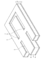
このような圧電アクチュエーター1は、図3に示すような積層構造を有して構成されている。すなわち、図3に示すように、振動部11、支持部12および接続部13は、第1振動板2と、第2振動板3と、これらの間に配置されている圧電素子4および中間部材5と、を有する。そして、第1振動板2は、接着剤61を介して圧電素子4および中間部材5に接合されている。同様に、第2振動板3は、接着剤62を介して圧電素子4および中間部材5に接合されている。以下、圧電アクチュエーター1の各部を順次説明する。   Such a piezoelectric actuator 1 has a laminated structure as shown in FIG. That is, as shown in FIG. 3, the vibration part 11, the support part 12, and the connection part 13 are composed of the first vibration plate 2, the second vibration plate 3, the piezoelectric element 4 and the intermediate member disposed therebetween. And 5. The first diaphragm 2 is bonded to the piezoelectric element 4 and the intermediate member 5 via an adhesive 61. Similarly, the second diaphragm 3 is joined to the piezoelectric element 4 and the intermediate member 5 via an adhesive 62. Hereinafter, each part of the piezoelectric actuator 1 will be described sequentially.

(第1、第2振動板)
第1振動板2および第2振動板3は、それぞれ、前述した振動部11、支持部12および接続部13に対応した平面視形状をなしている。そして、第1振動板2および第2振動板3は、圧電素子4を挟んでいる部分を有し、当該部分および圧電素子4を含む積層体が振動部11を構成している。また、第1振動板2および第2振動板3は、中間部材5を挟んでいる部分を有し、当該部分および中間部材5を含む積層体が支持部12を構成している。なお、接続部13には、圧電素子4および中間部材5がいずれも配置されておらず、第1振動板2と第2振動板3との間には、接続部13の長さと、圧電素子4または中間部材5の厚さと、に応じた隙間が形成されている。
(First and second diaphragm)
The 1st diaphragm 2 and the 2nd diaphragm 3 have comprised the planar view shape corresponding to the vibration part 11, the support part 12, and the connection part 13 which were mentioned above, respectively. The first diaphragm 2 and the second diaphragm 3 have a portion sandwiching the piezoelectric element 4, and the laminate including the portion and the piezoelectric element 4 constitutes the vibrating portion 11. Further, the first diaphragm 2 and the second diaphragm 3 have a portion that sandwiches the intermediate member 5, and the laminate including the portion and the intermediate member 5 constitutes the support portion 12. Note that neither the piezoelectric element 4 nor the intermediate member 5 is disposed in the connection portion 13, and the length of the connection portion 13 and the piezoelectric element are between the first diaphragm 2 and the second diaphragm 3. A gap corresponding to the thickness of 4 or the intermediate member 5 is formed.

このような第1振動板2および第2振動板3としては、それぞれ、特に限定されないが、例えば、シリコン基板、シリコンカーバイト基板等の半導体基板を用いることができる。第1振動板2または第2振動板3として半導体基板(特にシリコン基板)を用いることで、第1振動板2または第2振動板3をシリコンウエハープロセス(MEMSプロセス)により生産性よく高精度に製造することができる。   The first diaphragm 2 and the second diaphragm 3 are not particularly limited. For example, a semiconductor substrate such as a silicon substrate or a silicon carbide substrate can be used. By using a semiconductor substrate (particularly a silicon substrate) as the first diaphragm 2 or the second diaphragm 3, the first diaphragm 2 or the second diaphragm 3 can be produced with high productivity and high accuracy by a silicon wafer process (MEMS process). Can be manufactured.

第1振動板2の圧電素子4側(図4中上側)の面には、絶縁層24が設けられている。これにより、第1振動板2を介した配線層7の短絡を低減することができる。同様に、第2振動板3の圧電素子4側(図4中下側)の面には、絶縁層34が設けられている。これにより、第2振動板3を介した配線層8の短絡を低減することができる。絶縁層24、34は、それぞれ、例えば、第1振動板2および第2振動板3にそれぞれシリコン基板を用いた場合、シリコン基板の表面を熱酸化することにより形成されたシリコン酸化膜である。なお、絶縁層24、34は、それぞれ、熱酸化によるシリコン酸化膜に限定されず、例えば、TEOS(テトラエトキシシラン)を用いたCVD法等で形成したシリコン酸化膜であってもよい。また、絶縁層24、34は、それぞれ、絶縁性を有していればシリコン酸化膜に限定されず、例えば、シリコン窒化膜等の無機膜、エポキシ系樹脂、ウレタン系樹脂、ユリア系樹脂、メラミン系樹脂、フェノール系樹脂、エステル系樹脂、アクリル系樹脂等の各種樹脂材料で構成された有機膜であってもよい。さらに、絶縁層24、34は、それぞれ、異なる材料で構成された複数の層の積層膜であってもよい。   An insulating layer 24 is provided on the surface of the first diaphragm 2 on the piezoelectric element 4 side (upper side in FIG. 4). Thereby, a short circuit of the wiring layer 7 via the first diaphragm 2 can be reduced. Similarly, an insulating layer 34 is provided on the surface of the second diaphragm 3 on the piezoelectric element 4 side (lower side in FIG. 4). Thereby, a short circuit of the wiring layer 8 via the second diaphragm 3 can be reduced. Insulating layers 24 and 34 are silicon oxide films formed by thermally oxidizing the surface of a silicon substrate, for example, when a silicon substrate is used for each of first diaphragm 2 and second diaphragm 3. The insulating layers 24 and 34 are not limited to silicon oxide films formed by thermal oxidation, but may be silicon oxide films formed by, for example, a CVD method using TEOS (tetraethoxysilane). The insulating layers 24 and 34 are not limited to silicon oxide films as long as they have insulating properties. For example, inorganic films such as silicon nitride films, epoxy resins, urethane resins, urea resins, melamines, etc. It may be an organic film made of various resin materials such as resin, phenol resin, ester resin, and acrylic resin. Furthermore, the insulating layers 24 and 34 may each be a laminated film of a plurality of layers made of different materials.

第1振動板2の絶縁層24上には、配線層7が配置されている。配線層7は、振動部11に配置されている複数の第1電極71(配線電極)と、複数の第1電極71から接続部13を経由して支持部12にわたって配置されている複数の第1配線72と、を有する(図4参照)。これらは、例えば、公知の成膜工程により一括して形成される。   A wiring layer 7 is arranged on the insulating layer 24 of the first diaphragm 2. The wiring layer 7 includes a plurality of first electrodes 71 (wiring electrodes) disposed in the vibration portion 11 and a plurality of first electrodes disposed from the plurality of first electrodes 71 to the support portion 12 via the connection portion 13. 1 wiring 72 (see FIG. 4). These are formed in a lump by a known film forming process, for example.

複数の第1電極71は、前述した圧電素子4a、4b、4c、4d、4e、4fに対応して設けられ、対応する圧電素子4a、4b、4c、4d、4e、4f(より具体的には後述の第1電極42a、42b、42c、42d、42eまたは第3電極44)に電気的に接続されている。複数の第1配線72は、複数の第1電極71に対応して設けられ、それぞれ対応する第1電極71から支持部12の端部まで引き回されている。また、各第1配線72の端部には、中間部材5上の配線53を介して、図示しない基板に電気的に接続される端子91が接続されている(図4参照)。なお、各第1配線72の端部に端子91を直接設けてもよい。   The plurality of first electrodes 71 are provided corresponding to the piezoelectric elements 4a, 4b, 4c, 4d, 4e, and 4f described above, and the corresponding piezoelectric elements 4a, 4b, 4c, 4d, 4e, and 4f (more specifically, Are electrically connected to a first electrode 42a, 42b, 42c, 42d, 42e or a third electrode 44) described later. The plurality of first wirings 72 are provided corresponding to the plurality of first electrodes 71, and are respectively routed from the corresponding first electrode 71 to the end of the support portion 12. In addition, a terminal 91 that is electrically connected to a substrate (not shown) is connected to the end of each first wiring 72 via a wiring 53 on the intermediate member 5 (see FIG. 4). Note that the terminal 91 may be provided directly at the end of each first wiring 72.

一方、第2振動板3の絶縁層34上には、配線層8が配置されている。配線層8は、図4に示すように、振動部11に配置されている第2電極81と、第2電極81から接続部13を経由して支持部12にわたって配置されている第2配線82と、を有する。これらは、例えば、公知の成膜工程により一括して形成される。   On the other hand, the wiring layer 8 is disposed on the insulating layer 34 of the second diaphragm 3. As shown in FIG. 4, the wiring layer 8 includes a second electrode 81 disposed in the vibration part 11 and a second wiring 82 disposed from the second electrode 81 to the support part 12 via the connection part 13. And having. These are formed in a lump by a known film forming process, for example.

第2電極81は、前述した圧電素子4(より具体的には後述の第2電極43)に電気的に接続されている。第2配線82は、支持部12の端部まで引き回されている。また、第2配線82の端部には、図示しない基板に電気的に接続される端子92が設けられている(図4参照)。   The second electrode 81 is electrically connected to the above-described piezoelectric element 4 (more specifically, the second electrode 43 described later). The second wiring 82 is routed to the end of the support portion 12. Further, a terminal 92 that is electrically connected to a substrate (not shown) is provided at the end of the second wiring 82 (see FIG. 4).

配線53、配線層7、8および端子92、91の構成材料としては、それぞれ、特に限定されず、例えば、アルミニウム(Al)、ニッケル(Ni)、金(Au)、白金(Pt)、銅(Cu)、チタン(Ti)、タングステン(W)等の金属材料が挙げられる。また、端子91、92は、公知の成膜法を用いて形成することができる。   The constituent materials of the wiring 53, the wiring layers 7 and 8, and the terminals 92 and 91 are not particularly limited. For example, aluminum (Al), nickel (Ni), gold (Au), platinum (Pt), copper ( Examples thereof include metal materials such as Cu), titanium (Ti), and tungsten (W). The terminals 91 and 92 can be formed using a known film formation method.

以上のような第1振動板2および第2振動板3は、接着剤61、62により、圧電素子4および中間部材5に接合されている。ここで、接着剤61は、配線層7と圧電素子4との電気的接続を許容するように、第1振動板2と圧電素子4とを接合している。また、接着剤62は、配線層8と圧電素子4との電気的接続を許容するように、第2振動板3と圧電素子4とを接合している。接着剤61、62としては、それぞれ、特に限定されないが、例えば、エポキシ系、アクリル系、シリコン系等の各種接着剤、異方導電性接着剤等を用いることができる。   The first diaphragm 2 and the second diaphragm 3 as described above are joined to the piezoelectric element 4 and the intermediate member 5 by adhesives 61 and 62. Here, the adhesive 61 joins the first diaphragm 2 and the piezoelectric element 4 so as to allow electrical connection between the wiring layer 7 and the piezoelectric element 4. Further, the adhesive 62 joins the second diaphragm 3 and the piezoelectric element 4 so as to allow electrical connection between the wiring layer 8 and the piezoelectric element 4. The adhesives 61 and 62 are not particularly limited. For example, various adhesives such as epoxy, acrylic, and silicon, anisotropic conductive adhesives, and the like can be used.

(圧電素子)
圧電素子4は、図5に示すように、板状の圧電体41と、圧電体41の一方(第1振動板2側)の面上に配置されている第1電極42(駆動用電極)および第3電極44(検出用電極)と、圧電体41の他方(第2振動板3側)の面上に配置されている第2電極43(グランド電極)と、を有する。
(Piezoelectric element)
As shown in FIG. 5, the piezoelectric element 4 includes a plate-like piezoelectric body 41 and a first electrode 42 (driving electrode) disposed on one surface of the piezoelectric body 41 (on the first diaphragm 2 side). And a third electrode 44 (detection electrode) and a second electrode 43 (ground electrode) disposed on the other surface (second diaphragm 3 side) of the piezoelectric body 41.

圧電体41は、平面視で長方形をなしている。この圧電体41の構成材料としては、例えば、チタン酸ジルコン酸鉛(PZT)、チタン酸バリウム、チタン酸鉛、ニオブ酸カリウム、ニオブ酸リチウム、タンタル酸リチウム、タングステン酸ナトリウム、酸化亜鉛、チタン酸バリウムストロンチウム(BST)、タンタル酸ストロンチウムビスマス(SBT)、メタニオブ酸鉛、スカンジウムニオブ酸鉛等の圧電セラミックスが挙げられる。なお、圧電体41の構成材料としては、上述した圧電セラミックスの他にも、ポリフッ化ビニリデン、水晶等を用いてもよい。   The piezoelectric body 41 has a rectangular shape in plan view. Examples of the constituent material of the piezoelectric body 41 include lead zirconate titanate (PZT), barium titanate, lead titanate, potassium niobate, lithium niobate, lithium tantalate, sodium tungstate, zinc oxide, titanate. Examples thereof include piezoelectric ceramics such as barium strontium (BST), strontium bismuth tantalate (SBT), lead metaniobate, and lead scandium niobate. In addition to the above-described piezoelectric ceramics, polyvinylidene fluoride, quartz, or the like may be used as the constituent material of the piezoelectric body 41.

また、圧電体41は、例えば、バルク材料から形成してもよいし、ゾル−ゲル法やスパッタリング法を用いて形成してもよいが、バルク材料から形成することが好ましい。これにより、圧電体41の厚さを厚くし、圧電素子4の変位量を大きくすることができる。そのため、圧電アクチュエーター1の電流効率をさらに向上させることができる。   The piezoelectric body 41 may be formed from, for example, a bulk material, or may be formed using a sol-gel method or a sputtering method, but is preferably formed from a bulk material. Thereby, the thickness of the piezoelectric body 41 can be increased and the displacement amount of the piezoelectric element 4 can be increased. Therefore, the current efficiency of the piezoelectric actuator 1 can be further improved.

第1電極42(駆動用電極)は、圧電素子4a、4b、4c、4d、4eごとに個別に設けられた個別電極である複数(5つ)の第1電極42a、42b、42c、42d、42eで構成されている。第1電極42a、42b、42c、42d、42eには、それぞれ、駆動信号(駆動電圧)が入力される。また、第3電極44(検出用電極)は、圧電素子4fに設けられた個別電極であり、圧電素子4の駆動状態に応じた検出信号を出力する。一方、第2電極43(グランド電極)は、第1電極42a、42b、42c、42d、42eおよび第3電極44に対して個別に対向するように設けられた電極であり、基準電位(例えばグランド電位)に電気的に接続される。   The first electrode 42 (drive electrode) is a plurality of (five) first electrodes 42a, 42b, 42c, 42d, which are individual electrodes provided for each of the piezoelectric elements 4a, 4b, 4c, 4d, and 4e. 42e. A drive signal (drive voltage) is input to each of the first electrodes 42a, 42b, 42c, 42d, and 42e. The third electrode 44 (detection electrode) is an individual electrode provided in the piezoelectric element 4 f and outputs a detection signal corresponding to the driving state of the piezoelectric element 4. On the other hand, the second electrode 43 (ground electrode) is an electrode provided so as to face the first electrode 42a, 42b, 42c, 42d, 42e and the third electrode 44 individually. Electrical potential).

すなわち、圧電素子4aは、圧電体41、第1電極42aおよび第2電極43を含んで構成されている。同様に、圧電素子4b、4c、4d、4eは、圧電体41、第1電極42b、42c、42d、42eおよび第2電極43を含んで構成されている。圧電素子4fは、圧電体41、第3電極44および第2電極43を含んで構成されている。このように、圧電素子4は、6つの圧電素子4a、4b、4c、4d、4e、4fを有している。   That is, the piezoelectric element 4 a includes the piezoelectric body 41, the first electrode 42 a and the second electrode 43. Similarly, the piezoelectric elements 4b, 4c, 4d, and 4e include a piezoelectric body 41, first electrodes 42b, 42c, 42d, and 42e, and a second electrode 43. The piezoelectric element 4 f includes a piezoelectric body 41, a third electrode 44, and a second electrode 43. Thus, the piezoelectric element 4 has six piezoelectric elements 4a, 4b, 4c, 4d, 4e, and 4f.

ここで、駆動用電極である第1電極42a、42b、42c、42d、42eのうち、第1電極42a、42b、42c、42dは、駆動信号の入力により圧電体41を屈曲振動(前述した横振動)させる電界を第2電極43との間に発生させる屈曲用電極である。これに対し、第1電極42eは、駆動信号の入力により圧電体41を屈曲させずに伸縮振動(前述した縦振動)させる電界を第2電極43との間に発生させる縦振動用電極である。   Here, among the first electrodes 42a, 42b, 42c, 42d, and 42e, which are driving electrodes, the first electrodes 42a, 42b, 42c, and 42d cause the piezoelectric body 41 to bend and vibrate in response to the input of the driving signal (the above-described lateral vibration). This is a bending electrode that generates an electric field to be vibrated between the second electrode 43 and the second electrode 43. On the other hand, the first electrode 42e is an electrode for longitudinal vibration that generates an electric field between the second electrode 43 and the piezoelectric body 41 without causing the piezoelectric body 41 to bend and vibrate (the longitudinal vibration described above) without being bent. .

本実施形態では、第1電極42eは、圧電体41の幅方向の中央部に圧電体41の長手方向に沿って配置されている。第1電極42a、42bは、第1電極42eに対して圧電体41の幅方向の一方側に圧電体41の長手方向に沿って配置されている。第1電極42c、42dは、第1電極42eに対して圧電体41の幅方向の他方側に圧電体41の長手方向に沿って配置されている。第3電極44は、第1電極42eに対して伝達部14とは反対側に配置されている。   In the present embodiment, the first electrode 42 e is disposed along the longitudinal direction of the piezoelectric body 41 at the center in the width direction of the piezoelectric body 41. The first electrodes 42a and 42b are arranged along the longitudinal direction of the piezoelectric body 41 on one side in the width direction of the piezoelectric body 41 with respect to the first electrode 42e. The first electrodes 42c and 42d are arranged along the longitudinal direction of the piezoelectric body 41 on the other side in the width direction of the piezoelectric body 41 with respect to the first electrode 42e. The third electrode 44 is disposed on the opposite side of the transmission unit 14 with respect to the first electrode 42e.

なお、圧電体41は、圧電素子4a、4b、4c、4d、4e、4fに共通して一体的に構成されているが、圧電素子4a、4b、4c、4d、4e、4fごとに個別に分割して設けられていてもよい。   The piezoelectric body 41 is integrally formed in common with the piezoelectric elements 4a, 4b, 4c, 4d, 4e, and 4f, but is individually provided for each of the piezoelectric elements 4a, 4b, 4c, 4d, 4e, and 4f. It may be divided and provided.

第1電極42、第2電極43および第3電極44の構成材料としては、それぞれ、特に限定されないが、例えば、アルミニウム(Al)、ニッケル(Ni)、金(Au)、白金(Pt)、イリジウム(Ir)、銅(Cu)、チタン(Ti)、タングステン(W)等の金属材料が挙げられる。   The constituent materials of the first electrode 42, the second electrode 43, and the third electrode 44 are not particularly limited. For example, aluminum (Al), nickel (Ni), gold (Au), platinum (Pt), iridium Examples thereof include metal materials such as (Ir), copper (Cu), titanium (Ti), and tungsten (W).

(中間部材)
中間部材5は、前述した支持部12において、第1振動板2と第2振動板3との間に設けられ、平面視で、支持部12と実質的に同じ形状および大きさを有している。この中間部材5は、支持部12を補強するとともに、支持部12における第1振動板2と第2振動板3との間の距離を振動部11における第1振動板2と第2振動板3との間の距離と等しくするように規制する機能を有する。
(Intermediate member)
The intermediate member 5 is provided between the first diaphragm 2 and the second diaphragm 3 in the support portion 12 described above, and has substantially the same shape and size as the support portion 12 in plan view. Yes. The intermediate member 5 reinforces the support portion 12 and sets the distance between the first diaphragm 2 and the second diaphragm 3 in the support portion 12 to the first diaphragm 2 and the second diaphragm 3 in the vibration portion 11. It has the function to regulate so that it may become equal to the distance between.

図4に示すように、中間部材5は、本体51と、本体51上に設けられている絶縁層52と、を有する。このような中間部材5は、例えば、本体51がシリコンで構成され、絶縁層52がシリコン酸化膜で構成されている。なお、中間部材5の構成材料としては、これに限定されず、例えば、ジルコニア、アルミナ、チタニア等の各種セラミックス、各種樹脂材料等を用いてもよい。   As shown in FIG. 4, the intermediate member 5 includes a main body 51 and an insulating layer 52 provided on the main body 51. In such an intermediate member 5, for example, the main body 51 is made of silicon, and the insulating layer 52 is made of a silicon oxide film. In addition, as a constituent material of the intermediate member 5, it is not limited to this, For example, you may use various ceramics, such as a zirconia, an alumina, and a titania, various resin materials.

(伝達部)
伝達部14(先端チップ)は、例えば、セラミックス等の耐摩耗性に優れた材料で構成され、振動部11に対して接着剤等により接合されている。すなわち、伝達部14は、圧電素子4、第1振動板2および第2振動板3に接合するように配置され、ローター110(被駆動部材)に当接する当接面を含む。
(Transmission part)
The transmission portion 14 (tip tip) is made of a material having excellent wear resistance such as ceramics, and is bonded to the vibration portion 11 with an adhesive or the like. That is, the transmission unit 14 is disposed so as to be bonded to the piezoelectric element 4, the first diaphragm 2, and the second diaphragm 3, and includes a contact surface that contacts the rotor 110 (driven member).

図6は、図1に示す伝達部近傍を拡大して示す斜視図である。また、図7は、図6に示す伝達部を取り出して示す斜視図である。また、図8は、伝達部がローター(被駆動部材)に当接する当接面を、図7に示す第1平面F1で切断したときの第1断面形状を示す図である。   FIG. 6 is an enlarged perspective view showing the vicinity of the transmission section shown in FIG. FIG. 7 is a perspective view showing the transmission unit shown in FIG. FIG. 8 is a diagram showing a first cross-sectional shape when the contact surface where the transmission unit contacts the rotor (driven member) is cut along the first plane F1 shown in FIG.

伝達部14は、図7に示すように、直方体形状をなす基部141と、基部141の一面141aから突出する突出部142と、を備えている。そして、突出部142の表面のうち、ローター110に臨む面が当接面143である。   As shown in FIG. 7, the transmission portion 14 includes a base portion 141 having a rectangular parallelepiped shape, and a protruding portion 142 that protrudes from one surface 141 a of the base portion 141. And the surface which faces the rotor 110 among the surfaces of the protrusion part 142 is the contact surface 143.

一面141aは、圧電体41の厚さ方向に長軸を持つ長方形をなしている。この長軸の長さは、振動部11の厚さと同じになっている。そして、一面141aを平面視したとき、突出部142の幅は、一面141aの短辺よりも狭くなっており、かつ、突出部142の長さは、一面141aの長辺と同じ長さになっている。   The one surface 141 a has a rectangular shape with a major axis in the thickness direction of the piezoelectric body 41. The length of the long axis is the same as the thickness of the vibration part 11. When the one surface 141a is viewed in plan, the width of the protruding portion 142 is narrower than the short side of the one surface 141a, and the length of the protruding portion 142 is the same as the long side of the one surface 141a. ing.

なお、本願明細書では、圧電体41の厚さ方向(図7の上下方向)を「垂直方向D1」ともいう。   In the present specification, the thickness direction (vertical direction in FIG. 7) of the piezoelectric body 41 is also referred to as “vertical direction D1”.

ここで、図7に示す仮想的な第1平面F1について説明する。この第1平面F1は、第1電極42(図5参照)に直交するとともに、当接面143を通過する平面である。すなわち、第1平面F1は、前述した垂直方向D1に平行であり、かつ、突出部142の幅を二分するように通過する。このような第1平面F1で切断されたとき、当接面143の断面形状(第1断面形状)は、図8に示すように曲率を有している。   Here, the virtual first plane F1 shown in FIG. 7 will be described. The first plane F1 is a plane that is orthogonal to the first electrode 42 (see FIG. 5) and passes through the contact surface 143. That is, the first plane F1 is parallel to the above-described vertical direction D1 and passes so as to bisect the width of the protrusion 142. When cut along such a first plane F1, the cross-sectional shape (first cross-sectional shape) of the contact surface 143 has a curvature as shown in FIG.

このような形状を有する伝達部14によれば、当接面143のうち、突出部142とローター110との接触面積を小さくすることができる。これにより、伝達部14が楕円運動するように振動部11を駆動するときの拘束力(運動抵抗)を小さくすることができる。その結果、振動部11を駆動するための最低電圧を低くすることができ、圧電アクチュエーター1の高性能化を図ることができる。   According to the transmission part 14 having such a shape, the contact area between the protrusion 142 and the rotor 110 in the contact surface 143 can be reduced. Thereby, the restraining force (movement resistance) when driving the vibration part 11 so that the transmission part 14 carries out elliptical motion can be made small. As a result, the minimum voltage for driving the vibration part 11 can be lowered, and the performance of the piezoelectric actuator 1 can be improved.

なお、「曲率を有している」とは、当接面143の断面形状が曲線になっている状態をいう。この曲線は、いかなる線形であってもよいが、好ましくは円弧またはそれに準じた形状とされる。これにより、当接面143とローター110とが接触したとき、当接面143の摩耗による形状変化、および、それに伴う当接面143とローター110との接触状態が安定しやすくなる。また、当接面143の設計も比較的容易になる。   “Having curvature” means a state in which the cross-sectional shape of the contact surface 143 is a curve. This curve may be any linear shape, but is preferably a circular arc or a shape conforming thereto. Thereby, when the contact surface 143 contacts the rotor 110, the shape change due to wear of the contact surface 143 and the contact state between the contact surface 143 and the rotor 110 are easily stabilized. In addition, the design of the contact surface 143 is relatively easy.

なお、本願明細書では、前述した圧電体41の横振動の方向をローター110の「送り方向D2」ともいい、圧電体41の縦運動の方向をローター110に対する「押圧方向D3」ともいう。そして、送り方向D2と押圧方向D3とを含む平面を「振動面F2」という。垂直方向D1は、振動面F2に直交する。   In the present specification, the direction of transverse vibration of the piezoelectric body 41 described above is also referred to as “feed direction D2” of the rotor 110, and the direction of longitudinal movement of the piezoelectric body 41 is also referred to as “pressing direction D3” with respect to the rotor 110. A plane including the feeding direction D2 and the pressing direction D3 is referred to as a “vibrating surface F2.” The vertical direction D1 is orthogonal to the vibration surface F2.

以上のように、圧電アクチュエーター1は、第1振動板2および第2振動板3と、第1振動板2と第2振動板3との間に積層され圧電体41とその一方の面上に配置され駆動信号が入力される第1電極42と圧電体41の他方の面上に配置され基準電位に接続される第2電極43とを備える圧電素子4と、圧電素子4に配置されローター110(被駆動部材)に当接する当接面143を含む伝達部14(先端チップ)と、を有し、第1電極42に直交する第1平面F1で当接面143を切断したときの断面形状(第1断面形状)が、曲率を有している。   As described above, the piezoelectric actuator 1 is laminated between the first diaphragm 2 and the second diaphragm 3, and between the first diaphragm 2 and the second diaphragm 3, and on the piezoelectric body 41 and one surface thereof. A piezoelectric element 4 including a first electrode 42 that is disposed and to which a drive signal is input and a second electrode 43 that is disposed on the other surface of the piezoelectric body 41 and is connected to a reference potential, and the rotor 110 disposed on the piezoelectric element 4. A transmission section 14 (tip tip) including a contact surface 143 that contacts the (driven member), and a cross-sectional shape when the contact surface 143 is cut along a first plane F1 orthogonal to the first electrode 42 (First cross-sectional shape) has a curvature.

このような圧電アクチュエーター1によれば、当接面143とローター110との接触面積を小さくすることができ、振動部11を駆動するための最低電圧を低くすることができる。その結果、圧電アクチュエーター1の高性能化を図ることができる。   According to such a piezoelectric actuator 1, the contact area between the contact surface 143 and the rotor 110 can be reduced, and the minimum voltage for driving the vibration unit 11 can be reduced. As a result, high performance of the piezoelectric actuator 1 can be achieved.

より具体的に説明すると、第1平面F1による当接面143の第1断面形状(図8参照)は、その全長の中間付近の突出高さが最も高く、中間から離れるにつれて突出高さが徐々に低くなっている。そして、全体としては円弧状になっている。このため、当接面143のうちローター110と接触し得る部分は、図7に破線で示すように、当接面143の第1断面形状の中間付近に限られることとなり、接触面積を小さくすることができる。その結果、振動部11を駆動するための最低電圧を低くすることができる。   More specifically, the first cross-sectional shape (see FIG. 8) of the contact surface 143 by the first plane F1 has the highest protrusion height near the middle of the entire length, and the protrusion height gradually increases as the distance from the middle increases. It is low. And as a whole, it has an arc shape. Therefore, the portion of the contact surface 143 that can come into contact with the rotor 110 is limited to the vicinity of the middle of the first cross-sectional shape of the contact surface 143 as shown by the broken line in FIG. be able to. As a result, the minimum voltage for driving the vibration part 11 can be lowered.

また、当接面143の第1断面形状が曲率を有することにより、例えば振動部11が垂直方向D1に振動したとしても、その振動に伴う当接面143の摩耗を最小限に留めることができる。すなわち、当接面143の第1断面形状が曲率を有することにより、振動部11が垂直方向D1に振動したとしても、突出部142とローター110との接触面積が時間経過ととともに大きく拡大するといった顕著な変化が抑えられる。   Further, since the first cross-sectional shape of the contact surface 143 has a curvature, even if the vibration part 11 vibrates in the vertical direction D1, for example, wear of the contact surface 143 due to the vibration can be minimized. . That is, since the first cross-sectional shape of the contact surface 143 has a curvature, even if the vibration part 11 vibrates in the vertical direction D1, the contact area between the protrusion 142 and the rotor 110 greatly increases with time. Significant changes are suppressed.

なお、仮に、伝達部14とローター110との接触面積が経時的に変化してしまうと、圧電アクチュエーター1の特性も経時的に変化してしまい、信頼性の低下を招くおそれがある。   If the contact area between the transmission unit 14 and the rotor 110 changes over time, the characteristics of the piezoelectric actuator 1 also change over time, which may lead to a decrease in reliability.

これに対し、本実施形態に係る当接面143は、振動部11が垂直方向に振動した場合に生じる摩耗に伴う形状変化をあらかじめ見越した形状ともいえるため、そのような伝達部14を備える圧電アクチュエーター1では、その駆動に際して発生する当接面143の摩耗が当初から少なく抑えられる。その結果、伝達部14とローター110との接触状態が当初から安定することとなり、当初から設計通りの特性を安定的に発揮し得る、信頼性の高い圧電アクチュエーター1を実現することができる。   On the other hand, the contact surface 143 according to the present embodiment can be said to be a shape that anticipates a shape change accompanying wear that occurs when the vibration portion 11 vibrates in the vertical direction. In the actuator 1, the wear of the contact surface 143 that occurs during the driving is suppressed from the beginning. As a result, the contact state between the transmission portion 14 and the rotor 110 is stabilized from the beginning, and the highly reliable piezoelectric actuator 1 that can stably exhibit the designed characteristics from the beginning can be realized.

当接面143の第1断面形状は、圧電アクチュエーター1やローター110の大きさに応じて適宜設定されるが、例えば曲率半径が1mm以上2000mm以下の曲率を有する形状であるのが好ましく、3mm以上1000mm以下の曲率を有する形状であるのがより好ましい。これにより、摩耗による接触状態の変化が少なく、かつ、十分な大きさの駆動力を発生させ得る当接面143を実現することができる。   The first cross-sectional shape of the contact surface 143 is appropriately set according to the size of the piezoelectric actuator 1 and the rotor 110. For example, it is preferably a shape having a curvature with a curvature radius of 1 mm to 2000 mm, preferably 3 mm or more. A shape having a curvature of 1000 mm or less is more preferable. As a result, it is possible to realize the contact surface 143 that can change the contact state due to wear and that can generate a sufficiently large driving force.

一方、当接面143は、振動面F2で切断されたときの断面形状(第2断面形状)も曲率を有していることが好ましい。   On the other hand, it is preferable that the contact surface 143 has a curvature also in a cross-sectional shape (second cross-sectional shape) when cut at the vibration surface F2.

図9は、伝達部がローター(被駆動部材)に当接する当接面を、図7に示す振動面F2で切断したときの第2断面形状を示す図である。   FIG. 9 is a diagram illustrating a second cross-sectional shape when the contact surface with which the transmission unit contacts the rotor (driven member) is cut along the vibration surface F2 illustrated in FIG.

振動面F2は、第1平面F1に直交し、第1電極42(図5参照)に平行な平面(第2平面)である。このような振動面F2による当接面143の第2断面形状が曲率を有していることにより、当接面143とローター110との接触面積をより小さくすることができる。その結果、振動部11を駆動するための最低電圧をさらに低くすることができる。   The vibration surface F2 is a plane (second plane) orthogonal to the first plane F1 and parallel to the first electrode 42 (see FIG. 5). Since the second cross-sectional shape of the contact surface 143 by the vibration surface F2 has a curvature, the contact area between the contact surface 143 and the rotor 110 can be further reduced. As a result, the minimum voltage for driving the vibration unit 11 can be further reduced.

当接面143の第2断面形状は、圧電アクチュエーター1やローター110の大きさに応じて適宜設定されるが、第2断面形状の曲率半径は、第1断面形状の曲率半径より小さいことが好ましく、第1断面形状の曲率半径の50%以下であるのがより好ましい。これにより、摩耗がより少なく、かつ、十分な大きさの駆動力を発生させ得る当接面143を実現することができる。   The second cross-sectional shape of the contact surface 143 is appropriately set according to the size of the piezoelectric actuator 1 and the rotor 110, but the radius of curvature of the second cross-sectional shape is preferably smaller than the radius of curvature of the first cross-sectional shape. More preferably, it is 50% or less of the radius of curvature of the first cross-sectional shape. As a result, it is possible to realize the contact surface 143 that is less worn and can generate a sufficiently large driving force.

なお、以上のような当接面143の形状、すなわち第1断面形状および第2断面形状は、伝達部14を製造する際にあらかじめ形作られたものであってもよいし、ローター110との接触による摩耗を利用して形作られたものであってもよい。前者は、機械的加工またはその他の加工方法によって目的の形状を得ることができ、後者は、整形前の母材に摩耗を生じさせることによって目的の形状を得ることができる。   In addition, the shape of the contact surface 143 as described above, that is, the first cross-sectional shape and the second cross-sectional shape may be formed in advance when the transmission unit 14 is manufactured, or may be in contact with the rotor 110. It may be formed using the wear caused by. The former can obtain the target shape by mechanical processing or other processing methods, and the latter can obtain the target shape by causing wear on the base material before shaping.

このうち、後者の方法によれば、形作られた当接面143の形状が、ローター110との接触による摩耗を少なく抑え得る形状となる。すなわち、後者の方法では、当接面143の形状変化の原因であるローター110との接触を利用して当接面143の形状を整形しているため、整形後に同様の摩耗が生じたとしても、その摩耗量は非常に少ないものとなり、著しい形状変化を抑制することができる。このため、伝達部14とローター110との接触状態が経時的に変化しにくくなり、特性の経時的変化が特に抑えられた圧電アクチュエーター1が得られる。すなわち、使用開始直後から安定した特性を示す圧電アクチュエーター1が得られる。   Among these, according to the latter method, the shape of the formed contact surface 143 becomes a shape that can suppress wear due to contact with the rotor 110 to a small extent. That is, in the latter method, since the shape of the contact surface 143 is shaped using the contact with the rotor 110 that causes the shape change of the contact surface 143, even if similar wear occurs after shaping. The amount of wear is very small, and a significant change in shape can be suppressed. For this reason, the contact state between the transmission unit 14 and the rotor 110 is less likely to change with time, and the piezoelectric actuator 1 in which the change with time of the characteristics is particularly suppressed can be obtained. That is, the piezoelectric actuator 1 showing stable characteristics immediately after the start of use can be obtained.

したがって、圧電アクチュエーター1の製造にあたっては、当接面143をローター110に当接させ、形状変化が収束するまで圧電アクチュエーター1を駆動するプロセス(エージング)を経るようにしてもよい。このようなプロセスを経ることによって、当接面143とローター110との接触状態に個体差があったとしても、その個体差を踏まえた形状に当接面143を整形することができる。これにより、特性の経時的変化が特に抑えられた圧電アクチュエーター1が得られる。   Therefore, in manufacturing the piezoelectric actuator 1, the contact surface 143 may be brought into contact with the rotor 110, and a process (aging) for driving the piezoelectric actuator 1 may be performed until the shape change converges. By going through such a process, even if there is an individual difference in the contact state between the contact surface 143 and the rotor 110, the contact surface 143 can be shaped into a shape based on the individual difference. Thereby, the piezoelectric actuator 1 in which the change with time of the characteristics is particularly suppressed is obtained.

また、圧電素子4は、圧電体41の一方(第1電極42と同じ側)の面上に、第1電極42に対して伝達部14とは反対側に配置され、圧電体41の振動に伴って電荷を出力する検出用電極である第3電極44を有する。これにより、圧電体41上の領域を有効利用して、検出用電極である第3電極44を配置することができる。また、当該領域に第3電極44を配置することで、第3電極44が伝達部14とローター110との接触・離間による衝撃波の影響を受け難くなるため、ノイズの少ない検出信号が得られるという効果もある。なお、第3電極44は、必要に応じて設ければよく、省略してもよい。省略した場合、第1電極42a、42b、42c、42d、42eのいずれかを検出用電極との兼用にすればよい。   The piezoelectric element 4 is disposed on one side of the piezoelectric body 41 (on the same side as the first electrode 42) on the opposite side of the transmission portion 14 with respect to the first electrode 42, Along with this, there is a third electrode 44 that is a detection electrode that outputs charges. Accordingly, the third electrode 44 that is a detection electrode can be disposed by effectively using the region on the piezoelectric body 41. In addition, by arranging the third electrode 44 in the region, the third electrode 44 is not easily affected by a shock wave due to contact / separation between the transmission unit 14 and the rotor 110, and thus a detection signal with less noise can be obtained. There is also an effect. Note that the third electrode 44 may be provided as necessary and may be omitted. If omitted, any one of the first electrodes 42a, 42b, 42c, 42d, and 42e may be used also as a detection electrode.

なお、本実施形態に係る複数(6つ)の第2電極43は、圧電体41を介し、第1電極42および第3電極44に対向して設けられている。これらの複数の第2電極43は、例えば互いに等電位に設定されることから、第1電極42や第3電極44と対向していれば第2電極43の形状は特に限定されない。   Note that a plurality (six) of the second electrodes 43 according to the present embodiment are provided to face the first electrode 42 and the third electrode 44 via the piezoelectric body 41. Since the plurality of second electrodes 43 are set to be equipotential to each other, for example, the shape of the second electrode 43 is not particularly limited as long as it faces the first electrode 42 and the third electrode 44.

本実施形態では、各第2電極43が、複数の第1電極42および第3電極44のそれぞれと対向するように配置されているとともに、その面積は、対応する第1電極42または第3電極44の面積よりもそれぞれ大きくなるように設定されている。このように、第1電極42と第2電極43とで面積差を設定する(形状を異ならせる)ことにより、振動部11を送り方向D2や押圧方向D3のみでなく、垂直方向D1にも振動させることができる。このため、前述した第1断面形状および第2断面形状を整形するプロセスを効率よく行うことができる。   In the present embodiment, each second electrode 43 is disposed so as to face each of the plurality of first electrodes 42 and third electrodes 44, and the area thereof corresponds to the corresponding first electrode 42 or third electrode. Each area is set to be larger than 44 areas. Thus, by setting the area difference between the first electrode 42 and the second electrode 43 (different shapes), the vibration unit 11 vibrates not only in the feed direction D2 and the pressing direction D3 but also in the vertical direction D1. Can be made. For this reason, the process which shapes the 1st cross-sectional shape mentioned above and the 2nd cross-sectional shape can be performed efficiently.

つまり、本実施形態に係る圧電アクチュエーター1は、第1電極42に駆動信号が入力され、第2電極43が基準電位に接続されたとき、第1電極42と第2電極43とを結ぶ方向(垂直方向D1)に振動するように構成されている。これにより、振動部11を垂直方向D1に振動させることができ、前述した第1断面形状および第2断面形状を整形するプロセスを効率よく行うことができる。   That is, in the piezoelectric actuator 1 according to the present embodiment, when a drive signal is input to the first electrode 42 and the second electrode 43 is connected to the reference potential, the direction connecting the first electrode 42 and the second electrode 43 ( It is configured to vibrate in the vertical direction D1). Thereby, the vibration part 11 can be vibrated to the perpendicular direction D1, and the process which shapes the 1st cross-sectional shape mentioned above and the 2nd cross-sectional shape can be performed efficiently.

また、振動部11の中心CPは、圧電体41を屈曲させずに伸縮振動させたときの振動の節の位置に配置されていることが好ましい。これにより、圧電アクチュエーター1の起動時および定常振動時の双方における駆動電圧を効果的に低減することができる。   The center CP of the vibration part 11 is preferably arranged at the position of a vibration node when the piezoelectric body 41 is expanded and contracted without bending. Thereby, the drive voltage at the time of starting of the piezoelectric actuator 1 and at the time of steady vibration can be reduced effectively.

また、支持部12は、1対の接続部13を介して振動部11を支持しており、振動部11の中心CPは、1対の接続部13間に配置されていることが好ましい。これにより、圧電アクチュエーター1の起動時および定常振動時の双方における駆動電圧を効果的に低減することができる。   Further, the support part 12 supports the vibration part 11 via a pair of connection parts 13, and the center CP of the vibration part 11 is preferably disposed between the pair of connection parts 13. Thereby, the drive voltage at the time of starting of the piezoelectric actuator 1 and at the time of steady vibration can be reduced effectively.

また、圧電駆動装置100は、圧電アクチュエーター1と、圧電アクチュエーター1により駆動される被駆動部材であるローター110と、を備える。このような圧電駆動装置100によれば、圧電アクチュエーター1の優れた特性を利用して、圧電駆動装置100の特性を高めることができる。   The piezoelectric driving device 100 includes a piezoelectric actuator 1 and a rotor 110 that is a driven member driven by the piezoelectric actuator 1. According to such a piezoelectric driving device 100, the characteristics of the piezoelectric driving device 100 can be enhanced by utilizing the excellent characteristics of the piezoelectric actuator 1.

(第1変形例)
また、振動部11を垂直方向D1にも振動させる手段は、上記のものに限定されない。
(First modification)
Further, the means for vibrating the vibrating portion 11 in the vertical direction D1 is not limited to the above.

図10は、図1に示す圧電アクチュエーター1に含まれる振動部11の第1変形例を示す断面図である。   FIG. 10 is a cross-sectional view illustrating a first modification of the vibration unit 11 included in the piezoelectric actuator 1 illustrated in FIG. 1.

図10に示す振動部11は、第1振動板2と第2振動板3とで厚さが異なる以外、図5に示す振動部11と同様である。   The vibrating part 11 shown in FIG. 10 is the same as the vibrating part 11 shown in FIG. 5 except that the first diaphragm 2 and the second diaphragm 3 have different thicknesses.

すなわち、図10に示す振動部11では、第2振動板3の厚さが第1振動板2の厚さより厚くなっている。   That is, in the vibration part 11 shown in FIG. 10, the thickness of the second diaphragm 3 is greater than the thickness of the first diaphragm 2.

このようにして第1振動板2と第2振動板3とで厚さを異ならせることにより、例えば圧電素子4が第1振動板2側に屈曲しようとするときの曲げ剛性と第2振動板3側に屈曲しようとするときの曲げ剛性とが異なる。このように曲げ剛性を非対称にすることで、振動部11を垂直方向D1にも振動させることができる。   Thus, by making the first diaphragm 2 and the second diaphragm 3 different in thickness, for example, the bending rigidity and the second diaphragm when the piezoelectric element 4 tries to bend toward the first diaphragm 2 side. The bending stiffness when bending to the 3 side is different. By making the bending rigidity asymmetric in this way, the vibration part 11 can be vibrated also in the vertical direction D1.

第1振動板2および第2振動板3は、構成材料が互いに同じ場合、例えば、一方の厚さを他方の厚さの1.01倍以上3倍以下程度に異ならせるのが好ましい。   When the constituent materials of the first diaphragm 2 and the second diaphragm 3 are the same, for example, it is preferable that the thickness of one of the first diaphragm 2 and the second diaphragm 3 is different from about 1.01 to 3 times the thickness of the other.

なお、第1変形例は上記のものに限定されず、例えば第1振動板2および第2振動板3の間で厚さが同じである一方、材質が異なっていてもよい。すなわち、第1振動板2と第2振動板3との間で構成材料を異ならせることにより、厚さが同じであっても曲げ剛性が異なるように設定してもよい。
以上のような第1変形例によっても、図5に示す振動部11と同様の効果が得られる。
Note that the first modification is not limited to the above, and for example, the first diaphragm 2 and the second diaphragm 3 may have the same thickness, but may have different materials. That is, by making the constituent materials different between the first diaphragm 2 and the second diaphragm 3, the bending rigidity may be set to be different even if the thickness is the same.
Also by the first modified example as described above, the same effect as that of the vibrating portion 11 shown in FIG. 5 can be obtained.

なお、図10では、第1振動板2、第2振動板3、圧電素子4および伝達部14以外の部位の図示を省略している。   In FIG. 10, illustration of parts other than the first diaphragm 2, the second diaphragm 3, the piezoelectric element 4, and the transmission unit 14 is omitted.

(第2変形例)
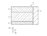
図11は、図1に示す圧電アクチュエーター1に含まれる振動部11の第2変形例を示す断面図である。なお、図11では、接着剤や電極等の一部の図示を省略している。
(Second modification)
FIG. 11 is a cross-sectional view illustrating a second modification of the vibration unit 11 included in the piezoelectric actuator 1 illustrated in FIG. 1. In FIG. 11, some of the adhesive, electrodes, and the like are not shown.

図11に示す振動部11は、第1振動板2および第2振動板3と圧電素子4とを含む単位構造6が複数積層されてなる以外、図5に示す振動部11と同様である。   The vibrating part 11 shown in FIG. 11 is the same as the vibrating part 11 shown in FIG. 5 except that a plurality of unit structures 6 including the first diaphragm 2, the second diaphragm 3, and the piezoelectric element 4 are stacked.

すなわち、図11に示す振動部11は、複数の単位構造6を積層してなるものである(スタック構造)。このような振動部11によれば、単位構造6による変位量が積層数の分だけ累積するため、ローター110の一か所に対してより大きな駆動力を伝達することができる。   That is, the vibration part 11 shown in FIG. 11 is formed by laminating a plurality of unit structures 6 (stack structure). According to such a vibration part 11, since the displacement amount by the unit structure 6 is accumulated by the number of stacked layers, a larger driving force can be transmitted to one part of the rotor 110.

単位構造6の積層数は、特に限定されないが、2以上20以下であるのが好ましく、3以上15以下であるのがより好ましい。これにより、圧電アクチュエーター1の大型化を抑制しつつ、十分な駆動量を確保することができる。
以上のような第2変形例によっても、図5に示す振動部11と同様の効果が得られる。
The number of stacked unit structures 6 is not particularly limited, but is preferably 2 or more and 20 or less, and more preferably 3 or more and 15 or less. Thereby, it is possible to ensure a sufficient driving amount while suppressing an increase in size of the piezoelectric actuator 1.
Also by the second modified example as described above, the same effect as that of the vibrating portion 11 shown in FIG. 5 can be obtained.

なお、図11では、第1振動板2、第2振動板3、圧電素子4および伝達部14以外の部位の図示を省略している。   In addition, in FIG. 11, illustration of parts other than the 1st diaphragm 2, the 2nd diaphragm 3, the piezoelectric element 4, and the transmission part 14 is abbreviate | omitted.

2.ロボット
次に、本発明のロボットの実施形態について説明する。
2. Next, an embodiment of the robot of the present invention will be described.

図12は、本発明のロボットの実施形態を示す斜視図である。
図12に示すロボット1000は、精密機器やこれを構成する部品(対象物)の給材、除材、搬送および組立等の作業を行うことができる。ロボット1000は、6軸ロボットであり、床や天井に固定されるベース1010と、ベース1010に回動自在に連結されたアーム1020と、アーム1020に回動自在に連結されたアーム1030と、アーム1030に回動自在に連結されたアーム1040と、アーム1040に回動自在に連結されたアーム1050と、アーム1050に回動自在に連結されたアーム1060と、アーム1060に回動自在に連結されたアーム1070と、これらアーム1020、1030、1040、1050、1060、1070の駆動を制御する制御部1080と、を有している。また、アーム1070にはハンド接続部が設けられており、ハンド接続部にはロボット1000に実行させる作業に応じたエンドエフェクター1090が装着される。また、各関節部のうちの全部または一部には、圧電アクチュエーター1を備える圧電駆動装置100が搭載されており、この圧電駆動装置100の駆動によって各アーム1020、1030、1040、1050、1060、1070が回動する。なお、各圧電駆動装置100の駆動は、制御部1080によって制御される。
FIG. 12 is a perspective view showing an embodiment of the robot of the present invention.
The robot 1000 shown in FIG. 12 can perform operations such as feeding, removing, transporting and assembling precision instruments and parts (objects) constituting the precision equipment. The robot 1000 is a six-axis robot, and includes a base 1010 fixed to a floor or a ceiling, an arm 1020 rotatably connected to the base 1010, an arm 1030 rotatably connected to the arm 1020, and an arm 1030. An arm 1040 that is pivotally connected to the arm 1040, an arm 1050 that is pivotally coupled to the arm 1040, an arm 1060 that is pivotally coupled to the arm 1050, and a arm 1060 that is pivotally coupled to the arm 1060. An arm 1070 and a control unit 1080 that controls driving of the arms 1020, 1030, 1040, 1050, 1060, and 1070 are provided. Further, the arm 1070 is provided with a hand connection unit, and an end effector 1090 corresponding to an operation to be executed by the robot 1000 is attached to the hand connection unit. In addition, a piezoelectric driving device 100 including the piezoelectric actuator 1 is mounted on all or a part of each joint, and each arm 1020, 1030, 1040, 1050, 1060, by driving the piezoelectric driving device 100. 1070 rotates. The driving of each piezoelectric driving device 100 is controlled by the control unit 1080.

以上のようなロボット1000は、圧電アクチュエーター1を備える。このようなロボット1000によれば、圧電アクチュエーター1の優れた特性を利用して、ロボット1000の特性を高めることができる。   The robot 1000 as described above includes the piezoelectric actuator 1. According to such a robot 1000, it is possible to improve the characteristics of the robot 1000 by using the excellent characteristics of the piezoelectric actuator 1.

3.電子部品搬送装置
次に、本発明の電子部品搬送装置の実施形態について説明する。
3. Next, an embodiment of the electronic component conveying device of the present invention will be described.

図13は、本発明の電子部品搬送装置の実施形態を示す斜視図である。図14は、図13に示す電子部品搬送装置が備える電子部品保持部の斜視図である。なお、以下では、説明の便宜上、互いに直交する3軸をX軸、Y軸およびZ軸とする。   FIG. 13 is a perspective view showing an embodiment of the electronic component carrying apparatus of the present invention. FIG. 14 is a perspective view of an electronic component holding unit provided in the electronic component transport apparatus shown in FIG. In the following, for convenience of explanation, the three axes orthogonal to each other are referred to as an X axis, a Y axis, and a Z axis.

図13に示す電子部品搬送装置2000は、電子部品検査装置に適用されており、基台2100と、基台2100の側方に配置された支持台2200と、を有している。また、基台2100には、検査対象の電子部品Qが載置されてY軸方向に搬送される上流側ステージ2110と、検査済みの電子部品Qが載置されてY軸方向に搬送される下流側ステージ2120と、上流側ステージ2110と下流側ステージ2120との間に位置し、電子部品Qの電気的特性を検査する検査台2130と、が設けられている。なお、電子部品Qの例として、例えば、半導体、半導体ウェハー、CLDやOLED等の表示デバイス、水晶デバイス、各種センサー、インクジェットヘッド、各種MEMSデバイス等が挙げられる。   An electronic component conveying apparatus 2000 shown in FIG. 13 is applied to an electronic component inspection apparatus, and includes a base 2100 and a support base 2200 disposed on the side of the base 2100. Further, on the base 2100, the upstream stage 2110 on which the electronic component Q to be inspected is placed and transported in the Y-axis direction, and the inspected electronic component Q is placed and transported in the Y-axis direction. A downstream stage 2120 and an inspection table 2130 that is located between the upstream stage 2110 and the downstream stage 2120 and inspects the electrical characteristics of the electronic component Q are provided. Examples of the electronic component Q include semiconductors, semiconductor wafers, display devices such as CLD and OLED, crystal devices, various sensors, ink jet heads, various MEMS devices, and the like.

また、支持台2200には、支持台2200に対してY軸方向に移動可能なYステージ2210が設けられており、Yステージ2210には、Yステージ2210に対してX軸方向に移動可能なXステージ2220が設けられており、Xステージ2220には、Xステージ2220に対してZ軸方向に移動可能な電子部品保持部2230が設けられている。   The support table 2200 is provided with a Y stage 2210 that can move in the Y-axis direction with respect to the support table 2200, and the Y stage 2210 can move in the X-axis direction with respect to the Y stage 2210. A stage 2220 is provided. The X stage 2220 is provided with an electronic component holder 2230 that can move in the Z-axis direction with respect to the X stage 2220.

また、図14に示すように、電子部品保持部2230は、X軸方向およびY軸方向に移動可能な微調整プレート2231と、微調整プレート2231に対してZ軸まわりに回動可能な回動部2232と、回動部2232に設けられ、電子部品Qを保持する保持部2233と、を有している。また、電子部品保持部2230には、微調整プレート2231をX軸方向に移動させるための圧電アクチュエーター1(1x)と、微調整プレート2231をY軸方向に移動させるための圧電アクチュエーター1(1y)と、回動部2232をZ軸まわりに回動させるための圧電アクチュエーター1(1θ)と、が内蔵されている。   As shown in FIG. 14, the electronic component holding unit 2230 has a fine adjustment plate 2231 that can move in the X-axis direction and the Y-axis direction, and a rotation that can turn around the Z-axis with respect to the fine adjustment plate 2231. And a holding portion 2233 that is provided in the rotating portion 2232 and holds the electronic component Q. The electronic component holding unit 2230 includes a piezoelectric actuator 1 (1x) for moving the fine adjustment plate 2231 in the X-axis direction and a piezoelectric actuator 1 (1y) for moving the fine adjustment plate 2231 in the Y-axis direction. And a piezoelectric actuator 1 (1θ) for rotating the rotating unit 2232 around the Z-axis.

以上のような電子部品搬送装置2000は、圧電アクチュエーター1を備える。このような電子部品搬送装置2000によれば、圧電アクチュエーター1の優れた特性を利用して、電子部品搬送装置2000の特性を高めることができる。   The electronic component transport apparatus 2000 as described above includes the piezoelectric actuator 1. According to such an electronic component transport apparatus 2000, the characteristics of the electronic component transport apparatus 2000 can be enhanced by utilizing the excellent characteristics of the piezoelectric actuator 1.

4.プリンター
図15は、本発明のプリンターの実施形態を示す斜視図である。
4). Printer FIG. 15 is a perspective view showing an embodiment of a printer of the present invention.

図15に示すプリンター3000は、インクジェット記録方式のプリンターである。このプリンター3000は、装置本体3010と、装置本体3010の内部に設けられている印刷機構3020、給紙機構3030および制御部3040と、を備えている。   A printer 3000 shown in FIG. 15 is an ink jet recording type printer. The printer 3000 includes an apparatus main body 3010 and a printing mechanism 3020, a paper feed mechanism 3030, and a control unit 3040 provided inside the apparatus main body 3010.

装置本体3010には、記録用紙Pを設置するトレイ3011と、記録用紙Pを排出する排紙口3012と、液晶ディスプレイ等の操作パネル3013とが設けられている。   The apparatus main body 3010 is provided with a tray 3011 for installing the recording paper P, a paper discharge port 3012 for discharging the recording paper P, and an operation panel 3013 such as a liquid crystal display.

印刷機構3020は、ヘッドユニット3021と、キャリッジモーター3022と、キャリッジモーター3022の駆動力によりヘッドユニット3021を往復動させる往復動機構3023と、を備えている。ヘッドユニット3021は、インクジェット式記録ヘッドであるヘッド3021aと、ヘッド3021aにインクを供給するインクカートリッジ3021bと、ヘッド3021aおよびインクカートリッジ3021bを搭載したキャリッジ3021cと、を有している。往復動機構3023は、キャリッジ3021cを往復移動可能に支持しているキャリッジガイド軸3023bと、キャリッジモーター3022の駆動力によりキャリッジ3021cをキャリッジガイド軸3023b上で移動させるタイミングベルト3023aと、を有している。   The printing mechanism 3020 includes a head unit 3021, a carriage motor 3022, and a reciprocating mechanism 3023 that reciprocates the head unit 3021 by the driving force of the carriage motor 3022. The head unit 3021 includes a head 3021a that is an ink jet recording head, an ink cartridge 3021b that supplies ink to the head 3021a, and a carriage 3021c on which the head 3021a and the ink cartridge 3021b are mounted. The reciprocating mechanism 3023 includes a carriage guide shaft 3023b that supports the carriage 3021c so as to reciprocate, and a timing belt 3023a that moves the carriage 3021c on the carriage guide shaft 3023b by the driving force of the carriage motor 3022. Yes.

給紙機構3030は、互いに圧接している従動ローラー3031および駆動ローラー3032と、駆動ローラー3032を駆動する給紙モーターである圧電駆動装置100(圧電アクチュエーター1)と、を有している。   The paper feeding mechanism 3030 includes a driven roller 3031 and a driving roller 3032 that are in pressure contact with each other, and a piezoelectric driving device 100 (piezoelectric actuator 1) that is a paper feeding motor that drives the driving roller 3032.

制御部3040は、例えばパーソナルコンピュータ等のホストコンピュータから入力された印刷データに基づいて、印刷機構3020や給紙機構3030等を制御する。   The control unit 3040 controls the printing mechanism 3020, the paper feeding mechanism 3030, and the like based on print data input from a host computer such as a personal computer.

このようなプリンター3000では、給紙機構3030が記録用紙Pを一枚ずつヘッドユニット3021の下部近傍へ間欠送りする。このとき、ヘッドユニット3021が記録用紙Pの送り方向とほぼ直交する方向に往復移動して、記録用紙Pへの印刷が行なわれる。   In such a printer 3000, the paper feed mechanism 3030 intermittently feeds the recording paper P one by one to the vicinity of the lower portion of the head unit 3021. At this time, the head unit 3021 reciprocates in a direction substantially orthogonal to the feeding direction of the recording paper P, and printing on the recording paper P is performed.

以上のようなプリンター3000は、圧電アクチュエーター1を備える。このようなプリンター3000によれば、圧電アクチュエーター1の優れた特性を利用して、プリンター3000の特性を高めることができる。   The printer 3000 as described above includes the piezoelectric actuator 1. According to such a printer 3000, the characteristics of the printer 3000 can be enhanced by utilizing the excellent characteristics of the piezoelectric actuator 1.

5.プロジェクター
図16は、本発明のプロジェクターの実施形態を示す模式図である。
5. Projector FIG. 16 is a schematic diagram showing an embodiment of a projector of the present invention.

図16に示すプロジェクター4000は、赤色光を出射する光源4100Rと、緑色光を出射する光源4100Gと、青色光を出射する光源4100Bと、レンズアレイ4200R、4200G、4200Bと、透過型の液晶ライトバルブ(光変調部)4300R、4300G、4300Bと、クロスダイクロイックプリズム4400と、投射レンズ(投射部)4500と、圧電駆動装置4700と、を有している。   A projector 4000 shown in FIG. 16 includes a light source 4100R that emits red light, a light source 4100G that emits green light, a light source 4100B that emits blue light, lens arrays 4200R, 4200G, and 4200B, and a transmissive liquid crystal light valve. (Light modulation section) 4300R, 4300G, 4300B, cross dichroic prism 4400, projection lens (projection section) 4500, and piezoelectric driving device 4700 are provided.

光源4100R、4100G、4100Bから出射された光は、各レンズアレイ4200R、4200G、4200Bを介して、液晶ライトバルブ4300R、4300G、4300Bに入射する。各液晶ライトバルブ4300R、4300G、4300Bは、入射した光をそれぞれ画像情報に応じて変調する。   Light emitted from the light sources 4100R, 4100G, and 4100B is incident on the liquid crystal light valves 4300R, 4300G, and 4300B via the lens arrays 4200R, 4200G, and 4200B. Each of the liquid crystal light valves 4300R, 4300G, and 4300B modulates incident light according to image information.

各液晶ライトバルブ4300R、4300G、4300Bによって変調された3つの色光は、クロスダイクロイックプリズム4400に入射して合成される。クロスダイクロイックプリズム4400によって合成された光は、投射光学系である投射レンズ4500に入射する。投射レンズ4500は、液晶ライトバルブ4300R、4300G、4300Bによって形成された像を拡大して、スクリーン4600(表示面)に投射する。これにより、スクリーン4600上に所望の映像が映し出される。ここで、投射レンズ4500は、圧電アクチュエーター1を有する圧電駆動装置4700に支持されており、圧電駆動装置4700の駆動により位置および姿勢の変更(位置決め)が可能となっている。これにより、スクリーン4600に投射される映像の形状や大きさ等を調整することができる。   The three color lights modulated by the liquid crystal light valves 4300R, 4300G, and 4300B are incident on the cross dichroic prism 4400 and synthesized. The light synthesized by the cross dichroic prism 4400 enters a projection lens 4500 that is a projection optical system. The projection lens 4500 enlarges the image formed by the liquid crystal light valves 4300R, 4300G, and 4300B and projects the enlarged image onto the screen 4600 (display surface). Thus, a desired image is displayed on the screen 4600. Here, the projection lens 4500 is supported by a piezoelectric driving device 4700 having the piezoelectric actuator 1, and the position and orientation can be changed (positioning) by driving the piezoelectric driving device 4700. Thereby, the shape and size of the image projected on the screen 4600 can be adjusted.

なお、上述の例では、光変調部として透過型の液晶ライトバルブを用いたが、液晶以外のライトバルブを用いてもよいし、反射型のライトバルブを用いてもよい。このようなライトバルブとしては、例えば、反射型の液晶ライトバルブや、デジタルマイクロミラーデバイス(Digital Micromirror Device)が挙げられる。また、投射光学系の構成は、使用されるライトバルブの種類によって適宜変更される。また、プロジェクターとしては、光をスクリーン上で走査させることにより、表示面に所望の大きさの画像を表示させる走査型のプロジェクターであってもよい。   In the above-described example, a transmissive liquid crystal light valve is used as the light modulation unit, but a light valve other than liquid crystal may be used, or a reflective light valve may be used. Examples of such a light valve include a reflective liquid crystal light valve and a digital micromirror device. Further, the configuration of the projection optical system is appropriately changed depending on the type of light valve used. Further, the projector may be a scanning projector that displays an image of a desired size on the display surface by scanning light on a screen.

以上のように、プロジェクター4000は、圧電アクチュエーター1を備える。このようなプロジェクター4000によれば、圧電アクチュエーター1の優れた特性を利用して、プロジェクター4000の特性を高めることができる。   As described above, the projector 4000 includes the piezoelectric actuator 1. According to such a projector 4000, it is possible to improve the characteristics of the projector 4000 using the excellent characteristics of the piezoelectric actuator 1.

以上、本発明の圧電アクチュエーター、圧電駆動装置、ロボット、電子部品搬送装置、プリンターおよびプロジェクターを、図示の実施形態に基づいて説明したが、本発明は、これに限定されるものではなく、各部の構成は、同様の機能を有する任意の構成のものに置換することができる。また、本発明に、他の任意の構成物が付加されていてもよい。また、各実施形態を適宜組み合わせてもよい。   As described above, the piezoelectric actuator, the piezoelectric driving device, the robot, the electronic component conveying device, the printer, and the projector according to the present invention have been described based on the illustrated embodiment, but the present invention is not limited to this, The configuration can be replaced with any configuration having a similar function. In addition, any other component may be added to the present invention. Moreover, you may combine each embodiment suitably.

また、前述した実施形態では圧電アクチュエーターを圧電駆動装置(圧電モーター)、ロボット、電子部品搬送装置、プリンターおよびプロジェクターに適用した構成について説明したが、圧電アクチュエーターは、これら以外の各種電子デバイスにも適用することができる。   In the above-described embodiment, the configuration in which the piezoelectric actuator is applied to a piezoelectric driving device (piezoelectric motor), a robot, an electronic component conveying device, a printer, and a projector has been described. However, the piezoelectric actuator is also applicable to various other electronic devices. can do.

1…圧電アクチュエーター、2…第1振動板、3…第2振動板、4…圧電素子、4a…圧電素子、4b…圧電素子、4c…圧電素子、4d…圧電素子、4e…圧電素子、4f…圧電素子、5…中間部材、6…単位構造、7…配線層、8…配線層、11…振動部、12…支持部、13…接続部、14…伝達部、24…絶縁層、34…絶縁層、41…圧電体、42…第1電極、42a…第1電極、42b…第1電極、42c…第1電極、42d…第1電極、42e…第1電極、43…第2電極、44…第3電極、51…本体、52…絶縁層、53…配線、61…接着剤、62…接着剤、71…第1電極、72…第1配線、81…第2電極、82…第2配線、91…端子、92…端子、100…圧電駆動装置、110…ローター、111…外周面、141…基部、141a…一面、142…突出部、143…当接面、1000…ロボット、1010…ベース、1020…アーム、1030…アーム、1040…アーム、1050…アーム、1060…アーム、1070…アーム、1080…制御部、1090…エンドエフェクター、2000…電子部品搬送装置、2100…基台、2110…上流側ステージ、2120…下流側ステージ、2130…検査台、2200…支持台、2210…Yステージ、2220…Xステージ、2230…電子部品保持部、2231…微調整プレート、2232…回動部、2233…保持部、3000…プリンター、3010…装置本体、3011…トレイ、3012…排紙口、3013…操作パネル、3020…印刷機構、3021…ヘッドユニット、3021a…ヘッド、3021b…インクカートリッジ、3021c…キャリッジ、3022…キャリッジモーター、3023…往復動機構、3023a…タイミングベルト、3023b…キャリッジガイド軸、3030…給紙機構、3031…従動ローラー、3032…駆動ローラー、3040…制御部、4000…プロジェクター、4100B…光源、4100G…光源、4100R…光源、4200B…レンズアレイ、4200G…レンズアレイ、4200R…レンズアレイ、4300B…液晶ライトバルブ、4300G…液晶ライトバルブ、4300R…液晶ライトバルブ、4400…クロスダイクロイックプリズム、4500…投射レンズ、4600…スクリーン、4700…圧電駆動装置、CP…中心、D1…垂直方向、D2…送り方向、D3…押圧方向、F1…第1平面、F2…振動面、O…回動軸、P…記録用紙、PSa…節、PSb…節、PSc…節、Q…電子部品 DESCRIPTION OF SYMBOLS 1 ... Piezoelectric actuator, 2 ... 1st diaphragm, 3 ... 2nd diaphragm, 4 ... Piezoelectric element, 4a ... Piezoelectric element, 4b ... Piezoelectric element, 4c ... Piezoelectric element, 4d ... Piezoelectric element, 4e ... Piezoelectric element, 4f DESCRIPTION OF SYMBOLS ... Piezoelectric element, 5 ... Intermediate member, 6 ... Unit structure, 7 ... Wiring layer, 8 ... Wiring layer, 11 ... Vibration part, 12 ... Supporting part, 13 ... Connection part, 14 ... Transmission part, 24 ... Insulating layer, 34 ... Insulating layer, 41 ... Piezoelectric body, 42 ... First electrode, 42a ... First electrode, 42b ... First electrode, 42c ... First electrode, 42d ... First electrode, 42e ... First electrode, 43 ... Second electrode 44 ... Third electrode 51 ... Main body 52 ... Insulating layer 53 ... Wiring 61 ... Adhesive 62 ... Adhesive 71 ... First electrode 72 ... First wiring 81 ... Second electrode 82 ... Second wiring, 91 ... terminal, 92 ... terminal, 100 ... piezoelectric drive device, 110 ... rotor, 111 ... outer peripheral surface, 41 ... Base, 141a ... One side, 142 ... Projection, 143 ... Abutting surface, 1000 ... Robot, 1010 ... Base, 1020 ... Arm, 1030 ... Arm, 1040 ... Arm, 1050 ... Arm, 1060 ... Arm, 1070 ... Arm DESCRIPTION OF SYMBOLS 1080 ... Control part, 1090 ... End effector, 2000 ... Electronic component conveying apparatus, 2100 ... Base, 2110 ... Upstream stage, 2120 ... Downstream stage, 2130 ... Inspection table, 2200 ... Supporting table, 2210 ... Y stage, 2220 ... X stage, 2230 ... electronic component holding unit, 2231 ... fine adjustment plate, 2232 ... rotating unit, 2233 ... holding unit, 3000 ... printer, 3010 ... main body, 3011 ... tray, 3012 ... discharge port, 3013 ... Operation panel, 3020 ... printing mechanism, 3021 ... head unit, 021a ... head, 3021b ... ink cartridge, 3021c ... carriage, 3022 ... carriage motor, 3023 ... reciprocating mechanism, 3023a ... timing belt, 3023b ... carriage guide shaft, 3030 ... feed mechanism, 3031 ... driven roller, 3032 ... driving roller , 3040 ... control unit, 4000 ... projector, 4100B ... light source, 4100G ... light source, 4100R ... light source, 4200B ... lens array, 4200G ... lens array, 4200R ... lens array, 4300B ... liquid crystal light valve, 4300G ... liquid crystal light valve, 4300R. Liquid crystal light valve, 4400 ... Cross dichroic prism, 4500 ... Projection lens, 4600 ... Screen, 4700 ... Piezoelectric drive, CP ... Center, D1 ... Vertical direction, D2 ... Send Direction, D3 ... pressing direction, F1 ... first plane, F2 ... vibrating surface, O ... rotating shaft, P ... recording paper, PSa ... node, PSb ... node, PSc ... node, Q ... electronic component

Claims (12)

振動板と、
前記振動板に積層され、圧電体と、前記圧電体の一方の面上に配置され駆動信号が入力される第1電極と、前記圧電体の他方の面上に配置され基準電位に接続される第2電極と、を備える圧電素子と、
前記圧電素子に配置され、被駆動部材に当接する当接面を含む先端チップと、
を有し、
前記第1電極に直交する第1平面で前記当接面を切断したときの第1断面形状が、曲率を有していることを特徴とする圧電アクチュエーター。
A diaphragm,
Laminated on the diaphragm, the piezoelectric body, a first electrode disposed on one surface of the piezoelectric body and receiving a drive signal, and disposed on the other surface of the piezoelectric body and connected to a reference potential A piezoelectric element comprising: a second electrode;
A tip having a contact surface disposed on the piezoelectric element and contacting the driven member;
Have
The piezoelectric actuator according to claim 1, wherein the first cross-sectional shape when the contact surface is cut along a first plane orthogonal to the first electrode has a curvature.
前記第1平面に直交し前記第1電極に平行な第2平面で前記当接面を切断したときの第2断面形状が、曲率を有している請求項1に記載の圧電アクチュエーター。   2. The piezoelectric actuator according to claim 1, wherein a second cross-sectional shape when the abutting surface is cut by a second plane orthogonal to the first plane and parallel to the first electrode has a curvature. 前記第2断面形状が有する曲率半径は、前記第1断面形状が有する曲率半径より小さい請求項2に記載の圧電アクチュエーター。   3. The piezoelectric actuator according to claim 2, wherein a radius of curvature of the second cross-sectional shape is smaller than a radius of curvature of the first cross-sectional shape. 前記振動板と前記圧電素子とを含む単位構造を複数有する請求項1ないし3のいずれか1項に記載の圧電アクチュエーター。   4. The piezoelectric actuator according to claim 1, comprising a plurality of unit structures including the vibration plate and the piezoelectric element. 5. 前記第1電極に前記駆動信号が入力され、前記第2電極が前記基準電位に接続されたとき、
前記第1電極と前記第2電極とを結ぶ方向に振動するように構成されている請求項1ないし4のいずれか1項に記載の圧電アクチュエーター。
When the drive signal is input to the first electrode and the second electrode is connected to the reference potential,
The piezoelectric actuator according to claim 1, wherein the piezoelectric actuator is configured to vibrate in a direction connecting the first electrode and the second electrode.
前記第1電極および前記第2電極は、形状が異なる請求項1ないし5のいずれか1項に記載の圧電アクチュエーター。   The piezoelectric actuator according to claim 1, wherein the first electrode and the second electrode have different shapes. 前記振動板として、前記圧電素子を介して反対側に配置されている第1振動板および第2振動板を有し、
前記第1振動板および前記第2振動板は、厚さが異なる請求項1ないし6のいずれか1項に記載の圧電アクチュエーター。
As the diaphragm, having a first diaphragm and a second diaphragm disposed on the opposite side through the piezoelectric element,
The piezoelectric actuator according to claim 1, wherein the first diaphragm and the second diaphragm have different thicknesses.
請求項1ないし7のいずれか1項に記載の圧電アクチュエーターと、
前記圧電アクチュエーターにより駆動される被駆動部材と、を備えることを特徴とする圧電駆動装置。
A piezoelectric actuator according to any one of claims 1 to 7,
And a driven member driven by the piezoelectric actuator.
請求項1ないし7のいずれか1項に記載の圧電アクチュエーターを備えることを特徴とするロボット。   A robot comprising the piezoelectric actuator according to any one of claims 1 to 7. 請求項1ないし7のいずれか1項に記載の圧電アクチュエーターを備えることを特徴とする電子部品搬送装置。   An electronic component conveying apparatus comprising the piezoelectric actuator according to claim 1. 請求項1ないし7のいずれか1項に記載の圧電アクチュエーターを備えることを特徴とするプリンター。   A printer comprising the piezoelectric actuator according to claim 1. 請求項1ないし7のいずれか1項に記載の圧電アクチュエーターを備えることを特徴とするプロジェクター。   A projector comprising the piezoelectric actuator according to claim 1.
JP2018028549A 2018-02-21 2018-02-21 Piezoelectric actuator, piezoelectric drive device, robot, electronic component transfer device, printer, and projector Withdrawn JP2019146365A (en)

Priority Applications (1)

Application Number Priority Date Filing Date Title
JP2018028549A JP2019146365A (en) 2018-02-21 2018-02-21 Piezoelectric actuator, piezoelectric drive device, robot, electronic component transfer device, printer, and projector

Applications Claiming Priority (1)

Application Number Priority Date Filing Date Title
JP2018028549A JP2019146365A (en) 2018-02-21 2018-02-21 Piezoelectric actuator, piezoelectric drive device, robot, electronic component transfer device, printer, and projector

Publications (2)

Publication Number Publication Date
JP2019146365A true JP2019146365A (en) 2019-08-29
JP2019146365A5 JP2019146365A5 (en) 2021-02-25

Family

ID=67774071

Family Applications (1)

Application Number Title Priority Date Filing Date
JP2018028549A Withdrawn JP2019146365A (en) 2018-02-21 2018-02-21 Piezoelectric actuator, piezoelectric drive device, robot, electronic component transfer device, printer, and projector

Country Status (1)

Country Link
JP (1) JP2019146365A (en)

Similar Documents

Publication Publication Date Title
JP6828342B2 (en) Manufacturing methods for piezoelectric actuators, piezoelectric motors, robots, electronic component transfer devices, printers and piezoelectric actuators
US10179405B2 (en) Piezoelectric drive device, robot, and drive method thereof
US11205974B2 (en) Piezoelectric driving device, piezoelectric motor, robot, electronic component conveyance apparatus, printer, and projector
JP2018038188A (en) Vibrator, piezoelectric actuator, piezoelectric motor, robot, electronic component transfer device, and method of manufacturing vibrator
CN109309458B (en) Piezoelectric driving device, driving method thereof, robot, and electronic component transfer device
US11133453B2 (en) Piezoelectric driving device, piezoelectric motor, robot, electronic-component conveying apparatus, printer, and projector
JP2018074723A (en) Drive device, piezoelectric motor, robot, electronic component transfer device, and printer
JP7077682B2 (en) Piezoelectric drives, robots, electronic component conveyors, printers and projectors
JP2019114671A (en) Piezoelectric actuator, piezoelectric drive device, robot, electronic component transfer device, printer and projector
JP2019146365A (en) Piezoelectric actuator, piezoelectric drive device, robot, electronic component transfer device, printer, and projector
JP2019146435A (en) Piezoelectric drive device, method for controlling piezoelectric actuator, robot, electronic component conveying device, printer, and projector
JP2018057148A (en) Oscillator, piezoelectric actuator, piezoelectric motor, robot, electronic component transfer device, and printer
JP2018174640A (en) Piezoelectric drive device, method for driving piezoelectric drive device, robot, electronic component conveying device, printer, and projector
CN108809141B (en) Piezoelectric driving device, method of driving piezoelectric driving device, robot, and electronic component transfer device
US11031884B2 (en) Control device for vibration actuator, method of controlling vibration actuator, robot, electronic component conveyance apparatus, printer, projector, and vibration device
JP2018074011A (en) Piezoelectric driving device, piezoelectric motor, robot, electronic component conveying device, printer, and method of manufacturing piezoelectric driving device
JP2019117853A (en) Piezoelectric actuator, piezoelectric drive device, robot, electronic component transfer device, printer, and projector
JP2019068546A (en) Piezoelectric actuator, piezoelectric driving device, robot, electronic component conveying device, printer, and projector
JP6954007B2 (en) Piezoelectric drive devices, piezoelectric motors, robots, electronic component transfer devices, printers and projectors
JP2020191767A (en) Piezoelectric actuator and robot
JP2019160975A (en) Piezoelectric actuator, additional force detection method of piezoelectric actuator, resonance state detection method of piezoelectric actuator, piezoelectric drive device, hand, robot, electronic component transfer device, printer and projector
JP2018019540A (en) Piezoelectric actuator, piezoelectric motor, robot, and electronic component conveyance device
JP2018037507A (en) Vibrator, piezoelectric actuator, piezoelectric motor, robot, and electronic component transfer device
JP2018074773A (en) Driving device, piezoelectric motor, robot, electronic component conveying device, and printer
JP2020107657A (en) Piezoelectric element unit, piezoelectric drive device, piezoelectric element unit manufacturing method, and robot

Legal Events

Date Code Title Description
RD05 Notification of revocation of power of attorney

Free format text: JAPANESE INTERMEDIATE CODE: A7425

Effective date: 20180910

RD03 Notification of appointment of power of attorney

Free format text: JAPANESE INTERMEDIATE CODE: A7423

Effective date: 20181121

RD07 Notification of extinguishment of power of attorney

Free format text: JAPANESE INTERMEDIATE CODE: A7427

Effective date: 20200807

A521 Request for written amendment filed

Free format text: JAPANESE INTERMEDIATE CODE: A523

Effective date: 20210113

A621 Written request for application examination

Free format text: JAPANESE INTERMEDIATE CODE: A621

Effective date: 20210113

A977 Report on retrieval

Free format text: JAPANESE INTERMEDIATE CODE: A971007

Effective date: 20210913

RD04 Notification of resignation of power of attorney

Free format text: JAPANESE INTERMEDIATE CODE: A7424

Effective date: 20210916

A131 Notification of reasons for refusal

Free format text: JAPANESE INTERMEDIATE CODE: A131

Effective date: 20210921

RD03 Notification of appointment of power of attorney

Free format text: JAPANESE INTERMEDIATE CODE: A7423

Effective date: 20211108

A761 Written withdrawal of application

Free format text: JAPANESE INTERMEDIATE CODE: A761

Effective date: 20211122