JP2019138027A - Cabinet management device - Google Patents
Cabinet management device Download PDFInfo
- Publication number
- JP2019138027A JP2019138027A JP2018020924A JP2018020924A JP2019138027A JP 2019138027 A JP2019138027 A JP 2019138027A JP 2018020924 A JP2018020924 A JP 2018020924A JP 2018020924 A JP2018020924 A JP 2018020924A JP 2019138027 A JP2019138027 A JP 2019138027A
- Authority
- JP
- Japan
- Prior art keywords
- storage
- user
- administrator
- registration information
- unit
- Prior art date
- Legal status (The legal status is an assumption and is not a legal conclusion. Google has not performed a legal analysis and makes no representation as to the accuracy of the status listed.)
- Pending
Links
Images


Abstract
Description
本発明は、例えばビジネスホテルまたは病院の部屋内に設置される金庫等の保管庫を遠隔操作によって制御、管理するのに好適に用いられる保管庫管理装置に関する。 The present invention relates to a storage management apparatus suitably used for controlling and managing a storage such as a safe installed in a room of a business hotel or a hospital by remote operation.
一般に、ビジネスホテルを含んだ宿泊施設の居室には、使用者の貴重品を安全に保管するため金庫に代表される保管庫が設置されている。また、病院の薬品類を保管する部屋内にも、ほぼ同様な構造の保管庫が設置されている。この種の従来技術による保管庫は、例えばテンキーを用いて暗証番号を利用者(使用者)が入力したり、ICカード等の記憶媒体から取得したID番号に基づく権限認証を行ったりして電気錠装置を開錠し、前記保管庫の扉を開,閉する制御を行う構成としている(例えば、特許文献1,2参照)。
In general, a storage room represented by a safe is installed in a room of an accommodation facility including a business hotel in order to safely store a user's valuables. In addition, a storage room having almost the same structure is installed in a room for storing medicines in a hospital. In this type of conventional storage, for example, a user (user) inputs a personal identification number using a numeric keypad, or performs authority authentication based on an ID number acquired from a storage medium such as an IC card. The lock device is unlocked, and the storage door is opened and closed (see, for example,
ところで、上述した従来技術では、例えば金庫の登録情報を登録または削除する場合に、金庫が設置されている場所まで行って、当該金庫を操作しなければならず、手間のかかる作業となっている。また、金庫の使用履歴を取得する場合、金庫が設置されている場所までPC等のコントローラを持って行き、金庫とPCを接続して使用履歴を取得していた。さらに、金庫の操作手順を知っている第三者が、金庫の管理者が不在中に勝手に登録情報を登録することができた。 By the way, in the above-described conventional technique, for example, when registering or deleting registration information of a safe, it is necessary to go to the place where the safe is installed and operate the safe, which is a troublesome work. . Further, when acquiring the use history of the safe, the controller such as a PC is brought to the place where the safe is installed, and the use history is acquired by connecting the safe and the PC. Furthermore, a third party who knows the safe operating procedure can register the registration information without permission from the safe administrator.
即ち、従来技術では、金庫を含んだ保管庫の利用者(使用者)が管理者の許可なく、保管庫を操作(例えば、登録情報を勝手に登録したり、削除したり、電気錠を開錠したり)することができる場合があり、保管庫としてのセキュリティ、安全性、操作性を高める上で、更なる改善が望まれている。 In other words, in the prior art, the user (user) of the vault including the safe operates the vault without permission from the administrator (for example, registering or deleting registration information without permission, or unlocking the electric lock). In order to improve security, safety, and operability as a storage, further improvement is desired.
本発明は、上述した従来技術の問題に鑑みなされたもので、本発明の目的は、保管庫としてのセキュリティ、安全性、操作性を高めることができるようにした保管庫管理装置を提供することにある。 The present invention has been made in view of the above-described problems of the prior art, and an object of the present invention is to provide a storage management apparatus capable of improving security, safety, and operability as a storage. It is in.
上述した課題を解決するために、本発明の保管庫管理装置は、1つの建物内の所定場所に設置された保管庫を遠隔操作により管理するメインコントローラを備え、前記保管庫の制御装置と前記メインコントローラとの間は、前記建物内に設けられたプライベート通信回線を用いて接続されており、前記保管庫の制御装置は、前記メインコントローラから出力される管理者の登録情報を認証する管理者認証手段と、前記保管庫の使用者による操作を禁止状態に設定する保管庫操作禁止手段と、前記保管庫の使用要求があったときに、前記メインコントローラから前記保管庫の使用許可信号を受信したか否かを判定する使用許可判定手段と、前記管理者認証手段により管理者の認証が行われ、かつ前記使用許可判定手段が使用許可信号を受信したと判定したときに、前記保管庫操作禁止手段による禁止状態を解除し前記保管庫の使用者による操作を許可する保管庫操作許可手段と、を備えている。 In order to solve the above-described problem, the storage management apparatus of the present invention includes a main controller that remotely manages a storage installed in a predetermined place in one building, and the storage controller and the storage controller The main controller is connected to the main controller using a private communication line provided in the building, and the storage control device authenticates the administrator registration information output from the main controller. Authentication means, storage operation prohibiting means for setting operation by a user of the storage to a prohibited state, and receiving a use permission signal of the storage from the main controller when there is a request to use the storage The use permission determination means for determining whether or not the administrator authentication is performed by the administrator authentication means, and the use permission determination means receives the use permission signal. When it is determined, and a, a depot operation permission means for canceling the inhibition state by the depot operation prohibiting means permits the operation by the user of the vault.
本発明によれば、メインコントローラから出力される管理者の登録情報が認証された上で、かつ使用許可判定手段が使用許可信号の受信判定を行ったときに、保管庫使用者による保管庫の操作禁止状態を解除することができる。このため、保管庫の使用者が管理者の許可なく、保管庫を操作(例えば、登録情報を勝手に登録したり、削除したり、電気錠を開錠したり)することは不可能となり、保管庫としてのセキュリティ、安全性、操作性を高めることができる。 According to the present invention, when the registration information of the administrator output from the main controller is authenticated, and the use permission determination means performs reception determination of the use permission signal, The operation prohibition state can be canceled. For this reason, it becomes impossible for the user of the vault to operate the vault (for example, to register or delete registration information without permission or to unlock the electric lock) without permission from the administrator. Security, safety, and operability as a warehouse can be improved.
以下、本発明の実施の形態による保管庫管理装置を添付図面の図1ないし図8に従って詳細に説明する。 Hereinafter, a storage management apparatus according to an embodiment of the present invention will be described in detail with reference to FIGS. 1 to 8 of the accompanying drawings.
図において、1はビジネスホテル等のビル(建築物)である建物を示し、該建物1は、複数のフロア1F,2F,3F,NF(N=4,5,6,…)を有し、例えば1階のフロア1Fは、当該ホテルのフロント(接客窓口)となっている。このフロントには、図1に示すように、パーソナルコンピュータ等からなるメインコントローラ(以下、PC2という)が設けられている。このPC2には、例えば液晶ディスプレイ等の表示器、入力操作装置としてのキーボード、カードリーダ/ライタ(いずれも図示せず)等が付設されている。
In the figure, 1 indicates a building which is a building (building) such as a business hotel, and the
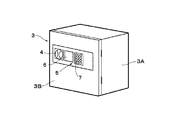
建物1の1階、2階、3階以上のフロア1F,2F,3F,NFには、それぞれ複数の居室が設けられ、各居室には金庫に代表される保管庫3が設置されている。これらの保管庫3は、図2に示すように、四角形状の筺体3Aと、該筺体3Aの開口側を開閉する扉3Bとを備えている。保管庫3の筺体3A内には、保管庫3の利用者(以下、使用者という)が扉3Bを開いた状態で貴重品等を入れて保管することができる。
The first floor, the second floor, the third floor and
ここで、保管庫3の扉3Bには、筺体3Aの開口側との間に電気錠(図示せず)が設けられている。この電気錠は、後述の施・開錠部10により施錠または開錠される。扉3Bの前面(表面)側には、手動操作用のノブ4と取得部5とが設けられている。この取得部5は、例えば登録情報等のデータを取得するため、ICカード等の読取り/書込みを行うNFC6(近距離無線通信機器)とテンキー7とを含んで構成されている。
Here, the
各保管庫3には、例えばマイクロコンピュータからなる保管庫制御装置8が設けられ、この保管庫制御装置8は、保管庫の制御装置を構成している。保管庫制御装置8には、図4に示すように、前記取得部5に加えて、記録部9、施・開錠部10および送・受信部11が接続して設けられている。各保管庫3の送・受信部11は、図3に示す有線LAN12および/または無線LAN13を介してプライベート通信回線14に接続され、このプライベート通信回線14には、前記フロントに設けられたPC2が有線LAN15および/または無線LAN16を介して接続されている。
Each
プライベート通信回線14は、図1に示す建物1内に設けられるコンピュータ(例えば、PC2)に有線LAN15および/または無線LAN16を介して接続可能となっている。プライベート通信回線14は、一般にプライベートネットワークと呼称されるもので、建物1の外部回線(例えば、所謂インターネットに代表されるパブリックなネットワーク)とは別の回線を構成している。即ち、プライベート通信回線14は、各保管庫3側に設けられる保管庫制御装置8の送・受信部11と、前記フロントに設けられたPC2(即ち、メインコントローラ)との間を専用回線として接続し、前記建物1内に閉じられたネットワークを構築するように設けられている。
The
保管庫制御装置8の記録部9は、例えばROM,RAM,不揮発性メモリおよび/またはハードディスク装置等により構成されている。この記録部9には、前記PC2(即ち、メインコントローラ)の管理者の登録情報、建物1内において複数の保管庫3毎に識別可能に割り振られた登録情報、登録情報の一覧(リスト)、保管庫3毎の使用履歴等が更新可能に格納されている。
The recording unit 9 of the
さらに、記録部9には、図5および図6に示す保管庫の管理制御処理(PCと保管庫制御装置との間で行われる管理制御処理)、図7に示す保管庫の遠隔操作許可/不可処理、図8に示す保管庫側での操作制御処理等のプログラムを含んだ種々の情報、データ等が更新可能に格納されている。保管庫制御装置8は、図5および図6に示す保管庫の管理制御処理と図7に示す保管庫の遠隔操作許可/不可処理とを交互に行うこともでき、または、両方の処理を同時並行的に行うこともできる。
Further, the recording unit 9 includes storage management control processing (management control processing performed between the PC and the storage control device) shown in FIGS. 5 and 6, and remote storage permission / reception shown in FIG. Various information, data, and the like including programs such as unusable processing and operation control processing on the storage side shown in FIG. 8 are stored in an updatable manner. The
ここで、登録情報とは、PC2の管理者、各保管庫3および使用者をそれぞれ識別可能に特定するための情報であり、例えば管理番号(000〜999)と登録を行った日付け(年月日時分秒)とを含んで構成されている。一例として、ICカード等を用いて登録情報の認証を行う場合には、PC2側のカードリーダにICカードを近付ける。これにより、当該ICカードに書込まれたPC2の管理者、各保管庫3および使用者の登録情報は、PC2の記憶装置(図示せず)に読込まれる。この読込み情報は、有線LAN15および/または無線LAN16とプライベート通信回線14と有線LAN12および/または無線LAN13とを介して送・受信部11から保管庫制御装置8の記録部9にも読込ませることができる。
Here, the registration information is information for identifying the manager of the
前記取得部5のNFC6(近距離無線通信機器)は、例えば登録情報等のデータを保管庫制御装置8の記録部9等に読込ませて取得するための機器である。保管庫3の使用者は、ICカード(即ち、ホテルのチェックイン時に前記フロントで提供され、既に居室情報と使用者情報とを含んだ登録情報が書込まれている情報媒体)をNFC6に近付ける。これにより、NFC6は、当該ICカードに書込まれた登録情報を取得し、保管庫制御装置8の記録部9等に読込ませることができる。但し、保管庫制御装置8は、保管庫3の使用者による操作(例えば、取得部5を介した登録情報の書込み、読出し)が禁止状態に設定される機能(後述の保管庫操作禁止手段)を有している。
The NFC 6 (short-range wireless communication device) of the acquisition unit 5 is a device for reading and acquiring data such as registration information in the recording unit 9 of the
また、取得部5のテンキー7は、例えば保管庫3の使用者が任意に暗証番号、パスワード等を手動で入力するための機器である。テンキー7の手動操作で取得部5から入力された情報(例えば、暗証番号、パスワード)も保管庫制御装置8の記録部9等に登録情報の一部として記憶される。NFC6から取得されたデータ、情報とテンキー7からの入力情報とを組合わせることにより、保管庫3のセキュリティを高めることができる。
The
保管庫3の施・開錠部10は、前記電気錠の施錠または開錠を行う機器で、例えばソレノイド等により構成されている。即ち、施・開錠部10は、保管庫制御装置8から出力される施錠信号と開錠信号とに従って保管庫3の扉3Bを筺体3Aに対してロック/解除する機能を有している。なお、保管庫3の扉3Bを開錠した状態では、図2に示すノブ4を保管庫3の使用者が廻すことにより扉3Bの開,閉を行うことができる。
The locking / unlocking
保管庫制御装置8は、図4に示すように認証部8Aを有している。この認証部8Aは、例えばメインコントローラ(PC2)から出力される管理者の登録情報を認証する管理者認証手段(図5中のステップ2,3、図7中のステップ21,22参照)と、保管庫3の使用要求にあったときに、メインコントローラ(PC2)から保管庫3の使用許可信号を受信したか否かを判定する使用許可判定手段(図7中のステップ24,25参照)とを含んで構成されている。また、認証部8Aは、PC2側および/または取得部5から入力された情報、データが正常か否かを判断し、異常なデータ等の取得を排除、禁止する機能も有している。
The
保管庫制御装置8は、保管庫3の使用者による操作(例えば、取得部5を介した登録情報の書込み、読出し、削除、電気錠の開錠)を禁止状態に設定する保管庫操作禁止手段(図7中のステップ23参照)と、前記管理者認証手段により管理者の認証が行われ、かつ前記使用許可判定手段が使用許可信号を受信したと判定したときに、前記保管庫操作禁止手段による禁止状態を解除し保管庫3の使用者による操作を許可する保管庫操作許可手段(図7中のステップ26,27参照)とを含んで構成されている。
The
また、保管庫制御装置8は、保管庫3の新たな使用者の登録情報をPC2からの操作に従って追加する使用者登録手段(図5中のステップ4,5参照)と、保管庫3の旧い使用者(例えば、チェックアウトした使用者)の登録情報をPC2からの操作に従って削除する使用者登録削除手段(図5中のステップ6,7参照)とを備えている。さらに、保管庫制御装置8は、前記使用者による保管庫3の操作が前記保管庫操作許可手段によって許可されたときに施・開錠部10に制御信号(例えば、開錠信号)を出力し、前記電気錠を開錠操作可能に設定する機能も有している。
Further, the
本実施の形態による保管庫管理装置は、上述の如き構成を有するものであり、次に、管理者側のPC2と保管庫制御装置8とによる各保管庫3の管理制御処理動作について、図5ないし図8を参照して説明する。
The storage management apparatus according to the present embodiment has the above-described configuration. Next, the management control processing operation of each
まず、図5に示す管理制御処理の動作が開始されると、ステップ1で管理者側のPC2が操作されている否かを判定し、「NO」と判定する間は待機状態とする。ステップ1で「YES」と判定したときには、次のステップ2でPC2からプライベート通信回線14等を介して保管庫制御装置8へと管理者の登録情報を読込む。次のステップ3では、ステップ2で読込んだ登録情報が本来の管理者情報(予め記録部9に格納されている管理者の登録情報)と一致するか否かを判定する。
First, when the operation of the management control process shown in FIG. 5 is started, it is determined in
ステップ3で「NO」と判定するときには、前記ステップ2で読込んだ登録情報が本来の管理者情報と不一致であるので、不正なデータ、情報がPC2側から入り込んだとして処理作業を終了させる。一方、ステップ3で「YES」と判定したときには、PC2の操作により取得した管理者の登録情報が正規な情報として保管庫制御装置8の認証部8A(管理者認証手段)により認証された場合である。
When it is determined as “NO” in
そこで、次のステップ4では、PC2の操作による登録情報の追加があるか否かを判定する。例えば、新規な使用者がホテル(建物1)にチェックインするときには、当該使用者に専用なICカード(即ち、当該使用者の登録情報が書込まれている情報媒体)が提供される。このような新しい使用者の登録情報をPC2の操作により追加する場合は、ステップ4で「YES」と判定される。そして、次のステップ5では、新規な登録情報を前記使用者の居室となる部屋内の保管庫3(保管庫制御装置8)の記録部9に書込む制御を行う。その後は、例えばステップ4に戻って、それ以降の処理を続ける。
Therefore, in the
ステップ4で「NO」と判定するときには、次のステップ6で、PC2の操作による登録情報の削除があるか否かを判定する。例えば、宿泊後の使用者がホテルの建物1からチェックアウトするときには、当該使用者に専用なICカード(即ち、当該使用者の登録情報が書込まれている情報媒体)がホテルのフロントに返却される。このような場合には、宿泊後の旧い使用者の登録情報を削除するため、ステップ6で「YES」と判定される。そして、次のステップ7では、旧い登録情報を該当する部屋内の保管庫3(保管庫制御装置8)の記録部9から削除する制御を行う。その後は、例えばステップ4に戻ってそれ以降の処理を続ける。
If “NO” is determined in the
ステップ6で「NO」と判定するときには、次のステップ8で、PC2の操作による履歴閲覧の要求があったか否かを判定する。ステップ8で「YES」と判定したときには、次のステップ9で該当する保管庫3の使用履歴を、保管庫制御装置8の送・受信部11からプライベート通信回線14等を介してPC2に出力する。これにより、保管庫制御装置8の記録部9に保存されている使用履歴のデータをプライベート通信回線14等を介してPC2に送信し、PC2の画面上に表示させる。この場合、必要に応じてPC2側の記憶装置に保存することもできる。その後は、例えばステップ4に戻ってそれ以降の処理を続ける。
If “NO” is determined in the
ステップ8で「NO」と判定するときには、次のステップ10で、PC2の操作による登録情報の閲覧要求があったか否かを判定する。ステップ10で「YES」と判定したときには、次のステップ11で保管庫制御装置8の送・受信部11からプライベート通信回線14等を介してPC2に登録情報を出力する。これにより、保管庫制御装置8の記録部9に保存されている登録情報のデータをプライベート通信回線14等を介してPC2に送信し、PC2の画面上に表示しつつ、必要に応じてPC2側の記憶装置に保存する。その後は、例えばステップ4に戻ってそれ以降の処理を続ける。
If “NO” is determined in the
ステップ10で「NO」と判定するときには、次のステップ12で、PC2の操作による遠隔日時設定の要求があったか否かを判定する。ステップ12で「YES」と判定したときには、次のステップ13で管理者側のPC2の操作により遠隔日時設定を行う。これにより、PC2側の遠隔操作による日時設定がプライベート通信回線14等を経由して保管庫3の送・受信部11へと送られ、保管庫制御装置8は、記録部9の日時を前記遠隔操作による日時設定に従って書き換える。その後は、例えばステップ4に戻ってそれ以降の処理を続ける。
If “NO” is determined in the
ステップ12で「NO」と判定するときには、図7に示す次のステップ14に移ってPC2の操作による接続先の一元管理を行うか否かを判定する。ステップ14で「YES」と判定したときには、次のステップ15において、接続先である各保管庫3の設定情報を保管庫制御装置8の送・受信部11からプライベート通信回線14等を介してPC2に出力する。これにより、PC2側では各保管庫3から受信したデータを保存することで、複数の保管庫3(接続先)を一元管理することができる。その後は、例えば図6中のステップ4に戻ってそれ以降の処理を続ける。
If “NO” is determined in the
ステップ14で「NO」と判定するときには、次のステップ16でPC2の操作による保管庫3の状態表示を行うか否かを判定する。このステップ16で「YES」と判定したときには、次のステップ17で、PC2の操作に従った表示内容の設定が行われる。これにより、PC2側では該当する保管庫3の状態をディスプレイに画面表示することができる。次のステップ18では、該当する保管庫3の状態に異常があるか否かを判定する。
If “NO” is determined in the
このステップ18で「YES」と判定したときには、該当する保管庫3の状態に異常があると判断された場合である。このため、次のステップ19では、当該保管庫3の異常内容を報知する処理を行う。この場合は、例えば警報ブザー、音声合成装置等で異常を報知してもよく、画像表示により異常を報知したり、警報機器を作動させたり、メールサーバを介して電子メールによる報知を行ったりすることもできる。
If “YES” is determined in the step 18, it is determined that the state of the
一方、ステップ18で「NO」と判定するときには、保管庫3の状態に異常はなく、該当する保管庫3の状態は正常と判断することができるので、次のステップ20に移ってリターンする。この場合、例えば図7に示す遠隔操作許可/不可処理を行ってもよく、前述したステップ1以降の処理を行ってもよい。
On the other hand, when “NO” is determined in step 18, it is determined that there is no abnormality in the state of the
次に、図7に示す遠隔操作許可/不可処理は、保管庫3の第三者による操作を防ぐため、PC2からの遠隔操作によって保管庫3の取得部5を「操作不可」としておき、その後に正規の使用者を認証した上で、取得部5を「操作許可」に設定する処理である。
Next, the remote operation permission / inhibition process shown in FIG. 7 sets the acquisition unit 5 of the
図7の処理動作がスタートすると、ステップ21でPC2からプライベート通信回線14等を介して保管庫制御装置8へと管理者の登録情報を読込む。次のステップ22では、前記ステップ21で読込んだ登録情報が本来の管理者情報(予め記録部9に格納されている管理者の登録情報)と一致するか否かを判定する。ステップ22で「NO」と判定するときには、前記ステップ21で読込んだ登録情報が本来の管理者情報と不一致であるので、不正なデータ、情報がPC2側から入り込んだとして処理作業を終了させる。
When the processing operation of FIG. 7 is started, the registration information of the manager is read from the
一方、ステップ22で「YES」と判定したときには、PC2の操作により取得した管理者の登録情報が正規な情報として保管庫制御装置8の認証部8A(管理者認証手段)により認証された場合である。しかし、この段階では、保管庫3側の取得部5(NFC6および/またはテンキー7)が第三者に不正操作される可能性があるので、次のステップ23では、取得部5の操作ができないように「操作不可」に設定する。
On the other hand, if “YES” is determined in step 22, the administrator registration information acquired by the operation of the
次のステップ24では、保管庫3の使用要求があるか否かを判定する。この判定処理は、保管庫3の使用者とPC2(即ち、管理者)側との間で無線または有線の電話連絡を行うことによって、保管庫3の使用要求があるか否かを判定してもよく、両者の共通回線または同等な手段で使用要求の有無を判定してもよい。このステップ24で「YES」と判定したときには、次のステップ25でPC2から「操作許可」を受けたか否かを判定する。即ち、ステップ24,25の処理は、保管庫3の使用要求にあったときに、メインコントローラ(PC2)から保管庫3の使用許可信号を受信したか否かを判定する使用許可判定手段の具体例を示している。
In the next step 24, it is determined whether or not there is a use request for the
ステップ24で「NO」と判定したときは、保管庫3の使用要求がない場合であり、ステップ25で「NO」と判定したときは、PC2から保管庫3の使用許可信号を受信しない場合である。このため、いずれの場合も、前記ステップ23で取得部5の操作ができないように「操作不可」に設定した状態で、この場合の処理を終了させる。
If “NO” is determined in step 24, there is no use request for the
一方、ステップ25で「YES」と判定したときには、前記ステップ22(管理者認証手段)により管理者の認証が行われ、かつ前記ステップ25で使用許可判定手段が使用許可信号を受信したと判定した場合である。そこで、この場合は次のステップ26で、保管庫3の取得部5を「操作可」に設定する。即ち、ステップ25で「YES」と判定されることにより、管理者はPC2から取得部5の「操作不可」の解除許可信号(使用許可信号)を保管庫3側の送・受信部11に送信し、取得部5を操作可能な状態にする。
On the other hand, if “YES” is determined in step 25, the administrator is authenticated by step 22 (administrator authentication means), and the use permission determination means determines in step 25 that the use permission signal has been received. Is the case. Therefore, in this case, in the next step 26, the acquisition unit 5 of the
これによって、保管庫3側の取得部5の操作が可能となり、保管庫3の使用者は、この段階でチェックイン後の居室内で当該保管庫3の取得部5を操作することが許可される。即ち、ステップ26の処理は、前記保管庫操作禁止手段による禁止状態を解除し、保管庫3の使用者による操作を許可する保管庫操作許可手段の具体例を示している。次のステップ27では、保管庫3側での操作制御(即ち、保管庫3の使用者による取得部5等の操作制御)処理を、図8に示す後述の手順に従って行い、次のステップ28でリターンする。
Thereby, the operation of the acquisition unit 5 on the
次に、図8を参照して保管庫3側での操作制御処理について説明する。この保管庫3側での操作制御処理は、前記ステップ26で保管庫3の取得部5が「操作可」に設定されたことにより行われる制御処理である。
Next, operation control processing on the
図8の操作制御処理がスタートすると、ステップ31では、保管庫制御装置8により取得部5(例えば、NFC6またはテンキー7)が操作されたか否かを判定する。ステップ31で「NO」と判定するときは、取得部5が操作されていない場合であり、次のステップ39では、設定時間が経過したか否かを判定する。この設定時間が経過するまでは、ステップ39で「NO」と判定して、ステップ31の処理に戻る。
When the operation control process in FIG. 8 starts, in step 31, it is determined whether or not the acquisition unit 5 (for example,
例えば、前記ステップ12,13で遠隔日時設定を行った場合には、保管庫制御装置8の記録部9に記録されている日時を書き換えることができる。この日時は現在の時刻と操作不可日時が含まれる。設定した操作不可日時が経過すると、ステップ39で「YES」と判定される。ステップ39で「YES」と判定された場合、次のステップ37の処理で、保管庫3の取得部5を自動的に「操作不可」とする。これにより、例えば保管庫3の管理者(PC2)側で設定した日時から外れた時間帯等に、保管庫3側で取得部5を操作することは不可となり、管理者の設定時間外での取得部5の操作(例えば、第三者の操作)を禁止することができる。
For example, when the remote date and time is set in
一方、ステップ31で「YES」と判定したときには、取得部5(例えば、NFC6)により複数認証を行うか否かを判定する。ステップ32で「YES」と判定したときには、例えばNFC6により複数認証を行う場合である。一方、ステップ32で「NO」と判定するときには、複数認証ではなく、単独認証を行う場合である。なお、複数認証を行うか、単独認証でよいのかは予め記録部9に書き込まれたプログラムにより決定されるもので、いずれか一方の認証システムを選択できるようにしてもよい。いずれの場合でも認証できたときには、次のステップ33で「YES」と判定される。
On the other hand, when it is determined as “YES” in step 31, it is determined whether or not multiple authentication is performed by the acquisition unit 5 (for example, NFC 6). If “YES” is determined in step 32, for example, multiple authentication is performed by
例えば、単独認証のときには、保管庫3の使用者がフロントでチェックイン時に渡されたICカード(即ち、既に使用者の登録情報が書込まれている情報媒体)をNFC6に近付けることにより、当該ICカードに書込まれた当該使用者の登録情報を保管庫制御装置8の記録部9等に読込ませ、認証部8Aにより登録情報の認証を行うことができる。一方、ステップ32で「YES」と判定するときには、複数認証を行う場合であり、このときには、保管庫3の使用者(例えば、2名の使用者)がフロントでチェックイン時に渡されたそれぞれのICカードをNFC6に順次近付けることにより、当該ICカードに書込まれた各使用者の登録情報を保管庫制御装置8の記録部9等に読込ませ、認証部8Aにより複数の登録情報の認証を行うことができる。
For example, in the case of single authentication, the IC card (that is, the information medium on which the user's registration information has already been written) handed over at the front-end by the user of the
単独または複数認証のいずれの場合でも、認証部8Aにより使用者の登録情報が認証できたときには、次のステップ33で「YES」と判定される。これにより、保管庫3の施・開錠部10には保管庫制御装置8から開錠信号が出力され、ステップ34では保管庫3の扉3Bが筺体3Aに対して開錠(ロック解除)される。しかし、ステップ33で「NO」と判定したときには、単独または複数認証ができない場合であり、次のステップ37に移って、保管庫3の取得部5を「操作不可」に設定する。即ち、前記保管庫操作禁止手段によって第三者の勝手な操作を再び禁止状態をする。
In either case of single or multiple authentication, if the user's registration information can be authenticated by the authentication unit 8A, “YES” is determined in the next step 33. As a result, an unlocking signal is output from the
前記ステップ34で保管庫3の扉3Bが開錠された後には、次のステップ35で保管庫3の操作が終了したか否かを判定する。ステップ35で「NO」と判定する間は、前記ステップ34に戻ってこれ以降の処理を続ける。なお、ステップ35で「YES」(即ち、保管庫3の操作が終了した)と判定するまでは、例えば保管庫3の使用者が取得部5を操作することによって、保管庫制御装置8による保管庫3の管理制御処理(例えば、登録情報の閲覧、管理、履歴閲覧)等を必要に応じて行うことができる。
After the
一方、ステップ35で「YES」と判定したときには、次のステップ36で、例えば保管庫3の使用者が扉3Bを筺体3Aに対して閉じることにより、この扉3Bの施錠が行われる。そして、この場合は次のステップ37で保管庫3の取得部5を「操作不可」に設定する。これにより、保管庫3側での取得部5の操作(例えば、第三者の操作)を禁止状態にすることができる。その後はステップ38でリターンし、例えば図5に示すステップ1以降の処理を行うようにする。
On the other hand, when it is determined as “YES” in step 35, in the next step 36, for example, when the user of the
保管庫3の使用者は、チェックインしてからチェックアウトするまでの間は前記ステップ24,25で「YES」と判定されることにより、ステップ26で取得部5を操作することが可能となっている。このため、保管庫3の使用者は、ICカードをNFC6に近付けるだけで、前記ステップ33で「YES」として認証できたと判定され、前記ステップ34で保管庫3の扉3Bを開錠したり、ステップ36で扉3Bを施錠したりすることができる。
The user of the
かくして、本実施の形態による保管庫管理装置は、1つの建物1内の所定場所に設置された保管庫3を遠隔操作により管理するメインコントローラ(PC2)を備え、保管庫3の保管庫制御装置8とPC2との間は、建物1内に設けられたプライベート通信回線14を用いて接続されている。この上で、保管庫制御装置8は、PC2から出力される管理者の登録情報を認証する管理者認証手段(認証部8A)と、保管庫3の使用者による操作を禁止状態に設定する保管庫操作禁止手段(図7中のステップ23参照)と、保管庫3の使用要求にあったときに、PC2から保管庫3の使用許可信号を受信したか否かを判定する使用許可判定手段(認証部8A)と、前記管理者認証手段により管理者の認証が行われ、かつ前記使用許可判定手段により使用許可信号を受信したと判定したときに、前記保管庫操作禁止手段による禁止状態を解除し、保管庫3の使用者による操作を許可する保管庫操作許可手段(図7中のステップ25,26参照)と、を備えている。
Thus, the storage management apparatus according to the present embodiment includes a main controller (PC2) that manages the
これにより、本実施の形態によれば、PC2から出力される管理者の登録情報が認証された上で、かつ前記使用許可判定手段によりPC2から保管庫3の使用許可を受けたときに、当該使用者による保管庫3(取得部5)の操作禁止状態を解除することができる。このため、例えばホテルの居室内で保管庫3の使用者が管理者の許可なく、保管庫3の取得部5を操作(例えば、登録情報を勝手に登録したり、削除したり、電気錠を開錠したり)することは不可能となり、保管庫としてのセキュリティ、安全性、操作性を高めることができる。
Thereby, according to the present embodiment, when the registration information of the administrator output from the
また、図5に示す前記ステップ12〜13では、PC2の操作による遠隔日時設定を行う構成としている。このため、例えばステップ27の処理(即ち、図8に示す保管庫3側での操作制御)を行うときに、ステップ39による設定時間の経過判定を有効に活用することができる。即ち、遠隔日時設定により「操作許可」の時間帯、日時を含めた時間設定をすることで、使用者が取得部5を操作するまでに設定した時間が経過すると、ステップ39→ステップ37で自動的に取得部5を操作不可にすることにより他者の操作を防ぐことができる。また、前述したステップ24〜26の如く、PC2から「操作許可」(操作不可の解除信号)を保管庫3の送・受信部11に送信して、使用者が保管庫3の取得部5を操作可能とするか否かの判定、即ち、ステップ25での「操作許可」信号を受けるか否かの判定処理等を、日時を含めて指定し、設定時間外ではPC2からの「操作許可」信号の出力を中止することもできる。
Further, in
このような遠隔操作による許可と、例えば取得部5を用いた複数(2人)認証とを組合わせて運用することにより、保管庫3の施・開錠部10をより安全に動作制御することができる。また、PC2から出力される管理者の登録情報が認証されたときには、建物1内における各保管庫3(接続先)の一元管理を行ったり、夫々の保管庫3側で記録部9に保存されている登録情報をPC2に送信し、PC2の画面上に表示したりすることができる。
Operation of the lock /
従って、本実施の形態によれば、例えばホテルの居室内で保管庫3の利用者が管理者の許可なく、保管庫3の取得部5を操作(例えば、登録情報を勝手に登録したり、削除したり、電気錠を開錠したり)することは不可能となり、保管庫としてのセキュリティ、安全性、操作性を高めることができる。また、PC2側の管理者にとっても、ホテルの各居室内に設置した複数の保管庫3を管理する上での利便性を向上させることができる。
Therefore, according to the present embodiment, for example, the user of the
保管庫制御装置8(保管庫の制御装置)は、前記保管庫3の新たな使用者の登録情報をメインコントローラ(PC2)からの操作に従って追加する使用者登録手段と、保管庫3の旧い使用者の登録情報を前記PC2からの操作に従って削除する使用者登録削除手段と、を備えている。これにより、例えばホテルをチェックアウトした旧い使用者の登録情報は、例えば図5に示す前記ステップ6,7の処理により「不要な登録情報」として削除される。これによって、PC2側の記憶エリア、各保管庫制御装置8の記録部9を最新情報に更新することができ、チェックアウト後の登録情報が新規な登録情報に影響を与えることはなくなり、登録情報の管理を円滑にすることができる。
The storage control device 8 (the storage control device) includes a user registration means for adding new user registration information of the
さらに、前記保管庫3は扉3Bの施錠を行う電気錠を有し、前記保管庫の制御装置(保管庫制御装置8)は、前記使用者による保管庫の操作が保管庫操作許可手段(図7中のステップ25,26参照)によって許可されたときに、図8のステップ34において前記電気錠を開錠操作する構成としている。このため、例えばホテルの居室内で保管庫3の利用者は、あくまでも管理者の許可の下で保管庫3の取得部5を操作することが許可されることにより、前記電気錠を開錠して、例えば貴重品を保管庫3内に保管することができる。
Further, the
なお、前記実施の形態では、例えばビジネスホテル等の各居室内に設置される複数の保管庫3をフロントのPC2(メインコントローラ)で遠隔操作により管理する場合を例に挙げて説明した。しかし、本発明はこれに限らず、例えば病院の薬品保管庫等を他のフロア(部屋)に設けたメインコートローラで遠隔操作により管理する構成としてもよい。要は、1つの建物内の所定場所に設置された保管庫を遠隔操作により管理するメインコントローラを備え、前記保管庫の制御装置と前記メインコントローラとの間を、前記建物内に設けられたプライベート通信回線を用いて接続してなる種々の保管庫管理装置にも適用することができる。
In the above-described embodiment, for example, a case where a plurality of
また、前記実施の形態では、例えばメインコントローラの管理者がPCソフトの起動時にパスワードやカード認証(ICカードや磁気カード等)により認証し管理する場合を例に挙げて説明した。しかし、本発明はこれに限らず、例えば指紋認証、静脈認証、虹彩認証等の生体認証を用いて管理者および/または使用者の認証を行う構成としてもよい。 In the above-described embodiment, for example, a case where the administrator of the main controller authenticates and manages by password or card authentication (such as an IC card or a magnetic card) when the PC software is activated has been described as an example. However, the present invention is not limited to this, and may be configured to authenticate an administrator and / or a user using biometric authentication such as fingerprint authentication, vein authentication, iris authentication, and the like.
1 建物
2 PC(メインコントローラ)
3 保管庫
3B 扉
5 取得部
6 NFC
7 テンキー
8 保管庫制御装置(保管庫の制御装置)
8A 認証部
9 記録部
10 施・開錠部
11 送・受信部
12,15 有線LAN
13,16 無線LAN
14 プライベート通信回線
1
3
7
8A Authentication unit 9
13,16 Wireless LAN
14 Private communication line
Claims (3)
前記保管庫の制御装置と前記メインコントローラとの間は、前記建物内に設けられたプライベート通信回線を用いて接続されており、
前記保管庫の制御装置は、
前記メインコントローラから出力される管理者の登録情報を認証する管理者認証手段と、
前記保管庫の使用者による操作を禁止状態に設定する保管庫操作禁止手段と、
前記保管庫の使用要求があったときに、前記メインコントローラから前記保管庫の使用許可信号を受信したか否かを判定する使用許可判定手段と、
前記管理者認証手段により管理者の認証が行われ、かつ前記使用許可判定手段により使用許可信号を受信したと判定したときに、前記保管庫操作禁止手段による禁止状態を解除し前記保管庫の使用者による操作を許可する保管庫操作許可手段と、
を備えている保管庫管理装置。 It is equipped with a main controller that remotely manages a vault installed at a predetermined location in one building,
The storage controller and the main controller are connected using a private communication line provided in the building,
The storage control device is:
Administrator authentication means for authenticating administrator registration information output from the main controller;
Storage operation prohibiting means for setting the operation by the user of the storage to a prohibited state;
When there is a use request for the storage, use permission determination means for determining whether or not a use permission signal for the storage is received from the main controller;
When it is determined that the administrator is authenticated by the administrator authentication unit and the use permission signal is received by the use permission determining unit, the prohibited state by the storage operation prohibiting unit is canceled and the storage unit is used. A repository operation permission means for permitting an operation by an operator,
A storage management device.
前記保管庫の新たな使用者の登録情報を前記メインコントローラからの操作に従って追加する使用者登録手段と、
前記保管庫の旧い使用者の登録情報を前記メインコントローラからの操作に従って削除する使用者登録削除手段と、
を備えてなる請求項1に記載の保管庫管理装置。 The storage control device is:
User registration means for adding new user registration information of the vault according to an operation from the main controller;
User registration deletion means for deleting old user registration information of the vault according to an operation from the main controller;
The storage management apparatus according to claim 1, comprising:
前記保管庫の制御装置は、前記使用者による保管庫の操作が前記保管庫操作許可手段によって許可されたときに前記電気錠を開錠操作する構成としてなる請求項1または2に記載の保管庫管理装置。 The storage has an electric lock for locking the door,
3. The storage according to claim 1, wherein the storage control device is configured to unlock the electric lock when an operation of the storage by the user is permitted by the storage operation permission unit. Management device.
Priority Applications (1)
| Application Number | Priority Date | Filing Date | Title |
|---|---|---|---|
| JP2018020924A JP2019138027A (en) | 2018-02-08 | 2018-02-08 | Cabinet management device |
Applications Claiming Priority (1)
| Application Number | Priority Date | Filing Date | Title |
|---|---|---|---|
| JP2018020924A JP2019138027A (en) | 2018-02-08 | 2018-02-08 | Cabinet management device |
Related Child Applications (1)
| Application Number | Title | Priority Date | Filing Date |
|---|---|---|---|
| JP2021022048A Division JP7183318B2 (en) | 2021-02-15 | 2021-02-15 | Storage management device |
Publications (1)
| Publication Number | Publication Date |
|---|---|
| JP2019138027A true JP2019138027A (en) | 2019-08-22 |
Family
ID=67693380
Family Applications (1)
| Application Number | Title | Priority Date | Filing Date |
|---|---|---|---|
| JP2018020924A Pending JP2019138027A (en) | 2018-02-08 | 2018-02-08 | Cabinet management device |
Country Status (1)
| Country | Link |
|---|---|
| JP (1) | JP2019138027A (en) |
Cited By (4)
| Publication number | Priority date | Publication date | Assignee | Title |
|---|---|---|---|---|
| CN111852253A (en) * | 2020-06-17 | 2020-10-30 | 宁波圣达智能科技有限公司 | Intelligent storage and management safety cabinet |
| JP2021073402A (en) * | 2021-02-15 | 2021-05-13 | 日本アイ・エス・ケイ株式会社 | Storage management system |
| JP2021092050A (en) * | 2019-12-09 | 2021-06-17 | ローレルバンクマシン株式会社 | Important object management device, important object management system, and important object management method |
| JP7299133B2 (en) | 2019-10-18 | 2023-06-27 | グローリー株式会社 | Key management device, key management system and key management method |
Citations (2)
| Publication number | Priority date | Publication date | Assignee | Title |
|---|---|---|---|---|
| JPS62119668A (en) * | 1985-11-20 | 1987-05-30 | Matsushita Electric Works Ltd | Card processing system |
| JPH10246043A (en) * | 1997-03-06 | 1998-09-14 | Unitec Kk | Lock device of building |
-
2018
- 2018-02-08 JP JP2018020924A patent/JP2019138027A/en active Pending
Patent Citations (2)
| Publication number | Priority date | Publication date | Assignee | Title |
|---|---|---|---|---|
| JPS62119668A (en) * | 1985-11-20 | 1987-05-30 | Matsushita Electric Works Ltd | Card processing system |
| JPH10246043A (en) * | 1997-03-06 | 1998-09-14 | Unitec Kk | Lock device of building |
Cited By (8)
| Publication number | Priority date | Publication date | Assignee | Title |
|---|---|---|---|---|
| JP7299133B2 (en) | 2019-10-18 | 2023-06-27 | グローリー株式会社 | Key management device, key management system and key management method |
| JP2021092050A (en) * | 2019-12-09 | 2021-06-17 | ローレルバンクマシン株式会社 | Important object management device, important object management system, and important object management method |
| JP7274174B2 (en) | 2019-12-09 | 2023-05-16 | ローレルバンクマシン株式会社 | Important-item management device, important-item management system, and important-item management method |
| JP7393776B2 (en) | 2019-12-09 | 2023-12-07 | ローレルバンクマシン株式会社 | Important item management device |
| CN111852253A (en) * | 2020-06-17 | 2020-10-30 | 宁波圣达智能科技有限公司 | Intelligent storage and management safety cabinet |
| CN111852253B (en) * | 2020-06-17 | 2021-09-21 | 宁波圣达智能科技有限公司 | Intelligent storage and management safety cabinet |
| JP2021073402A (en) * | 2021-02-15 | 2021-05-13 | 日本アイ・エス・ケイ株式会社 | Storage management system |
| JP7183318B2 (en) | 2021-02-15 | 2022-12-05 | 日本アイ・エス・ケイ株式会社 | Storage management device |
Similar Documents
| Publication | Publication Date | Title |
|---|---|---|
| US10565809B2 (en) | Method, system and device for securing and managing access to a lock and providing surveillance | |
| KR101296863B1 (en) | Entry authentication system using nfc door lock | |
| JP2019138027A (en) | Cabinet management device | |
| JP2006072446A (en) | Power supply control system for electronic device by means of user authentication at entry and exit | |
| US20070061272A1 (en) | Access administration system and method for a currency compartment | |
| JP4651016B2 (en) | Security system | |
| JP2007241368A (en) | Security management device, security management method, and program | |
| JP2019144695A (en) | Face authentication system, face authentication server and face authentication method | |
| JP2006348616A (en) | Control system of usage | |
| JP2007327253A (en) | Storage box with biological feature authenticating function | |
| JP4812371B2 (en) | Image display control system, authentication system, and application management apparatus | |
| JP3834056B1 (en) | Authentication system, reader / writer device and storage | |
| JP2010055182A (en) | System for managing entrance and exit | |
| JP5332152B2 (en) | Room reservation management system, room management apparatus, and apparatus program | |
| JP5018110B2 (en) | Information rewriting system for authentication stored in information storage medium | |
| JP7183318B2 (en) | Storage management device | |
| TWI804975B (en) | Management method of electronic locks | |
| JP2019085761A (en) | Opening/closing control system | |
| JP2021031845A (en) | Storage management system | |
| JP2008196154A (en) | Authentication equipment, mode switching card, control system for entrance into/exit from room, and authentication method | |
| JP2008045349A (en) | Key managing unit server, key managing unit, and key managing system | |
| JP2001175905A (en) | Entering/leaving method to be used for entering/leaving system | |
| JP2009098780A (en) | Entry/exit control system and entry/exit control method | |
| JP6175755B2 (en) | Management device, program and card management system | |
| JP2005285056A (en) | Authentication system, data management method, and electronic lock system |
Legal Events
| Date | Code | Title | Description |
|---|---|---|---|
| A621 | Written request for application examination |
Free format text: JAPANESE INTERMEDIATE CODE: A621 Effective date: 20190308 |
|
| A711 | Notification of change in applicant |
Free format text: JAPANESE INTERMEDIATE CODE: A711 Effective date: 20190806 |
|
| A521 | Request for written amendment filed |
Free format text: JAPANESE INTERMEDIATE CODE: A821 Effective date: 20190806 |
|
| RD04 | Notification of resignation of power of attorney |
Free format text: JAPANESE INTERMEDIATE CODE: A7424 Effective date: 20190827 |
|
| A977 | Report on retrieval |
Free format text: JAPANESE INTERMEDIATE CODE: A971007 Effective date: 20200131 |
|
| A131 | Notification of reasons for refusal |
Free format text: JAPANESE INTERMEDIATE CODE: A131 Effective date: 20200302 |
|
| A601 | Written request for extension of time |
Free format text: JAPANESE INTERMEDIATE CODE: A601 Effective date: 20200430 |
|
| A521 | Request for written amendment filed |
Free format text: JAPANESE INTERMEDIATE CODE: A523 Effective date: 20200701 |
|
| A131 | Notification of reasons for refusal |
Free format text: JAPANESE INTERMEDIATE CODE: A131 Effective date: 20201015 |
|
| A601 | Written request for extension of time |
Free format text: JAPANESE INTERMEDIATE CODE: A601 Effective date: 20201214 |
|
| A02 | Decision of refusal |
Free format text: JAPANESE INTERMEDIATE CODE: A02 Effective date: 20210510 |