JP2019130128A - Game machine - Google Patents
Game machine Download PDFInfo
- Publication number
- JP2019130128A JP2019130128A JP2018015969A JP2018015969A JP2019130128A JP 2019130128 A JP2019130128 A JP 2019130128A JP 2018015969 A JP2018015969 A JP 2018015969A JP 2018015969 A JP2018015969 A JP 2018015969A JP 2019130128 A JP2019130128 A JP 2019130128A
- Authority
- JP
- Japan
- Prior art keywords
- game ball
- game
- start port
- probability
- opening
- Prior art date
- Legal status (The legal status is an assumption and is not a legal conclusion. Google has not performed a legal analysis and makes no representation as to the accuracy of the status listed.)
- Pending
Links
Images


Classifications
-
- Y—GENERAL TAGGING OF NEW TECHNOLOGICAL DEVELOPMENTS; GENERAL TAGGING OF CROSS-SECTIONAL TECHNOLOGIES SPANNING OVER SEVERAL SECTIONS OF THE IPC; TECHNICAL SUBJECTS COVERED BY FORMER USPC CROSS-REFERENCE ART COLLECTIONS [XRACs] AND DIGESTS
- Y02—TECHNOLOGIES OR APPLICATIONS FOR MITIGATION OR ADAPTATION AGAINST CLIMATE CHANGE
- Y02E—REDUCTION OF GREENHOUSE GAS [GHG] EMISSIONS, RELATED TO ENERGY GENERATION, TRANSMISSION OR DISTRIBUTION
- Y02E60/00—Enabling technologies; Technologies with a potential or indirect contribution to GHG emissions mitigation
- Y02E60/10—Energy storage using batteries
Abstract
Description
本発明は、遊技機に関するものである。 The present invention relates to a gaming machine.
パチンコ遊技機やスロットマシン等の遊技機においては、遊技の興趣向上や、遊技機の処理負荷の低減、処理の最適化、制御の簡易化、構造の簡素化等を目的として、構造、制御、演出等の様々な観点から技術的な改良が行われている(例えば、特許文献1)。 In gaming machines such as pachinko machines and slot machines, the structure, control, etc. for the purpose of improving the fun of the game, reducing the processing load of the gaming machine, optimizing the processing, simplifying the control, simplifying the structure, etc. Technical improvements have been made from various viewpoints such as production (for example, Patent Document 1).
また、遊技者による不正な行為や遊技機に対する不正な改造の発見や抑止といった遊技の健全性の向上を目的とした様々な技術的な改良も行われている。 In addition, various technical improvements have been made for the purpose of improving the soundness of games, such as the discovery and suppression of illegal acts by players and unauthorized modifications to gaming machines.
上記のような遊技機においては、遊技の興趣向上や、遊技機の処理負荷の低減、処理の最適化、制御の簡易化、構造の簡素化、より健全な遊技の提供等を目的として、さらなる技術の向上が望まれている。 In the gaming machines as described above, for the purpose of improving the fun of the game, reducing the processing load of the gaming machine, optimizing the processing, simplifying the control, simplifying the structure, providing a more healthy game, etc. Improvement of technology is desired.
本発明は、上述の課題の少なくとも一部を解決するためになされたものであり、以下の形態として実現することが可能である。 SUMMARY An advantage of some aspects of the invention is to solve at least a part of the problems described above, and the invention can be implemented as the following forms.
[形態](本形態は、主に、下記の第2実施形態に基づく)
遊技球の入球が第1の図柄の変動の契機となる第1種入球手段と、
遊技球の入球が前記第1の図柄とは異なる第2の図柄の変動の契機となる第2種入球手段と、
遊技状態を制御する制御手段と、
を備え、
前記制御手段は、
遊技者にとって最も有利な流通態様で遊技球を流通させた場合において、遊技球が第1種入球手段に連続して入球する確率を第1種入球手段連続入球確率とし、遊技球が第1種入球手段と前記第2種入球手段とに交互に入球する確率を交互入球確率とし、遊技球が第2種入球手段に連続して入球する確率を第2種入球手段連続入球確率とした場合に、
前記第1種入球手段連続入球確率が、前記交互入球確率および前記第2種入球手段連続入球確率よりも高い第1の遊技状態と、
前記交互入球確率が、前記第1種入球手段連続入球確率および前記第2種入球手段連続入球確率よりも高い第2の遊技状態と、
前記第2種入球手段連続入球確率が、前記第1種入球手段連続入球確率および前記交互入球確率よりも高い第3の遊技状態と、
を切り替え可能に制御する遊技状態切替手段を備える
ことを特徴とする遊技機。
[Mode] (This mode is mainly based on the following second embodiment)
A first type of ball entry means for entering a game ball, which triggers a change in the first symbol;
A second type of ball entry means that triggers a change in a second symbol different from the first symbol in which a game ball enters;
Control means for controlling the gaming state;
With
The control means includes
When a game ball is distributed in a distribution manner that is most advantageous to the player, the probability that the game ball continuously enters the first type entry means is the first type entry means continuous entry probability, and the game ball Is the probability of alternately entering the first-type entrance means and the second-type entrance means, and the probability of the game ball entering the second-type entrance means is second. In the case of the seed entry means continuous entry probability,
A first gaming state in which the first-type entry means continuous entry probability is higher than the alternate entry probability and the second-type entry means continuous entry probability;
A second gaming state in which the alternate entrance probability is higher than the first type entrance means continuous entrance probability and the second type entrance means continuous entrance probability;
A third gaming state in which the second-type entry means continuous entry probability is higher than the first-type entry means continuous entry probability and the alternate entry probability;
A gaming machine comprising game state switching means for controlling the game to be switchable.
上記形態の遊技機によれば、遊技の興趣向上を図ることができる。 According to the gaming machine of the above form, it is possible to improve the interest of the game.
本発明にかかる遊技機の実施の形態について、図面を参照しながら以下の順序で説明する。
A.第1実施形態:
B.第2実施形態:
C.他の構成への適用:
D.上記各実施形態等から抽出される発明群について:
Embodiments of a gaming machine according to the present invention will be described in the following order with reference to the drawings.
A. First embodiment:
B. Second embodiment:
C. Application to other configurations:
D. About the invention group extracted from each of the above embodiments, etc.
A.第1実施形態:
A1.遊技機の構造:
図1は、本発明の第1実施形態としてのパチンコ遊技機(以下、「パチンコ機」ともいう)の斜視図である。パチンコ機10は、略矩形に組み合わされた木製の外枠11を備えている。パチンコ機10を遊技ホールに設置する際には、この外枠11が遊技ホールの島設備に固定される。また、パチンコ機10は、外枠11に回動可能に支持されたパチンコ機本体12を備えている。パチンコ機本体12は、内枠13と、内枠13の前面に配置された前扉枠14とを備えている。内枠13は、外枠11に対して金属製のヒンジ15によって回動可能に支持されている。前扉枠14は、内枠13に対して金属製のヒンジ16によって回動可能に支持されている。内枠13の背面には、主制御装置、音声発光制御装置、表示制御装置など、パチンコ機本体12を制御する制御機器が配置されている。これら制御機器の詳細については後述する。さらに、パチンコ機10には、シリンダ錠17が設けられている。シリンダ錠17は、内枠13を外枠11に対して開放不能に施錠する機能と、前扉枠14を内枠13に対して開放不能に施錠する機能とを有する。各施錠は、シリンダ錠17に対して専用の鍵を用いた所定の操作が行われることによって解錠される。
A. First embodiment:
A1. Game machine structure:
FIG. 1 is a perspective view of a pachinko gaming machine (hereinafter also referred to as “pachinko machine”) as a first embodiment of the present invention. The
前扉枠14の略中央部には、開口された窓部18が形成されている。窓部18の周囲には、パチンコ機10を装飾するための樹脂部品や電飾部品が設けられている。電飾部品は、LEDなどの各種ランプからなる発光手段によって構成されている。発光手段は、パチンコ機10によって行われる各遊技回、大当たり当選時、リーチ発生時などに点灯又は点滅することによって、演出効果を高める役割を果たす。また、前扉枠14の裏側には、2枚の板ガラスからなるガラスユニット19が配置されており、開口された窓部18がガラスユニット19によって封じられている。内枠13には、後述する遊技盤が着脱可能に取り付けられており、パチンコ機10の遊技者は、パチンコ機10の正面からガラスユニット19を介して遊技盤を視認することができる。遊技盤の詳細については後述する。
An opened
前扉枠14には、遊技球を貯留するための上皿20と下皿21とが設けられている。上皿20は、上面が開放した箱状に形成されており、図示しない貸出機から貸し出された貸出球やパチンコ機本体12から排出された賞球などの遊技球を貯留する。上皿20に貯留された遊技球は、パチンコ機本体12が備える遊技球発射機構に供給される。遊技球発射機構は、遊技者による操作ハンドル25の操作によって駆動し、上皿20から供給された遊技球を遊技盤の前面に発射する。下皿21は、上皿20の下方に配置されており、上面が開放した箱状に形成されている。下皿21は、上皿20で貯留しきれなかった遊技球を貯留する。下皿21の底面には、下皿21に貯留された遊技球を排出するための排出口22が形成されている。排出口22の下方にはレバー23が設けられており、遊技者がレバー23を操作することによって、排出口22の閉状態と開状態とを切り替えることが可能である。遊技者がレバー23を操作して排出口22を開状態にすると、排出口22から遊技球が落下し、遊技球は下皿21から外部に排出される。
The
上皿20の周縁部の前方には、演出操作ボタン24が設けられている。演出操作ボタン24は、パチンコ機10によって行われる遊技演出に対して、遊技者が入力操作を行うための操作部である。パチンコ機10によって用意された所定のタイミングで遊技者が演出操作ボタン24を操作することによって、当該操作が反映された遊技演出がパチンコ機10によって行われる。
An
前扉枠14の正面視右側(以下、単に「右側」とも呼ぶ)には、遊技者が操作するための操作ハンドル25が設けられている。遊技者が操作ハンドル25を操作(回動操作)すると、当該操作に連動して、遊技球発射機構から遊技盤の前面に遊技球が発射される。操作ハンドル25の内部には、遊技球発射機構の駆動を許可するためのタッチセンサー25aと、遊技者による押下操作によって遊技球発射機構による遊技球の発射を停止させるウェイトボタン25bと、操作ハンドル25の回動操作量を電気抵抗の変化により検出する可変抵抗器25cとが設けられている。遊技者が操作ハンドル25を握ると、タッチセンサー25aがオンになり、遊技者が操作ハンドル25を右回りに回動操作すると、可変抵抗器25cの抵抗値が回動操作量に対応して変化し、可変抵抗器25cの抵抗値に対応した強さで遊技球発射機構から遊技盤の前面に遊技球が発射される。
On the right side of the
上皿20の周縁部の正面視左側(以下、単に「左側」とも呼ぶ)には、遊技者が操作するための遊技球発射ボタン26が設けられている。遊技球発射ボタン26は、遊技者によって操作されることによって、遊技者の操作ハンドル25の回動操作量にかかわらず、所定の発射強度で、遊技盤の前面に遊技球が発射される。具体的には、遊技者が遊技球発射ボタン26を操作すると、操作ハンドル25の回動操作量が最大である場合と同じ発射強度で遊技球が遊技盤の前面に発射される。本実施形態の場合、遊技球発射ボタン26が操作されることによって遊技球が発射されると、遊技球は遊技盤の正面視右側に流れるとともに、遊技盤の右側を流下する。すなわち、遊技球発射ボタン26を操作することによって、遊技者はいわゆる「右打ち」をすることができる。なお、本実施形態のパチンコ機10においては、遊技球発射ボタン26が操作された場合、タッチセンサー25aがオンであることを条件として、遊技球が遊技盤に発射されるように構成されている。すなわち、遊技者は、操作ハンドル25を握ることによって少なくともタッチセンサー25aをオンにした上で、遊技球発射ボタン26を操作することで、遊技球発射ボタン26の操作を契機とした遊技球の発射を実現することができる。
On the left side of the peripheral portion of the
次に、パチンコ機10の背面の構成について説明する。パチンコ機10の背面には、パチンコ機10の動作を制御するための制御機器が配置されている。
Next, the configuration of the back surface of the
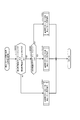
図2は、パチンコ機10の背面図である。図示するように、パチンコ機10は、第1制御ユニット51と、第2制御ユニット52と、第3制御ユニット53と、電源ユニット58とを備えている。具体的には、これらユニットは、内枠13の背面に設けられている。
FIG. 2 is a rear view of the
第1制御ユニット51は、主制御装置60を備えている。主制御装置60は、遊技の主たる制御を司る機能を有する主制御基板を有している。主制御基板は、透明樹脂材料からなる基板ボックスに収容されている。
The
第2制御ユニット52は、音声発光制御装置90と、表示制御装置100とを備えている。音声発光制御装置90は、主制御装置60から送信されたコマンドに基づいて、パチンコ機10の前面に設けられたスピーカーや各種ランプ等の発光手段の制御を行う。表示制御装置100は、音声発光制御装置90から送信されたコマンドに基づいて、液晶表示装置を制御する。液晶表示装置は、図柄や演出用の映像を表示する液晶ディスプレイを備えている。
The second control unit 52 includes a sound
第3制御ユニット53は、払出制御装置70と、発射制御装置80とを備えている。払出制御装置70は、賞球の払い出しを行うための払出制御を行う。発射制御装置80は、主制御装置60から遊技球の発射の指示が入力された場合に、遊技者による操作ハンドル25の回動操作量に応じた強さの遊技球の発射を行うように遊技球発射機構を制御する。その他、内枠13の背面には、遊技ホールの島設備から供給される遊技球が逐次補給されるタンク54、タンク54の下方に連結され遊技球が下流側に流れるように緩やかに傾斜した斜面を有するタンクレール55、タンクレール55の下流側に鉛直方向に連結されたケースレール56、ケースレール56から遊技球の供給を受け払出制御装置70からの指示により所定数の遊技球の払い出しを行う払出装置71など、パチンコ機10の動作に必要な複数の機器が設けられている。
The
電源ユニット58は、電源装置85と、電源スイッチ88とを備えている。電源装置85は、パチンコ機10の動作に必要な電力を供給する。電源装置85には、電源スイッチ88が接続されている。電源スイッチ88のON/OFF操作により、パチンコ機10に電力が供給されている供給状態と、パチンコ機10に電力が供給されていない非供給状態とが切り換えられる。
The
次に、遊技盤について説明する。遊技盤は、内枠13の前面に着脱可能に取り付けられている。
Next, the game board will be described. The game board is detachably attached to the front surface of the
図3は、遊技盤30の正面図である。遊技盤30は、合板によって構成されており、その前面には遊技領域PAが形成されている。遊技盤30には、遊技領域PAの外縁の一部を区画するようにして内レール部31aと、外レール部31bとが取り付けられている。内レール部31aと外レール部31bとの間には、遊技球を誘導するための誘導レール31が形成されている。遊技球発射機構から発射された遊技球は、誘導レール31に誘導されて遊技領域PAの上部に放出され、その後、遊技領域PAを流下する。遊技領域PAには、遊技盤30に対して複数の釘42が植設されるとともに、風車等の各役物が配設されている。これら釘42や風車は、遊技領域PAを流下する遊技球の落下方向を分散、整理する。
FIG. 3 is a front view of the
遊技盤30には、前後方向に貫通する複数の開口部が形成されている。各開口部には、一般入賞口32、第1始動口33、第2始動口34、スルーゲート35、及び可変入賞装置36が設けられている。一般入賞口32、第1始動口33、第2始動口34、スルーゲート35、及び可変入賞装置36のそれぞれに入球した遊技球は、遊技盤30に形成された個別の上記の開口部に誘導される。また、遊技盤30には、可変表示ユニット40及びメイン表示部45が設けられている。メイン表示部45は、特図ユニット37と、普図ユニット38と、ラウンド表示部39とを有している。
The
図示するように、一般入賞口32は、遊技球が入球可能な入球口を形成する入球口部材であり、遊技盤30上に複数設けられている。本実施形態では、一般入賞口32に遊技球が入賞すると、10個の遊技球が賞球として払出装置71(図2)から払い出される。
As shown in the figure, the
第1始動口33は、遊技球が入球可能な入球口を形成する入球口部材である。第1始動口33は、遊技盤30の中央下方に設けられている。本実施形態では、第1始動口33に遊技球が入球すると、3個の遊技球が賞球として払い出されるとともに、後述する大当たり抽選が実行される。
The
第2始動口34は、遊技球が入球可能な入球口を形成する入球口部材であり、遊技盤30の右側に設けられている。本実施形態では、第2始動口34に遊技球が入球すると、3個の遊技球が賞球として払い出されるとともに、後述する大当たり抽選が実行される。また、第2始動口34には、電動役物34aが設けられている。
The
スルーゲート35は、縦方向に貫通した貫通孔を備えている。スルーゲート35は、電動役物34aを開放状態とするための抽選を実行するための契機となるスルーゲートである。具体的には、遊技球がスルーゲート35を通過すると、主制御装置60は、当該通過を契機として内部抽選(電動役物開放抽選)を行う。内部抽選の結果、電役開放に当選すると、電動役物34aは、所定の態様で開放状態となる電役開放状態へと移行する。スルーゲート35は、遊技球の流下方向に対して第2始動口34よりも上流側に配置されているため、スルーゲート35を通過した遊技球は、通過後に遊技領域PAを流下して第2始動口34へ入球することが可能となっている。なお、本実施形態では、スルーゲート35に遊技球が通過しても、賞球の払い出しは実行されない。
The through
可変入賞装置36は、遊技盤30の背面側へと通じる大入賞口36aを備えるとともに、大入賞口36aを開閉する開閉扉36bを備えている。開閉扉36bは、通常は遊技球が大入賞口36aに入賞できない閉鎖状態になっている。主制御装置60による内部抽選(当たり抽選)の結果、大当たりに当選し、開閉実行モードに移行した場合には、開閉扉36bは、遊技球が入賞可能な開放状態と閉鎖状態とを繰り返す。開閉実行モードとは、第1始動口33又は第2始動口34への入賞をトリガとした主制御装置60による当たり抽選の結果、大当たりに当選した場合に移行し、開閉扉36bが開放状態と閉鎖状態とを繰り返すモードである。すなわち、第1始動口33への入賞に基づく当たり抽選の結果、大当たりに当選した場合には、可変入賞装置36の大入賞口36aへの入賞が可能になる開閉実行モードへ移行する。同様に、第2始動口34への入賞に基づく当たり抽選の結果、大当たりに当選した場合にも、可変入賞装置36の大入賞口36aへの入賞が可能な開閉実行モードへと移行する。本実施形態では、可変入賞装置36の大入賞口36aに遊技球が入賞すると、払出装置71によって15個の遊技球が賞球として払い出される。
The
遊技盤30の最下部にはアウト口43が設けられており、一般入賞口32、第1始動口33、第2始動口34、または可変入賞装置36に入球しなかった遊技球は、アウト口43を通って遊技領域PAから排出される。
An out
特図ユニット37は、第1図柄表示部37aと、第2図柄表示部37bとを備えている。第1図柄表示部37a及び第2図柄表示部37bは、それぞれ、複数のセグメント発光部が所定の態様で配列されたセグメント表示器によって構成されている。
The
第1図柄表示部37aは、第1始動口33への入賞をトリガとした当たり抽選が行われると、セグメント表示器に、抽選結果に対応した表示を行わせるまでの表示態様として、変動表示又は所定の表示を行わせる。抽選が終了した際には、第1図柄表示部37aは、セグメント表示器に、抽選結果に対応した所定の態様の表示を行わせる。
When a winning lottery triggered by a winning at the
第2図柄表示部37bは、第2始動口34への入賞をトリガとした当たり抽選が行われると、セグメント表示器に、抽選結果に対応した表示を行わせるまでの表示態様として、変動表示又は所定の表示を行わせる。抽選が終了した際には、第2図柄表示部37bは、セグメント表示器に、抽選結果に対応した所定の態様の表示を行わせる。
When a winning lottery triggered by winning a prize at the
特図ユニット37は、さらに、第1図柄表示部37a及び第2図柄表示部37bに隣接した位置に、LEDランプからなる第1保留表示部37cと第2保留表示部37dとを備えている。本実施形態では、第1始動口33に入賞した遊技球は、最大4個まで保留される。第1保留表示部37cは、点灯させるLEDランプの色や組み合わせによって、第1始動口33の保留個数を表示する。また、本実施形態では、第2始動口34に入賞した遊技球は、最大4個まで保留される。第2保留表示部37dは、点灯させるLEDランプの色や組み合わせによって、第2始動口34の保留個数を表示する。
The
普図ユニット38は、複数のLEDランプが所定の態様で配列された発光表示部によって構成されている。普図ユニット38は、スルーゲート35への入賞をトリガとした電動役物開放抽選が行われると、発光表示器の表示態様として点灯表示、点滅表示又は所定の態様の表示をさせる。電動役物開放抽選が終了した際には、普図ユニット38は、抽選結果に対応した所定の態様の表示を行う。
The
ラウンド表示部39は、複数のLEDランプが所定の態様で配列された発光表示部によって構成されており、開閉実行モードにおいて発生するラウンド遊技の回数の表示、又は、それに対応した表示をする。ラウンド遊技とは、予め定められた上限継続時間が経過すること、又は、予め定められた上限個数の遊技球が可変入賞装置36に入賞することのいずれか一方の条件が満たされるまで、開閉扉36bの開放状態を継続する遊技のことである。ラウンド遊技の回数は、その移行の契機となった大当たり当選の種類に応じて異なる。ラウンド表示部39は、開閉実行モードが開始される場合にラウンド遊技の回数の表示を開始し、開閉実行モードが終了し新たな遊技回が開始される場合に終了する。
The
なお、特図ユニット37、普図ユニット38、およびラウンド表示部39は、セグメント表示器やLEDランプによる発光表示器によって構成されることに限定されず、例えば、液晶表示装置、有機EL表示装置、CRT又はドットマトリックス表示器など、抽選中及び抽選結果を示すことが可能な種々の表示装置によって構成されてもよい。
The
可変表示ユニット40は、遊技領域PAの略中央に配置されている。可変表示ユニット40は、液晶表示装置41を備える。液晶表示装置41は、液晶ディスプレイを備えている。液晶表示装置41は、表示制御装置100によって表示内容が制御される。なお、液晶表示装置41は、例えば、プラズマディスプレイ装置、有機EL表示装置又はCRTなど、種々の表示装置に換えてもよい。
The
液晶表示装置41は、第1始動口33への入賞に基づいて第1図柄表示部37aが変動表示又は所定の表示をする場合に、それに合わせて図柄の変動表示又は所定の表示を行う。また、液晶表示装置41は、第2始動口34への入賞に基づいて第2図柄表示部37bが変動表示又は所定の表示をする場合に、それに合わせて図柄の変動表示又は所定の表示を行う。液晶表示装置41は、第1始動口33又は第2始動口34への入球をトリガとした表示演出に限らず、大当たり当選となった場合に移行する開閉実行モード中の表示演出なども行う。以下、液晶表示装置41の詳細について説明する。
When the first
図4は、液晶表示装置41において変動表示される図柄及び表示面41aを示す説明図である。図4(a)は、液晶表示装置41において変動表示される図柄を示す説明図である。図4(a)に示すように、液晶表示装置41には、数字の1〜8を示す図柄が変動表示される。なお、変動表示される図柄として、数字の1〜8を示す各図柄に、キャラクターなどの絵柄が付された図柄を採用してもよい。
FIG. 4 is an explanatory diagram showing symbols and
図4(b)は、液晶表示装置41の表示面41aを示す説明図である。図示するように、表示面41aには、左、中、右の3つの図柄列Z1、Z2、Z3が表示される。各図柄列Z1〜Z3には、図4(a)に示した数字1〜8の図柄が、数字の昇順又は降順に配列されるとともに、各図柄列が周期性をもって上から下へ又は下から上へとスクロールする変動表示が行われる。図4(b)に示すように、スクロールによる変動表示の後、各図柄列毎に1個の図柄が、有効ラインL上に停止した状態で表示される。具体的には、第1始動口33又は第2始動口34へ遊技球が入賞すると、各図柄列Z1〜Z3の図柄が周期性をもって所定の向きにスクロールする変動表示が開始される。そして、スクロールする各図柄が、図柄列Z1、図柄列Z3、図柄列Z2の順に、変動表示から待機表示に切り替わり、最終的に各図柄列Z1〜Z3に所定の図柄が停止表示した状態となる。図柄の変動表示が終了して停止表示した状態となる場合、主制御装置60による当たり抽選の結果が大当たり当選であった場合には、予め定められた所定の図柄の組み合わせが有効ラインL上に形成される。例えば、同一の図柄の組み合わせが有効ラインL上に形成される。なお、液晶表示装置41における図柄の変動表示の態様は、上述の態様に限定されることなく、図柄列の数、有効ラインの数、図柄列における図柄の変動表示の方向、各図柄列の図柄数など、図柄の変動表示の態様は種々の態様を採用可能である。
FIG. 4B is an explanatory diagram showing the
ここで、「遊技回」とは、第1図柄表示部37aまたは第2図柄表示部37bの変動表示が開始されてから、変動表示が終了して停止表示となり、当該停止表示が終了するまでを言い、第1始動口33又は第2始動口34のいずれかの入賞に基づいて取得された特別情報についての当たり抽選の抽選結果を、遊技者に告知する処理の1単位である。換言すれば、パチンコ機10は、1遊技回毎に、1つの特別情報についての1つの当たり抽選の抽選結果を遊技者に告知する。本実施形態のパチンコ機10は、第1始動口33又は第2始動口34のいずれかの入賞に基づいて特別情報を取得すると、1遊技回毎に、第1図柄表示部37a又は第2図柄表示部37bのいずれか一方において、セグメント表示器を変動表示させた後に、当該取得した特別情報の抽選結果に対応した表示となるようにセグメント表示器を停止表示させる。また、本実施形態のパチンコ機10は、第1始動口33又は第2始動口34のいずれかの入賞に基づいて特別情報を取得すると、1遊技回毎に、液晶表示装置41において、所定の図柄列を変動表示させた後に、当該取得した特別情報の抽選結果に対応した表示となるように図柄列を停止表示させる。また、1回の遊技回に要する時間を単位遊技時間とも呼ぶ。単位遊技時間は、変動表示が開始されてから所定の抽選結果が停止表示されるまでの時間である変動時間と、所定の抽選結果が停止表示されている時間である停止時間とによって構成されている。
Here, “game times” refers to the period from the start of the variable display of the first
さらに、図4(b)に示すように、液晶表示装置41の表示面41aには、第1保留表示領域Ds1と、第2保留表示領域Ds2とが表示される。第1保留表示領域Ds1には、第1始動口33への入賞に基づく保留個数が表示される。第2保留表示領域Ds2には、第2始動口34への入賞に基づく保留個数が表示される。なお、本実施形態では、上述したように、第1始動口33及び第2始動口34に入賞した遊技球の保留個数は、それぞれ最大4つまでである。
Further, as shown in FIG. 4B, a first reserved display area Ds1 and a second reserved display area Ds2 are displayed on the
図3に示すように、第1始動口33の上方には、一対の釘(いわゆる命釘、ヘソ釘)42(42a,42b)が設けられている。一対の釘42a,42bの間隔によって、第1始動口33への遊技球の入球の確率が変化する。
As shown in FIG. 3, a pair of nails (so-called life nails, navel nails) 42 (42 a, 42 b) are provided above the
A2.遊技機の電気的構成:
次に、パチンコ機10の電気的構成について説明する。本説明においては、パチンコ機10の電気的構成をブロック図を用いて説明する。
A2. The electrical configuration of the gaming machine:
Next, the electrical configuration of the
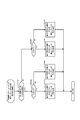
図5は、パチンコ機10の電気的構成を示すブロック図である。パチンコ機10は、主に、主制御装置60を中心に構成されるとともに、音声発光制御装置90と、表示制御装置100とを備えている。主制御装置60は、遊技の主たる制御を司る主制御基板61を備えている。主制御基板61は、複数の機能を有する素子によって構成されるMPU62を備えている。MPU62は、各種制御プログラムや固定値データを記録したROM63と、ROM63内に記録されているプログラムを実行する際に各種データ等を一時的に記憶するためのメモリであるRAM64とを備えている。MPU62は、その他、割込回路、タイマー回路、データ入出力回路、乱数発生器としてのカウンタ回路を備えている。なお、MPU62が有する機能の一部を、別の素子が備えていてもよい。ROM63やRAM64に設けられている各種エリアの詳細については後述する。
FIG. 5 is a block diagram showing an electrical configuration of the
主制御基板61には、入力ポート及び出力ポートがそれぞれ設けられている。主制御基板61の入力側には、各種検知センサ67a〜67eと、払出制御装置70と、電源装置85とが接続されている。主制御基板61は、電源装置85から直流安定24Vの電源の供給を受ける。電源装置85は、外部電源としての商用電源に接続されており、商用電源から供給される外部電力を、主制御装置60や払出制御装置70等が必要な動作電力に変換して、各装置に電力を供給する。
The
電源装置85は、停電監視回路86を備える。停電監視回路86は、電源を監視することによって、停電発生時に停電情報信号を出力する。「停電発生時」とは、商用電源の停電が発生した時に限らず、電源スイッチ88がオン状態からオフ状態に切り替えられた時(電源オフ時)も含む。
The
また、主制御基板61は、各種検知センサ67a〜67eとして、一般入賞口32、第1始動口33、第2始動口34、スルーゲート35、可変入賞装置36などの各種の入賞口に設けられた複数の検知センサと接続されている。主制御基板61のMPU62は、各種検知センサ67a〜67eからの信号に基づいて、遊技領域PAを流下する遊技球が各入球口へ入球したか否かの判定や、遊技球がスルーゲート35を通過したか否かの判定を行う。さらに、MPU62は、第1始動口33及び第2始動口34への遊技球の入球に基づいて大当たり抽選を実行するとともに、スルーゲート35への入球に基づいて電動役物開放抽選を実行する。
In addition, the
主制御基板61の出力側には、可変入賞装置36の開閉扉36bを開閉動作させる可変入賞駆動部36cと、第2始動口34の電動役物34aを開閉動作させる電動役物駆動部34bと、メイン表示部45とが接続されている。主制御基板61には各種ドライバ回路が設けられており、MPU62は、当該ドライバ回路を通じて各種駆動部の駆動制御を実行する。
On the output side of the
具体的には、MPU62は、開閉実行モードにおいては、開閉扉36bが開閉されるように可変入賞駆動部36cの駆動制御を実行する。また、電動役物開放抽選の結果、電役開放に当選した場合には、MPU62は、電動役物34aが開放されるように電動役物駆動部34bの駆動制御を実行する。各遊技回においては、MPU62は、メイン表示部45における第1図柄表示部37a又は第2図柄表示部37bの表示制御を実行する。また、開閉実行モードにおいて大当たり種別が決定され開閉実行モードにおいて実行されるラウンド遊技の回数が決定した場合には、メイン表示部45におけるラウンド表示部39の表示制御を実行する。
Specifically, in the opening / closing execution mode, the
また、主制御基板61の送信側には、払出制御装置70と、音声発光制御装置90とが接続されている。払出制御装置70には、例えば、主制御装置60から入賞判定結果に基づいて賞球コマンドが送信される。主制御装置60が賞球コマンドを送信する際には、主制御基板61のMPU62は、ROM63のコマンド情報記憶エリア63fを参照する。具体的には、一般入賞口32への入球を特定した場合には10個の遊技球の払い出しに対応した賞球コマンドが主制御装置60から送信され、第1始動口33への入球を特定した場合には3個の遊技球の払い出しに対応した賞球コマンドが主制御装置60から送信され、第2始動口34への入賞を特定した場合には1個の遊技球の払い出しに対応した賞球コマンドが主制御装置60から送信される。払出制御装置70は、主制御装置60から受信した賞球コマンドに基づいて、払出装置71を制御して賞球の払出を行う。
Further, a
払出制御装置70には、発射制御装置80が接続されている。発射制御装置80は、遊技球発射機構81の発射制御を行う。遊技球発射機構81は、所定の発射条件が整っている場合に駆動される。また、発射制御装置80には、操作ハンドル25と、遊技球発射ボタン26とが接続されている。
A
音声発光制御装置90は、主制御装置60から送信された各種コマンドを受信し、受信した各種コマンドに対応した処理を実行する。主制御装置60が各種コマンドを送信する際には、ROM63のコマンド情報記憶エリア63fを参照する。これら各種コマンドの詳細については後述する
The sound
その他、音声発光制御装置90は、主制御装置60から受信した各種コマンドに基づいて、前扉枠14に配置されたLEDなどの発光手段からなる各種ランプ47の駆動制御や、スピーカー46の駆動制御を行うとともに、表示制御装置100の制御を行う。また、音声発光制御装置90には、演出操作ボタン24が接続されており、所定のタイミングで遊技者によって演出操作ボタン24が操作された場合には、当該操作を反映した遊技演出を行うように各種ランプ47、スピーカー46、表示制御装置100等の制御を行う。
In addition, the sound
表示制御装置100は、音声発光制御装置90から受信した各種コマンドに基づいて、液晶表示装置41の表示制御を実行する。具体的には、表示制御装置100は、音声発光制御装置90から受信した各種コマンドに基づいて、液晶表示装置41における図柄の変動時間及び最終的に停止表示させる図柄の組み合わせの種類を把握するとともに、リーチの発生の有無、リーチ演出の内容、及び、各遊技回において実行される予告演出の内容等を把握する。なお、本実施形態においては、図柄の組み合わせが停止表示している時間である停止時間は一定である。従って、変動時間が決定されることによって、1遊技回に要する時間である単位遊技時間は一意に決定される。以上、パチンコ機10の電気的構成について説明した。
The
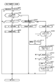
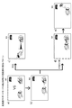
図6は、当たり抽選などに用いられる各種カウンタの内容を説明する説明図である。各種カウンタ情報は、MPU62が当たり抽選、メイン表示部45の表示の設定、及び、液晶表示装置41の図柄表示の設定などを行う際に用いられる。具体的には、当たり抽選には大当たり乱数カウンタC1が用いられる。確変大当たり結果や通常大当たり結果等の大当たり種別を判定する際には大当たり種別カウンタC2が用いられる。液晶表示装置41に表示させる図柄列を外れ変動させる際にリーチを発生させるか否かのリーチ抽選にはリーチ乱数カウンタC3が用いられる。
FIG. 6 is an explanatory diagram for explaining the contents of various counters used for winning lottery and the like. The various counter information is used when the
大当たり乱数カウンタC1の初期値設定には乱数初期値カウンタCINIが用いられる。また、メイン表示部45の第1図柄表示部37a及び第2図柄表示部37b、並びに液晶表示装置41における変動時間を決定する際には変動種別カウンタCSが用いられる。さらに、第2始動口34の電動役物34aを開放状態とするか否かの電動役物開放抽選には電動役物開放カウンタC5が用いられる。
A random number initial value counter CINI is used to set the initial value of the jackpot random number counter C1. In addition, the variation type counter CS is used when determining the variation time in the first
各カウンタC1〜C3、CINI、CS、C5は、その更新の都度、カウンタ値に1が加算され、最大値に達した後に0に戻るループカウンタである。各カウンタは短時間の間隔で更新され、その更新値がRAM64の所定領域に設定された抽選カウンタ用バッファ64aに適宜格納される。
Each of the counters C1 to C3, CINI, CS, and C5 is a loop counter that adds 1 to the counter value every time it is updated, and returns to 0 after reaching the maximum value. Each counter is updated at short intervals, and the updated value is appropriately stored in a
RAM64には保留情報格納エリア64bが設けられている。保留情報格納エリア64bは、第1保留エリアRaと、第2保留エリアRbと、実行エリアAEと、合計保留個数記憶エリアとから構成されている。第1始動口33又は第2始動口34へ遊技球が順次入賞すると、入賞のタイミングにおける大当たり乱数カウンタC1、大当たり種別カウンタC2、リーチ乱数カウンタC3の各値が保留情報格納エリア64bに時系列的に格納される。
The
大当たり乱数カウンタC1の詳細について説明する。大当たり乱数カウンタC1は、上述のように当たり抽選に用いられる。大当たり乱数カウンタC1は、例えば、0〜599の範囲内で順に1ずつ加算され、最大値に達した後0に戻るように構成されている。また、大当たり乱数カウンタC1が1周すると、その時点の乱数初期値カウンタCINIの値が当該大当たり乱数カウンタC1の初期値として読み込まれる。なお、乱数初期値カウンタCINIは、大当たり乱数カウンタC1と同様のループカウンタである(値=0〜599)。 Details of the jackpot random number counter C1 will be described. The jackpot random number counter C1 is used for winning lottery as described above. For example, the jackpot random number counter C1 is configured to increment one by one within a range of 0 to 599 and return to 0 after reaching the maximum value. When the jackpot random number counter C1 makes one round, the value of the random number initial value counter CINI at that time is read as the initial value of the jackpot random number counter C1. The random number initial value counter CINI is a loop counter similar to the jackpot random number counter C1 (value = 0 to 599).
大当たり乱数カウンタC1は定期的に更新され、その更新値は、遊技球が第1始動口33又は第2始動口34に入賞したタイミングでRAM64の保留情報格納エリア64bに格納される。具体的には、大当たり乱数カウンタC1の更新値は、第1始動口33に遊技球が入賞したタイミングで保留情報格納エリア64bの第1保留エリアRaに格納され、第2始動口34に遊技球が入賞したタイミングで保留情報格納エリア64bの第2保留エリアRbに格納される。大当たり当選となる乱数の値は、ROM63の当否テーブル記憶エリア63a(図5)に当否テーブルとして記憶されている。
The jackpot random number counter C1 is periodically updated, and the updated value is stored in the hold
図7は、当否テーブル記憶エリア63aに格納されている当否テーブルについて説明する説明図である。パチンコ機10には、当たり抽選の抽選モードとして、低確率モードと高確率モードとが設定されている。高確率モードは、確変大当たりに当選することによって開始される遊技状態であって、当たり抽選において大当たりに当選する確率が、低確率モードより相対的に高い遊技状態を言う。図7(a)は低確率モード用の当否テーブルを示し、図7(b)は高確率用の当否テーブルを示している。図7(a)に示すように、当たり抽選に際して低確率モード用の当否テーブルが参照されることとなる遊技状態下では、大当たり当選となる乱数の値は15個である。一方、図7(b)に示すように、当たり抽選に際して高確率モード用の当否テーブルが参照されることとなる遊技状態下では、大当たり当選となる乱数の値は30個である。また、低確率モードで大当たり当選となる大当たり乱数カウンタC1の値群は、高確率モードで大当たり当選となる大当たり乱数カウンタC1の値群に含まれている。なお、低確率モードよりも高確率モードの方の当選確率が高くなるのであれば、当選となる乱数の数及び値は任意である。
FIG. 7 is an explanatory diagram for explaining the success / failure table stored in the success / failure
図6に戻り、大当たり種別カウンタC2の詳細について次に説明する。大当たり種別カウンタC2は、確変大当たりや通常大当たり等の大当たり種別を判定する際に用いられる。大当たり種別カウンタC2は、0〜29の範囲内で順に1ずつ加算され、最大値に達した後0に戻る構成である。大当たり種別カウンタC2は定期的に更新され、遊技球が第1始動口33又は第2始動口34に入賞したタイミングでRAM64の保留情報格納エリア64bに格納される。より詳しくは、第1始動口33に遊技球が入賞したタイミングで保留情報格納エリア64b(RAM64)の第1保留エリアRaに格納され、第2始動口34に遊技球が入賞したタイミングで保留情報格納エリア64b(RAM64)の第2保留エリアRbに格納される。
Returning to FIG. 6, the details of the jackpot type counter C2 will be described next. The jackpot type counter C2 is used when determining jackpot types such as probability variation jackpots and normal jackpots. The jackpot type counter C2 is configured such that one by one is added in order within a range of 0 to 29 and returns to 0 after reaching the maximum value. The big hit type counter C2 is periodically updated and stored in the hold
ここで、パチンコ機10における大当たり種別について説明する。パチンコ機10には、複数種類の大当たりを設定することができる。具体的には、例えば、以下の3つの態様又はモードに差異を設けることにより、複数種類の大当たりを設定することができる。
(1)開閉実行モードにおける可変入賞装置36の開閉制御の態様
(2)開閉実行モード終了後の当たり抽選の抽選モード
(3)開閉実行モード終了後の第2始動口34の電動役物34aのサポートモード
Here, the jackpot type in the
(1) Mode of opening / closing control of variable winning
パチンコ機10には、上記の(1)開閉実行モードにおける可変入賞装置36の開閉制御の態様として、開閉実行モードが開始されてから終了するまでの間における可変入賞装置36への入賞の発生頻度が相対的に高低となるように高頻度入賞モードと低頻度入賞モードとを設定することができる。例えば、高頻度入賞モードでは、開閉実行モードの開始から終了までに、開閉扉36bの開閉が15回行われるとともに、1回の開放は30secが経過するまで又は開閉扉36bへの入賞個数が10個となるまで継続するように設定可能である。一方、低頻度入賞モードでは、開閉実行モードの開始から終了までに、開閉扉36bの開閉が2回行われるとともに、1回の開放は0.2secが経過するまで又は開閉扉36bへの入賞個数が6個となるまで継続するよう設定可能である。
In the
遊技者により操作ハンドル25が操作されている場合、0.6secに1個の遊技球が遊技領域PAに向けて発射されるように遊技球発射機構81が駆動制御される。上記具体例の場合、低頻度入賞モードでは、1回の開閉扉36bの開放時間は0.2secである。つまり、低頻度入賞モードでは、遊技球の発射周期よりも1回の開閉扉36bの開放時間が短くなっている。したがって、低頻度入賞モードにかかる開閉実行モードでは実質的に遊技球の入賞が発生しない。ただし、低頻度入賞モードにかかる開閉実行モードにおいても、遊技球の入賞が発生し得るように設定してもよい。
When the operation handle 25 is operated by the player, the game
なお、開閉扉36bの開閉回数、1回の開放に対する開放限度時間、及び1回の開放に対する開放限度個数は、開閉実行モードが開始されてから終了するまでの間における可変入賞装置36への入賞の発生頻度が、高頻度入賞モードの方が低頻度入賞モードよりも高くなるのであれば、開閉扉36bの開放態様は任意である。具体的には、高頻度入賞モードの方が低頻度入賞モードよりも、開閉回数が多い、1回の開放に対する開放限度時間が長い又は1回の開放に対する開放限度個数が多く設定されていればよい。高頻度入賞モードと低頻度入賞モードとの差異を明確にする上では、低頻度入賞モードの開閉実行モードでは、実質的に可変入賞装置36への入賞が発生しない構成としてもよい。
Note that the number of opening / closing of the open /
パチンコ機10には、上記の(2)開閉実行モード終了後の当たり抽選の抽選モードの態様として、当否テーブルとして高確率モード用の当否テーブルを用いて当たり抽選を行う高確率モードと、当否テーブルとして低確率モード用の当否テーブルを用いて当たり抽選を行う低確率モードとを設定することができる。図7を用いて説明したように、高確率用の当否テーブルを用いて当たり抽選を行う場合の方が、低確率用の当否テーブルを用いて当たり抽選を行う場合と比較して、大当たりに当選する確率が高い。
The
パチンコ機10には、上記の(3)開閉実行モード終了後の第2始動口34の電動役物34aのサポートモードの態様として、遊技領域PAに対して同様の態様で遊技球の発射が継続されている状況で比較した場合に、第2始動口34の電動役物34aが単位時間当たりに開放状態となる頻度が相対的に高低となるように、高頻度サポートモードと低頻度サポートモードとを設定することができる。
The
具体的には、高頻度サポートモードと低頻度サポートモードとでは、電動役物開放カウンタC5を用いた電動役物開放抽選における電役開放当選となる確率は同一であるが、高頻度サポートモードでは低頻度サポートモードよりも、電役開放当選となった際に電動役物34aが開放状態となる回数が多く設定され、さらに1回の開放時間が長く設定されてもよい。また、高頻度サポートモードで電役開放当選となり電動役物34aの開放状態が複数回発生する場合において、1回の開放状態が終了してから次の開放状態が開始されるまでの閉鎖時間は、1回の開放時間よりも短く設定されてもよい。さらに、高頻度サポートモードでは低頻度サポートモードよりも、1回の電動役物開放抽選が行われてから次の電動役物開放抽選が行われる上で最低限確保される確保時間が短く設定されてもよい。
Specifically, the high frequency support mode and the low frequency support mode have the same probability of winning a power combination opening lot in the electric component opening lottery using the electric component opening counter C5, but in the high frequency support mode, The number of times that the
上記のように高頻度サポートモードでは、低頻度サポートモードよりも第2始動口34への入賞が発生する確率が高くなる。すなわち、高頻度サポートモードは、特別情報の取得条件の成立を補助する補助遊技状態として機能する。
As described above, in the high frequency support mode, the probability of winning a prize at the
低頻度サポートモードでは、第2始動口34よりも第1始動口33への入賞が発生する確率が高くなるが、高頻度サポートモードでは、第1始動口33よりも第2始動口34への入賞が発生する確率が高くなる。第2始動口34への入賞が発生した場合には、所定個数の遊技球の払出が実行されるため、高頻度サポートモードでは、遊技者は持ち球をあまり減らさないようにしながら遊技を行うことができる。
In the low frequency support mode, the probability of winning a prize at the
なお、高頻度サポートモードを低頻度サポートモードよりも単位時間当たりに電役開放状態となる頻度を高くする構成は、上記のものに限定されることはなく、例えば、電動役物開放抽選における電役開放当選となる確率を高くする構成としてもよい。また、1回の電動役物開放抽選が行われてから次の電動役物開放抽選が行われる上で確保される確保時間が複数種類用意されている構成においては、高頻度サポートモードでは低頻度サポートモードよりも、短い確保時間が選択され易い又は平均の確保時間が短くなるように設定されていてもよい。さらには、開放回数を多くする、開放時間を長くする、1回の電動役物開放抽選が行われてから次の電動役物開放抽選が行われる上で確保される確保時間を短くする、係る確保時間の平均時間を短くする、及び当選確率を高くするのうち、いずれか1つ又は任意の組み合わせの条件を適用することで、低頻度サポートモードに対する高頻度サポートモードの有利性を高めてもよい。 In addition, the configuration in which the high frequency support mode is set to have a higher frequency of being in the power release state per unit time than the low frequency support mode is not limited to the above-described configuration. It is good also as a structure which raises the probability of becoming a winning combination winning. In addition, in a configuration in which a plurality of securing times to be secured after the next electrification opening lottery is performed after the first electrification opening lottery is performed, in the high frequency support mode, the frequency is low. It may be set so that a shorter securing time is more easily selected than the support mode or the average securing time is shortened. Furthermore, the number of times of opening is increased, the opening time is lengthened, and the securing time secured when the next electric character opening lottery is performed after the first electric character releasing lottery is shortened, Even if the advantage of the high frequency support mode is increased by applying any one or any combination of the conditions for shortening the average time of the reservation time and increasing the winning probability Good.
上述したように、パチンコ機10には、複数種類の大当たりを設定することが可能である。本実施形態では、当たり抽選において大当たりに当選した場合には、大当たり種別カウンタC2を用いて、複数種類の大当たりの種別を振り分ける。大当たり種別カウンタC2の値に対応する大当たりの種別の振分先は、ROM63の振分テーブル記憶エリア63bに振分テーブルとして記憶されている。
As described above, the
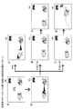
図8は、パチンコ機10に設定されている振分テーブルの内容を説明する説明図である。図8(a)は第1始動口用の振分テーブルを示し、図8(b)は第2始動口用の振分テーブルを示している。
FIG. 8 is an explanatory diagram for explaining the contents of the sorting table set in the
図8(a)の第1始動口用の振分テーブルに示すように、本実施形態のパチンコ機10では、第1始動口33に基づく大当たり種別として、16R確変大当たり、8R確変大当たり、16R通常大当たり、8R通常大当たりが設定されている。
As shown in the distribution table for the first start port in FIG. 8A, in the
16R確変大当たり及び8R確変大当たりは、開閉実行モードにおける可変入賞装置36の開閉制御の態様が高頻度入賞モードであり、開閉実行モードの終了後の当たり抽選の抽選モード(以下、単に「抽選モード」とも呼ぶ)が高確率モードであり、開閉実行モードの終了後のサポートモードが高頻度サポートモードとなる大当たりである。
In the 16R probability variation jackpot and the 8R probability variation jackpot, the open / close control mode of the variable winning
16R通常大当たり及び8R通常大当たりは、開閉実行モードにおける可変入賞装置36の開閉制御の態様が高頻度入賞モードであり、開閉実行モードの終了後の抽選モードが低確率モードであり、開閉実行モードの終了後のサポートモードが高頻度サポートモードとなる大当たりである。
In the 16R normal jackpot and 8R normal jackpot, the open / close control mode of the variable winning
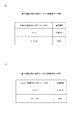
第1始動口用の振分テーブルでは、「0〜39」の大当たり種別カウンタC2の値のうち、「0〜5」が16R確変大当たりに対応しており、「6〜23」が8R確変大当たりに対応しており、「24〜27」が16R通常大当たりに対応しており、「28〜39」が8R通常大当たりに対応している。このため、本実施形態では、確変大当たりとなる確率は「0〜39」の大当たり種別カウンタC2の値のうちの60パーセントであり、通常大当たりとなる確率は「0〜39」の大当たり種別カウンタC2の値のうちの40パーセントとなっている。なお、大当たりに当選する乱数の数及び値は任意であり、他の構成を採用してもよい。 In the distribution table for the first start port, among the values of the jackpot type counter C2 of “0 to 39”, “0 to 5” corresponds to the 16R probability variation jackpot, and “6 to 23” corresponds to the 8R probability variation jackpot. “24 to 27” corresponds to 16R normal jackpot, and “28 to 39” corresponds to 8R normal jackpot. For this reason, in this embodiment, the probability of a probable jackpot is 60 percent of the value of the jackpot type counter C2 of “0 to 39”, and the probability of a normal jackpot is the jackpot type counter C2 of “0 to 39”. 40% of the value of. Note that the number and value of the random numbers won in the jackpot are arbitrary, and other configurations may be adopted.
上記のように、本実施形態のパチンコ機10では、大当たりの種別として、4種類の大当たりが設定されている。したがって、大当たりの態様が多様化する。この4種類の大当たりを比較した場合、遊技者にとっての有利度合は、16R確変大当たりが最も高く、8R確変大当たりが次に高く、次に16R通常大当たり、最後に8R通常大当たりと続く。このように遊技者にとって有利度の異なる複数種類の大当たりが設定されていることにより、遊技の単調化が抑えられ、遊技への注目度を高めることが可能となる。
As described above, in the
次に、図8(b)の第2始動口用の振分テーブルに示すように、本実施形態のパチンコ機10では、第2始動口34に基づく大当たり種別として、16R確変大当たり、8R確変大当たり、16R通常大当たり、8R通常大当たりが設定されている。第2始動口用の振分テーブルでは、「0〜39」の大当たり種別カウンタC2の値のうち、「0〜12」が16R確変大当たりに対応しており、「13〜23」が8R確変大当たりに対応しており、「24〜30」が16R通常大当たりに対応しており、「31〜39」が8R通常大当たりに対応している。上記のように本実施形態のパチンコ機10では、大当たり当選となった場合の大当たりの種別の振分態様は、第1始動口33への入賞に基づいて大当たり当選となった場合と、第2始動口34への入賞に基づいて大当たり当選となった場合とで異なっている。本実施形態では、第2始動口34への入賞に基づいて大当たり当選となる場合において、確変大当たりとなる確率は60パーセントであり、通常大当たりとなる確率は40パーセントであり、第1始動口33への入賞に基づいて大当たり当選となる場合と同一であるが、16Rと8Rとの振分けは、第1始動口33への入賞に基づいて大当たり当選となる場合よりも16Rとなる確率が高い確率となっている。なお、大当たりに当選する乱数の数及び値は任意であり、他の構成を採用してもよい。
Next, as shown in the distribution table for the second start port in FIG. 8B, in the
このように、第1始動口33と第2始動口34との大当たり種別の振分態様は、遊技者にとっての有利性に明確な差異が設けられている。したがって、遊技者は、第1始動口33及び第2始動口34のうち、第2始動口34への入賞が発生することを期待しながら遊技を行うことになる。なお、当否抽選において外れ結果となった場合、開閉実行モードに移行することはなく、抽選モード及びサポートモードの変更も発生しない。
As described above, the jackpot type distribution mode between the
上述のように、MPU62は、実行エリアAEに格納されている大当たり乱数カウンタC1の値を用いて当たり抽選を行うとともに、実行エリアAEに格納されている大当たり種別カウンタC2の値を用いて大当たり種別を判定するが、さらに、MPU62は、これらの大当たり乱数カウンタC1の値及び大当たり種別カウンタC2の値を用いて、第1図柄表示部37a及び第2図柄表示部37bに停止表示させるセグメント表示器の表示態様を決定する。その決定に際しては、ROM63の停止結果テーブル記憶エリア63eに格納されている停止結果テーブルが参照される。
As described above, the
図6に戻り、リーチ乱数カウンタC3の詳細について次に説明する。リーチ乱数カウンタC3は、例えば0〜238の範囲内で順に1ずつ加算され、最大値に達した後0に戻る構成である。リーチ乱数カウンタC3は定期的に更新され、遊技球が第1始動口33又は第2始動口34に入賞したタイミングでRAM64の保留情報格納エリア64bに格納される。具体的には、第1始動口33に遊技球が入賞したタイミングでリーチ乱数カウンタC3の更新値がRAM64の第1保留エリアRaに格納され、第2始動口34に遊技球が入賞したタイミングでリーチ乱数カウンタC3の更新値がRAM64の第2保留エリアRbに格納される。そして、第1保留エリアRa又は第2保留エリアRbに格納されたリーチ乱数カウンタC3の値は、実行エリアAEに移動した後、ROM63のリーチ判定用テーブル記憶エリア63cに記憶されているリーチ判定用テーブルと照合され、リーチを発生させるか否かが決定される。但し、当たり抽選の結果、大当たりに当選し、開閉実行モードに移行する場合には、MPU62は、リーチ乱数カウンタC3の値に関係なくリーチ発生の決定を行う。
Returning to FIG. 6, the details of the reach random number counter C3 will be described next. For example, the reach random number counter C3 is incremented one by one within a range of 0 to 238, for example, and reaches a maximum value and then returns to 0. The reach random number counter C3 is periodically updated and stored in the hold
リーチとは、液晶表示装置41の表示画面に表示される複数の図柄列のうち一部の図柄列について、大当たりに対応した図柄の組み合わせが成立する可能性がある図柄の一部の組み合わせが停止表示され、その状態で残りの図柄列において図柄の変動表示を行う表示状態のことを言う。なお、本実施形態のパチンコ機10において大当たりに対応した図柄の組み合わせとは、所定の有効ラインにおける同一の図柄の組み合わせのことをいう。具体的には、図4(b)の表示面41aにおいて、最初に図柄列Z1において図柄が停止表示され、次に図柄列Z3においてZ1と同じ図柄が停止表示されることでリーチラインが形成され、当該リーチラインが形成されている状況化において図柄列Z2において図柄の変動表示が行われることでリーチとなる。そして、大当たりが発生する場合には、リーチラインを形成している図柄と同一の図柄が図柄列Z2に停止表示される。
Reach means that for some of the symbol sequences displayed on the display screen of the liquid
また、リーチには、リーチラインが形成された状態で、残りの図柄列において図柄の変動表示を行うとともに、その背景画面において所定のキャラクターなどを動画として表示することによりリーチ演出を行うものや、リーチラインが形成された図柄の組み合わせを縮小表示させる又は非表示とした上で、表示面41aの略全体において所定のキャラクターなどを動画として表示することによりリーチ演出を行うものが含まれる。また、リーチ演出が行われている場合又はリーチ表示の前に所定のキャラクターといった所定画像を用いた予告表示を行うか否かの決定を、リーチ乱数カウンタC3やその他のカウンタを用いて行うようにしてもよい。
In addition, in the reach, in the state that the reach line is formed, while performing the variable display of the symbols in the remaining symbol row, and performing a reach effect by displaying a predetermined character or the like as a moving image on the background screen, A combination of performing a reach effect by displaying a predetermined character or the like as a moving image on substantially the
次に、変動種別カウンタCSの詳細について説明する。変動種別カウンタCSは、例えば0〜198の範囲内で順に1ずつ加算され、最大値に達した後0に戻る構成である。変動種別カウンタCSは、第1図柄表示部37a及び第2図柄表示部37bにおける変動時間と、液晶表示装置41における図柄の変動時間とをMPU62において決定する際に用いられる。変動種別カウンタCSは、後述する通常処理が1回実行される毎に1回更新され、当該通常処理内の残余時間内でも繰り返し更新される。そして、第1図柄表示部37a又は第2図柄表示部37bにおける変動表示の開始時及び液晶表示装置41による図柄の変動開始時における変動パターンの決定に際して変動種別カウンタCSのバッファ値が取得される。第1図柄表示部37a及び第2図柄表示部37bにおける変動時間の決定に際しては、ROM63の変動時間テーブル記憶エリア63dに記憶されている変動時間テーブルが用いられる。
Next, details of the variation type counter CS will be described. For example, the variation type counter CS is incremented one by one within a range of 0 to 198, for example, and returns to 0 after reaching the maximum value. The variation type counter CS is used when the
次に、電動役物開放カウンタC5の詳細について説明する。電動役物開放カウンタC5は、例えば、0〜249の範囲内で順に1ずつ加算され、最大値に達した後0に戻る構成である。電動役物開放カウンタC5は定期的に更新され、スルーゲート35に遊技球が入賞したタイミングでRAM64の電役保留エリア64cに格納される。そして、所定のタイミングで、その格納された電動役物開放カウンタC5の値を用いて電動役物34aを開放状態に制御するか否かの抽選が行われる。例えば、C5=0〜199であれば、電動役物34aを開放状態に制御し、C5=200〜249であれば、電動役物34aを閉鎖状態に制御する。
Next, details of the electric accessory release counter C5 will be described. The electric accessory release counter C5 has a configuration in which, for example, 1 is added in order within a range of 0 to 249, and after reaching the maximum value, returns to 0. The electric accessory release counter C5 is periodically updated and stored in the electric
なお、第1保留エリアRaに記憶された大当たり乱数カウンタC1、大当たり種別カウンタC2、及びリーチ乱数カウンタC3の一組の組み合わせが、第1始動口33に係る保留情報に相当し、第2保留エリアRbに記憶された大当たり乱数カウンタC1、大当たり種別カウンタC2、及びリーチ乱数カウンタC3の一組の組み合わせが、第2始動口34に係る保留情報に相当し、これらの保留情報が、本発明における特別情報に相当する。
Note that a combination of the jackpot random number counter C1, the jackpot type counter C2 and the reach random number counter C3 stored in the first hold area Ra corresponds to the hold information related to the
A3.音声発光制御装置及び表示制御装置の電気的構成:
次に、音声発光制御装置90及び表示制御装置100の電気的構成について説明する。
A3. Electrical configuration of the sound emission control device and the display control device:
Next, the electrical configurations of the sound
図9は、音声発光制御装置90及び表示制御装置100の電気的構成を中心として示すブロック図である。なお、電源装置85(図5)等の一部の構成は省略されている。音声発光制御装置90に設けられた音声発光制御基板91には、MPU92が搭載されている。MPU92は、ROM93、RAM94、割込回路、タイマ回路、データ入出力回路などが内蔵された素子である。
FIG. 9 is a block diagram showing mainly the electrical configurations of the sound
ROM93には、MPU92により実行される各種の制御プログラムや固定値データ、テーブル等が記憶されている。例えば、ROM93のエリアの一部には、演出パターンテーブル記憶エリア93a、変動表示パターンテーブル記憶エリア93b等が設けられている。これらの詳細については後述する。
The
RAM94は、ROM93内に記憶されている制御プログラムの実行の際に各種データ等を一時的に記憶するためのメモリである。例えば、RAM94のエリアの一部には、各種フラグ記憶エリア94a、各種カウンタエリア94b、抽選用カウンタエリア94c等が設けられている。なお、MPU92に対してROM93及びRAM94が1チップ化されていることは必須の構成ではなく、それぞれが個別にチップ化された構成としてもよい。
The
MPU92には、入力ポート及び出力ポートがそれぞれ設けられている。MPU92の入力側には、主制御装置60と演出操作ボタン24が接続されている。主制御装置60からは、各種コマンドを受信する。MPU92の出力側には、スピーカー46や各種ランプ47が接続されているとともに、表示制御装置100が接続されている。
The
表示制御装置100に設けられた表示制御基板101には、プログラムROM103及びワークRAM104が複合的にチップ化された素子であるMPU102と、ビデオディスプレイプロセッサ(VDP)105と、キャラクタROM106と、ビデオRAM107とが搭載されている。なお、MPU102に対してプログラムROM103及びワークRAM104が1チップ化されていることは必須の構成ではなく、それぞれが個別にチップ化された構成としてもよい。
A
MPU102は、音声発光制御装置90から受信した各種コマンドを解析し又は受信した各種コマンドに基づいて所定の演算処理を行って、VDP105の制御(具体的にはVDP105に対する内部コマンドの生成)を実施する。
The
プログラムROM103は、MPU102により実行される各種の制御プログラムや固定値データを記憶するためのメモリであり、背景画像用のJPEG形式画像データも併せて記憶されている。
The
ワークRAM104は、MPU102による各種プログラムの実行時に使用されるワークデータやフラグ等を一時的に記憶するためのメモリである。
The
VDP105は、一種の描画回路であり、液晶表示装置41に組み込まれた液晶表示部ドライバとしての画像処理デバイスを直接操作する。VDP105は、ICチップ化されているため「描画チップ」とも呼ばれ、描画処理専用のファームウェアを内蔵した一種のマイコンチップである。VDP105は、MPU102、ビデオRAM107等のそれぞれのタイミングを調整してデータの読み書きに介在するとともに、ビデオRAM107に記憶させる画像データを、キャラクタROM106から所定のタイミングで読み出して液晶表示装置41に表示させる。
The
キャラクタROM106は、液晶表示装置41に表示される図柄などのキャラクタデータを記憶するための画像データライブラリとしての役割を担うものである。このキャラクタROM106には、各種の表示図柄のビットマップ形式画像データ、ビットマップ画像の各ドットでの表現色を決定する際に参照される色パレットテーブル等が記憶されている。なお、キャラクタROM106を複数設け、各キャラクタROM106に分担して画像データ等を記憶させておくことも可能である。また、プログラムROM103に記憶した背景画像用のJPEG形式画像データをキャラクタROM106に記憶する構成とすることも可能である。
The
ビデオRAM107は、液晶表示装置41に表示させる表示データを記憶するためのメモリであり、ビデオRAM107の内容を書き替えることにより液晶表示装置41の表示内容が変更される。
The
以下では、主制御装置60のMPU62、ROM63、RAM64をそれぞれ主側MPU62、主側ROM63、主側RAM64とも呼び、音声発光制御装置90のMPU92、ROM93、RAM94をそれぞれ音光側MPU92、音光側ROM93、音光側RAM94とも呼び、表示制御装置100のMPU102を表示側MPU102とも呼ぶ。
Hereinafter, the
A4.第1始動口と命釘の構成:
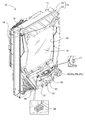
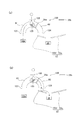
図10は、第1始動口33とその周辺を示す斜視図である。図中におけるX軸正方向は遊技盤30の正面視右側を示し、Y軸正方向は遊技盤30の上側を示し、Z軸正方向は遊技盤30の前側を示す。つまり、X軸方向は遊技盤30の正面視右左方向を示し、Y軸方向は遊技盤30の上下方向を示し、Z軸方向は遊技盤30の前後方向を示す。X軸、Y軸、Z軸は、互いに直交する三軸である。以下、X軸正方向を「+X方向」と呼び、X軸負方向を「−X方向」と呼び、Y軸正方向を「+Y方向」と呼び、Y軸負方向を「−Y方向」と呼び、Z軸正方向を「+Z方向」と呼び、Z軸負方向を「−Z方向」と呼ぶ。
A4. 1st starting port and life nail configuration:
FIG. 10 is a perspective view showing the
第1始動口33は、遊技球が入球可能な入球口33aを形成する入球口部材によって構成されている。具体的には、第1始動口33は、中空の箱形状であり、+Y方向側の面に入球口33aが形成され、−Z方向側の面に、遊技盤30を前後方向に貫通する開口部(図示せず)に連通する排球口33bが形成されている。入球口33aから入球した遊技球は、第1始動口33の中を通って排球口33bから排出され、遊技盤30を前後方向に貫通する開口部に送られる。第1始動口33は、半透明な樹脂製部材によって構成されている。
The
前述したように、第1始動口33の上方には、一対の釘42が植設されている。以下、一対の釘42のうちの+X方向側の釘を「第1の釘42a」と呼び、一対の釘42のうちの−X方向側の釘を「第2の釘42b」と呼ぶ。
As described above, the pair of
第1の釘42aおよび第2の釘42bを含めた本パチンコ機10に備えられる各釘42は、略半球形状の頭部421と、略円柱形状の胴部422と、を有しており、例えば真鍮材によって一体的に形成されている。胴部422は、真っ直ぐ伸びて、先端が尖って、外周面の一部に螺旋状のねじ溝422s(図11参照)が形成されている。釘42は、遊技盤30を構成する合板30aにねじ溝422sまで打ち込まれることによって、遊技球が激突しても衝撃で遊技盤30から抜けにくくなっている。各釘42は、自動釘打ち機によって打ち込まれる。各釘42の少なくとも一部は、自動釘打ち機によって打ち込まれた後に、必要に応じてその傾きが調整される構成としても良い。
Each
少なくともメーカーの出荷段階では、各釘42は、合板30aに対しておおむね垂直となっている。具体的には、第1始動口33の上方に設けられた第1の釘42aおよび第2の釘42bは、合板30aの表面と直角に交わる方向、すなわち+Z軸方向に対して微少な角度θ1,θ2だけ傾斜している。なお、第1の釘42aおよび第2の釘42bを含む少なくとも一部の釘42の傾斜角度が決められているのは、出球率や入賞率を設計値に合わせるためである。第1の釘42aおよび第2の釘42bの傾斜角度について、次に詳述する。
At least at the manufacturer's shipping stage, each
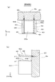
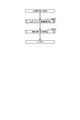
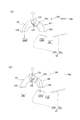
図11は、一対の釘42a,42bと第1始動口33とを示す図である。図11(a)は図10における1−1線矢視断面図であり、図11(b)は図10における2−2線矢視断面図である。すなわち、図11(a)は、第1および第2の釘42a,42bと第1始動口33とを、+Y方向側(上側)から−Y方向側(下側)に向けて見た場合(以下、単に「上側から見た場合」とも呼ぶ)の図である。図11(b)は、一対の釘42a,42bと第1始動口33とを、+X方向側(右側)から−X方向側(左側)に向けて見た場合(以下、単に「右側から見た場合」とも呼ぶ)の図である。図11(b)においては、左側に位置する第2の釘42bは、右側に位置する第1の釘42aに隠れて見えない。
FIG. 11 is a diagram showing a pair of
図11(a)に示すように、上側から見た場合に、右側に位置する第1の釘42aは、先端423を基準とした胴部422の中心軸方向が+Z方向(2点鎖線)から右側(+X方向)に第1角度θ1だけ傾斜した方向となるように設けられている。一般角で言えば、+Z方向に対して+θ1(反時計回りにθ1)だけ傾斜した方向となるように、第1の釘42aは設けられている。
As shown in FIG. 11A, when viewed from the upper side, the
一般にパチンコ機10は、機器性能の試験を受け、同じ型式で生産されている機器はおおむね同一性能を保持しているものとして、各パチンコ店への設置許可が行われている。第1角度θ1は、予め定められた所定角度であり、本実施形態では、型式検定試験に合格となった際の角度である。第1角度θ1は、例えば1度〜10度のうちのいずれかの値であり、本実施形態では例えば5度である。
In general, the
さらに、図11(b)に示すように、X軸とZ軸とに平行なX−Z平面に沿うように、第1の釘42aは設けられている。すなわち、右側から見た場合には、Z軸方向に沿うように、第1の釘42aは設けられている。
Further, as shown in FIG. 11B, the
図11(a)に示すように、上側から見た場合に、左側に位置する第2の釘42bは、先端423を基準とした胴部422の中心軸方向が+Z方向(2点鎖線)から左側(−X方向)に第2角度θ2だけ傾斜した方向となるように設けられている。一般角で言えば、+Z方向に対して−θ2(時計回りにθ2)だけ傾斜した方向となるように、第2の釘42bは設けられている。第2角度θ2は、予め定められた所定角度であり、本実施形態では、型式検定試験に合格となった際の角度である。第2角度θ2は、例えば1度〜10度のうちのいずれかの値であり、本実施形態では例えば5度である。なお、第1角度θ1と第2角度θ2とは、本実施形態では等しいが、これに換えて、異なっていてもよい。第1角度θ1と第2角度θ2が、メーカーの出荷段階で意図する角度でもある。
As shown in FIG. 11A, when viewed from the upper side, the
さらに、図11(b)に示すように、X軸とZ軸とに平行なX−Z平面に沿うように、第2の釘42bは設けられている。すなわち、右側から見た場合には、Z軸方向に沿うように、第2の釘42bは設けられている。
Furthermore, as shown in FIG. 11B, the
第1の釘42aと第2の釘42bとが上記のように傾斜して設けられている結果、図11(a)に示すように、第1の釘42aと第2の釘42bとの間の距離(広さ)は、後ろ側(−Z方向側)から前側(+Z方向側)に向かって漸次、広くなっている。
As a result of the
第1始動口33の入球口33aは、X−Z平面に沿った開口であり、図11(a)に示すように、台形形状を有する。具体的には、台形を構成する平行な1組の対辺のうちの一方に相当する第1のへり(縁)331と、上記1組の対辺のうちの他方に相当する第2のへり332と、台形を構成する他の組の対辺のうちの一方に相当する第3のへり333と、上記他の組の対辺のうちの他方に相当する第4のへり334と、によって入球口33aが構成される。第1のへり331と第2のへり332とは、遊技盤30を構成する合板30aの表面と平行であり(すなわち、X軸方向に沿っており)、第1のへり331は入球口33aの+Z方向側に位置し、第2のへり332は入球口33aの−Z方向側に位置する。第3のへり333は入球口33aの+X方向側に位置し、第4のへり334は入球口33aの−X方向側に位置する。なお、第1〜第4のへり331〜334は、内法を測る場合の入球口33aの内法面と言うこともできる。
The
本実施形態では、第1のへり331の長さは、第2のへり332の長さより長くなっている。第2のへり332の両端にある2つの内角のうちの+X方向側の角度をδ1とし、上記2つの内角のうちの−X方向側の角度をδ2とした場合に、δ1およびδ2は、下記の式(1)および式(2)を満たす。
In the present embodiment, the length of the
δ1=θ1+90度 ...(1)
δ2=θ2+90度 ...(2)
但し、θ1は上述した第1の釘42aの傾斜角度であり、θ2は上述した第2の釘42bの傾斜角度である。
δ1 = θ1 + 90 degrees (1)
δ2 = θ2 + 90 degrees (2)
However, (theta) 1 is an inclination angle of the
式(1)によれば、第3のへり333は、−Z方向側の端部を基準とした方向が+Z方向から右側(+X方向)に第1角度θ1だけ傾斜した構成であることが判る。式(2)によれば、第4のへり334は、−Z方向側の端部を基準とした方向が+Z方向から左側(−X方向)に第2角度θ2だけ傾斜した構成であることが判る。入球口33aにおける第3のへり333と第4のへり334との間の距離(広さ)は、後ろ側(−Z方向側)から前側(+Z方向側)に向かって漸次、広くなっている。
According to Equation (1), it can be seen that the
したがって、第1および第2の釘42a,釘42bと、第1始動口33の入球口33aとは、上側から見た場合に、第3のへり333が第1の釘42aの胴部422の中心軸方向と平行になり、第4のへり334が第2の釘42bの胴部422の中心軸方向と平行になっている。換言すれば、第3のへり333が第1の釘42aの傾斜角度、すなわち、第1の釘42aと合板30aの表面とのなす角度(より具体的には、合板30aの表面の垂線方向とのなす角度)を規定し、第4のへり334が第2の釘42bの傾斜角度、すなわち、第2の釘42bと合板30aの表面とのなす角度(より具体的には、合板30aの表面の垂線方向とのなす角度)を規定する。
Therefore, the first and
A5.実施形態の作用効果
第1始動口33の上方に設けられた第1の釘42aおよび第2の釘42bは、例えば、搬送時の偶発的な衝撃等の意図しない外的な要因によって、その傾き具合がメーカーの意図する大きさと異なってしまうことがある。
A5. Effects of Embodiment The
図12は、従来例を示す説明図である。従来例において、第1実施形態と同一の第1の釘42aが用いられている。第1の釘42aは、先に説明したように、出荷時には、+Z方向(2点鎖線)から右側(+X方向)に第1角度θ1だけ傾斜している。第1の釘42aの下方(−Y方向)には、第1実施形態と同様に、第1始動口P33が設けられている。第1始動口P33は、第1実施形態の第1始動口33と比較して、入球口P33aが矩形形状である点が相違する。すなわち、従来例では、入球口P33aの第3のへりP93は、遊技盤30を構成する合板30aの表面に対して垂直な方向(Z軸方向)と平行である。
FIG. 12 is an explanatory diagram showing a conventional example. In the conventional example, the same
従来例のパチンコ機では、搬送時に偶発的な衝撃が加わったり、経年変化等によって、第1の釘42aの傾き具合が、例えば図中の破線(42a′)に示すように、出荷時から変わってしまうことがあった。その場合に、修理者は、出荷時の角度である第1角度θに戻す必要がある。しかしながら、修理者は第1角度θがどれだけの傾きかを、その釘の傾きが変わってしまったパチンコ機から把握することは難しく、従来例のパチンコ機では、修理者に対して、釘の調整についての多くの経験や、専用の調整用器具を使用することを課していた。
In the conventional pachinko machine, the inclination of the
これに対して、第1実施形態のパチンコ機10では、出荷時の角度であるメーカーが意図する各釘42a,42bの傾き具合と一致するように、第1始動口33の有する入球口33aにおける第3のへり333と第4のへり334の向きが予め定められている。このため、パチンコ機10によれば、入球口33aにおける第3のへり333と第4のへり334とを頼りに、上側から見た場合に、第1の釘42aが第3のへり333と平行になるように、第2の釘42bが第4のへり334と平行になるように、各釘42a,42bの傾きを確認して修正することによって、各釘42a,42bの傾きをメーカの意図する傾きに簡単に戻すことができる。このため、釘42の調整についての多くの経験や専用の調整用器具を必要とせずに、第1および第2の釘42a,42bの傾きのずれを容易に修復することができる。
On the other hand, in the
また、本実施形態のパチンコ機10では、釘の傾きを確認するための専用の部材を別途、設けることなく、もともとある第1始動口33の入球口33aを利用して第1および第2の釘42a,42bの傾きの修復を行うことができることから、パチンコ機10の構成が複雑になることを防止することができる。
Further, in the
なお、第1実施形態の変形例として、第1の釘42aの傾斜角度を規定する第3のへり333と、第2の釘42bの傾斜角度を規定する第4のへり334とに、周囲とは異なる色で着色を行う構成としても良い。この構成によれば、第3のへり333と第4のへり334とが第1の釘42aと第2の釘42bの傾きを修復する際の基準となることを、修理者は容易に認めることができる。
As a modification of the first embodiment, the
A6.第1実施形態の変形例:
本発明は上記の実施形態に限られるものではなく、その要旨を逸脱しない範囲において種々の態様において実施することが可能であり、例えば次のような変形も可能である。なお、以下で説明する変形例では、上記の実施形態と同一の構成、処理及び効果については、説明を省略する。
A6. Modification of the first embodiment:
The present invention is not limited to the above-described embodiment, and can be implemented in various modes without departing from the gist thereof. For example, the following modifications are possible. In the modification described below, the description of the same configuration, processing, and effects as those in the above embodiment is omitted.
A6−1.変形例1:
変形例1としてのパチンコ機は、第1実施形態としてのパチンコ機10と比較して、命釘の傾斜方向と、第1始動口に形成された入球口の形状とが相違するだけであり、残余の構成については同一である。変形例1のパチンコ機において、第1実施形態のパチンコ機10と同じ構成については同一の名称と符号を付けて、以下の説明を行う。
A6-1. Modification 1:
The pachinko machine as the modified example 1 is different from the
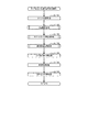
図13は、変形例1のパチンコ機に備えられる命釘としての一対の釘542a,542bと第1始動口533とを示す図である。図13(a)は、第1実施形態における図11(a)に対応した図であり、上側から見た図である。図13(b)は、第1実施形態における図11(b)に対応した図であり、右側から見た図である。
FIG. 13 is a diagram showing a pair of
第1実施形態では、図11に示すように、第1の釘42aと第2の釘42bとの間の距離(広さ)が、後ろ側(−Z方向側)から前側(+Z方向側)に向かって漸次、広くなる構成であった。これに対して、変形例1では、図13に示すように、第1の釘542aと第2の釘542bとの間の距離(広さ)が、後ろ側(−Z方向側)から前側(+Z方向側)に向かって漸次、狭くなっている。具体的には、右側に位置する第1の釘542aは、先端423を基準とした胴部422の中心軸方向が+Z方向(2点鎖線)から左側(−X方向)に第1角度φ1だけ傾斜した方向となるように設けられている。左側に位置する第2の釘542bは、先端423を基準とした胴部422の中心軸方向が+Z方向(2点鎖線)から右側(+X方向)に第2角度φ2だけ傾斜した方向となるように設けられている。第1角度φ1および第2角度φ2は、予め定められた所定角度であり、本実施形態では、型式検定試験に合格となった際の角度である。第1角度φ1および第2角度φ2は、例えば1度〜10度のうちのいずれかの値であり、例えば5度である。なお、第1角度φ1と第2角度φ2とは、等しいが、これに換えて、異なっていてもよい。
In the first embodiment, as shown in FIG. 11, the distance (width) between the
第1実施形態では、図11に示すように、第1始動口33に形成された入球口33aにおける第3のへり333と第4のへり334との間の距離(広さ)が、後ろ側(−Z方向側)から前側(+Z方向側)に向かって漸次、広くなる構成であった。これに対して、変形例1では、図13に示すように、第1始動口533に形成された入球口533aにおける第3のへり593と第4のへり594との間の距離(広さ)が、後ろ側(−Z方向側)から前側(+Z方向側)に向かって漸次、狭くなっている。具体的には、右側に位置する第3のへり593は、−Z方向側の端部を基準とした方向が+Z方向から左側(−X方向)に第1角度φ1だけ傾斜した構成となっている。左側に位置する第4のへり594は、−Z方向側の端部を基準とした方向が+Z方向から右側(+X方向)に第2角度φ2だけ傾斜した構成となっている。
In the first embodiment, as shown in FIG. 11, the distance (width) between the
したがって、変形例1のパチンコ機においても、第1および第2の釘542a,釘542bと、第1始動口533の入球口533aとは、上側から見た場合に、入球口533aの第3のへり593が第1の釘542aの胴部422の中心軸方向と平行になり、第4のへり594が第2の釘542bの胴部422の中心軸方向と平行になっている。
Therefore, also in the pachinko machine according to the first modification, the first and
以上のように構成された変形例1のパチンコ機によれば、第1実施形態のパチンコ機10と同様に、入球口533aにおける第3のへり593と第4のへり594とを頼りに、上側から見た場合に第1の釘542aが第3のへり593と平行になるように、第2の釘542bが第4のへり594と平行になるように、各釘542a,542bの傾きを確認して修正することができる。このため、釘の調整についての多くの経験や専用の調整用器具を必要とせずに、第1および第2の釘542a,542bの傾きのずれを容易に修復することができる。
According to the pachinko machine of
また、変形例1のパチンコ機によれば、第1実施形態のパチンコ機10と同様に、釘の傾きを確認するための専用の部材を別途、設けることなく、もともとある第1始動口33の入球口33aを利用して釘の傾きの修復を行うことができることから、パチンコ機の構成が複雑になることを防止することができる。
Further, according to the pachinko machine of the first modification, like the
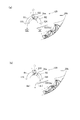
A6−2.変形例2:
変形例2としてのパチンコ機は、第1実施形態としてのパチンコ機10と比較して、命釘の傾斜方向と、第1始動口の形状とが相違するだけであり、残余の構成については同一である。変形例2のパチンコ機において、第1実施形態のパチンコ機10と同じ構成については同一の名称と符号を付けて、以下の説明を行う。
A6-2. Modification 2:
The pachinko machine as the modified example 2 is different from the
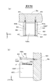
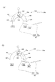
図14は、変形例2のパチンコ機に備えられる命釘としての一対の釘642a,642bと第1始動口633とを示す図である。図14(a)は、第1実施形態における図11(a)に対応した図であり、上側から見た図である。図14(b)は、第1実施形態における図11(b)に対応した図であり、右側から見た図である。
FIG. 14 is a view showing a pair of
第1実施形態や変形例1では、第1の釘42aと第2の釘42bとが、先端423を基準とした胴部422の中心軸方向が+Z方向(2点鎖線)からX軸の正または負方向(右左側)に傾斜する構成であった。これに対して、変形例2では、第1の釘642aと第2の釘642bとが、先端423を基準とした胴部422の中心軸方向が+Z方向(2点鎖線)からY軸の正方向(上側)に傾斜する構成とした。具体的には、第1の釘642aと第2の釘642bは、上側から見た場合に、図14(a)に示すようにZ軸に沿い、右側から見た場合に、図14(b)に示すように、先端423を基準とした胴部422の中心軸方向が+Z方向(2点鎖線)から上側(+Y方向)に所定角度μ1だけ傾斜するように、設けられている。所定角度μ1は、予め定められた所定角度であり、本実施形態では、型式検定試験に合格となった際の角度である。所定角度μ1は、予め定められた所定角度であり、本実施形態では、型式検定試験に合格となった際の角度である。所定角度μ1は、例えば1度〜10度のうちのいずれかの値であり、例えば5度である。
In the first embodiment and the first modification, the
第1実施形態や変形例1では、第1始動口33に形成された入球口33aは台形形状であった。これに対して、変形例2では、図14(a)に示すように、第1始動口633に形成された入球口633aは矩形形状である。このため、入球口633aを構成する+X方向側および−X方向側の第3のへり693および第4のへり694は、+Z方向に沿う構成となっている。その上で、図14(b)に示すように、第1始動口633の上側(+Y方向側)の面633Sが、合板30aと接する端部633bを基準として+Z方向(2点鎖線)から上側(+Y方向)に所定角度μ1だけ傾斜した構成となっている。
In 1st Embodiment and the
このため、変形例2のパチンコ機では、右側から見た場合に、第1の釘642aと第2の釘642bとの各胴部422の中心軸方向が、第1始動口633の入球口633aの上側の面633Sと平行になっている。
For this reason, in the pachinko machine according to the second modification, when viewed from the right side, the center axis direction of each
以上のように構成された変形例2のパチンコ機では、メーカーが意図する各釘642a,642bの上側への傾き具合と一致するように、第1始動口633の上側の面633Sの傾斜角度が予め定められている。このため、変形例2のパチンコ機によれば、第1始動口633の上側の面633Sを頼りに、右側から見た場合に各釘642a,642bがその平面633Sと平行になるように、各釘642a,642bの傾きを確認して修正することができる。したがって、釘の調整についての多くの経験や専用の調整用器具を必要とせずに、第1および第2の釘642a,642bの傾きのずれを容易に修復することができる。
In the pachinko machine according to the second modified example configured as described above, the inclination angle of the
また、変形例2のパチンコ機では、釘の傾きを確認するための専用の部材を別途、設けることなく、もともとある第1始動口33の平面633Sを利用して釘の傾きの修復を行うことができることから、パチンコ機の構成が複雑になることを防止することができる。
Further, in the pachinko machine according to the second modification, the nail inclination is restored by using the original
A6−3.変形例3:
変形例3としてのパチンコ機は、変形例2としてのパチンコ機と比較して、命釘の傾斜方向が相違するだけであり、残余の構成については同一である。変形例3のパチンコ機において、変形例2のパチンコ機と同じ構成については同一の名称と符号を付けて、以下の説明を行う。
A6-3. Modification 3:
The pachinko machine as the modified example 3 is different from the pachinko machine as the modified example 2 only in the inclination direction of the life nail, and the remaining configuration is the same. In the pachinko machine of the third modification, the same configuration and the same structure as those of the pachinko machine of the second modification are given the same names and symbols, and the following description will be given.
図15は、変形例3のパチンコ機に備えられる命釘としての一対の釘742a,742bと第1始動口733とを示す図である。図15(a)は、第1実施形態における図11(a)に対応した図であり、上側から見た図である。図15(b)は、第1実施形態における図11(b)に対応した図であり、右側から見た図である。
FIG. 15 is a view showing a pair of
変形例2では、図14(b)に示すように、第1の釘642aと第2の釘642bとが、先端423を基準とした胴部422の中心軸方向が+Z方向(2点鎖線)から上側(+Y方向)に所定角度μ1だけ傾斜する構成であった。これに対して、変形例3では、図15(b)に示すように、第1の釘742aと第2の釘742bとが、先端423を基準とした胴部422の中心軸方向が+Z方向(2点鎖線)から下側(−Y方向)に所定角度ν1だけ傾斜する構成である。所定角度ν1は、予め定められた所定角度であり、本実施形態では、型式検定試験に合格となった際の角度である。所定角度ν1は、例えば1度〜10度のうちのいずれかの値であり、例えば5度である。
In the second modification, as shown in FIG. 14B, the
変形例3では、第1始動口733に形成された入球口733aは、変形例2と同様に矩形形状である。しかしながら、第1始動口733の上側の面733Sが、変形例2とは相違し、合板30aと接する端部733bを基準として+Z方向(2点鎖線)から下側(−Y方向)に所定角度ν1だけ傾斜した構成となっている。
In the third modification, the
このため、変形例3のパチンコ機では、右側から見た場合に、第1の釘742aと第2の釘742bとの各胴部422の中心軸方向が、第1始動口733の入球口733aの上側の面733Sと平行になっている。
For this reason, in the pachinko machine according to the third modification, when viewed from the right side, the central axis directions of the
以上のように構成された変形例3のパチンコ機によれば、変形例2のパチンコ機と同様に、第1始動口733の上側の面733Sを頼りに、右側から見た場合に各釘742a,742bがその平面733Sと平行になるように、各釘742a,742bの傾きを確認して修正することができる。このため、釘の調整についての多くの経験や専用の調整用器具を必要とせずに、第1および第2の釘742a,742bの傾きのずれを容易に修復することができる。
According to the pachinko machine of the third modification configured as described above, each
また、変形例3のパチンコ機では、釘の傾きを確認するための専用の部材を別途、設けることなく、もともとある第1始動口733の平面733Sを利用して釘の傾きの修復を行うことができることから、パチンコ機の構成が複雑になることを防止することができる。
Further, in the pachinko machine according to the third modification, the nail inclination is restored by using the
A6−4.変形例4:
変形例4としてのパチンコ機は、第1実施形態としてのパチンコ機10と比較して、命釘の傾斜方向と、第1始動口の形状とが相違するだけであり、残余の構成については同一である。変形例4のパチンコ機において、第1実施形態のパチンコ機10と同じ構成については同一の名称と符号を付けて、以下の説明を行う。
A6-4. Modification 4:
The pachinko machine as the modified example 4 is different from the
図16は、変形例4のパチンコ機に備えられる命釘としての一対の釘842a,842bと第1始動口833とを示す図である。図16(a)は、第1実施形態における図11(a)に対応した図であり、上側から見た図である。図16(b)は、第1実施形態における図11(b)に対応した図であり、右側から見た図である。
FIG. 16 is a view showing a pair of
第1実施形態および変形例1〜3のパチンコ機では、命釘である第1の釘と第2の釘とが、先端423を基準とした胴部422の中心軸方向が+Z方向(2点鎖線)から右側(+X方向)、左側(−X方向)、上側(+Y方向)、下側(−Y方向)のうちのいずれかの方向に傾斜する構成であった。これに対して、変形例4では、命釘である第1の釘842aと第2の釘842bとが、先端423を基準とした胴部422の中心軸方向が+Z方向(2点鎖線)から以下の向きに傾斜する構成とした。この傾斜の向きは、X軸とY軸との双方に直角以外の角度で交差する角度である。具体的には、次の構成である。
In the pachinko machines according to the first embodiment and the first to third modifications, the first nail and the second nail that are life nails are arranged such that the central axis direction of the
第1実施形態では、右側に位置する第1の釘42aは、図11(a)に示すように、上側から見た場合に、先端423を基準とした胴部422の中心軸方向が+Z方向(2点鎖線)から右側(+X方向)に第1角度θ1だけ傾斜し、図11(b)に示すように、右側から見た場合に、胴部422の中心軸方向がZ軸方向に沿うように構成されていた。これに対して、変形例4では、右側に位置する第1の釘842aは、図16(a)に示すように、上側から見た場合に、第1実施形態の第1の釘42aと同様に傾斜し、図16(b)に示すように、右側から見た場合に、先端423を基準とした胴部422の中心軸方向が+Z方向(2点鎖線)から上側(+Y方向)に所定角度ξ1だけ傾斜するように構成した。
In the first embodiment, as shown in FIG. 11A, the
また、第1実施形態では、左側に位置する第2の釘42bは、図11(a)に示すように、上側から見た場合に、先端423を基準とした胴部422の中心軸方向が+Z方向(2点鎖線)から左側(−X方向)に第2角度θ2だけ傾斜し、図11(b)に示すように、右側から見た場合には、胴部422の中心軸方向がZ軸方向に沿うように構成されていた。これに対して、変形例4では、左側に位置する第2の釘842bは、図16(a)に示すように、上側から見た場合に、第1実施形態の第1の釘42aと同様に傾斜し、図16(b)に示すように、右側から見た場合に、先端423を基準とした胴部422の中心軸方向が+Z方向(2点鎖線)から上側(+Y方向)に所定角度ξ1だけ傾斜するように構成した。
Further, in the first embodiment, the
変形例4では、第1始動口833に形成された入球口833aは、第1実施形態と同一の台形形状である。しかしながら、第1始動口833の上側の面833Sが、第1実施形態と変形例2とは相違し、合板30aと接する端部833bを基準として+Z方向(2点鎖線)から上側(+Y方向)に所定角度ξ1だけ傾斜した構成となっている。所定角度ξ1は、予め定められた所定角度であり、本実施形態では、型式検定試験に合格となった際の角度である。所定角度ξ1は、例えば1度〜10度のうちのいずれかの値であり、例えば5度である。
In the
このため、変形例4のパチンコ機では、第1および第2の釘842a,釘842bと第1始動口833の入球口833aとは、上側から見た場合に、第3のへり893が第1の釘842aの胴部422の中心軸方向と平行になり、第4のへり894が第2の釘842bの胴部422の中心軸方向と平行になっている。また、右側から見た場合に、第1の釘842aと第2の釘842bとの各胴部422の中心軸方向が、第1始動口833の入球口833aの上側の面833Sと平行になっている。
For this reason, in the pachinko machine according to the fourth modification, the first and
以上のように構成された変形例4のパチンコ機によれば、入球口833aにおける第3のへり893と第4のへり894とを頼りに、上側から見た場合に第1の釘842aが第3のへり893と平行になるように、第2の釘842bが第4のへり894と平行になるように、各釘842a,842bの傾きを確認して修正することができる。また、第1始動口833の上側の面833Sを頼りに、右側から見た場合に各釘842a,842bがその平面833Sと平行になるように、各釘842a,842bの傾きを確認して修正することができる。したがって、釘の調整についての多くの経験や専用の調整用器具を必要とせずに、第1および第2の釘842a,842bの傾きのずれを容易に修復することができる。
According to the pachinko machine of the
また、変形例4のパチンコ機によれば、第1実施形態のパチンコ機10と同様に、釘の傾きを確認するための専用の部材を別途、設けることなく、もともとある第1始動口833を利用して釘の傾きの修復を行うことができることから、パチンコ機の構成が複雑になることを防止することができる。
Moreover, according to the pachinko machine of the fourth modification, the original
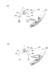
A6−5.変形例5:
第1実施形態および変形例1〜4のパチンコ機では、命釘である第1の釘と第2の釘の傾きを修復する際に平行か否かを確認するための基準となる基準部が、第1始動口における予め定められた部位、例えば、図11に示す入球口33aの第3のへり333および第4のへり334や、図14に示す第1始動口633の上側の面633Sであった。これに対して、変形例5では、上記基準部を、第1始動口に設けた専用の目印によって構成している。以下、詳しく説明する。
A6-5. Modification 5:
In the pachinko machine according to the first embodiment and the first to fourth modifications, a reference portion serving as a reference for confirming whether or not the first nail and the second nail, which are life nails, are parallel to each other is restored. , A predetermined portion in the first starting port, for example, the
変形例5としてのパチンコ機は、第1実施形態としてのパチンコ機10と比較して、第1始動口の構成が相違するだけであり、第1および第2の釘42a,42bを含めた残余の構成については同一である。変形例5のパチンコ機において、第1実施形態のパチンコ機10と同じ構成については同一の名称と符号を付けて、以下の説明を行う。
The pachinko machine as the modified example 5 is different from the
図17は、変形例5のパチンコ機に備えられる命釘としての一対の釘42a,42bと第1始動口933とを示す図である。図17(a)は、第1実施形態における図11(a)に対応した図であり、上側から見た図である。図17(a)において、第1および第2の釘42a,42bの一部分は、図示の便宜のために破断して省略している。図17(b)は、第1実施形態における図11(b)に対応した図であり、右側から見た図である。
FIG. 17 is a view showing a pair of
図17(a)に示すように、第1始動口933に形成された入球口933aは、変形例2と同様に矩形形状である。第1始動口933の上側の面933Sは、Z軸方向と平行である。この面933Sには、長尺な矩形形状のマーク951,952が印刷されている。マーク951,952は、印刷によって着色したものである。
As illustrated in FIG. 17A, the
面933Sにおいて、第1のマーク951は、入球口933aの右側のへり993に対して右側に印刷されている。上側から見た場合に、第1のマーク951の長手方向と、右側に位置する第1の釘42aの胴部422の中心軸方向とが平行となっている。面933Sにおいて、第2のマーク952は、入球口933aの左側のへり994に対して左側に印刷されている。上側から見た場合に、第2のマーク952の長手方向と、左側に位置する第2の釘42bの胴部422の中心軸方向とが平行となっている。その上、上側から見た場合に、第1のマーク951の右側外形線は第1の釘42aの胴部422の右側外形線より若干、右側に位置し、第2のマーク952の左側外形線は第2の釘42bの胴部422の左側外形線より若干、左側に位置する。すなわち、上側から見た場合に、第1のマーク951の少なくとも一部分が第1の釘42aによって隠れることがなく、第2のマーク952の少なくとも一部分が第2の釘42bによって隠れることがない。
On the
以上のように構成された変形例5のパチンコ機によれば、第1のマーク951と第2のマーク952を頼りに、上側から見た場合に第1の釘42aが第1のマーク951の長手方向と平行になるように、第2の釘42bが第2のマーク952の長手方向と平行になるように、各釘42a,42bの傾きを確認して修正することができる。このため、釘の調整についての多くの経験や専用の調整用器具を必要とせずに、第1および第2の釘42a,42bの傾きのずれを容易に修復することができる。また、上側から見た場合に、第1のマーク951の少なくとも一部分が第1の釘42aによって隠れることがなく、第2のマーク952の少なくとも一部分が第2の釘42bによって隠れることがないこから、第1および第2のマーク951,952の視認性が高い。このため、第1の釘42aおよび第2の釘42bの傾きの認定が容易である。
According to the pachinko machine of the modified example 5 configured as described above, the
A6−6.変形例6:
上述した基準部を、第1始動口に設けた専用の目印によって構成した他の例を、変形例6として次に説明する。
A6-6. Modification 6:
Another example in which the above-described reference portion is configured by a dedicated mark provided at the first start port will be described as a sixth modification.
変形例6としてのパチンコ機は、変形例2としてのパチンコ機と比較して、第1始動口の構成が相違するだけであり、第1および第2の釘642a,642bを含めた残余の構成については同一である。変形例6のパチンコ機において、変形例2のパチンコ機と同じ構成については同一の名称と符号を付けて、以下の説明を行う。
The pachinko machine as the modified example 6 is different from the pachinko machine as the modified example 2 only in the configuration of the first starting port, and the remaining configuration including the first and
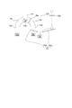
図18は、変形例6のパチンコ機に備えられる命釘としての一対の釘642a,642bと第1始動口1033とを示す図である。図18(a)は、第1実施形態における図11(a)に対応した図であり、上側から見た図である。図18(b)は、第1実施形態における図11(b)に対応した図であり、右側から見た図である。
FIG. 18 is a view showing a pair of
図18(a)に示すように、第1始動口1033に形成された入球口1033aは、変形例2と同様に矩形形状である。第1始動口1033の上側の面1033Sは、Z軸方向と平行である。第1始動口1033の右側の側面1033Tには、長尺な矩形形状のマーク1051が印刷されている。
As shown in FIG. 18A, the
右側から見た場合に、マーク1051の長手方向は、右側に位置する第1の釘642aの胴部422の中心軸方向に対して平行となっている。マーク1051は、印刷によって着色したものである。
When viewed from the right side, the longitudinal direction of the
以上のように構成された変形例6のパチンコ機によれば、マーク1051を頼りに、右側から見た場合に各釘642a,642bがマーク1051の長手方向と平行になるように、各釘642a,642bの傾きを確認して修正することができる。このため、釘の調整についての多くの経験や専用の調整用器具を必要とせずに、第1および第2の釘642a,642bの傾きのずれを容易に修復することができる。
According to the pachinko machine of
なお、変形例5における第1のマーク951、第2のマーク952、および変形例6におけるマーク1051は、印刷によって着色したものに換えて、第1始動口1033の面に凹凸を設けて印としたものでも良い。具体的には、リブや、凹み、段差等に換えても良い。また、マークの形状は、長尺な矩形形状に限る必要はなく、方向を規定することのできる形状であれば、いずれの形状としても良い。例えば、矢印記号や、基点と終点を示す2点等としても良い。
In addition, the
A6−7.変形例7:
変形例7としてのパチンコ機は、変形例5としてのパチンコ機と比較して、第1のマークと第2のマークとの向きが相違するだけであり、第1および第2の釘42a,42bと第1始動口933の形状とを含めた残余の構成については同一である。変形例7のパチンコ機において、変形例5のパチンコ機と同じ構成については同一の名称と符号を付けて、以下の説明を行う。
A6-7. Modification 7:
The pachinko machine as the modified example 7 is different from the pachinko machine as the modified example 5 only in the directions of the first mark and the second mark, and the first and
図19は、変形例7のパチンコ機に備えられる命釘としての一対の釘42a,42bと第1始動口933とを示す図である。図19(a)は、第1実施形態における図11(a)に対応した図であり、上側から見た図である。図19(a)において、第1および第2の釘42a,42bの一部分は、図示の便宜のために破断して省略している。図19(b)は、第1実施形態における図11(b)に対応した図であり、右側から見た図である。
FIG. 19 is a view showing a pair of
図19(a)に示すように、第1始動口933は変形例5と同一である。第1始動口933の有する入球口933aは矩形形状であり、第1始動口933の上側の面933SはZ軸方向と平行である。この面933Sに、長尺な矩形形状のマーク1151,1152が印刷されている。
As shown in FIG. 19A, the
面933Sにおいて、第1のマーク1151は、入球口933aの右側のへり993に対して右側に印刷されている。上側から見た場合に、第1のマーク1151の長手方向は、遊技盤30を構成する合板30aの表面に対して垂直な方向と平行である。すなわち、第1のマーク1151は、その長手方向によって、遊技盤30を構成する合板30aの表面に対して垂直であることが保証されて、合板30aに印刷されている。本実施形態では、直角であることを示す第1の直角マーク1153を印刷することで、一目で、第1のマーク1151が遊技盤30を構成する合板30aの表面に対して垂直であることが保証されていることが判るようにしている。
On the
面933Sにおいて、第2のマーク1152は、入球口933aの左側のへり994に対して左側に印刷されている。上側から見た場合に、第2のマーク1152の長手方向は、遊技盤30を構成する合板30aの表面に対して垂直な方向と平行である。すなわち、第2のマーク1152は、その長手方向によって、遊技盤30を構成する合板30aの表面に対して垂直であることが保証されて、合板30aに印刷されている。本実施形態では、直角であることを示す第2の直角マーク1154を印刷することで、一目で、第2のマーク1152が遊技盤30を構成する合板30aの表面に対して垂直であることが保証されていることが判るようにしている。さらに、図19(b)に示すように、第1始動口933の右側の側面に第3の直角マーク1155を印刷することで、第1始動口933の上側の面933Sが、遊技盤30を構成する合板30aの表面に対して垂直であることが保証されていることが判るようにしてもよい。なお、第1〜第3の直角マーク1153〜1155は、必ずしも必要なく、省く構成としても良い。
On the
以上のように構成された変形例7のパチンコ機によれば、第1のマーク1151を頼りに第1の釘42aの傾き具合を確認することができ、第2のマーク1152を頼りに第2の釘42aの傾き具合を確認することができる。具体的には、第1のマーク1151の長手方向と第1の釘42aの向きとを比べ、第2のマーク1152の長手方向と第2の釘42bの向きとを比べることによって、第1および第2の釘42a,42bの傾き具合を確認することができる。したがって、各釘42a,42bの調整を容易に行うことができる。
According to the pachinko machine of the modified example 7 configured as described above, the inclination of the
なお、他の変形例として、図18に示す変形例6において、マーク1051の向きを変える構成としても良い。具体的には、他の変形例では、右側から見た場合に、マーク1051の長手方向が、遊技盤30を構成する合板30aの表面に対して垂直な方向と平行となるようにする。すなわち、図18に示す変形例6において、第1始動口1033の右側の側面1033Tに印刷されたマーク1051は、その長手方向によって、遊技盤30を構成する合板30aの表面に対して垂直であることが保証されて、合板30aに印刷される構成に換える。この構成によっても、第1および第2の釘42a,42bの上下方向の傾き具合を確認することができる。
As another modification, a configuration in which the orientation of the
変形例7における第1のマーク1151および第2のマーク1152は、印刷によって着色したものであるが、これに換えて、第1始動口の面に凹凸を設けて印としたものでも良い。具体的には、リブや、凹み、段差等に換えても良い。また、マークの形状は、長尺な矩形形状に限る必要はなく、方向を規定することのできる形状であれば、いずれの形状としても良い。
The
変形例7では、遊技盤30を構成する合板30aの表面に対して垂直に設けられていることを保証する基準部を、第1始動口933に記載した第1のマーク1151と第2のマーク1152とした。これに対して、変形例として、マークに換えて、第1始動口933とは別体に遊技盤30に設けられた、例えば樹脂製の突起物を設ける構成としても良い。要は、遊技盤30を構成する合板30aの表面に対して垂直に設けられていることを保証するものであれば、いずれの構成とすることもできる。
In the modified example 7, the
さらに、他の変形例として、変形例7における第1のマーク1151と第2のマーク1152とを、上記第1実施形態およびその変形例1、4において追加する構成としてもよい。この構成によれば、入球口を構成する右側の第3のへりと、左側の第4のへり334とに加えて、第1のマーク1151と第2のマーク1152とによっても、釘の傾き具合を確認することができることから、釘の調整をより正確に行うことができる。
Furthermore, as another modification, the
A6−8.変形例8:
変形例8としてのパチンコ機は、第1実施形態としてのパチンコ機10と比較して、第1始動口の形状が相違するだけであり、第1および第2の釘を含めた残余の構成については同一である。変形例8のパチンコ機において、第1実施形態のパチンコ機10と同じ構成については同一の名称と符号を付けて、以下の説明を行う。
A6-8. Modification 8:
The pachinko machine as the modified example 8 is different from the
図20は、変形例8のパチンコ機に備えられる第1始動口1233とその周辺を示す斜視図である。第1実施形態および変形例1〜7では、第1始動口、例えば、図10に示す第1始動口33は、中空の箱形状であり、上側(+Y方向側)の面に形成された入球口33aは、前側(+Z方向側)の第1のへり331と、後ろ側(−Z方向側)の第2のへり332と、右側(+X方向側)の第3のへり333と、左側(−X方向側)の第4のへり334と、によって構成されていた。これに対して、変形例8では、図20に示すように、第1始動口1233は、中空の箱形状において後ろ側(−Z方向側)の壁面が取り除かれた形状を有する。すなわち、第1始動口1233の上側の端面は、略コの字形状である。
FIG. 20 is a perspective view showing the
第1始動口1233の上側(+Y方向側)の面に形成される入球口1233aは、前側(+Z方向側)の第1のへり1291と、右側(+X方向側)の第2のへり1293と、左側(−X方向側)の第3のへり1294と、合板30aの表面の一部分と、によって構成されている。入球口1233aから入球した遊技球は、第1始動口1233の中を通って、遊技盤30を前後方向に貫通する開口部30cに送られる。
A
右側(+X方向側)の第2のへり1293は、第1実施形態における第3のへり333と同様に、−Z方向側の端部を基準とした方向が+Z方向から右側(+X方向)に第1角度θ1だけ傾斜している。左側(−X方向側)の第3のへり1294は、第1実施形態における第4のへり334と同様に、−Z方向側の端部を基準とした方向が+Z方向から左側(−X方向)に第2角度θ2だけ傾斜している。第1角度θ1および第2角度θ2は、第1実施形態と同様に、第1および第2の釘42a,42bについての遊技機の出荷時における傾斜角度である。
As with the
以上のように構成された変形例8のパチンコ機によれば、第1実施形態のパチンコ機10と同様に、入球口1233aにおける第2のへり1293と第3のへり1294とを頼りに、第1実施形態と同様にして、各釘42a,42bの傾きを確認して修正することができる。このため、釘の調整についての多くの経験や専用の調整用器具を必要とせずに、第1および第2の釘42a,42bの傾きのずれを容易に修復することができる。
According to the pachinko machine of the modified example 8 configured as described above, as with the
なお、上述した第1始動口の形状、すなわち、上側の端面が略コの字形状となる第1始動口の形状は、第1実施形態以外にも、これまで説明してきた変形例1〜7において、採用する構成としても良い。 In addition, the shape of the 1st starting port mentioned above, ie, the shape of the 1st starting port from which an upper end surface becomes a substantially U-shape, the modification 1-7 demonstrated so far besides 1st Embodiment. In this case, the configuration may be adopted.
A6−9.変形例9:
変形例9としてのパチンコ機は、変形例8としてのパチンコ機10と比較して、第1始動口の形状が相違するだけであり、第1および第2の釘を含めた残余の構成については同一である。変形例9のパチンコ機において、変形例8のパチンコ機と同じ構成については同一の名称と符号を付けて、以下の説明を行う。
A6-9. Modification 9:
The pachinko machine as the modified example 9 is different from the
図21は、変形例9のパチンコ機に備えられる第1始動口1333とその周辺を示す斜視図である。第1始動口1333は、変形例8における第1始動口1233と同様に、上側の端面が略コの字形状の構成である。その上で、第1始動口1333は、変形例8における第1始動口1233と比較して、次の(i)〜(iii)の点で相違する。
FIG. 21 is a perspective view showing the
(i)変形例8における第1始動口1233では、図20に示すように、入球口1233aを構成する右側(+X方向側)の第2のへり1293と、左側(−X方向側)の第3のへり1294とが、+Z方向から第1角度θ1および第2角度θ2だけ傾斜する構成であった。これに対して、変形例9における第1始動口1333では、図21に示すように、右側(+X方向側)の第2のへり1393と、左側(−X方向側)の第3のへり1394とが、+Z方向と平行になっている。
(I) In the
(ii)変形例9における第1始動口1333では、図21に示すように、第1始動口1333の右側の側壁の外面1333bに、第1の釘42aについての遊技機の出荷時における傾斜角度である第1角度θ1を示す第1数値情報Naが記載されており、第1始動口1333の左側の側壁の内面1333cに、第2の釘42bについての遊技機の出荷時における傾斜角度である第2角度θ2を示す第2数値情報Nbが記載されている。これに対して、変形例8における第1始動口1233では、こうした構成を備えない。第1数値情報Naと第2数値情報Nbは、角度を示す数値であり、例えば「5度」である。
(Ii) In the
(iii)変形例8における第1始動口1233は、一体の構成であった。これに対して、変形例9における第1始動口1333は、第1パーツPaと第2パーツPbとによって構成されている。第2パーツPbは、主に、第1始動口1333の左側の側壁部分である。第1パーツPaは、第2パーツPb以外の部分である。最初は、図22に示すように、第1パーツPaと第2パーツPbとは別体であり、製造段階で、第1パーツPaと第2パーツPbとが接合されて、第1始動口1333が構成される。第1パーツPaに第1数値情報Naが印刷され、第2パーツPbに数値情報Nbが印刷されている。なお、第1数値情報Naと第2数値情報Nbとの印刷は、第1パーツPaと第2パーツPbとが接合される前に、行われる。
(Iii) The
以上のように構成された変形例9のパチンコ機によれば、第1始動口1333の右側の側壁の外面1333bに印刷された第1数値情報Naを頼りに、右側に位置する第1の釘42aの傾きを確認して修正することができる。また、第1始動口1333の左側の側壁の内面1333cに印刷された第2数値情報Nbを頼りに、左側に位置する第2の釘42bの傾きを確認して修正することができる。このため、釘の調整についての多くの経験や専用の調整用器具を必要とせずに、第1および第2の釘42a,42bの傾きのずれを容易に修復することができる。
According to the pachinko machine of the
また、変形例9のパチンコ機によれば、第1始動口1333が第1パーツPaと第2パーツPbとによって構成されていることから、製造時において、第1パーツPaに第1数値情報Naを印刷し、第2パーツPbに第2数値情報Nbを印刷することを容易に行うことができる。特に、第1数値情報Naと第2数値情報Nbとの双方を右側(+X方向側)から見ることができるように、第1数値情報Naと第2数値情報Nbとを同じ向きに設ける場合に、左側(−X方向側)に位置する第2数値情報Nbは第1始動口1233の内側となることから、製造時に、第2数値情報Nbを印刷することが困難であるが、変形例9のパチンコ機によれば、第1始動口1333が第1パーツPaと第2パーツPbとによって分かれて構成されていることから、容易に第2数値情報Nbを印刷することができ、第1始動口1333の製造が容易である。
Further, according to the pachinko machine of the modified example 9, since the
なお、第1数値情報Naと第2数値情報Nbを記載する構成であったが、これに換えて、複数のセグメント発光部の表示の態様で角度を示す情報を示す構成としても良い。要は、角度についての情報を示すものであれば、いずれの構成とすることもできる。 Although the first numerical information Na and the second numerical information Nb are described, the information indicating the angle may be displayed instead of the information in the display mode of the plurality of segment light emitting units. In short, any configuration can be used as long as it shows information about the angle.
変形例9のパチンコ機に備えられる第1始動口1333は、上側の端面が略コの字形状となるタイプのものであったが、これに換えて、後ろ側(−Z方向側)の壁面を有する中空の箱形状のタイプとすることもできる。また、第1始動口1333は、第1パーツPaと第2パーツPbとによって構成されているが、これに換えて、3つ以上のパーツによって構成しても良い。釘の傾斜角度を示す第1数値情報Naおよび第2数値情報Nbは、第1実施形態および変形例1,4,5,7,8においても記載する構成としても良い。
The
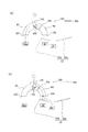
A6−10.変形例10:
図23は、変形例10としてのパチンコ機に備えられる電動役物1410と、その周辺を示す斜視図である。電動役物1410は、パチンコ機の遊技盤の例えば中央下方に設けられている。遊技盤には、先に説明したように、前後方向に貫通する複数の開口部が形成されているが、そのうちの一つである開口部1400に、電動役物1410が設けられている。
A6-10. Modification 10:
FIG. 23 is a perspective view showing the
電動役物1410は、普通電動役物であり、いわゆる電動チューリップとして構成されている。電動役物1410は、右左一対の可動片1411a,1411bを備えており、閉状態(閉鎖状態)と開状態(開放状態)とに切換可能に構成されている。閉状態が図23に示す状態である。閉状態では、一対の可動片1411a,1411b間の距離が小さいため、遊技球が入球しにくい。一方、開状態(変形例11の図24を参照)では、一対の可動片1411a,1411b間の距離が大きくなり、遊技球が入球し易くなっている。電動役物1410に入球した遊技球は、開口部1400に送られる。電動役物1410への遊技球の入球に基づいて、例えば当たり抽選がなされる。以下、一対の可動片1411a,1411bのうちの+X方向側の可動片を「第1の可動片1411a」と呼び、一対の可動片1411a,1411bのうちの−X方向側の可動片を「第2の可動片1411b」と呼ぶ。第1実施形態と同様に、+X方向は正面視右側を示し、−X方向は正面視左側を示す。
The
電動役物1410の上方には、右左一対の釘1442a,1442bが設けられている。一対の釘1442a,1442b間の距離によって、電動役物1410への遊技球の入球の確率が変化する。以下、一対の釘1442a,1442bのうちの+X方向側の釘を「第1の釘1442a」と呼び、一対の釘1442a,1442bのうちの−X方向側の釘を「第2の釘1442b」と呼ぶ。第1および第2の釘1442a,1442bの形状は第1実施形態の釘と同一である。
Above the
第1の釘1442aは、先端を基準とした胴部の中心軸方向が+Z方向から、予め定めた傾斜方向(例えば、+X方向)に予め定められた傾斜角度(例えば、5度)だけ傾斜して設けられている。第2の釘1442bは、先端を基準とした胴部の中心軸方向が+Z方向から、予め定めた傾斜方向(例えば、−X方向)に予め定められた傾斜角度(例えば、7度)だけ傾斜して設けられている。第1の釘1442aについての傾斜方向、傾斜角度と、第2の釘1442bについての傾斜方向、傾斜角度とは、個別のものであり、遊技機の出荷時におけるものである。
The
電動役物1410において、第1の可動片1411aの先端部分は切り落とされて平坦な面(以下、「第1平坦面」と呼ぶ)Saとなっている。第2の可動片1411bの先端部分は切り落とされて平坦な面(以下、「第2平坦面」と呼ぶ)Sbとなっている。本変形例10では、電動役物1410が閉状態にある場合に、第1平坦面Saの傾斜角度および傾斜方向が第1の釘1442aについての傾斜方向、傾斜角度と一致し、第2平坦面Sbの傾斜角度および傾斜方向が第2の釘1442bについての傾斜方向、傾斜角度と一致するように、予め設計されている。換言すれば、電動役物1410が閉状態にある場合に、第1平坦面Saは、その傾斜方向と傾斜角度によって、第1の釘1442aについての傾斜方向と傾斜角度を規定し、第2平坦面Sbは、その傾斜方向と傾斜角度によって、第2の釘1442bについての傾斜方向と傾斜角度を規定する。
In the
以上のように構成された変形例10のパチンコ機によれば、電動役物1410が閉状態にある場合に、電動役物1410における第1の可動片1411aの第1平坦面Saを頼りに、第1の釘1442aの傾きを確認して出荷時の状態に修正することができる。また、電動役物1410が閉状態にある場合に、電動役物1410における第2の可動片1411bの第2平坦面Sbを頼りに、第2の釘1442bの傾きを確認して出荷時の状態に修正することができる。このため、釘の調整についての多くの経験や専用の調整用器具を必要とせずに、電動役物1410の上方にある第1および第2の釘1442a,1442bの傾きのずれを容易に修復することができる。
According to the pachinko machine of
A6−11.変形例11:
変形例11としてのパチンコ機は、変形例10としてのパチンコ機と比較して、電動役物において、平坦部の傾斜方向と傾斜角度が相違し、さらに、第1の釘と第2の釘の位置とが相違する。これら以外の構成については、変形例11としてのパチンコ機と変形例10としてのパチンコ機とは同一である。
A6-11. Modification 11:
The pachinko machine as the modified example 11 is different from the pachinko machine as the modified example 10 in the electric accessory in that the inclination direction and the inclination angle of the flat portion are different, and further, the first nail and the second nail The position is different. About the structure of those other than these, the pachinko machine as the
図24は、変形例11としてのパチンコ機に備えられる電動役物1510と、その周辺を示す斜視図である。電動役物1510は、パチンコ機の遊技盤の例えば中央下方に設けられている。電動役物1510は、変形例10における電動役物1410と同様に、開口部1400に設けられている。開口部1400は、変形例10と同一なので、同一の符号を付けた。電動役物1510は、変形例10における電動役物1410と同様に、右左一対の可動片1511a,1511bを備えており、閉状態(閉鎖状態)と開状態(開放状態)とに切換可能に構成されている。開状態が図24に示す状態である。
FIG. 24 is a perspective view showing the
電動役物1510の右上方向には第1の釘1542aが設けられ、電動役物1510の左上方向には第2の釘1542bが設けられている。第1の釘1542aは、先端を基準とした胴部の中心軸方向が+Z方向から、予め定めた傾斜方向(例えば、+X方向)に予め定められた傾斜角度(例えば、5度)だけ傾斜して設けられている。第2の釘1542bは、先端を基準とした胴部の中心軸方向が+Z方向から、予め定めた傾斜方向(例えば、−X方向)に予め定められた傾斜角度(例えば、7度)だけ傾斜して設けられている。第1の釘1542aについての傾斜方向、傾斜角度と、第2の釘1542bについての傾斜方向、傾斜角度とは、個別のものであり、遊技機の出荷時におけるものである。
A
電動役物1510において、第1の可動片1511aの先端部分は切り落とされ第1平坦面Haとなっており、第2の可動片1511bの先端部分は切り落とされて第2平坦面Hbとなっている。本変形例11では、電動役物1510が開状態にある場合に、第1平坦面Haの傾斜角度および傾斜方向が第1の釘1542aについての傾斜方向、傾斜角度と一致し、第2平坦面Hbの傾斜角度および傾斜方向が第2の釘1542bについての傾斜方向、傾斜角度と一致するように、予め設計されている。換言すれば、電動役物1510が開状態にある場合に、第1平坦面Haは、その傾斜方向と傾斜角度によって、第1の釘1542aについての傾斜方向と傾斜角度を規定し、第2平坦面Hbは、その傾斜方向と傾斜角度によって、第2の釘1542bについての傾斜方向と傾斜角度を規定する。
In the
以上のように構成された変形例11のパチンコ機によれば、電動役物1510が開状態にある場合に、電動役物1510における第1の可動片1511aの第1平坦面Haを頼りに、電動役物1510の右上側に位置する第1の釘1542aの傾きを確認して修正することができる。また、電動役物1510が開状態にある場合に、電動役物1510における第2の可動片1511bの第2平坦面Hbを頼りに、電動役物1510の左上側に位置する第2の釘1542bの傾きを確認して修正することができる。このため、釘の調整についての多くの経験や専用の調整用器具を必要とせずに、第1および第2の釘1542a,1542bの傾きのずれを容易に修復することができる。特に、電動役物1510は、開状態にある場合の可動片1511a,1511bの先端位置に近い、電動役物1510の右上および左上にある第1および第2の釘1542a,1542bを、修復の対象とすることができ、その釘の修復を容易に行なうことができる。
According to the pachinko machine of
なお、変形例10において、第1、第2平坦面Sa,Sbに周囲とは異なる色で着色を行う構成としても良い。また、変形例11において、第1、第2平坦面Ha,Hbに周囲とは異なる色で着色を行う構成としても良い。これらの構成によれば、第1、第2平坦面Sa,Sbや第1、第2平坦面Ha,Hbが釘の傾きを修復する際の基準となることを、修理者は容易に認めることができる。
In
A6−12.変形例12:
変形例12としてのパチンコ機は、変形例11としてのパチンコ機と比較して、電動役物に備えられる第1の可動片の形状が相違し、残余の点で同一である。変形例12のパチンコ機において、変形例11のパチンコ機10と同じ構成については同一の名称と符号を付けて、以下の説明を行う。
A6-12. Modification 12:
The pachinko machine as the modified example 12 is different from the pachinko machine as the modified example 11 in the shape of the first movable piece provided in the electric accessory and is the same in the remaining points. In the pachinko machine of the modified example 12, the same configuration and the same configuration as those of the
図25は、変形例12のパチンコ機に備えられる電動役物の第1の可動片1611aを示す正面図である。変形例12における電動役物は、変形例11と同様に、いわゆる電動チューリップとして構成され、図中の矢印に示すように、閉状態(閉鎖状態)と開状態(開放状態)とに切換可能に構成されている。この電動役物に備えられる第1の可動片1611aは、変形例11における第1の可動片1511aに相当するものであり、X方向側(正面視右側)に位置する可動片である。
FIG. 25 is a front view showing the first
第1の可動片1611aは、可動片本体部1620と、可動片本体部1620の先端部分から突出した突出片1630と、を備える。突出片1630の可動片本体部1620とは反対側の端部は平坦な面(以下、「第1平坦面」と呼ぶ)Taとなっている。
The first
本変形例12における電動役物の周辺には、変形例11の電動役物と同様に、一対の釘が設けられている。一対の釘の内の一つが、図中の第1の釘1542aである。第1の釘1542aは、電動役物の右上に設けられている。電動役物が開状態となったときに、第1の可動片1611aに備えられる突出片1630の第1平坦面Taが、第1の釘1542aに最接近する。電動役物1510が開状態にある場合に、第1平坦面Taの傾斜角度および傾斜方向が、第1の釘1542aについての傾斜方向、傾斜角度と一致する。
A pair of nails are provided in the vicinity of the electric member in the modified example 12 as in the electric member in the modified example 11. One of the pair of nails is a
なお、本変形例12における電動役物の第2の可動片は、図示はしないが、第1の可動片1611aに対して、Y軸方向を軸とした線対称な形状となっている。電動役物が開状態となったときに、第2の可動片に備えられる突出片の第2平坦面が、第2の釘1542b(変形例11の図24を参照)に最接近する。電動役物が開状態にある場合に、その第2平坦面の傾斜角度および傾斜方向が、第2の釘1542bについての傾斜方向、傾斜角度と一致する。
Note that the second movable piece of the electric accessory in
以上のように構成された変形例12のパチンコ機によれば、変形例11と同様に、電動役物が開状態にある場合に、電動役物における第1の可動片1611aの第1平坦面Taを頼りに、電動役物の右上側に位置する第1の釘1542aの傾きを確認して修正することができる。同様に、第1の可動片の第2平坦面を頼りに、電動役物の左上側に位置する第2の釘1542bの傾きを確認して修正することができる。このため、釘の調整についての多くの経験や専用の調整用器具を必要とせずに、電動役物の右上および左上にある第1および第2の釘1542a,1542bの傾きのずれを容易に修復することができる。
According to the pachinko machine of the modified example 12 configured as described above, as in the modified example 11, when the electric accessory is in the open state, the first flat surface of the first
なお、変形例12においても、第1平坦面Taや第2平坦面を、周囲とは異なる色で着色を行う構成としても良い。この構成によれば、第1平坦面Taと第2平坦面が釘の傾きを修復する際の基準となることを、修理者は容易に認めることができる。 In the modified example 12, the first flat surface Ta and the second flat surface may be colored with a color different from the surroundings. According to this configuration, the repairer can easily recognize that the first flat surface Ta and the second flat surface serve as a reference for repairing the inclination of the nail.
A6−13.変形例13:
上記第1実施形態およびその変形例1、4、8では、釘と遊技盤の表面とのなす角度を規定する規定手段を、第1始動口の入球口におけるへりの部分とした。これに対して、変形例として、規定手段を、第1始動口の外周辺の一部としても良く、第1始動口の有する部位であれば、いずれの部分としても良い。また、第1始動口の有する部位に限る必要もなく、第2始動口や、その他の入球口部材の関わる部分としてもよい。さらに、入球口部材以外の部材の有する部位とすることもできる。
A6-13. Modification 13:
In the first embodiment and the
A6−14.変形例14:
上記第1実施形態およびその変形例1〜12では、遊技球の流通を変化させるものとして釘が採用されていたが、釘に限る必要はなく、遊技球の流通を変化させることができる棒状の部材であれば、樹脂製の突起物等、いずれの構成とすることもできる。
A6-14. Modification 14:
In the first embodiment and the first to twelfth modifications thereof, a nail has been adopted as one that changes the circulation of the game ball. However, the nail is not limited to a nail, and a rod-like shape that can change the circulation of the game ball is used. If it is a member, it can also be set as any structures, such as resin-made protrusions.
A6−15.変形例15:
上記変形例10〜12では、閉状態と開状態とに切り換え可能な可動手段として、普通電動役物である電動チューリップが採用されていたが、これに換えて、普通電動役物であるミニアタッカーが採用される構成としても良い。具体的には、ミニアタッカーの予め定められた部位が、釘と遊技盤の表面とのなす角度を規定する構成とする。さらに、可動手段として、普通電動役物に換えて、アタッカー(大入賞口)等の特別電動役物が採用される構成としても良い。具体的には、アタッカーの予め定められた部位が、釘と遊技盤の表面とのなす角度を規定する構成とする。さらには、可動手段として、電動役物に換えて、機械式等の非電動役物が採用される構成としても良い。
A6-15. Modification 15:
In the
B.第2実施形態:
B1.遊技機の構造:
本実施形態における遊技機の構造について説明する。なお、上記実施形態と同じ機能を備える構成要素には同じ符号を用いて説明する。
B. Second embodiment:
B1. Game machine structure:
The structure of the gaming machine in this embodiment will be described. In addition, the same code | symbol is used and demonstrated to the component provided with the same function as the said embodiment.
図26は、第2実施形態におけるパチンコ機10の斜視図である。パチンコ機10は、略矩形に組み合わされた木製の外枠11を備えている。パチンコ機10を遊技ホールに設置する際には、この外枠11が遊技ホールの島設備に固定される。また、パチンコ機10は、外枠11に回動可能に支持されたパチンコ機本体12を備えている。パチンコ機本体12は、内枠13と、内枠13の前面に配置された前扉枠14とを備えている。内枠13は、外枠11に対して金属製のヒンジ15によって回動可能に支持されている。前扉枠14は、内枠13に対して金属製のヒンジ16によって回動可能に支持されている。内枠13の背面には、主制御装置、音声発光制御装置、表示制御装置など、パチンコ機本体12を制御する制御機器が配置されている。これら制御機器の詳細については後述する。さらに、パチンコ機10には、シリンダ錠17が設けられている。シリンダ錠17は、内枠13を外枠11に対して開放不能に施錠する機能と、前扉枠14を内枠13に対して開放不能に施錠する機能とを有する。各施錠は、シリンダ錠17に対して専用の鍵を用いた所定の操作が行われることによって解錠される。
FIG. 26 is a perspective view of the
前扉枠14の略中央部には、開口された窓部18が形成されている。前扉枠14の窓部18の周囲には、パチンコ機10を装飾するための樹脂部品や電飾部品が設けられている。電飾部品は、LEDなどの各種ランプからなる発光手段によって構成されている。発光手段は、パチンコ機10によって行われる当たり抽選時、当たり当選時、リーチ発生時などに点灯又は点滅することによって、演出効果を高める役割を果たす。また、前扉枠14の裏側には、2枚の板ガラスからなるガラスユニット19が配置されており、開口された窓部18がガラスユニット19によって封じられている。内枠13には、後述する遊技盤が着脱可能に取り付けられており、パチンコ機10の遊技者は、パチンコ機10の正面からガラスユニット19を介して遊技盤を視認することができる。遊技盤の詳細については後述する。
An opened
前扉枠14には、遊技球を貯留するための上皿20と下皿21とが設けられている。上皿20は、上面が開放した箱状に形成されており、図示しない貸出機から貸し出された貸出球やパチンコ機本体12から排出された賞球などの遊技球を貯留する。上皿20に貯留された遊技球は、パチンコ機本体12が備える遊技球発射機構に供給される。遊技球発射機構は、遊技者による操作ハンドル25の操作によって駆動し、上皿20から供給された遊技球を遊技盤の前面に発射する。下皿21は、上皿20の下方に配置されており、上面が開放した箱状に形成されている。下皿21は、上皿20で貯留しきれなかった遊技球を貯留する。下皿21の底面には、下皿21に貯留された遊技球を排出するための排出口22が形成されている。排出口22の下方にはレバー23が設けられており、遊技者がレバー23を操作することによって、排出口22の閉状態と開状態とを切り替えることが可能である。遊技者がレバー23を操作して排出口22を開状態にすると、排出口22から遊技球が落下し、遊技球は下皿21から外部に排出される。
The
上皿20の周縁部の前方には、操作受入手段としての演出操作ボタン24が設けられている。演出操作ボタン24は、パチンコ機10によって行われる遊技演出に対して、遊技者が入力操作を行うための操作部である。パチンコ機10によって用意された所定のタイミングで遊技者が演出操作ボタン24を操作することによって、当該操作が反映された遊技演出がパチンコ機10によって行われる。
An
さらに、前扉枠14の正面視右側には、遊技者が操作するための操作ハンドル25が設けられている。遊技者が操作ハンドル25を操作(回動操作)すると、当該操作に連動して、遊技球発射機構から遊技盤の前面に遊技球が発射される。操作ハンドル25の内部には、遊技球発射機構の駆動を許可するためのタッチセンサ25aと、遊技者による押下操作によって遊技球発射機構による遊技球の発射を停止させるウェイトボタン25bと、操作ハンドル25の回動操作量を電気抵抗の変化により検出する可変抵抗器25cとが設けられている。遊技者が操作ハンドル25を握ると、タッチセンサ25aがオンになり、遊技者が操作ハンドル25を右回りに回動操作すると、可変抵抗器25cの抵抗値が回動操作量に対応して変化し、可変抵抗器25cの抵抗値に対応した強さで遊技球発射機構から遊技盤の前面に遊技球が発射される。
Furthermore, an
また、上皿20の周縁部の正面視左側には、遊技者が操作するための遊技球発射ボタン26が設けられている。遊技球発射ボタン26は、遊技者によって操作されることによって、遊技者の操作ハンドル25の回動操作量にかかわらず、所定の発射強度で、遊技盤の前面に遊技球が発射される。具体的には、遊技者が遊技球発射ボタン26を操作すると、操作ハンドル25の回動操作量が最大である場合と同じ発射強度で遊技球が遊技盤の前面に発射される。本実施形態の場合、遊技球発射ボタン26が操作されることによって遊技球が発射されると、遊技球は遊技盤の正面視右側に流れるとともに、遊技盤の右側を流下する。すなわち、遊技球発射ボタン26を操作することによって、遊技者はいわゆる「右打ち」をすることができる。また、以降の説明においては、操作ハンドル25が操作されることによって遊技球が発射され、遊技球が遊技盤の正面視左側に流れるとともに遊技盤の左側を流下する場合を、遊技者が「左打ち」をすると表現する場合がある。なお、本実施形態のパチンコ機10においては、遊技球発射ボタン26が操作された場合、タッチセンサ25aがオンであることを条件として、遊技球が遊技盤に発射されるように構成されている。すなわち、遊技者は、操作ハンドル25を握ることによって少なくともタッチセンサ25aをオンにした上で、遊技球発射ボタン26を操作することで、遊技球発射ボタン26の操作を契機とした遊技球の発射を実現することができる。
A game
なお、本実施形態においては、遊技球発射ボタン26は、上皿20の周縁部の正面視左側に配置される構成を採用したが、遊技球発射ボタン26が他の位置に配置される構成を採用してもよい。例えば、遊技球発射ボタン26を、ウェイトボタン25bと同様に、操作ハンドル25の内部(周縁部)に配置する構成を採用してもよい。このようにすることで、遊技者が、操作ハンドル25、ウェイトボタン25b、遊技球発射ボタン26を、右手のみで操作することを可能にする。
In the present embodiment, the game
図27は、遊技盤30の正面図である。遊技盤30は、合板によって構成されており、その前面には遊技領域PAが形成されている。遊技盤30には、遊技領域PAの外縁の一部を区画するようにして内レール部31aと、外レール部31bとが取り付けられている。内レール部31aと外レール部31bとの間には、遊技球を誘導するための誘導レール31が形成されている。遊技球発射機構から発射された遊技球は、誘導レール31に誘導されて遊技領域PAの上部に放出され、その後、遊技領域PAを流下する。遊技領域PAには、遊技盤30に対して略垂直に複数の釘42が植設されるとともに、風車等の各役物が配設されている。これら釘42や風車は、遊技領域PAを流下する遊技球の落下方向を分散、整理する。
FIG. 27 is a front view of the
遊技盤30には、一般入賞口32、第1始動口33a、第1始動口33b、第2始動口34、スルーゲート35a、スルーゲート35b、普通電動役物53、可変入賞装置54、および振分機構120が設けられている。また、遊技盤30には、可変表示ユニット40及びメイン表示部45が設けられている。メイン表示部45は、特図ユニット37と、普図ユニット38と、ラウンド表示部39とを有している。
The
一般入賞口32は、遊技球が入球可能な入球口であり、遊技盤30上に複数設けられている。本実施形態では、一般入賞口32に遊技球が入球すると、10個の遊技球が賞球として払出装置71から払い出される。
The
振分機構120は、遊技盤30の中央の下部に配置されている。振分機構120は、当該振分機構120に到達した遊技球を交互に2つの流路に振り分ける。振分機構120が振り分ける2つの流路のうち、一方の流路は、遊技球を第1始動口33aに案内し、他方の流路は、遊技球を第1始動口33bに案内する。振分機構120の構造についての詳細は後述する。
The
第1始動口33aおよび第1始動口33bは、遊技球が入球可能な入球口である。図27に示すように、第1始動口33aは、振分機構120によって、遊技盤30を正面視して左側に振り分けられた遊技球が入球可能な位置に配置されている。また、第1始動口33bは、振分機構120によって、遊技盤30を正面視して右側に振り分けられた遊技球が入球可能な位置に配置されている。本実施形態では、第1始動口33a、または、第1始動口33bに遊技球が入球すると、1個の遊技球が賞球として払い出されるとともに、後述する当たり抽選が実行される。なお、第1始動口33a、または、第1始動口33bに遊技球が入球した場合に払い出される賞球は1個に限らず、2個以上である構成を採用してもよい。
The
第2始動口34は、遊技球が入球可能な入球口である。図27に示すように、第2始動口34は、第1始動口33aと第1始動口33bとの間に配置されている。本実施形態では、第2始動口34に遊技球が入球すると、3個の遊技球が賞球として払い出されるとともに、後述する当たり抽選が実行される。なお、第2始動口34に遊技球が入球した場合に払い出される賞球は3個に限らず、2個以下や、4個以上である構成を採用してもよい。
The 2nd starting opening 34 is a entrance where a game ball can enter. As shown in FIG. 27, the
可変入賞装置54は、遊技盤30の背面側へと通じる大入賞口54aと、当該大入賞口54aを開閉する開閉扉54bとを備えている。開閉扉54bは、通常は遊技球が大入賞口54aに入球できない閉鎖状態となっている。第1始動口33a、第1始動口33b、または、第2始動口34に遊技球が入球すると、主制御装置60は、当たり抽選(内部抽選)を実行する。当たり抽選の結果、大当たりに当選すると、パチンコ機10は、開閉実行モードに移行する。開閉実行モードとは、可変入賞装置54の開閉扉54bの開閉処理を実行するモードである。具体的には、可変入賞装置54の開閉扉54bは、開閉実行モードに移行すると、遊技球が入球できない閉鎖状態から遊技球が入球可能な開放状態に遷移するとともに、所定の条件が満たされた後に、再び、閉鎖状態に遷移する。本実施形態では、可変入賞装置54の大入賞口54aに遊技球が入球すると、払出装置71によって15個の遊技球が賞球として払い出される。
The
スルーゲート35aおよびスルーゲート35bは、普通電動役物53を動作させるための抽選を実行するための契機となるスルーゲートである。図27に示すように、スルーゲート35aは振分機構120に配置されている。スルーゲート35aの詳細は後述する。スルーゲート35bは、振分機構120の外部であって、遊技盤30を正面視して振分機構120より右側に配置されている。遊技球がスルーゲート35aまたはスルーゲート35bを通過すると、主制御装置60は、当該通過を契機として内部抽選(電動役物開放抽選)を行なう。内部抽選の結果、電役開放に当選すると、普通電動役物53は、所定の態様で動作する電役開放状態へと移行する。なお、本実施形態においては、スルーゲート35aを通過した遊技球と、スルーゲート35bを通過した遊技球は保留されない。
The through
普通電動役物53は、振分機構120の下方であって第1始動口33bの上方に配置された電動役物である。上述のように、普通電動役物53は、遊技球がスルーゲート35aまたはスルーゲート35bを通過したことを契機として実行された電動役物開放抽選に当選した場合に、所定の態様で動作する。普通電動役物53の詳細については、後述する。
The ordinary
ここで、振分機構120および普通電動役物53について説明をする。
Here, the
図28は、振分機構120を説明する説明図である。図28(a)に示すように、振分機構120は、樹脂製の振分機構用筐体121を備える。図28においては、振分機構用筐体121の内部を示すため、振分機構用筐体121の外形を破線によって示した。振分機構用筐体121には、遊技球が流入可能な開口部122と、遊技球が流出可能な開口部123および開口部124が形成されている。また、振分機構用筐体121には、左側流路R1および右側流路R2が形成されている。さらに、振分機構用筐体121の内部には、振分用回動部125と、スルーゲート35aが配置されている。スルーゲート35aは右側流路R2に配置されている。
FIG. 28 is an explanatory diagram for explaining the
振分用回動部125は、回動軸126を備えており、回動軸126を中心として回動可能である。振分用回動部125が右回りに回動した場合、および、左回りに回動した場合、振分用回動部125の底部が振分機構用筐体121に当接するようになっており、振分用回動部125の回動域は制限される。また、振分用回動部125は、開口部122から流入した遊技球を一時的に保持する左側保持部127と、右側保持部128とを備える。
The
図28(a)から図28(d)を用いて、振分機構120の動作の一例を示す。図28(a)に示すように、振分用回動部125が左側に傾いた状態である場合、開口部122から遊技球が流入すると、右側保持部128において一時的に遊技球を保持する。その後、図28(b)に示すように、右側保持部128で保持した遊技球の重さで振分用回動部125が右回りに回動し、右側保持部128に保持していた遊技球を右側流路R2に向けて放出する。右側保持部128から放出された遊技球は、スルーゲート35aを通過し、右側流路R2を流通した後、開口部124から流出する。開口部124から流出した遊技球は、第1始動口33bに入球するか、または、普通電動役物53が動作している場合には第2始動口34に入球する。なお、右回りに回動した後の振分用回動部125は右側に傾いた状態を維持している。
An example of the operation of the
その後、図28(c)に示すように、次に開口部122から遊技球が流入すると、振分用回動部125は右側に傾いた状態を維持しているため、左側保持部127において一時的に当該遊技球を保持する。その後、図28(d)に示すように、左側保持部127で保持した遊技球の重さで振分用回動部125が左回りに回動し、左側保持部127に保持していた遊技球を左側流路R1に向けて放出する。左側保持部127から放出された遊技球は、左側流路R1を流通した後、開口部123から流出する。開口部123から流出した遊技球は、第1始動口33aに入球する。なお、左回りに回動した後の振分用回動部125は左側に傾いた状態を維持している。このように、振分機構120は、開口部122に流入する遊技球を左側流路R1と右側流路R2に交互に振り分ける機能を有する。
Thereafter, as shown in FIG. 28 (c), when the game ball next flows in from the
次に、普通電動役物53について説明する。
Next, the ordinary
図29は、普通電動役物53を説明する説明図である。図29(a)には、閉鎖状態の普通電動役物53を示した。上述したように、普通電動役物53は、振分機構120の下方であって、第1始動口33bの上方に配置されている。遊技球がスルーゲート35aまたはスルーゲート35bを通過したことを契機として実行された電動役物開放抽選において電役開放に当選すると、図29(b)に示すように、普通電動役物53が備える可動片53aが遊技盤30の手前側に向かって突出(以下、開放とも呼ぶ)する。
FIG. 29 is an explanatory diagram for explaining the ordinary
図示するように普通電動役物53は、可動片53aと、可動片53aに配置される凸部53bを備える。また、図29(b)には図示していないが、普通電動役物53は、可動片53aを駆動させる普電役物駆動部53cを備える。
As illustrated, the ordinary
図29(b)に示すように、突出した可動片53aは、遊技球が第2始動口34に入球するのを補助する。本実施形態においては、突出した可動片53aが第2始動口34に遊技球が入球するのを補助するパターンは、大きく2つのパターンである。1つ目のパターンは、遊技球が振分機構120の開口部122から流入し、右側流路R2に振り分けられた遊技球が第2始動口34に入球するのを補助するパターンである。具体的には、右側流路R2に振り分けられた遊技球が開口部124から流出したときに、可動片53aが突出している場合には、当該可動片53aは、当該遊技球を第2始動口34まで案内し、第2始動口34に入球することを補助する。2つ目のパターンは、スルーゲート35bを通過して流下する遊技球が第2始動口34に入球するのを補助するパターンである。具体的には、スルーゲート35bを通過した遊技球が流下して普通電動役物53まで到達したときに、可動片53aが突出している場合には、当該可動片53aは、当該遊技球を第2始動口34まで案内し、第2始動口34に入球することを補助する。なお、2つ目のパターンの場合には、スルーゲート35bを通過していない遊技球が普通電動役物53に到達したときに可動片53aが突出している場合には、可動片53aは当該遊技球が第2始動口34へ入球するのを補助する。
As shown in FIG. 29 (b), the protruding
上記説明したいずれのパターンの場合も、遊技球が可動片53aの上を流通して第2始動口34まで到達するまで普通電動役物53が開放状態を維持していた場合を前提としており、遊技球が可動片53aの上を流通して第2始動口34まで到達するよりも先に普通電動役物53が閉鎖状態となった場合には、上記パターンには該当せず、その場合には、可動片53aの上を流通した遊技球は第2始動口34に入球せずにさらに下流方向へ流下することになる。
In any of the patterns described above, it is assumed that the ordinary
図29(b)の状態から所定時間経過後、図29(c)に示すように、開放状態であった普通電動役物53は閉鎖状態となる。すなわち、突出していた可動片53aは遊技盤30内に収納される。本実施形態におけるパチンコ機10は、普通電動役物53の開放パターンを複数種類備えており、普通電動役物53が第2始動口34への遊技球の入球を補助するサポートモードの種類毎に異なる。パチンコ機10が備えるサポートモードは、各々、スルーゲート35aやスルーゲート35bを遊技球が通過したことを契機として実行される電動役物開放抽選の開始から抽選結果が出力されるまでの時間(電動役物開放抽選の変動時間)、電動役物開放抽選の当選確率、普通電動役物53の開放時間が異なる。本実施形態のパチンコ機10が備えるサポートモードの詳細については後述する。以上、振分機構120および普通電動役物53について説明をした。
After a predetermined time has elapsed from the state shown in FIG. 29B, as shown in FIG. 29C, the ordinary
説明を図27に戻す。遊技盤30の最下部にはアウト口43が設けられており、各種入球口に入球しなかった遊技球は、アウト口43を通って遊技領域PAから排出される。
Returning to FIG. An out
特図ユニット37は、第1図柄表示部37aと、第2図柄表示部37bとを備えている。第1図柄表示部37a及び第2図柄表示部37bは、それぞれ、複数のセグメント発光部が所定の態様で配列されたセグメント表示器によって構成されている。
The
第1図柄表示部37aは第1の図柄を表示するための表示部である。第1の図柄とは、第1始動口33aまたは第1始動口33bへの遊技球の入球を契機とした当たり抽選に基づいて変動表示または停止表示される図柄をいう。第1図柄表示部37aは、第1始動口33aまたは第1始動口33bへの遊技球の入球を契機とした当たり抽選が行われると、セグメント表示器に、抽選結果に対応した表示を行なわせるまでの表示態様として、第1の図柄の変動表示又は所定の表示を行なわせる。抽選が終了した際には、第1図柄表示部37aは、セグメント表示器に、抽選結果に対応した第1の図柄の停止表示を行なわせる。
The first
第2図柄表示部37bは第2の図柄を表示するための表示部である。第2の図柄とは、第2始動口34への遊技球の入球を契機とした当たり抽選に基づいて変動表示または停止表示される図柄をいう。第2図柄表示部37bは、第2始動口34への遊技球の入球を契機とした当たり抽選が行われると、セグメント表示器に、抽選結果に対応した表示を行なわせるまでの表示態様として、第2の図柄の変動表示又は所定の表示を行なわせる。抽選が終了した際には、第2図柄表示部37bは、第2図柄表示部37bは、セグメント表示器に、抽選結果に対応した第2の図柄の停止表示を行なわせる。
The 2nd
ここで、第1図柄表示部37aに表示される第1の図柄、または、第2図柄表示部37bに表示される第2の図柄の変動表示が開始されてから停止表示されるまでの時間を変動時間という。具体的には、第1図柄表示部37aに表示される第1の図柄の変動表示が開始されてから停止表示されるまでの時間を第1の変動時間といい、第2図柄表示部37bに表示される第2の図柄の変動表示が開始されてから停止表示されるまでの時間を第2の変動時間という。
Here, the time from the start of the first symbol displayed on the first
特図ユニット37は、さらに、第1図柄表示部37a及び第2図柄表示部37bに隣接した位置に、LEDランプからなる第1保留表示部37cと第2保留表示部37dとを備えている。
The
第1保留表示部37cは、点灯させるLEDランプの色や組み合わせによって、第1始動口(第1始動口33aと第1始動口33b)の保留個数を表示する。本実施形態では、第1始動口33aまたは第1始動口33bに入球した遊技球は、当該2つの第1始動口の合計として最大4個まで保留される。
The first
第2保留表示部37dは、点灯させるLEDランプの色や組み合わせによって、第2始動口34の保留個数を表示する。本実施形態では、第2始動口34に入球した遊技球は、最大4個まで保留される。
The second
普図ユニット38は、複数のLEDランプが所定の態様で配列された発光表示部によって構成されている。普図ユニット38は、スルーゲート35aまたはスルーゲート35bを遊技球が通過したことを契機とした電動役物開放抽選が行われると、発光表示器の表示態様として点灯表示、点滅表示又は所定の態様の表示をさせる。電動役物開放抽選が終了した際には、普図ユニット38は、抽選結果に対応した所定の態様の表示を行う。
The
ラウンド表示部39は、複数のLEDランプが所定の態様で配列された発光表示部によって構成されており、開閉実行モードにおいて発生するラウンド遊技の回数の表示、又は、それに対応した表示をする。ラウンド遊技とは、予め定められた上限継続時間が経過すること、又は、予め定められた上限個数の遊技球が可変入賞装置54に入球することのいずれか一方の条件が満たされるまで、開閉扉54bの開放状態を継続する遊技のことである。ラウンド遊技の回数は、その移行の契機となった大当たり当選の種類に応じて異なる。ラウンド表示部39は、開閉実行モードが開始される場合にラウンド遊技の回数の表示を開始し、開閉実行モードが終了した場合に終了する。
The
なお、特図ユニット37、普図ユニット38、及びラウンド表示部39は、セグメント表示器やLEDランプによる発光表示器によって構成されることに限定されず、例えば、液晶表示装置、有機EL表示装置、CRT又はドットマトリックス表示器など、抽選中及び抽選結果を示すことが可能な種々の表示装置によって構成されてもよい。
The
可変表示ユニット40は、遊技領域PAの略中央に配置されている。可変表示ユニット40は、液晶表示装置41を備える。液晶表示装置41は、液晶ディスプレイを備えている。液晶表示装置41は、表示制御装置100によって表示内容が制御される。なお、可変表示ユニット40が備える表示装置の構成は、液晶表示装置41に限定されず、例えば、プラズマディスプレイ装置、有機EL表示装置又はCRTなど、種々の表示装置によって構成されてもよい。
The
液晶表示装置41は、第1始動口33aまたは第1始動口33bへの遊技球の入球に基づいて第1図柄表示部37aが変動表示又は所定の表示をする場合に、それに合わせて図柄の変動表示又は所定の表示を行う。また、液晶表示装置41は、第2始動口34への遊技球の入球に基づいて第2図柄表示部37bが変動表示又は所定の表示をする場合に、それに合わせて図柄の変動表示又は所定の表示を行う。液晶表示装置41は、第1始動口33a、第1始動口33b又は第2始動口34への遊技球の入球を契機とした図柄の変動表示又は所定の表示をすることに限らず、大当たり当選となった場合に移行する開閉実行モード中の演出表示なども行なう。以下、液晶表示装置41の詳細について説明する。
When the 1st
図30は、液晶表示装置41において変動表示される図柄及び表示面41aを示す説明図である。図30(a)は、液晶表示装置41において変動表示される第1液晶用図柄または第2液晶用図柄を示す説明図である。第1液晶用図柄は、液晶表示装置41に表示される画像であって、第1図柄表示部37aに表示される第1の図柄に対応した図柄である。第2液晶用図柄は、液晶表示装置41に表示される画像であって、第2図柄表示部37bに表示される第1の図柄に対応した図柄である。
FIG. 30 is an explanatory diagram showing symbols and a
図30(a)に示すように、液晶表示装置41には、第1液晶用図柄または第2液晶用図柄として、数字の1〜8を示す図柄が変動表示される。なお、変動表示される図柄として、数字の1〜8を示す各図柄に、キャラクターなどの絵柄が付された図柄を採用してもよい。
As shown in FIG. 30 (a), on the liquid
図30(b)は、図柄表示装置41の表示面41aを示す説明図である。図示するように、表示面41aには、左、中、右の3つの図柄列Z1、Z2、Z3が表示される。各図柄列Z1〜Z3には、図30(a)に示した数字1〜8の図柄が、数字の昇順又は降順に配列されるとともに、各図柄列が周期性をもって上から下へ又は下から上へとスクロールする変動表示が行われる。図30(b)に示すように、スクロールによる変動表示の後、各図柄列毎に1個の図柄が、有効ラインL上に停止した状態で表示される。具体的には、第1始動口33(第1始動口33a、第1始動口33b)又は第2始動口34へ遊技球が入賞すると、各図柄列Z1〜Z3の図柄が周期性をもって所定の向きにスクロールする変動表示が開始される。そして、スクロールする各図柄が、図柄列Z1、図柄列Z3、図柄列Z2の順に、変動表示から待機表示に切り替わり、最終的に各図柄列Z1〜Z3に所定の図柄が停止表示した状態となる。図柄の変動表示が終了して停止表示した状態となる場合、主制御装置60による当たり抽選の結果が大当たり当選であった場合には、予め定められた所定の図柄の組み合わせが有効ラインL上に形成される。例えば、同一の図柄の組み合わせが有効ラインL上に形成される。なお、図柄表示装置41における図柄の変動表示の態様は、上述の態様に限定されることなく、図柄列の数、有効ラインの数、図柄列における図柄の変動表示の方向、各図柄列の図柄数など、図柄の変動表示の態様は種々の態様を採用可能である。
FIG. 30B is an explanatory diagram showing the
ここで、遊技回とは、第1始動口33又は第2始動口34のいずれかの入賞に基づいて取得された特別情報についての当たり抽選の抽選結果を、遊技者に告知する処理の1単位である。換言すれば、パチンコ機10は、1遊技回毎に、1つの特別情報についての1つの当たり抽選の抽選結果を遊技者に告知する。本実施形態のパチンコ機10は、第1始動口33又は第2始動口34のいずれかの入賞に基づいて特別情報を取得すると、1遊技回毎に、第1図柄表示部37a又は第2図柄表示部37bのいずれか一方において、セグメント表示器を変動表示させた後に、当該取得した特別情報の抽選結果に対応した表示となるようにセグメント表示器を停止表示させる。また、本実施形態のパチンコ機10は、第1始動口33又は第2始動口34のいずれかの入賞に基づいて特別情報を取得すると、1遊技回毎に、図柄表示装置41において、所定の図柄列を変動表示させた後に、当該取得した特別情報の抽選結果に対応した表示となるように図柄列を停止表示させる。また、1回の遊技回に要する時間を単位遊技時間とも呼ぶ。単位遊技時間は、変動表示が開始されてから所定の抽選結果が停止表示されるまでの時間である変動時間と、所定の抽選結果が停止表示されている時間である停止時間とによって構成されている。
Here, the game times is one unit of processing for notifying the player of the lottery result of the winning lottery for the special information acquired based on the winning of either the
さらに、図30(b)に示すように、図柄表示装置41の表示面41aには、第1保留表示領域Ds1と、第2保留表示領域Ds2とが表示される。第1保留表示領域Ds1には、第1始動口33への入賞に基づく保留個数が表示される。第2保留表示領域Ds2には、第2始動口34への入賞に基づく保留個数が表示される。なお、本実施形態では、上述したように、第1始動口33及び第2始動口34に入賞した遊技球の保留個数は、それぞれ最大4つまでである。
Further, as shown in FIG. 30B, a first reserved display area Ds1 and a second reserved display area Ds2 are displayed on the
図30(b)は、液晶表示装置41の表示面41aを示す説明図である。図示するように、表示面41aには、メイン表示領域MAが表示される。
FIG. 30B is an explanatory diagram showing the
メイン表示領域MAには、左、中、右の3つの図柄列Z1、Z2、Z3が表示される。各図柄列Z1〜Z3には、図30(a)に示した液晶用図柄として数字1〜8の図柄が、数字の昇順又は降順に配列されるとともに、各図柄列が周期性をもって上から下へ又は下から上へとスクロールする変動表示が行われる。図30(b)に示すように、スクロールによる変動表示の後、各図柄列毎に1個の図柄が、有効ラインL1上に停止した状態で表示される。
In the main display area MA, three symbol rows Z1, Z2, and Z3 of left, middle, and right are displayed. In each of the symbol rows Z1 to Z3, the
具体的には、特図始動口51に遊技球が入球すると、各図柄列Z1〜Z3の図柄が周期性をもって所定の向きにスクロールする変動表示が開始される。そして、スクロールする各図柄が、図柄列Z1、図柄列Z3、図柄列Z2の順に、変動表示から待機表示に切り替わり、最終的に各図柄列Z1〜Z3に所定の図柄が停止表示した状態となる。図柄の変動表示が終了して停止表示した状態となる場合、主制御装置60による当たり抽選の結果が大当たり当選であった場合には、予め定められた所定の図柄の組み合わせが有効ラインL1上に形成される。例えば、同一の図柄の組み合わせが有効ラインL1上に形成される。なお、メイン表示領域MAにおける液晶用図柄の態様は、上述の態様に限定されることはない。例えば、メイン表示領域MAにおける図柄列の数、有効ラインの数、図柄列における図柄の変動表示の方向、各図柄列の図柄数など、液晶用図柄の表示の態様は種々の態様を採用可能である。
Specifically, when a game ball enters the special
ここで、遊技回とは、第1図柄表示部37aまたは第2図柄表示部37bの変動表示が開始されてから、変動表示が終了して停止表示となり、当該停止表示が終了するまでを言い、第1始動口33(第1始動口33a、第1始動口33b)又は第2始動口34のいずれかの入球に基づいて取得された特別情報についての当たり抽選の抽選結果を、遊技者に報知する処理の1単位である。換言すれば、パチンコ機10は、1遊技回毎に、1回の当たり抽選の抽選結果を遊技者に告知する。本実施形態のパチンコ機10は、第1始動口33(第1始動口33a、第1始動口33b)又は第2始動口34への遊技球の入球に基づいて特別情報を取得すると、1遊技回毎に、第1図柄表示部37a又は第2図柄表示部37bのいずれか一方において、セグメント表示器を変動表示させた後に、当該取得した特別情報の抽選結果に対応した表示となるようにセグメント表示器を停止表示させる。また、本実施形態のパチンコ機10は、第1始動口33(第1始動口33a、第1始動口33b)又は第2始動口34への遊技球の入球に基づいて特別情報を取得すると、1遊技回毎に、図柄表示装置41において、第1液晶用図柄または第2液晶用図柄として図柄列を変動表示させた後に、当該取得した特別情報の抽選結果に対応した表示となるように図柄列を停止表示させる。また、1回の遊技回に要する時間を単位遊技時間とも呼ぶ。単位遊技時間は、変動表示が開始されてから所定の抽選結果が停止表示されるまでの時間である変動時間と、所定の抽選結果が停止表示されている時間である停止時間とによって構成されている。
Here, the game times means from the start of the variable display of the first
図30(b)に示すように、図柄表示装置41の表示面41aには、第1保留表示領域Ds1と、第2保留表示領域Ds2とが表示される。第1保留表示領域Ds1には、第1始動口33(第1始動口33a、第1始動口33b)への入球に基づく保留遊技回の数に対応した表示がされる。第2保留表示領域Ds2には、第2始動口34への入球に基づく保留遊技回の数に対応した表示がされる。保留遊技回とは、未実行の遊技回であって、第1始動口33(第1始動口33a、第1始動口33b)または第2始動口34への入球に基づいて取得された特別情報について、当たり抽選の抽選結果を報知するための変動表示が開始されていない遊技回を言う。第1始動口33(第1始動口33a、第1始動口33b)への入球に基づいて保留可能な保留遊技回の数は4つである。従って、図示するように、第1保留表示領域Ds1には4つの保留遊技回に対応した保留表示(以下、第1保留遊技回表示とも呼ぶ)が表示可能である。また、第2始動口34への入球に基づいて保留可能な保留遊技回の数は4つである。従って、図示するように、第2保留表示領域Ds2には4つの保留遊技回に対応した保留表示(以下、第2保留遊技回表示とも呼ぶ)が表示可能である。
As shown in FIG. 30 (b), on the
また、図30(b)に示すように、表示面41aには、特図ユニット37の第1図柄表示部37aに表示される第1の図柄の変動表示および停止表示に同期した点滅表示および点灯表示を行う第1同期表示部Sync1と、特図ユニット37の第2図柄表示部37bに表示される第2の図柄の変動表示および停止表示に同期した点滅表示および点灯表示を行う第2同期表示部Sync2とを備える。具体的には、第1図柄表示部37aが変動表示をしている場合には第1同期表示部Sync1は点滅表示をし、第1図柄表示部37aが停止表示をしている場合には第1同期表示部Sync1は点灯表示をする。また、第2図柄表示部37bが変動表示をしている場合には第2同期表示部Sync2は点滅表示をし、第2図柄表示部37bが停止表示をしている場合には第2同期表示部Sync2は点灯表示をする。
Further, as shown in FIG. 30 (b), the
なお、本実施形態においては、表示面41aは、メイン表示領域MA、第1保留表示領域Ds1、第2保留表示領域Ds2、第1同期表示部Sync1、および、第2同期表示部Sync2を表示する構成としたが、表示面41aがこれらの表示の一部または全部を表示しない構成を採用してもよい。
In the present embodiment, the
B2.遊技機の電気的構成:
次に、パチンコ機10の電気的構成について説明する。本説明においては、パチンコ機10の電気的構成をブロック図を用いて説明する。
B2. The electrical configuration of the gaming machine:
Next, the electrical configuration of the
図31は、パチンコ機10の電気的構成を示すブロック図である。パチンコ機10は、主に、主制御装置60を中心に構成されるとともに、音声発光制御装置90と、表示制御装置100とを備えている。主制御装置60は、遊技の主たる制御を司る主制御基板61を備えている。主制御基板61は、複数の機能を有する素子によって構成されるMPU62を備えている。MPU62は、各種制御プログラムや固定値データを記録したROM63と、ROM63内に記録されているプログラムを実行する際に各種データ等を一時的に記憶するためのメモリであるRAM64とを備えている。MPU62は、その他、割込回路、タイマー回路、データ入出力回路、乱数発生器としてのカウンタ回路を備えている。なお、MPU62が有する機能の一部を、別の素子が備えていてもよい。また、ROM63やRAM64に設けられている各種エリアの詳細については後述する。
FIG. 31 is a block diagram showing an electrical configuration of the
主制御基板61には、入力ポート及び出力ポートがそれぞれ設けられている。主制御基板61の入力側には、払出制御装置70と、電源装置85に設けられた停電監視回路86とが接続されている。主制御基板61は、停電監視回路86を介して、電源装置85から直流安定24Vの電源の供給を受ける。電源装置85は、外部電源としての商用電源に接続されており、商用電源から供給される外部電力を、主制御装置60や払出制御装置70等が必要な動作電力に変換して、各装置に電力を供給する。また、主制御基板61の入力側には、一般入賞口32、第1始動口33(第1始動口33a、第1始動口33b)、第2始動口34、スルーゲート35a、スルーゲート35b、可変入賞装置54などの各種の入球口やスルーゲートに設けられた各種検出センサーが接続されている。主制御基板61のMPU62は、これらの検出センサーからの信号に基づいて、遊技領域PAを流下する遊技球が各入球口へ入球したか否かの判定や、遊技球がスルーゲートを通過したか否かの判定を行う。さらに、MPU62は、第1始動口33(第1始動口33a、第1始動口33b)、第2始動口34への遊技球の入球に基づいて当たり抽選を実行する。
The
主制御基板61の出力側には、普通電動役物53を開閉動作させる普電役物駆動部53cと、可変入賞装置54の開閉扉54bを開閉動作させる可変入賞駆動部54cと、メイン表示部45とが接続されている。主制御基板61には各種ドライバ回路が設けられており、MPU62は、当該ドライバ回路を通じて各種駆動部の駆動制御を実行する。
On the output side of the
具体的には、MPU62は、開閉実行モードにおいては、開閉扉54bが開閉されるように、可変入賞駆動部54cの駆動制御を実行する。また、電動役物開放抽選の結果、電役開放に当選した場合には、MPU62は、普通電動役物53が開放されるように普電役物駆動部53cの駆動制御を実行する。さらに、各遊技回においては、MPU62は、メイン表示部45における第1図柄表示部37a又は第2図柄表示部37bの表示制御を実行するとともに、開閉実行モードにおいては、メイン表示部45におけるラウンド表示部39の表示制御を実行する。
Specifically, in the opening / closing execution mode, the
また、主制御基板61の送信側には、払出制御装置70と、音声発光制御装置90とが接続されている。払出制御装置70には、例えば、主制御装置60から入球判定結果に基づいて賞球コマンドが送信される。主制御装置60が賞球コマンドを送信する際には、主制御基板61のMPU62は、ROM63のコマンド情報記憶エリア63fを参照する。具体的には、一般入賞口32への遊技球の入球を特定した場合には10個の遊技球の払い出しに対応した賞球コマンドが主制御装置60から送信され、第1始動口33(第1始動口33a、第1始動口33b)への遊技球の入球を特定した場合には1個の遊技球の払い出しに対応した賞球コマンドが主制御装置60から送信され、第2始動口34への遊技球の入球を特定した場合には3個の遊技球の払い出しに対応した賞球コマンドが主制御装置60から送信される。払出制御装置70は、主制御装置60から受信した賞球コマンドに基づいて、払出装置71を制御して賞球の払出を行う。
Further, a
払出制御装置70には、発射制御装置80が接続されている。発射制御装置80は、遊技球発射機構81の発射制御を行う。遊技球発射機構81は、所定の発射条件が整っている場合に駆動される。また、発射制御装置80には、操作ハンドル25が接続されている。上述のように、操作ハンドル25は、タッチセンサー25aと、ウェイトボタン25bと、可変抵抗器25cとを備える。遊技者が操作ハンドル25を握ることによって、タッチセンサー25aがオンになり、遊技者が操作ハンドル25を回動操作すると、可変抵抗器25cの抵抗値が回動操作量に対応して変化し、可変抵抗器25cの抵抗値に対応した強さで遊技球発射機構から遊技盤の前面に遊技球が発射される。さらに、発射制御装置80には、遊技球発射ボタン26が接続されている。遊技者によって遊技球発射ボタン26が操作された場合、タッチセンサー25aがオンであることを条件として、遊技球が遊技盤に発射されるように構成されている。
A
音声発光制御装置90は、主制御装置60から送信された各種コマンドを受信し、受信した各種コマンドに対応した処理を実行する。主制御装置60が各種コマンドを送信する際には、ROM63のコマンド情報記憶エリア63fを参照する。これら各種コマンドの詳細については後述する
The sound
その他、音声発光制御装置90は、主制御装置60から受信した各種コマンドに基づいて、前扉枠14に配置されたLEDなどの発光手段からなる各種ランプ47の駆動制御や、スピーカー46の駆動制御を行うとともに、表示制御装置100の制御を行う。また、音声発光制御装置90には、演出操作ボタン24が接続されており、所定のタイミングで遊技者によって演出操作ボタン24が操作された場合には、当該操作を反映した遊技演出を行うように各種ランプ47、スピーカー46、表示制御装置100等の制御を行う。
In addition, the sound
表示制御装置100は、音声発光制御装置90から受信した各種コマンドに基づいて、図柄表示装置41の表示制御を実行する。具体的には、表示制御装置100は、音声発光制御装置90から受信した各種コマンドに基づいて、図柄表示装置41における図柄の変動時間及び最終的に停止表示させる図柄の組み合わせの種類を把握するとともに、リーチの発生の有無、リーチ演出の内容、及び、第1液晶用図柄や第2液晶用図柄が変動表示をしている間に実行される演出の内容等を把握する。なお、本実施形態においては、第1液晶用図柄または第2液晶用図柄が停止表示している時間である停止時間は一定ある。従って、変動時間が決定されることによって、1遊技回に要する時間である単位遊技回時間は一意に決定される。以上、パチンコ機10の電気的構成について説明した。
The
図32は、当たり抽選などに用いられる各種カウンタの内容を示す説明図である。各種カウンタ情報は、MPU62が当たり抽選、メイン表示部45の表示の設定、及び、図柄表示装置41の図柄表示の設定などを行う際に用いられる。具体的には、当たり抽選には大当たり乱数カウンタC1が用いられる。大当たり種別を振り分ける際には大当たり種別カウンタC2が用いられる。図柄表示装置41に表示させる図柄列を外れ変動させる際にリーチを発生させるか否かのリーチ判定にはリーチ乱数カウンタC3が用いられる。
FIG. 32 is an explanatory diagram showing the contents of various counters used for winning lottery and the like. The various counter information is used when the
大当たり乱数カウンタC1の初期値設定には乱数初期値カウンタCINIが用いられる。また、メイン表示部45の第1図柄表示部37a及び第2図柄表示部37b、並びに図柄表示装置41における変動時間を決定する際には変動種別カウンタCSが用いられる。さらに、普通電動役物53を開放状態とするか否かの電動役物開放抽選には電動役物開放カウンタC4が用いられる。
A random number initial value counter CINI is used to set the initial value of the jackpot random number counter C1. In addition, the variation type counter CS is used when determining the variation time in the first
各カウンタC1〜C3、CINI、CS、C4は、その更新の都度、カウンタ値に1が加算され、最大値に達した後に0に戻るループカウンタである。各カウンタは短時間の間隔で更新され、その更新値がRAM64の所定領域に設定された抽選カウンタ用バッファ64aに適宜記憶される。
Each of the counters C1 to C3, CINI, CS, and C4 is a loop counter that adds 1 to the counter value every time it is updated, and returns to 0 after reaching the maximum value. Each counter is updated at short intervals, and the updated value is appropriately stored in a
また、RAM64には保留情報記憶エリア64bと、判定処理実行エリア64cとが設けられている。保留情報記憶エリア64bには、第1保留エリアRaと第2保留エリアRbとが設けられている。本実施形態では、第1始動口33(第1始動口33a、第1始動口33b)に遊技球が入球すると、入球のタイミングにおける大当たり乱数カウンタC1、大当たり種別カウンタC2、リーチ乱数カウンタC3および変動種別カウンタCSの各値が保留情報記憶エリア64bの第1保留エリアRaに時系列的に記憶される。また、第2始動口34に遊技球が入球すると、入球のタイミングにおける大当たり乱数カウンタC1、大当たり種別カウンタC2、リーチ乱数カウンタC3および変動種別カウンタCSの各値が保留情報記憶エリア64bの第2保留エリアRbに時系列的に記憶される。
Further, the
大当たり乱数カウンタC1の詳細について説明する。大当たり乱数カウンタC1は、上述のように当たり抽選に用いられる。大当たり乱数カウンタC1は、例えば、0〜1199の範囲内で順に1ずつ加算され、最大値に達した後0に戻るように構成されている。また、大当たり乱数カウンタC1が1周すると、その時点の乱数初期値カウンタCINIの値が当該大当たり乱数カウンタC1の初期値として読み込まれる。なお、乱数初期値カウンタCINIは、大当たり乱数カウンタC1と同様のループカウンタである(値=0〜1199)。 Details of the jackpot random number counter C1 will be described. The jackpot random number counter C1 is used for winning lottery as described above. The jackpot random number counter C1 is configured to increment one by one within the range of 0 to 1199, for example, and return to 0 after reaching the maximum value. When the jackpot random number counter C1 makes one round, the value of the random number initial value counter CINI at that time is read as the initial value of the jackpot random number counter C1. The random number initial value counter CINI is a loop counter similar to the jackpot random number counter C1 (value = 0 to 1199).
大当たり乱数カウンタC1は定期的に更新され、その更新値は、第1始動口33(第1始動口33a、第1始動口33b)に遊技球が入球した場合には、当該入球のタイミングで保留情報記憶エリア64bの第1保留エリアRaに記憶され、第2始動口34に遊技球が入球した場合には、当該入球のタイミングで保留情報記憶エリア64bの第2保留エリアRbに記憶される。
The jackpot random number counter C1 is periodically updated, and when the game ball enters the first starting port 33 (the
第1保留エリアRaに記憶された大当たり乱数カウンタC1の値は、判定処理実行エリア64cの実行エリアAEに移動し、ROM63の当否テーブル記憶エリア63aに記憶されている当否テーブルと照合され、大当たりとなるか否かが判定される。また、第2保留エリアRbに記憶された大当たり乱数カウンタC1の値は、判定処理実行エリア64cの実行エリアAEに移動し、ROM63の当否テーブル記憶エリア63aに記憶されている当否テーブルと照合され、大当たりとなるか否かが判定される。
The value of the jackpot random number counter C1 stored in the first holding area Ra is moved to the execution area AE of the determination
本実施形態のパチンコ機10においては、第1保留エリアRaまたは第2保留エリアRbに記憶された大当たり乱数カウンタC1の値は、第1始動口33(第1始動口33a、第1始動口33b)または第2始動口34に遊技球が入球することによって取得された順番に判定処理実行エリア64cの実行エリアAEに移動する。そして、実行エリアAEに移動した大当たり乱数カウンタC1は、ROM63の当否テーブル記憶エリア63aに記憶されている当否テーブルと照合され、大当たりとなるか否かが判定される。
In the
次に、大当たり種別カウンタC2の詳細について説明する。大当たり種別カウンタC2は、大当たり種別を判定する際に用いられる。大当たり種別カウンタC2は、0〜39の範囲内で順に1ずつ加算され、最大値に達した後0に戻るように構成されている。 Next, details of the jackpot type counter C2 will be described. The jackpot type counter C2 is used when determining the jackpot type. The jackpot type counter C2 is configured to increment one by one within the range of 0 to 39 and return to 0 after reaching the maximum value.
大当たり種別カウンタC2は定期的に更新され、その更新値は、第1始動口33(第1始動口33a、第1始動口33b)に遊技球が入球した場合には当該入球のタイミングで保留情報記憶エリア64bの第1保留エリアRaに記憶され、第2始動口34に遊技球が入球した場合には当該入球のタイミングで保留情報記憶エリア64bの第2保留エリアRbに記憶される。
The jackpot type counter C2 is periodically updated, and the updated value is the timing of the entry when a game ball enters the first start port 33 (the
上述したように、MPU62は、判定処理実行エリア64cに記憶されている大当たり乱数カウンタC1の値を用いて当たり抽選を行なうとともに、当たり抽選の結果が大当たりである場合には、判定処理実行エリア64cに記憶されている大当たり種別カウンタC2の値を用いて大当たり種別を判定する。さらに、MPU62は、これらの大当たり乱数カウンタC1の値及び大当たり種別カウンタC2の値を用いて、第1図柄表示部37a及び第2図柄表示部37bに停止表示させるセグメント表示器の表示態様を決定する。その決定に際しては、ROM63の停止結果テーブル記憶エリア63eに記憶されている停止結果テーブルが参照される。
As described above, the
次に、リーチ乱数カウンタC3の詳細について説明する。リーチ乱数カウンタC3は、当たり抽選の結果が大当たりではない場合においてリーチが発生するか否かを判定する際に用いられる。リーチ乱数カウンタC3は、例えば0〜238の範囲内で順に1ずつ加算され、最大値に達した後0に戻るように構成されている。 Next, details of the reach random number counter C3 will be described. The reach random number counter C3 is used to determine whether or not a reach occurs when the winning lottery result is not a big win. The reach random number counter C3 is configured to increment one by one within a range of 0 to 238, for example, and return to 0 after reaching the maximum value.
リーチ乱数カウンタC3は定期的に更新され、その更新値は、第1始動口33(第1始動口33a、第1始動口33b)に遊技球が入球したタイミングで保留情報記憶エリア64bの第1保留エリアRaに記憶され、第2始動口34に遊技球が入球したタイミングで保留情報記憶エリア64bの第2保留エリアRbに記憶される。第1保留エリアRaに記憶されたリーチ乱数カウンタC3の値は、判定処理実行エリア64cに移動した後、ROM63のリーチ判定用テーブル記憶エリア63cに記憶されているリーチ判定用テーブルと照合され、リーチが発生するか否かが判定される。第2保留エリアRbに記憶されたリーチ乱数カウンタC3の値は、判定処理実行エリア64cに移動した後、ROM63のリーチ判定用テーブル記憶エリア63cに記憶されているリーチ判定用テーブルと照合され、リーチが発生するか否かが判定される。ただし、当たり抽選の結果が大当たりとなり、開閉実行モードに移行する場合には、MPU62は、リーチ乱数カウンタC3の値に関係なくリーチ発生が決定される。
The reach random number counter C3 is periodically updated, and the updated value is stored in the hold
リーチとは、図柄表示装置41の表示画面に表示される複数の図柄列のうち一部の図柄列について、大当たりに対応した図柄の組み合わせが成立する可能性がある図柄の一部の組み合わせが停止表示され、その状態で残りの図柄列において図柄の変動表示を行う表示状態のことを言う。なお、本実施形態のパチンコ機10において大当たりに対応した図柄の組み合わせとは、所定の有効ラインにおける同一の図柄の組み合わせのことをいう。具体例としては、図30(b)の表示面41aのメイン表示領域MAにおいて、最初に図柄列Z1において図柄が停止表示され、次に図柄列Z3においてZ1と同じ図柄が停止表示されることでリーチラインが形成され、当該リーチラインが形成されている状況化において図柄列Z2において図柄の変動表示が行われることでリーチとなる。そして、大当たりが発生する場合には、リーチラインを形成している図柄と同一の図柄が図柄列Z2に停止表示される。
Reach is the stop of a combination of symbols that may be a combination of symbols corresponding to the jackpot for a portion of a plurality of symbol sequences displayed on the display screen of the
また、リーチには、リーチラインが形成された状態で、残りの図柄列において図柄の変動表示を行うとともに、その背景画面において所定のキャラクターなどを動画として表示することによりリーチ演出を行うものや、リーチラインが形成された図柄の組み合わせを縮小表示させる又は非表示とした上で、表示面41aの略全体において所定のキャラクターなどを動画として表示することによりリーチ演出を行うものが含まれる。また、リーチ演出が行われている場合又はリーチ表示の前に所定のキャラクターといった所定画像を用いた予告表示を行うか否かの決定を、リーチ乱数カウンタC3やその他のカウンタを用いて行うようにしてもよい。
In addition, in the reach, in the state that the reach line is formed, while performing the variable display of the symbols in the remaining symbol row, and performing a reach effect by displaying a predetermined character or the like as a moving image on the background screen, A combination of performing a reach effect by displaying a predetermined character or the like as a moving image on substantially the
次に、変動種別カウンタCSの詳細について説明する。変動種別カウンタCSは、第1図柄表示部37a及び第2図柄表示部37bにおける変動時間と、図柄表示装置41における図柄の変動時間とを、MPU62において決定する際に用いられる。変動種別カウンタCSは、例えば0〜198の範囲内で順に1ずつ加算され、最大値に達した後0に戻るように構成されている。
Next, details of the variation type counter CS will be described. The variation type counter CS is used when the
変動種別カウンタCSは、後述する通常処理が1回実行される毎に1回更新され、当該通常処理内の残余時間内でも繰り返し更新される。そして、第1図柄表示部37a又は第2図柄表示部37bにおける変動表示の開始時及び図柄表示装置41による図柄の変動開始時における変動パターンの決定に際して変動種別カウンタCSのバッファ値が取得される。第1図柄表示部37a及び第2図柄表示部37bにおける変動時間の決定に際しては、ROM63の変動時間テーブル記憶エリア63dに記憶されている変動時間テーブルが用いられる。
The variation type counter CS is updated once every time a normal process to be described later is executed once, and is repeatedly updated even within the remaining time in the normal process. Then, the buffer value of the variation type counter CS is acquired when the variation pattern is determined at the start of variation display in the first
次に、電動役物開放カウンタC4の詳細について説明する。電動役物開放カウンタC4は、例えば、0〜465の範囲内で順に1ずつ加算され、最大値に達した後0に戻る構成である。電動役物開放カウンタC4は定期的に更新され、スルーゲート35aまたはスルーゲート35bに遊技球が入球したタイミングで、当該電動役物開放カウンタC4の値が電動役物用実行エリア64eに移動した後、電動役物用実行エリア64eにおいて電動役物開放カウンタC4の値を用いて普通電動役物53を開放状態に制御するか否かの抽選が行われる。例えば、C4=0,1であれば、普通電動役物53を開放状態に制御し、C4=2〜465であれば、普通電動役物53を閉鎖状態に維持する。
Next, details of the electric accessory release counter C4 will be described. The electric accessory release counter C4 has a configuration in which, for example, 1 is sequentially added within a range of 0 to 465, and returns to 0 after reaching the maximum value. The electric accessory release counter C4 is periodically updated, and the value of the electric accessory release counter C4 moves to the electric
なお、取得された大当たり乱数カウンタC1の値、大当たり種別カウンタC2の値、リーチ乱数カウンタC3の値、電動役物開放カウンタC4の値および変動種別カウンタCSの値の少なくとも一つが本発明における特別情報に相当する。また、第1保留エリアRaおよび第2保留エリアRbに記憶された大当たり乱数カウンタC1の値、大当たり種別カウンタC2の値、リーチ乱数カウンタC3の値および変動種別カウンタCSの値の少なくとも一つを保留情報とも呼ぶ。 Note that at least one of the acquired value of the jackpot random number counter C1, the value of the jackpot type counter C2, the value of the reach random number counter C3, the value of the electric accessory release counter C4, and the value of the fluctuation type counter CS is the special information in the present invention. It corresponds to. Further, at least one of the value of the jackpot random number counter C1, the value of the jackpot type counter C2, the value of the reach random number counter C3, and the value of the variation type counter CS stored in the first holding area Ra and the second holding area Rb is held. Also called information.
次に、当否テーブルについて説明する。当否テーブルは、大当たり乱数カウンタC1に基づいて当たり抽選を行う際に、当該大当たり乱数カウンタC1と照合するためのテーブルデータである。パチンコ機10には、当たり抽選の抽選モードとして、低確率モードと高確率モードとが設定されており、低確率モード時における当たり抽選の際には低確率モード用の当否テーブルが参照され、高確率モード時における当たり抽選の際には高確率モード用の当否テーブルが参照される。また、本実施形態においては、パチンコ機10は、第1始動口33(第1始動口33a、第1始動口33b)に遊技球が入球したタイミングで保留情報記憶エリア64bの第1保留エリアRaに記憶された大当たり乱数カウンタC1と照合するための当否テーブルと、第2始動口34に遊技球が入球したタイミングで判定処理実行エリア64cに記憶された大当たり乱数カウンタC1と照合するための当否テーブルとを、それぞれ別のテーブルデータとして記憶している。具体的には、パチンコ機10は、第1始動口用の当否テーブル(低確率モード用)、第1始動口用の当否テーブル(高確率モード用)、第2始動口用の当否テーブル(低確率モード用)、第2始動口用の当否テーブル(高確率モード用)の4つの当否テーブルを、ROM63の当否テーブル記憶エリア63aに記憶している。
Next, the success / failure table will be described. The success / failure table is table data for collating with the jackpot random number counter C1 when the lottery is performed based on the jackpot random number counter C1. In the
図33は、第1始動口用の当否テーブルの内容を示す説明図である。図33(a)は第1始動口用の当否テーブル(低確率モード用)を示し、図33(b)は第1始動口用の当否テーブル(高確率モード用)を示している。 FIG. 33 is an explanatory diagram showing the contents of the first start opening determination table. FIG. 33A shows a first start port success / failure table (low probability mode), and FIG. 33B shows a first start port success table (high probability mode).
図33(a)に示すように、第1始動口用の当否テーブル(低確率モード用)には、大当たりとなる大当たり乱数カウンタC1の値として、0〜3の4個の値が設定されている。そして、0〜1199の値のうち、0〜3の4個の値以外の値(4〜1199)が外れである。一方、図33(b)に示すように、第1始動口用の当否テーブル(高確率モード用)には、大当たりとなる大当たり乱数カウンタC1の値として、0〜19の20個の値が設定されている。そして、0〜1199の値のうち、0〜19の20個の値以外の値が外れである。このように、高確率モードは、低確率モードに比べて、当たり抽選において大当たりに当選する確率が高くなっている。
As shown in FIG. 33 (a), four values from 0 to 3 are set as the value of the jackpot random number counter C1, which is a jackpot, in the first start / fail table (for the low probability mode). Yes. Of the
図34は、第2始動口用の当否テーブルの内容を示す説明図である。図34(a)は第2始動口用の当否テーブル(低確率モード用)を示し、図34(b)は第2始動口用の当否テーブル(高確率モード用)を示している。 FIG. 34 is an explanatory diagram showing the contents of the success / failure table for the second start port. FIG. 34 (a) shows a second start port success / failure table (low probability mode), and FIG. 34 (b) shows a second start port success / failure table (high probability mode).
図34(a)に示すように、第2始動口用の当否テーブル(低確率モード用)には、大当たりとなる大当たり乱数カウンタC1の値として、0〜3の4個の値が設定されている。そして、0〜1199の値のうち、0〜3の4個の値以外の値(4〜1199)が外れである。一方、図34(b)に示すように、第2始動口用の当否テーブル(高確率モード用)には、大当たりとなる大当たり乱数カウンタC1の値として、0〜19の20個の値が設定されている。そして、0〜1199の値のうち、0〜19の20個の値以外の値が外れである。このように、高確率モードは、低確率モードに比べて、当たり抽選において大当たりに当選する確率が高くなっている。
As shown in FIG. 34 (a), four values of 0 to 3 are set as the value of the jackpot random number counter C1 that is a jackpot in the second start opening success / failure table (for the low probability mode). Yes. Of the
また、本実施形態では、低確率モード用の当否テーブルに大当たりとして設定されている大当たり乱数カウンタC1の値群は、高確率モード用の当否テーブルに大当たりとして設定されている大当たり乱数カウンタC1の値群に含まれている。ただし、当たり抽選の結果、低確率モードよりも高確率モードの方が大当たりとなる確率が高くなるのであれば、大当たりとして設定されている乱数の数及び値は任意である。 Further, in this embodiment, the value group of the jackpot random number counter C1 set as the jackpot in the low probability mode hit / fail table is the value of the jackpot random number counter C1 set as the jackpot in the high probability mode hit / fail table. Included in the group. However, as a result of the winning lottery, if the probability that the high probability mode is a big hit is higher than the low probability mode, the number and value of random numbers set as the big win are arbitrary.
なお、本実施形態における当否テーブルにおいては採用していないが、当たり抽選の結果として「小当たり」を設けてもよい。 Although not adopted in the success / failure table in the present embodiment, “small winning” may be provided as a result of the winning lottery.
「小当たり」とは、可変入賞装置54の開閉が実行される開閉実行モードへの移行契機とはなるが、抽選モードおよびサポートモードの両方について、移行契機とならない当否結果である。これに対して、「外れ」は、開閉実行モードの移行契機とはならず、さらに、抽選モードおよびサポートモードについても移行契機とならない当否結果である。
“Small Win” is a success / failure result that does not trigger a transition in both the lottery mode and the support mode, although it triggers the transition to the opening / closing execution mode in which the variable winning
次に、大当たり種別について説明する。パチンコ機10には、複数種類の大当たりを設定することができる。具体的には、例えば、以下の4つの態様又はモードに差異を設けることにより、複数種類の大当たりを設定することができる。
(1)開閉実行モードにおける可変入賞装置の開閉扉の開閉回数(ラウンド数)
(2)開閉実行モードにおける可変入賞装置の開閉制御の態様
(3)開閉実行モード終了後の当たり抽選の抽選モード(低確率モード又は高確率モード)
(4)開閉実行モード終了後のサポートモードの態様
Next, the jackpot type will be described. A plurality of types of jackpots can be set for the
(1) Number of times (number of rounds) of opening / closing door of variable winning device in open / close execution mode
(2) Aspect of open / close control of variable winning device in open / close execution mode (3) Winning lottery mode (low probability mode or high probability mode) after completion of open / close execution mode
(4) A mode of support mode after opening / closing execution mode ends
上記の(2)開閉実行モードにおける可変入賞装置の開閉制御の態様として、可変入賞装置54の開閉扉54bの開閉パターン(以下、単に「開閉パターン」とも呼ぶ)を複数種類設け、大当たりの種類毎に1種類の開閉パターンが対応して設定されてもよい。本実施形態においては、大当たりの種類毎に1種類の開閉パターンが対応して設定されており、開閉パターン毎に、開閉扉54bの開閉の態様が異なる。本実施形態における開閉扉54bの開閉パターンについては後述する。
As a mode of opening / closing control of the variable winning device in the above (2) opening / closing execution mode, a plurality of types of opening / closing patterns (hereinafter also simply referred to as “opening / closing patterns”) of the opening /
その他、開閉実行モードにおける可変入賞装置の開閉制御の態様として、開閉実行モードが開始されてから終了するまでの間における可変入賞装置54への遊技球の入球(入賞)の発生頻度が相対的に高低となるように高頻度入賞モードと低頻度入賞モードとを設定することができる。例えば、高頻度入賞モードでは、開閉実行モードにおける開閉扉54bの1回の開放は5秒が経過するまで又は開閉扉54bへの遊技球の入球個数が7個となるまで継続するように設定することができる。一方、低頻度入賞モードでは、開閉実行モードにおける開閉扉54bの1回の開放が1.6秒が経過するまで又は開閉扉54bへの入球個数が7個となるまで継続するよう設定することができる。
In addition, as a mode of opening / closing control of the variable winning device in the opening / closing execution mode, the occurrence frequency of the game ball entering (winning) in the variable winning
開閉扉54bの1回の開放に対する開放限度時間、及び1回の開放に対する開放限度個数は、開閉実行モードが開始されてから終了するまでの間における可変入賞装置への入球の発生頻度が、高頻度入賞モードの方が低頻度入賞モードよりも高くなるのであれば、開閉扉54bの開放態様は任意である。具体的には、高頻度入賞モードの方が低頻度入賞モードよりも、1回の開放に対する開放限度時間が長い又は1回の開放に対する開放限度個数が多く設定されていればよい。高頻度入賞モードと低頻度入賞モードとの差異を明確にする上では、低頻度入賞モードの開閉実行モードでは、実質的に可変入賞装置54への入賞が発生しない構成としてもよい。なお、本実施形態においては、低頻度入賞モードは設けておらず、全ての大当たりにおいて高頻度入賞モードが設定される。
The opening limit time for one opening of the opening /
本実施形態では、当たり抽選の結果、大当たりとなった場合には、大当たり種別カウンタC2を用いて、大当たり種別を振り分ける。大当たり種別カウンタC2の値に対応する大当たり種別の振り分けは、ROM63の振分テーブル記憶エリア63bに振分テーブルとして記憶されている。
In the present embodiment, if the winning lottery results in a big win, the big hit type is distributed using the big win type counter C2. The distribution of the jackpot type corresponding to the value of the jackpot type counter C2 is stored as a sorting table in the sorting
図35は、振分テーブルの内容を示す説明図である。図35(a)は第1始動口用の振分テーブルを示し、図35(b)は第2始動口用の振分テーブルを示している。第1始動口用の振分テーブルは、第1始動口33(第1始動口33a、第1始動口33b)への遊技球の入球に基づく当たり抽選の際に参照され、第2始動口用の振分テーブルは、第2始動口34への遊技球の入球に基づく当たり抽選の際に参照される。
FIG. 35 is an explanatory diagram showing the contents of the distribution table. FIG. 35A shows a distribution table for the first start port, and FIG. 35B shows a distribution table for the second start port. The distribution table for the first start port is referred to in the winning lottery based on the game ball entering the first start port 33 (the
図35(a)の第1始動口用の振分テーブルに示すように、第1始動口用の振分テーブルには、第1始動口33(第1始動口33a、第1始動口33b)への遊技球の入球に基づく大当たり種別として、16R確変大当たりB、8R確変大当たりA、8R通常大当たりAが設定されている。本実施形態においては、「0〜39」の大当たり種別カウンタC2の値のうち、「0〜4」が16R確変大当たりBに対応し、「5〜19」が8R確変大当たりAに対応し、「20〜39」が8R通常大当たりAに対応するように設定されている。
As shown in the distribution table for the first start port in FIG. 35A, the distribution table for the first start port includes the first start port 33 (the
16R確変大当たりBは、開閉実行モードにおける可変入賞装置54の開放回数が16回(16ラウンド)であり、開閉実行モードにおける可変入賞装置54の開閉制御の態様が高頻度入賞モードである。また、16R確変大当たりBは、開閉実行モードが終了した後の抽選モードが高確率モードとなり、サポートモードが高頻度サポートモードBとなり、次回に大当たりに当選するまで当該高頻度サポートモードBは継続する。なお、パチンコ機10において実行するサポートモードの詳細については後で説明する。
In the 16R probability variation jackpot B, the number of times the variable winning
8R確変大当たりAは、開閉実行モードにおける可変入賞装置54の開放回数が8回(8ラウンド)であり、開閉実行モードにおける可変入賞装置54の開閉制御の態様が高頻度入賞モードである。また、8R確変大当たりAは、開閉実行モードが終了した後の抽選モードが高確率モードとなり、サポートモードが高頻度サポートモードAとなり、次回に大当たりに当選するまで当該高頻度サポートモードAは継続する。
In the 8R probability variation jackpot A, the number of times the variable winning
8R通常大当たりAは、開閉実行モードにおける可変入賞装置54の開放回数が8回(8ラウンド)であり、開閉実行モードにおける可変入賞装置54の開閉制御の態様が高頻度入賞モードである。また、8R通常大当たりAは、開閉実行モードが終了した後の抽選モードが高確率モードとなり、サポートモードが高頻度サポートモードAとなり、高頻度サポートモードAが開始されてから遊技回が100回終了するまで当該高頻度サポートモードAは実行され、遊技回が100回終了すると、サポートモードは高頻度サポートモードAから低頻度サポートモードに移行する。
In the 8R normal jackpot A, the opening number of the variable winning
図35(b)の第2始動口用の振分テーブルに示すように、第2始動口用の振分テーブルには、第2始動口34への遊技球の入球に基づく大当たり種別として、16R確変大当たりB、8R確変大当たりB、8R通常大当たりBが設定されている。本実施形態においては、「0〜39」の大当たり種別カウンタC2の値のうち、「0〜9」が16R確変大当たりBに対応し、「10〜19」が8R確変大当たりBに対応し、「20〜39」が8R通常大当たりBに対応するように設定されている。 As shown in the distribution table for the second start opening in FIG. 35 (b), the distribution table for the second start opening includes, as a jackpot type based on the entry of the game ball into the second start opening 34, 16R probability variation jackpot B, 8R probability variation jackpot B, 8R normal jackpot B are set. In the present embodiment, among the values of the jackpot type counter C2 of “0 to 39”, “0 to 9” corresponds to the 16R probability variation jackpot B, “10 to 19” corresponds to the 8R probability variation jackpot B, “ 20-39 "is set to correspond to the 8R normal jackpot B.
16R確変大当たりBについては、図35の第1始動口用の振分テーブルにおいて説明したので、ここでの説明は省略する。 Since the 16R probability variation big hit B has been described in the distribution table for the first start port in FIG. 35, the description thereof is omitted here.
8R確変大当たりBは、開閉実行モードにおける可変入賞装置54の開放回数が8回(8ラウンド)であり、開閉実行モードにおける可変入賞装置54の開閉制御の態様が高頻度入賞モードである。また、8R確変大当たりBは、開閉実行モードが終了した後の抽選モードが高確率モードとなり、サポートモードが高頻度サポートモードBとなり、次回に大当たりに当選するまで当該高頻度サポートモードBは継続する。
In the 8R probability variation big hit B, the number of times the variable winning
8R通常大当たりBは、開閉実行モードにおける可変入賞装置54の開放回数が8回(8ラウンド)であり、開閉実行モードにおける可変入賞装置54の開閉制御の態様が高頻度入賞モードである。また、8R通常大当たりBは、開閉実行モードが終了した後の抽選モードが低確率モードとなり、サポートモードが高頻度サポートモードBとなり、高頻度サポートモードBが開始されてから遊技回が100回終了するまで当該高頻度サポートモードBは実行され、遊技回が100回終了すると、サポートモードは高頻度サポートモードBから低頻度サポートモードに移行する。
In the 8R normal jackpot B, the opening number of the variable winning
このように、本実施形態のパチンコ機10では、大当たりとなった場合の大当たり種別の振分態様は、第1始動口33(第1始動口33a、第1始動口33b)への遊技球の入球に基づいて大当たりとなった場合と、第2始動口34への遊技球の入球に基づいて大当たりとなった場合とで異なっているとともに、遊技者にとっての有利性に明確な差異が設けられている。
As described above, in the
上述のように、MPU62は、実行エリアAEに記憶されている大当たり乱数カウンタC1の値を用いて当たり抽選を行なうとともに、実行エリアAEに記憶されている大当たり種別カウンタC2の値を用いて大当たり種別を判定するが、さらに、MPU62は、これらの大当たり乱数カウンタC1の値及び大当たり種別カウンタC2の値を用いて、第1図柄表示部37a及び第2図柄表示部37bに停止表示させるセグメント表示器の表示態様を決定する。その決定に際しては、ROM63の停止結果テーブル記憶エリア63eに記憶されている停止結果テーブルが参照される。
As described above, the
次に、電役開放抽選およびサポートモードについて説明する。 Next, the electric role opening lottery and the support mode will be described.
図36は、電動役物開放抽選を実行する際に用いられる当否テーブル(電動役物開放抽選用当否テーブル)の内容を示す説明図である。 FIG. 36 is an explanatory diagram showing the contents of a success / failure table (electrical accessory release lottery success / failure table) used when the electrical accessory release lottery is executed.
図36(a)は、低頻度サポートモード時に用いられる電動役物開放抽選用当否テーブル(低頻度サポートモード用)を示している。図36(a)に示すように、電動役物開放抽選用当否テーブル(低頻度サポートモード用)には、電役開放当選となる電動役物開放カウンタC4の値として0、1の2個の値が設定されている。外れとなる電動役物開放カウンタC4の値として2〜465の464個の値が設定されている。すなわち、低頻度サポートモード時に遊技球がスルーゲート35(スルーゲート35a、スルーゲート35b)を通過し電動役物開放抽選が実行された場合には、1/233の確率で電役開放当選となる。電役開放抽選に当選すると、普通電動役物53の開閉動作が実行される。低頻度サポートモードの実行時における普通電動役物53の開閉動作の態様については後述する。
FIG. 36 (a) shows an electrical accessory release lottery acceptance / rejection table (for the low frequency support mode) used in the low frequency support mode. As shown in FIG. 36 (a), in the electric component release lottery success / rejection table (for the low frequency support mode), two values of 0 and 1 are set as the values of the electric component release counter C4 that is elected to win the electric utility. Value is set. 464 values of 2 to 465 are set as the value of the electric accessory release counter C4 to be detached. That is, when the game ball passes through the through gate 35 (through
図36(b)は、高頻度サポートモード時(高頻度サポートモードA、高頻度サポートモードB)に用いられる電動役物開放抽選用当否テーブル(高頻度サポートモード用)を示している。図36(b)に示すように、電動役物開放抽選用当否テーブル(高頻度サポートモード用)には、電役開放当選となる電動役物開放カウンタC4の値として0〜461の462個の値が設定されている。外れとなる電動役物開放カウンタC4の値として462〜465の4個の値が設定されている。すなわち、高頻度サポートモード時に遊技球がスルーゲート35(スルーゲート35a、スルーゲート35b)を通過し電動役物開放抽選が実行された場合には、231/233の確率で電役開放当選となる。電役開放抽選に当選すると、普通電動役物53の開閉動作が実行される。高頻度サポートモードAおよび高頻度サポートモードBの実行時における普通電動役物53の開閉動作の態様については後述する。
FIG. 36 (b) shows an electric accessory opening lottery acceptance / rejection table (for high frequency support mode) used in the high frequency support mode (high frequency support mode A, high frequency support mode B). As shown in FIG. 36 (b), in the electric component release lottery success / failure table (for the high frequency support mode), there are 462 values of 0 to 461 as the values of the electric agent release counter C4 that is elected to win the electric utility. Value is set. Four values of 462 to 465 are set as values of the electric accessory release counter C4 to be detached. That is, when the game ball passes through the through gate 35 (through
上記説明したように、電動役物開放抽選用当否テーブルによって、高頻度サポートモード(高頻度サポートモードA、高頻度サポートモードB)の方が低頻度サポートモードよりも電役開放抽選に当選しやすくなるように設定されている。 As described above, the high frequency support mode (high frequency support mode A, high frequency support mode B) is more likely to win the electric power open lottery than the low frequency support mode, according to the electric component release lottery success / failure table. It is set to be.
次に、パチンコ機10が実行可能なサポートモードの詳細について説明をする。
Next, details of the support mode that can be executed by the
図37は、パチンコ機10が実行可能なサポートモードの種類について説明をする説明図である。図示するように、パチンコ機10は、低頻度サポートモード、高頻度サポートモードA、高頻度サポートモードBの3種類のサポートモードを実行可能である。
FIG. 37 is an explanatory diagram for explaining the types of support modes that can be executed by the
[低頻度サポートモード]
図37に示すように、低頻度サポートモードは、電役開放抽選の当選確率が1/233であり、電役開放抽選における図柄(普通図柄)の変動時間が10秒である。すなわち、電役開放抽選が開始されるとともに普通図柄が変動を開始し、抽選結果を報知するために普通図柄が停止表示となるまでの時間が10秒である。また、電役開放抽選に当選した場合に変動時間が終了した時点から、可動片53aが突出を開始して遊技球が上面を流通可能な状態になるまでの時間は0.1秒である。電役開放抽選に当選した場合の普通電動役物53の開放時間(可動片53aが遊技盤30から突出した状態を維持している時間)は3秒である。ただし、普通電動役物53の開放中に遊技球が第2始動口34に1個入球したら普通電動役物53は閉鎖する。
[Infrequent support mode]
As shown in FIG. 37, in the low frequency support mode, the winning probability of the electrification opening lottery is 1/233, and the variation time of the symbol (ordinary symbol) in the electrifying opening lottery is 10 seconds. That is, the normal symbol starts to fluctuate as the electric role release lottery starts, and the time until the normal symbol is stopped and displayed to notify the lottery result is 10 seconds. In addition, when the electrification opening lottery is won, the time from when the variable time ends to when the
低頻度サポートモードは、左打ちをして振分機構120の開口部122に入球させるように遊技球を流通させた場合に遊技者の利益が最大になる。
In the low frequency support mode, the player's profit is maximized when the game ball is circulated so as to be left-handed and enter the
図38は、低頻度サポートモードの実行時に遊技球が流通する態様を説明する説明図である。なお、図38において普通電動役物53は破線で表した場合には閉鎖状態を示し、実線で表した場合には開放状態を示す。
FIG. 38 is an explanatory diagram illustrating a manner in which game balls circulate when the low-frequency support mode is executed. In FIG. 38, the ordinary
遊技者が左打ちをして振分機構120の開口部122に入球させるように遊技球を流通させた場合、開口部122に入球した遊技球は振分用回動部125によって左側流路R1と右側流路R2とに交互に振り分けられる。図38(a)に示したように、左側流路R1に振り分けられた遊技球は、開口部123から流出し、第1始動口33aに入球する。図38(b)に示したように、右側流路R2に振り分けられた遊技球は、スルーゲート35aを通過した後、開口部124から流出する。低頻度サポートモードにおいては、遊技球がスルーゲート35aを通過したことを契機として実行された電役開放抽選において当選する確率は低く(当選確率:1/233)、普通電動役物53が開放状態となる確率は低い。そのため、開口部124から遊技球が流出した時点において普通電動役物53は閉鎖している確率が高く、開口部124から流出した遊技球は、第1始動口33bに入球する。すなわち、低頻度サポートモードにおいては、振分機構120に入球した遊技球は、ほとんどの場合、第1始動口33aと第1始動口33bとに入球し、第1始動口33(第1始動口33a、第1始動口33b)への遊技球の入球を契機とする遊技回が実行される。また、低頻度サポートモードにおいては、遊技球がスルーゲート35aを通過したことを契機として実行された電役開放抽選において当選した場合であっても、電役開放抽選の変動時間が10秒であり、かつ、遊技球がスルーゲート35bを通過してから普通電動役物53に到達するまでの時間は約0.3秒であるので、当該当選の契機となったスルーゲート35aを通過した遊技球が、当該当選によって開放状態となった普通電動役物53の補助によって第2始動口34に入球することはない。なお、普通電動役物53が開放状態であるタイミングで当該普通電動役物53に到達した遊技球が、普通電動役物53の補助によって第2始動口34に入球することはある。
When the player circulates the game ball so as to make a left strike and enter the
また、仮に、低頻度サポートモードにおいて、右打ちをしてスルーゲート35bに遊技球を通過させるように遊技球を通過させた場合、遊技球がスルーゲート35bを通過したことを契機として実行された電役開放抽選において当選する確率は低く(当選確率:1/233)、普通電動役物53が開放状態となる確率は低い。よって、スルーゲート35bを通過した遊技球が第1始動口33a、第1始動口33b、第2始動口34に入球する可能性は低く、スルーゲート35bを通過した遊技球はそのまま流下してアウト口43に入球する。仮に、低頻度サポートモードにおいて、右打ちをしてスルーゲート35bに遊技球を通過させるように遊技球を通過させ、遊技球がスルーゲート35bを通過したことを契機として実行された電役開放抽選において当選した場合であっても、低頻度サポートモードにおける普通電動役物53の開放時間は3秒であり、また、スルーゲート35bを通過して普通電動役物53に到達した遊技球が第2始動口34に到達するまでに必要な時間は約5.0秒であるので、可動片53aの上面を流通している遊技球が第2始動口34に到達する前に普通電動役物53が閉鎖し、当該電役開放抽選に当選する契機となった遊技球が第2始動口34に入球することはない。
In addition, in the low-frequency support mode, if the game ball is passed so as to pass right and the game ball passes through the through
[高頻度サポートモードA]
図37に示すように、高頻度サポートモードAは、電役開放抽選の当選確率が231/233であり、電役開放抽選における図柄(普通図柄)の変動時間が0.05秒である。すなわち、電役開放抽選が開始されるとともに普通図柄が変動を開始し、抽選結果を報知するために普通図柄が停止表示となるまでの時間が0.05秒である。また、上述したように、電役開放抽選に当選した場合に変動時間が終了した時点から、可動片53aが突出を開始して遊技球が上面を流通可能な状態になるまでの時間は0.1秒である。電役開放抽選に当選した場合の普通電動役物53の開放時間は3秒である。ただし、普通電動役物53の開放中に遊技球が第2始動口34に1個入球したら普通電動役物53は閉鎖する。
[High frequency support mode A]
As shown in FIG. 37, in the high frequency support mode A, the winning probability of the electrification opening lottery is 231/233, and the variation time of the symbol (ordinary symbol) in the electrifying opening lottery is 0.05 seconds. In other words, the normal symbol starts to fluctuate at the same time as the electric character release lottery is started, and the time until the normal symbol is stopped and displayed in order to notify the lottery result is 0.05 seconds. Further, as described above, the time until the
高頻度サポートモードAは、左打ちをして振分機構120の開口部122に入球させるように遊技球を流通させた場合に遊技者の利益が最大になる。
In the high frequency support mode A, the player's profit is maximized when the game ball is circulated so as to be left-handed and enter the
図39は、高頻度サポートモードAの実行時に遊技球が流通する態様を説明する説明図である。なお、図39において普通電動役物53は破線で表した場合には閉鎖状態を示し、実線で表した場合には開放状態を示す。
FIG. 39 is an explanatory diagram for explaining a mode in which game balls are distributed when the high-frequency support mode A is executed. In FIG. 39, the ordinary
遊技者が左打ちをして振分機構120(開口部122)に入球させるように遊技球を流通させた場合、開口部122に入球した遊技球は振分用回動部125によって左側流路R1と右側流路R2とに交互に振り分けられる。図39(a)に示したように、左側流路R1に振り分けられた遊技球は、開口部123から流出し、第1始動口33aに入球する。図39(b)に示したように、右側流路R2に振り分けられた遊技球は、スルーゲート35aを通過した後、開口部124から流出する。高頻度サポートモードAにおいては、遊技球がスルーゲート35aを通過したことを契機として実行された電役開放抽選において当選する確率は高く(当選確率:231/233)、普通電動役物53が開放状態となる確率は高い。また、本実施形態においては、遊技球がスルーゲート35aを通過して電役開放抽選に当選した場合に、開口部124から遊技球が流出した時点において普通電動役物53が開放状態となるようにするために、高頻度サポートモードAにおける電役開放抽選の変動時間は0.05秒に設定されている。また、電役開放抽選に当選した場合に変動時間が終了した時点から、可動片53aが突出を開始して遊技球が上面を流通可能な状態になるまでの時間は0.1秒である。本実施形態のパチンコ機10においては、遊技球がスルーゲート35aを通過してから普通電動役物53に到達するまでの時間の平均値は、0.3秒である。すなわち、遊技球がスルーゲート35aを通過してから普通電動役物53に到達するまでの時間(0.3秒)より、遊技球がスルーゲート35aを通過したことを契機として実行される電役開放抽選の変動時間(0.05秒)と電役開放抽選に当選した場合に変動時間が終了した時点から、可動片53aが突出を開始して遊技球が上面を流通可能な状態になるまでの時間(0.1秒)の和の値(0.15秒)の方が短いため電役開放抽選に当選した場合には、開口部124から遊技球が流出した時点において普通電動役物53は開放しており、開口部124から流出した遊技球は普通電動役物53の可動片53aの上面を流通する。
When the player circulates the game ball so as to be left-handed and enter the distribution mechanism 120 (opening 122), the game ball that has entered the
また、本実施形態においては、開口部124から流出した遊技球が可動片53aの上面を流通し第2始動口34に到達することを可能とするために、高頻度サポートモードAにおける普通電動役物53の開放時間は3.0秒に設定されている。本実施形態のパチンコ機10においては、開口部124から流出し可動片53aに到達した遊技球が、当該可動片53aの上面を流通し第2始動口34に到達するまでの時間の平均値は2.0秒である。従って、開口部124から流出した遊技球は、可動片53aの上面を流通し第2始動口34に入球する。このように、高頻度サポートモードAにおいては、低頻度サポートモードと比較して、遊技球が右側流路R2に振り分けられた場合に、当該遊技球は普通電動役物53の補助によって第2始動口34に入球する確率が高い。なお、高頻度サポートモードAは、普通電動役物53の開放時間は3秒であるが、第2始動口34に遊技球が1個入球したら閉鎖するため、右側流路R2に振り分けられた遊技球が普通電動役物53が閉鎖した直後に当該普通電動役物53に到達した場合には、開口部124から流出した遊技球は第1始動口33bに入球する。また、第2始動口34に1個の遊技球が入球した時に他の遊技球が可動片53aの上面を流通している場合には、当該遊技球は普通電動役物53が閉鎖することによって第2始動口34には入球せず、さらに下流方向へ流下する。従って、高頻度サポートモードAにおいて、右側流路R2に振り分けられた遊技球の全てが第2始動口34に入球するとは限らない。また、本実施形態におけるパチンコ機10は、高頻度サポートモードAの場合に遊技者が右打ちをしてスルーゲート35bを通過させるように遊技球を流通させた場合に、スルーゲート35bを通過して普通電動役物53に到達した遊技球が第2始動口34に入球しないように構成されている。具体的には、本実施形態のパチンコ機10においては、スルーゲート35bを通過して普通電動役物53に到達した遊技球が、当該可動片53aの上面を流通し第2始動口34に到達するまでの時間の平均値は5.0秒である。一方、上述したように、高頻度サポートモードAにおける普通電動役物53の開放時間は3.0秒に設定されている。従って、仮にスルーゲート35bを通過した遊技球が開放中の普通電動役物53に到達したとしても、可動片53aの上面を流通している途中で普通電動役物53が閉鎖するため、当該遊技球は第2始動口34に到達する前に普通電動役物53から放出されさらに下方に流下することとなるため、第2始動口34には入球しない。よって、高頻度サポートモードAの場合には、振分機構120の開口部122に入球させる遊技球の流通態様が、遊技者の利益が最大となる遊技球の流通態様となる。
Further, in the present embodiment, in order to allow the game ball flowing out from the
[高頻度サポートモードB]
図37に示すように、高頻度サポートモードBは、電役開放抽選の当選確率が231/233であり、電役開放抽選における図柄(普通図柄)の変動時間が0.05秒である。すなわち、電役開放抽選が開始されるとともに普通図柄が変動を開始し、抽選結果を報知するために普通図柄が停止表示となるまでの時間が0.05秒である。また、上述のように、電役開放抽選に当選した場合に変動時間が終了した時点から、可動片53aが突出を開始して遊技球が上面を流通可能な状態になるまでの時間は0.1秒である。電役開放抽選に当選した場合の普通電動役物53の開放時間は6秒である。ただし、普通電動役物53の開放中に遊技球が第2始動口34に1個入球したら普通電動役物53は閉鎖する。
[High frequency support mode B]
As shown in FIG. 37, in the high frequency support mode B, the winning probability of the electrification opening lottery is 231/233, and the variation time of the symbol (ordinary symbol) in the electrifying opening lottery is 0.05 seconds. In other words, the normal symbol starts to fluctuate at the same time as the electric character release lottery is started, and the time until the normal symbol is stopped and displayed in order to notify the lottery result is 0.05 seconds. Further, as described above, when the electrification opening lottery is won, the time from when the variable time ends until the
高頻度サポートモードBは、右打ちをしてスルーゲート35bを通過させるように遊技球を流通させた場合に遊技者の利益が最大になる。
In the high frequency support mode B, the player's profit is maximized when the game ball is circulated so as to pass right through and pass through the through
図40は、高頻度サポートモードBの実行時に遊技球が流通する態様を説明する説明図である。なお、図40において普通電動役物53は破線で表した場合には閉鎖状態を示し、実線で表した場合には開放状態を示す。
FIG. 40 is an explanatory diagram for explaining a mode in which game balls circulate when the high-frequency support mode B is executed. In FIG. 40, the ordinary
遊技者が右打ちをしてスルーゲート35bを通過させるように遊技球を流通させた場合、遊技球がスルーゲート35bを通過したことを契機として電役開放抽選が実行される。高頻度サポートモードBにおいては、遊技球がスルーゲート35bを通過したことを契機として実行された電役開放抽選において当選する確率は高く(当選確率:231/233)、普通電動役物53が開放状態となる確率は高い。また、本実施形態においては、遊技球がスルーゲート35bを通過して電役開放抽選に当選した場合に、スルーゲート35bを通過した遊技球が普通電動役物53に到達した時点において当該普通電動役物53が開放状態となるようにするために、高頻度サポートモードBにおける電役開放抽選の変動時間は0.05秒に設定されている。また、電役開放抽選に当選した場合に変動時間が終了した時点から、可動片53aが突出を開始して遊技球が上面を流通可能な状態になるまでの時間は0.1秒である。本実施形態のパチンコ機10においては、遊技球がスルーゲート35bを通過してから普通電動役物53に到達するまでの時間の平均値は、0.3秒である。すなわち、遊技球がスルーゲート35bを通過してから普通電動役物53に到達するまでの時間(0.3秒)より、遊技球がスルーゲート35bを通過したことを契機として実行される電役開放抽選の変動時間(0.05秒)と電役開放抽選に当選した場合に変動時間が終了した時点から、可動片53aが突出を開始して遊技球が上面を流通可能な状態になるまでの時間(0.1秒)の和の値(0.15秒)の方が短いため電役開放抽選に当選した場合には、スルーゲート35bを通過した遊技球が普通電動役物53に到達した時点において当該普通電動役物53は開放しており、普通電動役物53に到達した遊技球は普通電動役物53の可動片53aの上面を流通する。
When the player makes a right turn and distributes the game ball so as to pass through the through
また、本実施形態においては、スルーゲート35bを通過して普通電動役物53に到達した遊技球が可動片53aの上面を流通し第2始動口34に到達することを可能とするために、高頻度サポートモードBにおける普通電動役物53の開放時間は6.0秒に設定されている。本実施形態のパチンコ機10においては、スルーゲート35bを通過して普通電動役物53に到達した遊技球が、当該可動片53aの上面を流通し第2始動口34に到達するまでの時間の平均値は5.0秒である。従って、開口部124から流出した遊技球は、可動片53aの上面を流通し第2始動口34に入球する。なお、高頻度サポートモードBは、普通電動役物53の開放時間は6.0秒であるが、第2始動口34に遊技球が1個入球したら閉鎖するため、スルーゲート35bを通過した遊技球が普通電動役物53が閉鎖した直後に当該普通電動役物53に到達した場合には、当該遊技球はそのまま流下する。すなわち、当該遊技球が第2始動口34に入球することはない。また、第2始動口34に1個の遊技球が入球した時に他の遊技球が可動片53aの上面を流通している場合には、当該遊技球は普通電動役物53が閉鎖することによって第2始動口34には入球せず、さらに下流方向へ流下する。従って、高頻度サポートモードBにおいて、スルーゲート35bを通過した遊技球の全てが第2始動口34に入球するとは限らない。
Further, in the present embodiment, in order to allow the game ball that has passed through the through
このように、高頻度サポートBにおいては、遊技者が右打ちをした場合、高い確率で第2始動口34にのみ遊技球を入球させることができる。図35の第1始動口用の振分テーブルおよび第2始動口用の振分テーブルで示したように、第1始動口33への遊技球の入球を契機とした当たり抽選において大当たりに当選した場合に付与される特典の期待値よりも、第2始動口34への遊技球の入球を契機とした当たり抽選において大当たりに当選した場合に付与される特典の期待値の方が高い。仮に、高頻度サポートモードBにおいて、仮に左打ちをして振分機構120の開口部122に入球させるように遊技球を流通させた場合には、第1始動口33と第2始動口34とに交互に遊技球が入球するため、右打ちをして高い確率で第2始動口34にのみ遊技球を入球させた場合よりも、大当たりに当選した場合に付与される特典の期待値は低くなる。よって、高頻度サポートモードBの場合には、右打ちをしてスルーゲート35bを通過させる遊技球の流通態様が、遊技者の利益が最大となる遊技球の流通態様となる。
As described above, in the high-frequency support B, when the player hits the right, the game ball can be made to enter only the
以上説明したように、本実施形態におけるパチンコ機10は、遊技者の利益が最大となるように遊技球を流通させた場合に、第1始動口33(第1始動口33a、第1始動口33b)のみに遊技球が入球する状態(低頻度サポートモードの状態)、第1始動口33と第2始動口34とに交互に遊技球が入球する状態(高頻度サポートモードAの状態)、第2始動口34のみに遊技球が入球する状態(高頻度サポートモードBの状態)の、3つの状態を作り出すことができる。
As described above, the
B3.遊技の流れ
次に、本実施形態のパチンコ機10における遊技の流れについて説明する。
B3. Game Flow Next, a game flow in the
図41は、パチンコ機10における遊技の流れを示す説明図である。
FIG. 41 is an explanatory diagram showing the flow of games in the
ステップF101に示すように、遊技者が遊技を開始した時点においては、パチンコ機10における抽選モードは低確率モードで、サポートモードは低頻度サポートモードである。このとき、パチンコ機10は、遊技者に対して、左打ちをして振分機構120(開口部122)に遊技球を入球させるように促す演出を実行する。
As shown in step F101, when the player starts playing, the lottery mode in the
上述のように、低頻度サポートモードの状態においては、振分機構120に入球した遊技球は、ほとんどの場合、第1始動口33aと第1始動口33bとに入球し、第1始動口33(第1始動口33a、第1始動口33b)への遊技球の入球を契機とする遊技回が実行される。ステップF101の状態は、第1始動口33(第1始動口33a、第1始動口33b)への遊技球の入球を契機とする遊技回において大当たりに当選するまで実行される(F102:NO)。
As described above, in the low-frequency support mode, the game balls that have entered the
ステップF101の状態で、第1始動口33(第1始動口33a、第1始動口33b)への遊技球の入球を契機とする遊技回において大当たりに当選すると(F102:YES)、大当たりの種別に応じたラウンド遊技が実行される(F103)。例えば、大当たり種別が16R確変大当たりBの場合であれば、可変入賞装置54が開閉動作を実行し16ラウンド分のラウンド遊技が実行され、8R確変大当たりAおよび8R通常大当たりAの場合であれば、可変入賞装置54が開閉動作を実行し8ラウンド分のラウンド遊技が実行される。
In the state of step F101, if a big win is won in the game times triggered by the game balls entering the first start port 33 (first start
ラウンド遊技の終了後は、先ほど当選した大当たりの大当たり種別毎に、異なる遊技の状態へと移行する。大当たり種別が大当たりBである場合には(F104:YES)、ステップF111に進む。すなわち、ラウンド遊技の終了後に高頻度サポートモードBの状態に移行する大当たり種別の場合には、ステップF111に進む。 After the round game is over, the game shifts to a different game state for each jackpot type that was won earlier. When the jackpot type is jackpot B (F104: YES), the process proceeds to step F111. That is, in the case of the jackpot type that shifts to the high-frequency support mode B after the round game ends, the process proceeds to step F111.
ステップF104において、大当たり種別が大当たりBではない場合(F104:NO)、ステップF105に進む。すなわち、ラウンド遊技の終了後に高頻度サポートモードAの状態に移行する大当たり種別の場合であり、具体的には、第1始動口33(第1始動口33a、第1始動口33b)への遊技球の入球を契機として実行された遊技回において8R確変大当たりA、8R通常大当たりAに当選した場合に、ステップF105に進む。
In step F104, when the jackpot type is not jackpot B (F104: NO), the process proceeds to step F105. That is, it is a case of a jackpot type that shifts to the state of the high frequency support mode A after the end of the round game, and specifically, a game to the first start port 33 (first start
ステップF105において、当該大当たり種別が確変大当たりである場合には(F105:YES)、ステップF109に進み、確変大当たりではない場合すなわち通常大当たり(例えば、8R通常大当たりA)の場合には(F105:NO)、ステップF106に進む。 In step F105, if the jackpot type is a probabilistic jackpot (F105: YES), the process proceeds to step F109, and if it is not a probable jackpot, that is, a normal jackpot (for example, 8R normal jackpot A) (F105: NO). ), And proceeds to Step F106.
ステップF106では、ラウンド遊技(F103)の終了後に、抽選モードは低確率モードで、サポートモードは高頻度サポートモードAとなる。また、パチンコ機10は、遊技者に対して、左打ちをして振分機構120(開口部122)に遊技球を入球させるように促す演出を実行する。
In step F106, after the round game (F103) ends, the lottery mode is the low probability mode and the support mode is the high frequency support mode A. In addition, the
上述のように、高頻度サポートモードAの状態においては、振分機構120に入球した遊技球は、第1始動口33(第1始動口33a)と、第2始動口34とに交互に入球する。パチンコ機10においては、各始動口に遊技球が入球した順に、当該遊技球の入球を契機とする遊技回が実行される。従って、遊技球が第1始動口33(第1始動口33a)と、第2始動口34とに交互に入球する状態においては、第1始動口33への遊技球の入球を契機とする遊技回と、第2始動口34への遊技球の入球を契機とする遊技回とが交互に実行される。
As described above, in the state of the high frequency support mode A, the game balls that have entered the
ステップF106の状態における高頻度サポートモードAは、第1始動口33(第1始動口33a、第1始動口33b)または第2始動口34への遊技球の入球を契機とする遊技回が100回実行されるまで継続し(F107:N0→F108:NO)、遊技回が100回実行されるまでに大当たりに当選しなかった場合には(F107:NO→F108:YES)、ステップF101に示した状態に戻る。すなわち、低確率モードかつ低頻度サポートモードの状態に戻る。
In the high frequency support mode A in the state of step F106, the game times triggered by the game balls entering the first start port 33 (the
一方、ステップF106の状態において、第1始動口33(第1始動口33a、第1始動口33b)または第2始動口34への遊技球の入球を契機とする遊技回が100回実行されるまでに大当たりに当選した場合には(F107:YES)、ステップF103に進み、大当たりの種別に応じたラウンド遊技が実行される。
On the other hand, in the state of step F106, the game times triggered by the game balls entering the first start port 33 (the
ステップF105において、大当たり種別が確変大当たりである場合には(F105:YES)、ステップF109に進む。 In step F105, when the jackpot type is a probable jackpot (F105: YES), the process proceeds to step F109.
ステップF109では、ラウンド遊技(F103)の終了後に、抽選モードは高確率モードで、サポートモードは高頻度サポートモードAとなる。また、パチンコ機10は、遊技者に対して、左打ちをして振分機構120(開口部122)に遊技球を入球させるように促す演出を実行する。
In step F109, after the round game (F103) ends, the lottery mode is the high probability mode and the support mode is the high frequency support mode A. In addition, the
ステップF109の状態は、高頻度サポートモードAである。上述のように、高頻度サポートモードAの状態においては、振分機構120に入球した遊技球は、第1始動口33(第1始動口33a)と、第2始動口34とに交互に入球する。パチンコ機10においては、各始動口に遊技球が入球した順に、当該遊技球の入球を契機とする遊技回が実行される。従って、遊技球が第1始動口33(第1始動口33a)と、第2始動口34とに交互に入球する状態においては、第1始動口33への遊技球の入球を契機とする遊技回と、第2始動口34への遊技球の入球を契機とする遊技回とが交互に実行される。
The state of step F109 is the high frequency support mode A. As described above, in the state of the high frequency support mode A, the game balls that have entered the
ステップF109の状態は高確率モードであるため、高頻度サポートモードAの状態は、実行される遊技回において大当たりに当選するまで継続する(F110:NO)。 Since the state of step F109 is the high probability mode, the state of the high frequency support mode A continues until a big win is won in the executed game times (F110: NO).
ステップF109の状態において、第1始動口33(第1始動口33a、第1始動口33b)または第2始動口34への遊技球の入球を契機とする遊技回において大当たりに当選した場合には(F110:YES)、ステップF103に進み、大当たりの種別に応じたラウンド遊技が実行される。
In the state of Step F109, when a big win is won in a game round triggered by a game ball entering the first start port 33 (first start
ステップF104において、大当たり種別が大当たりBである場合には(F104:YES)、ステップF111に進む。具体的には、第1始動口33(第1始動口33a、第1始動口33b)への遊技球の入球を契機として実行された遊技回において16R確変大当たりBに当選した場合や、第2始動口34への遊技球の入球を契機として実行された遊技回において16R確変大当たりB、8R確変大当たりB、8R通常大当たりBに当選した場合に、ステップF111に進む。
In step F104, when the jackpot type is jackpot B (F104: YES), the process proceeds to step F111. Specifically, when the game round executed with the game ball entering the first start port 33 (the
ステップF111において、当該大当たり種別が確変大当たりBである場合には(F111:YES)、ステップF112に進む。 In step F111, when the jackpot type is a probabilistic jackpot B (F111: YES), the process proceeds to step F112.
ステップF112では、ラウンド遊技(F103)の終了後に、抽選モードは高確率モードで、サポートモードは高頻度サポートモードBとなる。また、パチンコ機10は、遊技者に対して、右打ちをして振分機構120(開口部122)に遊技球を入球させるように促す演出を実行する。
In step F112, after the round game (F103) ends, the lottery mode is the high probability mode and the support mode is the high frequency support mode B. In addition, the
高頻度サポートモードBの状態においては、スルーゲート35bを通過した遊技球は、普通電動役物53に補助されて第2始動口34に入球する。従って、第2始動口34への遊技球の入球を契機とする遊技回が実行される。
In the state of the high-frequency support mode B, the game ball that has passed through the through
ステップF112は高確率モードであるため、高頻度サポートモードBの状態は、実行される遊技回において大当たりに当選するまで継続する(F113:NO)。 Since step F112 is a high probability mode, the state of the high frequency support mode B continues until a big win is won in the game times to be executed (F113: NO).
ステップF112の状態において、第2始動口34への遊技球の入球を契機とする遊技回において大当たりに当選した場合には(F113:YES)、ステップF103に進み、大当たりの種別に応じたラウンド遊技が実行される。 In the state of Step F112, when a big win is won in the game round triggered by the game ball entering the second start opening 34 (F113: YES), the process proceeds to Step F103, and the round corresponding to the type of the big win A game is executed.
ステップF111において、当該大当たり種別が確変大当たりBではない場合には(F111:NO)、ステップF114に進む。 In step F111, when the jackpot type is not the probability variation jackpot B (F111: NO), the process proceeds to step F114.
ステップF114では、ラウンド遊技(F103)の終了後に、抽選モードは低確率モードで、サポートモードは高頻度サポートモードBとなる。また、パチンコ機10は、遊技者に対して、左打ちをして振分機構120(開口部122)に遊技球を入球させるように促す演出を実行する。
In step F114, after the round game (F103) ends, the lottery mode is the low probability mode and the support mode is the high frequency support mode B. In addition, the
上述のように、高頻度サポートモードBの状態においては、スルーゲート35bを通過した遊技球は、普通電動役物53に補助されて第2始動口34に入球する。従って、第2始動口34への遊技球の入球を契機とする遊技回が実行される。
As described above, in the high frequency support mode B, the game ball that has passed through the through
ステップF114の状態における高頻度サポートモードBは、第2始動口34への遊技球の入球を契機とする遊技回が100回実行されるまで継続し(F115:N0→F116:NO)、遊技回が100回実行されるまでに大当たりに当選しなかった場合には(F115:NO→F116:YES)、ステップF101に示した状態に戻る。すなわち、低確率モードかつ低頻度サポートモードの状態に戻る。
The high-frequency support mode B in the state of step F114 continues until the game times triggered by the game balls entering the
一方、ステップF114の状態において、第2始動口34への遊技球の入球を契機とする遊技回が100回実行されるまでに大当たりに当選した場合には(F115:YES)、ステップF103に進み、大当たりの種別に応じたラウンド遊技が実行される。
On the other hand, in the state of step F114, when a big win is won by 100 times when the game times triggered by the game balls entering the
以上、パチンコ機10における遊技の流れについて説明をした。遊技の流れにおいて説明したように、本実施形態におけるパチンコ機10は、遊技者の利益が最大となるように遊技球を流通させた場合に、第1始動口33(第1始動口33a、第1始動口33b)のみに遊技球が入球する状態(低頻度サポートモードの状態)、第1始動口33と第2始動口34とに交互に遊技球が入球する状態(高頻度サポートモードAの状態)、第2始動口34のみに遊技球が入球する状態(高頻度サポートモードBの状態)の3つの状態の間を移行しながら遊技が進行する。
The game flow in the
ここで、本実施形態のパチンコ機10の特徴および当該特徴が奏する効果を、従来のパチンコ機との比較によって説明する。先に、第1始動口への遊技球の入球を契機として実行された当たり抽選において当たり当選(大当たり当選、および、小当たり当選が設定されている場合には小当たり当選も含む)した場合に付与される特典(例えば払い出される賞球数)の期待値を第1特典期待値とし、第2始動口への遊技球の入球を契機として実行された当たり抽選において当たり当選(大当たり当選、および、小当たり当選が設定されている場合には小当たり当選も含む)した場合に付与される特典(例えば払い出される賞球数)の期待値を第2特典期待値とする。また、通常時に当たりに当選した場合に付与される特典の期待値を通常時特典期待値とし、高頻度サポートモード時に当たりに当選した場合に付与される特典の期待値を高サポ時特典期待値とする。
Here, the characteristics of the
従来から、第1始動口と第2始動口とに遊技球を振り分ける振分機構を備えるパチンコ機(以下、「従来パチンコ機」とも呼ぶ)は存在する。従来パチンコ機は、遊技を開始した当初の通常状態(例えば、低確率モードかつ低頻度サポートモード)においては、振分機構に到達するように遊技球を流通させて第1始動口と第2始動口とに交互に遊技球を入球させる。そして、高頻度サポートモードに移行した場合には、補助手段(普通電動役物)が高頻度に動作することにより、振分手段を介さずに高い確率で第2始動口に遊技球を入球させる。 Conventionally, there is a pachinko machine (hereinafter also referred to as “conventional pachinko machine”) provided with a distribution mechanism that distributes game balls to a first start port and a second start port. In the conventional normal state (for example, the low-probability mode and the low-frequency support mode) when the game is started, the conventional pachinko machine distributes the game balls so as to reach the distribution mechanism, and the first start port and the second start. A game ball is alternately placed in the mouth. When the mode is shifted to the high-frequency support mode, the auxiliary means (ordinary electric accessory) operates at a high frequency, so that the game ball enters the second starting port with high probability without using the distribution means. Let
従来パチンコ機において、高サポ時特典期待値を通常時特典期待値よりも高く、かつ、その差を大きくしようとした場合には、高サポ時特典期待値を大きくするために必然的に第2特典期待値を大きくする必要があるが、第2特典期待値を大きくすると、通常時特典期待値も高くなってしまう(通常状態においては第1始動口と第2始動口とに遊技球が入球して当たり抽選が実行されるため)。また、第1特典期待値を小さくしても、通常時特典期待値は、第1特典期待値と第2特典期待値との平均であるので、第1特典期待値を小さくすることによる効果は小さくなってしまう。 In the conventional pachinko machine, when the bonus expectation value at the time of high support is higher than the bonus expectation value at the normal time and an attempt is made to increase the difference, it is inevitably necessary to increase the bonus expectation value at the time of high support. The bonus expectation value needs to be increased, but if the second privilege expectation value is increased, the bonus expectation value at the normal time will also increase (in a normal state, a game ball enters the first start port and the second start port) Because a lottery is performed by hitting a ball). Even if the first privilege expectation value is reduced, the normal benefit expectation value is an average of the first benefit expectation value and the second benefit expectation value, so the effect of reducing the first benefit expectation value is It gets smaller.
さらに、単位時間当たりに付与可能な特典の大きさに規制が設けられている場合、通常時特典期待値が比較的大きいと、当該規制の範囲内に調整するために、高サポ時特典期待値を小さくする必要がある。すなわち、従来パチンコ機においては、通常時特典期待値と高サポ時特典期待値との間に大きな差を設定することが困難である。換言すれば、開閉実行モードを除いた遊技状態のうち、通常の遊技状態と最も良い遊技状態との間で、遊技者が得られる利益に大きな振り幅を設けることができない。結果として、通常状態(通常の遊技状態、最も特典期待値の小さい状態)から高頻度サポートモード(最も良い遊技状態、最も特典期待値の大きい状態)に移行した場合における遊技者の期待感を大きく惹起させることができない。 In addition, when there are restrictions on the amount of benefits that can be granted per unit time, if the expected benefit value during normal times is relatively large, the expected benefit value at high support is required to adjust within the scope of the regulation. Need to be small. That is, in the conventional pachinko machine, it is difficult to set a large difference between the normal benefit expectation value and the high support benefit expectation value. In other words, among the game states excluding the opening / closing execution mode, it is not possible to provide a large swing in the profits obtained by the player between the normal game state and the best game state. As a result, the player's expectation is increased when the normal state (the normal gaming state, the state with the smallest benefit expectation value) is changed to the high-frequency support mode (the best gaming state, the state with the highest benefit expectation value). It cannot be triggered.
一方、本実施形態におけるパチンコ機10は、通常状態においては、振分機構120に到達するように遊技球を流通させるが、高い確率で第1始動口33aにのみ遊技球が入球するので、第1特典期待値を低く設定することによって、通常時特典期待値を低くすることができる。さらに、高頻度サポートモードBの場合には、遊技者が右打ちをすることによって、高い確率で第2始動口34にのみ遊技球が入球するので、第2特典期待値を高く設定することによって、高頻度サポートBにおける高サポ時特典期待値を高くすることができる。すなわち、開閉実行モードを除いた遊技状態のうち、通常の遊技状態と最も良い遊技状態との間で、遊技者が得られる利益に大きな振り幅を設けることができる。さらに、高頻度サポートモードAの場合には、振分機構120に到達するように遊技球を流通させ、第1始動口33aと第2始動口34とに遊技球を交互に入球させるので、高サポ時特典期待値(高頻度サポートモードA時)は、通常時特典期待値と高サポ時特典期待値(高頻度サポートモードB時)との中間的な値となり、通常状態→高頻度サポートモードA→高頻度サポートモードBといった遊技の流れで遊技が進行した場合、付与される特典期待値の値が段階的に大きくなりつつ、かつ、開閉実行モードを除いた遊技状態のうち、通常の遊技状態と最も良い遊技状態との間で、遊技者が得られる利益に大きな振り幅を設けることができる。
On the other hand, in the normal state, the
さらに、単位時間当たりに付与可能な特典の大きさに規制が設けられている場合には、第1特典期待値を低く設定することによって、全体として単位時間当たりに付与可能な特典の大きさを調整することが可能であり、第1特典期待値と第2特典期待値との差を大きくした状態を維持することが可能となる。すなわち、開閉実行モードを除いた遊技状態のうち、通常の遊技状態と最も良い遊技状態との間での遊技者が得られる利益の差に大きな振り幅を確保しつつ、単位時間当たりに付与可能な特典の大きさを規制の範囲内に調整することが容易となる。 Furthermore, when there is a restriction on the size of the privilege that can be granted per unit time, the size of the privilege that can be granted per unit time as a whole is set by setting the first privilege expected value low. It is possible to adjust, and it is possible to maintain a state in which the difference between the first privilege expected value and the second privilege expected value is increased. In other words, out of the game state excluding the opening / closing execution mode, it can be granted per unit time while ensuring a large swing in the difference in profits obtained by the player between the normal game state and the best game state It becomes easy to adjust the size of a special privilege within the range of regulation.
なお、本実施形態のパチンコ機10の特徴および当該特徴が奏する効果を、第1始動口と第2始動口とに遊技球を振り分ける振分機構を備えるパチンコ機(従来パチンコ機)との比較によって説明したが、当該効果は、上記に例示した従来パチンコ機に対してのみ効果を奏するものではなく、異なる種類の抽選が実行される契機となる2つ以上の入球部を備えるパチンコ機に対してその効果を奏する。
In addition, the characteristics of the
B4.主制御装置において実行される各種処理:
次に、本実施形態のパチンコ機10において実行される具体的な処理の一例を説明する。先に主制御装置60において実行される処理について説明し、その後、音声発光制御装置90及び表示制御装置100において実行される処理について説明する。
B4. Various processes executed in the main controller:
Next, an example of specific processing executed in the
<タイマ割込み処理>
図42は、タイマ割込み処理を示すフローチャートである。上述のように、タイマ割込み処理は、主制御装置60のMPU62によって定期的(例えば2msec周期)に起動される。
<Timer interrupt processing>
FIG. 42 is a flowchart showing timer interrupt processing. As described above, the timer interrupt process is started periodically (for example, at a cycle of 2 msec) by the
ステップS20101では、各種検知センサの読み込み処理を実行する。すなわち、主制御装置60に接続されている各種検知センサの状態を読み込み、当該センサの状態を判定して検出情報(入球検知情報)を保存する。その後、ステップS20102に進む。
In step S20101, reading processing of various detection sensors is executed. That is, the state of various detection sensors connected to the
ステップS20102では、乱数初期値カウンタCINIの更新を実行する。具体的には、乱数初期値カウンタCINIに1を加算すると共に、カウンタ値が最大値に達した場合には0にクリアする。そして、乱数初期値カウンタCINIの更新値を、RAM64の該当するバッファ領域に記憶する。その後、ステップS20103に進む。
In step S20102, the random number initial value counter CINI is updated. Specifically, 1 is added to the random number initial value counter CINI, and is cleared to 0 when the counter value reaches the maximum value. Then, the update value of the random number initial value counter CINI is stored in the corresponding buffer area of the
ステップS20103では、大当たり乱数カウンタC1、大当たり種別カウンタC2、リーチ乱数カウンタC3および電動役物開放カウンタC4の値の更新を実行する。具体的には、大当たり乱数カウンタC1、大当たり種別カウンタC2、リーチ乱数カウンタC3および電動役物開放カウンタC4にそれぞれ1を加算すると共に、それらの各カウンタ値が最大値に達した場合には、それぞれ0にクリアする。そして、各カウンタC1〜C4の更新値を、RAM64の該当するバッファ領域に記憶する。その後、ステップS20104に進む。なお、変動種別カウンタCSは、後述する通常処理(図48)において、その値を更新する。
In step S20103, the values of the jackpot random number counter C1, the jackpot type counter C2, the reach random number counter C3, and the electric accessory release counter C4 are updated. Specifically, 1 is added to each of the jackpot random number counter C1, the jackpot type counter C2, the reach random number counter C3 and the electric accessory release counter C4, and when each of these counter values reaches the maximum value, Clear to 0. Then, the updated values of the counters C1 to C4 are stored in the corresponding buffer area of the
ステップS20104では、第1始動口33(第1始動口33a、第1始動口33b)及び第2始動口34への入球に伴う始動口用の入球処理を実行する。ステップS20104の始動口用の入球処理の詳細については後述する。ステップS20104を実行した後、ステップS20105に進む。
In step S20104, the entrance processing for the start port accompanying the entrance into the first start port 33 (the
ステップS20105では、スルーゲート35(スルーゲート35a、スルーゲート35b)への入球に伴うスルー用の入球処理を実行する。ステップS20105におけるスルー用の入球処理の詳細については後述する。ステップS20105を実行した後、MPU62はタイマ割込み処理を終了する。
In step S20105, a through entry process for entering through the through gate 35 (through
<始動口用の入球処理>
次に、始動口用の入球処理について説明する。始動口用の入球処理は、タイマ割込み処理のサブルーチン(図42:S20104)として主制御装置60のMPU62によって実行される。
<Pick-up processing for starter>
Next, the ball entering process for the start port will be described. The starting ball entry processing is executed by the
図43は、始動口用の入球処理を示すフローチャートである。ステップS20201では、遊技球が第1始動口33(第1始動口33a、第1始動口33b)に入球(始動入賞)したか否かを、第1始動口33に対応した検知センサの検知状態により判定する。ステップS20201において、遊技球が第1始動口33に入球したと判定した場合には(S20201:YES)、ステップS20202に進み、払出制御装置70に遊技球を1個払い出させるための賞球コマンドをセットする。その後、ステップS20203に進む。
FIG. 43 is a flowchart showing a ball entry process for a start port. In step S20201, the detection sensor corresponding to the
ステップS20203では、第1始動口33(第1始動口33a、第1始動口33b)に遊技球が入球したことを遊技ホール側の管理制御装置に対して信号出力するために外部信号設定処理を行う。その後、ステップS20204に進む。
In step S20203, an external signal setting process is performed to output a signal to the management controller on the game hall side that a game ball has entered the first start port 33 (first start
ステップS20204では、第1保留エリアRaの保留個数記憶エリアに記憶された値である始動保留個数RaN(以下、第1始動保留個数RaNともいう)を読み出し、当該第1始動保留個数RaNを後述する処理の対象として設定する。第1始動保留個数RaNは、第1始動口33(第1始動口33a、第1始動口33b)への入球に基づく保留個数を示す。その後、ステップS20209に進む。
In step S20204, the start hold number RaN (hereinafter also referred to as the first start hold number RaN) that is a value stored in the hold number storage area of the first hold area Ra is read, and the first start hold number RaN will be described later. Set as the target of processing. The first start reserve number RaN indicates the number of reserves based on the ball entering the first start port 33 (first start
ステップS20201において、遊技球が第1始動口33(第1始動口33a、第1始動口33b)に入球していないと判定した場合には(S20201:NO)、ステップS20205に進み、遊技球が第2始動口34に入球したか否かを第2始動口34に対応した検知センサの検知状態により判定する。
If it is determined in step S20201 that the game ball has not entered the first start port 33 (first start
ステップS20205において、遊技球が第2始動口34に入球したと判定した場合には(S20205:YES)、ステップS20206に進み、払出制御装置70に遊技球を3個払い出させるための賞球コマンドをセットする。その後、ステップS20207に進む。一方、ステップS20205において、遊技球が第2始動口34に入球していないと判定した場合には(S20205:NO)、本始動口用の入球処理を終了する。
If it is determined in step S20205 that a game ball has entered the second start opening 34 (S20205: YES), the process proceeds to step S20206, and a prize ball for causing the
ステップS20207では、第2始動口34に遊技球が入賞したことを遊技ホール側の管理制御装置に対して信号出力するために、外部信号設定処理を行う。その後、ステップS20208に進む。
In step S20207, an external signal setting process is performed in order to output a signal to the management control device on the game hall side that the game ball has won the
ステップS20208では、第2保留エリアRbの保留個数記憶エリアに記憶された値である始動保留個数RbN(以下、第2始動保留個数RbNともいう)を読み出し、当該第2始動保留個数RbNを後述する処理の対象として設定する。第2始動保留個数RbNは、第2始動口34への入賞に基づく保留個数を示す。その後、ステップS20209に進む。
In step S20208, the start hold number RbN (hereinafter also referred to as the second start hold number RbN), which is a value stored in the hold number storage area of the second hold area Rb, is read, and the second start hold number RbN will be described later. Set as the target of processing. The second start reserved number RbN indicates the reserved number based on winning in the
ステップS20209では、上述したステップS20204又はステップS20208において設定された始動保留個数N(RaN又はRbN)が上限値(本実施形態では4)未満であるか否かを判定する。ステップS20209において、始動保留個数Nが上限値未満でない場合には(S20209:NO)、本始動口用の入球処理を終了する。 In step S20209, it is determined whether the number N of start suspensions (RaN or RbN) set in step S20204 or step S20208 described above is less than an upper limit value (4 in this embodiment). In step S20209, when the number N of starting suspension is not less than the upper limit value (S20209: NO), the ball entry processing for the starting port is ended.
一方、ステップS20209において、始動保留個数Nが上限値未満である場合には(S20209:YES)、ステップS20210に進み、対応する保留エリアの始動保留個数Nに1を加算した後、ステップS20211に進み、合計保留個数記憶エリアに記憶された値(以下、合計保留個数CRNと言う)に1を加算する。合計保留個数CRNは、第1始動保留個数RaNと第2始動保留個数RbNとの合計値を示す。その後、ステップS20212に進む。 On the other hand, in step S20209, when the number N of starting suspension is less than the upper limit value (S20209: YES), the process proceeds to step S20210, and 1 is added to the number N of starting suspensions in the corresponding suspension area, and then the process proceeds to step S20211. 1 is added to the value stored in the total reserved number storage area (hereinafter referred to as the total reserved number CRN). The total reserved number CRN indicates the total value of the first start reserved number RaN and the second start reserved number RbN. Thereafter, the process proceeds to step S20212.
ステップS20212では、ステップS20103(図42)において更新した大当たり乱数カウンタC1、大当たり種別カウンタC2、リーチ乱数カウンタC3、および、通常処理(図48)において更新している変動種別カウンタCSの各値を、対応する保留エリアの空き記憶エリアのうち最初の記憶エリア、すなわち、ステップS20210において1を加算した保留個数と対応する記憶エリアに記憶する。具体的には、第1始動保留個数RaNが処理の対象として設定されている場合には、ステップS20103(図42)にて更新した大当たり乱数カウンタC1、大当たり種別カウンタC2、リーチ乱数カウンタC3、および変動種別カウンタCSの各値を、第1保留エリアRaの空き記憶エリアのうち最初の記憶エリア、すなわちステップS20210において1を加算した第1始動保留個数RaNと対応する記憶エリアに記憶する。また、第2始動保留個数RbNが処理の対象として設定されている場合には、ステップS20103(図42)にて更新した大当たり乱数カウンタC1、大当たり種別カウンタC2、リーチ乱数カウンタC3、および変動種別カウンタCSの各値を、第2保留エリアRbの空き記憶エリアのうち最初の記憶エリア、すなわちステップS20210において1を加算した第2始動保留個数RbNと対応する記憶エリアに記憶する。ステップS20212を実行した後、ステップS20213に進む。 In step S20212, each value of the jackpot random number counter C1, the jackpot type counter C2, the reach random number counter C3 updated in step S20103 (FIG. 42), and the variation type counter CS updated in the normal processing (FIG. 48) is obtained. It is stored in the first storage area among the free storage areas of the corresponding reserved area, that is, the storage area corresponding to the reserved number obtained by adding 1 in step S20210. Specifically, when the first start pending number RaN is set as a processing target, the big hit random number counter C1, the big hit type counter C2, the reach random number counter C3 updated in step S20103 (FIG. 42), and Each value of the variation type counter CS is stored in the first storage area among the free storage areas of the first reservation area Ra, that is, in the storage area corresponding to the first start reservation number RaN obtained by adding 1 in step S20210. When the second start hold number RbN is set as a processing target, the big hit random number counter C1, the big hit type counter C2, the reach random number counter C3, and the fluctuation type counter updated in step S20103 (FIG. 42). Each value of CS is stored in the storage area corresponding to the first storage area among the free storage areas of the second reservation area Rb, that is, the second start reservation number RbN obtained by adding 1 in step S20210. After executing Step S20212, the process proceeds to Step S20213.
ステップS20213では、先判定処理を実行する。先判定処理は、大当たり乱数カウンタC1、大当たり種別カウンタC2、リーチ乱数カウンタC3、および変動種別カウンタCSの各値の情報(保留情報)に基づいて、当たり抽選の当否判定結果(抽選結果)、大当たりの種別、リーチの発生の有無、遊技回の変動時間などの判定を、当該保留情報が主制御装置60による当たり抽選の対象となるよりも前に実行する処理である。先判定処理の詳細については後述する。ステップS20213を実行した後、ステップS20214に進む。
In step S20213, a destination determination process is executed. The pre-judgment process is based on the information (holding information) of each value of the jackpot random number counter C1, the jackpot type counter C2, the reach random number counter C3, and the variation type counter CS. This type of determination is performed before the hold information is subject to a lottery by the
ステップS20214では、保留コマンドを設定する処理を実行する。具体的には、大当たり乱数カウンタC1、大当たり種別カウンタC2、リーチ乱数カウンタC3、および変動種別カウンタCSの各値の情報(保留情報)に基づいて実行された先判定処理の判定結果(先判定情報)を保留コマンドとして設定する。 In step S20214, processing for setting a hold command is executed. Specifically, the determination result (destination determination information) of the destination determination process executed based on the information (holding information) of each value of the jackpot random number counter C1, the jackpot type counter C2, the reach random number counter C3, and the variation type counter CS ) As a pending command.
保留コマンドは、第1始動口33(第1始動口33a、第1始動口33b)又は第2始動口34への入球が発生したこと及び当該入球に基づいて取得された保留情報に基づく先判定処理による判定結果(先判定情報)を、当該保留情報が主制御装置60による当たり抽選の対象となるよりも前に、サブ側の制御装置に確認させるためのコマンドである。保留コマンドは、後述する通常処理のコマンド出力処理(図48:ステップS20703)において音声発光制御装置90に送信される。
The hold command is based on the occurrence of a ball entering the first start port 33 (first start
また、音声発光制御装置90は、第1始動口33(第1始動口33a、第1始動口33b)への入球に基づいて送信された保留コマンドを受信した場合には、図柄表示装置41の第1保留表示領域Ds1における表示を保留個数の増加に対応させて変更させるためのコマンドを表示制御装置100に送信する。当該コマンドを受信した表示制御装置100は、図柄表示装置41の第1保留表示領域Ds1における表示を保留個数の増加に対応させて変更する。一方、第2始動口34への入球に基づいて送信された保留コマンドを受信した場合には、音声発光制御装置90は、図柄表示装置41の第2保留表示領域Ds2における表示を保留個数の増加に対応させて変更させるためのコマンドを表示制御装置100に送信する。当該コマンドを受信した表示制御装置100は、図柄表示装置41の第2保留表示領域Ds2における表示を保留個数の増加に対応させて変更する。
When the sound
主側MPU62は、ステップS20214を実行した後、本始動口用の入球処理を終了する。
After executing step S20214, the
<先判定処理>
次に、先判定処理について説明する。先判定処理は、始動口用の入球処理のサブルーチン(図43:S20213)として主制御装置60のMPU62によって実行される。
<First determination processing>
Next, the destination determination process will be described. The pre-determination process is executed by the
図44は、先判定処理を示すフローチャートである。上述のように先判定処理は、保留情報に基づいて、当たり抽選の当否判定、大当たりの種別の判定、リーチの発生の有無の判定、遊技回の変動時間の判定などを、当該保留情報が主制御装置60による当たり抽選の対象となるよりも前に実行する処理である。
FIG. 44 is a flowchart showing the destination determination process. As described above, based on the hold information, the hold information is mainly used to determine whether or not the winning lottery is determined, whether the jackpot type is determined, whether the reach is generated, whether the game time is changed, etc. This is a process executed before the winning lottery by the
ステップS20301では、大当たり・リーチ情報取得処理を実行する。当該処理は、当たり抽選の当否判定、大当たりの種別の判定、リーチの発生の有無の判定を行う処理である。大当たり・リーチ情報取得処理の詳細については後述する。ステップS20301を実行した後、ステップS20302に進む。 In step S20301, a jackpot / reach information acquisition process is executed. This process is a process for determining whether or not a winning lottery is successful, determining the type of jackpot, and determining whether or not a reach has occurred. Details of the jackpot / reach information acquisition process will be described later. After executing step S20301, the process proceeds to step S20302.
ステップS20302では、変動時間情報取得処理を実行する。当該処理は、遊技回の変動時間の判定を行う処理である。変動時間情報取得処理の詳細については後述する。 In step S20302, a variable time information acquisition process is executed. This process is a process for determining the variation time of game times. Details of the variable time information acquisition process will be described later.
ステップS20302を実行した後、本先判定処理を終了する。 After executing step S20302, the destination determination process is terminated.
<大当たり・リーチ情報取得処理>
次に、大当たり・リーチ情報取得処理について説明する。大当たり・リーチ情報取得処理は、先判定処理のサブルーチン(図44:S20301)として主制御装置60のMPU62によって実行される。
<Obtain and reach information acquisition processing>
Next, the jackpot / reach information acquisition process will be described. The jackpot / reach information acquisition processing is executed by the
図45は、大当たり・リーチ情報取得処理を示すフローチャートである。ステップS20401では、始動口用の入球処理(図43)における始動口への入球によって記憶エリアに記憶された大当たり乱数カウンタC1の値を読み出す。その後、ステップS20402に進み、今回の入球による当たり抽選が遊技回として実行される時点での抽選モードを判定する。具体的には、今回の入球よりも前の入球によって実行された先判定処理の判定結果を該当する記憶エリアから読み出し、今回の入球による当たり抽選よりも前に発生する確変大当たりの有無を判定することによって、今回の入球による当たり抽選が遊技回として実行される時点での抽選モードを判定する。 FIG. 45 is a flowchart showing a jackpot / reach information acquisition process. In step S20401, the value of the jackpot random number counter C1 stored in the storage area is read out by entering the starting port in the starting port entering process (FIG. 43). Thereafter, the process proceeds to step S20402, and the lottery mode at the time when the winning lottery by the current entry is executed as a game time is determined. Specifically, whether or not there is a probable big hit that occurs before the winning lottery by the current entry by reading the judgment result of the previous judgment process executed by the entry before the current entry from the corresponding storage area To determine the lottery mode at the time when the winning lottery by the current entry is executed as the game time.
ステップS20402において、今回の入球による当たり抽選が遊技回として実行される時点で、抽選モードが低確率モードであると判定した場合には、(S20402:YES)、ステップS20403に進み、当否テーブル記憶エリア63aに記憶されている低確率モード用の当否テーブルを参照する。その後、ステップS20405に進み、低確率モード用の当否テーブルを参照した結果、今回読み出した大当たり乱数カウンタC1の値の情報が、大当たりに対応しているか否かを判定する。
In step S20402, when it is determined that the lottery mode is the low probability mode at the time when the winning lottery by the current entry is executed as a game time (S20402: YES), the process proceeds to step S20403, and the pass / fail table is stored. The success / failure table for the low probability mode stored in the
一方、ステップS20402において、今回の入球による当たり抽選が遊技回として実行される時点で、抽選モードが低確率モードでないと判定した場合には(S20402:NO)、ステップS20404に進み、高確率モード用の当否テーブルを参照した結果、今回読み出した大当たり乱数カウンタC1の値が、大当たりに対応しているか否かを判定する。その後、ステップS20405に進み、高確率モード用の当否テーブルを参照した結果、今回読み出した大当たり乱数カウンタC1の値が、大当たりに対応しているか否かを判定する。 On the other hand, when it is determined in step S20402 that the lottery mode is not the low probability mode at the time when the winning lottery by the current entry is executed as a game time (S20402: NO), the process proceeds to step S20404, and the high probability mode. As a result of referring to the success / failure table for use, it is determined whether or not the value of the jackpot random number counter C1 read this time corresponds to the jackpot. Thereafter, the process proceeds to step S20405, and it is determined whether or not the value of the jackpot random number counter C1 read this time corresponds to the jackpot as a result of referring to the success / failure table for the high probability mode.
ステップS20405において、今回読み出した大当たり乱数カウンタC1の値が大当たりに対応していると判定した場合には(S20405:YES)、ステップS20406に進み、今回の始動口への入球によって記憶エリアに記憶された大当たり種別カウンタC2の値を読み出す。その後、ステップS20407に進み、振分テーブル記憶エリア63bに記憶されている振分テーブルを参照する。具体的には、今回の振り分け対象となった大当たり種別カウンタC2が第1始動口33(第1始動口33a、第1始動口33b)への入球に基づいて取得されたものである場合には、第1始動口用振分テーブルを参照し、第2始動口34への入球に基づいて取得されたものである場合には、第2始動口用振分テーブルを参照する。ステップS20407を実行した後、ステップS20408に進む。
In step S20405, when it is determined that the value of the jackpot random number counter C1 read this time corresponds to the jackpot (S20405: YES), the process proceeds to step S20406, and is stored in the storage area by entering the current start port. The value of the hit jackpot type counter C2 is read. Thereafter, the process proceeds to step S20407, and the distribution table stored in the distribution
ステップS20408では、振分テーブルを参照した結果、今回読み出した大当たり種別カウンタC2の値が、確変大当たりに対応しているか否かを判定する。ステップS20408において、確変大当たりに対応していると判定した場合には(S20408:YES)、ステップS20409に進み、先判定処理結果記憶エリア64fに確変大当たり情報を記憶する。その後、先判定処理を終了する。一方、ステップS20408において、確変大当たりに対応していないと判定した場合には(S20408:NO)、ステップS20410に進み、先判定処理結果記憶エリア64hに通常大当たり情報を記憶する。その後、先判定処理を終了する。
In step S20408, as a result of referring to the distribution table, it is determined whether or not the value of the jackpot type counter C2 read this time corresponds to the probability variation jackpot. If it is determined in step S20408 that the probability variation jackpot is supported (S20408: YES), the process proceeds to step S20409, and the probability variation jackpot information is stored in the previous determination processing
ステップS20405において、今回読み出した大当たり乱数カウンタC1の値が、大当たりに対応していないと判定した場合には(S20405:NO)、ステップS20411に進み、今回の始動口への入球によって記憶エリアに記憶されたリーチ乱数カウンタC3の値を読み出す。その後、ステップS20412に進み、リーチ判定用テーブル記憶エリア63cに記憶されているリーチ判定用テーブルを参照する。その後、ステップS20413に進み、リーチ判定用テーブルを参照した結果、今回読み出したリーチ乱数カウンタC3の値が、リーチ発生に対応しているか否かを判定する。
In step S20405, when it is determined that the value of the jackpot random number counter C1 read this time does not correspond to the jackpot (S20405: NO), the process proceeds to step S20411 and enters the storage area by entering the starting port this time. The stored value of the reach random number counter C3 is read. Thereafter, the process proceeds to step S20412, and the reach determination table stored in the reach determination
ステップS20413において、リーチ発生に対応していると判定した場合には(S20413:YES)、ステップS20414に進み、先判定処理結果記憶エリア64hにリーチ発生情報を記憶させる。その後、先判定処理を終了する。一方、ステップS20413において、リーチ発生に対応していないと判定した場合には(S20413:NO)、そのまま先判定処理を終了する。 In step S20413, when it is determined that it corresponds to the occurrence of reach (S20413: YES), the process proceeds to step S20414, and the reach occurrence information is stored in the destination determination process result storage area 64h. Thereafter, the destination determination process is terminated. On the other hand, if it is determined in step S20413 that the generation of the reach is not supported (S20413: NO), the destination determination process is terminated as it is.
<変動時間情報取得処理>
次に、変動時間情報取得処理について説明する。変動時間情報取得処理は、先判定処理のサブルーチン(図44:S20302)として主制御装置60のMPU62によって実行される。
<Variation time information acquisition processing>
Next, the variable time information acquisition process will be described. The fluctuation time information acquisition process is executed by the
図46は、変動時間情報取得処理を示すフローチャートである。ステップS20501では、始動口用の入球処理(図43)における始動口への入球によって記憶エリアに記憶された変動種別カウンタCSの値を取得する。その後、ステップS20502に進む。 FIG. 46 is a flowchart showing the variable time information acquisition process. In step S20501, the value of the variation type counter CS stored in the storage area is acquired by entering the starting port in the starting port entering process (FIG. 43). Thereafter, the process proceeds to step S20502.
ステップS20502では、今回の遊技回に係る当たり抽選が当選であるか否かを判定する。具体的には、大当たり・リーチ情報取得処理によって判定した当たり抽選の抽選結果に基づいて大当たりの有無を判定し、大当たりである場合には(S20502:YES)、ステップS20503に進む。 In step S20502, it is determined whether or not the winning lottery for the current game round is a win. Specifically, the presence / absence of a jackpot is determined based on the lottery result of the winning lottery determined by the jackpot / reach information acquisition process. If it is a jackpot (S20502: YES), the process proceeds to step S20503.
ステップS20503では、ROM63の変動時間テーブル記憶エリア63dに記憶されている大当たり用変動時間テーブルを参照して、今回の変動種別カウンタCSの値に対応した変動時間情報を取得する。ステップS20503を実行した後、ステップS20507に進む。
In step S20503, referring to the jackpot variation time table stored in the variation time
ステップS20507では、取得した変動時間情報をRAM64の先判定処理結果記憶エリア64hに記憶する。その後、本変動時間情報取得処理を終了する。
In step S20507, the acquired variation time information is stored in the previous determination processing result storage area 64h of the
ステップS20502において、当たり抽選の抽選結果が大当たりではないと判定した場合には(ステップS20502:NO)、ステップS20504に進み、リーチが発生するか否かを判定する。ステップS20504において、リーチが発生すると判定した場合には(S20504:YES)、ステップS20505に進む。 If it is determined in step S20502 that the lottery result of the winning lottery is not a big win (step S20502: NO), the process proceeds to step S20504, and it is determined whether or not reach occurs. If it is determined in step S20504 that a reach will occur (S20504: YES), the process proceeds to step S20505.
ステップS20505では、ROM63の変動時間テーブル記憶エリア63dに記憶されているリーチ発生用変動時間テーブルを参照して、今回の変動種別カウンタCSの値に対応した変動時間情報を取得する。その後、ステップS20507に進み、取得した変動時間情報をRAM64の先判定処理結果記憶エリア64hに記憶した後、本変動時間情報取得処理を終了する。
In step S20505, referring to the reach occurrence variation time table stored in the variation time
ステップS20504において、今回の遊技回においてリーチが発生しないと判定した場合には(ステップS20504:NO)、ステップS20506に進み、変動時間テーブル記憶エリア63dに記憶されているリーチ非発生用変動時間テーブルを参照して、今回の変動種別カウンタCSの値に対応した変動時間を取得する。その後、ステップS20507に進み、取得した変動時間情報をRAM64の先判定処理結果記憶エリア64hに記憶した後、本変動時間情報取得処理を終了する。
If it is determined in step S20504 that no reach occurs in the current game round (step S20504: NO), the process proceeds to step S20506, and the reach non-occurrence variable time table stored in the variable time
本実施形態のパチンコ機10では、変動時間テーブルに記憶されている変動時間情報は、第1始動保留個数RaNおよび第2始動保留個数RbNの値が大きいほど変動時間が短くなるように設定されている。すなわち、変動種別カウンタCSの値が同じであっても、当該遊技回の変動時間を決定するときの第1始動保留個数RaNおよび第2始動保留個数RbNの値によって、参照する変動時間テーブルのデータが異なる。
In the
なお、本実施形態のパチンコ機10では、変動時間テーブルに記憶されている変動時間情報は、第1始動保留個数RaNおよび第2始動保留個数RbNの値が大きいほど変動時間が短くなるように設定される構成としたが、その他、例えば、合計保留個数CRNの値が大きいほど、変動時間が短くなるように設定される構成としてもよい。また、これに限定されることはなく、例えば、合計保留個数CRNの数に依存しない構成としてもよく、合計保留個数CRNの数が少ないほど変動時間が短くなるように設定されていてもよい。また、第2始動保留個数RbNが「0」である場合には、第1始動保留個数RaNの数が多いほど変動時間が短くなり、第2始動保留個数RbNが「1」以上である場合には、第2始動保留個数RbNの数が多いほど変動時間が短くなるように設定されていてもよい。また、第2始動保留個数RbNが「0」である場合には、第1始動保留個数RaNの数が多いほど変動時間が長くなり、第2始動保留個数RbNが「1」以上である場合には、第2始動保留個数RbNの数が多いほど変動時間が長くなる又は各保留個数RaN,RbNに依存することなく一定となるように設定されていてもよい。
In the
また、サポートモードが高頻度サポートモードである状況においては低頻度サポートモードである状況よりも、保留情報の数が同一である場合で比較して、短い変動時間が選択されるようにリーチ非発生用変動時間テーブルが設定されていてもよい。ただし、これに限定されることはなく、選択される変動時間が同一であってもよく、上記の関係とは逆であってもよい。 Also, in the situation where the support mode is the high frequency support mode, reach is not generated so that a shorter fluctuation time is selected compared to the case where the number of pending information is the same as in the situation where the low frequency support mode is used A variable time table for use may be set. However, the present invention is not limited to this, and the selected variation times may be the same, and may be opposite to the above relationship.
さらには、リーチ発生時における変動時間に対して、上記構成を適用してもよく、大当たり当選時と外れリーチ時とで選択され易い変動時間と選択され難い変動時間とが異なっている構成としてもよい。また、確変大当たり用の変動時間テーブル、通常大当たり用の変動時間テーブル、外れリーチ用の変動時間テーブル及び完全外れ用の変動時間テーブルがそれぞれ個別に設定されている構成としてもよい。 Furthermore, the above configuration may be applied to the variation time at the time of reach occurrence, and the variation time that is easy to select and the variation time that is difficult to select at the time of jackpot winning and out of reach reach may be different Good. Further, a variation time table for probability variation jackpot, a variation time table for normal jackpot, a variation time table for outreach and a variation time table for complete losing may be set individually.
<スルー用の入球処理>
次に、スルー用の入球処理について説明する。スルー用の入球処理は、タイマ割込み処理のサブルーチン(図42:ステップS20105)として主制御装置60のMPU62によって実行される。
<Throwing processing for through>
Next, a through ball entry process will be described. The through ball entry process is executed by the
図47は、スルー用の入球処理を示すフローチャートである。ステップS20601では、遊技球がスルーゲート35(スルーゲート35a、スルーゲート35b)に入球(通過)したか否かを判定する。ステップS20601において、遊技球がスルーゲート35(スルーゲート35a、スルーゲート35b)に入球したと判定した場合には(S20601:YES)、ステップS20602に進む。一方、ステップS20601において、スルーゲート35(スルーゲート35a、スルーゲート35b)に遊技球が入球しなかったと判定した場合には(S20601:NO)、本スルー用の入球処理を終了する。
FIG. 47 is a flowchart showing a through ball entry process. In step S20601, it is determined whether or not the game ball has entered (passed) the through gate 35 (through
ステップS20602では、電役用処理実行中フラグがONであるか否かを判定する。電役用処理実行中フラグは、スルーゲート35(スルーゲート35a、スルーゲート35b)を遊技球が通過したことを契機とした電役開放抽選が実行される場合にONとなり、電役開放抽選の抽選結果が外れである場合には外れ表示の設定後にOFFにされ、電役開放抽選の抽選結果が当たりの場合には当たり表示の設定および当たりに伴って実行される普通電動役物53の開放処理の終了後にOFFにされる。以下、スルーゲート35(スルーゲート35a、スルーゲート35b)を遊技球が通過したことを契機とした電役開放抽選、当該抽選に伴って実行される抽選結果(当たり、外れ)の表示、および、当たりの場合に実行される普通電動役物53の開放処理を電役用処理とも呼ぶ。なお、本実施形態においては、スルーゲート35(スルーゲート35a、スルーゲート35b)は遊技球の通過を保留しない。すなわち、スルーゲート35(スルーゲート35a、スルーゲート35b)に遊技球が通過したことを契機とした電役用処理が実行されている期間に、新たにスルーゲート35(スルーゲート35a、スルーゲート35b)に遊技球が入球しても、当該入球を契機とした電役用処理は実行されない。
In step S20602, it is determined whether or not the electric utility processing execution flag is ON. The process for executing a power combination flag is ON when a power combination release lottery is executed when a game ball passes through the through gate 35 (through
ステップS20602において、電役用処理実行中フラグがONではないと判定した場合には(S20602:NO)、ステップS20603に進み、電役用処理実行中フラグをONにする。ステップS20603を実行した後、ステップS20604に進む。一方、ステップS20602において、電役用処理実行中フラグがONであると判定した場合には(S20602:YES)、本スルー用の入球処理を終了する。 If it is determined in step S20602 that the power combination process execution flag is not ON (S20602: NO), the process proceeds to step S20603, and the power combination process execution flag is turned ON. After executing step S20603, the process proceeds to step S20604. On the other hand, if it is determined in step S20602 that the power processing execution flag is ON (S20602: YES), the through-throwing ball entry processing is terminated.
ステップS20604では、ステップS20103(図42)において更新した電動役物開放カウンタC4の値を電動役物用実行エリア64eに移動する。その後、スルー用の入球処理を終了する。
In step S20604, the value of the electric accessory release counter C4 updated in step S20103 (FIG. 42) is moved to the electric
<通常処理>
次に、通常処理について説明する。通常処理は、電源投入に伴い主制御装置60のMPU62によって開始される処理である。通常処理においては、遊技の主要な処理が実行される。
<Normal processing>
Next, normal processing will be described. The normal process is a process started by the
図48は、通常処理を示すフローチャートである。ステップS20701では、立ち上げ処理を実行する。具体的には、電源投入に伴う各制御装置の初期設定や、RAM64に記憶保持されたデータの有効性の判定などが実行される。その後、ステップS20702に進む。
FIG. 48 is a flowchart showing normal processing. In step S20701, start-up processing is executed. Specifically, initial setting of each control device upon power-on, determination of the validity of data stored in the
ステップS20702では、立ち上げコマンドを設定する。立ち上げコマンドは、電源投入に伴ってサブ側の各制御装置に対してデモ動画を開始させるためのコマンドである。その後、ステップS20703に進む。 In step S20702, a startup command is set. The start-up command is a command for starting a demonstration video for each control device on the sub side when the power is turned on. Thereafter, the process proceeds to step S20703.
ステップS20703では、ステップS20702において設定された立ち上げコマンドや、タイマ割込み処理又は前回に実行した通常処理で設定されたコマンド等の出力データを、サブ側の各制御装置に送信する。具体的には、賞球コマンドの有無を判定し、賞球コマンドが設定されていればそれを払出制御装置70に対して送信する。また、立ち上げコマンド、変動用コマンド、種別コマンド、保留コマンド等の演出に関するコマンドが設定されている場合には、それらを音声発光制御装置90に対して送信する。ステップS20703を実行した後、ステップS20704に進む。
In step S20703, output data such as a startup command set in step S20702, a timer interrupt process, or a command set in the previous normal process is transmitted to each control device on the sub side. Specifically, the presence or absence of a prize ball command is determined, and if a prize ball command is set, it is transmitted to the
ステップS20704では、変動種別カウンタCSの更新を実行する。具体的には、変動種別カウンタCSに1を加算すると共に、カウンタ値が最大値に達した際にはカウンタ値を0にクリアする。そして、変動種別カウンタCSの更新値を、RAM64の該当するバッファ領域に記憶する。その後、ステップS20705に進む。
In step S20704, the variation type counter CS is updated. Specifically, 1 is added to the variation type counter CS, and the counter value is cleared to 0 when the counter value reaches the maximum value. Then, the update value of the variation type counter CS is stored in the corresponding buffer area of the
ステップS20705では、払出制御装置70から受信した賞球計数信号や払出異常信号を読み込み、ステップS20706に進む。ステップS20706では、各遊技回における遊技を制御するための遊技回制御処理を実行する。遊技回制御処理では、当たり抽選、図柄表示装置41による図柄の変動表示の設定、第1図柄表示部37a,第2図柄表示部37bの表示制御などを行う。遊技回制御処理の詳細は後述する。ステップS20706を実行した後、ステップS20707に進む。
In step S20705, the winning ball counting signal and the payout abnormality signal received from the
ステップS20707では、遊技状態を移行させるための遊技状態移行処理を実行する。遊技状態移行処理を実行することにより、遊技状態が開閉実行モード、高確率モード、高頻度サポートモードなどに移行する。遊技状態移行処理の詳細は後述する。その後、ステップS20708に進む。 In step S20707, a game state transition process for shifting the game state is executed. By executing the gaming state transition process, the gaming state transitions to an opening / closing execution mode, a high probability mode, a high frequency support mode, and the like. Details of the game state transition processing will be described later. Thereafter, the process proceeds to step S20708.
ステップS20708では、普通電動役物53を駆動制御するための電役サポート用処理を実行する。電役サポート用処理では、普通電動役物53を開放状態とするか否かの判定を行う。電役サポート用処理の詳細は後述する。その後、ステップS20709に進む。
In step S20708, a power combination support process for controlling the driving of the ordinary
ステップS20709では、今回の通常処理の開始(厳密には、ステップS20703のコマンド出力処理の開始)から所定時間(本実施形態では4msec)が経過したか否かを判定する。すなわち、次の通常処理の実行タイミングに至ったか否かを判定する。ステップS20709において、今回の通常処理の開始から所定時間(4msec)が経過していないと判定した場合には(S20709:NO)、ステップS20710及びステップS20711において、次の通常処理の実行タイミングに至るまでの残余時間内で、乱数初期値カウンタCINI及び変動種別カウンタCSの更新を繰り返し実行する。具体的には、ステップS20710において、乱数初期値カウンタCINIに1を加算するとともに、そのカウンタ値が最大値に達した際には0にクリアする。そして、乱数初期値カウンタCINIの更新値を、RAM64の該当するバッファ領域に記憶する。また、ステップS20711において、変動種別カウンタCSに1を加算するとともに、そのカウンタ値が最大値に達した際には0にクリアする。そして、変動種別カウンタCSの更新値を、RAM64の該当するバッファ領域に記憶する。一方、ステップS20709において、今回の通常処理の開始から所定時間(4msec)が経過していると判定した場合には(S20709:YES)、ステップS20703に戻り、ステップS20703からステップS20708までの各処理を実行する。
In step S20709, it is determined whether or not a predetermined time (4 msec in the present embodiment) has elapsed since the start of the current normal process (strictly speaking, the start of the command output process in step S20703). That is, it is determined whether or not the next normal processing execution timing has been reached. If it is determined in step S20709 that the predetermined time (4 msec) has not elapsed since the start of the current normal process (S20709: NO), in steps S20710 and S20711, the next normal process execution timing is reached. The random number initial value counter CINI and the variation type counter CS are repeatedly updated within the remaining time. Specifically, in step S20710, 1 is added to the random number initial value counter CINI, and is cleared to 0 when the counter value reaches the maximum value. Then, the update value of the random number initial value counter CINI is stored in the corresponding buffer area of the
なお、ステップS20703からステップS20708の各処理の実行時間は遊技の状態に応じて変化するため、次の通常処理の実行タイミングに至るまでの残余時間は一定でなく変動する。したがって、かかる残余時間を使用して乱数初期値カウンタCINI及び変動種別カウンタCSの更新を繰り返し実行することにより、これらのカウンタの値をランダムに更新することができる。 Since the execution time of each process from step S20703 to step S20708 changes according to the state of the game, the remaining time until the next normal process execution timing is not constant and varies. Therefore, by repeatedly executing the update of the random number initial value counter CINI and the variation type counter CS using the remaining time, the values of these counters can be updated at random.
<遊技回制御処理>
次に、遊技回制御処理について説明する。遊技回制御処理は、通常処理のサブルーチン(図48:S20706)として主制御装置60のMPU62によって実行される。
<Game times control processing>
Next, the game times control process will be described. The game times control process is executed by the
図49は、遊技回制御処理を示すフローチャートである。ステップS20801では、開閉実行モードフラグがONであるか否かを判定する。開閉実行モードフラグは、開閉実行モードの開始時にONにされ、開閉実行モードの終了時にOFFにされるフラグである。 FIG. 49 is a flowchart showing the game times control process. In step S20801, it is determined whether the opening / closing execution mode flag is ON. The opening / closing execution mode flag is a flag that is turned ON when the opening / closing execution mode starts and turned OFF when the opening / closing execution mode ends.
ステップS20801において開閉実行モードフラグがONであると判定した場合には(S20801:YES)、開閉実行モード中であると判定し、ステップS20802以降の処理のいずれも実行することなく、本遊技回制御処理を終了する。すなわち、開閉実行モード中である場合には、特図始動口51への入球が発生しているか否かに関係なく、遊技回が開始されることはない。一方、ステップS20801において、開閉実行モード中でないと判定した場合には(S20801:NO)、ステップS20802に進む。
If it is determined in step S20801 that the opening / closing execution mode flag is ON (S20801: YES), it is determined that the opening / closing execution mode is in effect, and the present game control is performed without executing any of the processes after step S20802. The process ends. That is, in the opening / closing execution mode, the game times are not started regardless of whether or not the special
ステップS20802では、メイン表示部45が変動表示中であるか否かを判定する。具体的には、第1図柄表示部37aまたは第2図柄表示部37bのいずれか一方が変動表示中であるか否かを判定する。この判定は、RAM64の各種大当たりフラグ記憶エリア64gにおける変動表示中フラグ記憶エリアの変動表示中フラグがONであるか否かを判定することにより行われる。変動表示中フラグは、第1図柄表示部37aまたは第2図柄表示部37bのいずれか一方について変動表示を開始させる場合にONにされ、その変動表示が終了する場合にOFFにされる。
In step S20802, it is determined whether or not the
ステップS20802において、メイン表示部45が変動表示中でないと判定した場合には(S20802:NO)、ステップS20803〜ステップS20805の遊技回開始用の処理に進む。ステップS20803では、保留個数CRNが「0」であるか否かを判定する。保留個数CRNが「0」である場合とは、第1始動口33(第1始動口33a、第1始動口33b)および第2始動口34のいずれについて保留個数が「0」であることを意味する。したがって、ステップS20803において、保留個数CRNが「0」であると判定した場合には(S20803:YES)、本遊技回制御処理を終了する。一方、ステップS20803において、保留個数CRNが「0」でないと判定した場合には(S20803:NO)、ステップS20804に進む。
If it is determined in step S20802 that the
ステップS20804では、第1保留エリアRa又は第2保留エリアRbに記憶されているデータを変動開始後の状態に設定するためのデータ設定処理を実行し、ステップS20805に進む。データ設定処理の詳細は後述する。 In step S20804, a data setting process for setting the data stored in the first reserved area Ra or the second reserved area Rb to the state after the start of fluctuation is executed, and the process proceeds to step S20805. Details of the data setting process will be described later.
ステップS20805では、メイン表示部45における変動表示及び図柄表示装置41における変動表示を開始させるための変動開始処理を実行する。なお、変動開始処理の詳細は後述する。ステップS20805を実行した後、本遊技回制御処理を終了する。
In step S20805, change start processing for starting change display on the
ステップS20802において、メイン表示部45が変動表示中であると判定した場合には(S20802:YES)、ステップS20806〜ステップS20815の遊技回進行用の処理を実行する。
If it is determined in step S20802 that the
ステップS20806では、今回の遊技回の変動時間が経過したか否かを判定する。変動時間とは、上述したように、図柄列が変動を開始してから全ての図柄列が停止するまでの時間であり、単位遊技時間の一部である。具体的には、ステップS20806では、RAM64の変動時間カウンタエリア(各種カウンタエリア64f)に記憶されている変動時間情報の値が「0」となったか否かを判定する。当該変動時間情報の値は、後述する変動時間の設定処理(図52)において設定される。この設定された変動時間情報の値は、タイマ割込み処理が起動される度に1減算される。
In step S20806, it is determined whether or not the variation time of the current game time has elapsed. As described above, the variation time is the time from when the symbol sequence starts to vary until all the symbol sequences are stopped, and is a part of the unit game time. Specifically, in step S20806, it is determined whether or not the value of the variation time information stored in the variation time counter area (
ステップS20806において、変動時間が経過していないと判定した場合には(S20806:NO)、ステップS20807に進み、変動表示用処理を実行する。変動表示用処理は、今回の遊技回に係る図柄表示部における表示態様を変更する処理である。ステップS20807を実行した後、遊技回制御処理を終了する。 If it is determined in step S20806 that the variation time has not elapsed (S20806: NO), the process proceeds to step S20807, and the variation display process is executed. The variation display process is a process of changing the display mode in the symbol display unit related to the current game time. After executing step S20807, the game times control process is terminated.
ステップS20806において、変動時間が経過していると判定した場合には(S20806:YES)、ステップS20808に進み、変動終了処理を実行する。変動終了処理は、後述する変動開始処理(図51)において決定された図柄表示部に表示させる図柄の態様が、今回の遊技回に係る図柄表示部にて表示されるように当該図柄表示部を表示制御する。ステップS20808を実行した後、ステップS20809に進む。 If it is determined in step S20806 that the variation time has elapsed (S20806: YES), the process proceeds to step S20808, and variation end processing is executed. In the variation end process, the symbol display unit is displayed so that the symbol display to be displayed on the symbol display unit related to the current game round is displayed on the symbol display unit determined in the variation start process (FIG. 51) described later. Control display. After executing Step S20808, the process proceeds to Step S20809.
ステップS20809では、いずれかの大当たりフラグ(本実施形態においては、16R確変大当たりBフラグ、8R確変大当たりBフラグ、8R確変大当たりフラグA、8R通常大当たりAフラグ)がONであるか否かを判定する。ステップS20809において、いずれかの大当たりフラグがONである場合には(S20809:YES)、ステップS20810に進む。 In step S20809, it is determined whether or not any jackpot flag (in this embodiment, 16R probability variable jackpot B flag, 8R probability variable jackpot B flag, 8R probability variable jackpot flag A, 8R normal jackpot A flag) is ON. . If any jackpot flag is ON in step S20809 (S20809: YES), the process proceeds to step S20810.
ステップS20810では、開閉実行モードフラグをONにする。その後、本遊技回制御処理を終了する。一方、ステップS20809において、いずれの大当たりフラグもONではない場合には(S20809:NO)、ステップS20811に進む。 In step S20810, the opening / closing execution mode flag is turned ON. Then, this game times control process is complete | finished. On the other hand, if none of the jackpot flags is ON in step S20809 (S20809: NO), the process proceeds to step S20811.
ステップS20811では、遊技回数カウンタPNCの値を1減算する。遊技回数カウンタPNCにセットされる値は、遊技回数を限定して高頻度サポートモードを実行する際の、当該遊技回数を示す値である。ステップS20811を実行した後、ステップS20812に進む。 In step S20811, 1 is subtracted from the value of the game number counter PNC. The value set in the game number counter PNC is a value indicating the number of games when the high frequency support mode is executed with the number of games limited. After executing Step S20811, the process proceeds to Step S20812.
ステップS20812では、現在の抽選モードが低確率モードであるか否かを判定する。具体的には、高確率モードフラグがONであるか否かを判定する。ステップS20812において、抽選モードが低確率モードではないと判定した場合には(S20812:NO)、そのまま遊技回制御処理を終了する。 In step S20812, it is determined whether the current lottery mode is the low probability mode. Specifically, it is determined whether or not the high probability mode flag is ON. If it is determined in step S20812 that the lottery mode is not the low probability mode (S20812: NO), the game number control process is terminated as it is.
ステップS20812において、抽選モードが低確率モードであると判定した場合には(S20812:YES)、ステップS20813に進み、遊技回数カウンタPNCの値が0であるか否かを判定する。 If it is determined in step S20812 that the lottery mode is the low probability mode (S20812: YES), the process proceeds to step S20813, and it is determined whether or not the value of the game number counter PNC is zero.
ステップS20813において、遊技回数カウンタPNCの値が0ではないと判定した場合には(S20813:NO)、そのまま遊技回制御処理を終了する。ステップS20813において、遊技回数カウンタPNCの値が0であると判定した場合には(S20813:YES)、ステップS20814に進み、高頻度サポートモードフラグをOFFにする。その後、ステップS20815に進み、低頻度サポートモードコマンドを設定する。低頻度サポートモードコマンドは、通常処理のコマンド出力処理(図48:ステップS20703)において音声発光制御装置90に送信される。低頻度サポートモードコマンドを受信した音声発光制御装置90は、サポートモードが高頻度サポートモードから低頻度サポートモードに移行したことを認識するとともに、低頻度サポートモードに対応した演出を実行する。ステップS20815を実行した後、遊技回制御処理を終了する。
If it is determined in step S20813 that the value of the game number counter PNC is not 0 (S20813: NO), the game number control process is terminated as it is. If it is determined in step S20813 that the value of the game number counter PNC is 0 (S20813: YES), the process proceeds to step S20814, and the high-frequency support mode flag is turned OFF. Thereafter, the process proceeds to step S20815 to set a low frequency support mode command. The low frequency support mode command is transmitted to the sound
<データ設定処理>
次に、データ設定処理について説明する。データ設定処理は、遊技回制御処理のサブルーチン(図49:S20804)として主制御装置60のMPU62によって実行される。
<Data setting process>
Next, the data setting process will be described. The data setting process is executed by the
図50は、データ設定処理を示すフローチャートである。ステップS20901では、データ設定処理を実行する処理対象である保留エリアが第1保留エリアRaであるか否かを判定する。具体的には、第1保留エリアRa(図32)に時系列的に記憶された保留情報のうち最も先に記憶された保留情報(第1保留エリアRaの第1エリアに記憶されている保留情報)の方が、第2保留エリアRb(図32)に時系列的に記憶された保留情報のうち最も先に記憶された保留情報(第2保留エリアRbの第1エリアに記憶されている保留情報)よりも先に保留エリアに記憶されている場合には、処理対象である保留エリアを第1保留エリアRaであると判定する。一方、第1保留エリアRaに時系列的に記憶された保留情報のうち最も先に記憶された保留情報よりも、第2保留エリアRbに時系列的に記憶された保留情報のうち最も先に記憶された保留情報の方が先に保留エリアに記憶されている場合には、処理対象である保留エリアを第2保留エリアRbであると判定する。すなわち、ステップS20901の処理を実行することにより、第1保留エリアRaまたは第2保留エリアRbに記憶された順に、保留情報を処理対象とすることができる。 FIG. 50 is a flowchart showing the data setting process. In step S20901, it is determined whether or not the reserved area that is the processing target for executing the data setting process is the first reserved area Ra. Specifically, among the hold information stored in time series in the first hold area Ra (FIG. 32), the hold information stored first (the hold stored in the first area of the first hold area Ra). Information) is stored first in the hold information (first area of the second hold area Rb) among the hold information stored in time series in the second hold area Rb (FIG. 32). If it is stored in the holding area prior to the holding information), the holding area to be processed is determined to be the first holding area Ra. On the other hand, the first hold information stored in the second hold area Rb is earlier than the first hold information stored in the first hold area Ra in time series. When the stored hold information is stored in the hold area first, it is determined that the hold area to be processed is the second hold area Rb. That is, by executing the processing of step S20901, the hold information can be processed in the order stored in the first hold area Ra or the second hold area Rb.
ステップS20901において、処理対象の保留エリアが第1保留エリアRaであると判定した場合には(ステップS20901:YES)、ステップS20902〜ステップS20907の第1保留エリア用のデータ設定処理を実行する。一方、ステップS20901において、処理対象の保留エリアが第1保留エリアRaではないと判定した場合、すなわち、処理対象の保留エリアが第2保留エリアRbであると判定した場合には(ステップS20901:NO)、ステップS20908〜ステップS20913の第2保留エリア用のデータ設定処理を実行する。 If it is determined in step S20901 that the processing target reserved area is the first reserved area Ra (step S20901: YES), the data setting process for the first reserved area in steps S20902 to S20907 is executed. On the other hand, when it is determined in step S20901 that the processing target holding area is not the first holding area Ra, that is, when it is determined that the processing target holding area is the second holding area Rb (step S20901: NO). ), The data setting process for the second reserved area in steps S20908 to S20913 is executed.
ステップS20902では、第1保留エリアRaの第1始動保留個数RaNを1減算した後、ステップS20903に進み、合計保留個数CRNを1減算する。その後、ステップS20904に進む。ステップS20904では、第1保留エリアRaの第1エリアに記憶されているデータを実行エリアAEに移動させる。その後、ステップS20905に進む。 In step S20902, after subtracting 1 from the first start hold number RaN of the first hold area Ra, the process proceeds to step S20903, where 1 is subtracted from the total hold number CRN. Thereafter, the process proceeds to step S20904. In step S20904, the data stored in the first area of the first reservation area Ra is moved to the execution area AE. Thereafter, the process proceeds to step S20905.
ステップS20905では、第1保留エリアRaの記憶エリアに記憶されているデータをシフトさせる処理を実行する。このデータシフト処理は、第1〜第4エリアに記憶されているデータを下位エリア側に順にシフトさせる処理である。具体的には、第1エリアのデータをクリアすると共に、第2エリア→第1エリア、第3エリア→第2エリア、第4エリア→第3エリアといった具合に各エリア内のデータをシフトさせる。ステップS20905を実行した後、ステップS20906に進む。 In step S20905, a process of shifting data stored in the storage area of the first reservation area Ra is executed. This data shift process is a process for sequentially shifting data stored in the first to fourth areas to the lower area side. Specifically, the data in the first area is cleared, and the data in each area is shifted such as second area → first area, third area → second area, and fourth area → third area. After executing Step S20905, the process proceeds to Step S20906.
ステップS20906では、各種フラグ記憶エリア64gの第2図柄表示部フラグがONである場合には当該フラグをOFFにし、ONではない場合にはその状態を維持する。第2図柄表示部フラグは、今回の変動表示の開始の対象が第1図柄表示部37a又は第2図柄表示部37bのいずれであるかを特定するための情報である。その後、ステップS20907へ進む。
In step S20906, when the 2nd symbol display part flag of various flag storage areas 64g is ON, the flag is turned OFF, and when not ON, the state is maintained. The second symbol display portion flag is information for specifying whether the target of the start of the current variation display is the first
ステップS20907では、シフト時コマンドを設定する。シフト時コマンドは、保留エリアのデータのシフトが行われたことをサブ側の制御装置である音声発光制御装置90に認識させるための情報を含むコマンドである。この場合、ROM63のコマンド情報記憶エリア63fから、今回のデータのシフトの対象となった保留エリアが、第1保留エリアRaに対応していることの情報、すなわち第1始動口33に対応していることの情報を含むシフト時コマンドを選定し、その選定したシフト時コマンドを音声発光制御装置90への送信対象のコマンドとして設定する。その後、データ設定処理を終了する。
In step S20907, a shift command is set. The shift command is a command including information for causing the audio
ステップS20907において設定されたシフト時コマンドは、通常処理(図48)におけるステップS20703において、音声発光制御装置90に送信される。音声発光制御装置90は、受信したシフト時コマンドに基づいて、図柄表示装置41の第1保留表示領域Ds1における表示を保留個数の減少に対応させて変更させるためのコマンドを表示制御装置100に送信する。当該コマンドを受信した表示制御装置100は、図柄表示装置41の第1保留表示領域Ds1における表示を保留個数の減少に対応させて変更する。
The shift command set in step S20907 is transmitted to the sound
ステップS20901において、処理対象の保留エリアが第1保留エリアRaではないと判定した場合、すなわち、処理対象の保留エリアが第2保留エリアRbであると判定した場合には(ステップS20901:NO)、ステップS20908に進む。 In step S20901, when it is determined that the processing target holding area is not the first holding area Ra, that is, when it is determined that the processing target holding area is the second holding area Rb (step S20901: NO), The process proceeds to step S20908.
ステップS20908では、第2保留エリアRbの第2始動保留個数RbNを1減算する。その後、ステップS20909に進む。ステップS20909では、合計保留個数CRNを1減算し、ステップS20910に進み、第2保留エリアRbの第1エリアに記憶されているデータを実行エリアAEに移動させる。その後、ステップS20911に進む。 In step S20908, 1 is subtracted from the second start holding number RbN of the second holding area Rb. Thereafter, the process proceeds to step S20909. In step S20909, 1 is subtracted from the total reserved number CRN, the process proceeds to step S20910, and the data stored in the first area of the second reserved area Rb is moved to the execution area AE. Thereafter, the process proceeds to step S20911.
ステップS20911では、第2保留エリアRbの記憶エリアに記憶されているデータをシフトさせる処理を実行する。このデータシフト処理は、第1〜第4エリアに記憶されているデータを下位エリア側に順にシフトさせる処理である。具体的には、第1エリアのデータをクリアすると共に、第2エリア→第1エリア、第3エリア→第2エリア、第4エリア→第3エリアといった具合に各エリア内のデータをシフトさせる。ステップS20911を実行した後、ステップS20912に進む。 In step S20911, a process of shifting data stored in the storage area of the second reservation area Rb is executed. This data shift process is a process for sequentially shifting data stored in the first to fourth areas to the lower area side. Specifically, the data in the first area is cleared, and the data in each area is shifted such as second area → first area, third area → second area, and fourth area → third area. After executing step S20911, the process proceeds to step S20912.
ステップS20912では、各種フラグ記憶エリア64gの第2図柄表示部フラグがONではない場合には当該フラグをONにし、ONである場合にはその状態を維持する。その後、ステップS20913に進む。 In step S20912, when the second symbol display part flag of the various flag storage areas 64g is not ON, the flag is turned ON, and when it is ON, the state is maintained. Thereafter, the process proceeds to step S20913.
ステップS20913では、シフト時コマンドを設定する。シフト時コマンドは、保留エリアのデータのシフトが行われたことをサブ側の制御装置である音声発光制御装置90に認識させるための情報を含むコマンドである。この場合、ROM63のコマンド情報記憶エリア63fから、今回のデータのシフトの対象となった保留エリアが、第2保留エリアRbに対応していることの情報、すなわち第2始動口34に対応していることの情報を含むシフト時コマンドを選定し、その選定したシフト時コマンドを音声発光制御装置90への送信対象のコマンドとして設定する。その後、本データ設定処理を終了する。
In step S20913, a shift command is set. The shift command is a command including information for causing the audio
ステップS20913において設定されたシフト時コマンドは、通常処理(図48)におけるステップS20703において、音声発光制御装置90に送信される。音声発光制御装置90は、受信したシフト時コマンドに基づいて、図柄表示装置41の第2保留表示領域Ds2における表示を、保留個数の減少に対応させて変更させるためのコマンドを表示制御装置100に送信する。当該コマンドを受信した表示制御装置100は、図柄表示装置41の第2保留表示領域Ds2における表示を保留個数の減少に対応させて変更する。
The shift command set in step S20913 is transmitted to the sound
<変動開始処理>
次に、変動開始処理について説明する。変動開始処理は、遊技回制御処理のサブルーチン(図49:S20805)として主制御装置60のMPU62によって実行される。
<Variation start processing>
Next, the fluctuation start process will be described. The variation start process is executed by the
図51は、変動開始処理を示すフローチャートである。ステップS21001では、当否抽選モードが高確率モードであるか否かを判定する。具体的には、RAM64の各種フラグ記憶エリア64gの高確率モードフラグがONであるか否かを判定する。高確率モードフラグは、当否抽選モードが高確率モードであるか否かをMPU62にて特定するためのフラグであり、本実施形態では、確変大当たりの当選に係る開閉実行モードの終了に際してONにされ、その後に通常大当たりに当選した場合にOFFにされる。ステップS21001において、高確率モードであると判定した場合には(S21001:YES)、ステップS21002に進む。
FIG. 51 is a flowchart showing the variation start process. In step S21001, it is determined whether or not the winning lottery mode is a high probability mode. Specifically, it is determined whether or not the high probability mode flag in the various flag storage areas 64g of the
ステップS21002では、高確率モード用の当否テーブルを参照して当否判定を行う。具体的には、実行エリアAEに記憶されている大当たり乱数カウンタC1の値が、図33(b)に示す高確率モード用の当否テーブルにおいて大当たり当選として設定されている値と一致しているか否かを判定する。その後、ステップS21004に進む。一方、ステップS21001において高確率モードではないと判定した場合には(S21001:NO)、ステップS21003に進む。 In step S21002, the success / failure determination is performed with reference to the success / failure table for high probability mode. Specifically, whether or not the value of the jackpot random number counter C1 stored in the execution area AE matches the value set as the jackpot winning in the winning table for the high probability mode shown in FIG. Determine whether. Thereafter, the process proceeds to step S21004. On the other hand, if it is determined in step S21001 that the mode is not the high probability mode (S21001: NO), the process proceeds to step S21003.
ステップS21003では、低確率モード用の当否テーブルを参照して当否判定を行う。具体的には、実行エリアAEに記憶されている大当たり乱数カウンタC1の値が、図33(a)に示す低確率モード用の当否テーブルにおいて大当たり当選として設定されている値と一致しているか否かを判定する。その後、ステップS21004に進む。 In step S21003, the success / failure determination is performed with reference to the success / failure table for the low probability mode. Specifically, whether or not the value of the jackpot random number counter C1 stored in the execution area AE coincides with the value set as the jackpot winning in the winning table for the low probability mode shown in FIG. Determine whether. Thereafter, the process proceeds to step S21004.
ステップS21004では、ステップS21002又はステップS21003における当否判定(当たり抽選)の結果が大当たり当選であるか否かを判定する。ステップS21004において、当否判定の結果が大当たり当選である場合には(S21004:YES)、ステップS21005〜ステップS21012において、大当たり当選である場合における遊技結果を設定するための処理及び停止結果を設定するための処理を実行する。 In step S21004, it is determined whether or not the determination result in step S21002 or step S21003 is a big win. In step S21004, in the case where the result of the determination of success / failure is a jackpot winning (S21004: YES), in step S21005 to step S21012, in order to set the processing for setting the game result in the case of the jackpot winning and the stop result. Execute the process.
ステップS21005では、RAM64の第2図柄表示部フラグがONであるか否かを判定する。ステップS21005において、第2図柄表示部フラグがONではないと判定した場合には(S21005:NO)、ステップS21006に進み、第1始動口用の振分テーブル(図35(a)参照)を参照して振分判定を行う。具体的には、実行エリアAEに記憶されている大当たり種別カウンタC2の値が、16R確変大当たりBの数値範囲、8R確変大当たりAの数値範囲、8R通常大当たりAの数値範囲のいずれに含まれているかを判定する。 In step S21005, it is determined whether the 2nd symbol display part flag of RAM64 is ON. If it is determined in step S21005 that the second symbol display unit flag is not ON (S21005: NO), the process proceeds to step S21006, and the first start port allocation table (see FIG. 35A) is referred to. To make a distribution decision. Specifically, the value of the jackpot type counter C2 stored in the execution area AE is included in any of the numerical range of 16R probability variation jackpot B, the numerical range of 8R probability variation jackpot A, and the numerical range of 8R normal jackpot A. It is determined whether or not.
一方、ステップS21005において、第2図柄表示部フラグがONであると判定した場合には(S21005:YES)、ステップS21007に進み、第2始動口用の振分テーブル(図35(b)参照)を参照して振分判定を行う。具体的には、実行エリアAEに記憶されている大当たり種別カウンタC2の値が、16R確変大当たりBの数値範囲、8R確変大当たりBの数値範囲、8R通常大当たりBのいずれに含まれているかを判定する。ステップS21006又はステップS21007の処理を実行した後。ステップS21008に進む。 On the other hand, if it is determined in step S21005 that the second symbol display unit flag is ON (S21005: YES), the process proceeds to step S21007, and the distribution table for the second start port (see FIG. 35B). Referring to, perform the distribution determination. Specifically, it is determined whether the value of the jackpot type counter C2 stored in the execution area AE is included in the numerical range of the 16R probability variation jackpot B, the numerical range of the 8R probability variation jackpot B, or the 8R normal jackpot B To do. After executing the process of step S21006 or step S21007. The process proceeds to step S21008.
ステップS21008では、ステップS21006又はステップS21007において振り分けた大当たりの種別が確変大当たりであるか否かを判定する。ステップS21008において、遊技結果が確変大当たりであると判定した場合には(S21008:YES)、ステップS21009に進む。 In step S21008, it is determined whether or not the jackpot type distributed in step S21006 or step S21007 is a probabilistic jackpot. If it is determined in step S21008 that the game result is a probable big hit (S21008: YES), the process proceeds to step S21009.
ステップS21009では、確変大当たり用の停止結果設定処理を実行する。確変大当たり用の停止結果設定処理とは、確変大当たりに当選することとなる今回の遊技回において、第1図柄表示部37a又は第2図柄表示部37bに、いずれの停止結果を表示した状態で変動表示を終了させるかを設定するための処理である。具体的には、停止結果テーブル記憶エリア63eに記憶されている確変大当たり用の停止結果テーブルを参照することで、ステップS21006又はステップS21007において振り分けた大当たりの種別に対応した停止結果データのアドレス情報を取得し、そのアドレス情報をRAM64の停止結果アドレス記憶エリアに記憶する。ステップS21009を実行した後、ステップS21010に進む。
In step S21009, a stop result setting process for probability variation big hit is executed. The stop result setting process for the probable jackpot is a change in the state in which any stop result is displayed on the first
ステップS21010では、ステップS21006又はステップS21007において振り分けた大当たりの種別に対応したフラグ(大当たり種別フラグ)をONにする。具体的には、16R確変大当たりBである場合には16R確変大当たりBフラグをONにし、8R確変大当たりBである場合には8R確変大当たりBフラグをONにし、8R確変大当たりAである場合には8R確変大当たりAフラグをONにする。その後、ステップS21016に進む。 In step S21010, the flag corresponding to the jackpot type distributed in step S21006 or step S21007 (big jackpot type flag) is turned ON. Specifically, when the 16R probability variation jackpot B is set, the 16R probability variation jackpot B flag is turned ON, when the 8R probability variation jackpot B is set, the 8R probability variation jackpot B flag is turned ON, and when the 8R probability variation jackpot A is set. Turn ON the 8R probability variation jackpot A flag. Thereafter, the process proceeds to step S21016.
一方、ステップS21008において、ステップS21006又はステップS21007において振り分けた大当たりの種別が確変大当たりでないと判定した場合には(S21008:NO)、すなわち、振り分けた大当たりの種別が通常大当たりである場合には、ステップS21011に進む。 On the other hand, if it is determined in step S21008 that the jackpot type assigned in step S21006 or step S21007 is not a probabilistic jackpot (S21008: NO), that is, if the assigned jackpot type is a normal jackpot, The process proceeds to S21011.
ステップS21011では、通常大当たり用の停止結果設定処理を実行する。通常大当たり用の停止結果設定処理とは、通常大当たりに当選することとなる今回の遊技回において、第1図柄表示部37a又は第2図柄表示部37bに、いずれの停止結果を表示した状態で変動表示を終了させるかを設定するための処理である。具体的には、停止結果テーブル記憶エリア63eに記憶されている通常大当たり用の停止結果テーブルを参照することで、ステップS21006又はステップS21007において振り分けた大当たりの種別に対応した停止結果データのアドレス情報を取得し、そのアドレス情報をRAM64の停止結果アドレス記憶エリアに記憶する。ステップS21011を実行した後、ステップS21012に進む。
In step S21011, a normal jackpot stop result setting process is executed. The normal jackpot stop result setting process varies in a state in which any stop result is displayed on the first
ステップS21012では、ステップS21006又はステップS21007において振り分けた大当たりの種別に対応したフラグ(大当たり種別フラグ)をONにする。具体的には、8R通常大当たりBである場合には8R通常大当たりBフラグをONにし、8R通常大当たりAである場合には8R通常大当たりAフラグをONにする。その後、ステップS21016に進む。 In step S21012, the flag corresponding to the jackpot type assigned in step S21006 or step S21007 (big jackpot type flag) is turned ON. Specifically, the 8R normal big hit B flag is turned ON when the 8R normal big hit B is set, and the 8R normal big hit A flag is turned ON when the 8R normal big hit A is set. Thereafter, the process proceeds to step S21016.
ステップS21004において、ステップS21002又はステップS21003における当たり抽選の結果が大当たり当選でない場合には(S21004:NO)、ステップS21013に進み、当該遊技回においてリーチが発生するか否かの判定をする。具体的には、実行エリアAEに記憶されているリーチ乱数カウンタC3の値が、リーチ判定用テーブル記憶エリア63cに記憶されているリーチ判定用テーブルにおいて、リーチが発生として設定されている値と一致しているか否かを判定する。
In step S21004, when the result of the winning lottery in step S21002 or step S21003 is not a big win, the process proceeds to step S21013, and it is determined whether or not reach occurs in the game times. Specifically, the value of the reach random number counter C3 stored in the execution area AE is equal to the value set as the occurrence of reach in the reach determination table stored in the reach determination
ステップS21013において、当該遊技回においてリーチが発生すると判定した場合には(S21013:YES)、ステップS21014に進む。 In step S21013, if it is determined that a reach occurs in the game time (S21013: YES), the process proceeds to step S21014.
ステップS21014では、リーチ用の停止結果設定処理を実行する。リーチ用の停止結果となる今回の遊技回において、第1図柄表示部37a又は第2図柄表示部37bに、いずれの停止結果を表示した状態で変動表示を終了させるかを設定するための処理である。具体的には、停止結果テーブル記憶エリア63eにおけるリーチ用の停止結果テーブルを参照することで、実行エリアAEに記憶されているリーチ乱数カウンタC3の値に対応した停止結果データのアドレス情報を取得し、そのアドレス情報をRAM64の停止結果アドレス記憶エリアに記憶する。ステップS21014を実行した後、ステップS21016に進む。
In step S21014, a stop result setting process for reach is executed. A process for setting which stop result is displayed on the first
ステップS21013において、当該遊技回においてリーチが発生しないと判定した場合には(S21013:NO)、ステップS21015に進む。 If it is determined in step S21013 that no reach occurs in the game time (S21013: NO), the process proceeds to step S21015.
ステップS21015では、外れ用の停止結果設定処理を実行する。外れ時用の停止結果設定処理とは、外れ結果となる今回の遊技回において、第1図柄表示部37a又は第2図柄表示部37bに、いずれの停止結果を表示した状態で変動表示を終了させるかを設定するための処理である。具体的には、停止結果テーブル記憶エリア63eにおける外れ時用の停止結果テーブルを参照することで、実行エリアAEに記憶されている大当たり乱数カウンタC1の値に対応した停止結果データのアドレス情報を取得し、そのアドレス情報をRAM64の停止結果アドレス記憶エリアに記憶する。ステップS21015を実行した後、ステップS21016に進む。
In step S21015, an outage stop result setting process is executed. The stop result setting process for off time is to end the variable display in a state where any stop result is displayed on the first
ステップS21016では、変動時間の設定処理を実行する。変動時間の設定処理とは、大当たりの有無やリーチの発生の有無に基づいて、第1図柄表示部37a又は第2図柄表示部37bにおける今回の遊技回に要する時間である変動時間を設定するための処理である。変動時間の設定処理の詳細については後述する。ステップS21016を実行した後、ステップS21017に進む。
In step S21016, a variable time setting process is executed. The variable time setting process is to set a variable time, which is the time required for the current game play in the first
ステップS21017では、RAM64の第2図柄表示部フラグがONであるか否かを判定する。ステップS21017において、RAM64の第2図柄表示部フラグがONではないと判定した場合には(S21017:NO)、ステップS21018に進み、第1変動用コマンドを設定する。第1変動用コマンドには、今回の遊技回が第1始動口33(第1始動口33a、第1始動口33b)への入球に基づいて取得された保留情報に係るものであることを示す情報が含まれているとともに、リーチの発生の有無の情報及びステップS21016で設定された変動時間の情報が含まれている。
In step S21017, it is determined whether the 2nd symbol display part flag of RAM64 is ON. If it is determined in step S21017 that the second symbol display unit flag of the
一方、ステップS21017において、第2図柄表示部フラグがONであると判定した場合には(S21017:YES)、ステップS21019に進み、第2変動用コマンドを設定する。第2変動用コマンドには、今回の遊技回が第2始動口34への入賞に基づいて取得された保留情報に係るものであることを示す情報が含まれているとともに、リーチの発生の有無の情報及びステップS21016で設定された変動時間の情報が含まれている。ステップS21018又はステップS21019を実行した後、ステップS21020に進む。
On the other hand, if it is determined in step S21017 that the second symbol display unit flag is ON (S21017: YES), the process proceeds to step S21019, and the second variation command is set. The second change command includes information indicating that the current game round is related to the hold information acquired based on the winning at the
ステップS21020では、種別コマンドを設定する。種別コマンドには、大当たりの有無及び振分け判定の結果、リーチ発生の有無の情報が含まれる。つまり、種別コマンドには、大当たりの種別の情報として、16R確変大当たりBの情報、8R確変大当たりBの情報、8R確変大当たりAの情報、8R通常大当たりBの情報、8R通常大当たりAの情報、または、リーチ発生の有無の情報および外れ結果の情報が含まれている。 In step S21020, a type command is set. The type command includes information on presence / absence of a jackpot and the presence / absence of reach as a result of the allocation determination. That is, in the type command, as information on the jackpot type, 16R probability variation jackpot B information, 8R probability variation jackpot B information, 8R probability variation jackpot A information, 8R normal jackpot B information, 8R ordinary jackpot B information, or , Information on presence / absence of reach and information on outage result are included.
ステップS21018〜ステップS21020にて設定された変動用コマンド及び種別コマンドは、通常処理(図48)におけるステップS20703によって、音声発光制御装置90に送信される。音声発光制御装置90は、受信した変動用コマンド及び種別コマンドに基づいて、その遊技回における演出の内容を決定し、その決定した演出の内容が実行されるように各種機器を制御する。ステップS21020を実行後、ステップS21021に進む。
The variation command and type command set in steps S21018 to S21020 are transmitted to the sound
ステップS21021では、第1図柄表示部37a及び第2図柄表示部37bのうち今回の遊技回に対応した結果表示部に、図柄の変動表示を開始させる。具体的には、RAM64の第2図柄表示部フラグがONではない場合には、今回の遊技回に対応した結果表示部が第1図柄表示部37aであると特定して変動表示を開始させ、第2図柄表示部フラグがONである場合には、今回の遊技回に対応した結果表示部が第2図柄表示部37bであると特定して変動表示を開始させる。ステップS21021を実行した後、本変動開始処理を終了する。
In step S21021, the variation display of symbols is started on the result display unit corresponding to the current game time out of the first
<変動時間の設定処理>
次に、変動時間の設定処理について説明する。変動時間の設定処理は、変動開始処理のサブルーチン(図51:S21016)として主制御装置60のMPU62によって実行される。
<Variation time setting process>
Next, the variable time setting process will be described. The change time setting process is executed by the
図52は、変動時間の設定処理を示すフローチャートである。ステップS21101では、実行エリアAEに格納されている変動種別カウンタCSの値を取得する。その後、ステップS21102に進む。 FIG. 52 is a flowchart showing the change time setting process. In step S21101, the value of the variation type counter CS stored in the execution area AE is acquired. Thereafter, the process proceeds to step S21102.
ステップS21102では、今回の遊技回に係る当たり抽選が当選であるか否かを判定する。具体的には、RAM64の、確変大当たりフラグ又は通常大当たりフラグがONであるか否かを判定し、いずれかのフラグがONである場合には(S21102:YES)、ステップS21103に進む。
In step S21102, it is determined whether or not the winning lottery for the current game round is a win. Specifically, it is determined whether or not the probability variation jackpot flag or the normal jackpot flag in the
ステップS21103では、ROM63の変動時間テーブル記憶エリア63dに記憶されている大当たり用変動時間テーブルを参照して、今回の変動種別カウンタCSの値に対応した変動時間情報を取得する。その後、ステップS21107に進み、取得した変動時間情報をRAM64の各種カウンタエリア64fに設けられた変動時間カウンタエリアにセットする。その後、変動時間の設定処理を終了する。
In step S21103, the variation time information corresponding to the value of the current variation type counter CS is acquired by referring to the big hit variation time table stored in the variation time
ステップS21102において、今回の遊技回に係る当たり抽選が当選ではないと判定した場合には(S21102:NO)、ステップS21104に進み、今回の遊技回においてリーチが発生するか否かを判定する。上記ステップS21102において今回の遊技回に係る当たり抽選が当選していない場合に本処理(S21104)を実行することから、ステップS21104においては、当たり抽選に当選していない遊技回のうちリーチが発生する遊技回であるか否の判定を行う。具体的には、実行エリアAEに記憶されているリーチ乱数カウンタC3の値がリーチの発生に対応した値である場合に、リーチが発生すると判定して(S21104:YES)、ステップS21105に進む。なお、リーチ乱数カウンタC3の値を用いたリーチの発生の有無の特定に際しては、ROM63のリーチ判定用テーブル記憶エリアに記憶されているリーチ判定用テーブルを参照する。
If it is determined in step S21102 that the winning lottery related to the current game round is not a win (S21102: NO), the flow proceeds to step S21104, and it is determined whether or not a reach occurs in the current game round. Since this process (S21104) is executed when the winning lottery relating to the current game round is not won in the above step S21102, in step S21104, a reach occurs among the gaming rounds not won in the winning lottery. It is determined whether or not it is a game time. Specifically, when the value of the reach random number counter C3 stored in the execution area AE is a value corresponding to the occurrence of the reach, it is determined that the reach has occurred (S21104: YES), and the process proceeds to step S21105. Note that the reach determination table stored in the reach determination table storage area of the
ステップS21105では、ROM63の変動時間テーブル記憶エリア63dに記憶されているリーチ発生用変動時間テーブルを参照して、今回の変動種別カウンタCSの値に対応した変動時間情報を取得する。本実施形態のパチンコ機10においては、リーチ発生用の変動時間は一定である。その後、ステップS21107に進み、取得した変動時間情報をRAM64の各種カウンタエリア64fに設けられた変動時間カウンタエリアにセットする。その後、変動時間の設定処理を終了する。
In step S21105, referring to the reach occurrence change time table stored in the change time
ステップS21104において、今回の遊技回においてリーチが発生しないと判定した場合には(S21104:NO)、ステップS21106に進み、変動時間テーブル記憶エリア63dに記憶されているリーチ非発生用変動時間テーブルを参照して、今回の変動種別カウンタCSの値に対応した変動時間を取得する。その後、ステップS21107に進み、取得した変動時間情報をRAM64の各種カウンタエリア64dに設けられた変動時間カウンタエリアにセットする。その後、変動時間の設定処理を終了する。
If it is determined in step S21104 that no reach occurs in the current game round (S21104: NO), the process proceeds to step S21106, and the change time table for non-reach occurrence stored in the change time
なお、上述のように、本実施形態のパチンコ機10では、変動時間テーブルに記憶されている変動時間情報は、第1始動保留個数RaNおよび第2始動保留個数RbNの値が大きいほど変動時間が短くなるように設定されている。すなわち、変動種別カウンタCSの値が同じであっても、当該遊技回の変動時間を決定するときの第1始動保留個数RaNおよび第2始動保留個数RbNの値によって、参照する変動時間テーブルのデータが異なる。
As described above, in the
また、本実施形態のパチンコ機10では、変動時間テーブルに記憶されている変動時間情報は、第1始動保留個数RaNおよび第2始動保留個数RbNの値が大きいほど変動時間が短くなるように設定される構成としたが、その他、例えば、合計保留個数CRNの値が大きいほど、変動時間が短くなるように設定される構成としてもよい。また、これに限定されることはなく、例えば、合計保留個数CRNの数に依存しない構成としてもよく、合計保留個数CRNの数が少ないほど変動時間が短くなるように設定されていてもよい。また、第2始動保留個数RbNが「0」である場合には、第1始動保留個数RaNの数が多いほど変動時間が短くなり、第2始動保留個数RbNが「1」以上である場合には、第2始動保留個数RbNの数が多いほど変動時間が短くなるように設定されていてもよい。また、第2始動保留個数RbNが「0」である場合には、第1始動保留個数RaNの数が多いほど変動時間が長くなり、第2始動保留個数RbNが「1」以上である場合には、第2始動保留個数RbNの数が多いほど変動時間が長くなる又は各保留個数RaN,RbNに依存することなく一定となるように設定されていてもよい。
Further, in the
また、サポートモードが高頻度サポートモードである状況においては低頻度サポートモードである状況よりも、保留情報の数が同一である場合で比較して、短い変動時間が選択されるようにリーチ非発生用変動時間テーブルが設定されていてもよい。ただし、これに限定されることはなく、選択される変動時間が同一であってもよく、上記の関係とは逆であってもよい。 Also, in the situation where the support mode is the high frequency support mode, reach is not generated so that a shorter fluctuation time is selected compared to the case where the number of pending information is the same as in the situation where the low frequency support mode is used A variable time table for use may be set. However, the present invention is not limited to this, and the selected variation times may be the same, and may be opposite to the above relationship.
さらには、リーチ発生時における変動時間に対して、上記構成を適用してもよく、大当たり当選時と外れリーチ時とで選択され易い変動時間と選択され難い変動時間とが異なっている構成としてもよい。また、確変大当たり用の変動時間テーブル、通常大当たり用の変動時間テーブル、外れリーチ用の変動時間テーブル及び完全外れ用の変動時間テーブルがそれぞれ個別に設定されている構成としてもよい。 Furthermore, the above configuration may be applied to the variation time at the time of reach occurrence, and the variation time that is easy to select and the variation time that is difficult to select at the time of jackpot winning and out of reach reach may be different Good. Further, a variation time table for probability variation jackpot, a variation time table for normal jackpot, a variation time table for outreach and a variation time table for complete losing may be set individually.
<遊技状態移行処理>
次に、遊技状態移行処理について説明する。遊技状態移行処理は、通常処理のサブルーチン(図48:S20707)として主制御装置60のMPU62によって実行される。
<Game state transition processing>
Next, the game state transition process will be described. The game state transition process is executed by the
図53は、遊技状態移行処理を示すフローチャートである。ステップS21201では、エンディング期間フラグがONであるか否かを判定する。エンディング期間フラグは、開閉実行モードにおける開閉処理期間の終了時(エンディング期間の開始時)にONにされ、エンディング期間の終了時にOFFにされる。エンディング期間は、開閉実行モードにおいてエンディング演出を実行するための期間である。 FIG. 53 is a flowchart showing a game state transition process. In step S22101, it is determined whether an ending period flag is ON. The ending period flag is turned ON at the end of the opening / closing process period in the opening / closing execution mode (at the start of the ending period), and is turned OFF at the end of the ending period. The ending period is a period for executing an ending effect in the opening / closing execution mode.
ステップS21201において、エンディング期間フラグがONではないと判定した場合には(S21201:NO)、ステップS21202に進み、開閉処理期間フラグがONであるか否かを判定する。上述のように、開閉処理期間フラグは、遊技状態を開閉処理期間に移行させる場合にONにされ、開閉処理期間を終了させる場合にOFFにされる。 If it is determined in step S2211 that the ending period flag is not ON (S21201: NO), the process proceeds to step S21202, and it is determined whether the opening / closing process period flag is ON. As described above, the opening / closing process period flag is turned ON when the gaming state is shifted to the opening / closing process period, and is turned OFF when the opening / closing process period is ended.
ステップS21202において、開閉処理期間フラグがONではないと判定した場合には(S21202:NO)、ステップS21203に進み、オープニング期間フラグがONであるか否かを判定する。オープニング期間フラグは、オープニング期間の開始時にONにされ、オープニング期間の終了時にOFFにされる。 If it is determined in step S21202 that the opening / closing process period flag is not ON (S21202: NO), the process proceeds to step S21203, and it is determined whether the opening period flag is ON. The opening period flag is turned on at the start of the opening period and turned off at the end of the opening period.
ステップS21203において、オープニング期間フラグがONではないと判定した場合には(S21203:NO)、ステップS21204に進み、開閉実行モードフラグがONであるか否かを判定する。開閉実行モードフラグは、開閉実行モードが開始される契機となった遊技回が終了する場合にONにされ、開閉実行モードが終了する場合にOFFにされる。 If it is determined in step S21203 that the opening period flag is not ON (S21203: NO), the process proceeds to step S21204, and it is determined whether the opening / closing execution mode flag is ON. The opening / closing execution mode flag is turned ON when the game time that triggered the opening / closing execution mode is ended, and is turned OFF when the opening / closing execution mode ends.
ステップS21204において、開閉実行モードフラグがONであると判定した場合には(S21204:YES)、ステップS21205に進む。一方、ステップS21204において、開閉実行モードフラグがONではないと判定した場合には(S21204:NO)、そのまま遊技状態移行処理を終了する。 If it is determined in step S21204 that the opening / closing execution mode flag is ON (S21204: YES), the process proceeds to step S21205. On the other hand, if it is determined in step S21204 that the opening / closing execution mode flag is not ON (S21204: NO), the gaming state transition process is terminated.
ステップS21205では、高確率モードフラグをOFFにする。大当たりに当選したことを契機として実行される開閉実行モードの実行中の抽選モードを低確率モードにするため、高確率モードフラグをOFFにする。ステップS21205を実行した後、ステップS21206に進む。 In step S21205, the high probability mode flag is turned OFF. The high probability mode flag is turned OFF in order to set the lottery mode during execution of the opening / closing execution mode that is executed when the jackpot is won as a trigger. After executing Step S21205, the process proceeds to Step S21206.
ステップS21206では、高頻度サポートモードフラグをOFFにする。大当たりに当選したことを契機として実行される開閉実行モードの実行中のサポートモードを低頻度サポートモードにするため、高頻度サポートモードフラグをOFFにする。ステップS21206を実行した後、ステップS21207に進む。 In step S21206, the high frequency support mode flag is turned OFF. The high-frequency support mode flag is set to OFF in order to set the support mode in the open / close execution mode, which is executed when the jackpot is won, to the low-frequency support mode. After executing Step S21206, the process proceeds to Step S21207.
ステップS21207では、開閉実行モード開始コマンドを設定する。開閉実行モード開始コマンドは、大当たり当選を契機として開閉実行モードが開始されることを音声発光制御装置90に通知するためのコマンドである。開閉実行モード開始コマンドは、通常処理のコマンド出力処理(図48:ステップS20703)において音声発光制御装置90に送信される。ステップS21207を実行した後、ステップS21208に進む。
In step S21207, an opening / closing execution mode start command is set. The opening / closing execution mode start command is a command for notifying the sound
ステップS21208では、開閉シナリオ設定処理を実行する。開閉シナリオ設定処理は、ラウンド遊技における開閉扉54bの開放パターンが設定された開閉シナリオを設定するための処理である。本実施形態においては、1ラウンド遊技における開閉扉54bの開放時間は30秒である。ただし、開閉扉54bの開放後30秒の経過前であっても、大入賞口54aに9個の遊技球が入球した場合には開閉扉54bは閉鎖する。本実施形態においては、このような開閉扉54bの開放パターンが開閉シナリオに設定されている。当該開閉シナリオ設定処理においては、大当たり種別に対応した開閉シナリオが設定される。例えば、16R確変大当たりBであれば、16ラウンド分の開閉扉54bの開放パターンが開閉シナリオに設定されており、8R確変大当たりAであれば、8ラウンド分の開閉扉54bの開放パターンが開閉シナリオに設定されている。ステップS21208を実行した後、ステップS21209に進む。
In step S21208, an open / close scenario setting process is executed. The open / close scenario setting process is a process for setting an open / close scenario in which an opening pattern of the open /
ステップS21209では、オープニング時間設定処理を実行する。オープニング時間設定処理は、特別遊技状態におけるオープニング期間の時間的長さ(以下、オープニング時間とも呼ぶ)を設定する処理である。具体的には、オープニング時間としてオープニング用タイマカウンタエリアに所定の値を設定する。ステップS21209を実行した後、ステップS21210に進む。 In step S21209, an opening time setting process is executed. The opening time setting process is a process for setting the time length of the opening period in the special gaming state (hereinafter also referred to as opening time). Specifically, a predetermined value is set in the opening timer counter area as the opening time. After executing step S21209, the process proceeds to step S21210.
ステップS21210では、オープニングコマンドを設定する。設定されたオープニングコマンドは、通常処理(図48)におけるステップS20703にて、音声発光制御装置90に送信される。このオープニングコマンドには、設定したオープニング時間の情報、大当たり種別の情報、および、今回の開閉実行モードが実行される契機となった大当たりに関する情報が含まれる。音声発光制御装置90では、受信したオープニングコマンドに基づいて、オープニング時間および開閉実行モードに対応した演出の内容を決定し、その決定した内容が実行されるように各種機器を制御する。ステップS21210を実行した後、ステップS21211に進み、オープニング期間フラグをONにする。その後、本遊技状態移行処理を終了する。
In step S21210, an opening command is set. The set opening command is transmitted to the sound
ステップS21203において、オープニング期間フラグがONであると判定した場合には(S21203:YES)、ステップS21212に進む。 If it is determined in step S2203 that the opening period flag is ON (S2203: YES), the process proceeds to step S21212.
ステップS21212では、オープニング期間が終了したか否かを判定する。具体的には、オープニング時間設定処理において設定したオープニング用タイマカウンタエリアTの値が「0」であるか否かを判定する。ステップS21212において、オープニング期間が終了したと判定した場合には(S21212:YES)、ステップS21213に進み、オープニング期間フラグをOFFにする。その後、ステップS21214に進む。 In step S21212, it is determined whether the opening period has ended. Specifically, it is determined whether or not the value of the opening timer counter area T set in the opening time setting process is “0”. If it is determined in step S21212 that the opening period has ended (S21212: YES), the process proceeds to step S21213, and the opening period flag is turned OFF. Thereafter, the process proceeds to step S21214.
ステップS21214では、今回の開閉実行モードの種別を報知するためのラウンド表示の開始処理を実行する。具体的には、大当たり種別をラウンド表示部39に表示させる。ステップS21214を実行した後、ステップS21215に進む。
In step S21214, a round display start process for informing the type of the current opening / closing execution mode is executed. Specifically, the jackpot type is displayed on the
ステップS21215では、開閉処理期間フラグをONにする。その後、本遊技状態移行処理を終了する。 In step S21215, the open / close processing period flag is set to ON. Thereafter, the gaming state transition process is terminated.
ステップS21202において、開閉処理期間フラグがONであると判定した場合には(S21202:YES)、ステップS21216に進み、大入賞口開閉処理を実行する。大入賞口開閉処理については後述する。ステップS21216を実行した後、ステップS21217に進む。 If it is determined in step S21202 that the opening / closing process period flag is ON (S21202: YES), the process proceeds to step S21216, and the big prize opening / closing process is executed. The big prize opening / closing process will be described later. After executing Step S21216, the process proceeds to Step S21217.
ステップS21217では、大入賞口開閉処理が終了したか否かを判定し、大入賞口開閉処理が終了したと判定した場合には(S21217:YES)、ステップS21218に進む。一方、ステップS21217において、大入賞口開閉処理が終了していないと判定した場合には(S21217:NO)、そのまま本遊技状態移行処理を終了する。 In step S21217, it is determined whether or not the special winning opening / closing process has been completed. If it is determined that the special winning opening / closing process has been completed (S21217: YES), the process proceeds to step S21218. On the other hand, if it is determined in step S21217 that the big prize opening / closing process has not ended (S21217: NO), the gaming state transition process is ended as it is.
ステップS21218では、開閉処理期間フラグをOFFにし、その後、ステップS21219に進む。 In step S21218, the opening / closing process period flag is turned OFF, and then the process proceeds to step S21219.
ステップS21219では、ラウンド表示の終了処理を実行する。当該処理では、メイン表示部45におけるラウンド表示部39が消灯されるように当該ラウンド表示部39の表示制御を終了する。ステップS21219を実行した後、ステップS21220に進む。
In step S21219, a round display end process is executed. In this process, the display control of the
ステップS21220では、エンディング時間設定処理を実行する。エンディング時間設定処理は、開閉実行モードにおけるエンディング期間の時間的長さ(以下、エンディング時間とも呼ぶ)を設定する処理である。具体的には、エンディング時間としてエンディング用タイマカウンタに所定の値を設定する。ステップS21220を実行した後、ステップS21221に進む。 In step S21220, an ending time setting process is executed. The ending time setting process is a process of setting a time length of an ending period in the opening / closing execution mode (hereinafter also referred to as an ending time). Specifically, a predetermined value is set in the ending timer counter as the ending time. After executing Step S21220, the process proceeds to Step S21221.
ステップS21221では、エンディングコマンドを設定する。設定されたエンディングコマンドは、通常処理(図48)におけるステップ40703にて、音声発光制御装置90に送信される。音声発光制御装置90では、エンディングコマンドを受信することに基づいて、当該エンディング期間に対応した演出を開始させる。ステップS21221を実行した後、ステップS21222に進む。
In step S21221, an ending command is set. The set ending command is transmitted to the sound
ステップS21222では、エンディング期間フラグをONにする。その後、本遊技状態移行処理を終了する。 In step S21222, the ending period flag is set to ON. Thereafter, the gaming state transition process is terminated.
ステップS21201において、エンディング期間フラグがONであると判定した場合には(S21201:YES)、ステップS21223に進む。 If it is determined in step S2201 that the ending period flag is ON (S2201: YES), the process proceeds to step S21223.
ステップS21223では、エンディング期間が終了したか否かの判定を行う。具体的には、エンディング時間設定処理(S21220)において、エンディング時間として設定したエンディング用タイマカウンタの値が「0」であるか否かを判定する。ステップS21223において、エンディング時間として設定したエンディング用タイマカウンタの値が「0」であると判定した場合には(S21223:YES)、ステップS21224に進む。 In step S21223, it is determined whether or not the ending period has ended. Specifically, in the ending time setting process (S21220), it is determined whether or not the value of the ending timer counter set as the ending time is “0”. If it is determined in step S21223 that the value of the ending timer counter set as the ending time is “0” (S21223: YES), the process proceeds to step S21224.
ステップS21224では、エンディング期間フラグをOFFにする。その後、ステップS21225に進み、エンディング期間終了時の移行処理を実行する。エンディング期間終了時の移行処理は、今回のエンディング期間が終了した後の遊技回の各種モードを設定するための処理である。エンディング期間終了時の移行処理の詳細は後述する。ステップS21225を実行した後、ステップS21226に進み、開閉実行モードフラグをOFFにする。その後、ステップS21227に進み、開閉実行モード終了コマンドを設定する。開閉実行モード終了コマンドは、開閉実行モードが終了したことを音声発光制御装置90に通知するためのコマンドである。開閉実行モード終了コマンドは、通常処理(図48)におけるステップS20703にて、音声発光制御装置90に送信される。その後、本遊技状態移行処理を終了する。
In step S21224, the ending period flag is turned OFF. Thereafter, the process proceeds to step S21225, and a transition process at the end of the ending period is executed. The transition process at the end of the ending period is a process for setting various modes of game times after the end of the current ending period. Details of the transition process at the end of the ending period will be described later. After executing step S21225, the process proceeds to step S21226, and the open / close execution mode flag is turned OFF. Thereafter, the process proceeds to step S21227, and an opening / closing execution mode end command is set. The opening / closing execution mode end command is a command for notifying the sound
一方、ステップS21223において、エンディング時間として設定したエンディング用タイマカウンタの値が「0」ではないと判定した場合には(S21223:NO)、そのまま本遊技状態移行処理を終了する。 On the other hand, if it is determined in step S21223 that the value of the ending timer counter set as the ending time is not “0” (S21223: NO), the gaming state transition process is terminated as it is.
<大入賞口開閉処理>
次に、大入賞口開閉処理について説明する。大入賞口開閉処理は、遊技状態移行処理のサブルーチン(図53:S21216)として主制御装置60のMPU62によって実行される。
<Big prize opening and closing process>
Next, the prize winning opening / closing process will be described. The big prize opening / closing process is executed by the
図54は、大入賞口開閉処理を示すフローチャートである。ステップS21301では、開閉扉54bは開放中であるか否かを判定する。ステップS21301において、開閉扉54bは開放中ではないと判定した場合には(S21301:NO)、ステップS21302に進む。
FIG. 54 is a flowchart showing the special winning opening / closing process. In step S23101, it is determined whether the open /
ステップS21302では、開閉扉54bの開放条件が成立したか否かを判定する。具体的には、開閉シナリオ設定処理(図53:S21208)によって設定された開閉シナリオを読み込み、開閉扉54bの開放のタイミングであるか否かを判定する。ステップS21302において、開閉扉54bの開放条件が成立したと判定した場合には(S21302:YES)、ステップS21303に進む。
In step S21302, it is determined whether the opening condition of the open /
ステップS21303では、開閉扉54bを開放する。その後、ステップS21304に進む。
In step S21303, the open /
ステップS21304では、開閉扉開放コマンドを設定する。開閉扉開放コマンドは、開閉扉54bが開放したことをサブ側の制御装置に認識させるためのコマンドである。開閉扉開放コマンドは、通常処理のコマンド出力処理(図48:S20703)において音声発光制御装置90に送信される。ステップS21304を実行した後、本大入賞口開閉処理を終了する。
In step S21304, an open / close door opening command is set. The opening / closing door opening command is a command for causing the sub-side control device to recognize that the opening /
ステップS21302において、開閉扉54bの開放条件が成立していないと判定した場合には(S21302:NO)、そのまま本大入賞口開閉処理を終了する。
If it is determined in step S21302 that the opening condition of the open /
ステップS21301において、開閉扉54bは開放中であると判定した場合には(S21301:YES)、ステップS21305に進む。
If it is determined in step S2301 that the open /
ステップS21305では、開閉扉54bの閉鎖条件が成立したか否かを判定する。開閉扉54bの閉鎖条件は、開閉シナリオに設定された開閉扉54bの継続開放時間(本実施形態においては30秒)が経過したか、または、大入賞口54aに予め設定された数(本実施形態においては9個)の遊技球が入球したことが検出された場合に成立する。ステップS21305において、開閉扉54bの閉鎖条件が成立したと判定した場合には(S21305:YES)、ステップS21306に進む。
In step S21305, it is determined whether or not the closing condition of the open /
ステップS21306では、開閉扉54bを閉鎖する。その後、ステップS21307に進む。
In step S21306, the open /
ステップS21307では、開閉扉閉鎖コマンドを設定する。開閉扉閉鎖コマンドは、開閉扉54bが閉鎖したことをサブ側の制御装置に認識させるためのコマンドである。開閉扉閉鎖コマンドは、通常処理のコマンド出力処理(図48:S20303)において音声発光制御装置90に送信される。ステップS21307を実行した後、本大入賞口開閉処理を終了する。
In step S21307, a door closing command is set. The open / close door close command is a command for causing the sub-side control device to recognize that the open /
ステップS21305において、開閉扉54bの閉鎖条件が成立していないと判定した場合には(S21305:NO)、そのまま本大入賞口開閉処理を終了する。
If it is determined in step S21305 that the closing condition of the opening /
<エンディング期間終了時の移行処理>
次に、エンディング期間終了時の移行処理について説明する。エンディング期間終了時の移行処理は、遊技状態移行処理のサブルーチン(図53:S21225)として主制御装置60のMPU62によって実行される。
<Transition process at the end of the ending period>
Next, the transition process at the end of the ending period will be described. The transition process at the end of the ending period is executed by the
図55は、エンディング期間終了時の移行処理を示すフローチャートである。ステップS21401では、RAM64に、大当たりフラグとして確変大当たりに対応する大当たりフラグがONにされているか否かを判定する。
FIG. 55 is a flowchart showing the transition process at the end of the ending period. In step S21401, it is determined whether or not the jackpot flag corresponding to the probability change jackpot is turned ON as a jackpot flag in the
ステップS21401において、RAM64に設定された確変大当たりに対応する大当たりフラグがONであると判定した場合には(S21401:YES)、ステップS21402に進み、高確率モードフラグをONにする。ステップS21402を実行した後、ステップS21403に進む。
If it is determined in step S21401 that the jackpot flag corresponding to the probability variation jackpot set in the
ステップS21403では、抽選モードが高確率モードであることをサブ側の制御装置に認識させるための情報を含むコマンドである高確率モードコマンドを、音声発光制御装置90への送信対象のコマンドとして設定する。ステップS21403を実行した後、ステップS21404に進む。
In step S21403, a high probability mode command, which is a command including information for causing the sub-side control device to recognize that the lottery mode is the high probability mode, is set as a command to be transmitted to the sound
一方、ステップS21401において、RAM64に設定された確変大当たりに対応する大当たりフラグがONではないと判定した場合には(S21401:NO)、そのままステップS21404に進む。
On the other hand, if it is determined in step S21401 that the jackpot flag corresponding to the probability variation jackpot set in the
ステップS21404では、大当たり種別に応じた高頻度サポートモードフラグをONにする。具体的には、大当たりフラグに基づいて大当たり種別を判定し、判定した大当たり種別が16R確変大当たりBおよび8R確変大当たりBの場合には高頻度サポートモードBフラグをONにし、判定した大当たり種別が8R確変大当たりAの場合には高頻度サポートモードAフラグをONにする。ステップS21404を実行した後、ステップS21405に進む。 In step S21404, the high frequency support mode flag corresponding to the jackpot type is set to ON. Specifically, the jackpot type is determined based on the jackpot flag, and when the determined jackpot type is 16R probability variation jackpot B and 8R probability variation jackpot B, the high-frequency support mode B flag is turned ON, and the determined jackpot type is 8R. In the case of a probable jackpot A, the high frequency support mode A flag is turned ON. After executing Step S21404, the process proceeds to Step S21405.
ステップS21405では、大当たり種別に応じた高頻度サポートモードコマンドを設定する。具体的には、高頻度サポートモードAコマンドまたは高頻度サポートモードBコマンドを設定する。設定されたコマンドは、通常処理のコマンド出力処理(図48:ステップS20703)において音声発光制御装置90に送信される。
In step S21405, a high frequency support mode command corresponding to the jackpot type is set. Specifically, the high frequency support mode A command or the high frequency support mode B command is set. The set command is transmitted to the sound
ステップS21406では、大当たりフラグを消去する(OFFにする)処理を実行する。その後、ステップS21407に進む。 In step S21406, a process of deleting the jackpot flag (turning it OFF) is executed. Thereafter, the process proceeds to step S21407.
ステップS21407では、RAM64の各種カウンタエリア64dに設けられた遊技回数カウンタPNCに100をセットする。遊技回数カウンタPNCにセットされる値は、遊技回数を限定して高頻度サポートモードを実行する際の、当該遊技回数を示す値である。その後、エンディング期間終了時の移行処理を終了する。
In step S21407, 100 is set to the game number counter PNC provided in the
<電役サポート用処理>
次に、電役サポート用処理について説明する。電役サポート用処理は、通常処理のサブルーチン(図48:S20708)として主制御装置60のMPU62によって実行される。
<Telephone support processing>
Next, the power combination support process will be described. The electric utility support processing is executed by the
図56は、電役サポート用処理を示すフローチャートである。ステップS21501では、サポート中であるか否かを判定する。具体的には、RAM64の各種大当たりフラグ記憶エリア64eのサポート中フラグがONであるか否かを判定する。サポート中フラグは、普通電動役物53を開放状態にさせる場合にONにされ、閉鎖状態に復帰させる場合にOFFにされるフラグである。ステップS21501において、サポート中フラグがONではないと判定した場合には(S21501:NO)、ステップS21502に進む。
FIG. 56 is a flowchart showing the power combination support process. In step S21501, it is determined whether support is in progress. Specifically, it is determined whether or not the supporting flag in the various jackpot
ステップS21502では、RAM64の各種大当たりフラグ記憶エリア64eのサポート当選フラグがONであるか否かを判定する。サポート当選フラグは、普通電動役物53を開放状態とするか否かの電動役物開放抽選において開放状態当選となった場合にONにされ、サポート中フラグがONである場合にOFFにされるフラグである。ステップS21502において、サポート当選フラグがONではないと判定した場合には(S21502:NO)、ステップS21503に進む。
In step S21502, it is determined whether the support winning flag in the various jackpot
ステップS21503では、RAM64の各種カウンタエリア64dに設けられた電役用タイマカウンタTdの値が「0」であるか否かを判定する。この場合、電役用タイマカウンタTdは、普図ユニット38の変動時間を計測するためのパラメーターとして用いられる。電役用タイマカウンタTdにセットされたカウント値は、タイマ割込み処理が起動される都度、すなわち2msec周期で1減算される。
In step S21503, it is determined whether or not the value of the electric timer counter Td provided in the
ステップS21503において、電役用タイマカウンタTdの値が「0」でないと判定した場合には(S21503:NO)、そのまま本電役サポート用処理を終了する。一方、電役用タイマカウンタTdの値が「0」であると判定した場合には(S21503:YES)、ステップS21504に進む。 In step S21503, when it is determined that the value of the power combination timer counter Td is not “0” (S21503: NO), the main role support processing is terminated as it is. On the other hand, if it is determined that the value of the electric timer counter Td is “0” (S21503: YES), the process proceeds to step S21504.
ステップS21504では、普図ユニット38における図柄の変動表示の終了タイミングであるか否かを判定する。ステップS21504において、変動表示の終了タイミングであると判定した場合には(S21504:YES)、ステップS21505に進み、外れ表示を設定する。外れ表示が設定されることにより、外れ表示を停止表示した状態で普図ユニット38における図柄の変動表示が終了される。その後、ステップS21506に進み、電役用処理実行中フラグをOFFにする。ステップS21506を実行した後、本電役サポート用処理を終了する。一方、ステップS21504において、変動表示の終了タイミングでないと判定した場合には(S21504:NO)、ステップS21507に進む。
In step S21504, it is determined whether it is the end timing of the symbol variation display in the
ステップS21507では、電役用処理実行中フラグがONであるか否かを判定する。ステップS21507において、電役用処理実行中フラグがONではないと判定した場合には(S21507:NO)、そのまま本電役サポート用処理を終了する。ステップS21507において、電役用処理実行中フラグがONであると判定した場合には(S21507:YES)、ステップS21508に進む。 In step S21507, it is determined whether or not the electric utility processing execution flag is ON. If it is determined in step S21507 that the electric power processing execution flag is not ON (S21507: NO), the electric power support processing is terminated as it is. If it is determined in step S21507 that the electric power processing execution flag is ON (S21507: YES), the process proceeds to step S21508.
ステップS21508では、開閉実行モード中であるか否かを判定し、その後、ステップS21509に進み、高頻度サポートモードであるか否かを判定する。具体的には、高頻度サポートモードAフラグまたは高頻度サポートモードBフラグのいずれかがONになっているか否かを判定する。ステップS21508において開閉実行モードではなく(S21508:NO)、且つ、ステップS21509において高頻度サポートモードである場合には(S21509:YES)、ステップS21510に進み、電動役物開放抽選を行う。具体的には、スルー用の入球処理(図47:S20604)において電動役物用実行エリア64eに移動した電動役物開放カウンタC4の値が0〜461であった場合に、電動役物開放抽選に当選となる(図36(b)参照)。また、電動役物開放抽選と同時に電役用タイマカウンタTdに「25」(すなわち0.05sec)をセットする。図37において説明したように、高頻度サポートモードAおよび高頻度サポートモードBは、電役開放抽選における変動時間が0.05秒であるため電役用タイマカウンタTdに「25」(すなわち0.05sec)をセットする。電役用タイマカウンタTdは、タイマ割込み処理が起動される度に1減算される。その後、ステップS21511に進む。
In step S21508, it is determined whether or not the opening / closing execution mode is in progress, and then the process proceeds to step S21509 to determine whether or not it is in the high frequency support mode. Specifically, it is determined whether either the high frequency support mode A flag or the high frequency support mode B flag is ON. If it is not the opening / closing execution mode in step S21508 (S21508: NO) and the high-frequency support mode is in step S21509 (S21509: YES), the process proceeds to step S21510, and the electric accessory release lottery is performed. Specifically, when the value of the electric accessory release counter C4 moved to the electric
ステップS21511では、ステップS21510の電動役物開放抽選の結果がサポート当選であるか否かを判定する。ステップS21511において、電動役物開放抽選の結果がサポート当選であると判定した場合には(S21511:YES)、ステップS21512に進み、サポート当選フラグをONにする。ステップS21512を実行した後、ステップS21513に進む。 In step S21511, it is determined whether the result of the electric accessory release lottery in step S21510 is a support winning. In step S21511, when it is determined that the result of the electric-powered object opening lottery is support winning (S21511: YES), the process proceeds to step S21512, and the support winning flag is turned ON. After executing step S21512, the process proceeds to step S21513.
ステップS21513では、高頻度サポートモードの種類に応じた高頻度サポートモード用電役開閉シナリオの設定処理を実行する。本処理は、高頻度サポートモード(高頻度サポートモードAまたは高頻度サポートモードB)において電動役物開放抽選に当選した場合の普通電動役物53の開放パターンが設定された開閉シナリオを設定する処理である。具体的には、高頻度サポートモードAフラグがONの場合には、高頻度サポートモードA用電役開閉シナリオが設定される。高頻度サポートモードA用電役開閉シナリオは、高頻度サポートモードA中に電動役物開放抽選に当選した場合に、普通電動役物53の開放を1回行うことが設定されるとともに、普通電動役物53の開放状態で3秒が経過することまたは第2始動口34に遊技球が1個入球することを条件として普通電動役物53を閉鎖することが設定されている(図37参照)。一方、高頻度サポートモードBフラグがONの場合には、高頻度サポートモードB用電役開閉シナリオが設定される。高頻度サポートモードB用電役開閉シナリオは、高頻度サポートモードB中に電動役物開放抽選に当選した場合に、普通電動役物53の開放を1回行うことが設定されるとともに、普通電動役物53の開放状態で6秒が経過することまたは第2始動口34に遊技球が1個入球することを条件として普通電動役物53を閉鎖することが設定されている(図37参照)。ステップS21513を実行した後、電役サポート用処理を終了する。
In step S21513, the setting process of the high frequency support mode electric utility open / close scenario corresponding to the type of the high frequency support mode is executed. This process is a process for setting an opening / closing scenario in which the opening pattern of the ordinary
ステップS21508において開閉実行モード中ではないと判定した場合(S21508:YES)、または、ステップS21509において高頻度サポートモードではないと判定した場合(S21509:NO)には、ステップS21514に進む。 If it is determined in step S21508 that it is not in the opening / closing execution mode (S21508: YES), or if it is determined in step S21509 that it is not the high frequency support mode (S21509: NO), the process proceeds to step S21514.
ステップS21514では、電動役物開放抽選を行う。具体的には、スルー用の入球処理(図47:S20604)において電動役物用実行エリア64eに移動した電動役物開放カウンタC4の値が0または1であった場合に、電動役物開放抽選に当選となる(図36(a)参照)。また、電動役物開放抽選と同時に電役用タイマカウンタTdに「5000」(すなわち10.0sec)をセットする。図37において説明したように、低頻度サポートモードは、電役開放抽選における変動時間が10秒であるため電役用タイマカウンタTdに「5000」(すなわち10.0sec)をセットする。電役用タイマカウンタTdは、タイマ割込み処理が起動される度に1減算される。その後、ステップS21515に進む。
In step S21514, an electric accessory release lottery is performed. Specifically, when the value of the electric accessory release counter C4 moved to the electric
ステップS21515では、ステップS21514の電動役物開放抽選の結果がサポート当選であるか否かを判定する。ステップS21515において、サポート当選でないと判定した場合には(S21515:NO)、そのまま本電役サポート用処理を終了する。一方、ステップS21515において、サポート当選であると判定した場合には(S21515:YES)、ステップS21516に進み、サポート当選フラグをONにする。ステップS21516を実行した後、ステップS21517に進む。 In step S21515, it is determined whether or not the result of the electric accessory release lottery in step S21514 is a support winning. If it is determined in step S21515 that the support is not won (S21515: NO), the main role support process is terminated. On the other hand, if it is determined in step S21515 that the support win is selected (S21515: YES), the process proceeds to step S21516, and the support win flag is turned ON. After executing Step S21516, the process proceeds to Step S21517.
ステップS21517では、低頻度サポートモード用電役開閉シナリオの設定処理を実行する。本処理は、低頻度サポートモードにおいて電動役物開放抽選に当選した場合の普通電動役物53の開放パターンが設定された開閉シナリオを設定する処理である。低頻度サポートモード用電役開閉シナリオは、低頻度サポートモード中に電動役物開放抽選に当選した場合に、普通電動役物53の開放を1回行うことが設定されるとともに、普通電動役物53の開放状態で3秒が経過することまたは第2始動口34に遊技球が1個入球することを条件として普通電動役物53を閉鎖することが設定されている(図37参照)。ステップS21517を実行した後、電役サポート用処理を終了する。
In step S21517, a low frequency support mode electric utility open / close scenario setting process is executed. This process is a process of setting an open / close scenario in which the opening pattern of the ordinary
ステップS21502において、サポート当選フラグがONであると判定した場合には(S21502:YES)、ステップS21518に進み、電役用タイマカウンタTdの値が「0」であるか否かを判定する。この場合、電役用タイマカウンタTdは、普図ユニット38の変動時間を計測するためのパラメーターとして用いられる。ステップS21518において、電役用タイマカウンタTdの値が「0」でないと判定した場合には(S21518:NO)、普図ユニット38における絵柄の変動表示中であるため、そのまま本電役サポート用処理を終了する。一方、ステップS21518において、電役用タイマカウンタTdの値が「0」であると判定した場合には(S21518:YES)、ステップS21519に進む。
If it is determined in step S21502 that the support winning flag is ON (S21502: YES), the process advances to step S21518 to determine whether or not the value of the electric timer counter Td is “0”. In this case, the electric timer counter Td is used as a parameter for measuring the fluctuation time of the
ステップS21519では、当たり表示を設定する。これにより、当たり表示を停止表示した状態で普図ユニット38における絵柄の変動表示が終了される。その後、ステップS21520に進み、サポート中フラグをONにするとともに、サポート当選フラグをOFFにする。その後、本電役サポート用処理を終了する。
In step S21519, a win display is set. Thereby, the variation display of the pattern in the
ステップS21501において、サポート中フラグがONであると判定した場合には(S21501:YES)、ステップS21521に進み、普通電動役物53を開閉制御するための電役開閉処理を実行する。電役開閉処理の詳細は後述する。ステップS21521を実行した後、ステップS21522に進む。
If it is determined in step S21501 that the supporting flag is ON (S21501: YES), the process advances to step S21521 to execute an electric utility opening / closing process for controlling the opening / closing of the ordinary
ステップS21522では、電役開閉処理が終了したかを判定する。ステップS21522において、電役開閉処理が終了していないと判定した場合には(S21522:NO)、そのまま電役サポート用処理を終了する。ステップS21522において、電役開閉処理が終了したと判定した場合には(S21522:YES)、ステップS21523に進み、サポート中フラグをOFFにする。その後、ステップS21524に進み、電役用処理実行中フラグをOFFにする。ステップS21524を実行した後、電役サポート用処理を終了する。 In step S21522, it is determined whether the electric utility opening / closing process has been completed. If it is determined in step S21522 that the power combination opening / closing process has not ended (S21522: NO), the power combination support process ends. If it is determined in step S21522 that the electric utility opening / closing process has been completed (S21522: YES), the process proceeds to step S21523, and the supporting flag is turned OFF. Thereafter, the process proceeds to step S21524, and the electric power processing execution flag is turned off. After executing step S21524, the electric power support process is terminated.
<電役開閉処理>
次に、電役開閉処理について説明する。電役開閉処理は、電役サポート用処理のサブルーチン(図56:S21521)として主制御装置60のMPU62によって実行される。
<Electrical opening and closing process>
Next, the electric role opening / closing process will be described. The power combination opening / closing process is executed by the
図57は、電役開閉処理を示すフローチャートである。ステップS21601では、普通電動役物53が開放中であるか否かを判定する。ステップS21601において、普通電動役物53が開放中ではないと判定した場合には(S21601:NO)、ステップS21602に進む。
FIG. 57 is a flowchart showing the power combination opening / closing process. In step S21601, it is determined whether or not the ordinary
ステップS21602では、設定された開閉シナリオの開放条件が成立しているか否かの判定を行う。具体的には、1回の電役開放抽選に当選した場合の普通電動役物53の開放回数(本実施形態においては1回)をカウントするとともに、普通電動役物53の閉鎖状態を維持する時間が経過し開放するタイミングに達したかをタイマカウンタでカウントすることによって、普通電動役物53を開放状態に移行する条件が成立したか否かを判定する。ステップS21602において、開閉シナリオの開放条件が成立していないと判定した場合には(S21602:NO)、電役開閉処理を終了する。
In step S21602, it is determined whether or not the open condition of the set open / close scenario is satisfied. Specifically, the number of times of opening of the ordinary electric combination 53 (one time in the present embodiment) in the case of winning one electric combination opening lottery is counted, and the closed state of the ordinary
一方、ステップS21602において、開閉シナリオの開放条件が成立していると判定した場合には(S21602:YES)、ステップS21603に進む。 On the other hand, if it is determined in step S21602 that the opening / closing scenario opening condition is satisfied (S21602: YES), the flow proceeds to step S21603.
ステップS21603では、普通電動役物53を開放状態にする。ステップS21603を実行した後、ステップS21604に進む。
In step S21603, the ordinary
ステップS21604では、電役開放コマンドを設定する。電役開放コマンドは、通常処理のコマンド出力処理(図48:ステップS20703)において音声発光制御装置90に送信される。電役開放コマンドを受信した音声発光装置は、電役開放用の演出を実行するための設定を実行する。その後、電役開閉処理を終了する。
In step S21604, a command release command is set. The electric role release command is transmitted to the sound
一方、ステップS21601において、普通電動役物53が開放中ではないと判定した場合には(S21601:YES)、ステップS21605に進む。
On the other hand, if it is determined in step S21601 that the ordinary
ステップS21605では、普通電動役物53の閉鎖条件が成立したか否かを判定する。具体的には、高頻度サポートモードA時における普通電動役物53の閉鎖条件は、「開放状態で3秒間が経過したこと」または「普通電動役物53が開放中に1個の遊技球が第2始動口34に入球したこと」のいずれか一方が成立することである。高頻度サポートモードB時における普通電動役物53の閉鎖条件は、「開放状態で6秒間が経過したこと」または「普通電動役物53が開放中に1個の遊技球が第2始動口34に入球したこと」のいずれか一方が成立することである。低頻度サポートモード時における普通電動役物53の閉鎖条件は、「開放状態で3秒間が経過したこと」または「普通電動役物53が開放中に1個の遊技球が第2始動口34に入球したこと」のいずれか一方が成立することである。ステップS21605において、閉鎖条件が成立していないと判定した場合には(S21605:NO)、電役開閉処理を終了する。一方、ステップS21605において、閉鎖条件が成立したと判定した場合には(S21605:YES)、ステップS21606に進む。
In step S21605, it is determined whether or not the closing condition for the ordinary
ステップS21606では、普通電動役物53を閉鎖状態にする。ステップS21606を実行した後、ステップS21607に進む。
In step S21606, the ordinary
ステップS21607では、電役閉鎖コマンドを設定する。電役閉鎖コマンドは、通常処理のコマンド出力処理(図48:ステップS20703)において音声発光制御装置90に送信される。電役閉鎖コマンドを受信した音声発光装置は、電役閉鎖用の演出を実行するための設定を実行する。その後、電役開閉処理を終了する。
In step S21607, a command closing command is set. The electronic role closing command is transmitted to the sound
B5.音声発光制御装置及び表示制御装置の電気的構成:
次に、音声発光制御装置90及び表示制御装置100の電気的構成について説明する。
B5. Electrical configuration of the sound emission control device and the display control device:
Next, the electrical configurations of the sound
図58は、音声発光制御装置90及び表示制御装置100の電気的構成を中心として示すブロック図である。なお、電源装置85等の一部の構成は省略されている。
FIG. 58 is a block diagram showing mainly the electrical configurations of the sound
音声発光制御装置90に設けられた音声発光制御基板91には、MPU92が搭載されている。MPU92は、ROM93、RAM94、割込回路、タイマ回路、データ入出力回路などが内蔵された素子である。
An
ROM93には、MPU92により実行される各種の制御プログラムや固定値データ、テーブル等が記憶されている。例えば、ROM93のエリアの一部には、演出パターンテーブル記憶エリア93a、変動表示パターンテーブル記憶エリア93b等が設けられている。
The
RAM94は、ROM93内に記憶されている制御プログラムの実行の際に各種データ等を一時的に記憶するためのメモリである。例えば、RAM94のエリアの一部には、各種フラグ記憶エリア94a、各種カウンタエリア94b、抽選用カウンタエリア94c等が設けられている。なお、MPU92に対してROM93及びRAM94が1チップ化されていることは必須の構成ではなく、それぞれが個別にチップ化された構成としてもよい。
The
MPU92には、入力ポート及び出力ポートがそれぞれ設けられている。MPU92の入力側には主制御装置60および演出操作ボタン24が接続されている。主制御装置60からは、各種コマンドを受信する。MPU92の出力側には、スピーカー46、各種ランプ47が接続されているとともに、表示制御装置100が接続されている。
The
表示制御装置100に設けられた表示制御基板101には、プログラムROM103及びワークRAM104が複合的にチップ化された素子であるMPU102と、ビデオディスプレイプロセッサ(VDP)105と、キャラクタROM106と、ビデオRAM107とが搭載されている。なお、MPU102に対してプログラムROM103及びワークRAM104が1チップ化されていることは必須の構成ではなく、それぞれが個別にチップ化された構成としてもよい。
A
MPU102は、音声発光制御装置90から受信した各種コマンドを解析し又は受信した各種コマンドに基づいて所定の演算処理を行って、VDP105の制御(具体的にはVDP105に対する内部コマンドの生成)を実施する。
The
プログラムROM103は、MPU102により実行される各種の制御プログラムや固定値データを記憶するためのメモリであり、背景画像用のJPEG形式画像データも併せて記憶されている。
The
ワークRAM104は、MPU102による各種プログラムの実行時に使用されるワークデータやフラグ等を一時的に記憶するためのメモリである。
The
VDP105は、一種の描画回路であり、液晶表示装置41に組み込まれた液晶表示部ドライバとしての画像処理デバイスを直接操作する。VDP105は、ICチップ化されているため「描画チップ」とも呼ばれ、描画処理専用のファームウェアを内蔵した一種のマイコンチップである。VDP105は、MPU102、ビデオRAM107等のそれぞれのタイミングを調整してデータの読み書きに介在するとともに、ビデオRAM107に記憶させる画像データを、キャラクタROM106から所定のタイミングで読み出して液晶表示装置41に表示させる。
The
キャラクタROM106は、液晶表示装置41に表示される図柄などのキャラクタデータを記憶するための画像データライブラリとしての役割を担うものである。このキャラクタROM106には、各種の表示図柄のビットマップ形式画像データ、ビットマップ画像の各ドットでの表現色を決定する際に参照される色パレットテーブル等が記憶されている。なお、キャラクタROM106を複数設け、各キャラクタROM106に分担して画像データ等を記憶させておくことも可能である。また、プログラムROM103に記憶した背景画像用のJPEG形式画像データをキャラクタROM106に記憶する構成とすることも可能である。
The
ビデオRAM107は、液晶表示装置41に表示させる表示データを記憶するためのメモリであり、ビデオRAM107の内容を書き替えることにより液晶表示装置41の表示内容が変更される。
The
以下では、主制御装置60のMPU62、ROM63、RAM64をそれぞれ主側MPU62、主側ROM63、主側RAM64とも呼び、音声発光制御装置90のMPU92、ROM93、RAM94をそれぞれ音光側MPU92、音光側ROM93、音光側RAM94とも呼び、表示制御装置100のMPU102を表示側MPU102とも呼ぶ。
Hereinafter, the
B6.音声発光制御装置及び表示制御装置において実行される各種処理:
次に、音声発光制御装置及び表示制御装置において実行される具体的な制御の一例を説明する。先に音声発光制御装置90において実行される処理について説明し、その後、表示制御装置100において実行される処理について説明する。
B6. Various processes executed in the sound emission control device and the display control device:
Next, an example of specific control executed in the sound emission control device and the display control device will be described. The process executed in the sound
<音声発光制御装置において実行される各種処理>
<タイマ割込み処理>
最初に、音声発光制御装置90のMPU92において実行されるタイマ割込み処理について説明する。
<Various processes executed in the sound emission control device>
<Timer interrupt processing>
First, timer interrupt processing executed in the
図59は、音声発光制御装置90のMPU92において実行されるタイマ割込み処理を示すフローチャートである。タイマ割込み処理は、比較的短い周期(例えば2msec)で繰り返し実行される。以下、タイマ割込み処理において実行される各ステップの処理について説明する。
FIG. 59 is a flowchart showing timer interrupt processing executed in the
ステップS21701では、コマンド記憶処理を実行する。コマンド記憶処理は、主側MPU62からコマンドを受信した場合に、受信したコマンドを音光側RAM94に記憶するための処理である。音光側RAM94には、主側MPU62から受信したコマンドの記憶及び読み出しを可能とするためのリングバッファが設けられており、主側MPU62から受信したコマンドは、当該リングバッファに順次記憶されるとともに、記憶された順序に従って順次読み出される。ステップS21701を実行した後、ステップS21702に進む。
In step S21701, command storage processing is executed. The command storage process is a process for storing the received command in the
ステップS21702では、状態記憶処理を実行する。状態記憶処理は、主側MPU62から受信したコマンドに基づいて、実行中の遊技の状態をフラグを用いて記憶する処理である。フラグとして記憶された遊技の状態は、実行する演出の決定に用いられる。状態記憶処理の詳細については後述する。ステップS21702を実行した後、ステップS21703に進む。
In step S21702, state storage processing is executed. The state storage process is a process of storing the state of the game being executed using a flag based on the command received from the
ステップS21703では、サポートモード演出用処理を実行する。サポートモード演出用処理は、サポートモードの種類に応じて遊技回毎の演出とは別に背景動画や出力する音声を設定するための処理である。サポートモード演出用処理の詳細は後述する。ステップS21703を実行した後、ステップS21704に進む。 In step S21703, a support mode effect process is executed. The support mode effect process is a process for setting a background video and audio to be output separately from the effect for each game time according to the type of support mode. Details of the support mode effect processing will be described later. After executing Step S21703, the process proceeds to Step S21704.
ステップS21704では、遊技回演出用処理を実行する。遊技回演出用処理は、遊技回毎に実行する演出を設定するための処理である。遊技回演出用処理の詳細は後述する。ステップS21704を実行した後、ステップS21705に進む。 In step S21704, a game round effect process is executed. The game time effect process is a process for setting an effect to be executed for each game time. Details of the game round effect process will be described later. After executing step S21704, the process proceeds to step S21705.
ステップS21705では、その他の表示用処理を実行する。その他の表示用処理は、主側MPU62から受信した種々のコマンドに基づいて、表示に関する種々の設定等を実行する処理である。例えば、主側MPU62から保留コマンドを受信した場合に、保留表示領域Dsに表示している保留の個数を更新するための処理を行う。ステップS21705を実行した後、ステップS21706に進む。
In step S21705, other display processing is executed. The other display processing is processing for executing various settings related to display based on various commands received from the
ステップS21706では、各種ランプ47の発光制御を行うための発光制御処理を実行する。発光制御処理では、上記ステップS21703からステップS21705の処理において読み出された発光データに基づいて、各種ランプ47の発光制御を行う。すなわち、上記ステップS21703からステップS21705において設定された演出に対応した発光態様となるように、各種ランプ47の発光制御を行う。ステップS21706を実行した後、ステップS21707に進む。
In step S21706, a light emission control process for performing light emission control of the
ステップS21707では、スピーカー46の音声出力制御を行うための音声出力制御処理を実行する。音声出力制御処理では、上記ステップS21703からステップS21705の処理において読み出された音声出力データに基づいて、スピーカー46の音声出力制御を行う。すなわち、上記ステップS21703からステップS21705において設定された演出に対応した音声が出力されるように、スピーカー46の音声出力制御を行う。ステップS21707を実行した後、本タイマ割込み処理を終了する。
In step S21707, an audio output control process for performing audio output control of the
<状態記憶処理>
次に、状態記憶処理について説明する。状態記憶処理は、タイマ割込み処理のサブルーチン(図59:S21702)として音声発光制御装置90の音光側MPU92によって実行される。
<State storage process>
Next, the state storage process will be described. The state storage process is executed by the sound
図60は、状態記憶処理を示すフローチャートである。当該状態記憶処理は、音声発光制御装置90において、実行中の遊技の状態を記憶するための処理である。当該状態記憶処理は、大きく3つの処理から構成される。具体的には、ステップS21801〜ステップS21804は、開閉実行モードの実行中であるか否かを記憶する処理である。ステップS21805〜ステップS21808は、抽選モードが高確率モードであるか低確率モードであるかを記憶する処理である。ステップS21809〜ステップS21818は、サポートモードが高頻度サポートモードAであるのか、高頻度サポートモードBであるのか、低頻度サポートモードであるのかを記憶する処理である。
FIG. 60 is a flowchart showing state storage processing. The state storage process is a process for storing the state of the game being executed in the sound
ステップS21801では、開閉実行モード終了コマンドを受信したか否かを判定する。開閉実行モード終了コマンドは、開閉実行モードが終了した場合に、主制御装置60から音声発光制御装置90に送信されるコマンドである。ステップS21801において、開閉実行モード終了コマンドを受信したと判定した場合には(S21801:YES)、ステップS21802に進み、開閉実行モード実行中フラグをOFFにする。開閉実行モード実行中フラグは、開閉実行モードの実行中であるかを記憶するためのフラグであり、開閉実行モードの実行が開始される場合にONにされ、開閉実行モードが終了する場合にOFFにされるフラグである。ステップS21802を実行した後、ステップS21803へ進む。
In step S21801, it is determined whether an open / close execution mode end command has been received. The opening / closing execution mode end command is a command transmitted from the
一方、ステップS21801において、開閉実行モード終了コマンドを受信していないと判定した場合には(S21801:NO)、そのままステップS21803に進む。 On the other hand, if it is determined in step S21801 that an opening / closing execution mode end command has not been received (S21801: NO), the process proceeds directly to step S21803.
ステップS21803では、開閉実行モード開始コマンドを受信したか否かを判定する。開閉実行モード開始コマンドは、開閉実行モードが開始された場合に、主制御装置60から音声発光制御装置90に送信されるコマンドである。ステップS21803において、開閉実行モード開始コマンドを受信したと判定した場合には(S21803:YES)、ステップS21804に進み、開閉実行モード実行中フラグをONにする。ステップS21804を実行した後、ステップS21805へ進む。
In step S21803, it is determined whether an open / close execution mode start command has been received. The opening / closing execution mode start command is a command transmitted from the
ステップS21803において、開閉実行モード開始コマンドを受信していないと判定した場合には(S21803:NO)、そのままステップS21805に進む。 If it is determined in step S21803 that the opening / closing execution mode start command has not been received (S21803: NO), the process directly proceeds to step S21805.
ステップS21805では、高確率モードコマンドを受信したか否かを判定する。高確率モードコマンドは、開閉実行モードが終了して高確率モードが開始される場合に主制御装置60から音声発光制御装置90に送信されるコマンドである。ステップS21805において、高確率モードコマンドを受信したと判定した場合には、ステップS21806に進み、音光側高確率モードフラグをONにする。音光側高確率モードフラグは、抽選モードが高確率モードであるか否かを記憶するためのフラグである。ステップS21806を実行した後、ステップS21807に進む。
In step S21805, it is determined whether a high probability mode command has been received. The high probability mode command is a command transmitted from the
一方、ステップS21805において、高確率モードコマンドを受信していないと判定した場合には(S21805:NO)、そのままステップS21807に進む。 On the other hand, if it is determined in step S21805 that the high probability mode command has not been received (S21805: NO), the process directly proceeds to step S21807.
ステップS21807では、低確率モードコマンドを受信したか否かを判定する。低確率モードコマンドは、抽選モードが高確率モードから低確率モードに移行した場合に主制御装置60から音声発光制御装置90に送信されるコマンドである。ステップS21807において、低確率モードコマンドを受信したと判定した場合には、ステップS21808に進み、音光側高確率モードフラグをOFFにする。ステップS21808を実行した後、ステップS21809に進む。
In step S21807, it is determined whether a low probability mode command has been received. The low probability mode command is a command transmitted from the
ステップS21807において、低確率モードコマンドを受信していないと判定した場合には(S21807:NO)、そのままステップS21809に進む。 If it is determined in step S21807 that the low probability mode command has not been received (S21807: NO), the process directly proceeds to step S21809.
ステップS21809では、高頻度サポートモードAコマンドを受信したか否かを判定する。高頻度サポートモードAコマンドは、サポートモードが高頻度サポートモードAに移行する場合に、主制御装置60から音声発光制御装置90に送信されるコマンドである。ステップS21809において、高頻度サポートモードAコマンドを受信したと判定した場合には(S21809:YES)、ステップS21810に進む。
In step S21809, it is determined whether a high frequency support mode A command has been received. The high frequency support mode A command is a command transmitted from the
ステップS21810では、音光側高頻度サポートモードBフラグがONであるか否かを判定する。音光側高頻度サポートモードBフラグは、サポートモードが高頻度サポートモードBに移行する場合にONにされ、高頻度サポートモードBから他のサポートモードに移行する場合にOFFにされるフラグである。ステップS21810において、音光側高頻度サポートモードBフラグがONであると判定した場合には(S21810:YES)、ステップS21811に進み、音光側高頻度サポートモードBフラグをOFFにする。その後、ステップS21812に進む。 In step S21810, it is determined whether the sound side high frequency support mode B flag is ON. The sound-side high frequency support mode B flag is turned on when the support mode shifts to the high frequency support mode B, and is turned off when the high frequency support mode B shifts to another support mode. . If it is determined in step S21810 that the sound light side high frequency support mode B flag is ON (S21810: YES), the process proceeds to step S21811 and the sound light side high frequency support mode B flag is turned OFF. Thereafter, the process proceeds to step S21812.
ステップS21810において、音光側高頻度サポートモードBフラグがONではないと判定した場合には(S21810:NO)、そのままステップS21812に進む。 If it is determined in step S21810 that the sound-side high frequency support mode B flag is not ON (S21810: NO), the process directly proceeds to step S21812.
ステップS21812では、音光側高頻度サポートモードAフラグをONにする。音光側高頻度サポートモードAフラグは、サポートモードが高頻度サポートモードAに移行する場合にONにされ、高頻度サポートモードAから他のサポートモードに移行する場合にOFFにされるフラグである。ステップS21812を実行した後、ステップS21813に進む。 In step S21812, the sound side high frequency support mode A flag is turned ON. The sound-side high frequency support mode A flag is turned on when the support mode shifts to the high frequency support mode A, and is turned off when the high frequency support mode A shifts to another support mode. . After executing Step S21812, the process proceeds to Step S21813.
一方、ステップS21809において、高頻度サポートモードAコマンドを受信していないと判定した場合には(S21809:NO)、そのままステップS21813に進む。 On the other hand, if it is determined in step S21809 that the high-frequency support mode A command has not been received (S21809: NO), the process directly proceeds to step S21813.
ステップS21813では、高頻度サポートモードBコマンドを受信したか否かを判定する。高頻度サポートモードBコマンドは、サポートモードが高頻度サポートモードBに移行する場合に、主制御装置60から音声発光制御装置90に送信されるコマンドである。ステップS21813において、高頻度サポートモードBコマンドを受信したと判定した場合には(S21813:YES)、ステップS21814に進む。
In step S21813, it is determined whether a high frequency support mode B command has been received. The high frequency support mode B command is a command transmitted from the
ステップS21814では、音光側高頻度サポートモードAフラグがONであるか否かを判定する。ステップS21814において、音光側高頻度サポートモードAフラグがONであると判定した場合には(S21814:YES)、ステップS21815に進み、音光側高頻度サポートモードAフラグをOFFにする。その後、ステップS21816に進む。 In step S21814, it is determined whether the sound side high frequency support mode A flag is ON. If it is determined in step S21814 that the sound light side high frequency support mode A flag is ON (S21814: YES), the process proceeds to step S21815, and the sound light side high frequency support mode A flag is turned OFF. Thereafter, the process proceeds to step S21816.
ステップS21814において、音光側高頻度サポートモードAフラグがONではないと判定した場合には(S21814:NO)、そのままステップS21816に進む。 If it is determined in step S21814 that the sound-side high frequency support mode A flag is not ON (S21814: NO), the process directly proceeds to step S21816.
ステップS21816では、音光側高頻度サポートモードBフラグをONにする。ステップS21816を実行した後、ステップS21817に進む。 In step S21816, the sound side high frequency support mode B flag is turned ON. After executing Step S21816, the process proceeds to Step S21817.
一方、ステップS21813において、高頻度サポートモードBコマンドを受信していないと判定した場合には(S21813:NO)、そのままステップS21817に進む。 On the other hand, if it is determined in step S21813 that the high-frequency support mode B command has not been received (S21813: NO), the process directly proceeds to step S21817.
ステップS21817では、低頻度サポートモードコマンドを受信したか否かを判定する。低頻度サポートモードコマンドは、サポートモードが低頻度サポートモードに移行する場合に、主制御装置60から音声発光制御装置90に送信されるコマンドである。ステップS21817において、低頻度サポートモードコマンドを受信したと判定した場合には(S21817:YES)、ステップS21818に進む。
In step S21817, it is determined whether a low frequency support mode command has been received. The low frequency support mode command is a command transmitted from the
ステップS21818では、音光側高頻度サポートモードAフラグまたは音光側高頻度サポートモードBフラグのうち、ONとなっているフラグをOFFにする。その後、状態記憶処理を終了する。一方、ステップS21817において、低頻度サポートモードコマンドを受信していないと判定した場合には(S21817:NO)、そのまま状態記憶処理を終了する。 In step S21818, the ON flag of the sound light side high frequency support mode A flag or the sound light side high frequency support mode B flag is turned OFF. Thereafter, the state storage process is terminated. On the other hand, if it is determined in step S21817 that the low frequency support mode command has not been received (S21817: NO), the state storage process is terminated.
<サポートモード演出用処理>
次に、サポートモード演出用処理について説明する。サポートモード演出用処理は、タイマ割込み処理のサブルーチン(図59:S21703)として音声発光制御装置90の音光側MPU92によって実行される。
<Support mode production process>
Next, the support mode effect process will be described. The support mode effect process is executed by the sound
図61は、サポートモード演出用処理を示すフローチャートである。ステップS21901では、開閉実行モード実行中フラグがONであるか否かを判定する。ステップS21901において、開閉実行モード実行中フラグがONではないと判定した場合には(S21901:NO)、ステップS21902に進む。一方、ステップS21901において、開閉実行モード実行中フラグがONであると判定した場合には(S21901:YES)、サポートモード演出用処理を終了する。 FIG. 61 is a flowchart showing the support mode effect process. In step S21901, it is determined whether the open / close execution mode execution flag is ON. If it is determined in step S21901 that the open / close execution mode execution flag is not ON (S21901: NO), the process proceeds to step S21902. On the other hand, if it is determined in step S21901 that the open / close execution mode execution flag is ON (S21901: YES), the support mode effect processing is terminated.
ステップS21902では、音光側高頻度サポートモードAフラグ、又は、音光側高頻度サポートモードBフラグがONであるか否かを判定する。ステップS21902において、音光側高頻度サポートモードAフラグ、および、音光側高頻度サポートモードBフラグのいずれもONではないと判定した場合には(S21902:NO)、ステップS21903に進む。 In step S21902, it is determined whether the sound light side high frequency support mode A flag or the sound light side high frequency support mode B flag is ON. If it is determined in step S21902 that neither the sound light side high frequency support mode A flag nor the sound light side high frequency support mode B flag is ON (S21902: NO), the process proceeds to step S21903.
ステップS21903では、低頻度サポートモード用の演出パターンの設定処理を実行する。具体的には、低頻度サポートモードの状態において、左打ちをして振分機構120に遊技球を入球させることを促す映像や音声を、遊技回毎の演出(遊技回演出)とは別に、背景映像および背景音楽として出力するために、当該背景映像および背景音楽として出力する内容を演出パターンとして設定するための処理である。ステップS21903を実行した後、当該サポートモード演出用処理を終了する。
In step S21903, an effect pattern setting process for the low frequency support mode is executed. Specifically, in the state of the low frequency support mode, the video and the sound for urging the player to enter the game ball into the
ステップS21902において、音光側高頻度サポートモードAフラグ、又は、音光側高頻度サポートモードBフラグがONであると判定した場合には(S21902:YES)、ステップS21904に進む。 If it is determined in step S21902 that the sound side high frequency support mode A flag or the sound side high frequency support mode B flag is ON (S21902: YES), the process proceeds to step S21904.
ステップS21904では、音光側高頻度サポートモードAフラグがONであるか否かを判定する。ステップS21904において、音光側高頻度サポートモードAフラグがONであると判定した場合には(S21904:YES)、ステップS21905に進む。 In step S21904, it is determined whether or not the sound side high frequency support mode A flag is ON. If it is determined in step S21904 that the sound side high frequency support mode A flag is ON (S21904: YES), the process proceeds to step S21905.
ステップS21905では、高頻度サポートモードA用の演出パターンの設定処理を実行する。具体的には、高頻度サポートモードAの状態において、左打ちをして振分機構120に遊技球を入球させることを遊技者に促す映像や音声を、遊技回毎の演出(遊技回演出)とは別に、背景映像および背景音楽として出力するために、当該背景映像および背景音楽として出力する内容を演出パターンとして設定するための処理である。高頻度サポートモードAの状態は、低頻度サポートモードの状態と比較して、第2始動口34に遊技球が入球する割合が高く、大当たりに当選した場合により有利な特典が付与される可能性があることから、高頻度サポートモードA用の演出は、低頻度サポートモード用の演出と比較して、より一層遊技者に期待感を付与する内容の演出である。ステップS21905を実行した後、当該サポートモード演出用処理を終了する。
In step S21905, an effect pattern setting process for the high frequency support mode A is executed. Specifically, in the state of the high-frequency support mode A, a video or sound that prompts the player to make a left turn and have the game ball enter the
ステップS21904において、音光側高頻度サポートモードAフラグがONではないと判定した場合には(S21904:NO)、ステップS21906に進む。 If it is determined in step S21904 that the sound-side high frequency support mode A flag is not ON (S21904: NO), the process proceeds to step S21906.
ステップS21906では、高頻度サポートモードB用の演出パターンの設定処理を実行する。具体的には、高頻度サポートモードBの状態において、右打ちをしてスルーゲート35bに遊技球を通過させることを遊技者に促す映像や音声を、遊技回毎の演出(遊技回演出)とは別に、背景映像および背景音楽として出力するために、当該背景映像および背景音楽として出力する内容を演出パターンとして設定するための処理である。高頻度サポートモードBの状態は、高頻度サポートモードAの状態と比較して、第2始動口34に遊技球が入球する割合が高く、大当たりに当選した場合により有利な特典が付与される可能性があることから、高頻度サポートモードB用の演出は、高頻度サポートモードA用の演出と比較して、より一層遊技者に期待感を付与する内容の演出である。ステップS21906を実行した後、当該サポートモード演出用処理を終了する。
In step S21906, an effect pattern setting process for the high frequency support mode B is executed. Specifically, in the state of the high-frequency support mode B, a video or sound that prompts the player to make a right turn and allow the game ball to pass through the through
<遊技回演出用処理>
次に、遊技回演出用処理について説明する。遊技回演出用処理は、タイマ割込み処理のサブルーチン(図59:S21704)として音声発光制御装置90のMPU92によって実行される。
<Game play production process>
Next, the game round effect process will be described. The game round effect process is executed by the
図62は、遊技回演出用処理を示すフローチャートである。ステップS22001では、主側MPU62から変動用コマンドを受信しているか否かを判定する。ステップS22001において、変動用コマンドを受信していると判定した場合には(S22001:YES)、ステップS22002に進む。
FIG. 62 is a flowchart showing the game times effect processing. In step S22001, it is determined whether a change command is received from the
ステップS22002では、今回受信した変動用コマンドを読み出し、当該コマンドから、大当たりの有無、大当たりの種別、リーチ発生の有無、および、変動時間の情報を読み出す。そして、読み出した情報を音光側MPU92のレジスタに記憶する。その後、ステップS22003に進む。
In step S22002, the variation command received this time is read out, and information on the presence / absence of jackpot, type of jackpot, presence / absence of reach, and variation time is read from the command. The read information is stored in the register of the sound
ステップS22003では、演出パターンの設定処理を実行する。当該処理は、処理対象である遊技回における演出のパターンを設定する処理である。演出パターンの設定処理の詳細は後述する。ステップS22003を実行した後、ステップS22004に進む。 In step S22003, an effect pattern setting process is executed. This process is a process of setting a production pattern in the game times to be processed. Details of the effect pattern setting process will be described later. After executing Step S22003, the process proceeds to Step S22004.
ステップS22004では、停止する液晶用図柄の設定処理を実行する。液晶用図柄の設定処理では、今回の遊技回の当たり抽選の結果が、大当たりである場合には、有効ラインL1上に同一の図柄の組合せが成立する停止結果に対応した情報を、今回の液晶用図柄の情報として設定する。また、今回の遊技回の当たり抽選の結果が、外れである場合には、変動用コマンドの内容からリーチ発生の有無を判定する。リーチ発生に対応していると判定した場合には、有効ラインL1上に同一の図柄の組合せが成立しない停止結果であって、有効ラインL1上にリーチ図柄の組合せが成立する停止結果に対応した情報を、今回の停止結果の情報として決定する。一方、リーチ発生に対応していないと判定した場合には、有効ラインL1上に同一の図柄の組合せが成立しない停止結果であって、有効ラインL1上にリーチ図柄の組合せが成立しない停止結果に対応した情報を、今回の液晶用図柄の情報として設定する。ステップS22004を実行した後、ステップS22005に進む。 In step S22004, the process for setting the liquid crystal symbols to be stopped is executed. In the liquid crystal symbol setting process, if the winning result of the current game round is a big hit, information corresponding to the stop result in which the same symbol combination is established on the active line L1 is displayed. Set as design information. In addition, when the result of the lottery for the current game round is out of play, the presence or absence of reach is determined from the contents of the change command. When it is determined that it corresponds to the occurrence of reach, it corresponds to a stop result in which the same symbol combination is not established on the effective line L1, and corresponds to the stop result in which the combination of reach symbols is established on the effective line L1. Information is determined as information of the current stop result. On the other hand, if it is determined that it does not correspond to the occurrence of reach, the stop result is that the same symbol combination is not established on the effective line L1, and the stop result is that the reach symbol combination is not established on the effective line L1. Corresponding information is set as information on the current liquid crystal design. After executing Step S22004, the process proceeds to Step S22005.
ステップS22005では、遊技回演出コマンドを表示制御装置100に送信する。遊技回演出コマンドは、ステップS22003で設定した演出パターンおよびステップS22004で設定した停止する液晶図柄の内容を含む情報である。遊技回演出コマンドを受信した表示制御装置100は、遊技回コマンドに含まれる情報に基づいて液晶表示装置41に演出用の画像や液晶用図柄の画像を表示させる。ステップS22005を実行した後、ステップS22006に進む。
In step S22005, a game times effect command is transmitted to display
ステップS22006では、保留情報の更新処理を実行する。保留情報の更新処理では、音光側RAM94の保留個数カウンタエリアに記憶されている保留個数が1減算されるように、当該保留個数カウンタエリアの情報を更新する。ステップS22008を実行した後、遊技回演出用処理を終了する。
In step S22006, a hold information update process is executed. In the hold information update process, the information in the hold number counter area is updated so that the hold number stored in the hold number counter area of the
<演出パターンの設定処理>
次に、演出パターンの設定処理について説明する。演出パターンの設定処理は、遊技回演出用処理のサブルーチン(図62:S22003)として音声発光制御装置90のMPU92によって実行される。
<Direction pattern setting processing>
Next, an effect pattern setting process will be described. The effect pattern setting process is executed by the
図63は、演出パターンの設定処理を示すフローチャートである。ステップS22101では、演出を設定する対象である遊技回が当たり抽選において大当たりに当選しているか否かを判定する。具体的には、受信した変動用コマンドに含まれる大当たりの有無に関する情報に基づいて判定する。ステップS22101において、処理対象である遊技回が当たり抽選において大当たりに当選していると判定した場合には(S22101:YES)、ステップS22102に進む。 FIG. 63 is a flowchart showing an effect pattern setting process. In step S2211, it is determined whether or not the game time, which is the target for setting the effect, has won a big win in the winning lottery. Specifically, the determination is made based on the information regarding the presence or absence of the jackpot included in the received variation command. If it is determined in step S22101 that the game time to be processed is a big win in the winning lottery (S22101: YES), the process proceeds to step S22102.
ステップS22102では、演出を設定する対象である遊技回が当たり抽選において確変大当たりに当選しているか否かを判定する。ステップS22102において、確変大当たりに当選していると判定した場合には(S22102:YES)、ステップS22103に進む。 In step S22102, it is determined whether or not the game time, which is the target for which the effect is set, is won in the winning lottery. If it is determined in step S22102 that the winning jackpot has been won (S22102: YES), the process proceeds to step S22103.
ステップS22103では、当該処理対象である大当たりに当選した遊技回の大当たり種別が大当たりBであるか否かを判定する。ステップS22103において、当該処理対象である大当たりに当選した遊技回の大当たり種別が大当たりBであると判定した場合には(S22103:YES)、ステップS22104に進む。 In step S22103, it is determined whether or not the jackpot type of the game times won for the processing target jackpot is jackpot B. If it is determined in step S22103 that the jackpot type of the game times won for the processing target jackpot is jackpot B (S22103: YES), the process proceeds to step S22104.
ステップS22104では、確変大当たりB用の演出パターンの設定処理を実行する。確変大当たりBに当選した場合、次回から実行される遊技回は高確率モードであり、かつ、高頻度サポートモードBとなる。よって、確変大当たりBは、遊技者にとっては非常に有利な状態となる大当たりであるので、確変大当たりB用の演出パターンは、遊技者に大きな期待感を付与する内容に設定されている。ステップS22104を実行した後、演出パターンの設定処理を終了する。 In step S22104, an effect pattern setting process for probability variation big hit B is executed. When the probability variation jackpot B is won, the game times to be executed from the next time are the high probability mode and the high frequency support mode B. Therefore, since the probability variation jackpot B is a jackpot that is very advantageous for the player, the production pattern for the probability variation jackpot B is set to a content that gives a great expectation to the player. After executing step S22104, the effect pattern setting process is terminated.
ステップS22103において、当該処理対象である大当たりに当選した遊技回の大当たり種別が大当たりBはないと判定した場合には(S22103:NO)、ステップS22105に進む。 If it is determined in step S22103 that the jackpot type of the game times won for the processing target jackpot is not jackpot B (S22103: NO), the process proceeds to step S22105.
ステップS22105では、確変大当たりA用の演出パターンの設定処理を実行する。ステップS22105を実行した後、演出パターンの設定処理を終了する。 In step S22105, an effect pattern setting process for probability variation big hit A is executed. After executing step S22105, the effect pattern setting process is terminated.
ステップS22102において、確変大当たりに当選していないと判定した場合には(S22102:NO)、ステップS22106に進む。ステップS22106では、当該処理対象である大当たりに当選した遊技回の大当たり種別が大当たりBであるか否かを判定する。ステップS22106において、当該処理対象である大当たりに当選した遊技回の大当たり種別が大当たりBであると判定した場合には(S22106:YES)、ステップS22107に進む。 If it is determined in step S22102 that the probability variation jackpot is not won (S22102: NO), the process proceeds to step S22106. In step S22106, it is determined whether or not the jackpot type of the game times won for the processing target jackpot is jackpot B. If it is determined in step S22106 that the jackpot type of the game times won for the processing target jackpot is jackpot B (S22106: YES), the process proceeds to step S22107.
ステップS22107では、通常大当たりB用の演出パターンの設定処理を実行する。ステップS22107を実行した後、演出パターンの設定処理を終了する。 In step S22107, a normal big hit B effect pattern setting process is executed. After executing step S22107, the effect pattern setting process is terminated.
ステップS22106において、当該処理対象である大当たりに当選した遊技回の大当たり種別が大当たりBではないと判定した場合には(S22106:NO)、ステップS22108に進む。 If it is determined in step S22106 that the jackpot type of the game times won for the processing target jackpot is not jackpot B (S22106: NO), the process proceeds to step S22108.
ステップS22108では、通常大当たりA用の演出パターンの設定処理を実行する。ステップS22108を実行した後、演出パターンの設定処理を終了する。 In step S22108, an effect pattern setting process for a normal jackpot A is executed. After executing step S22108, the effect pattern setting process is terminated.
ステップS22101において、処理対象である遊技回が当たり抽選において大当たりに当選していないと判定した場合には(S22101:NO)、ステップS22109に進む。 If it is determined in step S22101 that the game time to be processed has not been won in the winning lottery (S22101: NO), the process proceeds to step S22109.
ステップS22109では、外れ用の演出パターンの設定処理を実行する。ステップS22109を実行した後、演出パターンの設定処理を終了する。 In step S22109, an effect pattern setting process for removal is executed. After executing step S22109, the effect pattern setting process is terminated.
<メイン処理>
次に、表示制御装置100のMPU102によって実行されるメイン処理について説明する。
<Main processing>
Next, main processing executed by the
図64は、表示制御装置100のMPU102において実行されるメイン処理を示すフローチャートである。上述したように、メイン処理は、電源が投入された場合に実行され、電源が切断されるまでそのまま実行され続ける処理である。以下、メイン処理において実行される各ステップの処理について説明する。
FIG. 64 is a flowchart showing main processing executed in the
ステップS22201では、初期設定処理を実行する。具体的には、まず、MPU102を初期設定し、ワークRAM104及びビデオRAM107の記憶をクリアする処理が行われる。そして、キャラクタROM106に記憶された圧縮形式のキャラクタ情報を読み出し、読み出したキャラクタ情報を解凍して、解凍後のキャラクタ情報をビデオRAM107のキャラクタ領域に記憶する。更に、初期画面を表示するために、ビデオRAM107に書き込まれたキャラクタ情報から初期画面に対応した情報を抽出し、ビデオRAM107のフレームバッファ領域に、抽出したキャラクタ情報を書き込む。また、その他の初期化に必要な設定を行う。その後、ステップS22202に進む。
In step S22201, an initial setting process is executed. Specifically, first, the
ステップS22202では、割込み許可設定を実行する。割込み許可設定が実行されると、以後、メイン処理では、電源が切断されるまで無限ループ処理を実行する。これにより、割込み許可が設定されて以降、コマンドの受信及びV割込信号の検出に合わせて、以下で説明するコマンド割込み処理及びV割込み処理を実行する。 In step S22202, interrupt permission setting is executed. When the interrupt permission setting is executed, the main process thereafter executes an infinite loop process until the power is turned off. Thus, after the interrupt permission is set, the command interrupt process and the V interrupt process described below are executed in accordance with the reception of the command and the detection of the V interrupt signal.
<コマンド割込み処理>
次に、表示制御装置100のMPU102において実行されるコマンド割込み処理について説明する。上述したように、コマンド割込み処理は、音声発光制御装置90からコマンドを受信する毎に実行される処理である。
<Command interrupt processing>
Next, command interrupt processing executed in the
図65は、表示制御装置100のMPU102において実行されるコマンド割込み処理を示すフローチャートである。ステップS22301では、コマンド記憶処理を実行する。コマンド記憶処理では、受信したコマンドデータを抽出し、ワークRAM104に設けられたコマンド記憶エリアに、その抽出したコマンドデータを記憶する。コマンド記憶処理によってコマンド記憶エリアに記憶された各種コマンドは、後述するV割込み処理のコマンド判定処理によって読み出され、そのコマンドに対応した処理が実行される。
FIG. 65 is a flowchart showing command interrupt processing executed in the
<V割込み処理>
次に、表示制御装置100のMPU102において実行されるV割込み処理について説明する。
<V interrupt processing>
Next, the V interrupt process executed in the
図66は、表示制御装置100のMPU102において実行されるV割込み処理を示すフローチャートである。上述したように、V割込み処理は、VDP105からのV割込み信号が検出されることによって実行される処理である。V割込み処理では、コマンド割込み処理によってコマンド記憶領域に記憶されたコマンドに対応する各種処理を実行するとともに、図柄表示装置41に表示させる画像を特定した上で、VDP105に対してその画像の描画及び表示の指示を実行する。
FIG. 66 is a flowchart showing a V interrupt process executed in the
上述したように、V割込み信号は、VDP105において、1フレーム分の画像の描画処理が完了する20ミリ秒毎に生成されるとともに、MPU102に対して送信される信号である。したがって、MPU102がこのV割込み信号に同期してV割込み処理を実行することにより、VDP105に対する描画指示が、1フレーム分の画像の描画処理が完了する20ミリ秒毎に行われることになる。このため、VDP105は、画像の描画処理や表示処理が終了していない段階で、次の画像の描画指示を受け取ることがないので、画像の描画途中で新たな画像の描画を開始したり、表示中の画像情報が記憶されているフレームバッファ領域に、新たな描画指示に伴った画像が展開されたりすることを抑制することができる。以下、V割込み処理の各ステップの処理の詳細について説明する。
As described above, the V interrupt signal is a signal generated in the
ステップS22401では、コマンド対応処理を実行する。コマンド対応処理では、コマンド割込み処理(図65)によってコマンド記憶エリアに記憶されたコマンドの内容を解析するとともに、そのコマンドに対応した処理を実行する。具体的には、例えば、演出コマンドが記憶されていた場合には、その演出コマンドによって指定された演出態様が図柄表示装置41に表示されるように、画像の描画及び表示の制御を開始する。
In step S22401, command response processing is executed. In the command handling process, the contents of the command stored in the command storage area by the command interrupt process (FIG. 65) are analyzed, and the process corresponding to the command is executed. Specifically, for example, when an effect command is stored, image drawing and display control are started so that the effect mode specified by the effect command is displayed on the
演出操作コマンドが記憶されていた場合には、演出操作ボタン24の押下の受付期間であるか否かを判定し、演出操作ボタン24の押下の受付期間であると判定した場合には、演出操作ボタン24の押下に対応した演出態様が図柄表示装置41に表示されるように、画像の描画及び表示の制御を開始する。一方、演出操作ボタン24の押下の受付期間でないと判定した場合には、処理を実行することなく、次のコマンドの内容を解析する。
If the presentation operation command is stored, it is determined whether or not it is a reception period for pressing the
なお、コマンド対応処理(S22401)では、その時点でコマンド記憶エリアに記憶されている全てのコマンドを解析するとともに、当該解析した全てのコマンドに対応した処理を実行する。この理由について説明する。コマンド判定処理は、V割込み処理の実行される20ミリ秒間隔で行われるため、その20ミリ秒の間に複数のコマンドがコマンド記憶エリアに記憶されている可能性が高いためである。特に、音声発光制御装置90によって演出の内容が設定され、演出が開始される場合、当該演出の内容を特定するための各種のコマンドが同時にコマンド記憶エリアに記憶されている可能性が高い。したがって、これらのコマンドを一度に解析して実行することによって、音声発光制御装置90によって設定された予告演出や液晶用図柄等の演出の態様を素早く把握し、その態様に応じた演出画像を図柄表示装置41に表示させるように、画像の描画を制御することができる。
In the command handling process (S22401), all commands stored in the command storage area at that time are analyzed, and processes corresponding to all the analyzed commands are executed. The reason for this will be described. This is because the command determination process is performed at intervals of 20 milliseconds at which the V interrupt process is executed, and thus it is highly possible that a plurality of commands are stored in the command storage area during the 20 milliseconds. In particular, when the content of the effect is set by the sound
ステップS22402では、表示設定処理を実行する。表示設定処理では、コマンド対応処理(S22401)などによって設定された図柄表示装置41に表示すべき画面の種別に基づき、図柄表示装置41において次に表示すべき1フレーム分の画像の内容を特定する。その後、ステップS22403に進む。
In step S22402, display setting processing is executed. In the display setting process, based on the type of screen to be displayed on the
ステップS22403では、タスク処理を実行する。タスク処理では、表示設定処理(S22402)によって特定された、図柄表示装置41に表示すべき次の1フレーム分の画像の内容に基づき、その画像を構成するキャラクター(スプライト、表示物)の種別を特定すると共に、各キャラクター(スプライト)毎に、表示座標位置や拡大率、回転角度等の描画に必要な各種パラメーターを決定する。その後、ステップS22404に進む。
In step S22403, task processing is executed. In the task processing, the type of character (sprite, display object) constituting the image is determined based on the content of the next one frame image to be displayed on the
ステップS22404では、描画処理を実行する。描画処理では、タスク処理(S22403)によって決定された、1フレームを構成する各種キャラクターの種別やそれぞれのキャラクターの描画に必要なパラメーターを、VDP105に対して送信する。VDP105は、これらの情報に基づいて画像の描画処理を実行すると共に、1つ前のV割込み処理時に受信した情報に基づいて描画した画像を図柄表示装置41に表示させるべく、駆動信号とあわせてその画像データを図柄表示装置41へ送信する。その後、ステップS22405に進み、その他の処理を実行した後、V割込み処理を終了する。
In step S22404, a drawing process is executed. In the drawing process, the types of various characters constituting one frame and parameters necessary for drawing each character determined by the task process (S22403) are transmitted to the
以上説明したように、本実施形態のパチンコ機10においては、振分機構120によって開口部122から入球した遊技球が左側流路R1と右側流路R2とに振り分けられたにも関わらず、当該振り分けられた遊技球が、第1始動口33aに入球した場合も、第1始動口33bに入球した場合も、いずれも同一の図柄(第1の図柄)を変動させるので、振り分けられた先の入球部(始動口)ごとに異なる図柄が変動すると推測していた遊技者に対して意外性を付与することができる。また、2つの経路に振り分けたにも関わらず同一の図柄を変動させる入球部(始動口)に案内する振分機構120の役割(設置目的)について、遊技者に種々の推測をさせることができる。
As described above, in the
本実施形態におけるパチンコ機10は、右側流路R2から第1始動口33bへ遊技球が流通する経路上に普通電動役物53を備えるので、振分機構120によって左側流路R1と右側流路R2のいずれに振り分けられても、いずれに振り分けられた遊技球も同一の図柄(第1の図柄)を変動させる契機となる場合と、右側流路R2に振り分けられた遊技球が普通電動役物53によって第2の図柄を変動させる契機となる場合があり、遊技球を振分機構120に到達させる同じ流通態様であっても、サポートモードの種類によって第1の図柄と第2の図柄を変動させる割合を異なる態様にすることができる。すなわち、普通電動役物53が開放するか否かを決定する電役開放抽選の当選確率を制御することによって、第1の図柄と第2の図柄を変動させる割合を異なる態様にすることができる。
The
より具体的には、普通電動役物53は、開口部124から流出した遊技球を、第1始動口33bと第2始動口34に振り分ける振分機構と考えることができ、本実施形態におけるパチンコ機10は振分機構120と普通電動役物53の2つの振分機構を備えると考えることができる。そして、振分機構として機能する普通電動役物53が動作する確率は、電役開放抽選の当選確率であるので、サポートモードを変更することによって変更することが可能である。従って、振分機構120に到達した遊技球を当該振分機構120が、左側流路R1と右側流路R2とに交互に振り分ける場合であっても、振分機構として機能する普通電動役物53が右側流路R2に振り分けられた遊技球を第2始動口34に振り分ける確率(すなわち、電役開放抽選の当選確率)を変更することによって、第1の図柄と第2の図柄との変動する比率を変更することができる。例えば、普通電動役物53が遊技球を第2始動口34に振り分ける確率(電役開放抽選の当選確率)を低く設定した場合(低頻度サポートモードの場合)には、振分機構120によって左側流路R1に振り分けた遊技球を第1始動口33aに入球させ、第1の図柄を変動させる。そして、右側流路R2に振り分けた遊技球は、電役開放抽選の当選確率が低いので、高い確率で第1始動口33bに入球させ、第1の図柄を変動させることができる。すなわち、振分機構120に到達した遊技球を高い確率で第1始動口33(第1始動口33a、第1始動口33b)に入球させ、高い確率(頻度)で第1の図柄を変動させることができる。
More specifically, the ordinary
一方、普通電動役物53が遊技球を第2始動口34に振り分ける確率(電役開放抽選の当選確率)を高く設定した場合(高頻度サポートモードAの場合)には、振分機構120によって左側流路R1に振り分けた遊技球を第1始動口33aに入球させ、第1の図柄を変動させる。そして、右側流路R2に振り分けた遊技球は、電役開放抽選の当選確率が高いので、高い確率で第2始動口34に入球させ、第2の図柄を変動させることができる。このように、電役開放抽選の当選確率を変更することによって、遊技球の流通態様が同じであっても、第1の図柄と第2の図柄との変動する比率を変更することができる。
On the other hand, when the probability that the ordinary
本実施形態のパチンコ機10は、電役開放抽選を実行する契機となるスルーゲートとして、振分機構120の内部に配置されたスルーゲート35aとは別に、スルーゲート35bを備えるので、振分機構120を経由しない遊技球の流通態様であっても普通電動役物53を開放させることができる。その結果、高頻度サポートモードBの状態の場合に、スルーゲート35bを通過する流通態様で遊技球を流通させることによって、高い確率で第2始動口34に遊技球を入球させることができる。
The
従って、本実施形態におけるパチンコ機10は以下のことが実現可能である。低頻度サポートモードで遊技者が振分機構120に到達させるように遊技球を流通させた場合には、第1始動口33aと第1始動口33bに遊技球が入球し、第2始動口34に遊技球が入球する可能性は低いため、高い確率で第1の図柄のみを変動させることができる。高頻度サポートモードAで遊技者が振分機構120に到達させるように遊技球を流通させた場合には、第1始動口33aと第2始動口34に遊技球が入球する可能性が高いので、第1の図柄と第2の図柄とを変動させることができる。高頻度サポートモードBで遊技者がスルーゲート35bを通過するように遊技球を流通させた場合には、第2始動口34のみに遊技球が入球する可能性が高いので、高い確率で第2の図柄のみを変動させることができる。その結果、高い確率で第1の図柄のみが変動する遊技状態、第1の図柄と第2の図柄とが変動する遊技状態、高い確率で第2の図柄のみが変動する遊技状態の少なくとも3つの状態をつくり出すことができる。
Therefore, the
換言すれば、遊技者にとって最も有利な流通態様で遊技球を流通させた場合に、単位時間当たりにおける、第1始動口33(第1始動口33a、第1始動口33b)への遊技球の入球数と第2始動口34への遊技球の入球数との相対比を、少なくとも3段階に変更可能に制御することができる。よって、当該3段階の入球相対比(遊技状態)を組み合わせることによって、新たな種々の遊技の流れを創出することができ、遊技の興趣向上を図ることができる。
In other words, when the game balls are distributed in a distribution manner that is most advantageous for the player, the game balls to the first start port 33 (first start
さらに換言すれば、パチンコ機10は、遊技者にとって最も有利な流通態様で遊技球を流通させた場合において、遊技球が第1始動口に連続して入球する確率を第1始動口連続入球確率とし、遊技球が第1始動口と第2始動口とに交互に入球する確率を交互入球確率とし、遊技球が第2始動口に連続して入球する確率を第2始動口連続入球確率とした場合に、第1始動口連続入球確率が、交互入球確率および第2始動口連続入球確率よりも高い第1遊技状態(低頻度サポートモード)と、交互入球確率が、第1始動口連続入球確率および第2始動口連続入球確率よりも高い第2の遊技状態(高頻度サポートモードA)と、第2始動口連続入球確率が、第1始動口連続入球確率および交互入球確率よりも高い第3の遊技状態(高頻度サポートモードB)と、を切り替え可能に制御することができる。従って、パチンコ機10は、第1遊技状態(低頻度サポートモード)と第2の遊技状態(高頻度サポートモードA)と第3の遊技状態(高頻度サポートモードB)の3つの遊技状態を切り替え可能に制御するので、当該3つの遊技状態を組み合わせることによって、新たな種々の遊技の流れを創出することができ、遊技の興趣向上を図ることができる。
In other words, when the
そして、第1遊技状態(低頻度サポートモード)よりも第2の遊技状態(高頻度サポートモードA)の方が遊技者に有利な遊技状態であり、第2の遊技状態(高頻度サポートモードA)よりも第3の遊技状態(高頻度サポートモードB)の方が遊技者に有利な遊技状態であるという特徴を有する。従って、パチンコ機10は、遊技者にとって有利の度合いに差のある3つの遊技状態を切り替え可能に制御するので、遊技状態の切り替えを行うことによって遊技者の期待感に抑揚を付与することができ、遊技の興趣向上を図ることができる。
The second gaming state (high frequency support mode A) is more advantageous to the player than the first gaming state (low frequency support mode), and the second gaming state (high frequency support mode A). The third gaming state (high frequency support mode B) is more advantageous for the player than the third gaming state. Accordingly, the
上記の遊技の流れにおいても説明したが、ここで、本実施形態におけるパチンコ機10が奏する効果を従来のパチンコ機との比較によって説明する。先に、第1始動口への遊技球の入球を契機として実行された当たり抽選において当たり当選(大当たり当選、および、小当たり当選が設定されている場合には小当たり当選も含む)した場合に付与される特典(例えば払い出される賞球数)の期待値を第1特典期待値とし、第2始動口への遊技球の入球を契機として実行された当たり抽選において当たり当選(大当たり当選、および、小当たり当選が設定されている場合には小当たり当選も含む)した場合に付与される特典(例えば払い出される賞球数)の期待値を第2特典期待値とする。また、通常時に当たりに当選した場合に付与される特典の期待値を通常時特典期待値とし、高頻度サポートモード時に当たりに当選した場合に付与される特典の期待値を高サポ時特典期待値とする。
Although described in the flow of the above game, here, the effect of the
従来から、第1始動口と第2始動口とに遊技球を振り分ける振分機構を備えるパチンコ機(以下、「従来パチンコ機」とも呼ぶ)は存在する。従来パチンコ機は、遊技を開始した当初の通常状態(例えば、低確率モードかつ低頻度サポートモード)においては、振分機構に到達するように遊技球を流通させて第1始動口と第2始動口とに交互に遊技球を入球させる。そして、高頻度サポートモードに移行した場合には、補助手段(普通電動役物)が高頻度に動作することにより、振分手段を介さずに高い確率で第2始動口に遊技球を入球させる。 Conventionally, there is a pachinko machine (hereinafter also referred to as “conventional pachinko machine”) provided with a distribution mechanism that distributes game balls to a first start port and a second start port. In the conventional normal state (for example, the low-probability mode and the low-frequency support mode) when the game is started, the conventional pachinko machine distributes the game balls so as to reach the distribution mechanism, and the first start port and the second start. A game ball is alternately placed in the mouth. When the mode is shifted to the high-frequency support mode, the auxiliary means (ordinary electric accessory) operates at a high frequency, so that the game ball enters the second starting port with high probability without using the distribution means. Let
従来パチンコ機において、高サポ時特典期待値を通常時特典期待値よりも高く、かつ、その差を大きくしようとした場合には、高サポ時特典期待値を大きくするために必然的に第2特典期待値を大きくする必要があるが、第2特典期待値を大きくすると、通常時特典期待値も高くなってしまう(通常状態においては第1始動口と第2始動口とに遊技球が入球して当たり抽選が実行されるため)。また、第1特典期待値を小さくしても、通常時特典期待値は、第1特典期待値と第2特典期待値との平均であるので、第1特典期待値を小さくすることによる効果は小さくなってしまう。 In the conventional pachinko machine, when the bonus expectation value at the time of high support is higher than the bonus expectation value at the normal time and an attempt is made to increase the difference, it is inevitably necessary to increase the bonus expectation value at the time of high support. The bonus expectation value needs to be increased, but if the second privilege expectation value is increased, the bonus expectation value at the normal time will also increase (in a normal state, a game ball enters the first start port and the second start port) Because a lottery is performed by hitting a ball). Even if the first privilege expectation value is reduced, the normal benefit expectation value is an average of the first benefit expectation value and the second benefit expectation value, so the effect of reducing the first benefit expectation value is It gets smaller.
さらに、単位時間当たりに付与可能な特典の大きさに規制が設けられている場合、通常時特典期待値が比較的大きいと、当該規制の範囲内に調整するために、高サポ時特典期待値を小さくする必要がある。すなわち、従来パチンコ機においては、通常時特典期待値と高サポ時特典期待値との間に大きな差を設定することが困難である。換言すれば、開閉実行モードを除いた遊技状態のうち、通常の遊技状態と最も良い遊技状態との間で、遊技者が得られる利益に大きな振り幅を設けることができない。結果として、通常状態(通常の遊技状態、最も特典期待値の小さい状態)から高頻度サポートモード(最も良い遊技状態、最も特典期待値の大きい状態)に移行した場合における遊技者の期待感を大きく惹起させることができない。 In addition, when there are restrictions on the amount of benefits that can be granted per unit time, if the expected benefit value during normal times is relatively large, the expected benefit value at high support is required to adjust within the scope of the regulation. Need to be small. That is, in the conventional pachinko machine, it is difficult to set a large difference between the normal benefit expectation value and the high support benefit expectation value. In other words, among the game states excluding the opening / closing execution mode, it is not possible to provide a large swing in the profits obtained by the player between the normal game state and the best game state. As a result, the player's expectation is increased when the normal state (the normal gaming state, the state with the smallest benefit expectation value) is changed to the high-frequency support mode (the best gaming state, the state with the highest benefit expectation value). It cannot be triggered.
一方、本実施形態におけるパチンコ機10は、通常状態においては、振分機構120に到達するように遊技球を流通させるが、高い確率で第1始動口33aにのみ遊技球が入球するので、第1特典期待値を低く設定することによって、通常時特典期待値を低くすることができる。さらに、高頻度サポートモードBの場合には、遊技者が右打ちをすることによって、高い確率で第2始動口34にのみ遊技球が入球するので、第2特典期待値を高く設定することによって、高頻度サポートBにおける高サポ時特典期待値を高くすることができる。すなわち、開閉実行モードを除いた遊技状態のうち、通常の遊技状態と最も良い遊技状態との間で、遊技者が得られる利益に大きな振り幅を設けることができる。さらに、高頻度サポートモードAの場合には、振分機構120に到達するように遊技球を流通させ、第1始動口33aと第2始動口34とに遊技球を交互に入球させるので、高サポ時特典期待値(高頻度サポートモードA時)は、通常時特典期待値と高サポ時特典期待値(高頻度サポートモードB時)との中間的な値となり、通常状態→高頻度サポートモードA→高頻度サポートモードBといった遊技の流れで遊技が進行した場合、付与される特典期待値の値が段階的に大きくなりつつ、かつ、開閉実行モードを除いた遊技状態のうち、通常の遊技状態と最も良い遊技状態との間で、遊技者が得られる利益に大きな振り幅を設けることができる。
On the other hand, in the normal state, the
さらに、単位時間当たりに付与可能な特典の大きさに規制が設けられている場合には、第1特典期待値を低く設定することによって、全体として単位時間当たりに付与可能な特典の大きさを調整することが可能であり、第1特典期待値と第2特典期待値との差を大きくした状態を維持することが可能となる。すなわち、開閉実行モードを除いた遊技状態のうち、通常の遊技状態と最も良い遊技状態との間での遊技者が得られる利益の差に大きな振り幅を確保しつつ、単位時間当たりに付与可能な特典の大きさを規制の範囲内に調整することが容易となる。 Furthermore, when there is a restriction on the size of the privilege that can be granted per unit time, the size of the privilege that can be granted per unit time as a whole is set by setting the first privilege expected value low. It is possible to adjust, and it is possible to maintain a state in which the difference between the first privilege expected value and the second privilege expected value is increased. In other words, out of the game state excluding the opening / closing execution mode, it can be granted per unit time while ensuring a large swing in the difference in profits obtained by the player between the normal game state and the best game state It becomes easy to adjust the size of a special privilege within the range of regulation.
なお、本実施形態のパチンコ機10の特徴および当該特徴が奏する効果を、第1始動口と第2始動口とに遊技球を振り分ける振分機構を備えるパチンコ機(従来パチンコ機)との比較によって説明したが、当該効果は、上記に例示した従来パチンコ機に対してのみ効果を奏するものではなく、異なる種類の抽選が実行される契機となる2つ以上の入球部を備えるパチンコ機に対してその効果を奏する。
In addition, the characteristics of the
本実施形態におけるパチンコ機10は、遊技球の通過が電役開放抽選を実行する契機となるスルーゲート35aが、振分機構120によって振り分けられた一の経路(右側流路R2)に配置されているので、振分機構120が遊技球を振り分ける態様(左側流路R1と右側流路R2とに振り分ける順番)について、遊技者に注目させることができるとともに期待感を付与することができる。さらに、右側流路R2に振り分けられた場合には、電役開放抽選に当選するか否かといった期待感を付与することができる。従って、振分機構120における遊技球の振り分けの態様と、電役開放抽選における抽選結果(すなわち、普通電動役物53が開放するか否か)との、少なくとも2段階の期待感を付与することができる。
In the
本実施形態におけるパチンコ機10は、サポートモードとして、低頻度サポートモードと、電役開放抽選の当選確率は低頻度サポートモードより高いが電役開放抽選における変動時間(普通図柄の変動時間)および普通電動役物53の開放時間が低頻度サポートモードと同じである高頻度サポートモードAと、低頻度サポートモードと比べて電役開放抽選の当選確率が高く、電役開放抽選における変動時間(普通図柄の変動時間)が短く、普通電動役物53の開放時間が長い高頻度サポートモードBとを実行可能であり、これら3つのサポートモードの切り替えを利用して、上記の遊技の流れで説明したように、種々の新たな遊技の流れを創出することができる。
In the
また、本実施形態におけるパチンコ機10は、以下の効果を奏する。
まず、以下のように定義する。
・高頻度サポートモードAにおける電役開放抽選の抽選時間(普通図柄の変動時間)をTp、電役開放抽選に当選した場合に変動時間が終了した時点から、普通電動役物53が遊技球を補助可能な状態になるまでの時間(可動片53aが突出を開始して遊技球が上面を流通可能な状態になるまでの時間)をTm、1回の電役開放抽選に当選した場合の普通電動役物53の開放時間をTs1、遊技球がスルーゲート35aを通過した時点から普通電動役物53に到達するまでの時間をTr1、遊技球がスルーゲート35aを通過して普通電動役物53に到達した時点から開放した普通電動役物53によって第2始動口34に入球するまでの時間をTf1とする。
・高頻度サポートモードBにおける電役開放抽選の抽選時間(普通図柄の変動時間)をTp、電役開放抽選に当選した場合に変動時間が終了した時点から、普通電動役物53が遊技球を補助可能な状態になるまでの時間(可動片53aが突出を開始して遊技球が上面を流通可能な状態になるまでの時間)をTm、1回の電役開放抽選に当選した場合の普通電動役物53の開放時間をTs2、遊技球がスルーゲート35bを通過した時点から普通電動役物53に到達するまでの時間をTr2、遊技球がスルーゲート35bを通過して普通電動役物53に到達した時点から開放した普通電動役物53によって第2始動口34に入球するまでの時間をTf2とする。
このように定義した場合、本実施形態におけるパチンコ機10は、以下の式(1)〜式(3)を満たすように構成されている。
Tp+Tm≦Tr1...式(1)
Tp+Tm≦Tr2...式(2)
Tr1+Tf1≦Tp+Tm+Ts1<Tr2+Tf2≦Tp+Tm+Ts2...式(3)
なお、本実施形態においては、上記の各パラメータの具体的な値は、Tp=0.05秒、Tm=0.1秒、Tr1=0.3秒、Tr2=0.3秒、Tf1=2.0秒、Tf2=5.0秒、Ts1=3.0秒、Ts2=6.0秒であり、上記式(1)〜式(3)を満たす。
Moreover, the
First, it is defined as follows.
-The lottery time (normal symbol fluctuation time) of the electric role opening lottery in the high frequency support mode A is Tp, and when the electric power opening lottery is won, the normal
-The lottery time (normal symbol fluctuation time) of the electric role opening lottery in the high frequency support mode B is Tp, and when the electric character opening lottery is won, the normal
When defined in this way, the
Tp + Tm ≦ Tr1 ... Formula (1)
Tp + Tm ≦ Tr2 ... Formula (2)
Tr1 + Tf1 ≦ Tp + Tm + Ts1 <Tr2 + Tf2 ≦ Tp + Tm + Ts2 (3)
In this embodiment, the specific values of the above parameters are Tp = 0.05 seconds, Tm = 0.1 seconds, Tr1 = 0.3 seconds, Tr2 = 0.3 seconds, Tf1 = 2. 0.0 seconds, Tf2 = 5.0 seconds, Ts1 = 3.0 seconds, and Ts2 = 6.0 seconds, which satisfy the above expressions (1) to (3).
このような構成において、サポートモードが高頻度サポートモードAである場合には、スルーゲート35aを通過するように遊技球を流通(左打ち)させた場合には、普通電動役物53による誘導(補助)によって遊技球を第2始動口34に入球させることができるが、スルーゲート35bを通過するように遊技球を流通(右打ち)させた場合には、遊技球が第2始動口34に入球するよりも前に普通電動役物53が閉鎖してしまうため、遊技球を第2始動口34に入球させることができない。
よって、遊技者にとって有利な遊技球の流通態様を考えた場合、サポートモードが高頻度サポートモードAの場合には、スルーゲート35aを通過するように(振分機構120に到達するように)遊技球を流通させる流通態様(左打ち)の方が、スルーゲート35bを遊技球が通過するように流通させる流通態様(右打ち)よりも、遊技者にとって有利な遊技球の流通態様となる。
In such a configuration, when the support mode is the high-frequency support mode A, when the game ball is circulated (left-handed) so as to pass through the through
Therefore, in consideration of a distribution mode of game balls advantageous to the player, when the support mode is the high-frequency support mode A, the game passes through the through
一方、サポートモードが高頻度サポートモードBである場合には、スルーゲート35aを遊技球が通過するように流通させた場合、および、スルーゲート35bを遊技球が通過するように流通させた場合のいずれの場合であっても、普通電動役物53による誘導(補助)によって遊技球を第2始動口34に入球させることができる。しかしながら、スルーゲート35aを遊技球が通過するように流通させる場合、遊技球は振分機構120を通過するので、振分機構120に到達した遊技球のうち、右側流路R2に振り分けられた遊技球しかスルーゲート35aを通過することができない。よって、振分機構120に到達するように遊技球を流通(左打ち)させた場合における振分機構120に到達した遊技球の個数に対するスルーゲート35aを通過して第2始動口34に入球する遊技球の個数の割合は、スルーゲート35bを通過するように遊技球を流通(右打ち)させた場合におけるスルーゲート35bに到達した遊技球の個数に対する当該スルーゲート35bを通過して第2始動口34に入球する遊技球の個数の割合よりも低くなる。よって、遊技者にとって有利な遊技球の流通態様を考えた場合、サポートモードが高頻度サポートモードBの場合には、スルーゲート35bを遊技球が通過するように流通させる流通態様(右打ち)の方が、スルーゲート35aを通過するように(振分機構120に到達するように)遊技球を流通させる流通態様(左打ち)よりも、遊技者にとって有利な遊技球の流通態様となる。
On the other hand, when the support mode is the high-frequency support mode B, when the game ball is circulated through the through
ここで、高頻度サポートモードAと高頻度サポートモードBとは、遊技中の制御としては、1回の電役開放抽選に当選した場合の普通電動役物53の開放時間が異なるだけである。従って、本実施形態におけるパチンコ機10は、1回の電役開放抽選に当選した場合の普通電動役物53の開放時間が異なる2つの高頻度サポートモードを切り替えるだけで、遊技者にとって有利な遊技球の流通態様を変えることができる。従って、新たな遊技性を創出することができ、さらに、遊技者に遊技球の流通態様の変更操作に積極的に参加させることができ、遊技の興趣向上を図ることができる。
Here, the high frequency support mode A and the high frequency support mode B differ only in the opening time of the ordinary
B7.第2実施形態の変形例:
本発明は上記の実施形態に限られるものではなく、その要旨を逸脱しない範囲において種々の態様において実施することが可能であり、例えば次のような変形も可能である。なお、以下で説明する変形例では、上記の実施形態と同一の構成、処理及び効果については、説明を省略する。
B7. Modification of the second embodiment:
The present invention is not limited to the above-described embodiment, and can be implemented in various modes without departing from the gist thereof. For example, the following modifications are possible. In the modification described below, the description of the same configuration, processing, and effects as those in the above embodiment is omitted.
B7−1.変形例1:
上記第2実施形態は、遊技球を第2始動口34へ誘導する普通電動役物53が第1始動口33bの上方に配置されているため、高頻度サポートモードBにおいて、普通電動役物53が遊技球を第2始動口34に誘導中に、当該普通電動役物53が意図しないタイミングで閉鎖してしまい、遊技球が普通電動役物53から放出され流下し第1始動口33bに入球してしまうといった課題がある。以下に示す変形例1は、上記課題を解決する。
B7-1. Modification 1:
In the second embodiment, since the ordinary
図67は、変形例1における振分機構120、普通電動役物53、および各始動口を示す説明図である。また当該図67は、変形例1における低頻度サポートモードを説明する説明図でもある。なお、図67において普通電動役物53は破線で表した場合には閉鎖状態を示し、実線で表した場合には開放状態を示す。
FIG. 67 is an explanatory diagram showing the
図67(a)に示すように、本例における第2始動口34は、第1始動口33bよりも遊技盤30に正面視して右側に配置されている。また、普通電動役物53は、2つの可動片である左側可動片53dと右側可動片53eとを備える。左側可動片53dは、開口部124から第1始動口33bまでの遊技球の流通経路上に配置されている。左側可動片53dは、右側の部位が左側の部位より下方に位置するように傾斜している。右側可動片53eは、スルーゲート35bを通過した遊技球の流通経路上に配置されている。右側可動片53eは、左側の部位が右側の部位より下方に位置するように傾斜している。
As shown in FIG. 67 (a), the
その他の構成および各サポートモードにおける電役開放抽選の当選確率、電役開放抽選における変動時間、普通電動役物53の開放時間等の制御の内容は上記実施形態と同じである。このような構成を採用した場合の、各サポートモードについて以下に説明する。
The contents of the control such as the other configuration and the winning probability of the electrification opening lottery in each support mode, the variation time in the electrification opening lottery, the opening time of the ordinary
本例における低頻度サポートモードは、左打ちをして振分機構120の開口部122に入球させるように遊技球を流通させた場合に遊技者の利益が最大になる。低頻度サポートモードの実行中は、上記実施形態と同様に、振分機構120の開口部122に入球した遊技球は、左側流路R1と右側流路R2とに交互に振り分けられ、左側流路R1に振りけられた遊技球は第1始動口33aに入球し(図67(a))、右側流路R2に振り分けられた遊技球は第1始動口33bに入球する(図67(b))。
In the low frequency support mode in this example, the player's profit is maximized when the game ball is circulated so as to be left-handed and enter the
図68は、変形例1における高頻度サポートモードAを説明する説明図である。本例における高頻度サポートモードAは、左打ちをして振分機構120の開口部122に入球させるように遊技球を流通させた場合に遊技者の利益が最大になる。高頻度サポートモードAの実行中は、上記実施形態と同様に、振分機構120の開口部122に入球した遊技球は、左側流路R1と右側流路R2とに交互に振り分けられる。図68(a)に示すように、左側流路R1に振りけられた遊技球は第1始動口33aに入球する。図68(b)に示すように、右側流路R2に振り分けられた遊技球は、高い確率で、開放中の普通電動役物53の左側可動片53dに誘導(補助)されて第2始動口34に入球する。なお、本変形例においては、高頻度サポートモードAの実行中に遊技者が右打ちをしても、開放状態の普通電動役物53によって遊技球が誘導(補助)されて第2始動口34に到達するよりも前に、普通電動役物53が閉鎖状態に移行するため、当該遊技球は第2始動口34に入球しない。
FIG. 68 is an explanatory diagram for explaining the high-frequency support mode A in the first modification. In the high-frequency support mode A in this example, the player's profit is maximized when the game ball is distributed so as to be left-handed and enter the
図69は、変形例1における高頻度サポートモードBを説明する説明図である。本例における高頻度サポートモードBは、右打ちをしてスルーゲート35bを通過させるように遊技球を流通させた場合に遊技者の利益が最大になる。高頻度サポートモードBの実行中は、上記実施形態と同様に、スルーゲート35bを通過した遊技球は、高い確率で、開放中の普通電動役物53の右側可動片53eに誘導(補助)されて第2始動口34に入球する。
FIG. 69 is an explanatory diagram for explaining the high-frequency support mode B in the first modification. In the high-frequency support mode B in this example, the player's profit is maximized when the game ball is circulated so as to make a right turn and pass through the through
このとき、上記第2実施形態と異なり、高頻度サポートモードBの実行中に遊技球を第2始動口34へ誘導する普通電動役物53の部位(右側可動片53e)が第1始動口33bの上方に配置されていないので、高頻度サポートモードBにおいて普通電動役物53(右側可動片53e)によって誘導されている遊技球は、第1始動口33bの上部を通過しないで第2始動口34まで到達することができる。その結果、仮に、普通電動役物53が遊技球を第2始動口34に誘導中に普通電動役物53が閉鎖した場合であっても、普通電動役物53から放出されて流下した遊技球が第1始動口33bに入球することを抑制することができる。従って、高頻度サポートモードBの実行中に、第1始動口33への遊技球の入球個数と第2始動口34への遊技球の入球個数との相対比を考えた場合、変形例1は、上記実施形態と比較して、より一層、第2始動口34への遊技球の入球比率を高くすることができる。
At this time, unlike the second embodiment, the portion (the right
B7−2.変形例2:
上記第2実施形態は、遊技球を第2始動口34へ誘導する普通電動役物53が第1始動口33bの上方に配置されているため、高頻度サポートモードAにおいて、普通電動役物53が遊技球を第2始動口34に誘導中に、当該普通電動役物53が意図しないタイミングで閉鎖してしまい、遊技球が普通電動役物53から放出され流下した遊技球が第1始動口33bに入球してしまうといった課題がある。
B7-2. Modification 2:
In the second embodiment, since the ordinary
また、同様に、高頻度サポートモードBにおいて、普通電動役物53が遊技球を第2始動口34に誘導中に、当該普通電動役物53が意図しないタイミングで閉鎖してしまい、遊技球が普通電動役物53から放出され流下した遊技球が第1始動口33bに入球してしまうといった課題がある。以下に示す変形例2は、上記課題を解決する。
Similarly, in the high frequency support mode B, while the ordinary
図70は、変形例2における振分機構120、普通電動役物53、および各始動口を示す説明図である。また当該図70は、変形例2における低頻度サポートモードを説明する説明図でもある。
FIG. 70 is an explanatory diagram showing the
本変形例2と上記変形例1との異なる点は、変形例2は、変形例1が備えていた第1始動口33bを備えない点である。その他の構成は、変形例1と同じである。
The difference between the second modification and the first modification is that the second modification does not include the
図70は、変形例2における低頻度サポートモードを説明する説明図であり、図71は、変形例2における高頻度サポートモードAを説明する説明図であり、図72は、変形例2における高頻度サポートモードBを説明する説明図である。 70 is an explanatory diagram for explaining the low frequency support mode in the second modification, FIG. 71 is an explanatory diagram for explaining the high frequency support mode A in the second modification, and FIG. It is explanatory drawing explaining the frequency support mode B. FIG.
変形例2の場合、図71(b)に示すように、高頻度サポートモードAにおいて、振分機構120によって右側流路R2に振り分けられた遊技球は左側可動片53dによって誘導されて第2始動口34に入球する。このとき、変形例2は変形例1の構成と異なり、第1始動口33bを備えないので、遊技球を第2始動口34に誘導中に普通電動役物53が意図しないタイミングで閉鎖し、遊技球が普通電動役物53から放出され流下した場合であっても、遊技球が第1始動口33bに入球してしまうことを回避することができる。なお、本変形例においては、高頻度サポートモードAの実行中に遊技者が右打ちをしても、開放状態の普通電動役物53によって遊技球が誘導(補助)されて第2始動口34に到達するよりも前に、普通電動役物53が閉鎖状態に移行するため、当該遊技球は第2始動口34に入球しない。
In the case of the modified example 2, as shown in FIG. 71 (b), in the high frequency support mode A, the game balls distributed to the right flow path R2 by the
また、上記第2実施形態と異なり、第1始動口33bを備えないので、高頻度サポートモードBの実行中に遊技球を第2始動口34へ誘導する普通電動役物53の部位(右側可動片53e)が第1始動口33bの上方に位置することがなく、高頻度サポートモードBにおいて普通電動役物53(右側可動片53e)によって誘導されている遊技球は、第1始動口33bの上部を通過しないで第2始動口34まで到達することができる。その結果、仮に、普通電動役物53が遊技球を第2始動口34に誘導中に普通電動役物53が閉鎖した場合であっても、普通電動役物53から放出されて流下した遊技球が第1始動口33bに入球することを回避することができる。従って、高頻度サポートモードBの実行中に、第1始動口33への遊技球の入球個数と第2始動口34への遊技球の入球個数との相対比を考えた場合、変形例2は、上記第2実施形態と比較して、より一層、第2始動口34への遊技球の入球比率を高くすることができる。
Further, unlike the second embodiment, the
B7−3.変形例3:
上記第2実施形態は、遊技球を第2始動口34へ誘導する普通電動役物53が第1始動口33bの上方に配置されているため、高頻度サポートモードAにおいて、普通電動役物53が遊技球を第2始動口34に誘導中に、当該普通電動役物53が意図しないタイミングで閉鎖してしまい、遊技球が普通電動役物53から放出され流下した遊技球が第1始動口33bに入球してしまうといった課題がある。
B7-3. Modification 3:
In the second embodiment, since the ordinary
また、同様に、高頻度サポートモードBにおいて、普通電動役物53が遊技球を第2始動口34に誘導中に、当該普通電動役物53が意図しないタイミングで閉鎖してしまい、遊技球が普通電動役物53から放出され流下した遊技球が第1始動口33bに入球してしまうといった課題がある。以下に示す変形例2は、上記課題を解決する。
Similarly, in the high frequency support mode B, while the ordinary
また、上記変形例1および変形例2においては、普通電動役物53は左側可動片53dと右側可動片53eとの2つの部位を備えるため、遊技盤30の遊技領域PAに対して普通電動役物53を配置するスペースを広く(大きく)確保しないといけないといった課題がある。以下に示す変形例3は、上記課題を解決する。
Further, in the first and second modifications, the ordinary
図73は、変形例3における振分機構120、普通電動役物53、および各始動口を示す説明図である。また当該図73は、変形例3における低頻度サポートモードを説明する説明図でもある。
FIG. 73 is an explanatory diagram showing the
図73に示すように、変形例3のパチンコ機10は、変形例2と同様に第1始動口33bを備えない。また、第2始動口34が、開口部124から放出された遊技球が流下する流通経路上に配置されている。さらに、開口部124から第2始動口34までの遊技球の流通経路上に普通電動役物53が配置されている。本変形例における普通電動役物53の動作は、上記実施形態と異なる。変形例3における普通電動役物53は、遊技盤30から突出して配置されている可動片53aが遊技盤30の平面上を移動することで、その開閉動作が実行される。図73は、低頻度サポートモードの状態を示しており、図73(a)および図73(b)に示した普通電動役物53は閉鎖状態である。
As shown in FIG. 73, the
本例における低頻度サポートモードは、左打ちをして振分機構120の開口部122に入球させるように遊技球を流通させた場合に遊技者の利益が最大になる。図73(a)および図73(b)に示すように、低頻度サポートモードの実行中は、振分機構120の開口部122に入球した遊技球は、左側流路R1と右側流路R2とに交互に振り分けられ、左側流路R1に振りけられた遊技球は第1始動口33aに入球し、右側流路R2に振り分けられた遊技球は、開口部124から流出した後、閉鎖状態の普通電動役物53の可動片53aの上面を流下し、第2始動口34には入球せずにさらに普通電動役物53より下方に流下する。
In the low frequency support mode in this example, the player's profit is maximized when the game ball is circulated so as to be left-handed and enter the
図74は、変形例3における高頻度サポートモードAを説明する説明図である。本例における高頻度サポートモードAは、左打ちをして振分機構120の開口部122に入球させるように遊技球を流通させた場合に遊技者の利益が最大になる。高頻度サポートモードAの実行中は、振分機構120の開口部122に入球した遊技球は、左側流路R1と右側流路R2とに交互に振り分けられる。図74(a)は、左側流路R1に振りけられた遊技球が第1始動口33aに入球する様子を示している。図74(b)は、右側流路R2に振り分けられた遊技球が第2始動口34に入球する様子を示している。図74(b)に示すように、本例における普通電動役物53は、遊技盤30を正面視して右上方向に移動することによって、閉鎖状態から開放状態に移行する。普通電動役物53が右上方向に移動すると、開口部124から第2始動口34まで遊技球が流通可能となり、遊技球は第2始動口34に入球する。なお、上記実施形態および変形例における普通電動役物53は、普通電動役物53の上面に到達した遊技球を第2始動口34まで誘導するので、第2始動口34への遊技球の入球を補助する補助手段として機能するが、本例における普通電動役物53も、開放状態に移行することによって開口部124から放出された遊技球が第2始動口34に入球することを容易にすることから、第2始動口34への遊技球の入球を補助する補助手段として機能する。
FIG. 74 is an explanatory diagram for explaining the high-frequency support mode A in the third modification. In the high-frequency support mode A in this example, the player's profit is maximized when the game ball is distributed so as to be left-handed and enter the
また、本変形例においては、高頻度サポートモードAの実行中に遊技者が右打ちをしても、開放状態の普通電動役物53によって遊技球が誘導(補助)されて第2始動口34に到達するよりも前に、普通電動役物53が閉鎖状態に移行するため、当該遊技球は第2始動口34に入球しない。
Further, in the present modification, even if the player hits the right during the execution of the high frequency support mode A, the game ball is guided (assisted) by the normal
図75は、変形例3における高頻度サポートモードBを説明する説明図である。本例における高頻度サポートモードBは、右打ちをしてスルーゲート35bを通過させるように遊技球を流通させた場合に遊技者の利益が最大になる。図示するように、スルーゲート35bを通過した遊技球は、遊技盤30が備える壁部Wの上面に到達し、当該壁部Wの上面を流通した後、開放中の普通電動役物53の上面を流通し、第2始動口34に入球する。
FIG. 75 is an explanatory diagram for explaining the high-frequency support mode B in the third modification. In the high-frequency support mode B in this example, the player's profit is maximized when the game ball is circulated so as to make a right turn and pass through the through
このように、変形例3のパチンコ機10は、変形例2と同様に、第1始動口33bを備えないので、高頻度サポートモードAの状態において普通電動役物53が意図しないタイミングで開放状態から閉鎖状態に移行した場合であっても、遊技球が第1始動口33bに入球してしまうことを回避することができる。
As described above, the
また、第1始動口33bを備えないので、高頻度サポートモードBの実行中に遊技球を第2始動口34へ誘導する普通電動役物53が第1始動口33bの上方に位置することがなく、高頻度サポートモードBにおいて普通電動役物53によって誘導されている遊技球は、第1始動口33bの上部を通過しないで第2始動口34まで到達することができる。その結果、仮に、普通電動役物53が遊技球を第2始動口34に誘導中に普通電動役物53が閉鎖した場合であっても、普通電動役物53から放出されて流下した遊技球が第1始動口33bに入球することを回避することができる。従って、高頻度サポートモードBの実行中に、第1始動口33への遊技球の入球個数と第2始動口34への遊技球の入球個数との相対比を考えた場合、変形例3は、上記第2実施形態と比較して、より一層、第2始動口34への遊技球の入球比率を高くすることができる。
Further, since the
さらに、変形例3における普通電動役物53は、上記変形例1および変形例2と異なり、左側可動片53dおよび右側可動片53eといった2つの部位を備えず、1つの可動片によって構成されている。従って、遊技盤30の遊技領域PAに対して普通電動役物53を配置するスペースを狭く(小さく)することができ、普通電動役物53の配置領域の省スペース化を実現することができる。
Furthermore, unlike the first and second modifications, the ordinary
また、変形例3における普通電動役物53は、閉鎖状態のときには、右側流路R2から第2始動口34までの流通経路を遮蔽し、かつ、壁部Wから第2始動口34までの流通経路を分断する。そして、開放状態のときには、右側流路R2から第2始動口34までの流通経路の遮蔽を解除し、かつ、壁部Wから第2始動口34までの流通経路を形成する。従って、普通電動役物53は、閉鎖状態から開放状態に移行することによって、2つの流通経路を変更することができる。すなわち、普通電動役物53は、1つの状態変化で2種類の流通経路の状態を同時に変化させることができる。その結果、右側流路R2から第2始動口34までの流通経路に遊技球を流通させる場合も、壁部Wから第2始動口34までの流通経路に遊技球を流通させる場合も、いずれの場合も、普通電動役物53を利用した遊技を実行することができる。
Further, the ordinary
B7−4.変形例4:
上記第2実施形態は、遊技球を第2始動口34へ誘導する普通電動役物53が第1始動口33bの上方に配置されているため、高頻度サポートモードAにおいて、普通電動役物53が遊技球を第2始動口34に誘導中に、当該普通電動役物53が意図しないタイミングで閉鎖してしまい、遊技球が普通電動役物53から放出され流下した遊技球が第1始動口33bに入球してしまうといった課題がある。
B7-4. Modification 4:
In the second embodiment, since the ordinary
また、同様に、高頻度サポートモードBにおいて、普通電動役物53が遊技球を第2始動口34に誘導中に、当該普通電動役物53が意図しないタイミングで閉鎖してしまい、遊技球が普通電動役物53から放出され流下した遊技球が第1始動口33bに入球してしまうといった課題がある。以下に示す変形例2は、上記課題を解決する。
Similarly, in the high frequency support mode B, while the ordinary
また、上記変形例2および変形例3の構成においては、低頻度サポートモードにおいて右側流路R2に振り分けられ開口部124から放出された遊技球は第1始動口33や第2始動口34に入球せずそのまま流下する構成であった。その結果、一連の遊技において払い出される全賞球数に占める役物の動作によらないで払い出される賞球数の比率が低くなってしまうといった課題がある。以下に示す変形例4は、上記の課題を解決する。
In the configurations of
図76は、変形例4における振分機構120、普通電動役物53、および各始動口を示す説明図である。また当該図76は、変形例2における低頻度サポートモードを説明する説明図でもある。
FIG. 76 is an explanatory diagram showing the
変形例4のパチンコ機10は、開口部124から放出された遊技球が流下する流通経路上に一般入賞口32が配置されている。さらに、変形例4のパチンコ機10は第1始動口33bを備えない。
In the
図76(a)に示すように、低頻度サポートモードにおいて開口部122から入球し振分機構120によって左側流路R1に振り分けられた遊技球は第1始動口33aに入球する。そして、図76(b)に示すように、右側流路R2に振り分けられた遊技球は一般入賞口32に入球する。上記変形例2および変形例3の構成においては、低頻度サポートモードにおいて右側流路R2に振り分けられ開口部124から放出された遊技球は第1始動口33や第2始動口34に入球せずそのまま流下したが、本変形例においては、低頻度サポートモードにおいて右側流路R2に振り分けられ開口部124から放出された遊技球は一般入賞口32に入球する。よって、上記変形例2および変形例3と比較して、一連の遊技において払い出される全賞球数に占める役物の動作によらないで払い出される賞球数の比率を高めることができる。
As shown in FIG. 76 (a), the game balls that enter the
図77は、変形例4における高頻度サポートモードAを説明する説明図である。図77(a)および図77(b)に示すように、高頻度サポートモードAの場合には、振分機構120によって左側流路R1に振り分けられた遊技球は第1始動口33aに入球し、右側流路R2に振り分けられた遊技球は第2始動口34に入球する。変形例4の構成においては、仮に、左側可動片53dが遊技球を第2始動口34まで誘導中に、普通電動役物53が閉鎖した場合であっても、遊技球が一般入賞口32に入球し、意図せず第1始動口33bに入球してしまうことを回避することができる。なお、本変形例においては、高頻度サポートモードAの実行中に遊技者が右打ちをしても、開放状態の普通電動役物53によって遊技球が誘導(補助)されて第2始動口34に到達するよりも前に、普通電動役物53が閉鎖状態に移行するため、当該遊技球は第2始動口34に入球しない。
FIG. 77 is an explanatory diagram for explaining the high-frequency support mode A in the fourth modification. As shown in FIGS. 77 (a) and 77 (b), in the high frequency support mode A, the game balls distributed to the left channel R1 by the
図78は、変形例4における高頻度サポートモードBを説明する説明図である。図78に示すように、高頻度サポートモードBの場合には、上記変形例1と同様に、スルーゲート35bを通過した遊技球は、高い確率で、開放中の普通電動役物53の右側可動片53eに誘導(補助)されて第2始動口34に入球する。変形例4の構成においては、上記第2実施形態と異なり、第1始動口33bを備えないので、高頻度サポートモードBの実行中に遊技球を第2始動口34へ誘導する普通電動役物53の部位(右側可動片53e)が第1始動口33bの上方に位置することがなく、高頻度サポートモードBにおいて普通電動役物53(右側可動片53e)によって誘導されている遊技球は、第1始動口33bの上部を通過しないで第2始動口34まで到達することができる。その結果、仮に、普通電動役物53が遊技球を第2始動口34に誘導中に普通電動役物53が閉鎖した場合であっても、普通電動役物53から放出されて流下した遊技球が第1始動口33bに入球することを回避することができる。従って、高頻度サポートモードBの実行中に、第1始動口33への遊技球の入球個数と第2始動口34への遊技球の入球個数との相対比を考えた場合、変形例2は、上記第2実施形態と比較して、より一層、第2始動口34への遊技球の入球比率を高くすることができる。
FIG. 78 is an explanatory diagram for explaining the high-frequency support mode B in the fourth modification. As shown in FIG. 78, in the case of the high-frequency support mode B, as in the first modification, the game ball that has passed through the through
B7−5.変形例5:
上記第2実施形態においては、第1始動口33として第1始動口33aと第1始動口33bの2つを備えているので、第1始動口33に関して遊技球の入球の検出を、第1始動口33aと第1始動口33bの2つの入球部において行う必要があり、遊技球の入球検知用のセンサを従来より多く備えないといけないといった課題や、遊技盤30の遊技領域PAに対して始動口を配置するスペースを従来より広く(大きく)確保しないといけないといった課題がある。さらに、上記第2実施形態においては、高頻度サポートモードBの実行中に遊技球を第2始動口34へ誘導する普通電動役物53が第1始動口33bの上方に配置されているため、高頻度サポートモードBにおいて普通電動役物53によって誘導(補助)されている遊技球は、第1始動口33bの上部を通過して第2始動口34まで到達する。このとき、仮に、普通電動役物53が遊技球を第2始動口34に誘導中に普通電動役物53が閉鎖した場合には、普通電動役物53から放出されて流下した遊技球が、意図せず第1始動口33bに入球してしまうといった課題がある。以下に示す変形例5は、上記課題を解決する。
B7-5. Modification 5:
In the second embodiment, since the
図79は、変形例5における振分機構120、普通電動役物53、および各始動口を示す説明図である。また当該図79は、変形例5における低頻度サポートモードを説明する説明図でもある。
FIG. 79 is an explanatory diagram showing the
図79に示すように、変形例5における振分機構120は、左側流路R1が半円形状を形成している。また、左側流路R1に振り分けられ開口部123から放出された遊技球も、右側流路R2に振り分けられ開口部124から放出した遊技球も、いずれの遊技球も入球可能な位置に第1始動口33aが配置されている。また、変形例5のパチンコ機10は、第1始動口33bを備えない。
As shown in FIG. 79, in the
本例における低頻度サポートモードは、左打ちをして振分機構120の開口部122に入球させるように遊技球を流通させた場合に遊技者の利益が最大になる。
In the low frequency support mode in this example, the player's profit is maximized when the game ball is circulated so as to be left-handed and enter the
図79(a)および図79(b)に示すように、低頻度サポートモードの実行中は、振分機構120の開口部122に入球した遊技球は、左側流路R1と右側流路R2とに交互に振り分けられ、左側流路R1に振りけられた遊技球は第1始動口33aに入球し、右側流路R2に振り分けられた遊技球も、開口部124から流出した後、第1始動口33aに入球する。
As shown in FIGS. 79 (a) and 79 (b), during execution of the low frequency support mode, the game balls that have entered the
図80は、変形例5における高頻度サポートモードAを説明する説明図である。本例における高頻度サポートモードAは、左打ちをして振分機構120の開口部122に入球させるように遊技球を流通させた場合に遊技者の利益が最大になる。高頻度サポートモードAの実行中は、振分機構120の開口部122に入球した遊技球は、左側流路R1と右側流路R2とに交互に振り分けられる。図80(a)に示すように、左側流路R1に振りけられた遊技球は第1始動口33aに入球する。図80(b)に示すように、右側流路R2に振り分けられた遊技球は、高い確率で、開放中の普通電動役物53の左側可動片53dに誘導(補助)されて第2始動口34に入球する。なお、本変形例においては、高頻度サポートモードAの実行中に遊技者が右打ちをしても、開放状態の普通電動役物53によって遊技球が誘導(補助)されて第2始動口34に到達するよりも前に、普通電動役物53が閉鎖状態に移行するため、当該遊技球は第2始動口34に入球しない。
FIG. 80 is an explanatory diagram for explaining the high-frequency support mode A in the fifth modification. In the high-frequency support mode A in this example, the player's profit is maximized when the game ball is distributed so as to be left-handed and enter the
図81は、変形例5における高頻度サポートモードBを説明する説明図である。本例における高頻度サポートモードBは、右打ちをしてスルーゲート35bを通過させるように遊技球を流通させた場合に遊技者の利益が最大になる。高頻度サポートモードBの実行中は、スルーゲート35bを通過した遊技球は、高い確率で、開放中の普通電動役物53の右側可動片53eに誘導(補助)されて第2始動口34に入球する。
FIG. 81 is an explanatory diagram for explaining the high-frequency support mode B in the fifth modification. In the high-frequency support mode B in this example, the player's profit is maximized when the game ball is circulated so as to make a right turn and pass through the through
変形例5におけるパチンコ機10は、第1始動口として第1始動口33aの一つしか備えないので、上記第2実施形態と比較して、備えなければならない遊技球の入球検知用のセンサの数を削減することができる。また、それに伴って、入球検知に必要な処理も削減することができる。さらに、遊技盤30の遊技領域PAに対して始動口を配置するために確保しなければいけないスペースを上記第2実施形態より狭く(小さく)することができる。
The
また、本変形例におけるパチンコ機10は、高頻度サポートモードBの実行中に遊技球を第2始動口34へ誘導する普通電動役物53の部位(右側可動片53e)が第1始動口33(第1始動口33a)の上方に配置されていないので、高頻度サポートモードBにおいて普通電動役物53(右側可動片53e)によって誘導されている遊技球は、第1始動口33の上部を通過しないで第2始動口34まで到達することができる。その結果、仮に、普通電動役物53が遊技球を第2始動口34に誘導中に普通電動役物53が閉鎖した場合であっても、普通電動役物53から放出されて流下した遊技球が第1始動口33に入球することを抑制することができる。従って、高頻度サポートモードBの実行中に、第1始動口33への遊技球の入球個数と第2始動口34への遊技球の入球個数との相対比を考えた場合、変形例5は、上記実施形態と比較して、より一層、第2始動口34への遊技球の入球比率を高くすることができる。
Further, in the
さらに、本変形例におけるパチンコ機10は、遊技球が振分機構120によって振り分けられたにも関わらず、左側流路R1に振り分けられた遊技球と、右側流路R2に振り分けられた遊技球は、いずれも同一の入球部である第1始動口33aに入球するので、遊技者に、振分機構120の設置目的について種々の推測をさせるとともに、意外性を付与することができる。
Further, in the
B7−6.変形例6:
上記第2実施形態および変形例における振分機構120は、到達した遊技球を左側流路R1と右側流路R2とに交互に振り分けるため、遊技者は、振分機構120に到達した遊技球がどのように流通するのかを推測することができ、遊技者の遊技に対する集中力や、注目度が低下してしまう可能性があるといった課題がある。以下に示す変形例6は、上記課題を解決する。
B7-6. Modification 6:
Since the
図82は、変形例6における振分機構120、普通電動役物53、および各始動口を示す説明図である。また当該図82は、変形例6における低頻度サポートモードを説明する説明図でもある。なお、図82において普通電動役物53は破線で表した場合には閉鎖状態を示し、実線で表した場合には開放状態を示す。
FIG. 82 is an explanatory diagram showing the
図82に示すように、変形例6における振分機構120は、開口部122から入球した遊技球を一時的に滞留させるクルーン129を備える。クルーン129には開口部123と開口部124とが形成されている。また、開口部124にはスルーゲート35aが設けられている。
As shown in FIG. 82, the
開口部122から入球した遊技球は、クルーン129の領域内で移動しながら一時的に滞留した後、開口部123または開口部124から放出される。すなわち、本変形例における振分機構120は、到達した遊技球を開口部123と開口部124とにランダムに振り分ける。
The game ball that has entered from the
本例における低頻度サポートモードは、左打ちをして振分機構120の開口部122に入球させるように遊技球を流通させた場合に遊技者の利益が最大になる。図82(a)に示すように、クルーン129において開口部123に振り分けられた遊技球は、第1始動口33aに入球する。また、図82(b)に示すように、クルーン129において開口部124に振り分けられた遊技球はスルーゲート35aを通過する。当該通過を契機として電役開放抽選が実行されるが、低頻度サポートモードであるので当該抽選に当選する確率は低く、開口部124に振り分けられた遊技球は高い確率で第1始動口33bに入球する。
In the low frequency support mode in this example, the player's profit is maximized when the game ball is circulated so as to be left-handed and enter the
図83は、変形例6における高頻度サポートモードAを説明する説明図である。本例における高頻度サポートモードAは、左打ちをして振分機構120の開口部122に入球させるように遊技球を流通させた場合に遊技者の利益が最大になる。図83(a)に示すように、クルーン129において開口部123に振り分けられた遊技球は、第1始動口33aに入球する。また、図83(b)に示すように、クルーン129において開口部124に振り分けられた遊技球はスルーゲート35aを通過し、当該通過を契機として電役開放抽選が実行される。高頻度サポートモードAであるので当該抽選に当選する確率は高く、その場合、普通電動役物53が開放状態に移行する。よって、クルーン129によって開口部124に振り分けられた遊技球は、普通電動役物53に誘導(補助)され、高い確率で第2始動口34に入球する。なお、本変形例においては、高頻度サポートモードAの実行中に遊技者が右打ちをしても、開放状態の普通電動役物53によって遊技球が誘導(補助)されて第2始動口34に到達するよりも前に、普通電動役物53が閉鎖状態に移行するため、当該遊技球は第2始動口34に入球しない。
FIG. 83 is an explanatory diagram for explaining the high-frequency support mode A in the sixth modification. In the high-frequency support mode A in this example, the player's profit is maximized when the game ball is distributed so as to be left-handed and enter the
図84は、変形例6における高頻度サポートモードBを説明する説明図である。図84に示すように、高頻度サポートモードBの場合には、スルーゲート35bを通過した遊技球は、高い確率で、開放中の普通電動役物53の右側可動片53eに誘導(補助)されて第2始動口34に入球する。
FIG. 84 is an explanatory diagram for explaining the high-frequency support mode B in the sixth modification. As shown in FIG. 84, in the high-frequency support mode B, the game ball that has passed through the through
このように変形例6は、振分機構120の構成が上記実施形態および変形例と異なり、クルーン129を備える。すなわち、振分機構120に到達した遊技球を2つの経路に交互に振り分けるのではなく、ランダムに振り分ける。従って、遊技者は、振分機構120に到達した遊技球がどのように振り分けられるのかを推測しにくい。従って、遊技者に対して、振分機構120における振り分け態様に注目させることができるとともに、遊技者を遊技に集中させることができる。特に、高頻度サポートモードAの場合には、開口部123に振り分けられた遊技球は第1始動口33aに入球し、開口部124に振り分けられた遊技球は高い確率で第2始動口34に入球する。従って、振分機構120が2つの経路に交互に振り分ける場合と異なり、第1始動口33aへの遊技球の入球個数と第2始動口34への遊技球の入球個数との相対比に偏りが生じる場合がある。従って、変形例6の構成の場合、高頻度サポートAにおいて、遊技者に対して、期待感や緊迫感を付与することができる。
Thus, the
また、本変形例ではクルーン129には開口部123と開口部124との2つの開口部が形成されている構成を採用したが、クルーン129に3つ以上の開口部が形成されている構成を採用してもよい。例えば、クルーン129が、開口部123および開口部124に加え、3つ目の開口部を備える構成を採用してもよい。そして、3つ目の開口部から放出された遊技球の流通経路上に一般入賞口32を設ける構成や、入球部を設けない構成を採用してもよい。このようにすることで、遊技者は、振分機構120に到達した遊技球がどのように振り分けられるのかをより一層推測しにくくなる。従って、遊技者に対して、振分機構120における振り分け態様について、より一層注目させることができる。
Further, in this modification, the configuration in which the
B7−7.変形例7:
上記実施形態におけるパチンコ機10は、確変大当たりに当選した場合には、抽選モードが高確率モードとなり、次回に大当たりに当選するまで当該高確率モードが継続する構成を採用したが、高確率モードでの遊技回の実行数に制限がある構成を採用してもよい。このような構成を採用することによって、例えば、16R確変大当たりBに当選したことを契機として、高確率モードかつ高頻度サポートモードBとなった場合であっても、高確率モードかつ高頻度サポートモードBの状態で実行できる遊技回の回数に制限があるので(例えば150回)、当該制限回数に達するまでに大当たりに当選しない場合には、低確率モードかつ低頻度サポートモードになってしまう。従って、変形例7のパチンコ機10は、高確率モードの状態において、遊技者に対して、大当たりに当選する期待感を付与することに加え、制限回数以内に大当たりに当選しなかった場合に不利な状態に移行してしまうといった危機感も付与することができ、遊技者の期待感に抑揚を付与することができる。
B7-7. Modification 7:
The
B7−8.変形例8:
上記実施形態において、第1始動口用の振り分けテーブルに設定されている大当たり種別のうち、高頻度サポートモードAとなる大当たり種別(確変大当たりA、通常大当たりA)に当選した場合に、当該大当たりに当選したことを遊技者が認識しにくい態様にする構成を採用してもよい。例えば、高頻度サポートモードAとなる大当たりに当選した場合の遊技回の演出において大当たりに当選したことを遊技者が認識しにくい態様に設定する。そして、大当たりに当選した遊技回の終了後の開閉実行モードの期間を極めて短期間に設定して、遊技者が、開閉実行モードが実行されたことを認識しにくい態様に設定する。具体的には、高頻度サポートモードAとなる大当たり種別(確変大当たりA、通常大当たりA)に設定するラウンド遊技の回数(ラウンド数)を少なくし(例えば、2ラウンド)、かつ、当該ラウンド遊技の時間を極めて短期間に設定する。さらに、開閉実行モード中の演出も遊技者に認識されにくい態様に設定する。このような構成を採用することで、遊技者が低頻度サポートモードの状態から、大当たり当選を経て、高頻度サポートAに移行したことを認識しにくくする。その結果、遊技者の気が付かない間に、振分機構120に到達した遊技球が第1始動口33aと第1始動口33bに交互に入球していた状態(低頻度サポートモード)から、振分機構120に到達した遊技球が第1始動口33aと第2始動口34に交互に入球する状態(高頻度サポートモードA)に移行させることができ、遊技者に意外性を付与することができるとともに、遊技の興趣向上を図ることができる。
B7-8. Modification 8:
In the above embodiment, when the jackpot type set to the high frequency support mode A (probable jackpot A, normal jackpot A) among the jackpot types set in the distribution table for the first start port is won, You may employ | adopt the structure which makes a player the aspect which is hard to recognize having won. For example, the player is set in a mode in which it is difficult for the player to recognize that the jackpot has been won in the stage of the game times when the jackpot is won in the high frequency support mode A. Then, the period of the opening / closing execution mode after the end of the game round winning the jackpot is set to a very short time so that the player can hardly recognize that the opening / closing execution mode has been executed. Specifically, the number of round games (number of rounds) set to the jackpot type (probable jackpot A, normal jackpot A) that becomes the high frequency support mode A is reduced (for example, two rounds), and the round game Set the time in a very short time. Further, the effect during the opening / closing execution mode is set to a mode that is difficult for the player to recognize. By adopting such a configuration, it is difficult to recognize that the player has transitioned from the state of the low frequency support mode to the high frequency support A through the big win. As a result, from the state (the low frequency support mode) in which the game balls that have reached the
B7−9.変形例9:
上記実施形態のパチンコ機10において、スルーゲート35(スルーゲート35a、スルーゲート35b)を通過した遊技球を保留しない構成を採用したが、通過した遊技球を保留する構成を採用してもよい(最大保留数は4個)。このようにすることで、高頻度サポートモードA、および、高頻度サポートモードBの場合に、スルーゲート35(スルーゲート35a、スルーゲート35b)を通過して普通電動役物53に遊技球が到達するタイミングと、普通電動役物53が開放状態となるタイミングとがずれる現象が生じやすくなり、当該タイミングが合って普通電動役物53に誘導されて第2始動口34まで遊技球が到達するか否かについて遊技者により一層注目させることができるとともに、期待感や緊迫感を付与することができる。
B7-9. Modification 9:
In the
B7−10.変形例10:
普通電動役物53は、上記実施形態および変形例の構成に限らず、他の構成を採用することができる。図85は普通電動役物53の構成の一例を示す説明図である。図に示すように、普通電動役物53が閉鎖状態の場合には、板状の可動片53aにおける遊技球の流通面53sが遊技盤30の平面と平行になるように倒れた状態となっており、普通電動役物53が開放状態の場合には、流通面53sが遊技盤30の平面と略垂直となるように回動し、流通面53sを遊技球が流通可能な状態となる。このような構成を採用しても、上記実施形態および変形例と同様の効果を奏することができる。
B7-10. Modification 10:
The ordinary
B7−11.変形例11:
上記第2実施形態において、普通電動役物53に代えて、非電動役物を備えるとしてもよい。具体的には、スルーゲート35aまたはスルーゲート35bを遊技球が通過した場合には、スルーゲート35aおよびスルーゲート35bと機械的に連動した非電動役物が所定時間、開放状態となり、所定時間の経過後、閉鎖する。このようにすることで、処理を簡易化することができるとともに、上記第2実施形態と同様の効果を奏することができる。
B7-11. Modification 11:
In the said 2nd Embodiment, it may replace with the ordinary
B7−12.変形例12:
上記第2実施形態においては、低頻度サポートモード、高頻度サポートモードA、高頻度サポートモードBの各遊技状態における遊技回で実行される演出は、各遊技回に対応する抽選結果に基づいて決定されているが、遊技回が実行されている時点における遊技状態に関する情報を反映して設定していない。各遊技状態には各々特性があるにも関わらず、各特性を反映した演出が設定されておらず、演出を介した遊技の興趣向上を図る余地がある。
B7-12. Modification 12:
In the second embodiment, the effects executed in the game times in each gaming state of the low frequency support mode, the high frequency support mode A, and the high frequency support mode B are determined based on the lottery result corresponding to each game time. However, it is not set reflecting information on the gaming state at the time when the game times are executed. Although each game state has its own characteristics, no effects reflecting each characteristic are set, and there is room to improve the interest of the game through the effects.
例えば、高頻度サポートモードAにおいては、第1始動口(第1始動口33a、第1始動口33b)と第2始動口34とに交互に遊技球が入球する確率(以下、交互入球確率とも呼ぶ)が、第1始動口(第1始動口33a、第1始動口33b)に連続して遊技球が入球する確率(第1始動口連続入球確率とも呼ぶ)や、第2始動口34に連続して遊技球が入球する確率よりも高い。
For example, in the high-frequency support mode A, the probability of game balls entering the first start port (the
また、図35に示すように、第2実施形態のパチンコ機10においては、第1始動口に遊技球が入球したことを起因とする遊技回(以下、第1始動口遊技回とも呼ぶ)が実行されるよりも、第2始動口に遊技球が入球したことを起因とする遊技回(以下、第2始動口遊技回とも呼ぶ)が実行される方が遊技者にとって有利となるように構成されている。つまり、第1始動口に入球したことを契機として実行される遊技回において大当たりに当選するよりも、第2始動口に入球したことを契機として実行される遊技回において大当たりに当選する方が、遊技者にとって有利となる可能性が高い。具体的には、大当たりに当選した場合に、大当たり種別として高頻度サポートモードBに移行(または維持)する大当たり種別(大当たりB)に当選する確率は、第1始動口遊技回で大当たりに当選するよりも第2始動口遊技回で大当たりに当選する方が高く、逆に、第1始動口遊技回で大当たりに当選しても殆どの場合、大当たり種別が高頻度サポートモードAに移行(または維持)する大当たり種別(大当たりA)となる。換言すれば、第1始動口遊技回において大当たりに当選するよりも、第2始動口遊技回において大当たりに当選する方が、大当たりに当選したことによって付与される特典の有利度合の期待度が高い。
Also, as shown in FIG. 35, in the
従って、低頻度サポートモード、高頻度サポートモードA、高頻度サポートモードBの3つの遊技状態のうち、特に第1始動口遊技回と第2始動口遊技回が交互に実行される確率が高い高頻度サポートモードAにおいては、第1始動口遊技回は第2始動口遊技回と比較して相対的に遊技者の期待感が小さくなる。また、遊技者は、高頻度サポートモードAにおいては、第1始動口遊技回で大当たりに当選することを望まない場合もあり、そのような場合に、第1始動口遊技回において比較的長い期間をかけて、大当たりに当選するのか又は外れるのといった遊技者の期待感を煽る演出を実行すると遊技者に不快感を与えてしまう。従って、高頻度サポートモードAにおいては、遊技者の期待感が小さい第1始動口遊技回は短時間で実行し、遊技者の期待感が大きい第2始動口遊技回を比較的長い時間をかけて実行し遊技者に期待感を付与すること、および、遊技者の不快感を軽減、抑制することが好適である。 Therefore, among the three gaming states of the low-frequency support mode, the high-frequency support mode A, and the high-frequency support mode B, the probability that the first start port game times and the second start port game times are executed alternately is particularly high. In the frequency support mode A, the player's expectation is relatively smaller in the first start opening game times than in the second start opening game times. In addition, in the high frequency support mode A, the player may not want to win a jackpot at the first start opening game times. In such a case, the player has a relatively long period of time at the first start opening game times. , And performing an effect that defeats the player's expectation such as winning or losing the jackpot, the player is uncomfortable. Therefore, in the high-frequency support mode A, the first start opening game times where the player's expectation is small are executed in a short time, and the second start opening game times where the player's expectation is large take a relatively long time. It is preferable to execute the program and give the player a sense of expectation, and to reduce or suppress the player's discomfort.
そこで本変形例では、高頻度サポートモードAにおいて、第1始動口遊技回の変動時間の平均値を第2始動口遊技回の変動時間の平均値より短く設定する。このようにすることで、高頻度サポートモードAにおいて、遊技者の期待感が小さい第1始動口遊技回を短時間で実行して期待感の低下を抑制し、第2始動口遊技回を比較的長い時間をかけて実行して遊技者の期待感を向上させることができる。 Therefore, in this modification, in the high frequency support mode A, the average value of the variation time of the first start opening game times is set shorter than the average value of the variation time of the second start opening game times. By doing in this way, in the high frequency support mode A, the first start opening game times where the player's expectation is small are executed in a short time to suppress the decrease in expectation, and the second start opening game times are compared. It can be executed over a long time to improve the player's expectation.
また、通常の遊技機においては、当たり抽選の抽選結果が外れ(リーチ発生)や大当たり当選の場合には、リーチ演出等を実行する時間を考慮して、外れ(リーチ非発生)よりも変動時間が長くなるように設定されている。上記第2実施形態においては、外れ(リーチ非発生)、外れ(リーチ発生)、大当たりの各抽選結果に対応する3つの変動時間テーブルを用意し、当たり抽選の抽選結果に応じた変動時間テーブルを参照することによって実現している。 In addition, in a normal gaming machine, if the lottery result of the winning lottery is out of reach (reaches are generated) or a big win is won, the time for performing the reach production etc. is taken into consideration, and the fluctuation time is longer than the outage (no reach is generated) Is set to be longer. In the second embodiment, three variable time tables corresponding to each of the lottery results for winning (reach non-occurrence), disabling (reach occurrence) and jackpot are prepared, and the variable time table corresponding to the lottery result of the winning lottery is prepared. It is realized by referring.
しかしながら、上記第2実施形態における高頻度サポートモードAにおいては、第1始動口遊技回において当たり抽選に当選したとしても、高頻度サポートモードBに移行する大当たり種別(大当たりB)に当選する確率は低いため、第1始動口遊技回における演出によって大当たりに当選することを認識した場合であっても、その遊技回に対する遊技者の期待感は小さい。すなわち、高頻度サポートモードAにおいて実行される第1始動口遊技回に対しては、当たり抽選の結果如何に関わらず、遊技者の期待感は小さい。 However, in the high frequency support mode A in the second embodiment, even if the winning lottery is won in the first start opening game times, the probability of winning the big hit type (big hit B) that shifts to the high frequency support mode B is Since it is low, even if it is recognized that the big win is won by the effect at the first start opening game times, the player's expectation for the game times is small. That is, the player's expectation is small for the first start opening game times executed in the high frequency support mode A regardless of the result of the winning lottery.
そこで本変形例では、高頻度サポートモードAにおいて第1始動口遊技回が実行される場合には、当たり抽選の抽選結果が大当たりである場合と外れである場合において変動時間に差がない構成にする。具体的には、高頻度サポートモードAにおいて第1始動口遊技回が実行される際には、当たり抽選の抽選結果に関わらず同じ変動時間テーブルを参照する。以下、高頻度サポートモードAにおいて第1始動口遊技回が実行される際に参照する変動時間テーブルを、高サポA時第1始動口用変動時間テーブルとも呼ぶ。そして、上述したように、当該高サポA時第1始動口用変動時間テーブルを参照することによって設定される変動時間の平均値が、高頻度サポートモードAにおいて実行される第2始動口遊技回の変動時間の平均値より短くなるように、高サポA時第1始動口用変動時間テーブルに、変動時間に対応する情報(値)を設定する。 Therefore, in the present modification, when the first start opening game times are executed in the high frequency support mode A, there is no difference in variation time between the case where the lottery result of the winning lottery is a big hit and the case where the lottery is off. To do. Specifically, when the first start opening game is executed in the high frequency support mode A, the same variation time table is referred regardless of the lottery result of the winning lottery. Hereinafter, the variation time table that is referred to when the first start opening game times are executed in the high frequency support mode A is also referred to as the first start opening variation time table at the time of high support A. Then, as described above, the average value of the variation time set by referring to the first variation time table for the first start port at the time of high support A is the second start port game times executed in the high frequency support mode A. Information (value) corresponding to the variation time is set in the variation time table for the first start port at the time of high support A so as to be shorter than the average value of the variation time.
以下、本変形例を実現する具体的な構成の一例を説明する。なお、本説明においては、本変形例と上記第2実施形態との差異点を説明し、本変形例と上記第2実施形態における同じ構成については説明を省略する。 Hereinafter, an example of a specific configuration for realizing this modification will be described. In the present description, differences between the present modification and the second embodiment will be described, and description of the same configurations in the present modification and the second embodiment will be omitted.
<変動時間の設定処理>
図86は、変形例12における変動時間の設定処理を示すフローチャートである。変動時間の設定処理は、第2実施形態における変動開始処理のサブルーチン(図51:S21016)として主制御装置60のMPU62によって実行される。すなわち、本変形例においては、第2実施形態の図52で説明した変動時間の設定処理に代えて、以下に説明する図86に示す変動時間の設定処理を採用する。
<Variation time setting process>
FIG. 86 is a flowchart showing the change time setting process in the twelfth modification. The variation time setting process is executed by the
ステップS22501では、実行エリアAEに格納されている変動種別カウンタCSの値を取得する。その後、ステップS22502に進む。 In step S22501, the value of the variation type counter CS stored in the execution area AE is acquired. Thereafter, the process proceeds to step S22502.
ステップS22502では、高頻度サポートモードAフラグ、又は、高頻度サポートモードBフラグがONであるか否かを判定する。ステップS22502において、高頻度サポートモードAフラグおよび高頻度サポートモードBのいずれもONではないと判定した場合には(S22502:NO)、ステップS22503に進む。 In step S22502, it is determined whether the high frequency support mode A flag or the high frequency support mode B flag is ON. If it is determined in step S22502 that neither the high-frequency support mode A flag nor the high-frequency support mode B is ON (S22502: NO), the flow proceeds to step S22503.
ステップS22503では、低頻度サポートモード用変動時間設定処理を実行する。すなわち、高頻度サポートモードAフラグおよび高頻度サポートモードBフラグのいずれもONではない状態は、低頻度サポートモードの状態であるので、低頻度サポートモードに対応した変動時間の設定処理を実行する。低頻度サポートモード用変動時間設定処理は、低頻度サポートモードの状態において実行される遊技回の変動時間を設定する処理である。低頻度サポートモード用変動時間設定処理の詳細については後述する。ステップS22503を実行した後、ステップS22507に進む。 In step S22503, low frequency support mode variable time setting processing is executed. That is, the state in which neither the high-frequency support mode A flag nor the high-frequency support mode B flag is ON is the low-frequency support mode state, so that the variable time setting process corresponding to the low-frequency support mode is executed. The variation time setting process for the low frequency support mode is a process for setting the variation time of the game times executed in the state of the low frequency support mode. Details of the low frequency support mode variable time setting process will be described later. After executing Step S22503, the process proceeds to Step S22507.
一方、ステップS22502において、高頻度サポートモードAフラグ、又は、高頻度サポートモードBフラグがONであると判定した場合には(S22502:YES)、ステップS22504に進む。 On the other hand, if it is determined in step S22502 that the high-frequency support mode A flag or the high-frequency support mode B flag is ON (S22502: YES), the process proceeds to step S22504.
ステップS22504では、高頻度サポートモードAフラグがONであるか否かを判定する。ステップS22504において、高頻度サポートモードAフラグがONであると判定した場合には(S22504:YES)、ステップS22505に進む。 In step S22504, it is determined whether the high frequency support mode A flag is ON. If it is determined in step S22504 that the high-frequency support mode A flag is ON (S22504: YES), the process proceeds to step S22505.
ステップS22505では、高頻度サポートモードA用変動時間設定処理を実行する。高頻度サポートモードA用変動時間設定処理は、高頻度サポートモードAの状態において実行される遊技回の変動時間を設定する処理である。高頻度サポートモードA用変動時間設定処理の詳細については後述する。ステップS22505を実行した後、ステップS22507に進む。 In step S22505, a high frequency support mode A variation time setting process is executed. The high-frequency support mode A variable time setting process is a process of setting a variable time of game times executed in the high-frequency support mode A state. Details of the variable time setting process for the high frequency support mode A will be described later. After executing Step S22505, the process proceeds to Step S22507.
ステップS22504において、高頻度サポートモードAフラグがONではないと判定した場合には(S22504:NO)、ステップS22506に進む。ステップS22506では、高頻度サポートモードB用変動時間設定処理を実行する。高頻度サポートモードB用変動時間設定処理は、高頻度サポートモードBの状態において実行される遊技回の変動時間を設定する処理である。高頻度サポートモードB用変動時間設定処理の詳細については後述する。ステップS22506を実行した後、ステップS22507に進む。 If it is determined in step S22504 that the high-frequency support mode A flag is not ON (S22504: NO), the process proceeds to step S22506. In step S22506, a high frequency support mode B variable time setting process is executed. The variable time setting process for the high frequency support mode B is a process for setting the variable time of the game times executed in the state of the high frequency support mode B. Details of the variable time setting process for the high frequency support mode B will be described later. After executing Step S22506, the process proceeds to Step S22507.
ステップS22507では、取得した変動時間情報をRAM64の各種カウンタエリア64fに設けられた変動時間カウンタエリアにセットする。その後、変動時間の設定処理を終了する。
In step S22507, the obtained variation time information is set in the variation time counter area provided in the
<低頻度サポートモード用変動時間設定処理>
次に、低頻度サポートモード用変動時間設定処理について説明する。低頻度サポートモード用変動時間設定処理は、変動時間の設定処理のサブルーチン(図86:S22503)として主制御装置60のMPU62によって実行される。
<Variation time setting process for low frequency support mode>
Next, the variable time setting process for the low frequency support mode will be described. The low frequency support mode variable time setting process is executed by the
図87は、低頻度サポートモード用変動時間設定処理を示すフローチャートである。ステップS22601では、処理対象の遊技回の当たり抽選の抽選結果が大当たりであるか否かを判定する。ステップS22601において、処理対象の遊技回の当たり抽選の抽選結果が大当たりであると判定した場合には(S22601:YES)、ステップS22602に進む。 FIG. 87 is a flowchart showing the variable time setting process for the low frequency support mode. In step S22601, it is determined whether or not the lottery result of the lottery for the game times to be processed is a big hit. If it is determined in step S22601 that the lottery result of the winning game process lottery is a big win (S22601: YES), the process proceeds to step S22602.
ステップS22602では、変動時間テーブル記憶エリア63dに記憶されている低頻度サポートモード時大当たり用変動時間テーブル(図では、低サポ時大当たり用変動時間テーブルと表記)を参照して、今回の変動種別カウンタCSの値に対応した変動時間を取得する。その後、低頻度サポートモード用変動時間設定処理を終了する。
In step S22602, with reference to the low-frequency support mode jackpot variation time table stored in the variation time
ステップS22601において、処理対象の遊技回の当たり抽選の抽選結果が大当たりではないと判定した場合には(S22601:NO)、ステップS22603に進む。 If it is determined in step S22601 that the lottery result of the winning game number to be processed is not a big win (S22601: NO), the process proceeds to step S22603.
ステップS22603では、処理対象の遊技回の当たり抽選の抽選結果が外れ(リーチ発生)であるか否かを判定する。ステップS22603において、処理対象の遊技回の当たり抽選の抽選結果が外れ(リーチ発生)であると判定した場合には(S22603:YES)、ステップS22604に進む。 In step S22603, it is determined whether or not the lottery result of the lottery for the game times to be processed is out of reach (reach occurrence). If it is determined in step S22603 that the lottery result of the winning game number to be processed is out of reach (reach occurrence) (S22603: YES), the process proceeds to step S22604.
ステップS22604では、変動時間テーブル記憶エリア63dに記憶されている低頻度サポートモード時リーチ発生用変動時間テーブル(図では、低サポ時リーチ発生用変動時間テーブルと表記)を参照して、今回の変動種別カウンタCSの値に対応した変動時間を取得する。その後、低頻度サポートモード用変動時間設定処理を終了する。
In step S22604, the current fluctuation is referred to by referring to the fluctuation occurrence time table for low frequency support mode reach generation (represented as a fluctuation occurrence table for low support period reach in the figure) stored in the fluctuation time
ステップS22603において、処理対象の遊技回の当たり抽選の抽選結果が外れ(リーチ発生)ではないと判定した場合には(S22603:NO)、ステップS22605に進む。ステップS22605では、変動時間テーブル記憶エリア63dに記憶されている低頻度サポートモード時リーチ非発生用変動時間テーブル(図では、低サポ時リーチ非発生用変動時間テーブルと表記)を参照して、今回の変動種別カウンタCSの値に対応した変動時間を取得する。その後、低頻度サポートモード用変動時間設定処理を終了する。
If it is determined in step S22603 that the lottery result of the winning game number to be processed is not out of reach (reach occurrence) (S22603: NO), the process proceeds to step S22605. In step S22605, this time with reference to the low frequency support mode reach non-occurrence variable time table stored in the variable time
なお、本変形例においては、低頻度サポートモードの状態においては、第1始動口遊技回と第2始動口遊技回とを区別することなく、当たり抽選の抽選結果に応じた変動時間の設定を行う。このようにすることで、第1始動口遊技回用の変動時間テーブルと第2始動口遊技回用の変動時間テーブルを記憶する必要がなく、記憶容量を削減することができる。また、低頻度サポートモードにおいて、変動時間を設定する際に、第1始動口遊技回であるか第2始動口遊技回であるかを判定する処理を省略することができ、変動時間の設定処理を簡易化することができる。さらに、低頻度サポートモードにおいては、遊技球が第2始動口34に入球する確率が極めて低いため、低頻度サポートモードにおいて第2始動口遊技回が実行されることを想定してデータの記憶容量を確保したり、変動時間の設定処理を複雑化させることは、製造の非効率化につながるため、低頻度サポートモードの状態においては、第1始動口遊技回と第2始動口遊技回とを区別することなく、当たり抽選の抽選結果に応じた変動時間の設定を行うことは好適である。
In this variation, in the low frequency support mode, the variable time is set according to the lottery result of the winning lottery without distinguishing between the first start opening game times and the second start opening game times. Do. By doing in this way, it is not necessary to memorize | store the fluctuation | variation time table for 1st start opening | mouth game times, and the fluctuation | variation time table for 2nd start opening | mouth game times, and can reduce memory capacity. Further, in the low frequency support mode, when setting the variation time, it is possible to omit the process of determining whether it is the first start opening game time or the second start opening game time, and the variation time setting process Can be simplified. Further, in the low frequency support mode, the probability that a game ball enters the
また、本変形例においては、当たり抽選の抽選結果が大当たりである場合、外れ(リーチ発生)である場合、外れ(リーチ非発生)である場合のうち、大当たりである場合の変動時間の平均値が最も長く、次に、外れ(リーチ発生)である場合の変動時間の平均値が長く、外れ(リーチ非発生)である場合の変動時間の平均値が最も短くなるように、各変動時間テーブルは構成されている。 Further, in this modification, the average value of the variation time in the case of a big win among the cases where the lottery result of the win lottery is a big win, a case of being out (reach occurrence), or a case of a loss (no reach). Each variation time table so that the average value of the fluctuation time when the deviation is the longest, and then the deviation (reach occurrence) is long, and the average fluctuation time when the deviation (no reach) is the shortest Is structured.
<高頻度サポートモードA用変動時間設定処理>
次に、高頻度サポートモードA用変動時間設定処理について説明する。高頻度サポートモードA用変動時間設定処理は、変動時間の設定処理のサブルーチン(図87:S22505)として主制御装置60のMPU62によって実行される。
<Variable time setting process for high frequency support mode A>
Next, the variable time setting process for the high frequency support mode A will be described. The high frequency support mode A variable time setting process is executed by the
図88は、高頻度サポートモードA用変動時間設定処理を示すフローチャートである。ステップS22701では、処理対象である遊技回が第1始動口への遊技球の入球に起因する遊技回(第1始動口遊技回)であるか否かを判定する。具体的には、第2図柄表示部フラグがONであるか否かを判定し、第2図柄表示部フラグがOFFの場合には処理対象の遊技回が第1始動口遊技回であると判定し、第2図柄表示部フラグがONの場合には処理対象の遊技回が第2始動口遊技回であると判定する。 FIG. 88 is a flowchart showing the high frequency support mode A variation time setting process. In step S22601, it is determined whether or not the game times to be processed are game times (first start port game times) resulting from the game balls entering the first start port. Specifically, it is determined whether or not the second symbol display unit flag is ON. If the second symbol display unit flag is OFF, it is determined that the game time to be processed is the first start opening game time. When the second symbol display portion flag is ON, it is determined that the game number to be processed is the second start opening game number.
ステップS22701において、処理対象の遊技回が第1始動口遊技回であると判定した場合には(S22701:YES)、ステップS22702に進む。ステップS22702では、変動時間テーブル記憶エリア63dに記憶されている高頻度サポートモードA時第1始動口用変動時間テーブル(図では、高サポA時第1始動口用変動時間テーブルと表記)を参照して、今回の変動種別カウンタCSの値に対応した変動時間を取得する。その後、高頻度サポートモードA用変動時間設定処理を終了する。
If it is determined in step S22701 that the game time to be processed is the first start-up game time (S22701: YES), the process proceeds to step S22702. In step S22702, refer to the variable time table for the first start port in the high frequency support mode A stored in the variable time
ステップS22701において、処理対象の遊技回が第1始動口遊技回ではないと判定した場合には(S22701:NO)、ステップS22703に進む。すなわち、処理対象の遊技回が第2始動口遊技回である場合には、ステップS22703に進む。 If it is determined in step S22701 that the game time to be processed is not the first start-up game time (S22701: NO), the process proceeds to step S22703. That is, when the game time to be processed is the second start-up game time, the process proceeds to step S22703.
ステップS22703では、処理対象の遊技回の当たり抽選の抽選結果が大当たりであるか否かを判定する。ステップS22703において、処理対象の遊技回の当たり抽選の抽選結果が大当たりであると判定した場合には(S22703:YES)、ステップS22704に進む。ステップS22704では、高頻度サポートモードA時第2始動口大当たり用変動時間テーブル(図では、高サポA時第2始動口大当たり用変動時間テーブルと表記)を参照して、今回の変動種別カウンタCSの値に対応した変動時間を取得する。その後、高頻度サポートモードA用変動時間設定処理を終了する。 In step S22703, it is determined whether or not the lottery result of the lottery for the game times to be processed is a big hit. If it is determined in step S22703 that the lottery result of the winning game number to be processed is a big win (S22703: YES), the process proceeds to step S22704. In step S22704, the variation type counter CS of this time is referred to with reference to the second start opening jackpot variation time table in the high frequency support mode A (shown as the second start opening jackpot variation time table in the high support A). Get the variation time corresponding to the value of. After that, the high frequency support mode A variation time setting process is terminated.
ステップS22703において、処理対象の遊技回の当たり抽選の抽選結果が大当たりではないと判定した場合には(S22703:NO)、ステップS22705に進む。ステップS22705では、処理対象の遊技回の当たり抽選の抽選結果が外れ(リーチ発生)であるか否かを判定する。ステップS22705において、処理対象の遊技回の当たり抽選の抽選結果が外れ(リーチ発生)であると判定した場合には(S22705:YES)、ステップS22706に進む。 In step S22703, when it is determined that the lottery result of the process-target game times is not a big win (S22703: NO), the process proceeds to step S22705. In step S22705, it is determined whether or not the lottery result of the process target game times is out of reach (reach occurrence). If it is determined in step S22705 that the lottery result of the winning game number to be processed is out of reach (reach occurrence) (S22705: YES), the process proceeds to step S22706.
ステップS22706では、高頻度サポートモードA時第2始動口リーチ発生用変動時間テーブル(図では、高サポA時第2始動口リーチ発生用変動時間テーブルと表記)を参照して、今回の変動種別カウンタCSの値に対応した変動時間を取得する。その後、高頻度サポートモードA用変動時間設定処理を終了する。 In step S22706, with reference to the variation time table for generating the second start port reach in the high frequency support mode A (shown as the variation time table for generating the second start port reach at the time of high support A), this variation type The variation time corresponding to the value of the counter CS is acquired. After that, the high frequency support mode A variation time setting process is terminated.
ステップS22705において、処理対象の遊技回の当たり抽選の抽選結果が外れ(リーチ非発生)であると判定した場合には(S22705:NO)、ステップS22707に進む。 If it is determined in step S22705 that the lottery result of the game times to be processed is out of reach (no reach) (S22705: NO), the process proceeds to step S22707.
ステップS22707では、高頻度サポートモードA時第2始動口リーチ非発生用変動時間テーブル(図では、高サポA時第2始動口リーチ非発生用変動時間テーブルと表記)を参照して、今回の変動種別カウンタCSの値に対応した変動時間を取得する。その後、高頻度サポートモードA用変動時間設定処理を終了する。 In step S22707, referring to the variation time table for non-occurrence of the second start port reach in the high frequency support mode A (shown as a variation time table for non-occurrence of the second start port reach at the time of high support A), this time The variation time corresponding to the value of the variation type counter CS is acquired. After that, the high frequency support mode A variation time setting process is terminated.
上記図88のフローチャートに示すように、本変形例においては、高頻度サポートモードAのときは、第1始動口遊技回が実行される場合の変動時間は当たり抽選の抽選結果に関わらず同じ変動時間テーブルを参照して変動時間を設定する。本変形例の最初に説明したように、高頻度サポートモードAにおいては、第1始動口遊技回において当たり抽選に当選したとしても、高頻度サポートモードBに移行する大当たり種別(大当たりB)に当選する確率が低いため、第1始動口遊技回における演出によって大当たり当選に当選することを認識した場合であっても、その遊技回に対する遊技者の期待感は小さい。すなわち第1始動口遊技回に対しては、当たり抽選の結果如何に関わらず、遊技者の期待感が小さい。そこで、本変形例では、高頻度サポートモードAにおいて第1始動口遊技回が実行される場合には、当たり抽選の抽選結果が大当たりである場合と外れである場合において変動時間に差がない構成にするため、高頻度サポートモードAにおいて第1始動口遊技回が実行される際には、当たり抽選の抽選結果に関わらず同じ変動時間テーブルを参照する構成とした。さらに、本変形例においては、高頻度サポートモードAにおいて第1始動口遊技回が実行される場合には、当たり抽選の抽選結果が大当たりである場合に設定される変動時間と、外れである場合に設定される変動時間とが同一または略同一である。換言すれば、高頻度サポートモードAにおいて第1始動口遊技回が実行される場合には、当たり抽選の抽選結果が大当たりである場合に設定される変動時間の平均値と、外れである場合に設定される変動時間の平均値とが同一または略同一である。また、本変形例においては、高頻度サポートモードAにおいては、第1始動口遊技回が実行される際に参照する高サポA時第1始動口用変動時間テーブルによって設定される変動時間の平均値が、第2始動口遊技回が実行される際に参照する高サポA時第2始動口大当たり用変動時間テーブル、高サポA時第2始動口リーチ発生用変動時間テーブル、高サポA時第2始動口リーチ非発生用変動時間テーブルによって設定される変動時間の平均値より短くなるように、各変動時間テーブルは構成されている。すなわち、本変形例では、高頻度サポートモードAにおいては、遊技者の期待感の小さい第1始動口遊技回の変動時間の平均値が遊技者の期待感の大きい第2始動口遊技回の変動時間の平均値より短くなるように構成されている。このような構成を採用することによって、高頻度サポートモードAの状態のときに、第1始動口遊技回の変動時間を短くして遊技者の期待感の低下を抑制することができるとともに、第2始動口遊技回の変動時間を比較的長くして遊技者の期待感を上昇させることができる。また、遊技者は、高頻度サポートモードAにおいては、第1始動口遊技回で大当たりに当選することを望まない場合もあり、そのような場合に、第1始動口遊技回において比較的長い期間をかけて、大当たりに当選するのか又は外れるのといった遊技者の期待感を煽る演出を実行すると遊技者に不快感を与えてしまう。従って、本変形例のように、高頻度サポートモードAの場合に、第1始動口遊技回の変動時間の平均値を比較的短くすることによって、遊技に対する遊技者の不快感を軽減、抑制することができる。 As shown in the flowchart of FIG. 88, in the present variation, in the high frequency support mode A, the variation time when the first start opening game is executed is the same regardless of the lottery result of the winning lottery. Set the variable time by referring to the time table. As explained at the beginning of this modification, in the high frequency support mode A, even if the winning lottery is won in the first start opening game times, the big hit type (big hit B) that shifts to the high frequency support mode B is won. Since the probability of winning is low, the player's expectation for the game time is small even when he recognizes that he will win the big win by the effect at the first start opening game time. That is, the player's sense of expectation is small for the first start opening game regardless of the result of the winning lottery. Therefore, in the present modification, when the first start opening game times are executed in the high frequency support mode A, there is no difference in the variation time between the case where the lottery result of the winning lottery is a big hit and the case where the lottery is off Therefore, when the first start opening game is executed in the high frequency support mode A, the same variation time table is referred to regardless of the lottery result of the winning lottery. Furthermore, in this modified example, when the first start opening game times are executed in the high frequency support mode A, the variation time set when the lottery result of the winning lottery is a big hit and the deviation is out The variation time set in is the same or substantially the same. In other words, when the first start opening game times are executed in the high-frequency support mode A, the average value of the variation time set when the lottery result of the winning lottery is a big hit and the deviation is out The average value of the set fluctuation times is the same or substantially the same. Further, in this modified example, in the high frequency support mode A, the average of the variation time set by the variation time table for the first start port at the time of high support A that is referred to when the first start port game times are executed. When the second start opening game times are executed, the second start opening big hit fluctuation time table at the time of high support A, the second start opening reach fluctuation time table at the time of high support A, the time of high support A Each variation time table is configured to be shorter than the average value of the variation times set by the second start port reach non-occurrence variation time table. In other words, in the present modified example, in the high frequency support mode A, the variation of the second start opening game times in which the average value of the fluctuation times of the first start opening game times in which the player's expectation is small is large. It is comprised so that it may become shorter than the average value of time. By adopting such a configuration, in the state of the high frequency support mode A, the fluctuation time of the first start opening game times can be shortened to suppress a decrease in the player's expectation. (2) It is possible to raise the player's sense of expectancy by making the variation time of the start opening game times relatively long. In addition, in the high frequency support mode A, the player may not want to win a jackpot at the first start opening game times. In such a case, the player has a relatively long period of time at the first start opening game times. , And performing an effect that defeats the player's expectation such as winning or losing the jackpot, the player is uncomfortable. Therefore, in the case of the high frequency support mode A as in this modification, the average value of the variation time of the first start opening game times is made relatively short, thereby reducing or suppressing the player's discomfort with the game. be able to.
<高頻度サポートモードB用変動時間設定処理>
次に、高頻度サポートモードB用変動時間設定処理について説明する。高頻度サポートモードB用変動時間設定処理は、変動時間の設定処理のサブルーチン(図87:S22506)として主制御装置60のMPU62によって実行される。
<Fluctuation time setting process for high frequency support mode B>
Next, the changing time setting process for the high frequency support mode B will be described. The variable time setting process for the high frequency support mode B is executed by the
図89は、高頻度サポートモードB用変動時間設定処理を示すフローチャートである。ステップS22801では、処理対象である遊技回が第1始動口への遊技球の入球に起因する遊技回(第1始動口遊技回)であるか否かを判定する。具体的には、第2図柄表示部フラグがONであるか否かを判定し、第2図柄表示部フラグがOFFの場合には処理対象の遊技回が第1始動口遊技回であると判定し、第2図柄表示部フラグがONの場合には処理対象の遊技回が第2始動口遊技回であると判定する。 FIG. 89 is a flowchart showing the high-frequency support mode B variation time setting process. In step S22801, it is determined whether or not the game time to be processed is a game time (first start port game time) resulting from the entry of a game ball into the first start port. Specifically, it is determined whether or not the second symbol display unit flag is ON. If the second symbol display unit flag is OFF, it is determined that the game time to be processed is the first start opening game time. When the second symbol display portion flag is ON, it is determined that the game number to be processed is the second start opening game number.
ステップS22801において、処理対象の遊技回が第1始動口遊技回であると判定した場合には(S22801:YES)、ステップS22802に進む。ステップS22802では、変動時間テーブル記憶エリア63dに記憶されている高頻度サポートモードB時第1始動口用変動時間テーブル(図では、高サポB時第1始動口用変動時間テーブルと表記)を参照して、今回の変動種別カウンタCSの値に対応した変動時間を取得する。その後、高頻度サポートモードA用変動時間設定処理を終了する。
If it is determined in step S22801 that the game time to be processed is the first start-up game time (S22801: YES), the process proceeds to step S22802. In step S22802, refer to the first start port variation time table in the high frequency support mode B stored in the variation time
ステップS22801において、処理対象の遊技回が第1始動口遊技回ではないと判定した場合には(S22801:NO)、ステップS22803に進む。すなわち、処理対象の遊技回が第2始動口遊技回である場合には、ステップS22803に進む。 If it is determined in step S22801 that the game time to be processed is not the first start-up game time (S22801: NO), the process proceeds to step S22803. That is, when the game time to be processed is the second start-up game time, the process proceeds to step S22803.
ステップS22803では、処理対象の遊技回の当たり抽選の抽選結果が大当たりであるか否かを判定する。ステップS22803において、処理対象の遊技回の当たり抽選の抽選結果が大当たりであると判定した場合には(S22803:YES)、ステップS22804に進む。ステップS22804では、高頻度サポートモードB時第2始動口大当たり用変動時間テーブル(図では、高サポB時第2始動口大当たり用変動時間テーブルと表記)を参照して、今回の変動種別カウンタCSの値に対応した変動時間を取得する。その後、高頻度サポートモードA用変動時間設定処理を終了する。 In step S22803, it is determined whether or not the lottery result of the lottery for the game times to be processed is a big hit. If it is determined in step S22803 that the lottery result of the winning game number to be processed is a big win (S22803: YES), the process proceeds to step S22804. In step S22804, the variation type counter CS of this time is referred to with reference to the second start opening jackpot variation time table in the high-frequency support mode B (shown as the second start opening jackpot variation time table in the high support B). Get the variation time corresponding to the value of. After that, the high frequency support mode A variation time setting process is terminated.
ステップS22803において、処理対象の遊技回の当たり抽選の抽選結果が大当たりではないと判定した場合には(S22803:NO)、ステップS22805に進む。ステップS22805では、処理対象の遊技回の当たり抽選の抽選結果が外れ(リーチ発生)であるか否かを判定する。ステップS22805において、処理対象の遊技回の当たり抽選の抽選結果が外れ(リーチ発生)であると判定した場合には(S22805:YES)、ステップS22806に進む。 If it is determined in step S22803 that the lottery result of the winning game number to be processed is not a big win (S22803: NO), the process proceeds to step S22805. In step S22805, it is determined whether or not the lottery result of the lottery for the game time to be processed is out of reach (reach occurrence). If it is determined in step S22805 that the lottery result of the winning game number to be processed is out of reach (reach occurrence) (S22805: YES), the process proceeds to step S22806.
ステップS22806では、高頻度サポートモードB時第2始動口リーチ発生用変動時間テーブル(図では、高サポB時第2始動口リーチ発生用変動時間テーブルと表記)を参照して、今回の変動種別カウンタCSの値に対応した変動時間を取得する。その後、高頻度サポートモードB用変動時間設定処理を終了する。 In step S22806, with reference to the variation time table for generating the second start port reach in the high frequency support mode B (shown as the variation time table for generating the second start port reach at the time of high support B), the variation type of this time The variation time corresponding to the value of the counter CS is acquired. Thereafter, the variable time setting process for the high frequency support mode B is terminated.
ステップS22805において、処理対象の遊技回の当たり抽選の抽選結果が外れ(リーチ非発生)であると判定した場合には(S22805:NO)、ステップS22807に進む。 If it is determined in step S22805 that the lottery result of the winning game number to be processed is out of reach (no reach) (S22805: NO), the process proceeds to step S22807.
ステップS22807では、高頻度サポートモードB時第2始動口リーチ非発生用変動時間テーブル(図では、高サポB時第2始動口リーチ非発生用変動時間テーブルと表記)を参照して、今回の変動種別カウンタCSの値に対応した変動時間を取得する。その後、高頻度サポートモードB用変動時間設定処理を終了する。 In step S22807, referring to the second start port reach non-occurrence variation time table in the high frequency support mode B (shown as the second start port reach non-occurrence variation time table at the time of high support B), this time The variation time corresponding to the value of the variation type counter CS is acquired. Thereafter, the variable time setting process for the high frequency support mode B is terminated.
上記図89のフローチャートに示すように、高頻度サポートモードBのときも、高頻度サポートモードAのときと同様に、第1始動口遊技回が実行される場合における遊技者の期待感は小さい。従って、高頻度サポートモードBにおいて第1始動口遊技回の変動時間を設定する場合も、高頻度サポートモードAにおいて第1始動口遊技回の変動時間を設定する場合と同様に、当たり抽選の抽選結果に関わらず同じ変動時間テーブルを参照する構成とした。また、第1始動口遊技回が実行される際に参照する高サポB時第1始動口用変動時間テーブルによって設定される変動時間の平均値が、第2始動口遊技回が実行される際に参照する高サポB時第2始動口大当たり用変動時間テーブル、高サポB時第2始動口リーチ発生用変動時間テーブル、高サポB時第2始動口リーチ非発生用変動時間テーブルによって設定される変動時間の平均値より短くなるように、各変動時間テーブルは構成されている。すなわち、高頻度サポートモードBにおいても、第1始動口遊技回の変動時間の平均値が第2始動口遊技回の変動時間の平均値より短くなるように構成されている。このような構成を採用することによって、高頻度サポートモードBの状態のときに、第1始動口遊技回の変動時間を短くして遊技者の期待感の低下を抑制することができるとともに、第2始動口遊技回の変動時間を比較的長くして遊技者の期待感を上昇させることができる。 As shown in the flowchart of FIG. 89, in the high-frequency support mode B, as in the high-frequency support mode A, the player's expectation is small when the first start opening game times are executed. Accordingly, when the variation time of the first start opening game times is set in the high frequency support mode B, similarly to the case where the variation time of the first start opening game times is set in the high frequency support mode A, the winning lottery lottery is performed. The same variation time table is referred to regardless of the result. In addition, when the second start opening game times are executed, the average value of the variation times set by the first start opening variation time table at the time of high support B referred to when the first start opening game times are executed. The second start opening big hit variation time table at high support B, the second start opening reach generation time table at high support B, and the second start opening reach non-occurrence change time table at high support B Each variation time table is configured to be shorter than the average value of the variation times. That is, even in the high frequency support mode B, the average value of the variation time of the first start opening game times is configured to be shorter than the average value of the change time of the second start opening game times. By adopting such a configuration, in the state of the high frequency support mode B, the fluctuation time of the first start opening game times can be shortened to suppress a decrease in the player's expectation. (2) It is possible to raise the player's sense of expectancy by making the variation time of the start opening game times relatively long.
<演出パターンの設定処理>
図90は、変形例12における演出パターンの設定処理を示すフローチャートである。演出パターンの設定処理は、第2実施形態における遊技回演出用処理のサブルーチン(図62:S22003)として音声発光制御装置90の音光側MPU92によって実行される。すなわち、本変形例においては、第2実施形態の図63で説明した演出パターンの設定処理に代えて、以下に説明する図90に示す演出パターンの設定処理を採用する。
<Direction pattern setting processing>
FIG. 90 is a flowchart showing an effect pattern setting process in
ステップS22901では、音光側高頻度サポートモードAフラグ、又は、音光側高頻度サポートモードBフラグがONであるか否かを判定する。ステップS22901において、音光側高頻度サポートモードAフラグおよび音光側高頻度サポートモードBフラグのいずれもONではないと判定した場合には(S22901:NO)、ステップS22902に進む。 In step S22901, it is determined whether the sound light side high frequency support mode A flag or the sound light side high frequency support mode B flag is ON. If it is determined in step S22901 that neither the sound light side high frequency support mode A flag nor the sound light side high frequency support mode B flag is ON (S22901: NO), the process proceeds to step S22902.
ステップS22902では、低頻度サポートモード用演出パターン設定処理を実行する。低頻度サポートモード用演出パターン設定処理は、低頻度サポートモードの状態で実行される遊技回において実行する演出のパターンを設定する処理である。低頻度サポートモード用演出パターン設定処理の詳細については後述する。ステップS22902を実行した後、演出パターンの設定処理を終了する。 In step S22902, a low frequency support mode effect pattern setting process is executed. The effect pattern setting process for the low frequency support mode is a process for setting an effect pattern to be executed in the game times executed in the state of the low frequency support mode. Details of the low-frequency support mode effect pattern setting process will be described later. After executing step S22902, the effect pattern setting process is terminated.
一方、ステップS22901において、音光側高頻度サポートモードAフラグ、又は、音光側高頻度サポートモードBフラグがONであると判定した場合には(S22901:YES)、ステップS22903に進む。 On the other hand, if it is determined in step S22901 that the sound light side high frequency support mode A flag or the sound light side high frequency support mode B flag is ON (S22901: YES), the process proceeds to step S22903.
ステップS22903では、音光側高頻度サポートモードAフラグがONであるか否かを判定する。ステップS22903において、音光側高頻度サポートモードAフラグがONであると判定した場合には(S22903:YES)、ステップS22904に進む。 In step S22903, it is determined whether or not the sound side high frequency support mode A flag is ON. If it is determined in step S22903 that the sound side high frequency support mode A flag is ON (S22903: YES), the process proceeds to step S22904.
ステップS22904では、高頻度サポートモードA用演出パターン設定処理を実行する。高頻度サポートモードA用演出パターン設定処理は、高頻度サポートモードAの状態で実行される遊技回において実行する演出のパターンを設定する処理である。高頻度サポートモードA用演出パターン設定処理の詳細については後述する。ステップS22904を実行した後、演出パターンの設定処理を終了する。 In step S22904, a high frequency support mode A effect pattern setting process is executed. The production pattern setting process for the high frequency support mode A is a process for setting an effect pattern to be executed in the game times executed in the state of the high frequency support mode A. Details of the high-frequency support mode A effect pattern setting process will be described later. After executing step S22904, the effect pattern setting process is terminated.
ステップS22903において、音光側高頻度サポートモードAフラグがONではないと判定した場合には(S22903:NO)、ステップS22905に進む。 If it is determined in step S22903 that the sound side high frequency support mode A flag is not ON (S22903: NO), the process proceeds to step S22905.
ステップS22905では、高頻度サポートモードB用演出パターン設定処理を実行する。高頻度サポートモードB用演出パターン設定処理は、高頻度サポートモードBの状態で実行される遊技回において実行する演出のパターンを設定する処理である。高頻度サポートモードB用演出パターン設定処理の詳細については後述する。ステップS22905を実行した後、演出パターンの設定処理を終了する。 In step S22905, a high frequency support mode B effect pattern setting process is executed. The production pattern setting process for the high frequency support mode B is a process for setting an effect pattern to be executed in the game times executed in the state of the high frequency support mode B. Details of the high-frequency support mode B effect pattern setting process will be described later. After executing step S22905, the effect pattern setting process is terminated.
<低頻度サポートモード用演出パターン設定処理>
次に、低頻度サポートモード用演出パターン設定処理について説明する。低頻度サポートモード用演出パターン設定処理は、演出パターンの設定処理のサブルーチン(図90:S22902)として音声発光制御装置90の音光側MPU92によって実行される。
<Indication pattern setting processing for low frequency support mode>
Next, the production pattern setting process for the low frequency support mode will be described. The low frequency support mode effect pattern setting process is executed by the sound
図91は、低頻度サポートモード用演出パターン設定処理を示すフローチャートである。ステップS23001では、処理対象の遊技回が第1始動口遊技回であるか第2始動口遊技回であるか判定する。ステップS23001において、処理対象の遊技回が第1始動口遊技回であると判定した場合には(S23001:YES)、ステップS23002に進む。 FIG. 91 is a flowchart showing a low-frequency support mode effect pattern setting process. In step S23001, it is determined whether the game time to be processed is the first start port game time or the second start port game time. If it is determined in step S23001 that the game time to be processed is the first start-up game time (S23001: YES), the process proceeds to step S23002.
ステップS23002では、処理対象の遊技回の当たり抽選の抽選結果が大当たりであるか否かを判定する。ステップS23002において、処理対象の遊技回の当たり抽選の抽選結果が大当たりであると判定した場合には(S23002:YES)、ステップS23003に進む。 In step S23002, it is determined whether or not the lottery result of the lottery for the game times to be processed is a big win. In step S23002, when it is determined that the lottery result of the winning game lottery to be processed is a big win (S23002: YES), the process proceeds to step S23003.
ステップS23003では、低頻度サポートモード第1始動口大当たり用演出パターンの設定処理(図では、低サポ第1始動口大当たり用演出パターンの設定処理と表記)を実行する。当該処理は、低頻度サポートモードにおける第1始動口遊技回で大当たりに当選した場合に実行する演出のパターンを設定する処理である。低頻度サポートモードにおいては、第1始動口遊技回が継続的に実行される確率が高いため、第1始動口遊技回で実行する演出において遊技者の期待感を向上させる演出を実行する。より具体的には、後述する高頻度サポートモードAにおける第1始動口遊技回で実行する演出よりも、遊技者の期待感を向上させる内容の演出を実行する。すなわち、同じ第1始動口遊技回であっても、実行される遊技の状態が異なれば遊技者の期待感は異なったものとなる。高頻度サポートモードAにおいては、第1始動口遊技回の実行に加え、より遊技者にとって有利な第2始動口遊技回も頻繁に実行される(第1始動口遊技回と第2始動口遊技回が交互に実行される)。よって、高頻度サポートモードAにおいては、第1始動口遊技回に対して遊技者はあまり期待感を持たない。一方、低頻度サポートモードにおいては、高い確率で第1始動口遊技回のみが実行される。よって、低頻度サポートモードにおいては、第1始動口遊技回に対して遊技者は期待感を持つ。従って、低頻度サポートモードにおける第1始動口遊技回においては、高頻度サポートモードAにおける第1始動口遊技回で実行する演出よりも、遊技者の期待感を向上させる内容の演出を実行する。例えば、低頻度サポートモードにおける第1始動口遊技回においては、当たり抽選の抽選結果毎に、演出を実行する時間の長さ(変動時間の長さ)を変える。より具体的には、外れ(リーチ非発生)、外れ(リーチ発生)、大当たりの3つのうち、外れ(リーチ非発生)における演出を実行する時間の長さ(変動時間)が最も短く、次に外れ(リーチ発生)における演出を実行する時間の長さ(変動時間)が短く、大当たりにおける演出を実行する時間の長さ(変動時間)が最も長くなるように構成する。その他、当たり抽選の抽選結果に対応する液晶用図柄が停止またはそれに対応する演出にかける時間を高頻度サポートモードAにおける第1始動口遊技回よりも長くする。このようにすることで、低頻度サポートモードにおける第1始動口遊技回を、高頻度サポートモードAにおける第1始動口遊技回よりも、遊技者の期待感を向上させるものにすることができる。 In step S23003, the low frequency support mode first start opening jackpot effect pattern setting process (in the figure, the low support first start opening jackpot effect pattern setting process) is executed. This process is a process of setting an effect pattern to be executed when a big win is won in the first start opening game times in the low frequency support mode. In the low frequency support mode, since the probability that the first start opening game times are continuously executed is high, the effect that improves the player's expectation is executed in the effects executed in the first start opening game times. More specifically, an effect of improving the player's expectation is executed rather than an effect executed in the first start opening game times in the high frequency support mode A described later. That is, even in the same first start opening game times, the player's sense of expectation will be different if the game state to be executed is different. In the high frequency support mode A, in addition to the execution of the first start opening game times, the second start opening game times that are more advantageous to the player are also frequently executed (the first start opening game times and the second start opening game times). Times are executed alternately). Therefore, in the high frequency support mode A, the player does not have much expectation for the first start opening game times. On the other hand, in the low frequency support mode, only the first start opening game times are executed with high probability. Therefore, in the low frequency support mode, the player has a sense of expectation for the first start opening game times. Therefore, in the first start opening game times in the low frequency support mode, the effect of improving the player's expectation is executed as compared with the effects executed in the first start opening game times in the high frequency support mode A. For example, in the first start opening game times in the low frequency support mode, the length of time for executing the effect (the length of the fluctuation time) is changed for each lottery result of the winning lottery. More specifically, out of the three (outage (no reach)), out (reach occurrence), and jackpot, the length of time (fluctuation time) for performing the effect in the outage (no reach) is the shortest. It is configured such that the length of time for executing the effect in the case of losing (reach occurrence) (variation time) is short, and the length of time for executing the effect in the big hit (variation time) is the longest. In addition, the time taken for the liquid crystal symbol corresponding to the lottery result of the winning lottery to stop or the production corresponding thereto is made longer than the first start opening game times in the high frequency support mode A. By doing in this way, the 1st start opening game time in low frequency support mode can make a player's expectation improve compared with the 1st start opening game time in high frequency support mode A.
ステップS23003を実行した後、低頻度サポートモード用演出パターン設定処理を終了する。 After executing step S23003, the low frequency support mode effect pattern setting process is terminated.
ステップS23002において、処理対象の遊技回の当たり抽選の抽選結果が大当たりではないと判定した場合には(S23002:NO)、ステップS23004に進む。 If it is determined in step S23002 that the lottery result of the process target game number win is not a big win (S23002: NO), the process proceeds to step S23004.
ステップS23004では、低頻度サポートモード第1始動口外れ用演出パターンの設定処理(図では、低サポ第1始動口外れ用演出パターンの設定処理と表記)を実行する。当該処理は、低頻度サポートモードにおける第1始動口遊技回で当たり抽選の抽選結果が外れである場合に実行する演出のパターンを設定する処理である。上述のように、低頻度サポートモードにおいては、第1始動口遊技回が継続的に実行される確率が高いため、高頻度サポートモードAにおける第1始動口遊技回で実行する演出よりも、遊技者の期待感を向上させる内容の演出を実行する。 In step S23004, the low frequency support mode first start opening effect pattern setting process (in the figure, the low support first start opening effect pattern setting process) is executed. This process is a process of setting an effect pattern to be executed when the lottery result of the winning lottery is out of place at the first start opening game times in the low frequency support mode. As described above, in the low frequency support mode, the probability that the first start opening game times are continuously executed is high, so that the game is performed rather than the effect executed in the first start opening game times in the high frequency support mode A. Production of contents that improve the expectation of the user.
ステップS23004を実行した後、低頻度サポートモード用演出パターン設定処理を終了する。 After executing step S23004, the low frequency support mode effect pattern setting process is terminated.
ステップS23001において、処理対象の遊技回が第1始動口遊技回ではないと判定した場合には(S23001:NO)、ステップS23005に進む。 In step S23001, when it is determined that the game time to be processed is not the first start-up game time (S23001: NO), the process proceeds to step S23005.
ステップS23005では、処理対象の遊技回の当たり抽選の抽選結果が大当たりであるか否かを判定する。ステップS23005において、処理対象の遊技回の当たり抽選の抽選結果が大当たりであると判定した場合には(S23005:YES)、ステップS23006に進む。 In step S23005, it is determined whether or not the lottery result of the lottery for the game times to be processed is a big hit. In step S23005, when it is determined that the lottery result of the winning game number to be processed is a big win (S23005: YES), the process proceeds to step S23006.
ステップS23006では、低頻度サポートモード第2始動口大当たり用演出パターンの設定処理(図では、低サポ第2始動口大当たり用演出パターンの設定処理と表記)を実行する。当該処理は、低頻度サポートモードにおける第2始動口遊技回で大当たりに当選した場合に実行する演出のパターンを設定する処理である。低頻度サポートモードにおいては、第2始動口34に遊技球が入球する可能性が極めて低い。そのような状態にも関わらず、第2始動口34に遊技球が入球して第2始動口遊技回が実行され、かつ、大当たりに当選した場合に本処理は実行される。従って、本処理においては、極めて遊技者の期待感を向上させる内容の演出を設定する。ステップS23006を実行した後、低頻度サポートモード用演出パターン設定処理を終了する。
In step S23006, the low frequency support mode second start opening jackpot effect pattern setting process (in the figure, the
ステップS23005において、処理対象の遊技回の当たり抽選の抽選結果が外れであると判定した場合には(S23005:NO)、ステップS23007に進む。 If it is determined in step S23005 that the lottery result of the winning game times to be processed is out of play (S23005: NO), the process proceeds to step S23007.
ステップS23007では、低頻度サポートモード第2始動口外れ用演出パターンの設定処理(図では、低サポ第2始動口外れ用演出パターンの設定処理と表記)を実行する。当該処理は、低頻度サポートモードにおける第2始動口遊技回で当たり抽選の抽選結果が外れである場合に実行する演出のパターンを設定する処理である。本処理も、ステップS23006と同様に、極めて遊技者の期待感を向上させる内容の演出を設定する。ステップS23007を実行した後、低頻度サポートモード用演出パターン設定処理を終了する。 In step S23007, the low frequency support mode second start opening removal effect pattern setting process (in the figure, the low support second start opening removal effect pattern setting process) is executed. This process is a process of setting an effect pattern to be executed when the lottery result of the winning lottery is out of place at the second start opening game times in the low frequency support mode. In this process as well, similar to step S23006, an effect with content that greatly improves the player's expectation is set. After executing Step S23007, the low frequency support mode effect pattern setting process is terminated.
<高頻度サポートモードA用演出パターン設定処理>
次に、高頻度サポートモードA用演出パターン設定処理について説明する。高頻度サポートモードA用演出パターン設定処理は、演出パターンの設定処理のサブルーチン(図90:S22904)として音声発光制御装置90の音光側MPU92によって実行される。
<Production pattern setting process for high frequency support mode A>
Next, the production pattern setting process for the high frequency support mode A will be described. The effect pattern setting process for the high frequency support mode A is executed by the sound
図92は、高頻度サポートモードA用演出パターン設定処理を示すフローチャートである。ステップS23101では、処理対象の遊技回が第1始動口遊技回であるか否かを判定する。ステップS23101において、処理対象の遊技回が第1始動口遊技回であると判定した場合には(S23101:YES)、ステップS23102に進む。 FIG. 92 is a flowchart showing the high frequency support mode A effect pattern setting process. In step S23101, it is determined whether or not the game time to be processed is the first start opening game time. If it is determined in step S23101 that the game time to be processed is the first start opening game time (S23101: YES), the process proceeds to step S23102.
ステップS23102では、連続演出フラグがONであるか否かを判定する。本変形例においては、高頻度サポートモードAにおいて2回連続して第1始動口遊技回が実行される場合には、当該2回の第1始動口遊技回のうち1回目の遊技回における当たり抽選の抽選結果が外れである場合に、特定の演出として、当該2回の遊技回を跨いで一連の演出を実行する連続演出を実行する。連続演出フラグは、当該連続演出において実行する演出のパターンを設定する場合にONにされ、当該連続演出が設定された2回目の遊技回の開始時にOFFにされる。 In step S23102, it is determined whether the continuous effect flag is ON. In this modified example, when the first start opening game times are executed twice consecutively in the high frequency support mode A, the first game opening of the two first start opening game times is the hit. When the lottery result of the lottery is out of play, a continuous effect that executes a series of effects across the two game times is executed as a specific effect. The continuous effect flag is turned ON when setting a pattern of an effect to be executed in the continuous effect, and is turned OFF at the start of the second game time in which the continuous effect is set.
ステップS23102において、連続演出フラグがONではないと判定した場合には(S23102:NO)、ステップS23103に進む。ステップS23103では、当該処理対象である遊技回における当たり抽選の抽選結果が大当たりであるか否かを判定する。 If it is determined in step S23102 that the continuous performance flag is not ON (S23102: NO), the process proceeds to step S23103. In step S23103, it is determined whether or not the lottery result of the winning lottery in the game time that is the processing target is a big hit.
ステップS23103において、処理対象である遊技回における当たり抽選の抽選結果が大当たりではないと判定した場合には(S23103:NO)、ステップS23104に進む。ステップS23104では、保留されている次回の遊技回が第1始動口遊技回であるか否かを判定する。ステップS23104において、次回の遊技回が第1始動口遊技回であると判定した場合には(S23104:YES)、ステップS23105に進み、連続演出フラグをONにする。その後、ステップS23106に進む。 If it is determined in step S23103 that the lottery result of the winning lottery in the game time to be processed is not a big win (S23103: NO), the process proceeds to step S23104. In step S23104, it is determined whether or not the next game time that is reserved is the first start-up game time. If it is determined in step S23104 that the next game time is the first start-up game time (S23104: YES), the process proceeds to step S23105, and the continuous effect flag is turned ON. Thereafter, the process proceeds to step S23106.
ステップS23106では、連続演出用演出パターンの設定処理を実行する。本処理においては、連続演出を実行する2回の第1始動口遊技回について、2遊技回分の演出パターンを本処理において決定する。連続演出用演出パターンの設定処理で設定する演出の内容の詳細は後述する。ステップS23106を実行した後、高頻度サポートモードA用演出パターン設定処理を終了する。 In step S23106, an effect pattern setting process for continuous effects is executed. In this process, with respect to two first start opening game times for executing a continuous effect, an effect pattern for two game times is determined in this process. Details of the content of the effect set in the setting process of the effect pattern for continuous effect will be described later. After executing step S23106, the high frequency support mode A effect pattern setting process is terminated.
ステップS23102において、連続演出フラグがONであると判定した場合には(S23102:YES)、ステップS23107に進む。ステップS23107では、連続演出フラグをOFFにする。すなわち、処理対象の第1始動口遊技回の演出の設定を行う際に、既に連続演出フラグがONである場合とは、既に当該処理対象の第1始動口遊技回について連続演出の演出パターンが設定されている場合である。従って、その場合には、連続演出フラグをOFFにするとともに、そのまま高頻度サポートモードA用演出パターン設定処理を終了する。 If it is determined in step S23102 that the continuous performance flag is ON (S23102: YES), the process proceeds to step S23107. In step S23107, the continuous effect flag is turned OFF. That is, when setting the effect of the first start opening game times to be processed, the case where the continuous effect flag is already ON means that the effect pattern of the continuous effects has already been set for the first start opening game times to be processed. This is the case. Therefore, in that case, the continuous effect flag is turned OFF and the high frequency support mode A effect pattern setting process is ended as it is.
ステップS23104において、次回の遊技回が第1始動口遊技回ではないと判定した場合には(S23104:NO)、ステップS23108に進む。ステップS23108では、高頻度サポートモードA第1始動口外れ用演出パターンの設定処理(図では、高サポA第1始動口外れ用演出パターンの設定処理と表記)を実行する。当該処理は、高頻度サポートモードAにおける第1始動口遊技回で当たり抽選の抽選結果が外れである場合に実行する演出のパターンを設定する処理である。高頻度サポートモードA第1始動口外れ用演出パターンの設定処理で設定する演出の内容の詳細は後述する。ステップS23108を実行した後、高頻度サポートモードA用演出パターン設定処理を終了する。 If it is determined in step S23104 that the next game time is not the first start-up game time (S23104: NO), the process proceeds to step S23108. In step S23108, the high frequency support mode A first start opening effect pattern setting process (in the figure, the high support A first start opening effect pattern setting process) is executed. This process is a process of setting an effect pattern to be executed when the lottery result of the winning lottery is out of the first start opening game times in the high frequency support mode A. Details of the contents of the effect set in the setting process of the high-frequency support mode A first start opening effect pattern will be described later. After executing step S23108, the high frequency support mode A effect pattern setting process is terminated.
ステップS23103において、処理対象である遊技回における当たり抽選の抽選結果が大当たりであると判定した場合には(S23103:YES)、ステップS23109に進む。ステップS23109では、高頻度サポートモードA第1始動口大当たり用演出パターンの設定処理(図では、高サポA第1始動口大当たり用演出パターンの設定処理と表記)を実行する。当該処理は、高頻度サポートモードAにおける第1始動口遊技回で当たり抽選の抽選結果が大当たりである場合に実行する演出のパターンを設定する処理である。高頻度サポートモードA第1始動口大当たり用演出パターンの設定処理で設定する演出の内容の詳細は後述する。ステップS23109を実行した後、高頻度サポートモードA用演出パターン設定処理を終了する。 If it is determined in step S23103 that the lottery result of the winning lottery in the game time to be processed is a big win (S23103: YES), the process proceeds to step S23109. In step S23109, the high frequency support mode A first start opening jackpot effect pattern setting process (in the figure, the high support A first start opening big hit effect pattern setting process) is executed. This process is a process of setting an effect pattern to be executed when the lottery result of the winning lottery is a big hit at the first start opening game times in the high frequency support mode A. Details of the contents set in the high frequency support mode A first start opening jackpot effect pattern setting process will be described later. After executing step S23109, the high frequency support mode A effect pattern setting process is terminated.
ステップS23101において、処理対象の遊技回が第1始動口遊技回ではないと判定した場合には(S23101:NO)、ステップS23110に進む。ステップS23110では、当該処理対象である遊技回における当たり抽選の抽選結果が大当たりであるか否かを判定する。 If it is determined in step S23101 that the game time to be processed is not the first start-up game time (S23101: NO), the process proceeds to step S23110. In step S23110, it is determined whether or not the lottery result of the winning lottery in the game time that is the processing target is a big hit.
ステップS23110において、処理対象である遊技回における当たり抽選の抽選結果が大当たりであると判定した場合には(S23110:YES)、ステップS23111に進む。 If it is determined in step S23110 that the lottery result of the winning lottery in the game times to be processed is a big win (S23110: YES), the process proceeds to step S23111.
ステップS23111では、高頻度サポートモードA第2始動口大当たり用演出パターンの設定処理(図では、高サポA第2始動口大当たり用演出パターンの設定処理と表記)を実行する。当該処理は、高頻度サポートモードAにおける第2始動口遊技回で当たり抽選の抽選結果が大当たりである場合に実行する演出のパターンを設定する処理である。高頻度サポートモードA第2始動口大当たり用演出パターンの設定処理で設定する演出の内容の詳細は後述する。ステップS23111を実行した後、高頻度サポートモードA用演出パターン設定処理を終了する。 In step S23111, the high frequency support mode A second start opening jackpot effect pattern setting process (in the figure, the high support A second start opening big hit effect pattern setting process) is executed. This process is a process of setting an effect pattern to be executed when the lottery result of the winning lottery is a big hit in the second start opening game times in the high frequency support mode A. Details of the contents set in the high frequency support mode A second start opening jackpot effect pattern setting process will be described later. After executing step S23111, the high frequency support mode A effect pattern setting process is terminated.
ステップS23110において、処理対象である遊技回における当たり抽選の抽選結果が外れであると判定した場合には(S23110:NO)、ステップS23112に進む。 If it is determined in step S23110 that the lottery result of the winning lottery in the game times to be processed is out (S23110: NO), the process proceeds to step S23112.
ステップS23112では、高頻度サポートモードA第2始動口外れ用演出パターンの設定処理(図では、高サポA第2始動口外れ用演出パターンの設定処理と表記)を実行する。当該処理は、高頻度サポートモードAにおける第2始動口遊技回で当たり抽選の抽選結果が外れである場合に実行する演出のパターンを設定する処理である。高頻度サポートモードA第2始動口外れ用演出パターンの設定処理で設定する演出の内容の詳細は後述する。ステップS23112を実行した後、高頻度サポートモードA用演出パターン設定処理を終了する。 In step S23112, the high frequency support mode A second start opening effect pattern setting process (in the figure, the high support A second start opening effect pattern setting process) is executed. This process is a process of setting an effect pattern to be executed when the lottery result of the winning lottery is out of the second start opening game times in the high frequency support mode A. Details of the contents of the effect set in the setting process of the high-frequency support mode A second start-off effect pattern will be described later. After executing step S23112, the high frequency support mode A effect pattern setting process is terminated.
次に、高頻度サポートモードAの遊技回における演出のパターンについて説明する。 Next, the effect pattern in the game times of the high frequency support mode A will be described.
図93は、高頻度サポートモードAの第1始動口遊技回における演出パターンを説明する説明図である。先に、上記説明した連続演出以外の演出パターンについて説明し、その後、図94において、連続演出の演出パターンについて説明する。 FIG. 93 is an explanatory diagram illustrating an effect pattern in the first start opening game times of the high frequency support mode A. First, an effect pattern other than the above-described continuous effect will be described, and thereafter, an effect pattern of the continuous effect will be described with reference to FIG.
図93(a)、および、図93(b)には、高頻度サポートモードAでの第1始動口遊技回が開始された直後の演出パターンの様子を示した。図示するように、高頻度サポートモードAの第1始動口遊技回では、バトル演出が実行され、遊技者側を示すカメのキャラクターと、敵側を示すタコのキャラクターとが戦いをしている様子が表示面41aに表示される。図示するように、このときメイン表示領域MAは、表示面41aの右側上部に表示され、液晶用図柄は変動をしている。上述したように、高頻度サポートモードAでの第1始動口遊技回は、高頻度サポートモードAの第2始動口遊技回より遊技者にとって不利な遊技回であるので、当該演出では、第1始動口遊技回が開始された直後に敵側を示すタコが遊技者側を示すカメに攻めこみ、遊技者側が不利な状況であることを示唆する。
FIG. 93 (a) and FIG. 93 (b) show the state of the effect pattern immediately after the first start opening game times in the high frequency support mode A are started. As shown in the figure, in the first start opening game time of the high frequency support mode A, a battle effect is executed, and a turtle character indicating the player side and an octopus character indicating the enemy side are fighting. Is displayed on the
高頻度サポートモードAの第1始動口遊技回における当たり抽選の抽選結果が外れである場合には、図93(c)に示すように、遊技者側を示すカメが敗北する様子が表示面41aに表示される。その後、図示は省略したが、メイン表示領域MAが表示面41aの中央に表示され、外れを示す液晶用図柄が停止表示する。高サポA第1始動口外れ用演出パターンでは、遊技者が不利な状況であることを示唆するとともに、遊技者側が敗北したことを示唆する。図93(a)→図93(b)→図93(c)に示した演出パターンが、図92のステップS23108に示した高サポA第1始動口外れ用演出パターンの一例である。
When the lottery result of the winning lottery in the first start opening game game of the high frequency support mode A is out of place, as shown in FIG. 93 (c), the
高頻度サポートモードAの第1始動口遊技回における当たり抽選の抽選結果が大当たりAである場合には、図93(d)および図93(e)に示すように、遊技者側を示すカメが敵側を示すタコの攻撃に耐え、現在の状態を維持した様子が表示面41aに表示される。その後、図示は省略したが、メイン表示領域MAが表示面41aの中央に表示され、大当たりAを示す液晶用図柄が停止表示する。高頻度サポートモードAの第1始動口遊技回における当たり抽選の抽選結果が大当たりAであることは、現在の遊技状態(高頻度サポートモードA)が、当該遊技回の終了後、次回以降の遊技回においても維持されることを意味する。よって、図93(d)および図93(e)に示したように、高頻度サポートモードAの第1始動口遊技回における当たり抽選の抽選結果が大当たりAである場合には、現在の遊技状態が維持されたことを示唆する演出を実行する。
When the lottery result of the winning lottery in the first start opening game times of the high frequency support mode A is the big hit A, as shown in FIGS. 93 (d) and 93 (e), a turtle indicating the player side is displayed. The
高頻度サポートモードAの第1始動口遊技回における当たり抽選の抽選結果が大当たりBである場合には、図93(f)および図93(g)に示すように、遊技者側を示すカメが敵側を示すタコの攻撃に耐え、その後、遊技者を示すカメが敵を攻撃して勝利した様子が表示面41aに表示される。その後、図示は省略したが、メイン表示領域MAが表示面41aの中央に表示され、大当たりBを示す液晶用図柄が停止表示する。高頻度サポートモードAの第1始動口遊技回における当たり抽選の抽選結果が大当たりBであることは、次回以降の遊技回において、現在の遊技状態(高頻度サポートモードA)よりも有利な遊技状態に移行することを意味する。よって、図93(f)および図93(g)に示したように、高頻度サポートモードAの第1始動口遊技回における当たり抽選の抽選結果が大当たりBである場合には、現在の遊技状態よりも有利な遊技状態に移行することを示唆する演出を実行する。
When the lottery result of the winning lottery in the first start opening game times of the high frequency support mode A is the big hit B, as shown in FIGS. 93 (f) and 93 (g), a turtle indicating the player side is displayed. The
図93(a)→図93(b)→図93(d)→図93(e)、および、図93(a)→図93(b)→図93(f)→図93(g)に示した演出パターンが、図92のステップS23109に示した高サポA第1始動口大当たり用演出パターンの一例である。 93 (a) → FIG. 93 (b) → FIG. 93 (d) → FIG. 93 (e) and FIG. 93 (a) → FIG. 93 (b) → FIG. 93 (f) → FIG. 93 (g) The effect pattern shown is an example of the effect pattern for high support A first start-up jackpot shown in step S23109 of FIG.
なお、上述したように、高頻度サポートモードAにおいて実行される第1始動口遊技回は、当たり抽選の結果に関わらず同じ変動時間テーブルを用いて変動時間を設定する。従って、図93において説明した演出の実行時間も、当たり抽選の抽選結果には関わらず設定される。また、本変形例においては、高頻度サポートモードAにおける第1始動口遊技回に設定される変動時間は、当たり抽選の抽選結果には関わらず、同一また略同一である。より具体的には、抽選結果が大当たりである場合に設定される変動時間と外れ(リーチ発生およびリーチ非発生)の場合に設定される変動時間とが同一または略同一である。 As described above, in the first start opening game times executed in the high frequency support mode A, the variation time is set using the same variation time table regardless of the winning lottery result. Therefore, the execution time of the effect described in FIG. 93 is also set regardless of the lottery result of the winning lottery. Further, in the present modification, the variation time set for the first start opening game times in the high frequency support mode A is the same or substantially the same regardless of the lottery result of the winning lottery. More specifically, the variation time set when the lottery result is a big win and the variation time set when the lottery result is out (reach occurrence and non-reach occurrence) are the same or substantially the same.
図94は、高頻度サポートモードAの第1始動口遊技回における連続演出を説明する説明図である。 FIG. 94 is an explanatory diagram illustrating a continuous performance in the first start opening game times of the high frequency support mode A.
上述のように、高頻度サポートモードAにおいて2回連続で第1始動口遊技回が実行される場合に、連続演出は実行される。すなわち、高頻度サポートモードAにおいて実行される遊技回(第1始動口遊技回と第2始動口遊技回)の中で遊技者にとって不利な遊技回である第1始動口遊技回が2回連続で実行されるので、第1始動口遊技回と第2始動口遊技回とが交互に実行される場合と比較して、遊技者にとって不利である度合が大きい。従って、連続演出では、2回の第1始動口遊技回を跨いで遊技者にとって不利である度合が大きいことを示唆する演出を実行する。具体的には、図94(a)、図94(b)に示すように、敵側を示すタコがより大きく表示され、遊技者が不利である度合が大きいことを示唆する。連続演出においては、図94(a)→図94(b)の演出パターンが、2回の第1始動口遊技回のうちの1回目で実行され、右側上部のメイン表示領域MAに外れに対応する液晶用図柄が停止表示する。 As described above, when the first start opening game times are executed twice consecutively in the high frequency support mode A, the continuous effect is executed. That is, among the game times (first start port game times and second start port game times) executed in the high frequency support mode A, the first start port game times that are disadvantageous for the player are continuously performed twice. Therefore, it is more disadvantageous for the player than when the first start opening game times and the second start opening game times are executed alternately. Therefore, in the continuous effect, an effect that suggests that the degree of disadvantage for the player is large across the two first start opening game times is executed. Specifically, as shown in FIGS. 94 (a) and 94 (b), the octopus indicating the enemy side is displayed larger, which indicates that the degree of disadvantage of the player is large. In the continuous performance, the performance pattern of FIG. 94 (a) → FIG. 94 (b) is executed in the first of the two first start opening game times, and corresponds to the main display area MA on the upper right side. The liquid crystal symbol to be displayed is stopped.
2回目の第1始動口遊技回における当たり抽選の抽選結果が外れである場合には、図94(c)に示すように、遊技者側を示すカメが敗北する様子が表示面41aに表示される。その後、図示は省略したが、メイン表示領域MAが表示面41aの中央に表示され、2回目の第1始動口遊技回における当たり抽選の抽選結果が外れであることを示す液晶用図柄が停止表示する。
When the lottery result of the winning lottery in the second first start-up game game is unacceptable, as shown in FIG. 94 (c), the
2回目の第1始動口遊技回における当たり抽選の抽選結果が大当たりAである場合には、図94(d)および図94(e)に示すように、遊技者側を示すカメが敵側を示すタコの攻撃に耐え、現在の状態を維持した様子が表示面41aに表示される。その後、図示は省略したが、メイン表示領域MAが表示面41aの中央に表示され、2回目の第1始動口遊技回における当たり抽選の抽選結果が大当たりAであることを示す液晶用図柄が停止表示する。
If the lottery result of the winning lottery in the second first opening game game is a big hit A, as shown in FIGS. 94 (d) and 94 (e), the turtle indicating the player side moves the enemy side. The
2回目の第1始動口遊技回における当たり抽選の抽選結果が大当たりBである場合には、図94(f)および図94(g)に示すように、遊技者側を示すカメが敵側を示すタコの攻撃に耐え、その後、遊技者を示すカメが敵を攻撃して勝利した様子が表示面41aに表示される。その後、図示は省略したが、メイン表示領域MAが表示面41aの中央に表示され、2回目の第1始動口遊技回における当たり抽選の抽選結果が大当たりBであることを示す液晶用図柄が停止表示する。
When the lottery result of the winning lottery in the second first start opening game round is a big hit B, as shown in FIGS. 94 (f) and 94 (g), the turtle indicating the player side moves the enemy side. The
このように、高頻度サポートモードAにおいて2回連続で第1始動口遊技回が実行される場合には、特定の演出として、遊技者にとって不利である度合が大きいことを示唆する連続演出が実行される。このような態様の連続演出を実行することによって遊技者に緊迫感や危機感を付与するとともに、仮に、2回目の第1始動口遊技回において大当たりBに当選した場合には、遊技者に大きな達成感を付与することができる。 As described above, when the first start game time is executed twice in a high frequency support mode A, a continuous effect that indicates that the degree of disadvantage is large for the player is executed as a specific effect. Is done. By executing the continuous production in such a manner, a sense of urgency or a sense of crisis is given to the player, and if the big hit B is won in the second first opening game game, A sense of accomplishment can be imparted.
なお、連続演出が実行される場合において、2回連続して実行される第1始動口遊技回のうちの1回目の第1始動口遊技回および2回目の第1始動口遊技回の変動時間は、高頻度サポートモードAにおける第1始動口遊技回における変動時間の設定方法と同じである。すなわち、連続演出が実行される第1始動口遊技回の変動時間は、当たり抽選の抽選結果に関わらず同じ変動時間テーブル(高サポA時第1始動口用変動時間テーブル)を用いて変動時間を設定する。また、本変形例においては、高頻度サポートモードAにおける2回連続して実行される第1始動口遊技回に設定される変動時間は、当たり抽選の抽選結果には関わらず、同一また略同一である。具体的には、第1始動口遊技回の抽選結果が大当たりである場合に設定される変動時間と外れ(リーチ発生およびリーチ非発生)の場合に設定される変動時間とが同一または略同一である。 In the case where the continuous performance is executed, the variation time of the first first opening game time and the first first opening game time of the first starting port game times executed continuously twice. Is the same as the setting method of the variation time in the first start opening game times in the high frequency support mode A. That is, the variation time of the first start opening game times in which the continuous effect is executed is the variation time using the same variation time table (the first start port variation time table at high support A) regardless of the lottery result of the winning lottery. Set. Further, in this modification, the variation time set for the first start opening game times executed twice in the high frequency support mode A is the same or substantially the same regardless of the lottery result of the winning lottery. It is. Specifically, the variation time set when the lottery result of the first start opening game round is a big hit and the variation time set when it is out (reach occurrence and non-reach occurrence) are the same or substantially the same. is there.
図95は、高頻度サポートモードAの第2始動口遊技回における演出パターンを説明する説明図である。 FIG. 95 is an explanatory diagram illustrating an effect pattern in the second start opening game times of the high frequency support mode A.
図95(a)、および、図95(b)には、高頻度サポートモードAでの第2始動口遊技回が開始された直後の演出パターンの様子を示した。図示するように、高頻度サポートモードAの第2始動口遊技回では、バトル演出が実行され、遊技者側を示すカメのキャラクターと、敵側を示すタコのキャラクターとが戦いをしている様子が表示面41aに表示される。図示するように、このときメイン表示領域MAは、表示面41aの右側上部に表示され、液晶用図柄は変動をしている。上述したように、高頻度サポートAでの第2始動口遊技回は、高頻度サポートモードAの第1始動口遊技回より遊技者にとって有利な遊技回であるので、当該演出では、第2始動口遊技回が開始された直後に、遊技者側を示すカメが敵側を示すタコに攻めこみ、遊技者側が有利な状況であることを示唆する。
FIGS. 95 (a) and 95 (b) show the appearance patterns immediately after the start of the second start-up game in the high-frequency support mode A. As shown in the figure, in the second start opening game round of the high frequency support mode A, a battle effect is executed, and a turtle character indicating the player side and an octopus character indicating the enemy side are fighting. Is displayed on the
高頻度サポートモードAの第2始動口遊技回における当たり抽選の抽選結果が外れである場合には、図95(c)に示すように、遊技者側を示すカメが敵側を示すタコに攻められて敗北する様子が表示面41aに表示される。その後、図示は省略したが、メイン表示領域MAが表示面41aの中央に表示され、外れを示す液晶用図柄が停止表示する。高サポA第2始動口外れ用演出パターンでは、遊技者が有利な状況であることを示唆した後、遊技者側が敗北したことを示唆する。図95(a)→図95(b)→図95(c)に示した演出パターンが、図92のステップS23112に示した高サポA第2始動口外れ用演出パターンの一例である。
When the lottery result of the winning lottery in the second start opening game round in the high frequency support mode A is out of play, the turtle indicating the player side attacks the octopus indicating the enemy side as shown in FIG. 95 (c). The state of being defeated is displayed on the
高頻度サポートモードAの第2始動口遊技回における当たり抽選の抽選結果が大当たりBである場合には、図95(d)および図95(e)に示すように、遊技者側を示すカメが敵側を示すタコに攻撃し、その後、遊技者を示すカメが敵側を示すタコに勝利した様子が表示面41aに表示される。その後、図示は省略したが、メイン表示領域MAが表示面41aの中央に表示され、大当たりBを示す液晶用図柄が停止表示する。高頻度サポートモードAの第2始動口遊技回における当たり抽選の抽選結果が大当たりBであることは、次回以降の遊技回において、現在の遊技状態(高頻度サポートモードA)よりも有利な遊技状態に移行することを意味する。よって、高頻度サポートモードAの第2始動口遊技回における当たり抽選の抽選結果が大当たりBである場合には、現在の遊技状態よりも有利な遊技状態に移行することを示唆する演出を実行する。なお、上記第2実施形態および本変形例においては第2始動口遊技回において大当たりに当選した場合の大当たり種別に大当たりAは設定されていないため、第2始動口遊技回で大当たりAに当選した場合における演出パターンは構成として備えない。
When the lottery result of the winning lottery in the second start opening game times in the high frequency support mode A is the big hit B, as shown in FIGS. 95 (d) and 95 (e), a turtle indicating the player side is displayed. A state in which the octopus indicating the enemy side is attacked and then the turtle indicating the player wins the octopus indicating the enemy side is displayed on the
図95(a)→図95(b)→図95(d)→図95(e)に示した演出パターンが、図92のステップS23111に示した高サポA第2始動口大当たり用演出パターンの一例である。 95 (a) → FIG. 95 (b) → FIG. 95 (d) → FIG. 95 (e) corresponds to the high support A second start opening jackpot effect pattern shown in step S23111 of FIG. It is an example.
なお、上述のように、高頻度サポートモードAの第2始動口遊技回に設定される変動時間は、当たり抽選の抽選結果に対応して異なる。より具体的には、当たり抽選の抽選結果が大当たりである場合と、外れ(リーチ発生)である場合と、外れ(リーチ非発生)の場合とで、変動時間の設定処理において参照する変動時間テーブルが異なる(図88参照)。本変形例においては、当たり抽選の抽選結果が大当たりである場合に設定される変動時間(または変動時間の平均値)が最も長く、次に外れ(リーチ発生)である場合に設定される変動時間(または変動時間の平均値)が長く、外れ(リーチ非発生)である場合に設定される変動時間(または変動時間の平均値)が最も短い。 As described above, the variation time set for the second start-up game times in the high-frequency support mode A differs depending on the lottery result of the winning lottery. More specifically, a variation time table that is referred to in the variation time setting process when the lottery result of the winning lottery is a big win, when the lottery is out (reach occurrence), and when it is out (reach occurrence). Are different (see FIG. 88). In this modification, the variation time set when the lottery result of the winning lottery is a big win (or the average value of the variation time) is the longest, and the variation time set when it is out (reach occurrence) next The fluctuation time (or the average value of the fluctuation time) set when the (or the average value of the fluctuation time) is long and is out of place (no reach) is shortest.
以上、高頻度サポートモードAの遊技回における演出のパターンについて説明した。 As described above, the effect patterns in the game times of the high frequency support mode A have been described.
<高頻度サポートモードB用演出パターン設定処理>
次に、高頻度サポートモードB用演出パターン設定処理について説明する。高頻度サポートモードB用演出パターン設定処理は、演出パターンの設定処理のサブルーチン(図90:S22905)として音声発光制御装置90の音光側MPU92によって実行される。
<Production pattern setting process for high frequency support mode B>
Next, the production pattern setting process for the high frequency support mode B will be described. The effect pattern setting process for the high frequency support mode B is executed by the sound
図96は、高頻度サポートモードB用演出パターン設定処理を示すフローチャートである。ステップS23201では、処理対象の遊技回が第1始動口遊技回であるか否かを判定する。ステップS23201において、処理対象の遊技回が第1始動口遊技回であると判定した場合には(S23201:YES)、ステップS23202に進む。ステップS23202では、当該処理対象である遊技回における当たり抽選の抽選結果が大当たりであるか否かを判定する。 FIG. 96 is a flowchart showing the high frequency support mode B effect pattern setting process. In step S23201, it is determined whether or not the game time to be processed is the first start opening game time. If it is determined in step S 23201 that the game time to be processed is the first start-up game time (S 23201: YES), the process proceeds to step S 23202. In step S23202, it is determined whether or not the lottery result of the winning lottery in the game time that is the processing target is a big hit.
ステップS23202において、処理対象である遊技回における当たり抽選の抽選結果が大当たりであると判定した場合には(S23202:YES)、ステップS23203に進む。ステップS23203では、高頻度サポートモードB第1始動口大当たり用演出パターンの設定処理(図では、高サポB第1始動口大当たり用演出パターンの設定処理と表記)を実行する。当該処理は、高頻度サポートモードBにおける第1始動口遊技回で当たり抽選の抽選結果が大当たりである場合に実行する演出のパターンを設定する処理である。高頻度サポートモードBにおいても、高頻度サポートモードAと同様に、第1始動口遊技回は第2始動口遊技回より遊技者にとって不利である。従って、当該大当たりの種別が大当たりAの場合には、高頻度サポートモードA第1始動口遊技回の演出パターンと同様に、例えば、図93(a)→図93(b)→図93(d)→図93(e)の演出パターンが設定される。また、当該大当たりの種別が大当たりBの場合には、例えば、図93(a)→図93(b)→図93(f)→図93(g)の演出パターンが設定される。ステップS23203を実行した後、高頻度サポートモードB用演出パターン設定処理を終了する。 If it is determined in step S23202 that the lottery result of the winning lottery in the game time to be processed is a big win (S23202: YES), the process proceeds to step S23203. In step S23203, a high frequency support mode B first start opening jackpot effect pattern setting process (in the figure, referred to as a high support B first start opening big hit effect pattern setting process) is executed. This process is a process of setting an effect pattern to be executed when the lottery result of the winning lottery is a big hit in the first start opening game times in the high frequency support mode B. Also in the high frequency support mode B, similarly to the high frequency support mode A, the first start opening game times are disadvantageous for the player than the second start opening game times. Therefore, when the jackpot type is jackpot A, for example, as in the effect pattern of the high frequency support mode A first start opening game times, for example, FIG. 93 (a) → FIG. 93 (b) → FIG. 93 (d). ) → The effect pattern shown in FIG. 93 (e) is set. When the jackpot type is jackpot B, for example, an effect pattern of FIG. 93 (a) → FIG. 93 (b) → FIG. 93 (f) → FIG. 93 (g) is set. After executing step S23203, the high frequency support mode B effect pattern setting process is terminated.
ステップS23202において、処理対象である遊技回における当たり抽選の抽選結果が大当たりではないと判定した場合には(S23202:NO)、ステップS23204に進む。ステップS23204では、高頻度サポートモードB第1始動口外れ用演出パターンの設定処理(図では、高サポB第1始動口外れ用演出パターンの設定処理と表記)を実行する。当該処理は、高頻度サポートモードBにおける第1始動口遊技回で当たり抽選の抽選結果が外れである場合に実行する演出のパターンを設定する処理である。当該処理において設定される演出のパターンは、高頻度サポートモードA第1始動口遊技回の演出パターンと同様に、例えば、図93(a)→図93(b)→図93(c)の演出パターンが設定される。ステップS23204を実行した後、高頻度サポートモードB用演出パターン設定処理を終了する。 If it is determined in step S23202 that the lottery result of the winning lottery in the game times to be processed is not a big win (S23202: NO), the process proceeds to step S23204. In step S23204, high frequency support mode B first start opening effect pattern setting processing (in the figure, referred to as high support B first start opening effect pattern setting processing) is executed. This process is a process of setting an effect pattern to be executed when the lottery result of the winning lottery is out of the first start opening game times in the high frequency support mode B. The effect pattern set in this process is similar to the effect pattern of the high frequency support mode A first start opening game times, for example, the effect shown in FIG. 93 (a) → FIG. 93 (b) → FIG. 93 (c). A pattern is set. After executing step S23204, the high frequency support mode B effect pattern setting process is terminated.
ステップS23201において、処理対象の遊技回が第1始動口遊技回ではないと判定した場合には(S23201:NO)、ステップS23205に進む。ステップS23205では、当該処理対象である遊技回における当たり抽選の抽選結果が大当たりであるか否かを判定する。 If it is determined in step S23201 that the game time to be processed is not the first start-up game time (S23201: NO), the process proceeds to step S23205. In step S23205, it is determined whether or not the lottery result of the winning lottery in the game time that is the processing target is a big hit.
ステップS23205において、処理対象である遊技回における当たり抽選の抽選結果が大当たりであると判定した場合には(S23205:YES)、ステップS23206に進む。 If it is determined in step S23205 that the lottery result of the winning lottery in the game time to be processed is a big win (S23205: YES), the process proceeds to step S23206.
ステップS23206では、高頻度サポートモードB第2始動口大当たり用演出パターンの設定処理(図では、高サポB第2始動口大当たり用演出パターンの設定処理と表記)を実行する。当該処理は、高頻度サポートモードBにおける第2始動口遊技回で当たり抽選の抽選結果が大当たりである場合に実行する演出のパターンを設定する処理である。 In step S23206, high frequency support mode B second start opening jackpot effect pattern setting process (in the figure, high support B second starting opening jackpot effect pattern setting process) is executed. This process is a process of setting an effect pattern to be executed when the lottery result of the winning lottery is a big hit in the second start opening game times in the high frequency support mode B.
高頻度サポートモードBにおいても、高頻度サポートモードAと同様に、第2始動口遊技回は第1始動口遊技回より遊技者にとって有利である。従って、当該大当たりの種別が大当たりBの場合には、高頻度サポートモードA第2始動口遊技回の演出パターンと同様に、例えば、図95(a)→図95(b)→図95(d)→図95(e)の演出パターンが設定される。ステップS23206を実行した後、高頻度サポートモードB用演出パターン設定処理を終了する。 Also in the high frequency support mode B, as in the high frequency support mode A, the second start opening game times are more advantageous to the player than the first start opening game times. Therefore, when the jackpot type is jackpot B, for example, as in the high-frequency support mode A second start-up game times effect pattern, for example, FIG. 95 (a) → FIG. 95 (b) → FIG. ) → The production pattern shown in FIG. 95 (e) is set. After executing step S23206, the high frequency support mode B effect pattern setting process is terminated.
ステップS23205において、処理対象である遊技回における当たり抽選の抽選結果が外れであると判定した場合には(S23205:NO)、ステップS23207に進む。 If it is determined in step S23205 that the lottery result of the winning lottery in the game time that is the processing target is out (S23205: NO), the process proceeds to step S23207.
ステップS23207では、高頻度サポートモードB第2始動口外れ用演出パターンの設定処理(図では、高サポB第2始動口外れ用演出パターンの設定処理と表記)を実行する。当該処理は、高頻度サポートモードBにおける第2始動口遊技回で当たり抽選の抽選結果が外れである場合に実行する演出のパターンを設定する処理である。当該処理において設定される演出のパターンは、高頻度サポートモードA第2始動口遊技回の演出パターンと同様に、例えば、図95(a)→図95(b)→図95(c)の演出パターンが設定される。ステップS23207を実行した後、高頻度サポートモードB用演出パターン設定処理を終了する。 In step S23207, a high frequency support mode B second start opening effect pattern setting process (in the figure, referred to as a high support B second start opening effect pattern setting process) is executed. This process is a process of setting an effect pattern to be executed when the lottery result of the winning lottery is out of the second start opening game times in the high frequency support mode B. The effect pattern set in this process is similar to the effect pattern of the high frequency support mode A second start opening game times, for example, the effect of FIG. 95 (a) → FIG. 95 (b) → FIG. 95 (c). A pattern is set. After executing step S23207, the high frequency support mode B effect pattern setting process is terminated.
以上説明したように、本変形例では、高頻度サポートモードAにおいて実行される第1始動口遊技回の変動時間を決定する際に用いる変動時間テーブルは、当該第1始動口遊技回の当たり抽選の抽選結果に関係なく同じ変動時間テーブル(高サポA時第1始動口用変動時間テーブル)を用いるので、高頻度サポートモードAの状態において、第2始動口遊技回と比較して相対的に不利である第1始動口遊技回の抽選結果に注目させないようにすることができ、第1始動口遊技回が実行されることによる遊技者の期待感の低下を抑制することができる。 As described above, in the present modification, the variation time table used when determining the variation time of the first start opening game times executed in the high frequency support mode A is the lottery for the first start opening game times. The same variation time table (the first variation time table for the first start port at the time of high support A) is used regardless of the lottery result of the above, so in the state of the high frequency support mode A, it is relatively The lottery result of the first start opening game times, which is disadvantageous, can be prevented from paying attention, and a decrease in the player's expectation due to the execution of the first start opening game times can be suppressed.
より具体的には、低頻度サポートモードにおいては、第1始動口遊技回における変動時間を決定する場合に、当たり抽選の抽選結果毎に異なる変動時間テーブルを用い、高頻度サポートモードAにおいては、第1始動口遊技回における変動時間を決定する場合に、当たり抽選の抽選結果に関わらず同じ変動時間テーブルを用いる。すなわち、低頻度サポートモードにおいては、第1始動口遊技回の抽選結果毎に変動時間に変化を設けるのに対して、高頻度サポートモードAにおいては、第1始動口遊技回の抽選結果に関係なく変動時間に変化を設けない。このようにすることで、低頻度サポートモードと高頻度サポートモードAとの間で、第1始動口遊技回の抽選結果に注目させる度合に差をつけることができる。低頻度サポートモードにおいては、第1始動口遊技回の当たり抽選の結果毎に変動時間に変化を設けるので、遊技者に抽選結果について注目させることができる。高頻度サポートモードAにおいては、第1始動口遊技回の当たり抽選の結果に関係なく変動時間に変化を設けないので、遊技者に抽選結果について注目させないようにすることができる。よって、低頻度サポートモードと高頻度サポートモードAとの間で、第1始動口遊技回について遊技者の注目度合を変えることができ、遊技者の遊技に対する注目度の低下や期待感の低下を抑制することができる。また、高頻度サポートモードAにおいて、遊技者にとって有利でない第1始動口遊技回の当たり抽選の結果の注目度を下げ、遊技者にとって有利な第2始動口遊技回の当たり抽選の結果の注目度を上げることができる。その結果、遊技者の期待感の低下を抑制することができる。 More specifically, in the low frequency support mode, when determining the variation time in the first start opening game times, a different variation time table is used for each lottery result of the winning lottery, and in the high frequency support mode A, When determining the variation time in the first start opening game times, the same variation time table is used regardless of the lottery result of the winning lottery. That is, in the low frequency support mode, the variation time is set for each lottery result of the first start opening game times, whereas in the high frequency support mode A, the lottery result of the first start opening game times is related. There is no change in the fluctuation time. By doing in this way, between the low frequency support mode and the high frequency support mode A, it is possible to make a difference in the degree of paying attention to the lottery result of the first start opening game times. In the low frequency support mode, since the variation time is provided for each lottery result of the first start opening game times, it is possible to make the player pay attention to the lottery result. In the high frequency support mode A, no change is made in the variation time regardless of the result of the first lottery game lottery, so that it is possible to prevent the player from paying attention to the lottery result. Therefore, between the low frequency support mode and the high frequency support mode A, the player's degree of attention can be changed for the first start opening game times, and the player's attention to the game and a decrease in expectation can be reduced. Can be suppressed. Also, in the high frequency support mode A, the degree of attention of the result of the lottery of the first start opening game times that is not advantageous to the player is lowered, and the degree of attention of the result of the lottery of the second start opening game times that is advantageous to the player Can be raised. As a result, a decrease in the player's expectation can be suppressed.
さらに、高頻度サポートモードAにおいては、第1始動口遊技回における変動時間を決定する場合に、当たり抽選の抽選結果に関わらず同じ変動時間テーブルを用いるので、当たり抽選の抽選結果に応じて異なる変動時間テーブルを用いて変動時間を決定する場合と比較して、変動時間テーブルを記憶するための記憶容量の削減、および、変動時間を決定する際の処理の簡易化を実現することができる。 Furthermore, in the high frequency support mode A, when determining the variation time in the first start opening game times, the same variation time table is used regardless of the lottery result of the winning lottery, and therefore, it varies depending on the lottery result of the winning lottery. Compared with the case of determining the variation time using the variation time table, it is possible to reduce the storage capacity for storing the variation time table and to simplify the processing when determining the variation time.
高頻度サポートモードAにおいては、第1始動口遊技回が第2始動口遊技回よりも不利であると遊技者に想起させてしまう頻度が高く、第1始動口遊技回の実行中に遊技者の期待感を低下させてしまう可能性がある。従って、高頻度サポートモードAにおいて第1始動口遊技回が実行されることについて遊技者の期待感の低下を抑制する必要がある。そこで、第1始動口遊技回が実行されている期間(すなわち、変動時間)を第2始動口遊技回が実行されている期間(変動時間)よりも相対的に短くなるような構成にすれば、高頻度サポートモードAにおいて第1始動口遊技回の実行よりも第2始動口遊技回の実行に遊技者の意識がいく。すなわち、高頻度サポートモードAにおいて遊技者が、第1始動口遊技回の変動時間が短いと感じ、第2始動口遊技回の変動時間が長いと感じることができる構成にすることで、高頻度サポートモードAの期間全体として遊技者の期待感の低下を抑制することができる。 In the high frequency support mode A, the player is more likely to be reminded that the first start opening game times are disadvantageous than the second start opening game times, and the player is performing during the first start opening game times. May reduce the sense of expectation. Therefore, it is necessary to suppress a decrease in the player's expectation regarding the execution of the first start opening game in the high frequency support mode A. Therefore, if the period during which the first start opening game round is executed (that is, the variation time) is set to be relatively shorter than the period during which the second start opening game round is executed (variation time). In the high frequency support mode A, the player is more aware of the execution of the second start opening game times than the execution of the first start opening game times. In other words, in the high frequency support mode A, the player can feel that the variation time of the first start opening game times is short and can feel that the variation time of the second start opening game times is long. It is possible to suppress a decrease in the player's expectation over the entire support mode A period.
本変形例では、その一形態として、高頻度サポートモードAにおいては、第1始動口遊技回の変動時間の平均値が、第2始動口遊技回の変動時間の平均値より短くなるように変動時間を決定する。すなわち、高頻度サポートモードAにおいて実際に実行された第1始動口遊技回の変動時間の平均値が、高頻度サポートモードAにおいて実際に実行された第2始動口遊技回の変動時間の平均値よりも短くなるように構成にする。例えば、高頻度サポートモードA用変動時間設定処理において用いる4つの変動時間テーブル(高サポA時第1始動口用変動時間テーブル、高サポA時第2始動口大当たり用変動時間テーブル、高サポA時第2始動口リーチ発生用変動時間テーブル、高サポA時第2始動口リーチ非発生用変動時間テーブル:図88参照)において、乱数(変動種別カウンタCS)の値に対応して記録・設定する変動時間(または変動時間に対応する情報)の値の平均値が、長い方から高サポA時第2始動口大当たり用変動時間テーブル、高サポA時第2始動口リーチ発生用変動時間テーブル、高サポA時第2始動口リーチ非発生用変動時間テーブル、高サポA時第1始動口用変動時間テーブルの順になるような構成を採用してもよい。 In the present modification, as one form thereof, in the high frequency support mode A, the average value of the variation time of the first start port game times varies so as to be shorter than the average value of the variation time of the second start port game times. Determine the time. That is, the average value of the variation time of the first start opening game times actually executed in the high frequency support mode A is the average value of the change time of the second start opening game times actually executed in the high frequency support mode A. To make it shorter. For example, four variable time tables used in the high frequency support mode A variable time setting process (first start port variable time table at high support A, second start port big hit variable time table at high support A, and high support A In the second start-port reach occurrence variation time table and the high support A second start-port reach non-occurrence variation time table (see FIG. 88), recording and setting corresponding to the value of the random number (variation type counter CS) The average value of the fluctuation time (or the information corresponding to the fluctuation time) is the longest change time table for the second start opening big hit at the time of high support A, the change time table for the second start opening reach generation at the time of high support A Alternatively, a configuration may be adopted in which the second start port reach non-occurrence fluctuation time table at high support A time and the first start port change time table at high support time A are arranged in this order.
その他、高頻度サポートモードAにおいて、当たり抽選の抽選結果が大当たりである第1始動口遊技回の変動時間の平均値が、当たり抽選の抽選結果が大当たりである第2始動口遊技回の変動時間の平均値より短くなる構成を採用してもよいし、高頻度サポートモードAにおいて、当たり抽選の結果が外れ(リーチ発生)である第1始動口遊技回の変動時間の平均値が、当たり抽選の結果が外れ(リーチ発生)である第2始動口遊技回の変動時間の平均値より短くなる構成を採用してもよいし、高頻度サポートモードAにおいて、当たり抽選の結果が外れ(リーチ非発生)である第1始動口遊技回の変動時間の平均値が、当たり抽選の結果が外れ(リーチ非発生)である第2始動口遊技回の変動時間の平均値より短くなる構成を採用してもよいし、これら全ての特徴を備える構成を採用してもよい。 In addition, in the high frequency support mode A, the average value of the variation time of the first start opening game times where the lottery result of the winning lottery is a big win is the variation time of the second start opening game times where the lottery result of the winning lottery is a big hit The average value of the variation time of the first start opening game times in which the winning lottery result is out of reach (reach occurrence) in the high frequency support mode A may be adopted. The result may be shorter than the average value of the variation time of the second start-up game times in which the result is out of reach (reach occurs). In the high-frequency support mode A, the result of the winning lottery is out (reach non-reach) Adopted a configuration in which the average value of the variation time of the first start-up game times is less than the average value of the variation time of the second start-up game times where the winning lottery result is out of reach (no reach) May be A configuration may be adopted to provide all of these features.
例えば、本変形例では、高頻度サポートモードAにおける第1始動口遊技回の変動時間を設定する際に用いる変動時間テーブルは一つであるが、第1始動口遊技回の当たり抽選の抽選結果毎に用いる変動時間テーブルを分けてもよい。すなわち、高サポA時第1始動口大当たり用変動時間テーブル、高サポA時第1始動口リーチ発生用変動時間テーブル、高サポA時第1始動口リーチ非発生用変動時間テーブルを備える構成にする。そして、高サポA時第1始動口大当たり用変動時間テーブルに記録されている変動時間(又は、変動時間に対応する情報)の平均値が、高サポA時第2始動口大当たり用変動時間テーブルに記録されている変動時間(又は、変動時間に対応する情報)の平均値より短い構成を採用してもよい。また、高サポA時第1始動口リーチ発生用変動時間テーブルに記録されている変動時間(又は、変動時間に対応する情報)の平均値が、高サポA時第2始動口リーチ発生用変動時間テーブルに記録されている変動時間(又は、変動時間に対応する情報)の平均値より短い構成を採用してもよい。さらに、高サポA時第1始動口リーチ非発生用変動時間テーブルに記録されている変動時間(又は、変動時間に対応する情報)の平均値が、高サポA時第2始動口リーチ非発生用変動時間テーブルに記録されている変動時間(又は、変動時間に対応する情報)の平均値より短い構成を採用してもよい。 For example, in this modification, there is only one variation time table used when setting the variation time of the first start opening game times in the high frequency support mode A, but the lottery result of the lottery per first start opening game times You may divide the variable time table used for every. In other words, the first start port big hit variation time table at high support A, the first start port reach variation time table at high support A, and the first start port reach non-occurrence change time table at high support A. To do. Then, the average value of the fluctuation time (or information corresponding to the fluctuation time) recorded in the first start opening big hit fluctuation time table at high support A is the second start opening big hit fluctuation time table at high support A. Alternatively, a configuration may be adopted in which the time is shorter than the average value of the fluctuation times recorded in (or information corresponding to the fluctuation times). Further, the average value of the fluctuation time (or information corresponding to the fluctuation time) recorded in the fluctuation time table for generating the first start port reach at the time of high support A is the change for generating the second start port reach at the time of high support A. You may employ | adopt the structure shorter than the average value of the fluctuation | variation time (or information corresponding to fluctuation | variation time) currently recorded on the time table. Furthermore, the average value of the fluctuation time (or information corresponding to the fluctuation time) recorded in the fluctuation time table for the first start-up reach non-occurrence at high support A is the second start-up reach non-occurrence at the high support A. A configuration shorter than the average value of the fluctuation times (or information corresponding to the fluctuation times) recorded in the use fluctuation time table may be adopted.
このようにすることで、第1始動口遊技回が実行されている期間に遊技者の期待感を低下させることを抑制することができる。そして、遊技者にとって有利でない第1始動口遊技回の当たり抽選の結果の注目度を、遊技者にとって有利な第2始動口遊技回の当たり抽選の結果の注目度に対して相対的に下げ、逆に、遊技者にとって有利な第2始動口遊技回の当たり抽選の結果の注目度を、遊技者にとって有利でない第1始動口遊技回の当たり抽選の結果の注目度に対して相対的に上げることができる。 By doing in this way, it can suppress that a player's sense of expectation falls during the period when the 1st start opening game turn is performed. And the degree of attention of the result of the lottery of the first start opening game times that is not advantageous for the player is lowered relative to the degree of attention of the result of the lottery of the second start opening game times that is advantageous for the player, On the contrary, the degree of attention of the result of the lottery of the second start opening game times that is advantageous to the player is raised relatively to the degree of attention of the result of the lottery of the first opening opening game times that is not advantageous to the player. be able to.
さらに、本変形例では、高頻度サポートモードAにおいて、第1始動口遊技回においてタコがカメを攻撃する演出を実行し、第2始動口遊技回においてカメがタコを攻撃する演出を実行するので、いずれの第1始動口遊技回と第2始動口遊技回のいずれが実行されているのかを遊技者に認識させやすくすることができ、遊技者が遊技の流れを理解するのを補助することができる。 Furthermore, in this modified example, in the high frequency support mode A, the effect that the octopus attacks the turtle at the first start opening game time is executed, and the effect that the turtle attacks the octopus is executed at the second start opening game time. It is possible to make it easier for the player to recognize which of the first start opening game time and the second start opening game time is being executed, and to assist the player in understanding the flow of the game. Can do.
また、高頻度サポートモードAでは、第1始動口遊技回において敵側を示すタコが遊技者側を示すカメを攻撃する演出を実行することによって遊技者側が不利な状況であることを示唆し、第2始動口遊技回において遊技者側を示すカメが敵側を示すタコを攻撃する演出を実行することによって遊技者側が有利な状況であることを示唆する。このような演出を実行することによって、実行されている遊技回が遊技者に有利な遊技回であるのか、遊技者に不利な遊技回であるのかを遊技者に認識させやすくすることができ、遊技者の遊技の流れの理解をより一層補助することができる。 Further, in the high frequency support mode A, it is suggested that the player side is in a disadvantageous situation by performing an effect in which the octopus indicating the enemy side attacks the turtle indicating the player side in the first start opening game round, It is suggested that the player side is in an advantageous situation by performing an effect in which the turtle indicating the player side attacks the octopus indicating the enemy side in the second start opening game round. By executing such an effect, it is possible to make it easier for the player to recognize whether the game time being executed is a game time advantageous to the player or a game time unfavorable to the player, It is possible to further assist the player's understanding of the game flow.
さらに、高頻度サポートモードBにおいて、第1始動口遊技回が実行される場合には、現在の遊技状態よりも不利な遊技状態に移行する可能性があることを示唆する演出(図93(a)→図93(b)→図93(d)→図93(e)の演出パターン/図93(a)→図93(b)→図93(f)→図93(g)の演出パターン)を実行するので、複雑に変化する遊技状態において、実行される遊技回が有利となるのか不利となるのかを遊技者に認識しやすくすることができ、遊技者の遊技の流れの理解を一層補助することができる。 Furthermore, in the high-frequency support mode B, when the first start opening game round is executed, an effect suggesting that there is a possibility of shifting to a gaming state that is more disadvantageous than the current gaming state (FIG. 93 (a ) → FIG. 93 (b) → FIG. 93 (d) → FIG. 93 (e) effect pattern / FIG. 93 (a) → FIG. 93 (b) → FIG. 93 (f) → FIG. 93 (g) effect pattern) Therefore, it is possible to make it easier for the player to recognize whether the game times to be executed are advantageous or unfavorable in a game state that changes in a complicated manner, and further assists the player in understanding the game flow. can do.
また、高頻度サポートモードAにおいて、第1始動口遊技回を2回連続で実行する場合には特定の演出として連続演出を実行するので、特定の演出の実行を認識した遊技者に対して、第1始動口に遊技球が連続して2回入球するといった確率の低い事象が起きたことを認識させることができ、発生する確率の低い事象が起きたことに対する遊技者の好奇心を惹起させることができ、遊技の興趣向上を図ることができる。なお、特定の演出は連続演出に限定されず、2回の第1始動口遊技回の1回ごとに演出パターンが設定された演出を実行する構成を採用してもよい。また、2回の第1始動口遊技回のうちの少なくとも1回において特定の演出を実行するとしてもよい。 Further, in the high frequency support mode A, when the first start opening game times are continuously executed twice, a continuous effect is executed as a specific effect. Therefore, for a player who recognizes the execution of a specific effect, Recognize that a low-probability event has occurred, such as a game ball entering the first starting port twice in succession, and triggering the player's curiosity for the occurrence of a low-probability event Can improve the interest of the game. Note that the specific effect is not limited to the continuous effect, and a configuration may be adopted in which an effect in which an effect pattern is set is executed for each of the two first start opening game times. In addition, a specific effect may be executed at least one of the two first start opening game times.
また、第2実施形態においては、第1の図柄として特別図柄(始動口に入球したことを契機として変動させる図柄)、第2の図柄として普通図柄(電動役物開放抽選、電役開放抽選において変動させる図柄)を採用してもよいし、第1の図柄として普通図柄、第2の図柄として特別図柄を採用してもよい。その他、第1種入球手段を第1始動口33(第1始動口33a、第1始動口33b)、第2種入球手段を第2始動口34とする構成を採用してもよいし、第1種入球手段を第2始動口34、第2種入球手段を第1始動口33(第1始動口33a、第1始動口33b)とする構成を採用してもよい。
In the second embodiment, a special symbol (a symbol that varies when triggered by entering the starting port) is used as the first symbol, and a normal symbol (an electric utility release lottery, an electric utility release lottery) is used as the second symbol. May be employed, or a normal symbol may be employed as the first symbol and a special symbol may be employed as the second symbol. In addition, a configuration may be employed in which the first type entrance means is the first start port 33 (first start
なお、本変形例においては、高頻度サポートモードAにおいて第1始動口遊技回が実行される場合に、当たり抽選の抽選結果が大当たりである場合に設定される変動時間と、外れである場合に設定される変動時間とが同一または略同一であるようにする構成として、高頻度サポートモードAのときは、第1始動口遊技回が実行される場合の変動時間は当たり抽選の抽選結果に関わらず同じ変動時間テーブルを参照して変動時間を設定する構成を採用したが、高頻度サポートモードAにおいて第1始動口遊技回が実行される場合に、当たり抽選の抽選結果が大当たりである場合に設定される変動時間と、外れである場合に設定される変動時間とが同一または略同一であるようにする構成であればどのような構成を採用してもよい。 In addition, in this modification, when the first start opening game times are executed in the high frequency support mode A, the variation time set when the lottery result of the winning lottery is a big hit and the deviation time As a configuration in which the set variation time is the same or substantially the same, in the high frequency support mode A, the variation time when the first start opening game is executed is related to the lottery result of the winning lottery. When the first variation of the first start opening game is executed in the high frequency support mode A, the lottery result of the winning lottery is a big hit. Any configuration may be adopted as long as the set variation time and the variation time set in the case of deviation are the same or substantially the same.
例えば、高頻度サポートモードAにおいて第1始動口遊技回が実行される場合に、当たり抽選の抽選結果に応じて参照する変動時間テーブルを用意する。具体的には、大当たり用の変動時間テーブルと、外れ(リーチ発生)用の変動時間テーブルと、外れ(リーチ非発生)用の変動時間を用意し、それらのテーブルに記録されている変動時間(または変動時間に対応する情報)が、各変動時間テーブル間で同一または略同一である構成を採用してもよい。その他、高頻度サポートモードAのときは、第1始動口遊技回が実行される場合の変動時間は当たり抽選の抽選結果に関わらず常に同じ変動時間(常時、一定値の変動時間)が設定される構成を採用してもよい。具体的には、高頻度サポートモードAのときの第1始動口遊技回の変動時間の値(または、変動時間に対応する情報)を1つのみ記憶し、いずれの第1始動口遊技回の変動時間に対しても当該記憶している1つの変動時間を設定する構成を採用してもよいし、1つの変動時間テーブルを用意し、当該変動時間テーブルに記憶されている変動時間(または変動時間に対応する情報)が、全て同一または略同一である構成を採用してもよい。 For example, when the first start opening game is executed in the high-frequency support mode A, a variable time table that is referred to according to the lottery result of the winning lottery is prepared. Specifically, a variation time table for jackpot, a variation time table for detachment (reach occurrence), and a variation time for detachment (no reach occurrence) are prepared, and the variation times recorded in these tables ( Alternatively, a configuration in which the information corresponding to the variation time) is the same or substantially the same between the variation time tables may be adopted. In addition, in the high frequency support mode A, the same variation time (always, a constant variation time) is always set as the variation time when the first start game is executed regardless of the lottery result of the winning lottery. A configuration may be adopted. Specifically, only one value of the variation time (or information corresponding to the variation time) of the first start opening game times in the high frequency support mode A is stored, and any of the first start opening game times is stored. A configuration may be adopted in which one stored variation time is set for the variation time, or one variation time table is prepared and the variation time (or variation) stored in the variation time table is prepared. A configuration in which the information corresponding to time) is all the same or substantially the same may be adopted.
本変形例においては、高頻度サポートモードAにおいて第1始動口遊技回が連続して2回以上実行される場合に、特定の演出として連続演出を実行する構成を採用したが、他の構成を採用してもよい。例えば、高頻度サポートモードAにおいて第2始動口遊技回が連続して2回以上実行される場合に、特定の演出として連続演出を実行する構成を採用してもよい。この場合、高頻度サポートAにおいて第2始動口遊技回が連続して実行されることは遊技者にとって有利であるので、例えば、連続演出として、遊技者側を示すカメが敵側を示すタコを攻める演出を実行する構成を採用してもよい。このような構成を採用することによって、さらに遊技の興趣向上を図ることができる。 In this modification, when the first start opening game times are continuously executed twice or more in the high-frequency support mode A, a configuration in which a continuous effect is executed as a specific effect is adopted. It may be adopted. For example, in the high frequency support mode A, when the second start opening game times are continuously executed twice or more, a configuration in which a continuous effect is executed as a specific effect may be adopted. In this case, since it is advantageous for the player that the second start opening game times are continuously executed in the high frequency support A, for example, as a continuous performance, a turtle indicating the player side shows an octopus indicating the enemy side. You may employ | adopt the structure which performs the production which attacks. By adopting such a configuration, it is possible to further improve the interest of the game.
C.他の構成への適用:
上記各実施形態とは異なる他のタイプのパチンコ機等、例えば特別装置の特定領域に遊技球が入ると電動役物が所定回数開放するパチンコ機や、特別装置の特定領域に遊技球が入ると権利が発生して大当たりとなるパチンコ機、他の役物を備えたパチンコ機、アレンジボール機、雀球等の遊技機にも、本発明を適用できる。
C. Application to other configurations:
Other types of pachinko machines different from the above-described embodiments, such as pachinko machines that release a predetermined number of times when a game ball enters a specific area of a special device, or a game ball enters a specific area of a special device The present invention can also be applied to a pachinko machine that generates a right by generating a right, a pachinko machine equipped with another accessory, an arrangement ball machine, a sparrow ball and the like.
また、弾球式でない遊技機、例えば、複数種類の図柄が周方向に付された複数のリールを備え、メダルの投入及びスタートレバーの操作によりリールの回転を開始し、ストップスイッチが操作されるか所定時間が経過することでリールが停止した後に、表示窓から視認できる有効ライン上に特定図柄又は特定図柄の組合せが成立していた場合にはメダルの払い出し等といった特典を遊技者に付与するスロットマシンにも本発明を適用できる。 Also, a non-ballistic gaming machine, for example, a plurality of reels with a plurality of types of symbols attached in the circumferential direction, the reel rotation is started by the insertion of medals and the operation of the start lever, and the stop switch is operated. If a specific symbol or a combination of specific symbols is established on the active line visible from the display window after the reel has stopped after a predetermined time has passed, a privilege such as paying out medals is given to the player The present invention can also be applied to a slot machine.
また、外枠に開閉可能に支持された遊技機本体に貯留部及び取込装置を備え、貯留部に貯留されている所定数の遊技球が取込装置により取り込まれた後にスタートレバーが操作されることによりリールの回転を開始する、パチンコ機とスロットマシンとが融合された遊技機にも、本発明を適用できる。 In addition, the gaming machine main body that is supported by the outer frame so as to be openable and closable is provided with a storage unit and a take-in device. Thus, the present invention can also be applied to a gaming machine in which a pachinko machine and a slot machine are fused, which starts rotating the reel.
また、上記実施形態においてソフトウェアで実現されている機能の一部をハードウェアで実現してもよく、あるいは、ハードウェアで実現されている機能の一部をソフトウェアで実現してもよい。 In addition, in the above embodiment, a part of the function realized by software may be realized by hardware, or a part of the function realized by hardware may be realized by software.
D.上記各実施形態等から抽出される発明群について:
以下、上述した各実施形態から抽出される発明群の特徴について、必要に応じて効果等を示しつつ説明する。なお、以下においては、理解の容易のため、上記各実施形態において対応する構成を括弧書き等で適宜示すが、この括弧書き等で示した具体的構成に限定されるものではない。
D. About the invention group extracted from each of the above embodiments, etc.
Hereinafter, the characteristics of the invention group extracted from each of the above-described embodiments will be described while showing effects and the like as necessary. In the following, for easy understanding, the corresponding configuration in each of the above embodiments is appropriately shown in parentheses, but is not limited to the specific configuration shown in parentheses.
<特徴A群>
特徴A群は、上述した各実施形態、変形例、又はこれらの組み合わせから抽出され、主に第1実施形態およびその変形例1〜6,8,10〜12から抽出される。
<Feature A group>
The feature A group is extracted from the above-described embodiments, modifications, or combinations thereof, and is mainly extracted from the first embodiment and
[特徴A1]
遊技球が流通する遊技領域を構成する遊技盤と、
前記遊技盤の表面に設けられ、遊技球の流通を変化させる棒状部材(第1の釘42a,第2の釘42b)と、
所定方向から見た場合(上側から下側に向けて見た場合、右側から左側に向けて見た場合)に前記棒状部材と平行になるように、前記遊技盤に設けられた基準部(第1始動口33の入球口33aにおける第3のへり333,第4のへり334、第1始動口633の上側の面633S、第1のマーク951、第2のマーク952、マーク1051)と、
を備えることを特徴とする遊技機。
[Feature A1]
A game board constituting a game area in which game balls are distributed;
A rod-like member (
When viewed from a predetermined direction (when viewed from the upper side to the lower side, when viewed from the right side to the left side), a reference portion (first number) provided on the game board so as to be parallel to the rod-shaped member. A
A gaming machine comprising:
遊技球の流通を変化させる例えば釘等の棒状部材は、例えば、搬送時の偶発的な衝撃等の意図しない外的な要因によって、その傾き具合がメーカーの意図する大きさと異なってしまうことがある。特徴A1によれば、メーカーが意図する棒状部材の傾き具合と一致するように、基準部の傾き具合が予め定められた構成とすることで、基準部を頼りに、所定方向から見た場合に棒状部材が基準部と平行になるように、棒状部材の傾きを確認して修正することができる。このため、棒状部材の調整についての多くの経験や専用の調整用器具を必要とせずに、棒状部材の傾きのずれを容易に修復することができる。 For example, a rod-like member such as a nail that changes the circulation of the game ball may be different from the size intended by the manufacturer due to unintended external factors such as accidental impact during transportation, for example. . According to the feature A1, when the inclination of the reference portion is determined in advance so as to match the inclination of the rod-shaped member intended by the manufacturer, the reference portion can be relied on when viewed from a predetermined direction. The inclination of the rod-shaped member can be confirmed and corrected so that the rod-shaped member is parallel to the reference portion. For this reason, the shift | offset | difference of the inclination of a rod-shaped member can be easily repaired, without requiring much experience about adjustment of a rod-shaped member, and an exclusive adjustment tool.
[特徴A2]
特徴A1に記載の遊技機であって、
遊技球が入球可能な入球口(入球口33a)を形成する入球口部材(第1始動口33)
を備え、
前記棒状部材は、前記入球口部材の上方に設けられた釘(第1の釘42a,第2の釘42b)であり、
前記基準部は、前記入球口部材に設けられた
ことを特徴とする遊技機。
[Feature A2]
A gaming machine according to feature A1,
Entrance member (first start port 33) that forms an entrance (
With
The rod-shaped member is a nail (
The game machine according to
特徴A2によれば、入球口部材に設けられた基準部を頼りに、釘の傾きを確認して修正することができる。このため、入球口部材の上方に設けられた釘についての傾きのずれを容易に修復することができる。 According to the feature A2, the inclination of the nail can be confirmed and corrected by relying on the reference portion provided in the entrance port member. For this reason, it is possible to easily repair the inclination shift of the nail provided above the entrance port member.
[特徴A3]
特徴A2に記載の遊技機であって、
前記基準部は、前記入球口(入球口33a)のへり(第3のへり333,第4のへり334)である
ことを特徴とする遊技機。
[Feature A3]
A gaming machine according to feature A2,
The gaming machine according to
特徴A3によれば、入球口部材に基準部としての専用の部材を別途、設けることなく、釘の傾きの修復を行うことができることから、遊技機の構成が複雑になることを防止することができる。 According to the feature A3, it is possible to repair the inclination of the nail without separately providing a dedicated member as a reference portion for the entrance member, thereby preventing the configuration of the gaming machine from becoming complicated. Can do.
[特徴A4]
特徴A2に記載の遊技機であって、
前記基準部は、前記入球口部材に付けた目印(第1のマーク951、第2のマーク952、マーク1051)である
ことを特徴とする遊技機。
[Feature A4]
A gaming machine according to feature A2,
The gaming machine characterized in that the reference portion is a mark (
特徴A4によれば、基準部の視認性を高めることが容易にでき、修復の確実性を高めることができる。 According to the feature A4, the visibility of the reference portion can be easily increased, and the certainty of repair can be increased.
<特徴B群>
特徴B群は、上述した各実施形態、変形例、又はこれらの組み合わせから抽出され、主に第1実施形態およびその変形例1〜6,8,10〜12から抽出される。
<Feature B group>
The feature B group is extracted from the above-described embodiments, modifications, or combinations thereof, and is mainly extracted from the first embodiment and
[特徴B1]
遊技機であって、
遊技球が流通する遊技領域を構成する遊技盤と、
前記遊技盤の表面に設けられ、遊技球の流通を変化させる釘(第1の釘42a,第2の釘42b)と、
前記遊技機の出荷時における前記釘と前記遊技盤の表面とのなす角度を規定する、前記釘とは異なる規定手段(第1始動口33の入球口33aにおける第3のへり333,第4のへり334、第1始動口633の上側の面633S、第1のマーク951、第2のマーク952、マーク1051)と、
を備えることを特徴とする遊技機。
[Feature B1]
A gaming machine,
A game board constituting a game area in which game balls are distributed;
Nails (
Different means for defining the angle formed between the nail and the surface of the game board at the time of shipment of the gaming machine (
A gaming machine comprising:
遊技球の流通を変化させる釘は、例えば、搬送時の偶発的な衝撃等の意図しない外的な要因によって、その傾き具合がメーカーの意図する大きさと異なってしまうことがある。特徴B1によれば、規定手段は、遊技機の出荷時における釘と遊技盤の表面とのなす角度を規定することから、規定手段を頼りに、規定手段によって規定された角度となるように、釘の傾きを確認して修正することで、釘を出荷時の傾き具合に直すことができる。このため、釘の調整についての多くの経験や専用の調整用器具を必要とせずに、釘の傾きのずれを容易に修復することができる。 The nail that changes the circulation of the game ball may differ from the size intended by the manufacturer due to unintended external factors such as accidental impact during transportation. According to the feature B1, the defining means defines the angle formed between the nail and the surface of the game board at the time of shipment of the gaming machine, so that the angle defined by the defining means is based on the defining means. By checking and correcting the inclination of the nail, the nail can be corrected to the inclination at the time of shipment. For this reason, the shift | offset | difference of the inclination of a nail can be repaired easily, without requiring much experience about the adjustment of a nail, and an exclusive adjustment tool.
[特徴B2]
特徴B1に記載の遊技機であって、
前記釘の下方に設けられ、遊技球が入球可能な入球口(入球口33a)を形成する入球口部材(第1始動口33)
を備え、
前記規定手段は、前記入球口部材に設けられている
ことを特徴とする遊技機。
[Feature B2]
A gaming machine according to feature B1,
Entrance member (first start port 33) provided below the nail and forming an entrance (
With
The game machine according to
特徴B2によれば、入球口部材に設けられた規定手段を頼りに、釘の傾きを確認して修正することができる。このため、入球口部材の上方に設けられた釘についての傾きのずれを容易に修復することができる。 According to the feature B2, the inclination of the nail can be confirmed and corrected by relying on the defining means provided in the entrance port member. For this reason, it is possible to easily repair the inclination shift of the nail provided above the entrance port member.
[特徴B3]
特徴B2に記載の遊技機であって、
前記規定手段は、前記入球口(入球口33a)のへり(第3のへり333,第4のへり334)である
ことを特徴とする遊技機。
[Feature B3]
A gaming machine according to feature B2,
The game machine characterized in that the defining means is a margin (
特徴B3によれば、規定手段としての専用の部材を別途、設けることなく、釘の傾きの修復を行うことができることから、遊技機の構成が複雑になることを防止することができる。 According to the feature B3, since it is possible to repair the inclination of the nail without separately providing a dedicated member as the defining means, it is possible to prevent the configuration of the gaming machine from becoming complicated.
[特徴B4]
特徴B2に記載の遊技機であって、
前記規定手段は、前記入球口部材に付けた目印(第1のマーク951、第2のマーク952、マーク1051)である
ことを特徴とする遊技機。
[Feature B4]
A gaming machine according to feature B2,
The game machine characterized in that the defining means is a mark (
特徴B4によれば、規定手段の視認性を高めることが容易にでき、修復の確実性を高めることができる。 According to the feature B4, the visibility of the defining means can be easily increased, and the certainty of repair can be increased.
<特徴C群>
特徴C群は、上述した各実施形態、変形例、又はこれらの組み合わせから抽出され、主に第1実施形態の変形例9から抽出される。
<Feature C group>
The feature C group is extracted from each of the above-described embodiments, modifications, or a combination thereof, and is mainly extracted from
[特徴C1]
遊技球が流通する遊技領域を構成する遊技盤と、
前記遊技盤の表面に設けられ、遊技球の流通を変化させる釘(第1の釘42a,第2の釘42b)と、
前記釘と前記遊技盤の表面とのなす角度についての情報を示す角度情報明示手段(第1数値情報Na,第2数値情報Nb)と、
を備えることを特徴とする遊技機。
[Feature C1]
A game board constituting a game area in which game balls are distributed;
Nails (
Angle information specifying means (first numerical information Na, second numerical information Nb) indicating information about an angle formed between the nail and the surface of the game board;
A gaming machine comprising:
遊技球の流通を変化させる釘は、例えば、搬送時の偶発的な衝撃等の意図しない外的な要因によって、その傾き具合がメーカーの意図する大きさと異なってしまうことがある。特徴C1によれば、メーカーが意図する釘の傾き具合と一致する角度についての情報を角度情報明示手段が示す構成とすることで、角度情報明示手段を頼りに、釘の傾きを確認して修正することができる。このため、釘の調整についての多くの経験や専用の調整用器具を必要とせずに、釘の傾きのずれを容易に修復することができる。 The nail that changes the circulation of the game ball may differ from the size intended by the manufacturer due to unintended external factors such as accidental impact during transportation. According to the feature C1, the angle information clarification means indicates the information about the angle that matches the inclination of the nail intended by the manufacturer, and the angle information clarification means is used to check and correct the nail inclination. can do. For this reason, the shift | offset | difference of the inclination of a nail can be repaired easily, without requiring much experience about the adjustment of a nail, and an exclusive adjustment tool.
[特徴C2]
特徴C1に記載の遊技機であって、
前記釘の下方に設けられ、遊技球が入球可能な入球口(入球口33a)を形成する入球口部材(第1始動口33)
を備え、
前記角度情報明示手段は、前記入球口部材に設けられている
ことを特徴とする遊技機。
[Feature C2]
A gaming machine according to feature C1,
Entrance member (first start port 33) provided below the nail and forming an entrance (
With
The gaming machine according to
特徴C2によれば、入球口部材に設けられた角度情報明示手段を頼りに、釘の傾きを確認して修正することができる。このため、入球口部材の上方に設けられた釘についての傾きのずれを容易に修復することができる。 According to the feature C2, the inclination of the nail can be confirmed and corrected by relying on the angle information specifying means provided in the entrance port member. For this reason, it is possible to easily repair the inclination shift of the nail provided above the entrance port member.
[特徴C3]
特徴C2に記載の遊技機であって、
前記釘として、所定方向の一方の側に設けられた第1の釘と、前記所定方向の他方の側に設けられた第2の釘と、
を備え、
前記入球口部材は、
少なくとも第1パーツと第2パーツとによって構成され、
前記第1パーツに、前記第1の釘についての前記角度の情報を示す第1の角度情報明示手段が設けられ、
前記第2パーツに、前記第2の釘についての前記角度の情報を示す第2の角度情報明示手段が設けられている
ことを特徴とする遊技機。
[Feature C3]
A gaming machine according to feature C2,
As the nail, a first nail provided on one side in a predetermined direction, a second nail provided on the other side in the predetermined direction,
With
The entrance member is
Consists of at least a first part and a second part,
The first part is provided with first angle information indicating means for indicating the angle information about the first nail,
A gaming machine, wherein the second part is provided with second angle information specifying means for indicating the angle information about the second nail.
特徴C3によれば、入球口部材が少なくとも第1パーツと第2パーツとによって構成されていることから、製造時において、第1パーツに第1の角度情報明示手段を設け、第2パーツに第2の角度情報明示手段を設けることを容易に行なうことができる。特に、第1の角度情報明示手段と第2の角度情報明示手段の双方を一方の側から見ることができるように、第1の角度情報明示手段と第2の角度情報明示手段とを同じ向きに設ける場合に、一方の角度情報明示手段は入球口部材の内側となることから、製造時に、その内側の角度情報明示手段を設けることが困難であるが、特徴C3によれば、入球口部材が第1パーツと第2パーツとによって構成されていることから、製造が容易である。 According to the feature C3, since the entrance member is composed of at least the first part and the second part, the first part is provided with the first angle information indicating means at the time of manufacture, and the second part is provided with the second part. It is possible to easily provide the second angle information specifying means. In particular, the first angle information specifying means and the second angle information specifying means are oriented in the same direction so that both the first angle information specifying means and the second angle information specifying means can be seen from one side. When one of the angle information specifying means is provided on the inside of the entrance port member, it is difficult to provide the angle information specifying means on the inside at the time of manufacture. Since the mouth member is composed of the first part and the second part, manufacturing is easy.
<特徴D群>
特徴D群は、上述した各実施形態、変形例、又はこれらの組み合わせから抽出され、主に第1実施形態の変形例5から抽出される。
<Feature D group>
The feature D group is extracted from each of the above-described embodiments, modified examples, or a combination thereof, and is mainly extracted from the modified example 5 of the first embodiment.
[特徴D1]
遊技球が流通する遊技領域を構成する遊技盤と、
前記遊技盤の表面に設けられ、遊技球の流通を変化させる釘(第1の釘42a,第2の釘42b)と、
前記釘と前記遊技盤の表面とのなす角度を規定する目印(第1始動口33の入球口33aにおける第3のへり333,第4のへり334、第1始動口633の上側の面633S、第1のマーク951、第2のマーク952、マーク1051)と、
を備えることを特徴とする遊技機。
[Feature D1]
A game board constituting a game area in which game balls are distributed;
Nails (
Marks for defining the angle formed by the nail and the surface of the game board (the
A gaming machine comprising:
遊技球の流通を変化させる釘は、例えば、搬送時の偶発的な衝撃等の意図しない外的な要因によって、その傾き具合がメーカーの意図する大きさと異なってしまうことがある。特徴D1によれば、目印は、釘と遊技盤の表面とのなす角度を規定することから、目印を頼りに、目印によって規定された角度となるように、釘の傾きを確認して修正することで、釘をメーカーの意図する傾き具合に直すことができる。このため、釘の調整についての多くの経験や専用の調整用器具を必要とせずに、釘の傾きのずれを容易に修復することができる。 The nail that changes the circulation of the game ball may differ from the size intended by the manufacturer due to unintended external factors such as accidental impact during transportation. According to the feature D1, since the mark defines the angle between the nail and the surface of the game board, the inclination of the nail is confirmed and corrected so as to be the angle defined by the mark depending on the mark. In this way, the nail can be corrected to the inclination intended by the manufacturer. For this reason, the shift | offset | difference of the inclination of a nail can be repaired easily, without requiring much experience about the adjustment of a nail, and an exclusive adjustment tool.
[特徴D2]
特徴D1に記載の遊技機であって、
前記目印は、前記遊技機の出荷時における前記釘についての前記角度を規定する
ことを特徴とする遊技機。
[Feature D2]
A gaming machine according to feature D1,
The game machine according to
特徴D2によれば、釘の傾き具合を遊技機の出荷時の状態に容易に戻すことができる。 According to the feature D2, it is possible to easily return the inclination of the nail to the state when the gaming machine is shipped.
[特徴D3]
特徴D1または特徴D2に記載の遊技機であって、
前記釘の下方に設けられ、遊技球が入球可能な入球口(入球口33a)を形成する入球口部材(第1始動口33)
を備え、
前記目印は、前記入球口部材に設けられている
ことを特徴とする遊技機。
[Feature D3]
A gaming machine according to Feature D1 or Feature D2,
Entrance member (first start port 33) provided below the nail and forming an entrance (
With
The game machine, wherein the mark is provided on the entrance member.
特徴D3によれば、入球口部材に設けられた目印を頼りに、釘の傾きを確認して修正することができる。このため、入球口部材の上方に設けられた釘についての傾きのずれを容易に修復することができる。 According to the feature D3, the inclination of the nail can be confirmed and corrected by relying on the mark provided on the entrance port member. For this reason, it is possible to easily repair the inclination shift of the nail provided above the entrance port member.
[特徴D4]
特徴D1から特徴D3までのいずれか一つに記載の遊技機であって、
所定方向から見た場合(上側から下側に向けて見た場合)に、前記目印は前記釘と平行になり、かつ、前記目印の少なくとも一部分が前記釘によって隠れることがない
ことを特徴とする遊技機。
[Feature D4]
A gaming machine according to any one of features D1 to D3,
The mark is parallel to the nail when viewed from a predetermined direction (when viewed from the upper side to the lower side), and at least a part of the mark is not hidden by the nail. Gaming machine.
特徴D4によれば、所定方向から見て、釘が目印と平行であるか否かを確認することによって、釘の傾き具合がメーカーの意図する大きさであるか否かを認めることができる。その上、所定方向から見た場合に、目印の少なくとも一部分が前記釘によって隠れることがないことから、目印の視認性が高い。したがって、特徴D4によれば、釘の傾きの認定が容易であり、釘の傾きのずれをより容易に修復することができる。 According to the feature D4, it is possible to recognize whether or not the inclination of the nail is the size intended by the manufacturer by checking whether or not the nail is parallel to the mark when viewed from a predetermined direction. In addition, when viewed from a predetermined direction, at least a part of the mark is not hidden by the nail, so that the mark is highly visible. Therefore, according to the feature D4, it is easy to identify the inclination of the nail, and the deviation of the inclination of the nail can be repaired more easily.
<特徴E群>
特徴E群は、上述した各実施形態、変形例、又はこれらの組み合わせから抽出され、主に第1実施形態の変形例10〜12から抽出される。
<Feature E group>
The feature E group is extracted from the above-described embodiments, modifications, or combinations thereof, and is mainly extracted from
[特徴E1]
遊技球が流通する遊技領域を構成する遊技盤と、
前記遊技盤の表面に設けられ、遊技球の流通を変化させる釘(第1の釘42a,第2の釘42b)と、
遊技球が入球可能な入球口(開口部1400)と、
前記入球口に設けられ、前記入球口への入球のし易さを変更するために閉状態と開状態とに切り換え可能な可動部(可動片1411a、1411b,1511a,1511b,1611a)を備える可動手段(電動役物1410,1510)と、
を備える遊技機であって、
前記可動部は、
前記釘と前記遊技盤の表面とのなす角度を規定する所定部位(Sa,Sb,Ha,Hb,Ta)を有する
ことを特徴とする遊技機。
[Feature E1]
A game board constituting a game area in which game balls are distributed;
Nails (
The entrance (opening 1400) through which game balls can enter,
A movable portion (
A gaming machine comprising
The movable part is
A gaming machine having a predetermined portion (Sa, Sb, Ha, Hb, Ta) that defines an angle formed by the nail and the surface of the game board.
遊技球の流通を変化させる釘は、例えば、搬送時の偶発的な衝撃等の意図しない外的な要因によって、その傾き具合がメーカーの意図する大きさと異なってしまうことがある。特徴E1によれば、可動部における所定部位は、釘と遊技盤の表面とのなす角度を規定することから、所定部位を頼りに、所定部位によって規定された角度となるように、釘の傾きを確認して修正することで、釘をメーカーの意図するメーカーの意図する傾き具合に直すことができる。このため、釘の調整についての多くの経験や専用の調整用器具を必要とせずに、釘の傾きのずれを容易に修復することができる。 The nail that changes the circulation of the game ball may differ from the size intended by the manufacturer due to unintended external factors such as accidental impact during transportation. According to the feature E1, since the predetermined part in the movable part defines an angle between the nail and the surface of the game board, the inclination of the nail is set to an angle defined by the predetermined part depending on the predetermined part. By checking and correcting this, the nail can be corrected to the inclination intended by the manufacturer. For this reason, the shift | offset | difference of the inclination of a nail can be repaired easily, without requiring much experience about the adjustment of a nail, and an exclusive adjustment tool.
[特徴E2]
特徴E1に記載の遊技機であって、
前記所定部位は、前記遊技機の出荷時における前記釘についての前記角度を規定する
ことを特徴とする遊技機。
[Feature E2]
A gaming machine according to feature E1,
The predetermined portion defines the angle of the nail at the time of shipment of the gaming machine.
特徴E2によれば、釘を遊技機の出荷時の傾き具合に容易に修復することができる。 According to the feature E2, the nail can be easily repaired to the inclination at the time of shipment of the gaming machine.
[特徴E3]
特徴E1または特徴E2に記載の遊技機であって、
前記可動手段において、前記可動部が閉状態にある場合に、当該可動部の前記所定部位が、前記角度を規定する
ことを特徴とする遊技機。
[Feature E3]
A gaming machine according to feature E1 or feature E2,
In the movable means, when the movable part is in a closed state, the predetermined portion of the movable part defines the angle.
特徴E3によれば、閉状態にある場合の可動部の所定部位を頼りに、所定部位によって規定された角度となるように、釘の傾きを確認して修復することができる。 According to the feature E3, the inclination of the nail can be confirmed and repaired so that the angle is defined by the predetermined portion, depending on the predetermined portion of the movable portion in the closed state.
[特徴E4]
特徴E1または特徴E2に記載の遊技機であって、
前記可動手段において、前記可動部が開状態にある場合に、当該可動部の前記所定部位が、前記角度を規定する
ことを特徴とする遊技機。
[Feature E4]
A gaming machine according to feature E1 or feature E2,
In the movable means, when the movable part is in an open state, the predetermined portion of the movable part defines the angle.
特徴E4によれば、開状態にある場合の可動部の所定部位を頼りに、釘の傾きを確認して修復することができる。特に、開状態にある場合の可動部の位置に近い釘を、修復の対象とすることができ、その釘の修復を容易に行なうことができる。 According to the feature E4, the inclination of the nail can be confirmed and repaired by relying on a predetermined part of the movable part in the open state. In particular, a nail close to the position of the movable part when in the open state can be set as a repair target, and the nail can be easily repaired.
<特徴F群>
特徴F群は、上述した各実施形態、変形例、又はこれらの組み合わせから抽出され、主に第1実施形態の変形例7から抽出される。
<Feature F group>
The feature F group is extracted from each of the above-described embodiments, modified examples, or a combination thereof, and is mainly extracted from the modified example 7 of the first embodiment.
[特徴F1]
遊技球が流通する遊技領域を構成する遊技盤と、
前記遊技盤の表面に対して予め定められた角度で設置されていることが保証されて、前記遊技盤に設けられた基準部(第1のマーク1151,第2のマーク1152)と、
を備えることを特徴とする遊技機。
[Feature F1]
A game board constituting a game area in which game balls are distributed;
It is guaranteed that the game board is installed at a predetermined angle with respect to the surface of the game board, and a reference portion (
A gaming machine comprising:
遊技機においては、遊技盤上に釘等の付帯物が設置されている。特徴D1によれば、遊技盤の表面に対して予め定められた角度であることが保証されている基準部を頼りに、付帯物の傾きを確認して修正することができる。このため、付帯物の傾きの調整についての多くの経験や専用の調整用器具を必要とせずに、付帯物の傾きのずれを容易かつ正確に修復することができる。 In gaming machines, an accessory such as a nail is installed on the gaming board. According to the feature D1, the inclination of the accessory can be confirmed and corrected by relying on a reference portion that is guaranteed to have a predetermined angle with respect to the surface of the game board. For this reason, it is possible to easily and accurately repair the shift in the inclination of the accessory without requiring much experience in adjusting the inclination of the accessory and a dedicated adjustment tool.
[特徴F2]
特徴F1に記載の遊技機であって、
前記遊技盤の表面に設けられ、遊技球の流通を変化させる釘(第1の釘42a,第2の釘42b)
を備え、
前記基準部が保証する前記角度は、直角である
ことを特徴とする遊技機。
[Feature F2]
The gaming machine according to Feature F1,
Nail (
With
The gaming machine characterized in that the angle guaranteed by the reference portion is a right angle.
特徴F2によれば、遊技盤の表面に対して垂直に設置されていることが保証されている基準部を頼りに、釘の傾きを確認して修正することができる。釘はメーカーの意図する傾きで設けられているが、特徴D2によれば、垂直に設置されていることが保証されている基準部と釘の向きとを比べることで、釘の傾き具合を容易に確認することができる。したがって、釘の傾きの調整を容易に行うことができる。 According to the feature F2, the inclination of the nail can be confirmed and corrected by relying on the reference portion that is guaranteed to be installed perpendicular to the surface of the game board. The nail is provided with the inclination intended by the manufacturer, but according to the feature D2, the inclination of the nail can be easily adjusted by comparing the direction of the nail with the reference portion that is guaranteed to be installed vertically. Can be confirmed. Therefore, it is possible to easily adjust the inclination of the nail.
<特徴G群>
特徴G群は、上述した各実施形態、変形例、又はこれらの組み合わせから抽出され、主に第2実施形態から抽出される。
<Feature G group>
The feature G group is extracted from the above-described embodiments, modified examples, or combinations thereof, and is mainly extracted from the second embodiment.
[特徴G1]
遊技球の入球が第1の図柄の変動の契機となる第1種入球手段(第2実施形態における第1始動口)と、
遊技球の入球が第2の図柄の変動の契機となる第2種入球手段(第2実施形態における第2始動口)と、
遊技者にとって最も有利な流通態様で遊技球を流通させた場合に、単位時間当たりにおける、前記第1種入球手段への遊技球の入球数と前記第2種入球手段への遊技球の入球数との相対比である入球相対比を、少なくとも3段階に変更可能に制御する制御手段と、
を備えることを特徴とする遊技機。
[Feature G1]
The first type of ball entry means (first start port in the second embodiment) that the game ball enters when the first symbol fluctuates,
A second type of ball entry means (second start port in the second embodiment) that the game ball enters when the second symbol fluctuates;
When a game ball is distributed in a distribution manner that is most advantageous to the player, the number of game balls entering the first type of ball entry means and the game balls of the second type ball input means per unit time A control means for controlling the incoming ball relative ratio, which is a relative ratio to the number of incoming balls, to be changeable in at least three stages;
A gaming machine comprising:
特徴G1によれば、遊技者にとって最も有利な流通態様で遊技球を流通させた場合に、単位時間当たりにおける、第1種入球手段への遊技球の入球数と第2種入球手段への遊技球の入球数との相対比を、少なくとも3段階に変更可能に制御するので、当該3段階の入球相対比を組み合わせることによって、新たな種々の遊技の流れを創出することができ、遊技の興趣向上を図ることができる。 According to the characteristic G1, when the game balls are circulated in a distribution manner that is most advantageous to the player, the number of game balls that enter the first type ball entry means and the second type ball entry means per unit time Since the relative ratio of the number of game balls entering the ball is controlled so that it can be changed to at least three stages, it is possible to create various new game flows by combining the three stages of ball relative ratio. Can improve the interest of the game.
[特徴G2]
特徴G1に記載の遊技機であって、
所定の位置を遊技球が通過したことを検知する検知手段と、
前記検知手段が前記遊技球の通過を検知したことを契機として所定の抽選(電役開放抽選)を実行する抽選実行手段と、
前記所定の抽選に当選した場合に、前記第2種入球手段への遊技球の入球を補助する補助手段(普通電動役物53)と、
を備え、
前記制御手段は、
前記抽選実行手段による前記所定の抽選における当選確率を、第1の確率と、前記第1の確率より高い第2の確率との少なくとも2段階に変更可能であり、
前記所定の抽選を開始してから抽選結果を出力するまでの抽選実行時間を、第1の抽選実行時間と、前記第1の抽選実行時間より短い第2の抽選実行時間との少なくとも2段階に変更可能であり、
1回の前記所定の抽選の当選に対応して前記補助手段が前記補助をする時間である補助時間を、第1の補助時間と、前記第1の補助時間より長い第2の補助時間との少なくとも2段階に変更可能であり、
制御モードとして、第1制御モード(低頻度サポートモード)と、第2制御モード(高頻度サポートモードA)と、第3制御モード(高頻度サポートモードB)とを実行可能であり、
前記第1制御モードは、
前記当選確率が前記第1の確率であり、前記抽選実行時間が前記第1の抽選実行時間であり、前記補助時間が前記第1の補助時間であり、
前記第2の制御モードは、
前記当選確率が前記第2の確率であり、前記抽選実行時間が前記第2の抽選実行時間であり、前記補助時間が前記第1の補助時間であり、
前記第3の制御モードは、
前記当選確率が前記第2の確率であり、前記抽選実行時間が前記第2の抽選実行時間であり、前記補助時間が前記第2の補助時間であり、
前記制御モードを切り替えることによって、前記入球相対比を変更する
ことを特徴とする遊技機。
[Feature G2]
A gaming machine according to feature G1,
Detecting means for detecting that the game ball has passed through a predetermined position;
Lottery execution means for executing a predetermined lottery (electric role release lottery) triggered by the detection means detecting passage of the game ball;
An auxiliary means (ordinary electric accessory 53) for assisting the game ball to enter the second type ball entry means when winning the predetermined lottery;
With
The control means includes
The winning probability in the predetermined lottery by the lottery execution means can be changed to at least two stages of a first probability and a second probability higher than the first probability,
The lottery execution time from the start of the predetermined lottery to the output of the lottery result is at least two stages: a first lottery execution time and a second lottery execution time shorter than the first lottery execution time. Can be changed,
The auxiliary time, which is the time during which the auxiliary means performs the assistance in response to one winning of the predetermined lottery, is the first auxiliary time and the second auxiliary time longer than the first auxiliary time. Can be changed in at least two stages,
As the control mode, a first control mode (low frequency support mode), a second control mode (high frequency support mode A), and a third control mode (high frequency support mode B) can be executed.
The first control mode is:
The winning probability is the first probability, the lottery execution time is the first lottery execution time, and the auxiliary time is the first auxiliary time;
The second control mode is:
The winning probability is the second probability, the lottery execution time is the second lottery execution time, and the auxiliary time is the first auxiliary time;
The third control mode is:
The winning probability is the second probability, the lottery execution time is the second lottery execution time, and the auxiliary time is the second auxiliary time;
The gaming machine, wherein the pitch relative ratio is changed by switching the control mode.
特徴G2によれば、制御手段は、所定の抽選の当選確率と、抽選実行時間と、補助時間とが異なる3つの制御モードを切り替えることによって入球相対比を変更するので、比較的簡易な制御によって入球相対比の切り替えを実現することができる。 According to the feature G2, the control means changes the entrance relative ratio by switching the three control modes in which the winning probability of the predetermined lottery, the lottery execution time, and the auxiliary time are different. Thus, it is possible to realize the change of the relative pitch ratio.
<特徴H群>
特徴H群は、上述した各実施形態、変形例、又はこれらの組み合わせから抽出され、主に第2実施形態から抽出される。
<Characteristic H group>
The feature H group is extracted from the above-described embodiments, modified examples, or combinations thereof, and is mainly extracted from the second embodiment.
[特徴H1]
遊技球の入球が第1の図柄の変動の契機となる第1種入球手段(第2実施形態における第1始動口)と、
遊技球の入球が第2の図柄の変動の契機となる第2種入球手段(第2実施形態における第1始動口)と、
到達した遊技球を第1の経路(左側流路R1)と第2の経路(右側流路R2)とに交互に振り分ける振分手段(振分機構120)と、
前記第2の経路上の所定の位置である第1検知位置を遊技球が通過したことを検知する第1の検知手段(スルーゲート35a)と、
前記第1の検知手段が前記遊技球の通過を検知したことを契機として所定の抽選(電役開放抽選)を実行する抽選実行手段と、
前記所定の抽選に当選した場合に、到達した遊技球を所定の流通方向に案内する補助手段(普通電動役物53)と、
を備え、
前記第1の経路に振り分けられた遊技球が入球可能な位置に前記第1種入球手段が配置され、
前記第2の経路に振り分けられた遊技球が到達可能な位置に前記補助手段が配置され、
前記補助手段によって流通方向を案内された遊技球が入球可能な位置に前記第2種入球手段が配置される
ことを特徴とする遊技機。
[Feature H1]
The first type of ball entry means (first start port in the second embodiment) that the game ball enters when the first symbol fluctuates,
The second type of ball entry means (first start port in the second embodiment) that the game ball enters when the second symbol fluctuates,
A distribution means (distribution mechanism 120) for alternately distributing the reached game balls to the first path (left channel R1) and the second path (right channel R2);
First detection means (through
Lottery execution means for executing a predetermined lottery (electric role release lottery) triggered by the first detection means detecting the passage of the game ball;
Auxiliary means (ordinary electric accessory 53) for guiding the reached game ball in a predetermined distribution direction when the predetermined lottery is won;
With
The first type ball entry means is arranged at a position where game balls distributed to the first route can enter,
The auxiliary means is arranged at a position where the game balls distributed to the second route can reach,
The gaming machine according to
特徴H1によれば、振分手段に到達した遊技球のうち、第1の経路に振り分けられた遊技球は第1種入球手段に入球し、第2の経路に振り分けられた遊技球のうち補助手段によって補助された遊技球は第2種入球手段に入球する。従って、振分手段に到達させるような流通態様で遊技球を流通させた場合、所定の抽選の当選確率を変更することによって、第1種入球手段への遊技球の入球頻度を所定の範囲内で一定に保ちつつ、第2種入球手段への遊技球の入球頻度を変更することができる。 According to the feature H1, among the game balls that have reached the distribution means, the game balls distributed to the first route enter the first type ball input means, and the game balls distributed to the second route Of these, the game balls assisted by the assisting means enter the second-type entering means. Therefore, when the game balls are distributed in a distribution manner that reaches the distribution means, the frequency of entering the game balls into the first type ball entry means is determined by changing the winning probability of the predetermined lottery. While keeping constant within the range, it is possible to change the frequency of entering the game ball into the second type ball entry means.
[特徴H2]
特徴H1に記載の遊技機であって、
前記振分手段が設けられた位置および前記第1検知位置とは異なる位置である第2検知位置を通過したことを検知する第2の検知手段(スルーゲート35b)を備え、
前記抽選実行手段は、前記第2の検知手段が前記遊技球の通過を検知したことを契機として前記所定の抽選(電役開放抽選)を実行し、
前記補助手段は、
前記第2検知位置を通過した遊技球が到達可能な位置に配置されている
ことを特徴とする遊技機。
[Feature H2]
A gaming machine according to feature H1,
A second detection means (through
The lottery execution means executes the predetermined lottery (electric role release lottery) triggered by the second detection means detecting passage of the game ball,
The auxiliary means includes
A gaming machine, wherein the gaming ball that has passed through the second detection position is disposed at a position where it can be reached.
特徴H2によれば、振分手段が設けられた位置および第1検知位置を通過させないで第2検知位置を通過するように遊技球を流通させた場合に、第2種入球手段のみに遊技球を入球させることができる。従って、流通態様を変更することによって、第1種入球手段および第2種入球手段への入球頻度を変更することができる。 According to the feature H2, when the game ball is circulated so as to pass through the second detection position without passing through the position where the distribution means is provided and the first detection position, the game is played only by the second type ball entry means. A ball can be entered. Therefore, by changing the distribution mode, it is possible to change the frequency of entering the first type and second type incoming means.
<特徴I群>
特徴I群は、上述した各実施形態、変形例、又はこれらの組み合わせから抽出され、主に第2実施形態から抽出される。
<Feature I group>
The feature group I is extracted from each of the above-described embodiments, modified examples, or a combination thereof, and is mainly extracted from the second embodiment.
[特徴I1]
遊技球の入球が図柄の変動の契機となる第1の入球手段(第2実施形態における第1始動口33a)と、
遊技球の入球が図柄の変動の契機となる第2の入球手段(第2実施形態における第1始動口33b)と、
到達した遊技球を複数の経路に振り分ける振分手段(振分機構120)と、
前記振り分けられた遊技球を前記第1の入球手段に案内する第1案内経路(左側流路R1)と、
前記振り分けられた遊技球を前記第2の入球手段に案内する第2案内経路(右側流路R2)と、
を備え、
前記第1の入球手段への遊技球の入球を契機として変動する前記図柄と、前記第2の入球手段への遊技球の入球を契機として変動する前記図柄とが同一である
ことを特徴とする遊技機。
[Feature I1]
A first ball entry means (
A second ball entry means (
A distribution means (distribution mechanism 120) for distributing the reached game balls to a plurality of paths;
A first guide path (left channel R1) for guiding the distributed game balls to the first entrance means;
A second guide path (right flow path R2) for guiding the distributed game balls to the second entrance means;
With
The symbol that changes when the game ball enters the first ball entry means is the same as the symbol that changes when the game ball enters the second ball means. A gaming machine characterized by
特徴I1によれば、遊技球が振分手段によって振り分けられたにも関わらず、当該振り分けられた遊技球が、第1の入球手段に入球した場合も、第2の入球手段に入球した場合も、いずれも同一の図柄を変動させるので、各入球手段ごとに異なる図柄が変動すると推測していた遊技者に対して意外性を付与することができ、遊技の興趣向上を図ることができる。 According to the feature I1, even when the game balls are distributed by the distribution unit, the distributed game balls enter the first ball input unit even when they enter the first ball input unit. Even if the ball is played, the same symbol is changed, so that it is possible to give unexpectedness to the player who has been assumed that a different symbol changes for each entry means, and to improve the interest of the game. be able to.
[特徴I2]
特徴I1に記載の遊技機であって、
前記第1の入球手段および前記第2の入球手段に遊技球が入球したことを契機として、第1の図柄を変動させる第1図柄変動手段と、
遊技球の入球が図柄の変動の契機となる第3の入球手段(第2始動口34)と、
前記第3の入球手段に遊技球が入球したことを契機として、前記第1の図柄とは異なる図柄である第2の図柄を変動させる第2図柄変動手段と、
を備えることを特徴とする遊技機。
[Feature I2]
A gaming machine according to feature I1,
A first symbol changing means for changing a first symbol triggered by a game ball entering the first and second pitching means;
A third ball entry means (second start port 34) in which the game ball is triggered when the design fluctuates;
Second symbol changing means for changing a second symbol that is different from the first symbol, triggered by the game ball entering the third ball entering means,
A gaming machine comprising:
特徴I2によれば、遊技球の入球が第2の図柄を変動させる契機となる第3の入球手段を備えるので、遊技者に対して、第1の図柄の変動に関する期待感に加えて、第2の図柄の変動に関する期待感を付与することができる。さらに振分手段の役割に関して、遊技者に対して種々の推測をさせることができ、遊技の興趣向上を図ることができる。 According to the feature I2, since the game ball is provided with the third ball entry means that triggers the change of the second symbol, in addition to the expectation regarding the fluctuation of the first symbol to the player The expectation regarding the fluctuation | variation of a 2nd symbol can be provided. Furthermore, it is possible to make the player make various assumptions regarding the role of the distribution means, and to improve the interest of the game.
[特徴I3]
特徴I2に記載の遊技機であって、
前記振分手段から前記第2の入球手段へ遊技球が流通する経路上に配置され、当該経路上を流通する遊技球が前記第3の入球手段に入球することを補助する補助手段(普通電動役物53)を備える
ことを特徴とする遊技機。
[Feature I3]
A gaming machine described in feature I2,
Auxiliary means that is arranged on a path through which game balls circulate from the allocating means to the second ball entry means, and that assists the game balls flowing through the path to enter the third ball entry means. (Ordinary electric accessory 53) A gaming machine characterized by comprising:
特徴I3によれば、第2の入球手段へ遊技球が流通する経路上に第3の入球手段へ入球することを補助する補助手段を備えるので、振分手段によって振り分けられた遊技球が、第1案内経路と第2案内経路のいずれに振り分けられても同一の図柄(第1の図柄)を変動させる契機となる場合と、第2案内経路に振り分けられた遊技球が補助手段によって第2の図柄を変動させる契機となる場合があり、補助手段の動作パターンによって、第1の図柄と第2の図柄を変動させる割合を異なる態様にすることができる。 According to the feature I3, since the auxiliary means for assisting the entry into the third entry means is provided on the path through which the game balls circulate to the second entry means, the game balls distributed by the assignment means However, if it is an opportunity to change the same symbol (first symbol) regardless of whether it is distributed to the first guide route or the second guide route, the game ball distributed to the second guide route is In some cases, the second symbol may be changed, and the ratio of changing the first symbol and the second symbol may be changed depending on the operation pattern of the auxiliary means.
[特徴I4]
特徴I3に記載の遊技機であって、
前記第2案内経路上の所定の位置を遊技球が通過したことを検知する検知手段(スルーゲート35a)を備え、
前記補助手段は、
前記検知手段が前記遊技球の通過を検知したことを契機として、前記振分手段から前記第2の入球手段への経路上を流通する遊技球が前記第3の入球手段に入球することを補助する
ことを特徴とする遊技機。
[Feature I4]
A gaming machine according to feature I3,
A detection means (through
The auxiliary means includes
When the detection means detects the passage of the game ball, a game ball that circulates on the route from the sorting means to the second ball entry means enters the third ball entry means. A gaming machine characterized by assisting.
特徴I4によれば、補助手段は検知手段が遊技球の通過を検知したことを契機として振分手段から第2の入球手段へ遊技球が流通する経路上を流通する遊技球が第3の入球手段に入球することを補助するので、遊技球を第2案内経路に流通させることを遊技者に促し、遊技球が所定の位置を通過した場合には、遊技者に対して期待感を付与することができる。また、遊技球を第2案内経路に流通させることを遊技者に促すことで、遊技者を遊技に集中させることができる。 According to the characteristic I4, the auxiliary means detects that the game ball that circulates on the route through which the game sphere circulates from the distribution means to the second ball entry means when the detection means detects the passage of the game sphere. Since it assists the player to enter the entrance means, the player is encouraged to distribute the game ball to the second guide route, and when the game ball passes a predetermined position, the player is expected to Can be granted. Further, by urging the player to distribute the game ball to the second guide route, the player can be concentrated on the game.
[特徴I5]
特徴I4に記載の遊技機であって、
前記検知手段が前記遊技球の通過を検知したことを契機として所定の抽選(電役開放抽選)を実行する抽選実行手段を備え、
前記補助手段は、
前記所定の抽選に当選した場合に、前記振分手段から前記第2の入球手段への経路上を流通する遊技球が前記第3の入球手段に入球することを補助する
ことを特徴とする遊技機。
[Feature I5]
A gaming machine according to feature I4,
Lottery execution means for executing a predetermined lottery (electric role release lottery) triggered by the detection means detecting the passage of the game ball,
The auxiliary means includes
When the predetermined lottery is won, it assists a game ball that circulates on the route from the sorting means to the second entry means to enter the third entry means. A gaming machine.
特徴I5によれば、補助手段は検知手段が遊技球の通過を検知したことを契機として実行された所定の抽選に当選した場合に、振分手段から第2の入球手段への経路上を流通する遊技球が第3の入球手段に入球することを補助するので、所定の抽選における当選確率を制御することによって、第1の図柄と第2の図柄を変動させる割合を制御することができる。 According to the characteristic I5, the auxiliary means is on the route from the sorting means to the second ball entering means when a predetermined lottery executed in response to the detection means detecting the passing of the game ball is won. Since the game balls to be distributed are assisted in entering the third entry means, the ratio of changing the first symbol and the second symbol is controlled by controlling the winning probability in a predetermined lottery. Can do.
[特徴I6]
特徴I4または特徴I5に記載の遊技機であって、
前記第2案内経路上の所定の位置を通過したことを検知する前記検知手段を第1の検知手段(スルーゲート35a)とした場合に、
前記振分手段によって振り分けられる経路上の位置とは異なる特定の位置を通過したことを検知する前記第1の検知手段とは異なる第2の検知手段(スルーゲート35b)を備え、
前記補助手段は、
前記第2の検知手段が前記遊技球の通過を検知したことを契機として、前記第2の検知手段によって通過が検知された遊技球が前記第3の入球手段へ入球することを補助する
ことを特徴とする遊技機。
[Feature I6]
A gaming machine according to Feature I4 or Feature I5,
When the detection means for detecting the passage through a predetermined position on the second guide route is the first detection means (through
A second detection means (through
The auxiliary means includes
When the second detection means detects the passage of the game ball, it assists the game ball whose passage is detected by the second detection means to enter the third ball entry means. A gaming machine characterized by that.
特徴I6によれば、補助手段は、第2の検知手段が遊技球の通過を検知したことを契機として、第2の検知手段によって通過が検知された遊技球が第3の入球手段へ入球することを補助するので、振分手段を経由させずに第2の検知手段を経由させて遊技球を第3の入球手段に入球させることが可能となる。その結果、高い確率で第3の入球手段にのみ遊技球を入球させることができる遊技状態を作ることができる。 According to the characteristic I6, the auxiliary means is triggered when the second detection means detects the passage of the game ball, and the game ball whose passage is detected by the second detection means enters the third ball entry means. Since the ball is assisted, it is possible to allow the game ball to enter the third entry means via the second detection means without passing through the distribution means. As a result, it is possible to create a gaming state in which a gaming ball can be entered only by the third entering means with a high probability.
[特徴I7]
特徴I6に記載の遊技機であって、
前記抽選実行手段は、
前記第2の検知手段が前記遊技球の通過を検知したことを契機として前記所定の抽選を実行し、
前記補助手段は、
前記所定の抽選に当選した場合に、前記第2の検知手段によって通過が検知された遊技球が前記第3の入球手段へ入球することを補助する
ことを特徴とする遊技機。
[Feature I7]
A gaming machine according to Feature I6,
The lottery execution means
The predetermined lottery is executed when the second detecting means detects the passing of the game ball,
The auxiliary means includes
A gaming machine that assists a game ball whose passage has been detected by the second detection means to enter the third ball entry means when the predetermined lottery is won.
特徴I7によれば、補助手段は、第2の検知手段が遊技球の通過を検知したことを契機として実行された所定の抽選に当選した場合に、第2の検知手段によって通過が検知された遊技球が第3の入球手段へ入球することを補助するので、振分手段を経由させずに第2の検知手段を経由させて遊技球を第3の入球手段に入球させることが可能となる。従って、所定の抽選の当選確率を低くした上で、遊技者が振分手段に到達させるように遊技球を流通させた場合には、第1の入球手段および第2の入球手段に遊技球が入球し、第3の入球手段に遊技球が入球する可能性は低いため、高い確率で第1の図柄のみを変動させることができる。また、所定の抽選の当選確率を高くした上で、遊技者が振分手段に到達させるように遊技球を流通させた場合には、第1の入球手段、第2の入球手段、および第3の入球手段に遊技球が入球し、第1の図柄と第2の図柄とを変動させることができる。さらに、所定の抽選の当選確率を高くした上で、遊技者が第2の検出手段に遊技球の通過を検知させるよう遊技球を流通させた場合には、振分手段に遊技球が到達する確率は低く、第2の検知手段および補助手段を経由して遊技球は第3の入球手段に入球する確率が高いので、高い確率で第2の図柄のみを変動させることができる。従って、高い確率で第1の図柄のみが変動する遊技状態、第1の図柄と第2の図柄とが変動する遊技状態、高い確率で第2の図柄のみが変動する遊技状態の少なくとも3つの状態をつくり出すことができる。その結果、2つの図柄の変動する割合が異なる3つの遊技状態を種々に組み合わせることによって、新たな遊技性を創出することができる。 According to the characteristic I7, when the auxiliary means wins a predetermined lottery executed when the second detecting means detects the passing of the game ball, the passage is detected by the second detecting means. Since it assists that the game ball enters the third ball entry means, the game ball is caused to enter the third ball entry means via the second detection means without passing through the sorting means. Is possible. Accordingly, when the game balls are distributed so that the player can reach the sorting means after reducing the winning probability of the predetermined lottery, the game is given to the first entrance means and the second entrance means. Since it is unlikely that a ball enters and the game ball enters the third entrance means, only the first symbol can be changed with high probability. In addition, when the game ball is distributed so that the player reaches the distribution means after increasing the winning probability of the predetermined lottery, the first entry means, the second entry means, and A game ball enters the third ball entry means, and the first symbol and the second symbol can be changed. Further, when the player distributes the game ball so that the second detection means detects the passage of the game ball after increasing the winning probability of the predetermined lottery, the game ball reaches the distribution means. Since the probability is low and the game ball has a high probability of entering the third ball entry means via the second detection means and the auxiliary means, only the second symbol can be changed with a high probability. Therefore, at least three states: a gaming state in which only the first symbol fluctuates with a high probability, a gaming state in which the first symbol and the second symbol fluctuate, and a gaming state in which only the second symbol fluctuates with a high probability. Can be created. As a result, a new gameability can be created by variously combining three game states in which the two symbols change in different proportions.
[特徴I8]
特徴I6に記載の遊技機であって、
前記遊技機を制御する制御手段を備え、
前記制御手段は、第1の制御モード(低頻度サポートモード)と、第2の制御モード(高頻度サポートモードA)と、第3の制御モード(高頻度サポートモードB)とを実行可能であり、
前記第1の制御モードにおいては、
前記第1の検知手段によって通過が検知された遊技球が前記補助手段による補助によって前記第3の入球手段に入球することが不可能または困難であり、
前記第2の検知手段によって通過が検知された遊技球が前記補助手段による補助によって前記第3の入球手段に入球することが不可能または困難であり、
前記第2の制御モードにおいては、
前記第1の検知手段によって通過が検知された遊技球が前記補助手段による補助によって前記第3の入球手段に入球することが可能または容易であり、
前記第2の検知手段によって通過が検知された遊技球が前記補助手段による補助によって前記第3の入球手段に入球することが不可能または困難であり、
前記第3の制御モードにおいては、
前記第1の検知手段によって通過が検知された遊技球が前記補助手段による補助によって前記第3の入球手段に入球することが可能または容易であり、
前記第2の検知手段によって通過が検知された遊技球が前記補助手段による補助によって前記第3の入球手段に入球することが可能または容易である
ことを特徴とする遊技機。
[Feature I8]
A gaming machine according to Feature I6,
Comprising control means for controlling the gaming machine,
The control means can execute a first control mode (low frequency support mode), a second control mode (high frequency support mode A), and a third control mode (high frequency support mode B). ,
In the first control mode,
It is impossible or difficult for the game ball whose passage has been detected by the first detection means to enter the third ball entry means with the assistance of the auxiliary means,
It is impossible or difficult for the game ball whose passage has been detected by the second detection means to enter the third ball entry means with the assistance of the auxiliary means,
In the second control mode,
It is possible or easy for the game ball whose passage has been detected by the first detecting means to enter the third entering means with the assistance of the auxiliary means,
It is impossible or difficult for the game ball whose passage has been detected by the second detection means to enter the third ball entry means with the assistance of the auxiliary means,
In the third control mode,
It is possible or easy for the game ball whose passage has been detected by the first detecting means to enter the third entering means with the assistance of the auxiliary means,
A gaming machine characterized in that a game ball whose passage has been detected by the second detecting means can or can easily enter the third entering means with the assistance of the auxiliary means.
特徴I8によれば、制御手段は、第3の入球手段への遊技球の入球の難易度(困難性/容易性)が異なる3つの制御モードを実行可能であるので、当該制御モードの切り替えを利用して新たな種々の遊技の流れを創出することができる。 According to the feature I8, the control means can execute three control modes having different difficulty levels (difficulty / ease) of entering the game ball into the third ball entry means. A variety of new game flows can be created using switching.
[特徴I9]
特徴I8に記載の遊技機であって、
前記制御手段は、
前記抽選実行手段による前記所定の抽選における当選確率を、第1の確率と、前記第1の確率より高い第2の確率との少なくとも2段階に変更可能であり、
前記抽選を開始してから抽選結果を出力するまでの抽選実行時間(電役開放抽選の変動時間)を、第1の抽選実行時間と、前記第1の抽選実行時間より短い第2の抽選実行時間との少なくとも2段階に変更可能であり、
1回の前記所定の抽選の当選に対応して前記補助手段が前記補助をする時間である補助時間を、第1の補助時間と、前記第1の補助時間より長い第2の補助時間との少なくとも2段階に変更可能であり、
前記第1制御モードは、
前記当選確率が前記第1の確率であり、前記抽選実行時間が前記第1の抽選実行時間であり、前記補助時間が前記第1の補助時間であり、
前記第2の制御モードは、
前記当選確率が前記第2の確率であり、前記抽選実行時間が前記第2の抽選実行時間であり、前記補助時間が前記第1の補助時間であり、
前記第3の制御モードは、
前記当選確率が前記第2の確率であり、前記抽選実行時間が前記第2の抽選実行時間であり、前記補助時間が前記第2の補助時間である
ことを特徴とする遊技機。
[Feature I9]
A gaming machine according to feature I8,
The control means includes
The winning probability in the predetermined lottery by the lottery execution means can be changed to at least two stages of a first probability and a second probability higher than the first probability,
The lottery execution time from the start of the lottery to the output of the lottery result (the fluctuation time of the electric utility release lottery) is the first lottery execution time and the second lottery execution shorter than the first lottery execution time. It can be changed in at least two stages with time,
The auxiliary time, which is the time during which the auxiliary means performs the assistance in response to one winning of the predetermined lottery, is the first auxiliary time and the second auxiliary time longer than the first auxiliary time. Can be changed in at least two stages,
The first control mode is:
The winning probability is the first probability, the lottery execution time is the first lottery execution time, and the auxiliary time is the first auxiliary time;
The second control mode is:
The winning probability is the second probability, the lottery execution time is the second lottery execution time, and the auxiliary time is the first auxiliary time;
The third control mode is:
The gaming machine, wherein the winning probability is the second probability, the lottery execution time is the second lottery execution time, and the auxiliary time is the second auxiliary time.
特徴I9によれば、所定の抽選の当選確率と、抽選実行時間と、補助時間とを制御することによって、第3の入球手段への遊技球の入球の難易度(困難性/容易性)が異なる3つの制御モードを実行可能であるので、比較的容易な制御によって当該制御モードの切り替えを利用した新たな種々の遊技の流れの創出を実現することができる。 According to the feature I9, by controlling the winning probability of the predetermined lottery, the lottery execution time, and the auxiliary time, the difficulty level (difficulty / easiness) of entering the game ball into the third pitching means ) Can be executed in three different control modes, it is possible to realize the creation of various new game flows utilizing the switching of the control modes by relatively easy control.
<特徴J群>
特徴J群は、上述した各実施形態、変形例、又はこれらの組み合わせから抽出され、主に第2実施形態から抽出される。
<Feature J group>
The feature J group is extracted from the above-described embodiments, modified examples, or a combination thereof, and is mainly extracted from the second embodiment.
[特徴J1]
遊技球が入球可能な所定の入球手段(第2実施形態における第2始動口34)と、
特定の位置を遊技球が通過したことを検知する検知手段(スルーゲート35a)と、
前記検知手段が前記遊技球の通過を検知したことを契機として所定の抽選(電役開放抽選)を実行する抽選実行手段と、
前記所定の抽選に当選した場合に、前記入球手段への遊技球の入球を補助する補助手段(普通電動役物53)と、
到達した遊技球を複数の経路に振り分ける振分手段(振分機構120)と、
を備える遊技機であって、
前記検知手段は、前記複数の経路のうちの一の経路上(右側流路R2)に配置されている
ことを特徴とする遊技機。
[Feature J1]
A predetermined ball entry means (
Detection means (through
Lottery execution means for executing a predetermined lottery (electric role release lottery) triggered by the detection means detecting passage of the game ball;
An auxiliary means (ordinary electric accessory 53) for assisting a game ball to enter the ball entry means when the predetermined lottery is won;
A distribution means (distribution mechanism 120) for distributing the reached game balls to a plurality of paths;
A gaming machine comprising
The gaming machine is characterized in that the detection means is arranged on one of the plurality of routes (the right channel R2).
特徴J1によれば、補助手段が入球手段への遊技球の入球を補助するか否かの所定の抽選を実行する契機となる遊技球の通過を検知する検知手段が、振分手段によって振り分けられる複数の経路のうちの一の経路上に配置されているので、振分手段による遊技球の振り分けの態様について遊技者に注目をさせることができる。 According to the feature J1, the detecting means for detecting the passage of the game ball that triggers execution of a predetermined lottery as to whether or not the assisting means assists the entry of the game ball into the entering means is performed by the distributing means. Since it is arranged on one of the plurality of routes to be distributed, it is possible to make the player pay attention to the manner in which the game balls are distributed by the distribution means.
[特徴J2]
特徴J1に記載の遊技機であって、
前記振分手段によって前記一の経路に振り分けられた遊技球が、前記補助手段によって補助されなかった場合に入球可能な位置に配置された第1の入球手段(第1始動口33b)を備え、
前記補助手段によって補助された場合に遊技球が入球する前記入球手段は、前記第1の入球手段とは異なる第2の入球手段(第2始動口34)である
ことを特徴とする遊技機。
[Feature J2]
A gaming machine according to feature J1,
A first ball entry means (
The ball entry means into which a game ball enters when being assisted by the auxiliary means is a second ball entry means (second start port 34) different from the first ball entry means. To play.
特徴J2によれば、振分手段によって一の経路に振り分けられた遊技球が、補助手段によって補助されなかった場合に入球可能な位置に第1の入球手段が配置されているので、振分手段による遊技球の振り分けの態様について遊技者に期待感を付与することに加え、一の経路に振り分けられた場合には、遊技球が第1の入球手段に入球するのか、または、補助手段による補助によって第2の入球手段に入球するのかといった期待感を遊技者に付与することができ、振分手段に到達した遊技球の帰趨について、少なくとも2段階の期待感を付与することができる。 According to the feature J2, the first ball entry means is arranged at a position where the game balls distributed to the one route by the distribution means can be entered when not assisted by the auxiliary means. In addition to giving the player a sense of expectation regarding the mode of game ball distribution by the distribution means, if the game balls are distributed to one route, the game balls enter the first ball entry means, or The player can be given an expectation as to whether or not to enter the second entry means with the assistance of the assistance means, and at least two stages of expectation are given to the return of the game ball that has reached the distribution means. be able to.
[特徴J3]
特徴J1または特徴J2に記載の遊技機であって、
前記振分手段によって前記一の経路とは異なる経路(左側流路R1)に振り分けられた遊技球が入球可能な位置に配置された第3の入球手段(第1始動口33a)と、
前記第1の入球手段および前記第3の入球手段に遊技球が入球したことを契機として第1の図柄を変動させる第1図柄変動手段と、
前記第2の入球手段に遊技球が入球したことを契機として第2の図柄を変動させる第2図柄変動手段と、
を備えることを特徴とする遊技機。
[Feature J3]
A gaming machine according to feature J1 or feature J2,
Third ball entry means (
First symbol variation means for varying the first symbol triggered by a game ball entering the first ball entry means and the third ball entry means;
Second symbol variation means for varying the second symbol triggered by the game ball entering the second ball entry means;
A gaming machine comprising:
特徴J3によれば、遊技球が振分手段によって振り分けられたにも関わらず、当該振り分けられた遊技球が第1の入球手段に入球した場合も、第3の入球手段に入球した場合も、いずれも同一の図柄である第1の図柄を変動させるので、振分手段によって振り分けられた先の入球手段ごとに、遊技球の入球を契機として異なる図柄が変動する一般的な構成の遊技機であると推測していた遊技者に対して意外性を付与することができ、遊技の興趣向上を図ることができる。 According to the feature J3, even when the game ball is distributed by the distribution unit, the distributed game ball is input to the third input unit even when the distributed game ball is input to the first input unit. In this case, since the first symbol, which is the same symbol, is changed, a different symbol fluctuates with the entry of the game ball for each of the previous ball pitching means distributed by the sorting means. Unexpectedness can be imparted to a player who has been assumed to be a gaming machine with a simple structure, and the interest of the game can be improved.
<特徴K群>
[特徴K1]
到達した遊技球を第1の経路(第2実施形態における左側流路R1)と第2の経路(右側流路R2)とに交互に振り分ける第1の振分手段(振分機構120)と、
前記第2の経路を流通する遊技球を第3の経路と第4の経路とに振り分ける第2の振分手段(普通電動役物53)と、
遊技球の入球が第1の図柄の変動の契機となる第1種入球手段(第1始動口)と、
遊技球の入球が第2の図柄の変動の契機となる第2種入球手段(第2始動口)と、
を備え、
前記第1種入球手段は、前記第1の経路および前記第3の経路を流通した遊技球が入球可能な位置に配置され、
前記第2種入球手段は、前記第4の経路を流通した遊技球が入球可能な位置に配置され、
前記第2の振分手段は、遊技球を前記第4の経路に振り分ける確率を変更可能に制御する
ことを特徴とする遊技機。
<Feature K group>
[Feature K1]
A first distribution means (distribution mechanism 120) that alternately distributes the reached game balls into a first path (left channel R1 in the second embodiment) and a second path (right channel R2);
A second distribution means (ordinary electric accessory 53) that distributes the game balls flowing through the second route into a third route and a fourth route;
A first type of ball entry means (first start port) that triggers a change in the first symbol when a game ball enters;
A second-type ball entry means (second start port) that causes the game ball to enter when the second symbol fluctuates;
With
The first type ball entry means is disposed at a position where game balls that have circulated through the first route and the third route can enter,
The second type ball entry means is disposed at a position where a game ball that has circulated through the fourth route can enter,
The second distribution means controls the probability that game balls are distributed to the fourth route so as to be changeable.
特徴K1によれば、2つの振分手段を備え、かつ、第2の振分手段が遊技球を第4の経路に振り分ける確率は変更可能であるので、第1の振分手段が到達した遊技球を第1の経路と第2の経路とに交互に振り分ける場合であっても、第2の振分手段が第4の経路に遊技球を振り分ける確率を変更することによって、第1の図柄と第2の図柄との変動する比率を変更することができる。例えば、第2の振分手段が第4の経路に遊技球を振り分ける確率を低く設定した場合には、第1の振分手段によって第1の経路に振り分けた遊技球を第1種入球手段に入球させ、第1の図柄を変動させる。一方、第2の経路に振り分けた遊技球を、第2の振分手段によって高い確率で第3の経路に振り分け第1種入球手段に入球させ、第1の図柄を変動させることができる。すなわち、第1の振分手段に到達した遊技球を高い確率で第1種入球手段に入球させ、第1の図柄を変動させることができる。また、第2の振分手段が第4の経路に遊技球を振り分ける確率を高く設定した場合には、第1の振分手段によって第1の経路に振り分けた遊技球を第1種入球手段に入球させ、第1の図柄を変動させる。一方、第2の経路に振り分けた遊技球を、第2の振分手段によって高い確率で第4の経路に振り分け第2種入球手段に入球させ、第2の図柄を変動させることができる。このように、第2の振分手段が第4の経路に遊技球を振り分ける確率を変更することによって、第1の図柄と第2の図柄との変動する比率を変更することができる。 According to the feature K1, since the probability that the second distribution unit distributes the game ball to the fourth route can be changed, the game that the first distribution unit has reached has been provided. Even in the case of alternately distributing the balls to the first route and the second route, by changing the probability that the second distribution means distributes the game balls to the fourth route, the first symbol and The changing ratio with the second symbol can be changed. For example, when the probability that the second allocating unit distributes the game balls to the fourth route is set low, the game balls distributed to the first route by the first allocating unit are used as the first type ball entering unit. And the first symbol is changed. On the other hand, the game balls distributed to the second route can be distributed to the third route with high probability by the second distribution unit and can enter the first type ball input unit to change the first symbol. . That is, the game ball that has reached the first distribution means can be made to enter the first type entry means with a high probability, and the first symbol can be changed. In addition, when the probability that the second distribution means distributes the game balls to the fourth route is set high, the game balls distributed to the first route by the first distribution means are used as the first type incoming ball means. And the first symbol is changed. On the other hand, the game balls distributed to the second route can be distributed to the fourth route with high probability by the second distribution unit and can enter the second type ball input unit to change the second symbol. . In this way, by changing the probability that the second distribution means distributes the game balls to the fourth route, the changing ratio of the first symbol and the second symbol can be changed.
[特徴K2]
特徴K1に記載の遊技機であって、
前記第2の振分手段(普通電動役物53)は、前記第2の経路を流通する遊技球を前記第4の経路に振り分ける態様(開放状態)において、前記第1の振分手段を経由しないで流通する遊技球を前記第2種入球手段に案内する案内手段を備える
ことを特徴とする遊技機。
[Feature K2]
A gaming machine according to the feature K1,
The second allocating means (ordinary electric accessory 53) passes through the first allocating means in an aspect (open state) in which the game balls flowing through the second route are distributed to the fourth route (open state). A gaming machine comprising guide means for guiding a game ball that circulates without being directed to the second-type entrance means.
特徴K2によれば、第2の経路を流通する遊技球を第4の経路に振り分ける態様において、第1の振分手段を経由しないで流通する遊技球を第2種入球手段に案内する案内手段を備える。従って、第4の経路に振り分ける態様である第2の振分手段に、第1の振分手段を経由しないで到達させる流通態様で遊技球を流通させることによって、遊技球が第2種入球手段に入球する確率を高めることができ、第1の図柄と第2の図柄との変動する比率として、第2の図柄が変動する比率を高めることができる。 According to the feature K2, in the aspect in which the game balls that circulate through the second route are distributed to the fourth route, the guidance that guides the game balls that circulate without going through the first distribution means to the second type entry means. Means. Accordingly, the game ball is made to flow into the second type by distributing the game ball in a distribution mode that reaches the second distribution unit that is distributed to the fourth route without passing through the first distribution unit. The probability of entering the means can be increased, and the ratio at which the second symbol fluctuates can be increased as the ratio between the first symbol and the second symbol.
[特徴K3]
特徴K1または特徴K2に記載の遊技機であって、
前記第2の経路上の所定の位置を遊技球が通過したことを検知する検知手段(スルーゲート35a)と、
前記検知手段が前記遊技球の通過を検知したことを契機として所定の抽選(電役開放抽選)を実行する抽選実行手段と、
を備え、
前記第2の振分手段は、前記所定の抽選の結果に基づいて、前記第2の経路を流通する遊技球を前記第3の経路または前記第4の経路のいずれの経路に振り分けるかを決定する
ことを特徴とする遊技機。
[Feature K3]
A gaming machine according to feature K1 or feature K2,
Detection means (through
Lottery execution means for executing a predetermined lottery (electric role release lottery) triggered by the detection means detecting passage of the game ball;
With
The second allocating unit determines whether to distribute the game balls flowing through the second route to the third route or the fourth route based on the result of the predetermined lottery. A gaming machine characterized by that.
特徴K3によれば、第2の振分手段は、所定の抽選の結果に基づいて、第2の経路を流通する遊技球を第3の経路または第4の経路のいずれの経路に振り分けるかを決定するので、遊技者は、第2の経路を流通する遊技球が第3の経路または第4の経路のいずれの経路に振り分けられるかを事前に認識することができない。よって、遊技者に対して、所定の抽選の結果、および、第2の経路を流通する遊技球が第3の経路または第4の経路のいずれの経路に振り分けられるかについて推測させるとともに、期待感を付与することができ、遊技の興趣向上を図ることができる。 According to the feature K3, the second distribution means determines whether the game balls distributed through the second route are distributed to the third route or the fourth route based on a predetermined lottery result. Since the determination is made, the player cannot recognize in advance which of the third route and the fourth route the game balls flowing through the second route are distributed. Therefore, the player can make a guess as to the result of the predetermined lottery and whether the game ball circulating in the second route is distributed to the third route or the fourth route. Can be given and the interest of the game can be improved.
<特徴L群>
[特徴L1]
遊技球が入球可能な第1の入球手段(第2実施形態における第2始動口34)と、
所定の位置を遊技球が通過したことを検知する検知手段と、
前記検知手段が前記遊技球の通過を検知したことを契機として所定の抽選(電役開放抽選)を実行する抽選実行手段と、
前記所定の抽選に当選した場合に、前記第1の入球手段への遊技球の入球を補助する補助手段(普通電動役物53)と、
当該遊技機を制御する制御手段と、
を備え、
前記制御手段は、
前記抽選実行手段による前記所定の抽選における当選確率を、第1の確率と、前記第1の確率より高い第2の確率との少なくとも2段階に変更可能であり、
前記抽選を開始してから抽選結果を出力するまでの抽選実行時間(電役開放抽選の変動時間)を、第1の抽選実行時間と、前記第1の抽選実行時間より短い第2の抽選実行時間との少なくとも2段階に変更可能であり、
1回の前記所定の抽選の当選に対応して前記補助手段が前記補助をする時間である補助時間を、第1の補助時間と、前記第1の補助時間より長い第2の補助時間との少なくとも2段階に変更可能であり、
制御モードとして、第1制御モード(低頻度サポートモード)と、第2制御モード(高頻度サポートモードA)と、第3制御モード(高頻度サポートモードB)とを実行可能であり、
前記第1制御モードは、
前記当選確率が前記第1の確率であり、前記抽選実行時間が前記第1の抽選実行時間であり、前記補助時間が前記第1の補助時間であり、
前記第2の制御モードは、
前記当選確率が前記第2の確率であり、前記抽選実行時間が前記第2の抽選実行時間であり、前記補助時間が前記第1の補助時間であり、
前記第3の制御モードは、
前記当選確率が前記第2の確率であり、前記抽選実行時間が前記第2の抽選実行時間であり、前記補助時間が前記第2の補助時間である
ことを特徴とする遊技機。
<Feature L group>
[Feature L1]
A first ball entry means (
Detecting means for detecting that the game ball has passed through a predetermined position;
Lottery execution means for executing a predetermined lottery (electric role release lottery) triggered by the detection means detecting passage of the game ball;
An auxiliary means (ordinary electric accessory 53) for assisting a game ball to enter the first entrance means when the predetermined lottery is won;
Control means for controlling the gaming machine;
With
The control means includes
The winning probability in the predetermined lottery by the lottery execution means can be changed to at least two stages of a first probability and a second probability higher than the first probability,
The lottery execution time from the start of the lottery to the output of the lottery result (the fluctuation time of the electric utility release lottery) is the first lottery execution time and the second lottery execution shorter than the first lottery execution time. It can be changed in at least two stages with time,
The auxiliary time, which is the time during which the auxiliary means performs the assistance in response to one winning of the predetermined lottery, is the first auxiliary time and the second auxiliary time longer than the first auxiliary time. Can be changed in at least two stages,
As the control mode, a first control mode (low frequency support mode), a second control mode (high frequency support mode A), and a third control mode (high frequency support mode B) can be executed.
The first control mode is:
The winning probability is the first probability, the lottery execution time is the first lottery execution time, and the auxiliary time is the first auxiliary time;
The second control mode is:
The winning probability is the second probability, the lottery execution time is the second lottery execution time, and the auxiliary time is the first auxiliary time;
The third control mode is:
The gaming machine, wherein the winning probability is the second probability, the lottery execution time is the second lottery execution time, and the auxiliary time is the second auxiliary time.
特徴L1によれば、制御手段は、所定の抽選の当選確率と、抽選実行時間と、補助時間とが異なる3つの制御モードを切り替えることができるので、当該制御モードの切り替えを利用して新たな種々の遊技の流れを創出することができる。 According to the feature L1, the control means can switch between three control modes in which the winning probability of the predetermined lottery, the lottery execution time, and the auxiliary time are different. Various game flows can be created.
[特徴L2]
特徴L1に記載の遊技機であって、
遊技球が入球可能な入球手段であって、前記第1の入球手段とは異なる第2の入球手段(第1始動口)と、
到達した遊技球を第1の経路(左側流路R1)と第2の経路(右側流路R2)とに交互に振り分ける第1の振分手段と、
を備え、
前記第2の入球手段は、前記第1の経路および前記第2の経路を流通した遊技球が入球可能な位置に配置され、
前記検知手段は、前記第2の経路上の前記所定の位置を遊技球が通過したことを検知し、
前記補助手段は、前記第2の経路から前記2の入球手段まで遊技球が流通する経路上に配置されている
ことを特徴とする遊技機。
[Feature L2]
A gaming machine according to feature L1,
A second ball entry means (first start port) that is different from the first ball entry means;
First distribution means for alternately distributing the reached game balls into a first path (left channel R1) and a second path (right channel R2);
With
The second ball entry means is disposed at a position where a game ball that has circulated through the first route and the second route can enter,
The detection means detects that a game ball has passed through the predetermined position on the second route,
The gaming machine according to
特徴L2によれば、振分手段が第1の経路と第2の経路とに交互に遊技球を振り分けるにもかかわらず、第2の入球手段は、第1の経路および第2の経路を流通した遊技球が入球可能な位置に配置されているので、遊技者に対して、振分手段の設置目的について種々の推測をさせるとともに、意外性を付与することができる。また、第2の経路に振り分けられた遊技球を補助手段は第1の入球手段へ入球するのを補助するので、振分手段によって第2の経路に振り分けられた遊技球が補助手段によって補助されるか否かについて遊技者に注目をさせることができるとともに、期待感を付与することができる。 According to the feature L2, the second entry means is configured to change the first route and the second route, even though the assignment unit distributes the game balls alternately to the first route and the second route. Since the distributed game balls are arranged at positions where they can enter, it is possible to cause the player to make various assumptions about the purpose of installing the distribution means and to add unexpectedness. Further, since the auxiliary means assists the game balls distributed to the second route into the first ball entering means, the game balls distributed to the second route by the distribution means are used by the auxiliary means. The player can be paid attention to whether or not it is assisted, and a sense of expectation can be given.
<特徴M群>
特徴M群は、上述した各実施形態、変形例、又はこれらの組み合わせから抽出され、主に第2実施形態から抽出される。
<Feature M group>
The feature M group is extracted from the above-described embodiments, modified examples, or combinations thereof, and is mainly extracted from the second embodiment.
[特徴M1]
遊技球が入球可能な入球手段(第2実施形態における第2始動口34)と、
到達した遊技球を複数の経路に振り分ける振分手段(振分機構120)と、
前記複数の経路のうちの一の経路上の位置である第1検知位置を通過したことを検知する第1の検知手段(スルーゲート35a)と、
前記振分手段が設けられた位置および前記第1検知位置とは異なる位置である第2の検知位置を通過したことを検知する第2の検知手段(スルーゲート35b)と、
所定の抽選(電役開放抽選)を実行する抽選実行手段と、
前記入球手段への遊技球の入球を補助する補助手段(普通電動役物53)と、
を備え、
前記抽選実行手段は、
前記第1の検知手段が前記遊技球の通過を検知したことを契機として前記所定の抽選を実行し、
前記第2の検知手段が前記遊技球の通過を検知したことを契機として前記所定の抽選を実行し、
前記第1の検知手段または前記第2の検知手段が前記遊技球の通過を検知した時点から前記所定の抽選を開始して抽選結果を出力する時点までの抽選実行時間がTpである抽選モードを備え、
前記補助手段は、
前記所定の抽選に当選した場合に、前記第1検知位置を通過した遊技球が前記入球手段に入球することを補助し、
前記所定の抽選に当選した場合に、前記第2検知位置を通過した遊技球が前記入球手段に入球することを補助し、
前記所定の抽選に当選した場合に、前記抽選結果が出力された時点から前記補助手段が前記補助可能な状態になる時点までの時間はTmであり、
1回の前記所定の抽選の当選に対応して前記補助をする場合に、前記補助をする時間である補助時間が第1補助時間Ts1である補助モードと、前記補助時間が前記第1補助時間Ts1よりも長い第2補助時間Ts2である補助モードとを備え、
遊技球が前記第1検知位置を通過した時点から前記補助手段に到達する時点までの時間をTr1、遊技球が前記第2検知位置を通過した時点から前記補助手段に到達する時点までの時間をTr2とし、
前記第1検知位置を通過した遊技球が前記補助手段に到達した時点から前記補助手段による補助によって前記入球手段に入球するまでの時間をTf1、前記第2検知位置を通過した遊技球が前記補助手段に到達した時点から前記補助手段による補助によって前記入球手段に入球するまでの時間をTf2とした場合に、
Tp+Tm≦Tr1
Tp+Tm≦Tr2
Tr1+Tf1≦Tp+Tm+Ts1<Tr2+Tf2≦Tp+Tm+Ts2
であることを特徴とする遊技機。
[Feature M1]
A ball entry means (
A distribution means (distribution mechanism 120) for distributing the reached game balls to a plurality of paths;
First detection means (through
Second detection means (through
Lottery execution means for executing a predetermined lottery (electrical role opening lottery);
Auxiliary means (ordinary electric accessory 53) for assisting the game ball to enter the ball entry means,
With
The lottery execution means
The predetermined lottery is executed when the first detection means detects the passage of the game ball,
The predetermined lottery is executed when the second detecting means detects the passing of the game ball,
A lottery mode in which the lottery execution time is Tp from the time when the first detecting means or the second detecting means detects the passing of the game ball to the time when the predetermined lottery is started and the lottery result is output. Prepared,
The auxiliary means includes
When the predetermined lottery is won, the game ball that has passed the first detection position is assisted to enter the entry means,
When the predetermined lottery is won, the game ball that has passed the second detection position is assisted to enter the entry means,
When the predetermined lottery is won, the time from the time when the lottery result is output until the time when the auxiliary means becomes the assistable state is Tm,
When the assistance is performed in response to one winning of the predetermined lottery, the assistance mode in which the assistance time, which is the assistance time, is the first assistance time Ts1, and the assistance time is the first assistance time. An auxiliary mode having a second auxiliary time Ts2 longer than Ts1,
The time from the time when the game ball passes the first detection position to the time when it reaches the auxiliary means is Tr1, and the time from the time when the game ball passes the second detection position to the time when it reaches the auxiliary means is set as Tr1. Tr2
The time from when the game ball that has passed through the first detection position reaches the auxiliary means to the time when it enters the ball entry means with the assistance of the auxiliary means is Tf1, and the game ball that has passed through the second detection position is When the time from reaching the auxiliary means to entering the ball entry means with assistance from the auxiliary means is Tf2,
Tp + Tm ≦ Tr1
Tp + Tm ≦ Tr2
Tr1 + Tf1 ≦ Tp + Tm + Ts1 <Tr2 + Tf2 ≦ Tp + Tm + Ts2
A gaming machine characterized by being.
特徴M1によれば、補助手段は、補助時間が第1補助時間Ts1である補助モードと、補助時間が第2補助時間Ts2である補助モードとを備える。補助時間が第1補助時間Ts1である補助モードである場合には、第1検知位置を通過するように遊技球を流通させた場合、すなわち、振分手段に到達するように遊技球を流通させた場合には、補助手段による補助によって遊技球を入球手段に入球させることができるが、第2検知位置を遊技球が通過するように流通させた場合には、遊技球が入球手段に入球するよりも前に補助手段による補助が終了してしまうため、遊技球を入球手段に入球させることができない。よって、遊技者にとって有利な遊技球の流通態様を考えた場合、補助時間が第1補助時間Ts1である補助モードの場合には、第1検知位置を通過するように(振分手段に到達するように)遊技球を流通させる流通態様の方が、第2検知位置を遊技球が通過するように流通させる流通態様よりも、遊技者にとって有利な遊技球の流通態様となる。 According to the feature M1, the auxiliary means includes an auxiliary mode in which the auxiliary time is the first auxiliary time Ts1, and an auxiliary mode in which the auxiliary time is the second auxiliary time Ts2. In the auxiliary mode in which the auxiliary time is the first auxiliary time Ts1, when the game ball is distributed so as to pass through the first detection position, that is, the game ball is distributed so as to reach the distribution means. In this case, the game ball can be entered into the entrance means by the assistance of the assist means. However, when the game ball is circulated through the second detection position, the game ball enters the entrance means. Since the assisting by the assisting means ends before entering the ball, the game ball cannot enter the entering means. Therefore, in consideration of a distribution mode of game balls that is advantageous for the player, in the assist mode in which the assist time is the first assist time Ts1, the first detection position is passed (the distribution means is reached). As described above, the distribution mode in which the game balls are distributed is a more advantageous distribution mode of the game balls for the player than the distribution mode in which the game balls are distributed so as to pass through the second detection position.
一方、補助時間が第2補助時間Ts2である補助モードである場合には、第1検知位置を遊技球が通過するように流通させた場合、および、第2検知位置を遊技球が通過するように流通させた場合のいずれの場合であっても、補助手段による補助によって遊技球を入球手段に入球させることができる。しかしながら、第1検知位置を遊技球が通過するように流通させる場合、遊技球は振分手段を通過するので、振分手段に到達した遊技球のうち、一の経路に振り分けられた遊技球しか第1検知位置を通過することができない。よって、振分手段に到達するように遊技球を流通させた場合における振分手段に到達した遊技球の個数に対する第1検知位置を通過して入球手段に入球する遊技球の個数の割合は、第2検知位置を通過するように遊技球を流通させた場合における第2検知位置に到達した遊技球の個数に対する当該第2検知位置を通過して入球手段に入球する遊技球の個数の割合よりも低くなる。よって、遊技者にとって有利な遊技球の流通態様を考えた場合、補助時間が第2補助時間Ts2である補助モードの場合には、第2検知位置を遊技球が通過するように流通させる流通態様の方が、第1検知位置を通過するように(振分手段に到達するように)遊技球を流通させる流通態様よりも、遊技者にとって有利な遊技球の流通態様となる。 On the other hand, in the auxiliary mode in which the auxiliary time is the second auxiliary time Ts2, the game ball passes through the first detection position and the game ball passes through the second detection position. In any case, the game ball can be entered into the entrance means with the assistance of the assistance means. However, when the game balls are distributed so as to pass through the first detection position, the game balls pass through the sorting means, and therefore, only the game balls distributed to one route among the game balls that have reached the sorting means. The first detection position cannot be passed. Therefore, the ratio of the number of game balls entering the ball entry means through the first detection position with respect to the number of game balls reaching the distribution means when the game balls are distributed so as to reach the distribution means Is a game ball that passes through the second detection position and enters the ball entry means with respect to the number of game balls that have reached the second detection position when the game ball is distributed so as to pass through the second detection position. It becomes lower than the ratio of the number. Accordingly, in consideration of a distribution mode of game balls that is advantageous to the player, in the auxiliary mode in which the auxiliary time is the second auxiliary time Ts2, a distribution mode that distributes the game balls so as to pass through the second detection position. This is a game ball distribution mode that is more advantageous to the player than a distribution mode in which the game balls are distributed so as to pass through the first detection position (so as to reach the sorting means).
従って、補助手段による補助モードを切り替えることによって、補助手段による補助によって遊技球を入球手段に入球させる流通態様の中で、遊技者にとって有利な遊技球の流通態様を変えることができるので、新たな遊技性を創出することができ、さらに、遊技者に遊技球の流通態様の変更操作に積極的に参加させることができ、遊技の興趣向上を図ることができる。 Therefore, by switching the auxiliary mode by the auxiliary means, it is possible to change the distribution mode of the game balls that is advantageous for the player in the distribution mode in which the game balls enter the incoming ball means with the assistance of the auxiliary means. New game characteristics can be created, and the player can be actively participated in a change operation of the distribution mode of the game balls, so that the interest of the game can be improved.
<特徴N群>
特徴N群は、上述した各実施形態、変形例、又はこれらの組み合わせから抽出され、主に第2実施形態から抽出される。
<Feature N group>
The feature N group is extracted from the above-described embodiments, modified examples, or combinations thereof, and is mainly extracted from the second embodiment.
[特徴N1]
到達した遊技球を第1の案内経路(第2実施形態の変形例5における左側流路R1)と第2の案内経路(右側流路R2)とに交互に振り分ける振分手段(振分機構120)と、
遊技球が入球可能な入球部(第2実施形態の変形例5における第1始動口33a)と、
を備え、
前記第1の案内経路と、前記第2の案内経路とは、いずれも同一の前記入球部に遊技球を案内する
ことを特徴とする遊技機。
[Feature N1]
Distributing means (distributing mechanism 120) that alternately distributes the arrived game balls to the first guide path (the left channel R1 in
A ball entry part (
With
The gaming machine characterized in that the first guidance route and the second guidance route both guide the game ball to the same entrance portion.
特徴N1によれば、遊技球が振分手段によって振り分けられたにも関わらず、第1の案内経路に振り分けられた遊技球と、第2の案内経路に振り分けられた遊技球は、いずれも同一の入球部に案内されるので、遊技者に、振分手段の設置目的について種々の推測をさせるとともに、意外性を付与することができる。 According to the feature N1, the game balls distributed to the first guide route and the game balls distributed to the second guide route are the same even though the game balls are distributed by the distributing unit. Therefore, it is possible to make the player make various assumptions about the purpose of installing the distribution means and to add unexpectedness.
[特徴N2]
特徴N1に記載の遊技機であって、
前記第1の案内経路と前記第2の案内経路とがいずれも案内する前記入球部を第1の入球部とした場合において、遊技球が入球可能な入球部であって前記第1の入球部とは異なる第2の入球部(第2始動口34)と、
前記第2の案内経路上の所定の位置である第1検知位置を遊技球が通過したことを検知する第1の検知手段(スルーゲート35a)と、
前記第1の検知手段が前記遊技球の通過を検知したことを契機として所定の抽選を実行する抽選実行手段と、
前記第2の案内経路から前記第1の入球部まで遊技球が流通する経路上に配置された補助手段(普通電動役物53)であって、前記所定の抽選に当選した場合に、当該補助手段に到達した遊技球が前記第2の入球部に入球することを補助する補助手段と、
を備えることを特徴とする遊技機。
[Feature N2]
A gaming machine according to the feature N1,
In the case where the first entrance path is a first entrance section that is guided by both the first and second guide paths, the entrance section into which a game ball can enter and A second entrance part (second start port 34) different from the
First detection means (through
Lottery execution means for executing a predetermined lottery triggered by the fact that the first detection means detects passage of the game ball;
Auxiliary means (ordinary electric accessory 53) arranged on a route through which game balls circulate from the second guidance route to the first entrance part, and when the predetermined lottery is won, Auxiliary means for assisting a game ball that has reached the auxiliary means to enter the second incoming portion;
A gaming machine comprising:
特徴N2によれば、第2の案内経路に振り分けられた遊技球の一部を第2の入球部に入球させることができる。よって、所定の抽選の当選確率を制御することによって、第1の入球部への遊技球の入球数と第2の入球部への遊技球の入球数との相対比を制御することができる。 According to the feature N2, a part of the game balls distributed to the second guide route can be entered into the second entrance part. Therefore, by controlling the winning probability of a predetermined lottery, the relative ratio between the number of game balls entering the first entrance and the number of game balls entering the second entrance is controlled. be able to.
[特徴N3]
特徴N2に記載の遊技機であって、
前記振分手段が設けられた位置および前記第1検知位置とは異なる位置である第2検知位置を通過したことを検知する第2の検知手段(スルーゲート35b)を備え、
前記抽選実行手段は、前記第2の検知手段が前記遊技球の通過を検知したことを契機として前記所定の抽選を実行し、
前記補助手段は、
前記第2検知位置を通過した遊技球が到達可能な位置に配置されている
ことを特徴とする遊技機。
[Feature N3]
A gaming machine described in feature N2,
A second detection means (through
The lottery execution means executes the predetermined lottery when the second detection means detects passage of the game ball,
The auxiliary means includes
A gaming machine, wherein the gaming ball that has passed through the second detection position is disposed at a position where it can be reached.
特徴N3によれば、振分手段が設けられた位置および第1検知位置を通過させないで第2検知位置を通過するように遊技球を流通させた場合に、第2の入球部のみに遊技球を入球させることができる。 According to the feature N3, when the game ball is circulated so as to pass through the second detection position without passing through the position at which the distributing means is provided and the first detection position, the game is played only in the second entrance portion. A ball can be entered.
<特徴O群>
特徴O群は、上述した各実施形態、変形例、又はこれらの組み合わせから抽出され、主に第2実施形態から抽出される。
<Feature O group>
The feature O group is extracted from each of the above-described embodiments, modified examples, or a combination thereof, and is mainly extracted from the second embodiment.
[特徴O1]
遊技球が流通する流通領域と、
前記流通領域に配置され、遊技球が流通可能な流通経路を変更する流通経路変更手段(第2実施形態の変形例3における普通電動役物53)と、
を備え、
前記流通経路変更手段は、
第1の状態(閉鎖状態)のときには、遊技球が流通可能な第1の流通経路(右側流路R2から第2始動口34までの経路)を遮蔽し、かつ、遊技球が流通可能な第2の流通経路(壁部Wから第2始動口34までの経路)を分断し、
第2の状態(開放状態)のときには、前記第1の流通経路の前記遮蔽を解除し、かつ、前記第2の流通経路を形成する
ことを特徴とする遊技機。
[Feature O1]
Distribution area where game balls circulate,
Distribution route changing means (ordinary
With
The distribution route changing means is
In the first state (closed state), the first distribution path (path from the right flow path R2 to the second start port 34) through which the game ball can flow is shielded and the game ball can flow through. 2 distribution route (route from the wall W to the second start port 34),
In the second state (open state), the shielding of the first distribution route is released and the second distribution route is formed.
特徴O1によれば、流通経路変更手段は、第1の状態から第2の状態に移行することによって、2つの流通経路を変更することができる。すなわち、流通経路変更手段は、1つの状態変化で2種類の流通経路の状態を同時に変化させることができる。その結果、第1の流通経路に遊技球を流通させる場合も、第2の流通経路に遊技球を流通させる場合も、いずれの場合も、流通経路変更手段を利用した遊技を実行することができる。 According to the characteristic O1, the distribution route changing unit can change the two distribution routes by shifting from the first state to the second state. That is, the distribution route changing means can change the states of the two types of distribution routes simultaneously with one state change. As a result, it is possible to execute a game using the distribution route changing means in both cases where the game balls are distributed through the first distribution route and where the game balls are distributed through the second distribution route. .
[特徴O2]
特徴O1に記載の遊技機であって、
所定の抽選(電役開放抽選)を実行する抽選実行手段を備え、
前記流通経路変更手段は、
前記所定の抽選に当選した場合に、前記第1の状態から前記第2の状態に移行する
ことを特徴とする遊技機。
[Feature O2]
A gaming machine according to the characteristic O1,
A lottery execution means for executing a predetermined lottery (electrical role opening lottery);
The distribution route changing means is
When the predetermined lottery is won, the gaming machine shifts from the first state to the second state.
特徴O2によれば、流通経路変更手段は所定の抽選に当選した場合に第1の状態から第2の状態に移行するので、遊技者に対して、所定の抽選の抽選結果について期待感を付与することができる。また、所定の抽選の当選確率を制御することによって、第1の流通経路と第2の流通経路を変更する確率や頻度を制御することができる。 According to the feature O2, since the distribution route changing means shifts from the first state to the second state when a predetermined lottery is won, the player is given a sense of expectation regarding the lottery result of the predetermined lottery. can do. Further, by controlling the winning probability of a predetermined lottery, the probability and frequency of changing the first distribution route and the second distribution route can be controlled.
[特徴O3]
特徴O2に記載の遊技機であって、
前記第1の流通経路上であって前記流通経路変更手段よりも遊技球の流通方向に対して上流側の第1の位置を遊技球が通過したことを検知する第1の検知手段(スルーゲート35a)と、
前記第2の流通経路上であって前記流通経路変更手段よりも遊技球の流通方向に対して上流側の第2の位置を遊技球が通過したことを検知する第2の検知手段(スルーゲート35b)とを備え、
前記抽選実行手段は、
前記第1の検知手段が前記遊技球の通過を検知したことを契機として前記所定の抽選を実行し、
前記第2の検知手段が前記遊技球の通過を検知したことを契機として前記所定の抽選を実行する
ことを特徴とする遊技機。
[Feature O3]
A gaming machine according to feature O2,
First detection means (through gate) for detecting that the game ball has passed through a first position on the first distribution path and upstream of the distribution path change means with respect to the distribution direction of the game ball. 35a)
Second detection means (through gate) for detecting that the game ball has passed through a second position on the second distribution route and upstream of the distribution route change means and upstream of the distribution direction of the game ball. 35b)
The lottery execution means
The predetermined lottery is executed when the first detection means detects the passage of the game ball,
The predetermined lottery is executed when the second detection means detects the passage of the game ball.
特徴O3によれば、遊技球が第1の位置または第2の位置を通過した場合に所定の抽選が実行されるので、当該性質を利用して種々の遊技性を創出することができる。例えば、遊技の状態に応じて、第1の位置に遊技球を通過させた方が遊技者にとって有利になるように制御することや、第2の位置に遊技球を通過させた方が遊技者にとって有利になるように制御することによって、遊技者に対して遊技球の流通態様の変化を促す遊技性とし、遊技への積極的な参加を促すことができる。 According to the feature O3, since a predetermined lottery is executed when the game ball passes the first position or the second position, various game characteristics can be created using the property. For example, depending on the state of the game, it is controlled so that it is advantageous for the player to pass the game ball to the first position, or the player who passes the game ball to the second position By controlling so as to be advantageous to the player, it is possible to make the player have a gameability that promotes a change in the distribution mode of the game balls, and to promote the active participation in the game.
[特徴O4]
特徴O3に記載の遊技機であって、
前記流通経路変更手段は、
前記所定の抽選に当選した場合に、前記第1の位置を通過した遊技球であって前記当選の契機となった遊技球が前記流通経路変更手段によって前記遮蔽が解除された前記第1の流通経路を流通可能なタイミングで、前記第1の状態から前記第2の状態に移行する
ことを特徴とする遊技機。
[Feature O4]
A gaming machine described in feature O3,
The distribution route changing means is
When the predetermined lottery is won, the first circulation in which the game ball that has passed through the first position and the opportunity for the winning is released by the distribution path changing means The gaming machine is characterized in that it shifts from the first state to the second state at a timing when the route can be distributed.
特徴O4によれば、第1の位置に遊技球を通過させて所定の抽選に当選し流通経路変更手段が第1の状態から第2の状態に移行し第1の流通経路の遮蔽が解除されたにも関わらず遮蔽が解除されている期間に遊技球を第1の流通経路に流通させることができず遊技者の期待感を低下させてしまうといった事象を抑制することができる。 According to the characteristic O4, the game ball is passed to the first position and a predetermined lottery is won, and the distribution route changing means is shifted from the first state to the second state, and the shielding of the first distribution route is released. Nevertheless, it is possible to suppress an event that the game ball cannot be distributed to the first distribution route during the period in which the shielding is released and the player's expectation is lowered.
[特徴O5]
特徴O3または特徴O4に記載の遊技機であって、
前記流通経路変更手段は、
前記所定の抽選に当選した場合に、前記第2の位置を通過した遊技球であって前記当選の契機となった遊技球が前記流通経路変更手段によって前記形成された前記第2の流通経路を流通可能なタイミングで、前記第1の状態から前記第2の状態に移行する
ことを特徴とする遊技機。
[Feature O5]
A gaming machine according to feature O3 or feature O4,
The distribution route changing means is
When the predetermined lottery is won, the game ball that has passed through the second position and is the trigger for the winning is passed through the second distribution route formed by the distribution route changing means. The gaming machine is characterized in that it shifts from the first state to the second state at a time when it can be distributed.
特徴O5によれば、第2の位置に遊技球を通過させて所定の抽選に当選し流通経路変更手段が第1の状態から第2の状態に移行し第2の流通経路が形成されたにも関わらず第2の流通経路が形成されている期間に遊技球を第2の流通経路に流通させることができず遊技者の期待感を低下させてしまうといった事象を抑制することができる。 According to the feature O5, the game ball is passed to the second position and a predetermined lottery is won, and the distribution route changing means shifts from the first state to the second state to form the second distribution route. Nevertheless, it is possible to suppress an event in which the game ball cannot be distributed to the second distribution route during the period in which the second distribution route is formed and the player's expectation is lowered.
[特徴O6]
特徴O1から特徴O5に記載の遊技機であって、
前記流通領域の特定の位置に配置され、遊技球が入球可能な入球手段を備え、
前記特定の位置は、
前記第1の流通経路上であって前記流通経路変更手段よりも遊技球の流通方向に対して下流側の位置であり、かつ、前記第2の流通経路上であって前記流通経路変更手段よりも遊技球の流通方向に対して下流側の位置である
ことを特徴とする遊技機。
[Feature O6]
A gaming machine according to features O1 to O5,
It is arranged at a specific position in the circulation area, and has a ball entry means into which a game ball can enter,
The specific position is
On the first distribution route and at a position downstream of the distribution route changing means with respect to the distribution direction of the game ball, and on the second distribution route and from the distribution route changing means Is a downstream position with respect to the distribution direction of the game balls.
特徴O6によれば、第1の流通経路上であって流通経路変更手段よりも遊技球の流通方向に対して下流側の位置であり、かつ、第2の流通経路上であって流通経路変更手段よりも遊技球の流通方向に対して下流側の位置に入球手段を備えるので、流通経路変更手段が第1の状態から第2の状態に移行した場合には、入球手段に遊技球が入球する可能性が高く、遊技者の期待感を高めることができる。 According to the characteristic O6, the position is on the first distribution path and is located downstream of the distribution path changing means with respect to the distribution direction of the game ball, and on the second distribution path and the distribution path is changed. Since the ball entrance means is provided at a position downstream of the means with respect to the distribution direction of the game ball, when the distribution path changing means shifts from the first state to the second state, Is likely to enter the game, which can increase the player's expectation.
<特徴P群>
特徴P群は、上述した各実施形態、変形例、又はこれらの組み合わせから抽出され、主に第2実施形態から抽出される。
<Feature P group>
The feature P group is extracted from the above-described embodiments, modified examples, or combinations thereof, and is mainly extracted from the second embodiment.
[特徴P1]
遊技球の入球が第1の図柄の変動の契機となる第1種入球手段(第2実施形態における第1始動口33b)と、
遊技球の入球が前記第1の図柄とは異なる第2の図柄の変動の契機となる第2種入球手段(第2始動口34)と、
到達した遊技球を振り分ける振分手段(普通電動役物53)であって、動作しない場合に、所定の位置を流通する遊技球を前記第1種入球手段に入球させ、動作した場合に、前記所定の位置を流通する遊技球を前記第2種入球手段に入球させる振分手段と、
を備えることを特徴とする遊技機。
[Feature P1]
A first type of ball entry means (
A second-type ball entry means (second start port 34) that triggers a change in the second symbol different from the first symbol in which the game ball enters;
A distribution means (ordinary electric accessory 53) that distributes the game balls that have arrived, and when it does not operate, a game ball that circulates in a predetermined position enters the first type entry means and operates. , A distribution means for causing the game balls that circulate through the predetermined position to enter the second type entry means,
A gaming machine comprising:
特徴P1によれば、振分手段が動作するか否かによって振分手段に到達した遊技球が振り分けられた後に入球する入球手段が異なり、変動する図柄が異なるので、遊技者に対して、振分手段が動作するか否かに注目させることができる。 According to the characteristic P1, the game balls that arrive after the game balls that have reached the sorting means are different depending on whether or not the sorting means is operated, and the ball entering means to be different are different. It can be noted whether or not the distribution means operates.
[特徴P2]
特徴P1に記載の遊技機であって、
特定の位置を遊技球が通過したことを検知する検知手段(スルーゲート35a)と、
前記検知手段が前記遊技球の通過を検知したことを契機として所定の抽選(電役開放抽選)を実行する抽選実行手段と、
を備え、
前記振分手段は、前記所定の抽選に当選した場合に動作する
ことを特徴とする遊技機。
[Feature P2]
A gaming machine according to feature P1,
Detection means (through
Lottery execution means for executing a predetermined lottery (electric role release lottery) triggered by the detection means detecting passage of the game ball;
With
The distribution means operates when the predetermined lottery is won.
特徴P2によれば、振分手段は、所定の抽選に当選した場合に動作するので、当該所定の抽選における当選確率を制御することによって、振分手段が動作する頻度を制御することが可能であり、その結果、第1の図柄と第2の図柄を変動させる割合を制御することができる。 According to the feature P2, since the distribution means operates when a predetermined lottery is won, it is possible to control the frequency at which the distribution means operates by controlling the winning probability in the predetermined lottery. Yes, as a result, it is possible to control the rate at which the first symbol and the second symbol are varied.
[特徴P3]
特徴P2に記載の遊技機であって、
前記特定の位置は、当該特定の位置を通過した遊技球が前記振分手段に到達可能な位置である
ことを特徴とする遊技機。
[Feature P3]
A gaming machine according to feature P2,
The game machine according to
特徴P3によれば、特定の位置は、特定の位置を通過した遊技球が振分手段に到達可能な位置であるので、振分手段の動作に期待感を抱く遊技者に対して、特定の位置を遊技球が通過するか否かについても注目させることができる。従って、特定の位置を遊技球が通過するか否かに注目させ、その後、特定の位置を通過した遊技球が振分手段によってどのように振り分けられるかに注目させることができ、遊技球が流通する態様について段階的に遊技者に期待感を付与することができる。 According to the feature P3, the specific position is a position at which the game ball that has passed the specific position can reach the distribution means. Therefore, for the player who has a sense of expectation for the operation of the distribution means, It can also be noted whether or not the game ball passes through the position. Therefore, it is possible to focus on whether or not the game ball passes through a specific position, and then focus on how the game ball that has passed the specific position is distributed by the distribution means, and the game ball is distributed. It is possible to give the player a sense of expectation in a step-by-step manner.
<特徴Q群>
特徴Q群は、上述した各実施形態、変形例、又はこれらの組み合わせから抽出され、主に第2実施形態から抽出される。
<Characteristic Q group>
The feature Q group is extracted from the above-described embodiments, modified examples, or combinations thereof, and is mainly extracted from the second embodiment.
[特徴Q1]
遊技球の入球が第1の図柄の変動の契機となる第1種入球手段(第2実施形態における第1始動口)と、
遊技球の入球が前記第1の図柄とは異なる第2の図柄の変動の契機となる第2種入球手段(第2実施形態における第2始動口)と、
遊技状態を制御する制御手段と、
を備え、
前記制御手段は、
遊技者にとって最も有利な流通態様で遊技球を流通させた場合において、遊技球が第1種入球手段に連続して入球する確率を第1種入球手段連続入球確率とし、遊技球が第1種入球手段と前記第2種入球手段とに交互に入球する確率を交互入球確率とし、遊技球が第2種入球手段に連続して入球する確率を第2種入球手段連続入球確率とした場合に、
前記第1種入球手段連続入球確率が、前記交互入球確率および前記第2種入球手段連続入球確率よりも高い第1の遊技状態(低頻度サポートモード)と、
前記交互入球確率が、前記第1種入球手段連続入球確率および前記第2種入球手段連続入球確率よりも高い第2の遊技状態(高頻度サポートモードA)と、
前記第2種入球手段連続入球確率が、前記第1種入球手段連続入球確率および前記交互入球確率よりも高い第3の遊技状態(高頻度サポートモードB)と、
を切り替え可能に制御する遊技状態切替手段を備える
ことを特徴とする遊技機。
[Feature Q1]
The first type of ball entry means (first start port in the second embodiment) that the game ball enters when the first symbol fluctuates,
A second-type ball entry means (second start port in the second embodiment) that triggers a change in the second symbol different from the first symbol in which the game ball enters;
Control means for controlling the gaming state;
With
The control means includes
When a game ball is distributed in a distribution manner that is most advantageous to the player, the probability that the game ball continuously enters the first type entry means is the first type entry means continuous entry probability, and the game ball Is the probability of alternately entering the first-type entrance means and the second-type entrance means, and the probability of the game ball entering the second-type entrance means is second. In the case of the seed entry means continuous entry probability,
A first gaming state (low frequency support mode) in which the first-type entry means continuous entry probability is higher than the alternate entry probability and the second-type entry means continuous entry probability;
A second gaming state (high frequency support mode A) in which the alternately entering probability is higher than the first type entrance means continuous entrance probability and the second type entrance means continuous entrance probability;
A third gaming state (high frequency support mode B) in which the second-type entry means continuous entry probability is higher than the first-type entry means continuous entry probability and the alternate entry probability;
A gaming machine comprising game state switching means for controlling the game to be switchable.
特徴Q1によれば、制御手段は、第1の遊技状態と第2の遊技状態と第3の遊技状態の3つの遊技状態を切り替え可能に制御するので、当該3つの遊技状態を組み合わせることによって、新たな種々の遊技の流れを創出することができ、遊技の興趣向上を図ることができる。 According to the feature Q1, the control means controls the three gaming states of the first gaming state, the second gaming state, and the third gaming state so as to be switchable. Therefore, by combining the three gaming states, A variety of new game flows can be created, and the interest of the game can be improved.
[特徴Q2]
特徴Q1に記載の遊技機であって、
前記第1種入球手段および前記第2種入球手段に遊技球が入球したことを契機として特別情報を取得する情報取得手段と、
取得された前記特別情報を記憶する取得情報記憶手段と、
前記取得情報記憶手段が記憶した前記特別情報が所定の条件を満たすか否かを判定する判定手段と、
前記判定手段による前記判定の結果を報知する遊技動作が開始されてから前記遊技動作が終了されることを遊技回の1回とした場合に、当該遊技回を実行する遊技回実行手段と、
演出を実行する演出実行手段と、
を備え、
前記演出実行手段は、
前記第2の遊技状態(高頻度サポートモードA)において実行される遊技回に対応する前記特別情報が前記所定の条件を満たす場合であって、前記所定の条件を満たす前記特別情報に対応する前記遊技回の後に実行される遊技回が前記第2の遊技状態において実行される場合(高頻度サポートモードAの第1始動口遊技回における当たり抽選の抽選結果が大当たりAである場合)には特定の演出を実行する手段を備える
ことを特徴とする遊技機。
[Feature Q2]
A gaming machine according to feature Q1,
Information acquisition means for acquiring special information in response to a game ball entering the first-type incoming ball means and the second-type incoming ball means;
Acquired information storage means for storing the acquired special information;
Determination means for determining whether or not the special information stored in the acquired information storage means satisfies a predetermined condition;
A game time execution means for executing the game time when the game operation is ended once after the game operation for notifying the result of the determination by the determination means is started;
Production execution means for performing production,
With
The production execution means
The special information corresponding to the game times executed in the second gaming state (high frequency support mode A) satisfies the predetermined condition, and corresponds to the special information satisfying the predetermined condition. Specified when the game times executed after the game times are executed in the second game state (when the lottery result of the winning lottery in the first start opening game times of the high-frequency support mode A is a big hit A) A gaming machine comprising means for executing
特徴Q2によれば、第2の遊技状態において所定の条件を満たす特別情報に対応する遊技回の後に実行される遊技回が第2の遊技状態において実行される場合には特定の演出を実行するので、特定の演出を介して遊技者に対して第2の遊技状態が継続することを示唆することができる。また、第2の遊技状態において所定の条件を満たす特別情報に対応する遊技回が実行され、実行されている遊技回に対応する特別情報が所定の条件を満たしていることを遊技者が認識した場合には、遊技者に対して当該特定の演出が実行されるか否かに注目させることができ、遊技者の遊技に対する集中力を維持させることができる。 According to the characteristic Q2, when the game times executed after the game times corresponding to the special information satisfying the predetermined condition in the second game state are executed in the second game state, a specific effect is executed. Therefore, it can be suggested that the second gaming state continues to the player via the specific performance. In addition, in the second gaming state, the game times corresponding to the special information satisfying the predetermined conditions are executed, and the player recognizes that the special information corresponding to the game times being executed satisfies the predetermined conditions. In this case, it is possible to make the player pay attention to whether or not the specific effect is executed, and it is possible to maintain the player's concentration on the game.
[特徴Q3]
特徴Q2に記載の遊技機であって、
前記特定の演出は、現在の遊技状態が維持されることを示唆する演出である
ことを特徴とする遊技機。
[Feature Q3]
A gaming machine according to feature Q2,
The gaming machine according to
特徴Q3によれば、第2の遊技状態において所定の条件を満たす特別情報に対応する遊技回の後に実行される遊技回が第2の遊技状態において実行される場合には、現在の遊技状態が維持されることを示唆する演出を実行するので、遊技者に対して安堵感や、より有利な遊技状態へ移行させることへの意欲を惹起させることができ、遊技の興趣向上を図ることができる。 According to the feature Q3, when the game times executed after the game times corresponding to the special information satisfying the predetermined condition in the second game state are executed in the second game state, the current game state is Since the performance suggesting that it will be maintained is executed, it is possible to provoke a sense of relief for the player and a desire to shift to a more advantageous gaming state, and it is possible to improve the interest of the game .
[特徴Q4]
特徴Q1から特徴Q3のいずれか一つに記載の遊技機であって、
前記第1の遊技状態(低頻度サポートモード)よりも前記第2の遊技状態(高頻度サポートモードA)の方が遊技者に有利な遊技状態であり、
前記第2の遊技状態(高頻度サポートモードA)よりも前記第3の遊技状態(高頻度サポートモードB)の方が遊技者に有利な遊技状態である、
ことを特徴とする遊技機。
[Feature Q4]
A gaming machine according to any one of features Q1 to Q3,
The second gaming state (high frequency support mode A) is a more advantageous gaming state for the player than the first gaming state (low frequency support mode),
The third gaming state (high frequency support mode B) is a more advantageous game state for the player than the second gaming state (high frequency support mode A).
A gaming machine characterized by that.
特徴Q4によれば、遊技者にとって有利の度合いに差のある3つの遊技状態を切り替え可能に制御するので、遊技状態の切り替えを行うことによって遊技者の期待感に抑揚を付与することができ、遊技の興趣向上を図ることができる。 According to the feature Q4, since the three gaming states having a difference in the degree of advantage for the player are controlled so as to be switchable, an inflection can be given to the player's expectation by switching the gaming state, It is possible to improve the interest of games.
<特徴R群>
特徴R群は、上述した各実施形態、変形例、又はこれらの組み合わせから抽出され、主に第2実施形態から抽出される。
<Feature R group>
The feature R group is extracted from the above-described embodiments, modified examples, or combinations thereof, and is mainly extracted from the second embodiment.
[特徴R1]
遊技球の入球が第1の図柄の変動の契機となる第1種入球手段(第2実施形態における第1始動口)と、
遊技球の入球が前記第1の図柄とは異なる第2の図柄の変動の契機となる第2種入球手段(第2実施形態における第2始動口)と、
前記第1種入球手段および前記第2種入球手段に遊技球が入球したことを契機として特別情報を取得する情報取得手段と、
取得された前記特別情報を記憶する取得情報記憶手段と、
前記取得情報記憶手段が記憶した前記特別情報が所定の条件を満たすか否かを判定する判定手段と、
前記判定手段による前記判定の結果を報知する遊技動作が開始されてから前記遊技動作が終了されることを遊技回の1回とした場合に、当該遊技回を実行する遊技回実行手段と、
前記遊技回において前記第1の図柄および前記第2の図柄の各図柄の1回の変動が開始してから終了するまでの時間である変動時間を決定する変動時間決定手段と、
遊技状態を制御する制御手段と、
を備える遊技機であって、
前記変動時間決定手段は、
遊技球が前記第1種入球手段と前記第2種入球手段とに交互に入球する確率の方が、遊技球が同じ入球手段に連続して入球する確率よりも高い遊技状態(高頻度サポートモードA)においては、
前記第1種入球手段への遊技球の入球に起因して取得された前記特別情報が前記所定の条件を満たす場合の、当該特別情報に対応する前記遊技回の前記変動時間の値(当たり抽選の抽選結果が大当たりである第1始動口遊技回の変動時間の値)と、前記第1種入球手段への遊技球の入球に起因して取得された前記特別情報が前記所定の条件を満たさない場合の、当該特別情報に対応する前記遊技回の前記変動時間の値(当たり抽選の抽選結果が外れである第1始動口遊技回の変動時間の値)とを、同一または略同一の値に決定する手段を備える
ことを特徴とする遊技機。
[Feature R1]
The first type of ball entry means (first start port in the second embodiment) that the game ball enters when the first symbol fluctuates,
A second-type ball entry means (second start port in the second embodiment) that triggers a change in the second symbol different from the first symbol in which the game ball enters;
Information acquisition means for acquiring special information in response to a game ball entering the first-type incoming ball means and the second-type incoming ball means;
Acquired information storage means for storing the acquired special information;
Determination means for determining whether or not the special information stored in the acquired information storage means satisfies a predetermined condition;
A game time execution means for executing the game time when the game operation is ended once after the game operation for notifying the result of the determination by the determination means is started;
A variation time determining means for determining a variation time which is a time from the start to the end of one variation of each symbol of the first symbol and the second symbol in the game times;
Control means for controlling the gaming state;
A gaming machine comprising
The variation time determining means includes
A gaming state in which the probability that a game ball alternately enters the first type entrance means and the second type entrance means is higher than the probability that a game ball continuously enters the same entrance means (High frequency support mode A)
The value of the variation time of the game times corresponding to the special information when the special information acquired due to the entry of the game ball into the first type entry means satisfies the predetermined condition ( And the special information acquired due to the entry of the game ball into the first-type entry means is the predetermined value. If the above condition is not satisfied, the value of the variation time of the game times corresponding to the special information (the value of the variation time of the first start opening game times in which the lottery result of the winning lottery is out) is the same or A gaming machine comprising means for determining substantially the same value.
特徴R1によれば、遊技球が第1種入球手段と第2種入球手段とに交互に入球する確率の方が、遊技球が同じ入球手段に連続して入球する確率よりも高い遊技状態においては、第1種入球手段への遊技球の入球に起因して取得された特別情報が所定の条件を満たす場合と満たさない場合との間で、その特別情報に対応する遊技回の変動時間が同一または略同一であるので、特別情報が所定の条件を満たすか満たさないかの判定の結果について注目させないようにすることができる。従って、例えば、遊技球が第1種入球手段と第2種入球手段とに交互に入球する確率の方が、遊技球が同じ入球手段に連続して入球する確率よりも高い遊技状態において、遊技球が第1種入球手段に入球したことに起因して実行される遊技回が、遊技者に対して不利な遊技回である場合には、当該遊技回における判定の結果について遊技者に注目させないようにすることができるので、当該遊技回が実行されている期間における遊技者の期待感の低下を抑制することができる。 According to the feature R1, the probability that the game ball alternately enters the first and second type entrance means is greater than the probability that the game ball continuously enters the same entrance means. In the high gaming state, the special information acquired due to the entry of the game ball into the first type entry means corresponds to the special information between when the predetermined condition is satisfied and when the special information is not satisfied. Since the variation times of the game times to be performed are the same or substantially the same, it is possible to prevent the special information from paying attention to the result of the determination as to whether or not the predetermined information is satisfied. Therefore, for example, the probability that a game ball enters the first type entrance means and the second type entrance means alternately is higher than the probability that the game balls enter the same entrance means continuously. In the gaming state, when the game times executed due to the game balls entering the first type entry means are game times that are disadvantageous to the player, the determination of the game times is made. Since it is possible to prevent the player from paying attention to the result, it is possible to suppress a decrease in the player's expectation during the period in which the game round is being executed.
[特徴R2]
特徴R1に記載の遊技機であって、
前記変動時間を決定する際に用いられる変動時間乱数を取得する変動時間乱数取得手段と、
各変動時間乱数の値と、変動時間の時間的な長さを特定可能な情報である変動時間情報とが、対応して記録されている変動時間テーブルと、
を備え、
前記変動時間決定手段は、
遊技球が前記第1種入球手段と前記第2種入球手段とに交互に入球する確率の方が、遊技球が同じ入球手段に連続して入球する確率よりも低い遊技状態である交互入球低確率遊技状態(低頻度サポートモード、又は、高頻度サポートモードB)においては、
前記1種入球手段への遊技球の入球に起因して実行される前記遊技回における変動時間を決定する場合に、当該遊技回に対応する前記特別情報が前記所定の条件を満たす場合と満たさない場合とで、異なる変動時間テーブルを用い、
遊技球が前記第1種入球手段と前記第2種入球手段とに交互に入球する確率の方が、遊技球が同じ入球手段に連続して入球する確率よりも高い遊技状態である交互入球高確率遊技状態(高頻度サポートモードA)においては、
前記第1種入球手段への遊技球の入球に起因して実行される前記遊技回における変動時間を決定する場合に、当該遊技回に対応する前記特別情報が前記所定の条件を満たす場合と満たさない場合とで、同じ変動時間テーブルを用いる
ことを特徴とする遊技機。
[Feature R2]
A gaming machine according to feature R1,
A variable time random number acquisition means for acquiring a variable time random number used when determining the variable time;
A variable time table in which a value of each variable time random number and variable time information that is information that can specify the time length of the variable time are recorded correspondingly,
With
The variation time determining means includes
A gaming state in which the probability that a game ball alternately enters the first-type entrance means and the second-type entrance means is lower than the probability that a game ball continuously enters the same entrance means In the alternating pitch low probability gaming state (low frequency support mode or high frequency support mode B),
A case in which the special information corresponding to the game times satisfies the predetermined condition when determining a variation time in the game times to be executed due to the game balls entering the
A gaming state in which the probability that a game ball alternately enters the first type entrance means and the second type entrance means is higher than the probability that a game ball continuously enters the same entrance means In the alternate pitch high probability gaming state (high frequency support mode A),
When the special information corresponding to the game times satisfies the predetermined condition when determining the variation time in the game times executed due to the game balls entering the first type ball entry means A game machine characterized by using the same variable time table when not satisfying.
特徴R2によれば、交互入球低確率遊技状態においては、1種入球手段への遊技球の入球に起因して実行される遊技回における変動時間を決定する場合に、当該遊技回に対応する特別情報が所定の条件を満たす場合と満たさない場合とで、異なる変動時間テーブルを用い、交互入球高確率遊技状態においては、第1種入球手段への遊技球の入球に起因して実行される遊技回における変動時間を決定する場合に、当該遊技回に対応する特別情報が所定の条件を満たす場合と満たさない場合とで、同じ変動時間テーブルを用いる。すなわち、交互入球低確率遊技状態においては、第1種入球手段に対応する特別情報が所定の条件を満たす場合と満たさない場合との間で変動時間に変化を設けるのに対して、交互入球高確率遊技状態においては、第1種入球手段に対応する特別情報が所定の条件を満たす場合と満たさない場合との間で変動時間に変化を設けない。このようにすることで、交互入球低確率遊技状態と交互入球高確率遊技状態との間で、第1種入球手段に対応する特別情報が所定の条件を満たすか満たさないかの判定の結果を遊技者に注目させる度合に差をつけることができる。交互入球低確率遊技状態においては、第1種入球手段に対応する特別情報が所定の条件を満たす場合と満たさない場合との間で変動時間に変化を設けるので、遊技者に判定の結果について注目させることができる。交互入球高確率遊技状態においては、第1種入球手段に対応する特別情報が所定の条件を満たす場合と満たさない場合との間で変動時間に変化を設けないので、遊技者に判定の結果について注目させないようにすることができる。よって、交互入球低確率遊技状態と交互入球高確率遊技状態との間で、第1種入球手段への遊技球の入球に起因する遊技回について遊技者の注目度合を変えることができ、遊技者の遊技に対する注目度の低下や期待感の低下を抑制することができる。
According to the feature R2, in the alternate entry low probability game state, when determining the variation time in the game times executed due to the entry of the game balls into the
また、交互入球高確率遊技状態においては、第1種入球手段への遊技球の入球に起因して実行される遊技回における変動時間を決定する場合に、当該遊技回に対応する特別情報が所定の条件を満たす場合と満たさない場合とで、同じ変動時間テーブルを用いるので、遊技回に対応する特別情報が所定の条件を満たす場合と満たさない場合とで異なる変動時間テーブルを用いて変動時間を決定する場合と比較して、変動時間テーブルを記憶するための記憶容量の削減、および、変動時間を決定する際の処理の簡易化を実現することができる。 In addition, in the alternate pitch high probability game state, when determining the variation time in the game times executed due to the game balls entering the first type ball entry means, the special times corresponding to the game times are determined. Since the same variable time table is used when the information satisfies the predetermined condition and when the information does not satisfy the predetermined condition, the variable time table is different depending on whether the special information corresponding to the game times satisfies the predetermined condition or not. Compared with the case of determining the variation time, it is possible to reduce the storage capacity for storing the variation time table and simplify the processing when determining the variation time.
[特徴R3]
特徴R1または特徴R2に記載の遊技機であって、
前記第1種入球手段に遊技球が入球したことに起因して遊技回(第1始動口遊技回)が実行されるよりも、前記第2種入球手段に遊技球が入球したことに起因して遊技回(第2始動口遊技回)が実行される方が、遊技者にとって有利となるように構成されている
ことを特徴とする遊技機。
[Feature R3]
A gaming machine according to feature R1 or feature R2,
A game ball has entered the second type entry means rather than a game time (first start opening game number) being executed due to the game ball entering the first type entry means. Therefore, the game machine is characterized in that it is advantageous for the player to execute the game round (second start opening game round).
特徴R3によれば、第1種入球手段に遊技球が入球したことに起因して遊技回が実行されるよりも、第2種入球手段に遊技球が入球したことに起因して遊技回が実行される方が、遊技者にとって有利となるように構成されている。よって、遊技者は第2種入球手段に遊技球が入球したことに起因する遊技回に期待し、第1種入球手段に遊技球が入球したことに起因する遊技回には期待しない。しかし、交互入球低確率遊技状態においては、第1種入球手段に遊技球が入球したことに起因する遊技回の変動時間について、判定の結果に応じた変化を設けるので、第1種入球手段に遊技球が入球したことに起因する遊技回の判定結果に対して遊技者に注目させることができる。一方、交互入球高確率遊技状態においては、第1種入球手段に遊技球が入球したことに起因する遊技回の変動時間について、判定の結果に応じた変化を設けないので、第1種入球手段に遊技球が入球したことに起因する遊技回の判定結果に対して遊技者に注目させることを抑制することができる。よって、交互入球高確率遊技状態において、遊技者にとって有利でない遊技回の判定結果の注目度を下げ、遊技者にとって有利な遊技回の判定結果の注目度を上げることができる。その結果、遊技者の期待感の低下を抑制することができる。 According to the feature R3, the game ball is entered into the second type entry means, rather than the game round is executed due to the game ball entering the first type entry means. Thus, it is configured that it is advantageous for the player to execute the game times. Therefore, the player expects the game times due to the game balls entering the second type entrance means and expects the game times due to the game balls entering the first type entrance means. do not do. However, in the alternate entry low probability gaming state, since the variation time of the game times due to the game ball entering the first type entry means is changed according to the determination result, the first type It is possible to make the player pay attention to the determination result of the game times resulting from the game ball entering the ball entry means. On the other hand, in the alternate entrance high probability game state, the variation time of the game times due to the game ball entering the first type entry means is not changed according to the determination result. It is possible to suppress the player from paying attention to the determination result of the game times caused by the game ball entering the seed entry means. Therefore, in the alternating pitch high probability gaming state, the degree of attention of the determination result of the game times that is not advantageous to the player can be reduced, and the degree of attention of the determination result of the game times that is advantageous to the player can be increased. As a result, a decrease in the player's expectation can be suppressed.
[特徴R4]
特徴R1から特徴R3のいずれか一つに記載の遊技機であって、
前記制御手段は、
遊技者にとって最も有利な流通態様で遊技球を流通させた場合において、遊技球が第1種入球手段に連続して入球する確率を第1種入球手段連続入球確率とし、遊技球が第1種入球手段と前記第2種入球手段とに交互に入球する確率を交互入球確率とし、遊技球が第2種入球手段に連続して入球する確率を第2種入球手段連続入球確率とした場合に、
前記制御手段は、
前記第1種入球手段連続入球確率が、前記交互入球確率および前記第2種入球手段連続入球確率よりも高い第1の遊技状態(低頻度サポートモード)と、
前記交互入球確率が、前記第1種入球手段連続入球確率および前記第2種入球手段連続入球確率よりも高い第2の遊技状態(高頻度サポートモードA)と、
前記第2種入球手段連続入球確率が、前記第1種入球手段連続入球確率および前記交互入球確率よりも高い第3の遊技状態(高頻度サポートモードB)と、
を切り替え可能に制御する遊技状態切替手段を備える
ことを特徴とする遊技機。
[Feature R4]
A gaming machine according to any one of features R1 to R3,
The control means includes
When a game ball is distributed in a distribution manner that is most advantageous to the player, the probability that the game ball continuously enters the first type entry means is the first type entry means continuous entry probability, and the game ball Is the probability of alternately entering the first-type entrance means and the second-type entrance means, and the probability of the game ball entering the second-type entrance means is second. In the case of the seed entry means continuous entry probability,
The control means includes
A first gaming state (low frequency support mode) in which the first-type entry means continuous entry probability is higher than the alternate entry probability and the second-type entry means continuous entry probability;
A second gaming state (high frequency support mode A) in which the alternately entering probability is higher than the first type entrance means continuous entrance probability and the second type entrance means continuous entrance probability;
A third gaming state (high frequency support mode B) in which the second-type entry means continuous entry probability is higher than the first-type entry means continuous entry probability and the alternate entry probability;
A gaming machine comprising game state switching means for controlling the game to be switchable.
特徴R4によれば、制御手段は、第1の遊技状態と第2の遊技状態と第3の遊技状態の3つの遊技状態を切り替え可能に制御するので、当該3つの遊技状態を組み合わせることによって、新たな種々の遊技の流れを創出することができ、遊技の興趣向上を図ることができる。 According to the feature R4, the control means controls the three gaming states of the first gaming state, the second gaming state, and the third gaming state so as to be switchable. Therefore, by combining the three gaming states, A variety of new game flows can be created, and the interest of the game can be improved.
<特徴S群>
特徴S群は、上述した各実施形態、変形例、又はこれらの組み合わせから抽出され、主に第2実施形態から抽出される。
<Feature S group>
The feature S group is extracted from the above-described embodiments, modified examples, or a combination thereof, and is mainly extracted from the second embodiment.
[特徴S1]
遊技球の入球が第1の図柄の変動の契機となる第1種入球手段(第2実施形態における第1始動口)と、
遊技球の入球が前記第1の図柄とは異なる第2の図柄の変動の契機となる第2種入球手段(第2実施形態における第2始動口)と、
前記第1種入球手段および前記第2種入球手段に遊技球が入球したことを契機として特別情報を取得する情報取得手段と、
取得された前記特別情報を記憶する取得情報記憶手段と、
前記取得情報記憶手段が記憶した前記特別情報が所定の条件を満たすか否かを判定する判定手段と、
前記特別情報が所定の条件を満たした場合に特典を付与する特典付与手段と、
前記判定手段による前記判定の結果を報知する遊技動作が開始されてから前記遊技動作が終了されることを遊技回の1回とした場合に、当該遊技回を実行する遊技回実行手段と、
前記第1の図柄および前記第2の図柄の各図柄の1回の変動が開始してから終了するまでの時間である変動時間を決定する変動時間決定手段と、
を備える遊技機であって、
前記第1種入球手段に遊技球が入球したことに起因して遊技回(第1始動口遊技回)が実行されるよりも、前記第2種入球手段に遊技球が入球したことに起因して遊技回(第2始動口遊技回)が実行される方が、遊技者にとって有利であり、
前記変動時間決定手段は、
遊技球が前記第1種入球手段と前記第2種入球手段とに交互に入球する確率の方が、遊技球が同じ入球手段に連続して入球する確率よりも高い遊技状態(高頻度サポートモードA)においては、
前記第1種入球手段への遊技球の入球に起因して取得された前記特別情報が前記所定の条件を満たさない場合の、当該特別情報に対応する前記遊技回の前記変動時間の平均値(当たり抽選の抽選結果が外れである第1始動口遊技回の変動時間の平均値)が、前記第2種入球手段への遊技球の入球に起因して取得された前記特別情報が前記所定の条件を満たさない場合の、当該特別情報に対応する前記遊技回の前記変動時間の平均値(当たり抽選の抽選結果が外れである第2始動口遊技回の変動時間の平均値)より短くなるように前記変動時間を決定する
ことを特徴とする遊技機。
[Feature S1]
The first type of ball entry means (first start port in the second embodiment) that the game ball enters when the first symbol fluctuates,
A second-type ball entry means (second start port in the second embodiment) that triggers a change in the second symbol different from the first symbol in which the game ball enters;
Information acquisition means for acquiring special information in response to a game ball entering the first-type incoming ball means and the second-type incoming ball means;
Acquired information storage means for storing the acquired special information;
Determination means for determining whether or not the special information stored in the acquired information storage means satisfies a predetermined condition;
A privilege granting means for granting a privilege when the special information satisfies a predetermined condition;
A game time execution means for executing the game time when the game operation is ended once after the game operation for notifying the result of the determination by the determination means is started;
A variation time determining means for determining a variation time that is a time from the start to the end of one variation of each symbol of the first symbol and the second symbol;
A gaming machine comprising
A game ball has entered the second type entry means rather than a game time (first start opening game number) being executed due to the game ball entering the first type entry means. Therefore, it is advantageous for the player that the game times (second start opening game times) are executed,
The variation time determining means includes
A gaming state in which the probability that a game ball alternately enters the first type entrance means and the second type entrance means is higher than the probability that a game ball continuously enters the same entrance means (High frequency support mode A)
The average of the variation times of the game times corresponding to the special information when the special information acquired due to the game ball entering the first type ball entry means does not satisfy the predetermined condition The special information obtained as a result of the value (the average value of the variation time of the first start opening game times in which the lottery result of the winning lottery is out) is attributed to the entry of the game ball into the second type entry means When the game does not satisfy the predetermined condition, the average value of the variation times of the game times corresponding to the special information (the average value of the variation times of the second start opening game times in which the lottery result of the winning lottery is out) The game machine is characterized in that the variation time is determined to be shorter.
遊技球が第1種入球手段と第2種入球手段とに交互に入球する確率の方が、遊技球が同じ入球手段に連続して入球する確率よりも高い遊技状態においては、第1種入球手段に遊技球が入球したことに起因して実行される遊技回(以下、第1種遊技回とも呼ぶ)が、第2種入球手段に遊技球が入球したことに起因して実行される遊技回(第2種遊技回とも呼ぶ)よりも不利であると遊技者に想起させてしまう頻度が高く、第1種遊技回の実行中に遊技者の期待感を低下させてしまう可能性がある。 In the gaming state, the probability that the game ball alternately enters the first type entrance means and the second type entrance means is higher than the probability that the game balls enter the same entrance means continuously. A game time (hereinafter also referred to as a first type game time) executed due to a game ball entering the first type ball entry means is entered into the second type ball entry means. The game is often recalled to be more disadvantageous than the game times that are executed (also referred to as second type game times), and the player's expectation during the execution of the first type game times May be reduced.
特徴S1によれば、遊技球が第1種入球手段と第2種入球手段とに交互に入球する確率の方が、遊技球が同じ入球手段に連続して入球する確率よりも高い遊技状態においては、第1種遊技回に対応する特別情報が所定の条件を満たさない場合の当該遊技回の変動時間の平均値が、第2種遊技回に対応する特別情報が所定の条件を満たさない場合の当該遊技回の変動時間の平均値より短くなるように変動時間を決定するので、第1種遊技回が実行されている期間に遊技者の期待感を低下させることを抑制することができる。そして、遊技者にとって有利でない第1種遊技回の判定結果の注目度を、遊技者にとって有利な第2種遊技回の判定結果の注目度に対して相対的に下げ、逆に、遊技者にとって有利な第2種遊技回の判定結果の注目度を、遊技者にとって有利でない第1種遊技回の判定結果の注目度に対して相対的に上げることができる。 According to the feature S1, the probability that the game ball alternately enters the first type entrance means and the second type entrance means is greater than the probability that the game balls enter the same entrance means continuously. In the higher gaming state, the average value of the variation time of the game times when the special information corresponding to the first type game times does not satisfy the predetermined condition is the special information corresponding to the second type game times. Since the variation time is determined so as to be shorter than the average value of the variation times of the game times when the condition is not satisfied, it is possible to suppress a decrease in the player's expectation during the period in which the first type game times are being executed. can do. Then, the degree of attention of the determination result of the first type game times that is not advantageous to the player is lowered relative to the degree of attention of the determination result of the second type game times that is advantageous to the player. The attention level of the determination result of the advantageous second type game times can be relatively increased with respect to the attention level of the determination result of the first type game times that is not advantageous to the player.
[特徴S2]
特徴S1に記載の遊技機であって、
前記変動時間決定手段は、
遊技球が前記第1種入球手段と前記第2種入球手段とに交互に入球する確率の方が、遊技球が同じ入球手段に連続して入球する確率よりも高い前記遊技状態(高頻度サポートモードA)においては、
前記第1種入球手段への遊技球の入球に起因して取得された前記特別情報が前記所定の条件を満たす場合の、当該特別情報に対応する前記遊技回の前記変動時間の平均値(当たり抽選の抽選結果が大当たりである第1始動口遊技回の変動時間の平均値)が、前記第2種入球手段への遊技球の入球に起因して取得された前記特別情報が前記所定の条件を満たす場合の、当該特別情報に対応する前記遊技回の前記変動時間の平均値(当たり抽選の抽選結果が大当たりである第2始動口遊技回の変動時間の平均値)より短くなるように前記変動時間を決定する
ことを特徴とする遊技機。
[Feature S2]
A gaming machine according to the feature S1,
The variation time determining means includes
The game has a higher probability that a game ball will alternately enter the first-type and second-type entrance means than a probability that a game ball will continuously enter the same entrance means. In the state (high frequency support mode A),
The average value of the variation times of the game times corresponding to the special information when the special information acquired due to the entry of the game ball into the first type entry means satisfies the predetermined condition (The average value of the variation time of the first start opening game times in which the lottery result of the winning lottery is a big hit) is obtained as a result of the entry of the game ball into the second type entry means. When the predetermined condition is satisfied, the variation time of the game times corresponding to the special information is shorter than the average value (average value of the variation times of the second start opening game times where the lottery result of the winning lottery is a big hit). The game machine is characterized in that the variation time is determined as follows.
特徴S2によれば、遊技球が第1種入球手段と第2種入球手段とに交互に入球する確率の方が、遊技球が同じ入球手段に連続して入球する確率よりも高い遊技状態においては、第1種遊技回に対応する特別情報が所定の条件を満たす場合の当該遊技回の変動時間の平均値が、第2種遊技回に対応する特別情報が所定の条件を満たす場合の当該遊技回の変動時間の平均値より短くなるように変動時間を決定するので、第1種遊技回が実行されている期間に遊技者の期待感を低下させることを、さらに抑制することができる。そして、遊技者にとって有利でない第1種遊技回の判定結果の注目度を、遊技者にとって有利な第2種遊技回の判定結果の注目度に対して、より一層相対的に下げ、逆に、遊技者にとって有利な第2種遊技回の判定結果の注目度を、遊技者にとって有利でない第1種遊技回の判定結果の注目度に対して、より一層相対的に上げることができる。 According to the feature S2, the probability that the game ball alternately enters the first and second type entrance means is greater than the probability that the game ball continuously enters the same entrance means. In the higher gaming state, when the special information corresponding to the first type game times satisfies the predetermined condition, the average value of the variation time of the game times is the special information corresponding to the second type game times. Since the variation time is determined so as to be shorter than the average value of the variation times of the game times in the case of satisfying, the player's sense of expectation is further suppressed during the period in which the first type game times are being executed. can do. Then, the degree of attention of the determination result of the first type game times that is not advantageous to the player is further lowered relative to the degree of attention of the determination result of the second type game times that is advantageous to the player. The degree of attention of the determination result of the second type game times that is advantageous to the player can be further increased relative to the degree of attention of the determination result of the first type game times that is not advantageous to the player.
[特徴S3]
特徴S1または特徴S2に記載の遊技機であって、
遊技状態を制御する制御手段を備え、
前記制御手段は、
前記遊技状態を、
遊技球が前記第1種入球手段と前記第2種入球手段とに交互に入球する確率の方が、遊技球が同じ入球手段に連続して入球する確率よりも低い遊技状態(低頻度サポートモード、又は、高頻度サポートモードB)と、
遊技球が前記第1種入球手段と前記第2種入球手段とに交互に入球する確率の方が、遊技球が同じ入球手段に連続して入球する確率よりも高い遊技状態(高頻度サポートモードA)と、
に移行可能に制御する状態移行手段を備える
ことを特徴とする遊技機。
[Feature S3]
A gaming machine according to feature S1 or feature S2,
Comprising control means for controlling the gaming state;
The control means includes
The gaming state is
A gaming state in which the probability that a game ball alternately enters the first-type entrance means and the second-type entrance means is lower than the probability that a game ball continuously enters the same entrance means (Low frequency support mode or high frequency support mode B),
A gaming state in which the probability that a game ball alternately enters the first type entrance means and the second type entrance means is higher than the probability that a game ball continuously enters the same entrance means (High frequency support mode A),
A game machine, characterized by comprising state transition means for controlling to be able to shift to.
遊技球が第1種入球手段と第2種入球手段とに交互に入球する確率の方が、遊技球が同じ入球手段に連続して入球する確率よりも高い遊技状態は、第1種遊技回が第2種遊技回に対して相対的に不利であることを頻繁に想起させる状態であり、遊技球が第1種入球手段と第2種入球手段とに交互に入球する確率の方が、遊技球が同じ入球手段に連続して入球する確率よりも低い遊技状態は、第1種遊技回が第2種遊技回に対して相対的に不利であることを想起させにくい状態である。 The game state in which the probability that the game ball alternately enters the first type entrance means and the second type entrance means is higher than the probability that the game ball continuously enters the same entrance means, It is a state that frequently reminds that the first type game times are relatively disadvantageous with respect to the second type game times, and the game balls are alternately turned into the first type ball entering means and the second type ball entering means. In a gaming state in which the probability of entering is lower than the probability that the game ball will continuously enter the same entry means, the first type game times are relatively disadvantageous to the second type game times. It is in a state that is difficult to recall.
特徴S3によれば、遊技球が第1種入球手段と第2種入球手段とに交互に入球する確率の方が、遊技球が同じ入球手段に連続して入球する確率よりも低い遊技状態に移行可能であり、それは、第1種遊技回が第2種遊技回に対して相対的に不利であることを想起させにくい状態へ移行可能であることを意味し、遊技者の期待感を低下させることを、さらに抑制することができる。
According to the feature S3, the probability that the game ball alternately enters the first type entrance means and the second type entrance means is greater than the probability that the game ball continuously enters the same entrance means. Can be shifted to a lower gaming state, which means that it is possible to shift to a state in which it is difficult to recall that the
<特徴T群>
特徴T群は、上述した各実施形態、変形例、又はこれらの組み合わせから抽出され、主に第2実施形態から抽出される。
<Feature T group>
The feature T group is extracted from each of the above-described embodiments, modified examples, or a combination thereof, and is mainly extracted from the second embodiment.
[特徴T1]
遊技球の入球が第1の図柄の変動の契機となる第1種入球手段(第2実施形態における第1始動口)と、
遊技球の入球が前記第1の図柄とは異なる第2の図柄の変動の契機となる第2種入球手段(第2実施形態における第2始動口)と、
前記第1種入球手段および前記第2種入球手段に遊技球が入球したことを契機として特別情報を取得する情報取得手段と、
取得された前記特別情報を記憶する取得情報記憶手段と、
前記取得情報記憶手段が記憶した前記特別情報が所定の条件を満たすか否かを判定する判定手段と、
前記判定手段による前記判定の結果を報知する遊技動作が開始されてから前記遊技動作が終了されることを遊技回の1回とした場合に、当該遊技回を実行する遊技回実行手段と、
遊技状態を制御する制御手段と、
演出を実行する演出実行手段と、
を備える遊技機であって、
遊技球が前記第1種入球手段と前記第2種入球手段とに交互に入球する確率の方が、遊技球が前記第1種入球手段に連続して入球する確率よりも高い前記遊技状態(高頻度サポートモードA)において、
前記演出実行手段は、
前記第1種入球手段への遊技球の入球に起因して実行される遊技回(第1始動口遊技回)において、第1の演出(敵側のキャラクターが攻める演出)を実行する手段と、
前記第2種入球手段への遊技球の入球に起因して実行される遊技回(第2始動口遊技回)において、前記第1の演出とは異なる第2の演出(遊技者側のキャラクターが攻める演出)を実行する手段と
を備えることを特徴とする遊技機。
[Feature T1]
The first type of ball entry means (first start port in the second embodiment) that the game ball enters when the first symbol fluctuates,
A second-type ball entry means (second start port in the second embodiment) that triggers a change in the second symbol different from the first symbol in which the game ball enters;
Information acquisition means for acquiring special information in response to a game ball entering the first-type incoming ball means and the second-type incoming ball means;
Acquired information storage means for storing the acquired special information;
Determination means for determining whether or not the special information stored in the acquired information storage means satisfies a predetermined condition;
A game time execution means for executing the game time when the game operation is ended once after the game operation for notifying the result of the determination by the determination means is started;
Control means for controlling the gaming state;
Production execution means for performing production,
A gaming machine comprising
The probability that a game ball will alternately enter the first type entrance means and the second type entrance means is greater than the probability that the game ball will enter the first type entrance means continuously. In the high gaming state (high frequency support mode A),
The production execution means
Means for executing a first effect (an effect attacked by an enemy character) in a game time (first start game time) executed due to the game ball entering the first type ball entry means. When,
In the game times (second start opening game times) executed due to the game balls entering the second type entry means, a second effect (player side) different from the first effect is provided. A game machine characterized by comprising: a means for performing a character attack).
特徴T1によれば、遊技球が第1種入球手段と第2種入球手段とに交互に入球する確率の方が、遊技球が第1種入球手段に連続して入球する確率よりも高い遊技状態において、第1種入球手段への遊技球の入球に起因して実行される遊技回において第1の演出を実行し、第2種入球手段への遊技球の入球に起因して実行される遊技回において第2の演出を実行するので、いずれの入球手段に遊技球が入球したことに起因する遊技回であるかを遊技者に認識させやすくすることができ、遊技者が遊技の流れを理解するのを補助することができる。 According to the feature T1, the probability that the game ball enters the first type entrance means and the second type entrance means alternately enters the first type entrance means continuously. In a gaming state higher than the probability, the first effect is executed in the game times executed due to the entry of the game ball into the first type entry means, and the game balls to the second type entry means are executed. Since the second effect is executed in the game times executed due to the entry, it is easy for the player to recognize which entry means the game times are caused by the game balls entering. Can assist the player in understanding the flow of the game.
[特徴T2]
特徴T1に記載の遊技機であって、
前記第1種入球手段に遊技球が入球したことに起因して遊技回(第1始動口遊技回)が実行されるよりも、前記第2種入球手段に遊技球が入球したことに起因して遊技回(第2始動口遊技回)が実行される方が、遊技者にとって有利となるように構成されており、
前記第1の演出は、遊技者が不利な状況であることを示唆する演出であり、
前記第2の演出は、遊技者が有利な状況であることを示唆する演出である、
ことを特徴とする遊技機。
[Feature T2]
A gaming machine according to feature T1,
A game ball has entered the second type entry means rather than a game time (first start opening game number) being executed due to the game ball entering the first type entry means. It is configured so that it is advantageous for the player to execute the game times (second start opening game times)
The first effect is an effect suggesting that the player is in an unfavorable situation,
The second effect is an effect suggesting that the player is in an advantageous situation.
A gaming machine characterized by that.
特徴T2によれば、遊技球が第1種入球手段と第2種入球手段とに交互に入球する確率の方が、遊技球が第1種入球手段に連続して入球する確率よりも高い遊技状態において、実行されている遊技回が遊技者に有利な遊技回であるのか、遊技者に不利な遊技回であるのかを遊技者に認識させやすくすることができ、遊技者の遊技の流れの理解をより一層補助することができる。 According to the feature T2, the probability that a game ball will alternately enter the first-type entrance means and the second-type entrance means will successively enter the first-type entrance means. In a gaming state higher than the probability, it is possible to make it easier for the player to recognize whether the game time being executed is a game time advantageous to the player or a game time disadvantageous to the player. It is possible to further assist in understanding the flow of games.
[特徴T3]
特徴T1または特徴T2に記載の遊技機であって、
前記制御手段は、
遊技者にとって最も有利な流通態様で遊技球を流通させた場合において、遊技球が第1種入球手段に連続して入球する確率を第1種入球手段連続入球確率とし、遊技球が第1種入球手段と前記第2種入球手段とに交互に入球する確率を交互入球確率とし、遊技球が第2種入球手段に連続して入球する確率を第2種入球手段連続入球確率とした場合に、
前記第1種入球手段連続入球確率が、前記交互入球確率および前記第2種入球手段連続入球確率よりも高い第1の遊技状態(低頻度サポートモード)と、
前記交互入球確率が、前記第1種入球手段連続入球確率および前記第2種入球手段連続入球確率よりも高い第2の遊技状態(高頻度サポートモードA)と、
前記第2種入球手段連続入球確率が、前記第1種入球手段連続入球確率および前記交互入球確率よりも高い第3の遊技状態(高頻度サポートモードB)と、
を切り替え可能に制御する遊技状態切替手段を備える
ことを特徴とする遊技機。
[Feature T3]
A gaming machine according to feature T1 or feature T2,
The control means includes
When a game ball is distributed in a distribution manner that is most advantageous to the player, the probability that the game ball continuously enters the first type entry means is the first type entry means continuous entry probability, and the game ball Is the probability of alternately entering the first-type entrance means and the second-type entrance means, and the probability of the game ball entering the second-type entrance means is second. In the case of the seed entry means continuous entry probability,
A first gaming state (low frequency support mode) in which the first-type entry means continuous entry probability is higher than the alternate entry probability and the second-type entry means continuous entry probability;
A second gaming state (high frequency support mode A) in which the alternately entering probability is higher than the first type entrance means continuous entrance probability and the second type entrance means continuous entrance probability;
A third gaming state (high frequency support mode B) in which the second-type entry means continuous entry probability is higher than the first-type entry means continuous entry probability and the alternate entry probability;
A gaming machine comprising game state switching means for controlling the game to be switchable.
特徴T3によれば、制御手段は、第1の遊技状態と第2の遊技状態と第3の遊技状態の3つの遊技状態を切り替え可能に制御するので、当該3つの遊技状態を組み合わせることによって、新たな種々の遊技の流れを創出することができ、遊技の興趣向上を図ることができる。 According to the feature T3, the control unit controls the three gaming states of the first gaming state, the second gaming state, and the third gaming state so as to be switchable. By combining the three gaming states, A variety of new game flows can be created, and the interest of the game can be improved.
[特徴T4]
特徴T3に記載の遊技機であって、
前記第1の遊技状態(低頻度サポートモード)よりも前記第2の遊技状態(高頻度サポートモードA)の方が遊技者に有利な遊技状態であり、
前記第2の遊技状態(高頻度サポートモードA)よりも前記第3の遊技状態(高頻度サポートモードB)の方が遊技者に有利な遊技状態である、
ことを特徴とする遊技機。
[Feature T4]
A gaming machine according to feature T3,
The second gaming state (high frequency support mode A) is a more advantageous gaming state for the player than the first gaming state (low frequency support mode),
The third gaming state (high frequency support mode B) is a more advantageous game state for the player than the second gaming state (high frequency support mode A).
A gaming machine characterized by that.
特徴T4によれば、遊技者にとって有利の度合いに差のある3つの遊技状態を切り替え可能に制御するので、遊技状態の切り替えを行うことによって遊技者の期待感に抑揚を付与することができ、遊技の興趣向上を図ることができる。 According to the feature T4, since the three gaming states having a difference in the degree of advantage for the player are controlled to be switchable, an inflection can be given to the player's expectation by switching the gaming state, It is possible to improve the interest of games.
<特徴U群>
特徴U群は、上述した各実施形態、変形例、又はこれらの組み合わせから抽出され、主に第2実施形態から抽出される。
<Feature U group>
The feature U group is extracted from each of the above-described embodiments, modified examples, or a combination thereof, and is mainly extracted from the second embodiment.
[特徴U1]
遊技球の入球が第1の図柄の変動の契機となる第1種入球手段(第2実施形態における第1始動口)と、
遊技球の入球が前記第1の図柄とは異なる第2の図柄の変動の契機となる第2種入球手段(第2実施形態における第2始動口)と、
前記第1種入球手段および前記第2種入球手段に遊技球が入球したことを契機として特別情報を取得する情報取得手段と、
取得された前記特別情報を記憶する取得情報記憶手段と、
前記取得情報記憶手段が記憶した前記特別情報が所定の条件を満たすか否かを判定する判定手段と、
前記判定手段による前記判定の結果を報知する遊技動作が開始されてから前記遊技動作が終了されることを遊技回の1回とした場合に、当該遊技回を実行する遊技回実行手段と、
遊技状態を制御する制御手段と、
演出を実行する演出実行手段と、
を備える遊技機であって、
遊技者にとって最も有利な流通態様で遊技球を流通させた場合において、
遊技球が前記第2種入球手段に連続して入球する確率が、遊技球が前記第1種入球手段に連続して入球する確率および遊技球が前記第1種入球手段と前記第2種入球手段とに交互に入球する確率よりも高い前記遊技状態(高頻度サポートモードB)において、
前記演出実行手段は、
前記第1種入球手段への遊技球の入球に起因して遊技回(第1始動口遊技回)が実行される場合には、現在の遊技状態よりも不利な遊技状態に移行する可能性があることを示唆する演出を実行する
ことを特徴とする遊技機。
[Feature U1]
The first type of ball entry means (first start port in the second embodiment) that the game ball enters when the first symbol fluctuates,
A second-type ball entry means (second start port in the second embodiment) that triggers a change in the second symbol different from the first symbol in which the game ball enters;
Information acquisition means for acquiring special information in response to a game ball entering the first-type incoming ball means and the second-type incoming ball means;
Acquired information storage means for storing the acquired special information;
Determination means for determining whether or not the special information stored in the acquired information storage means satisfies a predetermined condition;
A game time execution means for executing the game time when the game operation is ended once after the game operation for notifying the result of the determination by the determination means is started;
Control means for controlling the gaming state;
Production execution means for performing production,
A gaming machine comprising
In the case where game balls are distributed in a distribution manner that is most advantageous to the player,
The probability that the game ball continuously enters the second type entrance means is the probability that the game ball continuously enters the first type entrance means and the game ball is the first type entrance means. In the gaming state (high frequency support mode B), which is higher than the probability of alternately entering the second-type entry means,
The production execution means
When a game time (first start opening game time) is executed due to the game ball entering the first type ball entry means, it is possible to shift to a game state that is more disadvantageous than the current game state. A game machine characterized by performing a production suggesting that there is a characteristic.
特徴U1によれば、遊技球が第2種入球手段に連続して入球する確率が、遊技球が第1種入球手段に連続して入球する確率および遊技球が第1種入球手段と第2種入球手段とに交互に入球する確率よりも高い遊技状態において、第1種入球手段への遊技球の入球に起因して遊技回が実行される場合には、現在の遊技状態よりも不利な遊技状態に移行する可能性があることを示唆する演出を実行するので、複雑な遊技状態において、実行される遊技回が有利となるのか不利となるのかを遊技者に認識しやすくすることができ、遊技者の遊技の流れの理解を一層補助することができる。 According to the characteristic U1, the probability that the game ball continuously enters the second type entrance means, the probability that the game ball continuously enters the first type entrance means, and the game ball enters the first type When a game round is executed due to the entry of a game ball into the first type entry means in a gaming state where the probability of alternately entering the ball means and the second type entry means is higher Since the effect that suggests that there is a possibility that the game state may be shifted to an unfavorable game state than the current game state is executed, whether the game times to be executed are advantageous or unfavorable in a complex game state. It is possible to make it easier for the player to recognize and further assist the player's understanding of the game flow.
[特徴U2]
特徴U1に記載の遊技機であって、
前記第1種入球手段に遊技球が入球したことに起因して遊技回(第1始動口遊技回)が実行されるよりも、前記第2種入球手段に遊技球が入球したことに起因して遊技回(第2始動口遊技回)が実行される方が、遊技者にとって有利となるように構成されている
ことを特徴とする遊技機。
[Feature U2]
A gaming machine according to feature U1,
A game ball has entered the second type entry means rather than a game time (first start opening game number) being executed due to the game ball entering the first type entry means. Therefore, the game machine is characterized in that it is advantageous for the player to execute the game round (second start opening game round).
特徴U2によれば、遊技球が第2種入球手段に連続して入球する確率が、遊技球が第1種入球手段に連続して入球する確率および遊技球が第1種入球手段と第2種入球手段とに交互に入球する確率よりも高い遊技状態においては、第1種入球手段への遊技球の入球に起因する遊技回が実行される確率が低く、換言すれば、遊技者にとって不利な状態となる確率が低い状態である。このような遊技状態において、第1種入球手段への遊技球の入球に起因して遊技回が実行される場合には、現在の遊技状態よりも不利な遊技状態に移行する可能性があることを示唆する演出を実行するので、複雑な遊技状態において、実行される遊技回が有利となるのか不利となるのかを遊技者に認識しやすくすることができ、遊技者の遊技の流れの理解を一層補助することができる。 According to the characteristic U2, the probability that the game ball continuously enters the second type entrance means, the probability that the game ball continuously enters the first type entrance means, and the game ball enters the first type In a gaming state that is higher than the probability of alternately entering the ball means and the second type entry means, the probability that the game times resulting from the entry of the game balls into the first type entry means is low. In other words, there is a low probability of being in a disadvantageous state for the player. In such a game state, when a game turn is executed due to the entry of the game ball into the first type entry means, there is a possibility that the game state may be shifted to a disadvantageous state compared to the current game state. Since the effect that suggests a certain situation is executed, it is possible to make it easier for the player to recognize whether the game times to be executed are advantageous or disadvantageous in a complicated gaming state, and the flow of the player's game It can help further understanding.
[特徴U3]
特徴U1または特徴U2に記載の遊技機であって、
前記制御手段は、
遊技者にとって最も有利な流通態様で遊技球を流通させた場合において、
遊技球が前記第1種入球手段に連続して入球する確率が、遊技球が前記第1種入球手段と前記第2種入球手段とに交互に入球する確率および遊技球が前記第2種入球手段に連続して入球する確率よりも高い第1の遊技状態(低頻度サポートモード)と、
遊技球が前記第1種入球手段と前記第2種入球手段とに交互に入球する確率が、遊技球が前記第1種入球手段に連続して入球する確率および遊技球が前記第2種入球手段に連続して入球する確率よりも高い第2の遊技状態(高頻度サポートモードA)と、
遊技球が前記第2種入球手段に連続して入球する確率が、遊技球が前記第1種入球手段に連続して入球する確率および遊技球が前記第1種入球手段と前記第2種入球手段とに交互に入球する確率よりも高い第3の遊技状態(高頻度サポートモードB)と、
を切り替え可能に制御する遊技状態切替手段を備える
ことを特徴とする遊技機。
[Feature U3]
A gaming machine according to Feature U1 or Feature U2,
The control means includes
In the case where game balls are distributed in a distribution manner that is most advantageous to the player,
The probability that the game ball continuously enters the first type entrance means is the probability that the game ball enters the first type entrance means and the second type entrance means alternately and the game ball is A first gaming state (low frequency support mode) higher than the probability of continuously entering the second type of ball entry means;
The probability that a game ball will alternately enter the first type entrance means and the second type entrance means is the probability that the game ball will enter the first type entrance means and the game ball A second gaming state (high frequency support mode A) having a higher probability of continuously entering the second-type entry means;
The probability that the game ball continuously enters the second type entrance means is the probability that the game ball continuously enters the first type entrance means and the game ball is the first type entrance means. A third gaming state (high frequency support mode B) that is higher than the probability of alternately entering the second-type entry means;
A gaming machine comprising game state switching means for controlling the game to be switchable.
特徴U3によれば、制御手段は、第1の遊技状態と第2の遊技状態と第3の遊技状態の3つの遊技状態を切り替え可能に制御するので、当該3つの遊技状態を組み合わせることによって、新たな種々の遊技の流れを創出することができ、遊技の興趣向上を図ることができる。このように3つの遊技状態が切り替わる中、第1種入球手段への遊技球の入球に起因して遊技回が実行される場合には、実行される遊技回が有利となるのか不利となるのかを遊技者に認識しやすくすることができ、遊技者の遊技の流れの理解を一層補助することができる。 According to the feature U3, the control unit controls the three gaming states of the first gaming state, the second gaming state, and the third gaming state so as to be switchable. By combining the three gaming states, A variety of new game flows can be created, and the interest of the game can be improved. In this way, when the game times are executed due to the entry of the game balls into the first type entry means while the three game states are switched, it is disadvantageous whether the game times to be executed are advantageous. This makes it easier for the player to recognize whether this is the case, and can further assist the player in understanding the game flow.
[特徴U4]
特徴U3に記載の遊技機であって、
前記第1の遊技状態(低頻度サポートモード)よりも前記第2の遊技状態(高頻度サポートモードA)の方が遊技者に有利な遊技状態であり、
前記第2の遊技状態(高頻度サポートモードA)よりも前記第3の遊技状態(高頻度サポートモードB)の方が遊技者に有利な遊技状態である、
ことを特徴とする遊技機。
[Feature U4]
A gaming machine described in feature U3,
The second gaming state (high frequency support mode A) is a more advantageous gaming state for the player than the first gaming state (low frequency support mode),
The third gaming state (high frequency support mode B) is a more advantageous game state for the player than the second gaming state (high frequency support mode A).
A gaming machine characterized by that.
特徴U4によれば、遊技者にとって有利の度合いに差のある3つの遊技状態を切り替え可能に制御するので、遊技状態の切り替えを行うことによって遊技者の期待感に抑揚を付与することができ、遊技の興趣向上を図ることができる。 According to the feature U4, since the three gaming states having a difference in the degree of advantage for the player are controlled so as to be switchable, an inflection can be given to the player's expectation by switching the gaming state, It is possible to improve the interest of games.
<特徴V群>
特徴V群は、上述した各実施形態、変形例、又はこれらの組み合わせから抽出され、主に第2実施形態から抽出される。
<Feature V group>
The feature V group is extracted from each of the above-described embodiments, modified examples, or a combination thereof, and is mainly extracted from the second embodiment.
[特徴V1]
遊技球の入球が第1の図柄の変動の契機となる第1種入球手段(第2実施形態における第1始動口)と、
遊技球の入球が前記第1の図柄とは異なる第2の図柄の変動の契機となる第2種入球手段(第2実施形態における第2始動口)と、
前記第1種入球手段および前記第2種入球手段に遊技球が入球したことを契機として特別情報を取得する情報取得手段と、
取得された前記特別情報を記憶する取得情報記憶手段と、
前記取得情報記憶手段が記憶した前記特別情報が所定の条件を満たすか否かを判定する判定手段と、
前記判定手段による前記判定の結果を報知する遊技動作が開始されてから前記遊技動作が終了されることを遊技回の1回とした場合に、当該遊技回を実行する遊技回実行手段と、
遊技状態を制御する制御手段と、
演出を実行する演出実行手段と、
を備える遊技機であって、
遊技球が前記第1種入球手段と前記第2種入球手段とに交互に入球する確率の方が、遊技球が前記第1種入球手段に連続して入球する確率よりも高い前記遊技状態(高頻度サポートモードA)において、
前記演出実行手段は、
前記第1種入球手段に遊技球が連続して2回入球した場合には、当該連続した2回の前記第1種入球手段への遊技球の入球に起因して実行される連続した2回の遊技回(第1始動口遊技回)のうちの少なくとも1回の遊技回において、特定の演出(第2実施形態における連続演出)を実行する手段を備える
ことを特徴とする遊技機。
[Feature V1]
The first type of ball entry means (first start port in the second embodiment) that the game ball enters when the first symbol fluctuates,
A second-type ball entry means (second start port in the second embodiment) that triggers a change in the second symbol different from the first symbol in which the game ball enters;
Information acquisition means for acquiring special information in response to a game ball entering the first-type incoming ball means and the second-type incoming ball means;
Acquired information storage means for storing the acquired special information;
Determination means for determining whether or not the special information stored in the acquired information storage means satisfies a predetermined condition;
A game time execution means for executing the game time when the game operation is ended once after the game operation for notifying the result of the determination by the determination means is started;
Control means for controlling the gaming state;
Production execution means for performing production,
A gaming machine comprising
The probability that a game ball will alternately enter the first type entrance means and the second type entrance means is greater than the probability that the game ball will enter the first type entrance means continuously. In the high gaming state (high frequency support mode A),
The production execution means
When a game ball enters the first type entrance means twice in succession, it is executed due to the game balls entering the first type entrance means twice. A game characterized by comprising means for executing a specific effect (continuous effect in the second embodiment) in at least one of the two consecutive game times (first start game time). Machine.
特徴V1によれば、遊技球が第1種入球手段と第2種入球手段とに交互に入球する確率の方が、遊技球が第1種入球手段に連続して入球する確率よりも高い遊技状態において、第1種入球手段に連続して2回入球した場合には特定の演出を実行するので、特定の演出の実行を認識した遊技者に対して、第1種入球手段に連続して2回入球するといった確率の低い事象が起きたことを認識させることができ、発生する確率の低い事象が起きたことに対する遊技者の好奇心を惹起させることができ、遊技の興趣向上を図ることができる。 According to the feature V1, the probability that the game ball enters the first type entrance means and the second type entrance means alternately enters the first type entrance means continuously. In a gaming state that is higher than the probability, a specific effect is executed when the player enters the first-type entering means twice in succession. It is possible to recognize that an event with a low probability of entering the seeding ball means twice in succession has occurred, and to raise the player's curiosity for the occurrence of an event with a low probability of occurring. Can improve the interest of the game.
[特徴V2]
特徴V1に記載の遊技機であって、
前記特定の演出(第2実施形態の連続演出)は、遊技球が前記第1種入球手段と前記第2種入球手段とに交互に入球する確率の方が、遊技球が前記第1種入球手段に連続して入球する確率よりも高い前記遊技状態(高頻度サポートモードA)において、遊技球が前記第1種入球手段と前記第2種入球手段とに交互に入球した場合の前記第1種入球手段への遊技球の入球に起因して実行される遊技回において実行される演出とは異なる演出である
ことを特徴とする遊技機。
[Feature V2]
A gaming machine according to feature V1,
The specific effect (continuous effect of the second embodiment) is that the probability that the game ball will alternately enter the first type and second type of ball entering means is higher than that of the game ball. In the gaming state (high frequency support mode A) that is higher than the probability of consecutively entering the first-type incoming ball means, the game balls alternately enter the first-type incoming ball means and the second-type incoming ball means. A game machine characterized by having an effect different from an effect executed in a game round executed due to the game ball entering the first type entry means when entering.
特徴V2によれば、特定の演出は、遊技球が第1種入球手段と第2種入球手段とに交互に入球した場合の第1種入球手段への遊技球の入球に起因して実行される遊技回において実行される演出とは異なる演出であるので、確率の低い事象が起きたことを、より一層遊技者に認識させることができ、発生する確率の低い事象が起きたことに対する遊技者の好奇心をさらに惹起させることができ、遊技の興趣向上を図ることができる。 According to the feature V2, the specific effect is that the game ball enters the first type entrance means when the game ball enters the first type entrance means and the second type entrance means alternately. This is an effect different from the effect executed in the game run that is caused by this, so that the player can be made to recognize that an event with a low probability has occurred, and an event with a low probability will occur. It is possible to further raise the curiosity of the player with respect to the event, and to improve the interest of the game.
[特徴V3]
特徴V1または特徴V2に記載の遊技機であって、
前記特定の演出は、前記連続した2回の前記第1種入球手段への遊技球の入球に起因して実行される連続した2回の遊技回を跨いだ一連の演出(連続演出)である
ことを特徴とする遊技機。
[Feature V3]
A gaming machine according to feature V1 or feature V2,
The specific effect is a series of effects (continuous effects) straddling two consecutive game times executed due to the game balls entering the first-type ball entry means twice. A gaming machine characterized by
特徴V3によれば、特定の演出は、連続した2回の第1種入球手段への遊技球の入球に起因して実行される連続した2回の遊技回を跨いだ一連の演出であるので、特定の演出の内容として2回の遊技回を跨いだ流れのある演出を実行することができる。従って、発生する確率の低い事象が起きたことに対して、特別な状況であることをさらに遊技者に認識させることができる。 According to the feature V3, the specific performance is a series of performances straddling two consecutive game times executed due to the game balls entering the first-type ball entry means twice in succession. Therefore, it is possible to execute an effect with a flow across two game times as the content of the specific effect. Therefore, it is possible to make the player further recognize that the situation is a special situation when an event having a low probability of occurring has occurred.
[特徴V4]
特徴V1から特徴V3のいずれか一つに記載の遊技機であって、
前記制御手段は、
遊技者にとって最も有利な流通態様で遊技球を流通させた場合において、遊技球が第1種入球手段に連続して入球する確率を第1種入球手段連続入球確率とし、遊技球が第1種入球手段と前記第2種入球手段とに交互に入球する確率を交互入球確率とし、遊技球が第2種入球手段に連続して入球する確率を第2種入球手段連続入球確率とした場合に、
前記制御手段は、
前記第1種入球手段連続入球確率が、前記交互入球確率および前記第2種入球手段連続入球確率よりも高い第1の遊技状態(低頻度サポートモード)と、
前記交互入球確率が、前記第1種入球手段連続入球確率および前記第2種入球手段連続入球確率よりも高い第2の遊技状態(高頻度サポートモードA)と、
前記第2種入球手段連続入球確率が、前記第1種入球手段連続入球確率および前記交互入球確率よりも高い第3の遊技状態(高頻度サポートモードB)と、
を切り替え可能に制御する遊技状態切替手段を備える
ことを特徴とする遊技機。
[Feature V4]
The gaming machine according to any one of features V1 to V3,
The control means includes
When a game ball is distributed in a distribution manner that is most advantageous to the player, the probability that the game ball continuously enters the first type entry means is the first type entry means continuous entry probability, and the game ball Is the probability of alternately entering the first-type entrance means and the second-type entrance means, and the probability of the game ball entering the second-type entrance means is second. In the case of the seed entry means continuous entry probability,
The control means includes
A first gaming state (low frequency support mode) in which the first-type entry means continuous entry probability is higher than the alternate entry probability and the second-type entry means continuous entry probability;
A second gaming state (high frequency support mode A) in which the alternately entering probability is higher than the first type entrance means continuous entrance probability and the second type entrance means continuous entrance probability;
A third gaming state (high frequency support mode B) in which the second-type entry means continuous entry probability is higher than the first-type entry means continuous entry probability and the alternate entry probability;
A gaming machine comprising game state switching means for controlling the game to be switchable.
特徴V4によれば、制御手段は、第1の遊技状態と第2の遊技状態と第3の遊技状態の3つの遊技状態を切り替え可能に制御するので、当該3つの遊技状態を組み合わせることによって、新たな種々の遊技の流れを創出することができ、遊技の興趣向上を図ることができる。 According to the feature V4, the control means controls the three gaming states of the first gaming state, the second gaming state, and the third gaming state so as to be switchable. Therefore, by combining the three gaming states, A variety of new game flows can be created, and the interest of the game can be improved.
[特徴V5]
特徴V4に記載の遊技機であって、
前記第1の遊技状態(低頻度サポートモード)よりも前記第2の遊技状態(高頻度サポートモードA)の方が遊技者に有利な遊技状態であり、
前記第2の遊技状態(高頻度サポートモードA)よりも前記第3の遊技状態(高頻度サポートモードB)の方が遊技者に有利な遊技状態である、
ことを特徴とする遊技機。
[Feature V5]
A gaming machine according to feature V4,
The second gaming state (high frequency support mode A) is a more advantageous gaming state for the player than the first gaming state (low frequency support mode),
The third gaming state (high frequency support mode B) is a more advantageous game state for the player than the second gaming state (high frequency support mode A).
A gaming machine characterized by that.
特徴V5によれば、遊技者にとって有利の度合いに差のある3つの遊技状態を切り替え可能に制御するので、遊技状態の切り替えを行うことによって遊技者の期待感に抑揚を付与することができ、遊技の興趣向上を図ることができる。 According to the feature V5, since the three gaming states having a difference in the degree of advantage for the player are controlled so as to be switchable, an inflection can be given to the player's expectation by switching the gaming state, It is possible to improve the interest of games.
なお、上記特徴A群〜特徴V群の発明は、以下の課題を解決する。 Note that the inventions of the above-described feature group A to feature group V solve the following problems.
パチンコ遊技機やスロットマシン等の遊技機においては、遊技の興趣向上や、遊技機の処理負荷の低減、処理の最適化、制御の簡易化等を目的として、構造、制御、演出等の様々な観点から技術的な改良が行われている。 In gaming machines such as pachinko machines and slot machines, there are various structures, controls, effects, etc. for the purpose of improving the fun of gaming, reducing the processing load of gaming machines, optimizing the processing, simplifying the control Technical improvements have been made from the point of view.
また、遊技者による不正な行為や遊技機に対する不正な改造の発見や抑止といった遊技の健全性の向上を目的とした様々な技術的な改良も行われている。 In addition, various technical improvements have been made for the purpose of improving the soundness of games, such as the discovery and suppression of illegal acts by players and unauthorized modifications to gaming machines.
上記のような遊技機においては、遊技の興趣向上や、遊技機の処理負荷の低減、処理の最適化、制御の簡易化、より健全な遊技の提供等を目的として、さらなる技術の向上が望まれている。 For gaming machines such as those mentioned above, further technological improvements are desired for the purposes of improving gaming, reducing the processing load on gaming machines, optimizing processing, simplifying control, and providing healthier games. It is rare.
なお、上記特徴A群〜特徴V群に含まれる1又は複数の構成を適宜組み合わせた構成を採用してもよい。これにより、その組み合わせた構成による相乗的な効果を奏することが可能となる。 Note that a configuration in which one or a plurality of configurations included in the feature A group to the feature V group is appropriately combined may be employed. Thereby, it becomes possible to produce a synergistic effect by the combined configuration.
以下に、上記の各特徴を適用し得る又は各特徴に適用される遊技機の基本構成を示す。 The basic configuration of the gaming machine to which each of the above features can be applied or applied to each feature is shown below.
パチンコ遊技機:遊技者による発射操作に基づいて、遊技領域に向けて遊技球を発射する発射手段と、前記遊技領域に設けられ、当該遊技領域を流下する遊技球が入球可能な始動入球部と、前記始動入球部に遊技球が入球したことに基づいて、特別情報を取得する情報取得手段と、前記情報取得手段が取得した特別情報を記憶する取得情報記憶手段とを備える遊技機。 Pachinko machine: Launching means for launching a game ball toward a game area based on a launch operation by a player, and a start entrance ball that is provided in the game area and can enter a game ball flowing down the game area And an acquisition information storage means for storing the special information acquired by the information acquisition means based on the fact that a game ball has entered the start ball entering section. Machine.
スロットマシン等の回胴式遊技機:複数の絵柄を可変表示させる絵柄表示手段と、始動操作手段の操作に起因して前記複数の絵柄の可変表示を始動させる始動手段と、停止操作手段の操作に起因して又は所定時間の経過に起因して前記複数の絵柄の可変表示を停止させる停止手段と、停止後の絵柄に応じて遊技者に特典を付与する特典付与手段とを備える遊技機。 Revolving type gaming machine such as a slot machine: design display means for variably displaying a plurality of pictures, start means for starting variable display of the plurality of pictures due to operation of the start operation means, and operation of stop operation means A gaming machine comprising stop means for stopping the variable display of the plurality of pictures due to or after elapse of a predetermined time, and privilege grant means for giving a privilege to the player in accordance with the stopped picture.
本発明は、上述の実施形態や変形例に限られるものではなく、その趣旨を逸脱しない範囲において種々の構成で実現することができる。例えば、発明の概要の欄に記載した各形態中の技術的特徴に対応する実施形態、変形例中の技術的特徴は、上述の課題の一部又は全部を解決するために、あるいは、上述の効果の一部又は全部を達成するために、適宜、差し替えや、組み合わせを行うことが可能である。また、その技術的特徴が本明細書中に必須なものとして説明されていなければ、適宜、削除することが可能である。 The present invention is not limited to the above-described embodiments and modifications, and can be realized with various configurations without departing from the spirit thereof. For example, the technical features in the embodiments and the modifications corresponding to the technical features in each embodiment described in the summary section of the invention are to solve some or all of the above-described problems, or In order to achieve part or all of the effects, replacement or combination can be performed as appropriate. Further, if the technical feature is not described as essential in the present specification, it can be deleted as appropriate.
10...パチンコ機
11...外枠
12...パチンコ機本体
13...内枠
14...前扉枠
15...ヒンジ
16...ヒンジ
17...シリンダ錠
18...窓部
19...ガラスユニット
20...上皿
21...下皿
22...排出口
23...レバー
24...演出操作ボタン
25...操作ハンドル
30...遊技盤
31...誘導レール
31a...内レール部
31b...外レール部
32...一般入球口
33...第1始動口
34...第2始動口
34a...電動役物
34b...電動役物駆動部
35...スルーゲート
36...可変入賞装置
36a...大入賞口
36b...開閉扉
36c...可変入賞駆動部
37...特図ユニット
37a...第1図柄表示部
37b...第2図柄表示部
37c...第1保留表示部
37d...第2保留表示部
38...普図ユニット
39...ラウンド表示部
40...可変表示ユニット
41...液晶表示装置
41a...表示面
41aL...表示領域
41aS...表示領域
42...釘
43...アウト口
45...メイン表示部
46...スピーカー
47...各種ランプ
51...第1制御ユニット
52...第2制御ユニット
53...第3制御ユニット
54...タンク
55...タンクレール
56...ケースレール
60...主制御装置
61...主制御基板
63a...当否テーブル記憶エリア
63b...振分テーブル記憶エリア
63c...リーチ判定用テーブル記憶エリア
63d...変動時間テーブル記憶エリア
63e...停止結果テーブル記憶エリア
63f...コマンド情報記憶エリア
64a...抽選カウンタ用バッファ
64b...保留情報格納エリア
64c...電役保留エリア
64d...各種カウンタエリア
64e...各種フラグ記憶エリア
64f...先判定処理結果格納エリア
67a...各種検知センサ
70...払出制御装置
71...払出装置
80...発射制御装置
81...遊技球発射機構
85...電源装置
86...停電監視回路
90...音声発光制御装置
91...音声発光制御基板
92...MPU
93...ROM
93a...演出パターンテーブル記憶エリア
93b...変動表示パターンテーブル記憶エリア
94a...各種フラグ記憶エリア
94b...各種カウンタエリア
94c...抽選用カウンタエリア
100...表示制御装置
101...表示制御基板
102...表示側MPU
533、633,733,833,933,1033,1233,1333...第1始動口
1410,1510...電動役物
10 ...
93 ... ROM
93a ... Production pattern
533, 633, 733, 833, 933, 1033, 1233, 1333 ...
Claims (4)
遊技球の入球が前記第1の図柄とは異なる第2の図柄の変動の契機となる第2種入球手段と、
遊技状態を制御する制御手段と、
を備え、
前記制御手段は、
遊技者にとって最も有利な流通態様で遊技球を流通させた場合において、遊技球が第1種入球手段に連続して入球する確率を第1種入球手段連続入球確率とし、遊技球が第1種入球手段と前記第2種入球手段とに交互に入球する確率を交互入球確率とし、遊技球が第2種入球手段に連続して入球する確率を第2種入球手段連続入球確率とした場合に、
前記第1種入球手段連続入球確率が、前記交互入球確率および前記第2種入球手段連続入球確率よりも高い第1の遊技状態と、
前記交互入球確率が、前記第1種入球手段連続入球確率および前記第2種入球手段連続入球確率よりも高い第2の遊技状態と、
前記第2種入球手段連続入球確率が、前記第1種入球手段連続入球確率および前記交互入球確率よりも高い第3の遊技状態と、
を切り替え可能に制御する遊技状態切替手段を備える
ことを特徴とする遊技機。 A first type of ball entry means for entering a game ball, which triggers a change in the first symbol;
A second type of ball entry means that triggers a change in a second symbol different from the first symbol in which a game ball enters;
Control means for controlling the gaming state;
With
The control means includes
When a game ball is distributed in a distribution manner that is most advantageous to the player, the probability that the game ball continuously enters the first type entry means is the first type entry means continuous entry probability, and the game ball Is the probability of alternately entering the first-type entrance means and the second-type entrance means, and the probability of the game ball entering the second-type entrance means is second. In the case of the seed entry means continuous entry probability,
A first gaming state in which the first-type entry means continuous entry probability is higher than the alternate entry probability and the second-type entry means continuous entry probability;
A second gaming state in which the alternate entrance probability is higher than the first type entrance means continuous entrance probability and the second type entrance means continuous entrance probability;
A third gaming state in which the second-type entry means continuous entry probability is higher than the first-type entry means continuous entry probability and the alternate entry probability;
A gaming machine comprising game state switching means for controlling the game to be switchable.
前記第1種入球手段および前記第2種入球手段に遊技球が入球したことを契機として特別情報を取得する情報取得手段と、
取得された前記特別情報を記憶する取得情報記憶手段と、
前記取得情報記憶手段が記憶した前記特別情報が所定の条件を満たすか否かを判定する判定手段と、
前記判定手段による前記判定の結果を報知する遊技動作が開始されてから前記遊技動作が終了されることを遊技回の1回とした場合に、当該遊技回を実行する遊技回実行手段と、
演出を実行する演出実行手段と、
を備え、
前記演出実行手段は、
前記第2の遊技状態において実行される遊技回に対応する前記特別情報が前記所定の条件を満たす場合であって、前記所定の条件を満たす前記特別情報に対応する前記遊技回の後に実行される遊技回が前記第2の遊技状態において実行される場合には特定の演出を実行する手段を備える
ことを特徴とする遊技機。 The gaming machine according to claim 1,
Information acquisition means for acquiring special information in response to a game ball entering the first-type incoming ball means and the second-type incoming ball means;
Acquired information storage means for storing the acquired special information;
Determination means for determining whether or not the special information stored in the acquired information storage means satisfies a predetermined condition;
A game time execution means for executing the game time when the game operation is ended once after the game operation for notifying the result of the determination by the determination means is started;
Production execution means for performing production,
With
The production execution means
The special information corresponding to the game times executed in the second gaming state satisfies the predetermined condition, and is executed after the game times corresponding to the special information satisfying the predetermined conditions. A gaming machine comprising: means for executing a specific effect when game times are executed in the second gaming state.
前記特定の演出は、現在の遊技状態が維持されることを示唆する演出である
ことを特徴とする遊技機。 A gaming machine according to claim 2,
The gaming machine according to claim 1, wherein the specific effect is an effect suggesting that the current gaming state is maintained.
前記第1の遊技状態よりも前記第2の遊技状態の方が遊技者に有利な遊技状態であり、
前記第2の遊技状態よりも前記第3の遊技状態の方が遊技者に有利な遊技状態である、
ことを特徴とする遊技機。 A gaming machine according to any one of claims 1 to 3,
The second gaming state is more advantageous to the player than the first gaming state,
The third gaming state is more advantageous to the player than the second gaming state,
A gaming machine characterized by that.
Priority Applications (3)
| Application Number | Priority Date | Filing Date | Title |
|---|---|---|---|
| JP2018015969A JP2019130128A (en) | 2018-01-31 | 2018-01-31 | Game machine |
| JP2021114668A JP2021164764A (en) | 2018-01-31 | 2021-07-10 | Game machine |
| JP2023044338A JP2023068074A (en) | 2018-01-31 | 2023-03-20 | game machine |
Applications Claiming Priority (1)
| Application Number | Priority Date | Filing Date | Title |
|---|---|---|---|
| JP2018015969A JP2019130128A (en) | 2018-01-31 | 2018-01-31 | Game machine |
Related Child Applications (1)
| Application Number | Title | Priority Date | Filing Date |
|---|---|---|---|
| JP2021114668A Division JP2021164764A (en) | 2018-01-31 | 2021-07-10 | Game machine |
Publications (1)
| Publication Number | Publication Date |
|---|---|
| JP2019130128A true JP2019130128A (en) | 2019-08-08 |
Family
ID=67544622
Family Applications (3)
| Application Number | Title | Priority Date | Filing Date |
|---|---|---|---|
| JP2018015969A Pending JP2019130128A (en) | 2018-01-31 | 2018-01-31 | Game machine |
| JP2021114668A Pending JP2021164764A (en) | 2018-01-31 | 2021-07-10 | Game machine |
| JP2023044338A Pending JP2023068074A (en) | 2018-01-31 | 2023-03-20 | game machine |
Family Applications After (2)
| Application Number | Title | Priority Date | Filing Date |
|---|---|---|---|
| JP2021114668A Pending JP2021164764A (en) | 2018-01-31 | 2021-07-10 | Game machine |
| JP2023044338A Pending JP2023068074A (en) | 2018-01-31 | 2023-03-20 | game machine |
Country Status (1)
| Country | Link |
|---|---|
| JP (3) | JP2019130128A (en) |
Cited By (2)
| Publication number | Priority date | Publication date | Assignee | Title |
|---|---|---|---|---|
| JP2019130130A (en) * | 2018-01-31 | 2019-08-08 | 株式会社三洋物産 | Game machine |
| JP2019130129A (en) * | 2018-01-31 | 2019-08-08 | 株式会社三洋物産 | Game machine |
Families Citing this family (1)
| Publication number | Priority date | Publication date | Assignee | Title |
|---|---|---|---|---|
| JP2019130128A (en) * | 2018-01-31 | 2019-08-08 | 株式会社三洋物産 | Game machine |
Citations (6)
| Publication number | Priority date | Publication date | Assignee | Title |
|---|---|---|---|---|
| JP2010029479A (en) * | 2008-07-29 | 2010-02-12 | Kyoraku Sangyo Kk | Pachinko game machine |
| JP2014136040A (en) * | 2013-01-17 | 2014-07-28 | Sankyo Co Ltd | Game machine |
| JP2015066055A (en) * | 2013-09-27 | 2015-04-13 | タイヨーエレック株式会社 | Game machine |
| JP2019130129A (en) * | 2018-01-31 | 2019-08-08 | 株式会社三洋物産 | Game machine |
| JP2019130130A (en) * | 2018-01-31 | 2019-08-08 | 株式会社三洋物産 | Game machine |
| JP2021164764A (en) * | 2018-01-31 | 2021-10-14 | 株式会社三洋物産 | Game machine |
Family Cites Families (2)
| Publication number | Priority date | Publication date | Assignee | Title |
|---|---|---|---|---|
| JP7345400B2 (en) * | 2020-01-17 | 2023-09-15 | シャープ株式会社 | Image forming apparatus, control program and control method |
| JP2021114669A (en) * | 2020-01-17 | 2021-08-05 | 株式会社KaMS | Sound quality modification element, audio system, audio amplifier device with sound quality modification element, and speaker system with sound quality modification element |
-
2018
- 2018-01-31 JP JP2018015969A patent/JP2019130128A/en active Pending
-
2021
- 2021-07-10 JP JP2021114668A patent/JP2021164764A/en active Pending
-
2023
- 2023-03-20 JP JP2023044338A patent/JP2023068074A/en active Pending
Patent Citations (6)
| Publication number | Priority date | Publication date | Assignee | Title |
|---|---|---|---|---|
| JP2010029479A (en) * | 2008-07-29 | 2010-02-12 | Kyoraku Sangyo Kk | Pachinko game machine |
| JP2014136040A (en) * | 2013-01-17 | 2014-07-28 | Sankyo Co Ltd | Game machine |
| JP2015066055A (en) * | 2013-09-27 | 2015-04-13 | タイヨーエレック株式会社 | Game machine |
| JP2019130129A (en) * | 2018-01-31 | 2019-08-08 | 株式会社三洋物産 | Game machine |
| JP2019130130A (en) * | 2018-01-31 | 2019-08-08 | 株式会社三洋物産 | Game machine |
| JP2021164764A (en) * | 2018-01-31 | 2021-10-14 | 株式会社三洋物産 | Game machine |
Cited By (2)
| Publication number | Priority date | Publication date | Assignee | Title |
|---|---|---|---|---|
| JP2019130130A (en) * | 2018-01-31 | 2019-08-08 | 株式会社三洋物産 | Game machine |
| JP2019130129A (en) * | 2018-01-31 | 2019-08-08 | 株式会社三洋物産 | Game machine |
Also Published As
| Publication number | Publication date |
|---|---|
| JP2023068074A (en) | 2023-05-16 |
| JP2021164764A (en) | 2021-10-14 |
Similar Documents
| Publication | Publication Date | Title |
|---|---|---|
| JP2021164764A (en) | Game machine | |
| JP2021164757A (en) | Game machine | |
| JP6834931B2 (en) | Game machine | |
| JP2021166779A (en) | Game machine | |
| JP2021166778A (en) | Game machine | |
| JP2021164758A (en) | Game machine | |
| JP2023068075A (en) | game machine | |
| JP2023075326A (en) | game machine | |
| JP2021164756A (en) | Game machine | |
| JP2021164745A (en) | Game machine | |
| JP2019130122A (en) | Game machine | |
| JP2019130126A (en) | Game machine | |
| JP2019130125A (en) | Game machine | |
| JP2019130124A (en) | Game machine | |
| JP2019130123A (en) | Game machine | |
| JP2019130127A (en) | Game machine | |
| JP2021164744A (en) | Game machine | |
| JP2021164743A (en) | Game machine | |
| JP2021164742A (en) | Game machine | |
| JP2021168939A (en) | Game machine | |
| JP2021062295A (en) | Game machine | |
| JP2021164749A (en) | Game machine | |
| JP2021164750A (en) | Game machine | |
| JP2021164747A (en) | Game machine | |
| JP2021166777A (en) | Game machine |
Legal Events
| Date | Code | Title | Description |
|---|---|---|---|
| A621 | Written request for application examination |
Free format text: JAPANESE INTERMEDIATE CODE: A621 Effective date: 20210128 |
|
| RD02 | Notification of acceptance of power of attorney |
Free format text: JAPANESE INTERMEDIATE CODE: A7422 Effective date: 20210128 |
|
| A131 | Notification of reasons for refusal |
Free format text: JAPANESE INTERMEDIATE CODE: A131 Effective date: 20211026 |
|
| A601 | Written request for extension of time |
Free format text: JAPANESE INTERMEDIATE CODE: A601 Effective date: 20211227 |
|
| A02 | Decision of refusal |
Free format text: JAPANESE INTERMEDIATE CODE: A02 Effective date: 20220426 |