JP2019129977A - Chair and method of manufacturing the same - Google Patents
Chair and method of manufacturing the same Download PDFInfo
- Publication number
- JP2019129977A JP2019129977A JP2018014153A JP2018014153A JP2019129977A JP 2019129977 A JP2019129977 A JP 2019129977A JP 2018014153 A JP2018014153 A JP 2018014153A JP 2018014153 A JP2018014153 A JP 2018014153A JP 2019129977 A JP2019129977 A JP 2019129977A
- Authority
- JP
- Japan
- Prior art keywords
- support member
- component
- chair
- surface portion
- seat surface
- Prior art date
- Legal status (The legal status is an assumption and is not a legal conclusion. Google has not performed a legal analysis and makes no representation as to the accuracy of the status listed.)
- Granted
Links
- 238000004519 manufacturing process Methods 0.000 title claims description 11
- 239000000470 constituent Substances 0.000 claims description 22
- 238000000034 method Methods 0.000 claims description 9
- 238000009434 installation Methods 0.000 claims description 5
- 230000015572 biosynthetic process Effects 0.000 claims description 2
- 230000002708 enhancing effect Effects 0.000 abstract 1
- 238000003780 insertion Methods 0.000 description 16
- 230000037431 insertion Effects 0.000 description 16
- 230000003014 reinforcing effect Effects 0.000 description 12
- 239000000463 material Substances 0.000 description 9
- UQMRAFJOBWOFNS-UHFFFAOYSA-N butyl 2-(2,4-dichlorophenoxy)acetate Chemical compound CCCCOC(=O)COC1=CC=C(Cl)C=C1Cl UQMRAFJOBWOFNS-UHFFFAOYSA-N 0.000 description 8
- 230000008878 coupling Effects 0.000 description 5
- 238000010168 coupling process Methods 0.000 description 5
- 238000005859 coupling reaction Methods 0.000 description 5
- 238000012986 modification Methods 0.000 description 4
- 230000004048 modification Effects 0.000 description 4
- NJPPVKZQTLUDBO-UHFFFAOYSA-N novaluron Chemical compound C1=C(Cl)C(OC(F)(F)C(OC(F)(F)F)F)=CC=C1NC(=O)NC(=O)C1=C(F)C=CC=C1F NJPPVKZQTLUDBO-UHFFFAOYSA-N 0.000 description 4
- 238000003466 welding Methods 0.000 description 3
- 238000005452 bending Methods 0.000 description 2
- 239000011162 core material Substances 0.000 description 2
- 230000000694 effects Effects 0.000 description 2
- 238000013459 approach Methods 0.000 description 1
- 238000001802 infusion Methods 0.000 description 1
- 238000009413 insulation Methods 0.000 description 1
- 239000010410 layer Substances 0.000 description 1
- 239000002184 metal Substances 0.000 description 1
- 239000011347 resin Substances 0.000 description 1
- 229920005989 resin Polymers 0.000 description 1
- 230000000630 rising effect Effects 0.000 description 1
- 239000002356 single layer Substances 0.000 description 1
- 125000006850 spacer group Chemical group 0.000 description 1
Images


Landscapes
- Chair Legs, Seat Parts, And Backrests (AREA)
Abstract
Description
本発明は、椅子および椅子の製造方法に関する。 The present invention relates to a chair and a method for manufacturing the chair.
従来、椅子において、上方を向く作業面を有する天板を、座の側方に備えるものが公知である。
例えば、特許文献1では、アウターシェルの上面に設けられた補強部材と、アウターシェルの下面側部に取り付けられるオプション部材である肘掛けとによって、アウターシェルを挟み込んでいる。
例えば、特許文献2では、L字状のアームの一端側の先端部にメモ台用天板を取り付け、他端側の直線部を椅子への取付け部とし、椅子に固定された二つの固定金具によってアームを支持している。
2. Description of the Related Art Conventionally, in a chair, a top board having a work surface facing upward is provided on the side of the seat.
For example, in Patent Document 1, the outer shell is sandwiched between a reinforcing member provided on the upper surface of the outer shell and an armrest that is an optional member attached to the lower surface side portion of the outer shell.
For example, in
ところで、このような椅子では、天板を支持する部材(以下「天板支持部材」という。)の椅子への連結部位と天板とが椅子幅方向で遠く離れる傾向にある。連結部位と天板とが椅子幅方向で遠く離れると、天板に入力された上方からの荷重(例えば、着座者の腕からの入力荷重)が連結部位に対して大きな脱落方向(例えば、天板支持部材を椅子に連結するボルトが外れる方向)へのモーメントへと転換されやすい。したがって、連結部位の堅牢性を増強する必要がある。
しかし、連結部位の堅牢性を極端に増強すると、上記の入力荷重に起因する負荷が局所的に作用することにより、天板支持部材が破損しやすくなる可能性がある。
By the way, in such a chair, there exists a tendency for the connection part to the chair of the member which supports a top plate (henceforth "the top plate support member"), and a top plate to leave | separate in the chair width direction. When the connecting part and the top plate are far apart in the chair width direction, the load from above (for example, the input load from the arm of the seated person) input to the top board is greatly dropped from the connecting part (for example, the top plate). It is easily converted into a moment in the direction in which the bolt connecting the plate support member to the chair is removed. Therefore, it is necessary to enhance the robustness of the connection site.
However, if the robustness of the connection portion is extremely increased, the top plate support member may be easily damaged due to local application of the load caused by the input load.
以上のような事情に鑑み、本発明は、延出端部で付属部品を支持可能な部品支持部材を備えた椅子において、部品支持部材と椅子との連結部位での堅牢性を極端に高めることなく、部品支持部材の脱落を防止することを目的とする。 In view of the circumstances as described above, the present invention extremely enhances the robustness at the connecting portion between the component support member and the chair in the chair including the component support member that can support the accessory component at the extended end. The purpose is to prevent the component support member from falling off.
本発明の一態様に係る椅子は、着座者が着座可能な座面部と、椅子が設置される椅子設置面に対向する第一面部と、を有する座面構成部材と、前記第一面部に対向する第二面部を有し、前記座面構成部材の前記第一面部を支持する荷重支持構造体と、前記第一面部と前記第二面部との間に形成される通路を経由して前記座面部の側方に延出され、延出端部で付属部品を支持可能な部品支持部材と、を備え、前記部品支持部材は、前記第一面部と前記第二面部とに挟まれ、前記座面構成部材および前記荷重支持構造体の少なくとも一方に支持される被支持部を備えることを特徴とする。 The chair according to one aspect of the present invention includes a seat surface component having a seat surface portion on which a seated person can sit, a first surface portion facing a chair installation surface on which the chair is installed, and the first surface portion. A load supporting structure that supports the first surface portion of the seat surface component, and a passage formed between the first surface portion and the second surface portion. And a component support member that extends to the side of the seat surface portion and is capable of supporting an accessory component at the extended end portion, and the component support member includes the first surface portion and the second surface portion. It is characterized by including a supported portion that is sandwiched and supported by at least one of the seat surface constituent member and the load support structure.
この構成によれば、部品支持部材が一定の広がりを有する一対の面部(第一面部および第二面部)で挟まれることにより、部品支持部材の延出端部に荷重が入力された場合であっても、入力荷重に起因する負荷を一対の面部で受けることができるため、部品支持部材の脱落を防止することができる。加えて、部品支持部材における被支持部が座面構成部材および荷重支持構造体の少なくとも一方に支持されることにより、部品支持部材と椅子との連結部位での堅牢性を極端に高める必要もない。したがって、部品支持部材と椅子との連結部位での堅牢性を極端に高めることなく、部品支持部材の脱落を防止することができる。 According to this configuration, when the component support member is sandwiched between a pair of surface portions (first surface portion and second surface portion) having a certain spread, a load is input to the extended end portion of the component support member. Even if it exists, since the load resulting from an input load can be received by a pair of surface part, drop-off | omission of a component support member can be prevented. In addition, since the supported portion of the component support member is supported by at least one of the seat surface component member and the load support structure, it is not necessary to extremely increase the robustness at the connection portion between the component support member and the chair. . Therefore, it is possible to prevent the component support member from falling off without extremely increasing the robustness at the connecting portion between the component support member and the chair.
本発明の一態様において、前記被支持部は、前記第二面部としての前記荷重支持構造体の上面部と、前記第一面部としての前記座面構成部材の下面部と、に挟まれ、前記延出端部には、前記付属部品としての天板が支持されていてもよい。
この構成によれば、部品支持部材が荷重支持構造体の上面部と座面構成部材の下面部とにより挟まれることにより、天板に上方からの荷重が入力された場合であっても、入力荷重に起因する負荷を上下一対の面部(上面部および下面部)で受けることができるため、部品支持部材と椅子との連結部位での堅牢性を極端に高めることなく、部品支持部材の脱落を防止することができる。
In one aspect of the present invention, the supported portion is sandwiched between an upper surface portion of the load supporting structure as the second surface portion and a lower surface portion of the seat surface constituent member as the first surface portion, A top plate as the accessory may be supported on the extended end portion.
According to this configuration, even when a load from above is input to the top plate, the component support member is sandwiched between the upper surface portion of the load support structure and the lower surface portion of the seat surface configuration member. Since the load caused by the load can be received by a pair of upper and lower surface portions (upper surface portion and lower surface portion), the component support member can be removed without extremely increasing the robustness at the connection portion between the component support member and the chair. Can be prevented.
本発明の一態様において、前記部品支持部材は、前記被支持部を有し、前記通路に配置される通路側配置部と、前記座面部の側方で前記通路側配置部から上方に延出される側方延出部と、を備え、前記座面構成部材は、前記被支持部よりも上方の位置で、前記側方延出部を通過させる中間経路を形成する中間経路形成部を備えていてもよい。
この構成によれば、部品支持部材における側方延出部が中間経路を通過することにより、部品支持部材の延出端部に荷重が入力された場合であっても、入力荷重に起因する負荷を中間経路形成部で受けることができるため、部品支持部材における被支持部に過大な負荷がかかることを抑えることができる。したがって、部品支持部材と椅子との連結部位での堅牢性を極端に高めることなく、部品支持部材の脱落をより効果的に防止することができる。
1 aspect of this invention WHEREIN: The said component support member has the said to-be-supported part, and is extended upwards from the said channel | path side arrangement | positioning part by the side of the said channel | path side arrangement | positioning part arrange | positioned in the said channel | path, and the said seat surface part. And the seat surface component includes an intermediate path forming part that forms an intermediate path through which the side extending part passes at a position above the supported part. May be.
According to this configuration, even when a load is input to the extended end portion of the component support member due to the side extended portion of the component support member passing through the intermediate path, the load caused by the input load Can be received by the intermediate path forming portion, so that it is possible to suppress an excessive load from being applied to the supported portion of the component support member. Therefore, it is possible to more effectively prevent the component support member from falling off without extremely increasing the robustness at the connecting portion between the component support member and the chair.
本発明の一態様に係る椅子の製造方法は、上記の椅子の製造方法であって、前記座面構成部材に前記部品支持部材を連結して組立体を作製する第一工程と、前記第一工程の後、前記組立体を前記荷重支持構造体に連結する第二工程と、を含むことを特徴とする。
この構成によれば、座面構成部材に部品支持部材を先行して連結して組立体を作製した後、組立体を荷重支持構造体に連結することができるため、椅子の組立効率が向上する。
A method for manufacturing a chair according to an aspect of the present invention is the above-described method for manufacturing a chair, wherein a first step of connecting the component support member to the seat surface constituting member to produce an assembly, and the first And a second step of connecting the assembly to the load support structure after the step.
According to this configuration, the assembly support can be connected to the load support structure after the component support member is connected to the seat surface component in advance and the assembly is manufactured, so that the assembly efficiency of the chair is improved. .
本発明によれば、延出端部で付属部品を支持可能な部品支持部材を備えた椅子において、部品支持部材と椅子との連結部位での堅牢性を極端に高めることなく、部品支持部材の脱落を防止することができる。 According to the present invention, in a chair provided with a component support member capable of supporting an accessory component at the extended end portion, the robustness at the connecting portion between the component support member and the chair is not significantly increased, and the component support member Dropout can be prevented.
以下、本発明の実施形態について図面を参照して説明する。各図において、同一構成については同一の符号を付す。実施形態においては、椅子の一例として、上方を向く作業面を有する天板を、座の側方に備える椅子を挙げて説明する。実施形態において、椅子が設置される椅子設置面は、屋内の平坦な床面とする。 Embodiments of the present invention will be described below with reference to the drawings. In each figure, the same code | symbol is attached | subjected about the same structure. In the embodiment, as an example of a chair, a chair provided with a top plate having a work surface facing upward on the side of the seat will be described. In the embodiment, the chair installation surface on which the chair is installed is an indoor flat floor surface.
[椅子1]
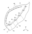
図1に示すように、椅子1は、床面2(図2参照)に起立する荷重支持構造体3と、着座者が着座可能な座面部20を有する座面構成部材4と、座面部20の側方に延出され延出端部5aで天板6(付属品)を支持可能な部品支持部材5と、を備える。
[Chair 1]
As shown in FIG. 1, the chair 1 includes a
以下の説明においては、座面部20に着座した着座者が前を向く方向を「前方」、前方とは反対方向を「後方」として説明する。つまり、図2に示す紙面に直交する方向を「前後方向」又は「椅子1の奥行方向」とする。また、床面2の法線方向(鉛直方向)を「上下方向」又は「椅子1の高さ方向」とする。また、前後方向および上下方向のそれぞれに直交する方向を「左右方向」又は「椅子1の幅方向」とする。図中において、前方を矢印FR、上方を矢印UP、左方を矢印LHでそれぞれ示している。
In the following description, the direction in which the seated person seated on the
[荷重支持構造体3]
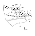
図2に示すように、荷重支持構造体3は、床面2に設定される脚部10と、脚部10の上部に取り付けられた支基15と、を備える。図2においては、天板6などの図示を省略している。
[Load support structure 3]
As shown in FIG. 2, the
図3に示すように、脚部10は、円環状の環状部材に三叉形状(Y字状)の連結部材が連結された脚本体11と、脚本体11の中央部(連結部材の中央部)から起立する柱状の脚柱12と、を備える。
As shown in FIG. 3, the
脚柱12は、脚本体11に固定された外筒12aと、外筒12aの径方向内側に位置する内筒12bと、を備える。内筒12bは、脚柱12の軸回りに回転可能に外筒12aに支持されている。内筒12bの上端部には、支基15が固定的に支持されている。なお、脚柱12は、ガススプリングを内蔵することにより、上下方向に伸縮可能に構成されていてもよい。
The
図2に示すように、支基15は、座面構成部材4の第一面部32を床面2の側から支持する。第一面部32は、座面構成部材4の下面部である。支基15は、脚部10の上部から第一面部32に近接するに従って前後幅および左右幅が広がる形状をなしている。支基15は、床面2の側から座面構成部材4の第一面部32に対向する第二面部16を備える。第二面部16は、支基15の上面部である。図5の上面視で、支基15は、後方に凸をなす三角形状をなしている。
As shown in FIG. 2, the
[座面構成部材4]
図1に示すように、座面構成部材4は、着座者が着座可能な座面部20と、座面部20の後端部から上方に延出する背凭れ部21と、背凭れ部21の上端部から上方に延出する頭部支持部22と、座面部20の左右側端部から上方に延出する肘掛け部23と、を備える。
[Seat surface component 4]
As shown in FIG. 1, the
椅子1の幅方向と直交する断面視(椅子1の要部を幅方向中心で切断した図7の断面視)で、座面部20と背凭れ部21とは互いに交差する形状をなしている。図7の断面視で、座面構成部材4は、J字状をなしている。
In a cross-sectional view orthogonal to the width direction of the chair 1 (a cross-sectional view in FIG. 7 in which a main part of the chair 1 is cut at the center in the width direction), the
上下方向と直交する断面視(椅子1の背凭れ部21を水平面に平行な面で切断した図8の断面視)で、座面構成部材4は、幅方向の中央部が幅方向の外側部よりも奥側に位置する凹形状をなしている。
In the cross-sectional view orthogonal to the vertical direction (the cross-sectional view of FIG. 8 in which the
図1に示すように、座面部20の上側には、クッションおよび表皮材が配置されて座面20aが形成されている。
背凭れ部21の前側には、クッションおよび表皮材が配置されて背凭れ面21aが形成されている。
なお、座面部20の上面および背凭れ部21の前側にクッションおよび表皮材が配置されておらず、芯材(図3に示すインナーシェル30)が着座者の身体に直接接する態様を採用してもよい。
As shown in FIG. 1, on the upper side of the
On the front side of the
The cushion and the skin material are not disposed on the upper surface of the
図5の上面視で、頭部支持部22は、着座者の頭部を後方および左右外方から覆う逆U字状をなしている。頭部支持部22における左右側壁は、外部からの音を遮る遮音部として機能する。図1に示すように、頭部支持部22の前側には、クッションおよび表皮材が配置されて頭部支持面22aが形成されている。
In the top view of FIG. 5, the
図2の前面視で、肘掛け部23は、上側ほど左右方向の幅が広い箱状をなしている。図1に示すように、肘掛け部23の前側、上側および幅方向内側には、クッションおよび表皮材が配置されて荷重受け面23aが形成されている。
図1においては、クッションの表面(表皮材)を破線で示している。
In the front view of FIG. 2, the
In FIG. 1, the surface (skin material) of the cushion is indicated by a broken line.
図3に示すように、座面構成部材4は、着座者の荷重を支持する強度部材としての芯材(以下「インナーシェル30」ともいう。)と、インナーシェル30の外側に配置される外装材(以下「アウターシェル40」ともいう。)と、を備える。図3においては、インナーシェル30およびアウターシェル40の右半部のみを示し、左半部の図示を省略している。
As shown in FIG. 3, the seat
インナーシェル30は、座面部20、背凭れ部21および頭部支持部22(図1参照)の支持体を構成するインナー本体31と、肘掛け部23(図1参照)を構成する肘掛構成部材35と、を備える。
The
アウターシェル40は、インナー本体31を外側から覆うアウター本体41と、肘掛構成部材35を外側から覆う肘掛カバー部材45と、を備える。
The
インナーシェル30は、アウターシェル40よりも高い剛性を有する。インナー本体31は、アウター本体41よりも肉厚に形成されている。インナー本体31およびアウター本体41の左右側部は、それぞれ後下方に凸の弧状をなす外形を有している。
The
図10の断面視で、肘掛構成部材35は、L字状をなしている。肘掛構成部材35は、幅方向で肘掛カバー部材45から離れるようにインナー本体31の外側部から上方に延出し、延出端から幅方向の外方に屈曲する屈曲部35vを有する板状をなしている。
In the cross-sectional view of FIG. 10, the
肘掛構成部材35は、幅方向で肘掛カバー部材45の内側面との間に空隙35sを形成するようにインナー本体31の外側部から起立する起立部36と、起立部36と共に屈曲部35vを形成するように起立部36の上端部から幅方向の外方に延出する外方延出部37と、起立部36の前端部から幅方向の外方に延出し、外方延出部37の前端部に連なりインナー本体31の外側部に向けて近接する方向に延出する前側延出部38(図12参照、第二外方延出部)と、を備える。図10において符号37hは、外方延出部37において部品支持部材5を挿通可能に上下方向に開口する開口部を示す。
The
図10の断面視で、肘掛構成部材35において、起立部36と外方延出部37とは互いに交差する屈曲形状を有している。実施形態において、起立部36と外方延出部37とは、互いに実質的に直交するL字形状を有している。
図10の断面視で、アウターシェル40において、アウター本体41と肘掛カバー部材45とは、下側方に凸の弧状をなして互いに連続する湾曲形状を有している。
図12の断面視で、肘掛構成部材35における前側延出部38は、前後方向に延びる外方延出部37の前端部から前上方に凸の弧状をなして前下方に延びる形状を有している。
In the cross-sectional view of FIG. 10, in the
In the cross-sectional view of FIG. 10, in the
In the cross-sectional view of FIG. 12, the
[補強リブ60]
肘掛構成部材35には、起立部36および外方延出部37の双方から空隙35sに向けて突出する補強要素としての補強リブ60が設けられている。図12の断面視で、補強リブ60は、部品支持部材5を避けるように格子状に形成されている。図12の断面視で、補強リブ60は、前後方向に直線状に延びる前後延在リブ61と、上下方向に直線状に延びる上下延在リブ62と、起立部36および外方延出部37とを連結する連結リブ63(連結補強部)と、を備える。補強リブ60は、起立部36と外方延出部37とを連結している。
[Reinforcing rib 60]
The
図12の断面視で、前後延在リブ61は、上下方向に間隔をあけて複数設けられている。図12の断面視で、上下延在リブ62は、前後方向に間隔をあけて複数設けられている。図12の断面視で、連結リブ63は、外方延出部37および前側延出部38の延在方向に間隔をあけて複数設けられている。図12の断面視で、複数の連結リブ63(外方延出部37の下面に連結されている部位)の一部は、最上位の前後延在リブ61の上方(最上位の前後延在リブ61と外方延出部37との上下間)において、上下延在リブ62と平行に延在している。
In the cross-sectional view of FIG. 12, a plurality of front and rear extending
図10に示すように、肘掛カバー部材45には、肘掛カバー部材45の内側面から幅方向内方(空隙35s)に向けて突出するアウター側リブ46が設けられている。図9に示すように、アウター側リブ46は、肘掛構成部材35における外方延出部37および前側延出部38(図12参照)の延在方向に沿うように弧状をなしている。図9において符号46hは、アウター側リブ46の厚み方向に開口し、アウター側リブ46の延在方向に間隔をあけて設けられた複数の貫通孔を示す。
As shown in FIG. 10, the
[部品支持部材5]
図6に示すように、部品支持部材5は、第一面部32と第二面部16との間に形成される通路25を経由して座面部20の側方に延出され、延出端部5aで天板6(図1参照)を支持可能に構成されている。部品支持部材5は、第一面部32と第二面部16とに挟まれている。部品支持部材5は、座面構成部材4に支持される被支持部55(図5参照)を備える。
[Part support member 5]
As shown in FIG. 6, the
図6の前面視で、部品支持部材5は、U字状をなしている。例えば、部品支持部材5は、断面円環状のパイプ材を曲げ加工することで形成されている。部品支持部材5は、通路25に配置される通路側配置部50と、座面部20の側方で通路側配置部50から上方に延出される側方延出部51と、を備える。
In the front view of FIG. 6, the
通路側配置部50は、第一面部32に沿う方向としての水平方向(幅方向)に直線状に延出している。通路側配置部50(以下「水平延出部50」ともいう。)には、被支持部としてのブラケット55(図5参照)が設けられている。例えば、ブラケット55は、水平延出部50に溶接で固定されている。
The passage-
側方延出部51は、上下方向に直線状に延在する上下延在部52と、上下延在部52の下端部と水平延出部50の幅方向外端部とを連結し、上側方に傾斜する傾斜連結部53と、を備える。
The
上下延在部52には、肘掛構成部材35(図12参照)に向けて延出する第二ブラケット56が設けられている。例えば、第二ブラケット56は、上下延在部52に溶接で固定されている。図12の側面視で、第二ブラケット56は、上下延在部52から前方に延出している。
The vertically extending
図6に示すように、上下延在部52は、水平延出部50の両端部から上方に延出するように左右に一対設けられている。上下延在部52の上端部は、天板6(図1参照)を支持する延出端部5aとして機能する。
As shown in FIG. 6, a pair of upper and lower extending
図6の前面視で、傾斜連結部53は、水平延出部50の幅方向外端部から上側ほど幅方向外方に位置するように直線状に傾斜している。図4の側面視で、傾斜連結部53は、水平延出部50の幅方向外端部から上側ほど前方に位置するように直線状に傾斜している。
In the front view of FIG. 6, the inclined connecting
[中間経路形成部34]
図13に示すように、座面構成部材4は、ブラケット55(図14参照)よりも上方の位置で、部品支持部材5における側方延出部51(具体的には傾斜連結部53)を通過させる中間経路34s(空間)を形成する中間経路形成部34を備える。図13の断面視で、中間経路形成部34は、前上方に凸をなす逆V字状を有している。中間経路形成部34は、傾斜連結部53の傾斜に沿って上側ほど幅方向外方に位置するように傾斜している。中間経路形成部34は、傾斜連結部53の前後方向、幅方向内方および上方への移動を規制する壁部として機能する。実施形態において、中間経路形成部34と傾斜連結部53との間には、微小な隙間が設けられている。
[Intermediate path forming unit 34]
As shown in FIG. 13, the seat
[インナー本体31と肘掛構成部材35との固定構造]
図11に示すように、肘掛構成部材35には、部品支持部材5(図12参照)および補強リブ60を避けて下方に弧状をなして延出する下方弧状延出部36aが設けられている。
[Fixing structure of
As shown in FIG. 11, the
図7に示すように、肘掛構成部材35における下方弧状延出部36a(図11参照)は、インナー本体31における弧状側部31aに複数のボルト36jで固定されている。図11において符号36hは、幅方向に開口し、下方弧状延出部36aに沿って間隔をあけて設けられた複数のボルト挿通孔を示す。図15において符号36kは、下方弧状延出部36aからインナー本体31における弧状側部31aに向けて突出する筒状のボス部を示す。
As shown in FIG. 7, the downward arc-shaped
[インナー本体31と部品支持部材5との固定構造]
図5に示すように、インナー本体31は、水平面に沿うインナー下面部32と、部品支持部材5を連結可能な部品支持部材連結部33と、を備える。
インナー下面部32は、座面構成部材4の下面部(第一面部)を構成する。
[Fixing structure of
As shown in FIG. 5, the inner
The inner
図14の断面視で、部品支持部材連結部33は、インナー下面部32から上方に膨出している。図5の上面視で、部品支持部材連結部33は、ブラケット55の外形に沿う矩形状をなしている。図14において符号33h,55hは、上下方向に開口し、ブラケット55固定用のボルト55jが挿通されるボルト挿通孔をそれぞれ示す。
In the sectional view of FIG. 14, the component support
図14に示すように、部品支持部材5(具体的には水平延出部50)は、部品支持部材連結部33およびブラケット55の各ボルト挿通孔33h,55hに下方からボルト55jが挿通され、ボルト55jの上方突出部(雄ネジ部)が不図示のナット(雌ネジ部)に螺着されることにより固定されている。実施形態において、部品支持部材5は、インナー本体31に対して左右一対の部品支持部材連結部33でブラケット55を介して各一箇所ずつ(左右合計二箇所)で固定されている(図5参照)。
As shown in FIG. 14, the component support member 5 (specifically, the horizontal extending portion 50) has
[肘掛構成部材35と部品支持部材5との固定構造]
図11に示すように、肘掛構成部材35は、部品支持部材5(具体的には上下延在部52、図12参照)を連結可能な第二部品支持部材連結部65を備える。第二部品支持部材連結部65は、起立部36から空隙35sに向けて補強リブ60よりも低い高さで突出している。図12において符号56hは、幅方向に開口し、第二ブラケット56固定用のボルト(不図示)が挿通されるボルト挿通孔を示す。
[Fixing structure of
As shown in FIG. 11, the
部品支持部材5における上下延在部52は、第二ブラケット56のボルト挿通孔56hに幅方向外方からボルトが挿通され、ボルトの幅方向内方突出部(雄ネジ部)が第二部品支持部材連結部65の雌ネジ部65mに螺着されることにより固定されている。実施形態において、部品支持部材5は、左右一対の肘掛構成部材35に対して左右一対の第二部品支持部材連結部65で第二ブラケット56を介して各一箇所ずつ(左右合計二箇所)で固定されている。
部品支持部材5は、肘掛け部23(図2参照)の補強部材であり、天板6のような追加機能部材(付属品)が取り付く場合には、その取付部材として機能する。
The vertically extending
The
[アウター本体41と肘掛カバー部材45との固定構造]
図9に示すように、肘掛カバー部材45には、アウター本体41における弧状側部43に沿うように弧状をなして肘掛カバー部材45の後下端部から幅方向内方に延出する内方弧状延出部47が設けられている。
[Fixing structure of outer
As shown in FIG. 9, the
肘掛カバー部材45における内方弧状延出部47は、アウター本体41における弧状側部43に複数のボルト47jで固定されている。図9において符号47aは、内方弧状延出部47に沿って間隔をあけて複数設けられ、ボルト47jの座面を形成する段部を示す。段部47aの前壁には、前後方向に開口するボルト挿通孔(不図示)が設けられている。図9において符号43aは、アウター本体41における弧状側部43から内方弧状延出部47のボルト挿通孔に向けて突出する筒状のボス部を示す。
The inward arc-shaped extending
[インナー本体31とアウター本体41との係合構造]
図2に示すように、インナー本体31の上部には、前後方向に開口し、上下方向に長手を有する矩形状のインナー側開口31hが設けられている。インナー側開口31hは、上下方向および幅方向に間隔をあけて複数設けられている。
[Engagement structure of
As shown in FIG. 2, a rectangular
図7に示すように、アウター本体41の上部には、インナー側開口31hに向けて突出するアウター側凸部44が設けられている。アウター側凸部44は、インナー側開口31hと対応するように、上下方向および幅方向に間隔をあけて複数設けられている。
As shown in FIG. 7, an outer side
図16の断面視で、アウター側凸部44には、クランク状の支持金具67が上下一対のボルト67jで固定されている。図16の断面視で、支持金具67は、アウター側凸部44の前面に沿って上下方向に延出するボルト連結部67aと、ボルト連結部67aの上端部から前方に延出した後に上方に屈曲して延出し、その後、前上方にやや傾斜して延出するインナー受け部67bと、を備える。
In the cross-sectional view of FIG. 16, a crank-shaped support fitting 67 is fixed to the outer
例えば、インナー本体31におけるインナー側開口31hに対し、アウター本体41におけるインナー受け部67bを後下方から挿通することによって、インナー本体31とアウター本体41とを係合することができる。
For example, the inner
図14に示すように、アウター本体41には、インナー本体31のインナー下面部32に沿うアウター下面部42を備える。アウター下面部42は、インナー本体31のインナー下面部32に対して下方から対向している。図14において符号32h,42hは、上下方向に開口し、アウター本体41固定用のボルト42jが挿通されるボルト挿通孔をそれぞれ示す。
As shown in FIG. 14, the outer
図14に示すように、アウター本体41は、インナー本体31(具体的にはインナー下面部32)およびアウター本体41(具体的にはアウター下面部42)の各ボルト挿通孔32h,42hに下方からボルト42jが挿通され、ボルト42jの上方突出部(雄ネジ部)が不図示のナット(雌ネジ部)に螺着されることにより固定されている。実施形態において、アウター本体41は、インナー本体31に対して左右一対のボルト42jで各一箇所ずつ(左右合計二箇所)で固定されている(図5参照)。
As shown in FIG. 14, the outer
[インナー本体31と支基15との固定構造]
図14に示すように、支基15は、インナー本体31の部品支持部材連結部33に部品支持部材5が連結されている状態で、座面構成部材4を連結可能な座面構成部材連結部17を備える。図14の断面視で、座面構成部材連結部17は、部品支持部材5を介して前後に離間して一対配置されている。図14の断面視で、座面構成部材連結部17は、アウター本体41を介してインナー本体31のインナー下面部32に向けて膨出している。
[Fixing structure of
As shown in FIG. 14, the
座面構成部材連結部17は、支基15の前部に位置する前側連結部18と、支基15の後部に位置する後側連結部19と、を備える。図14において符号18h,42fは、上下方向に開口し、支基15前部固定用のボルト18jが挿通されるボルト挿通孔をそれぞれ示す。図14において符号19h,42rは、上下方向に開口し、支基15後部固定用のボルト19jが挿通されるボルト挿通孔をそれぞれ示す。
The seat surface
図14に示すように、座面構成部材4は、座面構成部材連結部17(具体的には前側連結部18および後側連結部19)およびアウター本体41(具体的にはアウター下面部42)の各ボルト挿通孔18h,42f(19h,42r)に下方からボルト18j(19j)が挿通され、ボルト18j(19j)の上方突出部(雄ネジ部)がインナー本体31(具体的にはインナー下面部32)の雌ネジ部32f(32r)に螺着されることにより固定されている。実施形態において、インナー本体31は、支基15に対して前後一対の座面構成部材連結部17(前側連結部18および後側連結部19)でアウター本体41を介して各一箇所ずつ(左右合計四箇所)で固定されている。
As shown in FIG. 14, the seat surface
[椅子1の製造方法]
以下、実施形態の椅子1の製造方法の一例を説明する。
実施形態の椅子1の製造方法は、座面構成部材4に部品支持部材5を連結して組立体を作製する第一工程と、第一工程の後、組立体を荷重支持構造体3に連結する第二工程と、を含む。
[Manufacturing method of chair 1]
Hereinafter, an example of the manufacturing method of the chair 1 of embodiment is demonstrated.
The manufacturing method of the chair 1 according to the embodiment includes a first step in which the
以下、第一工程の一例を説明する。
まず、クッションをインナーシェル30の構成部材(インナー本体31および肘掛構成部材35)のそれぞれに接着する。
次に、インナー本体31と肘掛構成部材35とをボルト締結する。具体的に、肘掛構成部材35における下方弧状延出部36aを、インナー本体31における弧状側部31aに複数のボルト36jで固定する(図7、図11参照)。
Hereinafter, an example of the first step will be described.
First, the cushion is bonded to each of the constituent members of the inner shell 30 (the inner
Next, the inner
次に、インナーシェル30と部品支持部材5とをボルト締結する。
実施形態においては、部品支持部材5における水平延出部50をインナー本体31に固定するとともに、部品支持部材5における上下延在部52を肘掛構成部材35に固定する。
具体的に、インナー本体31と水平延出部50との固定は、部品支持部材連結部33およびブラケット55の各ボルト挿通孔33h,55hに下方からボルト55jを挿通し、ボルト55jの上方突出部(雄ネジ部)を不図示のナット(雌ネジ部)に螺着することにより行う(図14参照)。
一方、肘掛構成部材35と上下延在部52との固定は、第二ブラケット56のボルト挿通孔56hに幅方向外方からボルト(不図示)を挿通し、ボルトの幅方向内方突出部(雄ネジ部)を第二部品支持部材連結部65の雌ネジ部65mに螺着されることにより行う(図12参照)。
Next, the
In the embodiment, the horizontal extending
Specifically, the inner
On the other hand, the
次に、アウター本体41と肘掛カバー部材45とをボルト締結する。具体的に、肘掛カバー部材45における内方弧状延出部47を、アウター本体41における弧状側部43に複数のボルト47jで固定する(図9参照)。
Next, the outer
次に、プラスチックなどの樹脂製のキャッチ(不図示)をアウター本体41の適所に係合する。
次に、アウター本体41に表皮材を接着する。
次に、アウター本体41にクランク状の支持金具67をボルト締結する(図16参照)。
Next, a catch made of resin such as plastic (not shown) is engaged with an appropriate position of the
Next, a skin material is bonded to the outer
Next, a crank-shaped support fitting 67 is bolted to the outer body 41 (see FIG. 16).
次に、インナー本体31とアウター本体41とを係合する。具体的に、インナー本体31におけるインナー側開口31hに対し、アウター本体41における支持金具67(インナー受け部67b)を後下方から挿通することにより、インナー本体31とアウター本体41とを係合する(図7、図16参照)。
Next, the inner
次に、アウター本体41をインナー本体31に押し付けてキャッチ(不図示)をインナー本体31の凹部(不図示)に嵌め込む。
なお、キャッチをボルトに置換することで、インナーシェル30とアウターシェル40との一体性をより高め、全体を強度部材としてもよい。アウターシェル40は、インナーシェル30のカバー部材として機能するのみならず、補強部材として機能してもよい。
Next, the outer
In addition, by replacing the catch with a bolt, the integrity of the
次に、インナー本体31とアウター本体41とを固定する。具体的に、インナー本体31とアウター本体41との固定は、インナー本体31およびアウター本体41の各ボルト挿通孔32h,42hに下方からボルト42jを挿通し、ボルト42jの上方突出部(雄ネジ部)を不図示のナット(雌ネジ部)に螺着することにより行う(図14参照)。
以上の手順により、第一工程における組立体を製造することができる。
Next, the inner
The assembly in the first step can be manufactured by the above procedure.
以下、第二工程の一例を説明する。
第一工程の後、インナー本体31と支基15とを固定する。具体的に、インナー本体31と支基15との固定は、座面構成部材連結部17およびアウター本体41の各ボルト挿通孔18h,42f(19h,42r)に下方からボルト18j(19j)を挿通し、ボルト18j(19j)の上方突出部(雄ネジ部)をインナー本体31の雌ネジ部32f(32r)に螺着することにより行う(図14参照)。
以上の手順により、実施形態の椅子1を製造することができる。
図1に示すように、完成状態の椅子1において、天板6は、椅子1の中心位置より径方向外方にオフセットした位置に配置され、部品支持部材5の延出端部5aの軸線回りに回動可能とされている。着座に際しては、天板6を軸線回りの矢印R1方向に回動させることにより、着座空間を前方に開放することができる。
Hereinafter, an example of the second step will be described.
After the first step, the inner
The chair 1 of the embodiment can be manufactured by the above procedure.
As shown in FIG. 1, in the chair 1 in a completed state, the top plate 6 is disposed at a position offset radially outward from the center position of the chair 1, and is around the axis of the
以上説明したように、上記実施形態に係る椅子1は、着座者が着座可能な座面部20と、椅子1が設置される床面2に対向する第一面部32と、を有する座面構成部材4と、第一面部32に対向する第二面部16を有し、座面構成部材4の第一面部32を支持する荷重支持構造体3と、第一面部32と第二面部16との間に形成される通路25を経由して座面部20の側方に延出され、延出端部5aで付属部品を支持可能な部品支持部材5と、を備え、部品支持部材5は、第一面部32と第二面部16とに挟まれ、座面構成部材4に支持される被支持部55を備える。
As described above, the chair 1 according to the above-described embodiment has a seat surface configuration including the
この構成によれば、部品支持部材5が一定の広がりを有する一対の面部(第一面部32および第二面部16)で挟まれることにより、部品支持部材5の延出端部5aに荷重が入力された場合であっても、入力荷重に起因する負荷を一対の面部で受けることができるため、部品支持部材5の脱落を防止することができる。加えて、部品支持部材5における被支持部55が座面構成部材4に支持されることにより、部品支持部材5と椅子1との連結部位での堅牢性を極端に高める必要もない。したがって、部品支持部材5と椅子1との連結部位での堅牢性を極端に高めることなく、部品支持部材5の脱落を防止することができる。
According to this configuration, when the
上記実施形態において、被支持部55は、第二面部16としての荷重支持構造体3の上面部と、第一面部32としての座面構成部材4の下面部と、に挟まれ、延出端部5aには、付属部品としての天板6が支持されていることで、以下の効果を奏する。
この構成によれば、部品支持部材5が荷重支持構造体3の上面部と座面構成部材4の下面部とにより挟まれることにより、天板6に上方からの荷重が入力された場合であっても、入力荷重に起因する負荷を上下一対の面部(上面部および下面部)で受けることができるため、部品支持部材5と椅子1との連結部位での堅牢性を極端に高めることなく、部品支持部材5の脱落を防止することができる。
In the above-described embodiment, the supported
According to this configuration, when the
上記実施形態において、部品支持部材5は、被支持部55を有し、通路25に配置される通路側配置部50と、座面部20の側方で通路側配置部50から上方に延出される側方延出部51と、を備え、座面構成部材4は、被支持部55よりも上方の位置で、側方延出部51を通過させる中間経路34sを形成する中間経路形成部34を備えることで、以下の効果を奏する。
この構成によれば、部品支持部材5における側方延出部51が中間経路34sを通過することにより、部品支持部材5の延出端部5aに荷重が入力された場合であっても、入力荷重に起因する負荷を中間経路形成部34で受けることができるため、部品支持部材5における被支持部55に過大な負荷がかかることを抑えることができる。したがって、部品支持部材5と椅子1との連結部位での堅牢性を極端に高めることなく、部品支持部材5の脱落をより効果的に防止することができる。
In the above embodiment, the
According to this configuration, even when a load is input to the
上記実施形態に係る椅子1の製造方法は、上記の椅子1の製造方法であって、座面構成部材4に部品支持部材5を連結して組立体を作製する第一工程と、第一工程の後、組立体を荷重支持構造体3に連結する第二工程と、を含む。
この方法によれば、座面構成部材4に部品支持部材5を先行して連結して組立体を作製した後、組立体を荷重支持構造体3に連結することができるため、椅子1の組立効率が向上する。
The manufacturing method of the chair 1 which concerns on the said embodiment is a manufacturing method of said chair 1, Comprising: The 1st process which connects the
According to this method, since the assembly can be connected to the
なお、上記実施形態では、椅子1が設置される床面2を屋内の平坦な床面2とした例を挙げて説明したが、これに限らない。例えば、床面2は、屋外の平坦な地面や傾斜面であってもよく、競技場などのスタジアムにおけるスタンド設置面であってもよい。
In the above embodiment, the
また、上記実施形態では、部品支持部材5における被支持部55が座面構成部材4に支持される例を挙げて説明したが、これに限らない。例えば、部品支持部材5における被支持部55が荷重支持構造体3に支持されていてもよい。すなわち、部品支持部材5における被支持部55が座面構成部材4および荷重支持構造体3の少なくとも一方に支持されていてもよい。
Moreover, although the said embodiment demonstrated and demonstrated the example by which the to-
また、上記実施形態では、延出端部5aには、付属部品としての天板6が支持されている例を挙げて説明したが、これに限らない。例えば、延出端部5aには、付属部品としてのディスプレイやタブレット受け台が支持されていてもよいし、点滴器具などの医療機器が支持されていてもよい。また、延出端部5aには、付属備品が支持されるアタッチメントが取り付けられていてもよい。
Moreover, although the said embodiment demonstrated and demonstrated the example by which the top plate 6 as an accessory is supported by the
また、上記実施形態では、座面構成部材4は、被支持部55よりも上方の位置で、側方延出部51(具体的には傾斜連結部53)を通過させる中間経路34sを形成する中間経路形成部34を備える例を挙げて説明したが、これに限らない。例えば、図17に示すように、中間経路形成部34には、被支持部55よりも上方の位置で、側方延出部51(具体的には傾斜連結部53)を支持する中間支持部材68が設けられていてもよい。
Further, in the above-described embodiment, the seating surface
中間支持部材68は、傾斜連結部53の外面に沿うU字断面を有する中間支持本体68aと、中間支持本体の両端部から中間経路形成部34の外面に沿うように延出する延出片68bと、を備える(図17参照)。例えば、延出片68bは、中間経路形成部34の外面に溶接で固定されている。
また、中間経路形成部34と傾斜連結部53との間には、微小な隙間を埋めるスペーサ(不図示)が設けられていてもよい。
The
Further, a spacer (not shown) that fills a minute gap may be provided between the intermediate
また、上記実施形態では、延出端部5aが肘掛け面の上方に延出する例を挙げて説明したが、これに限らない。例えば、図18に示すように、椅子1Aにおいて、延出端部5aは、肘掛け部23の内部に設けられていてもよい。例えば、上下延在部52は、上下に分割可能に構成されていてもよい。
また、図19に示すように、椅子1Bにおいて、右側(幅方向一方側)の延出端部5aには天板6が支持される一方で、左側(幅方向他方側)の延出端部5aは肘掛け部23の内部に設けられていてもよい。
Moreover, although the said embodiment gave and demonstrated the example which the
As shown in FIG. 19, in the
また、上記実施形態では、座面構成部材4がインナーシェル30およびアウターシェル40を備える例(二層構造である例)を挙げて説明したが、これに限らない。例えば、座面構成部材4は、インナーシェル30のみを備える単層構造であってもよい。
Moreover, although the said surface embodiment mentioned and demonstrated the example (example which is a 2 layer structure) with which the seat surface
また、上記実施形態では、被支持部がブラケット55である例を挙げて説明したが、これに限らない。例えば、被支持部は、水平延出部50本体であってもよい。すなわち、部品支持部材5における水平延出部50が座面構成部材4に直接的に支持されていてもよい。
Moreover, although the said embodiment gave and demonstrated the example whose supported part is the
なお、本発明の技術範囲は上述した実施形態に限定されるものではなく、本発明の趣旨を逸脱しない範囲において種々の変更を加えることが可能である。 The technical scope of the present invention is not limited to the above-described embodiments, and various modifications can be made without departing from the spirit of the present invention.
1,1A,1B…椅子、2…床面(椅子設置面)、3…荷重支持構造体、4…座面構成部材、5…部品支持部材、5a…延出端部、6…天板(付属部品)、16…第二面部、17…座面構成部材連結部、20…座面部、25…通路、32…インナー下面部(第一面部)、33…部品支持部材連結部、34…中間経路形成部、34a…中間経路、50…水平延出部(通路側配置部)、51…側方延出部、55…ブラケット(被支持部)
DESCRIPTION OF
Claims (4)
前記第一面部に対向する第二面部を有し、前記座面構成部材の前記第一面部を支持する荷重支持構造体と、
前記第一面部と前記第二面部との間に形成される通路を経由して前記座面部の側方に延出され、延出端部で付属部品を支持可能な部品支持部材と、を備え、
前記部品支持部材は、前記第一面部と前記第二面部とに挟まれ、前記座面構成部材および前記荷重支持構造体の少なくとも一方に支持される被支持部を備えることを特徴とする椅子。 A seat surface component having a seat surface portion on which a seated person can be seated and a first surface portion facing the chair installation surface on which the chair is installed;
A load support structure that has a second surface portion facing the first surface portion and supports the first surface portion of the seat surface component;
A component support member that extends to the side of the seat surface portion via a passage formed between the first surface portion and the second surface portion, and that can support the accessory component at the extended end portion; Prepared,
The component support member includes a supported portion that is sandwiched between the first surface portion and the second surface portion and is supported by at least one of the seat surface constituent member and the load support structure. .
前記延出端部には、前記付属部品としての天板が支持されていることを特徴とする
請求項1に記載の椅子。 The supported portion is sandwiched between an upper surface portion of the load support structure as the second surface portion and a lower surface portion of the seat surface constituent member as the first surface portion,
The chair according to claim 1, wherein a top plate as the accessory part is supported on the extended end portion.
前記被支持部を有し、前記通路に配置される通路側配置部と、
前記座面部の側方で前記通路側配置部から上方に延出される側方延出部と、を備え、
前記座面構成部材は、前記被支持部よりも上方の位置で、前記側方延出部を通過させる中間経路を形成する中間経路形成部を備えることを特徴とする
請求項1または2に記載の椅子。 The component support member is
A passage-side arrangement portion that has the supported portion and is arranged in the passage;
A laterally extending portion that extends upward from the passage-side arrangement portion at a side of the seat surface portion,
The said seat surface structural member is provided with the intermediate | middle path | route formation part which forms the intermediate | middle path | route which lets the said side extension part pass in the position above the said to-be-supported part. Chairs.
前記座面構成部材に前記部品支持部材を連結して組立体を作製する第一工程と、
前記第一工程の後、前記組立体を前記荷重支持構造体に連結する第二工程と、を含むことを特徴とする椅子の製造方法。 It is a manufacturing method of the chair as described in any one of Claim 1 to 3,
A first step of producing an assembly by connecting the component support member to the seating surface component;
After the first step, a second step of connecting the assembly to the load support structure includes a method for manufacturing a chair.
Priority Applications (1)
| Application Number | Priority Date | Filing Date | Title |
|---|---|---|---|
| JP2018014153A JP7317469B2 (en) | 2018-01-30 | 2018-01-30 | Chair and method of making the chair |
Applications Claiming Priority (1)
| Application Number | Priority Date | Filing Date | Title |
|---|---|---|---|
| JP2018014153A JP7317469B2 (en) | 2018-01-30 | 2018-01-30 | Chair and method of making the chair |
Publications (2)
| Publication Number | Publication Date |
|---|---|
| JP2019129977A true JP2019129977A (en) | 2019-08-08 |
| JP7317469B2 JP7317469B2 (en) | 2023-07-31 |
Family
ID=67544569
Family Applications (1)
| Application Number | Title | Priority Date | Filing Date |
|---|---|---|---|
| JP2018014153A Active JP7317469B2 (en) | 2018-01-30 | 2018-01-30 | Chair and method of making the chair |
Country Status (1)
| Country | Link |
|---|---|
| JP (1) | JP7317469B2 (en) |
Citations (10)
| Publication number | Priority date | Publication date | Assignee | Title |
|---|---|---|---|---|
| JPH10127410A (en) * | 1996-10-28 | 1998-05-19 | Uchida Yoko Co Ltd | Armrest fitting structure of chair |
| JP2006187538A (en) * | 2005-01-07 | 2006-07-20 | Okamura Corp | Structure for fixing armrest of chair |
| US20080164737A1 (en) * | 2007-01-08 | 2008-07-10 | Parafincorporation | Workstation with computer systems and components |
| JP2012070977A (en) * | 2010-09-29 | 2012-04-12 | Lixil Corp | Chair |
| US20120306249A1 (en) * | 2010-01-13 | 2012-12-06 | Dae Hoon Jung | Multifunctional chair |
| JP2013063174A (en) * | 2011-09-16 | 2013-04-11 | Itoki Corp | Chair |
| JP2013075137A (en) * | 2011-09-12 | 2013-04-25 | Kokuyo Co Ltd | Chair |
| WO2013085214A1 (en) * | 2011-12-08 | 2013-06-13 | 한국생산기술연구원 | Seat-plate slide tilting seat |
| JP2015080642A (en) * | 2013-10-23 | 2015-04-27 | 株式会社岡村製作所 | Chair |
| KR20150060230A (en) * | 2013-11-26 | 2015-06-03 | 이두형 | chair |
-
2018
- 2018-01-30 JP JP2018014153A patent/JP7317469B2/en active Active
Patent Citations (10)
| Publication number | Priority date | Publication date | Assignee | Title |
|---|---|---|---|---|
| JPH10127410A (en) * | 1996-10-28 | 1998-05-19 | Uchida Yoko Co Ltd | Armrest fitting structure of chair |
| JP2006187538A (en) * | 2005-01-07 | 2006-07-20 | Okamura Corp | Structure for fixing armrest of chair |
| US20080164737A1 (en) * | 2007-01-08 | 2008-07-10 | Parafincorporation | Workstation with computer systems and components |
| US20120306249A1 (en) * | 2010-01-13 | 2012-12-06 | Dae Hoon Jung | Multifunctional chair |
| JP2012070977A (en) * | 2010-09-29 | 2012-04-12 | Lixil Corp | Chair |
| JP2013075137A (en) * | 2011-09-12 | 2013-04-25 | Kokuyo Co Ltd | Chair |
| JP2013063174A (en) * | 2011-09-16 | 2013-04-11 | Itoki Corp | Chair |
| WO2013085214A1 (en) * | 2011-12-08 | 2013-06-13 | 한국생산기술연구원 | Seat-plate slide tilting seat |
| JP2015080642A (en) * | 2013-10-23 | 2015-04-27 | 株式会社岡村製作所 | Chair |
| KR20150060230A (en) * | 2013-11-26 | 2015-06-03 | 이두형 | chair |
Also Published As
| Publication number | Publication date |
|---|---|
| JP7317469B2 (en) | 2023-07-31 |
Similar Documents
| Publication | Publication Date | Title |
|---|---|---|
| JP2006271622A (en) | Chair | |
| JP2019129977A (en) | Chair and method of manufacturing the same | |
| JP2019129978A (en) | Chair | |
| JP2019129966A (en) | Load support member for chair and chair | |
| JP2019129967A (en) | Furniture component and furniture manufacturing method | |
| JP7179573B2 (en) | table | |
| JP5096869B2 (en) | Chair | |
| JP4119226B2 (en) | Mounting structure such as backrest in chair | |
| CN210276530U (en) | Seat | |
| JP2018164668A (en) | Chair | |
| JP5096998B2 (en) | Chair | |
| JP5873304B2 (en) | Chair with armrests | |
| JP7172378B2 (en) | Chair | |
| JP4889946B2 (en) | Chair backrest structure | |
| JP4219155B2 (en) | Spectator seat system | |
| KR200367080Y1 (en) | structure for support of coupling chairs | |
| JP2018047137A (en) | Chair and chair structure | |
| JP5666880B2 (en) | Chair | |
| JP3113201U (en) | Chair structure | |
| JP2007202967A (en) | Chair | |
| JP2010131246A (en) | Armchair | |
| CN211608806U (en) | Public row chair | |
| JP3156116B2 (en) | Chair armrest mounting device | |
| JP2009106412A (en) | Leg device of furniture, such as chair | |
| JP6575747B2 (en) | Shielding member and chair |
Legal Events
| Date | Code | Title | Description |
|---|---|---|---|
| A621 | Written request for application examination |
Free format text: JAPANESE INTERMEDIATE CODE: A621 Effective date: 20210106 |
|
| A977 | Report on retrieval |
Free format text: JAPANESE INTERMEDIATE CODE: A971007 Effective date: 20211117 |
|
| A131 | Notification of reasons for refusal |
Free format text: JAPANESE INTERMEDIATE CODE: A131 Effective date: 20220104 |
|
| A521 | Request for written amendment filed |
Free format text: JAPANESE INTERMEDIATE CODE: A523 Effective date: 20220303 |
|
| A131 | Notification of reasons for refusal |
Free format text: JAPANESE INTERMEDIATE CODE: A131 Effective date: 20220719 |
|
| A521 | Request for written amendment filed |
Free format text: JAPANESE INTERMEDIATE CODE: A523 Effective date: 20220907 |
|
| A131 | Notification of reasons for refusal |
Free format text: JAPANESE INTERMEDIATE CODE: A131 Effective date: 20221220 |
|
| A521 | Request for written amendment filed |
Free format text: JAPANESE INTERMEDIATE CODE: A523 Effective date: 20230220 |
|
| TRDD | Decision of grant or rejection written | ||
| A01 | Written decision to grant a patent or to grant a registration (utility model) |
Free format text: JAPANESE INTERMEDIATE CODE: A01 Effective date: 20230620 |
|
| A61 | First payment of annual fees (during grant procedure) |
Free format text: JAPANESE INTERMEDIATE CODE: A61 Effective date: 20230719 |
|
| R150 | Certificate of patent or registration of utility model |
Ref document number: 7317469 Country of ref document: JP Free format text: JAPANESE INTERMEDIATE CODE: R150 |