JP2019129973A - Indwelling apparatus and indwelling apparatus set - Google Patents

Indwelling apparatus and indwelling apparatus set Download PDF

Info

Publication number
JP2019129973A
JP2019129973A JP2018014099A JP2018014099A JP2019129973A JP 2019129973 A JP2019129973 A JP 2019129973A JP 2018014099 A JP2018014099 A JP 2018014099A JP 2018014099 A JP2018014099 A JP 2018014099A JP 2019129973 A JP2019129973 A JP 2019129973A
Authority
JP
Japan
Prior art keywords
cover
needle
base
base member
cover member
Prior art date
Legal status (The legal status is an assumption and is not a legal conclusion. Google has not performed a legal analysis and makes no representation as to the accuracy of the status listed.)
Granted
Application number
JP2018014099A
Other languages
Japanese (ja)
Other versions
JP6991872B2 (en
Inventor
中西 勝
Masaru Nakanishi
勝 中西
保弘 小林
Yasuhiro Kobayashi
保弘 小林
Current Assignee (The listed assignees may be inaccurate. Google has not performed a legal analysis and makes no representation or warranty as to the accuracy of the list.)
Terumo Corp
Original Assignee
Terumo Corp
Priority date (The priority date is an assumption and is not a legal conclusion. Google has not performed a legal analysis and makes no representation as to the accuracy of the date listed.)
Filing date
Publication date
Application filed by Terumo Corp filed Critical Terumo Corp
Priority to JP2018014099A priority Critical patent/JP6991872B2/en
Publication of JP2019129973A publication Critical patent/JP2019129973A/en
Application granted granted Critical
Publication of JP6991872B2 publication Critical patent/JP6991872B2/en
Active legal-status Critical Current
Anticipated expiration legal-status Critical

Links

Images

Abstract

To provide an indwelling apparatus capable of suppressing damage to a living body by a needle member when removed from a living body surface, and an indwelling apparatus set.SOLUTION: An indwelling apparatus equipped with a needle member, which is indwelled on a living body surface and can be used in a state that the needle member is stuck into the living body surface, includes a base member that can be fixed to the living body surface, and a cover member that can be attached to the base member. The base member supports the needle member so as to move it in an axial direction. When the cover member is removed from the base member, the needle member becomes engaged with the cover member and moves to a base end side.SELECTED DRAWING: Figure 1

Description

本開示は、生体表面に留置された状態で使用可能な留置装置、及び当該留置装置を備える留置装置セットに関する。   The present disclosure relates to an indwelling device that can be used while being indwelled on a biological surface, and an indwelling device set including the indwelling device.

従来から、針部材を備え、患者などの被検者の生体表面から当該針部材を穿刺し、留置させて使用する留置装置が知られている。例えば、生体表面からセンサを含む針部材を穿刺し、被検者の血液又は間質液等の体液中の被計測物質(例えば、グルコースやpH、生理活性物質、タンパク質等)を当該センサによって検出することが行われている。   DESCRIPTION OF RELATED ART Conventionally, the indwelling apparatus which is provided with a needle member and punctures the said needle member from the living body surface of subjects, such as a patient, and is used is known. For example, a needle member including a sensor is punctured from the surface of a living body, and a substance to be measured (eg, glucose, pH, physiologically active substance, protein, etc.) in a body fluid such as blood or interstitial fluid of the subject is detected by the sensor. To be done.

例えば、特許文献1には、先端に針部材を有する挿入補助具を生体表面に穿刺することで、センサを生体表面から生体内に挿入して留置する装置が開示されている。   For example, Patent Document 1 discloses an apparatus for inserting and placing a sensor into a living body from the living body surface by puncturing an insertion assisting tool having a needle member at the tip thereof on the living body surface.

特表2008−539810号公報Special table 2008-539810 gazette

上述した従来の留置装置では、使用後に、針部材が穿刺されたままの状態で、例えば、生体表面から剥がし取ることで、生体表面から取り外す。この場合、針部材が軸方向以外の方向に回動しようとするため、生体を損傷する虞があった。   In the conventional indwelling device described above, after use, the needle member is removed from the living body surface, for example, by peeling off from the living body surface with the needle member being punctured. In this case, since the needle member tries to rotate in a direction other than the axial direction, there is a risk of damaging the living body.

本開示の目的は、上記問題に鑑み、生体表面から取り外す際に、針部材による生体への損傷を抑制することができる留置装置及び留置装置セットを提供することである。   In view of the above problems, an object of the present disclosure is to provide an indwelling device and an indwelling device set capable of suppressing damage to a living body due to a needle member when the surface is removed from the surface of the living body.

本発明の第1の態様としての留置装置は、針部材を備え、生体表面に留置されて前記針部材が生体表面に穿刺された状態で使用可能な留置装置であって、生体表面に固定可能なベース部材と、前記ベース部材に装着可能なカバー部材と、を備え、前記ベース部材は、前記針部材を軸方向に移動可能に支持し、前記カバー部材が前記ベース部材から取り外されると、前記針部材が前記カバー部材と係合して基端側に移動する。   An indwelling apparatus as a first aspect of the present invention is an indwelling apparatus that includes a needle member, can be used in a state in which the needle member is indwelled on the surface of a living body, and can be fixed to the surface of the living body. A base member and a cover member attachable to the base member, the base member supports the needle member so as to be movable in the axial direction, and when the cover member is removed from the base member, The needle member engages with the cover member and moves to the proximal end side.

本発明の一実施形態としての留置装置は、前記カバー部材が前記ベース部材に装着されると、前記針部材が前記カバー部材と係合して先端側に移動する。   In the indwelling device as one embodiment of the present invention, when the cover member is attached to the base member, the needle member engages with the cover member and moves to the distal end side.

本発明の一実施形態としての留置装置において、前記ベース部材は、基端側に移動した前記針部材を固定する。   In the indwelling apparatus as one embodiment of the present invention, the base member fixes the needle member moved to the proximal end side.

本発明の一実施形態としての留置装置において、前記ベース部材は、前記針部材を支持する支持部と、前記支持部を前記針部材の軸方向に移動させる可動部と、を備える。   In the indwelling apparatus as one embodiment of the present invention, the base member includes a support portion that supports the needle member, and a movable portion that moves the support portion in the axial direction of the needle member.

本発明の一実施形態としての留置装置において、前記針部材はセンサ電極を備え、前記カバー部材は通信装置を備え、前記カバー部材が前記ベース部材に装着された状態で、前記センサ電極は前記通信装置と電気的に接続される。   In the indwelling device as one embodiment of the present invention, the needle member includes a sensor electrode, the cover member includes a communication device, and the sensor electrode is connected to the base member in a state where the cover member is attached to the base member. Electrically connected to the device.

本発明の第2の態様としての留置装置セットは、前記留置装置と、前記ベース部材を保持可能なベース補助部材と、前記カバー部材を保持可能なカバー補助部材と、を備え、前記ベース補助部材及び前記カバー補助部材は、前記カバー部材を、前記ベース部材に対して前記針部材の軸方向に沿って移動可能に支持する。   The indwelling device set as a second aspect of the present invention includes the indwelling device, a base auxiliary member capable of holding the base member, and a cover auxiliary member capable of holding the cover member, and the base auxiliary member The cover auxiliary member supports the cover member so as to be movable along the axial direction of the needle member with respect to the base member.

本発明の一実施形態としての留置装置セットにおいて、前記カバー部材を保持した前記カバー補助部材、及び、前記ベース部材を保持した前記ベース補助部材は、前記カバー部材が前記ベース部材に装着されていない状態で、互いに係合する第1組立状態と、前記カバー部材が前記ベース部材に装着された状態で、互いに係合する第2組立状態と、を取ることが可能である。   In the indwelling device set as one embodiment of the present invention, the cover auxiliary member holding the cover member and the base auxiliary member holding the base member are not attached to the base member. It is possible to take a first assembled state that engages with each other in a state, and a second assembled state that engages with each other with the cover member mounted on the base member.

本開示の留置装置及び留置装置セットによると、生体表面から取り外す際に、針部材による生体への損傷を抑制することができる。   According to the indwelling device and the indwelling device set of the present disclosure, it is possible to suppress damage to the living body due to the needle member when removing from the surface of the living body.

本発明の第1実施形態としての留置装置を示す断面図である。It is sectional drawing which shows the indwelling apparatus as 1st Embodiment of this invention. 図1に示す留置装置の着脱方法の各工程を示すフローチャートである。It is a flowchart which shows each process of the attachment / detachment method of the indwelling apparatus shown in FIG. 図1に示す留置装置の着脱方法のベース部材固定工程を模式的に示す図である。It is a figure which shows typically the base member fixing process of the attachment / detachment method of the indwelling apparatus shown in FIG. 図1に示す留置装置の着脱方法のカバー部材装着工程を模式的に示す図(その1)である。It is a figure (the 1) which shows typically the cover member mounting process of the attachment / detachment method of the indwelling apparatus shown in FIG. 図1に示す留置装置の着脱方法のカバー部材装着工程を模式的に示す図(その2)である。FIG. 6 is a diagram (part 2) schematically illustrating a cover member mounting step of the method for attaching and detaching the indwelling device illustrated in FIG. 1. 図1に示す留置装置の着脱方法のカバー部材取り外し工程を模式的に示す図(その1)である。It is a figure (the 1) which shows typically the cover member removal process of the attachment or detachment method of the indwelling apparatus shown in FIG. 図1に示す留置装置の着脱方法のカバー部材取り外し工程を模式的に示す図(その2)である。FIG. 8 is a diagram (No. 2) schematically showing a cover member removing step of the indwelling device attaching / detaching method shown in FIG. 1. 図1に示す留置装置の着脱方法のベース部材取り外し工程を模式的に示す図である。It is a figure which shows typically the base member removal process of the attachment / detachment method of the indwelling apparatus shown in FIG. 本発明の第2実施形態としての留置装置の、装着状態を示す斜視図である。It is a perspective view which shows the mounting state of the indwelling apparatus as 2nd Embodiment of this invention. 図9に示す留置装置の、未装着状態を示す斜視図である。FIG. 10 is a perspective view showing an unmounted state of the indwelling device shown in FIG. 9. 図9に示す留置装置の、未装着状態を示す断面図である。FIG. 10 is a cross-sectional view showing an unmounted state of the indwelling device shown in FIG. 9. 図9に示す留置装置が備えるベース部材が、ベース補助部材に保持されてなる、ベース部材群の断面図である。It is sectional drawing of the base member group by which the base member with which the indwelling apparatus shown in FIG. 9 is provided is hold | maintained at the base auxiliary member. 図12に示すベース部材群の斜め上方から見た斜視図である。It is the perspective view seen from diagonally upward of the base member group shown in FIG. 図9に示す留置装置が備えるカバー部材が、カバー補助部材に保持されてなる、カバー部材群の断面図である。It is sectional drawing of the cover member group formed by the cover member with which the indwelling apparatus shown in FIG. 9 is hold | maintained at a cover auxiliary member. 図14に示すカバー部材群の斜め下方から見た斜視図である。It is the perspective view seen from diagonally downward of the cover member group shown in FIG. 図12に示すベース部材群と図14に示すカバー部材群との第1組立状態を示す断面図である。It is sectional drawing which shows the 1st assembly state of the base member group shown in FIG. 12, and the cover member group shown in FIG. 図16に示す第1組立状態の上面図である。It is a top view of the 1st assembly state shown in FIG. 図12に示すベース部材群と図14に示すカバー部材群との第2組立状態を示す断面図である。It is sectional drawing which shows the 2nd assembly state of the base member group shown in FIG. 12, and the cover member group shown in FIG. 図18に示す第2組立状態からベース補助部材及びカバー補助部材を取り除いて得られる留置装置を示す断面図である。It is sectional drawing which shows the indwelling apparatus obtained by removing a base auxiliary member and a cover auxiliary member from the 2nd assembly state shown in FIG. 図19に示す留置装置の着脱方法のカバー部材取り外し工程を示す断面図である。It is sectional drawing which shows the cover member removal process of the attachment or detachment method of the indwelling apparatus shown in FIG.

以下、本発明の一実施形態について、図面を参照して説明する。各図において共通の部材には、同一の符号を付している。本明細書において、「上方」とは、後述するベース部材やカバー部材の上面側(図1等の上側)を意味し、「下方」とは、ベース部材やカバー部材の下面側(図1等の下側)を意味する。   Hereinafter, an embodiment of the present invention will be described with reference to the drawings. In each figure, the same code | symbol is attached | subjected to the common member. In this specification, “upper” means the upper surface side (upper side of FIG. 1 and the like) of a base member and cover member, which will be described later, and “lower” means the lower surface side of the base member and cover member (FIG. 1 and the like). Lower side).

(第1実施形態)
[留置装置1の構成]
図1は、本発明の第1実施形態としての留置装置1を示す断面図である。図1に示すように、留置装置1は、ベース部材10aと、針部材50aと、カバー部材30aと、を備える。留置装置1は、被検者の体表面等の生体表面に留置されて、針部材50aが生体表面に穿刺された状態で、使用することができる。図1に示す留置装置1は、使用前の状態であり、カバー部材30aがベース部材10aに取り付けられる前の状態を示している。
(First embodiment)
[Configuration of Indwelling Device 1]
FIG. 1 is a cross-sectional view showing an indwelling apparatus 1 as a first embodiment of the present invention. As shown in FIG. 1, the indwelling apparatus 1 includes a base member 10a, a needle member 50a, and a cover member 30a. The indwelling device 1 can be used in a state where the indwelling device 1 is placed on a living body surface such as a body surface of a subject and the needle member 50a is punctured on the living body surface. The indwelling apparatus 1 shown in FIG. 1 is in a state before use, and shows a state before the cover member 30a is attached to the base member 10a.

ベース部材10aは、上面11及び下面12に連通する中空部13を内部に区画する。中空部13には、針部材50aが、その軸方向Aを中空部13の連通方向と一致させた向きで配置される。本実施形態では、中空部13に配置された針部材50aは、中空部13を区画する内面14と接触し、内面14に保持されている。これにより、針部材50aは、ベース部材10aに支持される。また、針部材50aは、中空部13を区画する内面14と摺動し、ガイドされることで、軸方向Aに移動可能である。このようにして、本実施形態の針部材50aは、ベース部材10aに対して、軸方向Aに移動可能に支持されている。本実施形態のベース部材10aは、上面11及び下面12を構成する底板26と、この底板26の軸方向Aに直交する方向(以下、「直交方向B」と記載する。)における端部付近から、上面11側に突出する第1外壁15と、を備える。   The base member 10 a defines a hollow portion 13 communicating with the upper surface 11 and the lower surface 12 inside. In the hollow portion 13, the needle member 50 a is arranged in a direction in which the axial direction A is aligned with the communication direction of the hollow portion 13. In the present embodiment, the needle member 50 a disposed in the hollow portion 13 is in contact with the inner surface 14 that defines the hollow portion 13 and is held on the inner surface 14. Thereby, the needle member 50a is supported by the base member 10a. The needle member 50a is movable in the axial direction A by sliding and guiding with the inner surface 14 that defines the hollow portion 13. Thus, the needle member 50a of this embodiment is supported so as to be movable in the axial direction A with respect to the base member 10a. The base member 10a of the present embodiment includes a bottom plate 26 that constitutes the upper surface 11 and the lower surface 12, and an end portion in a direction orthogonal to the axial direction A of the bottom plate 26 (hereinafter referred to as “orthogonal direction B”). And a first outer wall 15 projecting toward the upper surface 11 side.

ベース部材10aの下面12には、ベース部材10aを被検者の体表面等の生体表面に貼付可能な程度に粘着力を生じさせる粘着剤が塗布されている。具体的には、下面12における体表面に対する粘着力は、被検者が留置装置1を使用する期間(例えば数日から数週間程度)にわたって、留置装置1が被検者の体表面から剥がれない程度に強力であることが好ましく、通常の傷絆創膏等に比べて強力である。下面12における体表面に対する粘着力は、被検者が留置装置1を使用する期間にわたって体表面に対する一定の粘着性を維持しつつ、留置装置1を体表面から剥がす際に、被検者に痛みを与えにくい程度であることが好ましく、かつ、カバー部材30aをベース部材10aから取り外す際の摺動抵抗(針部材50aと中空部13の内面14との摺動抵抗、ベース部材10aとカバー部材30aとの摺動抵抗、及び、針部材50aを体表面から抜くときの摺動抵抗、を含む)よりも強力である。   The lower surface 12 of the base member 10a is coated with an adhesive that generates an adhesive force to such an extent that the base member 10a can be attached to a living body surface such as the body surface of the subject. Specifically, the adhesion force of the lower surface 12 to the body surface is such that the indwelling device 1 does not peel from the body surface of the subject over a period in which the subject uses the indwelling device 1 (for example, about several days to several weeks). It is preferable to be strong to the extent that it is stronger than a normal wound adhesive plaster or the like. The adhesive strength of the lower surface 12 to the body surface is painful to the subject when the indwelling device 1 is peeled off from the body surface while maintaining a certain level of adhesion to the body surface over the period in which the subject uses the indwelling device 1. And the sliding resistance when removing the cover member 30a from the base member 10a (sliding resistance between the needle member 50a and the inner surface 14 of the hollow portion 13, the base member 10a and the cover member 30a). And the sliding resistance when the needle member 50a is pulled out from the body surface).

下面12に塗布される粘着剤としては、例えばシリコーン系粘着剤、アクリル系粘着剤、又はゴム系(天然ゴム若しくは合成ゴム等)粘着剤を使用することができる。但し、粘着剤は、ここに列挙したものに限られない。下面12は、留置装置1の使用前の状態では、剥離紙等により覆われており、使用時には剥がされる。   As the pressure-sensitive adhesive applied to the lower surface 12, for example, a silicone-based pressure-sensitive adhesive, an acrylic pressure-sensitive adhesive, or a rubber-based (natural rubber or synthetic rubber) pressure-sensitive adhesive can be used. However, the pressure-sensitive adhesive is not limited to those listed here. The lower surface 12 is covered with release paper or the like before the indwelling apparatus 1 is used, and is peeled off during use.

針部材50aは、軸方向Aに沿って延在する線状の針本体51aと、針本体51aの基端(図1では上端)に固定されたハブ52aと、を備える。   The needle member 50a includes a linear needle body 51a extending along the axial direction A, and a hub 52a fixed to the proximal end (upper end in FIG. 1) of the needle body 51a.

針本体51aは、軸方向Aがベース部材10aの中空部13の連通方向と一致する向きで、中空部13に一部が挿入された状態で配置される。針本体51aは、ベース部材10aの中空部13を区画する内面14に沿って摺動することで、軸方向Aに移動可能である。詳細には、針本体51aの先端は、ベース部材10aの中空部13内に位置する状態と、ベース部材10aの下面12から突出する状態と、を取り得る。図1に示すように、カバー部材30aがベース部材10aに装着される前の状態(以下、「未装着状態」と記載する。)では、針本体51aの先端は、ベース部材10aの中空部13内に位置する。針本体51aの先端は、生体表面に穿刺可能な程度に鋭利に形成されている。   The needle body 51a is arranged in a state in which a part of the needle body 51a is inserted into the hollow portion 13 with the axial direction A coinciding with the communication direction of the hollow portion 13 of the base member 10a. The needle body 51a is movable in the axial direction A by sliding along the inner surface 14 that defines the hollow portion 13 of the base member 10a. Specifically, the tip of the needle body 51a can take a state of being located in the hollow portion 13 of the base member 10a and a state of protruding from the lower surface 12 of the base member 10a. As shown in FIG. 1, in a state before the cover member 30a is attached to the base member 10a (hereinafter referred to as “non-attached state”), the tip of the needle body 51a is the hollow portion 13 of the base member 10a. Located in. The tip of the needle body 51a is formed so sharp that it can puncture the surface of the living body.

ハブ52aは、針本体51aの長軸方向、すなわち軸方向Aに対して直交する直交方向Bに突出する突起部53を備える。ハブ52aは、ベース部材10aの中空部13よりも上面11側(軸方向Aに沿う上側C)に位置する。本実施形態のハブ52aの突起部53を含む直交方向Bの最大幅は、中空部13の直交方向Bの最大幅よりも大きい。   The hub 52a includes a protrusion 53 that protrudes in the long axis direction of the needle body 51a, that is, in the orthogonal direction B orthogonal to the axial direction A. The hub 52a is located on the upper surface 11 side (upper side C along the axial direction A) of the hollow portion 13 of the base member 10a. The maximum width in the orthogonal direction B including the protrusion 53 of the hub 52a of the present embodiment is larger than the maximum width in the orthogonal direction B of the hollow portion 13.

本実施形態の針部材50aは、センサ電極を備えてもよい。具体的には、例えば、本実施形態の針本体51aは、筒状の中空針で形成され、本実施形態のハブ52aは、針本体51aの中空部に連通する中空部を区画し、センサ電極が針本体51aの中空部及びハブ52aの中空部に位置する。針本体51aには、例えば中空部と外部とを連通する貫通孔が形成され、生体表面に穿刺された状態で、被検者の体液が先端開口及び貫通孔を通じて中空部に導入される。センサ電極は、例えば、作用極、参照極及び対極であり、作用極、参照極及び対極は互いに協働して、被計測物質の量又は濃度に応じた電気的信号を検出する。センサ電極は、ハブ52aの中空部を通じて、ハブ52aの上面に露出する接続部と電気的に接続されている。針本体51aの材料としては、例えば、ステンレス鋼、アルミニウム、アルミニウム合金、チタン、チタン合金等の金属材料を用いることができる。   The needle member 50a of the present embodiment may include a sensor electrode. Specifically, for example, the needle main body 51a of the present embodiment is formed of a cylindrical hollow needle, and the hub 52a of the present embodiment defines a hollow portion communicating with the hollow portion of the needle main body 51a, and the sensor electrode Is located in the hollow portion of the needle body 51a and the hollow portion of the hub 52a. In the needle body 51a, for example, a through-hole that communicates the hollow portion and the outside is formed, and the body fluid of the subject is introduced into the hollow portion through the tip opening and the through-hole while being punctured on the living body surface. The sensor electrode is, for example, a working electrode, a reference electrode, and a counter electrode, and the working electrode, the reference electrode, and the counter electrode cooperate with each other to detect an electrical signal corresponding to the amount or concentration of the substance to be measured. The sensor electrode is electrically connected to the connection part exposed on the upper surface of the hub 52a through the hollow part of the hub 52a. As a material of the needle body 51a, for example, a metal material such as stainless steel, aluminum, an aluminum alloy, titanium, or a titanium alloy can be used.

本実施形態のカバー部材30aは、天板46と、この天板46の下面31側に突出する突出部32と、突出部32の周囲で天板46の下面31側に突出する爪部33と、を備える。また、カバー部材30aは、天板46の下面31の端部から、下面31側に突出する第2外壁34を備える。カバー部材30aは、ベース部材10aに装着可能である。   The cover member 30a of the present embodiment includes a top plate 46, a protrusion 32 that protrudes toward the lower surface 31 of the top plate 46, and a claw portion 33 that protrudes toward the lower surface 31 of the top plate 46 around the protrusion 32. . Further, the cover member 30 a includes a second outer wall 34 that protrudes toward the lower surface 31 from the end of the lower surface 31 of the top plate 46. The cover member 30a can be attached to the base member 10a.

本実施形態のカバー部材30aは、通信装置を備えてもよい。具体的には、例えば、本実施形態のカバー部材30aは、内部に位置する通信装置と、通信装置に電気的に接続され、突出部32の下面に露出する接続部と、を備える。通信装置は、プロセッサ、通信デバイス、メモリ及び電池等により構成される。詳細は後述するが、カバー部材30aがベース部材10aに装着された状態(以下、「装着状態」と記載する。)で、針部材50aが備えるセンサ電極は、通信装置と電気的に接続される。   The cover member 30a of the present embodiment may include a communication device. Specifically, for example, the cover member 30a of the present embodiment includes a communication device located inside, and a connection portion that is electrically connected to the communication device and exposed to the lower surface of the protruding portion 32. The communication device includes a processor, a communication device, a memory, a battery, and the like. Although details will be described later, the sensor electrode provided in the needle member 50a is electrically connected to the communication device in a state where the cover member 30a is attached to the base member 10a (hereinafter referred to as “attached state”). .

[留置装置1の着脱方法]
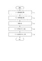
図2は、留置装置1の着脱方法の各工程を示すフローチャートである。図2に示すように、留置装置1の着脱方法は、ベース部材固定工程S1と、カバー部材装着工程S2と、使用工程S3と、カバー部材取り外し工程S4と、ベース部材取り外し工程S5と、を含む。
[Method of attaching / detaching indwelling device 1]
FIG. 2 is a flowchart showing each step of the method for attaching and detaching the indwelling apparatus 1. As shown in FIG. 2, the method for attaching / detaching the indwelling device 1 includes a base member fixing step S1, a cover member attaching step S2, a using step S3, a cover member removing step S4, and a base member removing step S5. .

図3は、留置装置1の着脱方法のベース部材固定工程S1を模式的に示す図である。図3に示すように、ベース部材固定工程S1では、図1に示した未装着状態のベース部材10aの下面12を生体表面Sに貼付して、ベース部材10aを生体表面Sに固定する。このとき、上述した通り、針部材50aの先端は、ベース部材10aの中空部13内に位置する。すなわち、針部材50aの先端は、ベース部材10aの下面12から突出していない。   FIG. 3 is a diagram schematically illustrating the base member fixing step S <b> 1 of the method for attaching and detaching the indwelling apparatus 1. As shown in FIG. 3, in the base member fixing step S <b> 1, the base member 10 a is fixed to the living body surface S by sticking the lower surface 12 of the base member 10 a in the unmounted state shown in FIG. At this time, as described above, the tip of the needle member 50a is located in the hollow portion 13 of the base member 10a. That is, the tip of the needle member 50a does not protrude from the lower surface 12 of the base member 10a.

図4及び図5は、留置装置1の着脱方法のカバー部材装着工程S2を模式的に示す図である。図4及び図5に示すように、カバー部材装着工程S2では、図3に示したベース部材固定工程S1で生体表面Sに固定したベース部材10aに、カバー部材30aを装着する。詳細には、まず、図4に示すように、カバー部材30aを、下面31がベース部材10aの上面11に向かい合うようにして、軸方向Aに沿ってベース部材10aに向けて下方に移動させる。このとき、カバー部材30aは、ベース部材10aの第1外壁15の外周にガイドされる。その後、カバー部材30aの突出部32及び爪部33が、針部材50aのハブ52aに係合し、針部材50aが先端側に押圧される。詳細には、突出部32はハブ52aの上面に接触し、爪部33はハブ52aの突起部53に係合する。このとき、ベース部材10aは生体表面Sに固定されているため、針部材50aはベース部材10aに対して先端側に移動する。これにより、図5に示すように、針部材50aは生体表面Sに穿刺される。図5に示すように、針部材50aが生体表面Sに穿刺されると同時に、カバー部材30aはベース部材10aに装着される。本実施形態では、図5に示すように、カバー部材30aの第2外壁34とベース部材10aの第1外壁15とが、摩擦力等によって互いに係合することで、カバー部材30aがベース部材10aに装着される。カバー部材30aの第2外壁34、及び、ベース部材10aの第1外壁15、の一方に爪部を設け、他方に爪部が入り込む係止溝部を設け、爪部と係止溝部を係合することで装着する構成としてもよい。   4 and 5 are diagrams schematically illustrating the cover member mounting step S2 of the method for attaching and detaching the indwelling device 1. FIG. As shown in FIGS. 4 and 5, in the cover member mounting step S2, the cover member 30a is mounted on the base member 10a fixed to the biological surface S in the base member fixing step S1 shown in FIG. Specifically, first, as shown in FIG. 4, the cover member 30a is moved downward along the axial direction A toward the base member 10a so that the lower surface 31 faces the upper surface 11 of the base member 10a. At this time, the cover member 30a is guided to the outer periphery of the first outer wall 15 of the base member 10a. Then, the protrusion part 32 and the nail | claw part 33 of the cover member 30a engage with the hub 52a of the needle member 50a, and the needle member 50a is pressed to the front end side. Specifically, the protruding portion 32 contacts the upper surface of the hub 52a, and the claw portion 33 engages with the protruding portion 53 of the hub 52a. At this time, since the base member 10a is fixed to the living body surface S, the needle member 50a moves to the distal end side with respect to the base member 10a. Thereby, the needle member 50a is punctured into the living body surface S as shown in FIG. As shown in FIG. 5, at the same time as the needle member 50a is punctured into the living body surface S, the cover member 30a is attached to the base member 10a. In the present embodiment, as shown in FIG. 5, the second outer wall 34 of the cover member 30a and the first outer wall 15 of the base member 10a are engaged with each other by a frictional force or the like, so that the cover member 30a is engaged with the base member 10a. It is attached to. A claw portion is provided on one of the second outer wall 34 of the cover member 30a and the first outer wall 15 of the base member 10a, a locking groove portion into which the claw portion enters is provided on the other side, and the claw portion and the locking groove portion are engaged. It is good also as a structure to mount | wear.

図5に示すように、カバー部材装着工程S2の後、すなわち、留置装置1が生体表面Sに留置されて針部材50aが生体表面Sに穿刺された状態で、留置装置1が使用可能となる(使用工程S3)。例えば、留置装置1は、針部材50aがセンサ電極を備える場合、センサ電極を用いて、被計測物質に関する情報を測定する。図5に示すように、装着状態では、針部材50aのハブ52aの上面と、カバー部材30aの突出部32の下面と、が互いに接触することで、針部材50aが備えるセンサ電極は、カバー部材30aが備える通信装置と電気的に接続可能となる。針部材50aが生体表面Sに穿刺された状態では、センサ電極は、針部材50aの中空部に導入された被検者の体液に含まれる被計測物質の量又は濃度に応じた電気的信号を検出する。検出された電気的信号は、通信装置に送信される。通信装置は、受信した電気的信号に応じた通信信号を生成し、外部の表示デバイス等に送信することができる。   As shown in FIG. 5, the indwelling device 1 can be used after the cover member mounting step S2, that is, in a state where the indwelling device 1 is placed on the living body surface S and the needle member 50a is punctured on the living body surface S. (Use process S3). For example, when the needle member 50a includes a sensor electrode, the indwelling apparatus 1 uses the sensor electrode to measure information regarding the substance to be measured. As shown in FIG. 5, in the mounted state, the upper surface of the hub 52a of the needle member 50a and the lower surface of the protruding portion 32 of the cover member 30a are in contact with each other. It becomes electrically connectable with the communication apparatus with which 30a is provided. In a state where the needle member 50a is punctured on the living body surface S, the sensor electrode outputs an electrical signal corresponding to the amount or concentration of the substance to be measured contained in the body fluid of the subject introduced into the hollow portion of the needle member 50a. To detect. The detected electrical signal is transmitted to the communication device. The communication apparatus can generate a communication signal corresponding to the received electrical signal and transmit it to an external display device or the like.

図6及び図7は、留置装置1の着脱方法のカバー部材取り外し工程S4を模式的に示す図である。図6及び図7に示すように、留置装置1の使用が終了すると、図5に示した留置装置1の装着状態を解除して、カバー部材30aをベース部材10aから取り外す。詳細には、まず、図6に示すように、カバー部材30aを、軸方向Aに沿ってベース部材10aから離隔するように上方に移動させる。これにより、カバー部材30aの第2外壁34とベース部材10aの第1外壁15との係合が解除される。このとき、カバー部材30aの突出部32及び爪部33と、針部材50aのハブ52aと、の間の係合は解除されず、針部材50aが軸方向Aに沿って基端側に移動する。これにより、針部材50aは生体表面Sから抜去される。このとき、針部材50aは、先端が中空部13内に位置する状態で、中空部13を区画する内面14によって、支持される。その後、図7に示すように、カバー部材30aの突出部32及び爪部33と、針部材50aのハブ52aと、の間の係合を解除して、カバー部材30aを針部材50aから取り外す。   6 and 7 are diagrams schematically showing the cover member removing step S4 of the method for attaching and detaching the indwelling device 1. FIG. As shown in FIGS. 6 and 7, when the use of the indwelling device 1 is finished, the indwelling state of the indwelling device 1 shown in FIG. 5 is released, and the cover member 30a is removed from the base member 10a. Specifically, first, as shown in FIG. 6, the cover member 30a is moved upward along the axial direction A so as to be separated from the base member 10a. Thereby, the engagement between the second outer wall 34 of the cover member 30a and the first outer wall 15 of the base member 10a is released. At this time, the engagement between the protruding portion 32 and the claw portion 33 of the cover member 30a and the hub 52a of the needle member 50a is not released, and the needle member 50a moves to the proximal end side along the axial direction A. . Thereby, the needle member 50a is extracted from the living body surface S. At this time, the needle member 50 a is supported by the inner surface 14 that defines the hollow portion 13 in a state where the tip is located in the hollow portion 13. Thereafter, as shown in FIG. 7, the engagement between the protruding portion 32 and the claw portion 33 of the cover member 30a and the hub 52a of the needle member 50a is released, and the cover member 30a is removed from the needle member 50a.

図8は、留置装置1の着脱方法のベース部材取り外し工程S5を模式的に示す図である。図8に示すように、カバー部材30a(図7等参照)が取り外され、針部材50aが生体表面Sから抜去された後のベース部材10aを、生体表面Sから取り外す。ベース部材10aは、例えば、図8に示すように、直交方向Bの一端(図8の左端)を引き上げて、下面12が直交方向Bに沿って生体表面Sから順次剥がし取るようにして、生体表面Sから取り外される。   FIG. 8 is a diagram schematically showing the base member removal step S5 of the method for attaching and detaching the indwelling device 1. As shown in FIG. As shown in FIG. 8, the cover member 30a (see FIG. 7 and the like) is removed, and the base member 10a after the needle member 50a is removed from the biological surface S is removed from the biological surface S. For example, as shown in FIG. 8, the base member 10 a is formed by pulling up one end in the orthogonal direction B (left end in FIG. 8) so that the lower surface 12 is sequentially peeled from the biological surface S along the orthogonal direction B. It is removed from the surface S.

上述のように、本実施形態の留置装置1では、カバー部材30aがベース部材10aから取り外されると、針部材50aがカバー部材30aと係合して基端側に移動する。したがって、留置装置1を生体表面Sから取り外す際に、カバー部材30aをベース部材10aから取り外すのに連動して針部材50aが基端側に移動して生体表面Sから抜去されるため、針部材50aによる生体への損傷を抑制することができる。すなわち、ベース部材10aを生体表面Sから取り外す前に、針部材50aを生体表面Sから抜去することで、生体への損傷を抑制することができる。また、カバー部材30aをベース部材10aから取り外す動作に連動して、針部材50aを生体表面Sから抜去することができるため、操作性を向上させることができる。   As described above, in the indwelling device 1 of the present embodiment, when the cover member 30a is removed from the base member 10a, the needle member 50a engages with the cover member 30a and moves to the proximal end side. Therefore, when removing the indwelling device 1 from the living body surface S, the needle member 50a moves to the proximal end side in conjunction with the removal of the cover member 30a from the base member 10a and is removed from the living body surface S. Damage to the living body due to 50a can be suppressed. That is, by removing the needle member 50a from the living body surface S before removing the base member 10a from the living body surface S, damage to the living body can be suppressed. Further, since the needle member 50a can be removed from the living body surface S in conjunction with the operation of removing the cover member 30a from the base member 10a, the operability can be improved.

上述のように、本実施形態の留置装置1では、カバー部材30aがベース部材10aに装着されると、針部材50aがカバー部材30aと係合して先端側に移動する。したがって、留置装置1を生体表面Sに取り付ける際に、生体表面Sに固定されたベース部材10aにカバー部材30aを装着するのに連動して針部材50aが先端側に移動して生体表面Sに穿刺されるため、操作性を向上させることができる。   As described above, in the indwelling device 1 of the present embodiment, when the cover member 30a is attached to the base member 10a, the needle member 50a engages with the cover member 30a and moves to the distal end side. Therefore, when the indwelling device 1 is attached to the living body surface S, the needle member 50a moves to the distal end side in conjunction with the mounting of the cover member 30a on the base member 10a fixed to the living body surface S. Since it is punctured, operability can be improved.

(第2実施形態)
[留置装置2の構成]
図9は、本発明の第2実施形態としての留置装置2の装着状態、すなわち、カバー部材30bがベース部材10bに装着されている状態を示す斜視図である。図10は、留置装置2の、未装着状態、すなわち、カバー部材30bがベース部材10bに装着される前の状態での斜視図である。図11は、留置装置2の、未装着状態での断面図である。
(Second Embodiment)
[Configuration of Indwelling Device 2]
FIG. 9 is a perspective view showing a mounting state of the indwelling device 2 as the second embodiment of the present invention, that is, a state where the cover member 30b is mounted on the base member 10b. FIG. 10 is a perspective view of the indwelling device 2 in an unmounted state, that is, a state before the cover member 30b is mounted on the base member 10b. FIG. 11 is a cross-sectional view of the indwelling device 2 in an unmounted state.

図9〜図11に示すように、留置装置2は、ベース部材10bと、針部材50bと、カバー部材30bと、を備える。留置装置2は、上述した第1実施形態としての留置装置1と同様に、被検者の体表面等の生体表面に留置されて、針部材50bが生体表面に穿刺された状態で、使用することができる。   As shown in FIGS. 9 to 11, the indwelling device 2 includes a base member 10b, a needle member 50b, and a cover member 30b. The indwelling device 2 is used in a state where the indwelling device 1 is placed on a living body surface such as the body surface of the subject and the needle member 50b is punctured on the living body surface, like the indwelling device 1 as the first embodiment described above. be able to.

図10及び図11に示すように、ベース部材10bは、平板状の底板26と、底板26の外縁に沿って、底板26の延在方向と直交する一方向(図11の上方)に延設された第1外壁15と、を備える。底板26は、図10に示すように、上面視で略円形状である。また、ベース部材10bは、第1外壁15に包囲される領域に、底板26から第1外壁15と同じ方向に突設された、筒状の外筒部18及び筒状の内筒部19を備える。図11に示すように、内筒部19は、外筒部18に包囲される領域に位置する。さらに、ベース部材10bは、外筒部18の内周側に位置する筒状の可動部17と、可動部17の内周側に位置する筒状の支持部16と、を備える。支持部16、可動部17、外筒部18、及び内筒部19は、それぞれの軸方向が一致するように配置されている。支持部16、可動部17、外筒部18、及び内筒部19は、それぞれの軸方向が一致するように同心円状に配置されていると、カバー部材30bとベース部材10bとの操作性がさらに向上する。   As shown in FIGS. 10 and 11, the base member 10 b extends in a direction (upward in FIG. 11) perpendicular to the extending direction of the bottom plate 26 along the flat bottom plate 26 and the outer edge of the bottom plate 26. First outer wall 15 is provided. As shown in FIG. 10, the bottom plate 26 has a substantially circular shape when viewed from above. In addition, the base member 10 b includes a cylindrical outer cylinder portion 18 and a cylindrical inner cylinder portion 19 that protrude from the bottom plate 26 in the same direction as the first outer wall 15 in a region surrounded by the first outer wall 15. Prepare. As shown in FIG. 11, the inner cylinder portion 19 is located in a region surrounded by the outer cylinder portion 18. Furthermore, the base member 10 b includes a cylindrical movable part 17 located on the inner peripheral side of the outer cylinder part 18 and a cylindrical support part 16 located on the inner peripheral side of the movable part 17. The support part 16, the movable part 17, the outer cylinder part 18, and the inner cylinder part 19 are arrange | positioned so that each axial direction may correspond. If the support part 16, the movable part 17, the outer cylinder part 18, and the inner cylinder part 19 are concentrically arranged so that the respective axial directions coincide with each other, the operability of the cover member 30b and the base member 10b is improved. Further improve.

図11に示すように、支持部16、可動部17、外筒部18、及び内筒部19は、全体として、中空部13を区画する。中空部13は、内筒部19を通じて、ベース部材10bの下面12に区画された開口20から外部に連通する。   As shown in FIG. 11, the support part 16, the movable part 17, the outer cylinder part 18, and the inner cylinder part 19 define the hollow part 13 as a whole. The hollow portion 13 communicates with the outside through the inner cylinder portion 19 from the opening 20 defined in the lower surface 12 of the base member 10b.

図11に示すように、支持部16は、針部材50bを支持する。詳細には、支持部16は、中空部13に対して開口20が位置する方向に、針部材50bの先端が向くように、針部材50bを支持する。本実施形態では、支持部16は、後述する針部材50bの針本体51bが内部を延在するように、後述する針部材50bの基端に位置するハブ52bを固定する。図10及び図11に示すように、可動部17は、支持部16を、可動部17に対して軸方向Aに移動可能に支持する。詳細には、可動部17は、支持部16の周囲を可動部17の内周面で覆うように位置することで、支持部16の軸方向A以外への移動を規制する。外筒部18は、可動部17を、外筒部18に対して軸方向Aに移動可能に支持する。詳細には、外筒部18は、可動部17の周囲を外筒部18の内周面で覆うように位置することで、可動部17の軸方向A以外への移動を規制する。このように、外筒部18、可動部17、及び支持部16は、全体として、複数の重なり合う筒状の部材で構成され、軸方向Aに沿って伸縮可能な、いわゆるテレスコピック機構を構成する。これにより、ベース部材10bの筐体を軸方向Aに薄くできる。   As shown in FIG. 11, the support part 16 supports the needle member 50b. Specifically, the support portion 16 supports the needle member 50b so that the tip of the needle member 50b faces in the direction in which the opening 20 is positioned with respect to the hollow portion 13. In the present embodiment, the support portion 16 fixes a hub 52b positioned at a proximal end of a needle member 50b described later so that a needle main body 51b of the needle member 50b described later extends inside. As shown in FIGS. 10 and 11, the movable portion 17 supports the support portion 16 so as to be movable in the axial direction A with respect to the movable portion 17. Specifically, the movable part 17 regulates the movement of the support part 16 in a direction other than the axial direction A by being positioned so as to cover the periphery of the support part 16 with the inner peripheral surface of the movable part 17. The outer cylinder part 18 supports the movable part 17 so as to be movable in the axial direction A with respect to the outer cylinder part 18. Specifically, the outer cylinder portion 18 is positioned so as to cover the periphery of the movable portion 17 with the inner peripheral surface of the outer cylinder portion 18, thereby restricting the movement of the movable portion 17 in a direction other than the axial direction A. As described above, the outer cylinder portion 18, the movable portion 17, and the support portion 16 are constituted by a plurality of overlapping cylindrical members as a whole, and constitute a so-called telescopic mechanism that can expand and contract along the axial direction A. Thereby, the housing of the base member 10b can be thinned in the axial direction A.

図11に示すように、内筒部19は、針部材50bの軸方向A以外への移動を規制する。詳細には、内筒部19は、内筒部19の内周面によって、後述する針部材50bの針本体51bの周囲を覆う。これにより、内筒部19は、針部材50bの軸方向A以外への移動を規制する。   As shown in FIG. 11, the inner cylinder portion 19 restricts the movement of the needle member 50 b in directions other than the axial direction A. In detail, the inner cylinder part 19 covers the circumference | surroundings of the needle main body 51b of the needle member 50b mentioned later by the internal peripheral surface of the inner cylinder part 19. FIG. Thereby, the inner cylinder part 19 controls the movement to the direction other than the axial direction A of the needle member 50b.

ベース部材10bの下面12には、ベース部材10bを、被検者の体表面等の生体表面に貼付可能な程度に粘着力を生じさせる粘着剤が塗布されている。ベース部材10bの下面12に塗布される粘着剤は、上述した第1実施形態のベース部材10aの下面12に塗布される粘着剤と同様であるため、ここでは説明を省略する。   The lower surface 12 of the base member 10b is coated with an adhesive that generates an adhesive force to such an extent that the base member 10b can be applied to a living body surface such as a body surface of a subject. Since the adhesive applied to the lower surface 12 of the base member 10b is the same as the adhesive applied to the lower surface 12 of the base member 10a of the first embodiment described above, description thereof is omitted here.

図9〜図11に示すように、本実施形態では、ベース部材10bの第1外壁15の所定の位置に、底板26の延在方向外側に向かって突出した爪部21が形成されている。また、図9及び図10に示すように、本実施形態では、ベース部材10bの第1外壁15の外周面の所定の位置に、上方に連通する凹部22が形成されている。   As shown in FIGS. 9-11, in this embodiment, the nail | claw part 21 which protruded toward the extending direction outer side of the baseplate 26 is formed in the predetermined position of the 1st outer wall 15 of the base member 10b. Further, as shown in FIGS. 9 and 10, in the present embodiment, a concave portion 22 communicating upward is formed at a predetermined position on the outer peripheral surface of the first outer wall 15 of the base member 10b.

図11に示すように、針部材50bは、軸方向Aに沿って延在する針本体51bと、針本体51bの基端(図11では上端)に固定されたハブ52bと、を備える。   As shown in FIG. 11, the needle member 50b includes a needle main body 51b extending along the axial direction A, and a hub 52b fixed to the proximal end (upper end in FIG. 11) of the needle main body 51b.

図11に示すように、針本体51bは、中空部13に対して開口20が位置する方向に先端が向くように配置される。つまり、針本体51bは、中空部13内を、支持部16、可動部17、外筒部18、及び内筒部19の軸方向に沿って延在している。すなわち、針本体51bの軸方向Aは、支持部16、可動部17、外筒部18、及び内筒部19の軸方向に略一致している。針本体51bは、ハブ52bと連動して、軸方向Aに移動可能である。詳細には、針本体51bの先端は、中空部13のうち内筒部19に区画される空間に位置する状態と、ベース部材10bの下面12から突出する状態と、を取り得る。図11に示す未装着状態では、針本体51bの先端は、内筒部19に区画される空間に位置する。針本体51bの先端は、鋭利に形成されている。   As shown in FIG. 11, the needle main body 51 b is arranged so that the tip thereof faces in the direction in which the opening 20 is positioned with respect to the hollow portion 13. That is, the needle body 51 b extends in the hollow portion 13 along the axial direction of the support portion 16, the movable portion 17, the outer cylinder portion 18, and the inner cylinder portion 19. That is, the axial direction A of the needle body 51 b substantially coincides with the axial directions of the support portion 16, the movable portion 17, the outer cylinder portion 18, and the inner cylinder portion 19. The needle body 51b is movable in the axial direction A in conjunction with the hub 52b. Specifically, the tip of the needle body 51b can take a state of being located in a space defined by the inner cylinder part 19 in the hollow part 13 and a state of protruding from the lower surface 12 of the base member 10b. In the unmounted state shown in FIG. 11, the tip of the needle body 51 b is located in a space defined by the inner cylinder portion 19. The tip of the needle body 51b is sharply formed.

図11に示すように、ハブ52bは、針本体51bの基端を周囲から挟み込むようにして、針本体51bを固定している。図10及び図11に示すように、ハブ52bは、針本体51bよりも直交方向Bに突出する突起部53を備える。ハブ52bの下面には、支持部16が接続されている。   As shown in FIG. 11, the hub 52b fixes the needle body 51b so as to sandwich the proximal end of the needle body 51b from the periphery. As shown in FIGS. 10 and 11, the hub 52b includes a protrusion 53 that protrudes in the orthogonal direction B with respect to the needle body 51b. The support portion 16 is connected to the lower surface of the hub 52b.

本実施形態の針部材50bは、センサ電極54を備える。本実施形態の針本体51bは、筒状の中空針で形成され、センサ電極54が針本体51bの中空部に位置する。針本体51bには、例えば中空部と外部とを連通する貫通孔が形成され、生体表面に穿刺された状態で、被検者の体液が先端開口及び貫通孔を通じて中空部に導入される。センサ電極54は、例えば、作用極、参照極及び対極であり、作用極、参照極及び対極は互いに協働して、被計測物質の量又は濃度に応じた電気的信号を検出する。図10に示すように、センサ電極54は、針本体51bの中空部(図11参照)を通じて、ハブ52bの上面に露出する接続部55と電気的に接続されている。針本体51bの材料としては、上述した実施形態1の針本体51aと同様の材料を用いることができる。   The needle member 50b of this embodiment includes a sensor electrode 54. The needle body 51b of the present embodiment is formed by a cylindrical hollow needle, and the sensor electrode 54 is located in the hollow portion of the needle body 51b. In the needle body 51b, for example, a through-hole that communicates the hollow portion with the outside is formed, and the body fluid of the subject is introduced into the hollow portion through the tip opening and the through-hole while being punctured on the surface of the living body. The sensor electrode 54 is, for example, a working electrode, a reference electrode, and a counter electrode, and the working electrode, the reference electrode, and the counter electrode cooperate with each other to detect an electrical signal corresponding to the amount or concentration of the substance to be measured. As shown in FIG. 10, the sensor electrode 54 is electrically connected to the connection portion 55 exposed on the upper surface of the hub 52b through the hollow portion (see FIG. 11) of the needle body 51b. As the material of the needle body 51b, the same material as that of the needle body 51a of the first embodiment described above can be used.

図9〜図11に示すように、カバー部材30bは、上方に凸となるように湾曲した天板46と、天板46の外縁に沿って天板46の延在方向と直交する一方向(図11の下方)に突設された第2外壁34と、を備える。天板46は、図10に示すように、上面視で略円形状である。また、カバー部材30bは、第2外壁34に包囲される領域に、天板46から第2外壁34と同じ方向に突設された装置カバー部35を備える。装置カバー部35は、図11及び後述する図15に示すように、針部材50bを挿入するための挿入空間36の周囲を包囲するように、形成されている。図11に示すように、天板46のうち、挿入空間36に面する位置には、第2外壁34と同じ方向に延設された突出部32が形成されている。また、装置カバー部35のうち、挿入空間36に面する位置には、爪部33が形成されている。   As shown in FIGS. 9 to 11, the cover member 30 b includes a top plate 46 that is curved so as to be convex upward, and a direction orthogonal to the extending direction of the top plate 46 along the outer edge of the top plate 46 ( And a second outer wall 34 projecting downward (downward in FIG. 11). As shown in FIG. 10, the top plate 46 has a substantially circular shape when viewed from above. In addition, the cover member 30 b includes a device cover portion 35 that protrudes from the top plate 46 in the same direction as the second outer wall 34 in a region surrounded by the second outer wall 34. As shown in FIG. 11 and FIG. 15 described later, the device cover portion 35 is formed so as to surround the periphery of the insertion space 36 for inserting the needle member 50b. As shown in FIG. 11, a protrusion 32 extending in the same direction as the second outer wall 34 is formed at a position facing the insertion space 36 in the top plate 46. Further, a claw portion 33 is formed in the device cover portion 35 at a position facing the insertion space 36.

図11に示すように、本実施形態のカバー部材30bは、通信装置40と、接続部41と、配線板44と、を備える。通信装置40は、装置カバー部35の内部に位置する。通信装置40は、プロセッサ、通信デバイス、メモリ及び電池等により構成される。接続部41は、配線板44を介して通信装置40に電気的に接続され、突出部32の下面に露出している。詳細は後述するが、装着状態で、針部材50bが備えるセンサ電極54は、通信装置40と電気的に接続される。   As shown in FIG. 11, the cover member 30 b of this embodiment includes a communication device 40, a connection unit 41, and a wiring board 44. The communication device 40 is located inside the device cover portion 35. The communication device 40 includes a processor, a communication device, a memory, a battery, and the like. The connecting portion 41 is electrically connected to the communication device 40 via the wiring board 44 and is exposed on the lower surface of the protruding portion 32. Although details will be described later, the sensor electrode 54 provided in the needle member 50b is electrically connected to the communication device 40 in the mounted state.

図10及び図11に示すように、カバー部材30bの第2外壁34の周方向における所定の位置には、係合孔42が形成されている。係合孔42に、ベース部材10bの爪部21が係合すると、図9に示すように、カバー部材30bがベース部材10bに装着される。つまり、カバー部材30b及びベース部材10bは、係合孔42及び爪部21の周方向の位置を合わせるように、周方向における相対的な位置関係を所定の関係とした状態で、装着可能となる。このように、カバー部材30bは、ベース部材10bに対して所定の回転方向(針部材50bの中心軸線周りの周方向)の位置で、ベース部材10bに装着可能である。   As shown in FIGS. 10 and 11, an engagement hole 42 is formed at a predetermined position in the circumferential direction of the second outer wall 34 of the cover member 30b. When the claw portion 21 of the base member 10b is engaged with the engagement hole 42, the cover member 30b is attached to the base member 10b as shown in FIG. That is, the cover member 30b and the base member 10b can be mounted in a state where the relative positional relationship in the circumferential direction is a predetermined relationship so that the positions of the engagement holes 42 and the claw portions 21 in the circumferential direction are matched. . Thus, the cover member 30b can be attached to the base member 10b at a position in a predetermined rotation direction (a circumferential direction around the central axis of the needle member 50b) with respect to the base member 10b.

図10に示すように、カバー部材30bの第2外壁34の外周面における、所定の周方向位置には、上方から下方に連通する凹部43が形成されている。   As shown in FIG. 10, a concave portion 43 that communicates from above to below is formed at a predetermined circumferential position on the outer peripheral surface of the second outer wall 34 of the cover member 30b.

[留置装置2の着脱方法]
留置装置2の着脱方法は、図2に示した留置装置1の着脱方法と同様に、ベース部材固定工程S1と、カバー部材装着工程S2と、使用工程S3と、カバー部材取り外し工程S4と、ベース部材取り外し工程S5と、を含む。留置装置2の着脱方法は、上記各工程に加えて、後述する図12〜図17に示す各工程を含む。
[Method of attaching / detaching indwelling device 2]
The attachment / detachment method of the indwelling device 2 is the same as the attachment / detachment method of the indwelling device 1 shown in FIG. Member removal process S5. The method for attaching / detaching the indwelling device 2 includes the steps shown in FIGS.

図12は、ベース部材10bがベース補助部材60に保持されてなる、ベース部材群70の断面図である。図13は、ベース部材群70の斜め上方から見た斜視図である。図12及び図13に示すように、留置装置2の着脱方法は、ベース部材10bをベース補助部材60に保持させて、ベース部材群70を形成する工程(ベース部材群形成工程)を含む。   FIG. 12 is a cross-sectional view of the base member group 70 in which the base member 10 b is held by the base auxiliary member 60. FIG. 13 is a perspective view of the base member group 70 as viewed obliquely from above. As shown in FIG.12 and FIG.13, the attachment / detachment method of the indwelling apparatus 2 includes the process (base member group formation process) which makes the base auxiliary member 60 hold | maintain the base member 10b, and forms the base member group 70. FIG.

図12及び図13に示すように、ベース補助部材60は、略円筒状の本体部61と、この本体部61の径方向外側を覆うカバー筒部66と、を備える。図13に示すように、本体部61は、内周面側に突設された複数の板バネ62と、内周面の所定の位置に形成された凸部63と、を備える。本体部61は、複数の板バネ62によりベース部材10bの外周を押圧することで、ベース補助部材60の内側に挿入されたベース部材10bを、保持する。このとき、ベース部材10bは、ベース部材10bの第1外壁15の外周面に形成された凹部22がベース補助部材60の凸部63と係合する場合にのみ、ベース補助部材60に保持される。すなわち、ベース補助部材60は、凸部63が凹部22に係合することで、ベース部材10bに対する周方向の位置が位置決めされる。本実施形態では、凸部63が凹部22に係合するようにベース補助部材60のベース部材10bに対する周方向の位置を合わせた状態で、ベース補助部材60を、ベース部材10bの上方からベース部材10bに向けて移動させて、ベース部材群70を形成する。   As shown in FIGS. 12 and 13, the base auxiliary member 60 includes a substantially cylindrical main body portion 61 and a cover cylinder portion 66 that covers the radially outer side of the main body portion 61. As shown in FIG. 13, the main body 61 includes a plurality of leaf springs 62 protruding from the inner peripheral surface side, and a convex portion 63 formed at a predetermined position on the inner peripheral surface. The main body 61 holds the base member 10 b inserted inside the base auxiliary member 60 by pressing the outer periphery of the base member 10 b with a plurality of leaf springs 62. At this time, the base member 10 b is held by the base auxiliary member 60 only when the concave portion 22 formed on the outer peripheral surface of the first outer wall 15 of the base member 10 b is engaged with the convex portion 63 of the base auxiliary member 60. . In other words, the base auxiliary member 60 is positioned in the circumferential direction with respect to the base member 10b by the convex portion 63 engaging the concave portion 22. In this embodiment, the base auxiliary member 60 is moved from the upper side of the base member 10b to the base member 10b in a state where the positions of the base auxiliary member 60 and the base member 10b are aligned with each other so that the convex portion 63 engages with the concave portion 22. The base member group 70 is formed by moving toward 10b.

図13に示すように、本体部61には、内周面から外周面を貫通する切り欠き部64が形成されている。また、本体部61は、内周面の所定の位置に形成された凸部65を備える。   As shown in FIG. 13, the body portion 61 is formed with a notch portion 64 penetrating from the inner peripheral surface to the outer peripheral surface. The main body portion 61 includes a convex portion 65 formed at a predetermined position on the inner peripheral surface.

図12及び図13に示すように、カバー筒部66は、内周面に形成された突起部67を備える。カバー筒部66は、本体部61に形成された切り欠き部64に突起部67を嵌合させた状態で、本体部61の周囲に位置する外筒である。切り欠き部64の周方向に沿う長さは、突起部67の周方向に沿う長さよりも長い。そのため、カバー筒部66は、突起部67が切り欠き部64内で周方向に移動可能な範囲で、本体部61に対して周方向に回転可能である。   As shown in FIGS. 12 and 13, the cover tube portion 66 includes a protrusion 67 formed on the inner peripheral surface. The cover cylinder part 66 is an outer cylinder located around the main body part 61 in a state in which the protruding part 67 is fitted to the notch part 64 formed in the main body part 61. The length along the circumferential direction of the notch 64 is longer than the length along the circumferential direction of the protrusion 67. Therefore, the cover tube portion 66 is rotatable in the circumferential direction with respect to the main body portion 61 within a range in which the protruding portion 67 can move in the circumferential direction within the cutout portion 64.

図14は、カバー部材30bが、カバー補助部材80に保持されてなる、カバー部材群90の断面図である。図15は、カバー部材群90の斜め下方から見た斜視図である。図14及び図15に示すように、留置装置2の着脱方法は、カバー部材30bをカバー補助部材80に保持させて、カバー部材群90を形成する工程(カバー部材群形成工程)を含む。   FIG. 14 is a cross-sectional view of the cover member group 90 in which the cover member 30 b is held by the cover auxiliary member 80. FIG. 15 is a perspective view of the cover member group 90 as viewed obliquely from below. As shown in FIGS. 14 and 15, the method for attaching and detaching indwelling device 2 includes a step of forming cover member group 90 (cover member group forming step) by holding cover member 30 b on cover auxiliary member 80.

図14に示すように、カバー補助部材80は、上方に凸となるように湾曲した天板81と、天板81の外縁に沿って天板81の延在方向と直交する一方向(図14の下方)に突設された第3外壁82と、を備える。天板81は、後述する図17に示す上面視で、略円形状である。図15に示すように、第3外壁82には、内周面の所定の周方向位置に凸部83が形成されている。また、図15に示すように、第3外壁82には、外周面の所定の周方向位置に突起部84が形成されている。さらに、図15に示すように、第3外壁82には、外周面の所定の位置で上下に連通する凹部85が形成されている。   As shown in FIG. 14, the cover auxiliary member 80 includes a top plate 81 curved so as to be convex upward, and one direction orthogonal to the extending direction of the top plate 81 along the outer edge of the top plate 81 (FIG. 14). And a third outer wall 82 projecting downward). The top plate 81 is substantially circular in a top view shown in FIG. As shown in FIG. 15, the third outer wall 82 has a convex portion 83 formed at a predetermined circumferential position on the inner peripheral surface. Further, as shown in FIG. 15, the third outer wall 82 is formed with a protrusion 84 at a predetermined circumferential position on the outer peripheral surface. Further, as shown in FIG. 15, the third outer wall 82 is formed with a recess 85 that communicates vertically at a predetermined position on the outer peripheral surface.

図14及び図15に示すように、カバー補助部材80は、第3外壁82の内周面側に挿入されたカバー部材30bを、第3外壁82の内周面と、カバー部材30bの第2外壁34の外周面との間の摩擦力等で、保持する。このとき、カバー部材30bは、カバー部材30bの第2外壁34の外周面に形成された凹部43が、カバー補助部材80の凸部83と係合する場合にのみ、カバー補助部材80に保持される。すなわち、カバー補助部材80は、凸部83が凹部43に係合することで、カバー部材30bに対する周方向の位置が位置決めされる。本実施形態では、凸部83が凹部43に係合するようにカバー補助部材80のカバー部材30bに対する周方向の位置を合わせた状態で、カバー補助部材80を、カバー部材30bの上方からカバー部材30bに向けて移動させて、カバー部材群90を形成する。   As shown in FIGS. 14 and 15, the cover auxiliary member 80 includes the cover member 30 b inserted on the inner peripheral surface side of the third outer wall 82, the inner peripheral surface of the third outer wall 82, and the second of the cover member 30 b. It is held by frictional force between the outer wall 34 and the outer peripheral surface. At this time, the cover member 30b is held by the cover auxiliary member 80 only when the concave portion 43 formed on the outer peripheral surface of the second outer wall 34 of the cover member 30b is engaged with the convex portion 83 of the cover auxiliary member 80. The That is, the cover auxiliary member 80 is positioned in the circumferential direction with respect to the cover member 30b by the protrusion 83 engaging the recess 43. In the present embodiment, the cover auxiliary member 80 is moved from the upper side of the cover member 30b to the cover member in a state where the circumferential position of the cover auxiliary member 80 with respect to the cover member 30b is adjusted so that the convex portion 83 engages with the concave portion 43. The cover member group 90 is formed by moving toward 30b.

図16は、ベース部材群70とカバー部材群90との第1組立状態を示す断面図である。図17は、第1組立状態の上面図である。図16及び図17に示すように、留置装置2の着脱方法は、ベース部材群70とカバー部材群90とを第1組立状態にする工程(第1組立工程)を含む。ベース部材群70及びカバー部材群90は、全体として留置装置セット5を構成する。すなわち、留置装置セット5は、ベース部材10bと、カバー部材30bと、ベース補助部材60と、カバー補助部材80と、を備える。   FIG. 16 is a cross-sectional view showing a first assembled state of the base member group 70 and the cover member group 90. FIG. 17 is a top view of the first assembled state. As shown in FIG.16 and FIG.17, the attachment / detachment method of the indwelling apparatus 2 includes the process (1st assembly process) which makes the base member group 70 and the cover member group 90 a 1st assembly state. The base member group 70 and the cover member group 90 constitute the indwelling device set 5 as a whole. That is, the indwelling device set 5 includes a base member 10b, a cover member 30b, a base auxiliary member 60, and a cover auxiliary member 80.

図16及び図17に示すように、第1組立工程では、カバー部材群90を、ベース部材群70の上方からベース補助部材60の本体部61の内周面側に挿入する。このとき、図17に示すように、カバー部材群90は、カバー補助部材80の外周面に形成された凹部85が、ベース補助部材60の凸部65と係合する場合にのみ、ベース補助部材60の本体部61の内周面側に挿入される。すなわち、ベース部材群70は、凸部65が凹部85に係合することで、カバー部材群90に対する周方向の位置が位置決めされる。   As shown in FIGS. 16 and 17, in the first assembly step, the cover member group 90 is inserted into the inner peripheral surface side of the main body 61 of the base auxiliary member 60 from above the base member group 70. At this time, as shown in FIG. 17, the cover member group 90 includes the base auxiliary member only when the concave portion 85 formed on the outer peripheral surface of the cover auxiliary member 80 engages the convex portion 65 of the base auxiliary member 60. 60 is inserted into the inner peripheral surface side of the main body 61. That is, the base member group 70 is positioned in the circumferential direction with respect to the cover member group 90 by the protrusion 65 engaging the recess 85.

上述のように位置決めが行われた状態で、カバー部材群90が、ベース補助部材60の本体部61の内周面側に挿入されると、図16に示すように、カバー補助部材80の突起部84が、ベース補助部材60のカバー筒部66の突起部67に当接して、それ以上挿入されない状態(第1組立状態)で保持される。図16に示すように、第1組立状態では、カバー部材30bはベース部材10bに装着されていない。また、第1組立状態では、針部材50bは、カバー部材30bの挿入空間36には挿入されているが、先端側には移動しておらず、ベース部材10bの下面12から突出していない。   When the cover member group 90 is inserted into the inner peripheral surface side of the main body 61 of the base auxiliary member 60 in the state where the positioning is performed as described above, the protrusion of the cover auxiliary member 80 as shown in FIG. The portion 84 contacts the protrusion 67 of the cover tube portion 66 of the base auxiliary member 60 and is held in a state where it is not inserted any more (first assembly state). As shown in FIG. 16, in the first assembly state, the cover member 30b is not attached to the base member 10b. In the first assembly state, the needle member 50b is inserted into the insertion space 36 of the cover member 30b, but has not moved to the distal end side and does not protrude from the lower surface 12 of the base member 10b.

このように、図16及び図17に示す第1組立状態では、針部材50bが外部に露出しておらず、各部材の位置関係が安定的に保たれている。したがって、第1組立状態で一体化されたベース部材群70及びカバー部材群90を、安全に移動させることができる。よって、第1組立状態のベース部材10bの下面12を生体表面S(図18等参照)に貼付して、ベース部材10bを生体表面Sに固定することができる(ベース部材固定工程S1)。   Thus, in the 1st assembly state shown in FIG.16 and FIG.17, the needle member 50b is not exposed outside, and the positional relationship of each member is maintained stably. Therefore, the base member group 70 and the cover member group 90 integrated in the first assembled state can be moved safely. Therefore, the lower surface 12 of the base member 10b in the first assembled state can be attached to the living body surface S (see FIG. 18 and the like) to fix the base member 10b to the living body surface S (base member fixing step S1).

図18は、ベース部材群70とカバー部材群90との第2組立状態を示す断面図である。図18に示すように、留置装置2の着脱方法は、ベース部材群70とカバー部材群90とを第2組立状態にする工程(第2組立工程)を含む。   FIG. 18 is a cross-sectional view showing a second assembled state of the base member group 70 and the cover member group 90. As shown in FIG. 18, the method for attaching and detaching the indwelling device 2 includes a step of bringing the base member group 70 and the cover member group 90 into the second assembly state (second assembly step).

図18に示すように、第2組立工程では、まず、第1組立状態から、ベース補助部材60のカバー筒部66を、本体部61に対して周方向に回転させる。これにより、カバー筒部66の突起部67(図16等参照)は、回転により、図18に示す断面以外の位置に移動する。したがって、カバー補助部材80の突起部84が突起部67に当接しない状態になる。そのため、カバー部材群90は、カバー部材30bがベース部材群70のベース部材10bに近づく方向(軸方向Aに沿う下側D)に更に挿入可能となる。カバー部材群90を更に挿入させると、カバー部材30bの突出部32及び爪部33が、針部材50bのハブ52bに係合し、針部材50bが先端側に押圧される。詳細には、突出部32はハブ52bの上面に係合し、爪部33はハブ52bの突起部53に係合する。このとき、ベース部材10bは生体表面Sに固定されているため、針部材50bがベース部材10bに対して先端側に移動する。このとき、ベース補助部材60の本体部61が、カバー部材30bを穿刺方向(軸方向Aに沿う下側D)に移動する際のガイドとして機能する。これにより、図18に示すように、針部材50bは生体表面Sに穿刺される。円筒状のベース補助部材60がカバー補助部材80の周面をガイドすることで、カバー部材30bが、ベース部材10bに対して軸方向Aに沿って移動可能に支持されるため、穿刺動作がより安定化する。図18に示すように、針部材50bが生体表面Sに穿刺されると同時に、カバー部材30bがベース部材10bに装着される。本実施形態では、カバー部材30bの係合孔42に、ベース部材10bの爪部21が係合することで、カバー部材30bがベース部材10bに装着される(第2組立状態)。従って、カバー部材群90及びベース部材群70は、カバー部材30bがベース部材10bに装着されていない状態で、互いに係合する第1組立状態と、カバー部材30bがベース部材10bに装着された状態で、互いに係合する第2組立状態と、を取ることが可能である。このように、カバー補助部材80及びベース補助部材60を更に用いることで、被検者がカバー部材30bをベース部材10bに取り付ける際や穿刺操作を行う際の扱いやすさが向上する。   As shown in FIG. 18, in the second assembly step, first, the cover cylinder portion 66 of the base auxiliary member 60 is rotated in the circumferential direction with respect to the main body portion 61 from the first assembly state. Thereby, the protrusion 67 (refer FIG. 16 etc.) of the cover cylinder part 66 moves to positions other than the cross section shown in FIG. 18 by rotation. Therefore, the protrusion 84 of the cover auxiliary member 80 is not in contact with the protrusion 67. Therefore, the cover member group 90 can be further inserted in the direction in which the cover member 30b approaches the base member 10b of the base member group 70 (lower side D along the axial direction A). When the cover member group 90 is further inserted, the protruding portion 32 and the claw portion 33 of the cover member 30b engage with the hub 52b of the needle member 50b, and the needle member 50b is pressed toward the distal end side. Specifically, the protrusion 32 engages with the upper surface of the hub 52b, and the claw 33 engages with the protrusion 53 of the hub 52b. At this time, since the base member 10b is fixed to the living body surface S, the needle member 50b moves to the distal end side with respect to the base member 10b. At this time, the main body 61 of the base auxiliary member 60 functions as a guide when moving the cover member 30b in the puncturing direction (lower side D along the axial direction A). Thereby, the needle member 50b is punctured into the living body surface S as shown in FIG. Since the cylindrical base auxiliary member 60 guides the peripheral surface of the cover auxiliary member 80, the cover member 30b is supported so as to be movable along the axial direction A with respect to the base member 10b. Stabilize. As shown in FIG. 18, at the same time as the needle member 50b is punctured into the living body surface S, the cover member 30b is attached to the base member 10b. In the present embodiment, the cover member 30b is attached to the base member 10b (second assembled state) by engaging the claw portion 21 of the base member 10b with the engagement hole 42 of the cover member 30b. Therefore, the cover member group 90 and the base member group 70 are in a first assembled state where the cover member 30b is engaged with the base member 10b and the cover member 30b is attached to the base member 10b. Thus, it is possible to take the second assembled state that engages with each other. As described above, by further using the cover auxiliary member 80 and the base auxiliary member 60, the ease of handling when the subject attaches the cover member 30b to the base member 10b or performs a puncture operation is improved.

図19は、第2組立状態からベース補助部材60及びカバー補助部材80を取り除いて得られる留置装置2を示す断面図である。図19に示すように、留置装置2の着脱方法は、ベース補助部材60及びカバー補助部材80を取り除く工程(補助部材取り除き工程)を含む。   FIG. 19 is a cross-sectional view showing the indwelling device 2 obtained by removing the base auxiliary member 60 and the cover auxiliary member 80 from the second assembled state. As shown in FIG. 19, the method for attaching / detaching the indwelling device 2 includes a step of removing the base auxiliary member 60 and the cover auxiliary member 80 (auxiliary member removing step).

補助部材取り除き工程では、まず、図18に示した第2組立状態から、ベース補助部材60を上方に持ち上げる。このとき、ベース部材10bは、カバー部材30bに爪部21において係合されているため、ベース補助部材60と係合するよりも強い力でカバー部材30bと係合している。同様に、カバー部材30bは、ベース部材10bに装着されているため、カバー補助部材80と係合するよりも強い力でベース部材10bと係合している。そして、ベース補助部材60は、第2組立状態では、例えば摩擦力により、ベース部材10bと係合するよりも強い力でカバー補助部材80と係合している。同様に、カバー補助部材80は、第2組立状態では、例えば摩擦力により、カバー部材30bと係合するよりも強い力でベース部材10bと係合している。これにより、ベース補助部材60を上方に持ち上げると、ベース部材10b及びカバー部材30bが生体表面Sに固定されたまま、ベース補助部材60と共にカバー補助部材80が上方に持ち上がる。このようにして、図19に示すように、ベース補助部材60及びカバー補助部材80を取り除くことができる。図18に示した第2組立工程、及び、図19に示した補助部材取り除き工程は、カバー部材装着工程S2を構成する。   In the auxiliary member removing step, first, the base auxiliary member 60 is lifted upward from the second assembly state shown in FIG. At this time, since the base member 10 b is engaged with the cover member 30 b at the claw portion 21, the base member 10 b is engaged with the cover member 30 b with a stronger force than that with which the base auxiliary member 60 is engaged. Similarly, since the cover member 30b is attached to the base member 10b, the cover member 30b is engaged with the base member 10b with a force stronger than that of the cover auxiliary member 80. And in the 2nd assembly state, the base auxiliary member 60 is engaged with the cover auxiliary member 80 by force stronger than engaging with the base member 10b, for example by frictional force. Similarly, in the second assembly state, the cover auxiliary member 80 is engaged with the base member 10b with a force stronger than that with which the cover member 30b is engaged, for example, due to a frictional force. Accordingly, when the base auxiliary member 60 is lifted upward, the cover auxiliary member 80 is lifted upward together with the base auxiliary member 60 while the base member 10b and the cover member 30b are fixed to the living body surface S. In this way, as shown in FIG. 19, the base auxiliary member 60 and the cover auxiliary member 80 can be removed. The second assembly process shown in FIG. 18 and the auxiliary member removing process shown in FIG. 19 constitute a cover member mounting process S2.

図19に示すように、カバー部材装着工程S2の後、すなわち、留置装置2が生体表面Sに留置されて針部材50bが生体表面Sに穿刺された状態で、留置装置2が使用可能となる(使用工程S3)。留置装置2は、センサ電極54を用いて、被計測物質に関する情報を測定する。図19に示すように、装着状態では、針部材50bのハブ52bの上面に露出する接続部55と、カバー部材30bの突出部32の下面に露出する接続部41と、が互いに接触するため、センサ電極54は、カバー部材30bが備える通信装置40と電気的に接続される。針部材50bが生体表面Sに穿刺された状態では、センサ電極54は、針本体51bの中空部に導入された被検者の体液に含まれる被計測物質の量又は濃度に応じた電気的信号を検出する。検出された電気的信号は、通信装置40に送信される。通信装置40は、受信した電気的信号に応じた通信信号を生成し、外部の表示デバイス等に送信することができる。   As shown in FIG. 19, the indwelling device 2 can be used after the cover member mounting step S2, that is, in a state where the indwelling device 2 is placed on the living body surface S and the needle member 50b is punctured on the living body surface S. (Use process S3). The indwelling device 2 uses the sensor electrode 54 to measure information related to the substance to be measured. As shown in FIG. 19, in the mounted state, the connecting portion 55 exposed on the upper surface of the hub 52b of the needle member 50b and the connecting portion 41 exposed on the lower surface of the protruding portion 32 of the cover member 30b are in contact with each other. The sensor electrode 54 is electrically connected to the communication device 40 included in the cover member 30b. In a state where the needle member 50b is punctured into the living body surface S, the sensor electrode 54 is an electrical signal corresponding to the amount or concentration of the substance to be measured contained in the body fluid of the subject introduced into the hollow portion of the needle body 51b. Is detected. The detected electrical signal is transmitted to the communication device 40. The communication device 40 can generate a communication signal corresponding to the received electrical signal and transmit it to an external display device or the like.

図20は、留置装置2の着脱方法のカバー部材取り外し工程S4を示す図である。留置装置2の使用の終了後、ベース部材10bの爪部21を、底板26の延在方向内側に押圧すると、爪部21と係合孔42との係合が解除され、カバー部材30bをベース部材10bから取り外すことができる。カバー部材30bをベース部材10bから取り外した後、図20に示すように、カバー部材30bを軸方向Aに沿ってベース部材10bから離隔するように上方に移動させる。このとき、カバー部材30bの爪部33と、針部材50bのハブ52bと、の間の係合は解除されず、針部材50bが軸方向Aに沿って基端側に移動する。これにより、針部材50bは生体表面Sから抜去される。   FIG. 20 is a diagram illustrating a cover member removing step S4 of the method for attaching and detaching the indwelling device 2. After the use of the indwelling device 2, when the claw portion 21 of the base member 10b is pressed inward in the extending direction of the bottom plate 26, the engagement between the claw portion 21 and the engagement hole 42 is released, and the cover member 30b is used as the base. It can be removed from the member 10b. After removing the cover member 30b from the base member 10b, the cover member 30b is moved upward along the axial direction A so as to be separated from the base member 10b, as shown in FIG. At this time, the engagement between the claw portion 33 of the cover member 30b and the hub 52b of the needle member 50b is not released, and the needle member 50b moves to the proximal end side along the axial direction A. Thereby, the needle member 50b is extracted from the living body surface S.

図20に示すように、針部材50bが軸方向Aに沿って基端側に移動すると、針部材50bに固定されたベース部材10bの支持部16、及び、支持部16を移動可能に支持する可動部17も、外筒部18に対して軸方向Aに沿って上方に移動する。外筒部18、可動部17、及び支持部16は、図11に示した未装着状態よりも全長が伸びると、支持部16と可動部17との間の摩擦力、及び、可動部17と外筒部18との間の摩擦力がそれぞれ上昇して、針部材10bが先端側に再度移動することを規制する。具体的には、例えば、支持部16の外周面の下端付近が拡径しており、また、可動部17の内周面の上端付近が縮径している。そして、支持部16の拡径した部分と可動部17の縮径した部分とが軸方向Aで同じ位置になると、支持部16と可動部17との間の摩擦力が上昇する。同様に、例えば、可動部17の外周面の下端付近が拡径しており、また、外筒部18の内周面の上端付近が縮径している。そして、可動部17の拡径した部分と外筒部18の縮径した部分とが軸方向Aで同じ位置になると、可動部17と外筒部18との間の摩擦力が上昇する。このように、ベース部材10bは、基端側に移動した針部材50bを固定する。これにより、針部材50bが誤って先端側に移動して、針部材50bの先端がベース部材10bの下面12から再び突出することを抑制することができる。   As shown in FIG. 20, when the needle member 50b moves to the proximal end side along the axial direction A, the support portion 16 of the base member 10b fixed to the needle member 50b and the support portion 16 are movably supported. The movable part 17 also moves upward along the axial direction A with respect to the outer cylinder part 18. When the overall length of the outer cylinder portion 18, the movable portion 17, and the support portion 16 is longer than the unmounted state shown in FIG. 11, the frictional force between the support portion 16 and the movable portion 17, and the movable portion 17 The frictional force between the outer cylinder portion 18 and the outer cylinder portion 18 respectively increases, and the needle member 10b is restricted from moving again to the distal end side. Specifically, for example, the vicinity of the lower end of the outer peripheral surface of the support portion 16 has an increased diameter, and the vicinity of the upper end of the inner peripheral surface of the movable portion 17 has a reduced diameter. And when the diameter-expanded part of the support part 16 and the diameter-reduced part of the movable part 17 become the same position in the axial direction A, the frictional force between the support part 16 and the movable part 17 will rise. Similarly, for example, the vicinity of the lower end of the outer peripheral surface of the movable portion 17 is enlarged, and the vicinity of the upper end of the inner peripheral surface of the outer cylinder portion 18 is reduced. And when the diameter-expanded part of the movable part 17 and the diameter-reduced part of the outer cylinder part 18 become the same position in the axial direction A, the frictional force between the movable part 17 and the outer cylinder part 18 will rise. Thus, the base member 10b fixes the needle member 50b that has moved to the proximal end side. Thereby, it can suppress that the needle member 50b moves to the front end side accidentally, and the front end of the needle member 50b protrudes from the lower surface 12 of the base member 10b again.

図20に示した状態から、カバー部材30bを、直交方向Bに沿う面内で、針部材50bの軸を中心に回転させることで、カバー部材30bの爪部33と、針部材50bのハブ52bの突起部53と、の間の係合が解除され、カバー部材30bをベース部材10bから取り外すことができる。あるいは、爪部33を外周方向から押圧することで針部材50bのハブ52bの突起部53と、の間の係合が解除され、カバー部材30bをベース部材10bから取り外せるように構成してもよい。   From the state shown in FIG. 20, the cover member 30b is rotated around the axis of the needle member 50b in the plane along the orthogonal direction B, so that the claw portion 33 of the cover member 30b and the hub 52b of the needle member 50b. And the protrusion 53 is released, and the cover member 30b can be removed from the base member 10b. Alternatively, by pressing the claw 33 from the outer peripheral direction, the engagement between the protrusion 53 of the hub 52b of the needle member 50b is released, and the cover member 30b may be configured to be removable from the base member 10b. .

留置装置2のベース部材取り外し工程S5は、上述した第1実施形態の留置装置1のベース部材取り外し工程S5と同様であるので、説明を省略する。   Since the base member removal step S5 of the indwelling device 2 is the same as the base member removal step S5 of the indwelling device 1 of the first embodiment described above, the description thereof is omitted.

上述のように、本実施形態の留置装置2では、上述の第1実施形態の留置装置1と同様の効果を得ることができる。加えて、上述した種々の効果を得ることができる。   As described above, the indwelling device 2 of the present embodiment can obtain the same effects as those of the indwelling device 1 of the first embodiment described above. In addition, the various effects described above can be obtained.

留置装置2は、ベース部材10bを使い捨て可能な構成とし、カバー部材30bを繰り返し利用可能な構成とすることができる。留置装置セット5(図16等参照)は、ベース部材10b、ベース補助部材60、及びカバー補助部材80を、使い捨て可能な交換具とし、カバー部材30bを繰り返し利用可能な構成とすることができる。   The indwelling device 2 can be configured such that the base member 10b is disposable and the cover member 30b can be used repeatedly. The indwelling device set 5 (see FIG. 16 and the like) can be configured such that the base member 10b, the base auxiliary member 60, and the cover auxiliary member 80 are disposable exchange tools and the cover member 30b can be used repeatedly.

本開示は、上述した各実施形態で特定された構成に限定されるものではなく、特許請求の範囲に記載した内容を逸脱しない範囲内で種々の変形が可能である。   The present disclosure is not limited to the configuration specified in each of the above-described embodiments, and various modifications can be made without departing from the contents described in the claims.

本開示は、生体表面に留置された状態で使用可能な留置装置及び留置装置セットに関する。   The present disclosure relates to an indwelling device and an indwelling device set that can be used while being placed on the surface of a living body.

1、2:留置装置
5:留置装置セット
10a、10b:ベース部材
11:上面
12:下面
13:中空部
14:内面
15:第1外壁
16:支持部
17:可動部
18:外筒部
19:内筒部
20:開口
21:爪部
22:凹部
26:底板
30a、30b:カバー部材
31:下面
32:突出部
33:爪部
34:第2外壁
35:装置カバー部
36:挿入空間
40:通信装置
41:接続部
42:係合孔
43:凹部
44:配線板
46:天板
50a、50b:針部材
51a、51b:針本体
52a、52b:ハブ
53:突起部
54:センサ電極
55:接続部
60:ベース補助部材
61:本体部
62:板バネ
63:凸部
64:切り欠き部
65:凸部
66:カバー筒部
67:突起部
70:ベース部材群
80:カバー補助部材
81:天板
82:第3外壁
83:凸部
84:突起部
85:凹部
90:カバー部材群
A:針部材の軸方向
B:直交方向
C:針部材の軸方向に沿う上側
D:針部材の軸方向に沿う下側
S:生体表面
1, 2: Indwelling device 5: Indwelling device set 10a, 10b: Base member 11: Upper surface 12: Lower surface 13: Hollow portion 14: Inner surface 15: First outer wall 16: Supporting portion 17: Movable portion 18: Outer cylindrical portion 19: Inner cylinder part 20: Opening 21: Claw part 22: Recessed part 26: Bottom plate 30a, 30b: Cover member 31: Lower surface 32: Projection part 33: Claw part 34: Second outer wall 35: Device cover part 36: Insertion space 40: Communication Device 41: Connection portion 42: Engagement hole 43: Recess 44: Wiring board 46: Top plate 50a, 50b: Needle member 51a, 51b: Needle body 52a, 52b: Hub 53: Projection portion 54: Sensor electrode 55: Connection portion 60: base auxiliary member 61: main body 62: leaf spring 63: convex part 64: notch part 65: convex part 66: cover tube part 67: protrusion part 70: base member group 80: cover auxiliary member 81: top plate 82 : Third outer wall 83: Projection 84 Protrusion 85: recess 90: cover member group A: the axial direction B of the needle: the perpendicular direction C: the upper along the axial direction of the needle member D: down along the axial direction of the needle member side S: the surface of the living body

Claims (7)

針部材を備え、生体表面に留置されて前記針部材が生体表面に穿刺された状態で使用可能な留置装置であって、
生体表面に固定可能なベース部材と、
前記ベース部材に装着可能なカバー部材と、を備え、
前記ベース部材は、前記針部材を軸方向に移動可能に支持し、
前記カバー部材が前記ベース部材から取り外されると、前記針部材が前記カバー部材と係合して基端側に移動する、留置装置。
An indwelling device comprising a needle member, which can be used in a state where the needle member is placed on the surface of the living body and punctured on the surface of the living body;
A base member that can be fixed to a biological surface;
A cover member attachable to the base member,
The base member supports the needle member so as to be movable in the axial direction,
The indwelling apparatus, wherein when the cover member is removed from the base member, the needle member engages with the cover member and moves to the proximal end side.
前記カバー部材が前記ベース部材に装着されると、前記針部材が前記カバー部材と係合して先端側に移動する、請求項1に記載の留置装置。   The indwelling device according to claim 1, wherein when the cover member is attached to the base member, the needle member engages with the cover member and moves to the distal end side. 前記ベース部材は、基端側に移動した前記針部材を固定する、請求項1又は2に記載の留置装置。   The indwelling device according to claim 1 or 2, wherein the base member fixes the needle member moved to the proximal end side. 前記ベース部材は、前記針部材を支持する支持部と、前記支持部を前記針部材の軸方向に移動させる可動部と、を備える、請求項1から3のいずれか一項に記載の留置装置。   The indwelling device according to any one of claims 1 to 3, wherein the base member includes a support portion that supports the needle member, and a movable portion that moves the support portion in an axial direction of the needle member. . 前記針部材はセンサ電極を備え、
前記カバー部材は通信装置を備え、
前記カバー部材が前記ベース部材に装着された状態で、前記センサ電極は前記通信装置と電気的に接続される、請求項1から4のいずれか一項に記載の留置装置。
The needle member includes a sensor electrode,
The cover member includes a communication device,
The indwelling device according to any one of claims 1 to 4, wherein the sensor electrode is electrically connected to the communication device in a state where the cover member is attached to the base member.
請求項1から5のいずれか一項に記載の留置装置と、
前記ベース部材を保持可能なベース補助部材と、
前記カバー部材を保持可能なカバー補助部材と、を備え、
前記ベース補助部材及び前記カバー補助部材は、前記カバー部材を、前記ベース部材に対して前記針部材の軸方向に沿って移動可能に支持する、留置装置セット。
An indwelling device according to any one of claims 1 to 5;
A base auxiliary member capable of holding the base member;
A cover auxiliary member capable of holding the cover member,
The base auxiliary member and the cover auxiliary member are indwelling device sets that support the cover member so as to be movable along the axial direction of the needle member with respect to the base member.
前記カバー部材を保持した前記カバー補助部材、及び、前記ベース部材を保持した前記ベース補助部材は、前記カバー部材が前記ベース部材に装着されていない状態で、互いに係合する第1組立状態と、前記カバー部材が前記ベース部材に装着された状態で、互いに係合する第2組立状態と、を取ることが可能である、請求項6に記載の留置装置セット。   The cover auxiliary member holding the cover member, and the base auxiliary member holding the base member are engaged with each other in a state where the cover member is not attached to the base member; The indwelling device set according to claim 6, wherein a second assembly state in which the cover members are engaged with each other can be taken in a state where the cover member is mounted on the base member.
JP2018014099A 2018-01-30 2018-01-30 Detention device and detention device set Active JP6991872B2 (en)

Priority Applications (1)

Application Number Priority Date Filing Date Title
JP2018014099A JP6991872B2 (en) 2018-01-30 2018-01-30 Detention device and detention device set

Applications Claiming Priority (1)

Application Number Priority Date Filing Date Title
JP2018014099A JP6991872B2 (en) 2018-01-30 2018-01-30 Detention device and detention device set

Publications (2)

Publication Number Publication Date
JP2019129973A true JP2019129973A (en) 2019-08-08
JP6991872B2 JP6991872B2 (en) 2022-01-13

Family

ID=67545122

Family Applications (1)

Application Number Title Priority Date Filing Date
JP2018014099A Active JP6991872B2 (en) 2018-01-30 2018-01-30 Detention device and detention device set

Country Status (1)

Country Link
JP (1) JP6991872B2 (en)

Citations (4)

* Cited by examiner, † Cited by third party
Publication number Priority date Publication date Assignee Title
JP2008539810A (en) * 2005-04-08 2008-11-20 エフ.ホフマン−ラ ロシュ アーゲー Device for positioning a probe in a living tissue
JP2012519536A (en) * 2009-03-05 2012-08-30 アースキン メディカル エルエルシー Needle medical device and related methods
JP2017512118A (en) * 2014-03-12 2017-05-18 グルコベーション, インコーポレーテッドGlucovation, Inc. Wearable electrochemical sensor and method
JP2017525502A (en) * 2014-08-29 2017-09-07 メデイカル コンポーネンツ,インコーポレーテツド Huba safety needle

Patent Citations (4)

* Cited by examiner, † Cited by third party
Publication number Priority date Publication date Assignee Title
JP2008539810A (en) * 2005-04-08 2008-11-20 エフ.ホフマン−ラ ロシュ アーゲー Device for positioning a probe in a living tissue
JP2012519536A (en) * 2009-03-05 2012-08-30 アースキン メディカル エルエルシー Needle medical device and related methods
JP2017512118A (en) * 2014-03-12 2017-05-18 グルコベーション, インコーポレーテッドGlucovation, Inc. Wearable electrochemical sensor and method
JP2017525502A (en) * 2014-08-29 2017-09-07 メデイカル コンポーネンツ,インコーポレーテツド Huba safety needle

Also Published As

Publication number Publication date
JP6991872B2 (en) 2022-01-13

Similar Documents

Publication Publication Date Title
US11246519B2 (en) Medical device inserters and processes of inserting and using medical devices
JP6090795B2 (en) Sensor insertion device
EP2059174B1 (en) Sterile cover and needle guide for an imaging device
JP4644678B2 (en) Puncture tool
JP5202537B2 (en) Puncture set
JP6960043B2 (en) Sensor insertion device
WO2014162383A1 (en) Sensor retention device and vital sign measurement system
JP7143308B2 (en) Insertion device and detection device
JP2021037274A (en) Method of assembling physiological signal monitoring device
JP2010523227A (en) Analyte sensing device having one or more sensing electrodes
CN114391838A (en) Implanter and method of use
JP2019129973A (en) Indwelling apparatus and indwelling apparatus set
US20170290573A1 (en) Puncture needle unit and puncture needle device, and safety tube for same
JP3115405U (en) Puncture needle and its cap
CN216060518U (en) Medical equipment and medical auxiliary device
JP4480441B2 (en) Sensor insertion aid
JP2017164257A (en) Catheter retainer
US20220039900A1 (en) Used device detection
JP2008200438A (en) Needle-integrated sensor
WO2019176331A1 (en) Sensor insertion device
US20220047189A1 (en) Insertion device
US20240065727A1 (en) Puncture needle and needle assembly
JP4995741B2 (en) Puncture device
WO2024088697A1 (en) Epidermal support patch
JP2005000516A (en) Blood-collecting apparatus and blood sugar level meter

Legal Events

Date Code Title Description
A621 Written request for application examination

Free format text: JAPANESE INTERMEDIATE CODE: A621

Effective date: 20200902

A977 Report on retrieval

Free format text: JAPANESE INTERMEDIATE CODE: A971007

Effective date: 20210719

A131 Notification of reasons for refusal

Free format text: JAPANESE INTERMEDIATE CODE: A131

Effective date: 20210803

A521 Request for written amendment filed

Free format text: JAPANESE INTERMEDIATE CODE: A523

Effective date: 20210927

TRDD Decision of grant or rejection written
A01 Written decision to grant a patent or to grant a registration (utility model)

Free format text: JAPANESE INTERMEDIATE CODE: A01

Effective date: 20211130

A61 First payment of annual fees (during grant procedure)

Free format text: JAPANESE INTERMEDIATE CODE: A61

Effective date: 20211208

R150 Certificate of patent or registration of utility model

Ref document number: 6991872

Country of ref document: JP

Free format text: JAPANESE INTERMEDIATE CODE: R150