JP2019127114A5 - - Google Patents
Download PDFInfo
- Publication number
- JP2019127114A5 JP2019127114A5 JP2018009176A JP2018009176A JP2019127114A5 JP 2019127114 A5 JP2019127114 A5 JP 2019127114A5 JP 2018009176 A JP2018009176 A JP 2018009176A JP 2018009176 A JP2018009176 A JP 2018009176A JP 2019127114 A5 JP2019127114 A5 JP 2019127114A5
- Authority
- JP
- Japan
- Prior art keywords
- power
- storage unit
- load
- power storage
- voltage
- Prior art date
- Legal status (The legal status is an assumption and is not a legal conclusion. Google has not performed a legal analysis and makes no representation as to the accuracy of the status listed.)
- Granted
Links
- 238000001514 detection method Methods 0.000 description 8
- 230000005540 biological transmission Effects 0.000 description 6
- 230000035611 feeding Effects 0.000 description 5
- 238000010586 diagram Methods 0.000 description 1
- 238000007599 discharging Methods 0.000 description 1
- 230000035553 feeding performance Effects 0.000 description 1
- 230000004907 flux Effects 0.000 description 1
Images
Description
受電コイル202夫々には、受電コイル202毎の電圧値、電流値、電力値又は磁束密
度等の受電コイル202が受電する電力に関する値を検出する受電側検出部201が設け
られている。受電側検出部201は、例えばシャント抵抗又はホール素子等によって構成
される。
Each of the power receiving coils 202 is provided with a power receiving side detection unit 201 that detects a voltage value, a current value, a power value, a magnetic flux density, or other value related to the power received by the power receiving coil 202. The power receiving side detection unit 201 is configured by, for example, a shunt resistor, a hall element, or the like.
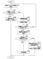
図3は、蓄電部4の充放電の状態遷移に関する一例を示す説明図である。蓄電部には、
過放電を防止するための所定値が定められており、当該所定値は、後述する第2シートE
CU2の第2記憶部22等の所定の記憶領域に記憶されている。過放電を防止するための
所定値は、例えば、蓄電部4のバッテリ特性等に基づき決定される放電終止電圧、又は当
該放電終止電圧に基づき決定される値として、放電終止電圧の略1.1倍とする値であっ
てもよい。図3に示すごとく、給電経路を介して給電される給電電力が、駆動対象の負荷
3の消費電力を合算した負荷電力よりも大きく、かつ蓄電部4が満充電でない場合、蓄電
部4は充電状態に切換えられる。給電電力が負荷電力よりも大きく、かつ満充電の場合、
蓄電部4は切離状態であってもよい。蓄電圧が所定値よりも小さく、かつ給電電力が負荷
電力以下の場合、蓄電部4は切離状態に切換えられる。蓄電圧が所定値以上であり、かつ
給電電力が負荷電力以下の場合、蓄電部4は放電状態に切換えられる。なお、蓄電圧が所
定値以上であり、かつ給電電力と負荷電力とが等しい場合、蓄電部4は切離状態であって
もよい。蓄電部4の出力電圧となる蓄電圧は、蓄電部4の蓄電残量に関連するものであり
、このように蓄電部4の蓄電圧と、給電電力と負荷電力との大小関係に基づいて、蓄電部
4を適切に充放電することができる。
FIG. 3 is an explanatory diagram illustrating an example of a state transition of charging/discharging of the power storage unit 4. In the power storage unit,
A predetermined value for preventing over-discharge is set, and the predetermined value is the second sheet E described later.
It is stored in a predetermined storage area such as the second storage unit 22 of the CU 2. Predetermined value to prevent over-discharge, for example, discharge end stop voltage is determined based on the battery characteristics and the like of power storage unit 4, or a value determined based on the discharge end stop voltage, substantially the discharge end stop voltage The value may be 1.1 times. As shown in FIG. 3, when the power supplied through the power supply path is larger than the sum of the power consumption of the load 3 to be driven and the power storage unit 4 is not fully charged, the power storage unit 4 is charged. It is switched to the state. When the supplied power is larger than the load power and is fully charged,
Power storage unit 4 may be in a disconnected state. When the stored voltage is smaller than the predetermined value and the supplied power is less than or equal to the load power, power storage unit 4 is switched to the disconnected state. When the stored voltage is equal to or higher than the predetermined value and the supplied power is equal to or lower than the load power, power storage unit 4 is switched to the discharge state. When the stored voltage is equal to or higher than a predetermined value and the supplied power and the load power are equal, power storage unit 4 may be in the disconnected state. The stored voltage that is the output voltage of the power storage unit 4 is related to the remaining amount of power stored in the power storage unit 4, and thus, based on the magnitude relationship between the stored voltage of the power storage unit 4 and the supplied power and the load power, Power storage unit 4 can be appropriately charged and discharged.
第2制御インターフェイス25は、受電側検出部201、蓄電圧検出部42及び各種セ
ンサ(図示せず)とシリアルケーブル等によって接続されており、受電側検出部201、
蓄電圧検出部42等が出力した検出結果を取得し、第2制御部21に送信する。第2制御
インターフェイス25は、受電側スイッチ203と電気的に接続してあり、第2制御部2
1から送信された制御指示に基づいて、受電側スイッチ203のオン又はオフするための
信号を出力する。第2制御インターフェイス25は、蓄電部スイッチ41と電気的に接続
してあり、第2制御部21から送信された制御指示に基づいて、蓄電部スイッチ41の切
換えるための信号を出力する。第2制御インターフェイス25は、シートSに設けられた
負荷3と電気的に接続してあり、第2制御部21から送信された制御指示に基づいて、当
該負荷3の駆動を行うための信号を出力する。
The second control interface 25, receiving-side detecting section 2 01, power storage pressure detector 42 and various sensors (not shown) and are connected by a serial cable or the like, receiving-side detecting section 2 01,
The detection result output by the accumulated voltage detection unit 42 or the like is acquired and transmitted to the second control unit 21. The second control interface 25 is electrically connected to the power receiving side switch 203, and the second control unit 2
A signal for turning on or off the power receiving side switch 203 is output based on the control instruction transmitted from No. 1. The second control interface 25 is electrically connected to the power storage unit switch 41, and outputs a signal for switching the power storage unit switch 41 based on the control instruction transmitted from the second control unit 21. The second control interface 25 is electrically connected to the load 3 provided on the seat S, and outputs a signal for driving the load 3 based on the control instruction transmitted from the second control unit 21. Output.
複数の送電コイル102夫々は、DC/ACコンバータ5を介して車載バッテリ7に接
続されている。複数の受電コイル202夫々は、AC/DCコンバータ6を介して、並列
に接続された複数の負荷3に接続されている。給電経路は、いずれかの送電コイル102
と、いずれかの受電コイル202との組み合わせによって形成されるため、この組み合わ
せに応じて、複数の給電経路を形成することができる。従って、いずれかの送電コイル1
02又は受電コイル202が故障した場合であっても、他の送電コイル102又は受電コ
イル202を組み合わせて給電経路を形成することによって、当該給電経路を介して、車
載バッテリ7からの電力を、シートS内に設けられた負荷3に対し、非接触にて給電する
ことができる。
Each of the plurality of power transmission coils 102 is connected to the vehicle-mounted battery 7 via the DC/AC converter 5. Each of the plurality of power receiving coils 202 is connected to the plurality of loads 3 connected in parallel via the AC/DC converter 6. The power feeding path is one of the power transmitting coils 102.
Is formed by a combination with any of the power receiving coils 202, so that a plurality of power feeding paths can be formed in accordance with this combination. Therefore, one of the power transmission coils 1
Even 02 or the power reception coil 202 in the case of failure, by forming the power feeding route in combination with other transmitting coil 102 or receiving coil 202, via the feed route, the power from the vehicle battery 7 Power can be supplied to the load 3 provided in the seat S in a non-contact manner.
第1シートECU1又は第2シートECU2は、送電側検出部101又は受電側検出部
201もしくは両検出部からの検出結果に基づき、所定の給電効率を発揮する給電経路を
特定し、送電側スイッチ103及び受電側スイッチ203のオン、オフを制御し、当該給
電経路となるように切換える。従って、送電コイル102及び受電コイル202の給電性
能を担保することができる。また、所定の給電効率として、最も給電効率が高い給電経路
に切換えることによって、より効率的にシートSに設けられた負荷3に電力を供給するこ
とができる。
The first seat ECU 1 or the second seat ECU 2 identifies a power supply path that exhibits a predetermined power supply efficiency based on the detection results from the power transmission side detection unit 101, the power reception side detection unit 201, or both detection units, and transmits the power transmission side switch 103. Also, the power receiving side switch 203 is controlled to be turned on and off to switch to the power feeding path. Therefore, the power feeding performance of the power transmitting coil 102 and the power receiving coil 202 can be ensured. Further, as the predetermined power supply efficiency, by switching to the highest power supply efficiency is high feed route, it is possible to supply power to the load 3 provided more efficiently sheet S.
第1シートECU1又は第2シートECU2は、シートSの現在位置に基づいて、最も
近接する送電コイル102と受電コイル202の組合せを導出する。第1シートECU1
又は第2シートECU2は、導出した送電コイル102と受電コイル202の組合せによ
る給電経路に切換えることによって、効率的にシートSに設けられた負荷3に電力を供給
することができる。
The first seat ECU 1 or the second seat ECU 2 derives the closest combination of the power transmission coil 102 and the power receiving coil 202 based on the current position of the seat S. First seat ECU 1
Or the second sheet ECU2, by switching the power transmission coil 102 derived the combination according to the feeding route of the power receiving coil 202, it is possible to efficiently supply power to the load 3 provided on the sheet S.
Priority Applications (4)
| Application Number | Priority Date | Filing Date | Title |
|---|---|---|---|
| JP2018009176A JP7003684B2 (en) | 2018-01-23 | 2018-01-23 | Vehicle seat power supply |
| PCT/JP2019/000980 WO2019146455A1 (en) | 2018-01-23 | 2019-01-16 | Power supply device for vehicular seat |
| CN201980007562.XA CN111565972A (en) | 2018-01-23 | 2019-01-16 | Power supply device for vehicle seat |
| US16/964,322 US11345257B2 (en) | 2018-01-23 | 2019-01-16 | Power supply device for vehicle seat |
Applications Claiming Priority (1)
| Application Number | Priority Date | Filing Date | Title |
|---|---|---|---|
| JP2018009176A JP7003684B2 (en) | 2018-01-23 | 2018-01-23 | Vehicle seat power supply |
Publications (3)
| Publication Number | Publication Date |
|---|---|
| JP2019127114A JP2019127114A (en) | 2019-08-01 |
| JP2019127114A5 true JP2019127114A5 (en) | 2020-07-02 |
| JP7003684B2 JP7003684B2 (en) | 2022-01-20 |
Family
ID=67395469
Family Applications (1)
| Application Number | Title | Priority Date | Filing Date |
|---|---|---|---|
| JP2018009176A Active JP7003684B2 (en) | 2018-01-23 | 2018-01-23 | Vehicle seat power supply |
Country Status (4)
| Country | Link |
|---|---|
| US (1) | US11345257B2 (en) |
| JP (1) | JP7003684B2 (en) |
| CN (1) | CN111565972A (en) |
| WO (1) | WO2019146455A1 (en) |
Families Citing this family (6)
| Publication number | Priority date | Publication date | Assignee | Title |
|---|---|---|---|---|
| JP2021036751A (en) * | 2019-08-30 | 2021-03-04 | 株式会社オートネットワーク技術研究所 | Power supply system |
| JP6957577B2 (en) * | 2019-11-05 | 2021-11-02 | 日本たばこ産業株式会社 | Power supply unit for aerosol aspirator |
| EP4212068A1 (en) * | 2020-09-10 | 2023-07-19 | APB Corporation | Method for recycling lithium ion cells, recycling equipment, seat for conveyance vehicle, and method for manufacturing same |
| KR102462446B1 (en) * | 2021-04-08 | 2022-11-03 | 대원산업 주식회사 | Seat apparatus including built-in battery, seat system and its charging method |
| DE102022202434A1 (en) | 2022-03-10 | 2023-09-14 | Brose Fahrzeugteile SE & Co. Kommanditgesellschaft, Coburg | Adjustment system for a vehicle seat and method for adjusting a vehicle seat |
| CN115179825A (en) * | 2022-07-11 | 2022-10-14 | 欧颂德婴童用品(湖北)有限公司 | Child electric safety seat with safety power supply system |
Family Cites Families (21)
| Publication number | Priority date | Publication date | Assignee | Title |
|---|---|---|---|---|
| JPH0692166A (en) * | 1992-09-14 | 1994-04-05 | Delta Kogyo Co Ltd | Electric-driven seat device |
| JPH08251713A (en) * | 1995-03-15 | 1996-09-27 | Yamaha Motor Co Ltd | Current controller for electric vehicle |
| US6195603B1 (en) * | 1995-08-11 | 2001-02-27 | Lear Corporation | Multiple speed vehicle seat memory control apparatus |
| US5890779A (en) * | 1997-04-08 | 1999-04-06 | Trw Vehicle Safety Systems Inc. | Apparatus for providing electrical communication between parts of a vehicle |
| JP2006056440A (en) * | 2004-08-23 | 2006-03-02 | Nissan Motor Co Ltd | Occupant protection device |
| US7342370B2 (en) * | 2005-03-08 | 2008-03-11 | Dura Global Technologies, Inc. | Electronic control system with torque and/or speed boost for motor vehicle seats |
| JP4804185B2 (en) * | 2006-03-24 | 2011-11-02 | 株式会社オーテックジャパン | Switch for raising and lowering the vehicle seat speed |
| JP2008289273A (en) * | 2007-05-17 | 2008-11-27 | Toyota Motor Corp | Power supply system, and vehicle |
| US8639413B2 (en) * | 2009-09-09 | 2014-01-28 | Toyota Jidosha Kabushiki Kaisha | Vehicle power supply system and method for controlling the same |
| US20130002415A1 (en) * | 2011-06-28 | 2013-01-03 | Geotab Inc. | Vehicular telematics device with voltage sensor-predicated GPS reciever activation |
| JP6111536B2 (en) * | 2012-06-01 | 2017-04-12 | マツダ株式会社 | Vehicle power supply control method and apparatus |
| JP5998755B2 (en) * | 2012-08-30 | 2016-09-28 | マツダ株式会社 | Vehicle power supply control apparatus and method |
| JP5825269B2 (en) * | 2013-01-24 | 2015-12-02 | トヨタ自動車株式会社 | Vehicle power supply |
| JP2014172162A (en) * | 2013-03-13 | 2014-09-22 | Panasonic Corp | Electric tool |
| JP6310258B2 (en) | 2014-01-16 | 2018-04-11 | 矢崎総業株式会社 | Slide sheet feeding mechanism |
| WO2015159388A1 (en) * | 2014-04-16 | 2015-10-22 | 三菱電機株式会社 | Control apparatus, control system, control method, and program |
| JP2015217919A (en) * | 2014-05-21 | 2015-12-07 | オムロンオートモーティブエレクトロニクス株式会社 | Vehicle power supply device and vehicle regenerative system |
| JP6353746B2 (en) * | 2014-08-26 | 2018-07-04 | 矢崎総業株式会社 | Vehicle power supply control system, wire harness, and vehicle power supply control device |
| US10536100B2 (en) * | 2016-04-01 | 2020-01-14 | Gentherm Incorporated | Systems and methods for calculating motor position, inertia and rest position in sensorless brushed DC motor control systems |
| EP3276768B1 (en) * | 2016-07-29 | 2019-04-24 | Ford Global Technologies, LLC | On-board electrical system for motor vehicles comprising a converter and a high-load consumer |
| KR102410936B1 (en) * | 2017-04-04 | 2022-06-20 | 현대자동차주식회사 | Apparatus and mathod for controlling motor of a vehicle |
-
2018
- 2018-01-23 JP JP2018009176A patent/JP7003684B2/en active Active
-
2019
- 2019-01-16 CN CN201980007562.XA patent/CN111565972A/en active Pending
- 2019-01-16 US US16/964,322 patent/US11345257B2/en active Active
- 2019-01-16 WO PCT/JP2019/000980 patent/WO2019146455A1/en active Application Filing
Similar Documents
| Publication | Publication Date | Title |
|---|---|---|
| JP2019127114A5 (en) | ||
| JP5612232B2 (en) | Power supply | |
| US9174547B2 (en) | Electric vehicle and charging control method for auxiliary battery thereof | |
| EP2879900B1 (en) | Electrical storage system | |
| US8754654B2 (en) | Power supply device for detecting disconnection of voltage detection lines | |
| JP4590379B2 (en) | System for charging / discharging multiple series storage cells | |
| WO2012127764A1 (en) | Battery system, equalizing device, equalizing system, electric vehicle, moving body, power storage device, and power supply device | |
| CN107662563B (en) | On-board electrical system of a motor vehicle comprising a converter and a high-load consumer | |
| US20130106320A1 (en) | Car power source apparatus and vehicle equipped with the power source apparatus | |
| US10407005B2 (en) | Vehicle power supply control device | |
| JP5414818B2 (en) | Electric vehicle power converter | |
| US20100308659A1 (en) | Power supply device | |
| JP5839047B2 (en) | Surveillance system and vehicle | |
| KR20140097435A (en) | Vehicle electrical system and method for operating a vehicle electrical system | |
| JP5827019B2 (en) | Balance correction device and power storage system | |
| JP2017121864A5 (en) | ||
| JP2012080762A5 (en) | ||
| JP2017195651A (en) | Relay device and on-vehicle system | |
| EP2890586B1 (en) | Electrical storage system | |
| EP2635799B1 (en) | Activation device and activation method for a dual-battery system | |
| JP2010263733A (en) | Equalizer | |
| TW202203543A (en) | Bidirectional battery charging system including capacitor divider circuit | |
| JP4798759B2 (en) | Capacitor bank balance circuit and power supply device | |
| WO2021132421A1 (en) | Electrical power device and control method for same | |
| JP2007020283A (en) | Power control system for vehicle |