JP2019120572A - Automatic analyzer and re-inspection instruction system - Google Patents
Automatic analyzer and re-inspection instruction system Download PDFInfo
- Publication number
- JP2019120572A JP2019120572A JP2018000091A JP2018000091A JP2019120572A JP 2019120572 A JP2019120572 A JP 2019120572A JP 2018000091 A JP2018000091 A JP 2018000091A JP 2018000091 A JP2018000091 A JP 2018000091A JP 2019120572 A JP2019120572 A JP 2019120572A
- Authority
- JP
- Japan
- Prior art keywords
- sample
- container
- unit
- reagent
- host device
- Prior art date
- Legal status (The legal status is an assumption and is not a legal conclusion. Google has not performed a legal analysis and makes no representation as to the accuracy of the status listed.)
- Pending
Links
Images


Classifications
-
- G—PHYSICS
- G01—MEASURING; TESTING
- G01N—INVESTIGATING OR ANALYSING MATERIALS BY DETERMINING THEIR CHEMICAL OR PHYSICAL PROPERTIES
- G01N35/00—Automatic analysis not limited to methods or materials provided for in any single one of groups G01N1/00 - G01N33/00; Handling materials therefor
- G01N35/00584—Control arrangements for automatic analysers
- G01N35/00594—Quality control, including calibration or testing of components of the analyser
- G01N35/00603—Reinspection of samples
-
- G—PHYSICS
- G01—MEASURING; TESTING
- G01N—INVESTIGATING OR ANALYSING MATERIALS BY DETERMINING THEIR CHEMICAL OR PHYSICAL PROPERTIES
- G01N35/00—Automatic analysis not limited to methods or materials provided for in any single one of groups G01N1/00 - G01N33/00; Handling materials therefor
- G01N35/00584—Control arrangements for automatic analysers
- G01N35/00722—Communications; Identification
- G01N35/00732—Identification of carriers, materials or components in automatic analysers
-
- G—PHYSICS
- G01—MEASURING; TESTING
- G01N—INVESTIGATING OR ANALYSING MATERIALS BY DETERMINING THEIR CHEMICAL OR PHYSICAL PROPERTIES
- G01N35/00—Automatic analysis not limited to methods or materials provided for in any single one of groups G01N1/00 - G01N33/00; Handling materials therefor
- G01N35/00584—Control arrangements for automatic analysers
- G01N35/00722—Communications; Identification
- G01N35/00871—Communications between instruments or with remote terminals
-
- G—PHYSICS
- G01—MEASURING; TESTING
- G01N—INVESTIGATING OR ANALYSING MATERIALS BY DETERMINING THEIR CHEMICAL OR PHYSICAL PROPERTIES
- G01N35/00—Automatic analysis not limited to methods or materials provided for in any single one of groups G01N1/00 - G01N33/00; Handling materials therefor
- G01N35/02—Automatic analysis not limited to methods or materials provided for in any single one of groups G01N1/00 - G01N33/00; Handling materials therefor using a plurality of sample containers moved by a conveyor system past one or more treatment or analysis stations
- G01N35/025—Automatic analysis not limited to methods or materials provided for in any single one of groups G01N1/00 - G01N33/00; Handling materials therefor using a plurality of sample containers moved by a conveyor system past one or more treatment or analysis stations having a carousel or turntable for reaction cells or cuvettes
-
- G—PHYSICS
- G01—MEASURING; TESTING
- G01N—INVESTIGATING OR ANALYSING MATERIALS BY DETERMINING THEIR CHEMICAL OR PHYSICAL PROPERTIES
- G01N35/00—Automatic analysis not limited to methods or materials provided for in any single one of groups G01N1/00 - G01N33/00; Handling materials therefor
- G01N35/10—Devices for transferring samples or any liquids to, in, or from, the analysis apparatus, e.g. suction devices, injection devices
- G01N35/1002—Reagent dispensers
-
- G—PHYSICS
- G01—MEASURING; TESTING
- G01N—INVESTIGATING OR ANALYSING MATERIALS BY DETERMINING THEIR CHEMICAL OR PHYSICAL PROPERTIES
- G01N35/00—Automatic analysis not limited to methods or materials provided for in any single one of groups G01N1/00 - G01N33/00; Handling materials therefor
- G01N35/00584—Control arrangements for automatic analysers
- G01N35/00722—Communications; Identification
- G01N2035/00891—Displaying information to the operator
-
- G—PHYSICS
- G01—MEASURING; TESTING
- G01N—INVESTIGATING OR ANALYSING MATERIALS BY DETERMINING THEIR CHEMICAL OR PHYSICAL PROPERTIES
- G01N35/00—Automatic analysis not limited to methods or materials provided for in any single one of groups G01N1/00 - G01N33/00; Handling materials therefor
- G01N35/02—Automatic analysis not limited to methods or materials provided for in any single one of groups G01N1/00 - G01N33/00; Handling materials therefor using a plurality of sample containers moved by a conveyor system past one or more treatment or analysis stations
- G01N35/04—Details of the conveyor system
- G01N2035/0439—Rotary sample carriers, i.e. carousels
Abstract
Description
本発明は、検体と試薬とを反応させて検体の成分を分析するための自動分析装置及び再検指示システムに関する。 The present invention relates to an automatic analyzer and a retest instruction system for analyzing a component of a sample by reacting the sample with a reagent.
自動分析装置として、血液や尿等の元検体(以下、「検体」と略記する)に含まれる各種成分を分析する生化学分析装置が知られている。この生化学分析装置では、血清、尿等の検体を一定の条件で希釈した後、反応容器に分注して、分析項目に応じた試薬と、検体とを反応容器内で混合して反応させている。そして、生化学分析装置は、反応容器に分注された希釈検体の吸光度を測定し、吸光度を濃度に換算することによって、検体に含まれる測定対象物質の分析を行っている。 As an automatic analyzer, there is known a biochemical analyzer which analyzes various components contained in an original sample (hereinafter abbreviated as "sample") such as blood and urine. In this biochemical analyzer, after diluting a sample such as serum or urine under certain conditions, it is dispensed into a reaction container, and a reagent according to the analysis item and the sample are mixed and reacted in the reaction container. ing. Then, the biochemical analyzer measures the absorbance of the diluted sample dispensed into the reaction container, and converts the absorbance into a concentration to analyze the measurement target substance contained in the sample.
従来、ほとんどの施設において、生化学分析装置等の自動分析装置がホスト装置と接続されている。そして、自動分析装置を使用する検査技師は、以下の図1に示す流れにより、ホスト装置上で分析結果の確認と再検が必要であるかの判断を行っている。 Conventionally, in most facilities, an automatic analyzer such as a biochemical analyzer is connected to a host device. Then, the inspection engineer who uses the automatic analysis device determines whether it is necessary to confirm the analysis result and to re-examine the analysis result on the host device according to the flow shown in FIG. 1 below.
<従来の自動分析装置とホスト装置との処理の流れ>
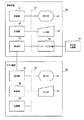
図1は、従来の自動分析装置とホスト装置との処理の流れの例を示すシーケンス図である。
始めに、自動分析装置は、ホスト装置に検査の依頼要求を送信する(S1)。次に、ホスト装置は、自動分析装置に対して検査の依頼情報を送信する(S2)。そして、自動分析装置は、ホスト装置から依頼情報を受信した検体の分析を開始する。
<Flow of processing between conventional automatic analyzer and host device>
FIG. 1 is a sequence diagram showing an example of the process flow of the conventional automatic analyzer and host device.
First, the automatic analyzer transmits a request for examination request to the host device (S1). Next, the host device transmits examination request information to the automatic analyzer (S2). Then, the automatic analyzer starts analysis of the sample that has received the request information from the host device.
自動分析装置は、検体の第1回目の分析(初検)を行うと、ホスト装置に初検の分析結果を送信する(S3)。そして、検査技師は、ホスト装置に表示された分析結果を確認し、再検が必要であるか否かを判断する。次に、検査技師は、ターンテーブル又はラックから再検が必要であると判断した検体を探し、検体の状態を確認する。次に、検査技師は、ホスト装置を操作して、再検する検体に対する測定項目の依頼を入力する。次に、検査技師は、自動分析装置に再検開始の指示を入力する。再検開始の指示が入力されると、自動分析装置が再検を開始する。そして、自動分析装置は、再検問い合わせをホスト装置に送信する(S4)。 When the first analysis (first examination) of the sample is performed, the automatic analyzer transmits the analysis result of the first examination to the host device (S3). Then, the inspection technician confirms the analysis result displayed on the host device, and determines whether re-examination is necessary. Next, the laboratory technician searches the sample on the turntable or rack for which it is determined that reexamination is necessary, and confirms the condition of the sample. Next, the laboratory technician operates the host device to input a request for measurement items for the sample to be retested. Next, the inspection technician inputs an instruction to start re-examination on the automatic analyzer. When an instruction to start retesting is input, the automatic analyzer starts retesting. Then, the automatic analysis device transmits a retest inquiry to the host device (S4).
ホスト装置は、自動分析装置に対して、再検指示(どの検体に対して、何の測定項目の分析を行うかを示す情報)を送信する(S5)。 The host device transmits a retest instruction (information indicating which measurement item is to be analyzed to which sample) to the automatic analysis device (S5).
そして、自動分析装置は、ホスト装置から送信された再検指示を受信すると、検査技師により状態が確認された検体の再検を開始する。 Then, when receiving the re-examination instruction transmitted from the host device, the automatic analyzer starts re-examination of the sample whose status has been confirmed by the examination technician.
再検が指示される検体を探す技術が、例えば、特許文献1及び2に開示されている。
特許文献1には、ある検体について再検が必要と決定された場合には、この検体IDと、再検が必要であることを示す情報とが含まれる再検要否決定結果通知データが検査情報管理装置によって送信されることが記載されている。
Techniques for searching for a sample for which re-examination is instructed are disclosed, for example, in
In
特許文献2には、再検推奨されている検体を強調表示することが記載されている。また、医師のコンピュータ端末に再検推奨情報が送られ、医師が再検要否を決定することが記載されている。
検体の再検が必要であれば、検査技師は、ホスト装置に表示される、再検が必要とされる検体を探すために必要な患者氏名やホスト受付番号等の検体識別情報をメモ書きする。その後、検査技師は、自動分析装置のコメント検索機能を用いて、メモ書きした検体識別情報を入力して、検体を探していた。また、検査技師は、検体が収容される容器に貼られたバーコードラベルに表示される検体名等の情報を1本ずつ確認して検体を探すこともあった。このため、再検指示された検体を探し出すまでに手間と時間が掛かっていた。 If it is necessary to re-examine the sample, the examination technician writes down the sample identification information such as the patient name and host reception number necessary for searching for the sample requiring re-examination, which is displayed on the host device. After that, the laboratory technician used the comment search function of the automatic analyzer to input the written sample identification information to search for a sample. In addition, there have also been cases where a laboratory technician searches for a sample by confirming information such as the sample name displayed on a barcode label attached to a container in which the sample is stored. For this reason, it took time and effort to find out the sample for which the re-inspection instruction was given.
また、特許文献1に開示されたように、再検要否決定結果通知データに基づいて再検が必要となる検体を探したり、特許文献2に開示されたように、再検要となる検体を探したりする手間が掛かっていた。このため、再検指示された検体を手間をかけずに探し出すことが求められていた。
Also, as disclosed in
本発明はこのような状況に鑑みて成されたものであり、再検指示された検体を探す手間を軽減することを目的とする。 The present invention has been made in view of such circumstances, and it is an object of the present invention to reduce the time and effort required to search for a retested sample.
本発明に係る自動分析装置は、表示部と、ホスト装置と通信可能な通信部と、測定対象の検体を収容する検体容器を保持する検体容器保持部と、試薬を収容する試薬容器を保持する試薬容器保持部と、検体及び試薬が攪拌される反応容器を保持する反応容器保持部と、検体容器から検体を吸引し、反応容器に検体を分注する検体分注部と、試薬容器から試薬を吸引し、反応容器に試薬を分注する試薬分注部と、反応容器に分注された検体と試薬とを反応させた反応物を所定の測定サイクルで測定する測定部と、測定部により測定された反応物の測定値を分析した分析結果を通信部を通じてホスト装置に出力し、ホスト装置から通信部を通じて再検指示された検体を識別するための検体識別情報、及びホスト装置から再検指示された検体が収容される検体容器の検体容器保持部における位置を表す検体容器位置情報とを表示部に表示させる制御部と、を備える。 The automatic analyzer according to the present invention holds a display unit, a communication unit capable of communicating with a host device, a sample container holding unit holding a sample container containing a sample to be measured, and a reagent container containing a reagent. A reagent container holding unit, a reaction container holding unit holding a reaction container in which a sample and a reagent are stirred, a sample dispensing unit suctioning a sample from the sample container and dispensing the sample into the reaction container, and a reagent from the reagent container A reagent dispensing unit for aspirating a reagent and dispensing the reagent into the reaction container, a measuring unit for measuring a reaction product obtained by reacting the sample and the reagent dispensed into the reaction container in a predetermined measurement cycle, and a measuring unit The analysis result obtained by analyzing the measured value of the reaction product is output to the host device through the communication unit, and the sample identification information for identifying the sample for which the host device instructs retesting through the communication unit, and the retest instruction from the host device Sample is stored And a control unit for displaying on the display unit and the specimen container position information indicating the position in the specimen container holder of the specimen container, the.
本発明によれば、例えば、検査技師は、表示部に表示された検体識別情報及び検体容器位置情報に基づいて、再検指示された検体が収容される検体容器を容易に探し出すことが可能となる。
上記した以外の課題、構成及び効果は、以下の実施の形態の説明により明らかにされる。
According to the present invention, for example, based on the sample identification information and the sample container position information displayed on the display unit, the inspection technician can easily find out the sample container in which the sample instructed to be retested is stored. .
Problems, configurations, and effects other than those described above will be apparent from the description of the embodiments below.
以下、本発明を実施するための形態例について、添付図面を参照して説明する。本明細書及び図面において、実質的に同一の機能又は構成を有する構成要素については、同一の符号を付することにより重複する説明を省略する。 Hereinafter, embodiments of the present invention will be described with reference to the attached drawings. In the specification and the drawings, components having substantially the same function or configuration will be assigned the same reference numerals and overlapping descriptions will be omitted.
[1.第1の実施の形態]
<1−1.自動分析システムの構成>
次に、本実施の形態に係る自動分析システムについて図2を参照して説明する。
図2は、本実施の形態に係る自動分析システム100の全体構成例を示すブロック図である。
[1. First embodiment]
<1-1. Configuration of automatic analysis system>
Next, the automatic analysis system according to the present embodiment will be described with reference to FIG.
FIG. 2 is a block diagram showing an example of the overall configuration of the
自動分析システム100は、生化学分析装置1、ホスト装置50及びラック装置60を備える。自動分析システム100は、ホスト装置50から生化学分析装置1に対して検体の再検を依頼可能な再検指示システムの一例として用いられる。
The
本発明の自動分析装置の一例として適用される生化学分析装置1は、血液や尿等の生体から採取した検体に含まれる特定の成分の量を自動的に測定する装置である。ホスト装置50から依頼を受けた生化学分析装置1は、検査技師により生化学分析装置1に対して分析開始の指示が入力されることで、検体の測定及び分析を開始する。このとき、生化学分析装置1は、測定項目を分析するために、検体と試薬を撹拌して使用する。また、生化学分析装置1は、ホスト装置50により再検指示された検体の再検を行う。また、生化学分析装置1は、キャリブレーションの実施、コントロール検体の測定、緊急に測定が必要とされる緊急検体の初検及び再検を行うことも可能である。
The
ホスト装置50は、生化学分析装置1と各種のデータを送受信可能に接続されている。そして、ホスト装置50は、生化学分析装置1から検体の分析結果を収集すると共に、初検と再検の分析依頼を生化学分析装置1に送信することが可能である。
The
ラック装置60(検体容器保持部の一例)は、検体が収容された多数のサンプル容器21(検体容器の一例)を保持する。ラック装置60は、生化学分析装置1にて分析されるサンプル容器21を所定のタイミングで生化学分析装置1に投入し、生化学分析装置1にてサンプル容器21に収容される検体の分析が行われた後、生化学分析装置1からサンプル容器21を回収する。生化学分析装置1及びラック装置60の動作は、制御装置40の制御部41(後述する図4を参照)により制御されている。生化学分析装置1は、ラック装置60からサンプル容器21を受け取って、このサンプル容器21に収容される検体を分析してもよいし、ラック装置60に保持された状態のサンプル容器21から吸引した検体を分析してもよい。
The rack apparatus 60 (an example of a sample container holding unit) holds a large number of sample containers 21 (an example of a sample container) in which a sample is stored. The
生化学分析装置1の表示部44(後述する図4を参照)の進捗モニターW1(後述する図6を参照)には、ホスト装置50から再検指示された検体を一意に表す情報(「再検検体情報」と呼ぶ)が表示される。ここで、表示部44には、再検指示、再検不指示に関わらず、生化学分析装置1により分析された全ての検体の情報が表示される。ただし、ホスト装置50から再検依頼された検体については、表示部44には、再検依頼されたことが分かるように表示される。なお、表示部44には、再検依頼された検体の情報だけが表示されてもよい。そして、進捗モニターW1には、再検指示された検体が収容されたサンプル容器21が、ラック装置60のどの位置にあるかが示される。このため、検査技師は、表示部44に表示された再検検体情報に基づいて再検指示された検体が収容されたサンプル容器21を容易に探し出し、生化学分析装置1にて再検することができる。
The progress monitor W1 (see FIG. 6 described later) of the display unit 44 (see FIG. 4 described later) of the
<1−2.生化学分析装置の構成>
図3は、生化学分析装置1を模式的に示す説明図である。
<1-2. Configuration of Biochemical Analyzer>
FIG. 3 is an explanatory view schematically showing the
生化学分析装置1は、サンプルターンテーブル2、希釈ターンテーブル3、第1試薬ターンテーブル4、第2試薬ターンテーブル5、及び反応ターンテーブル6を備える。また、生化学分析装置1は、元検体サンプリングプローブ7、希釈検体サンプリングプローブ8、希釈撹拌機構9、サンプルバーコードリーダー10、希釈容器洗浄機構11、第1試薬分注プローブ12、第2試薬分注プローブ13、第1反応液撹拌機構14、第2反応液撹拌機構15、多波長光度計16、恒温槽17、反応容器洗浄機構18、及び制御装置40を備える。さらに、生化学分析装置1は、元検体サンプリングプローブ洗浄機構31、希釈検体サンプリングプローブ洗浄機構32、第1試薬プローブ洗浄機構33、及び第2試薬分注プローブ洗浄機構34を備える。
The
サンプルターンテーブル2、希釈ターンテーブル3、第1試薬ターンテーブル4、第2試薬ターンテーブル5、反応ターンテーブル6は、不図示の駆動機構によって周方向に沿って回転可能に支持され、周方向に所定の角度範囲毎に、所定の速度で回転する。
The
サンプルターンテーブル2(検体容器保持部の一例)には、測定対象の検体が収容された複数のサンプル容器21(検体容器の一例)がサンプルターンテーブル2の周方向に並べて保持されている。このサンプルターンテーブル2には、サンプルターンテーブル2の円周上に配列された複数のサンプル容器21が収容されている。サンプル容器21には、検体、及び通常の希釈液である生理食塩水が収容されている。
On the sample turntable 2 (an example of the sample container holding unit), a plurality of sample containers 21 (an example of the sample container) in which the sample to be measured is accommodated are arranged side by side in the circumferential direction of the
希釈ターンテーブル3(希釈容器保持部の一例)には、複数の希釈容器23が希釈ターンテーブル3の周方向に並べて保持されている。希釈容器23には、サンプルターンテーブル2に配置されたサンプル容器21から吸引され、希釈液により希釈された検体(希釈検体)が収容される。
A plurality of
第1試薬ターンテーブル4(第1試薬容器保持部の一例)には、複数の第1試薬容器24が第1試薬ターンテーブル4の周方向に並べて保持されている。また、第2試薬ターンテーブル5(第2試薬容器保持部の一例)には、複数の第2試薬容器25が第2試薬ターンテーブル5の周方向に並べて保持されている。第1試薬容器24には、第1試薬が収容され、第2試薬容器25には、第2試薬が収容される。第1試薬容器24に収容された第1試薬と、第2試薬容器25に収容された第2試薬は、不図示の保冷機構によって所定の温度で保冷される。
A plurality of
反応ターンテーブル6(反応容器保持部の一例)は、希釈ターンテーブル3と、第1試薬ターンテーブル4及び第2試薬ターンテーブル5の間に配置される。反応ターンテーブル6には、複数の反応容器26が反応ターンテーブル6の周方向に並べて保持されている。そして、反応ターンテーブル6は、保持する反応容器26を間欠的に移動させる。反応容器26には、希釈ターンテーブル3の希釈容器23からサンプリングされた希釈検体と、第1試薬ターンテーブル4の第1試薬容器24からサンプリングされた第1試薬と、第2試薬ターンテーブル5の第2試薬容器25からサンプリングされた第2試薬とが注入される。そして、この反応容器26内において、希釈検体と、第1試薬及び第2試薬が撹拌され、反応が行われる。
The reaction turntable 6 (an example of a reaction container holder) is disposed between the dilution turntable 3 and the
元検体サンプリングプローブ7(検体分注部の一例)は、サンプルターンテーブル2と希釈ターンテーブル3の周囲に配置され、不図示の元検体サンプリングプローブ駆動機構により、サンプルターンテーブル2及び希釈ターンテーブル3の軸方向(例えば、上下方向)に移動可能に支持されている。元検体サンプリングプローブ7は、サンプル容器21から所定量の検体を吸引し、吸引した検体と、元検体サンプリングプローブ7自体から供給される所定量の希釈液(例えば、生理食塩水)とを、希釈容器23内に吐出する。これにより、希釈容器23内で、検体が所定倍数の濃度に希釈され、希釈検体が作成される。このように元検体サンプリングプローブ7は、検体を希釈することを主目的として希釈容器23に検体を分注する。元検体サンプリングプローブ7は、サンプルターンテーブル2と希釈ターンテーブル3の間に設けられた元検体サンプリングプローブ洗浄機構31(第1洗浄部の一例)により洗浄される。
The original sample sampling probe 7 (an example of the sample dispensing unit) is disposed around the
希釈検体サンプリングプローブ8(希釈検体分注部の一例)は、希釈ターンテーブル3と反応ターンテーブル6の間に配置され、不図示の希釈検体サンプリングプローブ駆動機構により、希釈ターンテーブル3の軸方向(上下方向)と水平方向に移動及び回動可能に支持されている。希釈検体サンプリングプローブ8は、希釈ターンテーブル3の希釈容器23から所定量の希釈検体を吸引し、吸引した希釈検体を反応ターンテーブル6の反応容器26内に吐出する。希釈検体サンプリングプローブ8は、希釈ターンテーブル3と反応ターンテーブル6の間に設けられた希釈検体サンプリングプローブ洗浄機構32(第2洗浄部の一例)によって洗浄される。
The diluted sample sampling probe 8 (an example of the diluted sample dispensing unit) is disposed between the dilution turntable 3 and the reaction turntable 6, and is driven in the axial direction of the dilution turntable 3 by the diluted sample sampling probe drive mechanism (not shown). It is supported so as to be movable and rotatable in the vertical direction and in the horizontal direction. The diluted sample sampling probe 8 aspirates a predetermined amount of diluted sample from the
希釈撹拌機構9及び希釈容器洗浄機構11は、希釈ターンテーブル3の周囲に配置されている。希釈撹拌機構9は、不図示の撹拌棒を希釈容器23内に挿入し、検体と希釈液を撹拌する。希釈容器洗浄機構11は、洗剤ポンプから希釈容器洗浄ノズルに洗剤を供給し、希釈容器洗浄ノズルから希釈容器23内に洗剤を吐出する。
The dilution /
サンプルバーコードリーダー10は、サンプルターンテーブル2の側面に設けられている。サンプルバーコードリーダー10は、サンプルターンテーブル2に収容されたサンプル容器21の側面に付されたバーコードを読み取り、サンプル容器21に収容された検体、希釈液等を管理している。
The
第1試薬分注プローブ12(第1試薬分注部の一例)は、反応ターンテーブル6と第1試薬ターンテーブル4の間に配置され、不図示の第1試薬分注プローブ駆動機構により、反応ターンテーブル6の軸方向(上下方向)と水平方向に移動及び回動可能に支持されている。第1試薬分注プローブ12は、第1試薬ターンテーブル4の第1試薬容器24から所定量の第1試薬を吸引し、吸引した第1試薬を反応ターンテーブル6の反応容器26内に吐出する。第1試薬分注プローブ12は、反応ターンテーブル6と第1試薬ターンテーブル4の間に設けられた第1試薬プローブ洗浄機構33(第3洗浄部の一例)によって洗浄される。
The first reagent dispensing probe 12 (an example of the first reagent dispensing part) is disposed between the reaction turntable 6 and the
第2試薬分注プローブ13(第2試薬分注部の一例)は、反応ターンテーブル6と第2試薬ターンテーブル5の間に配置され、不図示の第2試薬分注プローブ駆動機構により、反応ターンテーブル6の軸方向(上下方向)と水平方向に移動及び回動可能に支持されている。第2試薬分注プローブ13は、第2試薬ターンテーブル5の第2試薬容器25から所定量の第2試薬を吸引し、吸引した第2試薬を反応ターンテーブル6の反応容器26内に吐出する。第2試薬分注プローブ13は、反応ターンテーブル6と第2試薬ターンテーブル5の間に設けられた第2試薬分注プローブ洗浄機構34(第4洗浄部の一例)によって洗浄される。
The second reagent dispensing probe 13 (an example of the second reagent dispensing part) is disposed between the reaction turntable 6 and the
第1反応液撹拌機構14、第2反応液撹拌機構15及び反応容器洗浄機構18は、反応ターンテーブル6の周囲に配置されている。第1反応液撹拌機構14(第1撹拌部の一例)は、不図示の撹拌棒を反応容器26内に挿入し、検体と第1試薬を撹拌する。第2反応液撹拌機構15(第2撹拌部の一例)は、不図示の撹拌棒を反応容器26内に挿入し、検体と、第1試薬と、第2試薬との混合液を撹拌する。反応容器洗浄機構18は、検査が終了した反応容器26内を洗浄する。
The first reaction
多波長光度計16は、反応ターンテーブル6の周囲における反応ターンテーブル6の外壁と対向するように配置され、反応容器に光線を照射する光源ランプとして用いられる。多波長光度計16は、反応容器26内に分注された検体と、第1試薬及び第2試薬とを反応させた反応物を所定の測定サイクルで測定する測定部の一例である。この測定は、光学的測定(比色測定)により行われる。そして、多波長光度計16は、検体中の様々な成分の量を「吸光度」という数値データとして出力し、検体の反応状態を検出する。多波長光度計16には、生化学分析装置1の各部の動作を制御するための制御装置40が接続されている。
The
反応ターンテーブル6の周囲には、恒温槽17が配置されている。この恒温槽17は、反応ターンテーブル6に設けられた反応容器26の温度を常時一定に保持するように構成されている。
A
<1−3.制御装置の構成例>
次に、制御装置40とホスト装置50の内部構成例を説明する。
図4は、制御装置40とホスト装置50の内部構成例を示すブロック図である。
制御装置40は、バス47に接続された、制御部41、記憶部42、通信部43、表示部44、入力部45、及びインターフェイス部46を備える。
<1-3. Configuration Example of Control Device>
Next, an example of the internal configuration of the
FIG. 4 is a block diagram showing an example of the internal configuration of the
The
制御部41(第1制御部の一例)は、CPU(Central Processing Unit)等によって構成されており、記憶部42から読出したプログラムに基づいて生化学分析装置1内の各部の動作を制御する。制御部41は、多波長光度計16により測定された反応物の測定値を分析し、分析結果を通信部43を通じてホスト装置50に出力する。そして、制御部41は、ホスト装置50から通信部43を通じて再検指示された検体を識別するための検体ID、及びホスト装置50から再検指示された検体が収容されるサンプル容器21のサンプルターンテーブル2における位置を表す検体容器位置情報とを表示部44に表示させる。
The control unit 41 (an example of a first control unit) is configured by a CPU (Central Processing Unit) or the like, and controls the operation of each unit in the
記憶部42は、例えば、HDD(Hard disk drive)等の大容量の記憶装置によって構成されており、制御部41のプログラム、パラメータ、検量線、入力部45によってなされた入力操作等を記憶する。
The
通信部43(第1通信部の一例)は、ホスト装置50が備える通信部51と各種のデータを送受信可能である。例えば、通信部43は、ホスト装置50に対して検体の分析結果を送信したり、ホスト装置50から測定項目情報や再検指示を受信したりする。
The communication unit 43 (an example of a first communication unit) can transmit and receive various data to and from the
表示部44(第1表示部の一例)は、検体、第1試薬及び第2試薬の混合液の分析結果等を表示する。この表示部44には、例えば、液晶ディスプレイ装置等が用いられる。表示部44に表示される各種の画面の構成例については後述する。
入力部45は、検査技師によって行われる生化学分析装置1に対する操作入力を受け付け、入力信号を制御部41に出力する。この入力部45には、例えば、マウス、キーボード、タッチパネル等が用いられる。
The display unit 44 (an example of the first display unit) displays an analysis result of the mixed solution of the sample, the first reagent, and the second reagent, and the like. For example, a liquid crystal display device or the like is used for the
The
インターフェイス部46は、多波長光度計16が測定した混合液の測定値が入力されると、制御部41に測定値を渡す。なお、図4では、インターフェイス部46に多波長光度計16だけを接続した例を示しているが、生化学分析装置1内の各部についても同様にインターフェイス部46に接続され、制御装置40による制御が行われる。
When the measurement value of the mixed solution measured by the
ホスト装置50は、バス56に接続された、通信部51、制御部52、記憶部53、表示部54、及び入力部55を備える。
The
通信部51(第2通信部の一例)は、生化学分析装置1の制御装置40が備える通信部43と各種のデータを送受信可能である。例えば、通信部51は、制御装置40から検体の分析結果を受信したり、制御装置40に対して測定項目情報や再検指示を送信したりする。
The communication unit 51 (an example of a second communication unit) can transmit and receive various data to and from the
制御部52(第2制御部の一例)は、CPU等によって構成されており、記憶部53から読出したプログラムに基づいて、検査技師により入力部55から入力された検体の再検指示を通信部51を通じて生化学分析装置1に送信させる。
The control unit 52 (an example of a second control unit) is constituted by a CPU or the like, and based on the program read from the
記憶部53は、例えば、HDD等の大容量の記録装置によって構成されており、制御部52の実行可能なプログラム、入力部55によってなされた入力操作等を記録する。
The
表示部54(第2表示部の一例)は、通信部51が生化学分析装置1から受信する分析結果を表示する。この表示部54には、例えば、液晶ディスプレイ装置等が用いられる。
入力部55は、検査技師によって行われるホスト装置50に対する操作入力を受け付け、入力信号を制御部52に出力する。そして、検査技師が入力部55を操作することにより、再検する検体に対する測定項目の依頼が入力される。この入力部55には、例えば、マウス、キーボード、タッチパネル等が用いられる。
The display unit 54 (an example of a second display unit) displays the analysis result that the
The
<1−4.本実施の形態に係る生化学分析装置とホスト装置との処理の流れ>
図5は、本実施の形態に係る生化学分析装置1とホスト装置50との処理の流れの例を示すシーケンス図である。
図5におけるステップS11〜S13までの処理は、上述した図1に示すステップS1〜S3までの処理と同様であるため、詳細な説明を省略する。
<1-4. Flow of Processing Between Biochemical Analyzer and Host Device According to Present Embodiment>
FIG. 5 is a sequence diagram showing an example of the process flow of the
Since the process to step S11-S13 in FIG. 5 is the same as the process to step S1-S3 shown in FIG. 1 mentioned above, detailed description is abbreviate | omitted.
ステップS13にて、生化学分析装置1からホスト装置50に初検の分析結果が送られた後、検査技師は、ホスト装置50に表示された分析結果を確認し、再検が必要であるか否かを判断する。
After the analysis result of the first examination is sent from the
次に、ホスト装置50から生化学分析装置1に対して再検検体情報が送信され(S14)、生化学分析装置1の表示部44に再検検体情報が表示される。このとき、再検検体情報により、検体が収容されたサンプル容器21が、サンプルターンテーブル2又はラック装置60のどの位置にあるかが示される。このため、検査技師は、ホスト装置50により再検が必要であると判断された検体をターンテーブル又はラックから容易に探し出し、検体の状態を確認することができる。
Next, re-examination sample information is transmitted from the
次に、検査技師は、ホスト装置50を操作して、再検する検体に対する測定項目の依頼を入力する。次に、検査技師は、生化学分析装置1に再検開始の指示を入力し、生化学分析装置1が再検を開始する。そして、生化学分析装置1は、再検問い合わせをホスト装置50に送信する(S15)。
Next, the laboratory technician operates the
再検問い合わせを受信したホスト装置50は、生化学分析装置1に再検指示(どの検体に対して、何の測定項目の分析を行うかを示す情報)を送信する(S16)。そして、生化学分析装置1は、ホスト装置50から受信した再検指示に基づいて再検を行う。
The
<1−5.進捗モニターの表示例>
図6は、進捗モニターW1の表示例を示す説明図である。進捗モニターW1は、制御部41の制御により生化学分析装置1の表示部44に表示される画面であるが、ホスト装置50の表示部54に表示されてもよい。この進捗モニターW1は、検体の分析状況及び検体容器位置情報を表示する進捗画面の一例である。
<1-5. Display example of progress monitor>
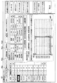
FIG. 6 is an explanatory view showing a display example of the progress monitor W1. The progress monitor W1 is a screen displayed on the
進捗モニターW1は、登録No.毎に、再検、検体ID、検体材料、コメント1、コメント2、ST Pos、RACK Posの各項目の情報が表示される。
登録No.項目には、サンプル容器21を一意に識別するために付与される容器識別情報の一例として登録No.が表示される。また、登録No.項目には、検査技師が測定中、測定完了等の状況を一目で分かるようにするためのアイコンが表示される。アイコンの凡例は進捗モニターW1の下部に表示される。
The progress monitor W1 has a registration No. Information on each item of retest, sample ID, sample material,
Registration No. The item has a registration No. as an example of container identification information given to uniquely identify the
再検項目には、ホスト装置50により再検指示されたか否かを示す情報が表示される。再検には、検体に対してホスト装置50から再検指示されたことを示す情報として「再」と表示される。なお、ホスト装置50から再検指示されたか否かに関わらず、生化学分析装置1が再検を必要であると判断した検体に対しても、再検項目に「再」と表示される。例えば、元検体サンプリングプローブ7に詰まりが生じた等の異常が生化学分析装置1に発生したことにより、正常に分析が行われなかった検体に対しては、生化学分析装置1が、この検体の再検が必要であると判断する。そして、この検体の再検項目に「再」と表示される。
検体ID項目には、検体を一意に識別するために付与される検体識別情報の一例として検体IDが表示される。
検体材料項目には、検体がどのような成分でできているかを表す情報(例えば、「血清」)が表示される。
コメント1項目、コメント2項目には、検査技師によって入力された任意のコメントが表示される。
In the retest item, information indicating whether a retest instruction has been issued by the
In the sample ID item, a sample ID is displayed as an example of sample identification information given to uniquely identify a sample.
In the sample material item, information (for example, "serum") indicating what kind of component the sample is made of is displayed.
In the
ST Pos(Sample Tray Position)項目には、サンプルターンテーブル2のどの位置に登録No.で識別されるサンプル容器21が収容されているかを示す情報が表示される。
RACK Pos(Rack Position)項目には、ラック装置60のどの位置に登録No.で識別されるサンプル容器21が収容されているかを示す情報が表示される。基本的に、再検指示される検体が収容されるサンプル容器21は、サンプルターンテーブル2又はラック装置60のいずれかに収容されている。そして、ST Pos、RACK Posは、いずれも再検指示されたサンプル容器21の位置を示す検体容器位置情報の一例として用いられる。
In the ST Pos (Sample Tray Position) item, at which position on the
In the RACK Pos (Rack Position) item, the registration No. at which position of the
進捗モニターW1にて斜線で強調表示されたレコードにおいて、例えば、登録No.16の再検項目に「再」と表示されることにより、登録No.16のサンプル容器21に収容される検体が再検指示されたことが示される。また、再検指示された検体が収容されるサンプル容器21は、ST Posに「02」で表される位置に格納されていることが分かる。このため、検査技師は、サンプルターンテーブル2のST Posに「02」で表される位置に格納されるサンプル容器21を抽出して、このサンプル容器21に収容された検体の再検を実施することが可能となる。
In the records highlighted with hatching on the progress monitor W1, for example, the registration No. When “re” is displayed in the 16 retest items, the registration No. It is shown that the specimens contained in the sixteen
以上説明した第1の実施の形態に係る自動分析システム100では、ホスト装置50から再検が指示された検体が収容されるサンプル容器21が、サンプルターンテーブル2又はラック装置60のどの位置にあるかが進捗モニターW1に表示される。このため、検査技師は、進捗モニターW1を確認することで、再検指示された検体が収容されるサンプル容器21を速やかに取得し、再検を実施することが可能となる。このように検査技師が、サンプルターンテーブル2又はラック装置60から探す作業が容易となるため、再検指示後に、再検を実施するまでの時間を短縮することができる。
In the
なお、生化学分析装置1は、サンプルターンテーブル2又はラック装置60の少なくとも一つを備える構成であればよい。このため、生化学分析装置1は、サンプルターンテーブル2のみを備える構成、又はラック装置60のみを備える構成としてもよい。
The
[2.第2の実施の形態]
次に、本発明の第2の実施の形態に係る自動分析システム100について説明する。ここでは、主に生化学分析装置1の表示部44に表示される画面の構成例を説明する。
[2. Second embodiment]
Next, an
<2−1.詳細結果ビューワーの表示例>
図7は、詳細結果ビューワーW2の表示例を示す説明図である。この詳細結果ビューワーW2は、進捗モニターW1に表示されるホスト装置50から再検指示されたことを示す情報が選択されることにより、分析結果を表示する分析結果表示画面の一例である。詳細結果ビューワーW2は、生化学分析装置1の表示部44に表示される画面であるが、ホスト装置50の表示部54に表示されてもよい。
<2-1. Display example of detailed result viewer>
FIG. 7 is an explanatory view showing a display example of the detailed result viewer W2. The detailed result viewer W2 is an example of the analysis result display screen for displaying the analysis result by selecting the information indicating that the reexamination instruction has been issued from the
第1の実施の形態にて説明した進捗モニターW1に表示される再検指示された検体が収容されるサンプル容器21を示す登録No.を含むレコードをクリックすると、表示部44に詳細結果ビューワーW2が表示される。詳細結果ビューワーW2から、反応容器26の使用履歴を表示するための反応セル使用履歴W3(後述する図8を参照)を表示させることが可能である。
The registration No. indicating the
詳細結果ビューワーW2には、測定条件W2a、詳細結果データW2b、詳細結果グラフW2c、セル使用履歴ボタンW2d等が表示される。
測定条件W2aには、検体の測定項目、測定回数、希釈条件が表示される。測定条件W2aには、検査技師が選択した測定項目(107.ALP)が塗りつぶして強調表示されている。
詳細結果データW2bには、測定条件W2aにて選択された検体の測定項目に関する測定時間、検体が収容された希釈容器23(図中では「希釈セル」と記載)、反応容器26(図中では「反応セル」と記載)の位置番号、測定日時、測定時間等の情報が表示される。
詳細結果グラフW2cには、測定条件W2aにて選択された測定項目の時間経過に伴う吸光度の変化を示すグラフが表示される。
In the detailed result viewer W2, a measurement condition W2a, detailed result data W2b, a detailed result graph W2c, a cell use history button W2d and the like are displayed.
In the measurement condition W2a, the measurement item of the sample, the number of measurements, and the dilution condition are displayed. In the measurement condition W2a, the measurement item (107. ALP) selected by the examination engineer is filled and highlighted.
The detailed result data W2b includes the measurement time relating to the measurement item of the sample selected under the measurement condition W2a, the
In the detailed result graph W2c, a graph showing a change in absorbance over time of the measurement item selected under the measurement condition W2a is displayed.
セル使用履歴ボタンW2dは、図8に示す反応セル使用履歴W3を表示部44に表示するためのボタンである。検査技師が、セル使用履歴ボタンW2dを押すと、反応セル使用履歴W3が表示される。
The cell use history button W2d is a button for displaying the reaction cell use history W3 shown in FIG. 8 on the
<2−2.反応セル使用履歴の表示例>
図8は、反応セル使用履歴W3の表示例を示す説明図である。制御部41は、詳細結果ビューワーW2を通じて反応容器26の使用履歴の表示が指示された場合に、ホスト装置50から再検指示された反応物が収容される反応容器26の反応ターンテーブル6における位置を示す反応容器位置情報と、反応容器26の使用履歴とを表示部44に表示させる。反応容器26の使用履歴とは、例えば、特定の反応容器26を用いて反応物の測定が行われた測定日時毎に表される情報である。反応容器26の使用履歴には、例えば、この反応容器26に対して吐出された希釈検体がどの希釈容器23から吸引されたかという情報、この反応容器26にどのような検体が希釈検体として用いられたかという情報、この反応容器26に収容された反応物によりどのような項目が測定されたかという情報が含まれる。
2-2. Display example of reaction cell usage history>
FIG. 8 is an explanatory view showing a display example of the reaction cell use history W3. When the display of the use history of the
反応セル使用履歴W3には、No.、日時、検体ID、プローブ種別、項目名、吸引元、吐出先、希釈条件の各項目の情報が表示される。
No.項目には、検体の測定順に付与される連続番号が表示される。
日時項目には、希釈検体が希釈容器23から吸引された日時が表示される。
検体ID項目には、測定された検体の検体IDが表示される。
プローブ種別項目には、希釈容器23から反応容器26に希釈検体を分注する希釈検体サンプリングプローブ8の種別が表示される。
In the reaction cell use history W3, no. Information of each item of date / time, sample ID, probe type, item name, suction source, discharge destination, and dilution condition is displayed.
No. In the item, a serial number given in the order of measurement of the sample is displayed.
The date and time item displays the date and time when the diluted sample was aspirated from the
In the sample ID item, the sample ID of the measured sample is displayed.
In the probe type item, the type of the diluted sample sampling probe 8 for dispensing the diluted sample from the
項目名項目には、検体の測定項目が表示される。
吸引元項目には、希釈検体サンプリングプローブ8が希釈検体を吸引した希釈容器23の識別番号が表示される。
吐出先項目には、希釈検体サンプリングプローブ8が希釈検体を吐出した反応容器26の識別番号が表示される。
希釈条件項目には、希釈容器23にて希釈される検体の希釈条件が表示される。例えば、希釈条件「M」とは、標準の希釈倍率で検体が希釈されることを表す。
The item name item displays the measurement item of the sample.
In the aspiration source item, the identification number of the
In the discharge destination item, the identification number of the
In the dilution condition item, the dilution condition of the sample to be diluted in the
反応セル使用履歴W3の強調表示されたレコードW3aにより、例えば、吐出先である52番目の反応容器26に収容された希釈検体が、どの希釈容器23から吸引されたものであるかが示される。このため、検査技師は、ある測定項目により検体を測定した日時の前後に、どのような測定項目により検体が測定されたかが分かる。したがって、検査技師は、測定に際して使用された試薬の影響の有無を判断することができる。
The highlighted record W3a of the reaction cell usage history W3 indicates, for example, from which
以上説明した第2の実施の形態では、詳細結果ビューワーW2のセル使用履歴ボタンW2dが押されると反応セル使用履歴W3が表示される。このため、検査技師は、反応セル使用履歴W3を見ることで、再検指示された検体が収容される反応容器26を用いて、過去に測定された検体の測定項目を知ることができる。この結果、検査技師は、ホスト装置50にて再検が指示された検体の再検対象項目が、過去に行われた測定項目により反応容器26に収容された検体、試薬等により、反応容器26がコンタミネーションの影響を受けたか否かを判断することが容易となる。
In the second embodiment described above, when the cell use history button W2d of the detailed result viewer W2 is pressed, the reaction cell use history W3 is displayed. For this reason, the inspection technician can know the measurement item of the sample measured in the past by using the
<2−3.希釈セル使用履歴の表示例>
なお、反応容器26だけでなく、希釈容器23の使用履歴を確認することも再検が指示された検体の再検対象項目がコンタミネーションの影響を受けたか否かを判断する際に有効である。このため、図7の詳細結果ビューワーW2に示したセル使用履歴ボタンW2dを押すと、図9に示す希釈セル使用履歴W4が表示されるようにしてもよい。
<2-3. Display example of dilution cell usage history>
It is effective to check not only the
図9は、希釈セル使用履歴W4の表示例を示す説明図である。制御部41は、詳細結果ビューワーW2を通じて希釈容器23の使用履歴の表示が指示された場合に、ホスト装置50から再検指示される前に分注された希釈検体が収容される希釈容器23の希釈ターンテーブル3における位置を示す希釈容器位置情報と、希釈容器23の使用履歴とを表示部44に表示させる。希釈容器23の使用履歴とは、例えば、特定の希釈容器23から吸引された希釈検体が反応容器26に吐出された日時毎に表される情報である。希釈容器23の使用履歴には、例えば、この希釈容器23から吸引された希釈検体がどの反応容器26に吐出されたかという情報、この希釈容器23にどのような検体が希釈検体として用いられたかという情報、この希釈容器23から反応容器26に分注された反応物によりどのような項目が測定されたかという情報が含まれる。
FIG. 9 is an explanatory view showing a display example of the dilution cell use history W4. When the display of the use history of the
希釈セル使用履歴W4には、No.、日時、検体ID、プローブ種別、項目名、吸引元、吐出先、希釈条件の各項目の情報が表示される。希釈セル使用履歴W4の各項目に表示される内容は、図8に示した反応セル使用履歴W3の各項目に表示される内容と同じである。 In the dilution cell use history W4, no. Information of each item of date / time, sample ID, probe type, item name, suction source, discharge destination, and dilution condition is displayed. The contents displayed on each item of the dilution cell use history W4 are the same as the contents displayed on each item of the reaction cell use history W3 shown in FIG.
希釈セル使用履歴W4の強調表示されたレコードW4aにより、例えば、吸引元である43番目の希釈容器23に前後して分注された検体の情報や分析結果を検査技師が確認し、過去の測定に際して使用された検体によるコンタミネーションの影響の有無を判断することができる。
With the highlighted record W4a of the dilution cell usage history W4, for example, the test technician confirms the information and analysis results of the sample dispensed before and after the
このように希釈セル使用履歴W4が表示されることにより、検査技師は、再検指示された検体が収容される希釈容器23に対して、過去にどのような検体が収容されたかを知ることができる。このため、検査技師は、希釈容器23に収容された再検指示された検体(希釈検体)が、希釈容器23からコンタミネーションの影響を受けたか否かを判断することが容易となる。
By displaying the dilution cell use history W4 as described above, the inspection technician can know what kind of sample has been stored in the past with respect to the
[3.変形例]
なお、生化学分析装置1が希釈ターンテーブル3、希釈検体サンプリングプローブ8、希釈撹拌機構9、希釈容器洗浄機構11を備えない構成であれば、検体に希釈液を加えて希釈する動作は行われない。この場合、元検体サンプリングプローブ7は、サンプル容器21から吸引した検体をそのまま反応ターンテーブル6の反応容器26に分注する。その後、第1試薬分注プローブ12により反応容器26に第1試薬が分注され、第2試薬分注プローブ13により反応容器26に第2試薬が分注される。そして、多波長光度計16は、第1試薬及び第2試薬と反応した検体に対して光学的測定を行って、検体の反応状態を検出する。
[3. Modified example]
If the
また、詳細結果ビューワーW2にて、反応セル使用履歴W3、希釈セル使用履歴W4のいずれをも表示するために2種類のセル使用履歴ボタンW2dを設けてもよい。例えば、反応セル使用履歴ボタンを押すと、反応セル使用履歴W3が表示され、希釈セル使用履歴ボタンを押すと、希釈セル使用履歴W4が表示されるようにしてもよい。 Further, two types of cell usage history buttons W2d may be provided to display both the reaction cell usage history W3 and the dilution cell usage history W4 in the detailed result viewer W2. For example, when the reaction cell use history button is pressed, the reaction cell use history W3 may be displayed, and when the dilution cell use history button is pressed, the dilution cell use history W4 may be displayed.
また、再検指示された検体が収容された反応容器26にコンタミネーションの影響があると判断された場合、生化学分析装置1は、コンタミネーションの影響があると判断された反応容器26を複数回にわたって洗浄する制御を行ってもよい。これにより、反応容器26が十分に洗浄され、コンタミネーションの影響を排除することができる。
In addition, when it is determined that the
また、上述した各実施の形態では、自動分析装置を生化学分析装置1に適用した例について説明したが、免疫装置等の他の装置に適用してもよい。
Moreover, although the example which applied the autoanalyzer to the
本発明は上述した実施の形態に限られるものではなく、特許請求の範囲に記載した本発明の要旨を逸脱しない限りその他種々の応用例、変形例を取り得ることは勿論である。
例えば、上述した実施の形態は本発明を分かりやすく説明するために装置及びシステムの構成を詳細かつ具体的に説明したものであり、必ずしも説明した全ての構成を備えるものに限定されない。また、ここで説明した実施の形態の構成の一部を他の実施の形態の構成に置き換えることは可能であり、さらにはある実施の形態の構成に他の実施の形態の構成を加えることも可能である。また、各実施の形態の構成の一部について、他の構成の追加、削除、置換をすることも可能である。
また、制御線や情報線は説明上必要と考えられるものを示しており、製品上必ずしも全ての制御線や情報線を示しているとは限らない。実際には殆ど全ての構成が相互に接続されていると考えてもよい。
The present invention is not limited to the above-described embodiment, and it goes without saying that various other applications and modifications can be taken without departing from the scope of the present invention described in the claims.
For example, the above-described embodiment is a detailed and specific description of the configuration of the apparatus and system in order to explain the present invention in an easy-to-understand manner, and is not necessarily limited to one having all the configurations described. Moreover, it is possible to replace a part of the configuration of the embodiment described here with the configuration of another embodiment, and furthermore, to add the configuration of another embodiment to the configuration of one embodiment. It is possible. Moreover, it is also possible to add, delete, and replace other configurations for part of the configurations of the respective embodiments.
Further, control lines and information lines indicate what is considered to be necessary for the description, and not all control lines and information lines in the product are necessarily shown. In practice, almost all configurations may be considered to be mutually connected.
1…生化学分析装置、2…サンプルターンテーブル、3…希釈ターンテーブル、6…反応ターンテーブル、7…元検体サンプリングプローブ、8…希釈検体サンプリングプローブ、21…サンプル容器、23…希釈容器、26…反応容器、40…制御装置、41…制御部、42…記憶部、43…通信部、44…表示部、45…入力部、46…インターフェイス部、50…ホスト装置、60…ラック装置、100…自動分析システム
DESCRIPTION OF
Claims (8)
ホスト装置と通信可能な通信部と、
測定対象の検体を収容する検体容器を保持する検体容器保持部と、
試薬を収容する試薬容器を保持する試薬容器保持部と、
前記検体及び前記試薬が攪拌される反応容器を保持する反応容器保持部と、
前記検体容器から前記検体を吸引し、前記反応容器に前記検体を分注する検体分注部と、
前記試薬容器から前記試薬を吸引し、前記反応容器に前記試薬を分注する試薬分注部と、
前記反応容器に分注された前記検体と前記試薬とを反応させた反応物を所定の測定サイクルで測定する測定部と、
前記測定部により測定された前記反応物の測定値を分析した分析結果を前記通信部を通じて前記ホスト装置に出力し、前記ホスト装置から前記通信部を通じて再検指示された前記検体を識別するための検体識別情報、及び前記ホスト装置から再検指示された前記検体が収容される前記検体容器の前記検体容器保持部における位置を表す検体容器位置情報とを前記表示部に表示させる制御部と、を備える
自動分析装置。 A display unit,
A communication unit capable of communicating with the host device;
A sample container holding unit that holds a sample container containing a sample to be measured;
A reagent container holding unit for holding a reagent container for containing a reagent;
A reaction container holding unit for holding a reaction container in which the sample and the reagent are stirred;
A sample dispensing unit configured to aspirate the sample from the sample container and dispense the sample into the reaction container;
A reagent dispensing unit configured to aspirate the reagent from the reagent container and dispense the reagent into the reaction container;
A measurement unit configured to measure a reaction product obtained by reacting the sample and the reagent dispensed in the reaction container in a predetermined measurement cycle;
A specimen for outputting the analysis result obtained by analyzing the measurement value of the reaction product measured by the measurement unit to the host device through the communication unit, and identifying the sample retested and instructed from the host device through the communication unit A control unit that causes the display unit to display identification information and sample container position information that indicates the position of the sample container in the sample container holding unit in which the sample instructed to be retested from the host device is stored Analysis equipment.
請求項1に記載の自動分析装置。 The automatic analyzer according to claim 1, wherein the sample container holding unit is at least one of a turntable that holds the sample container and a rack device that holds the sample container.
前記制御部は、前記検体に対して前記ホスト装置から再検指示されたことを示す情報を前記進捗画面に表示させる
請求項2に記載の自動分析装置。 The display unit displays a progress screen on which the analysis status of the sample and the sample container position information are displayed;
The automatic analyzer according to claim 2, wherein the control unit displays, on the progress screen, information indicating that the sample instruction has been issued from the host device to the sample again.
請求項3に記載の自動分析装置。 The control unit displays an analysis result when the display of the analysis result of the sample specified by the information indicating the retest instruction from the host device is instructed through the progress screen. The automatic analyzer according to claim 3, wherein a screen is displayed on the display unit.
請求項4に記載の自動分析装置。 The control unit holds the reaction container holding unit of the reaction container in which the reaction product instructed to be retested from the host device is received when the display of the use history of the reaction container is instructed through the analysis result display screen. The automatic analyzer according to claim 4, wherein the display unit displays reaction container position information indicating the position of the container and the use history of the reaction container.
前記希釈容器から前記希釈検体を吸引し、前記反応容器に前記希釈検体を分注する希釈検体分注部と、を備え、
前記検体分注部は、前記検体容器から前記検体を吸引し、前記希釈容器に前記検体を分注して前記希釈検体を作成する
請求項4又は5に記載の自動分析装置。 Furthermore, a dilution container holding unit for holding a dilution container for storing a diluted sample obtained by diluting the sample with a dilution liquid,
And a diluted sample dispensing unit configured to aspirate the diluted sample from the dilution container and dispense the diluted sample into the reaction container.
The automatic analyzer according to claim 4 or 5, wherein the sample dispensing unit aspirates the sample from the sample container, and dispenses the sample into the dilution container to create the diluted sample.
請求項6に記載の自動分析装置。 The control unit, when instructed to display the use history of the dilution container through the analysis result display screen, the dilution container in which the diluted sample dispensed before being instructed to be re-tested from the host device is accommodated The automatic analyzer according to claim 6, wherein dilution container position information indicating a position in the dilution container holding unit and usage history of the dilution container are displayed on the display unit.
前記自動分析装置は、
第1表示部と、
前記ホスト装置と通信可能な第1通信部と、
測定対象の検体を収容する検体容器を保持する検体容器保持部と、
試薬を収容する試薬容器を保持する試薬容器保持部と、
前記検体及び前記試薬が攪拌される反応容器を保持する反応容器保持部と、
前記検体容器から前記検体を吸引し、前記反応容器に前記検体を分注する検体分注部と、
前記試薬容器から前記試薬を吸引し、前記反応容器に前記試薬を分注する試薬分注部と、
前記反応容器に分注された前記検体と前記試薬とを反応させた反応物を所定の測定サイクルで測定する測定部と、
前記測定部により測定された前記反応物の測定値を分析した分析結果を前記第1通信部を通じて前記ホスト装置に出力し、前記ホスト装置から前記第1通信部を通じて再検指示された前記検体を識別するための検体識別情報、及び前記ホスト装置から再検指示された前記検体が収容される前記検体容器の位置を表す検体容器位置情報とを前記第1表示部に表示させる第1制御部と、を有し、
前記ホスト装置は、
前記自動分析装置の前記第1通信部と通信可能な第2通信部と、
前記第2通信部が前記自動分析装置から受信する前記分析結果を表示する第2表示部と、
前記検体の再検指示が入力される入力部と、
前記入力部から入力された前記検体の再検指示を前記第2通信部から前記自動分析装置に送信させる第2制御部と、を有する
再検指示システム。 Equipped with an automatic analyzer and a host device,
The automatic analyzer
A first display unit,
A first communication unit capable of communicating with the host device;
A sample container holding unit that holds a sample container containing a sample to be measured;
A reagent container holding unit for holding a reagent container for containing a reagent;
A reaction container holding unit for holding a reaction container in which the sample and the reagent are stirred;
A sample dispensing unit configured to aspirate the sample from the sample container and dispense the sample into the reaction container;
A reagent dispensing unit configured to aspirate the reagent from the reagent container and dispense the reagent into the reaction container;
A measurement unit configured to measure a reaction product obtained by reacting the sample and the reagent dispensed in the reaction container in a predetermined measurement cycle;
The analysis result obtained by analyzing the measurement value of the reaction product measured by the measurement unit is output to the host device through the first communication unit, and the sample whose retest instruction is issued from the host device through the first communication unit is identified A first control unit that causes the first display unit to display sample identification information for performing the test and sample container position information indicating the position of the sample container in which the sample instructed to be retested by the host device is stored; Have
The host device is
A second communication unit capable of communicating with the first communication unit of the automatic analyzer;
A second display unit for displaying the analysis result received by the second communication unit from the automatic analyzer;
An input unit to which a retest instruction of the sample is input;
And a second control unit that transmits the retest instruction of the sample input from the input unit to the automatic analyzer from the second communication unit.
Priority Applications (2)
| Application Number | Priority Date | Filing Date | Title |
|---|---|---|---|
| JP2018000091A JP2019120572A (en) | 2018-01-04 | 2018-01-04 | Automatic analyzer and re-inspection instruction system |
| US16/234,910 US20190204347A1 (en) | 2018-01-04 | 2018-12-28 | Automated analyzer and retesting instruction system |
Applications Claiming Priority (1)
| Application Number | Priority Date | Filing Date | Title |
|---|---|---|---|
| JP2018000091A JP2019120572A (en) | 2018-01-04 | 2018-01-04 | Automatic analyzer and re-inspection instruction system |
Publications (1)
| Publication Number | Publication Date |
|---|---|
| JP2019120572A true JP2019120572A (en) | 2019-07-22 |
Family
ID=67057651
Family Applications (1)
| Application Number | Title | Priority Date | Filing Date |
|---|---|---|---|
| JP2018000091A Pending JP2019120572A (en) | 2018-01-04 | 2018-01-04 | Automatic analyzer and re-inspection instruction system |
Country Status (2)
| Country | Link |
|---|---|
| US (1) | US20190204347A1 (en) |
| JP (1) | JP2019120572A (en) |
Citations (9)
| Publication number | Priority date | Publication date | Assignee | Title |
|---|---|---|---|---|
| JPH0572215A (en) * | 1991-09-13 | 1993-03-23 | Toshiba Corp | Automatic apparatus for chemical analysis |
| JP2004061456A (en) * | 2002-07-31 | 2004-02-26 | Teruaki Ito | Specimen pretreatment carrying system |
| JP2007033132A (en) * | 2005-07-25 | 2007-02-08 | Sysmex Corp | Analyzing system, inspection data processor, computer program and analyzer |
| JP2007226834A (en) * | 2007-05-23 | 2007-09-06 | Sysmex Corp | Clinical examination system |
| WO2009031455A1 (en) * | 2007-09-03 | 2009-03-12 | Olympus Corporation | Automatic analyzer |
| JP2009204409A (en) * | 2008-02-27 | 2009-09-10 | Hitachi High-Technologies Corp | Automatic analyzer |
| JP2010048827A (en) * | 2009-12-01 | 2010-03-04 | Toshiba Corp | Automatic analysis apparatus |
| JP2010256260A (en) * | 2009-04-28 | 2010-11-11 | Hitachi High-Technologies Corp | Automatic analyzer |
| JP2014048215A (en) * | 2012-09-03 | 2014-03-17 | Hitachi High-Technologies Corp | Specimen inspection automation system and method of carrying specimen |
-
2018
- 2018-01-04 JP JP2018000091A patent/JP2019120572A/en active Pending
- 2018-12-28 US US16/234,910 patent/US20190204347A1/en not_active Abandoned
Patent Citations (9)
| Publication number | Priority date | Publication date | Assignee | Title |
|---|---|---|---|---|
| JPH0572215A (en) * | 1991-09-13 | 1993-03-23 | Toshiba Corp | Automatic apparatus for chemical analysis |
| JP2004061456A (en) * | 2002-07-31 | 2004-02-26 | Teruaki Ito | Specimen pretreatment carrying system |
| JP2007033132A (en) * | 2005-07-25 | 2007-02-08 | Sysmex Corp | Analyzing system, inspection data processor, computer program and analyzer |
| JP2007226834A (en) * | 2007-05-23 | 2007-09-06 | Sysmex Corp | Clinical examination system |
| WO2009031455A1 (en) * | 2007-09-03 | 2009-03-12 | Olympus Corporation | Automatic analyzer |
| JP2009204409A (en) * | 2008-02-27 | 2009-09-10 | Hitachi High-Technologies Corp | Automatic analyzer |
| JP2010256260A (en) * | 2009-04-28 | 2010-11-11 | Hitachi High-Technologies Corp | Automatic analyzer |
| JP2010048827A (en) * | 2009-12-01 | 2010-03-04 | Toshiba Corp | Automatic analysis apparatus |
| JP2014048215A (en) * | 2012-09-03 | 2014-03-17 | Hitachi High-Technologies Corp | Specimen inspection automation system and method of carrying specimen |
Also Published As
| Publication number | Publication date |
|---|---|
| US20190204347A1 (en) | 2019-07-04 |
Similar Documents
| Publication | Publication Date | Title |
|---|---|---|
| JP6653375B2 (en) | Automatic analyzer | |
| EP1887356B1 (en) | Automatic analyzer | |
| EP2096446B1 (en) | Automatic analyzer | |
| JP3901587B2 (en) | Automatic analyzer and data management method in automatic analyzer | |
| CN102265162B (en) | Automatic analyzer and system for aiding same | |
| JP2008058129A (en) | Autoanalyzer | |
| US9213037B2 (en) | Sample analyzer and sample analyzing method | |
| EP3730945B1 (en) | Automatic analyzer | |
| JP6660844B2 (en) | Automatic analyzer and program | |
| JP5452070B2 (en) | Automatic analyzer | |
| JP6429753B2 (en) | Automatic analyzer and automatic analysis method | |
| JP5686710B2 (en) | Automatic analyzer | |
| WO2016017291A1 (en) | Automatic analysis device | |
| JP5271929B2 (en) | Automatic analyzer | |
| JP2009281802A (en) | Autoanalyzer and specimen searching system | |
| JP2009204446A (en) | Automatic analyzer | |
| JP6419641B2 (en) | Automatic analyzer and multiple measurement method | |
| JP2008122316A (en) | Autoanalyzer, and calibration curve display method for the autoanalyzer | |
| CN113196065B (en) | Automatic analysis device and analysis method | |
| JP2019120572A (en) | Automatic analyzer and re-inspection instruction system | |
| JP7219760B2 (en) | automatic analyzer | |
| JP2016170075A (en) | Automatic analyzer and method for automatic analysis | |
| JP3109443U (en) | Automatic analyzer | |
| JP2018072125A (en) | Automatic analyzer, method for screen display, and reaction analysis supporting system | |
| CN111863164B (en) | Automatic analysis device |
Legal Events
| Date | Code | Title | Description |
|---|---|---|---|
| A621 | Written request for application examination |
Free format text: JAPANESE INTERMEDIATE CODE: A621 Effective date: 20200717 |
|
| A977 | Report on retrieval |
Free format text: JAPANESE INTERMEDIATE CODE: A971007 Effective date: 20210618 |
|
| A131 | Notification of reasons for refusal |
Free format text: JAPANESE INTERMEDIATE CODE: A131 Effective date: 20210803 |
|
| A02 | Decision of refusal |
Free format text: JAPANESE INTERMEDIATE CODE: A02 Effective date: 20220208 |