JP2019105378A - Flow channel change-over valve - Google Patents
Flow channel change-over valve Download PDFInfo
- Publication number
- JP2019105378A JP2019105378A JP2019072369A JP2019072369A JP2019105378A JP 2019105378 A JP2019105378 A JP 2019105378A JP 2019072369 A JP2019072369 A JP 2019072369A JP 2019072369 A JP2019072369 A JP 2019072369A JP 2019105378 A JP2019105378 A JP 2019105378A
- Authority
- JP
- Japan
- Prior art keywords
- valve
- valve body
- shaft
- inlet
- outlet
- Prior art date
- Legal status (The legal status is an assumption and is not a legal conclusion. Google has not performed a legal analysis and makes no representation as to the accuracy of the status listed.)
- Granted
Links
Images


Abstract
Description
本発明は、少なくとも一つの流入口と二つの流出口とを持つ三方弁や四方弁等の流路切換弁に係り、特に、給湯設備における流路の切り換え等に使用するのに好適な流路切換弁に関する。 The present invention relates to a flow path switching valve such as a three-way valve or a four-way valve having at least one inlet and two outlets, and in particular, a flow path suitable for use in switching the flow path in a hot water supply facility. It relates to a switching valve.
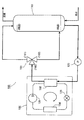
図10に、一つの流入口と二つの流出口とを持つ流路切換弁の一つである三方弁が使用された従来の給湯設備の一例の主要部を示す(特許文献1も参照)。図示例の給湯設備100は、基本的には、その下部に給水、その上部から給湯が行われる貯湯タンク110と、圧縮機131、湯水熱交換器(湯水加熱器)132、膨張弁133、及び空気熱交換器134等を有するヒートポンプ式湯水加熱源130と、貯湯タンク110と加熱源130との間で湯水を循環させるための沸き上げポンプ120と、一つの流入口160と二つの流出口161、162とを持つ流路切換弁としての三方弁150と、を備える。
FIG. 10 shows the main part of an example of a conventional hot water supply system in which a three-way valve, which is one of flow path switching valves having one inlet and two outlets, is used (see also Patent Document 1). Basically, the hot
三方弁150は、例えば、所要箇所に設けられた温度センサにより検出される湯水の温度等に基づいてその流路切換動作等が制御される電子制御式電動弁で構成され、該三方弁150においては、湯水を流入口160から第1流出口161へ流す第1の流通状態と、湯水を流入口160から第2流出口162へ流す第2の流通状態とを選択的にとり得るようにされており、通常、加熱源130からの湯水が高温の場合には、第1の流通状態がとられて、高温の湯は貯留タンク110の上部に戻され、加熱源130からの湯水が低温の場合には、第2の流通状態がとられて、低温の湯水は貯留タンク110の下部に戻され、再び、沸き上げポンプ120により加熱源130へ送られる。
The three-
前記した如くの従来の給湯設備等に使用される三方弁等の流路切換弁においては、第1の流通状態(流入口→第1流出口)のときに流体が第2流出口側へ漏れないようにするため、また、第2の流通状態(流入口→第2流出口)のときに流体が第1流出口側へ漏れないようにするため、少なくとも第1流出口と第2流出口との間にOリング等のシール材を設けているが、Oリング等のシール材を設けるには弁体等に円環状の装着溝等を設ける必要があり、部品コスト、加工組立コスト、ひいては製品コストが高くなる嫌いがあった。 In the flow path switching valve such as the three-way valve used in the conventional hot water supply system as described above, fluid leaks to the second outlet side in the first flow state (inflow port → first outlet) At least the first outlet and the second outlet in order to prevent the fluid from leaking to the first outlet side in the second flow state (inlet → second outlet). In order to provide a sealing material such as an O-ring, it is necessary to provide an annular mounting groove or the like on the valve body etc. I did not like the product cost to be high.
また、給湯設備等に使用される流路切換弁においては、流出口に接続された配管内の流体圧力が凍結等に起因して不意に高くなり、流路切換弁に通常の流れ方向とは逆向きの高い圧力(逆圧)が掛かることがあり、このような逆圧により流路切換弁や配管等が故障するおそれがあった。 Moreover, in the flow path switching valve used for the hot water supply facility etc., the fluid pressure in the pipe connected to the outlet becomes unexpectedly high due to freezing etc. A high pressure (reverse pressure) in the reverse direction may be applied, and there is a risk that the flow path switching valve, piping, etc. may be broken by such reverse pressure.
これを避けるには、例えば、流路切換弁をバイパスする流路を設け、該流路に所定圧以上で開くリリーフ弁を介装する方策が考えられるが、かかる方策では、配管や継手類などの部品の点数が増大するとともに、配管接続作業にも多大な手間と時間がかかり、設備のコストアップを招くという問題がある。 In order to avoid this, for example, it is conceivable to provide a flow passage that bypasses the flow passage switching valve and interpose a relief valve that opens at a predetermined pressure or more in the flow passage. As the number of parts increases, the piping connection work also takes a lot of time and effort, which leads to an increase in the cost of equipment.
本発明は、上記課題に鑑みてなされたもので、その目的とするところは、複数個の流出口間での漏れを防ぐためのOリング等のシール材を不要にできるとともに、厳格な寸法管理や高精度の加工成形技術を必要とすることなく、流出口間の漏れを確実に防ぐことができ、また、逆圧を効果的に逃がすリリーフ機能を持たせることもでき、加工組立コスト、製品コストを低く抑えることのできる流路切換弁を提供することにある。 The present invention has been made in view of the above problems, and the object of the present invention is to eliminate the need for a sealing material such as an O-ring for preventing leakage between a plurality of outlets, and to strictly control dimensional control. It is possible to reliably prevent the leak between the outlets without requiring high precision processing and molding technology, and it is also possible to provide a relief function to effectively release the back pressure, processing and assembly cost, product An object of the present invention is to provide a flow path switching valve capable of keeping the cost low.
前記目的を達成すべく、本発明に係る流路切換弁は、基本的には、弁軸と、該弁軸を回転駆動するための駆動源と、流入口、複数個の流出口、前記弁軸が回動可能に嵌挿される弁軸嵌挿部、及び、該弁軸嵌挿部の下部外周に設けられた弁座を有する弁本体と、を備え、前記弁座に、前記各流出口の始端部となる流出開口がそれぞれ形成され、前記弁軸における前記弁座より下方に突出した下端部に厚肉円板状ないし短円筒状の弁体が一体的に設けられるとともに、該弁体付き弁軸が前記弁軸嵌挿部を軸方向に所定範囲内で摺動可能とされ、前記弁座の下側に、前記弁体が収容される弁体収容部が設けられるとともに、該弁体収容部の下側に前記流入口が設けられ、前記弁本体は、前記複数個の流出口がその外周部に設けられた円筒状部を持つ本体部材と、前記流入口を持ち、前記本体部材の円筒状部の下部にその上部が内嵌固定される流入口部材と、で分割構成され、前記本体部材における円筒状部の下部及び弁座と、前記流入口部材の上端部とで前記弁体収容部が画成され、前記流入口部材の上端部は、前記弁体が前記弁座の下面から一定距離以上下降するのを阻止するストッパとして機能するようになっており、前記弁体は、前記流入口と前記各流出口とを選択的に開通させる少なくとも一つの開口状通路を持ち、前記弁体付き弁軸を回動させることにより、少なくとも、流体が前記流入口から前記開口状通路を介して前記流出口の一つへと流れる第1の流通状態と、流体が前記流入口から前記開口状通路を介して前記流出口の他の一つへと流れる第2の流通状態とを選択的にとり得るようにされる。 In order to achieve the above object, the flow path switching valve according to the present invention basically comprises a valve shaft, a drive source for rotationally driving the valve shaft, an inlet, a plurality of outlets, the valve A valve shaft insertion portion into which a shaft is rotatably inserted, and a valve body having a valve seat provided on a lower outer periphery of the valve shaft insertion portion An outflow opening serving as a start end of the valve stem is formed, and a thick disc-like or short cylindrical valve body is integrally provided at a lower end portion of the valve stem projecting downward from the valve seat, and the valve body An attached valve shaft is slidable within a predetermined range in the axial direction of the valve shaft fitting portion, and a valve body accommodating portion for accommodating the valve body is provided on the lower side of the valve seat, and the valve The inlet is provided on the lower side of the body housing, and the valve body has a cylindrical portion provided with the plurality of outlets at the outer peripheral portion thereof. The lower portion of the cylindrical portion of the main body member and the valve seat are divided into a body member and an inlet member having the inflow port and the upper portion of the cylindrical portion of the main body member is internally fitted and fixed thereto. And the upper end portion of the inflow member define the valve body accommodating portion, and the upper end portion of the inflow member is a stopper that prevents the valve body from moving downward from the lower surface of the valve seat by a predetermined distance or more The valve body has at least one open passage for selectively opening the inlet and the outlet, and by rotating the valve shaft with the valve body. At least a first flow state in which the fluid flows from the inlet to the one of the outlets through the open passage, and a fluid from the inlet through the open passage to the other of the outlet Selectively with the second distribution state flowing to one of Ri is get way.
好ましい態様では、前記弁体付き弁軸は、前記流入口に流入した流体の圧力により押し上げられ、これによって前記弁体の上面が前記弁座に押し付けられるようにされる。 In a preferred aspect, the valve body mounted valve stem is pushed up by the pressure of the fluid flowing into the inflow port so that the upper surface of the valve body is pressed against the valve seat.
他の好ましい態様では、前記各流出口のいずれかの圧力が所定圧以上高まると、前記弁体付き弁軸が押し下げられて前記弁座と前記弁体の上面との間に隙間が形成され、これによって、前記流出口側の圧力が前記流入口側に逃がされるようにされる。 In another preferred embodiment, when the pressure at any one of the outlets is increased by a predetermined pressure or more, the valve stem with a valve is depressed to form a gap between the valve seat and the upper surface of the valve. The pressure on the outlet side is thereby released to the inlet side.
前記弁体は、好ましくは、前記各流出口間を水密的にシールすべく、前記開口状通路以外の上面が前記弁座に密着し得るようにされる。 The valve body is preferably configured such that an upper surface other than the open passage can be in close contact with the valve seat so as to seal the space between the outlets in a watertight manner.
この場合、好ましい態様では、前記弁体における前記開口状通路以外の上面は、平坦な平滑面とされる。 In this case, in a preferred embodiment, the upper surface of the valve body other than the open passage is a flat smooth surface.
別の好ましい態様では、前記弁軸にセレーション軸部が設けられ、前記駆動源に前記セレーション軸部が軸方向に摺動可能に嵌挿されるセレーション嵌合穴が設けられ、前記弁体が前記流入口部材の上端部に接当する最下降位置をとっている状態において前記セレーション軸部の上端と前記セレーション嵌合穴における前記セレーション軸部より上側に設けられた上側段丘面との間の距離は、前記弁体が前記弁座に押し付けられる最上昇位置から前記流入口部材の上端部に接当する最下降位置までの距離より長い。 In another preferred embodiment, the valve shaft is provided with a serration shaft, and the drive source is provided with a serration fitting hole in which the serration shaft is axially slidably inserted, and the valve body is provided with the flow The distance between the upper end of the serration shaft and the upper terrace surface provided above the serration shaft in the serration fitting hole in the state of taking the lowest position in contact with the upper end of the entrance member is The distance from the highest position where the valve body is pressed against the valve seat to the lowest position where it abuts on the upper end of the inflow member is longer.
別の好ましい態様では、前記駆動源に、前記弁軸の上端部が軸方向に摺動可能に嵌合するとともに、上面が閉じた嵌合穴が設けられ、前記弁体が前記流入口部材の上端部に接当する最下降位置をとっている状態において前記弁軸の上端部と前記嵌合穴の上面との間の距離は、前記弁体が前記弁座に押し付けられる最上昇位置から前記流入口部材の上端部に接当する最下降位置までの距離より長い。 In another preferred embodiment, the drive source is provided with a fitting hole in which the upper end portion of the valve stem is slidably fitted in the axial direction and the upper surface is closed, and the valve body is the inlet member. The distance between the upper end of the valve stem and the upper surface of the fitting hole in the lowermost position in contact with the upper end is the distance from the highest position where the valve body is pressed against the valve seat It is longer than the distance to the lowest position in contact with the upper end of the inlet member.
本発明に係る流路切換弁では、弁本体内の流体圧力を利用して弁体の上面を弁座に押し付けて各流出口の間をシールするようにされているので、各流出口の間をシールするためのOリング等のシール材を不要にでき、加工組立コスト、製品コストを低く抑えることができる。 In the flow path switching valve according to the present invention, the fluid pressure in the valve body is used to press the upper surface of the valve body against the valve seat to seal between the respective outlets, so that between the respective outlets. It is possible to eliminate the need for sealing materials such as O-rings for sealing, and to reduce processing and assembly costs and product costs.
また、弁体付き弁軸は、比較的シンプルな構成とすることができ、弁本体内の流体圧力により押し上げられて弁体の上面が弁座に密着するようにされるので、厳格な寸法管理や高精度の加工成形技術を必要とすることなく、各流出口の間に所要のシール性を容易に確保することができ、これによっても、加工組立コスト、製品コストを低く抑えることができる。 Also, the valve stem with a valve body can be of a relatively simple configuration, and is pushed up by the fluid pressure in the valve body so that the upper surface of the valve body is in close contact with the valve seat. The required sealability can be easily secured between the respective outlets without requiring high-precision processing and molding techniques, which also can lower the processing and assembly costs and the product costs.
また、いずれかの流出口側の圧力が所定圧以上高まると、弁体に逆圧が掛かって、弁体が押し下げられ、弁体と弁座との間に隙間が形成され、これによって、流出口側の逆圧が前記隙間を介して流入口側に逃がされる。このように本発明の流路切換弁は、逆圧を効果的に逃がすリリーフ機能を持たせることができるので、逆圧による当該流路切換弁や配管系の故障を効果的に回避することができ、また、別途に流路にリリーフ弁を設けなくて済むので、設備のコストアップを抑えることができる。 In addition, when the pressure on any of the outlet side increases by a predetermined pressure or more, the valve body receives a reverse pressure to push down the valve body, thereby forming a gap between the valve body and the valve seat, thereby The counterpressure on the outlet side escapes to the inlet side through the gap. As described above, since the flow path switching valve of the present invention can have a relief function to effectively release the reverse pressure, it is possible to effectively avoid the failure of the flow path switching valve or the piping system due to the reverse pressure. In addition, since it is not necessary to provide a relief valve separately in the flow path, it is possible to suppress the cost increase of the equipment.
以下、本発明の実施形態を図面を参照しながら説明する。 Hereinafter, embodiments of the present invention will be described with reference to the drawings.
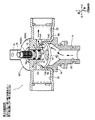
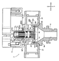
図1は、本発明に係る流路切換弁の一実施例を示す外観斜視図、図2、図3は、上記一実施例の第1の流通状態を示す部分切欠断面図、半断面斜視図、図4、図5は、上記一実施例の第2の流通状態を示す部分切欠断面図、半断面斜視図である。なお、図1ないし図5において、本発明の理解にさほど必要とはしない部分(モータ5の内部等)は、その図示やハッチングを省略している。また、各図において、部材間に形成される隙間や部材間の離隔距離等は、発明の理解を容易にするため、また、作図上の便宜を図るため、誇張して描かれている場合がある。
FIG. 1 is an external perspective view showing an embodiment of a flow path switching valve according to the present invention, and FIGS. 2 and 3 are partially cutaway sectional views showing a first flow state of the above-mentioned embodiment and a half sectional perspective view FIGS. 4 and 5 are a partially cutaway sectional view and a half sectional perspective view showing a second flow state of the above-mentioned embodiment. In FIG. 1 to FIG. 5, the parts (the inside of the
さらに、本明細書において、上下、左右、前後等の位置、方向を表わす記述は、説明が煩瑣になるのを避けるために図面に従って便宜上付けたものであり、実際の使用状態での位置、方向を指すものではない。 Furthermore, in the present specification, the descriptions representing the positions and directions such as upper and lower, right and left, front and back, etc. are added for convenience according to the drawings to avoid complicated explanation, and the positions and directions in the actual use state It does not refer to
図示実施例の流路切換弁1は、前述した図10に示される如くの給湯設備に使用されるもの(図10の符号150に相当)で、基本的には、弁軸30と、該弁軸30を回転駆動するための駆動源としてのモータ5と、このモータ5がその上側に取付固定される弁本体6とを備える。
The flow
弁本体6は、合成樹脂を素材としており、その成形上等の便宜を図るため、本体部材7と、流入口部材9と、に分割構成されている。
The valve
本体部材7は、図1〜図5に加えて図9を参照すればよくわかるように、上部短円柱状部8Aと下部円筒状部8Bとを持つ基体部8を有し、この基体部8の外周部(左右の側部)に、段付き円筒状の第1流出口(継手)21と第2流出口(継手)22が対向するように設けられている。
The
また、上部短円柱状部8Aの上部の前後には取付受台部7f、7fが設けられており、モータ5を本体部材7に取付固定するにあたっては、取付受台部7f、7fにモータ5の下部前後に設けられたねじ止め部5f、5fを載せて、モータ5と本体部材7を前後2本のねじ15で締付固定するようになっている。
Also, mounting supports 7f, 7f are provided on the front and rear of the upper portion of the upper short
基体部8の上部短円柱状部8Aには、該上部短円柱状部8Aの中央を縦貫するように弁軸嵌挿部12が設けられるとともに、第1流出口21側に開口する周面開口と下面開口とを持つ逆L字状の第1流出開口23と、第2流出口22側に開口する周面開口と下面開口とを持つ逆L字状の第2流出開口24とが180°の角度間隔をあけて左右対称的に形成されている。
The upper short
より詳細には、第1流出開口23と第2流出開口24の下面開口部分は、両端が半円状の曲がり長溝状ないし中心角が100°以上の扇形状を呈し、その下端部は、上部短円柱状部8Aの下端面8a(図9参照)より下方に突出しており、この第1流出開口23と第2流出開口24の下端部が後述する弁体40の上面が押し付けられて密着せしめられる弁座15A、15Bとなっている。言い換えれば、弁座15A、15Bは、第1流出開口23と第2流出開口24を画成する端縁部と同外形の、所定の幅を持つ枠状凸部からなっており、その下面(弁シート面)は、弁軸嵌挿部12の中心線(弁軸30の回転軸線)Oに直交する平坦な平滑面とされている。第1流出開口23及び第2流出開口24の下面開口部分の幅は、後述する弁体40に形成された開口状通路41、42の幅より若干大きく、その長さ(中心角)は、前記開口状通路41、42の長さ(中心角)より両端半円状部分程度長くされている(図6も参照)。
More specifically, the lower opening of each of the
一方、前記流入口部材9は、内周側に流入口20となる漏斗状の挿通穴を持ち、外周側に本体部材7の基体部8における下部円筒状部8Bが載せられる鍔状部9a、及び、この鍔状部9aから上方に突出して下部円筒状部8Bの下部に内挿される突出内挿部9bを有し、鍔状部9aと下部円筒状部8Bとが超音波溶着等により固着されている。
On the other hand, the
なお、下部円筒状部8Bの下部と、基体部8の下面8aと、流入口部材9の突出内挿部9b(の上端面)と、で後述する弁体40を揺動自在に収容する弁体収容部14が画成されている。また、流入口部材9の突出内挿部9bは、弁体40が弁座15A、15Bの下面(弁シート面)から一定距離以上下降するのを阻止するストッパとして機能するようになっている(図7参照)。
A valve that pivotably accommodates a
弁本体6において、弁軸嵌挿部12の中心線O上に、前記弁体収容部14及び流入口20が配置され、前記中心線Oに直交する共通の中心線C上に、第1流出口21と第2流出口22とが配置されている。
In the valve
弁軸30は、図1から図5に加えて図8を参照すればよくわかるように、その最上部に、周方向位置決め用のDカット凸部31、モータ5のロータの回転駆動力が減速歯車機構を介して伝達されるインボリュートセレーション軸部32が設けられ、そのセレーション軸部32の下側には、Oリング35、35が装着される、3段の鍔状部34からなる装着溝が設けられ(弁軸30におけるOリング35、35が装着されている部分をOリング装着部33と称す)、最下部には、厚肉円板状の弁体40が一体的に設けられている(弁軸30と弁体40は一体物)。この弁体40付き弁軸30は、弁軸嵌挿部12を軸方向(上下方向)に所定範囲内で摺動可能とされている。
The
詳細には、モータ5内には、前記減速歯車機構の出力歯車51を回転自在に支持する支持部57が設けられ、前記出力歯車51のボス部52には前記セレーション軸部32が軸方向に摺動自在に嵌挿されるセレーション嵌合穴53が設けられるとともに、該セレーション嵌合穴53の上側に前記Dカット凸部31が嵌合するD形嵌合穴54が連設されている。この場合、弁体40付き弁軸30は、図1ないし図5に示される如くの、弁体40が弁座15A、15Bに押し付けられた最上昇位置と、図7に示される如くの、弁体40が流入口部材9の突出内挿部9b上面に接当した最下降位置(最上昇位置から距離K分下降)とをとり得るように、弁体40付き弁軸30が最下降位置をとっている状態(図7)において、セレーション軸部32の上端とセレーション嵌合穴53の上側段丘面53aとの間、及び、Dカット凸部31の上端とD形嵌合穴54の上面54aとの間には、それぞれ前記Kより長い距離L分のスペースが設けられている。
In detail, in the
前記弁体40には、流入口20と第1流出口21あるいは流入口20と第2流出口22とを選択的に開通させるための2つの開口状通路41、42(第1開口状通路41、第2開口状通路42)が90°の角度間隔をあけて設けられている。各開口状通路41、42は、中心角が70°ないし80°の扇形状を呈し、前述したように、その幅及び長さ(中心角)は、第1流出開口23及び第2流出開口24の下面開口部分のそれより小さくされている。
In the
また、弁体40における開口状通路41、42以外の上面は、前記各流出口21、22間を水密的にシールすべく、前記弁座15A、15Bの下面(弁シート面)に密着し得るように、平坦な平滑面とされている。
Further, the upper surfaces of the
なお、弁座15A、15Bに対する弁体40の回転方向の位置は、ここでは、図2、図3、及び図6(A)に示される如くの、弁座15A(第1流出開口23)の真下に開口状通路41が位置する状態が基準(第1の流通状態)とされ、この第1の流通状態から反時計回りに90°回転させた状態、すなわち、図4、図5、図6(B)に示される如くの、弁座15B(第2流出開口24)の真下に開口状通路42が位置する状態が第2の流通状態とされる。
Here, the position of the
上記した如くの構成を有する本実施例の流路切換弁1を、前述した図10に示される如くの給湯設備に、符号150で示される三方弁として組み込んだ場合には、弁体40付き弁軸30は、弁本体6内の流体(湯水)圧力(弁軸30のOリング装着部33の下側に作用する圧力)と大気圧(弁軸30のOリング装着部33の上側に作用する圧力)との差圧、並びに、流入口20に流入して第1流出口21又は第2流出口22へと流れる流体(湯水)の圧力により、上側に押し上げられ、弁体40の上面が弁座15A、15Bに押し付けられ、かつ、その上面を弁座15A、15Bに押し付けられながら回動可能とされる。
When the flow
この場合、弁体40付き弁軸30が押し上げられて、弁体40の上面が弁座15A、15Bに押し付けられることにより、各流出口21、22間が水密的にシールされるとともに、該弁体40が押し付けられた状態で弁軸30を回動させることにより、流体が流入口20から第1開口状通路41を介して第1流出口21へと流れる第1の流通状態と、流体が流入口20から第2開口状通路42を介して第2流出口22へと流れる第2の流通状態とを選択的にとり得るようにされる。
In this case, the
すなわち、図2、図3に示される如くに、第1開口状通路41が第1流出開口23の下端部とされる弁座15Aの真下に来たときは、流体が流出口20→第1開口状通路41→第1流出開口23→第1流出口21へと流れる第1の流通状態がとられる。
That is, as shown in FIGS. 2 and 3, when the first
一方、上記第1の流通状態から弁体40を反時計回りに約90°回転させると、図4、図5に示される如くに、第2開口状通路42が第2流出開口24の下端部とされる弁座15Bの真下に来るので、このときは、流体が流出口20→第2開口状通路42→第2流出開口24→第2流出口22へと流れる第2流通状態がとられる。
On the other hand, when the
このように、本実施例の流路切換弁1では、弁本体6内の流体圧力を利用して、弁体40付き弁軸30を押し上げ、弁体40の上面を弁座15A、15Bに押し付けて第1流出口21と第2流出口22との間をシールするようにされているので、第1流出口と第2流出口との間をシールするためのOリング等のシール材を不要にでき、加工組立コスト、製品コストを低く抑えることができる。
As described above, in the flow
また、弁体40付き弁軸30は、比較的シンプルな構成とされ、弁本体6内の流体圧力により押し上げられて弁体40の上面が弁座15A、15Bに密着するようにされるので、厳格な寸法管理や高精度の加工成形技術を必要とすることなく、第1流出口21と第2流出口22との間に所要のシール性を容易に確保することができる。
Further, since the
また、図7に示される如くに、例えば、第1の流通状態(流入口20→第1流出口21)がとられているときにおいて、第2流出口22側の圧力が所定圧以上高まると、弁体40(の上面)に逆圧が掛かって、弁体40付き弁軸30が若干傾くか押し下げられ、弁座15A、15Bの下面(弁シート面)と弁体40の上面との間に微小隙間が形成され、これに伴い、第2流出口22側の圧力が流入口20側に逃がされる。この際、弁体40は、最大で、流入口部材9の突出内挿部9bの上端に接当するまで下降し、それ以上の下降は阻止される(突出内挿部9bは、弁体40が一定距離以上下降するのを阻止するストッパとして機能する)。
Further, as shown in FIG. 7, when, for example, the first flow state (
このように本実施例の流路切換弁1には、逆圧を効果的に逃がすリリーフ機能を持たせることができるので、凍結等に起因して発生する逆圧による当該流路切換弁1や配管系の故障を効果的に回避することができ、また、別途に流路にリリーフ弁を設けなくて済むので、設備のコストアップを抑えることができる。
As described above, since the flow
なお、上記実施例では、流路切換弁として流出口を2つ有する三方弁を例示したが、これに限られることはなく、流出口を3つあるいは4つ設けて四方弁あるいは五方弁とすることもできる。また、弁体の構成も上記実施例のものに限らず様々な態様のものを採用できる。具体的には、例えば、同一平面上に90°間隔で第1ないし第4の流出口を設けるとともに、弁体に開口状通路を一つ設け、弁体を90°、180°、270°回転させる毎に、流入口と各流出口とを選択的に開通させるようにする等してもよい。 In the above embodiment, although the three-way valve having two outlets as the flow path switching valve is illustrated, the present invention is not limited thereto, and three or four outlets are provided to form a four-way valve or five-way valve You can also Further, the configuration of the valve body is not limited to that of the above embodiment, and various aspects can be adopted. Specifically, for example, while providing the first to fourth outlets at 90 ° intervals on the same plane, providing one open passage in the valve body, the valve body is rotated by 90 °, 180 °, 270 ° In each case, the inlet and each outlet may be selectively opened.
また、上記実施例では、弁軸30と弁体40は一体物として作製されているが、それらを別体で作製した後に、一体的に組み付けるようにしてもよいことは勿論である。
Further, in the above embodiment, although the
1 流路切換弁
5 モータ
6 弁本体
7 本体部材
8 基体部
9 流入口部材
12 弁軸嵌挿部
14 弁体収容部
15A、15B 弁座
20 流入口
21 第1流出口
22 第2流出口
23 第1流出開口
24 第2流出開口
30 弁軸
40 弁体
41、42 開口状通路
DESCRIPTION OF
Claims (7)
前記弁座に、前記各流出口の始端部となる流出開口がそれぞれ形成され、
前記弁軸における前記弁座より下方に突出した下端部に厚肉円板状ないし短円筒状の弁体が一体的に設けられるとともに、該弁体付き弁軸が前記弁軸嵌挿部を軸方向に所定範囲内で摺動可能とされ、
前記弁座の下側に、前記弁体が収容される弁体収容部が設けられるとともに、該弁体収容部の下側に前記流入口が設けられ、
前記弁本体は、前記複数個の流出口がその外周部に設けられた円筒状部を持つ本体部材と、前記流入口を持ち、前記本体部材の円筒状部の下部にその上部が内嵌固定される流入口部材と、で分割構成され、
前記本体部材における円筒状部の下部及び弁座と、前記流入口部材の上端部とで前記弁体収容部が画成され、
前記流入口部材の上端部は、前記弁体が前記弁座の下面から一定距離以上下降するのを阻止するストッパとして機能するようになっており、
前記弁体は、前記流入口と前記各流出口とを選択的に開通させる少なくとも一つの開口状通路を持ち、
前記弁体付き弁軸を回動させることにより、少なくとも、流体が前記流入口から前記開口状通路を介して前記流出口の一つへと流れる第1の流通状態と、流体が前記流入口から前記開口状通路を介して前記流出口の他の一つへと流れる第2の流通状態とを選択的にとり得るようにされていることを特徴とする流路切換弁。 Valve shaft, drive source for rotationally driving the valve shaft, inlet, plural outlets, valve shaft insertion portion into which the valve shaft is rotatably inserted, and valve shaft insertion A valve body having a valve seat provided on the lower periphery of the part;
The valve seat is formed with an outlet opening which is a starting end of each outlet, respectively.
A thick disc-like or short cylindrical valve body is integrally provided at a lower end portion of the valve stem projecting downward from the valve seat, and the valve stem with the valve body is a shaft fitting portion of the valve stem It is possible to slide in a predetermined range in the direction,
A valve body accommodating portion for accommodating the valve body is provided on the lower side of the valve seat, and the inlet is provided on the lower side of the valve body accommodating portion,
The valve main body has a main body member having a cylindrical portion provided with the plurality of outlets at its outer peripheral portion, and the inflow port, and an upper portion thereof is fixedly fitted to a lower portion of the cylindrical portion of the main body member Divided into an inlet member, and
The lower portion of the cylindrical portion of the body member and the valve seat, and the upper end portion of the inflow member define the valve body accommodating portion,
The upper end portion of the inflow member functions as a stopper that prevents the valve body from moving down from the lower surface of the valve seat by a predetermined distance or more.
The valve body has at least one open passage selectively opening the inlet and the outlets.
At least a first flow state in which the fluid flows from the inlet to the one of the outlets through the open passage by rotating the valve stem with the valve body, and the fluid from the inlet A flow passage switching valve characterized in that it is possible to selectively take a second flow state flowing to another one of the outlet through the open passage.
前記弁体が前記流入口部材の上端部に接当する最下降位置をとっている状態において前記セレーション軸部の上端と前記セレーション嵌合穴における前記セレーション軸部より上側に設けられた上側段丘面との間の距離は、前記弁体が前記弁座に押し付けられる最上昇位置から前記流入口部材の上端部に接当する最下降位置までの距離より長いことを特徴とする請求項1に記載の流路切換弁。 A serration shaft portion is provided on the valve shaft, and a serration fitting hole is provided in the drive source, in which the serration shaft portion is axially slidably inserted.
An upper terrace surface provided above the upper end of the serration shaft and the serration shaft in the serration fitting hole in a state in which the valve body is in the lowermost position where the valve body contacts the upper end of the inflow member. The distance between them is longer than the distance between the highest position where the valve body is pressed against the valve seat and the lowest position where the valve body abuts on the upper end of the inflow member. Flow control valve.
前記弁体が前記流入口部材の上端部に接当する最下降位置をとっている状態において前記弁軸の上端部と前記嵌合穴の上面との間の距離は、前記弁体が前記弁座に押し付けられる最上昇位置から前記流入口部材の上端部に接当する最下降位置までの距離より長いことを特徴とする請求項1に記載の流路切換弁。 The drive source is provided with a fitting hole in which the upper end portion of the valve stem is slidably fitted in the axial direction and the upper surface is closed,
In a state in which the valve body is in the lowermost position where the valve body abuts on the upper end of the inflow member, a distance between the upper end of the valve stem and the upper surface of the fitting hole is the valve The flow path switching valve according to claim 1, characterized in that it is longer than the distance from the highest position to be pressed against the seat to the lowest position to contact the upper end of the inflow member.
Priority Applications (2)
| Application Number | Priority Date | Filing Date | Title |
|---|---|---|---|
| JP2019072369A JP6709477B2 (en) | 2019-04-05 | 2019-04-05 | Flow path switching valve |
| JP2020079148A JP6900076B2 (en) | 2019-04-05 | 2020-04-28 | Flow path switching valve |
Applications Claiming Priority (1)
| Application Number | Priority Date | Filing Date | Title |
|---|---|---|---|
| JP2019072369A JP6709477B2 (en) | 2019-04-05 | 2019-04-05 | Flow path switching valve |
Related Parent Applications (1)
| Application Number | Title | Priority Date | Filing Date |
|---|---|---|---|
| JP2014265979A Division JP6510810B2 (en) | 2014-12-26 | 2014-12-26 | Flow path switching valve |
Related Child Applications (1)
| Application Number | Title | Priority Date | Filing Date |
|---|---|---|---|
| JP2020079148A Division JP6900076B2 (en) | 2019-04-05 | 2020-04-28 | Flow path switching valve |
Publications (2)
| Publication Number | Publication Date |
|---|---|
| JP2019105378A true JP2019105378A (en) | 2019-06-27 |
| JP6709477B2 JP6709477B2 (en) | 2020-06-17 |
Family
ID=67061848
Family Applications (1)
| Application Number | Title | Priority Date | Filing Date |
|---|---|---|---|
| JP2019072369A Active JP6709477B2 (en) | 2019-04-05 | 2019-04-05 | Flow path switching valve |
Country Status (1)
| Country | Link |
|---|---|
| JP (1) | JP6709477B2 (en) |
-
2019
- 2019-04-05 JP JP2019072369A patent/JP6709477B2/en active Active
Also Published As
| Publication number | Publication date |
|---|---|
| JP6709477B2 (en) | 2020-06-17 |
Similar Documents
| Publication | Publication Date | Title |
|---|---|---|
| JP6510810B2 (en) | Flow path switching valve | |
| JP7284771B2 (en) | valve | |
| EP3017219B1 (en) | Temperature adjustment valve | |
| JP6557044B2 (en) | Flow control valve | |
| JP5388609B2 (en) | Mixing valve unit and hot water storage water heater | |
| JP6399860B2 (en) | Flow path switching valve | |
| JP6900076B2 (en) | Flow path switching valve | |
| KR101892604B1 (en) | Valve assembly | |
| JP2019105378A (en) | Flow channel change-over valve | |
| JP2016023704A (en) | Flow channel switching valve | |
| JP6250529B2 (en) | Three-way valve | |
| KR101793580B1 (en) | Electric two-line hree-way ball valve | |
| JP6187274B2 (en) | Multi-way valve and hot water storage water heater | |
| JP6419476B2 (en) | Flow path switching valve | |
| JP4640105B2 (en) | Hot water mixing valve | |
| JP5938902B2 (en) | Valve device and hot water supply device | |
| JP6085755B2 (en) | Control valve unit | |
| JP6419475B2 (en) | Flow path switching valve | |
| JP2005164129A (en) | Flow control unit | |
| JP4556834B2 (en) | Hot water mixing valve | |
| JP2008298164A (en) | Mixing valve | |
| JP2008298169A (en) | Mixing valve |
Legal Events
| Date | Code | Title | Description |
|---|---|---|---|
| A621 | Written request for application examination |
Free format text: JAPANESE INTERMEDIATE CODE: A621 Effective date: 20190405 |
|
| A131 | Notification of reasons for refusal |
Free format text: JAPANESE INTERMEDIATE CODE: A131 Effective date: 20200212 |
|
| A977 | Report on retrieval |
Free format text: JAPANESE INTERMEDIATE CODE: A971007 Effective date: 20200213 |
|
| A521 | Request for written amendment filed |
Free format text: JAPANESE INTERMEDIATE CODE: A523 Effective date: 20200310 |
|
| TRDD | Decision of grant or rejection written | ||
| A01 | Written decision to grant a patent or to grant a registration (utility model) |
Free format text: JAPANESE INTERMEDIATE CODE: A01 Effective date: 20200331 |
|
| A61 | First payment of annual fees (during grant procedure) |
Free format text: JAPANESE INTERMEDIATE CODE: A61 Effective date: 20200428 |
|
| R150 | Certificate of patent or registration of utility model |
Ref document number: 6709477 Country of ref document: JP Free format text: JAPANESE INTERMEDIATE CODE: R150 |
|
| R250 | Receipt of annual fees |
Free format text: JAPANESE INTERMEDIATE CODE: R250 |