JP2019105288A - Fluid pressure control device and working vehicle including fluid pressure control device - Google Patents

Fluid pressure control device and working vehicle including fluid pressure control device Download PDF

Info

Publication number
JP2019105288A
JP2019105288A JP2017237016A JP2017237016A JP2019105288A JP 2019105288 A JP2019105288 A JP 2019105288A JP 2017237016 A JP2017237016 A JP 2017237016A JP 2017237016 A JP2017237016 A JP 2017237016A JP 2019105288 A JP2019105288 A JP 2019105288A
Authority
JP
Japan
Prior art keywords
valve
flow path
connection
orifice
fluid pressure
Prior art date
Legal status (The legal status is an assumption and is not a legal conclusion. Google has not performed a legal analysis and makes no representation as to the accuracy of the status listed.)
Pending
Application number
JP2017237016A
Other languages
Japanese (ja)
Inventor
健 児玉
Takeshi Kodama
健 児玉
Current Assignee (The listed assignees may be inaccurate. Google has not performed a legal analysis and makes no representation or warranty as to the accuracy of the list.)
KYB Corp
Original Assignee
KYB Corp
Priority date (The priority date is an assumption and is not a legal conclusion. Google has not performed a legal analysis and makes no representation as to the accuracy of the date listed.)
Filing date
Publication date
Application filed by KYB Corp filed Critical KYB Corp
Priority to JP2017237016A priority Critical patent/JP2019105288A/en
Publication of JP2019105288A publication Critical patent/JP2019105288A/en
Pending legal-status Critical Current

Links

Images

Abstract

To improve volumetric efficiency while securing a neutral region of a discharge mechanism.SOLUTION: A fluid pressure control device 100 includes: a communication passage 5 for connecting a connection flow passage 3 to a connection flow passage 4; and an on-off valve 6 provided to the communication passage 5. The on-off valve 6 closes the valve thereof to shut down the communication passage 5 when a flow rate of hydraulic oil discharged from a two-way pump 1 is equal to or higher than a constant value, and opens the valve thereof to open through the communication passage 5 when the flow rate of hydraulic oil discharged from the two-way pump 1 is less than the constant value.SELECTED DRAWING: Figure 1

Description

本発明は、流体圧制御装置及び流体圧制御装置を備えた作業車両に関するものである。   The present invention relates to a fluid pressure control device and a work vehicle provided with the fluid pressure control device.

特許文献1には、2つのポートを有する油圧ポンプ(吐出装置)と、駆動輪を駆動する油圧モータと、油圧ポンプ及び油圧モータが閉回路を形成するように両者を流体接続する作動油ラインと、を備えたHST(Hydro Static Transmission)が記載されている。   Patent Document 1 discloses a hydraulic pump (discharge device) having two ports, a hydraulic motor for driving a drive wheel, and a hydraulic fluid line for fluidly connecting both the hydraulic pump and the hydraulic motor so that they form a closed circuit. , And HST (Hydro Static Transmission) is described.

特許文献1に記載のHSTでは、油圧ポンプの中立領域を確保するために、作動油ラインとポンプ側チャージ油路とを連通する流路に流量制御弁が設けられている。   In the HST described in Patent Document 1, in order to secure a neutral region of the hydraulic pump, a flow control valve is provided in a flow passage that communicates the hydraulic fluid line with the pump-side charge fluid passage.

特開2007−198419号公報JP 2007-198419 A

特許文献1に記載のHSTでは、作動油ラインとポンプ側チャージ油路とが流量制御弁によって常に連通する構成である。この構成では、油圧ポンプ(吐出装置)の中立領域は確保できるものの、通常走行時において、油圧ポンプから油圧モータに供給される高圧の作動油の一部が、作動油ラインから流量制御弁を通じて低圧のポンプ側チャージ油路に流出してしまうため、油圧ポンプの容積効率が低下してしまう。   In the HST described in Patent Document 1, the hydraulic oil line and the pump side charge oil path are always in communication by the flow control valve. In this configuration, although the neutral region of the hydraulic pump (discharge device) can be secured, a part of the high-pressure hydraulic oil supplied from the hydraulic pump to the hydraulic motor during normal traveling is a low pressure through the flow control valve from the hydraulic oil line. Since the fluid flows out to the pump side charge oil passage of the above, the volumetric efficiency of the hydraulic pump is reduced.

本発明は、上記の問題点に鑑みてなされたものであり、吐出装置の中立領域を確保しつつ、容積効率の向上を目的とする。   The present invention has been made in view of the above problems, and aims to improve volumetric efficiency while securing a neutral region of a discharge device.

第1の発明は、第1ポート及び第2ポートのいずれかから作動流体を吐出する吐出装置と、吐出装置から吐出された作動流体によって駆動される流体圧モータと、吐出装置の第1ポートと流体圧モータの一方のポートとを接続する第1接続流路と、吐出装置の第2ポートと流体圧モータの他方のポートとを接続する第2接続流路と、第1接続流路と第2接続流路とを接続するバイパス流路と、バイパス流路に設けられる開閉弁と、を備え、開閉弁は、吐出装置から吐出される作動流体の流量が一定値以上であるときには閉弁してバイパス流路を遮断し、吐出装置から吐出される作動流体の流量が一定値未満であるときには開弁してバイパス流路を開通することを特徴とする。   According to a first aspect of the present invention, there is provided a discharge device for discharging a working fluid from one of a first port and a second port, a fluid pressure motor driven by the working fluid discharged from the discharge device, and a first port of the discharge device. A first connection channel connecting one port of the fluid pressure motor, a second connection channel connecting the second port of the discharge device and the other port of the fluid pressure motor, a first connection channel and a first connection channel (2) A bypass flow path connecting the connection flow path and an on-off valve provided in the bypass flow path. The on-off valve is closed when the flow rate of the working fluid discharged from the discharge device is equal to or more than a predetermined value. It is characterized in that the bypass flow path is shut off, and when the flow rate of the working fluid discharged from the discharge device is less than a predetermined value, the flow path is opened to open the bypass flow path.

第1の発明では、吐出装置から吐出される作動流体の流量が一定の値以上であるときには、バイパス流路が開閉弁によって遮断されるので、吐出装置から吐出された作動流体が全量流体圧モータに供給され、吐出装置の容積効率が向上する。また、吐出装置から吐出される作動流体の流量が一定の値以下であるときには、バイパス流路が開通するので、吐出装置から吐出される作動流体は、流体圧モータに供給されることなく、バイパス流路を通じて吐出装置に戻されるので、吐出装置の中立領域を確保できる。   In the first aspect of the invention, when the flow rate of the working fluid discharged from the discharge device is equal to or more than a predetermined value, the bypass flow path is shut off by the on-off valve, so the working fluid discharged from the discharge device is totally fluid pressure motor To improve the volumetric efficiency of the discharge device. Further, when the flow rate of the working fluid discharged from the discharge device is equal to or less than a predetermined value, the bypass flow path is opened, so that the working fluid discharged from the discharge device is bypassed without being supplied to the fluid pressure motor. Since the fluid is returned to the discharge device through the flow path, the neutral region of the discharge device can be secured.

第2の発明は、吐出装置は、吐出容量を調整するための調整部材を有する可変容量型の双方向ポンプであって、開閉弁は、バイパス流路を遮断または開通するための弁体を操作する操作部材を有し、操作部材は、調整部材に連結されていることを特徴とする。   In a second aspect of the invention, the discharge device is a variable displacement bidirectional pump having an adjustment member for adjusting the discharge capacity, and the on-off valve operates a valve body for blocking or opening the bypass flow passage. The operating member is characterized in that the operating member is connected to the adjusting member.

第2の発明では、開閉弁は、調整部材の動作に伴って開閉されるため、開閉弁の動作を安定させることができる。   In the second aspect of the invention, the on-off valve is opened and closed in accordance with the operation of the adjusting member, so that the operation of the on-off valve can be stabilized.

第3の発明は、第1接続流路に設けられた第1オリフィスと、第2接続流路に設けられた第2オリフィスと、開閉弁を開弁方向に付勢する付勢部材と、をさらに備え、開閉弁には、第1オリフィスの吐出装置側の圧力と第2オリフィスの吐出装置側の圧力とが閉弁方向に作用すると共に、第1オリフィスの流体圧モータ側の圧力と第2オリフィスの流体圧モータ側の圧力とが開弁方向に作用することを特徴とする。   According to a third aspect of the present invention, a first orifice provided in the first connection flow path, a second orifice provided in the second connection flow path, and a biasing member biasing the on-off valve in the valve opening direction. Further, the on-off valve has a pressure on the discharge device side of the first orifice and a pressure on the discharge device side of the second orifice acting in the valve closing direction, and the pressure on the fluid pressure motor side of the first orifice and the second The pressure on the fluid pressure motor side of the orifice acts in the valve opening direction.

第4の発明は、第1接続流路に設けられた第1オリフィスと、第2接続流路に設けられた第2オリフィスと、第1接続流路及び第2接続流路に作動流体を供給するチャージポンプと、チャージポンプから吐出された作動流体を第1接続流路及び第2接続流路に導くチャージ流路と、チャージ流路に設けられチャージポンプから第1接続流路への作動流体の流れのみを許容する第1チェック弁と、チャージ流路に設けられチャージポンプから第2接続流路への作動流体の流れのみを許容する第2チェック弁と、第1接続流路に接続されると共にチャージ流路の第1チェック弁よりもチャージポンプ側に接続される第1連通路と、第2接続流路に接続されると共にチャージ流路の第2チェック弁よりもチャージポンプ側に接続される第2連通路と、をさらに備え、開閉弁は、第1連通路に設けられる第1開閉弁と、第1開閉弁を開弁方向に付勢する付勢部材と、第2連通路に設けられる第2開閉弁と、第2開閉弁を開弁方向に付勢する付勢部材と、を有し、第1開閉弁には、第1オリフィスの吐出装置側の圧力が閉弁方向に作用すると共に、第1オリフィスの流体圧モータ側の圧力が開弁方向に作用し、第2開閉弁には、第2オリフィスの吐出装置側の圧力が閉弁方向に作用すると共に、第2オリフィスの流体圧モータ側の圧力が開弁方向に作用し、バイパス流路は、第1連通路及びチャージ流路、または、第2連通路及びチャージ流路を通じて第1接続流路と第2接続流路とを接続することを特徴とする。   A fourth invention supplies a working fluid to a first orifice provided in a first connection flow channel, a second orifice provided in a second connection flow channel, and the first connection flow channel and the second connection flow channel. Charge pump, a charge flow path for guiding the working fluid discharged from the charge pump to the first connection flow path and the second connection flow path, and a working fluid provided in the charge flow path from the charge pump to the first connection flow path A second check valve provided in the charge flow path and permitting only the flow of the working fluid from the charge pump to the second connection flow path, and the first connection flow path And the first communication passage connected to the charge pump side of the charge flow passage relative to the first check valve, and the second connection passage connected to the charge pump side relative to the second check valve And the second communication passage And the first on-off valve provided in the first communication passage, the biasing member urging the first on-off valve in the valve opening direction, and the second on-off valve provided in the second communication passage And a biasing member for biasing the second on-off valve in the valve opening direction, and pressure on the discharge device side of the first orifice acts on the first on-off valve in the valve closing direction, and the first orifice The pressure on the fluid pressure motor side acts on the valve opening direction, and the pressure on the discharge device side of the second orifice acts on the second on-off valve in the valve closing direction, and the pressure on the fluid pressure motor side of the second orifice Acts in the valve opening direction, and the bypass flow path connects the first connection flow path and the second connection flow path through the first communication path and the charge flow path, or the second communication path and the charge flow path. It features.

第3、第4の発明では、吐出装置と開閉弁との距離が離れていて連結することができない場合でも、吐出装置の中立領域を確保しつつ、容積効率を向上することができる。   In the third and fourth inventions, even when the discharge device and the on-off valve are separated and can not be connected, the volumetric efficiency can be improved while securing the neutral region of the discharge device.

第5の発明は、作業車両は、第1の発明から第4の発明のいずれか1つの流体圧制御装置を備えたことを特徴とする。   A fifth invention is characterized in that the work vehicle includes the fluid pressure control device according to any one of the first invention to the fourth invention.

本発明によれば、吐出装置の中立領域を確保しつつ、容積効率を向上させることができる。   According to the present invention, the volumetric efficiency can be improved while securing the neutral region of the discharge device.

本発明の第1実施形態に係る流体圧制御装置の油圧回路図である。FIG. 1 is a hydraulic circuit diagram of a fluid pressure control device according to a first embodiment of the present invention. 本発明の第1実施形態に係る操作レバーの操作範囲を示す図である。It is a figure which shows the operation range of the control lever which concerns on 1st Embodiment of this invention. 本発明の第1実施形態に係る流体圧制御装置の変形例を示す油圧回路図である。It is a hydraulic circuit figure showing the modification of the fluid pressure control device concerning a 1st embodiment of the present invention. 本発明の第2実施形態に係る流体圧制御装置の油圧回路図である。FIG. 7 is a hydraulic circuit diagram of a fluid pressure control device according to a second embodiment of the present invention. 本発明の第3実施形態に係る流体圧制御装置の油圧回路図である。It is a hydraulic circuit figure of the fluid pressure control device concerning a 3rd embodiment of the present invention. 本発明の第3実施形態に係る流体圧制御装置の変形例を示す油圧回路図である。It is a hydraulic circuit figure showing the modification of the fluid pressure control device concerning a 3rd embodiment of the present invention. 本発明の第3実施形態に係る流体圧制御装置の別の変形例を示す油圧回路図である。It is a hydraulic circuit diagram showing another modification of the fluid pressure control device concerning a 3rd embodiment of the present invention. 本発明の第4実施形態に係る流体圧制御装置の油圧回路図である。It is a hydraulic circuit figure of the fluid pressure control device concerning a 4th embodiment of the present invention.

<第1実施形態>
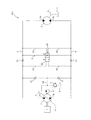
以下、図面を参照して、本発明の第1実施形態に係る流体圧制御装置100について説明する。図1は、流体圧制御装置100を示す油圧回路図である。
First Embodiment
Hereinafter, a fluid pressure control device 100 according to a first embodiment of the present invention will be described with reference to the drawings. FIG. 1 is a hydraulic circuit diagram showing a fluid pressure control device 100. As shown in FIG.

流体圧制御装置100は、例えば芝刈り機や農作業機、ホイールローダ等の流体圧によって駆動する作業車両の車体に搭載される。流体圧制御装置100では、作動流体として作動油が用いられるが、作動水等の他の流体を作動流体として用いてもよい。   The fluid pressure control device 100 is mounted on a vehicle body of a working vehicle driven by fluid pressure, such as a lawn mower, a farming machine, a wheel loader, or the like. In the fluid pressure control device 100, hydraulic oil is used as the working fluid, but other fluids such as working water may be used as the working fluid.

図1に示すように、流体圧制御装置100は、作動油を吐出する吐出装置としての双方向ポンプ1と、双方向ポンプ1から吐出された作動油によって駆動される流体圧モータとしての油圧モータ2と、双方向ポンプ1の第1ポートとしての一方のポート1aと油圧モータ2の一方のポート2aとを接続する第1接続流路としての接続流路3と、双方向ポンプ1の第2ポートとしての他方のポート1bと油圧モータ2の他方のポート2bとを接続する第2接続流路としての接続流路4と、接続流路3と接続流路4とを接続するバイパス流路としての連通路5と、連通路5に設けられる開閉弁6と、を備える。   As shown in FIG. 1, the fluid pressure control device 100 includes a bidirectional pump 1 as a discharge device for discharging hydraulic fluid, and a hydraulic motor as a fluid pressure motor driven by hydraulic fluid discharged from the bidirectional pump 1. 2, a connection flow path 3 as a first connection flow path connecting the one port 1 a as the first port of the bidirectional pump 1 and the one port 2 a of the hydraulic motor 2, and the second of the bidirectional pump 1 Connection flow path 4 as a second connection flow path connecting the other port 1 b as a port and the other port 2 b of the hydraulic motor 2, and bypass flow path connecting the connection flow path 3 and the connection flow path 4 The communication passage 5 and the on-off valve 6 provided in the communication passage 5 are provided.

双方向ポンプ1は、エンジンEの動力によって駆動される斜板型アキシャルピストンポンプである。双方向ポンプ1は、斜板1cの傾転角を調整することで、作動油の吐出容量を調整できると共に、作動油を吐出する方向(ポート1a及びポート1bのいずれから吐出するか)を制御できる可変容量型のポンプである。双方向ポンプ1では、斜板1cを軸支するトラニオン軸(図示せず)に連結された調整部材としての操作レバー7を操作することによって斜板1cの傾転角が調整される。   The bidirectional pump 1 is a swash plate type axial piston pump driven by the power of the engine E. The bidirectional pump 1 can adjust the displacement of the hydraulic fluid by adjusting the tilt angle of the swash plate 1c, and control the direction in which the hydraulic fluid is discharged (port 1a or port 1b). It is a variable displacement pump that can In the bidirectional pump 1, the tilt angle of the swash plate 1c is adjusted by operating the operation lever 7 as an adjustment member connected to a trunnion shaft (not shown) that pivotally supports the swash plate 1c.

油圧モータ2は、内接式のギヤモータであり、車輪を駆動するための走行用油圧モータとして使用される。油圧モータ2は、双方向ポンプ1から吐出された作動油の供給を受けて回転駆動される。油圧モータ2は、双方向ポンプ1から吐出される作動油の流れの向きによって正回転あるいは逆回転に切り換えられる。具体的には、双方向ポンプ1のポート1aから吐出された作動油が接続流路3を通じて油圧モータ2の2aに導かれることで油圧モータ2は正回転し、作業車両が前進する。これに対して、双方向ポンプ1のポート1bから吐出された作動油が接続流路4を通じて油圧モータ2の2bに導かれることで、油圧モータ2は逆回転し、作業車両が後進する。   The hydraulic motor 2 is an internal gear motor, and is used as a traveling hydraulic motor for driving wheels. The hydraulic motor 2 is rotationally driven in response to the supply of hydraulic fluid discharged from the bidirectional pump 1. The hydraulic motor 2 is switched to forward rotation or reverse rotation depending on the flow direction of the hydraulic fluid discharged from the bidirectional pump 1. Specifically, the hydraulic fluid discharged from the port 1a of the bidirectional pump 1 is guided to the hydraulic motor 2a of the hydraulic motor 2 through the connection flow path 3, whereby the hydraulic motor 2 rotates forward and the work vehicle advances. On the other hand, the hydraulic oil discharged from the port 1b of the bidirectional pump 1 is guided to the hydraulic motor 2b through the connection flow path 4, whereby the hydraulic motor 2 rotates in the reverse direction, and the work vehicle moves backward.

油圧モータ2には、内部漏れが存在する。内部漏れした作動油は、ドレン通路2cを通じてタンクTに戻される。なお、油圧モータ2は、容量が固定である内接式ギヤモータに限らず、斜板型アキシャルピストンモータ、あるいは、容量が可変である斜板型アキシャルピストンモータなどであってもよい。   The hydraulic motor 2 has an internal leak. The hydraulic oil that has leaked inside is returned to the tank T through the drain passage 2c. The hydraulic motor 2 is not limited to the internal gear motor having a fixed capacity, but may be a swash plate type axial piston motor or a swash plate type axial piston motor having a variable capacity.

開閉弁6は、連通位置Aでは連通路5を開通し、遮断位置B及び遮断位置Cでは連通路5を遮断する。開閉弁6は、連通路5を遮断または開通するための弁体を操作する操作部材としての操作レバー6aを有する。開閉弁6の操作レバー6aは、双方向ポンプ1の操作レバー7に機械式のリンク機構8によって機械的に連結される。これにより、操作レバー7の操作に応じて開閉弁6の操作レバー6aが操作される。   The on-off valve 6 opens the communication passage 5 at the communication position A, and blocks the communication passage 5 at the blocking position B and the blocking position C. The on-off valve 6 has an operating lever 6 a as an operating member for operating a valve for blocking or opening the communication passage 5. The control lever 6 a of the on-off valve 6 is mechanically coupled to the control lever 7 of the bidirectional pump 1 by a mechanical link mechanism 8. Thus, the operating lever 6 a of the on-off valve 6 is operated in accordance with the operation of the operating lever 7.

図2は、操作レバー7の操作範囲を示す図である。操作レバー7が中立位置及び中立位置から一定の操作範囲P内で操作されているとき、操作レバー6aも一定の操作範囲内で操作されるため、開閉弁6は連通位置Aに保持される。また、操作レバー7が一定の操作範囲Pを超えて一方側に操作されると、操作レバー6aも一定の操作範囲を超えて操作されるため、開閉弁6は遮断位置Bに切り換わる。操作レバー7が一定の操作範囲Pを超えて他方側に操作されると、操作レバー6aも一定の操作範囲を超えて操作されるため、開閉弁6は遮断位置Cに切り換わる。   FIG. 2 is a view showing an operating range of the operating lever 7. When the operating lever 7 is operated within the predetermined operating range P from the neutral position and the neutral position, the operating lever 6a is also operated within the predetermined operating range, so the on-off valve 6 is held at the communication position A. When the control lever 7 is operated to one side beyond the predetermined operation range P, the open / close valve 6 is switched to the blocking position B because the operation lever 6a is also operated beyond the predetermined operation range. When the control lever 7 is operated to the other side beyond the predetermined operation range P, the open / close valve 6 is switched to the blocking position C because the operation lever 6a is also operated beyond the predetermined operation range.

流体圧制御装置100は、エンジンEによって駆動され双方向ポンプ1と同軸に設けられるチャージポンプ9と、チャージポンプ9から吐出された作動油を接続流路3及び接続流路4に導くチャージ流路10と、チャージ流路10とタンクTとを接続する流路に設けられるリリーフ弁11と、をさらに備える。   The fluid pressure control device 100 includes a charge pump 9 driven by the engine E and provided coaxially with the bidirectional pump 1 and a charge flow path for guiding the hydraulic oil discharged from the charge pump 9 to the connection flow path 3 and the connection flow path 4 And a relief valve 11 provided in a flow path connecting the charge flow path 10 and the tank T.

チャージポンプ9は、タンクTから吸い込んだ作動油をチャージ流路10に吐出する。チャージポンプ9から吐出された作動油は、接続流路3,4の作動油が不足している場合にチャージ流路10からチェック弁12を通じて接続流路3,4に充填される。リリーフ弁11は、チャージ流路10の圧力が所定値を超えて上昇すると、開弁して作動油をタンクTに排出する。   The charge pump 9 discharges the hydraulic oil sucked from the tank T to the charge flow path 10. The hydraulic oil discharged from the charge pump 9 is charged from the charge flow path 10 through the check valve 12 into the connection flow paths 3 and 4 when the hydraulic oil in the connection flow paths 3 and 4 is insufficient. The relief valve 11 opens and discharges the hydraulic oil to the tank T when the pressure in the charge flow passage 10 rises above a predetermined value.

以上のように構成された流体圧制御装置100の動作について説明する。はじめに、停止状態から作業車両を前進させる場合について説明する。   The operation of the fluid pressure control device 100 configured as described above will be described. First, the case of advancing the work vehicle from the stopped state will be described.

乗務員が操作レバー7を一方側に向かって徐々に操作すると、双方向ポンプ1の斜板1cが中立位置から一方側に徐々に傾き、双方向ポンプ1のポート1aから斜板1cの傾転角に応じた流量の作動油が接続流路3に吐出される。このとき、開閉弁6の操作レバー6aは、操作レバー7とリンク機構8によって連結されているため、操作レバー7の操作に連動して動作する。操作レバー7をわずかに操作したとき、具体的には図2の操作範囲Q内で操作したときは、開閉弁6の操作レバー6aも一定の操作範囲内にあり、開閉弁6は連通位置Aに維持される。このため、双方向ポンプ1から接続流路3に吐出された作動油は、全量が連通路5を通って吸込側である接続流路4に戻される。したがって、油圧モータ2は駆動されない。このように、双方向ポンプ1が作動油を吐出しているにもかかわらず、油圧モータ2が作動しない状況、及びこのような状況の操作レバー7の操作範囲Qを、以下では「中立状態」または「中立領域」という。   When the crew operates the control lever 7 gradually toward one side, the swash plate 1c of the bidirectional pump 1 gradually inclines from the neutral position to one side, and the tilting angle of the swash plate 1c from the port 1a of the bidirectional pump 1 The hydraulic fluid of the flow rate according to is discharged to the connection flow path 3. At this time, since the control lever 6 a of the on-off valve 6 is connected to the control lever 7 by the link mechanism 8, the control lever 6 a operates in conjunction with the operation of the control lever 7. When the operating lever 7 is operated slightly, specifically, when operating within the operating range Q of FIG. 2, the operating lever 6a of the on-off valve 6 is also within a certain operating range, and the on-off valve 6 is in the communication position A Maintained. Therefore, the whole amount of the hydraulic oil discharged from the bidirectional pump 1 to the connection flow path 3 is returned to the connection flow path 4 on the suction side through the communication path 5. Therefore, the hydraulic motor 2 is not driven. In this way, the situation where the hydraulic motor 2 does not operate even though the bidirectional pump 1 discharges the hydraulic fluid, and the operating range Q of the operating lever 7 in such a situation, in the following "neutral state" Or it is called "neutral area".

この状態から操作レバー7をさらに操作する、具体的には、操作レバー7を操作範囲P内で操作範囲Q外(操作範囲R)まで操作すると、双方向ポンプ1の斜板1cがさらに傾き、双方向ポンプ1から吐出される作動油の流量が大きくなる。この状態では、開閉弁6の操作レバー6aも一定の操作範囲内にあり、開閉弁6は連通位置Aに維持される。しかしながら、この状態では、双方向ポンプ1から吐出される作動油の流量が大きくなるため、双方向ポンプ1から吐出された作動油の全量を連通路5から接続流路4に戻すことができなくなる。これにより、接続流路4に戻すことができなかった作動油はポート2aから油圧モータ2に供給され、油圧モータ2が始動する。よって、作業車両が前進を開始する。このように、双方向ポンプ1が吐出した作動油の一部によって油圧モータ2が作動する状況、及びこのような状況の操作レバー7の操作範囲Rを、以下では「微速状態」または「微速領域」という。   Further operating the operating lever 7 from this state, specifically, when the operating lever 7 is operated out of the operating range Q (operating range R) within the operating range P, the swash plate 1c of the bidirectional pump 1 is further inclined; The flow rate of the hydraulic oil discharged from the bidirectional pump 1 is increased. In this state, the operating lever 6a of the on-off valve 6 is also in a certain operating range, and the on-off valve 6 is maintained at the communication position A. However, in this state, since the flow rate of the hydraulic fluid discharged from the bidirectional pump 1 becomes large, the entire amount of the hydraulic fluid discharged from the bidirectional pump 1 can not be returned from the communication passage 5 to the connection passage 4 . As a result, the hydraulic oil that can not be returned to the connection flow path 4 is supplied from the port 2 a to the hydraulic motor 2, and the hydraulic motor 2 is started. Thus, the work vehicle starts to move forward. As described above, the condition where the hydraulic motor 2 operates by part of the hydraulic fluid discharged by the bidirectional pump 1, and the operation range R of the control lever 7 in such a condition are hereinafter referred to as "slow speed state" or "slow speed area" "

この状態から操作レバー7をさらに操作範囲Pを超えて操作すると、双方向ポンプ1の斜板1cがさらに傾く。これと同時に、開閉弁6の操作レバー6aも一定の操作範囲を超えて操作されるので、開閉弁6は遮断位置Bに切り換えられる。このため、連通路5は遮断され、双方向ポンプ1から接続流路3に吐出された作動油は、全量、油圧モータ2に供給される。この操作範囲Pを超えた領域では、油圧モータ2には、操作レバー7の操作量に応じた流量が供給される。したがって、作業車両は、操作レバー7の操作量に応じた速度で前進する。このように、双方向ポンプ1が吐出した作動油の全量によって油圧モータ2が作動する状況、及びこのような状況の操作レバー7の操作範囲を、以下では「通常走行状態」または「通常走行領域」という。   When the control lever 7 is further operated beyond the operating range P from this state, the swash plate 1c of the bidirectional pump 1 is further inclined. At the same time, the operating lever 6a of the on-off valve 6 is also operated beyond a certain operating range, so the on-off valve 6 is switched to the blocking position B. For this reason, the communication passage 5 is shut off, and the hydraulic oil discharged from the bidirectional pump 1 to the connection passage 3 is supplied to the hydraulic motor 2 as a whole. In the region beyond the operation range P, the hydraulic motor 2 is supplied with a flow rate corresponding to the amount of operation of the operation lever 7. Therefore, the work vehicle advances at a speed corresponding to the amount of operation of the control lever 7. As described above, the condition in which the hydraulic motor 2 is operated by the total amount of hydraulic fluid discharged by the bidirectional pump 1, and the operation range of the operation lever 7 in such a condition are hereinafter referred to as "normal traveling state" or "normal traveling area "

このように、流体圧制御装置100では、操作レバー7が一定の操作範囲Q内で操作されているときには、連通路5が開通した状態に維持され、双方向ポンプ1から吐出される作動油が油圧モータ2に供給されることがない。これにより、双方向ポンプ1の中立領域を確保できる。また、通常走行状態では、開閉弁6を通じて接続流路4に作動油が戻されることがないので、双方向ポンプ1の容積効率を向上させることができる。   As described above, in the fluid pressure control device 100, when the operation lever 7 is operated within the predetermined operation range Q, the communication passage 5 is maintained in the open state, and the hydraulic oil discharged from the bidirectional pump 1 is It is not supplied to the hydraulic motor 2. Thereby, the neutral region of the bidirectional pump 1 can be secured. In addition, since the hydraulic oil is not returned to the connection flow path 4 through the on-off valve 6 in the normal traveling state, the volumetric efficiency of the bidirectional pump 1 can be improved.

また、流体圧制御装置100では、中立領域と通常走行領域の間に、微速領域を設けている。微速領域が設けられていないと、中立状態から通常走行状態にいきなり切り換わるため油圧モータ2がショックを伴って始動するおそれがある。具体的に説明すると、中立状態では、双方向ポンプ1から接続流路3に吐出された作動油は、全量が連通路5を通って吸込側である接続流路4に戻され、油圧モータ2は停止している。この状態から、微速状態を経ることなく通常走行状態に切り換えられると、連通路5から接続流路4に戻されていた作動油が、急に油圧モータ2に供給されることになる。例えば、操作レバー7をゆっくりと操作した場合においても、このように急激に油圧モータ2に作動油が供給されると、操作レバー7をゆっくりと操作しているにもかかわらず、油圧モータ2がショックを伴って始動するおそれがある。   Further, in the fluid pressure control device 100, a low speed region is provided between the neutral region and the normal travel region. If the low speed region is not provided, the hydraulic motor 2 may start with a shock since the neutral state is suddenly switched to the normal running state. Specifically, in the neutral state, the whole amount of the hydraulic oil discharged from the bidirectional pump 1 to the connection flow path 3 is returned to the connection flow path 4 on the suction side through the communication path 5 and the hydraulic motor 2 Has stopped. From this state, when the vehicle is switched to the normal traveling state without passing through the slow speed state, the hydraulic oil returned from the communication passage 5 to the connection flow passage 4 is suddenly supplied to the hydraulic motor 2. For example, even when the operating lever 7 is operated slowly, when the hydraulic motor 2 is thus rapidly supplied with hydraulic fluid, the hydraulic motor 2 operates slowly even though the operating lever 7 is operated slowly. There is a risk of starting with a shock.

そこで、流体圧制御装置100では、上述のように微速領域を設けて、吐出された作動油の全量を連通路5を通じて接続流路4に戻すことができなくなったときに、作動油の一部によって油圧モータ2を始動するように構成している。これにより、油圧モータ2は小さな流量によって始動するので、始動時のショックを抑制できる。   Therefore, in the fluid pressure control device 100, when the slow speed region is provided as described above, and it is not possible to return the entire amount of the discharged hydraulic oil to the connection flow path 4 through the communication path 5, a part of the hydraulic oil Is configured to start the hydraulic motor 2. As a result, the hydraulic motor 2 is started with a small flow rate, so it is possible to suppress the shock at the start.

次に、走行状態から作業車両を停止させる場合について説明する。   Next, the case of stopping the work vehicle from the traveling state will be described.

通常走行状態から操作レバー7の操作量を小さくすると、双方向ポンプ1の斜板1cの傾きが小さくなって、双方向ポンプ1から吐出される作動油の流量も小さくなる。したがって、油圧モータ2の回転速度が減少する。   When the operation amount of the control lever 7 is reduced from the normal traveling state, the inclination of the swash plate 1c of the bidirectional pump 1 becomes smaller, and the flow rate of the hydraulic fluid discharged from the bidirectional pump 1 also becomes smaller. Therefore, the rotational speed of the hydraulic motor 2 is reduced.

この状態から、上述した微速領域(操作範囲R)内まで操作レバー7の操作量を小さくすると、開閉弁6が遮断位置Bから連通位置Aに切り換えられ、連通路5が開通する。これにより、双方向ポンプ1から吐出される作動油の一部が連通路5を通って接続流路4に戻され、油圧モータ2はさらに減速する。   From this state, when the operation amount of the operation lever 7 is reduced to within the above-described slow speed region (operation range R), the on-off valve 6 is switched from the blocking position B to the communication position A, and the communication passage 5 is opened. As a result, part of the hydraulic oil discharged from the bidirectional pump 1 is returned to the connection flow path 4 through the communication path 5, and the hydraulic motor 2 is further decelerated.

この状態から、さらに中立領域(操作範囲Q)内まで操作レバー7の操作量を小さくすると、双方向ポンプ1から吐出される作動油の全量が連通路5を通って接続流路4に戻されるので、油圧モータ2はさらに減速する。さらに、操作レバー7が中立位置に戻されると、斜板1cの傾転角が0になり、双方向ポンプ1から作動油は吐出されなくなる。   From this state, when the operation amount of the operation lever 7 is further reduced to the neutral region (operation range Q), the entire amount of hydraulic oil discharged from the bidirectional pump 1 is returned to the connection flow passage 4 through the communication passage 5 Therefore, the hydraulic motor 2 is further decelerated. Furthermore, when the control lever 7 is returned to the neutral position, the tilt angle of the swash plate 1c becomes zero, and the hydraulic fluid is not discharged from the bidirectional pump 1.

操作レバー7が中立領域または中立位置まで戻されたときには、作業車両は慣性によって前進を続けるため、油圧モータ2が強制的に回転させられる。これにより、油圧モータ2はポート2aから作動油を吸い込んでポート2bから吐出する。このようにしてポート2bから吐出された作動油は、連通路5及び開閉弁6を通じて接続流路3に戻される。このとき、作動油が開閉弁6を通過するときに生じる圧力損失や油圧モータ2で生じる圧力損失によって、油圧モータ2に制動力が作用するため、油圧モータ2は徐々に減速されて停止する。このように、流体圧制御装置100は、操作レバー7が中立位置に戻されたときに、開閉弁6が連通路5を開通するように構成されているので、油圧モータ2はがショックを伴わずに、滑らかに停止することができる。   When the control lever 7 is returned to the neutral region or the neutral position, the hydraulic vehicle 2 is forcibly rotated because the work vehicle continues to move forward by inertia. Thus, the hydraulic motor 2 sucks in hydraulic fluid from the port 2a and discharges it from the port 2b. The hydraulic fluid thus discharged from the port 2 b is returned to the connection flow path 3 through the communication path 5 and the on-off valve 6. At this time, the hydraulic motor 2 is gradually decelerated and stopped because the braking force acts on the hydraulic motor 2 due to the pressure loss generated when the hydraulic oil passes through the on-off valve 6 and the pressure loss generated by the hydraulic motor 2. As described above, the fluid pressure control device 100 is configured such that the on-off valve 6 opens the communication passage 5 when the control lever 7 is returned to the neutral position, so the hydraulic motor 2 is accompanied by a shock. Without it, it can be stopped smoothly.

流体圧制御装置100では、開閉弁6は、操作レバー7の操作量が一定値以上(操作範囲P外)であるときに閉弁して連通路5を遮断し、操作レバー7の操作量が一定値未満(操作範囲P内)であるときには開弁して連通路5を開通する。操作レバー7の操作量は、双方向ポンプ1が吐出する作動油の流量に対応する。つまり、流体圧制御装置100では、開閉弁6は、双方向ポンプ1から吐出される作動油の流量が一定値以上であるときには閉弁して連通路5を遮断し、双方向ポンプ1から吐出される作動油の流量が一定値未満であるときには開弁して連通路5を開通する。   In the fluid pressure control device 100, when the operation amount of the operation lever 7 is a predetermined value or more (outside of the operation range P), the on-off valve 6 closes the valve to shut off the communication passage 5, and the operation amount of the operation lever 7 When it is less than a predetermined value (within the operation range P), the communication passage 5 is opened by opening the valve. The operation amount of the operation lever 7 corresponds to the flow rate of the hydraulic fluid discharged by the bidirectional pump 1. That is, in the fluid pressure control device 100, the on-off valve 6 closes the communication passage 5 when the flow rate of the hydraulic fluid discharged from the bidirectional pump 1 is equal to or more than a predetermined value, and shuts off the communication passage 5. When the flow rate of the hydraulic oil to be fed is less than a predetermined value, the communication passage 5 is opened to open.

また、流体圧制御装置100は、作業車両が下り坂を微速領域で走行する際に、走行を安定させることができるという効果を奏する。以下に、この効果について具体的に説明する。   Further, the fluid pressure control device 100 has an effect that the traveling can be stabilized when the work vehicle travels on the downhill in the low speed region. Below, this effect is demonstrated concretely.

作業車両を微速で走行させる際には、操作レバー7は上述した微速領域(操作範囲R内)で操作される。このとき、双方向ポンプ1から操作レバー7の操作量に応じた作動油が接続流路3に吐出される。この状態では、上述のように、開閉弁6が連通位置Aに位置するので、双方向ポンプ1から吐出された作動油は、一部が連通路5を通じて接続流路4に戻される。また、残りの作動油は油圧モータ2に供給され、油圧モータ2が駆動される。   When the work vehicle travels at a low speed, the operation lever 7 is operated in the above-described low speed region (within the operation range R). At this time, hydraulic fluid corresponding to the operation amount of the control lever 7 is discharged from the bidirectional pump 1 to the connection flow path 3. In this state, as described above, since the on-off valve 6 is located at the communication position A, a portion of the hydraulic oil discharged from the bidirectional pump 1 is returned to the connection flow path 4 through the communication path 5. Further, the remaining hydraulic oil is supplied to the hydraulic motor 2 and the hydraulic motor 2 is driven.

作業車両が下り坂を走行していると、作業車両は自重により加速する。これにより、油圧モータ2が強制的に回転されるため、油圧モータ2はポート2aから作動油を吸い込んでポート2bに吐出する油圧ポンプとして機能してしまう。   When the work vehicle travels downhill, the work vehicle accelerates by its own weight. As a result, the hydraulic motor 2 is forced to rotate, so the hydraulic motor 2 functions as a hydraulic pump that sucks in hydraulic fluid from the port 2a and discharges it to the port 2b.

ここで、比較のために、連通路5及び開閉弁6を備えていない構成について説明する。連通路5及び開閉弁6を備えていない場合、油圧モータ2のポート2bから吐出された作動油は、双方向ポンプ1のポート1bに向かって流れる。しかしながら、上述のように油圧モータ2が油圧ポンプとして機能してしまうと、双方向ポンプ1における吸い込み量を上回る作動油が接続流路4内に供給されてしまうため、接続流路4内の圧力が接続流路3内の圧力よりも上昇する。このとき、内接式ギヤモータで構成される油圧モータ2では、内外のギヤの間から漏れが発生し、作動油が接続流路4側から接続流路3側に向かって作動油が逆流してしまうことがある。このような漏れが生じると、一時的に接続流路4の圧力が下がる。その後、油圧モータ2から供給される作動油によって、接続流路4の圧力が再び上昇する。このような圧力の上昇と下降を繰りかえすことで油圧モータ2にハンチングが生じ、作業車両の動作がギクシャクすることがある。   Here, for comparison, a configuration in which the communication passage 5 and the on-off valve 6 are not provided will be described. When the communication passage 5 and the on-off valve 6 are not provided, the hydraulic oil discharged from the port 2 b of the hydraulic motor 2 flows toward the port 1 b of the bidirectional pump 1. However, when the hydraulic motor 2 functions as a hydraulic pump as described above, the hydraulic oil exceeding the suction amount in the bidirectional pump 1 is supplied into the connection flow path 4, so the pressure in the connection flow path 4 Increases above the pressure in the connection channel 3. At this time, in the hydraulic motor 2 configured by the internal gear motor, a leak occurs between the inner and outer gears, and the hydraulic oil flows back from the connection flow path 4 to the connection flow path 3 There are times when When such a leak occurs, the pressure in the connection channel 4 temporarily decreases. Thereafter, the pressure of the connection flow path 4 is increased again by the hydraulic oil supplied from the hydraulic motor 2. By repeating the rise and fall of such pressure, hunting occurs in the hydraulic motor 2 and the operation of the work vehicle may be jerky.

流体圧制御装置100では、開閉弁6が微速領域において連通路5を開通するように構成されているので、このようにして接続流路4の圧力が上昇したときに、連通路5を通じて接続流路3に圧力を逃がすことができる。したがって、作業車両が下り坂を微速走行しているときに、ハンチングが起こることを抑制できるので走行が安定する。   In the fluid pressure control device 100, since the on-off valve 6 is configured to open the communication passage 5 in the low speed region, when the pressure of the connection flow passage 4 is thus increased, the connection flow is performed through the communication passage 5 The pressure can be released to the road 3. Therefore, when the work vehicle travels at a very low speed on the downward slope, it is possible to suppress the occurrence of hunting, and the traveling becomes stable.

なお、作業車両を後進させる場合は、操作レバー7を前進時とは逆方向に操作する。これにより、双方向ポンプ1の斜板1cが前進時と逆方向に傾斜し、双方向ポンプ1のポート1bから作動油が吐出される。また、前進時と同様に、操作レバー7の操作量が操作範囲Pを超えると、開閉弁6が連通位置Aから遮断位置にCに切り換わる。開閉弁6は、前進時と同様に機能するので、以降の説明を省略する。   When moving the work vehicle backward, the operation lever 7 is operated in the reverse direction to that at the time of forward movement. As a result, the swash plate 1c of the bidirectional pump 1 is inclined in the opposite direction to that at the time of forward movement, and the hydraulic oil is discharged from the port 1b of the bidirectional pump 1. Further, as in the forward movement, when the operation amount of the operation lever 7 exceeds the operation range P, the on-off valve 6 switches from the communication position A to the blocking position C. Since the on-off valve 6 functions in the same manner as at the time of forward movement, the description thereof will be omitted.

以上の第1実施形態によれば、以下の効果を奏する。   According to the first embodiment described above, the following effects can be obtained.

操作レバー7が通常走行領域で操作されているとき、つまり、双方向ポンプ1から吐出される作動油の流量が一定値以上であるときには、連通路5が開閉弁6によって遮断される。これにより、双方向ポンプ1から吐出された作動油が全量油圧モータ2に供給されるので、双方向ポンプ1の容積効率が向上する。また、操作レバー7が中立領域(操作範囲Q)内で操作されているとき、つまり、双方向ポンプ1から吐出される作動油の流量が一定値未満であるときには、開閉弁6が連通位置Aに位置し連通路5が開通する。これにより、双方向ポンプ1から吐出される作動油は油圧モータ2に供給されることなく、高圧側の接続流路3または接続流路4から連通路5を通じて低圧側の接続流路3または接続流路4に戻されるので、双方向ポンプ1の中立領域を確保できる。よって、流体圧制御装置100によれば、双方向ポンプ1の中立領域を確保しつつ、容積効率を向上することができる。   When the control lever 7 is operated in the normal travel area, that is, when the flow rate of the hydraulic fluid discharged from the bidirectional pump 1 is equal to or more than a predetermined value, the communication passage 5 is shut off by the on-off valve 6. As a result, since the entire amount of hydraulic oil discharged from the bidirectional pump 1 is supplied to the hydraulic motor 2, the volumetric efficiency of the bidirectional pump 1 is improved. Further, when the control lever 7 is operated in the neutral range (operation range Q), that is, when the flow rate of the hydraulic fluid discharged from the bidirectional pump 1 is less than a predetermined value, the on-off valve 6 is in the communication position A And the communication passage 5 is opened. Thereby, the hydraulic fluid discharged from the bidirectional pump 1 is not supplied to the hydraulic motor 2, and the connection channel 3 or connection channel 4 on the high pressure side through the communication channel 5 to the connection channel 3 or connection on the low pressure side Since it returns to the flow path 4, the neutral region of the bidirectional pump 1 can be secured. Therefore, according to the fluid pressure control device 100, volumetric efficiency can be improved while securing the neutral region of the bidirectional pump 1.

流体圧制御装置100では、開閉弁6が微速領域において連通路5を開通するように構成されているので、作業車両が下り坂を微速走行しているときに、油圧モータ2が油圧ポンプとして機能して接続流路4の圧力が上昇しても、連通路5を通じて接続流路3に圧力を逃がすことができる。したがって、作業車両が下り坂を微速走行しているときに油圧モータ2がハンチングを起こすことを抑制できるので、作業車両の走行を安定させることができる。   In the fluid pressure control device 100, the on-off valve 6 is configured to open the communication passage 5 in the low speed region, so the hydraulic motor 2 functions as a hydraulic pump when the work vehicle travels at a low speed at a downward slope. Thus, even if the pressure in the connection channel 4 is increased, the pressure can be released to the connection channel 3 through the communication channel 5. Therefore, it is possible to suppress the occurrence of hunting in the hydraulic motor 2 when the work vehicle travels at a very low speed on the downward slope, so that the travel of the work vehicle can be stabilized.

また、流体圧制御装置100では、開閉弁6の操作レバー6aは、双方向ポンプ1の操作レバー7に機械的に連結されている。これにより、開閉弁6は、操作レバー7の動作に伴って開閉されるため、開閉弁6の動作を安定させることができる。   Further, in the fluid pressure control device 100, the control lever 6 a of the on-off valve 6 is mechanically connected to the control lever 7 of the bidirectional pump 1. As a result, the on-off valve 6 is opened and closed in accordance with the operation of the control lever 7, so that the operation of the on-off valve 6 can be stabilized.

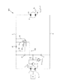
なお、開閉弁6は、図3に示す開閉弁16のように構成してもよい。この変形例について以下に説明する。   The on-off valve 6 may be configured as the on-off valve 16 shown in FIG. 3. This modification will be described below.

図3に示す変形例では、開閉弁16は、操作レバー7が中立位置にあるときに連通路5を遮断する遮断位置Dを備えている。これにより、操作レバー7が中立位置にあるとき、すなわち、双方向ポンプ1から作動油が吐出されないときに、油圧モータ2を油圧回路でロックすることができる。これにより、操作レバー7が中立位置にある時に、油圧モータ2が自走してしまうことを防止できる。   In the modification shown in FIG. 3, the on-off valve 16 is provided with a blocking position D for blocking the communication passage 5 when the control lever 7 is in the neutral position. Thereby, when the control lever 7 is in the neutral position, that is, when the hydraulic fluid is not discharged from the bidirectional pump 1, the hydraulic motor 2 can be locked by the hydraulic circuit. As a result, when the control lever 7 is in the neutral position, the hydraulic motor 2 can be prevented from traveling by itself.

このように、開閉弁6に代えて開閉弁16を備えることにより、操作レバー7が中立位置にあるときに油圧モータ2をロックすることができるので、機械的なロック機構を不要にできる。   As described above, by providing the on-off valve 16 instead of the on-off valve 6, the hydraulic motor 2 can be locked when the control lever 7 is in the neutral position, so that a mechanical lock mechanism can be eliminated.

<第2実施形態>
図4を参照して、本発明の第2実施形態に係る流体圧制御装置200について説明する。以下では、上述した第1実施形態と異なる点を中心に説明し、第1実施形態の流体圧制御装置100と同一の構成には、同一の符号を付して説明を省略する。
Second Embodiment
A fluid pressure control device 200 according to a second embodiment of the present invention will be described with reference to FIG. Hereinafter, differences from the above-described first embodiment will be mainly described, and the same components as those of the fluid pressure control device 100 of the first embodiment will be assigned the same reference numerals and descriptions thereof will be omitted.

第1実施形態では、開閉弁6が、双方向ポンプ1の操作レバー7の動きに伴って開閉するのに対し、第2実施形態では、開閉弁60が接続流路3,4から導かれる圧力の差に応じて開閉する点で相違する。以下、具体的に説明する。   In the first embodiment, the on-off valve 6 opens and closes in response to the movement of the control lever 7 of the bidirectional pump 1, while in the second embodiment, the pressure at which the on-off valve 60 is led from the connection flow paths 3 and 4 It differs in that it opens and closes according to the difference of. The details will be described below.

流体圧制御装置200は、連通路5に設けられた開閉弁60と、接続流路3の連通路5との合流点よりも双方向ポンプ1側に設けられた第1オリフィスとしてのオリフィス31と、接続流路4の連通路5との合流点よりも双方向ポンプ1側に設けられた第2オリフィスとしてのオリフィス41と、を備える。   The fluid pressure control device 200 includes an opening / closing valve 60 provided in the communication passage 5 and an orifice 31 as a first orifice provided on the bidirectional pump 1 side with respect to a junction of the communication passage 5 of the connection flow passage 3. And an orifice 41 as a second orifice provided closer to the bidirectional pump 1 than a junction of the connection flow path 4 with the communication path 5.

開閉弁60は、連通位置Eでは連通路5を開通し、遮断位置Fでは連通路5を遮断する。開閉弁60は、開閉弁60を閉弁方向である遮断位置F側に付勢するばね61を備える。開閉弁60には、オリフィス31の双方向ポンプ1側の圧力とオリフィス41の双方向ポンプ1側の圧力とがそれぞれ流路32,42を通じて閉弁方向に作用すると共に、オリフィス31の油圧モータ2側の圧力とオリフィス41の油圧モータ2側の圧力とがそれぞれ流路33,43を通じて開弁方向に作用する。   The on-off valve 60 opens the communication passage 5 at the communication position E and blocks the communication passage 5 at the blocking position F. The on-off valve 60 includes a spring 61 that biases the on-off valve 60 toward the blocking position F in the valve closing direction. In the on-off valve 60, the pressure on the bidirectional pump 1 side of the orifice 31 and the pressure on the bidirectional pump 1 side of the orifice 41 act in the valve closing direction through the flow paths 32 and 42, respectively. The pressure on the side and the pressure on the hydraulic motor 2 side of the orifice 41 act in the valve opening direction through the flow paths 33 and 43, respectively.

以上のように構成された流体圧制御装置200の動作について説明する。はじめに、停止状態から作業車両を前進させる場合について説明する。   The operation of the fluid pressure control device 200 configured as described above will be described. First, the case of advancing the work vehicle from the stopped state will be described.

乗務員が操作レバー7を一方側に向かって徐々に操作すると、双方向ポンプ1の斜板1cが中立位置から一方側に徐々に傾き、双方向ポンプ1のポート1aから斜板1cの傾転角に応じた流量の作動油が接続流路3に吐出される。このとき、接続流路3における上流側(オリフィス31の双方向ポンプ1側)の圧力が、流路32を通じて開閉弁60の閉弁方向に作用し、オリフィス31の下流側(油圧モータ2側)の圧力が流路33を通じて開閉弁60の開弁方向に作用する。この状態では、双方向ポンプ1から吐出される作動油の流量が小さいため、オリフィス31の前後での差圧による閉弁方向(開閉弁60を遮断位置Fに切り換える方向)への付勢力よりも、ばね61による開弁方向(開閉弁60を連通位置Eに切り換える方向)への付勢力が大きいため、開閉弁60は連通位置Eに保持される。これにより、双方向ポンプ1から接続流路3に吐出された高圧の作動油は、全量が連通路5を通って吸込側である接続流路4に戻される。したがって、油圧モータ2は駆動されない。   When the crew operates the control lever 7 gradually toward one side, the swash plate 1c of the bidirectional pump 1 gradually inclines from the neutral position to one side, and the tilting angle of the swash plate 1c from the port 1a of the bidirectional pump 1 The hydraulic fluid of the flow rate according to is discharged to the connection flow path 3. At this time, the pressure on the upstream side (the bidirectional pump 1 side of the orifice 31) in the connection flow path 3 acts in the valve closing direction of the on-off valve 60 through the flow path 32, and the downstream side of the orifice 31 (hydraulic motor 2 side) Pressure acts in the opening direction of the on-off valve 60 through the flow path 33. In this state, since the flow rate of the hydraulic fluid discharged from the bidirectional pump 1 is small, the biasing force in the valve closing direction (direction for switching the on-off valve 60 to the blocking position F) by the differential pressure before and after the orifice 31 Since the biasing force of the spring 61 in the valve opening direction (the direction of switching the on-off valve 60 to the communication position E) is large, the on-off valve 60 is held at the communication position E. As a result, the high-pressure hydraulic oil discharged from the bidirectional pump 1 to the connection flow path 3 is returned to the connection flow path 4 which is the suction side through the communication path 5. Therefore, the hydraulic motor 2 is not driven.

この状態から操作レバー7をさらに操作する、具体的には、操作レバー7を操作範囲Rまで操作すると、双方向ポンプ1の斜板1cがさらに傾き、双方向ポンプ1から吐出される作動油の流量が大きくなる。この状態では、オリフィス31の前後での差圧(以下、「前後差圧」という。)による閉弁方向(開閉弁60を遮断位置Fに切り換える方向)への付勢力よりも、ばね61による開弁方向(開閉弁60を連通位置Eに切り換える方向)への付勢力が大きいため、開閉弁60は連通位置Eに保持される。しかしながら、この状態では、双方向ポンプ1から吐出される作動油の流量が大きくなるため、双方向ポンプ1から吐出された作動油の全量を連通路5から接続流路4に戻すことができなくなる。これにより、接続流路4に戻すことができなかった作動油はポート2aから油圧モータ2に供給され、油圧モータ2が始動する。よって、作業車両が前進を開始する。   In this state, the operating lever 7 is further operated. Specifically, when the operating lever 7 is operated to the operating range R, the swash plate 1 c of the bidirectional pump 1 is further inclined, and the hydraulic fluid discharged from the bidirectional pump 1 Flow rate increases. In this state, the spring 61 opens more than the biasing force in the valve closing direction (direction in which the on-off valve 60 is switched to the blocking position F) by the differential pressure before and after the orifice 31 (hereinafter referred to as “front-rear differential pressure”). Since the biasing force in the valve direction (the direction in which the on-off valve 60 is switched to the communication position E) is large, the on-off valve 60 is held at the communication position E. However, in this state, since the flow rate of the hydraulic fluid discharged from the bidirectional pump 1 becomes large, the entire amount of the hydraulic fluid discharged from the bidirectional pump 1 can not be returned from the communication passage 5 to the connection passage 4 . As a result, the hydraulic oil that can not be returned to the connection flow path 4 is supplied from the port 2 a to the hydraulic motor 2, and the hydraulic motor 2 is started. Thus, the work vehicle starts to move forward.

この状態から操作レバー7をさらに操作範囲Pを超えて操作すると、双方向ポンプ1の斜板1cがさらに傾く。これにより、双方向ポンプ1から吐出される作動油の流量はさらに大きくなるため、オリフィス31の前後差圧が大きくなり、オリフィス31の前後差圧による閉弁方向(開閉弁60を遮断位置Fに切り換える方向)への付勢力が、ばね61による開弁方向(開閉弁60を連通位置Eに切り換える方向)への付勢力よりも大きくなる。したがって、開閉弁60は遮断位置Fに切り換えられる。このため、連通路5は遮断され、双方向ポンプ1から接続流路3に吐出された作動油は、全量油圧モータ2に供給される。この操作範囲Pを超えた領域では、油圧モータ2には、操作レバー7の操作量に応じた流量が供給され、作業車両は、操作レバー7の操作量に応じた速度で前進する。   When the control lever 7 is further operated beyond the operating range P from this state, the swash plate 1c of the bidirectional pump 1 is further inclined. As a result, the flow rate of the hydraulic fluid discharged from the bidirectional pump 1 further increases, so the differential pressure across the orifice 31 becomes larger, and the valve closing direction (the on-off valve 60 is set to the blocking position F) The biasing force in the switching direction is larger than the biasing force in the valve opening direction (the direction in which the on-off valve 60 is switched to the communication position E) by the spring 61. Therefore, the on-off valve 60 is switched to the blocking position F. For this reason, the communication passage 5 is shut off, and the hydraulic oil discharged from the bidirectional pump 1 to the connection passage 3 is supplied to the hydraulic motor 2 as a whole. In the region beyond the operation range P, the hydraulic motor 2 is supplied with a flow rate corresponding to the operation amount of the operation lever 7, and the work vehicle advances at a speed according to the operation amount of the operation lever 7.

油圧モータ2に供給された作動油は、ポート2bから接続流路4に排出される。上述のように、接続流路4にはオリフィス41が設けられており、オリフィス41の双方向ポンプ1側の圧力が流路42を通じて開閉弁60の閉弁方向に作用すると共に、オリフィス41の油圧モータ2側の圧力が流路43を通じて開閉弁60の開弁方向に作用する。   The hydraulic oil supplied to the hydraulic motor 2 is discharged from the port 2 b to the connection flow path 4. As described above, the connection flow path 4 is provided with the orifice 41, and the pressure on the bidirectional pump 1 side of the orifice 41 acts in the closing direction of the on-off valve 60 through the flow path 42. The pressure on the motor 2 side acts in the opening direction of the on-off valve 60 through the flow path 43.

上述のように、油圧モータ2には、内部リークが存在し、この内部リークはドレン通路2cを通じてタンクTに戻される。このため、接続流路4に排出される作動油の流量は、接続流路3に供給される作動油の流量よりも小さい。したがって、接続流路4に設けられたオリフィス41で発生する前後差圧は、接続流路3に設けられたオリフィス31で発生する前後差圧よりも小さくなる。つまり、開閉弁60は、オリフィス31の前後差圧による閉弁方向への付勢力が、オリフィス41の前後差圧による開弁方向への付勢力とばね61による開弁方向への付勢力との和よりも大きくなったときに、遮断位置Fに切り換えられる。   As described above, there is an internal leak in the hydraulic motor 2, and this internal leak is returned to the tank T through the drain passage 2c. Therefore, the flow rate of the hydraulic oil discharged to the connection flow path 4 is smaller than the flow rate of the hydraulic oil supplied to the connection flow path 3. Therefore, the differential pressure generated in the orifice 41 provided in the connection flow channel 4 is smaller than the differential pressure generated in the orifice 31 provided in the connection flow channel 3. That is, in the on-off valve 60, the biasing force in the valve closing direction by the differential pressure of the orifice 31 is the biasing force in the valve opening direction by the differential pressure of the orifice 41 and the biasing force in the valve opening direction by the spring 61. When it becomes larger than the sum, it is switched to the blocking position F.

オリフィス31,41の前後差圧は、双方向ポンプ1から吐出される作動油の流量に依存する。したがって、開閉弁60は、双方向ポンプ1から吐出される作動油の流量が一定値以上であるときには閉弁して連通路5を遮断し、双方向ポンプ1から吐出される作動油の流量が一定値未満であるときには開弁して連通路5を開通する。   The differential pressure across the orifices 31 and 41 depends on the flow rate of the hydraulic fluid discharged from the bidirectional pump 1. Therefore, the on-off valve 60 closes when the flow rate of the hydraulic fluid discharged from the bidirectional pump 1 is equal to or greater than a predetermined value to shut off the communication passage 5, and the flow rate of the hydraulic fluid discharged from the bidirectional pump 1 is When it is less than a fixed value, the valve is opened to open the communication passage 5.

次に、走行状態から作業車両を停止させる場合について説明する。   Next, the case of stopping the work vehicle from the traveling state will be described.

通常走行状態から操作レバー7の操作量を小さくすると、双方向ポンプ1の斜板1cの傾きが小さくなって、双方向ポンプ1から吐出される作動油の流量も小さくなる。したがって、油圧モータ2の回転速度が減少する。   When the operation amount of the control lever 7 is reduced from the normal traveling state, the inclination of the swash plate 1c of the bidirectional pump 1 becomes smaller, and the flow rate of the hydraulic fluid discharged from the bidirectional pump 1 also becomes smaller. Therefore, the rotational speed of the hydraulic motor 2 is reduced.

この状態から、微速領域(操作範囲R)内まで操作レバー7の操作量を小さくすると、オリフィス31の前後差圧が小さくなるため、開閉弁60が遮断位置Fから連通位置Eに切り換えられ、連通路5が開通する。これにより、双方向ポンプ1から吐出される作動油の一部が連通路5を通って接続流路4に戻され、油圧モータ2はさらに減速する。   From this state, if the operation amount of the operation lever 7 is reduced to within the slow speed region (operation range R), the pressure difference across the orifice 31 decreases, so the on-off valve 60 is switched from the blocking position F to the communication position E. The passage 5 opens. As a result, part of the hydraulic oil discharged from the bidirectional pump 1 is returned to the connection flow path 4 through the communication path 5, and the hydraulic motor 2 is further decelerated.

この状態から、さらに中立領域(操作範囲Q)内まで操作レバー7の操作量を小さくすると、双方向ポンプ1から吐出される作動油の全量が連通路5を通って接続流路4に戻されるので、油圧モータ2はさらに減速する。さらに、操作レバー7が中立位置に戻されると、斜板1cの傾転角が0になり、双方向ポンプ1から作動油は吐出されなくなる。   From this state, when the operation amount of the operation lever 7 is further reduced to the neutral region (operation range Q), the entire amount of hydraulic oil discharged from the bidirectional pump 1 is returned to the connection flow passage 4 through the communication passage 5 Therefore, the hydraulic motor 2 is further decelerated. Furthermore, when the control lever 7 is returned to the neutral position, the tilt angle of the swash plate 1c becomes zero, and the hydraulic fluid is not discharged from the bidirectional pump 1.

操作レバー7が中立領域または中立位置まで戻されたときには、作業車両は慣性によって前進を続けるため、油圧モータ2が強制的に回転させられる。これにより、油圧モータ2はポート2aから作動油を吸い込んでポート2bから吐出する。このようにしてポート2bから吐出された作動油は、連通路5及び開閉弁60を通じて接続流路3に戻される。このとき、作動油が開閉弁60を通過するときに生じる圧力損失や油圧モータ2で生じる圧力損失によって、油圧モータ2に制動力が作用するため、油圧モータ2は徐々に減速されて停止する。このように、流体圧制御装置200は、操作レバー7が中立位置に戻されたときに、開閉弁60が連通路5を開通するように構成されているので、油圧モータ2はがショックを伴わずに、滑らかに停止することができる。   When the control lever 7 is returned to the neutral region or the neutral position, the hydraulic vehicle 2 is forcibly rotated because the work vehicle continues to move forward by inertia. Thus, the hydraulic motor 2 sucks in hydraulic fluid from the port 2a and discharges it from the port 2b. The hydraulic oil thus discharged from the port 2 b is returned to the connection flow path 3 through the communication path 5 and the on-off valve 60. At this time, the braking force acts on the hydraulic motor 2 by the pressure loss generated when the hydraulic oil passes through the on-off valve 60 and the pressure loss generated by the hydraulic motor 2, so the hydraulic motor 2 is gradually decelerated and stopped. As described above, since the fluid pressure control device 200 is configured to open the communication passage 5 when the control lever 7 is returned to the neutral position, the hydraulic motor 2 is accompanied by a shock. Without it, it can be stopped smoothly.

流体圧制御装置200においても、作業車両が下り坂を微速領域で走行する際に、走行を安定させることができるという効果を奏する。以下に、この効果について具体的に説明する。   Also in the fluid pressure control device 200, when the work vehicle travels on the downward slope in the low speed region, the travel can be stabilized. Below, this effect is demonstrated concretely.

作業車両を微速領域で走行させる際には、操作レバー7は微速領域(操作範囲R内)で操作される。このとき、双方向ポンプ1から操作レバー7の操作量に応じた作動油が接続流路3に吐出される。この状態では、上述のように、開閉弁60は連通位置Eに位置するので、双方向ポンプ1から吐出された作動油は、一部が連通路5を通じて接続流路4に戻される。また、残りの作動油によって油圧モータ2が駆動される。   When the work vehicle travels in the low speed region, the operation lever 7 is operated in the low speed region (within the operation range R). At this time, hydraulic fluid corresponding to the operation amount of the control lever 7 is discharged from the bidirectional pump 1 to the connection flow path 3. In this state, as described above, since the on-off valve 60 is located at the communication position E, a portion of the hydraulic oil discharged from the bidirectional pump 1 is returned to the connection channel 4 through the communication channel 5. Further, the hydraulic motor 2 is driven by the remaining hydraulic oil.

作業車両が下り坂を走行していると、作業車両は自重により加速する。これにより、油圧モータ2は強制的に回転されるため、油圧モータ2はポート2aから作動油を吸い込んでポート2bに吐出する油圧ポンプとして機能してしまう。   When the work vehicle travels downhill, the work vehicle accelerates by its own weight. As a result, the hydraulic motor 2 is forced to rotate, so the hydraulic motor 2 functions as a hydraulic pump that sucks in hydraulic fluid from the port 2a and discharges it to the port 2b.

流体圧制御装置200においても、開閉弁60が微速領域において連通路5を開通するように構成されているので、このようにして接続流路4の圧力が上昇したときに、連通路5を通じて接続流路3に圧力を逃がすことができる。したがって、作業車両が下り坂を微速走行しているときに、走行が安定する。   Also in the fluid pressure control device 200, the on-off valve 60 is configured to open the communication passage 5 in the low speed region, so when the pressure in the connection flow passage 4 is increased in this manner, connection is made through the communication passage 5 The pressure can be released to the flow path 3. Therefore, when the work vehicle travels at a very low speed on the downhill, the traveling becomes stable.

作業車両を後進させる場合は、操作レバー7を前進時とは逆方向に操作する。これにより、双方向ポンプ1の斜板1cが前進時と逆方向に傾斜し、双方向ポンプ1のポート1bから作動油を吐出する。このとき、オリフィス41が、前進時におけるオリフィス31と同様に機能し、開閉弁60を切り換えるので、以降の説明を省略する。   When moving the work vehicle backward, the control lever 7 is operated in the reverse direction to that at the time of forward movement. As a result, the swash plate 1c of the bidirectional pump 1 is inclined in the opposite direction to that in forward movement, and the hydraulic fluid is discharged from the port 1b of the bidirectional pump 1. At this time, the orifice 41 functions in the same manner as the orifice 31 at the time of forward movement, and switches the on-off valve 60, so the description thereof will be omitted.

以上の第2実施形態によれば、第1実施形態の効果に加え、以下の効果を奏する。   According to the above second embodiment, in addition to the effects of the first embodiment, the following effects can be obtained.

流体圧制御装置200では、操作レバー7と開閉弁60とを機械的に連結する必要がないので、双方向ポンプ1と開閉弁60との距離が離れていて機械的に連結することができない場合でも、双方向ポンプ1の中立領域を確保しつつ、容積効率を向上することができる。   In the fluid pressure control device 200, since there is no need to mechanically connect the control lever 7 and the on-off valve 60, the distance between the bidirectional pump 1 and the on-off valve 60 is large and can not be mechanically connected. However, volumetric efficiency can be improved while securing the neutral region of the bidirectional pump 1.

<第3実施形態>
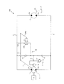
図5を参照して、本発明の第3実施形態に係る流体圧制御装置300について説明する。以下では、上述した第2実施形態と異なる点を中心に説明し、第2実施形態の流体圧制御装置200と同一の構成には、同一の符号を付して説明を省略する。
Third Embodiment
A fluid pressure control device 300 according to a third embodiment of the present invention will be described with reference to FIG. Hereinafter, differences from the above-described second embodiment will be mainly described, and the same components as those of the fluid pressure control device 200 of the second embodiment will be assigned the same reference numerals and descriptions thereof will be omitted.

第2実施形態では、連通路5が接続流路3及び接続流路4を直接連通しているのに対し、第3実施形態では、チャージ流路10を通じて接続流路3及び接続流路4を連通している点で相違している。また、第2実施形態では、連通路5に1つの開閉弁60が設けられるのに対し、第3実施形態では、連通路150に、第1、第2開閉弁161,162が設けられる点で相違している。以下、具体的に説明する。   In the second embodiment, the communication passage 5 directly communicates the connection flow passage 3 and the connection flow passage 4, whereas in the third embodiment, the connection flow passage 3 and the connection flow passage 4 are connected through the charge flow passage 10. The difference is that they are in communication. Further, in the second embodiment, one on-off valve 60 is provided in the communication passage 5, whereas in the third embodiment, the first and second on-off valves 161 and 162 are provided in the communication passage 150. It is different. The details will be described below.

流体圧制御装置300は、チャージ流路10に設けられチャージポンプ9から接続流路3への作動油の流れのみを許容し、接続流路3からチャージポンプ9への流れを遮断する第1チェック弁としてのチェック弁12aと、チャージ流路10に設けられチャージポンプ9から接続流路4への作動油の流れのみを許容し、接続流路4からチャージポンプ9への流れを遮断する第2チェック弁としてのチェック弁12bと、接続流路3に接続されると共にチャージ流路10のチェック弁12aよりもチャージポンプ9側に接続される第1連通路151と、接続流路4に接続されると共にチャージ流路10のチェック弁12bよりもチャージポンプ9側に接続される第2連通路152と、第1連通路151に設けられ第1連通路151を遮断または開通する第1開閉弁161と、第2連通路152に設けられ第2連通路152を遮断または開通する第2開閉弁162と、を備える。   The fluid pressure control device 300 is provided in the charge flow channel 10, and allows only the flow of hydraulic oil from the charge pump 9 to the connection flow channel 3, and cuts off the flow from the connection flow channel 3 to the charge pump 9 A check valve 12a as a valve, and a second flow passage provided in the charge flow passage 10 to allow only the flow of hydraulic oil from the charge pump 9 to the connection flow passage 4 and blocking the flow from the connection flow passage 4 to the charge pump 9 A check valve 12b as a check valve, a first communication passage 151 connected to the connection flow passage 3 and further connected to the charge pump 9 than the check valve 12a of the charge flow passage 10; And the second communication passage 152 connected to the charge pump 9 side closer to the charge pump 9 than the check valve 12 b of the charge passage 10 and the first communication passage 151 provided in the first communication passage 151 or Comprising a first on-off valve 161 through a second on-off valve 162 to block or open the second communication path 152 provided in the second communication passage 152, the.

第1連通路151及び第2連通路152は、それぞれチャージ流路10のチェック弁12a,12bよりも上流側の合流点153及び154において、チャージ流路10と合流する。流体圧制御装置300では、第1連通路151と合流点153からチェック弁12bを通じて接続流路4に到るチャージ流路10、及び第2連通路152と合流点154からチェック弁12aを通じて接続流路3に到るチャージ流路10が、それぞれバイパス流路としての連通路150に相当する。   The first communication passage 151 and the second communication passage 152 respectively merge with the charge flow passage 10 at junctions 153 and 154 on the upstream side of the check valves 12 a and 12 b of the charge flow passage 10. In the fluid pressure control device 300, the charge flow path 10 reaching the connection flow path 4 from the first communication path 151 and the junction 153 through the check valve 12b, and the connection flow from the second communication path 152 and the junction 154 through the check valve 12a. The charge flow paths 10 reaching the path 3 correspond to the communication paths 150 as bypass flow paths, respectively.

第1開閉弁161は、第1連通路151を開通する連通位置Gと、第1連通路151を遮断する遮断位置Hと、を備える。第2開閉弁162は、第2連通路152を開通する連通位置Iと、第2連通路152を遮断する遮断位置Jと、を備える。   The first on-off valve 161 has a communication position G for opening the first communication passage 151 and a blocking position H for blocking the first communication passage 151. The second on-off valve 162 has a communication position I for opening the second communication passage 152 and a blocking position J for blocking the second communication passage 152.

第1開閉弁161は、第1開閉弁161を閉弁方向である遮断位置H側に付勢するばね161aを備える。第1開閉弁161には、オリフィス31の双方向ポンプ1側の圧力が流路32を通じて閉弁方向に作用すると共に、オリフィス31の油圧モータ2側の圧力が流路33を通じて開弁方向に作用する。   The first on-off valve 161 includes a spring 161 a that biases the first on-off valve 161 toward the blocking position H in the valve closing direction. In the first on-off valve 161, the pressure on the bidirectional pump 1 side of the orifice 31 acts in the valve closing direction through the flow path 32, and the pressure on the hydraulic motor 2 side of the orifice 31 acts in the valve opening direction through the flow path 33 Do.

第2開閉弁162は、第2開閉弁162を閉弁方向である遮断位置J側に付勢するばね162aを備える。第2開閉弁162には、オリフィス41の双方向ポンプ1側の圧力が流路42を通じて閉弁方向に作用すると共に、オリフィス41の油圧モータ2側の圧力が流路43を通じて開弁方向に作用する。   The second on-off valve 162 includes a spring 162 a that urges the second on-off valve 162 toward the blocking position J in the valve closing direction. In the second on-off valve 162, the pressure on the bidirectional pump 1 side of the orifice 41 acts in the valve closing direction through the flow path 42, and the pressure on the hydraulic motor 2 side of the orifice 41 acts in the valve opening direction through the flow path 43 Do.

以上のように構成された流体圧制御装置300の動作について説明する。はじめに、停止状態から作業車両を前進させる場合について説明する。   The operation of the fluid pressure control device 300 configured as described above will be described. First, the case of advancing the work vehicle from the stopped state will be described.

乗務員が操作レバー7を一方側に向かって徐々に操作すると、双方向ポンプ1の斜板1cが中立位置から一方側に徐々に傾き、双方向ポンプ1のポート1aから斜板1cの傾転角に応じた流量の作動油が接続流路3に吐出される。このとき、接続流路3における上流側(オリフィス31の双方向ポンプ1側)の圧力が、流路32を通じて第1開閉弁161の閉弁方向に作用し、オリフィス31の下流側(油圧モータ2側)の圧力が流路33を通じて第1開閉弁161の開弁方向に作用する。この状態では、双方向ポンプ1から吐出される作動油の流量が小さいため、オリフィス31の前後での差圧による閉弁方向(第1開閉弁161を遮断位置Hに切り換える方向)への付勢力よりも、ばね161aによる開弁方向(第1開閉弁161を連通位置Gに切り換える方向)への付勢力が大きいため、第1開閉弁161は連通位置Gに保持される。これにより、双方向ポンプ1から接続流路3に吐出された高圧の作動油は、全量が第1連通路151から合流点153を通ってチャージ流路10に流入し、チェック弁12bを通って低圧側である接続流路4に戻される。したがって、油圧モータ2は駆動されない。   When the crew operates the control lever 7 gradually toward one side, the swash plate 1c of the bidirectional pump 1 gradually inclines from the neutral position to one side, and the tilting angle of the swash plate 1c from the port 1a of the bidirectional pump 1 The hydraulic fluid of the flow rate according to is discharged to the connection flow path 3. At this time, the pressure on the upstream side (the bidirectional pump 1 side of the orifice 31) in the connection flow path 3 acts in the valve closing direction of the first on-off valve 161 through the flow path 32, and the downstream side of the orifice 31 (hydraulic motor 2 The pressure on the side) acts in the valve opening direction of the first on-off valve 161 through the flow path 33. In this state, since the flow rate of the hydraulic fluid discharged from the bidirectional pump 1 is small, the biasing force in the valve closing direction (direction to switch the first on-off valve 161 to the blocking position H) by the differential pressure before and after the orifice 31 Since the biasing force in the valve opening direction (direction in which the first on-off valve 161 is switched to the communication position G) by the spring 161 a is larger than that, the first on-off valve 161 is held at the communication position G. As a result, the high-pressure hydraulic oil discharged from the bidirectional pump 1 to the connection flow path 3 flows into the charge flow path 10 from the first communication path 151 through the junction 153, and passes through the check valve 12b. It is returned to the connection channel 4 which is the low pressure side. Therefore, the hydraulic motor 2 is not driven.

この状態から操作レバー7さらに操作する、具体的には、操作レバー7を操作範囲Rまで操作すると、双方向ポンプ1の斜板1cがさらに傾き、双方向ポンプ1から吐出される作動油の流量が大きくなる。この状態では、オリフィス31の前後差圧による閉弁方向(第1開閉弁161を遮断位置Hに切り換える方向)への付勢力よりも、ばね161aによる開弁方向(第1開閉弁161を連通位置Gに切り換える方向)への付勢力が大きいため、第1開閉弁161は連通位置Gに保持される。しかしながら、この状態では、双方向ポンプ1から吐出される作動油の流量が大きくなるため、双方向ポンプ1から吐出された作動油の全量を第1連通路151から接続流路4に戻すことができなくなる。これにより、接続流路4に戻すことができなかった作動油はポート2aから油圧モータ2に供給され、油圧モータ2が始動する。よって、作業車両が前進を開始する。   From this state, the operating lever 7 is further operated. Specifically, when the operating lever 7 is operated to the operating range R, the swash plate 1c of the bidirectional pump 1 is further inclined, and the flow rate of hydraulic fluid discharged from the bidirectional pump 1 Becomes larger. In this state, the valve opening direction by the spring 161a (the first on-off valve 161 in the communication position is more than the biasing force in the valve closing direction (the direction to switch the first on-off valve 161 to the blocking position H) The first on-off valve 161 is held at the communication position G because the biasing force in the direction of switching to G) is large. However, in this state, the flow rate of the hydraulic fluid discharged from the bidirectional pump 1 increases, so that the entire amount of hydraulic fluid discharged from the bidirectional pump 1 can be returned from the first communication passage 151 to the connection passage 4. become unable. As a result, the hydraulic oil that can not be returned to the connection flow path 4 is supplied from the port 2 a to the hydraulic motor 2, and the hydraulic motor 2 is started. Thus, the work vehicle starts to move forward.

この状態から操作レバー7をさらに操作範囲Pを超えて操作すると、双方向ポンプ1の斜板1cがさらに傾く。これにより、双方向ポンプ1から吐出される作動油の流量はさらに大きくなるため、オリフィス31の前後差圧が大きくなり、オリフィス31の前後差圧による閉弁方向(第1開閉弁161を遮断位置Hに切り換える方向)への付勢力が、ばね161aによる開弁方向(第1開閉弁161を連通位置Gに切り換える方向)への付勢力よりも大きくなる。したがって、第1開閉弁161は遮断位置Hに切り換えられる。このため、第1連通路151は遮断され、双方向ポンプ1から接続流路3に吐出された作動油は、全量油圧モータ2に供給される。この操作範囲Pを超えた領域では、油圧モータ2には、操作レバー7の操作量に応じた流量が供給され、作業車両は、操作レバー7の操作量に応じた速度で前進する。   When the control lever 7 is further operated beyond the operating range P from this state, the swash plate 1c of the bidirectional pump 1 is further inclined. As a result, the flow rate of the hydraulic fluid discharged from the bidirectional pump 1 further increases, so the differential pressure across the orifice 31 becomes larger, and the valve closing direction by the differential pressure across the orifice 31 (the first on-off valve 161 shut off position The biasing force in the direction of switching to H) is larger than the biasing force in the valve opening direction (direction of switching the first on-off valve 161 to the communication position G) by the spring 161a. Therefore, the first on-off valve 161 is switched to the blocking position H. Therefore, the first communication passage 151 is shut off, and the hydraulic oil discharged from the bidirectional pump 1 to the connection passage 3 is supplied to the hydraulic motor 2 as a whole. In the region beyond the operation range P, the hydraulic motor 2 is supplied with a flow rate corresponding to the operation amount of the operation lever 7, and the work vehicle advances at a speed according to the operation amount of the operation lever 7.

油圧モータ2に供給された作動油は、ポート2bから接続流路4に排出される。上述のように、接続流路4にはオリフィス41が設けられており、オリフィス41の双方向ポンプ1側の圧力が流路42を通じて第2開閉弁162の閉弁方向に作用すると共に、オリフィス41の油圧モータ2側の圧力が流路43を通じて第2開閉弁162の開弁方向に作用する。このとき、流路43内の圧力は、流路42内の圧力より高い圧力であり、また、第1開閉弁161は、ばね162aによって開弁方向(第2開閉弁162を連通位置Iに切り換える方向)に付勢されているため、第2開閉弁162は連通位置Iに保持される。   The hydraulic oil supplied to the hydraulic motor 2 is discharged from the port 2 b to the connection flow path 4. As described above, the connection flow path 4 is provided with the orifice 41, and the pressure on the bidirectional pump 1 side of the orifice 41 acts in the valve closing direction of the second on-off valve 162 through the flow path 42. The pressure on the hydraulic motor 2 side acts on the second on-off valve 162 through the flow path 43 in the valve opening direction. At this time, the pressure in the flow path 43 is higher than the pressure in the flow path 42, and the first on-off valve 161 opens in the valve-opening direction (the second on-off valve 162 is switched to the communication position I by the spring 162a. And the second on-off valve 162 is held at the communication position I.

なお、流体圧制御装置300では、作業車両の前進時に第2開閉弁162が連通位置I及び遮断位置Jのいずれの位置にあっても、接続流路3内からチャージ流路10に流入した作動油は、チェック弁12bを通じて接続流路4に流れることができる。また、接続流路4のオリフィス41よりも油圧モータ2側の作動油が第2連通路152を通じてチャージ流路10に流れ込んでも、チェック弁12bを通じて接続流路4に戻すことができる。   In the fluid pressure control device 300, even if the second on-off valve 162 is at either the communication position I or the blocking position J when the work vehicle advances, the operation that flows into the charge flow path 10 from within the connection flow path 3 The oil can flow to the connection channel 4 through the check valve 12b. Even if the hydraulic oil on the hydraulic motor 2 side from the orifice 41 of the connection flow passage 4 flows into the charge flow passage 10 through the second communication passage 152, it can be returned to the connection flow passage 4 through the check valve 12b.

オリフィス31の前後差圧は、双方向ポンプ1から吐出される作動油の流量に依存する。したがって、第1開閉弁161は、双方向ポンプ1から吐出される作動油の流量が一定値以上であるときには閉弁して第1連通路151を遮断し、双方向ポンプ1から吐出される作動油の流量が一定値未満であるときには開弁して第1連通路151を開通することになる。   The differential pressure across the orifice 31 depends on the flow rate of the hydraulic fluid discharged from the bidirectional pump 1. Therefore, the first on-off valve 161 is closed when the flow rate of the hydraulic fluid discharged from the bidirectional pump 1 is equal to or more than a predetermined value to shut off the first communication passage 151 and the operation discharged from the bidirectional pump 1 When the flow rate of oil is less than a predetermined value, the valve opens to open the first communication passage 151.

なお、接続流路4内の圧力がチャージ流路10よりも高圧の場合、より具体的には、接続流路4内の圧力がリリーフ弁11の設定圧力よりも高圧の場合には、リリーフ弁11が開弁し、リリーフ弁11から作動油をタンクTに排出する。   When the pressure in the connection flow passage 4 is higher than the charge flow passage 10, more specifically, when the pressure in the connection flow passage 4 is higher than the set pressure of the relief valve 11, the relief valve The valve 11 is opened, and the hydraulic oil is discharged from the relief valve 11 to the tank T.

次に、走行状態から作業車両を停止させる場合について説明する。   Next, the case of stopping the work vehicle from the traveling state will be described.

通常走行状態から操作レバー7の操作量を小さくすると、双方向ポンプ1の斜板1cの傾きが小さくなって、双方向ポンプ1から吐出される作動油の流量も小さくなる。したがって、油圧モータ2の回転速度が減少する。   When the operation amount of the control lever 7 is reduced from the normal traveling state, the inclination of the swash plate 1c of the bidirectional pump 1 becomes smaller, and the flow rate of the hydraulic fluid discharged from the bidirectional pump 1 also becomes smaller. Therefore, the rotational speed of the hydraulic motor 2 is reduced.

この状態から、微速領域(操作範囲R)内まで操作レバー7の操作量を小さくすると、オリフィス31の前後差圧が小さくなるため、第1開閉弁161が遮断位置Hから連通位置Gに切り換えられ、第1連通路151が開通する。これにより、双方向ポンプ1から吐出される作動油の一部が第1連通路151及びチャージ流路10を通って接続流路4に戻され、油圧モータ2はさらに減速する。   From this state, if the operation amount of the operation lever 7 is reduced to within the slow speed region (operation range R), the first on-off valve 161 is switched from the blocking position H to the communication position G because the differential pressure across the orifice 31 decreases. , And the first communication passage 151 is opened. As a result, part of the hydraulic fluid discharged from the bidirectional pump 1 is returned to the connection flow path 4 through the first communication path 151 and the charge flow path 10, and the hydraulic motor 2 is further decelerated.

この状態から、さらに中立領域(操作範囲Q)内まで操作レバー7の操作量を小さくすると、双方向ポンプ1から吐出される作動油の全量が第1連通路151及びチャージ流路10を通って接続流路4に戻されるので、油圧モータ2はさらに減速する。さらに、操作レバー7が中立位置に戻されると、斜板1cの傾転角が0になり、双方向ポンプ1から作動油は吐出されなくなる。   From this state, when the operation amount of the operation lever 7 is further reduced to the neutral region (operation range Q), the entire amount of hydraulic oil discharged from the bidirectional pump 1 passes through the first communication passage 151 and the charge passage 10 As it is returned to the connection channel 4, the hydraulic motor 2 is further decelerated. Furthermore, when the control lever 7 is returned to the neutral position, the tilt angle of the swash plate 1c becomes zero, and the hydraulic fluid is not discharged from the bidirectional pump 1.

操作レバー7が中立領域または中立位置まで戻されたときには、作業車両は慣性によって前進を続けるため、油圧モータ2が強制的に回転させられる。これにより、油圧モータ2はポート2aから作動油を吸い込んでポート2bから吐出する。このようにしてポート2bから吐出された作動油は、第2連通路152、第2開閉弁162、チャージ流路10、及びチェック弁12aを通じて接続流路3に戻される。このとき、作動油が第2開閉弁162を通過するときに生じる圧力損失や油圧モータ2で生じる圧力損失によって、油圧モータ2に制動力が作用するため、油圧モータ2は徐々に減速されて停止する。このように、流体圧制御装置300は、操作レバー7が中立位置に戻されたときに、開閉弁60が連通路150(第2連通路152及びチャージ流路10)を開通するように構成されているので、油圧モータ2はがショックを伴わずに、滑らかに停止することができる。   When the control lever 7 is returned to the neutral region or the neutral position, the hydraulic vehicle 2 is forcibly rotated because the work vehicle continues to move forward by inertia. Thus, the hydraulic motor 2 sucks in hydraulic fluid from the port 2a and discharges it from the port 2b. The hydraulic oil thus discharged from the port 2 b is returned to the connection flow path 3 through the second communication path 152, the second on-off valve 162, the charge flow path 10, and the check valve 12 a. At this time, the braking force acts on the hydraulic motor 2 by the pressure loss generated when the hydraulic oil passes through the second on-off valve 162 and the pressure loss generated by the hydraulic motor 2, so the hydraulic motor 2 is gradually decelerated and stopped Do. Thus, the fluid pressure control device 300 is configured such that the on-off valve 60 opens the communication passage 150 (the second communication passage 152 and the charge passage 10) when the control lever 7 is returned to the neutral position. Thus, the hydraulic motor 2 can be smoothly stopped without shock.

流体圧制御装置300においても、作業車両が下り坂を微速領域で走行する際に、走行を安定させることができるという効果を奏する。以下に、この効果について具体的に説明する。   Also in the fluid pressure control device 300, when the work vehicle travels on the downhill in the low speed region, the traveling can be stabilized. Below, this effect is demonstrated concretely.

作業車両を微速領域で走行させる際には、操作レバー7は上述した微速領域(操作範囲R内)で操作される。このとき、双方向ポンプ1から操作レバー7の操作量に応じた作動油が接続流路3に吐出される。上述のように、第1開閉弁161は連通位置Gに位置するので、双方向ポンプ1から吐出された作動油は、一部が第1連通路151、チャージ流路10、及びチェック弁12bを通じて接続流路4に戻され、残りの作動油によって油圧モータ2が駆動される。これにより、作業車両は微速にて前進する。   When the work vehicle travels in the low speed region, the operation lever 7 is operated in the above-described low speed region (within the operation range R). At this time, hydraulic fluid corresponding to the operation amount of the control lever 7 is discharged from the bidirectional pump 1 to the connection flow path 3. As described above, since the first on-off valve 161 is located at the communication position G, the hydraulic oil discharged from the bidirectional pump 1 is partially through the first communication passage 151, the charge flow passage 10, and the check valve 12b. It is returned to the connection channel 4 and the hydraulic motor 2 is driven by the remaining hydraulic oil. Thereby, the work vehicle moves forward at a slight speed.

作業車両が下り坂を走行していると、作業車両は自重により加速する。これにより、油圧モータ2は強制的に回転されるため、油圧モータ2はポート2aから作動油を吸い込んでポート2bに吐出する油圧ポンプとして機能してしまう。   When the work vehicle travels downhill, the work vehicle accelerates by its own weight. As a result, the hydraulic motor 2 is forced to rotate, so the hydraulic motor 2 functions as a hydraulic pump that sucks in hydraulic fluid from the port 2a and discharges it to the port 2b.

このとき、オリフィス41の双方向ポンプ1側の圧力が流路42を通じて第2開閉弁162の閉弁方向に作用すると共に、オリフィス41の油圧モータ2側の圧力が流路43を通じて第2開閉弁162の開弁方向に作用する。流路43内の圧力は、流路42内の圧力より高い圧力であり、また、第2開閉弁162は、ばね162aによって開弁方向(第2開閉弁162を連通位置Iに切り換える方向)に付勢されているため、第2開閉弁162は連通位置Iに保持される。したがって、油圧モータ2から吐出された高圧の作動油は、第2連通路152からチャージ流路10及びチェック弁12aを通じて接続流路3に圧力を逃がすことができる。したがって、作業車両が下り坂を微速走行しているときに、走行が安定する。   At this time, the pressure on the bidirectional pump 1 side of the orifice 41 acts in the closing direction of the second on-off valve 162 through the flow path 42 and the pressure on the hydraulic motor 2 side of the orifice 41 flows through the flow path 43 to the second on-off valve It acts in the valve opening direction of 162. The pressure in the flow path 43 is higher than the pressure in the flow path 42, and the second on-off valve 162 is opened in the valve opening direction (a direction to switch the second on-off valve 162 to the communication position I) by the spring 162a. The second on-off valve 162 is held at the communication position I because it is biased. Therefore, high-pressure hydraulic fluid discharged from the hydraulic motor 2 can release pressure from the second communication passage 152 to the connection passage 3 through the charge passage 10 and the check valve 12 a. Therefore, when the work vehicle travels at a very low speed on the downhill, the traveling becomes stable.

なお、作業車両を後進させる場合は、作業車両を後進させる場合は、操作レバー7を前進時とは逆方向に操作する。これにより、双方向ポンプ1の斜板1cが前進時と逆方向に傾斜し、双方向ポンプ1のポート1bから作動油を吐出する。このとき、第1開閉弁161と第2開閉弁162の機能が入れ替わるだけであるので、説明を省略する。   When the work vehicle is moved backward, when the work vehicle is moved backward, the operation lever 7 is operated in the reverse direction to that at the time of forward movement. As a result, the swash plate 1c of the bidirectional pump 1 is inclined in the opposite direction to that in forward movement, and the hydraulic fluid is discharged from the port 1b of the bidirectional pump 1. At this time, the functions of the first on-off valve 161 and the second on-off valve 162 are merely interchanged, so the description will be omitted.

以上の第3実施形態によれば、第2実施形態と同様の効果を奏する。   According to the above third embodiment, the same effect as the second embodiment can be obtained.

なお、図6に示す変形例のように、第2開閉弁162を設けずに第1開閉弁161のみを設けて、前進時のみに連通路150を遮断するように構成してもよい。この場合には、双方向ポンプ1の前進方向における中立領域を確保しつつ、容積効率を向上することができる。   As in the modification shown in FIG. 6, only the first on-off valve 161 may be provided without providing the second on-off valve 162, and the communication passage 150 may be shut off only when moving forward. In this case, volumetric efficiency can be improved while securing a neutral region in the forward direction of the bidirectional pump 1.

また、図7に示す変形例のように、図6の第1開閉弁161に換えて、操作レバー7とリンク機構8によって連結された操作レバー206aによって切り換えられる開閉弁206を設けた構成にしてもよい。この場合にも、双方向ポンプ1の前進方向における中立領域を確保しつつ、容積効率を向上することができる。   Further, as in the modification shown in FIG. 7, instead of the first on-off valve 161 of FIG. 6, an on-off valve 206 switched by the operating lever 206a connected by the operating lever 7 and the link mechanism 8 is provided. It is also good. Also in this case, volumetric efficiency can be improved while securing a neutral region in the forward direction of the bidirectional pump 1.

<第4実施形態>
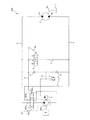
図8を参照して、本発明の第3実施形態に係る流体圧制御装置400について説明する。以下では、上述した第1実施形態と異なる点を中心に説明し、第1実施形態の流体圧制御装置100と同一の構成には、同一の符号を付して説明を省略する。
Fourth Embodiment
A fluid pressure control device 400 according to a third embodiment of the present invention will be described with reference to FIG. Hereinafter, differences from the above-described first embodiment will be mainly described, and the same components as those of the fluid pressure control device 100 of the first embodiment will be assigned the same reference numerals and descriptions thereof will be omitted.

第1実施形態では、双方向ポンプ1が吐出装置として機能するのに対し、第4実施形態では、単方向のポンプ402と切換弁403とによって吐出装置401が構成されている点で相違する。以下、具体的に説明する。   In the first embodiment, the bidirectional pump 1 functions as a discharge device, whereas in the fourth embodiment, the discharge device 401 is configured by the unidirectional pump 402 and the switching valve 403. The details will be described below.

図8に示すように、流体圧制御装置400は、単方向のポンプ402と、ポンプ402から吐出された作動油の方向を切り換える切換弁403と、を備える。油圧モータ2の一方のポート2aは、切換弁403のポート403aに接続され、他方のポート2bは、切換弁403のポート403bに接続される。本実施形態では、ポート403aが吐出装置401の第1ポートとして機能し、ポート403bが吐出装置401の第2ポートとして機能する。   As shown in FIG. 8, the fluid pressure control device 400 includes a unidirectional pump 402 and a switching valve 403 that switches the direction of hydraulic fluid discharged from the pump 402. One port 2 a of the hydraulic motor 2 is connected to the port 403 a of the switching valve 403, and the other port 2 b is connected to the port 403 b of the switching valve 403. In the present embodiment, the port 403 a functions as a first port of the discharge device 401, and the port 403 b functions as a second port of the discharge device 401.

切換弁403は、操作レバー403cによって切り換えられる。操作レバー403cは、開閉弁6の操作レバー6aに機械式のリンク機構8によって機械的に連結される。これにより、操作レバー403cの操作に応じて開閉弁6の操作レバー6aが操作される。操作レバー403cには、第1実施形態における操作レバー7と同様に、中立領域(操作範囲Q)及び微速領域(操作範囲R)に相当する領域が設けられる。   The switching valve 403 is switched by the operation lever 403c. The operating lever 403 c is mechanically connected to the operating lever 6 a of the on-off valve 6 by a mechanical link mechanism 8. Thereby, the operating lever 6a of the on-off valve 6 is operated in accordance with the operation of the operating lever 403c. Similar to the control lever 7 in the first embodiment, the control lever 403c is provided with a region corresponding to the neutral region (control range Q) and the low speed region (control range R).

以上のように構成された流体圧制御装置400においては、切換弁403の操作レバー403cを操作することによって、吐出装置401はポート403a及びポート403bのいずれかから作動油を吐出するように切り換えられる。その他については、流体圧制御装置100と同様に動作するので、流体圧制御装置400の動作に関する説明は省略する。   In the fluid pressure control device 400 configured as described above, by operating the operation lever 403c of the switching valve 403, the discharge device 401 is switched to discharge hydraulic fluid from either the port 403a or the port 403b. . The other components operate in the same manner as the fluid pressure control device 100, and thus the description of the operation of the fluid pressure control device 400 is omitted.

以上の第4実施形態によれば、第1実施形態と同様の効果を奏する。   According to the above fourth embodiment, the same effect as that of the first embodiment can be obtained.

以上のように構成された本発明の実施形態の構成、作用、及び効果をまとめて説明する。   The configuration, operation, and effects of the embodiment of the present invention configured as described above will be collectively described.

流体圧制御装置100,200,300,400は、第1ポート及び第2ポートのいずれかから作動流体(作動油)を吐出する吐出装置(双方向ポンプ1、吐出装置401)と、吐出装置(双方向ポンプ1、吐出装置401)から吐出された作動流体(作動油)によって駆動される流体圧モータ(油圧モータ2)と、吐出装置(双方向ポンプ1、吐出装置401)の第1ポート(ポート1a、ポート403a)と流体圧モータ(油圧モータ2)の一方のポート2aとを接続する第1接続流路(接続流路3)と、吐出装置(双方向ポンプ1、吐出装置401)の第2ポート(ポート1b、ポート403b)と流体圧モータ(油圧モータ2)の他方のポート2bとを接続する第2接続流路(接続流路4)と、第1接続流路(接続流路3)と第2接続流路(接続流路4)とを接続するバイパス流路(連通路5、連通路150)と、バイパス流路(連通路5、連通路150)に設けられる開閉弁(開閉弁6、開閉弁16、開閉弁60、第1開閉弁161、第2開閉弁162、開閉弁206)と、を備え、開閉弁(開閉弁6、開閉弁16、開閉弁60、第1開閉弁161、第2開閉弁162、開閉弁206)は、吐出装置(双方向ポンプ1、吐出装置401)から吐出される作動流体(作動油)の流量が一定値以上であるときには閉弁してバイパス流路(連通路5、連通路150)を遮断し、吐出装置(双方向ポンプ1、吐出装置401)から吐出される作動流体(作動油)の流量が一定値未満であるときには開弁してバイパス流路(連通路5、連通路150)を開通することを特徴とする。   The fluid pressure control devices 100, 200, 300, and 400 each include a discharge device (bidirectional pump 1, discharge device 401) that discharges working fluid (hydraulic oil) from either the first port or the second port, and a discharge device A fluid pressure motor (hydraulic motor 2) driven by hydraulic fluid (hydraulic fluid) discharged from the bidirectional pump 1, discharge device 401), and a first port of the discharge device (bidirectional pump 1, discharge device 401) The first connection flow path (connection flow path 3) for connecting the port 1a, the port 403a) and one port 2a of the fluid pressure motor (hydraulic motor 2), and the discharge device (bidirectional pump 1, discharge device 401) A second connection channel (connection channel 4) connecting the second port (port 1b, port 403b) and the other port 2b of the fluid pressure motor (hydraulic motor 2), and a first connection channel (connection channel) 3) and the second contact A bypass flow path (communication path 5, communication path 150) connecting the flow path (connection flow path 4) and an on-off valve (on-off valve 6, opening / closing valve provided in the bypass flow path (communication path 5, communication path 150) 16, an on-off valve 60, a first on-off valve 161, a second on-off valve 162, an on-off valve 206), the on-off valve (on-off valve 6, on-off valve 16, on-off valve 60, first on-off valve 161, second The on-off valve 162 and the on-off valve 206 are closed when the flow rate of the hydraulic fluid (hydraulic oil) discharged from the discharge device (bidirectional pump 1, discharge device 401) is equal to or more than a predetermined value. When the flow rate of the working fluid (hydraulic fluid) discharged from the discharge device (bidirectional pump 1, discharge device 401) is less than a predetermined value, the passage 5 and the communication passage 150 are shut off to open the bypass flow passage The communication passage 5 and the communication passage 150) are opened.

この構成によれば、吐出装置(双方向ポンプ1、吐出装置401)から吐出される作動流体(作動油)の流量が一定の値以上であるときには、バイパス流路(連通路5、連通路150)が開閉弁(開閉弁6、開閉弁16、開閉弁60、第1開閉弁161、第2開閉弁162、開閉弁206)によって遮断されるので、吐出装置(双方向ポンプ1、吐出装置401)から吐出された作動流体(作動油)が全量流体圧モータ(油圧モータ2)に供給され、吐出装置(双方向ポンプ1、吐出装置401)の容積効率が向上する。また、吐出装置(双方向ポンプ1、吐出装置401)から吐出される作動流体(作動油)の流量が一定の値以下であるときには、バイパス流路(連通路5、連通路150)が開通するので、吐出装置(双方向ポンプ1、吐出装置401)から吐出される作動流体(作動油)は、流体圧モータ(油圧モータ2)に供給されることなく、バイパス流路(連通路5、連通路150)を通じて吐出装置(双方向ポンプ1、吐出装置401)に戻されるので、吐出装置(双方向ポンプ1、吐出装置401)の中立領域を確保できる。したがって、吐出装置(双方向ポンプ1、吐出装置401)の中立領域を確保しつつ、容積効率を向上させることができる。   According to this configuration, when the flow rate of the working fluid (hydraulic fluid) discharged from the discharge device (bidirectional pump 1, discharge device 401) is equal to or greater than a predetermined value, the bypass flow passage (communication passage 5, communication passage 150) Is shut off by the on-off valve (on-off valve 6, on-off valve 16, on-off valve 60, first on-off valve 161, second on-off valve 162, on-off valve 206). The entire amount of the working fluid (working fluid) discharged from the above is supplied to the fluid pressure motor (hydraulic motor 2), and the volumetric efficiency of the discharge device (bidirectional pump 1, discharge device 401) is improved. In addition, when the flow rate of the working fluid (hydraulic oil) discharged from the discharge device (bidirectional pump 1, discharge device 401) is equal to or less than a predetermined value, the bypass flow passage (communication passage 5, communication passage 150) is opened. Therefore, the working fluid (hydraulic fluid) discharged from the discharge device (bidirectional pump 1, discharge device 401) is not supplied to the fluid pressure motor (hydraulic motor 2), and the bypass flow passage (communication passage 5; continuous gear) Since it is returned to the discharge device (bidirectional pump 1, discharge device 401) through the passage 150), the neutral region of the discharge device (bidirectional pump 1, discharge device 401) can be secured. Therefore, volumetric efficiency can be improved while securing the neutral region of the discharge device (bidirectional pump 1, discharge device 401).

また、流体圧制御装置100は、双方向ポンプ1は、吐出容量を調整するための調整部材(操作レバー7)を有する可変容量型の双方向ポンプであって、開閉弁6,16は、バイパス流路(連通路5)を遮断または開通するための弁体を操作する操作部材(操作レバー6a)を有し、操作部材(操作レバー6a)は、調整部材(操作レバー7)に連結されていることを特徴とする。   Further, in the fluid pressure control device 100, the bidirectional pump 1 is a variable displacement bidirectional pump having an adjusting member (a control lever 7) for adjusting the displacement, and the on-off valves 6, 16 are bypassed. It has an operation member (operation lever 6a) for operating the valve body for blocking or opening the flow path (communication passage 5), and the operation member (operation lever 6a) is connected to the adjustment member (operation lever 7) It is characterized by

この構成によれば、開閉弁6,16は、操作レバー7の動作に伴って開閉されるため、開閉弁6の動作を安定させることができる。   According to this configuration, since the on-off valves 6 and 16 are opened and closed in accordance with the operation of the control lever 7, the operation of the on-off valve 6 can be stabilized.

また、流体圧制御装置200は、第1接続流路(接続流路3)に設けられた第1オリフィス(オリフィス31)と、第2接続流路(接続流路4)に設けられた第2オリフィス(オリフィス41)と、開閉弁60を開弁方向に付勢する付勢部材(ばね61)と、をさらに備え、開閉弁60には、第1オリフィス(オリフィス31)の吐出装置(双方向ポンプ1)側の圧力と第2オリフィス(オリフィス41)の吐出装置(双方向ポンプ1)側の圧力とが閉弁方向に作用すると共に、第1オリフィス(オリフィス31)の流体圧モータ(油圧モータ2)側の圧力と第2オリフィス(オリフィス41)の流体圧モータ(油圧モータ2)側の圧力とが開弁方向に作用することを特徴とする。   Further, the fluid pressure control device 200 includes a first orifice (orifice 31) provided in the first connection channel (connection channel 3) and a second orifice provided in the second connection channel (connection channel 4). The orifice (orifice 41) and a biasing member (spring 61) for biasing the on-off valve 60 in the valve opening direction are further provided, and the on-off valve 60 has a discharge device for the first orifice (orifice 31) (bidirectional The pressure on the pump 1) side and the pressure on the discharge device (bidirectional pump 1) side of the second orifice (orifice 41) act in the valve closing direction, and the fluid pressure motor (hydraulic motor) of the first orifice (orifice 31) 2) The pressure on the side and the pressure on the fluid pressure motor (hydraulic motor 2) side of the second orifice (orifice 41) act in the valve opening direction.

また、流体圧制御装置300は、第1接続流路(接続流路3)に設けられた第1オリフィス(オリフィス31)と、第2接続流路(接続流路4)に設けられた第2オリフィス(オリフィス41の他方)と、第1接続流路(接続流路3)及び第2接続流路(接続流路4)に作動流体(作動油)を供給するチャージポンプ9と、チャージポンプ9から吐出された作動流体(作動油)を第1接続流路(接続流路3)及び第2接続流路(接続流路4)に導くチャージ流路10と、チャージ流路10に設けられチャージポンプ9から第1接続流路(接続流路3)への作動流体(作動油)の流れのみを許容する第1チェック弁(チェック弁12a)と、チャージ流路10に設けられチャージポンプ9から第2接続流路(接続流路4)への作動流体(作動油)の流れのみを許容する第2チェック弁(チェック弁12b)と、第1接続流路(接続流路3)に接続されると共にチャージ流路10の第1チェック弁(チェック弁12a)よりもチャージポンプ9側に接続される第1連通路151と、第2接続流路(接続流路4)に接続されると共にチャージ流路10の第2チェック弁(チェック弁12b、)よりもチャージポンプ9側に接続される第2連通路152と、をさらに備え、開閉弁(第1開閉弁161、第2開閉弁162)は、第1連通路151に設けられる第1開閉弁161と、第1開閉弁161を開弁方向に付勢する付勢部材(ばね161a)と、第2連通路152に設けられる第2開閉弁162と、第2開閉弁162を開弁方向に付勢する付勢部材(ばね162a)と、を有し、第1開閉弁161には、第1オリフィス31の吐出装置(双方向ポンプ1)側の圧力が閉弁方向に作用すると共に、第1オリフィス31の流体圧モータ(油圧モータ2)側の圧力が開弁方向に作用し、第2開閉弁162には、第2オリフィス41の吐出装置(双方向ポンプ1)側の圧力が閉弁方向に作用すると共に、第2オリフィス41の流体圧モータ(油圧モータ2)側の圧力が開弁方向に作用し、バイパス流路(連通路150)は、第1連通路151及びチャージ流路10、または、第2連通路152及びチャージ流路10を通じて第1接続流路(接続流路3)と第2接続流路(接続流路4)とを接続することを特徴とする。   Further, the fluid pressure control device 300 includes a first orifice (orifice 31) provided in the first connection channel (connection channel 3) and a second orifice provided in the second connection channel (connection channel 4). A charge pump 9 for supplying a working fluid (hydraulic oil) to an orifice (the other of the orifice 41), the first connection flow path (connection flow path 3) and the second connection flow path (connection flow path 4) Charge flow path 10 for guiding the working fluid (working oil) discharged from the first connection flow path (connection flow path 3) and the second connection flow path (connection flow path 4), and charge flow path 10 A first check valve (check valve 12a) that allows only the flow of hydraulic fluid (hydraulic oil) from the pump 9 to the first connection channel (connection channel 3), and a charge pump 9 provided in the charge channel 10 Hydraulic fluid (hydraulic fluid to second connection channel (connection channel 4) The second check valve (check valve 12b), which permits only the flow of the fuel, and the first connection flow passage (connection flow passage 3), is connected to the second connection check valve 12b and charges more than the first check valve (check valve 12a) The first communication passage 151 connected to the pump 9 side, and the charge pump 9 connected to the second connection passage (connection passage 4) and the second check valve (check valve 12b) of the charge passage 10 And the first on-off valve (the first on-off valve 161, the second on-off valve 162) is connected to the first on-off valve 161 provided on the first communication passage 151; A biasing member (spring 161a) for biasing the on / off valve 161 in the valve opening direction, a second on / off valve 162 provided in the second communication passage 152, and a bias for biasing the second on / off valve 162 in the valve opening direction A member (spring 162a), and the first opening The pressure on the discharge device (bidirectional pump 1) side of the first orifice 31 acts on the valve 161 in the valve closing direction and the pressure on the fluid pressure motor (hydraulic motor 2) side of the first orifice 31 opens in the valve 161 The pressure on the discharge device (bidirectional pump 1) side of the second orifice 41 acts on the second on-off valve 162 in the valve closing direction, and the fluid pressure motor (hydraulic motor 2) of the second orifice 41 The pressure on the side acts in the valve opening direction, and the bypass channel (communication channel 150) is the first connection channel through the first communication channel 151 and the charge channel 10, or the second communication channel 152 and the charge channel 10. (Connection flow path 3) and the second connection flow path (connection flow path 4) are connected.

これら構成によれば、吐出装置(双方向ポンプ1)と開閉弁(開閉弁60、第1開閉弁161、第2開閉弁162)との距離が離れていて連結することができない場合でも、双方向ポンプ1の中立領域を確保しつつ、容積効率を向上することができる。   According to these configurations, even when the discharge device (the bidirectional pump 1) and the on-off valve (the on-off valve 60, the first on-off valve 161, the second on-off valve 162) are separated and can not be connected, both While securing the neutral region of the directional pump 1, volumetric efficiency can be improved.

作業車両は、流体圧制御装置100,200,300,400のいずれか1つを備えたことを特徴とする。   The work vehicle is characterized by including any one of the fluid pressure control devices 100, 200, 300, and 400.

以上、本発明の実施形態について説明したが、上記実施形態は本発明の適用例の一部を示したに過ぎず、本発明の技術的範囲を上記実施形態の具体的構成に限定する趣旨ではない。   As mentioned above, although the embodiment of the present invention was described, the above-mentioned embodiment showed only a part of application example of the present invention, and in the meaning of limiting the technical scope of the present invention to the concrete composition of the above-mentioned embodiment. Absent.

図示はしないが、流体圧制御装置200においても、オリフィス41及び流路42,43を設けないことで、同様に前進方向にのみ機能する構成とすることができる。   Although not shown, the fluid pressure control device 200 can also be configured to function only in the forward direction by not providing the orifice 41 and the channels 42 and 43.

100,200,300,400・・・流体圧制御装置、1・・・双方向ポンプ(吐出装置)、1a・・・ポート(第1ポート)、1b・・・ポート(第2ポート)、1c・・・斜板、2・・・油圧モータ(流体圧モータ)、2a・・・ポート、2b・・・ポート、3,4・・・接続流路(第1接続流路または第2接続流路)、5・・・連通路(バイパス流路)、6・・・開閉弁、6a・・・操作レバー(操作部材)、7・・・操作レバー(調整部材)、9・・・チャージポンプ、 10・・・チャージ流路、16・・・開閉弁、31,41・・・オリフィス(第1、第2オリフィス)、60・・・開閉弁、61・・・ばね(付勢部材)、150・・・連通路、161・・・第1開閉弁、161a・・・ばね(付勢部材)、162・・・第2開閉弁、162a・・・ばね(付勢部材)、401・・・吐出装置、402・・・ポンプ、403・・・切換弁、403a・・・ポート(第1ポート)、403b・・・ポート(第2ポート)、403c・・・操作レバー 100, 200, 300, 400 · · · Fluid pressure control device, 1 · · · Bidirectional pump (discharge device), 1a · · · Port (first port), 1b · · · Port (second port), 1c ... Swash plate, 2 ... hydraulic motor (fluid pressure motor), 2a ... port, 2b ... port 3, 4 ... connection flow path (first connection flow path or second connection flow Path), 5 ... communication path (bypass flow path), 6 ... on-off valve, 6 a ... operation lever (operation member), 7 ... operation lever (adjustment member), 9 ... charge pump 10: charge flow path, 16: on-off valve, 31, 41: orifice (first and second orifice), 60: on-off valve, 61: spring (biasing member), 150 ··· communication passage, 161 · · · first on-off valve, 161 a · · · spring (biasing member), 162 · · · second Valve closing, 162a: spring (biasing member), 401: discharge device, 402: pump, 403: switching valve, 403a: port (first port), 403b: port (2nd port), 403c ... Operation lever

Claims (5)

第1ポート及び第2ポートのいずれかから作動流体を吐出するポンプを有する吐出装置と、
前記吐出装置から吐出された作動流体によって駆動される流体圧モータと、
前記吐出装置の第1ポートと前記流体圧モータの一方のポートとを接続する第1接続流路と、
前記吐出装置の第2ポートと前記流体圧モータの他方のポートとを接続する第2接続流路と、
前記第1接続流路と前記第2接続流路とを接続するバイパス流路と、
前記バイパス流路に設けられる開閉弁と、を備え、
前記開閉弁は、前記吐出装置から吐出される作動流体の流量が一定値以上であるときには閉弁して前記バイパス流路を遮断し、前記吐出装置から吐出される作動流体の流量が一定値未満であるときには開弁して前記バイパス流路を開通することを特徴とする流体圧制御装置。
A discharge device having a pump for discharging the working fluid from either the first port or the second port;
A fluid pressure motor driven by a working fluid discharged from the discharge device;
A first connection channel connecting a first port of the discharge device and one port of the fluid pressure motor;
A second connection channel connecting the second port of the discharge device and the other port of the fluid pressure motor;
A bypass flow path connecting the first connection flow path and the second connection flow path;
And an on-off valve provided in the bypass channel,
The on-off valve is closed when the flow rate of the working fluid discharged from the discharge device is a predetermined value or more to shut off the bypass flow path, and the flow rate of the working fluid discharged from the discharge device is less than a fixed value The fluid pressure control device is characterized in that the valve is opened to open the bypass channel.
前記吐出装置は、吐出容量を調整するための調整部材を有する可変容量型の双方向ポンプであって、
前記開閉弁は、前記バイパス流路を遮断または開通するための弁体を操作する操作部材を有し、
前記操作部材は、前記調整部材に連結されていることを特徴とする請求項1に記載の流体圧制御装置。
The discharge device is a variable displacement bidirectional pump having an adjustment member for adjusting a discharge volume,
The on-off valve has an operating member for operating a valve body for blocking or opening the bypass flow path,
The fluid pressure control device according to claim 1, wherein the operation member is connected to the adjustment member.
前記第1接続流路に設けられた第1オリフィスと、
前記第2接続流路に設けられた第2オリフィスと、
前記開閉弁を開弁方向に付勢する付勢部材と、をさらに備え、
前記開閉弁には、前記第1オリフィスの前記吐出装置側の圧力と前記第2オリフィスの前記吐出装置側の圧力とが閉弁方向に作用すると共に、前記第1オリフィスの前記流体圧モータ側の圧力と前記第2オリフィスの前記流体圧モータ側の圧力とが開弁方向に作用することを特徴とする請求項1に記載の流体圧制御装置。
A first orifice provided in the first connection channel,
A second orifice provided in the second connection channel,
And a biasing member for biasing the on-off valve in the valve opening direction,
The pressure on the discharge device side of the first orifice and the pressure on the discharge device side of the second orifice act on the on-off valve in the valve closing direction, and the fluid pressure motor side of the first orifice The fluid pressure control device according to claim 1, wherein the pressure and the pressure on the fluid pressure motor side of the second orifice act in a valve opening direction.
前記第1接続流路に設けられた第1オリフィスと、
前記第2接続流路に設けられた第2オリフィスと、
前記第1接続流路及び前記第2接続流路に作動流体を供給するチャージポンプと、
前記チャージポンプから吐出された作動流体を前記第1接続流路及び前記第2接続流路に導くチャージ流路と、
前記チャージ流路に設けられ前記チャージポンプから前記第1接続流路への作動流体の流れのみを許容する第1チェック弁と、
前記チャージ流路に設けられ前記チャージポンプから前記第2接続流路への作動流体の流れのみを許容する第2チェック弁と、
前記第1接続流路に接続されると共に前記チャージ流路の前記第1チェック弁よりも前記チャージポンプ側に接続される第1連通路と、
前記第2接続流路に接続されると共に前記チャージ流路の前記第2チェック弁よりも前記チャージポンプ側に接続される第2連通路と、をさらに備え、
前記開閉弁は、
前記第1連通路に設けられる第1開閉弁と、
前記第1開閉弁を開弁方向に付勢する付勢部材と、
前記第2連通路に設けられる第2開閉弁と、
前記第2開閉弁を開弁方向に付勢する付勢部材と、を有し、
前記第1開閉弁には、前記第1オリフィスの前記吐出装置側の圧力が閉弁方向に作用すると共に、前記第1オリフィスの前記流体圧モータ側の圧力が開弁方向に作用し、
前記第2開閉弁には、前記第2オリフィスの前記吐出装置側の圧力が閉弁方向に作用すると共に、前記第2オリフィスの前記流体圧モータ側の圧力が開弁方向に作用し、
前記バイパス流路は、前記第1連通路及び前記チャージ流路、または、前記第2連通路及び前記チャージ流路を通じて前記第1接続流路と前記第2接続流路とを接続することを特徴とする請求項1に記載の流体圧制御装置。
A first orifice provided in the first connection channel,
A second orifice provided in the second connection channel,
A charge pump for supplying a working fluid to the first connection passage and the second connection passage;
A charge flow path for guiding the working fluid discharged from the charge pump to the first connection flow path and the second connection flow path;
A first check valve provided in the charge flow path and permitting only the flow of working fluid from the charge pump to the first connection flow path;
A second check valve provided in the charge flow path and permitting only the flow of the working fluid from the charge pump to the second connection flow path;
A first communication passage connected to the first connection passage and connected to the charge pump side with respect to the first check valve of the charge passage;
And a second communication passage connected to the second connection passage and connected to the charge pump side with respect to the second check valve of the charge passage.
The on-off valve is
A first on-off valve provided in the first communication passage;
An urging member for urging the first on-off valve in the valve opening direction;
A second on-off valve provided in the second communication passage;
And a biasing member for biasing the second on-off valve in the valve opening direction,
The pressure on the discharge device side of the first orifice acts on the first on-off valve in the valve closing direction, and the pressure on the fluid pressure motor side of the first orifice acts on the first on-off valve,
The pressure on the discharge device side of the second orifice acts on the second on-off valve in the valve closing direction, and the pressure on the fluid pressure motor side of the second orifice acts on the second on-off valve,
The bypass flow path connects the first connection flow path and the second connection flow path through the first communication path and the charge flow path, or the second communication path and the charge flow path. The fluid pressure control device according to claim 1.
請求項1から4のいずれか1つに記載の流体圧制御装置を備えたことを特徴とする作業車両。   A work vehicle comprising the fluid pressure control device according to any one of claims 1 to 4.
JP2017237016A 2017-12-11 2017-12-11 Fluid pressure control device and working vehicle including fluid pressure control device Pending JP2019105288A (en)

Priority Applications (1)

Application Number Priority Date Filing Date Title
JP2017237016A JP2019105288A (en) 2017-12-11 2017-12-11 Fluid pressure control device and working vehicle including fluid pressure control device

Applications Claiming Priority (1)

Application Number Priority Date Filing Date Title
JP2017237016A JP2019105288A (en) 2017-12-11 2017-12-11 Fluid pressure control device and working vehicle including fluid pressure control device

Publications (1)

Publication Number Publication Date
JP2019105288A true JP2019105288A (en) 2019-06-27

Family

ID=67061194

Family Applications (1)

Application Number Title Priority Date Filing Date
JP2017237016A Pending JP2019105288A (en) 2017-12-11 2017-12-11 Fluid pressure control device and working vehicle including fluid pressure control device

Country Status (1)

Country Link
JP (1) JP2019105288A (en)

Cited By (1)

* Cited by examiner, † Cited by third party
Publication number Priority date Publication date Assignee Title
KR20210033244A (en) * 2019-09-18 2021-03-26 윤영원 Driving module for net hauler

Cited By (2)

* Cited by examiner, † Cited by third party
Publication number Priority date Publication date Assignee Title
KR20210033244A (en) * 2019-09-18 2021-03-26 윤영원 Driving module for net hauler
KR102289999B1 (en) 2019-09-18 2021-08-17 윤영원 Driving module for net hauler

Similar Documents

Publication Publication Date Title
US7231765B2 (en) Pump unit and hydrostatic transmission
US6389809B1 (en) Volume control valve of variable displacement hydraulic rotating machine
US6837047B2 (en) Hydraulic devices for smooth operations of hydrostatic transmission
JP5389461B2 (en) Hydraulic motor
US11753798B2 (en) Hydraulic system for working machine
US7921642B2 (en) Inertial body drive system
JP2019105288A (en) Fluid pressure control device and working vehicle including fluid pressure control device
JP4775812B2 (en) HST
WO2017170352A1 (en) Shovel
JP2002130473A (en) Hydraulic closed circuit
JP4325851B2 (en) HST travel drive device
JP7179683B2 (en) Hydraulic system of work equipment
JP2013221458A (en) Hydraulic pressure rotary machine
JP5870334B2 (en) Pump system
JP2002130474A (en) Hydraulic closed circuit
JP3872910B2 (en) Hydrostatic transmission device
JP3938894B2 (en) Valve structure of hydraulic equipment
JP2000074185A (en) Hydrostatic transmission device
JP5945742B2 (en) Pump unit swash plate angle control system
JP2017218988A (en) Pump device
JP2004204922A (en) Driving circuit of fluid motor
JPH0619389Y2 (en) Hydraulic circuit for traveling hydraulic motor
JP2008215504A (en) Hydraulic driving device of working machine
JP2010065830A (en) Carrier
JP2019056436A (en) Control valve