JP2019096541A - All-solid battery - Google Patents
All-solid battery Download PDFInfo
- Publication number
- JP2019096541A JP2019096541A JP2017226658A JP2017226658A JP2019096541A JP 2019096541 A JP2019096541 A JP 2019096541A JP 2017226658 A JP2017226658 A JP 2017226658A JP 2017226658 A JP2017226658 A JP 2017226658A JP 2019096541 A JP2019096541 A JP 2019096541A
- Authority
- JP
- Japan
- Prior art keywords
- active material
- electrode active
- battery
- positive electrode
- material layer
- Prior art date
- Legal status (The legal status is an assumption and is not a legal conclusion. Google has not performed a legal analysis and makes no representation as to the accuracy of the status listed.)
- Granted
Links
Images

Classifications
-
- Y—GENERAL TAGGING OF NEW TECHNOLOGICAL DEVELOPMENTS; GENERAL TAGGING OF CROSS-SECTIONAL TECHNOLOGIES SPANNING OVER SEVERAL SECTIONS OF THE IPC; TECHNICAL SUBJECTS COVERED BY FORMER USPC CROSS-REFERENCE ART COLLECTIONS [XRACs] AND DIGESTS
- Y02—TECHNOLOGIES OR APPLICATIONS FOR MITIGATION OR ADAPTATION AGAINST CLIMATE CHANGE
- Y02E—REDUCTION OF GREENHOUSE GAS [GHG] EMISSIONS, RELATED TO ENERGY GENERATION, TRANSMISSION OR DISTRIBUTION
- Y02E60/00—Enabling technologies; Technologies with a potential or indirect contribution to GHG emissions mitigation
- Y02E60/10—Energy storage using batteries
Landscapes
- Primary Cells (AREA)
- Secondary Cells (AREA)
- Battery Electrode And Active Subsutance (AREA)
Abstract
Description
本開示は、全固体電池に関する。 The present disclosure relates to all solid state batteries.
全固体電池は、正極活物質層および負極活物質層の間に固体電解質層を有する電池であり、可燃性の有機溶媒を含む電解液を有する液系電池に比べて、安全装置の簡素化が図りやすいという利点を有する。特許文献1には、正極層及び負極層のうち少なくともいずれか一方が、シアヌル酸メラミン又はポリリン酸メラミンを15質量%以上30質量%以下有する硫化物固体電池が開示されている。
The all-solid-state battery is a battery having a solid electrolyte layer between the positive electrode active material layer and the negative electrode active material layer, and the safety device is simplified compared to a liquid battery having an electrolyte containing a flammable organic solvent. It has the advantage of being easy to plan.
特許文献1では、シアヌル酸メラミンまたはポリリン酸メラミンを用いることにより、硫化物固体電池内における熱の伝播を抑制している。一方、シアヌル酸メラミンおよびポリリン酸メラミンは、Liイオン伝導性を有しないため、イオン抵抗の増加が大きくなる。
In
本開示は、上記実情に鑑みてなされたものであり、イオン抵抗の増加抑制と、電池温度の上昇抑制とを両立した全固体電池を提供することを主目的とする。 The present disclosure has been made in view of the above-described circumstances, and its main object is to provide an all-solid-state battery in which suppression of increase in ionic resistance and suppression of increase in battery temperature are compatible.
上記課題を解決するために、本開示においては、正極活物質層と、負極活物質層と、上記正極活物質層および上記負極活物質層の間に配置された固体電解質層とを有する全固体電池であって、上記正極活物質層および上記負極活物質層の少なくとも一方が、テトラブチルアンモニウムビス(トリフルオロメタンスルホニル)イミド(TBA−TFSI)およびリチウムビス(トリフルオロメタンスルホニル)イミド(Li−TFSI)を含有するLiイオン伝導性材料を5重量%以上20重量%以下の割合で含有する、全固体電池を提供する。 In order to solve the above problems, in the present disclosure, an all solid including a positive electrode active material layer, a negative electrode active material layer, and a solid electrolyte layer disposed between the positive electrode active material layer and the negative electrode active material layer A battery, wherein at least one of the positive electrode active material layer and the negative electrode active material layer is tetrabutylammonium bis (trifluoromethanesulfonyl) imide (TBA-TFSI) and lithium bis (trifluoromethanesulfonyl) imide (Li-TFSI) The present invention provides an all-solid-state battery including a Li ion conductive material containing 5 wt% or more and 20 wt% or less.
本開示によれば、正極活物質層および負極活物質層の少なくとも一方が、特定のLiイオン伝導性材料を所定量含有することにより、イオン抵抗の増加抑制と、電池温度の上昇抑制とを両立した全固体電池とすることができる。 According to the present disclosure, when at least one of the positive electrode active material layer and the negative electrode active material layer contains a predetermined amount of a specific Li ion conductive material, both suppression of increase in ion resistance and suppression of increase in battery temperature can be achieved. All-solid-state battery.
本開示の全固体電池は、イオン抵抗の増加抑制と、電池温度の上昇抑制とを両立できるという効果を奏する。 The all-solid-state battery of the present disclosure has the effect of being able to simultaneously suppress the increase in ion resistance and the increase in battery temperature.
以下、本開示の全固体電池について、詳細に説明する。 Hereinafter, the all-solid-state battery of the present disclosure will be described in detail.
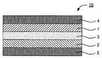
図1は、本開示の全固体電池の一例を示す概略断面図である。図1に示す全固体電10は、正極活物質層1と、負極活物質層2と、正極活物質層1および負極活物質層2の間に配置された固体電解質層3と、正極活物質層1の集電を行う正極集電体4と、負極活物質層2の集電を行う負極集電体5と、を有する。本開示の全固体電池は、正極活物質層1および負極活物質層2の少なくとも一方が、TBA−TFSIおよびLi−TFSIを含有するLiイオン伝導性材料を所定量含有することを大きな特徴とする。
FIG. 1 is a schematic cross-sectional view showing an example of the all-solid-state battery of the present disclosure. The all-solid-
本開示によれば、正極活物質層および負極活物質層の少なくとも一方が、特定のLiイオン伝導性材料を所定量含有することにより、イオン抵抗の増加抑制と、電池温度の上昇抑制とを両立した全固体電池とすることができる。 According to the present disclosure, when at least one of the positive electrode active material layer and the negative electrode active material layer contains a predetermined amount of a specific Li ion conductive material, both suppression of increase in ion resistance and suppression of increase in battery temperature can be achieved. All-solid-state battery.
上述したように、特許文献1では、シアヌル酸メラミンまたはポリリン酸メラミンを用いることにより、硫化物固体電池内における熱の伝播を抑制している。一方、シアヌル酸メラミンおよびポリリン酸メラミンは、Liイオン伝導性を有しないため、イオン抵抗の増加が大きくなる。これに対して、本開示におけるLiイオン伝導性材料は、Liイオン伝導性が高いため、イオン抵抗の増加を抑制できる。
As described above, in
また、シアヌル酸メラミンまたはポリリン酸メラミンは、熱の伝播を抑制する材料であり、温度を低下させる材料ではない。これに対して、本開示におけるLiイオン伝導性材料は、25℃では固体であるが、加熱(例えば200℃以下の加熱)により液化する材料である。液化の際に、吸熱反応を伴うため、温度を低下させることができる。その結果、何らかの理由で電池が発熱した場合であっても、電池温度の上昇を抑制できる。 In addition, melamine cyanurate or melamine polyphosphate is a material that suppresses the propagation of heat, and is not a material that reduces the temperature. On the other hand, the Li ion conductive material in the present disclosure is a material which is solid at 25 ° C. but liquefies by heating (for example, heating at 200 ° C. or less). During the liquefaction, the temperature can be lowered because an endothermic reaction is involved. As a result, even if the battery generates heat for some reason, the rise in battery temperature can be suppressed.
このように、本開示によれば、イオン抵抗の増加抑制と、電池温度の上昇抑制とを両立することができる。また、Liイオン伝導性材料は、柔粘性結晶(プラスチッククリスタル)であることが好ましい。
以下、本開示の全固体電池について、構成ごとに説明する。
Thus, according to the present disclosure, it is possible to simultaneously suppress the increase in ion resistance and the increase in battery temperature. The Li ion conductive material is preferably a plastic crystal (plastic crystal).
Hereinafter, the all-solid-state battery of the present disclosure will be described for each configuration.
1.正極活物質層
正極活物質層は、少なくとも正極活物質を含有する層である。正極活物質層は、Liイオン伝導性材料を含有することが好ましい。また、正極活物質層は、必要に応じて、固体電解質、導電材およびバインダーの少なくとも一つを含有していてもよい。
1. Positive Electrode Active Material Layer The positive electrode active material layer is a layer containing at least a positive electrode active material. The positive electrode active material layer preferably contains a Li ion conductive material. In addition, the positive electrode active material layer may contain at least one of a solid electrolyte, a conductive material, and a binder, as necessary.
(1)Liイオン伝導性材料
本開示におけるLiイオン伝導性材料は、テトラブチルアンモニウムビス(トリフルオロメタンスルホニル)イミド(TBA−TFSI)およびリチウムビス(トリフルオロメタンスルホニル)イミド(Li−TFSI)を含有する。
(1) Li Ion Conducting Material The Li ion conducting material in the present disclosure contains tetrabutylammonium bis (trifluoromethanesulfonyl) imide (TBA-TFSI) and lithium bis (trifluoromethanesulfonyl) imide (Li-TFSI) .
Li−TFSIに対するTBA−TFSIのモル比は、例えば1以上であり、2以上であってもよい。一方、上記モル比は、例えば100以下であり、50以下であってもよい。 The molar ratio of TBA-TFSI to Li-TFSI is, for example, 1 or more, and may be 2 or more. On the other hand, the molar ratio is, for example, 100 or less, and may be 50 or less.
Liイオン伝導性材料の融点は、全固体電池の通常使用温度よりも高いことが好ましい。全固体電池の通常使用温度は、例えば50℃未満であり、45℃以下であってもよい。Liイオン伝導性材料の融点は、例えば50℃以上であり、70℃以上であってもよく、90℃以上であってもよい。一方、Liイオン伝導性材料の融点は、例えば200℃以下である。Liイオン伝導性材料の融点は、示差走査熱量測定(DSC測定)により測定できる。Liイオン伝導性材料が複数の融点を有する場合、Liイオン伝導性材料の融点とは、DSC測定において最も大きい吸熱ピークを示す温度をいう。 The melting point of the Li ion conductive material is preferably higher than the normal use temperature of the all solid battery. The normal use temperature of the all-solid-state battery is, for example, less than 50 ° C., and may be 45 ° C. or less. The melting point of the Li ion conductive material is, for example, 50 ° C. or more, and may be 70 ° C. or more, or 90 ° C. or more. On the other hand, the melting point of the Li ion conductive material is, for example, 200 ° C. or less. The melting point of the Li ion conductive material can be measured by differential scanning calorimetry (DSC measurement). When the Li ion conductive material has a plurality of melting points, the melting point of the Li ion conductive material refers to a temperature at which the largest endothermic peak is observed in DSC measurement.
Liイオン伝導性材料は、Liイオン伝導度が高いことが好ましい。25℃におけるLiイオン伝導性材料のLiイオン伝導度は、例えば、1×10⁻⁶S/cm以上であり、1×10−5S/cm以上であることが好ましい。 The Li ion conductive material preferably has a high Li ion conductivity. The Li ion conductivity of the Li ion conductive material at 25 ° C. is, for example, 1 × 10 −6 S / cm or more, and preferably 1 × 10 −5 S / cm or more.
正極活物質層に含まれるLiイオン伝導性材料の割合は、例えば1重量%以上であり、5重量%以上であってもよい。一方、正極活物質層に含まれるLiイオン伝導性材料の割合は、例えば、40重量%以下であり、30重量%以下であってもよく、20重量%以下であってもよい。 The proportion of the Li ion conductive material contained in the positive electrode active material layer is, for example, 1% by weight or more, and may be 5% by weight or more. On the other hand, the proportion of the Li ion conductive material contained in the positive electrode active material layer is, for example, 40% by weight or less, 30% by weight or less, or 20% by weight or less.
(2)正極活物質
正極活物質は、特に限定されないが、典型的には酸化物活物質が挙げられる。酸化物活物質としては、例えば、LiCoO2、LiMnO2、LiNiO2、LiVO2、LiNi1/3Co1/3Mn1/3O2等の岩塩層状型活物質、LiMn2O4、Li(Ni0.5Mn1.5)O4等のスピネル型活物質、LiFePO4、LiMnPO4、LiNiPO4、LiCuPO4等のオリビン型活物質が挙げられる。
(2) Positive Electrode Active Material The positive electrode active material is not particularly limited, but typically an oxide active material can be mentioned. As the oxide active material, for example, a rock salt layered type active material such as LiCoO 2 , LiMnO 2 , LiNiO 2 , LiVO 2 , LiNi 1/3 Co 1/3 Mn 1/3 O 2 , LiMn 2 O 4 , Li ( Examples include spinel-type active materials such as Ni 0.5 Mn 1.5 ) O 4 , and olivine-type active materials such as LiFePO 4 , LiMnPO 4 , LiNiPO 4 , and LiCuPO 4 .
また、正極活物質の表面は、コート層で被覆されていてもよい。コート層により、正極活物質と固体電解質(特に硫化物固体電解質)とが反応することを抑制できる。コート層としては、例えば、LiNbO3、Li3PO4、LiPON等のLi含有酸化物が挙げられる。コート層の平均厚さは、例えば1nm以上である。一方、コート層の平均厚さは、例えば20nm以下であり、10nm以下であってもよい。 In addition, the surface of the positive electrode active material may be coated with a coat layer. The coat layer can suppress the reaction between the positive electrode active material and the solid electrolyte (in particular, a sulfide solid electrolyte). The coating layer, for example, LiNbO 3, Li 3 PO 4 , Li -containing oxides such as LiPON like. The average thickness of the coat layer is, for example, 1 nm or more. On the other hand, the average thickness of the coating layer is, for example, 20 nm or less, and may be 10 nm or less.
正極活物質の形状としては、例えば、粒子状が挙げられる。正極活物質の平均粒径(D50)は、例えば、0.1μm以上、50μm以下である。なお、平均粒径は、例えば、レーザー回折式粒度分布計、走査型電子顕微鏡(SEM)による測定から算出できる。正極活物質層に含まれる正極活物質の割合は、例えば40重量%以上であり、50重量%以上であってもよく、60重量%以上であってもよい。一方、正極活物質層に含まれる正極活物質の割合は、例えば95重量%以下である。 Examples of the shape of the positive electrode active material include particulates. The average particle size (D 50 ) of the positive electrode active material is, for example, 0.1 μm or more and 50 μm or less. In addition, an average particle diameter can be calculated from the measurement by a laser diffraction type particle size distribution analyzer, a scanning electron microscope (SEM), for example. The proportion of the positive electrode active material contained in the positive electrode active material layer is, for example, 40% by weight or more, and may be 50% by weight or more, or 60% by weight or more. On the other hand, the proportion of the positive electrode active material contained in the positive electrode active material layer is, for example, 95% by weight or less.
(3)固体電解質
固体電解質は、Liイオン伝導性を有する材料であれば特に限定されないが、例えば、硫化物固体電解質および酸化物固体電解質が挙げられる。
(3) Solid Electrolyte The solid electrolyte is not particularly limited as long as it is a material having Li ion conductivity, and examples thereof include a sulfide solid electrolyte and an oxide solid electrolyte.
硫化物固体電解質の構成元素は、特に限定されないが、硫化物固体電解質は、Li元素と、P元素、Ge元素、Si元素の少なくとも一種と、S元素とを含有することが好ましい。また、硫化物固体電解質は、ハロゲン元素として、Cl元素、Br元素およびI元素の少なくとも一つを含有していてもよい。また、硫化物固体電解質は、O元素を含有していてもよい。 The constituent elements of the sulfide solid electrolyte are not particularly limited, but the sulfide solid electrolyte preferably contains Li element, at least one of P element, Ge element and Si element, and S element. The sulfide solid electrolyte may contain at least one of Cl, Br and I as a halogen element. The sulfide solid electrolyte may also contain an O element.
硫化物固体電解質は、Li元素、P元素およびS元素を含有するイオン伝導体を含有することが好ましい。さらに、イオン伝導体は、PS4 3−をアニオン構造の主体として含有することが好ましい。「PS4 3−をアニオン構造の主体とする」とは、PS4 3−の割合が、イオン伝導体における全アニオン構造の中で最も多いことをいう。全アニオン構造におけるPS4 3−の割合は、例えば60mol%以上であり、70mol%以上であってもよく、80mol%以上であってもよく、90mol%以上であってもよい。PS4 3−の割合は、例えば、ラマン分光法、NMR、XPSにより決定することができる。また、イオン伝導体のS元素の一部は、O元素に置換されていてもよい。 The sulfide solid electrolyte preferably contains an ion conductor containing Li, P and S elements. Furthermore, the ion conductor preferably contains PS 4 3- as a main component of the anion structure. The phrase "having PS 4 3- as the main component of the anion structure" means that the proportion of PS 4 3- is the largest among all the anion structures in the ion conductor. The proportion of PS 4 3- in the total anion structure is, for example, 60 mol% or more, and may be 70 mol% or more, 80 mol% or more, or 90 mol% or more. The proportion of PS 4 3- can be determined by, for example, Raman spectroscopy, NMR, or XPS. In addition, a part of the S element of the ion conductor may be replaced by the O element.
硫化物固体電解質は、上記イオン伝導体に加えて、LiX(Xは、Cl、BrおよびIの少なくとも一種である)を含有することが好ましい。また、LiXの少なくとも一部は、LiXとしてイオン伝導体の構造中に取り込まれた状態で存在することが好ましい。硫化物固体電解質におけるLiXの割合は、例えば1mol%以上であり、10mol%以上であってもよい。一方、上記LiXの割合は、例えば50mol%以下であり、35mol%以下であってもよい。 The sulfide solid electrolyte preferably contains LiX (X is at least one of Cl, Br and I) in addition to the above ion conductor. In addition, at least a part of LiX is preferably present in the form of being incorporated into the structure of the ion conductor as LiX. The proportion of LiX in the sulfide solid electrolyte is, for example, 1 mol% or more, and may be 10 mol% or more. On the other hand, the ratio of LiX is, for example, 50 mol% or less, and may be 35 mol% or less.
硫化物固体電解質は、非晶質であってもよく、結晶質であってもよい。前者の一例としては、硫化物ガラスが挙げられ、後者の一例としては、結晶化硫化物ガラス(ガラスセラミックス)が挙げられる。 The sulfide solid electrolyte may be amorphous or crystalline. An example of the former is a sulfide glass, and an example of the latter is a crystallized sulfide glass (glass ceramic).
固体電解質は、Liイオン伝導度が高いことが好ましい。25℃における固体電解質のLiイオン伝導度は、例えば、1×10⁻⁴S/cm以上であることが好ましく、1×10−3S/cm以上であることがより好ましい。また、固体電解質の形状としては、例えば、粒子状が挙げられる。固体電解質の平均粒径(D50)は、例えば0.1μm以上であり、0.5μm以上であってもよい。一方、上記平均粒径(D50)は、例えば50μm以下であり、5μm以下であってもよい。なお、平均粒径は、例えば、レーザー回折式粒度分布計、走査型電子顕微鏡(SEM)による測定から算出できる。 The solid electrolyte preferably has a high Li ion conductivity. The Li ion conductivity of the solid electrolyte at 25 ° C. is, for example, preferably 1 × 10 −4 S / cm or more, and more preferably 1 × 10 −3 S / cm or more. Moreover, as a shape of a solid electrolyte, a particulate form is mentioned, for example. The average particle size (D 50 ) of the solid electrolyte is, for example, 0.1 μm or more, and may be 0.5 μm or more. On the other hand, the average particle diameter (D 50 ) may be, for example, 50 μm or less and 5 μm or less. In addition, an average particle diameter can be calculated from the measurement by a laser diffraction type particle size distribution analyzer, a scanning electron microscope (SEM), for example.
(4)正極活物質層
正極活物質層は、さらに導電材を含有していてもよい。導電材の添加により、正極活物質層の電子伝導性を向上させることができる。導電材としては、例えば、アセチレンブラック、ケッチェンブラック、カーボンファイバーが挙げられる。また、正極活物質層は、さらにバインダーを含有していてもよい。バインダーとしては、例えば、ポリビニリデンフロライド(PVDF)、ポリテトラフルオロエチレン(PTFE)等のフッ素含有バインダー、ブタジエンゴム等のゴム系バインダー、アクリル系バインダーが挙げられる。
(4) Positive Electrode Active Material Layer The positive electrode active material layer may further contain a conductive material. The addition of the conductive material can improve the electron conductivity of the positive electrode active material layer. Examples of the conductive material include acetylene black, ketjen black, and carbon fiber. The positive electrode active material layer may further contain a binder. Examples of the binder include fluorine-containing binders such as polyvinylidene fluoride (PVDF) and polytetrafluoroethylene (PTFE), rubber binders such as butadiene rubber, and acrylic binders.
正極活物質層の厚さは、例えば、0.1μm以上、1000μm以下である。正極活物質層の形成方法としては、例えば、正極活物質および分散媒を少なくとも含有するスラリーを塗工し、乾燥する方法が挙げられる。 The thickness of the positive electrode active material layer is, for example, 0.1 μm or more and 1000 μm or less. As a method of forming a positive electrode active material layer, for example, a method of coating a slurry containing at least a positive electrode active material and a dispersion medium and drying it may be mentioned.
2.負極活物質層
負極活物質層は、少なくとも負極活物質を含有する層である。負極活物質層は、上述したLiイオン伝導性材料を含有することが好ましい。また、負極活物質層は、必要に応じて、固体電解質、導電材およびバインダーの少なくとも一つを含有していてもよい。
2. Anode Active Material Layer The anode active material layer is a layer containing at least an anode active material. The negative electrode active material layer preferably contains the above-described Li ion conductive material. In addition, the negative electrode active material layer may contain at least one of a solid electrolyte, a conductive material, and a binder, as necessary.
負極活物質は、特に限定されないが、例えばカーボン活物質、金属活物質および酸化物活物質が挙げられる。カーボン活物質としては、例えば、グラファイト、ハードカーボン、ソフトカーボンが挙げられる。一方、金属活物質としては、例えば、Li、In、Al、SiおよびSn等の単体、および、これらの元素の少なくとも一種を含む合金が挙げられる。また、酸化物活物質としては、例えば、Li4TiO5が挙げられる。負極活物質層に含まれる負極活物質の割合は、例えば40重量%以上であり、50重量%以上であってもよく、60重量%以上であってもよい。一方、負極活物質層に含まれる負極活物質の割合は、例えば95重量%以下である。 Although a negative electrode active material is not specifically limited, For example, a carbon active material, a metal active material, and an oxide active material are mentioned. Examples of the carbon active material include graphite, hard carbon and soft carbon. On the other hand, examples of the metal active material include simple substances such as Li, In, Al, Si, and Sn, and alloys containing at least one of these elements. As oxide active material, for example, Li 4 TiO 5. The proportion of the negative electrode active material contained in the negative electrode active material layer is, for example, 40% by weight or more, and may be 50% by weight or more, or 60% by weight or more. On the other hand, the proportion of the negative electrode active material contained in the negative electrode active material layer is, for example, 95% by weight or less.
負極活物質層に用いられるLiイオン伝導性材料の種類、割合およびその他の事項については、上記「1.正極活物質層」に記載した内容と同様であるので、ここでの記載は省略する。 The type, proportion, and other matters of the Li ion conductive material used for the negative electrode active material layer are the same as the contents described in the above “1. Positive electrode active material layer”, and thus the description herein is omitted.
負極活物質層に用いられる、固体電解質、導電材およびバインダーについては、上記「1.正極活物質層」に記載した内容と同様であるので、ここでの記載は省略する。中でも、負極活物質層は、固体電解質として硫化物固体電解質を含有することが好ましい。 The solid electrolyte, the conductive material, and the binder used for the negative electrode active material layer are the same as the contents described in the above “1. positive electrode active material layer”, and thus the description thereof is omitted here. Among them, the negative electrode active material layer preferably contains a sulfide solid electrolyte as a solid electrolyte.
負極活物質層の厚さは、例えば、0.1μm以上、1000μm以下である。負極活物質層の形成方法としては、例えば、負極活物質および分散媒を少なくとも含有するスラリーを塗工し、乾燥する方法が挙げられる。 The thickness of the negative electrode active material layer is, for example, 0.1 μm or more and 1000 μm or less. Examples of the method of forming the negative electrode active material layer include a method of applying a slurry containing at least the negative electrode active material and the dispersion medium and drying it.
3.固体電解質層
固体電解質層は、正極活物質層および負極活物質層の間に配置される層である。固体電解質層は、固体電解質を少なくとも含有し、必要に応じてバインダーを含有していてもよい。また、固体電解質層は、上述したLiイオン伝導性材料を含有していてもよい。固体電解質、バインダーおよびLiイオン伝導性材料については、上記「1.正極活物質層」に記載した内容と同様であるので、ここでの記載は省略する。中でも、固体電解質層は、固体電解質として硫化物固体電解質を含有することが好ましい。
3. Solid Electrolyte Layer The solid electrolyte layer is a layer disposed between the positive electrode active material layer and the negative electrode active material layer. The solid electrolyte layer contains at least a solid electrolyte and may optionally contain a binder. The solid electrolyte layer may also contain the above-described Li ion conductive material. About a solid electrolyte, a binder, and Li ion conductive material, since it is the same as that of the content described in said "1. positive electrode active material layer", description here is abbreviate | omitted. Among them, the solid electrolyte layer preferably contains a sulfide solid electrolyte as a solid electrolyte.
固体電解質層の厚さは、例えば、0.1μm以上、1000μm以下である。固体電解質層の形成方法としては、例えば、固体電解質を圧縮成形する方法が挙げられる。 The thickness of the solid electrolyte layer is, for example, 0.1 μm or more and 1000 μm or less. As a method of forming a solid electrolyte layer, for example, a method of compression molding a solid electrolyte may be mentioned.
4.その他の部材
本開示の全固体電池は、上述した正極活物質層、負極活物質層および固体電解質層を少なくとも有する。さらに通常は、正極活物質層の集電を行う正極集電体、および、負極活物質層の集電を行う負極集電体を有する。正極集電体の材料としては、例えば、SUS、アルミニウム、ニッケル、鉄、チタンおよびカーボンが挙げられる。一方、負極集電体の材料としては、例えば、SUS、銅、ニッケルおよびカーボンが挙げられる。なお、正極集電体および負極集電体の厚さ、形状については、電池の用途に応じて適宜選択することが好ましい。また、本開示に用いられる電池ケースには、一般的な電池の電池ケースを用いることができ、例えばSUS製電池ケースが挙げられる。
4. Other Members The all-solid-state battery of the present disclosure at least includes the positive electrode active material layer, the negative electrode active material layer, and the solid electrolyte layer described above. Furthermore, usually, it has a positive electrode current collector for collecting current in the positive electrode active material layer, and a negative electrode current collector for collecting current in the negative electrode active material layer. Examples of the material of the positive electrode current collector include SUS, aluminum, nickel, iron, titanium and carbon. On the other hand, examples of the material of the negative electrode current collector include SUS, copper, nickel and carbon. The thickness and shape of the positive electrode current collector and the negative electrode current collector are preferably selected appropriately in accordance with the application of the battery. Moreover, the battery case of a general battery can be used for the battery case used for this indication, for example, the battery case made from SUS is mentioned.
5.全固体電池
本開示の全固体電池は、Liイオン伝導性材料の添加によるイオン抵抗の増加が少ないことが好ましい。ここで、本開示の全固体電池(Liイオン伝導性材料を含有する全固体電池)を電池Aとし、Liイオン伝導性材料を含有しないこと以外は電池Aと同じ電池を電池Bとする。電池Aおよび電池Bに対して、後述する条件でDC−IR測定を行った場合に、電池Bのイオン抵抗に対する、電池Aのイオン抵抗の割合(イオン抵抗の増加率)は、例えば、4倍以下であり、3倍以下であることが好ましく、2倍以下であることがより好ましい。
5. All-Solid-State Battery In the all-solid-state battery of the present disclosure, it is preferable that the increase in ionic resistance due to the addition of the Li ion conductive material be small. Here, the all-solid battery (all-solid battery containing Li ion conductive material) of the present disclosure is referred to as battery A, and the same battery as battery A is referred to as battery B except that the Li ion conductive material is not contained. When DC-IR measurement is performed on the battery A and the battery B under the conditions described later, the ratio of the ionic resistance of the battery A to the ionic resistance of the battery B (the increase ratio of the ionic resistance) is, for example, 4 times Or less, preferably 3 times or less, more preferably 2 times or less.
本開示の全固体電池は、釘刺し試験時の温度上昇が少ないことが好ましい。電池Aおよび電池Bに対して、後述する条件で釘刺し試験を行った場合に、電池Bの温度上昇に対する、電池Aの温度上昇の割合(温度上昇率)は、例えば99%以下であり、90%以下であることが好ましく、85%以下であることがより好ましい。 It is preferable that the all-solid-state battery of the present disclosure has a small temperature rise during the nail penetration test. When the nail penetration test is performed on the battery A and the battery B under the conditions described later, the ratio of the temperature rise of the battery A (the temperature rise ratio) to the temperature rise of the battery B is, for example, 99% or less It is preferably 90% or less, more preferably 85% or less.
本開示の全固体電池は、通常、全固体リチウム電池である。また、本開示の全固体電池は、一次電池であってもよく、二次電池であってもよいが、中でも二次電池であることが好ましい。繰り返し充放電でき、例えば車載用電池として有用だからである。また、本開示の全固体電池は、単層電池であってもよく、積層電池であってもよい。積層電池は、モノポーラ型積層電池(並列接続型の積層電池)であってもよく、バイポーラ型積層電池(直列接続型の積層電池)であってもよい。全固体電池の形状としては、例えば、コイン型、ラミネート型、円筒型および角型が挙げられる。 The all solid state battery of the present disclosure is usually an all solid state lithium battery. Further, the all solid state battery of the present disclosure may be a primary battery or a secondary battery, but among them, a secondary battery is preferable. This is because the battery can be repeatedly charged and discharged, and it is useful as, for example, an on-vehicle battery. In addition, the all solid state battery of the present disclosure may be a single layer battery or a laminated battery. The laminated battery may be a monopolar laminated battery (parallel connected laminated battery) or a bipolar laminated battery (series connected laminated battery). Examples of the shape of the all-solid-state battery include coin-type, laminate-type, cylindrical and square-type.
なお、本開示は、上記実施形態に限定されるものではない。上記実施形態は、例示であり、本開示の特許請求の範囲に記載された技術的思想と実質的に同一な構成を有し、同様な作用効果を奏するものは、いかなるものであっても本開示の技術的範囲に包含される。 The present disclosure is not limited to the above embodiment. The above-described embodiment is an exemplification, which has substantially the same configuration as the technical idea described in the claims of the present disclosure, and exhibits the same operation and effect as the present invention. It is included in the technical scope of the disclosure.
以下、本開示をさらに具体的に説明する。 Hereinafter, the present disclosure will be more specifically described.
[製造例1]
テトラブチルアンモニウムビス(トリフルオロメタンスルホニル)イミド(TBA−TFSI)およびリチウムビス(トリフルオロメタンスルホニル)イミド(Li−TFSI)を準備し、これらをTBA−TFSI:Li−TFSI=4:1のモル比で秤量し、混合した。得られた混合物をガラス容器に入れ、120℃で1時間減圧乾燥することにより、Liイオン伝導性材料(TBA−TFSI・Li−TFSI)を得た。
Production Example 1
Prepare tetrabutylammonium bis (trifluoromethanesulfonyl) imide (TBA-TFSI) and lithium bis (trifluoromethanesulfonyl) imide (Li-TFSI), with a molar ratio of TBA-TFSI: Li-TFSI = 4: 1 Weighed and mixed. The obtained mixture was put into a glass container and dried under reduced pressure at 120 ° C. for 1 hour to obtain a Li ion conductive material (TBA-TFSI · Li-TFSI).
[評価]
製造例1で得られたLiイオン伝導性材料に対して、示差走査熱量測定(DSC測定)を行った。DSC測定は、窒素フロー50ml/min、昇温速度5℃/minの条件で行った。その結果を図2に示す。図2に示すように、55℃付近および75℃付近に吸熱ピークが確認された。これらの吸熱ピーク温度は、Liイオン伝導性材料の融点と一致することから、Liイオン伝導性材料の溶解により吸熱反応が生じることが確認された。
[Evaluation]
Differential scanning calorimetry (DSC measurement) was performed on the Li ion conductive material obtained in Production Example 1. DSC measurement was performed under the conditions of a nitrogen flow of 50 ml / min and a temperature rising rate of 5 ° C./min. The results are shown in FIG. As shown in FIG. 2, endothermic peaks were confirmed around 55 ° C. and around 75 ° C. Since these endothermic peak temperatures coincide with the melting point of the Li ion conductive material, it was confirmed that the endothermic reaction occurs due to the dissolution of the Li ion conductive material.
[参考例1]
(硫化物固体電解質の作製)
Li2S(日本化学工業製)およびP2S5(アルドリッチ製)を出発原料とした。これらを、モル比でLi2S:P2S5=75:25となるように秤量した。Li2SおよびP2S5を、メノウ乳鉢で5分混合し、その後ヘプタンを入れ、遊星型ボールミルを用いて40時間メカニカルミリングを行った。これにより硫化物ガラスを得た。その後、180℃で2時間焼成することで硫化物固体電解質(ガラスセラミックス)を得た。
[Reference Example 1]
(Preparation of sulfide solid electrolyte)
Li 2 S (manufactured by Nippon Chemical Industrial Co., Ltd.) and P 2 S 5 (manufactured by Aldrich) were used as starting materials. These were weighed so that Li 2 S: P 2 S 5 = 75: 25 in molar ratio. Li 2 S and P 2 S 5 were mixed in an agate mortar for 5 minutes, then heptane was added, and mechanical milling was performed for 40 hours using a planetary ball mill. A sulfide glass was thus obtained. Then, a sulfide solid electrolyte (glass ceramic) was obtained by baking at 180 ° C. for 2 hours.
(正極合材スラリーの作製)
正極活物質としてLiNi1/3Co1/3Mn1/3O2(日亜化学工業製)を準備した。この正極活物質の表面にコート層を形成した。具体的には、エタノール溶媒に、等モルのLiOC2H5およびNb(OC2H5)5を溶解させた組成物を作製し、その組成物を、正極活物質の表面に、転動流動コーティング装置(SFP−01、パウレック製)を用いてスプレーコートした。その後、コーティングされた正極活物質を、350℃、大気圧、1時間の条件で熱処理することにより、正極活物質の表面にコート層を形成した。なお、得られた粒子(正極活物質およびコート層を有する粒子)の平均粒径(D50)は、5μmであった。
(Preparation of positive electrode mixture slurry)
LiNi 1/3 Co 1/3 Mn 1/3 O 2 (manufactured by Nichia Corporation) was prepared as a positive electrode active material. A coat layer was formed on the surface of this positive electrode active material. Specifically, a composition in which equimolar LiOC 2 H 5 and Nb (OC 2 H 5 ) 5 are dissolved in an ethanol solvent is prepared, and the composition is applied to the surface of the positive electrode active material by tumbling flow. It spray-coated using the coating apparatus (SFP-01, product made from Powrex). Thereafter, the coated positive electrode active material was heat-treated under the conditions of 350 ° C. and atmospheric pressure for 1 hour to form a coating layer on the surface of the positive electrode active material. The average particle diameter (D 50 ) of the obtained particles (the particles having a positive electrode active material and a coat layer) was 5 μm.
コート層を有する正極活物質52g、上述した硫化物固体電解質13g、導電材として気相法炭素繊維(VGCF、登録商標)1g、脱水ヘプタン(関東化学製)15gを秤量し、十分に混合した。その後、製造例1で得られたLiイオン伝導性材料(TBA−TFSI・Li−TFSI)を1重量%(固形成分比)となるように添加し、正極合材スラリーを得た。 52 g of a positive electrode active material having a coating layer, 13 g of the sulfide solid electrolyte described above, 1 g of vapor grown carbon fiber (VGCF (registered trademark)) as a conductive material, and 15 g of dehydrated heptane (manufactured by Kanto Chemical Co., Ltd.) were weighed and mixed sufficiently. Thereafter, the Li ion conductive material (TBA-TFSI · Li-TFSI) obtained in Production Example 1 was added to 1 wt% (solid component ratio) to obtain a positive electrode mixture slurry.
(負極合材スラリーの作製)
負極活物質としてグラファイト(三菱化学株式会社)36g、上述した硫化物固体電解質25g、脱水ヘプタン(関東化学製)60gを秤量し、十分に混合した。これにより、負極合材スラリーを得た。
(Preparation of negative electrode mixture slurry)
36 g of graphite (Mitsubishi Chemical Corporation), 25 g of the above-mentioned sulfide solid electrolyte, and 60 g of dehydrated heptane (manufactured by Kanto Chemical Co., Ltd.) were weighed and sufficiently mixed as negative electrode active materials. Thus, a negative electrode mixture slurry was obtained.
(積層電池の作製)
正極合材スラリーをAl箔(正極集電体)に厚さ50μmで塗工し、乾燥することにより、正極活物質層を得た。次に、負極合材スラリーをCu箔(負極集電体)に厚さ50μmで塗工し、乾燥することにより、負極活物質層を得た。次に、上述した硫化物固体電解質と、バインダー(アクリレートブタジエンゴム、ABR)とを硫化物固体電解質:ABR=98:2の体積比で混合した。得られた混合物を4.3ton/cm2でプレスし、シート状の固体電解質層を得た。得られた固体電解質層を、正極活物質層および負極活物質層の間に配置し、4.3ton/cm2でプレスし、単層電池を得た。得られた単層電池を8層積層し、集電タブを単層電池のセル端子と超音波溶接した。得られた積層体の外側をアルミラミネート材で真空封入し、0.5Ah級の積層電池を得た。
(Production of laminated battery)
The positive electrode mixture slurry was applied to an Al foil (positive electrode current collector) to a thickness of 50 μm and dried to obtain a positive electrode active material layer. Next, a negative electrode mixture material slurry was applied to a thickness of 50 μm on a Cu foil (negative electrode current collector) and dried to obtain a negative electrode active material layer. Next, the above-mentioned sulfide solid electrolyte and a binder (acrylate butadiene rubber, ABR) were mixed at a volume ratio of sulfide solid electrolyte: ABR = 98: 2. The obtained mixture was pressed at 4.3 ton / cm 2 to obtain a sheet-like solid electrolyte layer. The obtained solid electrolyte layer was disposed between the positive electrode active material layer and the negative electrode active material layer, and pressed at 4.3 ton / cm 2 to obtain a single layer battery. Eight layers of the obtained single layer battery were laminated, and the current collecting tab was ultrasonically welded to the cell terminal of the single layer battery. The outer side of the obtained laminate was vacuum sealed with an aluminum laminate material to obtain a 0.5 Ah grade laminated battery.
[実施例1〜3、参考例2]
正極合材スラリーにおけるLiイオン伝導性材料(TBA−TFSI・Li−TFSI)の割合を、固形成分比でそれぞれ5重量%、10重量%、20重量%および30重量%に変更したこと以外は、参考例1と同様にして積層電池を得た。
[Examples 1 to 3, Reference Example 2]
Except that the proportion of Li ion conductive material (TBA-TFSI · Li-TFSI) in the positive electrode mixture slurry was changed to 5% by weight, 10% by weight, 20% by weight and 30% by weight, respectively, in terms of solid component ratio A laminated battery was obtained in the same manner as in Reference Example 1.
[参考例3]
正極合材スラリーにLiイオン伝導性材料(TBA−TFSI・Li−TFSI)を用いる代わりに、負極合材スラリーにLiイオン伝導性材料(TBA−TFSI・Li−TFSI)を用いたこと以外は、参考例1と同様にして積層電池を得た。
[Reference Example 3]
Instead of using Li ion conductive material (TBA-TFSI · Li-TFSI) for the positive electrode mixture slurry, except that Li ion conductive material (TBA-TFSI · Li-TFSI) is used for the negative electrode mixture slurry, A laminated battery was obtained in the same manner as in Reference Example 1.
[実施例4〜6、参考例4]
負極合材スラリーにおけるLiイオン伝導性材料(TBA−TFSI・Li−TFSI)の割合を、固形成分比でそれぞれ5重量%、10重量%、20重量%および30重量%に変更したこと以外は、参考例3と同様にして積層電池を得た。
[Examples 4 to 6, Reference Example 4]
Except that the proportion of Li ion conductive material (TBA-TFSI · Li-TFSI) in the negative electrode mixture slurry was changed to 5% by weight, 10% by weight, 20% by weight and 30% by weight, respectively, in terms of solid component ratio A laminated battery was obtained in the same manner as in Reference Example 3.
[比較例1、2]
Liイオン伝導性材料(TBA−TFSI・Li−TFSI)の代わりに、シアヌル酸メラミンを、固形成分比でそれぞれ20重量%および30重量%となるように添加したこと以外は、参考例1と同様にして積層電池を得た。
Comparative Examples 1 and 2
Similar to Reference Example 1 except that melamine cyanurate was added so as to have a solid component ratio of 20% by weight and 30% by weight, respectively, instead of the Li ion conductive material (TBA-TFSI · Li-TFSI). The laminated battery was obtained.
[比較例3、4]
Liイオン伝導性材料(TBA−TFSI・Li−TFSI)の代わりに、シアヌル酸メラミンを、固形成分比でそれぞれ20重量%および30重量%となるように添加したこと以外は、参考例3と同様にして積層電池を得た。
[Comparative Examples 3 and 4]
The same as Reference Example 3, except that melamine cyanurate was added so as to have a solid component ratio of 20% by weight and 30% by weight, respectively, instead of Li ion conductive material (TBA-TFSI · Li-TFSI). The laminated battery was obtained.
[比較例5]
Liイオン伝導性材料(TBA−TFSI・Li−TFSI)を用いなかったこと以外は、参考例1と同様にして積層電池を得た。
Comparative Example 5
A laminated battery was obtained in the same manner as in Example 1 except that the Li ion conductive material (TBA-TFSI · Li-TFSI) was not used.
[評価]
(イオン抵抗測定)
実施例1〜6、参考例1〜4および比較例1〜5で得られた積層電池に対して、DC−IR測定を行い、積層電池のイオン抵抗を測定した。まず、積層電池を電圧3.6Vまで充電し、その後、電流値5mA(定電流)で10秒間充電し、電圧の増加分を電流値5mAで割ることで、抵抗を算出した。その結果を表1に示す。
[Evaluation]
(Ion resistance measurement)
The DC-IR measurement was performed on the laminated cells obtained in Examples 1 to 6 and Reference Examples 1 to 4 and Comparative Examples 1 to 5 to measure the ion resistance of the laminated cells. First, the laminated battery was charged to a voltage of 3.6 V, and then charged for 10 seconds at a current value of 5 mA (constant current), and the increase in voltage was divided by the
(釘刺し試験)
実施例1〜6、参考例1〜4および比較例1〜5で得られた積層電池に対して、釘刺し試験を行った。具体的には、満充電した積層電池を環境温度25℃の釘刺し試験機上に配置し、電池中央に10mm/secの速度で釘を刺し、電池の温度上昇を測定した。電池の温度上昇は、試験中の最高到達温度と、試験開始直前の温度との差をいう。その結果を表1に示す。なお、表1における温度上昇率は、比較例5を100%とした場合の相対値である。
(Tail test)
A nail penetration test was performed on the laminated cells obtained in Examples 1 to 6 and Reference Examples 1 to 4 and Comparative Examples 1 to 5. Specifically, the fully charged laminated battery was placed on a nail penetration tester with an environmental temperature of 25 ° C., and a nail was pierced at the center of the battery at a speed of 10 mm / sec, and the temperature rise of the battery was measured. The battery temperature rise refers to the difference between the maximum temperature reached during the test and the temperature immediately before the start of the test. The results are shown in Table 1. The temperature increase rate in Table 1 is a relative value when Comparative Example 5 is 100%.

表1に示すように、実施例1〜3および参考例1、2を比べると、Liイオン伝導性材料の量が増加するにつれ、イオン抵抗が大きくなることが確認された。正極活物質層内のLiイオン伝導は、主に硫化物固体電解質を通して行われるため、Liイオン伝導性材料の量が増加し、相対的に硫化物固体電解質の量が減ることで、イオン抵抗が増加したと推測される。同様の傾向が、実施例4〜6および参考例3、4でも確認された。 As shown in Table 1, when Examples 1 to 3 and Reference Examples 1 and 2 are compared, it was confirmed that the ionic resistance increases as the amount of the Li ion conductive material increases. Since Li ion conduction in the positive electrode active material layer is mainly performed through a sulfide solid electrolyte, the amount of Li ion conductive material is increased, and the amount of sulfide solid electrolyte is relatively decreased, whereby the ion resistance is reduced. It is presumed to have increased. The same tendency was also confirmed in Examples 4 to 6 and Reference Examples 3 and 4.
また、実施例1〜6および比較例1〜4を比べると、Liイオン伝導性材料(TBA−TFSI・Li−TFSI)を用いた場合は、シアヌル酸メラミンを添加した場合に比べて、イオン抵抗の増加が少ないことが確認された。シアヌル酸メラミンは、Liイオン伝導性を有しない材料であるため、Liイオン伝導を阻害し、イオン抵抗が増加したと推測される。これに対して、Liイオン伝導性材料(TBA−TFSI・Li−TFSI)はLiイオン伝導性材料であり、TFSIが硫化物固体電解質の機能を補助したため、イオン抵抗の増加が抑制できたと推測される。 Moreover, when Examples 1-6 and Comparative Examples 1-4 are compared, when Li ion conductive material (TBA-TFSI.Li-TFSI) is used, compared with the case where melamine cyanurate is added, ion resistance is carried out. It was confirmed that the increase in Since melamine cyanurate is a material not having Li ion conductivity, it is presumed that Li ion conduction is inhibited and ion resistance is increased. On the other hand, Li ion conductive material (TBA-TFSI · Li-TFSI) is a Li ion conductive material, and it is speculated that the increase in ion resistance could be suppressed because TFSI assisted the function of the sulfide solid electrolyte. Ru.
これらの結果から、イオン抵抗の増加を抑制するためには、Liイオン伝導性材料を添加することが好ましく、その割合も低いことが好ましいことが確認された。また、電池の出力の観点に基づくと、Liイオン伝導性材料の添加によるイオン抵抗の増加率は、3倍以下であることが好ましい。実施例1〜6におけるイオン抵抗は、いずれも比較例5におけるイオン抵抗の3倍以下であり、出力の面で好ましいことが確認された。 From these results, in order to suppress the increase in ion resistance, it was confirmed that it is preferable to add a Li ion conductive material, and it is preferable that the proportion is also low. Moreover, based on the viewpoint of the output of a battery, it is preferable that the increase rate of the ionic resistance by addition of Li ion conductive material is 3 times or less. The ion resistances in Examples 1 to 6 were all 3 times or less of the ion resistance in Comparative Example 5, and it was confirmed that they are preferable in terms of output.
表1に示すように、実施例1〜3および参考例1、2を比べると、Liイオン伝導性材料の量が増加するにつれ、温度上昇率が小さくなることが確認された。例えば、温度上昇率を90%以下とするためには、Liイオン伝導性材料(TBA−TFSI・Li−TFSI)を5重量%以上添加する必要がある。同様の傾向が、実施例4〜6および参考例3、4でも確認された。 As shown in Table 1, when Examples 1 to 3 and Reference Examples 1 and 2 are compared, it is confirmed that the temperature increase rate decreases as the amount of Li ion conductive material increases. For example, in order to make the temperature rise rate 90% or less, it is necessary to add 5% by weight or more of Li ion conductive material (TBA-TFSI · Li-TFSI). The same tendency was also confirmed in Examples 4 to 6 and Reference Examples 3 and 4.
また、実施例3および比較例1を比べると、Liイオン伝導性材料(TBA−TFSI・Li−TFSI)は、シアヌル酸メラミンに比べて、温度上昇率の低減効果が大きいことが確認された。同様の傾向が、参考例2および比較例2の間、実施例6および比較例3の間、参考例4および比較例4の間でも確認された。 Moreover, when Example 3 and the comparative example 1 are compared, it was confirmed that Li ion conductive material (TBA-TFSI * Li-TFSI) has a large reduction effect of a temperature rising rate compared with melamine cyanurate. The same tendency was also confirmed between Reference Example 2 and Comparative Example 2, between Example 6 and Comparative Example 3, and between Reference Example 4 and Comparative Example 4.
以上のことから、実施例1〜6は、イオン抵抗の増加抑制と、電池温度の上昇抑制とを両立できることが確認された。 From the above, it is confirmed that Examples 1 to 6 can simultaneously suppress the increase in ion resistance and the increase in battery temperature.
1…正極活物質層
2…負極活物質層
3…固体電解質層
4…正極集電体
5…負極集電体
6…電池ケース
10…全固体電池
DESCRIPTION OF
Claims (1)
前記正極活物質層および前記負極活物質層の少なくとも一方が、テトラブチルアンモニウムビス(トリフルオロメタンスルホニル)イミド(TBA−TFSI)およびリチウムビス(トリフルオロメタンスルホニル)イミド(Li−TFSI)を含有するLiイオン伝導性材料を5重量%以上20重量%以下の割合で含有する、全固体電池。 An all solid battery comprising a positive electrode active material layer, a negative electrode active material layer, and a solid electrolyte layer disposed between the positive electrode active material layer and the negative electrode active material layer,
Li ion in which at least one of the positive electrode active material layer and the negative electrode active material layer contains tetrabutylammonium bis (trifluoromethanesulfonyl) imide (TBA-TFSI) and lithium bis (trifluoromethanesulfonyl) imide (Li-TFSI) An all solid battery containing a conductive material in a proportion of 5% by weight to 20% by weight.
Priority Applications (1)
| Application Number | Priority Date | Filing Date | Title |
|---|---|---|---|
| JP2017226658A JP6972965B2 (en) | 2017-11-27 | 2017-11-27 | All solid state battery |
Applications Claiming Priority (1)
| Application Number | Priority Date | Filing Date | Title |
|---|---|---|---|
| JP2017226658A JP6972965B2 (en) | 2017-11-27 | 2017-11-27 | All solid state battery |
Publications (2)
| Publication Number | Publication Date |
|---|---|
| JP2019096541A true JP2019096541A (en) | 2019-06-20 |
| JP6972965B2 JP6972965B2 (en) | 2021-11-24 |
Family
ID=66971885
Family Applications (1)
| Application Number | Title | Priority Date | Filing Date |
|---|---|---|---|
| JP2017226658A Active JP6972965B2 (en) | 2017-11-27 | 2017-11-27 | All solid state battery |
Country Status (1)
| Country | Link |
|---|---|
| JP (1) | JP6972965B2 (en) |
Cited By (2)
| Publication number | Priority date | Publication date | Assignee | Title |
|---|---|---|---|---|
| EP4246642A1 (en) * | 2022-03-18 | 2023-09-20 | Toyota Jidosha Kabushiki Kaisha | Electrolytic material and secondary battery |
| JP7513059B2 (en) | 2022-06-17 | 2024-07-09 | トヨタ自動車株式会社 | Lithium ion conductor and lithium ion battery |
Citations (7)
| Publication number | Priority date | Publication date | Assignee | Title |
|---|---|---|---|---|
| JP2002324581A (en) * | 2001-04-26 | 2002-11-08 | Sony Corp | Solid electrolyte battery |
| WO2006101141A1 (en) * | 2005-03-23 | 2006-09-28 | Kyoto University | Molten salt composition and use thereof |
| JP2009193784A (en) * | 2008-02-13 | 2009-08-27 | Sony Corp | Nonaqueous electrolyte battery and method of manufacturing the same |
| JP2011225931A (en) * | 2010-04-20 | 2011-11-10 | Hokkaido Univ | Method for producing sodium, and apparatus for producing sodium |
| US20140329135A1 (en) * | 2011-06-09 | 2014-11-06 | Government Of The United States As Represented By The Secretary Of The Air Force | Solid-state electrolytes for rechargeable lithium batteries |
| JP2016033919A (en) * | 2014-07-30 | 2016-03-10 | トヨタ モーター エンジニアリング アンド マニュファクチャリング ノース アメリカ,インコーポレイティド | Lithium-air battery, and vehicle comprising lithium air-battery |
| JP2017045611A (en) * | 2015-08-26 | 2017-03-02 | 富士フイルム株式会社 | All-solid type secondary battery, electrode sheet for all-solid type secondary battery, and manufacturing methods thereof |
-
2017
- 2017-11-27 JP JP2017226658A patent/JP6972965B2/en active Active
Patent Citations (7)
| Publication number | Priority date | Publication date | Assignee | Title |
|---|---|---|---|---|
| JP2002324581A (en) * | 2001-04-26 | 2002-11-08 | Sony Corp | Solid electrolyte battery |
| WO2006101141A1 (en) * | 2005-03-23 | 2006-09-28 | Kyoto University | Molten salt composition and use thereof |
| JP2009193784A (en) * | 2008-02-13 | 2009-08-27 | Sony Corp | Nonaqueous electrolyte battery and method of manufacturing the same |
| JP2011225931A (en) * | 2010-04-20 | 2011-11-10 | Hokkaido Univ | Method for producing sodium, and apparatus for producing sodium |
| US20140329135A1 (en) * | 2011-06-09 | 2014-11-06 | Government Of The United States As Represented By The Secretary Of The Air Force | Solid-state electrolytes for rechargeable lithium batteries |
| JP2016033919A (en) * | 2014-07-30 | 2016-03-10 | トヨタ モーター エンジニアリング アンド マニュファクチャリング ノース アメリカ,インコーポレイティド | Lithium-air battery, and vehicle comprising lithium air-battery |
| JP2017045611A (en) * | 2015-08-26 | 2017-03-02 | 富士フイルム株式会社 | All-solid type secondary battery, electrode sheet for all-solid type secondary battery, and manufacturing methods thereof |
Cited By (2)
| Publication number | Priority date | Publication date | Assignee | Title |
|---|---|---|---|---|
| EP4246642A1 (en) * | 2022-03-18 | 2023-09-20 | Toyota Jidosha Kabushiki Kaisha | Electrolytic material and secondary battery |
| JP7513059B2 (en) | 2022-06-17 | 2024-07-09 | トヨタ自動車株式会社 | Lithium ion conductor and lithium ion battery |
Also Published As
| Publication number | Publication date |
|---|---|
| JP6972965B2 (en) | 2021-11-24 |
Similar Documents
| Publication | Publication Date | Title |
|---|---|---|
| JP6085370B2 (en) | All solid state battery, electrode for all solid state battery and method for producing the same | |
| JP7028100B2 (en) | Lithium solid state battery | |
| JP6409794B2 (en) | Method for producing positive electrode mixture, method for producing positive electrode, and method for producing all solid lithium ion secondary battery | |
| JP2019033053A (en) | Lithium solid battery and manufacturing method thereof | |
| JP6259704B2 (en) | Method for producing electrode for all solid state battery and method for producing all solid state battery | |
| JP5782616B2 (en) | Lithium secondary battery | |
| JP7070321B2 (en) | All solid state battery | |
| Guo et al. | Controlled prelithiation of PbS to Pb/Li2S for high initial Coulombic efficiency in lithium ion batteries | |
| JP7218751B2 (en) | All-solid battery | |
| JP6885327B2 (en) | Solid state battery | |
| JP6295966B2 (en) | All solid battery | |
| JP6972965B2 (en) | All solid state battery | |
| JP2022087504A (en) | Coated cathode active material, manufacturing method of coated cathode active material and all-solid-state battery | |
| JP2018113220A (en) | Method for manufacturing lithium ion secondary battery | |
| JP2014053166A (en) | Sintered body for battery, all solid state lithium battery, and method for producing sintered body for battery | |
| WO2015159331A1 (en) | Solid-state battery, electrode for solid-state battery, and production processes therefor | |
| JP6256451B2 (en) | All solid battery | |
| KR20220147501A (en) | All solid state battery | |
| JP2018190537A (en) | Laminate battery and method for manufacturing the same | |
| Deng et al. | Analysis on the constant-current overcharge electrode process and self-protection mechanism of LiCoO 2/graphite batteries | |
| JP2020113444A (en) | Positive electrode active material layer for all-solid battery | |
| CN114824155B (en) | All-solid battery | |
| JP7480765B2 (en) | Anodes and batteries | |
| JP2017111989A (en) | Electrode for all-solid battery, all-solid battery, and manufacturing methods thereof | |
| JP2022088978A (en) | All-solid-state battery |
Legal Events
| Date | Code | Title | Description |
|---|---|---|---|
| A621 | Written request for application examination |
Free format text: JAPANESE INTERMEDIATE CODE: A621 Effective date: 20200617 |
|
| A977 | Report on retrieval |
Free format text: JAPANESE INTERMEDIATE CODE: A971007 Effective date: 20210414 |
|
| A131 | Notification of reasons for refusal |
Free format text: JAPANESE INTERMEDIATE CODE: A131 Effective date: 20210427 |
|
| A521 | Request for written amendment filed |
Free format text: JAPANESE INTERMEDIATE CODE: A523 Effective date: 20210614 |
|
| TRDD | Decision of grant or rejection written | ||
| A01 | Written decision to grant a patent or to grant a registration (utility model) |
Free format text: JAPANESE INTERMEDIATE CODE: A01 Effective date: 20211005 |
|
| A61 | First payment of annual fees (during grant procedure) |
Free format text: JAPANESE INTERMEDIATE CODE: A61 Effective date: 20211018 |
|
| R151 | Written notification of patent or utility model registration |
Ref document number: 6972965 Country of ref document: JP Free format text: JAPANESE INTERMEDIATE CODE: R151 |