JP2019090464A - Control device of transmission - Google Patents
Control device of transmission Download PDFInfo
- Publication number
- JP2019090464A JP2019090464A JP2017218815A JP2017218815A JP2019090464A JP 2019090464 A JP2019090464 A JP 2019090464A JP 2017218815 A JP2017218815 A JP 2017218815A JP 2017218815 A JP2017218815 A JP 2017218815A JP 2019090464 A JP2019090464 A JP 2019090464A
- Authority
- JP
- Japan
- Prior art keywords
- transmission
- torque
- magnitude
- fastening element
- hydraulic pressure
- Prior art date
- Legal status (The legal status is an assumption and is not a legal conclusion. Google has not performed a legal analysis and makes no representation as to the accuracy of the status listed.)
- Granted
Links
Images


Landscapes
- Control Of Driving Devices And Active Controlling Of Vehicle (AREA)
- Control Of Transmission Device (AREA)
Abstract
Description
本発明は、変速機の制御装置に関する。 The present invention relates to a control device for a transmission.
従来、車両に搭載され、駆動源と車輪との間にあり、複数の締結要素の締結と解放を切り替えることで変速比を段階的に変更可能な有段変速機構を有する変速機が知られている。特許文献1には、有段変速機構の変速中、駆動源が出力するトルクを規制値以下に制限する制御装置が開示されている。この制御装置は、上記トルクを制限することで、変速ショックの低減等を図っている。 2. Description of the Related Art A transmission is known that is mounted on a vehicle, has a stepped transmission that is between a drive source and a wheel and that can change a gear ratio in stages by switching engagement and disengagement of a plurality of fastening elements. There is. Patent Document 1 discloses a control device that limits the torque output from the drive source to a regulation value or less during shifting of the stepped transmission mechanism. The control device is intended to reduce shift shock and the like by limiting the torque.
上記従来の制御装置では、駆動源が出力するトルクを過度に制限することで、加速の遅延等によって運転者に違和感を与えるおそれがあった。本発明は、このような技術的課題に鑑みてなされたもので、駆動源のトルク制限による加速性能の悪化を抑制可能な変速機の制御装置を提供することを目的とする。 In the above-described conventional control device, by excessively limiting the torque output from the drive source, there is a possibility that the driver may feel discomfort due to delay of acceleration or the like. The present invention has been made in view of such technical problems, and an object of the present invention is to provide a control device of a transmission capable of suppressing deterioration of acceleration performance due to torque limitation of a drive source.
本発明の一実施形態に係る変速機の制御装置は、上記規制値の時間変化率を、解放状態から締結状態に切り替わる締結要素に供給される油圧の大きさに応じて設定する。 The control device for a transmission according to an embodiment of the present invention sets the time change rate of the restriction value in accordance with the magnitude of the hydraulic pressure supplied to the coupling element that switches from the released state to the engaged state.
上記締結要素のトルク容量の増大応答性に合わせるように上記規制値が変化することで、上記締結要素の応答遅れを抑制しつつ、上記規制値(駆動源が出力するトルク)を大きくすることができる。よって、駆動源のトルク制限による加速性能の悪化を抑制できる。 The regulation value (torque output by the drive source) can be increased while suppressing the response delay of the fastening element by changing the regulation value to match the increase responsiveness of the torque capacity of the fastening element. it can. Therefore, the deterioration of the acceleration performance due to the torque limitation of the drive source can be suppressed.
以下、図面を参照しながら本発明の実施形態について説明する。以下の説明において、ある変速機構の「変速比」は、当該変速機構の入力回転数を当該変速機構の出力回転数で除して得られる値である。 Hereinafter, embodiments of the present invention will be described with reference to the drawings. In the following description, the "gear ratio" of a certain transmission mechanism is a value obtained by dividing the input rotation number of the transmission mechanism by the output rotation number of the transmission mechanism.
〔第1実施形態〕
図1は、本実施形態の車両の駆動システムを示す。駆動システムは、パワートレーン及び変速制御部を有する。パワートレーンは、エンジン(内燃機関)1、トルクコンバータ2、減速機構(第1ギア列)3、自動変速機4、ファイナルドライブギア機構(第2ギア列。終減速装置)6、及び車輪7を有する。エンジン1は車両の駆動源である。トルクコンバータ2はロックアップクラッチ20を有し、エンジン1に駆動結合(駆動力を伝達可能に連結)する。自動変速機4は減速機構3を介してトルクコンバータ2に駆動結合する。ファイナルドライブギア機構6は、変速機出力軸(プロペラシャフト)5を介して自動変速機4に駆動結合する。自動変速機4からの動力は、ファイナルドライブギア機構6を経て、車輪7に出力される。
First Embodiment
FIG. 1 shows a drive system of a vehicle according to the present embodiment. The drive system has a powertrain and a shift control unit. The powertrain includes an engine (internal combustion engine) 1, a torque converter 2, a reduction mechanism (first gear train) 3, an automatic transmission 4, a final drive gear mechanism (second gear train, final reduction gear) 6, and wheels 7. Have. The engine 1 is a drive source of a vehicle. The torque converter 2 has a
自動変速機4は、無段変速機構8及び副変速機構9を有する。無段変速機構8は、減速機構3の出力軸に連結される駆動プーリ(プライマリプーリ)8aと、副変速機構9の入力軸90に連結される従動プーリ(セカンダリプーリ)8bとを有し、これらの間にベルト8cを掛け渡したベルト式無段変速機構である。駆動プーリ8a及び従動プーリ8bにはそれぞれ、作動油(オイル)が供給され、その油圧に応じてプーリ幅を自由に変更することができる。無段変速機構8は、駆動プーリ8aへの供給圧と従動プーリ8bへの供給圧とを制御することで、変速比(プーリ比)を無段階に変更させることができる。
The automatic transmission 4 has a continuously
副変速機構9は、複数の摩擦締結要素及び遊星歯車機構を有する有段変速機構である。遊星歯車機構はラビニヨ型であり、複合サンギア9aに入力軸90(従動プーリ8b)を駆動結合することで当該サンギア9aを入力とする。キャリア9bを変速機出力軸5に駆動結合することで当該キャリア9bを出力とする。サンギア9aは、ローブレーキ(第1速選択用ブレーキ)L/Bを介してケースCに固定可能である。キャリア9bは、ハイクラッチ(第2速選択用クラッチ)H/Cを介してリングギア9cに駆動結合することが可能である。リングギア9cは、リバースブレーキR/Bを介してケースCに固定可能である。
The auxiliary transmission mechanism 9 is a stepped transmission mechanism having a plurality of friction coupling elements and a planetary gear mechanism. The planetary gear mechanism is a Ravigneaux type, and the
ローブレーキL/B、ハイクラッチH/C及びリバースブレーキR/Bは、湿式の摩擦締結要素であり、それぞれオイルが供給され、その油圧に応じて締結及び解放を自由に行うことができる。副変速機構9は、各締結要素への供給圧を制御することで、前進1速、前進2速及び後進を選択することができる。前進1速の選択の場合は、ローブレーキL/Bを締結すると共にハイクラッチH/C及びリバースブレーキR/Bを解放する。前進2速の選択の場合は、ハイクラッチH/Cを締結すると共にローブレーキL/B及びリバースブレーキR/Bを解放する。後進の選択の場合は、リバースブレーキR/Bを締結すると共にローブレーキL/B及びハイクラッチH/Cを解放する。 The low brake L / B, the high clutch H / C, and the reverse brake R / B are wet friction engagement elements, and are supplied with oil, respectively, and can be engaged and released freely according to the oil pressure. The auxiliary transmission mechanism 9 can select one forward speed, two forward speeds, and reverse by controlling the supply pressure to each fastening element. When the first forward speed is selected, the low brake L / B is engaged and the high clutch H / C and the reverse brake R / B are released. When selecting the second forward speed, the high clutch H / C is engaged and the low brake L / B and the reverse brake R / B are released. In case of the reverse selection, the reverse brake R / B is engaged and the low brake L / B and the high clutch H / C are released.
変速制御部は、自動変速機4の変速を制御するための制御部であり、油圧コントロールバルブユニット10及び変速機コントローラ11を有する。油圧コントロールバルブユニット10には、複数のソレノイドバルブS/Vが内蔵される。これらのソレノイドバルブS/Vの作動状態(オン・オフ)が切り替わることで、無段変速機構8の駆動プーリ8a及び従動プーリ8bへの供給圧(通常は、駆動プーリ8aへの供給圧のみ)が制御される。これにより、変速比が無段階に変更される。同様に、上記ソレノイドバルブS/Vの作動状態が切り替わることで、副変速機構9のローブレーキL/B、ハイクラッチH/C及びリバースブレーキR/Bへの供給圧が制御される。これにより、前進1速又は前進2速が選択される。また、上記ソレノイドバルブS/Vの作動状態が切り替わることで、ロックアップクラッチ20への供給圧が制御される。これにより、ロックアップクラッチ20の締結状態(締結及び解放)が変更される。
The transmission control unit is a control unit for controlling the transmission of the automatic transmission 4, and includes a hydraulic
図2は、ローブレーキL/Bの断面と共に、ローブレーキL/Bに接続する油路100を模式的に示す。ローブレーキL/Bは、回転要素91、摩擦部材92、摩擦相手部材93、ピストン94、及びリターンスプリング95を有する。回転要素91は、サンギア9aに連結する。摩擦部材92は、回転要素91に固定された複数の摩擦板である。摩擦相手部材93は、ケースCに固定された複数の摩擦相手板である。ピストン94は、ケースCの内部に往復移動可能に設置される。ピストン94の移動方向の一方側には油圧室96が画される。ピストン94の移動方向の他方側は、隙間を介して摩擦部材92(摩擦相手部材93)に対向する。リターンスプリング95は、ピストン94を摩擦部材92(摩擦相手部材93)から離れる方向(油圧室96の容積が減少する方向)に常時付勢する。油圧室96に油路100が接続する。油路100は、ローブレーキL/Bへ油圧を供給するための通路である。
FIG. 2 schematically shows an
油路100の上に、ソレノイドバルブS/Vがある。ソレノイドバルブS/Vは、液圧源(ポンプ)により作られたライン圧PLを用いて、ローブレーキL/Bへ供給するための油圧(ブレーキ圧PLB)を生成する。油路100におけるソレノイドバルブS/VとローブレーキL/Bとの間には、アキュームレータACCが接続する。アキュームレータACCは、油路100の油圧(ブレーキ圧PLB)により作動する。アキュームレータACCの作動中は、ブレーキ圧PLBの時間変化率(勾配)が抑制される。油圧室96のブレーキ圧PLBによりピストン94が移動(作動)する。ピストン94が所定以上移動すると、摩擦部材92と摩擦相手部材93が互いに接触し、ケースCに対する回転要素91の回転を規制するための摩擦力を発生することが可能になる。油圧室96に供給されるブレーキ圧PLBの大きさに応じて上記摩擦力が変化することで、ローブレーキL/Bのトルク容量が変化する。
Above the
変速機コントローラ11は、油圧コントロールバルブユニット10における複数のソレノイドバルブS/Vの作動状態を制御する。変速機コントローラ11は、無段変速制御部111として機能するモジュール、及び有段変速制御部112として機能するモジュールを有する。無段変速制御部111は、自動変速機4の目標とする入力回転数(以下、「目標自動変速機入力回転数」)Nin(o)を算出し、この目標自動変速機入力回転数Nin(o)に基づき、無段変速機構8の変速比(以下、「無段変速側レシオ」)ipを無段階に制御する。有段変速制御部112は、副変速機構9の目標変速段(以下、「目標副変速側レシオ」)isub(o)を算出し、この目標副変速側レシオisub(o)に副変速機構9を制御する。変速機コントローラ11は、無段変速機構8の変速制御と副変速機構9の変速制御を実行することで、自動変速機4の全体として目標とする変速比(以下、「目標トータルレシオ」)i(o)を実現する。自動変速機4の全体としての変速比(以下、「トータルレシオ」)iは、無段変速側レシオipに副変速機構9の変速比(以下、「副変速側レシオ」)isubを乗じて得られる。
The
変速機コントローラ11には、例えば、スロットル開度TVOを検出するスロットル開度センサSThからの信号、アクセルペダル開度APOを検出するアクセルペダル開度センサSAからの信号、エンジン1の出力回転数(以下、「エンジン回転数」)NEngを検出するエンジン回転センサSEからの信号、自動変速機4の入力回転数(以下、「自動変速機入力回転数」)Ninを検出する自動変速機入力回転センサSIからの信号、変速機出力軸5の回転数(以下、「自動変速機出力回転数」)Noutを検出する自動変速機出力回転センサSOからの信号、自動変速機4の油温を検出する油温センサSTeの出力信号、及びセレクトレバーの位置を検出するインヒビタスイッチSInhの出力信号が入力される。自動変速機出力回転数Noutとファイナルドライブギア機構6のギア比から車両の走行速度(以下、「車速」)VSPが検出される。
The
変速機コントローラ11は、これら入力情報に基づき図3に例示する変速線図を用いて以下のとおりに自動変速機4の変速制御を行う。図3の変速線図は、無段変速機構8の変速線と、副変速機構9の変速線とを組み合わせたものである。この変速線図上では、自動変速機4の動作点が、車速VSPと目標自動変速機入力回転数Nin(o)に基づき決定される。目標自動変速機入力回転数Nin(o)は車速VSPとアクセルペダル開度APOとに応じて求められる。動作点と変速線図左下隅の零点とを結ぶ線の傾きがトータルレシオiを表している。副変速機構9の変速段として前進1速が選択されている場合、無段変速機構8の変速可能領域は、1速最Low線から1速最Hi線までの領域である。これに対し、副変速機構9の変速段として前進2速が選択されている場合、無段変速機構8の変速可能領域は、2速最Low線から2速最Hi線までの領域である。このため、図3のA領域は、副変速機構9の変速段が前進1速であるときのみ変速制御が可能な領域となる。また、B領域は、副変速機構9の変速段が前進1速又は前進2速であるときに変速制御が可能な領域となる。更に、C領域は、副変速機構9の変速段が前進2速であるときのみ変速制御が可能な領域となる。このように、自動変速機4は、変速比(レシオ)を無段階に変更させることができる無段変速機構8と、複数の変速段から任意の変速段を選択することができる副変速機構9とを組み合わせることで、どちらか一方のみで取り得るレシオカバレッジに比べて、拡大されたレシオカバレッジを得ることができる。
The
図3のA〜C領域では、動作点(目標トータルレシオi(o))に応じて、目標自動変速機入力回転数Nin(o)が達成されるように、無段変速機構8が制御される。これにより、変速比が無段階に連続制御される。これに対し、副変速機構9の変速線は、前進1速から前進2速に切り替わる1→2UP線と、前進2速から前進1速に切り替わる2→1Down線とにより、前進1速領域と前進2速領域とが決定される。例えば、動作点が、1→2UP線を低車速側から高車速側に向かって横切ると、前進2速を選択する。2→1Down線を高車速側から低車速側に向かって横切ると、前進1速を選択する。また、例えば、走行中にセレクトレバーの位置がDレンジからLレンジへ切り替えられることに伴って動作点がC領域のP点からA領域のQ点に移行すると、副変速機構9を前進2速から前進1速にダウンシフトする要求が出力される。なお、Lレンジハイリミッタ線は、Lレンジでの回転数の下限を示す。
In the region A to C in FIG. 3, the continuously
また、変速機コントローラ11は、無段変速機構8の変速制御を副変速機構9の変速制御に協調させる。目標トータルレシオi(o)と予め定めた変速速度とから、目標トータルレシオi(o)に至るまでの過渡的なトータルレシオ(以下、「指示トータルレシオ」)i(c)を決める。予め定めた副変速機構9の変速時間(イナーシャ相の時間)から、目標副変速側レシオisub(o)に至るまでの過渡的な副変速側レシオ(以下、「指示副変速側レシオ」)isub(c)を決める。指示トータルレシオi(c)を指示副変速側レシオisub(c)で除することで、過渡的な無段変速側レシオ(以下、「指示無段変速側レシオ」)ip(c)を決める。
Further, the
変速機コントローラ11は、副変速機構9のイナーシャ相では、指示副変速側レシオisub(c)を実現するような、副変速機構9の解放側及び締結側の締結要素のトルク容量(指示トルク容量)をそれぞれ求め、これらの指示トルク容量を実現するような、解放側の締結要素への供給油圧及び締結側の締結要素への指示供給油圧を設定する。変速機コントローラ11は、フィードフォワード制御の操作量であるF/F指示容量と、フィードバック制御の操作量であるF/B指示容量との加算値として、上記指示トルク容量を求める。F/F指示容量を、副変速側入力トルクTsub_in を基に算出する。F/B指示容量を、副変速側入力回転数Nsub_inを基に算出する。F/F指示容量及びF/B指示容量は、各相の開始・終了の判定をトリガーにして算出される。なお、締結要素の実圧応答遅れ分を補正するための適合要素として、副変速機構9の変速の進行率に応じた補正ゲインとオフセットをF/F指示容量に持たせてもよい。この場合、トルク相から補正をかけ、終了相で進行率に応じて補正を解除する。また、変速機コントローラ11は、指示無段変速側レシオip(c)を実現するように、駆動プーリ8aへの供給圧と従動プーリ8bへの供給圧とを制御する。
In the inertia phase of the auxiliary transmission mechanism 9, the
以下、副変速機構9の入力軸90が駆動側となり変速機出力軸5が従動側となる状態をパワーオン状態といい、それ以外の状態をパワーオフ状態という。パワーオン状態は、エンジン1の側から自動変速機4(無段変速機構8)へ入力されるトルク(以下、「無段変速側入力トルク」)Tp_inが正である状態である。パワーオフ状態は、変速機出力軸5が駆動側となり入力軸90が従動側となる状態、言い換えると無段変速側入力トルクTp_inが負である状態を含むほか、無段変速側入力トルクTp_inが(正負に関わらず)ゼロ付近である状態を含む。言い換えると、パワーオフ状態は、副変速機構9の入力軸90が非駆動側となる状態をいう。エンジン1の出力トルク(以下、「エンジントルク」)Tengとトルクコンバータ2のロックアップクラッチ20の締結状態とから、無段変速側入力トルクTp_inを得ることができる。無段変速側入力トルクTp_inが所定のパワーオン判定値Tp_in*(正値)より大きければパワーオン状態と判定でき、パワーオン判定値Tp_in*以下であればパワーオフ状態と判定できる。無段変速側入力トルクTp_inは、エンジン1の側から副変速機構9(入力軸90)へ入力されるトルク(以下、「副変速側入力トルク」)Tsub_inに略相当する。なお、無段変速側入力トルクTp_inと無段変速側レシオipとから副変速側入力トルクTsub_inを算出し、副変速側入力トルクTsub_inが所定の判定値より大きいか否かによりパワーオン状態であるかパワーオフ状態であるかを判定してもよい。また、アクセルペダル操作の有無(例えばアクセル開度APO)その他によりパワーオン状態であるかパワーオフ状態であるかを判定してもよい。
Hereinafter, a state in which the
副変速機構9を前進1速と前進2速との間で変速するとき、ハイクラッチH/CとローブレーキL/Bのうち一方を締結し他方を解放するいわゆる架け替え制御が実施される。以下、前進2速から前進1速へのダウンシフトを例にとって説明する。ダウンシフトではハイクラッチH/Cが締結状態から解放状態に切り替わり、ローブレーキL/Bが解放状態から締結状態に切り替わる。変速機コントローラ11は、パワーオン状態と判定したとき、ハイクラッチH/Cへの供給油圧(ハイクラッチH/Cのトルク容量THC)の制御によりダウンシフト(パワーオンダウンシフト)を進行させる。パワーオフ状態と判定したとき、ローブレーキL/Bへの供給油圧(ローブレーキL/Bのトルク容量TLB)の制御によりダウンシフト(パワーオフダウンシフト)を進行させる。
When the auxiliary transmission mechanism 9 is shifted between the first forward speed and the second forward speed, so-called remake control is performed in which one of the high clutch H / C and the low brake L / B is engaged and the other is released. Hereinafter, the downshift from the second forward speed to the first forward speed will be described as an example. In the downshift, the high clutch H / C switches from the engaged state to the released state, and the low brake L / B switches from the released state to the engaged state. When the
具体的には、変速機コントローラ11は、車速VSPが所定の閾値VSP*より大きい非停車時(走行時)に、パワーオン状態と判定すると、準備(変速開始時)制御を行った後、ハイクラッチH/Cのトルク容量の制御によりダウンシフトを進行させる。イナーシャ相の後、トルク相となる。準備制御では、ローブレーキL/Bへの油圧のプリチャージを行い、ローブレーキL/Bを締結直前の状態で待機させる(準備相)。パワーオン状態では、ローブレーキL/Bのトルク容量TLBがなくても、副変速側入力トルクTp_inにより入力軸90の回転数(以下、「副変速側入力回転数」)Nsub_inが上昇しようとする。このため、ハイクラッチH/Cのトルク容量THCをある程度低下させるだけで、副変速側入力回転数Nsub_inが上昇し、イナーシャ相が進行する。イナーシャ相の進行中、ハイクラッチH/Cへの供給油圧の制御により、副変速側入力回転数Nsub_inの過度の上昇(吹き上がり)を抑制する。その後、ハイクラッチH/Cへの供給油圧(指示トルク容量)を低下させると共にローブレーキL/Bへの供給油圧を増大させ、トルクの伝達を受け持つ締結要素をハイクラッチH/CからローブレーキL/Bへと移行させる(トルク相)。
Specifically, when the
変速機コントローラ11は、走行時にパワーオフ状態と判定すると、準備制御を行った後、ローブレーキL/Bのトルク容量TLBの制御によりダウンシフトを進行させる。トルク相の後、イナーシャ相となる。パワーオフ状態では、副変速側入力トルクTsub_inが小さい(例えば負である)ため、単にハイクラッチH/Cのトルク容量THCを低下させても、副変速側入力回転数Nsub_inが上昇しない(低下しようとする)。よって、準備制御の後、ハイクラッチH/Cへの供給油圧(指示トルク容量)を低下させると共にローブレーキL/Bへの供給油圧を増大させ、トルクの伝達を受け持つ締結要素をハイクラッチH/CからローブレーキL/Bへと移行させる(トルク相)。その後、ローブレーキL/Bへの供給油圧の制御により、副変速側入力回転数Nsub_inを上昇させ、イナーシャ相を進行させる。
If the
車速VSPが閾値VSP*以下である停車時は、準備制御の後、イナーシャ相がなく、トルク相となる。上記いずれの場合も、終了制御(変速終了時制御)を行って遷移を終了する。変速機コントローラ11は、ハイクラッチH/Cへの供給油圧をゼロとしてハイクラッチH/Cを完全解放させるとともにローブレーキL/Bへの供給油圧を増大させてローブレーキL/Bを完全締結させる。
When the vehicle speed VSP is less than or equal to the threshold value VSP *, after the preparation control, there is no inertia phase and the torque phase is obtained. In any of the above cases, the end control (control at the end of the shift) is performed to end the transition. The
変速機コントローラ11は、副変速機構9の架け替え制御中、準備相から終了相までを通じて、トルクダウン制御を行う。すなわち、エンジンコントローラにトルクダウン要求値(規制値Tdwn)を出力する。これによりエンジントルクTengの上限を規制値Tdwn以下に制限(規制)して、締結要素への指示供給油圧に対する実供給油圧の応答遅れが許容範囲外となるようなエンジントルクTengの上昇を規制する。以下、アクセルペダル開度APOに応じた運転者の要求エンジントルクをTreqとする。変速機コントローラ11は、副変速機構9の架け替え制御中、アクセルペダルが踏み込まれる(要求エンジントルクTreqがゼロより大きくなる)前は、規制値Tdwnを、そのときのエンジントルクTeng(フューエルカット等により負値となる場合を含む)とゼロとのうち大きいほうに、所定のオフセット値αを加算した値に設定する。
The
変速機コントローラ11は、副変速機構9の架け替え制御中、アクセルペダルが踏み込まれると(要求エンジントルクTreqがゼロより大きくなると)、規制値Tdwnを所定の増大勾配すなわち時間変化率d(Tdwn)/dtで、徐々に大きくする(規制を徐々に解放し、要求エンジントルクTreqに向けて徐々に復帰させる)。この時間変化率d(Tdwn)/dtを、ローブレーキL/Bに供給される油圧(ブレーキ圧PLB)の大きさに応じて設定する。例えば、ダウンシフト時、ブレーキ圧PLBの大きさが第1所定値PLB1未満のときは、PLB1以上のときよりも、変化率d(Tdwn)/dtを小さく設定する。ブレーキ圧PLBの大きさが、第2所定値PLB2未満のときは、PLB2以上のときよりも、変化率d(Tdwn)/dtを小さく設定する。第1所定値PLB1は、ローブレーキL/Bのピストン94の作動により摩擦部材92が摩擦相手部材93に(完全に)接触する油圧(以後、供給される油圧に応じた摩擦力=トルク容量をローブレーキL/Bが発生可能となる油圧の閾値)の大きさであり、第2所定値PLB2は、アキュームレータACCの作動が終了する油圧の大きさである。PLB1はPLB2より小さい(PLB1<PLB2)。なお、アキュームレータACCの作動が開始するときの油圧の大きさはPLB1以上である。
具体的には、変速機コントローラ11は、ブレーキ圧PLBの大きさがPLB1未満のときは、d(Tdwn)/dtを第1変化率Δ1に設定する。PLBの大きさがPLB1以上PLB2未満のときは、d(Tdwn)/dtを第2変化率Δ2に設定する。PLBの大きさがPLB2以上のときは、d(Tdwn)/dtを第3変化率Δ3に設定する。Δ1,Δ2,Δ3はいずれも正値であり、この順に大きくなる(Δ1<Δ2<Δ3)。Δ1は、摩擦部材92が摩擦相手部材93に(完全には)接触していないときのトルク容量TLBの増大応答性に相当する。Δ2は、(摩擦部材92が摩擦相手部材93に(完全に)接触した後の)アキュームレータACCの作動中におけるトルク容量TLBの増大応答性に相当する。Δ3は、(アキュームレータACCの作動が終了した後の)ソレノイドバルブS/V等により規定されるブレーキ圧PLBの増圧応答性(トルク容量TLBの増大応答性)に相当する。d(Tdwn)/dtの設定に用いるブレーキ圧PLBは、例えばローブレーキL/Bへの指示供給油圧PLB(c)を用いることができる。なお、自動変速機4がブレーキ圧PLBを検出可能な油圧センサを有する場合は、この油圧センサの検出値を用いてもよい。
Specifically, when the magnitude of the brake pressure P LB is less than P LB 1, the
変速機コントローラ11は、副変速機構9の架け替え制御中、規制値Tdwnが要求エンジントルクTreq以上になると、トルクダウン制御を終了する。これにより規制が完全に解放され、エンジントルクTengが要求エンジントルクTreqと一致するように制御される。
The
次に、作用効果を説明する。副変速機構9の架け替え制御中でないとき、副変速機構9の締結要素のトルク容量は、副変速側入力トルクTsub_in よりも大きい。運転者がアクセルペダルを踏み込んでエンジントルクTengが上昇する際、締結要素への指示供給油圧に対する実供給油圧の応答遅れに起因して締結要素のトルク容量の増大が少し遅れたとしても、副変速側入力トルクTsub_in に対し締結要素のトルク容量が不足して副変速側入力回転数Nsub_inが上昇する(吹き上がる)ことはない。一方、副変速機構9の架け替え制御中、副変速機構9の締結要素のトルク容量は、副変速側入力トルクTsub_in 以下となる。よって、運転者がアクセルペダルを踏み込んでエンジントルクTengが上昇する際、上記応答遅れに起因して締結要素のトルク容量の増大が遅れると、副変速側入力トルクTsub_in に対し締結要素のトルク容量が不足し、副変速側入力回転数Nsub_inが上昇する(吹き上がる)。これにより、運転者に感じられるようなショックが発生したり、締結要素の急締結により無段変速機構8のベルト8cが滑ったりするおそれがある。これに対し、変速機コントローラ11は、副変速機構9の架け替え制御中、トルクダウン制御を行う。これにより、運転者がアクセルペダルを踏み込んでもエンジントルクTengの上昇が抑制されるため、締結要素のトルク容量の増大が遅れたとしても、副変速側入力トルクTsub_in に対し締結要素のトルク容量が不足する事態を回避できる。
Next, the function and effect will be described. When the changeover control of the auxiliary transmission mechanism 9 is not being performed, the torque capacity of the fastening element of the auxiliary transmission mechanism 9 is larger than the auxiliary transmission side input torque T sub — in . When the driver depresses the accelerator pedal and the engine torque T eng rises, even if the increase in torque capacity of the coupling element is slightly delayed due to the response delay of the actual supply hydraulic pressure to the command supply hydraulic pressure to the coupling element There is no case where the torque capacity of the fastening element is insufficient with respect to the shift side input torque T sub_in and the sub shift side input rotational speed N sub_in is increased (blowing up). On the other hand, during the changeover control of the sub transmission mechanism 9, the torque capacity of the fastening element of the sub transmission mechanism 9 becomes equal to or less than the sub transmission side input torque T sub — in . Therefore, when the driver depresses the accelerator pedal and engine torque T eng increases, if the increase in torque capacity of the fastening element is delayed due to the response delay, the torque of the fastening element with respect to the auxiliary shift side input torque T sub_in The capacity is insufficient, and the sub shift side input rotational speed N sub — in rises (blowing up). As a result, there is a possibility that a shock which is felt by the driver may occur, or the
しかし、エンジントルクTengの上昇を過度に規制すると、運転者がアクセルペダルを踏み込んでいるのに車両が加速されず、加速の遅延やタイムラグによって運転者に違和感を与えるおそれがある。これに対し、変速機コントローラ11は、規制値Tdwnの時間変化率d(Tdwn)/dtを、解放状態から締結状態に切り替わる締結要素(ダウンシフト時にはローブレーキL/B)に供給される油圧(ブレーキ圧PLB)の大きさに応じて設定する。すなわち、締結状態へと切り替わる締結要素のトルク容量の増大応答性は、そのとき当該締結要素に供給されている油圧の大きさによって異なる。よって、そのときの供給油圧の大きさに応じて変化率d(Tdwn)/dtを設定すれば、上記締結要素のトルク容量の増大応答性に合うように規制値Tdwnが変化することとなる。これにより、上記締結要素の応答遅れを抑制しつつ、規制値Tdwn(エンジントルクTeng)を可及的に大きくすることができる。したがって、トルクダウンによる加速性能の悪化を最低限に抑えつつ、締結要素のトルク容量不足による吹き上がりを抑制できる。
However, if the increase of the engine torque T eng is excessively restricted, the vehicle is not accelerated even though the driver depresses the accelerator pedal, and there is a possibility that the driver may feel discomfort due to a delay or a time lag of acceleration. On the other hand, the
具体的には、例えばローブレーキL/Bについてみると、ブレーキ圧PLBの大きさが第1所定値PLB1未満のときは、摩擦部材92が摩擦相手部材93に(完全には)接触しない。このため、ローブレーキL/Bのトルク容量TLBの増大応答性(増加率の上限)は最も小さい。一方、ブレーキ圧PLBの大きさがPLB1以上のときは、摩擦部材92が摩擦相手部材93に(完全に)接触する。このため、トルク容量TLBの増大応答性は、PLB1未満のときよりも大きい。よって、変速機コントローラ11は、ブレーキ圧PLBの大きさがPLB1未満のときは、PLB1以上のときよりも、規制値Tdwnの変化率d(Tdwn)/dtを小さく設定する。具体的には、PLBがPLB1未満のときは、d(Tdwn)/dtを第1変化率Δ1に設定する。Δ1は、摩擦部材92が摩擦相手部材93に(完全には)接触していないときのトルク容量TLBの増大応答性に相当する。したがって、ローブレーキL/Bの応答遅れを抑制しつつ、規制値Tdwn(エンジントルクTeng)を可及的に大きくすることができる。
Specifically, for example, in the case of the low brake L / B, when the magnitude of the brake pressure PLB is less than the first predetermined value PLB1 , the
また、ブレーキ圧PLBの大きさが第2所定値PLB2未満のときは、アキュームレータACCの作動が終了していない。このため、ローブレーキL/Bのトルク容量TLBの増大応答性(増加率の上限)は、アキュームレータACCの作動により実現されるブレーキ圧PLBの時間変化率により規定される。一方、ブレーキ圧PLBの大きさがPLB2以上のときは、アキュームレータACCの作動が終了しているため、ブレーキ圧PLBの時間変化率はアキュームレータACCにより規定されない。このため、トルク容量TLBの増大応答性は、PLB2未満のときよりも大きい。よって、変速機コントローラ11は、ブレーキ圧PLBの大きさがPLB2未満のときは、PLB2以上のときよりも、規制値Tdwnの変化率d(Tdwn)/dtを小さく設定する。具体的には、PLBがPLB2未満のときは、d(Tdwn)/dtを第2変化率Δ2に設定する。Δ2は、アキュームレータACCの作動中におけるトルク容量TLBの増大応答性に相当する。したがって、ローブレーキL/Bの応答遅れを抑制しつつ、規制値Tdwn(エンジントルクTeng)を可及的に大きくすることができる。
The size of the braking pressure P LB is when the second less than the predetermined value P LB 2, the operation of the accumulator ACC is not completed. Therefore, increased responsiveness of the torque capacity T LB of low brake L / B (the upper limit of the growth rate) is defined by the time rate of change of the brake pressure P LB realized by the operation of the accumulator ACC. On the other hand, when the magnitude of the brake pressure P LB is P LB 2 or more, the operation of the accumulator ACC is completed, the time rate of change of the braking pressure P LB is not defined by the accumulator ACC. For this reason, the increase responsiveness of the torque capacity T LB is larger than that when it is less than P LB 2. Therefore, the
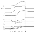
図4は、変速機コントローラ11によるパワーオフダウンシフトにおけるタイムチャートを示す。フェーズは副変速機構9の変速の各相を示す。TLBはローブレーキL/BのF/F指示容量、THCはハイクラッチH/CのF/F指示容量をそれぞれ示す。時刻t1〜t2が準備相、時刻t2〜t3がトルク相、時刻t3〜t4がイナーシャ相、時刻t4〜t5が終了相である。
時刻t1で副変速機構9の架け替え制御が開始すると共に、トルクダウン制御が開始する。時刻t11まで、アクセルペダルが踏み込まれないため、規制値Tdwnは、エンジントルクTenにオフセット値αを加算した値となる。時刻t11で、アクセルペダルが踏み込まれ、要求エンジントルクTreqが増大する。時刻t2までは、準備相であり、ローブレーキL/Bの摩擦部材92が摩擦相手部材93に(完全には)接触せず、ローブレーキL/Bのブレーキ圧PLBの大きさがPLB1未満であるため、規制値Tdwnの変化率d(Tdwn)/dtは第1変化率Δ1となる。時刻t2で、準備相が終了し、摩擦部材92が摩擦相手部材93に(完全に)接触する一方、アキュームレータACCが作動を開始する。アキュームレータACCの作動が終了する時刻t31まで、PLBがPLB1以上PLB2未満であるため、d(Tdwn)/dtは第2変化率Δ2となる。時刻t31で、アキュームレータACCの作動が終了する。規制値Tdwnが要求エンジントルクTreqに達する時刻t4まで、PLBがPLB2以上であるため、d(Tdwn)/dtは第3変化率Δ3となる。よって、時刻t11以降、規制値Tdwnは、Δ1,Δ2,Δ3の順に変化する変化率で徐々に増大し、エンジントルクTengはこの規制値Tdwn以下に制限される。時刻t4で、規制値TdwnがTreqに一致することにより、エンジントルクTengの制限(トルクダウン制御)が終了する。
FIG. 4 shows a time chart in a power off downshift by the
At time t1, the changeover control of the auxiliary transmission mechanism 9 is started, and the torque reduction control is started. Until time t11, the order the accelerator pedal is not depressed, the regulation value T dwn is a value obtained by adding the offset value α to the engine torque T en. At time t11, the accelerator pedal is depressed, and the required engine torque T req is increased. Until time t2, the preparatory phase is in progress, and the
図4において、一点鎖線で、ローブレーキL/Bのブレーキ圧PLBの大きさに応じた実トルク容量TLBの変化を示す。規制値Tdwnの変化率d(Tdwn)/dtを、上記のようにブレーキ圧PLBの大きさに応じて設定することで、規制値Tdwnの変化が、実トルク容量TLBの変化(トルク容量TLBの増大応答性)に沿う形となる。よって、トルク容量TLBの増大応答性を最大限確保(ローブレーキL/Bの応答遅れを最大限抑制)しつつ、規制値Tdwn(エンジントルクTeng)を可及的に大きくすることができる。 4, a dashed line shows the change in the actual torque capacity T LB corresponding to the magnitude of the brake pressure P LB of low brake L / B. By setting the change rate d (T dwn ) / dt of the limit value T dwn according to the magnitude of the brake pressure P LB as described above, the change of the limit value T dwn is the change of the actual torque capacity T LB It becomes a form along (the increase response of torque capacity TLB ). Therefore, the regulation value T dwn (engine torque T eng ) can be made as large as possible while securing the increase response of the torque capacity T LB as much as possible (maximum suppression of the response delay of the low brake L / B). it can.
なお、規制値Tdwnの変化率d(Tdwn)/dtを、トルクダウン制御開始からの経過時間に応じて決める、といった構成も考えられる。例えば、トルクダウン制御開始から第1時間が経過するまではd(Tdwn)/dtを第1変化率Δ1に設定し、第1時間の経過後、第2時間が経過するまではd(Tdwn)/dtを第2変化率Δ2に設定する、等の構成も考えられる。しかし、このように時間によりd(Tdwn)/dtを決める場合、想定される最悪の場面に合わせて設定値を決める必要があり、それは、トルクダウンを必要以上に掛ける(エンジントルクTengの上昇を過度に規制する)ことにつながる。これに対し、本実施形態では、d(Tdwn)/dtを、解放状態から締結状態に切り替わる締結要素に供給される油圧の大きさに応じて設定する。よって、規制値Tdwnを、より適切に、上記締結要素の実トルク容量の増大応答性に合わせて変化させることができる。これは、上記締結要素の応答遅れ(回転数の吹き上がり)を抑制しつつ規制値Tdwn(エンジントルクTeng)をより大きく設定できる(トルクダウンによる加速性能の悪化をより効果的に抑制できる)ことを意味する。 A configuration is also conceivable in which the change rate d (T dwn ) / dt of the restriction value T dwn is determined according to the elapsed time from the start of the torque down control. For example, d (T dwn ) / dt is set to the first change rate Δ1 until the first time elapses from the start of torque down control, and d (T (T dwn )) after the first time elapses until the second time elapses. A configuration is also conceivable in which dwn ) / dt is set to the second change rate Δ2. However, when d (T dwn ) / dt is determined by time in this way, it is necessary to determine the set value in accordance with the worst possible situation, which causes torque down to be more than necessary (engine torque T eng Lead to excessive regulation of the rise). On the other hand, in the present embodiment, d (T dwn ) / dt is set in accordance with the magnitude of the hydraulic pressure supplied to the coupling element that switches from the released state to the engaged state. Therefore, the regulation value T dwn can be more appropriately changed in accordance with the increase responsiveness of the actual torque capacity of the fastening element. This makes it possible to set the regulation value T dwn (engine torque T eng ) to a larger value while suppressing the response delay (the blow-up of the rotational speed) of the above-mentioned fastening element (the deterioration of acceleration performance due to torque down can be suppressed more effectively) Means that).
以上説明したように、第1実施形態にあっては、以下の作用効果を奏する。
(1)自動変速機4(変速機)の変速機コントローラ11(制御装置)であって、
自動変速機4は、エンジン1(車両の駆動源)と車輪7との間にあり、ローブレーキL/B及びハイクラッチH/C(複数の締結要素)の締結と解放を切り替えることで変速比を段階的に変更可能な副変速機構9(有段変速機構)を有し、
解放状態から締結状態に切り替わる締結要素をローブレーキL/B(第1締結要素)とするとき、ローブレーキL/Bは、供給される油圧(ブレーキ圧PLB)の大きさに応じてトルク容量TLBが変化し、
変速機コントローラ11は、
副変速機構9の変速中、エンジントルクTeng(エンジン1が出力するトルク)を規制値Tdwn以下に制限し、
規制値Tdwnの時間変化率d(Tdwn)/dtを、ブレーキ圧PLB(ローブレーキL/Bに供給される油圧)の大きさに応じて設定する。
よって、トルクダウン制御中、アクセルペダルが踏み込まれても、ローブレーキL/B(第1締結要素)のトルク容量TLBの増大応答性に合わせるように規制値Tdwnが変化することで、ローブレーキL/Bの応答遅れを抑制しつつ、規制値Tdwn(エンジントルクTeng)を可及的に大きくすることができる。したがって、トルク容量TLBの不足による吹き上がりを抑制しつつ、トルクダウンによる加速性能の悪化を抑制できる。
As described above, in the first embodiment, the following effects can be obtained.
(1) The transmission controller 11 (control device) of the automatic transmission 4 (transmission)
The automatic transmission 4 is between the engine 1 (drive source of the vehicle) and the wheels 7 and has a gear ratio by switching between engagement and disengagement of the low brake L / B and the high clutch H / C (plurality of fastening elements). Has an auxiliary transmission mechanism 9 (a stepped transmission mechanism) that can change
When a low brake L / B (first fastening element) is used as the fastening element that switches from the released state to the engaged state, the low brake L / B has a torque capacity corresponding to the magnitude of the supplied hydraulic pressure (brake pressure P LB ). T LB changes,
The
During shifting of the auxiliary transmission mechanism 9, the engine torque T eng (torque output by the engine 1) is limited to the regulation value T dwn or less,
The time change rate d (T dwn ) / dt of the regulation value T dwn is set in accordance with the magnitude of the brake pressure P LB (the hydraulic pressure supplied to the low brake L / B).
Therefore, even during depression of the torque, even if the accelerator pedal is depressed, the restriction value T dwn is changed to match the increase responsiveness of the torque capacity T LB of the low brake L / B (first engagement element). The regulation value T dwn (engine torque T eng ) can be made as large as possible while suppressing the response delay of the brake L / B. Therefore, it is possible to suppress the deterioration of the acceleration performance due to the torque reduction while suppressing the blowup due to the shortage of the torque capacity TLB .
(2)ローブレーキL/B(第1締結要素)は、
供給される油圧(ブレーキ圧PLB)により摩擦相手部材93に接触し、回転要素91の相対回転を規制するための摩擦力を発生可能な摩擦部材92を有し、
ブレーキ圧PLB(供給される油圧)の大きさに応じて上記摩擦力が変化することでトルク容量TLBが変化し、
変速機コントローラ11(制御装置)は、ブレーキ圧PLB(ローブレーキL/Bに供給される油圧)の大きさが、摩擦部材92が摩擦相手部材93に接触する第1所定値PLB1未満のときは、第1所定値PLB1以上のときよりも、規制値Tdwnの時間変化率d(Tdwn)/dtを小さく設定する。
よって、摩擦部材92が摩擦相手部材93に(完全には)接触していないときのトルク容量TLBの増大応答性に合わせるように規制値Tdwnが変化することで、ローブレーキL/Bの応答遅れを抑制しつつ、規制値Tdwn(エンジントルクTeng)を可及的に大きくすることができる。
(2) Low brake L / B (first fastening element)
It has a
As the above-mentioned frictional force changes according to the magnitude of the brake pressure P LB (the hydraulic pressure supplied), the torque capacity T LB changes.
In the transmission controller 11 (control device), the magnitude of the brake pressure P LB (the hydraulic pressure supplied to the low brake L / B) is less than a first predetermined value P LB 1 at which the
Therefore, the regulation value T dwn is changed to match the increase response of the torque capacity T LB when the
(3) 副変速機構9(有段変速機構)は、ローブレーキL/B(第1締結要素)へ油圧(ブレーキ圧PLB)を供給するための油路100上に、油路100の油圧(ブレーキ圧PLB)により作動するアキュームレータACCであってブレーキ圧PLB(ローブレーキL/Bへ供給される油圧)の時間変化率を抑制するためのアキュームレータACCを有し、
変速機コントローラ11(制御装置)は、ブレーキ圧PLBの大きさが、アキュームレータACCの作動が終了する第2所定値PLB2未満のときは、第2所定値PLB2以上のときよりも、規制値Tdwnの時間変化率d(Tdwn)/dtを小さく設定する。
よって、アキュームレータACCの作動中のトルク容量TLBの増大応答性に合わせるように規制値Tdwnが変化することで、ローブレーキL/Bの応答遅れを抑制しつつ、規制値Tdwn(エンジントルクTeng)を可及的に大きくすることができる。
(3) The auxiliary transmission mechanism 9 (the geared transmission mechanism) is configured to supply the hydraulic pressure (the brake pressure P LB ) to the low brake L / B (the first fastening element) on the
When the magnitude of the brake pressure P LB is less than a second predetermined value P LB 2 at which the operation of the accumulator ACC ends, the transmission controller 11 (control device) is more than when the second predetermined value P LB 2 or more. The time change rate d (T dwn ) / dt of the regulation value T dwn is set small.
Therefore, the regulation value T dwn is controlled while the response delay of the low brake L / B is suppressed by changing the regulation value T dwn to match the increase responsiveness of the torque capacity T LB during operation of the accumulator ACC. T eng ) can be made as large as possible.
以上、本発明を実施するための形態を実施形態に基づいて説明したが、本発明の具体的な構成は、実施形態に示した構成に限定されるものではなく、発明の要旨を逸脱しない範囲の設計変更等があっても本発明に含まれる。例えば、駆動源は、エンジン(内燃機関)に限らず、電動機等であってもよい。無段変速機構は、ベルト式に限らず、動力伝達部材としてチェーンがプーリ間に掛け回されたものや、トロイダル式であってもよいし、油圧で駆動されるものに限らず電気的に駆動されるものあってもよい。副変速機構(有段変速機構)は、前進用の変速段として3段以上を有してもよいし、通常の遊星歯車機構を用いてもよいし、ギア比の異なる複数の歯車列で構成される複数の動力伝達経路と、これら動力伝達経路を切り換える摩擦締結要素とによって構成されてもよい。トルクダウン制御の場面として、実施形態ではダウンシフト(ローブレーキの締結時)を例にとって説明したが、アップシフト(ハイクラッチの締結時)についても同様である。 As mentioned above, although the form for implementing this invention was demonstrated based on embodiment, the specific structure of this invention is not limited to the structure shown to embodiment, The range which does not deviate from the summary of invention Even if there is a design change or the like, the present invention is included in the present invention. For example, the drive source is not limited to the engine (internal combustion engine), and may be an electric motor or the like. The continuously variable transmission mechanism is not limited to the belt type, and may be a power transmission member in which a chain is wound between pulleys, or may be a toroidal type, or is not limited to one driven by oil pressure and electrically driven. There may be The auxiliary transmission mechanism (stepped transmission mechanism) may have three or more gears as forward gear stages, may use a normal planetary gear mechanism, and is configured by a plurality of gear trains having different gear ratios. It may be constituted by a plurality of power transmission paths, and a frictional engagement element which switches these power transmission paths. Although the downshift (when the low brake is engaged) is described as an example of the torque down control in the embodiment, the same applies to the upshift (when the high clutch is engaged).
1 エンジン(駆動源)
4 自動変速機(変速機)
7 車輪
9 副変速機構(有段変速機構)
91 回転要素
92 摩擦部材
93 摩擦相手部材
100 油路(通路)
11 変速機コントローラ(制御装置)
L/B ローブレーキ(締結要素)
H/C ハイクラッチ(締結要素)
ACC アキュームレータ
1 Engine (drive source)
4 Automatic transmission (transmission)
7 Wheels 9 Sub Transmission Mechanism (Stepped Transmission Mechanism)
91 rotating
11 Transmission controller (control device)
L / B low brake (fastening element)
H / C high clutch (fastening element)
ACC Accumulator
Claims (3)
前記変速機は、車両の駆動源と車輪との間にあり、複数の締結要素の締結と解放を切り替えることで変速比を段階的に変更可能な有段変速機構を有し、
解放状態から締結状態に切り替わる前記締結要素を第1締結要素とするとき、前記第1締結要素は、供給される油圧の大きさに応じてトルク容量が変化し、
前記制御装置は、
前記有段変速機構の変速中、前記駆動源が出力するトルクを規制値以下に制限し、
前記規制値の時間変化率を、前記第1締結要素に供給される油圧の大きさに応じて設定する、
変速機の制御装置。 A control device for a transmission,
The transmission is provided between a drive source of the vehicle and a wheel, and has a stepped transmission mechanism capable of changing the gear ratio in stages by switching engagement and release of a plurality of fastening elements.
When the fastening element switched from the released state to the engaged state is used as a first fastening element, the torque capacity of the first fastening element changes in accordance with the magnitude of the hydraulic pressure supplied.
The controller is
Restricting the torque output by the drive source to a regulation value or less during shifting of the stepped transmission mechanism,
The time rate of change of the regulation value is set according to the magnitude of the hydraulic pressure supplied to the first fastening element.
Transmission control device.
前記第1締結要素は、
前記供給される油圧により摩擦相手部材に接触し、回転要素の相対回転を規制するための摩擦力を発生可能な摩擦部材を有し、
前記供給される油圧の大きさに応じて前記摩擦力が変化することでトルク容量が変化し、
前記制御装置は、前記第1締結要素に供給される油圧の大きさが、前記摩擦部材が前記摩擦相手部材に接触する第1所定値未満のときは、前記第1所定値以上のときよりも、前記規制値の時間変化率を小さく設定する
ことを特徴とする変速機の制御装置。 In the transmission control device according to claim 1,
The first fastening element is
It has a friction member capable of generating a frictional force for contacting the friction counterpart member by the supplied hydraulic pressure and regulating the relative rotation of the rotating element,
As the friction force changes according to the magnitude of the supplied hydraulic pressure, the torque capacity changes.
When the magnitude of the hydraulic pressure supplied to the first fastening element is less than a first predetermined value at which the friction member contacts the friction counterpart member, the control device is more than when the magnitude is greater than the first predetermined value. The control device for a transmission, wherein the time change rate of the restriction value is set small.
前記有段変速機構は、前記第1締結要素へ油圧を供給するための通路上に、前記通路の油圧により作動するアキュームレータであって前記第1締結要素へ供給される油圧の時間変化率を抑制するための前記アキュームレータを有し、
前記制御装置は、前記第1締結要素に供給される油圧の大きさが、前記アキュームレータの作動が終了する第2所定値未満のときは、前記第2所定値以上のときよりも、前記規制値の時間変化率を小さく設定する
ことを特徴とする変速機の制御装置。 In the transmission control device according to claim 1 or 2,
The stepped transmission mechanism is an accumulator operated by the oil pressure of the passage on the passage for supplying the oil pressure to the first fastening element, and suppresses the time change rate of the oil pressure supplied to the first fastening element. With the accumulator for
When the magnitude of the hydraulic pressure supplied to the first coupling element is less than a second predetermined value at which the operation of the accumulator ends, the control device is configured to limit the restriction value more than when the magnitude is greater than the second predetermined value. A control device for a transmission, characterized in that the time change rate of is set small.
Priority Applications (1)
| Application Number | Priority Date | Filing Date | Title |
|---|---|---|---|
| JP2017218815A JP7004435B2 (en) | 2017-11-14 | 2017-11-14 | Transmission control device |
Applications Claiming Priority (1)
| Application Number | Priority Date | Filing Date | Title |
|---|---|---|---|
| JP2017218815A JP7004435B2 (en) | 2017-11-14 | 2017-11-14 | Transmission control device |
Publications (2)
| Publication Number | Publication Date |
|---|---|
| JP2019090464A true JP2019090464A (en) | 2019-06-13 |
| JP7004435B2 JP7004435B2 (en) | 2022-01-21 |
Family
ID=66836146
Family Applications (1)
| Application Number | Title | Priority Date | Filing Date |
|---|---|---|---|
| JP2017218815A Active JP7004435B2 (en) | 2017-11-14 | 2017-11-14 | Transmission control device |
Country Status (1)
| Country | Link |
|---|---|
| JP (1) | JP7004435B2 (en) |
Citations (3)
| Publication number | Priority date | Publication date | Assignee | Title |
|---|---|---|---|---|
| JP2009228848A (en) * | 2008-03-25 | 2009-10-08 | Jatco Ltd | Control device of automatic transmission |
| JP2017159758A (en) * | 2016-03-08 | 2017-09-14 | ジヤトコ株式会社 | Control device of automatic transmission |
| JP2017166600A (en) * | 2016-03-16 | 2017-09-21 | ジヤトコ株式会社 | Control device of automatic transmission |
-
2017
- 2017-11-14 JP JP2017218815A patent/JP7004435B2/en active Active
Patent Citations (3)
| Publication number | Priority date | Publication date | Assignee | Title |
|---|---|---|---|---|
| JP2009228848A (en) * | 2008-03-25 | 2009-10-08 | Jatco Ltd | Control device of automatic transmission |
| JP2017159758A (en) * | 2016-03-08 | 2017-09-14 | ジヤトコ株式会社 | Control device of automatic transmission |
| JP2017166600A (en) * | 2016-03-16 | 2017-09-21 | ジヤトコ株式会社 | Control device of automatic transmission |
Also Published As
| Publication number | Publication date |
|---|---|
| JP7004435B2 (en) | 2022-01-21 |
Similar Documents
| Publication | Publication Date | Title |
|---|---|---|
| JP5526005B2 (en) | Coast stop vehicle and coast stop vehicle control method | |
| KR101647513B1 (en) | Continuously variable transmission and method of controlling the same | |
| KR101740048B1 (en) | Control apparatus for continuously variable transmission for vehicle | |
| KR101691232B1 (en) | Control apparatus for continuously variable transmission for vehicle | |
| US9421978B2 (en) | Continuously variable transmission and control method therefor | |
| KR101812429B1 (en) | Control device for continuously variable transmission | |
| KR20100108274A (en) | Continuously variable transmission and method for controlling the same | |
| JP6303011B2 (en) | Continuously variable transmission and control method thereof | |
| US10371259B2 (en) | Control device for continuously variable transmission equipped with auxiliary transmission | |
| US10697540B2 (en) | Vehicle control device and vehicle control method | |
| JP6437125B2 (en) | Hydraulic control device and hydraulic control method for continuously variable transmission for vehicle | |
| JP5718530B2 (en) | Automatic transmission for vehicles | |
| KR101828724B1 (en) | Control device for continuously variable transmission equipped with auxiliary transmission | |
| EP3299677B1 (en) | Vehicle control device and method for controlling same | |
| JP2019090464A (en) | Control device of transmission | |
| JP2017137945A (en) | Vehicle control device and vehicle control method | |
| JP5545762B2 (en) | Coast neutral control device for vehicle | |
| JP6560758B2 (en) | Vehicle control apparatus and vehicle control method | |
| JP6653961B2 (en) | Control device for automatic transmission | |
| JP5977271B2 (en) | Continuously variable transmission and control method thereof | |
| JP2019052693A (en) | Control device of automatic transmission and control method of automatic transmission | |
| JPWO2018123225A1 (en) | Vehicle oil pump control device and control method | |
| JP7246130B2 (en) | gearbox controller | |
| JP6752506B2 (en) | Control device for continuously variable transmission for vehicles | |
| KR20170008259A (en) | Hydraulic control device for automatic transmission and control method therefor |
Legal Events
| Date | Code | Title | Description |
|---|---|---|---|
| A621 | Written request for application examination |
Free format text: JAPANESE INTERMEDIATE CODE: A621 Effective date: 20200609 |
|
| A977 | Report on retrieval |
Free format text: JAPANESE INTERMEDIATE CODE: A971007 Effective date: 20210301 |
|
| A131 | Notification of reasons for refusal |
Free format text: JAPANESE INTERMEDIATE CODE: A131 Effective date: 20210330 |
|
| A521 | Request for written amendment filed |
Free format text: JAPANESE INTERMEDIATE CODE: A523 Effective date: 20210525 |
|
| A131 | Notification of reasons for refusal |
Free format text: JAPANESE INTERMEDIATE CODE: A131 Effective date: 20211005 |
|
| A521 | Request for written amendment filed |
Free format text: JAPANESE INTERMEDIATE CODE: A523 Effective date: 20211206 |
|
| TRDD | Decision of grant or rejection written | ||
| A01 | Written decision to grant a patent or to grant a registration (utility model) |
Free format text: JAPANESE INTERMEDIATE CODE: A01 Effective date: 20211228 |
|
| A61 | First payment of annual fees (during grant procedure) |
Free format text: JAPANESE INTERMEDIATE CODE: A61 Effective date: 20211228 |
|
| R150 | Certificate of patent or registration of utility model |
Ref document number: 7004435 Country of ref document: JP Free format text: JAPANESE INTERMEDIATE CODE: R150 |