JP2019089233A - Manufacturing method of injection hole plate - Google Patents
Manufacturing method of injection hole plate Download PDFInfo
- Publication number
- JP2019089233A JP2019089233A JP2017218698A JP2017218698A JP2019089233A JP 2019089233 A JP2019089233 A JP 2019089233A JP 2017218698 A JP2017218698 A JP 2017218698A JP 2017218698 A JP2017218698 A JP 2017218698A JP 2019089233 A JP2019089233 A JP 2019089233A
- Authority
- JP
- Japan
- Prior art keywords
- polishing
- ink
- main surface
- nozzle
- metal substrate
- Prior art date
- Legal status (The legal status is an assumption and is not a legal conclusion. Google has not performed a legal analysis and makes no representation as to the accuracy of the status listed.)
- Withdrawn
Links
- 238000004519 manufacturing process Methods 0.000 title claims abstract description 28
- 238000002347 injection Methods 0.000 title claims abstract description 25
- 239000007924 injection Substances 0.000 title claims abstract description 25
- 238000005498 polishing Methods 0.000 claims abstract description 134
- 229910052751 metal Inorganic materials 0.000 claims abstract description 66
- 239000002184 metal Substances 0.000 claims abstract description 66
- 239000000758 substrate Substances 0.000 claims abstract description 63
- 239000000126 substance Substances 0.000 claims abstract description 54
- 238000000034 method Methods 0.000 claims abstract description 16
- 238000004080 punching Methods 0.000 claims abstract description 8
- 238000003825 pressing Methods 0.000 claims abstract description 7
- 230000008569 process Effects 0.000 claims abstract description 6
- 229910001220 stainless steel Inorganic materials 0.000 claims description 8
- 239000010935 stainless steel Substances 0.000 claims description 7
- 238000007790 scraping Methods 0.000 claims description 6
- 230000000149 penetrating effect Effects 0.000 claims description 3
- 239000000243 solution Substances 0.000 abstract description 7
- 238000007517 polishing process Methods 0.000 abstract 2
- 239000007788 liquid Substances 0.000 description 41
- 230000007246 mechanism Effects 0.000 description 27
- 239000000123 paper Substances 0.000 description 14
- 230000015572 biosynthetic process Effects 0.000 description 8
- 239000011651 chromium Substances 0.000 description 6
- 230000004048 modification Effects 0.000 description 6
- 238000012986 modification Methods 0.000 description 6
- 238000007599 discharging Methods 0.000 description 5
- 238000012545 processing Methods 0.000 description 5
- 230000007723 transport mechanism Effects 0.000 description 5
- 230000009471 action Effects 0.000 description 4
- 239000003795 chemical substances by application Substances 0.000 description 4
- 239000003086 colorant Substances 0.000 description 4
- 238000004891 communication Methods 0.000 description 4
- 230000007797 corrosion Effects 0.000 description 4
- 238000005260 corrosion Methods 0.000 description 4
- 230000000694 effects Effects 0.000 description 4
- XEEYBQQBJWHFJM-UHFFFAOYSA-N iron Substances [Fe] XEEYBQQBJWHFJM-UHFFFAOYSA-N 0.000 description 4
- 230000032258 transport Effects 0.000 description 4
- 239000006061 abrasive grain Substances 0.000 description 3
- 230000002378 acidificating effect Effects 0.000 description 3
- 239000000853 adhesive Substances 0.000 description 3
- 230000001070 adhesive effect Effects 0.000 description 3
- 230000007423 decrease Effects 0.000 description 3
- 238000010586 diagram Methods 0.000 description 3
- 230000001771 impaired effect Effects 0.000 description 3
- 239000000463 material Substances 0.000 description 3
- PXHVJJICTQNCMI-UHFFFAOYSA-N nickel Substances [Ni] PXHVJJICTQNCMI-UHFFFAOYSA-N 0.000 description 3
- ATJFFYVFTNAWJD-UHFFFAOYSA-N Tin Chemical compound [Sn] ATJFFYVFTNAWJD-UHFFFAOYSA-N 0.000 description 2
- 230000005856 abnormality Effects 0.000 description 2
- 238000005452 bending Methods 0.000 description 2
- 229910052804 chromium Inorganic materials 0.000 description 2
- 238000005516 engineering process Methods 0.000 description 2
- 229910052742 iron Inorganic materials 0.000 description 2
- HFGPZNIAWCZYJU-UHFFFAOYSA-N lead zirconate titanate Chemical compound [O-2].[O-2].[O-2].[O-2].[O-2].[Ti+4].[Zr+4].[Pb+2] HFGPZNIAWCZYJU-UHFFFAOYSA-N 0.000 description 2
- 229910052451 lead zirconate titanate Inorganic materials 0.000 description 2
- 239000000203 mixture Substances 0.000 description 2
- 230000010287 polarization Effects 0.000 description 2
- 238000007639 printing Methods 0.000 description 2
- 230000003746 surface roughness Effects 0.000 description 2
- VYZAMTAEIAYCRO-UHFFFAOYSA-N Chromium Chemical compound [Cr] VYZAMTAEIAYCRO-UHFFFAOYSA-N 0.000 description 1
- QVGXLLKOCUKJST-UHFFFAOYSA-N atomic oxygen Chemical compound [O] QVGXLLKOCUKJST-UHFFFAOYSA-N 0.000 description 1
- 239000004566 building material Substances 0.000 description 1
- 239000011111 cardboard Substances 0.000 description 1
- 238000007598 dipping method Methods 0.000 description 1
- 238000004090 dissolution Methods 0.000 description 1
- 239000004744 fabric Substances 0.000 description 1
- 239000000835 fiber Substances 0.000 description 1
- 230000006870 function Effects 0.000 description 1
- 238000010030 laminating Methods 0.000 description 1
- 230000015654 memory Effects 0.000 description 1
- 229910052759 nickel Inorganic materials 0.000 description 1
- 230000001151 other effect Effects 0.000 description 1
- 229910052760 oxygen Inorganic materials 0.000 description 1
- 239000001301 oxygen Substances 0.000 description 1
- 239000003973 paint Substances 0.000 description 1
- 239000004033 plastic Substances 0.000 description 1
- 229920006267 polyester film Polymers 0.000 description 1
- 239000007787 solid Substances 0.000 description 1
- 238000003860 storage Methods 0.000 description 1
- 238000012546 transfer Methods 0.000 description 1
Images


Classifications
-
- B—PERFORMING OPERATIONS; TRANSPORTING
- B41—PRINTING; LINING MACHINES; TYPEWRITERS; STAMPS
- B41J—TYPEWRITERS; SELECTIVE PRINTING MECHANISMS, i.e. MECHANISMS PRINTING OTHERWISE THAN FROM A FORME; CORRECTION OF TYPOGRAPHICAL ERRORS
- B41J2/00—Typewriters or selective printing mechanisms characterised by the printing or marking process for which they are designed
- B41J2/005—Typewriters or selective printing mechanisms characterised by the printing or marking process for which they are designed characterised by bringing liquid or particles selectively into contact with a printing material
- B41J2/01—Ink jet
- B41J2/135—Nozzles
- B41J2/16—Production of nozzles
- B41J2/162—Manufacturing of the nozzle plates
-
- B—PERFORMING OPERATIONS; TRANSPORTING
- B21—MECHANICAL METAL-WORKING WITHOUT ESSENTIALLY REMOVING MATERIAL; PUNCHING METAL
- B21D—WORKING OR PROCESSING OF SHEET METAL OR METAL TUBES, RODS OR PROFILES WITHOUT ESSENTIALLY REMOVING MATERIAL; PUNCHING METAL
- B21D31/00—Other methods for working sheet metal, metal tubes, metal profiles
- B21D31/02—Stabbing or piercing, e.g. for making sieves
-
- B—PERFORMING OPERATIONS; TRANSPORTING
- B23—MACHINE TOOLS; METAL-WORKING NOT OTHERWISE PROVIDED FOR
- B23P—METAL-WORKING NOT OTHERWISE PROVIDED FOR; COMBINED OPERATIONS; UNIVERSAL MACHINE TOOLS
- B23P15/00—Making specific metal objects by operations not covered by a single other subclass or a group in this subclass
- B23P15/16—Making specific metal objects by operations not covered by a single other subclass or a group in this subclass plates with holes of very small diameter, e.g. for spinning or burner nozzles
-
- B—PERFORMING OPERATIONS; TRANSPORTING
- B41—PRINTING; LINING MACHINES; TYPEWRITERS; STAMPS
- B41J—TYPEWRITERS; SELECTIVE PRINTING MECHANISMS, i.e. MECHANISMS PRINTING OTHERWISE THAN FROM A FORME; CORRECTION OF TYPOGRAPHICAL ERRORS
- B41J2/00—Typewriters or selective printing mechanisms characterised by the printing or marking process for which they are designed
- B41J2/005—Typewriters or selective printing mechanisms characterised by the printing or marking process for which they are designed characterised by bringing liquid or particles selectively into contact with a printing material
- B41J2/01—Ink jet
- B41J2/135—Nozzles
- B41J2/14—Structure thereof only for on-demand ink jet heads
- B41J2/14201—Structure of print heads with piezoelectric elements
- B41J2/14209—Structure of print heads with piezoelectric elements of finger type, chamber walls consisting integrally of piezoelectric material
-
- B—PERFORMING OPERATIONS; TRANSPORTING
- B41—PRINTING; LINING MACHINES; TYPEWRITERS; STAMPS
- B41J—TYPEWRITERS; SELECTIVE PRINTING MECHANISMS, i.e. MECHANISMS PRINTING OTHERWISE THAN FROM A FORME; CORRECTION OF TYPOGRAPHICAL ERRORS
- B41J2/00—Typewriters or selective printing mechanisms characterised by the printing or marking process for which they are designed
- B41J2/005—Typewriters or selective printing mechanisms characterised by the printing or marking process for which they are designed characterised by bringing liquid or particles selectively into contact with a printing material
- B41J2/01—Ink jet
- B41J2/135—Nozzles
- B41J2/14—Structure thereof only for on-demand ink jet heads
- B41J2/1433—Structure of nozzle plates
-
- B—PERFORMING OPERATIONS; TRANSPORTING
- B41—PRINTING; LINING MACHINES; TYPEWRITERS; STAMPS
- B41J—TYPEWRITERS; SELECTIVE PRINTING MECHANISMS, i.e. MECHANISMS PRINTING OTHERWISE THAN FROM A FORME; CORRECTION OF TYPOGRAPHICAL ERRORS
- B41J2/00—Typewriters or selective printing mechanisms characterised by the printing or marking process for which they are designed
- B41J2/005—Typewriters or selective printing mechanisms characterised by the printing or marking process for which they are designed characterised by bringing liquid or particles selectively into contact with a printing material
- B41J2/01—Ink jet
- B41J2/135—Nozzles
- B41J2/16—Production of nozzles
- B41J2/1607—Production of print heads with piezoelectric elements
- B41J2/1609—Production of print heads with piezoelectric elements of finger type, chamber walls consisting integrally of piezoelectric material
-
- B—PERFORMING OPERATIONS; TRANSPORTING
- B41—PRINTING; LINING MACHINES; TYPEWRITERS; STAMPS
- B41J—TYPEWRITERS; SELECTIVE PRINTING MECHANISMS, i.e. MECHANISMS PRINTING OTHERWISE THAN FROM A FORME; CORRECTION OF TYPOGRAPHICAL ERRORS
- B41J2/00—Typewriters or selective printing mechanisms characterised by the printing or marking process for which they are designed
- B41J2/005—Typewriters or selective printing mechanisms characterised by the printing or marking process for which they are designed characterised by bringing liquid or particles selectively into contact with a printing material
- B41J2/01—Ink jet
- B41J2/135—Nozzles
- B41J2/16—Production of nozzles
- B41J2/1621—Manufacturing processes
- B41J2/1632—Manufacturing processes machining
-
- B—PERFORMING OPERATIONS; TRANSPORTING
- B41—PRINTING; LINING MACHINES; TYPEWRITERS; STAMPS
- B41J—TYPEWRITERS; SELECTIVE PRINTING MECHANISMS, i.e. MECHANISMS PRINTING OTHERWISE THAN FROM A FORME; CORRECTION OF TYPOGRAPHICAL ERRORS
- B41J2/00—Typewriters or selective printing mechanisms characterised by the printing or marking process for which they are designed
- B41J2/005—Typewriters or selective printing mechanisms characterised by the printing or marking process for which they are designed characterised by bringing liquid or particles selectively into contact with a printing material
- B41J2/01—Ink jet
- B41J2/135—Nozzles
- B41J2/16—Production of nozzles
- B41J2/1621—Manufacturing processes
- B41J2/164—Manufacturing processes thin film formation
- B41J2/1643—Manufacturing processes thin film formation thin film formation by plating
-
- B—PERFORMING OPERATIONS; TRANSPORTING
- B41—PRINTING; LINING MACHINES; TYPEWRITERS; STAMPS
- B41J—TYPEWRITERS; SELECTIVE PRINTING MECHANISMS, i.e. MECHANISMS PRINTING OTHERWISE THAN FROM A FORME; CORRECTION OF TYPOGRAPHICAL ERRORS
- B41J2/00—Typewriters or selective printing mechanisms characterised by the printing or marking process for which they are designed
- B41J2/005—Typewriters or selective printing mechanisms characterised by the printing or marking process for which they are designed characterised by bringing liquid or particles selectively into contact with a printing material
- B41J2/01—Ink jet
- B41J2/21—Ink jet for multi-colour printing
-
- B—PERFORMING OPERATIONS; TRANSPORTING
- B41—PRINTING; LINING MACHINES; TYPEWRITERS; STAMPS
- B41J—TYPEWRITERS; SELECTIVE PRINTING MECHANISMS, i.e. MECHANISMS PRINTING OTHERWISE THAN FROM A FORME; CORRECTION OF TYPOGRAPHICAL ERRORS
- B41J2202/00—Embodiments of or processes related to ink-jet or thermal heads
- B41J2202/01—Embodiments of or processes related to ink-jet heads
- B41J2202/11—Embodiments of or processes related to ink-jet heads characterised by specific geometrical characteristics
-
- B—PERFORMING OPERATIONS; TRANSPORTING
- B41—PRINTING; LINING MACHINES; TYPEWRITERS; STAMPS
- B41J—TYPEWRITERS; SELECTIVE PRINTING MECHANISMS, i.e. MECHANISMS PRINTING OTHERWISE THAN FROM A FORME; CORRECTION OF TYPOGRAPHICAL ERRORS
- B41J2202/00—Embodiments of or processes related to ink-jet or thermal heads
- B41J2202/01—Embodiments of or processes related to ink-jet heads
- B41J2202/12—Embodiments of or processes related to ink-jet heads with ink circulating through the whole print head
Landscapes
- Engineering & Computer Science (AREA)
- Manufacturing & Machinery (AREA)
- Mechanical Engineering (AREA)
- Particle Formation And Scattering Control In Inkjet Printers (AREA)
Abstract
Description
本開示は、噴射孔プレートの製造方法に関する。 The present disclosure relates to a method of manufacturing an injection hole plate.
液体噴射ヘッドを備えた液体噴射記録装置が、様々な分野に利用されている。液体噴射ヘッドは、多数の噴射孔が形成された噴射孔プレートを含む複数のプレートの積層体を備えており、各噴射孔から被記録媒体に対して液体であるインクを吐出するように構成されている。このような噴射孔プレートは、例えば、金属基板に対してプレス加工を行うことにより形成される(例えば、特許文献1参照)。 Liquid jet recording devices provided with a liquid jet head are used in various fields. The liquid jet head includes a stack of a plurality of plates including a jet hole plate in which a large number of jet holes are formed, and is configured to eject ink, which is liquid, from each jet hole to a recording medium. ing. Such an injection hole plate is formed, for example, by pressing a metal substrate (see, for example, Patent Document 1).
このような噴射孔プレートでは、一般に、吐出の安定性や、ヘッドの耐久性を向上させることが求められている。吐出の安定性や、ヘッドの耐久性を向上させることが可能な噴射孔プレートの製造方法を提供することが望ましい。 In such an injection hole plate, it is generally required to improve the discharge stability and the durability of the head. It is desirable to provide a method of manufacturing a jet hole plate that can improve the stability of discharge and the durability of the head.
本開示の一実施の形態に係る噴射孔プレートの製造方法は、以下の工程を含むものである。
(A)金属基板の第1主面をパンチで押圧することにより、第1主面に凹部を形成するとともに、金属基板の第2主面のうち、凹部と対向する位置に凸部を形成するパンチ加工工程
(B)凸部を機械研磨によって削り、凹部を貫通させることにより、噴射孔を形成する第1研磨工程
(C)金属基板のうち、第1主面および第2主面の少なくとも一方の面を、化学研磨、電解研磨、または、化学機械研磨によって研磨する第2研磨工程
The method of manufacturing the injection hole plate according to the embodiment of the present disclosure includes the following steps.
(A) By pressing the first main surface of the metal substrate with a punch, a recess is formed on the first main surface, and a protrusion is formed at a position facing the recess on the second main surface of the metal substrate Punching process (B) A convex portion is cut by mechanical polishing, and a recess is penetrated to form an injection hole. At least one of the first main surface and the second main surface of the metal substrate of the first polishing step (C) Polishing step of polishing the surface of the substrate by chemical polishing, electro polishing or chemical mechanical polishing
本開示の一実施の形態に係る噴射孔プレートの製造方法によれば、吐出の安定性や、ヘッドの耐久性を向上させることが可能となる。 According to the method of manufacturing the injection hole plate according to the embodiment of the present disclosure, it is possible to improve the stability of discharge and the durability of the head.
以下、本開示の実施の形態について、図面を参照して詳細に説明する。なお、説明は以下の順序で行う。
1.実施の形態(ノズルプレートの製造方法)
2.変形例
Hereinafter, embodiments of the present disclosure will be described in detail with reference to the drawings. The description will be made in the following order.
1. Embodiment (manufacturing method of nozzle plate)
2. Modified example
<1.実施の形態>
[プリンタ1の全体構成]
図1は、本開示の一実施の形態に係る液体噴射記録装置としてのプリンタ1の概略構成例を、模式的に斜視図にて表したものである。プリンタ1は、後述するインク9を利用して、被記録媒体としての記録紙Pに対して、画像や文字等の記録(印刷)を行うインクジェットプリンタである。このプリンタ1はまた、詳細は後述するが、インク9を所定の流路に循環させて利用する、インク循環式のインクジェットプリンタである。
<1. Embodiment>
[Overall Configuration of Printer 1]
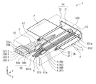
FIG. 1 is a schematic perspective view of a schematic configuration example of a printer 1 as a liquid jet recording apparatus according to an embodiment of the present disclosure. The printer 1 is an ink jet printer that performs recording (printing) of an image, characters, and the like on a recording paper P as a recording medium using an
プリンタ1は、図1に示したように、一対の搬送機構2a,2bと、インクタンク3と、インクジェットヘッド4と、循環機構5と、走査機構6とを備えている。これらの各部材は、所定形状を有する筺体10内に収容されている。なお、本明細書の説明に用いられる各図面では、各部材を認識可能な大きさとするため、各部材の縮尺を適宜変更している。
As shown in FIG. 1, the printer 1 includes a pair of
(搬送機構2a,2b)
搬送機構2a,2bはそれぞれ、図1に示したように、記録紙Pを搬送方向d(X軸方向)に沿って搬送する機構である。これらの搬送機構2a,2bはそれぞれ、グリッドローラ21、ピンチローラ22および駆動機構(不図示)を有している。グリッドローラ21およびピンチローラ22はそれぞれ、Y軸方向(記録紙Pの幅方向)に沿って延設されている。駆動機構は、グリッドローラ21を軸周りに回転させる(Z−X面内で回転させる)機構であり、例えばモータ等を用いて構成されている。
(
Each of the
(インクタンク3)
インクタンク3は、インク9を内部に収容するタンクである。このインクタンク3としては、この例では図1に示したように、イエロー(Y),マゼンダ(M),シアン(C),ブラック(B)の4色のインク9を個別に収容する、4種類のタンクが設けられている。すなわち、イエローのインク9を収容するインクタンク3Yと、マゼンダのインク9を収容するインクタンク3Mと、シアンのインク9を収容するインクタンク3Cと、ブラックのインク9を収容するインクタンク3Bとが設けられている。これらのインクタンク3Y,3M,3C,3Bは、筺体10内において、X軸方向に沿って並んで配置されている。なお、インクタンク3Y,3M,3C,3Bはそれぞれ、収容するインク9の色以外については同一の構成であるため、以下ではインクタンク3と総称して説明する。
(Ink tank 3)
The
(インクジェットヘッド4)
インクジェットヘッド4は、後述する複数のノズル孔(ノズル孔H1,H2)から記録紙Pに対して液滴状のインク9を噴射(吐出)して、画像や文字等の記録を行うヘッドである。このインクジェットヘッド4としても、この例では図1に示したように、上記したインクタンク3Y,3M,3C,3Bにそれぞれ収容されている4色のインク9を個別に噴射する、4種類のヘッドが設けられている。すなわち、イエローのインク9を噴射するインクジェットヘッド4Yと、マゼンダのインク9を噴射するインクジェットヘッド4Mと、シアンのインク9を噴射するインクジェットヘッド4Cと、ブラックのインク9を噴射するインクジェットヘッド4Bとが設けられている。これらのインクジェットヘッド4Y,4M,4C,4Bは、筺体10内において、Y軸方向に沿って並んで配置されている。
(Ink jet head 4)
The
なお、インクジェットヘッド4Y,4M,4C,4Bはそれぞれ、利用するインク9の色以外については同一の構成であるため、以下ではインクジェットヘッド4と総称して説明する。また、このインクジェットヘッド4の詳細構成については、後述する(図3〜図5)。
The ink jet heads 4Y, 4M, 4C, and 4B have the same configuration except for the color of the
(循環機構5)
循環機構5は、インクタンク3内とインクジェットヘッド4内との間でインク9を循環させるための機構である。図2は、循環機構5の構成例を、前述したインクタンク3およびインクジェットヘッド4と共に、模式的に表したものである。なお、図2中に示した実線の矢印は、インク9の循環方向を示している。循環機構5は、図2に示したように、インク9を循環させるための所定の流路(循環流路50)と、一対の送液ポンプ52a,52bとを備えている。
(Circulation mechanism 5)
The
循環流路50は、インクジェットヘッド4内とインクジェットヘッド4の外部(インクタンク3内)との間を循環する流路であり、インク9がこの循環流路50を循環して流れるようになっている。循環流路50は、インクタンク3からインクジェットヘッド4へと至る部分である流路50aと、インクジェットヘッド4からインクタンク3へと至る部分である流路50bとを有している。言い換えると、流路50aは、インクタンク3からインクジェットヘッド4へと向かって、インク9が流れる流路である。また、流路50bは、インクジェットヘッド4からインクタンク3へと向かって、インク9が流れる流路である。
The
送液ポンプ52aは、流路50a上において、インクタンク3とインクジェットヘッド4との間に配置されている。送液ポンプ52aは、インクタンク3内に収容されているインク9を、流路50aを介してインクジェットヘッド4内へと送液するためのポンプである。送液ポンプ52bは、流路50b上において、インクジェットヘッド4とインクタンク3との間に配置されている。送液ポンプ52bは、インクジェットヘッド4内に収容されているインク9を、流路50bを介してインクタンク3内へと送液するためのポンプである。
The liquid feed pump 52 a is disposed between the
(走査機構6)
走査機構6は、記録紙Pの幅方向(Y軸方向)に沿って、インクジェットヘッド4を走査させる機構である。この走査機構6は、図1に示したように、Y軸方向に沿って延設された一対のガイドレール61a,61bと、これらのガイドレール61a,61bに移動可能に支持されたキャリッジ62と、このキャリッジ62をY軸方向に沿って移動させる駆動機構63とを有している。また、駆動機構63は、ガイドレール61a,61bの間に配置された一対のプーリ631a,631bと、これらのプーリ631a,631b間に巻回された無端ベルト632と、プーリ631aを回転駆動させる駆動モータ633とを有している。
(Scanning mechanism 6)
The
プーリ631a,631bはそれぞれ、Y軸方向に沿って、各ガイドレール61a,61bにおける両端付近に対応する領域に配置されている。無端ベルト632には、キャリッジ62が連結されている。このキャリッジ62上には、前述した4種類のインクジェットヘッド4Y,4M,4C,4Bが、Y軸方向に沿って並んで配置されている。なお、このような走査機構6と前述した搬送機構2a,2bとにより、インクジェットヘッド4と記録紙Pとを相対的に移動させる、移動機構が構成される。
The
[インクジェットヘッド4の詳細構成]
次に、図1および図2に加えて図3〜図5を参照して、インクジェットヘッド4の詳細構成例について説明する。図3は、インクジェットヘッド4の詳細構成例を、分解斜視図で表したものである。図4は、図3に示したノズルプレート41(後出)を取り外した状態におけるインクジェットヘッド4の構成例を、模式的に底面図(X−Y底面図)で表したものである。図5は、インクジェットヘッド4の、図4に示したV−V線に対応する箇所での断面(Z−X断面)の一部の構成例を、模式的に表したものである。図6、図7は、ノズルプレート41の一部の断面構成例(Y−Z断面構成例)を、模式的に表したものである。
[Detailed Configuration of Inkjet Head 4]
Next, a detailed configuration example of the
本実施の形態のインクジェットヘッド4は、後述する複数のチャネル(チャネルC1,C2)における延在方向(Y軸方向)の中央部からインク9を吐出する、いわゆるサイドシュートタイプのインクジェットヘッドである。また、このインクジェットヘッド4は、前述した循環機構5(循環流路50)を用いることで、インクタンク3との間でインク9を循環させて利用する、循環式のインクジェットヘッドである。
The
図3に示したように、インクジェットヘッド4は、ノズルプレート(噴射孔プレート)41、アクチュエータプレート42およびカバープレート43を主に備えている。これらのノズルプレート41、アクチュエータプレート42およびカバープレート43は、例えば接着剤等を用いて互いに貼り合わされており、Z軸方向に沿ってこの順に積層されている。なお、以下では、Z軸方向に沿ってカバープレート43側を上方と称すると共に、ノズルプレート41側を下方と称して説明する。
As shown in FIG. 3, the
(ノズルプレート41)
ノズルプレート41は、インクジェットヘッド4に用いられるプレートである。ノズルプレート41は、例えば50μm程度の厚みを有する金属基板を有し、図3に示したように、アクチュエータプレート42の下面に接着されている。ノズルプレート41として用いられる金属基板としては、SUS316やSUS304をはじめとするステンレス鋼が挙げられる。また、図3および図4に示したように、このノズルプレート41には、X軸方向に沿ってそれぞれ延在する、2列のノズル列(ノズル列411,412)が設けられている。これらのノズル列411,412同士は、Y軸方向に沿って所定の間隔をおいて配置されている。このように、本実施の形態のインクジェットヘッド4は、2列タイプのインクジェットヘッドとなっている。本開示の一実施の形態に係る噴射孔プレートとしてのノズルプレート41の製造方法については、後に詳述する。
(Nozzle plate 41)
The
ノズル列411は、X軸方向に沿って所定の間隔をおいて一直線上に並んで形成された、複数のノズル孔(噴射孔)H1を有している。これらのノズル孔H1はそれぞれ、ノズルプレート41をその厚み方向(Z軸方向)に沿って貫通しており、例えば図5に示したように、後述するアクチュエータプレート42における吐出チャネルC1e内に連通している。具体的には図4に示したように、各ノズル孔H1は、列状に形成されており、かつ、吐出チャネルC1e上においてY軸方向に沿った中央部に位置するように形成されている。また、ノズル孔H1におけるX軸方向に沿った形成ピッチは、吐出チャネルC1eにおけるX軸方向に沿った形成ピッチと同一(同一ピッチ)となっている。このようなノズル列411内のノズル孔H1からは、詳細は後述するが、吐出チャネルC1e内から供給されるインク9が吐出(噴射)される。
The
ノズル列412も同様に、X軸方向に沿って所定の間隔をおいて一直線上に並んで形成された、複数のノズル孔(噴射孔)H2を有している。これらのノズル孔H2もそれぞれ、ノズルプレート41をその厚み方向に沿って貫通しており、後述するアクチュエータプレート42における吐出チャネルC2e内に連通している。具体的には図4に示したように、各ノズル孔H2は、列状に形成されており、かつ、吐出チャネルC2e上においてY軸方向に沿った中央部に位置するように形成されている。また、ノズル孔H2におけるX軸方向に沿った形成ピッチは、吐出チャネルC2eにおけるX軸方向に沿った形成ピッチと同一となっている。このようなノズル列412内のノズル孔H2からも、詳細は後述するが、吐出チャネルC2e内から供給されるインク9が吐出される。
Similarly, the
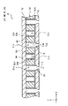
ノズルプレート41は、複数のノズル孔H1および複数のノズル孔H2が設けられた金属基板を有している。金属基板は、各ノズル孔H1,H2の噴出口Houtが設けられた噴出側主面410Bと、噴出口Houtよりも大きな、各ノズル孔H1,H2の流入口Hinが設けられた流入側主面410Aとを有している。これらのノズル孔H1,H2はそれぞれ、例えば、下方に向かうに従って漸次縮径するテーパー状のテーバー孔部410Cからなる貫通孔となっている。なお、例えば、図7に示したように、これらのノズル孔H1,H2はそれぞれ、下方に向かうに従って漸次縮径するテーパー状のテーバー孔部410Cと、テーバー孔部410Cに連通する円柱孔部410Dとを有する貫通孔となっていてもよい。
The
(アクチュエータプレート42)
アクチュエータプレート42は、例えばPZT(チタン酸ジルコン酸鉛)等の圧電材料により構成されたプレートである。このアクチュエータプレート42は、分極方向がZ方向で異なる2つの圧電基板を積層して形成された、いわゆるシェブロンタイプのアクチュエータである。なお、アクチュエータプレート42は、分極方向が厚み方向(Z軸方向)に沿って一方向に設定されている1つの圧電基板から形成された、いわゆるカンチレバータイプのアクチュエータであってもよい。また、図3および図4に示したように、アクチュエータプレート42には、X軸方向に沿ってそれぞれ延在する、2列のチャネル列(チャネル列421,422)が設けられている。これらのチャネル列421,422同士は、Y軸方向に沿って所定の間隔をおいて配置されている。
(Actuator plate 42)
The
このようなアクチュエータプレート42では、図4に示したように、X軸方向に沿った中央部(チャネル列421,422の形成領域)に、インク9の吐出領域(噴射領域)A1が設けられている。一方、アクチュエータプレート42において、X軸方向に沿った両端部(チャネル列421,422の非形成領域)には、インク9の非吐出領域(非噴射領域)A2が設けられている。この非吐出領域A2は、吐出領域A1に対して、X軸方向に沿った外側に位置している。なお、アクチュエータプレート42におけるY軸方向に沿った両端部はそれぞれ、尾部420を構成している。
In such an
上記したチャネル列421は、図3および図4に示したように、Y軸方向に沿って延在する複数のチャネルC1を有している。これらのチャネルC1は、X軸方向に沿って所定の間隔をおいて互いに平行となるよう、並んで配置されている。各チャネルC1は、圧電体(アクチュエータプレート42)からなる駆動壁Wdによってそれぞれ画成されており、断面視にて凹状の溝部となっている(図3参照)。
The above-described
チャネル列422も同様に、Y軸方向に沿って延在する複数のチャネルC2を有している。これらのチャネルC2は、X軸方向に沿って所定の間隔をおいて互いに平行となるよう、並んで配置されている。各チャネルC2もまた、上記した駆動壁Wdによってそれぞれ画成されており、断面視にて凹状の溝部となっている。
The
ここで、図3および図4に示したように、チャネルC1には、インク9を吐出させるための吐出チャネルC1eと、インク9を吐出させないダミーチャネルC1dとが存在している。チャネル列421において、これらの吐出チャネルC1eとダミーチャネルC1dとは、X軸方向に沿って交互に配置されている。各吐出チャネルC1eは、ノズルプレート41におけるノズル孔H1と連通している一方、各ダミーチャネルC1dはノズル孔H1には連通しておらず、ノズルプレート41の上面によって下方から覆われている。
Here, as shown in FIGS. 3 and 4, the channel C1 has a discharge channel C1e for discharging the
同様に、チャネルC2には、インク9を吐出させるための吐出チャネルC2eと、インク9を吐出させないダミーチャネルC2dとが存在している。チャネル列422において、これらの吐出チャネルC2eとダミーチャネルC2dとは、X軸方向に沿って交互に配置されている。各吐出チャネルC2eは、ノズルプレート41におけるノズル孔H2と連通している一方、各ダミーチャネルC2dはノズル孔H2には連通しておらず、ノズルプレート41の上面によって下方から覆われている。
Similarly, in the channel C2, a discharge channel C2e for discharging the
また、図4に示したように、チャネルC1における吐出チャネルC1eおよびダミーチャネルC1dは、チャネルC2における吐出チャネルC2eおよびダミーチャネルC2dに対し、互い違いとなるように配置されている。したがって、本実施の形態のインクジェットヘッド4では、チャネルC1における吐出チャネルC1eと、チャネルC2における吐出チャネルC2eとが、千鳥状に配置されている。図3に示したように、アクチュエータプレート42において、ダミーチャネルC1d,C2dに対応する部分には、ダミーチャネルC1d,C2dにおけるY軸方向に沿った外側端部に連通する、浅溝部Ddが形成されている。
Further, as shown in FIG. 4, the ejection channels C1e and the dummy channels C1d in the channel C1 are arranged alternately with respect to the ejection channels C2e and the dummy channels C2d in the channel C2. Therefore, in the
ここで、図3および図5に示したように、上記した駆動壁Wdにおける対向する内側面にはそれぞれ、Y軸方向に沿って延在する駆動電極Edが設けられている。この駆動電極Edには、吐出チャネルC1e,C2eに面する内側面に設けられたコモン電極Edcと、ダミーチャネルC1d,C2dに面する内側面に設けられたアクティブ電極Edaとが存在している。このような駆動電極Ed(コモン電極Edcおよびアクティブ電極Eda)は、図5に示したように、駆動壁Wdの内側面上において、駆動壁Wdと同じ深さ(Z軸方向において同じ深さ)まで形成されている。また、アクチュエータプレート42において、ノズルプレート41側の面には、駆動電極Edとノズルプレート41とが互いに電気的に短絡するのを防止する絶縁膜42Aが形成されている。なお、アクチュエータプレート42が上述のカンチレバータイプとなっている場合には、駆動電極Ed(コモン電極Edcおよびアクティブ電極Eda)は、駆動壁Wdの内側面内において、深さ方向(Z軸方向)の中間位置までしか形成されていない。
Here, as shown in FIG. 3 and FIG. 5, drive electrodes Ed extending along the Y-axis direction are provided on the opposing inner side surfaces of the drive wall Wd. The drive electrode Ed includes a common electrode Edc provided on the inner side facing the ejection channels C1e and C2e, and an active electrode Eda provided on the inner side facing the dummy channels C1d and C2d. Such a drive electrode Ed (common electrode Edc and active electrode Eda) has the same depth as the drive wall Wd (the same depth in the Z-axis direction) on the inner surface of the drive wall Wd, as shown in FIG. Are formed up to. Further, in the surface of the
同一の吐出チャネルC1e(または吐出チャネルC2e)内で対向する一対のコモン電極Edc同士は、コモン端子(不図示)において互いに電気的に接続されている。また、同一のダミーチャネルC1d(またはダミーチャネルC2d)内で対向する一対のアクティブ電極Eda同士は、互いに電気的に分離されている。一方、吐出チャネルC1e(または吐出チャネルC2e)を介して対向する一対のアクティブ電極Eda同士は、アクティブ端子(不図示)において互いに電気的に接続されている。 A pair of common electrodes Edc facing each other in the same discharge channel C1e (or discharge channel C2e) are electrically connected to each other at a common terminal (not shown). Further, the pair of active electrodes Eda facing each other in the same dummy channel C1d (or dummy channel C2d) are electrically separated from each other. On the other hand, a pair of active electrodes Eda facing each other through the discharge channel C1e (or discharge channel C2e) are electrically connected to each other at an active terminal (not shown).
ここで、前述した尾部420においては、図3に示したように、駆動電極Edと制御部(インクジェットヘッド4における後述する制御部40)との間を電気的に接続する、フレキシブルプリント基板44が実装されている。このフレキシブルプリント基板44に形成された配線パターン(不図示)は、上記したコモン端子およびアクティブ端子に対して電気的に接続されている。これにより、フレキシブルプリント基板44を介して、後述する制御部40から各駆動電極Edに対して、駆動電圧が印加されるようになっている。
Here, in the
(カバープレート43)
カバープレート43は、図3に示したように、アクチュエータプレート42における各チャネルC1,C2(各チャネル列421,422)を閉塞するように配置されている。具体的には、このカバープレート43は、アクチュエータプレート42の上面に接着されており、板状構造となっている。
(Cover plate 43)
The
カバープレート43には、図3に示したように、一対の入口側共通インク室431a,432aと、一対の出口側共通インク室431b,432bとが、それぞれ形成されている。具体的には、入口側共通インク室431aおよび出口側共通インク室431bはそれぞれ、アクチュエータプレート42におけるチャネル列421(複数のチャネルC1)に対応する領域に形成されている。また、入口側共通インク室432aおよび出口側共通インク室432bはそれぞれ、アクチュエータプレート42におけるチャネル列422(複数のチャネルC2)に対応する領域に形成されている。
As shown in FIG. 3, the
入口側共通インク室431aは、各チャネルC1におけるY軸方向に沿った内側の端部付近に形成されており、凹状の溝部となっている。この入口側共通インク室431aにおいて、各吐出チャネルC1eに対応する領域には、カバープレート43をその厚み方向(Z軸方向)に沿って貫通する、供給スリットSaが形成されている。同様に、入口側共通インク室432aは、各チャネルC2におけるY軸方向に沿った内側の端部付近に形成されており、凹状の溝部となっている。この入口側共通インク室432aにおいて、各吐出チャネルC2eに対応する領域にも、上記した供給スリットSaが形成されている。なお、これらの入口側共通インク室431a,432aはそれぞれ、インクジェットヘッド4における前述した入口部Tinを構成する部分である。
The inlet-side
出口側共通インク室431bは、図3に示したように、各チャネルC1におけるY軸方向に沿った外側の端部付近に形成されており、凹状の溝部となっている。この出口側共通インク室431bにおいて、各吐出チャネルC1eに対応する領域には、カバープレート43をその厚み方向に沿って貫通する、排出スリットSbが形成されている。同様に、出口側共通インク室432bは、各チャネルC2におけるY軸方向に沿った外側の端部付近に形成されており、凹状の溝部となっている。この出口側共通インク室432bにおいて、各吐出チャネルC2eに対応する領域にも、上記した排出スリットSbが形成されている。なお、これらの出口側共通インク室431b,432bはそれぞれ、インクジェットヘッド4における前述した出口部Toutを構成する部分である。
The outlet-side
このようにして、入口側共通インク室431aおよび出口側共通インク室431bはそれぞれ、供給スリットSaおよび排出スリットSbを介して各吐出チャネルC1eに連通する一方、各ダミーチャネルC1dには連通していない。すなわち、各ダミーチャネルC1dは、これら入口側共通インク室431aおよび出口側共通インク室431bにおける底部によって、閉塞されている。
In this manner, the inlet-side
同様に、入口側共通インク室432aおよび出口側共通インク室432bはそれぞれ、供給スリットSaおよび排出スリットSbを介して各吐出チャネルC2eに連通する一方、各ダミーチャネルC2dには連通していない。すなわち、各ダミーチャネルC2dは、これら入口側共通インク室432aおよび出口側共通インク室432bにおける底部によって、閉塞されている。
Similarly, the inlet-side
(制御部40)
ここで、本実施の形態のインクジェットヘッド4にはまた、図2に示したように、プリンタ1における各種動作の制御を行う、制御部40が設けられている。この制御部40は、例えば、プリンタ1における画像や文字等の記録動作(インクジェットヘッド4におけるインク9の噴射動作)の他、前述した送液ポンプ52a,52b等における各動作を制御するようになっている。このような制御部40は、例えば、演算処理部と各種メモリからなる記憶部とを有する、マイクロコンピュータにより構成されている。
(Control unit 40)
Here, as shown in FIG. 2, the
[プリンタ1の基本動作]
このプリンタ1では、以下のようにして、記録紙Pに対する画像や文字等の記録動作(印刷動作)が行われる。なお、初期状態として、図1に示した4種類のインクタンク3(3Y,3M,3C,3B)にはそれぞれ、対応する色(4色)のインク9が十分に封入されているものとする。また、インクタンク3内のインク9は、循環機構5を介してインクジェットヘッド4内に充填された状態となっている。
[Basic operation of printer 1]
In the printer 1, the recording operation (printing operation) of an image, characters, and the like on the recording paper P is performed as follows. In the initial state, it is assumed that the
このような初期状態において、プリンタ1を作動させると、搬送機構2a,2bにおけるグリッドローラ21がそれぞれ回転することで、グリッドローラ21とピンチローラ22と間に、記録紙Pが搬送方向d(X軸方向)に沿って搬送される。また、このような搬送動作と同時に、駆動機構63における駆動モータ633が、プーリ631a,631bをそれぞれ回転させることで、無端ベルト632を動作させる。これにより、キャリッジ62がガイドレール61a,61bにガイドされながら、記録紙Pの幅方向(Y軸方向)に沿って往復移動する。そしてこの際に、各インクジェットヘッド4(4Y,4M,4C,4B)によって、4色のインク9を記録紙Pに適宜吐出させることで、この記録紙Pに対する画像や文字等の記録動作がなされる。
In such an initial state, when the printer 1 is operated, the
[インクジェットヘッド4における詳細動作]
続いて、図1〜図7を参照して、インクジェットヘッド4における詳細動作(インク9の噴射動作)について説明する。すなわち、本実施の形態のインクジェットヘッド4(サイドシュートタイプ,循環式のインクジェットヘッド)では、以下のようにして、せん断(シェア)モードを用いたインク9の噴射動作が行われる。
[Detailed operation of the inkjet head 4]
Subsequently, the detailed operation (the operation of ejecting the ink 9) in the
まず、上記したキャリッジ62(図1参照)の往復移動が開始されると、制御部40は、フレキシブルプリント基板44を介して、インクジェットヘッド4内の駆動電極Ed(コモン電極Edcおよびアクティブ電極Eda)に対し、駆動電圧を印加する。具体的には、制御部40は、吐出チャネルC1e,C2eを画成する一対の駆動壁Wdに配置された各駆動電極Edに対し、駆動電圧を印加する。これにより、これら一対の駆動壁Wdがそれぞれ、その吐出チャネルC1e,C2eに隣接するダミーチャネルC1d,C2d側へ、突出するように変形する(図5参照)。
First, when the reciprocating movement of the carriage 62 (see FIG. 1) described above is started, the
このように、一対の駆動壁Wdによる屈曲変形によって、吐出チャネルC1e,C2eの容積が増大する。そして、吐出チャネルC1e,C2eの容積が増大することにより、入口側共通インク室431a,432a内に貯留されたインク9が、吐出チャネルC1e,C2e内へ誘導されることになる(図3参照)。
Thus, the volume of the discharge channels C1e and C2e is increased by the bending deformation due to the pair of drive walls Wd. Then, as the volumes of the discharge channels C1e and C2e increase, the
次いで、このようにして吐出チャネルC1e,C2e内へ誘導されたインク9は、圧力波となって吐出チャネルC1e,C2eの内部に伝播する。そして、ノズルプレート41のノズル孔H1,H2にこの圧力波が到達したタイミングで、駆動電極Edに印加される駆動電圧が、0(ゼロ)Vとなる。これにより、上記した屈曲変形の状態から駆動壁Wdが復元する結果、一旦増大した吐出チャネルC1e,C2eの容積が、再び元に戻ることになる(図5参照)。
Then, the
このようにして、吐出チャネルC1e,C2eの容積が元に戻ると、吐出チャネルC1e,C2e内部の圧力が増加し、吐出チャネルC1e,C2e内のインク9が加圧される。その結果、液滴状のインク9が、ノズル孔H1,H2を通って外部へと(記録紙Pへ向けて)吐出される(図5参照)。このようにしてインクジェットヘッド4におけるインク9の噴射動作(吐出動作)がなされ、その結果、記録紙Pに対する画像や文字等の記録動作が行われることになる。特に、本実施の形態のノズル孔H1,H2はそれぞれ、前述したように、下方に向かうに従って漸次縮径するテーパー状のテーバー孔部410Cを有しているので(図6、図7参照)、インク9を高速度で真っ直ぐに(直進性良く)吐出することができる。よって、高画質な記録を行うことが可能となる。
Thus, when the volumes of the discharge channels C1e and C2e return to their original states, the pressure inside the discharge channels C1e and C2e increases, and the
[ノズルプレート41の製造方法]
次に、本開示の一実施の形態に係る噴射孔プレートとしてのノズルプレート41の製造方法について説明する。図8は、ノズルプレート41の製造手順の一例を表す流れ図である。図9A〜図9Hは、ノズルプレート41の製造工程の一例を表す断面図である。
[Method of Manufacturing Nozzle Plate 41]
Next, a method of manufacturing the
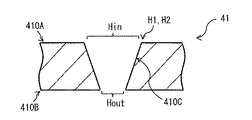
まず、金属基板100を用意する(図9A)。金属基板100は、SUS316やSUS304をはじめとするステンレス鋼によって形成されている。金属基板100の一方の面が第1主面100Aとなっており、金属基板の100の他方の面が第2主面100Bとなっている。なお、金属基板100を加工することによりノズルプレート41となる。また、金属基板100の第1主面100Aがノズルプレート41の流入側主面410Aとなる面であり、金属基板100の第2主面100Bがノズルプレート41の噴出側主面410Bとなる面である。
First, the
次に、パンチ加工を行う(ステップS101)。まず、ノズルプレート41のノズル孔H1におけるX軸方向に沿った形成ピッチと同一ピッチの複数の貫通孔300Hを有するダイ300上に、第1主面100Aを上にして、金属基板100を固定する。各貫通孔300Hの径は、後述のパンチ200の円柱部220の径よりも大きくなっている。続いて、金属基板100の第1主面100Aを1または複数のパンチ200で押圧する。具体的には、金属基板100の第1主面100Aのうち、各貫通孔300Hと対向する箇所を1または複数のパンチ200で押圧する。これにより、第1主面100Aに複数の凹部100Cを形成するとともに、第2主面100Bのうち、各凹部100Cと対向する位置に凸部100Dを形成する(図9B)。
Next, punching is performed (step S101). First, the
ここで、パンチ200は、円錐台形状のテーパー部210と、テーパー部210の先端に接して形成された円柱部220とを有している。そのため、パンチ200の押圧により形成された凹部100Cは、パンチ200の形状を反転させた形状となっており、具体的には、円錐台形状のテーパー孔部と、テーパー孔部と連通する円柱孔部とを有している。このとき、凹部100Cは、金属基板100の厚さ(第1主面100Aと第2主面100Bとの距離)よりも深くなっている。
Here, the
次に、1回目の研磨を行う(ステップS102)。具体的には、各凸部100Dを機械研磨によって削り、各凹部100Cを貫通させることにより、複数のノズル孔H1を形成する(図9C)。ここで、機械研磨としては、例えば、テープ400による研磨(テープ研磨)などが挙げられる。テープ400は、例えば、厚さ75μm程度の長尺なポリエステルフィルムの一方の面に、複数の砥粒が接着剤によりほぼ全面に亘って固定されたものである。
Next, the first polishing is performed (step S102). Specifically, the plurality of nozzle holes H1 are formed by scraping each convex portion 100D by mechanical polishing and penetrating each concave portion 100C (FIG. 9C). Here, examples of mechanical polishing include polishing with a tape 400 (tape polishing), and the like. The
なお、ノズル孔H1の流入端部(流入口Hin)近傍に、パンチ200の押圧に伴って突起が生じることがある。その場合には、機械研磨により、各凸部100Dを削ることに加えて、第1主面100Aをより平坦にしてもよい。その結果、第1主面100Aは概ね平坦となる。ここで、機械研磨としては、例えば、図9Dに示したように、テープ400による研磨(テープ研磨)などが挙げられる。
A protrusion may be generated near the inflow end (inflow port Hin) of the nozzle hole H1 as the
ところで、例えば、図9Eに示したように、上記の機械研磨に伴って、ノズル孔H1の吐出端部(噴出口Hout)にバリ100Fが生じることがある。本実施の形態では、そのようなバリ100Fの発生を考慮して、2回目の研磨を行う(ステップS103)。具体的には、金属基板100のうち、第1主面100Aおよび第2主面100Bの少なくとも一方の面を、化学研磨、電解研磨、または、化学機械研磨によって研磨する。
By the way, for example, as shown in FIG. 9E, the
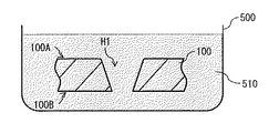
(化学研磨)
化学研磨とは、化学研磨液510と呼ばれる酸性液体にワークを投入し、ワーク表面を溶かす技術を指している。例えば、図9Fに示したように、容器500に、化学研磨液510を充填し、その化学研磨液510の中にワークとしての金属基板100を浸すことにより、化学研磨を行う。化学研磨液510としては、例えば、日本表面化学株式会社のU−2413などが挙げられる。なお、金属基板100の双方の主面のうちいずれか一方の主面(第1主面100Aまたは第2主面100B)だけを研磨したい場合には、金属基板100の双方の主面(第1主面100Aおよび第2主面100B)のうち、研磨しない方の主面を化学研磨液510に対して耐性を有する皮膜で覆うか、または、研磨しない方の主面を何らかの基板に接触させておいてもよい。
(Chemical polishing)
The chemical polishing refers to a technique in which a workpiece is introduced into an acidic liquid called a
(電解研磨)
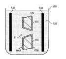
電解研磨とは、電解研磨液と呼ばれる酸性液体にワークおよび金属板を漬け込み、ワークを陽極とし、金属板を陰極とし電流を流すと、陰極側に面したワーク表面のFe(鉄)やNi(ニッケル)等の原子が酸性液体に溶けだし、ワーク表面がエッチングされる技術を指している。例えば、図9Gに示したように、容器500に、電解研磨液520を充填し、その電解研磨液520の中にワークとしての金属基板100と、金属板530を浸した上で、金属基板100を陽極とし、金属板530を陰極として電流を流すことにより、電解研磨を行う。電解研磨液520としては、例えば、日本表面化学株式会社の6C016などが挙げられる。
(Electrolytic polishing)
Electrolytic polishing involves dipping a work and a metal plate in an acidic liquid called electropolishing liquid, using the work as an anode, and using the metal plate as a cathode to flow current, Fe (iron) or Ni (on the surface of the work facing the cathode) It refers to a technology in which atoms such as nickel are dissolved in an acidic liquid and the work surface is etched. For example, as shown in FIG. 9G, the
電解研磨により、金属基板100の表面では、溶解が進行する一方で、酸化皮膜(不動態皮膜)110の生成が同時に進行する。ステンレスの主要な成分であるFeおよびCr(クロム)は、通電に伴って溶け出し、Crは直ちにO(酸素)と結合してステンレス表面に新たな酸化皮膜110を生成する。通電が進行するに伴い、ステンレス表面のCrが濃縮され、Cr濃度の高い酸化皮膜110を生成する。なお、金属基板100の双方の主面のうちいずれか一方の主面(第1主面100Aまたは第2主面100B)だけを研磨したい場合には、例えば、金属基板100の双方の主面(第1主面100Aおよび第2主面100B)のうち、研磨したくない方の主面と対向する位置には金属板530を設置せず、研磨したい方の主面と対向する位置にだけ金属板530を設置してもよい。
By electrolytic polishing, on the surface of the
(化学機械研磨)
化学機械研磨とは、研磨剤(砥粒)自体が有する表面化学作用または研磨液に含まれる化学成分の作用によって、研磨剤とワークとの相対運動による機械的研磨(表面除去)効果を増大させ、高速かつ平滑な研磨面を得る技術を指している。例えば、図9Hに示したように、吐出器540から、研磨剤を含む研磨液550を研磨パッド560上に吐出した上で、ワークである金属基板100を回転させると同時に研磨パッド560を回転させることにより、化学機械研磨を行う。例えば、第1主面100Aを上にして金属基板100を研磨パッド560上に置いて化学機械研磨を行った後に、第2主面100Bを上にして金属基板100を研磨パッド560上に置いて化学機械研磨を行う。
(Chemical mechanical polishing)
Chemical mechanical polishing increases the mechanical polishing (surface removal) effect by relative movement between the polishing agent and the work by the surface chemical action of the polishing agent (abrasive grain) itself or the action of chemical components contained in the polishing liquid. Point to a technology to obtain a high-speed and smooth polished surface. For example, as shown in FIG. 9H, after the polishing liquid 550 containing the polishing agent is discharged onto the
化学機械研磨により、金属基板100の表面では、研磨液550に含まれる研磨剤(砥粒)自体が有する表面化学作用または研磨液550に含まれる化学成分の作用によって、研磨液550とワークである金属基板100との相対運動による機械的研磨(表面除去)が促進され、金属基板100の表面が平滑となる。なお、金属基板100の双方の主面のうちいずれか一方の主面(第1主面100Aまたは第2主面100B)だけを研磨したい場合には、金属基板100の双方の主面(第1主面100Aおよび第2主面100B)のうち、研磨したい方の主面を研磨パッド560に接触させて、化学機械研磨を行ってもよい。
The surface of the
なお、2回目の研磨工程(ステップS103)において、第1主面100Aおよび第2主面100Bに加えて、各ノズル孔H1の内壁も、上記化学研磨、上記電解研磨、または、上記化学機械研磨によって研磨してもよい。例えば、図9Fに示したような方法で上記化学研磨を行うことにより、各ノズル孔H1の内壁にも化学研磨液510が接触する。その結果、第1主面100Aおよび第2主面100Bに加えて、各ノズル孔H1の内壁も、上記化学研磨によって研磨することができる。また、例えば、図9Gに示したような方法で上記電解研磨を行うことにより、各ノズル孔H1の内壁にも電解研磨液520が接触する。その結果、第1主面100Aおよび第2主面100Bに加えて、各ノズル孔H1の内壁も、上記電解研磨によって研磨することができる。また、例えば、図9Hに示したような方法で上記化学機械研磨を行うことにより、各ノズル孔H1の内壁にも研磨液550が接触する。その結果、第1主面100Aおよび第2主面100Bに加えて、各ノズル孔H1の内壁も、上記化学機械研磨によって研磨することができる。このようにして、ノズルプレート41が製造される。
In the second polishing step (step S103), in addition to the first
[作用・効果]
次に、本開示の一実施の形態に係る噴射孔プレートとしてのノズルプレート41の作用・効果について説明する。
[Operation / effect]
Next, the operation and effects of the
インクジェットヘッドを備えたプリンタが、様々な分野に利用されている。インクジェットヘッドは、多数のノズル孔が形成されたノズルプレートを含む複数のプレートの積層体を備えており、各ノズル孔から被記録媒体に対して液体であるインクを吐出するように構成されている。このようなノズルプレートは、例えば、金属基板に対してプレス加工を行うことにより形成される。このようなノズルプレートでは、一般に、耐久性を向上させることが求められている。 Printers equipped with an inkjet head are used in various fields. The inkjet head includes a laminate of a plurality of plates including a nozzle plate in which a large number of nozzle holes are formed, and is configured to eject ink, which is a liquid, from each nozzle hole to a recording medium. . Such a nozzle plate is formed, for example, by pressing a metal substrate. In such a nozzle plate, it is generally required to improve the durability.
しかし、ノズル孔を形成する際に、プレス加工後に凸部に対して機械研磨のみを行った場合、ノズル孔にバリが残る可能性がある。その場合には、飛翔液滴の偏向が誘発され、印字品質が落ちる可能性がある。また、プレス加工後の凸部除去を電解研磨のみで行った場合、ノズル孔にダレ(sag)が発生し、吐出安定性が損なわれる可能性がある。また、パンチによるプレス加工にてノズル孔を形成した場合、その内壁にはパンチの表面粗さに依存して凹凸が出来、気泡付着によるノズル抜け(液滴が吐出されない現象)が誘発される可能性がある。ノズル抜けが発生した場合、吐出安定性やインクの充填性が損なわれ、また、液体抵抗が高くなることによる吐出の高電圧化も懸念される。また、パンチによるプレス加工時に第1主面100A側に突起が発生した場合に、そのような突起が残っているときには、ノズルプレートとアクチュエータプレートとの接着性が低下し、ヘッドの耐久性を損なう可能性がある。また、アクチュエータプレートの絶縁膜42Aが突起によって破れ、駆動電極Edとノズルプレート41との間に電流リークが生じたり、駆動電極Edとノズルプレート41とが互いに電気的に短絡したりする可能性がある。第1主面100A側にそのような突起が残っていない場合であっても、第1主面100A側の表面組成が不均一となっているときには、ノズルプレートとアクチュエータプレートとの密着性が低下し、ヘッドの耐久性が低下する可能性がある。また、ノズルプレートに表面腐食が発生した場合、表面腐食に起因する吐出異常やノズルプレートがアクチュエータプレートから剥離する可能性がある。また、ノズルプレートの材料によっては、使用できるインクの種類が限定される可能性がある。
However, when forming a nozzle hole, when only mechanical polishing is performed with respect to a convex part after press processing, a burr may remain in the nozzle hole. In that case, deflection of the flying droplet may be induced and the print quality may be degraded. In addition, in the case where the removal of the convex portion after press working is performed only by electrolytic polishing, sag may occur in the nozzle hole, and the discharge stability may be impaired. In addition, when the nozzle holes are formed by press processing using a punch, the inner wall may be uneven depending on the surface roughness of the punch, and nozzle omission (a phenomenon in which droplets are not discharged) may be induced due to bubble adhesion. There is sex. When nozzle missing occurs, the discharge stability and the ink filling property are impaired, and there is also a concern about the increase in discharge voltage due to the increase in liquid resistance. In addition, when a protrusion is generated on the side of the first
一方、本実施の形態に係るノズルプレート41では、パンチ加工により形成された各凸部100Dが機械研磨によって削られ、パンチ加工により形成された各凹部100Cが貫通することにより、ノズル孔H1が金属基板100に形成される。その後、金属基板100のうち、第1主面100Aおよび第2主面100Bの少なくとも一方の面が、化学研磨、電解研磨、または、化学機械研磨によって研磨される。
On the other hand, in the
これにより、例えば、最初の機械研磨によってノズル孔H1の噴出口Houtに発生したバリなどが、その後の化学研磨、電解研磨、または、化学機械研磨によって小さくなるか、またはなくなる。これにより、噴射される液滴の直進性が向上するので、吐出安定性を確保することが可能となる。また、例えば、最初の機械研磨を省略し、化学研磨、電解研磨、または、化学機械研磨によって各凸部100Dを研磨した場合と比べて、ノズル孔H1にダレ(sag)が生じ難い。これにより、吐出安定性を確保することが可能となる。さらに、また、例えば、第1主面100Aおよび第2主面100Bの両面に対して化学研磨、電解研磨、または、化学機械研磨を行った場合、最初の機械研磨のみによって各凸部100Dを研磨した場合と比べて、第1主面100Aの表面組成が均一になる。これにより、ノズル孔H1へのインクの供給を制御するアクチュエータプレート42の、第1主面100Aへの密着性を向上させることが可能となる。その結果、ノズルプレート41の接着力不足に伴うヘッドの耐久性低下を抑制することができる。
Thereby, for example, burrs or the like generated at the jet holes Hout of the nozzle holes H1 by the first mechanical polishing become smaller or disappear by the subsequent chemical polishing, electro polishing or chemical mechanical polishing. As a result, the straightness of the ejected droplets is improved, and the ejection stability can be ensured. In addition, for example, the first mechanical polishing is omitted, and sag (sag) is less likely to occur in the nozzle holes H1 as compared to the case where each convex portion 100D is polished by chemical polishing, electrolytic polishing, or chemical mechanical polishing. This makes it possible to ensure the discharge stability. Furthermore, for example, when chemical polishing, electrolytic polishing, or chemical mechanical polishing is performed on both surfaces of the first
また、本実施の形態に係るノズルプレート41では、2回目の研磨工程(ステップS103)において、第1主面100Aおよび第2主面100Bに加えて、各ノズル孔H1の内壁も、化学研磨、電解研磨、または、化学機械研磨によって研磨される。これにより、最初のパンチ加工によってノズル孔H1の内壁に発生した表面荒れが、その後の化学研磨、電解研磨、または、化学機械研磨によって小さくなるか、またはなくなる。その結果、気泡付着によるノズル抜け(液滴が吐出されない現象)が生じ難くなるので、吐出安定性を確保することが可能となり、また、インクの充填性が向上する。また、液体抵抗が小さくなるので、低電圧での吐出が可能となる。
Further, in the
また、本実施の形態に係るノズルプレート41では、用いられる金属基板100が、ステンレス鋼によって形成されている。これにより、化学研磨、電解研磨、または、化学機械研磨によって、金属基板100の表面のCr濃度が高くなるので、金属基板100の表面腐食が抑制される。これにより、表面腐食に起因する吐出異常や金属基板剥離が抑制されるので、吐出安定性およびヘッドの耐久性が向上する。また、使用できるインクの種類が限定されることがなくなるので、ヘッドの汎用性が向上する。
Further, in the
また、本実施の形態に係るノズルプレート41において、1回目の研磨工程(ステップS102)において、機械研磨によって、各凸部100Dを削ることに加えて、第1主面100Aをより平坦にした場合には、例えば、パンチ200によって生じた、第1主面100A上の突起が原因で、ノズル孔H1へのインクの供給を制御するアクチュエータプレート42の、第1主面100Aへの密着性が低下するのを防止することができる。その結果、ヘッドの耐久性を保つことができる。さらに、例えば、第1主面100A上の突起が原因で絶縁膜42Aの絶縁性が破れる可能性がなくなる。その結果、駆動電極Edとノズルプレート41との間に電流リークが生じたり、駆動電極Edとノズルプレート41とが互いに電気的に短絡したりするのを防止することができる。
In addition, in the
<2.変形例>
以上、実施の形態を挙げて本開示を説明したが、本開示はこの実施の形態に限定されず、種々の変形が可能である。
<2. Modified example>
Although the present disclosure has been described above by the embodiments, the present disclosure is not limited to the embodiments, and various modifications are possible.
例えば、上記実施の形態では、プリンタ1およびインクジェットヘッド4における各部材の構成例(形状、配置、個数等)を具体的に挙げて説明したが、上記実施の形態で説明したものには限られず、他の形状や配置、個数等であってもよい。また、上記実施の形態で説明した各種パラメータの値や範囲、大小関係等についても、上記実施の形態で説明したものには限られず、他の値や範囲、大小関係等であってもよい。
For example, in the above embodiment, the configuration example (shape, arrangement, number, etc.) of each member in the printer 1 and the
具体的には、例えば、上記実施の形態では、2列タイプの(2列のノズル列411,412を有する)インクジェットヘッド4を挙げて説明したが、この例には限られない。すなわち、例えば、1列タイプ(1列のノズル列を有する)のインクジェットヘッドや、3列以上の複数例タイプ(3列以上のノズル列を有する)インクジェットヘッドであってもよい。
Specifically, for example, in the above embodiment, the two-row type (having two rows of
また、例えば、上記実施の形態では、ノズル列411,412がそれぞれX軸方向に沿って直線状に延在している場合について説明したが、この例には限らず、例えば、ノズル列411,412がそれぞれ、斜め方向に延在するようにしてもよい。更に、ノズル孔H1,H2の形状についても、上記実施の形態で説明したような円形状には限られず、例えば、三角形状等の多角形状や、楕円形状や星型形状などであってもよい。
Further, for example, in the above embodiment, the case where the
また、例えば、上記実施の形態では、インクジェットヘッド4がサイドシュートタイプとなっている場合について説明したが、この例には限らず、例えば、インクジェットヘッド4が他のタイプとなっていてもよい。また、例えば、上記実施の形態では、インクジェットヘッド4が循環式となっている場合について説明したが、この例には限らず、例えば、インクジェットヘッド4が循環しない他の方式となっていてもよい。
Further, for example, although the case where the
また、例えば、上記実施の形態およびその変形例において、1つのパンチ200を用いてパンチ加工を行う場合には、単一の貫通孔300Hが設けられたダイ300を用いてもよい。このとき、1つのパンチ200および単一の貫通孔300Hは、一対になっており、両者が金属基板100に対して相対的に移動することにより、金属基板100に複数の凸部100Dを列状に形成することができる。
Further, for example, in the above-described embodiment and the modification thereof, in the case of performing the punch processing using one
また、例えば、上記実施の形態およびその変形例において、ノズルプレート41に設けられたノズル孔H1の数が1つであってもよい。また、例えば、上記実施の形態およびその変形例において、ノズルプレート41に設けられたノズル孔H2の数が1つであってもよい。また、例えば、上記実施の形態およびその変形例において、ノズルプレート41に対して、ノズル孔H1およびノズル孔H2のいずれか一方だけが設けられていてもよく、さらに、ノズルプレート41に設けられた、インク9吐出用の孔の数が1つであってもよい。
Further, for example, in the above-described embodiment and the modification thereof, the number of the nozzle holes H1 provided in the
加えて、上記実施の形態で説明した一連の処理は、ハードウェア(回路)で行われるようにしてもよいし、ソフトウェア(プログラム)で行われるようにしてもよい。ソフトウェアで行われるようにした場合、そのソフトウェアは、各機能をコンピュータにより実行させるためのプログラム群で構成される。各プログラムは、例えば、上記コンピュータに予め組み込まれて用いられてもよいし、ネットワークや記録媒体から上記コンピュータにインストールして用いられてもよい。 In addition, the series of processes described in the above embodiment may be performed by hardware (circuit) or may be performed by software (program). When performed by software, the software is configured by a group of programs for causing a computer to execute each function. For example, each program may be incorporated in advance in the computer and used, or may be installed and used in the computer from a network or a recording medium.
また、上記実施の形態では、本開示における「液体噴射記録装置」の一具体例として、プリンタ1(インクジェットプリンタ)を挙げて説明したが、この例には限られず、インクジェットプリンタ以外の他の装置にも、本開示を適用することが可能である。換言すると、本開示の「液体噴射ヘッド」(インクジェットヘッド4)や「噴射孔プレート」(ノズルプレート41)を、インクジェットプリンタ以外の他の装置に適用するようにしてもよい。具体的には、例えば、ファクシミリやオンデマンド印刷機などの装置に、本開示の「液体噴射ヘッド」や「噴射孔プレート」を適用するようにしてもよい。 Further, in the above embodiment, the printer 1 (ink jet printer) has been described as a specific example of the “liquid jet recording apparatus” in the present disclosure, but the present invention is not limited to this example. It is also possible to apply the present disclosure. In other words, the “liquid jet head” (inkjet head 4) or the “jet hole plate” (nozzle plate 41) of the present disclosure may be applied to devices other than the ink jet printer. Specifically, for example, the “liquid jet head” or the “jet hole plate” of the present disclosure may be applied to an apparatus such as a facsimile machine or an on-demand printer.
また、上記実施の形態およびその変形例では、プリンタ1の記録対象物は記録紙Pであったが、本開示の「液体噴射記録装置」の記録対象物はこれに限られない。例えば、ボール紙、布、プラスチック、金属など、様々な材料にインクを噴射することによって、文字や模様を形成することができる。また、記録対象物は平面形状である必要もなく、食品、タイル等の建材、家具、自動車など様々な立体物の塗装や装飾を行うこともできる。さらに、本開示の「液体噴射記録装置」によって、繊維を捺染することができ、あるいは噴射後にインクを固化させることによって立体造形を行うこともできる(いわゆる3Dプリンタ)。 Further, in the above-described embodiment and its modification, the recording target of the printer 1 is the recording paper P, but the recording target of the “liquid jet recording apparatus” of the present disclosure is not limited to this. For example, characters and patterns can be formed by jetting ink to various materials such as cardboard, cloth, plastic, metal and the like. In addition, the recording target does not have to have a planar shape, and can be used to paint and decorate various three-dimensional objects such as food, building materials such as tiles, furniture, and automobiles. Furthermore, fibers can be printed by the “liquid jet recording apparatus” of the present disclosure, or three-dimensional modeling can be performed by solidifying the ink after jetting (so-called 3D printer).
更に、これまでに説明した各種の例を、任意の組み合わせで適用させるようにしてもよい。 Furthermore, the various examples described above may be applied in any combination.
なお、本明細書中に記載された効果はあくまで例示であって限定されるものではなく、また、他の効果があってもよい。 In addition, the effect described in this specification is an illustration to the last, is not limited, and may have other effects.
また、本開示は、以下のような構成を取ることも可能である。
(1)
金属基板の第1主面をパンチで押圧することにより、前記第1主面に凹部を形成するとともに、前記金属基板の第2主面のうち、前記凹部と対向する位置に凸部を形成するパンチ加工工程と、
前記凸部を機械研磨によって削り、前記凹部を貫通させることにより、噴射孔を形成する第1研磨工程と、
前記金属基板のうち、前記第1主面および前記第2主面の少なくとも一方の面を、化学研磨、電解研磨、または、化学機械研磨によって研磨する第2研磨工程と
を含む噴射孔プレートの製造方法。
(2)
前記第2研磨工程において、前記第1主面および前記第2主面に加えて、前記噴射孔の内壁も、前記化学研磨、前記電解研磨、または、前記化学機械研磨によって研磨する
(1)に記載の噴射孔プレートの製造方法。
(3)
前記金属基板は、ステンレス鋼によって形成されている
(1)または(2)に記載の噴射孔プレートの製造方法。
(4)
前記第1研磨工程において、機械研磨によって、前記凸部を削ることに加えて、前記第1主面をより平坦にする
(1)ないし(3)のいずれか1つに記載の噴射孔プレートの製造方法。
Furthermore, the present disclosure can also be configured as follows.
(1)
By pressing the first main surface of the metal substrate with a punch, a recess is formed on the first main surface, and a protrusion is formed on the second main surface of the metal substrate at a position facing the recess. Punching process,
A first polishing step of forming the injection hole by scraping the convex portion by mechanical polishing and penetrating the concave portion;
Manufacturing a jet hole plate including a second polishing step of polishing at least one of the first main surface and the second main surface of the metal substrate by chemical polishing, electro polishing, or chemical mechanical polishing Method.
(2)
In the second polishing step, in addition to the first main surface and the second main surface, the inner wall of the injection hole is also polished by the chemical polishing, the electrolytic polishing, or the chemical mechanical polishing. The manufacturing method of the injection hole plate of description.
(3)
The method for manufacturing a jet hole plate according to (1) or (2), wherein the metal substrate is formed of stainless steel.
(4)
In the first polishing step, in addition to scraping the convex portion by mechanical polishing, the first main surface is made flatter (1) to (3) Production method.
1…プリンタ、10…筺体、2a,2b…搬送機構、21…グリッドローラ、22…ピンチローラ、3(3Y,3M,3C,3B)…インクタンク、4(4Y,4M,4C,4B)…インクジェットヘッド、40…制御部、41…ノズルプレート、411,412…ノズル列、42…アクチュエータプレート、42A…絶縁膜、420…尾部、421,422…チャネル列、43…カバープレート、431a,432a…入口側共通インク室、431b,432b…出口側共通インク室、44…フレキシブルプリント基板、5…循環機構、50…循環流路、50a,50b…流路、52a,52b…送液ポンプ、6…走査機構、61a,61b…ガイドレール、62…キャリッジ、63…駆動機構、631a,631b…プーリ、632…無端ベルト、633…駆動モータ、9…インク、100…金属基板、100A…第1主面、100B…第2主面、100C…凹部、100D…凸部、100F…バリ、110…酸化皮膜、200…パンチ、210…テーパー部、220…円柱部、300…ダイ、300H…貫通孔、400…テープ、410A…流入側主面、410B…噴出側主面、500…容器、510…化学研磨液、520…電解研磨液、530…金属板、540…吐出器、550…研磨液、560…研磨パッド、P…記録紙、d…搬送方向、Tin…入口部、Tout…出口部、H1,H2…ノズル孔、A1…吐出領域(噴射領域)、A2…非吐出領域(非噴射領域)、C1,C2…チャネル、C1e,C2e…吐出チャネル、C1d,C2d…ダミーチャネル、Wd…駆動壁、Ed…駆動電極、Edc…コモン電極、Eda…アクティブ電極、Dd…浅溝部、Sa…供給スリット、Sb…排出スリット、Hin…流入口、Hout…噴出口。
DESCRIPTION OF SYMBOLS 1 ... Printer, 10 ... Housing, 2a, 2b ... Conveyance mechanism, 21 ... Grid roller, 22 ... Pinch roller, 3 (3Y, 3M, 3C, 3B) ... Ink tank, 4 (4Y, 4M, 4C, 4B) ... Ink jet head, 40: control unit, 41: nozzle plate, 411, 412: nozzle array, 42: actuator plate, 42A: insulating film, 420: tail portion, 421, 422: channel array, 43: cover plate, 431a, 432a ... Inlet side common ink chamber, 431b, 432b ... outlet side common ink chamber, 44 ... flexible printed circuit board, 5 ... circulation mechanism, 50 ... circulation flow path, 50a, 50b ... flow path, 52a, 52b ... liquid transfer pump, 6 ... Scanning mechanism, 61a, 61b: Guide rail, 62: Carriage, 63: Drive mechanism, 631a, 631b: Pulley, 632:
Claims (4)
前記凸部を機械研磨によって削り、前記凹部を貫通させることにより、噴射孔を形成する第1研磨工程と、
前記金属基板のうち、前記第1主面および前記第2主面の少なくとも一方の面を、化学研磨、電解研磨、または、化学機械研磨によって研磨する第2研磨工程と
を含む噴射孔プレートの製造方法。 By pressing the first main surface of the metal substrate with a punch, a recess is formed on the first main surface, and a protrusion is formed on the second main surface of the metal substrate at a position facing the recess. Punching process,
A first polishing step of forming the injection hole by scraping the convex portion by mechanical polishing and penetrating the concave portion;
Manufacturing a jet hole plate including a second polishing step of polishing at least one of the first main surface and the second main surface of the metal substrate by chemical polishing, electro polishing, or chemical mechanical polishing Method.
請求項1に記載の噴射孔プレートの製造方法。 In the second polishing step, in addition to the first main surface and the second main surface, the inner wall of the injection hole is also polished by the chemical polishing, the electrolytic polishing, or the chemical mechanical polishing. The manufacturing method of the injection hole plate of description.
請求項1または請求項2に記載の噴射孔プレートの製造方法。 The method according to claim 1, wherein the metal substrate is made of stainless steel.
請求項1ないし請求項3のいずれか一項に記載の噴射孔プレートの製造方法。 The injection hole plate according to any one of claims 1 to 3, wherein, in the first polishing step, in addition to scraping the convex portion by mechanical polishing, the first main surface is made flatter. Production method.
Priority Applications (4)
| Application Number | Priority Date | Filing Date | Title |
|---|---|---|---|
| JP2017218698A JP2019089233A (en) | 2017-11-14 | 2017-11-14 | Manufacturing method of injection hole plate |
| EP18205016.1A EP3482870A1 (en) | 2017-11-14 | 2018-11-07 | Method for manufacturing jet hole plate |
| US16/189,367 US20190143693A1 (en) | 2017-11-14 | 2018-11-13 | Method for manufacturing jet hole plate |
| CN201811352954.3A CN110001200A (en) | 2017-11-14 | 2018-11-14 | Spray the manufacturing method of orifice plate |
Applications Claiming Priority (1)
| Application Number | Priority Date | Filing Date | Title |
|---|---|---|---|
| JP2017218698A JP2019089233A (en) | 2017-11-14 | 2017-11-14 | Manufacturing method of injection hole plate |
Publications (1)
| Publication Number | Publication Date |
|---|---|
| JP2019089233A true JP2019089233A (en) | 2019-06-13 |
Family
ID=64184011
Family Applications (1)
| Application Number | Title | Priority Date | Filing Date |
|---|---|---|---|
| JP2017218698A Withdrawn JP2019089233A (en) | 2017-11-14 | 2017-11-14 | Manufacturing method of injection hole plate |
Country Status (4)
| Country | Link |
|---|---|
| US (1) | US20190143693A1 (en) |
| EP (1) | EP3482870A1 (en) |
| JP (1) | JP2019089233A (en) |
| CN (1) | CN110001200A (en) |
Cited By (1)
| Publication number | Priority date | Publication date | Assignee | Title |
|---|---|---|---|---|
| JP7462361B1 (en) | 2023-05-11 | 2024-04-05 | 大阪アサヒ化学株式会社 | Surface treatment method for convex nozzle plate used in jet soldering device |
Citations (4)
| Publication number | Priority date | Publication date | Assignee | Title |
|---|---|---|---|---|
| JPS5889370A (en) * | 1981-11-20 | 1983-05-27 | Ricoh Co Ltd | Ink jet nozzle |
| JPH10226070A (en) * | 1997-02-18 | 1998-08-25 | Fujitsu Ltd | Nozzle plate, ink jet head, printer, method and system for manufacturing nozzle plate |
| JP2001018398A (en) * | 1999-07-09 | 2001-01-23 | Konica Corp | Manufacture of nozzle plate of ink jet head |
| US20040017430A1 (en) * | 2002-07-23 | 2004-01-29 | Yosuke Mizuyama | Laser processing method and laser processing apparatus |
Family Cites Families (18)
| Publication number | Priority date | Publication date | Assignee | Title |
|---|---|---|---|---|
| JPS4935535B1 (en) | 1970-04-02 | 1974-09-24 | ||
| JPS62164543A (en) * | 1986-01-16 | 1987-07-21 | Nec Corp | Manufacture of ink jet printer head |
| US5574486A (en) * | 1993-01-13 | 1996-11-12 | Tektronix, Inc. | Ink jet print heads and methos for preparing them |
| JPH08267758A (en) * | 1995-03-28 | 1996-10-15 | Sony Corp | Orifice plate, manufacture of the same, liquid mixing device and printer |
| JP3438797B2 (en) * | 1995-09-08 | 2003-08-18 | 富士通株式会社 | Method of manufacturing inkjet head |
| EP0854040B1 (en) * | 1997-01-21 | 2003-03-19 | SCITEX DIGITAL PRINTING, Inc. | Method for providing particle-free ink jet printer components |
| JPH10217483A (en) * | 1997-02-07 | 1998-08-18 | Citizen Watch Co Ltd | Manufacture of nozzle plate for ink jet printer head |
| JP3826608B2 (en) * | 1999-03-17 | 2006-09-27 | 富士写真フイルム株式会社 | Formation of water-repellent film on the surface of the liquid ejection part |
| JP2000282300A (en) * | 1999-03-30 | 2000-10-10 | Kawasaki Steel Corp | Stainless steel sheet excellent in corrosion resistance and its production |
| MY127853A (en) * | 1999-09-08 | 2006-12-29 | Shinetsu Chemical Co | Yoke compartment of voice coil motor for hard disk drive and voice coil motor using said yoke component |
| JP2003127345A (en) * | 2001-10-22 | 2003-05-08 | Ricoh Co Ltd | Nozzle plate for ink jet head and its manufacturing method |
| JP2004001533A (en) * | 2003-06-19 | 2004-01-08 | Fujitsu Ltd | Nozzle plate, inkjet head and printer |
| JP4630540B2 (en) * | 2003-12-15 | 2011-02-09 | キヤノン株式会社 | Nozzle plate manufacturing method |
| JP4222218B2 (en) * | 2004-02-05 | 2009-02-12 | ブラザー工業株式会社 | Nozzle plate, nozzle plate manufacturing method, and inkjet head manufacturing method |
| JP4935535B2 (en) * | 2007-06-29 | 2012-05-23 | ブラザー工業株式会社 | Nozzle plate manufacturing method |
| JP4656670B2 (en) * | 2008-12-19 | 2011-03-23 | キヤノン株式会社 | Liquid discharge head and method of manufacturing liquid discharge head |
| JP2014043029A (en) * | 2012-08-25 | 2014-03-13 | Ricoh Co Ltd | Liquid discharge head and image formation device |
| JP5860991B1 (en) * | 2015-07-21 | 2016-02-16 | 新家工業株式会社 | Method for producing stainless steel-containing member |
-
2017
- 2017-11-14 JP JP2017218698A patent/JP2019089233A/en not_active Withdrawn
-
2018
- 2018-11-07 EP EP18205016.1A patent/EP3482870A1/en not_active Withdrawn
- 2018-11-13 US US16/189,367 patent/US20190143693A1/en not_active Abandoned
- 2018-11-14 CN CN201811352954.3A patent/CN110001200A/en active Pending
Patent Citations (4)
| Publication number | Priority date | Publication date | Assignee | Title |
|---|---|---|---|---|
| JPS5889370A (en) * | 1981-11-20 | 1983-05-27 | Ricoh Co Ltd | Ink jet nozzle |
| JPH10226070A (en) * | 1997-02-18 | 1998-08-25 | Fujitsu Ltd | Nozzle plate, ink jet head, printer, method and system for manufacturing nozzle plate |
| JP2001018398A (en) * | 1999-07-09 | 2001-01-23 | Konica Corp | Manufacture of nozzle plate of ink jet head |
| US20040017430A1 (en) * | 2002-07-23 | 2004-01-29 | Yosuke Mizuyama | Laser processing method and laser processing apparatus |
Cited By (1)
| Publication number | Priority date | Publication date | Assignee | Title |
|---|---|---|---|---|
| JP7462361B1 (en) | 2023-05-11 | 2024-04-05 | 大阪アサヒ化学株式会社 | Surface treatment method for convex nozzle plate used in jet soldering device |
Also Published As
| Publication number | Publication date |
|---|---|
| EP3482870A1 (en) | 2019-05-15 |
| CN110001200A (en) | 2019-07-12 |
| US20190143693A1 (en) | 2019-05-16 |
Similar Documents
| Publication | Publication Date | Title |
|---|---|---|
| JP7185512B2 (en) | HEAD CHIP, LIQUID JET HEAD AND LIQUID JET RECORDER | |
| US10654271B2 (en) | Head chip, liquid jet head and liquid jet recording device | |
| JP2022090065A (en) | Jet hole plate, liquid jet head, and liquid jet recording apparatus | |
| JP2019089234A (en) | Liquid jet head, and liquid jet recording device | |
| JP4935535B2 (en) | Nozzle plate manufacturing method | |
| CN110816062B (en) | Liquid ejecting head and liquid ejecting recording apparatus | |
| JP6968669B2 (en) | Head tip, liquid injection head and liquid injection recorder | |
| JP2019089233A (en) | Manufacturing method of injection hole plate | |
| CN111169168B (en) | Head chip, method of manufacturing the same, liquid ejecting head, and liquid ejecting recording apparatus | |
| JP2019089221A (en) | Head chip, liquid jet head, and liquid jet recording device | |
| CN110001201B (en) | Ejection orifice plate, liquid ejection head, and method for manufacturing ejection orifice plate | |
| US10259221B2 (en) | Element substrate, liquid ejection head, and liquid ejection apparatus | |
| JP2005270743A (en) | Ink jet head | |
| JP2019089223A (en) | Liquid jet head, and liquid jet recording device | |
| JP6965112B2 (en) | Head tip, liquid injection head and liquid injection recording device | |
| JP6340944B2 (en) | Method for manufacturing liquid discharge head and image forming apparatus | |
| JP2019084703A (en) | Liquid jet head and liquid jet recording device | |
| JP2020044669A (en) | Head chip, liquid jet head, liquid jet recording device, and manufacturing method of head chip |
Legal Events
| Date | Code | Title | Description |
|---|---|---|---|
| A621 | Written request for application examination |
Free format text: JAPANESE INTERMEDIATE CODE: A621 Effective date: 20200911 |
|
| A977 | Report on retrieval |
Free format text: JAPANESE INTERMEDIATE CODE: A971007 Effective date: 20210728 |
|
| A131 | Notification of reasons for refusal |
Free format text: JAPANESE INTERMEDIATE CODE: A131 Effective date: 20210824 |
|
| A521 | Request for written amendment filed |
Free format text: JAPANESE INTERMEDIATE CODE: A523 Effective date: 20211020 |
|
| A131 | Notification of reasons for refusal |
Free format text: JAPANESE INTERMEDIATE CODE: A131 Effective date: 20220315 |
|
| A761 | Written withdrawal of application |
Free format text: JAPANESE INTERMEDIATE CODE: A761 Effective date: 20220422 |