JP2019089071A - Filter cartridge and air filter assembly - Google Patents
Filter cartridge and air filter assembly Download PDFInfo
- Publication number
- JP2019089071A JP2019089071A JP2019012402A JP2019012402A JP2019089071A JP 2019089071 A JP2019089071 A JP 2019089071A JP 2019012402 A JP2019012402 A JP 2019012402A JP 2019012402 A JP2019012402 A JP 2019012402A JP 2019089071 A JP2019089071 A JP 2019089071A
- Authority
- JP
- Japan
- Prior art keywords
- filter cartridge
- seal
- cartridge according
- sealing surface
- medium
- Prior art date
- Legal status (The legal status is an assumption and is not a legal conclusion. Google has not performed a legal analysis and makes no representation as to the accuracy of the status listed.)
- Granted
Links
- 238000000034 method Methods 0.000 claims abstract description 18
- 238000007789 sealing Methods 0.000 claims description 363
- 239000000463 material Substances 0.000 claims description 51
- 230000006835 compression Effects 0.000 claims description 36
- 238000007906 compression Methods 0.000 claims description 36
- 238000000465 moulding Methods 0.000 claims description 32
- 230000002093 peripheral effect Effects 0.000 claims description 22
- 239000011347 resin Substances 0.000 claims description 19
- 229920005989 resin Polymers 0.000 claims description 19
- 238000009434 installation Methods 0.000 claims description 18
- 230000004323 axial length Effects 0.000 claims description 6
- 238000010276 construction Methods 0.000 description 47
- 239000007789 gas Substances 0.000 description 44
- 230000004048 modification Effects 0.000 description 30
- 238000012986 modification Methods 0.000 description 30
- 230000008901 benefit Effects 0.000 description 25
- 238000001914 filtration Methods 0.000 description 19
- 238000009423 ventilation Methods 0.000 description 18
- XLYOFNOQVPJJNP-UHFFFAOYSA-N water Substances O XLYOFNOQVPJJNP-UHFFFAOYSA-N 0.000 description 12
- 230000000712 assembly Effects 0.000 description 11
- 238000000429 assembly Methods 0.000 description 11
- 239000004033 plastic Substances 0.000 description 9
- 229920003023 plastic Polymers 0.000 description 9
- 230000000694 effects Effects 0.000 description 8
- 239000007788 liquid Substances 0.000 description 8
- 238000010586 diagram Methods 0.000 description 7
- 239000000428 dust Substances 0.000 description 7
- 239000003566 sealing material Substances 0.000 description 7
- 230000015572 biosynthetic process Effects 0.000 description 6
- 238000004519 manufacturing process Methods 0.000 description 6
- 239000007787 solid Substances 0.000 description 6
- 239000000126 substance Substances 0.000 description 6
- 238000003780 insertion Methods 0.000 description 5
- 230000037431 insertion Effects 0.000 description 5
- 238000007689 inspection Methods 0.000 description 5
- 230000033001 locomotion Effects 0.000 description 5
- 238000000926 separation method Methods 0.000 description 5
- 238000002485 combustion reaction Methods 0.000 description 4
- 238000005516 engineering process Methods 0.000 description 4
- 239000012778 molding material Substances 0.000 description 4
- 239000002245 particle Substances 0.000 description 4
- 239000011148 porous material Substances 0.000 description 4
- 238000012360 testing method Methods 0.000 description 4
- 230000005540 biological transmission Effects 0.000 description 3
- 238000012512 characterization method Methods 0.000 description 3
- 238000004891 communication Methods 0.000 description 3
- 239000000356 contaminant Substances 0.000 description 3
- 229920002635 polyurethane Polymers 0.000 description 3
- 239000004814 polyurethane Substances 0.000 description 3
- 230000008569 process Effects 0.000 description 3
- 125000006850 spacer group Chemical group 0.000 description 3
- 239000003795 chemical substances by application Substances 0.000 description 2
- 238000001816 cooling Methods 0.000 description 2
- 238000006073 displacement reaction Methods 0.000 description 2
- 239000002184 metal Substances 0.000 description 2
- 239000000203 mixture Substances 0.000 description 2
- 238000004382 potting Methods 0.000 description 2
- QNRATNLHPGXHMA-XZHTYLCXSA-N (r)-(6-ethoxyquinolin-4-yl)-[(2s,4s,5r)-5-ethyl-1-azabicyclo[2.2.2]octan-2-yl]methanol;hydrochloride Chemical compound Cl.C([C@H]([C@H](C1)CC)C2)CN1[C@@H]2[C@H](O)C1=CC=NC2=CC=C(OCC)C=C21 QNRATNLHPGXHMA-XZHTYLCXSA-N 0.000 description 1
- 241000550645 Danaea media Species 0.000 description 1
- JOYRKODLDBILNP-UHFFFAOYSA-N Ethyl urethane Chemical compound CCOC(N)=O JOYRKODLDBILNP-UHFFFAOYSA-N 0.000 description 1
- 229920001410 Microfiber Polymers 0.000 description 1
- 239000008186 active pharmaceutical agent Substances 0.000 description 1
- 239000000443 aerosol Substances 0.000 description 1
- 230000009286 beneficial effect Effects 0.000 description 1
- 238000004364 calculation method Methods 0.000 description 1
- 238000004140 cleaning Methods 0.000 description 1
- 239000013256 coordination polymer Substances 0.000 description 1
- 230000008878 coupling Effects 0.000 description 1
- 238000010168 coupling process Methods 0.000 description 1
- 238000005859 coupling reaction Methods 0.000 description 1
- 230000000994 depressogenic effect Effects 0.000 description 1
- 238000007599 discharging Methods 0.000 description 1
- 239000006261 foam material Substances 0.000 description 1
- 239000012943 hotmelt Substances 0.000 description 1
- 230000006698 induction Effects 0.000 description 1
- 230000003993 interaction Effects 0.000 description 1
- 230000014759 maintenance of location Effects 0.000 description 1
- 239000003658 microfiber Substances 0.000 description 1
- 239000013518 molded foam Substances 0.000 description 1
- 230000003534 oscillatory effect Effects 0.000 description 1
- 238000002360 preparation method Methods 0.000 description 1
- 238000003825 pressing Methods 0.000 description 1
- 102220047090 rs6152 Human genes 0.000 description 1
- 238000007493 shaping process Methods 0.000 description 1
- 230000000087 stabilizing effect Effects 0.000 description 1
- 230000001629 suppression Effects 0.000 description 1
- 238000004381 surface treatment Methods 0.000 description 1
- 210000003813 thumb Anatomy 0.000 description 1
Images


Classifications
-
- B—PERFORMING OPERATIONS; TRANSPORTING
- B01—PHYSICAL OR CHEMICAL PROCESSES OR APPARATUS IN GENERAL
- B01D—SEPARATION
- B01D46/00—Filters or filtering processes specially modified for separating dispersed particles from gases or vapours
- B01D46/24—Particle separators, e.g. dust precipitators, using rigid hollow filter bodies
-
- B—PERFORMING OPERATIONS; TRANSPORTING
- B01—PHYSICAL OR CHEMICAL PROCESSES OR APPARATUS IN GENERAL
- B01D—SEPARATION
- B01D46/00—Filters or filtering processes specially modified for separating dispersed particles from gases or vapours
- B01D46/0002—Casings; Housings; Frame constructions
- B01D46/0005—Mounting of filtering elements within casings, housings or frames
-
- B—PERFORMING OPERATIONS; TRANSPORTING
- B01—PHYSICAL OR CHEMICAL PROCESSES OR APPARATUS IN GENERAL
- B01D—SEPARATION
- B01D46/00—Filters or filtering processes specially modified for separating dispersed particles from gases or vapours
- B01D46/24—Particle separators, e.g. dust precipitators, using rigid hollow filter bodies
- B01D46/2403—Particle separators, e.g. dust precipitators, using rigid hollow filter bodies characterised by the physical shape or structure of the filtering element
- B01D46/2411—Filter cartridges
- B01D46/2414—End caps including additional functions or special forms
-
- B—PERFORMING OPERATIONS; TRANSPORTING
- B01—PHYSICAL OR CHEMICAL PROCESSES OR APPARATUS IN GENERAL
- B01D—SEPARATION
- B01D46/00—Filters or filtering processes specially modified for separating dispersed particles from gases or vapours
- B01D46/24—Particle separators, e.g. dust precipitators, using rigid hollow filter bodies
- B01D46/2403—Particle separators, e.g. dust precipitators, using rigid hollow filter bodies characterised by the physical shape or structure of the filtering element
- B01D46/2411—Filter cartridges
-
- B—PERFORMING OPERATIONS; TRANSPORTING
- B01—PHYSICAL OR CHEMICAL PROCESSES OR APPARATUS IN GENERAL
- B01D—SEPARATION
- B01D46/00—Filters or filtering processes specially modified for separating dispersed particles from gases or vapours
- B01D46/52—Particle separators, e.g. dust precipitators, using filters embodying folded corrugated or wound sheet material
- B01D46/521—Particle separators, e.g. dust precipitators, using filters embodying folded corrugated or wound sheet material using folded, pleated material
- B01D46/525—Particle separators, e.g. dust precipitators, using filters embodying folded corrugated or wound sheet material using folded, pleated material which comprises flutes
- B01D46/527—Particle separators, e.g. dust precipitators, using filters embodying folded corrugated or wound sheet material using folded, pleated material which comprises flutes in wound arrangement
-
- B—PERFORMING OPERATIONS; TRANSPORTING
- B01—PHYSICAL OR CHEMICAL PROCESSES OR APPARATUS IN GENERAL
- B01D—SEPARATION
- B01D2265/00—Casings, housings or mounting for filters specially adapted for separating dispersed particles from gases or vapours
- B01D2265/02—Non-permanent measures for connecting different parts of the filter
- B01D2265/021—Anti-rotational means
-
- B—PERFORMING OPERATIONS; TRANSPORTING
- B01—PHYSICAL OR CHEMICAL PROCESSES OR APPARATUS IN GENERAL
- B01D—SEPARATION
- B01D2265/00—Casings, housings or mounting for filters specially adapted for separating dispersed particles from gases or vapours
- B01D2265/02—Non-permanent measures for connecting different parts of the filter
- B01D2265/024—Mounting aids
- B01D2265/026—Mounting aids with means for avoiding false mounting
-
- B—PERFORMING OPERATIONS; TRANSPORTING
- B01—PHYSICAL OR CHEMICAL PROCESSES OR APPARATUS IN GENERAL
- B01D—SEPARATION
- B01D2265/00—Casings, housings or mounting for filters specially adapted for separating dispersed particles from gases or vapours
- B01D2265/06—Details of supporting structures for filtering material, e.g. cores
-
- B—PERFORMING OPERATIONS; TRANSPORTING
- B01—PHYSICAL OR CHEMICAL PROCESSES OR APPARATUS IN GENERAL
- B01D—SEPARATION
- B01D2271/00—Sealings for filters specially adapted for separating dispersed particles from gases or vapours
- B01D2271/02—Gaskets, sealings
- B01D2271/027—Radial sealings
Landscapes
- Chemical & Material Sciences (AREA)
- Chemical Kinetics & Catalysis (AREA)
- Physics & Mathematics (AREA)
- Geometry (AREA)
- Filtering Of Dispersed Particles In Gases (AREA)
- Separation Using Semi-Permeable Membranes (AREA)
- Cyclones (AREA)
- Respiratory Apparatuses And Protective Means (AREA)
Abstract
Description
本開示は、フィルタアセンブリ、例えばエアクリーナアセンブリ、その構成部品及び特徴、並びに組み立て方法及び使用方法に関する。フィルタアセンブリは、取り外し可能且つ交換可能なフィルタカートリッジを収納するハウジングを備える。フィルタカートリッジは、オプションとしてハウジングシール構造を有するように構成されるのが効果的である。利点を提供することができるフィルタハウジング及び/又はカートリッジの種々の特徴が説明される。組み立て方法及び使用方法が説明される。オプションとして設けられる効果的な共鳴器/ソニックチョーク構造が説明される。 The present disclosure relates to filter assemblies, such as air cleaner assemblies, their components and features, and methods of assembly and use. The filter assembly includes a housing that houses a removable and replaceable filter cartridge. The filter cartridge is advantageously configured to have a housing seal arrangement as an option. Various features of the filter housing and / or cartridge that can provide advantages are described. Methods of assembly and use are described. An optional resonator / sonic choke structure is described as an option.
多くのシステムで空気又は他のガスを濾過することが望まれる。典型的な用途は内燃機関の吸気の濾過である。別の用途は、クランクケース換気フィルタアセンブリの濾過である。通常、そのようなシステムは、点検可能なフィルタカートリッジを収納するフィルタアセンブリを備える。一定の使用期間の後、フィルタハウジング内部のフィルタ媒体を洗浄又は完全交換によって点検する必要がある。例えば車両の内燃機関と共に使用されるエアクリーナのフィルタアセンブリ又はクランクケース換気フィルタアセンブリの場合、フィルタ媒体は、通常、典型的にはフィルタ要素又はフィルタカートリッジと呼ばれる取り外し可能且つ交換可能な構成部品、すなわち点検可能な構成部品である。フィルタカートリッジは、使用中にエアクリーナの中に取り外し可能に密封されるように構成される。 It is desirable to filter air or other gases in many systems. A typical application is the filtration of the intake air of an internal combustion engine. Another application is the filtration of crankcase ventilation filter assemblies. Typically, such systems include a filter assembly that houses a serviceable filter cartridge. After a certain period of use, the filter medium inside the filter housing has to be checked by cleaning or complete replacement. For example, in the case of an air cleaner filter assembly or crankcase ventilation filter assembly for use with an internal combustion engine of a vehicle, the filter media is usually a removable and replaceable component, ie, an inspection typically referred to as a filter element or filter cartridge. It is a possible component. The filter cartridge is configured to be removably sealed in the air cleaner during use.
組み立て、点検性、使用に関連してフィルタ構造を改善することが望ましい。 It is desirable to improve the filter structure in relation to assembly, serviceability, and use.
フィルタアセンブリ(エアクリーナアセンブリ又はクランクケース換気フィルタアセンブリなど)、その構成部品及び特徴が説明される。組み立て方法及び使用方法も説明される。フィルタアセンブリは、一般に、フィルタカートリッジが取り外し可能に配置されるハウジングを備える。例えば半径方向内側へ突出する部分により互いに離間された複数の半径方向外側へ突出する部分を有する半径方向に向いた面であるハウジングシール面を有するフィルタカートリッジの一例が示される。 A filter assembly (such as an air cleaner assembly or a crankcase ventilation filter assembly), its components and features are described. Methods of assembly and use are also described. The filter assembly generally comprises a housing in which the filter cartridge is removably disposed. An example of a filter cartridge having a housing sealing surface is shown, for example a radially directed surface having a plurality of radially outwardly projecting portions spaced apart from one another by a radially inwardly projecting portion.
図示される特定の例の構造では、ハウジングは接続部をオプションとして含み、カートリッジに配置される2個のハウジングシールの間に接続部の一部が位置していると効果的である。 In the particular example construction shown, the housing optionally includes a connection, advantageously with a portion of the connection located between two housing seals disposed in the cartridge.
2個のハウジングシールを含まず、1個の効果的なハウジングシールを含むフィルタカートリッジに、本出願の選択された原理を適用できる。構造の一例では、半径方向に向いたシール面は、例えば対向する内側へ突出する(例えば凹形の)部分などのオプションとして設けられる直線状ではない部分によって分離された複数の互いに離間するローブ又は外側へ突出する(例えば凸形の)部分を備える。 The selected principles of the present application can be applied to a filter cartridge that does not include two housing seals but includes one effective housing seal. In one example of the construction, the radially oriented sealing surfaces are formed by a plurality of spaced apart lobes or lobes separated by optionally provided non-linear portions, such as, for example, opposite inwardly projecting (e.g. concave) portions. It comprises an outwardly projecting (eg convex) part.
図示される特定の例では、ハウジングシールとしてほぼ円形である半径方向に向いた面が設けられる。 In the particular example illustrated, a radially directed surface is provided that is generally circular as the housing seal.
本明細書において説明される技術の特定の用途において、2個のハウジングシールを含み、各ハウジングシールはほぼ半径方向に向いているが、外周の大きさが異なり、通常一方のハウジングシールの外周は他方のハウジングシールの外周より相当に大きいフィルタカートリッジが提供される。そのような用途の場合、2個のシールは共に円形であってもよいが、説明され且つ図示されるように別の形状も可能である。 In the particular application of the technology described herein, including two housing seals, each housing seal being generally radially oriented, but having different outer circumferential dimensions, typically the outer circumference of one housing seal is A filter cartridge is provided that is substantially larger than the perimeter of the other housing seal. For such applications, the two seals may both be circular, but other shapes are possible as described and illustrated.
本開示に係る何らかの利点を得るために、エアクリーナアセンブリ、その構成部品又は特徴が本明細書において説明される詳細な特徴のすべてを含むことは特段要求されない。 It is not specifically required that the air cleaner assembly, its components or features include all of the detailed features described herein, in order to obtain some of the benefits of the present disclosure.
例示的なフィルタアセンブリ、その特徴及び構成部品を説明し且つ図示する。多様な特定の特徴及び構成部品が詳細に説明される。利点を提供するために、多くの特徴及び構成部品が適用可能である。しかし、本開示に係る何らかの利益を提供するために、説明されるすべての特徴及びすべての特性を有するアセンブリ全体で種々の個別の特徴及び構成部品を適用することは特段要求されない。 An exemplary filter assembly, its features and components are described and illustrated. Various specific features and components are described in detail. Many features and components are applicable to provide an advantage. However, it is not particularly required to apply various individual features and components throughout the assembly having all the features and all the described features in order to provide some benefit according to the present disclosure.
尚、複数の実施形態が図示され且つ説明される。それらの実施形態は、図示される特徴に関して排他的であることを意図しない。すなわち、1つの実施形態の選択された特徴を必要に応じてその他の実施形態のうち1つ以上の実施形態において適用できるという利点がある。 Several embodiments are shown and described. The embodiments are not intended to be exclusive with respect to the illustrated features. That is, it has the advantage that selected features of one embodiment may be applied in one or more of the other embodiments as desired.
多くの例において、図示されるフィルタアセンブリは、例えば内燃機関の吸気を濾過するために使用されるエアクリーナアセンブリである。フィルタアセンブリがクランクケース換気フィルタアセンブリである付加的な実施形態も説明される。その場合、フィルタカートリッジは、通常微粒子汚染物質及び液体汚染物質の双方を含むクランクケースブローバイガスを濾過するために使用される。濾過されるべきキャリアステージがガス(空気又はクランクケースブローバイガス)であるので、これら2種類のフィルタアセンブリは、一般に「ガスフィルタアセンブリ」である。本明細書において説明される技術はガスの濾過という用途に通常使用されるが、必要に応じて例えば液体などの他の物質の濾過にも使用可能である。 In many instances, the illustrated filter assembly is an air cleaner assembly used, for example, to filter the intake air of an internal combustion engine. Additional embodiments are also described where the filter assembly is a crankcase ventilation filter assembly. In that case, the filter cartridge is used to filter crankcase blowby gas, which normally contains both particulate and liquid contaminants. These two filter assemblies are generally "gas filter assemblies" since the carrier stage to be filtered is a gas (air or crankcase blowby gas). The techniques described herein are commonly used for gas filtration applications, but can also be used for filtration of other substances, such as liquids, if desired.
I.例示的な一実施形態の全般的な特徴、図1〜図3
図1の図中符号1は、一般に本開示に係るフィルタアセンブリ、例えばエアクリーナ又はエアクリーナアセンブリ又はエアクリーナ構造を示す。フィルタアセンブリ(本例ではエアクリーナアセンブリ)1はハウジング2を備える。ハウジング2は側壁2sを規定し、第1の本体部分3と、第2の本体部分又はアクセスカバー4とを含む。図示される例では、アクセスカバー4は、第1の本体部分3に取り外し可能に固定されるが、他の構成も可能である。図示される例の場合、カバー部分4は本体部分3にラッチ構造5により装着されるが、他の構成も可能である。このラッチ構造は、通常、複数のオーバーセンターラッチ5xを備える。
I. General Features of an Exemplary Embodiment, FIGS. 1-3
一般に、エア(ガス)クリーナ1は空気(ガス)流れ入口構造7を含む。図示される例では、空気流れ入口構造7は、本体部分3にある図中符号7tで示される入口管である。図示される特定の入口管7tは側面接線方向入口として構成される。すなわち、ガス流れは、直接にハウジング中心軸Xに向かって誘導されるのではなく、ハウジング2の内壁に沿って接線方向に誘導される。これに代わる入口構造、位置及び方向も可能である。しかし、図示される接線方向入口構造は、以下に説明する理由により好都合であり且つ有利である。
In general, the air (gas)
図中符号8は、ハウジング2に配置された塵芥/水排出構造を示し、この構造は管9を備える。図示される例では、管9はアクセスカバー4の一部であるが、別の構成も可能である。管9は、エアクリーナと共に広く使用されている種類のダックビル形弁を備える減圧排気弁構造10により被覆される。例えば、本明細書に参考として取り入れられている国際公開第WO2006/06241A1号及び米国特許第6,419,718B1号公報を参照。これに代わる減圧排気弁構造も使用可能である。
The
図中符号15は、ハウジング本体部分3の他の部分に配置されたハウジング2の一部である出口管又は流れ管を示す。管15はハウジングの本体部分3と一体に形成できるが、管15は、通常、以下に説明するようにハウジング本体部分3にスナップフィット又は他の方法により装着される別の部材である。
動作中、濾過されるべき空気(ガス)は、入口管7tを介してエアクリーナアセンブリに流入する。最終的には、空気は、ハウジング2の内部空間2iの中に配置されたフィルタカートリッジ構造のフィルタ媒体を通過する。エアフィルタカートリッジの媒体を通過した後、濾過済み空気は、出口管15を介してハウジングから排出されるように誘導される。濾過済み空気は、出口管15からターボ系統又はエンジン系統の空気取り入れ口などの下流側の機器へ送出される。(尚、場合によっては、アセンブリ1は、空気がフィルタカートリッジから出口管15に向かって進む間に通過するオプションのセーフティフィルタカートリッジ又は二次フィルタカートリッジ(図示せず)を含むことが可能である。)
図示される特定のエアクリーナ(フィルタ)アセンブリ1は、オプションのプレクリーナのステージを含む。プレクリーナのステージは、一つには入口管7tからハウジング2の内部空間2iの中へ接線方向に空気を誘導することにより形成される。その後空気の一部は、図2の内部サイクロン傾斜面17によりアセンブリ1の内部空間の周囲でサイクロンパターン又は螺旋パターンを描くように誘導される。これにより、空気流れの中に含まれる水分又は塵芥粒子の一部は側壁2sの内面に向かって跳ね飛ばされる。空気流れから分離されたこの物質は、最終的には管9に向かって移動して管9の中に入り、管9から弁10を介して排出される。
In operation, air (gas) to be filtered flows into the air cleaner assembly through the
The particular air cleaner (filter)
図示される特定のエアクリーナアセンブリ1は、多様な向き、例えば中心軸Xが縦になる向き又は中心軸Xが横になる向きで取り付けできるように構成される。これは、軸Xが縦向き又は横向きのどちらであっても管9を下に向けることができるように、アクセスカバー4の下部の角で出口管9を軸Xに対して30〜60°の角度で下に向けることにより容易に実現される。
The particular air
図1及び図2を参照すると、ハウジング本体部分3は取り付けパッド構造11を含む。取り付けパッド構造11は、図示されるようにハウジング2の他の部分と一体に形成することが可能であるが、別の部材であってもよい。取り付けパッド構造11は、エアクリーナ1が使用されると考えられる機器の所定の位置にハウジング2を固定するのを助けるために使用される。ハウジング本体部分3に取り付けパッド構造11を設けることにより、点検中にハウジング本体部分3をボルトにより機器又は他のシステムに保持しておくことができ、点検に好都合なように、アクセスカバー4は本体部分3に取り外し可能に固定される。
Referring to FIGS. 1 and 2, the
尚、図2を参照すると、出口管15はオプションのタップ15tを含む。タップ15tは、例えば、エアクリーナアセンブリ1と共にオプションとして使用される制限指示器(図示せず)の圧力タップとして使用可能である。
In addition, referring to FIG. 2, the
ここまで説明した限りでは、エアクリーナアセンブリは、本明細書に参考として取り入れられている国際公開第WO2006/06241A1号、国際公開第WO2009014988号及び米国特許第6,419,718B1号公報に示され且つ説明されるエアクリーナアセンブリを含む多くの従来のエアクリーナアセンブリに類似している。 As far as described, the air cleaner assembly is shown and described in WO 2006/06241 A1, WO 2009014988 and U.S. Pat. No. 6,419,718 B1 incorporated herein by reference. Similar to many conventional air cleaner assemblies, including air cleaner assemblies.
次に図3に注目すると、図3には、いくつかの部分を断面図で示すエアクリーナアセンブリ1の別の立面図が示される。図3を参照すると、ハウジングの内部空間2iの中に配置されたフィルタカートリッジ25を見ることができる。フィルタカートリッジ25は、以下に更に詳細に説明される。一般に、カートリッジ25は、濾過されるべき空気がアセンブリ1から排出可能になる前に通過する延設フィルタ媒体26を含む点検可能な構成部品である。
Turning now to FIG. 3, another elevational view of the air
本明細書において、また、カートリッジ25を参照する場合に使用される用語「点検可能な構成部品」は、カートリッジ25がエアクリーナアセンブリ1で取り外し可能且つ交換可能であることを意味する。従って、使用中に媒体26が目詰まりした場合、カートリッジ25を取り外し、再生又は交換することができる。
As used herein and also in reference to the
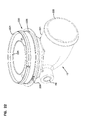
図3を参照すると、ハウジング2は、カートリッジ25の選択された一部分を取り囲むオプションではあるが、効果的なシールド構造27を含むことがわかる。シールド構造27は、ハウジング本体部分3にある第1のシールド部分28を含み、第1のシールド部分28は、その位置でカートリッジ25の一部を取り囲むように配向され、シールド28と外側壁30との間に環状空間29を形成する。入口7から流入した空気は、入口環状空間29の中へ(傾斜面17の内面によりサイクロンパターンを描きながら)送出される。シールド28は、空気の少なくとも一部がサイクロンパターンを描きながら動き、アクセスカバー4に向かう方向にシールド28を通り過ぎるまで、環状空間24にある入口空気により搬送されている塵芥及び他の物質が媒体26に直接衝突するのを抑止する。
Referring to FIG. 3, it can be seen that the
図3において、図中符号33は、アクセスカバー4にあるシールド構造27の第2のシールド部分を示す。第2のシールド部分33は、シールド33と部分4の側壁35との間に環状空間34を規定する。図中符号37は側壁2にあり、ハウジング内部空間2iから管9の内部空間9iに至る出口開口部又は排出開口部を示す。排出開口部又は出口開口部37は環状空間34と連通している。シールド33は、開口部37を介して塵芥及び他の物質を塵芥排出構造8の中へ取り除くのを助ける。
In FIG. 3,
シールド部分28及び33に類似する1個以上のシールドを有するシールド構造27に類似するシールド構造の使用は、多くのエアクリーナ構造に共通している。例えば、本明細書に参考として取り入れられている国際公開第WO2006/06241A1号、国際公開第WO2009/014988号、米国特許出願第61/446,653号公報、米国特許出願第61/473,296号公報及び米国特許第6,419,718B1号公報を参照。本開示でも類似の特徴及び原理を使用することができる。
The use of a shield structure similar to shield
図3Aには、図3の拡大部分図が示される。図3Aでは、シールド28及び環状空間29の各部分を見ることができる。
An enlarged partial view of FIG. 3 is shown in FIG. 3A. In FIG. 3A, portions of
尚、空気がフィルタカートリッジ25(第2ステージ)へ送出される前に空気から水分及び大型粒子を分離するための第1のプレクリーナのステージを有する「重複ステージ」又は「2ステージ」エア(ガス)クリーナが望まれる多くの用途において、シールド構造27及び塵芥排出構造8は一貫して使用されている。しかし、そのような特徴は一般にはオプションの特徴であり、そのような2ステージ構成又はプレクリーナステージを含まないエアクリーナにも本開示の原理の多くを適用できる。
It should be noted that a "double stage" or "two stage" air (gas) having a first precleaner stage for separating moisture and large particles from the air before it is delivered to the filter cartridge 25 (second stage). In many applications where a cleaner is desired, the
尚、図示される特定のエアクリーナアセンブリ1は、媒体26の下流側の出口50の前に配置されるセーフティフィルタ又はセーフティカートリッジを含まない。そのようなセーフティフィルタ又はセーフティカートリッジを使用するシステムにも、本明細書において説明される原理の多くを同様に適用できる。
It should be noted that the particular air
II.ハウジングシール構造に関連する特徴−全般
A.概要
先に示した通り、一般的なエアクリーナの構成及び動作に関連して図1〜図3Aに関して先に指摘し且つ説明した特徴構造は周知の特徴であり、それらの特徴構造の形態は多様なシステムで使用されてきた。図1〜図3Aのエアクリーナの特定の独特な特徴構造は、フィルタカートリッジ25の特定の特徴構造、特にフィルタカートリッジとエアクリーナアセンブリ1のその他の部分との係合に関する。本章では、この点に関連する選択された特徴構造を説明する。
II. Features related to the housing seal structure-General A. Overview As indicated above, the features pointed out and described above with respect to FIGS. 1-3A in connection with the construction and operation of a typical air cleaner are well known features and the form of those features is diverse. It has been used in the system. The particular and unique features of the air cleaner of FIGS. 1 to 3A relate to the particular features of the
一般的にいうと、カートリッジ25は点検可能な構成部品である。すなわち、カートリッジ25は、エアクリーナ1の耐用年数の間に取り外され且つ交換される。濾過されないままの空気がカートリッジ25を通過せずに出口管15に侵入してしまうと、エンジンの損傷が起こる可能性があるので、そのような事態を確実に防止するために、カートリッジ25とハウジング2との間には解放可能なシールが必要である。この目的を達成するフィルタカートリッジ25とハウジング2との解放可能な密封係合構造は、本明細書においてはハウジングシール構造として一般に特徴づけられる。
Generally speaking, the
図3を更に参照すると、フィルタカートリッジ25は、通常第1の媒体端部41とその反対側の第2の媒体端部42との間に延設されたフィルタ媒体26を備える。第1の媒体端部41は、第1の端部キャップ又は第1の端部材45と係合する。第2の媒体端部42は、第2の端部キャップ又は第2の端部材46と係合する。従って、媒体26は両端の端部キャップ(又は端部材)45、46の間に延設される。
With further reference to FIG. 3, the
図示される例の場合、フィルタ媒体26は、エアクリーナ1及びカートリッジ25の中心軸Xをほぼ中心として、開放されたフィルタ内部空間26iを取り囲むように構成されるが、本明細書において説明される選択された技術を使用して別の構造も可能である。媒体26は襞付き媒体であってもよいが、別の構造も可能である。図示されるような円筒形パターンで媒体26を構成できるが、必要に応じて別の構造も可能である。例えば、媒体26は、両端部41、42の間に多少円錐形になるように延設されてもよい。また、非円形の内周部及び/外周部を有するように媒体を構成することができ、例えば楕円形又は他の断面形状も可能である。
In the illustrated example, the
第2の端部材又は端部キャップ46は、通常閉鎖された端部材又は端部キャップであり、第2の端部42で媒体26を完全に覆うように延設されることにより、媒体26の第2の端部42及びフィルタ内部空間26iを閉鎖するが、本明細書において説明される選択された技術を使用して別の構造も可能である。すなわち、図示される例の場合、端部材又は端部キャップ46は、閉鎖された端部材又は端部キャップ、すなわち開放されたフィルタ内部空間26iと連通する貫通開口部を持たない端部キャップである。
The second end member or
これに対し、第1の端部材又は端部キャップ45は、開放された端部材又は端部キャップである。すなわち、第1の端部材又は端部キャップ45は、本例では開放されたフィルタ内部空間26iを介して媒体と連通する中央開口部50を取り囲み且つ規定する。通常の使用時、開口部50は、媒体から、例えば開放されたフィルタ内部空間26iから濾過済み空気を排出させる空気流れ排出開口部である。(濾過中にガスが逆方向に流れる別の用途では、開口部50は入口開口部であってもよい。一般に、開口部50はガス流れ開口部である。)
図示される例の場合、第1の端部材45は、外周部26xから内周部26oまでカートリッジ25の媒体26全体を完全に覆うように延設される。通常、第1の端部材45は、この端部材45を貫通するただ1つの中央開口部50を有する。
In contrast, the first end member or
In the illustrated example, the
カートリッジ25を挿入するか又は取り外すために、ハウジング本体部分3からアクセスカバー4を取り除くと、内部空間2iにアクセスできる。その後、濾過されないままの空気が出口管15へ流れ込むのを防止するために、フィルタカートリッジ25をハウジング2に対して適切に取り外し可能に密封しなければならない。これを可能にするために、カートリッジ25には第1の一次(又はハウジング)シール構造55が設けられている。
When the
第1のハウジングシール構造又は一次シール構造55並びに第1の端部キャップ45の他の特徴構造に関して、図3の拡大部分図である図3Aの同一部分に注目する。図3Aからわかるように、解放可能な密封を実現するために、一次シール構造55は、図中符号58で示されるエアクリーナアセンブリ1の部分と係合するような向きに配置された半径方向に向いたシール又はシール面55sを規定する。尚、図3Aは概略図であり、図3Aには、シール面55sを形成するシール材料が構造58との係合によってひずんでいない状態で示される。このことから、通常、密封中にシール構造55のシール材料と面58との間でどれほど多くの干渉が起こっているかを理解できるが、別の構造も可能である。このことは以下に更に詳細に説明される。
With respect to the first housing seal structure or other features of the
更に図3Aを参照すると、構造58と共にシールを形成する一次シール構造55の面55sは半径方向に向いた面と言えることが理解されるだろう。この場合、一次シール構造55は半径方向に向いたシールと呼ばれる。本明細書において、「半径方向」は、シール又はシール面(並びに密封中のシール面の圧縮)が一般に中心軸Xに対して(すなわち中心軸Xの周囲で)中心軸Xに向かう向き又は中心軸から離れる向きに規定されることを意味する。図示される例の特定の面55sは、中心軸Xに対して半径方向外側に向いているので、シール構造55を「半径方向外側に向いた」と特徴づけることができる。しかし、本開示に係るいくつかの原理によれば、半径方向内側に向いたシールも使用可能である。
Still referring to FIG. 3A, it will be appreciated that the
尚、図示される例において、ハウジングシール構造55は端部キャップ45の一部を含む。更に一般的に言えば、フィルタカートリッジに取り付けられるハウジングシール構造は、その特定のハウジングシール構造が端部材の一部を含むか否かにかかわらず、ハウジングに対して解放可能に密封されるように構成される。
In the illustrated example, the
本明細書において説明される好適且つ効果的なハウジングシール構造は、一般に、「非クランプ」又は「クランプなし」ハウジングシール構造である。これは、カートリッジがハウジングに挿入される時点で、何らかの種類のクランプ又はコネクタを締め付ける必要なくハウジングシール構造が形成されることを意味する。 The preferred and effective housing seal constructions described herein are generally "non-clamping" or "non-clamping" housing seal constructions. This means that when the cartridge is inserted into the housing, the housing seal structure is formed without having to clamp any kind of clamp or connector.
図示される例の一次シール構造55の特定の特徴構造は、以下に更に詳細に説明される。
The particular features of the illustrated example
一般に、図3Aに示される特定の構造の場合、一次シール構造55を形成するためにシール構造55が取り外し可能に係合する面58は、図3のアクセスカバー4に向かってハウジング2の軸方向内側に向いたシールフランジ60を備える。図示されるこの特定の例の場合、シールフランジ60は、流れ管、図示される例では出口管15の一部である。
In general, for the particular construction shown in FIG. 3A, the
更に図3Aを参照すると、図示される例の構造の場合、出口(流れ)管15は、ハウジング部分3とは別に形成された部材である。図示される特定の例の構造の場合、流れ管15は、ハウジング部分3の端部3xにスナップフィットされ、それら2個の部材の間には接続部62が形成される。接続部62は、ハウジング2の内部空間2iに水又は他の物質が入り込む可能性がある位置である。この点に関して起こりうるいくつかの問題は、オプションの第2の(ハウジング)シール構造65により効果的に解決される。
Still referring to FIG. 3A, in the case of the example construction shown, the outlet (flow)
一般に、エンジン系統(エアクリーナアセンブリ1が使用される機器)が動作されると、図3の管15で真空引き込み又は空気の吸引が起こり、それにより、空気はエアクリーナ1を介してエンジン又は他の機器系統の中へ引き込まれる。すなわち、一般に、周囲環境からハウジング2の内部空間2iの中へ空気が引き込まれる可能性がある。第2のシール65が設けられていれば、通常の動作中、この吸引によって接続部62でそのような引き込みが起こるだろう。
Generally, when the engine system (the equipment in which the air
一般に、第2のシール構造65は、ハウジング部分3のシール面67と取り外し可能に係合するシール面66をカートリッジ25に規定する。シール面66は一般に半径方向に向いており、従って半径方向シールである。図示される例では、シール面66は、装着時にハウジング部分3のシール面67に取り囲まれる半径方向外側に向いた(周囲)面である。
In general, the
カートリッジ25によりハウジング2の他の部分から隔離された一次シール構造55と第2のシール構造65との間の位置で、接続部62はハウジング2の内部空間2iと連通することがわかる。その結果、その位置で水及び/又は付随する物質を内部空間2iに引き込むように接続部62に対して作用する内部吸引力は存在しないので、接続部62における真空引き込みの危険は抑止される。尚、図示される実施形態の場合、第2のシール構造65は、その両側の大きな圧力差を調整するため及び/又は濾過されないままの空気が(出口)管15に侵入するのを回避するように調整するために設けられているのではない。従って、第2のシール構造65は、一次シール構造55より圧縮が少ない二次的なシール、すなわち密封力の小さいシールであると言える。以下の詳細な説明から理解されるだろうが、特定の好適な構造では、カートリッジ25の装着時に、第2のシール構造65のシール材料は、通常幾分かは圧縮するが、一次シール構造55のシール材料ほど圧縮しない。
It can be seen that the
次の章において、第1のシール構造55及びオプションの第2のシール構造65の特徴構造を更に詳細に説明する。
In the next chapter, the features of the
B.第1のシール構造55及び第2のシール構造65を含む端部材の特徴構造、図3及び図3A
図3及び図3Aを参照すると、図示される特定のアセンブリ1の場合、カートリッジ25は、第1の(端)部材45が媒体26の一部(例えば一方の端部)41が固定された、例えば埋め込まれたモールド・イン・プレース(端)部材70であるように構成される。これは典型的な構成であるが、本開示に係る選択された原理によって別の構成も可能である。典型的な構造では、端部材(キャップ)70は、媒体の外周部26xから媒体の内周部26oに至るまで媒体26の端部41を完全に覆うように閉鎖する。媒体26が襞付きである場合、外周部26xは外側襞先端部であり、内周部26oは内側襞先端部である。
B. Feature of end member including first sealing
With reference to FIGS. 3 and 3A, for the
通常、端部材(キャップ)70は、発泡ポリウレタンなどの発泡樹脂から形成された柔軟で圧縮可能な端部材(キャップ)材料から製造される。使用可能な材料は以下に説明される。 Typically, the end member (cap) 70 is manufactured from a soft and compressible end member (cap) material formed of a foamed resin such as foamed polyurethane. Materials that can be used are described below.
図示される特定のカートリッジ25の場合、第1のシール構造55及び第2のシール構造65は、端部キャップ70のモールド・イン・プレース成形部分に一体の部分として形成されるが、別の構造も可能である。このことは、以下に図4〜図8の説明に関連して更に詳細に説明される。
In the
図4〜図8を参照する前に、再び図3Aに注目する。端部材(キャップ)70は、凹部、受け入れ部分又は受け入れ溝73を有する軸方向外側端面72を含む。凹部、受け入れ部分又は受け入れ溝73の大きさ及び位置は、カートリッジ25が装着される場合に凹部、受け入れ部分又は受け入れ溝73の中へ突出するフランジ60及び図中符号3xで示されるハウジング部分3の一部を受け入れるように選択される。すなわち、接続部62の一部が凹部、受け入れ部分又は受け入れ溝73の中へ突出する。図示される例では、凹部、受け入れ部分又は受け入れ溝73の半径方向に最も内側の面73i(半径方向外側に向いた面)は、一次シール構造55の密封面55sを形成する。図示される例の構造の場合、凹部、受け入れ部分又は受け入れ溝73の半径方向に最も外側の面73o(半径方向内側に向いた面)は、まったくシールを形成しないのが好ましい。通常、この面73oは、ハウジング部分3又はフランジ58と半径方向にまったく係合しないが、別の構造も可能である。尚、図3Aの端部キャップ70には、端部41で媒体26を取り囲まない部分70kがある。本例では、媒体の端部41は端部材(キャップ)70に埋め込まれているので、これが典型的な構造である。領域70kはハウジングの一部と係合してもよいが、通常は大きく圧縮されないので、多くの場合、ハウジングの密封には関与しないが別の構造も可能である。
Attention is again directed to FIG. 3A before referring to FIGS. The end member (cap) 70 includes an axially
尚、更に図3Aを参照すると、二次シール構造65のシール面66は、端部材(キャップ)70の外周部70pの一部である。従って、このシール面は場合によっては周囲半径方向シールと呼ばれる。また、図示される実施形態の場合、密封中に圧縮されるシール面66の部分は媒体26を取り囲まないのが好ましいが、別の構造も可能である。
Still referring to FIG. 3A, the
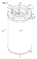
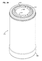
次に図4に注目すると、ほぼ出口端部75及び端部材(キャップ)70に向かって見た場合のカートリッジ25の概略斜視図が示される。前述のように、カートリッジ25は、一般に、第1の端部材(キャップ)45と第2の端部材(キャップ)46との間にカートリッジ中心軸Xを取り囲むように延設された媒体26を備える。一般に、カートリッジの特徴構造が半径方向に向いていると言う場合、それらの特徴構造が中心軸、本例ではカートリッジ中心軸Xからほぼ外側に、すなわち離れる方向に向いていることを意味する。特徴構造が軸方向である又は「軸方向に」向いていると言う場合、一般に、その特徴構造が中心軸、例えばカートリッジ中心軸Xとほぼ整列する向きにある(必ずしも中心軸と平行でなくてよい)ことを意味する。シールが「半径方向外側に」向いていると特徴づけられる場合、そのシール又はシール面がカートリッジ中心軸Xなどの中心軸からほぼ半径方向に離れる向きであることを意味する。
Turning now to FIG. 4, a schematic perspective view of the
更に図4を参照すると、端部材(キャップ)45は成形部分70mを備えることがわかる。成形部分70mは、本例では(濾過済みの)空気がカートリッジ25から排出される際に通過する開放された中央開口部50を規定する。端部材(キャップ)70(従って成形部分70m)は、凹部、受け入れ部分又は受け入れ溝73を規定する一体に成形された端部材(キャップ)である。凹部、受け入れ部分又は受け入れ溝73の図中符号73iで示される半径方向内側の部分は、一部でシール面55sを形成する。面55sはほぼ半径方向外側に向いており、半径方向外側に向いたシールを形成することがわかる。凹部、受け入れ部分又は受け入れ溝73の半径方向外側の面73oは、半径方向内側に向いた面、すなわち軸Xに向いた面を規定することがわかる。前述のように、図示される特定のカートリッジの場合、面73oは密封面ではないが、別の構造も可能である。
Still referring to FIG. 4, it can be seen that the end member (cap) 45 comprises a shaped
尚、凹部、受け入れ部分又は受け入れ溝73などの凹部、受け入れ部分又は受け入れ溝の側壁ではないシール面55xが突起を取り囲むような構成も可能である。しかし、図示される特定の実施形態の場合、シール面55xが凹部、受け入れ部分又は受け入れ溝73の側壁73iであると効果的である。
A configuration is also possible in which the recess is a recess such as a receiving portion or
更に図4を参照すると、図中符号66は、第2の(オプションの)シール構造65のシール面を示す。これは、図示される例の場合、カートリッジ25の装着時にハウジング部分3と係合して、ハウジング部分3と共に第2のシール65を形成する成形部分70の外周部の一部である。
With further reference to FIG. 4,
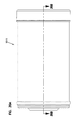
次に図5に注目すると、カートリッジ25の内部の詳細を示すために、いくつかの部分が断面で示される。本章における説明に関しては、第1の端部材(キャップ)45に特に注目する。前述のように、典型的な好適な構造では、端部材(キャップ)45は、媒体26の端部41に配置された成形部分70m(又は端部キャップ70)を備える。第2のシール構造65のシール面66及び一次シール構造55のシール面55sを見ることができる。また、溝73も断面図で示される。
Turning now to FIG. 5, several parts are shown in cross section to show the internal details of the
各シールを半径方向に圧縮可能な材料から形成し且つ好ましくは(オプションとして)比較的剛性の高い半径方向支持体構造を端部材(キャップ)70の中に埋め込むことにより、面55s及び66におけるシール構造55及び65の密封圧力がそれぞれ調整されるのが好ましい。一次シール構造55の場合、半径方向支持体は図中符号80で示される。二次シール構造65の場合、半径方向支持体は、端部材(キャップ)70に埋め込まれた支持体81により形成される。
Seals on
通常、シール構造55、65を支持する支持体構造は、端部材(キャップ)の成形部分70mに埋め込まれた「プレフォーム」である。本明細書の説明に関しては、「プレフォーム」は、支持体構造と共にカートリッジ25の組み立てに使用される事前に成形済みの構成部品又はプレフォーム構成部品であることを意味する。通常、プレフォーム構成部品はプラスチックから成形されるが、別の材料も可能である。通常、プレフォーム構成部品は、第2の端部キャップ46に向かって延設する構造に固定されるが、別の構造も可能である。
Typically, the support structure that supports the sealing
面55sと支持体80との間の領域における端部材(キャップ)の半径方向圧縮の量が少なくとも10%、典型的には少なくとも15%、好ましくは約35%以下の最大圧縮となり且つ典型的には約20%以上、30%以下の範囲内の最大圧縮となるように、中心軸Xに向かって半径方向に起こる面55sの圧縮が支持体80により支援されるような位置で一次シール55を形成するシール材料の中に、支持体80は通常埋め込まれる。通常、これを実現するために、支持体80は、面55sから最大で20mmを超えない距離、通常は15mmを超えない距離だけ離間し、典型的には間隔の幅は約5〜14mmの範囲内である。この点に関して、間隔の幅は、支持体80と、面55sが圧縮によってひずんでいない場合に半径方向に支持体80から最も遠い位置にある面55sの部分との間の最大間隔、すなわち離間距離を意味する。
The amount of radial compression of the end member (cap) in the region between the
これに対し、先に示したように、図示される例のカートリッジ25の場合、オプションの第2のシール構造65は、出口管15内への塵芥及び水の浸入には関与せず、図3Aの接続部62をハウジング2の内部空間2iから隔離する働きをするので、第2のシール構造65の圧縮(圧縮される場合)の量は、通常、第1のシール構造55より少ない。尚、第2のシール構造65に支持体81を設けることは可能であるが、支持体81はオプションである。場合によっては、相対的にわずかな圧縮(圧縮が起こる場合)を伴う位置合わせが実現するように、第2のシール面66と周囲を取り囲むハウジング部分との位置合わせが行われてもよい。通常、使用時、オプションの支持体81は、カートリッジ25が装着される際に圧縮する面66の半径方向に最も外側の部分から、約10mmを超えない距離、典型的には約8mmを超えない距離、通常は1〜6mmの範囲内の距離だけ離間した位置にある。通常、これらの寸法は、支持体81に向かって圧縮される領域66x、すなわち面66のシール材料の圧縮の総量が最大で約25%以下、通常は20%以下、典型的には少なくとも3%、多くの場合に少なくとも5%、通常は5%以上、20%以下の範囲内の量になるように選択されるが、別の構成も可能である。
On the other hand, as previously indicated, in the case of the
図5を参照すると、図示される構造の場合、半径方向外側に向いたシールを形成する面66の部分は、溝73の最も深い部分より大きく端部キャップ46に向かって延設する部分を含むことがわかる。これはオプションであるが、好適な構成であると言うことができる。すなわち、典型的な実施形態では、面66と面55xの各部分の間にオプションとして半径方向の重なり合いがあってもよいが、面66の少なくとも一部は、端部材(キャップ)42に向かって、面55sのどの部分より遠くまで延設する。この延設の量(使用時での)は少なくとも1mm、通常は少なくとも2mm、場合によっては少なくとも4mmである。
With reference to FIG. 5, in the case of the illustrated construction, the portion of the
端部材(キャップ)70のシール構造の特徴に関して更に説明する前に、図5に注目して、選択された付加的な特徴構造を簡単に説明する。それらの特徴構造は、以下に本明細書の後半部分で更に詳細に説明される。 Before further describing the features of the seal structure of the end member (cap) 70, attention is directed to FIG. 5 to briefly describe selected additional features. These feature structures are described in more detail below in the second part of the specification.
まず、媒体26の端部42に配置された端部材(キャップ)46に注目する。図示される特定の構造の場合、端部キャップ46は、媒体26の端部42を完全に覆い且つ開放された内部空間26iを覆うように閉鎖するモールド・イン・プレース成形端部キャップである。図示される特定のモールド・イン・プレース成形端部材46は、成形部分70に使用されるのと同様の材料から形成されるが、必要に応じて別の材料も可能である。
Attention is first directed to the end member (cap) 46 disposed at the
更に図5を参照して、支持体90に注目する。図示される例の支持体90は、端部材41、42の間に延設されて、媒体26により取り囲まれる中央支持体であり、実際、図示される例では、端部キャップ45(すなわち成形部分70m)及び端部キャップ46に埋め込まれる。図示される特定の支持体90のオプションの効果的な特徴構造は、本明細書の後半部分で更に詳細に説明される。
With further reference to FIG. 5, attention is focused on the
図6を参照すると、成形部分(端部材又は端部キャップ70)70mの端面図が示される。本明細書において、一般に、図6を見ている人に向いた端部成形部分70mの面は軸方向端面72と呼ばれる。図示される例では、軸方向端面72は、主に、受け入れ溝73の両側に外側リング72x及び内側リング72i(図5を参照)を備える。リング72xの外周部に、カートリッジ25は、一般に2種類の複数のインセット、すなわち、成形部分70mが形成されると考えられる成形型の底部においてスタンドオフにより一般に形成される人工物であるインセット93と、成形部分70mの形成中に成形型の中で媒体パックを中心位置合わせするのを助けるために使用される成形型の底面の部分から一般に形成されるインセット94とを含む。尚、図示される例では、スタンドオフによる人工物93は、中心位置合わせ人工物94のうち選択された人工物を含む。
Referring to FIG. 6, an end view of the formed portion (end member or end cap 70) 70m is shown. In the present specification, generally, the face of the
次に図7に注目すると、図6の線7−7にほぼ沿った断面図が示される。図7には、端部材(キャップ)46又は成形部分70mのモールド・イン・プレース成形材料が示される。すなわち、図7は概略図であり、種々の支持体80、81は示されていない。図7は、一般に端部材(キャップ)70を成形するために使用される樹脂から形成された特徴構造の構成を示すことを意図する。図7を参照すると、図中符号66は、二次シールを形成するための成形部分70の周囲部分を示す。部分66と端部72xとの間に、成形部分70mの外周面は、内側に向かって段差を有するか又は内側に向かって傾斜する領域95を更に含む。この領域は、通常、装着中にほぼ中心軸Xに向かって圧縮されないように装着時に隣接するハウジング部分の隣接部分と協働する大きさに形成されるが、別の構造も可能である。通常、領域95は、装着時にハウジング2の領域95を取り囲む部分との間でほぼ直線的に嵌合を形成するような大きさに形成されるのが好ましい。この直線的な嵌合は少なくとも4mmの長さにわたり続くのが好ましい。これに代わる構造も可能であり、例えば、この領域では何らかの量の(例えばわずかな)圧縮が起こる必要があるように構成することが可能であり且つ/又は面の軸方向長さを変更することが可能である。領域95は、領域66と協働して、図3Aの接続部62における引き込みを抑止するだけではなく、ハウジング2の中でカートリッジ25を安定させるのを助ける。
Turning now to FIG. 7, a cross-sectional view taken generally along line 7-7 of FIG. 6 is shown. The mold-in-place molding material of the end member (cap) 46 or the
図8に注目すると、図7の成形部分70mの選択された部分の拡大部分図が示される。図8では、受け入れ溝73を見ることができる。溝73の半径方向内側の面73i(半径方向外側に向いた面)は、一次シール構造55の半径方向外側に向いた半径方向シールの最も大きく圧縮される部分を形成するように構成された底部73bに隣接する下部73iを含む。図中符号98で示されるように、装着中にフランジ60に沿ってカートリッジ25を案内するのを容易にするために、面73iの外側部分は傾斜している。図からわかるように、装着中に同様にフランジ60及びハウジング部分3tの一部に沿った嵌合を容易にするために、半径方向外側の面73xは外側端部に傾斜73tを有する。以下にカートリッジ25及びハウジング2の概要を更に説明した後、シール構造55及び65が更に詳細に説明される。
Focusing on FIG. 8, an enlarged partial view of a selected portion of the molded
III.カートリッジ25の組み立て、内部構造の付加的な詳細説明
次に図9に注目する。図9には、支持体90が斜視図で示される。支持体構造90は、一般にライナ部分100及び出口端部支持部分101を備える。図示される例のアセンブリの場合、外側端部支持部分101及びライナ部分100は、互いに取り外し不可能に固定されるが、別の構造も可能である。通常、それらの部分はプラスチックから一体に成形されるが、別の構造も可能である。
III. Additional Detailed Description of Assembly of
出口端部支持部分101は、内側中央支持体又はハブ105と、ハブ105を取り囲み且つハブ105から離間するオプションの外周リング106と、ハブ105と外周リング106との間に延設された開放格子構造108とを含む。格子構造108は、複数の互いに離間する支柱、リブ又は支持部材110を備える。支持部材110は、外周リング106とハブ105との間に延設され、外周リング106を所定の位置に固定する。尚、外周リング106はオプションであるが、設けられていると好都合である。外周リング106は、条片、リブ又は支持部材110の端部に対して構造支持体として作用する。しかし、本開示のすべての用途で外周リング106が必要とされるわけではない。
The outlet
支柱、リブ又は支持部材110もオプションである。しかし、支柱、リブ又は支持部材110は、カートリッジの組み立てを助けるという意味で有益であり、また、端部キャップのモールド・イン・プレース成形部分と支持体構造90のプレフォーム部分との間に機械的な連接を実現するための領域を形成する。
Posts, ribs or
図9を参照すると、外周リング106は縁部114を含む。縁部114は、一般に、カートリッジ25の形成中に成形部分70mの中へ最も深く突出するリング106の部分である。図示される特定のアセンブリの場合、縁部114は、複数の互いに離間し且つ間に溝又は凹部116を有するタブ115によりオプションとして規定されるのが好ましい。一般に、凹部116は、端部キャップ70が形成される場合に縁部114及びタブ115の領域でリング106に沿って樹脂を流れやすくする働きをする。タブ付きの構成が好ましいが、別の構成も可能である。
Referring to FIG. 9, the outer
外周リング106は、オプションのシール支持領域118を更に含む。一般に、シール支持領域118が使用される場合、組み立て後のカートリッジ25において、シール支持領域118は、第2のシール構造65に対するオプションの図3Aの支持体81を構成する。
Outer
通常、支持部分101は、装着時に外周リング106のどの部分も媒体を取り囲まないように構成されるが、別の構造も可能である。
Typically, the
更に図9を参照すると、ハブ105は、内面105i及び外面105xを含む。図示される例のカートリッジ25では、外面105xは、一次リブシール構造55のシール支持体80を形成する。
Still referring to FIG. 9, the
尚、支持体90は、ハブ105から半径方向内側へ離間するオプションの内側リング120を更に含む。内側リング120とハブ105との間にトラフ120tが形成され、カートリッジの形成中、このトラフ120tに樹脂が流入できる。図9には、トラフ120に樹脂を流入させるいくつかの開口部121が示される。
Note that
次に図10に注目すると、支持体90の側面図が示される。図10の支持体90も、前述のように、タブ115(オプションの)を規定するオプションの端部リング106、凹部116及びシール支持領域118を含むことがわかる。樹脂を流れやすくするためのリング120を貫通する開口部121も見られる。
Turning now to FIG. 10, a side view of
更に図10を参照すると、支持体90にオプションの媒体中心位置合わせリング125があることがわかる。媒体中心位置合わせリング125は、端部キャップ70の成形前に適切な媒体形状の形成を容易にするのに、カートリッジを形成するために支持体90に媒体26(又は媒体パック)が位置決めされた場合に、媒体26の内周部がリング125に沿って且つリング125の周囲で支持体90と係合するように配置される。
Still referring to FIG. 10, it can be seen that the
一般に、カートリッジ25の組み立ては、通常は図3の媒体端部41が一般に図10の領域128で端部分101と係合するまで端部127を乗り越えて媒体パックを押し込むことにより媒体パックを支持体90に位置決めすることを含む。媒体中心位置合わせリング125は、媒体26が端部支持体100の付近で適切な周囲形状をとれるようにする。更に、リング125は完成後のカートリッジ25の中で媒体26を支持する。媒体パック26と支持体90との組み合わせに対して、図5の各端部キャップ45、46をモールド・イン・プレース成形できる。端部キャップ45の形成中、樹脂は凹部116及び開口部121を通って流れると共に、支持体110の間の空間に流入することにより、支持体100を所定の位置に確実に機械的に固定し且つ媒体26が襞付きであるか否かにかかわらず媒体26の端部41を確実に完全に密封する。更に、成形型は、端部材(キャップ)45にシール面55s及び66並びに溝73を形成するように構成されるだろう。
Generally, the assembly of the
尚、支持体90に押し込まれる媒体パックは、外側ライナを有していてもよいが、外側ライナなしでもよく、また内側ライナを有していてもよいが、内側ライナなしでもよい。通常、媒体パックは襞付き媒体であるので、支持体90に押し込まれる場合、内側ライナ又は外側ライナを含まない。通常、媒体は襞付きであり、使用中に襞を開いた状態に保つのを容易にするのに、襞の先端部に対してほぼ垂直に延設された波形構造を含んでもよい。当該技術で一般に知られているように、襞の先端部を折りたたむために種々の技術を容易に使用できる。本出願の譲受人であるミネソタ州ミネアポリスのDonaldson Company Inc.の商標「Pleatloc」が付された媒体パックで、この技術の例を見ることができる。
It should be noted that the media pack pushed into the
図11には、ほぼ端部構造100に向かって見た場合の支持体90の端面図が示される。
In FIG. 11, an end view of the
図12には、ほぼ端部127に向かって見た場合の支持体90の端面図が示される。
In FIG. 12, an end view of the
図13には、図11の一部の拡大部分図が示される。一般に、端部127にある複数の端部タブ127xのうち1個のタブが見られる。タブ127は、端部キャップ46を所定の位置に堅固に成形するのを助ける。
FIG. 13 shows an enlarged partial view of a portion of FIG. Generally, one of the plurality of
図14には、図11の拡大部分断面図の同一部分が示される。 FIG. 14 shows the same part of the enlarged partial cross-sectional view of FIG.
図15には、支持体90の一部の部分断面図が示される。トラフ120tを見ることができる。また、リング120とハブ105との間に、開口部121の一部を見ることができる。
A partial cross-sectional view of a portion of the
図16には、支持体90の端部支持構造101の一部の拡大部分図が示される。
An enlarged partial view of a portion of the
図16を参照すると、端部支持体101の特定の好適な構成が示される。詳細には、本例ではリブ110を備える格子構造108の場合、リブ110は、内側ハブ105に隣接する位置から外側リング106に隣接する位置まで延設され媒体端部41(図16には図示せず)から離れる方向に傾斜しているのが好ましい。媒体からのこの傾斜又は発散形状は、図16には角度CSにより示される。従って、媒体を支持体90に押し込んだ場合、媒体端部41は、一般に、リブ110が媒体26から離れる方向に発散するように、図16の突起128で支持構造101と係合する。実際、媒体端部41は図16の線111tとほぼ整列する。角度CSは、樹脂が媒体パックの端部を横切るように流れる際の流動領域を形成するという利点が得られる。一般に、角度CSは少なくとも0.5°、典型的には少なくとも1°であり、多くの場合にそれより大きい。通常、角度CSは1°以上、3°以下の範囲内にあるが、それに代わる数値も可能である。
Referring to FIG. 16, a particular preferred configuration of
図示される特定のカートリッジ25は、オプションの共鳴器又はソニックチョークを含むが、別の構造も可能である。オプションの共鳴器又はソニックチョークは、支持体90の図10の部分140を備える。更に一般的な用語で言えば、支持体90は、支持部分100に、支持部分101とは反対の側にある端部穴あきライナ部分141を含む。媒体26がライナ90の周囲に位置決めされた場合、穴あきライナ部分141は、媒体端部42に隣接して内側ライナ142として作用する。内側ライナ部分142の開口部143は、最終的には図4の出口開口部50に至る空気流路を形成する。
The
図10及び図16を参照すると、支持部分101と穴あき端部分142との間に、オプションのソニックチョーク又は共鳴器部分140を形成するためのいくつかの特徴構造が設けられる。第1に、部分160には、端部分142とスロート161との間の中間領域として、スロート161に至る漏斗部分が設けられる。スロート161から端部分101との係合位置まで、拡張円錐形部分又は漏斗部分162が設けられる。部分160、スロート161及び部分162は、一体となってソニックチョーク又は共鳴器部分140を規定する。これにより、カートリッジ25の使用時の外部のエンジン系統からの雑音の伝達が抑止される。
Referring to FIGS. 10 and 16, several features are provided between the
尚、図10を参照すると、図示されるオプションの共鳴器/ソニックチョーク構造は、オプションとして、米国特許第6,419,718B1号公報に記載されるような構造とはいくつかの態様で異なっていてもよい。尚、図10を参照すると、ライナ141からスロート161に向かって延設する領域に、図10に示される断面で及び/又は外側から見た場合に2個の対向する湾曲部分を有する先細り部分160が設けられる。そのうち第1の部分171は、半径方向内側に向かって湾曲する凹形部分と、半径方向外側に向かって湾曲する凸形部分とを含む湾曲形状である。また、領域171には、空気を流通させるための開口部構造172が設けられる。実際、開口部構造172が設けられているために、一般に、領域171の少なくとも40%が開放されており、通常は少なくとも50%が開放されている。
Still referring to FIG. 10, the optional resonator / sonic choke structure shown is optionally different in some ways from the structure as described in US Pat. No. 6,419,718 B1. May be Referring to FIG. 10, a tapered
領域171とスロート161との間に、一般に半径方向外側に向かって湾曲する側を含む湾曲形状となるように形成された領域173が設けられる。従って、領域142からスロート161に向かう中間領域では、(断面で見ると)支持体90の一方の側にわずかなS字状の湾曲形状が規定される。尚、図示される特定の構造の場合、領域173は中実であり且つ穴が形成されていないという利点を有するが、別の構造も可能である。
Between the
通常、スロート161は、少なくとも25mm、通常は35mm以下、多くの場合に26〜31mmの範囲の断面寸法を有する。スロート161は、使用中に空気の流れを過度に制限することなく適切な共鳴器効果を実現するように構成される。
Typically, the
一般に、円錐形領域175は、中心軸に対して両側で約3°〜4°の角度で外側へ傾斜し、それにより、図10にDBで示される約6〜8°の円錐拡張角度を規定する。典型的な円錐拡張角度は約7°である。 In general, the conical region 175 is inclined outward at an angle of about 3 ° to 4 ° on either side with respect to the central axis, thereby defining a cone expansion angle of about 6 to 8 °, shown as DB in FIG. Do. A typical cone extension angle is about 7 °.
一般に、部分160、161及び162はソニックチョーク効果又は共鳴器効果を発生する。これは、エンジンからエアクリーナの空気誘導構造を介して外部環境に至る雑音伝達を抑止する働きをする。また、周囲環境からエアクリーナに流入し、フィルタカートリッジ25を通過する空気の流れに対する望ましくない制限を回避するように、ソニックチョーク又は共鳴器は構成される。特に、領域162の開口部構造161はこれを容易にし、同時に、共鳴器の穴のない部分162を取り囲む媒体26の領域から管162に流入し、図3の開口部50を介して排出される空気の流れを助けることがわかっている。
In general,
支持体90並びに支持部分101及びソニックチョークを含む領域100の特徴構造は、図11〜図16を検討することにより更に理解できる。
The features of the
次に図29及び図30に注目すると、第2の端部キャップ46が示される。先に示した通り、第2の端部キャップ46はモールド・イン・プレース成形端部キャップであってもよいが、別の構造も可能である。図29には、端部キャップ46の端面平面図が示される。図30には、図29の線30−30に沿った断面図が示される。図30には、第2の端部キャップ46に埋め込まれた媒体26及びライナ90の部分を示さずに、第2の端部キャップ46が概略図で示される。端部キャップ46は、複数の突起又はバンパ46yを備える外側軸方向(又は端)面46xを有することがわかる。装着中、カートリッジ25をハウジング2の中に堅固に支持するのを助けるために、それらの突起又はバンパはアクセスカバー4と係合する。
Turning now to FIGS. 29 and 30, a
図30の外周部分46pの大きさは、図3のハウジングシールド部分33の中に位置決めされ且つカートリッジ26が望ましくないほど大きく動くのを防止するためにシールド部分33の中に支持されるように規定される。
The size of the outer
カートリッジ25の構成に関しては、媒体パック26が支持体90に適切に位置決めされた後、2個の端部キャップ45、46が成形によって形成される順序に特に条件はない。
With regard to the configuration of the
以上の説明を理解したならば、本開示に係る用途で多少の変形が可能であることを理解できる。例えば、支持体構造81は、媒体の中間支持体と一体である必要はない。すなわち、必要に応じて、媒体が周囲に位置決めされる何らかの構造に支持体構造81を直接装着しないか又はその構造と支持体構造81を一体に形成しないことも可能である。例えば、支持体構造81及び何らかの内側ライナを個別に設け、製造中にカートリッジにそれぞれ組み込むこと、例えばモールド・イン・プレース成形端部キャップ材料に埋め込むことができる。更に、カートリッジに内側ライナを設けないこと、又はソニックチョークとして構成されない内側ライナを媒体で取り囲むことも可能である。更に、図9を参照すると、例えば図中符号105で示される内側シールを支持する支持体構造の構造は、例えば図中符号118で示される外側シールを支持するために使用されるオプションの支持体に直接結合される必要はない。外側シールを支持するリングが使用される場合、内側シールを支持する構造からそのリングを完全に分離することが可能である。
Once the above description is understood, it can be understood that some variations are possible in the application according to the present disclosure. For example, the
更に、支持体構造又は支持構造の種々の部分を同一の材料から構成することは特段要求されない。例えば、内側ライナをエキスパンドメタル構成から形成し、双方又は一方のシールの支持体をプラスチックから形成することが可能である。 Furthermore, it is not particularly required to construct the support structure or the different parts of the support structure from the same material. For example, the inner liner can be formed from an expanded metal construction and the support for either or both seals can be formed from plastic.
IV.選択されたハウジング部分及び出口管の特徴構造、図17〜図28及び図31〜図32
図17〜図28及び図31〜図32には、ハウジング2及び出口管15の種々の特徴構造が詳細に示される。本章では、それらの特徴構造を説明する。
IV. Features of the selected housing part and outlet tube, FIGS. 17 to 28 and 31 to 32
Various features of the
図17を参照すると、プラスチックから成形された場合のハウジング部分3の典型的な外観が示される。入口管7t、側壁3s及び取り付けパッド11として、先に説明した特徴構造が示される。更に、図2のアクセスカバー4のラッチ構造5と係合すると考えられるリム3rも示される。内側傾斜面17を規定するハウジングの外側の特徴形状を見ることもできる。
Referring to FIG. 17, a typical appearance of the
ハウジング部分3の端部3xが示される。更に、使用中、出口管15の一部が突出すると考えられるライニング開口部200も示される。ライニング開口部200には、以下に説明するように出口管15の位置決めを容易にするための割り出し構造として作用するオプションの締め代波形構造又は締め代歯構造201が設けられる。
The
尚、図17を参照すると、図示されるハウジング部分3を必要に応じてプラスチックから成形できると好都合であるが、ハウジング部分3は他の材料から構成されてもよい。
Referring to FIG. 17, although it is convenient to be able to mold the illustrated
図18には、ハウジング部分3の側面図が示される。図19には、ほぼ端部3xに向かって見た場合のハウジング部分3の端面平面図が示される。図19では、締め代領域(本例ではリブ又は歯領域201により形成される)を有する開口部200を見ることができる。尚、オプションの歯付き領域又は割り出し領域201は、複数の外側へ撓むことが可能なタブ202をオプションとして備える。更に、側壁3s及び中心軸Xに対する入口管7tの接線方向の位置を見ることもできる。
A side view of the
図20には、図19の線20−20にほぼ沿った断面図が示される。先に説明した特徴構造に加えて、図中符号210は、端部3xからハウジング2の内部空間2iの中へ軸方向に延設する突起構造を示す。装着時に接続部を形成するために出口管の一部と係合するのは、この突起210である。突起構造210は、突起構造210の半径方向内側の部分に沿ってオプションのリブ又は歯付き構造を有する複数のオプションのタブ202を備える。
Referring to FIG. 20, a cross-sectional view taken generally along line 20-20 of FIG. In addition to the previously described features,
更に図20を参照して、内側側壁領域211に注目する。この領域211は、オプションの図3及び図3Aの二次シール構造65の面66と係合するためのシール面67を形成する支持部分212を含む。領域211において、面212は、(使用時に)図3Aのカートリッジ26と線状に整列するように構成された第1の端部領域213と、一般に図3Aのカートリッジ26の装着中に領域66のシール材料をオプションとして圧縮させるオプションの反対側の第2の端部領域214とを一般に含む。
Still referring to FIG. 20, the
図21には、図20の一部の拡大部分図が示される。領域213及び214を見ることができる。
An enlarged partial view of a portion of FIG. 20 is shown in FIG.
図22には、出口管15の斜視図が示される。出口管15は、使用中にハウジング部分3と係合するコネクタ領域220を含む。出口管15は、ガス流れ管領域221及び出口222を更に含む。尚、図示される特定の出口管15はL字形の管である。すなわち、出口管を通る導管は屈曲している。別の構造も可能である。
A perspective view of the
図22を参照すると、先に挙げた管部分221のオプションの圧力タップ15tが示される。
Referring to FIG. 22, an
更に図22を参照すると、コネクタ部分220は、外側リング224及び内側リング225という2個のリング部分を含むことがわかる。リング224、225については以下に更に詳細に説明する。
With further reference to FIG. 22, it can be seen that
図22を参照すると、コネクタ領域220には、オプションの歯/突起領域229を有する周囲リング部分228が設けられる。歯/リブ領域229の大きさは、一般に、ハウジング部分3のオプションの歯/リブ領域201と嵌合するように規定される。従って、L字形の管221をハウジング部分3に対して特定の角度に回転させることができ、管221は、ねじり運動により加えられる力が勝るようになるまで、その向きに(割り出し位置に)とどまる。
Referring to FIG. 22, the
図23には、出口管220の側面図が示される。尚、ホース又は他の導管の接続作業を容易にするために、出口管221にはリム222rが設けられる。
A side view of the
図24は、出口管15の平面図である。図25は、図24の線25−25にほぼ沿った断面図である。
FIG. 24 is a plan view of the
図25を参照すると、先に示した通り、コネクタ部分222は、一般に第1のリング部分224及び第2のリング部分225を備える。第1のリング部分224は、一般にハウジング部分3xに堅固に結合するための特徴構造を含む。第1のリング部分224は、一般に、図3Aの一次シール構造55の支持体60を形成し、第2のリング部分225は出口流れ部分を形成する。
Referring to FIG. 25, as shown above, the
更に図25を参照すると、第1のリング部分224は、オプションのスナップフィット誘導先端部226及び受け入れ部分227を有することがわかる。先端部226は、スナップフィットが起こるまで図17の開口部200に押し込まれ、開口部200を規定するハウジング部分3の部分は領域227に位置する。図25を図3Aと比較すると、出口管15は、第1のリング部分224に、外周リング部分227a及び基部227bを備えることができるのがわかる。図3Aには、このリング227aは軸方向突起227pを有するものとして示される。この軸方向突起227pは、水の密封を容易にするために、ハウジング端部230の図3Aの軸方向外側突起230の周囲に係合できる。尚、図25のリング227aは、このオプションの突起227p(図3Aには示される)なしで示されている。
With further reference to FIG. 25, it can be seen that the
図26には、図25の選択された部分の拡大部分図が示される。 An enlarged partial view of selected portions of FIG. 25 is shown in FIG.
図27には、図23の線27−27にほぼ沿った断面図が示される。 FIG. 27 shows a cross-sectional view generally along line 27-27 of FIG.
図28には、図27の一部の拡大部分図が示される。詳細には、リブ部分229を見ることができる。更に、図27から、リング224の両側に対向するリブ部分229があることもわかる。
FIG. 28 shows an enlarged partial view of a portion of FIG. In detail,
図31には、プラスチックから製造されていると考えられる場合のアクセスカバー4がラッチ5を配置しない状態で示される。図32には、アクセスカバー4の断面図が示される。フランジ33を見ることができる。フランジ33のスリット又は空間33xにより、使用中にフランジ33の内部に侵入する可能性がある水をフランジ33から排出させることができる。
FIG. 31 shows the
V.選択された特定の特徴構造の詳細な説明
A.一次シール構図55及び凹部、受け入れ部分又は溝73
本章では、図7及び図8に戻り、典型的なアセンブリでは、図示される例においてオプションの凹部、受け入れ部分又は受け入れ溝73にある一次半径方向シール面55sの定義を説明するが、別の構造も可能である。凹部、受け入れ部分又は溝73が設けられる場合、凹部、受け入れ部分又は溝73の深さは、面72x、72iのうち少なくとも一方又は他方の面、通常は双方の面から最も深い部分で、典型的には少なくとも5mmであり、通常は少なくとも8mm、多くの場合に10〜25mmである。また、典型的には底端部73bに隣接する部分で、凹部、受け入れ部分又は溝73の幅は、対向する側壁73x、73iの間で少なくとも3mmであり、通常は少なくとも5mmである(最も深い底部における傾斜を無視する)。
V. Detailed Description of Selected Specific Feature Structures A.
In this chapter, referring back to FIGS. 7 and 8, in the exemplary assembly, the definition of the primary
言い換えれば、オプションの凹部、受け入れ部分又は受け入れ溝73が使用される場合、凹部、受け入れ部分又は受け入れ溝73の内側及び外側の側壁73i、73xは、溝73の下部で、通常は少なくとも3mm離間し、典型的には少なくとも5mm離間し、多くの場合に5mm以上、10mm以下の範囲内の量だけ互いに離間している。凹部、受け入れ部分又は溝で形成されるシール面が円形である場合、通常、この間隔は、溝73の最大深さの30%以内、典型的には溝73の最大深さの35%以内の最も広い位置で、15mmの離間距離を超えないが、別の構造も可能である。しかし、側壁73x、73iが溝の最も深い底部73bで互いに向かって内側へ傾斜していてもよいことは認識される。
In other words, when the optional recess, receiving portion or receiving
オプションの凹部、受け入れ部分又は溝73で形成されるシール面が円形である場合、通常、図8の面72x、72に隣接する外側端部で、凹部、受け入れ部分又は溝73の幅は少なくとも5mmであり、典型的には7mm、多くの場合に7〜25mmである。
If the sealing surface formed by the optional recess, receiving portion or
図8の凹部、受け入れ部分又は溝73の面部分73rの領域に半径方向外側に向いたシールが形成される際に半径方向内側へ最も大きく圧縮された場合の面部分73rの軸方向長さは、通常は少なくとも5mm、典型的には8〜20mmの軸方向長さを有するのが好ましく、通常、面部分72x、72iののうち一方又は他方の面、典型的には双方の面から少なくとも4mmの距離だけ、多くの場合に4〜15mmの範囲内の距離だけ離間される。
When the radially outwardly directed seal is formed in the region of the
図7を参照すると、通常、半径方向シール面55sを規定する成形部分70mの部分は、(ひずんでいない場合に)開口部50から面55sまでの幅で、少なくとも5mmの厚さであり、典型的には少なくとも7mmの厚さであり、通常は7〜25mmの厚さである。面55sは開口部50から50mmを超えて離間していないのが好ましいが、別の構造も可能である。また、通常図5の支持体80は、この領域に装着時の圧縮によってひずむ前には面55sの最も近接する部分から20mmを超えない距離だけ、典型的には15mmを超えない距離だけ離間して埋め込まれるが、別の構造も可能である。
Referring to FIG. 7, the portion of the molded
一般に、多様な大きさの多様なカートリッジが使用されても、オプションの凹部、受け入れ部分又は受け入れ溝73が使用される場合の上記のような特徴は、効果的な第1の半径方向シール55、並びに出口管15及びハウジング部分3の係合部分の双方の軸方向に突出する部分を受け入れる領域という2個の構造を実現するという意味で有用であり且つ容認される。
Generally, even if different cartridges of different sizes are used, such features as described above when optional recesses, receiving portions or receiving
通常、半径方向シール面55xを規定する成形部分70mは、装着時に支持体80に対して、半径方向シール面を形成する材料がシール面55sを第1のシール支持体80に向かって(半径方向に最大で)その厚さの少なくとも10%圧縮させ、典型的にはひずんでいないときの厚さの少なくとも15%圧縮させ、通常はひずんでいないときの厚さの15〜35%の範囲内の量だけ圧縮させるように構成される。典型的な例は、ひずんでいないときの半径方向厚さの20%以上、30%以下の範囲内の圧縮を含むだろう。
In general, the molded
B.オプションの外側二次シール面66
再び図7及び図8を参照すると、外側面66は、面55sから典型的には半径方向に少なくとも3mmの距離にあり、多くの場合に少なくとも5mmの距離にあり、多くの場合に少なくとも10mmの距離にあり、通常は少なくとも15mmの距離にあり、図示されるように構成された構造では典型的には少なくとも20mmの距離にある。通常、この離間距離は20〜80mmの範囲であるが、別の数値も可能である。
B. Optional outer
Referring again to FIGS. 7 and 8, the
通常、第1の半径方向に向いたシール面は、第2の半径方向シール面より少なくとも6mm小さく、多くの場合に少なくとも10mm小さく、更に多くの場合に少なくとも20mm小さく、図示されるような構造では通常少なくとも30mm小さいシール周囲最大断面寸法を有する。円形のシール面が規定される場合、「シール周囲最大断面寸法」は通常は直径である。尚、図示されるようなカートリッジが使用される場合、通常第1の半径方向に向いたシール面は、第2の半径方向に向いたシール面より少なくとも30mm小さいシール周囲最大断面寸法を有する。 Typically, the first radially oriented sealing surface is at least 6 mm smaller, often at least 10 mm smaller, more often at least 20 mm smaller than the second radial sealing surface, and in the configuration as shown Usually has a seal perimeter maximum cross sectional dimension that is at least 30 mm smaller. If a circular sealing surface is defined, the "maximum seal perimeter dimension" is usually the diameter. It should be noted that when a cartridge as shown is used, the first radially oriented sealing surface typically has a seal perimeter maximum cross-sectional dimension that is at least 30 mm smaller than the second radially oriented sealing surface.
支持体81に対する圧縮が起こった場合、通常、第2のシール面66の支持体80からの離間距離は8mmを超えない。通常この領域の材料は、第2のシール支持体に向かって最大で(半径方向に)少なくとも3%圧縮し、通常は少なくとも5%圧縮し、多くの場合に5〜20%の範囲内の量だけ圧縮する。
If compression to the
尚、図示される例では、装着時に圧縮される面66のシール軸方向長さの大部分は面72xから軸方向に受け入れ溝73の底端部より遠く離れるように離間されるが、別の構造も可能である。これは、本明細書において説明されるようにカートリッジ25が組み立てられる場合には典型的な構造である。通常、面66は、カートリッジ25の反対側の端部46に向かって軸方向に溝73の底部73bを越えて少なくとも2mmの距離だけ延設する。
In the illustrated example, most of the seal axial length of the
C.端部キャップ45、46を成形するために使用可能な材料
媒体パックの端部における効果的なシール及び効果的なハウジングシールの双方を形成するために端部キャップ45、46がモールド・イン・プレース成形される場合、端部キャップ材料45、46に多様な材料を使用できる。通常、約30を超えず、典型的には約22を超えず、好ましくは20以下であるショアA硬さを有する発泡材料が使用される。通常、選択される材料は、28lbs./立方ft(約450kg/m3)を超えず、更に好ましくは約22lbs./立方ft(355kg/m3)を超えず、典型的には約18lbs./立方ft(290kg/m3)を超えない「成形時密度」を有する。多くの場合、13〜17lbs./ft(200〜275kg/m3)の範囲内の成形時密度を有する材料が選択される。本明細書において、用語「成形時密度」は、通常は重量を体積で除算した値として定義されるものとする。成形フォームの試料の体積を判定するために、排水量試験又はそれに類似する試験を使用できる。多孔質材料の孔の中へ圧力によって水を吸収させるために体積試験を適用する場合、孔が含む空気を排出させる必要はない。従って、試料の体積を判定するために使用される排水量試験は、材料の孔の中の空気を排出させるために長時間待つ必要のない即時排水になるだろう。言い換えれば、成形時密度の計算には、試料の外周により表される体積のみが使用されればよいということである。
C. Materials that can be used to mold end caps 45, 46 The end caps 45, 46 are molded in place to form both an effective seal at the end of the media pack and an effective housing seal. If molded, a variety of materials can be used for the
通常、硬化中に盛り上がり且つ硬化中に少なくとも40%、典型的には60%、多くの場合に80%以上の量だけ体積が増す樹脂が選択される。 Usually, resins are selected which swell during curing and increase in volume by an amount of at least 40%, typically 60% and often 80% or more during curing.
端部キャップのモールド・イン・プレース成形材料として、市販の発泡ポリウレタンを使用できる。使用可能なポリウレタンの詳細な説明は、本明細書に参考として取り入れられている国際公開第WO2006/026241号などの従来の技術で見ることができる。 A commercially available foamed polyurethane can be used as a mold-in-place molding material for the end cap. A detailed description of polyurethanes that can be used can be found in the prior art, such as WO 2006/026241, which is incorporated herein by reference.
D.媒体パック
媒体としてどの特定の材料を選択するかは、選択される用途に合わせてどの材料を選択するかという問題である。フィルタアセンブリがエアクリーナである場合、本開示の原理に従って、エアクリーナで現在使用されている多様な媒体材料のうちいずれの材料でも使用可能である。
D. Media Pack The choice of which particular material to choose as the media is a matter of which material to choose according to the application chosen. Where the filter assembly is an air cleaner, any of the various media materials currently used in air cleaners may be used in accordance with the principles of the present disclosure.
媒体パックは媒体26のみを備えていてもよいが、カートリッジ25に装着する前に内側ライナ及び/又は外側ライナを媒体に装備することもできる。媒体は襞付きであってもよいが、別の構造も可能である。媒体は、高温溶融媒体先端部スペーサ又は他の媒体スペーサを必要に応じて含んでもよい。媒体には、媒体中の波形構造及び/又は折りたたみ構造から形成される襞スペーサが設けられてもよい。媒体は、円筒形及び円錐形を含む多様な構成で提供でき、また内周部及び/又は外周部を規定する形状も、例えば円形又は楕円形など多様であってよい。
The media pack may comprise only the
E.例示的な構造の寸法例
本明細書において説明される原理は、多様な大きさ及び多様な特定の特徴構造を有する多様なシステムに適用可能である。使用可能なシステムについて寸法の例を提示する。しかし、それらの寸法は単なる例示であり、説明される原理の広範囲にわたる適用に何らかの特定の制限を加えようとするものではない。図面において参照のための文字により指示される寸法及び角度の例は次の通りである。AA=112mm、AB=76.7mm、AC=56.5mm、AD=35.2mm、AE=186.4mm、AF=173.5mm、AG=205.2mm、AH=113.5mm、AI=24.5mm、AJ=42.7mm、AK=54.4mm、AL=269.8mm、AM=136.4mm、AN=47°、AO=280.3mm、AP=130.4mm、AQ=78.7mm、AR=129.5mm、AS=11mm、AT=5.5mm、AU=30°、AV=半径2mm、AW=直径130.42mm、AX=128.45mm、AZ=87.53mm、BA=78.74mm、BB=55.32mm、BC=半径3mm、BD=3mm、BE=6mm、BF=25.5mm、BG=53.4mm、BH=130.2mm、BI=1.5mm、BJ=6.62mm、BK=16mm、BL=半径3mm、BM=半径2mm、BN=半径1mm、BO=半径1mm、BP=半径4mm、BQ=半径2mm、BR=231.4mm、BS=121.1mm、BT=2mm、BU=6.4mm、BV=7°、BW=直径123.5、mm、BX=0.95mm、BY=18°、BZ=47.6°、CA=直径29.36mm、CB=半径.5mm、CC=0.5°、CD=半径0.5mm、CE=1.7mm、CF=半径1.3mm、CG=半径0.5mm、CH=6.5mm、CI=15.8°、CJ=95.6mm、CK=3.3mm、CL=18.9mm、CM=1.5mm、CN=半径30mm、CO=半径14.2mm、CP=0.2°、CQ=半径3mm、CR=16mm、CS=2°、CT=15mm、CU=21.9mm、CV=12mm、CW=31.6mm、CX=15.8mm、CY=9mm、CZ=6mm、DA=105mm、DB=112mm、DC=40mm、DD=6mm、DE=15mm、DF=9mm、DG=80.7mm、DH=210mm、DI=55.8mm、DJ=54.9mm、DK=144.7mm、DL=124.4mm、DM=89mm、DN=12.7mm、DO=82.2mm、DP=80mm、DQ=33.1mm、DR=164.9mm、DS=169.6mm、DT=182.7mm、DU=10.9mm、DV=1.5mm、DW=1.5mm、DX=30°、DY=0.9mm、DZ=17mm、EA=81.2MM、EB=44.6mm、EC=110.6mm、ED=66mm、EE=89.2mm、EF=半径24.7mm、EG=3.1mm、EH=45°、EI=89.2mm、EJ=82.21mm、EK=79.56mm、EL=74.5mm、EM=63.1mm、EN=52.9mm、EO=46.7mm、EP=50.8mm、EQ=55.2mm、ER=2.1mm、ES=1.6mm、ET=半径0.7mm、EU=6mm、EV=25.3mm、EW=2.5mm、EX=1.4mm、EY=8mm、EZ=17mm、FA=2mm、FB=45°、FC=2.5mm、FD=3mm、FE=2mm、FF=4.9mm、FG=半径1mm、FI=120°、FJ=30°、FK=9.3mm、FH=半径62.4mm、FL=125.5mm、FM=100mm、FN=60°、FO=半径1.5mm、FP=8.5mm、FQ=5mm、FR=半径3mm、FS=半径3mm、FT=72.3mm、FU=75.8mm、FV=29.5mm、FW=196.5mm、FX=40°、FY=186.4mm、FZ=120.5mm、GA=97.7mm、GB=1.5mm、GC=132.28mm、GD=168.9mm、GE=183.9mm、GF=54.9mm。
E. Exemplary Structure Dimension Examples The principles described herein are applicable to a variety of systems having a variety of sizes and a variety of specific features. Examples of dimensions are presented for available systems. However, their dimensions are merely exemplary and are not intended to add any particular limitation to the widespread application of the principles described. Examples of dimensions and angles indicated by letters for reference in the drawings are as follows. AA = 112 mm, AB = 76.7 mm, AC = 56.5 mm, AD = 35.2 mm, AE = 186.4 mm, AF = 173.5 mm, AG = 205.2 mm, AH = 113.5 mm, AI = 24. 5 mm, AJ = 42.7 mm, AK = 54.4 mm, AL = 269.8 mm, AM = 136.4 mm, AN = 47 °, AO = 280.3 mm, AP = 130.4 mm, AQ = 78.7 mm, AR = 129.5 mm, AS = 11 mm, AT = 5.5 mm, AU = 30 °, AV =
F.オプションの共鳴器/ソニックチョーク
先に示した通り、本出願の1つの態様では、フィルタカートリッジ25にオプションの共鳴器/ソニックチョーク(又はソニックチョーク/共鳴器)を設けることができる。スロートと、スロートとカートリッジの第1の端部材(キャップ)との間の拡張漏斗部分と、カートリッジの第2の端部材(キャップ)に隣接する透過性ライナ部分と、スロートとライナ部分との間の中間領域とを含むソニックチョークの一例が提供される。図示される例では、中間領域はスロートに向かって下方へ先細りになっており、ライナ部分に隣接する外側に向かって凸形の透過性部分と、スロートに隣接する外側に向かって凹形の部分とを含む。
F. Optional Resonator / Sonic Choke As indicated above, in one aspect of the present application, the
図示される一例では、スロートは、少なくとも25mm、典型的には少なくとも26mm、多くの場合に26mm以上、35mm以下の範囲内の内径を有する。 In the illustrated example, the throat has an inner diameter in the range of at least 25 mm, typically at least 26 mm, and often 26 mm or more and 35 mm or less.
図示される一例では、漏斗部分は不透過性であるが、別の構造も可能である。一般に、漏斗部分は、スロートから第1の端部材(キャップ)まで延設する間に、少なくとも5°、典型的には6°以上、8°以下の範囲内の内角で拡張する。 In the illustrated example, the funnel portion is impermeable, but other configurations are possible. Generally, the funnel portion expands at an internal angle within the range of at least 5 °, typically 6 ° or more and 8 ° or less, while extending from the throat to the first end member (cap).
図示される一例の構造では、中間領域の外側に向かって凹形の部分は不透過性であるのが好ましい。すなわちその部分は中実の壁である。これにより、共鳴器/ソニックチョークの雑音抑制と空気流れ特性の組み合わせに関して利点が得られる。 In the example construction shown, it is preferred that the concave portion towards the outside of the intermediate region is impermeable. That is, the part is a solid wall. This provides advantages with regard to the combination of resonator / sonic choke noise suppression and air flow characteristics.
通常、中間領域の外側に向かって凹形の部分は、少なくとも25mmの外側曲率半径を有し、典型的には26mm以上、35mm以下の範囲内の外側曲率半径を有する。 In general, the outwardly concave portion of the intermediate region has an outer radius of curvature of at least 25 mm, and typically has an outer radius of curvature in the range of 26 mm to 35 mm.
通常、中間領域の外側に向かって凸形の部分は、少なくとも10mmの曲率半径を有し、典型的には12mm以上、18mm以下の範囲内の量の曲率半径を有する。 Generally, the outwardly convex portion of the intermediate region has a radius of curvature of at least 10 mm, and typically has an amount of radius of curvature in the range of 12 mm to 18 mm.
通常、中間領域の外側に向かって凸形の部分は、少なくとも40%が開放されており、典型的には少なくとも50%、多くの場合に60%以上が開放されている。「開放されている」という用語は、中実の壁ではなく、外側に向かって凸形の部分のうち開口部を形成する量を表す。この特定の構成により、不透過性の円錐形部分を直接取り囲む媒体26の領域からソニックチョーク及び共鳴器の内部空間へ流れ、続いて出口端部キャップ50へ流れる空気の流れが容易になる。
Typically, the outwardly convex portion of the intermediate region is at least 40% open, typically at least 50% and often 60% or more. The term "open" is not a solid wall, but refers to the amount of the outwardly convex portion that forms the opening. This particular configuration facilitates the flow of air from the region of the medium 26 directly surrounding the impermeable conical portion to the sonic choke and to the interior of the resonator and subsequently to the
VI.別の実施形態、選択された原理の代替用途、図33〜図70
A.概要
図33〜図57には、本開示に係る構造に適用可能ないくつかのオプションの代替原理及び代替特徴構造が示される。それら特徴構造の一部は、効果的に実現できる一次シールの代替構成に関する。一次シールの代替構成は二次シールと組み合わせて使用可能であるが、二次シールを含まない構造で使用した場合でも、利点を得ることができる。
VI. Alternative Embodiments, Alternative Applications of Selected Principles, FIGS.
A. Overview FIGS. 33-57 illustrate some optional alternative principles and alternative feature structures that can be applied to the structures according to the present disclosure. Some of these features relate to alternative configurations of the primary seal that can be implemented effectively. Alternative configurations of the primary seal may be used in combination with the secondary seal, but may also benefit when used in a configuration that does not include the secondary seal.
図58〜図65には、図33〜図57に示される種類のフィルタカートリッジの各部分を製造するための好適な成形型構造及び成形技術が示される。 FIGS. 58-65 illustrate the preferred mold construction and molding techniques for manufacturing portions of the filter cartridge of the type shown in FIGS. 33-57.
図66〜図70には、本開示に係るフィルタカートリッジ及びフィルタアセンブリにおいて使用できる代替シール形状の概略図が示される。 66-70 show schematic views of alternative seal shapes that can be used in filter cartridges and filter assemblies according to the present disclosure.
B.図33〜図57の第2の実施形態及び変形例
図33の図中符号500は、本開示の第2の実施形態に係るフィルタ(本例ではエアクリーナ)アセンブリの全体を示す。フィルタアセンブリは、フィルタカートリッジとハウジングとの間で変形された効果的な一次シールを使用する。図33を参照すると、エアクリーナアセンブリ500は、断面図で示されており、ハウジング本体503及びアクセスカバー504を規定するハウジング502を備える。アクセスカバー504は、図33には示されないラッチ構造505によりハウジング本体503に取り外し可能に固定される。図51を参照。
B. Second Embodiment and Modification of FIGS. 33 to 57 The
ハウジング502は内部空間502iを規定し、内部空間502iの中には取り外し可能且つ交換可能な、すなわち点検可能なフィルタカートリッジ510が配置される。カートリッジ510については以下に詳細に説明する。尚、図33には、カートリッジ510の端部材(キャップ)の一部は示されていないので、内部構造の詳細を見ることができる。このことは、以下の図34及び図35の説明を参照することにより理解されるだろう。
The
更に図33を参照すると、エアクリーナアセンブリ500は、ハウジング502に端壁511を含み、端壁511から空気流れ管512が外側へ突出している。通常、管512は、図1の管15と同様に使用される清浄空気出口管であるが、逆方向の流れが使用される場合、この管は入口管になるだろう。管512はオプションの圧力タップ512xを更に含む。図示されるように、管512はハウジング502の他の部分とは別の構造であってもよい。その場合、エアクリーナアセンブリ500のハウジング全体を形成するために、管512はハウジング502の他の部分に装着される。別の構造も可能である。
With further reference to FIG. 33, the
図示されるハウジング502は、減圧排気弁構造515が配置されたオプションの塵芥排出管構造514を更に含む。
The illustrated
図51を参照すると、ハウジング502に設けられたオプションの取り付けパッド構造が図中符号516で示される。
Referring to FIG. 51, an optional mounting pad structure provided on the
図33に戻ると、図中符号517は空気流れ入口傾斜面を示す。本体部分503のシールドは図中符号518で示され、アクセスカバー部分504のシールドは図中符号519で示される。図中符号514iで示される排出管514の内部空間に塵芥及び水を流入させるために、アクセスカバー504には開口部520が配置される。
Referring back to FIG. 33,
図51の図中符号521は、エアクリーナアセンブリの入口管を示す。
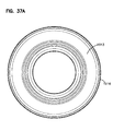
図33Aには、アクセスカバー504に向かって見た場合の平面図が示される。図33Aは、図33の線33−33における図を示す。
In FIG. 33A, a plan view as seen from the
ここまで説明した限りでは、アセンブリ500はアセンブリ1とほぼ同様である。識別された特徴構造は、先にアセンブリ1の実施形態に関連して説明した類似の特徴構造と同様に動作するように構成されてもよい。
As far as described above, the
次に図35に注目すると、内部の詳細を見るために一部を断面図で示すカートリッジ510の側面図が示される。カートリッジ510は、エアクリーナ500と共に使用できる点検可能な構成部品である。詳細には、アクセスカバー504をハウジング502の他の部分から取り外すと、カートリッジ510を挿入すること又は点検のために取り出すことができる。
Attention is now directed to FIG. 35, which shows a side view of the
一般に、図35を参照すると、カートリッジ510は、本例では開放されたフィルタ内部空間526(及びカートリッジ中心軸X)の周囲に配置され且つ第1の端部材(又は端部キャップ)528と第2の端部材(又は端部キャップ)529との間に延設される媒体525を備えるが、別の構造も可能である。尚、図35において、端部材528は、カートリッジ510の(本例では開放された)出口端部に配置され、動作中、空気(ガス)はこの出口端部を通って流れることができる。図33では、カートリッジ510は、端部材(キャップ)528のいくつかの部分を含まない状態で所定の位置に配置されているので、内部の好適な構造を詳細に見ることができる。図33に示されていない端部材(キャップ)528の部分は、本明細書において説明される原理の典型的な適用用途ではモールド・イン・プレース成形部分であるが、別の構造も可能である。
In general, referring to FIG. 35, the
通常、端部材528の少なくとも一部はモールド・イン・プレース成形され、媒体525の端部525xはその部分に埋め込まれ、また端部材529の少なくとも一部はモールド・イン・プレース成形され、媒体525の端部525yはその部分に埋め込まれるが、別の構造も可能である。媒体525は襞付き媒体であってもよいが、別の構造も可能である。媒体及び媒体の形態は、効率及び使用時の耐用年数を考慮して選択されるが、一般に、先に説明したような媒体及び媒体の特徴形状、あるいは多様なエア(ガス)フィルタで使用されているような媒体及び媒体の特徴形状を使用できる。
Generally, at least a portion of the
図示されるように、媒体525は内側ライナ又は中央支持体527の周囲に配置され、図示される例では、内側ライナ又は中央支持体527は、ほぼ図5のカートリッジ25に関して先に説明したような構造であってもよいオプションの共鳴器/ソニックチョーク構造546を含む。
As shown, the
端部材529は、図示されるように、典型的には閉鎖された端部材であり、図5の端部材(キャップ)42にほぼ対応していてもよい。
The
端部材528は、中央に空気流れ開口部530が貫通している開放された端部材である。端部材528は、第1の一次シール構造533と、オプションの二次シール構造534とを含む。オプションの二次シール構造534は、先に説明した図5のシール構造66とほぼ同様に構成されてもよいが、以下に説明する実施形態で説明されるシール構造を含めて、別の構造も可能である。
The
先に説明した実施形態の場合と同様に、図示される例では、一次シール構造533は、媒体と軸方向に重なり合って配置される半径方向外側に向いた半径方向シール又はシール面として構成される。しかし、一次シール構造533は、必要に応じて半径方向内側に向いたシールとして構成されてもよい。カートリッジ中心軸はXで示され、本明細書において説明される場合の半径方向は、軸Xに向かう方向(内側の場合)又は軸Xから離れる方向(外側の場合)を示すものとする。
As in the previously described embodiment, in the illustrated example, the
先に説明した実施形態の場合と同様に、通常確実な係合及び密封を実現するために締め付けなければならない付加的なクランプが設けられていないという意味で、一次シール構造833は、「非クランプ」、「非クランピング」又は「クランプなし」シール構造である。カートリッジ510をハウジングの中に適切且つ適正に装着した時点で密封は完成する。
As with the previously described embodiments, the
図37を参照すると、先に説明した図29のバンパ464と同様なバンパ537を有する閉鎖された端部材529が示される。端部材529は、図34の底面斜視図にも示される。
Referring to FIG. 37, a
図34Aには、ほぼ端部材528及び開口部530に向かって見た場合のカートリッジ510の等角投影図が示される。
In FIG. 34A, an isometric view of the
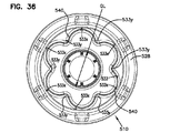
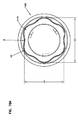
次に図36に注目する。図36は、ほぼ端部材528に向かって見た場合のカートリッジ510の端面図である。図中符号533は、一次シール構造を形成する半径方向に向いたハウジングシール(又はシール面)を示す。尚、図示される特定の例の場合、ハウジング半径方向シール533は、図35のカートリッジ中心軸Xに関してほぼ半径方向外側に向いているが、別の構造も可能である。
Attention is now directed to FIG. FIG. 36 is an end view of the
図36を参照すると、図示される例のカートリッジ510の場合、一次シール533は、非円形構成を規定するシール面を備える。これは、本例では直線状ではない(通常は内側へ突出し、本例では凹形に湾曲した)部分533yにより離間された交互配列の外側へ突出する(本例では外側に向かって凸形の)部分又はローブ533xを有する構成であるのが好ましい。外側へ突出する(本例では凸形に湾曲した)シール面部分533x及び内側へ突出する(本例では凹形に湾曲した)部分533yの特定の数は、少なくとも何らかの利点を得る上で重要ではない。典型的には、各部分の数は少なくとも2個であり、通常は少なくとも3個であり、場合によっては4個以上、8個以下であり、多くの場合に4個〜10個の範囲内、例えば6個以上、8個以下の範囲内の数であるのが好ましいが、別の数も可能である。
Referring to FIG. 36, for the
別の定義によれば、シール面533は、(本例では直線状ではなく、例えば凹形の)面533の部分533yにより互いに離間された複数の離間するローブ又は半径方向外側へ突出する(例えば凸形の)部分533xを備えると特徴づけることができる。典型的には、そのような外側へ突出するローブ又は部分は少なくとも2個あり、通常は少なくとも3個、場合によっては4個以上、8個以下の数で存在し、多くの場合に4個以上、10個以下(例えば6個以上、8個以下)の範囲内の数で存在するのが好ましいが、別の数も可能である。
According to another definition, the sealing
更に図35及び図36を参照すると、一次シール部材又は一次シール面533を取り囲むように凹部、受け入れ部分又は受け入れ溝540が配置される。この凹部、受け入れ部分又は受け入れ溝540は、溝73と同様に、ハウジング端部511及び管512の突出する部分を受け入れるように配置され且つ規定された受け入れ部分である。図3Aを参照。
Still referring to FIGS. 35 and 36, a recess, receiving portion or groove 540 is arranged to surround the primary sealing member or
図示される特定のカートリッジ510の場合、凹部、受け入れ部分又は受け入れ溝540は、先に説明したように定義上は非円形であるのが好ましい面533を形成する内壁を有するように構成される。図35の溝540の外壁541は、定義上、中心軸Xを中心としてほぼ円形であるのが好ましいが、別の形状も可能である。
For the
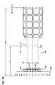
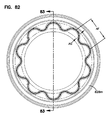
図38には、カートリッジ510の中央支持体545が示される。支持体545は、図35の支持体527として形成され且つ使用されることが可能である。これは、非円形のシール535を受け入れるように変形されている点を除き、図1〜図32の実施形態に関して図9〜図16を参照して先に説明した支持体90と同様である。図示される例では、支持体545は、一つにはオプションのソニック共鳴器/チョーク546を規定する。
In FIG. 38, the
図38を参照すると、支持体545は、支柱又は開放格子構造551により固定された外側支持体550から離間し且つ外側支持体550により取り囲まれる内側シール支持体又はハブ549を備える端部構造548を含む。支持体549は、使用中、端部材528(及びシール構造533)に埋め込まれることにより、装着時に制御された圧縮を支援する。従って、支持体549は、多くの面で図9の支持体105と同様に動作する。図示される特定のハブ549は、半径方向内側へ突出する(本例では湾曲した)シール部分549yと交互に配列された複数の半径方向外側へ突出する(本例では湾曲した)ローブ又はシール支持部分549xを備えるのが好ましい非円形の形状を有する連続した壁を含む。(あるいは、図示される例において、ハブ549は、非円形であり且つ本例では直線状ではない半径方向内側へ突出する部分549yにより分離された複数のローブ549xを備えると特徴づけることができる。)ハブ549に使用可能な種々のハブ形状の特徴については、以下に更に詳細に説明する。
Referring to FIG. 38, the
図示されるような形状である場合の半径方向外側へ突出する(例えば湾曲した又は凸形の)部分549x及び内側に向いた(例えば湾曲した又は凹形の)部分549yの数は、関連するシール構成には適切である。従って、典型的には各部分は少なくとも2個あり、通常は少なくとも3個以上、場合によって4個以上、8個以下の数でそれぞれ存在し、多くの場合に4個以上、10個以下の範囲内、例えば6個以上、8個以下の範囲内の数でそれぞれ存在するのが好ましい。
The number of radially outwardly projecting (e.g. curved or convex)
尚、図38を参照すると、図示される例では、ハブ549の非円形のシール支持部分は中実であり且つ連続している。すなわち、非円形のシール支持部分は、支柱551を越えて先端部549pに向かって延設する間に貫通する側方開口部を含まない。これが典型的な構造であるが、別の構造も可能である。
Still referring to FIG. 38, in the illustrated example, the non-circular seal support portion of the
外側支持体550及び支柱551は、図9に示される支持体108及び支柱110とほぼ同様であってもよい。
尚、支持体545は、典型的には図10に関して説明したソニックチョーク構造と同様のオプションのソニックチョーク構造546を図示される構造の中に含む。
It should be noted that the
図39には、支持体545の側面図が示される。図10のリング125と同様のリング554を見ることができる。流れ開口部121と同様の樹脂の流れ開口部555が示される。要するに、図39を参照すると、図示される例の支持体545は、図38の内側支持体(又はハブ)549の特定の構成を除き、支持体90とほぼ同様である。
A side view of
図40には、構造548の端面図が示される。図41には、支持体545の反対側の端面図が示される。
An end view of
図42には、支持体548の拡大部分断面図が示される。支持体部分548は、図16のフランジ120及びトラフ120eと同様にトラフ561を規定する内側軸方向フランジ560を含むことがわかる。開口部555はトラフ561の中へ樹脂を流入させる。
An enlarged partial cross-sectional view of
図43には、図42の一部の拡大部分図が示される。図16の部分128と同様の支柱551の半径方向内側の領域が図中符号564で示される。また、支柱551は、中心軸Xに垂直な平面に対して、図16に関して先に説明した角度CSとほぼ同様に、0°より大きい角度HFで延設されることがわかる。図33を参照すると、媒体525xから離れる方向に半径方向内側へ延設する支柱551の傾斜を見ることができる。尚、図33には、媒体525は、格子構造551のどの部分とも当接しないものとして示される。しかし、場合によっては、半径方向に最も内側の部分で媒体525と格子構造551との間に多少の軸方向接触が起こりうると予測される。
FIG. 43 shows an enlarged partial view of a portion of FIG. A radially inward region of
図44には、支持体545の部分図が示される。
A partial view of the
図45には、圧力タップ512xと共に出口管512を有する流れ(本例では出口)管構成570が示される。出口管512はシール面571を含み、このシール面571は、図示される例では、カートリッジ510が係合した場合にシール533が当接して、半径方向外側に向いたシールを形成する半径方向内側に向いたシール面である。他の多くの点で、構造570は、図22の管構造15とほぼ同様であってもよい。尚、ハウジング502と回転係合するようにリング572rに取り付けられた突起572は、図22の部分228とは形状、数及び位置が異なる。このことは以下に更に説明される。
In FIG. 45, a flow (in this example outlet)
図45に示されるように、管構成570は、リング572rに半径方向に配置された複数の半径方向に互いに離間するスナップフィットカム突起573を有する。リング572rは、使用中に受け入れ開口部及びハウジング部分に押し込まれる管構成570の一部である。突起573は、その押し込みが行われた場合にスナップフィットすることにより、離脱を抑止する。
As shown in FIG. 45, the
図46には、管構成又は管構造570の側面図が示される。図48には、図46の管構成570の平面図が示される。図47には、図48の線47−47にほぼ沿った断面図が示される。図49には、図46の線49−49にほぼ沿った断面図が示される。図50には、図49の識別された部分の拡大部分図が示される。
Referring to FIG. 46, a side view of a pipe configuration or
図49に注目する。尚、図示される例の管570にある個別の突起572は、壁575の薄い延設部分574と半径方向に整列するように、それぞれ位置決めされている。すなわち、その都度中空部分576と半径方向に整列される。これにより、管570が回転されて、突起572が歯付きハウジング部分と係合するにつれて、多少のばね効果が発生するので、部分570をハウジング502に回転係止させるのが容易になる。また、組み立て中又は突起572からの圧力を受けている間に領域574で変形が起こり、シール面領域571の形状に影響を及ぼす事態を回避するのにも有用である。例えば、管570をプラスチックから成形する間に、面571を適正に成形することが重要である。中空部分526は、面571のひずみを最小限に抑えるために均一な冷却を容易にする。図50には、中空部分576のうち1個を容易に詳細に見ることができる。
Attention is directed to FIG. It should be noted that the
一般に、図35に示されるカートリッジ510の場合、ハウジングシール533は、溝540の非円形の側面であり且つ半径方向外側へ突出するか又は半径方向内側へ突出する(図示される例では湾曲する)交互に配列された複数のシール面部分を有するように形成される。これにより、非円形であり且つ交互に配列された外側へ突出する部分及び内側へ突出する部分を備えるシール周囲部が形成される。図49を参照すると、カートリッジ510が装着される場合、カートリッジシール構造533は、ハウジングの同様な形状に形成されたシール支持体571と(半径方向シールにより)密封係合するように、別のクランプを使用せずに押し込まれる。図示される特定の例では、シールハウジング面571は出口管構成570の一部として形成される。
Generally, for the
本例のカートリッジ510の場合、一次シール構造は、図35の端部キャップ528の凹部、受け入れ部分又は受け入れ溝540の半径方向内側の面又は壁(外側に向いた面533)として構成される。凹部、受け入れ部分又は受け入れ溝540は、密封が起こる出口管の突出する部分だけではなく、管にスナップフィットされるハウジング側壁の突出する部分も受け入れるように構成される。従って、ハウジングにおける出口管部分570とハウジング端壁511との間の接続部は、カートリッジ510の溝540に受け入れられる、図33を参照。
In the case of the
図36、図38及び図49を比較することにより、シール構成が交互に配列された半径方向外側へ突出する部分533x及び半径方向内側へ突出する部分533yを備え、且つ図49のハウジングシール面571も交互に配列された外側へ突出する部分571x及び半径方向内側へ突出する部分571yを備える場合、面部分571yがシール構造533の外側へ突出する部分533xの間へ突出できることを理解できる。これは、シール構造533の回転係止を助けることができる。更に、カートリッジ510の装着時、カートリッジ510が正しく挿入され且つ完全に密封されたことが操作員にわかる確実且つ独特な感触を得ることができる。これにより、一次シール533に漏れ経路を残すことなく容易に装着が可能である。部分533yの数が少なくとも4個であると、相対的にわずかにカートリッジを回すだけで適正な係合が実現されるので、特に好都合である。
Comparing FIGS. 36, 38 and 49, the seal arrangement comprises alternating radially outwardly projecting
尚、いくつかの用途では、一次シール533のみがあればよい。しかし、場合によっては二次シールを設けることで利点が得られる。この点については本章の次の部分で説明する。
In some applications, only the
図35を参照すると、カートリッジ510は、ハウジングの側壁と係合する図35の二次シール534を含む。図4の二次シール65及びシール面66と同様に、カートリッジ510の端部キャップ材料に埋め込まれたオプションのシール支持体581により二次シール534を支持することができる。このオプションの支持体は、図38に示される構造545にあるオプションの支持体550により構成される。
Referring to FIG. 35, the
オプションの支持体550は、図1〜図32の実施形態の支持体と同様に、オプションの互いに離間するタブ531tを含む。実際、一次シール533の構成に関しては、図33〜図50の構造は、図1〜図32の構造とほぼ同様である。
一次シール533に関して図示したシール構成により、いくつかの利点が提供される。本実施形態の場合も、(出口)管570がカートリッジ510と係合した後、管570をハウジング本体503に対して半径方向に回転させることは不可能である。従って、回転応力及び回転力の影響を受けない更に確実な密封が得られる。
The seal configuration illustrated with respect to the
更に、複数のローブ又は複数の突起を含むシールでは、種々のローブ又は突起の(典型的には湾曲した)密封面の部分が周囲の一部で接線方向に向いているので、そのようなシールは「自己位置合わせ」シールである。すなわち、シール533の一部は完全に半径方向に向いているわけではない。従って、シール533を所定の位置に押し込んだ後、ローブ(突起)に加えられる圧力の不均衡によってシールはわずかに回転し、位置合わせのずれに対して自己修正する。この場合でも密封圧縮は軸Xと軸方向に整列する方向(すなわち軸Xの長手方向)に起こるのではなく、その大部分は軸Xに向かう方向又は軸Xから離れる方向に起こるので、シール533は半径方向シールと呼ばれる。
Furthermore, in seals that include multiple lobes or multiple protrusions, such portions of the (typically curved) sealing surface of the various lobes or protrusions are tangentially directed at a portion of the perimeter, such seals Is a "self-aligned" seal. That is, a portion of the
更に、前述のように、シール533の独特の構成は、システムに適する正しいカートリッジ510が選択されたことを点検担当者が確認する際の助けとなり、また、カートリッジのローブが出口管のローブと正しく位置合わせされるまでアクセスカバーを閉じられなくなるように構成部品を選択できるので、カートリッジが正しく装着されていない場合に、そのことをかなり容易に認識することができる。
In addition, as mentioned above, the unique configuration of the
尚、可能なシール構成及びシールの利点に関しては、以下に更に詳細に説明する。 It is noted that possible seal arrangements and the advantages of the seal will be described in more detail below.
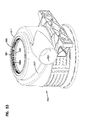
次に図51に注目すると、アセンブリ500の側面図が示される。図51から、ハウジング502は、ラッチ構造505により一体に固定された部分503及びアクセスカバー504を備えることがわかる。また、出口管512が管570の一部、入口管521及び排出管514を備えることがわかる。以下の更なる説明から理解されるように、ハウジング部分503、出口管512及びカートリッジ510の一部を通る断面線52−52に注目する。
Referring now to FIG. 51, a side view of the
図52に注目する。図52は、密封が起こるようにハウジング部分503の一部と位置合わせされたカートリッジ510の部分を示す。しかし、端部キャップ528のモールド・イン・プレース成形部分は図52には示されていないので、構造の詳細を見ることができる。
Attention is directed to FIG. FIG. 52 shows the portion of the
図52を参照して、まずシール面571及びハブ549に注目する。シール面533を形成する材料、すなわち端部材528のモールド・イン・プレース成形部分の一部によって、これら2個の構成部品の間の空間579を充填できることが理解されるだろう。ハブ549の外側に向いた突起549xは、面571の外側へ突出する領域571xと位置合わせされ、且つハブ549の内側へ突出する領域549yは、壁571の内側へ突出する領域571yと位置合わせされることがわかる。更に、回転を阻止するように回転に対する妨害が起こることもわかる。また、カートリッジ510をシール面571に挿入する間に何らかの位置合わせのずれが起こった場合、点検担当者がカートリッジ510をわずかに回すことにより、シールが正しい係合位置で係止したという感触が得られる。
Referring to FIG. 52, attention is first focused on the sealing
更に、図52を参照すると、ハウジング部分503の歯付き面又は歯付き領域、あるいはラチェット面又はラチェット領域581によって、個別の突起572がラチェット方式で又は抵抗を伴って係合することがわかる。このことは以下に更に詳細に説明される。
Further, referring to FIG. 52, it can be seen that the toothed surface or toothed area of the
図53には、ハウジング部分503の斜視図が示される。端部511に開口部580が示される。開口部580は、切欠き、歯又はラチェット構造581及び撓みタブ582が配列された部分580tを含む。図45の管構造570が開口部580に挿入されると、選択された回転位置に管570を固定するのを助けるために、部材572は歯581と係合する。撓みタブ582は、図46の部材573と同様に、スナップフィット効果を実現するのを助ける。尚、最初に装着する間に、ラチェット効果に勝る力を加えるために管を手で回転させることができるので、L形管512が使用される場合、必要に応じてその管を回転できる。しかし、カートリッジ510が装着された後は、カートリッジ510は管570を特定の回転位置に係止しようとする。これは、一つには先に説明したように周囲シール又は二次シール534がカートリッジ510に及ぼす影響によって、ハウジング部分503の側壁部分との係合が起こるためである。また、アクセスカバー504が所定の位置に押し込まれる間に、カートリッジ510を端部511に当接させるカートリッジ510に対する軸方向圧力によっても、管570の回転が抑止される。
A perspective view of the
図54には、ハウジング部分503の側面図が示される。図55には、ハウジング部分503の平面図が示される。図56には、図55の線56−56に沿った断面図が示される。図57には、図56に指示される部分の拡大部分図が示される。図57において、図中符号590は、カートリッジ510の装着時に図35のカートリッジ510の二次シール面534との間でシールを形成するハウジング部分503のシール面部分を示す。これは、図1〜図32の実施形態と同様である。
A side view of the
次に図33Bに注目すると、図33の一部の拡大部分図が示される。図33Bは、管570の一部とハウジング部分503の端部511との係合を示す。図33と同様に、図33Bには、端部キャップ528のモールド・イン・プレース成形シール材料の一部が示されていないので、構造の詳細を見ることができる。
Referring now to FIG. 33B, an enlarged partial view of a portion of FIG. 33 is shown. FIG. 33B shows the engagement of a portion of the
図33Bにおいて、図中符号591は、管570とハウジング部分502との間に位置し且つ装着中に図35のカートリッジ510の凹部、受け入れ部分又は受け入れ溝540の中へ突出する接続部を示す。また、接続部591における水漏れを抑止するのに有効な構造も図33Bに示される。詳細には、管570は、端部511と係合する半径方向に突出する取り付けリング部分593と、端部511に向かって突出するリム突起部分595とを含むことが図33からわかる。端部511は凹部511rを含み、この凹部511rの中へリム部分595が突出する。更に、端壁511は、リム突起部分595により取り囲まれる位置に、管570からリング部分593に向かって突出する突起リング511pを含む。端部511で管570とハウジング部分503とのスナップフィット係合が起こると、凹部511rの中のリング突起595及び突起リング511pにより示される曲がりくねった水流れ経路は、ハウジング502の内部空間502iの中へ水が流入するのを抑止する。端部511が上方へ突出するようにハウジング502の向きを定めた場合、この効果は特に望ましい。
In FIG. 33B,
C.カートリッジ510、特に端部材528の組み立て、図58〜図65
本開示に係る原理が適用される好適な用途では、端部材528は、カートリッジ510のプレフォーム部分にモールド・イン・プレース成形された部分を含む。詳細には、端部材528は、媒体525の端部525x、支持構造545の種々の部分並びに隣接するシール支持体549、550及び支柱551を覆うようにモールド・イン・プレース成形された材料を備える。本章では、図58〜図65を参照して、これを実現するための方法及び成形型構造を説明する。
C. Assembly of the
In the preferred application to which the principles of the present disclosure apply,
図58には、成形型600の平面図が示される。成形型600は成形型空洞602を取り囲む周囲リング面601を備える。成形型空洞602の中心には中央突起603が配置される。カートリッジ510の製造中、樹脂は、典型的には樹脂を分散させるための急速回転によって成形型空洞602の中に供給される。その後、媒体(媒体パック)及び支持体が成形型空洞602に挿入され、端部キャップ528を形成するのに適切な方法で、媒体パック及び支持体に樹脂が成形される。
A plan view of the
図59には、成形型600の断面図が示される。尚、空洞602はリング610を含み、成形後のカートリッジの端部キャップ528において、このリング610は図35の溝540を形成する。
A cross-sectional view of the
突起610の半径方向外側には成形型空洞部分602xがあり、成形型空洞部分602xの602pに位置する外周部は、成形後の材料において図35の外側シール面534を形成する。
Radially outwardly of the
支持体610の半径方向内側には、内側成形型空洞部分602iが配置される。突起610の内面610iは、一次シールの外側に向いた図35の半径方向シール面533を形成するように構成される。
Radially inward of the
図60には、空洞602及び中央突起603の拡大部分図が示される。尚、中央突起603は、全体が図中符号612で示される第1の部材の成形型回転位置合わせ構造を有する外周部603pを含む。図示される特定の構造の場合、成形型回転位置合わせ構造612は、ほぼ垂直方向に配向され且つ配置される突起603の外周部の周囲に互いに半径方向に離間する複数の凹部又は溝613を備える。図示される特定のアセンブリは6個の溝を使用するが、別の数(通常は3個以上、10個以下)も可能である。尚、それらの溝は、支柱603の中心の周囲に半径方向に等間隔で離間するものとして図示されているが、別の構造も可能である。溝613の作用は、以下の更なる説明から理解されるだろう。
An enlarged partial view of the
図61には、図59の拡大部分図の同一部分が示される。図示される部分は溝613の1つの断面図である。
FIG. 61 shows the same part of the enlarged partial view of FIG. The portion shown is a cross-sectional view of one of the
図62には、図59の部分断面図の第2の同一部分が示される。先に示した特徴構造を含めて成形型空洞602の断面図が示される。
In FIG. 62, a second identical part of the partial cross-sectional view of FIG. 59 is shown. A cross-sectional view of the
図63には、図58の一部の拡大部分図が示される。図63に示される部分は、成形を容易にするための成形型スタンドオフ615を示す。図58を参照すると、そのような成形型スタンドオフ615が複数示されている。スタンドオフ615は、端部キャップ528にアーティファクトを残す(図34Aの図中符号617を参照)。スタンドオフ615は、媒体及び支持体が成形型の中で適切に支持されるように機能する。
Referring to FIG. 63, an enlarged partial view of a portion of FIG. 58 is shown. The portion shown in FIG. 63 shows
図64には、端部キャップ528を形成するための成形型にカートリッジ構造を挿入する過程が概略的に示される。尚、詳細を見るのを容易にするために、図64に媒体は示されていないが、挿入中に媒体はその場に存在しているだろう。図64を参照すると、成形型600が示される。構造545が成形型空洞602の中へ押し下げられているところが示される。挿入前に、媒体は一般に中心545cの周囲に位置決めされているだろう。媒体はリング554を取り囲んでいると考えられる。また、通常、カートリッジ構成部品の挿入前に、成形型600を急速に回転させることによって、樹脂は、通常は領域619に向かって空洞602の中に供給されているだろう。
In FIG. 64, the process of inserting the cartridge structure into the mold for forming the
シール533のシール面を成形する外側成形型部分620に対して、成形型の中で支持体545を半径方向に適正に配向しなければならないことが理解されるだろう。図65を参照することにより、これを実現するための方法を理解できる。
It will be appreciated that the
図65を参照すると、カートリッジ支持体545は、中心549cに第2の部材の成形型回転位置合わせ構造625を有する内面545sを含むことがわかる。第2の部材625は、複数の半径方向内側に向いた突起626を備える。突起626は、中央支柱603の部材612と係合するように構成され且つ位置決めされる。図示される特定の構造の場合、部材626は、支持体545が成形型600の中へ押し下げられる間に凹部613の中に受け入れられるように配向され且つ互いに離間する垂直リブとして構成された突起である(別の構造も可能であるが)。従って、リブ626が受け入れ部分613と係合するまで、支持体545を成形型600の中へ完全に押し下げることはできない。これにより回転割り出しが実現されるので、図65の支持体545のハブ529は成形型部分520と適切に回転位置合わせされる。
Referring to FIG. 65, it can be seen that
D.いくつかの寸法例
図33〜図63には、いくつかの寸法例が次のように提示されている。GH=280.3mm、GI=128.3mm、GJ=92.4mm、GK=129.8mm、GL=45.4mm、GM=231.4mm、GN=102.1mm、GO=2mm、GP=6.4mm、GQ=7°、GR=117.5mm、GS=7°、GT=直径117.5mm、GU=2.8mm、GV=95.6mm、GW=3.3mm、GX=18.9mm、GY=1.5mm、GZ=14.62mm、HA=半径30mm、HB=半径14.2mm、HC=0.2°、HD=16mm、HE=半径3mm、HF=2°、HG=14.8mm、HH=21.9mm、HI=直径77.93mm、HJ=半径11.7mm、HK=半径27.9mm、HL=半径5.5mm、HM=直径60.41mm、HN=30°、HO=20mm、HP=81mm、HQ=55.5mm、HR=121.5mm、HS=48.9mm、HT=2.5mm、HU=45.8mm、HV=50.8mm、HW=54.2mm、HX=54.9mm、HY=88.46mm、HZ=96mm、HI=30°、H2=66mm、H3=直径59.9mm、H4=直径77.9mm、IA=111mm、IB=半径14.2mm、IC=111mm、ID=30°、IF=1.5mm、IG=半径0.5mm、IH=2.1mm、II=半径1mm、IJ=直径7.5mm、IK=半径2.7mm、IL=112mm、IM=105mm、IN=80.5mm、IO=40mm、IP=12mm、IQ=6mm、IR=15mm、IS=8.9mm、IT=15.8mm、IU=31.6mm、IV=8.9mm、IW=6mm、IX=55.8mm、IY=54.4mm、IZ=210mm、JA=96.5mm、JB=12.7mm、JC=93.5mm、JD=89mm、JE=124.4mm、JF=144.7mm、JG=133.1mm、JH=164.9mm、JI=169.6mm、JJ=182.7mm、JK=10.7mm、JL=2mm、JM=30°、JN=1.5mm、JO=0.9mm、JP=直径266.7mm、JQ=124mm、JR=38.1mm、JS=130.2mm、JT=98.2mm、JU=92.6mm、JV=43.9mm、JW=12.7mm、JX=14mm、JY=60°、JZ=30°、KA=半径15.1mm、KB=半径4.8mm、KC=直径77.9mm、KD=直径59.9mm、KE=1mm、KF=18.6mm、KG=半径2.9mm、KH=3mm、KI=半径2.9mm、KJ=2°、KK=28.2°、KL=19.5mm、KM=2°、KN=半径2mm、KO=14.9mm、KP=4mm、KQ=3mm、KR=半径2.5mm、KS=半径2.5mm、KT=0.5°、KU=半径2.5mm、KV=半径1mm、KW=15°、KX=半径3mm、KY=2°、KZ=半径2mm、LA=3mm、LB=半径2.5mm、LC=半径2mm、LD=31.8mm、LE=半径4.5mm、及びLF=11.3mm。これらの寸法が単に構造の一例を示しているにすぎないことは言うまでもなく、別の寸法を使用することも可能である。
D. Some Dimension Examples In Figures 33-63, some example dimensions are presented as follows. GH = 280.3 mm, GI = 128.3 mm, GJ = 92.4 mm, GK = 129.8 mm, GL = 45.4 mm, GM = 231.4 mm, GN = 102.1 mm, GO = 2 mm, GP = 6. 4 mm, GQ = 7 °, GR = 117.5 mm, GS = 7 °, GT = diameter 117.5 mm, GU = 2.8 mm, GV = 95.6 mm, GW = 3.3 mm, GX = 18.9 mm, GY = 1.5 mm, GZ = 14.62 mm, HA = radius 30 mm, HB = radius 14.2 mm, HC = 0.2 °, HD = 16 mm, HE = radius 3 mm, HF = 2 °, HG = 14.8 mm, HH = 21.9 mm, HI = diameter 77.93 mm, HJ = radius 11.7 mm, HK = radius 27.9 mm, HL = radius 5.5 mm, HM = diameter 60.41 mm, HN = 30 °, HO = 20 mm, H = 81 mm, HQ = 55.5 mm, HR = 121.5 mm, HS = 48.9 mm, HT = 2.5 mm, HU = 45.8 mm, HV = 50.8 mm, HW = 54.2 mm, HX = 54.9 mm , HY = 88.46 mm, HZ = 96 mm, HI = 30 °, H2 = 66 mm, H3 = diameter 59.9 mm, H4 = diameter 77.9 mm, IA = 111 mm, IB = radius 14.2 mm, IC = 111 mm, ID = 30 °, IF = 1.5 mm, IG = radius 0.5 mm, IH = 2.1 mm, II = radius 1 mm, IJ = diameter 7.5 mm, IK = radius 2.7 mm, IL = 112 mm, IM = 105 mm, IN = 80.5 mm, IO = 40 mm, IP = 12 mm, IQ = 6 mm, IR = 15 mm, IS = 8.9 mm, IT = 15.8 mm, IU = 31.6 mm, IV = 8 9 mm, IW = 6 mm, IX = 55.8 mm, IY = 54.4 mm, IZ = 210 mm, JA = 96.5 mm, JB = 12.7 mm, JC = 93.5 mm, JD = 89 mm, JE = 124.4 mm, JF = 144.7 mm, JG = 133.1 mm, JH = 164.9 mm, JI = 169.6 mm, JJ = 182.7 mm, JK = 10.7 mm, JL = 2 mm, JM = 30 °, JN = 1.5 mm , JO = 0.9 mm, JP = diameter 266.7 mm, JQ = 124 mm, JR = 38.1 mm, JS = 130.2 mm, JT = 98.2 mm, JU = 92.6 mm, JV = 43.9 mm, JW = 12.7 mm, JX = 14 mm, JY = 60 °, JZ = 30 °, KA = radius 15.1 mm, KB = radius 4.8 mm, KC = diameter 77.9 mm, KD = diameter 59. mm, KE = 1 mm, KF = 18.6 mm, KG = radius 2.9 mm, KH = 3 mm, KI = radius 2.9 mm, KJ = 2 °, KK = 28.2 °, KL = 19.5 mm, KM = 2 °, KN =
E.可能ないくつかの代替シール構成、シールの全般的説明、種々の代替構造
1.代替例のシール面の定義、図66〜図70
本開示に係る原理と共に多様なシール構成を使用できる。図66〜図70には、いくつかの例が示される。これらの図は概略図であり、可能であると考えられるシールの定義及び支持体の定義を示すことを意図しているにすぎない。
E. Several possible alternative seal configurations, a general description of the seal, various alternative structures Alternative Seal Face Definitions, FIGS. 66-70
A variety of seal configurations can be used with the principles of the present disclosure. Several examples are shown in FIGS. 66-70. These figures are schematic and are only intended to show the definition of the seal considered as possible and the definition of the support.
図66には、2個の内側へ突出する突起部分702により分離された2個の半径方向外側へ突出する部分又はローブ701を有する幾分「ピーナッツ形の」形状が図中符号700で示される。この特定のローブ701及び部分702の構成を図示される構成とは異なる形に変形できることはもちろんである。
Referring to FIG. 66, a somewhat "peanut-shaped" shape is shown at 700 with two radially outwardly projecting portions or
図67には、図中符号730により、3個の半径方向外側へ突出する部分又はローブ731及び3個の半径方向内側へ突出する部分732を有する3ローブ構成が示される。
In FIG. 67, the
図68には、半径方向内側に向いた突起又は部分752により分離された複数(4個)の半径方向外側へ突出する部分又はローブ751を含む「4ローブ」構成が図中符号750で示される。
In FIG. 68, a “four-lobe” configuration is shown at 750 including a plurality (four) of radially outwardly projecting portions or
図69には、半径方向外側へ突出する部分を有するシール構造が図中符号770で示される。この場合、シール構造770は、部分772により分離された6個の半径方向外側へ突出する部分771を有する。この場合、部分772は、突起771の間の方向に直線状であり、半径方向内側へ突出しない。しかし、部分772が内側へ突出するように構成されても、利点を得られるだろう。
In FIG. 69, a seal structure having a radially outwardly projecting portion is shown at 770 in the figure. In this case, the
図70には、5個の内側へ突出する部分782により分離された5個の外側へ突出する部分781を有するシール構造が図中符号780で示される。この場合、内側へ突出する部分782は全体としては直線状ではないが、各部分782は、半径方向に最も内側の頂点785の両側に直線状の部分783、784を備える。
In FIG. 70, a seal structure is shown at 780 with a seal structure having five outwardly projecting
図66〜図70の実施形態のいずれにおいても、ローブ及び部分に関して別の形状が可能である。更に、図66〜図70の構成は、図示されている数とは異なる数の部分又はローブを有する多様な構成を使用できることを実証している。 Alternate shapes are possible for the lobes and portions in any of the embodiments of FIGS. 66-70. Furthermore, the configurations of FIGS. 66-70 demonstrate that a variety of configurations can be used having a different number of portions or lobes than the numbers shown.
2.先に説明した選択されたシール及びシール面の概要説明
尚、図35及び図66〜図70の構造のシールは、場合によっては「半径方向」と特徴づけられる。しかし、非円形の形状であるので、密封力の一部は、特にカートリッジの中心軸Xに向かう向き又は中心軸Xから離れる向き以外の方向に作用する。それにもかかわらず、一般に、カートリッジ及びハウジングのシール面はほぼ半径方向に向いており且つ密封力は、関連するシール面が外側シール面であるか又は内側シール面であるかに応じて、軸Xを中心として半径方向外側に向くか又は半径方向内側に向くかのいずれかであるので、本明細書において、それらのシールは「半径方向」であると特徴づけられる。言い換えれば、圧縮力は軸方向(すなわち軸Xの長手方向)ではなく、ほぼ半径方向である。しかし、これらの非円形シール構成の各々でシール力が直接軸Xに向かう方向又は軸Xから離れる方向に向けられないような用途が存在する。
2. General Description of Selected Seals and Sealing Surfaces Described Above The seal of the construction of FIGS. 35 and 66-70 is sometimes characterized as "radial". However, because of the non-circular shape, part of the sealing force acts in particular in a direction other than towards or away from the central axis X of the cartridge. Nevertheless, in general, the sealing surfaces of the cartridge and the housing are generally radially oriented and the sealing force depends on whether the associated sealing surface is an outer sealing surface or an inner sealing surface, the axis X In the present specification, the seals are characterized as being "radial", as they are either radially outward or radially inward, with respect to. In other words, the compressive force is generally radial rather than axial (i.e., the longitudinal direction of the axis X). However, applications exist in which the sealing force is not directed directly towards or away from the axis X in each of these non-circular seal configurations.
更に一般的にいえば、半径方向シールは、中心軸を取り囲む(中心軸に向かう向き又は中心軸から離れる向きに規定された)シール面を備える。多くの場合、その中心軸はフィルタカートリッジの中心軸であり、その周囲には媒体も配置される。しかし、以下に説明される別の構造の場合、半径方向シールは、カートリッジの中心軸にはならない軸を取り囲むシールであってもよいことが理解されるだろう(これに対し、軸方向シールは、シールが周囲に配置される中心軸とほぼ整列するシールであり、典型的にはカートリッジ中心軸Xであるが、あらゆる場合にそうであるとは限らない)。 More generally speaking, the radial seal comprises a sealing surface (defined towards or away from the central axis) surrounding the central axis. In many cases, the central axis is the central axis of the filter cartridge, and the medium is also arranged around it. However, it will be appreciated that the radial seal may be a seal that encloses an axis that is not the central axis of the cartridge, as opposed to the axial seal, in the case of another configuration described below. A seal that is generally aligned with the central axis about which the seal is located, typically the cartridge central axis X, although this is not always the case).
本明細書において一般に使用される用語で言えば、図示される種々のハウジングシール構造は、一般に半径方向に向いたシール面を備えると特徴づけることができる。これは、図面に示される種々のハウジングシールのシール方向が、一般に「半径方向に向いた面」であるとほぼ特徴づけることができるハウジングのいずれかの部分(ハウジングシールの2個のうちどちらが関連しているかに応じて、出口管の一部であるか又はハウジングの外側部分である)と係合する面によって決まるからである。いずれの場合も、実際にシールを形成する面は、一般に中心軸Xの長手方向に向いたシール力を有すると考えられる軸方向シールとは異なり、中心軸X(通常カートリッジの中心軸でもある)を中心とする向きである(中心軸に向かう向き又は中心軸から離れる向き)。ハウジングと係合することによりシールを形成するカートリッジのシール部材の実際の面は、カートリッジの中心軸に向かうのではなく、ほぼ中心軸から離れる方向であるので、図示される例は、「外側半径方向シール面」又は「外側に向いた半径方向シール」である。しかし、本明細書において説明される原理の多くは、シールを形成するためにハウジングと係合するカートリッジのシール面が半径方向に中心軸に向かう向きである別の構造にも適用可能である。 In terms generally used herein, the various housing seal structures shown can be characterized as having generally radially oriented sealing surfaces. This is because any part of the housing where the sealing direction of the various housing seals shown in the drawings can generally be characterized as a "radially facing surface" (whichever of the two housing seals is relevant) Depending on the situation, it depends on the surface that is part of the outlet tube or the outer part of the housing). In any case, the surface which actually forms the seal is different from an axial seal which is generally considered to have a sealing force directed in the longitudinal direction of the central axis X, the central axis X (which is also usually the central axis of the cartridge) It is the direction centering (direction toward the central axis or direction away from the central axis). Since the actual surface of the seal member of the cartridge that forms the seal by engaging the housing is directed generally away from the central axis of the cartridge rather than toward the central axis of the cartridge, the illustrated example Directional sealing surface "or" outwardly directed radial seal ". However, many of the principles described herein are also applicable to other configurations where the sealing surface of the cartridge that engages the housing to form a seal is radially oriented towards the central axis.
本明細書において説明される半径方向ハウジングシールは、一般に、「非クランプ」構造、「非クランピング」構造又は「クランプなし」構造、あるいはそれに類似する用語で特徴づけることができる。これは、確実なシールを形成するために締め付ける必要があるホースクランプ又は他の構造のようなクランプの使用をシール構造が通常含まないことを意味する。シールは、カートリッジ構成部品により向きを規定されるハウジングの面にシール材料を当接させ、圧縮させる単なる装着によってシールは実現される。 The radial housing seals described herein can generally be characterized in terms of "non-clamping" structures, "non-clamping" structures or "non-clamping" structures, or the like. This means that the sealing structure does not usually include the use of clamps such as hose clamps or other structures that need to be tightened to form a secure seal. The seal is achieved by the simple attachment of a seal material to abut and compress the seal material against the face of the housing that is oriented by the cartridge component.
図33〜図70の構造に関して、非円形である一次シール面は、少なくとも2個の離間した半径方向外側へ突出するシール面部分を有すると特徴づけることができる。実際、図66の構造を除き、各構造は、少なくとも3個の半径方向に離間した外側へ突出するシール面部分、典型的には4個以上、10個以下の半径方向に離間した外側へ突出するシール面部分を有する。この場合、「半径方向外側へ突出する」という用語は、シール面が内側に向いたシールを形成するような向きに規定されるのか又は外側に向いたシールを形成するような向きに規定されるのかにかかわらず、中心軸の周囲方向に、中心軸に対してローブ、頂点又は突出部分の形状であることを示すものとする。すなわち、半径方向外側へ突出する部分は、シール面自体が密封のために向いている方向にかかわらず、シール(及び典型的にはカートリッジ)の中心軸から離れるように突出するシール面の部分である。図36の「6個の外側へ突出するシール部分」を有する構造の場合、それらの突起は図中符号533xで示される。図66の「2個の」外側へ突出する部分の場合、それらの部分は図中符号701で示される。図67の3個の外側へ突出する部分を含む構造の場合、それらの部分は図中符号731で示される。図68の4個の外側へ突出する部分を含む構造の場合、それらの部分は図中符号751で示される。図69の6個の外側へ突出する部分を含む構造の場合、それらの部分は図中符号771で示される。図70の5個の外側へ突出する部分を含む構造の場合、それらの部分は図中符号781で示される。
With respect to the structures of FIGS. 33-70, the non-circular primary sealing surface can be characterized as having at least two spaced apart radially outwardly projecting sealing surface portions. In fact, with the exception of the structure of FIG. 66, each structure has at least three radially spaced outwardly projecting sealing surface portions, typically four or more and ten or less radially spaced outwardly projecting surfaces. Seal surface portion. In this case, the term "projecting radially outward" is defined in such a way that the sealing surface is defined in such a way as to form an inward facing seal, or in such a way as to form an outward facing seal. Regardless of whether it is the circumferential direction of the central axis, it shall be indicated that it is in the shape of a lobe, an apex or a projecting portion with respect to the central axis. That is, the radially outwardly projecting portion is the portion of the sealing surface which projects away from the central axis of the seal (and typically the cartridge) regardless of the direction in which the sealing surface itself is facing for sealing. is there. In the case of the structure having "six outwardly protruding seal portions" in FIG. 36, those protrusions are indicated by
図69の構造を除き、図33〜図36及び図66〜図70の各シール構造は、先に定義した2個の半径方向外側へ突出する部分の間に配置された1個の半径方向内側へ突出するシール部分を有する。図36の構造の場合、それらの部分は図中符号533yで示される。図66の構造の場合、それらの部分は図中符号702で示される。図67の構造の場合、それらの部分は図中符号732で示される。図68の構造の場合、それらの部分は図中符号752で示される。図70の構造の場合、それらの部分は図中符号782で示される。尚、図69の構造は、外側へ突出する領域の間に延設する直線状の部分を有するので、内側へ突出するシール部分を含まない。内側へ突出するシール面部分のシール面の定義のこの部分に関連して、中心軸Xに対する幾何学的方向をいう場合、密封のためのシール面力の方向とは逆に面部分が屈曲又は突出していることを表す。
Except for the structure of FIG. 69, each seal structure of FIGS. 33-36 and 66-70 is one radially inner side disposed between the two radially outwardly projecting portions defined above. With a sealing portion projecting into the In the case of the structure of FIG. 36, those parts are indicated by
尚、構造の多くにおいて、内側に向いたシール面部分は直線状ではない。本明細書において使用される一般的な用語に関連して、これは、シール面の外側へ突出する部分の間に延設されている部分の外側へ突出する部分に対する状態を表す。この特徴づけは、図69に示されるシール構造を除き、図30、図66〜図68及び図70に示されるシール構造のすべてに当てはまる。 It should be noted that in many of the constructions, the inwardly facing seal surface portion is not linear. In the context of the general terms used herein, this refers to the situation for the outwardly projecting part of the part extending between the outwardly projecting parts of the sealing surface. This characterization applies to all of the seal structures shown in FIGS. 30, 66-68 and 70, except for the seal structure shown in FIG.
尚、図70では、部分783及び784はそれぞれ直線状であるが、各部分782は全体としては突起781の間で直線状ではないので、図70に示されるシール構造であっても、外側へ突出する部分の間の延設部分の定義によれば「直線状ではない」。
In FIG. 70, although the
通常、半径方向外側へ突出するシール面部分は、カートリッジ中心軸の周囲に半径方向に等間隔で離間し、実際これは本明細書に示されるどの構造にも当てはまる。しかし、この半径方向に等間隔の配置は特定して要求されているのではなく、本明細書において説明される原理の多くは別の構造にも適用可能である。半径方向内側へ突出するシール部分についても同じことが言える。 Typically, the radially outwardly projecting sealing surface portions are equally spaced radially about the central axis of the cartridge, and in fact this applies to any of the structures shown herein. However, this radial spacing is not specifically required, and many of the principles described herein are applicable to other structures. The same is true for the radially inwardly projecting seal portion.
シールの成形、製造及び使用に好都合なように、半径方向外側へ突出するシール面部分は、典型的には少なくとも5mmの半径、通常は35mm以下の半径、多くの場合に15mm以上、30mm以下の範囲内の半径で湾曲する。しかし、別の数値も可能である。半径方向内側へ突出する部分も、同様に、製造に好都合なように、典型的には少なくとも2mm、多くの場合に2〜35mmの範囲内の量の曲率半径を有する。しかし、この場合も、別の数値が可能である。 To favor the formation, manufacture and use of the seal, the radially outwardly projecting seal surface portion typically has a radius of at least 5 mm, usually no more than 35 mm, and often no less than 15 mm and no more than 30 mm. Curve at a radius within the range. However, other numbers are possible. The radially inward projecting portion likewise has a radius of curvature of typically at least 2 mm, often in the range of 2 to 35 mm, for the sake of manufacturing convenience. But again, other numbers are possible.
一般に本開示に係る原理が好適な構造で適用される場合、一次シール、例えばシール533を形成するシール面は、通常は媒体の最も内側の周囲部から外側へ少なくとも3mm離間し且つ媒体の最も外側の部分から内側へ少なくとも5mm離間するように半径方向に媒体の一端部と重なり合って配置される。また、構造が本明細書で説明したような外周部シール又は第2の半径方向に向いたシール構造を含む場合、このシール面の最大断面寸法は、典型的には、外周部シールの最大断面寸法より少なくとも3mm小さく、通常は少なくとも5mm、多くの場合に少なくとも8mm小さく、典型的には少なくとも10mm小さく、最も典型的には少なくとも15mm小さい。
In general, when the principles according to the present disclosure are applied in a suitable structure, the primary seal, eg the sealing surface forming the
カートリッジが2個のシール構造を含むことは特段要求されないが、説明される好適な実施形態が適用される場合、2個のシール構造を含むのが好ましい。また、一次シール533が溝の側面であることも特段要求されないが、これも本明細書において説明される用途には典型的且つ好適である。更に、溝が使用される場合、ハウジングシールを構成しない溝の面が定義上円形であることは特段要求されないが、傾斜した面も典型的且つ好適である。
Although it is not particularly required that the cartridge include two seal structures, it is preferable to include two seal structures if the preferred embodiment described is applied. Also, although it is not particularly required that the
半径方向に向いたシール面の寸法、周囲部又は断面の寸法を参照する場合、特に指示のない限り、この参照は装着によりひずんでいない場合の面に関する。従って、寸法は、場合によっては「無ひずみ断面寸法」のような用語又はそれに類似する用語で表される。 When referring to the dimensions of the radially directed sealing surface, the dimensions of the perimeter or cross section, this reference relates to the surface when unstrained due to the mounting unless otherwise indicated. Thus, the dimensions are sometimes expressed in terms such as "strain-free cross-sectional dimension" or similar terms.
3.いくつかの例示的な代替構造
次に図33Cに注目する。図33Cは、一般的な特徴構造に関して、図33とは異なる回転方向で示される図33とほぼ同様の図であるが、特定の特徴構造のいくつかの変形例を示す。
3. Some Exemplary Alternative Structures Attention is now directed to FIG. 33C. FIG. 33C is a view substantially similar to FIG. 33 shown with a different orientation of rotation than FIG. 33 with respect to general features, but showing some variations of particular features.
図33Cのアセンブリは、同様の部品が示される場合に図33のアセンブリに関して先に説明した構成及び特徴構造とほぼ同様の構成及び特徴構造を有すると理解されるべきである。 It is to be understood that the assembly of FIG. 33C has substantially similar constructions and features as those described above for the assembly of FIG. 33 where similar parts are shown.
図33Cを参照すると、ハウジング1001を備えるアセンブリ1000が示され、ハウジング1001の中にカートリッジ1010が取り外し可能に配置される。カートリッジ1010は、先に説明したカートリッジとほぼ同様であってもよく、第1の端部材1012と第2の端部材1013との間に延設された媒体1011を備える。相違点の一例は、閉鎖された端部材1013であり、周囲に媒体1011が配置される支持構造1017の一端部1016と軸方向に重なり合うような向きに規定された外側バンパ突起構造1015が示される。これは、バンパ構造が支持体の一端部から半径方向にずれた位置に配置される図33のアセンブリとは異なる。
Referring to FIG. 33C, an
図33Dを参照すると、図33の拡大部分図が示される。尚、端部材又は端部キャップ1012は、詳細な構造に関して先に示した端部キャップとは異なる構成であるが、動作はほぼ同様である。詳細には、モールド・イン・プレース成形材料1021の中に埋め込まれる支持体1020の詳細な構造が異なる。
Referring to FIG. 33D, an enlarged partial view of FIG. 33 is shown. It should be noted that end member or
図33Eには、アセンブリ1000及びハウジング1001の斜視図が示される。
A perspective view of
図34Bにはカートリッジ1010の底面斜視図が示される。図示される例では、バンパ構造1015は、分割されたリングではなく、連続するリングとして示される。分割リングによっても原理を実施することができる。
A bottom perspective view of the
図34Cには、カートリッジ1010の開放端部斜視図が示される。1012と1013との間に媒体1011が延設されている。端部材1012には、凹部、受け入れ部分又は溝1025が示され、その内壁1026は、先に説明した構造と同様に、離間された内側に向いた凹部又は領域1026iにより分離された複数の半径方向外側に向いたローブ又は突起1026oを備える半径方向に向いたシール面1026sを形成するように構成される。更に、カートリッジ1010は、二次半径方向シール又は第2の半径方向シールを形成する面1026を取り囲む外側に向いたシール面1028sを有するものとして示される。
An open end perspective view of the
図35Aには、カートリッジ1010の側面図が示される。図35Bには、カートリッジ1010の断面図が示される。図36Aには、端部材1012に向かって見た場合のカートリッジ1010の平面図が示される。寸法例は次の通りである。XA=71mm、XB=半径129mm、XC=半径16mm、XD=半径3mm、及びXE=93mm。
In FIG. 35A, a side view of the
図37Aには、カートリッジ1010の端部材1013に向かって見た場合の端面図が示される。
In FIG. 37A, an end view of the
F.効果的なシールの特徴構造に関する付加的な解説
先に示した通り、本開示に係る何らかの利点を得るために、フィルタカートリッジ又はカートリッジアセンブリが本明細書において特徴を示される特徴構造のすべてを含むことは特段要求されない。実際、本明細書において特徴を示される第2のシール構成の有無にかかわらず、本明細書において特徴を示される好適な第1のシール構成を実現することにより、いくつかのフィルタカートリッジでは利点を得ることができる。
F. Additional Comments on Effective Seal Features As noted above, to obtain some of the benefits of the present disclosure, the filter cartridge or cartridge assembly includes all of the features featured herein. Is not required. In fact, with or without the second seal configuration featured herein, advantages are realized in some filter cartridges by implementing the preferred first seal configuration featured herein. You can get it.
多くの典型的な用途では、有効なシール構造の適用に関して、フィルタカートリッジは第1の端部及び第2の端部を有する媒体を備え、媒体は典型的には開放されたフィルタ内部空間を取り囲み且つ規定する。媒体の第1の端部には、第1の開放された端部キャップが配置される。この端部キャップは、先に説明したように、媒体の第1の端部が埋め込まれたモールド・イン・プレース端部キャップであってもよい。しかし、別の構造も可能である。 In many typical applications, for effective sealing applications, the filter cartridge comprises a media having a first end and a second end, the media typically surrounding an open filter interior space And define. A first open end cap is disposed at the first end of the media. The end cap may be a mold-in-place end cap in which the first end of the media is embedded, as described above. However, other structures are possible.
第1の端部キャップにはハウジングシール構造が配置される。本明細書において規定される定義の一例では、ハウジングシール構造は、少なくとも2個、典型的には少なくとも3個、好ましくは少なくとも4個の互いに離間する半径方向外側へ突出するシール面突起を有する第1の半径方向に向いたシール面を備える。この点に関連して、「半径方向外側へ突出するシール面部分」は、シールを形成するためにその面が向いている方向ではなく、その面が中心軸から突出する方向を表す。従って、その用語は、「ローブ」又は部分自体の形状を表すのであって、密封の方向を表すのではない。従って、シール構造は、複数の半径方向外側へ突出するシール面部分を有し且つ外側に向いた半径方向シール又は内側に向いた半径方向のいずれかであることが可能である。 A housing seal arrangement is disposed on the first end cap. In one example of a definition as defined herein, the housing sealing structure comprises at least two, typically at least three, preferably at least four radially outwardly projecting sealing surface protrusions. A radially oriented sealing surface is provided. In relation to this point, "a radially outwardly projecting sealing surface portion" represents the direction in which the surface projects from the central axis, not the direction in which the surface faces to form a seal. Thus, the term refers to the shape of the "lobe" or part itself, not to the direction of the seal. Thus, the seal structure may have a plurality of radially outwardly projecting seal surface portions and may be either an outwardly directed radial seal or an inwardly directed radial direction.
典型的には、外側へ突出するシール面部分は、直線状ではないシール部分により、例えば半径方向内側へ突出するシール部分により分離されるが、別の構造も可能である。 Typically, the outwardly projecting sealing surface portions are separated by non-linear sealing portions, for example by radially inwardly projecting sealing portions, although other configurations are possible.
典型的には、4個以上、12個以下(多くの場合に4個以上、10個以下)の離間する半径方向外側へ突出するシール面部分があるのが好ましい。別の数も可能である。
Typically, it is preferred to have 4 or more, 12 or less (in
外側へ突出する面部分がほぼ湾曲していること、すなわち外側に向かって凸形であることは特段要求されないが、これが典型的な構造である。また、外側へ突出する面部分は典型的には円形の半径を成すように成形されるが、別の形状も可能である。同様に、外側へ突出するシール面部分の間に内側へ突出するシール面部分が配置される場合、それらの面は典型的には湾曲し(すなわち外側に向かって凹形であり)且つその湾曲は典型的には円形の半径であるが、別の形状も可能である。 This is a typical structure, although it is not particularly required that the outwardly projecting surface portion be substantially curved, i.e. convex towards the outside. Also, while the outwardly projecting surface portions are typically shaped to form a circular radius, other shapes are possible. Similarly, if an inwardly projecting sealing surface portion is disposed between the outwardly projecting sealing surface portions, those surfaces are typically curved (i.e. concave towards the outside) and the curvature Is typically a circular radius, but other shapes are possible.
外側へ突出するシール面部分の湾曲が内側へ突出するシール面部分の湾曲と同一であることは特段要求されない。実際、図示される選択された構造では、シール面の外側へ突出する部分は、内側へ突出するシール面部分のシール面より大きな半径で湾曲しているが、別の構造も可能である。 It is not particularly required that the curvature of the outwardly projecting sealing surface portion be identical to the curvature of the inwardly projecting sealing surface portion. In fact, in the chosen configuration shown, the outwardly projecting portion of the sealing surface is curved with a larger radius than the sealing surface of the inwardly projecting sealing surface portion, but other configurations are also possible.
典型的には、シールの定義は、半径方向外側へ突出する部分を同様に有し且つ典型的な好適な構造では半径方向内側へ突出する部分を有する支持体の上方を覆うように(支持体上に)モールド・イン・プレース成形される材料によって規定される。 Typically, the definition of a seal covers the top of a support which likewise has a radially outwardly projecting portion and, in a typical preferred construction, a radially inward projecting portion (support Specified by the material to be molded in place).
典型的には、ほぼ先に定義されたような非円形の形状を有するシール面は、モールド・イン・プレース成形された端部キャップに配置された受け入れ溝の側面である。シール面がそのような溝の半径方向内側の面であり、半径方向外側に向いたシール面を有すように構成された一例が示される。別の構造も可能である。 Typically, the sealing surface having a non-circular shape as defined above approximately is the side of the receiving groove disposed in the molded-in-place end cap. An example is shown where the sealing surface is the radially inner surface of such a groove and is configured to have a radially outwardly facing sealing surface. Other structures are also possible.
典型的には、本章で定義されるように非円形であり且つ先に定義したような部分を含むシール面は、媒体の一端部と重なり合うように配置され、シール面は、媒体パックの最も外側の部分から半径方向内側に後退した位置にあり且つ媒体の最も内側の部分から半径方向外側に離間する。媒体が襞付きである場合、シールは、典型的には、半径方向に最も外側の延設部分が外側襞先端部から内側に離間した位置にあり且つ半径方向に最も内側の方向が内側襞先端部から半径方向外側の位置にあるように配置されることになる。典型的には、シール面全体は、内側襞先端部及び外側襞先端部の各々から少なくとも3mm離れた位置にある。 Typically, a sealing surface which is non-circular as defined in this chapter and which includes a portion as defined above is arranged to overlap with one end of the media, the sealing surface being the outermost of the media pack At a position which is retracted radially inward from the portion of the media and spaced radially outward from the innermost portion of the media. Where the media is crimped, the seal is typically positioned such that the radially outermost extension is spaced inwardly from the outer heel tip and the radially innermost direction is the inner heel tip It will be arrange | positioned so that it may be in the position of a radial direction outer side from a part. Typically, the entire sealing surface is at least 3 mm away from each of the inner and outer weir tips.
非円形半径方向シールに関して本章で説明される原理の多くは、本明細書において先に説明した一般的な原理に従って、第2のシール又は外側の半径方向に向いたシールと関連させても適用可能である。例えば、非円形の内側シールの最大断面寸法より大きい断面寸法を有する二次シール又は外側シールを設けることができる。 Many of the principles described in this chapter for non-circular radial seals are also applicable in conjunction with a second seal or an outer radially oriented seal, according to the general principles described earlier herein. It is. For example, a secondary or outer seal may be provided having a cross-sectional dimension greater than the largest cross-sectional dimension of the non-circular inner seal.
VII.更なる実施形態及び選択された変形、図71〜図111
A.概要
図71〜図111には、本開示に係る構造に適用可能ないくつかの代替原理及び代替特徴構造が示される。それらの特徴構造は、1つには効果的に実現できる一次シールのオプションの代替構成に関する。このオプションの一次シールの代替構成は二次シールと共に使用可能であるが、二次シールを含まない構造において使用されても、利点を得ることができる。
VII. Further embodiments and selected variants, FIGS. 71 to 111
A. Overview FIGS. 71-111 illustrate some alternative principles and features that may be applied to the structures of the present disclosure. These features relate, in part, to an alternative alternative configuration of the primary seal that can be implemented effectively. While this optional primary seal alternative configuration can be used with the secondary seal, it can also benefit if used in a construction that does not include a secondary seal.
図71〜図111の構造のうち選択された構造は、フィルタカートリッジと選択された効果的な出口管構成との位置合わせを容易にするためのオプションの位置合わせ構造の使用にも関する。それらの特徴構造は、図71〜図89に関連して説明したシール構造及びその変形例と共に使用可能であるが、本明細書において説明される別のシール構造と共に使用されてもよい。 Selected ones of the structures of FIGS. 71-111 also relate to the use of an optional alignment structure to facilitate alignment of the filter cartridge with the selected effective outlet tube configuration. These features can be used with the seal structures described in connection with FIGS. 71-89 and variations thereof, but may be used with other seal structures described herein.
図71〜図111の構造のうち選択された構造は、本開示に係る多様な構造に適用できるオプションの二次シールの変形例にも関する。 Selected ones of the structures of FIGS. 71-111 also relate to optional secondary seal variations that can be applied to various structures according to the present disclosure.
更に、選択された変形例は、更に別の種類のシール及び/又は支持体並びに別の密封方法及び/又は支持方法に関する。それらの変形例は、本明細書において特徴づけられる実施形態のうち種々の実施形態で必要に応じて適用可能である。 Furthermore, selected variants relate to further types of seals and / or supports and further sealing and / or supporting methods. Those variations are optionally applicable in the various embodiments characterized herein.
尚、図71〜図111の実施形態のうち選択された実施形態は、共鳴器又はソニックチョークを使用しない形で示されている。先に説明した実施形態に係るソニックチョーク又は共鳴器は、図71〜図111の構造のうち選択された構造の一部として必要に応じて組み込まれてもよい。 It is noted that selected ones of the embodiments of FIGS. 71-111 are shown without the use of resonators or sonic chokes. The sonic chokes or resonators according to the previously described embodiments may be optionally incorporated as part of selected ones of the structures of FIGS.
図71〜図111の実施形態のうち選択された実施形態は、本開示に係る構造で使用できる別の種類の媒体に関する。また、実施形態のうち選択された実施形態は、クランクケース換気ガスの濾過に関する。 Selected ones of the embodiments of FIGS. 71-111 relate to other types of media that can be used in the structures according to the present disclosure. Also, selected ones of the embodiments relate to the filtration of crankcase ventilation gases.
B.図71〜図89の実施形態及び変形例
図71の図中符号800は、本開示の別のフィルタ(エアクリーナ)アセンブリの実施形態に係るエア(ガス)クリーナ(フィルタ)アセンブリの全体を示す。図71を参照すると、フィルタ(例えばエアクリーナ又はガスクリーナ)アセンブリ800は、ハウジング本体803及びアクセスカバー804を規定するハウジング802を備えるものとして示され、アクセスカバー804は、例えばラッチ構造805によりハウジング本体803に取り外し可能に固定される。
B. Embodiment and Modification of FIGS. 71-89
ハウジング802は内部空間802iを規定し、この内部空間802iの中に、取り外し可能且つ交換可能な、すなわち点検可能なフィルタカートリッジ構成部品又はカートリッジ810(図71には図示せず、図72を参照)が配置される。フィルタカートリッジ810については以下に詳細に説明する。
The
更に図71を参照すると、エア(ガス)クリーナアセンブリ800は、ハウジング802に、外側に向いた空気流れ(出口)管812を有する端壁811を含む。図示される順方向流れシステムの場合、通常、管812は、先に説明した管15、512と同様に使用される清浄空気出口管である。管812はオプションの圧力タップ812xを含む。図示されるハウジング802は、オプションの減圧排気弁構造815が配置されたオプションの塵芥排出管構造814を更に含む。
Still referring to FIG. 71, the air (gas)
ハウジング802には、先に説明した実施形態と同様の取り付けパッド構造を必要に応じて設けることができる。別の構造では、エアクリーナアセンブリ800を取り付けるために、クランプ又は追加の構造をハウジング802に解放可能に装着することができる。
Housing 802 can optionally be provided with a mounting pad structure similar to the previously described embodiments. In another configuration, a clamp or additional structure can be releasably attached to the
更に図71を参照すると、図中符号821は、エア(ガス)クリーナアセンブリ800に接続する第2の空気流れ(入口)管を示す。通常、管821は、濾過前の空気(ガス)をハウジング802の中へ誘導するために使用される。通常、管821は接線方向空気(ガス)流れ入口管として構成されるが、別の構造も可能である。
Still referring to FIG. 71,
次に図72に注目すると、フィルタ(エアクリーナ)アセンブリ800の断面図が示される。(エアクリーナの)ハウジング内部空間802iの中に配置されたフィルタカートリッジ810を見ることができる。空気流れ入口傾斜面構造は図中符号817で示される。ハウジング本体803のシールド部分は図中符号818で示され、アクセスカバー部分804のシールド部分は図中符号819で示される。図中符号814iで示される排出管814の内部空間の中へ塵芥及び水を流入させるための開口部820がアクセスカバー804に配置される。
Turning now to FIG. 72, a cross-sectional view of a filter (air cleaner)
ここまで説明した限りでは、アセンブリ800は、先に説明したアセンブリ1及び500とほぼ同様である。特徴構造の同一部分は、それらの実施形態と関連して説明した類似の構造と同様に動作するように構成できる。
As described above, the
先に説明した実施形態と比較した場合の図71〜図89の実施形態の選択された相違点の1つは、フィルタカートリッジ810が「ソニックチョーク」又は「共鳴器」を含む構成で示されていないことである。しかし、図71〜図89の実施形態でも、先に説明したソニックチョーク又は共鳴器と同様のソニックチョーク又は共鳴器を使用できる。
One of the selected differences of the embodiments of FIGS. 71-89 as compared to the previously described embodiments is shown in a configuration where the
先に説明した実施形態と比較した場合の図71〜図89の実施形態の更なる相違点のうち選択された相違点は、フィルタ810と係合する(出口)管812の構成と、(出口)管812と係合するフィルタカートリッジ810の選択された特徴構造とに関する。このことについては以下に更に詳細に説明する。
The selected difference among the further differences of the embodiments of FIGS. 71-89 as compared to the previously described embodiment is the configuration of the (outlet)
まず図73に注目すると、図73は、(出口)管812及びカートリッジ810の相互作用を示す。すなわち、理解を容易にするために、図71及び図72に示されるエアクリーナアセンブリ800の他の部分は図73には示されていない。当然のことながら、図73に示される構成部品は、図72のエアクリーナ800全体の環境で通常使用されるだろう。
Turning first to FIG. 73, FIG. 73 illustrates the interaction of the (outlet)
図73を参照すると、カートリッジ810が断面図で示される。カートリッジ810は、エアクリーナ800で使用可能な点検構成部品である。詳細には、ハウジング802の他の部分から図73のアクセスカバー804を取り外すと、カートリッジ810をハウジング802に装着すること又はカートリッジ810をハウジング802から取り外すことができる。
Referring to FIG. 73, the
一般に、図73を参照すると、カートリッジ810は、本例では開放されたフィルタ内部空間826(及びカートリッジ中心軸X)の周囲に配置され且つ第1の端部材(又は端部キャップ)828と第2の端部材(端部キャップ)829との間に延設された媒体825を備える。尚、図73では、端部材828はカートリッジ810の開放端部に配置され、従って動作中に空気が流通する開放された端部材又は端部キャップである。これに対し、端部材829は閉鎖された端部キャップとして示され、すなわち端部材829は空気が流通する中央開口部を持たない。これが典型的な構造であるが、本明細書において説明される選択された特徴構造を含む別の構造も可能である。
In general, referring to FIG. 73, the
通常、端部材828の少なくとも一部分828mは、典型的には媒体825の端部825x(端部分)が固定されている、例えば埋め込まれているモールド・イン・プレース成形部分であるが、別の構造も可能である。同様に、通常端部材829の少なくとも一部は、媒体825の端部825yが埋め込まれているモールド・イン・プレース成形部分であるが、別の構造も可能である。媒体825は襞付き媒体であってもよいが、別の構造も可能である。どの特定の媒体825を選択するかは、媒体の効率及び耐用年数を考慮してどの媒体を選択するかという問題である。一般に、先に説明したような媒体及び媒体の特徴構造を使用できる。
Typically, at least a
図示されるように、媒体825は、オプションの多孔質内側ライナ又は中央支持体827の周囲に延設され、図示される例では、中央支持体827は、リブ827rにより互いに結合された複数の長手方向部分827sを含む格子構造を備える。オプションの支持体827については、別の構成を使用することもできる。しかし、一般に、支持体827が使用される場合、支持体827は、所望の(空気)ガス流れを実現するのに十分な多孔性を有し且つ媒体825を支持するのに十分な構造上の頑丈さ又は剛性を有するように構成される。先に説明したように、必要に応じて支持体827は共鳴器/ソニックチョークとして構成されてもよい。実際、以下に説明するように、用途によっては、開放された内部空間を含まないように媒体を構成することもできる。
As shown, the
端部材828は、中央開口部830が貫通している開放された端部材である。使用中、空気は開口部830を通って流れる。また、使用中、ハウジング流れ管812の内側管部分821iは開口部832を通って突出する。
図78を参照すると、端部材828に向かって見た場合のカートリッジ810の斜視図が示され、開放されたフィルタ内部空間826と関連して空気流路を形成する中央開口部830を見ることができる。端部材828は、第1の一次シール構造833及びオプションの二次シール構造834を含む。オプションの二次シール構造834は、先に説明したシール構造66、534とほぼ同様に構成され且つ配置されてもよいが、異なる構成も可能である。
Referring to FIG. 78, a perspective view of the
図72Aを参照すると、図72の一部の拡大部分図が示される。本例の場合、特別の支持体が設けられていないため、このオプションの二次シール構造834は、半径方向外側へ撓むことができる部分の中に設けられる。従って、受け入れ溝の中へ突出するハウジング/出口管の部分は、領域834を外側へ偏向させ且つ二次シールを形成するために、ハウジングの領域834を取り囲む部分に対して領域834を圧接するように構成可能である。通常、偏向を引き起こす(出口)流れ管/ハウジングの部分は、領域834との間にシールを形成しないように構成することも可能である。尚、本明細書において説明される技術の用途によっては、必要に応じて領域834に剛性のシール支持体を設けることができ、領域834は上記のような偏向を起こさずに動作できる。
Referring to FIG. 72A, an enlarged partial view of a portion of FIG. 72 is shown. In the present case, this optional
図78に戻ると、選択された前述の実施形態の場合と同様に、図示される例では、一次シール構造833は、媒体825の一端部と軸方向に重なり合うように配置される半径方向に向いた半径方向シール面として構成される。図示されるように、シール面は、ほぼ半径方向外側に向いていてもよいが、必要に応じて半径方向内側に向いた面として構成されることも可能である。カートリッジ(及びシール)中心軸はXで示され、本明細書で使用される場合の用語「半径方向」は、先の説明とまったく同様に、軸Xに向かう向き(内側の場合)又は軸Xから離れる向き(外側の場合)を示すものとする。実際、カートリッジ軸Xが存在しないとしても、シール833は、シール力がほぼ中心軸(軸Xに対応する軸)に向かう方向又は中心軸から離れる方向に働くように中心軸を取り囲むと考えられるので、シール833は半径方向シールと特徴づけられるだろう。このような半径方向シールの特徴づけは一般的なものであるが、本明細書において説明されるどの実施形態にも適用可能である。
Referring back to FIG. 78, as in the selected previous embodiment, in the illustrated example, the
また、先に説明した実施形態と同様に、通常付加的なクランプを締め付ける必要がないという意味で、一次シール構造833は、「非クランプ」シール、「非クランピング」シール又は「クランプなし」シールであるのが好ましい。(適切なハウジング802にカートリッジ810が適切に正しく装着された場合に)付加的なクランプなしで密封が成立するのが好ましい。
Also, as with the previously described embodiments, the
更に図78を参照すると、図示されるカートリッジ810の場合、一次シール833は、本例では非円形の構成を規定する半径方向に向いたシール面833sを備えるが、別の構造も可能である。図示される例のシール構造833は、(本例では直線状ではなく、典型的には内側へ突出し、本例では湾曲した又は凹形の)部分833yと交互に配列され且つ部分833yにより分離された外側へ突出する部分又はローブ833x(本例では外側に向いた凸形部分)833xを有する構成である。外側へ突出する(本例では湾曲した)シール面ローブ又は部分833x及び内側へ突出する(本例では湾曲した)部分833yの特定の数は、少なくとも何らかの利点を得る上で重要ではない。典型的には、各部分の数は少なくとも2個であり、通常は少なくとも3個であり、(先に説明した実施形態に従って)少なくとも4個の数、例えば4個以上、12個以下の範囲内の数、場合によっては4個以上、10個以下の数である。しかし、図示される特定の例では、部分833x及び部分833yの数はそれぞれ10個である。典型的な用途の場合、そのような部分は4個以上、10個以下の数で存在する。しかし、この数も変更されてよい。
With further reference to FIG. 78, in the case of the illustrated
先に説明した特定の実施形態の場合と同様に、別の定義によれば、シール面833は、面833の(本例では直線状ではなく、内側へ突出し、例えば外側に向かって凹形の)部分833yにより互いに離間された複数の離間したローブ又は半径方向外側へ突出する(外側に向かって凸形の)部分833xを備えると特徴づけることができる。典型的には、そのような外側へ突出するローブ又は部分は少なくとも2個あり、通常は少なくとも3個あり、多くの場合に少なくとも4個あり、典型的には4個以上、12個以下の範囲内の数、例えば4個以上、10個以下の数で存在するが、別の数も可能である。
As in the case of the specific embodiment described above, according to another definition, the sealing surface 833 (not straight in this example but projecting inwards in the example 833, for example concave towards the outside) A
更に図78を参照すると、図示される例では、オプションの凹面又は凹部839が一次シール部材面833sを取り囲む。凹面又は凹部839は、図示される例では凹部、受け入れ部分又は受け入れ溝840である。凹部、受け入れ部分又は受け入れ溝840は、先に説明した受け入れ部分73、540と同様に、ハウジング端部811及び/又は管812の突出する部分を受け入れるように配置され且つ規定される受け入れ部分である。このことについては以下に更に詳細に説明する。
With further reference to FIG. 78, in the illustrated example, an optional concave or recessed
尚、シール833に関連して本明細書において説明される原理は、シール面833が凹部又は受け入れ溝により取り囲まれていない場合にも適用可能である。すなわち、シール面833は端部キャップ828の突起にあるシール面であってもよい。実際、これは、本明細書において説明される他の実施形態のうちいくつかの実施形態で見られる構造である。しかし、本明細書において説明される種々の特徴のすべてを含む構造では、面833sを取り囲む凹部、受け入れ部分又は受け入れ溝840を設けるのが好都合であり且つ効果的である。
It should be noted that the principles described herein in relation to the
図示される特定のカートリッジ810の場合、凹部又は受け入れ溝840は、図示されるように軸Xを中心として定義上円形ではない面833を形成する半径方向内側の壁と、中心軸Xを中心として定義上ほぼ円形である溝540の半径方向外側の面841とを有するように構成されることがわかるが、別の構造も可能である。
For the
図72では、凹部、受け入れ部分又は受け入れ溝840の中へ、ハウジング端部811の部分811x及び出口管812の部分812xが突出していることがわかる。これに関連して、図72Aにも注目すると、図72の一部の拡大部分図が示される。
In FIG. 72, it can be seen that the
先に説明したように、図示される特定の二次シール834は、ハウジングの部分811x及び出口管の部分812xが二次シール構造834の支持されていない端部領域を外側へ偏向させ、ハウジングの各部分を取り囲むシール管と係合させるように構成される。この任意の偏向は、大きさの関係で二次シール834の端部領域の中に剛性支持体を配置することが望ましくない場合に有効である。この構造は、オプションの二次シールに関して本明細書において説明される多くの変形例に適用可能である。
As described above, the particular
図75には、カートリッジ810が断面図で示され、凹部、受け入れ部分又は受け入れ溝840(内壁833及び外壁841を有する)を容易に見ることができる。溝840は、必要に応じて先に説明したように寸法を規定され、同様の特徴を有することが可能である。
In FIG. 75, the
図84には、カートリッジ810の支持構造又は中央支持体845が示される。支持体845は、プレフォームとして製造可能であり且つカートリッジ810に相応して図72及び図73の支持体827として使用できる。先に説明した代替構造と同様に、支持体845は、別の用途では、共鳴器/ソニックチョークを規定するように構成されてもよい。しかし、図示される特定の支持体845は、多孔質ではあるが、共鳴器/ソニックチョークとしては動作しない中央カートリッジ支持体827を規定する中央部分845sを含む。支持体845は、リブ827rにより相互に結合された細長い条片827sから成る格子構造を備える。
In FIG. 84, the support structure or
支持体545と同様に、支持構造845は、オプションの外側リム850から離間して配置され且つ外側リム850により取り囲まれた内側シール支持体又はハブ849を備える端部構造848を含む。ハブ849とリム850との間の間隙をまたぐように、支柱851sを備えるオプションの開放格子構造851が設けられる。通常、シール支持体849は、使用中、端部材828のモールド・イン・プレース成形部分(及びシール構造833)に埋め込まれ、装着時に圧縮を制御するための支持体を構成する。従って、ハブ849は、多くの点で支持体105、549の類似の部分と同様に動作する。図示される特定のハブ849は、半径方向内側へ突出する(本例では湾曲した)シール部分849yと交互に配列された複数の半径方向外側へ突出する(本例では湾曲した)支持部分849xを備えるのが好ましい非円形の形状を有する連続する壁を含む。(あるいは、図示される例では、ハブ849は、非円形であり且つ本例では半径方向内側へ突出する部分849yにより分離された複数のローブ849xを備えると特徴づけることができる。)
図示されるような形状である場合の半径方向外側へ突出する(本例では湾曲した)部分849x及び内側へ突出する(本例では湾曲した)部分849yの数は、シール構成に適する。従って、各部分は典型的には少なくとも2個あり、通常はそれぞれ3個あり、多くの場合に少なくとも4個、例えば4個以上、12個以下の数で存在する。
Similar to the
The number of radially outwardly projecting (curved in this example) 849x and inward projecting (curved in this example)
尚、図84を参照すると、図示される例では、ハブ849の非円形のシール支持部分は中実であり且つ連続している。すなわち、この部分は、支柱851を越えて先端部849pに向かって軸方向に延設する間に貫通する側方開口部又はスリットを持たない。先に説明した例と同様に、これが典型的な構造であるが、別の構造も可能である。
Still referring to FIG. 84, in the illustrated example, the non-circular seal support portion of the
オプションの外側支持体850及び支持体851は、先に説明した支持体108及び支柱110に代わる支持体550及び支柱851sとほぼ同様であってもよい。しかし、図示される特定の実施形態では、外側ハブ850は、先端部849pまでの延設長さが短く且つ縁部又は先端部849pが連続し、溝穴又はスリットを持たないという点で異なる。場合によっては、ハブ850は、端部材828のモールド・イン・プレース成形部分で終端するように外側形状が規定された支柱又は突起851sで終わる構造であってもよい。
Optional
尚、更に図84を参照すると、図示される特定の構造の場合、支持構造845は、シール支持体又は端部構造848が媒体により取り囲まれる(格子構造を備える)部分と一体であるように構成される。これはオプションであり、多くの場合、都合よく製造を行う上で好適である。しかし、支持体構造が1つの一体の部材であり且つシールを支持する部分が媒体を支持するオプションの部分とは別に構成可能であることは特段要求されない。更に、それら2個の部分の材料は別であってもよく、必要に応じて一方はプラスチック、他方は金属であってもよい。2個の部分が存在するが、互いに一体ではない場合、それらの部分は、共に端部キャップのモールド・イン・プレース成形材料に埋め込まれることにより所定の位置に固定されることが可能であるが、カートリッジの組み立て前に互いに装着されることも可能である。
Still referring to FIG. 84, for the particular structure shown, the
また、シールを支持するためにオプションの外側リム850が使用される場合、必要に応じて剛性結合により外側リム850が端部構造848のその他の部分に装着される必要はない。例えば、必要に応じて支持体構造845のその他の部分に装着されないリング(又はシール支持体)を使用できる。更に、端部材の外側部分の中にある支持体構造が円形であること又はその構成が連続していることも特段要求されない。
Also, if an optional
図85には、支持体845の側断面図が示される。支持体845は部分849により取り囲まれ、端部内側リング構造854を含む。このリング構造854は、一部で、図73及び図75の端部キャップ828を貫通し、結果としてカートリッジ810を貫通する出口開口部830を規定する。支持部分854(更に一般的にはカートリッジ810)は、カートリッジ−出口管(又は出口管−カートリッジ)回転位置合わせ構造の第1の部材856を有する典型的には半径方向内側に向いた面(又は内面)854iを含む。図示される例では、第1の部材856は、面854iに1個以上の(本例では複数個の)典型的には半径方向内側へ突出する、すなわち図75のカートリッジ中心軸Xに向かって突出する離間して配置された突起856xを備える。図示される特定の例では、突起856xは非円形である。本例では、突起850xはU字形であり、Uの開いた端部は、カートリッジの閉鎖された端部キャップ829にほぼ向いている。矢印形の又は湾曲した端部は、出口830に向いている。すなわち、閉鎖された端部キャップ829及び/又は媒体の第2の端部から離れる方向に向いている。以下に説明する理由により、この構造が典型的且つ効果的である。しかし、これに代わる形状及び配向も可能である。非円形の突起856xが典型的且つ好適である。
A side cross-sectional view of the
更に一般的に言えば、少なくとも1個の、典型的には各々の突起856xは、幅の狭い端部及び幅広の部分(典型的には端部)を含む非円形の形状を有する。幅の狭い端部は、一般に幅広の部分(典型的には端部)より媒体の第2の端部から離れている。図示されるU字形突起の例では、幅の狭い端部はUの中央部又は湾曲部分であり、幅広の部分(本例では端部)は、Uの側部の端である。いうまでもなく、変形として「菱形」又は「楕円形」の形状も使用可能だろう。その場合、幅の狭い端部は、すなわち「U」の場合と同様に媒体の第2の端部から離れる方向に向いており、幅広の部分(本例では中央部分)は媒体の第2の端部により近い。
More generally speaking, the at least one, typically each,
次に図87に注目する。図87には、流れ(出口)管812が示される。この場合、流れ管82は、ハウジング802の一部であると特徴づけられる。使用中、出口管812は、通常は端部811でハウジング802のその他の部分に固定される。一般に、出口管812は、取り付けフランジ構造812f、シール面812s、内側流れ管部分812i及び外側流れ管部分812zという一般的特徴構造を有するとみなすことができる。一般的に言えば、取り付けフランジ構造812fは、以下に説明するように、流れ管812をハウジング802の端部811に取り付ける働きをする。シール面又はシール部材812sは、カートリッジが装着される場合にカートリッジ810のシールが当接密封する面である。内側流れ管部分812iはハウジングの中へ突出し、濾過された後のガス流れを受け入れるためにカートリッジ810の内部空間830の中へ突出する流れ管部分を規定する。更に、流れ管部分812iは、以下に更に詳細に説明されるカートリッジ810との回転割り出しを実現するための特徴構造を含む。外側流れ管部分812zは、濾過済みガス流れをハウジング803から外側へ誘導するための導管である。図示される特定の外側流れ管部分812zは直角に曲がった管又はL字形の管であるが、先に説明した実施形態の場合と同様に、別の構造も可能である。
Attention is now directed to FIG. In FIG. 87, a flow (outlet)
次に内側流れ管部分812iに注目する。内側流れ管部分812iは、ハウジング802の最も内側の部分まで突出する先端部又は縁部812tを含み、先端部812tには、少なくとも1個の凹部、典型的には複数の凹部812rがある。凹部812rは突起又はタブ812bにより互いに離間される。図示される特定のアセンブリの場合、離間された10の凹部812rがあるが、この特定の数は何らかの利点を得る上で重要ではない。
Attention is now directed to the inner
各凹部812rは、カートリッジ810の図35の突起856sを受け入れる大きさに形成される。凹部812rは、カートリッジ810が中心軸Xに関して適切な回転位置に配向された場合にのみ図75の突起856xを受け入れることができるように、中心軸Xに関して回転位置決めされる。この回転割り出しは、好都合且つ適切な密封を実現するためにシールローブ833xがシール面812sの受け入れ部分812oに対して適切な向きに規定されるように軸に関してカートリッジ810が回転位置合わせされた場合にのみ凹部812rの中に突起856xを受け入れることができるように構成される。
Each
一般的に言えば、突起856xは、カートリッジ−出口管(又は出口管−カートリッジ)回転(割り出し)位置合わせ構造の第1の部材を構成する。凹部812rは、カートリッジ−出口管(又は出口管−カートリッジ)回転位置合わせ(割り出し)構造の第2の部材を構成する。言い換えると、アセンブリ800は、シールが適正に整列された状態で完全にカートリッジ810を挿入できる1個以上の選択された回転姿勢のうち1個の回転位置にカートリッジ810が嵌るように中心軸Xに関してカートリッジ810が回転された場合にのみカートリッジ810をハウジング802の中に完全に装着できるように、カートリッジ810と出口管812の間の回転位置合わせ(割り出し)構造として作用する突起/受け入れ部分(割り出し)構造を含む。尚、図示される特定の例の場合、突起構造はカートリッジに配置され、受け入れ構造はハウジングに、すなわち出口管812に配置される。しかし、別の構造も可能である。
Generally speaking, the
尚、図示される特定の例の場合、カートリッジ810は、5個の(典型的には2個〜8個の)離間して配置された突起856xを備える回転位置合わせ構造856の1個の部材を含むが、その数は特に重要ではない。重要なのは、カートリッジ810が軸Xに関して適切に半径方向に位置合わせされない限り、干渉が起こるということである。
It should be noted that, in the particular example illustrated, the
尚、突起856xの数より多くの数の受け入れ部分812rが設けられる。これが典型的な構造であるが、特定して要求されているわけではない。点検担当者がカートリッジを装着している間に、最初から望ましい回転位置に嵌合しない場合、完全に挿入するのに十分な位置合わせを実現するためにカートリッジを相対的にわずかに回すだけで済むように、凹部812rの数が選択される。
Note that a greater number of receiving
尚、典型的には、各突起856xは、受け入れ部分812rに正しく受け入れられた場合、実際に出口管部分812iと直接接触して係合することがないような大きさ及び形状に形成される。これが好適であるが、あらゆる用途で要求されるわけではない。
Typically, each
尚、突起856xが非円形であること、例えば「U字形」であることにより、装着中に突起856xが先端部812tに衝突した場合、引っかかることなく容易に回転可能であり、更にU字形は容易に破損しない構成を実現するという点で、都合のよい構造が得られる。この利点は、先に説明した幅の狭い端部及び幅広の部分により更に助長される。別の構造も可能である。
If the
尚、一般に、突起856xは、シールローブ833xの非円形シール構造がシール面812xとほぼ係合する状態になるまで挿入され始める前に先端部812tと係合するように配置される。この構造が好適である理由は、シール面に隣接するカートリッジの端部が面812sを形成する構造の部分に衝突するか又はその部分によって妨げられる前にカートリッジを適正に回転位置合わせしなければならないからである。
Note that generally, the
尚、本明細書において説明される別の実施形態で見られる特徴構造によっても、凹部812i及び突起856xを回転させる突起選択受け入れ部分範囲が適用可能である。
It should be noted that the projection selection receiving portion for rotating the
更に図87を参照して、管812tとシール面812sとの間に配置された凹部又は溝812gに注目する。凹部又は溝812gは、カートリッジの装着中にこの凹部又は溝812gの中へ突出するカートリッジ810の部分を受け入れるための受け入れ溝である。詳細には、溝812gは、図78に図中符号828pで示される端部材828の部分を受け入れるような大きさに形成され且つそのように構成される。端部材828のその部分828pは、シール面833を構成する外面を有する突起である。
Still referring to FIG. 87, attention is directed to the recess or
先に説明したように、シール面833は非円形であり、図示される例では、半径方向内側へ突出する凹部833yにより分離された複数の半径方向外側へ突出する部分833xを備える。
As explained above, the sealing
次に図87を参照すると、内壁812yと外壁812oとの間に溝812gが規定されている。壁812y、812oのうち一方の壁は、一般にカートリッジ810の密封面として構成される。図示される特定の実施形態の場合、カートリッジ810は半径方向外側に向いたシール面833を有するので、溝812gのシール壁(図中符号812sで示される)は、外側の半径方向内側に向いた壁812oである。
Referring now to FIG. 87, a
シール面812sは、同様に非円形である形状及び定義を有し、シール面833と係合した場合、材料及び突起828pの多少の圧縮によって密封が起こるように、シール面833の形状に対応する形状である。従って、面833が先に説明した特定の形状である場合、面812sは、領域812qにより互いに離間された複数の半径方向外側へ突出する領域812pを備える。図示される例では、領域812qは直線状ではなく、典型的には半径方向内側へ突出している。従って、領域812pは内側に向かって凹形(又は外側に向かって凸形)であり、領域812qは内側に向かって凸形(又は外側に向かって凹形)である。
The sealing
領域812p及び812qは、突起856xと凹部812rとの間で回転割り出しが起こった場合に完全な密封のための面833との位置合わせが実現されるように、中心軸Xに関して半径方向に位置を規定される。
構造がほぼ本明細書において説明する通りである場合、部分812pの数及び部分812qの数は、カートリッジ810にある同様の領域の対応する数とほぼ一致するが、別の構造も可能である。典型的には、半径方向外側へ突出する部分812pの数は少なくとも2個であり、通常は少なくとも3個であり、多くの場合に少なくとも4個、典型的には4個以上、12個以下であり、多くの場合に4個以上、10個以下であるが、別の数も可能である。本例では、部分812pは10あるが、別の数も可能である。
Where the structure is approximately as described herein, the number of
更に図87を参照して、取り付けフランジ812fに注目する。取り付けフランジ812fは、半径方向外側に向いたリム部分812v及び軸方向部分812aを備える。軸方向部分812aは領域812fの周囲にリムを形成する。尚、面812sの内側へ突出する部分812qとリム812aの整列する位置に、開口部812cが配置される。それらの開口部812cは、その位置で隆起部分812aの材料に幾分かの弾力を与え且つプラスチックの均等な冷却を確実に助けるように作用する。
Still referring to FIG. 87, attention is directed to the mounting
突起812aは、ハウジングのその他の部分とスナップフィット係合するような大きさに形成され且つそのように構成される。更に、リム又は突起812aは、以下に説明するように、回転を安定させるために端部811でハウジングの他の部分と係合する離間して配置された締め代部812eを含む。
図72Aを参照すると、先に図中符号811xで示した軸方向内側へ突出するハウジング端部811の部分が示される。管812は、フランジ811xにより規定される開口部の中にフランジ812aを押し込み、フランジ811xと係合させることにより取り付けられる。図示されるように、フランジ812aは、スナップフィット係合を容易にするための端部突起812jを含む。更に、回転位置合わせを容易にするために、図87の突起812eと回転係止する溝又はリブを突起811xの内面に備えることができる。
Referring to FIG. 72A, the portion of the axially inwardly projecting
更に図72A及び図72を参照すると、先に説明した他の特徴構造を使用することができる。例えば、端部キャップ又は端部材828は、オプションの外側に向いた半径方向周囲シール828sを備えることができ、この周囲シール828sは、必要に応じてハウジング802のシール828sを取り囲む部分と係合するように配置される。しかし、この二次シールは先に指示したようにオプションである。二次シールが使用される場合、先に別の実施形態に関して説明したように、典型的には二次シールの断面寸法は一次シールより大きい。前述のように、周囲シール828sは半径方向に偏向するように構成できるが、周囲シール828sに内部支持体を設けることも可能である。また、外側シール828sの先端部分828stは連続するリングとして設けられてもよいが、別の構造(凹部を含む不連続のリングなど)も可能である。凹部の一例は図74に想像線Pで示される。
Still referring to FIGS. 72A and 72, other features described above can be used. For example, the end cap or
典型的には、端部キャップの部分828mは、例えば成形可能なウレタン又は類似の材料からモールド・イン・プレース成形され、図79を参照するとわかるように、図85のフレーム構造845の一部が埋め込まれている。図82及び図83には、構造材料が埋め込まれていないと仮定した場合の端部キャップ828の成形部分の外観が示されるが、周囲の定義は同一である。
Typically,
図71〜図89の実施形態に示される図のうちその他の図は、ほぼ次のように示される。図74には、カートリッジ810の側面図が概略的に示される。媒体85は端部材828〜829の間に延設されていることがわかる。中心軸Xが示される。
The remaining ones of the views shown in the embodiment of FIGS. 71-89 are shown substantially as follows. A side view of the
図76には、ほぼ端部材828に向かって見た場合のカートリッジ810の端面図が示される。半径方向外側に向いたシール面833xと共に、第1のシール構造又は一次シール構造833を見ることができる。更に、開口部830を貫通する突起856xを見ることもできる。尚、図75の横断線は図76に示される。
In FIG. 76, an end view of the
図77には、ほぼ端部材829に向かって見た場合のカートリッジ810の端面図が示される。図示されるように、端部材829は、その一部に成形された突起リング860であり、図示される例では分割形のリングを有する。突起860はアクセスカバーと係合し、装着時にカートリッジ810に安定性を与えることができる。
Referring to FIG. 77, an end view of the
図79には、カートリッジ810の選択された部分の拡大部分断面図が示される。シール支持体849及び外側リム850を含む端部材848の部分は、モールド・イン・プレース成形された端部材828の中に埋め込まれていることがわかる。
Referring to FIG. 79, an enlarged partial cross-sectional view of selected portions of
図80には、端部材828のモールド・イン・プレース成形部分828mを除く図79の構造部分が示される。詳細には、支持体827の周囲に延設された媒体825が示される。媒体825と支持体の端部分848との軸方向位置合わせを見ることができる。図84の支柱851は、先に説明した実施形態と同様に、半径方向外側へ延設しつつ、ほぼ媒体825から離れる方向に傾斜していることがわかる。一般に、端部キャップ828の図79のオーバーモールド部分又は成形部分828mを形成するために、図80の構成を樹脂と共に成形型に挿入することができる。
Referring to FIG. 80, the structural portion of FIG. 79 is shown excluding the molded in place molded
図80の構造を成形型の中に位置決めする場合、成形型が適切に構成されていれば、図65のフィン又は突起626と同様に、成形型に関する半径方向の配向のために突起856を使用できる。従って、所望の構成が得られるように端部キャップ828の部分828mの成形を制御する目的、及び先に説明したようにハウジングに関して、特に出口管の内側部分812iに関して回転割り出しを実現する目的という2つの目的のために、突起856xを使用できる。
When positioning the structure of FIG. 80 into a mold, the
図81には、端部材828に向かって見た場合のカートリッジ810の端面図が示される。これは、ほぼ図79の断面線を規定する。
In FIG. 81, an end view of the
図82には、端部材828のモールド・イン・プレース成形部分828mの概略平面図が示される。図83には、そのモールド・イン・プレース成形部分828mの断面図が示される。尚、図83は、モールド・イン・プレース成形部分828mの周囲定義を概略的に示す。実際のカートリッジでは、端部分828mの中に構造材料が埋め込まれることは言うまでもないだろう。
Referring to FIG. 82, a schematic plan view of a molded in place molded
図86には、図84の支持体845の端面図が示される。この図は、ほぼ端部構造848に向かって見た場合の図である。
An end view of the
図88には、図87の斜視図と関連して先に十分に説明した管812が示される。図89には、図88の拡大部分が示される。
FIG. 88 shows the
カートリッジの構成が本明細書において先に説明したカートリッジとほぼ同様であってもよいことは、以上の説明から明らかだろう。プレフォーム845は支持体として構成されるだろう。媒体825は支持体の周囲に配置され、その後2個の端部材828、829が典型的にはモールド・イン・プレース成形されることにより配置されるだろう。シール面833xを形成するために、媒体と支持体845の組み合わせを成形型の中で適切に回転位置合わせするために、突起構造856sを使用できる。これは、先に特に図65のフィン626に関して説明した実施形態の場合と同様だろう。尚、先に説明した実施形態の代わりに突起構造856sを使用することもできる。
It will be apparent from the above description that the configuration of the cartridge may be substantially similar to the cartridge previously described herein.
図71〜図89に示される実施形態に関して、寸法の例を次に挙げる。図79において、AA=13mm。図80において、AB=22.5mm、AC=11.9mm、AD=12.5mm。図81において、AE=13.5mm。図82において、AF=27.5及びAG=7.1mm。図83において、AH=20mm。図89において、AI=長軸〜短軸寸法7.1mm、AJ=半径36.8mm及びAK=半径43.9mm。使用可能な構造の他の寸法は、縮尺から評価され且つ考慮されることが可能である。言うまでもなく、すべての実施形態の場合と同様に、本明細書において説明される原理と共に別の寸法及び別の相対的寸法を使用できる。 Examples of dimensions are given below with respect to the embodiments shown in FIGS. In FIG. 79, AA = 13 mm. In FIG. 80, AB = 22.5 mm, AC = 11.9 mm, AD = 12.5 mm. In FIG. 81, AE = 13.5 mm. In FIG. 82, AF = 27.5 and AG = 7.1 mm. In FIG. 83, AH = 20 mm. In FIG. 89, AI = major axis to minor axis dimension 7.1 mm, AJ = radius 36.8 mm, and AK = radius 43.9 mm. Other dimensions of usable structures can be evaluated and taken from scale. Of course, as with all embodiments, other dimensions and other relative dimensions can be used with the principles described herein.
更に図71〜図89を参照すると、例えば図79に示されるような受け入れ溝840は、端部材の最も近接する外側部分からの深さ及び延設長さ、溝の最深部分、溝の最も外側の開放部分、埋め込まれた支持体に向かって起こるシールの圧縮の量、内側シールとオプションの外側シールとの間隔などに関して、先に説明した受け入れ溝とほぼ同様の寸法を有することができる。
Still referring to FIGS. 71-89, for example, the receiving
図71〜図89の実施形態は、本明細書において先に説明した実施形態及び代替実施形態の種々の特徴構造を含む形で実施可能である。図示される種々の実施形態の説明は、説明される特徴構造又は原理の適用に関して互いに排他的であることを意図しない。従って、1つの実施形態の原理の特徴構造は、他の実施形態に存在する他の特徴構造と矛盾しないのであれば、他の実施形態でも適用可能である。 The embodiments of FIGS. 71-89 can be implemented to include various features of the embodiments previously described herein and alternative embodiments. The descriptions of the various embodiments illustrated are not intended to be mutually exclusive with respect to the application of the described features or principles. Therefore, the feature structure of the principle of one embodiment is applicable to the other embodiment as long as it does not contradict the other feature structure present in the other embodiment.
図示されるような2シール構成はオプションであるが、効果的であると言える。詳細には、非円形の形状を有する内側シールは、外側シールが円形であっても、使用中にカートリッジが回るのを防止する。これにより、清浄な面及び/又は清浄空気領域に侵入する可能性がある汚染物質の発生を抑止することができる。更に、カートリッジを通して外側から内側へ(外から内へ)濾過流れを誘導する構成に、図示されるように配向された2個の半径シールを設けることにより、ハウジングの中に塵芥粒子が存在している位置に外側の(オプションの)第2のシールのみが向けられる。従って、内側シールが非円形であるか否かにかかわらず、点検中、内側シールに近接するシール面はほぼ清浄な状態に保たれる。 The two-seal configuration as illustrated is optional but may be effective. In particular, the inner seal having a non-circular shape prevents the cartridge from rotating during use, even though the outer seal is circular. This may inhibit the generation of contaminants that may enter the clean surface and / or the clean air area. Furthermore, by providing two radius seals oriented as shown in the configuration to direct the filtered flow from the outside to the inside (outside to inside) through the cartridge, debris particles are present in the housing Only the outer (optional) second seal is directed to the down position. Thus, regardless of whether or not the inner seal is non-circular, the sealing surface adjacent to the inner seal is kept substantially clean during inspection.
非円形の形状は、要素の振動運動を少なくするという利点を有する。要素が一定の直径を有する場合、一次シールが非円形のシール形状であると、通常の円形のシールの単純な円周より周囲が長くなる。更に詳細には、ハウジング内の構造と接触し且つ運動に対抗するために(例えば軸方向運動に対抗するために)利用可能なシールの表面積の量は、相応する大きさの円形のシールのシール表面積の量より多くなる。従って、特に外側へ湾曲する部分と内側へ湾曲する部分との交互配列を使用する場合の非円形の形状は、シールの動きに対抗してカートリッジを支持することに関して効果的である。 The non-circular shape has the advantage of reducing the oscillatory motion of the element. If the element has a constant diameter, the non-circular seal shape of the primary seal will have a perimeter that is longer than the simple circumference of a conventional circular seal. More particularly, the amount of surface area of the seal available to contact the structure in the housing and to resist movement (e.g. to resist axial movement) corresponds to a seal of a correspondingly sized circular seal More than the amount of surface area. Thus, the non-circular shape, especially when using an alternating arrangement of outwardly curved and inwardly curved portions, is effective in supporting the cartridge against the movement of the seal.
尚、先に説明した実施形態では、カートリッジのシールを有する端部とは反対側にある端部材は、一般に閉鎖されていると説明されている。別の用途では、その端部材は開放されていてもよいだろう。図73の例では、これは端部材又は端部キャップ829に相当するだろう。尚、カートリッジの動作に適切であるならば、図29の端部材(いくつかの実施形態ではオプションである)も開放されていてよい。カートリッジを適正に動作させるために端部材を閉鎖する必要がある場合、ハウジング内の構造又は他の材料により端部材を閉鎖できるだろう。
It should be noted that in the previously described embodiments, the end member opposite the end with the seal of the cartridge is generally described as closed. In another application, the end member could be open. In the example of FIG. 73, this would correspond to the end member or
次に、図75から理解できるオプションの特徴構造に注目する。図75を参照すると、先に説明した面833sは、ハウジングと共にオプションの第1のシールを形成するシール面である。図中符号828qは、ハウジングと共にオプションの第2のシールを形成するシール面を示す。2個の半径方向シール面833s、828qが使用され、その一方のシール面が先に面833sについて説明したように非円形である場合、場合によっては、外側周囲面828(及びその面が配置される、本例ではほぼ円形である端部材の部分)は、図中符号825yで示される媒体の第2の端部、すなわち遠いほうの端部からシール面833s及びその面が配置される端部材の部分の最大軸方向リーチとは異なる最大軸方向リーチを有するのが好ましい。更に詳細に定義すれば、面833sは、所定の量の最大軸方向リーチ、すなわち第2の端部825yから最大の距離だけ離間した部分を有する。その量は、半径方向に向いたシールを形成するためにハウジングと係合する面828qの部分とは異なるのが好ましいだろう。その差は、総リーチで少なくとも0.5mmであり、通常は少なくとも1mmであり、多くの場合に2mm以上であるのが好ましい。
Attention is now directed to optional feature structures that can be understood from FIG. Referring to FIG. 75, the previously described
それら2個の部分の領域が異なる場合、どちらが長いかは優先順位のバランスによって決まる。例えば、場合によっては、面833sは長いほうのリーチを有する内側端部材領域の一部であるのが好ましいだろう。最大軸方向リーチ及び端部825yからの距離に関するこの構造が好適である理由は、動作を理解することにより明らかになるだろう。カートリッジ810の装着時、カートリッジ810を完全に挿入し且つ完全な密封を実現できるように、非円形のシール面833sがハウジングの各部分と適切に位置合わせされたことを確認するために、操作員がカートリッジをわずかに回転させなければならない。この回転位置合わせの間に、外周部半径方向シール828qはまだ係合していないことが好ましいだろう。係合してしまうと、カートリッジの回転が妨げられるからである。面833sの最大リーチを面828qの最大リーチより大きくすることにより、回転がより容易になることを理解できる。この好適な構造は、本明細書において説明される実施形態のうちどの実施形態でも効果的に実施可能である。
If the regions of the two parts are different, the balance of priorities determines which is longer. For example, in some cases, it may be preferable that
しかし、場合によっては、領域828(及び先端部841)が密封抵抗の位置に到達する前に突起構造856xが流れ管と係合することにより、カートリッジ810の挿入が制限される。その場合、シール833が配置される内側部分より端部材の外側リングを長くすることが望ましいだろう。その理由は、カートリッジ810を端部材828の上に立てた場合、シール833に隣接する領域が汚染物質と接触するのを外側リングが抑止するからである。
However, in some cases, engagement of the
従って、面833sを形成する領域が外周部828qを形成する領域と同一の軸方向リーチを有するか又は異なるか(長いか又は短いか)は、システムの他の特徴構造及びその関連事項によって決まるだろう。しかし、先に説明したように、変形例からも利点を得ることができる。
Thus, whether the
しかし、これは、有用且つ効果的な構造を生み出すために、ある特定の実施形態のあらゆる特徴構造がその実施形態で適用されなければならないということを示唆するものではない。図示され且つ説明される特徴構造のすべてを使用しない場合でも、選択された利点を実現することは可能である。 However, this does not imply that every feature of a particular embodiment must be applied in that embodiment in order to produce a useful and effective structure. It is possible to realize selected advantages even if not all of the illustrated and described features are used.
VIII.図71〜図89の構造のいくつかの例示的な変形例
A.図71A、図71B、図72B、図71C、図72B、図72C、図74A、図75A、図75B、図76A、図77A、図78A及び図78Bの変形例
図71A、図71B、図71C、図72B、図72C、図74A、図75A、図75B、図76A、図77A、図78A及び図78Bには、図71〜図89の実施形態に関連して先に説明した特徴構造のいくつかの選択された変形例が示される。それらの変形例を説明する。尚、これらの変形例の特徴構造は、例えば図1〜図70を含めて本明細書において説明される他の実施形態のうち多くの実施形態でも適用可能である。
VIII. Some Exemplary Variations of the Structures of FIGS. 71A, 71B, 72B, 71C, 72B, 72C, 74A, 75A, 75B, 76A, 77A, 78A, and 78B as a modified example of FIGS. 71A, 71B, 71C, and 72B, 72C, 74A, 75A, 75B, 76A, 77A, 78A and 78B, some of the features described above in connection with the embodiments of FIGS. Selected variations of are shown. Those modifications are described. Note that the feature structures of these modifications are also applicable to many of the other embodiments described herein including, for example, FIGS.
まず、図71Aを参照すると、フィルタアセンブリ1400が示される。フィルタアセンブリ1400は、ほぼ先に説明した特徴構造に従った特徴構造、すなわち、(入口)流れ管1403及び(出口)流れ管1404を有するハウジング本体部分1402と、取り外し可能なアクセスカバー1405とを有するハウジング1401を備える。図示されるように、取り外し可能なアクセスカバー1405は塵芥排出管1406を有する。塵芥排出管1406は減圧排気弁構造なしで示されているが、典型的には減圧排気弁構造が使用されるだろう。
First, referring to FIG. 71A, a
尚、先に説明した構造とは異なり、アクセスカバー1405の端部1410は、図示されるように複数の軸方向に突出するタブ1411を有する。更に、端部1410と重なり合うように配置されたサムキャッチ、タブ又はラッチ部分1416を含むラッチ構造1415が示される。点検中の作業に好都合なように、ラッチタブ1416は端部1410と重なり合うように配置される。タブ1411は、端部1410が下方へ突出するようにアクセスカバーを面に立てた場合、ラッチ部分1416が損傷を受けるのを防止するのを助ける働きをする。また、タブ1411は、端部1410に何かがこするか又はぶつかった場合にラッチが偶発的に開くか又は損傷する可能性を回避するのに有用である。
It should be noted that unlike the previously described structure, the
タブ1416が端部1410と重なり合う構造であるため、ラッチ端部1415xに至るまでのラッチ1415の長さは比較的長くなる。図中符号1420は、ラッチ1415をアクセスカバー1405の外面に近接する位置に保持するのを助ける保持構造を示す。保持構造1420はラッチ構造1415のガイドとしても機能する。ラッチ構造1415を開くと、ラッチ部分1421は出口1404に向かって動く。突起1425の付近のラッチ構造1421の部分は、出口1404に向かって動く間に、ラッチの端部が外側へ動いて、本体部分1402の保持フランジ1422を乗り越えるように屈曲している。突起1425は、ハウジング1401が操作される間にラッチ保持構造1420が破損するのを防止する。
Because
図中符号1427はアクセスカバー1405の丸形のくぼみを示す。このくぼみ1427は、本体1402の端部にある半径方向のこぎり歯構造(アクセスカバー1405の内側へ突出するところは見えない)とかみ合う。これにより、アクセスカバーを選択された角度位置に保持し且つその位置に容易に固定することができる。
In the figure,
図71Bには、アセンブリ1400の側面図が示される。図示されるように、出口1404は、本明細書において他の実施形態に関して先に説明した原理に従って使用可能なオプションのタップ1430を有する。
A side view of the
図72Bには、図71Bの線72B−72Bに沿ったアセンブリ1400の断面図が示される。ハウジング1401の中には、先に説明したような特徴構造を一般に備える点検可能なフィルタカートリッジ1430が示され、先に説明した関連する特徴構造に関しては図72及び図72Aを参照。
FIG. 72B shows a cross-sectional view of the
尚、更に図72Bを参照すると、出口管構成又は流れ管構成1404は、ほぼハウジング1401の外周部まで、例えば図中符号1401pで示される外周部の一部まで半径方向に延設するフランジ1431を含む。この変形例は、本明細書において説明される他の実施形態でも実現可能である。
Still referring to FIG. 72B, the outlet or flow
次に図74Aに注目すると、カートリッジ1430の側面図が示される。カートリッジ1430は、一般に第1の端部材1436と第2の端部材1437との間に延設された媒体1435を備える。図75Aには、図74Aの線75A−75Aにほぼ沿った断面図が示される。この図では、カートリッジ1430は断面図で示される。
Turning now to FIG. 74A, a side view of the
端部材1436を参照すると、先に説明したように非円形であるシールであってもよい第1のシール1440は、図示されるように媒体1435の遠いほうの端部、すなわち第2の端部1435yから離れる方向に最も外側の最長リーチ1440rまで突出していること、すなわち二次外側シール1441の図中符号1441rで示されるリーチ限界より更に遠くまで突出していることがわかる。2個のシール1440及び1441は、媒体1435の端部1435xに配置された端部材1436の一部であるものとして図示される。シール1440が挿入される際にシール1441はまだ係合していないように設けられているので、これはいくつかの構造では効果的である。
With reference to end
図75Aを参照すると、寸法XFの一例は273mmであると考えられるが、別の数値も可能である。 Referring to FIG. 75A, an example of dimension XF is considered to be 273 mm, but other numbers are possible.
尚、更に図75Aを参照すると、図示されるカートリッジ1430は、先に他の実施形態に関して説明した構造と同様に割り出し部材として使用可能な半径方向突起1445を含む。
Still referring to FIG. 75A, the illustrated
図72Bに戻ると、外側リム又はリング1450を形成する端部材1436の部分は、先端部1450tに向かって延設するシール支持体の大半の部分を含まないのが好ましい。溝1460の中に押し込まれるハウジングの部分は、装着中、密封を容易にするために可撓性の端部1450をハウジングに向かって半径方向外側へ偏向するような大きさに形成される。この変形例も、本明細書において説明される多様な別の実施形態で適用可能である。
Returning to FIG. 72B, the portion of the
更に図72Bを参照すると、端部材で且つ外周部の付近で支持をするように設けられる支持体1447は、カートリッジ1430の中の支持構造のその他の部分とは別のリングであってもよい。
Still referring to FIG. 72B, the
次に図71Cに注目する。図71Cは、本開示に係るフィルタアセンブリの更に別の実施形態1470を示す。このフィルタアセンブリ1470は、構造1400に関して先に説明した一般的特徴構造のうち多くの特徴構造を含むが、多少変形されており且つ構造の詳細部分で特定の特徴を有する。従って、構造1470は、本体部分1472及びアクセスカバー1475を含むハウジング1471を備える。ハウジング1471は、本例ではアクセスカバー1472に、ガス流れ入口1473及びガス流れ出口1474を含む。図72Cには、アセンブリ1470の断面図が示される。カートリッジ1480は、第1の端部1481x及びその反対側の第2の端部1481yを有し且つ端部材1484、1485の間に延設するように配置された媒体1481を備えてもよい。
Attention is now directed to FIG. 71C. FIG. 71C shows yet another
媒体の第1の端部1481に配置された端部材1484は、貫通する開放された中央流れ開口部を有し且つシール構造を含む端部材である。図示される例のシール構造は、第1の半径方向に向いたシール1486及び第2の半径方向に向いたシール1487を備え、2個のシール1486、1487の間に受け入れ溝1490が配置される。図示される例では、各シール1486、1487は半径方向外側に向いている。第1のシール1486は、媒体1481の外周部断面サイズより小さい最大半径方向外側断面寸法を有するように配置される。シール面1486は円形であってもよいが、典型的には、本明細書において先に説明した原理に従って非円形である。
図72Cに示される例では、シール面1486の端部キャップ部分の最大軸方向リーチは、端部1481yから離れる方向に、シール面1487を含む端部キャップの領域の最大延設量より遠くまで延びている。領域1495内の空間が空間内へ突出する突起を収容するには狭すぎる場合、これは都合のよい構成だろう。
In the example shown in FIG. 72C, the maximum axial reach of the end cap portion of the
図75Bには、カートリッジ1480の出口端部斜視図が示される。図示されるように、端部材1436の一端部に突起1492が配置される。突起1492は、端壁に係合し且つ使用中にカートリッジ1480を所定の位置に安定させるのを容易にするように構成できる。図76Aには、オプションの突起1492を除いてカートリッジ1480の端面図が示される。寸法の例は次のように提示される。XG=80mm、XH=半径20mm、XI=半径27mm及びXJ=90mm。
An outlet end perspective view of the
図77Aには、カートリッジ1480の閉鎖端部1437の端面図が示される。提示される寸法の例は次の通りである。XK=106mm。図78Aには、カートリッジ1480の斜視図が示され、図78Bには、カートリッジ1480の更なる斜視図が示される。
In FIG. 77A, an end view of the
以上の説明から、用途によっては、一次シールを有する端部材は、一次シールを有する端部の部分の最大延設長さに対して相対的に短いか、又は端部材のその部分に対して相対的に長い外側リム部分を含むのが望ましいと言えるだろう。更に、種々の構造では、端部キャップの外側部分の材料を、必要に応じてハウジングに対して撓むことができるように相対的に可撓性の材料にすることが望ましいか、又はその外側部分を内側構造支持体により支持させることが望ましいと言えるだろう。そのような多様な構造に、本明細書において説明される原理を効果的に適用することができ、それらの変形例は、本明細書において説明される多様な実施形態に適用可能である。 From the above description, depending on the application, the end member having the primary seal may be relatively short to the maximum extension length of the portion of the end having the primary seal, or relative to that portion of the end member It may be desirable to include a relatively long outer rim portion. Furthermore, in various constructions, it may be desirable or desirable to make the material of the outer portion of the end cap relatively flexible so that it can be flexed relative to the housing if desired. It may be desirable to have the portion supported by the inner structural support. The principles described herein can be effectively applied to such diverse structures, and the variations are applicable to the various embodiments described herein.
B.付加的な変形例、図90〜図101
図90には、本明細書において説明される実施形態のうち種々の実施形態で適用可能な変形例が示される。図90に示されるのは、本明細書において説明される種々のフィルタカートリッジで使用可能な支持体構造1600の変形例である。図示される支持体構造1600は、媒体支持体として機能する支持体部分1601を含み、使用中、支持体部分1601の周囲に媒体が配置されるだろう。この特定の支持体部分1601は、共鳴器/ソニックチョーク構造を含まない媒体支持体として示されるが、必要に応じて例えば先に説明した共鳴器/ソニックチョーク部分を含むように構成されてもよいだろう。支持体構造1600は、典型的には端部材のモールド・イン・プレース成形部分に埋め込まれ且つシール支持体として作用できる端部支持体構造を更に含む。
B. Additional Modifications, FIGS. 90-101
FIG. 90 illustrates variations applicable to various ones of the embodiments described herein. Shown in FIG. 90 is a variation of a
図91には、ほぼ端部支持体構造1602に向かって見た場合の支持体構造1600の部分斜視図が示される。端部支持体構造1602は、先に説明したように複数の外側へ突出する部分及び内側へ突出する部分を備える非円形のシールを支持するように構成された一次シール支持体1604を含む。
In FIG. 91, a partial perspective view of the
リブ1607及び外側フランジ部分1608を備える支持体構造1606は、一次シール支持体1604から半径方向外側へ突出している。
A
図92には、理解を容易にするために、第2の斜視図が示される。 A second perspective view is shown in FIG. 92 for ease of understanding.
図90〜図92から、最も外側のリムが連続するリングではなく、分割された部分であるような構造に原理を適用可能であることを理解できる。これは、本明細書に示され且つ説明される種々のカートリッジのうち多くで実施可能である。 From FIGS. 90-92 it can be seen that the principle is applicable to structures where the outermost rim is not a continuous ring but a segmented part. This can be done with many of the various cartridges shown and described herein.
図93には、更に別の支持体構造1650が示される。支持体1650は、支持体構造1600に類似しており、媒体を支持する支持体部分1651と、使用中に、通常端部キャップ材料に埋め込まれると考えられる入口部分1652とを含む。また、媒体支持体部分1651は多孔質媒体支持体として示されるが、必要に応じて共鳴器/ソニックチョーク構成/特徴構造を備えてもよい。端部分1652は、典型的には、使用中に端部材のモールド・イン・プレース成形部分に埋め込まれ、一次シールのシール支持体部分1653を含む。この部分は円形であってもよいが、交互に配列される外側へ突出する部分及び内側へ突出する部分を備える一次シールの支持体を形成するように構成されるものとして示されている。
Yet another
図94には斜視図が示され、半径方向部分1656及び軸方向突起1657を備える支持体部分1655は、部分1653から半径方向外側へ突出している。図95には、更に検討するために、別の斜視図が示される。図93〜図95を検討することにより、リブにより支持されず、それ以外の方法で支持体構造の他の部分に固定された外側支持領域及びセグメントを備える部分により外側シールの支持体を構成できることが理解されるだろう。軸方向支持体部分1651も使用可能である。
A perspective view is shown in FIG. 94, wherein a
図93〜図95の原理は、本明細書において説明される構造の多くで適用可能である。 The principles of FIGS. 93-95 are applicable with many of the structures described herein.
図96〜図101には、媒体支持体とは別にシール支持体を構成することに関連する変形例が示される。 Referring to FIGS. 96-101, variations associated with configuring a seal support separately from the media support are shown.
まず、図96に注目すると、図96には構造1700が示される。構造1700は概略的に示されており、媒体支持体部分1701及びシール支持体部分1702を備える。それら2個の部分1701、1702は互いに別であること、すなわち互いに一体ではないことがわかる。支持体部分1701は概略的に示される。支持体部分1701は、媒体支持体として格子構造を有する多孔質の管であってもよいが、必要に応じて共鳴器/ソニックチョーク部分として構成されることも可能である。図96の図は、使用中に媒体により取り囲まれる内部空間の中へ突出する部分があることを概略的に示すことを意図しているだけである。
Turning first to FIG. 96, a
支持体部分1702は、本明細書において先に説明した多様な支持体のうちいずれかの支持体に従った構成であってもよい。図示される例では、支持体部分1702は、多様な種々の形状のシールを支持するように構成できる一次シール支持体1703を備える。この特定の例では、支持体1703は、シールが複数の内側へ突出する部分及び外側へ突出する部分を備えるシール構造を支持するように構成される。支持体1702には、リブ1706により固定された外側リム1705も設けられる。先に説明した変形例を使用できる。
The
支持体1702は、空気流れ開口部1709が貫通している中央部分1708を更に含み且つ半径方向割り出し構造のオプションの部材1710を有する。図97には、典型的な組み立て中に通常見られるような一体に接合された部分1701及び1702が示される。図98には、先に説明したような部分1701及び1702と共に、図97の構造1700が概略的に示される。図99には、部分1702に向かって見た場合の端面図が先に説明した特徴構造と共に示される。図100には、支持体構造1700の断面図が先に説明したような部分1701及び1702と共に示される。図101には、図100の一部の拡大部分図が同様に先に説明したような部分と共に示される。
The
カートリッジの準備中、一体ではない部材から支持体1700を組み立てることができ、その後、それらの部材を一体に固定し且つカートリッジに適切な特徴構造を形成するために、端部材の成形の間に部材は一体に接合されるだろう。一体ではない部材は、同一の材料から製造されてもよいが、異なる材料からも製造可能である。
During preparation of the cartridge, the
IX.直通流れ構造を有する例示的な実施形態、図102〜図107
以上説明した例は、一般に、カートリッジの媒体が開放されたフィルタ内部空間を取り囲み且つ濾過中に流れが媒体を通って開放されたフィルタ内部空間の中に入り、その後、媒体パックの開放された端部材を通ってから排出される構造に関する。本明細書において説明される原理は、「直通流れ」構造、すなわち濾過中の流れが媒体の一端部から流入し、反対側の端部から出るように媒体が構成されている別の構造にも適用可能である。その例は、図102〜図107を参照することにより理解できる。直通流れカートリッジと共に使用するために、ハウジングが変形されることは言うまでもないだろう。
IX. Exemplary embodiments having a direct flow structure, FIGS. 102-107.
The examples described above generally describe that the media of the cartridge encloses the open filter interior and flow passes through the medium into the open filter interior during filtration, and then the open end of the media pack. The present invention relates to a structure which is discharged after passing through a member. The principle described herein also applies to "direct flow" structures, i.e. other structures in which the medium being configured is such that the stream being filtered flows in from one end of the medium and out of the opposite end. It is applicable. The example can be understood by referring to FIGS. 102-107. It will be appreciated that the housing may be modified for use with a direct flow cartridge.
図102を参照すると、濾過中の流れが直通流れとなるように構成された媒体パック901を備えるカートリッジ900が示される。一例として、濾過前の空気(ガス)は端部902に流入し、反対側の端部903を通って濾過済み空気(ガス)として流出することができる。媒体905は多様な形に構成可能である。例えば、媒体905は、両端部又は両側の流れ面902、903の間に延設する溝を有する溝付き構成として構成されてもよく、端部902では開放され、端部903では閉鎖されている入口溝と、端部902では閉鎖され、端部903では開放されている出口溝とを有し、媒体903は、端部902に入った空気が媒体を通過せずに出口903から出ることは不可能であるように構成される。そのような媒体は、例えば本明細書に参考として取り入れられている米国特許第6,190,432号公報及び第7,396,376号公報に記載される形態で提供されてもよい。それらの米国特許公報によれば、媒体パックは、裏当て材料に固定された溝付き材料を備え、動作に適する溝シールが媒体パックに形成される。
Referring to FIG. 102, a
典型的な例は、図103に図中符号910で示されるように、裏当てシート(例えば)に固定され且つコイル状に巻かれた溝付きシートを備える。そのような媒体の構成は、例えば本明細書に参考として取り入れられている米国特許第6,190,432号公報及び第7,396,736号公報に記載される。媒体は、多様な材料から製造可能であり且つ必要に応じて極細繊維などの表面処理を施されてもよい。図103を参照すると、図示されるように、媒体がコイル状であるので、溝913の一端部に形成されたシール912を有するコイル911が示されており、第2の溝914は、溝付きシート916と裏当てシート917との間に既に形成されている。このようなコイル911をカートリッジ900の媒体パックで使用することができる。
A typical example comprises a grooved sheet secured to a backing sheet (for example) and coiled as shown at 910 in FIG. The construction of such media is described, for example, in US Pat. Nos. 6,190,432 and 7,396,736, which are incorporated herein by reference. The medium can be manufactured from various materials and may be subjected to a surface treatment such as microfiber if necessary. Referring to FIG. 103, as illustrated, the
図102に戻ると、カートリッジ900は、媒体905の第1の端部に端部材920を有するものとして示される。図示される端部材920は、一般に先に説明したような第1のシール部材923を有するように構成されたモールド・イン・プレース成形部分921を含み、この第1のシール部材923は、直線状ではない内側に向いた、好ましくは外向きの(凹形の)領域931cにより離間されるのが好ましい複数の外側へ湾曲した(凸形の)ローブ923lを備える半径方向シール923s(本例では半径方向外側に向いたシール)の形である。ローブ923lの形状及び数は、他の実施形態に関して先に説明した通りであってもよい。更に、面923sを形成するシール材料は、必要に応じて構造支持体の上に成形されてもよい。
Returning to FIG. 102, the
図示される特定の端部材920は、シール面923sを取り囲むオプションの受け入れ溝940を含む。この溝はほぼ先に説明した通りの溝である。更に、端部材920は、先に説明したように二次周囲シールを形成するためにシール材料から形成できる外周部920pを含む。更に、端部材920は、シール920pの支持体を形成するために外周部920pの中に埋め込まれたオプションの支持体構造を含んでもよい。
The
先に示した通り、端部材920のモールド・イン・プレース成形部分の中に埋め込まれる形で支持体構造が含まれてもよく、従って図90に示される実施形態では、この支持体構造を見ることができないと考えられる。支持体構造は、必要に応じて923lの支持体及びシール920pの支持体を備えることができる。支持体が使用される場合、この例では媒体905は開放されたフィルタ内部空間の周囲にコイル状に巻き付けられていないので、支持体は、必要に応じて媒体905の中心までは延設しないように構成されることが可能だろう。コイル状の媒体の中央部分905cは、単に端部903に差し込まれるだけでよい。
As indicated above, the support structure may be included embedded in the molded-in-place molded portion of the
更に図102を参照すると、図示されるカートリッジ900は、カートリッジを握りやすくするために、端部902に隣接して第2の端部材930を備える。端部材930はオプションである。媒体パックの中へ流れを送り込むことができるように、端部材930の端部902は典型的には開放されているだろう。
With further reference to FIG. 102, the illustrated
図102のカートリッジ900の媒体パックは、必要に応じて媒体を取り囲む不透過性の被覆材又はシールドを備えてもよい。しかし、そのようなシールドはオプションであり、媒体パックは、必要に応じて単に溝付き媒体に固定された裏当て媒体のコイル状構成であってもよい。一般に、端部材920の特徴構造は、媒体の種類に対応するために必要に応じて実行される変形を除き、他の実施形態に関して先に本明細書で提示した説明に従った構造であってもよい。
The media pack of the
図102の図は概略的であり、何らかの選択された実施形態を精密に示すことを意図せず、先に直流流れに関して説明した種類の媒体を使用する構造において、本明細書で説明される原理をどのように適用できるかを示す。この場合も、ハウジングは、必要に応じて直通流れカートリッジに合わせて構成されるだろう。 The diagram of FIG. 102 is schematic and does not intend to show precisely any selected embodiments, but the principle described herein in a construction using a medium of the type described above for DC flow. Show how it can be applied. Again, the housing will be configured to the direct flow cartridge as needed.
尚、図示される例では、端部材920のいくつかの部分は、媒体905の一端部を覆うように配置され、従って媒体の外周部分を通る流れ、すなわち半径方向に最も外側の溝のうちいくつかの溝を遮断するだろう。必要に応じて端部材920は、端部材920のモールド・イン・プレース成形部分及びプレフォームの支持部分を媒体面で溝の端部から離間した状態で支持し、それにより、半径方向に最も外側の溝又は少なくとも少数の溝から流れが排出されないように、それらの溝を遮断するような支持体を備えてもよい。この結果を実現するために、米国特許第6,190,432号及び第7,396,376号に関連して説明した原理を支持体及びそのシール部材に適用することができる。
It should be noted that in the illustrated example, some portions of the
尚、図102及び図103の実施形態は、他の実施形態に関連して先に本明細書で説明した変形例、特にシールの寸法、受け入れ溝の寸法、シールの位置及び向きなどの詳細な構成に関して説明した変形例で実施することができる。 It should be noted that the embodiment of FIGS. 102 and 103 is a modification as previously described herein in relation to other embodiments, in particular the details of the dimensions of the seal, dimensions of the receiving groove, position and orientation of the seal etc. It can implement with the modification explained about composition.
説明される原理は、円形構成を含まない直通流れ構造に適用可能であり、例えば図104、図105の構造を参照。図104には、非円形のパターンで巻き付けられている点を除き、ほぼ図103に関連して先に説明したような媒体を使用する媒体パック1801を備えるカートリッジ1800が示される。そのような楕円形の構造は、例えば本明細書に参考として取り入れられている国際公開第WO00/50149号及び第WO2005/063361号に記載される。
The principles described are applicable to direct flow structures that do not include circular configurations, see, for example, the structures of FIGS. Shown in FIG. 104 is a
周囲にシール構造1804として支持体1803を有する媒体の端部1802が示される。図示されるシール構造1804は、非円形の半径方向(本例では外側)に向いたシールを形成するために、内側へ突出する部分1806により分離された複数の外側へ突出する部分1805を備える。この場合、そのような部分は13以上示されているが、別の数も可能である。この原理が半径方向内側に向いたシールにも適用可能であることは言うまでもないだろう。尚、図104の特定の実施形態は単一の一次シールとして示されるが、必要に応じてオプションの二次外側シールを有する実施形態にも原理を適用できるだろう。図105には、先に説明したような特徴構造を有するカートリッジ1800の端面図が示される。
An
尚、裏当てシートに固定された溝付きシートを備える媒体を使用する多様な直通流れ構造が知られており、そのような構成では、媒体パックはコイル状構造から構成されるのではなく、媒体のシートの積み重ね構造である。シートは裏当て媒体に固定された溝付き媒体を構成する。その例は、本明細書に参考として取り入れられている米国特許第8,216,334号公報に記載される。本明細書において説明される原理は、そのような構造でも適用可能である。その一例が図106及び図107に示される。それらの図は、本明細書に参考として取り入れられている米国特許第8,216,334号公報に示される構造の変形例を示す。 It is noted that a variety of direct flow configurations are known using media comprising a fluted sheet secured to a backing sheet, and in such configurations the media pack is not composed of a coiled structure, but rather the media Sheet stack structure. The sheet constitutes a fluted media secured to the backing media. An example is described in US Pat. No. 8,216,334, which is incorporated herein by reference. The principles described herein are also applicable to such structures. An example is shown in FIG. 106 and FIG. The figures show variations of the structure shown in US Pat. No. 8,216,334, which is incorporated herein by reference.
まず、図106を参照すると、フィルタカートリッジ1850が示される。フィルタカートリッジ1850は、直通流れに合わせて構成された媒体パック1851を含む。図中符号1852で示される媒体パック1851の面は、一般に入口面である。カートリッジ1850の中には、図中符号1853で示される出口面が設けられる。媒体パック1851は、例えば媒体片の積み重ね構造であってもよく、種々の条片は裏当て媒体に固定された溝付き媒体を構成し、入口溝及び出口溝は、面1852と面1853との間に延設される。
Referring first to FIG. 106, a
更に図106を参照すると、カートリッジ1850は、カートリッジ1850に取り付けられた端部材1855、1856を含む。尚、図示される端部材1855、1856は、媒体1851にモールド・イン・プレース成形されるが、別の構造も可能である。更に、カートリッジ1850は、媒体パック1851の選択された部分の周囲に延設される被覆材1860を含むが、構成の変形も可能である。
Still referring to FIG. 106, the
更に図106を参照すると、端部材1856は、ガスを流すために流れ開口部1870が貫通している開放された端部材である。通常、開口部1890は、濾過済みガス、通常は空気をカートリッジ1850の内部から排出させる出口開口部である。
Still referring to FIG. 106,
図示される構造では、半径方向に向いたシール1871を有する開口部1870が示される。このシール1871は、凹部1873により分離された複数のローブ1872を備える。図示される例では、シール1871は半径方向内側に向いたシールであり、ローブ1872は半径方向内側へ突出し(凸形)、凹部1873は半径方向外側へ突出する(凹形)。これは、半径方向に向いたシールにおいて本開示の原理を適用できることを示す。しかし、カートリッジ1850は、必要に応じて外側に向いたシールを有する構成であってもよいだろう。
In the illustrated construction, an
図107には、先に説明したような特徴構造を有するカートリッジ1850の端面図が示される。
FIG. 107 shows an end view of a
X.クランクケース換気カートリッジへの原理の適用、図108〜図111
先に示した通り、種々のガスを含み、場合によっては液体を含む多様な物質の濾過に関連して、本明細書において説明される原理を適用可能である。それらの用途の多くは、空気、例えば内燃機関のエンジン吸気の濾過に関連するのが好ましい。しかし、クランクケース換気ガスなどの他のガスの濾過にも、本開示の原理を提供できる。その例が図108〜図111に示される。
X. Application of the principle to crankcase ventilation cartridges, FIGS. 108 to 111
As indicated above, the principles described herein can be applied in connection with the filtration of various materials that contain various gases and possibly liquids. Many of those applications preferably relate to the filtration of air, for example the engine intake of an internal combustion engine. However, the principles of the present disclosure can also be provided for the filtration of other gases, such as crankcase ventilation gases. The example is shown by FIGS. 108-111.
第1の例は、図108〜図109に示される。本開示の原理が示されるクランクケース換気フィルタアセンブリは、他の点では、本明細書に参考として取り入れられている米国特許出願第61/503,008号公報及び第61/665,501号公報の説明にほぼ従ったフィルタであってもよい。 A first example is shown in FIGS. 108-109. A crankcase ventilation filter assembly in which the principles of the present disclosure are shown may be otherwise described in US Patent Application Nos. 61 / 503,008 and 61 / 665,501, which are incorporated herein by reference. It may be a filter substantially in accordance with the description.
図108を参照すると、両端部1902、1903の間に延設するように配置された媒体1901を備えるカートリッジ1900が示される。図示される特定の媒体1901は、開放されたフィルタ内部空間1905を取り囲むように構成される。クランクケース換気ガスフィルタにどの媒体を選択するかは、周知の一般原理に従って、例えば本明細書に参考として取り入れられている国際公開第WO2008/157251号に従ってなされてもよい。
Referring to FIG. 108, a
図示されるように、カートリッジ1900は端部材1910、1911を有し、それらの端部材の間に媒体1901が延設される。クランクケース換気フィルタカートリッジの典型的な用途では、媒体1901は端部材1910、1911に埋め込まれず、端部材1910、1911の間に延設されるだけだろうが、別の構造も可能である。典型的には、端部材1910、1911は、媒体支持体構造を含む構造の部分を備えるだろうが、別の構造も可能である。
As shown, the
端部材1910は、半径方向に向いたシールを有する外周部1911を有するものとして示される。半径方向に向いたシールは、凹部又は内側へ突出する領域1916により離間された複数の外側に向いたローブ1915を備えるように構成される。
図109には、先に示したような特徴構造を有するカートリッジ1900の平面図が示される。寸法の例は次の通りである。XL=半径5mm、XM=半径18.7mm、XN=106.34mm及びXO=100.5mm。
Referring to FIG. 109, a top view of a
尚、更に図108及び図109を参照すると、クランクケース換気フィルタカートリッジは、一般に液体(微細な滴又はエーロゾル)相並びに固体微粒子相を含むクランクケース換気ガスを濾過するように構成される。媒体は、一般に、液体粒子に対する凝集媒体として選択され、通常カートリッジにより回収された液体を排出するための排液経路が設けられる。カートリッジは、濾過中に外から内に向かう流れを発生するか又は内から外に向かって濾過するように構成できる。流れの方向に応じて、液体の排出流れを容易にするために、第2の端部キャップに貫通開口部が設けられてもよい。これに関連する原理は、本明細書に参考として取り入れられている国際公開第WO2007/53411号及び第WO2008/157251号に記載される。 Still referring to FIGS. 108 and 109, crankcase ventilation filter cartridges are generally configured to filter crankcase ventilation gases, including liquid (fine drop or aerosol) phases as well as solid particulate phases. The medium is generally selected as the coalescing medium for the liquid particles, and a drainage path is usually provided for discharging the liquid collected by the cartridge. The cartridge can be configured to generate an outward to inward flow during filtration or to filter from the inside to the outside. Depending on the direction of flow, a through opening may be provided in the second end cap to facilitate the drainage flow of the liquid. The principles related to this are described in WO 2007/53411 and WO 2008/157251, which are incorporated herein by reference.
図110、図111には、クランクケース換気フィルタカートリッジの更なる例が示される。尚、このカートリッジは、本明細書に参考として取り入れられている国際公開第WO2007/53411号及び第WO2008/157251号に記載されるような特徴構造を有するシステムで使用可能であるカートリッジとほぼ同様に構成される。 110 and 111 show a further example of a crankcase ventilation filter cartridge. It should be noted that this cartridge is substantially the same as a cartridge that can be used in a system having a feature structure as described in WO 2007/53411 and WO 2008/157251, which are incorporated herein by reference. Configured
図111を参照すると、両端の端部材1952、1953の間に延設された媒体1951を備えるカートリッジ1950が示される。この場合、端部材1952は第1のシール部分及び第2のシール部分を備え、第1の部分1955は、半径方向内側へ突出する部分1957により分離された複数の外側へ突出する部分1956を備える半径方向に向いたシール(本例では半径方向外側に向いたシール)を備える。開放された中央開口部1958を取り囲む一次シール1955が示される。
Referring to FIG. 111, a
端部材1958は、受け入れ溝1961によりシール構造1955から半径方向に離間して配置された周囲部分1960を有するものとして示される。周囲リム1960は外側に向いたシール1965を規定することができ、必要に応じてシール1965は二次シールを有する。
The
図11には、先に説明し、指示した特徴構造を有するカートリッジ1950の端面図が示される。
FIG. 11 shows an end view of the
図111において、寸法の例は次の通りである。XP=直径129mm、XQ=半径16mm、XR=半径3mm、XS=93mm及びXT=71mm。
In FIG. 111, examples of dimensions are as follows. XP = diameter 129 mm, XQ = radius 16 mm, XR =
XI.選択された全般的解説及び所見
本開示に従って、フィルタアセンブリ、その構成部品及び特徴構造が説明される。本開示に係る何らかの利益を得るために、アセンブリ、構成部品又は特徴構造が本明細書において特徴づけられる特定の詳細のすべてを含むことは特段要求されない。
XI. Selected General Description and Findings In accordance with the present disclosure, a filter assembly, its components and features are described. It is not specifically required that an assembly, component or feature include all of the specific details featured herein to obtain some benefit in accordance with the present disclosure.
本開示の1つの態様によれば、フィルタアセンブリで使用するためのフィルタカートリッジが説明される。エアフィルタカートリッジは、一般に第1の端部及び第2の端部を有する媒体を備える。特定の実施形態では、媒体は開放されたフィルタ内部空間を取り囲み且つ規定する。媒体は襞付きであってもよいが、別の構造も可能である。媒体はほぼ円筒形の周囲形状又はそれに代わる形状を有することができる。 According to one aspect of the present disclosure, a filter cartridge for use in a filter assembly is described. An air filter cartridge generally comprises media having a first end and a second end. In certain embodiments, the medium surrounds and defines the open filter interior space. The medium may be wrinkled, but other configurations are possible. The media can have a generally cylindrical peripheral shape or an alternative shape.
例えば媒体の一端部に、第1の端部材(典型的には端部キャップ)が配置される。第1の端部材は一般に開放された端部材であり、貫通する中央開口部を有する。選択された実施形態では、第1の端部材は、媒体の第1の端部全体に沿って延設され、それにより媒体の第1の端部を完全に閉鎖するのが好ましい端部キャップである。しかし、別の構造も可能である。典型的には、第1の開放された端部材の部分はモールド・イン・プレース成形されるが、別の構造も可能である。 For example, at one end of the media, a first end member (typically an end cap) is disposed. The first end member is a generally open end member and has a central opening therethrough. In selected embodiments, the first end member is an end cap that preferably extends along the entire first end of the media, thereby preferably completely closing the first end of the media. is there. However, other structures are possible. Typically, the portion of the first open end member is molded in place, although other configurations are possible.
多くの構造において、媒体の第2の端部はオプションの第2の端部材と係合する。選択された実施形態では、第2の端部材は、典型的には貫通する中央開口部を持たない閉鎖された端部キャップであるが、別の構造も可能である。第2の端部材はモールド・イン・プレース成形されるか又はモールド・イン・プレース成形部分を含んでもよいが、別の構造も可能である。 In many constructions, the media second end engages an optional second end member. In selected embodiments, the second end member is a closed end cap, which typically does not have a central opening therethrough, although other configurations are possible. The second end member may be molded in place or include a mold in place molding, although other configurations are possible.
図示されるフィルタカートリッジの一例では、第1の端部材にハウジングシール構造が配置される。ある例では、ハウジングシール構造は、(第1の)半径方向に向いたシール面を含む。図示される選択された例では、(第1の)半径方向に向いたシール面は、周囲方向に円形ではなく、例えば、少なくとも2個の互いに離間した半径方向外側へ突出するシール面部分、典型的には少なくとも3個の互いに離間した半径方向外側へ突出するシール面部分、好ましくは少なくとも4個の互いに離間した半径方向外側へ突出するシール面部分(典型的には4個以上、12個以下の通常は外側に向かって凸形のシール面部分)を有する。本明細書において説明される多くの実施形態では、半径方向外側へ突出するシール面部分は、直線状ではない、例えば半径方向内側へ突出するシール面部分、通常は外側に向かって凸形のシール面部分により互いに離間されるが、別の構造も可能である。典型的には、シール面は、軸方向に媒体と重なり合うように配向される。 In the illustrated example of the filter cartridge, a housing seal arrangement is disposed at the first end member. In one example, the housing seal structure includes a (first) radially oriented sealing surface. In the chosen example illustrated, the (first) radially oriented sealing surface is not circular in the circumferential direction, for example, at least two mutually spaced apart radially outwardly projecting sealing surface portions, typically At least three spaced apart radially outwardly projecting sealing surface portions, preferably at least 4 spaced apart radially outwardly projecting sealing surface portions (typically 4 or more, 12 or less) Usually has a convex sealing surface portion). In many embodiments described herein, the radially outwardly projecting seal surface portion is not linear, eg, a radially inwardly projecting seal surface portion, typically an outwardly convex seal. Although spaced apart from one another by the surface portions, other configurations are also possible. Typically, the sealing surface is axially oriented to overlap the media.
典型的には、シール面部分は、半径方向外側に向いており且つ外側に向いた第1の半径方向に向いたシール面を形成するように構成される。第1の半径方向に向いたシール面が6個の外側へ湾曲した面部分と、6個の内側へ湾曲した面部分とを備える例が示される。別の例では、10個の外側へ湾曲した面部分及びそれと交互に配列された内側へ湾曲する部分が使用される。 Typically, the seal surface portion is configured to form a radially outwardly facing and outwardly directed first radially directed sealing surface. An example is shown in which the first radially oriented sealing surface comprises six outwardly curved surface portions and six inwardly curved surface portions. In another example, ten outwardly curved surface portions and alternately inwardly curved portions are used.
第1のシール面を有する第1の半径方向に向いたシール構造と、第2のシール面を有するオプションの第2の半径方向に向いたシール構造とを備えるハウジングシール構造の例が説明される。典型的には、2個のシール構造が共に設けられる場合、第1のシール面は、第2のシール面から、半径方向に少なくとも5mm離間し、多くの場合に少なくとも10mm離間し、典型的には少なくとも15mm離間するように配置されるが、別の構造も可能である。 An example of a housing seal arrangement is described that includes a first radially oriented seal arrangement having a first seal face and an optional second radially oriented seal arrangement having a second seal plane . Typically, if two sealing structures are provided together, the first sealing surface is radially spaced at least 5 mm away from the second sealing surface, often at least 10 mm, and typically Are spaced at least 15 mm apart, but other configurations are possible.
オプションの第2のシールが設けられている場合、典型的には、第1の半径方向に向いたシール面は、(カートリッジが装着されていない時点で)第2の半径方向に向いたシール面の最大断面寸法より少なくとも5mm小さく、通常は少なくとも10mm小さく、多くの場合に少なくとも20mm小さく、場合によっては少なくとも30mm小さいシール周囲最大断面寸法を有する。双方のシール面が円形パターンを規定する場合、周囲断面寸法は、ほぼシール面のシール直径(装着によりひずんでいない)である。 If an optional second seal is provided, typically the first radially oriented sealing surface is the second radially oriented sealing surface (when the cartridge is not installed) Have a seal perimeter maximum cross-sectional dimension that is at least 5 mm smaller, usually at least 10 mm smaller, and often at least 20 mm smaller, and sometimes at least 30 mm smaller than the largest cross-sectional dimension of. If both sealing surfaces define a circular pattern, the peripheral cross-sectional dimension is approximately the sealing diameter of the sealing surface (not distorted by the fit).
第1の端部材が媒体の第1の端部(又は部分)が埋め込まれているモールド・イン・プレース成形部分を含む一例が提供される。第1のシール面及びオプションの第2のシール面は、典型的には、それぞれモールド・イン・プレース成形部分の面である。 An example is provided wherein the first end member comprises a molded-in-place molded portion in which the first end (or portion) of the media is embedded. The first sealing surface and the optional second sealing surface are typically each a surface of a molded-in-place molding portion.
図示されるいくつかの例の構造では、第1の半径方向に向いたシール面は、半径方向外側に向いた半径方向シール面であるが、別の構造も可能である。図示されるいくつかの例の構造では、オプションの第2の半径方向に向いたシール面は、例えば第1の端部キャップの外周部の周囲の半径方向外側に向いた半径方向シール面である。別の構造も可能である。 In the example structures shown, the first radially oriented sealing surface is a radially outwardly facing radial sealing surface, although other configurations are possible. In some example configurations shown, the optional second radially oriented sealing surface is, for example, a radially outwardly facing radial sealing surface around the periphery of the first end cap . Other structures are also possible.
図示されるいくつかの例の構造では、第1の端部材は受け入れ溝を含み、且つ第1のシール面は、受け入れ溝の側壁又は面部分である。典型的には、受け入れ溝は、最も近接する第1の端部材の軸方向端面から、少なくとも5mm、通常は少なくとも8mmの深さであり、典型的には、最も近接する第1の端部材の外側軸方向端面から10〜25mmの範囲内の深さである。 In the example structures shown, the first end member includes a receiving groove and the first sealing surface is a side wall or surface portion of the receiving groove. Typically, the receiving groove is at least 5 mm, usually at least 8 mm deep, from the axial end face of the closest first end member, and, typically, of the closest first end member The depth is in the range of 10 to 25 mm from the outer axial end face.
典型的には、受け入れ溝は、少なくとも3mm、通常は少なくとも4mm互いに離間する両側の内側側壁部分及び外側側壁部分を有する。図1〜図32の実施形態では、それらの側壁部分の離間距離は、受け入れ溝の最深部の30%の深さの位置で、通常は受け入れ溝の最深部の35%の深さの位置で、典型的には15mm以下である。しかし、受け入れ溝の最も深い部分は側壁が合流する方向の傾斜部分を含んでもよい。別の用途では、シール溝は非円形のシール面の周囲で幅が変化してもよい。 Typically, the receiving groove has an inner side wall portion and an outer side wall portion on both sides spaced apart from each other by at least 3 mm, usually by at least 4 mm. In the embodiment of FIGS. 1 to 32, the separation of the side wall portions is at a depth of 30% of the deepest part of the receiving groove, usually at a depth of 35% of the deepest part of the receiving groove. , Typically 15 mm or less. However, the deepest portion of the receiving groove may include an inclined portion in the direction in which the side walls merge. In another application, the sealing groove may vary in width around the non-circular sealing surface.
図示される図1〜図32の実施形態の場合、典型的には、受け入れ溝は、溝の最深部の30%の深さのいずれかの位置で、互いに15mm以下の距離で離間され、典型的には受け入れ溝の最深部の35%の深さのいずれかの位置で15mm以下の距離で離間された両側の内側側壁部分及び外側側壁部分を有する。 In the case of the illustrated embodiment of FIGS. 1 to 32, typically, the receiving grooves are spaced apart from each other by a distance of 15 mm or less at any position at a depth of 30% of the deepest part of the grooves, In particular, it has both inner and outer side wall portions separated by a distance of 15 mm or less at a depth of 35% of the deepest part of the receiving groove.
典型的には、受け入れ溝は、第1の端部材の外側端面に隣接して、外側へ開いた又は外側に向かって開放された外側端部分を含む断面を有し、その最大開き幅は少なくとも5mm、典型的には少なくとも7mmであり、多くの場合にそれより実質的に大きい。 Typically, the receiving groove has a cross section including an outwardly open or outwardly open outer end portion adjacent to the outer end surface of the first end member, the maximum opening width of at least 5 mm, typically at least 7 mm, and often substantially larger.
図示される例の構造では、第1の端部材には、第1の半径方向シールを支持する第1のシール支持体が埋め込まれる。典型的には、第1のシール支持体は、相対的に剛性の構造であり且つカートリッジがひずんでいない場合に第1のシール面から20mm以上離間しない位置に配置される。典型的には、第1のシール支持体は、カートリッジが装着によりひずんでいない場合に第1のシール面から15mm以上離間しない。また、典型的には、第1のシール面と第1のシール支持体との間の材料は、装着中に第1のシール支持体に向かって少なくとも10%、通常は少なくとも15%、典型的には15%以上、35%以下の範囲内の量、最も多くの場合に20%以上、30%以下の範囲内の量でひずむ(圧縮する)。 In the example construction shown, the first end member is embedded with a first seal support that supports a first radial seal. Typically, the first seal support is a relatively rigid structure and is disposed at a distance of no more than 20 mm from the first seal surface when the cartridge is unstrained. Typically, the first seal support is not spaced more than 15 mm from the first seal surface when the cartridge is not distorted by installation. Also, typically, the material between the first sealing surface and the first seal support is typically at least 10%, usually at least 15%, towards the first seal support during mounting. Strain (compress) with an amount in the range of 15% to 35%, and most often in the range of 20% to 30%.
第1の端部キャップ部材は、オプションとして、第2のシール構造のオプションの第2のシール面から10mm以上離間しない位置、典型的には8mm以上離間しない位置に埋め込まれた第2のシール支持体を備える。第2のシール構造が使用される場合、典型的には、第2のシール構造は、装着時にオプションの第2のシール支持体に向かって圧縮されるときに、第2のシール構造の面部分を最大で少なくとも3%、典型的には少なくとも5%、多くの場合に5%以上、20%以下の範囲内の量だけひずませる(圧縮する)ように構成される。 The first end cap member is optionally embedded with the second seal support embedded at a position not more than 10 mm away from the optional second sealing surface of the second seal structure, typically not more than 8 mm Prepare the body. If a second seal structure is used, typically the second seal structure is a face portion of the second seal structure as it is compressed towards the optional second seal support at the time of installation. Is configured to be distorted (compressed) by an amount up to at least 3%, typically at least 5%, and often 5% or more and 20% or less.
一例では、第2のシール面は、使用時に媒体の第2の端部に向かって、受け入れ溝の最も深い部分及び/又は第1のシール面のいずれかの部分より少なくとも2mm遠くまで、通常は少なくとも4mm遠くまで軸方向に延設する面部分を含む。 In one example, the second sealing surface is generally at least 2 mm further than the deepest portion of the receiving groove and / or any portion of the first sealing surface towards the second end of the medium, in use. It includes a surface portion that extends axially at least 4 mm away.
以上、内側シール及び半径方向外側の周囲シールという2個の半径方向シールを有する構造を説明した。それらのシールのうち一方は、媒体の第2の端部、すなわち遠いほうの端部から離れる方向に他方のシールよりも大きい最大軸方向リーチ最大延設長さを有する端部材の部分にある。これにより、どちらが長いかに応じて、先に説明した異なる利点をそれぞれ得ることができる。 The foregoing has described a structure having two radial seals: an inner seal and a radially outer circumferential seal. One of the seals is in the portion of the end member having a maximum axial reach maximum extension length greater than the other seal in a direction away from the second end of the medium, ie the far end. Thereby, depending on which is longer, different advantages described above can be obtained respectively.
オプションの共鳴器/ソニックチョーク構造(又はソニックチョーク/共鳴器)が設けられる例示的な構造が示される。共鳴器/ソニックチョークは、第1の端部材に埋め込まれた第1の端部と、中央スロートと、中間領域と、第1の端部キャップから反対の側の共鳴器/ソニックチョークの端部に隣接する穴あき端部領域とを含む。中間領域は、中央スロートと穴あき端部領域との間に延設され、外側に向いた凹形領域及び外側に向いた凸形領域を有する側壁部分を含むのが好ましい。外側に向いた凹形領域又は部分は、典型的には中央スロートに隣接し、外側に向いた凸形領域又は部分は、典型的にはライナ部分に隣接する。外側に向いた凸形部分は、典型的には少なくとも40%開放され、通常は少なくとも50%開放され、場合によっては60%以上開放されている。この場合、開放とは、開口部の開放面積を周囲面積に対する割合(%)で表したものである。
An exemplary structure is shown where an optional resonator / sonic choke structure (or sonic choke / resonator) is provided. The resonator / sonic choke has a first end embedded in the first end member, a central throat, an intermediate region, and an end of the resonator / sonic choke opposite the first end cap. And a perforated end area adjacent to The middle region preferably includes a sidewall portion extending between the central throat and the perforated end region and having an outwardly facing concave region and an outwardly facing convex region. The outwardly facing concave region or portion is typically adjacent to the central throat, and the outwardly facing convex region or portion is typically adjacent to the liner portion. The outwardly facing convex portion is typically at least 40% open, usually at least 50% open, and in some
外側に向いた凹形領域は、典型的には少なくとも25mm、多くの場合に26mm以上、35mm以下の範囲内の量の面半径を有する。 The outwardly facing concave region typically has an amount of face radius in the range of at least 25 mm, often 26 mm or more and 35 mm or less.
中央スロートは、典型的には少なくとも25mmの内径を有し、通常は27mm以上、35mm以下の範囲内の内径を有する。 The central throat typically has an inner diameter of at least 25 mm, and typically has an inner diameter in the range of 27 mm to 35 mm.
共鳴器/ソニックチョーク(又はソニックチョーク/共鳴器)は、スロートと第1の端部材との間に延設する間に幅が拡張される漏斗部分を含む。通常、漏斗部分は、数なくとも5°、典型的には6°以上、8°以下の範囲内の量の漏斗角度を有する。 The resonator / sonic choke (or sonic choke / resonator) includes a funnel portion that is expanded in width while extending between the throat and the first end member. Usually, the funnel portion has a funnel angle of an amount within the range of at least 5 °, typically 6 ° or more and 8 ° or less.
シール支持体構造が第1の端部材に埋め込まれたプレフォームであり、シール支持体構造は、中央ハブと、中央ハブに固定され且つ半径方向外側へ延設する支柱とを含む例示的なフィルタカートリッジが示される。開いた格子構造を形成するために、支柱構造はオプションの外側リングまで延設してもよい。図示される例では、支柱は、支柱がハブから離れる方向に、例えば使用される外側リングに向かって延設する間に媒体(又は第2の端部キャップ又はカートリッジ中心軸に対して垂直な平面)から離れる方向に少なくとも0.5°、典型的には少なくとも1°、多くの場合に1°以上、3°以下の範囲内の量の軸方向角度で延設する。ハブは、円形のシール支持体又は非円形のシール支持体を備えてもよく、それぞれの例が示される。 An exemplary filter wherein the seal support structure is a preform embedded in the first end member, the seal support structure including a central hub and struts secured to the central hub and extending radially outwardly. The cartridge is shown. The post structure may extend to an optional outer ring to form an open grid structure. In the illustrated example, the post is a medium (or a plane perpendicular to the second end cap or cartridge central axis) while the post extends away from the hub, for example towards the outer ring used Extending away from the axial direction by an amount within the range of at least 0.5 °, typically at least 1 °, and often at least 1 °, but not more than 3 °. The hub may comprise a circular seal support or a non-circular seal support, an example of each being shown.
外側支持体が使用される場合、典型的には、外側支持体は、5mm以上、15mm以下の軸方向長さにわたり延設されたシール支持領域を含むが、別の構造も可能である。 If an outer support is used, typically the outer support comprises a seal support area extending over an axial length of 5 mm or more and 15 mm or less, although other configurations are possible.
図示される一例では、中央ハブは、媒体に隣接して樹脂流れ開口部構造が貫通する基部領域を含む。図示される一例では、支持構造は中央基部領域により取り囲まれ且つ中央基部領域から離間して配置された中央リングを含み、中央領域は中央ハブと共にトラフを形成し、中央ハブの基部領域の開口部構造によりトラフへの連通が形成される。 In one illustrated example, the central hub includes a base area adjacent to the media and through which the resin flow opening structure passes. In the illustrated example, the support structure includes a central ring surrounded by and spaced apart from the central base region, the central region forming a trough with the central hub and the opening in the base region of the central hub The structure provides communication to the trough.
先に特徴を示した特徴構造のうち選択された特徴構造又はそれに代わる特徴構造を使用する多様なフィルタカートリッジにおいて、本発明の原理を適用できる。特徴づけの一例として、本開示によれば、例えば先に特徴づけたような媒体と、モールド・イン・プレース成形された第1の端部材とを含むエアフィルタカートリッジが提供され、第1の端部材はハウジングシール構造を規定する外周面を有する。第1の端部材は少なくとも5mmの深さを有する溝を含むのが好ましく、先に受け入れ溝に関して説明したような1個以上の特徴構造を含んでもよい。例えば、溝の側壁部分の一部はハウジングシール面であってもよい。 The principles of the present invention can be applied to a variety of filter cartridges that use selected features of the previously characterized features or alternative features. As an example of the characterization, according to the present disclosure there is provided an air filter cartridge comprising a medium as for example characterized above and a mold-in-place molded first end member, the first end The member has an outer circumferential surface defining a housing seal structure. The first end member preferably includes a groove having a depth of at least 5 mm, and may include one or more features as described above for the receiving groove. For example, a portion of the sidewall portion of the groove may be a housing seal surface.
本開示によれば、効果的なフィルタカートリッジの別の態様を次のように特徴づけることができる。フィルタカートリッジは、例えば第1の端部及び第2の端部を有し且つ例えば開放されたフィルタ内部空間を取り囲み且つ規定する媒体を含んでもよい。第1の端部材はモールド・イン・プレース成形されてもよく、媒体の第1の端部は第1の端部材に固定されて、例えば埋め込まれてもよい。第1の端部キャップは第1の半径方向に向いたシール面及び第2の半径方向に向いたシール面を有してもよい。シール支持体構造は第1の端部材に埋め込まれる。シール支持体構造は、圧縮を調整するように第1のシール面を形成する材料を動作可能に支えるために、第1の端部キャップに隣接し且つ第1のシール面から離間する第1の端部キャップの位置に埋め込まれた第1のシール支持リングを含む。オプションの第2のシール支持リングは、第1のシール支持リングを取り囲み且つ第1のシール支持リングから離間されるように配置されてもよい。第2のシール支持リングは、第1の端部キャップに隣接し且つ第2のシール面から、第2のシール面を形成するシール材料の圧縮を制御するのに十分な量だけ離間した第1の端部キャップの位置に埋め込まれる。 According to the present disclosure, another aspect of an effective filter cartridge can be characterized as follows. The filter cartridge may, for example, include a media having a first end and a second end and, for example, surrounding and defining an open filter interior. The first end member may be molded in place and the first end of the medium may be fixed, eg embedded, to the first end member. The first end cap may have a first radially oriented sealing surface and a second radially oriented sealing surface. The seal support structure is embedded in the first end member. The seal support structure is adjacent to the first end cap and spaced apart from the first sealing surface to operatively support the material forming the first sealing surface to adjust compression. A first seal support ring embedded at the end cap location. An optional second seal support ring may be disposed to surround the first seal support ring and be spaced apart from the first seal support ring. The second seal support ring is adjacent to the first end cap and spaced apart from the second seal surface by an amount sufficient to control the compression of the seal material forming the second seal surface. Embedded in the end cap position.
このような構造を有し、第1のシール面が半径方向外側に向いたシール面である一例が示されるが、別の構造も可能である。また、図示される一例では、第2のシール面は、半径方向外側に向いたシール面であり且つ周囲面であってもよい。 An example is shown having such a construction, wherein the first sealing surface is a radially outwardly facing sealing surface, although other constructions are possible. Also, in the illustrated example, the second sealing surface may be a radially outwardly facing sealing surface and a peripheral surface.
図示される一例では、第1のシール面は、第1の端部キャップに配置される溝の側壁面である。 In the illustrated example, the first sealing surface is a sidewall surface of a groove disposed in the first end cap.
先に特徴づけられた特徴構造のうち種々の特徴構造を本開示のこの態様と共に使用することができる。 Various features of the previously characterized features may be used with this aspect of the present disclosure.
本開示の別の態様において、媒体により取り囲まれるオプションの支持体を有するフィルタカートリッジが提供される。支持体は、一般に定義され且つ先に説明されたようなオプションの共鳴器及び/又はソニックチョーク構成を含む。この態様は、先に説明したような第1の端部キャップ及びシール構造の種々の特徴と共に又は他のエアフィルタ構造の第1の端部キャップ及びシール構造の種々の特徴と共にオプションとして使用されてよい。 In another aspect of the present disclosure, a filter cartridge having an optional support surrounded by media is provided. The support comprises an optional resonator and / or sonic choke configuration as generally defined and described above. This aspect is optionally used with the various features of the first end cap and seal structure as described above or with the various features of the first end cap and seal structure of other air filter structures. Good.
本明細書において、直通流れ構造を有するカートリッジ、すなわち、空気が媒体パックの入口端部から反対側の出口端部まで通過する間に濾過されるように媒体が構成されているカートリッジに本開示の原理を適用できるような実施形態が説明される。媒体が媒体パックの両端部の間に延設された複数の溝を備え、1組の入口溝は入口端部に隣接する位置では開いているが、出口端部に隣接する位置では閉鎖されており、且つ1組の出口溝は入口端部に隣接する位置では閉鎖され、出口端部に隣接する位置では開いている例示的な媒体パックが説明される。 As used herein, the present disclosure is directed to a cartridge having a direct flow structure, ie, a cartridge wherein the medium is configured to be filtered while air passes from the inlet end of the media pack to the opposite outlet end. An embodiment is described in which the principles can be applied. The media comprises a plurality of grooves extending between the ends of the media pack, wherein a set of inlet grooves is open adjacent to the inlet end but closed adjacent to the outlet end An exemplary media pack is described in which the set of outlet grooves is closed at a position adjacent to the inlet end and is open at a position adjacent to the outlet end.
また、本開示によれば、フィルタ(例えば(エア又はガス)クリーナアセンブリが説明される。フィルタ(例えばエアクリーナ又はガス)アセンブリは、一般に、(空気又はガス)流れ入口及び(空気又はガス)流れ出口を有するハウジングを備える。先に特徴づけたような選択された特徴構造を有するフィルタカートリッジは、ハウジングの中に動作可能且つ取り外し可能に配置される。 Also, according to the present disclosure, a filter (eg, (air or gas) cleaner assembly is described. The filter (eg, air cleaner or gas) assembly generally includes a (air or gas) flow inlet and a (air or gas) flow outlet A filter cartridge having selected features as previously characterized is operably and removably disposed within the housing.
図示され且つ説明される一例では、ハウジングは、流れ管が固定された本体部分を備え、ハウジングの本体部分と流れ管との間に接続部を有する。ハウジングに装着される(空気又はガス)フィルタカートリッジの第1の端部キャップは端部溝を含み、流れ管のハウジング本体部分の間(ハウジング本体部分と流れ管との間)の接続部の一部は、この端部溝の中へ突出する。図示される一例では、フィルタカートリッジは、溝の側壁に沿って配置される半径方向シールにより流れ管に取り外し可能に密封される。半径方向シールが外側に向いた半径方向シールである特定の例が説明される。一例では、シールは円形である。他の例では、シールは円形ではない。 In the example shown and described, the housing comprises a body portion to which the flow tube is fixed and has a connection between the body portion of the housing and the flow tube. The first end cap of the (air or gas) filter cartridge mounted on the housing includes an end groove and is one of the connections between the housing body portion of the flow tube (between the housing body portion and the flow tube) The part projects into this end groove. In the illustrated example, the filter cartridge is releasably sealed to the flow tube by radial seals disposed along the sidewalls of the groove. A particular example is described where the radial seal is an outwardly directed radial seal. In one example, the seal is circular. In another example, the seal is not circular.
図示される一例では、空気流れカートリッジは、溝に配置される第1の端部キャップのどの部分によっても、流れ管以外の本体部分には密封されない。第1の端部キャップは、本体部分を取り囲む部分に取り外し可能に固定された外周部半径方向シールを含む。 In the illustrated example, the airflow cartridge is not sealed to the body portion other than the flow tube by any portion of the first end cap disposed in the groove. The first end cap includes an outer circumferential radial seal removably secured to the portion surrounding the body portion.
このような構成は、流れ管に当接するカートリッジシールとハウジング側壁に当接するカートリッジシールとの間でハウジングの接続部を効果的に隔離することができる。 Such an arrangement can effectively isolate the housing connection between the cartridge seal abutting the flow tube and the cartridge seal abutting the housing sidewall.
本明細書において説明される原理は、多様なフィルタアセンブリに適用可能である。説明された例はこの原理が(エア)ガスフィルタアセンブリに適用される例である。例は説明されるエアフィルタ及びクランクケース換気フィルタアセンブリを含む。原理は、多様な別のガス濾過構造にも、場合によっては液体フィルタアセンブリであっても適用可能である。 The principles described herein are applicable to a variety of filter assemblies. The example described is an example where this principle is applied to an (air) gas filter assembly. Examples include the air filter and crankcase ventilation filter assembly described. The principles are applicable to a variety of other gas filtration structures, and in some cases even to liquid filter assemblies.
本明細書において説明される原理、技術及び特徴は、多様なシステムで適用可能であり、本開示に係る何らかの利益を得るために、識別される効果的な特徴構造のすべてがアセンブリ、システム又は構成部品に組み込まれなければならないということは要求されていない。 The principles, techniques and features described herein are applicable in a variety of systems, and all of the advantageous features identified are assembly, system or configuration in order to obtain some benefit in accordance with the present disclosure. It is not required that they have to be integrated into the part.
図30の外周部分46pの大きさは、図3のハウジングシールド部分33の中に位置決めされ且つカートリッジ25が望ましくないほど大きく動くのを防止するためにシールド部分33の中に支持されるように規定される。
The size of the outer
図33Cを参照すると、ハウジング1001を備えるアセンブリ1000が示され、ハウジング1001の中にカートリッジ1010が取り外し可能に配置される。カートリッジ1010は、先に説明したカートリッジとほぼ同様であってもよく、第1の端部材1012と第2の端部材1013との間に延設された媒体1011を備える。相違点の一例は、閉鎖された端部材1013において、周囲に媒体1011が配置される支持構造1017の一端部1016と軸方向に重なり合うような向きに規定された外側バンパ突起構造1015が示されることである。これは、バンパ構造が支持体の一端部から半径方向にずれた位置に配置される図33のアセンブリとは異なる。
Referring to FIG. 33C, an
オプションの外側支持体850及び支持体851は、先に説明した支持体108及び支柱110又は支持体550及び支柱551とほぼ同様であってもよい。しかし、図示される特定の実施形態では、外側ハブ850は、先端部849pまでの延設長さが短く且つ縁部又は先端部849pが連続し、溝穴又はスリットを持たないという点で異なる。場合によっては、ハブ850は、端部材828のモールド・イン・プレース成形部分で終端するように外側形状が規定された支柱又は突起851sで終わる構造であってもよい。
Optional
図85には、支持体845の側断面図が示される。支持体845は部分849により取り囲まれ、端部内側リング構造854を含む。このリング構造854は、一部で、図73及び図75の端部キャップ828を貫通し、結果としてカートリッジ810を貫通する出口開口部830を規定する。支持部分854(更に一般的にはカートリッジ810)は、カートリッジ−出口管(又は出口管−カートリッジ)回転位置合わせ構造の第1の部材856を有する典型的には半径方向内側に向いた面(又は内面)854iを含む。図示される例では、第1の部材856は、面854iに1個以上の(本例では複数個の)典型的には半径方向内側へ突出する、すなわち図75のカートリッジ中心軸Xに向かって突出する離間して配置された突起856xを備える。図示される特定の例では、突起856xは非円形である。本例では、突起850xはU字形であり、Uの開いた端部は、カートリッジの閉鎖された端部キャップ829にほぼ向いている。幅狭の又は湾曲した端部は、出口830に向いている。すなわち、閉鎖された端部キャップ829及び/又は媒体の第2の端部から離れる方向に向いている。以下に説明する理由により、この構造が典型的且つ効果的である。しかし、これに代わる形状及び配向も可能である。非円形の突起856xが典型的且つ好適である。
A side cross-sectional view of the
更に図71〜図89を参照すると、例えば図79に示されるような受け入れ溝840は、端部材の最も近接する外側部分からの深さ及び延設長さ、幅、溝の最深部分、溝の最も外側の開放部分の幅、埋め込まれた支持体に向かって起こるシールの圧縮の量、内側シールとオプションの外側シールとの間隔などに関して、先に説明した受け入れ溝とほぼ同様の寸法を有することができる。
With further reference to FIGS. 71-89, for example, the receiving
VIII.図71〜図89の構造のいくつかの例示的な変形例
A.図71A、図71B、図72B、図71C、図72C、図74A、図75A、図75B、図76A、図77A、図78A及び図78Bの変形例
図71A、図71B、図71C、図72B、図72C、図74A、図75A、図75B、図76A、図77A、図78A及び図78Bには、図71〜図89の実施形態に関連して先に説明した特徴構造のいくつかの選択された変形例が示される。それらの変形例を説明する。尚、これらの変形例の特徴構造は、例えば図1〜図70を含めて本明細書において説明される他の実施形態のうち多くの実施形態でも適用可能である。
VIII. Some Exemplary Variations of the Structures of FIGS. 71A, 71B, 72B, 71C , 72C, 74A, 75A, 75B, 76A, 77A, 78A, and 78B as a modified example of FIGS. 71A, 71B, 71C, 72B, 72B, FIGS. 72C, 74A, 75A, 75B, 76A, 77A, 78A and 78B show some of the features described above in connection with the embodiments of FIGS. Variations are shown. Those modifications are described. Note that the feature structures of these modifications are also applicable to many of the other embodiments described herein including, for example, FIGS.
IX.直通流れ構造を有する例示的な実施形態、図102〜図107
以上説明した例は、一般に、カートリッジの媒体が開放されたフィルタ内部空間を取り囲み且つ濾過中に流れが媒体を通って開放されたフィルタ内部空間の中に入り、その後、開放された端部材及び媒体パックの端部を通ってから排出される構造に関する。本明細書において説明される原理は、「直通流れ」構造、すなわち濾過中の流れが媒体の一端部から流入し、反対側の端部から出るように媒体が構成されている別の構造にも適用可能である。その例は、図102〜図107を参照することにより理解できる。直通流れカートリッジと共に使用するために、ハウジングが変形されることは言うまでもないだろう。
IX. Exemplary embodiments having a direct flow structure, FIGS. 102-107.
Or example described generally goes into and flow during filtration surrounds the filter internal space medium of the cartridge is opened is opened filter interior space through the medium, then, the end member and is released to open The present invention relates to a structure which is discharged after passing through the end of a media pack . The principle described herein also applies to "direct flow" structures, i.e. other structures in which the medium being configured is such that the stream being filtered flows in from one end of the medium and out of the opposite end. It is applicable. The example can be understood by referring to FIGS. 102-107. It will be appreciated that the housing may be modified for use with a direct flow cartridge.
図111には、先に説明し、指示した特徴構造を有するカートリッジ1950の端面図が示される。
FIG. 111 shows an end view of the
Claims (210)
(a)媒体を備え、
(b)ハウジングシール構造を備え、
前記ハウジングシール構造は、
(i)第1の半径方向に向いたシール面を備え、前記第1の半径方向に向いたシール面は、少なくとも3個の半径方向内側へ突出する部分と交互に配列された少なくとも3個の半径方向外側へ突出する部分を有することを特徴とするフィルタカートリッジ。 A filter cartridge,
(A) equipped with media,
(B) Housing seal structure,
The housing seal structure is
(I) comprising a first radially oriented sealing surface, said first radially oriented sealing surface alternating with at least three radially inwardly projecting portions; A filter cartridge having a radially outwardly projecting portion.
(b)前記媒体の前記第1の端部に開放された第1の端部材が配置され、
(c)前記ハウジングシール構造は前記第1の端部材に配置されることを特徴とする請求項1及び2のいずれか1項に記載のフィルタカートリッジ。 (A) the medium has a first end and a second end;
(B) an open first end member is disposed at the first end of the medium;
3. A filter cartridge according to any one of claims 1 and 2, wherein (c) the housing seal arrangement is arranged at the first end member.
(b)前記第1の半径方向に向いたシール面及び前記第2の半径方向に向いたシール面は、前記開放された第1の端部材にそれぞれ配置されることを特徴とする請求項9記載のフィルタカートリッジ。 (A) the cartridge includes an open first end member;
(B) said first radially oriented sealing surface and said second radially oriented sealing surface are respectively disposed on said open first end member; Filter cartridge as described.
(b)前記第1の半径方向に向いたシール面は、前記媒体の前記第2の端部から離間する方向に第1の最大軸方向リーチを有する端部材の部分にあり、
(c)前記第2の半径方向に向いたシール面は、前記媒体の前記第2の端部から離間する方向に第2の最大軸方向リーチを有する端部材の部分にあり、
(i)前記第1の最大軸方向リーチは前記第2の最大軸方向リーチより大きいことを特徴とする請求項9から14のいずれか1項に記載のフィルタカートリッジ。 (A) the medium has a first end and a second end, the first sealing surface and the second sealing surface being disposed adjacent to the first end of the medium And
(B) said first radially oriented sealing surface being at the portion of the end member having a first maximum axial reach in a direction away from said second end of said medium;
(C) said second radially oriented sealing surface is on the portion of the end member having a second maximum axial reach in a direction away from said second end of said medium;
15. The filter cartridge of any of claims 9-14, wherein: (i) the first maximum axial reach is greater than the second maximum axial reach.
(b)前記第1の半径方向に向いたシール面は、前記媒体の前記第2の端部から離間する方向に第1の最大軸方向リーチを有する端部材の部分にあり、
(c)前記第2の半径方向に向いたシール面は、前記媒体の前記第2の端部から離間する方向に第2の最大軸方向リーチを有する端部材の部分にあり、
(i)前記第2の最大軸方向リーチは前記第1の最大軸方向リーチより大きいことを特徴とする請求項9から14のいずれか1項に記載のフィルタカートリッジ。 (A) the medium has a first end and a second end, the first sealing surface and the second sealing surface being disposed adjacent to the first end of the medium And
(B) said first radially oriented sealing surface being at the portion of the end member having a first maximum axial reach in a direction away from said second end of said medium;
(C) said second radially oriented sealing surface is on the portion of the end member having a second maximum axial reach in a direction away from said second end of said medium;
15. A filter cartridge according to any of claims 9 to 14, wherein: (i) the second maximum axial reach is greater than the first maximum axial reach.
(b)前記第1の端部材は、前記媒体の一部が埋め込まれたモールド・イン・プレース成形部分を含むことを特徴とする請求項1から20のいずれか1項に記載のエアフィルタカートリッジ。 (A) the cartridge includes an open first end member;
21. The air filter cartridge according to any one of claims 1 to 20, wherein (b) the first end member includes a mold-in-place molded portion in which a part of the medium is embedded. .
(b)前記第2の半径方向に向いたシール面は、前記第1の端部材の外周に沿って配置された外側に向いた半径方向シール面であることを特徴とする請求項1から22のいずれか1項に記載のフィルタカートリッジ。 (A) the housing seal arrangement includes a second radially oriented seal arrangement having a second sealing surface at the first end member;
(B) The second radially oriented sealing surface is an outwardly directed radial sealing surface disposed along the outer periphery of the first end member. The filter cartridge according to any one of the preceding claims.
(b)前記第1のシール面は前記受け入れ溝の側面部分であることを特徴とする請求項1から23のいずれか1項に記載のフィルタカートリッジ。 (A) the cartridge includes a receiving groove,
24. A filter cartridge according to any one of the preceding claims, wherein the first sealing surface is a side portion of the receiving groove.
(b)前記受け入れ溝は、前記第1の端部材の最も近い隣接する外側軸方向端面から少なくとも5mmの深さであることを特徴とする請求項24記載のフィルタカートリッジ。 (A) the receiving groove is disposed in the first end member;
25. A filter cartridge according to claim 24, wherein (b) said receiving groove is at least 5 mm deep from the closest adjacent outer axial end face of said first end member.
(b)前記シール構造は、歪みがない場合に前記第1のシール支持体から半径方向に20mm以下離間する前記モールド・イン・プレース成形部分の第1の面部分を備えることを特徴とする請求項1から29のいずれか1項に記載のフィルタカートリッジ。 (A) the cartridge comprises a molded-in-place molded part in which a first seal support is embedded,
(B) The sealing structure comprises a first surface portion of the mold-in-place molding portion which is radially separated from the first seal support by 20 mm or less when there is no distortion. 30. A filter cartridge according to any one of Items 1 to 29.
(b)前記シール構造は、歪みがない場合に前記第1のシール支持体から半径方向に15mm以下離間する前記モールド・イン・プレース成形部分の第1の面部分を備えることを特徴とする請求項1から30のいずれか1項に記載のフィルタカートリッジ。 (A) the cartridge comprises a molded-in-place molded part in which a first seal support is embedded,
(B) The sealing structure comprises a first surface portion of the mold-in-place molding portion which is radially separated from the first seal support by 15 mm or less when there is no distortion. The filter cartridge according to any one of Items 1 to 30.
(b)前記シール構造は、設置時に第1の面部分を前記第1のシール支持体に向かって最大で少なくとも10%の圧縮量だけ圧縮するように構成されることを特徴とする請求項1から31のいずれか1項に記載のフィルタカートリッジ。 (A) the cartridge comprises a molded-in-place molded part in which a first seal support is embedded,
(B) The sealing arrangement is characterized in that it is arranged to compress the first surface portion towards the first sealing support by a compression amount of at most 10% at the time of installation. 31. A filter cartridge according to any one of 31 to 31.
(b)前記シール構造は、装着時に第1の面部分を前記第1のシール支持体に向かって最大で少なくとも15%の圧縮量だけ半径方向に圧縮するように構成されることを特徴とする請求項1から32のいずれか1項に記載のフィルタカートリッジ。 (A) the cartridge comprises a molded-in-place molded part in which a first seal support is embedded,
(B) the sealing arrangement is characterized in that it is configured to radially compress the first surface portion towards the first seal support by a compression amount of at most 15% at the time of installation 33. A filter cartridge according to any one of the preceding claims.
(b)前記カートリッジは、第2のシール支持体が埋め込まれたモールド・イン・プレース成形部分を含み、
(c)前記第2のシール構造は、前記第2のシール支持体から半径方向に10mm以下離間する前記モールド・イン・プレース成形部分の面部分を備えることを特徴とする請求項1から34のいずれか1項に記載のフィルタカートリッジ。 (A) the housing sealing structure includes a second radially oriented sealing structure having a second sealing surface;
(B) the cartridge comprises a molded-in-place molded part in which a second seal support is embedded,
(C) The second seal structure comprises a surface portion of the mold-in-place molding portion radially spaced from the second seal support by 10 mm or less. The filter cartridge according to any one of the items.
(b)前記カートリッジは、第2のシール支持体が埋め込まれたモールド・イン・プレース成形部分を含み、
(c)前記第2のシール構造は、その面部分を前記第2のシール支持体に向かって最大で少なくとも3%の圧縮量だけ圧縮するように構成されることを特徴とする請求項1から36記載のフィルタカートリッジ。 (A) the housing sealing structure includes a second radially oriented sealing structure having a second sealing surface;
(B) the cartridge comprises a molded-in-place molded part in which a second seal support is embedded,
And (c) said second seal structure is configured to compress its face portion towards said second seal support by at least a 3% compression amount. 36. The filter cartridge according to 36.
(b)前記第1のシールは、前記第1のシール支持体に圧接されるように構成され、
(c)前記ハウジングシール構造は、第2のシール面を有する第2の半径方向に向いたシールを含み、前記第2のシール面は、前記第2のシール支持体に圧接されるように構成されることを特徴とする請求項1から39のいずれか1項に記載のフィルタカートリッジ。 (A) the cartridge comprises a molded-in-place molded portion in which a first seal support and a second seal support are embedded;
(B) the first seal is configured to be in pressure contact with the first seal support;
(C) the housing sealing structure includes a second radially oriented seal having a second sealing surface, the second sealing surface being configured to be pressed against the second seal support 40. A filter cartridge according to any one of the preceding claims, characterized in that
(b)前記ハウジングシール構造は、第2のシール面を有する第2の半径方向に向いたシール構造を含み、前記第2のシール構造は、前記媒体の前記第1の端部に隣接して配置され、
(c)前記第2のシール面は、前記媒体の前記第2の端部に向かって前記第1のシール面のどの部分より軸方向に少なくとも2mm遠くまで延設された部分を少なくとも含むことを特徴とする請求項1から42のいずれか1項に記載のフィルタカートリッジ。 (A) the medium has a first end and a second end, and the first seal structure is disposed adjacent to the first end of the medium;
(B) the housing sealing structure comprises a second radially oriented sealing structure having a second sealing surface, the second sealing structure being adjacent to the first end of the medium Placed
(C) the second sealing surface includes at least a portion extending axially at least 2 mm farther than any portion of the first sealing surface toward the second end of the medium 43. A filter cartridge according to any one of the preceding claims, characterized in that.
(b)前記開放されたフィルタ内部空間の中に媒体支持体が配置されることを特徴とする請求項1から44のいずれか1項に記載のフィルタカートリッジ。 (A) the medium surrounds and defines the open filter interior;
45. A filter cartridge according to any one of the preceding claims, wherein (b) a media support is disposed within the open filter interior.
(b)前記開放されたフィルタ内部空間の中に共鳴器/ソニックチョークが配置されることを特徴とする請求項1から45のいずれか1項に記載のフィルタカートリッジ。 (A) the medium surrounds and defines the open filter interior;
46. A filter cartridge according to any of the preceding claims, wherein a resonator / sonic choke is arranged in the open filter interior space.
(i)前記外側に向かって凹形の領域は前記中央スロートに隣接し、
(ii)前記外側に向かって凸形の領域は、前記ライナ部分に隣接し且つ少なくとも40%開放されていることを特徴とする請求項47記載のフィルタカートリッジ。 (A) the intermediate region includes a sidewall portion extending between the central throat and the perforated end region and having an outwardly concave region and an outwardly convex region;
(I) said outwardly concave region adjacent to said central throat,
48. A filter cartridge according to claim 47, wherein: (ii) the outwardly convex region is adjacent to the liner portion and is at least 40% open.
(i)中央ハブと、
(ii)前記中央ハブから半径方向外側へ突出する支柱構造と
を有することを特徴とする請求項1から58のいずれか1項に記載のフィルタカートリッジ。 (A) includes a seal support structure, said seal support structure comprising
(I) with the central hub,
(Ii) A filter cartridge according to any one of the preceding claims, characterized in that it comprises: a strut structure projecting radially outward from the central hub.
(b)前記半径方向突起構造は、第1の幅の狭い端部及び幅の広い部分を有する少なくとも1個の非円形半径方向突起を備え、前記第1の幅の狭い端部は、前記幅の広い部分より前記媒体の前記第2の端部から遠く離れた位置に配置されることを特徴とする請求項69及び70のいずれか1項に記載のフィルタカートリッジ。 (A) the medium has a first end and a second end, and the first sealing surface is disposed at the first end of the medium;
(B) said radial projection structure comprises at least one non-circular radial projection having a first narrow end and a wide portion, said first narrow end having said width 71. A filter cartridge according to any of claims 69 and 70, wherein the filter cartridge is located farther from the second end of the medium than the widest part of the media.
(b)前記中央開口部にカートリッジ−出口回転位置合わせ構造の前記第1の部材が配置されることを特徴とする請求項68から75のいずれか1項に記載のフィルタカートリッジ。 (A) the cartridge includes a first open end cap surrounding the central opening;
76. A filter cartridge according to any of claims 68-75, wherein the first member of a cartridge-outlet rotational alignment structure is disposed at the central opening.
(b)前記媒体の前記第2の端部に閉鎖された端部キャップが配置されることを特徴とする請求項1から76のいずれか1項に記載のフィルタカートリッジ。 (A) the medium has a first end and a second end;
77. A filter cartridge according to any one of claims 1 to 76, wherein (b) a closed end cap is disposed at the second end of the medium.
(b)前記媒体の前記第2の端部に開放された端部キャップが配置されることを特徴とする請求項1から76のいずれか1項に記載のフィルタカートリッジ。 (A) the medium has a first end and a second end;
76. A filter cartridge according to any one of claims 1 to 76, characterized in that (b) an open end cap is arranged at the second end of the medium.
(i)前記端部材は、前記端部材を貫通する流れ開口部を有し、
(b)前記第1の半径方向に向いたシールは前記流れ開口部を取り囲むことを特徴とする請求項82記載のフィルタカートリッジ。 (A) The stack of pieces includes an end member disposed on one side of the stack of pieces,
(I) the end member has a flow opening through the end member;
83. The filter cartridge of claim 82, wherein (b) the first radially oriented seal surrounds the flow opening.
(a)媒体と、
(b)第1の端部材と、
(c)前記第1の端部材に配置されたクランプなしのハウジングシール構造と
を備え、
前記ハウジングシール構造は、
(i)第1の半径方向に向いたシール面を備え、前記第1の半径方向に向いたシール面は、少なくとも3個の互いに離間して半径方向外側へ突出するシール面部分を有することを特徴とするフィルタカートリッジ。 A filter cartridge,
(A) Medium,
(B) a first end member,
(C) a clampless housing seal arrangement disposed at said first end member;
The housing seal structure is
(I) providing a first radially oriented sealing surface, said first radially oriented sealing surface having at least three mutually spaced apart radially outwardly projecting sealing surface portions; Characteristic filter cartridge.
(b)前記媒体は開放された中央内部空間を取り囲むことを特徴とする請求項90から95のいずれか1項に記載のフィルタカートリッジ。 (A) the first end member is an open first end cap;
96. A filter cartridge according to any of claims 90 to 95, wherein (b) the medium encloses an open central internal space.
(a)媒体を備え、
(b)前記媒体に配置された第1の端部材を備え、
(c)前記第1の端部材に配置されたハウジングシール構造を備え、前記ハウジングシール構造は、第1のシール面を有する第1の半径方向外側に向いたシール構造と、第2のシール面を有する第2の半径方向外側に向いたシール構造とを備え、
(d)前記第1のシール面は、前記第2のシール面から半径方向に少なくとも10mm離間する部分を少なくとも有することを特徴とするフィルタカートリッジ。 A filter cartridge,
(A) equipped with media,
(B) comprising a first end member disposed on the medium;
(C) a housing seal arrangement disposed at the first end member, the housing seal arrangement comprising: a first radially outwardly facing seal arrangement having a first seal face; and a second seal face A second radially outwardly facing seal structure having
(D) A filter cartridge characterized in that the first seal surface at least has a portion radially spaced at least 10 mm from the second seal surface.
(b)前記第1のシール面及び前記第2のシール面は、それぞれ、前記モールド・イン・プレース成形部分の面部分であることを特徴とする請求項98から100のいずれか1項に記載のフィルタカートリッジ。 (A) the first end member comprises a mold in place molded portion in which the first end of the medium is embedded;
(B) The first sealing surface and the second sealing surface are respectively surface portions of the mold-in-place molding portion, and the method according to any one of claims 98 to 100. Filter cartridge.
(b)前記第1のシール面は前記受け入れ溝の側面部分であることを特徴とする請求項98から103のいずれか1項に記載のフィルタカートリッジ。 (A) the first end member includes a receiving groove;
104. A filter cartridge according to any one of claims 98 to 103, wherein (b) the first sealing surface is a side portion of the receiving groove.
(b)前記第1のシール構造は、ひずみがない場合に前記第1のシール支持体から半径方向に20mm以下離間する前記第1の端部材の面部分を備えることを特徴とする請求項98から113のいずれか1項に記載のフィルタカートリッジ。 (A) the first end member comprises a molded-in-place molded part in which a first seal support is embedded;
(B) The first seal structure comprises a surface portion of the first end member radially spaced from the first seal support by 20 mm or less when there is no strain. A filter cartridge according to any one of the preceding claims.
(b)前記第1のシール構造は、ひずみがない場合に前記第1のシール支持体から半径方向に15mm以下離間する前記第1の端部材の面部分を備えることを特徴とする請求項98から114のいずれか1項に記載のフィルタカートリッジ。 (A) the first end member comprises a molded-in-place molded part in which a first seal support is embedded;
(B) The first seal structure comprises a surface portion of the first end member that is radially separated from the first seal support by 15 mm or less when there is no strain. A filter cartridge according to any one of the preceding claims.
(b)前記第1のシール構造は、装着時にその面部分を前記第1のシール支持体に向かって最大で少なくとも10%の圧縮量だけ圧縮するように構成されることを特徴とする請求項98から115のいずれか1項に記載のフィルタカートリッジ。 (A) the first end member comprises a molded-in-place molded part in which a first seal support is embedded;
(B) The first sealing arrangement is characterized in that it is configured to compress its face portion towards the first seal support by a compression amount of at most 10% at the time of installation. The filter cartridge according to any one of 98 to 115.
(b)前記第1のシール構造は、装着時にその面部分を前記第1のシール支持体に向かって最大で少なくとも15%の圧縮量だけ圧縮するように構成されることを特徴とする請求項8から116のいずれか1項に記載のフィルタカートリッジ。 (A) the first end member comprises a molded-in-place molded part in which a first seal support is embedded;
(B) The first sealing arrangement is characterized in that it is configured to compress its face portion towards the first sealing support by a compression amount of at most 15% at the time of installation. The filter cartridge according to any one of 8 to 116.
(b)前記第2のシール構造は、前記第2のシール支持体から半径方向に10mm以下離間する前記第1の端部材の面部分を備えることを特徴とする請求項98から119のいずれか1項に記載のフィルタカートリッジ。 (A) the first end member comprises a molded-in-place molded part in which a second seal support is embedded;
(B) The second seal structure comprises a surface portion of the first end member radially spaced from the second seal support by 10 mm or less. The filter cartridge according to item 1.
(b)前記第2のシール構造は、前記第2のシール支持体から半径方向に8mm以下離間する前記第2の端部材の面部分を備えることを特徴とする請求項98から120のいずれか1項に記載のフィルタカートリッジ。 (A) the first end member comprises a molded-in-place molded part in which a second seal support is embedded;
(B) The second seal structure comprises a surface portion of the second end member radially separated from the second seal support by 8 mm or less in a radial direction. The filter cartridge according to item 1.
(b)前記第2のシール構造は、その面部分を前記第2のシール支持体に向かって最大で少なくとも3%の圧縮量だけ圧縮するように構成されることを特徴とする請求項98から121のいずれか1項に記載のフィルタカートリッジ。 (A) the first end member comprises a molded-in-place molded part in which a second seal support is embedded;
(B) The second sealing structure is characterized in that it is configured to compress its face portion towards the second sealing support by at most a compression amount of at least 3%. 121. A filter cartridge according to any one of 121.
(b)前記第2のシール構造は、その面部分を前記第2のシール支持体に向かって最大で少なくとも5%の圧縮量だけ圧縮するように構成されることを特徴とする請求項98から122のいずれか1項に記載のフィルタカートリッジ。 (A) the first end member comprises a molded-in-place molded part in which a second seal support is embedded;
(B) The second sealing structure is characterized in that it is configured to compress its face portion towards the second sealing support by at most a compression amount of at least 5%. 122. A filter cartridge according to any one of 122.
(b)前記開放されたフィルタ内部空間の中に共鳴器/ソニックチョークが配置されることを特徴とする請求項98から126のいずれか1項に記載のフィルタカートリッジ。 (A) the medium surrounds and defines the open filter interior;
127. A filter cartridge according to any one of claims 98 to 126, wherein (b) a resonator / sonic choke is arranged in the open filter interior space.
(i)前記外側に向かって凹形の領域は前記中央スロートに隣接し、
(ii)前記外側に向かって凸形の領域は、前記ライナ部分に隣接し且つ少なくとも40%開放されていることを特徴とする請求項128記載のフィルタカートリッジ。 (A) the intermediate region includes a sidewall portion extending between the central throat and the perforated end region and having an outwardly concave region and an outwardly convex region;
(I) said outwardly concave region adjacent to said central throat,
129. The filter cartridge of claim 128, wherein: (ii) the outwardly convex region is adjacent to the liner portion and is at least 40% open.
(i)中央ハブと、
(ii)前記中央ハブから半径方向外側へ突出する支柱構造と
を有することを特徴とする請求項98から136のいずれか1項に記載のフィルタカートリッジ。 (A) includes a seal support structure embedded in the first end member, the seal support structure comprising:
(I) with the central hub,
137. A filter cartridge according to any one of claims 98 to 136 having: (ii) a strut structure projecting radially outward from the central hub.
(b)前記第1の端部材は開放された端部キャップであることを特徴とする請求項98から145のいずれか1項に記載のフィルタカートリッジ。 (A) the medium encloses and defines the open filter interior;
146. A filter cartridge according to any of claims 98 to 145, wherein (b) the first end member is an open end cap.
(b)前記第1の半径方向に向いたシール面は、前記媒体の前記第2の端部から離間する方向に第1の最大軸方向リーチを有する前記第1の端部材の部分にあり、
(c)前記第2の半径方向に向いたシール面は、前記媒体の前記第2の端部から離間する方向に第2の最大軸方向リーチを有する前記第1の端部材の部分にあり、
(i)前記第1の最大軸方向リーチは前記第2の最大軸方向リーチより大きいことを特徴とする請求項98から148のいずれか1項に記載のフィルタカートリッジ。 (A) the medium has a first end and a second end, the first end member being disposed at the first end of the medium;
(B) said first radially oriented sealing surface being at a portion of said first end member having a first maximum axial reach in a direction away from said second end of said medium;
(C) said second radially oriented sealing surface being on the portion of said first end member having a second maximum axial reach in a direction away from said second end of said medium;
149. A filter cartridge according to any of claims 98 to 148, wherein: (i) the first maximum axial reach is greater than the second maximum axial reach.
(b)前記第1の半径方向に向いたシール面は、前記媒体の前記第2の端部から離間する方向に第1の最大軸方向リーチを有する第1の端部材の部分にあり、
(c)前記第2の半径方向に向いたシール面は、前記媒体の前記第2の端部から離間する方向に第2の最大軸方向リーチを有する前記第1の端部材の部分にあり、
(i)前記第1の最大軸方向リーチは前記第2の最大軸方向リーチより少なくとも1mm大きいことを特徴とする請求項98から147のいずれか1項に記載のフィルタカートリッジ。 (A) the medium has a first end and a second end, the first end member being disposed at the first end of the medium;
(B) said first radially oriented sealing surface is at a portion of the first end member having a first maximum axial reach in a direction away from said second end of said medium;
(C) said second radially oriented sealing surface being on the portion of said first end member having a second maximum axial reach in a direction away from said second end of said medium;
148. A filter cartridge according to any of claims 98 to 147, wherein: (i) the first maximum axial reach is at least 1 mm greater than the second maximum axial reach.
(b)前記第1の半径方向に向いたシール面は、前記媒体の前記第2の端部から離間する方向に第1の最大軸方向リーチを有する前記第1の端部材の部分にあり、
(c)前記第2の半径方向に向いたシール面は、前記媒体の前記第2の端部から離間する方向に第2の最大軸方向リーチを有する前記第1の端部材の部分にあり、
(i)前記第1の最大軸方向リーチは前記第2の最大軸方向リーチより少なくとも2mm大きいことを特徴とする請求項98から148のいずれか1項に記載のフィルタカートリッジ。 (A) the medium has a first end and a second end, the first end member being disposed at the first end of the medium;
(B) said first radially oriented sealing surface being at a portion of said first end member having a first maximum axial reach in a direction away from said second end of said medium;
(C) said second radially oriented sealing surface being on the portion of said first end member having a second maximum axial reach in a direction away from said second end of said medium;
149. A filter cartridge according to any one of claims 98 to 148, wherein: (i) said first maximum axial reach is at least 2 mm greater than said second maximum axial reach.
(b)前記第1の半径方向に向いたシール面は、前記媒体の前記第2の端部から離間する方向に第1の最大軸方向リーチを有する前記第1の端部材の部分にあり、
(c)前記第2の半径方向に向いたシール面は、前記媒体の前記第2の端部から離間する方向に第2の最大軸方向リーチを有する前記第1の端部材の部分にあり、
(i)前記第2の最大軸方向リーチは前記第1の最大軸方向リーチより大きいことを特徴とする請求項98から147のいずれか1項に記載のフィルタカートリッジ。 (A) the medium has a first end and a second end, the first end member being disposed at the first end of the medium;
(B) said first radially oriented sealing surface being at a portion of said first end member having a first maximum axial reach in a direction away from said second end of said medium;
(C) said second radially oriented sealing surface being on the portion of said first end member having a second maximum axial reach in a direction away from said second end of said medium;
148. A filter cartridge according to any one of claims 98 to 147, wherein: (i) the second maximum axial reach is greater than the first maximum axial reach.
(b)前記第1の半径方向に向いたシール面は、前記媒体の前記第2の端部から離間する方向に第1の最大軸方向リーチを有する前記第1の端部材の部分にあり、
(c)前記第2の半径方向に向いたシール面は、前記媒体の前記第2の端部から離間する方向に第2の最大軸方向リーチを有する前記第1の端部材の部分にあり、
(i)前記第2の最大軸方向リーチは前記第2の最大軸方向リーチより少なくとも1mm大きいことを特徴とする請求項150に記載のフィルタカートリッジ。 (A) the medium has a first end and a second end, the first end member being disposed at the first end of the medium;
(B) said first radially oriented sealing surface being at a portion of said first end member having a first maximum axial reach in a direction away from said second end of said medium;
(C) said second radially oriented sealing surface being on the portion of said first end member having a second maximum axial reach in a direction away from said second end of said medium;
151. The filter cartridge of claim 150, wherein: (i) the second maximum axial reach is at least 1 mm greater than the second maximum axial reach.
(b)前記第1の半径方向に向いたシール面は、前記媒体の前記第2の端部から離間する方向に第1の最大軸方向リーチを有する前記第1の端部材の部分にあり、
(c)前記第2の半径方向に向いたシール面は、前記媒体の前記第2の端部から離間する方向に第2の最大軸方向リーチを有する前記第1の端部材の部分にあり、
(i)前記第2の最大軸方向リーチは前記第2の最大軸方向リーチより少なくとも2mm大きいことを特徴とする請求項150及び151のいずれか1項に記載のフィルタカートリッジ。 (A) the medium has a first end and a second end, the first end member being disposed at the first end of the medium;
(B) said first radially oriented sealing surface being at a portion of said first end member having a first maximum axial reach in a direction away from said second end of said medium;
(C) said second radially oriented sealing surface being on the portion of said first end member having a second maximum axial reach in a direction away from said second end of said medium;
152. A filter cartridge according to any of claims 150 and 151, wherein: (i) the second maximum axial reach is at least 2 mm greater than the second maximum axial reach.
(a)媒体を備え、
(b)前記媒体の第1の端部に配置された第1の端部材を備え、
(i)前記第1の端部材はモールド・イン・プレース成形部分を有し、
(ii)前記第1の端部材は、ハウジングシール構造を規定する外周面を有し、
(iii)前記第1の端部材は、前記第1の端部材の最も近い外側軸方向端部面から少なくとも5mmの深さを有する受け入れ溝を前記モールド・イン・プレース成形部分に含むことを特徴とするフィルタカートリッジ。 A filter cartridge,
(A) equipped with media,
(B) a first end member disposed at a first end of the medium;
(I) the first end member has a molded-in-place molded portion;
(Ii) the first end member has an outer circumferential surface defining a housing seal structure;
(Iii) the first end member includes a receiving groove having a depth of at least 5 mm from the nearest outer axial end face of the first end member in the mold in place molding portion And filter cartridge.
(b)前記第1の端部材は、前記媒体の前記第1の端部に配置されることを特徴とする請求項153記載のフィルタカートリッジ。 (A) the medium defines a first end and a second end;
154. The filter cartridge of claim 153, wherein (b) the first end member is disposed at the first end of the media.
(b)前記第1の端部材は、前記端部の前記第1の端部が埋め込まれている開放された端部キャップであることを特徴とする請求項153から156のいずれか1項に記載のフィルタカートリッジ。 (A) the medium surrounds and defines the open filter interior;
(B) The first end member is an open end cap in which the first end of the end is embedded, according to any one of claims 153 to 156. Filter cartridge as described.
(a)第1の端部及び第2の端部を有する媒体を備え、
(b)前記媒体の前記第1の端部に配置されたモールド・イン・プレース成形部分を含む第1の端部材を備え、
(i)前記第1の端部材は、第1の半径方向シール面及び第2の半径方向シール面を有し、
(c)前記第1の端部材に埋め込まれたシール支持体構造を備え、
前記シール支持体構造は、
(i)前記第1の端部材の、前記第1のシール面に隣接し且つ前記第1のシール面から離間した位置に埋め込まれた第1のシール支持リングを含み、
(ii)前記第1のシール面は、前記第1の端部における前記媒体の外周より小さいことを特徴とするフィルタカートリッジ。 A filter cartridge,
(A) media having a first end and a second end,
(B) a first end member comprising a mold-in-place molded portion disposed at the first end of the medium;
(I) the first end member has a first radial sealing surface and a second radial sealing surface;
(C) comprising a seal support structure embedded in said first end member,
The seal support structure is
(I) includes a first seal support ring embedded in the first end member adjacent to and spaced from the first seal surface;
(Ii) The filter cartridge, wherein the first sealing surface is smaller than the outer periphery of the medium at the first end.
(b)前記第1の端部材は、前記媒体の前記第1の端部が埋め込まれている第1の端部キャップであることを特徴とする請求項164から169のいずれか1項に記載のフィルタカートリッジ。 (A) the medium surrounds and defines the open filter interior;
(B) the first end member is a first end cap in which the first end of the medium is embedded; Filter cartridge.
(a)第1の端部及び第2の端部を有する媒体を備え、
(b)前記媒体の前記第1の端部にモールド・イン・プレース成形部分を含む第1の端部材を備え、
(i)前記第1の端部材は、半径方向に離間する第1のシール面及び第2のシール面を規定し、
(c)前記第1の端部材に埋め込まれたシール支持体を備え、前記シール支持体は、前記半径方向に離間する第1のシール面及び第2のシール面のうち一方のシール面に隣接し且つ前記一方のシール面から離間する第1の支持リングを有することを特徴とするフィルタカートリッジ。 A filter cartridge,
(A) media having a first end and a second end,
(B) a first end member including a mold-in-place molded portion at the first end of the medium;
(I) the first end member defines radially spaced first and second sealing surfaces;
(C) a seal support embedded in the first end member, the seal support adjacent to one of the radially spaced first seal surface and the second seal surface; And a first support ring spaced apart from the one sealing surface.
(b)前記第1の端部材は、前記媒体の前記第1の端部が埋め込まれている第1の端部キャップであることを特徴とする請求項171に記載のフィルタカートリッジ。 (A) the medium surrounds and defines the open filter interior;
172. The filter cartridge of claim 171, wherein (b) the first end member is a first end cap in which the first end of the medium is embedded.
(a)第1の端部及び第2の端部を有する媒体を備え、前記媒体は、開放されたフィルタ内部空間を取り囲み且つ規定し、
(b)前記媒体の前記第1の端部に配置された第1の端部キャップ及び前記媒体の前記第2の端部に配置された第2の端部キャップを備え、
(i)前記第1の端部キャップは開放されており、
(c)前記媒体により取り囲まれた支持体を備え、前記支持体はソニックチョークを含み、前記ソニックチョークは、
(i)スロートと、
(ii)前記スロートと前記第1の端部キャップとの間の拡張漏斗部分と、
(iii)前記第2の端部キャップに隣接する透過性ライナ部分と、
(iv)前記スロートと前記ライナ部分との間の中間領域と、
(A)前記ライナ部分に隣接する外側に向かって凸形の透過性部分と、
(B)前記スロートに隣接する外側に向かって凹形の部分と
を有することを特徴とするフィルタカートリッジ。 A filter cartridge,
(A) comprising a medium having a first end and a second end, said medium enclosing and defining an open filter interior space,
(B) a first end cap disposed at the first end of the medium and a second end cap disposed at the second end of the medium;
(I) the first end cap is open;
(C) comprising a support surrounded by the medium, the support comprising a sonic choke, the sonic choke comprising
(I) With the throat
(Ii) an expansion funnel portion between the throat and the first end cap;
(Iii) a permeable liner portion adjacent said second end cap;
(Iv) an intermediate region between the throat and the liner portion;
(A) an outwardly convex permeable portion adjacent to the liner portion;
(B) A filter cartridge having an outwardly concave portion adjacent to the throat.
(b)前記シール支持体構造は前記第1の端部キャップに埋め込まれることを特徴とする請求項173から184のいずれか1項に記載のフィルタカートリッジ。 (A) the first end cap comprises a mold in place molded portion;
184. A filter cartridge according to any of claims 173 to 184, wherein (b) the seal support structure is embedded in the first end cap.
(a)第1の端部及び第2の端部を有する媒体を備え、
(b)前記媒体の前記第1の端部に配置された第1の端部キャップを備え、
(c)前記第1の端部材に配置されたハウジングシール構造を備え、
前記ハウジングシール構造は、
(i)半径方向内側へ突出するシール面部分と交互に配列された少なくとも2個の半径方向外側へ突出するシール面部分を有する第1の半径方向に向いたシール面を備え、
(d)カートリッジ−出口管回転位置合わせ構造の第1の部材を備えることを特徴とするフィルタカートリッジ。 A filter cartridge,
(A) media having a first end and a second end,
(B) a first end cap disposed at the first end of the medium;
(C) comprising a housing seal arrangement disposed at the first end member;
The housing seal structure is
(I) comprising a first radially oriented sealing surface having at least two radially outwardly projecting sealing surface portions alternating with radially inwardly projecting sealing surface portions;
(D) Cartridge-A filter cartridge comprising the first member of the outlet pipe rotational alignment structure.
(b)前記カートリッジ−出口管回転位置合わせ構造の前記第1の部材は、前記開放されたフィルタ内部空間の中に配置されることを特徴とする請求項187から195のいずれか1項に記載のフィルタカートリッジ構造。 (A) the medium surrounds and defines the open filter interior;
(B) The first member of the cartridge-outlet tube rotational alignment structure is disposed within the open filter interior space. Filter cartridge structure.
(b)前記カートリッジ−出口管回転位置合わせ構造の前記第1の部材は、前記中央開口部に配置されることを特徴とする請求項187から196のいずれか1項に記載のフィルタカートリッジ。 (A) the first end member comprises an end cap having a central opening;
197. A filter cartridge according to any of claims 187 to 196, wherein the first member of the cartridge-outlet tube rotational alignment structure is located at the central opening.
(a)ガス流れ入口及びガス流れ出口を有し且つ本体部分及びアクセスカバーを備えるハウジングと、
(b)前記ハウジングの中に動作可能且つ取り外し可能に配置された請求項1から197のいずれか1項に記載のフィルタカートリッジと
を備えることを特徴とするフィルタアセンブリ。 A filter assembly,
(A) a housing having a gas flow inlet and a gas flow outlet and comprising a body portion and an access cover;
197. A filter assembly comprising: (b) a filter cartridge according to any one of the preceding claims, operatively and removably disposed within the housing.
(b)前記エアフィルタカートリッジの前記第1の端部材は、前記ハウジングの前記本体部分と前記流れ管との間の前記接続部の一部が突出する端部受け入れ溝を含むことを特徴とする請求項198記載のフィルタアセンブリ。 (A) a flow tube is fixed to the body portion and a connection is arranged between the body portion of the housing and the flow tube;
(B) The first end member of the air filter cartridge is characterized by including an end receiving groove from which a portion of the connection between the body portion of the housing and the flow pipe protrudes. 204. The filter assembly of claim 198.
(i)前記流れ管の前記内側端部は受け入れ凹部を有し、
(b)前記エアフィルタカートリッジは、突起構造を有する内部空間を含み、
(i)前記突起構造は前記受け入れ凹部の中へ突出することを特徴とする請求項199から202のいずれか1項に記載のフィルタアセンブリ。 (A) the flow tube includes an inner portion having an inner end projection projecting towards the access cover;
(I) the inner end of the flow tube has a receiving recess;
(B) The air filter cartridge includes an internal space having a projecting structure,
213. A filter assembly according to any of claims 199 to 202, wherein: (i) the projection structure projects into the receiving recess.
(b)前記流れ管の前記内側端部は複数の受け入れ凹部を有し、
(i)前記エアフィルタカートリッジは、各突起が前記凹部のうち1個の凹部の中へ延設されるように配置されることを特徴とする請求項203記載のフィルタアセンブリ。 (A) The projection structure includes a plurality of radially inwardly projecting projections,
(B) the inner end of the flow tube has a plurality of receiving recesses;
204. The filter assembly of claim 203, wherein: (i) the air filter cartridge is arranged such that each projection extends into one of the recesses.
(a)非円形シール支持体を有する支持体に第1の部材を有し且つ非円形のシール面を成形するように構成された面を有する成形型の中の中央突起に第2の部材を有する回転割り出し構造によって、前記支持体を前記成形型の前記中央突起と係合させることにより、前記支持体を半径方向に割り出すステップと、
(b)前記非円形シール支持体の所定の位置に前記端部キャップのモールド・イン・プレース成形部分を成形するステップと
を備えることを特徴とする方法。 A method of forming an end member of a filter cartridge, comprising:
(A) A central member in a mold having a first member on a support having a non-circular seal support and a face having a surface configured to form a non-circular seal surface; Radially indexing the support by engaging the support with the central projection of the mold by means of a rotary indexing structure having:
(B) molding the mold-in-place molded portion of the end cap at a predetermined position of the non-circular seal support.
Priority Applications (1)
| Application Number | Priority Date | Filing Date | Title |
|---|---|---|---|
| JP2020072332A JP6889309B2 (en) | 2011-10-26 | 2020-04-14 | Filter assembly, its components and features, and how to use and assemble |
Applications Claiming Priority (6)
| Application Number | Priority Date | Filing Date | Title |
|---|---|---|---|
| US201161551741P | 2011-10-26 | 2011-10-26 | |
| US61/551,741 | 2011-10-26 | ||
| US201161565114P | 2011-11-30 | 2011-11-30 | |
| US61/565,114 | 2011-11-30 | ||
| US201261712454P | 2012-10-11 | 2012-10-11 | |
| US61/712,454 | 2012-10-11 |
Related Parent Applications (1)
| Application Number | Title | Priority Date | Filing Date |
|---|---|---|---|
| JP2017149252A Division JP6577533B2 (en) | 2011-10-26 | 2017-08-01 | Filter cartridge and air filter assembly |
Related Child Applications (1)
| Application Number | Title | Priority Date | Filing Date |
|---|---|---|---|
| JP2020072332A Division JP6889309B2 (en) | 2011-10-26 | 2020-04-14 | Filter assembly, its components and features, and how to use and assemble |
Publications (2)
| Publication Number | Publication Date |
|---|---|
| JP2019089071A true JP2019089071A (en) | 2019-06-13 |
| JP6692473B2 JP6692473B2 (en) | 2020-05-13 |
Family
ID=47146734
Family Applications (7)
| Application Number | Title | Priority Date | Filing Date |
|---|---|---|---|
| JP2014539083A Active JP5810226B2 (en) | 2011-10-26 | 2012-10-26 | Filter cartridge and filter assembly |
| JP2015144335A Active JP6188749B2 (en) | 2011-10-26 | 2015-07-21 | Air filter cartridge and filter assembly |
| JP2017149252A Active JP6577533B2 (en) | 2011-10-26 | 2017-08-01 | Filter cartridge and air filter assembly |
| JP2019012402A Active JP6692473B2 (en) | 2011-10-26 | 2019-01-28 | Filter cartridge and air filter assembly |
| JP2020072332A Active JP6889309B2 (en) | 2011-10-26 | 2020-04-14 | Filter assembly, its components and features, and how to use and assemble |
| JP2021085534A Active JP7241804B2 (en) | 2011-10-26 | 2021-05-20 | Filter assembly, its components and features, and methods of use and assembly |
| JP2023034869A Pending JP2023088923A (en) | 2011-10-26 | 2023-03-07 | Filter assembly, components and characteristics of the same, using method and assembling method |
Family Applications Before (3)
| Application Number | Title | Priority Date | Filing Date |
|---|---|---|---|
| JP2014539083A Active JP5810226B2 (en) | 2011-10-26 | 2012-10-26 | Filter cartridge and filter assembly |
| JP2015144335A Active JP6188749B2 (en) | 2011-10-26 | 2015-07-21 | Air filter cartridge and filter assembly |
| JP2017149252A Active JP6577533B2 (en) | 2011-10-26 | 2017-08-01 | Filter cartridge and air filter assembly |
Family Applications After (3)
| Application Number | Title | Priority Date | Filing Date |
|---|---|---|---|
| JP2020072332A Active JP6889309B2 (en) | 2011-10-26 | 2020-04-14 | Filter assembly, its components and features, and how to use and assemble |
| JP2021085534A Active JP7241804B2 (en) | 2011-10-26 | 2021-05-20 | Filter assembly, its components and features, and methods of use and assembly |
| JP2023034869A Pending JP2023088923A (en) | 2011-10-26 | 2023-03-07 | Filter assembly, components and characteristics of the same, using method and assembling method |
Country Status (15)
| Country | Link |
|---|---|
| US (5) | US8864866B2 (en) |
| EP (4) | EP2771092B1 (en) |
| JP (7) | JP5810226B2 (en) |
| KR (5) | KR102123464B1 (en) |
| CN (4) | CN104159652B (en) |
| AU (4) | AU2012323991B8 (en) |
| BR (2) | BR122019025206B1 (en) |
| DE (1) | DE112012004521T5 (en) |
| EA (1) | EA028952B1 (en) |
| IN (1) | IN2014KN01044A (en) |
| MX (4) | MX345350B (en) |
| PL (1) | PL3248668T3 (en) |
| RU (2) | RU2749960C2 (en) |
| WO (1) | WO2013063497A2 (en) |
| ZA (1) | ZA201403728B (en) |
Families Citing this family (80)
| Publication number | Priority date | Publication date | Assignee | Title |
|---|---|---|---|---|
| US7520913B2 (en) | 2005-02-04 | 2009-04-21 | Donaldson Company, Inc. | Non-cylindrical filter elements, and methods |
| CN101405068B (en) | 2005-11-09 | 2011-09-14 | 唐纳森公司 | Seal arrangement for filter element, filter element assembly and methods |
| EP2086663B2 (en) | 2006-10-06 | 2018-04-11 | Donaldson Company, Inc. | Air cleaner |
| US8404029B2 (en) | 2007-06-14 | 2013-03-26 | Donaldson Company, Inc. | Crankcase ventilation filter arrangments; components; and, methods |
| US8292984B2 (en) | 2007-07-20 | 2012-10-23 | Donaldson Company, Inc. | Air cleaner arrangments with end support for cartridge; components; and, methods |
| US8066791B2 (en) | 2007-07-20 | 2011-11-29 | Donaldson Company, Inc. | Air cleaner arrangements with internal and external support for cartridge; components; and, methods |
| EP2231302B1 (en) | 2007-11-15 | 2016-04-13 | Donaldson Company, Inc. | Air filter arrangements; assemblies; and, methods |
| DE112012000984T5 (en) | 2011-02-25 | 2014-02-20 | Donaldson Company, Inc. | Air filter cartridges; Components of these; and air cleaner assemblies |
| US11235274B2 (en) | 2011-06-30 | 2022-02-01 | Donaldson Company, Inc. | Filter systems; components; features; and, methods of assembly and use |
| DE112012004521T5 (en) | 2011-10-26 | 2014-08-07 | Donaldson Company, Inc. | Filter assemblies, components and features thereof, and methods of use and assembly |
| US9387425B2 (en) | 2011-10-26 | 2016-07-12 | Donaldson Company, Inc. | Filter assemblies; components and features thereof; and, methods of use and assembly |
| DE102012005731B4 (en) * | 2012-03-23 | 2017-07-06 | Mann + Hummel Gmbh | Air filter and filter element of an air filter |
| WO2014018528A1 (en) * | 2012-07-25 | 2014-01-30 | Baldwin Filters, Inc. | Filter housing, fluted filter and safety filter |
| US8900356B2 (en) * | 2012-10-12 | 2014-12-02 | Mann+Hummel Gmbh | Filter assembly with sound attenuation member and related method of manufacture |
| PL2742986T3 (en) * | 2012-12-17 | 2018-10-31 | Mann + Hummel Gmbh | Air filter system, air filter element and method for exchanging an air filter element |
| DE102014000927A1 (en) * | 2013-02-12 | 2014-08-14 | Mann + Hummel Gmbh | filter element |
| US10359011B2 (en) | 2013-05-22 | 2019-07-23 | Donaldson Company, Inc. | Vertical air intake system; air cleaner; and filter element |
| WO2014194275A2 (en) * | 2013-05-31 | 2014-12-04 | Donaldson Company, Inc. | Filter cartridge arrangements and assemblies; preferred features; methods of assembly and use |
| US9726123B2 (en) * | 2013-06-20 | 2017-08-08 | Mann+Hummel Gmbh | Air filter, filter element and filter housing of an air filter |
| US10376822B2 (en) | 2013-07-19 | 2019-08-13 | Donaldson Company, Inc. | Filter element, air cleaner, and methods |
| DE102014014748A1 (en) * | 2013-10-30 | 2015-04-30 | Mann + Hummel Gmbh | Filter element and filter assembly |
| USD735293S1 (en) * | 2014-05-07 | 2015-07-28 | Cummins Filtration Ip, Inc. | Filter element |
| DE102014012579B4 (en) * | 2014-08-29 | 2023-06-15 | Mann+Hummel Gmbh | Filter element, its use and filter system |
| DE102014012578B4 (en) | 2014-08-29 | 2023-06-07 | Mann+Hummel Gmbh | Filter system and its use |
| US9534570B2 (en) * | 2014-10-10 | 2017-01-03 | Mann+Hummel Gmbh | Air cleaner assembly with integrated acoustic resonator |
| US9689334B2 (en) | 2014-11-14 | 2017-06-27 | Cnh Industrial America Llc | Air intake system for an off-road vehicle |
| DE112015005692T5 (en) * | 2014-12-19 | 2017-09-07 | Cummins Filtration Ip, Inc. | Air filter for pre-cleaning |
| USD770592S1 (en) | 2015-05-05 | 2016-11-01 | Cummins Filtration Ip, Inc. | Filter element |
| US10029198B2 (en) | 2015-06-25 | 2018-07-24 | Donaldson Company, Inc. | Assemblies; components and filter features thereof; and, methods of use and assembly |
| ES2962878T3 (en) | 2015-11-04 | 2024-03-21 | Parker Hannifin Corp | Urethane Corrugated Seal for Filter Element |
| WO2017106752A1 (en) | 2015-12-18 | 2017-06-22 | Kristof Decoster | Filter cartridges and air cleaner assemblies |
| WO2017102027A1 (en) * | 2015-12-18 | 2017-06-22 | Volvo Truck Corporation | Filter element comprising two offset outlets in communication with filter inner space, as well as corresponding housing |
| EP4272855A3 (en) | 2016-02-12 | 2024-01-03 | Donaldson Company, Inc. | Filter elements and air cleaner assemblies |
| US10646806B2 (en) * | 2016-03-31 | 2020-05-12 | Lg Electronics Inc. | Cleaner |
| DE102016004315A1 (en) * | 2016-04-12 | 2017-10-12 | Mann + Hummel Gmbh | A filter assembly |
| KR101776494B1 (en) | 2016-04-28 | 2017-09-07 | 현대자동차주식회사 | Round type air filter for vehicle and air cleaner assembly of vehicle having the air filter |
| DE102016005352A1 (en) | 2016-05-03 | 2017-11-09 | Mann + Hummel Gmbh | Annular filter element, in particular for gas filtration |
| DE102016005356A1 (en) * | 2016-05-03 | 2017-11-09 | Mann+Hummel Gmbh | Filter element, in particular for gas filtration, and filter device |
| DE102016005354A1 (en) * | 2016-05-03 | 2017-11-09 | Mann+Hummel Gmbh | Filter device, in particular gas filter |
| US10350533B2 (en) | 2016-08-30 | 2019-07-16 | Filtereasy, Inc. | Folding air filter assembly and apparatus |
| US10646811B2 (en) | 2016-09-15 | 2020-05-12 | Mahle International Gmbh | Air filter |
| EP3311902B1 (en) * | 2016-10-24 | 2020-06-24 | Donaldson Company, Inc. | Air filter element and method for producing same |
| WO2018111434A2 (en) | 2016-11-04 | 2018-06-21 | Donaldson Company, Inc. | Filter elements, air cleaner assemblies, and methods of use and assembly |
| WO2018102712A2 (en) | 2016-12-01 | 2018-06-07 | Donaldson Company, Inc. | Filter elements, air cleaner assemblies, and methods of use and assembly |
| US20220347614A1 (en) * | 2017-01-23 | 2022-11-03 | John F. Weisbach | Filter header pocket channel frame |
| US11278836B2 (en) | 2018-01-23 | 2022-03-22 | John F. Weisbach | Filter header pocket channel frame |
| US10758854B2 (en) * | 2017-01-23 | 2020-09-01 | John F. Weisbach | Filter frame header locking device |
| EP3401000A1 (en) | 2017-05-09 | 2018-11-14 | Donaldson Company, Inc. | Adapter and air filter cartridge being adapted for use with such an adapter |
| US11136947B2 (en) | 2017-06-27 | 2021-10-05 | Parker-Hannifin Corporation | Air cleaner with high performance seal and media |
| US11426692B2 (en) | 2017-07-20 | 2022-08-30 | Cummins Filtration Ip, Inc. | Radial seal air filter |
| USD885546S1 (en) | 2017-08-09 | 2020-05-26 | Donaldson Company, Inc. | Filter cartridge |
| USD885545S1 (en) | 2017-08-09 | 2020-05-26 | Donaldson Company, Inc. | Filter cartridge |
| KR20230146099A (en) | 2017-08-09 | 2023-10-18 | 도날드슨 컴파니, 인코포레이티드 | Filter cartridges, air cleaner assemblies, housings, features, components, and, methods |
| CN107376425A (en) * | 2017-08-22 | 2017-11-24 | 浙江美纳环保科技有限公司 | A kind of floating oil collecting seperator |
| KR20200088868A (en) | 2017-11-27 | 2020-07-23 | 도날드슨 컴파니, 인코포레이티드 | Air cleaner assembly and how to use |
| MX2020005694A (en) * | 2017-12-08 | 2020-08-20 | Cummins Filtration Ip Inc | Oval seal with stabilization contour. |
| AU2019227827B2 (en) | 2018-02-28 | 2024-04-04 | Filtereasy, Llc | Variable air filter assemblies |
| US10918978B2 (en) | 2018-05-08 | 2021-02-16 | Cummins Filtration Ip, Inc. | Oval filter with exterior elliptical radial seal and internal support structure |
| USD884866S1 (en) | 2018-05-08 | 2020-05-19 | Cummins Filtration Ip, Inc. | Filter element |
| DE102018004041A1 (en) * | 2018-05-18 | 2019-11-21 | Mann+Hummel Gmbh | Air filter element with circumferentially protruding clean air seal, filter housing and air filter |
| US11298642B2 (en) | 2018-11-21 | 2022-04-12 | Donaldson Company, Inc. | Assemblies; components and filter features thereof; and, methods of use and assembly |
| DE112019005928T5 (en) | 2018-11-28 | 2021-09-30 | Cummins Filtration Ip, Inc. | CURVED SEAL ON FILTER ELEMENT AND PROTECTIVE SEAL FORM |
| RU190161U1 (en) * | 2018-12-14 | 2019-06-21 | Публичное акционерное общество "КАМАЗ" | AIR FILTER FOR INTERNAL COMBUSTION ENGINE |
| USD1002792S1 (en) | 2019-02-05 | 2023-10-24 | Donaldson Company, Inc. | Filter cartridge |
| USD915564S1 (en) | 2019-02-08 | 2021-04-06 | Donaldson Company, Inc. | End cap seal |
| EA202192031A1 (en) * | 2019-02-08 | 2021-11-26 | Дональдсон Компани, Инк. | FILTER ASSEMBLY WITH SEAL AND FILTRATION SYSTEM |
| EP3924615B1 (en) * | 2019-02-14 | 2023-06-07 | Volvo Truck Corporation | A filter element for mounting in an air cleaner housing of a vehicle |
| US20220145836A1 (en) * | 2019-03-15 | 2022-05-12 | Volvo Truck Corporation | Air cleaner housing for a vehicle |
| US20220176295A1 (en) | 2019-04-19 | 2022-06-09 | Donaldson Company, Inc. | Filter element with outlet port check valve |
| WO2020231769A1 (en) * | 2019-05-14 | 2020-11-19 | Cummins Filtration Ip, Inc. | Curved lobed seal lock air filter system |
| US11724225B2 (en) | 2019-06-26 | 2023-08-15 | Gita Green, Inc. | Filtering medium cleaning apparatus and method |
| USD969289S1 (en) | 2020-03-05 | 2022-11-08 | Cummins Filtration Inc. | Filter element |
| US11772028B2 (en) * | 2020-06-01 | 2023-10-03 | The Sy-Klone Company, Llc | Radial seal filter |
| KR20230051776A (en) * | 2020-09-03 | 2023-04-18 | 어클라리스 워터 이노베이션즈 게엠베하, 린다우, 츠바이크니더라쑹 렙슈타인 | filter cartridge |
| AU2021335415B2 (en) | 2020-09-03 | 2023-06-15 | Aclaris Water Innovations Gmbh , Lindau , Zweigniederlassung Rebstein | Water tank with filter cartridge |
| DE102020128911A1 (en) | 2020-11-03 | 2022-05-05 | Mann+Hummel Gmbh | Filter system and filter element |
| CN112656622B (en) * | 2021-01-12 | 2021-11-16 | 大连市中心医院 | Special support of changing dressings of thoracic surgery |
| KR102357512B1 (en) * | 2021-07-14 | 2022-02-08 | 주식회사 피티케이 | Heat exchanger HEPA filter device |
| WO2023022721A1 (en) | 2021-08-19 | 2023-02-23 | Donaldson Company, Inc. | Filter cartridges; features and methods of assembly; filter assemblies; and, filter cartridge combinations |
| WO2023141473A1 (en) | 2022-01-18 | 2023-07-27 | Donaldson Company, Inc. | Filter cartridges; air cleaner assemblies; housing; features; components; and methods |
Citations (5)
| Publication number | Priority date | Publication date | Assignee | Title |
|---|---|---|---|---|
| JP2005521554A (en) * | 2002-04-04 | 2005-07-21 | ドナルドソン カンパニー,インコーポレイティド | Filter element, air cleaner, assembly and method |
| JP2007205261A (en) * | 2006-02-02 | 2007-08-16 | Toyota Boshoku Corp | Filter device and filter cartridge |
| JP2009501859A (en) * | 2005-07-13 | 2009-01-22 | ドナルドソン カンパニー,インコーポレイティド | Cartridge and air cleaner for air filtration |
| US20100064646A1 (en) * | 2008-09-18 | 2010-03-18 | Cummins Filtration Ip Inc. | Elliptical seal interface for filter assembly |
| WO2011047754A1 (en) * | 2009-10-24 | 2011-04-28 | Hydac Filtertechnik Gmbh | Filter device and filter element for use with such a filter device |
Family Cites Families (111)
| Publication number | Priority date | Publication date | Assignee | Title |
|---|---|---|---|---|
| FR2214505A1 (en) | 1973-01-24 | 1974-08-19 | Cfea | Filter element for air, oil or petrol - is mfd. from folded paper, felt or porous plastics, in cylindrical shape |
| GB2119674B (en) | 1982-05-05 | 1985-10-30 | Marshall D A G | Air filter element |
| CA1219855A (en) | 1984-06-01 | 1987-03-31 | Bralorne Resources Limited | Floating cushion sub |
| US4719012A (en) * | 1986-05-30 | 1988-01-12 | Caterpillar Inc. | Twist on disposable filter |
| US4720292B1 (en) | 1986-07-14 | 1991-09-10 | Cylindrical air filter with lightweight housing and radially directed seal | |
| DE4322226C2 (en) | 1993-07-03 | 1996-07-18 | Ulrich Teipel | Filter cartridge with a radial sealing lip |
| US5487767A (en) * | 1993-09-30 | 1996-01-30 | Dana Corporation | Radially sealed air filters |
| US5547480A (en) | 1994-01-21 | 1996-08-20 | Donaldson Company, Inc. | Cylindrical air filter with radially directed seal |
| JP2684019B2 (en) * | 1994-11-16 | 1997-12-03 | 株式会社いすゞセラミックス研究所 | Particulate filter |
| DE29517919U1 (en) * | 1995-11-11 | 1995-12-21 | Mann & Hummel Filter | Air filter |
| USD425189S (en) | 1996-04-26 | 2000-05-16 | Donaldson Company, Inc. | Combined filter element and frame therefor |
| USD398046S (en) | 1996-04-26 | 1998-09-08 | Donaldson Company, Inc. | Combined filter element and frame therefor |
| US5882367A (en) * | 1997-06-26 | 1999-03-16 | Nelson Industries, Inc. | Rotatable sealed filter outlet |
| US6045599A (en) * | 1998-11-13 | 2000-04-04 | Solberg Manufacturing, Inc. | Renewable filter |
| EP1159052B2 (en) | 1999-02-26 | 2011-08-03 | Donaldson Company, Inc. | Sealing system for filter |
| US6190432B1 (en) | 1999-02-26 | 2001-02-20 | Donaldson Company, Inc. | Filter arrangement; sealing system; and methods |
| JP3773373B2 (en) * | 1999-03-19 | 2006-05-10 | 株式会社共立 | Air cleaner |
| DE19935297A1 (en) * | 1999-07-27 | 2001-02-01 | Mahle Filtersysteme Gmbh | Filter body of a fluid filter, especially an air filter |
| US6348084B1 (en) | 1999-11-05 | 2002-02-19 | Donaldson Company, Inc. | Filter element, air cleaner, and methods |
| US6572667B1 (en) | 1999-11-09 | 2003-06-03 | Filterwerk Mann & Hummel Gmbh | Filter system |
| FR2801970B1 (en) | 1999-12-07 | 2002-02-15 | St Microelectronics Sa | VERY HIGH SENSITIVITY MAGNETIC SENSOR |
| IT1309947B1 (en) | 1999-12-10 | 2002-02-05 | Virgis Filter Snc | AIR FILTER WITH SEALING COLLAR IN TWO COMPONENTS |
| US6482247B2 (en) | 2000-06-23 | 2002-11-19 | Nelson Industries, Inc. | Multi-panel fluid filter with equalized contaminant passages |
| US6387162B1 (en) | 2000-06-30 | 2002-05-14 | Donaldson Company Inc. | Air filter assembly having non-cylindrical filter elements, for filtering air with particulate matter |
| US6419718B1 (en) | 2000-10-13 | 2002-07-16 | Donaldson Company, Inc. | Cover member and air cleaner construction; use; and, method of assembly |
| DE10052524A1 (en) | 2000-10-23 | 2002-04-25 | Beko Technologies Gmbh | Filter used for removing pollutants from a gas stream has an inlet elbow partially formed in the housing head and in the element head |
| US6652614B2 (en) | 2000-12-04 | 2003-11-25 | Donaldson Company, Inc. | Filter system; element configuration; and methods |
| US6447567B1 (en) | 2001-05-14 | 2002-09-10 | Baldwin Filters, Inc. | Air filter element with integral radial seal gasket |
| US6517598B2 (en) | 2001-06-06 | 2003-02-11 | Donaldson Company, Inc. | Filter element having flange and methods |
| US6610126B2 (en) * | 2001-06-06 | 2003-08-26 | Donaldson Company, Inc. | Filter element having sealing members and methods |
| US6638332B1 (en) | 2001-10-31 | 2003-10-28 | Fleetguard, Inc. | Filter with multi-purpose end cap |
| DE60311092T3 (en) | 2002-05-09 | 2009-10-15 | Donaldson Co., Inc., Minneapolis | AIR FILTER WITH FOLDED FILTER MEDIA |
| US7168573B2 (en) * | 2002-06-07 | 2007-01-30 | Baldwin Filters, Inc. | Environmentally friendly filter cartridge |
| DE10235904A1 (en) | 2002-08-06 | 2004-02-19 | Mahle Filtersysteme Gmbh | Ring filter insert for a fluid filter |
| JP4141226B2 (en) | 2002-10-17 | 2008-08-27 | 和興フィルタテクノロジー株式会社 | Filter device |
| US7537631B2 (en) | 2002-10-28 | 2009-05-26 | Donaldson Company, Inc. | Filter cartridges; air cleaners; and methods |
| EP2243537B1 (en) | 2002-10-28 | 2016-05-04 | Donaldson Company, Inc. | Air cleaner |
| CA2516007C (en) | 2003-02-11 | 2014-09-02 | Donaldson Company, Inc. | Air cleaner arrangements; serviceable filter elements; and, methods |
| US8226786B2 (en) | 2003-03-18 | 2012-07-24 | Donaldson Company, Inc. | Process and materials for coiling z-filter media, and/or closing flutes of filter media; and, products |
| US6902598B2 (en) | 2003-05-02 | 2005-06-07 | Fleetguard, Inc. | Filter with efficiently sealed end |
| ATE503551T1 (en) | 2003-11-12 | 2011-04-15 | Donaldson Co Inc | AIR FILTER WITH A SLIDING BRACKET FOR FILTRATION ELEMENT |
| CN100484608C (en) | 2003-11-17 | 2009-05-06 | 唐纳森公司 | Separator arrangement for gas/liquid separation, apparatus, and methods |
| WO2005063361A1 (en) | 2003-12-22 | 2005-07-14 | Donaldson Company, Inc. | Filter element comprising a seal arrangement and method for making the same |
| EP1722880B2 (en) | 2004-02-17 | 2018-10-03 | Donaldson Company, Inc. | Air cleaner arrangements; serviceable filter elements; and, methods |
| MXPA06011808A (en) | 2004-04-13 | 2006-12-15 | Donaldson Co Inc | Filter cartridge for liquid filtration. |
| US7905936B2 (en) | 2004-04-30 | 2011-03-15 | Donaldson Company, Inc. | Filter arrangements; housing; assemblies; and, methods |
| US7494017B2 (en) | 2004-05-17 | 2009-02-24 | Parker-Hannifin Corporation | Filter element with off-axis end cap |
| DE602005024687D1 (en) | 2004-06-14 | 2010-12-23 | Donaldson Co Inc | AIR FILTER ARRANGEMENT AND METHOD |
| US8048188B2 (en) | 2004-06-18 | 2011-11-01 | Donaldson Company, Inc. | Air cleaner arrangements; serviceable filter cartridge; and, methods |
| CN100475311C (en) * | 2004-06-23 | 2009-04-08 | 株式会社小松制作所 | Air cleaner |
| WO2006006241A1 (en) | 2004-07-14 | 2006-01-19 | D4 Enterprise, Inc. | Content distribution system and launcher |
| EP1781398B1 (en) | 2004-07-20 | 2010-02-17 | Donaldson Company, Inc. | Z-filter media pack arrangement, filter cartridge, air cleaner arrangement and methods |
| CN101596387B (en) | 2004-08-06 | 2013-02-13 | 唐纳森公司 | Air filter arrangement |
| US8216335B2 (en) | 2004-08-25 | 2012-07-10 | Donaldson Company, Inc. | Air cleaner; replaceable filter cartridges; and methods |
| DE102004049403A1 (en) * | 2004-10-08 | 2006-04-20 | Mann + Hummel Gmbh | Compact filter with 4-edge seal |
| US8292983B2 (en) | 2005-01-13 | 2012-10-23 | Donaldson Company, Inc. | Air filter cartridge and air cleaner assembly |
| JP5053099B2 (en) | 2005-01-13 | 2012-10-17 | ドナルドソン カンパニー,インコーポレイティド | Air filter device |
| EP1874432A2 (en) | 2005-01-19 | 2008-01-09 | Donaldson Company, Inc. | Inlet baffle arrangement with perforated vortex finder for gas/liquid separation |
| CN101111297A (en) * | 2005-02-04 | 2008-01-23 | 唐纳森公司 | Non-cylindrical filter elements |
| US7520913B2 (en) | 2005-02-04 | 2009-04-21 | Donaldson Company, Inc. | Non-cylindrical filter elements, and methods |
| CN101222966B (en) * | 2005-05-03 | 2011-08-10 | 唐纳森公司 | Air cleaner, air filter cartridge and method of manufacturing |
| US7524349B2 (en) | 2005-05-03 | 2009-04-28 | Donaldson Company, Inc. | Air cleaner; air filter cartridge and method of manufacturing |
| US20060260469A1 (en) * | 2005-05-18 | 2006-11-23 | Advanced Flow Engineering, Inc. | High flow air filtration system |
| DE602005026002D1 (en) | 2005-08-16 | 2011-03-03 | Donaldson Co Inc | Air cleaner with anti-twist arrangement and procedure |
| KR101646891B1 (en) | 2005-10-11 | 2016-08-08 | 도날드슨 컴파니, 인코포레이티드 | Air filter arrangement, assembly, and methods |
| EP1943413B1 (en) | 2005-10-28 | 2013-01-02 | Donaldson Company, Inc. | Aerosol separator, components and methods |
| CN101405068B (en) | 2005-11-09 | 2011-09-14 | 唐纳森公司 | Seal arrangement for filter element, filter element assembly and methods |
| US7625419B2 (en) | 2006-05-10 | 2009-12-01 | Donaldson Company, Inc. | Air filter arrangement; assembly; and, methods |
| CN200951361Y (en) * | 2006-09-19 | 2007-09-26 | 李志武 | Air filtering device |
| DE202006014784U1 (en) | 2006-09-26 | 2008-02-07 | Hengst Gmbh & Co.Kg | Ring filter insert for a filter |
| EP2086663B2 (en) | 2006-10-06 | 2018-04-11 | Donaldson Company, Inc. | Air cleaner |
| KR101748049B1 (en) | 2007-03-20 | 2017-06-15 | 도날드슨 컴파니, 인코포레이티드 | Aerosol separator assembly; components; and, methods |
| JP5144743B2 (en) * | 2007-03-26 | 2013-02-13 | パーカー・ハニフィン・コーポレーション | Spin-on filter cartridge |
| US8414675B2 (en) | 2007-04-03 | 2013-04-09 | Donaldson Company, Inc. | Air cleaner; air filter cartridge and method of manufacturing |
| EP2543833B1 (en) * | 2007-06-14 | 2017-08-09 | Donaldson Company, Inc. | Crankcase ventilation filter arrangements; components; and, methods |
| US8404029B2 (en) | 2007-06-14 | 2013-03-26 | Donaldson Company, Inc. | Crankcase ventilation filter arrangments; components; and, methods |
| US8292984B2 (en) | 2007-07-20 | 2012-10-23 | Donaldson Company, Inc. | Air cleaner arrangments with end support for cartridge; components; and, methods |
| US8066791B2 (en) * | 2007-07-20 | 2011-11-29 | Donaldson Company, Inc. | Air cleaner arrangements with internal and external support for cartridge; components; and, methods |
| US8714142B2 (en) | 2007-08-02 | 2014-05-06 | Donaldson Company, Inc. | Crankcase ventilation filter assembly; components; and methods |
| DE102007046209A1 (en) * | 2007-09-27 | 2009-04-09 | Hydac Filtertechnik Gmbh | Filter device and filter element |
| DE202007014821U1 (en) | 2007-10-02 | 2009-02-26 | Mann+Hummel Gmbh | Filter element V-seal |
| DE202007013822U1 (en) | 2007-10-02 | 2009-02-19 | Mann+Hummel Gmbh | Filter element and filter system |
| DE202007014822U1 (en) | 2007-10-02 | 2009-02-19 | Mann+Hummel Gmbh | Filter element Zackendichtung |
| EP2231302B1 (en) | 2007-11-15 | 2016-04-13 | Donaldson Company, Inc. | Air filter arrangements; assemblies; and, methods |
| US8419938B2 (en) * | 2007-11-19 | 2013-04-16 | Catepillar Inc. | Fluid filter system |
| JP2009136733A (en) | 2007-12-04 | 2009-06-25 | Inax Corp | Strainer and its manufacturing method |
| DE202007018076U1 (en) | 2007-12-21 | 2009-05-07 | Mann+Hummel Gmbh | Filter device, in particular liquid filter |
| DE202007018072U1 (en) | 2007-12-21 | 2009-05-07 | Mann + Hummel Gmbh | Filter device, in particular air filter for internal combustion engines |
| CN201179395Y (en) * | 2008-03-22 | 2009-01-14 | 赵振华 | Air filter |
| JP2010024978A (en) * | 2008-07-18 | 2010-02-04 | Toyota Boshoku Corp | Case for air cleaner, and air cleaner |
| EP2328669B1 (en) * | 2008-07-22 | 2020-04-08 | Donaldson Company, Inc. | Air filter cartridge and air cleaner assembly |
| DE102009008450B4 (en) | 2009-02-11 | 2011-07-21 | Mann + Hummel GmbH, 71638 | Filter element and filter system |
| US8727134B2 (en) | 2009-08-11 | 2014-05-20 | Mann + Hummel Gmbh | Sealing device of a filter system for filtering fluids |
| CN101695616B (en) * | 2009-10-30 | 2010-09-22 | 常州市同福车辆配件有限公司 | Air filter |
| DE102010009268A1 (en) * | 2010-02-25 | 2011-08-25 | MAHLE International GmbH, 70376 | Filter element and filter device |
| DE102010041948A1 (en) | 2010-10-04 | 2012-04-05 | Mahle International Gmbh | filtering device |
| DE102011106502A1 (en) | 2011-06-15 | 2012-12-20 | Mann + Hummel Gmbh | Filter element and housing for a filter element |
| DE102011078057A1 (en) | 2011-06-24 | 2013-01-10 | Mahle International Gmbh | Plate filter element |
| WO2013003769A2 (en) | 2011-06-30 | 2013-01-03 | Donaldson Company, Inc. | Air/oil separator assemblies; components; and, methods |
| US9440177B2 (en) | 2011-06-30 | 2016-09-13 | Donaldson Company, Inc. | Crankcase ventilation filter systems; components; features; and, methods of assembly and use |
| US9387425B2 (en) * | 2011-10-26 | 2016-07-12 | Donaldson Company, Inc. | Filter assemblies; components and features thereof; and, methods of use and assembly |
| DE112012004521T5 (en) | 2011-10-26 | 2014-08-07 | Donaldson Company, Inc. | Filter assemblies, components and features thereof, and methods of use and assembly |
| WO2013104790A1 (en) | 2012-01-13 | 2013-07-18 | Mann+Hummel Gmbh | Air filter element having a specific retaining geometry |
| WO2013104792A1 (en) | 2012-01-13 | 2013-07-18 | Mann+Hummel Gmbh | Air filter element having a specific retaining geometry |
| WO2013104791A1 (en) | 2012-01-13 | 2013-07-18 | Mann+Hummel Gmbh | Air filter element having a specific retaining geometry |
| DE102012016955A1 (en) | 2012-08-28 | 2014-03-06 | Mann+Hummel Gmbh | Filter arrangement and method for producing a filter holder |
| EP2742906B8 (en) | 2012-12-17 | 2016-08-24 | Ivoclar Vivadent AG | Method and system for creating a dental prosthesis |
| PL2742986T3 (en) | 2012-12-17 | 2018-10-31 | Mann + Hummel Gmbh | Air filter system, air filter element and method for exchanging an air filter element |
| WO2014194275A2 (en) | 2013-05-31 | 2014-12-04 | Donaldson Company, Inc. | Filter cartridge arrangements and assemblies; preferred features; methods of assembly and use |
| EP4272855A3 (en) | 2016-02-12 | 2024-01-03 | Donaldson Company, Inc. | Filter elements and air cleaner assemblies |
| KR20230146099A (en) | 2017-08-09 | 2023-10-18 | 도날드슨 컴파니, 인코포레이티드 | Filter cartridges, air cleaner assemblies, housings, features, components, and, methods |
-
2012
- 2012-10-26 DE DE112012004521.1T patent/DE112012004521T5/en active Pending
- 2012-10-26 IN IN1044KON2014 patent/IN2014KN01044A/en unknown
- 2012-10-26 EP EP12783792.0A patent/EP2771092B1/en active Active
- 2012-10-26 KR KR1020197028882A patent/KR102123464B1/en active IP Right Grant
- 2012-10-26 KR KR1020207028420A patent/KR102263008B1/en active IP Right Grant
- 2012-10-26 PL PL17153627T patent/PL3248668T3/en unknown
- 2012-10-26 US US13/662,022 patent/US8864866B2/en active Active
- 2012-10-26 EP EP17153627.9A patent/EP3248668B1/en active Active
- 2012-10-26 CN CN201280064113.7A patent/CN104159652B/en active Active
- 2012-10-26 BR BR122019025206-8A patent/BR122019025206B1/en active IP Right Grant
- 2012-10-26 KR KR1020217016735A patent/KR102274418B1/en active IP Right Grant
- 2012-10-26 CN CN201610983389.5A patent/CN106861310B/en active Active
- 2012-10-26 RU RU2018100143A patent/RU2749960C2/en active
- 2012-10-26 RU RU2014120924A patent/RU2641818C2/en active
- 2012-10-26 EP EP22200237.0A patent/EP4151302A1/en active Pending
- 2012-10-26 BR BR112014010175A patent/BR112014010175B8/en active IP Right Grant
- 2012-10-26 KR KR1020147014065A patent/KR102031390B1/en active Application Filing
- 2012-10-26 WO PCT/US2012/062265 patent/WO2013063497A2/en active Application Filing
- 2012-10-26 MX MX2014005053A patent/MX345350B/en active IP Right Grant
- 2012-10-26 CN CN202010202741.3A patent/CN111495068B/en active Active
- 2012-10-26 EA EA201490866A patent/EA028952B1/en unknown
- 2012-10-26 EP EP20172040.6A patent/EP3777996B1/en active Active
- 2012-10-26 CN CN201610983390.8A patent/CN106861311B/en active Active
- 2012-10-26 AU AU2012323991A patent/AU2012323991B8/en active Active
- 2012-10-26 JP JP2014539083A patent/JP5810226B2/en active Active
- 2012-10-26 KR KR1020207016498A patent/KR102164297B1/en active IP Right Grant
-
2014
- 2014-04-25 MX MX2023006272A patent/MX2023006272A/en unknown
- 2014-04-25 MX MX2023006273A patent/MX2023006273A/en unknown
- 2014-04-25 MX MX2023006275A patent/MX2023006275A/en unknown
- 2014-05-22 ZA ZA2014/03728A patent/ZA201403728B/en unknown
- 2014-10-20 US US14/518,102 patent/US9636615B2/en active Active
-
2015
- 2015-07-21 JP JP2015144335A patent/JP6188749B2/en active Active
-
2016
- 2016-10-13 AU AU2016244275A patent/AU2016244275B2/en active Active
-
2017
- 2017-05-01 US US15/582,995 patent/US10576403B2/en active Active
- 2017-08-01 JP JP2017149252A patent/JP6577533B2/en active Active
-
2019
- 2019-01-28 JP JP2019012402A patent/JP6692473B2/en active Active
- 2019-04-02 AU AU2019202262A patent/AU2019202262B2/en active Active
-
2020
- 2020-01-16 US US16/744,360 patent/US11331609B2/en active Active
- 2020-04-14 JP JP2020072332A patent/JP6889309B2/en active Active
- 2020-11-05 AU AU2020264345A patent/AU2020264345B2/en active Active
-
2021
- 2021-05-20 JP JP2021085534A patent/JP7241804B2/en active Active
-
2022
- 2022-05-02 US US17/734,598 patent/US11890565B2/en active Active
-
2023
- 2023-03-07 JP JP2023034869A patent/JP2023088923A/en active Pending
Patent Citations (6)
| Publication number | Priority date | Publication date | Assignee | Title |
|---|---|---|---|---|
| JP2005521554A (en) * | 2002-04-04 | 2005-07-21 | ドナルドソン カンパニー,インコーポレイティド | Filter element, air cleaner, assembly and method |
| JP2009501859A (en) * | 2005-07-13 | 2009-01-22 | ドナルドソン カンパニー,インコーポレイティド | Cartridge and air cleaner for air filtration |
| JP2007205261A (en) * | 2006-02-02 | 2007-08-16 | Toyota Boshoku Corp | Filter device and filter cartridge |
| US20100064646A1 (en) * | 2008-09-18 | 2010-03-18 | Cummins Filtration Ip Inc. | Elliptical seal interface for filter assembly |
| WO2011047754A1 (en) * | 2009-10-24 | 2011-04-28 | Hydac Filtertechnik Gmbh | Filter device and filter element for use with such a filter device |
| JP2013508132A (en) * | 2009-10-24 | 2013-03-07 | ハイダック フィルターテヒニク ゲゼルシャフト ミット ベシュレンクテル ハフツング | Filter device and filter element used in the filter device |
Also Published As
Similar Documents
| Publication | Publication Date | Title |
|---|---|---|
| JP7241804B2 (en) | Filter assembly, its components and features, and methods of use and assembly | |
| US10835850B2 (en) | Filter assemblies; components and features thereof; and, methods of use and assembly |
Legal Events
| Date | Code | Title | Description |
|---|---|---|---|
| A521 | Request for written amendment filed |
Free format text: JAPANESE INTERMEDIATE CODE: A523 Effective date: 20190213 |
|
| A621 | Written request for application examination |
Free format text: JAPANESE INTERMEDIATE CODE: A621 Effective date: 20190213 |
|
| A977 | Report on retrieval |
Free format text: JAPANESE INTERMEDIATE CODE: A971007 Effective date: 20191120 |
|
| A131 | Notification of reasons for refusal |
Free format text: JAPANESE INTERMEDIATE CODE: A131 Effective date: 20191125 |
|
| A521 | Request for written amendment filed |
Free format text: JAPANESE INTERMEDIATE CODE: A523 Effective date: 20200213 |
|
| TRDD | Decision of grant or rejection written | ||
| A01 | Written decision to grant a patent or to grant a registration (utility model) |
Free format text: JAPANESE INTERMEDIATE CODE: A01 Effective date: 20200316 |
|
| A61 | First payment of annual fees (during grant procedure) |
Free format text: JAPANESE INTERMEDIATE CODE: A61 Effective date: 20200414 |
|
| R150 | Certificate of patent or registration of utility model |
Ref document number: 6692473 Country of ref document: JP Free format text: JAPANESE INTERMEDIATE CODE: R150 |
|
| R250 | Receipt of annual fees |
Free format text: JAPANESE INTERMEDIATE CODE: R250 |
|
| R250 | Receipt of annual fees |
Free format text: JAPANESE INTERMEDIATE CODE: R250 |