JP2019078417A - Outdoor side heat exchanger in heat pump - Google Patents
Outdoor side heat exchanger in heat pump Download PDFInfo
- Publication number
- JP2019078417A JP2019078417A JP2017203274A JP2017203274A JP2019078417A JP 2019078417 A JP2019078417 A JP 2019078417A JP 2017203274 A JP2017203274 A JP 2017203274A JP 2017203274 A JP2017203274 A JP 2017203274A JP 2019078417 A JP2019078417 A JP 2019078417A
- Authority
- JP
- Japan
- Prior art keywords
- water
- heat exchanger
- fins
- dewatering
- water absorbing
- Prior art date
- Legal status (The legal status is an assumption and is not a legal conclusion. Google has not performed a legal analysis and makes no representation as to the accuracy of the status listed.)
- Pending
Links
- XLYOFNOQVPJJNP-UHFFFAOYSA-N water Substances O XLYOFNOQVPJJNP-UHFFFAOYSA-N 0.000 claims abstract description 99
- 239000000835 fiber Substances 0.000 claims abstract description 38
- 238000010521 absorption reaction Methods 0.000 claims abstract description 18
- 238000001179 sorption measurement Methods 0.000 claims abstract description 16
- 239000002250 absorbent Substances 0.000 claims description 21
- 230000002745 absorbent Effects 0.000 claims description 17
- 230000002093 peripheral effect Effects 0.000 claims description 4
- 239000011347 resin Substances 0.000 claims description 3
- 229920005989 resin Polymers 0.000 claims description 3
- 238000010438 heat treatment Methods 0.000 abstract description 14
- 230000015572 biosynthetic process Effects 0.000 abstract description 6
- 230000018044 dehydration Effects 0.000 abstract description 2
- 238000006297 dehydration reaction Methods 0.000 abstract description 2
- 238000010257 thawing Methods 0.000 description 3
- 230000007423 decrease Effects 0.000 description 2
- 238000005265 energy consumption Methods 0.000 description 2
- 230000008014 freezing Effects 0.000 description 1
- 238000007710 freezing Methods 0.000 description 1
- 239000002184 metal Substances 0.000 description 1
- 229920000098 polyolefin Polymers 0.000 description 1
- 229920002635 polyurethane Polymers 0.000 description 1
- 239000004814 polyurethane Substances 0.000 description 1
- 230000001737 promoting effect Effects 0.000 description 1
Images
Landscapes
- Other Air-Conditioning Systems (AREA)
Abstract
Description
本発明は、ヒートポンプにおける室外側熱交換器に関し、特にフィンの着霜を防止した室外側熱交換器に関する。 TECHNICAL FIELD The present invention relates to an outdoor heat exchanger in a heat pump, and more particularly to an outdoor heat exchanger that prevents frost formation on fins.
従来より、ヒートポンプ式空調機は、その暖房運転時において、室外側熱交換器を蒸発器とし、室内側熱交換器を凝縮機として機能させて室内に温風を供給するようにしている。ところが、このような暖房運転において、外気温度が低い場合には、外気中の水分が水滴となって室外側熱交換器のフィンに付着し、これが凍ることで着霜が発生する。すると、室外側熱交換器に風が流れなくなり、熱交換効率が低下して暖房運転能力が大幅に低下してしまうことがある。 Conventionally, in the heat pump type air conditioner, during the heating operation, the outdoor heat exchanger is an evaporator, and the indoor heat exchanger functions as a condenser to supply warm air to the room. However, in such a heating operation, when the outside air temperature is low, the moisture in the outside air becomes water droplets and adheres to the fins of the outdoor heat exchanger, which causes frost formation due to freezing. As a result, the wind does not flow to the outdoor heat exchanger, the heat exchange efficiency may be reduced, and the heating operation capacity may be significantly reduced.
そこで、従来、このような着霜が発生した場合には、一時的に除霜運転を行うようにしている。この除霜運転としては、ヒートポンプサイクルを反転させて、圧縮機からの吐出ガス(ヒートガス)を室外側熱交換器に導入することよって、フィンに付着した霜(氷)を溶かすことが行われていた。 Therefore, conventionally, when such frost formation occurs, the defrosting operation is temporarily performed. In this defrosting operation, the heat pump cycle is reversed, and the discharge gas (heat gas) from the compressor is introduced into the outdoor heat exchanger to melt the frost (ice) attached to the fins. The
しかしながら、上述した除霜運転を行うと、その間は暖房運転が停止されることになるため、暖房性能の低下を招いていた。また、霜を溶かすために、大きな熱を外気に捨てることになり、無駄にエネルギーが消費されていた。 However, when the above-described defrosting operation is performed, the heating operation is stopped during that time, resulting in a decrease in heating performance. Also, in order to melt the frost, it was necessary to throw away a large amount of heat to the outside air, which was wasting energy.
本発明のヒートポンプにおける室外側熱交換器は、上述の課題に鑑みてなされたものであり、熱媒体が流通するチューブと、前記チューブに熱的に接続された複数のフィンと、を有する熱交換器本体と、前記複数のフィンに付着した水滴を吸水性繊維によって吸着する吸着装置と、前記吸水性繊維の脱水を行う脱水装置と、を備えることを特徴とする。 The outdoor heat exchanger in the heat pump according to the present invention is made in view of the above-mentioned problems, and is a heat exchange having a tube through which a heat medium flows and a plurality of fins thermally connected to the tube. It is characterized by comprising: a vessel body; an adsorbing device which adsorbs water droplets attached to the plurality of fins by means of a water absorbing fiber; and a dewatering device which dewaters the water absorbing fiber.
本発明のヒートポンプにおける室外側熱交換器によれば、複数のフィンに付着した水滴を吸水性繊維によって吸着する吸着装置と、吸水性繊維の脱水を行う脱水装置を備えているので、暖房運転を停止させることなく着霜を防止し、暖房性能の向上に大きく寄与することができる。 According to the outdoor heat exchanger in the heat pump of the present invention, since the adsorption device for adsorbing the water droplets attached to the plurality of fins by the water absorbing fibers and the dehydrating device for dewatering the water absorbing fibers are provided It is possible to prevent frost formation without stopping and greatly contribute to the improvement of the heating performance.
また、本発明のヒートポンプにおける室外側熱交換器によれば、フィンに付着した水滴が霜となる前に、該水滴を吸水性繊維で吸着除去するので、従来のような霜を溶かすものに比べてエネルギー消費を大幅に少なくすることができる。 In addition, according to the outdoor heat exchanger in the heat pump of the present invention, before the water droplets attached to the fins become frost, the water droplets are absorbed and removed by the water-absorbent fibers, so that the conventional heat sinks are compared. Energy consumption can be significantly reduced.
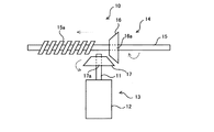
本発明の第1の実施形態によるヒートポンプにおける室外側熱交換器100を図1乃至図5に基づいて説明する。図1は、ヒートポンプにおける室外側熱交換器100の斜視図である。図2は、吸着装置10の正面図、図3は他の吸着装置10Aの平面図、図4は 吸水ローラの平面図、図5は脱水装置20の動作を説明する平面図である。
An
ヒートポンプにおける室外側熱交換器100は、例えば、ヒートポンプ式空調機の暖房運転時における蒸発器として機能するもので、熱媒体が流通するチューブ1と、チューブ1に熱的に接続された複数のフィン2と、を有する熱交換器本体3と、複数のフィン2に付着した水滴4を吸水性繊維12によって吸着する吸着装置10と、吸水性繊維12の脱水を行う脱水装置20とを備えて構成される。吸着装置10は、複数のフィンに付着した水滴4が霜となる前に、水滴4を吸水性繊維12によって吸着除去する。
The
複数のフィン2は、外気と熱媒体との熱交換を促進するための部材で、複数の金属板をチューブ2の周囲に取り付けたものである。複数のフィン2の端部は吸水性繊維12との当接面になっている。
The plurality of
吸着装置10は、ローラ軸11の周りに吸水性繊維12が円筒状に巻き付けられた吸水ローラ13と、吸水性樹脂12の外周面を複数のフィン2の端部に当接させながら、熱交換器本体3の一方の端5から他方の端6まで吸水ローラ13を回転移動させる回転移動装置14と、を備える。吸水性繊維12は、ポリウレタン、ポリオレフィン等からなり、水を吸着し、保水するための細かい穴が多数形成されている。
The
図2に示すように、回転移動装置14は、熱交換器本体3に沿って、水平に延びた支軸15と、第1の歯車16と、第2の歯車17と、を備える。第1の支軸15は長手方向に沿ってテーパ雌ネジ部15aを有している。第1の歯車16の軸穴16aに支軸15が挿通され、支軸15のテーパ雌ネジ部15aに係合すべく、第1の歯車16の軸穴16aの内面にテーパ雄ネジ部が刻設されている。なお、テーパ雌ネジ部15aは、支軸15における第1の歯車16の移動範囲の全体に渡って刻設されているが、図2においては、図面を見やすくするために、その一部分のみを示してある。
As shown in FIG. 2, the
吸水ローラ13のローラ軸11は、垂直に立っており、このローラ軸11の上端部は第2の歯車17の軸穴17aに挿通され、第2の歯車17に接続されている。第1の歯車16と第2の歯車17とは、直交軸(ローラ軸11と支軸15)の回転に使用される、いわゆるマイタ歯車である。
The
第1の歯車16を不図示の回転駆動機構により回転させると、第1の歯車16は支軸15に沿って水平移動するとともに、第2の歯車17が回転する。この第2の歯車17の回転に伴ってローラ軸11が回転し、ローラ軸11に巻き付けられた吸水性繊維12が回転する。すなわち、吸水ローラ13は回転しながら支軸15に沿って水平移動するようになっている。
When the
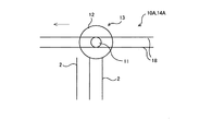
次に、他のタイプの吸着装置10Aの構成を図3に基づいて説明する。この吸着装置10Aは、ローラ軸11を挟んで、吸水ローラ13の水平移動をガイドするガイドレール18と、ローラ軸11を水平駆動する駆動装置(不図示)とを、備えた回転移動装置14Aを備えている。
Next, the configuration of another type of
この場合、円筒状に成形された吸水性繊維12は、ローラ軸11に対して、ローラ軸11を中心に回転自在に係合されている。また、吸水性繊維12の外周面が複数のフィン2の端部に当接するように配置され、ローラ軸11を水平移動させると、吸水性繊維12は複数のフィン2の端部に当接し、回転するようになっている。
In this case, the water
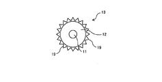
上述した吸着装置10,10Aを構成する吸水ローラ13において、図4に示すように、吸水性繊維12は、その外周面に複数のフィン2の端部の間に係合する、吸着性繊維12からなる複数の突起19を有していることが好ましい。このように構成することで、各突起19が隣接する一対のフィン2の端部の隙間に入り込み、フィン2の端面だけでなく、この隙間に付着した水滴4も吸着することができる。
In the
次に、脱水装置20の構成を図1及び図5に基づいて説明する。上述のように、吸着装置10,10Aは、複数のフィン2に付着した水滴4を吸水性繊維12によって吸着するが、水滴4を吸着して水分を多く含んだ吸水性繊維12は吸水性能が低下し、繰り返し使用することができなくなる。そこで、吸水性繊維12の脱水を行う脱水装置20が設けられている。
Next, the configuration of the
脱水装置20は、熱交換器本体3に隣接して配置され、回転移動装置14,14Aによって熱交換器本体3の外に移動した吸水ローラ13を両側から挟んで押圧し、且つ回転することで吸水ローラ13に巻き付けられた吸水性繊維12の脱水を行う一対の脱水ローラ21,22を備える。これにより、吸水性繊維12の吸水性能を復活させ、繰り返し使用することが可能になる。
The
次に、本発明の第2の実施形態によるヒートポンプにおける室外側熱交換器100Aを図6に基づいて説明する。ヒートポンプにおける室外側熱交換器100Aは、例えば、ヒートポンプ式空調機の暖房運転時における蒸発器として機能するもので、熱媒体が流通するチューブ1と、チューブ1に熱的に接続された複数のフィン2と、を有する熱交換器本体3と、複数のフィン2に付着した水滴4を吸水性繊維12によって吸着する吸着装置30と、吸水性繊維12の脱水を行う脱水装置40とを備えて構成される。
Next, an
吸着装置30は、熱交換器本体3の上下に回転軸を水平にして配置された一対の回転ローラ31,32と、一対の回転ローラ31,32に垂直方向に掛け渡され、一対の回転ローラ31,32の回転に伴って複数のフィン2の端部に当接しながら回動する吸水性繊維を有した吸水ベルト33と、を備えて構成される。吸着装置30は、複数のフィンに付着した水滴4が霜となる前に、水滴4を吸水ベルト33によって吸着除去する。
The
この場合、一対の回転ローラ31,32の一方のローラ軸は、不図示の回転駆動装置によって回転される。吸水ベルト33は、膜状の吸水性繊維によって構成してもよいし、ベルト本体の表面に膜状の吸水性樹脂を接着して構成してもよい。また、一対の回転ローラ31,32は、熱交換器本体3の左右に回転軸を垂直にして配置し、吸水ベルト33を水平方向に掛け渡してもよい。
In this case, one roller shaft of the pair of
上述のように、吸着装置30は、複数のフィン2に付着した水滴4を吸水ベルト33によって吸着するが、水滴4を吸着して水分を多く含んだ吸水ベルト33は吸水性能が低下し、繰り返し使用することができなくなる。
As described above, the
そこで、吸水ベルト33の脱水を行う脱水装置40が設けられている。脱水装置40は、一対の回転ローラ31,32のうち、一方の回転ローラを押圧することで吸水ベルト33の脱水を行う脱水ローラ41を備える。これにより、吸水ベルト33の吸水性能を復活させ、繰り返し使用することが可能になる。
Therefore, a
また、図6のように、一対の回転ローラ31,32を熱交換器本体3の上下に隣接して配置する場合、脱水ローラ41は、熱交換器本体3の下側に配置された回転ローラ32の下側に配置することで、吸水ベルト33が吸着した水滴4が落下して再び複数のフィン2に付着することがなく、熱交換器本体3の下方に落下させることができる。
Further, as shown in FIG. 6, when the pair of
以上説明したように、この室外側熱交換器100,100Aによれば、複数のフィン2に付着した水滴4を吸水性繊維12によって吸着する吸着装置10,10A,30と、吸水性繊維12の脱水を行う脱水装置20,30を備えているので、暖房運転を停止させることなく着霜を防止し、暖房性能の向上に大きく寄与することができる。
As described above, according to the
また、この室外側熱交換器100,100Aによれば、複数のフィン2に付着した水滴4が霜となる前に、水滴4を吸水性繊維で吸着除去するので、従来のような霜を溶かすものに比べてエネルギー消費を大幅に少なくすることができる。
Further, according to the
1 チューブ
2 フィン
3 熱交換器本体
4 水滴
5 一方の端
6 他方の端
10,10A 吸着装置
11 ローラ軸
12 吸水性繊維
13 吸水ローラ
14,14A 回転移動装置
15 支軸
15a テーパ雌ネジ部
16 第1の歯車
16a 軸穴
17 第2の歯車
17a 軸穴
18 ガイドレール
19 突起
20 脱水装置
21,22 脱水ローラ
30 脱水装置
31,32 回転ローラ
33 吸水ベルト
40 脱水装置
41 脱水ローラ
100,100A ヒートポンプにおける室外側熱交換器
DESCRIPTION OF SYMBOLS 1
Claims (6)
前記複数のフィンに付着した水滴を吸水性繊維によって吸着する吸着装置と、
前記吸水性繊維の脱水を行う脱水装置と、を備えることを特徴とするヒートポンプにおける室外側熱交換器。 A heat exchanger body having a tube through which a heat transfer medium flows, and a plurality of fins thermally connected to the tube;
An adsorption device for adsorbing water droplets attached to the plurality of fins by means of a water absorbing fiber;
And a dewatering device for dewatering the water-absorbent fibers.
前記一対の回転ローラに掛け渡され、前記一対の回転ローラの回転に伴って前記複数のフィンの端部に当接しながら回動する吸水性繊維を有した吸水ベルトと、を備えることを特徴とする請求項1に記載のヒートポンプにおける室外側熱交換器。 The adsorption device comprises a pair of rotating rollers disposed on both sides of the heat exchanger body;
And a water absorbing belt having a water absorbing fiber, which is wound around the pair of rotating rollers and rotates while being in contact with the ends of the plurality of fins with the rotation of the pair of rotating rollers. The outdoor heat exchanger in the heat pump according to claim 1.
Priority Applications (1)
| Application Number | Priority Date | Filing Date | Title |
|---|---|---|---|
| JP2017203274A JP2019078417A (en) | 2017-10-20 | 2017-10-20 | Outdoor side heat exchanger in heat pump |
Applications Claiming Priority (1)
| Application Number | Priority Date | Filing Date | Title |
|---|---|---|---|
| JP2017203274A JP2019078417A (en) | 2017-10-20 | 2017-10-20 | Outdoor side heat exchanger in heat pump |
Publications (2)
| Publication Number | Publication Date |
|---|---|
| JP2019078417A true JP2019078417A (en) | 2019-05-23 |
| JP2019078417A5 JP2019078417A5 (en) | 2020-10-08 |
Family
ID=66627623
Family Applications (1)
| Application Number | Title | Priority Date | Filing Date |
|---|---|---|---|
| JP2017203274A Pending JP2019078417A (en) | 2017-10-20 | 2017-10-20 | Outdoor side heat exchanger in heat pump |
Country Status (1)
| Country | Link |
|---|---|
| JP (1) | JP2019078417A (en) |
Cited By (1)
| Publication number | Priority date | Publication date | Assignee | Title |
|---|---|---|---|---|
| CN110260572A (en) * | 2019-06-18 | 2019-09-20 | 陈亚军 | A kind of defroster of A/C evaporator |
Citations (3)
| Publication number | Priority date | Publication date | Assignee | Title |
|---|---|---|---|---|
| JPH10305163A (en) * | 1997-05-06 | 1998-11-17 | Ace Denken:Kk | Cigar end disposal device |
| JP2002071168A (en) * | 2000-08-29 | 2002-03-08 | Yuuki:Kk | Radiation type air conditioning device |
| JP2010025442A (en) * | 2008-07-18 | 2010-02-04 | Sharp Corp | Defrosting device of heat exchanger and air conditioner comprising same |
-
2017
- 2017-10-20 JP JP2017203274A patent/JP2019078417A/en active Pending
Patent Citations (3)
| Publication number | Priority date | Publication date | Assignee | Title |
|---|---|---|---|---|
| JPH10305163A (en) * | 1997-05-06 | 1998-11-17 | Ace Denken:Kk | Cigar end disposal device |
| JP2002071168A (en) * | 2000-08-29 | 2002-03-08 | Yuuki:Kk | Radiation type air conditioning device |
| JP2010025442A (en) * | 2008-07-18 | 2010-02-04 | Sharp Corp | Defrosting device of heat exchanger and air conditioner comprising same |
Cited By (1)
| Publication number | Priority date | Publication date | Assignee | Title |
|---|---|---|---|---|
| CN110260572A (en) * | 2019-06-18 | 2019-09-20 | 陈亚军 | A kind of defroster of A/C evaporator |
Similar Documents
| Publication | Publication Date | Title |
|---|---|---|
| CN100476308C (en) | Humidity controller | |
| CN106062483B (en) | The Enhancement Method of heat-pump dehumidification | |
| US8701425B2 (en) | Refrigeration air conditioning system | |
| JP4958935B2 (en) | Dehumidifying air conditioner | |
| CN107869812B (en) | Integrated membrane solution heat pump system | |
| CN100507379C (en) | Adsorption heat exchanger | |
| CN101122406B (en) | Small central air-conditioning unit with separate treatment of heat and humidity | |
| EP2703762A2 (en) | Apparatus and method for evaporation cooling a cooling fluid | |
| CN101663545B (en) | Absorption-type freezing unit | |
| JP2001201106A (en) | Air conditioner | |
| JP2019078417A (en) | Outdoor side heat exchanger in heat pump | |
| KR101445378B1 (en) | Apparatus for dehumidifying and cooling air | |
| JP6065096B2 (en) | Humidity control device | |
| CN103791574A (en) | Device and method for heat medium exchanger changeover | |
| CN104729195B (en) | Space humidity control device and there is its refrigerator | |
| JP5470490B1 (en) | Desiccant dehumidifier, desiccant air conditioning system, and desiccant rotor | |
| US20070138662A1 (en) | Closed evaporative cooling tower | |
| WO2012108354A1 (en) | Moisture absorption/desorption unit, humidity conditioning system, and air humidity adjustment device | |
| CN107869867B (en) | Membrane method solution direct cooling type refrigeration equipment | |
| CN107869808B (en) | Heat recovery type membrane solution air conditioner | |
| JP2016084982A (en) | Dehumidifier | |
| CN107869810B (en) | Heat recovery type membrane solution heat pump system | |
| JPH0658643A (en) | Adsorptive type freezer | |
| CN107869811B (en) | Membrane solution wind type refrigeration equipment | |
| CN2926889Y (en) | Fixed water vapor siphon permeable honeycomb dehumidifier |
Legal Events
| Date | Code | Title | Description |
|---|---|---|---|
| A521 | Request for written amendment filed |
Free format text: JAPANESE INTERMEDIATE CODE: A523 Effective date: 20200825 |
|
| A621 | Written request for application examination |
Free format text: JAPANESE INTERMEDIATE CODE: A621 Effective date: 20200825 |
|
| A871 | Explanation of circumstances concerning accelerated examination |
Free format text: JAPANESE INTERMEDIATE CODE: A871 Effective date: 20200826 |
|
| A975 | Report on accelerated examination |
Free format text: JAPANESE INTERMEDIATE CODE: A971005 Effective date: 20200909 |
|
| A131 | Notification of reasons for refusal |
Free format text: JAPANESE INTERMEDIATE CODE: A131 Effective date: 20200914 |
|
| A02 | Decision of refusal |
Free format text: JAPANESE INTERMEDIATE CODE: A02 Effective date: 20210308 |


