JP2019076570A - Medicine discharge device, and medicine assortment device and medicine delivery system comprising the same - Google Patents
Medicine discharge device, and medicine assortment device and medicine delivery system comprising the same Download PDFInfo
- Publication number
- JP2019076570A JP2019076570A JP2017206944A JP2017206944A JP2019076570A JP 2019076570 A JP2019076570 A JP 2019076570A JP 2017206944 A JP2017206944 A JP 2017206944A JP 2017206944 A JP2017206944 A JP 2017206944A JP 2019076570 A JP2019076570 A JP 2019076570A
- Authority
- JP
- Japan
- Prior art keywords
- medicine
- tray
- roller
- unit
- receiving tray
- Prior art date
- Legal status (The legal status is an assumption and is not a legal conclusion. Google has not performed a legal analysis and makes no representation as to the accuracy of the status listed.)
- Pending
Links
Images


Landscapes
- Medical Preparation Storing Or Oral Administration Devices (AREA)
Abstract
Description
本発明は、薬品を排出する薬品排出装置およびこれを備えた薬品仕分装置、薬品払出システムに関する。 TECHNICAL FIELD The present invention relates to a medicine discharging apparatus for discharging medicine, a medicine sorting apparatus equipped with the same, and a medicine dispensing system.
近年、例えば、膨大な数、種類の薬品を扱う病院内における業務負担の軽減を図るために、処方箋情報に従って、自動的に所望の薬品をトレイに払い出す薬品払出装置が用いられている。
これにより、薬剤師等によって1つずつ必要な薬品をトレイに取り出す作業が自動化され、業務負担を大幅に軽減するとともに、取り出すべき薬品の種類や量を間違える等の人為的なミスの発生を防止することができる。
In recent years, for example, in order to reduce the work load in a hospital that handles a large number and types of drugs, a drug dispensing apparatus that automatically dispenses a desired drug onto a tray according to prescription information has been used.
This automates the task of taking out necessary medicines one by one to the tray by the pharmacist etc., greatly reducing the workload, and preventing the occurrence of human error such as mistaken type and quantity of medicine to be taken out. be able to.
また、薬品払出装置によって自動的に払い出されたトレイが病室等へ搬送された後、患者の容態が急変する等して、払い出された薬品が使用されることなく返品される場合がある。
このため、このような返品された薬品を、その種類や大きさ等に応じて自動的に仕分けを行う返品薬仕分け装置が用いられている。
In addition, after the tray automatically delivered by the drug delivery device is transported to a patient's room etc., the condition of the patient may be suddenly changed, and the delivered drug may be returned without being used. .
For this reason, a return medicine sorting apparatus is used which automatically sorts such returned medicines according to the type, size, and the like.
例えば、特許文献1には、カセットから適切な容器が取り出されたか否かを認識して、高精度に所望の容器を取り出す薬品払出装置について開示されている。
また、特許文献2には、非整列の状態で収納された返品薬を1つずつピッキングして、返品薬の種類や大きさ等を認識し、種類や大きさに応じて自動的に仕分けを行う返品薬仕分け装置について開示されている。
For example,
In addition, in
しかしながら、上記従来の薬品排出装置では、以下に示すような問題点を有している。
すなわち、上記公報に開示された薬品払出装置および薬品仕分装置では、薬品の払出し・仕分けを行う際に、所定の方向へ薬品を排出する排出機構を備えている。このような薬品の排出機構は、ガラス製の薬品等が排出時に破損しないように配慮する必要があるため、構成が複雑化しやすいという問題がある。
However, the above-mentioned conventional medicine discharging apparatus has the following problems.
That is, the medicine dispensing apparatus and the medicine sorting apparatus disclosed in the above publication are provided with a discharge mechanism for discharging the medicine in a predetermined direction when dispensing and sorting the medicine. Such a chemical discharge mechanism has a problem that the structure is likely to be complicated because it is necessary to take care not to damage the glass chemical or the like at the time of discharge.
本発明の課題は、簡素な構成により、薬品を所定の方向へ排出することが可能な薬品排出装置およびこれを備えた薬品仕分装置、薬品払出システムを提供することにある。 An object of the present invention is to provide a drug discharge device capable of discharging a drug in a predetermined direction, a drug assortment device including the same, and a drug discharge system with a simple configuration.
第1の発明に係る薬品排出装置は、薬品を所定の方向へ排出する薬品排出装置であって、円筒状のローラと、保持板と、薬品情報取得部と、連結部と、第1駆動部と、を備えている。円筒状のローラは、回転軸を有しており、回転軸を中心に回転する。保持板は、回転軸の方向から見て、ローラとともにV字部を形成するように配置されている。薬品情報取得部は、V字部に載置された状態でローラによって回転させた薬品の種類に関する情報を取得する。連結部は、ローラと保持板とを一体化する。第1駆動部は、ローラを第1方向に回転させるとともに、ローラと保持板とを第1方向とは反対の第2方向に回動させ薬品を所定の方向へ排出する。 The drug discharge device according to the first invention is a drug discharge device for discharging a drug in a predetermined direction, and includes a cylindrical roller, a holding plate, a drug information acquisition unit, a connection unit, and a first drive unit. And have. The cylindrical roller has a rotation axis and rotates around the rotation axis. The holding plate is arranged to form a V-shaped portion with the roller, as viewed in the direction of the rotation axis. The medicine information acquisition unit acquires information on the type of medicine rotated by the roller in a state of being placed in the V-shaped part. The connecting portion integrates the roller and the holding plate. The first driving unit rotates the roller in the first direction, rotates the roller and the holding plate in the second direction opposite to the first direction, and discharges the medicine in the predetermined direction.
ここでは、薬品を所定の方向へ排出する薬品排出装置において、互いに近接配置されたローラと保持板とによってローラの回転軸の方向から見てV字部を形成し、このV字部に薬品を載置した状態で第1駆動部によってローラを第1方向に回転させることで、薬品を回転させて薬品の表面に付された種類情報を取得する。そして、薬品の種類情報を取得した後、第1駆動部を第2方向に回転させることで、連結板によって一体化されているローラと保持板とを回動させて、V字部に載置された薬品を下流側へ排出する。 Here, in the medicine discharging apparatus for discharging the medicine in a predetermined direction, a V-shaped portion is formed by the roller and the holding plate disposed close to each other as seen from the direction of the rotation shaft of the roller, By rotating the roller in the first direction by the first drive unit in the mounted state, the medicine is rotated to acquire type information attached to the surface of the medicine. Then, after acquiring the type information of the medicine, the first drive unit is rotated in the second direction, so that the roller integrated with the connecting plate and the holding plate are rotated and placed on the V-shaped portion Discharge the medicines downstream.
ここで、本薬品排出装置は、例えば、返品された薬品等を種類ごとに仕分けして収納する薬品仕分装置や、処方箋情報に従って所定の払出しトレイへ所望の薬品を排出する薬品払出装置等に搭載される。そして、本薬品排出装置は、例えば、大量の薬品を扱う病院等に設置される。
そして、薬品情報取得部において取得される薬品の種類情報とは、例えば、薬剤の種類、薬品の容器の形状、大きさ、内容量等が含まれる。
Here, the medicine discharge device is mounted on, for example, a medicine sorting device for sorting and storing returned drugs etc. by type, a medicine dispensing device for discharging a desired medicine to a predetermined delivery tray according to prescription information, etc. Be done. And this medicine discharge device is installed in the hospital etc. which handle a large amount of medicine, for example.
The medicine type information acquired by the medicine information acquisition unit includes, for example, the type of medicine, the shape, size, and internal volume of the medicine container.
また、薬品情報取得部には、例えば、薬品に付されたバーコードや文字等の情報を読み取る手段、薬品の容器の形状や大きさ等の情報を取得する手段等が含まれる。
これにより、単一の第1駆動部を用いて、薬品の種類情報の取得時における薬品の回転動作と、種類情報の取得後における薬品の排出動作とを実施することができる。
よって、簡素な構成により、薬品を所定の方向へ排出することができる。
Further, the medicine information acquisition unit includes, for example, means for reading information such as barcodes and characters attached to medicine, and means for acquiring information such as the shape and size of a medicine container.
As a result, the rotation operation of the medicine at the time of acquisition of the medicine type information and the discharge operation of the medicine after the acquisition of the kind information can be performed using the single first drive unit.
Therefore, the medicine can be discharged in a predetermined direction with a simple configuration.
第2の発明に係る薬品排出装置は、薬品を所定の方向へ排出する薬品排出装置であって、円筒状のローラと、保持板と、薬品情報取得部と、第1駆動部と、第1付勢部と、第1クラッチと、第2クラッチと、を備えている。円筒状のローラは、回転軸を有しており、回転軸を中心に回転する。保持板は、ローラに近接配置されており、ローラとともに薬品が載置される凹部を形成する。薬品情報取得部は、薬品の種類に関する情報を取得する。第1駆動部は、薬品情報取得部が薬品の種類に関する情報を取得する際に、ローラを第1方向に回転させて薬品を回転させる。第1付勢部は、保持板を第1方向に向かって付勢する。第1クラッチは、第1駆動部とローラとに接続されており、第1方向において第1駆動部の回転駆動力をローラに伝達するとともに、第1方向とは反対の第2方向において回転駆動力をローラに伝達しない。第2クラッチは、第1駆動部と保持板とに接続されており、第1方向において第1駆動部の回転駆動力を保持板に伝達しないとともに、第2方向において回転駆動力を保持板に伝達する。 A drug discharge device according to a second aspect of the present invention is a drug discharge device for discharging a drug in a predetermined direction, which comprises a cylindrical roller, a holding plate, a drug information acquisition unit, a first drive unit, and a first drive unit. A biasing portion, a first clutch, and a second clutch are provided. The cylindrical roller has a rotation axis and rotates around the rotation axis. The holding plate is disposed close to the roller, and together with the roller forms a recess in which the medicine is placed. The medicine information acquisition unit acquires information on the type of medicine. The first drive unit rotates the roller in the first direction to rotate the medicine when the medicine information acquisition unit acquires information on the type of medicine. The first biasing unit biases the holding plate in the first direction. The first clutch is connected to the first drive unit and the roller, transmits the rotational driving force of the first drive unit to the roller in the first direction, and rotationally drives in the second direction opposite to the first direction. Do not transmit force to the rollers. The second clutch is connected to the first drive portion and the holding plate, and does not transmit the rotational driving force of the first drive portion to the holding plate in the first direction, and transmits the rotational driving force to the holding plate in the second direction. introduce.
ここでは、薬品を所定の方向へ排出する薬品排出装置において、互いに近接配置されたローラと保持板とによって薬品が載置される凹部が形成され、この凹部に薬品を載置した状態で、第1駆動部の回転駆動力がワンウェイクラッチ(第1クラッチ)を介して伝達されたローラを第1方向に回転させることで、薬品を回転させて薬品の表面に付された種類情報を取得する。そして、薬品の種類情報を取得した後、第1駆動部を第1方向とは反対の第2方向に回転させることで、第1駆動部の回転駆動力がワンウェイクラッチ(第2クラッチ)を介して連結板に伝達される。そして、第1付勢部によって第1方向に付勢された保持板が回転駆動力によって回動して、凹部に載置された薬品が下流側へ排出される。 Here, in the medicine discharging apparatus for discharging the medicine in a predetermined direction, a recess in which the medicine is placed is formed by the roller and the holding plate which are arranged close to each other, and the medicine is placed in the recess. (1) The medicine is rotated by rotating the roller in which the rotational driving force of the driving unit is transmitted through the one-way clutch (first clutch) in the first direction, and the type information attached to the surface of the medicine is acquired. Then, after acquiring the type information of the medicine, the rotational drive force of the first drive unit is transmitted through the one-way clutch (second clutch) by rotating the first drive unit in the second direction opposite to the first direction. Is transmitted to the connecting plate. Then, the holding plate biased in the first direction by the first biasing unit is rotated by the rotational driving force, and the medicine placed in the recess is discharged to the downstream side.
ここで、本薬品排出装置は、例えば、返品された薬品等を種類ごとに仕分けして収納する薬品仕分装置や、処方箋情報に従って所定の払出しトレイへ所望の薬品を排出する薬品払出装置等に搭載される。そして、本薬品排出装置が搭載された薬品仕分装置や薬品払出装置は、例えば、大量の薬品を扱う病院等に設置される。
そして、薬品情報取得部において取得される薬品の種類情報とは、例えば、薬剤の種類、薬品の容器の形状、大きさ、内容量等が含まれる。
Here, the medicine discharge device is mounted on, for example, a medicine sorting device for sorting and storing returned drugs etc. by type, a medicine dispensing device for discharging a desired medicine to a predetermined delivery tray according to prescription information, etc. Be done. Then, the medicine sorting apparatus and the medicine dispensing apparatus equipped with the medicine discharge apparatus are installed, for example, in a hospital that handles a large amount of medicine.
The medicine type information acquired by the medicine information acquisition unit includes, for example, the type of medicine, the shape, size, and internal volume of the medicine container.
また、薬品情報取得部には、例えば、薬品に付されたバーコードや文字等の情報を読み取る手段、薬品の容器の形状や大きさ等の情報を取得する手段等が含まれる。
さらに、第1クラッチおよび第2クラッチとしては、第1駆動部の回転駆動力を一方向に伝達し、他方向に伝達しない、いわゆるワンウェイクラッチが用いられる。
これにより、単一の第1駆動部を用いた構成であっても、2つのワンウェイクラッチを組み合わせて用いることで、薬品の種類情報取得時における薬品の回転動作と、保持板を回動させる薬品の排出動作とを実施することができる。
Further, the medicine information acquisition unit includes, for example, means for reading information such as barcodes and characters attached to medicine, and means for acquiring information such as the shape and size of a medicine container.
Furthermore, as the first clutch and the second clutch, a so-called one-way clutch that transmits the rotational drive force of the first drive unit in one direction and does not transmit in the other direction is used.
Thus, even if the single first drive unit is used, the combination operation of two one-way clutches causes the rotation operation of the medicine at the time of acquisition of the medicine type information, and the medicine for rotating the holding plate. And the discharge operation of the
よって、簡素な構成により、薬品を所定の方向へ排出することができる。
第3の発明に係る薬品排出装置は、薬品を所定の方向へ排出する薬品排出装置であって、薬品情報取得部と、薬品受けトレイと、第2駆動部と、第2付勢部と、第3クラッチと、備えている。薬品情報取得部は、薬品の種類に関する種類情報を取得する。薬品受けトレイは、種類情報が取得された薬品が搬送され、薬品を保持する。第2駆動部は、薬品を薬品受けトレイから排出する際に、薬品受けトレイを第3方向に回動させる。第2付勢部は、薬品受けトレイを第3方向に向かって付勢する。第3クラッチは、第2駆動部と薬品受けトレイとに接続されており、第3方向において第2駆動部の回転駆動力を薬品受けトレイに伝達しないとともに、第3方向とは反対の第4方向において第2駆動部の回転駆動力を薬品受けトレイに伝達する。
Therefore, the medicine can be discharged in a predetermined direction with a simple configuration.
The drug discharge device according to the third aspect of the present invention is a drug discharge device for discharging a drug in a predetermined direction, and includes a drug information acquisition unit, a drug receiving tray, a second drive unit, and a second urging unit. It has a third clutch. The medicine information acquisition unit acquires type information on the type of medicine. The medicine receiving tray carries the medicine whose type information has been acquired, and holds the medicine. The second driving unit rotates the medicine receiving tray in the third direction when discharging the medicine from the medicine receiving tray. The second biasing unit biases the medicine receiving tray in the third direction. The third clutch is connected to the second driving unit and the medicine receiving tray, and does not transmit the rotational driving force of the second driving unit to the medicine receiving tray in the third direction, and the fourth clutch is opposite to the third direction. The rotational driving force of the second drive unit is transmitted to the medicine receiving tray in the direction.
ここでは、薬品を所定の方向へ排出する薬品排出装置において、種類情報が取得された後で搬送されてきた薬品を保持するとともに、第2付勢部材によって第3方向に付勢された薬品受けトレイを回動させて薬品を排出する。そして、第3クラッチは、第3方向においては第2駆動部の回転駆動力を薬品受けトレイに伝達しないとともに、第3方向とは反対の第4方向において第2駆動部の回転駆動力を薬品受けトレイに伝達する。このため、薬品を排出した後、第2駆動部の回転駆動力が第3クラッチを介して伝達され、薬品受けトレイは、第4方向に回動されて閉状態へ移行する。 Here, the medicine discharging apparatus for discharging the medicine in a predetermined direction holds the medicine transported after the type information is acquired, and receives the medicine biased in the third direction by the second biasing member. Rotate the tray to discharge the medicine. The third clutch does not transmit the rotational drive force of the second drive unit to the medicine receiving tray in the third direction, and the rotational drive force of the second drive unit in the fourth direction opposite to the third direction. Transmit to the receiving tray. Therefore, after the medicine is discharged, the rotational driving force of the second drive unit is transmitted through the third clutch, and the medicine receiving tray is rotated in the fourth direction to shift to the closed state.
ここで、本薬品排出装置は、例えば、返品された薬品等を種類ごとに仕分けして収納する薬品仕分装置や、処方箋情報に従って所定の払出しトレイへ所望の薬品を排出する薬品払出装置等に搭載される。そして、本薬品排出装置が搭載された薬品仕分装置や薬品払出装置は、例えば、大量の薬品を扱う病院等に設置される。
そして、薬品情報取得部において取得される薬品の種類情報とは、例えば、薬剤の種類、薬品の容器の形状、大きさ、内容量等が含まれる。
Here, the medicine discharge device is mounted on, for example, a medicine sorting device for sorting and storing returned drugs etc. by type, a medicine dispensing device for discharging a desired medicine to a predetermined delivery tray according to prescription information, etc. Be done. Then, the medicine sorting apparatus and the medicine dispensing apparatus equipped with the medicine discharge apparatus are installed, for example, in a hospital that handles a large amount of medicine.
The medicine type information acquired by the medicine information acquisition unit includes, for example, the type of medicine, the shape, size, and internal volume of the medicine container.
また、薬品情報取得部には、例えば、薬品に付されたバーコードや文字等の情報を読み取る手段、薬品の容器の形状や大きさ等の情報を取得する手段等が含まれる。
さらに、第3クラッチとしては、第2駆動部の回転駆動力を、薬品受けトレイを閉じる方向(第4方向)に伝達し、薬品を排出するために開ける方向(第3方向)に伝達しない、いわゆるワンウェイクラッチが用いられる。
Further, the medicine information acquisition unit includes, for example, means for reading information such as barcodes and characters attached to medicine, and means for acquiring information such as the shape and size of a medicine container.
Furthermore, as the third clutch, the rotational driving force of the second drive unit is transmitted in the medicine reception tray closing direction (fourth direction) and is not transmitted in the opening direction (third direction) for discharging the medicine. A so-called one-way clutch is used.
これにより、上流側から搬送されてくる薬品を受けて排出する際には、第2付勢部材によって薬品受けトレイを開状態へ移行させるとともに、開状態から閉状態へ移行する際には、第2駆動部の回転駆動力を薬品受けトレイへ伝達して第4方向へ回動させて閉状態へ移行することができる。
この結果、単一の駆動源(第2駆動部)を用いた簡素な構成により、薬品を所定の方向へ排出することができる。
As a result, when the medicine conveyed from the upstream side is received and discharged, the second urging member causes the medicine receiving tray to shift to the open state, and when transitioning from the open state to the closed state, (2) The rotational driving force of the drive unit can be transmitted to the medicine receiving tray and rotated in the fourth direction to shift to the closed state.
As a result, the medicine can be discharged in a predetermined direction by a simple configuration using a single drive source (second drive unit).
第4の発明に係る薬品排出装置は、第3の発明に係る薬品排出装置であって、薬品受けトレイは、患者ごとに作成された処方箋情報に基づいて薬品が払い出される払出しトレイに対して、薬品を排出する。
ここでは、第2駆動部の回転駆動力が第3クラッチを介して伝達される薬品受けトレイは、処方箋情報に基づいて所望の薬品が払い出される払出しトレイに対して薬品を排出する。
The medicine discharge apparatus according to the fourth invention is the medicine discharge apparatus according to the third invention, wherein the medicine receiving tray is for a discharge tray from which medicine is discharged based on prescription information created for each patient, Discharge the medicine.
Here, the medicine receiving tray to which the rotational driving force of the second drive unit is transmitted through the third clutch discharges the medicine to a dispensing tray from which the desired medicine is dispensed based on the prescription information.
これにより、薬品情報取得部によって取得された種類情報と処方箋情報とに基づいて、払出しトレイに所望の薬品を排出することができる。
よって、本薬品排出装置を、薬品払出装置として用いることができる。
薬品払出装置として機能させることができる。
第5の発明に係る薬品排出装置は、第3または第4の発明に係る薬品排出装置であって、薬品受けトレイ、第2駆動部および第3クラッチを含む構造体を、上下方向に移動させる構造体搬送部を、さらに備えている。
Thereby, a desired medicine can be discharged to the delivery tray based on the type information and the prescription information acquired by the medicine information acquisition unit.
Therefore, this medicine discharge device can be used as a medicine discharge device.
It can function as a medicine dispensing device.
A medicine discharge apparatus according to a fifth invention is the medicine discharge apparatus according to the third or fourth invention, which vertically moves a structure including a medicine receiving tray, a second drive unit, and a third clutch. A structure transfer unit is further provided.
ここでは、薬品受けトレイと第2駆動部と第3クラッチを含む構造体を、構造体搬送部によって上下方向に移動させる。
これにより、薬品受けトレイを回動させて薬品を排出する際には、排出先となる払出しトレイ等に対して近接する位置まで下降することができる。
よって、薬品受けトレイから排出される薬品に衝撃を付与することなく、薬品を排出することができる。
Here, the structure transfer unit moves the structure including the medicine receiving tray, the second drive unit, and the third clutch in the vertical direction.
Thus, when the medicine receiving tray is rotated to discharge the medicine, the medicine receiving tray can be lowered to a position close to the delivery tray as the discharge destination.
Therefore, the medicine can be discharged without giving an impact to the medicine discharged from the medicine receiving tray.
第6の発明に係る薬品排出装置は、第5の発明に係る薬品排出装置であって、構造体搬送部が、所定の排出位置まで構造体を下降させると、薬品受けトレイは、薬品受けトレイの回動軸とは反対側の端部が払出しトレイに当接するまで回動する。
ここでは、薬品受けトレイから薬品を排出する際に、構造体を下降させながら薬品受けトレイを回動させて、薬品受けトレイの端部を払出しトレイに当接させる。
A medicine discharge device according to a sixth aspect of the present invention is the medicine discharge device according to the fifth aspect, wherein when the structure conveyance unit lowers the structure to a predetermined discharge position, the medicine receiving tray is a medicine receiving tray Until the end opposite to the pivoting axis of the shaft abuts against the payout tray.
Here, when the medicine is discharged from the medicine receiving tray, the medicine receiving tray is rotated while lowering the structure, and the end of the medicine receiving tray is brought into contact with the dispensing tray.
これにより、薬品受けトレイから薬品が排出される際には、薬品受けトレイの端部が払出しトレイに当接した状態となるため、薬品が払出しトレイへ落下して衝撃が付与される等の不具合を回避することができる。
第7の発明に係る薬品排出装置は、第5または第6の発明に係る薬品排出装置であって、薬品受けトレイが、薬品受けトレイの回動軸とは反対側の端部が払出しトレイに当接するまで回動すると、構造体搬送部は、薬品受けトレイがさらに回動している間に、排出位置から構造体を上昇させる。
As a result, when the medicine is discharged from the medicine receiving tray, the end of the medicine receiving tray is in contact with the dispensing tray, so that the medicine is dropped to the dispensing tray and an impact is given, etc. Can be avoided.
The medicine discharge apparatus according to the seventh invention is the medicine discharge apparatus according to the fifth or sixth invention, wherein the medicine receiving tray has an end opposite to the rotation axis of the medicine receiving tray being a discharge tray. When pivoted to abut, the structure transfer section raises the structure from the discharging position while the medicine receiving tray is further rotated.
ここでは、上述したように、薬品受けトレイが払出しトレイに当接した状態まで回動すると、構造体搬送部によって、薬品受けトレイを含む構造体が上昇する。
これにより、薬品受けトレイが払出しトレイに当接した後、薬品受けトレイをさらに回動させることで、薬品受けトレイに保持された薬品に衝撃等を付与することなく、安全に排出することができる。
Here, as described above, when the medicine receiving tray is rotated to a state in which the medicine receiving tray abuts on the dispensing tray, the structure conveying unit raises the structure including the medicine receiving tray.
Thus, by rotating the medicine receiving tray further after the medicine receiving tray abuts on the delivery tray, the medicine held in the medicine receiving tray can be safely discharged without applying an impact or the like. .
第8の発明に係る薬品仕分装置は、第1から第7の発明のいずれか1つに係る薬品排出装置と、薬品を保持して搬送する搬送部と、薬品を種類ごとに仕分けして所定の収納トレイへ搬送するように搬送部を制御する制御部と、を備えている。
ここでは、上述した薬品排出装置と、薬品を搬送する搬送部と、搬送部を制御して所定の収納トレイへ薬品を種類ごとに収納する制御部と、を備えた薬品仕分装置を構成する。
The medicine sorting apparatus according to the eighth invention is a medicine dispensing apparatus according to any one of the first to seventh inventions, a transport unit for holding and transporting medicines, and medicines sorted according to types. And a control unit that controls the conveyance unit to convey the sheet to the storage tray.
Here, a medicine sorting apparatus including the above-described medicine discharge device, a transport unit for transporting the medicine, and a control unit for controlling the transport unit to store the medicine for each type in a predetermined storage tray is configured.
これにより、上述したように、簡易な構成によって所望の薬品を排出することが可能な薬品仕分装置を得ることができる。
第9の発明に係る薬品払出システムは、第8の発明に係る薬品仕分装置と、処方箋情報に基づいて、薬品仕分装置から払い出された薬品以外の薬品を払出しトレイに払い出す薬品払出装置と、を備えている。
Thus, as described above, it is possible to obtain a medicine sorting apparatus capable of discharging a desired medicine with a simple configuration.
A medicine dispensing system according to a ninth aspect of the present invention is a medicine dispensing apparatus according to the eighth aspect, and a medicine dispensing apparatus for dispensing medicines other than medicine dispensed from the medicine sorting apparatus onto a dispensing tray based on prescription information. And.
ここでは、上述した薬品仕分装置と、薬品払出装置とを含む薬品払出システムを構成する。
これにより、上述した薬品仕分装置において仕分けされた返品薬等の薬品を、再度、処方箋情報に基づいて再利用するとともに、処方箋情報に基づいて所望の薬品を払出しトレイへ払い出すことができる。
Here, a medicine dispensing system including the medicine sorting apparatus described above and the medicine dispensing apparatus is configured.
Thus, it is possible to reuse again the medicine such as the return medicine sorted in the medicine sorting apparatus described above based on the prescription information, and to pay out the desired medicine to the delivery tray based on the prescription information.
本発明に係る薬品排出装置によれば、簡素な構成により、薬品を所定の方向へ排出することができる。 According to the medicine discharge device according to the present invention, medicine can be discharged in a predetermined direction with a simple configuration.
本発明の一実施形態に係る薬品排出装置(第2薬品確認部40)を搭載した薬品仕分装置10および薬品払出システム100について、図1〜図28(d)を用いて説明すれば以下の通りである。
(薬品払出システム100の構成)
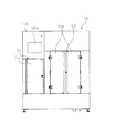
本実施形態に係る薬品払出システム100は、例えば、病院等に設置されており、患者ごとに作成される処方箋情報に基づいて所定の払出しトレイT3に対して必要な薬品Dを払い出す。そして、薬品払出システム100は、図1に示すように、トレイ供給装置101、プラボトル払出装置102、薬品仕分装置10、アンプルバイアル払出装置104、ラベル注射箋投入装置105、およびトレイ収納移載装置106を備えている。
The
(Configuration of drug delivery system 100)
The
トレイ供給装置101は、図1に示すように、薬品払出システム100の最上流側(図1中の左端)に配置されている。そして、トレイ供給装置101は、払出しトレイT3が積み重ねた状態でセットされており、下流側へ空の払出しトレイT3を供給する。
プラボトル払出装置102は、プラボトル状の薬品Dを保管しており、図1に示すように、トレイ供給装置101の下流側に配置されている。そして、プラボトル払出装置102は、トレイ供給装置101から搬送されてくる払出しトレイT3に対して、処方箋情報に含まれる薬剤が入ったプラボトル(薬品D)を払い出す。
The
The
薬品仕分装置10は、例えば、患者ごとの処方箋情報に基づいて病室等へ搬出された薬品のうち、患者の容態の急変等によって返品された薬品Dを、所定の収納トレイT2へ仕分けして収納する。
具体的には、薬品仕分装置10は、図1に示すように、プラボトル払出装置102の下流側に配置されている。そして、薬品仕分装置10は、薬品仕分装置10内において仕分け処理されて収納トレイT2に収納された返品薬を、処方箋情報に基づいて取り出して、払出しトレイT3に対して払い出す。
The
Specifically, as shown in FIG. 1, the
これにより、返品された薬品Dは、薬剤の有効期限等が確認された後、再度、患者へ投与される薬品として払出しトレイT3へ払い出されることで、再利用される。
ここで、薬品仕分装置10は、プラボトル払出装置102の上流側に配置されていてもよい。
ただし、一般的に、プラボトル状の薬品Dは大きく重いものが多いため、薬品仕分装置10から払い出されたアンプル状の薬品D等を破損させるリスクを考慮すれば、プロボトルを最初に払出しトレイT3に払い出しておくことが望ましい。よって、薬品仕分装置10は、図1に示す位置に配置されていることが好ましい。
Thereby, the returned drug D is reused by being paid out to the delivery tray T3 again as the drug to be administered to the patient after the expiration date and the like of the drug are confirmed.
Here, the
However, in general, plastic bottles D are large and heavy, so taking into consideration the risk of damaging ampoule D, etc. dispensed from
なお、薬品仕分装置10の詳細な構成については、後段にて詳述する。
アンプルバイアル払出装置104は、アンプル状の薬品Dを保管しており、図1に示すように、薬品仕分装置10の下流側に配置されている。そして、アンプルバイアル払出装置104は、上流側から搬送されてくる払出しトレイT3に対して、処方箋情報に含まれており、薬品仕分装置10から払い出されていないアンプルバイアル(薬品D)を払い出す。
The detailed configuration of the
The ampoule
すなわち、薬品仕分装置10の下流側に配置されたアンプルバイアル払出装置104は、処方箋情報に含まれる薬品のうち、プラボトル払出装置102および薬品仕分装置10から払い出された薬品D以外の不足分を払出しトレイT3へ払い出す。
ラベル注射箋投入装置105は、患者名、処方箋情報等を所定のラベルに印刷する装置であって、図1に示すように、アンプルバイアル払出装置104の下流側に配置されている。そして、ラベル注射箋投入装置105は、処方箋情報に基づいて、処方箋情報等が印刷されたラベルを作成して、上流側から搬送されてくる払出しトレイT3に投入する。これにより、薬剤師等は、払出しトレイT3に投入されたラベルを確認して、払出しトレイT3に払い出された薬品Dが適切であるか否かを容易に確認することができる。
That is, the ampoule
The label injection
トレイ収納移載装置106は、図1に示すように、ラベル注射箋投入装置105の下流側であって、薬品払出システム100の最下流側(図1中の右端)に配置されている。そして、トレイ収納移載装置106は、処方箋情報に基づいて払い出された薬品Dとラベルとを含む払出しトレイT3を収納しており、薬剤師等によって必要な払出しトレイT3が取り出される。
As shown in FIG. 1, the tray storage and
薬品払出システム100では、以上の構成により、払出しトレイT3に対して、処方箋情報に基づいて適切な薬品Dを払い出すとともに、薬品仕分装置10によって自動的に仕分けして収納トレイT2に収納された返品薬を再利用することができる。
(薬品仕分装置10の構成)
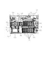
本実施形態の薬品仕分装置10は、図2に示すように、本体部10aと、本体部10aの正面に取り付けられた扉10b,10cと、モニタ50aと、を備えている。
With the above-described configuration, the
(Configuration of drug sorting apparatus 10)
As shown in FIG. 2, the
なお、本実施形態において、薬品仕分装置10の正面とは、図2に示す正面を意味しており、背面とはその反対側の面を意味するものとする。
本体部10aは、略直方体形状の筐体であって、正面に2つの扉10b,10cが開閉可能な状態で取り付けられている。
扉10bを開けると、図3に示すように、返品された複数の薬品Dが非整列の状態で載置された返品薬トレイT1が収納される返品薬トレイ収納空間S1が外部に露出する。そして、返品薬トレイ収納空間S1には、鉛直方向に沿って複数の返品薬トレイT1がセットされる返品薬トレイ設置部11が設けられている。そして、病室等から返品された薬品Dは、返品薬トレイT1に非整列に入れられた状態で、薬剤師等によって返品薬トレイ収納空間S1内の返品薬トレイ設置部11へ積み重ねるようにセットされる。
In the present embodiment, the front of the
The
When the
扉10cを開けると、図3に示すように、返品後に仕分けされた薬品Dを各種類ごとに収納する収納トレイT2が載置される収納トレイ載置空間S3が外部に露出する。そして、収納トレイ載置空間S3には、鉛直方向および水平方向に沿って幅等が異なる複数種類の収納トレイT2が設置される収納トレイ設置部(トレイ設置部)12が設けられている。そして、病室等から返品された薬品Dは、薬品仕分装置10内において種類等によって仕分けされ、自動的に、収納トレイ設置部12に設置された適切な収納トレイT2へ収納される。
When the
収納トレイ設置部12には、鉛直方向および水平方向に複数の収納トレイT2が配列されており、薬剤師等の使用者は、本体部10aの正面の扉10cを開けて、収納トレイT2の着脱を行う。
モニタ50aは、本体部10aの正面における左上部に設けられており、各種設定の入力を受け付けるとともに、設定画面、エラー発生画面等の各種表示を行う。そして、モニタ50aは、薬品仕分装置10を制御する制御部50(図8参照)に接続されている。
A plurality of storage trays T2 are arrayed in the vertical direction and the horizontal direction in the storage
The
(薬品Dの種類)
ここで、本実施形態の薬品払出システム100において扱われる薬品Dは、図4(a)〜図4(d)に示すように、内包する薬剤、形状・大きさが異なる複数種類の薬品を含んでいる。具体的には、薬品Dには、図4(a)に示すように、細長い外形で短いアンプル状の形状を有する薬品D1、図4(b)に示すように、細長い外形で長いアンプル状の形状を有する薬品D2、図4(c)に示すように、太いボトル状の形状を有する薬品D3、図4(d)に示すように、太く長いボトル状の形状を有する薬品D4等が含まれる。
(Type of drug D)
Here, as shown in FIG. 4A to FIG. 4D, the medicine D handled in the
なお、図4(a)〜図4(d)に示す薬品D1〜D4は、本実施形態の薬品仕分装置10において扱われる薬品Dの一例であって、実際には、さらに多くの形状、種類の薬品が扱われるものとする。
よって、本実施形態の薬品仕分装置10では、多種多様な形状、大きさを有する薬品D1〜D4等を仕分け処理して、各薬品D1〜D4に対応する適切な大きさ、幅を有する収納トレイT2へ収納するための制御を実施する。
The drugs D1 to D4 shown in FIGS. 4 (a) to 4 (d) are an example of the drug D handled in the
Therefore, in the
また、各薬品D1〜D4の外周面には、それぞれの薬品D1〜D4に内包された薬剤の種類等の種類情報が記録されたバーコード(種類情報)B1が付されている。
なお、バーコードB1に記録された種類情報は、薬品仕分装置10に搭載された2つのバーコードリーダ25,31によって読み取られる。
さらに、返品された薬品Dは、図5に示すように、返品薬専用の返品薬トレイT1に非整列の状態で載置され、そのまま薬品仕分装置10内の返品薬トレイ設置部11にセットされる。
Further, on the outer peripheral surface of each drug D1 to D4, a bar code (type information) B1 in which type information such as the type of drug contained in each drug D1 to D4 is recorded is attached.
The type information recorded in the barcode B1 is read by the two
Furthermore, as shown in FIG. 5, the returned drug D is placed on the returned drug tray T1 exclusively for returned drugs in an unaligned state, and is set as it is in the returned drug
(収納トレイT2の種類)
本実施形態の薬品仕分装置10では、上述した多種多様な薬品Dを種類ごとに仕分けして、各薬品Dに対応する複数種類の収納トレイT2の中から適切な収納トレイT2を選択して収納する。
本実施形態では、図6に示すように、トレイ番号1〜5が付され、薬品Dを保持する凹部T2z(図7(a)等参照)のピッチ、幅、薬品Dの入り数等が異なる5種類の収納トレイT2が用いられている。なお、図6に示す5種類の収納トレイT2のトレイ番号、凹部T2zのピッチ、幅等の識別情報は、後述する記憶部51に予め保存されている。
(Type of storage tray T2)
In the
In the present embodiment, as shown in FIG. 6,
トレイ番号1の収納トレイT2a(図7(a)参照)は、図6に示すように、幅S(スモール)サイズ、凹部T2zのピッチ21mm、薬品Dの入り数10個、薬品仕分装置10にセットされている全トレイ数15個、全収納薬品数150個のトレイである。よって、収納トレイT2aには、アンプルバイアル等の細く短い薬品Dが収納される。
具体的には、収納トレイT2aは、図7(a)に示すように、長手方向における第1端部にバーコード(識別情報)B2、その反対側の第2端部に取っ手Nがそれぞれ設けられている。また、収納トレイT2aの薬品Dが収納される内部には、複数の凹凸(凹部T2z)が形成されている。
As shown in FIG. 6, the storage tray T2a (refer to FIG. 7A) of the tray No. 1 has a width S (small) size, a
Specifically, as shown in FIG. 7A, the storage tray T2a is provided with a bar code (identification information) B2 at the first end in the longitudinal direction and a handle N at the second end on the opposite side. It is done. A plurality of concavities and convexities (concave portions T2z) are formed in the storage tray T2a in which the medicine D is stored.
バーコードB2は、収納トレイT2aの種類(ピッチ、幅等)に関する識別情報が記録されており、後述するバーコードリーダ25によってその識別情報が読み取られて取得される。
収納トレイT2aの底面に形成された複数の凹凸を形成する凹部T2zは、各薬品Dの形状・大きさに合わせて形成されており、一定のピッチで設けられている。そして、凹部T2zは、窪みの部分において、収納トレイT2aに搬送されてきた薬品Dを保持する。
In the barcode B2, identification information on the type (pitch, width, etc.) of the storage tray T2a is recorded, and the identification information is read and acquired by a
Recesses T2z for forming a plurality of irregularities formed on the bottom surface of the storage tray T2a are formed in accordance with the shape and size of each medicine D, and are provided at a constant pitch. And the recessed part T2z hold | maintains the chemical | medical agent D conveyed to the storage tray T2a in the part of a hollow.
トレイ番号2の収納トレイT2b(図7(b)参照)は、図6に示すように、幅S(スモール)サイズ、凹部T2zのピッチ38mm、薬品Dの入り数5個、薬品仕分装置10にセットされている全トレイ数15個、全収納薬品数75個のトレイである。よって、収納トレイT2bには、細く、長さが中程度の薬品Dが収納される。
具体的には、収納トレイT2bは、図7(b)に示すように、長手方向における第1端部にバーコード(識別情報)B2、その反対側の第2端部に取っ手Nがそれぞれ設けられている。また、収納トレイT2bの薬品Dが収納される内部には、複数の凹凸(凹部T2z)が形成されている。
As shown in FIG. 6, the storage tray T2b of tray No. 2 (see FIG. 7B) has a width S (small) size, a pitch of 38 mm for the concave portion T2z, the number of medicines D contained, and the
Specifically, as shown in FIG. 7B, the storage tray T2b is provided with a bar code (identification information) B2 at the first end in the longitudinal direction and a handle N at the second end on the opposite side. It is done. A plurality of concavities and convexities (concave portions T2z) are formed in the storage tray T2b in which the medicine D is stored.
バーコードB2は、収納トレイT2bの種類(ピッチ、幅等)に関する識別情報が記録されており、後述するバーコードリーダ25によってその識別情報が読み取られて取得される。
収納トレイT2bの底面に形成された複数の凹凸を形成する凹部T2zは、各薬品Dの形状・大きさに合わせて形成されており、一定のピッチで設けられている。そして、凹部T2zは、窪みの部分において、収納トレイT2bに搬送されてきた薬品Dを保持する。
In the barcode B2, identification information on the type (pitch, width, etc.) of the storage tray T2b is recorded, and the identification information is read and acquired by the
Recesses T2z forming a plurality of irregularities formed on the bottom surface of the storage tray T2b are formed in accordance with the shape and size of each medicine D, and are provided at a constant pitch. Then, the recess T2z holds the medicine D transported to the storage tray T2b at the portion of the recess.
トレイ番号3の収納トレイT2は、図6に示すように、幅M(ミディアム)サイズ、凹部T2zのピッチ21mm、薬品Dの入り数10個、薬品仕分装置10にセットされている全トレイ数10個、全収納薬品数100個のトレイである。よって、収納トレイT2には、プラボトル等の太く、短い薬品Dが収納される。
具体的には、収納トレイT2は、長手方向における第1端部にバーコード(識別情報)B2、その反対側の第2端部に取っ手Nがそれぞれ設けられている。また、収納トレイT2の薬品Dが収納される内部には、複数の凹凸(凹部T2z)が形成されている。
As shown in FIG. 6, the storage tray T2 of tray No. 3 has a width M (medium) size, a
Specifically, the storage tray T2 is provided with a bar code (identification information) B2 at a first end in the longitudinal direction, and a handle N at a second end on the opposite side. A plurality of concavities and convexities (concave portions T2z) are formed inside the medicine tray D of the storage tray T2.
バーコードB2は、収納トレイT2の種類(ピッチ、幅等)に関する識別情報が記録されており、後述するバーコードリーダ25によってその識別情報が読み取られて取得される。
収納トレイT2の底面に形成された複数の凹凸を形成する凹部T2zは、各薬品Dの形状・大きさに合わせて形成されており、一定のピッチで設けられている。そして、凹部T2zは、窪みの部分において、収納トレイT2に搬送されてきた薬品Dを保持する。
In the barcode B2, identification information on the type (pitch, width, etc.) of the storage tray T2 is recorded, and the identification information is read and acquired by the
Recesses T2z for forming a plurality of irregularities formed on the bottom surface of the storage tray T2 are formed in accordance with the shape and size of each medicine D, and are provided at a constant pitch. And the recessed part T2z hold | maintains the chemical | medical agent D conveyed to the storage tray T2 in the part of a hollow.
トレイ番号4の収納トレイT2c(図7(c)参照)は、図6に示すように、幅M(ミディアム)サイズ、凹部T2zのピッチ38mm、薬品Dの入り数5個、薬品仕分装置10にセットされている全トレイ数10個、全収納薬品数50個のトレイである。よって、収納トレイT2cには、太く、長さは中程度の薬品Dが収納される。
具体的には、収納トレイT2cは、図7(c)に示すように、長手方向における第1端部にバーコード(識別情報)B2、その反対側の第2端部に取っ手Nがそれぞれ設けられている。また、収納トレイT2cの薬品Dが収納される内部には、複数の凹凸(凹部T2z)が形成されている。
As shown in FIG. 6, the storage tray T2c (refer to FIG. 7C) of tray No. 4 has a width M (medium) size, a
Specifically, as shown in FIG. 7C, the storage tray T2c is provided with a bar code (identification information) B2 at the first end in the longitudinal direction and a handle N at the second end on the opposite side. It is done. Further, a plurality of concavities and convexities (concave portions T2z) are formed inside the medicine tray D of the storage tray T2c.
バーコードB2は、収納トレイT2cの種類(ピッチ、幅等)に関する識別情報が記録されており、後述するバーコードリーダ25によってその識別情報が読み取られて取得される。
収納トレイT2cの底面に形成された複数の凹凸を形成する凹部T2zは、各薬品Dの形状・大きさに合わせて形成されており、一定のピッチで設けられている。そして、凹部T2zは、窪みの部分において、収納トレイT2cに搬送されてきた薬品Dを保持する。
In the barcode B2, identification information on the type (pitch, width, etc.) of the storage tray T2c is recorded, and the identification information is read and acquired by the
Recesses T2z for forming a plurality of irregularities formed on the bottom surface of the storage tray T2c are formed in accordance with the shape and size of each medicine D, and are provided at a constant pitch. And the recessed part T2z hold | maintains the chemical | medical agent D conveyed to the storage tray T2c in the part of a hollow.
トレイ番号5の収納トレイT2は、図6に示すように、幅L(ラージ)サイズ、凹部T2zのピッチ38mm、薬品Dの入り数5個、薬品仕分装置10にセットされている全トレイ数6個、全収納薬品数30個のトレイである。よって、収納トレイT2には、大型のプラボトル等の最も太くて長い薬品Dが収納される。
具体的には、収納トレイT2は、長手方向における第1端部にバーコード(識別情報)B2、その反対側の第2端部に取っ手Nがそれぞれ設けられている。また、収納トレイT2の薬品Dが収納される内部には、複数の凹凸(凹部T2z)が形成されている。
As shown in FIG. 6, the storage tray T2 having the
Specifically, the storage tray T2 is provided with a bar code (identification information) B2 at a first end in the longitudinal direction, and a handle N at a second end on the opposite side. A plurality of concavities and convexities (concave portions T2z) are formed inside the medicine tray D of the storage tray T2.
バーコードB2は、収納トレイT2の種類(ピッチ、幅等)に関する識別情報が記録されており、後述するバーコードリーダ25によってその識別情報が読み取られて取得される。
収納トレイT2の底面に形成された複数の凹凸を形成する凹部T2zは、各薬品Dの形状・大きさに合わせて形成されており、一定のピッチで設けられている。そして、凹部T2zは、窪みの部分において、収納トレイT2に搬送されてきた薬品Dを保持する。
In the barcode B2, identification information on the type (pitch, width, etc.) of the storage tray T2 is recorded, and the identification information is read and acquired by the
Recesses T2z for forming a plurality of irregularities formed on the bottom surface of the storage tray T2 are formed in accordance with the shape and size of each medicine D, and are provided at a constant pitch. And the recessed part T2z hold | maintains the chemical | medical agent D conveyed to the storage tray T2 in the part of a hollow.
なお、上述した5種類の収納トレイT2a〜T2c等は、図7(a)〜図7(c)等に示すように、外観上、S,M,Lという3種類の幅と、共通の高さ、奥行きを有している。
(薬品仕分装置10の内部の構成)
本実施形態の薬品仕分装置10は、制御部50を中心にして、図8に示す制御ブロックを構成する。
The five types of storage trays T2a to T2c and the like described above have three types of widths S, M, and L and a common height in appearance as shown in FIGS. 7A to 7C and the like. Have a depth.
(Internal configuration of the medicine sorting apparatus 10)
The
制御部50は、薬品仕分装置10の内部に設けられており、図8に示すように、モニタ50a、返品薬トレイ搬送部13、カメラC1,C2、ピッキング部(第1搬送部)20、第1薬品確認部30、バーコードリーダ(薬品情報取得部)25、バーコードリーダ31、収納トレイ搬送部14、第2薬品確認部(薬品排出装置)40、記憶部51および処方箋情報取得部60と接続されている。
The
返品薬トレイ搬送部13は、上述した本体部10aに取り付けられた扉10bを開けて返品薬トレイ設置部11にセットされた返品薬トレイT1を、所定の方向へ搬送する。
具体的には、返品薬トレイ搬送部13は、図9に示すように、本体部10a内における正面側に配置された返品薬トレイ収納空間S1から、背面側に配置されたピッキング空間S2へと、返品薬トレイT1を搬送する。
The returned drug
Specifically, as shown in FIG. 9, the returned drug
すなわち、本実施形態の薬品仕分装置10では、仕分運転が開始されると、図9に示すように、返品薬トレイ搬送部13が返品された複数の薬品Dが非整列の状態で載置された返品薬トレイT1を、返品薬トレイ収納空間S1から所定のピッキング空間S2側へと搬送する。
収納トレイ搬送部14は、上述した本体部10aに取り付けられた扉10cを開けて収納トレイ設置部12にセットされた複数の収納トレイT2を、所定の方向へ搬送する。
That is, in the
The storage
具体的には、収納トレイ搬送部14は、図9および図10に示すように、本体部10a内における正面側に配置された収納トレイ載置空間S3から、背面側に配置された返品薬仕分け空間S4へと、収納トレイT2を搬送する。
すなわち、本実施形態の薬品仕分装置10では、仕分運転が開始されると、図9に示すように、収納トレイ搬送部14が、ピッキング部20によって吸着搬送される薬品Dを収納する適切な収納トレイT2を、収納トレイ載置空間S3から返品薬仕分け空間S4側へと搬送する。
Specifically, as shown in FIG. 9 and FIG. 10, the storage
That is, in the
なお、本実施形態の薬品仕分装置10では、収納トレイ搬送部14は、鉛直方向に沿って配置された各段の収納トレイT2のうち、所望の段の高さに移動して、所望の収納トレイT2を返品薬仕分け空間S4へと搬送する。
カメラC1は、図12に示すように、ピッキング空間S2に搬送された返品薬トレイT1の上方に設けられている。そして、カメラC1は、ピッキング空間S2に搬送されてきた返品薬トレイT1に載置された複数の薬品Dを含む画像を取得する。
In the
As shown in FIG. 12, the camera C1 is provided above the returned medicine tray T1 transported to the picking space S2. Then, the camera C1 obtains an image including a plurality of medicines D placed on the returned medicine tray T1 transported to the picking space S2.
これにより、制御部50は、カメラC1において取得した画像情報を用いて、返品薬トレイT1内に非整列の状態で載置された複数の薬品Dの中の1つをピッキングする位置を特定する。
カメラC2は、図14に示すように、第1薬品確認部30の上方に配置されている。そして、カメラC2は、薬品Dに付されたバーコードB1を含むラベル部分の画像を取得する。
Thereby, the
The camera C2 is disposed above the first
これにより、制御部50は、カメラC2において取得した画像情報を用いて、ラベルの文字情報を読み取って、第1薬品確認部30に載置された薬品Dの使用期限を確認する。
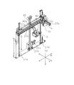
ピッキング部20は、返品薬トレイT1内に非整列の状態で載置された複数の返品された薬品Dを先端部で吸着して、所定の方向へ搬送するために、3次元方向に移動可能な状態で本体部10aの内部に設けられている。
Thereby, the
The picking
具体的には、ピッキング部20は、仕分運転が開始されると、返品薬トレイT1から第1薬品確認部30へ、第1薬品確認部30から待機台35、待機台35から収納トレイT2へと、薬品Dを吸着して搬送する。
そして、ピッキング部20は、このような3次元方向における薬品Dの搬送が可能になるように、図13に示すように、縦支柱21a、ベルト21b、モータ21c、横支柱22a、ベルト22b、モータ22c、横支柱23a等を有している。
Specifically, when the sorting operation is started, the picking
And as shown in FIG. 13, the picking
例えば、ピッキング部20は、Z方向(鉛直方向)に沿って配置された2本の縦支柱21a,21aの間に、Z方向に沿って設けられたベルト21bを、モータ21cによって回転させる。これにより、ピッキング部20は、Z方向(鉛直方向)における移動が可能となり、例えば、薬品Dの吸着動作や各トレイへ薬品Dを置く動作等を行うことができる。
For example, the picking
また、ピッキング部20は、X方向(水平方向)(本体部10aの幅方向)に沿って配置された横支柱22aに沿って設けられたベルト22bを、モータ22cによって回転させる。これにより、ピッキング部20は、X方向(水平方向)における移動が可能となり、例えば、薬品Dを本体部10aの幅方向へ搬送する動作等を行うことができる。
同様に、ピッキング部20は、Y方向(水平方向)(本体部10aの奥行き方向)に沿って配置された横支柱23aに沿って設けられたベルト(図示を省略)を、モータ(図示を省略)によって回転させる。これにより、ピッキング部20は、Y方向(水平方向)における移動が可能となり、例えば、薬品Dを本体部10aの奥行き方向へ搬送する動作等を行うことができる。
Further, the picking
Similarly, the picking
バーコードリーダ(薬品情報取得部)25は、図15等に示すように、ピッキング部20の近傍に配置されており、ピッキング部20と一体化して3次元方向に移動する。そして、バーコードリーダ25は、ピッキング部20によって吸着搬送される薬品Dを収納トレイT2へ収納する前に、収納トレイT2に付されたバーコードB2を読み取って収納トレイT2の識別情報を取得する。
The barcode reader (drug information acquisition unit) 25 is disposed in the vicinity of the picking
第1薬品確認部30は、図9および図10に示すように、本体部10aの内部に形成されるピッキング空間S2と返品薬仕分け空間S4との間に配置されている。そして、第1薬品確認部30は、ピッキング空間S2においてピッキング部20によって吸着保持された返品された薬品Dの種類等を確認する。
具体的には、第1薬品確認部30は、図14に示すように、バーコードリーダ31、保持板32、ローラ33、モータ33aを有している。第1薬品確認部30は、薬品Dの使用期限を確認するために設置されたカメラC2の下方に配置されており、互いに近接配置された保持板32とローラ33とで形成された凹部に薬品Dを保持する。そして、第1薬品確認部30は、薬品Dを保持したまま、モータ33aによってローラ33を回転させることで薬品Dを回転させて、後述するバーコードリーダ31によって、薬品Dに付されたバーコードB1の種類情報を読み取って取得する。
As shown in FIGS. 9 and 10, the first
Specifically, as shown in FIG. 14, the first
バーコードリーダ31は、図14に示すように、保持板32とローラ33とで形成された凹部に保持された薬品Dの斜め上方に配置されている。そして、バーコードリーダ31は、モータ33aによって回転駆動されるローラ33によって回転する薬品Dに付されたバーコードB1を読み取って、薬品Dの種類(薬剤の種類等)に関する種類情報を取得する。
The
第2薬品確認部40は、収納トレイT2から取り出されバーコードリーダ25によって種類情報が読み取られた薬品Dを、所定の払出しトレイT3へ排出する薬品排出装置として設けられている。そして、第2薬品確認部40は、図10および図11に示すように、本体部10a内における返品薬仕分け空間S4の下方に、支持部40a(図13参照)を介して配置されている。そして、第2薬品確認部40は、収納トレイT2内からピッキング部20によって取り出されて払出しトレイT3へ吸着搬送される薬品Dの種類等を確認する。
The second
なお、第2薬品確認部40の詳細な説明については、後段にて詳述する。
記憶部51は、上述した各構成を駆動制御するための制御プログラムが保存されている。そして、記憶部51は、収納トレイT2に付されたバーコードB2から取得される識別情報として、図6に示すように、トレイ番号、トレイ幅、ピッチ、1つのトレイへの薬品の入り数、装置内に収納される最大トレイ数、最大収納薬品数の関係を示すテーブルを保存している。
The detailed description of the second
The
処方箋情報取得部60は、病院等に設置されたサーバ等から、患者ごとの処方箋情報を取得する。これにより、制御部50は、収納トレイT2に収納された薬品Dの中から、処方箋情報に基づいて必要な薬品Dを排出するように、ピッキング部20を制御する。
(第2薬品確認部40)
本実施形態の薬品仕分装置10に搭載された第2薬品確認部40の構成について、図16〜図20(b)を用いて説明すれば以下の通りである。
The prescription
(2nd drug check section 40)
It will be as follows if the structure of the 2nd chemical | medical
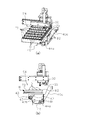
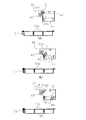
本実施形態の薬品仕分装置10には、収納トレイT2に収納された後、処方箋情報に基づいて取り出された返品された薬品Dの種類情報を取得して、払出しトレイT3へ排出する第2薬品確認部40が設けられている。
具体的には、第2薬品確認部40は、図16等に示すように、本体部41と、保持板42と、付勢部材(第1付勢部材)42bと、ローラ43と、モータ(第1駆動部)43aと、回転軸43b(図18(a)参照)と、ワンウェイクラッチ(第1クラッチ)43c(図18(a)参照)と、ワンウェイクラッチ(第2クラッチ)43d(図18(a)参照)と、薬品受けトレイ44と、モータ(第2駆動部)44aと、付勢部材(第2付勢部材)44bと、ワンウェイクラッチ(第3クラッチ)44c(図18(b)参照)と、構造体搬送部45(図13参照)とを備えている。
After being stored in the storage tray T2, the
Specifically, as shown in FIG. 16 and the like, the second
本体部41は、図16および図19(a)等に示すように、平面視において、略U字形の形状を有する部材であって、略U字形の両腕の部分において、保持板42、ローラ43および薬品受けトレイ44等を保持している。そして、本体部41は、図16に示すように、略U字形を構成する互いに対向する2つの面のうちの一方の面に、他方の面に向かって突出するストッパ41a,41bを有している。
The
ストッパ41aは、保持板42とローラ43との間に形成されるV字部42cで薬品Dを受け取って保持する状態において、図19(a)等に示すように、保持板42の一部に当接して、保持板42とローラ43とを含む構造物の姿勢を維持する。換言すれば、ストッパ41aは、モータ43aによって、保持板42とローラ43とを含む構造物が回動する際に、回動限界位置を設定するために設けられている。すなわち、ストッパ41aによって設定される回動限界位置は、V字部42cにおいて薬品Dを保持する姿勢を維持する位置と一致する。
The
ストッパ41bは、薬品受けトレイ44で薬品Dを受け取って保持する状態において、図19(a)等に示すように、薬品受けトレイ44の一部に当接して、薬品受けトレイ44の姿勢を維持する。換言すれば、ストッパ41bは、モータ44aによって、薬品受けトレイ44が回動する際に、回動限界位置を設定するために設けられている。すなわち、ストッパ41bによって設定される回動限界位置は、薬品受けトレイ44において薬品Dを受け取って保持する姿勢を維持する位置と一致する。
As shown in FIG. 19A and the like, the
保持板42は、図16および図17(b)等に示すように、ローラ43に対して近接配置された板状の部材であって、側面視において、ローラ43とともに、薬品Dを保持するためのV字部42cを形成する。そして、保持板42は、薬品Dを受け取って保持する姿勢において、鉛直方向に対して約45度の角度になるように配置されている。さらに、保持板42の幅方向における両端には、ローラ43が回転可能な状態でローラ43と一体化する連結部42aが設けられている。
The holding
連結部42aは、保持板42の幅方向における両端部と、ローラ43の回転軸43bの両端とをそれぞれ連結する部材であって、保持板42の薬品Dと当接する面に対して略垂直に立設されている。そして、連結部42aは、ローラ43が回転可能な状態で、その回転軸の両端を保持する。
これにより、連結部42aは、ローラ43が回転可能な状態で、保持板42とローラ43とを一体化することができる。
The connecting
Thereby, the
付勢部材(第1付勢部材)42bは、例えば、コンストンバネであって、図16等に示すように、本体部41における保持板42およびローラ43の側方に設けられている。そして、付勢部材42bは、ローラ43と一体化された保持板42を、図17(b)に示すA方向(第1方向)に付勢する。すなわち、付勢部材42bは、ストッパ41aに対して保持板42の一部を押し当てる方向に、保持板42を付勢する。
The biasing member (first biasing member) 42 b is, for example, a conston spring, and is provided on the side of the holding
これにより、一体化された保持板42とローラ43とを、薬品Dを受け取って保持する姿勢で保持することができる。
ローラ43は、上述したように、連結部42aによって保持板42と一体化されており、保持板42との間に形成されるV字部42cにおいて、搬送されてきた薬品Dを受け取って保持する。そして、ローラ43は、モータ43aの回転駆動力が、ワンウェイクラッチ43cを介して回転軸43bに伝達されることで、図17(b)に示すA方向に回転駆動される。
Thus, the integrated holding
As described above, the
モータ(第1駆動部)43aは、図16および図18(a)等に示すように、本体部41の側面に設けられており、ローラ43の回転軸43bに接続されている。そして、モータ43aは、ワンウェイクラッチ43c,43dを介して、保持板42およびローラ43に対して回転駆動力を伝達することで、ローラ43を回転させたり、保持板42を回動させたりする。
The motor (first drive unit) 43a is provided on the side surface of the
なお、図18(a)は、図17(a)に示すA−A線矢視断面図であって、図18(b)は、図17(a)に示すB−B線矢視断面図である。
ワンウェイクラッチ(第1クラッチ)43cは、図18(a)に示すように、モータ43aの回転駆動力が伝達される回転軸43bとローラ43とを接続する位置に設けられている。そして、ワンウェイクラッチ43cは、図17(b)に示すA方向においては、回転軸43bの回転駆動力をローラ43に対して伝達するとともに、B方向においては、回転駆動力をローラ43に対して伝達しない。
18 (a) is a cross-sectional view taken along the line A-A shown in FIG. 17 (a), and FIG. 18 (b) is a cross-sectional view taken along the line B-B shown in FIG. It is.
As shown in FIG. 18A, the one-way clutch (first clutch) 43c is provided at a position where the
ワンウェイクラッチ(第2クラッチ)43dは、図18(a)に示すように、モータ43aの回転駆動力が伝達される回転軸43bと保持板42とを接続する位置に設けられている。そして、ワンウェイクラッチ43dは、図17(b)に示すA方向においては、回転軸43bの回転駆動力を保持板42に対して伝達しないとともに、B方向においては、回転駆動力を保持板42に対して伝達する。
As shown in FIG. 18A, the one-way clutch (second clutch) 43d is provided at a position where the
ここで、モータ43a(回転軸43b)が、図17(b)に示すA方向(第1方向)に回転すると、ワンウェイクラッチ43c(図18(a)参照)を介して回転駆動力がローラ43に対して伝達され、ローラ43をA方向へ回転させる。
これにより、ワンウェイクラッチ43cによって、保持板42とローラ43との間に形成されるV字部42cに保持された薬品Dを、ローラ43との摩擦によってV字部42c内において回転させることができる。
Here, when the
Thus, the medicine D held in the V-shaped
このとき、ワンウェイクラッチ43dによって、保持板42に対して回転駆動力は伝達されないため、保持板42およびローラ43の姿勢を維持することができる。
一方、モータ43a(回転軸43b)が、図17(b)に示すB方向(第2方向)に回転すると、ワンウェイクラッチ43c(図18(a)参照)を介して回転駆動力がローラ43に対して伝達されることはない。
At this time, since the rotational driving force is not transmitted to the holding
On the other hand, when the
そして、ワンウェイクラッチ43dによって、保持板42に対して回転駆動力が伝達されるため、回転軸43bを中心にして保持板42をB方向へ回動させることができる。
このとき、保持板42はローラ43と一体化されているため、保持板42をローラ43とともに、B方向へ回動させることができることができる。
これにより、図19(a)および図19(b)に示すように、保持板42とローラ43との間に形成されるV字部42cを斜め下向き傾けることができるため、V字部42cに保持された状態で種類情報が取得された薬品Dを、下流側(薬品受けトレイ44)へ排出することができる。
Then, since the rotational driving force is transmitted to the holding
At this time, since the holding
Thereby, as shown in FIGS. 19A and 19B, the V-shaped
この結果、単一のモータ43aを用いて、薬品Dの種類情報の取得時における薬品Dの回転動作と、種類情報の取得後における薬品Dの排出動作とを実施することができるため、簡素な構成により、薬品Dを所定の方向へ排出することができる。
また、単一のモータ43aを用いた構成であっても、2つのワンウェイクラッチ43c,43dを組み合わせて用いることで、薬品Dの種類情報取得時における薬品Dの回転動作と、保持板42を回動させる薬品Dの排出動作とを実施することができる。よって、簡素な構成により、薬品Dを所定の方向へ排出することができる。
As a result, since rotation operation of the medicine D at the time of acquisition of kind information of medicine D and discharge operation of medicine D after acquisition of kind information can be performed using a
Further, even in the configuration using the
なお、保持板42とローラ43との間に形成されたV字部42cへの薬品Dの搬送工程、およびV字部42cから薬品受けトレイ44への薬品Dの搬送工程については、後段にて詳述する。
薬品受けトレイ44は、図18(a)および図18(b)に示すように、本体部41における保持板42およびローラ43の下方に設けられている。そして、薬品受けトレイ44は、保持板42とローラ43との間に形成されたV字部42cから排出された薬品Dを受け取って保持するとともに、モータ44aの回転駆動力によって回動することで、下方に搬送されてきた払出しトレイT3へ薬品Dを排出する。
The conveying process of the medicine D to the V-shaped
The
これにより、薬品受けトレイ44は、モータ44aの回転駆動力、付勢部材44bの付勢力によって、図20(a)に示す閉状態と、図20(b)に示す開状態とを切り替えることができる。
モータ(第2駆動部)44aは、図16および図18(b)等に示すように、モータ43aと同様に、本体部41の側面に設けられており、薬品受けトレイ44の回動軸44dに接続されている。そして、モータ44aは、ワンウェイクラッチ44cを介して、回転駆動力を薬品受けトレイ44に対して伝達することで、薬品受けトレイ44を回動させる。
Thus, the
The motor (second drive unit) 44a is provided on the side surface of the
付勢部材(第2付勢部材)44bは、例えば、コンストンバネであって、本体部41における薬品受けトレイ44の側方に設けられている。そして、付勢部材44bは、図20(a)および図20(b)に示すC方向に向かって、薬品受けトレイ44を付勢する。すなわち、付勢部材44bは、薬品受けトレイ44を開く方向に付勢する。
ワンウェイクラッチ(第3クラッチ)44cは、図18(b)に示すように、モータ44aの回動軸44dと薬品受けトレイ44とに接続されている。そして、ワンウェイクラッチ44cは、図20(a)および図20(b)に示すC方向(開く方向)において、回動軸44dから薬品受けトレイ44に対して回転駆動力を伝達しない。一方、ワンウェイクラッチ44cは、図20(a)および図20(b)に示すD方向(閉める方向)において、回転駆動力を伝達する。
The biasing member (second biasing member) 44 b is, for example, a conston spring, and is provided on the side of the
The one-way clutch (third clutch) 44c is connected to the
これにより、薬品受けトレイ44を開く動作では、付勢部材44bの付勢力を利用するとともに、薬品受けトレイ44を閉める動作では、モータ44aの回転駆動力を利用することができる。
なお、薬品受けトレイ44は、付勢部材44bによって開状態へ向かうC方向に付勢されているが、ワンウェイクラッチ44cおよび減速ギア(1/90)によって、薬品受けトレイ44が開かないように保持される。
Thus, in the operation of opening the
The
これにより、薬品受けトレイ44を、図20(a)に示す薬品Dを受け取って保持する閉状態のまま保持することができる。
構造体搬送部45は、図13に示すように、第2薬品確認部40をZ方向において搬送する手段であって、上述した2本の縦支柱21a,21a、Z方向に沿って設けられたベルト21b、モータ21cによって構成されている。そして、Z方向(鉛直方向)に沿って配置された2本の縦支柱21a,21aの間に、Z方向に沿って設けられたベルト21bを、モータ21cによって回転させることで、横支柱22aに固定された第2薬品確認部40をZ方向において移動させる。
Thereby, the
As shown in FIG. 13, the
具体的には、構造体搬送部45は、上述した本体部41、保持板42と、付勢部材(第1付勢部材)42bと、ローラ43と、モータ(第1駆動部)43aと、回転軸43bと、ワンウェイクラッチ(第1クラッチ)43cと、ワンウェイクラッチ(第2クラッチ)43dと、薬品受けトレイ44と、モータ(第2駆動部)44aと、付勢部材(第2付勢部材)44bと、ワンウェイクラッチ(第3クラッチ)44c等を含む構造体を、上下方向(Z方向)において移動させる。
Specifically, the
なお、薬品受けトレイ44から払出しトレイT3への薬品Dの排出工程については、後段にて詳述する。
<返品された薬品Dを収納トレイT2へ収納するまでの流れ>
本実施形態の薬品仕分装置10では、上述した各構成を備え、返品された薬品Dを、返品薬トレイT1から取り出して、薬品Dの形状や大きさに対応する適切な収納トレイT2へ仕分けして収納する。
The discharging process of the drug D from the
<Flow of storing medicine D returned to storage tray T2>
In the
具体的には、制御部50は、まず、返品薬トレイ搬送部13を制御して、図9等に示すように、1つの返品薬トレイT1を、返品薬トレイ収納空間S1からピッキング空間S2へ搬送する。
次に、制御部50は、図5に示す返品薬トレイT1内に非整列の状態で載置された複数の薬品Dの中から、仕分けして収納トレイT2へ収納する薬品Dを選択する。このとき、制御部50は、図12に示すカメラC1によって取得された画像情報に基づいて、薬品Dをピッキングする位置を設定する。
Specifically, the
Next, the
次に、制御部50は、ピッキング部20を制御して、返品薬トレイT1内から所望の薬品Dを吸着し、第1薬品確認部30へ搬送する。
次に、制御部50は、第1薬品確認部30に載置された薬品Dの種類(薬剤等)を確認するために、図14に示すように、モータ33aによってローラ33を回転駆動して薬品Dを回転させ、バーコードリーダ31によって薬品Dに付されたバーコードB1を読み取る。これにより、薬品Dの種類情報を得ることができる。
Next, the
Next, in order to confirm the type (drug or the like) of the drug D placed in the first
このとき、制御部50は、図14に示すように、第1薬品確認部30の上方に載置されたカメラC2を制御して、薬品Dの画像情報を取得する。これにより、薬品Dの外周面にバーコードB1とともに付された薬品Dの使用期限に関する文字情報を得ることができる。
次に、制御部50は、ピッキング部20を制御して、第1薬品確認部30に載置された薬品Dを吸着して、第1薬品確認部30に隣接配置された待機台35の凹部35aへ搬送する。
At this time, as shown in FIG. 14, the
Next, the
次に、制御部50は、ピッキング部20を制御して、待機台35の凹部35aに載置された薬品Dを吸着し、返品薬仕分け空間S4の上方へ搬送する。
次に、制御部50は、収納トレイ搬送部14を制御して、図9に示すように、種類情報が取得された薬品Dを収納するための収納トレイT2を含む段を、収納トレイ載置空間S3から返品薬仕分け空間S4へ搬送する。
Next, the
Next, the
次に、制御部50は、図21(a)および図21(b)に示すように、薬品Dを吸着したピッキング部20を、収納先となる収納トレイT2の手前まで移動させ、ピッキング部20とともに移動するバーコードリーダ25を用いて、収納トレイT2のバーコードB2を読み取る。
そして、制御部50は、読み取られた情報に基づいて、収納トレイT2が正しい収納とりえであるか否かを判定する。
Next, as shown in FIGS. 21 (a) and 21 (b), the
Then, the
ここで、制御部50は、正しいと判定した場合には、ピッキング部20を制御して、図22(a)および図22(b)に示すように、専用トレイとして設定された収納トレイT2内の所定の凹部T2zに、吸着搬送されている薬品Dを載置する。
<収納トレイT2から第2薬品確認部40へ薬品Dを搬送するまでの流れ>
次に、本実施形態の薬品仕分装置10おいて、一旦、収納トレイT2へ収納された薬品Dを、処方箋情報に基づいて取り出して、第2薬品確認部40へと搬送する工程について、図23(a)〜図26(b)を用いて説明すれば以下の通りである。
Here, when it is determined that the
<Flow of Conveying Drug D from Storage Tray T2 to Second
Next, in the
制御部50は、図23(a)および図23(b)に示すように、返品薬仕分け空間S4に引き出され、処方箋情報に基づいて必要な薬品Dを収納していると認識されている収納トレイT2の近傍まで、ピッキング部20と一体化して駆動されるバーコードリーダ25を移動させる。そして、バーコードリーダ25は、収納トレイT2のバーコードB2を読み取って制御部50へ送信する。
As shown in FIGS. 23 (a) and 23 (b), the
次に、制御部50は、図24(a)および図24(b)に示すように、ピッキング部20を所望の薬品Dの直上まで移動させて吸着し、収納トレイT2から薬品Dを取り出す。
次に、制御部50は、収納トレイ搬送部14を制御して、図25(a)および図25(b)に示すように、薬品Dが取り出された収納トレイT2を、返品薬仕分け空間S4から収納トレイ載置空間S3へ移動させる。
Next, as shown in FIGS. 24 (a) and 24 (b), the
Next, the
次に、制御部50は、ピッキング部20を制御して、図26(a)および図26(b)に示すように、収納トレイT2が返品薬仕分け空間S4から収納トレイ載置空間S3へ移動すると上方空間が開放される第2薬品確認部40へ、吸着した薬品Dを搬送する。
より詳細には、制御部50は、ピッキング部20を制御して、第2薬品確認部40の保持板42とローラ43との間に形成されるV字部42cへ薬品Dを載置する。
Next, the
More specifically, the
<第2薬品確認部40から払出しトレイT3へ薬品Dを排出するまでの流れ>
次に、本実施形態の薬品仕分装置10おいて、第2薬品確認部40へ搬送された薬品Dを、払出しトレイT3へ排出する工程について、図27(a)〜図28(b)を用いて説明すれば以下の通りである。
なお、払出しトレイT3は、図27(a)等に示すように、2枚の仕切り板T3aによって、収納空間が3区画に分割されている。これにより、例えば、朝、昼、晩用に処方された薬品Dを1つの払出しトレイT3へ分類した状態で払い出すことができる。
<Flow of discharging the drug D from the second
Next, in the
In addition, as shown to FIG. 27 (a) etc., as for delivery tray T3, the storage space is divided into three divisions by the partition plate T3a of 2 sheets. Thereby, for example, medicine D prescribed for morning, noon, and night can be dispensed in a state of being classified into one dispensing tray T3.
制御部50は、第2薬品確認部40において、モータ43aを制御してローラ43をA方向(図17(b)参照)に回転駆動することで、V字部42cに載置された薬品Dを回転させて、バーコードリーダ25によって薬品DのバーコードB1を読み取り、薬品Dの種類情報を取得する。
なお、ローラ43によって薬品DをA方向に回転させる際には、回転軸43bとローラ43とを接続するワンウェイクラッチ43cは、ローラ43に対して回転駆動量を伝達する。一方、回転軸43bと保持板42とを接続するワンウェイクラッチ43dは、保持板42に対して回転駆動力を伝達しない。
The
When the medicine D is rotated in the A direction by the
これにより、ローラ43を回転させて薬品Dの種類情報をバーコードリーダ25によって取得する際には、ローラ43だけに回転駆動力を伝達し、保持板42には回転駆動力は伝達されないため、保持板42の姿勢はそのまま維持される。
次に、制御部50は、図27(a)に示すように、モータ43aを制御して回転軸43bをB方向(図17(b)参照)に回転駆動する。このとき、回転軸43bとローラ43とを接続するワンウェイクラッチ43cは、ローラ43に対して回転駆動量を伝達しない。一方、回転軸43bと保持板42とを接続するワンウェイクラッチ43dは、保持板42に対して回転駆動力を伝達する。
Thereby, when the
Next, as shown in FIG. 27A, the
これにより、付勢部材42bによってA方向において保持板42に対して付与される付勢力に逆らう形で、回転駆動力が保持板42に伝達されることで、保持板42はローラ43とともにB方向に回動する。
この結果、図27(b)に示すように、保持板42とローラ43との間に形成され薬品Dが載置されたV字部42cが斜め下向きになるため、V字部42cに保持された薬品Dを、薬品受けトレイ44へ排出することができる。
As a result, the rotational drive force is transmitted to the holding
As a result, as shown in FIG. 27 (b), the V-shaped
なお、制御部50は、薬品Dを薬品受けトレイ44へ落下させた後、保持板42およびローラ43を初期状態(V字部42cが上向きの状態)に戻すために、モータ43aを制御して回転軸43bをA方向へ回転させる。
これにより、保持板42は、付勢部材42bによってA方向へ付勢されているため、付勢力によってA方向に回動する。
The
As a result, the holding
このとき、保持板42は、A方向においては、ワンウェイクラッチ43cを介して回転軸43bと接続されている。このため、保持板42は、付勢力によって高速で初期状態へ戻ることなく、モータ43aによる回転軸43bの回転速度と同じ一定速度で回動しながら、初期状態へと移行する。
なお、回転軸43bをA方向へ回転させると、ワンウェイクラッチ43cを介して回転駆動力がローラ43に伝達されてローら43が回転するが、このときV字部42c内に薬品Dはないため、ローラ43の回転は本装置の機能に影響を及ぼすことはない。
At this time, the holding
When the
次に、制御部50は、図27(c)に示すように、薬品受けトレイ44において薬品Dを保持した状態から、下方へ搬送されてきた払出しトレイT3に対して、薬品Dを排出する動作を開始する。
すなわち、図20および図28(a)等に示す閉状態では、薬品受けトレイ44は、略水平方向に沿って配置されている。
Next, as shown in FIG. 27C, the
That is, in the closed state shown in FIG. 20 and FIG. 28 (a) etc., the
そして、上流側から薬品Dが薬品受けトレイ44へ排出されると、制御部50は、図28(a)に示すように、構造体搬送部45(図13等参照)を制御して、第2薬品確認部40を払出しトレイT3上に降下させるとともに、モータ44aを制御して、薬品受けトレイ44をC方向(開ける方向)へ回動させる。
このとき、薬品受けトレイ44は、付勢部材44bによってC方向に付勢されているため、付勢力によって回動軸44dを中心にしてC方向に回動する。
Then, when the medicine D is discharged to the
At this time, since the
なお、薬品受けトレイ44に対する付勢力は、薬品受けトレイ44自身に掛かる重力を利用してもよい。
このとき、薬品受けトレイ44は、回動軸44dに接続されているため、付勢力によってC方向に高速で回動することなく、回動軸44dと同じ一定速度でC方向に回動する。
次に、図28(b)に示すように、薬品受けトレイ44における回動軸44dとは反対側の端部が払出しトレイT3の底面に当接すると、薬品受けトレイ44は、これ以上C方向に回動できない。
The biasing force on the
At this time, since the
Next, as shown in FIG. 28 (b), when the end of the
このとき、回動軸44dはそのままC方向に回転するが、ワンウェイクラッチ44cによって、C方向においてモータ44aの回転駆動力は伝達されない。よって、薬品受けトレイ44や払出しトレイT3に対して無理な負荷が掛かることを防止することができる。
次に、制御部50は、図28(c)に示すように、構造体搬送部45を制御して第2薬品確認部40を上昇させていくと、薬品受けトレイ44は付勢部材44bの付勢力によって、払出しトレイT3の底面に当接した状態で引き続きC方向へ回動し続ける。
At this time, the
Next, as shown in FIG. 28C, when the
次に、制御部50は、図28(d)に示すように、構造体搬送部45によって第2薬品確認部40をさらに上昇させると、薬品受けトレイ44の底面が本体部41に設けられたストッパ41cに当接して、薬品受けトレイ44の回動は停止する。
これにより、薬品受けトレイ44において保持していた薬品Dに衝撃等を付与することなく、安全に払出しトレイT3へと排出することができる。
Next, as shown in FIG. 28 (d), when the
As a result, the medicine D held in the
このとき、回動軸44dはC方向に回転しているが、ワンウェイクラッチ44cによって回動軸44dの回転駆動力は薬品受けトレイ44には伝達されない。これにより、薬品受けトレイ44およびストッパ41cに無理な負荷が掛かることを防止することができる。
なお、図28(a)から図28(b)への移行時において、薬品受けトレイ44がC方向へ回動する際に、薬品受けトレイ44の端部が払出しトレイT3の底面に接触するまでは、薬品受けトレイ44は付勢力によって高速で回動することはない。
At this time, the
When the
これは、薬品受けトレイ44が回動軸44dと接続されているため、回動軸44dよりも高速で回動することができないためである。よって、薬品受けトレイ44は、図28(a)に示す閉状態から、払出しトレイT3の底面に端部が接触するまでの間、回動軸44dと同じ一定速度で回動する。
次に、制御部50は、図28(d)に示す状態において、薬品受けトレイ44がストッパ41cに接触したことをフォトセンサ(図示せず)によって検出し、モータ44aを制御して、回動軸44dの回転方向をD方向(閉じる方向)へ切り替える。
This is because the
Next, in the state shown in FIG. 28D, the
このとき、回動軸44dがD方向へ回転すると、ワンウェイクラッチ44cを介して、回動軸44dの回転駆動力が薬品受けトレイ44に伝達される。このため、薬品受けトレイ44は、付勢部材44bのC方向における付勢力に逆らって閉じる方向(D方向)へ回動する。
次に、制御部50は、薬品受けトレイ44がD方向へ回動して、薬品受けトレイ44の一部がストッパ41bに接触した閉状態への移行がフォトセンサ(図示せず)によって検出されると、モータ44aを制御して回動軸44dの回転を停止させる。
At this time, when the
Next, the
なお、この状態において、薬品受けトレイ44は、付勢部材44bによってC方向へ回動する付勢力を受けるが、ワンウェイクラッチ44cを介して、回動軸44dの回転駆動力が薬品受けトレイ44に伝達される。よって、薬品受けトレイ44は、付勢力によって開く方向へ回動することなく、閉状態が維持される。
また、モータ44aには、減速比が1/90のギアヘッドが内蔵されている。このため、薬品受けトレイ44は、開く方向(C方向)に回動しようとすると、ワンウェイクラッチ44cを介して回動軸44dの力が薬品受けトレイ44に伝達されて、薬品受けトレイ44の閉状態は維持される。
In this state, the
Further, a gear head with a reduction ratio of 1/90 is built into the
さらに、モータ44aのギアヘッドにより、閉状態においてモータ44aの電源をオフにしても、ギアヘッドの摩擦によって回動軸44dが回転することはない。
これにより、電源をオフにしても閉状態が維持されるため、薬品受けトレイ44の閉状態を維持するための無駄な電力の消費を削減することができる。
また、例えば、停電等によって、薬品受けトレイ44内に薬品Dが保持された状態で意図せずに電源がオフになった場合でも、薬品受けトレイ44が回動して開状態へ移行することはないため、薬品Dの破損等を防止することができる。
Further, even if the power of the
As a result, since the closed state is maintained even when the power is turned off, it is possible to reduce unnecessary consumption of power for maintaining the
Also, for example, even if the power is turned off unintentionally in a state where the medicine D is held in the
本実施形態の薬品仕分装置10によれば、以上の構成により、上流側から搬送されてくる薬品Dを薬品受けトレイ44において受け取った薬品Dを排出する際には、付勢部材44bの付勢力によってC方向へ薬品受けトレイ44を回動させて開状態へ移行することで、薬品Dを排出することができる。一方、開状態から閉状態へ移行する際には、モータ44aの回転駆動力を回動軸44dへ伝達して薬品受けトレイ44を回動させることで、閉状態へ移行することができる。
According to the
この結果、単一の駆動源(モータ44a)を用いた簡素な構成により、薬品Dを所定の方向へ排出することができる。
[他の実施形態]
以上、本発明の一実施形態について説明したが、本発明は上記実施形態に限定されるものではなく、発明の要旨を逸脱しない範囲で種々の変更が可能である。
As a result, the drug D can be discharged in a predetermined direction by a simple configuration using a single drive source (
[Other embodiments]
As mentioned above, although one Embodiment of this invention was described, this invention is not limited to the said embodiment, A various change is possible in the range which does not deviate from the summary of invention.
(A)
上記実施形態では、本薬品排出装置として、薬品仕分装置10内に第2薬品確認部40を設けた例を挙げて説明した。しかし、本発明はこれに限定されるものではない。
例えば、本薬品排出装置は、薬品仕分装置内に搭載された構成である必要はなく、薬品排出装置単体として構成されていてもよい。
この場合でも、簡素な構成により、薬品を所定の方向へ排出することができるという上記と同様の効果を得ることができる。
(A)
In the above embodiment, an example in which the second
For example, the present medicine discharge device need not be configured to be mounted in the medicine sorting device, and may be configured as a single medicine discharge device.
Even in this case, with the simple configuration, it is possible to obtain the same effect that the medicine can be discharged in the predetermined direction.
(B)
上記実施形態では、排出される薬品Dの種類情報を読み取る薬品情報取得部として、ピッキング部20と一体化して移動するバーコードリーダ25を用いた例を挙げて説明した。しかし、本発明はこれに限定されるものではない。
(B)
In the above embodiment, an example using the
例えば、薬品排出装置(第2薬品確認部)の近傍に固定配置されたバーコードリーダ等の薬品情報取得部を用いてもよい。
また、薬品情報取得部としては、上記実施形態のように、トレイに付されたバーコードを読み取る手段との兼用ではなく、薬品の種類情報を取得する専用の手段として設けられていてもよい。
For example, a medicine information acquisition unit such as a bar code reader fixedly disposed in the vicinity of the medicine discharge device (second medicine confirmation unit) may be used.
Further, the medicine information acquisition unit may be provided as a dedicated means for acquiring medicine type information instead of the means for reading the barcode attached to the tray as in the above embodiment.
(C)
上記実施形態では、薬品Dに付された種類情報(バーコードB1)を読み取って取得する手段として、バーコードリーダ25を用いた例を挙げて説明した。しかし、本発明はこれに限定されるものではない。
例えば、薬品にバーコードの代わりにICタグが付されている構成では、バーコードリーダの代わりに、ICタグと通信可能な装置等を用いてもよい。
さらに、バーコードリーダの代わりに、薬品の形状や大きさを判別するための画像情報を取得するカメラを用いてもよい。
(C)
In the above embodiment, an example using the
For example, in a configuration in which an IC tag is attached to a medicine instead of a barcode, a device or the like that can communicate with the IC tag may be used instead of the barcode reader.
Furthermore, instead of the bar code reader, a camera that acquires image information for determining the shape or size of the medicine may be used.
(D)
上記実施形態では、本発明の薬品排出装置(第2薬品確認部40)が返品薬の仕分けを行う薬品仕分装置10に搭載された例を挙げて説明した。しかし、本発明はこれに限定されるものではない。
例えば、本発明の薬品排出装置は、返品薬の仕分けを行う薬品仕分装置や、処方箋情報に基づいて薬品の払出しを行う薬品払出装置等に限らず、他の装置に搭載されていてもよい。
(D)
In the above-described embodiment, the example in which the medicine discharge device (the second medicine confirmation unit 40) of the present invention is mounted on the
For example, the drug discharge device of the present invention may be mounted not only on a drug sorting device for sorting returned medicines, a drug dispensing device for dispensing medicine based on prescription information, but also on other devices.
(E)
上記実施形態では、本発明の薬品排出装置(第2薬品確認部40)が扱う薬品として、病室等から返品されてきた薬品(返品薬)を例として挙げて説明した。しかし、本発明はこれに限定されるものではない。
例えば、本発明の薬品排出装置によって排出される薬品は、返品薬に限定されるものではない。
(E)
In the above embodiment, as the medicine handled by the medicine discharge device (the second medicine confirmation unit 40) of the present invention, the medicine (return medicine) returned from a hospital room or the like has been described as an example. However, the present invention is not limited to this.
For example, the medicine discharged by the medicine discharge device of the present invention is not limited to the returned medicine.
(F)
上記実施形態では、保持板42に対して特定方向へ付勢力を付与する第1付勢部材(付勢部材42b)として、コンストンバネを用いた例を挙げて説明した。しかし、本発明はこれに限定されるものではない。
(F)
In the above embodiment, an example in which a conston spring is used as the first biasing member (biasing
例えば、コンストンバネの代わりに、引っ張りバネ、ねじりバネ等の他の付勢部材を用いてもよい。
同様に、上記実施形態では、薬品受けトレイ44に対して特定方向へ付勢力を付与する第2付勢部材(付勢部材44b)として、コンストンバネを用いた例を挙げて説明した。しかし、本発明はこれに限定されるものではない。
For example, other biasing members such as a tension spring and a torsion spring may be used instead of the conston spring.
Similarly, in the above embodiment, an example in which a conston spring is used as the second biasing member (biasing
例えば、コンストンバネの代わりに、引っ張りバネ、ねじりバネ等の他の付勢部材を用いてもよい。あるいは、バネを用いることなく、薬品受けトレイ44に掛かる重力を特定の方向への付勢力としてもよい。
For example, other biasing members such as a tension spring and a torsion spring may be used instead of the conston spring. Alternatively, gravity may be applied to the
本発明の薬品排出装置は、簡素な構成により、薬品を所定の方向へ排出することができるという効果を奏することから、多種多様な薬品を扱う各種装置、システムに対して広く適用可能である。 The drug discharge device of the present invention has the effect of being able to discharge a drug in a predetermined direction with a simple configuration, and is widely applicable to various devices and systems that handle a wide variety of drugs.
10 薬品仕分装置
10a 本体部
10b 扉
10c 扉
11 返品薬トレイ設置部
12 収納トレイ設置部
13 返品薬トレイ搬送部
14 収納トレイ搬送部
20 ピッキング部(搬送部)
21a 縦支柱
21b ベルト
21c モータ
22a 横支柱
22b ベルト
22c モータ
23a 横支柱
25 バーコードリーダ(薬品情報取得部)
30 第1薬品確認部
31 バーコードリーダ
32 保持板
33 ローラ
33a モータ
35 待機台
35a 凹部
40 第2薬品確認部(薬品排出装置)
40a 支持部
41 本体部
41a ストッパ
41b ストッパ
41c ストッパ
42 保持板
42a 連結部
42b 付勢部材(第1付勢部材)
42c V字部(凹部)
43 ローラ
43a モータ(第1駆動部)
43b 回転軸
43c ワンウェイクラッチ(第1クラッチ)
43d ワンウェイクラッチ(第2クラッチ)
44 薬品受けトレイ
44a モータ(第2駆動部)
44b 付勢部材(第2付勢部材)
44c ワンウェイクラッチ(第3クラッチ)
44d 回動軸
45 構造体搬送部
50 制御部
50a モニタ
51 記憶部
60 処方箋情報取得部
100 薬品払出システム
101 トレイ供給装置
102 プラボトル払出装置
104 アンプルバイアル払出装置
105 ラベル注射箋投入装置
106 トレイ収納移載装置
B1 バーコード(種類情報)
B2 バーコード(識別情報)
C1,C2 カメラ
D 薬品
D1〜D4 薬品
N 取っ手
S1 返品薬トレイ収納空間
S2 ピッキング空間
S3 収納トレイ載置空間
S4 返品薬仕分け空間
T1 返品薬トレイ
T2 収納トレイ
T2a〜T2c 収納トレイ
T2z 凹部
T3 払出しトレイ
DESCRIPTION OF
21a
30 first
42c V-shaped part (concave part)
43
43d one-way clutch (second clutch)
44
44b Biasing member (second biasing member)
44c one-way clutch (third clutch)
B2 barcode (identification information)
C1, C2 Camera D Drug D1 to D4 Drug N Handle S1 Returned Medicine Tray Storage Space S2 Picking Space S3 Storage Tray Placement Space S4 Returned Medicine Sorting Space T1 Returned Medicine Tray T2 Storage Tray T2a to T2c Storage Tray T2z Concave T3 Payout Tray
Claims (9)
回転軸を有しており、前記回転軸を中心に回転する円筒状のローラと、
前記回転軸の方向から見て、前記ローラとともにV字部を形成するように配置された保持板と、
前記V字部に載置された状態で前記ローラによって回転させた前記薬品の種類に関する情報を取得する薬品情報取得部と、
前記ローラと前記保持板とを一体化する連結部と、
前記ローラを第1方向に回転させるとともに、前記ローラと前記保持板とを前記第1方向とは反対の第2方向に回動させ前記薬品を所定の方向へ排出する第1駆動部と、
を備えている薬品排出装置。 A medicine discharging device for discharging medicine in a predetermined direction,
A cylindrical roller having a rotation axis and rotating about the rotation axis;
A holding plate arranged to form a V-shaped part with the roller, viewed from the direction of the rotation axis;
A medicine information acquisition unit for acquiring information on the type of medicine rotated by the roller in a state of being placed on the V-shaped portion;
A connecting portion that integrates the roller and the holding plate;
A first driving unit configured to rotate the roller in a first direction and rotate the roller and the holding plate in a second direction opposite to the first direction to discharge the medicine in a predetermined direction;
Chemical discharge device equipped with.
回転軸を有しており、前記回転軸を中心に回転する円筒状のローラと、
前記ローラに近接配置されており、前記ローラとともに前記薬品が載置される凹部を形成する保持板と、
前記薬品の種類に関する情報を取得する薬品情報取得部と、
前記薬品情報取得部が前記薬品の種類に関する情報を取得する際に、前記ローラを第1方向に回転させて前記薬品を回転させる第1駆動部と、
前記保持板を前記第1方向に向かって付勢する第1付勢部材と、
前記第1駆動部と前記ローラとに接続されており、前記第1方向において前記第1駆動部の回転駆動力を前記ローラに伝達するとともに、前記第1方向とは反対の第2方向において前記回転駆動力を前記ローラに伝達しない第1クラッチと、
前記第1駆動部と前記保持板とに接続されており、前記第1方向において前記第1駆動部の回転駆動力を前記保持板に伝達しないとともに、前記第2方向において前記回転駆動力を前記保持板に伝達する第2クラッチと、
を備えている薬品排出装置。 A medicine discharging device for discharging medicine in a predetermined direction,
A cylindrical roller having a rotation axis and rotating about the rotation axis;
A holding plate disposed close to the roller and forming a recess along which the medicine is placed with the roller;
A medicine information acquisition unit for acquiring information on the type of medicine;
A first driving unit that rotates the roller in a first direction to rotate the medicine when the medicine information acquisition unit acquires information on the type of the medicine;
A first biasing member that biases the holding plate toward the first direction;
The first drive unit and the roller are connected to each other, and transmit the rotational drive force of the first drive unit to the roller in the first direction, and the second direction in the second direction opposite to the first direction. A first clutch that does not transmit rotational driving force to the roller;
The first driving portion and the holding plate are connected, and the rotational driving force of the first driving portion is not transmitted to the holding plate in the first direction, and the rotational driving force is transmitted in the second direction. A second clutch that transmits to the holding plate,
Chemical discharge device equipped with.
前記薬品の種類に関する種類情報を取得する薬品情報取得部と、
前記種類情報が取得された前記薬品が搬送され、前記薬品を保持する薬品受けトレイと、
前記薬品を前記薬品受けトレイから排出する際に、前記薬品受けトレイを第3方向に回動させる第2駆動部と、
前記薬品受けトレイを前記第3方向に向かって付勢する第2付勢部材と、
前記第2駆動部と前記薬品受けトレイとに接続されており、前記第3方向において前記第2駆動部の回転駆動力を前記薬品受けトレイに伝達しないとともに、前記第3方向とは反対の第4方向において前記第2駆動部の回転駆動力を前記薬品受けトレイに伝達する第3クラッチと、
備えている薬品排出装置。 A medicine discharging device for discharging medicine in a predetermined direction,
A medicine information acquisition unit for acquiring type information on the type of medicine;
A medicine receiving tray for conveying the medicine for which the type information has been acquired and holding the medicine;
A second drive unit configured to rotate the medicine receiving tray in a third direction when discharging the medicine from the medicine receiving tray;
A second biasing member for biasing the medicine receiving tray in the third direction;
A second driving unit and the medicine receiving tray are connected to each other, and the rotational driving force of the second driving unit is not transmitted to the medicine receiving tray in the third direction, and the second driving unit is opposite to the third direction. A third clutch that transmits the rotational drive force of the second drive unit to the medicine receiving tray in four directions;
Chemical discharge device equipped.
請求項3に記載の薬品排出装置。 The medicine receiving tray discharges the medicine to a delivery tray from which the medicine is dispensed based on prescription information created for each patient.
The medicine discharge device according to claim 3.
請求項3または4に記載の薬品排出装置。 The apparatus further comprises a structure transfer unit for moving the structure including the medicine receiving tray, the second drive unit, and the third clutch in the vertical direction.
The medicine discharge device according to claim 3 or 4.
前記薬品受けトレイは、前記薬品受けトレイの回動軸とは反対側の端部が払出しトレイに当接するまで回動する、
請求項5に記載の薬品排出装置。 When the structure transfer unit lowers the structure to a predetermined discharge position,
The medicine receiving tray rotates until the end opposite to the rotation axis of the medicine receiving tray abuts against the dispensing tray.
The medicine discharge device according to claim 5.
前記構造体搬送部は、前記薬品受けトレイがさらに回動している間に、所定の排出位置から前記構造体を上昇させる、
請求項5または6に記載の薬品排出装置。 When the medicine receiving tray rotates until the end opposite to the rotation axis of the medicine receiving tray abuts on the dispensing tray,
The structure transfer unit raises the structure from a predetermined discharge position while the medicine receiving tray is further rotated.
The medicine discharge device according to claim 5 or 6.
前記薬品を保持して搬送する搬送部と、
前記薬品を種類ごとに仕分けして所定の収納トレイへ搬送するように前記搬送部を制御する制御部と、
を備えている薬品仕分装置。 The medicine discharge device according to any one of claims 1 to 7,
A transport unit that holds and transports the medicine;
A control unit that controls the transport unit to sort the medicines by type and transport them to a predetermined storage tray;
The drug sorting device is equipped with.
処方箋情報に基づいて、前記薬品仕分装置から払い出された前記薬品以外の薬品を払出しトレイに払い出す薬品払出装置と、
を備えている薬品払出システム。 A medicine sorting apparatus according to claim 8;
A medicine dispensing apparatus for dispensing medicines other than the medicine dispensed from the medicine sorting apparatus to a dispensing tray based on prescription information;
The drug delivery system that is equipped with.
Priority Applications (3)
| Application Number | Priority Date | Filing Date | Title |
|---|---|---|---|
| JP2017206944A JP2019076570A (en) | 2017-10-26 | 2017-10-26 | Medicine discharge device, and medicine assortment device and medicine delivery system comprising the same |
| JP2021063364A JP7025579B2 (en) | 2017-10-26 | 2021-04-02 | Chemical discharge device, chemical sorting device equipped with this, and chemical discharge system |
| JP2021164819A JP7133696B2 (en) | 2017-10-26 | 2021-10-06 | Chemical discharging device, chemical sorting device equipped with the same, and chemical dispensing system |
Applications Claiming Priority (1)
| Application Number | Priority Date | Filing Date | Title |
|---|---|---|---|
| JP2017206944A JP2019076570A (en) | 2017-10-26 | 2017-10-26 | Medicine discharge device, and medicine assortment device and medicine delivery system comprising the same |
Related Child Applications (2)
| Application Number | Title | Priority Date | Filing Date |
|---|---|---|---|
| JP2021063364A Division JP7025579B2 (en) | 2017-10-26 | 2021-04-02 | Chemical discharge device, chemical sorting device equipped with this, and chemical discharge system |
| JP2021164819A Division JP7133696B2 (en) | 2017-10-26 | 2021-10-06 | Chemical discharging device, chemical sorting device equipped with the same, and chemical dispensing system |
Publications (1)
| Publication Number | Publication Date |
|---|---|
| JP2019076570A true JP2019076570A (en) | 2019-05-23 |
Family
ID=66628460
Family Applications (3)
| Application Number | Title | Priority Date | Filing Date |
|---|---|---|---|
| JP2017206944A Pending JP2019076570A (en) | 2017-10-26 | 2017-10-26 | Medicine discharge device, and medicine assortment device and medicine delivery system comprising the same |
| JP2021063364A Active JP7025579B2 (en) | 2017-10-26 | 2021-04-02 | Chemical discharge device, chemical sorting device equipped with this, and chemical discharge system |
| JP2021164819A Active JP7133696B2 (en) | 2017-10-26 | 2021-10-06 | Chemical discharging device, chemical sorting device equipped with the same, and chemical dispensing system |
Family Applications After (2)
| Application Number | Title | Priority Date | Filing Date |
|---|---|---|---|
| JP2021063364A Active JP7025579B2 (en) | 2017-10-26 | 2021-04-02 | Chemical discharge device, chemical sorting device equipped with this, and chemical discharge system |
| JP2021164819A Active JP7133696B2 (en) | 2017-10-26 | 2021-10-06 | Chemical discharging device, chemical sorting device equipped with the same, and chemical dispensing system |
Country Status (1)
| Country | Link |
|---|---|
| JP (3) | JP2019076570A (en) |
Family Cites Families (6)
| Publication number | Priority date | Publication date | Assignee | Title |
|---|---|---|---|---|
| TWI295573B (en) | 2002-10-18 | 2008-04-11 | Yuyama Mfg Co Ltd | Feeding device of drug |
| JP4837927B2 (en) | 2005-02-18 | 2011-12-14 | 株式会社寺岡精工 | Empty container collection device |
| JP5850426B2 (en) | 2011-01-21 | 2016-02-03 | 株式会社ソルブ | Container recognition device |
| JP5883445B2 (en) | 2011-06-27 | 2016-03-15 | パナソニックヘルスケアホールディングス株式会社 | Chemical dispensing device and container identification device |
| JP5902022B2 (en) | 2012-04-06 | 2016-04-13 | 株式会社セントラルユニ | Returned medicine sorting apparatus and returned medicine sorting method |
| JP5959903B2 (en) | 2012-04-06 | 2016-08-02 | 株式会社セントラルユニ | Automatic medicine label reader |
-
2017
- 2017-10-26 JP JP2017206944A patent/JP2019076570A/en active Pending
-
2021
- 2021-04-02 JP JP2021063364A patent/JP7025579B2/en active Active
- 2021-10-06 JP JP2021164819A patent/JP7133696B2/en active Active
Also Published As
| Publication number | Publication date |
|---|---|
| JP7133696B2 (en) | 2022-09-08 |
| JP2021100688A (en) | 2021-07-08 |
| JP2022000275A (en) | 2022-01-04 |
| JP7025579B2 (en) | 2022-02-24 |
Similar Documents
| Publication | Publication Date | Title |
|---|---|---|
| CA2165985C (en) | Vacuum operated medicine dispenser | |
| US20100147868A1 (en) | Apparatus for releasing drugs | |
| JP5883445B2 (en) | Chemical dispensing device and container identification device | |
| WO2001068484A1 (en) | Automatic dispenser for injection-containing members | |
| JP5807239B2 (en) | Automatic medicine dispensing device | |
| US11203454B2 (en) | Medicine dispensing device | |
| JP2011015902A (en) | Automatic medicine dispenser and tray for automatic medicine dispenser | |
| JP7133696B2 (en) | Chemical discharging device, chemical sorting device equipped with the same, and chemical dispensing system | |
| JP6957312B2 (en) | Chemical sorting device | |
| JP5433329B2 (en) | Tray and automatic medicine dispensing device using the same | |
| JP6953366B2 (en) | Chemical identification device and chemical sorting device equipped with this, chemical dispensing system, chemical identification method | |
| JP7088803B2 (en) | Chemical orientation determination device, chemical orientation determination method, and chemical orientation determination program | |
| JP6902454B2 (en) | Chemical sorting device and chemical dispensing system equipped with this, chemical sorting method | |
| JP2019076574A (en) | Drug put-out system | |
| JP2019076569A (en) | Drug sorting apparatus and drug put-out system with the same | |
| JP2011010768A5 (en) | ||
| JP2011010768A (en) | Medicine dispenser | |
| JP7348373B2 (en) | Chemical sorting equipment | |
| JP2011020694A5 (en) | ||
| JP2019076573A (en) | Medicament delivery device, and medicament sorting apparatus and medicament dispenser including the same | |
| JP2013244172A (en) | Medicine issuing device | |
| JP2011004972A (en) | Medicine dispenser | |
| JP2013244173A (en) | Container moving device and medicine dispenser | |
| CA2520414A1 (en) | Vacuum operated medicine dispenser | |
| JP2013244174A (en) | Container moving device and medicine dispenser |
Legal Events
| Date | Code | Title | Description |
|---|---|---|---|
| A621 | Written request for application examination |
Free format text: JAPANESE INTERMEDIATE CODE: A621 Effective date: 20200602 |
|
| A977 | Report on retrieval |
Free format text: JAPANESE INTERMEDIATE CODE: A971007 Effective date: 20210315 |
|
| A131 | Notification of reasons for refusal |
Free format text: JAPANESE INTERMEDIATE CODE: A131 Effective date: 20210323 |
|
| A521 | Written amendment |
Free format text: JAPANESE INTERMEDIATE CODE: A523 Effective date: 20210402 |
|
| A02 | Decision of refusal |
Free format text: JAPANESE INTERMEDIATE CODE: A02 Effective date: 20210921 |