JP2019058493A - Laser treatment device, ophthalmologic information processing device, and ophthalmologic system - Google Patents
Laser treatment device, ophthalmologic information processing device, and ophthalmologic system Download PDFInfo
- Publication number
- JP2019058493A JP2019058493A JP2017186711A JP2017186711A JP2019058493A JP 2019058493 A JP2019058493 A JP 2019058493A JP 2017186711 A JP2017186711 A JP 2017186711A JP 2017186711 A JP2017186711 A JP 2017186711A JP 2019058493 A JP2019058493 A JP 2019058493A
- Authority
- JP
- Japan
- Prior art keywords
- image data
- unit
- information
- laser treatment
- eye
- Prior art date
- Legal status (The legal status is an assumption and is not a legal conclusion. Google has not performed a legal analysis and makes no representation as to the accuracy of the status listed.)
- Pending
Links
Images


Abstract
Description
本発明は、眼科分野で用いられるレーザ治療装置、眼科情報処理装置、及び、眼科システムに関する。 The present invention relates to a laser treatment apparatus, an ophthalmologic information processing apparatus, and an ophthalmologic system used in the ophthalmology field.
眼科分野において、網膜、虹彩、隅角、水晶体等に対するレーザ治療が行われている。例えば、所定パターン(複数のスポットの配列)の照準光を用いて治療部位に照準を合わせた後、その治療部位に所定パターンのレーザ光を照射するよう構成されたものが知られている(例えば、特許文献1−5を参照)。また、レーザ照射による外傷(エンドポイント)の程度を制御するための技術も知られている(例えば、特許文献5を参照)。
In the field of ophthalmology, laser treatment for the retina, iris, angle, lens, etc. is performed. For example, after aiming at a treatment site using aiming light of a predetermined pattern (arrangement of a plurality of spots), it is known that the treatment site is irradiated with laser light of a predetermined pattern (for example, ,
一般に、眼科レーザ治療においては様々な情報が参照される。例えば、術前プランニングにおいて、治療部位、レーザの波長・パワー・照射時間などに関する治療計画を作成するために、患者眼の画像や検査結果が参照される。 In general, various information are referred to in ophthalmic laser treatment. For example, in preoperative planning, images of patients' eyes and examination results are referred to create a treatment plan regarding treatment site, laser wavelength, power, irradiation time and the like.
レーザ治療時には、患者眼の観察画像とともに各種の情報が術者(医師)に提示される。提示される情報としては、患者情報、治療計画に基づく情報、ガイダンス、測定情報(測定軸、距離、面積、目盛、グリッド、照明領域の径、スリット幅、フィルタなど)、患者眼の術前の画像、照準光のパターン、治療光の条件(パワー、スポットサイズ、間隔など)がある(例えば、特許文献6を参照)。 At the time of laser treatment, various information is presented to the operator (doctor) along with the observation image of the patient's eye. Information to be presented includes patient information, information based on treatment plan, guidance, measurement information (measurement axis, distance, area, scale, grid, diameter of illumination area, slit width, filter, etc.) There is an image, a pattern of aiming light, conditions of treatment light (power, spot size, interval, etc.) (see, for example, Patent Document 6).
本発明の目的は、眼科レーザ治療のための情報の提示の向上を図ることにある。 The object of the present invention is to improve the presentation of information for ophthalmic laser treatment.
実施形態の第1の態様は、患者眼のレーザ治療を行うためのレーザ治療装置であって、光コヒーレンストモグラフィ(OCT)血管造影を前記患者眼の眼底に適用して取得された血管造影画像データを含む前記患者眼の画像データを記憶する画像データ記憶部と、前記患者眼に対するレーザ治療の条件を表す条件情報を記憶する条件情報記憶部と、前記血管造影画像データに基づく血管造影画像と前記条件情報の少なくとも一部に基づく情報とを表示装置に表示させる表示制御部とを含む。
実施形態の第2の態様は、第1の態様のレーザ治療装置であって、前記患者眼に照明光を投射する照明光学系と、前記照明光が投射されている前記患者眼を観察するための観察光学系とを更に含むことを特徴とする。
実施形態の第3の態様は、第2の態様のレーザ治療装置であって、前記観察光学系は、接眼レンズと、前記患者眼に投射された前記照明光の戻り光を前記接眼レンズに導く第1光学系とを含み、前記表示装置から出射された光の光路と前記第1光学系が形成する光路とを結合する光路結合部材を更に含むことを特徴とする。
実施形態の第4の態様は、第3の態様のレーザ治療装置であって、前記第1光学系が形成する前記光路からの分岐光路を形成する光路分岐部材と、前記分岐光路に配置された第1撮像装置と、前記第1撮像装置により取得された画像データと前記画像データ記憶部に記憶された前記画像データとの間のレジストレーションを行う第1レジストレーション部とを含み、前記表示制御部は、前記レジストレーションの結果に基づいて前記血管造影画像の表示位置を決定することを特徴とする。
実施形態の第5の態様は、第4の態様のレーザ治療装置であって、前記条件情報は、予め設定されたレーザ治療の目標となる前記眼底の位置を表す治療目標位置情報を含み、前記表示制御部は、前記レジストレーションの結果に基づいて、前記治療目標位置情報が表す位置を示す治療目標位置画像の表示位置を決定することを特徴とする。
実施形態の第6の態様は、第2の態様のレーザ治療装置であって、前記観察光学系は、第2撮像装置と、前記患者眼に投射された前記照明光の戻り光を前記第2撮像装置に導く第2光学系とを含み、前記表示制御部は、前記血管造影画像と前記条件情報の少なくとも一部に基づく情報と前記第2撮像装置により取得された画像データに基づく観察画像とを前記表示装置に表示させることを特徴とする。
実施形態の第7の態様は、第6の態様のレーザ治療装置であって、前記第2撮像装置により取得された画像データと前記画像データ記憶部に記憶された前記画像データとの間のレジストレーションを行う第2レジストレーション部を含み、前記表示制御部は、前記レジストレーションの結果に基づいて、前記血管造影画像と前記観察画像との間の相対位置を決定することを特徴とする。
実施形態の第8の態様は第7の態様のレーザ治療装置であって、前記条件情報は、予め設定されたレーザ治療の目標となる前記眼底の位置を表す治療目標位置情報を含み、前記表示制御部は、前記レジストレーションの結果に基づいて、前記治療目標位置情報が表す位置を示す治療目標位置画像と前記観察画像との間の相対位置を決定することを特徴とする。
実施形態の第9の態様は、第1〜第8の態様のいずれかのレーザ治療装置であって、前記血管造影画像データは、前記眼底の3次元領域にOCT血管造影を適用して取得された3次元血管造影画像データを含み、前記3次元血管造影画像データをレンダリングして正面血管造影画像を形成するレンダリング部を更に含み、前記表示制御部は、前記レンダリング部により形成された前記正面血管造影画像を前記血管造影画像として表示させることを特徴とする。
実施形態の第10の態様は、第9の態様のレーザ治療装置であって、前記条件情報は、治療用レーザ光の波長を表す波長情報、及び、レーザ治療の目標となる前記眼底の深さ領域を表す深さ領域情報の少なくとも一方を含み、前記レンダリング部は、前記波長情報及び前記深さ領域情報の少なくとも一方に基づいて前記3次元血管造影画像データの3次元部分データを抽出し、前記3次元部分データをレンダリングして正面血管造影画像を形成することを特徴とする。
実施形態の第11の態様は、第1〜第10の態様のいずれかのレーザ治療装置であって、前記眼底にOCT血管造影を適用してデータを収集するデータ収集部と、前記データ収集部により収集された前記データを処理して血管造影画像データを形成するデータ処理部とを更に含み、前記画像データ記憶部は、前記データ処理部により形成された前記血管造影画像データを記憶することを特徴とする。
実施形態の第12の態様は、患者眼のレーザ治療に関する情報を処理する眼科情報処理装置であって、光コヒーレンストモグラフィ(OCT)血管造影を前記患者眼の眼底に適用して取得された血管造影画像データを含む前記患者眼の画像データを記憶する画像データ記憶部と、前記患者眼に対するレーザ治療の条件を表す条件情報を記憶する条件情報記憶部と、前記血管造影画像データに基づく血管造影画像と前記条件情報の少なくとも一部に基づく情報とを表示装置に表示させる表示制御部とを含む。
実施形態の第13の態様は、第12の態様の眼科情報処理装置であって、前記血管造影画像データは、前記眼底の3次元領域にOCT血管造影を適用して取得された3次元血管造影画像データを含み、操作部と、前記3次元血管造影画像データをレンダリングするレンダリング部とを更に含み、前記表示制御部は、前記レンダリング部により形成されたレンダリング画像を前記血管造影画像として表示させ、前記操作部は、レーザ治療の目標となる前記眼底の位置を前記レンダリング画像に基づき設定するために用いられ、前記操作部を用いて設定された前記眼底の位置を表す治療目標位置情報を生成する条件情報生成部を更に含み、前記条件情報記憶部は、前記条件情報生成部により生成された前記治療目標位置情報を前記条件情報として記憶することを特徴とする。
実施形態の第14の態様は、第13の態様の眼科情報処理装置であって、前記レンダリング部は、前記3次元血管造影画像データの3次元部分データを抽出し、前記3次元部分データをレンダリングして正面血管造影画像を形成し、前記表示制御部は、前記レンダリング部により形成された前記正面血管造影画像を前記レンダリング画像として表示させ、前記条件情報生成部は、レーザ治療の目標となる前記眼底の位置が前記正面血管造影画像に基づき設定されたとき、前記正面血管造影画像に対応する前記眼底の深さ領域に基づいて、前記深さ領域を表す深さ領域情報、及び、治療用レーザ光の波長を表す波長情報の少なくとも一方を生成し、前記条件情報記憶部は、前記深さ領域情報及び前記波長情報の少なくとも一方を前記条件情報として記憶することを特徴とする。
実施形態の第15の態様は、第13又は第14の態様の眼科情報処理装置であって、前記画像データ記憶部は、前記レンダリング部により形成された画像データを記憶することを特徴とする。
実施形態の第16の態様は、第12〜第15の態様のいずれかの眼科情報処理装置と、患者眼のレーザ治療を行うためのレーザ治療装置とを含み、前記レーザ治療装置は、前記眼科情報処理装置の前記条件情報記憶部に記憶された前記条件情報の少なくとも一部を受け付ける受付部と、光コヒーレンストモグラフィ(OCT)血管造影を前記患者眼の眼底に適用して取得された血管造影画像データを含む前記患者眼の画像データを記憶する第1記憶部と、前記受付部により受け付けられた条件情報を記憶する第2記憶部と、前記第1記憶部に記憶された前記血管造影画像データに基づく血管造影画像と前記第2記憶部に記憶された前記条件情報の少なくとも一部に基づく情報とを表示装置に表示させる制御部とを含む眼科システムである。
実施形態の第17の態様は、第16の態様の眼科システムであって、前記受付部は、前記眼科情報処理装置の前記画像データ記憶部に記憶された前記画像データの少なくとも一部を受け付け、前記第1記憶部は、前記受付部により受け付けられた画像データを記憶することを特徴とする。
A first aspect of the embodiment is a laser treatment apparatus for performing laser treatment of a patient's eye, the angiographic image acquired by applying optical coherence tomography (OCT) angiography to the fundus of the patient's eye An image data storage unit for storing image data of the patient's eye including data, a condition information storage unit for storing condition information representing a condition of laser treatment for the patient's eye, an angiographic image based on the angiographic image data; And a display control unit configured to display information based on at least a part of the condition information on a display device.
A second aspect of the embodiment is the laser treatment apparatus according to the first aspect, wherein an illumination optical system that projects illumination light onto the patient's eye, and the patient's eye onto which the illumination light is projected are observed And an observation optical system of
A third aspect of the embodiment is the laser treatment apparatus according to the second aspect, wherein the observation optical system guides an eyepiece and return light of the illumination light projected onto the patient's eye to the eyepiece. The optical device may further include an optical path coupling member including a first optical system and coupling an optical path of light emitted from the display device and an optical path formed by the first optical system.
A fourth aspect of the embodiment is the laser treatment apparatus according to the third aspect, wherein an optical path branching member forming a branched optical path from the optical path formed by the first optical system, and the optical path branching member disposed in the branched optical path And a first registration unit for performing registration between the image data acquired by the first imaging device and the image data stored in the image data storage unit, the display control comprising A section determines the display position of the angiographic image based on the result of the registration.
A fifth aspect of the embodiment is the laser treatment apparatus according to the fourth aspect, wherein the condition information includes treatment target position information indicating a position of the fundus, which is a target of laser treatment set in advance, The display control unit is characterized in that the display position of the treatment target position image indicating the position represented by the treatment target position information is determined based on the result of the registration.
A sixth aspect of the embodiment is the laser treatment apparatus according to the second aspect, wherein the observation optical system includes a second imaging device, and the second return light of the illumination light projected onto the patient's eye. And a second optical system leading to an imaging device, the display control unit including an angiographic image, information based on at least a part of the condition information, and an observation image based on image data acquired by the second imaging device. Is displayed on the display device.
A seventh aspect of the embodiment is the laser treatment apparatus according to the sixth aspect, wherein a resist is formed between the image data acquired by the second imaging device and the image data stored in the image data storage unit. The display control unit may be configured to determine a relative position between the angiographic image and the observation image based on the result of the registration.
An eighth aspect of the embodiment is the laser treatment apparatus according to the seventh aspect, wherein the condition information includes treatment target position information indicating a position of the fundus to be a target of laser treatment set in advance, the display The control unit is characterized in that the relative position between the treatment target position image indicating the position represented by the treatment target position information and the observation image is determined based on the result of the registration.
A ninth aspect of the embodiment is the laser treatment apparatus according to any of the first to eighth aspects, wherein the angiographic image data is acquired by applying OCT angiography to a three-dimensional area of the fundus. And a rendering unit for rendering the three-dimensional angiographic image data to form a front angiographic image including the three-dimensional angiographic image data, the display control unit further comprising: the front blood vessel formed by the rendering unit The contrast image is displayed as the angiographic image.
A tenth aspect of the embodiment is the laser treatment apparatus according to the ninth aspect, wherein the condition information includes wavelength information representing a wavelength of therapeutic laser light, and a depth of the fundus to be a target of laser treatment. The rendering unit extracts three-dimensional partial data of the three-dimensional angiographic image data based on at least one of the wavelength information and the depth area information; Three-dimensional partial data are rendered to form a front angiographic image.
An eleventh aspect of the embodiment is the laser treatment apparatus according to any of the first to tenth aspects, wherein a data acquisition unit applies OCT angiography to the fundus to acquire data, and the data acquisition unit And a data processing unit that processes the data collected by the processing unit to form angiographic image data, and the image data storage unit stores the angiographic image data formed by the data processing unit. It features.
A twelfth aspect of the embodiment is an ophthalmologic information processing apparatus for processing information on laser treatment of a patient's eye, the blood vessel obtained by applying optical coherence tomography (OCT) angiography to the fundus of the patient's eye An image data storage unit for storing image data of the patient's eye including contrast image data, a condition information storage unit for storing condition information indicating a condition of laser treatment for the patient's eye, and angiography based on the angiographic image data And a display control unit that causes a display device to display an image and information based on at least a part of the condition information.
A thirteenth aspect of the embodiment is the ophthalmologic information processing apparatus according to the twelfth aspect, wherein the angiographic image data is acquired by applying OCT angiography to a three-dimensional area of the fundus The display control unit further includes an operation unit and a rendering unit that renders the three-dimensional angiographic image data, the display unit including the image data, and the display control unit displays the rendering image formed by the rendering unit as the angiographic image. The operation unit is used to set the position of the fundus to be a target of laser treatment based on the rendered image, and generates treatment target position information indicating the position of the fundus set using the operation unit. A condition information generation unit is further included, and the condition information storage unit uses the treatment target position information generated by the condition information generation unit as the condition information. Characterized in that it 憶.
A fourteenth aspect of the embodiment is the ophthalmologic information processing apparatus according to the thirteenth aspect, wherein the rendering unit extracts three-dimensional partial data of the three-dimensional angiographic image data and renders the three-dimensional partial data To form a front angiographic image, the display control unit displays the front angiographic image formed by the rendering unit as the rendering image, and the condition information generation unit is the target of the laser treatment. Depth region information representing the depth region based on the depth region of the fundus corresponding to the front angiographic image when the position of the fundus is set based on the front angiographic image, and a therapeutic laser At least one of wavelength information representing a wavelength of light is generated, and the condition information storage unit generates at least one of the depth region information and the wavelength information as the condition information. And to store Te.
A fifteenth aspect of the embodiment is the ophthalmologic information processing apparatus according to the thirteenth or fourteenth aspect, wherein the image data storage unit stores the image data formed by the rendering unit.
The sixteenth aspect of the embodiment includes the ophthalmic information processing apparatus according to any of the twelfth to fifteenth aspects, and a laser treatment apparatus for performing laser treatment of a patient's eye, wherein the laser treatment apparatus An acceptor for receiving at least a part of the condition information stored in the condition information storage unit of the information processing apparatus, and angiography obtained by applying optical coherence tomography (OCT) angiography to the fundus of the patient's eye A first storage unit storing image data of the patient's eye including image data, a second storage unit storing condition information received by the receiving unit, and the angiographic image stored in the first storage unit A control unit that causes a display device to display an angiographic image based on data and information based on at least a part of the condition information stored in the second storage unit.
A seventeenth aspect of the embodiment is the ophthalmologic system according to the sixteenth aspect, wherein the receiving unit receives at least a part of the image data stored in the image data storage unit of the ophthalmologic information processing apparatus, The first storage unit stores the image data received by the receiving unit.
実施形態によれば、眼科レーザ治療のための情報の提示の向上を図ることができる。 According to the embodiment, it is possible to improve the presentation of information for ophthalmic laser treatment.
例示的な実施形態に係るレーザ治療装置、眼科情報処理装置、及び眼科システムについて、図面を参照しながら詳細に説明する。以下の実施形態において、上記の特許文献に開示された技術を任意に援用することが可能である。また、以下に説明する実施形態及び変形例のうちのいずれか2以上を組み合わせることが可能である。 A laser treatment apparatus, an ophthalmic information processing apparatus, and an ophthalmic system according to an exemplary embodiment will be described in detail with reference to the drawings. In the following embodiments, the techniques disclosed in the above-mentioned patent documents can be arbitrarily incorporated. Also, any two or more of the embodiments and modifications described below can be combined.
〈第1の実施形態〉
[構成]
本実施形態に係るレーザ治療装置1の構成の一例を図1に示す。レーザ治療装置1は、患者の眼(患者眼E)にレーザ治療を施すために使用される。レーザ治療は、患者眼Eの眼底Efや隅角に対して施される。隅角は、角膜Ecと虹彩Eiとが接触している部位である。図1に示す符号Elは水晶体を表す。
First Embodiment
[Constitution]
An example of a structure of the
レーザ治療装置1は、光源ユニット2と、スリットランプ顕微鏡3と、光ファイバ4と、処理ユニット5と、操作ユニット6と、表示ユニット7とを備える。なお、スリットランプ顕微鏡3に代えて、手術用顕微鏡や、倒像鏡や、眼内挿入タイプの観察装置などを用いてレーザ治療を実施するようにしてもよい。
The
光源ユニット2とスリットランプ顕微鏡3は、光ファイバ4を介して光学的に接続されている。光ファイバ4は、1つ以上の導光路を有する。光源ユニット2と処理ユニット5は、信号を伝送可能に接続されている。スリットランプ顕微鏡3と処理ユニット5は、信号を伝送可能に接続されている。操作ユニット6と処理ユニット5は、信号を伝送可能に接続されている。表示ユニット7と処理ユニット5は、信号を伝送可能に接続されている。信号の伝送形態は有線でも無線でもよい。
The
処理ユニット5は、ハードウェアとソフトウェアとの協働によって動作するコンピュータを含む。このハードウェアは、プロセッサと記憶装置とを含む。処理ユニット5が実行する処理については後述する。
The
本明細書において「プロセッサ」は、例えば、CPU(Central Processing Unit)、GPU(Graphics Processing Unit)、ASIC(Application Specific Integrated Circuit)、プログラマブル論理デバイス(例えば、SPLD(Simple Programmable Logic Device)、CPLD(Complex Programmable Logic Device)、FPGA(Field Programmable Gate Array))等の回路を意味する。プロセッサは、例えば、記憶装置に格納されているプログラムを読み出し実行することで、実施形態に係る機能を実現する。 In the present specification, the “processor” is, for example, a central processing unit (CPU), a graphics processing unit (GPU), an application specific integrated circuit (ASIC), a programmable logic device (for example, a simple programmable logic device (SPLD), or a CPLD (complex). It means a circuit such as a programmable logic device (FPGA), a field programmable gate array (FPGA) or the like. The processor implements the function according to the embodiment by, for example, reading and executing a program stored in a storage device.
(光源ユニット2)
光源ユニット2は、患者眼Eに照射される光を発生する。光源ユニット2は、照準光源2aと、治療光源2bと、ガルバノミラー2cと、遮光板2dとを含む。なお、これら以外の部材が光源ユニット2に設けられていてもよい。例えば、光ファイバ4の直前位置に、光源ユニット2により発生された光を光ファイバ4の端面に入射させる光学素子(レンズ等)を設けることができる。
(Light source unit 2)
The
(照準光源2a)
照準光源2aは、レーザ治療が施される部位に照準を合わせるための照準光LAを発生する。照準光LAは、エイミング光などとも呼ばれる。照準光LAは、ガルバノミラー2cに導かれる。照準光源2aの動作は、処理ユニット5により制御される。照準光源2aは任意の種別の光源であってよい。
(Aiming
The aiming
接眼レンズを介して患者眼Eを観察しつつ照準を合わせる構成が適用される場合、術者眼E0によって認識可能な可視光を発する光源(レーザ光源、発光ダイオード等)が照準光源2aとして用いられる。また、患者眼Eの撮影画像を観察しつつ照準を合わせる構成が適用される場合、撮影画像を取得するための撮像装置が感度を有する波長帯の光を発する光源(レーザ光源、発光ダイオード等)が照準光源2aとして用いられる。
If the configuration aiming while observing the patient's eye E through the eyepiece is applied, a light source for emitting a recognizable visible light by the operator's eye E 0 (a laser light source, light emitting diode, etc.) is used as an aiming
(治療光源2b)
治療光源2bは、治療用レーザ光(治療光LT)を発する。治療光LTは、その用途に応じて可視レーザ光でも不可視レーザ光でもよい。また、治療光源2bは、異なる波長のレーザ光を発する単一のレーザ光源又は複数のレーザ光源を含んでいてよい。治療光LTは、ガルバノミラー2cに導かれる。治療光源2bの動作は、処理ユニット5により制御される。治療光源2bは任意の種別のレーザ光源であってよい。
(Treatment
The
(ガルバノミラー2c)
ガルバノミラー2cは、反射面を有するミラーと、ミラーの向き(反射面の向き)を変更するアクチュエータとを含む。照準光LAと治療光LTは、ガルバノミラー2cの反射面の同じ位置に到達するようになっている。なお、照準光LAと治療光LTをまとめて「照射光」と呼ぶことがある。
(
The
ガルバノミラー2c(の反射面)の向きは、少なくとも、照射光を光ファイバ4に向けて反射させる向き(照射用向き)と、照射光を遮光板2dに向けて反射させる向き(停止用向き)とに切り替えられる。光ファイバ4に2以上の導光路が設けられている場合、予め選択された導光路に照射光を入射させるようにガルバノミラー2cの向きが制御される。ガルバノミラー2cの動作は、処理ユニット5により制御される。
The direction of (the reflection surface of) the
(遮光板2d)
ガルバノミラー2cが停止用向きに配置されているとき、照射光は遮光板2dに到達する。遮光板2dは、例えば照射光を吸収する材質及び/又は形態からなる部材であり、遮光作用を有する。
(
When the
例示的な実施形態において、照準光源2aと治療光源2bのそれぞれは、連続光を発生する。この場合、ガルバノミラー2cを照射用向きに配置させることで、照射光を患者眼Eに照射させる。また、ガルバノミラー2cを停止用向きに配置させることで、患者眼Eに対する照射光の照射を停止させる。
In the exemplary embodiment, each of the aiming
他の例示的な実施形態において、照準光源2a及び/又は治療光源2bは、断続的に光を発生可能に構成されていてよい。すなわち、照準光源2a及び/又は治療光源2bは、パルス光を発生可能に構成されていてよい。この場合、処理ユニット5は、照準光源2a及び/又は治療光源2bのパルス制御を実行する。このような構成が適用される場合には、ガルバノミラー2c及び遮光板2dが設けられていなくてよい。
In another exemplary embodiment, the aiming
(スリットランプ顕微鏡3)
スリットランプ顕微鏡3は、患者眼Eの前眼部及び眼底Efの観察に用いられる眼科装置である。より詳しく説明すると、スリットランプ顕微鏡3は、患者眼Eをスリット光で照明し、その照明野の拡大像を観察するための眼科装置である。ここで、「観察」は、患者眼Eからの戻り光を接眼レンズを介して観察する場合と、患者眼Eからの戻り光を撮像装置で検出して得られた撮影画像を観察する場合との少なくとも一方を含む。
(Slit lamp microscope 3)
The
スリットランプ顕微鏡3は、照明部3aと、観察部3bと、接眼部3cと、レーザ照射部3dとを含む。照明部3aには、図2に示す照明系10が設けられている。観察部3bと接眼部3cには観察系30が設けられている。観察部3bには更に撮影系40が設けられている。接眼部3cには、表示系60が設けられている。レーザ照射部3dにはレーザ照射系50が設けられている。なお、照明系10、観察系30、撮影系40、照射系50、及び表示系60のそれぞれの配置は、本例に限定されない。
The
(スリットランプ顕微鏡3の光学系)
スリットランプ顕微鏡3に設けられた光学系について図2を参照しつつ説明する。患者眼Eには、眼底Efや隅角のレーザ治療に用いられるコンタクトレンズCLが当接される。スリットランプ顕微鏡3は、照明系10と、観察系30と、撮影系40と、レーザ照射系50と、表示系60とを含む。
(Optical system of slit lamp microscope 3)
The optical system provided in the
(照明系10)
照明系10は、患者眼Eを観察するための照明光を出力する。照明部3aは、照明系10の光軸(照明光軸)10aの向きを変更するための機構を含む。それにより、患者眼Eの照明方向を任意に変更することができる。
(Lighting system 10)
The
照明系10は、光源11と、集光レンズ12と、フィルタ13、14及び15と、スリット絞り16と、結像レンズ17、18及び19と、偏向部材20とを含む。
The
光源11は照明光を出力する。照明系10に複数の光源を設けてもよい。例えば、定常光を出力する光源(ハロゲンランプ、LED等)と、フラッシュ光を出力する光源(キセノンランプ、LED等)の双方を光源11として設けることができる。また、前眼部観察用の光源と眼底観察用の光源とを別々に設けてもよい。集光レンズ12は、光源11から出力された光を集めるレンズ(系)である。光源11の動作は、処理ユニット5により制御される。
The
フィルタ13〜15は、それぞれ、照明光の特定の成分を除去又は弱める作用を持つ光学素子である。フィルタ13〜15としては、例えば、ブルーフィルタ、無赤色フィルタ、減光フィルタ、防熱フィルタ、角膜蛍光フィルタ、色温度変換フィルタ、演色性変換フィルタ、紫外線カットフィルタ、赤外線カットフィルタなどがある。各フィルタ13〜15は、照明系10が形成する光路(照明光路)に対して挿脱される。各フィルタ13〜15の挿脱動作は、処理ユニット5により制御される。
Each of the
スリット絞り16は、スリット状の光(スリット光)を生成するためのスリットを形成する。スリット絞り16は、一対のスリット刃を含む。これらスリット刃の間隔を変更することによりスリット幅が変更される。また、一対のスリット刃を一体的に回転させることによりスリットの向きが変更される。このときの回転中心は照明光軸10aである。スリット幅を変更する動作やスリットの向きを変更する動作は、処理ユニット5によって制御される。
The slit diaphragm 16 forms a slit for generating slit-like light (slit light). The
スリット絞り16とは異なる構成の絞り部材を照明系10に設けてもよい。そのような絞り部材の例として、照明光の光量を変更するための照明絞りや、照明野のサイズを変更するための照明野絞りがある。また、液晶シャッタなどのデバイスを利用して照明光の光量や照明野のサイズを変更するように構成してもよい。これら部材やデバイスの動作は、処理ユニット5により制御される。
The
結像レンズ17、18及び19は、照明光(典型的にはスリット光)の像を形成するためのレンズ系である。偏向部材20は、結像レンズ17、18及び19を経由した照明光を偏向して患者眼Eに投射させる。偏向部材20としては、例えば反射ミラー又は反射プリズムが適用される。
The
上記以外の部材が照明系10に設けられていてもよい。例えば、偏向部材20と患者眼Eとの間に拡散板を設けることができる。拡散板は、患者眼Eに向かう照明光を拡散して照明野の明るさを一様にする。拡散板は、照明光路に対して挿脱される。照明系10は、患者眼Eに背景照明光を投射する背景光源を含んでいてよい。背景照明光は、照明光が投射される領域の周囲(背景領域)に投射される。
A member other than the above may be provided in the
(観察系30)
観察系30は、患者眼Eに投射された照明光の戻り光を術者眼E0に案内する光学系を含む。観察系30は、左右両眼での観察を可能とする左右一対の光学系を含む。左右の光学系は実質的に同一の構成を有する。図2には一方の光学系のみが示されている。
(Observation system 30)
観察部3bは、観察系30の光軸(観察光軸)30aの向きを変更するための機構を含む。それにより、患者眼Eの観察方向を任意に変更することができる。
The
観察系30は、対物レンズ31と、変倍レンズ32及び33と、保護フィルタ34と、結像レンズ35と、間隔変更部36と、視野絞り37と、接眼レンズ38とを含む。
The
対物レンズ31は、患者眼Eに対向して配置される。変倍レンズ32及び33は、変倍光学系(ズームレンズ系)として機能する。変倍レンズ32及び33は、観察光軸30aに沿って相対的に移動される。変倍光学系の他の例は、観察系30が形成する光路(観察光路)に対して選択的に挿入可能な複数の変倍レンズ群を含む。これら変倍レンズ群は、それぞれ異なる倍率(観察倍率、撮影倍率)に対応する。
The
保護フィルタ34は、治療光LTを遮蔽するフィルタである。それにより、術者眼E0をレーザ光から保護することができる。保護フィルタ34は、例えば、レーザ治療(又はレーザ出力)の開始トリガに対応して観察光路に挿入される。保護フィルタ34の挿脱は、処理ユニット5により制御される。保護フィルタ34の代わりに、又は、保護フィルタ34に加えて、見かけ上の色味の変化を減少させる多層膜構造のフィルタが設けられていてもよい。多層膜フィルタは、典型的には、常に観察光路に配置されている。
The
結像レンズ35は、患者眼Eの像を形成するレンズ(系)である。間隔変更部36は、左右の光軸の間の距離を変更する。それにより、左光学系(少なくとも、左眼用の接眼レンズ38)と右光学系(少なくとも、右眼用接眼レンズ38)との間隔を、術者の眼幅に合わせて調整することができる。間隔変更部36は、プリズム36a及び36bを含む。接眼レンズ38は間隔変更部36と一体的に移動する。間隔変更部36と接眼レンズ38は接眼部3cに格納されている。
The
(撮影系40)
撮影系40は、患者眼Eを撮影するための光学系を含む。撮影系40は、ビームスプリッタ41と、結像レンズ42と、イメージセンサ43とを含む。撮影系40の光路は、観察系30の光路から分岐している。
(Shooting system 40)
The imaging system 40 includes an optical system for imaging the patient's eye E. The imaging system 40 includes a beam splitter 41, an
ビームスプリッタ41は、結像レンズ35と間隔変更部36との間に配置されており、観察光路からの分岐光路を形成する。ビームスプリッタ41は、例えばハーフミラーである。ビームスプリッタ41により形成される分岐光路に結像レンズ42とイメージセンサ43とが配置されている。
The beam splitter 41 is disposed between the
結像レンズ42は、患者眼Eの像をイメージセンサ43上に形成するレンズ(系)である。イメージセンサ43は、例えば、CCDやCMOS等の撮像素子を含むエリアセンサである。イメージセンサ43から出力される信号(画像信号、映像信号)は、処理ユニット5に送られる。
The
撮影系40は、観察系30における左右の光学系の一方又は双方に設けられている。左右の光学系の双方に撮影系40が設けられる場合、患者眼Eの立体画像(ステレオ画像)を取得することができる。
The imaging system 40 is provided in one or both of the left and right optical systems in the
(レーザ照射系50)
レーザ照射系50は、光源ユニット2から光ファイバ4を介してスリットランプ顕微鏡3に伝送された照射光を患者眼Eに導く光学系を含む。レーザ照射系50は、コリメータレンズ51と、光スキャナ52と、ミラー53と、リレーレンズ54及び55と、ミラー56と、コリメータレンズ57と、偏向部材58とを含む。
(Laser irradiation system 50)
The
コリメータレンズ51は、光ファイバ4から出射された照射光を平行光束にする。光スキャナ52は、照射光を2次元的に偏向する。光スキャナ52は、例えば、1つの2次元光スキャナ又は2つの1次元光スキャナを含む。光スキャナ52は、ガルバノスキャナ、MEMS光スキャナなど、任意の種類の光スキャナを含む。光スキャナ52の動作は、処理ユニット5により制御される。
The
ミラー53は、光スキャナ52を経由した照射光を反射して、その進行方向を変える。リレーレンズ54及び55は、ミラー53により反射された照射光をリレーする。ミラー56は、リレーレンズ54及び55を経由した照射光を反射して、その進行方向を変える。コリメータレンズ57は、リレーレンズ54及び55を経由した照射光を平行光束にする。偏向部材58は、対物レンズ31の後方に配置され、コリメータレンズ57を経由した照射光を偏向し、対物レンズ31を介して患者眼Eに照射させる。
The
(表示系60)
表示系60は、術者に情報を提示するための光学系を含む。表示系60は、表示装置61と、レンズ62と、ビームスプリッタ63とを含む。
(Display system 60)
The
表示装置61は、例えば、液晶ディスプレイ(LCD)、有機発光ダイオード(OLED)ディスプレイ、マイクロディスプレイ(マイクロディスプレイプロジェクタ)など、任意の種類の表示デバイスを含む。表示装置61の動作は、処理ユニット5により制御される。
The
レンズ62は、表示装置61から出力された光を集光してビームスプリッタ63に導く。ビームスプリッタ63は、間隔変更部36と接眼レンズ38との間に配置されており、表示装置61から出射された光の光路を観察光路に結合する。ビームスプリッタ41は、例えばハーフミラーである。
The
表示装置61から出射された光は、レンズ62により集光され、ビームスプリッタ63により反射され、接眼レンズ38を介して術者眼E0に入射する。
The light emitted from the
(コンタクトレンズCL)
眼底Efや隅角のレーザ治療を行う場合、角膜EcにコンタクトレンズCLが当接される。様々な種類のレーザ治療を行うために、倍率や形状が異なる複数のコンタクトレンズが準備されている。ユーザは、治療種別や治療部位や患者眼Eの状態などに応じてコンタクトレンズを選択する。
(Contact lens CL)
When performing laser treatment of the fundus oculi Ef and corner angles, the contact lens CL is abutted against the cornea Ec. In order to perform various types of laser treatment, a plurality of contact lenses having different magnifications and shapes are prepared. The user selects the contact lens in accordance with the type of treatment, the treatment site, the state of the patient's eye E, and the like.
(操作ユニット6、表示ユニット7)
操作ユニット6及び表示ユニット7は、レーザ治療装置1のユーザインターフェイス(マンマシンインターフェイス)として機能する。ユーザインターフェイスは、他の要素を含んでいてもよい。例えば、ユーザインターフェイスは、音声出力装置、音声入力装置、各種センサなどを含んでいてよい。
(
The
操作ユニット6は、レーザ治療装置1に対する指示入力や情報入力に用いられる。操作ユニット6は、各種ハードウェアキー及び/又は各種ソフトウェアキーを含む。ハードウェアキーの例として、スリットランプ顕微鏡3に設けられたボタン・ハンドル・ノブや、スリットランプ顕微鏡3に接続されたコンピュータ(処理ユニット5等)に設けられたキーボード・ポインティングデバイス(マウス・トラックボール等)や、フットスイッチ・操作パネルなどがある。ソフトウェアキーは、例えば、表示ユニット7などの表示デバイスに表示されるグラフィカルユーザインターフェイス(GUI)に設けられている。
The
表示ユニット7は、例えばフラットパネルディスプレイを含む。操作ユニット6の少なくとも一部と表示ユニット7の少なくとも一部とを一体的に構成することが可能である。タッチパネルディスプレイはその一例である。
The display unit 7 includes, for example, a flat panel display. It is possible to integrally configure at least a part of the
[照射条件]
レーザ治療装置1は、事前に指定されたパターンに応じて照射光を患者眼Eに適用することができる。照射光の投影像をスポットと呼ぶ。照射光には様々な条件(照射条件)がある。例示的な照射条件として、複数のスポットの配列パターン(配列条件)、配列パターンのサイズ(配列サイズ条件)、配列パターンの向き(配列方向条件)、スポットのサイズ(スポットサイズ条件)、スポットの間隔(スポット間隔条件)、照射光の強度(パワー条件)、照射光の波長(波長条件)、照射光が適用される時間の長さ(照射時間条件)などがある。処理ユニット5は、設定された照射条件にしたがってレーザ治療装置1(特に、レーザ照射系50、光源ユニット2など)の動作を制御する。
[Irradiation conditions]
The
[処理系]
レーザ治療装置1の処理系について、図3を参照しながら説明する。ここで、図3は、レーザ治療装置1が実行する処理に関連する要素の一部のみを含む。
[Processing system]
The processing system of the
レーザ治療装置1の処理系は、制御部100と、記憶部110と、データ処理部120とを含む。制御部100、記憶部110、及びデータ処理部120は、例えば、処理ユニット5に設けられている。
The processing system of the
(制御部100)
制御部100は、レーザ治療装置1の各要素を制御する。例えば、制御部100は、光源ユニット2の制御、表示ユニット7の制御、照明系10の制御、観察系30の制御、レーザ照射系50の制御、表示系60の制御などを行う。制御部100は、少なくとも図3に示す要素を制御する。例えば、制御部100は、前述した照射条件に基づく制御や、各種情報を表示装置61に表示させる制御を実行する。
(Control unit 100)
The
光源ユニット2の制御として、制御部100は、照準光源2aの制御、治療光源2bの制御、ガルバノミラー2cの制御などを行う。照準光源2a及び治療光源2bの制御は、照射光の出力のオン/オフ、照射光の出力強度(出力パワー)の制御などを含む。また、1つ以上の治療光源2bにより複数種別の治療光LTを出力可能な構成が適用される場合、制御部100は、治療光LTを選択的に出力させるように治療光源2bを制御する。ガルバノミラー2cの制御は、ガルバノミラー2cの反射面の向きを変更する制御を含む。
As control of the
照明系10の制御として、制御部100は、光源11の制御、フィルタ13〜15の制御、スリット絞り16の制御、その他の絞り部材の制御などを行う。光源11の制御は、照明光の出力のオン・オフ、照明光の出力強度(出力光量)の制御などを含む。フィルタ13〜15の制御は、照明光軸10aに対してフィルタ13〜15をそれぞれ挿脱する制御を含む。フィルタ13〜15の制御は、フィルタ駆動部13Aを制御することにより行われる。スリット絞り16の制御は、一対のスリット刃の間隔を変更する制御と、一対のスリット刃を一体的に移動・回転させる制御とを含む。前者の制御は、スリット幅の変更制御に相当する。後者の制御は、スリット幅を一定に保った状態で照明光(スリット光)の照射位置を変更する制御に相当する。その他の絞り部材には、前述のように、照明光の光量を変更するための照明絞りや、照明野のサイズを変更するための照明野絞りがある。スリット絞り16、照明絞り、照明野絞りの制御は、絞り駆動部16Aを制御することによりそれぞれ行われる。
As control of the
観察系30の制御として、制御部100は、変倍レンズ32及び33の制御、保護フィルタ34の制御などを行う。変倍レンズ32及び33の制御は、変倍駆動部32Aを制御してこれらを観察光軸30aに沿って移動させる制御、或いは、異なる倍率の変倍レンズ群を観察光路に配置させる制御である。それにより、倍率(画角)が変更される。保護フィルタ34の制御は、保護フィルタ駆動部34Aを制御して、保護フィルタ34を観察光軸30aに対して挿脱する制御である。
As control of the
レーザ照射系50の制御として、制御部100は、光スキャナ52の制御などを行う。それにより、光源ユニット2から光ファイバ4を介して入射された照射光が2次元的に偏向される。制御部100は、予め設定された照射条件に基づいて光源ユニット2及び/又はレーザ照射系50を制御することができる。
As the control of the
制御部100は、プロセッサ、RAM、ROM、ハードディスクドライブ等を含む。ハードディスクドライブには、制御プログラム等のコンピュータプログラムが予め記憶されている。制御部100の機能は、コンピュータプログラムと上記ハードウェアとが協働することによって実現される。また、制御部100は、外部装置と通信するための通信デバイスを含んでいてもよい。
The
(記憶部110)
記憶部110は各種のデータやコンピュータプログラムを記憶する。記憶部110は、例えばRAM、ROM、ハードディスクドライブ等の記憶装置を含む。記憶部110は、画像データ記憶部111と、条件情報記憶部112とを含む。画像データ記憶部111と条件情報記憶部112は、同じ記憶装置に設定された異なる記憶領域であってもよいし、異なる記憶装置であってもよい。
(Storage unit 110)
The
(画像データ記憶部111)
画像データ記憶部111は、患者眼Eの画像データを記憶する。特に、画像データ記憶部111には、光コヒーレンストモグラフィ(OCT)血管造影を患者眼Eの眼底Efに適用して取得された画像データ(血管造影画像データ)が記憶される。
(Image data storage unit 111)
The image
OCT血管造影(OCT−Angiography)は、眼底にOCTを適用して収集された時系列データに基づいて、血管が強調された画像(血管造影画像、アンジオグラム、モーションコントラスト画像)を構築する撮像モダリティである(例えば、特表2015−515894号公報を参照)。 OCT angiography (OCT-Angiography) is an imaging modality that constructs an image (angiographic image, angiogram, motion contrast image) in which blood vessels are enhanced based on time-series data acquired by applying OCT to the fundus (See, for example, JP-A-2015-515894).
典型的には、患者眼Eの眼底Efの3次元領域に対してOCT血管造影が適用されて3次元血管造影画像データが取得され、この3次元血管造影画像データが画像データ記憶部111に格納される。画像データ記憶部111は、3次元血管造影画像データをレンダリングして構築された画像データ(プロジェクション画像データ、シャドウグラムデータ、多断面再構成(MPR)画像データ、ボリュームレンダリングデータ、サーフェスレンダリングデータなど)を記憶してもよい。
Typically, OCT angiography is applied to a three-dimensional area of the fundus oculi Ef of the patient's eye E to acquire three-dimensional angiographic image data, and this three-dimensional angiographic image data is stored in the image
眼底Efに対するOCT血管造影は、少なくともOCT機能を有する任意の眼科装置を用いて行われる。典型的には、レーザ治療の術前プランニングのためにOCT血管造影が行われる。術前プランニングでは、患者眼Eの検査結果や画像や解析結果や診断結果などに基づいて、レーザ治療(レーザ手術)の内容や条件が決定される。また、過去に実施されたレーザ治療の結果や、患者・患者眼の属性(性別、年齢、既往歴、治療歴等)や、標準データ・統計データなどを参照してもよい。 OCT angiography for the fundus oculi Ef is performed using any ophthalmologic apparatus having at least an OCT function. Typically, OCT angiography is performed for preoperative planning of the laser treatment. In preoperative planning, the contents and conditions of the laser treatment (laser surgery) are determined based on the examination results and images of the patient's eye E, analysis results, diagnosis results, and the like. In addition, results of laser treatment performed in the past, attributes of the patient / patient's eye (sex, age, medical history, treatment history, etc.), standard data, statistical data, etc. may be referred to.
術前プランニングで決定される事項として、レーザ治療の目標となる眼底Efの位置(治療目標位置)や、レーザ治療の目標となる眼底Efの深さ領域や、治療光LTの条件(例えば、前述した照射条件)、コンタクトレンズCLの種別や、レーザ治療の実施回数・実施間隔などがある。 As the items to be determined in the preoperative planning, the position of the fundus Ef to be targeted for laser treatment (the treatment target position), the depth region of the fundus Ef to be targeted for the laser treatment, the conditions of the treatment light LT (for example, Irradiation conditions), the type of contact lens CL, the number of times of laser treatment, and the interval between the treatments.
なお、レーザ治療の目標となる眼底Efの深さ領域と治療光LTの波長との間には関係がある。一般に、治療の目的となる領域の深さが増すほど、治療光LTの波長が長くなる。典型的な例として、ブルー・グリーン波長(514nm)、グリーン波長(532nm)、イエロー波長(561nm)、レッド波長(670nm)の順に、治療の目的となる深さが増加する。このような既知の対応関係に基づいて、レーザ治療の目標となる眼底Efの深さ領域と治療光LTの波長とを同一視することや、一方から他方を求めることが可能である。 There is a relationship between the depth region of the fundus oculi E f targeted for laser treatment and the wavelength of the treatment light LT. In general, as the depth of the area targeted for treatment increases, the wavelength of the treatment light LT increases. As a typical example, the depth to be treated increases in order of blue-green wavelength (514 nm), green wavelength (532 nm), yellow wavelength (561 nm), and red wavelength (670 nm). Based on such a known correspondence relationship, it is possible to identify the depth region of the fundus oculi E to be a target of laser treatment with the wavelength of the treatment light LT or to obtain the other from one.
レーザ治療装置1が撮影機能(例えば、OCT機能、眼底撮影機能など)を備える場合、レーザ治療装置1により取得された画像データを画像データ記憶部111に記憶することができる。
When the
患者眼Eの画像データに関連する情報を画像データ記憶部111に記憶させてもよい。画像データに関連する情報の例として、撮影日時、撮影場所、撮影者名、OCT撮像条件、画像データの識別情報、患者の識別情報などがある。このような情報は、例えば、画像規格や通信規格に準拠したフォーマット(典型的には、DICOMのタグ情報)で内包される。
Information related to image data of the patient's eye E may be stored in the image
(条件情報記憶部112)
条件情報記憶部112は、患者眼Eに対するレーザ治療の条件を表す条件情報を記憶する。
(Condition information storage unit 112)
The condition
条件情報は、例えば、術前プランニングにおいて設定された条件に基づき予め生成される。典型的には、条件情報は、レーザ治療の目標となる眼底Efの位置(治療目標位置)を表す治療目標位置情報、レーザ治療の目標となる眼底Efの深さ領域を表す深さ領域情報(これに対応する治療光LTの波長を表す波長情報)、治療光LTの条件(例えば、前述した照射条件)を表す情報、コンタクトレンズCLの種別を表す情報などがある。 Condition information is generated in advance, for example, based on conditions set in preoperative planning. Typically, the condition information includes treatment target position information indicating the position (treatment target position) of the fundus Ef which is a target of laser treatment, depth region information which indicates a depth region of the fundus Ef which is a target of laser treatment ( There are wavelength information representing the wavelength of the treatment light LT corresponding thereto, information representing the condition of the treatment light LT (for example, the irradiation condition described above), information representing the type of the contact lens CL, and the like.
条件情報は、レーザ治療において設定、調整又は補正された条件に基づき生成されてもよい。このような条件の例として、レーザ治療において眼底Efを観察しつつ設定、調整又は補正された治療目標位置、深さ領域、照射条件などがある。レーザ治療において条件が設定、調整又は補正されたとき、この条件に基づく条件情報の生成は、例えばデータ処理部120によって実行される。
Condition information may be generated based on conditions set, adjusted or corrected in laser treatment. Examples of such conditions include a treatment target position set, adjusted or corrected while observing the fundus oculi Ef in laser treatment, a depth region, and irradiation conditions. When the condition is set, adjusted or corrected in the laser treatment, generation of condition information based on the condition is performed by, for example, the
条件情報は、レーザ治療を行うための条件を表す情報には限定されず、実際に行なわれたレーザ治療における条件を表す情報を含んでいてもよい。例えば、条件情報は、レーザ治療が適用された眼底Efの位置を表す治療目標位置情報、レーザ治療が適用された眼底Efの深さ領域を表す深さ領域情報、レーザ治療において適用された治療光LTの照射条件を表す情報、レーザ治療において使用されたコンタクトレンズCLの種別を表す情報などがある。 The condition information is not limited to the information indicating the condition for performing the laser treatment, and may include the information indicating the condition for the laser treatment actually performed. For example, the condition information is treatment target position information indicating the position of the fundus Ef to which the laser treatment is applied, depth region information indicating the depth area of the fundus Ef to which the laser treatment is applied, the treatment light applied in the laser treatment There are information indicating the irradiation condition of LT, information indicating the type of contact lens CL used in the laser treatment, and the like.
(データ処理部120)
データ処理部120は各種のデータ処理を行う。データ処理部120は、レジストレーション部121と、レンダリング部122とを含む。
(Data processing unit 120)
The
(レジストレーション部121)
レジストレーション部121は、イメージセンサ43により取得された眼底Efの画像データと画像データ記憶部111に記憶された画像データとの間のレジストレーションを行う。
(Registration section 121)
The
典型的には、レジストレーション部121は、イメージセンサ43により取得された眼底Efの正面画像データ(例えば、観察画像のフレーム)と、画像データ記憶部111に記憶された3次元血管造影画像データ(又は、そのレンダリング画像データ)との間のレジストレーションを行う。
Typically, the
レジストレーションとは、異なる2以上の画像の間の位置合わせ(画像マッチング)である。本実施形態では、任意のレジストレーション手法が適用される。例えば、特徴ベースのレジストレーション手法、又は、領域ベースのレジストレーション手法が適用される。特徴ベースの手法では、画像から特徴点(例えば、エッジ、コーナー)を抽出し、その周囲の情報から特徴量を算出することにより、画像間のレジストレーションを行う。領域ベースの手法では、探索目標となる領域のテンプレートを用意し、このテンプレートと画像との比較によって、画像間のレジストレーションを行う。 Registration is registration (image matching) between two or more different images. In the present embodiment, any registration method is applied. For example, a feature based registration approach or a region based registration approach is applied. In the feature-based method, registration between images is performed by extracting feature points (for example, edges and corners) from images and calculating feature quantities from information around the features. In the region-based method, a template of a region to be a search target is prepared, and comparison between the template and the image is performed to perform registration between images.
眼底Efの2次元画像データ(例えば、正面画像データ)と3次元データ(例えば、3次元血管造影画像データ)との間のレジストレーションが行われる場合、一方又は双方の画像データに前処理を施すことができる。例えば、3次元血管造影画像データをレンダリングして2次元血管造影画像データ(例えば、プロジェクション画像データ、シャドウグラムデータ、Cスキャン画像データ)を作成し、この2次元血管造影画像データと正面画像データとの間のレジストレーションを実行することができる。 When registration between two-dimensional image data (for example, frontal image data) and three-dimensional data (for example, three-dimensional angiographic image data) of the fundus oculi Ef is performed, one or both of the image data are subjected to preprocessing be able to. For example, three-dimensional angiographic image data is rendered to create two-dimensional angiographic image data (eg, projection image data, shadow gram data, C-scan image data), and this two-dimensional angiographic image data and frontal image data Registration can be performed.
画像データ記憶部111に血管造影画像データ以外の画像データも記憶されている場合、レジストレーション部121は、この画像データと、イメージセンサ43により取得された眼底Efの画像データとの間のレジストレーションを実行し、その結果を利用して、イメージセンサ43により取得された眼底Efの画像データと、血管造影画像データとの間のレジストレーションを行うようにしてもよい。画像データ記憶部111に記憶される血管造影画像データ以外の画像データの例として、通常の3次元OCT画像データがある。ここで、通常の3次元OCT画像データの描出領域の少なくとも一部と、血管造影画像データの描出領域の少なくとも一部とは、共通である。
When image data other than angiographic image data is also stored in the image
(レンダリング部122)
レンダリング部122は、画像データ記憶部111に記憶された3次元血管造影画像データをレンダリングして正面血管造影画像を形成する。
(Rendering section 122)
The
正面血管造影画像データは、例えば、3次元血管造影画像データの全体(全ての深さ領域)を深さ方向(Aライン方向)に投影して得られるプロジェクション画像データ、3次元血管造影画像データの一部(一部の深さ領域)を深さ方向に投影して得られるシャドウグラムデータ、又は、3次元血管造影画像データのCスキャン断面を表すCスキャン画像であってよい。 The front angiographic image data includes, for example, projection image data obtained by projecting the whole (all depth regions) of the three-dimensional angiographic image data in the depth direction (A line direction), three-dimensional angiographic image data It may be shadowgram data obtained by projecting a part (part of the depth region) in the depth direction, or a C-scan image representing a C-scan cross section of three-dimensional angiographic image data.
シャドウグラムデータを形成する場合などにおいて、レンダリング部122は、3次元血管造影画像データにセグメンテーションを適用することができる。セグメンテーションは、画像データ中の部分データを特定する処理である。レンダリング部122は、例えば、眼底Efの任意の深さ領域又は任意の組織に相当する部分データを特定することができる。特定された部分データを深さ方向に投影することによってシャドウグラムデータが構築される。
In the case of forming shadow gram data, the
このようにして形成されるシャドウグラムデータの例として、眼底Efの任意の深さ領域(例えば、網膜浅部、網膜深部、脈絡膜毛細血管板、強膜など)に相当する部分データに基づき形成されるシャドウグラムデータや、眼底Efの所定組織(例えば、内境界膜、神経線維層、神経節細胞層、内網状層、内顆粒層、外網状層、外顆粒層、外境界膜、網膜色素上皮、ブルッフ膜、脈絡膜、脈絡膜強膜境界、強膜、これらのいずれかの一部、これらの少なくとも2以上の組み合わせなど)に相当する部分データに基づき形成されるシャドウグラムデータがある。 As an example of shadowgram data formed in this manner, it is formed based on partial data corresponding to an arbitrary depth region of the fundus oculi Ef (for example, shallow retina, deep retina, choroidal capillary plate, sclera etc.) Of the fundus Ef (eg, inner limiting membrane, nerve fiber layer, ganglion cell layer, inner plexiform layer, inner granular layer, outer plexiform layer, outer granular layer, outer limiting membrane, retinal pigment epithelium, There are shadowgram data formed based on partial data corresponding to Bruch's membrane, choroid, choroid-scleral boundary, sclera, a part of any of these, a combination of at least two of these, etc.
条件情報記憶部112に記憶された条件情報が、前述した波長情報及び深さ領域情報の少なくとも一方を含む場合、レンダリング部112は、波長情報及び深さ領域情報の少なくとも一方に基づいて3次元血管造影画像データにセグメンテーションを適用することができる。
When the condition information stored in the condition
例えば、レンダリング部122は、波長情報が表す波長に対応する深さ領域に相当する3次元部分データ、又は、深さ領域情報が表す深さ領域に相当する3次元部分データを、3次元血管造影画像データから抽出することができる。
For example, the
更に、レンダリング部122は、抽出された3次元部分データを深さ方向に投影してシャドウグラムを形成する。このシャドウグラムは、波長情報が表す波長に対応する深さ領域を表現した正面血管造影画像データ、又は、深さ領域情報が表す深さ領域を表現した正面血管造影画像データである。
Furthermore, the
レンダリング部122が実行可能なレンダリング手法は任意であってよく、例えば3次元コンピュータグラフィクスを含む。3次元コンピュータグラフィクスは、3次元座標系により定義された3次元空間内の仮想的な立体物(スタックデータ、ボリュームデータなどの3次元画像データ)を2次元情報に変換することによって立体感のある画像データを作成する演算手法である。
The rendering method that can be executed by the
レンダリングの例として、ボリュームレンダリング法、最大値投影法(MIP)、最小値投影法(MinIP)、サーフェスレンダリング法、多断面再構成法(MPR)、プロジェクション画像形成、シャドウグラム形成などがある。 Examples of rendering include volume rendering, maximum value projection (MIP), minimum value projection (MinIP), surface rendering method, multi-section reconstruction (MPR), projection imaging, shadowgram formation, and the like.
[動作]
本実施形態に係るレーザ治療装置1の動作について説明する。レーザ治療装置1の動作の一例を図4に示す。
[Operation]
The operation of the
(S1:患者眼の血管造影画像データを記憶する)
まず、レーザ治療装置1は、予め取得された患者眼Eの血管造影画像データを画像データ記憶部111に記憶する。この血管造影画像データは、例えば、術前プランニングにおいて参照されたものである。
(S1: Stores angiographic image data of the patient's eye)
First, the
(S2:患者眼に関する条件情報を記憶する)
また、レーザ治療装置1は、患者眼Eについて予め生成された条件情報を条件情報記憶部112に記憶する。この条件情報は、例えば、術前プランニングにおいて作成されたものである。
(S2: memorize the condition information about the patient's eye)
Further, the
(S3:観察開始の指示を受ける)
レーザ治療装置1のユーザ(例えば、術者である医師)は、患者眼Eの観察を開始するための指示を、操作ユニット6を用いて入力する。
(S3: Receive instruction to start observation)
A user of the laser treatment apparatus 1 (for example, a doctor who is an operator) inputs an instruction to start observation of the patient's eye E using the
(S4:患者眼の照明を開始する)
制御部100は、ステップS3で入力された指示を受け、照明系10の光源11を点灯させる。それにより、患者眼Eの照明が開始される。ユーザは接眼レンズ38を介して患者眼E(眼底Ef)を観察することができる。ここで、ユーザは、スリット絞り16などを操作して照明状態(観察状態)を任意に調整することが可能である。
(S4: Start lighting of the patient's eye)
The
(S5:血管造影画像と条件情報を表示する)
制御部100は、ステップS1で画像データ記憶部111に記憶された血管造影画像データに基づく血管造影画像と、ステップS2で条件情報記憶部112に記憶された条件情報の少なくとも一部に基づく情報とを、表示系60の表示装置61に表示させる。それにより、ユーザは、患者眼E(眼底Ef)の観察画像とともに、血管造影画像及び条件情報を、接眼レンズ38を介して視認することができる。
(S5: Display angiographic image and condition information)
The
観察画像と血管造影画像とは、例えば、一方が他方にオーバーレイ表示されてよい。或いは、観察画像と血管造影画像とは、所定のレイアウトで配列されてよい。或いは、観察画像と血管造影画像とを切り替えて表示されてよい。なお、観察画像と血管造影画像とを位置合わせ(レジストレーション)することや、互いの位置関係を表す情報を表示させることも可能である。 The observation image and the angiographic image may be displayed, for example, one on top of the other. Alternatively, the observation image and the angiographic image may be arranged in a predetermined layout. Alternatively, the observation image and the angiographic image may be switched and displayed. In addition, it is also possible to align the observation image and the angiographic image, or to display information indicating the positional relationship between each other.
条件情報に基づき表示される情報の例として、治療目標位置情報、深さ領域情報、照射条件などがある。また、照射条件の例として、配列条件、配列サイズ条件、配列方向条件、スポットサイズ条件、スポット間隔条件、パワー条件、波長条件、照射時間条件などがある。また、照射条件は、レーザ照射による外傷(エンドポイント)の程度を制御するためのパラメータを含んでいてもよい(例えば、特許文献5を参照)。また、マイクロパルスが適用される場合、照射条件は、マイクロパルスに関するパラメータ(例えば、デューティ比)を含んでいてもよい。 Examples of information displayed based on the condition information include treatment target position information, depth region information, and irradiation conditions. Further, examples of the irradiation conditions include arrangement conditions, arrangement size conditions, arrangement direction conditions, spot size conditions, spot interval conditions, power conditions, wavelength conditions, irradiation time conditions, and the like. The irradiation conditions may also include parameters for controlling the degree of trauma (end point) due to laser irradiation (see, for example, Patent Document 5). Also, if micro-pulses are applied, the illumination conditions may include parameters (eg, duty ratio) for the micro-pulses.
(S6:観察画像と表示情報を参照してレーザ治療を実施する)
ユーザは、患者眼E(眼底Ef)の観察画像、血管造影画像、及び条件情報を参照してレーザ治療を行うことができる。レーザ治療のために、制御部100は、条件情報に含まれる照射条件に基づいて光源ユニット2やレーザ照射系50を制御する。それにより、例えば、治療光LTの波長・パワー・照射時間の設定や、スポットの配列パターン・サイズ・間隔の設定が行われる。
(S6: Laser treatment is performed with reference to the observation image and display information)
The user can perform the laser treatment with reference to the observation image, the angiographic image, and the condition information of the patient's eye E (fundus oculi Ef). For laser treatment, the
レーザ治療では、まず、眼底Efに照準光LAが投射され、治療目標位置に対するエイミングが行われる。このとき、動脈/静脈の判定、無血管領域の特定、血流の有無の判定、新生血管の特定などを行うことができる。動脈/静脈の判定は、例えば、観察画像、血管造影画像、OCT血流計測で得られたデータ、レーザスペックルフローグラフィで得られたデータ、眼底撮影画像、蛍光血管造影画像などに基づいて実行することが可能である。無血管領域の特定についても同様である。血流の有無の判定は、例えば、OCT血流計測で得られたデータ、レーザスペックルフローグラフィで得られたデータ、蛍光血管造影画像などに基づいて実行することが可能である。新生血管の特定は、例えば、レーザスペックルフローグラフィで得られたデータ、蛍光血管造影画像などに基づいて実行することが可能である。 In the laser treatment, first, the aiming light LA is projected to the fundus oculi Ef, and aiming to a treatment target position is performed. At this time, determination of an artery / vein, identification of an avascular region, determination of presence or absence of blood flow, identification of neovascularization, and the like can be performed. The determination of the artery / vein is performed based on, for example, an observation image, an angiographic image, data obtained by OCT blood flow measurement, data obtained by laser speckle flowgraphy, a fundus radiographed image, a fluorescence angiographic image, etc. It is possible. The same applies to the identification of the avascular region. The determination of the presence or absence of blood flow can be performed based on, for example, data obtained by OCT blood flow measurement, data obtained by laser speckle flowgraphy, a fluorescent angiographic image, and the like. Identification of neovascularization can be performed based on, for example, data obtained by laser speckle flowgraphy, a fluorescent angiographic image, and the like.
エイミングでは、治療目標位置の調整や照射条件の調整が行われる。治療目標位置の調整結果や照射条件の調整結果を条件情報として条件情報記憶部112に保存することができる。エイミングや各種調整が完了したら、眼底Efに治療光LTが適用される。実際に適用された治療光LTの照射条件、治療光LTが適用された位置(治療目標位置)を表す情報、治療光LTが適用された深さ領域を表す情報などを、条件情報として条件情報記憶部112に保存することができる。治療目標位置情報や深さ領域情報は、例えば、血管造影画像データ(典型的には、3次元血管造影画像データ)における位置(座標)として記録される。
In aiming, adjustment of a treatment target position and adjustment of irradiation conditions are performed. The adjustment result of the treatment target position and the adjustment result of the irradiation condition can be stored in the condition
図4のステップS5(血管造影画像と条件情報を表示する)の具体例を説明する。図5のフローチャートは、眼底Efの観察画像と血管造影画像とのレジストレーションを行う場合におけるステップS5の処理の例を示す。図6のフローチャートは、レーザ治療が適用される位置を提示する場合におけるステップS5の処理の例を示す。図7のフローチャートは、レーザ治療が適用される深さ領域に対応する正面血管造影を提示する場合におけるステップS5の処理の例を示す。 A specific example of step S5 (displaying an angiographic image and condition information) of FIG. 4 will be described. The flowchart of FIG. 5 shows an example of the process of step S5 in the case of performing registration of the observation image of the fundus oculi Ef and the angiographic image. The flowchart of FIG. 6 shows an example of the process of step S5 in the case of presenting the position to which the laser treatment is applied. The flowchart of FIG. 7 illustrates an example of the process of step S5 in the case of presenting a front angiogram corresponding to the depth region to which laser treatment is applied.
ステップS5で実行可能な処理はこれらに限定されない。例えば、これら3つの処理例のいずれか2つを組み合わせることや、これら3つの処理例と異なる処理を実行することや、これら3つの処理例のいずれかと他の処理とを組み合わせることが可能である。 The processes that can be executed in step S5 are not limited to these. For example, it is possible to combine any two of these three processing examples, to execute processing different from these three processing examples, or to combine any of these three processing examples with other processing. .
まず、図5を参照しつつ、眼底Efの観察画像と血管造影画像とのレジストレーションを行う場合におけるステップS5の処理の例を説明する。 First, with reference to FIG. 5, an example of the process of step S5 in the case of performing registration of the observation image of the fundus oculi Ef and the angiographic image will be described.
(S11:患者眼を撮影して画像データを得る)
撮影系40は、ユーザが接眼レンズ38を介して観察している患者眼Eを撮影することができる。イメージセンサ43により得られた患者眼Eの画像データ(撮影画像データ)は、制御部100に送られる。
(S11: Take an image of the patient's eye to obtain image data)
The imaging system 40 can image the patient's eye E observed by the user through the
(S12:撮影画像データと血管造影画像データのレジストレーションを行う)
レジストレーション部121は、ステップS11で取得された撮影画像データと、ステップS1で画像データ記憶部111に記憶された血管造影画像データとの間のレジストレーションを実行する。なお、血管造影画像データのレンダリング画像を表示させる場合には、このレンダリング画像データと撮影画像データとの間のレジストレーションを行うようにしてもよい。
(S12: Perform registration of captured image data and angiographic image data)
The
(S13:血管造影画像の表示位置を決定する)
制御部100は、ステップS12で行なわれたレジストレーションの結果に基づいて、血管造影画像データに基づく血管造影画像の表示位置を決定する。
(S13: Determine the display position of the angiographic image)
The
ここで図8を参照する。図8は、ステップS12のレジストレーションの結果の例を表す。符号G1は、ステップS11で取得された撮影画像データを示し、符号G2は、ステップS1で画像データ記憶部111に記憶された血管造影画像データを示す。図8に示すレジストレーション結果に基づいて、制御部100は、血管造影画像データG2に基づく血管造影画像H2の表示位置(表示装置61における座標)を決定する。本例では、図9に示す表示位置(表示装置61の表示画面における略中央上部位置)に、血管造影画像H2が表示される。それにより、ユーザは、接眼レンズ38を介して、図9に示すような位置関係で重畳配置された眼底Efの観察画像H1と血管造影画像H2とを観察することができる。観察画像H1と血管造影画像H2との位置関係は、撮影画像データG1と血管造影画像データG2との位置関係と実質的に同じである。なお、図9では、条件情報は省略されている。
Reference is now made to FIG. FIG. 8 shows an example of the result of registration in step S12. The code G1 indicates the photographed image data acquired in step S11, and the code G2 indicates angiographic image data stored in the image
患者眼Eの眼球運動などにより、接眼レンズ38を介して観察される眼底Efの観察画像は移動する。この観察画像の移動に合わせて血管造影画像の表示位置を移動させることが可能である。例えば、ステップS11の撮影画像データの取得を所定時間間隔で繰り返し実行し、繰り返し取得される撮影画像データそれぞれと血管造影画像データとのレジストレーション(ステップS12)を逐次に実行し、繰り返し取得されるレジストレーション結果それぞれに応じて血管造影画像の表示位置を逐次に決定することができる。
An observation image of the fundus oculi Ef observed through the
(S14:決定位置に血管造影画像を表示し、且つ、条件情報を表示する)
上記したように、制御部100は、ステップS13で決定された位置に血管造影画像データに基づく血管造影画像を表示させ、且つ、ステップS2で条件情報記憶部112に記憶された条件情報の少なくとも一部に基づく情報を表示させる。
(S14: Angiographic image is displayed at the determined position, and condition information is displayed)
As described above, the
図5に示す例によれば、眼底Efをリアルタイムで観察しつつ、この観察画像上の好適な位置に配置された血管造影画像を観察することができる。それにより、ユーザは、眼底Efをリアルタイムで観察しつつ眼底血管の分布を把握することが可能である。 According to the example shown in FIG. 5, while observing the fundus oculi Ef in real time, it is possible to observe an angiographic image disposed at a suitable position on the observation image. Thereby, the user can grasp the distribution of the fundus blood vessels while observing the fundus oculi Ef in real time.
次に、図6を参照しつつ、レーザ治療が適用される位置を提示する場合におけるステップS5の処理の例を説明する。本例において、条件情報記憶部112に記憶された条件情報は、予め設定されたレーザ治療の目標となる眼底Efの位置を表す治療目標位置情報を含んでいる。
Next, referring to FIG. 6, an example of the process of step S5 in the case of presenting the position to which the laser treatment is applied will be described. In the present example, the condition information stored in the condition
(S21〜S23)
ステップS21、S22、及びS23は、それぞれ、図5のステップS11、S12、及びS13と同じ要領で実行される。
(S21 to S23)
Steps S21, S22 and S23 are performed in the same manner as steps S11, S12 and S13 in FIG. 5, respectively.
(S24:治療目標位置画像の表示位置を決定する)
制御部100は、ステップS22で行なわれたレジストレーションの結果に基づいて、条件情報に含まれる治療目標位置情報が表す位置を示す画像(治療目標位置画像)の表示位置を決定する。
(S24: Determine the display position of the treatment target position image)
The
治療目標位置情報と血管造影画像データG2との間には、直接的又は間接的な関係がある。例えば、図10に示すように、治療目標位置情報が表す位置Pは、血管造影画像データG2における座標として定義されていてよい。ステップS22において実行された撮影データG1と血管造影画像データG2との間のレジストレーションの結果を、先の例を同じく図8に示す。このようなレジストレーション結果に基づいて、制御部100は、治療目標位置画像Qの表示位置(表示装置61における座標)を決定する。この処理は、治療目標位置情報と血管造影画像データG2との間の位置関係と、レジストレーションで得られた撮影データG1と血管造影画像データG2との間の位置関係とを組み合わせることによって行われる。
There is a direct or indirect relationship between the treatment target position information and the angiographic image data G2. For example, as shown in FIG. 10, the position P represented by the treatment target position information may be defined as coordinates in the angiographic image data G2. The result of the registration between the imaging data G1 and the angiographic image data G2 executed in step S22 is shown in FIG. The
本例では、図11にそれぞれ示す表示位置に血管造影画像H2と治療目標位置画像Qとを表示させることができる。それにより、ユーザは、接眼レンズ38を介して、図11に示すような位置関係で重畳配置された眼底Efの観察画像H1と血管造影画像H2とを観察することができ、更に、治療目標位置画像Qによってレーザ治療の目標となる位置を把握することができる。
In this example, the angiographic image H2 and the treatment target position image Q can be displayed at the display positions shown in FIG. Thereby, the user can observe the observation image H1 and the angiographic image H2 of the fundus oculi Ef arranged in a superimposed relationship as shown in FIG. 11 through the
或いは、本例において、血管造影画像H2を表示させることなく、図12に示す表示位置に治療目標位置画像Qを表示させることができる。それにより、ユーザは、接眼レンズ38を介して、眼底Efの観察画像H1を観察しつつレーザ治療の目標となる位置を把握することができる。
Alternatively, in the present example, the treatment target position image Q can be displayed at the display position shown in FIG. 12 without displaying the angiographic image H2. Thereby, the user can grasp the target position of the laser treatment while observing the observation image H1 of the fundus oculi Ef through the
先の例と同じ要領で、患者眼Eの眼球運動などに起因する観察画像の移動に合わせて治療目標位置画像(及び血管造影画像)の表示位置を移動させることが可能である。 In the same manner as in the previous example, it is possible to move the display position of the treatment target position image (and the angiographic image) in accordance with the movement of the observation image caused by eye movement or the like of the patient's eye E.
(S25:血管造影画像と治療目標位置画像をそれぞれの決定位置に表示する)
上記したように、制御部100は、ステップS23で決定された位置に血管造影画像データに基づく血管造影画像を表示させ、且つ、ステップS24で決定された位置に治療目標位置画像を表示させる。
(S25: Angiographic image and treatment target position image are displayed at each determined position)
As described above, the
図6に示す例によれば、眼底Efをリアルタイムで観察しつつレーザ治療の目標位置を把握することができる。また、眼底Efをリアルタイムで観察しつつ、この観察画像上の好適な位置に配置された血管造影画像を観察し、更に、レーザ治療の目標位置を把握することができる。それにより、ユーザは、眼底Efをリアルタイムで観察しつつレーザ治療の目標位置や眼底血管の分布を把握することが可能である。 According to the example shown in FIG. 6, the target position of the laser treatment can be grasped while observing the fundus oculi Ef in real time. In addition, while observing the fundus oculi Ef in real time, it is possible to observe the angiographic image disposed at a suitable position on the observation image, and further to grasp the target position of the laser treatment. Thereby, the user can grasp the target position of the laser treatment and the distribution of the fundus blood vessels while observing the fundus oculi Ef in real time.
次に、図7を参照しつつ、レーザ治療が適用される深さ領域に対応する正面血管造影を提示する場合におけるステップS5の処理の例を説明する。本例において、条件情報記憶部112に記憶された条件情報は、予め設定された治療光の波長を表す波長情報、及び/又は、レーザ治療の目標となる眼底Efの深さ領域を表す深さ領域情報を含んでいる。また、ステップS1で画像データ記憶部111に記憶される血管造影画像データは、3次元血管造影画像データを含む。
Next, with reference to FIG. 7, an example of the process of step S5 in the case of presenting a front angiogram corresponding to the depth region to which laser treatment is applied will be described. In this example, the condition information stored in the condition
(S31:波長情報/深さ領域情報に対応する3次元部分データを3次元血管造影画像データから抽出する)
レンダリング部122は、画像データ記憶部111に記憶されている3次元血管造影画像データから、条件情報に含まれる波長情報及び/又は深さ領域情報に対応する3次元部分データを抽出する。
(S31: Extract three-dimensional partial data corresponding to wavelength information / depth area information from three-dimensional angiographic image data)
The
(S32:3次元部分データをレンダリングしてシャドウグラムデータを形成する)
続いて、レンダリング部122は、ステップS31で抽出された3次元部分データをレンダリングして正面血管造影画像データを形成する。この正面血管造影画像データは、波長情報及び/又は深さ領域情報に対応する眼底Efの深さ領域における血管分布を表すシャドウグラムデータである。
(S32: 3D partial data is rendered to form shadowgram data)
Subsequently, the
(S33:患者眼を撮影して画像データを得る)
撮影系40は、ユーザが接眼レンズ38を介して観察している患者眼Eを撮影して画像データ(撮影画像データ)を取得する。取得された撮影画像データは、制御部100に送られる。
(S33: Photograph the patient's eye to obtain image data)
The imaging system 40 images the patient's eye E observed by the user through the
(S34:撮影画像データとシャドウグラムデータのレジストレーションを行う)
レジストレーション部121は、ステップS33で取得された撮影画像データと、ステップS32で形成されたシャドウグラムデータとの間のレジストレーションを実行する。なお、3次元血管造影画像データと撮影画像データとの間のレジストレーションを実行し、その結果をシャドウグラムデータに反映させるようにしてもよい。
(S34: Perform registration of photographed image data and shadow gram data)
The
(S35:シャドウグラムの表示位置を決定する)
制御部100は、ステップS34で行なわれたレジストレーションの結果に基づいて、シャドウグラムデータに基づく血管造影画像(シャドウグラム)の表示位置を決定する。
(S35: Determine the display position of the shadow gram)
The
(S36:決定位置にシャドウグラムを表示し、且つ、深さ領域を表す情報を表示する)
制御部100は、ステップS35で決定された位置にシャドウグラムを表示させ、且つ、波長情報及び/又は深さ領域情報に対応する深さ領域を表す情報を表示させる。
(S36: Display a shadowgram at the determined position and display information representing the depth region)
The
深さ領域を表す表示情報は、例えば、深さ領域を表す文字列、色などであってよい。深さ領域を表す文字列は、例えば、眼底組織の名称又は略称を表す文字列を含んでいてよい。深さ領域を表す色は、例えば、眼底の複数の深さ領域に対して予め割り当てられた複数の色のいずれかであってよい。複数の深さ領域に割り当てられる複数の色は、例えば、対応する深さ領域のレーザ治療に適用される治療光の色に合わせられていてよい。 The display information representing the depth area may be, for example, a character string representing the depth area, a color, or the like. The character string representing the depth region may include, for example, a character string representing the name or abbreviation of the fundus tissue. The color representing the depth region may be, for example, any of a plurality of colors pre-assigned to a plurality of depth regions of the fundus. The plurality of colors assigned to the plurality of depth regions may, for example, be matched to the color of the treatment light applied to the laser treatment of the corresponding depth region.
図7に示す例によれば、眼底Efをリアルタイムで観察しつつ、レーザ治療の対象となる深さ領域における血管造影画像を観察することができる。それにより、ユーザは、眼底Efをリアルタイムで観察しつつ、レーザ治療の対象となる深さ領域における血管の分布を把握することが可能である。 According to the example shown in FIG. 7, while observing the fundus oculi Ef in real time, it is possible to observe an angiographic image in the depth region to be subjected to the laser treatment. Thereby, the user can grasp the distribution of blood vessels in the depth region targeted for the laser treatment while observing the fundus oculi Ef in real time.
〈第2の実施形態〉
第1の実施形態では、患者眼Eの眼底Efの観察画像、血管造影画像、及び条件情報の全てを、接眼レンズ38を介して提示する構成について説明したが、実施形態はこれに限定されない。例えば、観察画像、血管造影画像、及び条件情報のいずれかを接眼レンズ38を介さずに提示できるように構成されていてもよい。
Second Embodiment
In the first embodiment, the configuration in which all of the observation image, the angiographic image, and the condition information of the fundus oculi Ef of the patient eye E are presented through the
このような構成の例として、第2の実施形態では、観察画像、血管造影画像、及び条件情報の全てを接眼レンズ38を介さずに提示可能なレーザ治療装置について説明する。なお、観察画像、血管造影画像、及び条件情報のいずれかを接眼レンズ38を介さずに提示可能な構成において、観察画像、血管造影画像、及び条件情報の一部又は全てを接眼レンズ38を介して提示可能であってもよい。
As an example of such a configuration, in the second embodiment, a laser treatment apparatus capable of presenting all of an observation image, an angiographic image, and condition information without using the
本実施形態に係るレーザ治療装置は、第1の実施形態に係るレーザ治療装置1と同様の構成を備えていてよい。以下、図1〜図3を参照する。
The laser treatment apparatus according to the present embodiment may have the same configuration as the
図2に示すように、本実施形態に係るレーザ治療装置は、患者眼Eを撮影するための撮影系40を含む。患者眼Eに投射された照明光の戻り光は、撮影系40のイメージセンサ43に導かれる。
As shown in FIG. 2, the laser treatment apparatus according to the present embodiment includes an imaging system 40 for imaging a patient's eye E. The return light of the illumination light projected onto the patient's eye E is guided to the
制御部100は、画像データ記憶部111に記憶された血管造影画像データに基づく血管造影画像と、条件情報の少なくとも一部に基づく情報と、イメージセンサ43により取得された画像データに基づく観察画像とを、表示デバイス7に表示させることができる。
The
第1の実施形態と同様に、観察画像と血管造影画像とを重畳表示することも可能である。例えば、レジストレーション部121は、イメージセンサ43により取得された画像データと画像データ記憶部111に記憶された画像データとの間のレジストレーションを行う。第1の実施形態で説明したように、画像データ記憶部111に記憶された画像データは、血管造影画像データでもよいし、他の種類の画像データでもよい。
As in the first embodiment, it is also possible to superimpose and display the observation image and the angiographic image. For example, the
制御部100は、イメージセンサ43により取得された画像データと画像データ記憶部111に記憶された画像データとの間のレジストレーションの結果に基づいて、血管造影画像と観察画像との間の相対位置を決定することができる。
Based on the result of registration between the image data acquired by the
更に、制御部100は、決定された相対位置に応じて血管造影画像と観察画像とを表示デバイス7に表示させ、且つ、条件情報の少なくとも一部に基づく情報を表示デバイス7に表示させることができる。
Furthermore, the
第1の実施形態と同様に、レーザ照射目標位置を観察画像に重畳表示することも可能である。この場合、条件情報記憶部112に記憶された条件情報は、予め設定されたレーザ治療の目標となる眼底Efの位置を表す治療目標位置情報を含む。
As in the first embodiment, it is also possible to superimpose the laser irradiation target position on the observation image. In this case, the condition information stored in the condition
レジストレーション部121は、イメージセンサ43により取得された画像データと画像データ記憶部111に記憶された画像データとの間のレジストレーションを行う。
The
制御部100は、レジストレーションの結果に基づいて、治療目標位置情報が表す位置を示す治療目標位置画像と観察画像との間の相対位置を決定することができる。
The
更に、制御部100は、決定された相対位置に応じて治療目標位置画像と観察画像とを表示デバイス7に表示させ、且つ、血管造影画像を表示デバイス7に表示させることができる。
Furthermore, the
本実施形態に係るレーザ治療装置に対し、第1の実施形態における任意の要素や事項を適用することが可能である。 It is possible to apply arbitrary elements and matters in the first embodiment to the laser treatment apparatus according to the present embodiment.
〈第3の実施形態〉
本実施形態に係るレーザ治療装置は、患者眼の眼底に対して光コヒーレンストモグラフィ(OCT)を適用するための構成を備える。特に、本実施形態に係るレーザ治療装置は、OCT血管造影を行うための制御及びデータ処理を行うことが可能である。OCTの手法は、例えば、スペクトラルドメインOCT又はスウェプトソースOCTであってよい。
Third Embodiment
The laser treatment apparatus according to the present embodiment has a configuration for applying optical coherence tomography (OCT) to the fundus of a patient's eye. In particular, the laser treatment apparatus according to the present embodiment can perform control and data processing for performing OCT angiography. The OCT approach may be, for example, spectral domain OCT or swept source OCT.
本実施形態に係るレーザ治療装置の構成の例を図13に示す。図13に示す構成では、図3に示す第1の実施形態の構成に、OCTデータ収集部130と画像形成部123とが付加されている。
An example of the configuration of the laser treatment apparatus according to the present embodiment is shown in FIG. In the configuration shown in FIG. 13, an OCT
OCTデータ収集部130は、眼底EfにOCT血管造影を適用してデータを収集する。画像形成部123は、OCTデータ収集部130により収集されたデータを処理して血管造影画像データを形成する。なお、OCTデータ収集部130は通常のOCTスキャンを実行可能であり、画像形成部123は通常のOCT画像データを形成することが可能である。
The OCT
OCT血管造影は、典型的には、眼底Efの3次元領域にOCTを適用して収集された時系列データに基づいて、血管が強調された画像(血管造影画像、アンジオグラム、モーションコントラスト画像)を構築する技術である。 OCT angiography is an image in which blood vessels are enhanced (angiographic image, angiogram, motion contrast image) based on time-series data acquired by applying OCT to a three-dimensional area of the fundus oculi Ef Technology to build
画像形成部123は、図示しない画像形成プロセッサを含む。画像形成部123は、OCTデータ収集部130により収集されたデータに基づいて、眼底Efの断面像データを形成する。この処理には、従来のOCTと同様に、ノイズ除去(ノイズ低減)、フィルタ処理、高速フーリエ変換(FFT)などの信号処理が含まれる。画像形成部123により形成される画像データは、スキャンラインに沿って配列された複数のAライン(深さ方向に沿うスキャンライン)における反射強度プロファイルを画像化することにより形成された一群の画像データ(一群のAスキャン像データ)を含むデータセットである。
The
OCT血管造影が実施される場合、画像形成部123は、所定回数だけ繰り返し行われたスキャンにより収集されたデータに基づいて、モーションコントラスト画像を形成することができる。このモーションコントラスト画像は、眼底Efの血管が強調された血管造影画像(アンジオグラム)である。なお、モーションコントラスト画像とは、同一位置において異なる時間に取得された複数のデータ(画像)に基づき作成された画像であって、当該位置における運動を表現した画像である。
When OCT angiography is performed, the
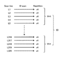
ここで、OCT血管造影に適用可能なスキャンパターンの典型的な例を説明する。OCT血管造影では3次元スキャン(ラスタースキャン)が適用される。3次元スキャンは、互いに平行に配列された複数のスキャンラインに沿ったスキャンである。複数のスキャンラインは予め順序付けられており、この順序でスキャンが適用される。本実施形態において適用可能な3次元スキャンの例を図14A及び図14Bに示す。 Here, a typical example of a scan pattern applicable to OCT angiography will be described. In OCT angiography, a three-dimensional scan (raster scan) is applied. A three-dimensional scan is a scan along a plurality of scan lines arranged parallel to one another. The plurality of scan lines are pre-ordered, and the scan is applied in this order. An example of a three-dimensional scan applicable in the present embodiment is shown in FIGS. 14A and 14B.
図14Bに示すように、本例の3次元スキャンは320本のスキャンラインL1〜L320に対して実行される。1本のスキャンラインLi(i=1〜320)に沿った1回のスキャンはBスキャンと呼ばれる。1つのBスキャンは320個のAスキャンからなる(図14Aを参照)。Aスキャンは1つのAラインに対するスキャンである。つまり、Aスキャンは、OCT測定光の入射方向(深さ方向、軸方向)に沿うAラインに対するスキャンである。Bスキャンは、深さ方向に直交する面上のスキャンラインLiに沿って配列された320個のAスキャンからなる。 As shown in FIG. 14B, the three-dimensional scan of this example is performed on 320 scan lines L1 to L320. One scan along one scan line Li (i = 1 to 320) is called a B scan. One B-scan consists of 320 A-scans (see FIG. 14A). A scan is a scan for one A line. That is, the A-scan is a scan for an A-line along the incident direction (the depth direction, the axial direction) of the OCT measurement light. The B-scan consists of 320 A-scans arranged along a scan line Li on a plane orthogonal to the depth direction.
本例の3次元スキャンでは、スキャンラインL1〜L320に対するBスキャンを任意の順序で4回ずつ実行する。各スキャンラインLiに対する4回のBスキャンはレペティションスキャンと呼ばれる。各スキャンラインLiに対する4回の繰り返し(レペティション)の順序は、任意である。例えば、4回のスキャンを連続的に行ってもよいし、4回のスキャンの間に他のスキャンラインに対するBスキャンを行ってもよい。 In the three-dimensional scan of this example, B scans for scan lines L1 to L320 are performed four times in an arbitrary order. The four B-scans for each scan line Li are called repetition scans. The order of the four repetitions (repetitions) for each scan line Li is arbitrary. For example, four scans may be performed continuously, or B scans for other scan lines may be performed during the four scans.
スキャンラインL1〜L320は、これらの配列順序に応じて5本ずつの組に分類されている。この分類により得られる64個の組のそれぞれはユニットと呼ばれ、各ユニットに対するスキャンをユニットスキャンと呼ぶ。ユニットスキャンは、5本のスキャンラインのそれぞれに対する4回のBスキャン(レペティション)からなる。すなわち、ユニットスキャンは、20回のBスキャンからなる。 The scan lines L1 to L320 are classified into sets of five in accordance with the arrangement order. Each of the 64 sets obtained by this classification is called a unit, and the scan for each unit is called a unit scan. A unit scan consists of four B scans (repetitions) for each of five scan lines. That is, a unit scan consists of 20 B scans.
画像形成部123は、このようなスキャンパターンでOCTデータ収集部130が収集したデータをスキャンラインLi毎のデータセット(時系列データ)に分類する。ここで、データセットには、4回のレペティションに対応する4つのBスキャンデータが含まれている。4つのBスキャンデータのそれぞれは、スキャンラインLiに対する1回のBスキャンで収集されたデータである。
The
更に、画像形成部123は、各スキャンラインLiに対応するデータセットに基づいて当該スキャンラインLiに対応するモーションコントラスト画像データを形成する。各スキャンラインLiに対応するモーションコントラスト画像データは、このスキャンラインLiを含むBスキャン面(縦断面)を表す2次元血管造影画像データである。
Furthermore, the
モーションコントラスト画像データを形成する処理は、従来のOCT血管造影データの形成と同様にして実行される。前述したように、本例では、スキャンラインLiに対応するデータセットに4つのBスキャンデータが含まれている。各Bスキャンデータは、スキャンラインLiに対する1回のBスキャンで収集されたデータである。 The process of forming motion contrast image data is performed in the same manner as forming conventional OCT angiography data. As described above, in this example, four B scan data are included in the data set corresponding to the scan line Li. Each B scan data is data collected by one B scan on the scan line Li.
まず、画像形成部123は、各Bスキャンデータに基づいて、通常のOCT画像データを形成する。このOCT画像データは、320個のAスキャン像データからなるBスキャン画像データである。それにより、スキャンラインLiに対応する4個のBスキャン画像データが得られる。
First, the
次に、画像形成部123は、4個のBスキャン画像データの間で変化している画像領域を特定する。この処理は、例えば、異なるBスキャン画像データの間の差分を求める処理を含む。各Bスキャン画像データは、眼底Efの形態を表す輝度画像データ(強度画像データ)であり、血管以外の部位に相当する画像領域は実質的に不変であると考えられる。一方、干渉信号に寄与する後方散乱が血流によってランダムに変化することを考慮すると、4個のBスキャン画像データの間で変化が生じた画像領域(例えば、差分がゼロでない画素、又は差分が所定閾値以上である画素)は血管領域であると推定することができる。
Next, the
画像形成部123は、特定された血管領域内の画素に所定の画素値を付与する。この画素値は、例えば、比較的高い輝度値(表示時には明るく、白く表現される)や、疑似カラー値であってよい。なお、他の従来技術と同様に、ドップラーOCTや画像処理を用いて血管領域を特定することも可能である。
The
このような処理により、320本のスキャンラインL1〜L320に対応する320個の2次元血管造影画像データが得られる。画像形成部123は、320本のスキャンラインL1〜L320の配列にしたがって320個の2次元血管造影画像データを配置する。この処理は、例えば、320本のスキャンラインL1〜L320の配列順序及び配列間隔(スペーシング)に合わせて、320個の2次元血管造影画像データを単一の3次元座標系に配置する(埋め込む)処理を含む。つまり、320本のスキャンラインL1〜L320の配列に応じた320個の2次元血管造影画像データのスタックデータを形成することができる。このスタックデータは、眼底Efの血管の3次元的な分布を表す画像データ(3次元血管造影画像データ)の例である。画像形成部123は、このスタックデータに補間処理等を施してボリュームデータ(ボクセルデータ)を形成することも可能である。
Through such processing, 320 two-dimensional angiographic image data corresponding to 320 scan lines L1 to L320 are obtained. The
収集されたデータから血管造影画像データを形成する処理は上記の例には限定されず、任意の公知技術を用いて血管造影画像データを形成することが可能である。 The process of forming angiographic image data from the collected data is not limited to the above example, and any known technique may be used to form angiographic image data.
データ処理部120は、ボリュームデータやスタックデータなどの3次元画像データを加工することができる。例えば、レンダリング部122は、3次元画像データにレンダリングを適用することができる。レンダリングの手法としては、ボリュームレンダリング、最大値投影(MIP)、最小値投影(MinIP)、サーフェスレンダリング、多断面再構成(MPR)などがある。また、レンダリング部122は、3次元画像データの少なくとも一部をAライン方向(深さ方向)に投影することにより、プロジェクションデータやシャドウグラムデータを構築することができる。
The
データ処理部120は、任意の解析処理や画像処理を実行することができる。例えば、データ処理部120は、2次元断面像データ又は3次元画像データにセグメンテーションを適用することができる。セグメンテーションは、画像データ中の部分データを特定する処理である。本例では、眼底Efの所定組織に相当する画像領域を特定することができる。
The
OCT血管造影において、レンダリング部122は、3次元血管造影画像データから、任意の2次元血管造影画像データ及び/又は任意の擬似的3次元血管造影画像データを構築することが可能である。例えば、データ処理部230は、3次元血管造影画像データに多断面再構成を適用することにより、眼底Efの任意の断面を表す2次元血管造影画像データを構築することができる。
In OCT angiography, the
また、画像形成部123は、3次元血管造影画像データにセグメンテーションを適用して眼底Efの所定組織に相当する画像領域を特定し、特定された画像領域をAスキャン方向に投影してシャドウグラムデータ(正面血管造影画像データ)を構築することができる。正面血管造影画像データの例として、眼底Efの任意の深さ領域(例えば、網膜浅部、網膜深部、脈絡膜毛細血管板、強膜など)に対応する正面画像や、眼底Efの所定組織(例えば、内境界膜、神経線維層、神経節細胞層、内網状層、内顆粒層、外網状層、外顆粒層、外境界膜、網膜色素上皮、ブルッフ膜、脈絡膜、脈絡膜強膜境界、強膜、これらのいずれかの一部、これらの少なくとも2以上の組み合わせなど)に対応する正面画像データがある。
In addition, the
画像データ記憶部111は、画像形成部123により形成された血管造影画像データを記憶することができる。また、画像データ記憶部111は、画像形成部123により形成された血管造影画像データをレンダリング部122がレンダリングすることによって構築された画像データを記憶することができる。このような画像データはレーザ治療において取得される。例えば、レーザ照射前、レーザ照射中、レーザ照射後などの任意のタイミングでOCT(特にOCT血管造影)を行うことが可能である。
The image
レーザ治療において取得された画像データは、例えば、治療効果の診断、術前術後比較、経過観察などに利用される。 The image data acquired in the laser treatment is used, for example, for diagnosis of treatment effect, preoperative and postoperative comparison, and observation.
〈第4の実施形態〉
例示的な実施形態に係る眼科情報処理装置について説明する。本実施形態の眼科情報処理装置の構成例を図15に示す。眼科情報処理装置200は、患者眼のレーザ治療に関する情報を処理する。例えば、眼科情報処理装置200は、患者眼のレーザ治療のための術前プランニングにおいて使用される。
Fourth Embodiment
An ophthalmologic information processing apparatus according to an exemplary embodiment will be described. A configuration example of the ophthalmologic information processing apparatus of the present embodiment is shown in FIG. The ophthalmologic
眼科情報処理装置200は、例えば、患者眼の画像や検査結果や診断結果などの各種情報を、表示部260に表示することができる。なお、本例では表示部260は眼科情報処理装置200に含まれるが、眼科情報処理装置に接続された外部装置としての表示デバイスを採用することも可能である。また、眼科情報処理装置200は、各種情報を、コンピュータ、記憶装置、眼科装置などに送ることができる。特に、眼科情報処理装置200は、術前プランニングにおいて作成された情報や参照された情報を、直接的又は間接的にレーザ治療装置に送ることができる。
The ophthalmologic
眼科情報処理装置200は、制御部210と、記憶部220と、データ処理部230と、データ入力部240と、操作部250と、表示部260とを含む。記憶部220は、画像データ記憶部221と、条件情報記憶部222とを含む。データ処理部230は、レンダリング部231と、条件情報生成部232とを含む。
The ophthalmologic
眼科情報処理装置200の各要素は、例えば、前述したレーザ治療装置1に含まれる対応する要素と同様の構成及び機能を有する。例えば、制御部210は制御部100と同様の構成及び機能を有し、画像データ記憶部221は画像データ記憶部111と同様の構成及び機能を有し、条件情報記憶部222は条件情報記憶部112と同様の構成及び機能を有し、レンダリング部231はレンダリング部122と同様の構成及び機能を有し、操作部250は操作ユニット6と同様の構成及び機能を有し、表示部260は表示ユニット7と同様の構成及び機能を有する。
Each element of the ophthalmic
条件情報記憶部112は、患者眼に対するレーザ治療の条件を表す条件情報を生成する。生成された条件情報は、条件情報記憶部222に保存される。
The condition
データ入力部240は、患者眼の画像や検査結果や診断結果などの各種情報を外部から眼科情報処理装置200に入力する。特に、データ入力部240は、OCT機能を有する眼科装置によって取得された血管造影画像データを受け付ける。受け付けられた血管造影画像データ(更には、他の画像データ)は、画像データ記憶部221に保存される。
The
データ入力部240は、例えば、外部装置との間でデータ通信を行うための通信インターフェイス、記録媒体からデータを読み取る装置などを含んでいてよい。
The
眼科情報処理装置200の使用形態の例を説明する。
An example of usage of the ophthalmologic
まず、上記したレーザ治療装置1などと同様に、眼科情報処理装置200は、画像データ記憶部221に記憶された血管造影画像データに基づく血管造影画像と、条件情報記憶部222に記憶された条件情報の少なくとも一部に基づく情報とを、表示部260に表示させることができる。更に、上記した第1〜第3の実施形態において説明した任意の構成及び機能を眼科情報処理装置200に組み合わせることが可能である。
First, as in the above-described
術前プランニングなどにおいて、レーザ照射目標位置などを設定するために眼科情報処理装置200を使用することができる。この場合、画像データ記憶部221に記憶された血管造影画像データは、患者眼の眼底の3次元領域にOCT血管造影を適用して取得された3次元血管造影画像データを含む。
The ophthalmologic
レンダリング部231は、3次元血管造影画像データをレンダリングする。制御部100は、レンダリング部231により形成されたレンダリング画像(血管造影画像)を表示部260に表示させる。
The
ユーザは、表示部260に表示されたレンダリング画像に基づいて、レーザ治療の目標となる眼底の位置を設定する。この治療目標位置の設定は、操作部250を用いて行われる。
The user sets the position of the fundus, which is the target of the laser treatment, based on the rendered image displayed on the
条件情報生成部232は、ユーザにより設定された治療目標位置を表す治療目標位置情報を生成する。例えば、治療目標位置情報は、治療目標位置の設定において参照されたレンダリング画像における、治療目標位置の座標を含む。この治療目標位置の座標は、3次元血管造影画像データにおける座標でもある。
The condition
条件情報記憶部222は、条件情報生成部232により生成された治療目標位置情報を条件情報として記憶する。これにより、ユーザが設定した治療目標位置が、画像データ記憶部221に記憶された3次元血管造影画像データ(又は、そのレンダリング画像データ)に関連付けられて、条件情報として記憶される。
The condition
術前プランニングなどにおいて、眼底表面以外の位置を治療目標として設定するためにシャドウグラムを参照することができる。 In preoperative planning and the like, a shadowgram can be referred to set a position other than the surface of the fundus as a treatment target.
まず、レンダリング部231は、画像データ記憶部221に記憶された3次元血管造影画像データにセグメンテーションを適用するなどして3次元部分データを抽出する。更に、レンダリング部231は、抽出された3次元部分データをレンダリングして正面血管造影画像(シャドウグラム)を形成する。制御部100は、レンダリング部231により形成されたシャドウグラムを表示部260に表示させる。
First, the
ユーザは、表示部260に表示されたシャドウグラムを参照して、レーザ治療の目標となる眼底の位置を設定することができる。このとき、ユーザは、シャドウグラムとして画像化する深さ領域を任意に変更することができる。
The user can set the position of the fundus to be a target of the laser treatment with reference to the shadowgram displayed on the
ユーザがシャドウグラムを参照して治療目標位置を設定すると、条件情報生成部232は、このシャドウグラムに対応する眼底の深さ領域を特定する。更に、条件情報生成部232は、特定された深さ領域を表す深さ領域情報を生成することができる。或いは、条件情報生成部232は、特定された深さ領域に対応する治療光の波長を表す波長情報を生成することができる。
When the user sets a treatment target position with reference to the shadowgram, the condition
深さ領域情報は、例えば、シャドウグラムにおける治療目標位置の座標、又は、このシャドウグラムにおける座標に対応する3次元血管造影画像データにおける座標を含む。波長情報は、例えば、第1の実施形態で説明した深さ領域と波長との対応関係に基づいて求められる。 The depth region information includes, for example, the coordinates of the treatment target position in the shadowgram, or the coordinates in three-dimensional angiographic image data corresponding to the coordinates in the shadowgram. The wavelength information is obtained, for example, based on the correspondence relationship between the depth region and the wavelength described in the first embodiment.
条件情報記憶部222は、条件情報生成部232により生成された深さ領域情報及び/又は波長情報を条件情報として記憶する。これにより、ユーザが設定した治療目標位置に対応する眼底の深さ領域や治療光の波長を自動で特定し、その特定結果を画像データ記憶部221に記憶された3次元血管造影画像データ(又は、シャドウグラムデータ)に関連付けて、条件情報として記憶することができる。画像データ記憶部111は、このシャドウグラムデータを記憶してもよい。
The condition
〈第5の実施形態〉
例示的な実施形態に係る眼科システムについて説明する。本実施形態の眼科システムの構成例を図16に示す。この眼科システムは、眼科情報処理装置200と、レーザ治療装置300とを含む。眼科情報処理装置200とレーザ治療装置300とは、LAN、インターネット、専用線などの通信回線を介して通信可能に接続されている。
Fifth Embodiment
An ophthalmic system according to an exemplary embodiment will be described. A configuration example of the ophthalmologic system of the present embodiment is shown in FIG. The ophthalmologic system includes an ophthalmologic
眼科システムは、眼科情報処理装置200及びレーザ治療装置300に加えて他の装置を含んでいてもよい。典型的には、眼科システムは、サーバ、データベース、医師端末、眼科装置(例えば、OCT機能を有する装置)などを含んでいてもよい。
The ophthalmic system may include other devices in addition to the ophthalmic
眼科情報処理装置200は、第4の実施形態に係る眼科情報処理装置であってよい。レーザ治療装置300は、第1〜第3の実施形態のいずれかに係るレーザ治療装置であってよい。
The ophthalmologic
レーザ治療装置300は、制御部310と、記憶部320と、データ処理部330と、データ受付部340と、操作部350と、表示部360とを含む。記憶部320は、画像データ記憶部321と、条件情報記憶部322とを含む。
レーザ治療装置300の各要素は、例えば、第1の実施形態に係るレーザ治療装置1に含まれる対応する要素と同様の構成及び機能を有する。例えば、制御部310は制御部100と同様の構成及び機能を有し、画像データ記憶部321は画像データ記憶部111と同様の構成及び機能を有し、条件情報記憶部322は条件情報記憶部112と同様の構成及び機能を有し、データ処理部330はデータ処理部120と同様の構成及び機能を有し、操作部350は操作ユニット6と同様の構成及び機能を有し、表示部360は表示ユニット7と同様の構成及び機能を有する。
Each element of the
図示は省略するが、レーザ治療装置300は、例えば、第1の実施形態における光源ユニット2及びスリットランプ顕微鏡3などを含む(図1〜図3を参照)。
Although not shown, the
データ受付部340は、眼科情報処理装置200の条件情報記憶部222に記憶された条件情報の少なくとも一部を受け付ける。また、データ受付部340は、眼科情報処理装置200の画像データ記憶部221に記憶された画像データ(例えば、血管造影画像データ)の少なくとも一部を受け付けてもよい。また、データ受付部340は、図示しない画像アーカイビングシステムに保存された画像データ(例えば、血管造影画像データ)の少なくとも一部を受け付けてもよい。データ受付部340は、例えば、外部装置との間でデータ通信を行うための通信インターフェイス、記録媒体からデータを読み取る装置などを含んでいてよい。
The
画像データ記憶部321は、OCT血管造影を患者眼の眼底に適用して取得された血管造影画像データを含む患者眼の画像データを記憶する。画像データは、例えば、眼科情報処理装置200及び/又は画像アーカイビングシステムからデータ受付部340によって受け付けられる。また、レーザ治療装置300がOCT機能を有する場合、レーザ治療装置300により形成された画像データを画像データ記憶部321に記憶することが可能である。
The image
条件情報記憶部322は、データ受付部340により受け付けられた条件情報を記憶する。レーザ治療装置300が条件情報生成機能を有する場合、レーザ治療装置300により生成された条件情報を条件情報記憶部322に記憶することが可能である。
Condition
制御部310は、画像データ記憶部321に記憶された血管造影画像データに基づく血管造影画像と条件情報記憶部322に記憶された条件情報の少なくとも一部に基づく情報とを表示部360に表示させる。
このような眼科システムによれば、眼科情報処理装置200を用いて条件情報を生成し、この条件情報を利用しながらレーザ治療装置300を用いて患者眼にレーザ治療を適用することが可能である。また、眼科情報処理装置200において参照した血管造影画像を参照しながら、レーザ治療装置300を用いて患者眼にレーザ治療を適用することが可能である。
According to such an ophthalmologic system, it is possible to generate condition information using the ophthalmologic
〈作用・効果〉
例示的な実施形態に係るレーザ治療装置、眼科情報処理装置、及び眼科システムの作用及び効果について説明する。
<Operation / Effect>
An operation and an effect of a laser treatment apparatus, an ophthalmologic information processing apparatus, and an ophthalmologic system according to an exemplary embodiment will be described.
例示的な実施形態に係るレーザ治療装置は、患者眼のレーザ治療を行うために用いられ、画像データ記憶部と、条件情報記憶部と、表示制御部とを含む。画像データ記憶部(111)は、OCT血管造影を患者眼(E)の眼底(Ef)に適用して取得された血管造影画像データを含む、患者眼の画像データを記憶する。条件情報記憶部(112)は、患者眼に対するレーザ治療の条件を表す条件情報を記憶する。表示制御部(制御部100)は、血管造影画像データに基づく血管造影画像と条件情報の少なくとも一部に基づく情報とを表示装置(表示装置61、又は表示ユニット7)に表示させる。
A laser treatment apparatus according to an exemplary embodiment is used to perform laser treatment of a patient's eye, and includes an image data storage unit, a condition information storage unit, and a display control unit. The image data storage unit (111) stores image data of the patient's eye, including angiographic image data acquired by applying OCT angiography to the fundus (Ef) of the patient's eye (E). The condition information storage unit (112) stores condition information indicating the condition of the laser treatment for the patient's eye. The display control unit (control unit 100) causes the display device (
このような実施形態によれば、ユーザは、患者眼の眼底の血管分布とレーザ治療の条件とを参照することができる。したがって、眼科レーザ治療のための情報の提示の向上を図ることが可能である。 According to such an embodiment, the user can refer to the vascularity of the fundus of the patient's eye and the conditions of the laser treatment. Therefore, it is possible to improve the presentation of information for ophthalmic laser treatment.
例示的な実施形態において、レーザ治療装置は、患者眼に照明光を投射する照明光学系(照明系10)と、照明光が投射されている患者眼を観察するための観察光学系(観察系30)とを更に含んでいてよい。 In an exemplary embodiment, the laser treatment apparatus comprises an illumination optical system (illumination system 10) for projecting illumination light to a patient's eye and an observation optical system (observation system for observing a patient's eye onto which the illumination light is projected) And 30) may be further included.
このような構成によれば、ユーザは、患者眼(眼底)の観察画像と眼底血管分布とレーザ治療の条件とを参照することができる。したがって、眼科レーザ治療のための情報の提示の向上を図ることが可能である。 According to such a configuration, the user can refer to the observation image of the patient's eye (fundus), the fundus blood vessel distribution, and the condition of the laser treatment. Therefore, it is possible to improve the presentation of information for ophthalmic laser treatment.
例示的な実施形態において、観察光学系(観察系30)は、接眼レンズ(38)と、患者眼に投射された照明光の戻り光を接眼レンズに導く第1光学系(対物レンズ31〜視野絞り37)とを含んでいてよい。更に、レーザ治療装置は、表示装置(61)から出射された光の光路と第1光学系が形成する光路(観察光路)とを結合する光路結合部材(ビームスプリッタ63)を更に含んでいてよい。
In an exemplary embodiment, the observation optical system (observation system 30) includes an eyepiece (38) and a first optical system (
このような構成によれば、ユーザは、接眼レンズを介して患者眼(眼底)を観察しつつ、同じく接眼レンズを介して眼底血管分布及びレーザ治療の条件を認識することが可能である。したがって、眼科レーザ治療のための情報の提示の向上を図ることが可能である。 According to such a configuration, it is possible for the user to recognize the fundus blood vessel distribution and the condition of the laser treatment while observing the patient's eye (fundus oculi) through the eyepiece and similarly through the eyepiece. Therefore, it is possible to improve the presentation of information for ophthalmic laser treatment.
例示的な実施形態において、レーザ治療装置は、第1光学系(対物レンズ31〜視野絞り37)が形成する光路(観察光路)からの分岐光路を形成する光路分岐部材(ビームスプリッタ41)と、この分岐光路に配置された第1撮像装置(イメージセンサ43)と、第1撮像装置により取得された画像データと画像データ記憶部に記憶された画像データとの間のレジストレーションを行う第1レジストレーション部(レジストレーション部121)とを含んでいてよい。更に、表示制御部(制御部100)は、レジストレーションの結果に基づいて血管造影画像の表示位置を決定するように構成されていてよい。
In an exemplary embodiment, the laser treatment apparatus includes an optical path branching member (beam splitter 41) that forms a branched optical path from an optical path (observation optical path) formed by the first optical system (the
このような構成によれば、接眼レンズを介して提供される患者眼(眼底)の観察画像と血管造影画像との間の位置関係をユーザに提供することができる。例えば、観察画像に血管造影画像を重ねてユーザに提示することが可能である。したがって、眼科レーザ治療のための情報の提示の向上を図ることが可能である。 According to such a configuration, it is possible to provide the user with the positional relationship between the observation image of the patient's eye (fundus) provided via the eyepiece and the angiographic image. For example, an angiographic image can be superimposed on the observation image and presented to the user. Therefore, it is possible to improve the presentation of information for ophthalmic laser treatment.
例示的な実施形態において、条件情報は、予め設定されたレーザ治療の目標となる眼底の位置を表す治療目標位置情報を含んでいてよい。更に、表示制御部(制御部100)は、第1レジストレーション部が実行したレジストレーションの結果に基づいて、治療目標位置情報が表す位置を示す治療目標位置画像の表示位置を決定するように構成されていてよい。 In an exemplary embodiment, the condition information may include treatment target position information indicating a position of a fundus to be a target of laser treatment set in advance. Furthermore, the display control unit (control unit 100) is configured to determine the display position of the treatment target position image indicating the position represented by the treatment target position information based on the result of the registration performed by the first registration unit. It may be done.
このような構成によれば、患者眼(眼底)の観察画像及び血管造影画像とともに、レーザ治療の目標となる眼底の位置を提示することが可能である。治療目標位置画像は、例えば、観察画像に重ねられた状態でユーザに提示される。したがって、眼科レーザ治療のための情報の提示の向上を図ることが可能である。 According to such a configuration, it is possible to present the position of the fundus to be a target of the laser treatment together with the observation image and the angiographic image of the patient's eye (fundus). The treatment target position image is presented to the user, for example, in a state of being superimposed on the observation image. Therefore, it is possible to improve the presentation of information for ophthalmic laser treatment.
例示的な実施形態において、観察光学系(観察系30、撮影系40)は、第2撮像装置(イメージセンサ43)と、患者眼に投射された照明光の戻り光を第2撮像装置に導く第2光学系(対物レンズ31〜結像レンズ35、ビームスプリッタ41、結像レンズ42)とを含んでいてよい。更に、表示制御部(制御部100)は、血管造影画像と、条件情報の少なくとも一部に基づく情報と、第2撮像装置により取得された画像データに基づく観察画像とを、表示装置(表示ユニット7)に表示させるように構成されていてよい。
In an exemplary embodiment, the observation optical system (the
このような構成によれば、ユーザは、表示装置を介して患者眼(眼底)を観察しつつ、同じく表示装置を介して眼底血管分布及びレーザ治療の条件を認識することが可能である。したがって、眼科レーザ治療のための情報の提示の向上を図ることが可能である。 According to such a configuration, the user can recognize the fundus blood vessel distribution and the condition of the laser treatment while observing the patient's eye (fundus oculi) through the display device while similarly observing the patient's eye (fundus oculi) through the display device. Therefore, it is possible to improve the presentation of information for ophthalmic laser treatment.
例示的な実施形態において、レーザ治療装置は、第2撮像装置(イメージセンサ43)により取得された画像データと画像データ記憶部(111)に記憶された画像データとの間のレジストレーションを行う第2レジストレーション部(レジストレーション部121)を含んでいてよい。更に、表示制御部(制御部100)は、レジストレーションの結果に基づいて、血管造影画像と観察画像との間の相対位置を決定するように構成されていてよい。 In an exemplary embodiment, the laser treatment apparatus performs registration between the image data acquired by the second imaging device (image sensor 43) and the image data stored in the image data storage unit (111). 2 A registration unit (registration unit 121) may be included. Furthermore, the display control unit (control unit 100) may be configured to determine the relative position between the angiographic image and the observation image based on the result of the registration.
このような構成によれば、表示装置を介して提供される患者眼(眼底)の観察画像と血管造影画像との間の位置関係をユーザに提供することができる。例えば、観察画像に血管造影画像を重ねて表示させることが可能である。したがって、眼科レーザ治療のための情報の提示の向上を図ることが可能である。 According to such a configuration, it is possible to provide the user with the positional relationship between the observation image of the patient's eye (fundus oculi) and the angiographic image provided via the display device. For example, an angiographic image can be superimposed and displayed on the observation image. Therefore, it is possible to improve the presentation of information for ophthalmic laser treatment.
例示的な実施形態において、条件情報は、予め設定されたレーザ治療の目標となる眼底の位置を表す治療目標位置情報を含んでいてよい。更に、表示制御部(制御部100)は、第2レジストレーション部により実行されたレジストレーションの結果に基づいて、治療目標位置情報が表す位置を示す治療目標位置画像と観察画像との間の相対位置を決定するように構成されていてよい。 In an exemplary embodiment, the condition information may include treatment target position information indicating a position of a fundus to be a target of laser treatment set in advance. Furthermore, the display control unit (the control unit 100) determines, based on the result of the registration performed by the second registration unit, the relative between the treatment target position image indicating the position indicated by the treatment target position information and the observation image. It may be configured to determine the position.
このような構成によれば、患者眼(眼底)の観察画像及び血管造影画像とともに、レーザ治療の目標となる眼底の位置を提示することが可能である。治療目標位置画像は、例えば、観察画像に重ねて表示される。したがって、眼科レーザ治療のための情報の提示の向上を図ることが可能である。 According to such a configuration, it is possible to present the position of the fundus to be a target of the laser treatment together with the observation image and the angiographic image of the patient's eye (fundus). The treatment target position image is displayed, for example, superimposed on the observation image. Therefore, it is possible to improve the presentation of information for ophthalmic laser treatment.
例示的な実施形態において、血管造影画像データは、患者眼の眼底の3次元領域にOCT血管造影を適用して取得された3次元血管造影画像データを含んでいてよい。また、レーザ治療装置は、この3次元血管造影画像データをレンダリングして正面血管造影画像を形成するレンダリング部(122)を更に含んでいてよい。更に、表示制御部(制御部100)は、レンダリング部により形成された正面血管造影画像を血管造影画像として表示させるように構成されていてよい。 In an exemplary embodiment, the angiographic image data may include three-dimensional angiographic image data acquired by applying OCT angiography to a three-dimensional area of a fundus of a patient's eye. The laser treatment apparatus may further include a rendering unit (122) for rendering this three-dimensional angiographic image data to form a front angiographic image. Furthermore, the display control unit (control unit 100) may be configured to display the front angiographic image formed by the rendering unit as an angiographic image.
このような構成によれば、ユーザは、正面血管造影画像(シャドウグラム、プロジェクション画像など)が表す血管分布とレーザ治療の条件とを参照することができる。したがって、眼科レーザ治療のための情報の提示の向上を図ることが可能である。 According to such a configuration, the user can refer to the blood vessel distribution represented by the front angiographic image (shadowgram, projection image, etc.) and the condition of the laser treatment. Therefore, it is possible to improve the presentation of information for ophthalmic laser treatment.
例示的な実施形態において、条件情報は、治療用レーザ光(治療光LT)の波長を表す波長情報、及び、レーザ治療の目標となる眼底の深さ領域を表す深さ領域情報の少なくとも一方を含んでいてよい。更に、レンダリング部(122)は、波長情報及び深さ領域情報の少なくとも一方に基づいて3次元血管造影画像データの3次元部分データを抽出し、この3次元部分データをレンダリングして正面血管造影画像を形成するように構成されていてよい。 In the exemplary embodiment, the condition information includes at least one of wavelength information indicating the wavelength of the treatment laser light (the treatment light LT) and depth region information indicating the depth region of the fundus to be targeted for the laser treatment. May be included. Furthermore, the rendering unit (122) extracts three-dimensional partial data of the three-dimensional angiographic image data based on at least one of the wavelength information and the depth region information, renders the three-dimensional partial data, and displays a front angiographic image. May be configured to form
このような構成によれば、レーザ治療の目標となる眼底の深さ領域における血管分布を選択的にユーザに提供することが可能である。したがって、眼科レーザ治療のための情報の提示の向上を図ることが可能である。 According to such a configuration, it is possible to selectively provide the user with the blood vessel distribution in the depth region of the fundus to be targeted for the laser treatment. Therefore, it is possible to improve the presentation of information for ophthalmic laser treatment.
例示的な実施形態において、レーザ治療装置は、患者眼の眼底にOCT血管造影を適用してデータを収集するデータ収集部(130)と、データ収集部により収集されたデータを処理して血管造影画像データを形成するデータ処理部(画像形成部123)とを更に含んでいてよい。更に、画像データ記憶部は、データ処理部により形成された血管造影画像データを記憶するように構成されていてよい。 In an exemplary embodiment, the laser treatment device applies a OCT angiography to the fundus of a patient's eye to acquire data by collecting data (130) and processing the data collected by the data collector to perform angiography It may further include a data processing unit (image forming unit 123) that forms image data. Furthermore, the image data storage unit may be configured to store angiographic image data formed by the data processing unit.
このような構成によれば、レーザ治療装置を用いてOCT血管造影を実施できるので、レーザ治療の直前、レーザ治療中、レーザ治療の直後における患者眼の眼底の血管造影画像データを取得することが可能である。更に、この新たな血管造影画像を観察することや、この新たな血管造影画像と術前に得られた血管造影画像とを比較することが可能となる。したがって、眼科レーザ治療のための情報の提示の向上を図ることが可能である。 According to such a configuration, since OCT angiography can be performed using the laser treatment apparatus, it is possible to acquire angiographic image data of the fundus of a patient's eye immediately before, during, and immediately after laser treatment. It is possible. Furthermore, it becomes possible to observe this new angiographic image and to compare this new angiographic image with the angiographic image obtained before the operation. Therefore, it is possible to improve the presentation of information for ophthalmic laser treatment.
例示的な実施形態に係る眼科情報処理装置(200)は、患者眼のレーザ治療に関する情報を処理する装置であって、画像データ記憶部と、条件情報記憶部と、表示制御部とを含む。画像データ記憶部(221)は、OCT血管造影を患者眼の眼底に適用して取得された血管造影画像データを含む患者眼の画像データを記憶する。条件情報記憶部(222)は、患者眼に対するレーザ治療の条件を表す条件情報を記憶する。表示制御部(制御部210)は、血管造影画像データに基づく血管造影画像と条件情報の少なくとも一部に基づく情報とを表示装置(表示部260)に表示させる。 An ophthalmologic information processing apparatus (200) according to an exemplary embodiment is an apparatus for processing information on laser treatment of a patient's eye, and includes an image data storage unit, a condition information storage unit, and a display control unit. The image data storage unit (221) stores image data of a patient's eye including angiographic image data acquired by applying OCT angiography to the fundus of the patient's eye. The condition information storage unit (222) stores condition information indicating the condition of the laser treatment for the patient's eye. The display control unit (control unit 210) causes the display device (display unit 260) to display an angiographic image based on the angiographic image data and information based on at least a part of the condition information.
このような実施形態によれば、レーザ治療の前(例えば、術前プランニング)、レーザ治療中、レーザ治療後(例えば、治療効果の診断、術前術後比較、経過観察)に、ユーザは、患者眼の眼底の血管分布とレーザ治療の条件とを参照することができる。したがって、眼科レーザ治療のための情報の提示の向上を図ることが可能である。 According to such an embodiment, the user may (e.g., pre-operative planning), during (e.g., pre-operative planning), (e.g., diagnose treatment effects, compare pre- and post-operative comparisons, follow-up) laser treatment. The vascular distribution of the fundus of the patient's eye and the conditions of the laser treatment can be referenced. Therefore, it is possible to improve the presentation of information for ophthalmic laser treatment.
例示的な実施形態に係るレーザ治療装置が具備する任意の構成及び/又は任意の機能を、例示的な実施形態に係る眼科情報処理装置に組み合わせることが可能である。 Any configuration and / or any function of the laser treatment apparatus according to the exemplary embodiment can be combined with the ophthalmic information processing apparatus according to the exemplary embodiment.
例示的な実施形態において、血管造影画像データは、患者眼の眼底の3次元領域にOCT血管造影を適用して取得された3次元血管造影画像データを含んでいてよい。また、眼科情報処理装置(200)は、操作部(250)と、3次元血管造影画像データをレンダリングするレンダリング部(231)とを更に含んでいてよい。また、表示制御部(制御部210)は、レンダリング部により形成されたレンダリング画像を血管造影画像として表示させるように構成されていてよい。操作部(250)は、レーザ治療の目標となる眼底の位置をレンダリング画像に基づき設定するために用いられる。眼科情報処理装置(200)は、操作部を用いて設定された眼底の位置を表す治療目標位置情報を生成する条件情報生成部(232)を更に含んでいてよい。更に、条件情報記憶部(222)は、条件情報生成部により生成された治療目標位置情報を条件情報として記憶する。 In an exemplary embodiment, the angiographic image data may include three-dimensional angiographic image data acquired by applying OCT angiography to a three-dimensional area of a fundus of a patient's eye. The ophthalmologic information processing apparatus (200) may further include an operation unit (250) and a rendering unit (231) for rendering three-dimensional angiographic image data. The display control unit (control unit 210) may be configured to display the rendering image formed by the rendering unit as an angiographic image. The operation unit (250) is used to set the position of the fundus to be a target of laser treatment based on the rendered image. The ophthalmologic information processing apparatus (200) may further include a condition information generation unit (232) that generates treatment target position information indicating the position of the fundus set using the operation unit. Furthermore, the condition information storage unit (222) stores the treatment target position information generated by the condition information generation unit as condition information.
このような構成によれば、術前プランニングなどにおいて、ユーザは、3次元血管造影画像データのレンダリング画像を参照しつつ治療目標位置を設定することができ、この設定された治療目標位置に基づき条件情報が自動で生成され記憶される。したがって、条件情報を作成する作業の効率化を図ることができる。 According to such a configuration, in preoperative planning and the like, the user can set the treatment target position while referring to the rendered image of the three-dimensional angiographic image data, and the condition is set based on the set treatment target position. Information is automatically generated and stored. Therefore, the efficiency of the work of creating the condition information can be achieved.
例示的な実施形態において、レンダリング部(231)は、3次元血管造影画像データの3次元部分データを抽出し、この3次元部分データをレンダリングして正面血管造影画像を形成するように構成されていてよい。表示制御部(制御部210)は、レンダリング部により形成された正面血管造影画像をレンダリング画像として表示させるように構成されていてよい。条件情報生成部(232)は、レーザ治療の目標となる眼底の位置が正面血管造影画像に基づき設定されたときに、この正面血管造影画像に対応する眼底の深さ領域に基づいて、この深さ領域を表す深さ領域情報、及び、治療用レーザ光の波長を表す波長情報の少なくとも一方を生成するように構成されていてよい。条件情報記憶部(222)は、生成された深さ領域情報及び波長情報の少なくとも一方を条件情報として記憶するように構成されていてよい。 In the exemplary embodiment, the rendering unit (231) is configured to extract three-dimensional partial data of the three-dimensional angiographic image data and render the three-dimensional partial data to form a front angiographic image. You may The display control unit (control unit 210) may be configured to display the front angiographic image formed by the rendering unit as a rendering image. When the position of the fundus to be targeted for the laser treatment is set based on the front angiographic image, the condition information generation unit (232) determines the depth based on the depth region of the fundus corresponding to the front angiographic image. The optical system may be configured to generate at least one of depth region information indicating the wavelength region and wavelength information indicating the wavelength of the therapeutic laser light. The condition information storage unit (222) may be configured to store at least one of the generated depth region information and wavelength information as the condition information.
このような構成によれば、術前プランニングなどにおいて、ユーザは、3次元血管造影画像データのレンダリング画像を参照しつつ治療目標となる深さ領域や治療用レーザ光の波長を設定することができ、その設定内容に基づき条件情報が自動で生成され記憶される。したがって、条件情報を作成する作業の効率化を図ることができる。 According to such a configuration, in preoperative planning and the like, the user can set the depth region to be the treatment target and the wavelength of the treatment laser light while referring to the rendered image of the three-dimensional angiographic image data. Condition information is automatically generated and stored based on the setting contents. Therefore, the efficiency of the work of creating the condition information can be achieved.
例示的な実施形態において、画像データ記憶部(221)は、レンダリング部(231)により形成された画像データを記憶するように構成されていてよい。 In an exemplary embodiment, the image data storage unit (221) may be configured to store the image data formed by the rendering unit (231).
このような構成によれば、術前プランニングなどにおいて参照されたレンダリング画像データを記憶しておくことができる。 According to such a configuration, it is possible to store rendering image data referred to in preoperative planning and the like.
例示的な実施形態に係る眼科システムは、眼科情報処理装置(200)と、レーザ治療装置(300)とを含む。レーザ治療装置(300)は、受付部と、第1記憶部と、第2記憶部と、制御部とを含む。受付部(データ受付部340)は、眼科情報処理装置の条件情報記憶部(222)に記憶された条件情報の少なくとも一部を受け付ける。第1記憶部(画像データ記憶部321)は、OCT血管造影を患者眼の眼底に適用して取得された血管造影画像データを含む患者眼の画像データを記憶する。第2記憶部(条件情報記憶部322)は、受付部により受け付けられた条件情報を記憶する。制御部(310)は、第1記憶部に記憶された血管造影画像データに基づく血管造影画像と、第2記憶部に記憶された条件情報の少なくとも一部に基づく情報とを、表示装置(表示部360)に表示させる。 An ophthalmologic system according to an exemplary embodiment includes an ophthalmologic information processing apparatus (200) and a laser treatment apparatus (300). The laser treatment apparatus (300) includes a reception unit, a first storage unit, a second storage unit, and a control unit. The receiving unit (data receiving unit 340) receives at least a part of the condition information stored in the condition information storage unit (222) of the ophthalmologic information processing apparatus. The first storage unit (image data storage unit 321) stores image data of a patient's eye including angiographic image data acquired by applying OCT angiography to the fundus of the patient's eye. The second storage unit (condition information storage unit 322) stores the condition information received by the receiving unit. The control unit (310) displays an angiographic image based on the angiographic image data stored in the first storage unit and information based on at least a part of the condition information stored in the second storage unit. It is displayed on the part 360).
このような実施形態によれば、ユーザは、事前に生成された条件情報や、レーザ治療前又はレーザ治療中に取得された血管造影画像を参照しつつ、患者眼にレーザ治療を施すことができる。したがって、眼科レーザ治療のための情報の提示の向上を図ることが可能である。 According to such an embodiment, the user can perform the laser treatment on the patient's eye while referring to the pre-generated condition information and the angiographic image acquired before or during the laser treatment. . Therefore, it is possible to improve the presentation of information for ophthalmic laser treatment.
例示的な実施形態に係るレーザ治療装置が具備する任意の構成及び/又は任意の機能を、例示的な実施形態に係る眼科システムに組み合わせることが可能である。また、例示的な実施形態に係る眼科情報処理装置が具備する任意の構成及び/又は任意の機能を、例示的な実施形態に係る眼科システムに組み合わせることが可能である。 Any configuration and / or any function of the laser treatment apparatus according to the exemplary embodiment can be combined with the ophthalmic system according to the exemplary embodiment. In addition, any configuration and / or any function of the ophthalmic information processing apparatus according to the exemplary embodiment can be combined with the ophthalmic system according to the exemplary embodiment.
例示的な実施形態において、受付部(データ受付部340)は、眼科情報処理装置(200)の画像データ記憶部(221)に記憶された画像データの少なくとも一部を受け付けるように構成されていてよい。更に、第1記憶部(画像データ記憶部321)は、受付部により受け付けられた画像データを記憶するように構成されていてよい。 In the exemplary embodiment, the receiving unit (data receiving unit 340) is configured to receive at least a part of the image data stored in the image data storage unit (221) of the ophthalmologic information processing apparatus (200). Good. Furthermore, the first storage unit (image data storage unit 321) may be configured to store the image data received by the reception unit.
このような構成によれば、ユーザは、眼科情報処理装置により生成された条件情報に加え、条件情報を生成するために参照された画像を参照しつつ、患者眼にレーザ治療を施すことができる。したがって、眼科レーザ治療のための情報の提示の向上を図ることが可能である。 According to such a configuration, the user can perform the laser treatment on the patient's eye while referring to the image referred to generate the condition information in addition to the condition information generated by the ophthalmologic information processing apparatus . Therefore, it is possible to improve the presentation of information for ophthalmic laser treatment.
以上に説明した実施形態及び変形例は例示に過ぎない。本発明を実施しようとする者は、本発明の要旨の範囲内において任意の変形、省略、追加、置換等を施すことが可能である。 The embodiments and modifications described above are merely illustrative. A person who intends to practice the present invention can make any modification, omission, addition, substitution, etc. within the scope of the present invention.
1 レーザ治療装置
100 制御部
110 記憶部
111 画像データ記憶部
112 条件情報記憶部
120 データ処理部
121 レジストレーション部
122 レンダリング部
1
Claims (17)
光コヒーレンストモグラフィ(OCT)血管造影を前記患者眼の眼底に適用して取得された血管造影画像データを含む前記患者眼の画像データを記憶する画像データ記憶部と、
前記患者眼に対するレーザ治療の条件を表す条件情報を記憶する条件情報記憶部と、
前記血管造影画像データに基づく血管造影画像と前記条件情報の少なくとも一部に基づく情報とを表示装置に表示させる表示制御部と
を含むレーザ治療装置。 A laser treatment apparatus for performing laser treatment of a patient's eye, comprising:
An image data storage unit storing image data of the patient's eye including angiographic image data acquired by applying optical coherence tomography (OCT) angiography to the fundus of the patient's eye;
A condition information storage unit that stores condition information representing the condition of the laser treatment for the patient's eye;
A display control unit that displays on the display device an angiographic image based on the angiographic image data and information based on at least a part of the condition information.
前記照明光が投射されている前記患者眼を観察するための観察光学系と
を更に含む
ことを特徴とする請求項1に記載のレーザ治療装置。 An illumination optical system that projects illumination light onto the patient's eye;
The laser treatment apparatus according to claim 1, further comprising: an observation optical system for observing the patient's eye on which the illumination light is projected.
接眼レンズと、
前記患者眼に投射された前記照明光の戻り光を前記接眼レンズに導く第1光学系と
を含み、
前記表示装置から出射された光の光路と前記第1光学系が形成する光路とを結合する光路結合部材を更に含む
ことを特徴とする請求項2に記載のレーザ治療装置。 The observation optical system is
With eyepieces,
A first optical system for guiding the return light of the illumination light projected onto the patient's eye to the eyepiece;
The laser treatment apparatus according to claim 2, further comprising an optical path coupling member that couples an optical path of light emitted from the display device and an optical path formed by the first optical system.
前記分岐光路に配置された第1撮像装置と、
前記第1撮像装置により取得された画像データと前記画像データ記憶部に記憶された前記画像データとの間のレジストレーションを行う第1レジストレーション部と
を含み、
前記表示制御部は、前記レジストレーションの結果に基づいて前記血管造影画像の表示位置を決定する
ことを特徴とする請求項3に記載のレーザ治療装置。 An optical path branching member that forms a branched optical path from the optical path formed by the first optical system;
A first imaging device disposed in the branched light path;
A first registration unit for performing registration between the image data acquired by the first imaging device and the image data stored in the image data storage unit;
The laser treatment apparatus according to claim 3, wherein the display control unit determines a display position of the angiographic image based on a result of the registration.
前記表示制御部は、前記レジストレーションの結果に基づいて、前記治療目標位置情報が表す位置を示す治療目標位置画像の表示位置を決定する
ことを特徴とする請求項4に記載のレーザ治療装置。 The condition information includes treatment target position information indicating a position of the fundus which is a target of laser treatment set in advance.
5. The laser treatment apparatus according to claim 4, wherein the display control unit determines a display position of a treatment target position image indicating a position represented by the treatment target position information based on the result of the registration.
第2撮像装置と、
前記患者眼に投射された前記照明光の戻り光を前記第2撮像装置に導く第2光学系と
を含み、
前記表示制御部は、前記血管造影画像と前記条件情報の少なくとも一部に基づく情報と前記第2撮像装置により取得された画像データに基づく観察画像とを前記表示装置に表示させる
ことを特徴とする請求項2に記載のレーザ治療装置。 The observation optical system is
A second imaging device,
A second optical system for guiding return light of the illumination light projected onto the patient's eye to the second imaging device;
The display control unit causes the display device to display an observation image based on the angiographic image, information based on at least a part of the condition information, and image data acquired by the second imaging device. The laser treatment apparatus according to claim 2.
前記表示制御部は、前記レジストレーションの結果に基づいて、前記血管造影画像と前記観察画像との間の相対位置を決定する
ことを特徴とする請求項6に記載のレーザ治療装置。 A second registration unit that performs registration between the image data acquired by the second imaging device and the image data stored in the image data storage unit;
The said display control part determines the relative position between the said angiographic image and the said observation image based on the result of the said registration. The laser treatment apparatus of Claim 6 characterized by the above-mentioned.
前記表示制御部は、前記レジストレーションの結果に基づいて、前記治療目標位置情報が表す位置を示す治療目標位置画像と前記観察画像との間の相対位置を決定する
ことを特徴とする請求項7に記載のレーザ治療装置。 The condition information includes treatment target position information indicating a position of the fundus which is a target of laser treatment set in advance.
The display control unit determines a relative position between a treatment target position image indicating a position represented by the treatment target position information and the observation image based on the result of the registration. The laser treatment apparatus as described in.
前記3次元血管造影画像データをレンダリングして正面血管造影画像を形成するレンダリング部を更に含み、
前記表示制御部は、前記レンダリング部により形成された前記正面血管造影画像を前記血管造影画像として表示させる
ことを特徴とする請求項1〜8のいずれかに記載のレーザ治療装置。 The angiographic image data includes three-dimensional angiographic image data acquired by applying OCT angiography to a three-dimensional area of the fundus.
The image processing apparatus further includes a rendering unit that renders the three-dimensional angiographic image data to form a front angiographic image.
The laser processing apparatus according to any one of claims 1 to 8, wherein the display control unit displays the front angiographic image formed by the rendering unit as the angiographic image.
前記レンダリング部は、前記波長情報及び前記深さ領域情報の少なくとも一方に基づいて前記3次元血管造影画像データの3次元部分データを抽出し、前記3次元部分データをレンダリングして正面血管造影画像を形成する
ことを特徴とする請求項9に記載のレーザ治療装置。 The condition information includes at least one of wavelength information representing a wavelength of therapeutic laser light and depth region information representing a depth region of the fundus to be a target of laser treatment.
The rendering unit extracts three-dimensional partial data of the three-dimensional angiographic image data based on at least one of the wavelength information and the depth region information, renders the three-dimensional partial data, and generates a front angiographic image. The laser treatment device according to claim 9, wherein the laser treatment device is formed.
前記データ収集部により収集された前記データを処理して血管造影画像データを形成するデータ処理部と
を更に含み、
前記画像データ記憶部は、前記データ処理部により形成された前記血管造影画像データを記憶する
ことを特徴とする請求項1〜10のいずれかに記載のレーザ治療装置。 A data acquisition unit that applies OCT angiography to the fundus to collect data;
A data processing unit for processing the data collected by the data collection unit to form angiographic image data;
The laser image processing apparatus according to any one of claims 1 to 10, wherein the image data storage unit stores the angiographic image data formed by the data processing unit.
光コヒーレンストモグラフィ(OCT)血管造影を前記患者眼の眼底に適用して取得された血管造影画像データを含む前記患者眼の画像データを記憶する画像データ記憶部と、
前記患者眼に対するレーザ治療の条件を表す条件情報を記憶する条件情報記憶部と、
前記血管造影画像データに基づく血管造影画像と前記条件情報の少なくとも一部に基づく情報とを表示装置に表示させる表示制御部と
を含む眼科情報処理装置。 An ophthalmic information processing apparatus that processes information related to laser treatment of a patient's eye, comprising:
An image data storage unit storing image data of the patient's eye including angiographic image data acquired by applying optical coherence tomography (OCT) angiography to the fundus of the patient's eye;
A condition information storage unit that stores condition information representing the condition of the laser treatment for the patient's eye;
An ophthalmologic information processing apparatus comprising: a display control unit that causes a display device to display an angiographic image based on the angiographic image data and information based on at least a part of the condition information.
操作部と、
前記3次元血管造影画像データをレンダリングするレンダリング部と
を更に含み、
前記表示制御部は、前記レンダリング部により形成されたレンダリング画像を前記血管造影画像として表示させ、
前記操作部は、レーザ治療の目標となる前記眼底の位置を前記レンダリング画像に基づき設定するために用いられ、
前記操作部を用いて設定された前記眼底の位置を表す治療目標位置情報を生成する条件情報生成部を更に含み、
前記条件情報記憶部は、前記条件情報生成部により生成された前記治療目標位置情報を前記条件情報として記憶する
ことを特徴とする請求項12に記載の眼科情報処理装置。 The angiographic image data includes three-dimensional angiographic image data acquired by applying OCT angiography to a three-dimensional area of the fundus.
Operation unit,
Further comprising: a rendering unit that renders the three-dimensional angiographic image data.
The display control unit displays a rendered image formed by the rendering unit as the angiographic image.
The operation unit is used to set the position of the fundus to be a target of laser treatment based on the rendered image.
The system further includes a condition information generation unit that generates treatment target position information indicating the position of the fundus set using the operation unit.
The ophthalmologic information processing apparatus according to claim 12, wherein the condition information storage unit stores the treatment target position information generated by the condition information generation unit as the condition information.
前記表示制御部は、前記レンダリング部により形成された前記正面血管造影画像を前記レンダリング画像として表示させ、
前記条件情報生成部は、レーザ治療の目標となる前記眼底の位置が前記正面血管造影画像に基づき設定されたとき、前記正面血管造影画像に対応する前記眼底の深さ領域に基づいて、前記深さ領域を表す深さ領域情報、及び、治療用レーザ光の波長を表す波長情報の少なくとも一方を生成し、
前記条件情報記憶部は、前記深さ領域情報及び前記波長情報の少なくとも一方を前記条件情報として記憶する
ことを特徴とする請求項13に記載の眼科情報処理装置。 The rendering unit extracts three-dimensional partial data of the three-dimensional angiographic image data, and renders the three-dimensional partial data to form a front angiographic image.
The display control unit displays the front angiographic image formed by the rendering unit as the rendered image.
The condition information generation unit may set the depth based on a depth region of the fundus corresponding to the front angiographic image when the position of the fundus to be a target of laser treatment is set based on the front angiographic image. Generating at least one of depth region information representing the intensity region and wavelength information representing the wavelength of the therapeutic laser light,
The ophthalmologic information processing apparatus according to claim 13, wherein the condition information storage unit stores at least one of the depth region information and the wavelength information as the condition information.
ことを特徴とする請求項13又は14に記載の眼科情報処理装置。 The ophthalmologic information processing apparatus according to claim 13, wherein the image data storage unit stores the image data formed by the rendering unit.
患者眼のレーザ治療を行うためのレーザ治療装置と
を含み、
前記レーザ治療装置は、
前記眼科情報処理装置の前記条件情報記憶部に記憶された前記条件情報の少なくとも一部を受け付ける受付部と、
光コヒーレンストモグラフィ(OCT)血管造影を前記患者眼の眼底に適用して取得された血管造影画像データを含む前記患者眼の画像データを記憶する第1記憶部と、
前記受付部により受け付けられた条件情報を記憶する第2記憶部と、
前記第1記憶部に記憶された前記血管造影画像データに基づく血管造影画像と前記第2記憶部に記憶された前記条件情報の少なくとも一部に基づく情報とを表示装置に表示させる制御部と
を含む眼科システム。 The ophthalmologic information processing apparatus according to any one of claims 12 to 15.
A laser treatment device for performing laser treatment of the patient's eye;
The laser treatment device
A receiving unit that receives at least a part of the condition information stored in the condition information storage unit of the ophthalmologic information processing apparatus;
A first storage unit storing image data of the patient's eye including angiographic image data acquired by applying optical coherence tomography (OCT) angiography to the fundus of the patient's eye;
A second storage unit storing condition information received by the receiving unit;
A control unit that causes a display device to display an angiographic image based on the angiographic image data stored in the first storage unit and information based on at least a part of the condition information stored in the second storage unit; Ophthalmic system including.
前記第1記憶部は、前記受付部により受け付けられた画像データを記憶する
ことを特徴とする請求項16に記載の眼科システム。 The receiving unit receives at least a part of the image data stored in the image data storage unit of the ophthalmologic information processing apparatus.
The ophthalmologic system according to claim 16, wherein the first storage unit stores the image data received by the receiving unit.
Priority Applications (2)
| Application Number | Priority Date | Filing Date | Title |
|---|---|---|---|
| JP2017186711A JP2019058493A (en) | 2017-09-27 | 2017-09-27 | Laser treatment device, ophthalmologic information processing device, and ophthalmologic system |
| JP2022085816A JP2022111159A (en) | 2017-09-27 | 2022-05-26 | Laser treatment device and ophthalmologic information processing device |
Applications Claiming Priority (1)
| Application Number | Priority Date | Filing Date | Title |
|---|---|---|---|
| JP2017186711A JP2019058493A (en) | 2017-09-27 | 2017-09-27 | Laser treatment device, ophthalmologic information processing device, and ophthalmologic system |
Related Child Applications (1)
| Application Number | Title | Priority Date | Filing Date |
|---|---|---|---|
| JP2022085816A Division JP2022111159A (en) | 2017-09-27 | 2022-05-26 | Laser treatment device and ophthalmologic information processing device |
Publications (2)
| Publication Number | Publication Date |
|---|---|
| JP2019058493A true JP2019058493A (en) | 2019-04-18 |
| JP2019058493A5 JP2019058493A5 (en) | 2020-09-24 |
Family
ID=66176901
Family Applications (2)
| Application Number | Title | Priority Date | Filing Date |
|---|---|---|---|
| JP2017186711A Pending JP2019058493A (en) | 2017-09-27 | 2017-09-27 | Laser treatment device, ophthalmologic information processing device, and ophthalmologic system |
| JP2022085816A Pending JP2022111159A (en) | 2017-09-27 | 2022-05-26 | Laser treatment device and ophthalmologic information processing device |
Family Applications After (1)
| Application Number | Title | Priority Date | Filing Date |
|---|---|---|---|
| JP2022085816A Pending JP2022111159A (en) | 2017-09-27 | 2022-05-26 | Laser treatment device and ophthalmologic information processing device |
Country Status (1)
| Country | Link |
|---|---|
| JP (2) | JP2019058493A (en) |
Cited By (1)
| Publication number | Priority date | Publication date | Assignee | Title |
|---|---|---|---|---|
| JP2022111159A (en) * | 2017-09-27 | 2022-07-29 | 株式会社トプコン | Laser treatment device and ophthalmologic information processing device |
Citations (4)
| Publication number | Priority date | Publication date | Assignee | Title |
|---|---|---|---|---|
| JP2014061416A (en) * | 2007-10-05 | 2014-04-10 | Topcon Medical Laser Systems Inc | Ophthalmic treatment system |
| JP2016159070A (en) * | 2015-03-05 | 2016-09-05 | 株式会社トプコン | Laser therapy equipment |
| JP2017143994A (en) * | 2016-02-16 | 2017-08-24 | 株式会社トプコン | Ophthalmologic imaging device |
| JP2017153751A (en) * | 2016-03-02 | 2017-09-07 | 株式会社ニデック | Ophthalmic laser treatment device, ophthalmic laser treatment system and laser radiation program |
Family Cites Families (1)
| Publication number | Priority date | Publication date | Assignee | Title |
|---|---|---|---|---|
| JP2019058493A (en) * | 2017-09-27 | 2019-04-18 | 株式会社トプコン | Laser treatment device, ophthalmologic information processing device, and ophthalmologic system |
-
2017
- 2017-09-27 JP JP2017186711A patent/JP2019058493A/en active Pending
-
2022
- 2022-05-26 JP JP2022085816A patent/JP2022111159A/en active Pending
Patent Citations (5)
| Publication number | Priority date | Publication date | Assignee | Title |
|---|---|---|---|---|
| JP2014061416A (en) * | 2007-10-05 | 2014-04-10 | Topcon Medical Laser Systems Inc | Ophthalmic treatment system |
| JP2016019915A (en) * | 2007-10-05 | 2016-02-04 | トプコン・メディカル・レーザー・システムズ・インコーポレイテッドTopcon Medical Laser Systems, Inc. | Ophthalmic treatment system |
| JP2016159070A (en) * | 2015-03-05 | 2016-09-05 | 株式会社トプコン | Laser therapy equipment |
| JP2017143994A (en) * | 2016-02-16 | 2017-08-24 | 株式会社トプコン | Ophthalmologic imaging device |
| JP2017153751A (en) * | 2016-03-02 | 2017-09-07 | 株式会社ニデック | Ophthalmic laser treatment device, ophthalmic laser treatment system and laser radiation program |
Cited By (1)
| Publication number | Priority date | Publication date | Assignee | Title |
|---|---|---|---|---|
| JP2022111159A (en) * | 2017-09-27 | 2022-07-29 | 株式会社トプコン | Laser treatment device and ophthalmologic information processing device |
Also Published As
| Publication number | Publication date |
|---|---|
| JP2022111159A (en) | 2022-07-29 |
Similar Documents
| Publication | Publication Date | Title |
|---|---|---|
| JP6080128B2 (en) | Ophthalmic photographing apparatus and optical unit that can be attached to the same | |
| JP5981213B2 (en) | Fundus observation device | |
| JP5628636B2 (en) | Fundus image processing apparatus and fundus observation apparatus | |
| JP6392275B2 (en) | Ophthalmic photographing apparatus, ophthalmic image display apparatus, and ophthalmic image processing apparatus | |
| JP5941761B2 (en) | Ophthalmic photographing apparatus and ophthalmic image processing apparatus | |
| JP2011095005A (en) | Optical image measuring apparatus | |
| JP6411728B2 (en) | Ophthalmic observation device | |
| JP7220509B2 (en) | OPHTHALMIC DEVICE AND OPHTHALMIC IMAGE PROCESSING METHOD | |
| JP5514026B2 (en) | Fundus image processing apparatus and fundus observation apparatus | |
| JP6556466B2 (en) | Laser therapy device | |
| JP2022111159A (en) | Laser treatment device and ophthalmologic information processing device | |
| JP6099782B2 (en) | Ophthalmic imaging equipment | |
| JP6084315B2 (en) | Fundus observation device | |
| JP2018023818A (en) | Ophthalmological observation device | |
| JP7043208B2 (en) | Laser treatment device | |
| JP6021289B2 (en) | Blood flow information generation device, blood flow information generation method, and program | |
| JP2018023816A (en) | Ophthalmological observation device | |
| JP7164338B2 (en) | Photocoagulator, fundus observation device, program, and recording medium | |
| JP6404431B2 (en) | Ophthalmic observation device | |
| JP6254729B2 (en) | Ophthalmic imaging equipment | |
| JP6106300B2 (en) | Ophthalmic imaging equipment | |
| JP6106299B2 (en) | Ophthalmic photographing apparatus and ophthalmic image processing apparatus | |
| JP2019037833A (en) | Laser treatment device | |
| JP2019037834A (en) | Laser treatment device | |
| JP2018023815A (en) | Ophthalmological observation device |
Legal Events
| Date | Code | Title | Description |
|---|---|---|---|
| A521 | Request for written amendment filed |
Free format text: JAPANESE INTERMEDIATE CODE: A523 Effective date: 20200812 |
|
| A621 | Written request for application examination |
Free format text: JAPANESE INTERMEDIATE CODE: A621 Effective date: 20200812 |
|
| A977 | Report on retrieval |
Free format text: JAPANESE INTERMEDIATE CODE: A971007 Effective date: 20210531 |
|
| A131 | Notification of reasons for refusal |
Free format text: JAPANESE INTERMEDIATE CODE: A131 Effective date: 20210608 |
|
| A601 | Written request for extension of time |
Free format text: JAPANESE INTERMEDIATE CODE: A601 Effective date: 20210805 |
|
| A521 | Request for written amendment filed |
Free format text: JAPANESE INTERMEDIATE CODE: A523 Effective date: 20210929 |
|
| A02 | Decision of refusal |
Free format text: JAPANESE INTERMEDIATE CODE: A02 Effective date: 20220308 |