JP2019045848A - Imaging apparatus - Google Patents
Imaging apparatus Download PDFInfo
- Publication number
- JP2019045848A JP2019045848A JP2018116889A JP2018116889A JP2019045848A JP 2019045848 A JP2019045848 A JP 2019045848A JP 2018116889 A JP2018116889 A JP 2018116889A JP 2018116889 A JP2018116889 A JP 2018116889A JP 2019045848 A JP2019045848 A JP 2019045848A
- Authority
- JP
- Japan
- Prior art keywords
- pan
- ultrasonic motor
- support member
- imaging device
- rotation shaft
- Prior art date
- Legal status (The legal status is an assumption and is not a legal conclusion. Google has not performed a legal analysis and makes no representation as to the accuracy of the status listed.)
- Pending
Links
- 238000003384 imaging method Methods 0.000 title claims abstract description 41
- 239000000758 substrate Substances 0.000 claims abstract description 22
- 230000002265 prevention Effects 0.000 claims description 3
- 230000004043 responsiveness Effects 0.000 abstract description 2
- 239000002184 metal Substances 0.000 description 6
- 230000000452 restraining effect Effects 0.000 description 3
- 238000004091 panning Methods 0.000 description 2
- 239000011347 resin Substances 0.000 description 2
- 229920005989 resin Polymers 0.000 description 2
- 230000003287 optical effect Effects 0.000 description 1
- 230000002093 peripheral effect Effects 0.000 description 1
- 230000004044 response Effects 0.000 description 1
- 239000002699 waste material Substances 0.000 description 1
Images


Landscapes
- Studio Devices (AREA)
- Accessories Of Cameras (AREA)
Abstract
Description
本発明は撮像装置に関するものである。 The present invention relates to an imaging device.
撮像装置にはユーザーの望む位置・方向を撮影するために、カメラ部のパンチルト角度を変更できるものがある。 Some image pickup apparatuses can change the pan / tilt angle of the camera unit in order to photograph the position / direction desired by the user.
一般的なチルト回転機能を有する撮像装置には、チルト軸の下側に配置したステッピングモーターによって減速機構を介してチルト回転軸に固定したギアを回転させることで、カメラ部をチルト回転させるものがある。 In an imaging apparatus having a general tilt rotation function, a camera unit is tilt-rotated by rotating a gear fixed to the tilt rotation shaft through a reduction mechanism by a stepping motor disposed below the tilt shaft is there.
同様に一般的なパン回転機能を有する撮像装置には、パン軸の周りに配置したステッピングモーターによって減速機構を介してパン回転軸に固定したギアを回転させることで、カメラ部をパン回転させるものがある。(例えば、特許文献1参照。) Similarly, in an imaging apparatus having a general pan rotation function, a camera unit is pan-rotated by rotating a gear fixed to the pan rotation axis via a speed reduction mechanism by a stepping motor disposed around the pan axis There is. (For example, refer to patent document 1.)
しかしながら、上記従来例のように、ステッピングモーターを用いた撮像装置では、モータへの入力に対して出力が遅い、すなわち、応答性がよくない場合が考えられる。 However, as in the above-described conventional example, in an imaging device using a stepping motor, there may be a case where the output is slow with respect to the input to the motor, that is, the response is not good.
そこで、本発明は、より応答性が優れている駆動源を備える撮像装置を提供する。 Therefore, the present invention provides an imaging device provided with a drive source that is more responsive.
上記の課題を解決するために、本発明の撮像装置は以下の構成を有する。撮像素子を含むカメラユニットと、前記カメラユニットをチルト方向に回転可能に支持するチルト支持部材と、前記チルト支持部材をパン方向に回転可能に支持するパン支持部材と、前記パン支持部材がパン方向へ回転する際の回転中心であるパン回転軸と、前記パン回転軸方向において前記パン支持部材に対して前記カメラユニットの反対側に配置されるベース部材と、
前記パン支持部材に支持される基板と、前記基板と接続され、電圧を印加することで振動を発生する振動子および前記振動子と接触する摺擦部材を有するとともに、前記パン回転軸と同軸で配置され、前記パン支持部材をパン方向へ回転駆動するリング状の超音波モーターと、を備える。前記超音波モーターの前記振動子は、前記パン支持部材に支持され、振動が発生することで、前記摺擦部材に対して相対移動し、前記超音波モーターの前記摺擦部材は、前記ベース部材に支持される。
In order to solve the above-mentioned subject, an imaging device of the present invention has the following composition. A camera unit including an imaging device, a tilt support member rotatably supporting the camera unit in a tilt direction, a pan support member rotatably supporting the tilt support member in a pan direction, and the pan support member in a pan direction A pan rotation axis, which is a rotation center when rotating to the bottom, and a base member disposed on the opposite side of the camera unit with respect to the pan support member in the pan rotation axis direction;
A substrate supported by the pan support member, a vibrator connected to the substrate and generating a vibration when a voltage is applied, and a rubbing member in contact with the vibrator, and coaxial with the pan rotation axis And a ring-shaped ultrasonic motor arranged to rotate the pan support member in the pan direction. The vibrator of the ultrasonic motor is supported by the pan support member, and generates vibration to move relative to the rubbing member, and the rubbing member of the ultrasonic motor is the base member Supported by
以上説明したように本発明によれば、超音波モーターを用いたことで、ステッピングモータを用いた撮像装置より応答性が優れている撮像装置を提供することができる。 As described above, according to the present invention, by using an ultrasonic motor, it is possible to provide an imaging device having better responsiveness than an imaging device using a stepping motor.
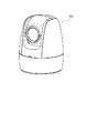
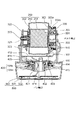
以下、本発明の実施形態について説明する。図1に本発明の実施形態における撮像装置の外観図、図2にチルトユニットの分解図、図3にカメラユニットの分解図、図4に撮像装置の断面図を示す。 Hereinafter, embodiments of the present invention will be described. FIG. 1 is an external view of an imaging apparatus according to an embodiment of the present invention, FIG. 2 is an exploded view of a tilt unit, FIG. 3 is an exploded view of a camera unit, and FIG.
撮像装置100は撮影を行うためのカメラユニット200、カメラユニット200をチルト軸線L2周りにチルト方向に回転させるチルトユニット300を備える。さらに、撮像装置100は、カメラユニット200をパン軸線L3周りにパン方向に回転させるパンユニット400、撮像装置100を壁面や天井に取り付ける際の固定部となるベースユニット500を備える。
The
<カメラユニット200>
カメラユニット200は、図2に示すように、光軸L1方向を撮影することができるカメラ201と、ケース部材202と、カメラカバー203とから構成される。カメラ201は、撮像素子および複数のレンズを含む。ケース部材202は、図3に示すように、板金で形成されている上ケース202a及び板金で形成されている下ケース202bからなる。カメラ201は、ケース部材202に取付支持される。カメラカバー203は、樹脂で形成されている上カバー203a及び樹脂で形成されている下カバー203bからなる。カメラカバー203は、カメラ201およびケース部材202の一部を覆う。また、図2に示すように、パンカバー331、フロントカバー330、サイドカバー324、サイドカバー311が後述するボトムケース501に取付固定されることでカメラユニット200及びチルトユニット300が保護される。
<
As shown in FIG. 2, the
<チルトユニット300>
図5に本発明の実施形態におけるチルト回転軸周辺の断面図、図6にチルト軸の超音波モーター周辺の分解図を示す。チルトユニット300は、第1の回転軸320と、第2の回転軸301と、超音波モーター305と、ローター固定部材302と、第1の支持部材323と、第2の支持部材310と、ベアリングホルダー322と、回転防止部材307と、を備える。
<
FIG. 5 is a cross-sectional view around the tilt rotation axis in the embodiment of the present invention, and FIG. 6 is an exploded view around the ultrasonic motor of the tilt axis. The
チルト回転軸としての第1の回転軸320は、チルト軸線L2周りに回転可能であり、一方がケース部材202に取り付けされ、他方がベアリング321内に挿通される。ベアリング321は、図4に示すように、ベアリングホルダー322に嵌めあい支持される。ベアリングホルダー322は、第1の支持部材323に取付固定される。ベアリングホルダー322は、図2に示すように、円筒形の部分を有し、ベアリング321を保持する。
The
ローター固定部材302は、図2に示すように、円状であり、図4に示すように、カメラカバー203の開口に挿入され、ケース部材202の側面に固定されている。また、ローター固定部材302には、エンコーダーのスケール312が固定されている。
The
チルト回転軸としての第2の回転軸301は、中空であり、ローター固定部材302と一体成形されている。第2の回転軸301は、ベアリング303によってチルト軸線L2周りに回転可能に支持される。ベアリング303は、第1のベアリング抑え部材304と、後述するステーター固定部材308と、第2のベアリング抑え部材309と、によって、支持されている。
The
第1のベアリング抑え部材304は、円筒状であり、ベアリング303の内輪303a側を固定する。第2のベアリング抑え部材309は、円筒状であり、ベアリング303の外輪303b側を固定する。さらに、ベアリング303は、ステーター固定部材308に設けた貫通孔308bの内部に挿入され、支持される。また、第2のベアリング抑え部材309は、ステーター固定部材308の貫通孔308bの内部に挿入され、固定される。
The first bearing pressing
チルト支持部材としての第1の支持部材323は、カメラユニット200に対して、超音波モーター305が配置されていない側に配置され、ベアリングホルダー322を固定する。第1の支持部材323は、パンベース409に固定される。
The
チルト支持部材としての第2の支持部材310は、第1の支持部材323と対になるように、パンベース409に固定されている。第2の支持部材310は、超音波モーター305に対してカメラユニット200と反対側に配置されている。第2の支持部材310は、ステーター固定部材308を固定する。
A
接続部材としての信号線333は、カメラ201の撮像素子基板と後述の制御基板412をつないでいる。信号線333は、超音波モーター305及び第2の回転軸301の内部(内側空間部)を挿通される。
A
回転防止部材307は、ステーター305bのステーター固定部材308に対するチルト軸線L2周りの回転移動を防止する。回転防止部材307は、ステーター固定部材308上の取付部308aに取付支持され、取付部308aと超音波モーター305の隙間に設けられた取付空間334に配置される。回転防止部材307は第2の回転軸301の径方向に突起部307aが略等間隔に設けられ、突起部307aがステーター305bの櫛歯部305cの隙間に挿通される。これによりステーター305bのステーター固定部材308に対するチルト軸線L2周りの回転移動を防止する。
The
エンコーダーは、カメラユニット200のチルト方向の回転角度を検出する。エンコーダーのスケール312は、回転軸301と同軸かつローター固定部材302上に固定されている。エンコーダーのセンサ313は、ローター固定部材302上のスケール312と対応するようにステーター固定部材308に配置される。センサ313の値を読み取ることで、ステーター305bに対するローター305aの回転移動量が分かり、カメラユニット200のチルト角度を検出することができる。
The encoder detects the rotation angle of the
超音波モーター305は、カメラユニット200をチルト方向に回転させる駆動源であり、リング状の部材からなる。超音波モーター305は、図6に示すように、駆動用の信号線332を備える環状のステーター305bと、ステーター305bに対して相対的に回転駆動される環状のローター305aで構成される。超音波モーター305は、第2の回転軸301と同軸であり、かつ、ステーター固定部材308の外周面に配置される。詳細には、ローター305aがカメラユニット側、ステーター305bが第2の支持部材側に配置される。さらにローター305aは回転軸301と同軸かつ、ローター固定部材302上に設置される。
The
ステーター305bは回転軸301と同軸かつローター305aに接するように配置され、後述の制御基板412と信号線332で接続される。付勢部材306がステーター305bをローター305a方向に付勢するように、ステーター固定部材308上に取付支持される。すなわち、超音波モーター305及び付勢部材306はローター固定部材302とステーター固定部材308に挟持されている。このとき、付勢部材306はステーター305bがローター305aを回転させる上で十分な付勢力を発揮する。これによってステーター305bを駆動することでローター305aがチルト軸線L2まわりに回転する。
The
以下、超音波モータ305によるカメラユニット200の駆動について、説明する。駆動用の信号線332から信号が入力されると、ステーター305bが振動する。ローター305aは、その振動がステーター305bから伝わり、チルト方向に回転する。また、ロータ305aは、ローター固定部材302に固定されているので、ロータ305aが回転することにより、ロータ固定部材302も、第2の回転軸301を中心に回転する。すなわち、第2の回転軸301は、ロータ305aの回転によって、チルト方向に回転する。また、ロータ固定部材302には、ケース部材202が固定されているため、ロータ固定部材302が回転すると、カメラユニット200も回転する。
Hereinafter, driving of the
上述の通り、超音波モーター305を用いたことで、ステッピングモータを用いた撮像装置より応答性が優れている撮像装置を提供することができる。また、超音波モーター305のローターは、超音波モーター305のステーターよりもカメラユニット200側に配置されているので、無駄のない効率的な配置である。より詳細には、ローターとステータを本実施形態とは逆に配置した場合、ステーターを支持する支持部材とは別にローターを抑える部材が別途必要になる。よって、本実施形態の配置は、無駄のない効率的な配置といえる。
As described above, by using the
また、ステッピングモータは、減速機構が必要であるが、超音波モータを用いることにより、複雑なギア構成を有する減速機構が不要となる。また、ステッピングモータの場合は、チルト回転軸と同軸上に減速機構を設け、その下方に、モータを配置していた。しかしながら、本実施形態では、超音波モーター305を第2の回転軸301と同軸に配置したことで第2の回転軸301の下側にモーターを配置する必要がなくなるため、小型化につながる。また、カメラ201で撮影した映像信号を制御基板412に伝送する信号線333を、超音波モーター305及び回転軸301の内部に配置することで、カメラユニット200に対して超音波モーター305とは逆側に信号線を設ける必要がなくなる。
In addition, although the stepping motor requires a reduction mechanism, the use of an ultrasonic motor eliminates the need for a reduction mechanism having a complicated gear configuration. Further, in the case of the stepping motor, the speed reduction mechanism is provided coaxially with the tilt rotation shaft, and the motor is disposed below it. However, in the present embodiment, by disposing the
ローター固定部材302と第2の回転軸301を一体形成の部品として形成することで、部品点数を削減することができる。超音波モーター305の内部かつステーター固定部材308の貫通孔308bにベアリング303、ベアリング抑え部材309、ベアリング抑え環304、回転軸301、信号線333を配置したことで、スペースが削減される。具体的には、従来は超音波モーターを配置するスペースとは別に必要となる、ベアリングやベアリングを抑える部材のスペースが削減される。よって、撮像装置本体を小型化することができる。
By forming the
<ベースユニット500>
ベースユニット500は、図4に示すように、ボトムケース501と、ボトム板金502と、電源基板503と、を備える。
<
As shown in FIG. 4, the
ボトムケース501は、ボトム板金502を介して、天井や壁に設置され、内部には後述するパンユニット400が配置される。ボトム板金502は、天井や壁に固定される部材である。電源基板503は、電源供給用の基板であり、信号線414によって制御基板412へ電源を供給する。接続部材としての信号線414は、後述するパン回転軸401の内部(内側空間部)を挿通している。電源基板503は、ボトム板金502に取り付けられている。
The
<パンユニット400>
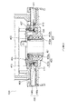
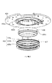
図7に本発明の実施形態における撮像装置のパンユニットの分解図、図8にパン回転軸周辺の断面図、図9にパン軸の超音波モーターの分解図を示す。パンユニット400は、パン回転軸401と、パン支持部材としてのパンベース409と、ベース部材413と、超音波モーター406と、を備える。
<
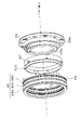
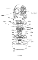
FIG. 7 is an exploded view of a pan unit of an imaging apparatus according to an embodiment of the present invention, FIG. 8 is a sectional view around a pan rotation axis, and FIG. 9 is an exploded view of an ultrasonic motor of the pan axis. The
パンベース409は、中心に貫通孔409bを有する略円状の部材であり、パン回転時に回転する。パンベース409には、第1の支持部材323及び第2の支持部材310が固定されている。また、パンベース409には、制御基板412が固定されている。制御基板412は、それぞれ信号線によってカメラ201、超音波モーター305、後述の超音波モーター406、電源基板503と接続される。
The
ベース部材413は、中心に貫通孔413aを有する円状の部材である。ベース部材413は、ボトムケース501に固定される。ベース部材413は、パン回転軸方向においてパンベース409に対してカメラユニット200の反対側に配置される。
The
パン回転軸401は、中空であり、パン軸線L3周りに回転可能である。また、パン回転軸401は、パンベース409がパン方向に回転する際の回転中心である。パン回転軸401の端部には、抜け防止部材405と係合するねじ部401aが形成されている。また、パン回転軸401には、ベアリング402、403およびベアリング402、403がパン軸線L3方向へ動くのを抑えるためのベアリング抑え部材404が挿通されている。
The
ベアリング抑え部材404は、3本の突起401dを有し、3本の突起401dが、パンベース409上の3本の突起409dに対応するように配置され、パンベース409に固定される。抜け防止部材405はベアリング抑え部材404がパン回転軸401から脱落するのを防止するためにパン回転軸401のねじ部401dにねじ固定される。これにより、ベアリング抑え部材404が回転軸401に取付固定され、パン回転軸401がパン軸線L3周りに回転可能になる。
The
回転防止部材408は、振動子406bがパンベース409に対して相対的に回転しないようにするための部材である。回転防止部材408は、図9に示すように、パンベース409上の取付部409aに取付支持され、取付部409aと超音波モーター406の隙間に設けられた取付空間416に配置される。回転防止部材408はパン軸線L3の径方向に突起部408aが略等間隔に設けられ、突起部408aが振動子406bの櫛歯部406cの隙間に挿通される。これにより振動子406bがパンベース409に対してパン軸線L3周りに回転するのを防ぐ。
The
エンコーダーは、カメラユニット200のパン方向の回転角度を検出する。エンコーダーのスケール410は、回転軸401と同軸かつベース部材413上に固定されている。エンコーダーのセンサ411は、ベース部材413上のスケール410と対応するように、パンベース409に配置される。センサ411の値を読み取ることで、ベース部材413に対するパンベース409の回転移動量が分かり、カメラユニット200のパン角度を検出することができる。
The encoder detects the rotation angle of the
超音波モーター406は、カメラユニット200をパン方向に回転させる駆動源であり、リング状の部材からなる。超音波モーター406は、駆動用の信号線415(図4参照)を備える環状の振動子406bと、環状の摺擦部材406aで構成される。また、超音波モーター406は、パン回転軸401と同軸かつベース部材413の貫通孔413aの周囲に配置される。詳細には、環状の振動子406bがパンベース409側、摺擦部材406aがベース部材413側に配置される。
The
さらに、摺擦部材406aは、パン回転軸401と同軸かつ、ベース部材413上に固定される。振動子406bはパン回転軸401と同軸かつ摺擦部材406aに接触するように配置され、制御基板412と信号線415で接続される。付勢部材407が振動子406bを摺擦部材406a方向に付勢するように、パンベース409に取付支持される。すなわち、超音波モーター406及び付勢部材407はベース部材413とパンベース409に挟持されている。このとき、付勢部材407は、振動子406bと摺擦部材406aとが相対的に回転する上で十分な付勢力を発揮する。これによって、振動子406bは、振動することで摺擦部材406aに対して、パン軸まわりに回転する。
Further, the rubbing
以下、超音波モータ406によるカメラユニット200の駆動について、説明する。駆動用の信号線415から電圧が印加されると、振動子406bが振動する。これにより、振動子406bは、摺擦部材406aに対して、相対的にパン方向に回転する。
Hereinafter, driving of the
また、振動子406bは、後述する回転防止部材408によりパンベース409に対して相対的に回転しないように固定されているので、振動子406bの振動により、パンベース409も、パン回転軸401を中心に回転する。すなわち、パン回転軸401は、振動子406bの振動によって、パン方向に回転する。また、パンベース409には、第1の支持部材323及び第2の支持部材310が固定されているため、パンベース409が回転すると、カメラユニット200も回転する。
Further, since the
上述の通り、超音波モーター406を用いたことで、ステッピングモータを用いた撮像装置より応答性が優れている撮像装置を提供することができる。また、制御基板412と振動子406bが、パンベース409に配置されるので、カメラユニット200がパン方向に回転しても制御基板412と振動子406bをつなぐ信号線415がねじれることがない。
As described above, by using the
また、ステッピングモータは、減速機構が必要であるが、超音波モータを用いることにより、複雑なギア構成を有する減速機構が不要となる。また、ステッピングモータの場合は、パン回転軸と同軸上に減速機構を設け、その隣に、モータを配置していた。しかしながら、本実施形態では、超音波モーター406をパン回転軸301と同軸に配置したことでパン回転軸301の隣にモーターを配置する必要がなくなる。よって、空いたスペースに別の部品を配置することができる。
In addition, although the stepping motor requires a reduction mechanism, the use of an ultrasonic motor eliminates the need for a reduction mechanism having a complicated gear configuration. Further, in the case of the stepping motor, the speed reduction mechanism is provided coaxially with the pan rotation shaft, and the motor is disposed adjacent thereto. However, in the present embodiment, by disposing the
超音波モーター406の内部やベース部材413の貫通孔413aに信号線414、回転軸401、ベアリング402、ベアリング403、ベアリング抑え部材404、抜け防止部材405を配置したことで、スペースが削減される。具体的には、従来は超音波モーターを配置するスペースとは別に必要となるベアリングやベアリングを抑える部材のスペースが削減される。よって、撮像装置本体を小型化することができる。
By arranging the signal wire 414, the
<その他実施形態>
以上、本発明をその好適な実施形態に基づいて詳述してきたが、本発明はこれら特定の実施形態に限られるものではなく、この発明の要旨を逸脱しない範囲の様々な形態も本発明に含まれる。上述の実施形態の一部を適宜組み合わせてもよい。
<Other embodiments>
Although the present invention has been described in detail based on its preferred embodiments, the present invention is not limited to these specific embodiments, and various embodiments within the scope of the present invention are also included in the present invention. included. Some of the embodiments described above may be combined as appropriate.
例えば、ローター固定部材302と回転軸301は別部品でもよい。付勢部材306、407は超音波モーター305、406のローター305a、406aとステーター305b、406bの間に回転駆動する上で適切な付勢力を発揮できれば、ウェーブワッシャーやゴムなどの弾性部材でもよい。
For example, the
カメラ201と制御基板412を接続する信号線333及び制御基板412と電源基板503を接続する信号線414は、フレキシブルプリント基板や細線同軸ケーブル、スリップリングでもよい。回転防止部材307、408をステーター固定部材308、パンベース409にそれぞれ固定する手段はスナップフィットやねじ止めとしてもよい。
The
100 撮像装置
200 カメラユニット
300 チルトユニット
301 第2の回転軸
302 ローター固定部材
303 ベアリング
304 ベアリング抑え部材
305 超音波モーター
305a ローター
305b ステーター
307 回転防止部材
308 ステーター固定部材
309 ベアリング抑え部材
310 第2の支持部材
320 第1の回転軸
323 第1の支持部材
400 パンユニット
401 パン回転軸
404 ベアリング抑え部材
406 超音波モーター
406a ローター
406b ステーター
408 回転防止部材
409 パンベース
413 ベース部材
500 ベースユニット
DESCRIPTION OF
Claims (11)
前記カメラユニットをチルト方向に回転可能に支持するチルト支持部材と、
前記チルト支持部材をパン方向に回転可能に支持するパン支持部材と、
前記パン支持部材がパン方向へ回転する際の回転中心であるパン回転軸と、
前記パン回転軸方向において前記パン支持部材に対して前記カメラユニットの反対側に配置されるベース部材と、
前記パン支持部材に支持される基板と、
前記基板と接続され、電圧を印加することで振動する振動子および前記振動子と接触する摺擦部材を有するとともに、前記パン回転軸と同軸で配置され、前記パン支持部材をパン方向へ回転駆動するリング状の超音波モーターと、を備え、
前記超音波モーターの前記振動子は、前記パン支持部材に支持され、振動することで、前記摺擦部材に対して相対的に移動し、
前記超音波モーターの前記摺擦部材は、前記ベース部材に支持されることを特徴とする、撮像装置。 A camera unit including an imaging device;
A tilt support member rotatably supporting the camera unit in a tilt direction;
A pan support member rotatably supporting the tilt support member in a pan direction;
A pan rotation axis which is a rotation center when the pan support member rotates in the pan direction;
A base member disposed on the opposite side of the camera unit with respect to the pan support member in the pan rotation axis direction;
A substrate supported by the pan support member;
A vibrator is connected to the substrate and vibrates by applying a voltage, and a rubbing member is in contact with the vibrator, and is arranged coaxially with the pan rotation shaft to rotate the pan support member in the pan direction. Equipped with a ring-shaped ultrasonic motor,
The vibrator of the ultrasonic motor is supported by the pan support member and vibrates to move relative to the rubbing member.
The imaging device, wherein the rubbing member of the ultrasonic motor is supported by the base member.
前記接続部材は、前記パン回転軸の内側空間部に配置されることを特徴とする請求項2記載の撮像装置。 The pan rotation axis is hollow,
The imaging device according to claim 2, wherein the connection member is disposed in an inner space portion of the pan rotation shaft.
前記ベアリングは、前記超音波モーターの内側空間部に配置されることを特徴とする請求項1から3のいずれか一項に記載の撮像装置。 A bearing rotatably supporting the pan rotation shaft;
The imaging device according to any one of claims 1 to 3, wherein the bearing is disposed in an inner space of the ultrasonic motor.
前記抜け防止部材は前記パン回転軸のねじ部にねじ込まれることを特徴とする請求項8に記載の撮像装置。 It has a detachment prevention member which prevents the pressing member inserted into the pan rotation shaft from coming off the pan rotation shaft.
The imaging device according to claim 8, wherein the removal prevention member is screwed into a screw portion of the pan rotation shaft.
前記エンコーダーのスケールは、前記ベース部材に配置され、前記エンコーダーのセンサは、前記パンベースに配置されることを特徴とする請求項1から9のいずれか一項に記載の撮像装置。 An encoder for detecting a rotational angle of the camera unit in the pan direction,
The imaging device according to any one of claims 1 to 9, wherein a scale of the encoder is disposed on the base member, and a sensor of the encoder is disposed on the pan base.
前記回転防止部材は、前記超音波モーターと前記パンベースの間に配置されることを特徴とする請求項1から10のいずれか一項に記載の撮像装置。 A rotation preventing member for preventing the vibrator of the ultrasonic motor from rotationally moving with respect to the pan base;
The imaging apparatus according to any one of claims 1 to 10, wherein the rotation preventing member is disposed between the ultrasonic motor and the pan base.
Priority Applications (6)
| Application Number | Priority Date | Filing Date | Title |
|---|---|---|---|
| US16/115,154 US10645265B2 (en) | 2017-08-31 | 2018-08-28 | Image pickup apparatus |
| US16/114,757 US10536616B2 (en) | 2017-08-31 | 2018-08-28 | Image pickup apparatus |
| CN201810996224.0A CN109428508B (en) | 2017-08-31 | 2018-08-29 | Image pickup apparatus |
| CN201810995714.9A CN109429000B (en) | 2017-08-31 | 2018-08-29 | Image pickup apparatus |
| EP18191832.7A EP3451056B1 (en) | 2017-08-31 | 2018-08-30 | Pant tilt image pickup apparatus |
| EP18191833.5A EP3451057B1 (en) | 2017-08-31 | 2018-08-30 | Image pickup apparatus |
Applications Claiming Priority (2)
| Application Number | Priority Date | Filing Date | Title |
|---|---|---|---|
| JP2017167756 | 2017-08-31 | ||
| JP2017167756 | 2017-08-31 |
Publications (2)
| Publication Number | Publication Date |
|---|---|
| JP2019045848A true JP2019045848A (en) | 2019-03-22 |
| JP2019045848A5 JP2019045848A5 (en) | 2021-07-26 |
Family
ID=65814357
Family Applications (1)
| Application Number | Title | Priority Date | Filing Date |
|---|---|---|---|
| JP2018116889A Pending JP2019045848A (en) | 2017-08-31 | 2018-06-20 | Imaging apparatus |
Country Status (1)
| Country | Link |
|---|---|
| JP (1) | JP2019045848A (en) |
Cited By (1)
| Publication number | Priority date | Publication date | Assignee | Title |
|---|---|---|---|---|
| US11545916B2 (en) | 2020-07-13 | 2023-01-03 | Canon Kabushiki Kaisha | Vibration-type actuator including member that restrains movement of vibrating body with respect to supporting member, and apparatus that uses the same |
Citations (7)
| Publication number | Priority date | Publication date | Assignee | Title |
|---|---|---|---|---|
| JP2005198424A (en) * | 2004-01-07 | 2005-07-21 | Nikon Corp | Oscillation actuator and optical instrument |
| JP2005278071A (en) * | 2004-03-26 | 2005-10-06 | Victor Co Of Japan Ltd | Slip-ring coupling structure of monitor camera |
| JP2007189777A (en) * | 2006-01-11 | 2007-07-26 | Canon Inc | Driving device, electronic apparatus, and control method and program |
| JP2008072485A (en) * | 2006-09-14 | 2008-03-27 | Sony Corp | Lens barrel rotary type imaging apparatus |
| JP2010107772A (en) * | 2008-10-30 | 2010-05-13 | Victor Co Of Japan Ltd | Tilt mechanism of monitoring camera apparatus |
| CN106715269A (en) * | 2016-10-24 | 2017-05-24 | 深圳市大疆创新科技有限公司 | Holder, capturing system and aircraft |
| JP2017134114A (en) * | 2016-01-25 | 2017-08-03 | キヤノン株式会社 | Support base and imaging apparatus |
-
2018
- 2018-06-20 JP JP2018116889A patent/JP2019045848A/en active Pending
Patent Citations (7)
| Publication number | Priority date | Publication date | Assignee | Title |
|---|---|---|---|---|
| JP2005198424A (en) * | 2004-01-07 | 2005-07-21 | Nikon Corp | Oscillation actuator and optical instrument |
| JP2005278071A (en) * | 2004-03-26 | 2005-10-06 | Victor Co Of Japan Ltd | Slip-ring coupling structure of monitor camera |
| JP2007189777A (en) * | 2006-01-11 | 2007-07-26 | Canon Inc | Driving device, electronic apparatus, and control method and program |
| JP2008072485A (en) * | 2006-09-14 | 2008-03-27 | Sony Corp | Lens barrel rotary type imaging apparatus |
| JP2010107772A (en) * | 2008-10-30 | 2010-05-13 | Victor Co Of Japan Ltd | Tilt mechanism of monitoring camera apparatus |
| JP2017134114A (en) * | 2016-01-25 | 2017-08-03 | キヤノン株式会社 | Support base and imaging apparatus |
| CN106715269A (en) * | 2016-10-24 | 2017-05-24 | 深圳市大疆创新科技有限公司 | Holder, capturing system and aircraft |
Cited By (1)
| Publication number | Priority date | Publication date | Assignee | Title |
|---|---|---|---|---|
| US11545916B2 (en) | 2020-07-13 | 2023-01-03 | Canon Kabushiki Kaisha | Vibration-type actuator including member that restrains movement of vibrating body with respect to supporting member, and apparatus that uses the same |
Similar Documents
| Publication | Publication Date | Title |
|---|---|---|
| CN109429000B (en) | Image pickup apparatus | |
| EP2259571B1 (en) | Optical image stabilizer for camera lens module | |
| JP2007049895A (en) | Piezoelectric ultrasonic motor | |
| JP2007041455A (en) | Image blur correction device of optical device | |
| JP4058392B2 (en) | Two-axis rotary table device and driven body rotation control system | |
| JP2003301994A (en) | Bearing integrated type rotary device | |
| US8031418B2 (en) | Lens driving mechanism and image pickup apparatus using the same | |
| CN111142316B (en) | Image pickup apparatus | |
| JP2018132641A5 (en) | Optical scanning device and image forming apparatus | |
| JP2019045848A (en) | Imaging apparatus | |
| JP7150492B2 (en) | Imaging device | |
| JP2010011199A (en) | Monitoring camera apparatus with movable universal head | |
| JP2008165046A (en) | Lens drive device | |
| JP6611445B2 (en) | Vibration type actuator and electronic device | |
| JP2007306660A (en) | Piezoactuator, lens drive unit and portable apparatus | |
| JP7039337B2 (en) | Lens device and image pickup device equipped with it | |
| JP2010276636A (en) | Imaging apparatus | |
| JP2019045848A5 (en) | ||
| KR100703660B1 (en) | Panning apparatus for camera | |
| JP2020076948A (en) | Imaging device | |
| JP2020150357A (en) | Imaging apparatus and sliding packing | |
| JPH06148499A (en) | Motor rotation detecting device for camera | |
| JP2019045849A5 (en) | ||
| JP2021013206A (en) | Drive unit and imaging apparatus having vibration actuator | |
| JP2007201817A (en) | Monitoring camera |
Legal Events
| Date | Code | Title | Description |
|---|---|---|---|
| A521 | Request for written amendment filed |
Free format text: JAPANESE INTERMEDIATE CODE: A523 Effective date: 20210602 |
|
| A621 | Written request for application examination |
Free format text: JAPANESE INTERMEDIATE CODE: A621 Effective date: 20210602 |
|
| A977 | Report on retrieval |
Free format text: JAPANESE INTERMEDIATE CODE: A971007 Effective date: 20220323 |
|
| A131 | Notification of reasons for refusal |
Free format text: JAPANESE INTERMEDIATE CODE: A131 Effective date: 20220329 |
|
| A521 | Request for written amendment filed |
Free format text: JAPANESE INTERMEDIATE CODE: A523 Effective date: 20220518 |
|
| A131 | Notification of reasons for refusal |
Free format text: JAPANESE INTERMEDIATE CODE: A131 Effective date: 20220809 |
|
| A02 | Decision of refusal |
Free format text: JAPANESE INTERMEDIATE CODE: A02 Effective date: 20230214 |