JP2019042120A - Game machine - Google Patents
Game machine Download PDFInfo
- Publication number
- JP2019042120A JP2019042120A JP2017168447A JP2017168447A JP2019042120A JP 2019042120 A JP2019042120 A JP 2019042120A JP 2017168447 A JP2017168447 A JP 2017168447A JP 2017168447 A JP2017168447 A JP 2017168447A JP 2019042120 A JP2019042120 A JP 2019042120A
- Authority
- JP
- Japan
- Prior art keywords
- information
- game
- main
- display
- management
- Prior art date
- Legal status (The legal status is an assumption and is not a legal conclusion. Google has not performed a legal analysis and makes no representation as to the accuracy of the status listed.)
- Withdrawn
Links
Images


Classifications
-
- Y—GENERAL TAGGING OF NEW TECHNOLOGICAL DEVELOPMENTS; GENERAL TAGGING OF CROSS-SECTIONAL TECHNOLOGIES SPANNING OVER SEVERAL SECTIONS OF THE IPC; TECHNICAL SUBJECTS COVERED BY FORMER USPC CROSS-REFERENCE ART COLLECTIONS [XRACs] AND DIGESTS
- Y02—TECHNOLOGIES OR APPLICATIONS FOR MITIGATION OR ADAPTATION AGAINST CLIMATE CHANGE
- Y02E—REDUCTION OF GREENHOUSE GAS [GHG] EMISSIONS, RELATED TO ENERGY GENERATION, TRANSMISSION OR DISTRIBUTION
- Y02E60/00—Enabling technologies; Technologies with a potential or indirect contribution to GHG emissions mitigation
- Y02E60/10—Energy storage using batteries
Abstract
Description
本発明は、遊技機に関するものである。 The present invention relates to a gaming machine.
遊技機としてパチンコ遊技機やスロットマシンなどが知られている。例えば、パチンコ遊技機は、遊技者に付与された遊技球を貯留する皿貯留部を遊技機前面部に備えており、当該皿貯留部に貯留された遊技球が遊技球発射装置に案内されて、遊技者の発射操作に応じて遊技領域に向けて発射される。そして、例えば遊技領域に設けられた入球部に遊技球が入球した場合に、例えば払出装置から皿貯留部に遊技球が払い出される。また、パチンコ遊技機においては、皿貯留部として上側皿貯留部と下側皿貯留部とを備えた構成も知られており、この場合、上側皿貯留部に貯留された遊技球が遊技球発射装置に案内され、当該上側皿貯留部にて余剰となった遊技球が下側皿貯留部に排出される(例えば特許文献1参照)。 Pachinko gaming machines and slot machines are known as gaming machines. For example, a pachinko gaming machine is provided with a plate storage unit for storing game balls provided to the player on the front face of the gaming machine, and the game balls stored in the plate storage unit are guided by the game ball launcher , Is fired toward the game area according to the player's firing operation. Then, for example, when the game ball enters the ball entry portion provided in the game area, the game ball is paid out, for example, from the payout device to the dish storage portion. Moreover, in a pachinko gaming machine, a configuration is also known in which the upper plate storage unit and the lower plate storage unit are provided as the plate storage unit, and in this case, the game ball stored in the upper plate storage unit is released The game balls which are guided to the device and become surplus in the upper plate storage section are discharged to the lower plate storage section (see, for example, Patent Document 1).
また、スロットマシンでは、メダルがベットされている状況でスタートレバーが操作されて新たなゲームが開始される場合に制御手段にて抽選処理が実行される。また、抽選処理が実行された場合には制御手段にて回転開始制御が実行されることによりリールの回転が開始され、当該リールの回転中にストップボタンが操作された場合には制御手段にて回転停止制御が実行されることによりリールの回転が停止される。そして、リールの回転停止後の停止結果が抽選処理の当選役に対応したものである場合には、当該当選役に対応した特典が遊技者に付与される。 Further, in the slot machine, the lottery process is executed by the control means when the start lever is operated and a new game is started in a situation where medals are bet. Further, when the lottery process is executed, the rotation of the reel is started by the rotation start control being executed by the control means, and when the stop button is operated during the rotation of the reel, the control means is executed. The rotation stop control is executed to stop the rotation of the reel. Then, in the case where the stop result after the stop of the rotation of the reel corresponds to the winning combination of the lottery process, a bonus corresponding to the winning combination is given to the player.
ここで、上記例示等のような遊技機においては、遊技機の管理が好適に行われる必要があり、この点について未だ改良の余地がある。 Here, in the gaming machine as exemplified above, management of the gaming machine needs to be suitably performed, and there is still room for improvement in this respect.
本発明は、上記例示した事情等に鑑みてなされたものであり、遊技機の管理を好適に行うことが可能な遊技機を提供することを目的とするものである。 The present invention has been made in view of the above-described circumstances and the like, and it is an object of the present invention to provide a gaming machine capable of suitably managing gaming machines.
上記課題を解決すべく請求項1記載の発明は、遊技が実行されることにより所定事象が発生した場合にそれに対応する遊技の履歴情報を履歴記憶手段に記憶させる履歴記憶実行手段と、
前記履歴記憶手段に記憶されている前記履歴情報を利用して遊技の結果に対応する態様情報を導出する情報導出手段と、
当該情報導出手段により導出された前記態様情報に対応する表示が行われるように情報表示手段を表示制御する態様情報表示制御手段と、
所定の表示契機が発生したことに基づいて、前記態様情報に対応する表示が新たに開始される前に所定対応表示が前記情報表示手段にて行われるようにする所定対応表示制御手段と、
を備えていることを特徴とする。
In order to solve the above problems, the invention according to
Information deriving means for deriving aspect information corresponding to a game result using the history information stored in the history storage means;
Aspect information display control means for performing display control of the information display means so that display corresponding to the aspect information derived by the information derivation means is performed;
Predetermined correspondence display control means for causing the information display means to perform predetermined correspondence display before display corresponding to the mode information is newly started based on occurrence of a predetermined display trigger;
It is characterized by having.
本発明によれば、遊技機の管理を好適に行うことが可能となる。 According to the present invention, management of a gaming machine can be suitably performed.
<第1の実施形態>
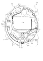
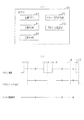
以下、遊技機の一種であるパチンコ遊技機(以下、「パチンコ機」という)の第1の実施形態を、図面に基づいて詳細に説明する。図1はパチンコ機10の斜視図、図2はパチンコ機10の主要な構成を分解して示す斜視図である。なお、図2では便宜上パチンコ機10の遊技領域PA内の構成を省略している。
First Embodiment
Hereinafter, a first embodiment of a pachinko gaming machine (hereinafter referred to as "pachinko machine"), which is a type of gaming machine, will be described in detail based on the drawings. FIG. 1 is a perspective view of a
パチンコ機10は、図1に示すように、当該パチンコ機10の外殻を形成する外枠11と、この外枠11に対して前方に回動可能に取り付けられた遊技機本体12と、を有する。外枠11は木製の板材を四辺に連結し構成されるものであって矩形枠状をなしている。パチンコ機10は、外枠11を島設備に取り付け固定することにより、遊技ホールに設置される。なお、パチンコ機10において外枠11は必須の構成ではなく、遊技ホールの島設備に外枠11が備え付けられた構成としてもよい。
The
遊技機本体12は図2に示すように、内枠13と、その内枠13の前方に配置される前扉枠14と、内枠13の後方に配置される裏パックユニット15と、を備えている。遊技機本体12のうち内枠13が外枠11に回動可能に支持されている。詳細には、正面視で左側を回動基端側とし右側を回動先端側として内枠13が前方へ回動可能とされている。
As shown in FIG. 2, the gaming machine
内枠13には、前扉枠14が回動可能に支持されており、正面視で左側を回動基端側とし右側を回動先端側として前方へ回動可能とされている。また、内枠13には、裏パックユニット15が回動可能に支持されており、正面視で左側を回動基端側とし右側を回動先端側として後方へ回動可能とされている。
A
なお、遊技機本体12には、その回動先端部に施錠装置が設けられており、遊技機本体12を外枠11に対して開放不能に施錠状態とする機能を有しているとともに、前扉枠14を内枠13に対して開放不能に施錠状態とする機能を有している。これらの各施錠状態は、パチンコ機10前面にて露出させて設けられたシリンダ錠17に解錠キーを用いて解錠操作を行うことにより、それぞれ解除される。
In addition, the gaming machine
次に、遊技機本体12の前面側の構成について説明する。
Next, the configuration of the front side of the
内枠13は、外形が外枠11とほぼ同一形状をなす樹脂ベース21を主体に構成されている。樹脂ベース21の中央部には略楕円形状の窓孔23が形成されている。樹脂ベース21には遊技盤24が着脱可能に取り付けられている。遊技盤24は合板よりなり、遊技盤24の前面に形成された遊技領域PAが樹脂ベース21の窓孔23を通じて内枠13の前面側に露出した状態となっている。
The
ここで、遊技盤24の構成を図3に基づいて説明する。図3は遊技盤24の正面図である。
Here, the configuration of the
遊技盤24には、遊技領域PAの外縁の一部を区画するようにして内レール部25と外レール部26とが取り付けられており、これら内レール部25と外レール部26とにより誘導手段としての誘導レールが構成されている。樹脂ベース21において窓孔23の下方に取り付けられた遊技球発射機構27(図2参照)から発射された遊技球は誘導レールにより遊技領域PAの上部に案内されるようになっている。
The
ちなみに、遊技球発射機構27は、誘導レールに向けて延びる発射レール27aと、後述する上皿55aに貯留されている遊技球を発射レール27a上に供給する球送り装置27bと、発射レール27a上に供給された遊技球を誘導レールに向けて発射させる電動アクチュエータであるソレノイド27cと、を備えている。前扉枠14に設けられた発射操作装置(又は操作ハンドル)28が回動操作されることによりソレノイド27cが駆動制御され、遊技球が発射される。
Incidentally, the game
遊技盤24には、前後方向に貫通する大小複数の開口部が形成されている。各開口部には一般入賞口31、特電入賞装置32、第1作動口33、第2作動口34、スルーゲート35、可変表示ユニット36、特図ユニット37及び普図ユニット38等がそれぞれ設けられている。一般入賞口31は合計で4個設けられており、それ以外はそれぞれ1個ずつ設けられている。
The
スルーゲート35への入球が発生したとしても遊技球の払い出しは実行されない。一方、一般入賞口31、特電入賞装置32、第1作動口33及び第2作動口34への入球が発生すると、所定数の遊技球の払い出しが実行される。当該賞球個数について具体的には、第1作動口33への1個の遊技球の入球が発生した場合又は第2作動口34への1個の遊技球の入球が発生した場合には、1個の賞球の払い出しが実行され、一般入賞口31への1個の遊技球の入球が発生した場合には、10個の賞球の払い出しが実行され、特電入賞装置32への1個の遊技球の入球が発生した場合には、15個の賞球の払い出しが実行される。
Even if the ball enters the through
なお、上記賞球個数は任意であり、例えば、第2作動口34の方が第1作動口33よりも賞球個数が少ない構成としてもよく、第2作動口34の方が第1作動口33よりも賞球個数が多い構成としてもよい。
The number of winning balls is arbitrary. For example, the
その他に、遊技盤24の最下部にはアウト口24aが設けられており、各種入賞口等に入らなかった遊技球はアウト口24aを通って遊技領域PAから排出される。また、遊技盤24には、遊技球の落下方向を適宜分散、調整等するために多数の釘24bが植設されているとともに、風車等の各種部材が配設されている。
In addition, an out port 24a is provided at the lowermost portion of the
ここで、入球とは所定の開口部を遊技球が通過することを意味し、開口部を通過した後に遊技領域PAから排出される態様だけではなく、開口部を通過した後に遊技領域PAから排出されることなく遊技領域PAの流下を継続する態様も含まれる。但し、以下の説明では、アウト口24aへの遊技球の入球と明確に区別するために、一般入賞口31、特電入賞装置32、第1作動口33、第2作動口34及びスルーゲート35への遊技球の入球を、入賞とも表現する。
Here, entering the ball means that the gaming ball passes through the predetermined opening, and not only the aspect of being ejected from the gaming area PA after passing through the opening, but also from the gaming area PA after passing through the opening Also included is an aspect of continuing the flow of the game area PA without being discharged. However, in the following description, in order to distinguish the game ball from entering the out port 24 a clearly, the general winning
第1作動口33及び第2作動口34は、作動口装置としてユニット化されて遊技盤24に設置されている。第1作動口33及び第2作動口34は共に上向きに開放されている。また、第1作動口33が上方となるようにして両作動口33,34は鉛直方向に並んでいる。第2作動口34には、左右一対の可動片よりなるガイド片としての普電役物34aが設けられている。普電役物34aの閉鎖状態では遊技球が第2作動口34に入賞できず、普電役物34aが開放状態となることで第2作動口34への入賞が可能となる。
The
第2作動口34よりも遊技球の流下方向の上流側に、スルーゲート35が設けられている。スルーゲート35は縦方向に貫通した図示しない貫通孔を有しており、スルーゲート35に入賞した遊技球は入賞後に遊技領域PAを流下する。これにより、スルーゲート35に入賞した遊技球が第2作動口34へ入賞することが可能となっている。
A through
スルーゲート35への入賞に基づき第2作動口34の普電役物34aが閉鎖状態から開放状態に切り換えられる。具体的には、スルーゲート35への入賞をトリガとして内部抽選が行われるとともに、遊技領域PAにおいて遊技球が通過しない領域である右下の隅部に設けられた普図ユニット38の普図表示部38aにて絵柄の変動表示が行われる。そして、内部抽選の結果が電役開放当選であり当該結果に対応した停止結果が表示されて普図表示部38aの変動表示が終了された場合に普電開放状態へ移行する。普電開放状態では、普電役物34aが所定の態様で開放状態となる。
Based on the winning on the through
なお、普図表示部38aは、LEDによる複数の表示用セグメントが所定の態様で配列されてなるセグメント表示器により構成されているが、これに限定されることはなく、液晶表示装置、有機EL表示装置、CRT又はドットマトリックス表示器等その他のタイプの表示装置によって構成されていてもよい。また、普図表示部38aにて変動表示される絵柄としては、複数種の文字が変動表示される構成、複数種の記号が変動表示される構成、複数種のキャラクタが変動表示される構成又は複数種の色が切り換え表示される構成などが考えられる。 In addition, although the common view display part 38a is comprised by the segment display which the some display segment by LED arranges in a predetermined | prescribed aspect, it is not limited to this, A liquid crystal display device, organic EL It may be configured by a display device, a CRT, or another type of display device such as a dot matrix display. In addition, as a pattern that is variably displayed in the common view display unit 38a, a configuration in which plural types of characters are variably displayed, a configuration in which plural types of symbols are variably displayed, a configuration in which plural types of characters are variably displayed A configuration in which a plurality of colors are switched and displayed may be considered.
普図ユニット38において、普図表示部38aに隣接した位置には、普図保留表示部38bが設けられている。遊技球がスルーゲート35に入賞した個数は最大4個まで保留され、普図保留表示部38bの点灯によってその保留個数が表示されるようになっている。
In the
第1作動口33又は第2作動口34への入賞をトリガとして当たり抽選が行われる。そして、当該抽選結果は特図ユニット37及び可変表示ユニット36の図柄表示装置41における表示演出を通じて明示される。
A lottery is triggered by winning of the
特図ユニット37について詳細には、特図ユニット37には特図表示部37aが設けられている。特図表示部37aの表示領域は図柄表示装置41の表示面41aよりも狭い。特図表示部37aでは、第1作動口33への入賞又は第2作動口34への入賞をトリガとして当たり抽選が行われることで絵柄の変動表示又は所定の表示が行われる。そして、抽選結果に対応した結果が表示される。なお、特図表示部37aは、LEDによる複数の表示用セグメントが所定の態様で配列されてなるセグメント表示器により構成されているが、これに限定されることはなく、液晶表示装置、有機EL表示装置、CRT又はドットマトリックス表示器等その他のタイプの表示装置によって構成されていてもよい。また、特図表示部37aにて表示される絵柄としては、複数種の文字が表示される構成、複数種の記号が表示される構成、複数種のキャラクタが表示される構成又は複数種の色が表示される構成などが考えられる。
In detail, the
特図ユニット37において、特図表示部37aに隣接した位置には、特図保留表示部37bが設けられている。遊技球が第1作動口33又は第2作動口34に入賞した個数は最大4個まで保留され、特図保留表示部37bの点灯によってその保留個数が表示されるようになっている。
In the
図柄表示装置41について詳細には、図柄表示装置41は、液晶ディスプレイを備えた液晶表示装置として構成されており、後述する表示制御装置により表示内容が制御される。なお、図柄表示装置41は、液晶表示装置に限定されることはなく、プラズマディスプレイ装置、有機EL表示装置又はCRTといった表示画面を有する他の表示装置であってもよく、ドットマトリクス表示器であってもよい。
In detail, the
図柄表示装置41では、第1作動口33への入賞又は第2作動口34への入賞に基づき特図表示部37aにて絵柄の変動表示又は所定の表示が行われる場合にそれに合わせて図柄の変動表示又は所定の表示が行われる。例えば、図柄表示装置41の表示面41aには、複数の表示領域として上段・中段・下段の3つの図柄列が設定され、各図柄列において「1」〜「9」の数字が付された主図柄が昇順又は降順で配列された状態でスクロール表示される。このスクロール表示においては、最初に全図柄列におけるスクロール表示が開始され、上図柄列→下図柄列→中図柄列の順にスクロール表示から待機表示に切り換えられ、最終的に各図柄列にて所定の図柄を静止表示した状態で終了される。そして、遊技結果が大当たり結果となる遊技回では、図柄表示装置41の表示面41aにおいて予め設定されている有効ライン上に所定の図柄の組み合わせが停止表示される。具体的には、後述する最有利大当たり結果となる場合には同一の奇数図柄の組み合わせが停止表示され、後述する低確大当たり結果となる場合には同一の偶数図柄の組み合わせが停止表示され、後述する低入賞高確大当たり結果となる場合には同一の図柄の組み合わせではないものの低入賞高確大当たり結果ではない場合には停止表示されない図柄の組み合わせが停止表示される。
In the
なお、図柄表示装置41では、第1作動口33又は第2作動口34への入賞をトリガとした表示演出だけではなく、当たり当選となった後に移行する開閉実行モード中の表示演出などが行われる。また、いずれかの作動口33,34への入賞に基づいて、特図表示部37a及び図柄表示装置41にて表示が開始され、所定の結果を表示して終了されるまでが遊技回の1回に相当する。また、図柄表示装置41における図柄の変動表示の態様は上記のものに限定されることはなく任意であり、図柄列の数、図柄列における図柄の変動表示の方向、各図柄列の図柄数などは適宜変更可能である。また、図柄表示装置41にて変動表示される絵柄は上記のような図柄に限定されることはなく、例えば絵柄として数字のみが変動表示される構成としてもよい。
In the
第1作動口33への入賞又は第2作動口34への入賞に基づく当たり抽選にて大当たり当選となった場合には、特電入賞装置32への入賞が可能となる開閉実行モードへ移行する。特電入賞装置32は、遊技盤24の背面側へと通じる図示しない大入賞口を備えているとともに、当該大入賞口を開閉する開閉扉32aを備えている。開閉扉32aは、閉鎖状態及び開放状態のいずれかに配置される。具体的には、開閉扉32aは、通常は遊技球が入賞できない閉鎖状態になっており、内部抽選において開閉実行モードへの移行に当選した場合に遊技球が入賞可能な開放状態に切り換えられるようになっている。ちなみに、開閉実行モードとは、当たり結果となった場合に移行することとなるモードである。なお、閉鎖状態では入賞が不可ではないが開放状態よりも入賞が発生しづらい状態となる構成としてもよい。
When the jackpot is won in the winning lottery based on the winning of the first operation opening 33 or the winning of the second operation opening 34, transition to the open / close execution mode in which winning to the special
図4は、遊技領域PAを流下した遊技球の排出に関する構成を説明するための説明図である。 FIG. 4 is an explanatory view for explaining a configuration relating to the discharge of gaming balls having flowed down the game area PA.
既に説明したとおり、一般入賞口31、特電入賞装置32、第1作動口33、第2作動口34及びアウト口24aのいずれかに入球した遊技球は遊技領域PAから排出される。換言すれば、遊技球発射機構27から発射されて遊技領域PAに流入した遊技球は一般入賞口31、特電入賞装置32、第1作動口33、第2作動口34及びアウト口24aのいずれかに入球することにより遊技領域PAから排出されることとなる。一般入賞口31、特電入賞装置32、第1作動口33、第2作動口34及びアウト口24aのいずれかに入球した遊技球は遊技盤24の背面側に導かれる。
As described above, the game balls entered in any of the general winning
遊技盤24の背面には、一般入賞口31、特電入賞装置32、第1作動口33、第2作動口34及びアウト口24aのそれぞれに対応させて排出通路部42〜48が形成されている。排出通路部42〜48に流入した遊技球はその流入した排出通路部42〜48を流下することにより、遊技盤24の背面側において遊技盤24の下端部に導かれ図示しない排出球回収部にて回収される。そして、排出球回収部にて回収された遊技球は、遊技ホールにおいてパチンコ機10が設置された島設備の球循環装置に排出される。
At the back of the
各排出通路部42〜48には遊技球を検知するための各種検知センサ42a〜48aが設けられている。これら排出通路部42〜48及び検知センサ42a〜48aについて以下に説明する。一般入賞口31は既に説明したとおり4個設けられているため、それら4個のそれぞれに対応させて排出通路部42〜44が存在している。この場合、最も左の一般入賞口31に対応する第1排出通路部42及びその右隣りの一般入賞口31に対応する第2排出通路部43のそれぞれに対しては1個ずつ検知センサ42a,43aが設けられている。具体的には、第1排出通路部42の途中位置に検知範囲が存在するようにして第1入賞口検知センサ42aが設けられているとともに、第2排出通路部43の途中位置に検知範囲が存在するように第2入賞口検知センサ43aが設けられている。最も左の一般入賞口31に入球した遊技球は第1排出通路部42を通過する途中で第1入賞口検知センサ42aにて検知され、その右隣りの一般入賞口31に入球した遊技球は第2排出通路部43を通過する途中で第2入賞口検知センサ43aにて検知される。また、右側2個の一般入賞口31に対しては途中位置で合流するように形成された第3排出通路部44が設けられている。当該第3排出通路部44は、2個の一般入賞口31のそれぞれに対応する入口側領域を有しているとともに、それら入口側領域が途中で合流することで1個の出口側領域を有している。第3排出通路部44における出口側領域の途中位置に検知範囲が存在するように第3入賞口検知センサ44aが設けられている。右側2個のいずれかの一般入賞口31に入球した遊技球は第3排出通路部44を通過する途中で第3入賞口検知センサ44aにて検知される。
Each of the
特電入賞装置32に対応させて第4排出通路部45が存在している。第4排出通路部45の途中位置に検知範囲が存在するようにして特電検知センサ45aが設けられており、特電入賞装置32に入球した遊技球は第4排出通路部45を通過する途中で特電検知センサ45aにて検知される。第1作動口33に対応させて第5排出通路部46が存在している。第5排出通路部46の途中位置に検知範囲が存在するようにして第1作動口検知センサ46aが設けられており、第1作動口33に入球した遊技球は第5排出通路部46を通過する途中で第1作動口検知センサ46aにて検知される。第2作動口34に対応させて第6排出通路部47が存在している。第6排出通路部47の途中位置に検知範囲が存在するようにして第2作動口検知センサ47aが設けられており、第2作動口34に入球した遊技球は第6排出通路部47を通過する途中で第2作動口検知センサ47aにて検知される。アウト口24aに対応させて第7排出通路部48が存在している。第7排出通路部48の途中位置に検知範囲が存在するようにしてアウト口検知センサ48aが設けられており、アウト口24aに入球した遊技球は第7排出通路部48を通過する途中でアウト口検知センサ48aにて検知される。
A fourth
なお、各種検知センサ42a〜48aのうちいずれか1個の検知センサ42a〜48aにて検知対象となった遊技球は他の検知センサ42a〜48aの検知対象となることはない。また、スルーゲート35に対してもゲート検知センサ49aが設けられており、遊技領域PAを流下する途中でスルーゲート35を通過する遊技球はゲート検知センサ49aにて検知される。
The game ball detected by any one of the
各種検知センサ42a〜49aとしては、いずれも電磁誘導型の近接センサが用いられているが、遊技球を個別に検知できるのであれば使用するセンサは任意である。また、各種検知センサ42a〜49aは後述する主制御装置60と電気的に接続されており、各種検知センサ42a〜49aの検知結果は主制御装置60に出力される。具体的には、各種検知センサ42a〜49aは、遊技球を検知していない状況ではLOWレベル信号を出力し、遊技球を検知している状況ではHIレベル信号を出力する。なお、これに限定されることはなくHI及びLOWの関係が逆であってもよい。
Although an electromagnetic induction type proximity sensor is used as each of the
図2に示すように、上記構成の遊技盤24が樹脂ベース21に取り付けられてなる内枠13の前面側全体を覆うようにして前扉枠14が設けられている。前扉枠14には、図1に示すように、遊技領域PAのほぼ全域を前方から視認することができるようにした窓部51が形成されている。窓部51は、略楕円形状をなし、窓パネル52が嵌め込まれている。窓パネル52は、ガラスによって無色透明に形成されているが、これに限定されることはなく合成樹脂によって無色透明に形成されていてもよく、パチンコ機10前方から窓パネル52を通じて遊技領域PAを視認可能であれば有色透明に形成されていてもよい。
As shown in FIG. 2, a
窓部51の上方には表示発光部53が設けられている。また、遊技状態に応じた効果音などが出力される左右一対のスピーカ部54が設けられている。また、窓部51の下方には、手前側へ膨出した上側膨出部55と下側膨出部56とが上下に並設されている。上側膨出部55内側には上方に開口した上皿55aが設けられており、下側膨出部56内側には同じく上方に開口した下皿56aが設けられている。上皿55aは、後述する払出装置より払い出された遊技球を一旦貯留し、一列に整列させながら遊技球発射機構27側へ導くための機能を有する。また、下皿56aは、上皿55a内にて余剰となった遊技球を貯留する機能を有する。
The display
次に、遊技機本体12の背面側の構成について説明する。
Next, the configuration of the back side of the
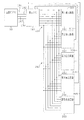
図2に示すように、内枠13(具体的には、遊技盤24)の背面には、遊技の主たる制御を司る主制御装置60が搭載されている。図5は主制御装置60の正面図である。
As shown in FIG. 2, on the back of the inner frame 13 (specifically, the game board 24), a
主制御装置60は、図5に示すように、主制御基板61が基板ボックス60aに収容されてなる。主制御基板61の一方の板面である素子搭載面には、MPU62が搭載されている。基板ボックス60aは当該基板ボックス60aの外部から当該基板ボックス60a内に収容されたMPU62を目視することが可能となるように透明に形成されている。なお、基板ボックス60aは無色透明に形成されているが、基板ボックス60aの外部から当該基板ボックス60a内に収容されたMPU62を目視することが可能であれば有色透明に形成されていてもよい。主制御装置60は基板ボックス60aにおいて主制御基板61の素子搭載面と対向する対向壁部60bがパチンコ機10後方を向くようにして樹脂ベース21の背面に搭載されている。したがって、遊技機本体12を外枠11に対してパチンコ機10前方に開放させて樹脂ベース21の背面を露出させることにより、基板ボックス60aの対向壁部60bを目視することが可能となるとともに当該対向壁部60bを通じてMPU62を目視することが可能となる。
As shown in FIG. 5, the
基板ボックス60aは複数のケース体60cを前後に組合せることにより形成されているが、これら複数のケース体60cには、これらケース体60cの分離を阻止するとともにこれらケース体60cの分離に際してその痕跡を残すための結合部60eが設けられている。結合部60eは、略直方体形状の基板ボックス60aにおける一辺に複数並設されている。これにより、一部の結合部60eを利用してケース体60cの分離を阻止している状態において当該一部の結合部60eを破壊してケース体60cを分離したとしても、その後に別の結合部60eを結合状態とすることでケース体60cの分離を再度阻止することが可能となる。また、ケース体60cの分離に際して結合部60eが破壊されてその痕跡が残ることにより、結合部60eを目視確認することでケース体60cの分離が不正に行われているか否かを把握することが可能となる。また、基板ボックス60aにおいて結合部60eが並設された一辺とは逆の一辺にはケース体60c間の境界を跨ぐようにして封印シール60fが貼り付けられている。封印シール60fはその引き剥がしに際して粘着層がケース体60cに残る。これにより、ケース体60cの分離に際して封印シール60fが剥がされた場合にはその痕跡を残すことが可能となる。
The
上記構成の主制御装置60において主制御基板61には、パチンコ機10の設定状態を「設定1」から「設定6」の範囲で変更する契機を生じさせるために遊技ホールの管理者が所有する設定キーが挿入されてON操作される設定キー挿入部68aと、設定キー挿入部68aに対するON操作後においてパチンコ機10の設定状態を順次変更させるために操作される更新ボタン68bと、主制御装置60のMPU62に設けられた後述する主側RAM65のデータをクリアするために操作されるリセットボタン68cと、遊技履歴の管理結果を報知するための第1〜第3報知用表示装置69a〜69cと、が設けられている。また、主制御基板61に搭載されたMPU62には、遊技履歴の管理結果又は主側ROM64に記憶された情報(プログラム及びデータ)を外部装置にて読み取るために当該外部装置の接続端子を接続するための読み取り用端子68dが設けられている。なお、パチンコ機10の設定状態は「設定1」〜「設定6」の6段階に限定されることはなく複数段階であれば任意である。
In the
これら設定キー挿入部68a、更新ボタン68b、リセットボタン68c、読み取り用端子68d(すなわちMPU62)及び第1〜第3報知用表示装置69a〜69cはいずれも主制御基板61の素子搭載面に設けられている。また、主制御基板61の素子搭載面は既に説明したとおり基板ボックス60aの対向壁部60bと対向しているが、設定キー挿入部68a、更新ボタン68b、リセットボタン68c及び読み取り用端子68dは対向壁部60bにより覆われていない。つまり、対向壁部60bには設定キー挿入部68a、更新ボタン68b、リセットボタン68c及び読み取り用端子68dのそれぞれと対向する領域が個別の開口部とされている。これにより、基板ボックス60aの開放を要することなく、設定キー挿入部68aに設定キーを挿入することが可能であり、更新ボタン68bを押圧操作することが可能であり、リセットボタン68cを押圧操作することが可能であり、読み取り用端子68dに外部装置の接続端子を接続することが可能である。
The setting
設定キー挿入部68aに設定キーを挿入して所定方向に回転操作することにより設定キー挿入部68aがON操作された状態となる。その状態でパチンコ機10への動作電力の供給を開始させることで(すなわち主制御装置60のMPU62への動作電力の供給を開始させることで)、パチンコ機10の設定状態を変更することが可能な変更可能状態となる。そして、この状態において更新ボタン68bを1回押圧操作する度にパチンコ機10の設定状態が「設定1」〜「設定6」の範囲において昇順で1段階ずつ変更される。なお、「設定6」の状態で更新ボタン68bが操作された場合には「設定1」に更新される。また、設定キー挿入部68aに挿入している設定キーをON操作の位置から所定方向とは反対方向に回転操作して初期位置に復帰させることにより設定キー挿入部68aがOFF操作された状態となる。設定キー挿入部68aがOFF操作された状態となることで上記変更可能状態が終了し、その時点における設定値の状態で遊技を行うことが可能な状態となる。つまり、変更可能状態が終了した後に更新ボタン68bを操作しても設定値を変更することはできない。
By inserting the setting key into the setting
設定キー挿入部68aに対するON操作はパチンコ機10への動作電力の供給開始時(すなわち主制御装置60のMPU62への動作電力の供給開始時)のみ有効とされる。したがって、主制御装置60のMPU62において動作電力の供給開始時の処理が終了した後に設定キー挿入部68aに対するON操作を行ったとしても設定値を変更することはできない。
The ON operation to the setting
パチンコ機10の設定状態は当該パチンコ機10における単位時間当たりの有利度を定めるものであり、「設定n」(nは「1」〜「6」の整数)のnが大きい値ほど(すなわち設定値が高いほど)有利度が高くなる。詳細は後述するが大当たり結果の当選確率を決定する当否抽選モードとして相対的に当選確率が低くなる低確率モードと相対的に当選確率が高くなる高確率モードとが存在しており、設定値が高いほど低確率モードにおける大当たり結果の当選確率が高くなるように設定されている。一方、いずれの設定値であっても高確率モードにおける大当たり結果の当選確率は一定となっている。
The setting state of the
リセットボタン68cは上記のとおり主側RAM65のデータをクリアするために操作されるが、当該データのクリアを発生させるためにはリセットボタン68cを押圧操作した状態でパチンコ機10への動作電力の供給を開始させる必要がある(すなわち主制御装置60のMPU62への動作電力の供給を開始させる必要がある)。リセットボタン68cに対するON操作はパチンコ機10への動作電力の供給開始時(すなわち主制御装置60のMPU62への動作電力の供給開始時)のみ有効とされる。したがって、主制御装置60のMPU62において動作電力の供給開始時の処理が終了した後にリセットボタン68cを押圧操作したとしても主側RAM65のデータのクリアを行うことはできない。
The
読み取り用端子68dは既に説明したとおり遊技履歴の管理結果又は主側ROM64に記憶された情報(プログラム及びデータ)を外部装置にて読み取るために当該外部装置の接続端子が接続されるが、外部装置への外部出力を行うためには読み取り用端子68dに外部装置の接続端子を接続した状態でパチンコ機10への動作電力の供給を開始させる必要がある(すなわち主制御装置60のMPU62への動作電力の供給を開始させる必要がある)。読み取り用端子68dに対する外部装置の接続はパチンコ機10への動作電力の供給開始時(すなわち主制御装置60のMPU62への動作電力の供給開始時)のみ有効とされる。したがって、主制御装置60のMPU62において動作電力の供給開始時の処理が終了した後に読み取り用端子68dに外部装置を接続したとしても当該外部装置への外部出力は行われない。
The reading
第1〜第3報知用表示装置69a〜69cはいずれも、LEDによる表示用セグメントが7個配列されたセグメント表示器であるが、これに限定されることはなく多色発光タイプの単一の発光体であってもよく、液晶表示装置であってもよく、有機ELディスプレイであってもよい。第1〜第3報知用表示装置69a〜69cはいずれもその表示面が主制御基板61の素子搭載面が向く方向を向くようにして設置されているとともに、基板ボックス60aの対向壁部60bにより覆われている。この場合に、基板ボックス60aが透明に形成されていることにより、基板ボックス60aの外部から当該基板ボックス60a内に収容された第1〜第3報知用表示装置69a〜69cの表示面を目視することが可能となる。また、既に説明したとおり主制御装置60は基板ボックス60aにおいて主制御基板61の素子搭載面と対向する対向壁部60bがパチンコ機10後方を向くようにして樹脂ベース21の背面に搭載されているため、遊技機本体12を外枠11に対してパチンコ機10前方に開放させて樹脂ベース21の背面をパチンコ機10前方に露出させた場合には、対向壁部60bを通じて第1〜第3報知用表示装置69a〜69cの表示面を目視することが可能となる。
Each of the first to third
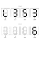
第1報知用表示装置69aの表示面においては「0」〜「9」の数字だけではなく、アルファベット文字を含めた各種文字が表示される。一方、第2報知用表示装置69b及び第3報知用表示装置69cにおいては「0」〜「9」の数字が表示される。第1〜第3報知用表示装置69a〜69cを利用して遊技履歴の管理結果が報知されるが、この報知内容については後に詳細に説明する。また、パチンコ機10の設定状態を変更することが可能な変更可能状態においては現状の設定値に対応する値が第3報知用表示装置69cにて表示される。なお、当該設定値に対応する値が第1報知用表示装置69aにて表示される構成としてもよく、第2報知用表示装置69bにて表示される構成としてもよい。また、変更可能状態となる前における設定値が第1〜第3報知用表示装置69a〜69cのうちの一の報知用表示装置にて表示されるとともに現状の設定値が第1〜第3報知用表示装置69a〜69cのうちの他の一の報知用表示装置にて表示される構成としてもよい。
Not only the numerals “0” to “9” but various characters including alphabet characters are displayed on the display surface of the first
図2に示すように、主制御装置60を含めて内枠13の背面側を覆うようにして裏パックユニット15が設置されている。裏パックユニット15は、透明性を有する合成樹脂により形成された裏パック72を備えており、当該裏パック72に払出機構部73及び制御装置集合ユニット74が取り付けられている。
As shown in FIG. 2, the
払出機構部73は、遊技ホールの島設備から供給される遊技球が逐次補給されるタンク75と、当該タンク75に貯留された遊技球を払い出すための払出装置76と、を備えている。払出装置76より払い出された遊技球は、当該払出装置76の下流側に設けられた払出通路を通じて、上皿55a又は下皿56aに排出される。なお、払出機構部73には、例えば交流24ボルトの主電源が供給されるとともに、電源のON操作及びOFF操作を行うための電源スイッチを有する裏パック基板が搭載されている。
The
制御装置集合ユニット74は、払出装置76を制御する機能を有する払出制御装置77と、各種制御装置等で要する所定の電力が生成されて出力されるとともに遊技者による発射操作装置28の操作に伴う遊技球の打ち出しの制御が行われる電源・発射制御装置78と、を備えている。これら払出制御装置77と電源・発射制御装置78とは、払出制御装置77がパチンコ機10後方となるように前後に重ねて配置されている。
The control
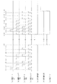
<パチンコ機10の電気的構成>
図6は、パチンコ機10の電気的構成を示すブロック図である。
<Electric Configuration of
FIG. 6 is a block diagram showing the electrical configuration of the
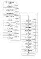
主制御装置60は、遊技の主たる制御を司る主制御基板61と、電源を監視する停電監視基板67と、を具備している。主制御基板61には、MPU62が搭載されている。MPU62には、制御部及び演算部を含む演算処理装置である主側CPU63の他に、主側ROM64、主側RAM65及び管理用IC66が内蔵されている。なお、MPU62には、上記素子以外に、割込回路、タイマ回路、データ入出力回路、乱数発生器としての各種カウンタ回路などが内蔵されている。
The
主側ROM64は、NOR型フラッシュメモリ及びNAND型フラッシュメモリなどの記憶保持に外部からの電力供給が不要なメモリ(すなわち、不揮発性記憶手段)であり、読み出し専用として利用される。主側ROM64は、主側CPU63により実行される各種の制御プログラムや固定値データを記憶している。
The
主側RAM65は、SRAM及びDRAMなどの記憶保持に外部からの電力供給が必要なメモリ(すなわち、揮発性記憶手段)であり、読み書き両用として利用される。主側RAM65は、ランダムアクセスが可能であるとともに、同一のデータ容量で比較した場合に主側ROM64よりも読み出しに要する時間が早いものとなっている。主側RAM65は、主側ROM64内に記憶されている制御プログラムの実行に対して各種のデータなどを一時的に記憶する。
The
管理用IC66は、主側CPU63から供給された情報に基づいて遊技履歴を管理する管理装置である。詳細は後述するが、管理用IC66にて一般入賞口31、特電入賞装置32、第1作動口33、第2作動口34及びアウト口24aへの遊技球の入球履歴が把握されるとともに、その把握された入球履歴に応じて一般入賞口31、特電入賞装置32、第1作動口33及び第2作動口34への入球頻度が把握される。また、管理用IC66にて後述する開閉実行モード及び高頻度サポートモードの発生頻度が把握される。
The
MPU62には、入力ポート及び出力ポートがそれぞれ設けられている。MPU62の入力側には主制御装置60に設けられた停電監視基板67及び払出制御装置77が接続されている。停電監視基板67には動作電力を供給する機能を有する電源・発射制御装置78が接続されており、MPU62には停電監視基板67を介して動作電力が供給される。
The
MPU62の入力側には、各入球検知センサ42a〜49aといった各種センサが接続されている。各入球検知センサ42a〜49aには、既に説明したとおり、第1入賞口検知センサ42a、第2入賞口検知センサ43a、第3入賞口検知センサ44a、特電検知センサ45a、第1作動口検知センサ46a、第2作動口検知センサ47a、アウト口検知センサ48a及びゲート検知センサ49aが含まれる。これら入球検知センサ42a〜49aの検知結果に基づいて、主側CPU63にて各入球部への入球判定が行われる。また、主側CPU63では第1作動口33への入賞に基づいて各種抽選が実行されるとともに第2作動口34への入賞に基づいて各種抽選が実行される。
Various sensors such as ball entering
MPU62の入力側には、主制御基板61に設けられた設定キー挿入部68a、更新ボタン68b及びリセットボタン68cが設けられている。設定キー挿入部68aには図示しないセンサが設けられており、当該センサにより当該設定キー挿入部68aがON操作の位置及びOFF操作の位置のいずれに配置されているのかが検知される。そして、主側CPU63はそのセンサからの検知結果に基づいて設定キー挿入部68aがON操作の位置及びOFF操作の位置のいずれに配置されているのかを特定する。更新ボタン68bには図示しないセンサが設けられており、当該センサにより更新ボタン68bが押圧操作されているか否かが検知される。そして、主側CPU63はそのセンサからの検知結果に基づいて更新ボタン68bが押圧操作されているか否かを特定する。リセットボタン68cには図示しないセンサが設けられており、当該センサによりリセットボタン68cが押圧操作されているか否かが検知される。そして、主側CPU63はそのセンサからの検知結果に基づいてリセットボタン68cが押圧操作されているか否かを特定する。
On the input side of the
MPU62の出力側には、停電監視基板67、払出制御装置77及び音声発光制御装置81が接続されている。払出制御装置77には、例えば、上記入球部のうち入球の発生が遊技球の払い出しに対応する賞球対応入球部に遊技球が入球したことに基づいて賞球コマンドが出力される。音声発光制御装置81には、変動用コマンド、種別コマンド及びオープニングコマンドなどの各種コマンドが出力される。
The power
MPU62の出力側には、特電入賞装置32の開閉扉32aを開閉動作させる特電用の駆動部32b、第2作動口34の普電役物34aを開閉動作させる普電用の駆動部34b、特図ユニット37及び普図ユニット38が接続されている。ちなみに、特図ユニット37には、特図表示部37a及び特図保留表示部37bが設けられているが、これらの全てがMPU62の出力側に接続されている。同様に、普図ユニット38には、普図表示部38a及び普図保留表示部38bが設けられているが、これらの全てがMPU62の出力側に接続されている。主制御基板61には各種ドライバ回路が設けられており、当該ドライバ回路を通じてMPU62は各種駆動部及び各種表示部の駆動制御を実行する。
On the output side of the
つまり、開閉実行モードにおいては特電入賞装置32が開閉されるように、主側CPU63において特電用の駆動部32bの駆動制御が実行される。また、普電役物34aの開放状態当選となった場合には、普電役物34aが開閉されるように、主側CPU63において普電用の駆動部34bの駆動制御が実行される。また、各遊技回に際しては、主側CPU63において特図表示部37aの表示制御が実行される。また、普電役物34aを開放状態とするか否かの抽選結果を明示する場合に、主側CPU63において普図表示部38aの表示制御が実行される。また、第1作動口33若しくは第2作動口34への入賞が発生した場合、又は特図表示部37aにおいて変動表示が開始される場合に、主側CPU63において特図保留表示部37bの表示制御が実行され、スルーゲート35への入賞が発生した場合、又は普図表示部38aにおいて変動表示が開始される場合に、主側CPU63において普図保留表示部38bの表示制御が実行される。
That is, in the open / close execution mode, drive control of the drive unit 32b for the special power is performed in the
MPU62の出力側には第1〜第3報知用表示装置69a〜69cが接続されている。また、管理用IC66における遊技履歴の管理結果が第1〜第3報知用表示装置69a〜69cにおける表示を通じて報知される。また、パチンコ機10の設定状態の変更に際しては第3報知用表示装置69cにて現状の設定値が表示される。この場合、第1報知用表示装置69a及び第2報知用表示装置69bは管理用IC66により表示制御され主側CPU63により表示制御されないのに対して、第3報知用表示装置69cは主側CPU63により表示制御されるとともに管理用IC66により表示制御される。第3報知用表示装置69cの表示は管理用IC66による表示制御よりも主側CPU63による表示制御が優先される。
First to third
但し、これに限定されることはなく第3報知用表示装置69cについても管理用IC66により表示制御され主側CPU63により表示制御されない構成としてもよい。この場合、パチンコ機10の設定状態の変更に際して第3報知用表示装置69cにて現状の設定値を表示する場合には主側CPU63から管理用IC66に設定値の表示指示が行われる構成とするとよい。
However, the configuration is not limited to this, and the display control of the third
MPU62には読み取り用端子68dが設けられている。読み取り用端子68dには図示しないセンサが設けられており、当該センサにより読み取り用端子68dに外部装置の接続端子が接続されているか否かが検知される。そして、主側CPU63はそのセンサからの検知結果に基づいて読み取り用端子68dに外部装置の接続端子が接続されているか否かを特定する。また、読み取り用端子68dに外部装置が接続されている場合、管理用IC66における遊技履歴の管理結果又は主側ROM64に記憶された情報(プログラム及びデータ)が当該外部装置に外部出力される。
The
停電監視基板67は、主制御基板61と電源・発射制御装置78とを中継し、電源・発射制御装置78から出力される最大電圧である直流安定24ボルトの電圧を監視する。払出制御装置77は、主制御装置60から受信した賞球コマンドに基づいて、払出装置76により賞球や貸し球の払出制御を行うものである。
The power
電源・発射制御装置78は、例えば、遊技ホール等における商用電源(外部電源)に接続されている。そして、その商用電源から供給される外部電力に基づいて主制御基板61や払出制御装置77等に対して各々に必要な動作電力を生成するとともに、その生成した動作電力を供給する。ちなみに、電源・発射制御装置78にはバックアップ用コンデンサなどの電断時用電源部が設けられており、パチンコ機10の電源がOFF状態の場合であっても当該電断時用電源部から主制御装置60の主側RAM65及び払出制御装置77に記憶保持用の電力が供給される。また、電源・発射制御装置78は遊技球発射機構27の発射制御を担うものであり、遊技球発射機構27は所定の発射条件が整っている場合に駆動される。また、払出機構部73には既に説明したとおり電源スイッチが設けられており、電源スイッチがON操作されることによりパチンコ機10への動作電力の供給が開始され、電源スイッチがOFF操作されることによりパチンコ機10への動作電力の供給が停止される。
The power supply and
音声発光制御装置81は、主制御装置60から受信した各種コマンドに基づいて、前扉枠14に設けられた表示発光部53及びスピーカ部54を駆動制御するとともに、表示制御装置82を制御するものである。表示制御装置82は、音声発光制御装置81から受信したコマンドに基づいて、図柄表示装置41の表示制御を実行する。
The sound
<主側CPU63にて各種抽選を行うための電気的構成>
次に、主側CPU63にて各種抽選を行うための電気的な構成について図7を用いて説明する。
<Electrical configuration for performing various lottery in
Next, an electrical configuration for performing various lottery in the
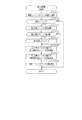
主側CPU63は遊技に際し各種カウンタ情報を用いて、大当たり発生抽選、特図表示部37aの表示の設定、図柄表示装置41の図柄表示の設定、普図表示部38aの表示の設定などを行うこととしており、具体的には、図7に示すように、当たり発生の抽選に使用する当たり乱数カウンタC1と、大当たり種別を判定する際に使用する大当たり種別カウンタC2と、図柄表示装置41が外れ変動する際のリーチ発生抽選に使用するリーチ乱数カウンタC3と、当たり乱数カウンタC1の初期値設定に使用する乱数初期値カウンタCINIと、特図表示部37a及び図柄表示装置41における表示継続時間を決定する変動種別カウンタCSと、を用いることとしている。さらに、第2作動口34の普電役物34aを普電開放状態とするか否かの抽選に使用する普電役物開放カウンタC4を用いることとしている。なお、上記各カウンタC1〜C3,CINI,CS,C4は、主側RAM65の各種カウンタエリア65bに設けられている。
During the game, the
各カウンタC1〜C3,CINI,CS,C4は、その更新の都度前回値に1が加算され、最大値に達した後に「0」に戻るループカウンタとなっている。各カウンタは短時間間隔で更新される。当たり乱数カウンタC1、大当たり種別カウンタC2及びリーチ乱数カウンタC3に対応した情報は、第1作動口33又は第2作動口34への入賞が発生した場合に、主側RAM65に取得情報記憶手段として設けられた保留格納エリア65aに格納される。
Each of the counters C1 to C3, CINI, CS, and C4 is a loop counter in which 1 is added to the previous value each time it is updated, and after reaching the maximum value, it returns to "0". Each counter is updated at short intervals. The information corresponding to the per random number counter C1, the big hit type counter C2 and the reach random number counter C3 is provided as an acquisition information storage means in the
保留格納エリア65aは、保留用エリアREと、実行エリアAEとを備えている。保留用エリアREは、第1保留エリアRE1、第2保留エリアRE2、第3保留エリアRE3及び第4保留エリアRE4を備えており、第1作動口33又は第2作動口34への入賞履歴に合わせて、当たり乱数カウンタC1、大当たり種別カウンタC2及びリーチ乱数カウンタC3の各数値情報の組合せが保留情報として、いずれかの保留エリアRE1〜RE4に格納される。
The holding storage area 65a includes a holding area RE and an execution area AE. The reserve area RE includes a first reserve area RE1, a second reserve area RE2, a third reserve area RE3 and a fourth reserve area RE4, and the winning history to the
この場合、第1保留エリアRE1〜第4保留エリアRE4には、第1作動口33又は第2作動口34への入賞が複数回連続して発生した場合に、第1保留エリアRE1→第2保留エリアRE2→第3保留エリアRE3→第4保留エリアRE4の順に各数値情報が時系列的に格納されていく。このように4つの保留エリアRE1〜RE4が設けられていることにより、第1作動口33又は第2作動口34への遊技球の入賞履歴が最大4個まで保留記憶されるようになっている。
In this case, if winnings to the
なお、保留記憶可能な数は、4個に限定されることはなく任意であり、2個、3個又は5個以上といったように他の複数であってもよく、単数であってもよい。 The number that can be reserved and stored is not limited to four and is arbitrary, and may be other plural such as two, three, five or more, or may be singular.
実行エリアAEは、特図表示部37aの変動表示を開始する際に、保留用エリアREの第1保留エリアRE1に格納された各数値情報を移動させるためのエリアであり、1遊技回の開始に際しては実行エリアAEに記憶されている各種数値情報に基づいて、当否判定などが行われる。 The execution area AE is an area for moving each numerical information stored in the first holding area RE1 of the holding area RE when the variable display of the special view display unit 37a is started, and the start of one game cycle is started On the occasion of the above, on the basis of various numerical value information stored in the execution area AE, a judgment of success or failure is performed.
上記各カウンタについて詳細に説明する。 The respective counters will be described in detail.
まず、普電役物開放カウンタC4について説明する。普電役物開放カウンタC4は、例えば、0〜250の範囲内で順に1ずつ加算され、最大値に達した後に「0」に戻る構成となっている。普電役物開放カウンタC4は定期的に更新され、スルーゲート35に遊技球が入賞したタイミングで主側RAM65の普電保留エリア65cに格納される。そして、所定のタイミングにおいて、その格納された普電役物開放カウンタC4の値によって普電役物34aを開放状態に制御するか否かの抽選が行われる。
First, the general purpose power product release counter C4 will be described. For example, the commercial power release counter C4 is sequentially incremented by 1 within the range of 0 to 250, and returns to “0” after reaching the maximum value. The routine charge release counter C4 is periodically updated, and is stored in the common
本パチンコ機10では、普電役物34aによるサポートの態様が相互に異なるように複数種類のサポートモードが設定されている。詳細には、サポートモードには、遊技領域PAに同様の態様で遊技球の発射が継続されている状況で比較した場合に、第2作動口34の普電役物34aが単位時間当たりに開放状態となる頻度が相対的に高低となるように、高頻度サポートモードと低頻度サポートモードとが設定されている。
In the
高頻度サポートモードと低頻度サポートモードとでは、普電役物開放カウンタC4を用いた普電開放抽選における普電開放状態当選となる確率は同一(例えば、共に4/5)となっているが、高頻度サポートモードでは低頻度サポートモードよりも、普電開放状態当選となった際に普電役物34aが開放状態となる回数が多く設定されており、さらに1回の開放時間が長く設定されている。この場合、高頻度サポートモードにおいて普電開放状態当選となり普電役物34aの開放状態が複数回発生する場合において、1回の開放状態が終了してから次の開放状態が開始されるまでの閉鎖時間は、1回の開放時間よりも短く設定されている。さらにまた、高頻度サポートモードでは低頻度サポートモードよりも、1回の普電開放抽選が行われてから次の普電開放抽選が行われる上で最低限確保される確保時間(すなわち、普図表示部38aにおける1回の表示継続時間)が短く設定されている。 In the high-frequency support mode and the low-frequency support mode, the probability of winning the common power open status in the common power open lottery using the common power utility open counter C4 is the same (for example, both are 4/5) In the high-frequency support mode, the number of times the general-purpose product 34a becomes open when the general-purpose open state is won is set to a larger number than in the low-frequency support mode, and one open time is set longer It is done. In this case, when the general electric power release state is won in the high frequency support mode and the open state of the general power utility item 34a occurs a plurality of times, it is from the end of one open state to the start of the next open state. The closing time is set to be shorter than one opening time. Furthermore, in the high frequency support mode, the securing time minimumly secured in performing the next public power release lottery after the first public power release lottery is performed rather than the low frequency support mode One display continuation time in the display unit 38a is set to be short.
上記のとおり、高頻度サポートモードでは、低頻度サポートモードよりも第2作動口34への入賞が発生する確率が高くなる。換言すれば、低頻度サポートモードでは、第2作動口34よりも第1作動口33への入賞が発生する確率が高くなるが、高頻度サポートモードでは、第1作動口33よりも第2作動口34への入賞が発生する確率が高くなる。そして、第2作動口34への入賞が発生した場合には、所定個数の遊技球の払出が実行されるため、高頻度サポートモードでは、遊技者は持ち球をあまり減らさないようにしながら遊技を行うことができる。
As described above, in the high frequency support mode, the probability of winning in the
なお、高頻度サポートモードを低頻度サポートモードよりも単位時間当たりに普電開放状態となる頻度を高くする上での構成は、上記のものに限定されることはなく、例えば普電開放抽選における普電開放状態当選となる確率を高くする構成としてもよい。また、1回の普電開放抽選が行われてから次の普電開放抽選が行われる上で確保される確保時間(例えば、スルーゲート35への入賞に基づき普図表示部38aにて実行される変動表示の時間)が複数種類用意されている構成においては、高頻度サポートモードでは低頻度サポートモードよりも、短い確保時間が選択され易い又は平均の確保時間が短くなるように設定されていてもよい。さらには、開放回数を多くする、開放時間を長くする、1回の普電開放抽選が行われてから次の普電開放抽選が行われる上で確保される確保時間を短くする、係る確保時間の平均時間を短くする及び当選確率を高くするのうち、いずれか1条件又は任意の組合せの条件を適用することで、低頻度サポートモードに対する高頻度サポートモードの有利性を高めてもよい。 Note that the configuration for increasing the frequency at which the common power release state occurs per unit time in the high-frequency support mode rather than the low-frequency support mode is not limited to the above-described one. It is good also as composition which makes high the probability of being in a state where the general public is released. In addition, a securement time (for example, based on winning on the through gate 35) is performed in the generalization display portion 38a, which is secured when the next general public open lottery is performed after one public open public lottery is performed. In the configuration in which multiple types of variable display time) are prepared, the high frequency support mode is set so that the short securing time is easier to be selected or the average securing time is shorter than the low frequency support mode. It is also good. Furthermore, the number of opening times is increased, the opening time is extended, and the securing time secured in performing the next public power release lottery after the one public power opening lottery is performed, the securing time to be related, The advantage of the high frequency support mode over the low frequency support mode may be enhanced by applying any one condition or any combination of conditions among the shortening of the average time of and the increase of the winning probability.
ここで、既に説明したとおりパチンコ機10には「設定1」〜「設定6」の設定状態が存在しているが、低頻度サポートモードにおける普電役物34aの開放頻度及び開放態様はいずれの設定値であっても同一であるとともに、高頻度サポートモードにおける普電役物34aの開放頻度及び開放態様もいずれの設定値であっても同一となっている。但し、これに限定されることはなく、低頻度サポートモード及び高頻度サポートモードの少なくとも一方について普電役物34aの開放頻度及び開放態様の少なくとも一方がパチンコ機10の設定状態に応じて変動する構成としてもよい。例えば設定値が高いほど、低頻度サポートモードにおいて普電役物34aの開放頻度が高くなる構成としてもよく、低頻度サポートモードにおいて普電役物34aが1回開放状態となる場合における第2作動口34への遊技球の入球確率が高くなる構成としてもよい。また、設定値が高いほど、高頻度サポートモードにおいて普電役物34aの開放頻度が高くなる構成としてもよく、高頻度サポートモードにおいて普電役物34aが1回開放状態となる場合における第2作動口34への遊技球の入球確率が高くなる構成としてもよい。
Here, as described above, setting states “setting 1” to “setting 6” exist in the
次に、当たり乱数カウンタC1について説明する。当たり乱数カウンタC1は、例えば0〜599の範囲内で順に1ずつ加算され、最大値に達した後に「0」に戻る構成となっている。特に当たり乱数カウンタC1が1周した場合、その時点の乱数初期値カウンタCINIの値が当該当たり乱数カウンタC1の初期値として読み込まれる。なお、乱数初期値カウンタCINIは、当たり乱数カウンタC1と同様のループカウンタである(値=0〜599)。当たり乱数カウンタC1は定期的に更新され、遊技球が第1作動口33又は第2作動口34に入賞したタイミングで主側RAM65の保留格納エリア65aに格納される。
Next, the per-random number counter C1 will be described. The per-random number counter C1 is configured to be sequentially incremented by one, for example, within the range of 0 to 599, and return to “0” after reaching the maximum value. In particular, when the per-random number counter C1 makes one revolution, the value of the random-number initial value counter CINI at that time is read as the initial value of the per-random number counter C1. The random number initial value counter CINI is a loop counter similar to the per random number counter C1 (value = 0 to 599). The random number counter C1 is periodically updated, and is stored in the hold storage area 65a of the
大当たり当選となる乱数の値は、主側ROM64に当否テーブルとして記憶されている。図8は主側ROM64に記憶されている各種テーブルを説明するための説明図である。当否テーブルとして、低確率モード用の低確当否テーブル64a〜64fと、高確率モード用の高確当否テーブル64gとが記憶されている。
The value of the random number for winning the jackpot is stored in the
低確当否テーブル64a〜64fは、「設定1」〜「設定6」の設定状態に1対1で対応させて設けられている。つまり、パチンコ機10の設定状態が「設定1」である場合に参照される設定1用の低確当否テーブル64aと、パチンコ機10の設定状態が「設定2」である場合に参照される設定2用の低確当否テーブル64bと、パチンコ機10の設定状態が「設定3」である場合に参照される設定3用の低確当否テーブル64cと、パチンコ機10の設定状態が「設定4」である場合に参照される設定4用の低確当否テーブル64dと、パチンコ機10の設定状態が「設定5」である場合に参照される設定5用の低確当否テーブル64eと、パチンコ機10の設定状態が「設定6」である場合に参照される設定6用の低確当否テーブル64fと、が存在している。
The low probability results tables 64a to 64f are provided in one-to-one correspondence with the setting states of "setting 1" to "setting 6". That is, the low probability table 64a for setting 1 referred to when the setting state of the
これら低確当否テーブル64a〜64fは高い設定値ほど大当たり結果の当選確率が高くなるように設定されている。具体的には、設定1用の低確当否テーブル64aが参照された場合には約1/320で大当たり結果となり、設定2用の低確当否テーブル64bが参照された場合には約1/310で大当たり結果となり、設定3用の低確当否テーブル64cが参照された場合には約1/300で大当たり結果となり、設定4用の低確当否テーブル64dが参照された場合には約1/290で大当たり結果となり、設定5用の低確当否テーブル64eが参照された場合には約1/280で大当たり結果となり、設定6用の低確当否テーブル64fが参照された場合には約1/270で大当たり結果となる。これにより、パチンコ機10の設定状態が高い設定値である方が低確率モードにおいて大当たり結果が発生し易くなり、遊技者にとって有利となる。
The low probability table 64a to 64f is set such that the winning probability of the jackpot result is higher as the setting value is higher. Specifically, when the low probability of failure table 64a for setting 1 is referred to, the result is a big hit with about 1/320, and when the low probability of failure table 64b for setting 2 is referred to, it is about 1/310. Results in a big hit, and when the low probability table 64c for setting 3 is referred to, the jackpot result is about 1/300, and when the low probability table 64d for setting 4 is referred to, about 1/290 The jackpot results in and the jackpot result for about 5 if the low probability table 64e for setting 5 is referenced is about 1/270 if the low probability for table 6f for setting 6 is referred to Results in a big hit. As a result, a jackpot result is more easily generated in the low probability mode when the setting state of the
一方、高確当否テーブル64gは、「設定1」〜「設定6」のいずれの設定状態であっても共通となるように1種類のみ設けられている。高確当否テーブル64gは「設定1」〜「設定6」のいずれの設定状態であっても低確当否テーブル64a〜64fよりも大当たり結果の当選確率が高くなるように設定されている。具体的には、高確当否テーブル64gが参照された場合には約1/30で大当たり結果となる。これにより、パチンコ機10の設定状態に関係なく高確率モードを低確率モードよりも有利な状態とすることが可能となる。また、最も低い設定状態である「設定1」であっても高確率モードとなることで最も高い設定状態である「設定6」の低確率モードよりも大当たり結果となる確率を高くすることが可能となる。また、高確率モードについてはパチンコ機10の設定状態による有利又は不利が生じないようにすることが可能となるとともに、高確当否テーブル64gを主側ROM64にて予め記憶するための記憶容量を抑えることが可能となる。
On the other hand, only one type of the high probability of failure table 64 g is provided so as to be common regardless of any setting state of “setting 1” to “setting 6”. The high probability of failure table 64g is set such that the winning probability of the jackpot result is higher than that of the low probability of failure tables 64a to 64f in any setting state of "setting 1" to "setting 6". Specifically, when the high probability nonconforming table 64g is referred to, the jackpot result is about 1/30. Thus, regardless of the setting state of the
大当たり種別カウンタC2は、0〜29の範囲内で順に1ずつ加算され、最大値に達した後に「0」に戻る構成となっている。大当たり種別カウンタC2は定期的に更新され、遊技球が第1作動口33又は第2作動口34に入賞したタイミングで保留格納エリア65aに格納される。
The jackpot type counter C2 is configured to be sequentially incremented by one within the range of 0 to 29 and to return to “0” after reaching the maximum value. The jackpot type counter C2 is periodically updated, and is stored in the hold storage area 65a at a timing when the gaming ball has won the
本パチンコ機10では、複数の大当たり結果が設定されている。これら複数の大当たり結果は、(1)開閉実行モードにおける特電入賞装置32の開閉制御の態様、(2)開閉実行モード終了後の当否抽選手段における抽選モード、(3)開閉実行モード終了後の第2作動口34の普電役物34aにおけるサポートモード、という3つの条件に差異を設けることにより、複数の大当たり結果が設定されている。
In the
開閉実行モードにおける特電入賞装置32の開閉制御の態様としては、開閉実行モードが開始されてから終了するまでの間における特電入賞装置32への入賞の発生頻度が相対的に高低となるように高頻度入賞モードと低頻度入賞モードとが設定されている。具体的には、高頻度入賞モード及び低頻度入賞モードのいずれであっても、予め定められた回数のラウンド遊技を上限として実行される。
As an aspect of the open / close control of the special
ラウンド遊技とは、予め定められた上限継続時間が経過すること、及び予め定められた上限個数の遊技球が特電入賞装置32に入賞することのいずれか一方の条件が満たされるまで継続する遊技のことである。また、大当たり結果が契機となった開閉実行モードにおけるラウンド遊技の回数は、その移行の契機となった大当たり結果の種類がいずれであっても固定ラウンド回数で同一となっている。具体的には、いずれの大当たり結果となった場合であっても、ラウンド遊技の上限回数は15ラウンドに設定されている。
The round game is a game that continues until either a predetermined upper limit continuation time elapses or a predetermined upper limit number of gaming balls wins the special
また、本パチンコ機10では、特電入賞装置32の1回の開放態様が、特電入賞装置32が開放されてから閉鎖されるまでの開放継続時間を相違させて、複数種類設定されている。詳細には、開放継続時間が長時間である29秒に設定された長時間態様と、開放継続時間が上記長時間よりも短い短時間である0.06秒に設定された短時間態様と、が設定されている。
Further, in the
本パチンコ機10では、発射操作装置28が遊技者により操作されている状況では、0.6秒に1個の遊技球が遊技領域PAに向けて発射されるように遊技球発射機構27が駆動制御される。また、ラウンド遊技は終了条件の上限個数が9個に設定されている。そうすると、上記開放態様のうち長時間態様では、遊技球の発射周期と1回のラウンド遊技との積よりも長い時間の開放継続時間が設定されていることとなる。一方、短時間態様では、遊技球の発射周期と1回のラウンド遊技との積よりも短い時間、より詳細には、遊技球の発射周期よりも短い時間の開放継続時間が設定されている。したがって、長時間態様で1回の開放が行われた場合には、特電入賞装置32に対して、1回のラウンド遊技における上限個数分の入賞が発生することが期待され、短時間態様で1回の開放が行われた場合には、特電入賞装置32への入賞が発生しないこと又は入賞が発生するとしても1個程度となることが期待される。
In the
高頻度入賞モードでは、各ラウンド遊技において長時間態様による特電入賞装置32の開放が1回行われる。一方、低頻度入賞モードでは、各ラウンド遊技において短時間態様による特電入賞装置32の開放が1回行われる。
In the high frequency winning mode, the special
なお、高頻度入賞モード及び低頻度入賞モードにおける特電入賞装置32の開閉回数、ラウンド遊技の回数、1回の開放に対する開放継続時間及び1回のラウンド遊技における上限個数は、高頻度入賞モードの方が低頻度入賞モードよりも、開閉実行モードが開始されてから終了するまでの間における特電入賞装置32への入賞の発生頻度が高くなるのであれば、上記の値に限定されることはなく任意である。
In addition, the number of opening and closing times of special
大当たり種別カウンタC2に対する大当たり結果の振分先は、図8に示すように主側ROM64に振分テーブル64hとして記憶されている。そして、振分テーブル64hにおいては大当たり結果となった場合における大当たり結果の振分先として、低確大当たり結果と、低入賞高確大当たり結果と、最有利大当たり結果とが設定されている。
The distribution destination of the jackpot result for the jackpot type counter C2 is stored as a distribution table 64h in the
低確大当たり結果は、開閉実行モードが高頻度入賞モードとなり、さらに開閉実行モードの終了後には、当否抽選モードが低確率モードとなるとともに、サポートモードが高頻度サポートモードとなる大当たり結果である。但し、この高頻度サポートモードは、移行後において遊技回数が終了基準回数(具体的には、100回)に達した場合に低頻度サポートモードに移行する。 The low probability jackpot result is a jackpot result in which the opening / closing execution mode becomes the high frequency winning mode, and after the opening / closing execution mode ends, the pass / fail lottery mode becomes the low probability mode and the support mode becomes the high frequency support mode. However, in the high-frequency support mode, the transition to the low-frequency support mode is made when the number of games has reached the end reference frequency (specifically, 100 times) after the transition.
低入賞高確大当たり結果は、開閉実行モードが低頻度入賞モードとなり、さらに開閉実行モードの終了後には、当否抽選モードが高確率モードとなるとともに、サポートモードが高頻度サポートモードとなる大当たり結果である。これら高確率モード及び高頻度サポートモードは、当否抽選における抽選結果が大当たり状態当選となり、それによる大当たり状態に移行するまで継続する。 In the low winning high probability big hit result, the opening and closing execution mode becomes the low frequency winning mode, and after the opening and closing execution mode ends, the success or failure lottery mode becomes the high probability mode and the support mode becomes the high frequency support mode. is there. The high probability mode and the high frequency support mode continue until the lottery result in the success or failure lottery becomes the jackpot state winning, and shifts to the jackpot state by it.
最有利大当たり結果は、開閉実行モードが高頻度入賞モードとなり、さらに開閉実行モードの終了後には、当否抽選モードが高確率モードとなるとともに、サポートモードが高頻度サポートモードとなる大当たり結果である。これら高確率モード及び高頻度サポートモードは、当否抽選における抽選結果が大当たり状態当選となり、それによる大当たり状態に移行するまで継続する。 The most advantageous jackpot result is a jackpot result in which the opening / closing execution mode becomes the high frequency winning mode, and after the opening / closing execution mode ends, the pass / fail lottery mode becomes the high probability mode and the support mode becomes the high frequency support mode. The high probability mode and the high frequency support mode continue until the lottery result in the success or failure lottery becomes the jackpot state winning, and shifts to the jackpot state by it.
なお、上記各遊技状態との関係で通常遊技状態とは、開閉実行モードではなく、さらに当否抽選モードが低確率モードであり、サポートモードが低頻度サポートモードである状態をいう。また、遊技結果として、低入賞高確大当たり結果が設定されていない構成としてもよい。また、低入賞高確大当たり結果における開閉実行モードでは、ラウンド遊技の回数が低確大当たり結果及び最有利大当たり結果の場合よりも少ない回数である構成としてもよい。 Note that the normal gaming state is not the opening / closing execution mode, but the winning lottery mode is the low probability mode and the support mode is the low frequency support mode, in relation to the above gaming states. Further, as a game result, a configuration may be made in which the low winning high probability big hit result is not set. Further, in the opening and closing execution mode in the low winning high probability jackpot result, the number of round games may be smaller than in the low probability jackpot result and the most advantageous jackpot result.
振分テーブル64hでは、「0〜29」の大当たり種別カウンタC2の値のうち、「0〜9」が低確大当たり結果に対応しており、「10〜14」が低入賞高確大当たり結果に対応しており、「15〜29」が最有利大当たり結果に対応している。 In the distribution table 64h, among the values of "0 to 29" jackpot type counter C2, "0 to 9" correspond to the low probability jackpot result, and "10 to 14" is the low winning high probability jackpot result It corresponds, and "15-29" corresponds to the most advantageous big hit result.
振分テーブル64hは、「設定1」〜「設定6」のいずれの設定状態であっても共通となるように1種類のみ設けられている。これにより、大当たり結果の振分態様についてパチンコ機10の設定状態による有利又は不利が生じないようにすることが可能となるとともに、振分テーブル64hを主側ROM64にて予め記憶するための記憶容量を抑えることが可能となる。
Only one type of distribution table 64h is provided so as to be common regardless of any setting state of "setting 1" to "setting 6". As a result, it becomes possible to prevent the setting condition of the
なお、パチンコ機10の設定状態に応じて大当たり結果の振分態様が相違する構成としてもよい。例えば、高い設定値ほど最有利大当たり結果に振り分けられる確率を高くする構成としてもよく、高い設定値ほど最有利大当たり結果又は低入賞高確大当たり結果に振り分けられる確率を高くする構成としてもよい。この場合、高い設定値ほど大当たり結果となった後に高確率モードとなる確率を高くすることが可能となる。また、高い設定値ほど低入賞高確大当たり結果に振り分けられる確率を低くする構成としてもよく、高い設定値では低入賞高確大当たり結果に振り分けられないのに対して低い設定値では低入賞高確大当たり結果に振り分けられ得る構成としてもよい。この場合、高い設定値ほど高頻度入賞モードの開閉実行モードが発生する確率を高くすることが可能となる。
The distribution mode of the jackpot result may be different depending on the setting state of the
次に、リーチ乱数カウンタC3について説明する。リーチ乱数カウンタC3は、例えば0〜238の範囲内で順に1ずつ加算され、最大値に達した後に「0」に戻る構成となっている。本パチンコ機10には、図柄表示装置41における表示演出の一種として期待演出が設定されている。期待演出とは、図柄の変動表示を行うことが可能な図柄表示装置41を備え、所定の大当たり結果となる遊技回では最終的な停止結果が付与対応結果となる遊技機において、図柄表示装置41における図柄の変動表示が開始されてから停止結果が導出表示される前段階で、前記付与対応結果となり易い変動表示状態であると遊技者に思わせるための表示状態をいう。なお、付与対応結果について具体的には、いずれかの有効ライン上に同一の数字が付された図柄の組合せが停止表示される。
Next, the reach random number counter C3 will be described. For example, the reach random number counter C3 is sequentially incremented by one within the range of 0 to 238, and returns to “0” after reaching the maximum value. In the
期待演出には、リーチ表示と、リーチ表示が発生する前段階などにおいてリーチ表示の発生や付与対応結果の発生を期待させるための予告表示との2種類が設定されている。 In the expectation effect, two types of reach display and advance notice display for expecting the occurrence of reach display and the occurrence of the response to an assignment in a stage before the reach display and the like are set.
リーチ表示には、図柄表示装置41の表示面41aに表示される複数の図柄列のうち一部の図柄列について図柄を停止表示させることで、リーチ図柄の組合せを表示し、その状態で残りの図柄列において図柄の変動表示を行う表示状態が含まれる。また、上記のようにリーチ図柄の組合せを表示した状態で、残りの図柄列において図柄の変動表示を行うとともに、その背景画面において所定のキャラクタなどを動画として表示することによりリーチ演出を行うものや、リーチ図柄の組合せを縮小表示させる又は非表示とした上で、表示面41aの略全体において所定のキャラクタなどを動画として表示することによりリーチ演出を行うものが含まれる。
In the reach display, a combination of reach symbols is displayed by stopping the symbols of some of the plurality of symbol rows displayed on the display surface 41a of the
予告表示には、図柄表示装置41の表示面41aにおいて図柄の変動表示が開始されてから、全ての図柄列にて図柄が変動表示されている状況において、又は一部の図柄列であって複数の図柄列にて図柄が変動表示されている状況において、図柄列上の図柄とは別にキャラクタを表示させる態様が含まれる。また、背景画面をそれまでの態様とは異なる所定の態様とするものや、図柄列上の図柄をそれまでの態様とは異なる所定の態様とするものも含まれる。かかる予告表示は、リーチ表示が行われる場合及びリーチ表示が行われない場合のいずれの遊技回においても発生し得るが、リーチ表示が行われる場合の方がリーチ表示が行われない場合よりも高確率で発生するように設定されている。
In the advance notice display, after the variable display of the symbols is started on the display surface 41a of the
リーチ表示は、最終的に同一の図柄の組合せが停止表示される遊技回では、リーチ乱数カウンタC3の値に関係なく実行される。また、同一の図柄の組合せが停止表示されない大当たり結果に対応した遊技回では、リーチ乱数カウンタC3の値に関係なく実行されない。また、外れ結果に対応した遊技回では、主側ROM64に記憶されたリーチ用テーブルを参照して所定のタイミングで取得したリーチ乱数カウンタC3がリーチ表示の発生に対応している場合に実行される。
The reach display is executed regardless of the value of the reach random number counter C3 in the game times in which the combination of the same symbols is finally stopped and displayed. Moreover, in the game time corresponding to the big hit result in which the combination of the same symbol is not stopped and displayed, it is not performed irrespective of the value of the reach random number counter C3. In addition, the game times corresponding to the out result are executed when the reach random number counter C3 acquired at a predetermined timing with reference to the reach table stored in the
一方、予告表示を行うか否かの決定は、主制御装置60において行うのではなく、音声発光制御装置81において行われる。この場合、音声発光制御装置81は、いずれかの大当たり結果に対応した遊技回の方が、外れ結果に対応した遊技回に比べ、予告表示が発生し易いこと、及び出現率の低い予告表示が発生し易いことの少なくとも一方の条件を満たすように、予告表示用の抽選処理を実行する。ちなみに、この抽選結果は、図柄表示装置41にて遊技回用の演出が実行される場合に反映される。
On the other hand, the
ここで、外れ結果となる遊技回においてリーチ表示の発生となる確率は「設定1」〜「設定6」のいずれの設定状態であっても同一である。これにより、外れ結果となる遊技回においてリーチ表示が発生する確率に関してパチンコ機10の設定状態による有利又は不利が生じないようにすることが可能となる。但し、これに限定されることはなく、高い設定値ほど外れ結果となる遊技回においてリーチ表示が発生する確率が高くなる構成としてもよい。
Here, the probability that the reach display occurs in the game round which results in the disconnection result is the same regardless of which setting state of “setting 1” to “setting 6”. This makes it possible to prevent the setting condition of the
次に、変動種別カウンタCSについて説明する。変動種別カウンタCSは、例えば0〜198の範囲内で順に1ずつ加算され、最大値に達した後に「0」に戻る構成となっている。変動種別カウンタCSは、特図表示部37aにおける表示継続時間と、図柄表示装置41における図柄の表示継続時間とを主側CPU63において決定する上で用いられる。変動種別カウンタCSは、後述するタイマ割込み処理が1回実行される毎に1回更新され、次回のタイマ割込み処理が実行されるまでの残余時間内でも繰り返し更新される。そして、特図表示部37aにおける変動表示の開始時及び図柄表示装置41による図柄の変動開始時における変動パターン決定に際して変動種別カウンタCSのバッファ値が取得される。
Next, the variation type counter CS will be described. For example, the fluctuation type counter CS is sequentially incremented by one within the range of 0 to 198, and returns to “0” after reaching the maximum value. The fluctuation type counter CS is used when the
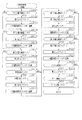
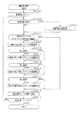
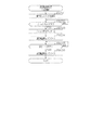
<主側CPU63の処理構成について>
次に、主側CPU63にて遊技を進行させるために実行される各処理を説明する。かかる主側CPU63の処理としては大別して、電源投入に伴い起動されるメイン処理と、定期的に(本実施の形態では4ミリ秒周期で)起動されるタイマ割込み処理とがある。
<About the processing configuration of the
Next, each process performed in order to advance a game in main side CPU63 is explained. The processes of the
<メイン処理>
まず、図9のフローチャートを参照しながらメイン処理を説明する。
<Main processing>
First, the main processing will be described with reference to the flowchart of FIG.
まず電源投入ウェイト処理を実行する(ステップS101)。当該電源投入ウェイト処理では、例えばメイン処理が起動されてからウェイト用の所定時間(具体的には1秒)が経過するまで次の処理に進行することなく待機する。かかる電源投入ウェイト処理の実行期間において図柄表示装置41の動作開始及び初期設定が完了することとなる。その後、主側RAM65のアクセスを許可する(ステップS102)。
First, power on wait processing is executed (step S101). In the power-on wait process, for example, the process waits until the predetermined time for wait (specifically, one second) elapses after the main process is started, without proceeding to the next process. The operation start and initialization of the
その後、設定キー挿入部68aがON操作されているか否かを判定する(ステップS103)。設定キー挿入部68aがON操作されていない場合(ステップS103:NO)、リセットボタン68cが押圧操作されているか否かを判定する(ステップS104)。リセットボタン68cが押圧操作されている場合(ステップS104:YES)、主側RAM65においてパチンコ機10の設定状態を示す設定値の情報が設定されたエリアを除いて、主側RAM65の各エリアを「0」クリアするとともにその「0」クリアしたエリアに対して初期設定を行う(ステップS105)。つまり、設定キー挿入部68aのON操作を伴わずにリセットボタン68cを押圧操作しながらパチンコ機10への動作電力の供給が開始された場合には設定値の情報についてはパチンコ機10への動作電力の供給が停止される前の状態に維持したまま主側RAM65のクリア処理が実行されるとともにそのクリア処理が実行された記憶エリアに対して初期設定が行われる。これにより、設定値の変更を要することなく主側RAM65の他のエリアを初期化させることが可能となる。なお、ステップS105では主側CPU63の各種レジスタも「0」クリアした後に初期設定を行う。
Thereafter, it is determined whether the setting
リセットボタン68cが押圧操作されていない場合(ステップS104:NO)、停電フラグに「1」がセットされているか否かを判定する(ステップS106)。停電フラグは主側RAM65に設けられており、主側CPU63への動作電力の供給が停止される場合において予め定められた停電時処理が正常に実行された場合には当該停電フラグに「1」がセットされることとなる。停電フラグに「1」がセットされている場合には、チェックサムの算出結果が電源遮断時に保存したチェックサムと一致するか否かすなわち記憶保持されたデータの有効性を判定する(ステップS107)。ステップS105の処理を実行した場合、又はステップS107にて肯定判定をした場合、主側RAM65を確認することでパチンコ機10の設定値が正常か否かを判定する(ステップS108)。具体的には、設定値が「設定1」〜「設定6」のいずれかである場合に正常であると判定し、「0」又は7以上である場合に異常であると判定する。
When the
ステップS106〜ステップS108のいずれかで否定判定をした場合には動作禁止処理を実行する。動作禁止処理では、ホール管理者等にエラーの発生を報知するためのエラー報知処理を実行した後に(ステップS109)、無限ループとなる。当該動作禁止処理は、後述する全部クリア処理(ステップS117)が実行されることにより解除される。 If a negative determination is made in any of steps S106 to S108, the operation inhibiting process is performed. In the operation prohibition process, after an error notification process for notifying a hole manager or the like of the occurrence of an error (step S109), an infinite loop is made. The operation prohibition process is canceled by executing the all clear process (step S117) described later.
ステップS106〜ステップS108の全てにおいて肯定判定をした場合には電源投入設定処理を実行する(ステップS110)。電源投入設定処理では、停電フラグの初期化といった主側RAM65の所定のエリアを初期値に設定するとともに、現状の遊技状態に対応したコマンドを音声発光制御装置81に送信する。また、ステップS110の処理を実行した後は、管理用IC66に各種情報を認識させるための認識用処理(ステップS111)、及びMPU62の読み取り用端子68dに接続された外部装置に各種データを出力するためのデータ出力用処理を実行する(ステップS112)。これら認識用処理及びデータ出力用処理の詳細については後に説明する。
If the determination in step S106 to step S108 is affirmative, the power on setting process is performed (step S110). In the power on setting process, a predetermined area of the
なお、主側CPU63はタイマ割込み処理を定期的に実行する構成であるが、メイン処理が開始された段階においてはタイマ割込み処理の発生が禁止されている。このタイマ割込み処理の発生が禁止された状態はステップS112の処理が完了してステップS113の処理が実行される前のタイミングで解除され、タイマ割込み処理の実行が許可される。これにより、主側CPU63への動作電力の供給が開始された場合にはステップS112のデータ出力用処理が終了して、ステップS113の処理が開始される前の段階までタイマ割込み処理は実行されない。よって、当該状況となるまでは主側CPU63にて遊技を進行させるための処理が開始されないこととなる。
Although the
その後、ステップS113〜ステップS116の残余処理に進む。つまり、主側CPU63はタイマ割込み処理を定期的に実行する構成であるが、1のタイマ割込み処理と次のタイマ割込み処理との間に残余時間が生じることとなる。この残余時間は各タイマ割込み処理の処理完了時間に応じて変動することとなるが、かかる不規則な時間を利用してステップS113〜ステップS116の残余処理を繰り返し実行する。この点、当該ステップS113〜ステップS116の残余処理は非定期的に実行される非定期処理であると言える。
Thereafter, the process proceeds to the remaining process of step S113 to step S116. That is, although the
残余処理では、まずステップS113にて、タイマ割込み処理の発生を禁止するために割込み禁止の設定を行う。続くステップS114では、乱数初期値カウンタCINIの更新を行う乱数初期値更新処理を実行するとともに、ステップS115にて変動種別カウンタCSの更新を行う変動用カウンタ更新処理を実行する。これらの更新処理では、主側RAM65の対応するカウンタから現状の数値情報を読み出し、その読み出した数値情報を1加算する処理を実行した後に、読み出し元のカウンタに上書きする処理を実行する。この場合、カウンタ値が最大値を超えた際にそれぞれ「0」にクリアする。その後、ステップS116にて、タイマ割込み処理の発生を禁止している状態から許可する状態へ切り換える割込み許可の設定を行う。ステップS116の処理を実行した場合、ステップS113に戻り、ステップS113〜ステップS116の処理を繰り返す。
In the remaining process, first, in step S113, in order to inhibit the generation of the timer interrupt process, the interrupt disable setting is performed. In the following step S114, random number initial value updating processing for updating the random number initial value counter CINI is executed, and in step S115, variation counter updating processing for updating the variation type counter CS is executed. In these update processes, the present numerical value information is read out from the corresponding counter of the
一方、設定キー挿入部68aがON操作されている場合(ステップS103:YES)、主側RAM65においてパチンコ機10の設定状態を示す設定値の情報が設定されたエリアも含めて、主側RAM65の全てのエリアを「0」クリアするとともにその「0」クリアしたエリアに対して初期設定を行う(ステップS117)。つまり、パチンコ機10の設定状態を変更するための操作が行われている場合にはリセットボタン68cが押圧操作されていなくても主側RAM65の全てのエリアが「0」クリアされるとともにそのクリア処理が実行された記憶エリアに対して初期設定が行われる。また、ステップS117では主側CPU63の各種レジスタも「0」クリアした後に初期設定を行う。なお、これに限定されることはなく、パチンコ機10の設定状態を変更するための操作が行われている場合であってもリセットボタン68cが押圧操作されていない場合には主側RAM65の全部クリア処理が実行されずに、パチンコ機10の設定状態を変更するための操作が行われているとともにリセットボタン68cが押圧操作されている場合に全部クリア処理が実行される構成としてもよい。
On the other hand, when the setting
その後、ステップS118にて設定値更新処理を実行し、ステップS119にて設定値更新信号の出力処理を実行した後に、ステップS110の処理に移行する。以下、設定値更新処理について説明する。なお、設定値更新信号の出力処理については後に詳細に説明する。図10は設定値更新処理を示すフローチャートである。 Thereafter, the setting value update process is performed in step S118, and the output process of the setting value update signal is performed in step S119, and then the process proceeds to step S110. Hereinafter, the setting value update process will be described. The process of outputting the set value update signal will be described in detail later. FIG. 10 is a flowchart showing setting value update processing.
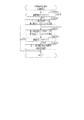
まず主側RAM65に設けられた設定値カウンタに「1」をセットする(ステップS201)。設定値カウンタはパチンコ機10の設定状態がいずれの設定値であるのかを主側CPU63にて特定するためのカウンタである。設定値カウンタに「1」がセットされることにより、設定値更新処理が実行される場合にはそれまでの設定値に関係なく設定値が「設定1」となる。
First, "1" is set in the set value counter provided in the main RAM 65 (step S201). The set value counter is a counter used by the
その後、設定値の表示開始処理を実行する(ステップS202)。設定値の表示開始処理では、「設定1」に対応する「1」の数字が表示されるように第3報知用表示装置69cを表示制御する。遊技ホールの管理者は設定値の変更に際しては第3報知用表示装置69cを確認することでパチンコ機10の現状の設定状態を把握することが可能となる。
Thereafter, display start processing of the setting value is executed (step S202). In the display start process of the setting value, the display control of the third
その後、設定キー挿入部68aがOFF操作されていないことを条件として(ステップS203:NO)、更新ボタン68bが1回押圧操作されたか否かを判定する(ステップS204)。具体的には更新ボタン68bの押圧操作を検知するセンサからの信号がLOWレベルからHIレベルに切り換わったか否かを判定する。ステップS204にて否定判定をした場合、ステップS203の処理に戻り、設定キー挿入部68aがOFF操作されているか否かを判定する。
Thereafter, under the condition that the setting
更新ボタン68bが1回押圧操作されている場合(ステップS204:YES)、主側RAM65の設定値カウンタの値を1加算する(ステップS205)。また、1加算後における設定値カウンタの値が「6」を超えた場合(ステップS206:YES)、設定値カウンタに「1」をセットする(ステップS207)。これにより、更新ボタン68bが1回押圧操作される度に1段階上の設定値に更新され、「設定6」の状況で更新ボタン68bが1回押圧操作された場合には「設定1」に戻ることになる。
If the
ステップS206にて否定判定をした場合、又はステップS207の処理を実行した場合、設定値の表示更新処理を実行する(ステップS208)。設定値の表示更新処理では、主側RAM65の設定値カウンタの値に対応する数字が表示されるように第3報知用表示装置69cを表示制御する。遊技ホールの管理者は第3報知用表示装置69cを確認することで更新ボタン68bを押圧操作した後のパチンコ機10の設定状態を把握することが可能となる。
If a negative determination is made in step S206, or if the process of step S207 is performed, display update processing of the setting value is performed (step S208). In the display value update process of the setting value, the display control of the third
ステップS208の処理を実行した後はステップS203に戻り、設定キー挿入部68aがOFF操作されているか否かを判定する。OFF操作されていない場合(ステップS203:NO)、ステップS204以降の処理を再度実行する。OFF操作されている場合(ステップS203:YES)、設定値の表示終了処理を実行する(ステップS209)。設定値の表示終了処理では、第3報知用表示装置69cにおける設定値の表示を終了させる。
After the process of step S208 is performed, the process returns to step S203, and it is determined whether the setting
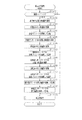
<タイマ割込み処理>
次に、図11のフローチャートを参照しながらタイマ割込み処理を説明する。タイマ割込み処理は定期的(例えば4ミリ秒周期)に実行される。
<Timer interrupt processing>
Next, timer interrupt processing will be described with reference to the flowchart of FIG. The timer interrupt processing is executed periodically (for example, in a 4 millisecond cycle).
まず停電情報記憶処理を実行する(ステップS301)。停電情報記憶処理では、停電監視基板67から電源遮断の発生に対応した停電信号を受信しているか否かを監視し、停電の発生を特定した場合には停電時処理を実行した後に無限ループとなる。停電時処理では、主側RAM65の停電フラグに「1」をセットするとともに、チェックサムを算出しその算出したチェックサムを保存する。
First, a power failure information storage process is executed (step S301). In the power failure information storage processing, it is monitored whether or not a power failure signal corresponding to the occurrence of the power interruption is received from the power
その後、抽選用乱数更新処理を実行する(ステップS302)。抽選用乱数更新処理では、当たり乱数カウンタC1、大当たり種別カウンタC2、リーチ乱数カウンタC3及び普電役物開放カウンタC4の更新を実行する。具体的には、当たり乱数カウンタC1、大当たり種別カウンタC2、リーチ乱数カウンタC3及び普電役物開放カウンタC4から現状の数値情報を順次読み出し、それら読み出した数値情報をそれぞれ1加算する処理を実行した後に、読み出し元のカウンタに上書きする処理を実行する。この場合、カウンタ値が最大値を超えた際にそれぞれ「0」にクリアする。その後、ステップS303ではステップS114と同様に乱数初期値更新処理を実行するとともに、ステップS304にてステップS115と同様に変動用カウンタ更新処理を実行する。 Thereafter, a lottery random number updating process is executed (step S302). In the random number updating process for drawing, the update of the per random number counter C1, the big hit type counter C2, the reach random number counter C3, and the general purpose battery release counter C4 is executed. Specifically, the present numerical value information was sequentially read out from the per random number counter C1, the big hit type counter C2, the reach random number counter C3 and the general electric utility release counter C4, and the process of adding one each of the read numerical information was executed. Later, the process of overwriting the read source counter is executed. In this case, when the counter value exceeds the maximum value, they are cleared to "0". Thereafter, in step S303, the random number initial value updating process is performed as in step S114, and in step S304, the variation counter updating process is performed as in step S115.
その後、不正用の監視対象として設定されている所定の事象が発生しているか否かを監視する不正検知処理を実行する(ステップS305)。当該不正検知処理では、複数種類の事象の発生を監視し、所定の事象が発生していることを確認することで、主側RAM65に設けられた遊技停止フラグに「1」をセットする。続くステップS306では、上記遊技停止フラグに「1」がセットされているか否かを判定することで、遊技の進行を停止している状態であるか否かを判定する。ステップS306にて否定判定をした場合に、ステップS307以降の処理を実行する。
Thereafter, the fraud detection process is executed to monitor whether or not a predetermined event set as a fraud monitoring target has occurred (step S305). In the fraud detection process, occurrence of multiple types of events is monitored, and it is confirmed that a predetermined event has occurred, thereby setting “1” to the game stop flag provided in the
ステップS307では、ポート出力処理を実行する。ポート出力処理では、前回のタイマ割込み処理において出力情報の設定が行われている場合に、その出力情報に対応した出力を各種駆動部32b,34bに行うための処理を実行する。例えば、特電入賞装置32を開放状態に切り換えるべき情報が設定されている場合には特電用の駆動部32bへの駆動信号の出力を開始させ、閉鎖状態に切り換えるべき情報が設定されている場合には当該駆動信号の出力を停止させる。また、第2作動口34の普電役物34aを開放状態に切り換えるべき情報が設定されている場合には普電用の駆動部34bへの駆動信号の出力を開始させ、閉鎖状態に切り換えるべき情報が設定されている場合には当該駆動信号の出力を停止させる。
In step S307, port output processing is performed. In the port output process, when setting of output information is performed in the previous timer interrupt process, a process for performing an output corresponding to the output information to the various drive units 32 b and 34 b is executed. For example, when the information to switch the special
その後、読み込み処理を実行する(ステップS308)。読み込み処理では、停電信号及び入賞信号以外の信号の読み込みを実行し、その読み込んだ情報を今後の処理にて利用するために記憶する。 Thereafter, the reading process is executed (step S308). In the reading process, reading of signals other than the power failure signal and the winning signal is executed, and the read information is stored for use in future processing.
その後、入球検知処理を実行する(ステップS309)。当該入球検知処理では、各入球検知センサ42a〜49aから受信している信号を読み込み、その読み込み結果に基づいて、アウト口24a、一般入賞口31、特電入賞装置32、第1作動口33、第2作動口34及びスルーゲート35への入球の有無を特定する。なお、入球検知処理の詳細については後に説明する。
Thereafter, the ball entering detection process is executed (step S309). In the ball entry detection process, the signals received from the respective ball
その後、主側RAM65に設けられている複数種類のタイマカウンタの数値情報をまとめて更新するためのタイマ更新処理を実行する(ステップS310)。この場合、記憶されている数値情報が減算されて更新されるタイマカウンタを集約して扱う構成であるが、減算式のタイマカウンタの更新及び加算式のタイマカウンタの更新の両方を集約して行う構成としてもよい。
Thereafter, a timer update process for collectively updating numerical information of a plurality of types of timer counters provided in the
その後、遊技球の発射制御を行うための発射制御処理を実行する(ステップS311)。発射操作装置28への発射操作が継続されている状況では、所定の発射周期である0.6秒に1個の遊技球が発射される。続くステップS312では、入力状態監視処理として、ステップS308の読み込み処理にて読み込んだ情報に基づいて、各入球検知センサ42a〜49aの断線確認や、遊技機本体12や前扉枠14の開放確認を行う。
Thereafter, launch control processing for performing launch control of the game balls is executed (step S311). In the situation where the firing operation to the
その後、遊技回の実行制御及び開閉実行モードの実行制御を行うための特図特電制御処理を実行する(ステップS313)。特図特電制御処理については後に詳細に説明する。 Thereafter, special figure special power control processing for executing execution control of the game run and execution control of the open / close execution mode is executed (step S313). The special figure special power control process will be described in detail later.
その後、普図普電制御処理を実行する(ステップS314)。普図普電制御処理では、スルーゲート35への入賞が発生している場合に普図側の保留情報を取得するための処理を実行するとともに、普図側の保留情報が記憶されている場合にその保留情報について開放判定を行い、さらにその開放判定を契機として普図用の演出を行うための処理を実行する。また、開放判定の結果に基づいて、第2作動口34の普電役物34aを開閉させる処理を実行する。この場合、サポートモードが低頻度サポートモードであればそれに対応する処理が実行され、サポートモードが高頻度サポートモードであればそれに対応する処理が実行される。また、開閉実行モードである場合にはその直前のサポートモードが高頻度サポートモードであったとしても低頻度サポートモードとなる。
After that, the common drawing common control control process is executed (step S314). When the winning gate on the through
続くステップS315では、直前のステップS313及びステップS314の処理結果に基づいて、特図表示部37aに係る保留情報の増減個数を特図保留表示部37bに反映させるための出力情報の設定を行うとともに、普図表示部38aに係る保留情報の増減個数を普図保留表示部38bに反映させるための出力情報の設定を行う。また、ステップS315では、直前のステップS313及びステップS314の処理結果に基づいて、特図表示部37aの表示内容を更新させるための出力情報の設定を行うとともに、普図表示部38aの表示内容を更新させるための出力情報の設定を行う。
In the following step S315, based on the processing results of the immediately preceding step S313 and step S314, setting of output information for reflecting the increase / decrease number of the hold information concerning the special view display unit 37a on the special view
その後、払出制御装置77から受信したコマンド及び信号の内容を確認し、その確認結果に対応した処理を行うための払出状態受信処理を実行する(ステップS316)。また、賞球コマンドを出力対象として設定するための払出出力処理を実行する(ステップS317)。また、今回のタイマ割込み処理にて実行された各種処理の処理結果に応じた外部信号の出力の開始及び終了を制御するための外部情報設定処理を実行する(ステップS318)。その後、遊技領域PAにおける遊技球の入球結果に対応する情報を管理用IC66に出力するための管理用出力処理を実行する(ステップS319)。管理用出力処理の詳細については後に説明する。
Thereafter, the contents of the command and signal received from the
次に、ステップS313の特図特電制御処理について、図12のフローチャートを参照しながら説明する。 Next, the special view special power control process of step S313 will be described with reference to the flowchart of FIG.
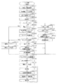
まず保留情報の取得処理を実行する(ステップS401)。保留情報の取得処理では、第1作動口33又は第2作動口34への入賞が発生しているか否かを判定し、入賞が発生している場合には保留格納エリア65aにおける保留数が上限値(本実施の形態では「4」)未満であるか否かを判定する。保留数が上限値未満である場合には、保留数を1加算するとともに、前回のステップS302にて更新した当たり乱数カウンタC1、大当たり種別カウンタC2及びリーチ乱数カウンタC3の各数値情報を、保留用エリアREの空き保留エリアRE1〜RE4のうち最初の保留エリアに格納する。なお、第1作動口33及び第2作動口34への入賞が同時に発生している場合には、保留情報の取得処理を1回実行する範囲内において、上記保留情報を取得するための処理を複数回実行する。また、保留情報の新たな取得が行われた場合にはそれに対応する取得時コマンドを音声発光制御装置81に送信する。音声発光制御装置81は当該コマンドを受信した場合、図柄表示装置41における保留情報の個数を示す画像の表示を保留情報の増加に対応する表示内容に更新させる。
First, acquisition processing of suspension information is executed (step S401). In the process of acquiring the hold information, it is determined whether or not a winning has occurred in the first operation opening 33 or the second operation opening 34, and when the winning is occurring, the number of holdings in the holding storage area 65a is an upper limit It is determined whether it is less than a value ("4" in the present embodiment). If the number of reservations is less than the upper limit, the number of reservations is incremented by 1 and each numerical information of the per-random number counter C1, the jackpot type counter C2 and the reach random number counter C3 updated in the previous step S302 is for suspension It stores in the first reserve area among the reserve areas RE1 to RE4 of the area RE. In the case where winnings to the
その後、主側RAM65に設けられた特図特電カウンタの情報を読み出すとともに(ステップS402)、主側ROM64に設けられた特図特電アドレステーブルを読み出す(ステップS403)。そして、特図特電アドレステーブルから特図特電カウンタの情報に対応した開始アドレスを取得し(ステップS404)、ステップS406〜ステップS412の処理のうちその取得した開始アドレスが示す処理にジャンプする(ステップS405)。特図特電カウンタは、ステップS406〜ステップS412の各種処理のうちいずれを実行すべきであるかを主側CPU63にて把握するためのカウンタであり、特図特電アドレステーブルは、特図特電カウンタの数値情報に対応させて、ステップS406〜ステップS412の処理を実行するためのプログラムの開始アドレスが設定されている。
Thereafter, the information of the special drawing special charge counter provided in the
ステップS406では特図変動開始処理を実行する。図13は特図変動開始処理を示すフローチャートである。 In step S406, special figure fluctuation start processing is executed. FIG. 13 is a flowchart showing the special figure change start process.
特図変動開始処理では保留用エリアREに格納されている保留情報の個数が1以上であることを条件として(ステップS501:YES)、データ設定処理を実行する(ステップS502)。データ設定処理では、まず保留数を1減算するとともに、保留用エリアREの第1保留エリアRE1に格納されたデータを実行エリアAEに移動する。その後、保留用エリアREの各保留エリアRE1〜RE4に格納されたデータをシフトさせる処理を実行する。このデータシフト処理は、第1保留エリアRE1〜第4保留エリアRE4に格納されているデータを下位エリア側に順にシフトさせる処理であり、詳細には、第2保留エリアRE2→第1保留エリアRE1、第3保留エリアRE3→第2保留エリアRE2、第4保留エリアRE4→第3保留エリアRE3といった具合に各エリア内のデータをシフトさせた後に第4保留エリアRE4を「0」クリアする。この際、保留エリアのデータのシフトが行われたことを認識させるためのシフト時コマンドを音声発光制御装置81に送信する。音声発光制御装置81は当該コマンドを受信した場合、図柄表示装置41における保留情報の個数を示す画像の表示を保留情報の減少に対応する表示内容に更新させる。
In the special view fluctuation start process, the data setting process is executed (step S502) on condition that the number of the hold information stored in the hold area RE is one or more (step S501: YES). In the data setting process, the number of reservations is first decremented by 1, and the data stored in the first reservation area RE1 of the reservation area RE is moved to the execution area AE. Thereafter, a process of shifting data stored in the respective reserve areas RE1 to RE4 of the reserve area RE is executed. This data shift process is a process of sequentially shifting data stored in the first reserve area RE1 to the fourth reserve area RE4 to the lower area side, and more specifically, the second reserve area RE2 → the first reserve area RE1. The data in each area is shifted in such a way as to the third reserve area RE3 → the second reserve area RE2 and the fourth reserve area RE4 → the third reserve area RE3 and the fourth reserve area RE4 is cleared to “0”. At this time, a shift command for making it possible to recognize that the data of the reserved area has been shifted is transmitted to the sound
データ設定処理を実行した後は当否テーブルを主側ROM64から読み出す(ステップS503)。具体的には、まず主側RAM65の当否抽選モードを示す情報を読み出すことにより現状の当否抽選モードを把握する。高確率モードである場合には主側ROM64から高確当否テーブル64gを読み出す。一方、低確率モードである場合には主側RAM65の設定値カウンタの値を読み出すことによりパチンコ機10の設定状態を把握する。そして、その把握した設定値に対応する低確当否テーブル64a〜64fを主側ROM64から読み出す。
After the data setting process is executed, the success / failure table is read out from the main ROM 64 (step S503). Specifically, first, information on the
その後、ステップS503にて読み出した当否テーブル64a〜64gを参照して当否判定処理を実行する(ステップS504)。当否判定処理では、実行エリアAEに格納された情報のうち当否判定用の情報、すなわち当たり乱数カウンタC1に係る数値情報が、ステップS503にて読み出した当否テーブル64a〜64gに設定された大当たり数値情報と一致しているか否かを判定する。 Thereafter, the success or failure determination process is executed with reference to the success or failure tables 64a to 64g read out in step S503 (step S504). In the success / failure determination process, among the information stored in the execution area AE, information for determination of success or failure, that is, numerical information related to the per random number counter C1, is the jackpot numerical information set in the success or failure tables 64a to 64g read in step S503. It is determined whether or not it matches.
当否判定処理の結果が大当たり当選結果である場合には(ステップS505:YES)、振分判定処理を実行する(ステップS506)。振分判定処理では、実行エリアAEに格納された情報のうち振分判定用の情報、すなわち大当たり種別カウンタC2に係る数値情報を読み出す。そして、主側ROM64に設けられた振分テーブル64hを参照して、上記読み出した大当たり種別カウンタC2に係る数値情報がいずれの大当たり結果に対応しているのかを特定する。具体的には、低確大当たり結果、低入賞高確大当たり結果及び最有利大当たり結果のうちいずれの大当たり結果に対応しているのかを特定する。
If the result of the propriety determination processing is a big hit winning result (step S505: YES), the distribution determination processing is executed (step S506). In the distribution determination process, information for distribution determination among the information stored in the execution area AE, that is, numerical information on the jackpot type counter C2 is read. Then, with reference to the distribution table 64h provided in the
その後、大当たり結果用の停止結果設定処理を実行する(ステップS507)。具体的には、今回の変動開始に係る遊技回において特図表示部37aに最終的に停止表示させる絵柄の態様の情報を、主側ROM64に予め記憶されている大当たり結果用の停止結果テーブルから特定し、その特定した情報を主側RAM65に書き込む。この大当たり結果用の停止結果テーブルには、特図表示部37aに停止表示される絵柄の態様の情報が、大当たり結果の種類毎に相違させて設定されている。
Thereafter, a stop result setting process for the jackpot result is executed (step S507). Specifically, from the stop result table for the jackpot result stored in advance in the
その後、振分判定結果に対応したフラグセット処理を実行する(ステップS508)。具体的には、主側RAM65には各大当たり結果の種類に対応したフラグが設けられており、ステップS508では、それら各大当たり結果の種類に対応したフラグのうち、ステップS506の振分判定処理の結果に対応したフラグに「1」をセットする。
Thereafter, a flag setting process corresponding to the distribution determination result is executed (step S508). Specifically, the
一方、ステップS505にて大当たり当選結果ではないと判定した場合には、外れ結果用の停止結果設定処理を実行する(ステップS509)。具体的には、今回の変動開始に係る遊技回において特図表示部37aに最終的に停止表示させる絵柄の態様の情報を、主側ROM64に予め記憶されている外れ結果用の停止結果テーブルから特定し、その特定した情報を主側RAM65に書き込む。この場合に選択される絵柄の態様の情報は、大当たり結果の場合に選択される絵柄の態様の情報とは異なっている。
On the other hand, when it is determined in step S505 that the jackpot is not the winning result, the stop result setting process for the outlier is executed (step S509). Specifically, information on the pattern aspect to be finally displayed on the special view display unit 37a in the game round relating to the start of the change from the stop result table for deviation result stored in advance in the
ステップS508及びステップS509のいずれかの処理を実行した後は、遊技回の継続期間の把握処理を実行する(ステップS510)。かかる処理では、変動種別カウンタCSの数値情報を取得する。また、今回の遊技回において図柄表示装置41にてリーチ表示が発生するか否かを判定する。具体的には、今回の変動開始に係る遊技回が低確大当たり結果又は最有利大当たり結果である場合には、リーチ表示が発生すると判定する。また、いずれの大当たり結果でもなく、さらに実行エリアAEに格納されているリーチ乱数カウンタC3に係る数値情報がリーチ発生に対応した数値情報である場合には、リーチ表示が発生すると判定する。
After one of the processes in step S508 and step S509 is executed, a process of grasping the duration of the game is executed (step S510). In this process, numerical information of the fluctuation type counter CS is acquired. In addition, it is determined whether reach display is generated by the
リーチ表示が発生すると判定した場合には、主側ROM64に記憶されているリーチ発生用継続期間テーブルを参照して、今回の変動種別カウンタCSの数値情報に対応した遊技回の継続期間を取得する。一方、リーチ表示が発生しないと判定した場合には、主側ROM64に記憶されているリーチ非発生用継続期間テーブルを参照して、今回の変動種別カウンタCSの数値情報に対応した遊技回の継続期間を取得する。ちなみに、リーチ非発生用継続期間テーブルを参照して取得され得る遊技回の継続期間は、リーチ発生用継続期間テーブルを参照して取得され得る遊技回の継続期間と異なっている。
If it is determined that the reach display occurs, the duration period of the game corresponding to the numerical information of the variation type counter CS of this time is acquired with reference to the reach generation continuation period table stored in the
なお、リーチ非発生時における遊技回の継続期間は、保留用エリアREに格納されている保留情報の数が多いほど遊技回の継続期間が短くなるように設定されている。また、サポートモードが高頻度サポートモードである状況においては低頻度サポートモードである状況よりも、保留情報の数が同一である場合で比較して、短い遊技回の継続期間が選択されるようにリーチ非発生用継続期間テーブルが設定されている。但し、これに限定されることはなく、保留情報の数やサポートモードに応じて遊技回の継続期間が変動しない構成としてもよく、上記の関係とは逆であってもよい。さらには、リーチ発生時における遊技回の継続期間に対して、上記構成を適用してもよい。また、各種大当たり結果の場合、外れリーチ時の場合及びリーチ非発生の外れ結果の場合のそれぞれに対して個別に継続期間テーブルが設定されていてもよい。この場合、各遊技結果に応じた遊技回の継続期間の振分が行われることとなる。 In addition, the continuation period of the game times at the time of reach non-occurrence | occurrence | production is set so that the continuation period of game times becomes short, so that there are many numbers of pending | holding information stored in area RE for suspension. Also, in the situation where the support mode is the high frequency support mode, the duration of the short game times is selected as compared with the situation where the number of holding information is the same as the situation where the support mode is the low frequency support mode. A reach non-occurrence duration table is set. However, the present invention is not limited to this, and the duration of the game times may not change depending on the number of holding information and the support mode, or may be opposite to the above relationship. Furthermore, the above configuration may be applied to the duration of the game play at the time of reach occurrence. Further, in the case of various jackpot results, a duration table may be individually set for each of the case of outreach and the case of outreach in which no reach occurs. In this case, distribution of the continuation period of the game times according to each game result will be performed.
その後、ステップS510にて取得した遊技回の継続期間の情報を、主側RAM65に設けられた特図特電タイマカウンタにセットする(ステップS511)。特図特電タイマカウンタにセットされた数値情報の更新は、タイマ更新処理(ステップS310)にて実行される。ちなみに、遊技回用の演出として、特図表示部37aにおける絵柄の変動表示と図柄表示装置41における図柄の変動表示とが行われるが、これらの各変動表示が終了される場合にはその遊技回の停止結果が表示された状態(図柄表示装置41では有効ライン上に所定の図柄の組合せが待機された状態)で最終停止期間(例えば0.5秒)に亘って最終停止表示される。この場合に、ステップS510にて取得される遊技回の継続期間は1遊技回分のトータル時間となっている。
Thereafter, the information on the continuation period of the game times acquired in step S510 is set in the special-image special-charge timer counter provided in the main RAM 65 (step S511). The updating of the numerical information set in the special drawing special power timer counter is executed in the timer updating process (step S310). By the way, although the variation display of the pattern in the special figure display unit 37a and the variation display of the symbol in the
その後、変動用コマンド及び種別コマンドを音声発光制御装置81に送信する(ステップS512)。変動用コマンドには、遊技回の継続期間の情報が含まれる。ここで、上記のとおりリーチ非発生用継続期間テーブルを参照して取得される遊技回の継続期間は、リーチ発生用継続期間テーブルを参照して取得される遊技回の継続期間と異なっているため、変動用コマンドにリーチ発生の有無の情報が含まれていなかったとしても、音声発光制御装置81では遊技回の継続期間の情報からリーチ発生の有無を特定することは可能である。この点、変動用コマンドには、リーチ発生の有無を示す情報が含まれているとも言える。なお、変動用コマンドにリーチ発生の有無を直接示す情報が含まれていてもよい。また、種別コマンドには、遊技結果の情報が含まれる。
Thereafter, the variation command and the type command are transmitted to the sound emission control apparatus 81 (step S512). The variable command includes information on the duration of the game play. Here, the duration of the game times obtained by referring to the reach non-occurrence duration table as described above is different from the duration of the game times obtained with reference to the reach occurrence duration table. Even if the command for variation does not include information on the presence or absence of reach, the voice
音声発光制御装置81は変動用コマンド及び種別コマンドを主側CPU63から受信した場合、表示発光部53、スピーカ部54及び図柄表示装置41において遊技回用の演出が実行されるようにする。この場合、当該遊技回用の演出は変動用コマンド及び種別コマンドの内容に対応する態様で行われる。また、図柄表示装置41では遊技回用の演出として図柄の変動表示が行われ、当該遊技回用の演出が終了する場合には当否判定処理及び振分判定処理の結果に対応する図柄の組み合わせが停止表示される。
When the voice light
その後、特図表示部37aにおける絵柄の変動表示を開始させる(ステップS513)。そして、特図特電カウンタを1加算する(ステップS514)。この場合、特図変動開始処理が実行される場合における特図特電カウンタの数値情報は「0」であるため特図特電カウンタの数値情報は「1」となる。その後、主側RAM65に設けられた第11出力フラグに「1」をセットする(ステップS515)。第11出力フラグは、遊技回が開始されたことを示す情報出力を管理用IC66に対して実行すべきことを主側CPU63にて特定するためのフラグである。
Thereafter, the variation display of the pattern on the special view display unit 37a is started (step S513). Then, the special drawing special charge counter is incremented by 1 (step S514). In this case, since the numerical information of the special view special charge counter is “0” when the special view change start process is executed, the numerical information of the special view special charge counter is “1”. After that, “1” is set to the eleventh output flag provided in the main RAM 65 (step S515). The eleventh output flag is a flag for specifying that the
特図特電制御処理(図52)の説明に戻り、ステップS407では特図変動中処理を実行する。特図変動中処理では、遊技回の継続時間中であって最終停止表示前のタイミングであるか否かを判定し、最終停止表示前であれば特図表示部37aにおける絵柄の表示態様を規則的に変化させるための処理を実行する。最終停止表示させるタイミングとなった場合には、特図特電カウンタの数値情報を1加算することで、当該カウンタの数値情報を特図変動中処理に対応したものから特図確定中処理に対応したものに更新する。なお、本実施形態においては主側CPU63から音声発光制御装置81に最終停止コマンドは送信されない。
Returning to the description of the special figure special power control process (FIG. 52), in step S407, the special figure changing process is executed. In the special figure changing process, it is determined whether it is the continuation time of the game times and the timing before the final stop display, and if it is before the final stop display, the display mode of the pattern in the special view display unit 37a is ruled Execute the process to make a change. When it is time to display the final stop, the numerical information of the special figure special power counter is added by 1, and the numerical information of the counter is processed from the special figure during fluctuation processing to the special figure determination fixed processing Update to things. In the present embodiment, the final stop command is not transmitted from the
ステップS408では特図確定中処理を実行する。特図確定中処理では、特図表示部37aにおける絵柄の表示態様を今回の遊技回の抽選結果に対応した表示態様とする。また、特図確定中処理では、最終停止期間が経過したか否かを判定し、当該期間が経過している場合には開閉実行モードへの移行が発生するか否かの判定を行う。開閉実行モードへの移行が発生しない場合には特図特電カウンタの数値情報を「0」クリアする。開閉実行モードへの移行が発生する場合には特図特電カウンタの数値情報を1加算することで、当該カウンタの数値情報を特図確定中処理に対応したものから特電開始処理に対応したものに更新する。 In step S408, the process is executed during special image determination. In the special figure determination process, the display mode of the pattern in the special view display unit 37a is set to a display mode corresponding to the lottery result of the current game round. Further, in the processing during special-figure determination, it is determined whether or not the final stop period has elapsed, and if the period has elapsed, it is determined whether or not transition to the open / close execution mode occurs. If transition to the open / close execution mode does not occur, the numeric information of the special figure special power counter is cleared to “0”. When transition to the open / close execution mode occurs, the numerical information of the special electric power special counter is incremented by 1, so that the numerical information of the counter is processed while the special electric power is determined. Update.
ステップS409では特電開始処理を実行する。特電開始処理では今回の開閉実行モードにおけるオープニング期間を開始させるための処理を未だ実行していない場合、オープニング期間のセット処理を実行する。また、オープニングコマンドを音声発光制御装置81に送信する。音声発光制御装置81はオープニングコマンドを受信することにより、表示発光部53、スピーカ部54及び図柄表示装置41にてオープニング演出が実行されるようにする。オープニング期間が経過している場合、最初のラウンド遊技を開始させるための開始用処理を実行する。当該開始用処理では、特電入賞装置32を開放状態とするとともにラウンド遊技の終了条件を設定する。この終了条件の設定に際しては、今回の最初のラウンド遊技において特電入賞装置32を開放状態に継続させる場合の上限継続時間をセットするとともに、今回の最初のラウンド遊技において特電入賞装置32に入賞可能な遊技球の上限個数を主側RAM65に設けられた入賞個数カウンタにセットする。
In step S409, a special power start process is performed. In the special power start process, when the process for starting the opening period in the current switching execution mode is not performed yet, the setting process of the opening period is performed. Also, the opening command is transmitted to the sound
ステップS410では特電開放中処理を実行する。特電開放中処理ではラウンド遊技の終了条件が成立したか否かを判定する。終了条件が成立している場合には特電入賞装置32を閉鎖状態とする。そして、今回終了したラウンド遊技が最後の実行回のラウンド遊技でなければ特図特電カウンタの数値情報を1加算することで当該カウンタの数値情報を特電開放中処理に対応したものから特電閉鎖中処理に対応したものに更新し、今回終了したラウンド遊技が最後の実行回のラウンド遊技であれば特図特電カウンタの数値情報を2加算することで当該カウンタの数値情報を特電開放中処理に対応したものから特電終了処理に対応したものに更新する。
In step S410, the special power release open process is executed. In the processing during the special power release, it is determined whether the ending condition of the round game is satisfied. If the termination condition is satisfied, the special
ステップS411では特電閉鎖中処理を実行する。特電閉鎖中処理では、ラウンド遊技間のインターバル期間が経過したか否かを判定する。インターバル期間は前回のラウンド遊技が終了する場合に設定される。インターバル期間が経過した場合には、特電入賞装置32を開放状態とするとともにラウンド遊技の終了条件を設定する。そして、特図特電カウンタの数値情報を1減算することで、当該カウンタの数値情報を特電閉鎖中処理に対応したものから特電開放中処理に対応したものに更新する。
In step S411, the processing during special power close is executed. In the special power closed process, it is determined whether or not an interval period between round games has elapsed. The interval period is set when the previous round game ends. When the interval period has elapsed, the special
ステップS412では特電終了処理を実行する。特電終了処理では、今回の開閉実行モードにおけるエンディング期間を開始させるための処理を未だ実行していない場合、エンディング期間(例えば5秒)をセットするとともに、エンディングコマンドを音声発光制御装置81に送信する。音声発光制御装置81はエンディングコマンドを受信することにより、表示発光部53、スピーカ部54及び図柄表示装置41にてエンディング演出が実行されるようにする。エンディング期間が経過した場合には、開閉実行モードの終了後における当否抽選モード及びサポートモードのそれぞれを、今回の開閉実行モードの開始契機となった大当たり結果に対応するモードに設定する。
In step S412, a special power termination process is performed. In the special power termination process, when the process for starting the ending period in the current opening / closing execution mode is not yet executed, the ending period (for example, 5 seconds) is set and the ending command is transmitted to the voice
次に、主側CPU63にて、各入球検知センサ42a〜49aの検知結果に基づき、アウト口24a、一般入賞口31、特電入賞装置32、第1作動口33、第2作動口34及びスルーゲート35への遊技球の入球の有無を特定するための構成について説明する。図14は主側CPU63に入球検知センサ42a〜49aの検知結果が入力されるようにする構成を説明するための説明図である。
Next, based on the detection result of each
主側CPU63には入力ポート63aが設けられている。入力ポート63aは、8種類の信号を同時に扱うことができるように8ビットのパラレルインターフェースとして構成されている。そして、各信号の電圧に応じて「0」又は「1」の情報が格納されるエリアが、各端子に1対1で対応させて設けられている。つまり、当該エリアとして、第0ビットD0〜第7ビットD7を備えている。また、入力ポート63aには8種類を超える信号が入力されることとなるが、同時に入力される対象を8種類に制限するために、入力ポート63aへの入力対象となる信号群はドライバICによる切換制御を通じて切り換えられる。
The
タイマ割込み処理(図11)の入球検知処理(ステップS309)では、入力ポート63aへの入力対象となる信号群が各入球検知センサ42a〜49aからの信号群に設定される。かかる設定がなされた状況では、第0ビットD0は第1入賞口検知センサ42aからの検知信号に対応した情報が格納され、第1ビットD1は第2入賞口検知センサ43aからの検知信号に対応した情報が格納され、第2ビットD2は第3入賞口検知センサ44aからの検知信号に対応した情報が格納され、第3ビットD3は特電検知センサ45aからの検知信号に対応した情報が格納され、第4ビットD4は第1作動口検知センサ46aからの検知信号に対応した情報が格納され、第5ビットD5は第2作動口検知センサ47aからの検知信号に対応した情報が格納され、第6ビットD6はアウト口検知センサ48aからの検知信号に対応した情報が格納され、第7ビットD7はゲート検知センサ49aからの検知信号に対応した情報が格納される。
In the ball entering detection process (step S309) of the timer interrupt process (FIG. 11), a signal group to be input to the input port 63a is set as a signal group from each ball entering
上記各入球検知センサ42a〜49aは、遊技球の通過を検知していない場合には検知信号として非検知中であることを示すLOWレベル信号を出力し、遊技球の通過を検知している場合には検知信号として検知中であることを示すHIレベル信号を出力する。そして、入力ポート63aではLOWレベル信号を受信している場合に該当するビットに対して「0」の情報を格納し、HIレベル信号を受信している場合に該当するビットに対して「1」の情報を格納する。つまり、入球検知センサ42a〜49aにおいて遊技球の通過が検知されていない状況では該当するビットに対して非検知中を示す情報に対応した「0」の情報が格納され、遊技球の通過が検知されている状況では該当するビットに対して検知中を示す情報に対応した「1」の情報が格納される。
Each of the above-mentioned ball
図15はタイマ割込み処理(図11)のステップS309にて実行される入球検知処理を示すフローチャートである。 FIG. 15 is a flow chart showing the ball entering detection process executed in step S309 of the timer interrupt process (FIG. 11).
第0ビットD0に「0」の情報が格納されている状況から「1」の情報が格納されている状況に切り換わったことを確認した場合、第1入賞口検知センサ42aにて1個の遊技球が検知されたと判定する(ステップS601:YES)。この場合、主側RAM65に設けられた第1出力フラグに「1」をセットするとともに(ステップS602)、主側RAM65に設けられた10個賞球用カウンタの値を1加算する(ステップS603)。第1出力フラグは、第1入賞口検知センサ42aにて1個の遊技球が検知されたことを示す情報出力を管理用IC66に対して実行すべきことを主側CPU63にて特定するためのフラグである。10個賞球用カウンタは、10個の遊技球の払い出しを実行すべき回数を主側CPU63にて特定するためのカウンタである。10個賞球用カウンタの値が1以上である場合、タイマ割込み処理(図11)におけるステップS317の払出出力処理にて10個賞球コマンドを払出制御装置77に出力するとともに、10個賞球コマンドを1回出力した場合には10個賞球用カウンタの値を1減算する。払出制御装置77は10個賞球コマンドを受信した場合、10個の遊技球が払い出されるように払出装置76を駆動制御する。
When it is confirmed that the information has been switched to the state in which the information of "1" is stored from the state in which the information of "0" is stored in the 0th bit D0, one first winning
第1ビットD1に「0」の情報が格納されている状況から「1」の情報が格納されている状況に切り換わったことを確認した場合、第2入賞口検知センサ43aにて1個の遊技球が検知されたと判定する(ステップS604:YES)。この場合、主側RAM65に設けられた第2出力フラグに「1」をセットするとともに(ステップS605)、主側RAM65に設けられた10個賞球用カウンタの値を1加算する(ステップS606)。第2出力フラグは、第2入賞口検知センサ43aにて1個の遊技球が検知されたことを示す情報出力を管理用IC66に対して実行すべきことを主側CPU63にて特定するためのフラグである。
When it is confirmed that the information has been switched to the state in which the information of "1" is stored from the state in which the information of "0" is stored in the first bit D1, one second winning
第2ビットD2に「0」の情報が格納されている状況から「1」の情報が格納されている状況に切り換わったことを確認した場合、第3入賞口検知センサ44aにて1個の遊技球が検知されたと判定する(ステップS607:YES)。この場合、主側RAM65に設けられた第3出力フラグに「1」をセットするとともに(ステップS608)、主側RAM65に設けられた10個賞球用カウンタの値を1加算する(ステップS609)。第3出力フラグは、第3入賞口検知センサ44aにて1個の遊技球が検知されたことを示す情報出力を管理用IC66に対して実行すべきことを主側CPU63にて特定するためのフラグである。
When it is confirmed that the information has been switched to the state in which the information of "1" is stored from the state in which the information of "0" is stored in the second bit D2, one third winning
第3ビットD3に「0」の情報が格納されている状況から「1」の情報が格納されている状況に切り換わったことを確認した場合、特電検知センサ45aにて1個の遊技球が検知されたと判定する(ステップS610:YES)。この場合、主側RAM65に設けられた特電入賞フラグに「1」をセットするとともに(ステップS611)、主側RAM65に設けられた第4出力フラグに「1」をセットし(ステップS612)、さらに主側RAM65に設けられた15個賞球用カウンタの値を1加算する(ステップS613)。特電入賞フラグは開閉実行モードのラウンド遊技において特電入賞装置32に1個の遊技球が入球したことを主側CPU63にて特定するためのフラグである。タイマ割込み処理(図11)の特図特電制御処理(ステップS313)では特電入賞フラグに「1」がセットされていることを確認することで、特電入賞装置32への1個の遊技球の入球が発生したことを特定し、ラウンド遊技における特電入賞装置32への残りの入球可能個数を1減算する。かかる入球可能個数を1減算する処理を実行した場合に特電入賞フラグを「0」クリアする。第4出力フラグは、特電検知センサ45aにて1個の遊技球が検知されたことを示す情報出力を管理用IC66に対して実行すべきことを主側CPU63にて特定するためのフラグである。15個賞球用カウンタは、15個の遊技球の払い出しを実行すべき回数を主側CPU63にて特定するためのカウンタである。15個賞球用カウンタの値が1以上である場合、タイマ割込み処理(図11)におけるステップS317の払出出力処理にて15個賞球コマンドを払出制御装置77に出力するとともに、15個賞球コマンドを1回出力した場合には15個賞球用カウンタの値を1減算する。払出制御装置77は15個賞球コマンドを受信した場合、15個の遊技球が払い出されるように払出装置76を駆動制御する。
When it is confirmed that the information has been switched to the state in which the information of "1" is stored from the state in which the information of "0" is stored in the third bit D3, one game ball is detected by the electric
第4ビットD4に「0」の情報が格納されている状況から「1」の情報が格納されている状況に切り換わったことを確認した場合、第1作動口検知センサ46aにて1個の遊技球が検知されたと判定する(ステップS614:YES)。この場合、主側RAM65に設けられた第1作動入賞フラグに「1」をセットするとともに(ステップS615)、主側RAM65に設けられた第5出力フラグに「1」をセットし(ステップS616)、さらに主側RAM65に設けられた1個賞球用カウンタの値を1加算する(ステップS617)。第1作動入賞フラグは第1作動口33に1個の遊技球が入球したことを主側CPU63にて特定するためのフラグである。タイマ割込み処理(図11)の特図特電制御処理(ステップS313)では第1作動入賞フラグに「1」がセットされていることを確認することで、保留格納エリア65aの保留用エリアREに格納されている保留情報の個数が上限数である4個未満であることを条件として、保留情報を新たに格納する処理を実行する。特電特電制御処理(ステップS313)にて第1作動入賞フラグに「1」がセットされていることを確認し、その確認に対応する処理を実行した場合に第1作動入賞フラグを「0」クリアする。第5出力フラグは、第1作動口検知センサ46aにて1個の遊技球が検知されたことを示す情報出力を管理用IC66に対して実行すべきことを主側CPU63にて特定するためのフラグである。1個賞球用カウンタは、1個の遊技球の払い出しを実行すべき回数を主側CPU63にて特定するためのカウンタである。1個賞球用カウンタの値が1以上である場合、タイマ割込み処理(図11)におけるステップS317の払出出力処理にて1個賞球コマンドを払出制御装置77に出力するとともに、1個賞球コマンドを1回出力した場合には1個賞球用カウンタの値を1減算する。払出制御装置77は1個賞球コマンドを受信した場合、1個の遊技球が払い出されるように払出装置76を駆動制御する。
When it is confirmed that the information has been switched to the state in which the information “1” is stored from the state in which the information “0” is stored in the fourth bit D4, one first operation
第5ビットD5に「0」の情報が格納されている状況から「1」の情報が格納されている状況に切り換わったことを確認した場合、第2作動口検知センサ47aにて1個の遊技球が検知されたと判定する(ステップS618:YES)。この場合、主側RAM65に設けられた第2作動入賞フラグに「1」をセットするとともに(ステップS619)、主側RAM65に設けられた第6出力フラグに「1」をセットし(ステップS620)、さらに主側RAM65に設けられた1個賞球用カウンタの値を1加算する(ステップS621)。第2作動入賞フラグは第2作動口34に1個の遊技球が入球したことを主側CPU63にて特定するためのフラグである。タイマ割込み処理(図11)の特図特電制御処理(ステップS313)では第2作動入賞フラグに「1」がセットされていることを確認することで、保留格納エリア65aの保留用エリアREに格納されている保留情報の個数が上限数である4個未満であることを条件として、保留情報を新たに格納する処理を実行する。特電特電制御処理(ステップS313)にて第2作動入賞フラグに「1」がセットされていることを確認し、その確認に対応する処理を実行した場合に第2作動入賞フラグを「0」クリアする。第6出力フラグは、第2作動口検知センサ47aにて1個の遊技球が検知されたことを示す情報出力を管理用IC66に対して実行すべきことを主側CPU63にて特定するためのフラグである。
When it is confirmed that the information has been switched to the state in which the information “1” is stored from the state in which the information “0” is stored in the fifth bit D5, one second operation
第6ビットD6に「0」の情報が格納されている状況から「1」の情報が格納されている状況に切り換わったことを確認した場合、アウト口検知センサ48aにて1個の遊技球が検知されたと判定する(ステップS622:YES)。この場合、主側RAM65に設けられた第7出力フラグに「1」をセットする(ステップS623)。第7出力フラグは、アウト口検知センサ48aにて1個の遊技球が検知されたことを示す情報出力を管理用IC66に対して実行すべきことを主側CPU63にて特定するためのフラグである。
When it is confirmed that the information has been switched to the state in which the information of "1" is stored from the state in which the information of "0" is stored in the sixth bit D6, one game ball is detected by the out
第7ビットD7に「0」の情報が格納されている状況から「1」の情報が格納されている状況に切り換わったことを確認した場合、ゲート検知センサ49aにて1個の遊技球が検知されたと判定する(ステップS624:YES)。この場合、主側RAM65に設けられたゲート入賞フラグに「1」をセットする(ステップS625)。ゲート入賞フラグはスルーゲート35に1個の遊技球が入球したことを主側CPU63にて特定するためのフラグである。タイマ割込み処理(図11)の普図普電制御処理(ステップS314)ではゲート入賞フラグに「1」がセットされていることを確認することで、普電保留エリア65cに格納されている普図側の保留情報の個数が上限数である4個未満であることを条件として、現状の普電役物開放カウンタC4の数値情報を普図側の保留情報として普電保留エリア65cに格納する処理を実行する。普図普電制御処理(ステップS314)にてゲート入賞フラグに「1」がセットされていることを確認し、その確認に対応する処理を実行した場合にゲート入賞フラグを「0」クリアする。
When it is confirmed that the information has been switched to the state in which the information of "1" is stored from the state in which the information of "0" is stored in the seventh bit D7, one game ball is detected by the gate detection sensor 49a. It is determined that it has been detected (step S624: YES). In this case, "1" is set in the gate winning flag provided in the main RAM 65 (step S625). The gate winning flag is a flag for the
なお、タイマ割込み処理(図11)は既に説明したとおり4ミリ秒周期で起動されるため、1個の入球検知センサ42a〜49aにて1個の遊技球の検知が開始された場合、当該入球検知センサ42a〜49aにてその1個の遊技球の検知を継続している状況において当該入球検知センサ42a〜49aにて1個の遊技球が検知されたことの特定が主側CPU63にて行われる。したがって、第1〜第7出力フラグはそれぞれ1個ずつ設けられていれば十分である。
Since the timer interrupt process (FIG. 11) is activated at a cycle of 4 milliseconds as described above, when one
次に、払出制御装置77にて実行される処理内容について説明する。まず払出制御装置77及び当該払出制御装置77との間で通信を行う各種装置の電気的構成について、図16のブロック図を参照しながら説明する。
Next, the contents of processing executed by the
払出制御装置77はMPU91を備えている。MPU91には、制御部及び演算部を含む演算処理装置である払出側CPU92の他に、払出側ROM93、払出側RAM94、割込回路、タイマ回路、データ入出力回路などが内蔵されている。
The
払出側ROM93は、NOR型フラッシュメモリ及びNAND型フラッシュメモリなどの記憶保持に外部からの電力供給が不要なメモリ(すなわち、不揮発性記憶手段)であり、読み出し専用として利用される。払出側ROM93は、払出側CPU92により実行される各種の制御プログラムや固定値データを記憶している。
The
払出側RAM94は、SRAM及びDRAMなどの記憶保持に外部からの電力供給が必要なメモリ(すなわち、揮発性記憶手段)であり、読み書き両用として利用される。払出側RAM94は、ランダムアクセスが可能であるとともに、同一のデータ容量で比較した場合に払出側ROM93よりも読み出しに要する時間が早いものとなっている。払出側RAM94は、払出側ROM93内に記憶されている制御プログラムの実行に対して各種のデータなどを一時的に記憶する。
The
払出側CPU92は、主側CPU63と双方向通信を行うことが可能となっている。払出側CPU92は主側CPU63から賞球コマンドを受信することにより、その賞球コマンドに対応する個数の遊技球が払い出されるように払出装置76を駆動制御する。また、払出側CPU92は、遊技球の払い出しを正常に行うことが可能な状態であるか否かを監視し、正常に行うことが可能ではない状態であると特定した場合には払出側RAM94に未払出の賞球個数情報が記憶されている状況であっても払出装置76を停止させる。また、払出側CPU92は、このように正常に払い出しを行うことが可能ではない状態であることを示す払出制限コマンドを主側CPU63に送信する。主側CPU63は当該払出制限コマンドを受信した場合、遊技球の払い出しを正常に行うことが可能ではない状態であることを示す報知が図柄表示装置41、表示発光部53及びスピーカ部54にて実行されるように音声発光制御装置81に報知用コマンドを送信する。遊技球の払い出しを正常に行うことが可能ではない状態として、下皿56aが遊技球で満タンとなる満タン状態と、タンク75に遊技球が補充されていない球無状態と、払出装置76が正常に動作しない払出異常状態と、遊技機本体12が外枠11から開放された本体開放状態と、前扉枠14が内枠13から開放された前扉開放状態と、が存在している。
The
払出装置76から下皿56aへと通じる遊技球通路の途中位置には図示しない満タン検知センサが設けられており、当該満タン検知センサの検知結果は払出側CPU92に入力される。払出側CPU92は、満タン検知センサにおいて遊技球が継続して検知された場合に満タン状態であると特定し、満タン検知センサにて遊技球が継続して検知される状態が解除された場合に満タン状態が解除されたと特定する。
A full tank detection sensor (not shown) is provided at an intermediate position of the gaming ball passage leading from the
タンク75から払出装置76へと通じる遊技球通路の途中位置に図示しない球無検知センサが設けられており、当該球無検知センサの検知結果は払出側CPU92に入力される。払出側CPU92は、球無検知センサにおいて遊技球が継続して検知されない場合に球無状態であると特定し、球無検知センサにて遊技球が継続して検知されない状態が解除された場合に球無状態が解除されたと特定する。
A ball non-detection sensor (not shown) is provided at an intermediate position in the gaming ball passage leading from the
払出装置76には当該払出装置76から払い出される遊技球を検知するための図示しない払出検知センサが設けられており、当該払出検知センサの検知結果は払出側CPU92に入力される。払出側CPU92は、払出検知センサにて遊技球が検知された場合に払出装置76から1個の遊技球が払い出されたと特定する。また、払出側CPU92は、遊技球が払い出されるように払出装置76を駆動制御しているにも関わらず払出検知センサにて遊技球が継続して検知されない場合に払出異常状態であると特定し、払出検知センサにて遊技球が継続して検知されない状態が解除された場合に払出異常状態が解除されたと特定する。
The
内枠13の前面部には前扉開放センサ95が設けられており(図2参照)、当該前扉開放センサ95の検知結果は払出側CPU92に入力される。この場合、内枠13に対して前扉枠14が閉鎖状態である場合に前扉開放センサ95は閉鎖検知信号を払出側CPU92に送信し、内枠13に対して前扉枠14が開放状態である場合に前扉開放センサ95は開放検知信号を払出側CPU92に送信する。払出側CPU92は、前扉開放センサ95から閉鎖検知信号を受信している場合に前扉枠14が閉鎖状態であると特定し、前扉開放センサ95から開放検知信号を受信している場合に前扉枠14が開放状態であると特定する。また、払出側CPU92は、前扉枠14が閉鎖状態から開放状態となったと特定したタイミングで主側CPU63に前扉開放コマンドを送信し、前扉枠14が開放状態から閉鎖状態となったと特定したタイミングで主側CPU63に前扉閉鎖コマンドを送信する。主側CPU63は、前扉開放コマンドを受信した場合に前扉枠14が開放状態となったと特定し、前扉閉鎖コマンドを受信した場合に前扉枠14が閉鎖状態となったと特定する。
A front
裏パックユニット15の前面部には本体開放センサ96が設けられており(図2参照)、当該本体開放センサ96の検知結果は払出側CPU92に入力される。この場合、外枠11に対して遊技機本体12が閉鎖状態である場合に本体開放センサ96は閉鎖検知信号を払出側CPU92に送信し、外枠11に対して遊技機本体12が開放状態である場合に本体開放センサ96は開放検知信号を払出側CPU92に送信する。払出側CPU92は、本体開放センサ96から閉鎖検知信号を受信している場合に遊技機本体12が閉鎖状態であると特定し、本体開放センサ96から開放検知信号を受信している場合に遊技機本体12が開放状態であると特定する。また、払出側CPU92は、遊技機本体12が閉鎖状態から開放状態となったと特定したタイミングで主側CPU63に本体開放コマンドを送信し、遊技機本体12が開放状態から閉鎖状態となったと特定したタイミングで主側CPU63に本体閉鎖コマンドを送信する。主側CPU63は、本体開放コマンドを受信した場合に遊技機本体12が開放状態となったと特定し、本体閉鎖コマンドを受信した場合に遊技機本体12が閉鎖状態となったと特定する。
A main
図17のフローチャートを参照しながら、払出側CPU92にて実行されるタイマ割込み処理について説明する。タイマ割込み処理は、予め定められた周期(例えば2ミリ秒)で繰り返し起動されるものである。
The timer interrupt process executed by the
まず満タン用処理を実行する(ステップS701)。満タン用処理では、既に説明したとおり満タン検知センサの検知結果に基づいて満タン状態であるか否かを特定し、満タン状態である場合には遊技球の払い出しを停止させるための処理を実行するとともに、満タン状態であることを示すコマンドを主側CPU63に送信する。また、満タン状態が解除された場合には遊技球の払い出しを可能とさせるための処理を実行するとともに、満タン状態が解除されたことを示すコマンドを主側CPU63に送信する。
First, a full tank process is executed (step S701). In the full tank process, as described above, it is specified based on the detection result of the full tank detection sensor whether or not it is full, and in the case of the full tank process, the process for stopping the payout of gaming balls And a command indicating that the tank is full is sent to the
その後、球無用処理を実行する(ステップS702)。球無用処理では、既に説明したとおり球無検知センサの検知結果に基づいて球無状態であるか否かを特定し、球無状態である場合には遊技球の払い出しを停止させるための処理を実行するとともに、球無状態であることを示すコマンドを主側CPU63に送信する。また、球無状態が解除された場合には遊技球の払い出しを可能とさせるための処理を実行するとともに、球無状態が解除されたことを示すコマンドを主側CPU63に送信する。
Thereafter, a ball useless process is executed (step S702). In the ball useless processing, as described above, it is specified whether or not the ball is in the non-ball state based on the detection result of the ball non-detection sensor, and in the case of the ball non-state, the processing for stopping the payout of the game ball Along with execution, a command indicating that the ball is in a non-ball state is sent to the
その後、払出異常監視処理を実行する(ステップS703)。払出異常監視処理では、既に説明したとおり払出検知センサの検知結果に基づいて払出異常状態であるか否かを特定し、払出異常状態である場合には遊技球の払い出しを停止させる処理を実行するとともに、払出異常状態であることを示すコマンドを主側CPU63に送信する。また、払出異常状態が解除された場合には遊技球の払い出しを可能とさせる処理を実行するとともに、払出異常状態が解除されたことを示すコマンドを主側CPU63に送信する。
Thereafter, the dispensing abnormality monitoring process is executed (step S703). In the payout abnormality monitoring processing, as described above, whether or not the payout abnormal state is identified based on the detection result of the payout detection sensor is executed, and in the case of the payout abnormal state, processing for stopping the payout of the gaming ball is executed. At the same time, the
その後、前扉開放監視処理を実行する(ステップS704)。前扉開放監視処理では、既に説明したとおり前扉開放センサ95の検知結果に基づいて前扉枠14が開放状態であるか否かを特定し、前扉枠14が開放状態である場合には遊技球の払い出しを停止させる処理を実行するとともに、前扉開放コマンドを主側CPU63に送信する。また、前扉枠14が閉鎖された場合には遊技球の払い出しを可能とさせる処理を実行するとともに、前扉閉鎖コマンドを主側CPU63に送信する。
Thereafter, the front door opening monitoring process is executed (step S704). In the front door opening monitoring process, whether or not the
その後、本体開放監視処理を実行する(ステップS705)。本体開放監視処理では、既に説明したとおり本体開放センサ96の検知結果に基づいて遊技機本体12が開放状態であるか否かを特定し、遊技機本体12が開放状態である場合には遊技球の払い出しを停止させる処理を実行するとともに、本体開放コマンドを主側CPU63に送信する。また、遊技機本体12が閉鎖された場合には遊技球の払い出しを可能とさせる処理を実行するとともに、本体閉鎖コマンドを主側CPU63に送信する。
Thereafter, the main body opening monitoring process is executed (step S705). In the main body opening monitoring process, whether or not the gaming machine
その後、コマンド読込処理を実行する(ステップS706)。当該コマンド読込処理では、主側CPU63が送信した賞球コマンドを読み込む処理を実行し、その賞球コマンドを払出側RAM94に格納する。そして、その受信した賞球コマンドに対応する個数を払出側RAM94における未払出の賞球個数情報に加算するための賞球設定処理を実行した後に(ステップS707)、払出装置76による遊技球の払い出しの実行制御を行うための払出制御処理を実行する(ステップS708)。払出制御処理では、払出側RAM94に記憶されている未払出の賞球個数情報が1以上の値である場合に払出装置76の駆動制御を行い、払出検知センサにて1個の遊技球を検知した場合に賞球個数情報の値を1減算する。そして、賞球個数情報の値が「0」となった場合には払出装置76の駆動制御を停止する。その後、今回のタイマ割込み処理にて実行された各種処理の処理結果に応じた外部信号の出力の開始及び終了を制御するための外部情報設定処理を実行する(ステップS709)。
Thereafter, command read processing is executed (step S706). In the command reading process, the
次に、遊技ホールに設けられたホールコンピュータHCにパチンコ機10から情報を外部出力するための構成について説明する。
Next, a configuration for externally outputting information from the
図2に示すように、裏パックユニット15には外部端子板97が設けられている。外部端子板97には多数の外部端子が設けられており、一部の外部端子であって複数の外部端子が主側CPU63と電気的に接続されているとともに、一部の外部端子であって複数の外部端子が払出側CPU92と電気的に接続されている。このように主側CPU63及び払出側CPU92のそれぞれが外部端子板97と電気的に接続されていることにより、図16に示すように、主側CPU63及び払出側CPU92はホールコンピュータHCに情報を外部出力することが可能である。
As shown in FIG. 2, the
外部端子板97の1個の外部端子は前扉開放センサ95と電気的に接続されているとともに、外部端子板97の1個の外部端子は本体開放センサ96と電気的に接続されている。この電気的な接続の構成について詳細には、前扉開放センサ95から払出側CPU92に向けた信号経路の途中位置には信号中継基板98が設けられている。当該信号中継基板98には、前扉開放センサ95から払出側CPU92に向けた信号経路SL1から分岐させて分岐経路SL2が設けられている。そして、当該分岐経路SL2は外部端子板97における前扉開放用の外部端子に接続されている。したがって、前扉開放センサ95における検知結果に対応した電気信号は、払出側CPU92に入力されるだけでなく、外部端子板97における前扉開放用の外部端子にも入力される。これにより、払出側CPU92による制御を介することなく、前扉枠14が開放状態であるか否かを示す信号をホールコンピュータHCに外部出力することが可能となる。
One external terminal of the
本体開放センサ96について詳細には、信号中継基板98には、本体開放センサ96から払出側CPU92に向けた信号経路SL3から分岐させて分岐経路SL4が設けられている。そして、当該分岐経路SL4は外部端子板97における本体開放用の外部端子に接続されている。したがって、本体開放センサ96における検知結果に対応した電気信号は、払出側CPU92に入力されるだけでなく、外部端子板97における本体開放用の外部端子にも入力される。これにより、払出側CPU92による制御を介することなく、遊技機本体12が開放状態であるか否かを示す信号をホールコンピュータHCに外部出力することが可能となる。
More specifically, the main
次に、主側CPU63及び払出側CPU92からホールコンピュータHCに外部出力される情報の内容について説明する。まず主側CPU63からホールコンピュータHCに外部出力される情報の内容について説明する。
Next, the contents of information externally output from the
主側CPU63はタイマ割込み処理(図11)における外部情報設定処理(ステップS318)にて、外部端子板97において主側CPU63に割り当てられている各外部端子への情報の出力設定を行う。主側CPU63から外部端子板97に出力される情報として、開閉実行モード中であることを示す情報と、サポートモードが高頻度サポートモード中であることを示す情報と、一の遊技回が終了したことを示す情報と、所定個数(例えば100個)の遊技球がアウト口24a、一般入賞口31、特電入賞装置32、第1作動口33及び第2作動口34のいずれかを通じて遊技領域PAから排出されたことを示す情報と、第1作動口33に遊技球が入球したことを示す情報と、第2作動口34に遊技球が入球したことを示す情報と、が含まれている。
In the external information setting process (step S318) in the timer interrupt process (FIG. 11), the
払出側CPU92はタイマ割込み処理(図17)における外部情報設定処理(ステップS709)にて、外部端子板97において払出側CPU92に割り当てられている各外部端子への情報の出力設定を行う。払出側CPU92から外部端子板97に出力される情報として、10個の遊技球の払い出しが行われたことを示す情報が含まれている。
In the external information setting process (step S 709) in the timer interrupt process (FIG. 17), the
ホールコンピュータHCでは外部端子板97を通じてパチンコ機10から受信する各種情報に応じて、当該パチンコ機10における遊技球の払い出しの実行態様などを把握することが可能である。例えば、
・パチンコ機10の遊技領域PAから100個の遊技球が排出されるまでに発生した遊技球の払出個数の割合である出玉率
・開閉実行モード及び高頻度サポートモードではない通常遊技状態における出玉率(以下、この出玉率を「B」とする)
・開閉実行モードにおける出玉率
・高頻度サポートモードにおける出玉率
・パチンコ機10の遊技領域PAから100個の遊技球が排出されるまでに実行された遊技回の回数(以下、この割合を「S」とする)
・B−S×「第1作動口33及び第2作動口34への入賞に対する賞球個数」
・パチンコ機10の遊技領域PAから100個の遊技球が排出されるまでに発生した第1作動口33への遊技球の入球個数(以下、この割合を「S1」とする)
・パチンコ機10の遊技領域PAから100個の遊技球が排出されるまでに発生した第2作動口34への遊技球の入球個数(以下、この割合を「S2」とする)
・B−(S1×「第1作動口33への入賞に対する賞球個数」+S2×「第2作動口34への入賞に対する賞球個数」)
・単位遊技回当たりにおける開閉実行モードの発生確率
・単位遊技回当たりにおける高頻度サポートモードの発生確率
などが算出される。これにより、ホールコンピュータHCにおいてパチンコ機10の遊技領域PAにおける遊技球の入球態様を管理することが可能となる。なお、賞球個数とは対応する入球部に1個の遊技球が入球した場合に払い出される遊技球の個数のことである。
In the hall computer HC, it is possible to grasp the execution mode of the payout of the gaming balls in the
・ Dumped ball ratio which is a ratio of the number of game balls paid out until 100 game balls are discharged from the game area PA of the
・ Dumped ball rate in open / close execution mode ・ Dumped ball rate in high frequency support mode ・ Number of times played before 100 game balls were discharged from the game area PA of the pachinko machine 10 (hereinafter, this ratio "S")
-B-S x "the number of prize balls for winning on the
The number of game balls entered into the first operation opening 33 generated until 100 game balls are discharged from the game area PA of the pachinko machine 10 (hereinafter, this ratio is referred to as "S1")
The number of ball entry into the second operation opening 34 which occurred until 100 game balls were ejected from the game area PA of the pachinko machine 10 (hereinafter, this ratio is referred to as "S2")
-B-(S1 x "number of prize balls for winning in the
-Probability of opening / closing execution mode in unit game times-Occurrence probability of high frequency support mode in unit game times, etc. are calculated. Thereby, it becomes possible to manage the ball entering mode of the game balls in the game area PA of the
<遊技球の入賞態様を管理するための構成>
次に、管理用IC66を利用して遊技履歴を管理するための構成について説明する。まず図18のブロック図を参照しながら、管理用IC66の電気的構成について説明する。
<Configuration for Managing the Prize Mode of the Game Ball>
Next, the configuration for managing the game history using the
既に説明したとおり主制御装置60のMPU62は、主側CPU63、主側ROM64、主側RAM65、及び管理用IC66を備えている。また、MPU62は、これら以外にもI/F101を備えているとともに、既に説明した読み取り用端子68dを備えている。
As described above, the
I/F101は、MPU62の外部の機器との間で信号を送受信するためのインターフェースである。I/F101は、内部バス103を介して主側CPU63と電気的に接続されている。I/F101の入力ポートを通じて各入球検知センサ42a〜49aなどのセンサからの検知結果、及び払出側CPU92からのコマンドなどがMPU62に入力され、その入力された検知結果及びコマンドの内容に基づいて既に説明したとおり主側CPU63にて各種処理が実行される。また、主側CPU63にて各種処理が実行された結果、特電用の駆動部32bなどの機器へ信号出力が行われる場合には当該信号出力はI/F101の出力ポートを通じて行われるとともに、主側CPU63にて各種処理が実行された結果、払出側CPU92及び音声発光制御装置81へコマンド出力が行われる場合には当該コマンド出力はI/F101の出力ポートを通じて行われる。
The I /
管理用IC66は、管理側I/F111と、管理側CPU112と、管理側ROM113と、管理側RAM114と、RTC115と、対応関係用メモリ116と、履歴用メモリ117と、演算結果用メモリ131と、を備えている。これら各装置は管理用IC66に設けられた内部バス66aを通じて双方向通信可能に接続されている。
The
管理側I/F111は、MPU62に内蔵された単方向通信用の信号経路群118を介して主側CPU63から各種信号を受信するとともに、MPU62に内蔵された単方向通信用の信号経路群119を介して読み取り用端子68dに各種信号を送信するためのインターフェースである。主側CPU63からの各種信号は管理側I/F111の入力ポートに入力され、読み取り用端子68dへの各種信号は管理側I/F111の出力ポートから出力される。なお、主側CPU63はMPU62に内蔵された双方向通信用の信号経路群120を介して読み取り用端子68dと電気的に接続されている。
The management-side I / F 111 receives various signals from the
管理側CPU112は、制御部及び演算部を含む演算処理装置である。管理側ROM113は、NOR型フラッシュメモリ及びNAND型フラッシュメモリなどの記憶保持に外部からの電力供給が不要なメモリ(すなわち、不揮発性記憶手段)であり、読み出し専用として利用される。管理側ROM113は、管理側CPU112により実行される各種の制御プログラムや固定値データを記憶している。管理側RAM114は、SRAM及びDRAMなどの記憶保持に外部からの電力供給が必要なメモリ(すなわち、揮発性記憶手段)であり、読み書き両用として利用される。管理側RAM114は、ランダムアクセスが可能であるとともに、同一のデータ容量で比較した場合に管理側ROM113よりも読み出しに要する時間が早いものとなっている。管理側RAM114は管理側ROM113内に記憶されている制御プログラムの実行に対して各種のデータなどを一時的に記憶する。
The
RTC115はリアルタイムクロックであり、年月日情報及び時刻情報を常時計測し、管理側CPU112からの指示に従い、その計測している年月日情報及び時刻情報(以下、日時情報ともいう)を出力することが可能な構成である。なお、RTC115にはバックアップ電源が設けられており、パチンコ機10の電源遮断中においても年月日情報及び時刻情報を計測することが可能となっている。
The
対応関係用メモリ116は、SRAM及びDRAMなどの記憶保持に外部からの電力供給が必要なメモリ(すなわち、揮発性記憶手段)であり、読み書き両用として利用される。対応関係用メモリ116は、管理側I/F111の入力ポート121に設けられた各バッファ122a〜122pとそれらバッファ122a〜122pに入力される信号の種類との対応関係の情報を記憶しておくために利用される。対応関係用メモリ116の内容の詳細については後に説明する。
The
履歴用メモリ117は、NOR型フラッシュメモリ及びNAND型フラッシュメモリなどの記憶保持に外部からの電力供給が不要なメモリ(すなわち、不揮発性記憶手段)であり、読み書き両用として利用される。履歴用メモリ117は、管理側I/F111を通じて主側CPU63から受信した遊技履歴に関する情報を記憶しておくために利用される。履歴用メモリ117の内容の詳細については後に説明する。
The
演算結果用メモリ131は、NOR型フラッシュメモリ及びNAND型フラッシュメモリなどの記憶保持に外部からの電力供給が不要なメモリ(すなわち、不揮発性記憶手段)であり、読み書き両用として利用される。演算結果用メモリ131は、履歴用メモリ117に格納されている履歴情報を利用して管理側CPU112にて演算された各種パラメータを順次記憶するために利用される。演算結果用メモリ131に記憶された各種パラメータの内容は、第1〜第3報知用表示装置69a〜69cにて順次表示されるとともに、読み取り用端子68dに接続された外部装置に出力される。
The
次に、管理側I/F111に設けられた入力ポート121の構成について説明する。図19は管理側I/F111の入力ポート121の構成を説明するための説明図である。
Next, the configuration of the
入力ポート121には複数のバッファ122a〜122pが設けられている。具体的には第1〜第16バッファ122a〜122pが設けられている。第1〜第16バッファ122a〜122pのそれぞれには信号経路118a〜118pを通じて1種類の信号を入力可能となっており、第1〜第16バッファ122a〜122pのそれぞれは入力対象となっている信号がLOWレベルである場合に第1データとして「0」の情報が格納され、入力対象となっている信号がHIレベルである場合に第2データとして「1」の情報が格納される。なお、これらLOW及びHIと第1データ及び第2データとの関係が逆であってもよい。
The
第1バッファ122aには第1入賞口検知センサ42aの検知結果に対応する第1信号が入力される。この場合、主側CPU63は第1入賞口検知センサ42aにて新たな遊技球が検知されていない状況ではLOWレベルの第1信号を出力し、第1入賞口検知センサ42aにて1個の遊技球が検知された場合に特定期間に亘ってHIレベルの第1信号を出力する。この特定期間は、第1バッファ122aにHIレベルの第1信号が入力されていることを管理側CPU112にて特定するのに十分な期間となっている。
A first signal corresponding to the detection result of the first winning
第2バッファ122bには第2入賞口検知センサ43aの検知結果に対応する第2信号が入力される。この場合、主側CPU63は第2入賞口検知センサ43aにて新たな遊技球が検知されていない状況ではLOWレベルの第2信号を出力し、第2入賞口検知センサ43aにて1個の遊技球が検知された場合に特定期間に亘ってHIレベルの第2信号を出力する。この特定期間は、第2バッファ122bにHIレベルの第2信号が入力されていることを管理側CPU112にて特定するのに十分な期間となっている。
A second signal corresponding to the detection result of the second winning
第3バッファ122cには第3入賞口検知センサ44aの検知結果に対応する第3信号が入力される。この場合、主側CPU63は第3入賞口検知センサ44aにて新たな遊技球が検知されていない状況ではLOWレベルの第3信号を出力し、第3入賞口検知センサ44aにて1個の遊技球が検知された場合に特定期間に亘ってHIレベルの第3信号を出力する。この特定期間は、第3バッファ122cにHIレベルの第3信号が入力されていることを管理側CPU112にて特定するのに十分な期間となっている。
A third signal corresponding to the detection result of the third winning
第4バッファ122dには特電検知センサ45aの検知結果に対応する第4信号が入力される。この場合、主側CPU63は特電検知センサ45aにて新たな遊技球が検知されていない状況ではLOWレベルの第4信号を出力し、特電検知センサ45aにて1個の遊技球が検知された場合に特定期間に亘ってHIレベルの第4信号を出力する。この特定期間は、第4バッファ122dにHIレベルの第4信号が入力されていることを管理側CPU112にて特定するのに十分な期間となっている。
A fourth signal corresponding to the detection result of the electric
第5バッファ122eには第1作動口検知センサ46aの検知結果に対応する第5信号が入力される。この場合、主側CPU63は第1作動口検知センサ46aにて新たな遊技球が検知されていない状況ではLOWレベルの第5信号を出力し、第1作動口検知センサ46aにて1個の遊技球が検知された場合に特定期間に亘ってHIレベルの第5信号を出力する。この特定期間は、第5バッファ122eにHIレベルの第5信号が入力されていることを管理側CPU112にて特定するのに十分な期間となっている。
A fifth signal corresponding to the detection result of the first operation
第6バッファ122fには第2作動口検知センサ47aの検知結果に対応する第6信号が入力される。この場合、主側CPU63は第2作動口検知センサ47aにて新たな遊技球が検知されていない状況ではLOWレベルの第6信号を出力し、第2作動口検知センサ47aにて1個の遊技球が検知された場合に特定期間に亘ってHIレベルの第6信号を出力する。この特定期間は、第6バッファ122fにHIレベルの第6信号が入力されていることを管理側CPU112にて特定するのに十分な期間となっている。
A sixth signal corresponding to the detection result of the second operation
第7バッファ122gにはアウト口検知センサ48aの検知結果に対応する第7信号が入力される。この場合、主側CPU63はアウト口検知センサ48aにて新たな遊技球が検知されていない状況ではLOWレベルの第7信号を出力し、アウト口検知センサ48aにて1個の遊技球が検知された場合に特定期間に亘ってHIレベルの第7信号を出力する。この特定期間は、第7バッファ122gにHIレベルの第7信号が入力されていることを管理側CPU112にて特定するのに十分な期間となっている。
A seventh signal corresponding to the detection result of the out-
第8バッファ122hには開閉実行モードの期間中であるか否かに対応する第8信号が入力される。この場合、主側CPU63は開閉実行モードではない状況ではLOWレベルの第8信号を継続して出力し、開閉実行モードである状況ではHIレベルの第8信号を継続して出力する。
An eighth signal corresponding to whether or not the open / close execution mode is in progress is input to the eighth buffer 122 h. In this case, the
第9バッファ122iには高頻度サポートモードの期間中であるか否かに対応する第9信号が入力される。この場合、主側CPU63は高頻度サポートモードではない状況ではLOWレベルの第9信号を継続して出力し、高頻度サポートモードである状況ではHIレベルの第9信号を継続して出力する。
A ninth signal corresponding to whether or not it is in the high frequency support mode period is input to the ninth buffer 122i. In this case, the
第10バッファ122jには前扉枠14が開放されている期間中であるか否かに対応する第10信号が入力される。この場合、主側CPU63は前扉枠14が閉鎖状態である状況ではLOWレベルの第10信号を継続して出力し、前扉枠14が開放状態である状況ではHIレベルの第10信号を継続して出力する。
A tenth signal corresponding to whether or not the
第11バッファ122kには遊技回が開始されたか否かに対応する第11信号が入力される。この場合、主側CPU63は遊技回が開始される前まではLOWレベルの第11信号を継続して出力し、遊技回が開始された場合に特定期間に亘ってHIレベルの第11信号を出力する。この特定期間は、第11バッファ122kにHIレベルの第11信号が入力されていることを管理側CPU112にて特定するのに十分な期間となっている。
An eleventh signal corresponding to whether or not the game play has been started is input to the
第15バッファ122oには主側CPU63にてパチンコ機10の設定状態の新たな設定が行われたことを管理側CPU112に認識させるための設定値更新信号が入力される。この場合、主側CPU63はパチンコ機10の設定状態の新たな設定が行われていない状況ではLOWレベルの設定値更新信号を出力し、パチンコ機10の設定状態の新たな設定が行われた場合にHIレベルの設定値更新信号が特定期間に亘って維持されるパルス信号をその新たに設定された設定値に対応する数分出力する。この特定期間は、第15バッファ122oにHIレベルの設定値更新信号が入力されていることを管理側CPU112にて特定するのに十分な期間となっている。
A setting value update signal for causing the
第16バッファ122pには履歴用メモリ117に格納された履歴情報及び演算結果用メモリ131に記憶された各種パラメータを読み取り用端子68dに出力する契機を管理側CPU112に認識させるための出力指示信号が入力される。この場合、主側CPU63は履歴情報を出力する必要がない状況ではLOWレベルの出力指示信号を出力し、履歴情報を出力する必要がある場合に特定期間に亘ってHIレベルの出力指示信号を出力する。この特定期間は、第16バッファ122pにHIレベルの出力指示信号が入力されていることを管理側CPU112にて特定するのに十分な期間となっている。
An output instruction signal for causing the
第12バッファ122l、第13バッファ122m及び第14バッファ122nは、主側CPU63からの信号を入力可能ではあるものの、本パチンコ機10では通常の信号が入力されないブランクとなっている。このように管理側I/F111の入力ポート121として本パチンコ機10において主側CPU63から管理用IC66に出力される信号の種類よりも多くの数のバッファ122a〜122pが設けられていることにより、管理用IC66を本パチンコ機10とは異なる機種にも流用することが可能となる。これにより、管理用IC66の汎用性を高めることが可能となる。ちなみに、主側CPU63と第1〜第16バッファ122a〜122pのそれぞれとの間には第1〜第16バッファ122a〜122pに1対1で対応するように信号経路118a〜118pが形成されているが、これに限定されることはなく、ブランク対象となるバッファ122l〜122nとの間には信号経路118l〜118nが形成されていない構成としてもよい。
Although the twelfth buffer 1221, the thirteenth buffer 122m and the fourteenth buffer 122n can receive signals from the
第15バッファ122oに設定値更新信号が入力されること及び第16バッファ122pに出力指示信号が入力されることは管理用IC66の設計段階において決定されており、主側CPU63からの指示を受けることなく、管理側CPU112は第15バッファ122oに設定値更新信号が入力されることび第16バッファ122pに出力指示信号が入力されることを特定可能となっている。一方、第1〜第14バッファ122a〜122nにどのような種類の信号が入力されるのかは管理用IC66の設計段階において決定されておらず、これら信号の種類は主側CPU63からの指示を受けることで管理側CPU112にて特定される。管理側CPU112におけるこれら信号の種類の特定は、詳細は後述するが、MPU62への動作電力の供給開始に伴い主側CPU63及び管理側CPU112において制御が開始された場合に主側CPU63から管理側CPU112に種類識別コマンドが送信されることにより行われる。この場合、種類識別コマンドにより提供された各種信号の種類の情報は対応関係用メモリ116に記憶され、動作電力が供給されている状況において各種信号の種類を管理側CPU112にて特定する場合には対応関係用メモリ116に記憶された情報が参照される。
That the setting value update signal is input to the fifteenth buffer 122 o and that the output instruction signal is input to the sixteenth buffer 122 p are determined at the design stage of the
図20は対応関係用メモリ116の構成を説明するための説明図である。対応関係用メモリ116には、管理側I/F111の入力ポート121に設けられた第1〜第14バッファ122a〜122nに1対1で対応させて第1〜第14対応関係エリア123a〜123nが設けられている。
FIG. 20 is an explanatory diagram for explaining the configuration of the
第1対応関係エリア123aには第1バッファ122aに入力される信号の種類を管理側CPU112にて特定するための情報として、一般入賞口31であることを示す情報が格納される。また、第1対応関係エリア123aには一般入賞口31であることを示す情報とともに一般入賞口31に1個の遊技球が入球した場合に払い出される遊技球の個数の情報(10個)も格納される。第2対応関係エリア123bには第2バッファ122bに入力される信号の種類を管理側CPU112にて特定するための情報として、一般入賞口31であることを示す情報が格納される。また、第2対応関係エリア123bには一般入賞口31であることを示す情報とともに一般入賞口31に1個の遊技球が入球した場合に払い出される遊技球の個数の情報(10個)も格納される。第3対応関係エリア123cには第3バッファ122cに入力される信号の種類を管理側CPU112にて特定するための情報として、一般入賞口31であることを示す情報が格納される。また、第3対応関係エリア123cには一般入賞口31であることを示す情報とともに一般入賞口31に1個の遊技球が入球した場合に払い出される遊技球の個数の情報(10個)も格納される。
In the
第4対応関係エリア123dには第4バッファ122dに入力される信号の種類を管理側CPU112にて特定するための情報として、特電入賞装置32であることを示す情報が格納される。また、第4対応関係エリア123dには特電入賞装置32であることを示す情報とともに特電入賞装置32に1個の遊技球が入球した場合に払い出される遊技球の個数の情報(15個)も格納される。第5対応関係エリア123eには第5バッファ122eに入力される信号の種類を管理側CPU112にて特定するための情報として、第1作動口33であることを示す情報が格納される。また、第5対応関係エリア123eには第1作動口33であることを示す情報とともに第1作動口33に1個の遊技球が入球した場合に払い出される遊技球の個数の情報(1個)も格納される。第6対応関係エリア123fには第6バッファ122fに入力される信号の種類を管理側CPU112にて特定するための情報として、第2作動口34であることを示す情報が格納される。また、第6対応関係エリア123fには第2作動口34であることを示す情報とともに第2作動口34に1個の遊技球が入球した場合に払い出される遊技球の個数の情報(1個)も格納される。第7対応関係エリア123gには第7バッファ122gに入力される信号の種類を管理側CPU112にて特定するための情報として、アウト口24aであることを示す情報が格納される。
The
第8対応関係エリア123hには第8バッファ122hに入力される信号の種類を管理側CPU112にて特定するための情報として、開閉実行モードであることを示す情報が格納される。第9対応関係エリア123iには第9バッファ122iに入力される信号の種類を管理側CPU112にて特定するための情報として、高頻度サポートモードであることを示す情報が格納される。第10対応関係エリア123jには第10バッファ122jに入力される信号の種類を管理側CPU112にて特定するための情報として、前扉枠14であることを示す情報が格納される。第11対応関係エリア123kには第11バッファ122kに入力される信号の種類を管理側CPU112にて特定するための情報として、遊技回の開始であることを示す情報が格納される。
The
第12対応関係エリア123lには第12バッファ122lに入力される信号の種類を管理側CPU112にて特定するための情報として、いずれにも対応しないブランクであることを示す情報が格納される。第13対応関係エリア123mには第13バッファ122mに入力される信号の種類を管理側CPU112にて特定するための情報として、いずれにも対応しないブランクであることを示す情報が格納される。第14対応関係エリア123nには第14バッファ122nに入力される信号の種類を管理側CPU112にて特定するための情報として、いずれにも対応しないブランクであることを示す情報が格納される。
The
上記のように第1〜第14バッファ122a〜122nにどのような種類の信号が入力されるのかが、主側CPU63からの指示を受けることで管理側CPU112にて特定される構成とすることで、管理用IC66を本パチンコ機10とは異なる機種にも流用することが可能となる。これにより、管理用IC66の汎用性を高めることが可能となる。
By configuring the
また、第1〜第14バッファ122a〜122nに履歴情報の記憶に対応する信号出力を行う度にその信号の種類を認識させるための情報を出力するのではなく、事前に信号の種類を認識させるための情報を出力するとともにその出力された情報に基づき第1〜第14バッファ122a〜122nに入力される信号の種類を管理側CPU112にて特定するための情報が対応関係用メモリ116に格納される構成である。これにより、第1〜第14バッファ122a〜122nに履歴情報の記憶に対応する信号出力を行う度にその信号の種類を認識させるための情報が出力される構成に比べ、都度の信号出力に際して主側CPU63から管理側CPU112に出力される情報量を抑えることが可能となる。
In addition, each time the first to
また、第1〜第14バッファ122a〜122nに入力される信号の種類を管理側CPU112にて特定するための情報の出力は、動作電力の供給開始時に行われる。これにより、本パチンコ機10にて遊技が開始される状況においては、第1〜第14バッファ122a〜122nに入力される信号の種類を管理側CPU112にて特定することが可能となる。
Further, the output of information for specifying the types of signals input to the first to
また、第15バッファ122oに設定値更新信号が入力されることの情報設定及び第16バッファ122pに出力指示信号が入力されることの情報設定が管理用IC66の設計段階において行われている。これにより、本パチンコ機10に限らず管理用IC66を利用する他の機種のパチンコ機であっても確実に使用する設定値更新信号及び出力指示信号については、第15バッファ122o及び第16バッファ122pに入力される信号の種類を特定するための処理を省略することが可能となる。よって、かかる信号の種類を特定するための処理の処理負荷を抑えることが可能となる。
Further, information setting that the setting value update signal is input to the fifteenth buffer 122 o and information setting that the output instruction signal is input to the sixteenth buffer 122 p are performed at the design stage of the
次に、管理用IC66の履歴用メモリ117について説明する。図21は履歴用メモリ117の構成を説明するための説明図である。
Next, the
履歴用メモリ117には、履歴情報を順次記憶するための履歴用エリア124が設けられている。履歴用エリア124には、複数のポインタ情報が連番で設定されているとともに、各ポインタ情報に1対1で対応させて履歴情報格納エリア125が設定されている。履歴情報格納エリア125には、RTC情報と対応関係情報との組合せを格納可能となっている。この場合、各履歴情報格納エリア125は2バイトのデータ容量となっており、RTC情報を格納するためのエリアとして1バイトのデータ容量が割り当てられており、対応関係情報を格納するためのエリアとして1バイトのデータ容量が割り当てられている。第1〜第14バッファ122a〜122n(本パチンコ機10の場合は実際には第1〜第11バッファ122a〜122k)に入力されている信号に応じて対応関係情報を格納する必要が生じた場合には、まず現状の書き込み対象となっているポインタ情報に対応する履歴情報格納エリア125のRTC情報を格納するためのエリアに、現状のRTC115において計測されている日時情報を格納する。その後、今回の情報格納契機となったバッファ122a〜122nに対応する対応関係情報を対応関係用メモリ116における当該バッファ122a〜122nに対応する対応関係エリア123a〜123nから読み出し、その読み出した対応関係情報を現状の書き込み対象となっているポインタ情報に対応する履歴情報格納エリア125の対応関係情報を格納するためのエリアに格納する。
The
履歴情報格納エリア125に格納される対応関係情報について具体的には、第1〜第7バッファ122a〜122gは既に説明したとおり入球検知センサ42a〜48aの検知結果に対応する信号が入力されるため、対応関係用メモリ116における第1〜第7対応関係エリア123a〜123gには入球検知センサ42a〜48aの種類に対応する情報が格納されている。より詳細には、入球検知センサ42a〜48aのそれぞれに対応する入球部の種類に対応する情報が、第1〜第7対応関係エリア123a〜123gに格納されている。本パチンコ機10では既に説明したとおり第1〜第3入賞口検知センサ42a〜44aはいずれも一般入賞口31に入球した遊技球を検知するものであるため、これら第1〜第3入賞口検知センサ42a〜44aに対応する第1〜第3対応関係エリア123a〜123cにはいずれも一般入賞口31であることを示す情報が格納されている。また、第4対応関係エリア123dには特電入賞装置32であることを示す情報が格納されており、第5対応関係エリア123eには第1作動口33であることを示す情報が格納されており、第6対応関係エリア123fには第2作動口34であることを示す情報が格納されており、第7対応関係エリア123gにはアウト口24aであることを示す情報が格納されている。今回の情報格納契機となったバッファ122a〜122nが第1〜第7バッファ122a〜122gのいずれかである場合には、そのバッファ122a〜122gに対応する入球部の種類の情報が第1〜第7対応関係エリア123a〜123gのいずれかから読み出され、その読み出された入球部の種類の情報が履歴情報格納エリア125の対応関係情報を格納するためのエリアにそのまま格納される。
Specifically, as for the correspondence information stored in the history
一方、第8バッファ122hは開閉実行モード中であるか否かを示す信号が入力され、第9バッファ122iは高頻度サポートモード中であるか否かを示す信号が入力され、第10バッファ122jは前扉枠14が開放中であるか否かを示す信号が入力され、第11バッファ122kは遊技回が開始されたか否かを示す信号が入力される。したがって、第8対応関係エリア123hには開閉実行モードであることを示す情報が格納され、第9対応関係エリア123iには高頻度サポートモードであることを示す情報が格納され、第10対応関係エリア123jには前扉枠14であることを示す情報が格納され、第11対応関係エリア123kには遊技回であることを示す情報が格納される。
On the other hand, a signal indicating whether the eighth buffer 122 h is in the open / close execution mode is input, a signal indicating whether the high frequency support mode is in the ninth buffer 122 i is input, and the tenth buffer 122 j is A signal indicating whether or not the
主側CPU63は既に説明したとおり開閉実行モードではない状況ではLOWレベルの第8信号を継続して出力し、開閉実行モードである状況ではHIレベルの第8信号を継続して出力するため、管理側CPU112は第8信号がLOWレベルからHIレベルに変化した場合に開閉実行モードが開始されたと特定し、第8信号がHIレベルからLOWレベルに変化した場合に開閉実行モードが終了したと特定することが可能となる。そして、第8信号がLOWレベルからHIレベルに変化した場合、及びHIレベルからLOWレベルに変化した場合のいずれにおいても、管理側CPU112は履歴情報格納エリア125への対応関係情報の格納契機が発生したと特定する。つまり、第8信号がLOWレベルからHIレベルに変化した場合には、第8対応関係エリア123hから読み出した開閉実行モードであることを示す情報だけではなく開始情報も一緒に、履歴情報格納エリア125の対応関係情報を格納するためのエリアに格納する。また、第8信号がHIレベルからLOWレベルに変化した場合には、第8対応関係エリア123hから読み出した開閉実行モードであることを示す情報だけではなく終了情報も一緒に、履歴情報格納エリア125の対応関係情報を格納するためのエリアに格納する。
As described above, the
主側CPU63は既に説明したとおり高頻度サポートモードではない状況ではLOWレベルの第9信号を継続して出力し、高頻度サポートモードである状況ではHIレベルの第9信号を継続して出力するため、管理側CPU112は第9信号がLOWレベルからHIレベルに変化した場合に高頻度サポートモードが開始されたと特定し、第9信号がHIレベルからLOWレベルに変化した場合に高頻度サポートモードが終了したと特定することが可能となる。そして、第9信号がLOWレベルからHIレベルに変化した場合、及びHIレベルからLOWレベルに変化した場合のいずれにおいても、管理側CPU112は履歴情報格納エリア125への対応関係情報の格納契機が発生したと特定する。つまり、第9信号がLOWレベルからHIレベルに変化した場合には、第9対応関係エリア123iから読み出した高頻度サポートモードであることを示す情報だけではなく開始情報も一緒に、履歴情報格納エリア125の対応関係情報を格納するためのエリアに格納する。また、第9信号がHIレベルからLOWレベルに変化した場合には、第9対応関係エリア123iから読み出した高頻度サポートモードであることを示す情報だけではなく終了情報も一緒に、履歴情報格納エリア125の対応関係情報を格納するためのエリアに格納する。
As described above, the
主側CPU63は既に説明したとおり前扉枠14が閉鎖状態である状況ではLOWレベルの第10信号を継続して出力し、前扉枠14が開放状態である状況ではHIレベルの第10信号を継続して出力するため、管理側CPU112は第10信号がLOWレベルからHIレベルに変化した場合に前扉枠14が開放されたと特定し、第10信号がHIレベルからLOWレベルに変化した場合にが前扉枠14が閉鎖されたと特定することが可能となる。そして、第10信号がLOWレベルからHIレベルに変化した場合、及びHIレベルからLOWレベルに変化した場合のいずれにおいても、管理側CPU112は履歴情報格納エリア125への対応関係情報の格納契機が発生したと特定する。つまり、第10信号がLOWレベルからHIレベルに変化した場合には、第10対応関係エリア123jから読み出した前扉枠14であることを示す情報だけではなく開放開始情報も一緒に、履歴情報格納エリア125の対応関係情報を格納するためのエリアに格納する。また、第10信号がHIレベルからLOWレベルに変化した場合には、第10対応関係エリア123jから読み出した前扉枠14であることを示す情報だけではなく開放終了情報も一緒に、履歴情報格納エリア125の対応関係情報を格納するためのエリアに格納する。
As described above, the
主側CPU63は既に説明したとおり遊技回の開始タイミングとなるまではLOWレベルの第11信号を継続して出力し、遊技回の開始タイミングとなった場合に特定期間に亘ってHIレベルの第11信号を出力する。したがって、管理側CPU112は第11信号がLOWレベルからHIレベルに変化した場合に遊技回が開始されたと特定する。つまり、第11信号がLOWレベルからHIレベルに変化した場合には、第11対応関係エリア123kから読み出した遊技回であることを示す情報を、履歴情報格納エリア125の対応関係情報を格納するためのエリアに格納する。
The
履歴情報格納エリア125は、仮に開店から閉店まで本パチンコ機10における遊技球の発射が継続される営業日が10日間連続したとしてもその間に発生した各履歴情報を全て記憶しておくことを可能とする数分設けられている。例えば1日に履歴情報が60000回発生するとした場合、600000個以上の履歴情報格納エリア125が設けられている。これにより、少なくとも10日間は全ての履歴情報を履歴用メモリ117において記憶保持することが可能である。
The history
履歴用メモリ117には履歴用エリア124とは別にポインタ用エリア126が設けられている。ポインタ用エリア126には、履歴用メモリ117において現状の書き込み対象となっているポインタ情報を管理側CPU112にて特定するための情報が格納されている。具体的には、パチンコ機10の出荷段階ではポインタ用エリア126には「0」のポインタ情報を書き込み対象に指定する情報が設定されている。そして、1個の履歴情報が履歴情報格納エリア125に新たに格納される度に、書き込み対象となるポインタ情報の値が1加算されるようにポインタ用エリア126の情報が更新される。最後の順番のポインタ情報が書き込み対象となり当該最後の順番のポインタ情報に対応する履歴情報格納エリア125に履歴情報が格納された場合には、「0」のポインタ情報が書き込み対象となるようにポインタ用エリア126の情報が更新される。これにより、格納可能な履歴情報の個数を超えて履歴情報の格納契機が発生した場合には、古い履歴情報が格納されている履歴情報格納エリア125から順に新しい履歴情報に上書きされていくこととなる。
The
また、外部装置による履歴用メモリ117からの履歴情報の読み取りが発生した場合には、履歴情報格納エリア125が全て「0」クリアされるとともに、「0」のポインタ情報が書き込み対象となるようにポインタ用エリア126の情報が更新される。これにより、一旦読み取り対象となった履歴情報が再度読み取り対象となってしまうことを阻止することが可能となる。
When reading of history information from the
次に、管理用IC66を利用して遊技履歴を管理するための具体的な処理構成について説明する。まず管理側I/F111の入力ポート121に設けられた第1〜第14バッファ122a〜122nと信号の種類との対応関係の情報を対応関係用メモリ116に格納するための処理構成について説明する。図22は主側CPU63にて実行される認識用処理を示すフローチャートである。なお、認識用処理はメイン処理(図9)におけるステップS111にて実行される。
Next, a specific processing configuration for managing the game history using the
まず主側RAM65に設けられた認識用出力カウンタに「14」をセットする(ステップS801)。認識用出力カウンタは、管理側I/F111における入力ポート121の第1〜第14バッファ122a〜122nがいずれの種類の信号に対応しているのかを管理側CPU112に認識させるための情報出力の残りの必要回数を主側CPU63にて特定するためのカウンタである。既に説明したとおり第1〜第14バッファ122a〜122nの14個が信号の種類の認識対象となるため、認識用出力カウンタには「14」をセットする。
First, "14" is set in the recognition output counter provided in the main RAM 65 (step S801). The recognition output counter is the remainder of the information output for causing the
その後、識別開始コマンドの出力処理を実行する(ステップS802)。主側CPU63は、第1〜第14バッファ122a〜122nがいずれの種類の信号に対応しているのかを管理側CPU112に認識させるために当該管理側CPU112に各種コマンドを出力する。このコマンド出力に際しては第1〜第8バッファ122a〜122hに入力される第1〜第8信号が利用される。つまり、履歴情報の格納契機を管理側CPU112に指示するために利用される第1〜第8信号(すなわち第1〜第8信号経路118a〜118h)を利用して、第1〜第14バッファ122a〜122nがいずれの種類の信号に対応しているのかを管理側CPU112に認識させるためのコマンド出力が行われる。これにより、当該コマンド出力を行うための信号経路を、第1〜第16バッファ122a〜122pに信号出力するための信号経路118a〜118pとは別に設ける構成に比べて、信号経路の数を減らすことが可能となり構成を簡素化させることが可能となる。識別開始コマンドは8ビットのデータ容量となっており各ビットのデータがそれぞれ第1〜第8信号として第1〜第8バッファ122a〜122hに入力される。また、識別開始コマンドの出力処理では、新たなコマンドを送信したことを管理側CPU112に認識させるために、識別開始コマンドの出力を開始するタイミングで第9信号の出力状態をHIレベルに切り換える。また、識別開始コマンドの出力期間及び第9信号の出力状態をHIレベルに維持する期間は、これら識別開始コマンド及び第9信号の出力状態を管理側CPU112にて認識するのに十分な期間に設定されている。識別開始コマンドを受信することにより、管理側CPU112は第1〜第14バッファ122a〜122nと信号の種類との対応関係の情報を対応関係用メモリ116に格納するための処理を開始すべきことを特定する。
Thereafter, output processing of the identification start command is executed (step S802). The
その後、主側RAM65の認識用出力カウンタの現状の値に対応する種類識別コマンドを主側ROM64から読み出す(ステップS803)。この場合、第1バッファ122aが最初に信号種類の設定対象となり、その後は第nバッファの次に第n+1バッファが信号種類の設定対象となるように、第1〜第14バッファ122a〜122nに対応する信号種類の認識設定が行われる。したがって、認識用出力カウンタが「14」〜「12」であれば一般入賞口31であること及びその賞球個数を示す種類識別コマンドを読み出し、認識用出力カウンタが「11」であれば特電入賞装置32であること及びその賞球個数を示す種類識別コマンドを読み出し、認識用出力カウンタが「10」であれば第1作動口33であること及びその賞球個数を示す種類識別コマンドを読み出し、認識用出力カウンタが「9」であれば第2作動口34であること及びその賞球個数を示す種類識別コマンドを読み出し、認識用出力カウンタが「8」であればアウト口24aであることを示す種類識別コマンドを読み出し、認識用出力カウンタが「7」であれば開閉実行モードであることを示す種類識別コマンドを読み出し、認識用出力カウンタが「6」であれば高頻度サポートモードであることを示す種類識別コマンドを読み出し、認識用出力カウンタが「5」であれば前扉枠14であることを示す種類識別コマンドを読み出し、認識用出力カウンタが「4」であれば遊技回であることを示す種類識別コマンドを読み出し、認識用出力カウンタが「3」〜「1」であればブランクであることを示す種類識別コマンドを読み出す。
Thereafter, the type identification command corresponding to the current value of the recognition output counter of the
その後、読み出した種類識別コマンドの出力処理を実行する(ステップS804)。種類識別コマンドは、識別開始コマンドと同様に8ビットのデータ容量となっており、各ビットのデータがそれぞれ第1〜第8信号として第1〜第8バッファ122a〜122hに入力される。また、識別種類コマンドの出力処理では、新たなコマンドを送信したことを管理側CPU112に認識させるために、識別種類コマンドの出力を開始するタイミングで第9信号の出力状態をHIレベルに切り換える。また、識別種類コマンドの出力期間及び第9信号の出力状態をHIレベルに維持する期間は、これら識別種類コマンド及び第9信号の出力状態を管理側CPU112にて認識するのに十分な期間に設定されている。識別種類コマンドを受信することにより、管理側CPU112は第1〜第14バッファ122a〜122nのうち今回の設定対象となっているバッファに対応する対応関係エリア123a〜123nに、その識別種類コマンドに対応する情報を格納する。
Thereafter, output processing of the read type identification command is executed (step S804). The type identification command has an 8-bit data capacity as in the identification start command, and data of each bit is input to the first to
その後、主側RAM65の認識用出力カウンタの値を1減算し(ステップS805)、その1減算後における認識用出力カウンタの値が「0」であるか否かを判定する(ステップS806)。認識用出力カウンタの値が1以上である場合には(ステップS806:NO)、1減算後における認識用出力カウンタの値に対応する種類識別コマンドを出力するための処理を実行する(ステップS803及びステップS804)。
Thereafter, the value of the recognition output counter of the
一方、認識用出力カウンタの値が「0」である場合には(ステップS806:YES)、識別終了コマンドの出力処理を実行する(ステップS807)。識別終了コマンドは8ビットのデータ容量となっており、各ビットのデータがそれぞれ第1〜第8信号として第1〜第8バッファ122a〜122hに入力される。また、識別終了コマンドの出力処理では、新たなコマンドを送信したことを管理側CPU112に認識させるために、識別終了コマンドの出力を開始するタイミングで第9信号の出力状態をHIレベルに切り換える。また、識別終了コマンドの出力期間及び第9信号の出力状態をHIレベルに維持する期間は、これら識別終了コマンド及び第9信号の出力状態を管理側CPU112にて認識するのに十分な期間に設定されている。識別終了コマンドを受信することにより、管理側CPU112は第1〜第14バッファ122a〜122nと信号の種類との対応関係の情報を対応関係用メモリ116に格納するための処理が完了したことを特定する。
On the other hand, when the value of the recognition output counter is "0" (step S806: YES), the output process of the identification end command is executed (step S807). The identification end command has a data capacity of 8 bits, and data of each bit is input to the first to
次に、管理側CPU112にて実行される管理処理について、図23のフローチャートを参照しながら説明する。管理処理は、管理側CPU112への動作電力の供給が開始された場合に開始される。なお、管理側CPU112の処理速度は主側CPU63の処理速度よりも速い構成であり、主側CPU63において1回のタイマ割込み処理(図11)が開始されてから次回のタイマ割込み処理(図11)が開始されるまでに、管理処理におけるステップS908以降の処理の組合せが16回以上実行される。
Next, management processing executed by the
まず主側CPU63から識別開始コマンドを受信したか否かを判定する(ステップS901)。識別開始コマンドを受信していない場合(ステップS901:NO)、設定更新認識用処理を実行した後に(ステップS902)、ステップS901に戻る。設定更新認識用処理では、詳細は後述するが主側CPU63にてパチンコ機10の設定状態の新たな設定が行われた場合にそれに対応する処理を実行する。
First, it is determined whether an identification start command has been received from the main CPU 63 (step S901). If the identification start command has not been received (step S901: NO), the setting update recognition process is executed (step S902), and the process returns to step S901. In the setting update recognition process, although the details will be described later, when a new setting of the setting state of the
主側CPU63から識別開始コマンドを受信した場合(ステップS901:YES)、管理側RAM114に設けられた設定対象カウンタの値を「0」クリアする(ステップS903)。設定対象カウンタは、信号の種類の設定対象となっているバッファ122a〜122nの種類を管理側CPU112にて特定するためのカウンタである。第1バッファ122aが最初に信号種類の設定対象となり、その後は第nバッファの次に第n+1バッファが信号種類の設定対象となる。
When the identification start command is received from the main CPU 63 (step S 901: YES), the value of the setting target counter provided in the
その後、主側CPU63から種類識別コマンドを受信していることを条件として(ステップS904:YES)、対応関係設定処理を実行する(ステップS905)。対応関係設定処理では、対応関係用メモリ116の第1〜第14対応関係エリア123a〜123nのうち、管理側RAM114の設定対象カウンタにおける現状の値に対応する対応関係エリアに、今回受信した種類識別コマンドに設定されている信号種類の情報を格納する。その後、管理側RAM114の設定対象カウンタの値を1加算する(ステップS906)。
Thereafter, under the condition that the type identification command is received from the main CPU 63 (step S904: YES), the correspondence setting process is executed (step S905). In the correspondence setting process, among the first to
ステップS904にて否定判定をした場合、又はステップS906の処理を実行した場合、主側CPU63から識別終了コマンドを受信したか否かを判定する(ステップS907)。識別終了コマンドを受信していない場合(ステップS907:NO)、ステップS904に戻り、主側CPU63から種類識別コマンドを新たに受信することを条件として(ステップS904:YES)、ステップS905及びステップS906の処理を再度実行する。 If a negative determination is made in step S904, or if the process of step S906 is performed, it is determined whether an identification end command has been received from the main CPU 63 (step S907). If the identification end command has not been received (step S 907: NO), the process returns to step S 904, and on condition that a type identification command is newly received from the main CPU 63 (step S 904: YES), step S 905 and step S 906 are performed. Execute the process again.
主側CPU63から識別終了コマンドを受信している場合(ステップS907:YES)、ステップS908〜ステップS910の処理を繰り返し実行する。ステップS908では詳細は後述するが、主側CPU63から受信した信号の種類に対応する履歴情報を履歴用メモリ117に格納するための履歴設定処理を実行する。ステップS909では、詳細は後述するが、履歴用メモリ117に格納された履歴情報を利用して各種パラメータを演算するとともにその演算結果を第1〜第3報知用表示装置69a〜69cにて報知するための表示出力処理を実行する。ステップS910では、詳細は後述するが、履歴用メモリ117に格納された履歴情報及び演算結果用メモリ131に記憶された各種パラメータを読み取り用端子68dに出力するための外部出力用処理を実行する。
If the identification end command has been received from the main CPU 63 (step S 907: YES), the processing of step S 908 to step S 910 is repeatedly executed. Although details will be described later in step S 908, history setting processing for storing history information corresponding to the type of signal received from the
図24は第1〜第14バッファ122a〜122nとこれらバッファ122a〜122nに入力される信号の種類との対応関係の情報が対応関係用メモリ116に格納される様子を示すタイムチャートである。図24(a)は第1〜第8信号(すなわち第1〜第8信号経路118a〜118h)を利用して主側CPU63から管理側CPU112にコマンドが出力されている期間を示し、図24(b)は第9信号の出力状態がHIレベルとなっている期間を示し、図24(c)は第1〜第14バッファ122a〜122nとこれらバッファ122a〜122nに入力される信号の種類との対応関係を識別するための処理が実行される識別状態の実行期間を示し、図24(d)は管理側CPU112にて対応関係設定処理(ステップS905)が実行されるタイミングを示す。
FIG. 24 is a time chart showing how the
主側CPU63及び管理側CPU112への動作電力の供給が開始されることで、t1のタイミングで図24(a)に示すように第1〜第8信号を利用した識別開始コマンドの出力が開始される。また、当該t1のタイミングで図24(b)に示すように第9信号の出力状態がLOWレベルからHIレベルに変更される。その後、識別開始コマンドの出力が継続されている状況であるt2のタイミングで、図24(b)に示すように第9信号の出力状態がHIレベルからLOWレベルに変更される。管理側CPU112は第9信号の出力状態がHIレベルからLOWレベルに変更されたことを確認することで主側CPU63からコマンドが送信されていることを特定し、第1〜第8バッファ122a〜122hの情報を確認することで主側CPU63から受信しているコマンドの内容を把握する。この場合、識別開始コマンドを受信しているため、管理側CPU112は管理処理(図23)のステップS901にて肯定判定をすることで識別状態となる。その後、t3のタイミングで図24(a)に示すように識別開始コマンドの出力が停止される。
When the supply of operation power to the
その後、t4のタイミングで図24(a)に示すように第1〜第8信号を利用した1個目の種類識別コマンドの出力が開始される。また、当該t4のタイミングで図24(b)に示すように第9信号の出力状態がLOWレベルからHIレベルに変更される。その後、種類識別コマンドの出力が継続されている状況であるt5のタイミングで、図24(b)に示すように第9信号の出力状態がHIレベルからLOWレベルに変更される。管理側CPU112は第9信号の出力状態がHIレベルからLOWレベルに変更されたことを確認することで主側CPU63からコマンドが送信されたことを特定し、第1〜第8バッファ122a〜122hの情報を確認することで主側CPU63から受信しているコマンドの内容を把握する。この場合、1個目の種類識別コマンドを受信しているため、管理側CPU112はt5のタイミングで図24(d)に示すように対応関係設定処理を実行する。当該対応関係設定処理では、対応関係用メモリ116の第1対応関係エリア123aに一般入賞口31であることを示す情報及びその賞球個数の情報を格納する。その後、t6のタイミングで図24(a)に示すように種類識別コマンドの出力が停止される。
Thereafter, as shown in FIG. 24A, the output of the first type identification command using the first to eighth signals is started at the timing of t4. Further, at the timing of t4, as shown in FIG. 24B, the output state of the ninth signal is changed from the LOW level to the HI level. After that, at the timing of t5 where the output of the type identification command is continued, the output state of the ninth signal is changed from the HI level to the LOW level as shown in FIG. 24 (b). The
その後、t7のタイミング〜t9のタイミング、t10のタイミング〜t12のタイミング、t13のタイミング〜t15のタイミング、及びt16のタイミング〜t18のタイミングのそれぞれにおいて、t4のタイミング〜t6のタイミングと同様に、主側CPU63から出力された種類識別コマンドに対応する対応関係設定処理が管理側CPU112にて実行される。この場合、t16のタイミング〜t18のタイミングにおいて14個目の種類識別コマンドに対応する対応関係設定処理が完了する。
Then, at timing t7 to timing t9, timing t10 to timing t12, timing t13 to timing t15, and timing t16 to timing t18, respectively, as in timing t4 to timing t6, The correspondence setting process corresponding to the type identification command output from the
その後、t19のタイミングで図24(a)に示すように第1〜第8信号を利用した識別終了コマンドの出力が開始される。また、当該t19のタイミングで図24(b)に示すように第9信号の出力状態がLOWレベルからHIレベルに変更される。その後、識別終了コマンドの出力が継続されている状況であるt20のタイミングで、図24(b)に示すように第9信号の出力状態がHIレベルからLOWレベルに変更される。管理側CPU112は第9信号の出力状態がHIレベルからLOWレベルに変更されたことを確認することで主側CPU63からコマンドが送信されたことを特定し、第1〜第8バッファ122a〜122hの情報を確認することで主側CPU63から受信しているコマンドの内容を把握する。この場合、識別終了コマンドを受信しているため、t20のタイミングで図24(c)に示すように管理側CPU112の識別状態が終了する。その後、t21のタイミングで図24(a)に示すように識別終了コマンドの出力が停止される。
Thereafter, as shown in FIG. 24A, the output of the identification end command using the first to eighth signals is started at the timing of t19. Further, at the timing of t19, as shown in FIG. 24B, the output state of the ninth signal is changed from the LOW level to the HI level. After that, the output state of the ninth signal is changed from the HI level to the LOW level as shown in FIG. 24B at time t20 at which the output of the identification end command is continued. The
上記のように第9信号を利用してコマンドが出力されている状況であるか否かを管理側CPU112に認識させる構成であることにより、履歴情報の格納契機を管理側CPU112に指示するために利用される第1〜第8信号(すなわち第1〜第8信号経路)を利用してコマンド出力が行われる構成であってもコマンドが出力されている状況であることを管理側CPU112に明確に認識させることが可能となる。
As described above, the
次に、履歴情報を履歴用メモリ117に格納させるための処理構成について説明する。図25は主側CPU63にて実行される管理用出力処理を示すフローチャートである。なお、管理用出力処理はタイマ割込み処理(図11)におけるステップS319にて実行される。
Next, a processing configuration for storing history information in the
まず主側RAM65に設けられた管理対象カウンタに「11」をセットする(ステップS1001)。管理対象カウンタは、今回の管理用出力処理において管理側CPU112への信号出力状態を変更すべきか否かの特定対象となっていない管理対象が存在しているか否かを主側CPU63にて特定するとともに、いずれの管理対象について管理側CPU112への信号出力状態を変更すべきか否かを主側CPU63にて特定するためのカウンタである。1回の管理用出力処理にて、管理側CPU112への信号出力状態を変更すべきか否かを主側CPU63にて特定する対象となる管理対象は、7個の入球検知センサ42a〜48a、開閉実行モードの実行の有無、高頻度サポートモードの実行の有無、前扉枠14の開閉の有無、及び遊技回の開始の有無の合計11個である。したがって、最初に管理対象カウンタに「11」をセットする。
First, "11" is set in the management target counter provided in the main RAM 65 (step S1001). The management target counter specifies with the
その後、現状の管理対象カウンタの値に対応する管理対象についての管理側CPU112への信号の出力状態がHIレベルであるか否かを判定する(ステップS1002)。HIレベルではない場合(ステップS1002:NO)、管理対象カウンタの値が5以上であるか否かを判定することで、管理対象カウンタの値に対応する管理対象が7個の入球検知センサ42a〜48aのいずれかであるかを特定する(ステップS1003)。
Thereafter, it is determined whether the output state of the signal to the
ステップS1003にて肯定判定をした場合、管理対象カウンタの値に対応する主側RAM65の出力フラグに「1」がセットされているか否かを判定する(ステップS1004)。具体的には、管理対象カウンタの値が「11」であり第1入賞口検知センサ42aに対応している場合には第1出力フラグに「1」がセットされているか否かを判定し、管理対象カウンタの値が「10」であり第2入賞口検知センサ43aに対応している場合には第2出力フラグに「1」がセットされているか否かを判定し、管理対象カウンタの値が「9」であり第3入賞口検知センサ44aに対応している場合には第3出力フラグに「1」がセットされているか否かを判定し、管理対象カウンタの値が「8」であり特電検知センサ45aに対応している場合には第4出力フラグに「1」がセットされているか否かを判定し、管理対象カウンタの値が「7」であり第1作動口検知センサ46aに対応している場合には第5出力フラグに「1」がセットされているか否かを判定し、管理対象カウンタの値が「6」であり第2作動口検知センサ47aに対応している場合には第6出力フラグに「1」がセットされているか否かを判定し、管理対象カウンタの値が「5」でありアウト口24aに対応している場合には第7出力フラグに「1」がセットされているか否かを判定する。なお、これら第1〜第7出力フラグには既に説明したとおり、入球検知処理(図15)にて「1」がセットされる。
If an affirmative determination is made in step S1003, it is determined whether "1" is set in the output flag of the
管理対象カウンタの値に対応する出力フラグに「1」がセットされている場合(ステップS1004:YES)、第1〜第7信号のうち管理対象カウンタの値に対応する信号の出力状態をHIレベルに設定する(ステップS1005)。その後、管理対象カウンタの値に対応する出力フラグを「0」クリアする(ステップS1006)。 If "1" is set in the output flag corresponding to the value of the management target counter (step S1004: YES), the output state of the signal corresponding to the value of the management target counter among the first to seventh signals is HI level (Step S1005). Thereafter, the output flag corresponding to the value of the management target counter is cleared to "0" (step S1006).
ステップS1003にて否定判定をした場合、管理対象カウンタの値に対応する信号の出力状態をHIレベルに切り換える契機が発生したか否かを判定する(ステップS1007)。具体的には、管理対象カウンタの値が「4」である場合には開閉実行モードへの移行が発生したか否かを判定し、管理対象カウンタの値が「3」である場合には高頻度サポートモードへの移行が発生したか否かを判定し、管理対象カウンタの値が「2」である場合には前扉枠14が開放状態となったか否かを判定し、管理対象カウンタの値が「1」である場合には第11出力フラグに「1」がセットされているか否かを判定することで遊技回が開始されたか否かを判定する。ステップS1007にて肯定判定をした場合には、管理対象カウンタの値に対応する信号の出力状態をHIレベルに設定する(ステップS1008)。なお、管理対象カウンタの値が「1」である場合にステップS1008の処理を実行した場合、第11出力フラグを「0」クリアする。
If a negative determination is made in step S1003, it is determined whether a trigger to switch the output state of the signal corresponding to the value of the management target counter to the HI level has occurred (step S1007). Specifically, it is determined whether the transition to the open / close execution mode has occurred when the value of the management target counter is “4”, and is high when the value of the management target counter is “3”. It is determined whether the transition to the frequency support mode has occurred, and if the value of the managed counter is “2”, it is determined whether the
ステップS1002にて肯定判定をした場合、管理対象カウンタの値に対応する信号の出力状態をLOWレベルに切り換える契機が発生したか否かを判定する(ステップS1009)。具体的には管理対象カウンタの値が5以上又は「1」であり現状の管理対象がいずれかの入球検知センサ42a〜48a又は遊技回の開始である場合には、第1〜第7信号及び第11信号のうち管理対象カウンタの値に対応する信号の出力状態をLOWレベルからHIレベルに切り換えてからHI出力継続期間(具体的には10ミリ秒)が経過したか否かを判定する。このHI出力継続期間は管理側CPU112において管理処理(図23)の履歴設定処理(ステップS908)の最長処理間隔よりも長い期間に設定されており、LOWレベルからHIレベルに切り換わった信号の出力状態を管理側CPU112にて確実に特定することが可能な期間となっている。また、管理対象カウンタの値が「4」であり現状の管理対象が開閉実行モードである場合には開閉実行モードが終了したか否かを判定し、管理対象カウンタの値が「3」であり現状の管理対象が高頻度サポートモードである場合には高頻度サポートモードが終了したか否かを判定し、管理対象カウンタの値が「2」であり現状の管理対象が前扉枠14である場合には前扉枠14が閉鎖状態であるか否かを判定する。管理対象カウンタの値に対応する信号の出力状態をLOWレベルに切り換える契機が発生している場合(ステップS1009:YES)、管理対象カウンタの値に対応する信号の出力状態をLOWレベルに設定する(ステップS1010)。
If an affirmative determination is made in step S1002, it is determined whether a trigger to switch the output state of the signal corresponding to the value of the management target counter to the LOW level has occurred (step S1009). Specifically, in the case where the value of the management target counter is 5 or more or "1" and the current management target is any one of the entering
ステップS1004にて否定判定をした場合、ステップS1006の処理を実行した場合、ステップS1007にて否定判定をした場合、ステップS1008の処理を実行した場合、ステップS1009にて否定判定をした場合、又はステップS1010の処理を実行した場合、主側RAM65の管理対象カウンタの値を1減算する(ステップS1011)。そして、その1減算後における管理対象カウンタの値が「0」であるか否かを判定する(ステップS1012)。管理対象カウンタの値が1以上である場合には(ステップS1012:NO)、新たな管理対象カウンタの値に対応する管理対象について、ステップS1002以降の処理を実行する。
When a negative determination is made in step S1004, when the process of step S1006 is performed, when a negative determination is made in step S1007, when a process of step S1008 is performed, when a negative determination is made in step S1009 When the process of S1010 is executed, the value of the management target counter of the
次に、管理側CPU112にて実行される履歴設定処理について図26のフローチャートを参照しながら説明する。履歴設定処理は、管理処理(図23)のステップS908にて実行される。
Next, the history setting process executed by the
まず管理側RAM114に設けられた確認対象カウンタに、第1〜第14バッファ122a〜122nのうち管理側CPU112において確認対象となるバッファの数をセットする(ステップS1101)。具体的には、対応関係用メモリ116における第1〜第14対応関係エリア123a〜123nのうちブランクであることを示す情報以外の情報が格納されている対応関係エリアの数を特定し、その特定した数の情報を確認対象カウンタにセットする。本パチンコ機10では既に説明したとおり第1〜第11対応関係エリア123a〜123kにブランクであることを示す情報以外の情報が格納されているため、ステップS1101では確認対象カウンタに「11」をセットする。
First, the number of buffers to be checked in the
その後、第1〜第14バッファ122a〜122nのうち現状の確認対象カウンタの値に対応するバッファに格納されている数値情報が、「0」から「1」に変更されたか否かを確認することで、当該バッファへの主側CPU63からの入力信号の出力状態がLOWレベルからHIレベルに切り換えられたか否かを判定する(ステップS1102)。なお、確認対象カウンタの値が「n」である場合には第nバッファ122a〜122nが数値情報の確認対象となる。例えば、確認対象カウンタの値が「11」であれば第11バッファ122kが数値情報の確認対象となり、確認対象カウンタの値が「5」であれば第5バッファ122eが数値情報の確認対象となる。
After that, it is checked whether the numerical information stored in the buffer corresponding to the value of the current check target counter among the first to
ステップS1102にて肯定判定をした場合には、RTC115から年月日情報及び時刻情報であるRTC情報を読み出す(ステップS1103)。そして、履歴用メモリ117への書き込み処理を実行する(ステップS1104)。当該書き込み処理では、履歴用メモリ117のポインタ用エリア126を参照することで現状の書き込み対象となっている履歴用エリア124のポインタ情報を特定し、その書き込み対象となっているポインタ情報に対応する履歴用エリア124の履歴情報格納エリア125に、ステップS1103にて読み出したRTC情報を書き込む。また、現状の確認対象カウンタの値に対応する対応関係エリア123a〜123nから対応関係情報を読み出し、その対応関係情報を上記書き込み対象となっているポインタ情報に対応する履歴情報格納エリア125に書き込む。また、対応関係情報が、開閉実行モードであることを示す情報、高頻度サポートモードであることを示す情報、及び前扉枠14であることを示す情報のうちいずれかである場合には、上記書き込み対象となっているポインタ情報に対応する履歴情報格納エリア125に対応関係情報だけではなく開始情報を書き込む。なお、確認対象カウンタの値が「n」である場合には第n対応関係エリア123a〜123nが対応関係情報の読み出し対象となる。例えば、確認対象カウンタの値が「11」であれば第11対応関係エリア123kが対応関係情報の読み出し対象となり、確認対象カウンタの値が「5」であれば第5対応関係エリア123eが対応関係情報の読み出し対象となる。
When an affirmative determination is made in step S1102, the
上記のように書き込み処理が実行されることにより、確認対象カウンタの値がアウト口24a、一般入賞口31、特電入賞装置32、第1作動口33、第2作動口34及び遊技回のいずれかである場合には、書き込み対象となっているポインタ情報に対応する履歴情報格納エリア125に、RTC情報と、アウト口24a、一般入賞口31、特電入賞装置32、第1作動口33、第2作動口34及び遊技回のいずれかであることを示す対応関係情報と、の組合せが履歴情報として記憶された状態となる。また、確認対象カウンタの値が開閉実行モード、高頻度サポートモード及び前扉枠14のいずれかである場合には、書き込み対象となっているポインタ情報に対応する履歴情報格納エリア125に、RTC情報と、開閉実行モード、高頻度サポートモード及び前扉枠14のうちいずれかであることを示す対応関係情報と、開始情報と、の組合せが履歴情報として記憶された状態となる。
By executing the writing process as described above, the value of the check target counter is any of the out-port 24a, the general winning
その後、対象ポインタの更新処理を実行する(ステップS1105)。当該更新処理では、履歴用メモリ117のポインタ用エリア126に格納されている数値情報を読み出し1加算する。その1加算後におけるポインタ情報が履歴用エリア124におけるポインタ情報の最大値を超えたか否かを判定する。最大値を超えていない場合には1加算後におけるポインタ情報を新たな書き込み対象のポインタ情報としてポインタ用エリア126に上書きする。最大値を超えている場合には書き込み対象のポインタ情報が最初のポインタ情報となるようにポインタ用エリア126を「0」クリアする。
Thereafter, the target pointer update process is executed (step S1105). In the updating process, numerical value information stored in the
ステップS1102にて否定判定をした場合、又はステップS1105の処理を実行した場合、現状の確認対象カウンタの値に対応する対応関係エリア123a〜123nに、信号出力がLOWレベルに切り換えられたか否かを確認すべき対象となる対応関係情報が格納されているか否かを判定する(ステップS1106)。具体的には、現状の確認対象カウンタの値が「8」〜「10」である場合には対応する対応関係エリア123h〜123jに、開閉実行モードであることを示す情報、高頻度サポートモードであることを示す情報、及び前扉枠14であることを示す情報のいずれかが格納されているため、ステップS1106にて肯定判定をする。
If a negative determination is made in step S1102 or if the process of step S1105 is executed, signal output is switched to the LOW level in
ステップS1106にて肯定判定をした場合、第1〜第14バッファ122a〜122nのうち現状の確認対象カウンタの値に対応するバッファに格納されている数値情報が「1」から「0」に変更されたか否かを確認することで、当該バッファへの主側CPU63からの入力信号の出力状態がHIレベルからLOWレベルに切り換えられたか否かを判定する(ステップS1107)。ステップS1107にて肯定判定をした場合には、ステップS1103と同様にRTC情報を読み出し(ステップS1108)、さらに履歴用メモリ117への書き込み処理を実行する(ステップS1109)。当該書き込み処理では、書き込み対象となっているポインタ情報に対応する履歴用エリア124の履歴情報格納エリア125に、ステップS1108にて読み出したRTC情報を書き込む。また、現状の確認対象カウンタの値に対応する対応関係エリア123a〜123nから対応関係情報を読み出し、その対応関係情報を上記書き込み対象となっているポインタ情報に対応する履歴情報格納エリア125に書き込む。また、上記書き込み対象となっているポインタ情報に対応する履歴情報格納エリア125に対応関係情報だけではなく終了情報を書き込む。このように書き込み処理が実行されることにより、確認対象カウンタの値が開閉実行モード、高頻度サポートモード及び前扉枠14のいずれかである場合には、書き込み対象となっているポインタ情報に対応する履歴情報格納エリア125に、RTC情報と、開閉実行モード、高頻度サポートモード及び前扉枠14のうちいずれかであることを示す対応関係情報と、終了情報と、の組合せが履歴情報として記憶された状態となる。その後、ステップS1105と同様に対象ポインタの更新処理を実行する(ステップS1110)。
When an affirmative determination is made in step S1106, the numerical information stored in the buffer corresponding to the value of the current check target counter among the first to
ステップS1106にて否定判定をした場合、ステップS1107にて否定判定をした場合、又はステップS1110の処理を実行した場合、管理側RAM114の確認対象カウンタの値を1減算する(ステップS1111)。そして、その1減算後における確認対象カウンタの値が「0」であるか否かを判定する(ステップS1112)。確認対象カウンタの値が1以上である場合には(ステップS1112:NO)、新たな確認対象カウンタの値に対応する確認対象について、ステップS1102以降の処理を実行する。
If the negative determination is made in step S1106, the negative determination is made in step S1107, or the process of step S1110 is executed, the value of the check target counter of the
次に、履歴用メモリ117に履歴情報が格納されていく様子について、図27のタイムチャートを参照しながら説明する。図27(a)は第1〜第7,第11バッファ122a〜122g,122kのいずれかにHIレベルの信号が入力されている期間を示し、図27(b)は第8バッファ122hにHIレベルの信号が入力されている期間を示し、図27(c)は第9バッファ122iにHIレベルの信号が入力されている期間を示し、図27(d)は第10バッファ122jにHIレベルの信号が入力されている期間を示し、図27(e)は履歴用メモリ117への履歴情報の書き込みタイミングを示す。
Next, how the history information is stored in the
t1のタイミングで、図27(a)に示すように第1〜第7,第11バッファ122a〜122g,122kのいずれかに入力されている信号の出力状態がLOWレベルからHIレベルに切り換えられる。したがって、当該t1のタイミングで図27(e)に示すように履歴用メモリ117に履歴情報が書き込まれる。その後、t2のタイミングで、図27(a)に示すようにt1のタイミングでHIレベルに切り換えられた信号がLOWレベルに切り換えられる。しかしながら、当該信号は第1〜第7,第11バッファ122a〜122g,122kのいずれかに入力されている信号であり、LOWレベルの切り換えが履歴情報の格納対象となっていないため、当該t2のタイミングでは図27(e)に示すように履歴情報の書き込みは実行されない。
At the timing of t1, as shown in FIG. 27A, the output state of the signal input to any one of the first to seventh and
その後、t3のタイミング、t5のタイミング、t6のタイミング、t9のタイミング、t10のタイミング、t13のタイミング及びt14のタイミングのそれぞれにおいて、図27(a)に示すように、第1〜第7,第11バッファ122a〜122g,122kのいずれかに入力されている信号の出力状態がLOWレベルからHIレベルに切り換えられる。したがって、これら各タイミングにおいて図27(e)に示すように履歴情報が書き込まれる。
Thereafter, at timing t3, timing t5, timing t6, timing t9, timing t10, timing t13, and timing t14, as shown in FIG. The output state of the signal input to any of the 11
図27(b)に示すようにt4のタイミング〜t7のタイミングに亘って、第8バッファ122hに入力されている信号の出力状態がHIレベルとなる。この第8バッファ122hは開閉実行モードの発生の有無に対応している。したがって、図27(e)に示すように第8バッファ122hに入力されている信号の出力状態がHIレベルに切り換わるタイミングであるt4のタイミング、及び当該信号の出力状態がLOWレベルに切り換わるタイミングであるt7のタイミングのそれぞれにおいて、履歴情報が書き込まれる。この場合、t4のタイミングで書き込まれる履歴情報には開始情報が含まれ、t7のタイミングで書き込まれる履歴情報には終了情報が含まれる。これにより、履歴用メモリ117の履歴情報を確認することで開閉実行モードの実行期間を把握することが可能となる。
As shown in FIG. 27B, the output state of the signal input to the eighth buffer 122h becomes HI level from timing t4 to timing t7. The eighth buffer 122 h corresponds to the presence or absence of the open / close execution mode. Therefore, as shown in FIG. 27 (e), the timing of t4, which is the timing at which the output state of the signal input to the eighth buffer 122h switches to the HI level, and the timing at which the output state of the signal switches to the LOW level. The history information is written at each of the timings of t7. In this case, the history information written at the timing of t4 includes the start information, and the history information written at the timing of t7 includes the end information. Thus, the execution period of the open / close execution mode can be grasped by confirming the history information of the
また、履歴用メモリ117には履歴情報が時間の経過の順に従って書き込まれる。したがって、アウト口24a、一般入賞口31、特電入賞装置32、第1作動口33及び第2作動口34のいずれかへの入球が発生したことを示す履歴情報が開閉実行モード中のものか否かを区別することが可能となる。また、履歴情報にはRTC情報が含まれるため、当該RTC情報を対比することによっても、アウト口24a、一般入賞口31、特電入賞装置32、第1作動口33及び第2作動口34のいずれかへの入球が発生したことを示す履歴情報が開閉実行モード中のものか否かを区別することが可能となる。
In addition, history information is written to the
図27(c)に示すようにt8のタイミング〜t11のタイミングに亘って、第9バッファ122iに入力されている信号の出力状態がHIレベルとなる。この第9バッファ122iは高頻度サポートモードの発生の有無に対応している。したがって、図27(e)に示すように第9バッファ122iに入力されている信号の出力状態がHIレベルに切り換わるタイミングであるt8のタイミング、及び当該信号の出力状態がLOWレベルに切り換わるタイミングであるt11のタイミングのそれぞれにおいて、履歴情報が書き込まれる。この場合、t8のタイミングで書き込まれる履歴情報には開始情報が含まれ、t11のタイミングで書き込まれる履歴情報には終了情報が含まれる。これにより、履歴用メモリ117の履歴情報を確認することで高頻度サポートモードの実行期間を把握することが可能となる。
As shown in FIG. 27C, the output state of the signal input to the ninth buffer 122i becomes HI level from the timing t8 to the timing t11. The ninth buffer 122i corresponds to the occurrence of the high frequency support mode. Therefore, as shown in FIG. 27E, the timing of t8, which is the timing when the output state of the signal input to the ninth buffer 122i switches to the HI level, and the timing when the output state of the signal switches to the LOW level The history information is written at each of the timings of t11 which is In this case, the history information written at the timing of t8 includes the start information, and the history information written at the timing of t11 includes the end information. Thus, the execution period of the high frequency support mode can be grasped by confirming the history information of the
また、履歴用メモリ117には履歴情報が時間の経過の順に従って書き込まれる。したがって、アウト口24a、一般入賞口31、特電入賞装置32、第1作動口33及び第2作動口34のいずれかへの入球が発生したことを示す履歴情報が高頻度サポートモード中のものか否かを区別することが可能となる。また、履歴情報にはRTC情報が含まれるため、当該RTC情報を対比することによっても、アウト口24a、一般入賞口31、特電入賞装置32、第1作動口33及び第2作動口34のいずれかへの入球が発生したことを示す履歴情報が高頻度サポートモード中のものか否かを区別することが可能となる。
In addition, history information is written to the
図27(d)に示すようにt12のタイミング〜t15のタイミングに亘って、第10バッファ122jに入力されている信号の出力状態がHIレベルとなる。この第10バッファ122jは前扉枠14の開放の有無に対応している。したがって、図27(e)に示すように第10バッファ122jに入力されている信号の出力状態がHIレベルに切り換わるタイミングであるt12のタイミング、及び当該信号の出力状態がLOWレベルに切り換わるタイミングであるt15のタイミングのそれぞれにおいて、履歴情報が書き込まれる。この場合、t12のタイミングで書き込まれる履歴情報には開始情報が含まれ、t15のタイミングで書き込まれる履歴情報には終了情報が含まれる。これにより、履歴用メモリ117の履歴情報を確認することで前扉枠14が開放状態となっている期間を把握することが可能となる。
As shown in FIG. 27 (d), the output state of the signal input to the tenth buffer 122j becomes HI level from the timing t12 to the timing t15. The tenth buffer 122 j corresponds to the presence or absence of the opening of the
また、履歴用メモリ117には履歴情報が時間の経過の順に従って書き込まれる。したがって、アウト口24a、一般入賞口31、特電入賞装置32、第1作動口33及び第2作動口34のいずれかへの入球が発生したことを示す履歴情報が前扉枠14の開放中のものか否かを区別することが可能となる。また、履歴情報にはRTC情報が含まれるため、当該RTC情報を対比することによっても、アウト口24a、一般入賞口31、特電入賞装置32、第1作動口33及び第2作動口34のいずれかへの入球が発生したことを示す履歴情報が前扉枠14の開放中のものか否かを区別することが可能となる。
In addition, history information is written to the
次に、主側CPU63にてパチンコ機10の設定状態の設定が行われた場合に実行される設定値更新信号の出力処理について説明する。図28は主側CPU63にて実行される設定値更新信号の出力処理を示すフローチャートである。なお、設定値更新信号の出力処理はメイン処理(図9)におけるステップS119にて実行される。
Next, an output process of the setting value update signal executed when the setting state of the
主側RAM65に設けられたパルス個数カウンタに今回設定されたパチンコ機10の設定値に対応する値を設定する(ステップS1201)。具体的には、主側RAM65の設定値カウンタの値をパルス個数カウンタに設定する。その後、管理側CPU112に向けた設定値更新信号がHIレベルとなっているか否かを判定する(ステップS1202)。既に説明したとおり、設定値更新信号は管理用IC66における入力ポート121の第15バッファ122oに入力されている。ここで、設定値更新信号の出力処理は、メイン処理(図9)において入力ポート121の第1〜第14バッファ122a〜122nに入力される信号の種類を管理側CPU112に特定させるための処理である認識用処理よりも前のタイミングで実行される。これに対して、第15バッファ122oに設定値更新信号が入力されることはパチンコ機10の設計段階において管理用IC66に設定されているため、認識用処理よりも前に設定値更新信号の出力処理が実行されたとしても、管理側CPU112において第15バッファ122oに入力されている信号が設定値更新信号であることを特定することが可能となる。
A value corresponding to the setting value of the
ステップS1202にて否定判定をした場合、主側RAM65に設けられたLOWレベルカウンタの値を1減算し(ステップS1203)、その1減算後におけるLOWレベルカウンタの値が「0」となっているか否かを判定する(ステップS1204)。LOWレベルカウンタは設定値更新信号がHIレベルとなるパルスを複数出力する間において当該設定値更新信号をLOWレベルに所定期間に亘って維持したか否かを主側CPU63にて特定するためのカウンタである。LOWレベルカウンタの値が「0」となっている場合(ステップS1204:YES)、設定値更新信号をHIレベルに設定するタイミングとなっていることを意味するため、設定値更新信号をHIレベルに設定する(ステップS1205)。
If a negative determination is made in step S1202, the value of the LOW level counter provided in the
その後、主側RAM65に設けられたHIレベルカウンタに「20」を設定する(ステップS1206)。HIレベルカウンタは設定値更新信号をHIレベルに維持する期間を主側CPU63にて特定するためのカウンタである。HIレベルカウンタに設定された値は約10マイクロ秒周期で1減算されるため、1パルスの出力に際して設定値更新信号は200マイクロ秒に亘ってHIレベルに維持される。このHIレベルの維持期間は管理側CPU112において設定値更新信号がLOWレベルからHIレベルに変更されたことを特定するのに十分な期間となっている。
Thereafter, “20” is set in the HI level counter provided in the main RAM 65 (step S1206). The HI level counter is a counter for specifying in the main CPU 63 a period in which the set value update signal is maintained at the HI level. Since the value set in the HI level counter is decremented by 1 in a cycle of about 10 microseconds, the setting value update signal is maintained at the HI level for 200 microseconds when one pulse is output. The period during which the HI level is maintained is sufficient for the
設定値更新信号がHIレベルである場合(ステップS1202:YES)、主側RAM65のHIレベルカウンタの値を1減算し(ステップS1207)、その1減算後におけるHIレベルカウンタの値が「0」となっているか否かを判定する(ステップS1208)。HIレベルカウンタの値が「0」となっている場合(ステップS1208:YES)、設定値更新信号をLOWレベルに設定するタイミングとなっていることを意味するため、設定値更新信号をLOWレベルに設定する(ステップS1209)。
If the set value update signal is HI level (step S1202: YES), the value of the HI level counter of the
その後、主側RAM65のパルス個数カウンタの値を1減算し(ステップS1210)、その1減算後におけるパルス個数カウンタの値が「0」となっているか否かを判定する(ステップS1211)。パルス個数カウンタの値が「0」となっていない場合(ステップS1211:NO)、今回設定されたパチンコ機10の設定値に対応する数分の設定値更新信号によるパルス信号の出力が完了していないことを意味するため、主側RAM65のLOWレベルカウンタに「20」を設定する(ステップS1212)。LOWレベルカウンタに設定された値は約10マイクロ秒周期で1減算されるため、設定値更新信号による複数のパルス出力間において200マイクロ秒に亘ってLOWレベルに維持される。このLOWレベルの維持期間は管理側CPU112において設定値更新信号がHIレベルからLOWレベルに変更されたことを特定するのに十分な期間となっている。
Thereafter, the value of the pulse number counter of the
パルス個数カウンタの値が「0」となっている場合(ステップS1211:YES)、今回設定されたパチンコ機10の設定値に対応する数分の設定値更新信号によるパルス信号の出力が完了したことを意味するため、設定値識別終了コマンドの出力処理を実行する(ステップS1213)。設定値識別終了コマンドは、今回設定されたパチンコ機10の設定値を管理側CPU112に認識させるための設定値更新信号の出力が完了したことを管理側CPU112に認識させるためのコマンドである。設定値識別終了コマンドの出力に際しては識別開始コマンド、種類識別コマンド及び識別終了コマンドと同様に第1〜第8バッファ122a〜122hに入力される第1〜第8信号が利用される。但し、設定値識別終了コマンドの信号パターンは識別開始コマンド、種類識別コマンド及び識別終了コマンドとは異なっている。
When the value of the pulse number counter is “0” (step S1211: YES), the output of the pulse signal by the set value update signal for the number corresponding to the set value of the
上記のとおり設定値更新信号の出力処理では、今回の動作電力の供給開始時に設定されたパチンコ機10の設定値の値に対応する数分の設定値更新信号によるパルス信号を管理用IC66に出力する。管理側CPU112は設定更新認識用処理を実行することにより、当該設定値更新信号によるパルス信号の数を把握して、それに基づき今回設定されたパチンコ機10の設定値を把握する。
As described above, in the process of outputting the set value update signal, pulse signals corresponding to the set value update signals corresponding in number to the set value value of the
図29は管理側CPU112にて実行される設定更新認識用処理を示すフローチャートである。なお、設定更新認識用処理は、管理処理(図23)のステップS902にて実行される。
FIG. 29 is a flowchart showing the setting update recognition process executed by the
入力ポート121の第15バッファ122oに入力されている設定値更新信号がLOWレベルからHIレベルに切り換わったか否かを判定する(ステップS1301)。ステップS1301にて肯定判定をした場合、管理側RAM114に設けられた設定値把握カウンタの値を「1」に設定する(ステップS1302)。設定値把握カウンタはパチンコ機10の設定値を管理側CPU112にて特定するためのカウンタであり、例えば設定値把握カウンタの値が「1」であれば「設定1」であることを意味し、設定値把握カウンタの値が「6」であれば「設定6」であることを意味する。
It is determined whether the set value update signal input to the fifteenth buffer 122o of the
その後、入力ポート121の第15バッファ122oに入力されている設定値更新信号が再度LOWレベルからHIレベルに切り換わったか否かを判定する(ステップS1303)。ステップS1303にて肯定判定をした場合、管理側RAM114の設定値把握カウンタの値を1加算する(ステップS1304)。これにより、管理側CPU112において特定しているパチンコ機10の設定値が1段階上昇することとなる。
Thereafter, it is determined whether the setting value update signal input to the fifteenth buffer 122o of the
ステップS1303にて否定判定をした場合、又はステップS1304の処理を実行した場合、入力ポート121の第1〜第8バッファ122a〜122hに入力されている第1〜第8信号の入力状態に基づいて、主側CPU63から設定値識別終了コマンドを受信したか否かを判定する(ステップS1305)。ステップS1305にて否定判定をした場合、ステップS1303の処理に戻る。
If a negative determination is made in step S1303, or if the process of step S1304 is performed, the input states of the first to eighth signals input to the first to
ステップS1305にて肯定判定をした場合、RTC115から年月日情報及び時刻情報であるRTC情報を読み出す(ステップS1306)。そして、履歴用メモリ117への書き込み処理を実行する(ステップS1307)。当該書き込み処理では、履歴用メモリ117のポインタ用エリア126を参照することで現状の書き込み対象となっている履歴用エリア124のポインタ情報を特定し、その書き込み対象となっているポインタ情報に対応する履歴用エリア124の履歴情報格納エリア125に、ステップS1306にて読み出したRTC情報を書き込む。また、設定値であることを識別するための情報及び設定値把握カウンタの値の情報の両方を上記書き込み対象となっているポインタ情報に対応する履歴情報格納エリア125に書き込む。これにより、パチンコ機10の設定状態が新たに設定されたことを示す情報と、当該設定が行われた日時に対応するRTC情報と、当該設定が行われた場合の設定値の情報と、の組合せが履歴情報として記憶された状態となる。
When an affirmative determination is made in step S1305, date information and RTC information as time information are read out from the RTC 115 (step S1306). Then, write processing to the
その後、対象ポインタの更新処理を実行する(ステップS1308)。当該更新処理では、履歴用メモリ117のポインタ用エリア126に格納されている数値情報を読み出し1加算する。その1加算後におけるポインタ情報が履歴用エリア124におけるポインタ情報の最大値を超えたか否かを判定する。最大値を超えていない場合には1加算後におけるポインタ情報を新たな書き込み対象のポインタ情報としてポインタ用エリア126に上書きする。最大値を超えている場合には書き込み対象のポインタ情報が最初のポインタ情報となるようにポインタ用エリア126を「0」クリアする。
Thereafter, the process of updating the target pointer is executed (step S1308). In the updating process, numerical value information stored in the
上記のように設定更新認識用処理が実行されることにより、パチンコ機10の設定状態が新たに設定された場合には、当該設定が行われたこと、当該設定が行われた日時、及び当該設定が行われた場合の設定値の組合せが履歴情報として履歴用エリア124に格納される。これにより、読み取り用端子68dに接続した外部装置を利用して履歴用メモリ117に格納された情報を読み出して解析することにより、パチンコ機10の設定状態が新たに設定された日時及び当該設定が行われた場合の設定値の内容を把握することが可能となる。
When the setting state of the
ここで、パチンコ機10の設定状態が新たに設定されたとしても履歴用メモリ117に記憶されている情報はそのまま維持される。これにより、パチンコ機10の設定状態が新たに設定されたとしても履歴用メモリ117の履歴情報が消去されないようにすることが可能となるとともに後述する各種パラメータはパチンコ機10の設定状態の変更タイミングの前後を跨いで存在する履歴情報を利用して算出される。この場合に、上記のとおりパチンコ機10の設定状態が新たに設定された日時は履歴用メモリ117に記憶されるため、読み取り用端子68dに外部装置を接続して履歴用メモリ117に格納された情報を読み取ることで、パチンコ機10の設定状態が新たに設定されたタイミング以後であって当該設定状態が維持されている期間における各種パラメータを演算することが可能となる。
Here, even if the setting state of the
次に、管理側CPU112にて実行される表示出力処理について、図30のフローチャートを参照しながら説明する。なお、表示出力処理は、管理処理(図23)のステップS909にて実行される。
Next, the display output process executed by the
まず演算タイミングであるか否かを判定する(ステップS1401)。管理側CPU112への動作電力の供給が開始されてから51秒が経過した場合、又は前回ステップS1401にて肯定判定をしてから51秒が経過した場合、ステップS1401にて肯定判定をする。ステップS1401にて肯定判定をした場合、通常時の各種入球個数を演算する(ステップS1402)。具体的には、まず履歴用メモリ117の履歴用エリア124においてアウト口24aであることを示す対応関係情報が格納されている履歴情報格納エリア125の数をカウントすることで、アウト口24aへの入球個数を演算する。また、履歴用メモリ117の履歴用エリア124において一般入賞口31であることを示す対応関係情報が格納されている履歴情報格納エリア125の数をカウントすることで、一般入賞口31への入球個数を演算する。また、履歴用メモリ117の履歴用エリア124において特電入賞装置32であることを示す対応関係情報が格納されている履歴情報格納エリア125の数をカウントすることで、特電入賞装置32への入球個数を演算する。また、履歴用メモリ117の履歴用エリア124において第1作動口33であることを示す対応関係情報が格納されている履歴情報格納エリア125の数をカウントすることで、第1作動口33への入球個数を演算する。また、履歴用メモリ117の履歴用エリア124において第2作動口34であることを示す対応関係情報が格納されている履歴情報格納エリア125の数をカウントすることで、第2作動口34への入球個数を演算する。
First, it is determined whether it is the operation timing (step S1401). If 51 seconds have elapsed since the start of the supply of operating power to the
その後、履歴用メモリ117の履歴用エリア124において前扉枠14であることを示す対応関係情報及び開始情報が格納されている履歴情報格納エリア125と、前扉枠14であることを示す対応関係情報及び終了情報が格納されている履歴情報格納エリア125との間の期間に存在している履歴情報格納エリア125を参照することで、前扉枠14が開放状態である状況で発生したアウト口24a、一般入賞口31、特電入賞装置32、第1作動口33及び第2作動口34のそれぞれへの入球個数を演算する(ステップS1403)。履歴用メモリ117の履歴用エリア124において前扉枠14であることを示す対応関係情報及び開始情報が格納されている履歴情報格納エリア125と、前扉枠14であることを示す対応関係情報及び終了情報が格納されている履歴情報格納エリア125との間の期間は、これら履歴情報格納エリア125に格納されているRTC情報から算出される。また、連番となるポインタ情報の全体において、前扉枠14であることを示す対応関係情報及び開始情報が格納されている履歴情報格納エリア125と、前扉枠14であることを示す対応関係情報及び終了情報が格納されている履歴情報格納エリア125との区間が複数存在している場合にはその区間の合計分の各入球個数を演算する。また、前扉枠14であることを示す対応関係情報及び開始情報が格納されている履歴情報格納エリア125が存在しているものの、当該履歴情報格納エリア125よりも後の時間に対応するRTC情報が格納されている履歴情報格納エリア125に前扉枠14であることを示す対応関係情報及び終了情報が格納されていない場合、前扉枠14であることを示す対応関係情報及び開始情報が格納されている履歴情報格納エリア125よりも後の時間に対応するRTC情報が格納されている履歴情報格納エリア125の履歴情報はいずれも前扉枠14が開放状態におけるものとして扱う。
Thereafter, in the
その後、ステップS1402及びステップS1403の演算結果を利用して各種パラメータを演算する(ステップS1404)。具体的には、まずステップS1402で算出した各入球個数から、ステップS1403にて算出した前扉枠14が開放中に発生した各入球個数を減算する。そして、その減算後における各入球個数を利用して以下の第1〜第8パラメータを演算する。なお、ステップS1402にて算出したアウト口24aの入球個数に対するステップS1403にて算出したアウト口24aの入球個数の差を入球個数K1とし、ステップS1402にて算出した一般入賞口31の入球個数に対するステップS1403にて算出した一般入賞口31の入球個数の差を入球個数K2とし、ステップS1402にて算出した特電入賞装置32の入球個数に対するステップS1403にて算出した特電入賞装置32の入球個数の差を入球個数K3とし、ステップS1402にて算出した第1作動口33の入球個数に対するステップS1403にて算出した第1作動口33の入球個数の差を入球個数K4とし、ステップS1402にて算出した第2作動口34の入球個数に対するステップS1403にて算出した第2作動口34の入球個数の差を入球個数K5とする。
・第1パラメータ:遊技球の合計払出個数(K2×「一般入賞口31への入賞に対する賞球個数」+K3×「特電入賞装置32への入賞に対する賞球個数」+K4×「第1作動口33への入賞に対する賞球個数」+K5×「第2作動口34への入賞に対する賞球個数」)/遊技領域PAから排出された遊技球の合計個数(K1+K2+K3+K4+K5)の割合(以下、この割合を「D1」とする)
・第2パラメータ:一般入賞口31への遊技球の合計入球個数K2/遊技領域PAから排出された遊技球の合計個数(K1+K2+K3+K4+K5)の割合
・第3パラメータ:特電入賞装置32への遊技球の合計入球個数K3/遊技領域PAから排出された遊技球の合計個数(K1+K2+K3+K4+K5)の割合
・第4パラメータ:第1作動口33への遊技球の合計入球個数K4/遊技領域PAから排出された遊技球の合計個数(K1+K2+K3+K4+K5)の割合(以下、この割合を「D2」とする)
・第5パラメータ:第2作動口34への遊技球の合計入球個数K5/遊技領域PAから排出された遊技球の合計個数(K1+K2+K3+K4+K5)の割合(以下、この割合を「D3」とする)
・第6パラメータ:D1−(D2×「第1作動口33への入賞に対する賞球個数」+D3×「第2作動口34への入賞に対する賞球個数」)
・第7パラメータ:(K3×「特電入賞装置32への入賞に対する賞球個数」+K5×「第2作動口34への入賞に対する賞球個数」)/遊技球の合計払出個数(K2×「一般入賞口31への入賞に対する賞球個数」+K3×「特電入賞装置32への入賞に対する賞球個数」+K4×「第1作動口33への入賞に対する賞球個数」+K5×「第2作動口34への入賞に対する賞球個数」)の割合
・第8パラメータ:K3×「特電入賞装置32への入賞に対する賞球個数」/遊技球の合計払出個数(K2×「一般入賞口31への入賞に対する賞球個数」+K3×「特電入賞装置32への入賞に対する賞球個数」+K4×「第1作動口33への入賞に対する賞球個数」+K5×「第2作動口34への入賞に対する賞球個数」)の割合
ステップS1404では演算結果である上記第1〜第8パラメータを演算結果用メモリ131における通常時用記憶エリアに記憶させる。当該通常時用記憶エリアに記憶された上記第1〜第8パラメータは次回のステップS1404が実行されるまで記憶保持される。つまり、次回のステップS1404が実行されて上記第1〜第8パラメータが演算された場合、その新たに演算された上記第1〜第8パラメータが通常時用記憶エリアに記憶されることで、それまで通常時用記憶エリアに記憶されていた前回の第1〜第8パラメータの演算結果が上書きされる。
Thereafter, various parameters are calculated using the calculation results of step S1402 and step S1403 (step S1404). Specifically, first, the number of entering balls generated during opening of the
First parameter: total payout number of game balls (K2 x "number of prize balls for winning in general winning
-Second parameter: Total number of game balls entering general winning
The fifth parameter: The ratio of the total number of game balls entered into the second operation opening 34 K5 / the total number of game balls discharged from the game area PA (K1 + K2 + K3 + K4 + K5) (hereinafter, this ratio is referred to as “D3”)
Sixth parameter: D1− (D2 × “number of prize balls for winning in
· Seventh parameter: (K3 × "number of prize balls for winning in special
その後、履歴用メモリ117の履歴用エリア124において開閉実行モードであることを示す対応関係情報及び開始情報が格納されている履歴情報格納エリア125と、開閉実行モードであることを示す対応関係情報及び終了情報が格納されている履歴情報格納エリア125との間の期間に存在している履歴情報格納エリア125を参照することで、開閉実行モードである状況で発生したアウト口24a、一般入賞口31、特電入賞装置32、第1作動口33及び第2作動口34のそれぞれへの入球個数を演算する(ステップS1405)。履歴用メモリ117の履歴用エリア124において開閉実行モードであることを示す対応関係情報及び開始情報が格納されている履歴情報格納エリア125と、開閉実行モードであることを示す対応関係情報及び終了情報が格納されている履歴情報格納エリア125との間の期間は、これら履歴情報格納エリア125に格納されているRTC情報から算出される。また、連番となるポインタ情報の全体において、開閉実行モードであることを示す対応関係情報及び開始情報が格納されている履歴情報格納エリア125と、開閉実行モードであることを示す対応関係情報及び終了情報が格納されている履歴情報格納エリア125との区間が複数存在している場合にはその区間の合計分の各入球個数を演算する。また、開閉実行モードであることを示す対応関係情報及び開始情報が格納されている履歴情報格納エリア125が存在しているものの、当該履歴情報格納エリア125よりも後の時間に対応するRTC情報が格納されている履歴情報格納エリア125に開閉実行モードであることを示す対応関係情報及び終了情報が格納されていない場合、開閉実行モードであることを示す対応関係情報及び開始情報が格納されている履歴情報格納エリア125よりも後の時間に対応するRTC情報が格納されている履歴情報格納エリア125の履歴情報はいずれも開閉実行モードにおけるものとして扱う。
Thereafter, the history
その後、ステップS1405にて特定した開閉実行モードである期間のうち、前扉枠14が開放状態である状況で発生したアウト口24a、一般入賞口31、特電入賞装置32、第1作動口33及び第2作動口34のそれぞれへの入球個数を演算する(ステップS1406)。これら入球個数の演算の方法は、ステップS1405にて特定した開閉実行モードである期間を前提とする点を除き、ステップS1403の場合と同様である。
Thereafter, out of the periods in the open / close execution mode specified in step S1405, the
その後、ステップS1405及びステップS1406の演算結果を利用して各種パラメータを演算する(ステップS1407)。具体的には、まずステップS1405にて算出した各入球個数から、ステップS1406にて算出した前扉枠14が開放中に発生した各入球個数を減算する。そして、その減算後における各入球個数を利用して以下の第11〜第18パラメータを演算する。なお、ステップS1405にて算出したアウト口24aの入球個数に対するステップS1406にて算出したアウト口24aの入球個数の差を入球個数K11とし、ステップS1405にて算出した一般入賞口31の入球個数に対するステップS1406にて算出した一般入賞口31の入球個数の差を入球個数K12とし、ステップS1405にて算出した特電入賞装置32の入球個数に対するステップS1406にて算出した特電入賞装置32の入球個数の差を入球個数K13とし、ステップS1405にて算出した第1作動口33の入球個数に対するステップS1406にて算出した第1作動口33の入球個数の差を入球個数K14とし、ステップS1405にて算出した第2作動口34の入球個数に対するステップS1406にて算出した第2作動口34の入球個数の差を入球個数K15とする。
・第11パラメータ:遊技球の合計払出個数(K12×「一般入賞口31への入賞に対する賞球個数」+K13×「特電入賞装置32への入賞に対する賞球個数」+K14×「第1作動口33への入賞に対する賞球個数」+K15×「第2作動口34への入賞に対する賞球個数」)/遊技領域PAから排出された遊技球の合計個数(K11+K12+K13+K14+K15)の割合(以下、この割合を「D11」とする)
・第12パラメータ:一般入賞口31への遊技球の合計入球個数K12/遊技領域PAから排出された遊技球の合計個数(K11+K12+K13+K14+K15)の割合
・第13パラメータ:特電入賞装置32への遊技球の合計入球個数K13/遊技領域PAから排出された遊技球の合計個数(K11+K12+K13+K14+K15)の割合
・第14パラメータ:第1作動口33への遊技球の合計入球個数K14/遊技領域PAから排出された遊技球の合計個数(K11+K12+K13+K14+K15)の割合(以下、この割合を「D12」とする)
・第15パラメータ:第2作動口34への遊技球の合計入球個数K15/遊技領域PAから排出された遊技球の合計個数(K11+K12+K13+K14+K15)の割合(以下、この割合を「D13」とする)
・第16パラメータ:D11−(D12×「第1作動口33への入賞に対する賞球個数」+D13×「第2作動口34への入賞に対する賞球個数」)
・第17パラメータ:(K13×「特電入賞装置32への入賞に対する賞球個数」+K15×「第2作動口34への入賞に対する賞球個数」)/遊技球の合計払出個数(K12×「一般入賞口31への入賞に対する賞球個数」+K13×「特電入賞装置32への入賞に対する賞球個数」+K14×「第1作動口33への入賞に対する賞球個数」+K15×「第2作動口34への入賞に対する賞球個数」)の割合
・第18パラメータ:K13×「特電入賞装置32への入賞に対する賞球個数」/遊技球の合計払出個数(K12×「一般入賞口31への入賞に対する賞球個数」+K13×「特電入賞装置32への入賞に対する賞球個数」+K14×「第1作動口33への入賞に対する賞球個数」+K15×「第2作動口34への入賞に対する賞球個数」)の割合
ステップS1407では演算結果である上記第11〜第18パラメータを演算結果用メモリ131における開閉実行モード時用記憶エリアに記憶させる。当該開閉実行モード時用記憶エリアに記憶された上記第11〜第18パラメータは次回のステップS1407が実行されるまで記憶保持される。つまり、次回のステップS1407が実行されて上記第11〜第18パラメータが演算された場合、その新たに演算された上記第11〜第18パラメータが開閉実行モード時用記憶エリアに記憶されることで、それまで開閉実行モード時用記憶エリアに記憶されていた前回の第11〜第18パラメータの演算結果が上書きされる。
Thereafter, various parameters are calculated using the calculation results of step S1405 and step S1406 (step S1407). Specifically, first, the number of entering balls generated during opening of the
-11th parameter: Total payout number of game balls (K12 x "Number of prize balls for winning in general winning
Twelfth parameter: Total entry number of gaming balls to general winning
Fifteenth parameter: The ratio of the total number of game balls entered into the second operation port 34 (K15) / the total number of game balls (K11 + K12 + K13 + K14 + K15) discharged from the game area PA (hereinafter, this ratio is referred to as “D13”)
Sixteenth parameter: D11− (D12 × “number of prize balls for winning in
・ The 17th parameter: (K13 × “number of prize balls for winning in special
その後、履歴用メモリ117の履歴用エリア124において高頻度サポートモードであることを示す対応関係情報及び開始情報が格納されている履歴情報格納エリア125と、高頻度サポートモードであることを示す対応関係情報及び終了情報が格納されている履歴情報格納エリア125との間の期間に存在している履歴情報格納エリア125を参照することで、高頻度サポートモードである状況で発生したアウト口24a、一般入賞口31、特電入賞装置32、第1作動口33及び第2作動口34のそれぞれへの入球個数を演算する(ステップS1408)。履歴用メモリ117の履歴用エリア124において高頻度サポートモードであることを示す対応関係情報及び開始情報が格納されている履歴情報格納エリア125と、高頻度サポートモードであることを示す対応関係情報及び終了情報が格納されている履歴情報格納エリア125との間の期間は、これら履歴情報格納エリア125に格納されているRTC情報から算出される。また、連番となるポインタ情報の全体において、高頻度サポートモードであることを示す対応関係情報及び開始情報が格納されている履歴情報格納エリア125と、高頻度サポートモードであることを示す対応関係情報及び終了情報が格納されている履歴情報格納エリア125との区間が複数存在している場合にはその区間の合計分の各入球個数を演算する。また、高頻度サポートモードであることを示す対応関係情報及び開始情報が格納されている履歴情報格納エリア125が存在しているものの、当該履歴情報格納エリア125よりも後の時間に対応するRTC情報が格納されている履歴情報格納エリア125に高頻度サポートモードであることを示す対応関係情報及び終了情報が格納されていない場合、高頻度サポートモードであることを示す対応関係情報及び開始情報が格納されている履歴情報格納エリア125よりも後の時間に対応するRTC情報が格納されている履歴情報格納エリア125の履歴情報はいずれも高頻度サポートモードにおけるものとして扱う。
Thereafter, in the
その後、ステップS1408にて特定した高頻度サポートモードである期間のうち、前扉枠14が開放状態である状況で発生したアウト口24a、一般入賞口31、特電入賞装置32、第1作動口33及び第2作動口34のそれぞれへの入球個数を演算する(ステップS1409)。これら入球個数の演算の方法は、ステップS1408にて特定した高頻度サポートモードである期間を前提とする点を除き、ステップS1403の場合と同様である。
Thereafter, out of the period in which the
その後、ステップS1408及びステップS1409の演算結果を利用して各種パラメータを演算する(ステップS1410)。具体的には、まずステップS1408にて算出した各入球個数から、ステップS1409にて算出した前扉枠14が開放中に発生した各入球個数を減算する。そして、その減算後における各入球個数を利用して以下の第21〜第26パラメータを演算する。なお、ステップS1408にて算出したアウト口24aの入球個数に対するステップS1409にて算出したアウト口24aの入球個数の差を入球個数K21とし、ステップS1408にて算出した一般入賞口31の入球個数に対するステップS1409にて算出した一般入賞口31の入球個数の差を入球個数K22とし、ステップS1408にて算出した特電入賞装置32の入球個数に対するステップS1409にて算出した特電入賞装置32の入球個数の差を入球個数K23とし、ステップS1408にて算出した第1作動口33の入球個数に対するステップS1409にて算出した第1作動口33の入球個数の差を入球個数K24とし、ステップS1408にて算出した第2作動口34の入球個数に対するステップS1409にて算出した第2作動口34の入球個数の差を入球個数K25とする。
・第21パラメータ:遊技球の合計払出個数(K22×「一般入賞口31への入賞に対する賞球個数」+K23×「特電入賞装置32への入賞に対する賞球個数」+K24×「第1作動口33への入賞に対する賞球個数」+K25×「第2作動口34への入賞に対する賞球個数」)/遊技領域PAから排出された遊技球の合計個数(K21+K22+K23+K24+K25)の割合(以下、この割合を「D11」とする)
・第22パラメータ:一般入賞口31への遊技球の合計入球個数K22/遊技領域PAから排出された遊技球の合計個数(K21+K22+K23+K24+K25)の割合
・第23パラメータ:特電入賞装置32への遊技球の合計入球個数K23/遊技領域PAから排出された遊技球の合計個数(K21+K22+K23+K24+K25)の割合
・第24パラメータ:第1作動口33への遊技球の合計入球個数K24/遊技領域PAから排出された遊技球の合計個数(K21+K22+K23+K24+K25)の割合(以下、この割合を「D22」とする)
・第25パラメータ:第2作動口34への遊技球の合計入球個数K25/遊技領域PAから排出された遊技球の合計個数(K21+K22+K23+K24+K25)の割合(以下、この割合を「D23」とする)
・第26パラメータ:D21−(D22×「第1作動口33への入賞に対する賞球個数」+D23×「第2作動口34への入賞に対する賞球個数」)
ステップS1410では演算結果である上記第21〜第26パラメータを演算結果用メモリ131における高頻度サポートモード時用記憶エリアに記憶させる。当該高頻度サポートモード時用記憶エリアに記憶された上記第21〜第26パラメータは次回のステップS1410が実行されるまで記憶保持される。つまり、次回のステップS1410が実行されて上記第21〜第26パラメータが演算された場合、その新たに演算された上記第21〜第26パラメータが高頻度サポートモード時用記憶エリアに記憶されることで、それまで高頻度サポートモード時用記憶エリアに記憶されていた前回の第21〜第26パラメータの演算結果が上書きされる。
After that, various parameters are calculated using the calculation results of step S1408 and step S1409 (step S1410). Specifically, first, the number of entering balls generated during opening of the
21st parameter: Total payout number of game balls (K 22 × “number of prize balls for winning in general winning
22nd parameter: Total entry number of gaming balls to general winning
Twenty-fifth parameter: The ratio of the total number of game balls entered into the second operation opening 34 K25 / the total number of game balls (K21 + K22 + K23 + K24 + K25) discharged from the game area PA (hereinafter, this ratio is referred to as "D23")
Twenty-sixth parameter: D21− (D22 × “number of prize balls for winning in
In step S1410, the above-described twenty-first to twenty-sixth parameters, which are the calculation results, are stored in the high-frequency support mode storage area in the
その後、開閉実行モードの発生頻度を演算して記憶する(ステップS1411)。具体的には、履歴用メモリ117の履歴用エリア124において開閉実行モードであることを示す対応関係情報及び開始情報が格納されている履歴情報格納エリア125の数をカウントすることで、開閉実行モードの発生回数を演算する。また、履歴用メモリ117の履歴用エリア124において遊技回の開始であることを示す対応関係情報が格納されている履歴情報格納エリア125の数をカウントすることで、遊技回の発生回数を演算する。そして、単位遊技回当たりの開閉実行モードの発生回数を演算する。なお、開閉実行モードの発生回数を発生回数K31とし、遊技回の発生回数を発生回数K32とする。
・第31パラメータ:K31/K32
ステップS1411では演算結果である上記第31パラメータを演算結果用メモリ131における開閉実行モード頻度用記憶エリアに記憶させる。当該開閉実行モード頻度用記憶エリアに記憶された上記第31パラメータは次回のステップS1411が実行されるまで記憶保持される。つまり、次回のステップS1411が実行されて上記第31パラメータが演算された場合、その新たに演算された上記第31パラメータが開閉実行モード頻度用記憶エリアに記憶されることで、それまで開閉実行モード頻度用記憶エリアに記憶されていた前回の第31パラメータの演算結果が上書きされる。
Thereafter, the occurrence frequency of the open / close execution mode is calculated and stored (step S1411). Specifically, the open / close execution mode is performed by counting the number of history
The 31st parameter: K31 / K32
In step S1411, the 31st parameter, which is the calculation result, is stored in the opening / closing execution mode frequency storage area in the
その後、高頻度サポートモードの発生頻度を演算して記憶する(ステップS1412)。具体的には、履歴用メモリ117の履歴用エリア124において高頻度サポートモードであることを示す対応関係情報及び開始情報が格納されている履歴情報格納エリア125の数をカウントすることで、高頻度サポートモードの発生回数を演算する。また、履歴用メモリ117の履歴用エリア124において遊技回の開始であることを示す対応関係情報が格納されている履歴情報格納エリア125の数をカウントすることで、遊技回の発生回数を演算する。そして、単位遊技回当たりの高頻度サポートモードの発生回数、及び開閉実行モードの発生回数に対する高頻度サポートモードの発生回数の割合を演算する。なお、高頻度サポートモードの発生回数を発生回数K41とし、遊技回の発生回数を発生回数K42とし、ステップS1411にて演算された開閉実行モードの発生回数を発生回数K43とする。
・第41パラメータ:K41/K42
・第42パラメータ:K41/K43
ステップS1412では演算結果である上記第41〜第42パラメータを演算結果用メモリ131における高頻度サポートモード頻度用記憶エリアに記憶させる。当該高頻度サポートモード頻度用記憶エリアに記憶された上記第41〜第42パラメータは次回のステップS1412が実行されるまで記憶保持される。つまり、次回のステップS1412が実行されて上記第41〜第42パラメータが演算された場合、その新たに演算された上記第41〜第42パラメータが高頻度サポートモード頻度用記憶エリアに記憶されることで、それまで高頻度サポートモード頻度用記憶エリアに記憶されていた前回の第41〜第42パラメータの演算結果が上書きされる。
Thereafter, the occurrence frequency of the high frequency support mode is calculated and stored (step S1412). Specifically, by counting the number of history
・ The 41st parameter: K41 / K42
・ The 42nd parameter: K41 / K43
In step S1412, the above-described 41st to 42nd parameters, which are calculation results, are stored in the high-frequency support mode frequency storage area in the
ステップS1401にて否定判定をした場合、又はステップS1412の処理を実行した場合、表示用処理を実行する(ステップS1413)。図31は表示用処理を示すフローチャートである。 If a negative determination is made in step S1401 or if the process of step S1412 is performed, a display process is performed (step S1413). FIG. 31 is a flowchart showing display processing.
まず管理側RAM114に設けられた更新タイミングカウンタの値を1減算する(ステップS1501)。更新タイミングカウンタは第1〜第3報知用表示装置69a〜69cにおける遊技履歴の管理結果の表示内容を更新するタイミングであることを管理側CPU112にて特定するためのカウンタである。管理側CPU112は第1〜第3報知用表示装置69a〜69cを表示制御することにより、上記第1〜第8パラメータ、上記第11〜第18パラメータ、上記第21〜第26パラメータ、上記第31パラメータ及び上記第41〜第42パラメータの演算結果を報知する。この場合、第1報知用表示装置69aでは報知対象となっているパラメータの種類に対応する情報が表示される。また、報知対象となっているパラメータを100倍した値のうち、10の位に対応する数字が第2報知用表示装置69bにて表示され、1の位に対応する数字が第3報知用表示装置69cにて表示される。そして、第1〜第3報知用表示装置69a〜69cにおいては、上記第1〜第8パラメータ、上記第11〜第18パラメータ、上記第21〜第26パラメータ、上記第31パラメータ及び上記第41〜第42パラメータの演算結果に対応する表示が予め定められた順序に従って順次切り換えられ、最後の順番の表示対象である第42パラメータの演算結果が表示された後は最初の順番の表示対象である第1パラメータの演算結果が表示される。この場合、一のパラメータの演算結果が継続して表示される期間は2秒となっている。
First, the value of the update timing counter provided in the
ここで、管理側CPU112における上記各種パラメータの演算周期は51秒となっている。これに対して、各種パラメータの数は25個となっているとともに、一のパラメータの演算結果が継続して表示される期間は2秒となっている。したがって、管理側CPU112にて演算された各種パラメータは少なくとも1回は第1〜第3報知用表示装置69a〜69cにおける表示対象となる。
Here, the calculation cycle of the various parameters in the
ステップS1501の処理を実行した場合、1減算後における更新タイミングカウンタの値が「0」となっているか否かを判定することで第1〜第3報知用表示装置69a〜69cの表示内容を更新するタイミングとなったか否かを判定する(ステップS1502)。ステップS1502にて肯定判定をした場合、管理側RAM114に設けられている表示対象カウンタの値を1加算する(ステップS1503)。そして、1加算後における表示対象カウンタの値が最大値である「24」を超えた場合(ステップS1504:YES)、表示対象カウンタの値を「0」クリアする(ステップS1505)。
When the process of step S1501 is executed, the display contents of the first to third
表示対象カウンタは第1〜第3報知用表示装置69a〜69cにおける表示対象となっているパラメータの種類を管理側CPU112にて特定するためのカウンタである。上記第1〜第8パラメータ、上記第11〜第18パラメータ、上記第21〜第26パラメータ、上記第31パラメータ及び上記第41〜第42パラメータと、「0」〜「24」の表示対象カウンタの取り得る値とは1対1で対応している。例えば表示対象カウンタの値が「0」である場合、最初の表示対象である第1パラメータが第1〜第3報知用表示装置69a〜69cの表示対象となり、表示対象カウンタの値が「24」である場合、最後の表示対象である第42パラメータが第1〜第3報知用表示装置69a〜69cの表示対象となる。
The display target counter is a counter for specifying the types of parameters to be displayed on the first to third
ステップS1504にて否定判定をした場合、又はステップS1505の処理を実行した場合、表示対象カウンタの値に対応するパラメータの種類に対応する情報が表示されるように第1報知用表示装置69aを表示制御する(ステップS1506)。また、表示対象カウンタの値に対応するパラメータを演算結果用メモリ131から読み出すとともに、その読み出したパラメータを100倍し、10の位に対応する数字が第2報知用表示装置69bにて表示され、1の位に対応する数字が第3報知用表示装置69cにて表示されるようにする(ステップS1507)。ステップS1506及びステップS1507により第1〜第3報知用表示装置69a〜69cにて表示された内容は次回の更新タイミングとなるまで、又は管理側CPU112への動作電力の供給が停止されるまで継続される。その後、管理側RAM114の更新タイミングカウンタに次回の更新タイミングに対応する値として2秒に対応する値を設定する(ステップS1508)。
If a negative determination is made in step S1504, or if the process of step S1505 is performed, the first
上記のように表示用処理が実行されることにより、管理側CPU112に動作電力の供給が開始されている場合、第1〜第3報知用表示装置69a〜69cにて遊技履歴の管理結果が表示される。当該遊技履歴の管理結果の表示は遊技が継続されているか否かに関係なく行われるとともに、遊技機本体12が外枠11に対して開放操作されて主制御装置60がパチンコ機10の前方から視認可能となっているか否かに関係なく行われる。このように遊技の状況やパチンコ機10の状態に関係なく第1〜第3報知用表示装置69a〜69cの表示制御が実行されるようにすることにより、第1〜第3報知用表示装置69a〜69cを表示制御するための処理構成を簡素化することが可能となる。
When the supply of operation power to the
第1〜第3報知用表示装置69a〜69cにおける遊技履歴の管理結果の表示は管理側CPU112への動作電力の供給が開始された後であって主側CPU63から識別終了コマンドを受信した後に開始される。この場合、演算結果用メモリ131に記憶されている情報は履歴用メモリ117に記憶されている情報と同様に、パチンコ機10への動作電力の供給が停止されている場合であっても記憶保持されるため、管理側CPU112への動作電力の供給が開始された場合には当該管理側CPU112への動作電力の供給が停止される前に算出された遊技履歴の管理結果が表示される。
The display of the management result of the game history in the first to third
主側CPU63への動作電力の供給が開始された場合にパチンコ機10の設定状態の設定が行われる場合、変更途中の設定値に対応する情報が第3報知用表示装置69cにて表示されることとなるが、当該設定値に対応する情報の表示は主側CPU63から識別終了コマンドが送信される前に行われるのに対して、第1〜第3報知用表示装置69a〜69cにおける遊技履歴の管理結果の表示は主側CPU63から識別終了コマンドが送信された後に開始される。これにより、第3報知用表示装置69cが設定値に対応する情報の表示と遊技履歴の管理結果の表示とを行うための表示装置として兼用されている構成であっても、これらの表示の表示期間が重複してしまわないようにすることが可能となる。
When the setting of the setting state of the
また、設定値に対応する情報の表示が行われる場合には第1報知用表示装置69a及び第2報知用表示装置69bが非表示とされる。これに対して、遊技履歴の管理結果の表示が行われている場合、第1報知用表示装置69a及び第2報知用表示装置69bが非表示とならない。これにより、第3報知用表示装置69cにおいて設定値に対応する情報の表示及び遊技履歴の管理結果の表示のうちいずれが行われているのかを識別することが可能となる。
When the display of the information corresponding to the setting value is performed, the first
次に、MPU62の読み取り用端子68dに電気的に接続された外部装置に、履歴用メモリ117に記憶された履歴情報及び演算結果用メモリ131に記憶された各種パラメータを出力するための処理構成について説明する。図32(a)は主側CPU63にて実行されるデータ出力用処理を示すフローチャートである。なお、データ出力用処理はメイン処理(図9)におけるステップS112にて実行される。
Next, a processing configuration for outputting the history information stored in the
データ出力用処理では、まず読み取り用端子68dに外部装置が電気的に接続されていることを示す接続信号を、読み取り用端子68dから受信しているか否かを判定する(ステップS1601)。ステップS1601にて否定判定をした場合にはそのまま本データ出力用処理を終了する。この場合、データ出力用処理が実行されるようにするためには主側CPU63への動作電力の供給が再度開始されるようにする必要がある。これにより、履歴情報及び各種パラメータの外部出力が行われるようにするためには、読み取り用端子68dに外部装置を電気的に接続した状態で主側CPU63への動作電力の供給が開始されるようにする必要がある。主側CPU63への動作電力の供給の停止操作及び開始操作を行うための電源スイッチは裏パックユニット15の背面に搭載された払出機構部73に設けられているため、これら停止操作及び開始操作を行うためには外枠11に対して遊技機本体12を開放させて裏パックユニット15の背面を露出させる必要がある。このような事情において、履歴情報及び各種パラメータの外部出力が行われるようにするためには読み取り用端子68dに外部装置を電気的に接続した状態で主側CPU63への動作電力の供給が開始されるようにする必要がある構成とすることで、履歴情報及び各種パラメータを読み取る操作を遊技ホールの管理者以外が行おうとしても、それを行いづらくさせることが可能となる。
In the data output process, it is first determined whether a connection signal indicating that the external device is electrically connected to the
ステップS1601にて肯定判定をした場合、読み取り用端子68dから制御情報確認用の信号を受信しているか否かを判定することで、読み取り用端子68dへの外部装置の今回の接続が主側ROM64の制御情報(プログラム及びデータ)の確認に対応しているか否かを判定する(ステップS1602)。外部装置は制御情報の確認と、履歴情報及び各種パラメータの確認との両方を行うことが可能な構成であり、外部装置に対する手動操作により制御情報の確認が選択されている場合には外部装置から制御情報確認用の信号が送信され、外部装置に対する手動操作により履歴情報及び各種パラメータの確認が選択されている場合には外部装置から履歴確認用の信号が送信される。なお、これに限定されることはなく、制御情報確認用の外部装置と履歴確認用の外部装置とが別である構成としてもよい。この場合、読み取り用端子68dに制御情報確認用の外部装置が電気的に接続されている場合には当該外部装置から制御情報確認用の信号が送信され、読み取り用端子68dに履歴確認用の外部装置が電気的に接続されている場合には当該外部装置から履歴確認用の信号が送信される。
When an affirmative determination is made in step S1601, the current connection of the external device to the
ステップS1602にて肯定判定をした場合には、制御情報確認用の出力処理を実行する(ステップS1603)。当該出力処理では、主側ROM64から制御情報としてプログラム及びデータを読み出し、その読み出した制御情報を読み取り用端子68dに出力する。これにより、当該読み取り用端子68dに電気的に接続されている外部装置において制御情報を読み取ることが可能となり、制御情報が正規のものであるか否か又は正常なものであるか否かの確認を行うことが可能となる。
If an affirmative determination is made in step S1602, an output process for control information confirmation is executed (step S1603). In the output process, the program and data are read as control information from the
ステップS1602にて否定判定をした場合には、管理側CPU112に出力指示信号を送信する(ステップS1604)。具体的には、出力指示信号の出力状態をLOWレベルからHIレベルに切り換える。このHIレベルの出力状態は特定期間に亘って継続される。この特定期間は、第16バッファ122pにHIレベルの出力指示信号が入力されていることを管理側CPU112にて特定するのに十分な期間となっている。出力指示信号の出力状態がHIレベルに切り換えられることにより、管理側CPU112において履歴情報を出力するための処理が実行される。
If a negative determination is made in step S1602, an output instruction signal is transmitted to the management CPU 112 (step S1604). Specifically, the output state of the output instruction signal is switched from the LOW level to the HI level. This HI level output state continues for a specific period. This particular period is a period sufficient for the
具体的には、図32(b)のフローチャートに示すように管理側CPU112は入力ポート121の第16バッファ122pに入力されている出力指示信号の出力状態がLOWレベルからHIレベルに切り換わった場合(ステップS1701:YES)、履歴用メモリ117に記憶されている履歴情報及び演算結果用メモリ131に記憶されている各種パラメータを読み出し、その読み出した履歴情報及び各種パラメータを読み取り用端子68dに出力する(ステップS1702)。これにより、当該読み取り用端子68dに電気的に接続されている外部装置において履歴情報及び各種パラメータを読み取ることが可能となり、遊技履歴の管理結果の情報を解析することが可能となる。また、管理側CPU112は履歴情報を読み取り用端子68dに出力した場合、履歴用メモリ117を「0」クリアする(ステップS1703)。履歴用メモリ117の履歴情報は外部装置にて履歴情報の読み取りが行われた場合にのみ消去される。
Specifically, as shown in the flowchart of FIG. 32B, when the
データ出力用処理(図32(a))の説明に戻り、ステップS1603の処理を実行した場合、又はステップS1604の処理を実行した場合、読み取り用端子68dへの外部装置の電気的な接続が継続されているか否かを判定する(ステップS1605)。継続されている場合には(ステップS1605:YES)、そのままステップS1605にて待機する。これにより、読み取り用端子68dに対する外部装置の接続が解除されるまでは、データ出力用処理よりも後の実行順序に設定されている処理が実行されないようにすることが可能となる。読み取り用端子68dへの外部装置の接続が解除された場合(ステップS1605:NO)、本データ出力用処理を終了する。
Returning to the description of the data output process (FIG. 32A), when the process of step S1603 is performed or when the process of step S1604 is performed, the electrical connection of the external device to the
以上詳述した本実施形態によれば、以下の優れた効果を奏する。 According to the embodiment described above, the following excellent effects can be obtained.
一般入賞口31、特電入賞装置32、第1作動口33及び第2作動口34のいずれかに遊技球が入球した場合に遊技球が払い出されるため、遊技者はこれら入球部のいずれかに遊技球が入球することを期待しながら遊技を行うこととなる。当該構成において、アウト口24a、一般入賞口31、特電入賞装置32、第1作動口33及び第2作動口34(以下、履歴対象入球部ともいう)のいずれかへの遊技球の入球が発生した場合にはそれに対応する履歴情報が管理用IC66の履歴用メモリ117にて記憶されることとなる。これにより、各履歴対象入球部への遊技球の入球個数又は入球頻度を管理するための情報をパチンコ機10にて記憶保持することが可能となり、この管理されている情報を利用することで各履歴対象入球部への遊技球の入球態様の管理を適切に行うことが可能となる。また、履歴情報がパチンコ機10自身にて記憶保持されることにより、履歴情報への不正なアクセスや不正な改変を阻止することが可能となる。
The game ball is paid out when the game ball enters any of the general winning
遊技領域PAから遊技球を排出させる全ての入球部が、履歴情報の記憶処理の実行対象となるとともに履歴情報を利用した管理の対象となる。これにより、任意の履歴対象入球部についての入球頻度を、履歴情報を利用して管理することが可能となる。また、遊技領域PAから排出される遊技球の個数に対する各履歴対象入球部への遊技球の入球個数の割合を、履歴情報を利用して管理することが可能となる。 All ball entry units that discharge game balls from the game area PA are targets for execution of storage processing of history information and targets for management using history information. As a result, it is possible to manage the pitching frequency for any history target ball entry unit using history information. In addition, it is possible to manage the ratio of the number of game balls to be entered into each history object ball entry unit to the number of game balls discharged from the game area PA using history information.
履歴情報には当該履歴情報を記憶させる契機となった履歴対象入球部に遊技球が入球したタイミングに対応する情報であるRTC情報が含まれている。これにより、履歴情報を利用することで、履歴対象入球部への遊技球の入球履歴を詳細に把握することが可能となる。 The history information includes RTC information which is information corresponding to the timing at which the game ball enters the history target ball entry unit that has triggered the storage of the history information. Thereby, by using the history information, it becomes possible to grasp the ball entering history of the gaming ball to the history target ball entering unit in detail.
履歴用メモリ117には、履歴対象入球部に遊技球が入球したことに対応する履歴情報だけではなく、開閉実行モード中であるか否かを示す履歴情報、高頻度サポートモード中であるか否かを示す履歴情報、及び前扉枠14が開放中であるか否かを示す履歴情報が記憶される。これにより、これら各状況であるか否かを区別して、履歴対象入球部への遊技球の入球態様を管理することが可能となる。
In the
履歴用メモリ117に格納された履歴情報を、パチンコ機10外部の装置である外部装置に出力することが可能である。これにより、外部装置にて履歴情報を読み取り、その読み取った履歴情報を利用して履歴対象入球部への遊技球の入球態様を分析することが可能となる。
The history information stored in the
MPU62には読み取り用端子68dが設けられており、当該読み取り用端子68dに電気的に接続された外部装置により主側ROM64からプログラムを読み出すことが可能である。これにより、プログラムが正常なものであるか否かを確認することが可能となる。当該構成において、プログラムを外部出力するための読み取り用端子68dを利用して、履歴用メモリ117に記憶された履歴情報が外部出力される。これにより、構成が複雑化してしまうことを阻止しながら、履歴情報を外部出力することが可能となる。
The
読み取り用端子68dから出力すべき情報がプログラム及び履歴情報のうちいずれであるかを特定し、その特定結果に対応する側の情報が読み取り用端子68dを通じて外部出力される。これにより、プログラムを外部出力するための読み取り用端子68dを利用して履歴情報が外部出力される構成において、外部出力の対象となる情報がプログラム及び履歴情報のうちいずれであるのかがパチンコ機10側にて特定され、その特定された情報が外部出力される。よって、読み取り用端子68dが兼用される構成であっても必要な情報のみを読み出すことが可能となる。
It is specified whether the information to be output from the reading
読み取り用端子68dに電気的に接続された外部装置から受信する情報に基づき、当該読み取り用端子68dから出力すべき情報がプログラム及び履歴情報のうちいずれの情報であるのかが特定される。これにより、外部出力の対象となる情報の選択に関する構成が複雑化してしまわないようにすることが可能となる。
Based on the information received from the external device electrically connected to the
プログラムを予め記憶する主側ROM64を有するMPU62が、管理用IC66及び読み取り用端子68dを有する。これにより、読み取り用端子68dに対する信号経路をMPU62内に集約することが可能となる。よって、読み取り用端子68dへの信号経路に対する不正なアクセスを行いづらくさせながら、既に説明したような優れた効果を奏することが可能となる。
An
一般入賞口31、特電入賞装置32、第1作動口33及び第2作動口34のいずれかへの遊技球の入球に基づき遊技球が払い出されるようにするための処理を実行する主側CPU63とは別に管理側CPU112が設けられており、当該管理側CPU112にて履歴用メモリ117に履歴情報が記憶されるようにするための処理が実行される。これにより、主側CPU63の処理負荷が極端に増加してしまわないようにしながら、各履歴対象入球部への遊技球の入球態様を管理することが可能となる。
主側CPU63と管理側CPU112とがMPU62として同一のチップに設けられている。これにより、これら主側CPU63と管理側CPU112との間の通信経路への不正なアクセスを阻止することが可能となる。
The
主側CPU63は各入球検知センサ42a〜48aの検知結果に対応する情報を、入球検知センサ42a〜48aのそれぞれに対応する信号経路を利用して、管理用IC66の入力ポート121の各バッファ122a〜122gに送信する。これにより、主側CPU63から送信される情報の種類と各バッファ122a〜122g(すなわち各信号経路)とが対応することとなり、管理側CPU112にて各情報の種類を区別するための構成を簡素化することが可能となる。
The
主側CPU63は開閉実行モード中であるか否かに対応する情報、高頻度サポートモード中であるか否かに対応する情報、前扉枠14が開放中であるか否かに対応する情報、及び遊技回が開始されたことに対応する情報を、これら各状況のそれぞれに対応する信号経路を利用して、管理用IC66の入力ポート121の各バッファ122h〜122kに送信する。これにより、これら各状況に対応する情報の種類と各バッファ122h〜122k(すなわち各信号経路)とが対応することとなり、管理側CPU112にて各情報の種類を区別するための構成を簡素化することが可能となる。
Information corresponding to whether or not the
主側CPU63は、各バッファ122a〜122k(すなわち各信号経路118a〜118k)がいずれの種類の情報に対応しているのかを示す対応関係情報を管理側CPU112に送信する。これにより、当該対応関係情報を管理用IC66において予め記憶しておく必要が生じない。よって、管理用IC66の汎用性を高めることが可能となる。
The
主側CPU63への動作電力の供給が開始された場合に当該主側CPU63から管理用IC66に対応関係情報が送信される。これにより、履歴対象入球部への遊技球の入球が発生し得る状況においては、主側CPU63から送信される情報と履歴対象入球部との対応関係を管理用IC66にて特定可能となるようにすることが可能となる。
When the supply of operation power to the
履歴対象入球部への遊技球の入球の有無を示す情報を送信するための信号経路118a〜118gを利用して、対応関係情報が主側CPU63から管理用IC66に送信される。これにより、対応関係情報を送信するための専用の信号経路を設ける構成に比べて通信に関する構成を簡素化することが可能となる。
The correspondence information is transmitted from the
管理用IC66には対応関係用メモリ116が設けられており、主側CPU63から管理用IC66に送信された対応関係情報は対応関係用メモリ116にて記憶される。これにより、送信対象の情報に対応する履歴対象入球部を管理用IC66にて特定可能とする情報を、主側CPU63から各入球検知センサ42a〜48aの検知結果の情報を送信する度に提供する必要がなくなる。よって、主側CPU63から送信される各入球検知センサ42a〜48aの検知結果の情報の情報量を抑えることが可能となる。
A
主側CPU63から管理用IC66に出力されている出力指示信号の出力状態がLOWレベルからHIレベルに切り換わることにより、管理用IC66から読み取り用端子68dへの情報出力が行われる。この場合に、第16バッファ122pに対応する信号経路が出力指示信号に対応していることは、主側CPU63からの対応関係情報を受信しなくても管理側CPU112にて特定可能となっている。これにより、対応関係情報の送信に関する構成が極端に複雑化してしまわないようにすることが可能となる。
When the output state of the output instruction signal output from the
管理用IC66には、主側CPU63からの情報を受信することが可能なバッファ122a〜122pとして、主側CPU63から管理用IC66に送信する必要がある情報の種類数よりも多い数のバッファが設けられている。これにより、パチンコ機10の機種に応じて当該情報の種類数が増減する場合であってもバッファ122a〜122pに関する構成を変更することなく対応することが可能となる。よって、管理用IC66の汎用性を高めることが可能となる。
The
管理用IC66から履歴情報が読み取り用端子68dに送信される場合、当該履歴情報に対応する履歴対象入球部の種類を示す対応関係情報が各履歴情報に含まれている。これにより、読み取った履歴情報を利用して、各履歴対象入球部への遊技球の入球態様を特定することが可能となる。
When history information is transmitted from the
管理用IC66において、履歴用メモリ117に記憶された履歴情報を利用することにより、所定の期間における遊技領域PAの遊技球の入球態様に対応する各種パラメータ(第1〜第8パラメータ、第11〜第18パラメータ、第21〜第26パラメータ、第31パラメータ、第41〜第42パラメータ)が演算される。そして、これら演算された結果の各種パラメータが第1〜第3報知用表示装置69a〜69cにて順次表示される。これにより、履歴情報を利用して演算した結果である各種パラメータをパチンコ機10にて報知することが可能となる。
By using the history information stored in the
前扉枠14が開放中である状況に対応する履歴情報を除外した状態で各種パラメータが演算される。これにより、前扉枠14が閉鎖状態である正常な状況における各種パラメータを導き出すことが可能となる。また、開閉実行モードである状況及び高頻度サポートモードである状況のそれぞれに対応した各種パラメータが演算される。これにより、各状況に応じた遊技球の入球態様を遊技ホールの管理者などが把握することが可能となる。
Various parameters are calculated in a state in which the history information corresponding to the situation in which the
履歴用メモリ117の履歴情報が外部装置に出力された場合、履歴用メモリ117のクリア処理が実行されることにより当該履歴用メモリ117が初期化される。これにより、履歴用メモリ117の記憶容量を超えてしまうほどの履歴情報が履歴用メモリ117への記憶対象となってしまい、本来なら記憶保持されるべき履歴情報が上書きによって消去されてしまうという事象を発生しづらくさせることが可能となる。
When the history information of the
第1作動口33や第2作動口34への遊技球の入球が発生した場合にそれに対応する外部出力が外部端子板97を通じて行われる構成において、履歴情報が履歴用メモリ117に記憶される。これにより、外部端子板97を通じて外部出力される情報を利用することで第1作動口33や第2作動口34への遊技球の入球個数及び入球頻度を簡易的に把握しながら、履歴用メモリ117に記憶された履歴情報を利用することで履歴対象入球部への遊技球の入球個数及び入球頻度を正確に把握することが可能となる。
The history information is stored in the
低確率モードにおいて大当たり結果となる確率が「設定1」〜「設定6」のパチンコ機10の設定状態に応じて変動する。これにより、単一のパチンコ機10であっても低確率モードにおいて大当たり結果となる確率について有利又は不利となる状況を生じさせることが可能となる。よって、遊技の興趣向上を図ることが可能となる。
The probability of becoming a jackpot result in the low probability mode fluctuates according to the setting state of the
低確率モードにおいて大当たり結果となる確率については「設定1」〜「設定6」のパチンコ機10の設定状態に応じて変動する一方、高確率モードにおいて大当たり結果となる確率についてはパチンコ機10の設定状態に応じて変動しない。これにより、大当たり結果となる確率に対するパチンコ機10の設定状態の影響を低確率モードにおける状況に制限することが可能となる。また、高確率モードにおいて参照される高確当否テーブル64gをパチンコ機10の設定状態のいずれであっても共通のものとすることが可能となるため、主側ROM64において当否テーブル64a〜64gを予め記憶するための記憶容量の増大化を抑制することが可能となる。
The probability of becoming a jackpot result in the low probability mode fluctuates according to the setting state of the
低確率モードにおいて大当たり結果となる確率については「設定1」〜「設定6」のパチンコ機10の設定状態に応じて変動する一方、大当たり結果の種類の振分態様はパチンコ機10の設定状態に応じて変動しない。これにより、パチンコ機10の設定状態の影響を低確率モードにおける状況に制限することが可能となる。また、大当たり結果の種類を振り分ける場合に参照される振分テーブル64hをパチンコ機10の設定状態のいずれであっても共通のものとすることが可能となるため、主側ROM64において振分テーブル64hを予め記憶するための記憶容量の増大化を抑制することが可能となる。
The probability of becoming a jackpot result in the low probability mode varies according to the setting state of the
パチンコ機10の設定状態の新たな設定が行われたとしても履歴用メモリ117に記憶されている履歴情報が消去されずに記憶保持される。これにより、パチンコ機10の設定状態の新たな設定が行われたとしてもそれまでの履歴情報を履歴用メモリ117に継続して記憶させておくことが可能となり、長期間に亘って履歴用メモリ117に累積された履歴情報を利用して遊技履歴の管理結果を特定することが可能となる。
Even if new setting of the setting state of the
パチンコ機10の設定状態の新たな設定が行われたとしても履歴用メモリ117に記憶されている履歴情報が消去されずに記憶保持されている構成において、パチンコ機10の設定状態の新たな設定が行われた場合にはそれに対応する履歴情報が履歴用メモリ117に記憶される。これにより、パチンコ機10の設定状態の新たな設定が行われる前の履歴情報と行われた後の履歴情報とを区別することが可能となる。
In the configuration where history information stored in
パチンコ機10の設定状態の新たな設定が行われることで履歴用メモリ117にそれに対応する履歴情報が記憶される場合、その設定値に対応する情報が当該履歴情報に含まれる。これにより、履歴情報を参照することにより過去に設定された設定値の内容を特定することが可能となる。
When new setting of the setting state of the
なお、演算タイミングとなることで各種パラメータを演算する場合、履歴用メモリ117においてパチンコ機10の設定状態の新たな設定に対応する履歴情報を基準として、それよりも後に記憶された履歴情報を利用して各種パラメータを演算する構成としてもよい。この場合、パチンコ機10の設定状態の新たな設定が行われた後のタイミングにおける遊技履歴の管理結果を各種パラメータとして導出することが可能となる。
When various parameters are calculated by the operation timing, history information stored later than the history information corresponding to the new setting of the setting state of the
また、演算タイミングとなることで各種パラメータを演算する場合、履歴用メモリ117においてパチンコ機10の設定状態の新たな設定に対応する履歴情報であって設定値の変更に対応する履歴情報を基準として、それよりも後に記憶された履歴情報を利用して各種パラメータを演算する構成としてもよい。この場合、パチンコ機10の設定状態が変更された後のタイミングにおける遊技履歴の管理結果を各種パラメータとして導出することが可能となる。
When various parameters are calculated by the calculation timing, history information corresponding to the new setting of the setting state of the
また、主制御装置60の基板ボックス60aに読み取り用端子68dを露出させるための開口部が設けられている構成としたが、当該開口部が設けられておらず読み取り用端子69dが対向壁部60bにより覆われている構成としてもよい。この場合、読み取り用端子68dに外部装置を接続するためには基板ボックス60aを開放させる必要が生じる。
Although the
<第2の実施形態>
本実施形態ではパチンコ機10の設定状態に対応する当否テーブルの内容が上記第1の実施形態と相違している。以下、上記第1の実施形態と相違している構成について説明する。なお、上記第1の実施形態と同一の構成については基本的にその説明を省略する。
Second Embodiment
In the present embodiment, the contents of the pass / fail table corresponding to the setting state of the
図33は本実施形態における主側ROM64に記憶されている各種テーブルを説明するための説明図である。
FIG. 33 is an explanatory diagram for explaining various tables stored in the
図33に示すように主側ROM64には設定1用エリア161と、設定2用エリア162と、設定3用エリア163と、設定4用エリア164と、設定5用エリア165と、設定6用エリア166と、が設けられている。設定1用エリア161には、パチンコ機10の設定状態が「設定1」であって当否抽選モードが低確率モードである場合に参照される設定1用の低確当否テーブル161aと、パチンコ機10の設定状態が「設定1」であって当否抽選モードが高確率モードである場合に参照される設定1用の高確当否テーブル161bと、が記憶されている。設定2用エリア162には、パチンコ機10の設定状態が「設定2」であって当否抽選モードが低確率モードである場合に参照される設定2用の低確当否テーブル162aと、パチンコ機10の設定状態が「設定2」であって当否抽選モードが高確率モードである場合に参照される設定2用の高確当否テーブル162bと、が記憶されている。設定3用エリア163には、パチンコ機10の設定状態が「設定3」であって当否抽選モードが低確率モードである場合に参照される設定3用の低確当否テーブル163aと、パチンコ機10の設定状態が「設定3」であって当否抽選モードが高確率モードである場合に参照される設定3用の高確当否テーブル163bと、が記憶されている。
As shown in FIG. 33, the
設定4用エリア164には、パチンコ機10の設定状態が「設定4」であって当否抽選モードが低確率モードである場合に参照される設定4用の低確当否テーブル164aと、パチンコ機10の設定状態が「設定4」であって当否抽選モードが高確率モードである場合に参照される設定4用の高確当否テーブル164bと、が記憶されている。設定5用エリア165には、パチンコ機10の設定状態が「設定5」であって当否抽選モードが低確率モードである場合に参照される設定5用の低確当否テーブル165aと、パチンコ機10の設定状態が「設定5」であって当否抽選モードが高確率モードである場合に参照される設定5用の高確当否テーブル165bと、が記憶されている。設定6用エリア166には、パチンコ機10の設定状態が「設定6」であって当否抽選モードが低確率モードである場合に参照される設定6用の低確当否テーブル166aと、パチンコ機10の設定状態が「設定6」であって当否抽選モードが高確率モードである場合に参照される設定6用の高確当否テーブル166bと、が記憶されている。
In the setting 4
低確当否テーブル161a〜166aのそれぞれに設定されている大当たり結果の当選確率は相互に異なっている。具体的には、設定1用の低確当否テーブル161aが参照された場合には約1/320で大当たり結果となり、設定2用の低確当否テーブル162aが参照された場合には約1/310で大当たり結果となり、設定3用の低確当否テーブル163aが参照された場合には約1/300で大当たり結果となり、設定4用の低確当否テーブル164aが参照された場合には約1/290で大当たり結果となり、設定5用の低確当否テーブル165aが参照された場合には約1/280で大当たり結果となり、設定6用の低確当否テーブル166aが参照された場合には約1/270で大当たり結果となる。これにより、パチンコ機10の設定状態が高い設定値である方が低確率モードにおいて大当たり結果が発生し易くなり、遊技者にとって有利となる。
The winning probability of the jackpot result set in each of the low probability table 161a to 166a is mutually different. Specifically, when the low probability nonconforming table 161a for setting 1 is referred to, a big hit results at about 1/320, and when the low probability nonconforming table 162a for setting 2 is referenced, it is approximately 1/310. Results in a big hit, and when the low probability table 163a for setting 3 is referred to, the jackpot result is about 1/300, and when the low probability table 164a for setting 4 is referred to, about 1/290 Results in a big hit, and when the low probability table 165a for setting 5 is referred to, the jackpot result is about 1/280, and when the low probability table 166a for setting 6 is referred to, about 1/270 Results in a big hit. As a result, a jackpot result is more easily generated in the low probability mode when the setting state of the
高確当否テーブル161b〜166bのそれぞれに設定されている大当たり結果の当選確率は相互に異なっている。具体的には、設定1用の高確当否テーブル161bが参照された場合には約1/45で大当たり結果となり、設定2用の高確当否テーブル162bが参照された場合には約1/40で大当たり結果となり、設定3用の高確当否テーブル163bが参照された場合には約1/35で大当たり結果となり、設定4用の高確当否テーブル164bが参照された場合には約1/30で大当たり結果となり、設定5用の高確当否テーブル165bが参照された場合には約1/25で大当たり結果となり、設定6用の高確当否テーブル166bが参照された場合には約1/20で大当たり結果となる。これにより、パチンコ機10の設定状態が高い設定値である方が高確率モードにおいて大当たり結果が発生し易くなり、遊技者にとって有利となる。
The winning probability of the jackpot result set in each of the high probability failure tables 161b to 166b is different from each other. Specifically, when the high probability non-conformity table 161b for setting 1 is referred to, the jackpot result is about 1/45, and when the high probability non-existence table 162b for setting 2 is referenced, it is about 1/40. Results in the jackpot result, and when the high probability nonconformity table 163b for setting 3 is referred to, the jackpot results in about 1/35, and when the high probability nonconformity table 164b for setting 4 is referred to approximately 1/30 The jackpot results in and the jackpot result for about 5 when the high probability failure table 165b for setting 5 is referenced is about 1/20 when the high probability failure table 166b for setting 6 is referred to Results in a big hit. As a result, when the setting state of the
つまり、上記第1の実施形態では低確率モードにおける大当たり結果の当選確率はパチンコ機10の設定状態が高い設定値であるほど高くなる一方、高確率モードにおける大当たり結果の当選確率は「設定1」〜「設定6」のいずれの設定状態であっても共通となる構成としたが、本実施形態では低確率モードにおける大当たり結果の当選確率及び高確率モードにおける大当たり結果の当選確率の両方が、パチンコ機10の設定状態が高い設定値であるほど高くなる構成となっている。これにより、高い設定値が設定されていることに対する遊技者の有利度を高めることが可能となる。
That is, in the first embodiment, the winning probability of the jackpot result in the low probability mode becomes higher as the setting state of the
また、最も高い設定状態である「設定6」の場合における低確率モードの大当たり結果の当選確率であっても、最も低い設定状態である「設定1」の場合における高確率モードの大当たり結果の当選確率よりも低く設定されている。これにより、パチンコ機10の設定状態が「設定1」である場合の遊技者の有利度が極端に低くなってしまわないようにすることが可能となるとともに、パチンコ機10の設定状態が「設定6」である場合の遊技者の有利度が極端に高くなってしまわないようにすることが可能となる。
In addition, even if it is the winning probability of the jackpot result of the low probability mode in the case of "setting 6" which is the highest setting state, the winning of the jackpot result of high probability mode in the case of "setting 1" which is the lowest setting state. It is set lower than the probability. This makes it possible to prevent the player's advantage from becoming extremely low when the setting state of the
一方、振分テーブル64hは上記第1の実施形態と同様に、「設定1」〜「設定6」のいずれの設定状態であっても共通となるように1種類のみ設けられている。これにより、大当たり結果の振分態様についてパチンコ機10の設定状態による有利又は不利が生じないようにすることが可能となるとともに、振分テーブル64hを主側ROM64にて予め記憶するための記憶容量を抑えることが可能となる。
On the other hand, as in the first embodiment, only one type of distribution table 64h is provided so as to be common to any setting state of "setting 1" to "setting 6". As a result, it becomes possible to prevent the setting condition of the
なお、低確率モードにおける大当たり結果の当選確率についてはパチンコ機10の設定状態が高い設定値である方が高くなる一方、高確率モードにおける大当たり結果の当選確率についてはパチンコ機10の設定状態が高い設定値である方が低くなる構成としてもよい。この場合、低確率モードにおいてはパチンコ機10の設定状態が高い設定値ほど遊技者にとって有利となり、高確率モードにおいてはパチンコ機10の設定状態が低い設定値ほど遊技者にとって有利となるようにすることが可能となる。
The winning probability of the jackpot result in the low probability mode is higher when the setting state of the
また、高確率モードにおける大当たり結果の当選確率についてはパチンコ機10の設定状態が高い設定値である方が高くなる一方、低確率モードにおける大当たり結果の当選確率については「設定1」〜「設定6」の設定状態において一定である構成としてもよい。この場合、高確率モードにおいてはパチンコ機10の設定状態が高い設定値ほど遊技者にとって有利となり、低確率モードにおいてはパチンコ機10の設定状態による有利又は不利が生じないようにすることが可能となる。
In addition, the winning probability of the jackpot result in the high probability mode is higher when the setting state of the
<第3の実施形態>
本実施形態ではパチンコ機10の設定状態が新たに設定された場合における遊技履歴の管理結果の扱いが上記第1の実施形態と相違している。以下、上記第1の実施形態と相違している構成について説明する。なお、上記第1の実施形態と同一の構成については基本的にその説明を省略する。
Third Embodiment
In the present embodiment, handling of the management result of the game history when the setting state of the
管理用IC66には情報を記憶するためのメモリとして上記第1の実施形態における各メモリに加えて別保存用メモリ171が設けられている。図34は別保存用メモリ171を説明するための説明図である。別保存用メモリ171は、NOR型フラッシュメモリ及びNAND型フラッシュメモリなどの記憶保持に外部からの電力供給が不要なメモリ(すなわち、不揮発性記憶手段)であり、読み書き両用として利用される。
The
別保存用メモリ171には第1別保存エリア172、第2別保存エリア173、第3別保存エリア174、第4別保存エリア175及び第5別保存エリア176が設けられている。これら第1〜第5別保存エリア172〜176にはパチンコ機10の設定状態が新たに設定された場合に算出された遊技履歴の管理結果の情報、より具体的には上記第1の実施形態で説明した各種パラメータ(第1〜第8パラメータ、第11〜第18パラメータ、第21〜第26パラメータ、第31パラメータ、第41〜第42パラメータ)が順次記憶される。この場合、パチンコ機10の設定状態が新たに設定された場合、まず第1別保存エリア172に各種パラメータが記憶され、その後はパチンコ機10の設定状態が新たに設定される毎に第n別保存エリア172〜176→第n+1別保存エリア172〜176となるように記憶対象となるエリアが切り換えられる。そして、第5別保存エリア176に各種パラメータが記憶された後にパチンコ機10の設定状態が新たに設定された場合には第1別保存エリア172に各種パラメータが再度記憶される。この際、既に第1別保存エリア172に記憶されていた各種パラメータは消去される。これにより、パチンコ機10の設定状態の新たな設定が5回実行されるまでにおける各種パラメータが別保存用メモリ171に記憶されることとなり、5回を超える分については最も古い各種パラメータを消去することで記憶される。
The
第1〜第5別保存エリア172〜176に記憶された各種パラメータは、読み取り用端子68dに外部装置を接続することにより当該外部装置にて読み取ることが可能である。これにより、パチンコ機10において設定状態の新たな設定が行われる前における遊技履歴の管理結果を把握することが可能となる。
Various parameters stored in the first to fifth
次に、管理側CPU112にて実行される本実施形態における設定更新認識用処理について図35のフローチャートを参照しながら説明する。
Next, the processing for setting update recognition in this embodiment executed by the
入力ポート121の第15バッファ122oに入力されている設定値更新信号がLOWレベルからHIレベルに切り換わった場合(ステップS1801:YES)、管理側RAM114の設定値把握カウンタの値を「1」に設定する(ステップS1802)。設定値把握カウンタはパチンコ機10の設定値を管理側CPU112にて特定するためのカウンタであり、例えば設定値把握カウンタの値が「1」であれば「設定1」であることを意味し、設定値把握カウンタの値が「6」であれば「設定6」であることを意味する。
When the setting value update signal input to the fifteenth buffer 122o of the
その後、入力ポート121の第15バッファ122oに入力されている設定値更新信号が再度LOWレベルからHIレベルに切り換わったか否かを判定する(ステップS1803)。ステップS1803にて肯定判定をした場合、管理側RAM114の設定値把握カウンタの値を1加算する(ステップS1804)。これにより、管理側CPU112において特定しているパチンコ機10の設定値が1段階上昇することとなる。
Thereafter, it is determined whether the setting value update signal input to the fifteenth buffer 122o of the
ステップS1803にて否定判定をした場合、又はステップS1804の処理を実行した場合、入力ポート121の第1〜第8バッファ122a〜122hに入力されている第1〜第8信号の入力状態に基づいて、主側CPU63から設定値識別終了コマンドを受信したか否かを判定する(ステップS1805)。ステップS1805にて否定判定をした場合、ステップS1803の処理に戻る。
If a negative determination is made in step S1803, or if the process of step S1804 is performed, the input states of the first to eighth signals input to the first to
ステップS1805にて肯定判定をした場合、繰り返し変更の監視処理を実行する(ステップS1806)。繰り返し変更の監視処理では詳細は後述するが、パチンコ機10の設定状態の新たな設定が短期間で繰り返し発生した場合にそれを報知するための処理を実行する。パチンコ機10の設定状態の新たな設定が行われる度に各種パラメータが別保存用メモリ171に記憶される構成においては、所定期間に亘って遊技が行われた場合における遊技履歴の管理結果を意図的に消去させるべくパチンコ機10の設定状態の新たな設定が短期間で繰り返し行われることが想定される。これに対して、繰り返し変更の監視処理が実行されることで、このような行為が行われた場合にはそれに対応する報知が実行されることとなる。
If an affirmative determination is made in step S1805, a repeated change monitoring process is executed (step S1806). Although details will be described later in the repeated change monitoring process, a process for notifying that a new setting of the setting state of the
その後、各種演算処理を実行する(ステップS1807)。各種演算処理では上記第1の実施形態における表示出力処理(図30)のステップS1402〜ステップS1412の処理を実行する。これにより、その時点における履歴用メモリ117に記憶された履歴情報を利用して各種パラメータ(第1〜第8パラメータ、第11〜第18パラメータ、第21〜第26パラメータ、第31パラメータ及び第41〜第42パラメータ)が算出される。
Thereafter, various calculation processes are executed (step S1807). In the various arithmetic processing, the processing of step S1402 to step S1412 of the display output processing (FIG. 30) in the first embodiment is executed. As a result, various parameters (first to eighth parameters, eleventh to eighteenth parameters, twenty-first to twenty-sixth parameters, thirty-first parameters, and thirty-first parameters) are used by using the history information stored in the
その後、ステップS1807にて算出した各種パラメータを別保存用メモリ171の第1〜第5別保存エリア172〜176のうち今回の記憶対象となっているエリアに記憶させる(ステップS1808)。別保存用メモリ171には第1〜第5別保存エリア172〜176のうち記憶対象となるエリアを管理側CPU112にて特定可能とするためのポインタ情報エリアが設定されている。当該ポインタ情報エリアの情報は、第1〜第5別保存エリア172〜176のうち記憶対象となっているエリアに各種パラメータが記憶された場合に次の順番のエリアに記憶対象が変更されるように更新される。ステップS1808の処理が実行されることにより、今回のパチンコ機10の設定状態の新たな設定に対してその時点における各種パラメータが別保存用メモリ171に記憶されることとなる。
Thereafter, the various parameters calculated in step S1807 are stored in the area which is the current storage target among the first to fifth
その後、履歴用メモリ117を「0」クリアする(ステップS1809)。つまり、本実施形態では読み取り用端子68dに接続された外部装置にて履歴情報の読み取りが行われた場合だけではなく、パチンコ機10の設定状態が新たに設定された場合にも、履歴用メモリ117の履歴情報が消去される。
Thereafter, the
その後、RTC115から年月日情報及び時刻情報であるRTC情報を読み出す(ステップS1810)。そして、履歴用メモリ117への書き込み処理を実行する(ステップS1811)。当該書き込み処理では、履歴用メモリ117のポインタ用エリア126を参照することで現状の書き込み対象となっている履歴用エリア124のポインタ情報を特定し、その書き込み対象となっているポインタ情報に対応する履歴用エリア124の履歴情報格納エリア125に、ステップS1810にて読み出したRTC情報を書き込む。また、設定値であることを識別するための情報及び設定値把握カウンタの値の情報の両方を上記書き込み対象となっているポインタ情報に対応する履歴情報格納エリア125に書き込む。これにより、パチンコ機10の設定状態が新たに設定されたことを示す情報と、当該設定が行われた日時に対応するRTC情報と、当該設定が行われた場合の設定値の情報と、の組合せが履歴情報として記憶された状態となる。
After that, the
その後、対象ポインタの更新処理を実行する(ステップS1812)。当該更新処理では、履歴用メモリ117のポインタ用エリア126に格納されている数値情報を読み出し1加算する。その1加算後におけるポインタ情報が履歴用エリア124におけるポインタ情報の最大値を超えたか否かを判定する。最大値を超えていない場合には1加算後におけるポインタ情報を新たな書き込み対象のポインタ情報としてポインタ用エリア126に上書きする。最大値を超えている場合には書き込み対象のポインタ情報が最初のポインタ情報となるようにポインタ用エリア126を「0」クリアする。
Thereafter, the process of updating the target pointer is executed (step S1812). In the updating process, numerical value information stored in the
次に、ステップS1806にて実行される繰り返し変更の監視処理について、図36のフローチャートを参照しながら説明する。 Next, the repetitive change monitoring process executed in step S1806 will be described with reference to the flowchart in FIG.
まずパチンコ機10の設定状態が前回設定されてから実行された遊技回の回数が基準回数(具体的には100回)以内であるか否かを判定する(ステップS1901)。具体的には、履歴用メモリ117の履歴用エリア124において遊技回の開始であることを示す対応関係情報が格納されている履歴情報格納エリア125の数をカウントすることで、パチンコ機10の設定状態が前回設定されてから実行された遊技回の回数を把握し、さらにその把握した遊技回の回数が基準回数(具体的には100回)以内であるか否かを判定する。
First, it is determined whether the number of game times executed since the setting state of the
ステップS1901にて肯定判定をした場合、別保存用メモリ171に設けられた繰り返し変更カウンタの値を1加算する(ステップS1902)。別保存用メモリ171は既に説明したとおり記憶保持に外部からの電力供給が不要なメモリであるため、繰り返し変更カウンタの値についても記憶保持に外部からの電力供給が不要となっている。
If an affirmative determination is made in step S1901, the value of the repetition change counter provided in the
その後、1加算後における繰り返し変更カウンタの値が報知基準値である「5」を超えているか否かを判定する(ステップS1903)。報知基準値は別保存用メモリ171に設けられた第1〜第5別保存エリア172〜176の数に対応している。したがって、ステップS1903では、基準回数を超える遊技回の実行を間に挟むことなくパチンコ機10の設定状態の新たな設定が繰り返された回数が第1〜第5別保存エリア172〜176の数を超えたか否かを判定している。
Thereafter, it is determined whether or not the value of the repetition change counter after the addition of 1 exceeds the notification reference value “5” (step S1903). The notification reference value corresponds to the number of first to fifth
ステップS1903にて肯定判定をした場合、繰り返し変更の表示処理を実行する(ステップS1904)。繰り返し変更の表示処理では第1〜第3報知用表示装置69a〜69cの表示内容を、パチンコ機10の設定状態の新たな設定が短期間において報知基準値を超える回数繰り返されたことに対応する繰り返し変更の表示内容とする。当該繰り返し変更の表示内容は、第1〜第3報知用表示装置69a〜69cの全てにおいて「E」を表示する表示内容となっており、この表示内容は他の状況においては発生しない。また、第1〜第3報知用表示装置69a〜69cにおいて繰り返し変更の表示内容が表示された状態は、別保存用メモリ171に設けられた繰り返し変更フラグが「0」クリアされるまで継続される。繰り返し変更フラグは第1〜第3報知用表示装置69a〜69cにおいて繰り返し変更の表示内容を表示させるべき状況であることを管理側CPU112にて特定するためのフラグである。また、繰り返し変更フラグに「1」がセットされており第1〜第3報知用表示装置69a〜69cにて繰り返し変更の表示内容が表示されている場合、上記第1の実施形態における表示用処理(図31)は実行されない。その後、別保存用メモリ171の繰り返し変更フラグに「1」をセットする(ステップS1905)。
If an affirmative determination is made in step S1903, display processing of repeated change is executed (step S1904). In the display processing of repeated change, the display contents of the first to third
ステップS1901にて否定判定をした場合、別保存用メモリ171の繰り返し変更カウンタの値を「0」クリアする(ステップS1906)。その後、別保存用メモリ171の繰り返し変更フラグに「1」がセットされていることを条件として(ステップS1907:YES)、第1〜第3報知用表示装置69a〜69cにおける繰り返し変更の表示内容の表示を終了させ(ステップS1908)、繰り返し変更フラグを「0」クリアする(ステップS1909)。
If a negative determination is made in step S1901, the value of the repetitive change counter in the
以上詳述した本実施形態によれば、以下の優れた効果を奏する。 According to the embodiment described above, the following excellent effects can be obtained.
パチンコ機10の設定状態の新たな設定が行われた場合には履歴用メモリ117に記憶されている履歴情報が消去される。これにより、パチンコ機10の設定状態の新たな設定が行われた後に実行された遊技による履歴情報を履歴用メモリ117に残すことが可能となる。
When new setting of the setting state of the
パチンコ機10の設定状態の新たな設定が行われた場合にはその時点における履歴用メモリ117の履歴情報を利用して遊技履歴の管理結果として各種パラメータが算出される。これにより、パチンコ機10において設定状態の新たな設定が行われる前の状況における遊技履歴の管理結果を把握することが可能となる。また、パチンコ機10の設定状態の新たな設定が行われた場合に履歴用メモリ117の履歴情報が消去されるとしても、当該消去対象となる履歴情報による遊技履歴の管理結果を把握することが可能となる。
When new setting of the setting state of the
パチンコ機10において設定状態の新たな設定が行われた場合にその時点における履歴用メモリ117の履歴情報を利用して各種パラメータが算出される構成において、この算出された各種パラメータは別保存用メモリ171に記憶される。これにより、パチンコ機10において設定状態の新たな設定が行われたとしても、その後の任意のタイミングで当該設定が行われる前の状況における遊技履歴の管理結果を把握することが可能となる。
In the configuration in which various parameters are calculated using the history information of the
別保存用メモリ171に複数の別保存エリア172〜176が設けられていることにより、複数回分の設定状態の設定タイミングに対応する各種パラメータを記憶することが可能となる。これにより、設定状態の新たな設定が行われたタイミングを基準として、複数の期間における遊技履歴の管理結果を把握することが可能となる。また、遊技が行われない状況下においてパチンコ機10の設定状態の新たな設定が繰り返されたとしても、実質的に遊技が行われている状況の履歴情報を利用して算出された各種パラメータが別保存用メモリ171に残っている可能性を高めることが可能となる。
By providing a plurality of
第1〜第5別保存エリア172〜176に記憶された各種パラメータは、読み取り用端子68dに外部装置を接続することにより当該外部装置にて読み取ることが可能である。これにより、パチンコ機10において設定状態の新たな設定が行われる前における遊技履歴の管理結果を把握することが可能となる。
Various parameters stored in the first to fifth
パチンコ機10の設定状態の新たな設定が行われる度に各種パラメータが別保存用メモリ171に記憶される構成においては、所定期間に亘って遊技が行われた場合における遊技履歴の管理結果を意図的に消去させるべくパチンコ機10の設定状態の新たな設定が短期間で繰り返し行われることが想定される。これに対して、繰り返し変更の監視処理が実行されることで、このような行為が行われた場合にはそれに対応する報知が実行されることとなる。これにより、パチンコ機10の設定状態の新たな設定が短期間で繰り返し行われたことを管理者などに報知することが可能となる。
In the configuration in which various parameters are stored in the
パチンコ機10の設定状態の新たな設定が短期間で繰り返し行われたことの報知は第1〜第3報知用表示装置69a〜69cにて行われる。これにより、遊技履歴の管理結果を報知するための第1〜第3報知用表示装置69a〜69cを利用して、パチンコ機10の設定状態の新たな設定が短期間で繰り返し行われたことの報知を行うことが可能となる。
Notification that the new setting of the setting state of the
パチンコ機10の設定状態の新たな設定が短期間で繰り返し行われたことの報知を行うべき状況においては、第1〜第3報知用表示装置69a〜69cでは繰り返し変更の表示内容が表示され続け、通常時の遊技履歴の管理結果の報知は第1〜第3報知用表示装置69a〜69cにて行われない。これにより、パチンコ機10の設定状態の新たな設定が短期間で繰り返し行われたことの報知を強調することが可能となる。
In the situation where it should be notified that the new setting of the setting state of the
なお、パチンコ機10の設定状態の新たな設定が行われてから実行された遊技回の回数が基準回数以内である状況で当該新たな設定が行われる事象が報知基準値を超えて連続した場合にそれに対応する報知が実行される構成としたが、これに限定されることはなく、パチンコ機10の設定状態の新たな設定が行われてから遊技領域PAから排出された遊技球の総排出個数が基準個数以内である状況で当該新たな設定が行われる事象が報知基準値を超えて連続した場合にそれに対応する報知が実行される構成としてもよい。また、パチンコ機10の設定状態の新たな設定が行われてから所定の入球部(例えばアウト口24a、一般入賞口31、第1作動口33及び第2作動口34のいずれか又は所定の組合せ)に入球した遊技球の総排出個数が基準個数以内である状況で当該新たな設定が行われる事象が報知基準値を超えて連続した場合にそれに対応する報知が実行される構成としてもよい。また、パチンコ機10の設定状態の新たな設定が行われてから履歴用メモリ117に新たに記憶された履歴情報の合計個数が基準個数以内である状況で当該新たな設定が行われる事象が報知基準値を超えて連続した場合にそれに対応する報知が実行される構成としてもよい。
In the situation where the number of times of game execution executed since the new setting of the setting state of the
また、パチンコ機10の設定状態の新たな設定が監視基準期間(例えば600秒)内に報知基準値を超えて実行された場合に、それに対応する報知が実行される構成としてもよい。
Further, when a new setting of the setting state of the
また、パチンコ機10の設定状態の新たな設定が行われてから実行された遊技回の回数が基準回数以内である状況で当該新たな設定が行われる事象が報知基準値を超えて連続した場合にそれに対応する報知が実行される構成としたが、パチンコ機10の設定状態の新たな設定が行われてから実行された遊技回の回数が基準回数以内である状況で設定値が変更された事象が報知基準値を超えて連続した場合にそれに対応する報知が実行される構成としてもよい。
In addition, when the number of game times executed since the new setting of the setting state of the
また、パチンコ機10の設定状態の新たな設定が行われてから実行された遊技回の回数が基準回数以内である状況で当該新たな設定が行われる事象が報知基準値を超えて連続した場合にそれに対応する報知が実行される構成としたが、パチンコ機10の設定状態の新たな設定が行われてから実行された遊技回の回数が基準回数以内である状況で当該新たな設定を契機とした各種パラメータが演算される事象が報知基準値を超えて連続した場合にそれに対応する報知が実行される構成としてもよい。
In addition, when the number of game times executed since the new setting of the setting state of the
また、パチンコ機10の設定状態の新たな設定が行われてから実行された遊技回の回数が基準回数以内である状況で当該新たな設定が行われる事象が報知基準値を超えて連続した場合にそれに対応する報知が実行される構成としたが、それに加えて又は代えて、遊技の進行が所定期間(例えば1時間)に亘って制限される構成としてもよい。
In addition, when the number of game times executed since the new setting of the setting state of the
<第4の実施形態>
本実施形態では繰り返し変更の監視処理が主側CPU63にて実行される点で上記第3の実施形態と相違している。以下、上記第3の実施形態と相違している構成について説明する。なお、上記第3の実施形態と同一の構成については基本的にその説明を省略する。
Fourth Embodiment
The present embodiment is different from the third embodiment in that the
図37は主側CPU63にて実行される繰り返し変更の監視処理を示すフローチャートである。なお、繰り返し変更の監視処理はメイン処理(図9)において設定値更新処理(ステップS118)が実行された場合に実行される。つまり、パチンコ機10の設定状態が新たに設定された場合に繰り返し変更の監視処理が実行される。但し、これに限定されることはなく設定値が変更された場合に繰り返し変更の監視処理が実行される構成としてもよい。
FIG. 37 is a flowchart showing a monitoring process of repetitive change executed by the
まずパチンコ機10の設定状態が前回設定されてから実行された遊技回の回数が基準回数(具体的には100回)以内であるか否かを判定する(ステップS2001)。主側RAM65にはパチンコ機10の設定状態が新たに設定されてから実行された遊技回の回数を計測するための遊技回数カウンタが設けられており、主側CPU63は遊技回が新たに実行される度に遊技回数カウンタの値を1加算する。当該遊技回数カウンタは主側RAM65のクリア処理(ステップS105、ステップS117)が実行される場合であっても「0」クリアの対象から除外されている。
First, it is determined whether the number of game times executed since the setting state of the
ステップS2001にて肯定判定をした場合、主側RAM65に設けられた繰り返し変更カウンタの値を1加算する(ステップS2002)。当該繰り返し変更カウンタは主側RAM65のクリア処理(ステップS105、ステップS117)が実行される場合であっても「0」クリアの対象から除外されている。
If an affirmative determination is made in step S2001, the value of the repetition change counter provided in the
その後、1加算後における繰り返し変更カウンタの値が報知基準値である「5」を超えているか否かを判定する(ステップS2003)。報知基準値は別保存用メモリ171に設けられた第1〜第5別保存エリア172〜176の数に対応している。したがって、ステップS2003では、基準回数を超える遊技回の実行を間に挟むことなくパチンコ機10の設定状態の新たな設定が繰り返された回数が第1〜第5別保存エリア172〜176の数を超えたか否かを判定している。
Thereafter, it is determined whether or not the value of the repetition change counter after one addition exceeds the notification reference value “5” (step S2003). The notification reference value corresponds to the number of first to fifth
ステップS2003にて肯定判定をした場合、主側RAM65に設けられた繰り返し変更フラグに「1」をセットする(ステップS2004)。繰り返し変更フラグは繰り返し変更の報知を行うべき状況であることを主側CPU63にて特定するためのフラグである。当該繰り返し変更フラグは主側RAM65のクリア処理(ステップS105、ステップS117)が実行される場合であっても「0」クリアの対象から除外されている。
If an affirmative determination is made in step S2003, "1" is set in the repeat change flag provided in the main RAM 65 (step S2004). The repeated change flag is a flag for specifying in the
ステップS2001にて否定判定をした場合、主側RAM65の繰り返し変更カウンタの値を「0」クリアする(ステップS2005)。その後、主側RAM65の繰り返し変更フラグに「1」がセットされていることを条件として(ステップS2006:YES)、繰り返し変更フラグを「0」クリアする(ステップS2007)。
If a negative determination is made in step S2001, the value of the repetition change counter in the
繰り返し変更の監視処理では、主側RAM65の繰り返し変更フラグに「1」がセットされている場合(ステップS2008:YES)、繰り返し変更の報知コマンドを音声発光制御装置81に送信する(ステップS2009)。音声発光制御装置81は繰り返し変更の報知コマンドを受信した場合、図柄表示装置41、表示発光部53及びスピーカ部54において繰り返し変更の報知が行われるようにする。当該繰り返し変更の報知は音声発光制御装置81への動作電力の供給が停止されるまで継続される。
In the repeated change monitoring process, when “1” is set in the repeated change flag of the main RAM 65 (step S2008: YES), a notification command of repeated change is transmitted to the voice emission control device 81 (step S2009). When the sound
上記構成によれば、パチンコ機10の設定状態の新たな設定が短期間で繰り返し行われたことの報知を主側CPU63による制御に基づき行うことが可能となる。また、当該報知が図柄表示装置41、表示発光部53及びスピーカ部54にて行われるため、外枠11に対して遊技機本体12を前方に開放させなくても、パチンコ機10の設定状態の新たな設定が短期間で繰り返し行われたことを管理者に認識させることが可能となる。
According to the above configuration, it is possible to notify that the new setting of the setting state of the
なお、パチンコ機10の設定状態の新たな設定が短期間で繰り返し行われた場合には繰り返し変更の報知コマンドが主側CPU63から音声発光制御装置81に送信される構成に加えて又は代えて、それに対応する外部出力が行われる構成としてもよい。
In addition to or instead of a configuration in which a notification command of repeated change is transmitted from the
また、主側CPU63において本実施形態における繰り返し変更の監視処理が実行されるとともに、管理側CPU112において上記第3の実施形態における繰り返し変更の監視処理が実行される構成としてもよい。これにより、パチンコ機10の設定状態の新たな設定が短期間で繰り返し行われるか否かの監視を厳重に行うことが可能となる。
Further, the
<第5の実施形態>
本実施形態では管理側CPU112における設定更新認識用処理の処理構成が上記第3の実施形態と相違している。以下、上記第3の実施形態と相違している構成について説明する。なお、上記第3の実施形態と同一の構成については基本的にその説明を省略する。
Fifth Embodiment
In the present embodiment, the processing configuration of processing for setting update recognition in the
図38は管理側CPU112にて実行される本実施形態における設定更新認識用処理を示すフローチャートである。
FIG. 38 is a flowchart showing the setting update recognition process according to the present embodiment which is executed by the
入力ポート121の第15バッファ122oに入力されている設定値更新信号がLOWレベルからHIレベルに切り換わった場合(ステップS2101:YES)、管理側RAM114の設定値把握カウンタの値を「1」に設定する(ステップS2102)。設定値把握カウンタはパチンコ機10の設定値を管理側CPU112にて特定するためのカウンタであり、例えば設定値把握カウンタの値が「1」であれば「設定1」であることを意味し、設定値把握カウンタの値が「6」であれば「設定6」であることを意味する。
When the setting value update signal inputted to the fifteenth buffer 122o of the
その後、入力ポート121の第15バッファ122oに入力されている設定値更新信号が再度LOWレベルからHIレベルに切り換わったか否かを判定する(ステップS2103)。ステップS2103にて肯定判定をした場合、管理側RAM114の設定値把握カウンタの値を1加算する(ステップS2104)。これにより、管理側CPU112において特定しているパチンコ機10の設定値が1段階上昇することとなる。
Thereafter, it is determined whether the setting value update signal input to the fifteenth buffer 122o of the
ステップS2103にて否定判定をした場合、又はステップS2104の処理を実行した場合、入力ポート121の第1〜第8バッファ122a〜122hに入力されている第1〜第8信号の入力状態に基づいて、主側CPU63から設定値識別終了コマンドを受信したか否かを判定する(ステップS2105)。ステップS2105にて否定判定をした場合、ステップS2103の処理に戻る。
If a negative determination is made in step S2103, or if the process of step S2104 is performed, based on the input states of the first to eighth signals input to the first to
ステップS2105にて肯定判定をした場合、履歴用メモリ117に所定数以上の所定の履歴情報が存在しているか否かを判定する(ステップS2106)。具体的には、履歴用メモリ117の履歴用エリア124において遊技回の開始であることを示す対応関係情報が格納されている履歴情報格納エリア125の数をカウントすることで、パチンコ機10の設定状態が前回設定されてから実行された遊技回の回数を把握し、さらにその把握した遊技回の回数が基準回数(具体的には100回)を超えているか否かを判定する。但し、これに限定されることはなく、遊技領域PAから遊技球が排出されたことを示す対応関係情報が格納されている履歴情報格納エリア125の数が基準数(具体的には1000個)を超えているか否かをステップS2106にて判定する構成としてもよい。また、所定の入球部(例えばアウト口24a、一般入賞口31、第1作動口33及び第2作動口34のいずれか又は所定の組合せ)に遊技球が入球したことを示す対応関係情報が格納されている履歴情報格納エリア125の数が基準数(具体的には1000個)を超えているか否かをステップS2106にて判定する構成としてもよい。また、履歴用メモリ117に記憶されている履歴情報の総数基準数(具体的には1000個)を超えているか否かをステップS2106にて判定する構成としてもよい。
If an affirmative determination is made in step S2105, it is determined whether or not a predetermined number or more of predetermined history information exists in the history memory 117 (step S2106). Specifically, the setting of the
なお、パチンコ機10の設定状態の新たな設定が行われてから実行された遊技回の回数が基準回数以内である状況で当該新たな設定が行われる事象が報知基準値を超えて連続した場合にそれに対応する報知が実行される構成としたが、これに限定されることはなく、パチンコ機10の設定状態の新たな設定が行われてから遊技領域PAから排出された遊技球の総排出個数が基準個数以内である状況で当該新たな設定が行われる事象が報知基準値を超えて連続した場合にそれに対応する報知が実行される構成としてもよい。また、パチンコ機10の設定状態の新たな設定が行われてから所定の入球部(例えばアウト口24a、一般入賞口31、第1作動口33及び第2作動口34のいずれか又は所定の組合せ)に入球した遊技球の総排出個数が基準個数以内である状況で当該新たな設定が行われる事象が報知基準値を超えて連続した場合にそれに対応する報知が実行される構成としてもよい。また、パチンコ機10の設定状態の新たな設定が行われてから履歴用メモリ117に新たに記憶された履歴情報の合計個数が基準個数以内である状況で当該新たな設定が行われる事象が報知基準値を超えて連続した場合にそれに対応する報知が実行される構成としてもよい。
In the situation where the number of times of game execution executed since the new setting of the setting state of the
ステップS2106にて肯定判定をした場合、各種演算処理を実行する(ステップS2107)。各種演算処理では上記第1の実施形態における表示出力処理(図30)のステップS1402〜ステップS1412の処理を実行する。これにより、その時点における履歴用メモリ117に記憶された履歴情報を利用して各種パラメータ(第1〜第8パラメータ、第11〜第18パラメータ、第21〜第26パラメータ、第31パラメータ及び第41〜第42パラメータ)が算出される。
When an affirmative determination is made in step S2106, various arithmetic processing is executed (step S2107). In the various arithmetic processing, the processing of step S1402 to step S1412 of the display output processing (FIG. 30) in the first embodiment is executed. As a result, various parameters (first to eighth parameters, eleventh to eighteenth parameters, twenty-first to twenty-sixth parameters, thirty-first parameters, and thirty-first parameters) are used by using the history information stored in the
その後、ステップS2107にて算出した各種パラメータを別保存用メモリ171の第1〜第5別保存エリア172〜176のうち今回の記憶対象となっているエリアに記憶させる(ステップS2108)。別保存用メモリ171には第1〜第5別保存エリア172〜176のうち記憶対象となるエリアを管理側CPU112にて特定可能とするためのポインタ情報エリアが設定されている。当該ポインタ情報エリアの情報は、第1〜第5別保存エリア172〜176のうち記憶対象となっているエリアに各種パラメータが記憶された場合に次の順番のエリアに記憶対象が変更されるように更新される。ステップS2108の処理が実行されることにより、今回のパチンコ機10の設定状態の新たな設定に対してその時点における各種パラメータが別保存用メモリ171に記憶されることとなる。
Thereafter, the various parameters calculated in step S2107 are stored in the area which is the current storage target among the first to fifth
ステップS2106にて否定判定をした場合、又はステップS2108の処理を実行した場合、履歴用メモリ117を「0」クリアする(ステップS2109)。つまり、本実施形態では読み取り用端子68dに接続された外部装置にて履歴情報の読み取りが行われた場合だけではなく、パチンコ機10の設定状態が新たに設定された場合にも、履歴用メモリ117の履歴情報が消去される。
If a negative determination is made in step S2106, or if the process of step S2108 is executed, the
その後、RTC115から年月日情報及び時刻情報であるRTC情報を読み出す(ステップS2110)。そして、履歴用メモリ117への書き込み処理を実行する(ステップS2111)。当該書き込み処理では、履歴用メモリ117のポインタ用エリア126を参照することで現状の書き込み対象となっている履歴用エリア124のポインタ情報を特定し、その書き込み対象となっているポインタ情報に対応する履歴用エリア124の履歴情報格納エリア125に、ステップS2110にて読み出したRTC情報を書き込む。また、設定値であることを識別するための情報及び設定値把握カウンタの値の情報の両方を上記書き込み対象となっているポインタ情報に対応する履歴情報格納エリア125に書き込む。これにより、パチンコ機10の設定状態が新たに設定されたことを示す情報と、当該設定が行われた日時に対応するRTC情報と、当該設定が行われた場合の設定値の情報と、の組合せが履歴情報として記憶された状態となる。
After that, the
その後、対象ポインタの更新処理を実行する(ステップS2112)。当該更新処理では、履歴用メモリ117のポインタ用エリア126に格納されている数値情報を読み出し1加算する。その1加算後におけるポインタ情報が履歴用エリア124におけるポインタ情報の最大値を超えたか否かを判定する。最大値を超えていない場合には1加算後におけるポインタ情報を新たな書き込み対象のポインタ情報としてポインタ用エリア126に上書きする。最大値を超えている場合には書き込み対象のポインタ情報が最初のポインタ情報となるようにポインタ用エリア126を「0」クリアする。
Thereafter, the target pointer update process is executed (step S2112). In the updating process, numerical value information stored in the
上記構成によれば、パチンコ機10の設定状態が新たに設定された場合、履歴用メモリ117に所定数以上の履歴情報が記憶されていることを条件として、当該履歴用メモリ117に記憶された履歴情報を利用して各種パラメータが算出されるとともに当該各種パラメータが別保存用メモリ171に記憶される。これにより、パチンコ機10の設定状態の新たな設定が短期間で繰り返し行われたとしても、別保存用メモリ171には実質的に遊技が行われた結果としての遊技履歴の管理結果の情報が格納されるようにすることが可能となる。
According to the above configuration, when the setting state of the
なお、ステップS2109の処理がステップS2107及びステップS2108の処理が実行されたことを条件として実行される構成としてもよい。つまり、履歴用メモリ117に所定数以上の履歴情報が記憶されていることを条件として、履歴用メモリ117に記憶された履歴情報が消去される。これにより、パチンコ機10の設定状態の新たな設定が短期間で繰り返し行われたとしても、履歴用メモリ117の履歴情報が消去されてしまわないようにすることが可能となる。
The process of step S2109 may be executed on condition that the process of step S2107 and step S2108 is performed. That is, the history information stored in the
<第6の実施形態>
本実施形態では履歴用メモリ117の構成が上記第1の実施形態と相違している。以下、上記第1の実施形態と相違している構成について説明する。なお、上記第1の実施形態と同一の構成については基本的にその説明を省略する。
Sixth Embodiment
In the present embodiment, the configuration of the
図39は本実施形態における履歴用メモリ117の構成を説明するための説明図である。
FIG. 39 is an explanatory diagram for describing a configuration of the
履歴用メモリ117には、合計用エリア141と、第1状態用エリア142と、第2状態用エリア143と、第3状態用エリア144と、が設けられている。これら各エリア141〜144のそれぞれには、第1〜第14カウンタ141a〜141n,142a〜142n,143a〜143n,144a〜144nが設けられている。各エリア141〜144の第1カウンタ141a〜144aには第1バッファ122aに入力される第1信号の出力状態がLOWレベルからHIレベルに変更された回数の情報が記憶される。各エリア141〜144の第2カウンタ141b〜144bには第2バッファ122bに入力される第2信号の出力状態がLOWレベルからHIレベルに変更された回数の情報が記憶される。各エリア141〜144の第3カウンタ141c〜144cには第3バッファ122cに入力される第3信号の出力状態がLOWレベルからHIレベルに変更された回数の情報が記憶される。各エリア141〜144の第4カウンタ141d〜144dには第4バッファ122dに入力される第4信号の出力状態がLOWレベルからHIレベルに変更された回数の情報が記憶される。各エリア141〜144の第5カウンタ141e〜144eには第5バッファ122eに入力される第5信号の出力状態がLOWレベルからHIレベルに変更された回数の情報が記憶される。各エリア141〜144の第6カウンタ141f〜144fには第6バッファ122fに入力される第6信号の出力状態がLOWレベルからHIレベルに変更された回数の情報が記憶される。各エリア141〜144の第7カウンタ141g〜144gには第7バッファ122gに入力される第7信号の出力状態がLOWレベルからHIレベルに変更された回数の情報が記憶される。各エリア141〜144の第8カウンタ141h〜144hには第8バッファ122hに入力される第8信号の出力状態がLOWレベルからHIレベルに変更された回数の情報が記憶される。各エリア141〜144の第9カウンタ141i〜144iには第9バッファ122iに入力される第9信号の出力状態がLOWレベルからHIレベルに変更された回数の情報が記憶される。各エリア141〜144の第10カウンタ141j〜144jには第10バッファ122jに入力される第10信号の出力状態がLOWレベルからHIレベルに変更された回数の情報が記憶される。各エリア141〜144の第11カウンタ141k〜144kには第11バッファ122kに入力される第11信号の出力状態がLOWレベルからHIレベルに変更された回数の情報が記憶される。各エリア141〜144の第12カウンタ141l〜144lには第12バッファ122lに入力される第12信号の出力状態がLOWレベルからHIレベルに変更された回数の情報が記憶される。各エリア141〜144の第13カウンタ141m〜144mには第13バッファ122mに入力される第13信号の出力状態がLOWレベルからHIレベルに変更された回数の情報が記憶される。各エリア141〜144の第14カウンタ141n〜144nには第14バッファ122nに入力される第14信号の出力状態がLOWレベルからHIレベルに変更された回数の情報が記憶される。
The
図40は管理側CPU112にて実行される本実施形態における履歴設定処理を示すフローチャートである。
FIG. 40 is a flowchart showing a history setting process according to the present embodiment executed by the
まず管理側RAM114の確認対象カウンタに、第1〜第14バッファ122a〜122nのうち管理側CPU112において確認対象となるバッファの数をセットする(ステップS2201)。具体的には、対応関係用メモリ116における第1〜第14対応関係エリア123a〜123nのうちブランクであることを示す情報以外の情報が格納されている対応関係エリアの数を特定し、その特定した数の情報を確認対象カウンタにセットする。本パチンコ機10では第1〜第11対応関係エリア123a〜123kにブランクであることを示す情報以外の情報が格納されているため、ステップS2201では確認対象カウンタに「11」をセットする。
First, the number of buffers to be checked in the
その後、現状の確認対象カウンタに対応するバッファ122a〜122nが状態情報の信号が入力されるバッファであるか否かを判定する(ステップS2202)。具体的には、現状の確認対象カウンタの値に対応する対応関係エリア123a〜123nに、対応関係情報として、開閉実行モードであることを示す情報、高頻度サポートモードであることを示す情報、及び前扉枠14であることを示す情報のいずれかが格納されているか否かを判定する。
Thereafter, it is determined whether or not the
ステップS2202にて肯定判定をした場合、状態情報の設定処理を実行する(ステップS2203)。当該設定処理では、開閉実行モード中か否かを示す第8信号の出力状態がLOWレベルからHIレベルに切り換わった場合には開閉実行モード中であることを示す第1状態の情報を管理側RAM114に記憶し、当該第8信号の出力状態がHIレベルからLOWレベルに切り換わった場合には第1状態の情報を管理側RAM114から消去する。また、高頻度サポートモード中か否かを示す第9信号の出力状態がLOWレベルからHIレベルに切り換わった場合には高頻度サポートモード中であることを示す第2状態の情報を管理側RAM114に記憶し、当該第9信号の出力状態がHIレベルからLOWレベルに切り換わった場合には第2状態の情報を管理側RAM114から消去する。また、前扉枠14が開放中か否かを示す第10信号の出力状態がLOWレベルからHIレベルに切り換わった場合には前扉枠14が開放中であることを示す第3状態の情報を管理側RAM114に記憶し、当該第10信号の出力状態がHIレベルからLOWレベルに切り換わった場合には第3状態の情報を管理側RAM114から消去する。
When an affirmative determination is made in step S2202, setting processing of state information is executed (step S2203). In the setting process, when the output state of the eighth signal indicating whether or not the open / close execution mode is switched from the LOW level to the HI level, the management of the information of the first state indicating that the open / close execution mode is being performed It is stored in the
ステップS2202にて否定判定をした場合、又はステップS2203の処理を実行した場合、第1〜第14バッファ122a〜122nのうち現状の確認対象カウンタの値に対応するバッファに格納されている数値情報が、「0」から「1」に変更されたか否かを確認することで、当該バッファへの主側CPU63からの入力信号の出力状態がLOWレベルからHIレベルに切り換えられたか否かを判定する(ステップS2204)。なお、現状の確認対象カウンタの値が第8バッファ122hに対応する値である状況において第8バッファ122hに格納されている数値情報が「0」から「1」に変更された場合、ステップS2203にて第1状態の情報が管理側RAM114に記憶されるとともに、ステップS2204にて肯定判定をする。また、現状の確認対象カウンタの値が第9バッファ122iに対応する値である状況において第9バッファ122iに格納されている数値情報が「0」から「1」に変更された場合、ステップS2203にて第2状態の情報が管理側RAM114に記憶されるとともに、ステップS2204にて肯定判定をする。また、現状の確認対象カウンタの値が第10バッファ122jに対応する値である状況において第10バッファ122jに格納されている数値情報が「0」から「1」に変更された場合、ステップS2203にて第3状態の情報が管理側RAM114に記憶されるとともに、ステップS2204にて肯定判定をする。
If a negative determination is made in step S2202 or if the process of step S2203 is performed, the numerical information stored in the buffer corresponding to the value of the current check target counter among the first to
ステップS2204にて肯定判定をした場合、対応する合計用のカウンタの加算処理を実行する(ステップS2205)。当該加算処理では、履歴用メモリ117の合計用エリア141における合計用の第1〜第14カウンタ141a〜141nのうち現状の確認対象カウンタの値に対応するカウンタの値を1加算する。例えば、確認対象カウンタの値が「11」であれば合計用の第11カウンタ141kが加算対象となり、確認対象カウンタの値が「5」であれば合計用の第5カウンタ141eが加算対象となり、確認対象カウンタの値が「1」であれば合計用の第1カウンタ141aが加算対象となる。
If an affirmative determination is made in step S2204, an adding process of the corresponding total counter is executed (step S2205). In the addition processing, the value of the counter corresponding to the value of the current check target among the first to fourteenth counters 141 a to 141 n for total in the
その後、管理側RAM114の状態情報を参照することで第1状態であるか否か、すなわち開閉実行モード中であるか否かを判定する(ステップS2206)。第1状態である場合には(ステップS2206:YES)、対応する第1状態用のカウンタの加算処理を実行する(ステップS2207)。当該加算処理では、履歴用メモリ117の第1状態用エリア142における第1状態用の第1〜第14カウンタ142a〜142nのうち現状の確認対象カウンタの値に対応するカウンタの値を1加算する。例えば、確認対象カウンタの値が「11」であれば第1状態用の第11カウンタ142kが加算対象となり、確認対象カウンタの値が「5」であれば第1状態用の第5カウンタ142eが加算対象となり、確認対象カウンタの値が「1」であれば第1状態用の第1カウンタ142aが加算対象となる。
Thereafter, by referring to the state information of the
その後、管理側RAM114の状態情報を参照することで第2状態であるか否か、すなわち高頻度サポートモード中であるか否かを判定する(ステップS2208)。第2状態である場合には(ステップS2208:YES)、対応する第2状態用のカウンタの加算処理を実行する(ステップS2209)。当該加算処理では、履歴用メモリ117の第2状態用エリア143における第2状態用の第1〜第14カウンタ143a〜143nのうち現状の確認対象カウンタの値に対応するカウンタの値を1加算する。例えば、確認対象カウンタの値が「11」であれば第2状態用の第11カウンタ143kが加算対象となり、確認対象カウンタの値が「5」であれば第2状態用の第5カウンタ143eが加算対象となり、確認対象カウンタの値が「1」であれば第2状態用の第1カウンタ143aが加算対象となる。
Thereafter, by referring to the state information of the
その後、管理側RAM114の状態情報を参照することで第3状態であるか否か、すなわち前扉枠14が開放中であるか否かを判定する(ステップS2210)。第3状態である場合には(ステップS2210:YES)、対応する第3状態用のカウンタの加算処理を実行する(ステップS2211)。当該加算処理では、履歴用メモリ117の第3状態用エリア144における第3状態用の第1〜第14カウンタ144a〜144nのうち現状の確認対象カウンタの値に対応するカウンタの値を1加算する。例えば、確認対象カウンタの値が「11」であれば第3状態用の第11カウンタ144kが加算対象となり、確認対象カウンタの値が「5」であれば第3状態用の第5カウンタ144eが加算対象となり、確認対象カウンタの値が「1」であれば第3状態用の第1カウンタ144aが加算対象となる。
Thereafter, by referring to the state information of the
ステップS2204にて否定判定をした場合、ステップS2210にて否定判定をした場合、又はステップS2211の処理を実行した場合、管理側RAM114の確認対象カウンタの値を1減算する(ステップS2212)。そして、その1減算後における確認対象カウンタの値が「0」であるか否かを判定する(ステップS2213)。確認対象カウンタの値が1以上である場合には(ステップS2213:NO)、新たな確認対象カウンタの値に対応する確認対象について、ステップS2202以降の処理を実行する。
If a negative determination is made in step S2204, if a negative determination is made in step S2210, or if the process of step S2211 is performed, the value of the check target counter in the
上記のように履歴設定処理が実行されることにより、アウト口24a、一般入賞口31、特電入賞装置32、第1作動口33及び第2作動口34への遊技球の入球回数、開閉実行モードの発生回数、高頻度サポートモードの発生回数、及び遊技回の発生回数が、上記第1の実施形態のような履歴情報として記憶されるのではなく回数情報として記憶される。これにより、各履歴情報を個別に記憶していく構成に比べて、履歴用メモリ117において必要な記憶容量を抑えることが可能となる。
By executing the history setting process as described above, the number of times the game ball enters the game opening to the out port 24a, the general winning
このように履歴情報ではなく回数情報として記憶される構成であることにより、各種パラメータの演算に際して履歴情報から回数情報を導出する処理を実行する必要が生じない。これにより、各種パラメータを演算するための処理負荷を軽減することが可能となる。 As described above, since the configuration is stored as the count information instead of the history information, there is no need to execute the process of deriving the count information from the history information when calculating various parameters. This makes it possible to reduce the processing load for computing various parameters.
次に、管理側CPU112にて実行される本実施形態における設定更新認識用処理について、図41のフローチャートを参照しながら説明する。
Next, the processing for setting update recognition in the present embodiment executed by the
入力ポート121の第15バッファ122oに入力されている設定値更新信号がLOWレベルからHIレベルに切り換わった場合(ステップS2301:YES)、管理側RAM114の設定値把握カウンタの値を「1」に設定する(ステップS2302)。設定値把握カウンタはパチンコ機10の設定値を管理側CPU112にて特定するためのカウンタであり、例えば設定値把握カウンタの値が「1」であれば「設定1」であることを意味し、設定値把握カウンタの値が「6」であれば「設定6」であることを意味する。
When the set value update signal inputted to the fifteenth buffer 122o of the
その後、入力ポート121の第15バッファ122oに入力されている設定値更新信号が再度LOWレベルからHIレベルに切り換わったか否かを判定する(ステップS2303)。ステップS2303にて肯定判定をした場合、管理側RAM114の設定値把握カウンタの値を1加算する(ステップS2304)。これにより、管理側CPU112において特定しているパチンコ機10の設定値が1段階上昇することとなる。
Thereafter, it is determined whether the setting value update signal input to the fifteenth buffer 122o of the
ステップS2303にて否定判定をした場合、又はステップS2304の処理を実行した場合、入力ポート121の第1〜第8バッファ122a〜122hに入力されている第1〜第8信号の入力状態に基づいて、主側CPU63から設定値識別終了コマンドを受信したか否かを判定する(ステップS2305)。ステップS2305にて否定判定をした場合、ステップS2303の処理に戻る。
If a negative determination is made in step S2303, or if the process of step S2304 is performed, the input states of the first to eighth signals input to the first to
ステップS2305にて肯定判定をした場合、履歴用メモリ117における合計用エリア141において遊技回の実行回数を計測している合計用の第11カウンタ141k、履歴用メモリ117における合計用エリア141において開閉実行モードの発生回数を計測している合計用の第8カウンタ141h、及び履歴用メモリ117における合計用エリア141において高頻度サポートモードの発生回数を計測している合計用の第9カウンタ141iのそれぞれを「0」クリアする(ステップS2306〜ステップS2308)。これにより、遊技回の実行回数、開閉実行モードの発生回数及び高頻度サポートモードの発生回数の各回数情報はパチンコ機10の設定状態の新たな設定が行われたことを契機として「0」クリアされる。したがって、単位遊技回当たりの開閉実行モードの発生回数を示す第31パラメータ、単位遊技回当たりの高頻度サポートモードの発生回数を示す第41パラメータ、及び開閉実行モードの発生回数に対する高頻度サポートモードの発生回数の割合を示す第42パラメータの演算結果は、パチンコ機10の設定状態の新たな設定が行われた後の遊技内容に対応したものとなる。パチンコ機10の設定値が変更された場合には大当たり結果の当選確率が変更される構成において、上記のように第31パラメータ、第41パラメータ及び第42パラメータの演算結果がパチンコ機10の設定状態の新たな設定が行われた後の遊技内容に対応したものとなるようにすることで、現状の設定値を基準としてそれら第31パラメータ、第41パラメータ及び第42パラメータの演算結果が適切であるか否かを判断することが可能となる。
If an affirmative determination is made in step S2305, an opening and closing execution is performed in the total 11th counter 141k for measuring the number of times of game times executed in the
その一方、パチンコ機10の設定状態の新たな設定が行われたとしても、履歴用メモリ117において合計用の第8カウンタ141h、合計用の第9カウンタ141i及び第11カウンタ141k以外のカウンタは「0」クリアされない。これにより、各履歴対象入球部への遊技球の入球個数又は入球頻度の管理については、パチンコ機10の設定状態の新たな設定に影響されることなく長期の遊技履歴に基づいて行うことが可能となる。
On the other hand, even if a new setting of the setting state of the
上記構成によれば、アウト口24a、一般入賞口31、特電入賞装置32、第1作動口33及び第2作動口34への遊技球の入球回数、開閉実行モードの発生回数、高頻度サポートモードの発生回数、及び遊技回の発生回数が、上記第1の実施形態のような履歴情報として記憶されるのではなく回数情報として記憶される。これにより、各履歴情報を個別に記憶していく構成に比べて、履歴用メモリ117において必要な記憶容量を抑えることが可能となる。
According to the above configuration, the number of times the game ball is entered into the out port 24a, the general winning
また、このように履歴情報ではなく回数情報として記憶される構成であることにより、各種パラメータの演算に際して履歴情報から回数情報を導出する処理を実行する必要が生じない。これにより、各種パラメータを演算するための処理負荷を軽減することが可能となる。 Further, since the configuration is stored as frequency information instead of history information, there is no need to execute processing for deriving frequency information from the history information when calculating various parameters. This makes it possible to reduce the processing load for computing various parameters.
遊技回の実行回数、開閉実行モードの発生回数及び高頻度サポートモードの発生回数の各回数情報はパチンコ機10の設定状態の新たな設定が行われたことを契機として「0」クリアされる。したがって、単位遊技回当たりの開閉実行モードの発生回数を示す第31パラメータ、単位遊技回当たりの高頻度サポートモードの発生回数を示す第41パラメータ、及び開閉実行モードの発生回数に対する高頻度サポートモードの発生回数の割合を示す第42パラメータの演算結果は、パチンコ機10の設定状態の新たな設定が行われた後の遊技内容に対応したものとなる。パチンコ機10の設定値が変更された場合には大当たり結果の当選確率が変更される構成において、上記のように第31パラメータ、第41パラメータ及び第42パラメータの演算結果がパチンコ機10の設定状態の新たな設定が行われた後の遊技内容に対応したものとなるようにすることで、現状の設定値を基準としてそれら第31パラメータ、第41パラメータ及び第42パラメータの演算結果が適切であるか否かを判断することが可能となる。
Information on the number of times of execution of the game, the number of occurrences of the open / close execution mode, and the number of occurrences of the high frequency support mode is cleared to “0” upon new setting of the setting state of the
その一方、パチンコ機10の設定状態の新たな設定が行われたとしても、履歴用メモリ117において合計用の第8カウンタ141h、合計用の第9カウンタ141i及び第11カウンタ141k以外のカウンタは「0」クリアされない。これにより、各履歴対象入球部への遊技球の入球個数又は入球頻度の管理については、パチンコ機10の設定状態の新たな設定に影響されることなく長期の遊技履歴に基づいて行うことが可能となる。
On the other hand, even if a new setting of the setting state of the
なお、本実施形態のような履歴用メモリ117の構成を上記第1〜第5の実施形態や本実施形態以降に記載されている実施形態に対して適用してもよい。例えば上記第1の実施形態に適用した場合、パチンコ機10の設定状態の新たな設定が行われたとしても履歴用メモリ117の情報はそのまま維持される。また、第3の実施形態に適用した場合、パチンコ機10の設定状態の新たな設定が行われた場合には履歴用メモリ117の全体が「0」クリアされる。
The configuration of the
また、パチンコ機10の設定値が変更された場合に設定更新認識用処理(図41)においてステップS2306〜ステップS2308の処理が実行される構成としてもよい。これにより、パチンコ機10の設定状態の新たな設定が行われたとしてもその前後で設定値が変更されない場合には遊技回の実行回数の情報、開閉実行モードの発生回数の情報及び高頻度サポートモードの発生回数の情報が「0」クリアされることはなく、パチンコ機10の設定値が変更された場合に遊技回の実行回数の情報、開閉実行モードの発生回数の情報及び高頻度サポートモードの発生回数の情報が「0」クリアされるようにすることが可能となる。
In addition, when the setting value of the
また、設定更新認識用処理(図41)においてステップS2306〜ステップS2308の処理が実行される前に履歴用メモリ117の各カウンタ141〜144を利用して各種パラメータが演算されるとともにその演算された各種パラメータが演算結果用メモリ131に記憶される構成としてもよい。
Also, before the processing of step S2306 to step S2308 is executed in the setting update recognition process (FIG. 41), various parameters are calculated using the
<第7の実施形態>
本実施形態では履歴用メモリ117の構成が上記第1の実施形態と相違している。以下、上記第1の実施形態と相違している構成について説明する。なお、上記第1の実施形態と同一の構成については基本的にその説明を省略する。
Seventh Embodiment
In the present embodiment, the configuration of the
図42は本実施形態における履歴用メモリ117の構成を説明するための説明図である。
FIG. 42 is an explanatory diagram for describing a configuration of the
履歴用メモリ117として、パチンコ機10の設定状態である「設定1」〜「設定6」のそれぞれに対応する履歴用メモリ181〜186が設けられている。具体的には、「設定1」に対応させて設定1用の履歴用メモリ181が設けられており、「設定2」に対応させて設定2用の履歴用メモリ182が設けられており、「設定3」に対応させて設定3用の履歴用メモリ183が設けられており、「設定4」に対応させて設定4用の履歴用メモリ184が設けられており、「設定5」に対応させて設定5用の履歴用メモリ185が設けられており、「設定6」に対応させて設定6用の履歴用メモリ186が設けられている。
As the
設定1〜6用の履歴用メモリ181〜186のそれぞれには、上記第1の実施形態における履歴用メモリ117の履歴用エリア124及びポインタ用エリア126の組わせが設けられている。これにより、「設定1」〜「設定6」のパチンコ機10の設定状態のそれぞれに対応させて履歴情報を記憶していくことが可能となる。この場合、パチンコ機10の設定状態の新たな設定が行われた場合には、その新たな設定が行われた設定値に対応する履歴用メモリ181〜186が履歴情報の記憶対象とされるため、パチンコ機10の設定状態の新たな設定に際して履歴情報の消去を行わなくても設定値ごとに区別して履歴情報を記憶することが可能となる。また、現状設定されているパチンコ機10の設定状態に対応する履歴情報を利用して各種パラメータが算出されるため、各設定値に対応する各種パラメータを適切に導出することが可能となる。
In each of the
なお、設定1〜6用の履歴用メモリ181〜186のそれぞれに、上記第6の実施形態における合計用エリア141、第1状態用エリア142、第2状態用エリア143及び第3状態用エリア144の組合せが設定されている構成としてもよい。
In addition, the area for
次に、管理側CPU112にて実行される本実施形態における設定更新認識用処理について、図43のフローチャートを参照しながら説明する。
Next, the processing for setting update recognition in the present embodiment executed by the
入力ポート121の第15バッファ122oに入力されている設定値更新信号がLOWレベルからHIレベルに切り換わった場合(ステップS2401:YES)、演算結果用メモリ131に設けられた設定値把握カウンタの値を「1」に設定する(ステップS2402)。設定値把握カウンタはパチンコ機10の設定値を管理側CPU112にて特定するためのカウンタであり、例えば設定値把握カウンタの値が「1」であれば「設定1」であることを意味し、設定値把握カウンタの値が「6」であれば「設定6」であることを意味する。また、本実施形態では記憶保持に外部からの電力供給が不要なメモリである演算結果用メモリ131に設定値把握カウンタが設けられているため管理用IC66への動作電力の供給が停止されたとしても設定値把握カウンタに記憶された値は記憶保持される。
When the setting value update signal input to the fifteenth buffer 122o of the
その後、入力ポート121の第15バッファ122oに入力されている設定値更新信号が再度LOWレベルからHIレベルに切り換わったか否かを判定する(ステップS2403)。ステップS2403にて肯定判定をした場合、演算結果用メモリ131の設定値把握カウンタの値を1加算する(ステップS2404)。これにより、管理側CPU112において特定しているパチンコ機10の設定値が1段階上昇することとなる。
Thereafter, it is determined whether the setting value update signal input to the fifteenth buffer 122o of the
ステップS2403にて否定判定をした場合、又はステップS2404の処理を実行した場合、入力ポート121の第1〜第8バッファ122a〜122hに入力されている第1〜第8信号の入力状態に基づいて、主側CPU63から設定値識別終了コマンドを受信したか否かを判定する(ステップS2405)。ステップS2405にて否定判定をした場合、ステップS2403の処理に戻る。
If a negative determination is made in step S 2403, or if the process of step S 2404 is performed, the input states of the first to eighth signals input to the first to
ステップS2405にて肯定判定をした場合、演算結果用メモリ131の設定値把握カウンタの値に対応する履歴用メモリ181〜186を履歴情報の記憶対象及び各種パラメータの演算時における参照対象として設定する(ステップS2406)。具体的には、設定値把握カウンタの値が「1」であれば「設定1」に設定されたことを意味するため、設定1用の履歴用メモリ181を履歴情報の記憶対象及び各種パラメータの演算時における参照対象として設定する。また、設定値把握カウンタの値が「2」であれば「設定2」に設定されたことを意味するため、設定2用の履歴用メモリ182を履歴情報の記憶対象及び各種パラメータの演算時における参照対象として設定する。また、設定値把握カウンタの値が「3」であれば「設定3」に設定されたことを意味するため、設定3用の履歴用メモリ183を履歴情報の記憶対象及び各種パラメータの演算時における参照対象として設定する。また、設定値把握カウンタの値が「4」であれば「設定4」に設定されたことを意味するため、設定4用の履歴用メモリ184を履歴情報の記憶対象及び各種パラメータの演算時における参照対象として設定する。また、設定値把握カウンタの値が「5」であれば「設定5」に設定されたことを意味するため、設定5用の履歴用メモリ185を履歴情報の記憶対象及び各種パラメータの演算時における参照対象として設定する。また、設定値把握カウンタの値が「6」であれば「設定6」に設定されたことを意味するため、設定6用の履歴用メモリ186を履歴情報の記憶対象及び各種パラメータの演算時における参照対象として設定する。
If an affirmative determination is made in step S2405,
その後、RTC115から年月日情報及び時刻情報であるRTC情報を読み出す(ステップS2407)。そして、履歴用メモリ117への書き込み処理を実行する(ステップS2408)。当該書き込み処理では、設定1〜6用の履歴用メモリ181〜186のうちステップS2406にて履歴情報の記憶対象として設定された履歴用メモリ181〜186を選択する。そして、その記憶対象となっている履歴用メモリ181〜186においてポインタ用エリア126を参照することで現状の書き込み対象となっている履歴用エリア124のポインタ情報を特定し、その書き込み対象となっているポインタ情報に対応する履歴用エリア124の履歴情報格納エリア125に、ステップS2407にて読み出したRTC情報を書き込む。また、設定値であることを識別するための情報を上記書き込み対象となっているポインタ情報に対応する履歴情報格納エリア125に書き込む。これにより、パチンコ機10の設定状態が新たに設定されたことを示す情報と、当該設定が行われた日時に対応するRTC情報と、の組合せが履歴情報として記憶された状態となる。
Thereafter, date information and RTC information which is time information are read out from the RTC 115 (step S2407). Then, write processing to the
その後、対象ポインタの更新処理を実行する(ステップS2409)。当該更新処理では、設定1〜6用の履歴用メモリ181〜186のうちステップS2406にて履歴情報の記憶対象として設定された履歴用メモリ181〜186を選択し、その履歴用メモリ181〜186のポインタ用エリア126に格納されている数値情報を読み出し1加算する。その1加算後におけるポインタ情報が履歴用エリア124におけるポインタ情報の最大値を超えたか否かを判定する。最大値を超えていない場合には1加算後におけるポインタ情報を新たな書き込み対象のポインタ情報としてポインタ用エリア126に上書きする。最大値を超えている場合には書き込み対象のポインタ情報が最初のポインタ情報となるようにポインタ用エリア126を「0」クリアする。
Thereafter, the target pointer update process is executed (step S2409). In the update process, the
上記構成によれば、履歴用メモリ117として、「設定1」〜「設定6」のそれぞれに対応するように設定1〜6用の履歴用メモリ181〜186が設けられている。これにより、「設定1」〜「設定6」のパチンコ機10の設定状態のそれぞれに対応させて遊技履歴を記憶していくことが可能となる。この場合、パチンコ機10の設定状態の新たな設定が行われた場合には、その新たな設定が行われた設定値に対応する履歴用メモリ181〜186が履歴情報の記憶対象とされるため、パチンコ機10の設定状態の新たな設定に際して履歴情報の消去を行わなくても設定値ごとに区別して履歴情報を記憶することが可能となる。また、現状設定されているパチンコ機10の設定状態に対応する履歴情報を利用して各種パラメータが算出されるため、各設定値に対応する各種パラメータを適切に導出することが可能となる。
According to the above configuration,
なお、履歴用メモリ117として、設定1〜6用の履歴用メモリ181〜186の6個のメモリが設けられている構成に限定されることはなく、1個のメモリに対して、設定1用の履歴用メモリ181に対応するエリアと、設定2用の履歴用メモリ182に対応するエリアと、設定3用の履歴用メモリ183に対応するエリアと、設定4用の履歴用メモリ184に対応するエリアと、設定5用の履歴用メモリ185に対応するエリアと、設定6用の履歴用メモリ186に対応するエリアとが設定されている構成としてもよい。
The configuration is not limited to the configuration in which the six memories of
<第8の実施形態>
本実施形態では履歴用メモリ117の構成が上記第1の実施形態と相違している。以下、上記第1の実施形態と相違している構成について説明する。なお、上記第1の実施形態と同一の構成については基本的にその説明を省略する。
Eighth Embodiment
In the present embodiment, the configuration of the
図44は本実施形態における履歴用メモリ117の構成を説明するための説明図である。
FIG. 44 is an explanatory diagram for describing a configuration of the
履歴用メモリ117として、第1履歴用メモリ191と第2履歴用メモリ192とが設けられている。第1履歴用メモリ191及び第2履歴用メモリ192のそれぞれには、上記第1の実施形態における履歴用メモリ117の履歴用エリア124及びポインタ用エリア126の組わせが設けられている。この場合、第1履歴用メモリ191及び第2履歴用メモリ192のうち一方の履歴用メモリ191,192を利用して履歴情報の記憶を行っている状況においてパチンコ機10の設定状態の新たな設定が行われた場合には、その後に所定数以上の履歴情報が他方の履歴用メモリ191,192に記憶されるまでは上記一方の履歴用メモリ191,192の履歴情報を消去することなく残すことが可能となるとともに、上記他方の履歴用メモリ191,192に所定数以上の履歴情報が記憶されるまでは両方の履歴用メモリ191,192において履歴情報を新たに記憶しておくことが可能となる。
As the
次に、管理側CPU112にて実行される本実施形態における設定更新認識用処理について、図45のフローチャートを参照しながら説明する。
Next, the processing for setting update recognition in the present embodiment executed by the
入力ポート121の第15バッファ122oに入力されている設定値更新信号がLOWレベルからHIレベルに切り換わった場合(ステップS2501:YES)、管理側RAM114に設けられた設定値把握カウンタの値を「1」に設定する(ステップS2502)。設定値把握カウンタはパチンコ機10の設定値を管理側CPU112にて特定するためのカウンタであり、例えば設定値把握カウンタの値が「1」であれば「設定1」であることを意味し、設定値把握カウンタの値が「6」であれば「設定6」であることを意味する。
When the setting value update signal inputted to the fifteenth buffer 122o of the
その後、入力ポート121の第15バッファ122oに入力されている設定値更新信号が再度LOWレベルからHIレベルに切り換わったか否かを判定する(ステップS2503)。ステップS2503にて肯定判定をした場合、管理側RAM114の設定値把握カウンタの値を1加算する(ステップS2504)。これにより、管理側CPU112において特定しているパチンコ機10の設定値が1段階上昇することとなる。
Thereafter, it is determined whether the setting value update signal input to the fifteenth buffer 122o of the
ステップS2503にて否定判定をした場合、又はステップS2504の処理を実行した場合、入力ポート121の第1〜第8バッファ122a〜122hに入力されている第1〜第8信号の入力状態に基づいて、主側CPU63から設定値識別終了コマンドを受信したか否かを判定する(ステップS2505)。ステップS2505にて否定判定をした場合、ステップS2503の処理に戻る。
If a negative determination is made in step S2503, or if the process of step S2504 is performed, the input states of the first to eighth signals input to the first to
ステップS2505にて肯定判定をした場合、演算結果用メモリ131に設けられた設定変更発生フラグに「1」をセットする(ステップS2506)。設定変更発生フラグは、パチンコ機10の設定状態の新たな設定が行われた後において、第1履歴用メモリ191及び第2履歴用メモリ192のうちそれまで履歴情報の記憶対象と設定されていた履歴用メモリ191,192だけではなくもう一方の履歴用メモリ191,192も履歴情報の記憶対象とする状況であるか否かを管理側CPU112にて特定するためのフラグである。また、記憶保持に外部からの電力供給が不要なメモリである演算結果用メモリ131に設定変更発生フラグが設けられているため管理用IC66への動作電力の供給が停止されたとしても設定変更発生フラグに記憶された値は記憶保持される。
If an affirmative determination is made in step S2505, “1” is set in the setting change occurrence flag provided in the calculation result memory 131 (step S2506). The setting change occurrence flag has been set as the storage target of the history information in the
その後、RTC115から年月日情報及び時刻情報であるRTC情報を読み出す(ステップS2507)。そして、各履歴用メモリ191,192への書き込み処理を実行する(ステップS2508)。当該書き込み処理では、まず第1履歴用メモリ191のポインタ用エリア126を参照することで現状の書き込み対象となっている履歴用エリア124のポインタ情報を特定し、その書き込み対象となっているポインタ情報に対応する履歴用エリア124の履歴情報格納エリア125に、ステップS2507にて読み出したRTC情報を書き込む。また、設定値であることを識別するための情報及び設定値把握カウンタの値の情報の両方を上記書き込み対象となっているポインタ情報に対応する履歴情報格納エリア125に書き込む。これにより、パチンコ機10の設定状態が新たに設定されたことを示す情報と、当該設定が行われた日時に対応するRTC情報と、当該設定が行われた場合の設定値の情報と、の組合せが履歴情報として第1履歴用メモリ191に記憶された状態となる。また、当該書き込み処理では、第2履歴用メモリ192のポインタ用エリア126を参照することで現状の書き込み対象となっている履歴用エリア124のポインタ情報を特定し、その書き込み対象となっているポインタ情報に対応する履歴用エリア124の履歴情報格納エリア125に、ステップS2507にて読み出したRTC情報を書き込む。また、設定値であることを識別するための情報及び設定値把握カウンタの値の情報の両方を上記書き込み対象となっているポインタ情報に対応する履歴情報格納エリア125に書き込む。これにより、パチンコ機10の設定状態が新たに設定されたことを示す情報と、当該設定が行われた日時に対応するRTC情報と、当該設定が行われた場合の設定値の情報と、の組合せが履歴情報として第2履歴用メモリ192に記憶された状態となる。
After that, the
その後、各対象ポインタの更新処理を実行する(ステップS2509)。当該更新処理では、まず第1履歴用メモリ191のポインタ用エリア126に格納されている数値情報を読み出し1加算する。その1加算後におけるポインタ情報が履歴用エリア124におけるポインタ情報の最大値を超えたか否かを判定する。最大値を超えていない場合には1加算後におけるポインタ情報を新たな書き込み対象のポインタ情報としてポインタ用エリア126に上書きする。最大値を超えている場合には書き込み対象のポインタ情報が最初のポインタ情報となるようにポインタ用エリア126を「0」クリアする。また、当該更新処理では、第2履歴用メモリ192のポインタ用エリア126に格納されている数値情報を読み出し1加算する。その1加算後におけるポインタ情報が履歴用エリア124におけるポインタ情報の最大値を超えたか否かを判定する。最大値を超えていない場合には1加算後におけるポインタ情報を新たな書き込み対象のポインタ情報としてポインタ用エリア126に上書きする。最大値を超えている場合には書き込み対象のポインタ情報が最初のポインタ情報となるようにポインタ用エリア126を「0」クリアする。
Thereafter, update processing of each target pointer is executed (step S2509). In the updating process, first, numerical value information stored in the
次に、管理側CPU112にて実行される本実施形態における履歴設定処理について、図46のフローチャートを参照しながら説明する。
Next, the history setting process according to the present embodiment executed by the
演算結果用メモリ131の設定変更発生フラグに「1」がセットされていない場合(ステップS2601:NO)、第1履歴用メモリ191及び第2履歴用メモリ192のうち記憶対象となっている側にのみ履歴情報を記憶させるべき状況であることを意味する。この場合、まず現状の記憶対象となっている履歴用メモリ191,192を把握する(ステップS2602)。演算結果用メモリ131には記憶対象フラグが設けられており、記憶対象フラグの値が「0」である場合には第1履歴用メモリ191が記憶対象となり、記憶対象フラグの値が「1」である場合には第2履歴用メモリ192が記憶対象となる。なお、記憶対象フラグは記憶保持に外部からの電力供給が不要なメモリである演算結果用メモリ131に設けられているため、管理用IC66への動作電力の供給が停止されたとしても記憶対象フラグの値は記憶保持される。
If “1” is not set in the setting change occurrence flag of the calculation result memory 131 (step S 2601: NO), the
その後、記憶対象となっている履歴用メモリ191,192に対して履歴設定の実行処理を実行する(ステップS2603)。具体的には、記憶対象となっている一方の履歴用メモリ191,192に対して上記第1の実施形態における履歴設定処理(図26)のステップS1101〜ステップS1112の処理を実行する。これにより、記憶対象となっている一方の履歴用メモリ191,192に履歴情報が記憶される。
Thereafter, execution processing of history setting is executed on the
一方、演算結果用メモリ131の設定変更発生フラグに「1」がセットされている場合(ステップS2601:YES)、第1履歴用メモリ191及び第2履歴用メモリ192のうち記憶対象となっている側だけではなく他方にも履歴情報を記憶させるべき状況であることを意味する。この場合、両方の履歴用メモリ191,192に対して履歴設定の実行処理を実行する(ステップS2604)。具体的には、まず第1履歴用メモリ191に対して上記第1の実施形態における履歴設定処理(図26)のステップS1101〜ステップS1112の処理を実行する。これにより、第1履歴用メモリ191に履歴情報が記憶される。その後に、第2履歴用メモリ192に対して上記第1の実施形態における履歴設定処理(図26)のステップS1101〜ステップS1112の処理を実行する。これにより、第2履歴用メモリ192に履歴情報が記憶される。
On the other hand, when the setting change occurrence flag of the
ステップS2603の処理を実行した場合、又はステップS2604の処理を実行した場合、演算結果用メモリ131の設定変更発生フラグに「1」がセットされているか否かを判定する(ステップS2605)。ステップS2605にて肯定判定をした場合、非記憶対象の履歴用メモリ191,192において所定数以上の球排出履歴が存在しているか否かを判定する(ステップS2606)。具体的には、演算結果用メモリ131の記憶対象フラグの値が「0」である場合には第1履歴用メモリ191が記憶対象となっているため、第2履歴用メモリ192に遊技領域PAから遊技球が排出されたことを示す履歴情報が所定数(具体的には「1000」)以上記憶されているか否かを判定する。また、演算結果用メモリ131の記憶対象フラグの値が「1」である場合には第2履歴用メモリ192が記憶対象となっているため、第1履歴用メモリ191に遊技領域PAから遊技球が排出されたことを示す履歴情報が所定数(具体的には「1000」)以上記憶されているか否かを判定する。なお、遊技領域PAから遊技球が排出されたことを示す履歴情報が所定数(具体的には「1000」)以上記憶されているか否かを判定するのではなく、遊技回が実行されたことを示す履歴情報が所定数(具体的には「100」)以上記憶されているか否かを判定する構成としてもよい。
If the process of step S2603 is performed or if the process of step S2604 is performed, it is determined whether "1" is set in the setting change occurrence flag of the calculation result memory 131 (step S2605). If an affirmative determination is made in step S2605, it is determined whether or not a predetermined number or more of ball discharge histories exist in the non-storage
ステップS2606にて肯定判定をした場合、記憶対象の変更処理を実行する(ステップS2607)。記憶対象の変更処理では、演算結果用メモリ131の記憶対象フラグの値を2値の間で現状の値とは異なる値に設定することで第1履歴用メモリ191及び第2履歴用メモリ192のうち記憶対象となる側を変更する。具体的には、記憶対象フラグの値が「0」であれば記憶対象フラグに「1」をセットすることで記憶対象を第1履歴用メモリ191から第2履歴用メモリ192に変更する。また、記憶対象フラグの値が「1」であれば記憶対象フラグを「0」クリアすることで記憶対象を第2履歴用メモリ192から第1履歴用メモリ191に変更する。これにより、パチンコ機10の設定状態の新たな設定が行われた後において実行された遊技による履歴情報のみが記憶された履歴用メモリ191,192が記憶対象として設定される。そして、この新たに記憶対象となった履歴用メモリ191,192の履歴情報を利用して各種パラメータが算出されることにより、パチンコ機10の設定状態の新たな設定が行われた後において実行された遊技による各種パラメータを導出することが可能となる。
If an affirmative determination is made in step S2606, a change process of the storage target is executed (step S2607). In the storage target change process, the value of the storage target flag of the
その後、第1履歴用メモリ191及び第2履歴用メモリ192のうちそれまで記憶対象となっていた側のクリア処理を実行する(ステップS2608)。具体的には、記憶対象フラグの値が「0」であれば第2履歴用メモリ192を「0」クリアし、記憶対象フラグの値が「1」であれば第1履歴用メモリ191を「0」クリアする。その後、演算結果用メモリ131の設定変更発生フラグを「0」クリアする(ステップS2609)。
After that, the clear process of the side which has been the storage target of the
次に、管理側CPU112にて実行される本実施形態における表示出力処理について、図47のフローチャートを参照しながら説明する。
Next, the display output processing in the present embodiment executed by the
演算タイミングである場合(ステップS2701:YES)、第1履歴用メモリ191及び第2履歴用メモリ192のうち記憶対象となっている側を把握する(ステップS2702)。具体的には、演算結果用メモリ131の記憶対象フラグの値が「0」であれば第1履歴用メモリ191を記憶対象として把握し、記憶対象フラグの値が「1」であれば第2履歴用メモリ192を記憶対象として把握する。その後、ステップS2702にて把握した記憶対象の履歴用メモリ191,192に記憶された履歴情報を利用して上記第1の実施形態における表示出力処理(図30)のステップS1402〜ステップS1412を実行することで、各種パラメータ(第1〜第8パラメータ、第11〜第18パラメータ、第21〜第26パラメータ、第31パラメータ、第41〜第42パラメータ)を算出するとともに、その算出した各種パラメータを演算結果用メモリ131に記憶させる(ステップS2703)。この場合、演算結果用メモリ131の設定変更発生フラグに「1」がセットされていることにより第1履歴用メモリ191及び第2履歴用メモリ192の両方に対して履歴情報が記憶される状況であったとしても、記憶対象となっている一方の履歴用メモリ191,192を利用して各種パラメータが算出される。
When it is the calculation timing (step S2701: YES), the side which is the storage target among the
ステップS2701にて否定判定をした場合、又はステップS2703の処理を実行した場合、表示用処理を実行する(ステップS2704)。表示用処理の処理内容は上記第1の実施形態における表示用処理(図31)と同一である。 If a negative determination is made in step S2701 or if the process of step S2703 is performed, a display process is performed (step S2704). The processing content of the display processing is the same as the display processing (FIG. 31) in the first embodiment.
上記構成によれば、履歴用メモリ117として第1履歴用メモリ191と第2履歴用メモリ192とが設けられており、パチンコ機10の設定状態の新たな設定が行われた場合にはそれまで記憶対象となっていた履歴用メモリ191,192がそのまま記憶対象とされながら、記憶対象となっていない側の履歴用メモリ191,192にも履歴情報が記憶される。そして、記憶対象となっていない側の履歴用メモリ191,192に遊技領域PAから遊技球が排出されたことに対応する履歴情報が所定数以上記憶された場合に、その記憶対象となっていない側の履歴用メモリ191,192がそのまま記憶対象とされ、それまで記憶対象となっていた側の履歴用メモリ191,192は「0」クリアされる。これにより、パチンコ機10の設定状態の新たな設定が行われた場合にはその新たに設定された設定値において行われた遊技の履歴情報のみを利用して各種パラメータを算出することが可能となる。
According to the above configuration, the
その一方、上記構成によれば、各種パラメータの算出を適切に行わせないようにすべくパチンコ機10の設定状態の新たな設定が短期間で繰り返し行われたとしても、記憶対象となる履歴用メモリ191,192は変更されることなく維持される。これにより、パチンコ機10の設定状態の新たな設定が短期間で繰り返し行われたとしても、それまでの遊技履歴の管理結果を適切に導出することが可能となる。
On the other hand, according to the above configuration, even if a new setting of the setting state of the
なお、履歴用メモリ117として、第1履歴用メモリ191及び第2履歴用メモリ192の2個のメモリが設けられている構成に限定されることはなく、1個のメモリに対して第1履歴用メモリ191に対応する第1履歴用エリアと第2履歴用メモリ192に対応する第2履歴用エリアとが設定されている構成としてもよい。
The present invention is not limited to the configuration in which two memories of the
また、1個の履歴用メモリ117のみが設けられた構成としてもよい。この場合、パチンコ機10の設定状態の新たな設定が行われてから遊技領域PAからの遊技球の総排出個数が所定個数以上となった場合にパチンコ機10の設定状態の新たな設定が行われたタイミングよりも前の履歴情報が消去され、当該設定が行われたタイミング以降の履歴情報は消去されることなく記憶保持される構成としてもよい。これにより、パチンコ機10の設定状態の新たな設定が行われてから所定数以上の履歴情報が貯まったタイミングで、パチンコ機10の設定状態の新たな設定が行われたタイミングよりも前の履歴情報が消去されるようにすることが可能となる。また、パチンコ機10の設定状態の新たな設定が行われたタイミングでそれに対応する履歴情報が履歴用メモリ117に記憶されるようにすることで、履歴用メモリ117において上記設定状態の新たな設定が行われたタイミングよりも前の履歴情報と後の履歴情報とを区別することが可能となる。
Further, only one
また、履歴情報を消去するタイミングは、パチンコ機10の設定状態の新たな設定が行われてから遊技領域PAからの遊技球の総排出個数が所定個数以上となった場合に限定されることはなく、パチンコ機10の設定状態の新たな設定が行われてから実行された遊技回の回数が所定回数以上となった場合としてもよい。
Further, the timing of erasing the history information is limited to the case where the total number of game balls discharged from the game area PA becomes equal to or more than the predetermined number after the setting of the
また、パチンコ機10の設定状態の新たな設定が行われたとしてもその前後で設定値が変更されていない場合には上記のような記憶対象の履歴用メモリ191,192の変更及び履歴情報の消去は行われないようにし、パチンコ機10の設定状態の新たな設定が行われた場合であってその前後で設定値が変更された場合に上記のような記憶対象の履歴用メモリ191,192の変更及び履歴情報の消去が行われる構成としてもよい。
Further, even if a new setting of the setting state of the
<第9の実施形態>
本実施形態では、管理側I/F111における入力ポート121の第1〜第16バッファ122a〜122pのうち、入力される信号の種類が管理用IC66の設計段階において決定されているバッファの種類が上記第1の実施形態と相違している。また、入力される信号の種類を管理側CPU112に特定させるために主側CPU63にて実行される処理構成が上記第1の実施形態と相違している。以下、上記第1の実施形態と相違している構成について説明する。なお、上記第1の実施形態と同一の構成については基本的にその説明を省略する。
The ninth embodiment
In the present embodiment, among the first to sixteenth
図48は本実施形態における管理側I/F111の入力ポート121の構成を説明するための説明図である。
FIG. 48 is an explanatory diagram for describing a configuration of the
第1〜第7バッファ122a〜122g及び第16バッファ122pには、上記第1の実施形態と同一の種類の信号が入力される。詳細には、第1バッファ122aには第1入賞口検知センサ42aの検知結果に対応する第1信号が入力され、第2バッファ122bには第2入賞口検知センサ43aの検知結果に対応する第2信号が入力され、第3バッファ122cには第3入賞口検知センサ44aの検知結果に対応する第3信号が入力され、第4バッファ122dには特電検知センサ45aの検知結果に対応する第4信号が入力され、第5バッファ122eには第1作動口検知センサ46aの検知結果に対応する第5信号が入力され、第6バッファ122fには第2作動口検知センサ47aの検知結果に対応する第6信号が入力され、第7バッファ122gにはアウト口検知センサ48aの検知結果に対応する第7信号が入力され、第16バッファ122pには出力指示信号が入力される。
The same types of signals as the first embodiment are input to the first to
一方、上記第1の実施形態では開閉実行モードに対応する信号が第8信号として第8バッファ122hに入力され、高頻度サポートモードに対応する信号が第9信号として第9バッファ122iに入力され、前扉枠14に対応する信号が第10信号として第10バッファ122jに入力され、遊技回の開始に対応する信号が第11信号として第11バッファ122kに入力され、設定値更新信号が第15バッファ122oに入力される構成としたが、本実施形態ではこれら信号の入力対象となるバッファが異なっている。具体的には遊技回の開始に対応する信号は遊技回信号として第11バッファ122kに入力され、設定値更新信号は第12バッファ122lに入力され、開閉実行モードに対応する信号は開閉実行モード中信号として第13バッファ122mに入力され、高頻度サポートモードに対応する信号は高頻度サポートモード中信号として第14バッファ122nに入力され、前扉枠14に対応する信号は扉開放中信号として第15バッファ122oに入力される。
On the other hand, in the first embodiment, a signal corresponding to the open / close execution mode is input to the eighth buffer 122h as an eighth signal, and a signal corresponding to the high frequency support mode is input to the ninth buffer 122i as a ninth signal, A signal corresponding to the
第11バッファ122kに遊技回信号が入力されること、第12バッファ122lに設定値更新信号が入力されること、第13バッファ122mに開閉実行モード中信号が入力されること、第14バッファ122nに高頻度サポートモード中信号が入力されること、第15バッファ122oに扉開放中信号が入力されること、及び第16バッファ122pに出力指示信号が入力されることは管理用IC66の設計段階において決定されており、主側CPU63からの指示を受けることなく、管理側CPU112はこれら第11〜第16バッファ122k〜122pにそれぞれに対応する上記各信号が入力されることを特定可能となっている。一方、第1〜第10バッファ122a〜122jにどのような種類の信号が入力されるのかは管理用IC66の設計段階において決定されておらず、これら信号の種類は主側CPU63からの指示を受けることで管理側CPU112にて特定される。この信号の種類を特定するための処理は、上記第1の実施形態と同様に、主側CPU63及び管理側CPU112に動作電力の供給が開始された場合に実行される。
The game time signal is input to the
図49は主側CPU63にて実行される本実施形態の認識用処理を示すフローチャートである。なお、認識用処理は上記第1の実施形態と同様にメイン処理(図9)におけるステップS111にて実行される。
FIG. 49 is a flowchart showing the recognition process of this embodiment executed by the
まず主側RAM65の認識用出力カウンタに、信号の種類の認識対象となる第1〜第10バッファ122a〜122jの数である「10」をセットする(ステップS2801)。その後、識別開始信号の出力処理を実行する(ステップS2802)。当該出力処理では、第1バッファ122aに入力される第1信号、第13バッファ122mに入力される開閉実行モード中信号、第14バッファ122nに入力される高頻度サポートモード中信号のそれぞれの出力状態をHIレベルに設定することで、識別開始信号の出力を開始する。これら信号をHIレベルに維持する期間は、これら信号の出力状態を管理側CPU112にて認識するのに十分な期間に設定されている。
First, “10”, which is the number of first to
その後、主側RAM65の認識用出力カウンタの現状の値に対応する出力回数の情報を主側ROM64から読み出し、その読み出した出力回数の情報を主側RAM65に設けられた出力回数カウンタにセットする(ステップS2803)。出力回数カウンタは、種類識別用信号の出力回数を主側CPU63にて特定するためのカウンタである。
Thereafter, information on the number of outputs corresponding to the current value of the output counter for recognition of the
本実施形態では、第1バッファ122a〜第10バッファ122jに入力される信号の種類を管理側CPU112に認識させる場合、その信号の種類に対応する入球部に対して設定されている賞球個数と同一回数、種類識別用信号を出力する。管理側CPU112は第1バッファ122a〜第10バッファ122jのそれぞれについて種類識別用信号を受信した回数に対応する情報を、対応関係用メモリ116の第1〜第10対応関係エリア123a〜123jに格納する。つまり、第1バッファ122a〜第10バッファ122jに入力される信号の種類が、その信号の種類に対応する入球部に対して設定されている賞球個数として把握される。
In the present embodiment, when the
ステップS2803では、認識用出力カウンタの値が「10」、「9」及び「8」のいずれかである場合、一般入賞口31の賞球個数に対応する「10」を出力回数カウンタにセットする。また、認識用出力カウンタの値が「7」である場合、特電入賞装置32の賞球個数に対応する「15」を出力回数カウンタにセットする。また、認識用出力カウンタの値が「6」である場合、第1作動口33の賞球個数に対応する「1」を出力回数カウンタにセットする。また、認識用出力カウンタの値が「5」である場合、第2作動口34の賞球個数に対応する「1」を出力回数カウンタにセットする。また、認識用出力カウンタの値が「4」である場合、アウト口24aに対応しているものの当該アウト口24aに遊技球が入球したとしても遊技球の払い出しは実行されないため、出力回数カウンタに「0」をセットする。また、認識用出力カウンタの値が「3」〜「1」のいずれかである場合、対応する入球部が存在しておらずブランクであるため、出力回数カウンタに「0」をセットする。
In step S2803, when the value of the recognition output counter is any of "10", "9" and "8", "10" corresponding to the number of winning balls in the general winning
その後、開始契機信号の出力処理を実行する(ステップS2804)。当該出力処理では、第1バッファ122aに入力される第1信号の出力状態をHIレベルに設定することで、開始契機信号の出力を開始する。第1信号をHIレベルに維持する期間は、第1信号の出力状態を管理側CPU112にて認識するのに十分な期間に設定されている。
Thereafter, output processing of the start trigger signal is executed (step S2804). In the output process, the output state of the start signal is started by setting the output state of the first signal input to the
その後、主側RAM65の出力回数カウンタの値が「0」ではないことを条件として(ステップS2805:YES)、すなわちステップS2803にて1以上の値が出力回数カウンタにセットされたことを条件として、ステップS2806に進む。ステップS2806では、種類識別用信号の出力処理を実行する。当該出力処理では、第2バッファ122bに入力される第2信号の出力状態をHIレベルに設定することで、種類識別信号の出力を開始する。第2信号をHIレベルに維持する期間は、第2信号の出力状態を管理側CPU112にて認識するのに十分な期間に設定されている。
Thereafter, on the condition that the value of the output number counter of the
その後、主側RAM65の出力回数カウンタの値を1減算し(ステップS2807)、その1減算後における出力回数カウンタの値が「0」であるか否かを判定する(ステップS2808)。出力回数カウンタの値が1以上である場合には(ステップS2808:NO)、ステップS2806に戻る。
Thereafter, the value of the output number counter of the
ステップS2805にて肯定判定をした場合、又はステップS2808にて肯定判定をした場合、終了契機信号の出力処理を実行する(ステップS2809)。当該出力処理では、第3バッファ122cに入力される第3信号の出力状態をHIレベルに設定することで、終了契機信号の出力を開始する。第3信号をHIレベルに維持する期間は、第3信号の出力状態を管理側CPU112にて認識するのに十分な期間に設定されている。
If an affirmative determination is made in step S2805, or if an affirmative determination is made in step S2808, output processing of an end trigger signal is executed (step S2809). In the output process, the output state of the termination trigger signal is started by setting the output state of the third signal input to the third buffer 122 c to the HI level. The period in which the third signal is maintained at the HI level is set to a period sufficient for the
その後、主側RAM65の認識用出力カウンタの値を1減算し(ステップS2810)、その1減算後における認識用出力カウンタの値が「0」であるか否かを判定する(ステップS2811)。認識用出力カウンタの値が1以上である場合には(ステップS2811:NO)、ステップS2803に戻り、1減算後における認識用出力カウンタの値に対応する信号の種類を認識させるための処理を実行する。
Thereafter, the value of the recognition output counter of the
一方、認識用出力カウンタの値が「0」である場合には(ステップS2811:YES)、識別終了信号の出力処理を実行する(ステップS2812)。当該出力処理では、第3バッファ122cに入力される第3信号、第13バッファ122mに入力される開閉実行モード中信号、第14バッファ122nに入力される高頻度サポートモード中信号のそれぞれの出力状態をHIレベルに設定することで、識別終了信号の出力を開始する。これら信号をHIレベルに維持する期間は、これら信号の出力状態を管理側CPU112にて認識するのに十分な期間に設定されている。
On the other hand, when the value of the recognition output counter is “0” (step S2811: YES), the process of outputting the identification end signal is executed (step S2812). In the output process, the output states of the third signal input to the third buffer 122c, the open / close execution mode signal input to the thirteenth buffer 122m, and the high frequency support mode signal input to the fourteenth buffer 122n. Is set to HI level to start the output of the identification end signal. The period in which these signals are maintained at the HI level is set to a period sufficient for the
次に、管理側CPU112にて実行される本実施形態における管理処理について、図50のフローチャートを参照しながら説明する。管理処理は、上記第1の実施形態と同様に管理側CPU112への動作電力の供給が開始された場合に開始される。
Next, the management processing in the present embodiment executed by the
まず主側CPU63からの識別開始信号の受信を終了したか否かを判定する(ステップS2901)。識別開始信号を受信していない場合、ステップS2902にて設定更新認識用処理を実行した後にステップS2901の処理を再度実行する。設定更新認識用処理の処理内容は上記第1の実施形態と同一である。
First, it is determined whether the reception of the identification start signal from the
主側CPU63からの識別開始信号の受信が終了した場合(ステップS2901:YES)、管理側RAM114の設定対象カウンタの値を「0」クリアする(ステップS2903)。その後、主側CPU63から開始契機信号を受信していることを条件として(ステップS2904:YES)、ステップS2905に進む。ステップS2905では、主側CPU63から種類識別用信号を受信しているか否かを判定する。種類識別用信号を受信している場合(ステップS2905:YES)、管理側RAM114に設けられた受信回数カウンタの値を1加算する(ステップS2906)。受信回数カウンタは、主側CPU63から種類識別用信号を受信した回数を管理側CPU112にて特定するためのカウンタである。なお、受信回数カウンタの値はステップS2904にて肯定判定をした場合に「0」クリアされる。
When the reception of the identification start signal from the
ステップS2905にて否定判定をした場合、又はステップS2906の処理を実行した場合、主側CPU63から終了契機信号を受信しているか否かを判定する(ステップS2907)。終了契機信号を受信していない場合(ステップS2907:NO)、ステップS2905に戻り、終了契機信号を受信している場合(ステップS2907:YES)、対応関係設定処理を実行する(ステップS2908)。対応関係設定処理では、対応関係用メモリ116の第1〜第10対応関係エリア123a〜123jのうち、管理側RAM114の設定対象カウンタにおける現状の値に対応する対応関係エリアに、受信回数カウンタにセットされている値を格納する。この場合、第1対応関係エリア123a、第2対応関係エリア123b及び第3対応関係エリア123cには一般入賞口31の賞球個数に対応する「10」がセットされ、第4対応関係エリア123dには特電入賞装置32の賞球個数に対応する「15」がセットされ、第5対応関係エリア123eには第1作動口33の賞球個数に対応する「1」がセットされ、第6対応関係エリア123fには第2作動口34の賞球個数に対応する「1」がセットされる。また、第7〜第12対応関係エリア123g〜123lには「0」がセットされる。その後、管理側RAM114の設定対象カウンタの値を1加算する(ステップS2909)。
If a negative determination is made in step S2905, or if the process of step S2906 is performed, it is determined whether an end trigger signal has been received from the main CPU 63 (step S2907). If the end trigger signal has not been received (step S2907: NO), the process returns to step S2905, and if the end trigger signal has been received (step S2907: YES), the correspondence setting process is executed (step S2908). In the correspondence setting process, of the first to
ステップS2904にて否定判定をした場合、又はステップS2909の処理を実行した場合、主側CPU63からの識別終了信号の受信が終了したか否かを判定する(ステップS2910)。識別終了信号の受信が終了していない場合(ステップS2910:NO)、ステップS2904に戻り、主側CPU63から開始契機信号を受信することを条件として(ステップS2904:YES)、ステップS2905以降の処理を実行する。主側CPU63からの識別終了信号の受信が終了している場合(ステップS2910:YES)、ステップS2911の履歴設定処理、ステップS2912の表示出力処理及びステップS2913の外部出力用処理を繰り返し実行する。
If a negative determination is made in step S2904, or if the process of step S2909 is performed, it is determined whether the reception of the identification end signal from the
図51は第1〜第10バッファ122a〜122jとこれらバッファ122a〜122jに入力される信号の種類との対応関係の情報が対応関係用メモリ116に格納される様子を示すタイムチャートである。図51(a)は第1信号の出力状態がHIレベルとなっている期間を示し、図51(b)は第2信号の出力状態がHIレベルとなっている期間を示し、図51(c)は第3信号の出力状態がHIレベルとなっている期間を示し、図51(d)は開閉実行モード中信号の出力状態がHIレベルとなっている期間を示し、図51(e)は高頻度サポートモード中信号の出力状態がHIレベルとなっている期間を示し、図51(f)は第1〜第10バッファ122a〜122jとこれらバッファ122a〜122jに入力される信号の種類との対応関係を識別するための処理が実行される識別状態の実行期間を示し、図51(g)は管理側RAM114の受信回数カウンタの値が1加算されるタイミングを示し、図51(h)は管理側CPU112にて対応関係設定処理(ステップS2908)が実行されるタイミングを示す。
FIG. 51 is a time chart showing how the
主側CPU63及び管理側CPU112への動作電力の供給が開始されることで、t1のタイミングで、図51(a)、図51(d)及び図51(e)に示すように、第1信号、開閉実行モード中信号及び高頻度サポートモード中信号の出力状態がLOWレベルからHIレベルに変更される。これにより、主側CPU63から管理側CPU112への識別開始信号の出力が開始される。その後、t2のタイミングで、第1信号、開閉実行モード中信号及び高頻度サポートモード中信号の出力状態がHIレベルからLOWベルに変更される。これにより、主側CPU63から管理側CPU112への識別開始信号の出力が停止される。当該t2のタイミングで、管理側CPU112は管理処理(図50)のステップS2901にて肯定判定をすることで、図51(f)に示すように識別状態となる。
As the supply of operation power to the
その後、t3のタイミング〜t4のタイミングに亘って図51(a)に示すように第1信号の出力状態がHIレベルに維持される。これにより、管理側CPU112に開始契機信号が出力された状態となる。そして、t5のタイミング〜t7のタイミングに亘って図51(b)に示すように第2信号の出力状態がHIレベルに維持される。これにより、管理側CPU112に種類識別用信号が1回出力された状態となる。この場合、t6のタイミングで、図51(g)に示すように管理側RAM114の受信回数カウンタの値が1加算される。
Thereafter, as shown in FIG. 51A, the output state of the first signal is maintained at the HI level over the timing of t3 to the timing of t4. As a result, the start trigger signal is output to the
その後、t8のタイミング〜t10のタイミングに亘って図51(c)に示すように第3信号の出力状態がHIレベルに維持される。これにより、管理側CPU112に終了契機信号が出力された状態となる。この場合、t9のタイミングで、図51(h)に示すように管理側CPU112にて対応関係設定処理が実行される。当該対応関係設定処理が実行されるタイミングでは受信回数カウンタの値が「1」となっているため、対応関係用メモリ116における今回の設定対象の対応関係エリア123a〜123jに対応関係情報として「1」の情報を格納する。
Thereafter, as shown in FIG. 51C, the output state of the third signal is maintained at the HI level over the timing of t8 to the timing of t10. As a result, the end trigger signal is output to the
その後、t11のタイミング〜t12のタイミングに亘って図51(a)に示すように第1信号の出力状態がHIレベルに維持される。これにより、管理側CPU112に開始契機信号が出力された状態となる。そして、t13のタイミング〜t15のタイミング、t16のタイミング〜t18のタイミング、t19のタイミング〜t21のタイミング、及びt22のタイミング〜t24のタイミングのそれぞれに亘って図51(b)に示すように第2信号の出力状態がHIレベルに維持される。これにより、管理側CPU112に種類識別用信号がそれぞれ1回出力された状態となる。この場合、t14のタイミング、t17のタイミング、t20のタイミング、t23のタイミングのそれぞれで、図51(g)に示すように管理側RAM114の受信回数カウンタの値が1加算される。
After that, as shown in FIG. 51A, the output state of the first signal is maintained at the HI level over the timing of t11 to the timing of t12. As a result, the start trigger signal is output to the
その後、t25のタイミング〜t27のタイミングに亘って図51(c)に示すように第3信号の出力状態がHIレベルに維持される。これにより、管理側CPU112に終了契機信号が出力された状態となる。この場合、t26のタイミングで、図51(h)に示すように管理側CPU112にて対応関係設定処理が実行される。当該対応関係設定処理が実行されるタイミングでは受信回数カウンタの値が「10」となっているため、対応関係用メモリ116における今回の設定対象の対応関係エリア123a〜123jに対応関係情報として「10」の情報を格納する。
Thereafter, as shown in FIG. 51C, the output state of the third signal is maintained at the HI level from timing t25 to timing t27. As a result, the end trigger signal is output to the
その後、t28のタイミングで、図51(c)、図51(d)及び図51(e)に示すように、第3信号、開閉実行モード中信号及び高頻度サポートモード中信号の出力状態がLOWレベルからHIレベルに変更される。これにより、主側CPU63から管理側CPU112への識別終了信号の出力が開始される。その後、t29のタイミングで、第3信号、開閉実行モード中信号及び高頻度サポートモード中信号の出力状態がHIレベルからLOWベルに変更される。これにより、主側CPU63から管理側CPU112への識別終了信号の出力が停止される。当該t29のタイミングで、管理側CPU112は管理処理(図50)のステップS2910にて肯定判定をすることで、図51(f)に示すように識別状態が解除される。
Thereafter, at the timing of t28, as shown in FIGS. 51C, 51D, and 51E, the output states of the third signal, the open / close execution mode signal, and the high-frequency support mode signal are LOW. Change from level to HI level. As a result, the output of the identification end signal from the
なお、本実施形態では対応関係情報として賞球個数の情報が格納されるため、履歴用メモリ117に格納される履歴情報にはその履歴情報の格納契機となった入球部に対応する賞球個数の情報が対応関係情報として含まれる。当該構成においては、賞球個数が同一である入球部が複数種類存在している場合、履歴情報においてそれら入球部を区別することができない。具体的には、第1作動口33と第2作動口34とは賞球個数がいずれも1個であるため、履歴情報において第1作動口33と第2作動口34とを区別することができない。このような事情において第1作動口33と第2作動口34との賞球個数を異ならせてもよい。これにより、本実施形態のような履歴情報が格納される構成であっても、履歴情報において第1作動口33と第2作動口34とを区別することが可能となる。
In the present embodiment, since the information on the number of winning balls is stored as the correspondence information, the history information stored in the
以上詳述した本実施形態によれば、設定値更新信号及び出力指示信号だけではなく、遊技回が開始されたか否かに対応する情報、開閉実行モード中であるか否かに対応する情報、高頻度サポートモード中であるか否かに対応する情報、及び前扉枠14が開放中であるか否かに対応する情報についても、これら情報に対応する信号経路であることを主側CPU63からの対応関係情報を受信しなくても管理側CPU112にて特定可能となっている。この場合、各入球検知センサ42a〜48aの検知結果に対応する情報のみが、各情報と各信号経路118a〜118jとの対応関係を主側CPU63から管理側CPU112に認識させる必要がある情報となる。そして、対応関係情報を管理側CPU112に認識させる場合、各入球検知センサ42a〜48aに対応する賞球個数と同一の数のパルス信号が第2信号を利用して主側CPU63から管理側CPU112に出力される。これにより、対応関係情報の送信に関する構成を簡素化することが可能となる。
According to the present embodiment described above, not only the setting value update signal and the output instruction signal but also information corresponding to whether or not the game play has started, and information corresponding to whether or not the open / close execution mode is in progress. The information corresponding to whether or not the high frequency support mode is in progress, and the information corresponding to whether or not the
<第10の実施形態>
本実施形態では、各入球結果の情報を管理用IC66に提供するための構成が上記第1の実施形態と相違している。以下、上記第1の実施形態と相違している構成について説明する。なお、上記第1の実施形態と同一の構成については基本的にその説明を省略する。
Tenth Embodiment
In the present embodiment, a configuration for providing information on each ball entry result to the
図52は各入球検知センサ42a〜48aの検知結果が主側CPU63及び管理用IC66に入力されるようにするための信号経路の構成を説明するための説明図である。
FIG. 52 is an explanatory diagram for explaining the configuration of signal paths for causing the detection results of the ball entering
第1入賞口検知センサ42aの検知結果は第1信号経路SL11を通じて主側CPU63に入力される。また、第2入賞口検知センサ43aの検知結果は第2信号経路SL12を通じて主側CPU63に入力される。また、第3入賞口検知センサ44aの検知結果は第3信号経路SL13を通じて主側CPU63に入力される。また、特電検知センサ45aの検知結果は第4信号経路SL14を通じて主側CPU63に入力される。また、第1作動口検知センサ46aの検知結果は第5信号経路SL15を通じて主側CPU63に入力される。また、第2作動口検知センサ47aの検知結果は第6信号経路SL16を通じて主側CPU63に入力される。また、アウト口検知センサ48aの検知結果は第7信号経路SL17を通じて主側CPU63に入力される。
The detection result of the first winning
第1信号経路SL11の途中位置から分岐させるようにして第1分岐経路SL21が形成されており、当該第1分岐経路SL21は管理用IC66と電気的に接続されている。また、第2信号経路SL12の途中位置から分岐させるようにして第2分岐経路SL22が形成されており、当該第2分岐経路SL22は管理用IC66と電気的に接続されている。また、第3信号経路SL13の途中位置から分岐させるようにして第3分岐経路SL23が形成されており、当該第3分岐経路SL23は管理用IC66と電気的に接続されている。また、第4信号経路SL14の途中位置から分岐させるようにして第4分岐経路SL24が形成されており、当該第4分岐経路SL24は管理用IC66と電気的に接続されている。また、第5信号経路SL15の途中位置から分岐させるようにして第5分岐経路SL25が形成されており、当該第5分岐経路SL25は管理用IC66と電気的に接続されている。また、第6信号経路SL16の途中位置から分岐させるようにして第6分岐経路SL26が形成されており、当該第6分岐経路SL26は管理用IC66と電気的に接続されている。また、第7信号経路SL17の途中位置から分岐させるようにして第7分岐経路SL27が形成されており、当該第7分岐経路SL27は管理用IC66と電気的に接続されている。
A first branch path SL21 is formed so as to branch from an intermediate position of the first signal path SL11, and the first branch path SL21 is electrically connected to the
上記構成であることにより、各入球検知センサ42a〜48aの検知結果は主側CPU63による処理を介在させることなく管理用IC66に入力される。これにより、アウト口24a、一般入賞口31、特電入賞装置32、第1作動口33及び第2作動口34の各入球結果を管理側CPU112に認識させるための処理を主側CPU63にて実行する必要がなくなるため、主側CPU63の処理負荷の軽減を図ることが可能となる。
With the above configuration, the detection results of the ball
また、各信号経路SL11〜SL17からの各分岐経路SL21〜SL27の分岐箇所はMPU62内に存在している。これにより、当該分岐箇所及び各分岐経路SL21〜SL27に対する外部からのアクセスを行いづらくさせることが可能となり、管理用IC66にのみ異常な入球結果を入力させる不正行為を阻止することが可能となる。
The branch points of the branch paths SL21 to SL27 from the signal paths SL11 to SL17 exist in the MPU 62. As a result, it becomes possible to make external access to the branch point and the branch paths SL21 to SL27 from the outside difficult, and it becomes possible to prevent a fraudulent action to make the
<第11の実施形態>
本実施形態では遊技履歴の管理結果を表示するための表示装置の構成が上記第1の実施形態と相違している。以下、上記第1の実施形態と相違している構成について説明する。なお、上記第1の実施形態と同一の構成については基本的にその説明を省略する。
Eleventh Embodiment
In the present embodiment, the configuration of a display device for displaying the game history management result is different from that of the first embodiment. The configuration different from the first embodiment will be described below. The description of the same configuration as that of the first embodiment is basically omitted.
図53は本実施形態における主制御装置60の正面図である。
FIG. 53 is a front view of the
上記第1の実施形態では主制御装置60に第1報知用表示装置69a、第2報知用表示装置69b及び第3報知用表示装置69cが設けられていたが、本実施形態では第1報知用表示装置201、第2報知用表示装置202、第3報知用表示装置203及び第4報知用表示装置204が設けられている。これら第1〜第4報知用表示装置201〜204は主制御基板61の素子搭載面において横並びで設けられている。
In the first embodiment, the
第1〜第4報知用表示装置201〜204はいずれも、LEDによる表示用セグメントが7個配列されたセグメント表示器であるが、これに限定されることはなく多色発光タイプの単一の発光体であってもよく、液晶表示装置であってもよく、有機ELディスプレイであってもよい。第1〜第4報知用表示装置201〜204はいずれもその表示面が主制御基板61の素子搭載面が向く方向を向くようにして設置されているとともに、基板ボックス60aの対向壁部60bにより覆われている。この場合に、基板ボックス60aが透明に形成されていることにより、基板ボックス60aの外部から当該基板ボックス60a内に収容された第1〜第4報知用表示装置201〜204の表示面を目視することが可能となる。また、主制御装置60は基板ボックス60aにおいて主制御基板61の素子搭載面と対向する対向壁部60bがパチンコ機10後方を向くようにして樹脂ベース21の背面に搭載されているため、遊技機本体12を外枠11に対してパチンコ機10前方に開放させて樹脂ベース21の背面をパチンコ機10前方に露出させた場合には、対向壁部60bを通じて第1〜第4報知用表示装置201〜204の表示面を目視することが可能となる。
Each of the first to fourth
第1報知用表示装置201の表示面においては「A」、「E」、「H」、「L」、「O」といったアルファベットが表示される。一方、第2報知用表示装置202、第3報知用表示装置203及び第4報知用表示装置204においては「0」〜「9」の範囲で数字が表示される。第1〜第4報知用表示装置201〜204を利用して遊技履歴の管理結果が報知される。この場合、第1報知用表示装置201及び第2報知用表示装置202では報知対象となっている遊技履歴の管理結果(上記第1の実施形態における第1〜第8パラメータ、第11〜第18パラメータ、第21〜第26パラメータ、第31パラメータ、第41〜第42パラメータ)の種類に対応する表示が行われ、第3報知用表示装置203及び第4報知用表示装置204では報知対象となっている種類の遊技履歴の管理結果の内容に対応する表示が行われる。
On the display surface of the first
詳細には、遊技履歴の管理結果の種類として上記第1の実施形態における第1〜第8パラメータ、第11〜第18パラメータ、第21〜第26パラメータ、第31パラメータ及び第41〜第42パラメータが存在している。第1報知用表示装置201では報知対象となっているパラメータ群の種類に対応する表示が行われる。具体的には、第1〜第8パラメータのいずれかが報知対象となっている場合には第1報知用表示装置201にて「A」が表示され、第11〜第18パラメータのいずれかが報知対象となっている場合には第1報知用表示装置201にて「E」が表示され、第21〜第26パラメータのいずれかが報知対象となっている場合には第1報知用表示装置201にて「H」が表示され、第31パラメータのいずれかが報知対象となっている場合には第1報知用表示装置201にて「L」が表示され、第41〜第42パラメータが報知対象となっている場合には第1報知用表示装置201にて「O」が表示される。
In detail, the first to eighth parameters, the 11th to 18th parameters, the 21st to 26th parameters, the 31st parameter and the 41st to 42th parameters in the first embodiment as the type of management result of game history Exists. In the first
第2報知用表示装置202では報知対象となっているパラメータ群における遊技履歴の管理結果の配列順序のうち報知対象となっている遊技履歴の管理結果の種類に対応する順序の表示が行われる。第1〜第8パラメータのパラメータ群を例に挙げて説明すると、第1パラメータが報知対象となっている場合には第2報知用表示装置202にて「1」が表示され、第2パラメータが報知対象となっている場合には第2報知用表示装置202にて「2」が表示され、第3パラメータが報知対象となっている場合には第2報知用表示装置202にて「3」が表示され、第4パラメータが報知対象となっている場合には第2報知用表示装置202にて「4」が表示され、第5パラメータが報知対象となっている場合には第2報知用表示装置202にて「5」が表示され、第6パラメータが報知対象となっている場合には第2報知用表示装置202にて「6」が表示され、第7パラメータが報知対象となっている場合には第2報知用表示装置202にて「7」が表示され、第8パラメータが報知対象となっている場合には第2報知用表示装置202にて「8」が表示される。また、第21〜第26パラメータのパラメータ群を例に挙げて説明すると、第21パラメータが報知対象となっている場合には第2報知用表示装置202にて「1」が表示され、第22パラメータが報知対象となっている場合には第2報知用表示装置202にて「2」が表示され、第23パラメータが報知対象となっている場合には第2報知用表示装置202にて「3」が表示され、第24パラメータが報知対象となっている場合には第2報知用表示装置202にて「4」が表示され、第25パラメータが報知対象となっている場合には第2報知用表示装置202にて「5」が表示され、第26パラメータが報知対象となっている場合には第2報知用表示装置202にて「6」が表示される。
In the second
第3報知用表示装置203及び第4報知用表示装置204の表示内容について詳細には、報知対象となっているパラメータを100倍した値のうち、10の位に対応する数字が第3報知用表示装置203にて表示され、1の位に対応する数字が第4報知用表示装置204にて表示される。
Regarding the display contents of the third informing
第1〜第4報知用表示装置201〜204においては、上記第1〜第8パラメータ、上記第11〜第18パラメータ、上記第21〜第26パラメータ、上記第31パラメータ及び上記第41〜第42パラメータの演算結果に対応する表示が予め定められた順序に従って順次切り換えられ、最後の順番の表示対象である第42パラメータの演算結果が表示された後は最初の順番の表示対象である第1パラメータの演算結果が表示される。この場合、一のパラメータの演算結果が継続して表示される期間は2秒となっている。これに対して、管理側CPU112における上記各種パラメータの演算周期は51秒となっているとともに、各種パラメータの数は25個となっている。したがって、管理側CPU112にて演算された各種パラメータは少なくとも1回は第1〜第4報知用表示装置201〜202における報知対象となる。
In the first to fourth
第1〜第4報知用表示装置201〜204においては上記第1の実施形態と同様に遊技履歴の管理結果の報知だけではなく、パチンコ機10の設定状態を変更することが可能な変更可能状態においては現状の設定値に対応する値が表示される。具体的には、当該変更可能状態においては第1〜第3報知用表示装置201〜203が消灯状態とされるのに対して、横並びの第1〜第4報知用表示装置204において右端に存在している第4報知用表示装置204にて現状の設定値に対応する値が表示される。つまり、変更可能状態において「設定1」が選択されている場合には第4報知用表示装置204にて「1」が表示され、変更可能状態において「設定2」が選択されている場合には第4報知用表示装置204にて「2」が表示され、変更可能状態において「設定3」が選択されている場合には第4報知用表示装置204にて「3」が表示され、変更可能状態において「設定4」が選択されている場合には第4報知用表示装置204にて「4」が表示され、変更可能状態において「設定5」が選択されている場合には第4報知用表示装置204にて「5」が表示され、変更可能状態において「設定6」が選択されている場合には第4報知用表示装置204にて「6」が表示される。
In the first to fourth
次に、MPU62の制御に基づき第1〜第4報知用表示装置201〜204において各種表示を行うための電気的な構成について説明する。図54はMPU62の制御に基づき第1〜第4報知用表示装置201〜204において各種表示を行うための電気的な構成を説明するためのブロック図である。
Next, an electrical configuration for performing various displays in the first to fourth
既に説明したとおり主制御基板61にはMPU62及び第1〜第4報知用表示装置201〜204が設けられている。また、主制御基板61には第1表示IC205、第2表示IC206、第3表示IC207及び第4表示IC208が設けられている。
As described above, the
第1表示IC205は第1報知用表示装置201に対応させて設けられており、信号経路SL31によりMPU62と電気的に接続されているとともに信号経路SL32により第1報知用表示装置201と電気的に接続されている。第1表示IC205にはMPU62から受信した表示データを記憶するための記憶バッファが設けられており、当該記憶バッファに記憶されている表示データに従って第1報知用表示装置201の表示制御、すなわち各表示用セグメントの発光制御を行う。第1表示IC205は動作電力が供給されている場合には記憶バッファに記憶された表示データを記憶保持可能であり、その記憶保持している表示データに対応する表示内容を第1報知用表示装置201に継続して表示させる。そして、表示データがMPU62により変更されることにより、その変更された表示データに対応する表示内容に第1報知用表示装置201の表示が変更される。また、第1表示IC205への動作電力の供給が開始された後であってMPU62による表示データの設定が行われていない状況においては表示データがオール「0」のデータとなるが、この場合には第1報知用表示装置201は非表示状態、すなわち消灯状態となる。
The
但し、当該構成に限定されることはなく第1表示IC205にバックアップ電力が供給されることでパチンコ機10への動作電力の供給が停止されている状況であっても第1表示IC205にて表示データを記憶保持可能な構成としてもよい。この場合、パチンコ機10への動作電力の供給が開始された場合には、パチンコ機10の動作電力の供給が停止される直前に第1報知用表示装置201にて行われていた表示が当該第1報知用表示装置201にて開始されることとなる。
However, the present invention is not limited to this configuration, and even if the supply of the operating power to the
第2表示IC206は第2報知用表示装置202に対応させて設けられており、信号経路SL33によりMPU62と電気的に接続されているとともに信号経路SL34により第2報知用表示装置202と電気的に接続されている。第2表示IC206にはMPU62から受信した表示データを記憶するための記憶バッファが設けられており、当該記憶バッファに記憶されている表示データに従って第2報知用表示装置202の表示制御、すなわち各表示用セグメントの発光制御を行う。第2表示IC206は動作電力が供給されている場合には記憶バッファに記憶された表示データを記憶保持可能であり、その記憶保持している表示データに対応する表示内容を第2報知用表示装置202に継続して表示させる。そして、表示データがMPU62により変更されることにより、その変更された表示データに対応する表示内容に第2報知用表示装置202の表示が変更される。また、第2表示IC206への動作電力の供給が開始された後であってMPU62による表示データの設定が行われていない状況においては表示データがオール「0」のデータとなるが、この場合には第2報知用表示装置202は非表示状態、すなわち消灯状態となる。
The
但し、当該構成に限定されることはなく第2表示IC206にバックアップ電力が供給されることでパチンコ機10への動作電力の供給が停止されている状況であっても第2表示IC206にて表示データを記憶保持可能な構成としてもよい。この場合、パチンコ機10への動作電力の供給が開始された場合には、パチンコ機10の動作電力の供給が停止される直前に第2報知用表示装置202にて行われていた表示が当該第2報知用表示装置202にて開始されることとなる。
However, the present invention is not limited to this configuration, and even if the supply of the operating power to the
第3表示IC207は第3報知用表示装置203に対応させて設けられており、信号経路SL35によりMPU62と電気的に接続されているとともに信号経路SL36により第3報知用表示装置203と電気的に接続されている。第3表示IC207にはMPU62から受信した表示データを記憶するための記憶バッファが設けられており、当該記憶バッファに記憶されている表示データに従って第3報知用表示装置203の表示制御、すなわち各表示用セグメントの発光制御を行う。第3表示IC207は動作電力が供給されている場合には記憶バッファに記憶された表示データを記憶保持可能であり、その記憶保持している表示データに対応する表示内容を第3報知用表示装置203に継続して表示させる。そして、表示データがMPU62により変更されることにより、その変更された表示データに対応する表示内容に第3報知用表示装置203の表示が変更される。また、第3表示IC207への動作電力の供給が開始された後であってMPU62による表示データの設定が行われていない状況においては表示データがオール「0」のデータとなるが、この場合には第3報知用表示装置203は非表示状態、すなわち消灯状態となる。
The
但し、当該構成に限定されることはなく第3表示IC207にバックアップ電力が供給されることでパチンコ機10への動作電力の供給が停止されている状況であっても第3表示IC207にて表示データを記憶保持可能な構成としてもよい。この場合、パチンコ機10への動作電力の供給が開始された場合には、パチンコ機10の動作電力の供給が停止される直前に第3報知用表示装置203にて行われていた表示が当該第3報知用表示装置203にて開始されることとなる。
However, the present invention is not limited to this configuration, and even if the supply of the operating power to the
第4表示IC208は第4報知用表示装置204に対応させて設けられており、信号経路SL37によりMPU62と電気的に接続されているとともに信号経路SL38により第4報知用表示装置204と電気的に接続されている。第4表示IC208にはMPU62から受信した表示データを記憶するための記憶バッファが設けられており、当該記憶バッファに記憶されている表示データに従って第4報知用表示装置204の表示制御、すなわち各表示用セグメントの発光制御を行う。第4表示IC208は動作電力が供給されている場合には記憶バッファに記憶された表示データを記憶保持可能であり、その記憶保持している表示データに対応する表示内容を第4報知用表示装置204に継続して表示させる。そして、表示データがMPU62により変更されることにより、その変更された表示データに対応する表示内容に第4報知用表示装置204の表示が変更される。また、第4表示IC208への動作電力の供給が開始された後であってMPU62による表示データの設定が行われていない状況においては表示データがオール「0」のデータとなるが、この場合には第4報知用表示装置204は非表示状態、すなわち消灯状態となる。
The fourth display IC 208 is provided to correspond to the fourth
但し、当該構成に限定されることはなく第4表示IC208にバックアップ電力が供給されることでパチンコ機10への動作電力の供給が停止されている状況であっても第4表示IC208にて表示データを記憶保持可能な構成としてもよい。この場合、パチンコ機10への動作電力の供給が開始された場合には、パチンコ機10の動作電力の供給が停止される直前に第4報知用表示装置204にて行われていた表示が当該第4報知用表示装置204にて開始されることとなる。
However, the present invention is not limited to this configuration, and even if the supply of the operating power to the
第1〜第4表示IC205〜208への表示データの出力はMPU62により行われるが、当該表示データの出力設定は主側CPU63及び管理側CPU112のそれぞれにて行われる。つまり、主側CPU63において第1〜第4報知用表示装置201〜204の表示制御が実行されるとともに管理側CPU112において第1〜第4報知用表示装置201〜204の表示制御が実行される。この場合、主側CPU63及び管理側CPU112において同時期に表示データの出力設定が行われないように、それぞれにおいて表示データの出力設定が行われる期間が調整されている。具体的には、MPU62への動作電力の供給が開始された後においてパチンコ機10の設定状態を変更することが可能である変更可能状態においては主側CPU63による表示データの出力設定が行われるのに対して管理側CPU112による表示データの出力設定は行われない。一方、設定値の変更可能状態ではない状態においては管理側CPU112による表示データの出力設定が行われるのに対して主側CPU63による表示データの出力設定は行われない。
Although the display data is output to the first to
なお、仮に主側CPU63による表示データの出力設定と管理側CPU112による表示データの出力設定とが同期時に行われた場合には主側CPU63による表示データの出力設定が優先される。但し、これに限定されることはなく管理側CPU112による表示データの出力設定が優先される構成としてもよい。
If the output setting of display data by the
次に、管理側CPU112にて実行される本実施形態における表示用処理について、図55のフローチャートを参照しながら説明する。
Next, the display processing in the present embodiment executed by the
まず管理側RAM114の更新タイミングカウンタの値を1減算する(ステップS3001)。更新タイミングカウンタは第1〜第4報知用表示装置201〜204における遊技履歴の管理結果の表示内容を更新するタイミングであることを管理側CPU112にて特定するためのカウンタである。その後、1減算後における更新タイミングカウンタの値が「0」となっているか否かを判定することで第1〜第4報知用表示装置201〜204の表示内容を更新するタイミングとなったか否かを判定する(ステップS3002)。
First, the value of the update timing counter of the
ステップS3002にて肯定判定をした場合、管理側RAM114の表示対象カウンタの値を1加算する(ステップS3003)。そして、1加算後における表示対象カウンタの値が最大値である「24」を超えた場合(ステップS3004:YES)、表示対象カウンタの値を「0」クリアする(ステップS3005)。表示対象カウンタは第1〜第4報知用表示装置201〜204における表示対象となっているパラメータの種類を管理側CPU112にて特定するためのカウンタである。上記第1〜第8パラメータ、上記第11〜第18パラメータ、上記第21〜第26パラメータ、上記第31パラメータ及び上記第41〜第42パラメータと、「0」〜「24」の表示対象カウンタの取り得る値とは1対1で対応している。例えば表示対象カウンタの値が「0」である場合、最初の表示対象である第1パラメータが第1〜第4報知用表示装置201〜204の表示対象となり、表示対象カウンタの値が「24」である場合、最後の表示対象である第42パラメータが第1〜第4報知用表示装置201〜204の表示対象となる。
When an affirmative determination is made in step S3002, the value of the display target counter in the
ステップS3004にて否定判定をした場合、又はステップS3005の処理を実行した場合、表示対象カウンタの値に対応するパラメータの種類に対応する表示データを管理側ROM113から読み出す(ステップS3006)。そして、第1報知用表示装置201に対応する表示データの設定処理を実行するとともに(ステップS3007)、第2報知用表示装置202に対応する表示データの設定処理を実行する(ステップS3008)。例えば表示対象カウンタの値が「0」であり第1パラメータが表示対象となっているのであれば、第1報知用表示装置201に「A」を表示するための表示データを第1表示IC205に出力するとともに、第2報知用表示装置202に「1」を表示するための表示データを第2表示IC206に出力する。また、例えば表示対象カウンタの値が「24」であり第42パラメータが表示対象となっているのであれば、第1報知用表示装置201に「O」を表示するための表示データを第1表示IC205に出力するとともに、第2報知用表示装置202に「2」を表示するための表示データを第2表示IC206に出力する。
If a negative determination is made in step S3004, or if the process of step S3005 is executed, display data corresponding to the type of parameter corresponding to the value of the display target counter is read from the management side ROM 113 (step S3006). Then, while setting processing of display data corresponding to the first
その後、表示対象カウンタの値に対応するパラメータを演算結果用メモリ131から読み出すとともに、その読み出したパラメータを100倍した結果の10の位に対応する表示データと1の位に対応する表示データとを管理側ROM113から読み出す(ステップS3009)。そして、その結果の10の位に対応する数字が表示されるように第3報知用表示装置203を表示制御するとともに(ステップS3010)、1の位に対応する数字が表示されるように第4報知用表示装置204を表示制御する(ステップS3011)。例えば100倍した結果が「53」である場合には第3報知用表示装置203に「5」を表示するための表示データを第3表示IC207に出力するとともに、第4報知用表示装置204に「3」を表示するための表示データを第4表示IC208に出力する。
Thereafter, the parameter corresponding to the value of the display target counter is read out from the
その後、管理側RAM114の更新タイミングカウンタに次回の更新タイミングに対応する値として2秒に対応する値を設定する(ステップS3012)。 After that, a value corresponding to 2 seconds is set as the value corresponding to the next update timing in the update timing counter of the management side RAM 114 (step S3012).
上記のように表示用処理が実行されることにより、第1〜第4報知用表示装置201〜204にて遊技履歴の管理結果が表示される。当該遊技履歴の管理結果の表示は遊技が継続されているか否かに関係なく行われるとともに、遊技機本体12が外枠11に対して開放操作されて主制御装置60がパチンコ機10の前方から視認可能となっているか否かに関係なく行われる。このように遊技の状況やパチンコ機10の状態に関係なく第1〜第4報知用表示装置201〜204の表示制御が実行されるようにすることにより、第1〜第4報知用表示装置201〜204を表示制御するための処理構成を簡素化することが可能となる。
As described above, when the display processing is executed, the management results of the game history are displayed on the first to fourth
第1〜第4報知用表示装置201〜204における遊技履歴の管理結果の表示は管理側CPU112への動作電力の供給が開始された後であって主側CPU63から識別終了コマンドを受信した後に開始される。この場合、演算結果用メモリ131に記憶されている情報は履歴用メモリ117に記憶されている情報と同様に、パチンコ機10への動作電力の供給が停止されている場合であっても記憶保持されるため、管理側CPU112への動作電力の供給が開始された場合には当該管理側CPU112への動作電力の供給が停止される前に算出された遊技履歴の管理結果が表示される。
The display of the management result of the gaming history in the first to fourth
第1〜第4表示IC205〜208は動作電力が供給されている間はMPU62から出力された表示データを記憶保持するとともに、その表示データに従って対応する第1〜第4報知用表示装置201〜204を表示制御する。したがって、遊技履歴の管理結果の表示が開始された後は第1〜第4報知用表示装置201〜204は消灯状態(すなわち非表示状態)となることはなく、何らかの表示に対応する点灯状態(すなわち表示状態)となっている。
The first to
次に、主側CPU63にて実行される本実施形態における設定値更新処理について、図56のフローチャートを参照しながら説明する。
Next, the setting value update processing in the present embodiment executed by the
まず第1〜第3報知用表示装置201〜203の消灯処理を実行する(ステップS3101)。具体的には、第1〜第3表示IC205〜207に対してオール「0」となる表示データを出力する。これにより、第1〜第3報知用表示装置201〜203の表示用セグメントは全て消灯状態となり、第1〜第3報知用表示装置201〜203は非表示状態となる。なお、パチンコ機10への動作電力の供給が開始された直後においては第1〜第4報知用表示装置201〜204の表示用セグメントは全て消灯状態であり第1〜第4報知用表示装置201〜204は非表示状態である。したがって、ステップS3101は、第1〜第3報知用表示装置201〜203を非表示状態に維持させる処理であるとともに、仮に何らかの影響で第1〜第3報知用表示装置201〜203のいずれかが表示状態となっていた場合にはそれを非表示状態とする処理である。
First, the process of turning off the first to third
その後、主側RAM65の設定値カウンタに「1」をセットする(ステップS3102)。設定値カウンタはパチンコ機10の設定状態がいずれの設定値であるのかを主側CPU63にて特定するためのカウンタである。設定値カウンタに「1」がセットされることにより、設定値更新処理が実行される場合にはそれまでの設定値に関係なく設定値が「設定1」となる。
Thereafter, “1” is set to the set value counter of the main RAM 65 (step S3102). The set value counter is a counter used by the
その後、第4表示用報知装置204における設定値の表示開始処理を実行する(ステップS3103)。設定値の表示開始処理では、「1」を表示するための表示データを第4表示IC208に出力する。これにより、「設定1」に対応する「1」の数字が第4報知用表示装置204にて表示される。
Thereafter, display start processing of the set value in the fourth
その後、設定キー挿入部68aがOFF操作されていないことを条件として(ステップS3104:NO)、更新ボタン68bが1回押圧操作されたか否かを判定する(ステップS3105)。具体的には更新ボタン68bの押圧操作を検知するセンサからの信号がLOWレベルからHIレベルに切り換わったか否かを判定する。ステップS3105にて否定判定をした場合、ステップS3104の処理に戻り、設定キー挿入部68aがOFF操作されているか否かを判定する。
Thereafter, under the condition that the setting
更新ボタン68bが1回押圧操作されている場合(ステップS3105:YES)、主側RAM65の設定値カウンタの値を1加算する(ステップS3106)。また、1加算後における設定値カウンタの値が「6」を超えた場合(ステップS3107:YES)、設定値カウンタに「1」をセットする(ステップS3108)。これにより、更新ボタン68bが1回押圧操作される度に1段階上の設定値に更新され、「設定6」の状況で更新ボタン68bが1回押圧操作された場合には「設定1」に戻ることになる。
When the
ステップS3107にて否定判定をした場合、又はステップS3108の処理を実行した場合、第4報知用表示装置204における設定値の表示更新処理を実行する(ステップS3109)。設定値の表示更新処理では、主側RAM65の設定値カウンタの値に対応する数字を表示するための表示データを第4表示IC208に出力する。これにより、現状の設定値に対応する数字が第4報知用表示装置204にて表示される。遊技ホールの管理者は第4報知用表示装置204を確認することで更新ボタン68bを押圧操作した後のパチンコ機10の設定状態を把握することが可能となる。
If a negative determination is made in step S3107, or if the process of step S3108 is executed, display update processing of the setting value in the fourth
ステップS3109の処理を実行した後はステップS3104に戻り、設定キー挿入部68aがOFF操作されているか否かを判定する。OFF操作されていない場合(ステップS3104:NO)、ステップS3105以降の処理を再度実行する。OFF操作されている場合(ステップS3104:YES)、第1〜第4報知用表示装置201〜204における管理結果の表示開始処理を実行する(ステップS3110)。
After the process of step S3109 is performed, the process returns to step S3104, and it is determined whether the setting
当該表示開始処理では主側CPU63から管理側CPU112に管理結果の表示開始コマンドが送信される。当該管理結果の表示開始コマンドを受信した管理側CPU112は演算結果用メモリ131に記憶されている各種パラメータのうち第1パラメータを表示するための処理を実行する。この場合の処理内容は表示用処理(図55)におけるステップS3006〜ステップS3012と同様である。これにより、パチンコ機10の動作電力が前回停止される直前に演算された第1パラメータに対応する表示が第1〜第4報知用表示装置201〜204にて行われる。
In the display start process, the display start command of the management result is transmitted from the
次に、遊技履歴の管理結果が表示される場合及びパチンコ機10の設定状態が更新される場合のそれぞれにおける第1〜第4報知用表示装置201〜204の表示態様について説明する。図57(a)は遊技履歴の管理結果が表示される場合における第1〜第4報知用表示装置201〜204の表示態様を説明するための説明図であり、図57(b)はパチンコ機10の設定状態が変更される場合における第1〜第4報知用表示装置201〜204の表示態様を説明するための説明図である。
Next, display modes of the first to fourth
遊技履歴の管理結果が表示される場合、図57(a)に示すように第1〜第4報知用表示装置201〜204のそれぞれにおいて少なくとも1個の表示用セグメントが発光状態となる。つまり、第1〜第4報知用表示装置201〜204のそれぞれが表示状態となる。そして、これは第1〜第8パラメータ、第11〜第18パラメータ、第21〜第26パラメータ、第31パラメータ及び第41〜第42パラメータのいずれが報知対象となる場合であっても同様である。これにより、遊技ホールの管理者は第1〜第4報知用表示装置201〜204の全てが表示状態となっていることを目視することで、第1〜第4報知用表示装置201〜204において遊技履歴の管理結果が表示されていることを把握することが可能となる。
When the game history management result is displayed, as shown in FIG. 57A, at least one display segment in each of the first to fourth
一方、パチンコ機10の設定状態が変更される場合、図57(b)に示すように第1〜第3報知用表示装置201〜203のそれぞれにおいて全ての表示用セグメントが消灯状態となる。つまり、第1〜第3報知用表示装置201〜203のそれぞれが非表示状態となる。また、第4報知用表示装置204において「1」〜「6」のいずれかの表示が行われる。このように第4報知用表示装置204において「1」〜「6」のいずれかの表示が行われるとともに第1〜第3報知用表示装置201〜203のそれぞれが非表示状態となることにより、遊技ホールの管理者は第1〜第4報知用表示装置201〜204において設定値に対応する表示が行われていることを把握することが可能となるとともに、現状の設定値を明確に把握することが可能となる。
On the other hand, when the setting state of the
次に、図58(a)〜図58(h)のタイムチャートを参照しながら第1〜第4報知用表示装置201〜204が表示状態となる様子について説明する。図58(a)はパチンコ機10の設定状態を変更することが可能な変更可能状態の期間を示し、図58(b)は第1〜第4報知用表示装置201〜204における設定表示の更新タイミングを示し、図58(c)は遊技履歴の管理結果を第1〜第4報知用表示装置201〜204に表示する期間を示し、図58(d)は第1〜第4報知用表示装置201〜204における遊技履歴の管理結果に対応する表示の更新タイミングを示し、図58(e)は第1報知用表示装置201が表示状態となっている期間を示し、図58(f)は第2報知用表示装置202が表示状態となっている期間を示し、図58(g)は第3報知用表示装置203が表示状態となっている期間を示し、図58(h)は第4報知用表示装置204が表示状態となっている期間を示す。
Next, how the first to fourth
設定キー挿入部68aがON操作された状態でパチンコ機10への動作電力の供給が開始されることで図58(a)に示すようにt1のタイミングでパチンコ機10の設定状態を変更することが可能な変更可能状態となる。当該t1のタイミングで図58(b)に示すように設定表示の更新タイミングとなり図58(h)に示すように第4報知用表示装置204が表示状態となりその表示状態が継続される。この場合、「設定1」が選択されているため、第4報知用表示装置204では「1」が表示される。一方、t1のタイミングでは図58(e)〜図58(g)に示すように第1〜第3報知用表示装置201〜203は非表示状態、すなわち全ての表示用セグメントが消灯された状態に維持される。
As shown in FIG. 58A, the setting state of the
その後、t2のタイミング、t3のタイミング、t4のタイミング及びt5のタイミングのそれぞれで更新ボタン68bの操作により設定値を変更する操作が行われることにより、図58(b)に示すようにこれら各タイミングで設定値表示の更新タイミングとなる。この場合、図58(h)に示すように第4報知用表示装置204ではそれら各タイミングにおいて、変更後における設定値に対応する数字に表示内容が切り換えられることとなるが、この表示内容の切り換えが行われる各タイミングを含めて第4報知用表示装置204は表示状態に維持される。一方、図58(e)〜図58(g)に示すようにこれら設定値表示の更新タイミングのそれぞれにおいても第1〜第3報知用表示装置201〜203は非表示状態、すなわち全ての表示用セグメントが消灯された状態に維持される。
Thereafter, each of the timings is changed as shown in FIG. 58 (b) by the operation of changing the set value by the operation of the
その後、t6のタイミングで設定キー挿入部68aがOFF操作されることで図58(a)に示すように変更可能状態が終了される。この場合、当該t6のタイミングで図58(c)に示すように遊技履歴の管理結果の表示期間が開始される。具体的には、演算結果用メモリ131に記憶されている第1パラメータの表示が開始される。したがって、当該t6のタイミングで図58(e)〜図58(g)に示すように第1〜第3報知用表示装置201〜203が非表示状態から表示状態に切り換えられるとともに第4報知用表示装置204が表示内容は変更されるものの表示状態に維持される。
Thereafter, the setting
その後、t7のタイミング、t8のタイミング、t9のタイミング、t10のタイミング、t11のタイミング及びt12のタイミングのそれぞれで図58(d)に示すように遊技履歴の管理結果の表示の更新タイミングとなる。この場合、図58(e)〜図58(h)に示すように第1〜第4報知用表示装置201〜204ではそれら各タイミングにおいて、更新後における遊技履歴の管理結果に対応する表示内容に切り換えられることとなるが、この表示内容の切り換えが行われる各タイミングを含めて第1〜第4報知用表示装置201〜204はいずれも表示状態に維持される。
After that, as shown in FIG. 58D, the display update result of the game history management result is obtained at timing t7, timing t8, timing t9, timing t10, timing t11 and timing t12. In this case, as shown in FIG. 58 (e) to FIG. 58 (h), the display contents corresponding to the management result of the game history after the update at the respective timings in the first to fourth
以上詳述した本実施形態によれば、以下の優れた効果を奏する。 According to the embodiment described above, the following excellent effects can be obtained.
遊技履歴の管理結果が第1〜第4報知用表示装置201〜204にて表示される構成において、パチンコ機10の設定状態を変更することが可能である変更可能状態においてはそれに対応する表示が第1〜第4報知用表示装置201〜204にて行われる。これにより、第1〜第4報知用表示装置201〜204を遊技履歴の管理結果を表示するためだけではなく変更可能状態においてそれに対応する表示を行うための表示装置として兼用することが可能となる。
In the configuration in which the game history management results are displayed on the first to fourth
第1〜第4報知用表示装置201〜204において遊技履歴の管理結果が表示される期間と、第1〜第4報知用表示装置201〜204において設定値の変更可能状態であることに対応する表示が行われる期間とは区別されている。これにより、第1〜第4報知用表示装置201〜204において表示が行われている状況を把握することで、当該第1〜第4報知用表示装置201〜204においていずれの表示が行われているのかを特定することが可能となる。
It corresponds to being in the change possible state of the setting value in the period when the management result of the game history is displayed in the first to fourth
設定値の変更可能状態に対応する表示が行われる場合、遊技履歴の管理結果が表示される場合における表示態様とは異なる表示態様となるように第1〜第4報知用表示装置201〜204が表示制御される。これにより、第1〜第4報知用表示装置201〜204の表示態様を把握することで、当該第1〜第4報知用表示装置201〜204においていずれの表示が行われているのかを特定することが可能となる。
When the display corresponding to the changeable state of the setting value is performed, the
複数の報知用表示装置201〜204が設けられている。これにより、遊技履歴の管理結果に対応する表示として多種多様な表示を行うことが可能となる。また、複数の報知用表示装置201〜204が存在していることにより、遊技履歴の管理結果が表示される場合と設定値の変更可能状態に対応する表示が行われる場合とで表示態様を大きく相違させることが可能となる。
A plurality of
設定値の変更可能状態に対応する表示が行われる場合、遊技履歴の管理結果を表示する場合に非表示状態とならない第1〜第3報知用表示装置201〜203が非表示状態となる。これにより、第1〜第3報知用表示装置201〜203が非表示状態となっているか否かを確認するだけで、遊技履歴の管理結果の表示及び設定値の変更可能状態に対応する表示のうちいずれが第1〜第4報知用表示装置201〜204にて行われているのかを明確に特定することが可能となる。
When the display corresponding to the changeable state of the setting value is performed, the first to third
設定値の変更可能状態に対応する表示が行われる場合、第4報知用表示装置204が表示状態となるとともに、その表示内容は遊技履歴の管理結果を表示する場合において第4報知用表示装置204にて表示され得る表示内容である。このように第4報知用表示装置204における表示内容が重複し得るようにすることにより、遊技履歴の管理結果が表示される場合及び設定値の変更可能状態に対応する表示が行われる場合のそれぞれの表示内容に制約を与えないようにすることが可能となる。また、このように第4報知用表示装置204における表示内容が重複し得る構成であっても、設定値の変更可能状態に対応する表示が行われる場合には第1〜第3報知用表示装置201〜203が非表示状態とされるため、第1〜第4報知用表示装置201〜204においていずれの表示が行われているのかを特定することができる。
When the display corresponding to the changeable state of the setting value is performed, the fourth
遊技履歴の管理結果が表示される場合、第1〜第4報知用表示装置201〜204のそれぞれが表示状態となる。これにより、遊技履歴の管理結果が表示される場合と設定値の変更可能状態に対応する表示が行われる場合とで第1〜第4報知用表示装置201〜204の表示態様を明確に相違させることが可能となる。
When the game history management result is displayed, each of the first to fourth
遊技履歴の管理結果が表示される場合、表示対象となる遊技履歴の管理結果の種類が変更される場合であっても第1〜第4報知用表示装置201〜204は非表示状態に維持されない。これにより、遊技履歴の管理結果が表示されている状況における第1〜第4報知用表示装置201〜204を確認したタイミングに関係なく、遊技履歴の管理結果を特定することが可能となる。また、第1〜第4報知用表示装置201〜204を確認したタイミングに関係なく、第1〜第4報知用表示装置201〜204において遊技履歴の管理結果の表示及び設定値の変更可能状態に対応する表示のうちいずれが行われているのかを特定することが可能となる。
When the management result of the game history is displayed, the first to fourth
設定値の変更可能状態に対応する表示が行われる場合、第4報知用表示装置204の1個のみが表示状態となる。これにより、設定値の変更可能状態に対応する表示が行われているか否かを把握し易くなる。
When the display corresponding to the changeable state of the setting value is performed, only one of the fourth
第1〜第4報知用表示装置201〜204が横方向に配列されている構成において右端に配置された第4報知用表示装置204のみを利用して設定値の変更可能状態に対応する表示が行われる。これにより、設定値の変更可能状態に対応する表示が行われているか否かを把握し易くなる。
In the configuration in which the first to fourth
遊技履歴の管理結果が表示される場合には第1報知用表示装置201及び第2報知用表示装置202を利用して表示対象となる遊技履歴の管理結果の種類に対応する表示が行われるとともに第3報知用表示装置203及び第4報知用表示装置204を利用して遊技履歴の管理結果の内容に対応する表示が行われる。これにより、遊技履歴の管理結果を把握し易くなる。この場合に、設定値の変更可能状態においては遊技履歴の管理結果の種類が表示される第1報知用表示装置201及び第2報知用表示装置202がいずれも非表示状態となる。これにより、種類を表示するための第1,第2報知用表示装置201,202が非表示の状態が設定値の変更可能状態に対応していることとなり、設定値の変更可能状態に対応する表示が行われていることを把握し易くなる。
When the management result of the game history is displayed, the display corresponding to the type of the management result of the game history to be displayed is performed using the first
また、設定値の変更可能状態に対応する表示が行われる場合には、遊技履歴の管理結果の種類が表示される第1報知用表示装置201及び第2報知用表示装置202だけではなく、遊技履歴の管理結果の内容が表示される第3報知用表示装置203も非表示状態となる。これにより、設定値の変更可能状態に対応する表示が行われていることを把握し易くなる。
In addition, when the display corresponding to the changeable state of the setting value is performed, not only the first
MPU62から第1〜第4表示IC205〜208に表示データが出力され、第1〜第4表示IC205〜208はその表示データに従って第1〜第4報知用表示装置201〜204に所定の表示を行わせる構成において、第1〜第4表示IC205〜208にて表示データが記憶保持される。これにより、例えば電波検知異常や振動検知異常が発生したことで主側CPU63において遊技を進行させるための処理の実行が停止された場合であっても(ステップS306にて肯定判定をする場合)、第1〜第4報知用表示装置201〜204における遊技履歴の管理結果の表示を維持させることが可能となる。
Display data is output from the
なお、第1〜第4報知用表示装置201〜204のうちパチンコ機10の設定状態を変更することが可能である変更可能状態において非表示状態(全消灯状態)となる対象は、第1〜第3報知用表示装置201〜203に限定されることはなく第1,第2報知用表示装置201,202としてもよい。この場合、第3報知用表示装置203にて現状の設定値の内容とは異なる所定の表示(例えば「5」の表示)が行われるとともに、第4報知用表示装置204にて現状の設定値に対応する数字が表示される構成としてもよく、第4報知用表示装置204にて現状の設定値の内容とは異なる所定の表示(例えば「5」の表示)が行われるとともに、第3報知用表示装置203にて現状の設定値に対応する数字が表示される構成としてもよい。また、第1報知用表示装置201と第3報知用表示装置203とが非表示状態(全消灯状態)となり第2報知用表示装置202と第4報知用表示装置204とが表示状態となる構成としてもよく、第1報知用表示装置201と第4報知用表示装置204とが非表示状態(全消灯状態)となり第2報知用表示装置202と第3報知用表示装置203とが表示状態となる構成としてもよく、第2報知用表示装置202と第3報知用表示装置203とが非表示状態(全消灯状態)となり第1報知用表示装置201と第4報知用表示装置204とが表示状態となる構成としてもよく、第2報知用表示装置202と第4報知用表示装置204とが非表示状態(全消灯状態)となり第1報知用表示装置201と第3報知用表示装置203とが表示状態となる構成としてもよい。
Among the first to fourth
また、パチンコ機10の設定状態を変更することが可能である変更可能状態においては、第1報知用表示装置201のみが非表示状態(全消灯状態)となる構成としてもよく、第2報知用表示装置202のみが非表示状態(全消灯状態)となる構成としてもよく、第3報知用表示装置203のみが非表示状態(全消灯状態)となる構成としてもよく、第4報知用表示装置204のみが非表示状態(全消灯状態)となる構成としてもよい。
In addition, in the changeable state in which the setting state of the
また、パチンコ機10の設定状態を変更することが可能である変更可能状態においては、第1報知用表示装置201のみが表示状態となる構成としてもよく、第2報知用表示装置202のみが表示状態となる構成としてもよく、第3報知用表示装置203のみが表示状態となる構成としてもよい。
Further, in the changeable state where the setting state of the
<第12の実施形態>
本実施形態では、設定値の変更可能状態における第1報知用表示装置201及び第2報知用表示装置202の表示内容が上記第11の実施形態と相違している。以下、上記第11の実施形態と相違している構成について説明する。なお、上記第11の実施形態と同一の構成については基本的にその説明を省略する。
Twelfth Embodiment
In the present embodiment, the display contents of the first
図59(a)は第1報知用表示装置201の構成を説明するための説明図であり、図59(b)は第2報知用表示装置202の構成を説明するための説明図である。
FIG. 59 (a) is an explanatory view for explaining the configuration of the first
図59(a)に示すように第1報知用表示装置201は7個の第1〜第7表示用セグメント201a〜201gを備えている。第1〜第7表示用セグメント201a〜201gはいずれも棒状に形成されており、内部にLEDなどの発光体を有している。これら7個の第1〜第7表示用セグメント201a〜201gは第1報知用表示装置201が所謂7セグメントディスプレイとなるように配列されている。
As shown in FIG. 59A, the first
図59(b)に示すように第2報知用表示装置202は7個の第1〜第7表示用セグメント202a〜202gを備えている。第1〜第7表示用セグメント202a〜202gはいずれも棒状に形成されており、内部にLEDなどの発光体を有している。これら7個の第1〜第7表示用セグメント202a〜202gは第2報知用表示装置202が所謂7セグメントディスプレイとなるように配列されている。
As shown in FIG. 59 (b), the second informing
図60は第1〜第4報知用表示装置201〜204にて遊技履歴の管理結果を表示する場合及びパチンコ機10の設定状態を変更することが可能な変更可能状態であることを表示する場合における第1報知用表示装置201及び第2報知用表示装置202の表示内容を説明するための説明図である。
In FIG. 60, when displaying the management result of the game history on the first to fourth
遊技履歴の管理結果を表示する場合における第1報知用表示装置201及び第2報知用表示装置202の表示内容は上記第11の実施形態と同様である。したがって、第1報知用表示装置201では「A」、「E」、「H」、「L」、「O」のいずれかが表示され、第2報知用表示装置202では「1」〜「8」のいずれかが表示される。
The display contents of the first
この場合、第1報知用表示装置201の第1〜第7表示用セグメント201a〜201gのそれぞれは、第1報知用表示装置201における「A」、「E」、「H」、「L」、「O」の表示のうち少なくとも1種類の表示において発光対象となる。つまり、第1報知用表示装置201において「A」、「E」、「H」、「L」、「O」のいずれを表示する場合であっても発光対象とならない表示用セグメント201a〜201gは存在していない。
In this case, each of the first to seventh display segments 201a to 201g of the first
第2報知用表示装置202についても同様に、第2報知用表示装置202の第1〜第7表示用セグメント202a〜202gのそれぞれは、第2報知用表示装置202における「1」〜「8」の表示のうち少なくとも1種類の表示において発光対象となる。つまり、第2報知用表示装置202において「1」〜「8」のいずれを表示する場合であっても発光対象とならない表示用セグメント202a〜202gは存在していない。
Similarly for the second
パチンコ機10の設定状態を変更することが可能な変更可能状態においては第1報知用表示装置201では第2表示用セグメント201bと第5表示用セグメント201eとが発光状態となる。これら第2表示用セグメント201b及び第5表示用セグメント201eは既に説明したとおり第1報知用表示装置201にて遊技履歴の管理結果を表示する場合において発光状態となり得る。さらに言うと第1報知用表示装置201にて遊技履歴の管理結果を表示する場合のいずれにおいても第2表示用セグメント201b及び第5表示用セグメント201eは発光状態となる。その一方、第1〜第7表示用セグメント201a〜201gのうち第2表示用セグメント201b及び第5表示用セグメント201eのみが発光状態となる第1報知用表示装置201の表示内容は遊技履歴の管理結果を表示する場合において存在していない。これにより、設定値の変更可能状態において、遊技履歴の管理結果を表示する場合に発光状態となり得る表示用セグメント201b,201eを利用しながら、遊技履歴の管理結果を表示する場合には表示されない表示態様を第1報知用表示装置201に表示させることが可能となる。よって、遊技履歴の管理結果を表示する場合に利用される表示用セグメント201a〜201gを兼用しながら、設定値の変更可能状態に対応する表示を第1報知用表示装置201にて行わせることが可能となる。
In the changeable state in which the setting state of the
設定値の変更可能状態においては第2報知用表示装置202では第3表示用セグメント202cが発光状態となる。第3表示用セグメント202cは既に説明したとおり第2報知用表示装置202にて遊技履歴の管理結果を表示する場合において発光状態となり得る。その一方、第1〜第7表示用セグメント202a〜202gのうち第3表示用セグメント202cのみが発光状態となる第2報知用表示装置202の表示内容は遊技履歴の管理結果を表示する場合において存在していない。これにより、設定値の変更可能状態において、遊技履歴の管理結果を表示する場合に発光状態となり得る表示用セグメント202cを利用しながら、遊技履歴の管理結果を表示する場合には表示されない表示態様を第2報知用表示装置202に表示させることが可能となる。よって、遊技履歴の管理結果を表示する場合に利用される表示用セグメント202a〜202gを兼用しながら、設定値の変更可能状態に対応する表示を第2報知用表示装置202にて行わせることが可能となる。
In the changeable state of the set value, the
次に、主側CPU63にて実行される本実施形態における設定値更新処理について、図61のフローチャートを参照しながら説明する。
Next, the setting value update processing in the present embodiment executed by the
まず第1〜第2報知用表示装置201,202における設定値表示の開始処理を実行する(ステップS3201)。具体的には、第1報知用表示装置201については第2表示用セグメント201b及び第5表示用セグメント201eが発光状態となりそれ以外の表示用セグメント201a,201c,201d,201f,201gが消灯状態となる表示データを第1表示IC205に出力する。また、第2報知用表示装置202については第3表示用セグメント202cが発光状態となりそれ以外の表示用セグメント202a,202b,202d〜202gが消灯状態となる表示データを第2表示IC206に出力する。これにより、パチンコ機10の設定状態を変更することが可能な変更可能状態であることを報知するための表示が第1報知用表示装置201及び第2報知用表示装置202にて開始される。
First, start processing of setting value display in the first and second
その後、第3報知用表示装置203の消灯処理を実行する(ステップS3202)。具体的には、第3表示IC207に対してオール「0」となる表示データを出力する。これにより、第3報知用表示装置203は全ての表示用セグメントが消灯状態となり、第3報知用表示装置203は非表示の状態となる。
Thereafter, the process of turning off the third
その後、主側RAM65の設定値カウンタに「1」をセットする(ステップS3203)。設定値カウンタはパチンコ機10の設定状態がいずれの設定値であるのかを主側CPU63にて特定するためのカウンタである。設定値カウンタに「1」がセットされることにより、設定値更新処理が実行される場合にはそれまでの設定値に関係なく設定値が「設定1」となる。
Thereafter, “1” is set to the set value counter of the main RAM 65 (step S3203). The set value counter is a counter used by the
その後、第4報知用表示装置204における設定値の表示開始処理を実行する(ステップS3204)。設定値の表示開始処理では、「1」を表示するための表示データを第4表示IC208に出力する。これにより、「設定1」に対応する「1」の数字が第4報知用表示装置204にて表示される。
Thereafter, display start processing of the setting value in the fourth
その後、設定キー挿入部68aがOFF操作されていないことを条件として(ステップS3205:NO)、更新ボタン68bが1回押圧操作されたか否かを判定する(ステップS3206)。具体的には更新ボタン68bの押圧操作を検知するセンサからの信号がLOWレベルからHIレベルに切り換わったか否かを判定する。ステップS3206にて否定判定をした場合、ステップS3205の処理に戻り、設定キー挿入部68aがOFF操作されているか否かを判定する。
Thereafter, on the condition that the setting
更新ボタン68bが1回押圧操作されている場合(ステップS3206:YES)、主側RAM65の設定値カウンタの値を1加算する(ステップS3207)。また、1加算後における設定値カウンタの値が「6」を超えた場合(ステップS3208:YES)、設定値カウンタに「1」をセットする(ステップS3209)。これにより、更新ボタン68bが1回押圧操作される度に1段階上の設定値に更新され、「設定6」の状況で更新ボタン68bが1回押圧操作された場合には「設定1」に戻ることになる。
If the
ステップS3208にて否定判定をした場合、又はステップS3209の処理を実行した場合、第4報知用表示装置204における設定値の表示更新処理を実行する(ステップS3210)。設定値の表示更新処理では、主側RAM65の設定値カウンタの値に対応する数字を表示するための表示データを第4表示IC208に出力する。これにより、現状の設定値に対応する数字が第4報知用表示装置204にて表示される。遊技ホールの管理者は第4報知用表示装置204を確認することで更新ボタン68bを押圧操作した後のパチンコ機10の設定状態を把握することが可能となる。
If a negative determination is made in step S3208, or if the process of step S3209 is performed, display update processing of the setting value in the fourth
ステップS3210の処理を実行した後はステップS3205に戻り、設定キー挿入部68aがOFF操作されているか否かを判定する。OFF操作されていない場合(ステップS3205:NO)、ステップS3206以降の処理を再度実行する。OFF操作されている場合(ステップS3205:YES)、第1〜第4報知用表示装置201〜204における管理結果の表示開始処理を実行する(ステップS3211)。
After the process of step S3210 is executed, the process returns to step S3205, and it is determined whether the setting
当該表示開始処理では主側CPU63から管理側CPU112に管理結果の表示開始コマンドが送信される。当該管理結果の表示開始コマンドを受信した管理側CPU112は演算結果用メモリ131に記憶されている各種パラメータのうち第1パラメータを表示するための処理を実行する。この場合の処理内容は表示用処理(図55)におけるステップS3006〜ステップS3012と同様である。これにより、パチンコ機10の動作電力が前回停止される直前に演算された第1パラメータに対応する表示が第1〜第4報知用表示装置201〜204にて行われる。
In the display start process, the display start command of the management result is transmitted from the
以上詳述した本実施形態によれば、以下の優れた効果を奏する。 According to the embodiment described above, the following excellent effects can be obtained.
遊技履歴の管理結果が表示される場合に発光状態となり得る第1,第2報知用表示装置201,202の表示用セグメント201a〜201g,202a〜202gを発光状態とすることにより設定値の変更可能状態に対応する表示が行われる。これにより、遊技履歴の管理結果の表示の多様化を図る上で遊技履歴の管理結果に対応する表示の内容に極力制約を与えないようにすることが可能となる。その一方、第1報知用表示装置201及び第2報知用表示装置202のそれぞれについて、設定値の変更可能状態に対応する表示が行われる場合に発光状態となる表示用セグメント201a〜201g,202a〜202gの組合せが、遊技履歴の管理結果が表示される場合には存在しない組合せとなっている。これにより、第1報知用表示装置201及び第2報知用表示装置202のそれぞれについて発光状態となる表示用セグメント201a〜201g,202a〜202gの組合せを把握することにより、遊技履歴の管理結果の表示及び設定値の変更可能状態に対応する表示のうちいずれが行われているのかを把握することが可能となる。
Setting values can be changed by setting the display segments 201a to 201g and 202a to 202g of the first and second
第1報知用表示装置201及び第2報知用表示装置202のそれぞれについて、遊技履歴の管理結果の表示が全パターン行われたとしても発光状態とならない表示用セグメント201a〜201g,202a〜202gは存在していない。これにより、遊技履歴の管理結果に対応する表示の多様化を図る上で遊技履歴の管理結果の表示内容に極力制約を与えないようにすることが可能となる。
For each of the first
設定値の変更可能状態に対応する表示が行われる場合、遊技履歴の管理結果を表示する場合に非表示状態とならない第3報知用表示装置203が非表示状態となる。これにより、第1報知用表示装置201及び第2報知用表示装置202の表示内容だけではなく、第3報知用表示装置203が非表示状態となっているか否かを確認することで、遊技履歴の管理結果の表示及び設定値の変更可能状態に対応する表示のうちいずれが第1〜第4報知用表示装置201〜204にて行われているのかを明確に特定することが可能となる。
When the display corresponding to the changeable state of the setting value is performed, the third
なお、第1,第2報知用表示装置201,202におけるパチンコ機10の設定状態を変更することが可能である変更可能状態に対応する表示内容の種類が1種類のみ設定されている構成に限定されることはなく、複数種類設定されている構成としてもよい。この場合、当該複数種類の表示内容は表示順序が予め定められており、変更可能状態が新たに実行される度にその表示順序に従って表示対象となる表示内容が変更される構成としてもよい。このように設定値の変更可能状態に対応する表示内容が複数種類存在している場合であっても、それら表示内容は、遊技履歴の管理結果を表示する場合に発光状態となる表示用セグメント201a〜201g,202a〜202gを利用して表示されるとともに、遊技履歴の管理結果を表示する場合には表示されない表示内容となっている。
In addition, it is possible to change the setting state of the
また、遊技履歴の管理結果を表示する場合及びパチンコ機10の設定状態を変更することが可能である変更可能状態に対応する表示を行う場合のうち一方においては第1,第2報知用表示装置201,202において点滅表示が行われ、他方においては点灯を維持する表示が行われる構成としてもよい。この場合、点滅表示及び点灯表示のいずれであるかによって遊技履歴の管理結果の表示及び変更可能状態に対応する表示のうちいずれであるかを遊技ホールの管理者が特定することができるため、変更可能状態に対応する表示において発光状態とされる表示用セグメント201a〜201g,202a〜202gの組合せが、遊技履歴の管理結果を表示する場合に利用される組合せであってもよく、遊技履歴の管理結果を表示する場合に利用されない組合せであってもよい。また、点滅表示における点灯期間と消灯期間とが、第1報知用表示装置201と第2報知用表示装置202とで相互に一致している構成としてもよく、完全にずれている構成としてもよく、一部だけ重複する構成としてもよい。
In one of the case of displaying the management result of the game history and the case of performing the display corresponding to the changeable state in which the setting state of the
<第13の実施形態>
本実施形態ではパチンコ機10に異常状態が発生した場合にそれに対応する表示が第1〜第4報知用表示装置201〜204を利用して行われることが上記第11の実施形態と相違している。以下、上記第11の実施形態と相違している構成について説明する。なお、上記第11の実施形態と同一の構成については基本的にその説明を省略する。
The thirteenth embodiment
In the present embodiment, when an abnormal state occurs in the
図62は主側RAM65に設けられた異常表示エリア211の構成を説明するための説明図である。
FIG. 62 is an explanatory diagram for explaining the configuration of the
異常表示エリア211は、第1〜第4報知用表示装置201〜204にて表示すべき異常状態の情報を記憶するためのエリアである。異常表示エリア211には、複数の単位エリア211a〜211dが設けられている。具体的には、第1単位エリア211a、第2単位エリア211b、第3単位エリア211c及び第4単位エリア211dが設けられている。これら第1〜第4単位エリア211a〜211dのそれぞれには1個ずつパチンコ機10の異常状態の情報を格納することが可能である。つまり、異常表示エリア211においてはパチンコ機10の異常状態の情報を最大で4個記憶保持可能である。
The
ここで、本実施形態ではパチンコ機10において発生する異常状態の全ての情報が主側CPU63にて特定される。例えば、遊技球の払い出しに関する異常(例えば、下皿56aの満タン、タンク75の球無し、払出装置76による払出異常)が発生した場合には、その発生した異常に対応するコマンドが払出側CPU92から主側CPU63に送信される。また、パチンコ機10には図示しない電波検知センサ及び振動検知センサが設けられており、不正な電波を電波検知センサが検知した場合にはそれに対応する異常信号が主側CPU63に送信され、異常な振動を振動検知センサが検知した場合にはそれに対応する異常信号が主側CPU63に送信される。また、各入球検知センサ42a〜49aから正常な信号の送信が行われなくなることを特定することに基づいて、これら入球検知センサ42a〜49aの断線異常の発生を特定する。
Here, in the present embodiment, the
主側CPU63にて特定される異常状態の種類は、異常表示エリア211において記憶可能な異常状態の情報の最大数よりも多い数となっている。そうすると、多数の異常状態が同時に発生した場合には異常表示エリア211に既に最大数の異常状態の情報が記憶されているにも関わらず新たな異常情報が発生することが想定される。これに対して、異常状態の情報に対してはパチンコ機10の設定段階において記憶優先度が設定されており、異常表示エリア211に既に最大数の異常状態の情報が記憶されている状況において新たに異常状態が発生した場合には記憶優先度が高い異常状態の情報が異常表示エリア211に残されることとなる。これにより、記憶優先度が高い異常状態の報知を優先して実行することが可能となる。
The type of abnormal state specified by the
次に、主側CPU63にて実行される異常設定処理について、図63のフローチャートを参照しながら説明する。なお、異常設定処理はタイマ割込み処理(図11)の最初の処理として実行される。
Next, the abnormality setting process executed by the
まず異常表示対象が発生しているか否かを判定する(ステップS3301)。異常表示対象の種類は、下皿56aの満タン、タンク75の球無し、払出装置76による払出異常、電波検知異常、振動検知異常、各入球検知センサ42a〜49aの断線異常が含まれる。この異常表示対象の種類の数は異常表示エリア211に設けられた第1〜第4単位エリア211a〜211dの数よりも多い数となっている。
First, it is determined whether an abnormal display target is generated (step S3301). The types of abnormality display targets include full tank of lower tray 56a, no ball of
ステップS3301にて肯定判定をした場合、今回発生した異常表示対象に対応する異常状態の情報が異常表示エリア211の第1〜第4単位エリア211a〜211dのいずれかに既に記憶されているか否かを判定する(ステップS3302)。既に記憶されている場合には今回発生した異常表示対象に対応する異常状態の情報は異常表示エリア211に記憶されない。これにより、同一種類の異常状態の情報が異常表示エリア211に重複して記憶されてしまわないようにすることが可能となる。
When an affirmative determination is made in step S3301, it is determined whether the information of the abnormal state corresponding to the abnormal display target generated this time is already stored in any of the first to fourth unit areas 211a to 211d of the
ステップS3302にて否定判定をした場合、主側RAM65に設けられた異常対象カウンタの値が最大値(具体的には「4」)であるか否かを判定する(ステップS3303)。異常対象カウンタは、異常表示エリア211における第1〜第4単位エリア211a〜211dのうち異常状態の情報が格納されているエリアの数を主側CPU63にて特定するためのカウンタである。
If a negative determination is made in step S3302, it is determined whether the value of the abnormality target counter provided in the
異常対象カウンタの値が最大値である場合(ステップS3303:YES)、優先度の比較処理を実行する(ステップS3304)。優先度の比較処理では、まず異常表示エリア211の第1〜第4単位エリア211a〜211dに記憶されている異常状態の情報のうち最も記憶優先度が低い異常状態の情報を特定する。記憶優先度はパチンコ機10の設計段階において予め定められており、具体的には下皿56aの満タン→タンク75の球無し→振動検知異常→払出装置76による払出異常→入球検知センサ42a〜49aの断線異常→電波検知異常の順序で記憶優先度が高くなる。優先度の比較処理では、第1〜第4単位エリア211a〜211dに記憶されている最も記憶優先度が低い異常状態の情報と、今回発生した異常表示対象とのうちいずれの記憶優先度が高いのかを比較判定する。
If the value of the abnormality target counter is the maximum value (step S3303: YES), priority comparison processing is executed (step S3304). In the priority comparison process, first, the information of the abnormal state having the lowest storage priority is specified among the information of the abnormal state stored in the first to fourth unit areas 211a to 211d of the
今回発生した異常表示対象の記憶優先度の方が低い場合には(ステップS3305:NO)、今回発生した異常表示対象に対応する異常状態の情報を異常表示エリア211に記憶しない。これにより、異常表示対象の種類の数が異常表示エリア211に設けられた第1〜第4単位エリア211a〜211dの数よりも多い数である構成において、記憶優先度が高い異常状態の情報を異常表示エリア211に残すことが可能となる。
When the storage priority of the abnormality display target generated this time is lower (step S3305: NO), the information on the abnormality state corresponding to the abnormality display target generated this time is not stored in the
今回発生した異常表示対象の記憶優先度の方が高い場合には(ステップS3305:YES)、異常表示エリア211の設定処理を実行する(ステップS3306)。ステップS3305にて肯定判定をした場合に実行される異常表示エリア211の設定処理では、記憶優先度が最も低い異常状態の情報が記憶されていると特定された単位エリア211a〜211dに、今回発生した異常表示対象に対応する異常状態の情報を上書きする。
If the storage priority of the abnormality display target generated this time is higher (step S3305: YES), the setting processing of the
一方、主側RAM65の異常対象カウンタの値が最大値に達していない場合には(ステップS3303:NO)、異常対象カウンタの値を1加算した後に(ステップS3307)、異常表示エリア211の設定処理を実行する(ステップS3306)。当該設定処理では、異常表示エリア211において異常状態の情報が格納されていない単位エリア211a〜211dの中から一のエリアを選択し、その選択したエリアに今回発生した異常表示対象に対応する異常状態の情報を格納する。
On the other hand, when the value of the abnormality target counter in the
なお、ステップS3306では、異常表示エリア211に記憶されている異常状態の情報が1個のみである場合にはその異常状態の情報は第1単位エリア211aに格納されるようにし、異常表示エリア211に記憶されている異常状態の情報が複数個である場合には第n単位エリア211a〜211bの「n」の値が小さいエリアから順に異常状態の情報が格納されるようにする。
In step S3306, when there is only one piece of abnormal state information stored in the
異常設定処理では、異常表示対象の解除事象が発生したか否かを判定する(ステップS3308)。例えば下皿56aの満タンが解除されたこと、タンク75の球無しが解除されたこと、又は払出装置76による払出異常が解除されたことを示すコマンドを払出側CPU92から受信したか否かを判定する。また、電波検知異常の発生に対する異常解除操作が行われたか否か、振動検知異常の発生に対する異常解除操作が行われたか否か、又は断線異常の発生に対する異常解除操作が行われたか否かを判定する。
In the abnormality setting process, it is determined whether a cancellation event for the abnormality display target has occurred (step S3308). For example, whether or not a command indicating that the lower tray 56a has been full, that the
ステップS3308にて肯定判定をした場合、異常表示エリア211の消去処理を実行する(ステップS3309)。当該消去処理では、今回解除対象となった異常表示対象に対応する異常状態の情報が異常表示エリア211の第1〜第4単位エリア211a〜211dのいずれかに格納されているか否かを特定し、格納されている場合にはその格納されているエリアを「0」クリアすることでその異常状態の情報を消去する。この場合、消去後において異常表示エリア211に記憶されている異常状態の情報が1個のみである場合にはその異常状態の情報は第1単位エリア211aに格納されるようにし、消去後において異常表示エリア211に記憶されている異常状態の情報が複数個である場合には第n単位エリア211a〜211bの「n」の値が小さいエリアから順に異常状態の情報が格納されるようにする。また、主側RAM65の異常対象カウンタの値を1減算する(ステップS3310)。
If an affirmative determination is made in step S3308, deletion processing of the
異常設定処理では、異常表示の開始操作が発生したか否かを判定する(ステップS3311)。異常表示の開始操作は、パチンコ機10の設定状態を変更することが可能な変更可能状態ではない状況において外枠11に対して遊技機本体12を前方に開放させた状態で更新ボタン68bを押圧操作することにより行われる。
In the abnormality setting process, it is determined whether or not an operation to start abnormality display has occurred (step S3311). The start operation of the abnormal display presses the
ステップS3311にて肯定判定をした場合、異常表示エリア211に1個以上の異常状態の情報が記憶されているか否かを判定する(ステップS3312)。異常状態の情報が記憶されていない場合には第1〜第4報知用表示装置201〜204における異常表示が開始されない。これにより、報知すべき異常状態の情報が存在していないにも関わらず異常表示が開始されてしまわないようにすることが可能となる。
If an affirmative determination is made in step S3311, it is determined whether information on one or more abnormal states is stored in the abnormal display area 211 (step S3312). When the information on the abnormal state is not stored, the abnormality display in the first to fourth
ステップS3312にて肯定判定をした場合、主側RAM65に設けられた異常表示中フラグに「1」をセットする(ステップS3313)。異常表示中フラグは、遊技履歴の管理結果に対応する表示を中止して、異常表示エリア211に格納されている異常状態の情報に対応する表示を第1〜第4報知用表示装置201〜204にて行うべき状況であることを主側CPU63にて特定するためのフラグである。なお、既に異常表示中フラグに「1」がセットされている状況で異常表示の開始操作が行われたとしてもステップS3311にて否定判定をする。
If an affirmative determination is made in step S3312, "1" is set in the abnormality display flag provided in the main RAM 65 (step S3313). The abnormal display flag cancels the display corresponding to the management result of the game history, and displays the display corresponding to the information of the abnormal state stored in the
その後、管理結果の表示の中止設定処理を実行する(ステップS3314)。当該中止設定処理では、管理側CPU112に対して表示中止コマンドを送信することで、第1〜第4報知用表示装置201〜204における遊技履歴の管理結果の表示の更新を一旦中止させる。管理側CPU112は当該表示中止コマンドを受信することで、表示用処理(図55)の実行を中止する。但し、管理側CPU112は表示中止コマンドを受信したとしても第1〜第4表示IC205〜208にオール「0」のデータとなる表示データを設定しない。したがって、主側CPU63から第1〜第4表示IC205〜208に表示データが送信されるまではその時点における遊技履歴の管理結果の表示が第1〜第4報知用表示装置201〜204において継続される。
After that, processing for setting cancellation of display of the management result is executed (step S3314). In the suspension setting process, the display suspension command is transmitted to the
異常設定処理では、異常表示の終了操作が発生したか否かを判定する(ステップS3315)。異常表示の終了操作は、パチンコ機10の設定状態を変更することが可能な変更可能状態ではない状況において外枠11に対して遊技機本体12を前方に開放させた状態でリセットボタン68cを押圧操作することにより行われる。ステップS3315にて肯定判定をした場合、主側RAM65の異常表示中フラグを「0」クリアする(ステップS3316)。なお、既に異常表示中フラグの値が「0」である状況で異常表示の終了操作が行われたとしてもステップS3315にて否定判定をする。
In the abnormality setting process, it is determined whether or not an operation for ending the abnormality display has occurred (step S3315). In the abnormal display end operation, the
その後、管理結果の表示の中止解除処理を実行する(ステップS3317)。当該中止解除処理では、管理側CPU112に対して中止解除コマンドを送信することで、第1〜第4報知用表示装置201〜204における遊技履歴の管理結果の表示の更新が中止されている状態を解除する。管理側CPU112は当該中止解除コマンドを受信することで、表示用処理(図55)の実行を再開する。但し、管理側CPU112は中止解除コマンドを受信したとしても第1〜第4表示IC205〜208にオール「0」のデータとなる表示データを設定しない。したがって、管理側CPU112から第1〜第4表示IC205〜208に表示データが送信されるまではその時点における異常表示が第1〜第4報知用表示装置201〜204において継続される。また、管理側CPU112は遊技履歴の管理結果の表示の更新が中止されている状況であっても履歴情報の記憶及び各種パラメータの演算を継続しており、各種パラメータの演算を行った結果は演算結果用メモリ131に記憶されている。したがって、遊技履歴の管理結果の表示の更新が中止された状態が解除された場合には、直近の遊技履歴の管理結果についての表示が第1〜第4報知用表示装置201〜204において即座に再開されることとなる。
Thereafter, the cancellation of the display of the management result is executed (step S3317). In the cancellation cancellation process, by transmitting a cancellation cancellation command to the
異常設定処理では、主側RAM65の異常表示中フラグに「1」がセットされている場合(ステップS3318:YES)、異常表示用処理を実行する(ステップS3319)。図64は異常表示用処理を示すフローチャートである。 In the abnormality setting process, when “1” is set in the abnormality display flag of the main side RAM 65 (step S3318: YES), the process for the abnormality display is executed (step S3319). FIG. 64 is a flowchart showing an abnormality display process.
まず第1,第2報知用表示装置201,202の消灯処理を実行する(ステップS3401)。具体的には、第1,第2表示IC205,206に対してオール「0」となる表示データを出力する。これにより、第1,第2報知用表示装置201,202はいずれも全ての表示用セグメントが消灯状態となり、第1,第2報知用表示装置201,202は非表示の状態となる。
First, the process of turning off the first and second
その後、主側RAM65に設けられた更新タイミングカウンタの値を1減算する(ステップS3402)。更新タイミングカウンタは第1〜第4報知用表示装置201〜204における異常表示の表示内容を更新するタイミングであることを主側CPU63にて特定するためのカウンタである。なお、既に更新タイミングカウンタの値が「0」となっている場合にはその状態を維持する。その後、更新タイミングカウンタの値が「0」となっているか否かを判定することで第1〜第4報知用表示装置201〜204の表示内容を更新するタイミングとなったか否かを判定する(ステップS3403)。
Thereafter, the value of the update timing counter provided in the
ステップS3403にて肯定判定をした場合、主側RAM65に設けられた表示対象カウンタの更新処理を実行する(ステップS3404)。当該更新処理では、今回が主側RAM65の異常表示中フラグに「1」がセットされてから最初の異常表示処理の処理回である場合には表示対象カウンタに「0」をセットする。表示対象カウンタの値は異常表示エリア211の第1〜第4単位エリア211a〜211dに対応しており、具体的には表示対象カウンタの「0」の値は第1単位エリア211aに対応しており、表示対象カウンタの「1」の値は第2単位エリア211bに対応しており、表示対象カウンタの「2」の値は第3単位エリア211cに対応しており、表示対象カウンタの「3」の値は第4単位エリア211dに対応している。更新処理では、今回が主側RAM65の異常表示中フラグに「1」がセットされてから最初の異常表示処理の処理回ではない場合には表示対象カウンタの値を1加算する。
If an affirmative determination is made in step S3403, the process of updating the display target counter provided in the
その後、第1〜第4単位エリア211a〜211dのうち表示対象カウンタの現状の値に対応するエリアに異常状態の情報が格納されているか否かを判定する(ステップS3405)。ここで、既に説明したとおり異常状態の情報が1個のみ記憶されている場合にはその異常状態の情報は第1単位エリア211aに記憶されており、異常状態の情報が複数個記憶されている場合には第n単位エリア211a〜211bの「n」の値が小さいエリアから順に異常状態の情報が格納されている。したがって、表示対象カウンタの現状の値に対応するエリアに異常状態の情報が格納されていない場合には当該表示対象カウンタの値よりも大きい値に対応するエリアにも異常状態の情報が格納されていないことになる。また、1加算後における表示対象カウンタの値が最大値である「3」を超えている場合にはそもそも対応するエリアが存在していないため、異常状態の情報は格納されていないものとして扱われる。 Thereafter, it is determined whether information of an abnormal state is stored in an area corresponding to the current value of the display target counter among the first to fourth unit areas 211a to 211d (step S3405). Here, as described above, when only one piece of information on an abnormal state is stored, the information on the abnormal state is stored in the first unit area 211a, and a plurality of pieces of information on an abnormal state are stored. In this case, the information on the abnormal state is stored in order from the area having the smallest value of “n” of the n-th unit areas 211 a to 211 b. Therefore, when the information on the abnormal state is not stored in the area corresponding to the current value of the display target counter, the information on the abnormal state is also stored in the area corresponding to the value larger than the value of the display target counter. It will not be. Further, when the value of the display target counter after the addition of 1 exceeds the maximum value “3”, the corresponding area does not exist in the first place, so the information of the abnormal state is treated as not stored. .
ステップS3405にて肯定判定をした場合、主側RAM65の表示対象カウンタの値を「0」クリアする(ステップS3406)。ここで、異常表示が行われている状況において異常表示の対象となっている異常状態の全てが解除されることが想定される。この場合、異常表示用処理が実行される状況であっても異常表示エリア211に異常状態の情報が記憶されていない状況となる。このような状況においては、第3,第4報知用表示装置203,204にて異常状態の情報が記憶されていないことを示す表示が行われる。
If an affirmative determination is made in step S3405, the value of the display target counter in the
ステップS3405にて否定判定をした場合、又はステップS3406の処理を実行した場合、主側RAM65の表示対象カウンタの値に対応する表示対象の表示データを主側ROM64から読み出す(ステップS3407)。具体的には、異常表示エリア211の第1〜第4単位エリア211a〜211dのうち主側RAM65の表示対象カウンタの値に対応するエリアに記憶されている情報を読み出す。そして、その情報に対応する表示データを主側ROM64から読み出す。表示データは異常状態の情報に対して1対1で対応させて設定されており、その表示データによる第3,第4報知用表示装置203,204の表示内容は異常状態の情報の種類毎に相違している。また、異常状態の情報が存在していないことに対応する表示データも存在しており、この表示データは異常状態の情報に対応する表示データと相違している。したがって、異常状態の情報が存在していない場合には、第3,第4報知用表示装置203,204の表示内容は異常状態の情報が存在している場合とは異なる表示内容となる。
If a negative determination is made in step S3405, or if the process of step S3406 is executed, display data to be displayed corresponding to the value of the display object counter of the
一方、第3,第4報知用表示装置203,204における異常状態の情報に対応する表示の表示内容及び異常状態の情報が存在していないことに対応する表示の表示内容は、第3,第4報知用表示装置203,204にて遊技履歴の管理結果を表示する場合の表示内容及び第4報知用表示装置204における設定値の表示内容と重複している。これに対して、遊技履歴の管理結果を表示する場合には第1〜第4報知用表示装置201〜204の全てが表示状態となり、パチンコ機10の設定状態を変更することが可能な変更可能状態においては第1〜第3報知用表示装置201〜203が非表示状態となるとともに第4報知用表示装置204が表示状態となり、異常表示を行う場合には第1,第2報知用表示装置201,202が非表示状態となるとともに第3,第4報知用表示装置203,204が表示状態となるため、上記のように表示内容が重複しているとしてもいずれの状況に対応している表示であるのかを遊技ホールの管理者が把握することが可能となる。
On the other hand, the display contents of the display corresponding to the information of the abnormal state in the third and fourth
その後、ステップS3407にて読み出した表示データに従って第3報知用表示装置203を表示制御するとともに(ステップS3408)、第4報知用表示装置204を表示制御する(ステップS3409)。この場合、異常状態の情報に対応する表示を行う場合及び異常状態の情報が存在していないことに対応する表示を行う場合のいずれであっても第3報知用表示装置203及び第4報知用表示装置204はいずれも非表示状態となることはなく(すなわち全消灯状態となることはなく)、何らかの表示状態となっている。
Thereafter, display control of the third
その後、主側RAM65の更新タイミングカウンタに次回の更新タイミングに対応する値として2秒に対応する値を設定する(ステップS3410)。 After that, a value corresponding to 2 seconds is set as the value corresponding to the next update timing in the update timing counter of the main RAM 65 (step S3410).
以上詳述した本実施形態によれば、以下の優れた効果を奏する。 According to the embodiment described above, the following excellent effects can be obtained.
遊技履歴の管理結果が第1〜第4報知用表示装置201〜204にて表示される構成において、パチンコ機10の異常状態に対応する表示が第1〜第4報知用表示装置201〜204にて行われる。これにより、第1〜第4報知用表示装置201〜204を遊技履歴の管理結果を表示するためだけではなく異常状態に対応する表示を行うための表示装置として兼用することが可能となる。
In the configuration in which the game history management results are displayed on the first to fourth
パチンコ機10に異常状態が発生していない場合において異常状態に対応する表示を第1〜第4報知用表示装置201〜204に行わせる場合、第1〜第4報知用表示装置201〜204では異常状態が発生していないことに対応する表示が行われる。これにより、第1〜第4報知用表示装置201〜204を確認することでパチンコ機10に異常状態が発生しているか否かを明確に特定することが可能となる。
When the display corresponding to the abnormal state is performed by the first to fourth informing
第1〜第4報知用表示装置201〜204において遊技履歴の管理結果が表示される期間と、第1〜第4報知用表示装置201〜204においてパチンコ機10の異常状態に対応する表示が行われる期間とは区別されている。これにより、第1〜第4報知用表示装置201〜204において表示が行われている状況を把握することで、当該第1〜第4報知用表示装置201〜204においていずれの表示が行われているのかを特定することが可能となる。
The display period corresponding to the abnormal state of the
パチンコ機10の異常状態に対応する表示が行われる場合、遊技履歴の管理結果が表示される場合における表示態様とは異なる表示態様となるように第1〜第4報知用表示装置201〜204が表示制御される。これにより、第1〜第4報知用表示装置201〜204の表示態様を把握することで、当該第1〜第4報知用表示装置201〜204においていずれの表示が行われているのかを特定することが可能となる。
When the display corresponding to the abnormal state of the
複数の報知用表示装置201〜204が設けられている。これにより、遊技履歴の管理結果に対応する表示として多種多様な表示を行うことが可能となる。また、複数の報知用表示装置201〜204が存在していることにより、遊技履歴の管理結果が表示される場合とパチンコ機10の異常状態に対応する表示が行われる場合とで表示態様を大きく相違させることが可能となる。
A plurality of
パチンコ機10の異常状態に対応する表示が行われる場合、遊技履歴の管理結果を表示する場合に非表示状態とならない第1,第2報知用表示装置201,202が非表示状態となる。これにより、第1,第2報知用表示装置201,202が非表示状態となっているか否かを確認するだけで、遊技履歴の管理結果の表示及びパチンコ機10の異常状態に対応する表示のうちいずれが第1〜第4報知用表示装置201〜204にて行われているのかを明確に特定することが可能となる。
When the display corresponding to the abnormal state of the
パチンコ機10の異常状態に対応する表示が行われる場合、第3,第4報知用表示装置203,204が表示状態となるとともに、その表示内容は遊技履歴の管理結果を表示する場合において第3,第4報知用表示装置203,204にて表示され得る表示内容である。このように第3,第4報知用表示装置203,204における表示内容が重複し得るようにすることにより、遊技履歴の管理結果が表示される場合及びパチンコ機10の異常状態に対応する表示が行われる場合のそれぞれの表示内容に制約を与えないようにすることが可能となる。また、このように第3,第4報知用表示装置203,204における表示内容が重複し得る構成であっても、パチンコ機10の異常状態に対応する表示が行われる場合には第1,第2報知用表示装置201,202が非表示状態とされるため、第1〜第4報知用表示装置201〜204においていずれの表示が行われているのかを特定することができる。
When the display corresponding to the abnormal state of the
なお、異常表示エリア211に異常状態の情報が記憶されていない状況において異常表示の開始操作が行われた場合、その時点で第1〜第4報知用表示装置201〜204にて異常状態の情報が記憶されていないことに対応する表示が行われる構成としてもよい。
In addition, when the start operation of an abnormal display is performed in the condition where the information of the abnormal state is not memorize | stored in the
<第14の実施形態>
本実施形態では主側CPU63にて実行される管理用出力処理の処理構成が上記第1の実施形態と相違している。以下、上記第1の実施形態と相違している構成について説明する。なお、上記第1の実施形態と同一の構成については基本的にその説明を省略する。
Fourteenth Embodiment
In the present embodiment, the processing configuration of the management output process executed by the
図65は主側CPU63にて実行される本実施形態における管理用出力処理を示すフローチャートである。
FIG. 65 is a flowchart showing the management output process according to the present embodiment which is executed by the
まず主側RAM65に設けられた管理開始フラグに「1」がセットされているか否かを判定する(ステップS3501)。管理開始フラグは、履歴用メモリ117に履歴情報を記憶させるべき状況であるか否かを主側CPU63にて特定するためのフラグである。本実施形態ではパチンコ機10への動作電力の供給が開始された後(すなわちMPU62への動作電力の供給が開始された後)において遊技領域PAから排出された遊技球の合計個数が管理開始基準値に対応する個数以上となるまでは履歴用メモリ117に履歴情報を記憶させることなく、遊技領域PAから排出された遊技球の合計個数が管理開始基準値に対応する個数以上となった場合に履歴用メモリ117への履歴情報の記憶を開始させる。パチンコ機10の出荷段階などにおいては出荷前にパチンコ機10の動作チェックが行われることがあり、その際には各入球部に遊技球を手入れしてその後の動作がチェックされる。これに対して、パチンコ機10への動作電力の供給開始後において遊技領域PAから排出された遊技球の合計個数が管理開始基準値以上となるまでは履歴用メモリ117に履歴情報を記憶させないようにすることにより、上記のような動作チェック時における入球結果などが履歴情報として記憶されてしまわないようにすることが可能となる。
First, it is judged whether "1" is set in the management start flag provided in the main RAM 65 (step S3501). The management start flag is a flag for specifying in the
ステップS3501にて否定判定をした場合、主側RAM65に設けられた開始時管理カウンタに「7」をセットする(ステップS3502)。開始時管理カウンタは、管理開始フラグに「1」がセットされていない状況において7個の入球検知センサ42a〜48aのうちいずれのセンサについて遊技球の検知状態の特定を行う状況であるのかを主側CPU63にて特定するためのカウンタである。
If a negative determination is made in step S3501, "7" is set in the start time management counter provided in the main RAM 65 (step S3502). The start time management counter is a state in which the detection state of the game ball is specified for which one of the seven ball
その後、開始時管理カウンタの値に対応する主側RAM65の出力フラグに「1」がセットされているか否かを判定する(ステップS3503)。具体的には、開始時管理カウンタの値が「7」であり第1入賞口検知センサ42aに対応している場合には第1出力フラグに「1」がセットされているか否かを判定し、開始時管理カウンタの値が「6」であり第2入賞口検知センサ43aに対応している場合には第2出力フラグに「1」がセットされているか否かを判定し、開始時管理カウンタの値が「5」であり第3入賞口検知センサ44aに対応している場合には第3出力フラグに「1」がセットされているか否かを判定し、開始時管理カウンタの値が「4」であり特電検知センサ45aに対応している場合には第4出力フラグに「1」がセットされているか否かを判定し、開始時管理カウンタの値が「3」であり第1作動口検知センサ46aに対応している場合には第5出力フラグに「1」がセットされているか否かを判定し、開始時管理カウンタの値が「2」であり第2作動口検知センサ47aに対応している場合には第6出力フラグに「1」がセットされているか否かを判定し、開始時管理カウンタの値が「1」でありアウト口24aに対応している場合には第7出力フラグに「1」がセットされているか否かを判定する。なお、これら第1〜第7出力フラグには既に説明したとおり、入球検知処理(図15)にて「1」がセットされる。
Thereafter, it is determined whether "1" is set in the output flag of the
ステップS3503にて肯定判定をした場合、開始時管理カウンタの値に対応する出力フラグを「0」クリアする(ステップS3504)。その後、主側RAM65に設けられた排出個数カウンタの値を1加算する(ステップS3505)。排出個数カウンタは、主側RAM65の管理開始フラグに「1」がセットされていない状況において遊技領域PAから排出された遊技球の合計個数を主側CPU63にて特定するためのカウンタである。
When an affirmative determination is made in step S3503, the output flag corresponding to the value of the start time management counter is cleared to "0" (step S3504). Thereafter, the value of the discharge number counter provided in the
その後、排出個数カウンタの値が管理開始基準値以上となっているか否かを判定する(ステップS3506)。管理開始基準値は「300」に設定されているが、これに限定されることはなく「300」よりも少ない数である構成としてもよく、「300」よりも多い数である構成としてもよい。 Thereafter, it is determined whether the value of the discharged number counter is equal to or more than the management start reference value (step S3506). Although the management start reference value is set to "300", it is not limited to this, and may be a number smaller than "300", or may be a number larger than "300". .
ステップS3503にて否定判定をした場合、又はステップS3506にて否定判定をした場合、主側RAM65の開始時管理カウンタの値を1減算する(ステップS3507)。そして、その1減算後における開始時管理カウンタの値が「0」であるか否かを判定する(ステップS3508)。ステップS3508にて否定判定をした場合にはステップS3503に戻り、ステップS3508にて肯定判定をした場合にはそのまま本管理用出力処理を終了する。
If a negative determination is made in step S3503, or if a negative determination is made in step S3506, the value of the start management counter of the
一方、主側RAM65の排出個数カウンタの値が管理開始基準値以上である場合(ステップS3506:YES)、主側RAM65の管理開始フラグに「1」をセットする(ステップS3509)。その後、管理用処理を実行する(ステップS3510)。また、管理開始フラグに「1」がセットされておりステップS3501にて肯定判定をした場合にも管理用処理を実行する(ステップS3510)。管理用処理の処理内容は上記第1の実施形態における管理用出力処理(図25)のステップS1001〜ステップS1012と同一である。
On the other hand, when the value of the discharged number counter of the
上記構成によれば、パチンコ機10への動作電力の供給が開始された後(すなわちMPU62への動作電力の供給が開始された後)において遊技領域PAから排出された遊技球の合計個数が管理開始基準値に対応する個数以上となるまでは履歴用メモリ117に履歴情報を記憶させることなく、遊技領域PAから排出された遊技球の合計個数が管理開始基準値に対応する個数以上となった場合に履歴用メモリ117への履歴情報の記憶を開始させる。パチンコ機10の出荷段階などにおいては出荷前にパチンコ機10の動作チェックが行われることがあり、その際には各入球部に遊技球を手入れしてその後の動作がチェックされる。これに対して、パチンコ機10への動作電力の供給開始後において遊技領域PAから排出された遊技球の合計個数が管理開始基準値以上となるまでは履歴用メモリ117に履歴情報を記憶させないようにすることにより、上記のような動作チェック時における入球結果などが履歴情報として記憶されてしまわないようにすることが可能となる。
According to the above configuration, after the supply of the operating power to the
ここで、上記のようにパチンコ機10への動作電力の供給が開始された後において遊技領域PAから排出された遊技球の合計個数が管理開始基準値に対応する個数以上となるまでは履歴用メモリ117に履歴情報が記憶されない構成においては、その間の遊技履歴の管理結果を算出することができない。そこでこのような状況においては第1〜第4報知用表示装置201〜204において当該状況に対応する表示が行われる構成としてもよい。例えば第1〜第4報知用表示装置201〜204のそれぞれにおいて全ての表示用セグメントを発光状態とする構成としてもよい。当該表示内容は、遊技履歴の管理結果を表示する場合及びパチンコ機10の設定状態を変更することが可能である変更可能状態であることを表示する場合のいずれであっても表示されないため、第1〜第4報知用表示装置201〜204を確認することで上記のように履歴情報が記憶されない状況であるか否かを特定することが可能となる。
Here, after the supply of the operating power to the
なお、パチンコ機10への動作電力の供給開始後においてパチンコ機10の設定状態を変更することが可能な変更可能状態となったか否かにより主側RAM65の管理開始フラグの情報の設定態様が相違する構成としてもよい。図66は主側CPU63にて実行される当該別形態におけるメイン処理を示すフローチャートである。ステップS3601〜ステップS3609では上記第1の実施形態におけるメイン処理(図9)のステップS101〜ステップS109と同一の処理を実行し、ステップS3611〜ステップS3620では上記第1の実施形態におけるメイン処理(図9)のステップS110〜ステップS119と同一の処理を実行する。一方、本別形態ではステップS3608にて肯定判定をした場合には主側RAM65の管理開始フラグを「0」クリアし(ステップS3610)、ステップS3620の処理を実行した後に主側RAM65の管理開始フラグに「1」をセットする(ステップS3621)。当該構成によれば、パチンコ機10の設定状態を新たに設定するための処理が実行されない場合にはパチンコ機10への動作電力の供給開始後において遊技領域PAから排出された遊技球の合計個数が管理開始基準値以上となるまでは履歴用メモリ117に履歴情報を記憶させないようにされ、パチンコ機10の設定状態を新たに設定するための処理が実行された場合にはパチンコ機10への動作電力の供給開始後における遊技球の排出個数に関係なく履歴用メモリ117に履歴情報が記憶される。これにより、パチンコ機10の出荷段階における動作チェックに該当しない可能性が高い状況においてはパチンコ機10への動作電力の供給開始直後から遊技履歴の管理を行うことが可能となる。
It should be noted that the setting mode of the information of the management start flag of the
また、パチンコ機10への動作電力の供給が開始されてから遊技領域PAから排出された遊技球の合計個数が管理開始基準値以上となるまで履歴用メモリ117への履歴情報の格納が行われない構成に代えて、履歴用メモリ117とは別に、遊技球の合計個数が管理開始基準値以上となるまで履歴情報を格納するためのエリアを設ける構成としてもよい。これにより、当該状況における遊技履歴の管理結果を特定することが可能となる。
In addition, the history information is stored in the
また、パチンコ機10への動作電力の供給が開始されてから遊技領域PAから排出された遊技球の合計個数が管理開始基準値以上となるまで履歴用メモリ117への履歴情報の格納が行われない状況が発生する条件として、履歴用メモリ117に履歴情報が格納されていない状況においてパチンコ機10への動作電力の供給が開始された場合という条件が追加されている構成としてもよい。この場合、履歴用メモリ117に履歴情報が既に格納されている状況においてパチンコ機10への動作電力の供給が開始された場合には遊技領域PAから排出された遊技球の合計個数が管理開始基準値以上となるか否かに関係なく当初から履歴用メモリ117への履歴情報の格納が行われることとなる。
In addition, the history information is stored in the
また、パチンコ機10への動作電力の供給が開始されてから遊技領域PAから排出された遊技球の合計個数が管理開始基準値以上となるまで履歴用メモリ117への履歴情報の格納が行われない構成に加えて又は代えて、電波検知異常や振動検知異常といった異常状態となった場合には当該異常状態が解除されるまで履歴用メモリ117に履歴情報が格納されないようにしてもよい。これにより、異常状態である状況において発生した事象に対して履歴情報が格納されてしまわないようにすることが可能となる。
In addition, the history information is stored in the
また、パチンコ機10への動作電力の供給が開始されてから遊技領域PAから排出された遊技球の合計個数が管理開始基準値以上となるまで履歴用メモリ117への履歴情報の格納が行われない構成に加えて又は代えて、遊技機本体12又は前扉枠14が開放されている状況においては履歴用メモリ117に履歴情報が格納されないようにしてもよい。これにより、遊技機本体12又は前扉枠14が開放されている状況において発生した事象に対して履歴情報が格納されてしまわないようにすることが可能となる。
In addition, the history information is stored in the
<第15の実施形態>
本実施形態では遊技履歴を管理する処理の実行主体が上記第1の実施形態と相違している。以下、上記第1の実施形態と相違している構成について説明する。なお、上記第1の実施形態と同一の構成については基本的にその説明を省略する。
The fifteenth embodiment
In the present embodiment, the execution subject of the process of managing the game history is different from that of the first embodiment. The configuration different from the first embodiment will be described below. The description of the same configuration as that of the first embodiment is basically omitted.
上記第1の実施形態ではMPU62に管理用IC66が設けられている構成としたが、本実施形態ではMPU62に管理用IC66が設けられていない。管理用IC66が設けられていない代わりに、本実施形態では遊技履歴を管理するための処理が主側CPU63にて実行される。また、本実施形態では主側CPU63は特定制御と非特定制御とに区別して各種制御を実行する。具体的には、遊技履歴の管理に関する制御が非特定制御とされ、遊技者による遊技操作に基づき遊技を進行させるための制御を含めて非特定制御以外の制御が特定制御とされている。
Although the
特定制御について詳細には、主側CPU63への動作電力の供給が開始された場合に実行されるメイン処理(図9)による制御は全て特定制御に含まれている。なお、本実施形態では上記第1の実施形態におけるメイン処理(図9)のうち認識用処理(ステップS111)、データ出力用処理(ステップS112)及び設定値更新信号の出力処理(ステップS119)は実行されない。また、本実施形態であってもメイン処理(図9)におけるステップS113〜ステップS116の処理に割り込むようにしてタイマ割込み処理が定期的に実行されることとなるが、当該タイマ割込み処理の各種処理のうち後述する管理用処理以外の処理はいずれも特定制御に含まれる。また、管理用処理についても一部は特定制御に含まれる。
More specifically, the control according to the main process (FIG. 9) executed when the supply of operation power to the
図67は主側ROM64におけるプログラム及びデータの設定態様を説明するための説明図である。主側CPU63にて実行される制御が特定制御と非特定制御とで区別されていることに対応させて、図67に示すように、主側ROM64においても特定制御用のプログラム及び特定制御用のデータと、非特定制御用のプログラム及び非特定制御用のデータとが記憶されているエリアのアドレスが明確に区別されている。
FIG. 67 is an explanatory diagram for describing a setting mode of programs and data in the
具体的には、アドレスX(1)〜X(k+2)の範囲内における連続する各アドレスのエリアに特定制御用のプログラムが集約して記憶されている。また、アドレスX(1)〜X(k+2)に連続するアドレスX(k+3)〜X(k+5)はデータが記憶されていない未使用のエリアのアドレスとなっており、その後に続けてアドレスX(k+6)〜X(m+2)の範囲内における連続する各アドレスのエリアに特定制御用のデータが集約して記憶されている。また、アドレスX(k+6)〜X(m+2)に連続するアドレスX(m+3)〜X(m+5)はデータが記憶されていない未使用のエリアのアドレスとなっており、その後に続けてアドレスX(m+6)〜X(n+2)の範囲内における連続する各アドレスのエリアに非特定制御用のプログラムが集約して記憶されている。また、アドレスX(m+6)〜X(n+2)に連続するアドレスX(n+3)〜X(n+5)はデータが記憶されていない未使用のエリアのアドレスとなっており、その後に続けてアドレスX(n+6)〜X(p+2)の範囲内における連続する各アドレスのエリアに非特定制御用のデータが集約して記憶されている。なお、上記のようなプログラム及びデータとアドレスとの関係は、主側ROM64における物理アドレス及び主側CPU63において認識されるメモリマップ上の論理アドレスの両方において設定されている。
Specifically, programs for specific control are collectively stored in the area of each successive address within the range of the addresses X (1) to X (k + 2). In addition, addresses X (k + 3) to X (k + 5) following addresses X (1) to X (k + 2) are addresses of unused areas in which data are not stored, and address X Data for specific control is collected and stored in the area of each successive address in the range of k + 6) to X (m + 2). Also, addresses X (m + 3) to X (m + 5) following addresses X (k + 6) to X (m + 2) are addresses of unused areas in which data are not stored, and address X (m Programs for non-specific control are stored collectively in the area of each successive address in the range of m + 6) to X (n + 2). In addition, addresses X (n + 3) to X (n + 5) following addresses X (m + 6) to X (n + 2) are addresses of unused areas in which data are not stored. Data for non-specific control are stored collectively in the area of each successive address in the range of n + 6) to X (p + 2). The relationship between the program and data as described above and the address is set in both the physical address in the
上記のように特定制御用のプログラム及び特定制御用のデータと、非特定制御用のプログラム及び非特定制御用のデータとが、対応する制御を実行するための処理の実行順序とは関係なく、異なる範囲のアドレスのエリアに記憶されていることにより、例えば特定制御用のプログラム及び特定制御用のデータのみをチェックする場合にはこれら特定制御用のプログラム及び特定制御用のデータが記憶されたアドレス範囲のエリアのみをチェックすればよく、例えば非特定制御用のプログラム及び非特定制御用のデータのみをチェックする場合にはこれら非特定制御用のプログラム及び非特定制御用のデータが記憶されたアドレス範囲のエリアのみをチェックすればよい。よって、プログラム及びデータを特定制御と非特定制御とで区別してチェックする場合の作業を効率的に行うことが可能となる。また、それに伴ってプログラム及びデータを特定制御と非特定制御とで区別して修正する場合の作業を効率的に行うことが可能となる。 As described above, the program for specific control and the data for specific control, and the program for non-specific control and the data for non-specific control are independent of the execution order of the process for executing the corresponding control, For example, when only a program for specific control and data for specific control are checked by storing in an area of an address of a different range, an address where the program for specific control and the data for specific control are stored Only the area of the range needs to be checked. For example, when only the program for non-specific control and the data for non-specific control are checked, an address at which the program for non-specific control and data for non-specific control are stored You only need to check the area of the range. Therefore, it is possible to efficiently carry out an operation in the case where programs and data are checked separately for specific control and non-specific control. Moreover, it becomes possible to perform efficiently the task in the case of distinguishing and modifying a program and data by specific control and non-specific control in connection with it.
特定制御用のプログラム及び特定制御用のデータが記憶されたエリアのアドレス範囲と、非特定制御用のプログラム及び非特定制御用のデータが記憶されたエリアのアドレス範囲との間に何らデータが記憶されていない未使用のエリアのアドレス範囲が設定されていることにより、特定制御用のアドレス範囲と非特定制御用のアドレス範囲との境界をチェック作業に際して把握し易くなる。 Any data is stored between the address range of the area where the program for specific control and data for specific control is stored, and the address range of the area where the program for non-specific control and data for non-specific control are stored By setting the address range of the unused area which is not used, it becomes easy to grasp the boundary between the address range for specific control and the address range for non-specific control at the time of check work.
特定制御用のアドレス範囲及び非特定制御用のアドレス範囲のそれぞれにおいて、プログラムとデータとが、対応する制御を実行するための処理の実行順序とは関係なく、異なる範囲のアドレスのエリアに記憶されていることにより、プログラムとデータとで区別してチェックする場合の作業を効率的に行うことが可能となる。また、プログラムが記憶されたエリアのアドレス範囲と、データが記憶されたエリアのアドレス範囲との間に何らデータが記憶されていない未使用のエリアのアドレス範囲が設定されていることにより、プログラムのアドレス範囲とデータのアドレス範囲との境界をチェック作業に際して把握し易くなる。 In each of the address range for specific control and the address range for non-specific control, the program and data are stored in the area of the address of different range regardless of the execution order of the process for executing the corresponding control. By doing this, it is possible to efficiently carry out the work in the case of separately checking the program and the data. In addition, the address range of the unused area in which no data is stored is set between the address range of the area in which the program is stored and the address range of the area in which the data is stored. The boundary between the address range and the data address range can be easily grasped in the checking operation.
図68は主側RAM65における各エリアの設定態様を説明するための説明図である。主側CPU63にて実行される制御が特定制御と非特定制御とで区別されていることに対応させて、図68に示すように、主側RAM65においても特定制御用のワークエリア221及び特定制御用のスタックエリア222のアドレス範囲と、非特定制御用のワークエリア223及び非特定制御用のスタックエリア224のアドレス範囲とが明確に区別されている。
FIG. 68 is an explanatory diagram for describing a setting mode of each area in the
具体的には、アドレスY(1)〜Y(r+2)の範囲内における連続する各アドレスのエリアが特定制御用のワークエリア221として設定されている。また、アドレスY(1)〜Y(r+2)に連続するアドレスY(r+3)〜Y(r+5)は未使用のエリアのアドレスとなっており、その後に続けてアドレスY(r+6)〜Y(s+2)の範囲内における連続する各アドレスのエリアが特定制御用のスタックエリア222として設定されている。また、アドレスY(r+6)〜Y(s+2)に連続するアドレスY(s+3)〜Y(s+5)は未使用のエリアのアドレスとなっており、その後に続けてアドレスY(s+6)〜Y(t+2)の範囲内における連続する各アドレスのエリアが非特定制御用のワークエリア223として設定されている。また、アドレスY(s+6)〜Y(t+2)に連続するアドレスY(t+3)〜Y(t+5)は未使用のエリアのアドレスとなっており、その後に続けてアドレスY(t+6)〜Y(u+2)の範囲内における連続する各アドレスのエリアが非特定制御用のスタックエリア224として設定されている。なお、上記のような各エリアとアドレスとの関係は、主側RAM65における物理アドレス及び主側CPU63において認識されるメモリマップ上の論理アドレスの両方において設定されている。
Specifically, the area of each successive address within the range of the addresses Y (1) to Y (r + 2) is set as the
上記のように特定制御用のワークエリア221と、非特定制御用のワークエリア223とが区別して設定されていることにより、主側CPU63において特定制御を実行する場合と非特定制御を実行する場合とで、各種演算などを実行する場合において主側RAM65の異なるエリアが使用されることとなる。これにより、特定制御及び非特定制御のうち一方を実行する場合に他方において必要な主側RAM65の情報が消去されてしまうといった事象を発生しづらくさせることが可能となる。ちなみに、各ワークエリア221,223への情報の書き込み及び各ワークエリア221,223からの情報の読み出しに際しては主側CPU63にてロード命令が行われる。
As described above, when the
特定制御用のスタックエリア222と、非特定制御用のスタックエリア224とが区別して設定されていることにより、主側CPU63において特定制御を実行する場合と非特定制御を実行する場合とで、主側CPU63のレジスタに記憶された情報を退避する場合及びプログラム上の戻り番地の情報を記憶する場合において主側RAM65の異なるエリアが使用されることとなる。これにより、特定制御及び非特定制御のうち一方を実行している状況において主側CPU63のレジスタに記憶された情報を退避する場合及びプログラム上の戻り番地の情報を記憶する場合に、他方において使用される情報が消去されてしまうといった事象を発生しづらくさせることが可能となる。ちなみに、各スタックエリア222,224への情報の書き込みに際しては主側CPU63にてプッシュ命令が行われ、各スタックエリア222,224からの情報の読み出しに際しては主側CPU63にてポップ命令が行われる。また、各スタックエリア222,224からの情報の読み出しに際しては当該スタックエリア222,224への書き込み順序が後の情報から先に読み出し対象となる。
Since the
ここで、主側CPU63において特定制御に対応する処理を実行する場合には、主側CPU63は特定制御用のワークエリア221及び特定制御用のスタックエリア222への情報の書き込みが可能であるとともに、特定制御用のワークエリア221及び特定制御用のスタックエリア222からの情報の読み出しが可能である。一方、主側CPU63において特定制御に対応する処理を実行する場合には、主側CPU63は非特定制御用のワークエリア223及び非特定制御用のスタックエリア224からの情報の読み出しは可能であるものの、非特定制御用のワークエリア223及び非特定制御用のスタックエリア224への情報の書き込みは不可である。これにより、特定制御に対応する処理が実行されている状況において、非特定制御に対応する処理にて利用される情報を誤って消去してしまわないようにすることが可能となる。
Here, when the
また、主側CPU63において非特定制御に対応する処理を実行する場合には、主側CPU63は非特定制御用のワークエリア223及び非特定制御用のスタックエリア224への情報の書き込みが可能であるとともに、非特定制御用のワークエリア223及び非特定制御用のスタックエリア224からの情報の読み出しが可能である。一方、主側CPU63において非特定制御に対応する処理を実行する場合には、主側CPU63は特定制御用のワークエリア221及び特定制御用のスタックエリア222からの情報の読み出しは可能であるものの、特定制御用のワークエリア221及び特定制御用のスタックエリア222への情報の書き込みは不可である。これにより、非特定制御に対応する処理が実行されている状況において、特定制御に対応する処理にて利用される情報を誤って消去してしまわないようにすることが可能となる。
When the
なお、主側RAM65にはパチンコ機10の電源遮断後においてもバックアップ電力が供給されることとなるが、当該バックアップ電力は特定制御用のワークエリア221、特定制御用のスタックエリア222、非特定制御用のワークエリア223及び非特定制御用のスタックエリア224の全てに供給される。これにより、これら特定制御用のワークエリア221、特定制御用のスタックエリア222、非特定制御用のワークエリア223及び非特定制御用のスタックエリア224に記憶された情報は、パチンコ機10の電源遮断後においてもバックアップ電力が供給されている間は記憶保持される。
Although backup power is supplied to the
次に、主側CPU63にて実行される本実施形態におけるタイマ割込み処理について、図69のフローチャートを参照しながら説明する。タイマ割込み処理は、上記第1の実施形態と同様にメイン処理(図9)においてステップS113〜ステップS116の処理が実行されている状況で定期的(例えば4ミリ秒周期)に実行される。なお、タイマ割込み処理に対応するプログラムは特定制御用のプログラムに設定されている。
Next, timer interrupt processing in the present embodiment executed by the
ステップS3701〜ステップS3718では上記第1の実施形態におけるタイマ割込み処理(図11)のステップS301〜ステップS318と同一の処理を実行する。これらの処理は、主側CPU63において特定制御用のプログラム及び特定制御用のデータを利用して実行される。タイマ割込み処理におけるステップS3719では管理用処理を実行する。管理用処理の実行に際しては、特定制御用のプログラムに設定されている管理用処理に対応するサブルーチンのプログラムが実行されることとなるが、当該サブルーチンのプログラムの実行に際しては管理用処理の実行後におけるタイマ割込み処理の戻り番地を特定するための情報がプッシュ命令により特定制御用のスタックエリア222に書き込まれる。そして、管理用処理が終了した場合にはポップ命令によりその戻り番地を特定するための情報が読み出され、当該戻り番地が示すタイマ割込み処理のプログラムに復帰する。
In steps S3701 to S3718, the same processes as steps S301 to S318 of the timer interrupt process (FIG. 11) in the first embodiment are executed. These processes are executed by the
図70は管理用処理を示すフローチャートである。なお、管理用処理におけるステップS3801〜ステップS3805の処理は、主側CPU63において特定制御用のプログラム及び特定制御用のデータを利用して実行される。
FIG. 70 is a flowchart showing management processing. The processes of steps S3801 to S3805 in the management process are executed by the
まずタイマ割込み処理(図69)の発生を禁止するために割込み禁止の設定を行う(ステップS3801)。これにより、非特定制御に対応する処理である後述する管理実行処理の途中の状況において、特定制御に対応する処理であるタイマ割込み処理(図69)が割り込んで起動されてしまわないようにすることが可能となる。 First, in order to inhibit the generation of the timer interrupt process (FIG. 69), interrupt disable is set (step S3801). In this way, the timer interrupt process (FIG. 69), which is a process corresponding to specific control, is prevented from being interrupted and activated in the middle of the management execution process described later, which is a process corresponding to non-specific control. Is possible.
その後、「PUSH PSW」として、プッシュ命令により、主側CPU63のフラグレジスタの情報を特定制御用のスタックエリア222に退避させる(ステップS3802)。フラグレジスタにはキャリフラグ、ゼロフラグ、P/Vフラグ、サインフラグ及びハーフキャリフラグなどを含み、演算命令、ローテート命令及び入出力命令などの実行結果によってフラグレジスタの情報は変化することとなる。このようなフラグレジスタの情報を管理実行処理に対応するサブルーチンのプログラムが開始される前に退避させることにより、当該サブルーチンのコールや当該サブルーチンの開始後において変化する前の状態のフラグレジスタの情報を特定制御用のスタックエリア222に退避させておくことが可能となる。なお、フラグレジスタの情報量は1バイトとなっている。
Thereafter, as “PUSH PSW”, the information on the flag register of the
その後、非特定制御用のプログラムに設定されている管理実行処理に対応するサブルーチンのプログラムを読み出すことにより、当該管理実行処理を開始する(ステップS3803)。この場合、当該管理実行処理の実行後における管理用処理の戻り番地を特定するための情報がプッシュ命令により特定制御用のスタックエリア222に書き込まれる。そして、管理実行処理が終了した場合にはポップ命令によりその戻り番地を特定するための情報が読み出され、当該戻り番地が示す管理用処理のプログラムに復帰する。
Thereafter, the program of the subroutine corresponding to the management execution process set in the non-specific control program is read out to start the management execution process (step S3803). In this case, information for specifying the return address of the management process after execution of the management execution process is written in the
管理実行処理の実行後において管理用処理のプログラムに復帰した場合、「POP PSW」として、ポップ命令により、ステップS3802にて特定制御用のスタックエリア222に退避させたフラグレジスタの情報を主側CPU63のフラグレジスタに復帰させる(ステップS3804)。これにより、主側CPU63のフラグレジスタの情報が、ステップS3802が実行された時点の情報に復帰することとなる。つまり、主側CPU63のフラグレジスタの情報が特定制御を実行するための情報に復帰することとなる。
When returning to the program for management processing after execution of the management execution processing, the
その後、タイマ割込み処理(図69)の発生を禁止している状態から許可する状態へ切り換えるために割込み許可の設定を行う(ステップS3805)。これにより、タイマ割込み処理の新たな実行が可能となる。 Thereafter, in order to switch from the state in which the generation of the timer interrupt process (FIG. 69) is prohibited to the state in which it is permitted, the setting of interrupt permission is performed (step S3805). This enables new execution of the timer interrupt process.
図71は管理実行処理を示すフローチャートである。なお、管理実行処理におけるステップS3901〜ステップS3915の処理は、主側CPU63において非特定制御用のプログラム及び非特定制御用のデータを利用して実行される。
FIG. 71 is a flowchart showing management execution processing. The processes of steps S3901 to S3915 in the management execution process are executed by the
まず「LD SP,Y(u+2)」として、ロード命令により、主側CPU63のスタックポインタに非特定制御の開始時における固定アドレスとしてY(u+2)を設定する(ステップS3901)。スタックポインタは、スタックエリア222,224においてプッシュ命令による情報の書き込み対象となる記憶エリアを主側CPU63にて特定するためのアドレスの情報が設定されるエリアである。プッシュ命令が行われる度にスタックポインタの情報が、次の順番の書き込み対象となる記憶エリアのアドレスの情報に更新され、ポップ命令が行われる度にスタックポインタの情報が、前の順番の書き込み対象となる記憶エリアのアドレスの情報に更新される。また、非特定制御用のスタックエリア224を使用する場合、記憶対象となる情報は非特定制御用のスタックエリア224における最後のアドレスの記憶エリアから記憶され、記憶対象となる情報が追加される度に非特定制御用のスタックエリア224における最初のアドレス側に向けて記憶先の記憶エリアが変更される。したがって、ステップS3901では、非特定制御用のスタックエリア224における最後のアドレスの情報をスタックポインタに設定する。このように最後のアドレスの記憶エリアから最初のアドレスの記憶エリアに向けて情報が記憶されることは、特定制御用のスタックエリア222についても同様である。
First, Y (u + 2) is set as the fixed address at the start of non-specific control in the stack pointer of the
ちなみに、特定制御用のスタックエリア222及び非特定制御用のスタックエリア224のいずれについても、全ての記憶エリアに情報が設定されているにも関わらず追加でプッシュ命令が実行された場合には、記憶処理に関して異常が発生したものとして主側RAM65の全エリアが「0」クリアされる。これにより、記憶処理に関して異常が発生しているにも関わらずそのまま遊技が進行してしまわないようにすることが可能となる。
Incidentally, for any of the
その後、「LD (_WABUF),WA」として、ロード命令により、主側CPU63のWAレジスタの情報を非特定制御用のワークエリア223に設定されたWAバッファに退避させる(ステップS3902)。また、「LD (_BCBUF),BC」として、ロード命令により、主側CPU63のBCレジスタの情報を非特定制御用のワークエリア223に設定されたBCバッファに退避させる(ステップS3903)。また、「LD (_DEBUF),DE」として、ロード命令により、主側CPU63のDEレジスタの情報を非特定制御用のワークエリア223に設定されたDEバッファに退避させる(ステップS3904)。また、「LD (_HLBUF),HL」として、ロード命令により、主側CPU63のHLレジスタの情報を非特定制御用のワークエリア223に設定されたHLバッファに退避させる(ステップS3905)。また、「LD (_IXBUF),IX」として、ロード命令により、主側CPU63のIXレジスタの情報を非特定制御用のワークエリア223に設定されたIXバッファに退避させる(ステップS3906)。また、「LD (_IYBUF),IY」として、ロード命令により、主側CPU63のIYレジスタの情報を非特定制御用のワークエリア223に設定されたIYバッファに退避させる(ステップS3907)。
After that, the information of the WA register of the
主側CPU63のレジスタには、既に説明したフラグレジスタ以外にも、各種の汎用レジスタ、補助レジスタ及びインデックスレジスタが存在している。この場合に、ステップS3902〜ステップS3907では、これら各種の汎用レジスタ、補助レジスタ及びインデックスレジスタのうち一部のレジスタであるWAレジスタ、BCレジスタ、DEレジスタ、HLレジスタ、IXレジスタ及びIYレジスタの各情報を、非特定制御用のワークエリア223における対応するバッファに退避させている。なお、WAレジスタ、BCレジスタ、DEレジスタ、HLレジスタ、IXレジスタ及びIYレジスタの情報量はいずれも2バイトとなっている。
In the registers of the
これらWAレジスタ、BCレジスタ、DEレジスタ、HLレジスタ、IXレジスタ及びIYレジスタは非特定制御に対応する処理であるチェック処理(ステップS3908)にて利用されるレジスタである。そのようなレジスタに設定されている情報をチェック処理(ステップS3908)の実行に先立ち非特定制御用のワークエリア223に退避させることにより、特定制御に際して利用されていたこれらレジスタの情報を非特定制御が開始される前に退避させることが可能となる。よって、非特定制御に際してこれらレジスタが上書きされたとしても、非特定制御を終了する場合には非特定制御用のワークエリア223に退避させた情報をこれらレジスタに復帰させることで、これらレジスタの状態を非特定制御が実行される前における特定制御に対応する状態に復帰させることが可能となる。
These WA register, BC register, DE register, HL register, IX register and IY register are registers used in the check processing (step S3908) corresponding to non-specific control. By saving the information set in such registers in the
また、各種の汎用レジスタ、補助レジスタ及びインデックスレジスタの全ての情報を非特定制御用のワークエリア223に退避させるのではなく、非特定制御に対応する処理であるチェック処理にて利用対象となるWAレジスタ、BCレジスタ、DEレジスタ、HLレジスタ、IXレジスタ及びIYレジスタの情報を選択的に非特定制御用のワークエリア223に退避させることにより、非特定制御用のワークエリア223においてレジスタの情報を退避させるために確保する容量を抑えることが可能となる。よって、チェック処理に際して利用可能となる非特定制御用のワークエリア223の容量を大きく確保しながら、上記のようなレジスタの情報の退避を行うことが可能となる。なお、当然のことながら主側CPU63における各種の汎用レジスタ、補助レジスタ及びインデックスレジスタのうちWAレジスタ、BCレジスタ、DEレジスタ、HLレジスタ、IXレジスタ及びIYレジスタ以外のレジスタについては、非特定制御に対応する処理が開始される前に設定された情報が当該非特定制御に対応する処理が終了して特定制御に対応する処理が再開されるまで記憶保持される。
Also, instead of saving all the information of various general-purpose registers, auxiliary registers, and index registers in the
また、レジスタの情報を非特定制御用のスタックエリア224に退避させるのではなく非特定制御用のワークエリア223に退避させることにより、それだけ非特定制御用のスタックエリア224の容量を小さく抑えることが可能となる。また、非特定制御用のスタックエリア224を利用する場合、既に説明したとおり情報の書き込み順序が後の情報から先に読み出されることとなるため、仮に何らかのノイズなどの原因で情報の読み出し順序がずれてしまうとそれ以降の読み出し順序の情報が全て異なるレジスタに復帰されることとなってしまう。このような事象の発生確率は非特定制御用のスタックエリア224に退避させる情報量が多くなるほど高くなってしまう。これに対して、レジスタの情報を非特定制御用のワークエリア223に退避させることにより退避対象となる情報が多い場合であっても上記のような事象が発生しないようにすることが可能となる。
In addition, the capacity of the non-specific
ステップS3902〜ステップS3907の処理を実行した後は、チェック処理を実行する(ステップS3908)。チェック処理の実行に際しては、非特定制御用のプログラムに設定されているチェック処理に対応するサブルーチンのプログラムが実行されることとなるが、当該サブルーチンのプログラムの実行に際してはチェック処理の実行後における管理実行処理の戻り番地を特定するための情報がプッシュ命令により非特定制御用のスタックエリア224に書き込まれる。そして、チェック処理が終了した場合にはポップ命令によりその戻り番地を特定するための情報が読み出され、当該戻り番地が示す管理実行処理のプログラムに復帰する。チェック処理の詳細については後に説明する。
After the processes of steps S3902 to S3907 are performed, a check process is performed (step S3908). When executing check processing, a program of a subroutine corresponding to the check processing set in the non-specific control program is executed, but when executing the program of the subroutine, management after execution of the check processing Information for specifying the return address of the execution process is written to the non-specific
チェック処理を実行した後は、「LD SP,Y(r+α)」として、ロード命令により、主側CPU63のスタックポインタに特定制御への復帰時における固定アドレスとしてY(r+α)を設定する(ステップS3909)。Y(r+α)のアドレスは、特定制御用のスタックエリア222におけるY(r+8)とY(s)との間のアドレスとして設定されている。
After executing the check processing, Y (r + α) is set as the fixed address at the return to the specific control in the stack pointer of the
管理用処理(図70)のステップS3803にて管理実行処理のサブルーチンが実行される直前において特定制御用のスタックエリア222に記憶されている情報量は常に一定であり、それに伴って当該タイミングにおける主側CPU63のスタックポインタの情報(すなわちスタックポインタの値)は一定である。この場合に特定制御用のスタックエリア222に記憶されている情報としては、例えば管理実行処理(図71)が終了した後における管理用処理(図70)の戻り番地の情報、及び管理用処理(図70)が終了した後におけるタイマ割込み処理(図69)の戻り番地の情報が挙げられる。スタックポインタの上記一定の情報がY(r+α)となっている。したがって、非特定制御に対応する処理であるチェック処理が終了して特定制御に対応する処理に復帰する場合には、その一定の情報であるY(r+α)を主側CPU63のスタックポインタに設定することで、当該スタックポインタの情報を非特定制御に対応する処理が開始される直前の情報に復帰させることが可能となる。このように固定の情報をスタックポインタに設定することによって当該スタックポインタの情報を非特定制御に対応する処理が開始される直前の情報に復帰させる構成とすることで、非特定制御に対応する処理を開始する前に特定制御に対応する主側CPU63のスタックポインタの情報を主側RAM65に退避させる必要がなくなる。よって、処理負荷を軽減させることが可能となるとともに当該退避させるための領域を主側RAM65において確保する必要がなくなる。
The amount of information stored in the specific
その後、「LD WA,(_WABUF)」として、ロード命令により、非特定制御用のワークエリア223のWAバッファに退避された情報を主側CPU63のWAレジスタに上書きする(ステップS3910)。また「LD BC,(_BCBUF)」として、ロード命令により、非特定制御用のワークエリア223のBCバッファに退避された情報を主側CPU63のBCレジスタに上書きする(ステップS3911)。また「LD DE,(_DEBUF)」として、ロード命令により、非特定制御用のワークエリア223のDEバッファに退避された情報を主側CPU63のDEレジスタに上書きする(ステップS3912)。また「LD HL,(_HLBUF)」として、ロード命令により、非特定制御用のワークエリア223のHLバッファに退避された情報を主側CPU63のHLレジスタに上書きする(ステップS3913)。また「LD IX,(_IXBUF)」として、ロード命令により、非特定制御用のワークエリア223のIXバッファに退避された情報を主側CPU63のIXレジスタに上書きする(ステップS3914)。また「LD IY,(_IYBUF)」として、ロード命令により、非特定制御用のワークエリア223のIYバッファに退避された情報を主側CPU63のIYレジスタに上書きする(ステップS3915)。ステップS3910〜ステップS3915の処理が実行されることにより、主側CPU63のWAレジスタ、BCレジスタ、DEレジスタ、HLレジスタ、IXレジスタ及びIYレジスタの各情報を、非特定制御に対応する処理が開始される直前における特定制御に対応する情報に復帰させることが可能となる。
After that, the information saved in the WA buffer of the non-specific
ここで、非特定制御に対応する処理が実行された場合に主側CPU63のフラグレジスタ及び各種レジスタに記憶された情報は、特定制御に対応する処理が再開される場合に主側RAM65に退避されない。これにより、特定制御用のワークエリア221及び特定制御用のスタックエリア222において上記情報を退避させるための記憶エリアを確保する必要が生じない。
Here, when the process corresponding to non-specific control is executed, the information stored in the flag register and various registers of the
また、非特定制御に対応する処理が実行された場合に主側CPU63のフラグレジスタ及び各種レジスタに記憶された情報は、特定制御に対応する処理への復帰後において非特定制御に対応する処理が再度開始された場合に利用されない情報である。つまり、特定制御に対応する処理を間に挟んで実行される非特定制御に対応する処理の複数回の処理回において必要な情報は非特定制御用のワークエリア223又は非特定制御用のスタックエリア224に記憶されており、主側CPU63のフラグレジスタ及び各種レジスタには記憶されていない。したがって、非特定制御に対応する処理が実行された場合に主側CPU63のフラグレジスタ及び各種レジスタに記憶された情報が主側RAM65に退避されないとしても、非特定制御に対応する処理を実行する上で問題が生じない。
In addition, when the process corresponding to non-specific control is executed, the information stored in the flag register and various registers of the
次に、ステップS3908にてサブルーチンのプログラムが呼び出されることにより実行されるチェック処理について説明する。当該チェック処理では遊技履歴の情報を収集するための処理、遊技履歴の管理結果を導出するための処理及びその管理結果を報知するための処理を実行する。つまり、遊技履歴の情報を収集するための処理、遊技履歴の管理結果を導出するための処理及びその管理結果を報知するための処理は、非特定制御に対応する処理として実行される。 Next, check processing executed by calling a program of a subroutine in step S3908 will be described. In the check process, a process for collecting game history information, a process for deriving a game history management result, and a process for notifying the management result are executed. That is, the process for collecting the game history information, the process for deriving the game history management result, and the process for notifying the management result are executed as the process corresponding to the nonspecific control.
チェック処理の説明に先立ち、遊技履歴を管理するために使用される非特定制御用のワークエリア223の各種エリア231〜234の内容について説明する。図72は遊技履歴を管理するために使用される非特定制御用のワークエリア223の各種エリア231〜234を説明するための説明図である。
Prior to the description of the check process, the contents of the
非特定制御用のワークエリア223には、通常用カウンタエリア231、開閉実行モード用カウンタエリア232及び高頻度サポートモード用カウンタエリア233が設けられている。これら各エリア231〜233のそれぞれには、一般入賞カウンタ231a,232a,233a、特電入賞カウンタ231b,232b,233b、第1作動カウンタ231c,232c,233c、第2作動カウンタ231d,232d,233d、及びアウトカウンタ231e,232e,233eが設けられている。一般入賞カウンタ231a,232a,233aは所定の計測開始契機からの一般入賞口31への遊技球の入球個数を計測するためのカウンタである。特電入賞カウンタ231b,232b,233bは所定の計測開始契機からの特電入賞装置32への遊技球の入球個数を計測するためのカウンタである。第1作動カウンタ231c,232c,233cは所定の計測開始契機からの第1作動口33への遊技球の入球個数を計測するためのカウンタである。第2作動カウンタ231d,232d,233dは所定の計測開始契機からの第2作動口34への遊技球の入球個数を計測するためのカウンタである。アウトカウンタ231e,232e,233eは所定の計測開始契機からのアウト口24aへの遊技球の入球個数を計測するためのカウンタである。
In the
通常用カウンタエリア231の各カウンタ231a〜231eは、前扉枠14が閉鎖状態となっている状況であって開閉実行モード及び高頻度サポートモードのいずれでもない状況において対象となる入球部24a,31〜34に入球した遊技球の個数を計測するために利用される。開閉実行モード用カウンタエリア232の各カウンタ232a〜232eは、前扉枠14が閉鎖状態となっている状況であって開閉実行モードである状況において対象となる入球部24a,31〜34に入球した遊技球の個数を計測するために利用される。高頻度サポートモード用カウンタエリア233の各カウンタ233a〜233eは、前扉枠14が閉鎖状態となっている状況であって高頻度サポートモードである状況において対象となる入球部24a,31〜34に入球した遊技球の個数を計測するために利用される。
The counters 231a to 231e of the
なお、前扉枠14が開放状態となっている状況が計測対象外となっているのは、前扉枠14を開放した状態で入球部24a,31〜34に手入れで遊技球が入球された場合の入球個数を計測対象から除外するためである。但し、これに限定されることはなく前扉枠14が開放状態となっている状況も前扉枠14が閉鎖状態となっている状況と同様に計測対象とする構成としてもよい。
It should be noted that the situation where the
非特定制御用のワークエリア223には、通常用カウンタエリア231、開閉実行モード用カウンタエリア232及び高頻度サポートモード用カウンタエリア233以外にも演算結果記憶エリア234が設けられている。演算結果記憶エリア234は、通常用カウンタエリア231、開閉実行モード用カウンタエリア232及び高頻度サポートモード用カウンタエリア233を利用して算出した遊技履歴の管理結果の情報を記憶するためのエリアである。演算結果記憶エリア234に記憶された遊技履歴の管理結果の情報は、遊技履歴の管理結果の情報が新たに算出されることで当該新たに算出された情報が上書きされるまで記憶保持される。
In the
図73はステップS3908にてサブルーチンのプログラムが呼び出されることにより実行されるチェック処理を示すフローチャートである。なお、チェック処理におけるステップS4001〜ステップS4008の処理はサブルーチンの処理も含めて、主側CPU63において非特定制御用のプログラム及び非特定制御用のデータを利用して実行される。また、サブルーチンの処理を実行する場合には当該サブルーチンの処理の実行後における戻り番地の情報を非特定制御用のスタックエリア224において主側CPU63の現状のスタックポインタの値に対応する記憶エリアに書き込むとともに、当該スタックポインタの値を次の順番の記憶対象となる記憶エリアのアドレスの情報に更新する。また、サブルーチンの処理が完了した場合には主側CPU63の現状のスタックポインタの値に対して手前の順番の値に対応する記憶エリアから戻り番地の情報を読み出してその戻り番地の情報に対応するプログラムに復帰するとともに、当該スタックポインタの値をその戻り番地の情報の読み出し元となった記憶エリアのアドレスの情報に更新する。
FIG. 73 is a flowchart showing a check process executed by calling a subroutine program in step S3908. The processes of steps S4001 to S4008 in the check process, including the process of a subroutine, are executed by the
チェック処理では、前扉枠14が開放状態である場合には(ステップS4001:YES)、通常の入球管理処理(ステップS4004)、開閉実行モード中の入球管理処理(ステップS4005)及び高頻度サポートモード中の入球管理処理(ステップS4006)のいずれも実行することなく、後述する結果演算処理(ステップS4007)及び表示用処理(ステップS4008)を実行する。前扉枠14に設けられた窓パネル52の裏面と遊技盤24の前面によって前後に区画された空間によって遊技領域PAが形成されているため、前扉枠14が開放状態となった場合には遊技領域PAが前方に向けて開放された状態となりその状況で遊技領域PAに向けて遊技球が発射されたとしてもその遊技球は遊技領域PAを正常に流下することはできない。また、前扉枠14が開放状態である状況で入球部24a,31〜34への遊技球の入球が発生する場合というのは、メンテナンスや不具合の解消のために遊技ホールの管理者により前扉枠14が開放状態とされて手入れなどにより遊技球の入球が発生する場合である。このような遊技球の入球は正規の遊技の実行状況における遊技球の入球ではないため、そのような遊技球の入球を管理対象とする必要がない。したがって、チェック処理では上記のとおり前扉枠14が開放状態である場合にはステップS4004〜ステップS4006のいずれの処理も実行しない。
In the check process, when the
前扉枠14が閉鎖状態であって開閉実行モード及び高頻度サポートモードのいずれでもない場合(ステップS4001〜ステップS4003:NO)、通常の入球管理処理を実行する(ステップS4004)。また、前扉枠14が閉鎖状態であって開閉実行モードである場合(ステップS4001:NO、ステップS4002:YES)、開閉実行モード中の入球管理処理を実行する(ステップS4005)。また、前扉枠14が閉鎖状態であって高頻度サポートモードである場合(ステップS4001:NO、ステップS4003:YES)、高頻度サポートモード中の入球管理処理を実行する(ステップS4006)。
If the
図74は、ステップS4004における通常の入球管理処理を示すフローチャートである。 FIG. 74 is a flowchart showing the normal ball entering management process in step S4004.
第1入賞口検知センサ42aにて1個の遊技球が検知されたと判定した場合(ステップS4101:YES)、すなわち第1入賞口検知センサ42aから受信している信号がLOWレベルからHIレベルに切り換わったことを確認した場合、第2入賞口検知センサ43aにて1個の遊技球が検知されたと判定した場合(ステップS4103:YES)、すなわち第2入賞口検知センサ43aから受信している信号がLOWレベルからHIレベルに切り換わったことを確認した場合、又は第3入賞口検知センサ44aにて1個の遊技球が検知されたと判定した場合(ステップS4105:YES)、すなわち第3入賞口検知センサ44aから受信している信号がLOWレベルからHIレベルに切り換わったことを確認した場合、通常用の一般入賞カウンタ231aの値を1加算する(ステップS4102、ステップS4104、ステップS4106)。
When it is determined that one game ball has been detected by the first winning
なお、開閉実行モード中の入球管理処理であればステップS4102、ステップS4104及びステップS4106に対応する処理として開閉実行モード用の一般入賞カウンタ232aの値を1加算し、高頻度サポートモード中の入球管理処理であればステップS4102、ステップS4104及びステップS4106に対応する処理として高頻度サポートモード用の一般入賞カウンタ233aの値を1加算する。また、特定制御に対応する処理として実行されるタイマ割込み処理(図69)の入球検知処理(ステップS3709)においても第1〜第3入賞口検知センサ42a〜44aの検知結果が監視され、第1〜第3入賞口検知センサ42a〜44aのいずれかにて1個の遊技球が検知されたと判定した場合には一般入賞口31に対応する個数の遊技球が払い出されるようにするための処理を実行する。
If the ball entering management process is in the opening / closing execution mode, the value of the general winning counter 232a for the opening / closing execution mode is incremented by 1 as the processing corresponding to step S4102, step S4104 and step S4106. In the case of the ball management process, the value of the general winning counter 233a for the high frequency support mode is incremented by one as the process corresponding to the steps S4102, S4104 and S4106. The detection results of the first to third winning
特電検知センサ45aにて1個の遊技球が検知されたと判定した場合(ステップS4107:YES)、すなわち特電検知センサ45aから受信している信号がLOWレベルからHIレベルに切り換わったことを確認した場合、通常用の特電入賞カウンタ231bの値を1加算する(ステップS4108)。
When it is determined that one game ball is detected by the special
なお、開閉実行モード中の入球管理処理であればステップS4108に対応する処理として開閉実行モード用の特電入賞カウンタ232bの値を1加算し、高頻度サポートモード中の入球管理処理であればステップS4108に対応する処理として高頻度サポートモード用の特電入賞カウンタ233bの値を1加算する。また、特定制御に対応する処理として実行されるタイマ割込み処理(図69)の入球検知処理(ステップS3709)においても特電検知センサ45aの検知結果が監視され、特電検知センサ45aにて1個の遊技球が検知されたと判定した場合には特電入賞装置32に対応する個数の遊技球が払い出されるようにするための処理を実行するとともにラウンド遊技の終了契機を特定するための処理を実行する。
If the ball entering management process is in the open / close execution mode, the value corresponding to the special power winning counter 232b for the open / close execution mode is incremented by 1 as the process corresponding to step S4108. If the ball entry management process is in the high frequency support mode As a process corresponding to step S4108, 1 is added to the value of the special power pay counter 233b for the high frequency support mode. The detection result of the special
第1作動口検知センサ46aにて1個の遊技球が検知されたと判定した場合(ステップS4109:YES)、すなわち第1作動口検知センサ46aから受信している信号がLOWレベルからHIレベルに切り換わったことを確認した場合、通常用の第1作動カウンタ231cの値を1加算する(ステップS4110)。
When it is determined that one gaming ball is detected by the first operation opening
なお、開閉実行モード中の入球管理処理であればステップS4110に対応する処理として開閉実行モード用の第1作動カウンタ232cの値を1加算し、高頻度サポートモード中の入球管理処理であればステップS4110に対応する処理として高頻度サポートモード用の第1作動カウンタ233cの値を1加算する。また、特定制御に対応する処理として実行されるタイマ割込み処理(図69)の入球検知処理(ステップS3709)においても第1作動口検知センサ46aの検知結果が監視され、第1作動口検知センサ46aにて1個の遊技球が検知されたと判定した場合には第1作動口33に対応する個数の遊技球が払い出されるようにするための処理を実行するとともに特図用の保留情報の取得契機を特定するための処理を実行する。
If the ball entering management process is in the opening / closing execution mode, the value corresponding to step S4110 is added to the value of the
第2作動口検知センサ47aにて1個の遊技球が検知されたと判定した場合(ステップS4111:YES)、すなわち第2作動口検知センサ47aから受信している信号がLOWレベルからHIレベルに切り換わったことを確認した場合、通常用の第2作動カウンタ231dの値を1加算する(ステップS4112)。
When it is determined that one gaming ball is detected by the second operation opening
なお、開閉実行モード中の入球管理処理であればステップS4112に対応する処理として開閉実行モード用の第2作動カウンタ232dの値を1加算し、高頻度サポートモード中の入球管理処理であればステップS4112に対応する処理として高頻度サポートモード用の第2作動カウンタ233dの値を1加算する。また、特定制御に対応する処理として実行されるタイマ割込み処理(図69)の入球検知処理(ステップS3709)においても第2作動口検知センサ47aの検知結果が監視され、第2作動口検知センサ47aにて1個の遊技球が検知されたと判定した場合には第2作動口34に対応する個数の遊技球が払い出されるようにするための処理を実行するとともに特図用の保留情報の取得契機を特定するための処理を実行する。
If the ball entering management process is in the opening / closing execution mode, the value of the
アウト口検知センサ48aにて1個の遊技球が検知されたと判定した場合(ステップS4113:YES)、すなわちアウト口検知センサ48aから受信している信号がLOWレベルからHIレベルに切り換わったことを確認した場合、通常用のアウトカウンタ231eの値を1加算する(ステップS4114)。
If it is determined that one gaming ball has been detected by the out
なお、開閉実行モード中の入球管理処理であればステップS4114に対応する処理として開閉実行モード用のアウトカウンタ232eの値を1加算し、高頻度サポートモード中の入球管理処理であればステップS4114に対応する処理として高頻度サポートモード用のアウトカウンタ233eの値を1加算する。また、特定制御に対応する処理として実行されるタイマ割込み処理(図69)の入球検知処理(ステップS3709)においてはアウト口検知センサ48aの検知結果は監視されない。
If the ball entering management process is in the opening / closing execution mode, the value of the
以上のようにステップS4004〜ステップS4006の処理が実行されることにより、一般入賞口31への遊技球の入球個数が一般入賞カウンタ231a,232a,233aを利用して計測され、特電入賞装置32への遊技球の入球個数が特電入賞カウンタ231b,232b,233bを利用して計測され、第1作動口33への遊技球の入球個数が第1作動カウンタ231c,232c,233cを利用して計測され、第2作動口34への遊技球の入球個数が第2作動カウンタ231d,232d,233dを利用して計測され、アウト口24aへの遊技球の入球個数がアウトカウンタ231e,232e,233eを利用して計測される。これにより、各入球部24a,31〜34への入球履歴を主側CPU63にて把握することが可能となる。また、通常用カウンタエリア231、開閉実行モード用カウンタエリア232及び高頻度サポートモード用カウンタエリア233のそれぞれが区別して設けられていることにより、開閉実行モード及び高頻度サポートモードのいずれでもない状況と、開閉実行モードである状況と、高頻度サポートモードである状況とのそれぞれを区別して各入球部24a,31〜34への入球履歴を主側CPU63にて把握することが可能となる。
As described above, by executing the processing of steps S4004 to S4006, the number of game balls entering the general winning
チェック処理(図73)の説明に戻り、ステップS4001にて肯定判定をした場合、ステップS4004の処理を実行した場合、ステップS4005の処理を実行した場合、又はステップS4006の処理を実行した場合、ステップS4007にて結果演算処理を実行し、ステップS4008にて表示用処理を実行する。 Returning to the description of the check process (FIG. 73), when an affirmative determination is made in step S4001, the process of step S4004 is performed, the process of step S4005 is performed, or the process of step S4006 is performed, the step In step S4007, result calculation processing is performed, and in step S4008, display processing is performed.
図75はステップS4007の結果演算処理を示すフローチャートである。 FIG. 75 is a flowchart showing the result calculation process of step S4007.
まず非特定制御用のワークエリア223に設けられた管理開始フラグに「1」がセットされているか否かを判定する(ステップS4201)。管理開始フラグは、遊技履歴の管理結果を算出するための遊技履歴の収集を実行すべき状況であるか否かを主側CPU63にて特定するためのフラグである。本実施形態ではパチンコ機10の製造後に初めて当該パチンコ機10への動作電力の供給が開始された場合(すなわちMPU62への動作電力の供給が開始された場合)、遊技領域PAから排出された遊技球の合計個数が管理開始基準値に対応する個数以上となるまでは遊技履歴の管理結果を算出するための遊技履歴の収集を実行することなく、遊技領域PAから排出された遊技球の合計個数が管理開始基準値に対応する個数以上となった場合に遊技履歴の管理結果を算出するための遊技履歴の収集を実行する。パチンコ機10の出荷段階などにおいては出荷前にパチンコ機10の動作チェックが行われることがあり、その際には各入球部に遊技球を手入れしてその後の動作がチェックされる。これに対して、パチンコ機10への動作電力の供給開始後において遊技領域PAから排出された遊技球の合計個数が管理開始基準値以上となるまでは遊技履歴の管理結果を算出するための遊技履歴の収集を実行させないようにすることにより、上記のような動作チェック時における入球結果などが遊技履歴の管理結果を算出するための遊技履歴として収集されてしまわないようにすることが可能となる。
First, it is determined whether "1" is set in the management start flag provided in the non-specific control work area 223 (step S4201). The management start flag is a flag for specifying in the
ここで、パチンコ機10の製造後に初めて当該パチンコ機10への動作電力の供給が開始された場合(すなわちMPU62への動作電力の供給が開始された場合)、管理開始フラグの値は「0」となっている。この場合、通常用カウンタエリア231の各カウンタ231a〜231eの値、開閉実行モード用カウンタエリア232の各カウンタ232a〜232eの値、及び高頻度サポートモード用カウンタエリア233の各カウンタ233a〜233eの値も「0」となっている。一方、管理開始フラグの値が「1」である状況においてパチンコ機10への動作電力の供給が停止され、その後に主側RAM65にバックアップ電力が供給されている状況においてパチンコ機10への動作電力の供給が開始された場合には管理開始フラグの値が「1」のままとなる。この場合、通常用カウンタエリア231の各カウンタ231a〜231eの値、開閉実行モード用カウンタエリア232の各カウンタ232a〜232eの値、及び高頻度サポートモード用カウンタエリア233の各カウンタ233a〜233eの値もパチンコ機10への動作電力の供給が停止される前の状態に維持される。上記構成であることにより管理開始フラグの値が「0」である場合には通常用カウンタエリア231の各カウンタ231a〜231eの値、開閉実行モード用カウンタエリア232の各カウンタ232a〜232eの値、及び高頻度サポートモード用カウンタエリア233の各カウンタ233a〜233eの値も「0」となる。
Here, when the supply of operating power to the
ちなみに、メイン処理(図9)におけるステップS105又はステップS117にて主側RAM65のクリア処理が実行される場合、そのクリア処理の対象となるのは特定制御用のワークエリア221及び特定制御用のスタックエリア222であり、非特定制御用のワークエリア223及び非特定制御用のスタックエリア224はクリア処理の対象から除外される。これにより、遊技ホールの管理者が意図的に非特定制御用のワークエリア223及び非特定制御用のスタックエリア224を「0」クリアすることができない構成となっている。
Incidentally, when the clear process of the
また、主側CPU63は後述するタイマ割込み処理(図69)において非特定制御用のワークエリア223及び非特定制御用のスタックエリア224に異常が発生していないか否かを確認し、異常の発生を確認した場合には非特定制御用のワークエリア223及び非特定制御用のスタックエリア224が「0」クリアされる構成としてもよい。これにより、非特定制御用のワークエリア223及び非特定制御用のスタックエリア224に異常が発生した場合には初期化することが可能となる。また、当該構成において非特定制御用のワークエリア223に異常が発生した場合には非特定制御用のスタックエリア224を「0」クリアすることなく非特定制御用のワークエリア223を「0」クリアし、非特定制御用のスタックエリア224に異常が発生した場合には非特定制御用のワークエリア223を「0」クリアすることなく非特定制御用のスタックエリア224を「0」クリアする構成としてもよい。また、非特定制御用のワークエリア223及び非特定制御用のスタックエリア224に異常が発生したとしても演算結果記憶エリア234は「0」クリアの対象から除外される構成としてもよい。
Further, the
ステップS4201にて否定判定をした場合、通常用カウンタエリア231の各カウンタ231a〜231eの値、開閉実行モード用カウンタエリア232の各カウンタ232a〜232eの値、及び高頻度サポートモード用カウンタエリア233の各カウンタ233a〜233eの値を全て合計することで合計個数を算出する(ステップS4202)。そして、その算出した合計個数が管理開始基準値である「300」よりも多い個数となっているか否かを判定する(ステップS4203)。
If a negative determination is made in step S4201, the values of the counters 231a to 231e of the
ステップS4203にて肯定判定をした場合、非特定制御用のワークエリア223の管理開始フラグに「1」をセットする(ステップS4204)。また、通常用カウンタエリア231の各カウンタ231a〜231e、開閉実行モード用カウンタエリア232の各カウンタ232a〜232e、及び高頻度サポートモード用カウンタエリア233の各カウンタ233a〜233eを全て「0」クリアする(ステップS4205)。これにより、パチンコ機10への動作電力の供給が開始された後(すなわちMPU62への動作電力の供給が開始された後)において遊技領域PAから排出された遊技球の合計個数が管理開始基準値に対応する個数以上となるまでに収集された遊技履歴の情報が全て消去されることとなる。よって、パチンコ機10への動作電力の供給開始後において遊技領域PAから排出された遊技球の合計個数が管理開始基準値以上となるまでは遊技履歴の管理結果を算出するための遊技履歴の収集を実行させないようにすることが可能となる。
If an affirmative determination is made in step S4203, "1" is set in the management start flag of the
ステップS4201にて肯定判定をした場合、ステップS4202と同様に合計個数の演算処理を実行する(ステップS4206)。つまり、通常用カウンタエリア231の各カウンタ231a〜231eの値、開閉実行モード用カウンタエリア232の各カウンタ232a〜232eの値、及び高頻度サポートモード用カウンタエリア233の各カウンタ233a〜233eの値を全て合計することで合計個数を算出する。そして、その算出した合計個数が演算基準個数である「6000」以上の個数となっているか否かを判定する(ステップS4207)。
When an affirmative determination is made in step S4201, calculation processing of the total number is executed as in step S4202 (step S4206). That is, the values of the counters 231a to 231e of the
ステップS4207にて肯定判定をした場合、各種パラメータの演算処理を実行する(ステップS4208)。具体的には、通常用カウンタエリア231の各種カウンタ231a〜231eの値をK61〜K65とし、開閉実行モード用カウンタエリア232の各種カウンタ232a〜232eの値をK71〜K75とし、高頻度サポートモード用カウンタエリア233の各種カウンタ233a〜233eの値をK81〜K85とした場合において以下の第61パラメータ〜第68パラメータを算出する。
・第61パラメータ:遊技球の合計払出個数(「K61+K71+K81」×「一般入賞口31への入賞に対する賞球個数」+「K62+K72+K82」×「特電入賞装置32への入賞に対する賞球個数」+「K63+K73+K83」×「第1作動口33への入賞に対する賞球個数」+「K64+K74+K84」×「第2作動口34への入賞に対する賞球個数」)/遊技領域PAから排出された遊技球の合計個数(K61+K62+K63+K64+K65+K71+K72+K73+K74+K75+K81+K82+K83+K84+K85)の割合
・第62パラメータ:通常時における遊技球の合計払出個数(K61×「一般入賞口31への入賞に対する賞球個数」+K62×「特電入賞装置32への入賞に対する賞球個数」+K63×「第1作動口33への入賞に対する賞球個数」+K64×「第2作動口34への入賞に対する賞球個数」)/通常時における技領域PAから排出された遊技球の合計個数(K61+K62+K63+K64+K65)の割合
・第63パラメータ:開閉実行モード時における遊技球の合計払出個数(K71×「一般入賞口31への入賞に対する賞球個数」+K72×「特電入賞装置32への入賞に対する賞球個数」+K73×「第1作動口33への入賞に対する賞球個数」+K74×「第2作動口34への入賞に対する賞球個数」)/開閉実行モード時における技領域PAから排出された遊技球の合計個数(K71+K72+K73+K74+K75)の割合
・第64パラメータ:高頻度サポートモード時における遊技球の合計払出個数(K81×「一般入賞口31への入賞に対する賞球個数」+K82×「特電入賞装置32への入賞に対する賞球個数」+K83×「第1作動口33への入賞に対する賞球個数」+K84×「第2作動口34への入賞に対する賞球個数」)/高頻度サポートモード時における技領域PAから排出された遊技球の合計個数(K81+K82+K83+K84+K85)の割合
・第65パラメータ:一般入賞口31への遊技球の合計入球個数(K61+K71+K81)/遊技領域PAから排出された遊技球の合計個数(K61+K62+K63+K64+K65+K71+K72+K73+K74+K75+K81+K82+K83+K84+K85)の割合
・第66パラメータ:第1作動口33への遊技球の合計入球個数(K63+K73+K83)/遊技領域PAから排出された遊技球の合計個数(K61+K62+K63+K64+K65+K71+K72+K73+K74+K75+K81+K82+K83+K84+K85)の割合
・第67パラメータ:(「K62+K72+K82」×「特電入賞装置32への入賞に対する賞球個数」+「K64+K74+K84」×「第2作動口34への入賞に対する賞球個数」)/遊技球の合計払出個数(「K61+K71+K81」×「一般入賞口31への入賞に対する賞球個数」+「K62+K72+K82」×「特電入賞装置32への入賞に対する賞球個数」+「K63+K73+K83」×「第1作動口33への入賞に対する賞球個数」+「K64+K74+K84」×「第2作動口34への入賞に対する賞球個数」)の割合
・第68パラメータ:「K62+K72+K82」×「特電入賞装置32への入賞に対する賞球個数」/遊技球の合計払出個数(「K61+K71+K81」×「一般入賞口31への入賞に対する賞球個数」+「K62+K72+K82」×「特電入賞装置32への入賞に対する賞球個数」+「K63+K73+K83」×「第1作動口33への入賞に対する賞球個数」+「K64+K74+K84」×「第2作動口34への入賞に対する賞球個数」)の割合
その後、ステップS4208にて算出した第61〜第68パラメータを演算結果記憶エリア234に上書きする(ステップS4209)。この場合、演算結果記憶エリア234に既に記憶されていた前回の処理回における演算結果の第61〜第68パラメータは消去される。なお、パチンコ機10への動作電力の供給が停止されている状況であっても主側RAM65にはバックアップ電力が供給されるため、当該バックアップ電力が供給されている状況であればパチンコ機10への動作電力の供給開始直後であっても演算結果記憶エリア234にはパチンコ機10への動作電力の供給が停止される前に算出された第61〜第68パラメータの情報が記憶されている。
When an affirmative determination is made in step S4207, arithmetic processing of various parameters is executed (step S4208). Specifically, the values of the various counters 231a to 231e in the
・ The 61st parameter: Total payout number of game balls (“
その後、通常用カウンタエリア231の各カウンタ231a〜231e、開閉実行モード用カウンタエリア232の各カウンタ232a〜232e、及び高頻度サポートモード用カウンタエリア233の各カウンタ233a〜233eを全て「0」クリアする(ステップS4210)。これにより、第61〜第68パラメータが演算されたことを契機として、その時点で遊技履歴の情報を一旦消去することが可能となる。
Thereafter, the counters 231a to 231e of the
なお、管理開始フラグに「1」がセットされた直後においては遊技領域PAから排出された遊技球の合計個数が演算基準個数から管理開始基準値を減算した値以上となった場合にステップS4208〜ステップS4210の処理を実行し、その後は遊技領域PAから排出された遊技球の合計個数が演算基準個数以上となった場合にステップS4208〜ステップS4210の処理を実行する構成としてもよい。 If the total number of gaming balls discharged from the gaming area PA becomes equal to or more than the value obtained by subtracting the management start reference value from the calculation reference number immediately after the management start flag is set to “1”, step S4208 to S4208 The process of step S4210 may be executed, and thereafter, the process of step S4208 to step S4210 may be executed when the total number of gaming balls discharged from the gaming area PA becomes equal to or greater than the calculation reference number.
図76はチェック処理(図73)におけるステップS4008の表示用処理を示すフローチャートである。 FIG. 76 is a flowchart showing the display process of step S4008 in the check process (FIG. 73).
まず非特定制御用のワークエリア223に設けられた更新タイミングカウンタの値を1減算する(ステップS4301)。更新タイミングカウンタは第1〜第3報知用表示装置69a〜69cにおける遊技履歴の管理結果の表示内容を更新するタイミングであることを主側CPU63にて特定するためのカウンタである。主側CPU63は第1〜第3報知用表示装置69a〜69cを表示制御することにより、上記第61〜第68パラメータの演算結果を報知する。この場合、第1報知用表示装置69aでは報知対象となっているパラメータの種類に対応する情報が表示される。また、報知対象となっているパラメータを100倍した値のうち、10の位に対応する数字が第2報知用表示装置69bにて表示され、1の位に対応する数字が第3報知用表示装置69cにて表示される。そして、第1〜第3報知用表示装置69a〜69cにおいては、上記第61〜第68パラメータの演算結果に対応する表示が予め定められた順序に従って順次切り換えられ、最後の順番の表示対象である第68パラメータの演算結果が表示された後は最初の順番の表示対象である第61パラメータの演算結果が表示される。この場合、一のパラメータの演算結果が継続して表示される期間は10秒となっている。
First, the value of the update timing counter provided in the non-specific
ここで、主側CPU63における上記第61〜第68パラメータの演算周期は最短で60分となっている。これに対して、第61〜第68パラメータの数は8個となっているとともに、一のパラメータの演算結果が継続して表示される期間は10秒となっている。したがって、主側CPU63にて演算された第61〜第68パラメータは少なくとも1回は第1〜第3報知用表示装置69a〜69cにおける表示対象となる。
Here, the calculation cycle of the above-described sixty-first to sixty-eighth parameters in the
ステップS4301の処理を実行した場合、1減算後における更新タイミングカウンタの値が「0」となっているか否かを判定することで第1〜第3報知用表示装置69a〜69cの表示内容を更新するタイミングとなったか否かを判定する(ステップS4302)。ステップS4302にて肯定判定をした場合、非特定制御用のワークエリア223に設けられた表示対象カウンタの値を1加算する(ステップS4303)。そして、1加算後における表示対象カウンタの値が最大値である「7」を超えた場合(ステップS4304:YES)、表示対象カウンタの値を「0」クリアする(ステップS4305)。
When the process of step S4301 is executed, the display contents of the first to third
表示対象カウンタは第1〜第3報知用表示装置69a〜69cにおける表示対象となっているパラメータの種類を主側CPU63にて特定するためのカウンタである。上記第61〜第68パラメータと、「0」〜「7」の表示対象カウンタの取り得る値とは1対1で対応している。例えば表示対象カウンタの値が「0」である場合、最初の表示対象である第61パラメータが第1〜第3報知用表示装置69a〜69cの表示対象となり、表示対象カウンタの値が「7」である場合、最後の表示対象である第68パラメータが第1〜第3報知用表示装置69a〜69cの表示対象となる。
The display target counter is a counter for specifying the types of parameters to be displayed on the first to third
ステップS4304にて否定判定をした場合、又はステップS4305の処理を実行した場合、表示対象カウンタの値に対応するパラメータの種類に対応する情報が表示されるように第1報知用表示装置69aを表示制御する(ステップS4306)。また、表示対象カウンタの値に対応するパラメータを演算結果記憶エリア234から読み出すとともに、その読み出したパラメータを100倍し、10の位に対応する数字が第2報知用表示装置69bにて表示され、1の位に対応する数字が第3報知用表示装置69cにて表示されるようにする(ステップS4307)。
If a negative determination is made in step S4304, or if the process of step S4305 is performed, the first
ここで、第1〜第3報知用表示装置69a〜69cのそれぞれに対応させて表示ICが設けられている。ステップS4306では主側CPU63は第1報知用表示装置69aに対応する表示ICに表示データを出力し、ステップS4307では主側CPU63は第2報知用表示装置69bに対応する表示IC、及び第3報知用表示装置69cに対応する表示ICのそれぞれに表示データを出力する。これら表示ICは動作電力が供給されている場合には表示データを記憶保持可能であり、その記憶保持している表示データに対応する表示内容を対応する報知用表示装置69a〜69cに継続して表示させる。そして、表示データが主側CPU63により変更されることにより、その変更された表示データに対応する表示内容に報知用表示装置69a〜69cの表示が変更される。これにより、非特定制御に対応する処理である管理実行処理(図71)が終了して特定制御に対応する処理に復帰した後においても、非特定制御に対応する処理の実行状況において設定された表示データに対応する表示が第1〜第3報知用表示装置69a〜69cにて継続されることとなる。
Here, a display IC is provided to correspond to each of the first to third
その後、非特定制御用のワークエリア223の更新タイミングカウンタに次回の更新タイミングに対応する値として10秒に対応する値を設定する(ステップS4308)。 Thereafter, a value corresponding to 10 seconds is set as the value corresponding to the next update timing in the update timing counter of the non-specific control work area 223 (step S4308).
上記のように表示用処理が実行されることにより、主側CPU63に動作電力の供給が開始されている場合、第1〜第3報知用表示装置69a〜69cにて遊技履歴の管理結果が表示される。当該遊技履歴の管理結果の表示は遊技が継続されているか否かに関係なく行われるとともに、遊技機本体12が外枠11に対して開放操作されて主制御装置60がパチンコ機10の前方から視認可能となっているか否かに関係なく行われる。このように遊技の状況やパチンコ機10の状態に関係なく第1〜第3報知用表示装置69a〜69cの表示制御が実行されるようにすることにより、第1〜第3報知用表示装置69a〜69cを表示制御するための処理構成を簡素化することが可能となる。
As described above, when the operation power supply to the
以上詳述した本実施形態によれば、以下の優れた効果を奏する。 According to the embodiment described above, the following excellent effects can be obtained.
主側RAM65には、特定制御用のワークエリア221及び特定制御用のスタックエリア222と、非特定制御用のワークエリア223及び非特定制御用のスタックエリア224とが設けられている。そして、特定制御用のワークエリア221及び特定制御用のスタックエリア222は、特定制御用のプログラム及び特定制御用のデータを利用して特定制御に対応する処理が主側CPU63にて実行される場合に情報の記憶及び情報の読み出しが可能であるのに対して、非特定制御用のプログラム及び非特定制御用のデータを利用して非特定制御に対応する処理が主側CPU63にて実行される場合には情報の読み出しは可能ではあるものの情報の記憶が不可である。また、非特定制御用のワークエリア223及び非特定制御用のスタックエリア224は、非特定制御に対応する処理が主側CPU63にて実行される場合に情報の記憶及び情報の読み出しが可能であるのに対して、特定制御に対応する処理が主側CPU63にて実行される場合には情報の読み出しは可能ではあるものの情報の記憶が不可である。これにより、特定制御用のワークエリア221及び特定制御用のスタックエリア222を特定制御に対応する処理の専用の記憶領域として扱うとともに、非特定制御用のワークエリア223及び非特定制御用のスタックエリア224を非特定制御に対応する処理の専用の記憶領域として扱うことが可能となる。したがって、特定制御に対応する処理と非特定制御に対応する処理とで主側RAM65における情報の記憶先を明確に相違させることが可能となる。よって、特定制御に対応する処理及び非特定制御に対応する処理のうち一方の処理の実行に際して他方の処理において利用される情報が消去されてしまわないようにすることが可能となる。
The
特定制御に対応する処理には遊技の進行を制御するための処理が含まれ、非特定制御に対応する処理には遊技履歴を管理するための処理が含まれる。そして、上記のとおり特定制御用のワークエリア221及び特定制御用のスタックエリア222は特定制御に対応する処理の専用の記憶領域として扱われるとともに、非特定制御用のワークエリア223及び非特定制御用のスタックエリア224は非特定制御に対応する処理の専用の記憶領域として扱われる。これにより、遊技の進行を制御するための処理の実行に際して、遊技履歴を管理するための処理にて利用される情報、例えば通常用カウンタエリア231、開閉実行モード用カウンタエリア232、高頻度サポートモード用カウンタエリア233及び演算結果記憶エリア234に記憶された情報が書き換えられてしまわないようにすることが可能となる。
The process corresponding to the specific control includes a process for controlling the progress of the game, and the process corresponding to the non-specific control includes a process for managing a game history. As described above, the
遊技履歴を管理するための情報が記憶される通常用カウンタエリア231、開閉実行モード用カウンタエリア232、高頻度サポートモード用カウンタエリア233及び演算結果記憶エリア234が主側RAM65に設けられている。これにより、主側CPU63にて遊技履歴を管理するための処理を完結することが可能となる。また、遊技履歴の情報及び当該遊技履歴の情報を利用して算出された各種パラメータの情報への不正なアクセスや不正な改変を阻止することができる。
The
特定制御に対応する処理を実行している状況から非特定制御に対応する処理を実行する状況となる場合又は非特定制御に対応する処理を実行する状況となった場合には主側CPU63の各種レジスタの情報が主側RAM65に退避される。これにより、非特定制御に対応する処理が実行される場合に、特定制御に対応する処理の実行に際して主側CPU63の各種レジスタに記憶された情報が書き換えられてしまわないようにすることが可能となる。また、非特定制御に対応する処理を終了する場合又は終了した後に、主側RAM65に退避された情報が主側CPU63の各種レジスタに復帰される。これにより、非特定制御に対応する処理が終了した場合には当該非特定制御に対応する処理の実行前における主側CPU63の各種レジスタの状態から特定制御に対応する処理を実行することが可能となる。
When the process corresponding to non-specific control is executed from the situation where the process corresponding to specific control is executed, or when the process corresponding to non-specific control is executed, various types of
特定制御に対応する処理を実行している状況から非特定制御に対応する処理を実行する状況となる場合又は非特定制御に対応する処理を実行する状況となった場合、主側CPU63の各種レジスタのうち一部のレジスタの情報が主側RAM65に退避される。これにより、主側RAM65において主側CPU63のレジスタの情報を退避させるために必要な記憶容量を抑えることが可能となる。
When the process corresponding to the specific control is executed, the process corresponding to the nonspecific control is executed or the process corresponding to the nonspecific control is executed, the various registers of the
特定制御に対応する処理を実行している状況から非特定制御に対応する処理を実行する状況となる場合又は非特定制御に対応する処理を実行する状況となった場合、主側CPU63の各種レジスタのうち非特定制御に対応する処理にて情報の記憶対象となるレジスタの情報が主側RAM65に退避される。これにより、非特定制御に対応する処理が終了した場合には当該非特定制御に対応する処理の実行前における主側CPU63のレジスタの状態から特定制御に対応する処理を再開することを可能としながら、主側RAM65において主側CPU63のレジスタの情報を退避させるために必要な記憶容量を抑えることが可能となる。
When the process corresponding to the specific control is executed, the process corresponding to the nonspecific control is executed or the process corresponding to the nonspecific control is executed, the various registers of the
非特定制御に対応する処理が開始される場合、主側CPU63のフラグレジスタの情報が特定制御に対応する処理において特定制御用のスタックエリア222に退避され、主側CPU63のWAレジスタ、BCレジスタ、DEレジスタ、HLレジスタ、IXレジスタ及びIYレジスタの各情報が非特定制御に対応する処理において非特定制御用のワークエリア223に退避される。これにより、主側CPU63の各種レジスタに記憶された各情報にとって好ましいタイミングで退避を行うことが可能となるとともに、情報を退避させるための処理を特定制御に対応する処理と非特定制御に対応する処理とで分散させて実行することが可能となる。
When the process corresponding to non-specific control is started, the information of the flag register of the
フラグレジスタにはキャリフラグ、ゼロフラグ、P/Vフラグ、サインフラグ及びハーフキャリフラグなどを含み、演算命令、ローテート命令及び入出力命令などの実行結果によってフラグレジスタの情報は変化することとなる。この場合に、フラグレジスタの情報は非特定制御に対応する処理が開始される前において特定制御に対応する処理にて、特定制御用のスタックエリア222に退避される。これにより、非特定制御に対応するサブルーチンのコールや当該サブルーチンの開始後において変化する前の状態のフラグレジスタの情報を特定制御用のスタックエリア222に退避させておくことが可能となる。
The flag register includes a carry flag, a zero flag, a P / V flag, a sign flag, a half carry flag, and the like, and the information in the flag register changes according to the execution result of an operation instruction, a rotate instruction, and an input / output instruction. In this case, the information of the flag register is saved in the
WAレジスタ、BCレジスタ、DEレジスタ、HLレジスタ、IXレジスタ及びIYレジスタの情報を非特定制御用のスタックエリア224に退避させるのではなく非特定制御用のワークエリア223に退避させることにより、それだけ非特定制御用のスタックエリア224の容量を小さく抑えることが可能となる。また、非特定制御用のスタックエリア224を利用する場合、情報の書き込み順序が後の情報から先に読み出されることとなるため、仮に何らかのノイズなどの原因で情報の読み出し順序がずれてしまうとそれ以降の読み出し順序の情報が全て異なるレジスタに復帰されることとなってしまう。このような事象の発生確率は非特定制御用のスタックエリア224に退避させる情報量が多くなるほど高くなってしまう。これに対して、レジスタの情報を非特定制御用のワークエリア223に退避させることにより退避対象となる情報が多い場合であっても上記のような事象が発生しないようにすることが可能となる。
The information in the WA register, BC register, DE register, HL register, IX register and IY register is not saved in the non-specific
特定制御に対応する処理を実行している状況から非特定制御に対応する処理を実行する状況となる場合又は非特定制御に対応する処理を実行する状況となった場合に主側CPU63のスタックポインタの情報は固定の情報となる構成であり、当該スタックポインタの情報は非特定制御に対応する処理の開始に際して主側RAM65に退避されない。これにより、主側RAM65においてスタックポインタの情報を退避させるための容量を確保する必要がないため、主側RAM65の記憶容量をそれだけ抑えることが可能となる。また、このようにスタックポインタの情報が退避されない構成であっても、特定制御に対応する処理を実行している状況から非特定制御に対応する処理を実行する状況となる場合又は非特定制御に対応する処理を実行する状況となった場合において主側CPU63のスタックポインタの情報は固定の情報となるため、上記のようにスタックポインタの情報を退避させなくても非特定制御に対応する処理が終了した場合には当該非特定制御に対応する処理が開始される前におけるスタックポインタの情報に復帰させることが可能である。
The stack pointer of the
なお、非特定制御に対応する処理が実行される場合に主側CPU63のフラグレジスタの情報が特定制御に対応する処理において主側RAM65に退避される構成としたが、これに限定されることはなく、当該フラグレジスタの情報が非特定制御に対応する処理において主側RAM65に退避される構成としてもよい。また、非特定制御に対応する処理が終了した後において主側CPU63のフラグレジスタへの情報の復帰が特定制御に対応する処理において行われる構成としたが、これに限定されることはなく、当該フラグレジスタへの情報の復帰が非特定制御に対応する処理において行われる構成としてもよい。
Although the information of the flag register of the
また、主側CPU63のWAレジスタ、BCレジスタ、DEレジスタ、HLレジスタ、IXレジスタ及びIYレジスタの情報が非特定制御に対応する処理が開始された後において当該非特定制御に対応する処理にて主側RAM65に退避される構成としたが、これに限定されることはなく、これらレジスタの情報が特定制御に対応する処理において主側RAM65に退避される構成としてもよい。また、非特定制御に対応する処理が終了する場合において上記各レジスタへの情報の復帰が非特定制御に対応する処理にて行われる構成としたが、これに限定されることはなく、上記各レジスタへの情報の復帰が非特定制御に対応する処理が終了した後における特定制御に対応する処理にて行われる構成としてもよい。
In addition, after the processing corresponding to non-specific control of the information of WA register, BC register, DE register, HL register, IX register and IY register of
<第16の実施形態>
本実施形態では管理用処理の処理構成が上記第15の実施形態と相違している。以下、上記第15の実施形態と相違している構成について説明する。なお、上記第15の実施形態と同一の構成については基本的にその説明を省略する。
Sixteenth Embodiment
In the present embodiment, the processing configuration of the management process is different from that of the fifteenth embodiment. Hereinafter, the configuration different from the fifteenth embodiment will be described. The description of the same configuration as that of the fifteenth embodiment is basically omitted.
図77は主側CPU63にて実行される本実施形態における管理用処理を示すフローチャートである。なお、管理用処理におけるステップS4401〜ステップS4405の処理は、主側CPU63において特定制御用のプログラム及び特定制御用のデータを利用して実行される。
FIG. 77 is a flowchart showing management processing in the present embodiment executed by the
まずタイマ割込み処理(図69)の発生を禁止するために割込み禁止の設定を行う(ステップS4401)。これにより、非特定制御に対応する処理である後述する管理実行処理の途中の状況において、特定制御に対応する処理であるタイマ割込み処理(図69)が割り込んで起動されてしまわないようにすることが可能となる。 First, in order to inhibit the generation of the timer interrupt process (FIG. 69), interrupt disable is set (step S4401). In this way, the timer interrupt process (FIG. 69), which is a process corresponding to specific control, is prevented from being interrupted and activated in the middle of the management execution process described later, which is a process corresponding to non-specific control. Is possible.
その後、「LD (_PSWBUF),PSW」として、ロード命令により、主側CPU63のフラグレジスタの情報を特定制御用のワークエリア221に設定されたPSWバッファに退避させる(ステップS4402)。フラグレジスタにはキャリフラグ、ゼロフラグ、P/Vフラグ、サインフラグ及びハーフキャリフラグなどを含み、演算命令、ローテート命令及び入出力命令などの実行結果によってフラグレジスタの情報は変化することとなる。このようなフラグレジスタの情報を管理実行処理に対応するサブルーチンのプログラムが開始される前に退避させることにより、当該サブルーチンのコールや当該サブルーチンの開始後において変化してしまう前の状態のフラグレジスタの情報を特定制御用のワークエリア221に退避させておくことが可能となる。
After that, as a “LD (_PSWBUF), PSW”, the load instruction saves the information of the flag register of the
その後、非特定制御用のプログラムに設定されている管理実行処理に対応するサブルーチンのプログラムを読み出すことにより、当該管理実行処理を開始する(ステップS4403)。この場合、当該管理実行処理の実行後における管理用処理の戻り番地を特定するための情報がプッシュ命令により特定制御用のスタックエリア222に書き込まれる。そして、管理実行処理が終了した場合にはポップ命令によりその戻り番地を特定するための情報が読み出され、当該戻り番地が示す管理用処理のプログラムに復帰する。
Thereafter, the program of the subroutine corresponding to the management execution process set in the non-specific control program is read out to start the management execution process (step S4403). In this case, information for specifying the return address of the management process after execution of the management execution process is written in the
管理実行処理の実行後において管理用処理のプログラムに復帰した場合には、「LD PSW,(_PSWBUF)」として、ロード命令により、ステップS4402にて特定制御用のワークエリア221におけるPSWバッファに退避させたフラグレジスタの情報を主側CPU63のフラグレジスタに復帰させる(ステップS4404)。これにより、主側CPU63のフラグレジスタの情報が、ステップS4402が前回実行された時点の情報に復帰することとなる。つまり、主側CPU63のフラグレジスタの情報が特定制御を実行するための情報に復帰することとなる。
If it returns to the program for management processing after execution of the management execution processing, it is saved as a "LD PSW, (_PSWBUF)" in the PSW buffer in the
その後、タイマ割込み処理(図69)の発生を禁止している状態から許可する状態へ切り換えるために割込み許可の設定を行う(ステップS4405)。これにより、タイマ割込み処理の新たな実行が可能となる。 Thereafter, in order to switch from the state in which the generation of timer interrupt processing (FIG. 69) is prohibited to the state in which it is permitted, the setting of interrupt permission is performed (step S4405). This enables new execution of the timer interrupt process.
上記構成によれば特定制御から非特定制御に切り換わる直前における主側CPU63のフラグレジスタの情報が特定制御用のスタックエリア222ではなく特定制御用のワークエリア221に退避される。これにより、特定制御用のスタックエリア222の容量を抑えながらフラグレジスタの情報を退避させることが可能となる。
According to the above configuration, the information of the flag register of the
なお、特定制御用のワークエリア221におけるPSWバッファは専用エリアとして確保されているがこれに限定されることはなく、他の情報も書き込まれ得る兼用エリアである構成としてもよい。つまり、管理用処理が実行されない状況においては特定制御に対応する主側CPU63のフラグレジスタの情報を退避させる必要がないため、管理用処理が実行されない状況における特定制御に対応する処理にて所定の演算処理を実行する場合などにPSWバッファとしても利用される兼用エリアを利用する構成としてもよい。この場合、当該兼用エリアは管理用処理の実行に際してフラグレジスタの情報を退避させるために確実に利用されることとなるため、フラグレジスタの情報以外の情報として、管理用処理が実行される前に不要となる情報が兼用エリアに書き込まれる構成とする必要がある。
Although the PSW buffer in the specific
<第17の実施形態>
本実施形態では管理実行処理の処理構成が上記第15の実施形態と相違している。以下、上記第15の実施形態と相違している構成について説明する。なお、上記第15の実施形態と同一の構成については基本的にその説明を省略する。
Seventeenth Embodiment
The processing configuration of the management execution processing in this embodiment is different from that of the fifteenth embodiment. Hereinafter, the configuration different from the fifteenth embodiment will be described. The description of the same configuration as that of the fifteenth embodiment is basically omitted.
図78は主側CPU63にて実行される本実施形態における管理実行処理を示すフローチャートである。なお、管理実行処理におけるステップS4501〜ステップS4515の処理は、主側CPU63において非特定制御用のプログラム及び非特定制御用のデータを利用して実行される。
FIG. 78 is a flow chart showing management execution processing in the present embodiment executed by the
まず、上記第15の実施形態における管理実行処理(図71)のステップS3901と同様に「LD SP,Y(u+2)」として、ロード命令により、主側CPU63のスタックポインタに非特定制御の開始時における固定アドレスとしてY(u+2)を設定する(ステップS4501)。
First, as in step S3901 of the management execution process (FIG. 71) in the fifteenth embodiment, “LD SP, Y (u + 2)” is used to start the nonspecific control in the stack pointer of the
その後、「PUSH WA」として、プッシュ命令により、主側CPU63のWAレジスタの情報を非特定制御用のスタックエリア224における主側CPU63の現状のスタックポインタの情報に対応する記憶エリアに退避させる(ステップS4502)。この場合、ステップS4501にて主側CPU63のスタックポインタに設定した固定アドレスに対応する記憶エリアにWAレジスタの情報を退避させる。また、主側CPU63のスタックポインタの情報を次の順番の書き込み対象となる記憶エリアのアドレスの情報に更新する。
After that, as "PUSH WA", the push instruction is made to save the information of the WA register of the
その後、「PUSH BC」として、プッシュ命令により、主側CPU63のBCレジスタの情報を非特定制御用のスタックエリア224における主側CPU63の現状のスタックポインタの情報に対応する記憶エリアに退避させる(ステップS4503)。また、主側CPU63のスタックポインタの情報を次の順番の書き込み対象となる記憶エリアのアドレスの情報に更新する。
After that, the information of the BC register of the
その後、「PUSH DE」として、プッシュ命令により、主側CPU63のDEレジスタの情報を非特定制御用のスタックエリア224における主側CPU63の現状のスタックポインタの情報に対応する記憶エリアに退避させる(ステップS4504)。また、主側CPU63のスタックポインタの情報を次の順番の書き込み対象となる記憶エリアのアドレスの情報に更新する。
After that, as "PUSH DE", the push instruction is made to save the information of the DE register of the
その後、「PUSH HL」として、プッシュ命令により、主側CPU63のHLレジスタの情報を非特定制御用のスタックエリア224における主側CPU63の現状のスタックポインタの情報に対応する記憶エリアに退避させる(ステップS4505)。また、主側CPU63のスタックポインタの情報を次の順番の書き込み対象となる記憶エリアのアドレスの情報に更新する。
After that, the information of the HL register of the
その後、「PUSH IX」として、プッシュ命令により、主側CPU63のIXレジスタの情報を非特定制御用のスタックエリア224における主側CPU63の現状のスタックポインタの情報に対応する記憶エリアに退避させる(ステップS4506)。また、主側CPU63のスタックポインタの情報を次の順番の書き込み対象となる記憶エリアのアドレスの情報に更新する。
After that, the information of the IX register of the
その後、「PUSH IY」として、プッシュ命令により、主側CPU63のIYレジスタの情報を非特定制御用のスタックエリア224における主側CPU63の現状のスタックポインタの情報に対応する記憶エリアに退避させる(ステップS4507)。また、主側CPU63のスタックポインタの情報を次の順番の書き込み対象となる記憶エリアのアドレスの情報に更新する。
After that, as “PUSH IY”, the information in the IY register of the
ステップS4502〜ステップS4507の処理を実行した後は、チェック処理を実行する(ステップS4508)。チェック処理の実行に際しては、非特定制御用のプログラムに設定されているチェック処理に対応するサブルーチンのプログラムが実行されることとなる。当該サブルーチンのプログラムの実行に際してはチェック処理の実行後における管理実行処理の戻り番地を特定するための情報を、プッシュ命令により、非特定制御用のスタックエリア224における主側CPU63の現状のスタックポインタの情報に対応する記憶エリアに書き込む。そして、チェック処理が終了した場合にはポップ命令によりその戻り番地を特定するための情報を読み出し、当該戻り番地が示す管理実行処理のプログラムに復帰する。チェック処理の内容は上記第15の実施形態と同一である。
After the processes of step S4502 to step S4507 are performed, a check process is performed (step S4508). When executing the check process, the program of the subroutine corresponding to the check process set in the non-specific control program is executed. At the time of execution of the program of the subroutine, information for specifying the return address of the management execution process after execution of the check process is the information of the current stack pointer of the
その後、上記第15の実施形態における管理実行処理(図71)のステップS3909と同様に「LD SP,Y(r+α)」として、ロード命令により、主側CPU63のスタックポインタに特定制御への復帰時における固定アドレスとしてY(r+α)を設定する(ステップS4509)。Y(r+α)のアドレスは、特定制御用のスタックエリア222におけるY(r+8)とY(s)との間のアドレスとして設定されている。
Thereafter, as in step S3909 of the management execution process (FIG. 71) in the fifteenth embodiment, “LD SP, Y (r + α)” is used to return to the specific control to the stack pointer of the
その後、「POP IY」として、ポップ命令により、非特定制御用のスタックエリア224における主側CPU63の現状のスタックポインタの情報に対して前の順番の情報に対応する記憶エリアに退避された情報を主側CPU63のIYレジスタに上書きする(ステップS4510)。また、主側CPU63のスタックポインタの情報を前の順番の書き込み対象となる記憶エリアのアドレスの情報に更新する。
Thereafter, as "POP IY", the information saved in the storage area corresponding to the information of the previous order with respect to the information of the current stack pointer of the
その後、「POP IX」として、ポップ命令により、非特定制御用のスタックエリア224における主側CPU63の現状のスタックポインタの情報に対して前の順番の情報に対応する記憶エリアに退避された情報を主側CPU63のIXレジスタに上書きする(ステップS4511)。また、主側CPU63のスタックポインタの情報を前の順番の書き込み対象となる記憶エリアのアドレスの情報に更新する。
Thereafter, as "POP IX", the information saved in the storage area corresponding to the information of the previous order with respect to the information of the current stack pointer of the
その後、「POP HL」として、ポップ命令により、非特定制御用のスタックエリア224における主側CPU63の現状のスタックポインタの情報に対して前の順番の情報に対応する記憶エリアに退避された情報を主側CPU63のHLレジスタに上書きする(ステップS4512)。また、主側CPU63のスタックポインタの情報を前の順番の書き込み対象となる記憶エリアのアドレスの情報に更新する。
After that, as "POP HL", the information saved in the storage area corresponding to the information of the previous order with respect to the information of the current stack pointer of the
その後、「POP DE」として、ポップ命令により、非特定制御用のスタックエリア224における主側CPU63の現状のスタックポインタの情報に対して前の順番の情報に対応する記憶エリアに退避された情報を主側CPU63のDEレジスタに上書きする(ステップS4513)。また、主側CPU63のスタックポインタの情報を前の順番の書き込み対象となる記憶エリアのアドレスの情報に更新する。
Thereafter, as "POP DE", the information saved in the storage area corresponding to the information of the previous order with respect to the information of the current stack pointer of the
その後、「POP BC」として、ポップ命令により、非特定制御用のスタックエリア224における主側CPU63の現状のスタックポインタの情報に対して前の順番の情報に対応する記憶エリアに退避された情報を主側CPU63のBCレジスタに上書きする(ステップS4514)。また、主側CPU63のスタックポインタの情報を前の順番の書き込み対象となる記憶エリアのアドレスの情報に更新する。
Thereafter, as "POP BC", the information saved in the storage area corresponding to the information of the previous order with respect to the information of the current stack pointer of the
その後、「POP WA」として、ポップ命令により、非特定制御用のスタックエリア224における主側CPU63の現状のスタックポインタの情報に対して前の順番の情報に対応する記憶エリアに退避された情報を主側CPU63のWAレジスタに上書きする(ステップS4515)。また、主側CPU63のスタックポインタの情報を前の順番の書き込み対象となる記憶エリアのアドレスの情報に更新する。
After that, as "POP WA", the information saved in the storage area corresponding to the information of the previous order with respect to the information of the current stack pointer of the
ステップS4510〜ステップS4515の処理が実行されることにより、主側CPU63のWAレジスタ、BCレジスタ、DEレジスタ、HLレジスタ、IXレジスタ及びIYレジスタの各情報を、非特定制御に対応する処理が開始される直前における特定制御に対応する情報に復帰させることが可能となる。
By executing the processing of step S4510 to step S4515, processing corresponding to non-specific control of each information of the WA register, BC register, DE register, HL register, IX register and IY register of the
主側CPU63のレジスタには、フラグレジスタ以外にも、各種の汎用レジスタ、補助レジスタ及びインデックスレジスタが存在している。この場合に、ステップS4502〜ステップS4507では、これら各種の汎用レジスタ、補助レジスタ及びインデックスレジスタのうち一部のレジスタであるWAレジスタ、BCレジスタ、DEレジスタ、HLレジスタ、IXレジスタ及びIYレジスタの各情報を、非特定制御用のスタックエリア224に退避させている。これらWAレジスタ、BCレジスタ、DEレジスタ、HLレジスタ、IXレジスタ及びIYレジスタは非特定制御に対応する処理であるチェック処理(ステップS4508)にて利用されるレジスタである。そのようなレジスタに設定されている情報をチェック処理(ステップS4508)の実行に先立ち非特定制御用のスタックエリア224に退避させることにより、特定制御に際して利用されていたこれらレジスタの情報を非特定制御が開始される前に退避させることが可能となる。よって、非特定制御に際してこれらレジスタが上書きされたとしても、非特定制御を終了する場合には非特定制御用のスタックエリア224に退避させた情報をこれらレジスタに復帰させることで、これらレジスタの状態を非特定制御が実行される前における特定制御に対応する状態に復帰させることが可能となる。
In the registers of the
また、各種の汎用レジスタ、補助レジスタ及びインデックスレジスタの全ての情報を非特定制御用のスタックエリア224に退避させるのではなく、非特定制御に対応する処理であるチェック処理にて利用対象となるWAレジスタ、BCレジスタ、DEレジスタ、HLレジスタ、IXレジスタ及びIYレジスタの情報を選択的に非特定制御用のスタックエリア224に退避させることにより、非特定制御用のスタックエリア224においてレジスタの情報を退避させるために確保する容量を抑えることが可能となる。よって、チェック処理に際して利用可能となる非特定制御用のスタックエリア224の容量を大きく確保しながら、上記のようなレジスタの情報の退避を行うことが可能となる。
Also, instead of saving all the information of various general-purpose registers, auxiliary registers, and index registers in the
<第18の実施形態>
本実施形態では管理実行処理の処理構成が上記第15の実施形態と相違している。以下、上記第15の実施形態と相違している構成について説明する。なお、上記第15の実施形態と同一の構成については基本的にその説明を省略する。
Eighteenth Embodiment
The processing configuration of the management execution processing in this embodiment is different from that of the fifteenth embodiment. Hereinafter, the configuration different from the fifteenth embodiment will be described. The description of the same configuration as that of the fifteenth embodiment is basically omitted.
図79は主側CPU63にて実行される本実施形態における管理実行処理を示すフローチャートである。なお、管理実行処理におけるステップS4601〜ステップS4605の処理は、主側CPU63において非特定制御用のプログラム及び非特定制御用のデータを利用して実行される。
FIG. 79 is a flow chart showing management execution processing in the present embodiment executed by the
まず、上記第15の実施形態における管理実行処理(図71)のステップS3901と同様に「LD SP,Y(u+2)」として、ロード命令により、主側CPU63のスタックポインタに非特定制御の開始時における固定アドレスとしてY(u+2)を設定する(ステップS4601)。
First, as in step S3901 of the management execution process (FIG. 71) in the fifteenth embodiment, “LD SP, Y (u + 2)” is used to start the nonspecific control in the stack pointer of the
その後、「LD (_ALLBUF),ALL」として、ロード命令により、主側CPU63の全レジスタの情報を非特定制御用のワークエリア223に設定されたALLバッファに退避させる(ステップS4602)。これにより、非特定制御に対応する処理であるチェック処理にて利用されるWAレジスタ、BCレジスタ、DEレジスタ、HLレジスタ、IXレジスタ及びIYレジスタだけではなく、それ以外のレジスタも含めて、全てのレジスタの情報がまとめて非特定制御用のワークエリア223のALLバッファに退避されることとなる。このように主側CPU63の全レジスタを非特定制御用のワークエリア223に退避させることにより、主側CPU63のレジスタの情報を選択的に退避させる必要が生じない。
After that, the information of all the registers of the
ここで、退避対象となるレジスタにはフラグレジスタも含まれる。フラグレジスタの情報は管理用処理(図70)のステップS3802にて特定制御用のスタックエリア222に退避されているが、ステップS4602においてはフラグレジスタの情報が非特定制御用のワークエリア223に退避される。これにより、フラグレジスタの情報も含めて、主側CPU63のレジスタの情報の選択的な退避を行う必要が生じない。また、このようにフラグレジスタの情報が重複させて退避されるとしても、当該管理実行処理の終了後において管理用処理(図70)のステップS3804にて特制御用のスタックエリア222から主側CPU63のフラグレジスタへの情報の復帰が行われるため、特定制御に対応する処理に復帰する場合には主側CPU63のフラグレジスタの情報を管理実行処理が実行される直前の状態に復帰させることが可能となる。
Here, the registers to be saved include flag registers. The information of the flag register is saved in the
その後、チェック処理を実行する(ステップS4603)。チェック処理の実行に際しては、非特定制御用のプログラムに設定されているチェック処理に対応するサブルーチンのプログラムが実行されることとなる。当該サブルーチンのプログラムの実行に際してはチェック処理の実行後における管理実行処理の戻り番地を特定するための情報を、プッシュ命令により、非特定制御用のスタックエリア224における主側CPU63の現状のスタックポインタの情報に対応する記憶エリアに書き込む。そして、チェック処理が終了した場合にはポップ命令によりその戻り番地を特定するための情報を読み出し、当該戻り番地が示す管理実行処理のプログラムに復帰する。チェック処理の内容は上記第15の実施形態と同一である。
Thereafter, check processing is executed (step S4603). When executing the check process, the program of the subroutine corresponding to the check process set in the non-specific control program is executed. At the time of execution of the program of the subroutine, information for specifying the return address of the management execution process after execution of the check process is the information of the current stack pointer of the
その後、上記第15の実施形態における管理実行処理(図71)のステップS3909と同様に「LD SP,Y(r+α)」として、ロード命令により、主側CPU63のスタックポインタに特定制御への復帰時における固定アドレスとしてY(r+α)を設定する(ステップS4604)。Y(r+α)のアドレスは、特定制御用のスタックエリア222におけるY(r+8)とY(s)との間のアドレスとして設定されている。
Thereafter, as in step S3909 of the management execution process (FIG. 71) in the fifteenth embodiment, “LD SP, Y (r + α)” is used to return to the specific control to the stack pointer of the
その後、「LD ALL,(_ALLBUF)」として、ロード命令により、非特定制御用のワークエリア223のALLバッファに退避された情報を主側CPU63のそれぞれに対応するレジスタに上書きする(ステップS4605)。これにより、主側CPU63の全レジスタの各情報を、非特定制御に対応する処理が開始される直前における特定制御に対応する情報に復帰させることが可能となる。
Thereafter, as “LD ALL, (_ALLBUF)”, the information saved in the ALL buffer of the
上記構成によれば、主側CPU63のレジスタの情報を非特定制御用のスタックエリア224に退避させるのではなく非特定制御用のワークエリア223に退避させることにより、それだけ非特定制御用のスタックエリア224の容量を小さく抑えることが可能となる。また、非特定制御用のスタックエリア224を利用する場合、情報の書き込み順序が後の情報から先に読み出されることとなるため、仮に何らかのノイズなどの原因で情報の読み出し順序がずれてしまうとそれ以降の読み出し順序の情報が全て異なるレジスタに復帰されることとなってしまう。このような事象の発生確率は非特定制御用のスタックエリア224に退避させる情報量が多くなるほど高くなってしまう。これに対して、レジスタの情報を非特定制御用のワークエリア223に退避させることにより退避対象となる情報が多い場合であっても上記のような事象が発生しないようにすることが可能となる。
According to the above configuration, the stack area for non-specific control is saved by saving the information of the register of the
また、主側CPU63のレジスタの情報を非特定制御用のワークエリア223に退避させる場合、非特定制御に対応する処理であるチェック処理にて利用されるWAレジスタ、BCレジスタ、DEレジスタ、HLレジスタ、IXレジスタ及びIYレジスタだけではなく、それ以外のレジスタも含めて、全てのレジスタの情報がまとめて非特定制御用のワークエリア223のALLバッファに退避されることとなる。このように主側CPU63の全レジスタを非特定制御用のワークエリア223に退避させることにより、主側CPU63のレジスタの情報を選択的に退避させる必要が生じない。
Further, when the information in the register of the
なお、主側CPU63の全レジスタの情報が非特定制御に対応する処理が開始された後において当該非特定制御に対応する処理にて主側RAM65に退避される構成としたが、これに限定されることはなく、全レジスタの情報が特定制御に対応する処理において主側RAM65に退避される構成としてもよい。また、非特定制御に対応する処理が終了する場合において全レジスタへの情報の復帰が非特定制御に対応する処理にて行われる構成としたが、これに限定されることはなく、全レジスタへの情報の復帰が非特定制御に対応する処理が終了した後における特定制御に対応する処理にて行われる構成としてもよい。
Although the information of all the registers of the
<第19の実施形態>
本実施形態では管理実行処理の処理構成が上記第15の実施形態と相違している。以下、上記第15の実施形態と相違している構成について説明する。なお、上記第15の実施形態と同一の構成については基本的にその説明を省略する。
The Nineteenth Embodiment
The processing configuration of the management execution processing in this embodiment is different from that of the fifteenth embodiment. Hereinafter, the configuration different from the fifteenth embodiment will be described. The description of the same configuration as that of the fifteenth embodiment is basically omitted.
図80は主側CPU63にて実行される本実施形態における管理実行処理を示すフローチャートである。なお、管理実行処理におけるステップS4701〜ステップS4706の処理は、主側CPU63において非特定制御用のプログラム及び非特定制御用のデータを利用して実行される。
FIG. 80 is a flowchart showing management execution processing in the present embodiment executed by the
まず「LD (_SPBUF),SP」として、ロード命令により、主側CPU63のスタックポインタの情報を非特定制御用のワークエリア223に設定されたSPバッファに退避させる(ステップS4701)。これにより、非特定制御に対応する処理が開始される直前の特定制御に対応するスタックポインタの情報が非特定制御用のワークエリア223に退避されることとなる。
First, with the load instruction, the information on the stack pointer of the
その後、上記第15の実施形態における管理実行処理(図71)のステップS3901と同様に「LD SP,Y(u+2)」として、ロード命令により、主側CPU63のスタックポインタに非特定制御の開始時における固定アドレスとしてY(u+2)を設定する(ステップS4702)。
After that, as in step S3901 of the management execution process (FIG. 71) in the fifteenth embodiment, “LD SP, Y (u + 2)” is used to start the nonspecific control in the stack pointer of the
その後、「PUSH ALL」として、プッシュ命令により、主側CPU63の全レジスタの情報を非特定制御用のスタックエリア224における主側CPU63の現状のスタックポインタの情報に対応する記憶エリア及び当該記憶エリアから連続する記憶エリアに退避させる(ステップS4703)。この場合、主側CPU63の全レジスタの情報を非特定制御用のスタックエリア224における一の記憶エリアに記憶させることができないため、上記のとおり非特定制御用のスタックエリア224における主側CPU63の現状のスタックポインタの情報に対応する記憶エリア及び当該記憶エリアから連続する記憶エリアをレジスタの情報の退避先とする。また、主側CPU63のスタックポインタの情報を全レジスタの情報の退避に際して最後の情報を記憶させた記憶エリアに対して次の順番の書き込み対象となる記憶エリアのアドレスの情報に更新する。
Thereafter, as "PUSH ALL", the information of all the registers of the
その後、チェック処理を実行する(ステップS4704)。チェック処理の実行に際しては、非特定制御用のプログラムに設定されているチェック処理に対応するサブルーチンのプログラムが実行されることとなる。当該サブルーチンのプログラムの実行に際してはチェック処理の実行後における管理実行処理の戻り番地を特定するための情報を、プッシュ命令により、非特定制御用のスタックエリア224における主側CPU63の現状のスタックポインタの情報に対応する記憶エリアに書き込む。そして、チェック処理が終了した場合にはポップ命令によりその戻り番地を特定するための情報を読み出し、当該戻り番地が示す管理実行処理のプログラムに復帰する。チェック処理の内容は上記第15の実施形態と同一である。
Thereafter, check processing is executed (step S4704). When executing the check process, the program of the subroutine corresponding to the check process set in the non-specific control program is executed. At the time of execution of the program of the subroutine, information for specifying the return address of the management execution process after execution of the check process is the information of the current stack pointer of the
その後、「POP ALL」として、ポップ命令により、非特定制御用のスタックエリア224における主側CPU63の現状のスタックポインタの情報に対応する記憶エリア及び当該記憶エリアから連続する記憶エリアに退避された情報を主側CPU63のそれぞれに対応するレジスタに上書きする(ステップS4705)。これにより、主側CPU63の全レジスタの情報を、非特定制御に対応する処理が開始される直前における特定制御に対応する情報に復帰させることが可能となる。
Thereafter, as a "POP ALL", a storage area corresponding to the information of the current stack pointer of the
その後、「LD SP,(_SPBUF)」として、ロード命令により、非特定制御用のワークエリア223のSPバッファに退避された情報を主側CPU63のスタックポインタに上書きする(ステップS4706)。これにより、主側CPU63のスタックポインタの情報が非特定制御に対応する処理が開始される直前の特定制御に対応する情報に復帰することとなる。
After that, the information saved in the SP buffer of the non-specific
上記構成によれば、主側CPU63のレジスタの情報を非特定制御用のスタックエリア224に退避させる場合、非特定制御に対応する処理であるチェック処理にて利用されるWAレジスタ、BCレジスタ、DEレジスタ、HLレジスタ、IXレジスタ及びIYレジスタだけではなく、それ以外のレジスタも含めて、全てのレジスタの情報がまとめて非特定制御用のスタックエリア224に退避されることとなる。このように主側CPU63の全レジスタを非特定制御用のスタックエリア224に退避させることにより、主側CPU63のレジスタの情報を選択的に退避させる必要が生じない。
According to the above configuration, when the information in the register of the
非特定制御に対応する処理が開始される直前の特定制御に対応するスタックポインタの情報が非特定制御用のワークエリア223に退避される。これにより、非特定制御に対応する処理が開始される直前における特定制御に対応するスタックポインタの情報が変動し得る構成であったとしても、非特定制御に対応する処理が終了して特定制御に対応する処理に復帰する場合には、主側CPU63のスタックポインタの情報を非特定制御に対応する処理が開始される直前の特定制御に対応する情報に復帰させることが可能となる。
The information of the stack pointer corresponding to the specific control immediately before the process corresponding to the non-specific control is started is saved in the
なお、主側CPU63の全レジスタの情報が非特定制御に対応する処理が開始された後において当該非特定制御に対応する処理にて主側RAM65に退避される構成としたが、これに限定されることはなく、全レジスタの情報が特定制御に対応する処理において主側RAM65に退避される構成としてもよい。また、非特定制御に対応する処理が終了する場合において全レジスタへの情報の復帰が非特定制御に対応する処理にて行われる構成としたが、これに限定されることはなく、全レジスタへの情報の復帰が非特定制御に対応する処理が終了した後における特定制御に対応する処理にて行われる構成としてもよい。
Although the information of all the registers of the
<第20の実施形態>
本実施形態では管理用処理及び管理実行処理の処理構成が上記第15の実施形態と相違している。以下、上記第15の実施形態と相違している構成について説明する。なお、上記第15の実施形態と同一の構成については基本的にその説明を省略する。
The Twentieth Embodiment
In the present embodiment, the processing configuration of management processing and management execution processing is different from that of the fifteenth embodiment. Hereinafter, the configuration different from the fifteenth embodiment will be described. The description of the same configuration as that of the fifteenth embodiment is basically omitted.
図81は主側CPU63にて実行される本実施形態における管理用処理を示すフローチャートである。なお、管理用処理におけるステップS4801〜ステップS4811の処理は、主側CPU63において特定制御用のプログラム及び特定制御用のデータを利用して実行される。
FIG. 81 is a flowchart showing management processing in the present embodiment executed by the
まずタイマ割込み処理(図69)の発生を禁止するために割込み禁止の設定を行う(ステップS4801)。これにより、非特定制御に対応する処理である後述する管理実行処理の途中の状況において、特定制御に対応する処理であるタイマ割込み処理(図69)が割り込んで起動されてしまわないようにすることが可能となる。 First, in order to inhibit the generation of the timer interrupt process (FIG. 69), the interrupt disable is set (step S4801). In this way, the timer interrupt process (FIG. 69), which is a process corresponding to specific control, is prevented from being interrupted and activated in the middle of the management execution process described later, which is a process corresponding to non-specific control. Is possible.
その後、「PUSH PSW」として、プッシュ命令により、主側CPU63のフラグレジスタの情報を特定制御用のスタックエリア222に退避させる(ステップS4802)。フラグレジスタにはキャリフラグ、ゼロフラグ、P/Vフラグ、サインフラグ及びハーフキャリフラグなどを含み、演算命令、ローテート命令及び入出力命令などの実行結果によってフラグレジスタの情報は変化することとなる。このようなフラグレジスタの情報を管理実行処理に対応するサブルーチンのプログラムが開始される前に退避させることにより、当該サブルーチンのコールや当該サブルーチンの開始後において変化してしまう前の状態のフラグレジスタの情報を特定制御用のスタックエリア222に退避させておくことが可能となる。
Thereafter, as “PUSH PSW”, the information of the flag register of the
その後、「LD WA,0」として、ロード命令により、主側CPU63のWAレジスタを「0」クリアする(ステップS4803)。また、「LD BC,0」として、ロード命令により、主側CPU63のBCレジスタを「0」クリアする(ステップS4804)。また、「LD DE,0」として、ロード命令により、主側CPU63のDEレジスタを「0」クリアする(ステップS4805)。また、「LD HL,0」として、ロード命令により、主側CPU63のHLレジスタを「0」クリアする(ステップS4806)。また、「LD IX,0」として、ロード命令により、主側CPU63のIXレジスタを「0」クリアする(ステップS4807)。また、「LD IY,0」として、ロード命令により、主側CPU63のIYレジスタを「0」クリアする(ステップS4808)。
After that, as a load instruction, the WA register of the
主側CPU63のレジスタには、フラグレジスタ以外にも、各種の汎用レジスタ、補助レジスタ及びインデックスレジスタが存在している。この場合に、ステップS4803〜ステップS4808では、これら各種の汎用レジスタ、補助レジスタ及びインデックスレジスタのうち一部のレジスタであるWAレジスタ、BCレジスタ、DEレジスタ、HLレジスタ、IXレジスタ及びIYレジスタのそれぞれを「0」クリアする。これらWAレジスタ、BCレジスタ、DEレジスタ、HLレジスタ、IXレジスタ及びIYレジスタは非特定制御に対応する処理であるチェック処理(ステップS4902)にて利用されるレジスタである。そのようなレジスタを非特定制御に対応する処理である管理実行処理(ステップS4809)の実行に先立ち「0」クリアすることにより、これらレジスタの状態を非特定制御に対応する処理が開始される前に、主側CPU63への動作電力の供給が開始された直後の状態とすることが可能となる。
In the registers of the
また、非特定制御に対応する処理が開始される前におけるWAレジスタ、BCレジスタ、DEレジスタ、HLレジスタ、IXレジスタ及びIYレジスタの各情報は、当該非特定制御に対応する処理が終了した後における特定制御に対応する処理において不要な情報である。よって、これらレジスタの情報が退避されることなく「0」クリアされたとしても、非特定制御に対応する処理が終了した後に復帰した特定制御に対応する処理において問題が生じない。 In addition, each information of WA register, BC register, DE register, HL register, IX register, and IY register before the processing corresponding to non-specific control is started after the processing corresponding to the non-specific control is completed. This is unnecessary information in the process corresponding to the specific control. Therefore, even if the information in these registers is cleared to “0” without being saved, no problem occurs in the processing corresponding to the specific control returned after the processing corresponding to the non-specific control ends.
ステップS4803〜ステップS4808の処理を実行した後は、非特定制御用のプログラムに設定されている管理実行処理に対応するサブルーチンのプログラムを読み出すことにより、当該管理実行処理を開始する(ステップS4809)。この場合、当該管理実行処理の実行後における管理用処理の戻り番地を特定するための情報がプッシュ命令により特定制御用のスタックエリア222に書き込まれる。そして、管理実行処理が終了した場合にはポップ命令によりその戻り番地を特定するための情報が読み出され、当該戻り番地が示す管理用処理のプログラムに復帰する。
After the processes of steps S4803 to S4808 are executed, the management execution process is started by reading a program of a subroutine corresponding to the management execution process set in the non-specific control program (step S4809). In this case, information for specifying the return address of the management process after execution of the management execution process is written in the
管理実行処理の実行後において管理用処理のプログラムに復帰した場合、「POP PSW」として、ポップ命令により、ステップS4802にて特定制御用のスタックエリア222に退避させたフラグレジスタの情報を主側CPU63のフラグレジスタに復帰させる(ステップS4810)。これにより、主側CPU63のフラグレジスタの情報が、ステップS4802が前回実行された時点の情報に復帰することとなる。つまり、主側CPU63のフラグレジスタの情報が特定制御を実行するための情報に復帰することとなる。
When returning to the management processing program after execution of the management execution processing, the
その後、タイマ割込み処理(図69)の発生を禁止している状態から許可する状態へ切り換えるために割込み許可の設定を行う(ステップS4811)。これにより、タイマ割込み処理の新たな実行が可能となる。 Thereafter, in order to switch from the state in which the generation of the timer interrupt process (FIG. 69) is prohibited to the state in which it is permitted, the setting of interrupt permission is performed (step S4811). This enables new execution of the timer interrupt process.
図82は主側CPU63にて実行される本実施形態における管理実行処理を示すフローチャートである。なお、管理実行処理におけるステップS4901〜ステップS4909の処理は、主側CPU63において非特定制御用のプログラム及び非特定制御用のデータを利用して実行される。
FIG. 82 is a flow chart showing management execution processing in the present embodiment executed by the
まず上記第15の実施形態における管理実行処理(図71)のステップS3901と同様に「LD SP,Y(u+2)」として、ロード命令により、主側CPU63のスタックポインタに非特定制御の開始時における固定アドレスとしてY(u+2)を設定する(ステップS4901)。
First, as in step S3901 of the management execution process (FIG. 71) in the fifteenth embodiment, “LD SP, Y (u + 2)” is used to start the nonspecific control in the stack pointer of the
その後、チェック処理を実行する(ステップS4902)。チェック処理の実行に際しては、非特定制御用のプログラムに設定されているチェック処理に対応するサブルーチンのプログラムが実行されることとなるが、当該サブルーチンのプログラムの実行に際してはチェック処理の実行後における管理実行処理の戻り番地を特定するための情報がプッシュ命令により非特定制御用のスタックエリア224に書き込まれる。そして、チェック処理が終了した場合にはポップ命令によりその戻り番地を特定するための情報が読み出され、当該戻り番地が示す管理実行処理のプログラムに復帰する。チェック処理の内容は上記第15の実施形態と同一である。
Thereafter, check processing is executed (step S4902). When executing check processing, a program of a subroutine corresponding to the check processing set in the non-specific control program is executed, but when executing the program of the subroutine, management after execution of the check processing Information for specifying the return address of the execution process is written to the non-specific
その後、「LD WA,0」として、ロード命令により、主側CPU63のWAレジスタを「0」クリアする(ステップS4903)。また、「LD BC,0」として、ロード命令により、主側CPU63のBCレジスタを「0」クリアする(ステップS4904)。また、「LD DE,0」として、ロード命令により、主側CPU63のDEレジスタを「0」クリアする(ステップS4905)。また、「LD HL,0」として、ロード命令により、主側CPU63のHLレジスタを「0」クリアする(ステップS4906)。また、「LD IX,0」として、ロード命令により、主側CPU63のIXレジスタを「0」クリアする(ステップS4907)。また、「LD IY,0」として、ロード命令により、主側CPU63のIYレジスタを「0」クリアする(ステップS4908)。
After that, the load on the
これらWAレジスタ、BCレジスタ、DEレジスタ、HLレジスタ、IXレジスタ及びIYレジスタは既に説明したとおり非特定制御に対応する処理であるチェック処理(ステップS4902)にて利用されるレジスタである。そのようなレジスタを非特定制御に対応する処理から特定制御に対応する処理への復帰に先立ち「0」クリアすることにより、これらレジスタの状態を特定制御に対応する処理への復帰前に、主側CPU63への動作電力の供給が開始された直後の状態とすることが可能となる。
The WA register, the BC register, the DE register, the HL register, the IX register and the IY register are registers used in the check process (step S4902) corresponding to the nonspecific control as described above. By clearing such registers to “0” prior to returning from processing corresponding to non-specific control to processing corresponding to specific control, the state of these registers is mainly returned to the processing corresponding to specific control. It becomes possible to set the state immediately after the supply of the operation power to the
また、特定制御に対応する処理が開始される前におけるWAレジスタ、BCレジスタ、DEレジスタ、HLレジスタ、IXレジスタ及びIYレジスタの各情報は、当該特定制御に対応する処理が終了した後における非特定制御に対応する処理において不要な情報である。よって、これらレジスタの情報が退避されることなく「0」クリアされたとしても、特定制御に対応する処理が終了した後に復帰した非特定制御に対応する処理において問題が生じない。 In addition, each information of WA register, BC register, DE register, HL register, IX register and IY register before the process corresponding to the specific control is started is not specified after the process corresponding to the specific control is completed. It is unnecessary information in the process corresponding to control. Therefore, even if the information in these registers is cleared to “0” without being saved, no problem occurs in the process corresponding to the non-specific control returned after the process corresponding to the specific control is completed.
その後、上記第15の実施形態における管理実行処理(図71)のステップS3909と同様に「LD SP,Y(r+α)」として、ロード命令により、主側CPU63のスタックポインタに特定制御への復帰時における固定アドレスとしてY(r+α)を設定する(ステップS4909)。Y(r+α)のアドレスは、特定制御用のスタックエリア222におけるY(r+8)とY(s)との間のアドレスとして設定されている。
Thereafter, as in step S3909 of the management execution process (FIG. 71) in the fifteenth embodiment, “LD SP, Y (r + α)” is used to return to the specific control to the stack pointer of the
上記構成によれば、特定制御に対応する処理が実行されている状況から非特定制御に対応する処理が開始される場合に主側CPU63のWAレジスタ、BCレジスタ、DEレジスタ、HLレジスタ、IXレジスタ及びIYレジスタを「0」クリアする構成である。これにより、れら各レジスタの情報を主側RAM65に退避させる必要が生じない。よって、これら各情報を退避させるための容量を確保する必要が生じない。
According to the above configuration, when processing corresponding to non-specific control is started from the situation where processing corresponding to specific control is being executed, WA register, BC register, DE register, HL register, IX register of
また、非特定制御に対応する処理が実行されている状況から特定制御に対応する処理に復帰させる場合にも主側CPU63のWAレジスタ、BCレジスタ、DEレジスタ、HLレジスタ、IXレジスタ及びIYレジスタを「0」クリアする構成である。これにより、特定制御に対応する処理に復帰させる場合には、これら各レジスタの状態を非特定制御に対応する処理が開始される直前の状態に復帰させることが可能となる。
Also, when returning to the process corresponding to the specific control from the situation where the process corresponding to the non-specific control is being executed, the WA register, the BC register, the DE register, the HL register, the IX register and the IY register of the
上記各レジスタが「0」クリアされた状態は、MPU62への動作電力の供給が開始された場合の状態である。これにより、非特定制御に対応する処理を開始する場合及び特定制御に対応する処理に復帰する場合において上記各レジスタを所定状態に設定するための処理構成を簡素なものとすることが可能となる。
The state where each of the above registers is cleared to “0” is a state when supply of operating power to the
非特定制御に対応する処理を開始する場合及び特定制御に対応する処理に復帰する場合において「0」クリアの実行対象となるレジスタは主側CPU63の各種レジスタのうち一部のレジスタである。これにより、非特定制御に対応する処理を開始する場合及び特定制御に対応する処理に復帰する場合において上記各レジスタを所定状態に設定するための処理負荷を軽減することが可能となる。
The registers targeted for execution of “0” clear are a part of various registers of the
非特定制御に対応する処理を開始する場合及び特定制御に対応する処理に復帰する場合にWAレジスタ、BCレジスタ、DEレジスタ、HLレジスタ、IXレジスタ及びIYレジスタを「0」クリアする構成において、それ以外のレジスタは「0」クリアしない。これにより、特定制御に対応する処理において必要な情報を非特定制御に対応する処理の開始に際して消去してしまわないようにすることが可能となる。 In a configuration in which the WA register, the BC register, the DE register, the HL register, the IX register, and the IY register are cleared to “0” when starting processing corresponding to non-specific control and returning to processing corresponding to specific control Registers other than "0" are not cleared. This makes it possible to prevent information required in the process corresponding to the specific control from being erased when the process corresponding to the non-specific control starts.
また、WAレジスタ、BCレジスタ、DEレジスタ、HLレジスタ、IXレジスタ及びIYレジスタ以外のレジスタの情報は非特定制御に対応する処理の開始に際して主側RAM65に退避されない。これにより、これら情報を退避させるための領域を主側RAM65において確保する必要が生じない。
Also, information on registers other than the WA register, BC register, DE register, HL register, IX register, and IY register is not saved in the
非特定制御に対応する処理が開始される前における主側CPU63のWAレジスタ、BCレジスタ、DEレジスタ、HLレジスタ、IXレジスタ及びIYレジスタの情報は、非特定制御に対応する処理が終了した後における特定制御に対応する処理にて利用されない情報である。これにより、非特定制御に対応する処理が開始される場合に上記各レジスタが「0」クリアされる構成であったとしても、非特定制御に対応する処理が終了した後における特定制御に対応する処理に影響を与えないようにすることが可能となる。
Information on the WA register, BC register, DE register, HL register, IX register, and IY register of the
なお、管理用処理(図81)におけるステップS4803〜ステップS4808にて主側CPU63のWAレジスタ、BCレジスタ、DEレジスタ、HLレジスタ、IXレジスタ及びIYレジスタを「0」クリアする構成に代えて、これらレジスタを初期化する構成としてもよい。つまり、MPU62への動作電力の供給が開始された場合、これら主側CPU63の各レジスタは一旦「0」クリアされた後に、初期状態となるように各レジスタの情報設定が行われるが、ステップS4803〜ステップS4808ではこの初期状態となるように各レジスタの設定を行う構成としてもよい。この場合、ステップS4903〜ステップS4908においても上記初期状態となるように各レジスタの設定が行われる構成とすることで、特定制御に対応する処理に復帰させる場合にはこれら各レジスタの状態を非特定制御に対応する処理が開始される直前の状態に復帰させることが可能となる。
It should be noted that instead of the configuration in which the WA register, BC register, DE register, HL register, IX register and IY register of the
また、管理用処理(図81)におけるステップS4803〜ステップS4808にて主側CPU63のWAレジスタ、BCレジスタ、DEレジスタ、HLレジスタ、IXレジスタ及びIYレジスタを「0」クリアする構成に代えて、これらレジスタの全てに「1」を設定する構成としてもよい。この場合、ステップS4903〜ステップS4908においても上記各レジスタの全てに「1」を設定することで、特定制御に対応する処理に復帰させる場合にはこれら各レジスタの状態を非特定制御に対応する処理が開始される直前の状態に復帰させることが可能となる。
Also, in place of the configuration in which the WA register, BC register, DE register, HL register, IX register, and IY register of the
また、非特定制御に対応する処理が実行される場合に主側CPU63のフラグレジスタの情報が特定制御に対応する処理において主側RAM65に退避される構成としたが、これに限定されることはなく、当該フラグレジスタの情報が非特定制御に対応する処理において主側RAM65に退避される構成としてもよい。また、非特定制御に対応する処理が終了した後において主側CPU63のフラグレジスタへの情報の復帰が特定制御に対応する処理において行われる構成としたが、これに限定されることはなく、当該フラグレジスタへの情報の復帰が非特定制御に対応する処理において行われる構成としてもよい。
In addition, when the processing corresponding to non-specific control is executed, the information in the flag register of the
また、主側CPU63のWAレジスタ、BCレジスタ、DEレジスタ、HLレジスタ、IXレジスタ及びIYレジスタを「0」クリアする処理が非特定制御に対応する処理が開始される前において特定制御に対応する処理にて実行される構成としたが、これに限定されることはなく、これらレジスタを「0」クリアする処理が非特定制御に対応する処理にて実行される構成としてもよい。また、非特定制御に対応する処理が終了する場合において上記各レジスタを「0」クリアする処理が非特定制御に対応する処理にて行われる構成としたが、これに限定されることはなく、上記各レジスタを「0」クリアする処理が非特定制御に対応する処理が終了した後における特定制御に対応する処理にて行われる構成としてもよい。
In addition, processing for clearing the WA register, BC register, DE register, HL register, IX register, and IY register of the
また、管理用処理(図81)においてステップS4802における「PUSH PSW」の処理がステップS4803〜ステップS4808にて各レジスタに「0」を設定する前に実行される構成としたが、これに代えて、ステップS4802における「PUSH PSW」の処理がステップS4803〜ステップS4808にて各レジスタに「0」を設定した後であってステップS4809にて管理実行処理に対応するサブルーチンのプログラムが読み出される前に実行される構成としてもよい。これにより、ステップS4803〜ステップS4808のロード命令により変化した後におけるフラグレジスタの情報を特定制御用のスタックエリア222に退避させることが可能となる。
Further, in the management process (FIG. 81), the process of "PUSH PSW" in step S4802 is performed before setting "0" in each register in steps S4803 to S4808, but instead of this, After the processing of "PUSH PSW" in step S4802 sets "0" in each register in steps S4803 to S4808 and before the program of the subroutine corresponding to the management execution processing is read out in step S4809 It may be configured as As a result, it is possible to save information of the flag register after being changed by the load instruction of steps S4803 to S4808 in the
<第21の実施形態>
本実施形態では遊技履歴の情報を収集するための構成が上記第15の実施形態と相違している。以下、上記第15の実施形態と相違している構成について説明する。なお、上記第15の実施形態と同一の構成については基本的にその説明を省略する。
The Twenty-first Embodiment
The present embodiment is different from the fifteenth embodiment in the configuration for collecting game history information. Hereinafter, the configuration different from the fifteenth embodiment will be described. The description of the same configuration as that of the fifteenth embodiment is basically omitted.
図83は本実施形態における電気的構成を説明するための説明図である。 FIG. 83 is an explanatory diagram for describing an electrical configuration in the present embodiment.
MPU62には上記第15の実施形態と同様に主側CPU63、主側ROM64及び主側RAM65が設けられている。また、MPU62には上記第15の実施形態と異なり、MPU62に管理用RAM241が電気的に接続されている。つまり、MPU62に内蔵されている主側RAM65とは別に管理用RAM241が設けられており、当該管理用RAM241はMPU62に外付けされている。
The
主側RAM65には上記第15の実施形態と同様に特定制御用のワークエリア221、特定制御用のスタックエリア222、非特定制御用のワークエリア223及び非特定制御用のスタックエリア224が設けられている。したがって、主側CPU63にて主側ROM64における特定制御用のプログラム及び特定制御用のデータを利用して特定制御に対応する処理を実行する場合には主側RAM65における特定制御用のワークエリア221及び特定制御用のスタックエリア222を利用し、主側CPU63にて主側ROM64における非特定制御用のプログラム及び非特定制御用のデータを利用して非特定制御に対応する処理を実行する場合には主側RAM65における非特定制御用のワークエリア223及び非特定制御用のスタックエリア224を利用する。
Similar to the fifteenth embodiment, the
管理用RAM241には通常用カウンタエリア231、開閉実行モード用カウンタエリア232、高頻度サポートモード用カウンタエリア233及び演算結果記憶エリア234が設けられている。これら各エリア231〜234の内容は上記第15の実施形態と同一である。本実施形態においても主側CPU63における非特定制御に対応する処理としてチェック処理を含む管理実行処理が実行される。そして、当該チェック処理において上記第15の実施形態と同様に通常用カウンタエリア231、開閉実行モード用カウンタエリア232及び高頻度サポートモード用カウンタエリア233の更新を通じて遊技履歴の収集が行われるとともに、その収集された遊技履歴を利用して算出された第61〜第68パラメータは演算結果記憶エリア234に書き込まれる。つまり、管理用RAM241は主側CPU63において非特定制御に対応する処理を実行する場合に利用されることとなるため、管理用RAM241は非特定制御用のワークエリアとして利用されることとなる。
The
また、遊技履歴の収集やその収集された履歴情報を利用して第61〜第68パラメータを算出する場合に主側RAM65の非特定制御用のワークエリア223及び非特定制御用のスタックエリア224が適宜利用される。
In addition, when calculating the 61st to 68th parameters using the collection of game history and the collected history information, the
上記構成によれば、通常用カウンタエリア231、開閉実行モード用カウンタエリア232、高頻度サポートモード用カウンタエリア233及び演算結果記憶エリア234がMPU62に外付けされた管理用RAM241に設けられている。これにより、主側RAM65における非特定制御用のワークエリア223において必要な記憶容量を増加させないようにしながら、収集した遊技履歴の情報を記憶することが可能となるとともに、当該遊技履歴を利用して算出された第61〜第68パラメータを記憶することが可能となる。また、汎用的なMPU62を利用しながら、遊技履歴の情報を記憶するための記憶容量を増大化させることが可能となる。
According to the above configuration, the
遊技履歴の収集やその収集された履歴情報を利用して第61〜第68パラメータを算出する場合に主側RAM65の非特定制御用のワークエリア223及び非特定制御用のスタックエリア224が適宜利用される。これにより、履歴情報に関する処理を実行する場合における処理速度が極端に低下してしまわないようにすることが可能となる。
When calculating the 61st to 68th parameters using the collection of gaming history and the collected history information, the
なお、管理用RAM241に通常用カウンタエリア231、開閉実行モード用カウンタエリア232、高頻度サポートモード用カウンタエリア233及び演算結果記憶エリア234が設けられる構成に加えて又は代えて、上記第1の実施形態などにおける履歴用メモリ117に対応する記憶エリアが設定されている構成としてもよい。この場合、履歴情報を記憶するために必要な記憶容量を増大化させる必要があるが、MPU62に外付けされた管理用RAM241が当該履歴情報を記憶するための記憶手段として利用される構成であるため、記憶容量の増大化に柔軟に対応することが可能となる。
In addition to or instead of the configuration that the
<第22の実施形態>
本実施形態では主側CPU63にて実行される処理構成が上記第15の実施形態と相違している。以下、上記第15の実施形態と相違している構成について説明する。なお、上記第15の実施形態と同一の構成については基本的にその説明を省略する。
Twenty-Second Embodiment
In the present embodiment, the processing configuration executed by the
図84は主側CPU63にて実行される本実施形態におけるメイン処理を示すフローチャートである。なお、メイン処理におけるステップS5001〜ステップS5019の処理は、主側CPU63において特定制御用のプログラム及び特定制御用のデータを利用して実行される。
FIG. 84 is a flowchart showing the main processing in the present embodiment executed by the
まず電源投入ウェイト処理を実行する(ステップS5001)。当該電源投入ウェイト処理では、例えばメイン処理が起動されてからウェイト用の所定時間(具体的には1秒)が経過するまで次の処理に進行することなく待機する。かかる電源投入ウェイト処理の実行期間において図柄表示装置41の動作開始及び初期設定が完了することとなる。その後、主側RAM65のアクセスを許可する(ステップS5002)。
First, power on wait processing is executed (step S5001). In the power-on wait process, for example, the process waits until the predetermined time for wait (specifically, one second) elapses after the main process is started, without proceeding to the next process. The operation start and initialization of the
その後、リセットボタン68cが押圧操作されているか否かを判定し(ステップS5003)、設定キー挿入部68aが設定キーを利用してON操作されているか否かを判定し(ステップS5004)、内枠13に対して前扉枠14が開放状態であるか否かを判定し(ステップS5005)、外枠11に対して遊技機本体12が開放状態であるか否かを判定する(ステップS5006)。
Thereafter, it is determined whether the
本実施形態では内枠13に対して前扉枠14が開放状態となっているか否かを検知するための前扉開放センサ95が主側CPU63と電気的に接続されており、前扉開放センサ95の検知結果は主側CPU63に入力される。この場合、内枠13に対して前扉枠14が閉鎖状態である場合に前扉開放センサ95は閉鎖検知信号を主側CPU63に送信し、内枠13に対して前扉枠14が開放状態である場合に前扉開放センサ95は開放検知信号を主側CPU63に送信する。主側CPU63は、前扉開放センサ95から閉鎖検知信号を受信している場合に前扉枠14が閉鎖状態であると特定し、前扉開放センサ95から開放検知信号を受信している場合に前扉枠14が開放状態であると特定する。
In the present embodiment, a front door
また、本実施形態では外枠11に対して遊技機本体12が開放状態となっているか否かを検知するための本体開放センサ96が主側CPU63と電気的に接続されており、本体開放センサ96の検知結果は主側CPU63に入力される。この場合、外枠11に対して遊技機本体12が閉鎖状態である場合に本体開放センサ96は閉鎖検知信号を主側CPU63に送信し、外枠11に対して遊技機本体12が開放状態である場合に本体開放センサ96は開放検知信号を主側CPU63に送信する。主側CPU63は、本体開放センサ96から閉鎖検知信号を受信している場合に遊技機本体12が閉鎖状態であると特定し、本体開放センサ96から開放検知信号を受信している場合に遊技機本体12が開放状態であると特定する。
Further, in the present embodiment, a main
リセットボタン68cが押圧操作されている場合であって(ステップS5003:YES)、ステップS5004〜ステップS5006のいずれかにて否定判定をした場合、非設定更新時のクリア処理を実行する(ステップS5007)。非設定更新時のクリア処理では、特定制御用のワークエリア221においてパチンコ機10の設定状態を示す設定値の情報が設定されたエリア(具体的には設定値カウンタ)を除いて、当該特定制御用のワークエリア221を「0」クリアするとともにその「0」クリアしたエリアに対して初期設定を行う。これにより、当否抽選モードが高確率モードであるか否かを示すエリアが「0」クリアされるため、パチンコ機10への動作電力の供給が停止される直前における当否抽選モードに関係なく当否抽選モードは低確率モードとなる。また、遊技回が実行されていない状況となるとともに開閉実行モードが実行されていない状況となり、さらに普図表示部38aが変動表示されていない状況であって普電役物34aが閉鎖状態である状況となる。また、特定制御用のワークエリア221に設けられた保留格納エリア65a及び普電保留エリア65cも「0」クリアされるため、特図表示部37a用の保留情報が消去されるとともに普図表示部38a用の保留情報が消去される。また、非設定更新時のクリア処理では特定制御用のスタックエリア222を「0」クリアする。また、非設定更新時のクリア処理では主側CPU63の各種レジスタも「0」クリアした後に初期設定を行う。
If the
非設定更新時のクリア処理では非特定制御用のワークエリア223及び非特定制御用のスタックエリア224を「0」クリアしない。これにより、リセットボタン68cを押圧操作した状態でパチンコ機10への動作電力の供給を開始したとしても、非特定制御用のワークエリア223及び非特定制御用のスタックエリア224が「0」クリアされないようにすることが可能となる。
In the clear processing at the time of non-setting update, the
リセットボタン68cが押圧操作されていない場合(ステップS5003:NO)、停電フラグに「1」がセットされているか否かを判定する(ステップS5008)。停電フラグは特定制御用のワークエリア221に設けられており、主側CPU63への動作電力の供給が停止される場合において予め定められた停電時処理が正常に実行された場合には当該停電フラグに「1」がセットされることとなる。停電フラグに「1」がセットされている場合には、チェックサムの算出結果が電源遮断時に保存したチェックサムと一致するか否かすなわち記憶保持されたデータの有効性を判定する(ステップS5009)。ステップS5007にて非設定更新時のクリア処理を実行した場合、又はステップS5009にて肯定判定をした場合、特定制御用のワークエリア221における設定値カウンタの値を確認することでパチンコ機10の設定値が正常か否かを判定する(ステップS5010)。具体的には、設定値カウンタに設定された設定値が「設定1」〜「設定6」のいずれかである場合に正常であると判定し、「0」又は7以上である場合に異常であると判定する。
If the
ステップS5008〜ステップS5010のいずれかで否定判定をした場合には動作禁止処理を実行する。動作禁止処理では、ホール管理者等にエラーの発生を報知するためのエラー報知処理を実行した後に(ステップS5011)、無限ループとなる。当該動作禁止処理は、後述する設定更新時のクリア処理(ステップS5018)が実行されることにより解除される。 If a negative determination is made in any of steps S5008 to S5010, the operation inhibiting process is executed. In the operation prohibition process, after an error notification process for notifying a hole manager or the like of the occurrence of an error is performed (step S5011), an infinite loop is made. The operation prohibition process is canceled by executing a clear process (step S5018) at the time of setting update, which will be described later.
ステップS5008〜ステップS5010の全てにおいて肯定判定をした場合には電源投入設定処理を実行する(ステップS5012)。電源投入設定処理では、停電フラグの初期化といった特定制御用のワークエリア221の所定のエリアを初期値に設定するとともに、現状の遊技状態に対応したコマンドを音声発光制御装置81に送信する。
If all the steps S5008 to S5010 make an affirmative determination, the power on setting process is executed (step S5012). In the power-on setting process, a predetermined area of the
なお、主側CPU63はタイマ割込み処理を定期的に実行する構成であるが、メイン処理が開始された段階においてはタイマ割込み処理の発生が禁止されている。このタイマ割込み処理の発生が禁止された状態はステップS5012の処理が完了してステップS5013の処理が実行される前のタイミングで解除され、タイマ割込み処理の実行が許可される。これにより、主側CPU63への動作電力の供給が開始された場合にはステップS5012の電源投入設定処理が終了して、ステップS5013の処理が開始される前の段階までタイマ割込み処理は実行されない。よって、当該状況となるまでは主側CPU63にて遊技を進行させるための処理が開始されないこととなる。
Although the
その後、ステップS5013〜ステップS5016の残余処理に進む。つまり、主側CPU63はタイマ割込み処理を定期的に実行する構成であるが、1のタイマ割込み処理と次のタイマ割込み処理との間に残余時間が生じることとなる。この残余時間は各タイマ割込み処理の処理完了時間に応じて変動することとなるが、かかる不規則な時間を利用してステップS5013〜ステップS5016の残余処理を繰り返し実行する。この点、当該ステップS5013〜ステップS5016の残余処理は非定期的に実行される非定期処理であると言える。ステップS5013〜ステップS5016では、上記第1の実施形態におけるメイン処理(図9)のステップS113〜ステップS116と同一の処理を実行する。
Thereafter, the process proceeds to the remaining process of step S <b> 5013 to step S <b> 5016. That is, although the
一方、リセットボタン68cが押圧操作されている場合であって(ステップS5003:YES)、ステップS5004〜ステップS5006の全てで肯定判定をした場合、設定値を更新するための処理を実行する。具体的には、まず設定値のコピー処理を実行する(ステップS5017)。当該コピー処理では、特定制御用のワークエリア221においてパチンコ機10の設定値を特定するために利用される設定値カウンタの情報を、特定制御用のワークエリア221に設けられたコピー領域に記憶させる。これにより、この後に実行される設定更新時のクリア処理(ステップS5018)にて設定値カウンタの情報が「0」クリアされたとしても、当該設定値更新時のクリア処理が実行される前における本パチンコ機10の設定値(すなわちパチンコ機10への動作電力の供給が停止される前における当該パチンコ機10の設定値)を把握することが可能となる。
On the other hand, when the
その後、設定更新時のクリア処理を実行する(ステップS5018)。設定更新時のクリア処理では、特定制御用のワークエリア221における当否抽選モードが高確率モードであるか否かを示すエリア及び上記コピー領域を除いて、当該特定制御用のワークエリア221を「0」クリアするとともにその「0」クリアしたエリアに対して初期設定を行う。これにより、遊技回が実行されていない状況となるとともに開閉実行モードが実行されていない状況となり、さらに普図表示部38aが変動表示されていない状況であって普電役物34aが閉鎖状態である状況となる。また、特定制御用のワークエリア221に設けられた保留格納エリア65a及び普電保留エリア65cも「0」クリアされるため、特図表示部37a用の保留情報が消去されるとともに普図表示部38a用の保留情報が消去される。また、設定更新時のクリア処理では特定制御用のスタックエリア222を「0」クリアするとともにその「0」クリアしたエリアに対して初期設定を行う。また、設定更新時のクリア処理ではパチンコ機10の設定値を特定するために利用される設定値カウンタを「0」クリアする。また、設定更新時のクリア処理では主側CPU63の各種レジスタも「0」クリアした後に初期設定を行う。
Thereafter, the clear processing at the time of setting update is executed (step S5018). In the clearing process at the time of setting update, the
その一方、設定更新時のクリア処理では当否抽選モードが高確率モードであるか否かを示すエリアを「0」クリアしないため、設定値更新処理(ステップS5019)が実行されたとしても当否抽選モードをパチンコ機10への動作電力の供給が停止される前におけるモードに維持させることが可能となる。また、設定更新時のクリア処理ではコピー領域を「0」クリアしないため、設定更新時のクリア処理が実行される前に設定されていた設定値をその後に特定することが可能となる。
On the other hand, in the clearing process at the time of setting update, the area indicating whether or not the winning lottery mode is the high probability mode is not cleared to “0”. Therefore, the winning lottery mode is set even if the set value updating process (step S5019) is executed. Can be maintained in the mode before the supply of the operating power to the
設定更新時のクリア処理では非特定制御用のワークエリア223及び非特定制御用のスタックエリア224を「0」クリアしない。これにより、パチンコ機10の設定値を変更することが可能な設定値更新処理が実行されたとしても、非特定制御用のワークエリア223及び非特定制御用のスタックエリア224が「0」クリアされないようにすることが可能となる。
In the clearing process at the time of setting update, the
その後、ステップS5019にて設定値更新処理を実行した後に、ステップS5012の処理に移行する。以下、設定値更新処理について説明する。図85は設定値更新処理を示すフローチャートである。なお、設定値更新処理におけるステップS5101〜ステップS5114の処理は、主側CPU63において特定制御用のプログラム及び特定制御用のデータを利用して実行される。
Thereafter, after the setting value update process is performed in step S5019, the process proceeds to step S5012. Hereinafter, the setting value update process will be described. FIG. 85 is a flowchart showing setting value update processing. The
まず特定制御用のワークエリア221に設けられた設定値カウンタに「1」をセットする(ステップS5101)。設定値カウンタはパチンコ機10の設定状態がいずれの設定値であるのかを主側CPU63にて特定するためのカウンタである。設定値カウンタに「1」がセットされることにより、設定値更新処理が実行される場合にはそれまでの設定値に関係なく設定値が「設定1」となる。
First, “1” is set to the set value counter provided in the specific control work area 221 (step S5101). The set value counter is a counter used by the
その後、設定値の表示開始処理を実行する(ステップS5102)。設定値の表示開始処理では、「設定1」に対応する「1」の数字が表示されるように第3報知用表示装置69cを表示制御する。遊技ホールの管理者は設定値の変更に際しては第3報知用表示装置69cを確認することでパチンコ機10の現状の設定状態を把握することが可能となる。
Thereafter, display start processing of the set value is executed (step S5102). In the display start process of the setting value, the display control of the third
その後、アウト口検知センサ48aにて1個の遊技球が検知されたか否かを判定する(ステップS5103)。具体的にはアウト口検知センサ48aから受信している信号がLOWレベルからHIレベルに切り換わったか否かを判定する。ステップS5103にて否定判定をした場合、更新ボタン68bが1回押圧操作されたか否かを判定する(ステップS5104)。具体的には更新ボタン68bの押圧操作を検知するセンサからの信号がLOWレベルからHIレベルに切り換わったか否かを判定する。ステップS5104にて否定判定をした場合、ステップS5103の処理に戻り、アウト口検知センサ48aにて1個の遊技球を検知したか否かを判定する。
Thereafter, it is determined whether or not one gaming ball has been detected by the out-
更新ボタン68bが1回押圧操作されている場合(ステップS5104:YES)、特定制御用のワークエリア221における設定値カウンタの値を1加算する(ステップS5105)。また、1加算後における設定値カウンタの値が「6」を超えた場合(ステップS5106:YES)、設定値カウンタに「1」をセットする(ステップS5107)。これにより、更新ボタン68bが1回押圧操作される度に1段階上の設定値に更新され、「設定6」の状況で更新ボタン68bが1回押圧操作された場合には「設定1」に戻ることになる。
If the
ステップS5106にて否定判定をした場合、又はステップS5107の処理を実行した場合、設定値の表示更新処理を実行する(ステップS5108)。設定値の表示更新処理では、特定制御用のワークエリア221における設定値カウンタの値に対応する数字が表示されるように第3報知用表示装置69cを表示制御する。遊技ホールの管理者は第3報知用表示装置69cを確認することで更新ボタン68bを押圧操作した後のパチンコ機10の設定状態を把握することが可能となる。
If a negative determination is made in step S5106, or if the process of step S5107 is performed, display update processing of the set value is performed (step S5108). In the display value update process of the setting value, display control of the third
ステップS5108の処理を実行した後はステップS5103に戻り、アウト口検知センサ48aにて1個の遊技球が検知されたか否かを判定する。アウト口検知センサ48aにて1個の遊技球を検知していない場合(ステップS5103:NO)、ステップS5104以降の処理を再度実行する。アウト口検知センサ48aにて1個の遊技球を検知している場合(ステップS5103:YES)、設定キー挿入部68aがON状態からOFF状態に切り換わったか否かを判定する(ステップS5109)。この場合、設定キー挿入部68aがOFF状態であるか否かが特定されるのではなく、ON状態からOFF状態への切り換わりが発生したか否かが特定され、当該切り換わりが発生したと特定された場合にステップS5109にて肯定判定をする。
After the process of step S5108 is executed, the process returns to step S5103, and it is determined whether or not one game ball is detected by the out-
OFF状態に切り換わっていない場合(ステップS5109:NO)、ステップS5109の処理を再度実行する。これにより、設定キー挿入部68aがOFF操作されるまで処理の進行を待機することとなる。OFF状態に切り換わった場合(ステップS5109:YES)、設定値の表示終了処理を実行する(ステップS5110)。設定値の表示終了処理では、第3報知用表示装置69cにおける設定値の表示を終了させる。この場合、非特定制御用のワークエリア223に設けられた演算結果記憶エリア234に記憶された各種パラメータの情報の表示が第1〜第3報知用表示装置69a〜69cにて開始される。
If not switched to the OFF state (step S5109: NO), the process of step S5109 is executed again. As a result, the process waits until the setting
その後、設定値の比較処理を実行する(ステップS5111)。設定値の比較処理では特定制御用のワークエリア221における設定値カウンタの情報が、特定制御用のワークエリア221におけるコピー領域に記憶された情報と一致しているか否かを判定する。つまり、パチンコ機10への動作電力の供給が停止される前に設定されていた設定値と、今回の設定値更新処理にて設定された設定値とが同一であるか否かを判定する。
After that, the comparison processing of the set value is executed (step S5111). In the comparison processing of the setting value, it is determined whether the information of the setting value counter in the
パチンコ機10への動作電力の供給が停止される前に設定されていた設定値と、今回の設定値更新処理にて設定された設定値とが同一である場合(ステップS5112:NO)、非変更時の報知用処理を実行する(ステップS5113)。非変更時の報知用処理では設定値が変更されなかったことを示す設定維持コマンドを音声発光制御装置81に送信する。音声発光制御装置81は当該設定維持コマンドを受信することにより、表示発光部53を設定維持に対応する態様で発光させるとともに、スピーカ部54から「設定維持です。」という音声を出力させる。また、図柄表示装置41にて「設定維持です。」という文字画像が表示されるようにする。
If the set value set before the supply of the operating power to the
これら報知は設定維持コマンドが送信されてから報知実行期間(例えば10秒)が経過するまでは維持され、報知実行期間が経過した場合に終了される。但し、これに限定されることはなく報知終了操作が遊技ホールの管理者により行われた場合に上記報知が終了される構成としてもよい。報知終了操作としては例えば更新ボタン68bが押圧操作されることとしてもよく、リセットボタン68cが押圧操作されることとしてもよい。上記報知を確認することにより遊技ホールの管理者は設定値が維持されたことを把握することが可能となる。なお、非変更時の報知用処理では、第1〜第3報知用表示装置69a〜69cの少なくとも一の表示装置における表示内容を設定維持に対応する表示内容とすることで設定値が維持されたことを報知する構成としてもよく、設定値が維持されたことを示す外部出力を行う構成としてもよい。
These notifications are maintained until the notification execution period (for example, 10 seconds) elapses after the setting maintenance command is transmitted, and is ended when the notification execution period has elapsed. However, the present invention is not limited to this, and the notification may be terminated when the notification termination operation is performed by the game hall manager. As the notification end operation, for example, the
パチンコ機10への動作電力の供給が停止される前に設定されていた設定値と、今回の設定値更新処理にて設定された設定値とが同一ではない場合(ステップS5112:YES)、変更時の報知用処理を実行する(ステップS5114)。変更時の報知用処理では設定値が変更されたことを示す設定変更コマンドを音声発光制御装置81に送信する。音声発光制御装置81は当該設定変更コマンドを受信することにより、表示発光部53を設定変更に対応する態様で発光させるとともに、スピーカ部54から「設定変更です。」という音声を出力させる。また、図柄表示装置41にて「設定変更です。」という文字画像が表示されるようにする。
If the set value set before the supply of the operating power to the
これら報知は設定変更コマンドが送信されてから報知実行期間(例えば10秒)が経過するまでは維持され、報知実行期間が経過した場合に終了される。但し、これに限定されることはなく報知終了操作が遊技ホールの管理者により行われた場合に上記報知が終了される構成としてもよい。報知終了操作としては例えば更新ボタン68bが押圧操作されることとしてもよく、リセットボタン68cが押圧操作されることとしてもよい。上記報知を確認することにより遊技ホールの管理者は設定値が変更されたことを把握することが可能となる。なお、変更時の報知用処理では、第1〜第3報知用表示装置69a〜69cの少なくとも一の表示装置における表示内容を設定変更に対応する表示内容とすることで設定値が変更されたことを報知する構成としてもよく、設定値が変更されたことを示す外部出力を行う構成としてもよい。
These notifications are maintained until a notification execution period (for example, 10 seconds) elapses after the setting change command is transmitted, and is ended when the notification execution period has elapsed. However, the present invention is not limited to this, and the notification may be terminated when the notification termination operation is performed by the game hall manager. As the notification end operation, for example, the
上記のとおり本実施形態では設定値更新処理が実行されるためには、設定キー挿入部68aがON操作されるだけではなく、リセットボタン68cが押圧操作されており、前扉枠14が開放状態とされており、遊技機本体12が開放状態とされている必要がある。これにより、設定値更新処理を不正に実行させようとしてもそれを行いづらくさせることが可能となる。
As described above, in the present embodiment, in order to execute the setting value update process, not only the setting
また、設定値更新処理が実行されるためには前扉枠14及び遊技機本体12が開放状態である必要がある。これにより、設定値更新処理を不正に実行させようとしたとしても、前扉枠14及び遊技機本体12が開放状態となっているため当該不正行為が目立つこととなり、遊技ホールの管理者は当該不正行為を発見し易くなる。
Further, the
特に、設定値更新処理が実行されるためには、主制御装置60を露出させるために必要な遊技機本体12の開放操作だけではなく、前扉枠14の開放操作も必要とすることにより、上記不正行為の作業を煩雑なものとすることが可能となるとともに、上記不正行為を目立たせることが可能となる。
In particular, in order to execute the setting value update process, not only the opening operation of the gaming machine
また、設定値更新処理が完了しない場合には遊技を進行させるための処理に復帰しない構成において、設定値更新処理において選択した設定値を確定させて当該設定値更新処理を終了させるためには、アウト口24aに遊技球を入球させてアウト口検知センサ48aに遊技球を検知させ、その後に設定キー挿入部68aをOFF操作する必要がある。これにより、設定値更新処理を不正に実行させたとしても、その後に設定値更新処理を終了させて遊技を進行させるための処理に復帰させるための操作を行いづらくさせることが可能となる。
In addition, in the configuration in which the setting value update process is not completed, the process does not return to the process for advancing the game, and in order to fix the set value selected in the set value update process and end the set value update process, It is necessary to cause the game ball to enter the out port 24a and cause the out
また、パチンコ機10への動作電力の供給が停止される前に設定されていた設定値と、設定値更新処理にて選択された設定値とが比較され、両設定値が同一であるか否かに対応する報知が実行される。これにより、遊技ホールの管理者は設定値更新処理によって設定値を変更させることができたか否かを容易に把握することが可能となる。
Further, the set value set before the supply of the operating power to the
図86は主側CPU63にて実行される本実施形態におけるタイマ割込み処理を示すフローチャートである。タイマ割込み処理は、メイン処理(図84)においてステップS5013〜ステップS5016の処理が実行されている状況で定期的(例えば4ミリ秒周期)に実行される。なお、タイマ割込み処理に対応するプログラムは特定制御用のプログラムに設定されている。
FIG. 86 is a flowchart showing timer interrupt processing in the present embodiment executed by the
ステップS5201〜ステップS5205では上記第1の実施形態におけるタイマ割込み処理(図11)のステップS301〜ステップS305と同一の処理を実行する。これらの処理は、主側CPU63において特定制御用のプログラム及び特定制御用のデータを利用して実行される。
In steps S5201 to S5205, the same processes as steps S301 to S305 in the timer interrupt process (FIG. 11) in the first embodiment are executed. These processes are executed by the
その後、設定確認用処理を実行する(ステップS5206)。設定確認用処理の実行に際しては、特定制御用のプログラムに設定されている設定確認用処理に対応するサブルーチンのプログラムが実行されることとなるが、当該サブルーチンのプログラムの実行に際しては設定確認用処理の実行後におけるタイマ割込み処理の戻り番地を特定するための情報がプッシュ命令により特定制御用のスタックエリア222に書き込まれる。そして、設定確認用処理が終了した場合にはポップ命令によりその戻り番地を特定するための情報が読み出され、当該戻り番地が示すタイマ割込み処理のプログラムに復帰する。
Thereafter, a setting confirmation process is executed (step S5206). While the setting confirmation process is executed, the subroutine program corresponding to the setting confirmation process set in the specific control program is executed. However, the setting confirmation process is executed when the subroutine program is executed. Information for specifying the return address of the timer interrupt process after execution of is written in the
図87は設定確認用処理を示すフローチャートである。なお、設定確認用処理におけるステップS5301〜ステップS5312の処理は、主側CPU63において特定制御用のプログラム及び特定制御用のデータを利用して実行される。
FIG. 87 is a flowchart of the setting confirmation process. The processes of steps S5301 to S5312 in the setting confirmation process are executed by the
まず第3報知用表示装置69cにて特定制御用のワークエリア221における設定値カウンタの情報に対応する設定値の表示が行われているか否かを判定する(ステップS5301)。ステップS5301にて否定判定をした場合、遊技回及び開閉実行モードのいずれでもないか否かを判定し(ステップS5302)、普図表示部38aにおける絵柄の変動表示回及び普電役物34aが開放状態となり得る普電開放状態のいずれでもないか否かを判定し(ステップS5303)、内枠13に対して前扉枠14が開放状態であるか否かを判定し(ステップS5304)、外枠11に対して遊技機本体12が開放状態であるか否かを判定し(ステップS5305)、設定キー挿入部68aがON操作されているか否かを判定する(ステップS5306)。前扉枠14が開放状態であるか否かの判定はメイン処理(図84)におけるステップS5005と同様に前扉開放センサ95の検知結果に基づき行い、遊技機本体12が開放状態であるか否かの判定はメイン処理(図84)におけるステップS5006と同様に本体開放センサ96の検知結果に基づき行う。
First, it is determined whether the setting value corresponding to the information of the setting value counter in the
ステップS5302〜ステップS5306のいずれかにて否定判定をした場合、ステップS5307〜ステップS5309の処理を実行することなく本設定確認用処理を終了する。ステップS5302〜ステップS5306の全てにて肯定判定をした場合、設定値の表示開始処理を実行する(ステップS5307)。設定値の表示開始処理では、特定制御用のワークエリア221における設定値カウンタの情報に対応する設定値の数字が表示されるように第3報知用表示装置69cを表示制御する。遊技ホールの管理者は設定値の確認に際しては第3報知用表示装置69cを目視することでパチンコ機10の現状の設定状態を把握することが可能となる。
If a negative determination is made in any of steps S5302 to S5306, the process for setting confirmation is ended without executing the processes of steps S5307 to S5309. If the determination in step S5302 to step S5306 is affirmative, processing to start display of the set value is executed (step S5307). In the display start process of the setting value, display control of the third
その後、特定制御用のワークエリア221に設けられた遊技停止フラグに「1」をセットする(ステップS5308)。遊技停止フラグは、タイマ割込み処理(図86)においてステップS5207にて肯定判定をしてステップS5208〜ステップS5221の処理を実行しない状況、すなわち遊技を進行させるための処理の実行を停止すべき状況であるか否かを主側CPU63にて特定するためのフラグである。遊技停止フラグに「1」がセットされることにより、タイマ割込み処理(図86)のステップS5207にて肯定判定をすることでステップS5208〜ステップS5221の処理が実行されない状況となる。これにより、遊技を進行させるための処理の実行が停止されている状況において設定値の確認が行われることとなる。但し、遊技停止フラグに「1」がセットされている状況であってもタイマ割込み処理(図86)におけるステップS5201〜ステップS5205の処理が実行されるため、設定値の確認が行われている状況であっても停電監視が実行されるとともに、当たり乱数カウンタC1、大当たり種別カウンタC2、リーチ乱数カウンタC3及び乱数初期値カウンタCINIの更新が実行され、さらに不正の検知が実行される。
Thereafter, “1” is set to the game stop flag provided in the specific control work area 221 (step S5308). The game stop flag is a situation where the timer interrupt process (FIG. 86) makes an affirmative determination in step S5207 and the processes of step S5208 to step S5221 are not executed, that is, the situations where execution of the process for advancing the game should be stopped It is a flag for specifying in the
その後、確認報知開始コマンドを音声発光制御装置81に送信する(ステップS5309)。音声発光制御装置81は当該確認報知開始コマンドを受信することにより、表示発光部53を設定確認中に対応する態様で発光させるとともに、スピーカ部54から「設定確認中です。」という音声を出力させる。また、図柄表示装置41にて「設定確認中です。」という文字画像が表示されるようにする。これら報知は主側CPU63から確認報知終了コマンドを受信するまで継続される。なお、設定値の確認中であることを示す外部出力を行う構成としてもよい。
Thereafter, a confirmation notification start command is transmitted to the sound emission control apparatus 81 (step S5309). By receiving the confirmation notification start command, the voice
上記のとおり遊技回及び開閉実行モードのいずれでもなく、さらに普図表示部38aにおける絵柄の変動表示回及び普電役物34aが開放状態となり得る普電開放状態のいずれでもないことを条件として、設定値を確認するための表示が第3報知用表示装置69cにて行われるようにすることにより、遊技が行われている状況において設定値の確認作業が行われてしまわないようにすることが可能となる。
As described above, it is neither in the game times nor in the opening / closing execution mode, and further, under the condition that it is neither in the fluctuation display times of the symbols in the common drawing display portion 38a nor the common power open state in which the common control utility 34a can be open. By performing the display for confirming the setting value on the third
また、設定値を確認するための表示が第3報知用表示装置69cにて行われるようにするためには、設定キー挿入部68aがON操作されるだけではなく、前扉枠14が開放状態とされており、遊技機本体12が開放状態とされている必要がある。これにより、設定値の確認用の表示を不正に行わせようとしてもそれを行いづらくさせることが可能となる。
In addition, in order for the display for confirming the set value to be displayed on the third
また、設定値を確認するための表示が第3報知用表示装置69cにて行われるようにするためには、前扉枠14及び遊技機本体12が開放状態である必要がある。これにより、設定値の確認用の表示を不正に行わせようとしたとしても、前扉枠14及び遊技機本体12が開放状態となっているため当該不正行為が目立つこととなり、遊技ホールの管理者は当該不正行為を発見し易くなる。
Further, in order for the display for confirming the setting value to be performed by the third
特に、設定値を確認するための表示が第3報知用表示装置69cにて行われるようにするためには、主制御装置60を露出させるために必要な遊技機本体12の開放操作だけではなく、前扉枠14の開放操作も必要とすることにより、上記不正行為の作業を煩雑なものとすることが可能となるとともに、上記不正行為を目立たせることが可能となる。
In particular, in order to cause the display for confirming the setting value to be displayed on the third
ステップS5301にて肯定判定をした場合、設定キー挿入部68aがOFF操作されているか否かを判定する(ステップS5310)。OFF操作されている場合(ステップS5310:YES)、特定制御用のワークエリア221における遊技停止フラグを「0」クリアする(ステップS5311)。これにより、タイマ割込み処理(図86)のステップS5207にて否定判定をすることでステップS5208〜ステップS5221の処理が実行される状況となる。これにより、遊技を進行させるための処理の実行が停止されている状態が解除される。
If an affirmative determination is made in step S5301, it is determined whether the setting
その後、確認報知終了コマンドを音声発光制御装置81に送信する(ステップS5312)。音声発光制御装置81は当該確認報知終了コマンドを受信することにより、図柄表示装置41、表示発光部53及びスピーカ部54における設定値の確認中であることを示す報知を終了させる。
Thereafter, a confirmation notification end command is transmitted to the sound emission control apparatus 81 (step S5312). By receiving the confirmation notification end command, the voice
タイマ割込み処理(図86)の説明に戻り、ステップS5206の設定確認用処理を終了した後は、遊技停止中か否かを判定する(ステップS5207)。この場合、ステップS5206の設定確認用処理にて特定制御用のワークエリア221における遊技停止フラグに「1」がセットされている場合にはステップS5207にて肯定判定をしてステップS5208〜ステップS5221の処理を実行しない。また、ステップS5205の不正検知処理にて不正の発生を検知している場合にもステップS5207にて肯定判定をしてステップS5208〜ステップS5221の処理を実行しない。
Returning to the description of the timer interrupt process (FIG. 86), after the process for setting confirmation in step S5206 is ended, it is determined whether or not the game is stopped (step S5207). In this case, if "1" is set to the game stop flag in the
ステップS5208〜ステップS5219では上記第1の実施形態におけるタイマ割込み処理(図11)のステップS307〜ステップS318と同一の処理を実行する。これらの処理は、主側CPU63において特定制御用のプログラム及び特定制御用のデータを利用して実行される。また、ステップS5221では上記第15の実施形態におけるタイマ割込み処理(図69)のステップS3719と同一の処理を実行する。
In steps S5208 to S5219, the same processes as steps S307 to S318 of the timer interrupt process (FIG. 11) in the first embodiment are executed. These processes are executed by the
一方、ステップS5220ではRAM監視処理を実行する。RAM監視処理の実行に際しては、特定制御用のプログラムに設定されているRAM監視処理に対応するサブルーチンのプログラムが実行されることとなるが、当該サブルーチンのプログラムの実行に際してはRAM監視処理の実行後におけるタイマ割込み処理の戻り番地を特定するための情報がプッシュ命令により特定制御用のスタックエリア222に書き込まれる。そして、RAM監視処理が終了した場合にはポップ命令によりその戻り番地を特定するための情報が読み出され、当該戻り番地が示すタイマ割込み処理のプログラムに復帰する。
On the other hand, in step S5220, a RAM monitoring process is executed. When executing the RAM monitoring process, the program of the subroutine corresponding to the RAM monitoring process set in the program for specific control is executed. However, when executing the program of the subroutine, after the execution of the RAM monitoring process The information for specifying the return address of the timer interrupt process in step (1) is written to the
図88はRAM監視処理を示すフローチャートである。なお、RAM監視処理におけるステップS5401〜ステップS5412の処理は、主側CPU63において特定制御用のプログラム及び特定制御用のデータを利用して実行される。
FIG. 88 is a flowchart showing a RAM monitoring process. The processes of steps S5401 to S5412 in the RAM monitoring process are executed by the
まず特定制御用のワークエリア221の監視処理を実行する(ステップS5401)。当該監視処理ではノイズなどの原因で特定制御用のワークエリア221に記憶されている情報に異常が発生しているか否かを監視する。この監視方法は任意であるが、例えば特定制御用のワークエリア221において主側CPU63における各種制御にて情報の書き込みが行われない記憶エリアの状態が初期状態とは異なる状態となっているか否かを監視し、初期状態とは異なる状態となっている場合に異常発生と判定する方法が挙げられる。この場合、記憶エリアの初期状態が「0」の値である状態とした場合には当該記憶エリアに「1」が記憶されている場合に異常発生と判定し、記憶エリアの初期状態が「1」の値である状態とした場合には当該記憶エリアが「0」の値となっている場合に異常発生と判定する。また、上記監視方法以外にも所定のバイトの値が正常な状態において設定され得る値とは異なる値となっている場合に異常発生と判定する構成としてもよい。
First, monitoring processing of the
ステップS5401にて異常有りと判定した場合(ステップS5402:YES)、ステップS5409〜ステップS5412の処理を実行する。ステップS5401にて異常有りと判定しなかった場合(ステップS5402:NO)、ステップS5403に進む。 If it is determined in step S5401 that there is an abnormality (step S5402: YES), the processes of steps S5409 to S5412 are executed. If it is not determined in step S5401 that there is an abnormality (step S5402: NO), the process proceeds to step S5403.
ステップS5403では、特定制御用のスタックエリア222の監視処理を実行する。当該監視処理ではノイズなどの原因で特定制御用のスタックエリア222に記憶されている情報に異常が発生しているか否かを監視する。この監視方法は任意であるが、例えば特定制御用のスタックエリア222において主側CPU63における各種制御にて情報の書き込みが行われない記憶エリアの状態が初期状態とは異なる状態となっているか否かを監視し、初期状態とは異なる状態となっている場合に異常発生と判定する方法が挙げられる。この場合、記憶エリアの初期状態が「0」の値である状態とした場合には当該記憶エリアに「1」が記憶されている場合に異常発生と判定し、記憶エリアの初期状態が「1」の値である状態とした場合には当該記憶エリアが「0」の値となっている場合に異常発生と判定する。また、上記監視方法以外にも所定のバイトの値が正常な状態において設定され得る値とは異なる値となっている場合に異常発生と判定する構成としてもよい。
In step S5403, monitoring processing of the
ステップS5403にて異常有りと判定した場合(ステップS5404:YES)、ステップS5409〜ステップS5412の処理を実行する。ステップS5403にて異常有りと判定しなかった場合(ステップS5404:NO)、ステップS5405に進む。 If it is determined in step S5403 that there is an abnormality (step S5404: YES), the processes of steps S5409 to S5412 are executed. If it is not determined in step S5403 that there is an abnormality (step S5404: NO), the process proceeds to step S5405.
ステップS5405では、非特定制御用のワークエリア223の監視処理を実行する。当該監視処理ではノイズなどの原因で非特定制御用のワークエリア223に記憶されている情報に異常が発生しているか否かを監視する。この監視方法は任意であるが、例えば非特定制御用のワークエリア223において主側CPU63における各種制御にて情報の書き込みが行われない記憶エリアの状態が初期状態とは異なる状態となっているか否かを監視し、初期状態とは異なる状態となっている場合に異常発生と判定する方法が挙げられる。この場合、記憶エリアの初期状態が「0」の値である状態とした場合には当該記憶エリアに「1」が記憶されている場合に異常発生と判定し、記憶エリアの初期状態が「1」の値である状態とした場合には当該記憶エリアが「0」の値となっている場合に異常発生と判定する。また、上記監視方法以外にも所定のバイトの値が正常な状態において設定され得る値とは異なる値となっている場合に異常発生と判定する構成としてもよい。
In step S5405, monitoring processing of the
ステップS5405にて異常有りと判定した場合(ステップS5406:YES)、ステップS5409〜ステップS5412の処理を実行する。ステップS5405にて異常有りと判定しなかった場合(ステップS5406:NO)、ステップS5407に進む。 If it is determined in step S5405 that there is an abnormality (step S5406: YES), the processes of steps S5409 to S5412 are executed. If it is not determined in step S5405 that there is an abnormality (step S5406: NO), the process proceeds to step S5407.
ステップS5407では、非特定制御用のスタックエリア224の監視処理を実行する。当該監視処理ではノイズなどの原因で非特定制御用のスタックエリア224に記憶されている情報に異常が発生しているか否かを監視する。この監視方法は任意であるが、例えば非特定制御用のスタックエリア224において主側CPU63における各種制御にて情報の書き込みが行われない記憶エリアの状態が初期状態とは異なる状態となっているか否かを監視し、初期状態とは異なる状態となっている場合に異常発生と判定する方法が挙げられる。この場合、記憶エリアの初期状態が「0」の値である状態とした場合には当該記憶エリアに「1」が記憶されている場合に異常発生と判定し、記憶エリアの初期状態が「1」の値である状態とした場合には当該記憶エリアが「0」の値となっている場合に異常発生と判定する。また、上記監視方法以外にも所定のバイトの値が正常な状態において設定され得る値とは異なる値となっている場合に異常発生と判定する構成としてもよい。
In step S5407, monitoring processing of the
ステップS5407にて異常有りと判定した場合(ステップS5408:YES)、ステップS5409〜ステップS5412の処理を実行する。具体的には、まず設定値のコピー処理を実行する(ステップS5409)。当該コピー処理では、特定制御用のワークエリア221においてパチンコ機10の設定値を特定するために利用される設定値カウンタの情報を、特定制御用のワークエリア221に設けられたコピー領域に記憶させる。これにより、この後に実行される異常時のクリア処理(ステップS5410)にて設定値カウンタの情報が「0」クリアされたとしても、当該異常時のクリア処理が実行される前における本パチンコ機10の設定値を把握することが可能となる。
If it is determined in step S5407 that there is an abnormality (step S5408: YES), the processes of steps S5409 to S5412 are executed. Specifically, first, copy processing of the setting value is executed (step S5409). In the copy process, information of a setting value counter used to specify a setting value of the
その後、異常時のクリア処理を実行する(ステップS5410)。異常時のクリア処理では、コピー領域を除いて特定制御用のワークエリア221を「0」クリアするとともに、特定制御用のスタックエリア222、非特定制御用のワークエリア223及び非特定制御用のスタックエリア224を「0」クリアする。また、「0」クリアした後に初期設定を行う。つまり、RAM監視処理では、特定制御用のワークエリア221、特定制御用のスタックエリア222、非特定制御用のワークエリア223及び非特定制御用のスタックエリア224のいずれか1つでも異常が発生していると特定した場合には、コピー領域を除いて特定制御用のワークエリア221を「0」クリアするとともに、特定制御用のスタックエリア222、非特定制御用のワークエリア223及び非特定制御用のスタックエリア224を「0」クリアする。これにより、主側RAM65において何らかの情報異常が発生している可能性がある場合には、そのままの状態で特定制御に対応する処理及び非特定制御に対応する処理のいずれもが実行されてしまわないようにすることが可能となる。
Thereafter, the clear processing at the time of abnormality is executed (step S5410). In the clearing process at the time of abnormality, the
なお、特定制御用のスタックエリア222が「0」クリアされた場合、RAM監視処理の実行後における戻り番地の情報も消去されてしまう。そこで、特定制御用のスタックエリア222が「0」クリアされた場合にはステップS5412の処理を終了した後に、所定のプログラムに一義的に復帰する。具体的には、メイン処理(図22)におけるステップS5013の処理に一義的に復帰する構成とする。但し、一義的に復帰するプログラムはステップS5013に限定されることはなく、タイマ割込み処理(図86)におけるステップS5221であってもよい。また、特定制御用のスタックエリア222が「0」クリアされた場合には主側CPU63のスタックポインタも特定制御用のスタックエリア222における記憶順序が最初の記憶エリアのアドレスに設定される。
When the
その後、異常時のクリア処理が発生したことを示す異常コマンドを音声発光制御装置81に送信する(ステップS5411)。音声発光制御装置81は当該異常コマンドを受信することにより、表示発光部53を強制クリアに対応する態様で発光させるとともに、スピーカ部54から「強制クリアされました。」という音声を出力させる。また、図柄表示装置41にて「強制クリアされました。」という文字画像が表示されるようにする。これら報知はパチンコ機10への動作電力の供給が停止されるまでは維持され、パチンコ機10への動作電力の供給が停止された場合に終了される。但し、これに限定されることはなく報知終了操作が遊技ホールの管理者により行われた場合に上記報知が終了される構成としてもよい。報知終了操作としては例えば更新ボタン68bが押圧操作されることとしてもよく、リセットボタン68cが押圧操作されることとしてもよい。上記報知を確認することにより遊技ホールの管理者は主側RAM65が強制クリアされたことを把握することが可能となる。
Thereafter, an abnormal command indicating that the clear processing at the time of abnormality has occurred is transmitted to the sound emission control apparatus 81 (step S5411). By receiving the abnormality command, the voice
その後、設定値更新処理を実行する(ステップS5412)。つまり、異常時のクリア処理が発生した場合には特定制御用のワークエリア221における設定値カウンタを含めて「0」クリアが実行されることとなるため、パチンコ機10の設定値の再設定を行うために設定値更新処理を実行する。設定値更新処理の処理内容はメイン処理(図84)のステップS5019と同一である。したがって、更新ボタン68bが1回押圧操作される度に設定値が1段階ずつ更新され、アウト口検知センサ48aにて遊技球を検知することで選択中の設定値が確定される。更新途中の設定値及び確定した設定値は第3報知用表示装置69cにて表示される。その後、設定キー挿入部68aのON状態からOFF状態への切り換わりが発生した場合に設定値更新処理の終了条件が成立したと判定する。
Thereafter, the setting value update process is executed (step S5412). That is, since “0” clear is executed including the setting value counter in the
ここで、設定キー挿入部68aがOFF状態となっているだけでは終了条件が成立したと判定されることはなく、設定キー挿入部68aがON状態からOFF状態に切り換わった場合に終了条件が成立したと判定する。RAM監視処理(図88)にて設定値更新処理が実行される場合、当該設定値更新処理の開始時には設定キー挿入部68aがOFF状態となっているため、当該設定値更新処理の終了条件を成立させるためには設定キー挿入部68aに設定キーを挿入して一旦ON操作を行った後にOFF操作を行う必要がある。これにより、遊技ホールの管理者による正規の操作が行われていないにも関わらず設定値更新処理が終了してしまわないようにすることが可能となる。
Here, it is not determined that the termination condition is satisfied only when the setting
設定キー挿入部68aのON状態からOFF状態への切り換わりが発生して設定値更新処理の終了条件が成立した場合には、設定値更新処理(図85)におけるステップS5111を実行することで、特定制御用のワークエリア221におけるコピー領域に記憶された設定値と、特定制御用のワークエリア221における設定値カウンタに今回設定された設定値とが同一であるか否かを比較する。つまり、異常時のクリア処理(ステップS5410)が実行される前に設定されていた設定値と、今回の設定値更新処理にて設定された設定値とが同一であるか否かを判定する。両設定値が同一である場合(ステップS5112:NO)、非変更時の報知用処理(ステップS5113)を実行することで、既に説明した設定維持報知が行われるようにする。一方、両設定値が異なる場合(ステップS5112:YES)、変更時の報知用処理(ステップS5114)を実行することで、既に説明した設定変更報知が行われるようにする。
When the setting
以上詳述した本実施形態によれば、以下の優れた効果を奏する。 According to the embodiment described above, the following excellent effects can be obtained.
パチンコ機10への動作電力の供給が開始された場合に設定値更新処理が実行されるためには、設定キー挿入部68aがON操作されるだけではなく、リセットボタン68cが押圧操作されており、前扉枠14が開放状態とされており、遊技機本体12が開放状態とされている必要がある。これにより、設定値更新処理を不正に実行させようとしてもそれを行いづらくさせることが可能となる。
In order to execute the setting value update process when the supply of the operating power to the
設定値更新処理が実行されるためには前扉枠14及び遊技機本体12が開放状態である必要がある。これにより、設定値更新処理を不正に実行させようとしたとしても、前扉枠14及び遊技機本体12が開放状態となっているため当該不正行為が目立つこととなり、遊技ホールの管理者は当該不正行為を発見し易くなる。
The
特に、設定値更新処理が実行されるためには、主制御装置60を露出させるために必要な遊技機本体12の開放操作だけではなく、前扉枠14の開放操作も必要とすることにより、上記不正行為の作業を煩雑なものとすることが可能となるとともに、上記不正行為を目立たせることが可能となる。
In particular, in order to execute the setting value update process, not only the opening operation of the gaming machine
設定値更新処理が完了しない場合には遊技を進行させるための処理に復帰しない構成において、設定値更新処理において選択した設定値を確定させて当該設定値更新処理を終了させるためには、アウト口24aに遊技球を入球させてアウト口検知センサ48aに遊技球を検知させ、その後に設定キー挿入部68aをOFF操作する必要がある。これにより、設定値更新処理を不正に実行させたとしても、その後に設定値更新処理を終了させて遊技を進行させるための処理に復帰させるための操作を行いづらくさせることが可能となる。
In the configuration where the setting value update process is not completed, the configuration does not return to the process for advancing the game, and the setting value selected in the setting value update process is fixed to end the setting value update process. It is necessary to cause the game ball to be detected by the out-
パチンコ機10への動作電力の供給が停止される前に設定されていた設定値と、設定値更新処理にて選択された設定値とが比較され、両設定値が同一であるか否かに対応する報知が実行される。これにより、遊技ホールの管理者は設定値更新処理によって設定値を変更させることができたか否かを容易に把握することが可能となる。
The setting value set before the supply of operating power to the
遊技回及び開閉実行モードのいずれでもなく、さらに普図表示部38aにおける絵柄の変動表示回及び普電役物34aが開放状態となり得る普電開放状態のいずれでもないことを条件として、設定値を確認するための表示が第3報知用表示装置69cにて行われるようにすることにより、遊技が行われている状況において設定値の確認作業が行われてしまわないようにすることが可能となる。
The setting value is set under the condition that neither the game times nor the opening / closing execution mode is in any of the variation display times of the symbol in the common drawing display portion 38a and the common power release state in which the common control utility 34a can be opened. By performing the display for confirmation on the third
設定値を確認するための表示が第3報知用表示装置69cにて行われるようにするためには、設定キー挿入部68aがON操作されるだけではなく、前扉枠14が開放状態とされており、遊技機本体12が開放状態とされている必要がある。これにより、設定値の確認用の表示を不正に行わせようとしてもそれを行いづらくさせることが可能となる。
In order for the display for confirming the set value to be displayed on the third
設定値を確認するための表示が第3報知用表示装置69cにて行われるようにするためには、前扉枠14及び遊技機本体12が開放状態である必要がある。これにより、設定値の確認用の表示を不正に行わせようとしたとしても、前扉枠14及び遊技機本体12が開放状態となっているため当該不正行為が目立つこととなり、遊技ホールの管理者は当該不正行為を発見し易くなる。
In order for the display for confirming the setting value to be displayed on the third
特に、設定値を確認するための表示が第3報知用表示装置69cにて行われるようにするためには、主制御装置60を露出させるために必要な遊技機本体12の開放操作だけではなく、前扉枠14の開放操作も必要とすることにより、上記不正行為の作業を煩雑なものとすることが可能となるとともに、上記不正行為を目立たせることが可能となる。
In particular, in order to cause the display for confirming the setting value to be displayed on the third
特定制御用のワークエリア221、特定制御用のスタックエリア222、非特定制御用のワークエリア223及び非特定制御用のスタックエリア224のいずれか1つでも異常が発生していると特定した場合には、コピー領域を除いて特定制御用のワークエリア221を「0」クリアするとともに、特定制御用のスタックエリア222、非特定制御用のワークエリア223及び非特定制御用のスタックエリア224を「0」クリアする。これにより、主側RAM65に対して何らかの情報異常が発生している可能性がある場合には、そのままの状態で特定制御に対応する処理及び非特定制御に対応する処理のいずれもが実行されてしまわないようにすることが可能となる。
When it is specified that an error has occurred in any one of the specific
特定制御に対応する処理にて、特定制御用のワークエリア221及び特定制御用のスタックエリア222だけではなく、非特定制御用のワークエリア223及び非特定制御用のスタックエリア224に情報異常が発生しているか否かが監視される。これにより、特定制御に対応する処理と非特定制御に対応する処理とで分けて情報異常が発生しているか否かを監視する構成に比べて処理構成を簡素化させることが可能となる。
In the process corresponding to the specific control, information abnormality occurs not only in the specific
特定制御用のワークエリア221、特定制御用のスタックエリア222、非特定制御用のワークエリア223及び非特定制御用のスタックエリア224のいずれか1つでも異常が発生していると特定した場合には、特定制御に対応する処理にて、特定制御用のワークエリア221及び特定制御用のスタックエリア222だけではなく、非特定制御用のワークエリア223及び非特定制御用のスタックエリア224が「0」クリアされる。これにより、特定制御に対応する処理と非特定制御に対応する処理とで分けて「0」クリアを行う構成に比べて処理構成を簡素化させることが可能となる。
When it is specified that an error has occurred in any one of the specific
情報異常が発生していることにより異常時のクリア処理が実行された場合には設定値更新処理が実行される。これにより、設定値が設定されていないにも関わらず遊技が進行してしまわないようにすることが可能となる。この場合に、異常時のクリア処理が実行される前に設定されていた設定値と、異常時のクリア処理の実行後における設定値更新処理にて設定された設定値とが同一である場合には設定維持報知が行われる。これにより、異常時のクリア処理が実行されたとしてもその前の状況において設定されていた設定値を再設定することで設定維持報知が行われることとなり、異常時のクリア処理が実行されたとしても設定値が変化していないことを遊技者に明示することが可能となる。ちなみに、遊技ホールにおいては設置された各パチンコ機10の設定値を記録するのが一般的であるため、その記録された設定値となるように異常時のクリア処理の実行後における設定値更新処理を実行することが可能である。
When the clear processing at the time of abnormality is executed due to the occurrence of the information abnormality, the setting value update processing is performed. This makes it possible to prevent the game from proceeding even though the set value is not set. In this case, when the setting value set before the clearing process at the time of abnormality is executed and the setting value set by the setting value updating process after the execution of the clearing process at the time of abnormality are the same. The setting maintenance notification is performed. As a result, even if the clearing process at the time of abnormality is executed, the setting maintenance notification is performed by resetting the setting value set in the previous situation, and it is assumed that the clearing process at the time of abnormality is executed. It is also possible to clearly indicate to the player that the setting value has not changed. By the way, since it is general to record the setting value of each
なお、パチンコ機10への動作電力の供給が開始された場合に設定値更新処理が実行されるための条件を上記実施形態とは異なる条件としてもよい。図89は別形態となるメイン処理を示すフローチャートである。当該メイン処理ではステップS5501〜ステップS5506及びステップS5508〜ステップS5520にて上記実施形態におけるメイン処理(図84)のステップS5001〜ステップS5019と同一の処理を実行する。一方、当該メイン処理ではステップS5507にて遊技領域PAに遊技球を発射させるために操作される発射操作装置28の操作ハンドルが初期回転位置から回動操作されているか否かを判定する。そして、リセットボタン68cが押圧操作されており(ステップS5503:YES)、設定キー挿入部68aがON操作されており(ステップS5504:YES)、内枠13に対して前扉枠14が開放状態とされており(ステップS5505:YES)、外枠11に対して遊技機本体12が開放状態とされており(ステップS5506:YES)、発射操作装置28の操作ハンドルが初期回転位置から回動操作されている場合に(ステップS5507:YES)、設定値更新処理(ステップS5520)が実行される。これにより、パチンコ機10への動作電力の供給が開始された場合に設定値更新処理が実行されるためには設定キー挿入部68aに設定キーを挿入してON操作を行うだけではなく、発射操作装置28の操作ハンドルを回動操作した状態でパチンコ機10への動作電力の供給が開始されるようにする必要が生じる。よって、設定値を不正に変更しようとする行為を行いづらくさせることが可能となる。なお、ステップS5507にて発射操作装置28の操作ハンドルが初期回転位置から回動操作されているか否かを判定するのではなく、発射操作装置28が遊技者により触れられているか否かを判定する構成としてもよい。
The condition for executing the setting value update process may be different from that in the above-described embodiment when the supply of operating power to the
また、パチンコ機10への動作電力の供給が開始された場合に設定値更新処理が実行されるための条件として、内枠13に対して前扉枠14が開放状態となっていること及び外枠11に対して遊技機本体12が開放状態となっていることという両方の条件が設定されている構成としたが、これら条件のうち一方のみが設定されている構成としてもよい。
In addition, as a condition for executing the setting value update process when the supply of operating power to the
また、パチンコ機10への動作電力の供給が開始された場合に設定値更新処理が実行されるための条件として、リセットボタン68cが押圧操作されていることという条件が設定されている構成としたが、当該条件が設定されていない構成としてもよい。
Further, as a condition for executing the setting value update process when the supply of the operation power to the
また、パチンコ機10への動作電力の供給が開始された場合に設定値更新処理が実行されるための条件として、ゲート検知センサ49aにおいて遊技球が検知されている状況でパチンコ機10への動作電力の供給が開始されたことという条件が設定されている構成としてもい。これにより、パチンコ機10への動作電力の供給が開始された場合に設定値更新処理が実行されるためには設定キー挿入部68aに設定キーを挿入してON操作を行うだけではなく、スルーゲート35に遊技球を滞留させた状態でパチンコ機10への動作電力の供給が開始されるようにする必要が生じる。よって、設定値を不正に変更しようとする行為を行いづらくさせることが可能となる。
In addition, as a condition for executing the setting value update process when the supply of operation power to the
また、設定値更新処理において設定値を確定させるための操作の内容を上記実施形態とは異なる内容としてもよい。図90は別形態となる設定値更新処理を示すフローチャートである。当該設定値更新処理ではステップS5601〜ステップS5602及びステップS5604〜ステップS5614にて上記実施形態における設定値更新処理(図85)のステップS5101〜ステップS5102及びステップS5104〜ステップS5114と同一の処理を実行する。一方、当該設定値更新処理ではステップS5603にて、アウト口検知センサ48aにて遊技球を検知したか否かを判定するのではなく、ゲート検知センサ49aからON信号が継続して出力されているON継続期間が終了基準期間(具体的には5秒)以上となっているか否かを判定する。そして、ステップS5603にて肯定判定をした場合に選択中の設定値を確定させてステップS5609に進む。当該構成によれば、選択中の設定値を確定させるためにはスルーゲート35に遊技球を終了基準期間以上に亘って意図的に滞留させる必要がある。スルーゲート35に遊技球が終了基準期間以上に亘って滞留することは通常の遊技が行われている状況においては発生しない。これにより、選択中の設定値を確定させるための条件が通常の遊技が行われている状況においては成立しない又は成立しづらくなるようにすることが可能となる。また、不正により設定値更新処理が開始されたとしても、当該設定値更新処理にて選択中の設定値を確定させるための操作を行いづらくさせることが可能となる。
Further, the content of the operation for fixing the setting value in the setting value update process may be different from that of the above embodiment. FIG. 90 is a flowchart showing setting value update processing according to another embodiment. In the setting value update process, the same process as step S5101 to step S5102 and step S5104 to step S5114 of the setting value update process (FIG. 85) in the above embodiment is executed in step S5601 to step S5602 and step S5604 to step S5614. . On the other hand, in the setting value update process, in step S5603, it is not determined whether the game ball is detected by the out-
また、設定値更新処理において、発射操作装置28の操作ハンドルが初期回転位置から回動操作された場合に選択中の設定値が確定される構成としてもよく、発射操作装置28が遊技者により触れられた場合に選択中の設定値が確定される構成としてもよい。
Further, in the setting value update process, the setting value being selected may be determined when the operation handle of the
また、設定値更新処理において、開閉部材が設けられた特電入賞装置32に遊技球が入球したことが特電検知センサ45aにて検知された場合に選択中の設定値が確定される構成としてもよく、開閉部材が設けられた第2作動口34に遊技球が入球したことが第2作動口検知センサ47aにて検知された場合に選択中の設定値が確定される構成としてもよい。この場合、選択中の設定値を確定させるためには対象となる入球部を手動で開放状態とした後に遊技球を手入れする必要が生じるため、不正に設定値を変更する行為を行いづらくさせることが可能となる。
In addition, in the setting value update process, the setting value being selected is determined when the special electric
また、設定値更新処理において、第1の入球部に遊技球が入球したことが検知された後に第2の入球部に遊技球が入球したことが検知されたことに基づいて選択中の設定値が確定される構成としてもよい。この場合、選択中の設定値を確定させるためには所定の順序に従って複数の入球部に手入れにより遊技球を入球させる必要が生じるため、不正に設定値を変更する行為を行いづらくさせることが可能となる。この場合、第1の入球部及び第2の入球部をいずれも開閉部材が設けられていない入球部とすることで、正規の作業の作業性が極端に低下してしまわないようにすることが可能となる。 In the set value update process, selection is made based on detection that the game ball has entered the second ball entry portion after it is detected that the game ball has entered the first ball entry portion. The setting value in the middle may be determined. In this case, in order to fix the selected set value, it is necessary to cause the game balls to enter the plurality of ball storage sections by maintenance in accordance with a predetermined order, thus making it difficult to perform an action of changing the set value illegally. Is possible. In this case, by setting the first ball entering portion and the second ball entering portion as the ball entering portions not provided with the opening / closing member, the workability of the regular operation is not extremely reduced. It is possible to
また、設定値更新処理では設定キー挿入部68aをON状態からOFF状態に切り換えることで、選択中の設定値が確定されるとともに設定値更新処理の終了条件が成立する構成としてもよい。
Further, in the setting value updating process, the setting
また、設定値更新処理において設定値を1段階更新させるための操作が更新ボタン68bの押圧操作である構成に限定されることはなく、リセットボタン68cが押圧操作されることで設定値が1段階更新される構成としてもよい。
Further, the setting value updating process is not limited to the configuration in which the setting value is updated by one step in the setting value update process by pressing the
また、リセットボタン68cが押圧操作されている状況であって設定キー挿入部68aが設定キーによりON操作されている状況においてパチンコ機10への動作電力の供給が開始された場合であって、内枠13に対して前扉枠14が開放状態ではない場合又は外枠11に対して遊技機本体12が開放状態ではない場合、非設定更新時のクリア処理(ステップS5007)が実行される構成に限定されることはなく、非設定更新時のクリア処理が実行されない構成としてもよい。これにより、遊技ホールの管理者の意思に反して非設定更新時のクリア処理が実行されてしまわないようにすることが可能となる。
In the situation where the
また、リセットボタン68cが押圧操作されている状況であって設定キー挿入部68aが設定キーによりON操作されていない状況においてパチンコ機10への動作電力の供給が開始された場合であって、内枠13に対して前扉枠14が開放状態ではない場合又は外枠11に対して遊技機本体12が開放状態ではない場合、非設定更新時のクリア処理(ステップS5007)が実行される構成に限定されることはなく、非設定更新時のクリア処理が実行されない構成としてもよい。これにより、不正に非設定更新時のクリア処理を実行させようとしてもそれを行いづらくさせることが可能となる。
In the situation where the
<第23の実施形態>
本実施形態ではメイン処理の処理構成が上記第22の実施形態と相違している。以下、上記第22の実施形態と相違している構成について説明する。なお、上記第22の実施形態と同一の構成については基本的にその説明を省略する。
The Twenty-Third Embodiment
In the present embodiment, the processing configuration of the main processing is different from that of the twenty-second embodiment. Hereinafter, the configuration different from the twenty-second embodiment will be described. The description of the same configuration as the twenty-second embodiment will be basically omitted.
図91は主側CPU63にて実行される本実施形態におけるメイン処理を示すフローチャートである。なお、メイン処理におけるステップS5701〜ステップS5720の処理は、主側CPU63において特定制御用のプログラム及び特定制御用のデータを利用して実行される。
FIG. 91 is a flowchart showing main processing in the present embodiment executed by the
まず電源投入ウェイト処理を実行する(ステップS5701)。当該電源投入ウェイト処理では、例えばメイン処理が起動されてからウェイト用の所定時間(具体的には1秒)が経過するまで次の処理に進行することなく待機する。かかる電源投入ウェイト処理の実行期間において図柄表示装置41の動作開始及び初期設定が完了することとなる。その後、主側RAM65のアクセスを許可する(ステップS5702)。
First, power on wait processing is executed (step S5701). In the power-on wait process, for example, the process waits until the predetermined time for wait (specifically, one second) elapses after the main process is started, without proceeding to the next process. The operation start and initialization of the
その後、前扉開放センサ95の検知結果に基づき内枠13に対して前扉枠14が開放状態であるか否かを判定し(ステップS5703)、本体開放センサ96の検知結果に基づき外枠11に対して遊技機本体12が開放状態であるか否かを判定し(ステップS5704)、リセットボタン68cが押圧操作されているか否かを判定する(ステップS5705)。ステップS5703〜ステップS5705のいずれかにて否定判定をした場合、ステップS5706〜ステップS5714の処理を実行する。これらステップS5706〜ステップS5714の処理は上記第22の実施形態におけるメイン処理(図84)のステップS5008〜ステップS5016と同一である。
Thereafter, based on the detection result of the front
ステップS5703〜ステップS5705の全てにて肯定判定をした場合、選択用処理を実行する(ステップS5715)。選択用処理では、非設定更新時のクリア処理を実行し設定値更新処理を実行しない状況、及び設定更新時のクリア処理を実行するとともに設定値更新処理を実行する状況のうちいずれの状況とするのかを遊技ホールの管理者による選択操作に基づき決定する処理を実行する。具体的には、更新ボタン68bが1回押圧操作される度に上記各状況のうち一方の状況が選択されている状態から他方の状況が選択されている状態に切り換わるようにする。なお、当該選択操作がリセットボタン68cの操作により行われる構成としてもよく、他の操作部の操作により行われる構成としてもよい。また、非設定更新時のクリア処理を実行し設定値更新処理を実行しない状況を選択している場合には第1報知用表示装置69aにおいて「O」を表示するとともに第2報知用表示装置69b及び第3報知用表示装置69cを消灯状態とし、設定更新時のクリア処理を実行するとともに設定値更新処理を実行する状況を選択している場合には第2報知用表示装置69bにおいて「O」を表示するとともに第1報知用表示装置69a及び第3報知用表示装置69cを消灯状態とする。また、リセットボタン68cが確定選択期間(具体的には10秒)以上に亘って継続して押圧操作された場合に、上記各状況のうち選択されている側の状況を今回の選択対象として確定する。
If the determination in step S5703 to step S5705 is affirmative, the process for selection is executed (step S5715). In the process for selection, there is a situation in which the clear process at the time of non-setting update is performed and the setting value update process is not performed, and the clear process at the time of setting update is performed The game is executed based on the selection operation of the game hall manager. Specifically, each time the
なお、更新ボタン68bが確定選択期間(具体的には10秒)以上に亘って継続して押圧操作された場合に上記各状況のうち選択されている側の状況を今回の選択対象として確定する構成としてもよく、他の操作部が確定選択期間(具体的には10秒)以上に亘って継続して押圧操作された場合に上記各状況のうち選択されている側の状況を今回の選択対象として確定する構成としてもよい。また、発射操作装置28の操作ハンドルが回動操作されることにより上記各状況のうち選択されている側の状況を今回の選択対象として確定する構成としてもよい。
When the
選択用処理において、非設定更新時のクリア処理を実行し設定値更新処理を実行しない状況が今回の選択対象として確定された場合(ステップS5716:NO)、非設定更新時のクリア処理を実行する(ステップS5717)。非設定更新時のクリア処理の処理内容は、上記第22の実施形態におけるメイン処理(図84)のステップS5007と同一である。 In the processing for selection, when the clear processing at the time of non-setting update is executed and the setting value update processing is not executed is decided as the current selection target (step S5716: NO), the clear processing at the non-setting update is executed. (Step S5717). The processing content of the clear processing at the time of non-setting update is the same as step S5007 of the main processing (FIG. 84) in the twenty-second embodiment.
選択用処理において、設定更新時のクリア処理を実行するとともに設定値更新処理を実行する状況が今回の選択対象として確定された場合(ステップS5716:YES)、設定値のコピー処理を実行し(ステップS5718)、設定更新時のクリア処理を実行し(ステップS5719)、設定値更新処理を実行する(ステップS5720)。これらステップS5718〜ステップS5720の処理内容は上記第22の実施形態におけるメイン処理(図84)のステップS5017〜ステップS5019と同一である。 In the selection process, when the setting update process and the setting value update process are determined as the current selection target (step S5716: YES), the setting value copy process is executed (step In step S5718), the clear processing at the time of setting update is executed (step S5719), and the setting value update processing is executed (step S5720). The processing contents of these steps S5718 to S5720 are the same as the steps S5017 to S5019 of the main processing (FIG. 84) in the twenty-second embodiment.
上記構成によれば、設定キー挿入部68aが設けられていない構成であっても、非設定更新時のクリア処理を実行し設定値更新処理を実行しない状況、及び設定更新時のクリア処理を実行するとともに設定値更新処理を実行する状況のうちいずれの状況とするのかを遊技ホールの管理者が選択することが可能となる。
According to the above configuration, even in the configuration in which the setting
また、設定値更新処理を実行する場合だけではなく非設定更新時のクリア処理を実行する場合であっても、リセットボタン68cが押圧操作されている状況でパチンコ機10への動作電力の供給を開始するだけではなく、内枠13に対して前扉枠14を開放状態とするとともに外枠11に対して遊技機本体12を開放状態とする必要がある。これにより、不正に非設定更新時のクリア処理を実行させようとしてもそれを行いづらくさせることが可能となる。
Further, not only when the setting value update process is performed but also when the clear process at the time of non-setting update is performed, the operation power supply to the
なお、パチンコ機10への動作電力の供給が開始された場合に選択用処理が実行されるための条件として、内枠13に対して前扉枠14が開放状態となっていること及び外枠11に対して遊技機本体12が開放状態となっていることの両方の条件が設定されている構成としたが、これら条件のうち一方のみが設定されている構成としてもよい。
The
また、パチンコ機10への動作電力の供給が開始された場合に選択用処理が実行されるための条件として、発射操作装置28の発射ハンドルが回動操作されていることという条件が追加されている構成としてもよく、発射操作装置28が触れられていることという条件が追加されている構成としてもよく、ゲート検知センサ49aにおいて遊技球を検知していることという条件が追加されている構成としてもよい。
In addition, as a condition for executing the selection process when the supply of operating power to the
<第24の実施形態>
本実施形態ではRAM監視処理の処理構成が上記第22の実施形態と相違している。以下、上記第22の実施形態と相違している構成について説明する。なお、上記第22の実施形態と同一の構成については基本的にその説明を省略する。
Twenty-Fourth Embodiment
The processing configuration of the RAM monitoring processing in this embodiment is different from that of the twenty-second embodiment. Hereinafter, the configuration different from the twenty-second embodiment will be described. The description of the same configuration as the twenty-second embodiment will be basically omitted.
図92は主側CPU63にて実行される本実施形態におけるRAM監視処理を示すフローチャートである。なお、RAM監視処理におけるステップS5801〜ステップS5814の処理は、主側CPU63において特定制御用のプログラム及び特定制御用のデータを利用して実行される。
FIG. 92 is a flowchart showing the RAM monitoring processing according to the present embodiment executed by the
まず特定制御用のワークエリア221の監視処理を実行する(ステップS5801)。当該監視処理の内容は上記第22の実施形態におけるRAM監視処理(図88)のステップS5401と同一である。ステップS5801にて異常有りと判定した場合(ステップS5802:YES)、ステップS5805〜ステップS5808の処理を実行する。
First, monitoring processing of the
ステップS5801にて異常有りと判定しなかった場合(ステップS5802:NO)、特定制御用のスタックエリア222の監視処理を実行する(ステップS5803)。当該監視処理の内容は上記第22の実施形態におけるRAM監視処理(図88)のステップS5403と同一である。ステップS5803にて異常有りと判定した場合(ステップS5804:YES)、ステップS5805〜ステップS5808の処理を実行する。
If it is not determined that there is an abnormality at step S5801 (step S5802: NO), monitoring processing of the
ステップS5805〜ステップS5808の処理について詳細には、まず設定値のコピー処理を実行する(ステップS5805)。当該コピー処理では、特定制御用のワークエリア221においてパチンコ機10の設定値を特定するために利用される設定値カウンタの情報を、特定制御用のワークエリア221に設けられたコピー領域に記憶させる。これにより、この後に実行される異常時のクリア処理(ステップS5806)にて設定値カウンタの情報が「0」クリアされたとしても、当該異常時のクリア処理が実行される前における本パチンコ機10の設定値を把握することが可能となる。
In detail, the process of steps S5805 to S5808 executes the copy process of the setting value (step S5805). In the copy process, information of a setting value counter used to specify a setting value of the
その後、異常時のクリア処理を実行する(ステップS5806)。異常時のクリア処理では、コピー領域を除いて特定制御用のワークエリア221を「0」クリアするとともに、特定制御用のスタックエリア222を「0」クリアする。また、「0」クリアした後に初期設定を行う。一方、非特定制御用のワークエリア223及び非特定制御用のスタックエリア224の「0」クリアは実行しない。つまり、本実施形態におけるRAM監視処理では、特定制御用のワークエリア221及び特定制御用のスタックエリア222のいずれかで異常が発生していると特定した場合には、コピー領域を除いて特定制御用のワークエリア221を「0」クリアするとともに、特定制御用のスタックエリア222を「0」クリアする。これにより、特定制御用のワークエリア221又は特定制御用のスタックエリア222に対して何らかの情報異常が発生している可能性がある場合には、そのままの状態で特定制御に対応する処理が実行されてしまわないようにすることが可能となる。また、特定制御用のワークエリア221又は特定制御用のスタックエリア222に情報異常が発生していたとしても、非特定制御用のワークエリア223及び非特定制御用のスタックエリア224は「0」クリアされないことにより、特定制御用のワークエリア221又は特定制御用のスタックエリア222における情報異常を契機として非特定制御用のワークエリア223及び非特定制御用のスタックエリア224が「0」クリアされてしまわないようにすることが可能となる。
Thereafter, the clear processing at the time of abnormality is executed (step S5806). In the clear processing at the time of abnormality, the
なお、特定制御用のスタックエリア222が「0」クリアされた場合、RAM監視処理の実行後における戻り番地の情報も消去されてしまう。そこで、特定制御用のスタックエリア222が「0」クリアされた場合にはステップS5808の処理を終了した後に、所定のプログラムに一義的に復帰する。具体的には、メイン処理(図22)におけるステップS5013の処理に一義的に復帰する構成とする。但し、一義的に復帰するプログラムはステップS5013に限定されることはなく、タイマ割込み処理(図86)におけるステップS5221であってもよい。また、特定制御用のスタックエリア222が「0」クリアされた場合には主側CPU63のスタックポインタも特定制御用のスタックエリア222における記憶順序が最初の記憶エリアのアドレスに設定される。
When the
その後、異常時のクリア処理が発生したことを示す異常コマンドを音声発光制御装置81に送信する(ステップS5807)。音声発光制御装置81は当該異常コマンドを受信することにより、表示発光部53を強制クリアに対応する態様で発光させるとともに、スピーカ部54から「強制クリアされました。」という音声を出力させる。また、図柄表示装置41にて「強制クリアされました。」という文字画像が表示されるようにする。これら報知はパチンコ機10への動作電力の供給が停止されるまでは維持され、パチンコ機10への動作電力の供給が停止された場合に終了される。但し、これに限定されることはなく報知終了操作が遊技ホールの管理者により行われた場合に上記報知が終了される構成としてもよい。報知終了操作としては例えば更新ボタン68bが押圧操作されることとしてもよく、リセットボタン68cが押圧操作されることとしてもよい。上記報知を確認することにより遊技ホールの管理者は特定制御用のワークエリア221及び特定制御用のスタックエリア222が強制クリアされたことを把握することが可能となる。
Thereafter, an abnormal command indicating that the clear processing at the time of abnormality has occurred is transmitted to the sound emission control apparatus 81 (step S5807). By receiving the abnormality command, the voice
その後、設定値更新処理を実行する(ステップS5808)。設定値更新処理の処理内容は上記第22の実施形態におけるRAM監視処理(図88)におけるステップS5412と同一である。 Thereafter, setting value update processing is executed (step S5808). The processing content of the setting value update processing is the same as step S5412 in the RAM monitoring processing (FIG. 88) in the twenty-second embodiment.
ステップS5801及びステップS5803の両方にて異常有りと判定しなかった場合(ステップS5802及びステップS5804:NO)、非特定制御用のワークエリア223の監視処理を実行する(ステップS5809)。当該監視処理の内容は上記第22の実施形態におけるRAM監視処理(図88)のステップS5405と同一である。ステップS5809にて異常有りと判定した場合(ステップS5810:YES)、非特定制御用のワークエリア223を「0」クリアするとともに初期設定を行う(ステップS5811)。この場合、通常用カウンタエリア231、開閉実行モード用カウンタエリア232、高頻度サポートモード用カウンタエリア233、演算結果記憶エリア234及び管理開始フラグの全てが「0」クリアされる。これにより、非特定制御用のワークエリア223における情報異常を解消することが可能となる。
If it is not determined that there is an abnormality in both step S5801 and step S5803 (step S5802 and step S5804: NO), monitoring processing of the non-specific
その一方、ステップS5811では、特定制御用のワークエリア221、特定制御用のスタックエリア222及び非特定制御用のスタックエリア224は「0」クリアされない。これにより、非特定制御用のワークエリア223に情報異常が発生したとしても、それを理由に特定制御用のワークエリア221、特定制御用のスタックエリア222及び非特定制御用のスタックエリア224が「0」クリアされないようにすることが可能となる。
On the other hand, in step S5811, the
なお、ステップS5811では、通常用カウンタエリア231、開閉実行モード用カウンタエリア232、高頻度サポートモード用カウンタエリア233及び演算結果記憶エリア234を「0」クリアするものの管理開始フラグは「0」クリアしない構成としてもよい。また、ステップS5811では、通常用カウンタエリア231、開閉実行モード用カウンタエリア232、高頻度サポートモード用カウンタエリア233及び管理開始フラグを「0」クリアするものの演算結果記憶エリア234は「0」クリアしない構成としてもよい。また、ステップS5811では、通常用カウンタエリア231、開閉実行モード用カウンタエリア232及び高頻度サポートモード用カウンタエリア233を「0」クリアするものの演算結果記憶エリア234及び管理開始フラグは「0」クリアしない構成としてもよい。
Note that, in step S5811, the management start flag for clearing “0” for the
ステップS5810にて否定判定をした場合又はステップS5811の処理を実行した場合、非特定制御用のスタックエリア224の監視処理を実行する(ステップS5812)。当該監視処理の内容は上記第22の実施形態におけるRAM監視処理(図88)のステップS5407と同一である。ステップS5812にて異常有りと判定した場合(ステップS5813:YES)、非特定制御用のスタックエリア224を「0」クリアするとともに初期設定を行う(ステップS5814)。これにより、非特定制御用のスタックエリア224における情報異常を解消することが可能となる。
If a negative determination is made in step S5810, or if the process of step S5811 is performed, a monitoring process of the
その一方、ステップS5814では、特定制御用のワークエリア221、特定制御用のスタックエリア222及び非特定制御用のワークエリア223は「0」クリアされない。これにより、非特定制御用のスタックエリア224に情報異常が発生したとしても、それを理由に特定制御用のワークエリア221、特定制御用のスタックエリア222及び非特定制御用のワークエリア223が「0」クリアされないようにすることが可能となる。
On the other hand, in step S5814, the
上記構成によれば、特定制御用のワークエリア221及び特定制御用のスタックエリア222のいずれかで異常が発生していると特定した場合には、コピー領域を除いて特定制御用のワークエリア221を「0」クリアするとともに、特定制御用のスタックエリア222を「0」クリアする。これにより、特定制御用のワークエリア221又は特定制御用のスタックエリア222に対して何らかの情報異常が発生している可能性がある場合には、そのままの状態で特定制御に対応する処理が実行されてしまわないようにすることが可能となる。
According to the above configuration, when it is determined that an abnormality occurs in either the specific
特定制御用のワークエリア221又は特定制御用のスタックエリア222に情報異常が発生していたとしても、非特定制御用のワークエリア223及び非特定制御用のスタックエリア224は「0」クリアされない。これにより、特定制御用のワークエリア221又は特定制御用のスタックエリア222における情報異常を契機として非特定制御用のワークエリア223及び非特定制御用のスタックエリア224が「0」クリアされてしまわないようにすることが可能となる。
Even if an information error occurs in the specific
非特定制御用のワークエリア223に情報異常が発生していたとしても、特定制御用のワークエリア221、特定制御用のスタックエリア222及び非特定制御用のスタックエリア224は「0」クリアされない。これにより、非特定制御用のワークエリア223における情報異常を契機として特定制御用のワークエリア221、特定制御用のスタックエリア222及び非特定制御用のスタックエリア224が「0」クリアされないようにすることが可能となる。
Even if an information abnormality occurs in the non-specific
非特定制御用のスタックエリア224に情報異常が発生していたとしても、特定制御用のワークエリア221、特定制御用のスタックエリア222及び非特定制御用のワークエリア223は「0」クリアされない。これにより、非特定制御用のスタックエリア224における情報異常を契機として特定制御用のワークエリア221、特定制御用のスタックエリア222及び非特定制御用のワークエリア223が「0」クリアされないようにすることが可能となる。
Even if an information abnormality occurs in the
なお、特定制御用のワークエリア221に情報異常が発生していた場合にはコピー領域を除いて特定制御用のワークエリア221が「0」クリアされる一方、特定制御用のスタックエリア222が「0」クリアされない構成としてもよい。
When an information error occurs in the specific
また、特定制御用のスタックエリア222に情報異常が発生している場合には特定制御用のスタックエリア222が「0」クリアされる一方、特定制御用のワークエリア221が「0」クリアされない構成としてもよい。この場合、特定制御用のスタックエリア222が「0」クリアされたとしてもステップS5805〜ステップS5808の処理を実行しない構成としてもよい。
In addition, when an information error occurs in the
<第25の実施形態>
本実施形態では主側RAM65の各エリア221〜224に情報異常が発生しているか否かを監視するための処理構成が上記第22の実施形態と相違している。以下、上記第22の実施形態と相違している構成について説明する。なお、上記第22の実施形態と同一の構成については基本的にその説明を省略する。
The Twenty-Fifth Embodiment
In the present embodiment, the processing configuration for monitoring whether or not an information abnormality has occurred in each of the
図93は主側CPU63にて実行される本実施形態におけるRAM監視処理を示すフローチャートである。なお、RAM監視処理におけるステップS5901〜ステップS5908の処理は、主側CPU63において特定制御用のプログラム及び特定制御用のデータを利用して実行される。
FIG. 93 is a flowchart showing the RAM monitoring processing according to the present embodiment which is executed by the
まず特定制御用のワークエリア221の監視処理を実行する(ステップS5901)。当該監視処理の内容は上記第22の実施形態におけるRAM監視処理(図88)のステップS5401と同一である。ステップS5901にて異常有りと判定した場合(ステップS5902:YES)、ステップS5905〜ステップS5908の処理を実行する。
First, monitoring processing of the
ステップS5901にて異常有りと判定しなかった場合(ステップS5902:NO)、特定制御用のスタックエリア222の監視処理を実行する(ステップS5903)。当該監視処理の内容は上記第22の実施形態におけるRAM監視処理(図88)のステップS5403と同一である。ステップS5903にて異常有りと判定した場合(ステップS5904:YES)、ステップS5905〜ステップS5908の処理を実行する。
If it is not determined at step S5901 that there is an abnormality (step S5902: NO), monitoring processing of the
ステップS5905〜ステップS5908の処理について詳細には、まず設定値のコピー処理を実行する(ステップS5905)。当該コピー処理では、特定制御用のワークエリア221においてパチンコ機10の設定値を特定するために利用される設定値カウンタの情報を、特定制御用のワークエリア221に設けられたコピー領域に記憶させる。これにより、この後に実行される異常時のクリア処理(ステップS5906)にて設定値カウンタの情報が「0」クリアされたとしても、当該異常時のクリア処理が実行される前における本パチンコ機10の設定値を把握することが可能となる。
In detail, the process of steps S5905 to S5908 is executed to copy setting values (step S5905). In the copy process, information of a setting value counter used to specify a setting value of the
その後、異常時のクリア処理を実行する(ステップS5906)。異常時のクリア処理では、コピー領域を除いて特定制御用のワークエリア221を「0」クリアするとともに、特定制御用のスタックエリア222を「0」クリアする。また、「0」クリアした後に初期設定を行う。一方、非特定制御用のワークエリア223及び非特定制御用のスタックエリア224の「0」クリアは実行しない。つまり、本実施形態におけるRAM監視処理では、特定制御用のワークエリア221及び特定制御用のスタックエリア222のいずれかで異常が発生していると特定した場合には、コピー領域を除いて特定制御用のワークエリア221を「0」クリアするとともに、特定制御用のスタックエリア222を「0」クリアする。これにより、特定制御用のワークエリア221又は特定制御用のスタックエリア222に対して何らかの情報異常が発生している可能性がある場合には、そのままの状態で特定制御に対応する処理が実行されてしまわないようにすることが可能となる。また、特定制御用のワークエリア221又は特定制御用のスタックエリア222に情報異常が発生していたとしても、非特定制御用のワークエリア223及び非特定制御用のスタックエリア224は「0」クリアされないことにより、特定制御用のワークエリア221又は特定制御用のスタックエリア222における情報異常を契機として非特定制御用のワークエリア223及び非特定制御用のスタックエリア224が「0」クリアされてしまわないようにすることが可能となる。
Thereafter, the clear processing at the time of abnormality is executed (step S5906). In the clear processing at the time of abnormality, the
その後、異常時のクリア処理が発生したことを示す異常コマンドを音声発光制御装置81に送信する(ステップS5907)。音声発光制御装置81は当該異常コマンドを受信することにより、表示発光部53を特定制御用のワークエリア221及び特定制御用のスタックエリア222の強制クリアに対応する態様で発光させるとともに、スピーカ部54から「特定制御に関して強制クリアが実行されました。」という音声を出力させる。また、図柄表示装置41にて「特定制御に関して強制クリアが実行されました。」という文字画像が表示されるようにする。これら報知はパチンコ機10への動作電力の供給が停止されるまでは維持され、パチンコ機10への動作電力の供給が停止された場合に終了される。但し、これに限定されることはなく報知終了操作が遊技ホールの管理者により行われた場合に上記報知が終了される構成としてもよい。報知終了操作としては例えば更新ボタン68bが押圧操作されることとしてもよく、リセットボタン68cが押圧操作されることとしてもよい。上記報知を確認することにより遊技ホールの管理者は特定制御用のワークエリア221及び特定制御用のスタックエリア222が強制クリアされたことを把握することが可能となる。
Thereafter, an abnormal command indicating that the clear processing at the time of abnormality has occurred is transmitted to the sound emission control apparatus 81 (step S5907). The voice
その後、設定値更新処理を実行する(ステップS5908)。設定値更新処理の処理内容は上記第22の実施形態におけるRAM監視処理(図88)におけるステップS5412と同一である。 Thereafter, setting value update processing is executed (step S5908). The processing content of the setting value update processing is the same as step S5412 in the RAM monitoring processing (FIG. 88) in the twenty-second embodiment.
上記のとおり特定制御用のプログラム及び特定制御用のデータを利用して実行されるRAM監視処理では、特定制御用のワークエリア221及び特定制御用のスタックエリア222について情報異常の監視が実行されるものの、非特定制御用のワークエリア223及び非特定制御用のスタックエリア224について情報異常の監視は実行されない。これら非特定制御用のワークエリア223及び非特定制御用のスタックエリア224についての情報異常の監視は非特定制御用のプログラム及び非特定制御用のデータが利用される非特定制御に対応する処理にて実行される。
As described above, in the RAM monitoring process executed using the program for specific control and the data for specific control, monitoring of information abnormality is performed for the
図94は主側CPU63にて実行される本実施形態における管理実行処理を示すフローチャートである。なお、管理実行処理は上記第15の実施形態と同様に管理用処理(図70)にてサブルーチンのプログラムが読み出されることにより実行される。また、管理実行処理におけるステップS6001〜ステップS6016の処理は、主側CPU63において非特定制御用のプログラム及び非特定制御用のデータを利用して実行される。
FIG. 94 is a flow chart showing management execution processing in the present embodiment executed by the
ステップS6001〜ステップS6008及びステップS6010〜ステップS6016では上記第15の実施形態における管理実行処理(図71)のステップS3901〜ステップS3915と同一の処理を実行する。また、ステップS6009では別監視処理を実行する。別監視処理の実行に際しては、非特定制御用のプログラムに設定されている別監視処理に対応するサブルーチンのプログラムが実行されることとなるが、当該サブルーチンのプログラムの実行に際しては別監視処理の実行後における管理実行処理の戻り番地を特定するための情報がプッシュ命令により非特定制御用のスタックエリア224に書き込まれる。そして、別監視処理が終了した場合にはポップ命令によりその戻り番地を特定するための情報が読み出され、当該戻り番地が示す管理実行処理のプログラムに復帰する。
Steps S6001 to S6008 and steps S6010 to S6016 execute the same processes as steps S3901 to S3915 of the management execution process (FIG. 71) in the fifteenth embodiment. In step S6009, another monitoring process is performed. When executing the separate monitoring process, the program of the subroutine corresponding to the separate monitoring process set in the non-specific control program is executed, but when the program of the subroutine is executed, the separate monitoring process is executed Information for specifying the return address of the management execution process later is written to the non-specific
図95は別監視処理を示すフローチャートである。なお、別監視処理におけるステップS6101〜ステップS6108の処理は、主側CPU63において非特定制御用のプログラム及び非特定制御用のデータを利用して実行される。
FIG. 95 is a flowchart showing another monitoring process. The processes of steps S6101 to S6108 in the separate monitoring process are executed by the
まず非特定制御用のワークエリア223の監視処理を実行する(ステップS6101)。当該監視処理の内容は上記第22の実施形態におけるRAM監視処理(図88)のステップS5405と同一である。ステップS6101にて異常有りと判定した場合(ステップS6102:YES)、非特定制御用のワークエリア223を「0」クリアするとともに初期設定を行う(ステップS6103)。この場合、通常用カウンタエリア231、開閉実行モード用カウンタエリア232、高頻度サポートモード用カウンタエリア233、演算結果記憶エリア234及び管理開始フラグの全てが「0」クリアされる。これにより、非特定制御用のワークエリア223における情報異常を解消することが可能となる。
First, monitoring processing of the
その一方、ステップS6103では、特定制御用のワークエリア221、特定制御用のスタックエリア222及び非特定制御用のスタックエリア224は「0」クリアされない。これにより、非特定制御用のワークエリア223に情報異常が発生したとしても、それを理由に特定制御用のワークエリア221、特定制御用のスタックエリア222及び非特定制御用のスタックエリア224が「0」クリアされないようにすることが可能となる。
On the other hand, in step S6103, the
なお、ステップS6103では、通常用カウンタエリア231、開閉実行モード用カウンタエリア232、高頻度サポートモード用カウンタエリア233及び演算結果記憶エリア234を「0」クリアするものの管理開始フラグは「0」クリアしない構成としてもよい。また、ステップS6103では、通常用カウンタエリア231、開閉実行モード用カウンタエリア232、高頻度サポートモード用カウンタエリア233及び管理開始フラグを「0」クリアするものの演算結果記憶エリア234は「0」クリアしない構成としてもよい。また、ステップS6103では、通常用カウンタエリア231、開閉実行モード用カウンタエリア232及び高頻度サポートモード用カウンタエリア233を「0」クリアするものの演算結果記憶エリア234及び管理開始フラグは「0」クリアしない構成としてもよい。
In step S6103, the management start flag is not cleared to “0” although “0” is cleared in the
その後、クリア報知処理を実行する(ステップS6104)。クリア報知処理では非特定制御用のワークエリア223が「0」クリアされたことを示すコマンドを音声発光制御装置81に送信する。音声発光制御装置81は当該コマンドを受信することにより、表示発光部53を非特定制御用のワークエリア223の強制クリアに対応する態様で発光させるとともに、スピーカ部54から「履歴情報が強制クリアされました。」という音声を出力させる。また、図柄表示装置41にて「履歴情報が強制クリアされました。」という文字画像が表示されるようにする。これら報知はパチンコ機10への動作電力の供給が停止されるまでは維持され、パチンコ機10への動作電力の供給が停止された場合に終了される。但し、これに限定されることはなく報知終了操作が遊技ホールの管理者により行われた場合に上記報知が終了される構成としてもよい。報知終了操作としては例えば更新ボタン68bが押圧操作されることとしてもよく、リセットボタン68cが押圧操作されることとしてもよい。上記報知を確認することにより遊技ホールの管理者は非特定制御用のワークエリア223が強制クリアされたことを把握することが可能となる。
Thereafter, the clear notification process is executed (step S6104). In the clear notification process, a command indicating that the
ステップS6102にて否定判定をした場合又はステップS6104の処理を実行した場合、非特定制御用のスタックエリア224の監視処理を実行する(ステップS6105)。当該監視処理の内容は上記第22の実施形態におけるRAM監視処理(図88)のステップS5407と同一である。ステップS6105にて異常有りと判定した場合(ステップS6106:YES)、非特定制御用のスタックエリア224を「0」クリアするとともに初期設定を行う(ステップS6107)。これにより、非特定制御用のスタックエリア224における情報異常を解消することが可能となる。
If a negative determination is made in step S6102 or if the processing of step S6104 is executed, monitoring processing of the
その一方、ステップS6107では、特定制御用のワークエリア221、特定制御用のスタックエリア222及び非特定制御用のワークエリア223は「0」クリアされない。これにより、非特定制御用のスタックエリア224に情報異常が発生したとしても、それを理由に特定制御用のワークエリア221、特定制御用のスタックエリア222及び非特定制御用のワークエリア223が「0」クリアされないようにすることが可能となる。
On the other hand, in step S6107, the
その後、クリア報知処理を実行する(ステップS6108)。クリア報知処理では非特定制御用のスタックエリア224が「0」クリアされたことを示すコマンドを音声発光制御装置81に送信する。音声発光制御装置81は当該コマンドを受信することにより、表示発光部53を非特定制御用のスタックエリア224の強制クリアに対応する態様で発光させるとともに、スピーカ部54から「非特定制御のスタックが強制クリアされました。」という音声を出力させる。また、図柄表示装置41にて「非特定制御のスタックが強制クリアされました。」という文字画像が表示されるようにする。これら報知はパチンコ機10への動作電力の供給が停止されるまでは維持され、パチンコ機10への動作電力の供給が停止された場合に終了される。但し、これに限定されることはなく報知終了操作が遊技ホールの管理者により行われた場合に上記報知が終了される構成としてもよい。報知終了操作としては例えば更新ボタン68bが押圧操作されることとしてもよく、リセットボタン68cが押圧操作されることとしてもよい。上記報知を確認することにより遊技ホールの管理者は非特定制御用のスタックエリア224が強制クリアされたことを把握することが可能となる。
Thereafter, the clear notification process is executed (step S6108). In the clear notification process, a command indicating that the
なお、非特定制御用のスタックエリア224が強制クリアされた場合、別監視処理の実行後における戻り番地の情報として管理実行処理(図94)におけるステップS6010のプログラムのアドレスが一義的に設定される。これにより、非特定制御用のスタックエリア224が強制クリアされたとしても、管理実行処理において本来復帰すべきプログラムに復帰することが可能となる。また、非特定制御用のスタックエリア224が強制クリアされた場合には主側CPU63のスタックポインタも非特定制御用のスタックエリア224における記憶順序が最初の記憶エリアのアドレスに設定される。
When the
上記構成によれば、特定制御用のワークエリア221及び特定制御用のスタックエリア222に情報異常が発生しているか否かの監視が主側CPU63における特定制御に対応する処理にて実行され、非特定制御用のワークエリア223及び非特定制御用のスタックエリア224に情報異常が発生しているか否かの監視が主側CPU63における非特定制御に対応する処理にて実行される。これにより、特定制御に対応する処理と非特定制御に対応する処理とで、利用対象となる主側RAM65のエリア221〜224を明確に区別するだけではなく、監視対象となる主側RAM65のエリア221〜224も明確に区別することが可能となる。
According to the above configuration, the monitoring of whether or not the information abnormality occurs in the specific
なお、非特定制御用のワークエリア223が「0」クリアされた場合、特定制御に対応する処理にて利用される主側CPU63の各種レジスタの情報であって非特定制御用のワークエリア223に退避された情報も「0」クリアされる。この場合、非特定制御に対応する処理が終了して特定制御に対応する処理に復帰したとしても非特定制御に対応する処理が開始される前の状態に復帰することができないおそれがある。したがって、非特定制御用のワークエリア2223が「0」クリアされた場合には特定制御用のワークエリア221及び特定制御用のスタックエリア222も「0」クリアされる構成としてもよい。また、当該構成においては特定制御用のワークエリア221における設定値カウンタも「0」クリアされてしまうため、非特定制御に対応する処理から特定制御に対応する処理に復帰した場合には特定制御に対応する処理として設定値更新処理が最初に実行される構成としてもよい。
When the non-specific
<第26の実施形態>
本実施形態では管理用処理の処理構成が上記第20の実施形態と相違している。以下、上記第20の実施形態と相違している構成について説明する。なお、上記第20の実施形態と同一の構成については基本的にその説明を省略する。
Twenty-Sixth Embodiment
The present embodiment differs from the twentieth embodiment in the processing configuration of management processing. The configuration different from the twentieth embodiment will be described below. The description of the same configuration as the twentieth embodiment is basically omitted.
図96は主側CPU63にて実行される本実施形態における管理用処理を示すフローチャートである。なお、管理用処理におけるステップS6201〜ステップS6219の処理は、主側CPU63において特定制御用のプログラム及び特定制御用のデータを利用して実行される。
FIG. 96 is a flowchart showing management processing in the present embodiment executed by the
まずタイマ割込み処理(図69)の発生を禁止するために割込み禁止の設定を行う(ステップS6201)。これにより、非特定制御に対応する処理である後述する管理実行処理の途中の状況において、特定制御に対応する処理であるタイマ割込み処理(図69)が割り込んで起動されてしまわないようにすることが可能となる。 First, in order to inhibit the generation of the timer interrupt process (FIG. 69), interrupt disable is set (step S6201). In this way, the timer interrupt process (FIG. 69), which is a process corresponding to specific control, is prevented from being interrupted and activated in the middle of the management execution process described later, which is a process corresponding to non-specific control. Is possible.
その後、「LD HL,SP」として、ロード命令により、主側CPU63のスタックポインタの情報を主側CPU63のHLレジスタに上書きする(ステップS6202)。この場合、スタックポインタの情報量は16ビットとなっているとともにHレジスタ及びLレジスタのそれぞれの情報量は8ビットとなっているため、スタックポインタの上位側から連続する8ビットの情報がHレジスタに上書きされ、スタックポインタの下位側から連続する8ビットの情報がLレジスタに上書きされる。
Thereafter, the information on the stack pointer of the
その後、「LD (HL),0」として、ロード命令により、特定制御用のスタックエリア222における主側CPU63のHLレジスタに記憶されたスタックポインタの情報に対応する1バイトの記憶エリアを「0」クリアする(ステップS6203)。なお、主側CPU63のHLレジスタにはステップS6202にて主側CPU63のスタックポインタの情報が上書きされているとともに、ステップS6203の処理が実行されるまでに主側CPU63のスタックポインタは情報の更新が行われていないため、ステップS6203では特定制御用のスタックエリア222における主側CPU63のスタックポインタの情報に対応する1バイトの記憶エリアを「0」クリアしたことになる。
After that, as “LD (HL), 0”, 1 byte of storage area corresponding to the information of the stack pointer stored in the HL register of the
その後、「LD SP,SP−1」として、ロード命令により、主側CPU63のスタックポインタの情報を特定制御用のスタックエリア222における次の順番の書き込み対象となる記憶エリアのアドレスの情報に更新する(ステップS6204)。特定制御用のスタックエリア222を使用する場合、記憶対象となる情報は特定制御用のスタックエリア222における最後のアドレスの記憶エリアから記憶され、記憶対象となる情報が追加される度に特定制御用のスタックエリア222における最初のアドレス側に向けて記憶先の記憶エリアが変更される。したがって、ステップS6204では、主側CPU63のスタックポインタの情報を特定制御用のスタックエリア222における1個分アドレスが小さい側の記憶エリアに対応するアドレスの情報に更新している。ステップS6204の処理を実行することにより、ステップS6203にて「0」クリアした記憶エリアに対して次の順番の記憶エリアが次回のプッシュ命令による情報の記憶対象として設定されるとともに、ステップS6203にて「0」クリアした記憶エリアが次回のポップ命令による情報の読み出し対象として設定される。
After that, the information on the stack pointer of the
その後、「LD WA,0」として、ロード命令により、主側CPU63のWAレジスタを「0」クリアする(ステップS6205)。また、「LD BC,0」として、ロード命令により、主側CPU63のBCレジスタを「0」クリアする(ステップS6206)。また、「LD DE,0」として、ロード命令により、主側CPU63のDEレジスタを「0」クリアする(ステップS6207)。また、「LD HL,0」として、ロード命令により、主側CPU63のHLレジスタを「0」クリアする(ステップS6208)。また、「LD IX,0」として、ロード命令により、主側CPU63のIXレジスタを「0」クリアする(ステップS6209)。また、「LD IY,0」として、ロード命令により、主側CPU63のIYレジスタを「0」クリアする(ステップS6210)。
After that, as a load instruction, the WA register of the
主側CPU63のレジスタには、フラグレジスタ以外にも、各種の汎用レジスタ、補助レジスタ及びインデックスレジスタが存在している。この場合に、ステップS6205〜ステップS6210では、これら各種の汎用レジスタ、補助レジスタ及びインデックスレジスタのうち一部のレジスタであるWAレジスタ、BCレジスタ、DEレジスタ、HLレジスタ、IXレジスタ及びIYレジスタのそれぞれを「0」クリアする。これらWAレジスタ、BCレジスタ、DEレジスタ、HLレジスタ、IXレジスタ及びIYレジスタは非特定制御に対応する処理である管理実行処理(ステップS6212)にて利用されるレジスタである。そのようなレジスタを非特定制御に対応する処理である管理実行処理(ステップS6212)の実行に先立ち「0」クリアすることにより、これらレジスタの状態を非特定制御に対応する処理が開始される前に、主側CPU63への動作電力の供給が開始された直後の状態とすることが可能となる。
In the registers of the
また、非特定制御に対応する処理が開始される前におけるWAレジスタ、BCレジスタ、DEレジスタ、HLレジスタ、IXレジスタ及びIYレジスタの各情報は、当該非特定制御に対応する処理が終了した後における特定制御に対応する処理において不要な情報である。よって、これらレジスタの情報が退避されることなく「0」クリアされたとしても、非特定制御に対応する処理が終了した後に復帰した特定制御に対応する処理において問題が生じない。 In addition, each information of WA register, BC register, DE register, HL register, IX register, and IY register before the processing corresponding to non-specific control is started after the processing corresponding to the non-specific control is completed. This is unnecessary information in the process corresponding to the specific control. Therefore, even if the information in these registers is cleared to “0” without being saved, no problem occurs in the processing corresponding to the specific control returned after the processing corresponding to the non-specific control ends.
その後、「POP PSW」として、ポップ命令により、特定制御用のスタックエリア222における主側CPU63のスタックポインタの情報に対応する記憶エリアに対して1個前の書き込み順序の記憶エリアから情報を読み出し、その読み出した情報を主側CPU63のフラグレジスタに上書きする(ステップS6211)。ステップS6211のポップ命令が実行される直前における主側CPU63のスタックポインタの情報は、ステップS6203にて「0」クリアした特定制御用のスタックエリア222における記憶エリアに対して次の書き込み順序の記憶エリアに対応する情報となっている。したがって、特定制御用のスタックエリア222における主側CPU63のスタックポインタの情報に対応する記憶エリアに対して1個前の書き込み順序の記憶エリアは、ステップS6203にて「0」クリアした記憶エリアとなる。そして、この記憶エリアから読み出した情報を主側CPU63のフラグレジスタに上書きすることにより、当該フラグレジスタが「0」クリアされた状態となる。なお、特定制御用のスタックエリア222における1個の記憶エリアは8ビット(1バイト)の情報量となっているとともに主側CPU63のフラグレジスタも8ビット(1バイト)の情報量となっている。フラグレジスタを非特定制御に対応する処理である管理実行処理(ステップS6212)の実行に先立ち「0」クリアすることにより、フラグレジスタの状態を非特定制御に対応する処理が開始される前に、主側CPU63への動作電力の供給が開始された直後の状態とすることが可能となる。
Thereafter, as a "POP PSW", the information is read from the storage area of the immediately preceding writing order to the storage area corresponding to the information of the stack pointer of the
その後、非特定制御用のプログラムに設定されている管理実行処理に対応するサブルーチンのプログラムを読み出すことにより、当該管理実行処理を開始する(ステップS6212)。この場合、当該管理実行処理の実行後における管理用処理の戻り番地を特定するための情報がプッシュ命令により特定制御用のスタックエリア222に書き込まれる。そして、管理実行処理が終了した場合にはポップ命令によりその戻り番地を特定するための情報が読み出され、当該戻り番地が示す管理用処理のプログラムに復帰する。
Thereafter, the program of the subroutine corresponding to the management execution process set in the non-specific control program is read out to start the management execution process (step S6212). In this case, information for specifying the return address of the management process after execution of the management execution process is written in the
なお、管理実行処理の処理内容は上記第20の実施形態における管理実行処理(図82)と同一である。したがって、管理実行処理においてチェック処理が終了した後は、WAレジスタ、BCレジスタ、DEレジスタ、HLレジスタ、IXレジスタ及びIYレジスタは「0」クリアされる。これにより、非特定制御に対応する処理から特定制御に対応する処理への復帰に先立ちこれらレジスタが「0」クリアされることとなり、これらレジスタの状態を特定制御に対応する処理への復帰前に主側CPU63への動作電力の供給が開始された直後の状態とすることが可能となる。
The contents of the management execution process are the same as the management execution process (FIG. 82) in the twentieth embodiment. Therefore, after the check process is completed in the management execution process, the WA register, the BC register, the DE register, the HL register, the IX register, and the IY register are cleared to "0". As a result, these registers are cleared to “0” prior to the return from the process corresponding to non-specific control to the process corresponding to specific control, and the state of these registers is returned to the process corresponding to specific control. It becomes possible to set the state immediately after the supply of the operation power to the
管理実行処理の実行後において管理用処理のプログラムに復帰した場合、主側CPU63のフラグレジスタを「0」クリアするための処理を実行する。詳細には、まず「PUSH HL」として、プッシュ命令により、主側CPU63のHLレジスタの情報を特定制御用のスタックエリア222に退避させる(ステップS6213)。当該プッシュ命令の実行後には主側CPU63のスタックポインタの情報は、特定制御用のスタックエリア222においてHLレジスタの情報が退避された記憶エリアに対して次の書き込み順序の記憶エリアに対応する情報となる。
After returning to the management processing program after execution of the management execution processing, processing for clearing the flag register of the
その後、「LD HL,SP」として、ロード命令により、主側CPU63のスタックポインタの情報を主側CPU63のHLレジスタに上書きする(ステップS6214)。この場合、スタックポインタの情報量は16ビットとなっているとともにHレジスタ及びLレジスタのそれぞれの情報量は8ビットとなっているため、スタックポインタの上位側から連続する8ビットの情報がHレジスタに上書きされ、スタックポインタの下位側から連続する8ビットの情報がLレジスタに上書きされる。
After that, the information on the stack pointer of the
その後、「LD (HL),0」として、ロード命令により、特定制御用のスタックエリア222における主側CPU63のHLレジスタに記憶されたスタックポインタの情報に対応する1バイトの記憶エリアを「0」クリアする(ステップS6215)。なお、主側CPU63のHLレジスタにはステップS6214にて主側CPU63のスタックポインタの情報が上書きされているとともに、ステップS6215の処理が実行されるまでに主側CPU63のスタックポインタは情報の更新が行われていないため、ステップS6215では特定制御用のスタックエリア222における主側CPU63のスタックポインタの情報に対応する1バイトの記憶エリアを「0」クリアしたことになる。
After that, as “LD (HL), 0”, 1 byte of storage area corresponding to the information of the stack pointer stored in the HL register of the
その後、「LD SP,SP−1」として、ロード命令により、主側CPU63のスタックポインタの情報を特定制御用のスタックエリア222における次の順番の書き込み対象となる記憶エリアのアドレスの情報に更新する(ステップS6216)。特定制御用のスタックエリア222を使用する場合、記憶対象となる情報は特定制御用のスタックエリア222における最後のアドレスの記憶エリアから記憶され、記憶対象となる情報が追加される度に特定制御用のスタックエリア222における最初のアドレス側に向けて記憶先の記憶エリアが変更される。したがって、ステップS6216では、主側CPU63のスタックポインタの情報を特定制御用のスタックエリア222における1個分アドレスが小さい側の記憶エリアに対応するアドレスの情報に更新している。ステップS6216の処理を実行することにより、ステップS6215にて「0」クリアした記憶エリアに対して次の順番の記憶エリアが次回のプッシュ命令による情報の記憶対象として設定されるとともに、ステップS6215にて「0」クリアした記憶エリアが次回のポップ命令による情報の読み出し対象として設定される。
After that, the information on the stack pointer of the
その後、「POP PSW」として、ポップ命令により、特定制御用のスタックエリア222における主側CPU63のスタックポインタの情報に対応する記憶エリアに対して1個前の書き込み順序の記憶エリアから情報を読み出し、その読み出した情報を主側CPU63のフラグレジスタに上書きする(ステップS6217)。ステップS6217のポップ命令が実行される直前における主側CPU63のスタックポインタの情報は、ステップS6215にて「0」クリアした特定制御用のスタックエリア222における記憶エリアに対して次の書き込み順序の記憶エリアに対応する情報となっている。したがって、特定制御用のスタックエリア222における主側CPU63のスタックポインタの情報に対応する記憶エリアに対して1個前の書き込み順序の記憶エリアは、ステップS6215にて「0」クリアした特定制御用のスタックエリア222における記憶エリアとなる。そして、この記憶エリアから読み出した情報を主側CPU63のフラグレジスタに上書きすることにより、当該フラグレジスタが「0」クリアされた状態となる。なお、特定制御用のスタックエリア222における1個の記憶エリアは8ビット(1バイト)の情報量となっているとともに主側CPU63のフラグレジスタも8ビット(1バイト)の情報量となっている。フラグレジスタを非特定制御に対応する処理である管理実行処理(ステップS6212)の実行後に「0」クリアすることにより、フラグレジスタの状態を非特定制御に対応する処理が終了した後に、主側CPU63への動作電力の供給が開始された直後の状態とすることが可能となる。また、上記ポップ命令が実行された場合、主側CPU63のスタックポインタの情報は特定制御用のスタックエリア222における書き込み順序が1個前の記憶エリアに対応する情報に更新される。
Thereafter, as a "POP PSW", the information is read from the storage area of the immediately preceding writing order to the storage area corresponding to the information of the stack pointer of the
その後、「POP HL」として、ポップ命令により、ステップS6213にて特定制御用のスタックエリア222に退避させたHLレジスタの情報を主側CPU63のHLレジスタに復帰させる(ステップS6218)。なお、HLレジスタは管理実行処理(ステップS6212)が終了する直前において「0」クリアされているため、ステップS6213ではその「0」クリアされた情報が特定制御用のスタックエリア222に退避されているとともに、ステップS6218ではその「0」クリアされた情報が主側CPU63のHLレジスタに復帰されるため、結果的に主側CPU63のHLレジスタが「0」クリアされた状態となる。また、上記ポップ命令が実行された場合、主側CPU63のスタックポインタの情報は特定制御用のスタックエリア222における書き込み順序が2個前の記憶エリアに対応する情報に更新される。
After that, the information of the HL register saved in the
その後、タイマ割込み処理(図69)の発生を禁止している状態から許可する状態へ切り換えるために割込み許可の設定を行う(ステップS6219)。これにより、タイマ割込み処理の新たな実行が可能となる。 Thereafter, in order to switch from the state in which the generation of the timer interrupt process (FIG. 69) is prohibited to the state in which it is permitted, the interrupt permission is set (step S6219). This enables new execution of the timer interrupt process.
上記構成によれば上記第20の実施形態にて説明した効果に加え以下の効果を奏することが可能である。 According to the above configuration, in addition to the effects described in the twentieth embodiment, the following effects can be achieved.
特定制御に対応する処理が実行されている状況から非特定制御に対応する処理が開始される場合に主側CPU63のフラグレジスタを「0」クリアする構成である。これにより、非特定制御に対応する処理が実行されている状況において特定制御に対応する処理にて利用されるフラグレジスタの情報を主側RAM65に退避させておく必要が生じない。よって、当該情報を退避させるための容量を確保する必要が生じない。
When the process corresponding to the non-specific control is started from the situation where the process corresponding to the specific control is being executed, the flag register of the
また、非特定制御に対応する処理が実行されている状況から特定制御に対応する処理に復帰させた場合にも主側CPU63のフラグレジスタを「0」クリアする構成である。これにより、特定制御に対応する処理に復帰させる場合には、フラグレジスタの状態を非特定制御に対応する処理が開始される直前の状態に復帰させることが可能となる。
The flag register of the
フラグレジスタが「0」クリアされた状態は、MPU62への動作電力の供給が開始された場合の状態である。これにより、非特定制御に対応する処理を開始する場合及び特定制御に対応する処理に復帰する場合においてフラグレジスタを所定状態に設定するための処理構成を簡素なものとすることが可能となる。
The state in which the flag register is cleared to "0" is a state when the supply of operating power to the
非特定制御に対応する処理が開始される前における主側CPU63のフラグレジスタの情報は、非特定制御に対応する処理が終了した後における特定制御に対応する処理にて利用されない情報である。これにより、非特定制御に対応する処理が開始される場合にフラグレジスタが「0」クリアされる構成であったとしても非特定制御に対応する処理が終了した後における特定制御に対応する処理に影響を与えないようにすることが可能となる。
The information of the flag register of the
特定制御用のスタックエリア222の所定の記憶エリアを「0」クリアし、その「0」クリアした記憶エリアの情報をポップ命令によりフラグレジスタに上書きすることにより、当該フラグレジスタを「0」クリアする構成である。これにより、フラグレジスタに対する「0」クリアをロード命令により直接的に行うことが規制されている構成であっても、当該フラグレジスタを「0」クリアすることが可能となる。
A predetermined storage area of the
なお、フラグレジスタを「0」クリアする構成に代えて、フラグレジスタを初期化する構成としてもよい。つまり、MPU62への動作電力の供給が開始された場合、主側CPU63のフラグレジスタは一旦「0」クリアされた後に、初期状態となるように情報設定が行われるが、ステップS6202〜ステップS6204及びステップS6211ではこの初期状態となるようにフラグレジスタの設定を行う構成としてもよい。この場合、ステップS6213〜ステップS6218においても上記初期状態となるようにフラグレジスタの設定が行われる構成とすることで、特定制御に対応する処理に復帰させる場合にはフラグレジスタの状態を非特定制御に対応する処理が開始される直前の状態に復帰させることが可能となる。
The flag register may be initialized instead of the flag register being cleared to “0”. That is, when the supply of the operating power to the
また、ステップS6202〜ステップS6204及びステップS6211では主側CPU63のフラグレジスタを「0」クリアする構成に代えて、フラグレジスタの全てに「1」を設定する構成としてもよい。この場合、ステップS6213〜ステップS6218においてもフラグレジスタの全てに「1」を設定することで、特定制御に対応する処理に復帰させる場合にはフラグレジスタの状態を非特定制御に対応する処理が開始される直前の状態に復帰させることが可能となる。
Further, instead of clearing the flag register of the
また、ステップS6202〜ステップS6204及びステップS6211の処理に代えて、「LD PSW,0」として、ロード命令により、主側CPU63のフラグレジスタを直接的に「0」クリアする構成としてもよい。また、ステップS6213〜ステップS6218の処理に代えて、「LD PSW,0」として、ロード命令により、主側CPU63のフラグレジスタを直接的に「0」クリアする構成としてもよい。
Further, instead of the processing of steps S6202 to S6204 and step S6211, the flag register of the
また、ステップS6213及びステップS6218の処理を実行する構成に代えて、「LD HL,0」としてロード命令によりHLレジスタを「0」クリアする構成としてもよい。この場合であっても、HLレジスタの状態を非特定制御に対応する処理である管理実行処理が実行される直前の状態に復帰させることが可能となる。 Also, instead of executing the processes of steps S6213 and S6218, the HL register may be cleared to "0" by a load instruction as "LD HL, 0". Even in this case, it is possible to restore the state of the HL register to the state immediately before the management execution process which is the process corresponding to the nonspecific control.
また、フラグレジスタを「0」クリアする処理が特定制御に対応する処理にて実行される構成に代えて、非特定制御に対応する処理にて実行される構成としてもよい。 Further, instead of the configuration in which the process of clearing the flag register to "0" is executed in the process corresponding to the specific control, the process may be executed in the process corresponding to the non-specific control.
<第27の実施形態>
本実施形態では管理用処理の処理構成が上記第20の実施形態と相違している。以下、上記第20の実施形態と相違している構成について説明する。なお、上記第20の実施形態と同一の構成については基本的にその説明を省略する。
Twenty-Seventh Embodiment
The present embodiment differs from the twentieth embodiment in the processing configuration of management processing. The configuration different from the twentieth embodiment will be described below. The description of the same configuration as the twentieth embodiment is basically omitted.
図97は主側CPU63にて実行される本実施形態における管理用処理を示すフローチャートである。なお、管理用処理におけるステップS6301〜ステップS6323の処理は、主側CPU63において特定制御用のプログラム及び特定制御用のデータを利用して実行される。
FIG. 97 is a flow chart showing management processing in the present embodiment executed by the
まずタイマ割込み処理(図69)の発生を禁止するために割込み禁止の設定を行う(ステップS6301)。これにより、非特定制御に対応する処理である後述する管理実行処理の途中の状況において、特定制御に対応する処理であるタイマ割込み処理(図69)が割り込んで起動されてしまわないようにすることが可能となる。 First, in order to inhibit the generation of the timer interrupt process (FIG. 69), interrupt disable is set (step S6301). In this way, the timer interrupt process (FIG. 69), which is a process corresponding to specific control, is prevented from being interrupted and activated in the middle of the management execution process described later, which is a process corresponding to non-specific control. Is possible.
その後、「PUSH AF」として、プッシュ命令により、主側CPU63のAレジスタの情報及びフラグレジスタの情報のそれぞれを特定制御用のスタックエリア222における主側CPU63の現状のスタックポインタの情報に対応する記憶エリア及び当該記憶エリアに対して次の書き込み順序の記憶エリアのそれぞれに退避させる(ステップS6302)。主側CPU63のAレジスタ及びフラグレジスタはそれぞれ8ビット(1バイト)の情報量となっているため、Aレジスタの情報及びフラグレジスタの情報はアドレスが連続する2個の記憶エリアに対して個別に退避される。なお、上記プッシュ命令が実行された場合、主側CPU63のスタックポインタの情報は特定制御用のスタックエリア222における書き込み順序が2個後の記憶エリアに対応する情報に更新される。
Thereafter, as “PUSH AF”, storage of the information of the A register of the
その後、「POP HL」として、ポップ命令により、ステップS6302にて特定制御用のスタックエリア222に退避させたAレジスタの情報及びフラグレジスタの情報を主側CPU63のHLレジスタに上書きする(ステップS6303)。この場合、特定制御用のスタックエリア222に退避されたAレジスタの情報が主側CPU63のHレジスタに上書きされ、特定制御用のスタックエリア222に退避されたフラグレジスタの情報が主側CPU63のLレジスタに上書きされる。主側CPU63のHレジスタ及びLレジスタはそれぞれ8ビット(1バイト)の情報量となっている。なお、上記ポップ命令が実行された場合、主側CPU63のスタックポインタの情報は特定制御用のスタックエリア222における書き込み順序が2個前の記憶エリアに対応する情報に更新される。
Thereafter, as the “POP HL”, the information on the A register and the information on the flag register saved in the
その後、「LD A,0」として、ロード命令により、主側CPU63のAレジスタを「0」クリアする(ステップS6304)。そして、「LD L,A」として、ロード命令により、主側CPU63のAレジスタの情報を主側CPU63のLレジスタに上書きするとともに(ステップS6305)、「LD H,A」として、ロード命令により、主側CPU63のAレジスタの情報を主側CPU63のHレジスタに上書きする(ステップS6306)。AレジスタはステップS6304にて「0」クリアされているため、そのAレジスタの情報をLレジスタ及びHレジスタのそれぞれに上書きすることでこれらLレジスタ及びHレジスタのそれぞれが「0」クリアされた状態となる。
Thereafter, with the load instruction as “LD A, 0”, the A register of the
その後、「PUSH HL」として、プッシュ命令により、主側CPU63のHLレジスタ(すなわちHレジスタ及びLレジスタ)の情報を特定制御用のスタックエリア222における主側CPU63の現状のスタックポインタの情報に対応する記憶エリア及び当該記憶エリアに対して次の書き込み順序の記憶エリアのそれぞれに退避させる(ステップS6307)。主側CPU63のHレジスタ及びLレジスタはそれぞれ8ビット(1バイト)の情報量となっているため、Hレジスタの情報及びLレジスタの情報はアドレスが連続する2個の記憶エリアに対して個別に退避される。なお、上記プッシュ命令が実行された場合、主側CPU63のスタックポインタの情報は特定制御用のスタックエリア222における書き込み順序が2個後の記憶エリアに対応する情報に更新される。
Thereafter, as "PUSH HL", the information of the HL register (that is, the H register and the L register) of the
その後、「LD BC,0」として、ロード命令により、主側CPU63のBCレジスタを「0」クリアする(ステップS6308)。また、「LD DE,0」として、ロード命令により、主側CPU63のDEレジスタを「0」クリアする(ステップS6309)。また、「LD IX,0」として、ロード命令により、主側CPU63のIXレジスタを「0」クリアする(ステップS6310)。また、「LD IY,0」として、ロード命令により、主側CPU63のIYレジスタを「0」クリアする(ステップS6311)。
Thereafter, with the load instruction as "LD BC, 0", the BC register of the
主側CPU63のレジスタには、フラグレジスタ以外にも、各種の汎用レジスタ、補助レジスタ及びインデックスレジスタが存在している。この場合に、ステップS6308〜ステップS6311では、これら各種の汎用レジスタ、補助レジスタ及びインデックスレジスタのうち一部のレジスタであるBCレジスタ、DEレジスタ、IXレジスタ及びIYレジスタのそれぞれを「0」クリアする。また、ステップS6305及びステップS6306にてHLレジスタが「0」クリアされている。これらBCレジスタ、DEレジスタ、HLレジスタ、IXレジスタ及びIYレジスタは非特定制御に対応する処理である管理実行処理(ステップS6313)にて利用されるレジスタである。そのようなレジスタを非特定制御に対応する処理である管理実行処理(ステップS6313)の実行に先立ち「0」クリアすることにより、これらレジスタの状態を非特定制御に対応する処理が開始される前に、主側CPU63への動作電力の供給が開始された直後の状態とすることが可能となる。
In the registers of the
また、非特定制御に対応する処理が開始される前におけるBCレジスタ、DEレジスタ、HLレジスタ、IXレジスタ及びIYレジスタの各情報は、当該非特定制御に対応する処理が終了した後における特定制御に対応する処理において不要な情報である。よって、これらレジスタの情報が退避されることなく「0」クリアされたとしても、非特定制御に対応する処理が終了した後に復帰した特定制御に対応する処理において問題が生じない。 In addition, each information of the BC register, DE register, HL register, IX register, and IY register before the processing corresponding to non-specific control is started to the specific control after the processing corresponding to the non-specific control is completed. It is unnecessary information in the corresponding processing. Therefore, even if the information in these registers is cleared to “0” without being saved, no problem occurs in the processing corresponding to the specific control returned after the processing corresponding to the non-specific control ends.
その後、「POP AF」として、ポップ命令により、ステップS6307にて特定制御用のスタックエリア222に退避させたHレジスタの情報及びLレジスタの情報を主側CPU63のAレジスタ及びフラグレジスタに上書きする(ステップS6312)。この場合、特定制御用のスタックエリア222に退避されたHレジスタの情報が主側CPU63のAレジスタに上書きされ、特定制御用のスタックエリア222に退避されたLレジスタの情報が主側CPU63のフラグレジスタに上書きされる。特定制御用のスタックエリア222に退避されたHレジスタの情報及びLレジスタの情報はいずれもオール「0」の情報であるため、ステップS6312の処理が実行されることにより主側CPU63のAレジスタが「0」クリアされた状態となるとともに主側CPU63のフラグレジスタが「0」クリアされた状態となる。これにより、フラグレジスタの状態を非特定制御に対応する処理が開始される前に、主側CPU63への動作電力の供給が開始された直後の状態とすることが可能となる。なお、上記ポップ命令が実行された場合、主側CPU63のスタックポインタの情報は特定制御用のスタックエリア222における書き込み順序が2個前の記憶エリアに対応する情報に更新される。
After that, the information on the H register and the information on the L register saved in the
その後、非特定制御用のプログラムに設定されている管理実行処理に対応するサブルーチンのプログラムを読み出すことにより、当該管理実行処理を開始する(ステップS6313)。この場合、当該管理実行処理の実行後における管理用処理の戻り番地を特定するための情報がプッシュ命令により特定制御用のスタックエリア222に書き込まれる。そして、管理実行処理が終了した場合にはポップ命令によりその戻り番地を特定するための情報が読み出され、当該戻り番地が示す管理用処理のプログラムに復帰する。
Thereafter, the program of the subroutine corresponding to the management execution process set in the non-specific control program is read out to start the management execution process (step S6313). In this case, information for specifying the return address of the management process after execution of the management execution process is written in the
なお、管理実行処理においてチェック処理が終了した後は、BCレジスタ、DEレジスタ、HLレジスタ、IXレジスタ及びIYレジスタは「0」クリアされる。これにより、非特定制御に対応する処理から特定制御に対応する処理への復帰に先立ちこれらレジスタが「0」クリアされることとなり、これらレジスタの状態を特定制御に対応する処理への復帰前に主側CPU63への動作電力の供給が開始された直後の状態とすることが可能となる。
It should be noted that, after the check process is completed in the management execution process, the BC register, the DE register, the HL register, the IX register and the IY register are cleared to "0". As a result, these registers are cleared to “0” prior to the return from the process corresponding to non-specific control to the process corresponding to specific control, and the state of these registers is returned to the process corresponding to specific control. It becomes possible to set the state immediately after the supply of the operation power to the
管理実行処理の実行後において管理用処理のプログラムに復帰した場合、主側CPU63のフラグレジスタを「0」クリアするための処理を実行する。詳細には、まず「PUSH HL」として、プッシュ命令により、主側CPU63のHLレジスタの情報を特定制御用のスタックエリア222に退避させる(ステップS6314)。当該プッシュ命令の実行後には主側CPU63のスタックポインタの情報は、特定制御用のスタックエリア222においてHLレジスタの情報が退避された記憶エリアに対して次の書き込み順序の記憶エリアに対応する情報となる。
After returning to the management processing program after execution of the management execution processing, processing for clearing the flag register of the
その後、「PUSH AF」として、プッシュ命令により、主側CPU63のAレジスタの情報及びフラグレジスタの情報のそれぞれを特定制御用のスタックエリア222における主側CPU63の現状のスタックポインタの情報に対応する記憶エリア及び当該記憶エリアに対して次の書き込み順序の記憶エリアのそれぞれに退避させる(ステップS6315)。主側CPU63のAレジスタ及びフラグレジスタはそれぞれ8ビット(1バイト)の情報量となっているため、Aレジスタの情報及びフラグレジスタの情報はアドレスが連続する2個の記憶エリアに対して個別に退避される。なお、上記プッシュ命令が実行された場合、主側CPU63のスタックポインタの情報は特定制御用のスタックエリア222における書き込み順序が2個後の記憶エリアに対応する情報に更新される。
Thereafter, as “PUSH AF”, storage of the information of the A register of the
その後、「POP HL」として、ポップ命令により、ステップS6315にて特定制御用のスタックエリア222に退避させたAレジスタの情報及びフラグレジスタの情報を主側CPU63のHLレジスタに上書きする(ステップS6316)。この場合、特定制御用のスタックエリア222に退避されたAレジスタの情報が主側CPU63のHレジスタに上書きされ、特定制御用のスタックエリア222に退避されたフラグレジスタの情報が主側CPU63のLレジスタに上書きされる。主側CPU63のHレジスタ及びLレジスタはそれぞれ8ビット(1バイト)の情報量となっている。なお、上記ポップ命令が実行された場合、主側CPU63のスタックポインタの情報は特定制御用のスタックエリア222における書き込み順序が2個前の記憶エリアに対応する情報に更新される。
Thereafter, as the “POP HL”, the information on the A register and the information on the flag register saved in the
その後、「LD A,0」として、ロード命令により、主側CPU63のAレジスタを「0」クリアする(ステップS6317)。そして、「LD L,A」として、ロード命令により、主側CPU63のAレジスタの情報を主側CPU63のLレジスタに上書きするとともに(ステップS6318)、「LD H,A」として、ロード命令により、主側CPU63のAレジスタの情報を主側CPU63のHレジスタに上書きする(ステップS6319)。AレジスタはステップS6317にて「0」クリアされているため、そのAレジスタの情報をLレジスタ及びHレジスタのそれぞれに上書きすることでこれらLレジスタ及びHレジスタのそれぞれが「0」クリアされた状態となる。
Thereafter, with the load instruction as "LD A, 0", the A register of the
その後、「PUSH HL」として、プッシュ命令により、主側CPU63のHLレジスタ(すなわちHレジスタ及びLレジスタ)の情報を特定制御用のスタックエリア222における主側CPU63の現状のスタックポインタの情報に対応する記憶エリア及び当該記憶エリアに対して次の書き込み順序の記憶エリアのそれぞれに退避させる(ステップS6320)。主側CPU63のHレジスタ及びLレジスタはそれぞれ8ビット(1バイト)の情報量となっているため、Hレジスタの情報及びLレジスタの情報はアドレスが連続する2個の記憶エリアに対して個別に退避される。なお、上記プッシュ命令が実行された場合、主側CPU63のスタックポインタの情報は特定制御用のスタックエリア222における書き込み順序が2個後の記憶エリアに対応する情報に更新される。
Thereafter, as "PUSH HL", the information of the HL register (that is, the H register and the L register) of the
その後、「POP AF」として、ポップ命令により、ステップS6320にて特定制御用のスタックエリア222に退避させたHレジスタの情報及びLレジスタの情報を主側CPU63のAレジスタ及びフラグレジスタに上書きする(ステップS6321)。この場合、特定制御用のスタックエリア222に退避されたHレジスタの情報が主側CPU63のAレジスタに上書きされ、特定制御用のスタックエリア222に退避されたLレジスタの情報が主側CPU63のフラグレジスタに上書きされる。特定制御用のスタックエリア222に退避されたHレジスタの情報及びLレジスタの情報はいずれもオール「0」の情報であるため、ステップS6321の処理が実行されることにより主側CPU63のAレジスタが「0」クリアされた状態となるとともに主側CPU63のフラグレジスタが「0」クリアされた状態となる。フラグレジスタを非特定制御に対応する処理である管理実行処理(ステップS6313)の実行後に「0」クリアすることにより、フラグレジスタの状態を非特定制御に対応する処理が終了した後に、主側CPU63への動作電力の供給が開始された直後の状態とすることが可能となる。なお、上記ポップ命令が実行された場合、主側CPU63のスタックポインタの情報は特定制御用のスタックエリア222における書き込み順序が2個前の記憶エリアに対応する情報に更新される。
After that, the information on the H register and the information on the L register saved in the
その後、「POP HL」として、ポップ命令により、ステップS6314にて特定制御用のスタックエリア222に退避させたHLレジスタの情報を主側CPU63のHLレジスタに復帰させる(ステップS6322)。なお、HLレジスタは管理実行処理(ステップS6313)が終了する直前において「0」クリアされているため、ステップS6314ではその「0」クリアされた情報が特定制御用のスタックエリア222に退避されているとともに、ステップS6322ではその「0」クリアされた情報が主側CPU63のHLレジスタに復帰されるため、結果的に主側CPU63のHLレジスタが「0」クリアされた状態となる。また、上記ポップ命令が実行された場合、主側CPU63のスタックポインタの情報は特定制御用のスタックエリア222における書き込み順序が2個前の記憶エリアに対応する情報に更新される。
After that, the information of the HL register saved in the
その後、タイマ割込み処理(図69)の発生を禁止している状態から許可する状態へ切り換えるために割込み許可の設定を行う(ステップS6323)。これにより、タイマ割込み処理の新たな実行が可能となる。 Thereafter, in order to switch from the state in which the generation of the timer interrupt process (FIG. 69) is prohibited to the state in which it is permitted, the setting of interrupt permission is performed (step S6323). This enables new execution of the timer interrupt process.
上記構成によれば、特定制御用のスタックエリア222における所定の記憶エリアをロード命令により「0」クリアするという処理を実行することなく、主側CPU63のフラグレジスタを「0」クリアすることが可能となる。これにより、特定制御用のスタックエリア222における所定の記憶エリアに対する「0」クリアをロード命令により行うことが規制されている構成であっても、主側CPU63のフラグレジスタを「0」クリアすることが可能となる。
According to the above configuration, it is possible to clear the flag register of the
なお、フラグレジスタを「0」クリアする構成に代えて、フラグレジスタを初期化する構成としてもよい。つまり、MPU62への動作電力の供給が開始された場合、主側CPU63のフラグレジスタは一旦「0」クリアされた後に、初期状態となるように情報設定が行われるが、ステップS6302〜ステップS6307及びステップS6312ではこの初期状態となるようにフラグレジスタの設定を行う構成としてもよい。この場合、ステップS6314〜ステップS6322においても上記初期状態となるようにフラグレジスタの設定が行われる構成とすることで、特定制御に対応する処理に復帰させる場合にはフラグレジスタの状態を非特定制御に対応する処理が開始される直前の状態に復帰させることが可能となる。
The flag register may be initialized instead of the flag register being cleared to “0”. That is, when the supply of the operating power to the
また、ステップS6302〜ステップS6307及びステップS6312では主側CPU63のフラグレジスタを「0」クリアする構成に代えて、フラグレジスタの全てに「1」を設定する構成としてもよい。この場合、ステップS6314〜ステップS6322においてもフラグレジスタの全てに「1」を設定することで、特定制御に対応する処理に復帰させる場合にはフラグレジスタの状態を非特定制御に対応する処理が開始される直前の状態に復帰させることが可能となる。
Further, instead of the configuration in which the flag register of the
また、ステップS6302及びステップS6303の処理が実行されない構成としてもよい。この場合、処理構成を簡素化することが可能となる。 In addition, the processing in step S6302 and step S6303 may not be executed. In this case, the processing configuration can be simplified.
また、ステップS6315及びステップS6316の処理が実行されない構成としてもよい。この場合、処理構成を簡素化することが可能となる。 In addition, the processing in step S6315 and step S6316 may not be executed. In this case, the processing configuration can be simplified.
また、ステップS6302〜ステップS6306の処理を実行する構成に代えて、「LD HL,0」として、ロード命令により、HLレジスタを「0」クリアした後に、その「0」クリアしたHLレジスタをプッシュ命令により特定制御用のスタックエリア222に退避させた後にポップ命令によりその退避させた情報をAFレジスタに復帰させることで、主側CPU63のフラグレジスタを「0」クリアする構成としてもよい。
Also, instead of executing the process of step S6302 to step S6306, the HL register is cleared to "0" by the load instruction as "LD HL, 0", and then the HL register cleared to "0" is pushed. Then, the flag register of the
また、フラグレジスタを「0」クリアする処理が特定制御に対応する処理にて実行される構成に代えて、非特定制御に対応する処理にて実行される構成としてもよい。 Further, instead of the configuration in which the process of clearing the flag register to "0" is executed in the process corresponding to the specific control, the process may be executed in the process corresponding to the non-specific control.
<第28の実施形態>
本実施形態では管理用処理の処理構成が上記第15の実施形態と相違している。以下、上記第15の実施形態と相違している構成について説明する。なお、上記第15の実施形態と同一の構成については基本的にその説明を省略する。
<Twenty-eighth embodiment>
In the present embodiment, the processing configuration of the management process is different from that of the fifteenth embodiment. Hereinafter, the configuration different from the fifteenth embodiment will be described. The description of the same configuration as that of the fifteenth embodiment is basically omitted.
図98は主側CPU63にて実行される本実施形態における管理用処理を示すフローチャートである。なお、管理用処理におけるステップS6401〜ステップS6416の処理は、主側CPU63において特定制御用のプログラム及び特定制御用のデータを利用して実行される。
FIG. 98 is a flowchart showing management processing in the present embodiment executed by the
まずタイマ割込み処理(図69)の発生を禁止するために割込み禁止の設定を行う(ステップS6401)。これにより、非特定制御に対応する処理である後述する管理実行処理の途中の状況において、特定制御に対応する処理であるタイマ割込み処理(図69)が割り込んで起動されてしまわないようにすることが可能となる。 First, in order to inhibit the generation of the timer interrupt process (FIG. 69), the interrupt disable is set (step S6401). In this way, the timer interrupt process (FIG. 69), which is a process corresponding to specific control, is prevented from being interrupted and activated in the middle of the management execution process described later, which is a process corresponding to non-specific control. Is possible.
その後、「PUSH WA」として、プッシュ命令により、主側CPU63のWAレジスタ(すなわちWレジスタ及びAレジスタ)の情報を特定制御用のスタックエリア222における主側CPU63の現状のスタックポインタの情報に対応する記憶エリア及び当該記憶エリアに対して次の書き込み順序の記憶エリアのそれぞれに退避させる(ステップS6402)。主側CPU63のWレジスタ及びAレジスタはそれぞれ8ビット(1バイト)の情報量となっているため、Wレジスタ及びAレジスタの情報はアドレスが連続する2個の記憶エリアに対して個別に退避される。なお、上記プッシュ命令が実行された場合、主側CPU63のスタックポインタの情報は特定制御用のスタックエリア222における書き込み順序が2個後の記憶エリアに対応する情報に更新される。
Thereafter, as "PUSH WA", the information on the WA register (that is, the W register and the A register) of the
その後、「LD A,PSW」として、ロード命令により、主側CPU63のフラグレジスタの情報を主側CPU63のAレジスタに上書きする(ステップS6403)。この場合、フラグレジスタ及びAレジスタはいずれも情報量が8ビット(1バイト)となっている。そして、「LD (_FGBUF),A」として、ロード命令により、主側CPU63のAレジスタの情報を特定制御用のワークエリア221に設定されたFGバッファに退避させる(ステップS6404)。AレジスタにはステップS6403にてフラグレジスタの情報が上書きされているため、ステップS6404が実行されることによりフラグレジスタの情報が特定制御用のワークエリア221に退避された状態となる。
After that, the information on the flag register of the
その後、「POP WA」として、ポップ命令により、ステップS6402にて特定制御用のスタックエリア222に退避させたWAレジスタの情報を主側CPU63のWAレジスタに復帰させる(ステップS6405)。これにより、フラグレジスタの情報を特定制御用のワークエリア221に退避させるためにAレジスタが利用されたとしても、当該Aレジスタの状態を当該退避が行われる前の状態に復帰させることが可能となる。なお、上記ポップ命令が実行された場合、主側CPU63のスタックポインタの情報は特定制御用のスタックエリア222における書き込み順序が2個前の記憶エリアに対応する情報に更新される。
After that, the information of the WA register saved in the
その後、非特定制御用のプログラムに設定されている管理実行処理に対応するサブルーチンのプログラムを読み出すことにより、当該管理実行処理を開始する(ステップS6406)。この場合、当該管理実行処理の実行後における管理用処理の戻り番地を特定するための情報がプッシュ命令により特定制御用のスタックエリア222に書き込まれる。そして、管理実行処理が終了した場合にはポップ命令によりその戻り番地を特定するための情報が読み出され、当該戻り番地が示す管理用処理のプログラムに復帰する。
Thereafter, the program of the subroutine corresponding to the management execution process set in the non-specific control program is read out to start the management execution process (step S6406). In this case, information for specifying the return address of the management process after execution of the management execution process is written in the
なお、管理実行処理の処理内容は上記第15の実施形態における管理実行処理(図71)と同一である。したがって、管理実行処理においてチェック処理が開始される前に主側CPU63のWAレジスタ、BCレジスタ、DEレジスタ、HLレジスタ、IXレジスタ及びIYレジスタの各情報が非特定制御用のワークエリア223に退避されるとともに、管理実行処理においてチェック処理が終了した後にその非特定制御用のワークエリア223に退避された各情報が主側CPU63のWAレジスタ、BCレジスタ、DEレジスタ、HLレジスタ、IXレジスタ及びIYレジスタに復帰される。これにより、チェック処理の前後で主側CPU63のWAレジスタ、BCレジスタ、DEレジスタ、HLレジスタ、IXレジスタ及びIYレジスタの状態を同一の状態とすることが可能となる。
The contents of the management execution process are the same as the management execution process (FIG. 71) in the fifteenth embodiment. Therefore, before check processing is started in the management execution processing, each information of WA register, BC register, DE register, HL register, IX register, and IY register of
但し、これに限定されることはなく管理実行処理の処理内容が上記第17の実施形態における管理実行処理(図78)と同一である構成としてもよく、上記第18の実施形態における管理実行処理(図79)と同一である構成としてもよく、上記第19の実施形態における管理実行処理(図80)と同一である構成としてもよい。 However, the present invention is not limited to this, and the configuration of the management execution process may be identical to the management execution process (FIG. 78) in the seventeenth embodiment, and the management execution process in the eighteenth embodiment. The configuration may be the same as (FIG. 79), or may be the same as the management execution process (FIG. 80) in the nineteenth embodiment.
管理実行処理の実行後において管理用処理のプログラムに復帰した場合、主側CPU63のフラグレジスタの情報を管理実行処理が実行される前の状態に復帰させるための処理を実行する。詳細にはまず「PUSH HL」として、プッシュ命令により、主側CPU63のHLレジスタの情報を特定制御用のスタックエリア222に退避させる(ステップS6407)。当該プッシュ命令の実行後には主側CPU63のスタックポインタの情報は、特定制御用のスタックエリア222においてHLレジスタの情報が退避された記憶エリアに対して次の書き込み順序の記憶エリアに対応する情報となる。
If the program for the management process is restored after the execution of the management execution process, the process for restoring the information of the flag register of the
その後、「PUSH WA」として、プッシュ命令により、主側CPU63のWAレジスタの情報を特定制御用のスタックエリア222に退避させる(ステップS6408)。当該プッシュ命令の実行後には主側CPU63のスタックポインタの情報は、特定制御用のスタックエリア222においてWAレジスタの情報が退避された記憶エリアに対して次の書き込み順序の記憶エリアに対応する情報となる。
After that, as “PUSH WA”, the information on the WA register of the
その後、「LD HL,SP」として、ロード命令により、主側CPU63のスタックポインタの情報を主側CPU63のHLレジスタに上書きする(ステップS6409)。この場合、スタックポインタの情報量は16ビットとなっているとともにHレジスタ及びLレジスタのそれぞれの情報量は8ビットとなっているため、スタックポインタの上位側から連続する8ビットの情報がHレジスタに上書きされ、スタックポインタの下位側から連続する8ビットの情報がLレジスタに上書きされる。
After that, the information on the stack pointer of the
その後、「LD A,(_FGBUF)」として、ロード命令により、ステップS6406にて特定制御用のワークエリア221におけるFGバッファに退避させたフラグレジスタの情報を主側CPU63のAレジスタに上書きする(ステップS6410)。そして、「LD (HL),A」として、ロード命令により、特定制御用のスタックエリア222における主側CPU63のHLレジスタに記憶されたスタックポインタの情報に対応する1バイトの記憶エリアに、主側CPU63のAレジスタの情報を記憶させる(ステップS6411)。これにより、ステップS6404にて特定制御用のワークエリア221におけるFGバッファに退避させたフラグレジスタの情報が特定制御用のスタックエリア222に退避された状態となる。
After that, with the load instruction as "LD A, (_FGBUF)", overwrite the information of the flag register saved in the FG buffer in the
その後、「LD SP,SP−1」として、ロード命令により、主側CPU63のスタックポインタの情報を特定制御用のスタックエリア222における次の順番の書き込み対象となる記憶エリアのアドレスの情報に更新する(ステップS6412)。特定制御用のスタックエリア222を使用する場合、記憶対象となる情報は特定制御用のスタックエリア222における最後のアドレスの記憶エリアから記憶され、記憶対象となる情報が追加される度に特定制御用のスタックエリア222における最初のアドレス側に向けて記憶先の記憶エリアが変更される。したがって、ステップS6412では、主側CPU63のスタックポインタの情報を特定制御用のスタックエリア222における1個分アドレスが小さい側の記憶エリアに対応するアドレスの情報に更新している。ステップS6412の処理を実行することにより、ステップS6411にてAレジスタの情報を退避させた記憶エリアに対して次の順番の記憶エリアが次回のプッシュ命令による情報の記憶対象として設定されるとともに、ステップS6411にてAレジスタの情報を退避させた記憶エリアが次回のポップ命令による情報の読み出し対象として設定される。
After that, the information on the stack pointer of the
その後、「POP PSW」として、ポップ命令により、特定制御用のスタックエリア222における主側CPU63のスタックポインタの情報に対応する記憶エリアに対して1個前の書き込み順序の記憶エリアから情報を読み出し、その読み出した情報を主側CPU63のフラグレジスタに上書きする(ステップS6413)。ステップS6413のポップ命令が実行される直前における主側CPU63のスタックポインタの情報は、ステップS6411にてAレジスタの情報を退避させた記憶エリアに対して次の書き込み順序の記憶エリアに対応する情報となっている。したがって、特定制御用のスタックエリア222における主側CPU63のスタックポインタの情報に対応する記憶エリアに対して1個前の書き込み順序の記憶エリアは、ステップS6411にてAレジスタの情報を退避させた記憶エリアとなる。そして、この記憶エリアから読み出した情報を主側CPU63のフラグレジスタに上書きすることにより、ステップS6404にて特定制御用のワークエリア221におけるFGバッファに退避させたフラグレジスタの情報が主側CPU63のフラグレジスタに復帰されることとなる。なお、上記ポップ命令が実行された場合、主側CPU63のスタックポインタの情報は特定制御用のスタックエリア222における書き込み順序が1個前の記憶エリアに対応する情報に更新される。
Thereafter, as a "POP PSW", the information is read from the storage area of the immediately preceding writing order to the storage area corresponding to the information of the stack pointer of the
その後、「POP WA」として、ポップ命令により、ステップS6408にて特定制御用のスタックエリア222に退避させたWAレジスタの情報を主側CPU63のWAレジスタに復帰させる(ステップS6414)。なお、上記ポップ命令が実行された場合、主側CPU63のスタックポインタの情報は特定制御用のスタックエリア222における書き込み順序が2個前の記憶エリアに対応する情報に更新される。また、「POP HL」として、ポップ命令により、ステップS6407にて特定制御用のスタックエリア222に退避させたHLレジスタの情報を主側CPU63のHLレジスタに復帰させる(ステップS6415)。なお、上記ポップ命令が実行された場合、主側CPU63のスタックポインタの情報は特定制御用のスタックエリア222における書き込み順序が2個前の記憶エリアに対応する情報に更新される。
After that, the information of the WA register saved in the
その後、タイマ割込み処理(図69)の発生を禁止している状態から許可する状態へ切り換えるために割込み許可の設定を行う(ステップS6416)。これにより、タイマ割込み処理の新たな実行が可能となる。 Thereafter, in order to switch from the state in which the generation of timer interrupt processing (FIG. 69) is prohibited to the state in which it is permitted, the setting of interrupt permission is performed (step S6416). This enables new execution of the timer interrupt process.
上記構成によれば、特定制御に対応する処理が実行されている状況から非特定制御に対応する処理が開始される場合に主側CPU63のフラグレジスタの情報を特定制御用のスタックエリア222ではなく特定制御用のワークエリア221に退避させることが可能となる。そして、非特定制御に対応する処理が実行されている状況から特定制御に対応する処理に復帰させた場合には特定制御用のワークエリア221に退避されたフラグレジスタの情報が主側CPU63のフラグレジスタに復帰される。これにより、主側CPU63のスタックポインタの情報を参照することなくプログラム上において指定された特定制御用のワークエリア221の記憶エリアから主側CPU63のフラグレジスタに情報を復帰させればよいため、主側CPU63のスタックポインタの情報がノイズなどの原因で書き換えられてしまった場合であっても主側CPU63のフラグレジスタに情報を復帰させることが可能となる。
According to the above configuration, when the process corresponding to the non-specific control is started from the situation where the process corresponding to the specific control is executed, the information of the flag register of the
また、フラグレジスタの情報を主側RAM65に退避させる処理が特定制御に対応する処理にて実行される構成に代えて、非特定制御に対応する処理にて実行される構成としてもよい。また、主側RAM65に退避させたフラグレジスタの情報を主側CPU63のフラグレジスタに復帰させる処理が特定制御に対応する処理にて実行される構成に代えて、非特定制御に対応する処理にて実行される構成としてもよい。
Further, instead of the configuration in which the process of saving the information of the flag register in the
<第29の実施形態>
本実施形態では管理用処理の処理構成が上記第15の実施形態と相違している。以下、上記第15の実施形態と相違している構成について説明する。なお、上記第15の実施形態と同一の構成については基本的にその説明を省略する。
The Twenty-ninth Embodiment
In the present embodiment, the processing configuration of the management process is different from that of the fifteenth embodiment. Hereinafter, the configuration different from the fifteenth embodiment will be described. The description of the same configuration as that of the fifteenth embodiment is basically omitted.
図99は主側CPU63にて実行される本実施形態における管理用処理を示すフローチャートである。なお、管理用処理におけるステップS6501〜ステップS6519の処理は、主側CPU63において特定制御用のプログラム及び特定制御用のデータを利用して実行される。
FIG. 99 is a flowchart showing management processing in the present embodiment executed by the
まずタイマ割込み処理(図69)の発生を禁止するために割込み禁止の設定を行う(ステップS6501)。これにより、非特定制御に対応する処理である後述する管理実行処理の途中の状況において、特定制御に対応する処理であるタイマ割込み処理(図69)が割り込んで起動されてしまわないようにすることが可能となる。 First, in order to inhibit the generation of the timer interrupt process (FIG. 69), interrupt disable is set (step S6501). In this way, the timer interrupt process (FIG. 69), which is a process corresponding to specific control, is prevented from being interrupted and activated in the middle of the management execution process described later, which is a process corresponding to non-specific control. Is possible.
その後、「PUSH HL」として、プッシュ命令により、主側CPU63のHLレジスタ(すなわちHレジスタ及びLレジスタ)の情報を特定制御用のスタックエリア222における主側CPU63の現状のスタックポインタの情報に対応する記憶エリア及び当該記憶エリアに対して次の書き込み順序の記憶エリアのそれぞれに退避させる(ステップS6502)。主側CPU63のHレジスタ及びLレジスタはそれぞれ8ビット(1バイト)の情報量となっているため、Hレジスタ及びLレジスタの情報はアドレスが連続する2個の記憶エリアに対して個別に退避される。なお、上記プッシュ命令が実行された場合、主側CPU63のスタックポインタの情報は特定制御用のスタックエリア222における書き込み順序が2個後の記憶エリアに対応する情報に更新される。
Thereafter, as "PUSH HL", the information of the HL register (that is, the H register and the L register) of the
その後、「PUSH AF」として、プッシュ命令により、主側CPU63のAレジスタの情報及びフラグレジスタの情報のそれぞれを特定制御用のスタックエリア222における主側CPU63の現状のスタックポインタの情報に対応する記憶エリア及び当該記憶エリアに対して次の書き込み順序の記憶エリアのそれぞれに退避させる(ステップS6503)。主側CPU63のAレジスタ及びフラグレジスタはそれぞれ8ビット(1バイト)の情報量となっているため、Aレジスタの情報及びフラグレジスタの情報はアドレスが連続する2個の記憶エリアに対して個別に退避される。なお、上記プッシュ命令が実行された場合、主側CPU63のスタックポインタの情報は特定制御用のスタックエリア222における書き込み順序が2個後の記憶エリアに対応する情報に更新される。
Thereafter, as “PUSH AF”, storage of the information of the A register of the
その後、「POP HL」として、ポップ命令により、ステップS6503にて特定制御用のスタックエリア222に退避させたAレジスタの情報及びフラグレジスタの情報を主側CPU63のHLレジスタに上書きする(ステップS6504)。この場合、特定制御用のスタックエリア222に退避されたAレジスタの情報が主側CPU63のHレジスタに上書きされ、特定制御用のスタックエリア222に退避されたフラグレジスタの情報が主側CPU63のLレジスタに上書きされる。なお、上記ポップ命令が実行された場合、主側CPU63のスタックポインタの情報は特定制御用のスタックエリア222における書き込み順序が2個前の記憶エリアに対応する情報に更新される。
Thereafter, as the “POP HL”, the information on the A register and the information on the flag register saved in the
その後、「LD A,L」として、ロード命令により、主側CPU63のLレジスタの情報を主側CPU63のAレジスタに上書きする(ステップS6505)。LレジスタにはステップS6504にて主側CPU63のフラグレジスタの情報が上書きされているため、そのLレジスタの情報をAレジスタに上書きすることで当該Aレジスタにフラグレジスタの情報が上書きされた状態となる。そして、「LD (_FGBUF),A」として、ロード命令により、主側CPU63のAレジスタの情報を特定制御用のワークエリア221に設定されたFGバッファに退避させる(ステップS6506)。AレジスタにはステップS6505にてフラグレジスタの情報が上書きされているため、ステップS6506が実行されることによりフラグレジスタの情報が特定制御用のワークエリア221に退避された状態となる。
Thereafter, the information on the L register of the
その後、「PUSH HL」として、プッシュ命令により、主側CPU63のHLレジスタ(すなわちHレジスタ及びLレジスタ)の情報を特定制御用のスタックエリア222における主側CPU63の現状のスタックポインタの情報に対応する記憶エリア及び当該記憶エリアに対して次の書き込み順序の記憶エリアのそれぞれに退避させる(ステップS6507)。この場合、HLレジスタにはステップS6504にてAレジスタの情報及びフラグレジスタの情報が上書きされているため、ステップS6507ではそのAレジスタの情報及びフラグレジスタの情報を特定制御用のスタックエリア222に退避させたことになる。なお、上記プッシュ命令が実行された場合、主側CPU63のスタックポインタの情報は特定制御用のスタックエリア222における書き込み順序が2個後の記憶エリアに対応する情報に更新される。
Thereafter, as "PUSH HL", the information of the HL register (that is, the H register and the L register) of the
その後、「POP AF」として、ポップ命令により、ステップS6507にて特定制御用のスタックエリア222に退避させたHレジスタの情報及びLレジスタの情報を主側CPU63のAレジスタ及びフラグレジスタに上書きする(ステップS6508)。この場合、特定制御用のスタックエリア222に退避されたHレジスタの情報が主側CPU63のAレジスタに上書きされ、特定制御用のスタックエリア222に退避されたLレジスタの情報が主側CPU63のフラグレジスタに上書きされる。特定制御用のスタックエリア222に退避されたHレジスタの情報はステップS6503の時点におけるAレジスタの情報であり、特定制御用のスタックエリア222に退避されたLレジスタの情報はステップS6503の時点におけるフラグレジスタの情報である。したがって、ステップS6508の処理が実行されることにより、主側CPU63のAレジスタ及びフラグレジスタの状態がステップS6503の時点における状態に復帰することとなる。なお、上記ポップ命令が実行された場合、主側CPU63のスタックポインタの情報は特定制御用のスタックエリア222における書き込み順序が2個前の記憶エリアに対応する情報に更新される。
After that, the information on the H register and the information on the L register saved in the
その後、「POP HL」として、ポップ命令により、ステップS6502にて特定制御用のスタックエリア222に退避させたHLレジスタの情報を主側CPU63のHLレジスタに復帰させる(ステップS6509)。これにより、主側CPU63のHLレジスタの状態がステップS6502の時点における状態に復帰することとなる。なお、上記ポップ命令が実行された場合、主側CPU63のスタックポインタの情報は特定制御用のスタックエリア222における書き込み順序が2個前の記憶エリアに対応する情報に更新される。
After that, the information of the HL register saved in the
その後、非特定制御用のプログラムに設定されている管理実行処理に対応するサブルーチンのプログラムを読み出すことにより、当該管理実行処理を開始する(ステップS6510)。この場合、当該管理実行処理の実行後における管理用処理の戻り番地を特定するための情報がプッシュ命令により特定制御用のスタックエリア222に書き込まれる。そして、管理実行処理が終了した場合にはポップ命令によりその戻り番地を特定するための情報が読み出され、当該戻り番地が示す管理用処理のプログラムに復帰する。
Thereafter, the program of the subroutine corresponding to the management execution process set in the non-specific control program is read out to start the management execution process (step S6510). In this case, information for specifying the return address of the management process after execution of the management execution process is written in the
なお、管理実行処理ではチェック処理が開始される前に主側CPU63のBCレジスタ、DEレジスタ、HLレジスタ、IXレジスタ及びIYレジスタの各情報が非特定制御用のワークエリア223に退避されるとともに、管理実行処理においてチェック処理が終了した後にその非特定制御用のワークエリア223に退避された各情報が主側CPU63のBCレジスタ、DEレジスタ、HLレジスタ、IXレジスタ及びIYレジスタに復帰される。これにより、チェック処理の前後で主側CPU63のBCレジスタ、DEレジスタ、HLレジスタ、IXレジスタ及びIYレジスタの状態を同一の状態とすることが可能となる。
In the management execution process, each information of the BC register, the DE register, the HL register, the IX register, and the IY register of the
但し、これに限定されることはなく管理実行処理の処理内容が上記第17の実施形態における管理実行処理(図78)と同一である構成としてもよく、上記第18の実施形態における管理実行処理(図79)と同一である構成としてもよく、上記第19の実施形態における管理実行処理(図80)と同一である構成としてもよい。 However, the present invention is not limited to this, and the configuration of the management execution process may be identical to the management execution process (FIG. 78) in the seventeenth embodiment, and the management execution process in the eighteenth embodiment. The configuration may be the same as (FIG. 79), or may be the same as the management execution process (FIG. 80) in the nineteenth embodiment.
管理実行処理の実行後において管理用処理のプログラムに復帰した場合、主側CPU63のフラグレジスタの情報を管理実行処理が実行される前の状態に復帰させるための処理を実行する。詳細にはまず「PUSH HL」として、プッシュ命令により、主側CPU63のHLレジスタの情報を特定制御用のスタックエリア222に退避させる(ステップS6511)。当該プッシュ命令の実行後には主側CPU63のスタックポインタの情報は、特定制御用のスタックエリア222においてHLレジスタの情報が退避された記憶エリアに対して次の書き込み順序の記憶エリアに対応する情報となる。
If the program for the management process is restored after the execution of the management execution process, the process for restoring the information of the flag register of the
その後、「PUSH AF」として、プッシュ命令により、主側CPU63のAレジスタの情報及びフラグレジスタの情報のそれぞれを特定制御用のスタックエリア222における主側CPU63の現状のスタックポインタの情報に対応する記憶エリア及び当該記憶エリアに対して次の書き込み順序の記憶エリアのそれぞれに退避させる(ステップS6512)。主側CPU63のAレジスタ及びフラグレジスタはそれぞれ8ビット(1バイト)の情報量となっているため、Aレジスタの情報及びフラグレジスタの情報はアドレスが連続する2個の記憶エリアに対して個別に退避される。なお、上記プッシュ命令が実行された場合、主側CPU63のスタックポインタの情報は特定制御用のスタックエリア222における書き込み順序が2個後の記憶エリアに対応する情報に更新される。
Thereafter, as “PUSH AF”, storage of the information of the A register of the
その後、「POP HL」として、ポップ命令により、ステップS6512にて特定制御用のスタックエリア222に退避させたAレジスタの情報及びフラグレジスタの情報を主側CPU63のHLレジスタに上書きする(ステップS6513)。この場合、特定制御用のスタックエリア222に退避されたAレジスタの情報が主側CPU63のHレジスタに上書きされ、特定制御用のスタックエリア222に退避されたフラグレジスタの情報が主側CPU63のLレジスタに上書きされる。なお、上記ポップ命令が実行された場合、主側CPU63のスタックポインタの情報は特定制御用のスタックエリア222における書き込み順序が2個前の記憶エリアに対応する情報に更新される。
Thereafter, as the “POP HL”, the information on the A register and the information on the flag register saved in the
その後、「LD A,(_FGBUF)」として、ロード命令により、ステップS6506にて特定制御用のワークエリア221におけるFGバッファに退避させたステップS6503の時点におけるフラグレジスタの情報を主側CPU63のAレジスタに上書きする(ステップS6514)。そして、「LD L,A」として、ロード命令により、主側CPU63のAレジスタの情報を主側CPU63のLレジスタに上書きする(ステップS6515)。AレジスタにはステップS6514にてステップS6503の時点における主側CPU63のフラグレジスタの情報が復帰されているため、そのAレジスタの情報をLレジスタに上書きすることで当該LレジスタにステップS6503の時点におけるフラグレジスタの情報が上書きされた状態となる。
After that, the information on the flag register at the time of step S6503 saved in the FG buffer in the
その後、「PUSH HL」として、プッシュ命令により、主側CPU63のHLレジスタ(すなわちHレジスタ及びLレジスタ)の情報を特定制御用のスタックエリア222における主側CPU63の現状のスタックポインタの情報に対応する記憶エリア及び当該記憶エリアに対して次の書き込み順序の記憶エリアのそれぞれに退避させる(ステップS6516)。この場合、HレジスタにはステップS6513にて当該ステップS6512の時点におけるAレジスタの情報が上書きされているため、ステップS6516ではそのAレジスタの情報を特定制御用のスタックエリア222に退避させたことになる。また、LレジスタにはステップS6515にてステップS6503の時点におけるフラグレジスタの情報が上書きされているため、ステップS6516ではそのフラグレジスタの情報を特定制御用のスタックエリア222に退避させたことになる。
Thereafter, as "PUSH HL", the information of the HL register (that is, the H register and the L register) of the
その後、「POP AF」として、ポップ命令により、ステップS6516にて特定制御用のスタックエリア222に退避させたHレジスタの情報及びLレジスタの情報を主側CPU63のAレジスタ及びフラグレジスタに上書きする(ステップS6517)。この場合、特定制御用のスタックエリア222に退避されたHレジスタの情報が主側CPU63のAレジスタに上書きされ、特定制御用のスタックエリア222に退避されたLレジスタの情報が主側CPU63のフラグレジスタに上書きされる。特定制御用のスタックエリア222に退避されたHレジスタの情報はステップS6512の時点におけるAレジスタの情報であり、特定制御用のスタックエリア222に退避されたLレジスタの情報はステップS6503の時点におけるフラグレジスタの情報である。したがって、ステップS6517の処理が実行されることにより、主側CPU63のAレジスタの状態がステップS6512の状態に復帰するとともに、フラグレジスタの状態がステップS6503の時点における状態に復帰することとなる。
After that, the information on the H register and the information on the L register saved in the
ちなみに、管理実行処理においては主側CPU63のAレジスタは利用されない。したがって、ステップS6512の時点におけるAレジスタの状態はステップS6508の時点におけるAレジスタの状態であり、ステップS6508の時点におけるAレジスタの状態はステップS6503の時点におけるAレジスタの状態である。したがって、ステップS6517の処理が実行されることにより、主側CPU63のAレジスタ及びフラグレジスタの状態がステップS6503の時点における状態に復帰することとなる。なお、上記ポップ命令が実行された場合、主側CPU63のスタックポインタの情報は特定制御用のスタックエリア222における書き込み順序が2個前の記憶エリアに対応する情報に更新される。
Incidentally, the A register of the
その後、「POP HL」として、ポップ命令により、ステップS6511にて特定制御用のスタックエリア222に退避させたHLレジスタの情報を主側CPU63のHLレジスタに復帰させる(ステップS6518)。これにより、主側CPU63のHLレジスタの状態がステップS6511の時点における状態に復帰することとなる。なお、上記ポップ命令が実行された場合、主側CPU63のスタックポインタの情報は特定制御用のスタックエリア222における書き込み順序が2個前の記憶エリアに対応する情報に更新される。
After that, the information of the HL register saved in the
その後、タイマ割込み処理(図69)の発生を禁止している状態から許可する状態へ切り換えるために割込み許可の設定を行う(ステップS6519)。これにより、タイマ割込み処理の新たな実行が可能となる。 Thereafter, in order to switch from the state in which the generation of the timer interrupt process (FIG. 69) is prohibited to the state in which it is permitted, the interrupt permission is set (step S6519). This enables new execution of the timer interrupt process.
上記構成によれば、ロード命令により、主側CPU63のフラグレジスタから当該主側CPU63の他のレジスタに当該フラグレジスタの情報を直接上書きする処理を実行することなく、主側CPU63のフラグレジスタの情報を特定制御用のワークエリア221に退避させることが可能となる。
According to the above configuration, the load instruction causes the flag register of the
なお、ステップS6505〜ステップS6508の処理を実行することなく、その代わりに、ステップS6504の処理を実行した後に、「LD (_FGBUF),L」として、ロード命令により、フラグレジスタの情報が上書きされたLレジスタの情報をFGバッファに退避させることにより、フラグレジスタの情報を特定制御用のワークエリア221に退避させる構成としてもよい。
It should be noted that the information of the flag register is overwritten by the load instruction as “LD (_FGBUF), L” after performing the processing of step S6504 instead of performing the processing of steps S6505 to S6508. The information in the flag register may be saved in the specific
また、ステップSステップS6514及びステップS6515の処理を実行することなく、その代わりに、ステップS6513の処理を実行した後に、「LD L,(_FGBUF)」として、ロード命令により、特定制御用のワークエリア221に退避されたフラグレジスタの情報をLレジスタに上書きする構成としてもよい。 In addition, without executing the process of step S 6514 and step S 6515, instead, after executing the process of step S 6513, the work area for specific control according to the load instruction as “LDL, (_FGBUF)”. The information of the flag register saved in 221 may be overwritten in the L register.
また、フラグレジスタの情報を主側RAM65に退避させる処理が特定制御に対応する処理にて実行される構成に代えて、非特定制御に対応する処理にて実行される構成としてもよい。また、主側RAM65に退避させたフラグレジスタの情報を主側CPU63のフラグレジスタに復帰させる処理が特定制御に対応する処理にて実行される構成に代えて、非特定制御に対応する処理にて実行される構成としてもよい。
Further, instead of the configuration in which the process of saving the information of the flag register in the
<第30の実施形態>
本実施形態では主側CPU63にて実行される処理構成が上記第15の実施形態と相違している。以下、上記第15の実施形態と相違している構成について説明する。なお、上記第15の実施形態と同一の構成については基本的にその説明を省略する。
The thirtieth embodiment
In the present embodiment, the processing configuration executed by the
図100は主側CPU63にて実行される本実施形態におけるメイン処理を示すフローチャートである。なお、メイン処理におけるステップS6601〜ステップS6621の処理は、主側CPU63における特定制御用のプログラム及び特定制御用のデータを利用して実行される。
FIG. 100 is a flowchart showing the main processing in the present embodiment executed by the
まず電源投入ウェイト処理を実行する(ステップS6601)。当該電源投入ウェイト処理では、例えばメイン処理が起動されてからウェイト用の所定時間(具体的には1秒)が経過するまで次の処理に進行することなく待機する。かかる電源投入ウェイト処理の実行期間において図柄表示装置41の動作開始及び初期設定が完了することとなる。その後、主側RAM65のアクセスを許可する(ステップS6602)。
First, the power on wait process is executed (step S6601). In the power-on wait process, for example, the process waits until the predetermined time for wait (specifically, one second) elapses after the main process is started, without proceeding to the next process. The operation start and initialization of the
その後、主側RAM65における特定制御用のワークエリア221に設けられた停電フラグに「1」がセットされているか否かを判定する(ステップS6603)。停電フラグに「1」がセットされている場合(ステップS6603:YES)、特定制御用のワークエリア221及び特定制御用のスタックエリア222についてチェックサムを算出する(ステップS6604)。
Thereafter, it is determined whether the power failure flag provided in the
チェックサムの算出方法は任意であるが、例えばチェックサムの演算対象となる記憶エリアの全ての数値を加算する算出方法が挙げられる。このチェックサムの算出方法は後述する停電時処理におけるチェックサムの算出方法と同一の算出方法となっている。後述する停電時処理において算出されたチェックサムは特定制御用のワークエリア221に記憶されることとなるが、このチェックサムが記憶される特定制御用のワークエリア221の記憶エリアはチェックサムの算出に際して演算対象となる記憶エリアから除外される。
Although the calculation method of a checksum is arbitrary, the calculation method which adds all the numerical values of the storage area used as calculation object of a checksum, for example is mentioned. The method of calculating the checksum is the same as the method of calculating the checksum in the power failure process described later. Although the checksum calculated in the power failure process described later is stored in the
つまり、チェックサムの算出に際しては特定制御用のワークエリア221及び特定制御用のスタックエリア222において一部の記憶エリアが演算対象となる。この演算対象となる記憶エリアは、MPU62への動作電力の供給が停止される場合における停電時処理においてチェックサムを算出してからMPU62への動作電力の供給が再開されてステップS6604の処理が実行されるまで、特定制御用のワークエリア221及び特定制御用のスタックエリア222へのバックアップ電力といった電力供給が継続された場合には基本的には情報の書き換えが行われない記憶エリアである。したがって、MPU62への動作電力の供給が停止されてから当該MPU62への動作電力の供給が再開されるまでに特定制御用のワークエリア221及び特定制御用のスタックエリア222の情報が変更されていない場合には、特定制御用のワークエリア221及び特定制御用のスタックエリア222についてのチェックサムはMPU62への動作電力の供給が停止される直前と同一である。なお、このチェックサムの算出に際して演算対象となる記憶エリアには、特定制御用のワークエリア221においてパチンコ機10の設定状態を示す設定値の情報が設定されたエリア(具体的には設定値カウンタ)が含まれている。
That is, at the time of calculation of the checksum, a part of the storage areas in the
その後、MPU62への動作電力の供給が停止される直前に実行された停電時処理において算出されて特定制御用のワークエリア221に保存された特定制御用のワークエリア221及び特定制御用のスタックエリア222についてのチェックサムを特定制御用のワークエリア221から読み出すとともに、その読み出したチェックサムを、ステップS6604にて算出したチェックサムと比較する(ステップS6605)。そして、それらチェックサムが一致しているか否かを判定する(ステップS6606)。
Thereafter, the specific
ここで、図101のフローチャートを参照しながら主側CPU63にて実行される停電情報記憶処理について説明する。なお、停電情報記憶処理は後述するタイマ割込み処理(図103)におけるステップS6801にて実行される。
Here, the power failure information storage process executed by the
停電情報記憶処理では、まず特定制御用のワークエリア221に設けられた繰り返しカウンタに停電信号用の繰り返し回数情報である「10」の情報をセットするとともに(ステップS6701)、特定制御用のワークエリア221に設けられた停電検知カウンタを「0」クリアする(ステップS6702)。
In the power failure information storage process, first, the information of "10" which is the repetition frequency information for the power failure signal is set in the repetition counter provided in the
その後、MPU62の入力ポートに受信している停電信号の情報を読み込む処理を実行する(ステップS6703)。この場合、電源遮断が発生していないことに対応した停電信号(LOWレベルの停電信号)を受信している場合には入力ポートに非電断情報として「0」の情報が格納されており、電源遮断が発生していることに対応した停電信号(HIレベルの停電信号)を受信している場合には入力ポートに電断発生情報として「1」の情報が格納されている。ステップS6703では、かかる停電信号の情報を主側CPU63のレジスタに読み込む処理を実行する。
Thereafter, processing for reading information of the power failure signal received at the input port of the
ステップS6703にて読み込んだ停電信号の情報が停電の発生(電断の発生)に対応したものである場合(ステップS6704:YES)、停電検知カウンタの数値情報を1加算する(ステップS6705)。ステップS6704にて否定判定をした場合又はステップS6705の処理を実行した場合、繰り返しカウンタの数値情報を1減算する(ステップS6706)。そして、その1減算後における繰り返しカウンタの数値情報が「0」であるか否かを判定する(ステップS6707)。ステップS6707にて否定判定をした場合には、ステップS6703に戻りステップS6703〜ステップS6706の処理を繰り返す。一方、ステップS6707にて肯定判定をした場合には、ステップS6708に進む。 If the information of the power failure signal read in step S6703 corresponds to the occurrence of power failure (occurrence of power failure) (step S6704: YES), the numerical information of the power failure detection counter is incremented by 1 (step S6705). If a negative determination is made in step S6704, or if the process of step S6705 is performed, the numerical information of the repetition counter is decremented by 1 (step S6706). Then, it is determined whether the numerical information of the repetition counter after the one subtraction is “0” (step S6707). When negative determination is carried out in step S6707, it returns to step S6703 and repeats the process of step S6703-step S6706. On the other hand, when an affirmative determination is made in step S6707, the process proceeds to step S6708.
ステップS6708では、停電検知カウンタの現状の数値情報が、停電発生に対応した契機基準回数以上となっているか否かを判定する。契機基準回数未満である場合には、そのまま本停電情報記憶処理を終了する。一方、契機基準回数以上である場合には、ステップS6709〜ステップS6712の停電時処理を実行する。 In step S6708, it is determined whether the current numerical value information of the power failure detection counter is equal to or greater than the trigger reference number of times corresponding to the occurrence of the power failure. If it is less than the trigger reference number of times, the main power failure information storage process is ended as it is. On the other hand, if the number of times is equal to or more than the trigger reference number, the power failure process of step S6709 to step S6712 is executed.
具体的には、まず特定制御用のワークエリア221に設けられた停電フラグに「1」をセットする(ステップS6709)。これにより、正常に停電時処理が実行されるとともに主側RAM65における情報の記憶保持が正常に行われた場合には、主側CPU63への動作電力の供給が再度開始された場合に特定制御用のワークエリア221の停電フラグに「1」がセットされていることとなる。
Specifically, first, the power failure flag provided in the specific
その後、特定制御用のワークエリア221及び特定制御用のスタックエリア222についてチェックサムを算出する(ステップS6710)。この場合、チェックサムの算出に際して演算対象となる特定制御用のワークエリア221及び特定制御用のスタックエリア222における記憶エリアは、メイン処理(図100)のステップS6604にてチェックサムの演算対象となる特定制御用のワークエリア221及び特定制御用のスタックエリア222における記憶エリアと同一である。また、このチェックサムの算出に際して演算対象となる記憶エリアには、特定制御用のワークエリア221においてパチンコ機10の設定状態を示す設定値の情報が設定されたエリア(具体的には設定値カウンタ)が含まれている。そして、その算出したチェックサムを特定制御用のワークエリア221における当該チェックサムを記憶するための記憶エリアであってチェックサムの算出対象から除外されている記憶エリアに記憶させる。
Thereafter, checksums are calculated for the specific
その後、主側CPU63のレジスタにおける出力ポートの情報を全て「0」にセットするとともに(ステップS6711)、主側RAM65へのアクセスを禁止する(ステップS6712)。そして、電源が完全に遮断して処理が実行できなくなるまで無限ループを継続する。
Thereafter, all the information on the output port in the register of the
なお、タイマ割込み処理の最初の処理として停電情報記憶処理を実行するようにしたことにより、復電後にタイマ割込み処理の途中から実行する必要がなくなる。これにより、停電発生時に実行していた処理のアドレスをスタック情報として主側RAM65に記憶する必要がなくなり、停電発生時の処理の処理負荷を軽減することが可能となる。
Since the power failure information storage process is executed as the first process of the timer interrupt process, it is not necessary to execute the process from the middle of the timer interrupt process after the power recovery. As a result, there is no need to store the address of the process being executed at the time of the power failure as stack information in the
メイン処理(図100)の説明に戻り、ステップS6603又はステップS6606にて否定判定をした場合、非設定更新時のクリア処理を実行する(ステップS6607)。非設定更新時のクリア処理では、特定制御用のワークエリア221においてパチンコ機10の設定状態を示す設定値の情報が設定されたエリア(具体的には設定値カウンタ)を除いて、当該特定制御用のワークエリア221を「0」クリアするとともに初期設定を実行する。これにより、当否抽選モードが高確率モードであるか否かを示すエリアが「0」クリアされるため、パチンコ機10への動作電力の供給が停止される直前における当否抽選モードに関係なく当否抽選モードは低確率モードとなる。また、遊技回が実行されていない状況となるとともに開閉実行モードが実行されていない状況となり、さらに普図表示部38aが変動表示されていない状況であって普電役物34aが閉鎖状態である状況となる。また、特定制御用のワークエリア221に設けられた保留格納エリア65a及び普電保留エリア65cも「0」クリアされるため、特図表示部37a用の保留情報が消去されるとともに普図表示部38a用の保留情報が消去される。また、非設定更新時のクリア処理では特定制御用のスタックエリア222を「0」クリアするとともに初期設定を実行する。また、非設定更新時のクリア処理では主側CPU63の各種レジスタも「0」クリアした後に初期設定を実行する。
Returning to the description of the main processing (FIG. 100), when a negative determination is made in step S6603 or step S6606, the clear processing at the time of non-setting update is executed (step S6607). In the clearing process at the time of non-setting update, the specific control except for the area (specifically, the setting value counter) in which the information of the setting value indicating the setting state of the
一方、非設定更新時のクリア処理では非特定制御用のワークエリア223及び非特定制御用のスタックエリア224を「0」クリアしない。これにより、停電時処理が正常に実行されなかったことで停電フラグに「1」がセットされていなかったとしても非特定制御用のワークエリア223及び非特定制御用のスタックエリア224が「0」クリアされないようにすることが可能となる。また、特定制御用のワークエリア221及び特定制御用のスタックエリア222についてのチェックサムに関して異常が発生したとしても非特定制御用のワークエリア223及び非特定制御用のスタックエリア224が「0」クリアされないようにすることが可能となる。
On the other hand, in the clear processing at the time of non-setting update, the
ステップS6603又はステップS6606にて否定判定をした場合においてステップS6607にて非設定更新時のクリア処理を実行した後は、特定制御用のワークエリア221における設定値カウンタの値を確認することでパチンコ機10の設定値が正常か否かを判定する(ステップS6608)。具体的には、設定値カウンタに設定された設定値が「設定1」〜「設定6」のいずれかである場合に正常であると判定し、「0」又は7以上である場合に異常であると判定する。設定値が異常である場合(ステップS6608:NO)、後述する設定値を新たに設定するための処理(ステップS6619〜ステップS6621)を実行する。これにより、ステップS6603又はステップS6606にて否定判定をして非設定更新時のクリア処理(ステップS6607)が実行される場合であっても設定値が正常であるか否かを監視することが可能となるとともに、設定値が異常である場合には設定値の再設定を行うようにすることが可能となる。
After executing the clear processing at the time of non-updating in step S6607 when a negative determination is made in step S6603 or step S6606, the pachinko machine is confirmed by confirming the value of the setting value counter in the
設定値が正常である場合(ステップS6608:YES)、電源投入設定処理を実行する(ステップS6609)。電源投入設定処理では、停電フラグの初期化といった特定制御用のワークエリア221の所定のエリアを初期値に設定するとともに、現状の遊技状態に対応したコマンドを音声発光制御装置81に送信する。
If the set value is normal (step S6608: YES), the power on setting process is executed (step S6609). In the power-on setting process, a predetermined area of the
なお、主側CPU63はタイマ割込み処理を定期的に実行する構成であるが、メイン処理が開始された段階においてはタイマ割込み処理の発生が禁止されている。このタイマ割込み処理の発生が禁止された状態はステップS6609の処理が完了してステップS6610の処理が実行される前のタイミングで解除され、タイマ割込み処理の実行が許可される。これにより、主側CPU63への動作電力の供給が開始された場合にはステップS6609の電源投入設定処理が終了して、ステップS6610の処理が開始される前の段階までタイマ割込み処理は実行されない。よって、当該状況となるまでは主側CPU63にて遊技を進行させるための処理が開始されないこととなる。
Although the
その後、ステップS6610〜ステップS6613の残余処理に進む。つまり、主側CPU63はタイマ割込み処理を定期的に実行する構成であるが、1のタイマ割込み処理と次のタイマ割込み処理との間に残余時間が生じることとなる。この残余時間は各タイマ割込み処理の処理完了時間に応じて変動することとなるが、かかる不規則な時間を利用してステップS6610〜ステップS6613の残余処理を繰り返し実行する。この点、当該ステップS6610〜ステップS6613の残余処理は非定期的に実行される非定期処理であると言える。ステップS6610〜ステップS6613では、上記第1の実施形態におけるメイン処理(図9)のステップS113〜ステップS116と同一の処理を実行する。
Thereafter, the process proceeds to the remaining process of step S6610 to step S6613. That is, although the
上記のとおり本実施形態では主側CPU63への動作電力の供給が開始された場合において、特定制御用のワークエリア221の停電フラグに「1」がセットされていない場合、又はチェックサムが一致しない場合、非設定更新時のクリア処理を実行した後に、設定値が正常であれば(ステップS6608:YES)、遊技を進行させるための処理に移行する。これにより、停電時処理が正常に実行されなかったことで停電フラグに「1」がセットされていなかったとしても、主側CPU63への動作電力の供給が開始された後に再度の電源のON・OFF操作をする必要がない。また、特定制御用のワークエリア221及び特定制御用のスタックエリア222についてのチェックサムに関して異常が発生したとしても、主側CPU63への動作電力の供給が開始された後に再度の電源のON・OFF操作をする必要がない。
As described above, in the present embodiment, when the operation power supply to the
ステップS6603及びステップS6606の両方にて肯定判定をした場合、特定制御用のワークエリア221における設定値カウンタの値を確認することでパチンコ機10の設定値が正常か否かを判定する(ステップS6614)。具体的には、設定値カウンタに設定された設定値が「設定1」〜「設定6」のいずれかである場合に正常であると判定し、「0」又は7以上である場合に異常であると判定する。設定値が異常である場合(ステップS6614:NO)、後述する設定値を新たに設定するための処理(ステップS6619〜ステップS6621)を実行する。
If an affirmative determination is made in both step S6603 and step S6606, it is determined whether or not the setting value of the
設定値が正常である場合(ステップS6614:YES)、リセットボタン68cが押圧操作されているか否かを判定し(ステップS6615)、設定キー挿入部68aが設定キーを利用してON操作されているか否かを判定し(ステップS6616)、内枠13に対して前扉枠14が開放状態であるか否かを判定し(ステップS6617)、外枠11に対して遊技機本体12が開放状態であるか否かを判定する(ステップS6618)。
If the set value is normal (step S6614: YES), it is determined whether or not the
本実施形態では内枠13に対して前扉枠14が開放状態となっているか否かを検知するための前扉開放センサ95が主側CPU63と電気的に接続されており、前扉開放センサ95の検知結果は主側CPU63に入力される。この場合、内枠13に対して前扉枠14が閉鎖状態である場合に前扉開放センサ95は閉鎖検知信号を主側CPU63に送信し、内枠13に対して前扉枠14が開放状態である場合に前扉開放センサ95は開放検知信号を主側CPU63に送信する。主側CPU63は、前扉開放センサ95から閉鎖検知信号を受信している場合に前扉枠14が閉鎖状態であると特定し、前扉開放センサ95から開放検知信号を受信している場合に前扉枠14が開放状態であると特定する。
In the present embodiment, a front door
また、本実施形態では外枠11に対して遊技機本体12が開放状態となっているか否かを検知するための本体開放センサ96が主側CPU63と電気的に接続されており、本体開放センサ96の検知結果は主側CPU63に入力される。この場合、外枠11に対して遊技機本体12が閉鎖状態である場合に本体開放センサ96は閉鎖検知信号を主側CPU63に送信し、外枠11に対して遊技機本体12が開放状態である場合に本体開放センサ96は開放検知信号を主側CPU63に送信する。主側CPU63は、本体開放センサ96から閉鎖検知信号を受信している場合に遊技機本体12が閉鎖状態であると特定し、本体開放センサ96から開放検知信号を受信している場合に遊技機本体12が開放状態であると特定する。
Further, in the present embodiment, a main
リセットボタン68cが押圧操作されていない場合(ステップS6615:NO)、ステップS6609にて電源投入設定処理を実行した後に、ステップS6610〜ステップS6613の残余処理を繰り返す。つまり、リセットボタン68cが押圧操作されていない場合には特定制御用のワークエリア221及び特定制御用のスタックエリア222のクリア処理を実行することなく、遊技の進行を制御するための処理に移行する。
If the
リセットボタン68cが押圧操作されている場合であって(ステップS6615:YES)、ステップS6616〜ステップS6618のいずれかにて否定判定をした場合、非設定更新時のクリア処理を実行した後に(ステップS6607)、設定値が正常であることを条件として(ステップS6608:YES)、ステップS6609以降における遊技の進行を制御するための処理に移行する。非設定更新時のクリア処理の処理内容は既に説明したとおりである。
If it is determined that the
リセットボタン68cが押圧操作されている場合であって(ステップS6615:YES)、ステップS6616〜ステップS6618の全てで肯定判定をした場合、設定値を更新するための処理を実行する。また、ステップS6608又はステップS6614にて設定値が異常であると判定した場合にも、設定値を更新するための処理を実行する。
If it is determined that the
具体的には、まず設定値のコピー処理を実行する(ステップS6619)。当該コピー処理では、特定制御用のワークエリア221においてパチンコ機10の設定値を特定するために利用される設定値カウンタの情報を、特定制御用のワークエリア221に設けられたコピー領域に記憶させる。これにより、この後に実行される設定更新時のクリア処理(ステップS6620)にて設定値カウンタの情報が「0」クリアされたとしても、当該設定値更新時のクリア処理が実行される前における本パチンコ機10の設定値(すなわちパチンコ機10への動作電力の供給が停止される前における当該パチンコ機10の設定値)を把握することが可能となる。
Specifically, first, copy processing of the setting value is executed (step S6619). In the copy process, information of a setting value counter used to specify a setting value of the
その後、設定更新時のクリア処理を実行する(ステップS6620)。設定更新時のクリア処理では、特定制御用のワークエリア221における当否抽選モードが高確率モードであるか否かを示すエリア及び上記コピー領域を除いて、当該特定制御用のワークエリア221を「0」クリアするとともに初期設定を実行する。これにより、遊技回が実行されていない状況となるとともに開閉実行モードが実行されていない状況となり、さらに普図表示部38aが変動表示されていない状況であって普電役物34aが閉鎖状態である状況となる。また、特定制御用のワークエリア221に設けられた保留格納エリア65a及び普電保留エリア65cも「0」クリアされるため、特図表示部37a用の保留情報が消去されるとともに普図表示部38a用の保留情報が消去される。また、設定更新時のクリア処理では特定制御用のスタックエリア222を「0」クリアするとともに初期設定を実行する。また、設定更新時のクリア処理ではパチンコ機10の設定値を特定するために利用される設定値カウンタを「0」クリアする。また、設定更新時のクリア処理では主側CPU63の各種レジスタも「0」クリアした後に初期設定を実行する。
Thereafter, the clear processing at the time of setting update is executed (step S6620). In the clearing process at the time of setting update, the
その一方、設定更新時のクリア処理では当否抽選モードが高確率モードであるか否かを示すエリアを「0」クリアしないため、設定値更新処理(ステップS6621)が実行されたとしても当否抽選モードをパチンコ機10への動作電力の供給が停止される前におけるモードに維持させることが可能となる。また、設定更新時のクリア処理ではコピー領域を「0」クリアしないため、設定更新時のクリア処理が実行される前に設定されていた設定値をその後に特定することが可能となる。なお、上記構成に限定されることはなく設定更新時のクリア処理ではパチンコ機10の設定値を特定するために利用される設定値カウンタを「0」クリアしない構成としてもよく、設定更新時のクリア処理では当否抽選モードが高確率モードであるか否かを示すエリアを「0」クリアする構成としてもよい。
On the other hand, in the clearing process at the time of setting update, the area indicating whether or not the lottery mode is the high probability mode is not cleared to “0”. Therefore, even if the setting value update process (step S6621) is executed, the lottery mode Can be maintained in the mode before the supply of the operating power to the
設定更新時のクリア処理では非特定制御用のワークエリア223及び非特定制御用のスタックエリア224を「0」クリアしない。これにより、パチンコ機10の設定値を変更することが可能な設定値更新処理が実行されたとしても、非特定制御用のワークエリア223及び非特定制御用のスタックエリア224が「0」クリアされないようにすることが可能となる。
In the clearing process at the time of setting update, the
その後、ステップS6621にて設定値更新処理を実行する。設定値更新処理の処理内容は上記第22の実施形態における設定値更新処理(図85)と同一である。設定値更新処理を実行した後は、ステップS6609以降の遊技の進行を制御するための処理に移行する。 Thereafter, in step S6621, setting value update processing is performed. The processing content of the setting value update processing is the same as the setting value update processing (FIG. 85) in the twenty-second embodiment. After executing the set value update process, the process proceeds to a process for controlling the progress of the game after step S6609.
上記構成によれば設定値が異常であった場合、遊技ホールの管理者による特別な操作を要することなく設定値更新処理が開始される。そして、設定値更新処理が完了した場合には遊技の進行を制御するための処理に移行する。これにより、正常な設定値に設定された状況において遊技が行われるようにすることが可能となる。その一方、設定値更新処理を完了させるためには設定キー挿入部68aに対する設定キーによるOFF操作などを要するため、遊技ホールの管理者以外の者により設定値が勝手に設定されて遊技が開始されてしまうという事象の発生を阻止することが可能となる。
According to the above configuration, when the setting value is abnormal, the setting value update process is started without requiring a special operation by the game hall manager. And when setting value update processing is completed, it shifts to processing for controlling progress of a game. This makes it possible to play a game in a situation where the setting value is normal. On the other hand, in order to complete the setting value update process, since it is necessary to turn off the setting
次に、主側CPU63にて各種処理を正常に行うことができない状況となった場合に遊技の進行を強制的に停止させるための構成について説明する。図102(a)はMPU62の構成を説明するためのブロック図である。
Next, a configuration for forcibly stopping the progress of the game when the
図102(a)に示すようにMPU62には主側CPU63、主側ROM64及び主側RAM65が設けられているとともに、リセット信号出力部251及びプログラム監視部252が設けられている。リセット信号出力部251は主側CPU63にリセット信号を出力する機能を有している。具体的には、リセット信号出力部251は、電源・発射制御装置78から動作電力が供給されている場合であって出力不可条件が成立していない場合にHIレベルの信号としてリセット信号を主側CPU63に出力し、電源・発射制御装置78から動作電力が供給されていない場合又は動作電力が供給されている場合であっても出力不可条件が成立している場合にはリセット信号を主側CPU63に出力しない。主側CPU63は電源・発射制御装置78から動作電力が供給されている場合であってリセット信号出力部251からリセット信号を受信している場合に各種処理を実行し、電源・発射制御装置78から動作電力が供給されている場合であってもリセット信号出力部251からリセット信号を受信していない場合には各種処理を実行しない。また、主側CPU63は電源・発射制御装置78から動作電力が供給されている場合においてリセット信号出力部251からリセット信号を受信していない状況からリセット信号を受信している状況に切り換わった場合にメイン処理(図100)を開始する。
As shown in FIG. 102 (a), the
プログラム監視部252は主側CPU63にて各種処理を正常に行うことができる状況であるか否かを監視する機能を有している。具体的には、プログラム監視部252は、主側CPU63に設けられたプログラムカウンタの値が異常な値であるか否かを監視する。プログラムカウンタは主側CPU63において実行すべき命令が格納されているアドレスを記憶するためのものである。プログラムカウンタは取り得る値が定められており、プログラム監視部252はプログラムカウンタの値が取り得る値以外の値となっているか否かを監視する。また、プログラム監視部252は、ロード命令により情報を特定制御用のワークエリア221に書き込む場合にその書き込み先のエリアとして指定されたアドレスが異常なアドレスか否かを監視する。なお、プログラム監視部252は、ロード命令により情報を特定制御用のワークエリア221から読み出す場合にその読み出し対象のエリアとして指定されたアドレスが異常なアドレスか否かを監視する構成としてもよい。
The
プログラム監視部252は、プログラムカウンタの値が異常な値であると判断した場合、又はロード命令により情報を書き込む場合に指定されたアドレスが異常なアドレスであると判断した場合、リセット信号出力部251に監視異常信号を出力する。リセット信号出力部251はプログラム監視部252から監視異常信号を受信した場合には電源・発射制御装置78から動作電力が供給されている場合であってもリセット信号の出力を一旦停止させ、停止継続期間に亘ってリセット信号の出力を停止させた後にリセット信号の出力を再開させる。停止継続期間はリセット信号の出力が停止されていることを主側CPU63にて特定するのに十分な期間となっている。これにより、プログラムカウンタの値が異常な値となった場合、又はロード命令により情報を書き込む場合に指定されたアドレスが異常なアドレスとなった場合には、リセット信号のOFF・ONを通じて主側CPU63にてメイン処理が実行されることとなる。
When the
図102(b)はリセット信号出力部251によるリセット信号の出力の様子を示すタイムチャートである。図102(b1)は電源・発射制御装置78から動作電力が供給されている期間を示し、図102(b2)はリセット信号出力部251からリセット信号が出力されている期間を示し、図102(b3)はプログラム監視部252から監視異常信号が出力されるタイミングを示す。
FIG. 102 (b) is a time chart showing how the reset
まずプログラム監視部252から監視異常信号が出力されない場合について説明すると、t1のタイミングで図102(b1)に示すように電源・発射制御装置78からMPU62への動作電力の供給が開始されることで、t2のタイミングで図102(b)に示すようにリセット信号出力部251からのリセット信号の出力が開始される。その後、t3のタイミングで図102(b1)に示すように電源・発射制御装置78からMPU62への動作電力の供給が停止されることで、t4のタイミングで図102(b2)に示すようにリセット信号出力部251からのリセット信号の出力が停止される。
First, the case where the monitoring abnormality signal is not output from the
次にプログラム監視部252から監視異常信号が出力される場合について説明すると、t5のタイミングで図102(b1)に示すように電源・発射制御装置78からMPU62への動作電力の供給が開始されることで、t6のタイミングで図102(b)に示すようにリセット信号出力部251からのリセット信号の出力が開始される。その後、t7のタイミングで、プログラムカウンタの値が異常な値となる又はロード命令により情報を書き込む場合に指定されたアドレスが異常なアドレスとなることにより、図102(b3)に示すようにプログラム監視部252からリセット信号出力部251に監視異常信号が出力される。これにより、図102(b2)に示すようにリセット信号出力部251からのリセット信号の出力がt7のタイミングで一旦停止され、その後のt8のタイミングで再開される。
Next, the case where the monitoring abnormality signal is output from the
この場合、主側CPU63はt7のタイミングで各種処理の実行を停止し、リセット信号の立ち上がりを確認したタイミングであるt8のタイミングでメイン処理(図100)を開始する。但し、主側CPU63の各種処理の実行の停止に際して停電時処理は実行されていないため、特定制御用のワークエリア221における停電フラグに「1」がセットされていない状況でメイン処理(図100)が開始されるとともに、特定制御用のワークエリア221及び特定制御用のスタックエリア222についてのチェックサムが保存されることなくメイン処理(図100)が開始される。したがって、メイン処理(図100)ではステップS6603又はステップS6606にて否定判定をすることとなり、非設定更新時のクリア処理(ステップS6607)を実行する。これにより、プログラムカウンタの値が異常な値となる又はロード命令により情報を書き込む場合に指定されたアドレスが異常なアドレスとなることによりプログラム監視部252から監視異常信号が出力された場合には、特定制御用のワークエリア221及び特定制御用のスタックエリア222のうち所定の記憶エリアが「0」クリアされることとなる非設定更新時のクリア処理が実行されるようにすることが可能となる。
In this case, the
但し、非設定更新時のクリア処理では非特定制御用のワークエリア223及び非特定制御用のスタックエリア224を「0」クリアしない。これにより、プログラムカウンタの値が異常な値となる又はロード命令により情報を書き込む場合に指定されたアドレスが異常なアドレスとなることによりプログラム監視部252から監視異常信号が出力されたとしても、非特定制御用のワークエリア223及び非特定制御用のスタックエリア224が「0」クリアされないようにすることが可能となる。
However, in the clear processing at the time of non-setting update, the
図102(b)の説明に戻り、その後、t9のタイミングで図102(b1)に示すように電源・発射制御装置78からMPU62への動作電力の供給が停止されることで、t10のタイミングで図102(b2)に示すようにリセット信号出力部251からのリセット信号の出力が停止される。
Returning to the explanation of FIG. 102 (b), thereafter, as shown in FIG. 102 (b1) at the timing of t9, the supply of the operating power from the power and
次に、主側CPU63にて実行される本実施形態におけるタイマ割込み処理について、図103のフローチャートを参照しながら説明する。タイマ割込み処理は、メイン処理(図100)においてステップS6610〜ステップS6613の処理が実行されている状況で定期的(例えば4ミリ秒周期)に実行される。なお、タイマ割込み処理に対応するプログラムは特定制御用のプログラムに設定されている。
Next, timer interrupt processing in the present embodiment executed by the
ステップS6801〜ステップS6819では上記第22の実施形態におけるタイマ割込み処理(図86)のステップS5201〜ステップS5219と同一の処理を実行する。これらの処理は、主側CPU63において特定制御用のプログラム及び特定制御用のデータを利用して実行される。その後、設定監視処理を実行する(ステップS6820)。図104は設定監視処理を示すフローチャートである。
In steps S6801 to S6819, the same processes as steps S5201 to S5219 of the timer interrupt process (FIG. 86) in the twenty-second embodiment are executed. These processes are executed by the
特定制御用のワークエリア221における設定値カウンタの値を確認することでパチンコ機10の設定値が正常か否かを判定する(ステップS6901)。具体的には、設定値カウンタに設定された設定値が「設定1」〜「設定6」のいずれかである場合に正常であると判定し、「0」又は7以上である場合に異常であると判定する。
Whether or not the setting value of the
設定値が異常である場合(ステップS6901:NO)、まず設定値のコピー処理を実行する(ステップS6902)。当該コピー処理では、特定制御用のワークエリア221においてパチンコ機10の設定値を特定するために利用される設定値カウンタの情報を、特定制御用のワークエリア221に設けられたコピー領域に記憶させる。これにより、この後に実行される設定値更新処理の実行前における本パチンコ機10の設定値を把握することが可能となる。
If the set value is abnormal (step S6901: NO), copy processing of the set value is first executed (step S6902). In the copy process, information of a setting value counter used to specify a setting value of the
その後、設定値の異常が発生したことを示す異常コマンドを音声発光制御装置81に送信する(ステップS6903)。音声発光制御装置81は当該異常コマンドを受信することにより、表示発光部53を設定値異常に対応する態様で発光させるとともに、スピーカ部54から「設定値の異常を検出しました。」という音声を出力させる。また、図柄表示装置41にて「設定値の異常を検出しました。」という文字画像が表示されるようにする。これら報知はパチンコ機10への動作電力の供給が停止されるまでは維持され、パチンコ機10への動作電力の供給が停止された場合に終了される。但し、これに限定されることはなく報知終了操作が遊技ホールの管理者により行われた場合に上記報知が終了される構成としてもよい。報知終了操作としては例えば更新ボタン68bが押圧操作されることとしてもよく、リセットボタン68cが押圧操作されることとしてもよい。上記報知を確認することにより遊技ホールの管理者は設定値異常が発生したことを把握することが可能となる。
Thereafter, an abnormal command indicating that the setting value abnormality has occurred is transmitted to the sound emission control apparatus 81 (step S6903). The sound
その後、設定値更新処理を実行する(ステップS6904)。つまり、タイマ割込み処理(図103)が実行される度に設定値に異常が発生しているか否かが監視され、設定値異常の発生を特定した場合にはパチンコ機10の設定値の再設定を行うために設定値更新処理を実行する。設定値更新処理の処理内容は上記第22の実施形態における設定値更新処理(図85)と同一である。したがって、更新ボタン68bが1回押圧操作される度に設定値が1段階ずつ更新され、アウト口検知センサ48aにて遊技球を検知することで選択中の設定値が確定される。更新途中の設定値及び確定した設定値は第3報知用表示装置69cにて表示される。その後、設定キー挿入部68aのON状態からOFF状態への切り換わりが発生した場合に設定値更新処理の終了条件が成立したと判定する。設定値更新処理を実行した後は、タイマ割込み処理(図103)に復帰する。
Thereafter, setting value update processing is executed (step S6904). That is, every time the timer interrupt process (FIG. 103) is executed, whether or not an abnormality occurs in the set value is monitored, and when the occurrence of the set value abnormality is identified, the setting value of the
ここで、設定値更新処理では、設定キー挿入部68aがOFF状態となっているだけでは終了条件が成立したと判定されることはなく、設定キー挿入部68aがON状態からOFF状態に切り換わった場合に終了条件が成立したと判定する。設定監視処理にて設定値更新処理が実行される場合、当該設定値更新処理の開始時には設定キー挿入部68aがOFF状態となっているため、当該設定値更新処理の終了条件を成立させるためには設定キー挿入部68aに設定キーを挿入して一旦ON操作を行った後にOFF操作を行う必要がある。これにより、遊技ホールの管理者による正規の操作が行われていないにも関わらず設定値更新処理が終了してしまわないようにすることが可能となる。
Here, in the setting value update process, it is not determined that the end condition is satisfied only when the setting
設定キー挿入部68aのON状態からOFF状態への切り換わりが発生して設定値更新処理の終了条件が成立した場合には、設定値更新処理(図85)におけるステップS5111を実行することで、特定制御用のワークエリア221におけるコピー領域に記憶された設定値と、特定制御用のワークエリア221における設定値カウンタに今回設定された設定値とが同一であるか否かを比較する。つまり、設定値更新処理(ステップS6904)が実行される前に設定されていた設定値と、今回の設定値更新処理にて設定された設定値とが同一であるか否かを判定する。両設定値が同一である場合(ステップS5112:NO)、非変更時の報知用処理(ステップS5113)を実行することで、既に説明した設定維持報知が行われるようにする。一方、両設定値が異なる場合(ステップS5112:YES)、変更時の報知用処理(ステップS5114)を実行することで、既に説明した設定変更報知が行われるようにする。
When the setting
設定値異常が発生している場合には設定値更新処理が実行される構成において、当該設定値更新処理が実行される前に設定されていた設定値と、当該設定値更新処理にて設定された設定値とが同一である場合には設定維持報知が行われる。これにより、設定値異常により設定値更新処理が実行されたとしてもその前の状況において設定されていた設定値を再設定することで設定維持報知が行われることとなり、設定値異常による設定値更新処理が実行されたとしても設定値が変化していないことを遊技者に明示することが可能となる。ちなみに、遊技ホールにおいては設置された各パチンコ機10の設定値を記録するのが一般的であるため、その記録された設定値となるように設定値異常による設定値更新処理を実行することが可能である。
In the configuration in which the setting value update process is executed when the setting value abnormality occurs, the setting value set before the setting value update process is performed and the setting value update process are set. If the setting value is the same, the setting maintenance notification is performed. As a result, even if the setting value update process is executed due to the setting value abnormality, the setting maintenance notification is performed by resetting the setting value set in the previous situation, and the setting value update due to the setting value abnormality is performed. It is possible to clearly indicate to the player that the setting value has not changed even if the processing is executed. By the way, since it is general to record the setting value of each
タイマ割込み処理(図103)の説明に戻り、ステップS6820にて設定監視処理を実行した後は、ステップS6821にて管理用処理を実行する。管理用処理の実行に際しては、特定制御用のプログラムに設定されている管理用処理に対応するサブルーチンのプログラムが実行されることとなるが、当該サブルーチンのプログラムの実行に際しては管理用処理の実行後におけるタイマ割込み処理の戻り番地を特定するための情報がプッシュ命令により特定制御用のスタックエリア222に書き込まれる。そして、管理用処理が終了した場合にはポップ命令によりその戻り番地を特定するための情報が読み出され、当該戻り番地が示すタイマ割込み処理のプログラムに復帰する。
Returning to the description of the timer interrupt process (FIG. 103), after the setting monitoring process is executed in step S6820, a management process is executed in step S6821. When executing the management process, a program of a subroutine corresponding to the management process set in the program for specific control is executed. However, when executing the program of the subroutine, after execution of the management process The information for specifying the return address of the timer interrupt process in step (1) is written to the
図105は主側CPU63にて実行される本実施形態における管理用処理を示すフローチャートである。なお、管理用処理におけるステップS7001〜ステップS7005の処理は、主側CPU63において特定制御用のプログラム及び特定制御用のデータを利用して実行される。
FIG. 105 is a flow chart showing management processing in the present embodiment executed by the
まずタイマ割込み処理(図103)の発生を禁止するために割込み禁止の設定を行う(ステップS7001)。これにより、非特定制御に対応する処理である後述する管理実行処理の途中の状況において、特定制御に対応する処理であるタイマ割込み処理(図103)が割り込んで起動されてしまわないようにすることが可能となる。 First, in order to inhibit the generation of the timer interrupt process (FIG. 103), interrupt disable is set (step S7001). In this way, the timer interrupt process (FIG. 103) corresponding to the specific control is prevented from being interrupted and activated in the middle of the management execution process described later which is the process corresponding to the non-specific control. Is possible.
その後、「LD (_PSWBUF),PSW」として、ロード命令により、主側CPU63のフラグレジスタの情報を特定制御用のワークエリア221に設定されたPSWバッファに退避させる(ステップS7002)。フラグレジスタにはキャリフラグ、ゼロフラグ、P/Vフラグ、サインフラグ及びハーフキャリフラグなどを含み、演算命令、ローテート命令及び入出力命令などの実行結果によってフラグレジスタの情報は変化することとなる。このようなフラグレジスタの情報を管理実行処理に対応するサブルーチンのプログラムが開始される前に退避させることにより、当該サブルーチンのコールや当該サブルーチンの開始後において変化してしまう前の状態のフラグレジスタの情報を特定制御用のワークエリア221に退避させておくことが可能となる。
After that, as “LD (_PSWBUF), PSW”, the load instruction saves the information of the flag register of the
その後、非特定制御用のプログラムに設定されている管理実行処理に対応するサブルーチンのプログラムを読み出すことにより、当該管理実行処理を開始する(ステップS7003)。この場合、当該管理実行処理の実行後における管理用処理の戻り番地を特定するための情報がプッシュ命令により特定制御用のスタックエリア222に書き込まれる。そして、管理実行処理が終了した場合にはポップ命令によりその戻り番地を特定するための情報が読み出され、当該戻り番地が示す管理用処理のプログラムに復帰する。
Thereafter, the program of the subroutine corresponding to the management execution process set in the non-specific control program is read out to start the management execution process (step S7003). In this case, information for specifying the return address of the management process after execution of the management execution process is written in the
管理実行処理の実行後において管理用処理のプログラムに復帰した場合には「LD PSW,(_PSWBUF)」として、ロード命令により、ステップS7002にて特定制御用のワークエリア221におけるPSWバッファに退避させたフラグレジスタの情報を主側CPU63のフラグレジスタに復帰させる(ステップS7004)。これにより、主側CPU63のフラグレジスタの情報が、ステップS7002が前回実行された時点の情報に復帰することとなる。つまり、主側CPU63のフラグレジスタの情報が特定制御を実行するための情報に復帰することとなる。
If it returns to the program for management processing after execution of management execution processing, it is saved in the PSW buffer in the
その後、タイマ割込み処理(図103)の発生を禁止している状態から許可する状態へ切り換えるために割込み許可の設定を行う(ステップS7005)。これにより、タイマ割込み処理の新たな実行が可能となる。 Thereafter, in order to switch from the state in which the generation of the timer interrupt process (FIG. 103) is prohibited to the state in which it is permitted, the interrupt permission is set (step S7005). This enables new execution of the timer interrupt process.
図106は主側CPU63にて実行される本実施形態における管理実行処理を示すフローチャートである。なお、管理実行処理におけるステップS7101〜ステップS7116の処理は、主側CPU63において非特定制御用のプログラム及び非特定制御用のデータを利用して実行される。
FIG. 106 is a flowchart showing the management execution process in the present embodiment executed by the
ステップS7101〜ステップS7108及びステップS7110〜ステップS7116では上記第17の実施形態における管理実行処理(図78)のステップS4501〜ステップS4515と同一の処理を実行する。また、ステップS7109では別監視処理を実行する。別監視処理の実行に際しては非特定制御用のプログラムに設定されている別監視処理に対応するサブルーチンのプログラムが実行されることとなるが、当該サブルーチンのプログラムの実行に際しては別監視処理の実行後における管理実行処理の戻り番地を特定するための情報がプッシュ命令により非特定制御用のスタックエリア224に書き込まれる。そして、別監視処理が終了した場合にはポップ命令によりその戻り番地を特定するための情報が読み出され、当該戻り番地が示す管理実行処理のプログラムに復帰する。
Steps S7101 to S7108 and steps S7110 to S7116 execute the same processes as steps S4501 to S4515 of the management execution process (FIG. 78) in the seventeenth embodiment. In step S7109, another monitoring process is executed. When executing another monitoring process, the program of the subroutine corresponding to the other monitoring process set in the non-specific control program is executed. However, when executing the program of the subroutine, after the execution of another monitoring process The information for specifying the return address of the management execution process in the step is written to the non-specific
図107は別監視処理を示すフローチャートである。なお、別監視処理におけるステップS7201〜ステップS7206の処理は、主側CPU63において非特定制御用のプログラム及び非特定制御用のデータを利用して実行される。
FIG. 107 is a flowchart showing another monitoring process. The processes of steps S7201 to S7206 in the separate monitoring process are executed by the
別監視処理では、非特定制御用のプログラムにおいて実行している処理の処理位置を示すポインタの値が正常な数値範囲を超えた値となっているか否かを判定する(ステップS7201)。また、非特定制御用のワークエリア223に設けられた通常用カウンタエリア231、開閉実行モード用カウンタエリア232及び高頻度サポートモード用カウンタエリア233に記憶されている情報が明らかに異常な情報となっているか否かを判定する(ステップS7202)。例えば通常用カウンタエリア231において通常用のアウトカウンタ231eの値が「0」であるにも関わらず通常用の一般入賞カウンタ231aの値が1000以上となっている場合には異常と判定する。また、非特定制御用のワークエリア223に設けられた演算結果記憶エリア234に記憶されている情報が明らかに異常な情報となっているか否かを判定する(ステップS7203)。例えば第61パラメータが「0」であるにも関わらず第62〜第64パラメータのいずれかが「0」ではない場合には異常と判定する。
In the separate monitoring process, it is determined whether the value of the pointer indicating the process position of the process being executed in the non-specific control program is a value exceeding the normal numerical range (step S7201). Also, the information stored in the
ステップS7201〜ステップS7203のいずれかにて肯定判定をした場合、非特定制御用のワークエリア223について情報異常が発生しているとして、非特定制御用のワークエリア223の一部クリア処理を実行する(ステップS7204)。当該一部クリア処理では非特定制御用のワークエリア223において管理開始フラグ以外の記憶エリアを「0」クリアする。この場合、通常用カウンタエリア231、開閉実行モード用カウンタエリア232、高頻度サポートモード用カウンタエリア233及び演算結果記憶エリア234の全てが「0」クリアされる。これにより、非特定制御用のワークエリア223における情報異常を解消することが可能となる。
If an affirmative determination is made in any of steps S7201 to S7203, it is assumed that an information abnormality has occurred in the non-specific
また、管理開始フラグを「0」クリアしないようにすることにより管理開始フラグに既に「1」がセットされている状態を維持させることが可能となり、既にパチンコ機10が遊技ホールにて継続して使用されているにも関わらず履歴情報の収集に関してパチンコ機10の出荷段階の規制を生じさせてしまわないようにすることが可能となる。但し、これに限定されることはなくステップS7204では管理開始フラグを含めて非特定制御用のワークエリア223の全体を「0」クリアする構成としてもよい。
Also, by not clearing the management start flag to "0", it becomes possible to maintain the state in which "1" is already set in the management start flag, and the
また、ステップS7204では非特定制御用のスタックエリア224を「0」クリアしない。非特定制御用のスタックエリア224には管理実行処理(図106)におけるステップS7102〜ステップS7107にて特定制御に対応する処理にて利用される各種レジスタの情報が退避されている。この場合に、非特定制御用のスタックエリア224を「0」クリアしないようにすることにより、この特定制御に対応する処理にて利用される各種レジスタの情報であって非特定制御用のスタックエリア224に退避されている情報を消去してしまわないようにすることが可能となる。また、非特定制御用のスタックエリア224には別監視処理が終了した後における管理実行処理(図106)の戻り番地の情報が格納されているが、非特定制御用のスタックエリア224を「0」クリアしないようにすることにより、この戻り番地の情報が消去されてしまわないようにすることが可能となる。
In step S7204, the
その後、初期設定処理を実行する(ステップS7205)。初期設定処理では、非特定制御用のワークエリア223においてステップS7204にて「0」クリアの対象となった記憶エリアに対して初期設定を行う。
Thereafter, the initial setting process is executed (step S7205). In the initial setting process, initial setting is performed on the storage area which is the target of “0” clear in step S7204 in the non-specific
その後、クリア報知処理を実行する(ステップS7206)。クリア報知処理では非特定制御用のワークエリア223が「0」クリアされたことを示すコマンドを音声発光制御装置81に送信する。音声発光制御装置81は当該コマンドを受信することにより、表示発光部53を非特定制御用のワークエリア223の強制クリアに対応する態様で発光させるとともに、スピーカ部54から「履歴情報が強制クリアされました。」という音声を出力させる。また、図柄表示装置41にて「履歴情報が強制クリアされました。」という文字画像が表示されるようにする。これら報知はパチンコ機10への動作電力の供給が停止されるまでは維持され、パチンコ機10への動作電力の供給が停止された場合に終了される。但し、これに限定されることはなく報知終了操作が遊技ホールの管理者により行われた場合に上記報知が終了される構成としてもよい。報知終了操作としては例えば更新ボタン68bが押圧操作されることとしてもよく、リセットボタン68cが押圧操作されることとしてもよい。上記報知を確認することにより遊技ホールの管理者は非特定制御用のワークエリア223が強制クリアされたことを把握することが可能となる。
Thereafter, the clear notification process is executed (step S7206). In the clear notification process, a command indicating that the
ステップS7201〜ステップS7203の全てにて否定判定をした場合、又はステップS7206の処理を実行した場合、別監視処理を終了して監視実行処理(図106)に復帰する。 If negative determination is made in all of steps S7201 to S7203, or if the process of step S7206 is executed, the separate monitoring process is ended and the process returns to the monitoring execution process (FIG. 106).
以上詳述した本実施形態によれば、以下の優れた効果を奏する。 According to the embodiment described above, the following excellent effects can be obtained.
プログラム監視部252においてロード命令により情報を書き込む場合に指定されたアドレスが異常なアドレスであることが特定された場合、リセット信号出力部251によりリセット信号のOFF→ONが行われることにより主側CPU63では動作電力の供給が新たに開始された場合と同様にメイン処理(図100)が実行される。そして、リセット信号のOFF→ONが行われた場合には特定制御用のワークエリア221における停電フラグに「1」がセットされていないとともに停電時におけるチェックサムが特定制御用のワークエリア221に記憶されていないため、強制的に非設定更新時のクリア処理(ステップS6607)が実行される。非設定更新時のクリア処理では、特定制御用のワークエリア221においてパチンコ機10の設定値が記憶された記憶エリア以外の記憶エリアが「0」クリアされるとともに特定制御用のスタックエリア222が「0」クリアされ、さらにこれらエリアの初期設定処理が実行される。これにより、特定制御用のワークエリア221又は特定制御用のスタックエリア222に関して情報異常が発生している可能性がある場合には、特定制御用のワークエリア221及び特定制御用のスタックエリア222に対して「0」クリア処理と初期設定処理とを実行することで当該情報異常が解消されるようにすることが可能となる。
When the
プログラム監視部252において主側CPU63のプログラムカウンタの値が異常な値であることが特定された場合、リセット信号出力部251によりリセット信号のOFF→ONが行われることにより主側CPU63では動作電力の供給が新たに開始された場合と同様にメイン処理(図100)が実行される。そして、リセット信号のOFF→ONが行われた場合には特定制御用のワークエリア221における停電フラグに「1」がセットされていないとともに停電時におけるチェックサムが特定制御用のワークエリア221に記憶されていないため、強制的に非設定更新時のクリア処理(ステップS6607)が実行される。非設定更新時のクリア処理では、各種レジスタを含めた主側CPU63の内部記憶エリアが「0」クリアされるとともに初期設定処理が実行される。これにより、主側CPU63の内部記憶エリアに関して情報異常が発生している可能性がある場合には、主側CPU63の内部記憶エリアに対して「0」クリア及び初期設定処理を実行することで当該情報異常が解消されるようにすることが可能となる。
When the
一方、非設定更新時のクリア処理では非特定制御用のワークエリア223及び非特定制御用のスタックエリア224を「0」クリアしない。これにより、上記のようにプログラム監視部252において情報異常が特定されたことで主側CPU63の内部記憶エリア、特定制御用のワークエリア221及び特定制御用のスタックエリア222に対して「0」クリアと初期設定処理とが実行される場合であっても、遊技履歴の情報が消去されてしまわないようにすることが可能となるとともに、遊技履歴の管理結果の情報が消去されてしまわないようにすることが可能となる。
On the other hand, in the clear processing at the time of non-setting update, the
主側CPU63への動作電力の供給が開始された場合のメイン処理(図100)にて停電フラグに「1」がセットされていない場合又はチェックサムが一致しない場合には非設定更新時のクリア処理(ステップS6607)が実行される構成において、プログラム監視部252にて情報異常の発生が特定された場合にはリセット信号のOFF→ONを行うことで停電フラグに「1」がセットされていないとともにチェックサムが記憶されていない状況にてメイン処理(図100)が実行されるようにする。これにより、動作電力の供給開始時において情報異常を解消するための構成を利用して、プログラム監視部252にて特定された情報異常を解消することが可能となる。
In the main processing (Fig. 100) when the supply of operation power to the
主側CPU63への動作電力の供給が開始された場合のメイン処理(図100)にてチェックサムが正常であるか否かが監視される構成において、当該チェックサムの算出対象には特定制御用のワークエリア221及び特定制御用のスタックエリア222が含まれ、非特定制御用のワークエリア223及び非特定制御用のスタックエリア224は含まれない。これにより、主側RAM65において特定制御に対応する記憶エリアのみについて情報異常が発生しているか否かを特定することが可能となる。
In the configuration where it is monitored whether or not the checksum is normal in the main processing (FIG. 100) when the supply of operation power to the
主側CPU63への動作電力の供給が開始された場合のメイン処理(図100)にてチェックサムが異常であることが特定された場合には非設定更新時のクリア処理(ステップS6607)が実行されることとなるが、当該非設定更新時のクリア処理では特定制御用のワークエリア221及び特定制御用のスタックエリア222には「0」クリアする処理と初期設定処理とが実行されるのに対して、非特定制御用のワークエリア223及び非特定制御用のスタックエリア224には「0」クリアする処理が実行されない。これにより、特定制御用のワークエリア221及び特定制御用のスタックエリア222に情報異常が発生しているにも関わらずそのままの状態で特定制御に対応する処理が継続して実行されてしまわないようにすることが可能となるとともに、特定制御用のワークエリア221及び特定制御用のスタックエリア222の情報異常を契機として主側RAM65の非特定制御に対応する記憶エリアまで「0」クリアされてしまわないようにすることが可能となる。
If the checksum is determined to be abnormal in the main process (FIG. 100) when the supply of operating power to the
停電情報記憶処理(図101)の停電時処理(ステップS6709〜ステップS6712)では特定制御用のワークエリア221及び特定制御用のスタックエリア222についてチェックサムが算出されるのに対して、主側RAM65の非特定制御に対応する記憶エリアについてはチェックサムが算出されない。これにより、停電時処理を完了するまでに要する処理期間が過剰に長くなってしまわないようにすることが可能となる。
In the power failure time process (steps S6709 to S6712) of the power failure information storage process (FIG. 101), the checksum is calculated for the
非特定制御に対応する処理にて実行される別監視処理(図107)にて非特定制御用のワークエリア223に記憶された情報について異常の発生を特定した場合には、非特定制御に対応する処理である当該別監視処理(図107)にて非特定制御用のワークエリア223を「0」クリアするとともに初期設定処理を実行する。これにより、非特定制御用のワークエリア223に何らかの異常が発生しているにも関わらず非特定制御用のワークエリア223の情報がそのまま保持された状態で非特定制御に対応する処理が実行されてしまわないようにすることが可能となる。また、非特定制御用のワークエリア223を「0」クリアする処理及び初期設定する処理は非特定制御に対応する処理にて実行されるため、非特定制御用のワークエリア223の情報の更新に関して特定制御に対応する処理が介在してしまわないようにすることが可能となる。
When an occurrence of abnormality is specified for the information stored in the
非特定制御に対応する処理である別監視処理(図107)において非特定制御用のワークエリア223に異常が発生しているか否かの監視が実行されるとともに、異常が発生している場合には当該非特定制御用のワークエリア223を「0」クリアする処理と初期設定する処理とが実行される。これにより、非特定制御用のワークエリア223に異常が発生しているか否かの監視と当該非特定制御用のワークエリア223の初期化の実行とを非特定制御に対応する処理における一連の処理として実行することが可能となる。
In the separate monitoring process (FIG. 107) which is a process corresponding to non-specific control, monitoring is performed as to whether or not an abnormality occurs in the
非特定制御に対応する処理にて実行される別監視処理(図107)にて非特定制御用のワークエリア223に記憶された情報について異常の発生を特定した場合には、非特定制御用のワークエリア223に対して「0」クリアする処理及び初期設定する処理を実行するものの、非特定制御用のスタックエリア224に対しては「0」クリアする処理及び初期設定する処理を実行しない。これにより、非特定制御用のワークエリア223における情報異常を解消可能としながら、非特定制御用のスタックエリア224に退避された特定制御に対応する処理にて利用される各種レジスタの情報及び別管理処理が終了した後における戻り番地の情報が消去されてしまわないようにすることが可能となる。
When an occurrence of an abnormality is specified for the information stored in the
特定制御用のワークエリア221及び特定制御用のスタックエリア222を「0」クリアするとともに初期設定する処理は特定制御に対応する処理にて実行され、非特定制御用のワークエリア223を「0」クリアするとともに初期設定する処理は非特定制御に対応する処理にて実行される。これにより、このような初期化の処理に関しても、特定制御用のワークエリア221及び特定制御用のスタックエリア222が特定制御に対応する処理の専用の記憶エリアとして扱われるとともに、非特定制御用のワークエリア223が非特定制御に対応する処理の専用の記憶エリアとして扱われるようにすることが可能となる。
The process of clearing the
なお、メイン処理(図100)ではステップS6608及びステップS6614にて設定値が正常であるか否かの監視を実行する構成としたが、これら設定値が正常であるか否かを監視する処理が実行されない構成としてもよい。これにより、主側CPU63への動作電力の供給が開始された場合に実行される動作電力の供給開始時の処理の処理負荷を軽減することが可能となる。また、このように動作電力の供給開始時の処理では設定値が正常であるか否かの監視が行われないとしても、当該動作電力の供給開始時の処理が終了した後に実行されるタイマ割込み処理(図103)の設定監視処理(ステップS6820)にて設定値が正常であるか否かの監視が行われるため、設定値が異常である場合にはそれに対処することが可能となる。
In the main process (FIG. 100), it is configured to monitor whether the set value is normal or not in step S6608 and step S6614. However, the process of monitoring whether or not the set value is normal is The configuration may not be performed. As a result, it is possible to reduce the processing load of the process at the start of the supply of the operating power which is executed when the supply of the operating power to the
また、設定監視処理(ステップS6820)がタイマ割込み処理(図103)が起動される度に実行される構成に限定されることはなく、例えばタイマ割込み処理(図103)が複数として定められた契機回数(例えば10000回)実行される度に設定監視処理(ステップS6820)が実行される構成としてもよい。この場合、設定値が正常であるか否かの監視を定期的に行うようにしながらも、当該監視の実行頻度を抑えることが可能となる。 Further, the setting monitoring process (step S6820) is not limited to the configuration executed each time the timer interrupt process (FIG. 103) is started, and for example, the timing when the timer interrupt process (FIG. 103) is defined as plural The setting monitoring process (step S6820) may be executed every time it is executed a number of times (for example, 10000 times). In this case, it is possible to suppress the execution frequency of the monitoring while regularly monitoring whether the set value is normal.
また、設定監視処理(ステップS6820)がメイン処理(図100)における残余処理(ステップS6610〜ステップS6613)にて実行される構成としてもよい。この場合、タイマ割込み処理が実行されていない状況における空き時間を利用して設定値が正常であるか否かの監視を行うことが可能となる。 The setting monitoring process (step S6820) may be executed in the remaining process (steps S6610 to S6613) in the main process (FIG. 100). In this case, it is possible to monitor whether the set value is normal or not by using the idle time in the situation where the timer interrupt process is not executed.
また、遊技回が新たに開始される場合に設定監視処理(ステップS6820)が実行される構成としてもよい。より具体的には遊技回が新たに開始される場合において当否判定処理が実行される前に設定監視処理(ステップS6820)が実行される構成としてもよい。これにより、設定値が異常な状況で当否判定処理が実行されてしまわないようにすることが可能となる。 The setting monitoring process (step S6820) may be executed when the game play is newly started. More specifically, when the game play is newly started, the setting monitoring process (step S6820) may be executed before the acceptance determination process is executed. As a result, it becomes possible to prevent the success or failure determination process from being executed in a situation where the set value is abnormal.
また、設定監視処理(ステップS6820)において設定値が異常であることを特定した場合には、設定値更新処理(ステップS6904)に移行する構成に代えて、特定制御用のワークエリア221に設けられた遊技停止フラグに「1」をセットする構成としてもよい。この場合、タイマ割込み処理(図103)においてステップS6807にて肯定判定をすることでステップS6808〜ステップS6821の処理が実行されないため、設定値が異常である場合には遊技の進行が停止されることとなる。但し、ステップS6801〜ステップS6806の処理は実行されるため、停電監視が実行されるとともに、当たり乱数カウンタC1、大当たり種別カウンタC2、リーチ乱数カウンタC3及び乱数初期値カウンタCINIの更新が実行され、さらに不正の検知が実行される。また、遊技停止フラグに「1」をセットした場合には設定値を更新すべきことを示す報知が実行されるようにすることで、設定値更新処理の実行を促すようにしてもよい。この場合、当該報知を確認した遊技ホールの管理者が、電源OFF操作を行った後に、設定値更新処理が実行される態様で電源のON操作を行うことで、遊技停止フラグが「0」クリアされて遊技の進行が停止された状態が解除されるとともに、設定値更新処理が実行されて正常な設定値が設定されることとなる。
In addition, when it is specified in the setting monitoring process (step S6820) that the setting value is abnormal, the setting control process (step S6904) is replaced with a configuration for shifting to the setting value updating process, and provided in the
また、設定監視処理(ステップS6820)において設定値が異常であることを特定した場合には、特定制御用のワークエリア221に設けられた設定異常フラグに「1」をセットした状態でメイン処理(図100)を開始する構成としてもよく、当該設定異常フラグに「1」をセットした状態で遊技の進行を停止させるとともに当該遊技の進行が停止された状態を解除するためには電源のOFF→ONが必要である構成としてもよい。この場合、メイン処理(図100)では設定値更新処理が実行されるようにするための操作が行われないとしても、設定異常フラグに「1」がセットされている場合には強制的に設定値更新処理が実行されるようにすることで、メイン処理(図100)に設定された設定値更新処理を利用して設定値の新たな設定を強制的に行わせることが可能となる。
If it is determined in the setting monitoring process (step S6820) that the setting value is abnormal, the main process (1) is set in the setting abnormality flag provided in the
また、プログラム監視部252にて情報異常の発生が特定されてリセット信号が強制的にOFF→ONされた場合には、特定制御用のワークエリア221に対して初期化処理が実行されることで、パチンコ機10の設定値が「設定1」となる構成としてもよい。また、プログラム監視部252にて情報異常の発生が特定されてリセット信号が強制的にOFF→ONされた場合には、特定制御用のワークエリア221に対して初期化処理が実行された後に設定値更新処理が実行される構成としてもよい。
Further, when the occurrence of an information abnormality is identified by the
また、プログラム監視部252にて情報異常の発生が特定された場合にはリセット信号が強制的にOFF→ONされることなく、非設定更新時のクリア処理(ステップS6607)が実行される構成としてもよく、設定更新時のクリア処理(ステップS6620)及び設定値更新処理(ステップS6621)が実行される構成としてもよい。
In addition, when the occurrence of an information abnormality is specified by the
また、非設定更新時のクリア処理(ステップS6607)では特定制御用のワークエリア221において設定値の情報を記憶する記憶エリアを初期化することでパチンコ機10の設定値が「設定1」となる構成としてもよく、「設定1」以外の予め定められた設定値となる構成としてもよい。これにより、非設定更新時のクリア処理が実行された場合には予め定められた設定値とすることが可能となる。
Further, in the clearing process at the time of non-setting update (step S6607), the setting value of the
また、非設定更新時のクリア処理(ステップS6607)では非特定制御用のワークエリア223及び非特定制御用のスタックエリア224が「0」クリアされない構成としたが「0」クリアされる構成としてもよい。
In addition, in the clear processing at the time of non-setting update (step S6607), the
また、別監視処理(図107)におけるステップS7204では管理開始フラグを「0」クリアしない構成としたが、管理開始フラグを「0」クリアする構成としてもよい。また、別監視処理(図107)におけるステップS7204では通常用カウンタエリア231、開閉実行モード用カウンタエリア232及び高頻度サポートモード用カウンタエリア233を「0」クリアしない構成としてもよく、演算結果記憶エリア234を「0」クリアしない構成としてもよい。
Further, although the management start flag is not cleared to “0” in step S7204 in the separate monitoring process (FIG. 107), the management start flag may be cleared to “0”. In step S7204 in the separate monitoring process (FIG. 107), the
また、別監視処理(図107)におけるステップS7204では非特定制御用のワークエリア223だけではなく非特定制御用のスタックエリア224に対しても「0」クリアの処理と初期設定処理とを実行する構成としてもよい。この場合、非特定制御用のスタックエリア224において別監視処理の終了後における管理実行処理の戻り番地の情報及び非特定制御用のスタックエリア224に退避された特定制御に対応する処理にて利用される各種レジスタの情報は消去しないようにすることが好ましい。
In step S7204 in the separate monitoring process (FIG. 107), the process of clearing "0" and the initial setting process are performed not only on the non-specific
また、別監視処理(図107)では非特定制御用のスタックエリア224に異常が発生しているか否かを監視し、異常が発生していることが特定された場合には非特定制御用のスタックエリア224に対して「0」クリアの処理と初期設定処理とを実行する構成としてもよい。この場合、非特定制御用のスタックエリア224において別監視処理の終了後における管理実行処理の戻り番地の情報は消去しないようにすることが好ましい。
Further, in the separate monitoring process (FIG. 107), it is monitored whether or not an abnormality has occurred in the
また、特定制御用のワークエリア221及び特定制御用のスタックエリア222の両方がチェックサムの算出対象である構成に限定されることはなく、特定制御用のワークエリア221のみがチェックサムの算出対象である構成としてもよく、特定制御用のスタックエリア222のみがチェックサムの算出対象である構成としてもよい。
Further, the
<第31の実施形態>
本実施形態では主側CPU63にて実行されるメイン処理の処理構成が上記第30の実施形態と相違している。以下、上記第30の実施形態と相違している構成について説明する。なお、上記第30の実施形態と同一の構成については基本的にその説明を省略する。
The Thirty-First Embodiment
In the present embodiment, the processing configuration of the main processing executed by the
図108は主側CPU63にて実行される本実施形態におけるメイン処理を示すフローチャートである。なお、メイン処理におけるステップS7301〜ステップS7322の処理は、主側CPU63における特定制御用のプログラム及び特定制御用のデータを利用して実行される。
FIG. 108 is a flow chart showing the main processing performed by the
まず電源投入ウェイト処理を実行する(ステップS7301)。当該電源投入ウェイト処理では、例えばメイン処理が起動されてからウェイト用の所定時間(具体的には1秒)が経過するまで次の処理に進行することなく待機する。かかる電源投入ウェイト処理の実行期間において図柄表示装置41の動作開始及び初期設定が完了することとなる。その後、主側RAM65のアクセスを許可する(ステップS7302)。
First, the power on wait process is executed (step S7301). In the power-on wait process, for example, the process waits until the predetermined time for wait (specifically, one second) elapses after the main process is started, without proceeding to the next process. The operation start and initialization of the
その後、主側RAM65における特定制御用のワークエリア221に設けられた停電フラグに「1」がセットされているか否かを判定する(ステップS7303)。停電フラグに「1」がセットされている場合(ステップS7303:YES)、特定制御用のワークエリア221及び特定制御用のスタックエリア222についてチェックサムを算出する(ステップS7304)。チェックサムの算出方法は上記第30の実施形態におけるメイン処理(図100)のステップS6604と同一である。
Thereafter, it is determined whether “1” is set in the power failure flag provided in the specific
その後、MPU62への動作電力の供給が停止される直前に実行された停電時処理において算出されて特定制御用のワークエリア221に保存された特定制御用のワークエリア221及び特定制御用のスタックエリア222についてのチェックサムを特定制御用のワークエリア221から読み出すとともに、その読み出したチェックサムを、ステップS7304にて算出したチェックサムと比較する(ステップS7305)。そして、それらチェックサムが一致しているか否かを判定する(ステップS7306)。
Thereafter, the specific
ステップS7306にて肯定判定をした場合、ステップS7307〜ステップS7320の処理を実行する。この場合、ステップS7307〜ステップS7314の処理内容は上記第30の実施形態におけるメイン処理(図100)のステップS6614〜ステップS6621と同一であり、ステップS7316〜ステップS7320は上記第30の実施形態におけるメイン処理(図100)のステップS6609〜ステップS6613と同一である。 When an affirmation judging is carried out at Step S7306, processing of Step S7307-Step S7320 is performed. In this case, the process contents of step S7307 to step S7314 are the same as step S6614 to step S6621 of the main process (FIG. 100) in the above-mentioned thirty-th embodiment, and step S7316 to step S7320 The same as step S6609 to step S6613 of the process (FIG. 100).
また、リセットボタン68cが押圧操作されているのに対して(ステップS7308:YES)、ステップS7309〜ステップS7311のいずれかにて否定判定をした場合、非設定更新時のクリア処理を実行する(ステップS7315)。非設定更新時のクリア処理の処理内容は上記第30の実施形態におけるメイン処理(図100)のステップS6607と同一である。但し、本実施形態では非設定更新時のクリア処理を実行した後は設定値が正常であるか否かの判定を行うことなくステップS7316〜ステップS7320の処理に進む。ステップS7309〜ステップS7311のいずれかにて否定判定をした場合にのみ非設定更新時のクリア処理(ステップS7315)が実行されることとなるが、ステップS7309〜ステップS7311の処理が実行される前にステップS7307にて設定値が正常であるか否かの判定を行っているため、非設定更新時のクリア処理を実行した後に設定値が正常であるか否かの判定を行う必要がない。
When the
ステップS7303又はステップS7306にて否定判定をした場合、すなわち特定制御用のワークエリア221における停電フラグに「1」がセットされていない場合又はチェックサム異常が発生した場合、異常時のクリア処理を実行する(ステップS7321)。図109は異常時のクリア処理を示すフローチャートである。なお、異常時のクリア処理におけるステップS7401〜ステップS7405の処理は、主側CPU63において特定制御用のプログラム及び特定制御用のデータを利用して実行される。
If a negative determination is made in step S7303 or step S7306, that is, if "1" is not set in the power failure flag in the specific
まず特定制御用のワークエリア221のクリア処理を実行する(ステップS7401)。当該クリア処理では、特定制御用のワークエリア221においてパチンコ機10の設定状態を示す設定値の情報が設定されたエリア(具体的には設定値カウンタ)を除いて、当該特定制御用のワークエリア221を「0」クリアするとともにその「0」クリアしたエリアに対して初期設定を行う。これにより、当否抽選モードが高確率モードであるか否かを示すエリアが「0」クリアされるため、パチンコ機10への動作電力の供給が停止される直前における当否抽選モードに関係なく当否抽選モードは低確率モードとなる。また、遊技回が実行されていない状況となるとともに開閉実行モードが実行されていない状況となり、さらに普図表示部38aが変動表示されていない状況であって普電役物34aが閉鎖状態である状況となる。また、特定制御用のワークエリア221に設けられた保留格納エリア65a及び普電保留エリア65cも「0」クリアされるため、特図表示部37a用の保留情報が消去されるとともに普図表示部38a用の保留情報が消去される。
First, the process of clearing the specific
その後、特定制御用のスタックエリア222のクリア処理を実行する(ステップS7402)。当該クリア処理では、特定制御用のスタックエリア222を「0」クリアするとともに初期設定を行う。
Thereafter, the process of clearing the
その後、「PUSH PSW」として、プッシュ命令により、主側CPU63のフラグレジスタの情報を特定制御用のスタックエリア222に退避させる(ステップS7403)。フラグレジスタにはキャリフラグ、ゼロフラグ、P/Vフラグ、サインフラグ及びハーフキャリフラグなどを含み、演算命令、ローテート命令及び入出力命令などの実行結果によってフラグレジスタの情報は変化することとなる。このようなフラグレジスタの情報を非特定制御用のクリア処理に対応するサブルーチンのプログラムが開始される前に退避させることにより、当該サブルーチンのコールや当該サブルーチンの開始後において変化する前の状態のフラグレジスタの情報を特定制御用のスタックエリア222に退避させておくことが可能となる。なお、フラグレジスタの情報量は1バイトとなっている。
After that, as “PUSH PSW”, the information on the flag register of the
その後、非特定制御用のプログラムに設定されている非特定制御用のクリア処理に対応するサブルーチンのプログラムを読み出すことにより、当該非特定制御用のクリア処理を開始する(ステップS7404)。この場合、当該非特定制御用のクリア処理の実行後における異常時のクリア処理の戻り番地を特定するための情報がプッシュ命令により特定制御用のスタックエリア222に書き込まれる。そして、非特定制御用のクリア処理が終了した場合にはポップ命令によりその戻り番地を特定するための情報が読み出され、当該戻り番地が示す異常時のクリア処理のプログラムに復帰する。
Thereafter, the non-specific control clear process is started by reading out a program of a subroutine corresponding to the non-specific control clear process set in the non-specific control program (step S7404). In this case, information for specifying the return address of the clearing process at the time of abnormality after execution of the clearing process for non-specific control is written in the
非特定制御用のクリア処理の実行後において異常時のクリア処理のプログラムに復帰した場合、「POP PSW」として、ポップ命令により、ステップS7402にて特定制御用のスタックエリア222に退避させたフラグレジスタの情報を主側CPU63のフラグレジスタに復帰させる(ステップS7405)。これにより、主側CPU63のフラグレジスタの情報が、ステップS7402が実行された時点の情報に復帰することとなる。つまり、主側CPU63のフラグレジスタの情報が特定制御を実行するための情報に復帰することとなる。
If it returns to the program of clear processing at the time of abnormality after execution of the clear processing for non-specific control, the flag register saved as "POP PSW" in the
図110は非特定制御用のクリア処理を示すフローチャートである。なお、非特定制御用のクリア処理におけるステップS7501〜ステップS7516の処理は主側CPU63において非特定制御用のプログラム及び非特定制御用のデータを利用して実行される。
FIG. 110 is a flowchart showing a clear process for nonspecific control. The processing of steps S7501 to S7516 in the clearing process for nonspecific control is executed by the
まず「LD SP,Y(u+2)」として、ロード命令により、主側CPU63のスタックポインタに非特定制御の開始時における固定アドレスとしてY(u+2)を設定する(ステップS7501)。この場合、上記第15の実施形態における管理実行処理(図71)のステップS3901と同様に、非特定制御用のスタックエリア224における最後のアドレスの情報をスタックポインタに設定する。
First, Y (u + 2) is set as the fixed address at the start of non-specific control in the stack pointer of the
その後、「LD (_WABUF),WA」として、ロード命令により、主側CPU63のWAレジスタの情報を非特定制御用のワークエリア223に設定されたWAバッファに退避させる(ステップS7502)。また、「LD (_BCBUF),BC」として、ロード命令により、主側CPU63のBCレジスタの情報を非特定制御用のワークエリア223に設定されたBCバッファに退避させる(ステップS7503)。また、「LD (_DEBUF),DE」として、ロード命令により、主側CPU63のDEレジスタの情報を非特定制御用のワークエリア223に設定されたDEバッファに退避させる(ステップS7504)。また、「LD (_HLBUF),HL」として、ロード命令により、主側CPU63のHLレジスタの情報を非特定制御用のワークエリア223に設定されたHLバッファに退避させる(ステップS7505)。また、「LD (_IXBUF),IX」として、ロード命令により、主側CPU63のIXレジスタの情報を非特定制御用のワークエリア223に設定されたIXバッファに退避させる(ステップS7506)。また、「LD (_IYBUF),IY」として、ロード命令により、主側CPU63のIYレジスタの情報を非特定制御用のワークエリア223に設定されたIYバッファに退避させる(ステップS7507)。
After that, the information of the WA register of the
主側CPU63のレジスタには、既に説明したフラグレジスタ以外にも、各種の汎用レジスタ、補助レジスタ及びインデックスレジスタが存在している。この場合に、ステップS7502〜ステップS7507では、これら各種の汎用レジスタ、補助レジスタ及びインデックスレジスタのうち一部のレジスタであるWAレジスタ、BCレジスタ、DEレジスタ、HLレジスタ、IXレジスタ及びIYレジスタの各情報を、非特定制御用のワークエリア223における対応するバッファに退避させている。なお、WAレジスタ、BCレジスタ、DEレジスタ、HLレジスタ、IXレジスタ及びIYレジスタの情報量はいずれも2バイトとなっている。
In the registers of the
これらWAレジスタ、BCレジスタ、DEレジスタ、HLレジスタ、IXレジスタ及びIYレジスタは非特定制御に対応する処理である非特定制御用のワークエリア223の一部クリア処理(ステップS7508)及び初期設定処理(ステップS7509)にて利用されるレジスタである。そのようなレジスタに設定されている情報を非特定制御用のワークエリア223の一部クリア処理(ステップS7508)及び初期設定処理(ステップS7509)の実行に先立ち非特定制御用のワークエリア223に退避させることにより、特定制御に際して利用されていたこれらレジスタの情報を非特定制御が開始される前に退避させることが可能となる。よって、非特定制御に際してこれらレジスタが上書きされたとしても、非特定制御を終了する場合には非特定制御用のワークエリア223に退避させた情報をこれらレジスタに復帰させることで、これらレジスタの状態を非特定制御が実行される前における特定制御に対応する状態に復帰させることが可能となる。
These WA register, BC register, DE register, HL register, IX register and IY register are processes corresponding to non-specific control. Partial clear processing of non-specific control work area 223 (step S7508) and initialization processing ( It is a register used in step S7509). The information set in such a register is saved in the
また、各種の汎用レジスタ、補助レジスタ及びインデックスレジスタの全ての情報を非特定制御用のワークエリア223に退避させるのではなく、非特定制御に対応する処理である非特定制御用のワークエリア223の一部クリア処理(ステップS7508)及び初期設定処理(ステップS7509)にて利用対象となるWAレジスタ、BCレジスタ、DEレジスタ、HLレジスタ、IXレジスタ及びIYレジスタの情報を選択的に非特定制御用のワークエリア223に退避させることにより、非特定制御用のワークエリア223においてレジスタの情報を退避させるために確保する容量を抑えることが可能となる。よって、非特定制御用のワークエリア223の一部クリア処理(ステップS7508)及び初期設定処理(ステップS7509)に際して利用可能となる非特定制御用のワークエリア223の容量を大きく確保しながら、上記のようなレジスタの情報の退避を行うことが可能となる。なお、当然のことながら主側CPU63における各種の汎用レジスタ、補助レジスタ及びインデックスレジスタのうちWAレジスタ、BCレジスタ、DEレジスタ、HLレジスタ、IXレジスタ及びIYレジスタ以外のレジスタについては、非特定制御に対応する処理が開始される前に設定された情報が当該非特定制御に対応する処理が終了して特定制御に対応する処理が再開されるまで記憶保持される。
Also, instead of saving all the information of various general-purpose registers, auxiliary registers, and index registers in the non-specific
また、レジスタの情報を非特定制御用のスタックエリア224に退避させるのではなく非特定制御用のワークエリア223に退避させることにより、それだけ非特定制御用のスタックエリア224の容量を小さく抑えることが可能となる。また、非特定制御用のスタックエリア224を利用する場合、既に説明したとおり情報の書き込み順序が後の情報から先に読み出されることとなるため、仮に何らかのノイズなどの原因で情報の読み出し順序がずれてしまうとそれ以降の読み出し順序の情報が全て異なるレジスタに復帰されることとなってしまう。このような事象の発生確率は非特定制御用のスタックエリア224に退避させる情報量が多くなるほど高くなってしまう。これに対して、レジスタの情報を非特定制御用のワークエリア223に退避させることにより退避対象となる情報が多い場合であっても上記のような事象が発生しないようにすることが可能となる。
In addition, the capacity of the non-specific
ステップS7502〜ステップS7507の処理を実行した後は、非特定制御用のワークエリア223の一部クリア処理を実行する(ステップS7508)。当該一部クリア処理では非特定制御用のワークエリア223の各記憶エリアのうち、特定制御に対応する処理にて利用される主側CPU63の各種レジスタの情報が退避された記憶エリア以外の記憶エリアを「0」クリアする。具体的には、非特定制御用のワークエリア223の各記憶エリアのうちWAバッファ、BCバッファ、DEバッファ、HLバッファ、IXバッファ及びIYバッファは「0」クリアしない一方、これら各種バッファ以外の記憶エリアを「0」クリアする。
After the processing of step S7502 to step S7507 is executed, partial clear processing of the non-specific
この場合、通常用カウンタエリア231、開閉実行モード用カウンタエリア232、高頻度サポートモード用カウンタエリア233、演算結果記憶エリア234及び管理開始フラグの全てが「0」クリアされる。これにより、非特定制御用のワークエリア223における情報異常を解消することが可能となる。また、特定制御に対応する処理にて利用される主側CPU63の各種レジスタの情報が退避された記憶エリアを「0」クリアしないようにすることにより、非特定制御に対応する処理が終了して特定制御に対応する処理に復帰する場合には主側CPU63の各種レジスタに特定制御に対応する処理にて利用される情報を復帰させることが可能となる。
In this case, all of the
また、ステップS7508では非特定制御用のスタックエリア224を「0」クリアしない。非特定制御用のスタックエリア224には非特定制御用のクリア処理が終了した後における異常時のクリア処理(図109)の戻り番地の情報が格納されているが、非特定制御用のスタックエリア224を「0」クリアしないようにすることにより、この戻り番地の情報が消去されてしまわないようにすることが可能となる。
In step S7508, the
その後、初期設定処理を実行する(ステップS7509)。初期設定処理では、非特定制御用のワークエリア223においてステップS7508にて「0」クリアの対象となった記憶エリアに対して初期設定を行う。
Thereafter, the initial setting process is executed (step S 7509). In the initial setting process, initial setting is performed on the storage area which is the target of “0” clear in step S7508 in the non-specific
その後、「LD SP,Y(r+α)」として、ロード命令により、上記第15の実施形態における管理実行処理(図71)のステップS3909と同様に、主側CPU63のスタックポインタに特定制御への復帰時における固定アドレスとしてY(r+α)を設定する(ステップS7510)。Y(r+α)のアドレスは、特定制御用のスタックエリア222におけるY(r+8)とY(s)との間のアドレスとして設定されている。
Thereafter, as “LD SP, Y (r + α)”, return to specific control to the stack pointer of the
その後、「LD WA,(_WABUF)」として、ロード命令により、非特定制御用のワークエリア223のWAバッファに退避された情報を主側CPU63のWAレジスタに上書きする(ステップS7511)。また「LD BC,(_BCBUF)」として、ロード命令により、非特定制御用のワークエリア223のBCバッファに退避された情報を主側CPU63のBCレジスタに上書きする(ステップS7512)。また「LD DE,(_DEBUF)」として、ロード命令により、非特定制御用のワークエリア223のDEバッファに退避された情報を主側CPU63のDEレジスタに上書きする(ステップS7513)。また「LD HL,(_HLBUF)」として、ロード命令により、非特定制御用のワークエリア223のHLバッファに退避された情報を主側CPU63のHLレジスタに上書きする(ステップS7514)。また「LD IX,(_IXBUF)」として、ロード命令により、非特定制御用のワークエリア223のIXバッファに退避された情報を主側CPU63のIXレジスタに上書きする(ステップS7515)。また「LD IY,(_IYBUF)」として、ロード命令により、非特定制御用のワークエリア223のIYバッファに退避された情報を主側CPU63のIYレジスタに上書きする(ステップS7516)。ステップS7511〜ステップS7516の処理が実行されることにより、主側CPU63のWAレジスタ、BCレジスタ、DEレジスタ、HLレジスタ、IXレジスタ及びIYレジスタの各情報を、非特定制御に対応する処理が開始される直前における特定制御に対応する情報に復帰させることが可能となる。
After that, the information saved in the WA buffer of the non-specific
上記構成によれば、主側CPU63への動作電力の供給が開始された場合に実行されるメイン処理(図108)にて停電フラグに「1」がセットされていない場合又はチェックサムが異常である場合には、異常時のクリア処理(ステップS7321)が実行されることにより、特定制御用のワークエリア221及び特定制御用のスタックエリア222だけではなく非特定制御用のワークエリア223も「0」クリアされるとともに初期設定される。特定制御用のワークエリア221について情報異常が発生している場合には非特定制御用のワークエリア223も情報異常が発生している可能性があるが、異常時のクリア処理において非特定制御用のワークエリア223も初期化されることにより非特定制御用のワークエリア223に情報異常が発生しているにも関わらずそのままの状態で非特定制御に対応する処理が実行されてしまわないようにすることが可能となる。
According to the above configuration, in the main process (FIG. 108) executed when the supply of operation power to
異常時のクリア処理(ステップS7321)において非特定制御用のワークエリア223に対して「0」クリアする処理及び初期設定する処理が実行される場合であっても、当該非特定制御用のワークエリア223に退避された特定制御に対応する処理にて利用される各種レジスタの情報は「0」クリアされない。これにより、非特定制御に対応する処理が終了した後に特定制御に対応する処理にて利用される情報を消去しないようにしながら、非特定制御用のワークエリア223に対して「0」クリアする処理及び初期設定する処理を実行することが可能となる。
Even if the process of clearing "0" in the
異常時のクリア処理(ステップS7321)において非特定制御用のワークエリア223に対して「0」クリアする処理及び初期設定する処理が実行される場合であっても、非特定制御用のスタックエリア224に対しては「0」クリアする処理及び初期設定する処理は実行されない。これにより、非特定制御用のクリア処理(図110)が終了した後における戻り番地の情報が消去されてしまわないようにすることが可能となる。
Even if the process of clearing “0” in the
特定制御用のワークエリア221及び特定制御用のスタックエリア222を「0」クリアする処理と初期設定する処理とは特定制御に対応する処理にて実行され、非特定制御用のワークエリア223を「0」クリアする処理と初期設定する処理とは非特定制御に対応する処理にて実行される。これにより、「0」クリアする処理及び初期設定する処理に関しても、特定制御用のワークエリア221及び特定制御用のスタックエリア222が特定制御に対応する処理の専用の記憶エリアとして扱われるとともに、非特定制御用のワークエリア223が非特定制御に対応する処理の専用の記憶エリアとして扱われるようにすることが可能となる。
The process of clearing the
なお、特定制御用のワークエリア221及び特定制御用のスタックエリア222の両方がチェックサムの算出対象である構成に限定されることはなく、特定制御用のワークエリア221のみがチェックサムの算出対象である構成としてもよく、特定制御用のスタックエリア222のみがチェックサムの算出対象である構成としてもよい。
The
また、非特定制御用のワークエリア223がチェックサムの算出対象である構成としてもよい。この場合、特定制御用のワークエリア221及び非特定制御用のワークエリア223がチェックサムの算出対象である構成としてもよく、特定制御用のスタックエリア222及び非特定制御用のワークエリア223がチェックサムの算出対象である構成としてもよく、特定制御用のワークエリア221、特定制御用のスタックエリア222及び非特定制御用のワークエリア223がチェックサムの算出対象である構成としてもよい。
In addition, the
また、非特定制御用のスタックエリア224がチェックサムの算出対象である構成としてもよい。この場合、特定制御用のワークエリア221及び非特定制御用のスタックエリア224がチェックサムの算出対象である構成としてもよく、特定制御用のスタックエリア222及び非特定制御用のスタックエリア224がチェックサムの算出対象である構成としてもよく、特定制御用のワークエリア221、特定制御用のスタックエリア222及び非特定制御用のスタックエリア224がチェックサムの算出対象である構成としてもよい。
In addition, the
また、非特定制御用のワークエリア223及び非特定制御用のスタックエリア224がチェックサムの算出対象である構成としてもよい。この場合、特定制御用のワークエリア221、非特定制御用のワークエリア223及び非特定制御用のスタックエリア224がチェックサムの算出対象である構成としてもよく、特定制御用のスタックエリア222、非特定制御用のワークエリア223及び非特定制御用のスタックエリア224がチェックサムの算出対象である構成としてもよく、特定制御用のワークエリア221、特定制御用のスタックエリア222、非特定制御用のワークエリア223及び非特定制御用のスタックエリア224がチェックサムの算出対象である構成としてもよい。
In addition, the
また、非特定制御用のクリア処理(図110)におけるステップS7508及びステップS7509では非特定制御用のワークエリア223だけではなく非特定制御用のスタックエリア224に対しても「0」クリアの処理と初期設定処理とを実行する構成としてもよい。この場合、非特定制御用のクリア処理の終了後における異常時のクリア処理の戻り番地の情報は消去しないようにすることが好ましい。
Further, in step S7508 and step S7509 in the clear process for non-specific control (FIG. 110), the process of clearing "0" for not only the non-specific
また、非特定制御用のクリア処理(図110)におけるステップS7508では管理開始フラグを「0」クリアする構成としたが、管理開始フラグを「0」クリアしない構成としてもよい。また、非特定制御用のクリア処理(図110)におけるステップS7508では通常用カウンタエリア231、開閉実行モード用カウンタエリア232及び高頻度サポートモード用カウンタエリア233を「0」クリアしない構成としてもよく、演算結果記憶エリア234を「0」クリアしない構成としてもよい。
Further, although the management start flag is cleared to “0” in step S7508 in the non-specific control clear process (FIG. 110), the management start flag may not be cleared to “0”. Further, in step S7508 in the clearing process (FIG. 110) for nonspecific control, the
<第32の実施形態>
本実施形態ではチェックサムを利用した主側RAM65の情報異常の監視に関する処理構成が上記第30の実施形態と相違している。以下、上記第30の実施形態と相違している構成について説明する。なお、上記第30の実施形態と同一の構成については基本的にその説明を省略する。
The Thirty-Second Embodiment
In the present embodiment, the processing configuration relating to information abnormality monitoring of the
図111は主側CPU63にて実行される本実施形態における停電情報記憶処理を示すフローチャートである。なお、停電情報記憶処理はタイマ割込み処理(図103)におけるステップS6801にて実行される。また、停電情報記憶処理におけるステップS7601〜ステップS7613の処理は、主側CPU63において特定制御用のプログラム及び特定制御用のデータを利用して実行される。
FIG. 111 is a flowchart showing a power failure information storage process according to the present embodiment which is executed by the
停電情報記憶処理におけるステップS7601〜ステップS7608では上記第30の実施形態における停電情報記憶処理(図101)のステップS6701〜ステップS6708と同一の処理を実行する。停電の発生を特定した場合、ステップS7608にて肯定判定をしてステップS7609〜ステップS7613の停電時処理を実行する。 In step S7601 to step S7608 in the power failure information storage process, the same process as step S6701 to step S6708 of the power failure information storage process (FIG. 101) in the thirtieth embodiment is executed. If the occurrence of a power failure is identified, an affirmative determination is made in step S7608, and the power failure processing of steps S7609 to S7613 is executed.
具体的には、まず特定制御用のワークエリア221に設けられた停電フラグに「1」をセットする(ステップS7609)。これにより、正常に停電時処理が実行されるとともに主側RAM65における情報の記憶保持が正常に行われた場合には、主側CPU63への動作電力の供給が再度開始された場合に特定制御用のワークエリア221の停電フラグに「1」がセットされていることとなる。
Specifically, first, the power failure flag provided in the
その後、特定制御用のワークエリア221及び特定制御用のスタックエリア222についてチェックサムを算出する(ステップS7610)。この場合、特定制御用のチェックサムの算出に際して演算対象となる特定制御用のワークエリア221及び特定制御用のスタックエリア222における記憶エリアは、後述するチェックサムの監視処理(図112)のステップS7701にて特定制御用のチェックサムの演算対象となる特定制御用のワークエリア221及び特定制御用のスタックエリア222における記憶エリアと同一である。また、この特定制御用のチェックサムの算出に際して演算対象となる記憶エリアには、特定制御用のワークエリア221においてパチンコ機10の設定状態を示す設定値の情報が設定されたエリア(具体的には設定値カウンタ)が含まれている。そして、その算出した特定制御用のチェックサムを特定制御用のワークエリア221における当該特定制御用のチェックサムを記憶するための記憶エリアであって特定制御用のチェックサムの算出対象から除外されている記憶エリアに記憶させる。
Thereafter, checksums are calculated for the specific
その後、非特定制御用のワークエリア223及び非特定制御用のスタックエリア224についてチェックサムを算出する(ステップS7611)。この場合、非特定制御用のチェックサムの算出に際して演算対象となる非特定制御用のワークエリア223及び非特定制御用のスタックエリア224における記憶エリアは、後述するチェックサムの監視処理(図112)のステップS7706にて非特定制御用のチェックサムの演算対象となる非特定制御用のワークエリア223及び非特定制御用のスタックエリア224における記憶エリアと同一である。そして、その算出した非特定制御用のチェックサムを特定制御用のワークエリア221における当該非特定制御用のチェックサムを記憶するための記憶エリアであって特定制御用のチェックサムの算出対象から除外されている記憶エリアに記憶させる。
Thereafter, checksums are calculated for the non-specific
その後、主側CPU63のレジスタにおける出力ポートの情報を全て「0」にセットするとともに(ステップS7612)、主側RAM65へのアクセスを禁止する(ステップS7613)。そして、電源が完全に遮断して処理が実行できなくなるまで無限ループを継続する。
Thereafter, all the information on the output port in the register of the
次に、図112のフローチャートを参照しながら主側CPU63にて実行されるチェックサムの監視処理について説明する。なお、チェックサムの監視処理はメイン処理(図100)においてステップS6604〜ステップS6606の代わりに実行される。また、チェックサムの監視処理におけるステップS7701〜ステップS7711の処理は、主側CPU63において特定制御用のプログラム及び特定制御用のデータを利用して実行される。
Next, the checksum monitoring process executed by the
まず特定制御用のワークエリア221及び特定制御用のスタックエリア222について特定制御用のチェックサムを算出する(ステップS7701)。当該特定制御用のチェックサムの算出方法は停電情報記憶処理(図111)におけるステップS7610と同一である。その後、MPU62への動作電力の供給が停止される直前に実行された停電時処理のステップS7610にて算出されて特定制御用のワークエリア221に保存された特定制御用のチェックサムを特定制御用のワークエリア221から読み出すとともに、その読み出した特定制御用のチェックサムを、ステップS7701にて算出した特定制御用のチェックサムと比較する(ステップS7702)。そして、それら特定制御用のチェックサムが一致しているか否かを判定する(ステップS7703)。
First, a checksum for specific control is calculated for the specific
特定制御用のチェックサムが一致していない場合(ステップS7703:NO)。特定制御用のワークエリア221のクリア処理を実行する(ステップS7704)。当該クリア処理では、特定制御用のワークエリア221においてパチンコ機10の設定状態を示す設定値の情報が設定されたエリア(具体的には設定値カウンタ)を除いて、当該特定制御用のワークエリア221を「0」クリアするとともに初期設定を実行する。これにより、当否抽選モードが高確率モードであるか否かを示すエリアが「0」クリアされるため、パチンコ機10への動作電力の供給が停止される直前における当否抽選モードに関係なく当否抽選モードは低確率モードとなる。また、遊技回が実行されていない状況となるとともに開閉実行モードが実行されていない状況となり、さらに普図表示部38aが変動表示されていない状況であって普電役物34aが閉鎖状態である状況となる。また、特定制御用のワークエリア221に設けられた保留格納エリア65a及び普電保留エリア65cも「0」クリアされるため、特図表示部37a用の保留情報が消去されるとともに普図表示部38a用の保留情報が消去される。また、当該クリア処理では主側CPU63の各種レジスタも「0」クリアした後に初期設定を実行する。また、特定制御用のスタックエリア222を「0」クリアするとともに初期設定を実行する(ステップS7705)。
If the checksums for specific control do not match (step S7703: NO). Clear processing of the
ステップS7703にて肯定判定をした場合、又はステップS7705の処理を実行した場合、非特定制御用のワークエリア223及び非特定制御用のスタックエリア224について非特定制御用のチェックサムを算出する(ステップS7706)。当該非特定制御用のチェックサムの算出方法は停電情報記憶処理(図111)におけるステップS7611と同一である。その後、MPU62への動作電力の供給が停止される直前に実行された停電時処理のステップS7611にて算出されて特定制御用のワークエリア221に保存された非特定制御用のチェックサムを特定制御用のワークエリア221から読み出すとともに、その読み出した非特定制御用のチェックサムを、ステップS7706にて算出した非特定制御用のチェックサムと比較する(ステップS7707)。そして、それら非特定制御用のチェックサムが一致しているか否かを判定する(ステップS7708)。
If an affirmative determination is made in step S7703 or the process of step S7705 is executed, a checksum for nonspecific control is calculated for the nonspecific
非特定制御用のチェックサムが一致していない場合(ステップS7708:NO)、「PUSH PSW」として、プッシュ命令により、主側CPU63のフラグレジスタの情報を特定制御用のスタックエリア222に退避させる(ステップS7709)。フラグレジスタにはキャリフラグ、ゼロフラグ、P/Vフラグ、サインフラグ及びハーフキャリフラグなどを含み、演算命令、ローテート命令及び入出力命令などの実行結果によってフラグレジスタの情報は変化することとなる。このようなフラグレジスタの情報を非特定制御用のクリア処理に対応するサブルーチンのプログラムが開始される前に退避させることにより、当該サブルーチンのコールや当該サブルーチンの開始後において変化する前の状態のフラグレジスタの情報を特定制御用のスタックエリア222に退避させておくことが可能となる。なお、フラグレジスタの情報量は1バイトとなっている。
If the checksums for non-specific control do not match (step S7708: NO), the information on the flag register of the
その後、非特定制御用のプログラムに設定されている非特定制御用のクリア処理に対応するサブルーチンのプログラムを読み出すことにより、当該非特定制御用のクリア処理を開始する(ステップS7710)。この場合、当該非特定制御用のクリア処理の実行後におけるチェックサムの監視処理の戻り番地を特定するための情報がプッシュ命令により特定制御用のスタックエリア222に書き込まれる。そして、非特定制御用のクリア処理が終了した場合にはポップ命令によりその戻り番地を特定するための情報が読み出され、当該戻り番地が示すチェックサムの監視処理のプログラムに復帰する。
Thereafter, the non-specific control clear process is started by reading out the program of the subroutine corresponding to the non-specific control clear process set in the non-specific control program (step S7710). In this case, information for specifying the return address of the check sum monitoring process after execution of the non-specific control clear process is written to the specific
非特定制御用のクリア処理の実行後において異常時のクリア処理のプログラムに復帰した場合、「POP PSW」として、ポップ命令により、ステップS7709にて特定制御用のスタックエリア222に退避させたフラグレジスタの情報を主側CPU63のフラグレジスタに復帰させる(ステップS7711)。これにより、主側CPU63のフラグレジスタの情報が、ステップS7709が実行された時点の情報に復帰することとなる。つまり、主側CPU63のフラグレジスタの情報が特定制御を実行するための情報に復帰することとなる。
If the program returns to the program for clear processing at the time of abnormality after execution of the clear processing for non-specific control, the flag register saved in the
図113は非特定制御用のクリア処理を示すフローチャートである。なお、非特定制御用のクリア処理におけるステップS7801〜ステップS7818の処理は主側CPU63において非特定制御用のプログラム及び非特定制御用のデータを利用して実行される。
FIG. 113 is a flowchart showing clear processing for nonspecific control. The processing of steps S7801 to S7818 in the clearing process for nonspecific control is executed by the
非特定制御用のクリア処理におけるステップS7801〜ステップS7807では上記第31の実施形態における非特定制御用のクリア処理(図110)におけるステップS7501〜ステップS7507と同一の処理を実行する。 In steps S7801 to S7807 in the clearing process for nonspecific control, the same processes as steps S7501 to S7507 in the clearing process for nonspecific control (FIG. 110) in the thirty-first embodiment are executed.
その後、非特定制御用のワークエリア223の一部クリア処理を実行する(ステップS7808)。当該一部クリア処理では非特定制御用のワークエリア223の各記憶エリアのうち、特定制御に対応する処理にて利用される主側CPU63の各種レジスタの情報が退避された記憶エリア以外の記憶エリアを「0」クリアする。具体的には、非特定制御用のワークエリア223の各記憶エリアのうちWAバッファ、BCバッファ、DEバッファ、HLバッファ、IXバッファ及びIYバッファは「0」クリアしない一方、これら各種バッファ以外の記憶エリアを「0」クリアする。
Thereafter, partial clear processing of the non-specific
この場合、通常用カウンタエリア231、開閉実行モード用カウンタエリア232、高頻度サポートモード用カウンタエリア233、演算結果記憶エリア234及び管理開始フラグの全てが「0」クリアされる。これにより、非特定制御用のワークエリア223における情報異常を解消することが可能となる。また、特定制御に対応する処理にて利用される主側CPU63の各種レジスタの情報が退避された記憶エリアを「0」クリアしないようにすることにより、非特定制御に対応する処理が終了して特定制御に対応する処理に復帰する場合には主側CPU63の各種レジスタに特定制御に対応する処理にて利用される情報を復帰させることが可能となる。
In this case, all of the
その後、初期設定処理を実行する(ステップS7809)。初期設定処理では、非特定制御用のワークエリア223においてステップS7808にて「0」クリアの対象となった記憶エリアに対して初期設定を行う。
Thereafter, the initial setting process is executed (step S7809). In the initial setting process, initial setting is performed on the storage area which is the target of “0” clear in step S7808 in the non-specific
その後、非特定制御用のスタックエリア224の一部クリア処理を実行する(ステップS7810)。当該一部クリア処理では非特定制御用のスタックエリア224の各記憶エリアのうち、非特定制御用のクリア処理が終了した後におけるチェックサムの監視処理(図112)の戻り番地の情報が格納された記憶エリア以外の記憶エリアを「0」クリアする。これにより、非特定制御用のクリア処理が終了した後におけるチェックサムの監視処理(図112)の戻り番地の情報が消去されてしまわないようにしながら、非特定制御用のスタックエリア224の情報異常を解消することが可能となる。
Thereafter, partial clear processing of the
その後、初期設定処理を実行する(ステップS7811)。初期設定処理では、非特定制御用のスタックエリア224においてステップS7810にて「0」クリアの対象となった記憶エリアに対して初期設定を行う。
Thereafter, the initial setting process is executed (step S7811). In the initial setting process, initial setting is performed on the storage area which is the target of “0” clear in step S7810 in the
その後、ステップS7812〜ステップS7818の処理を実行する。これらステップS7812〜ステップS7818の処理は上記第31の実施形態における非特定制御用のクリア処理(図110)におけるステップS7510〜ステップS7516と同一の処理を実行する。 Thereafter, the processing of step S7812 to step S7818 is executed. The processes of steps S7812 to S7818 execute the same processes as steps S7510 to S7516 in the clearing process (FIG. 110) for nonspecific control in the thirty-first embodiment.
上記構成によれば、特定制御用のワークエリア221及び特定制御用のスタックエリア222についてのチェックサムと、非特定制御用のワークエリア223及び非特定制御用のスタックエリア224についてのチェックサムとが個別に算出される。これにより、主側RAM65における特定制御に対応する記憶エリアと、主側RAM65における非特定制御に対応する記憶エリアとのそれぞれについて個別に情報異常を特定することが可能となる。
According to the above configuration, the checksums for the specific
特定制御用のチェックサムに異常がある場合には特定制御用のワークエリア221及び特定制御用のスタックエリア222に対して「0」クリアの処理と初期設定処理とを実行し、非特定制御用のチェックサムに異常がある場合には非特定制御用のワークエリア223及び非特定制御用のスタックエリア224に対して「0」クリアの処理と初期設定処理とを実行する。これにより、「0」クリアの処理及び初期設定処理を実行する対象を、チェックサムの異常が特定されたエリアに絞ることが可能となる。
If there is an error in the checksum for specific control, execute the processing of “0” clear processing and initialization processing for the
特定制御用のワークエリア221及び特定制御用のスタックエリア222を「0」クリアする処理と初期設定する処理とは特定制御に対応する処理にて実行され、非特定制御用のワークエリア223を「0」クリアする処理と初期設定する処理とは非特定制御に対応する処理にて実行される。これにより、「0」クリアする処理及び初期設定処理に関しても、特定制御用のワークエリア221及び特定制御用のスタックエリア222が特定制御に対応する処理の専用の記憶エリアとして扱われるとともに、非特定制御用のワークエリア223が非特定制御に対応する処理の専用の記憶エリアとして扱われるようにすることが可能となる。
The process of clearing the
なお、非特定制御用のクリア処理(図113)におけるステップS7808では管理開始フラグを「0」クリアする構成としたが、管理開始フラグを「0」クリアしない構成としてもよい。また、非特定制御用のクリア処理(図113)におけるステップS7808では通常用カウンタエリア231、開閉実行モード用カウンタエリア232及び高頻度サポートモード用カウンタエリア233を「0」クリアしない構成としてもよく、演算結果記憶エリア234を「0」クリアしない構成としてもよい。
Although the management start flag is cleared to “0” in step S7808 in the non-specific control clearing process (FIG. 113), the management start flag may not be cleared to “0”. Further, in step S7808 in the clearing process (FIG. 113) for nonspecific control, the
<第33の実施形態>
本実施形態では主側CPU63にて実行される処理構成が上記第15の実施形態と相違している。以下、上記第15の実施形態と相違している構成について説明する。なお、上記第15の実施形態と同一の構成については基本的にその説明を省略する。
The Thirty-Third Embodiment
In the present embodiment, the processing configuration executed by the
図114は主側CPU63にて実行される本実施形態におけるメイン処理を示すフローチャートである。なお、メイン処理におけるステップS7901〜ステップS7924の処理は、主側CPU63における特定制御用のプログラム及び特定制御用のデータを利用して実行される。
FIG. 114 is a flowchart showing the main processing in the present embodiment executed by the
まず電源投入初期設定処理を実行する(ステップS7901)。電源投入初期設定処理では、例えばメイン処理が起動されてからウェイト用の所定時間(具体的には1秒)が経過するまで次の処理に進行することなく待機する。このウェイト用の所定期間において図柄表示装置41の動作開始及び初期設定が完了することとなる。また、主側RAM65のアクセスを許可する。
First, power on initialization processing is executed (step S7901). In the power-on initialization process, for example, the process waits until the predetermined time for waiting (specifically, one second) elapses after the main process is started, without progressing to the next process. The operation start and initial setting of the
その後、内部機能レジスタ設定処理を実行する(ステップS7902)。内部機能レジスタ設定処理では、当該メイン処理に対して定期的に割り込んで起動される処理である第1タイマ割込み処理(図117)の割込み周期を第1割込み周期(具体的には4ミリ秒)に設定するとともに、当該メイン処理に対して定期的に割り込んで起動される処理である第2タイマ割込み処理(図123)の割込み周期を上記第1割込み周期よりも短い周期である第2割込み周期(具体的には2ミリ秒)に設定する。 Thereafter, internal function register setting processing is executed (step S7902). In the internal function register setting process, the interrupt cycle of the first timer interrupt process (FIG. 117), which is a process that is started up regularly interrupting the main process, is the first interrupt cycle (specifically, 4 milliseconds) And setting the interrupt cycle of the second timer interrupt process (FIG. 123), which is a process that is started by periodically interrupting the main process, and the second interrupt cycle, which is a cycle shorter than the first interrupt cycle. (Specifically, 2 milliseconds).
つまり、本実施形態ではタイマ割込み処理として割込み周期が相対的に長短となるように第1タイマ割込み処理と第2タイマ割込み処理とが存在している。第1タイマ割込み処理及び第2タイマ割込み処理はいずれもメイン処理に対して割り込んで起動される。また、第2タイマ割込み処理は第1タイマ割込み処理に対して割り込んで起動される。一方、第1タイマ割込み処理は第2タイマ割込み処理に対して割り込んで起動されない。また、第1タイマ割込み処理及び第2タイマ割込み処理の両方が実行されていない状況において第1割込み周期及び第2割込み周期の両方が経過している場合、それら周期の経過順序に関係なく第2タイマ割込み処理から先に起動される。この点、第2タイマ割込み処理は第1タイマ割込み処理よりも優先して起動される処理であると言える。 That is, in this embodiment, the first timer interrupt process and the second timer interrupt process exist as the timer interrupt process so that the interrupt cycle becomes relatively long and short. Both the first timer interrupt process and the second timer interrupt process are activated by interrupting the main process. Further, the second timer interrupt process is started by interrupting the first timer interrupt process. On the other hand, the first timer interrupt process is not activated by interrupting the second timer interrupt process. Also, in the situation where both the first timer interrupt processing and the second timer interrupt processing are not executed, if both the first interrupt cycle and the second interrupt cycle have elapsed, then the second interrupt process and the second interrupt cycle do not matter Timer interrupt processing is started first. In this respect, it can be said that the second timer interrupt process is a process that is activated prior to the first timer interrupt process.
内部機能レジスタ設定処理では、第1タイマ割込み処理の第1割込み周期を主側CPU63の所定のレジスタに設定するとともに、第2タイマ割込み処理の第2割込み周期を主側CPU63の特定のレジスタに設定する。また、内部機能レジスタ設定処理では上記第1,第2割込み周期の設定以外にも例えば当たり乱数カウンタC1の数値範囲といった各種カウンタの数値範囲の設定処理などを実行する。
In the internal function register setting process, the first interrupt cycle of the first timer interrupt process is set in a predetermined register of the
その後、特定制御用のワークエリア221に設けられた立ち上げ処理中フラグに「1」をセットする(ステップS7903)。立ち上げ処理中フラグは、第1タイマ割込み処理が起動されたとしても当該第1タイマ割込み処理に設定されている各種処理を実行することなく当該第1タイマ割込み処理を終了すべき状況であることを主側CPU63にて特定するためのフラグである。立ち上げ処理中フラグに「1」がセットされることにより、第1タイマ割込み処理が起動されたとしても当該第1タイマ割込み処理に設定されている各種処理は実行されることはなく当該第1タイマ割込み処理が終了されることとなる。
After that, “1” is set in the start-up processing flag provided in the specific control work area 221 (step S7903). The start-up processing flag is a state where the first timer interrupt processing should be ended without executing various processing set in the first timer interrupt processing even if the first timer interrupt processing is started. Is a flag for specifying the
その後、割込み許可の設定を行う(ステップS7904)。これにより、第1タイマ割込み処理(図117)が第1割込み周期で割り込んで起動されるとともに、第2タイマ割込み処理(図123)が第2割込み周期で割り込んで起動される。但し、ステップS7903にて立ち上げ処理中フラグに「1」がセットされているため、第1タイマ割込み処理が起動されたとしても当該第1タイマ割込み処理に設定されている各種処理が実行されることなく当該第1タイマ割込み処理が終了される。 Thereafter, interrupt permission is set (step S7904). Thus, the first timer interrupt process (FIG. 117) is started by interrupting the first interrupt cycle, and the second timer interrupt process (FIG. 123) is started by interrupting the second interrupt cycle. However, since “1” is set in the start-up processing flag in step S7903, even if the first timer interrupt processing is started, various processing set in the first timer interrupt processing is executed. The first timer interrupt process is ended without.
その後、リセットボタン68cが押圧操作されているか否かを判定する(ステップS7905)。つまり、リセットボタン68cが押圧操作されている状態においてパチンコ機10の電源ON操作が行われてMPU62への動作電力の供給が開始されたか否かを判定する。ここで、本実施形態では主制御装置60に設定キー挿入部68a及びリセットボタン68cが設けられているものの更新ボタン68bは設けられていない。また、主制御装置60には第1〜第3報知用表示装置69a〜69cではなく第11の実施形態と同様に第1〜第4報知用表示装置201〜204が設けられている。
Then, it is determined whether the
リセットボタン68cが押圧操作されていない場合(ステップS7905:NO)、特定制御用のワークエリア221に設けられた停電フラグに「1」がセットされているか否かを判定する(ステップS7906)。後述する第1タイマ割込み処理(図117)の停電情報記憶処理(ステップS8202)にて停電時処理が実行された場合に停電フラグに「1」がセットされる。停電フラグは、前回の電源遮断時において停電時処理が適切に行われたか否かを主側CPU63にて特定するためのフラグである。
If the
停電フラグに「1」がセットされている場合(ステップS7906:YES)、特定制御用のワークエリア221及び特定制御用のスタックエリア222についてチェックサムを算出する(ステップS7907)。チェックサムの算出方法は任意であるが、後述する第1タイマ割込み処理(図117)の停電情報記憶処理(ステップS8202)における停電時処理においてチェックサムが算出される場合の算出方法と同一の算出方法となっている。当該停電時処理において算出されたチェックサムは特定制御用のワークエリア221に記憶されることとなるが、このチェックサムが記憶される特定制御用のワークエリア221の記憶エリアはチェックサムの算出に際して演算対象となる記憶エリアから除外される。
If "1" is set in the power failure flag (step S7906: YES), a checksum is calculated for the
つまり、チェックサムの算出に際しては特定制御用のワークエリア221及び特定制御用のスタックエリア222において一部の記憶エリアである演算対象となる記憶エリアが演算対象となる。この演算対象となる記憶エリアは、MPU62への動作電力の供給が停止される場合における停電時処理においてチェックサムを算出してからMPU62への動作電力の供給が再開されてステップS7907の処理が実行されるまで、特定制御用のワークエリア221及び特定制御用のスタックエリア222へのバックアップ電力といった電力供給が継続された場合には基本的には情報の書き換えが行われない記憶エリアである。したがって、MPU62への動作電力の供給が停止されてから当該MPU62への動作電力の供給が再開されるまでに特定制御用のワークエリア221及び特定制御用のスタックエリア222の情報が変更されていない場合には、特定制御用のワークエリア221及び特定制御用のスタックエリア222についてのチェックサムはMPU62への動作電力の供給が停止される直前と同一である。また、このチェックサムの算出に際して演算対象となる記憶エリアには、特定制御用のワークエリア221においてパチンコ機10の設定状態を示す設定値の情報が設定されたエリア(具体的には設定値カウンタ)が含まれている。なお、上記チェックサムの演算対象には非特定制御用のワークエリア223及び非特定制御用のスタックエリア224は含まれていない。
That is, at the time of calculation of the checksum, the storage area to be calculated which is a part of the storage area in the
その後、MPU62への動作電力の供給が停止される直前に実行された停電時処理において算出されて特定制御用のワークエリア221に保存された特定制御用のワークエリア221及び特定制御用のスタックエリア222についてのチェックサムを特定制御用のワークエリア221から読み出すとともに、その読み出したチェックサムを、ステップS7907にて算出したチェックサムと比較する(ステップS7908)。そして、それらチェックサムが一致しているか否かを判定する(ステップS7909)。
Thereafter, the specific
ステップS7906又はステップS7909にて否定判定をした場合、すなわち停電フラグに「1」がセットされていない場合又はチェックサムが一致しなかった場合、特定制御用のワークエリア221に設けられた遊技停止フラグに「1」をセットする(ステップS7910)。遊技停止フラグは、後述する第1タイマ割込み処理(図117)においてステップS8207にて肯定判定をしてステップS8208〜ステップS8221の処理を実行しない状況、すなわち遊技を進行させるための処理の実行を停止すべき状況であるか否かを主側CPU63にて特定するためのフラグである。遊技停止フラグに「1」がセットされることにより、後述する第1タイマ割込み処理(図117)のステップS8207にて肯定判定をすることでステップS8208〜ステップS8221の処理が実行されない状況となる。これにより、前回の電源遮断時において停電時処理が適切に行われなかったことで停電フラグに「1」がセットされていない場合には遊技の進行が停止された状態となるとともに、特定制御用のワークエリア221及び特定制御用のスタックエリア222の少なくとも一方について前回の電源遮断時から情報の記憶状態が変化していることに起因してチェックサムが一致しない場合には遊技の進行が停止された状態となる。
If a negative determination is made in step S7906 or step S7909, that is, if the power failure flag is not set to “1” or if the checksums do not match, the game stop flag provided in the
この場合に、チェックサムの算出に際して演算対象となる記憶エリアには上記のとおり特定制御用のワークエリア221においてパチンコ機10の設定状態を示す設定値の情報が設定されたエリア(具体的には設定値カウンタ)が含まれている。したがって、前回の電源遮断時の後において設定値異常が発生している場合にはチェックサムが一致しないこととなり、遊技の進行が停止された状態となる。
In this case, in the storage area to be calculated when calculating the checksum, as described above, an area in which information of setting values indicating the setting state of the
その一方、遊技停止フラグに「1」がセットされている状況であっても第1タイマ割込み処理(図117)におけるステップS8202〜ステップS8206の処理が実行される。したがって、遊技の進行が停止されている状況であっても停電監視が実行されるとともに、当たり乱数カウンタC1、大当たり種別カウンタC2、リーチ乱数カウンタC3及び乱数初期値カウンタCINIの更新が実行され、さらに不正の検知が実行される。 On the other hand, even in the situation where the gaming stop flag is set to "1", the processing of step S8202 to step S8206 in the first timer interrupt processing (FIG. 117) is executed. Therefore, power failure monitoring is executed even when the progress of the game is stopped, and updating of the random number counter C1, jackpot type counter C2, reach random number counter C3 and random number initial value counter CINI is executed, and further, Fraud detection is performed.
その後、動作電力の供給開始時において停電フラグ又はチェックサムに関して異常が発生したことを示す異常コマンドを音声発光制御装置81に送信する(ステップS7911)。音声発光制御装置81は当該異常コマンドを受信することにより、表示発光部53を動作電力の供給開始時における情報異常に対応する態様で発光させるとともに、スピーカ部54から「設定変更をして下さい。」という音声を出力させる。また、図柄表示装置41にて「設定変更をして下さい。」という文字画像が表示されるようにする。これら報知はパチンコ機10への動作電力の供給が停止されるまでは維持され、パチンコ機10への動作電力の供給が停止された場合に終了される。但し、パチンコ機10への動作電力の供給が一旦停止されたとしても設定値更新処理(ステップS7918)が実行されるまではパチンコ機10への動作電力の供給が再開された場合に上記報知が継続される構成としてもよい。
Thereafter, an abnormal command indicating that an abnormality has occurred with respect to the power failure flag or the checksum at the start of the operation power supply is transmitted to the voice emission control device 81 (step S7911). The sound
遊技の進行が停止されている状況において上記報知を確認した遊技ホールの管理者は、パチンコ機10への動作電力の供給を一旦停止させて、その後にパチンコ機10への動作電力の供給を再開させる場合に設定値更新処理(ステップS7918)が実行されるようにするための操作を行うこととなる。これにより、動作電力の供給開始時において停電フラグ又はチェックサムに関して異常が発生した場合には設定値更新処理(ステップS7918)にて設定値の新たな設定が行われるようにすることが可能となる。
The administrator of the gaming hall that has confirmed the above notification in a situation where the progress of the game is stopped temporarily suspends the supply of operating power to the
特に、チェックサムの算出に際して演算対象となる記憶エリアには上記のとおり特定制御用のワークエリア221においてパチンコ機10の設定状態を示す設定値の情報が設定されたエリア(具体的には設定値カウンタ)が含まれているため、チェックサムに異常が発生している場合には設定値に異常が発生している可能性がある。これに対して、上記のようにチェックサムに関して異常が発生した場合には設定値更新処理(ステップS7918)の実行が促されることにより、異常な設定値のまま遊技が行われてしまわないようにすることが可能となる。
In particular, an area in which information of setting values indicating the setting state of the
停電フラグに「1」がセットされているとともにチェックサムが正常である場合(ステップS7906及びステップS7909:YES)、設定キー挿入部68aが設定キーを利用してON操作されているか否かを判定し(ステップS7912)、内枠13に対して前扉枠14が開放状態であるとともに外枠11に対して遊技機本体12が開放状態であるか否かを判定する(ステップS7913)。内枠13に対して前扉枠14が開放状態であるか否かの検知は上記第30の実施形態と同様に前扉開放センサ95が利用され、外枠11に対して遊技機本体12が開放状態であるか否かの検知は上記第30の実施形態と同様に本体開放センサ96が利用される。設定キー挿入部68aが設定キーを利用してON操作されており(ステップS7912:YES)、さらに内枠13に対して前扉枠14が開放状態であるとともに外枠11に対して遊技機本体12が開放状態である場合(ステップS7913:YES)、設定確認用処理を実行する(ステップS7914)。設定確認用処理では、遊技履歴の管理結果である各種パラメータを表示するために利用される第1〜第4報知用表示装置201〜204にて、パチンコ機10の現状の設定値を確認している状況であることを示す表示及びパチンコ機10の現状の設定値を示す表示を行うための処理を実行する。
If the power failure flag is set to "1" and the checksum is normal (steps S7906 and S7909: YES), it is determined whether the setting
図115は設定確認用処理を示すフローチャートである。なお、設定確認用処理におけるステップS8001〜ステップS8003の処理は、主側CPU63における特定制御用のプログラム及び特定制御用のデータを利用して実行される。
FIG. 115 is a flowchart showing setting confirmation processing. The processing in steps S8001 to S8003 in the setting confirmation processing is executed using the program for specific control in the
まず特定制御用のワークエリア221に設けられた設定確認表示フラグに「1」をセットする(ステップS8001)。設定確認表示フラグは、パチンコ機10の現状の設定値を確認している状況であることを主側CPU63にて特定するためのフラグである。設定確認表示フラグに「1」がセットされることにより、後述する第2タイマ割込み処理(図123)にてそれに対応する表示制御が第1〜第4報知用表示装置201〜204に対して行われる。これにより、第1〜第4報知用表示装置201〜204にて、パチンコ機10の現状の設定値を確認している状況であることを示す表示及びパチンコ機10の現状の設定値を示す表示が行われる。
First, "1" is set in the setting confirmation display flag provided in the specific control work area 221 (step S8001). The setting confirmation display flag is a flag for specifying in the
その後、設定キー挿入部68aが設定キーを利用してOFF操作されているか否かを判定する(ステップS8002)。この場合、設定キー挿入部68aがON状態からOFF状態に切り換わったか否かを判定する構成としてもよく、設定キー挿入部68aがOFF状態であるか否かを判定する構成としてもよい。設定キー挿入部68aがOFF操作されていない場合(ステップS8002:NO)、そのままステップS8002の処理を繰り返す。
Thereafter, it is determined whether the setting
設定キー挿入部68aがOFF操作されている場合(ステップS8002:YES)、特定制御用のワークエリア221における設定確認表示フラグを「0」クリアする(ステップS8003)。これにより、第1〜第4報知用表示装置201〜204にて、パチンコ機10の現状の設定値を確認している状況であることを示す表示及びパチンコ機10の現状の設定値を示す表示が行われる状態が解除される。この場合、第1〜第4報知用表示装置201〜204では遊技履歴の管理結果を示す表示が開始されることとなる。
If the setting
上記のとおり本実施形態ではリセットボタン68cを押圧操作することなく設定キー挿入部68aを設定キーによりON操作した状態でパチンコ機10の電源ON操作が行われることにより、主側CPU63への動作電力の供給が開始されてメイン処理が開始された状況においてリセットボタン68cが押圧操作されていないとともに設定キー挿入部68aがON操作された状態となり、メイン処理にて遊技の進行を可能とする処理が実行される前の状況である動作電力の供給開始時の処理が実行されている状況において設定確認用処理が実行される。これにより、遊技が行われていない状況下において設定値の確認を行うことが可能となる。
As described above, in the present embodiment, the power ON operation of the
遊技の進行が継続される状況において設定値の確認が行われる場合を想定すると、例えば遊技回の実行途中において設定値の確認が行われた場合には、設定値の確認が行われている途中で開閉実行モードへの移行が発生してしまうおそれがある。この場合、開閉実行モードが開始されているにも関わらず特電入賞装置32に向けて遊技球を発射することができないおそれがある。また、開閉実行モードの実行途中において設定値の確認が行われた場合、設定値の確認が行われている状況下において開閉実行モードが進行することとなるため、この場合にも特電入賞装置32に向けて遊技球を発射することができないおそれがある。
Assuming that the setting value is confirmed in a situation where the progress of the game is continued, for example, when the confirmation of the setting value is performed while the game is being performed, the setting value is being confirmed. There is a risk that transition to the open / close execution mode may occur. In this case, there is a possibility that the game ball can not be launched toward the special
設定値の確認が行われる場合には遊技の進行が停止される場合を想定すると、遊技が行われている状況において設定値の確認が開始された場合には、遊技の進行を途中で停止させるための処理が複雑化してしまうおそれがある。例えば遊技回の実行途中において設定値の確認が開始されて遊技の進行を途中で停止させようとすると、遊技回を途中で停止させるための処理が必要となる。この場合、設定値の確認が開始された場合に図柄表示装置41における図柄の変動表示を途中で停止させて、設定値の確認が終了した場合に図柄表示装置41における図柄の変動表示を再開させようとすると、それだけ複雑な処理を要することとなる。また、例えば開閉実行モードの実行途中において設定値の確認が開始されて遊技の進行を途中で停止させようとすると、開閉実行モードを途中で停止させるための処理が必要となる。また、普図表示部38aにおける絵柄の変動表示の実行途中において設定値の確認が開始されて遊技の進行を途中で停止させようとすると、当該絵柄の変動表示を途中で停止させるための処理が必要となる。また、普電役物34aの開放実行状態の実行途中において設定値の確認が開始されて遊技の進行を途中で停止させようとすると、当該開放実行状態を途中で停止させるための処理が必要となる。その一方、全ての遊技が終了するまで待って設定値の確認が行われる構成も考えられるが、この場合、遊技回、開閉実行モード、普図表示部38aにおける絵柄の変動表示、及び普電役物34aの開放実行状態のいずれもが実行されない状況まで待つ必要が生じ、設定値の確認を開始させるまでの待ち時間が長くなってしまうおそれがある。
Assuming that the progress of the game is stopped when the confirmation of the set value is performed, if the confirmation of the set value is started in the situation where the game is being performed, the progress of the game is stopped halfway Processing may be complicated. For example, if confirmation of the set value is started during execution of the game run and it is attempted to stop the progress of the game, a process for stopping the game run is required. In this case, the variation display of the symbol in the
これに対して、主側CPU63への動作電力の供給が開始された場合に実行されるメイン処理において遊技の進行を可能とする処理が実行される前の状況である動作電力の供給開始時の処理が実行されている状況で設定確認用処理が実行されるため、遊技の進行が既に停止されている状況において設定値の確認が行われることとなる。これにより、遊技が進行している状況で設定値の確認が行われないようにすることが可能となるとともに、設定値の確認に際して遊技の進行を途中で停止させたり、遊技の進行が停止されるまで設定値の確認を待つ必要が生じない。よって、設定値の確認を適切に行うことが可能となる。
On the other hand, at the time of the supply start of the operation power which is the situation before the processing which enables the progress of the game is executed in the main processing which is executed when the supply of the operation power to the
メイン処理(図114)の説明に戻り、リセットボタン68cが押圧操作されている場合(ステップS7905:YES)、RAMクリア処理を実行する(ステップS7915)。RAMクリア処理では、特定制御用のワークエリア221においてパチンコ機10の設定状態を示す設定値の情報が設定されたエリア(具体的には設定値カウンタ)を除いて、当該特定制御用のワークエリア221を「0」クリアするとともに初期設定を実行する。これにより、当否抽選モードが高確率モードであるか否かを示すエリアが「0」クリアされるため、パチンコ機10への動作電力の供給が停止される直前における当否抽選モードに関係なく当否抽選モードは低確率モードとなる。また、遊技回が実行されていない状況となるとともに開閉実行モードが実行されていない状況となり、さらに普図表示部38aが変動表示されていない状況であって普電役物34aが閉鎖状態である状況となる。また、特定制御用のワークエリア221に設けられた保留格納エリア65a及び普電保留エリア65cも「0」クリアされるため、特図表示部37a用の保留情報が消去されるとともに普図表示部38a用の保留情報が消去される。また、RAMクリア処理では特定制御用のスタックエリア222を「0」クリアするとともに初期設定を実行する。また、RAMクリア処理では主側CPU63の各種レジスタも「0」クリアした後に初期設定を実行する。この初期設定ではステップS7902の内部機能レジスタ設定処理(ステップS7902)と同様の処理を実行する。
Returning to the description of the main processing (FIG. 114), if the
一方、RAMクリア処理では非特定制御用のワークエリア223及び非特定制御用のスタックエリア224を「0」クリアしない。これにより、遊技ホールの管理者によるクリア操作によっては非特定制御用のワークエリア223及び非特定制御用のスタックエリア224が「0」クリアされないようにすることが可能となる。
On the other hand, in the RAM clear process, the non-specific
その後、設定キー挿入部68aが設定キーを利用してON操作されているか否かを判定し(ステップS7916)、内枠13に対して前扉枠14が開放状態であるとともに外枠11に対して遊技機本体12が開放状態であるか否かを判定する(ステップS7917)。内枠13に対して前扉枠14が開放状態であるか否かの検知は上記第30の実施形態と同様に前扉開放センサ95が利用され、外枠11に対して遊技機本体12が開放状態であるか否かの検知は上記第30の実施形態と同様に本体開放センサ96が利用される。設定キー挿入部68aが設定キーを利用してON操作されており(ステップS7916:YES)、さらに内枠13に対して前扉枠14が開放状態であるとともに外枠11に対して遊技機本体12が開放状態である場合(ステップS7917:YES)、設定値更新処理を実行する(ステップS7918)。
Thereafter, it is determined whether the setting
図116は設定値更新処理を示すフローチャートである。なお、設定値更新処理におけるステップS8101〜ステップS8107の処理は、主側CPU63における特定制御用のプログラム及び特定制御用のデータを利用して実行される。
FIG. 116 is a flowchart showing setting value update processing. The processing of steps S8101 to S8107 in the setting value update processing is executed using the program for specific control in the
まず特定制御用のワークエリア221に設けられた設定更新表示フラグに「1」をセットする(ステップS8101)。設定更新表示フラグは、パチンコ機10の設定値を更新している状況であることを主側CPU63にて特定するためのフラグである。設定更新表示フラグに「1」がセットされることにより、後述する第2タイマ割込み処理(図123)にてそれに対応する表示制御が第1〜第4報知用表示装置201〜204に対して行われる。これにより、第1〜第4報知用表示装置201〜204にて、パチンコ機10の設定値を更新している状況であることを示す表示及びパチンコ機10の現状の設定値を示す表示が行われる。
First, "1" is set in the setting update display flag provided in the specific control work area 221 (step S8101). The setting update display flag is a flag for specifying in the
その後、特定制御用のワークエリア221に設けられた設定値カウンタの値が「設定1」に対応する1以上であって「設定6」に対応する6以下であるか否かを判定する(ステップS8102)。設定値カウンタの値が「0」である場合又は7以上である場合、ステップS8102にて否定判定をして、設定値カウンタに「1」をセットする(ステップS8103)。これにより、パチンコ機10の設定値が「設定1」となる。
After that, it is determined whether or not the value of the setting value counter provided in the
ステップS8102にて肯定判定をした場合又はステップS8103の処理を実行した場合、設定キー挿入部68aが設定キーを利用してOFF操作されているか否かを判定する(ステップS8104)。この場合、設定キー挿入部68aがON状態からOFF状態に切り換わったか否かを判定する構成としてもよく、設定キー挿入部68aがOFF状態であるか否かを判定する構成としてもよい。
If an affirmative determination is made in step S8102 or the process of step S8103 is performed, it is determined whether the setting
設定キー挿入部68aがOFF操作されていない場合(ステップS8104:NO)、リセットボタン68cが押圧操作されていることを条件として(ステップS8105:YES)、特定制御用のワークエリア221における設定値カウンタの値を1加算する(ステップS8106)。これにより、リセットボタン68cが1回押圧操作される度に1段階上の設定値に更新される。また、リセットボタン68cが押圧操作されていない場合(ステップS8105:NO)又は設定値カウンタの値を1加算した場合にはステップS8102の処理に戻ることとなるが、ステップS8102にて設定値カウンタの値が7以上であると判定されると、ステップS8103にて設定値カウンタに「1」がセットされる。これにより、「設定6」の状況でリセットボタン68cが1回押圧操作された場合には「設定1」に戻ることになる。
When the setting
設定キー挿入部68aがOFF操作されている場合(ステップS8104:YES)、特定制御用のワークエリア221における設定更新表示フラグを「0」クリアする(ステップS8107)。これにより、第1〜第4報知用表示装置201〜204にて、パチンコ機10の設定値を更新している状況であることを示す表示及びパチンコ機10の現状の設定値を示す表示が行われる状態が解除される。この場合、第1〜第4報知用表示装置201〜204では遊技履歴の管理結果を示す表示が開始されることとなる。
If the setting
上記のとおり本実施形態ではリセットボタン68cを押圧操作しながらパチンコ機10の電源ON操作が行われることにより、主側CPU63への動作電力の供給が開始されてメイン処理が開始された状況においてリセットボタン68cが押圧操作された状態となり、設定キー挿入部68aがON操作されているか否かに関係なくRAMクリア処理(ステップS7915)が実行される。これにより、リセットボタン68cを押圧操作しながらパチンコ機10の電源ON操作を行うという操作内容が、RAMクリア処理(ステップS7915)の実行に一義的に結びつくこととなり、RAMクリア処理(ステップS7915)を発生させるための操作内容を遊技ホールの管理者にとって分かり易いものとすることが可能となる。
As described above, in the present embodiment, the power ON operation of the
RAMクリア処理(ステップS7915)が実行されたとしても特定制御用のワークエリア221における設定値カウンタは「0」クリアされないとともに設定値カウンタの情報は変更されない。これにより、RAMクリア処理(ステップS7915)が実行されたとしても設定値が変更されてしまわないようにすることが可能となる。
Even when the RAM clear process (step S7915) is executed, the set value counter in the
リセットボタン68cを押圧操作しながらパチンコ機10の電源ON操作を行うだけではなくさらに設定キー挿入部68aを設定キーによりON操作しながらパチンコ機10の電源ON操作を行うことに基づき、RAMクリア処理(ステップS7915)だけではなく設定値更新処理(ステップS7918)が実行される。また、既に説明したとおりリセットボタン68cを押圧操作することなく設定キー挿入部68aを設定キーによりON操作しながらパチンコ機10の電源ON操作を行うことに基づき、設定確認用処理(ステップS7914)が実行される。これにより、設定値に関する処理が実行されるための操作として、設定キー挿入部68aに対するON操作を共通させることが可能となる。よって、設定値に関する処理を発生させるための操作内容を遊技ホールの管理者にとって分かり易いものとすることが可能となる。
Not only does the power on operation of the
また、設定キー挿入部68aを設定キーによりON操作しながらパチンコ機10の電源ON操作を行う場合であって、リセットボタン68cの押圧操作を付加しない場合には設定確認用処理が実行され、リセットボタン68cの押圧操作を付加する場合には設定値更新処理が実行される。これにより、リセットボタン68cの押圧操作の有無によって設定確認用処理及び設定値更新処理のうち実行対象の処理を相違させることが可能となる。よって、設定確認用処理及び設定値更新処理のうち所望の処理を実行させるための操作内容を遊技ホールの管理者にとって分かり易いものとすることが可能となる。また、設定確認用処理よりも設定値更新処理を実行させるための操作内容を多くすることにより、設定値更新処理を不正に行わせる行為を特に行いづらくさせることが可能となる。
Further, in the case where the power ON operation of the
メイン処理(図114)の説明に戻り、ステップS7911の処理を実行した場合、ステップS7912若しくはステップS7913にて否定判定をした場合、ステップS7914の処理を実行した場合、ステップS7916若しくはステップS7917にて否定判定をした場合、又はステップS7918の処理を実行した場合、特定制御用のワークエリア221における立ち上げ処理中フラグを「0」クリアする(ステップS7919)。立ち上げ処理中フラグが「0」クリアされることにより、第1タイマ割込み処理が起動されたとしても当該第1タイマ割込み処理に設定されている各種処理が実行されない状態が解除される。なお、ステップS7919では特定制御用のワークエリア221における停電フラグも「0」クリアする。
Returning to the description of the main process (FIG. 114), if the process of step S7911 is executed, if the negative determination is made in step S7912 or step S7913, if the process of step S7914 is executed, the negative in step S7916 or step S7917 If it is determined or if the process of step S7918 is executed, the startup processing in progress flag in the specific
その後、復帰コマンドを音声発光制御装置81に送信する(ステップS7920)。復帰コマンドには、特図表示部37a用の保留情報の数を示す情報、現状の当否抽選モードを示す情報、現状のサポートモードを示す情報、開閉実行モードの実行途中であるか否かを示す情報、及び遊技回の実行途中であるか否かを示す情報が含まれている。これら情報は特定制御用のワークエリア221に記憶された情報に基づき設定される。音声発光制御装置81は復帰コマンドを受信することにより、図柄表示装置41の表示内容、表示発光部53の発光内容及びスピーカ部54の音出力内容を、復帰コマンドに設定されている各種情報に対応する内容とする。
Thereafter, a return command is transmitted to the sound emission control apparatus 81 (step S7920). The recovery command includes information indicating the number of pending information for the special view display unit 37a, information indicating the current status of the lottery mode, information indicating the current support mode, and indicating whether the open / close execution mode is being executed. Information and information indicating whether the game is being executed are included. These pieces of information are set based on the information stored in the specific
ここで、パチンコ機10の設定値の確認を行う場合、設定キー挿入部68aを設定キーによりON操作しながらパチンコ機10の電源ON操作を行う必要がある。そうすると、例えば遊技回の実行途中に設定値を確認する必要が生じた場合には、遊技回の実行途中でパチンコ機10の電源OFF操作が行われ、その後に設定キー挿入部68aを設定キーによりON操作しながらパチンコ機10の電源ON操作が行われることとなる。この場合に、音声発光制御装置81に設けられたRAMにはバックアップ電力が供給されないため、パチンコ機10の電源OFF操作が行われた段階で、音声発光制御装置81のRAMにおける遊技回用の演出を制御するための情報は消去されてしまう。これに対して、主側RAM65にはバックアップ電力が供給されるとともに設定値の確認に際しては主側RAM65のクリア処理は実行されないため、遊技回の実行途中でパチンコ機10の電源OFF操作が行われ、その後に設定キー挿入部68aを設定キーによりON操作しながらパチンコ機10の電源ON操作が行われた場合には、設定確認用処理の実行後には特図表示部37aにて絵柄の変動表示が再開されることとなる。そうすると特図表示部37aでは絵柄の変動表示が行われているにも関わらず、図柄表示装置41では図柄の変動表示が行われない状況が発生してしまう。
Here, when confirming the setting value of the
これに対して、設定確認用処理が終了した後に復帰コマンドが音声発光制御装置81に送信されるとともに当該復帰コマンドには遊技回の実行途中であるか否かを示す情報が含まれている。そして、音声発光制御装置81は復帰コマンドを受信した場合には図柄表示装置41において図柄の変動表示を開始させる。これにより、特図表示部37aでは絵柄の変動表示が行われているにも関わらず図柄表示装置41では図柄の変動表示が行われない状況が発生してしまわないようにすることが可能となる。この図柄の変動表示は変動表示中の各図柄が遊技者にとって識別不可又は識別しづらくなるように相対的に速い速度で行われる。また、復帰コマンドには再開対象となる遊技回の当否判定処理の結果及び振分判定処理の結果が含まれていないとともに再開対象となる遊技回の終了タイミングを示す情報も含まれていない。したがって、音声発光制御装置81は復帰コマンドに基づき図柄表示装置41における図柄の変動表示を開始させた場合、再開対象の遊技回が外れ結果に対応しているのであれば次の遊技回の開始を示すコマンド又はデモ表示を図柄表示装置41にて開始すべきコマンドを受信した場合に復帰コマンドに基づく図柄の変動表示を終了させてその新たに受信したコマンドに対応する表示を開始させ、再開対象の遊技回が大当たり結果に対応しているのであれば開閉実行モードの開始を示すオープニングコマンドを受信した場合に復帰コマンドに基づく図柄の変動表示を終了させてオープニング演出を開始させる。
On the other hand, a return command is transmitted to the sound
また、復帰コマンドに開閉実行モードの実行途中であることを示す情報が含まれている場合には、音声発光制御装置81は開閉実行モードであることを示す表示演出が図柄表示装置41にて開始されるようにする。これにより、開閉実行モードが実行されていることを遊技者に認識させることが可能となる。
When the return command includes information indicating that the open / close execution mode is being executed, the display control effect indicating that the voice
その後、ステップS7921〜ステップS7924の残余処理に進む。つまり、主側CPU63は第1タイマ割込み処理(図117)及び第2タイマ割込み処理(図123)を定期的に実行する構成であるが、1のタイマ割込み処理と次のタイマ割込み処理との間に残余時間が生じることとなる。この残余時間は各タイマ割込み処理の処理完了時間に応じて変動することとなるが、かかる不規則な時間を利用してステップS7921〜ステップS7924の残余処理を繰り返し実行する。この点、当該ステップS7921〜ステップS7924の残余処理は非定期的に実行される非定期処理であると言える。ステップS7921〜ステップS7924では、上記第1の実施形態におけるメイン処理(図9)のステップS113〜ステップS116と同一の処理を実行する。
Thereafter, the process proceeds to the remaining process of steps S7921 to S7924. That is, although the
次に、主側CPU63にて実行される第1タイマ割込み処理について、図117のフローチャートを参照しながら説明する。なお、第1タイマ割込み処理は既に説明したとおり第1割込み周期である4ミリ秒周期で定期的に起動される。また、第1タイマ割込み処理に対応するプログラムは特定制御用のプログラムに設定されている。
Next, the first timer interrupt process executed by the
まず特定制御用のワークエリア221における立ち上げ処理中フラグに「1」がセットされているか否かを判定する(ステップS8201)。既に説明したとおり立ち上げ処理中フラグにはメイン処理(図114)のステップS7903にて「1」がセットされる。そして、立ち上げ処理中フラグに「1」がセットされている場合(ステップS8201:YES)、ステップS8202〜ステップS8221の各種処理を実行することなく第1タイマ割込み処理を終了する。これにより、パチンコ機10への動作電力の供給が開始されてメイン処理(図114)が開始された場合には早期に第1タイマ割込み処理及び第2タイマ割込み処理の実行が許可される構成であっても、動作電力の供給開始時の処理が終了して遊技の進行を制御するための処理の実行が許可されるまでは第1タイマ割込み処理において遊技の進行を制御するための各種処理が実行されないようにすることが可能となる。
First, it is determined whether "1" is set in the startup processing flag in the specific control work area 221 (step S8201). As already described, "1" is set in the start processing flag in step S7903 of the main processing (FIG. 114). Then, if “1” is set in the startup processing flag (step S8201: YES), the first timer interrupt processing is ended without executing the various processing of step S8202 to step S8221. Thereby, when the supply of the operation power to the
既に説明したとおり立ち上げ処理中フラグは、メイン処理(図114)において動作電力の供給開始時の処理が終了した場合にステップS7919にて「0」クリアされる。第1タイマ割込み処理では立ち上げ処理中フラグに「1」がセットされていない場合(ステップS8201:NO)、ステップS8202以降の処理を実行する。 As already described, the start-up processing flag is cleared to “0” in step S7919 when the processing at the start of supply of the operating power ends in the main processing (FIG. 114). In the first timer interrupt process, when “1” is not set in the start-up process flag (step S8201: NO), the processes after step S8202 are executed.
ステップS8202〜ステップS8219及びステップS8221では上記第15の実施形態におけるタイマ割込み処理(図69)のステップS3701〜ステップS3719と同一の処理を実行する。これらの処理は、主側CPU63において特定制御用のプログラム及び特定制御用のデータを利用して実行される。この場合に、既に説明したとおりメイン処理(図114)において停電フラグに「1」がセットされていないと判定した場合(ステップS7906:NO)又はチェックサムが一致していないと判定した場合(ステップS7909:NO)、特定制御用のワークエリア221における遊技停止フラグに「1」をセットする(ステップS7910)。遊技停止フラグに「1」がセットされている場合、第1タイマ割込み処理ではステップS8201〜ステップS8206の処理は実行するものの、ステップS8207にて肯定判定をすることでステップS8208〜ステップS8221の処理を実行しない。これにより、前回の電源遮断時において停電時処理が適切に行われなかったことで停電フラグに「1」がセットされていない場合には遊技の進行が停止された状態となるとともに、特定制御用のワークエリア221及び特定制御用のスタックエリア222の少なくとも一方について前回の電源遮断時から情報の記憶状態が変化していることに起因してチェックサムが一致しない場合には遊技の進行が停止された状態となる。例えばステップS8212の処理が実行されないことで遊技球の発射が禁止される。また、ステップS8214の処理が実行されないことで遊技回及び開閉実行モードの実行が禁止される。また、ステップS8218の処理が実行されないことで遊技球の払い出しが禁止される。
Steps S8202 to S8219 and step S8221 execute the same processes as steps S3701 to S3719 of the timer interrupt process (FIG. 69) in the fifteenth embodiment. These processes are executed by the
その一方、このように遊技の進行が停止されている状況であってもステップS8202による停電監視が実行されるとともに、ステップS8203及びステップS8204による当たり乱数カウンタC1、大当たり種別カウンタC2、リーチ乱数カウンタC3及び乱数初期値カウンタCINIの更新が実行され、さらにステップS8206による不正の検知が実行される。 On the other hand, even if the progress of the game is stopped in this way, the power failure monitoring in step S8202 is executed, and the per random number counter C1 in step S8203 and step S8204, the big hit type counter C2, the reach random number counter C3 Then, the update of the random number initial value counter CINI is executed, and the detection of fraud according to step S8206 is executed.
第1タイマ割込み処理ではステップS8220にて設定監視処理を実行する。図118は設定監視処理を示すフローチャートである。なお、設定監視処理におけるステップS8301〜ステップS8303の処理は、主側CPU63における特定制御用のプログラム及び特定制御用のデータを利用して実行される。
In the first timer interrupt process, the setting monitoring process is executed in step S8220. FIG. 118 is a flowchart showing setting monitoring processing. The processing of step S8301 to step S8303 in the setting monitoring processing is executed using the program for specific control in the
特定制御用のワークエリア221における設定値カウンタの値を確認することでパチンコ機10の設定値が正常か否かを判定する(ステップS8301)。具体的には、設定値カウンタに設定された設定値が「設定1」〜「設定6」のいずれかである場合に正常であると判定し、「0」又は7以上である場合に異常であると判定する。
Whether or not the setting value of the
設定値が異常である場合(ステップS8301:NO)、メイン処理(図114)におけるステップS7910と同様に、特定制御用のワークエリア221における遊技停止フラグに「1」をセットする(ステップS8302)。遊技停止フラグに「1」がセットされることにより、第1タイマ割込み処理(図117)のステップS8207にて肯定判定をすることでステップS8208〜ステップS8221の処理が実行されない状況となる。これにより、設定値が異常であることが特定された場合には遊技の進行が停止された状態となる。その一方、遊技停止フラグに「1」がセットされている状況であっても第1タイマ割込み処理(図117)におけるステップS8202〜ステップS8206の処理が実行されるため、遊技の進行が停止されている状況であっても停電監視が実行されるとともに、当たり乱数カウンタC1、大当たり種別カウンタC2、リーチ乱数カウンタC3及び乱数初期値カウンタCINIの更新が実行され、さらに不正の検知が実行される。
If the setting value is abnormal (step S8301: NO), "1" is set to the game stop flag in the
その後、設定値が異常であることを示す異常コマンドを音声発光制御装置81に送信する(ステップS8303)。音声発光制御装置81は当該異常コマンドを受信することにより、表示発光部53を設定値異常に対応する態様で発光させるとともに、スピーカ部54から「設定変更をして下さい。」という音声を出力させる。また、図柄表示装置41にて「設定変更をして下さい。」という文字画像が表示されるようにする。これら報知はパチンコ機10への動作電力の供給が停止されるまでは維持され、パチンコ機10への動作電力の供給が停止された場合に終了される。但し、パチンコ機10への動作電力の供給が一旦停止されたとしてもメイン処理(図114)の設定値更新処理(ステップS7918)が実行されるまではパチンコ機10への動作電力の供給が再開された場合に上記報知が継続される構成としてもよい。
Thereafter, an abnormal command indicating that the setting value is abnormal is transmitted to the sound emission control apparatus 81 (step S8303). The sound
遊技の進行が停止されている状況において上記報知を確認した遊技ホールの管理者は、パチンコ機10への動作電力の供給を一旦停止させて、その後にパチンコ機10への動作電力の供給を再開させる場合に設定値更新処理(ステップS7918)が実行されるようにするための操作を行うこととなる。これにより、設定値異常が発生した場合には設定値更新処理(ステップS7918)にて設定値の新たな設定が行われるようにすることが可能となる。
The administrator of the gaming hall that has confirmed the above notification in a situation where the progress of the game is stopped temporarily suspends the supply of operating power to the
ここで、設定値が異常であるか否かの監視処理が定期的に起動される第1タイマ割込み処理(図117)にて実行される。これにより、設定値が異常であるか否かの監視を遊技が行われている状況であっても行うことが可能となる。よって、設定値が異常であるにも関わらず遊技が継続されてしまわないようにすることが可能となる。また、設定値が異常であるか否かの監視は監視契機が発生する度に実行される。これにより、設定値が異常であるか否かを監視する頻度を高めることが可能となる。 Here, a monitoring process as to whether or not the set value is abnormal is executed in the first timer interrupt process (FIG. 117) periodically activated. This makes it possible to monitor whether or not the set value is abnormal even in a situation where a game is being performed. Therefore, it is possible to prevent the game from being continued even though the setting value is abnormal. Further, monitoring of whether or not the set value is abnormal is executed each time a monitoring opportunity occurs. This makes it possible to increase the frequency of monitoring whether or not the set value is abnormal.
メイン処理(図114)には設定値が正常であるか否かを監視するための処理は設定されていない。メイン処理(図114)における動作電力の供給開始時の処理において設定値が正常であるか否かを監視するための処理が設定されていると、動作電力の供給開始時において停電フラグ及びチェックサムの監視を行うだけではなく設定値が正常であるか否かの監視を行う必要が生じ、監視負荷が高くなってしまう。さらに動作電力の供給開始時において設定値が異常であることを特定した場合にはRAMクリア処理(ステップS7915)及び設定値更新処理(ステップS7918)が実行されるようにしようとすると、それだけ処理構成が複雑化してしまう。これに対して、メイン処理(図114)には設定値が正常であるか否かを監視するための処理が設定されていないことにより、動作電力の供給開始時の処理の処理構成を好適なものとすることが可能となる。また、このように動作電力の供給開始時の処理において設定値が正常であるか否かを監視するための処理が設定されていないとしても、上記のとおり第1タイマ割込み処理(図117)にて設定監視処理(ステップS8220)を実行する構成であるため、設定値が異常である場合にはそれに対処することが可能となる。 In the main process (FIG. 114), a process for monitoring whether or not the set value is normal is not set. If a process for monitoring whether the set value is normal is set in the process at the start of the operation power supply in the main process (FIG. 114), the power failure flag and the checksum at the start of the operation power supply It is necessary to monitor whether the set value is normal or not as well as to monitor, and the monitoring load becomes high. Furthermore, if it is attempted to execute the RAM clear process (step S7915) and the set value update process (step S7918) when it is specified that the set value is abnormal at the start of the supply of the operating power, only that process configuration Becomes complicated. On the other hand, since the process for monitoring whether or not the set value is normal is not set in the main process (FIG. 114), the process configuration at the time of supply start of the operating power is preferable. It becomes possible to In addition, even if the process for monitoring whether or not the set value is normal is not set in the process at the start of the supply of the operating power as described above, the first timer interrupt process (FIG. 117) is performed as described above. Since the setting monitoring process (step S8220) is executed, when the setting value is abnormal, it is possible to cope with it.
第1タイマ割込み処理が上記のように実行される構成において、本実施形態では既に説明したとおりタイマ割込み処理として第1タイマ割込み処理(図117)とは別に第2タイマ割込み処理(図123)が存在しているとともに、当該第2タイマ割込み処理は第1タイマ割込み処理の実行途中であっても当該第1タイマ割込み処理に対して割り込んで起動される。この場合に、第1タイマ割込み処理では図示は省略するが、ステップS8201〜ステップS8221の各処理の前後においてタイマ割込み処理の禁止とタイマ割込み処理の許可とを行っている。例えば、抽選用乱数更新処理(ステップS8203)を実行する前にタイマ割込み処理を禁止し、抽選用乱数更新処理(ステップS8203)を実行した後にタイマ割込み処理を許可する。これにより、抽選用乱数更新処理が実行されている途中で第2タイマ割込み処理が割り込んで起動されてしまわないようにすることが可能となる。また、特図特電制御処理(ステップS8214)を実行する前にタイマ割込み処理を禁止し、特図特電制御処理(ステップS8214)を実行した後にタイマ割込み処理を許可する。これにより、特図特電制御処理が実行されている途中で第2タイマ割込み処理が割り込んで起動されてしまわないようにすることが可能となる。 In the configuration in which the first timer interrupt process is executed as described above, in the present embodiment, the second timer interrupt process (FIG. 123) is performed separately from the first timer interrupt process (FIG. 117) as the timer interrupt process as described above. While being present, the second timer interrupt process is started by interrupting the first timer interrupt process even while the first timer interrupt process is being executed. In this case, although illustration is omitted in the first timer interrupt process, the timer interrupt process is inhibited and the timer interrupt process is permitted before and after each process of steps S8201 to S8221. For example, the timer interrupt process is prohibited before executing the lottery random number update process (step S8203), and the timer interrupt process is permitted after executing the lottery random number update process (step S8203). This makes it possible to prevent the second timer interrupt process from being interrupted and activated while the lottery random number update process is being executed. Further, the timer interrupt process is inhibited before executing the special figure special power control process (step S8214), and the timer interrupt process is permitted after executing the special figure special power control process (step S8214). This makes it possible to prevent the second timer interrupt process from being interrupted and activated while special image special power control process is being executed.
次に、主側CPU63にて各種表示部を表示制御するための構成について説明する。図119は主側CPU63にて各種表示部を表示制御するための構成を説明するためのブロック図である。
Next, a configuration for controlling display of various display units by the
主側CPU63にて表示制御が行われる対象として、特図表示部37a、特図保留表示部37b、普図表示部38a、普図保留表示部38b及び第1〜第4報知用表示装置201〜204が存在している。これらはいずれもLEDによる表示用セグメントが複数配列されたセグメント表示部として設けられている。これらセグメント表示部は、発光状態に対応するデータ(例えば2値データのうち一方である「1」のデータ)が設定されることにより発光状態となり、消灯状態に対応するデータ(例えば2値データのうち他方である「0」のデータ)が設定されることにより消灯状態となる。
Targets for display control by the
主制御基板61には、特図表示部37aに対応させて第1表示回路261が設けられており、特図保留表示部37bに対応させて第2表示回路262が設けられており、普図表示部38aに対応させて第3表示回路263が設けられており、普図保留表示部38bに対応させて第4表示回路264が設けられており、第1〜第4報知用表示装置201〜204に対応させて第5表示回路265が設けられている。なお、上記第11の実施形態では主制御基板61に第1〜第4報知用表示装置201〜204に1対1で対応させて第1〜第4表示IC205〜208が設けられている構成としたが、本実施形態ではこれら第1〜第4表示IC205〜208は設けられていない。
The
第1表示回路261は供給された表示データに対応するデータを特図表示部37aの複数の表示用セグメントのそれぞれに提供する。これにより、第1表示回路261に提供された表示データに対応する態様で特図表示部37aの各表示用セグメントが発光状態又は消灯状態となる。この場合に、第1表示回路261は提供された表示データを所定期間(例えば16ミリ秒)に亘って記憶保持することが可能であるものの所定期間が経過すると表示データは徐々にオール「0」の状態に近付くこととなる。したがって、第1表示回路261に提供された表示データによって発光状態となっている特図表示部37aの表示用セグメントは新たな表示データが第1表示回路261に提供されることなく所定期間が経過することで徐々に消灯状態となる。また、このような構成であることにより特図表示部37aの表示内容が変更される場合だけではなく特図表示部37aの表示内容が変更されない場合であっても、前回の表示データの出力処理回と同一の表示データが第1表示回路261に供給される。
The
特図表示部37aに設けられた表示用セグメントの数は8個である。したがって、特図表示部37aを表示制御するための表示データとして8ビットのデータが第1表示回路261に提供される。
The number of display segments provided in the special view display unit 37a is eight. Therefore, 8-bit data is provided to the
第2表示回路262は供給された表示データに対応するデータを特図保留表示部37bの複数の表示用セグメントのそれぞれに提供する。これにより、第2表示回路262に提供された表示データに対応する態様で特図保留表示部37bの各表示用セグメントが発光状態又は消灯状態となる。この場合に、第2表示回路262は提供された表示データを所定期間(例えば16ミリ秒)に亘って記憶保持することが可能であるものの所定期間が経過すると表示データは徐々にオール「0」の状態に近付くこととなる。したがって、第2表示回路262に提供された表示データによって発光状態となっている特図保留表示部37bの表示用セグメントは新たな表示データが第2表示回路262に提供されることなく所定期間が経過することで徐々に消灯状態となる。また、このような構成であることにより特図保留表示部37bの表示内容が変更される場合だけではなく特図保留表示部37bの表示内容が変更されない場合であっても、前回の表示データの出力処理回と同一の表示データが第2表示回路262に供給される。
The
特図保留表示部37bに設けられた表示用セグメントの数は4個である。したがって、特図保留表示部37bを表示制御するための表示データとして4ビットのデータが第2表示回路262に提供される。但し、表示データの提供は8ビット単位で行われるため、第2表示回路262に表示データが提供される場合にも8ビットのデータが提供されるが、そのうちの4ビットが特図保留表示部37bを表示制御するための表示データとして利用される。
The number of display segments provided in the special view
第3表示回路263は供給された表示データに対応するデータを普図表示部38aの複数の表示用セグメントのそれぞれに提供する。これにより、第3表示回路263に提供された表示データに対応する態様で普図表示部38aの各表示用セグメントが発光状態又は消灯状態となる。この場合に、第3表示回路263は提供された表示データを所定期間(例えば16ミリ秒)に亘って記憶保持することが可能であるものの所定期間が経過すると表示データは徐々にオール「0」の状態に近付くこととなる。したがって、第3表示回路263に提供された表示データによって発光状態となっている普図表示部38aの表示用セグメントは新たな表示データが第3表示回路263に提供されることなく所定期間が経過することで徐々に消灯状態となる。また、このような構成であることにより普図表示部38aの表示内容が変更される場合だけではなく普図表示部38aの表示内容が変更されない場合であっても、前回の表示データの出力処理回と同一の表示データが第3表示回路263に供給される。
The
普図表示部38aに設けられた表示用セグメントの数は8個である。したがって、普図表示部38aを表示制御するための表示データとして8ビットのデータが第3表示回路263に提供される。
The number of display segments provided in the common view display unit 38a is eight. Therefore, 8-bit data is provided to the
第4表示回路264は供給された表示データに対応するデータを普図保留表示部38bの複数の表示用セグメントのそれぞれに提供する。これにより、第4表示回路264に提供された表示データに対応する態様で普図保留表示部38bの各表示用セグメントが発光状態又は消灯状態となる。この場合に、第4表示回路264は提供された表示データを所定期間(例えば16ミリ秒)に亘って記憶保持することが可能であるものの所定期間が経過すると表示データは徐々にオール「0」の状態に近付くこととなる。したがって、第4表示回路264に提供された表示データによって発光状態となっている普図保留表示部38bの表示用セグメントは新たな表示データが第4表示回路264に提供されることなく所定期間が経過することで徐々に消灯状態となる。また、このような構成であることにより普図保留表示部38bの表示内容が変更される場合だけではなく普図保留表示部38bの表示内容が変更されない場合であっても、前回の表示データの出力処理回と同一の表示データが第4表示回路264に供給される。
The
普図保留表示部38bに設けられた表示用セグメントの数は4個である。したがって、普図保留表示部38bを表示制御するための表示データとして4ビットのデータが第4表示回路264に提供される。但し、表示データの提供は8ビット単位で行われるため、第4表示回路264に表示データが提供される場合にも8ビットのデータが提供されるが、そのうちの4ビットが普図保留表示部38bを表示制御するための表示データとして利用される。
The number of display segments provided in the common view
第5表示回路265は供給された表示データに対応するデータを第1〜第4報知用表示装置201〜204のそれぞれに設けられた複数の表示用セグメントのそれぞれに提供する。これにより、第5表示回路265に提供された表示データに対応する態様で第1〜第4報知用表示装置201〜204の各表示用セグメントが発光状態又は消灯状態となる。この場合に、第5表示回路265は提供された表示データを所定期間(例えば16ミリ秒)に亘って記憶保持することが可能であるものの所定期間が経過すると表示データは徐々にオール「0」の状態に近付くこととなる。したがって、第5表示回路265に提供された表示データによって発光状態となっている第1〜第4報知用表示装置201〜204の表示用セグメントは新たな表示データが第5表示回路265に提供されることなく所定期間が経過することで徐々に消灯状態となる。また、このような構成であることにより第1〜第4報知用表示装置201〜204の表示内容が変更される場合だけではなく第1〜第4報知用表示装置201〜204の表示内容が変更されない場合であっても、前回の表示データの出力処理回と同一の表示データが第5表示回路265に供給される。
The
第1〜第4報知用表示装置201〜204のそれぞれには表示用セグメントが7個設けられている。これに対して、表示データの提供は8ビット単位で行われる。第1〜第4報知用表示装置201〜204の表示データが第5表示回路265に提供される場合、第1報知用表示装置201に対応する7ビットの表示データが8ビット単位のデータとして提供され、その後に第2報知用表示装置202に対応する7ビットの表示データが8ビット単位のデータとして提供され、その後に第3報知用表示装置203に対応する7ビットの表示データが8ビット単位のデータとして提供され、最後に第4報知用表示装置204に対応する7ビットの表示データが8ビット単位のデータとして提供される。
Seven display segments are provided in each of the first to fourth
上記のように第1〜第5表示回路261〜265が設けられた構成において、主側CPU63は表示IC266に対して表示データを供給する。つまり、第1〜第5表示回路261〜265に1対1で表示IC266が設けられているのではなく、第1〜第5表示回路261〜265の全てに対して共通となるように1個の表示IC266が設けられている。そして、主側CPU63は表示IC266に表示データを供給する場合、その表示データが第1〜第5表示回路261〜265のいずれに対応しているのかを示す種別データも表示IC266に供給する。
In the configuration in which the first to
主側CPU63と表示IC266との電気的な接続について詳細には、主側CPU63と表示IC266とは、種別データ信号線LN1と、種別クロック信号線LN2と、表示データ信号線LN3と、表示クロック信号線LN4とを利用して電気的に接続されている。これら信号線LN1〜LN4はいずれも主側CPU63から表示IC266に一方向通信で信号を送信するための信号線である。
In detail, regarding the electrical connection between the
種別データ信号線LN1を利用して主側CPU63から表示IC266に種別データがシリアル通信で送信される。この場合、シリアル通信による種別データの各1ビットの区切りが、種別クロック信号線LN2を利用して主側CPU63から表示IC266に送信される種別クロック信号により示される。種別データは送信対象となっている表示データが第1〜第5表示回路261〜265のいずれに対応しているのかを示すデータである。種別データは第1ビット〜第5ビットによる5ビットのデータとして送信される。表示データが第1表示回路261に対応している場合には第1ビットがHIレベルとなるとともに他のビットはLOWレベルとなる。表示データが第2表示回路262に対応している場合には第2ビットがHIレベルとなるとともに他のビットはLOWレベルとなる。表示データが第3表示回路263に対応している場合には第3ビットがHIレベルとなるとともに他のビットはLOWレベルとなる。表示データが第4表示回路264に対応している場合には第4ビットがHIレベルとなるとともに他のビットはLOWレベルとなる。表示データが第5表示回路265に対応している場合には第5ビットがHIレベルとなるとともに他のビットはLOWレベルとなる。
Type data is transmitted from the
表示データ信号線LN3を利用して主側CPU63から表示IC266に表示データがシリアル通信で送信される。この場合、シリアル通信による表示データの各1ビットの区切りが、表示クロック信号線LN4を利用して主側CPU63から表示IC266に送信される表示クロック信号により示される。表示データは第1〜第8ビットによる8ビット単位で送信される。
Display data is transmitted by serial communication from the
主側CPU63は後述する第2タイマ割込み処理(図123)にて、第1〜第5表示回路261〜265のそれぞれに対応する表示データを表示IC266に送信する。この場合、第2タイマ割込み処理の1回の処理回では第1〜第5表示回路261〜265のうち1個の表示回路に対して表示データを送信するとともに、第n表示回路→第n+1表示回路となる順序に従って第2タイマ割込み処理の新たな処理回が発生する度に表示データの送信対象となる表示回路261〜265が1個ずつ変更される。また、当該順序において最後の順番となる第5表示回路265に対応する表示データを送信した処理回の次の処理回における第2タイマ割込み処理では上記順序において最初の順番となる第1表示回路261に対応する表示データを送信する。なお、第1〜第4表示回路261〜264のいずれかに表示データを送信する第2タイマ割込み処理の処理回では8ビット単位の表示データが1個のみ送信されるが、第5表示回路265に表示データを送信する第2タイマ割込み処理の処理回では8ビット単位の表示データが第1〜第4報知用表示装置201〜204の数に対応させて4個送信される。
The
上記のように主側CPU63が表示データを送信する構成において特定制御用のワークエリア221及び非特定制御用のワークエリア223には表示データを送信するために主側CPU63により参照される各種記憶エリアが設定されている。図120(a)は特定制御用のワークエリア221に設けられた各種バッファ271〜275を説明するための説明図であり、図120(b)は非特定制御用のワークエリア223に設けられた各種記憶エリア234,276を説明するための説明図である。
As described above, in the configuration in which the
図120(a)に示すように特定制御用のワークエリア221には第1表示データバッファ271と、第2表示データバッファ272と、第3表示データバッファ273と、第4表示データバッファ274と、第5表示データバッファ275とが設けられている。
As shown in FIG. 120 (a), in the
第1表示データバッファ271には第1表示回路261に供給するための表示データが格納される。第1表示回路261は既に説明したとおり特図表示部37aに対応させて設けられているため、第1表示データバッファ271には特図表示部37aに所定の表示を行わせるための表示データが格納されることになる。この場合、第1表示データバッファ271に対する表示データの格納は第1タイマ割込み処理(図117)における特図特電制御処理(ステップS8214)の内容を踏まえて表示制御処理(ステップS8216)にて行われる。また、第1表示回路261に表示データを送信する第2タイマ割込み処理(図123)の処理回となった場合には、第1表示データバッファ271に格納された表示データが変更された場合だけではなく、当該表示データが変更されていない場合であっても、第1表示データバッファ271に格納された表示データが表示IC266に送信される。
Display data to be supplied to the
第2表示データバッファ272には第2表示回路262に供給するための表示データが格納される。第2表示回路262は既に説明したとおり特図保留表示部37bに対応させて設けられているため、第2表示データバッファ272には特図保留表示部37bに所定の表示を行わせるための表示データが格納されることになる。この場合、第2表示データバッファ272に対する表示データの格納は第1タイマ割込み処理(図117)における特図特電制御処理(ステップS8214)の内容を踏まえて表示制御処理(ステップS8216)にて行われる。また、第2表示回路262に表示データを送信する第2タイマ割込み処理(図123)の処理回となった場合には、第2表示データバッファ272に格納された表示データが変更された場合だけではなく、当該表示データが変更されていない場合であっても、第2表示データバッファ272に格納された表示データが表示IC266に送信される。
The second display data buffer 272 stores display data to be supplied to the
第3表示データバッファ273には第3表示回路263に供給するための表示データが格納される。第3表示回路263は既に説明したとおり普図表示部38aに対応させて設けられているため、第3表示データバッファ273には普図表示部38aに所定の表示を行わせるための表示データが格納されることになる。この場合、第3表示データバッファ273に対する表示データの格納は第1タイマ割込み処理(図117)における普図普電制御処理(ステップS8215)の内容を踏まえて表示制御処理(ステップS8216)にて行われる。また、第3表示回路263に表示データを送信する第2タイマ割込み処理(図123)の処理回となった場合には、第3表示データバッファ273に格納された表示データが変更された場合だけではなく、当該表示データが変更されていない場合であっても、第3表示データバッファ273に格納された表示データが表示IC266に送信される。
Display data to be supplied to the
第4表示データバッファ274には第4表示回路264に供給するための表示データが格納される。第4表示回路264は既に説明したとおり普図保留表示部38bに対応させて設けられているため、第4表示データバッファ274には普図保留表示部38bに所定の表示を行わせるための表示データが格納されることになる。この場合、第4表示データバッファ274に対する表示データの格納は第1タイマ割込み処理(図117)における普図普電制御処理(ステップS8215)の内容を踏まえて表示制御処理(ステップS8216)にて行われる。また、第4表示回路264に表示データを送信する第2タイマ割込み処理(図123)の処理回となった場合には、第4表示データバッファ274に格納された表示データが変更された場合だけではなく、当該表示データが変更されていない場合であっても、第4表示データバッファ274に格納された表示データが表示IC266に送信される。
The fourth display data buffer 274 stores display data to be supplied to the
第5表示データバッファ275には第5表示回路265に供給するための表示データが格納される。第5表示回路265は既に説明したとおり第1〜第4報知用表示装置201〜204に対応させて設けられているため、第5表示データバッファ275には第1〜第4報知用表示装置201〜204に所定の表示を行わせるための表示データが格納されることになる。第5表示回路265に表示データを送信する第2タイマ割込み処理の処理回となった場合には、第5表示データバッファ275に格納された表示データが変更された場合だけではなく、当該表示データが変更されていない場合であっても、第5表示データバッファ275に格納された表示データが表示IC266に送信される。
The fifth display data buffer 275 stores display data to be supplied to the
ここで、第1〜第4報知用表示装置201〜204では遊技履歴の管理結果に対応する表示が行われるとともに、設定確認用処理(図115)又は設定値更新処理(図116)が実行される場合には現状の設定値に対応する表示が行われる。この場合に、第5表示データバッファ275は特定制御用のワークエリア221に設けられているため、第5表示データバッファ275に表示データを格納する処理は特定制御に対応する処理として行われる。一方、遊技履歴の管理結果を導出するための処理は非特定制御に対応する処理として行われるとともに、遊技履歴の管理結果である第61パラメータ〜第68パラメータは第1〜第4報知用表示装置201〜204において順次表示対象となる。
Here, in the first to fourth
そこで、図120(b)に示すように非特定制御用のワークエリア223には第61パラメータ〜第68パラメータを格納するための演算結果記憶エリア234だけではなく、それら第61パラメータ〜第68パラメータのうち第1〜第4報知用表示装置201〜204への表示対象となるパラメータを格納するための表示対象設定エリア276が設けられている。本実施形態であっても上記第15の実施形態と同様に一のパラメータの演算結果が継続して表示される期間は10秒となっているため、非特定制御に対応する処理にて、10秒が経過する毎に予め定められた表示順序に従って表示対象となるパラメータの演算結果が演算結果記憶エリア234から読み出され、その読み出されたパラメータの演算結果が表示対象設定エリア276に格納される。そして、第1〜第4報知用表示装置201〜204にて遊技履歴の管理結果を表示する状況である場合には、特定制御に対応する処理である第2タイマ割込み処理(図123)にて、表示対象設定エリア276に格納された表示データが読み出され、その読み出された表示データが第5表示データバッファ275に格納される。
Therefore, as shown in FIG. 120 (b), not only the calculation
一方、設定確認用処理(図115)が実行されている状況である場合には、特定制御に対応する処理である第2タイマ割込み処理(図123)にて、第1〜第4報知用表示装置201〜204においてパチンコ機10の現状の設定値を確認している状況であることを示す表示及びパチンコ機10の現状の設定値を示す表示が行われるようにするための表示データが第5表示データバッファ275に格納される。また、設定値更新処理(図116)が実行されている状況である場合には、特定制御に対応する処理である第2タイマ割込み処理(図123)にて、第1〜第4報知用表示装置201〜204においてパチンコ機10の設定値を更新している状況であることを示す表示及びパチンコ機10の現状の設定値を示す表示が行われるようにするための表示データが第5表示データバッファ275に格納される。
On the other hand, when the setting confirmation process (FIG. 115) is being executed, the first to fourth notification displays are displayed in the second timer interrupt process (FIG. 123) corresponding to the specific control. In the
上記のように第1〜第5表示データバッファ271〜275が設けられた構成において、主側CPU63は第2タイマ割込み処理(図123)の各処理回にて、その処理回に対応する表示データバッファ271〜275から表示データを読み出し、その読み出した表示データを表示IC266に送信するとともに、その表示データが第1〜第5表示回路261〜265のいずれに対応しているのかを示す種別データを表示IC266に送信する。図121は表示IC266の電気的な構成を説明するための説明図である。
In the configuration in which the first to fifth display data buffers 271 to 275 are provided as described above, the
表示IC266は図121に示すように、種別データバッファ281と、選択信号出力部282と、表示データバッファ283と、表示データ出力部284と、を備えている。表示データバッファ283には主側CPU63から受信した表示データが格納される。表示データ出力部284は表示データバッファ283に格納された表示データを第1〜第5表示回路261〜265に送信する。種別データバッファ281には主側CPU63から受信した種別データが格納される。選択信号出力部282は第1〜第5表示回路261〜265のうち種別データバッファ281に格納されている種別データに対応する表示回路261〜265を表示データの受信先として指定するための選択信号を出力する。
As shown in FIG. 121, the
詳細には図119に示すように、表示IC266と第1表示回路261とは表示用信号群291を利用して電気的に接続されている。表示用信号群291は8ビットの表示データを一度に送信することを可能とするように設けられており、8ビット単位の表示データはパラレル通信で表示IC266から送信される。また、表示用信号群291から分岐させて分岐信号群292が設けられており、当該分岐信号群292は第2表示回路262、第3表示回路263、第4表示回路264及び第5表示回路265のそれぞれと電気的に接続されている。分岐信号群292は表示用信号群291と同様に8ビットの表示データを一度に送信することを可能とするように設けられており、8ビット単位の表示データはパラレル通信で表示IC266から送信される。
Specifically, as shown in FIG. 119, the
上記のように表示用信号群291及び分岐信号群292が設けられていることにより、表示データバッファ283に格納された表示データが表示データ出力部284により送信された場合、その表示データは第1〜第5表示回路261〜265の全てに供給される。この場合に、その供給された表示データを受信して利用すべき表示回路261〜265を指定するために第1〜第5選択信号線301〜305が設けられている。
By providing the
第1選択信号線301は表示IC266と第1表示回路261とを電気的に接続するように設けられている。種別データバッファ281に第1表示回路261に対応する種別データが格納されている場合には、表示データ出力部284から供給している表示データを第1表示回路261に受信させて利用させるために、表示IC266の選択信号出力部282は第1選択信号線301を通じて第1表示回路261に第1選択信号を送信する。これにより、表示用信号群291及び分岐信号群292を通じて第1〜第5表示回路261〜265の全てに供給されている表示データが、第1表示回路261のみにおいて受信されて利用される。
The first selection signal line 301 is provided to electrically connect the
第2選択信号線302は表示IC266と第2表示回路262とを電気的に接続するように設けられている。種別データバッファ281に第2表示回路262に対応する種別データが格納されている場合には、表示データ出力部284から供給している表示データを第2表示回路262に受信させて利用させるために、表示IC266の選択信号出力部282は第2選択信号線302を通じて第2表示回路262に第2選択信号を送信する。これにより、表示用信号群291及び分岐信号群292を通じて第1〜第5表示回路261〜265の全てに供給されている表示データが、第2表示回路262のみにおいて受信されて利用される。
The second
第3選択信号線303は表示IC266と第3表示回路263とを電気的に接続するように設けられている。種別データバッファ281に第3表示回路263に対応する種別データが格納されている場合には、表示データ出力部284から供給している表示データを第3表示回路263に受信させて利用させるために、表示IC266の選択信号出力部282は第3選択信号線303を通じて第3表示回路263に第3選択信号を送信する。これにより、表示用信号群291及び分岐信号群292を通じて第1〜第5表示回路261〜265の全てに供給されている表示データが、第3表示回路263のみにおいて受信されて利用される。
The third
第4選択信号線304は表示IC266と第4表示回路264とを電気的に接続するように設けられている。種別データバッファ281に第4表示回路264に対応する種別データが格納されている場合には、表示データ出力部284から供給している表示データを第4表示回路264に受信させて利用させるために、表示IC266の選択信号出力部282は第4選択信号線304を通じて第4表示回路264に第4選択信号を送信する。これにより、表示用信号群291及び分岐信号群292を通じて第1〜第5表示回路261〜265の全てに供給されている表示データが、第4表示回路264のみにおいて受信されて利用される。
The fourth
第5選択信号線305は表示IC266と第5表示回路265とを電気的に接続するように設けられている。種別データバッファ281に第5表示回路265に対応する種別データが格納されている場合には、表示データ出力部284から供給している表示データを第5表示回路265に受信させて利用させるために、表示IC266の選択信号出力部282は第5選択信号線305を通じて第5表示回路265に第5選択信号を送信する。これにより、表示用信号群291及び分岐信号群292を通じて第1〜第5表示回路261〜265の全てに供給されている表示データが、第5表示回路265のみにおいて受信されて利用される。
The fifth
図122は、主側CPU63から表示IC266に種別データ及び表示データが送信されるとともに、表示IC266から送信された表示データが第1表示回路261又は第2表示回路262にて受信される様子を示すタイムチャートである。図122(a)は主側CPU63から表示IC266への種別データ信号の送信期間を示し、図122(b)は主側CPU63から表示IC266への種別クロック信号の送信期間を示し、図122(c)は主側CPU63から表示IC266への表示データ信号の送信期間を示し、図122(d)は主側CPU63から表示IC266への表示クロック信号の送信期間を示し、図122(e)は表示IC266から第1表示回路261への第1選択信号の送信期間を示し、図122(f)は表示IC266から第2表示回路262への第2選択信号の送信期間を示し、図122(g)は表示IC266から第1〜第5表示回路261〜265への表示データの送信期間を示す。なお、第3〜第5表示回路263〜265において表示データが受信される場合についても同様である。
FIG. 122 shows that the type data and the display data are transmitted from the
主側CPU63、表示IC266及び第1〜第5表示回路261〜265を含めてパチンコ機10への動作電力の供給が開始された後におけるt1のタイミングで、主側CPU63から表示IC266への種別データ及び表示データの送信が開始される。具体的には、図122(b)に示すようにt1のタイミング、t2のタイミング、t3のタイミング、t4のタイミング及びt5のタイミングのそれぞれでパルス状の種別クロック信号が送信されるとともに、図122(a)に示すようにt1のタイミングにおけるパルス状の種別クロック信号の送信に対応させてパルス状の種別データ信号が送信される。これにより、表示IC266の種別データバッファ281には第1表示回路261に対応する情報が格納される。
Type data from the
また、図122(d)に示すようにt1のタイミング、t2のタイミング、t3のタイミング、t4のタイミング、t5のタイミング、t6のタイミング、t7のタイミング及びt8のタイミングのそれぞれでパルス状の表示クロック信号が送信されるとともに、図122(c)に示すようにt2のタイミング、t3のタイミング、t5のタイミング及びt7のタイミングにおけるパルス状の表示クロック信号の送信に対応させてパルス状の表示データ信号が送信される。これにより、表示IC266の表示データバッファ283には上記情報形態に対応する表示データが格納される。
Further, as shown in FIG. 122 (d), a pulse-shaped display clock is generated at each of the timing t1, the timing t2, the timing t3, the timing t4, the timing t5, the timing t6, the timing t7 and the timing t8. While the signal is transmitted, as shown in FIG. 122 (c), a pulse-like display data signal corresponding to the transmission of the pulse-like display clock signal at the timing of t2, the timing of t3, the timing of t5 and the timing of t7. Is sent. Thereby, display data corresponding to the above-described information form is stored in the
そして、t9のタイミングで図122(d)に示すように8ビット目の表示クロック信号の送信が完了することで、当該t9のタイミングで図122(e)に示すように、種別データバッファ281に格納された種別データに対応する第1表示回路261に向けて表示IC266の選択信号出力部282により第1選択信号の送信が開始されるとともに、当該t9のタイミングで図122(g)に示すように表示IC266の表示データ出力部284により表示データバッファ283に格納された表示データの送信が開始される。これにより、第1表示回路261にて表示データが受信されて利用される。
Then, when the transmission of the display clock signal of the 8th bit is completed as shown in FIG. 122 (d) at the timing of t9, as shown in FIG. 122 (e), the
その後、t10のタイミングで、図122(a)〜図122(d)に示すように、主側CPU63から表示IC266への種別データ及び表示データの送信が新たに開始される。この場合、当該t10のタイミングで、図122(e)及び図122(g)に示すように表示IC266から第1表示回路261に向けた第1選択信号の送信が停止されるとともに、表示IC266から第1〜第5表示回路261〜265に向けた表示データの送信が停止される。
Thereafter, as shown in FIGS. 122A to 122D, transmission of type data and display data from the
種別データ及び表示データの新たな送信について詳細には、図122(b)に示すようにt10のタイミング、t11のタイミング、t12のタイミング、t13のタイミング及びt14のタイミングのそれぞれでパルス状の種別クロック信号が送信されるとともに、図122(a)に示すようにt11のタイミングにおけるパルス状の種別クロック信号の送信に対応させてパルス状の種別データ信号が送信される。これにより、表示IC266の種別データバッファ281には第2表示回路262に対応する情報が格納される。
As for the new transmission of type data and display data, in detail, as shown in FIG. 122 (b), the type clock of pulse form at each of the timing of t10, the timing of t11, the timing of t12, the timing of t13 and the timing of t14. While the signal is transmitted, as shown in FIG. 122 (a), a pulse type data signal is transmitted corresponding to the transmission of the pulse type clock signal at the timing of t11. Thereby, the information corresponding to the
また、図122(d)に示すようにt10のタイミング、t11のタイミング、t12のタイミング、t13のタイミング、t14のタイミング、t15のタイミング、t16のタイミング及びt17のタイミングのそれぞれでパルス状の表示クロック信号が送信されるとともに、図122(c)に示すようにt10のタイミング、t11のタイミング、t12のタイミング、t15のタイミング、t16のタイミング及びt17のタイミングにおけるパルス状の表示クロック信号の送信に対応させてパルス状の表示データ信号が送信される。これにより、表示IC266の表示データバッファ283には上記情報形態に対応する表示データが格納される。
In addition, as shown in FIG. 122 (d), a pulse-shaped display clock is generated at timing t10, timing t11, timing t12, timing t13, timing t14, timing t15, timing t16, and timing t17. A signal is transmitted, and as shown in FIG. 122 (c), it corresponds to the transmission of a pulse-like display clock signal at timing t10, timing t11, timing t12, timing t15, timing t16, and timing t17. The pulse-like display data signal is transmitted. Thereby, display data corresponding to the above-described information form is stored in the
そして、t18のタイミングで図122(d)に示すように8ビット目の表示クロック信号の送信が完了することで、当該t18のタイミングで図122(f)に示すように種別データバッファ281に格納された種別データに対応する第2表示回路262に向けて表示IC266の選択信号出力部282により第2選択信号の送信が開始されるとともに、当該t18のタイミングで図122(g)に示すように表示IC266の表示データ出力部284により表示データバッファ283に格納された表示データの送信が開始される。これにより、第2表示回路262にて表示データが受信されて利用される。
Then, when the transmission of the display clock signal of the 8th bit is completed as shown in FIG. 122 (d) at the timing of t18, it is stored in the
なお、第1〜第4表示回路261〜264については表示データの送信対象となる第2タイマ割込み処理(図123)において1個の表示データのみが送信されるが、第5表示回路265については表示データの送信対象となる第2タイマ割込み処理(図123)において第1〜第4報知用表示装置201〜204の数に対応させて4個の表示データが送信される。第2タイマ割込み処理(図123)は既に説明したとおり第2割込み周期(具体的には2ミリ秒)で起動されることとなるが、4個の表示データを送信する処理回であっても第2割込み周期未満で1処理回が終了するように各処理時間が設定されている。
Although only one display data is transmitted in the second timer interrupt process (FIG. 123) to which display data is transmitted for the first to
上記構成であることにより1個の表示IC266を利用して複数の表示回路261〜265に表示データを送信することが可能となる。ここで、既に説明したとおり第1〜第5表示回路261〜265のそれぞれは提供された表示データを所定期間(例えば16ミリ秒)に亘って記憶保持することが可能であるものの所定期間が経過すると表示データは徐々にオール「0」の状態に近付くこととなる。この場合において各表示回路261〜265における表示データの受信が所定期間を超えてしまうと、特図表示部37a、特図保留表示部37b、普図表示部38a、普図保留表示部38b及び第1〜第4報知用表示装置201〜204において表示内容が変更されていない状況であっても発光状態である表示用セグメントが一時的に消灯状態に近付くこととなり、結果的に表示用セグメントにおける光の点滅が生じてしまうおそれがある。これに対して、本実施形態では第1割込み周期(具体的には4ミリ秒)で起動される第1タイマ割込み処理(図117)とは別に、当該第1割込み周期よりも短い第2割込み周期(具体的には2ミリ秒)で起動される第2タイマ割込み処理(図123)が設定されており、当該第2タイマ割込み処理において表示IC266への表示データの送信が集約して行われる。
With the above configuration, display data can be transmitted to the plurality of
以下、第2タイマ割込み処理について図123のフローチャートを参照しながら説明する。なお、第2タイマ割込み処理におけるステップS8401〜ステップS8413の処理は、主側CPU63における特定制御用のプログラム及び特定制御用のデータを利用して実行される。
The second timer interrupt process will be described below with reference to the flowchart of FIG. The processing of step S8401 to step S8413 in the second timer interrupt processing is executed using the program for specific control in the
まず第1タイマ割込み処理(図117)及び第2タイマ割込み処理(図123)の発生を禁止するために割込み禁止の設定を行う(ステップS8401)。第1タイマ割込み処理(図117)の発生が禁止されることにより、第1割込み周期が経過したとしても第2タイマ割込み処理(図123)に対して第1タイマ割込み処理(図117)が割り込んで起動されてしまわないようにすることが可能となる。また、第2タイマ割込み処理(図123)の発生が禁止されることにより、第2タイマ割込み処理(図123)の実行途中において仮に第2割込み周期が経過してしまったとしても第2タイマ割込み処理(図123)が重複して起動されてしまわないようにすることが可能となる。 First, in order to inhibit the generation of the first timer interrupt process (FIG. 117) and the second timer interrupt process (FIG. 123), interrupt disable is set (step S8401). By inhibiting the generation of the first timer interrupt process (FIG. 117), the first timer interrupt process (FIG. 117) interrupts the second timer interrupt process (FIG. 123) even if the first interrupt cycle has elapsed. It is possible to prevent it from being activated by Further, even if the second interrupt cycle has elapsed during execution of the second timer interrupt processing (FIG. 123) by inhibiting the generation of the second timer interrupt processing (FIG. 123), the second timer interrupt is generated. It becomes possible to prevent the process (FIG. 123) from being activated redundantly.
その後、特定制御用のワークエリア221における設定更新表示フラグに「1」がセットされているか否かを判定する(ステップS8402)。設定更新表示フラグは主側CPU63にて設定値更新処理(図116)を実行している状況であるか否かを主側CPU63にて特定するためのフラグである。既に説明したとおり設定値更新処理(図116)は主側CPU63への動作電力の供給が開始された場合におけるメイン処理(図114)において動作電力の供給開始時の処理が実行されている状況で実行されることとなるが、第2タイマ割込み処理(図123)は当該動作電力の供給開始時の処理が実行されている状況であっても割り込んで起動されるため、主側CPU63にて設定値更新処理(図116)が実行されている状況であっても第2タイマ割込み処理(図123)は割り込んで起動される。
After that, it is determined whether “1” is set in the setting update display flag in the specific control work area 221 (step S8402). The setting update display flag is a flag for specifying in the
設定更新表示フラグに「1」がセットされている状況とは、第2タイマ割込み処理(図123)の今回の処理回が主側CPU63にて設定値更新処理(図116)が実行されている状況で割り込んで起動された処理回であることを意味する。ステップS8402にて肯定判定をした場合、設定更新中における第5表示データバッファ275への設定処理を実行する(ステップS8403)。当該設定処理では、第1〜第4報知用表示装置201〜204にてパチンコ機10の設定値を更新している状況であることを示す表示及びパチンコ機10の現状の設定値を示す表示を行わせるための表示データを第5表示データバッファ275に格納する。
In the situation where the setting update display flag is set to “1”, the
第5表示データバッファ275に格納された当該表示データが表示IC266を介して第5表示回路265に送信された場合、第1〜第4報知用表示装置201〜204では図124(a)の説明図に示す表示が行われる。具体的には、第1〜第4報知用表示装置201〜204において設定値を更新している状況であることを示す表示が行われる場合、第1〜第4報知用表示装置201〜204のそれぞれにおいて少なくとも1個の表示用セグメントが発光状態となる。つまり、第1〜第4報知用表示装置201〜204のそれぞれが表示状態となる。これにより、設定値を更新している状況であることを示す表示が行われている場合であっても、第1〜第4報知用表示装置201〜204が故障していないことを遊技ホールの管理者は把握することが可能となる。なお、遊技履歴の管理結果が表示される場合であっても第1〜第4報知用表示装置201〜204のそれぞれにおいて少なくとも1個の表示用セグメントが発光状態となり、第1〜第4報知用表示装置201〜204のそれぞれが表示状態となる。
When the display data stored in the fifth
第1〜第4報知用表示装置201〜204のそれぞれの表示内容について詳細には、第1報知用表示装置201では中央の1個の表示用セグメントが発光状態となり残りの表示用セグメントが消灯状態となる。遊技履歴の管理結果が第1〜第4報知用表示装置201〜204において表示される場合であっても第1報知用表示装置201における中央の1個の表示用セグメントが発光状態となり得るが、遊技履歴の管理結果が表示される場合における第1報知用表示装置201の表示内容には中央の1個の表示用セグメントが発光状態となり残りの表示用セグメントが消灯状態となる表示内容は含まれていない。これにより、遊技履歴の管理結果が表示される場合にも発光状態となり得る表示用セグメントを利用しながらも、設定値を更新している状況における第1報知用表示装置201の表示内容を遊技履歴の管理結果において表示されない表示内容とすることが可能となる。
In detail, regarding the display content of each of the first to fourth
第2報知用表示装置202では第1報知用表示装置201と同様に、中央の1個の表示用セグメントが発光状態となり残りの表示用セグメントが消灯状態となる。遊技履歴の管理結果が第1〜第4報知用表示装置201〜204において表示される場合であっても第2報知用表示装置202における中央の1個の表示用セグメントが発光状態となり得るが、遊技履歴の管理結果が表示される場合における第2報知用表示装置202の表示内容には中央の1個の表示用セグメントが発光状態となり残りの表示用セグメントが消灯状態となる表示内容は含まれていない。これにより、遊技履歴の管理結果が表示される場合にも発光状態となり得る表示用セグメントを利用しながらも、設定値を更新している状況における第2報知用表示装置202の表示内容を遊技履歴の管理結果において表示されない表示内容とすることが可能となる。
In the second
第3報知用表示装置203では「H」の文字が表示されるように一部の表示用セグメントが発光状態となり残りの表示用セグメントが消灯状態となる。この場合に発光状態となる表示用セグメントは遊技履歴の管理結果が第1〜第4報知用表示装置201〜204において表示される場合であっても発光状態となり得るが、遊技履歴の管理結果が表示される場合における第3報知用表示装置203の表示内容には「H」の文字が表示される表示内容は含まれていない。これにより、遊技履歴の管理結果が表示される場合にも発光状態となり得る表示用セグメントを利用しながらも、設定値を更新している状況における第3報知用表示装置203の表示内容を遊技履歴の管理結果において表示されない表示内容とすることが可能となる。また、設定値を確認している状況における第3報知用表示装置203の表示内容にも「H」の文字が表示される表示内容は含まれていない。これにより、第3報知用表示装置203において「H」を表示することにより、設定値を更新している状況であることを遊技ホールの管理者に報知することが可能となる。
In the third
第4報知用表示装置204では現状の設定値に対応する表示が行われるように一部の表示用セグメントが発光状態となり残りの表示用セグメントが消灯状態となる。図124(a)の場合においては現状の設定値が「設定2」であるため、第4報知用表示装置204においては「設定2」に対応する「2」が表示されている。第4報知用表示装置204を確認することで、遊技ホールの管理者は現状の設定値を把握することが可能となる。なお、設定値を更新している状況における第4報知用表示装置204の表示内容は遊技履歴の管理結果が表示される状況及び設定値を確認している状況のいずれにおいても表示され得る。
In the fourth
第2タイマ割込み処理(図123)の説明に戻り、ステップS8402にて否定判定をした場合、特定制御用のワークエリア221における設定確認表示フラグに「1」がセットされているか否かを判定する(ステップS8404)。設定確認表示フラグは主側CPU63にて設定確認用処理(図115)を実行している状況であるか否かを主側CPU63にて特定するためのフラグである。既に説明したとおり設定確認用処理(図115)は主側CPU63への動作電力の供給が開始された場合におけるメイン処理(図114)において動作電力の供給開始時の処理が実行されている状況で実行されることとなるが、第2タイマ割込み処理(図123)は当該動作電力の供給開始時の処理が実行されている状況であっても割り込んで起動されるため、主側CPU63にて設定確認用処理(図115)が実行されている状況であっても第2タイマ割込み処理(図123)は割り込んで起動される。
Returning to the description of the second timer interrupt processing (FIG. 123), when a negative determination is made in step S8402, it is determined whether "1" is set in the setting confirmation display flag in the
設定確認表示フラグに「1」がセットされている状況とは、第2タイマ割込み処理(図123)の今回の処理回が主側CPU63にて設定確認用処理(図115)が実行されている状況で割り込んで起動された処理回であることを意味する。ステップS8404にて肯定判定をした場合、設定確認中における第5表示データバッファ275への設定処理を実行する(ステップS8405)。当該設定処理では、第1〜第4報知用表示装置201〜204にてパチンコ機10の設定値を確認している状況であることを示す表示及びパチンコ機10の現状の設定値を示す表示を行わせるための表示データを第5表示データバッファ275に格納する。
In the situation where "1" is set in the setting confirmation display flag, the
第5表示データバッファ275に格納された当該表示データが表示IC266を介して第5表示回路265に送信された場合、第1〜第4報知用表示装置201〜204では図124(b)の説明図に示す表示が行われる。具体的には、第1〜第4報知用表示装置201〜204において設定値を更新している状況であることを示す表示が行われる場合、第1〜第4報知用表示装置201〜204のそれぞれにおいて少なくとも1個の表示用セグメントが発光状態となる。つまり、第1〜第4報知用表示装置201〜204のそれぞれが表示状態となる。これにより、設定値を確認している状況であることを示す表示が行われている場合であっても、第1〜第4報知用表示装置201〜204が故障していないことを遊技ホールの管理者は把握することが可能となる。
When the display data stored in the fifth
第1〜第4報知用表示装置201〜204のそれぞれの表示内容について詳細には、第1報知用表示装置201では中央の1個の表示用セグメントが発光状態となり残りの表示用セグメントが消灯状態となる。遊技履歴の管理結果が第1〜第4報知用表示装置201〜204において表示される場合であっても第1報知用表示装置201における中央の1個の表示用セグメントが発光状態となり得るが、遊技履歴の管理結果が表示される場合における第1報知用表示装置201の表示内容には中央の1個の表示用セグメントが発光状態となり残りの表示用セグメントが消灯状態となる表示内容は含まれていない。これにより、遊技履歴の管理結果が表示される場合にも発光状態となり得る表示用セグメントを利用しながらも、設定値を確認している状況における第1報知用表示装置201の表示内容を遊技履歴の管理結果において表示されない表示内容とすることが可能となる。
In detail, regarding the display content of each of the first to fourth
第2報知用表示装置202では第1報知用表示装置201と同様に、中央の1個の表示用セグメントが発光状態となり残りの表示用セグメントが消灯状態となる。遊技履歴の管理結果が第1〜第4報知用表示装置201〜204において表示される場合であっても第2報知用表示装置202における中央の1個の表示用セグメントが発光状態となり得るが、遊技履歴の管理結果が表示される場合における第2報知用表示装置202の表示内容には中央の1個の表示用セグメントが発光状態となり残りの表示用セグメントが消灯状態となる表示内容は含まれていない。これにより、遊技履歴の管理結果が表示される場合にも発光状態となり得る表示用セグメントを利用しながらも、設定値を確認している状況における第2報知用表示装置202の表示内容を遊技履歴の管理結果において表示されない表示内容とすることが可能となる。
In the second
ここで、第1報知用表示装置201及び第2報知用表示装置202における表示内容は設定値を更新している状況及び設定値を確認している状況のいずれであっても同一となる。これにより、第1〜第4報知用表示装置201〜204における表示対象が遊技履歴の管理結果ではなく設定値に関するものであることを、第1報知用表示装置201及び第2報知用表示装置202の表示により遊技ホールの管理者に明確に報知することが可能となる。
Here, the display contents in the first
第3報知用表示装置203では「k」の文字が表示されるように一部の表示用セグメントが発光状態となり残りの表示用セグメントが消灯状態となる。この場合に発光状態となる表示用セグメントは遊技履歴の管理結果が第1〜第4報知用表示装置201〜204において表示される場合であっても発光状態となり得るが、遊技履歴の管理結果が表示される場合における第3報知用表示装置203の表示内容には「k」の文字が表示される表示内容は含まれていない。これにより、遊技履歴の管理結果が表示される場合にも発光状態となり得る表示用セグメントを利用しながらも、設定値を確認している状況における第3報知用表示装置203の表示内容を遊技履歴の管理結果において表示されない表示内容とすることが可能となる。また、設定値を更新している状況では第3報知用表示装置203に「H」が表示されるのに対して、設定値を確認している状況では第3報知用表示装置203に「k」が表示される。これにより、第3報知用表示装置203の表示内容を確認することにより、設定値を更新している状況及び設定値を確認している状況のいずれであるのかを遊技ホールの管理者に報知することが可能となる。
In the third
第4報知用表示装置204では現状の設定値に対応する表示が行われるように一部の表示用セグメントが発光状態となり残りの表示用セグメントが消灯状態となる。図124(b)の場合においては現状の設定値が「設定2」であるため、第4報知用表示装置204においては「設定2」に対応する「2」が表示されている。第4報知用表示装置204を確認することで、遊技ホールの管理者は現状の設定値を把握することが可能となる。なお、設定値を確認している状況における第4報知用表示装置204の表示内容は遊技履歴の管理結果が表示される状況及び設定値を更新している状況のいずれにおいても表示され得る。
In the fourth
第2タイマ割込み処理(図123)の説明に戻り、ステップS8404にて否定判定をした場合、通常時における第5表示データバッファ275への設定処理を実行する(ステップS8406)。この場合、非特定制御用のワークエリア223における表示対象設定エリア276から情報を読み出し、その読み出した情報に対応するパラメータの表示を第1〜第4報知用表示装置201〜204に行わせるための表示データを第5表示データバッファ275に格納する。当該表示データが表示IC266を介して第5表示回路265に送信されることで、第1〜第4報知用表示装置201〜204では第61〜第68パラメータのうち現状の表示対象のパラメータの演算結果が表示される。
Returning to the description of the second timer interrupt process (FIG. 123), when a negative determination is made in step S8404, a process of setting the fifth
ステップS8403、ステップS8405又はステップS8406の処理を実行した場合、種別データ信号線LN1及び種別クロック信号線LN2を通じた信号の送信状態をOFF状態とするとともに(ステップS8407)、表示データ信号線LN3及び表示クロック信号線LN4を通じた信号の送信状態をOFF状態とする(ステップS8408)。その後、特定制御用のワークエリア221に設けられた種別カウンタの更新処理を実行する(ステップS8409)。
When the process of step S8403, step S8405 or step S8406 is executed, the transmission state of the signal through type data signal line LN1 and type clock signal line LN2 is turned off (step S8407), and display data signal line LN3 and display The transmission state of the signal through the clock signal line LN4 is turned off (step S8408). Thereafter, the process of updating the type counter provided in the specific
種別カウンタは、第2タイマ割込み処理の今回の処理回において第1〜第5表示データバッファ271〜275のうち表示データの送信対象を主側CPU63にて特定するためのカウンタである。種別カウンタの値が「1」である場合、第1表示データバッファ271の表示データが送信対象となり、種別カウンタの値が「2」である場合、第2表示データバッファ272の表示データが送信対象となり、種別カウンタの値が「3」である場合、第3表示データバッファ273の表示データが送信対象となり、種別カウンタの値が「4」である場合、第4表示データバッファ274の表示データが送信対象となり、種別カウンタの値が「5」である場合、第5表示データバッファ275の表示データが送信対象となる。種別カウンタの更新処理では種別カウンタの値を1加算するとともに、その1加算後における種別カウンタの値が上限値である「5」を超えた場合には種別カウンタの値を「1」に設定する。これにより、第2タイマ割込み処理の各処理回ごとに第1〜第5表示データバッファ271〜275において表示データの送信対象が順次変更される。
The type counter is a counter for specifying the transmission target of display data among the first to fifth display data buffers 271 to 275 by the
その後、種別カウンタの値に対応する種別データを主側ROM64から読み出す(ステップS8410)。具体的には、種別カウンタの値が「1」である場合には第1表示回路261に対応する種別データを主側ROM64から読み出し、種別カウンタの値が「2」である場合には第2表示回路262に対応する種別データを主側ROM64から読み出し、種別カウンタの値が「3」である場合には第3表示回路263に対応する種別データを主側ROM64から読み出し、種別カウンタの値が「4」である場合には第4表示回路264に対応する種別データを主側ROM64から読み出し、種別カウンタの値が「5」である場合には第5表示回路265に対応する種別データを主側ROM64から読み出す。
Thereafter, the type data corresponding to the value of the type counter is read out from the main ROM 64 (step S8410). Specifically, when the value of the type counter is "1", the type data corresponding to the
その後、種別カウンタの値に対応する表示データバッファ271〜275から表示データを読み出す(ステップS8411)。具体的には、種別カウンタの値が「1」である場合には第1表示データバッファ271から表示データを読み出し、種別カウンタの値が「2」である場合には第2表示データバッファ272から表示データを読み出し、種別カウンタの値が「3」である場合には第3表示データバッファ273から表示データを読み出し、種別カウンタの値が「4」である場合には第4表示データバッファ274から表示データを読み出し、種別カウンタの値が「5」である場合には第5表示データバッファ275から表示データを読み出す。
Thereafter, display data is read from the display data buffers 271 to 275 corresponding to the value of the type counter (step S8411). Specifically, when the value of the type counter is “1”, display data is read from the first
その後、各種信号の送信処理を実行する(ステップS8412)。当該送信処理では、ステップS8410にて読み出した種別データが表示IC266に送信されるように、種別データ信号線LN1及び種別クロック信号線LN2に対する信号出力を行う。また、当該送信処理では、ステップS8411にて読み出した表示データが表示IC266に送信されるように、表示データ信号線LN3及び表示クロック信号線LN4に対する信号出力を行う。
Thereafter, transmission processing of various signals is executed (step S8412). In the transmission process, signal output to the type data signal line LN1 and the type clock signal line LN2 is performed so that the type data read in step S8410 is transmitted to the
その後、第1タイマ割込み処理(図117)及び第2タイマ割込み処理(図123)の発生を許可するために割込み許可の設定を行う(ステップS8413)。 Thereafter, in order to permit generation of the first timer interrupt process (FIG. 117) and the second timer interrupt process (FIG. 123), interrupt permission is set (step S8413).
以上詳述した本実施形態によれば、以下の優れた効果を奏する。 According to the embodiment described above, the following excellent effects can be obtained.
リセットボタン68cを押圧操作することなく設定キー挿入部68aを設定キーによりON操作した状態でパチンコ機10の電源のON操作が行われることにより、主側CPU63への動作電力の供給が開始されてメイン処理(図114)が開始された状況においてリセットボタン68cが押圧操作されていないとともに設定キー挿入部68aがON操作された状態となり、メイン処理にて遊技の進行を可能とする処理が実行される前の状況である動作電力の供給開始時の処理が実行されている状況において設定確認用処理が実行される。これにより、設定値を不正に確認しようとする行為を行いづらくさせることが可能となる。
By turning on the power of the
遊技の進行が継続される状況において設定値の確認が行われる場合を想定すると、例えば遊技回の実行途中において設定値の確認が行われた場合には、設定値の確認が行われている途中で開閉実行モードへの移行が発生してしまうおそれがある。この場合、開閉実行モードが開始されているにも関わらず特電入賞装置32に向けて遊技球を発射することができないおそれがある。また、開閉実行モードの実行途中において設定値の確認が行われた場合、設定値の確認が行われている状況下において開閉実行モードが進行することとなるため、この場合にも特電入賞装置32に向けて遊技球を発射することができないおそれがある。
Assuming that the setting value is confirmed in a situation where the progress of the game is continued, for example, when the confirmation of the setting value is performed while the game is being performed, the setting value is being confirmed. There is a risk that transition to the open / close execution mode may occur. In this case, there is a possibility that the game ball can not be launched toward the special
設定値の確認が行われる場合には遊技の進行が停止される場合を想定すると、遊技が行われている状況において設定値の確認が開始された場合には、遊技の進行を途中で停止させるための処理が複雑化してしまうおそれがある。例えば遊技回の実行途中において設定値の確認が開始されて遊技の進行を途中で停止させようとすると、遊技回を途中で停止させるための処理が必要となる。この場合、設定値の確認が開始された場合に図柄表示装置41における図柄の変動表示を途中で停止させて、設定値の確認が終了した場合に図柄表示装置41における図柄の変動表示を再開させようとすると、それだけ複雑な処理を要することとなる。また、例えば開閉実行モードの実行途中において設定値の確認が開始されて遊技の進行を途中で停止させようとすると、開閉実行モードを途中で停止させるための処理が必要となる。また、普図表示部38aにおける絵柄の変動表示の実行途中において設定値の確認が開始されて遊技の進行を途中で停止させようとすると、当該絵柄の変動表示を途中で停止させるための処理が必要となる。また、普電役物34aの開放実行状態の実行途中において設定値の確認が開始されて遊技の進行を途中で停止させようとすると、当該開放実行状態を途中で停止させるための処理が必要となる。その一方、全ての遊技が終了するまで待って設定値の確認が行われる構成も考えられるが、この場合、遊技回、開閉実行モード、普図表示部38aにおける絵柄の変動表示、及び普電役物34aの開放実行状態のいずれもが実行されない状況まで待つ必要が生じ、設定値の確認を開始させるまでの待ち時間が長くなってしまうおそれがある。
Assuming that the progress of the game is stopped when the confirmation of the set value is performed, if the confirmation of the set value is started in the situation where the game is being performed, the progress of the game is stopped halfway Processing may be complicated. For example, if confirmation of the set value is started during execution of the game run and it is attempted to stop the progress of the game, a process for stopping the game run is required. In this case, the variation display of the symbol in the
これに対して、主側CPU63への動作電力の供給が開始された場合に実行されるメイン処理において遊技の進行を可能とする処理が実行される前の状況である動作電力の供給開始時の処理が実行されている状況で設定確認用処理が実行されるため、遊技の進行が既に停止されている状況において設定値の確認が行われることとなる。これにより、遊技が進行している状況で設定値の確認が行われないようにすることが可能となるとともに、設定値の確認に際して遊技の進行を途中で停止させたり、遊技の進行が停止されるまで設定値の確認を待つ必要が生じない。よって、設定値の確認を適切に行うことが可能となる。
On the other hand, at the time of the supply start of the operation power which is the situation before the processing which enables the progress of the game is executed in the main processing which is executed when the supply of the operation power to the
リセットボタン68cを押圧操作しながらパチンコ機10の電源のON操作が行われることにより、主側CPU63への動作電力の供給が開始されてメイン処理(図114)が開始された状況においてリセットボタン68cが押圧操作された状態となり、設定キー挿入部68aがON操作されているか否かに関係なくRAMクリア処理(ステップS7915)が実行される。これにより、リセットボタン68cを押圧操作しながらパチンコ機10の電源のON操作を行うという操作内容が、RAMクリア処理(ステップS7915)の実行に一義的に結びつくこととなり、RAMクリア処理(ステップS7915)を発生させるための操作内容を遊技ホールの管理者にとって分かり易いものとすることが可能となる。
By turning on the power of the
RAMクリア処理(ステップS7915)が実行されたとしても特定制御用のワークエリア221における設定値カウンタは「0」クリアされないとともに設定値カウンタの情報は変更されない。これにより、RAMクリア処理(ステップS7915)が実行されたとしても設定値が変更されてしまわないようにすることが可能となる。
Even when the RAM clear process (step S7915) is executed, the set value counter in the
リセットボタン68cを押圧操作しながらパチンコ機10の電源のON操作を行うだけではなくさらに設定キー挿入部68aを設定キーによりON操作しながらパチンコ機10の電源のON操作を行うことに基づき、RAMクリア処理(ステップS7915)だけではなく設定値更新処理(ステップS7918)が実行される。また、既に説明したとおりリセットボタン68cを押圧操作することなく設定キー挿入部68aを設定キーによりON操作しながらパチンコ機10の電源のON操作を行うことに基づき、設定確認用処理(ステップS7914)が実行される。これにより、設定値に関する処理が実行されるための操作として、設定キー挿入部68aに対するON操作を共通させることが可能となる。よって、設定値に関する処理を発生させるための操作内容を遊技ホールの管理者にとって分かり易いものとすることが可能となる。
Not only does the power of the
設定キー挿入部68aを設定キーによりON操作しながらパチンコ機10の電源のON操作を行う場合であって、リセットボタン68cの押圧操作を付加しない場合には設定確認用処理が実行され、リセットボタン68cの押圧操作を付加する場合には設定値更新処理が実行される。これにより、リセットボタン68cの押圧操作の有無によって設定確認用処理及び設定値更新処理のうち実行対象の処理を相違させることが可能となる。よって、設定確認用処理及び設定値更新処理のうち所望の処理を実行させるための操作内容を遊技ホールの管理者にとって分かり易いものとすることが可能となる。また、設定確認用処理よりも設定値更新処理を実行させるための操作内容を多くすることにより、設定値更新処理を不正に行わせる行為を特に行いづらくさせることが可能となる。
In the case where the power of the
設定値が異常であるか否かの監視処理が定期的に起動される第1タイマ割込み処理(図117)にて実行される。これにより、設定値が異常であるか否かの監視を遊技が行われている状況であっても行うことが可能となる。よって、設定値が異常であるにも関わらず遊技が継続されてしまわないようにすることが可能となる。 A monitoring process of whether or not the set value is abnormal is executed in the first timer interrupt process (FIG. 117) which is periodically started. This makes it possible to monitor whether or not the set value is abnormal even in a situation where a game is being performed. Therefore, it is possible to prevent the game from being continued even though the setting value is abnormal.
設定値が異常であるか否かの監視は監視契機が発生する度に実行される。より詳細には第1タイマ割込み処理(図117)が起動される度に実行される。これにより、設定値が異常であるか否かを監視する頻度を高めることが可能となる。 The monitoring of whether or not the set value is abnormal is executed each time a monitoring trigger occurs. More specifically, it is executed each time the first timer interrupt process (FIG. 117) is started. This makes it possible to increase the frequency of monitoring whether or not the set value is abnormal.
メイン処理(図114)には設定値が正常であるか否かを監視するための処理は設定されていない。メイン処理(図114)における動作電力の供給開始時の処理において設定値が正常であるか否かを監視するための処理が設定されていると、動作電力の供給開始時において停電フラグ及びチェックサムの監視を行うだけではなく設定値が正常であるか否かの監視を行う必要が生じ、監視負荷が高くなってしまう。さらに動作電力の供給開始時において設定値が異常であることを特定した場合にはRAMクリア処理(ステップS7915)及び設定値更新処理(ステップS7918)が実行されるようにしようとすると、それだけ処理構成が複雑化してしまう。これに対して、メイン処理(図114)には設定値が正常であるか否かを監視するための処理が設定されていないことにより、動作電力の供給開始時の処理の処理構成を好適なものとすることが可能となる。また、このように動作電力の供給開始時の処理において設定値が正常であるか否かを監視するための処理が設定されていないとしても、第1タイマ割込み処理(図117)にて設定監視処理(ステップS8220)を実行する構成であるため、設定値が異常である場合にはそれに対処することが可能となる。 In the main process (FIG. 114), a process for monitoring whether or not the set value is normal is not set. If a process for monitoring whether the set value is normal is set in the process at the start of the operation power supply in the main process (FIG. 114), the power failure flag and the checksum at the start of the operation power supply It is necessary to monitor whether the set value is normal or not as well as to monitor, and the monitoring load becomes high. Furthermore, if it is attempted to execute the RAM clear process (step S7915) and the set value update process (step S7918) when it is specified that the set value is abnormal at the start of the supply of the operating power, only that process configuration Becomes complicated. On the other hand, since the process for monitoring whether or not the set value is normal is not set in the main process (FIG. 114), the process configuration at the time of supply start of the operating power is preferable. It becomes possible to In addition, even if the process for monitoring whether or not the set value is normal is not set in the process at the start of the supply of the operating power, the setting is monitored by the first timer interrupt process (FIG. 117). Since the process (step S8220) is executed, when the setting value is abnormal, it is possible to cope with it.
主側CPU63から送信された表示データに従って表示IC266にて第1〜第5表示回路261〜265に対する表示設定が行われることで、当該表示データに対応する表示内容となるように特図表示部37a、特図保留表示部37b、普図表示部38a、普図保留表示部38b及び第1〜第4報知用表示装置201〜204が表示制御される。これにより、主側CPU63の処理負荷を軽減することが可能となる。この場合に、特図表示部37a、特図保留表示部37b、普図表示部38a、普図保留表示部38b及び第1〜第4報知用表示装置201〜204といったように複数の表示部が設けられた構成においてそれら複数の表示部に1対1で対応させて表示IC266が設けられているのではなく、複数の表示部に対して1個の表示IC266が兼用されている。これにより、表示IC266の数の増加を抑えながら表示制御対象となる表示部の数を増加させることが可能となる。また、主側CPU63から表示IC266への表示データの送信間隔は、各表示部において表示データに対応する表示を維持することができなくなる前に、各表示部に対応する表示回路261〜265に対して表示IC266による表示設定が行われることとなる送信間隔に設定されている。これにより、複数の表示部に対して1個の表示IC266が兼用される構成であっても、各表示部において表示データに対応する表示を適切に行わせることが可能となる。
The display setting for the first to
主側CPU63は表示データを表示IC266に送信する場合、その表示データの設定対象となる表示回路261〜265の種類を特定可能とする種別データを表示IC266に送信する。これにより、表示IC266は、主側CPU63から表示データが送信された場合には主側CPU63から送信されている種別データに対応する表示回路261〜265に対してその表示データを設定すればよい。よって、複数の表示部に対して1個の表示IC266が兼用される構成であっても、表示IC266の構成を簡素なものとすることが可能となる。
When transmitting the display data to the
主側CPU63は、複数の表示部が予め定められた順序で1回ずつ表示データの設定対象となることを更新周回の1回とした場合に、当該更新周回が繰り返されるように表示データの送信を行う。これにより、主側CPU63は予め定められた順序に従って表示データの送信対象となる表示部を変更すればよいため、主側CPU63の処理構成を簡素なものとすることが可能となる。
The
主側CPU63は、一の表示部に対する表示データの内容が当該表示部を送信対象として前回送信した場合における表示データの内容と同一であったとしても、当該表示部が送信対象となった場合にはその表示データを送信する。これにより、複数の表示部に対して1個の表示IC266が兼用される構成であっても、所定の表示部にて同一の表示を継続させることが可能となる。
Even if the
主側CPU63は第2割込み周期となった場合に他の処理に割り込んで起動される第2タイマ割込み処理(図123)にて表示IC266に表示データを送信するための処理を実行する。これにより、各表示部に表示データが設定される周期を所定の周期とすることが可能となる。よって、複数の表示部に対して1個の表示IC266が兼用される構成であっても、各表示部において表示データに対応する表示を維持することができなくなる前に、各表示部に対して表示IC266による表示データの設定が行われるようにすることが可能となる。
The
表示IC266により表示設定の対象となる第1〜第5表示回路261〜265に対して表示データを送信するための処理は、第2タイマ割込み処理(図123)に集約されている。これにより、第1〜第5表示回路261〜265に表示データが設定される周期を同一の周期とすることが可能となる。
The processing for transmitting display data to the first to
主側CPU63は第1割込み周期となった場合に他の処理に割り込んで第1タイマ割込み処理(図117)を実行する。この場合に、第2タイマ割込み処理(図123)の第2割込み周期は第1タイマ割込み処理(図117)の第1割込み周期よりも短い周期に設定されている。これにより、第1タイマ割込み処理(図117)にて表示IC266に表示データを送信する処理が実行される構成に比べて短い周期で表示データを送信することが可能となる。
When the first interrupt cycle is reached, the
また、遊技を進行させるための処理が設定されている第1タイマ割込み処理(図117)よりも割込み周期が短い第2タイマ割込み処理(図123)に表示IC266に表示データを送信する処理が設定されている。これにより、遊技を進行させるための処理を実行する上で適切な周期で第1タイマ割込み処理(図117)が起動されるようにしながら、既に説明したような優れた効果を奏することが可能となる。
In addition, the processing to transmit display data to the
第2タイマ割込み処理(図123)は第1タイマ割込み処理(図117)が実行されている状況であっても割り込んで起動される。これにより、表示データの送信周期を所定の周期とすることが可能となる。 The second timer interrupt process (FIG. 123) is started by interrupting even if the first timer interrupt process (FIG. 117) is being executed. This makes it possible to set the transmission cycle of display data to a predetermined cycle.
第2タイマ割込み処理(図123)が開始される場合に第1タイマ割込み処理(図117)の割込みが禁止され、第2タイマ割込み処理(図123)が終了される場合に第1タイマ割込み処理(図117)の割込みが許可される。これにより、第2タイマ割込み処理(図123)が実行されている状況において第1タイマ割込み処理(図117)が割り込んで実行されてしまわないようにすることが可能となる。よって、表示データを送信するための処理を優先させることが可能となる。 When the second timer interrupt process (FIG. 123) is started, the interrupt of the first timer interrupt process (FIG. 117) is inhibited, and the second timer interrupt process (FIG. 123) is ended, the first timer interrupt process The interrupts shown in FIG. 117 are permitted. This makes it possible to prevent the first timer interrupt process (FIG. 117) from being interrupted and executed while the second timer interrupt process (FIG. 123) is being executed. Therefore, it is possible to give priority to the process for transmitting display data.
第2タイマ割込み処理(図123)はメイン処理(図114)において動作電力の供給開始時の処理(ステップS7901〜ステップS7918)が実行されている状況であっても割り込んで起動される。これにより、動作電力の供給開始時の処理が実行されている状況であっても複数の表示部を表示制御することが可能となる。また、動作電力の供給開始時の処理に対して第2タイマ割込み処理(図123)が割り込んで起動される構成であるため、動作電力の供給開始時の処理の処理構成を複雑化させなくても、動作電力の供給開始時の処理が実行されている状況において複数の表示部を表示制御することが可能となる。 The second timer interrupt process (FIG. 123) is started by interrupting even when the process (steps S7901 to S7918) at the start of the supply of the operating power is performed in the main process (FIG. 114). This makes it possible to control the display of the plurality of display units even in the situation where the process at the start of the supply of the operating power is being performed. Further, since the second timer interrupt process (FIG. 123) is started by interrupting the process at the start of supply of the operating power, the process configuration at the start of the supply of the operating power is not complicated. Also, it becomes possible to control display of a plurality of display units in a situation where processing at the start of supply of operating power is being performed.
メイン処理(図114)にて設定値更新処理(ステップS7918)が実行されている状況においても第2タイマ割込み処理(図123)が割り込んで起動されるとともに、当該状況においては第2タイマ割込み処理(図123)にて現状の設定値を第4報知用表示装置204に表示させるための表示データが送信される。これにより、メイン処理(図114)の処理構成を複雑化させなくても、設定値更新処理(ステップS7918)が実行されている状況において現状の設定値が第4報知用表示装置204にて表示されるようにすることが可能となる。
While the setting value update process (step S7918) is being executed in the main process (FIG. 114), the second timer interrupt process (FIG. 123) is interrupted and activated, and in the situation, the second timer interrupt process In FIG. 123, display data for displaying the current setting value on the fourth
メイン処理(図114)にて動作電力の供給開始時の処理が実行された後であっても第2割込み周期が経過する度に第2タイマ割込み処理(図123)が割り込んで起動される。これにより、第2タイマ割込み処理(図123)を利用することで、動作電力の供給開始時の処理が実行されている状況及び当該動作電力の供給開始時の処理が終了した後の状況のいずれにおいても複数の表示部を表示制御することが可能となる。 Even after the process at the start of the supply of the operating power is executed in the main process (FIG. 114), the second timer interrupt process (FIG. 123) is interrupted and activated each time the second interrupt cycle elapses. Thus, by using the second timer interrupt process (FIG. 123), either the situation where the process at the time of supply start of the operating power is being executed or the situation after the process at the start of supply of the operating power is finished It is possible to control display of a plurality of display units also in
なお、上記第1の実施形態と同様に更新ボタン68bが設けられており、設定値更新処理(図116)においてはリセットボタン68cが押圧操作される度に設定値が1段階更新されるのではなく更新ボタン68bが押圧操作される度に設定値が1段階更新される構成としてもよい。また、設定キー挿入部68aに設定キーを挿入して回動操作をした場合における回動操作位置として「設定1」〜「設定6」のそれぞれに対応する位置が設定されており、設定キー挿入部68aの回動操作位置に対応する設定値が設定される構成としてもよい。また、設定キー挿入部68aをON位置よりもさらに回動操作することが可能な構成とし、ON位置を超えた回動操作が行われる度に更新途中の設定値が次の順番の設定値に更新される構成としてもよい。
As in the first embodiment, the
また、設定値更新処理(図116)では設定キー挿入部68aをOFF操作することで選択中の設定値が確定されるとともに、さらにリセットボタン68cが押圧操作されることにより設定値更新処理が終了される構成としてもよい。また、更新ボタン68bが設けられた構成においては、設定値更新処理(図116)では設定キー挿入部68aをOFF操作することで選択中の設定値が確定されるとともに、さらに更新ボタン68bが押圧操作されることにより設定値更新処理が終了される構成としてもよい。
Further, in the setting value updating process (FIG. 116), the setting value being selected is decided by turning OFF the setting
また、設定値更新処理(図116)が実行されるための条件として、遊技機本体12が開放状態であることという条件が設定されていない構成としてもよく、前扉枠14が開放状態であることという条件が設定されていない構成としてもよく、遊技機本体12が開放状態であることという条件及び前扉枠14が開放状態であることという条件の両方が設定されていない構成としてもよい。
Further, the condition that the gaming machine
また、設定確認用処理(図115)が実行されるための条件として、遊技機本体12が開放状態であることという条件が設定されていない構成としてもよく、前扉枠14が開放状態であることという条件が設定されていない構成としてもよく、遊技機本体12が開放状態であることという条件及び前扉枠14が開放状態であることという条件の両方が設定されていない構成としてもよい。
Further, as a condition for executing the setting confirmation process (FIG. 115), the condition that the gaming machine
また、主側CPU63への動作電力の供給が開始された場合に実行されるメイン処理(図114)において停電フラグに「1」がセットされていないこと又はチェックサムが異常であることが特定された場合には、RAMクリア処理(ステップS7915)が実行される構成としてもよい。この場合、RAMクリア処理(ステップS7915)が実行された後は、設定値更新処理(ステップS7918)が実行される構成としてもよく、設定値更新処理(ステップS7918)を実行すべきことを示す報知を実行するとともに遊技の進行を停止させる構成としてもよく、遊技の進行を制御するための処理が開始される構成としてもよい。
Further, in the main process (FIG. 114) executed when the supply of operation power to
また、メイン処理(図114)において設定確認用処理(ステップS7914)が停電フラグに「1」がセットされているか否かの判定処理及びチェックサムの比較処理よりも後に実行される構成に代えて、これら処理よりも前に実行される構成としてもよい。この場合、設定値を確認させるための処理を優先させることが可能となる。 Further, in the main processing (FIG. 114), the setting confirmation processing (step S7914) is replaced with the configuration executed after the determination processing of whether the power failure flag is set to "1" and the comparison processing of checksums. The configuration may be performed prior to these processes. In this case, it is possible to give priority to the process for confirming the setting value.
また、設定監視処理(ステップS8220)が第1タイマ割込み処理(図117)が起動される度に実行される構成に限定されることはなく、例えば第1タイマ割込み処理(図117)が複数として定められた契機回数(例えば10000回)実行される度に設定監視処理(ステップS8220)が実行される構成としてもよい。この場合、設定値が正常であるか否かの監視を定期的に行うようにしながらも、当該監視の実行頻度を抑えることが可能となる。 Further, the setting monitoring process (step S8220) is not limited to the configuration executed each time the first timer interrupt process (FIG. 117) is activated, and, for example, the first timer interrupt process (FIG. 117) is plural. The setting monitoring process (step S8220) may be executed every time the number of triggers is set (for example, 10000 times). In this case, it is possible to suppress the execution frequency of the monitoring while regularly monitoring whether the set value is normal.
また、設定監視処理(ステップS8220)がメイン処理(図114)における残余処理(ステップS7921〜ステップS7924)にて実行される構成としてもよい。この場合、第1タイマ割込み処理(図117)及び第2タイマ割込み処理(図123)が実行されていない状況における空き時間を利用して設定値が正常であるか否かの監視を行うことが可能となる。 Further, the setting monitoring process (step S8220) may be executed in the remaining process (steps S7921 to S7924) in the main process (FIG. 114). In this case, it may be monitored whether the set value is normal or not by using the idle time in a state where the first timer interrupt process (FIG. 117) and the second timer interrupt process (FIG. 123) are not executed. It becomes possible.
また、遊技回が新たに開始される場合に設定監視処理(ステップS8220)が実行される構成としてもよい。より具体的には遊技回が新たに開始される場合において当否判定処理が実行される前に設定監視処理(ステップS8220)が実行される構成としてもよい。これにより、設定値が異常な状況で当否判定処理が実行されてしまわないようにすることが可能となる。 The setting monitoring process (step S8220) may be executed when the game play is newly started. More specifically, when the game play is newly started, the setting monitoring process (step S8220) may be executed before the acceptance determination process is executed. As a result, it becomes possible to prevent the success or failure determination process from being executed in a situation where the set value is abnormal.
また、設定監視処理(ステップS8220)において設定値が異常であることを特定した場合には、設定値更新処理(ステップS7918)に移行する構成としてもよい。 When it is specified in the setting monitoring process (step S8220) that the setting value is abnormal, the process may be shifted to the setting value updating process (step S7918).
また、設定監視処理(ステップS8220)において設定値が異常であることを特定した場合には、特定制御用のワークエリア221に設けられた設定異常フラグに「1」をセットした状態でメイン処理(図114)を開始する構成としてもよく、当該設定異常フラグに「1」をセットした状態で遊技の進行を停止させるとともに当該遊技の進行が停止された状態を解除するためには電源のOFF→ONが必要である構成としてもよい。この場合、メイン処理(図114)では設定値更新処理が実行されるようにするための操作が行われないとしても、設定異常フラグに「1」がセットされている場合には強制的に設定値更新処理が実行されるようにすることで、メイン処理(図114)に設定された設定値更新処理を利用して設定値の新たな設定を強制的に行わせることが可能となる。
If it is determined in the setting monitoring process (step S8220) that the setting value is abnormal, the main process (1) is set in the setting abnormality flag provided in the
また、第1作動口33に遊技球が入球した場合に取得される保留情報と第2作動口34に遊技球が入球した場合に取得される保留情報とが区別して記憶されるとともに、特図表示部37aとしてそれら保留情報に対応させて第1特図表示部と第2特図表示部とが設けられている構成としてもよい。この場合、第1特図表示部における絵柄の変動表示と第2特図表示部における絵柄の変動表示とが重複して実行され得るとともに、所定の遊技状態となった場合にはいずれか一方の特図表示部における絵柄の変動表示の継続期間が極端に長くなる構成としてもよい。当該構成においては遊技が行われていない状況となるまで設定値の確認を待機しようとすると、その待機時間が長くなってしまう。これに対して、主側CPU63における動作電力の供給開始時の処理にて設定確認用処理(ステップS7914)が実行されるようにすることで、上記のような待機時間を生じさせることなく設定値を確認することが可能となる。
In addition, the hold information acquired when the game ball enters the first operation opening 33 and the hold information acquired when the game ball enters the second operation opening 34 are stored separately, As the special view display unit 37a, a first special view display unit and a second special view display unit may be provided in correspondence with the hold information. In this case, the variation display of the pattern in the first special view display unit and the variation display of the pattern in the second special view display unit can be executed in an overlapping manner, and one of the two is displayed in the predetermined gaming state. It is good also as composition which the continuation period of the change display of the pattern in a special figure display part becomes extremely long. In this configuration, if it is attempted to wait for confirmation of the set value until the game is not being played, the waiting time will be long. On the other hand, the setting confirmation process (step S7914) is executed in the process at the time of start of supply of the operating power in the
また、低頻度サポートモードにおいては普図表示部38aにおける絵柄の変動表示の継続期間が極端に長くなる構成としてもよい。当該構成においては遊技が行われていない状況となるまで設定値の確認を待機しようとすると、その待機時間が長くなってしまう。これに対して、主側CPU63における動作電力の供給開始時の処理にて設定確認用処理(ステップS7914)が実行されるようにすることで、上記のような待機時間を生じさせることなく設定値を確認することが可能となる。
In the low frequency support mode, the duration of the variable display of the pattern in the common view display section 38a may be extremely long. In this configuration, if it is attempted to wait for confirmation of the set value until the game is not being played, the waiting time will be long. On the other hand, the setting confirmation process (step S7914) is executed in the process at the time of start of supply of the operating power in the
また、設定確認用処理(図115)が実行される場合における第1〜第4報知用表示装置201〜204の表示内容は上記実施形態における表示内容に限定されることはなく、例えば第3報知用表示装置203において「k」の文字が表示されるのではなく第1報知用表示装置201及び第2報知用表示装置202と同様に中央の表示用セグメントのみが発光状態となる構成としてもよい。また、第1〜第3報知用表示装置201〜203は消灯状態となり第4報知用表示装置204において現状の設定値に対応する表示が行われる構成としてもよい。
Further, the display contents of the first to fourth
また、設定値更新処理(図116)が実行される場合における第1〜第4報知用表示装置201〜204の表示内容は上記実施形態における表示内容に限定されることはなく、例えば第3報知用表示装置203において「H」の文字が表示されるのではなく第1報知用表示装置201及び第2報知用表示装置202と同様に中央の表示用セグメントのみが発光状態となる構成としてもよい。また、第1〜第3報知用表示装置201〜203は消灯状態となり第4報知用表示装置204において現状の設定値に対応する表示が行われる構成としてもよい。
In addition, when the setting value update process (FIG. 116) is executed, the display content of the first to fourth
また、主側CPU63は表示IC266に対して種別データと表示データとを同時に送信する構成に代えて、種別データの送信を開始した後に表示データの送信を開始する構成としてもよい。この場合、種別データの送信途中において表示データの送信が開始される構成としてもよく、種別データの送信が完了した後に表示データの送信が開始される構成としてもよい。また、表示データの送信を開始した後に種別データの送信を開始する構成としてもよい。この場合、表示データの送信途中において種別データの送信が開始される構成としてもよく、表示データの送信が完了した後に種別データの送信が開始される構成としてもよい。
Further, instead of the configuration in which the type data and the display data are simultaneously transmitted to the
また、表示IC266は第1〜第5表示回路261〜265に対して共通となるように1個のみ設けられている構成に限定されることはなく、第1〜第5表示回路261〜265のそれぞれに1対1で対応させて設けられている構成としてもよい。当該構成において、第1〜第5表示回路261〜265に1対1で対応させて設けられた各表示ICにて表示データを記憶保持する期間が短い場合には各表示ICへの表示データの提供周期によっては各表示部にて意図しない点滅が発生してしまうおそれがある。これに対して、上記実施形態と同様に相対的に割込み周期が短い第2タイマ割込み処理(図123)に表示データを送信するための処理を集約させることにより、各表示ICへの表示データの提供周期を短くすることが可能となり、各表示部にて意図しない点滅が発生してしまわないようにすることが可能となる。
Further, the
また、当たり乱数カウンタC1が主側RAM65に設けられている構成に代えて、当否判定処理にて取得される乱数を更新するための乱数回路が設けられている構成としてもよい。この場合、メイン処理(図114)における内部機能レジスタ設定処理において当該乱数回路の乱数を当否判定処理にて取得される乱数として対応付けるための設定が行われることとなる。
Further, instead of the configuration in which the main random number counter C1 is provided in the
また、第1タイマ割込み処理(図117)ではステップS8201〜ステップS8221の各処理の前後においてタイマ割込み処理の禁止とタイマ割込み処理の許可とを行う構成としたがこれを変更してもよい。例えば、第1タイマ割込み処理(図117)の一部の処理についてはその前後においてタイマ割込み処理の禁止とタイマ割込み処理の許可とを行う一方、第1タイマ割込み処理(図117)のその他の処理についてはその前後においてタイマ割込み処理の禁止とタイマ割込み処理の許可とを行わない構成としてもよい。また、第1タイマ割込み処理(図117)に含まれる複数の処理を間に挟むようにして、タイマ割込み処理の禁止とタイマ割込み処理の許可とが設定されている構成としてもよい。 In the first timer interrupt process (FIG. 117), the timer interrupt process is prohibited and the timer interrupt process is permitted before and after each process of steps S8201 to S8221, but this may be changed. For example, for part of the processing of the first timer interrupt processing (FIG. 117), prohibition of the timer interrupt processing and permission of the timer interrupt processing are performed before and after that, and other processing of the first timer interrupt processing (FIG. 117) In the case of (1), the timer interrupt process may not be inhibited and the timer interrupt process may not be permitted before and after that. Further, it may be configured that prohibition of the timer interrupt process and permission of the timer interrupt process are set by interposing a plurality of processes included in the first timer interrupt process (FIG. 117).
また、第1タイマ割込み処理(図117)では第2タイマ割込み処理(図123)の割込みを禁止する設定が行われない構成としてもよい。この場合、第1タイマ割込み処理(図117)よりも第2タイマ割込み処理(図123)が優先して実行されることとなるため、複数の表示部の表示制御を優先させることが可能となる。また、当該構成において第1タイマ割込み処理(図117)では第1タイマ割込み処理(図117)が重複して起動されることを阻止するために第1タイマ割込み処理(図117)の割込みは禁止される一方、第2タイマ割込み処理(図123)の割込みは禁止されない構成としてもよい。 Further, in the first timer interrupt process (FIG. 117), the setting for prohibiting the interrupt of the second timer interrupt process (FIG. 123) may not be performed. In this case, since the second timer interrupt process (FIG. 123) is executed with priority over the first timer interrupt process (FIG. 117), display control of a plurality of display units can be prioritized. . Also, in this configuration, in the first timer interrupt process (FIG. 117), the interrupt of the first timer interrupt process (FIG. 117) is prohibited in order to prevent the first timer interrupt process (FIG. 117) from being activated repeatedly. On the other hand, the interrupt of the second timer interrupt process (FIG. 123) may not be inhibited.
また、第1タイマ割込み処理(図117)及び第2タイマ割込み処理(図123)の両方の割込み契機が発生した場合、第2タイマ割込み処理(図123)の実行が第1タイマ割込み処理(図117)の実行よりも優先される構成に代えて、第1タイマ割込み処理(図117)の実行が第2タイマ割込み処理(図123)の実行よりも優先される構成としてもよく、割込み契機が発生した順序が早い方のタイマ割込み処理から先に開始される構成としてもよい。 When both the first timer interrupt process (FIG. 117) and the second timer interrupt process (FIG. 123) trigger an interrupt, the second timer interrupt process (FIG. 123) is executed as the first timer interrupt process (FIG. 123). Instead of the configuration in which priority is given to execution of step 117), the execution of the first timer interrupt processing (FIG. 117) may be prioritized over the execution of the second timer interrupt processing (FIG. 123). The timer interrupt process may be started earlier than the timer interrupt process which occurs earlier.
また、第2タイマ割込み処理(図123)が実行されている状況においては第1タイマ割込み処理(図117)の実行が禁止される構成に代えて、第2タイマ割込み処理(図123)が実行されている状況であっても第1タイマ割込み処理(図117)が割り込んで起動される構成としてもよい。これにより、複数の表示部の表示制御よりも遊技を進行させるための処理の実行を優先させることが可能となる。 Also, in a situation where the second timer interrupt process (FIG. 123) is being executed, the second timer interrupt process (FIG. 123) is executed instead of the configuration in which the execution of the first timer interrupt process (FIG. 117) is prohibited. Even in the situation described above, the first timer interrupt process (FIG. 117) may be interrupted and activated. This makes it possible to give priority to the execution of the process for advancing the game over the display control of the plurality of display units.
また、第2タイマ割込み処理(図123)が設定されておらず、当該第2タイマ割込み処理(図123)の各種処理がメイン処理(図114)及び第1タイマ割込み処理(図117)のそれぞれにおいて分散して実行される構成としてもよい。例えば、メイン処理(図114)における設定確認用処理(ステップS7914)に、設定確認中であることを示す表示及び現状の設定値に対応する表示を第1〜第4報知用表示装置201〜204にて行わせるための処理が設定されている構成としてもよい。また、メイン処理(図114)における設定値更新処理(ステップS7918)に、設定更新中であることを示す表示及び現状の設定値に対応する表示を第1〜第4報知用表示装置201〜204にて行わせるための処理が設定されている構成としてもよい。また、第1タイマ割込み処理(図117)に、、特図表示部37a、特図保留表示部37b、普図表示部38a、普図保留表示部38b及び第1〜第4報知用表示装置201〜204を表示制御するための処理が設定されている構成としてもよい。
Further, the second timer interrupt process (FIG. 123) is not set, and various processes of the second timer interrupt process (FIG. 123) are the main process (FIG. 114) and the first timer interrupt process (FIG. 117). May be distributed and executed. For example, in the setting confirmation process (step S7914) in the main process (FIG. 114), a display indicating that the setting is being confirmed and a display corresponding to the current setting value are displayed on the first to fourth
また、第2タイマ割込み処理(図123)では複数の表示部を表示制御するための処理のみが実行される構成に限定されることはなく、複数の表示部を表示制御するための処理に加えて又は代えて、複数の表示部を表示制御するための処理とは異なる処理が実行される構成としてもよい。例えば、遊技を進行させるための処理の一部が第1タイマ割込み処理(図117)にて実行され、残りが第2タイマ割込み処理(図123)にて実行される構成としてもよい。この場合、実行周期が相対的に短い方が好ましい処理を割込み周期が相対的に短い第2タイマ割込み処理(図123)にて実行し、実行周期が相対的に長くても問題が生じない処理を割込み周期が相対的に長い第1タイマ割込み処理(図117)にて実行する構成とすることが好ましい。また、上記実施形態の第1タイマ割込み処理(図117)におけるステップS8202〜ステップS8221の処理のうち、停電情報記憶処理(ステップS8202)が第2タイマ割込み処理(図123)にて実行され、それ以外の処理が第1タイマ割込み処理(図117)にて実行される構成としてもよい。この場合、停電監視を相対的に短い周期で繰り返し実行することが可能となる。また、当該構成に加えて又は代えて、不正検知処理(ステップS8206)が第2タイマ割込み処理(図123)にて実行され、それ以外の処理が第1タイマ割込み処理(図117)にて実行される構成としてもよい。この場合、不正監視を相対的に短い周期で繰り返し実行することが可能となる。 Further, the second timer interrupt processing (FIG. 123) is not limited to the configuration in which only processing for display control of a plurality of display units is executed, and in addition to processing for display control of a plurality of display units. Alternatively or alternatively, processing different from the processing for display control of the plurality of display units may be performed. For example, part of the process for advancing the game may be executed in the first timer interrupt process (FIG. 117), and the remaining process may be executed in the second timer interrupt process (FIG. 123). In this case, the process in which the execution cycle is relatively short is preferable in the second timer interrupt process (FIG. 123) in which the interruption cycle is relatively short, and even if the execution cycle is relatively long, no problem occurs. Is preferably executed in the first timer interrupt process (FIG. 117) in which the interrupt cycle is relatively long. Further, among the processes of step S8202 to step S8221 in the first timer interrupt process (FIG. 117) of the above embodiment, the power failure information storage process (step S8202) is executed in the second timer interrupt process (FIG. 123). Processing other than that may be executed in the first timer interrupt processing (FIG. 117). In this case, the power failure monitoring can be repeatedly performed in a relatively short cycle. In addition to or instead of the configuration, the fraud detection process (step S8206) is executed in the second timer interrupt process (FIG. 123), and the other processes are executed in the first timer interrupt process (FIG. 117). It may be configured as In this case, fraud monitoring can be repeatedly performed in a relatively short cycle.
また、表示IC266により表示データの表示設定が行われる対象となる表示回路261〜265の数は5個に限定されることはなく、2個、3個、4個又は6個以上である構成としてもよい。また、第5表示回路265に対して第1〜第4報知用表示装置201〜204が対応付けられている構成に限定されることはなく、第1〜第4報知用表示装置201〜204に1対1で対応させて表示回路が設けられている構成としてもよい。
Further, the number of
<第34の実施形態>
本実施形態では主側CPU63にて実行される設定値更新処理の処理構成が上記第33の実施形態と相違している。以下、上記第33の実施形態と相違している構成について説明する。なお、上記第33の実施形態と同一の構成については基本的にその説明を省略する。また、本実施形態では主制御基板61に上記第1の実施形態と同様に更新ボタン68bが設けられている。
The Thirty-Fourth Embodiment
In the present embodiment, the processing configuration of setting value update processing executed by the
図125は主側CPU63にて実行される本実施形態における設定値更新処理を示すフローチャートである。なお、設定値更新処理におけるステップS8501〜ステップS8508の処理は、主側CPU63における特定制御用のプログラム及び特定制御用のデータを利用して実行される。
FIG. 125 is a flowchart showing setting value update processing according to the present embodiment which is executed by the
まず特定制御用のワークエリア221に設けられた設定更新表示フラグに「1」をセットする(ステップS8501)。その後、特定制御用のワークエリア221に設けられた設定値カウンタの値が「設定1」に対応する1以上であって「設定6」に対応する6以下であるか否かを判定する(ステップS8502)。設定値カウンタの値が「0」である場合又は7以上である場合、ステップS8502にて否定判定をして、設定値カウンタに「1」をセットする(ステップS8503)。これにより、パチンコ機10の設定値が「設定1」となる。
First, “1” is set in the setting update display flag provided in the specific control work area 221 (step S8501). After that, it is determined whether or not the value of the setting value counter provided in the
ステップS8502にて肯定判定をした場合又はステップS8503の処理を実行した場合、リセットボタン68cが押圧操作されているか否かを判定する(ステップS8504)。リセットボタン68cが押圧操作されていない場合(ステップS8504:NO)、更新ボタン68bが押圧操作されていることを条件として(ステップS8505:YES)、特定制御用のワークエリア221における設定値カウンタの値を1加算する(ステップS8506)。これにより、更新ボタン68bが1回押圧操作される度に1段階上の設定値に更新される。また、更新ボタン68bが押圧操作されていない場合(ステップS8505:NO)又は設定値カウンタの値を1加算した場合にはステップS8502の処理に戻ることとなるが、ステップS8502にて設定値カウンタの値が7以上であると判定されると、ステップS8503にて設定値カウンタに「1」がセットされる。これにより、「設定6」の状況で更新ボタン68bが1回押圧操作された場合には「設定1」に戻ることになる。
If an affirmative determination is made in step S8502 or if the process of step S8503 is performed, it is determined whether the
リセットボタン68cが押圧操作されている場合(ステップS8504:YES)、現状の設定値を確定させてステップS8507に進む。ステップS8507では、設定キー挿入部68aが設定キーを利用してOFF操作されているか否かを判定する。この場合、設定キー挿入部68aがON状態からOFF状態に切り換わったか否かを判定する構成としてもよく、設定キー挿入部68aがOFF状態であるか否かを判定する構成としてもよい。設定キー挿入部68aがOFF操作されていない場合(ステップS8507:NO)、ステップS8507の処理を再度実行する。
If the
設定キー挿入部68aがOFF操作されている場合(ステップS8507:YES)、特定制御用のワークエリア221における設定更新表示フラグを「0」クリアする(ステップS8508)。
If the setting
上記構成によれば、更新ボタン68bが押圧操作されることにより設定値が更新される構成においてリセットボタン68cが押圧操作されることにより設定値が確定され、設定キー挿入部68aがOFF操作されることにより設定値更新処理が終了される。つまり、設定値更新処理において設定値を更新させた後に当該設定値更新処理を終了させるためには、設定キー挿入部68aをOFF操作するだけではなくリセットボタン68cを押圧操作する必要がある。これにより、不正に設定値を更新させた後にその設定値にて遊技を行おうとする行為を行いづらくさせることが可能となる。
According to the above configuration, in the configuration in which the setting value is updated by pressing the
<第35の実施形態>
本実施形態では主側CPU63にて実行される第1〜第4報知用表示装置201〜204の表示制御に関する処理構成が上記第33の実施形態と相違している。以下、上記第33の実施形態と相違している構成について説明する。なお、上記第33の実施形態と同一の構成については基本的にその説明を省略する。
The Thirty-Fifth Embodiment
In the present embodiment, the processing configuration regarding display control of the first to fourth
図126は非特定制御用のワークエリア223に設けられた演算結果記憶エリア234の電気的構成を説明するための説明図である。
FIG. 126 is an explanatory diagram for describing an electrical configuration of the calculation
演算結果記憶エリア234には、主側CPU63により算出されるベース値の情報が記憶される。ベース値とは、大当たり結果による開閉実行モード及び高頻度サポートモードのいずれでもない状況における遊技領域PAから排出された遊技球の合計個数(すなわち遊技領域PAに供給された遊技球の合計個数)に対する遊技球の合計払出個数の割合のことである。
The calculation
ベース値の算出に関して詳細には、本実施形態では非特定制御用のワークエリア223に通常用カウンタエリア231は設けられているものの、開閉実行モード用カウンタエリア232及び高頻度サポートモード用カウンタエリア233は設けられていない。通常用カウンタエリア231には上記第15の実施形態と同様に通常用の一般入賞カウンタ231a、通常用の特電入賞カウンタ231b、通常用の第1作動カウンタ231c、通常用の第2作動カウンタ231d及び通常用のアウトカウンタ231eが設けられている。大当たり結果による開閉実行モード及び高頻度サポートモードのいずれでもない状況において、一般入賞口31に1個の遊技球が入球した場合には通常用の一般入賞カウンタ231aの値が1加算され、特電入賞装置32に1個の遊技球が入球した場合には通常用の特電入賞カウンタ231bの値が1加算され、第1作動口33に1個の遊技球が入球した場合には通常用の第1作動カウンタ231cの値が1加算され、第2作動口34に1個の遊技球が入球した場合には通常用の第2作動カウンタ231dの値が1加算され、アウト口24aに1個の遊技球が入球した場合には通常用のアウトカウンタ231eの値が1加算される。そして、大当たり結果による開閉実行モード及び高頻度サポートモードのいずれでもない状況における通常用カウンタエリア231の各種カウンタ231a〜231eの値をK91〜K95とした場合にベース値は以下のものとなる。
・ベース値:遊技球の合計払出個数(K91×「一般入賞口31への入賞に対する賞球個数」+K92×「特電入賞装置32への入賞に対する賞球個数」+K93×「第1作動口33への入賞に対する賞球個数」+K94×「第2作動口34への入賞に対する賞球個数」)/遊技領域PAから排出された遊技球の合計個数(K91+K92+K93+K94+K95)の割合。
In detail, regarding the calculation of the base value, although the
Base value: Total payout number of game balls (K91 x "Number of prize balls for winning in general winning
ベース値の算出は、後述する第1タイマ割込み処理(図133)の管理用処理(ステップS8920)にて後述する結果演算処理(図130)が実行される度に行われるが、通常用カウンタエリア231の各種カウンタ231a〜231eの値は、非特定制御用のワークエリア223に設けられた管理開始フラグに「1」がセットされていない状況であって大当たり結果による開閉実行モード及び高頻度サポートモードのいずれでもない状況において遊技領域PAから排出された遊技球の合計個数(すなわち遊技領域PAに供給された遊技球の合計個数)が管理開始基準個数となることで「0」クリアされるとともに、管理開始フラグに「1」がセットされている状況であって大当たり結果による開閉実行モード及び高頻度サポートモードのいずれでもない状況において遊技領域PAから排出された遊技球の合計個数(すなわち遊技領域PAに供給された遊技球の合計個数)がシフト基準個数となることで「0」クリアされる。
The calculation of the base value is performed each time when the result calculation process (FIG. 130) described later is executed in the management process (step S8920) of the first timer interrupt process (FIG. 133) described later. The values of the various counters 231a to 231e of 231 are in a situation where "1" is not set in the management start flag provided in the
管理開始基準個数は、上記第15の実施形態と同様にシフト基準個数よりも少ない個数である300個に設定されている。パチンコ機10の出荷段階などにおいては出荷前にパチンコ機10の動作チェックが行われることがあり、その際には各入球部に遊技球を手入れしてその後の動作がチェックされる。このような状況下におけるベース値は通常の遊技が行われる状況とは異なる値となり得る。したがって、管理開始フラグに「1」がセットされていない状況であって大当たり結果による開閉実行モード及び高頻度サポートモードのいずれでもない状況において遊技領域PAから排出された遊技球の合計個数(すなわち遊技領域PAに供給された遊技球の合計個数)がシフト基準個数よりも少ない個数である管理開始基準個数となった段階で一旦、通常用カウンタエリア231の各種カウンタ231a〜231eを「0」クリアすることで、パチンコ機10の出荷後において通常の遊技が行われている状況におけるベース値に対する上記動作チェックの影響を低減することが可能となる。なお、管理開始基準個数は300個に限定されることはなく複数個数であれば任意であり、300個よりも少ない個数に設定されていてもよく、300個よりも多い個数に設定されていてもよい。
The management start reference number is set to 300, which is smaller than the shift reference number, as in the fifteenth embodiment. At the shipping stage of the
シフト基準個数は、60000個に設定されている。パチンコ機10では1分間に最大で100個の遊技球の発射が行われるため、60000個は10時間における最大の発射個数となる。この場合に遊技ホールにおける一般的な営業時間は13時間程度であり、そのうち大当たり結果による開閉実行モード及び高頻度サポートモードのいずれでもない状況において遊技が行われる時間は10時間程度となる。したがって、シフト基準個数は概ね1営業日における遊技球の最大発射個数を想定して設定されている。シフト基準個数となる度に通常用カウンタエリア231の各種カウンタ231a〜231eを「0」クリアすることで、シフト基準個数の範囲においてベース値を算出することが可能となる。なお、シフト基準個数は60000個に限定されることはなく複数個数であれば任意であり、60000個よりも少ない個数に設定されていてもよく、60000個よりも多い個数に設定されていてもよい。
The shift reference number is set to 60000. In the
演算結果記憶エリア234には上記ベース値の情報を格納するための記憶エリアとして、現状エリア311と、第1履歴エリア312と、第2履歴エリア313と、第3履歴エリア314とが設けられている。これら各種エリア311〜314はいずれも同一の記憶容量となっており、具体的にはベース値の情報を格納可能とするように1バイトの容量となっている。
The calculation
現状エリア311には直近の結果演算処理(図130)にて算出されたベース値が格納される。つまり、現状エリア311には直近のベース値が格納されることとなる。
The
第1履歴エリア312には1回前の算出期間における最終的なベース値が格納される。この場合、1回前の算出期間が管理開始フラグに「1」がセットされた後である状況であれば、第1履歴エリア312には、1回前の算出期間において大当たり結果による開閉実行モード及び高頻度サポートモードのいずれでもない状況で遊技領域PAから排出された遊技球の合計個数(すなわち遊技領域PAに供給された遊技球の合計個数)がシフト基準個数となったタイミングにおけるベース値が格納される。また、1回前の算出期間が経過することで管理開始フラグに「1」がセットされたのであれば、第1履歴エリア312には、1回前の算出期間において大当たり結果による開閉実行モード及び高頻度サポートモードのいずれでもない状況で遊技領域PAから排出された遊技球の合計個数(すなわち遊技領域PAに供給された遊技球の合計個数)が管理開始基準個数となったタイミングにおけるベース値が格納される。
The
第2履歴エリア313には2回前の算出期間における最終的なベース値が格納される。この場合、2回前の算出期間が管理開始フラグに「1」がセットされた後である状況であれば、第2履歴エリア313には、2回前の算出期間において大当たり結果による開閉実行モード及び高頻度サポートモードのいずれでもない状況で遊技領域PAから排出された遊技球の合計個数(すなわち遊技領域PAに供給された遊技球の合計個数)がシフト基準個数となったタイミングにおけるベース値が格納される。また、2回前の算出期間が経過することで管理開始フラグに「1」がセットされたのであれば、第2履歴エリア313には、2回前の算出期間において大当たり結果による開閉実行モード及び高頻度サポートモードのいずれでもない状況で遊技領域PAから排出された遊技球の合計個数(すなわち遊技領域PAに供給された遊技球の合計個数)が管理開始基準個数となったタイミングにおけるベース値が格納される。
The
第3履歴エリア314には3回前の算出期間における最終的なベース値が格納される。この場合、3回前の算出期間が管理開始フラグに「1」がセットされた後である状況であれば、第3履歴エリア314には、3回前の算出期間において大当たり結果による開閉実行モード及び高頻度サポートモードのいずれでもない状況で遊技領域PAから排出された遊技球の合計個数(すなわち遊技領域PAに供給された遊技球の合計個数)がシフト基準個数となったタイミングにおけるベース値が格納される。また、3回前の算出期間が経過することで管理開始フラグに「1」がセットされたのであれば、第3履歴エリア314には、3回前の算出期間において大当たり結果による開閉実行モード及び高頻度サポートモードのいずれでもない状況で遊技領域PAから排出された遊技球の合計個数(すなわち遊技領域PAに供給された遊技球の合計個数)が管理開始基準個数となったタイミングにおけるベース値が格納される。
The
現状エリア311、第1履歴エリア312、第2履歴エリア313及び第3履歴エリア314に格納されたベース値は、第1〜第4報知用表示装置201〜204にて順次報知される。具体的には、表示継続期間(具体的には5秒)が経過する度に、現状エリア311→第1履歴エリア312→第2履歴エリア313→第3履歴エリア314という予め定められた順序で報知対象となるベース値が切り換えられるとともに、当該予め定められた順序による報知対象となるベース値の切り換えが繰り返される。
The base values stored in the
図127(a)〜図127(d)は管理開始フラグに「1」がセットされている状況において各種エリア311〜314に格納されたベース値が報知される場合における第1〜第4報知用表示装置201〜204の表示内容を説明するための説明図である。図127(a)は現状エリア311に格納されたベース値が報知される場合における第1〜第4報知用表示装置201〜204の表示内容の一例を示し、図127(b)は第1履歴エリア312に格納されたベース値が報知される場合における第1〜第4報知用表示装置201〜204の表示内容の一例を示し、図127(c)は第2履歴エリア313に格納されたベース値が報知される場合における第1〜第4報知用表示装置201〜204の表示内容の一例を示し、図127(d)は第3履歴エリア314に格納されたベース値が報知される場合における第1〜第4報知用表示装置201〜204の表示内容の一例を示す。
Figs. 127 (a) to 127 (d) are for the first to fourth notification when the base values stored in the
図127(a)〜図127(d)に示すように第1〜第4報知用表示装置201〜204はいずれも8個の表示用セグメント321〜324を有している。8個の表示用セグメント321〜324のうち7個の表示用セグメント321〜324はいずれも同一形状及び同一サイズとなる棒状の発光領域となっており、「8」の字を生じさせるように配列されている。一方、1個の表示用セグメント321〜324は円形状の発光領域となっており、「8」の字状に配列されている7個の表示用セグメント321〜324に対して右下の位置に設けられている。各種エリア311〜314のいずれのベース値を報知する場合であっても、第1〜第4報知用表示装置201〜204のそれぞれにおいて少なくとも1個の表示用セグメント321〜324が発光状態となる。
As shown in FIGS. 127 (a) to 127 (d), each of the first to fourth
第1報知用表示装置201では、第1〜第4報知用表示装置201〜204においてベース値を報知している状況であることを示す表示が行われる。具体的には、各種エリア311〜314のいずれのベース値を報知する場合であっても第1報知用表示装置201には「b」の文字が表示される。第1〜第4報知用表示装置201〜204においてベース値以外の情報が報知される場合には第1報知用表示装置201にて「b」の文字が表示されることはない。これにより、第1報知用表示装置201にて「b」の文字が表示されていることを確認することで、遊技ホールの管理者は第1〜第4報知用表示装置201〜204にてベース値が報知されていることを把握することが可能となる。
In the first
第2報知用表示装置202では、各種エリア311〜314のうちいずれのベース値を報知している状況であるのかを示す表示が行われる。具体的には、現状エリア311のベース値が報知されている状況においては図127(a)に示すように第2報知用表示装置202にて「L.」の文字が表示される。第1履歴エリア312のベース値が報知されている状況においては図127(b)に示すように第2報知用表示装置202にて「1.」の文字が表示される。第2履歴エリア313のベース値が報知されている状況においては図127(c)に示すように第2報知用表示装置202にて「2.」の文字が表示される。第3履歴エリア314のベース値が報知されている状況においては図127(d)に示すように第2報知用表示装置202にて「3.」の文字が表示される。これにより、第2報知用表示装置202に表示されている文字を確認することで、遊技ホールの管理者は第1〜第4報知用表示装置201〜204にて報知されているベース値がいずれの算出期間におけるものであるのかを把握することが可能となる。
The second
第2報知用表示装置202では各種エリア311〜314のうちいずれのベース値を報知している状況であっても円形状の表示用セグメント321〜324が発光状態となる。後述するように第3報知用表示装置203及び第4報知用表示装置204ではベース値に対応する表示として「0」〜「9」のいずれかの数字が表示されることとなる。この場合に、第2報知用表示装置202にて「1」〜「3」のいずれかの数字が表示されると、第2〜第4報知用表示装置202〜204にて3個の数字が並ぶこととなり、ベース値を把握しづらくなってしまう。これに対して、第2報知用表示装置202の右下に設けられた円形状の表示用セグメント321〜324が発光状態となることにより、第2報知用表示装置202にて「1」〜「3」のいずれかの数字が表示される場合であっても、その第2報知用表示装置202に表示される数字と第3報知用表示装置203及び第4報知用表示装置204に表示される数字とを区別して把握することが可能となる。
In the second
第3報知用表示装置203及び第4報知用表示装置204では、報知対象となっているベース値の数字が表示される。ベース値は小数点第2位までの少数として算出されることとなるが、当該ベース値のうち小数点第1位の数字が第3報知用表示装置203にて表示され、当該ベース値のうち小数点第2位の数字が第4報知用表示装置204にて表示される。ここで、ベース値が「1.00」の場合には第3報知用表示装置203及び第4報知用表示装置204のそれぞれにて「0」の数字が表示される。一方、報知対象となっているエリア311〜314にベース値が未だ格納されていない場合には、図128(a)の説明図に示すように第3報知用表示装置203及び第4報知用表示装置204のそれぞれにて「−」の文字が表示される。これにより、第3報知用表示装置203及び第4報知用表示装置204の2個の表示装置にて小数点第2位までの少数として算出されるベース値を報知する場合であっても、ベース値が「1.00」の場合と、報知対象となっているエリア311〜314にベース値が未だ格納されていない場合とで表示内容を区別することが可能となる。
The third
なお、ベース値が「1.00」の場合とベース値が「0.00」の場合とでは第3報知用表示装置203及び第4報知用表示装置204の組合せの表示内容が同一となる。これに対して、両者を区別するために前者及び後者のうち一方では「00」の表示の発光状態が維持され、他方では「00」の表示が点滅状態とされる構成としてもよい。
The display content of the combination of the third
次に、図129のタイムチャートを参照しながら管理開始フラグに「1」がセットされている状況において第1〜第4報知用表示装置201〜204にて各種エリア311〜314のベース値が報知される様子を説明する。図129(a)は現状エリア311に格納されたベース値が第1〜第4報知用表示装置201〜204にて報知される期間を示し、図129(b)は第1履歴エリア312に格納されたベース値が第1〜第4報知用表示装置201〜204にて報知される期間を示し、図129(c)は第2履歴エリア313に格納されたベース値が第1〜第4報知用表示装置201〜204にて報知される期間を示し、図129(d)は第3履歴エリア314に格納されたベース値が第1〜第4報知用表示装置201〜204にて報知される期間を示し、図129(e)はベース値の算出期間が新たに開始されてから大当たり結果による開閉実行モード及び高頻度サポートモードのいずれでもない状況で遊技領域PAから排出された遊技球の合計個数(すなわち遊技領域PAに供給された遊技球の合計個数)が初期基準個数(具体的には6000個)に達するまでの期間を示す。
Next, while the management start flag is set to "1" while referring to the time chart of FIG. 129, the base values of the
t1のタイミングで図129(a)に示すように現状エリア311に格納されたベース値の報知が第1〜第4報知用表示装置201〜204にて開始される。この報知に際しては図127(a)に示すように第1報知用表示装置201ではベース値が報知対象であることを示す表示が行われ、第2報知用表示装置202では現状エリア311に格納されたベース値が報知対象であることを示す表示が行われ、第3報知用表示装置203及び第4報知表示装置204では現状エリア311に格納されたベース値に対応する表示が行われる。
Notification of the base value stored in the
ここで、図129(e)に示すようにt1のタイミング〜t2のタイミングに亘って演算初期表示が行われる。具体的には、ベース値の算出期間が新たに開始されてから大当たり結果による開閉実行モード及び高頻度サポートモードのいずれでもない状況で遊技領域PAから排出された遊技球の合計個数(すなわち遊技領域PAに供給された遊技球の合計個数)が初期基準個数(具体的には6000個)に達するまでの期間において、第1報知用表示装置201及び第2報知用表示装置202において表示対象となる文字の点灯を継続させるのではなく、演算初期表示として当該表示対象となる文字が点滅表示される。算出期間が開始された直後においてはベース値を算出するための遊技履歴の情報が少ないため、ベース値の実測値がベース値の理論値範囲から大きく外れた値となり得る。これに対して、このように算出期間が開始された直後においては演算初期表示を行わせることで、算出期間が開始された直後であることを遊技ホールの管理者に認識させることが可能となる。
Here, as shown in FIG. 129 (e), the calculation initial display is performed over the timing of t1 to the timing of t2. Specifically, the total number of gaming balls discharged from the gaming area PA in a situation where neither the opening / closing execution mode nor the high frequency support mode according to the jackpot result is started after the calculation period of the base value is newly started (that is, the gaming area In the period until the total number of gaming balls supplied to PA reaches the initial reference number (specifically, 6000), it becomes a display target in the first
また、演算初期表示ではベース値に対応する数字が表示される第3報知用表示装置203及び第4報知用表示装置204では当該数字の点灯を継続させるのに対して、第1報知用表示装置201及び第2報知用表示装置202において表示対象となる文字が点滅表示される。これにより、ベース値の視認性を低下させないようにしながら、算出期間が開始された直後であることを報知することが可能となる。なお、これに限定されることはなく演算初期表示であっても第3報知用表示装置203及び第4報知用表示装置204の少なくとも一方において点滅表示が行われる構成としてもよく、これら両方において点滅表示が行われる構成としてもよく、第1報知用表示装置201及び第2報知用表示装置202の一方のみにおいて点滅表示が行われる構成としてもよい。また、初期基準個数は6000個に限定されることはなく複数個数であれば任意であり、6000個よりも少ない個数に設定されていてもよく、6000個よりも多い個数に設定されていてもよい。
In addition, in the third
t2のタイミングで、t1のタイミングから大当たり結果による開閉実行モード及び高頻度サポートモードのいずれでもない状況で遊技領域PAから排出された遊技球の合計個数(すなわち遊技領域PAに供給された遊技球の合計個数)が初期基準個数(具体的には6000個)に達することで、図129(e)に示すように演算初期表示が終了される。これにより、第3報知用表示装置203及び第4報知用表示装置204だけではなく第1報知用表示装置201及び第2報知用表示装置202においても点灯表示が開始される。
The total number of gaming balls discharged from the gaming area PA in a situation where neither the opening / closing execution mode nor the high-frequency support mode according to the big hit result from the timing t1 at the timing of t2 When the total number) reaches the initial reference number (specifically, 6000), the operation initial display is ended as shown in FIG. 129 (e). Thus, the lighting display is started not only in the third
その後、t3のタイミングでt1のタイミングから表示継続期間が経過することで、図129(a)に示すように現状エリア311に格納されたベース値の報知が終了されて、図129(b)に示すように第1履歴エリア312に格納されたベース値の報知が開始される。この場合、第1履歴エリア312に格納されたベース値は1回前の算出期間における最終的なベース値の算出結果であるため演算初期表示は行われない。
Thereafter, when the display continuation period elapses from the timing of t1 at the timing of t3, the notification of the base value stored in the
その後、t4のタイミングでt3のタイミングから表示継続期間が経過することで、図129(b)に示すように第1履歴エリア312に格納されたベース値の報知が終了されて、図129(c)に示すように第2履歴エリア313に格納されたベース値の報知が開始される。この場合、第2履歴エリア313に格納されたベース値は2回前の算出期間における最終的なベース値の算出結果であるため演算初期表示は行われない。
Thereafter, when the display continuation period elapses from the timing of t3 at the timing of t4, the notification of the base value stored in the
その後、t5のタイミングでt4のタイミングから表示継続期間が経過することで、図129(c)に示すように第2履歴エリア313に格納されたベース値の報知が終了されて、図129(d)に示すように第3履歴エリア314に格納されたベース値の報知が開始される。この場合、第3履歴エリア314に格納されたベース値は3回前の算出期間における最終的なベース値の算出結果であるため演算初期表示は行われない。
Thereafter, when the display continuation period elapses from the timing of t4 at the timing of t5, the notification of the base value stored in the
その後、t6のタイミングでt5のタイミングから表示継続期間が経過することで、図129(d)に示すように第3履歴エリア314に格納されたベース値の報知が終了されて、図129(a)に示すように現状エリア311に格納されたベース値の報知が開始される。この場合、ベース値の算出期間が新たに開始されてから大当たり結果による開閉実行モード及び高頻度サポートモードのいずれでもない状況で遊技領域PAから排出された遊技球の合計個数(すなわち遊技領域PAに供給された遊技球の合計個数)が初期基準個数(具体的には6000個)に達するまでの期間であることを報知するために、t6のタイミング〜t7のタイミングに亘って図129(e)に示すように演算初期表示が行われる。
Thereafter, when the display continuation period elapses from the timing of t5 at the timing of t6, the notification of the base value stored in the
その後、t8のタイミングでt6のタイミングから表示継続期間が経過することで、図129(a)に示すように現状エリア311に格納されたベース値の報知が終了されて、図129(b)に示すように第1履歴エリア312に格納されたベース値の報知が開始される。この場合、第1履歴エリア312に格納されたベース値は1回前の算出期間における最終的なベース値の算出結果であるため演算初期表示は行われない。
Thereafter, when the display continuation period elapses from the timing of t6 at the timing of t8, the notification of the base value stored in the
次に、上記のようなベース値の報知を可能とするための処理構成について説明する。 Next, a processing configuration for enabling notification of the above base value will be described.
後述する第1タイマ割込み処理(図133)における管理用処理(ステップS8920)では上記第15の実施形態における管理用処理(図70)と同様にステップS3803にて非特定制御に対応する処理である管理実行処理のプログラムを読み出す。そして、この管理実行処理(図71)では上記第15の実施形態と同様にステップS3908にてチェック処理を実行する。 The management process (step S8920) in the first timer interrupt process (FIG. 133) described later is a process corresponding to the nonspecific control in step S3803 as in the management process (FIG. 70) in the fifteenth embodiment. Read the program of management execution processing. Then, in the management execution process (FIG. 71), the check process is executed in step S3908 as in the fifteenth embodiment.
チェック処理では、大当たり結果による開閉実行モード及び高頻度サポートモードのいずれでもない状況において、一般入賞口31への1個の遊技球の入球を特定した場合には通常用の一般入賞カウンタ231aの値を1加算し、特電入賞装置32への1個の遊技球の入球を特定した場合には通常用の特電入賞カウンタ231bの値を1加算し、第1作動口33への1個の遊技球の入球を特定した場合には通常用の第1作動カウンタ231cの値を1加算し、第2作動口34への1個の遊技球の入球を特定した場合には通常用の第2作動カウンタ231dの値を1加算し、アウト口24aへの1個の遊技球の入球を特定した場合には通常用のアウトカウンタ231eの値を1加算する。また、チェック用処理では、結果演算処理及び表示用処理を実行する。
In the check processing, in a situation where neither the opening / closing execution mode nor the high-frequency support mode according to the jackpot result, the entry of one gaming ball to the general winning
図130は結果演算処理を示すフローチャートである。なお、結果演算処理におけるステップS8601〜ステップS8615の処理は、主側CPU63における非特定制御用のプログラム及び非特定制御用のデータを利用して実行される。
FIG. 130 is a flowchart showing result calculation processing. The processing of step S8601 to step S8615 in the result calculation processing is executed using the non-specific control program and non-specific control data in the
まずベース値の演算処理を実行する(ステップS8601)。当該演算処理では、通常用カウンタエリア231の各種カウンタ231a〜231eの値を利用してベース値を算出する。ベース値の演算方法は既に説明したとおりである。そして、その算出したベース値を現状エリア311に上書きする(ステップS8602)。
First, calculation processing of a base value is executed (step S8601). In the calculation process, the base value is calculated using the values of the various counters 231a to 231e in the
その後、非特定制御用のワークエリア223に設けられた管理開始フラグに「1」がセットされているか否かを判定する(ステップS8603)。管理開始フラグは、パチンコ機10の製造後に初めて当該パチンコ機10への動作電力の供給が開始された場合において「0」の値となっている。また、非特定制御用のワークエリア223が管理開始フラグを含めて「0」クリアされて初期化された場合にも管理開始フラグの値は「0」となる。管理開始フラグが「0」の値である状況であって大当たり結果による開閉実行モード及び高頻度サポートモードのいずれでもない状況において遊技領域PAから排出された遊技球の合計個数(すなわち遊技領域PAに供給された遊技球の合計個数)が管理開始基準個数となることで管理開始フラグに「1」がセットされる。また、管理開始フラグに「1」がセットされる場合に、通常用カウンタエリア231の各種カウンタ231a〜231eの値が「0」クリアされて新たな算出期間が開始される。これにより、パチンコ機10の出荷段階における動作チェックの影響が、パチンコ機10の出荷後において通常の遊技が行われている状況におけるベース値に対して及びづらくさせることが可能となる。
Thereafter, it is determined whether "1" is set in the management start flag provided in the non-specific control work area 223 (step S8603). The management start flag has a value of “0” when the supply of operating power to the
ステップS8603にて否定判定をした場合、通常用カウンタエリア231の各種カウンタ231a〜231eの値を全て合計することで合計個数を算出する(ステップS8604)。そして、その算出した合計個数が管理開始基準個数である300個よりも多い個数であるか否かを判定する(ステップS8605)。 If a negative determination is made in step S8603, the total number is calculated by totaling all the values of the various counters 231a to 231e in the normal counter area 231 (step S8604). Then, it is determined whether the calculated total number is a number larger than 300, which is the management start reference number (step S 8605).
ステップS8605にて肯定判定をした場合、管理開始フラグに「1」をセットする(ステップS8606)。その後、データシフト処理を実行する(ステップS8607)。データシフト処理では、演算結果記憶エリア234における現状エリア311、第1履歴エリア312、第2履歴エリア313及び第3履歴エリア314に記憶された情報を、第2履歴エリア313→第3履歴エリア314、第1履歴エリア312→第2履歴エリア313、現状エリア311→第1履歴エリア312の順序でシフトする。これにより、2回前の算出期間における最終的なベース値が3回前の算出期間における最終的なベース値として第3履歴エリア314に記憶され、1回前の算出期間における最終的なベース値が2回前の算出期間における最終的なベース値として第2履歴エリア313に記憶され、現状の算出期間において最後に算出されたベース値が1回前の算出期間における最終的なベース値として第1履歴エリア312に記憶される。データシフト処理では、上記のような情報のシフトを行う場合、LDIR命令を利用する。LDIR命令では、情報の記憶元のエリアのアドレスと情報の記憶先のエリアのアドレスとを指定することで、記憶元のエリアに記憶された情報が記憶先のエリアにシフト(コピー)されることとなる。
When an affirmative determination is made in step S8605, "1" is set in the management start flag (step S8606). Thereafter, data shift processing is executed (step S8607). In the data shift processing, the information stored in the
但し、管理開始フラグに「1」がセットされていない状況においては基本的に第1〜第3履歴エリア312〜314にベース値の情報が記憶されていないため、ステップS8607では実質的に、管理開始フラグに「1」がセットされていない状況における算出期間の最終的なベース値の第1履歴エリア312へのシフトのみが行われる。その後、通常用カウンタエリア231の各カウンタ231a〜231eを全て「0」クリアする(ステップS8608)。
However, in a situation where “1” is not set in the management start flag, basically no information on the base value is stored in the first to
ステップS8603にて肯定判定をした場合、通常用カウンタエリア231の各種カウンタ231a〜231eの値を全て合計することで合計個数を算出する(ステップS8609)。そして、その算出した合計個数が初期基準個数である6000個よりも多い個数であるか否かを判定する(ステップS8610)。ステップS8610にて否定判定をした場合には非特定制御用のワークエリア223に設けられた演算初期フラグに「1」をセットし(ステップS8611)、ステップS8610にて肯定判定をした場合には当該演算初期フラグを「0」クリアする(ステップS8612)。演算初期フラグは、ベース値の算出期間が新たに開始されてから大当たり結果による開閉実行モード及び高頻度サポートモードのいずれでもない状況で遊技領域PAから排出された遊技球の合計個数(すなわち遊技領域PAに供給された遊技球の合計個数)が初期基準個数に達しているか否かを主側CPU63にて特定するためのフラグである。
If an affirmative determination is made in step S8603, the total number is calculated by totaling all the values of the various counters 231a to 231e in the normal counter area 231 (step S8609). Then, it is determined whether the calculated total number is a number larger than the initial reference number of 6000 (step S8610). If a negative determination is made in step S8610, "1" is set in the operation initial flag provided in the
ステップS8611又はステップS8612の処理を実行した場合、ステップS8609にて算出した合計個数がシフト基準個数である60000個以上であるか否かを判定する(ステップS8613)。ステップS8613にて肯定判定をした場合、データシフト処理を実行する(ステップS8614)。データシフト処理ではステップS8607と同様に演算結果記憶エリア234における現状エリア311、第1履歴エリア312、第2履歴エリア313及び第3履歴エリア314に記憶された情報を、第2履歴エリア313→第3履歴エリア314、第1履歴エリア312→第2履歴エリア313、現状エリア311→第1履歴エリア312の順序でシフトする。これにより、2回前の算出期間における最終的なベース値が3回前の算出期間における最終的なベース値として第3履歴エリア314に記憶され、1回前の算出期間における最終的なベース値が2回前の算出期間における最終的なベース値として第2履歴エリア313に記憶され、現状の算出期間において最後に算出されたベース値が1回前の算出期間における最終的なベース値として第1履歴エリア312に記憶される。データシフト処理では、上記のような情報のシフトを行う場合、LDIR命令を利用する。LDIR命令では、情報の記憶元のエリアのアドレスと情報の記憶先のエリアのアドレスとを指定することで、記憶元のエリアに記憶された情報が記憶先のエリアにシフト(コピー)されることとなる。その後、通常用カウンタエリア231の各カウンタ231a〜231eを全て「0」クリアする(ステップS8615)。
If the process of step S8611 or step S8612 is executed, it is determined whether the total number calculated in step S8609 is 60000 or more, which is the shift reference number (step S8613). If an affirmative determination is made in step S8613, data shift processing is executed (step S8614). In the data shift process, as in step S8607, the information stored in the
図131は表示用処理を示すフローチャートである。なお、表示用処理におけるステップS8701〜ステップS8714の処理は、主側CPU63における非特定制御用のプログラム及び非特定制御用のデータを利用して実行される。
FIG. 131 is a flowchart showing display processing. The processing in steps S8701 to S8714 in the display processing is executed using the non-specific control program and the non-specific control data in the
まず非特定制御用のワークエリア223に設けられた管理開始フラグに「1」がセットされているか否かを判定する(ステップS8701)。ステップS8701にて肯定判定をした場合、非特定制御用のワークエリア223に設けられた切換タイミングカウンタの値を1減算する(ステップS8702)。切換タイミングカウンタは、演算結果記憶エリア234の現状エリア311、第1履歴エリア312、第2履歴エリア313及び第3履歴エリア314のそれぞれに記憶されたベース値のうち第1〜第4報知用表示装置201〜204における報知対象となるベース値を切り換えるタイミングであることを主側CPU63にて特定するためのカウンタである。既に説明したとおり表示継続期間(具体的には5秒)が経過する度に、現状エリア311→第1履歴エリア312→第2履歴エリア313→第3履歴エリア314という予め定められた順序で報知対象となるベース値が切り換えられるとともに、当該予め定められた順序による報知対象となるベース値の切り換えが繰り返される。
First, it is determined whether “1” is set in the management start flag provided in the non-specific control work area 223 (step S8701). If an affirmative determination is made in step S8701, the value of the switching timing counter provided in the non-specific
ステップS8702の処理を実行した場合、1減算後における切換タイミングカウンタの値が「0」となっているか否かを判定することで、現状の報知対象となっているベース値が報知対象となってから表示継続期間が経過したか否かを判定する(ステップS8703)。ステップS8703にて肯定判定をした場合、非特定制御用のワークエリア223に設けられた表示対象カウンタの値を1加算する(ステップS8704)。そして、1加算後における表示対象カウンタの値が最大値である「3」を超えた場合(ステップS8705:YES)、表示対象カウンタの値を「0」クリアする(ステップS8706)。
When the process of step S8702 is executed, it is determined whether the value of the switching timing counter after one subtraction is "0", and the base value currently being notified becomes the notification target. It is determined whether or not the display continuation period has passed since (step S8703). If an affirmative determination is made in step S8703, the value of the display target counter provided in the non-specific
表示対象カウンタは、演算結果記憶エリア234における現状エリア311、第1履歴エリア312、第2履歴エリア313及び第3履歴エリア314のそれぞれに記憶されたベース値のうち第1〜第4報知用表示装置201〜204における報知対象となるベース値を主側CPU63にて特定するためのカウンタである。具体的には表示対象カウンタの値が「0」である場合には現状エリア311に記憶されたベース値が報知対象となり、表示対象カウンタの値が「1」である場合には第1履歴エリア312に記憶されたベース値が報知対象となり、表示対象カウンタの値が「2」である場合には第2履歴エリア313に記憶されたベース値が報知対象となり、表示対象カウンタの値が「3」である場合には第3履歴エリア314に記憶されたベース値が報知対象となる。
The display target counter displays the first to fourth notification displays among the base values stored in the
ステップS8705にて否定判定をした場合、又はステップS8706の処理を実行した場合、非特定制御用のワークエリア223の切換タイミングカウンタに次回の報知対象の切換タイミングに対応する値として表示継続期間(具体的には5秒)に対応する値を設定する(ステップS8707)。
If a negative determination is made in step S8705, or if the process of step S8706 is performed, the switching timing counter of the
ステップS8703にて否定判定をした場合、又はステップS8707の処理を実行した場合、非特定制御用のワークエリア223に設けられた表示対象設定エリア276に今回の報知対象となっているベース値に対応する表示データを設定するための処理を実行する。具体的には、まず表示対象カウンタの値に対応する表示種別データを表示対象設定エリア276に設定する(ステップS8708)。表示種別データは、第1〜第4報知用表示装置201〜204の報知対象がベース値であることを示す表示を第1報知用表示装置201に行わせるための表示データと、報知対象のベース値が演算結果記憶エリア234における現状エリア311、第1履歴エリア312、第2履歴エリア313及び第3履歴エリア314のうちいずれに対応しているのかを示す表示を第2報知用表示装置202に行わせるための表示データとを含む。
If a negative determination is made in step S8703, or if the process of step S8707 is executed, the display
その後、演算結果記憶エリア234における現状エリア311、第1履歴エリア312、第2履歴エリア313及び第3履歴エリア314のうち表示対象カウンタの値に対応するエリアからベース値を読み出し、その読み出したベース値における少数点第1位の数字及び少数点第2位の数字に対応する演算結果データを表示対象設定エリア276に設定する(ステップS8709)。演算結果データは、報知対象のベース値における小数点第1位の数字に対応する表示を第3報知用表示装置203に行わせるための表示データと、報知対象のベース値における小数点第2位の数字に対応する表示を第4報知用表示装置204に行わせるための表示データとを含む。
Thereafter, the base value is read out from the area corresponding to the value of the display target counter among the
上記のように表示対象設定エリア276に表示種別データと演算結果データとからなる表示データが設定される。後述する第2タイマ割込み処理(図134)にて当該表示データが表示IC266に送信されることにより、第1〜第4報知用表示装置201〜204にて当該表示データに対応する表示が行われる。
As described above, display data including display type data and operation result data is set in the display
また、ステップS8709の処理は報知対象のベース値の切換タイミングとは関係なく表示用処理(図131)が実行される度に実行される。既に説明したとおり演算結果記憶処理(図130)が実行される度に通常用カウンタエリア231の各カウンタ231a〜231eにおける現状の値を利用してベース値が算出され、その算出されたベース値が演算結果記憶エリア234の現状エリア311に記憶される。この場合に、上記のとおり演算結果データを表示対象設定エリア276に設定するためのステップS8709の処理が報知対象のベース値の切換タイミングとは関係なく表示用処理(図131)が実行される度に実行されることにより、現状エリア311のベース値が報知対象となっている状況において当該ベース値が変更された場合にはその変更されたベース値を報知することが可能となる。
Also, the process of step S8709 is executed each time the process for display (FIG. 131) is executed, regardless of the switching timing of the base value to be notified. As described above, every time the calculation result storage process (FIG. 130) is executed, the base value is calculated using the current values in the counters 231a to 231e of the
その後、表示対象カウンタの値に基づき現状エリア311のベース値が報知対象となっているか否かを判定するとともに(ステップS8710)、非特定制御用のワークエリア223に設けられた演算初期フラグに「1」がセットされているか否かを判定する(ステップS8711)。演算初期フラグは既に説明した通り、ベース値の算出期間が新たに開始されてから大当たり結果による開閉実行モード及び高頻度サポートモードのいずれでもない状況で遊技領域PAから排出された遊技球の合計個数(すなわち遊技領域PAに供給された遊技球の合計個数)が初期基準個数に達しているか否かを主側CPU63にて特定するためのフラグである。ステップS8710及びステップS8711の両方にて肯定判定をした場合、非特定制御用のワークエリア223に設けられた初期表示フラグに「1」をセットし(ステップS8712)、ステップS8710及びステップS8711のいずれかにて否定判定をした場合、初期表示フラグを「0」クリアする(ステップS8713)。
Thereafter, based on the value of the display target counter, it is determined whether or not the base value of the
初期表示フラグは、現状エリア311のベース値が報知対象となっている状況において当該ベース値が算出期間の開始後における演算初期のベース値であることを報知するために第1報知用表示装置201及び第2報知用表示装置202を点滅表示させるべき状況であることを主側CPU63にて特定するためのフラグである。後述する第2タイマ割込み処理(図134)にて初期表示フラグに「1」がセットされていることを特定した場合、表示対象設定エリア276に記憶された表示データを表示IC266に送信するだけではなく、当該表示データに対応する表示を第1〜第4報知用表示装置201〜204にて行わせる場合に第1報知用表示装置201及び第2報知用表示装置202を点滅表示させるとともに第3報知用表示装置203及び第4報知用表示装置204を点灯表示させる。なお、後述する第2タイマ割込み処理(図134)にて初期表示フラグに「1」がセットされていないことを特定した場合、表示対象設定エリア276に記憶された表示データに対応する表示を第1〜第4報知用表示装置201〜204にて行わせる場合に第1〜4報知用表示装置201〜204の全てを点灯表示させる。
The initial display flag indicates that the base value is the base value of the calculation initial stage after the start of the calculation period in a situation where the base value of the
一方、非特定制御用のワークエリア223に設けられた管理開始フラグに「1」がセットされておらずステップS8701にて否定判定をした場合、表示対象カウンタの値に関係なく、現状エリア311からベース値を読み出し、その読み出したベース値における小数点第1位の数字及び小数点第2位の数字に対応する演算結果データを表示対象設定エリア276に設定する(ステップS8714)。当該演算結果データに対応する表示データが表示IC266に送信されることにより、現状エリア311のベース値における小数点第1位の数字が第3報知用表示装置203にて表示され、現状エリア311のベース値における小数点第2位の数字が第4報知用表示装置204にて表示される。上記構成であることにより、管理開始フラグに「1」がセットされていない状況においては過去の算出期間におけるベース値は報知されることなく、現状の算出期間において算出されているベース値のみが報知される。
On the other hand, when “1” is not set in the management start flag provided in the non-specific
管理開始フラグに「1」がセットされていない状況においては表示対象設定エリア276に演算結果データは設定されるものの表示種別データは設定されない。詳細は後述するが管理開始フラグに「1」がセットされていない状況においてベース値の報知が行われる場合には第1報知用表示装置201及び第2報知用表示装置202の表示内容が、管理開始フラグに「1」がセットされている状況においてベース値の報知が行われる場合とは異なる表示内容となる。
In the situation where "1" is not set in the management start flag, although the calculation result data is set in the display
次に、主側CPU63にて実行される本実施形態におけるメイン処理について、図132のフローチャートを参照しながら説明する。なお、メイン処理におけるステップS8801〜ステップS8825の処理は、主側CPU63における特定制御用のプログラム及び特定制御用のデータを利用して実行される。
Next, main processing in the present embodiment executed by the
まず電源投入初期設定処理を実行する(ステップS8801)。電源投入初期設定処理では、例えばメイン処理が起動されてからウェイト用の所定時間(具体的には1秒)が経過するまで次の処理に進行することなく待機する。このウェイト用の所定期間において図柄表示装置41の動作開始及び初期設定が完了することとなる。また、主側RAM65のアクセスを許可する。
First, power on initialization processing is executed (step S8801). In the power-on initialization process, for example, the process waits until the predetermined time for waiting (specifically, one second) elapses after the main process is started, without progressing to the next process. The operation start and initial setting of the
その後、内部機能レジスタ設定処理を実行する(ステップS8802)。内部機能レジスタ設定処理では、当該メイン処理に対して定期的に割り込んで起動される処理である第1タイマ割込み処理(図133)の割込み周期を第1割込み周期(具体的には4ミリ秒)に設定するとともに、当該メイン処理に対して定期的に割り込んで起動される処理である第2タイマ割込み処理(図134)の割込み周期を上記第1割込み周期よりも短い周期である第2割込み周期(具体的には2ミリ秒)に設定する。 Thereafter, internal function register setting processing is executed (step S8802). In the internal function register setting process, the interrupt cycle of the first timer interrupt process (FIG. 133), which is a process that is started up regularly interrupting the main process, is the first interrupt cycle (specifically, 4 milliseconds) And setting the interrupt cycle of the second timer interrupt process (FIG. 134), which is a process periodically started by interrupting the main process, to the second interrupt cycle which is shorter than the first interrupt cycle. (Specifically, 2 milliseconds).
つまり、本実施形態では上記第33の実施形態と同様に、タイマ割込み処理として割込み周期が相対的に長短となるように第1タイマ割込み処理と第2タイマ割込み処理とが存在している。第1タイマ割込み処理及び第2タイマ割込み処理はいずれもメイン処理に対して割り込んで起動される。また、第2タイマ割込み処理は第1タイマ割込み処理に対して割り込んで起動される。一方、第1タイマ割込み処理は第2タイマ割込み処理に対して割り込んで起動されない。また、第1タイマ割込み処理及び第2タイマ割込み処理の両方が実行されていない状況において第1割込み周期及び第2割込み周期の両方が経過している場合、それら周期の経過順序に関係なく第2タイマ割込み処理から先に起動される。この点、第2タイマ割込み処理は第1タイマ割込み処理よりも優先して起動される処理であると言える。但し、これに限定されることはなく第1タイマ割込み処理が第2タイマ割込み処理よりも優先して起動される構成としてもよい。 That is, in this embodiment, as in the thirty-third embodiment, the first timer interrupt process and the second timer interrupt process exist as the timer interrupt process so that the interrupt cycle becomes relatively long and short. Both the first timer interrupt process and the second timer interrupt process are activated by interrupting the main process. Further, the second timer interrupt process is started by interrupting the first timer interrupt process. On the other hand, the first timer interrupt process is not activated by interrupting the second timer interrupt process. Also, in the situation where both the first timer interrupt processing and the second timer interrupt processing are not executed, if both the first interrupt cycle and the second interrupt cycle have elapsed, then the second interrupt process and the second interrupt cycle do not matter Timer interrupt processing is started first. In this respect, it can be said that the second timer interrupt process is a process that is activated prior to the first timer interrupt process. However, the present invention is not limited to this. The first timer interrupt process may be activated prior to the second timer interrupt process.
内部機能レジスタ設定処理では、第1タイマ割込み処理の第1割込み周期を主側CPU63の所定のレジスタに設定するとともに、第2タイマ割込み処理の第2割込み周期を主側CPU63の特定のレジスタに設定する。また、内部機能レジスタ設定処理では上記第1,第2割込み周期の設定以外にも例えば当たり乱数カウンタC1の数値範囲といった各種カウンタの数値範囲の設定処理などを実行する。
In the internal function register setting process, the first interrupt cycle of the first timer interrupt process is set in a predetermined register of the
その後、特定制御用のワークエリア221に設けられた立ち上げ処理中フラグに「1」をセットする(ステップS8803)。立ち上げ処理中フラグは、第1タイマ割込み処理が起動されたとしても当該第1タイマ割込み処理に設定されている各種処理のうち停電監視、各種カウンタの更新及び不正監視を行うための処理は実行する一方、遊技を進行させるための処理を実行することなく当該第1タイマ割込み処理を終了すべき状況であることを主側CPU63にて特定するためのフラグである。
After that, “1” is set in the startup processing in-progress flag provided in the specific control work area 221 (step S8803). Among the various processes set in the first timer interrupt process, the process for performing a power failure monitoring, updating of various counters, and fraud monitoring is executed even if the first timer interrupt process is started. On the other hand, the
図133は主側CPU63にて実行される本実施形態における第1タイマ割込み処理を示すフローチャートである。なお、第1タイマ割込み処理は既に説明したとおり第1割込み周期である4ミリ秒周期で定期的に起動される。また、第1タイマ割込み処理に対応するプログラムは特定制御用のプログラムに設定されている。
FIG. 133 is a flowchart showing a first timer interrupt process according to the present embodiment which is executed by the
ステップS8901〜ステップS8905では上記第1の実施形態におけるタイマ割込み処理(図11)のステップS301〜ステップS305と同一の処理を実行する。すなわち、ステップS8901にて停電情報記憶処理を実行することで停電監視を実行する。具体的には、上記第30の実施形態における停電情報記憶処理(図101)と同様に、停電監視基板67から電源遮断の発生に対応した停電信号を受信しているか否かを監視し、停電の発生を特定した場合には停電時処理を実行した後に無限ループとなる。停電時処理では、特定制御用のワークエリア221に設けられた停電フラグに「1」をセットするとともに、チェックサムを算出しその算出したチェックサムを特定制御用のワークエリア221に保存する。また、ステップS8902にて抽選用乱数更新処理を実行することで当たり乱数カウンタC1、大当たり種別カウンタC2、リーチ乱数カウンタC3及び普電役物開放カウンタC4の各数値情報を更新し、ステップS8903にて乱数初期値更新処理を実行することで乱数初期値カウンタCINIの数値情報を更新し、ステップS8904にて変動用カウンタ更新処理を実行することで変動種別カウンタCSの数値情報を更新する。また、ステップS8905にて不正検知処理を実行することで不正用の監視対象として設定されている事象が発生しているか否かを監視する。当該不正検知処理では、複数種類の事象の発生を監視し、これら複数種類の事象のうちいずれかが発生していることを確認することで、特定制御用のワークエリア221に設けられた遊技停止フラグに「1」をセットする。
In steps S8901 to S8905, the same processes as steps S301 to S305 in the timer interrupt process (FIG. 11) in the first embodiment are executed. That is, the power failure monitoring process is executed by executing the power failure information storage process in step S8901. Specifically, similarly to the power failure information storage process (FIG. 101) in the thirtieth embodiment, it is monitored whether or not a power failure signal corresponding to the occurrence of the power interruption is received from the power
ステップS8901〜ステップS8905の処理を実行した後は、特定制御用のワークエリア221に設けられた遊技停止フラグ及び立ち上げ処理中フラグのいずれかに「1」がセットされているか否かを判定する(ステップS8906)。遊技停止フラグ及び立ち上げ処理中フラグのいずれにも「1」がセットされていない場合(ステップS8906:NO)、ステップS8907〜ステップS8920の処理を実行する。ステップS8907〜ステップS8919では上記第33の実施形態における第1タイマ割込み処理(図117)のステップS8208〜ステップS8220と同一の処理を実行する。また、ステップS8920では上記第33の実施形態における第1タイマ割込み処理(図117)のステップS8221と同様に管理用処理を実行するものの、当該管理用処理において呼び出される管理実行処理のチェック処理の内容は既に説明した内容となっている。当該チェック処理にて通常用カウンタエリア231の各カウンタ231a〜231eの更新処理が実行されるとともに、結果演算処理(図130)及び表示用処理(図131)が実行される。
After executing the processing of step S8901 to step S8905, it is determined whether "1" is set in any of the game stop flag and the start processing flag provided in the
一方、遊技停止フラグ及び立ち上げ処理中フラグの少なくとも一方に「1」がセットされている場合(ステップS8906:YES)、ステップS8907〜ステップS8920の処理を実行することなく本第1タイマ割込み処理を終了する。つまり、遊技停止フラグに「1」がセットされている状況だけではなく立ち上げ処理中フラグに「1」がセットされている場合にも、第1タイマ割込み処理においてステップS8901〜ステップS8905の処理を実行する一方、ステップS8907〜ステップS8920の処理を実行しない。 On the other hand, when "1" is set in at least one of the game stop flag and the start processing flag (step S8906: YES), the first timer interrupt process is executed without executing the process of steps S8907 to S8920. finish. That is, not only in the situation where the game stop flag is set to “1” but also when the start processing flag is set to “1”, the processing of step S8901 to step S8905 is performed in the first timer interrupt processing. While the process is performed, the processes of steps S8907 to S8920 are not performed.
立ち上げ処理中フラグは、上記第33の実施形態と同様にメイン処理(図132)において動作電力の供給開始時の処理(ステップS8801〜ステップS8819)が開始されて割込許可(ステップS8805)を行う前に「1」がセットされ、動作電力の供給開始時の処理が終了して残余処理(ステップS8822〜ステップS8825)が開始される前に「0」クリアされる。この場合に、上記のとおり第1タイマ割込み処理では立ち上げ処理中フラグに「1」がセットされている場合にはステップS8907〜ステップS8920の処理を実行しないようにすることにより、動作電力の供給開始時の処理(ステップS8801〜ステップS8819)が実行されている状況において遊技を進行させるための処理が実行されないようにすることが可能となる。その一方、上記のとおり第1タイマ割込み処理では立ち上げ処理中フラグに「1」がセットされている場合であってもステップS8901〜ステップS8905の処理を実行することで、動作電力の供給開始時の処理(ステップS8801〜ステップS8819)が実行されている状況であっても停電監視が実行されるとともに、当たり乱数カウンタC1、大当たり種別カウンタC2、リーチ乱数カウンタC3及び乱数初期値カウンタCINIの更新が実行され、さらに不正の検知が実行される。 As in the above-described thirty-third embodiment, the process during start of supply of operating power (steps S8801 to S8819) is started and an interrupt permission flag is set (step S8805). Before execution, “1” is set, and processing at the start of supply of operating power is completed, and “0” is cleared before the remaining processing (steps S8822 to S8825) is started. In this case, in the first timer interrupt processing as described above, when the flag during start processing is set to “1”, the processing of steps S 8907 to S 8920 is not performed to supply operating power. In the situation where the process at the start (steps S8801 to S8819) is being executed, it is possible to prevent the process for proceeding the game from being executed. On the other hand, in the first timer interrupt processing as described above, even when "1" is set in the startup processing flag, the processing of steps S8901 to S8905 is executed to start the supply of operating power. The blackout monitoring is performed even in the situation where the process (steps S8801 to S8819) is executed, and the update of the random number counter C1, the jackpot type counter C2, the reach random number counter C3 and the random number initial value counter CINI is performed. Is performed and fraud detection is performed.
特に、立ち上げ処理中フラグに「1」がセットされている状況であっても停電情報記憶処理(ステップS8901)が実行されることにより、動作電力の供給開始時の処理(ステップS8801〜ステップS8819)が実行されている状況において停電が発生したとしてもそれに対して停電時処理を実行することが可能となる。停電時処理では既に説明したとおり、特定制御用のワークエリア221に設けられた停電フラグに「1」をセットするとともに、チェックサムを算出しその算出したチェックサムを特定制御用のワークエリア221に保存するため、動作電力の供給が再度開始された場合には主側RAM65の異常発生と特定されないようにすることが可能となる。これにより、設定値更新処理(ステップS8819)の途中で停電が発生した場合であってもその時点で選択されている設定値を現状のパチンコ機10の設定値として記憶保持することが可能となる。よって、設定値更新処理の実行途中で停電が発生したとしても、動作電力の供給が再度開始された場合に設定値更新処理を再度実行する必要がなくなる。
In particular, even when the power-on process flag is set to “1”, the process at the start of the operation power supply start (step S8801 to step S8819) by executing the power failure information storage process (step S8901). Even if a power failure occurs in the situation where) is being executed, it is possible to execute the processing at the time of the power failure. In the power failure process, as described above, “1” is set in the power failure flag provided in the specific
ちなみに、設定値更新処理が実行されている状況では、第1タイマ割込み処理(図133)及び第2タイマ割込み処理(図134)のいずれについても割込みが禁止されることはなく任意のタイミングで割込み可能となっている。この場合、設定値更新処理を含めてメイン処理(図132)において第1タイマ割込み処理(図133)又は第2タイマ割込み処理(図134)が割り込んで起動される場合には、その起動対象となったタイマ割込み処理が終了した後に復帰するためのメイン処理(図132)の戻り番地の情報が特定制御用のスタックエリア222に退避されるとともに、当該タイマ割込み処理が起動される直前における主側CPU63の各種レジスタの情報が特定制御用のスタックエリア222に退避される。そして、起動対象となったタイマ割込み処理が終了した場合には特定制御用のスタックエリア222に退避された戻り番地の情報に対応するメイン処理(図132)の処理に復帰することとなるとともに、特定制御用のスタックエリア222に退避された情報が主側CPU63の各種レジスタに復帰される。
Incidentally, in the situation where the setting value update process is being executed, the interrupt is not inhibited for any of the first timer interrupt process (FIG. 133) and the second timer interrupt process (FIG. 134), and an interrupt occurs at an arbitrary timing. It is possible. In this case, when the first timer interrupt process (FIG. 133) or the second timer interrupt process (FIG. 134) is interrupted and activated in the main process (FIG. 132) including the setting value update process, While the information of the return address of the main process (FIG. 132) for returning after the end of the timer interrupt process is saved is saved in the
メイン処理(図132)の説明に戻り、ステップS8803にて立ち上げ処理中フラグに「1」をセットした後は、特定制御用のワークエリア221に設けられたチェック中カウンタに初期チェック期間(具体的には5秒)に対応する値をセットする(ステップS8804)。本実施形態では主側CPU63への動作電力の供給が開始された場合、第1〜第4報知用表示装置201〜204に設けられた各表示用セグメント321〜324が正常に発光状態となり得るかどうかを遊技ホールの管理者に確認させるために、ステップS8804の処理が開始されてから初期チェック期間が経過するまで、第1〜第4報知用表示装置201〜204にてチェック用表示が行われる。当該チェック用表示として具体的には、図128(b)の説明図に示すように第1〜第4報知用表示装置201〜204の全ての表示用セグメント321〜324が発光状態に維持される。ステップS8804では、この初期チェック期間に対応する情報をチェック中カウンタに設定する。
Returning to the description of the main processing (FIG. 132), after setting the startup processing flag to “1” in step S8803, an initial check period (specifically, to the check processing counter provided in the
なお、初期チェック期間は、メイン処理において後述するステップS8811、ステップS8812、ステップS8815及びステップS8819のいずれの処理も実行されなかった場合に遊技の進行を制御するための処理が開始されるまでに要する最長時間よりも長い時間に設定されている。したがって、第1〜第4報知用表示装置201〜204にてチェック用表示が行われている状況において遊技が開始されることがある。 In addition, the initial check period is required until the process for controlling the progress of the game is started when none of steps S8811, S8812, S8815, and S8819 described later is executed in the main process. It is set to a time longer than the longest time. Therefore, a game may be started in the condition where the display for a check is performed by the display apparatuses 201-204 for 1st-4th alerting | reporting.
その後、割込み許可の設定を行う(ステップS8805)。これにより、第1タイマ割込み処理(図133)が第1割込み周期で割り込んで起動されるとともに、第2タイマ割込み処理(図134)が第2割込み周期で割り込んで起動される。但し、ステップS8803にて立ち上げ処理中フラグに「1」がセットされているため、第1タイマ割込み処理が起動されたとしても当該第1タイマ割込み処理の各種処理のうち停電監視、各種カウンタの更新及び不正監視を行うための処理は実行される一方、遊技を進行させるための処理が実行されることなく当該第1タイマ割込み処理が終了される。 Thereafter, interrupt permission is set (step S8805). As a result, the first timer interrupt process (FIG. 133) is started by interrupting the first interrupt cycle, and the second timer interrupt process (FIG. 134) is started by interrupting the second interrupt cycle. However, since “1” is set in the start-up processing flag in step S8803, even if the first timer interrupt processing is activated, power failure monitoring among various processing of the first timer interrupt processing is performed. While the process for updating and monitoring the fraud is executed, the first timer interrupt process is ended without the process for advancing the game being executed.
その後、ステップS8806〜ステップS8825では上記第33の実施形態におけるメイン処理(図114)のステップS7905〜ステップS7924と同様の処理を実行する。具体的には、ステップS8806にてリセットボタン68cが押圧操作されているか否かを判定する。つまり、リセットボタン68cが押圧操作されている状態においてパチンコ機10の電源ON操作が行われてMPU62への動作電力の供給が開始されたか否かを判定する。ここで、本実施形態では上記第33の実施形態と同様に、主制御装置60に設定キー挿入部68a及びリセットボタン68cが設けられているものの更新ボタン68bは設けられていない。また、主制御装置60には第1〜第3報知用表示装置69a〜69cではなく第11の実施形態と同様に第1〜第4報知用表示装置201〜204が設けられている。
Thereafter, in step S8806 to step S8825, the same process as step S7905 to step S7924 of the main process (FIG. 114) in the thirty-third embodiment is executed. Specifically, in step S8806, it is determined whether the
リセットボタン68cが押圧操作されていない場合(ステップS8806:NO)、特定制御用のワークエリア221に設けられた停電フラグに「1」がセットされているか否かを判定する(ステップS8807)。第1タイマ割込み処理(図133)の停電情報記憶処理(ステップS8901)にて停電時処理が実行された場合に停電フラグに「1」がセットされる。停電フラグは、前回の電源遮断時において停電時処理が適切に行われたか否かを主側CPU63にて特定するためのフラグである。
If the
停電フラグに「1」がセットされている場合(ステップS8807:YES)、特定制御用のワークエリア221及び特定制御用のスタックエリア222についてチェックサムを算出する(ステップS8808)。チェックサムの算出方法は上記第33の実施形態と同一である。その後、MPU62への動作電力の供給が停止される直前に実行された停電時処理において算出されて特定制御用のワークエリア221に保存された特定制御用のワークエリア221及び特定制御用のスタックエリア222についてのチェックサムを特定制御用のワークエリア221から読み出すとともに、その読み出したチェックサムを、ステップS8808にて算出したチェックサムと比較する(ステップS8809)。そして、それらチェックサムが一致しているか否かを判定する(ステップS8810)。
If "1" is set in the power failure flag (step S8807: YES), a checksum is calculated for the specific
ステップS8807又はステップS8810にて否定判定をした場合、すなわち停電フラグに「1」がセットされていない場合又はチェックサムが一致しなかった場合、特定制御用のワークエリア221に設けられた遊技停止フラグに「1」をセットする(ステップS8811)。遊技停止フラグに「1」がセットされることにより、第1タイマ割込み処理(図133)においてステップS8901〜ステップS8905の処理を実行する一方、ステップS8906にて肯定判定をすることでステップS8907〜ステップS8920の処理を実行しない。これにより、前回の電源遮断時において停電時処理が適切に行われなかったことで停電フラグに「1」がセットされていない場合、又は特定制御用のワークエリア221及び特定制御用のスタックエリア222の少なくとも一方について前回の電源遮断時から情報の記憶状態が変化していることに起因してチェックサムが一致しない場合には、停電監視、各種カウンタの更新及び不正監視を行うための処理は実行される一方、遊技を進行させるための処理が実行されないことになる。
If a negative determination is made in step S8807 or step S8810, that is, if the power failure flag is not set to "1" or if the checksums do not match, the game stop flag provided in the
その後、動作電力の供給開始時において停電フラグ又はチェックサムに関して異常が発生したことを示す異常コマンドを音声発光制御装置81に送信する(ステップS8812)。音声発光制御装置81は当該異常コマンドを受信することにより、表示発光部53を動作電力の供給開始時における情報異常に対応する態様で発光させるとともに、スピーカ部54から「設定変更をして下さい。」という音声を出力させる。また、図柄表示装置41にて「設定変更をして下さい。」という文字画像が表示されるようにする。これら報知はパチンコ機10への動作電力の供給が停止されるまでは維持され、パチンコ機10への動作電力の供給が停止された場合に終了される。但し、パチンコ機10への動作電力の供給が一旦停止されたとしても設定値更新処理(ステップS8819)が実行されるまではパチンコ機10への動作電力の供給が再開された場合に上記報知が継続される構成としてもよい。
Thereafter, an abnormal command indicating that an abnormality has occurred with respect to the power failure flag or the checksum at the start of the operation power supply is transmitted to the voice emission control device 81 (step S8812). The sound
停電フラグに「1」がセットされているとともにチェックサムが正常である場合(ステップS8807及びステップS8810:YES)、設定キー挿入部68aが設定キーを利用してON操作されているか否かを判定し(ステップS8813)、内枠13に対して前扉枠14が開放状態であるとともに外枠11に対して遊技機本体12が開放状態であるか否かを判定する(ステップS8814)。内枠13に対して前扉枠14が開放状態であるか否かの検知は上記第30の実施形態と同様に前扉開放センサ95が利用され、外枠11に対して遊技機本体12が開放状態であるか否かの検知は上記第30の実施形態と同様に本体開放センサ96が利用される。設定キー挿入部68aが設定キーを利用してON操作されており(ステップS8813:YES)、さらに内枠13に対して前扉枠14が開放状態であるとともに外枠11に対して遊技機本体12が開放状態である場合(ステップS8814:YES)、設定確認用処理を実行する(ステップS8815)。設定確認用処理の詳細については後に説明する。
If “1” is set in the power failure flag and the checksum is normal (step S 8807 and step S 8810: YES), it is determined whether the setting
リセットボタン68cが押圧操作されている場合(ステップS8806:YES)、RAMクリア処理を実行する(ステップS8816)。RAMクリア処理の内容は上記第33の実施形態におけるメイン処理(図114)のステップS7915と同一である。その後、設定キー挿入部68aが設定キーを利用してON操作されており(ステップS8817:YES)、さらに内枠13に対して前扉枠14が開放状態であるとともに外枠11に対して遊技機本体12が開放状態である場合(ステップS8818:YES)、設定値更新処理を実行する(ステップS8819)。設定値更新処理の詳細については後に説明する。
If the
ステップS8812の処理を実行した場合、ステップS8813若しくはステップS8814にて否定判定をした場合、ステップS8815の処理を実行した場合、ステップS8817若しくはステップS8818にて否定判定をした場合、又はステップS8819の処理を実行した場合、特定制御用のワークエリア221における立ち上げ処理中フラグを「0」クリアする(ステップS8820)。立ち上げ処理中フラグが「0」クリアされることにより、第1タイマ割込み処理が起動されたとしても遊技を進行させるための処理が実行されない状態が解除される。なお、ステップS8820では特定制御用のワークエリア221における停電フラグも「0」クリアする。
If the process of step S8812 is executed, if the determination in step S8813 or step S8814 is negative, if the process of step S8815 is executed, if the determination in step S8817 or step S8818 is negative, or the process of step S8819 If it has been executed, then the startup processing flag in the
その後、復帰コマンドを音声発光制御装置81に送信する(ステップS8821)。復帰コマンドに含まれている情報の内容及び復帰コマンドを受信した場合における音声発光制御装置81の処理内容は、上記第33の実施形態におけるメイン処理(図114)のステップS7920の場合と同一である。
Thereafter, a return command is transmitted to the sound emission control apparatus 81 (step S8821). The contents of the information contained in the return command and the processing contents of the voice
その後、ステップS8822〜ステップS8825の残余処理に進む。つまり、主側CPU63は第1タイマ割込み処理(図133)及び第2タイマ割込み処理(図134)を定期的に実行する構成であるが、1のタイマ割込み処理と次のタイマ割込み処理との間に残余時間が生じることとなる。この残余時間は各タイマ割込み処理の処理完了時間に応じて変動することとなるが、かかる不規則な時間を利用してステップS8822〜ステップS8825の残余処理を繰り返し実行する。この点、当該ステップS8822〜ステップS8825の残余処理は非定期的に実行される非定期処理であると言える。ステップS8822〜ステップS8825では、上記第1の実施形態におけるメイン処理(図9)のステップS113〜ステップS116と同一の処理を実行する。
Thereafter, the process proceeds to the remaining process of step S8822 to step S8825. That is, although the
次に、主側CPU63にて実行される本実施形態における第2タイマ割込み処理について、図134のフローチャートを参照しながら説明する。なお、第2タイマ割込み処理におけるステップS9001〜ステップS9014の処理は主側CPU63において特定制御用のプログラム及び特定制御用のデータを利用して実行される。
Next, the second timer interrupt process in the present embodiment executed by the
まず第1タイマ割込み処理(図133)及び第2タイマ割込み処理(図134)の発生を禁止するために割込み禁止の設定を行う(ステップS9001)。第1タイマ割込み処理(図133)の発生が禁止されることにより、第1割込み周期が経過したとしても第2タイマ割込み処理(図134)に対して第1タイマ割込み処理(図133)が割り込んで起動されてしまわないようにすることが可能となる。また、第2タイマ割込み処理(図134)の発生が禁止されることにより、第2タイマ割込み処理(図134)の実行途中において仮に第2割込み周期が経過してしまったとしても第2タイマ割込み処理(図134)が重複して起動されてしまわないようにすることが可能となる。 First, in order to inhibit the generation of the first timer interrupt process (FIG. 133) and the second timer interrupt process (FIG. 134), interrupt disable is set (step S9001). By inhibiting the generation of the first timer interrupt process (FIG. 133), the first timer interrupt process (FIG. 133) interrupts the second timer interrupt process (FIG. 134) even if the first interrupt cycle has elapsed. It is possible to prevent it from being activated by Also, even if the second interrupt cycle has elapsed during execution of the second timer interrupt process (FIG. 134) because the second timer interrupt process (FIG. 134) is inhibited from being generated, the second timer interrupt is generated. It is possible to prevent the process (FIG. 134) from being activated redundantly.
その後、チェック中カウンタの更新処理を実行する(ステップS9002)。チェック中カウンタの更新処理では、特定制御用のワークエリア221に設けられたチェック中カウンタの値が1以上である場合に当該チェック中カウンタの値を1減算する。これにより、チェック中カウンタを利用して初期チェック期間を計測している状況である場合、当該チェック中カウンタの値が第2タイマ割込み処理(図134)が起動される度に定期的に減算されることとなる。
Thereafter, the process of updating the counter during check is executed (step S9002). In the process of updating the counter during check, when the value of the counter during check provided in the
その後、特定制御用のワークエリア221における設定更新表示フラグに「1」がセットされているか否かを判定する(ステップS9003)。設定更新表示フラグは主側CPU63にて設定値更新処理(図137)を実行している状況であるか否かを主側CPU63にて特定するためのフラグである。既に説明したとおり設定値更新処理(図137)は主側CPU63への動作電力の供給が開始された場合におけるメイン処理(図132)において動作電力の供給開始時の処理が実行されている状況で実行されることとなるが、第2タイマ割込み処理(図134)は当該動作電力の供給開始時の処理が実行されている状況であっても割り込んで起動されるため、主側CPU63にて設定値更新処理(図137)が実行されている状況であっても第2タイマ割込み処理(図134)は割り込んで起動される。
Thereafter, it is determined whether "1" is set in the setting update display flag in the specific control work area 221 (step S9003). The setting update display flag is a flag for specifying in the
設定更新表示フラグに「1」がセットされている状況とは、第2タイマ割込み処理(図134)の今回の処理回が主側CPU63にて設定値更新処理(図137)が実行されている状況で割り込んで起動された処理回であることを意味する。ステップS9003にて肯定判定をした場合、設定更新中における第5表示データバッファ275への設定処理を実行する(ステップS9004)。当該設定処理では、上記第33の実施形態における第2タイマ割込み処理(図123)のステップS8403と同様に、第1〜第4報知用表示装置201〜204にてパチンコ機10の設定値を更新している状況であることを示す表示及びパチンコ機10の現状の設定値を示す表示を行わせるための表示データを第5表示データバッファ275に格納する。これにより、上記第33の実施形態と同様に、第1〜第4報知用表示装置201〜204にて、設定値を更新している状況であることを示す表示及び現状の設定値を示す表示が行われる。
In the situation where the setting update display flag is set to "1", the
ステップS9003にて否定判定をした場合、特定制御用のワークエリア221における設定確認表示フラグに「1」がセットされているか否かを判定する(ステップS9005)。設定確認表示フラグは主側CPU63にて設定確認用処理(図136)を実行している状況であるか否かを主側CPU63にて特定するためのフラグである。既に説明したとおり設定確認用処理(図136)は主側CPU63への動作電力の供給が開始された場合におけるメイン処理(図132)において動作電力の供給開始時の処理が実行されている状況で実行されることとなるが、第2タイマ割込み処理(図134)は当該動作電力の供給開始時の処理が実行されている状況であっても割り込んで起動されるため、主側CPU63にて設定確認用処理(図136)が実行されている状況であっても第2タイマ割込み処理(図134)は割り込んで起動される。
If a negative determination is made in step S9003, it is determined whether "1" is set in the setting confirmation display flag in the
設定確認表示フラグに「1」がセットされている状況とは、第2タイマ割込み処理(図134)の今回の処理回が主側CPU63にて設定確認用処理(図137)が実行されている状況で割り込んで起動された処理回であることを意味する。ステップS9005にて肯定判定をした場合、設定確認中における第5表示データバッファ275への設定処理を実行する(ステップS9006)。当該設定処理では、上記第33の実施形態における第2タイマ割込み処理(図123)のステップS8405と同様に、第1〜第4報知用表示装置201〜204にてパチンコ機10の設定値を確認している状況であることを示す表示及びパチンコ機10の現状の設定値を示す表示を行わせるための表示データを第5表示データバッファ275に格納する。これにより、上記第33の実施形態と同様に、第1〜第4報知用表示装置201〜204にて、設定値を確認している状況であることを示す表示及び現状の設定値を示す表示が行われる。
In the situation where "1" is set in the setting confirmation display flag, the
ステップS9005にて否定判定をした場合、通常時の設定処理を実行する(ステップS9007)。通常時の設定処理については後に詳細に説明する。 If a negative determination is made in step S9005, a setting process at the normal time is executed (step S9007). The setting process at the normal time will be described in detail later.
ステップS9004、ステップS9006又はステップS9007の処理を実行した場合、ステップS9008〜ステップS9014の処理を実行する。これらステップS9008〜ステップS9014の処理内容は上記第33の実施形態における第2タイマ割込み処理(図123)のステップS8407〜ステップS8413と同一である。 When the process of step S9004, step S9006 or step S9007 is performed, the process of step S9008 to step S9014 is performed. The processing contents of these steps S9008 to S9014 are the same as the steps S8407 to S8413 of the second timer interrupt processing (FIG. 123) in the thirty-third embodiment.
具体的には、まず種別データ信号線LN1及び種別クロック信号線LN2を通じた信号の送信状態をOFF状態とするとともに(ステップS9008)、表示データ信号線LN3及び表示クロック信号線LN4を通じた信号の送信状態をOFF状態とする(ステップS9009)。その後、特定制御用のワークエリア221に設けられた種別カウンタの更新処理を実行する(ステップS9010)。
Specifically, first, the transmission state of the signal through the type data signal line LN1 and the type clock signal line LN2 is turned off (step S9008), and the signal transmission through the display data signal line LN3 and the display clock signal line LN4 is performed. The state is set to the OFF state (step S9009). Thereafter, the process of updating the type counter provided in the specific
種別カウンタは、第2タイマ割込み処理の今回の処理回において第1〜第5表示データバッファ271〜275のうち表示データの送信対象を主側CPU63にて特定するためのカウンタである。種別カウンタの値が「1」である場合、第1表示データバッファ271の表示データが送信対象となり、種別カウンタの値が「2」である場合、第2表示データバッファ272の表示データが送信対象となり、種別カウンタの値が「3」である場合、第3表示データバッファ273の表示データが送信対象となり、種別カウンタの値が「4」である場合、第4表示データバッファ274の表示データが送信対象となり、種別カウンタの値が「5」である場合、第5表示データバッファ275の表示データが送信対象となる。種別カウンタの更新処理では種別カウンタの値を1加算するとともに、その1加算後における種別カウンタの値が上限値である「5」を超えた場合には種別カウンタの値を「1」に設定する。これにより、第2タイマ割込み処理の各処理回ごとに第1〜第5表示データバッファ271〜275において表示データの送信対象が順次変更される。
The type counter is a counter for specifying the transmission target of display data among the first to fifth display data buffers 271 to 275 by the
その後、種別カウンタの値に対応する種別データを主側ROM64から読み出す(ステップS9011)。具体的には、種別カウンタの値が「1」である場合には第1表示回路261に対応する種別データを主側ROM64から読み出し、種別カウンタの値が「2」である場合には第2表示回路262に対応する種別データを主側ROM64から読み出し、種別カウンタの値が「3」である場合には第3表示回路263に対応する種別データを主側ROM64から読み出し、種別カウンタの値が「4」である場合には第4表示回路264に対応する種別データを主側ROM64から読み出し、種別カウンタの値が「5」である場合には第5表示回路265に対応する種別データを主側ROM64から読み出す。
Thereafter, the type data corresponding to the value of the type counter is read out from the main ROM 64 (step S9011). Specifically, when the value of the type counter is "1", the type data corresponding to the
その後、種別カウンタの値に対応する表示データバッファ271〜275から表示データを読み出す(ステップS9012)。具体的には、種別カウンタの値が「1」である場合には第1表示データバッファ271から表示データを読み出し、種別カウンタの値が「2」である場合には第2表示データバッファ272から表示データを読み出し、種別カウンタの値が「3」である場合には第3表示データバッファ273から表示データを読み出し、種別カウンタの値が「4」である場合には第4表示データバッファ274から表示データを読み出し、種別カウンタの値が「5」である場合には第5表示データバッファ275から表示データを読み出す。
Thereafter, display data is read from the display data buffers 271 to 275 corresponding to the value of the type counter (step S9012). Specifically, when the value of the type counter is “1”, display data is read from the first
その後、各種信号の送信処理を実行する(ステップS9013)。当該送信処理では、ステップS9011にて読み出した種別データが表示IC266に送信されるように、種別データ信号線LN1及び種別クロック信号線LN2に対する信号出力を行う。また、当該送信処理では、ステップS9012にて読み出した表示データが表示IC266に送信されるように、表示データ信号線LN3及び表示クロック信号線LN4に対する信号出力を行う。
Thereafter, transmission processing of various signals is executed (step S9013). In the transmission process, signal output to the type data signal line LN1 and the type clock signal line LN2 is performed so that the type data read in step S9011 is transmitted to the
その後、第1タイマ割込み処理(図133)及び第2タイマ割込み処理(図134)の発生を許可するために割込み許可の設定を行う(ステップS9014)。 Thereafter, in order to permit generation of the first timer interrupt process (FIG. 133) and the second timer interrupt process (FIG. 134), interrupt permission is set (step S9014).
図135は第2タイマ割込み処理(図134)のステップS9007における通常時の設定処理を示すフローチャートである。なお、通常時の設定処理におけるステップS9101〜ステップS9109の処理は主側CPU63において特定制御用のプログラム及び特定制御用のデータを利用して実行される。
FIG. 135 is a flow chart showing setting processing in the normal state in step S9007 of the second timer interrupt processing (FIG. 134). The processes of steps S9101 to S9109 in the normal setting process are executed by the
まず特定制御用のワークエリア221に設けられたチェック中カウンタの値が1以上であるか否かを判定する(ステップS9101)。チェック中カウンタの値が1以上である場合(ステップS9101:YES)、初期チェック期間であることを意味する。この場合、チェック用表示のデータを特定制御用のワークエリア221における第5表示データバッファ275に設定する(ステップS9102)。第5表示データバッファ275に設定された表示データは既に説明したとおり第1〜第4報知用表示装置201〜204を表示制御するための表示データである。また、チェック用表示のデータは、第1〜第4報知用表示装置201〜204にてチェック用表示を行わせるための表示データ、すなわち第1〜第4報知用表示装置201〜204のそれぞれにおいて全ての表示用セグメント321〜324を発光状態とするための表示データである。当該チェック用表示のデータが表示IC266に供給されることにより、図128(b)の説明図に示すように、チェック用表示として、第1〜第4報知用表示装置201〜204のそれぞれにおいて全ての表示用セグメント321〜324が発光状態となる。これにより、遊技ホールの管理者は第1〜第4報知用表示装置201〜204の各表示用セグメント321〜324が正常に発光状態となり得るか否かを把握することが可能となる。
First, it is determined whether the value of the counter under check provided in the specific
ここで、初期チェック期間は設定確認又は設定値更新に際してキャンセル可能な構成となっている。かかるキャンセル可能な構成について説明する。図136はメイン処理(図132)のステップS8815にて実行される設定確認用処理を示すフローチャートである。なお、設定確認用処理におけるステップS9201〜ステップS9206の処理は、主側CPU63における特定制御用のプログラム及び特定制御用のデータを利用して実行される。
Here, the initial check period is configured to be cancelable at the time of setting confirmation or setting value update. Such a cancelable configuration will be described. FIG. 136 is a flowchart showing the setting confirmation process performed in step S8815 of the main process (FIG. 132). The processing of steps S9201 to S9206 in the setting confirmation processing is executed using the program for specific control in the
まず操作指示コマンドを音声発光制御装置81に送信する(ステップS9201)。音声発光制御装置81は当該操作指示コマンドを受信することにより、スピーカ部54から「リセットボタン68cを操作して下さい。」という音声を出力させる。当該報知はリセットボタン68cが押圧操作されるまで継続される。
First, an operation instruction command is transmitted to the sound emission control apparatus 81 (step S9201). The voice
その後、リセットボタン68cが押圧操作されたか否かを判定する(ステップS9202)。リセットボタン68cが押圧操作されていない場合にはステップS9202にて待機する。リセットボタン68cが押圧操作された場合(ステップS9202:YES)、特定制御用のワークエリア221に設けられたチェック中カウンタを「0」クリアする(ステップS9203)。これにより、初期チェック期間がキャンセルされる。
Thereafter, it is determined whether the
その後、特定制御用のワークエリア221に設けられた設定確認表示フラグに「1」をセットする(ステップS9204)。設定確認表示フラグに「1」がセットされることで、第2タイマ割込み処理(図134)では既に説明したとおりステップS9005にて肯定判定をして、第1〜第4報知用表示装置201〜204にてパチンコ機10の設定値を確認している状況であることを示す表示及びパチンコ機10の現状の設定値を示す表示を行わせるための表示データを第5表示データバッファ275に格納する(ステップS9006)。これにより、上記第33の実施形態と同様に、第1〜第4報知用表示装置201〜204にて、設定値を確認している状況であることを示す表示及び現状の設定値を示す表示が行われる。
After that, “1” is set in the setting confirmation display flag provided in the specific control work area 221 (step S9204). By setting “1” to the setting confirmation display flag, the second timer interrupt process (FIG. 134) makes an affirmative determination in step S9005 as already described, and displays the first to fourth
その後、設定キー挿入部68aがOFF操作されていることを条件として(ステップS9205:YES)、特定制御用のワークエリア221における設定確認表示フラグを「0」クリアする(ステップS9206)。これにより、第1〜第4報知用表示装置201〜204にて、パチンコ機10の現状の設定値を確認している状況であることを示す表示及びパチンコ機10の現状の設定値を示す表示が行われる状態が解除される。この場合、第1〜第4報知用表示装置201〜204ではベース値を示す表示が開始されることとなる。
Thereafter, under the condition that the setting
上記のとおり設定確認用処理が開始された場合、リセットボタン68cが押圧操作されたことを条件として、初期チェック期間が途中で解除されて第1〜第4報知用表示装置201〜204にて現状の設定値が報知される。これにより、主側CPU63への動作電力の供給が開始されて当該主側CPU63にてメイン処理(図132)が開始された場合には、当該メイン処理における動作電力の供給開始時の処理が実行されている状況において初期チェック期間が開始されて第1〜第4報知用表示装置201〜204にてチェック用表示が行われる構成であったとしても、動作電力の供給開始時の処理が実行されている状況において設定値を確認する場合には初期チェック期間をキャンセルして第1〜第4報知用表示装置201〜204に現状の設定値を表示させることが可能となる。よって、初期チェック期間が経過するのを待つことなく設定値を確認することが可能となる。
As described above, when the setting confirmation process is started, the initial check period is canceled midway on the condition that the
また、メイン処理(図132)において設定確認用処理(図136)が実行される場合であっても初期チェック期間が先に開始されるため、第1〜第4報知用表示装置201〜204のそれぞれにおける各表示用セグメント321〜324が正常に発光状態となり得るかどうかを確認した後に設定値を確認することが可能となる。これにより、設定値の確認を正確に行うことが可能となる。
In addition, even when the setting confirmation process (FIG. 136) is executed in the main process (FIG. 132), the initial check period is started first, so the first to fourth
図137はメイン処理(図132)のステップS8819にて実行される設定値更新処理を示すフローチャートである。なお、設定値更新処理におけるステップS9301〜ステップS9310の処理は、主側CPU63における特定制御用のプログラム及び特定制御用のデータを利用して実行される。
FIG. 137 is a flowchart showing setting value update processing executed in step S8819 of the main processing (FIG. 132). The processing of steps S9301 to S9310 in the setting value update processing is executed using the program for specific control in the
まず更新開始コマンドを音声発光制御装置81に送信する(ステップS9301)。音声発光制御装置81は当該更新開始コマンドを受信することにより、スピーカ部54から「設定変更中です。」という音声を出力させる。当該報知は本設定値更新処理が終了されるまで継続される。
First, an update start command is transmitted to the sound emission control apparatus 81 (step S9301). By receiving the update start command, the voice
その後、特定制御用のワークエリア221に設けられた設定値カウンタの値が「設定1」に対応する1以上であって「設定6」に対応する6以下であるか否かを判定する(ステップS9302)。設定値カウンタの値が「0」である場合又は7以上である場合、ステップS9302にて否定判定をして、設定値カウンタに「1」をセットする(ステップS9303)。これにより、パチンコ機10の設定値が「設定1」となる。
After that, it is determined whether or not the value of the setting value counter provided in the
ステップS9302にて肯定判定をした場合又はステップS9303の処理を実行した場合、設定キー挿入部68aが設定キーを利用してOFF操作されているか否かを判定する(ステップS9304)。この場合、設定キー挿入部68aがON状態からOFF状態に切り換わったか否かを判定する構成としてもよく、設定キー挿入部68aがOFF状態であるか否かを判定する構成としてもよい。
If an affirmative determination is made in step S9302 or if the process of step S9303 is executed, it is determined whether the setting
設定キー挿入部68aがOFF操作されていない場合(ステップS9304:NO)、リセットボタン68cが押圧操作されているか否かを判定する(ステップS9305)。リセットボタン68cが押圧操作されている場合(ステップS9305:YES)、特定制御用のワークエリア221に設けられた設定更新表示フラグに「1」がセットされていないことを条件として(ステップS9306:NO)、当該設定更新表示フラグに「1」をセットするとともに(ステップS9307)、特定制御用のワークエリア221に設けられたチェック中カウンタを「0」クリアする(ステップS9308)。
If the setting
チェック中カウンタが「0」クリアされることで、初期チェック期間がキャンセルされる。また、設定更新表示フラグに「1」がセットされることで、第2タイマ割込み処理(図134)では既に説明したとおりステップS9003にて肯定判定をして、第1〜第4報知用表示装置201〜204にてパチンコ機10の設定値を更新している状況であることを示す表示及びパチンコ機10の現状の設定値を示す表示を行わせるための表示データを第5表示データバッファ275に格納する(ステップS9004)。これにより、上記第33の実施形態と同様に、第1〜第4報知用表示装置201〜204にて、設定値を更新している状況であることを示す表示及び現状の設定値を示す表示が行われる。
The initial check period is canceled by clearing the counter “0” during the check. Further, by setting “1” to the setting update display flag, the second timer interrupt process (FIG. 134) makes an affirmative determination in step S9003 as already described, and displays the first to fourth notification display devices In the fifth
ステップS9306にて肯定判定をした場合、又はステップS9308の処理を実行した場合、特定制御用のワークエリア221における設定値カウンタの値を1加算する(ステップS9309)。これにより、リセットボタン68cが1回押圧操作される度に1段階上の設定値に更新される。また、リセットボタン68cが押圧操作されていない場合(ステップS9305:NO)又は設定値カウンタの値を1加算した場合にはステップS9302の処理に戻ることとなるが、ステップS9302にて設定値カウンタの値が7以上であると判定されると、ステップS9303にて設定値カウンタに「1」がセットされる。これにより、「設定6」の状況でリセットボタン68cが1回押圧操作された場合には「設定1」に戻ることになる。
If an affirmative determination is made in step S9306, or if the process of step S9308 is performed, the value of the setting value counter in the
設定キー挿入部68aがOFF操作されている場合(ステップ9304:YES)、特定制御用のワークエリア221における設定更新表示フラグを「0」クリアする(ステップS9310)。これにより、第1〜第4報知用表示装置201〜204にて、パチンコ機10の設定値を更新している状況であることを示す表示及びパチンコ機10の現状の設定値を示す表示が行われる状態が解除される。この場合、第1〜第4報知用表示装置201〜204ではベース値を示す表示が開始されることとなる。
If the setting
上記のとおり設定値更新処理が実行された場合、リセットボタン68cが押圧操作されたことを条件として、初期チェック期間が途中で解除されて第1〜第4報知用表示装置201〜204にて現状の設定値が報知される。これにより、主側CPU63への動作電力の供給が開始されて当該主側CPU63にてメイン処理(図132)が開始された場合には、当該メイン処理における動作電力の供給開始時の処理が実行されている状況において初期チェック期間が開始されて第1〜第4報知用表示装置201〜204にてチェック用表示が行われる構成であったとしても、動作電力の供給開始時の処理が実行されている状況において設定値を更新する場合には初期チェック期間をキャンセルして第1〜第4報知用表示装置201〜204に現状の設定値を表示させることが可能となる。よって、初期チェック期間が経過するのを待つことなく、現状の設定値を確認しながら設定値を更新することが可能となる。
As described above, when the setting value update process is executed, the initial check period is canceled midway on the condition that the
また、メイン処理(図132)において設定値更新処理(図137)が実行される場合であっても初期チェック期間が先に開始されるため、第1〜第4報知用表示装置201〜204のそれぞれにおける各表示用セグメント321〜324が正常に発光状態となり得るかどうかを確認した後に設定値を更新することが可能となる。これにより、設定値の更新を正確に行うことが可能となる。
In addition, even when the setting value update process (FIG. 137) is executed in the main process (FIG. 132), the initial check period is started first, so the first to fourth
また、設定値更新処理(図137)において設定値を更新させるためにリセットボタン68cが押圧操作された場合に初期チェック期間がキャンセルされる。これにより、設定値を更新するためにリセットボタン68cを押圧操作した場合にはそれに伴って初期チェック期間がキャンセルされることとなり、初期チェック期間をキャンセルするための操作性を向上させることが可能となる。
Further, when the
通常時の設定処理(図135)の説明に戻り、チェック中カウンタの値が「0」であり初期チェック期間ではない場合(ステップS9101:NO)、非特定制御用のワークエリア223に設けられた管理開始フラグに「1」がセットされているか否かを判定する(ステップS9103)。管理開始フラグに「1」がセットされていない場合(ステップS9103:NO)、第1,第2報知用表示装置201,202について管理開始前表示の設定処理を実行する(ステップS9104)。当該設定処理では、第1,第2報知用表示装置201,202のそれぞれにおいて全ての表示用セグメント321,322を発光状態とするための表示データを第5表示データバッファ275に設定する。なお、第1,第2報知用表示装置201,202のそれぞれにおいて全ての表示用セグメント321,322を発光状態とする構成に限定されることはなく、第1,第2報知用表示装置201,202のそれぞれにおいて全ての表示用セグメント321,322にて点滅表示が行われるようにする構成としてもよい。
Returning to the description of the normal setting process (FIG. 135), when the value of the counter under check is “0” and it is not the initial check period (step S9101: NO), the
その後、非特定制御用のワークエリア223における表示対象設定エリア276に設定された演算結果データを読み出し(ステップS9105)、その読み出した演算結果データを第3,第4報知用表示装置203,204に適用する表示データとして第5表示データバッファ275に設定する(ステップS9106)。既に説明したとおり表示用処理(図131)では管理開始フラグに「1」がセットされていない場合(ステップS8701:NO)、現状エリア311からベース値を読み出し、その読み出したベース値における小数点第1位の数字及び小数点第2位の数字に対応する演算結果データを表示対象設定エリア276に設定する(ステップS8714)。ステップS9106ではこの演算結果データを第3,第4報知用表示装置203,204に適用する表示データとして第5表示データバッファ275に設定する。
Thereafter, the operation result data set in the display
ステップS9104及びステップS9106にて第5表示データバッファ275に設定された表示データが表示IC266に供給されることにより、図128(c)の説明図に示すように、第1,第2報知用表示装置201,202のそれぞれにおいて全ての表示用セグメント321,322が発光状態となっている状況において、第3報知用表示装置203にて現状の算出期間において算出されているベース値の小数点第1位の数字が表示されるとともに、第4報知用表示装置204にて現状の算出期間において算出されているベース値の小数点第2位の数字が表示される。第1,第2報知用表示装置201,202のそれぞれにおいて全ての表示用セグメント321,322を発光状態としながら第3,第4報知用表示装置203,204にてベース値に対応する数字を表示することにより、現状報知されているベース値が管理開始フラグに「1」がセットされていない状況におけるベース値であることを遊技ホールの管理者に認識させることが可能となる。
As the display data set in the fifth
また、管理開始フラグに「1」がセットされている状況においては、既に説明したとおり表示継続期間(具体的には5秒)が経過する度に、現状エリア311→第1履歴エリア312→第2履歴エリア313→第3履歴エリア314という予め定められた順序で第1〜第4報知用表示装置201〜204にて報知対象となるベース値が切り換えられるのに対して、管理開始フラグに「1」がセットされていない状況においては現状エリア311のベース値が報知対象として維持される。これにより、パチンコ機10の出荷段階においてパチンコ機10の動作チェックが行われる場合には、現状のベース値を任意のタイミングで確認することが可能となる。
Further, in a situation where the management start flag is set to “1”, as described above, the
管理開始フラグに「1」がセットされている場合(ステップS9103:YES)、非特定制御用のワークエリア223における表示対象設定エリア276に設定された表示データを読み出し、その読み出した表示データを第5表示データバッファ275に設定する(ステップS9107)。当該表示データが表示IC266に供給されることにより、現状エリア311のベース値が報知対象となっているのであれば図127(a)の説明図に示すような表示が第1〜第4報知用表示装置201〜204にて行われ、第1履歴エリア312のベース値が報知対象となっているのであれば図127(b)の説明図に示すような表示が第1〜第4報知用表示装置201〜204にて行われ、第2履歴エリア313のベース値が報知対象となっているのであれば図127(c)の説明図に示すような表示が第1〜第4報知用表示装置201〜204にて行われ、第3履歴エリア314のベース値が報知対象となっているのであれば図127(d)の説明図に示すような表示が第1〜第4報知用表示装置201〜204にて行われる。
If “1” is set in the management start flag (step S 9103: YES), the display data set in the display
その後、非特定制御用のワークエリア223に設けられた初期表示フラグに「1」がセットされているか否かを判定する(ステップS9108)。初期表示フラグは、既に説明したとおり現状エリア311のベース値が報知対象となっている状況において当該ベース値が算出期間の開始後における演算初期のベース値であることを報知するために第1報知用表示装置201及び第2報知用表示装置202を点滅表示させるべき状況であることを主側CPU63にて特定するためのフラグである。初期表示フラグに「1」がセットされている場合(ステップS9108:YES)、第1,第2報知用表示装置201,202について点滅設定処理を実行する(ステップS9109)。
After that, it is determined whether “1” is set in the initial display flag provided in the non-specific control work area 223 (step S9108). The initial display flag is a first notification to notify that the base value is the base value of the calculation initial stage after the start of the calculation period in the situation where the base value of the
当該点滅設定処理では、第5表示データバッファ275に現状設定されている表示データに対応する表示が第1,第2報知用表示装置201,202にて行われる場合に、当該表示が点滅表示されるようにするための設定を行う。点滅表示されるようにするための設定として、具体的には第1,第2報知用表示装置201,202に対する表示データの送信については第5表示データバッファ275に現状設定されている表示データに対応するデータを所定点灯期間(例えば0.5秒)が経過するまでは表示IC266に送信し、その後に第1,第2報知用表示装置201,202の全ての表示用セグメント321,322を消灯状態とするデータを所定消灯期間(例えば0.5秒)が経過するまでは表示IC266に送信し、その後はこれら所定点灯期間と所定消灯期間とが交互に繰り返されるようにする。これにより、ベース値の新たな算出期間が開始された直後において現状エリア311のベース値が報知対象となった場合には第1,第2報知用表示装置201,202にて演算初期表示が行われることとなり、第1〜第4報知用表示装置201〜204にて報知されている現状のベース値が新たな算出期間の開始直後のものであることを遊技ホールの管理者に把握させることが可能となる。
In the blink setting process, when the display corresponding to the display data currently set in the fifth
次に、主側CPU63への動作電力の供給が開始された場合における第1〜第4報知用表示装置201〜204の表示内容について、図138のタイムチャートを参照しながら説明する。図138(a)は初期チェック期間を示し、図138(b)は管理開始フラグに「1」がセットされていない状況において第1〜第4報知用表示装置201〜204にてベース値が報知される管理開始前表示期間を示し、図138(c)は演算結果記憶エリア234の各種エリア311〜314に記憶されたベース値が第1〜第4報知用表示装置201〜204にて順次報知される通常表示期間を示し、図138(d)はパチンコ機10の設定値を更新している状況であることを示す表示及びパチンコ機10の現状の設定値を示す表示が第1〜第4報知用表示装置201〜204にて行われる設定更新中表示期間を示し、図138(e)はパチンコ機10の設定値を確認している状況であることを示す表示及びパチンコ機10の現状の設定値を示す表示が第1〜第4報知用表示装置201〜204にて行われる設定確認中表示期間を示し、図138(f)はリセットボタン68cが押圧操作されたタイミングを示す。
Next, the display contents of the first to fourth
まず管理開始フラグに「1」がセットされていない状況で主側CPU63への動作電力の供給が開始された場合であって動作電力の供給開始時の処理において設定確認用処理(図136)及び設定値更新処理(図137)が実行されない場合について説明する。
First, when the supply of the operating power to the
t1のタイミングで図138(a)に示すように初期チェック期間が開始される。これにより、図128(b)の説明図に示すように第1〜第4報知用表示装置201〜204にてチェック用表示が開始される。
At the timing of t1, as shown in FIG. 138 (a), the initial check period is started. As a result, as shown in the explanatory diagram of FIG. 128 (b), the display for check is started on the first to fourth
その後、t2のタイミングで図138(a)に示すように初期チェック期間が途中でキャンセルされることなく終了する。この場合、当該t2のタイミングで図138(b)に示すように管理開始前表示期間が開始される。管理開始前表示期間では、図128(c)の説明図に示すように第1報知用表示装置201及び第2報知用表示装置202においては全ての表示用セグメント321,322が発光状態となり、第3報知用表示装置203及び第4報知用表示装置204においては現状のベース値に対応する数字が表示される。
After that, as shown in FIG. 138 (a), the initial check period ends without being canceled midway at the timing of t2. In this case, as shown in FIG. 138 (b), the display period before start of management is started at the timing of t2. In the display period before the start of management, as shown in the explanatory diagram of FIG. 128 (c), in the first
その後、t3のタイミングで、管理開始フラグに「1」がセットされていない状況であって大当たり結果による開閉実行モード及び高頻度サポートモードのいずれでもない状況において遊技領域PAから排出された遊技球の合計個数(すなわち遊技領域PAに供給された遊技球の合計個数)がシフト基準個数よりも少ない個数である管理開始基準個数に達する。これにより、管理開始フラグに「1」がセットされることで、図138(b)に示すように管理開始前表示期間が終了する。この場合、当該t3のタイミングで図138(c)に示すように通常表示期間が開始される。通常表示期間では、図127(a)〜図127(d)に示すように演算結果記憶エリア234における各種エリア311〜314に記憶されたベース値が第1〜第4報知用表示装置201〜204にて順次報知される。
Thereafter, at time t3, the gaming start state of the gaming ball discharged from the gaming area PA in a situation where the management start flag is not set to “1” and is neither the opening / closing execution mode nor the high frequency support mode The total number (i.e., the total number of gaming balls supplied to the gaming area PA) reaches a management start reference number, which is a number smaller than the shift reference number. As a result, the management start flag is set to "1", whereby the display period before management start is ended as shown in FIG. 138 (b). In this case, the normal display period is started as shown in FIG. 138 (c) at the timing of t3. In the normal display period, as shown in FIGS. 127 (a) to 127 (d), the base values stored in the
次に、管理開始フラグに「1」がセットされている状況において主側CPU63への動作電力の供給が開始された場合であって動作電力の供給開始時の処理において設定確認用処理(図136)及び設定値更新処理(図137)が実行されない場合について説明する。
Next, the process for setting confirmation in the process when the supply of operating power is started in the case where the supply of operating power to the
t4のタイミングで図138(a)に示すように初期チェック期間が開始される。これにより、図128(b)の説明図に示すように第1〜第4報知用表示装置201〜204にてチェック用表示が開始される。
At the timing of t4, as shown in FIG. 138 (a), an initial check period is started. As a result, as shown in the explanatory diagram of FIG. 128 (b), the display for check is started on the first to fourth
その後、t5のタイミングで図138(a)に示すように初期チェック期間が途中でキャンセルされることなく終了する。この場合、当該t5のタイミングで図138(c)に示すように通常表示期間が開始される。通常表示期間では、図127(a)〜図127(d)に示すように演算結果記憶エリア234における各種エリア311〜314に記憶されたベース値が第1〜第4報知用表示装置201〜204にて順次報知される。
After that, as shown in FIG. 138 (a), the initial check period ends without being canceled midway at the timing of t5. In this case, the normal display period is started as shown in FIG. 138 (c) at the timing of t5. In the normal display period, as shown in FIGS. 127 (a) to 127 (d), the base values stored in the
次に、管理開始フラグに「1」がセットされている状況において主側CPU63への動作電力の供給が開始された場合であって動作電力の供給開始時の処理において設定値更新処理(図137)が実行される場合について説明する。
Next, when the supply of operating power to the
t6のタイミングで図138(a)に示すように初期チェック期間が開始される。これにより、図128(b)の説明図に示すように第1〜第4報知用表示装置201〜204にてチェック用表示が開始される。
At the timing of t6, as shown in FIG. 138 (a), the initial check period is started. As a result, as shown in the explanatory diagram of FIG. 128 (b), the display for check is started on the first to fourth
その後、初期チェック期間の途中において設定値更新処理(図137)が開始されて、t7のタイミングで図138(f)に示すようにリセットボタン68cが押圧操作される。これにより、当該t7のタイミングで図138(a)に示すように初期チェック期間が途中で終了されるとともに、当該t7のタイミングで図138(d)に示すように設定更新中表示期間が開始される。
Thereafter, the setting value update process (FIG. 137) is started in the middle of the initial check period, and the
その後、t8のタイミングで図138(d)に示すように設定更新中表示期間が終了する。この場合、当該t8のタイミングで図138(c)に示すように通常表示期間が開始される。通常表示期間では、図127(a)〜図127(d)に示すように演算結果記憶エリア234における各種エリア311〜314に記憶されたベース値が第1〜第4報知用表示装置201〜204にて順次報知される。
Thereafter, at the timing of t8, as shown in FIG. 138 (d), the setting updating display period ends. In this case, the normal display period is started as shown in FIG. 138 (c) at the timing of t8. In the normal display period, as shown in FIGS. 127 (a) to 127 (d), the base values stored in the
次に、管理開始フラグに「1」がセットされている状況において主側CPU63への動作電力の供給が開始された場合であって動作電力の供給開始時の処理において設定確認用処理(図136)が実行される場合について説明する。
Next, the process for setting confirmation in the process when the supply of operating power is started in the case where the supply of operating power to the
t9のタイミングで図138(a)に示すように初期チェック期間が開始される。これにより、図128(b)の説明図に示すように第1〜第4報知用表示装置201〜204にてチェック用表示が開始される。
At the timing of t9, an initial check period is started as shown in FIG. 138 (a). As a result, as shown in the explanatory diagram of FIG. 128 (b), the display for check is started on the first to fourth
その後、初期チェック期間の途中において設定確認用処理(図136)が開始されて、t10のタイミングで図138(f)に示すようにリセットボタン68cが押圧操作される。これにより、当該t10のタイミングで図138(a)に示すように初期チェック期間が途中で終了されるとともに、当該t10のタイミングで図138(e)に示すように設定確認中表示期間が開始される。
Thereafter, the process for setting confirmation (FIG. 136) is started in the middle of the initial check period, and the
その後、t11のタイミングで図138(e)に示すように設定確認中表示期間が終了する。この場合、当該t11のタイミングで図138(c)に示すように通常表示期間が開始される。通常表示期間では、図127(a)〜図127(d)に示すように演算結果記憶エリア234における各種エリア311〜314に記憶されたベース値が第1〜第4報知用表示装置201〜204にて順次報知される。
Thereafter, at the timing of t11, as shown in FIG. 138 (e), the display period during setting confirmation ends. In this case, the normal display period is started as shown in FIG. 138 (c) at the timing of t11. In the normal display period, as shown in FIGS. 127 (a) to 127 (d), the base values stored in the
なお、管理開始フラグに「1」がセットされていない状況において主側CPU63への動作電力の供給が開始された場合であって動作電力の供給開始時の処理において設定確認用処理(図136)又は設定値更新処理(図137)が実行されて初期チェック期間が途中でキャンセルされた場合、設定更新中表示期間又は設定確認中表示期間が終了された後に、管理開始前表示期間が開始されることとなる。
It should be noted that the setting confirmation process is performed in the process when the supply of the operating power is started in the case where the supply of the operating power to the
以上詳述した本実施形態によれば、以下の優れた効果を奏する。 According to the embodiment described above, the following excellent effects can be obtained.
チェック用表示として第1〜第4報知用表示装置201〜204のそれぞれにおける各表示用セグメント321〜324が発光状態となる初期チェック期間が発生し得る。これにより、各表示用セグメント321〜324のそれぞれについて発光状態となるか否かの確認を行うことが可能となり、第1〜第4報知用表示装置201〜204が正常であるか否かを確認することが可能となる。
As a check display, an initial check period may occur in which each of the
主側CPU63への動作電力の供給が開始された場合に第1〜第4報知用表示装置201〜204の初期チェック期間が開始される。これにより、動作電力の供給が開始された場合には第1〜第4報知用表示装置201〜204が正常であるか否かの確認を早期に行うことが可能となる。
When supply of operation power to the
主側CPU63への動作電力の供給が開始される度に第1〜第4報知用表示装置201〜204の初期チェック期間が開始される。これにより、動作電力の供給が開始される度に第1〜第4報知用表示装置201〜204が正常であるか否かを確認することが可能となる。
Every time supply of operation power to the
主側CPU63への動作電力の供給が開始された場合、特別な操作を要することなく第1〜第4報知用表示装置201〜204の初期チェック期間が開始される。これにより、第1〜第4報知用表示装置201〜204が正常であるか否かの確認作業を容易なものとすることが可能となる。
When the supply of operation power to the
初期チェック期間が経過していなくてもキャンセル契機が発生した場合に、第1〜第4報知用表示装置201〜204における上記チェック用表示が途中で終了される。これにより、初期チェック期間の途中であっても上記チェック用表示を終了させて第1〜第4報知用表示装置201〜204にて他の表示を行わせることが可能となる。
Even if the initial check period has not elapsed, the display for check in the first to fourth
主側CPU63への動作電力の供給が開始された場合であって遊技の進行を制御するための処理が実行される前に初期チェック期間が開始されて第1〜第4報知用表示装置201〜204にて上記チェック用表示が開始される。これにより、遊技が開始される前に、第1〜第4報知用表示装置201〜204が正常であるか否かの確認を行うことが可能となる。
When the supply of operation power to the
動作電力の供給開始時の処理が実行されている状況において設定確認用処理(図136)及び設定値更新処理(図137)といった所定の設定関連処理が実行される構成において、動作電力の供給開始時の処理が実行されている状況において初期チェック期間が開始される。これにより、動作電力の供給開始時の処理に対して、所定の設定関連処理だけではなく初期チェック期間を開始させるための処理を集約させることが可能となる。 In a configuration in which predetermined setting related processing such as setting confirmation processing (FIG. 136) and setting value update processing (FIG. 137) is executed in a situation where processing at the start of operation power supply start is performed, operation power supply start An initial check period is initiated in situations where the hour process is being performed. As a result, it is possible to aggregate processing for starting the initial check period as well as predetermined setting related processing with respect to processing at the start of supply of operating power.
設定確認用処理(図136)及び設定値更新処理(図137)では第1〜第4報知用表示装置201〜204にて現状の設定値に対応する表示が行われる構成において、これら所定の設定関連処理が実行される前に初期チェック期間が開始されて第1〜第4報知用表示装置201〜204にて上記チェック用表示が開始される。これにより、第1〜第4報知用表示装置201〜204が正常であるか否かを確認した後に、当該第1〜第4報知用表示装置201〜204を利用して現状の設定値を確認することが可能となる。よって、設定値の確認を正確に行うことが可能となる。
In the configuration confirmation process (FIG. 136) and the setting value update process (FIG. 137), in the configuration in which the display corresponding to the current setting value is performed on the first to fourth
初期チェック期間である状況において設定確認用処理(図136)又は設定値更新処理(図137)が実行されたことに基づいて当該初期チェック期間が経過していなくても第1〜第4報知用表示装置201〜204における上記チェック用表示が途中で終了される。これにより、設定確認用処理(図136)又は設定値更新処理(図137)が実行された場合には初期チェック期間が経過することを待たなくても第1〜第4報知用表示装置201〜204における上記チェック用処理を終了させて第1〜第4報知用表示装置201〜204にて現状の設定値を表示させることが可能となる。よって、現状の設定値の確認を早期に行うことが可能となる。
Even if the initial check period has not elapsed based on execution of the setting confirmation process (FIG. 136) or the setting value update process (FIG. 137) in the situation of the initial check period, the first to fourth notification The display for check in the
初期チェック期間である状況において設定確認用処理(図136)又は設定値更新処理(図137)が実行された場合であってリセットボタン68cが押圧操作された場合に当該初期チェック期間が経過していなくても第1〜第4報知用表示装置201〜204における上記チェック用表示が途中で終了される。これにより、設定確認用処理(図136)又は設定値更新処理(図137)が開始された後の任意のタイミングで初期チェック期間を終了させることが可能となる。例えば設定確認用処理(図136)又は設定値更新処理(図137)が開始された場合に、第1〜第4報知用表示装置201〜204が正常であることを遊技ホールの管理者が十分に確認した後に、当該第1〜第4報知用表示装置201〜204において上記チェック用表示を終了させて現状の設定値の表示を開始させることが可能となる。
When the setting confirmation process (FIG. 136) or the setting value update process (FIG. 137) is executed in a situation that is an initial check period, and the
また、設定値更新処理(図137)においてはリセットボタン68cが押圧操作されることで選択対象の設定値が更新される。この場合に、上記のとおりリセットボタン68cが押圧操作された場合に第1〜第4報知用表示装置201〜204にて上記チェック用表示が終了されて現状の設定値の表示が開始されるようにすることで、チェック用表示を終了させて現状の設定値の表示を開始させるための専用の操作が必要なくなる。よって、設定値を更新するための作業の作業性を向上させることが可能となる。
Further, in the setting value update process (FIG. 137), the setting value of the selection target is updated by pressing the
演算結果記憶エリア234には、異なる期間における通常用カウンタエリア231の情報を利用して導出された複数のベース値が記憶される。これにより、複数の期間におけるベース値を把握することが可能となるため、遊技領域PAに供給された遊技球の個数に対する賞球個数の割合を正確に把握することが可能となる。
The calculation
演算結果記憶エリア234には、直近のベース値が記憶される現状エリア311と、それよりも前に導出されたベース値が記憶される第1〜第3履歴エリア312〜314とが設けられている。これにより、遊技領域PAに供給された遊技球の個数に対する賞球個数の割合を直近のものだけではなく過去のものも把握することが可能となる。
The calculation
一の算出期間が経過する前において比較的短い周期で繰り返し算出されるベース値は現状エリア311に記憶されるとともに、一の算出期間が経過した場合に算出されたベース値が第1〜第3履歴エリア312〜314に記憶される。これにより、遊技領域PAに供給された遊技球の個数に対する賞球個数の割合について直近のものを把握することが可能となるとともに、一の算出期間の単位での過去の上記割合を把握することが可能となる。また、第1〜第3履歴エリア312〜314には一の算出期間の単位でのベース値が記憶されるため、第1〜第3履歴エリア312〜314に記憶されるベース値の数を抑えることが可能となる。
The base value repeatedly calculated in a relatively short cycle before the elapse of the first calculation period is stored in the
一の算出期間が経過したことに基づいて通常用カウンタエリア231の各種カウンタ231a〜231eが「0」クリアされる。これにより、通常用カウンタエリア231において必要な記憶容量を抑えることが可能となる。また、このように通常用カウンタエリア231の各種カウンタ231a〜231eが「0」クリアされる構成であったとしても、一の算出期間が経過した場合に算出されたベース値が第1〜第3履歴エリア312〜314に記憶されるため、過去の算出期間における遊技領域PAに供給された遊技球の個数に対する賞球個数の割合を後から把握することが可能となる。
The various counters 231 a to 231 e of the
過去のベース値を記憶するためのエリアとして複数の履歴エリア312〜314が設けられている。これにより、過去の複数の算出期間におけるベース値を比較することが可能となる。
A plurality of
現状エリア311、第1履歴エリア312、第2履歴エリア313及び第3履歴エリア314のそれぞれに記憶されたベース値は、第1〜第4報知用表示装置201〜204にて順次表示される。これにより、報知用装置201〜204の数を抑えながら、複数の算出期間におけるベース値を個別に把握することが可能となる。
The base values stored in each of the
動作電力の供給開始時の処理が実行されている状況であっても停電情報記憶処理(ステップS8901)が実行されることで停電の発生が監視されるとともに停電の発生が特定された場合には停電時処理が実行される。これにより、動作電力の供給開始時の処理が実行されている状況において停電が発生した場合にはそれに対して適切に対処することが可能となる。 Even if the process at the time of starting the supply of operating power is being executed, the occurrence of a power failure can be monitored and the occurrence of a power failure can be specified by execution of the power failure information storage process (step S8901). A power failure process is performed. As a result, when a power failure occurs in a situation where processing at the start of supply of operating power is being performed, it is possible to appropriately cope with the power failure.
第1タイマ割込み処理(図133)に停電情報記憶処理(ステップS8901)が含まれている構成において、動作電力の供給開始時の処理が実行されている状況であっても第1タイマ割込み処理が割り込んで起動される。これにより、動作電力の供給開始時の処理が実行されている状況であっても停電の発生の監視を定期的に行うことが可能となる。 In the configuration in which the power failure information storage process (step S8901) is included in the first timer interrupt process (FIG. 133), the first timer interrupt process is executed even if the process at the time of starting the supply of operating power is being executed. Interrupted and activated. This makes it possible to periodically monitor the occurrence of a power failure even in a situation where processing at the start of supply of operating power is being performed.
第1タイマ割込み処理(図133)は動作電力の供給開始時の処理が終了した後において残余処理が実行されている状況であっても割り込んで起動される。これにより、残余処理に割り込んで起動される第1タイマ割込み処理を利用して、動作電力の供給開始時の処理が実行されている状況において停電の発生の監視を定期的に行うことが可能となる。 The first timer interrupt process (FIG. 133) is started by interrupting even if the remaining process is being performed after the process at the start of the supply of the operating power is finished. Thereby, it is possible to periodically monitor the occurrence of a power failure in a situation where processing at the start of supply of operating power is being performed, using the first timer interrupt processing which is started by interrupting residual processing. Become.
動作電力の供給開始時の処理が実行されている状況において第1タイマ割込み処理(図133)が割り込んで起動された場合、特定制御用のワークエリア221に設けられた立ち上げ処理中フラグに「1」がセットされていることで遊技を進行させるための処理は実行されない。これにより、動作電力の供給開始時の処理が実行されている状況であっても第1タイマ割込み処理が割り込んで起動されることで停電の発生の監視を定期的に行う構成において、動作電力の供給開始時の処理が実行されている状況において遊技を進行させるための処理が実行されてしまわないようにすることが可能となる。
If the first timer interrupt process (FIG. 133) is interrupted and started in the situation where the process at the start of supply of the operating power is being executed, the startup process flag provided in the
動作電力の供給開始時の処理が実行されている状況において設定値更新処理(図137)が実行される構成において、動作電力の供給開始時の処理が実行されている状況であっても停電情報記憶処理(ステップS8901)が実行される。これにより、使用対象となる設定値の設定を行っている途中で停電が発生したとしてもそれに対して適切に対処することが可能となる。 In the configuration in which the setting value update process (FIG. 137) is executed in the situation where the process at the start of the operation power supply start, power failure information even in the situation where the process at the start of the operation power supply start is performed Storage processing (step S8901) is executed. As a result, even if a power failure occurs while setting the setting value to be used, it is possible to appropriately cope with it.
なお、第1〜第4報知用表示装置201〜204のチェック用表示が、初期チェック期間が経過した場合に終了される構成に限定されることはなく、当該チェック用表示を終了させるための操作が行われるまでは当該チェック用表示が継続される構成としてもよい。当該終了させるための操作としては、例えば設定確認用処理(図136)及び設定値更新処理(図137)のいずれかが実行されているか否かに関係なくリセットボタン68cが操作されることとしてもよく、リセットボタン68c以外の操作部が操作されることとしてもよい。この場合、第1〜第4報知用表示装置201〜204にてベース値又は設定値を確認するタイミングとなるまで第1〜第4報知用表示装置201〜204においてチェック用表示が継続されることとなるため、第1〜第4報知用表示装置201〜204が正常であるか否かを確認した後にベース値又は設定値を確認することが可能となる。また、操作部の操作に基づきチェック用表示が終了されるため、所望のタイミングでチェック用表示を終了させることが可能となる。
In addition, the display for check of the
また、動作電力の供給が開始された場合かどうかに関係なく更新ボタン68bやリセットボタン68cといった所定の操作部が操作された場合に、第1〜第4報知用表示装置201〜204のチェック用表示が開始される構成としてもよい。この場合、ベース値又は設定値を確認する場合における所望のタイミングでチェック用表示を開始させることが可能となる。また、当該構成において所定期間(例えば5秒)が経過した場合にチェック用表示が終了される構成としてもよく、チェック用表示を開始させるために操作された上記所定の操作部又はそれとは別の操作部が操作された場合にチェック用表示が終了される構成としてもよい。
In addition, when a predetermined operation unit such as the
また、更新ボタン68bといったリセットボタン68c以外の特定の操作部が操作された状態で主側CPU63への動作電力の供給が開始された場合には第1〜第4報知用表示装置201〜204のチェック用表示が開始され、当該特定の操作部が操作されることなく主側CPU63への動作電力の供給が開始された場合にはチェック用表示が開始されない構成としてもよい。この場合、動作電力の供給が開始されたことを契機としてチェック用表示が行われる構成において、遊技ホールの管理者の操作によりチェック用表示を開始させるか否かを選択することが可能となる。
Further, when the supply of operating power to the
また、遊技機本体12が開放状態であるか否かに関係なく第1〜第4報知用表示装置201〜204にてベース値が表示される構成に限定されることはなく、遊技機本体12が開放状態となっていることが本体開放センサ96の検知結果に基づき特定されている場合に第1〜第4報知用表示装置201〜204にてベース値が表示される構成としてもよい。この場合、遊技機本体12が開放状態となった場合にはまず第1〜第4報知用表示装置201〜204のチェック用表示が開始され、その後に第1〜第4報知用表示装置201〜204にてベース値が表示される構成としてもよい。これにより、ベース値を確認する場合にはその前に第1〜第4報知用表示装置201〜204が正常であるか否かを確認することが可能となる。また、当該構成において所定期間(例えば5秒)が経過した場合にチェック用表示が終了される構成としてもよく、チェック用表示を開始させるために操作された上記所定の操作部又はそれとは別の操作部が操作された場合にチェック用表示が終了される構成としてもよい。
Further, the present invention is not limited to the configuration in which the base value is displayed on the first to fourth
また、設定確認用処理(図136)が実行される条件を満たした状態でメイン処理(図132)が開始された場合には第1〜第4報知用表示装置201〜204のチェック用表示が開始されずに、設定確認用処理が実行される条件を満たさない状態でメイン処理が開始された場合にはチェック用表示が開始される構成としてもよい。この場合、設定値の確認が行われることが確定している場合にはチェック用表示が行われないようにすることが可能となる。
Also, when the main process (FIG. 132) is started in a state where the condition for executing the setting confirmation process (FIG. 136) is satisfied, the display for check of the first to fourth
また、設定値更新処理(図137)が実行される条件を満たした状態でメイン処理(図132)が開始された場合には第1〜第4報知用表示装置201〜204のチェック用表示が開始されずに、設定値更新処理が実行される条件を満たさない状態でメイン処理が開始された場合にはチェック用表示が開始される構成としてもよい。この場合、設定値の更新が行われることが確定している場合にはチェック用表示が行われないようにすることが可能となる。
Further, when the main process (FIG. 132) is started in a state where the conditions for executing the setting value update process (FIG. 137) are satisfied, the display for checking the first to fourth
また、設定確認用処理(図136)が実行される条件及び設定値更新処理(図137)が実行される条件のいずれかを満たした状態でメイン処理(図132)が開始された場合には第1〜第4報知用表示装置201〜204のチェック用表示が開始されずに、設定確認用処理が実行される条件及び設定値更新処理が実行される条件の両方を満たさない状態でメイン処理が開始された場合にはチェック用表示が開始される構成としてもよい。この場合、設定値の確認又は設定値の更新が行われることが確定している場合にはチェック用表示が行われないようにすることが可能となる。
Also, in the case where the main process (FIG. 132) is started in a state in which either the condition for executing the setting confirmation process (FIG. 136) or the condition for executing the setting value update process (FIG. 137) is satisfied. The main processing is performed in a state in which both the condition for executing the setting confirmation processing and the condition for executing the setting value update processing are not satisfied without the display for checking the first to fourth
また、チェック用表示では第1〜第4報知用表示装置201〜204のそれぞれにおける各表示用セグメント321〜324が発光状態に維持される構成に限定されることはなく、第1〜第4報知用表示装置201〜204のそれぞれにおける各表示用セグメント321〜324が点滅状態とされる構成としてもよい。また、チェック用表示では、第1〜第4報知用表示装置201〜204のそれぞれにおいて各表示用セグメント321〜324が1個ずつ又は一部の複数個ずつ順次発光状態となり、初期チェック期間の範囲内で各表示用セグメント321〜324が少なくとも1回は発光状態となる構成としてもよい。
Further, the display for check is not limited to the configuration in which the
また、第1〜第4報知用表示装置201〜204にてチェック用表示を行わせる処理が特定制御に対応する処理として実行される構成に限定されることはなく、非特定制御に対応する処理として実行される構成としてもよい。
Further, the process of causing the first to fourth
また、演算結果記憶エリア234の第1〜第3履歴エリア312〜314のいずれかにベース値が記憶されていない場合には、その履歴エリア312〜314は第1〜第4報知用表示装置201〜204にて報知対象とならない構成としてもよい。この場合、例えば現状エリア311及び第1履歴エリア312にベース値が記憶されている一方、第2履歴エリア313及び第3履歴エリア314にはベース値が記憶されていない場合には、表示継続期間が経過する度に、現状エリア311と第1履歴エリア312との間で第1〜第4報知用表示装置201〜204における報知対象が切り換えられ、第2履歴エリア313及び第3履歴エリア314は報知対象とならないことになる。
Further, when the base value is not stored in any of the first to
また、演算結果記憶エリア234の現状エリア311、第1履歴エリア312、第2履歴エリア313及び第3履歴エリア314には、少数点第2位までの少数として表されるベース値が記憶される構成としたが、これに限定されることはなく、当該ベース値のうち小数点第1位の数字と少数点第2位の数字との組合せの情報が記憶される構成としてもよく、ベース値を算出することを可能とするための遊技球の合計払出個数(K91×「一般入賞口31への入賞に対する賞球個数」+K92×「特電入賞装置32への入賞に対する賞球個数」+K93×「第1作動口33への入賞に対する賞球個数」+K94×「第2作動口34への入賞に対する賞球個数」)と、技領域PAから排出された遊技球の合計個数(K91+K92+K93+K94+K95)との組合せの情報が記憶される構成としてもよい。前者の場合には各種エリア311〜314の情報をそのまま表示対象設定エリア276に設定することが可能となり、後者の場合には各種エリア311〜314の情報を利用してベース値を算出した後に当該ベース値から抽出した小数点第1位の数字と小数点第2位の数字との情報を表示対象設定エリア276に設定することとなる。
Further, in the
また、演算結果記憶エリア234にはベース値を記憶するためのエリアとして、現状エリア311及び第1履歴エリア312のみが設けられている構成としてもよく、現状エリア311、第1履歴エリア312及び第2履歴エリア313のみが設けられている構成としてもよい。また、過去のベース値の情報を記憶するための履歴エリアとして4個以上のエリアが設けられている構成としてもよい。
In addition, only the
また、演算結果記憶エリア234は各種エリア311〜314がアドレス上固定されており、必要に応じてベース値がそれら各種エリア311〜314においてシフトされる構成に限定されることはなく、各種エリア311〜314がリングバッファとして設けられている構成としてもよい。
The calculation
また、態様情報としてベース値が算出される構成に代えて、上記第15の実施形態のように第61パラメータ〜第68パラメータが算出される構成としてもよい。この場合、演算結果記憶エリア234の現状エリア311、第1履歴エリア312、第2履歴エリア313及び第3履歴エリア314のそれぞれには第61〜第68パラメータの全てが記憶される構成としてもよく、現状エリア311には第61〜第68パラメータが記憶されるものの第1〜第3履歴エリア312〜314には第61パラメータのみといったように一部のパラメータが記憶される構成としてもよい。
Further, instead of the configuration in which the base value is calculated as the aspect information, it may be configured that the 61st parameter to the 68th parameter are calculated as in the above-mentioned fifteenth embodiment. In this case, all of the 61st to 68th parameters may be stored in each of the
また、態様情報としてベース値に加えて又は代えて、大当たり結果の発生確率が算出されて記憶される構成としてもよく、高頻度サポートモードの発生確率が算出されて記憶される構成としてもよい。 In addition to or instead of the base value as aspect information, the occurrence probability of the jackpot result may be calculated and stored, or the occurrence probability of the high frequency support mode may be calculated and stored.
また、演算結果記憶エリア234における各種エリア311〜314においてベース値のシフトが行われる契機は、遊技領域PAから排出された遊技球の合計個数がシフト基準個数以上となった場合に限定されることはなく、所定期間(例えば8時間)が経過した場合にシフトが行われる構成としてもよく、主側CPU63への動作電力の供給が停止される場合にシフトが行われる構成としてもよく、主側CPU63への動作電力の供給が開始された場合にシフトが行われる構成としてもよく、パチンコ機10の設定値が変更された場合にシフトが行われる構成としてもよい。またシフトが行われる契機が複数種類存在している構成としてもよい。
In addition, the trigger for the base value to be shifted in the
また、非特定制御用のワークエリア223に設けられた管理開始フラグに「1」がセットされるまでは、第1,第2報知用表示装置202のそれぞれにおける表示用セグメント321,322が発光状態に維持される構成に限定されることはなく、第1,第2報知用表示装置202のそれぞれにおける表示用セグメント321,322が点滅状態とされる構成としてもよい。また、管理開始フラグに「1」がセットされるまでは、第1〜第4報知用表示装置201〜204において「bL.−−」→「b1.−−」→「b2.−−」→「b3.−−」という表示が繰り返される構成としてもよい。
Further, until the management start flag provided in the non-specific
また、非特定制御用のワークエリア223に設けられた管理開始フラグに「1」がセットされるまでは、第1〜第4報知用表示装置201〜204のそれぞれにおける表示用セグメント321〜324が発光状態となるチェック用表示が行われずに、第1,第2報知用表示装置201,202のそれぞれにおける各表示用セグメント321,322が発光状態又は点滅状態となるとともに、第3,第4報知用表示装置203,204にて現状のベース値に対応する表示が行われるといったように、管理開始フラグに「1」がセットされていないことに対応する表示が行われる構成としてもよい。
Also, until the management start flag provided in the non-specific
また、停電フラグに「1」がセットされていない又はチェックサムが一致しないことにより遊技停止フラグに「1」がセットされて遊技の進行が停止される場合には、第1〜第4報知用表示装置201〜204においてチェック用表示と同様に各表示用セグメント321〜324が発光状態となる構成としてもよく、各表示用セグメント321〜324が点滅状態となる構成としてもよい。
In addition, when the game stop flag is set to “1” and the progress of the game is stopped because “1” is not set to the power failure flag or the checksum does not match, the first to fourth notification In the
また、第1〜第4報知用表示装置201〜204の表示制御が主側CPU63により行われる構成に限定されることはなく、専用の制御手段により行われる構成としてもよく、音声発光制御装置81により行われる構成としてもよく、表示制御装置82により行われる構成としてもよい。この場合、第1〜第4報知用表示装置201〜204においてベース値を表示する場合には報知対象となるベース値が主側CPU63から制御主体となる制御手段に送信されることとなり、第1〜第4報知用表示装置201〜204において設定値を表示する場合には報知対象となる設定値が主側CPU63から制御主体となる制御手段に送信されることとなる。また、主側CPU63において動作電力の供給開始時の処理が実行される場合には当該動作電力の供給開始時の処理が実行されている状況において第1〜第4報知用表示装置201〜204にてチェック用表示が開始されるように、チェック用表示の開始に対応する情報が主側CPU63から制御主体となる制御手段に送信されることとなる。
In addition, the display control of the first to fourth
<第36の実施形態>
本実施形態では主側CPU63にて実行されるメイン処理の処理構成が上記第35の実施形態と相違している。以下、上記第35の実施形態と相違している構成について説明する。なお、上記第35の実施形態と同一の構成については基本的にその説明を省略する。
The Thirty-Sixth Embodiment
In the present embodiment, the processing configuration of the main processing executed by the
図139は主側CPU63にて実行される本実施形態におけるメイン処理を示すフローチャートである。なお、メイン処理におけるステップS9401〜ステップS9426の処理は、主側CPU63における特定制御用のプログラム及び特定制御用のデータを利用して実行される。
FIG. 139 is a flowchart showing the main processing in the present embodiment executed by the
ステップS9401〜ステップS9403では上記第35の実施形態におけるメイン処理(図132)のステップS8801〜ステップS8803と同一の処理を実行する。その後、割込み許可の設定を行う(ステップS9404)。これにより、第1タイマ割込み処理(図133)が第1割込み周期で割り込んで起動されるとともに、第2タイマ割込み処理(図134)が第2割込み周期で割り込んで起動される。但し、ステップS9403にて立ち上げ処理中フラグに「1」がセットされているため、第1タイマ割込み処理が起動されたとしても当該第1タイマ割込み処理の各種処理のうち停電監視、各種カウンタの更新及び不正監視を行うための処理は実行される一方、遊技を進行させるための処理が実行されることなく当該第1タイマ割込み処理が終了される。 In step S9401 to step S9403, the same process as step S8801 to step S8803 of the main process (FIG. 132) in the thirty-fifth embodiment is performed. Thereafter, interrupt permission is set (step S9404). As a result, the first timer interrupt process (FIG. 133) is started by interrupting the first interrupt cycle, and the second timer interrupt process (FIG. 134) is started by interrupting the second interrupt cycle. However, since “1” is set in the start-up processing flag in step S9403, even if the first timer interrupt processing is activated, power failure monitoring among various processing of the first timer interrupt processing is performed. While the process for updating and monitoring the fraud is executed, the first timer interrupt process is ended without the process for advancing the game being executed.
その後、特定制御用のワークエリア221に設けられたチェック中カウンタに初期チェック期間(具体的には5秒)に対応する情報をセットする(ステップS9405)。チェック中カウンタにセットされた値は上記第35の実施形態と同様に第2タイマ割込み処理(図134)が起動される度に1減算される。チェック中カウンタに1以上の値が設定されている場合、上記第35の実施形態と同様に第1〜第4報知用表示装置201〜204にてチェック用表示が行われる。
After that, information corresponding to the initial check period (specifically, 5 seconds) is set in the checking counter provided in the specific control work area 221 (step S9405). The value set in the counter during check is decremented by one each time the second timer interrupt process (FIG. 134) is activated as in the above-mentioned thirty-fifth embodiment. When one or more values are set in the counter during check, the display for check is performed in the first to fourth
その後、チェック中カウンタの値が「0」となっているか否かを判定する(ステップS9406)。そして、チェック中カウンタの値が「0」となるまで、ステップS9406にて待機する。これにより、ステップS9405にてセットされた初期チェック期間が経過するまでは、第1〜第4報知用表示装置201〜204におけるチェック用表示が継続される。
Thereafter, it is determined whether the value of the counter under check is “0” (step S9406). Then, the process waits in step S9406 until the value of the counter during check becomes "0". Thus, the display for check in the first to fourth
その後、ステップS9407〜ステップS9426の処理を実行する。これらステップS9407〜ステップS9426の処理内容は、上記第35の実施形態におけるメイン処理(図132)のステップS8806〜ステップS8825と同一である。 Thereafter, the processing of step S9407 to step S9426 is executed. The processing contents of these steps S 9407 to S 9426 are the same as steps S 8806 to S 8825 of the main processing (FIG. 132) in the above-mentioned thirty-fifth embodiment.
上記構成によれば主側CPU63への動作電力の供給が開始されて当該主側CPU63において動作電力の供給開始時の処理が開始された場合、第1〜第4報知用表示装置201〜204にてチェック用表示が行われるとともにその状況で初期チェック期間が経過するまで動作電力の供給開始時の処理の進行が停止される。これにより、初期チェック期間の途中で設定確認及び設定値更新が実行されないようにすることが可能となり、処理負荷の増加を抑えることが可能となる。また、初期チェック期間の途中で遊技が開始されてしまわないようにすることが可能となる。
According to the above configuration, when the supply of the operating power to the
<第37の実施形態>
本実施形態では主側CPU63にて実行されるメイン処理の処理構成が上記第35の実施形態と相違している。以下、上記第35の実施形態と相違している構成について説明する。なお、上記第35の実施形態と同一の構成については基本的にその説明を省略する。
The Thirty-Seventh Embodiment
In the present embodiment, the processing configuration of the main processing executed by the
図140は主側CPU63にて実行される本実施形態におけるメイン処理を示すフローチャートである。なお、メイン処理におけるステップS9501〜ステップS9525の処理は、主側CPU63における特定制御用のプログラム及び特定制御用のデータを利用して実行される。
FIG. 140 is a flow chart showing main processing in the present embodiment executed by the
ステップS9501〜ステップS9518では上記第33の実施形態におけるメイン処理(図114)のステップS7901〜ステップS7918と同一の処理を実行する。その後、特定制御用のワークエリア221に設けられたチェック中カウンタに初期チェック期間(具体的には5秒)に対応する情報をセットする(ステップS9519)。チェック中カウンタにセットされた値は上記第35の実施形態と同様に第2タイマ割込み処理(図134)が起動される度に1減算される。チェック中カウンタに1以上の値が設定されている場合、上記第35の実施形態と同様に第1〜第4報知用表示装置201〜204にてチェック用表示が継続される。
Steps S9501 to S9518 execute the same processes as steps S7901 to S7918 of the main process (FIG. 114) in the thirty-third embodiment. Thereafter, information corresponding to the initial check period (specifically, 5 seconds) is set in the check counter provided in the specific control work area 221 (step S9519). The value set in the counter during check is decremented by one each time the second timer interrupt process (FIG. 134) is activated as in the above-mentioned thirty-fifth embodiment. If one or more values are set in the counter during check, the check display is continued on the first to fourth
その後、ステップS9520以降の処理を実行する。ステップS9520〜ステップS9525の処理内容は上記第33の実施形態におけるメイン処理(図114)のステップS7919〜ステップS7924と同一である。 Thereafter, the processing of step S9520 and thereafter is executed. The processing contents of steps S9520 to S9525 are the same as steps S7919 to S7924 of the main processing (FIG. 114) in the thirty-third embodiment.
上記構成によれば主側CPU63への動作電力の供給が開始された場合、当該主側CPU63にて動作電力の供給開始時の処理(ステップS9501〜ステップS9518)が終了した後であって残余処理(ステップS9522〜ステップS9525)が開始される前に、初期チェック期間が開始される。これにより、動作電力の供給開始時の処理が実行されている状況において初期チェック期間を制御する必要がないため、当該動作電力の供給開始時の処理が実行されている状況における処理負荷を軽減することが可能となる。
According to the above configuration, when the supply of the operating power to the
また、設定確認用処理(ステップS9514)及び設定値更新処理(ステップS9518)は動作電力の供給開始時の処理として実行されるのに対して、初期チェック期間は動作電力の供給開始時の処理が終了した後に開始される。これにより、初期チェック期間において第1〜第4報知用表示装置201〜204にてチェック用表示が行われるとしても、第1〜第4報知用表示装置201〜204を利用した設定値の表示に影響を与えないようにすることが可能となる。
In addition, while the process for setting confirmation (step S9514) and the process for updating the set value (step S9518) are executed as processing at the start of supply of operating power, processing at the start of supply of operating power is performed during the initial check period It starts after finishing. Thereby, even if the first to fourth
なお、初期チェック期間が経過するまでステップS9520以降の処理が開始されない構成としてもよい。この場合、第1〜第4報知用表示装置201〜204にてチェック用表示が行われている状況で遊技が開始されてしまわないようにすることが可能となる。
Note that the processing after step S9520 may not be started until the initial check period has elapsed. In this case, it is possible to prevent the game from being started in a state in which the check display is performed on the first to fourth
<第38の実施形態>
本実施形態では主側CPU63にて実行される通常時の設定処理の処理構成が上記第35の実施形態と相違している。以下、上記第35の実施形態と相違している構成について説明する。なお、上記第35の実施形態と同一の構成については基本的にその説明を省略する。
<The 38th embodiment>
In the present embodiment, the processing configuration of setting processing executed at the
図141は主側CPU63にて実行される本実施形態における通常時の設定処理を示すフローチャートである。なお、通常時の設定処理におけるステップS9601〜ステップS9605の処理は、主側CPU63における特定制御用のプログラム及び特定制御用のデータを利用して実行される。
FIG. 141 is a flow chart showing setting processing in a normal state according to the present embodiment which is executed by the
まず非特定制御用のワークエリア223に設けられた管理開始フラグに「1」がセットされているか否かを判定する(ステップS9601)。管理開始フラグに「1」がセットされていない場合(ステップS9601:NO)、チェック用表示のデータを特定制御用のワークエリア221における第5表示データバッファ275に設定する(ステップS9602)。当該チェック用表示のデータが表示IC266に供給されることにより、第1〜第4報知用表示装置201〜204にてチェック用表示が開始される。具体的には、第1〜第4報知用表示装置201〜204のそれぞれにおいて全ての表示用セグメント321〜324が発光状態となる。これにより、遊技ホールの管理者は第1〜第4報知用表示装置201〜204の各表示用セグメント321〜324が正常に発光状態となり得るか否かを把握することが可能となる。
First, it is determined whether "1" is set in the management start flag provided in the non-specific control work area 223 (step S9601). If "1" is not set in the management start flag (step S9601: NO), data for display for check is set in the fifth
管理開始フラグに「1」がセットされている場合(ステップS9601:YES)、ステップS9603〜ステップS9605の処理を実行する。ステップS9603〜ステップS9605の処理内容は上記第35の実施形態における通常時の設定処理(図135)におけるステップS9107〜ステップS9109と同一である。ステップS9603〜ステップS9605の処理が実行されることにより、演算結果記憶エリア234の各種エリア311〜314に記憶されたベース値が第1〜第4報知用表示装置201〜204にて順次報知されるとともに、新たな算出期間の開始直後において現状エリア311のベース値が報知される場合には第1,第2報知用表示装置201,202にて演算初期表示が行われる。
If "1" is set in the management start flag (step S9601: YES), the processing of steps S9603 to S9605 is executed. The processing contents of step S9603 to step S9605 are the same as step S9107 to step S9109 in the setting processing at the normal time (FIG. 135) in the above-mentioned thirty-fifth embodiment. By executing the processes of steps S9603 to S9605, the base values stored in the
上記構成によれば管理開始フラグに「1」がセットされていない場合に、第1〜第4報知用表示装置201〜204にてチェック用表示が行われる初期チェック期間となる。これにより、主側CPU63への動作電力の供給が開始された場合に初期チェック期間となる状況をパチンコ機10の出荷段階などにおいて管理開始フラグに「1」がセットされていない状況に制限することが可能となる。
According to the above configuration, when the management start flag is not set to “1”, it is an initial check period in which the check display is performed on the first to fourth
<第39の実施形態>
本実施形態では設定値に関する構成が上記第33の実施形態と相違している。以下、上記第33の実施形態と相違している構成について説明する。なお、上記第33の実施形態と同一の構成については基本的にその説明を省略する。
The forty-ninth embodiment
In the present embodiment, the configuration relating to set values is different from that in the thirty-third embodiment. Hereinafter, the configuration different from the above-described thirty-third embodiment will be described. The description of the same configuration as the above-described thirty-third embodiment will be basically omitted.
図142(a)〜図142(d)は主側ROM64に設けられた設定対応記憶エリア325を説明するための説明図である。
142 (a) to 142 (d) are explanatory diagrams for explaining the setting
設定対応記憶エリア325には、パチンコ機10の設定値に対応させて低確率モードの当否テーブル、高確率モードの当否テーブル、並びに設定確認用処理(図115)及び設定値更新処理(図116)において第1〜第4報知用表示装置201〜204に現状の設定値を表示させるために利用される設定値の表示データが設定されている。より詳細には、設定対応記憶エリア325には第1設定情報記憶エリア325a、第2設定情報記憶エリア325b、第3設定情報記憶エリア325c、第4設定情報記憶エリア325d、第5設定情報記憶エリア325e及び第6設定情報記憶エリア325fが設けられている。
In the setting
第1〜第6設定情報記憶エリア325a〜325fのそれぞれには、当否抽選モードが低確率モードである場合に参照される低確率モードの当否テーブルを記憶するための記憶エリアと、当否抽選モードが高確率モードである場合に参照される高確率モードの当否テーブルを記憶するための記憶エリアと、設定確認用処理(図115)及び設定値更新処理(図116)において第1〜第4報知用表示装置201〜204に現状の設定値を表示させるために利用される設定値の表示データを記憶するための記憶エリアとが設けられている。第1〜第6設定情報記憶エリア325a〜325fのそれぞれにおいて、低確率モードの当否テーブルを記憶するための記憶エリアとして所定の複数バイトのエリアが確保されており、高確率モードの当否テーブルを記憶するための記憶エリアとして所定の複数バイトのエリアが確保されており、設定値の表示データを記憶するための記憶エリアとして1バイトのエリアが確保されている。したがって、第1〜第6設定情報記憶エリア325a〜325fのそれぞれは複数バイトの記憶容量となっている。この場合、第1設定情報記憶エリア325aの開始アドレスはA(1)となっており、第2設定情報記憶エリア325bの開始アドレスはA(2)となっており、第3設定情報記憶エリア325cの開始アドレスはA(3)となっており、第4設定情報記憶エリア325dの開始アドレスはA(4)となっており、第5設定情報記憶エリア325eの開始アドレスはA(5)となっており、第6設定情報記憶エリア325fの開始アドレスはA(6)となっている。
In each of the first to sixth setting
上記構成において本実施形態における第1形態のパチンコ機10では、当該パチンコ機10の設定値として上記33の実施形態と同様に「設定1」〜「設定6」の6段階の設定値が設定されている。この場合、「設定1」〜「設定6」のそれぞれで低確率モードにおいて大当たり結果となる確率は相違する一方、高確率モードにおいて大当たり結果となる確率は相互に同一となっている。したがって、図142(a)に示すように第1設定情報記憶エリア325aには、低確率モードの当否テーブルを記憶するための記憶エリアに「設定1」に対応する第1低確当否テーブルLT(1)が記憶されており、高確率モードの当否テーブルを記憶するための記憶エリアに「設定1」〜「設定6」で共通となる共通高確当否テーブルHTが記憶されており、設定値の表示データを記憶するための記憶エリアに「1」を表示するための表示データが記憶されている。第2設定情報記憶エリア325bには、低確率モードの当否テーブルを記憶するための記憶エリアに「設定2」に対応する第2低確当否テーブルLT(2)が記憶されており、高確率モードの当否テーブルを記憶するための記憶エリアに「設定1」〜「設定6」で共通となる共通高確当否テーブルHTが記憶されており、設定値の表示データを記憶するための記憶エリアに「2」を表示するための表示データが記憶されている。
In the above configuration, in the
第3設定情報記憶エリア325cには、低確率モードの当否テーブルを記憶するための記憶エリアに「設定3」に対応する第3低確当否テーブルLT(3)が記憶されており、高確率モードの当否テーブルを記憶するための記憶エリアに「設定1」〜「設定6」で共通となる共通高確当否テーブルHTが記憶されており、設定値の表示データを記憶するための記憶エリアに「3」を表示するための表示データが記憶されている。第4設定情報記憶エリア325dには、低確率モードの当否テーブルを記憶するための記憶エリアに「設定4」に対応する第4低確当否テーブルLT(4)が記憶されており、高確率モードの当否テーブルを記憶するための記憶エリアに「設定1」〜「設定6」で共通となる共通高確当否テーブルHTが記憶されており、設定値の表示データを記憶するための記憶エリアに「4」を表示するための表示データが記憶されている。
In the third setting
第5設定情報記憶エリア325eには、低確率モードの当否テーブルを記憶するための記憶エリアに「設定5」に対応する第5低確当否テーブルLT(5)が記憶されており、高確率モードの当否テーブルを記憶するための記憶エリアに「設定1」〜「設定6」で共通となる共通高確当否テーブルHTが記憶されており、設定値の表示データを記憶するための記憶エリアに「5」を表示するための表示データが記憶されている。第6設定情報記憶エリア325fには、低確率モードの当否テーブルを記憶するための記憶エリアに「設定6」に対応する第6低確当否テーブルLT(6)が記憶されており、高確率モードの当否テーブルを記憶するための記憶エリアに「設定1」〜「設定6」で共通となる共通高確当否テーブルHTが記憶されており、設定値の表示データを記憶するための記憶エリアに「6」を表示するための表示データが記憶されている。
In the fifth setting
上記第1形態の構成の場合、低確率モードにおいて大当たり結果となる確率は大きい設定値ほど高くなる。その一方、高確率モードにおいて大当たり結果となる確率はいずれの設定値であっても同一となる。なお、高確率モードにおいて大当たり結果となる確率は1/30であるため、「設定1」であっても高確率モードにおいて大当たり結果となる確率は「設定6」における低確率モードの大当たり確率よりも高い確率となる。 In the case of the configuration of the first embodiment, the probability of becoming a jackpot result in the low probability mode is higher as the setting value is larger. On the other hand, the probability of a jackpot result in the high probability mode is the same regardless of which setting value. In addition, since the probability of becoming a big hit result in the high probability mode is 1/30, the probability of becoming a big hit result in the high probability mode is higher than the big hit probability of the low probability mode in “setting 6” even in the “setting 1” It has a high probability.
設定値として「設定1」〜「設定6」が設定された第1形態において、特図変動開始処理(図13)のステップS504にて当否判定処理を実行するために、ステップS503にて実行される当否テーブルの読み出し処理について説明する。図143は当否テーブルの読み出し処理を示すフローチャートである。なお、当否テーブルの読み出し処理におけるステップS9701〜ステップS9705の処理は、主側CPU63における特定制御用のプログラム及び特定制御用のデータを利用して実行される。
In the first mode in which “setting 1” to “setting 6” are set as setting values, the process is executed in step S 503 in order to execute the equivalence determination process in step S 504 of the special figure fluctuation start process (FIG. 13). The read processing of the success / failure table will be described. FIG. 143 is a flowchart showing the read process of the success or failure table. The processing of steps S9701 to S9705 in the read processing of the success / failure table is executed using the program for specific control in the
まず主側RAM65における特定制御用のワークエリア221に設けられた設定値カウンタの値を読み出す(ステップS9701)。設定値カウンタは、当否テーブルを読み出す場合及び設定値の表示データを読み出す場合のそれぞれにおいて設定対応記憶エリア325における第1〜第6設定情報記憶エリア325a〜325fのうちいずれを参照すべきであるのかを主側CPU63にて特定するためのカウンタである。
First, the value of the setting value counter provided in the
その後、設定対応記憶エリア325における第1〜第6設定情報記憶エリア325a〜325fのうち、ステップS9701にて読み出した設定値カウンタの値に対応する記憶エリアを選択する(ステップS9702)。設定値カウンタは上記第33の実施形態と同様に「1」〜「6」のいずれかの値を取るように構成されており、設定値カウンタの値が「1」である場合には第1設定情報記憶エリア325aを選択し、設定値カウンタの値が「2」である場合には第2設定情報記憶エリア325bを選択し、設定値カウンタの値が「3」である場合には第3設定情報記憶エリア325cを選択し、設定値カウンタの値が「4」である場合には第4設定情報記憶エリア325dを選択し、設定値カウンタの値が「5」である場合には第5設定情報記憶エリア325eを選択し、設定値カウンタの値が「6」である場合には第6設定情報記憶エリア325fを選択する。
Thereafter, among the first to sixth setting
この選択に際しては主側ROM64に予め記憶された対応テーブルが参照される。当該対応テーブルには設定値カウンタの値と第1〜第6設定情報記憶エリア325a〜325fの開始アドレスとの対応関係が定められている。詳細には、設定値カウンタの「1」の値に対応させて第1設定情報記憶エリア325aの開始アドレスであるA(1)が設定されており、設定値カウンタの「2」の値に対応させて第2設定情報記憶エリア325bの開始アドレスであるA(2)が設定されており、設定値カウンタの「3」の値に対応させて第3設定情報記憶エリア325cの開始アドレスであるA(3)が設定されており、設定値カウンタの「4」の値に対応させて第4設定情報記憶エリア325dの開始アドレスであるA(4)が設定されており、設定値カウンタの「5」の値に対応させて第5設定情報記憶エリア325eの開始アドレスであるA(5)が設定されており、設定値カウンタの「6」の値に対応させて第6設定情報記憶エリア325fの開始アドレスであるA(6)が設定されている。
At this time, the correspondence table stored in advance in the
その後、現状の当否抽選モードが低確率モードであれば(ステップS9703:NO)、ステップS9702にて選択した設定情報記憶エリア325a〜325fから低確率モードの当否テーブルを読み出す(ステップS9704)。一方、現状の当否抽選モードが高確率モードであれば(ステップS9703:YES)、ステップS9702にて選択した設定情報記憶エリア325a〜325fから高確率モードの当否テーブルを読み出す(ステップS9705)。
After that, if the current success or failure lottery mode is the low probability mode (step S9703: NO), the low probability mode success / failure table is read out from the setting
上記のように当否テーブルの読み出し処理が実行されることにより、設定値カウンタの値に対応する設定情報記憶エリア325a〜325fから、現状の当否抽選モードに対応する当否テーブルが読み出される。そして、特図変動開始処理(図13)の当否判定処理(ステップS504)では、その読み出した当否テーブルを利用して、今回の遊技回が大当たり結果に対応しているか否かを判定する。
As described above, when the read process of the success or failure table is executed, the success or failure table corresponding to the current success or failure lottery mode is read out from the setting
次に、主側CPU63におけるメイン処理(図114)にて設定値更新処理(ステップS7918)が実行されている状況で第2タイマ割込み処理(図123)が割り込んで起動された場合における処理について説明する。この場合、第2タイマ割込み処理(図123)では設定値更新中における第5表示データバッファ275への設定処理を実行する(ステップS8403)。図144は設定更新中における第5表示データバッファ275への設定処理を示すフローチャートである。なお、当該設定処理におけるステップS9801〜ステップS9805の処理は、主側CPU63における特定制御用のプログラム及び特定制御用のデータを利用して実行される。
Next, description will be given of processing when the second timer interrupt processing (FIG. 123) is interrupted and started in a situation where the setting value update processing (step S7918) is executed in the main processing (FIG. 114) in the
まず主側RAM65における特定制御用のワークエリア221に設けられた設定値カウンタの値を読み出す(ステップS9801)。その後、設定対応記憶エリア325における第1〜第6設定情報記憶エリア325a〜325fのうち、ステップS9801にて読み出した設定値カウンタの値に対応する記憶エリアを選択する(ステップS9802)。設定値カウンタは上記第33の実施形態と同様に「1」〜「6」のいずれかの値を取るように構成されており、設定値カウンタの値が「1」である場合には第1設定情報記憶エリア325aを選択し、設定値カウンタの値が「2」である場合には第2設定情報記憶エリア325bを選択し、設定値カウンタの値が「3」である場合には第3設定情報記憶エリア325cを選択し、設定値カウンタの値が「4」である場合には第4設定情報記憶エリア325dを選択し、設定値カウンタの値が「5」である場合には第5設定情報記憶エリア325eを選択し、設定値カウンタの値が「6」である場合には第6設定情報記憶エリア325fを選択する。この選択に際しては当否テーブルの読み出し処理(図143)と同様に主側ROM64に予め記憶された対応テーブルが参照される。
First, the value of the setting value counter provided in the
その後、ステップS9802にて選択した設定情報記憶エリア325a〜325fから設定値の表示データを読み出す(ステップS9803)。そして、その読み出した設定値の表示データを第4報知用表示装置204に適用するための表示データとして特定制御用のワークエリア221における第5表示データバッファ275に設定する(ステップS9804)。また、パチンコ機10の設定値を更新している状況であることを示す表示を第1〜第3報知用表示装置201〜203に表示させるための表示データを第5表示データバッファ275に設定する(ステップS9805)。
Thereafter, display data of setting values is read out from the setting
上記のように設定更新中における第5表示データバッファ275への設定処理が実行されることにより、ステップS9805にて第5表示データバッファ275に設定された表示データに対応する表示が第1〜第3報知用表示装置201〜203にて行われるとともに、ステップS9804にて第5表示データバッファ275に設定された表示データに対応する表示が第4報知用表示装置204にて行われる。これにより、例えば図124(a)の説明図に示すように、パチンコ機10の設定値を更新している状況であることを示す表示及びパチンコ機10の現状の設定値を示す表示が第1〜第4報知用表示装置201〜204にて行われる。
As described above, by executing the setting process to the fifth
なお、主側CPU63におけるメイン処理(図114)にて設定確認用処理(ステップS7914)が実行されている状況で第2タイマ割込み処理(図123)が割り込んで起動された場合に実行される設定確認中における第5表示データバッファ275への設定処理(ステップS8405)においても、設定値の表示データの設定に関して、上記設定更新中における第5表示データバッファ275への設定処理(図144)と同様の処理が実行される。
The setting executed when the second timer interrupt process (FIG. 123) is interrupted and activated in a state where the setting confirmation process (step S7914) is executed in the main process (FIG. 114) in the
ここで、第1形態のパチンコ機10においては当該パチンコ機10の設定値として「設定1」〜「設定6」の6段階の設定値が設定されていたが、パチンコ機10の機種や型式によっては6段階よりも少ない設定値が利用される場合がある。具体的には、図142(b)の説明図に示す第2形態のパチンコ機10では「設定1」、「設定3」及び「設定6」の3段階の設定値が設定されており、図142(c)の説明図に示す第3形態のパチンコ機10では「設定1」、「設定2」、「設定3」及び「設定4」の4段階の設定値が設定されており、図142(d)の説明図に示す第4形態のパチンコ機10では「設定1」の1段階の設定値のみが設定されている。この場合に、第2〜第4形態のいずれのパチンコ機10であっても第1形態のパチンコ機10と同様に、6段階の設定値の設定を可能とする第1〜第6設定情報記憶エリア325a〜325fを有する設定対応記憶エリア325が利用される。
Here, in the
第2形態のパチンコ機10において設定対応記憶エリア325が利用される場合について詳細には、図142(b)の説明図に示すように、第1設定情報記憶エリア325a及び第4設定情報記憶エリア325dには「設定1」に対応する各種情報が記憶されている。つまり、第1設定情報記憶エリア325a及び第4設定情報記憶エリア325dには、低確率モードの当否テーブルを記憶するための記憶エリアに「設定1」に対応する第1低確当否テーブルLT(1)が記憶されており、高確率モードの当否テーブルを記憶するための記憶エリアに「設定1」に対応する第1高確当否テーブルHT(1)が記憶されており、設定値の表示データを記憶するための記憶エリアに「1」を表示するための表示データが記憶されている。
In the case where the setting
第2設定情報記憶エリア325b及び第5設定情報記憶エリア325eには「設定3」に対応する各種情報が記憶されている。つまり、第2設定情報記憶エリア325b及び第5設定情報記憶エリア325eには、低確率モードの当否テーブルを記憶するための記憶エリアに「設定3」に対応する第3低確当否テーブルLT(3)が記憶されており、高確率モードの当否テーブルを記憶するための記憶エリアに「設定3」に対応する第3高確当否テーブルHT(3)が記憶されており、設定値の表示データを記憶するための記憶エリアに「3」を表示するための表示データが記憶されている。
Various information corresponding to “setting 3” is stored in the second setting
第3設定情報記憶エリア325c及び第6設定情報記憶エリア325fには「設定6」に対応する各種情報が記憶されている。つまり、第3設定情報記憶エリア325c及び第6設定情報記憶エリア325fには、低確率モードの当否テーブルを記憶するための記憶エリアに「設定6」に対応する第6低確当否テーブルLT(6)が記憶されており、高確率モードの当否テーブルを記憶するための記憶エリアに「設定6」に対応する第6高確当否テーブルHT(6)が記憶されており、設定値の表示データを記憶するための記憶エリアに「6」を表示するための表示データが記憶されている。
Various information corresponding to “setting 6” is stored in the third setting
上記第2形態の構成の場合、第1〜第6設定情報記憶エリア325a〜325fを有する設定対応記憶エリア325が利用される構成であっても、これら第1〜6設定情報記憶エリア325a〜325fの数である6個よりも少ない段階数の設定値が設定されている。そして、低確率モードにおいて大当たり結果となる確率は大きい設定値ほど高くなり、高確率モードにおいて大当たり結果となる確率も大きい設定値ほど高くなる。なお、「設定1」における高確率モードの大当たり確率は、「設定6」における低確率モードの大当たり確率よりも高い確率である。
In the case of the configuration of the second embodiment, even if the configuration corresponding
上記第2形態の構成の場合、当否テーブルの読み出し処理(図143)では、設定値カウンタの値が「1」の場合及び「4」の場合のいずれであっても「設定1」に対応する当否テーブルが読み出され、設定値カウンタの値が「2」の場合及び「5」の場合のいずれであっても「設定3」に対応する当否テーブルが読み出され、設定値カウンタの値が「3」の場合及び「6」の場合のいずれであっても「設定6」に対応する当否テーブルが読み出される。 In the case of the configuration of the second embodiment, in the read process of the hit / fail table (FIG. 143), the setting value counter corresponds to "setting 1" regardless of whether it is "1" or "4". The pass / fail table is read, and the pass / fail table corresponding to “setting 3” is read regardless of whether the value of the set value counter is “2” or “5”, and the value of the set value counter is Whether the case is "3" or "6", the result table corresponding to "setting 6" is read out.
当否テーブルの読み出し処理(図143)では、設定値の段階数がいずれであったとしても設定値カウンタの値に対応する設定情報記憶エリア325から当否テーブルを読み出す構成である。これにより、3段階の設定値が設定されている場合であっても、当否テーブルの読み出し処理(図143)の処理構成を6段階の設定値が設定されている場合と同一の処理構成とすることが可能となる。
In the read process of the pass / fail table (FIG. 143), the pass / fail table is read out from the setting
上記第2形態の構成の場合、6段階の設定値を設定可能である設定対応記憶エリア325が利用される場合において3段階の設定値が設定されているため、設定対応記憶エリア325において設定可能な設定値の段階数を、使用対象となる設定値の段階数で割り切ることが可能である。つまり、使用対象となる設定値の段階数は、設定対応記憶エリア325において設定可能な設定値の最大の段階数の約数であって、当該最大の段階数とは異なる数となっている。この場合に、使用対象となる設定値のそれぞれに対して同一数の設定情報記憶エリア325a〜325fが割り当てられているとともに、3段階の設定値が昇順で1個ずつ配列された態様を1グループとした場合にそのグループが繰り返されるように第1〜第6設定情報記憶エリア325a〜325fに対する設定値の割り当てが行われている。これにより、設定値更新処理(図116)において設定値カウンタの値が「1」である状況からリセットボタン68cが繰り返し操作された場合には、第1〜第4報知用表示装置201〜204にて表示される設定値は、「1」→「3」→「6」→「1」→「3」→「6」→「1」→・・・の順で変更されることとなる。つまり、リセットボタン68cの1回の操作に対して異なる設定値の表示に変更されるとともに、設定可能な設定値が1回ずつ表示される場合を1表示周回とした場合に一定の態様の表示周回が繰り返されることとなる。よって、設定値の更新操作を行い易くなる。
In the case of the configuration of the second embodiment, since three setting values are set when setting
設定更新中における第5表示データバッファ275への設定処理(図144)では、設定値の段階数がいずれであったとしても設定値カウンタの値に対応する設定情報記憶エリア325から設定値の表示データを読み出す構成である。これにより、3段階の設定値が設定されている場合であっても、当該設定処理(図144)の処理構成を6段階の設定値が設定されている場合と同一の処理構成とすることが可能となる。
In setting processing to the fifth
なお、第2形態のパチンコ機10において第1設定情報記憶エリア325a及び第2設定情報記憶エリア325bに「設定1」に対応する各種情報が記憶されており、第3設定情報記憶エリア325c及び第4設定情報記憶エリア325dに「設定3」に対応する各種情報が記憶されており、第5設定情報記憶エリア325e及び第6設定情報記憶エリア325fに「設定6」に対応する各種情報が記憶されている構成としてもよい。つまり、使用対象となる設定値のそれぞれに対して同一数の設定情報記憶エリア325a〜325fが割り当てられているとともに、同一の設定値が設定値カウンタの値との関係で連続する設定情報記憶エリア325a〜325fに設定されている構成としてもよい。この場合、設定値更新処理(図116)において設定値カウンタの値が「1」である状況からリセットボタン68cが繰り返し操作された場合には、第1〜第4報知用表示装置201〜204にて表示される設定値は、「1」→「1」→「3」→「3」→「6」→「6」→「1」→・・・の順で変更されることとなる。
In the
第3形態のパチンコ機10において設定対応記憶エリア325が利用される場合について詳細には、図142(c)の説明図に示すように、第1設定情報記憶エリア325a及び第2設定情報記憶エリア325bには「設定1」に対応する各種情報が記憶されている。つまり、第1設定情報記憶エリア325a及び第2設定情報記憶エリア325bには、低確率モードの当否テーブルを記憶するための記憶エリアに「設定1」に対応する第1低確当否テーブルLT(1)が記憶されており、高確率モードの当否テーブルを記憶するための記憶エリアに「設定1」〜「設定6」で共通となる共通高確当否テーブルHTが記憶されており、設定値の表示データを記憶するための記憶エリアに「1」を表示するための表示データが記憶されている。
In the case where the setting
第3設定情報記憶エリア325c及び第4設定情報記憶エリア325dには「設定2」に対応する各種情報が記憶されている。つまり、第3設定情報記憶エリア325c及び第4設定情報記憶エリア325dには、低確率モードの当否テーブルを記憶するための記憶エリアに「設定2」に対応する第2低確当否テーブルLT(2)が記憶されており、高確率モードの当否テーブルを記憶するための記憶エリアに「設定1」〜「設定6」で共通となる共通高確当否テーブルHTが記憶されており、設定値の表示データを記憶するための記憶エリアに「2」を表示するための表示データが記憶されている。
Various information corresponding to “setting 2” is stored in the third setting
第5設定情報記憶エリア325eには「設定3」に対応する各種情報が記憶されている。つまり、第5設定情報記憶エリア325eには、低確率モードの当否テーブルを記憶するための記憶エリアに「設定3」に対応する第3低確当否テーブルLT(3)が記憶されており、高確率モードの当否テーブルを記憶するための記憶エリアに「設定1」〜「設定6」で共通となる共通高確当否テーブルHTが記憶されており、設定値の表示データを記憶するための記憶エリアに「3」を表示するための表示データが記憶されている。
Various information corresponding to “setting 3” is stored in the fifth setting
第6設定情報記憶エリア325fには「設定4」に対応する各種情報が記憶されている。つまり、第6設定情報記憶エリア325fには、低確率モードの当否テーブルを記憶するための記憶エリアに「設定4」に対応する第4低確当否テーブルLT(4)が記憶されており、高確率モードの当否テーブルを記憶するための記憶エリアに「設定1」〜「設定6」で共通となる共通高確当否テーブルHTが記憶されており、設定値の表示データを記憶するための記憶エリアに「4」を表示するための表示データが記憶されている。
Various information corresponding to “setting 4” is stored in the sixth setting
上記第3形態の構成の場合、第1〜第6設定情報記憶エリア325a〜325fを有する設定対応記憶エリア325が利用される構成であっても、これら第1〜6設定情報記憶エリア325a〜325fの数である6個よりも少ない段階数の設定値が設定されている。そして、低確率モードにおいて大当たり結果となる確率は大きい設定値ほど高くなり、高確率モードにおいて大当たり結果となる確率はいずれの設定値であっても同一となる。なお、高確率モードにおいて大当たり結果となる確率は1/30であるため、「設定1」であっても高確率モードにおいて大当たり結果となる確率は「設定4」における低確率モードの大当たり確率よりも高い確率となる。
In the case of the configuration of the third embodiment, even if the configuration corresponding
上記第3形態の構成の場合、当否テーブルの読み出し処理(図143)では、設定値カウンタの値が「1」の場合及び「2」の場合のいずれであっても「設定1」に対応する当否テーブルが読み出され、設定値カウンタの値が「3」の場合及び「4」の場合のいずれであっても「設定2」に対応する当否テーブルが読み出され、設定値カウンタの値が「5」の場合には「設定3」に対応する当否テーブルが読み出され、設定値カウンタの値が「6」の場合には「設定4」に対応する当否テーブルが読み出される。 In the case of the configuration of the third embodiment, in the read process of the hit / fail table (FIG. 143), the setting value counter corresponds to “setting 1” regardless of whether it is “1” or “2”. The pass / fail table is read out, and the pass / fail table corresponding to “setting 2” is read out regardless of whether the value of the set value counter is “3” or “4”, and the value of the set value counter is In the case of “5”, the success or failure table corresponding to “setting 3” is read out, and when the value of the setting value counter is “6”, the success or failure table corresponding to “setting 4” is read out.
当否テーブルの読み出し処理(図143)では、設定値の段階数がいずれであったとしても設定値カウンタの値に対応する設定情報記憶エリア325から当否テーブルを読み出す構成である。これにより、4段階の設定値が設定されている場合であっても、当否テーブルの読み出し処理(図143)の処理構成を6段階の設定値が設定されている場合と同一の処理構成とすることが可能となる。
In the read process of the pass / fail table (FIG. 143), the pass / fail table is read out from the setting
上記第3形態の構成の場合、6段階の設定値を設定可能である設定対応記憶エリア325が利用される場合において4段階の設定値が設定されているため、設定対応記憶エリア325において設定可能な設定値の段階数を、使用対象となる設定値の段階数で割り切ることができない。この場合に、「設定1」及び「設定2」のそれぞれについては設定値カウンタの値との関係で連続する2個の設定情報記憶エリア325a〜325dが割り当てられているとともに、「設定3」及び「設定4」のそれぞれについては1個の設定情報記憶エリア325e,325fが割り当てられている。これにより、設定値更新処理(図116)において設定値カウンタの値が「1」である状況からリセットボタン68cが繰り返し操作された場合には、第1〜第4報知用表示装置201〜204にて表示される設定値は、「1」→「1」→「2」→「2」→「3」→「4」→「1」→・・・の順で変更されることとなる。
In the case of the configuration of the third embodiment, in the case where the setting
設定更新中における第5表示データバッファ275への設定処理(図144)では、設定値の段階数がいずれであったとしても設定値カウンタの値に対応する設定情報記憶エリア325から設定値の表示データを読み出す構成である。これにより、4段階の設定値が設定されている場合であっても、当該設定処理(図144)の処理構成を6段階の設定値が設定されている場合と同一の処理構成とすることが可能となる。
In setting processing to the fifth
なお、設定値更新処理(図116)においてリセットボタン68cの1回の操作に対して、第1〜第4報知用表示装置201〜204における設定値の表示が変更されるようにする上では、設定値カウンタの値との関係で連続する設定情報記憶エリア325a〜325fに同一の設定値に対応する各種情報が設定されてないようにすることが好ましい。例えば、第1設定情報記憶エリア325aに「設定1」に対応する各種情報を設定し、第2設定情報記憶エリア325bに「設定2」に対応する各種情報を設定し、第3設定情報記憶エリア325cに「設定3」に対応する各種情報を設定し、第4設定情報記憶エリア325dに「設定4」に対応する各種情報を設定し、第5設定情報記憶エリア325eに「設定1」に対応する各種情報を設定し、第6設定情報記憶エリア325fに「設定2」に対応する各種情報を設定する構成が考えられる。この場合、設定値更新処理(図116)において設定値カウンタの値が「1」である状況からリセットボタン68cが繰り返し操作された場合には、第1〜第4報知用表示装置201〜204にて表示される設定値は、「1」→「2」→「3」→「4」→「1」→「2」→「1」→・・・の順で変更されることとなる。
In order to change the display of the set values in the first to fourth
第4形態のパチンコ機10において設定対応記憶エリア325が利用される場合について詳細には、図142(d)の説明図に示すように、第1〜第6設定情報記憶エリア325a〜325fの全てに「設定1」に対応する各種情報が記憶されている。つまり、第1〜第6設定情報記憶エリア325a〜325fには、低確率モードの当否テーブルを記憶するための記憶エリアに「設定1」に対応する第1低確当否テーブルLT(1)が記憶されており、高確率モードの当否テーブルを記憶するための記憶エリアに「設定1」〜「設定6」で共通となる共通高確当否テーブルHTが記憶されており、設定値の表示データを記憶するための記憶エリアに「1」を表示するための表示データが記憶されている。
In the case where the setting
上記第4形態の構成の場合、第1〜第6設定情報記憶エリア325a〜325fを有する設定対応記憶エリア325が利用される構成であっても、1種類の設定値のみが設定されている。このように1種類の設定値のみが設定されている構成であっても、当否テーブルの読み出し処理(図143)では設定値カウンタの値に対応する設定情報記憶エリア325から当否テーブルを読み出す構成である。これにより、1種類の設定値のみが設定されている場合であっても、当否テーブルの読み出し処理(図143)の処理構成を6段階の設定値が設定されている場合と同一の処理構成とすることが可能となる。
In the case of the configuration of the fourth embodiment, only one type of setting value is set even if the setting
上記第4形態の構成の場合、設定値を設定する必要がないため基本的には設定値更新処理(図116)を実行する必要がないが、設定値の異常が発生した場合には設定値更新処理(図116)が実行され得る。この場合、第1〜第6設定情報記憶エリア325a〜325fの全てに対して「設定1」が割り当てられている。したがって、設定値更新処理(図116)において設定値カウンタの値が「1」である状況からリセットボタン68cが繰り返し操作された場合には、第1〜第4報知用表示装置201〜204にて表示される設定値は、「1」→「1」→「1」→「1」→「1」→「1」→「1」→・・・というように「1」の表示が継続されることとなる。
In the case of the configuration of the fourth embodiment, there is basically no need to execute the setting value update process (FIG. 116) since there is no need to set the setting value, but if an abnormality occurs in the setting value, the setting value is set. An update process (FIG. 116) may be performed. In this case, "setting 1" is allocated to all of the first to sixth setting
設定更新中における第5表示データバッファ275への設定処理(図144)では、設定値の段階数がいずれであったとしても設定値カウンタの値に対応する設定情報記憶エリア325から設定値の表示データを読み出す構成である。これにより、1種類の設定値のみが設定されている場合であっても、当該設定処理(図144)の処理構成を6段階の設定値が設定されている場合と同一の処理構成とすることが可能となる。
In setting processing to the fifth
以上詳述した本実施形態によれば、以下の優れた効果を奏する。 According to the embodiment described above, the following excellent effects can be obtained.
遊技者の有利度に対応する複数段階の設定値の中から使用対象となる設定値が設定される構成であるため、遊技者はより有利な設定値が使用対象となっていることを期待することとなる。この場合に、第2形態〜第4形態のパチンコ機10では、設定値に対応する当否テーブルを記憶するための設定情報記憶エリア325a〜325fが第1所定数(具体的には6個)設けられている構成において使用対象となる設定値の種類数は第1所定数よりも少ない数となっている。これにより、使用対象となる設定値の種類数が第1所定数である第1形態のパチンコ機10と設定対応記憶エリア325に関する構成を共通化させることが可能となり、設定値の種類数を変更する場合におけるパチンコ機10の設計作業を簡易的に行うことが可能となる。
Since the setting value to be used is set from among the setting values of a plurality of stages corresponding to the player's degree of advantage, the player expects that the more advantageous setting value is to be used. It will be. In this case, in the
設定値更新処理(ステップS7918)ではリセットボタン68cが操作される度に特定制御用のワークエリア221に設けられた設定値カウンタの数値情報が変更されることで使用対象となる設定値が変更され、その変更された数値情報に対応する設定情報記憶エリア325a〜325fの当否テーブルが当否判定処理にて利用されることで使用対象の設定値に対応する態様で当否判定処理が実行されることとなる。この場合に、設定され得る設定値の各当否テーブルは少なくとも1個の設定情報記憶エリア325a〜325fに記憶されている構成であって、第1所定数の一部であって複数の設定情報記憶エリア325a〜325fには同一の当否テーブルが記憶されている構成であることにより、第1所定数の設定情報記憶エリア325a〜325fの全てに当否テーブルが記憶されている。これにより、第1所定数の設定情報記憶エリア325a〜325fをそのまま利用するとともに設定値カウンタを利用して使用対象となる設定値を決定する構成をそのまま利用しながら、使用対象となる設定値の種類数を第1所定数よりも少ない数とすることが可能となる。
In the setting value update process (step S7918), the numerical value information of the setting value counter provided in the
設定値カウンタの数値情報に対応する設定情報記憶エリア325a〜325fから当否テーブルを読み出し、その読み出した当否テーブルを利用して当否判定処理を実行する構成である。これにより、使用対象となる設定値の種類数が第1所定数よりも少ない数である構成であったとしても、当否判定処理の実行に際して当否テーブルを読み出す構成をそのまま利用することが可能となる。
The success / failure table is read out from the setting
設定値更新処理(ステップS7918)が実行される状況においては、設定値カウンタの数値情報に対応する設定情報記憶エリア325a〜325fから設定値の表示データを読み出し、その読み出した設定値の表示データに対応する表示を第4報知用表示装置204にて行わせる構成である。これにより、使用対象となる設定値の種類数が第1所定数よりも少ない数である構成であったとしても、設定値に対応する表示の実行に際して設定値の表示データを読み出す構成をそのまま利用することが可能となる。
In the situation where setting value update processing (step S7918) is executed, display data of the setting value is read out from the setting
使用対象となる設定値の段階数は、設定対応記憶エリア325において設定可能な設定値の最大の段階数の約数であって、当該最大の段階数とは異なる数となっている。この場合に、使用対象となる設定値のそれぞれに対して同一数の設定情報記憶エリア325a〜325fが割り当てられているとともに、3段階の設定値が昇順で1個ずつ配列された態様を1グループとした場合にそのグループが繰り返されるように第1〜第6設定情報記憶エリア325a〜325fに対する設定値の割り当てが行われている。これにより、設定値更新処理(図116)において設定値カウンタの値が「1」である状況からリセットボタン68cが繰り返し操作された場合には、第1〜第4報知用表示装置201〜204にて表示される設定値は、「1」→「3」→「6」→「1」→「3」→「6」→「1」→・・・の順で変更されることとなる。つまり、リセットボタン68cの1回の操作に対して異なる設定値の表示に変更されるとともに、設定可能な設定値が1回ずつ表示される場合を1表示周回とした場合に一定の態様の表示周回が繰り返されることとなる。よって、設定値の更新操作を行い易くなる。
The number of stages of setting values to be used is a divisor of the maximum number of stages of setting values that can be set in the setting
なお、高確率モードの当否テーブルが設定値に応じて変化しない構成においては、高確率モードの当否テーブルが、設定対応記憶エリア325の第1〜第6設定情報記憶エリア325a〜325fに記憶されているのではなく、主側ROM64における設定対応記憶エリア325とは異なる記憶エリアに記憶されている構成としてもよい。
In the configuration in which the high probability mode success / failure table does not change according to the setting value, the high probability mode success / failure table is stored in the first to sixth setting
また、使用対象となる設定値が1個のみである場合にはその設定値に対応する当否テーブルが1個の設定情報記憶エリア325a〜325fのみに設定されるとともに残りの設定情報記憶エリア325a〜325fには当否テーブルが設定されない構成としてもよい。また、使用対象となる設定値が複数段階ではあるもののその段階数が第1〜第6設定情報記憶エリア325a〜325fの数よりも少ない場合には、それら各設定値に対応する当否テーブルはそれぞれ対応する1個の設定情報記憶エリア325a〜325fのみに設定されるとともに残りの設定情報記憶エリア325a〜325fには当否テーブルが設定されない構成としてもよい。当該構成においては当否テーブルが設定されていない設定情報記憶エリア325a〜325に対応する数値情報が設定値カウンタにおいて選択され得ない数値情報とすることで、当否テーブルが設定されていない設定情報記憶エリア325a〜325fが、当否テーブルの読み出しや設定値の表示データの読み出しに際して選択されてしまわないようにすることが可能となる。
In addition, when there is only one set value to be used, the pass / fail table corresponding to the set value is set in only one set
<第40の実施形態>
上記第39の実施形態では6段階の設定値を設定することが可能な設定対応記憶エリア325を利用する構成としたが、本実施形態では3段階の設定値を設定することが可能な設定対応記憶エリア326を利用する。
Forty-Fourth Embodiment
Although the configuration corresponding
図145(a)〜図145(c)は主側ROM64に予め記憶されている設定対応記憶エリア326を説明するための説明図である。
FIGS. 145 (a) to 145 (c) are explanatory diagrams for explaining the setting
設定対応記憶エリア326には、第1設定情報記憶エリア326a、第2設定情報記憶エリア326b及び第3設定情報記憶エリア326cが設けられている。図145(a)に示す第1形態のパチンコ機10では第1設定情報記憶エリア326aに「設定1」に対応する各種情報が設定されており、第2設定情報記憶エリア326bに「設定2」に対応する各種情報が設定されており、第3設定情報記憶エリア326cに「設定3」に対応する各種情報が設定されている。つまり、第1形態のパチンコ機10では設定対応記憶エリア326において設定可能な最大数分の設定値が設定されている。
In the setting
図145(b)に示す第2形態のパチンコ機10では第1〜第3設定情報記憶エリア326a〜326cの全てに「設定1」に対応する各種情報が設定されている。つまり、第2形態のパチンコ機10では3段階の設定値を設定可能な設定対応記憶エリア326を利用して、1種類の設定値のみが設定されている。
In the
図145(c)に示す第3形態のパチンコ機10では、第1設定情報記憶エリア326a及び第2設定情報記憶エリア326bに「設定1」に対応する各種情報が設定されており、第3設定情報記憶エリア326cに「設定3」に対応する各種情報が設定されている。つまり、第3形態のパチンコ機10では3段階の設定値を設定可能な設定対応記憶エリア326を利用して、2段階の設定値が設定されている。
In the
上記構成によれば3段階の設定値を設定することが可能な設定対応記憶エリア326を、3段階の設定値よりも少ない段階数の設定値が使用対象となる第2形態及び第3形態のパチンコ機10に対してそのまま流用することが可能となる。また、上記第39の実施形態と同様に、当否テーブルの読み出し処理(図143)の処理構成及び設定更新中における第5表示データバッファ275への設定処理(図144)の処理構成を、第1〜第3形態のパチンコ機10において共通して利用することが可能となる。
According to the above configuration, in the setting corresponding
<第41の実施形態>
本実施形態では主側CPU63におけるメイン処理(図114)にて設定確認用処理(ステップS7914)又は設定値更新処理(ステップS7918)が実行されている場合に、パチンコ機10の前面側から視認可能となる表示部にて所定の報知が実行される点で上記第33の実施形態と相違している。以下、上記第33の実施形態と相違している構成について説明する。なお、上記第33の実施形態と同一の構成については基本的にその説明を省略する。
Forty-First Embodiment
In the present embodiment, when the setting confirmation process (step S7914) or the setting value update process (step S7918) is executed in the main process (FIG. 114) in the
図146(a)は、パチンコ機10の前面を生じさせる窓パネル52を通じてパチンコ機10前方から視認可能となる領域に設けられた各種表示部を説明するための説明図である。
FIG. 146 (a) is an explanatory view for explaining various display portions provided in an area which can be viewed from the front of the
各種表示部として、特図表示部37aと、特図保留表示部37bと、普図表示部38aと、普図保留表示部38bとが設けられている。これらの機能は上記第1の実施形態と同一である。特図表示部37a及び普図表示部38aは横並びとなるように設けられているが、これら特図表示部37a及び普図表示部38aに対して横並びとなるようにしてラウンド表示部330が設けられている。
As various display units, a special view display unit 37a, a special view
ラウンド表示部330は、特図表示部37a及び普図表示部38aと同様に、7個の表示用セグメント331〜337を有している。7個の表示用セグメント331〜337はいずれも同一形状及び同一サイズとなる棒状の発光領域となっており、「8」の字を生じさせるように配列されている。7個の表示用セグメント331〜337は個別に発光制御される。
The
ラウンド表示部330では、大当たり結果となったことを契機とした開閉実行モードにて発生するラウンド遊技の回数が報知される。本実施形態では当否判定処理にて大当たり当選となった場合に選択され得る大当たり結果として、ラウンド遊技の実行回数が相対的に少ない開閉実行モードへの移行契機となる第1大当たり結果と、ラウンド遊技の実行回数が相対的に多い開閉実行モードへの移行契機となる第2大当たり結果とが存在している。具体的には、第1大当たり結果を契機とした開閉実行モードではラウンド遊技が2回実行され、第2大当たり結果を契機とした開閉実行モードではラウンド遊技が16回実行される。
In the
なお、第1大当たり結果には、開閉実行モードの終了後に当否抽選モードが低確率モードとなるとともにサポートモードが低頻度サポートモードとなる大当たり結果と、開閉実行モードの終了後に当否抽選モードが高確率モードとなるとともにサポートモードが高頻度サポートモードとなる大当たり結果とが存在している。また、第2大当たり結果には、開閉実行モードの終了後に当否抽選モードが低確率モードとなるとともにサポートモードが低頻度サポートモードとなる大当たり結果と、開閉実行モードの終了後に当否抽選モードが高確率モードとなるとともにサポートモードが高頻度サポートモードとなる大当たり結果とが存在している。 In the first jackpot result, the jackpot result in which the success or failure lottery mode becomes the low probability mode and the support mode becomes the low frequency support mode after the end of the open / close execution mode, and the success / failure lottery mode has a high probability after the end of the open / close execution mode There is a jackpot result in which the support mode becomes the frequent support mode as well as the mode. In the second jackpot result, the jackpot result in which the success or failure lottery mode becomes the low probability mode and the support mode becomes the low frequency support mode after the end of the open / close execution mode, and the success / failure lottery mode has a high probability after the end of the open / close execution mode There is a jackpot result in which the support mode becomes the frequent support mode as well as the mode.
図146(b)はラウンド表示部330の表示内容を説明するための説明図である。
FIG. 146 (b) is an explanatory view for explaining display contents of the
ラウンド表示部330は、いずれかの大当たり結果を契機とした開閉実行モードが開始される場合に、全ての表示用セグメント331〜337が消灯状態となった非表示状態から、少なくとも一部の表示用セグメント331〜337が発光状態となる表示状態となる。開閉実行モードが継続している状況においては当該開閉実行モードの開始時にラウンド表示部330に表示された表示内容が維持される。そして、開閉実行モードが終了する場合にラウンド表示部330が表示状態から非表示状態となる。
When the open / close execution mode triggered by any of the big hit results is started, the
2回のラウンド遊技が実行されることとなる開閉実行モードにおいては図146(b)に示すように、ラウンド表示部330の第1〜第4表示用セグメント331〜334が消灯状態となり、第5〜第7表示用セグメント335〜337が点灯状態となる。16回のラウンド遊技が実行されることとなる開閉実行モードにおいては図146(b)に示すように、ラウンド表示部330の第1〜第4表示用セグメント331〜334が点灯状態となり、第5〜第7表示用セグメント335〜337が消灯状態となる。これにより、遊技ホールの管理者はパチンコ機10にて開閉実行モードが実行されている場合にはラウンド表示部330を確認することで、その開閉実行モードがいずれの種類の開閉実行モードに対応しているのかを把握することが可能となる。
In the opening / closing execution mode in which two round games are to be executed, as shown in FIG. 146 (b), the first to
主側CPU63におけるメイン処理(図114)にて設定値更新処理(ステップS7918)が実行されている場合にはラウンド表示部330にてそれに対応する表示が行われる。具体的には、設定値更新処理(ステップS7918)が実行されている場合には図146(b)に示すように、ラウンド表示部330の第1表示用セグメント331、第3表示用セグメント333、第5表示用セグメント335及び第7表示用セグメント337が消灯状態となり、第2表示用セグメント332、第4表示用セグメント334及び第6表示用セグメント336が点灯状態となる。
When the setting value update process (step S7918) is executed in the main process (FIG. 114) in the
設定値更新処理(ステップS7918)に対応するラウンド表示部330における表示は、設定値更新処理(ステップS7918)が開始された場合に開始され、設定値更新処理(ステップS7918)が終了された場合に終了される。この表示内容は、開閉実行モードが実行される場合にラウンド表示部330に表示される表示内容とは異なっており、さらに後述する設定確認用処理(ステップS7914)が実行される場合にラウンド表示部330に表示される表示内容とも異なっている。これにより、遊技ホールの管理者はラウンド表示部330を確認することで設定値更新処理(ステップS7918)が実行されている状況であるか否かを容易に把握することが可能となる。また、このような把握を、ラウンド表示部330を利用して行うことが可能となる。
The display on the
主側CPU63におけるメイン処理(図114)にて設定確認用処理(ステップS7914)が実行されている場合にはラウンド表示部330にてそれに対応する表示が行われる。具体的には、設定確認用処理(ステップS7914)が実行されている場合には図146(b)に示すように、ラウンド表示部330の第1表示用セグメント331、第3表示用セグメント333、第5表示用セグメント335及び第7表示用セグメント337が点灯状態となり、第2表示用セグメント332、第4表示用セグメント334及び第6表示用セグメント336が消灯状態となる。
When the setting confirmation process (step S7914) is executed in the main process (FIG. 114) in the
設定確認用処理(ステップS7914)に対応するラウンド表示部330における表示は、設定確認用処理(ステップS7914)が開始された場合に開始され、設定確認用処理(ステップS7914)が終了された場合に終了される。この表示内容は、開閉実行モードが実行される場合にラウンド表示部330に表示される表示内容とは異なっており、さらに設定値更新処理(ステップS7918)が実行される場合にラウンド表示部330に表示される表示内容とも異なっている。これにより、遊技ホールの管理者はラウンド表示部330を確認することで設定確認用処理(ステップS7914)が実行されている状況であるか否かを容易に把握することが可能となる。また、このような把握を、ラウンド表示部330を利用して行うことが可能となる。
The display on the
メイン処理(図114)において設定確認用処理(ステップS7914)及び設定値更新処理(ステップS7918)が実行される状況では、遊技を進行させるための処理は実行されない。したがって、開閉実行モードが実行されている状況において設定確認用処理(ステップS7914)及び設定値更新処理(ステップS7918)が実行されることはない。また、設定確認用処理(ステップS7914)及び設定値更新処理(ステップS7918)のうち一方が実行されている状況において他方が実行されることもない。したがって、ラウンド表示部330をそれぞれの表示を行うための表示部として兼用したとしても、各表示を行うべき状況が重複して発生してしまうことはない。
In the situation where the setting confirmation process (step S7914) and the setting value update process (step S7918) are executed in the main process (FIG. 114), the process for advancing the game is not executed. Therefore, the setting confirmation process (step S7914) and the setting value update process (step S7918) are not performed in the situation where the open / close execution mode is being executed. Further, the other of the setting confirmation process (step S7914) and the setting value update process (step S7918) is not executed in the situation where one is being executed. Therefore, even if the
なお、ラウンド表示部330の表示内容は上記の表示内容に限定されることはなく、それぞれの状況であることをラウンド表示部330の表示内容から区別することが可能であれば任意であり、例えば設定確認用処理(ステップS7914)に対応する表示及び設定値更新処理(ステップS7918)のうち一方は第1〜第7表示用セグメント331〜337の全てが点灯状態となる構成としてもよい。また、設定確認用処理(ステップS7914)に対応する表示及び設定値更新処理(ステップS7918)のうち一方は第1〜第7表示用セグメント331〜337の全てが点灯状態となるとともにその状態が維持され、他方は第1〜第7表示用セグメント331〜337の全てが点滅状態となる構成としてもよい。
Note that the display content of the
また、ラウンド表示部330にて設定確認用処理に対応する表示及び設定値更新処理に対応する表示が行われる構成に代えて、特図表示部37aにてこれら表示が行われる構成としてもよく、普図表示部38aにてこれら表示が行われる構成としてもよい。また、特図表示部37a、普図表示部38a及びラウンド表示部330のいずれか1個の表示部にて設定確認用処理に対応する表示が行われ、他の1個の表示部にて設定値更新処理に対応する表示が行われる構成としてもよい。
Further, instead of the configuration in which the display corresponding to the setting confirmation process and the display corresponding to the setting value update process are performed in the
また、第1作動口33への遊技球の入球に基づき取得された保留情報と第2作動口34への遊技球の入球に基づき取得された保留情報とが区別して記憶されるとともに、特図表示部37aとして、第1作動口33に対応する保留情報を契機とした遊技回が実行される第1特図表示部と、第2作動口34に対応する保留情報を契機とした遊技回が実行される第2特図表示部とが設けられた構成においては、第1特図表示部にて設定確認用処理に対応する表示及び設定値更新処理に対応する表示が行われる構成としてもよく、第2特図表示部にて設定確認用処理に対応する表示及び設定値更新処理に対応する表示が行われる構成としてもよく、第1特図表示部にて設定確認用処理に対応する表示が行われるとともに第2特図表示部にて設定値更新処理に対応する表示が行われる構成としてもよい。 In addition, the hold information acquired based on the entry of the game ball into the first operation opening 33 and the hold information acquired based on the entry of the game ball into the second operation opening 34 are stored separately, As a special view display unit 37a, a first special view display unit in which game times are executed triggered by the hold information corresponding to the first operation opening 33, and a game triggered by the hold information corresponding to the second operation opening 34 In the configuration provided with the second special view display unit in which the time is executed, the display corresponding to the process for setting confirmation and the display corresponding to the setting value update process are performed in the first special view display unit. The second special view display unit may be configured to perform display corresponding to the setting confirmation process and display corresponding to the setting value update process, and the first special view display unit may correspond to the setting confirmation process. Display is performed and the setting value is updated on the second special view display unit It may be configured to display corresponding sense is performed.
また、設定確認用処理が実行されている状況であることを表示するための専用の表示部が設けられている構成としてもよく、設定値更新処理が実行されている状況であることを表示するための専用の表示部が設けられている構成としてもよく、設定確認用処理が実行されている状況であること又は設定値更新処理が実行されている状況であることを表示するための専用の表示部が設けられている構成としてもよい。この場合、当該専用の表示部が主側CPU63により表示制御される構成としてもよく、音声発光制御装置81又は表示制御装置82により表示制御される構成としてもよい。
In addition, a configuration may be provided in which a dedicated display unit for displaying that the setting confirmation process is being performed is provided, and it is displayed that the setting value update process is being performed. A dedicated display unit may be provided for displaying that the setting confirmation process is being executed or the setting value update process is being executed. The display unit may be provided. In this case, the dedicated display unit may be configured to be display-controlled by the
<第42の実施形態>
本実施形態ではメイン処理及び第1タイマ割込み処理の処理構成が上記第33の実施形態と相違している。以下、上記第33の実施形態と相違している構成について説明する。なお、上記第33の実施形態と同一の構成については基本的にその説明を省略する。
Forty-Second Embodiment
In the present embodiment, the processing configuration of the main processing and the first timer interrupt processing is different from that of the thirty-third embodiment. Hereinafter, the configuration different from the above-described thirty-third embodiment will be described. The description of the same configuration as the above-described thirty-third embodiment will be basically omitted.
図147は主側CPU63にて実行される本実施形態におけるメイン処理を示すフローチャートである。なお、メイン処理におけるステップS9901〜ステップS9923の処理は、主側CPU63における特定制御用のプログラム及び特定制御用のデータを利用して実行される。
FIG. 147 is a flowchart showing the main processing in the present embodiment executed by the
まず電源投入初期設定処理を実行する(ステップS9901)。電源投入初期設定処理では、例えばメイン処理が起動されてからウェイト用の所定時間(具体的には1秒)が経過するまで次の処理に進行することなく待機する。このウェイト用の所定期間において図柄表示装置41の動作開始及び初期設定が完了することとなる。また、主側RAM65のアクセスを許可する。
First, power on initialization processing is executed (step S9901). In the power-on initialization process, for example, the process waits until the predetermined time for waiting (specifically, one second) elapses after the main process is started, without progressing to the next process. The operation start and initial setting of the
その後、内部機能レジスタ設定処理を実行する(ステップS9902)。内部機能レジスタ設定処理では、上記第33の実施形態におけるメイン処理(図114)のステップS7902と同様に、当該メイン処理に対して定期的に割り込んで起動される処理である第1タイマ割込み処理(図148)の割込み周期を第1割込み周期(具体的には4ミリ秒)に設定するとともに、当該メイン処理に対して定期的に割り込んで起動される処理である第2タイマ割込み処理(図123)の割込み周期を上記第1割込み周期よりも短い周期である第2割込み周期(具体的には2ミリ秒)に設定する。 Thereafter, internal function register setting processing is executed (step S9902). In the internal function register setting process, as in step S7902 of the main process (FIG. 114) in the thirty-third embodiment, a first timer interrupt process (a process started by periodically interrupting the main process) is executed. The second timer interrupt process (FIG. 123), which is a process that is started up by periodically interrupting the main process, while setting the interrupt cycle of FIG. 148) to the first interrupt cycle (specifically, 4 milliseconds). Is set to a second interrupt cycle (specifically, 2 milliseconds) which is a cycle shorter than the first interrupt cycle.
その後、第2タイマ割込み処理(図123)について割込み許可の設定を行う(ステップS9903)。これにより、第2タイマ割込み処理(図123)が第2割込み周期で割り込んで起動される。一方、第1タイマ割込み処理(図148)については割込み許可の設定が行われない。これにより、第1タイマ割込み処理(図148)は依然として割込みが禁止された状態に維持される。 Thereafter, interrupt permission is set for the second timer interrupt process (FIG. 123) (step S9903). As a result, the second timer interrupt process (FIG. 123) is started by interrupting at the second interrupt cycle. On the other hand, no interrupt permission setting is made for the first timer interrupt process (FIG. 148). As a result, the first timer interrupt process (FIG. 148) is still maintained in a state where interrupts are inhibited.
その後、ステップS9904〜ステップS9917の処理を実行する。これらステップS9904〜ステップS9917の処理内容は上記第33の実施形態におけるメイン処理(図114)のステップS7905〜ステップS7918と同一である。 Thereafter, the processes of steps S9904 to S9917 are executed. The processing contents of these steps S9904 to S9917 are the same as steps S7905 to S7918 of the main processing (FIG. 114) in the thirty-third embodiment.
ステップS9904〜ステップS9917の処理を終了した後は、第1タイマ割込み処理(図148)について割込み許可の設定を行う(ステップS9918)。これにより、第1タイマ割込み処理(図148)が第1割込み周期で割り込んで起動される。つまり、第1タイマ割込み処理(図117)が第1割込み周期で割り込んで起動されるとともに、第2タイマ割込み処理(図123)が第2割込み周期で割り込んで起動される。その後、ステップS9919〜ステップS9923では上記第33の実施形態におけるメイン処理(図114)のステップS7920〜ステップS7924と同一の処理を実行する。 After the processes of steps S9904 to S9917 are finished, interrupt permission is set for the first timer interrupt process (FIG. 148) (step S9918). Thereby, the first timer interrupt process (FIG. 148) is started by interrupting at the first interrupt cycle. That is, the first timer interrupt process (FIG. 117) is started by interrupting the first interrupt cycle, and the second timer interrupt process (FIG. 123) is started by interrupting the second interrupt cycle. Thereafter, in step S9919 to step S9923, the same process as step S7920 to step S7924 of the main process (FIG. 114) in the thirty-third embodiment is executed.
図148は主側CPU63にて実行される本実施形態における第1タイマ割込み処理を示すフローチャートである。なお、第1タイマ割込み処理は既に説明したとおり第1割込み周期である4ミリ秒周期で定期的に起動される。また、第1タイマ割込み処理に対応するプログラムは特定制御用のプログラムに設定されている。
FIG. 148 is a flow chart showing the first timer interrupt process in the present embodiment executed by the
まず第1タイマ割込み処理(図148)及び第2タイマ割込み処理(図123)の発生を禁止するために割込み禁止の設定を行う(ステップSA101)。第1タイマ割込み処理(図148)の発生が禁止されることにより、第1タイマ割込み処理(図148)の発生が禁止されることにより、第1タイマ割込み処理(図148)の実行途中において仮に第1割込み周期が経過してしまったとしても第1タイマ割込み処理(図148)が重複して起動されてしまわないようにすることが可能となる。また、第2タイマ割込み処理(図123)の発生が禁止されることにより、第2割込み周期が経過したとしても第1タイマ割込み処理(図148)に対して第2タイマ割込み処理(図123)が割り込んで起動されてしまわないようにすることが可能となる。 First, in order to inhibit the generation of the first timer interrupt process (FIG. 148) and the second timer interrupt process (FIG. 123), interrupt disable is set (step SA101). By prohibiting the generation of the first timer interrupt process (FIG. 148), the generation of the first timer interrupt process (FIG. 148) is prohibited, thereby provisionally executing the first timer interrupt process (FIG. 148). Even if the first interrupt cycle has elapsed, it is possible to prevent the first timer interrupt process (FIG. 148) from being activated in duplicate. Also, since the occurrence of the second timer interrupt process (FIG. 123) is inhibited, the second timer interrupt process (FIG. 123) with respect to the first timer interrupt process (FIG. 148) even if the second interrupt cycle has elapsed. It is possible to prevent the program from interrupting and being activated.
その後、ステップSA102〜ステップSA121では上記第33の実施形態における第1タイマ割込み処理(図117)のステップS8202〜ステップS8221と同一の処理を実行する。ステップSA107にて肯定判定をした場合、又はステップSA121の処理を実行した場合、第1タイマ割込み処理(図148)及び第2タイマ割込み処理(図123)の発生を許可するために割込み許可の設定を行う(ステップSA122)。 Thereafter, in steps SA102 to SA121, the same processes as steps S8202 to S8221 of the first timer interrupt process (FIG. 117) in the thirty-third embodiment are executed. If a positive determination is made in step SA107, or if the process of step SA121 is executed, setting of interrupt permission to permit generation of the first timer interrupt process (FIG. 148) and the second timer interrupt process (FIG. 123) (Step SA122).
上記構成によればメイン処理(図147)において動作電力の供給開始時の処理が実行されている状況においては第2タイマ割込み処理(図123)の割込みは許可される一方、第1タイマ割込み処理(図148)の割込みは許可されない。これにより、動作電力の供給開始時の処理が実行されている状況であっても第2タイマ割込み処理(図123)による第1〜第4報知用表示装置201〜204の表示制御の実行は可能とする一方、第1タイマ割込み処理(図148)による遊技の進行を制御するための処理は実行されないようにすることが可能となる。
According to the above configuration, in the situation where the process at the start of supply of the operating power is executed in the main process (FIG. 147), the interrupt of the second timer interrupt process (FIG. 123) is permitted while the first timer interrupt process The interrupts of FIG. 148 are not allowed. Thus, even when processing at the start of supply of operating power is being executed, display control of the first to fourth
また、第1タイマ割込み処理(図148)は第2タイマ割込み処理(図123)に対して割り込んで起動されないとともに、第2タイマ割込み処理(図123)は第1タイマ割込み処理(図148)に対して割り込んで起動されない。これにより、タイマ割込み処理が重複して起動されないようにすることが可能となる。 Also, the first timer interrupt process (FIG. 148) is not activated by interrupting the second timer interrupt process (FIG. 123), and the second timer interrupt process (FIG. 123) is a first timer interrupt process (FIG. 148). It is not started by interrupting. This makes it possible to prevent the timer interrupt process from being activated in duplicate.
<第43の実施形態>
本実施形態では第1〜第4報知用表示装置201〜204にてベース値を表示するための構成が上記第35の実施形態と相違している。以下、上記第35の実施形態と相違している構成について説明する。なお、上記第35の実施形態と同一の構成については基本的にその説明を省略する。
Forty-Third Embodiment
In the present embodiment, the configuration for displaying the base value on the first to fourth
本実施形態であっても上記第35の実施形態と同様に、非特定制御用のワークエリア223には通常用カウンタエリア231が設けられている。通常用カウンタエリア231には上記第15の実施形態と同様に通常用の一般入賞カウンタ231a、通常用の特電入賞カウンタ231b、通常用の第1作動カウンタ231c、通常用の第2作動カウンタ231d及び通常用のアウトカウンタ231eが設けられている。大当たり結果による開閉実行モード及び高頻度サポートモードのいずれでもない状況において、一般入賞口31に1個の遊技球が入球した場合には通常用の一般入賞カウンタ231aの値が1加算され、特電入賞装置32に1個の遊技球が入球した場合には通常用の特電入賞カウンタ231bの値が1加算され、第1作動口33に1個の遊技球が入球した場合には通常用の第1作動カウンタ231cの値が1加算され、第2作動口34に1個の遊技球が入球した場合には通常用の第2作動カウンタ231dの値が1加算され、アウト口24aに1個の遊技球が入球した場合には通常用のアウトカウンタ231eの値が1加算される。そして、大当たり結果による開閉実行モード及び高頻度サポートモードのいずれでもない状況における通常用カウンタエリア231の各種カウンタ231a〜231eの値をK91〜K95とした場合にベース値は以下のものとなる。
・ベース値:遊技球の合計払出個数(K91×「一般入賞口31への入賞に対する賞球個数」+K92×「特電入賞装置32への入賞に対する賞球個数」+K93×「第1作動口33への入賞に対する賞球個数」+K94×「第2作動口34への入賞に対する賞球個数」)/遊技領域PAから排出された遊技球の合計個数(K91+K92+K93+K94+K95)の割合。
Even in the present embodiment, as in the above-described thirty-fifth embodiment, the
Base value: Total payout number of game balls (K91 x "Number of prize balls for winning in general winning
非特定制御用のワークエリア223には通常用カウンタエリア231以外にも演算結果記憶エリア234が設けられている。演算結果記憶エリア234には上記第35の実施形態と同様に、ベース値の情報を格納するための記憶エリアとして、現状エリア311と、第1履歴エリア312と、第2履歴エリア313と、第3履歴エリア314とが設けられている(図126参照)。現状エリア311には結果演算処理(図149)にて算出された直近のベース値が格納される。第1履歴エリア312には1回前の算出期間における最終的なベース値が格納される。第2履歴エリア313には2回前の算出期間における最終的なベース値が格納される。第3履歴エリア314には3回前の算出期間における最終的なベース値が格納される。
In the
図149は主側CPU63にて実行される本実施形態における結果演算処理を示すフローチャートである。なお、第1タイマ割込み処理(図133)における管理用処理(ステップS8920)では上記第15の実施形態における管理用処理(図70)と同様にステップS3803にて非特定制御に対応する処理である管理実行処理のプログラムを読み出す。そして、この管理実行処理(図71)では上記第15の実施形態と同様にステップS3908にてチェック処理を実行する。このチェック処理において結果演算処理を実行するとともに後述する表示用処理(図150)を実行する。また、結果演算処理におけるステップSA201〜ステップSA217の処理は、主側CPU63における非特定制御用のプログラム及び非特定制御用のデータを利用して実行される。
FIG. 149 is a flow chart showing the result calculation processing in the present embodiment executed by the
まずベース値の演算処理を実行する(ステップSA201)。当該演算処理では、上記第35の実施形態と同様に通常用カウンタエリア231の各種カウンタ231a〜231eの値を利用してベース値を算出する。ここで、本実施形態ではベース値の演算が結果演算処理の1回の処理回で完了するのではなく、結果演算処理の処理回が所定の複数回実行されることにより完了する。
First, calculation processing of a base value is executed (step SA201). In the arithmetic processing, the base value is calculated using the values of the various counters 231a to 231e of the
具体的には、新たにベース値の演算が開始されることとなる結果演算処理の所定の処理回ではステップSA201にて、通常用カウンタエリア231の各種カウンタ231a〜231eの値をK91〜K95とした場合に、K91×「一般入賞口31への入賞に対する賞球個数」と、K92×「特電入賞装置32への入賞に対する賞球個数」と、K93×「第1作動口33への入賞に対する賞球個数」と、K94×「第2作動口34への入賞に対する賞球個数」と、技領域PAから排出された遊技球の合計個数(K91+K92+K93+K94+K95)と、を演算して、それら各演算結果を非特定制御用のワークエリア223に設けられた演算中記憶エリアに記憶させる。その後、上記所定の処理回に対して1回後の処理回の結果演算処理のステップSA201において、上記演算中記憶エリアに記憶された各種情報を利用して、遊技球の合計払出個数(K91×「一般入賞口31への入賞に対する賞球個数」+K92×「特電入賞装置32への入賞に対する賞球個数」+K93×「第1作動口33への入賞に対する賞球個数」+K94×「第2作動口34への入賞に対する賞球個数」)を演算して、その演算結果を上記演算中記憶エリアに記憶させる。その後、上記所定の処理回に対して2回後の処理回の結果演算処理のステップSA201において、上記演算中記憶エリアに記憶された各種情報を利用して、上記ベース値を演算する。
Specifically, at step SA201, the values of the various counters 231a to 231e of the
つまり、本実施形態では一のベース値を算出するために結果演算処理を3回実行する必要がある。この場合に、結果演算処理は第1タイマ割込み処理(図133)にて呼び出されて実行されるため、第1割込み周期(具体的には4ミリ秒)が経過する度に実行されることとなる。したがって、一のベース値は約12ミリ秒周期で算出されることとなる。但し、これに限定されることはなく一のベース値が算出される周期は12ミリ秒周期よりも短い周期としてもよく、12ミリ秒周期よりも長い周期としてもよい。 That is, in the present embodiment, it is necessary to execute result calculation processing three times in order to calculate one base value. In this case, since the result calculation process is called and executed in the first timer interrupt process (FIG. 133), it is executed each time the first interrupt cycle (specifically, 4 milliseconds) elapses. Become. Therefore, one base value is calculated in a cycle of about 12 milliseconds. However, the present invention is not limited to this, and the cycle in which one base value is calculated may be a cycle shorter than a 12 millisecond cycle, or may be a cycle longer than a 12 millisecond cycle.
上記のように結果演算処理の処理回を複数回実行することで一のベース値を算出する構成とすることにより、ベース値を算出するための処理負荷を軽減することが可能となる。特に、結果演算処理は非特定制御に対応する処理として実行されるため、結果演算処理を実行するためには非特定制御用のプログラム及び非特定制御用のデータを読み出す処理だけではなく、特定制御に対応する処理において利用された主側CPU63の各種レジスタの情報を退避させる必要がある。この場合に、ベース値を算出するための処理負荷を軽減することで、結果演算処理の処理負荷を軽減することが可能となり、結果的に非特定制御に対応する処理を実行するための処理負荷を軽減することが可能となる。
As described above, the processing load for calculating the base value can be reduced by calculating the one base value by executing the process of the result calculation process a plurality of times. In particular, since result calculation processing is executed as processing corresponding to non-specific control, in order to execute result calculation processing, not only processing for reading out non-specific control programs and data for non-specific control, but also specific control It is necessary to save the information of various registers of the
一のベース値を算出するために結果演算処理の処理回が複数回実行される構成であっても、結果演算処理の各処理回におけるベース値の算出途中の各情報は非特定制御用のワークエリア223に書き込まれる。これにより、結果演算処理の一の処理回と次の処理回との間で特定制御に対応する処理が実行されることに伴って、非特定制御に対応する処理において利用された主側CPU63の各種レジスタの情報が消去されるとしても、ベース値の算出途中の各情報を記憶保持することが可能となる。
Even if the processing of result calculation processing is executed multiple times to calculate one base value, each piece of information during calculation of the base value in each processing round of result calculation processing is a work for non-specific control It is written to the
一のベース値を算出するために結果演算処理の処理回が複数回実行される構成であっても、新たなベース値を算出するための結果演算処理の最初の処理回において通常用カウンタエリア231の各種カウンタ231a〜231eの値が全て抽出され、その抽出された値を利用してその算出回のベース値が算出される。これにより、一のベース値を算出している途中で通常用カウンタエリア231の各種カウンタ231a〜231eの値が変更されたとしても、その値の変更の影響を受けないようにしながら一のベース値を算出することが可能となる。
Even if the processing of result calculation processing is executed multiple times to calculate one base value, the counter area for normal 231 is used in the first processing number of result calculation processing for calculating a new base value. All of the values of the various counters 231a to 231e are extracted, and the base value of the number of times of calculation is calculated using the extracted values. Thus, even if the values of the various counters 231a to 231e in the
ステップSA201にてベース値の演算処理を実行した後は、今回の処理回の結果演算処理にて一のベース値の算出が完了したか否かを判定する(ステップSA202)。一のベース値の算出が完了していない場合(ステップSA202:NO)、ステップSA203〜SA205の処理を実行しないことにより演算結果記憶エリア234の現状エリア311へのベース値の上書きを実行しない。
After the calculation process of the base value is performed in step SA201, it is determined whether or not the calculation of one base value is completed in the result calculation process of the present processing cycle (step SA202). When the calculation of the one base value is not completed (step SA202: NO), the process of steps SA203 to SA205 is not performed to overwrite the base value in the
一のベース値の算出が完了している場合(ステップSA202:YES)、その算出が完了したベース値を現状エリア311に上書きする(ステップSA203)。その後、非特定制御用のワークエリア223に設けられたシフト契機フラグに「1」がセットされているか否かを判定する(ステップSA204)。本実施形態では、大当たり結果による開閉実行モード及び高頻度サポートモードのいずれでもない状況で遊技領域PAから排出された遊技球の合計個数(すなわち遊技領域PAに供給された遊技球の合計個数)がシフト基準個数(具体的には60000個)となった後に新たなベース値の算出が完了した場合に、演算結果記憶エリア234におけるデータシフト処理(ステップSA216)が実行される。このデータシフト処理では、演算結果記憶エリア234における現状エリア311、第1履歴エリア312、第2履歴エリア313及び第3履歴エリア314に記憶された情報を、第2履歴エリア313→第3履歴エリア314、第1履歴エリア312→第2履歴エリア313、現状エリア311→第1履歴エリア312の順序でシフトした後に、現状エリア311を「0」クリアする。シフト契機フラグは、上記遊技球の合計個数がシフト基準個数に達した後であってデータシフト処理を実行する前の状況であることを主側CPU63にて特定するためのフラグである。
When the calculation of one base value is completed (step SA202: YES), the base value whose calculation is completed is overwritten on the current area 311 (step SA203). Thereafter, it is determined whether the shift trigger flag provided in the non-specific
シフト契機フラグに「1」がセットされている場合(ステップSA204:YES)、非特定制御用のワークエリア223に設けられたシフト時の演算完了フラグに「1」をセットする(ステップSA205)。シフト時の演算完了フラグは、上記遊技球の合計個数がシフト基準個数に達した後において一のベース値の算出が完了したことを主側CPU63にて特定するためのフラグである。
When the shift trigger flag is set to "1" (step SA204: YES), "1" is set to the calculation completion flag at the time of shifting provided in the non-specific control work area 223 (step SA205). The calculation completion flag at the time of shift is a flag for specifying in the
ステップSA202にて否定判定をした場合、ステップSA204にて否定判定をした場合、又はステップSA205の処理を実行した場合、非特定制御用のワークエリア223に設けられた管理開始フラグに「1」がセットされているか否かを判定する(ステップSA206)。管理開始フラグに「1」がセットされていない場合(ステップSA206:NO)、管理開始前用処理を実行する(ステップSA207)。管理開始前用処理では、上記第35の実施形態における結果演算処理(図130)のステップS8604〜ステップS8608の処理を実行する。
If a negative determination is made in step SA202, a negative determination is made in step SA204, or if the process of step SA205 is performed, “1” is included in the management start flag provided in the non-specific
管理開始フラグに「1」がセットされている場合(ステップSA206:YES)、非特定制御用のワークエリア223におけるシフト契機フラグに「1」がセットされているか否かを判定する(ステップSA208)。シフト契機フラグに「1」がセットされていない場合(ステップSA208:NO)、通常用カウンタエリア231の各種カウンタ231a〜231eの値を全て合計することで合計個数を算出する(ステップSA209)。そして、その算出した合計個数がシフト基準個数である60000個以上であるか否かを判定する(ステップSA210)。
If "1" is set in the management start flag (step SA206: YES), it is determined whether or not "1" is set in the shift trigger flag in the
ステップSA210にて肯定判定をした場合、非特定制御用のワークエリア223におけるシフト契機フラグに「1」をセットする(ステップSA211)。また、非特定制御用のワークエリア223に設けられたシフト前表示フラグに「1」をセットする(ステップSA212)。シフト前表示フラグは、上記遊技球の合計個数がシフト基準個数に達したことに対応するシフト前表示を第1〜第4報知用表示装置201〜204にて開始すべき状況であることを主側CPU63にて特定するためのフラグである。
When an affirmative determination is made in step SA210, the shift trigger flag in the
シフト契機フラグに「1」がセットされておりステップSA208にて肯定判定をした場合、非特定制御用のワークエリア223におけるシフト時の演算完了フラグに「1」がセットされているか否かを判定する(ステップSA213)。シフト時の演算完了フラグは、既に説明したとおり上記遊技球の合計個数がシフト基準個数に達した後において一のベース値の算出が完了した場合に「1」がセットされる。ステップSA213にて肯定判定をした場合、非特定制御用のワークエリア223におけるシフト契機フラグを「0」クリアする(ステップSA214)。また、非特定制御用のワークエリア223におけるシフト時の演算完了フラグを「0」クリアする(ステップSA215)。
If the shift trigger flag is set to “1” and an affirmative determination is made in step SA208, it is determined whether “1” is set to the calculation completion flag at the time of shifting in the
その後、データシフト処理を実行する(ステップSA216)。データシフト処理では、演算結果記憶エリア234における現状エリア311、第1履歴エリア312、第2履歴エリア313及び第3履歴エリア314に記憶された情報を、第2履歴エリア313→第3履歴エリア314、第1履歴エリア312→第2履歴エリア313、現状エリア311→第1履歴エリア312の順序でシフトした後に、現状エリア311を「0」クリアする。これにより、2回前の算出期間における最終的なベース値が3回前の算出期間における最終的なベース値として第3履歴エリア314に記憶され、1回前の算出期間における最終的なベース値が2回前の算出期間における最終的なベース値として第2履歴エリア313に記憶され、現状の算出期間において上記遊技球の合計個数がシフト基準個数に達した後に算出されたベース値が1回前の算出期間における最終的なベース値として第1履歴エリア312に記憶される。また、現状エリア311はベース値が何ら記憶されていない状態となる。なお、データシフト処理では上記のような情報のシフトを行う場合、LDIR命令を利用する。LDIR命令では、情報の記憶元のエリアのアドレスと情報の記憶先のエリアのアドレスとを指定することで、記憶元のエリアに記憶された情報が記憶先のエリアにシフト(コピー)されることとなる。その後、通常用カウンタエリア231の各カウンタ231a〜231eを全て「0」クリアする(ステップSA217)。
Thereafter, data shift processing is performed (step SA216). In the data shift process, the information stored in the
図150は主側CPU63にて実行される本実施形態における表示用処理を示すフローチャートである。なお、表示用処理におけるステップSA301〜ステップSA320の処理は、主側CPU63における非特定制御用のプログラム及び非特定制御用のデータを利用して実行される。
FIG. 150 is a flowchart showing the display processing in the present embodiment executed by the
まず非特定制御用のワークエリア223における管理開始フラグに「1」がセットされているか否かを判定する(ステップSA301)。ステップSA301にて否定判定をした場合、上記第35の実施形態における表示用処理(図131)のステップS8714と同様に、現状エリア311からベース値を読み出し、その読み出したベース値における小数点第1位の数字及び小数点第2位の数字に対応する演算結果データを表示対象設定エリア276に設定する(ステップSA302)。当該演算結果データに対応する表示データが表示IC266に送信されることにより、現状エリア311のベース値における小数点第1位の数字が第3報知用表示装置203にて表示され、現状エリア311のベース値における小数点第2位の数字が第4報知用表示装置204にて表示される。上記構成であることにより、管理開始フラグに「1」がセットされていない状況においては過去の算出期間におけるベース値は報知されることなく、現状の算出期間において算出されているベース値のみが報知される。なお、管理開始フラグに「1」がセットされていない状況においてベース値が報知される場合における第1〜第4報知用表示装置201〜204の表示内容は上記第35の実施形態と同様である。
First, it is determined whether "1" is set in the management start flag in the non-specific control work area 223 (step SA301). If a negative determination is made in step SA301, the base value is read out from the
ステップSA301にて肯定判定をした場合、非特定制御用のワークエリア223に設けられた切換タイミングカウンタの値を1減算する(ステップSA303)。切換タイミングカウンタは、第1〜第4報知用表示装置201〜204にてベース値に関する表示を行う状況において当該第1〜第4報知用表示装置201〜204の表示内容を切り換えるタイミングを主側CPU63にて特定するためのカウンタである。
If an affirmative determination is made in step SA301, the value of the switching timing counter provided in the non-specific
本実施形態では、大当たり結果による開閉実行モード及び高頻度サポートモードのいずれでもない状況で遊技領域PAから排出された遊技球の合計個数(すなわち遊技領域PAに供給された遊技球の合計個数)がシフト基準個数に達していない状況においては、現状エリア311、第1履歴エリア312、第2履歴エリア313及び第3履歴エリア314のそれぞれに記憶されたベース値の報知が表示継続期間(具体的には5秒)に亘って実行されるとともに、それらベース値の報知の間において報知対象となるベース値の切り換えが発生することを報知するためにインターバル用非表示がインターバル期間(具体的には1秒)に亘って実行される。インターバル用非表示として具体的に、第1〜第4報知用表示装置201〜204のそれぞれにおいて全ての表示用セグメント321〜324が消灯状態となることで第1〜第4報知用表示装置201〜204が非表示状態となる。現状エリア311→第1履歴エリア312→第2履歴エリア313→第3履歴エリア314という予め定められた順序で報知対象となるベース値が切り換えられる前にインターバル用非表示が行われることにより、報知対象となるベース値が切り換えられることを遊技ホールの管理者に明確に認識させることが可能となる。
In the present embodiment, the total number of gaming balls discharged from the gaming area PA (that is, the total number of gaming balls supplied to the gaming area PA) in the situation where neither the opening / closing execution mode nor the high frequency support mode according to the jackpot result In a situation where the shift reference number has not been reached, notification of the base value stored in each of the
上記遊技球の合計個数がシフト基準個数に達した状況においては第1〜第4報知用表示装置201〜204にてそれに対応するシフト前表示が行われる。シフト前表示として具体的には、第1〜第4報知用表示装置201〜204のそれぞれにおいて「A.」の表示が行われる。「A.」の表示内容はベース値に対応する表示の表示継続期間及びインターバル用非表示となるインターバル期間のいずれにおいても第1〜第4報知用表示装置201〜204にて表示されない表示内容である。これにより、シフト前表示が行われる状況における第1〜第4報知用表示装置201〜204の全体の表示内容を、ベース値に対応する表示の表示継続期間及びインターバル用非表示となるインターバル期間とは異なる表示内容とすることが可能となる。よって、第1〜第4報知用表示装置201〜204にてシフト前表示が行われていることを遊技ホールの管理者が確認することで、上記遊技球の合計個数がシフト基準個数に達したことでベース値のシフトが行われる状況であることを把握することが可能となる。
In the situation where the total number of game balls reaches the shift reference number, the display before shift corresponding to it is performed by the first to fourth notification display devices 201-204. Specifically, “A.” is displayed on each of the first to fourth
シフト前表示の表示内容は、チェック用表示が行われている状況における第1〜第4報知用表示装置201〜204の表示内容、管理開始前フラグに「1」がセットされていない状況における第1〜第4報知用表示装置201〜204の表示内容、設定確認用処理(図136)が実行されている状況における第1〜第4報知用表示装置201〜204の表示内容、及び設定値更新処理(図137)が実行されている状況における第1〜第4報知用表示装置201〜204の表示内容とも異なっている。この点からも、第1〜第4報知用表示装置201〜204にてシフト前表示が行われていることを遊技ホールの管理者が確認することで、上記遊技球の合計個数がシフト基準個数に達したことでベース値のシフトが行われる状況であることを把握することが可能となる。
The display contents of the pre-shift display are the display contents of the first to fourth
シフト前表示の実行期間はインターバル用非表示が行われるインターバル期間(具体的には1秒)よりも長い期間に設定されている。また、シフト前表示の実行期間はベース値に対応する表示の表示継続期間(具体的には5秒)よりも長い期間に設定されている。具体的には、シフト前表示の実行期間は8秒に設定されている。なお、これに限定されることはなくシフト前表示の実行期間が、インターバル期間よりも長くベース値に対応する表示の表示継続期間以下である構成としてもよく、インターバル期間以下である構成としてもよい。但し、シフト前表示が行われていることを遊技ホールの管理者に明確に認識させるためには、シフト前表示の実行期間がインターバル期間よりも長い期間に設定されていることが好ましい。 The execution period of the pre-shift display is set to a period longer than the interval period (specifically, one second) in which the non-display for interval is performed. In addition, the execution period of the pre-shift display is set to a period longer than the display continuation period (specifically, 5 seconds) of the display corresponding to the base value. Specifically, the execution period of the pre-shift display is set to 8 seconds. The present invention is not limited to this, and the execution period of the pre-shift display may be longer than the interval period and not longer than the display continuation period of the display corresponding to the base value, or may be shorter than the interval period. . However, in order to make the administrator of the gaming hall clearly recognize that the pre-shift display is being performed, it is preferable that the execution period of the pre-shift display is set to be longer than the interval period.
既に説明したとおり一のベース値の算出が完了するためには結果演算処理(図149)の処理回が複数回実行される必要があり、具体的には一のベース値が算出される周期は12ミリ秒周期となっている。また、上記遊技球の合計個数がシフト基準個数に達することで演算結果記憶エリア234の各種エリア311〜314間でベース値の情報がシフトされるデータシフト処理(ステップSA216)は、シフト基準個数に達した後において一のベース値が新たに算出された後に実行される。この場合に、シフト前表示の実行期間は、上記遊技球の合計個数がシフト基準個数に達したことを契機としてデータシフト処理(ステップSA216)が完了するまでに要する最長の期間よりも長い期間に設定されている。これにより、第1〜第4報知用表示装置201〜204にてシフト前表示が行われている状況において一のベース値の新たな算出及びベース値のデータシフト処理(ステップSA216)を完了させることが可能となる。
As described above, in order to complete the calculation of one base value, the processing of the result calculation process (FIG. 149) needs to be executed a plurality of times. Specifically, the cycle in which one base value is calculated It has a 12 millisecond cycle. In addition, the data shift process (step SA216) in which the base value information is shifted between the
表示用処理(図150)の説明に戻り、ステップSA303の処理を実行した場合、1減算後における切換タイミングカウンタの値が「0」となっているか否かを判定することで、ベース値の表示継続期間、インターバル用非表示が行われるインターバル期間及びシフト前表示の実行期間のうち現状の計測対象の期間が経過したか否かを判定する(ステップSA304)。ステップSA304にて肯定判定をした場合、非特定制御用のワークエリア223におけるシフト前表示フラグに「1」がセットされているか否かを判定することで、シフト前表示を開始すべき状況であるか否かを判定する(ステップSA305)。ステップSA305にて否定判定をした場合、非特定制御用のワークエリア223に設けられたインターバルフラグに「1」がセットされているか否かを判定する(ステップSA306)。インターバルフラグはインターバル用非表示を開始すべき状況であるか否かを主側CPU63にて特定するためのフラグである。
Returning to the description of the display process (FIG. 150), when the process of step SA303 is executed, the base value is displayed by determining whether the value of the switching timing counter after 1 subtraction is "0". It is determined whether or not the current measurement target period has elapsed among the duration period, the interval period in which the interval non-display is performed, and the execution period of the display before shift (step SA304). If an affirmative determination is made in step SA304, it is determined that the pre-shift display should be started by determining whether or not the pre-shift display flag in the non-specific
ステップSA306にて否定判定をした場合、第1〜第4報知用表示装置201〜204にて今回の切換タイミングを契機として報知を開始すべき対象がベース値であることを意味する。この場合、非特定制御用のワークエリア223に設けられた表示対象カウンタの値を1加算する(ステップSA307)。そして、1加算後における表示対象カウンタの値が最大値である「3」を超えた場合(ステップSA308:YES)、表示対象カウンタの値を「0」クリアする(ステップSA309)。
If a negative determination is made in step SA306, this means that the target for which notification is to be started on the basis of the current switching timing in the first to fourth
表示対象カウンタは、演算結果記憶エリア234における現状エリア311、第1履歴エリア312、第2履歴エリア313及び第3履歴エリア314のそれぞれに記憶されたベース値のうち第1〜第4報知用表示装置201〜204における報知対象となるベース値を主側CPU63にて特定するためのカウンタである。具体的には表示対象カウンタの値が「0」である場合には現状エリア311に記憶されたベース値が報知対象となり、表示対象カウンタの値が「1」である場合には第1履歴エリア312に記憶されたベース値が報知対象となり、表示対象カウンタの値が「2」である場合には第2履歴エリア313に記憶されたベース値が報知対象となり、表示対象カウンタの値が「3」である場合には第3履歴エリア314に記憶されたベース値が報知対象となる。
The display target counter displays the first to fourth notification displays among the base values stored in the
ステップSA308にて否定判定をした場合、又はステップSA309の処理を実行した場合、非特定制御用のワークエリア223の切換タイミングカウンタに次回の切換タイミングに対応する値として、ベース値を表示するための表示継続期間(具体的には5秒)に対応する値を設定する(ステップSA310)。その後、非特定制御用のワークエリア223におけるインターバルフラグに「1」をセットする(ステップSA311)。これにより、次回の切換タイミングとなるまでに非特定制御用のワークエリア223におけるシフト前表示フラグに「1」がセットされていない場合には、次回の切換タイミングとなった場合にはインターバル用非表示が行われることとなる。
When a negative determination is made in step SA308, or when the process of step SA309 is executed, a base value is displayed on the switching timing counter of the non-specific
その後、非特定制御用のワークエリア223に設けられた表示対象設定エリア276に今回の報知対象となっているベース値に対応する表示データを設定するための処理を実行する。具体的には、上記第35の実施形態における表示用処理(図131)のステップS8708と同様に、表示対象カウンタの値に対応する表示種別データを表示対象設定エリア276に設定する(ステップSA312)。表示種別データは、第1〜第4報知用表示装置201〜204の報知対象がベース値であることを示す表示を第1報知用表示装置201に行わせるための表示データと、報知対象のベース値が演算結果記憶エリア234における現状エリア311、第1履歴エリア312、第2履歴エリア313及び第3履歴エリア314のうちいずれに対応しているのかを示す表示を第2報知用表示装置202に行わせるための表示データとを含む。
Thereafter, processing for setting display data corresponding to the base value that is the target of the present notification in the display
その後、上記第35の実施形態における表示用処理(図131)のステップS8709と同様に、演算結果記憶エリア234における現状エリア311、第1履歴エリア312、第2履歴エリア313及び第3履歴エリア314のうち表示対象カウンタの値に対応するエリアからベース値を読み出し、その読み出したベース値における少数点第1位の数字及び少数点第2位の数字に対応する演算結果データを表示対象設定エリア276に設定する(ステップSA313)。演算結果データは、報知対象のベース値における小数点第1位の数字に対応する表示を第3報知用表示装置203に行わせるための表示データと、報知対象のベース値における小数点第2位の数字に対応する表示を第4報知用表示装置204に行わせるための表示データとを含む。
Thereafter, the
表示種別データ及び演算結果データからなる表示データが表示対象設定エリア276に設定されることにより、上記第35の実施形態と同様に第2タイマ割込み処理(図134)にて当該表示データが表示IC266に送信され、第1〜第4報知用表示装置201〜204にて当該表示データに対応する表示が行われる。つまり、現状エリア311のベース値が報知対象となっている場合には一例として図127(a)に示すような表示が第1〜第4報知用表示装置201〜204にて行われ、第1履歴エリア312のベース値が報知対象となっている場合には一例として図127(b)に示すような表示が第1〜第4報知用表示装置201〜204にて行われ、第2履歴エリア313のベース値が報知対象となっている場合には一例として図127(c)に示すような表示が第1〜第4報知用表示装置201〜204にて行われ、第3履歴エリア314のベース値が報知対象となっている場合には一例として図127(d)に示すような表示が第1〜第4報知用表示装置201〜204にて行われる。
By setting display data including display type data and operation result data in the display
非特定制御用のワークエリア223におけるインターバルフラグに「1」がセットされていることでステップSA306にて肯定判定をした場合、第1〜第4報知用表示装置201〜204にて今回の切換タイミングを契機として報知を開始すべき対象がインターバル用非表示であることを意味する。この場合、インターバルの設定処理を実行する(ステップSA314)。当該設定処理では、非特定制御用のワークエリア223の切換タイミングカウンタに次回の切換タイミングに対応する値として、インターバル期間(具体的には1秒)に対応する値を設定する。その後、非特定制御用のワークエリア223におけるインターバルフラグを「0」クリアする(ステップSA315)。これにより、次回の切換タイミングとなるまでに非特定制御用のワークエリア223におけるシフト前表示フラグに「1」がセットされていない場合には、次回の切換タイミングとなった場合にはベース値の表示が行われることとなる。
When an affirmative determination is made in step SA306 because the interval flag in the
その後、非特定制御用のワークエリア223に設けられた表示対象設定エリア276にインターバルデータを設定する(ステップSA316)。インターバルデータは第1〜第4報知用表示装置201〜204にインターバル用非表示を行わせるためのデータであり、具体的には第1〜第4報知用表示装置201〜204のそれぞれにおいて全ての表示用セグメント321〜324を消灯状態とするためのデータである。表示データとしてインターバルデータが表示対象設定エリア276に設定されることにより、第2タイマ割込み処理(図134)にて当該インターバルデータが表示IC266に送信され、第1〜第4報知用表示装置201〜204はいずれも非表示状態となる。第1〜第4報知用表示装置201〜204が非表示状態となっていることを確認した遊技ホールの管理者は、インターバル期間であることを把握することが可能となる。
Thereafter, interval data is set in the display
非特定制御用のワークエリア223におけるシフト前表示フラグに「1」がセットされていることでステップSA305にて肯定判定をした場合、第1〜第4報知用表示装置201〜204にて今回の切換タイミングを契機として報知を開始すべき対象がシフト前表示であることを意味する。この場合、シフト前表示期間の設定処理を実行する(ステップSA317)。当該設定処理では、非特定制御用のワークエリア223の切換タイミングカウンタに次回の切換タイミングに対応する値として、シフト前表示の実行期間(具体的には8秒)に対応する値を設定する。
When an affirmative determination is made in step SA305 because the pre-shift display flag in the
その後、非特定制御用のワークエリア223におけるインターバルフラグを「0」クリアするとともに非特定制御用のワークエリア223におけるシフト前表示フラグを「0」クリアし(ステップSA318)、さらに非特定制御用のワークエリア223における表示対象カウンタに最大値である「3」をセットする(ステップSA319)。インターバルフラグを「0」クリアすることでシフト前表示の実行期間が経過した場合には次の報知対象がベース値となる。そして、表示対象カウンタに最大値をセットすることで、ベース値を報知すべくステップSA306にて否定判定をした場合にはステップSA307にて表示対象カウンタの値を1加算した後における当該表示対象カウンタの値が最大値を超えることとなり、ステップSA308にて肯定判定をして表示対象カウンタの値を「0」クリアする。これにより、シフト前表示の実行期間が経過した場合には次の報知対象がベース値となるとともに、そのベース値は演算結果記憶エリア234の現状エリア311のベース値となる。
Thereafter, the interval flag in the non-specific
つまり、シフト前表示が行われた場合には、そのシフト前表示が行われる前における報知対象がベース値及びインターバル用非表示のいずれであたっとしてもベース値の報知から開始される。これにより、シフト前表示が終了した場合にはインターバル期間の経過を待たずにベース値の確認を行うことが可能となる。また、シフト前表示が行われる前において最後に報知対象となったベース値が演算結果記憶エリア234の現状エリア311、第1履歴エリア312、第2履歴エリア313及び第3履歴エリア314のいずれであったとしても、シフト前表示が終了した場合には現状エリア311のベース値から報知が開始される。これにより、現状エリア311、第1履歴エリア312、第2履歴エリア313及び第3履歴エリア314におけるベース値の報知順序を最初の報知順序に戻すことが可能となり、ベース値のシフトが発生した直後であることを遊技ホールの管理者に認識させ易くすることが可能となる。
That is, when the display before shift is performed, the notification of the base value is started from the notification of the base value regardless of whether the notification target before the display before shift is performed is the base value or the non-display for interval. As a result, when the pre-shift display is completed, it is possible to confirm the base value without waiting for the interval period to elapse. In addition, the base value finally notified of before the display before shift is displayed is any of the
その後、非特定制御用のワークエリア223に設けられた表示対象設定エリア276にシフト前表示データを設定する(ステップSA320)。シフト前表示データは第1〜第4報知用表示装置201〜204にシフト前表示を行わせるためのデータであり、具体的には第1〜第4報知用表示装置201〜204のそれぞれにおいて「A.」の表示を行わせるためのデータである。表示データとしてシフト前表示データが表示対象設定エリア276に設定されることにより、第2タイマ割込み処理(図134)にて当該シフト前表示データが表示IC266に送信され、第1〜第4報知用表示装置201〜204のそれぞれにおいて「A.」が表示される。第1〜第4報知用表示装置201〜204にてシフト前表示が行われていることを確認した遊技ホールの管理者は、シフト前表示の実行期間であることを把握することが可能となる。
Thereafter, display data before shift is set in the display
次に、図151のタイムチャートを参照しながら管理開始フラグに「1」がセットされている状況において第1〜第4報知用表示装置201〜204にて各種エリア311〜314のベース値が報知される様子を説明する。図151(a)は現状エリア311に格納されたベース値が第1〜第4報知用表示装置201〜204にて報知される期間を示し、図151(b)は第1履歴エリア312に格納されたベース値が第1〜第4報知用表示装置201〜204にて報知される期間を示し、図151(c)は第2履歴エリア313に格納されたベース値が第1〜第4報知用表示装置201〜204にて報知される期間を示し、図151(d)は第3履歴エリア314に格納されたベース値が第1〜第4報知用表示装置201〜204にて報知される期間を示し、図151(e)は第1〜第4報知用表示装置201〜204にてインターバル用非表示が行われる期間を示し、図151(f)は第1〜第4報知用表示装置201〜204にてシフト前表示が行われる期間を示し、図151(g)はベース値の算出期間が新たに開始されてから大当たり結果による開閉実行モード及び高頻度サポートモードのいずれでもない状況で遊技領域PAから排出された遊技球の合計個数(すなわち遊技領域PAに供給された遊技球の合計個数)がシフト基準個数(具体的には60000個)に達したタイミングを示す。
Next, while the management start flag is set to "1" while referring to the time chart of FIG. 151, the base values of the
t1のタイミングで図151(a)に示すように現状エリア311に格納されたベース値の報知が第1〜第4報知用表示装置201〜204にて開始される。この報知に際しては図127(a)に示すように第1報知用表示装置201ではベース値が報知対象であることを示す表示が行われ、第2報知用表示装置202では現状エリア311に格納されたベース値が報知対象であることを示す表示が行われ、第3報知用表示装置203及び第4報知表示装置204では現状エリア311に格納されたベース値に対応する表示が行われる。
At the timing of t1, as shown in FIG. 151 (a), the notification of the base value stored in the
その後、t2のタイミングでt1のタイミングから表示継続期間が経過することで、図151(a)に示すように現状エリア311に格納されたベース値の報知が終了され、図151(e)に示すようにインターバル用非表示が第1〜第4報知用表示装置201〜204にて開始される。このインターバル用非表示はt2のタイミングからインターバル期間が経過したタイミングであるt3のタイミングで図151(e)に示すように終了される。
Thereafter, when the display continuation period elapses from the timing of t1 at the timing of t2, the notification of the base value stored in the
t3のタイミングで図151(b)に示すように第1履歴エリア312に格納されたベース値の報知が第1〜第4報知用表示装置201〜204にて開始される。この報知に際しては図127(b)に示すように第1報知用表示装置201ではベース値が報知対象であることを示す表示が行われ、第2報知用表示装置202では第1履歴エリア312に格納されたベース値が報知対象であることを示す表示が行われ、第3報知用表示装置203及び第4報知表示装置204では第1履歴エリア312に格納されたベース値に対応する表示が行われる。
Notification of the base value stored in the
その後、t4のタイミングでt3のタイミングから表示継続期間が経過することで、図151(b)に示すように第1履歴エリア312に格納されたベース値の報知が終了され、図151(e)に示すようにインターバル用非表示が第1〜第4報知用表示装置201〜204にて開始される。このインターバル用非表示はt4のタイミングからインターバル期間が経過したタイミングであるt5のタイミングで図151(e)に示すように終了される。
Thereafter, when the display continuation period elapses from the timing of t3 at the timing of t4, the notification of the base value stored in the
t5のタイミングで図151(c)に示すように第2履歴エリア313に格納されたベース値の報知が第1〜第4報知用表示装置201〜204にて開始される。この報知に際しては図127(c)に示すように第1報知用表示装置201ではベース値が報知対象であることを示す表示が行われ、第2報知用表示装置202では第2履歴エリア313に格納されたベース値が報知対象であることを示す表示が行われ、第3報知用表示装置203及び第4報知表示装置204では第2履歴エリア313に格納されたベース値に対応する表示が行われる。
Notification of the base value stored in the
その後、t6のタイミングでt5のタイミングから表示継続期間が経過することで、図151(c)に示すように第2履歴エリア313に格納されたベース値の報知が終了され、図151(e)に示すようにインターバル用非表示が第1〜第4報知用表示装置201〜204にて開始される。このインターバル用非表示はt6のタイミングからインターバル期間が経過したタイミングであるt7のタイミングで図151(e)に示すように終了される。
Thereafter, when the display continuation period elapses from the timing of t5 at the timing of t6, the notification of the base value stored in the
t7のタイミングで図151(d)に示すように第3履歴エリア314に格納されたベース値の報知が第1〜第4報知用表示装置201〜204にて開始される。この報知に際しては図127(d)に示すように第1報知用表示装置201ではベース値が報知対象であることを示す表示が行われ、第2報知用表示装置202では第3履歴エリア314に格納されたベース値が報知対象であることを示す表示が行われ、第3報知用表示装置203及び第4報知表示装置204では第3履歴エリア314に格納されたベース値に対応する表示が行われる。
Notification of the base value stored in the
その後、t8のタイミングでt7のタイミングから表示継続期間が経過することで、図151(d)に示すように第3履歴エリア314に格納されたベース値の報知が終了され、図151(e)に示すようにインターバル用非表示が第1〜第4報知用表示装置201〜204にて開始される。このインターバル用非表示はt8のタイミングからインターバル期間が経過したタイミングであるt9のタイミングで図151(e)に示すように終了される。
Thereafter, when the display continuation period elapses from the timing of t7 at the timing of t8, the notification of the base value stored in the
その後、t9のタイミング〜t10のタイミングに亘ってt1のタイミング〜t2のタイミングと同様に、図151(a)に示すように現状エリア311に格納されたベース値に対応する表示が第1〜第4報知用表示装置201〜204にて行われ、さらにt10のタイミング〜t11のタイミングに亘ってt2のタイミング〜t3のタイミングと同様に、図151(e)に示すようにインターバル用非表示が第1〜第4報知用表示装置201〜204にて行われる。そして、t11のタイミングでt3のタイミングと同様に、図151(b)に示すように第1履歴エリア312に格納されたベース値に対応する表示が第1〜第4報知用表示装置201〜204にて開始される。
Thereafter, similarly to the timing t1 to the timing t2 over the timing t9 to the timing t10, the display corresponding to the base value stored in the
その後、第1履歴エリア312に格納されたベース値に対応する表示が行われている途中のタイミングであるt12のタイミングで、図151(g)に示すように、ベース値の算出期間が新たに開始されてから大当たり結果による開閉実行モード及び高頻度サポートモードのいずれでもない状況で遊技領域PAから排出された遊技球の合計個数(すなわち遊技領域PAに供給された遊技球の合計個数)がシフト基準個数(具体的には60000個)に達する。但し、当該t12のタイミングでは、t11のタイミングにて第1履歴エリア312のベース値に対応する表示が開始されてから表示継続期間が経過していないため、図151(b)に示すように第1履歴エリア312のベース値に対応する表示が継続される。これにより、上記遊技球の合計個数がシフト基準個数に達するタイミングが任意である構成であったとしても、第1〜第4報知用表示装置201〜204における現状の報知対象の表示を予定通りの期間に亘って行った後に当該第1〜第4報知用表示装置201〜204にてシフト前表示を開始することが可能となる。
Thereafter, as shown in FIG. 151 (g), the calculation period of the base value is newly added at the timing of t12 which is the timing during the display in which the display corresponding to the base value stored in the
その後、t13のタイミングでt11のタイミングから表示継続期間が経過することで、図151(b)に示すように第1履歴エリア312に格納されたベース値の報知が終了され、図151(f)に示すようにシフト前表示が第1〜第4報知用表示装置201〜204にて開始される。なお、他のベース値の報知が行われている途中で上記遊技球の合計個数がシフト基準個数に達した場合であってもそのベース値の報知についての表示継続継続が経過した場合にシフト前表示が第1〜第4報知用表示装置201〜204にて開始される。また、インターバル用非表示が行われている途中で上記遊技球の合計個数がシフト基準個数に達した場合であってもそのインターバル用非表示についてのインターバル期間が経過した場合にシフト前表示が第1〜第4報知用表示装置201〜204にて開始される。
Thereafter, when the display continuation period elapses from the timing of t11 at the timing of t13, the notification of the base value stored in the
その後、t14のタイミングでt13のタイミングからシフト前表示の実行期間が経過することで、図151(f)に示すようにシフト前表示が終了され、図151(a)に示すように現状エリア311に格納されたベース値の報知が第1〜第4報知用表示装置201〜204にて開始される。つまり、シフト前表示が開始される場合における報知対象が第1履歴エリア312のベース値であったとしても、シフト前表示が終了した場合にはベース値の報知順序における最初の報知順序に対応する現状エリア311のベース値から報知が開始される。
Thereafter, when the execution period of the display before shift elapses from the timing of t13 at the timing of t14, the display before shift is ended as shown in FIG. 151 (f), and the
その後、t15のタイミングでt14のタイミングから表示継続期間が経過することで、図151(a)に示すように現状エリア311に格納されたベース値の報知が終了され、図151(e)に示すようにインターバル用非表示が第1〜第4報知用表示装置201〜204にて開始される。このインターバル用非表示はt15のタイミングからインターバル期間が経過したタイミングであるt16のタイミングで図151(e)に示すように終了され、図151(b)に示すように第1履歴エリア312のベース値に対応する表示が第1〜第4報知用表示装置201〜204にて開始される。
Thereafter, when the display continuation period elapses from the timing of t14 at the timing of t15, the notification of the base value stored in the
以上詳述した本実施形態によれば、以下の優れた効果を奏する。 According to the embodiment described above, the following excellent effects can be obtained.
演算結果記憶エリア234の現状エリア311、第1履歴エリア312、第2履歴エリア313及び第3履歴エリア314に記憶されたベース値が第1〜第4報知用表示装置201〜204にて順次表示される。これにより、第1〜第4報知用表示装置201〜204の数を抑えながらも、異なる期間に対応するそれぞれのベース値を個別に報知することが可能となる。また、予め定められた順序に従って各ベース値が表示されるため、表示対象となっているベース値の種類を遊技ホールの管理者が把握し易くなる。
The base values stored in the
演算結果記憶エリア234における現状エリア311、第1履歴エリア312、第2履歴エリア313及び第3履歴エリア314のそれぞれに対応付けてベース値の表示順序が定められている。これにより、ベース値の表示を新たに開始する場合において表示対象となるベース値の種類を特定するための処理構成を簡素なものとすることが可能となる。
The display order of the base values is determined in association with each of the
一のベース値が表示されている状況から次のベース値が表示される状況となる前に、第1〜第4報知用表示装置201〜204はインターバル用非表示の状態となる。これにより、表示対象となっているベース値の種類が切り換わったことを遊技ホールの管理者が明確に把握することが可能となる。
Before the first base value is displayed and the next base value is displayed, the first to fourth
第1〜第4報知用表示装置201〜204にてベース値が順次表示される構成において、ベース値の算出期間が新たに開始されてから大当たり結果による開閉実行モード及び高頻度サポートモードのいずれでもない状況で遊技領域PAから排出された遊技球の合計個数(すなわち遊技領域PAに供給された遊技球の合計個数)がシフト基準個数(具体的には60000個)に達した場合には第1〜第4報知用表示装置201〜204にてシフト前表示が行われる。これにより、第1〜第4報知用表示装置201〜204を利用して、上記遊技球の合計個数がシフト基準個数に達したことを報知することが可能となる。
In the configuration in which the base value is sequentially displayed on the first to fourth
上記遊技球の合計個数がシフト基準個数に達した場合には演算結果記憶エリア234において現状エリア311、第1履歴エリア312、第2履歴エリア313及び第3履歴エリア314に記憶されているベース値が記憶順序の後側の記憶エリアにシフトされるとともに、通常用カウンタエリア231の各種カウンタ231a〜231eが「0」クリアされて新たな算出期間のベース値の算出が開始される。したがって、上記遊技球の合計個数がシフト基準個数に達したことを契機として第1〜第4報知用表示装置201〜204におけるベース値の報知内容が変更されることとなる。この場合に、上記遊技球の合計個数がシフト基準個数に達した場合にはシフト前表示が行われた後にベース値の報知が再開されるため、上記遊技球の合計個数がシフト基準個数に達したことを契機としてベース値の報知内容が変更されることを遊技ホールの管理者に認識させることが可能となる。
When the total number of game balls reaches the shift reference number, the base value stored in the
ベース値が表示されている途中で上記遊技球の合計個数がシフト基準個数に達した場合、そのベース値の表示の表示継続期間が経過した後にシフト前表示が開始される。これにより、既に行われているベース値の表示を邪魔しないようにしながら、シフト前表示を開始することが可能となる。 If the total number of gaming balls reaches the shift reference number while the base value is being displayed, the pre-shift display is started after the display continuation period of the display of the base value has elapsed. This makes it possible to start the pre-shift display while not disturbing the display of the base value already performed.
演算結果記憶エリア234に記憶された複数のベース値が所定表示順序に従って順次表示される構成において、シフト前表示が行われた後は、所定表示順序における最初の順番のベース値から表示される。これにより、上記遊技球の合計個数がシフト基準個数に達した場合には、所定表示順序における最初の順番のベース値から改めて確認することが可能となる。
In the configuration in which the plurality of base values stored in the calculation
結果演算処理(図149)にてベース値を算出する構成において、一のベース値の算出を開始してから当該ベース値の算出が完了するまでに結果演算処理が複数回実行される。これにより、1回の結果演算処理にてベース値の算出を完了させる構成に比べて、結果演算処理を実行するための処理負荷を軽減することが可能となる。 In the configuration for calculating the base value in the result calculation process (FIG. 149), the result calculation process is performed multiple times from when the calculation of one base value is started to when the calculation of the base value is completed. This makes it possible to reduce the processing load for executing the result calculation process as compared with the configuration in which the calculation of the base value is completed in one result calculation process.
上記遊技球の合計個数がシフト基準個数に達した場合には当該シフト基準個数に達したタイミングにおいてベース値が新たに導出された後にベース値のデータシフト処理(ステップSA216)が実行される構成において、上記遊技球の合計個数がシフト基準個数に達した場合には第1〜第4報知用表示装置201〜204にてシフト前表示が行われる。これにより、ベース値が新たに導出されてベース値のデータシフト処理が行われている状況においては第1〜第4報知用表示装置201〜204にてシフト前表示を行うことが可能となり、シフト基準個数に達したにも関わらずそれ以前のベース値の表示がそのまま継続されてしまわないようにすることが可能となる。
When the total number of game balls reaches the shift reference number, after the base value is newly derived at the timing when the shift reference number is reached, the data shift process (step SA216) of the base value is executed. When the total number of game balls reaches the shift reference number, the display before shift is performed on the first to fourth
なお、ベース値の算出期間が開始されてから大当たり結果による開閉実行モード及び高頻度サポートモードのいずれでもない状況で遊技領域PAから排出された遊技球の合計個数(すなわち遊技領域PAに供給された遊技球の合計個数)が初期基準個数(具体的には6000個)に達するまでは上記第35の実施形態と同様に、現状エリア311のベース値が表示される場合には第1〜第4報知用表示装置201〜204にて演算初期表示が行われる構成としてもよい。
In addition, since the calculation period of the base value has been started, the total number of gaming balls discharged from the gaming area PA in a situation where neither the open / close execution mode nor the high frequency support mode according to the big hit result is supplied (ie supplied to the gaming area PA) As in the thirty-fifth embodiment, the first to fourth base values of the
また、第1〜第4報知用表示装置201〜204がインターバル用非表示である状態において上記遊技球の合計個数がシフト基準個数(具体的には60000個)に達した場合には即座にシフト前表示が開始され、第1〜第4報知用表示装置201〜204にてベース値が表示されている状況において上記遊技球の合計個数がシフト基準個数(具体的には60000個)に達した場合にはそのベース値の表示の表示継続期間が経過した場合にシフト前表示が開始される構成としてもよい。これにより、既に行われているベース値の表示が途中で終了されてしまわないようにしながら、シフト前表示を早期に開始させることが可能となる。
Also, when the total number of game balls reaches the shift reference number (specifically, 60000) while the first to fourth
また、シフト前表示の表示内容は上記のものに限定されることはなく、第1〜第4報知用表示装置201〜204の少なくとも一部における表示内容は他の状況においても表示され得る表示内容ではあるものの、第1〜第4報知用表示装置201〜204の全体の表示内容は他の状況においては表示されない表示内容である構成としてもよい。また、シフト前表示が行われる場合には第1〜第4報知用表示装置201〜204のそれぞれにおいて少なくとも1個の表示用セグメント321〜324が点灯状態となる構成としたが、第1〜第4報知用表示装置201〜204の一部については全ての表示用セグメント321〜324が消灯状態となる構成としてもよい。また、シフト前表示が行われる場合には当該シフト前表示の表示内容がシフト前表示の実行期間に亘って維持される構成に限定されることはなく、シフト前表示の表示内容がシフト前表示の実行期間に亘って点滅される構成としてもよい。
Further, the display content of the pre-shift display is not limited to the above, and the display content of at least a part of the first to fourth
また、シフト前表示の実行期間が固定である構成に限定されることはなく、例えば上記遊技球の合計個数がシフト基準個数(具体的には60000個)に達してから新たなベース値が算出されてベース値のデータシフト処理が完了するまでに要した期間に応じて、シフト前表示の実行期間が変動する構成としてもよい。 Further, the present invention is not limited to a configuration in which the execution period of the pre-shift display is fixed, and for example, a new base value is calculated after the total number of game balls reaches the shift reference number (specifically, 60000). The execution period of the pre-shift display may be varied according to the period required for the base value data shift processing to be completed.
また、上記遊技球の合計個数がシフト基準個数に達した場合には、その時点で第1〜第4報知用表示装置201〜204にて行われている各ベース値の表示周回のうち最後の順番のベース値(すなわち第3履歴エリア314に格納されたベース値)の表示が完了した後にシフト前表示が開始される構成としてもよい。これにより、各ベース値の表示周回が完了した後にシフト前表示を経由して新たな各ベース値の表示周回を開始させることが可能となる。
In addition, when the total number of game balls reaches the shift reference number, the final display cycle of each base value performed by the first to fourth
また、上記遊技球の合計個数がシフト基準個数に達した場合にはその時点における通常用カウンタエリア231の各種カウンタ231a〜231eを利用してベース値の算出が開始され、そのベース値の算出が完了した場合にデータシフト処理(ステップSA216)が行われる構成としてもよい。この場合、上記遊技球の合計個数がシフト基準個数に達したタイミングにおけるベース値を正確に算出することが可能となる。
Further, when the total number of game balls reaches the shift reference number, calculation of a base value is started using various counters 231a to 231e of the
また、インターバル期間においてはインターバル用非表示が行われることに代えて、第1〜第4報知用表示装置201〜204の少なくとも一部では所定の表示が行われるとともに第1〜第4報知用表示装置201〜204の全体の表示としてはベース値が報知される状況において発生し得る表示内容とは異なる表示内容となるインターバル用表示が行われる構成としてもよい。例えば、第1〜第4報知用表示装置201〜204のそれぞれにおいて中央の表示用セグメント321〜324のみが点灯状態となることで「−」の表示が行われる構成としてもよく、第1〜第4報知用表示装置201〜204の一部の表示装置において「−」の表示が行われるとともに残りの表示装置は非表示状態となる構成としてもよい。
Also, instead of the interval non-display being performed in the interval period, at least a part of the first to fourth
また、インターバル期間が設定されていない構成としてもよい。この場合、一のベース値について表示継続期間が経過した場合には、次の順番の表示対象となるベース値の表示が第1〜第4報知用表示装置201〜204にて開始されることとなる。
Further, the interval period may not be set. In this case, when the display continuation period has elapsed for one base value, the display of the base values to be displayed in the next order is started on the first to fourth
<第44の実施形態>
本実施形態ではシフト前表示の開始タイミングが上記第43の実施形態と相違している。以下、上記第43の実施形態と相違している構成について説明する。なお、上記第43の実施形態と同一の構成については基本的にその説明を省略する。
Forty-Fourth Embodiment
In the present embodiment, the start timing of the display before shift is different from that of the forty-third embodiment. The configuration different from the above-described forty-third embodiment will be described below. The description of the same configuration as the above-described forty-third embodiment will be basically omitted.
本実施形態におけるシフト前表示の開始タイミングについて図152のタイムチャートを参照しながら説明する。図152(a)は現状エリア311に格納されたベース値が第1〜第4報知用表示装置201〜204にて報知される期間を示し、図152(b)は第1履歴エリア312に格納されたベース値が第1〜第4報知用表示装置201〜204にて報知される期間を示し、図152(c)は第2履歴エリア313に格納されたベース値が第1〜第4報知用表示装置201〜204にて報知される期間を示し、図152(d)は第3履歴エリア314に格納されたベース値が第1〜第4報知用表示装置201〜204にて報知される期間を示し、図152(e)は第1〜第4報知用表示装置201〜204にてインターバル用非表示が行われる期間を示し、図152(f)は第1〜第4報知用表示装置201〜204にてシフト前表示が行われる期間を示し、図152(g)はベース値の算出期間が新たに開始されてから大当たり結果による開閉実行モード及び高頻度サポートモードのいずれでもない状況で遊技領域PAから排出された遊技球の合計個数(すなわち遊技領域PAに供給された遊技球の合計個数)がシフト基準個数(具体的には60000個)に達したタイミングを示す。
The start timing of the pre-shift display in this embodiment will be described with reference to the time chart of FIG. FIG. 152 (a) shows a period during which the base value stored in the
t1〜t11のタイミングでは、上記第43の実施形態における図151(a)〜図151(g)のタイムチャートと同様に、第1〜第4報知用表示装置201〜204にて、表示継続期間に亘るベース値に対応する表示と、インターバル期間におけるインターバル用非表示の実行とが繰り返されるとともに、ベース値に対応する表示は演算結果記憶エリア234の現状エリア311→第1履歴エリア312→第2履歴エリア313→第3履歴エリア314の順序で繰り返される。そして、t11のタイミングで図152(b)に示すように第1履歴エリア312に格納されたベース値に対応する表示が第1〜第4報知用表示装置201〜204にて開始される。
At the timing of t1 to t11, the display duration period of the first to fourth
その後、第1履歴エリア312に格納されたベース値に対応する表示が行われている途中のタイミングであるt12のタイミングで、図152(g)に示すように、ベース値の算出期間が新たに開始されてから大当たり結果による開閉実行モード及び高頻度サポートモードのいずれでもない状況で遊技領域PAから排出された遊技球の合計個数(すなわち遊技領域PAに供給された遊技球の合計個数)がシフト基準個数(具体的には60000個)に達する。この場合、当該t12のタイミングでは、t11のタイミングにて第1履歴エリア312のベース値に対応する表示が開始されてから表示継続期間が経過していないものの、図152(b)に示すように第1履歴エリア312に格納されたベース値の報知が終了され、図152(f)に示すようにシフト前表示が第1〜第4報知用表示装置201〜204にて開始される。
Thereafter, as shown in FIG. 152 (g), the calculation period of the base value is newly added at the timing of t12 which is a timing in the middle of the display corresponding to the base value stored in the
なお、他のベース値の報知が行われている途中で上記遊技球の合計個数がシフト基準個数に達した場合であってもそのタイミングでシフト前表示が第1〜第4報知用表示装置201〜204にて開始される。また、インターバル用非表示が行われている途中で上記遊技球の合計個数がシフト基準個数に達した場合であってもそのタイミングでシフト前表示が第1〜第4報知用表示装置201〜204にて開始される。
It should be noted that even if the total number of gaming balls reaches the shift reference number during notification of other base values, the display before shift is the first to fourth
その後、t13のタイミングでt12のタイミングからシフト前表示の実行期間が経過することで、図152(f)に示すようにシフト前表示が終了され、図152(a)に示すように現状エリア311に格納されたベース値の報知が第1〜第4報知用表示装置201〜204にて開始される。つまり、シフト前表示が開始される場合における報知対象が第1履歴エリア312のベース値であったとしても、シフト前表示が終了した場合にはベース値の報知順序における最初の報知順序に対応する現状エリア311のベース値から報知が開始される。
Thereafter, when the execution period of the display before shift elapses from the timing of t12 at the timing of t13, the display before shift is ended as shown in FIG. The notification of the base value stored in is started by the first to fourth
その後、t14のタイミングでt13のタイミングから表示継続期間が経過することで、図152(a)に示すように現状エリア311に格納されたベース値の報知が終了され、図152(e)に示すようにインターバル用非表示が第1〜第4報知用表示装置201〜204にて開始される。このインターバル用非表示はt14のタイミングからインターバル期間が経過したタイミングであるt15のタイミングで図152(e)に示すように終了され、図152(b)に示すように第1履歴エリア312のベース値に対応する表示が第1〜第4報知用表示装置201〜204にて開始される。
Thereafter, when the display continuation period elapses from the timing of t13 at the timing of t14, the notification of the base value stored in the
上記構成によれば、ベース値の算出期間が新たに開始されてから大当たり結果による開閉実行モード及び高頻度サポートモードのいずれでもない状況で遊技領域PAから排出された遊技球の合計個数(すなわち遊技領域PAに供給された遊技球の合計個数)がシフト基準個数(具体的には60000個)に達した場合には、そのタイミングで第1〜第4報知用表示装置201〜204にてシフト前表示が開始される。これにより、シフト前表示を早期に開始することが可能となり、上記遊技球の合計個数がシフト基準個数に達したことを早期に報知することが可能となる。
According to the above configuration, the total number of gaming balls discharged from gaming area PA in a situation where neither the opening / closing execution mode nor the high frequency support mode according to the big hit result is started after the calculation period of the base value is newly started When the total number of gaming balls supplied to the area PA reaches the shift reference number (specifically, 60000), it is before the shift in the first to fourth
<他の実施形態>
なお、上述した実施形態の記載内容に限定されず、本発明の趣旨を逸脱しない範囲内で種々の変形改良が可能である。例えば以下のように変更してもよい。ちなみに、以下の別形態の構成を、上記実施形態の構成に対して、個別に適用してもよく、組合せて適用してもよい。
Other Embodiments
In addition, it is not limited to the description content of embodiment mentioned above, A various deformation | transformation improvement is possible within the range which does not deviate from the meaning of this invention. For example, it may be changed as follows. Incidentally, the configurations of the following different embodiments may be applied individually to the configuration of the above embodiment, or may be applied in combination.
(1)上記第1〜第14の実施形態では、開閉実行モードの発生頻度を示すパラメータとして、単位遊技回当たりの開閉実行モードの発生回数を演算する構成としたが、これに加えて又は代えて、開閉実行モードの発生回数を遊技領域PAからの遊技球の総排出個数で除算した結果を演算する構成としてもよい。また、これに加えて又は代えて、第1作動口33への入球個数と第2作動口34への入球個数との合計個数で開閉実行モードの発生回数を除算した結果を演算する構成としてもよい。また、当該構成を上記第15〜第44の実施形態に適用してもよい。
(1) In the first to fourteenth embodiments described above, the number of occurrences of the open / close execution mode per unit game cycle is calculated as a parameter indicating the occurrence frequency of the open / close execution mode. It is also possible to calculate the result of dividing the number of times of occurrence of the open / close execution mode by the total number of game balls discharged from the game area PA. Further, in addition to or instead of this, the result of dividing the number of occurrences of the open / close execution mode by the total number of the number of balls entering the
(2)上記第1〜第14の実施形態では、高頻度サポートモードの発生頻度を示すパラメータとして、単位遊技回当たりの高頻度サポートモードの発生回数及び開閉実行モードの発生回数に対する高頻度サポートモードの発生回数の割合を演算する構成としたが、これに加えて又は代えて、高頻度サポートモードの発生回数を遊技領域PAからの遊技球の総排出個数で除算した結果を演算する構成としてもよい。また、これに加えて又は代えて、第1作動口33への入球個数と第2作動口34への入球個数との合計個数で高頻度サポートモードの発生回数を除算した結果を演算する構成としてもよい。また、当該構成を上記第15〜第44の実施形態に適用してもよい。
(2) In the first to fourteenth embodiments, the high frequency support mode with respect to the number of occurrences of the high frequency support mode per unit game cycle and the number of occurrences of the open / close execution mode as a parameter indicating the occurrence frequency of the high frequency support mode In addition to or instead of this, the ratio of the number of occurrences of is calculated as a result of dividing the number of occurrences of the high frequency support mode by the total number of game balls discharged from the game area PA. Good. In addition to or instead of this, the result of dividing the number of occurrences of the high frequency support mode by the total number of the number of balls entering the
(3)開閉実行モードの発生契機となる遊技結果として大当たり結果だけではなく小当たり結果が存在している構成としてもよい。小当たり結果となった場合には開閉実行モードが発生するものの開閉実行モードの前後で当否抽選モード及びサポートモードが変更されない。また、小当たり結果となった開閉実行モードでは低頻度入賞モードとなる構成としてもよい。この場合、大当たり結果が発生した場合には大当たり結果の発生に対応する履歴情報が履歴用メモリ117に記憶され、小当たり結果が発生した場合には小当たり結果の発生に対応する履歴情報が履歴用メモリ117に記憶される構成としてもよい。また、当該構成において、履歴用メモリ117に記憶された履歴情報を利用することにより大当たり結果の発生頻度を示すパラメータと小当たり結果の発生頻度を示すパラメータとが演算される構成としてもよい。また、当該構成を上記第15〜第44の実施形態に適用してもよい。
(3) Not only the jackpot result but also the small hit result may be present as a game result that becomes an occurrence trigger of the open / close execution mode. In the case of the small hit result, although the open / close execution mode occurs, the pass / fail lottery mode and the support mode are not changed before and after the open / close execution mode. Further, in the opening / closing execution mode resulting in the small hitting result, the low frequency winning mode may be adopted. In this case, the history information corresponding to the occurrence of the big hit result is stored in the
また、小当たり結果に当選する確率がパチンコ機10の設定状態に応じて変化する構成としてもよく、変化しない構成としてもよい。小当たり結果に当選する確率がパチンコ機10の設定状態に応じて変化する構成の場合、高い設定値ほど小当たり結果に当選する確率が高い構成としてもよく、高い設定値ほど小当たり結果に当選する確率が低い構成としてもよい。
Further, the probability of winning in the small hitting result may be changed according to the setting state of the
また、小当たり結果が存在している構成において、第1作動口33に遊技球が入球した場合に取得される保留情報と第2作動口34に遊技球が入球した場合に取得される保留情報とで大当たり結果となった場合における大当たり結果の種類の振分割合が相違する構成とするとともに、第1作動口33への入球を狙う場合には遊技領域PAにおいて可変表示ユニット36よりも左側の領域を遊技球が流下するように発射操作が行われ、第2作動口34への入球を狙う場合には遊技領域PAにおいて可変表示ユニット36よりも右側の領域を遊技球が流下するように発射操作が行われる構成とし、さらに第1作動口33に遊技球が入球した場合に取得された保留情報に基づき小当たり結果が発生し得る構成としてもよい。
Also, in a configuration in which a small hit result exists, it is obtained when the game ball enters the
当該構成において遊技履歴の管理結果として、以下の第51パラメータが存在している構成としてもよい。なお、第1作動口33への入球に基づく小当たり結果を契機とした開閉実行モードの実行期間と、開閉実行モードではなく低頻度サポートモードである実行期間とを合計した期間を通常期間とする。また、通常期間におけるアウト口24aへの入球個数を入球個数K51と、通常期間における一般入賞口31への入球個数を入球個数K52とし、通常期間における特電入賞装置32への入球個数を入球個数K53とし、通常期間における第1作動口33への入球個数を入球個数K54とし、通常期間における第2作動口34への入球個数を入球個数K55とする。
・第51パラメータ:通常期間における遊技球の合計払出個数(K52×「一般入賞口31への入賞に対する賞球個数」+K53×「特電入賞装置32への入賞に対する賞球個数」+K54×「第1作動口33への入賞に対する賞球個数」+K55×「第2作動口34への入賞に対する賞球個数」)/通常期間において技領域PAから排出された遊技球の合計個数(K51+K52+K53+K54+K55)の割合
上記第51パラメータが演算される構成において、小当たり結果の当選確率がパチンコ機10の設定状態に応じて変動する場合にはパチンコ機10の設定状態に応じて第51パラメータの正常値は変動することとなる。したがって、第51パラメータを算出するために利用される履歴情報はパチンコ機10の設定状態が変更された場合には消去されることが好ましい。一方、小当たり結果の当選確率がパチンコ機10の設定状態に応じて変動しない場合にはパチンコ機10の設定状態に応じて第51パラメータの正常値は変動しない。したがって、第51パラメータを算出するために利用される履歴情報はパチンコ機10の設定状態が変更されたとしても消去されないことが好ましい。
In the configuration, the following 51st parameter may be present as a management result of the game history. In addition, the period which added the execution period of opening / closing execution mode triggered by the small hitting result based on entering the ball to the 1st operation opening 33, and the execution period which is not opening / closing execution mode but low frequency support mode Do. In addition, the number of balls entered into the out port 24a in the normal period is the number of balls entered K51, and the number of balls entered into the general winning
Parameter 51: Total payout number of gaming balls in a normal period (
(4)上記第1〜第14の実施形態において、いずれの種類の大当たり結果が発生した場合であっても開閉実行モードの発生に対応する履歴情報が履歴用メモリ117に記憶される構成に代えて、大当たり結果の種類に対応する履歴情報が履歴用メモリ117に記憶される構成としてもよい。この場合、大当たり結果の各種類のそれぞれについて発生頻度を示すパラメータが演算される構成としてもよい。また、当該構成を上記第15〜第44の実施形態に適用してもよい。
(4) In the first to fourteenth embodiments, the history information corresponding to the occurrence of the open / close execution mode is stored in the
(5)上記第1〜第14の実施形態では、定期的に各種パラメータ(第1〜第8パラメータ、第11〜第18パラメータ、第21〜第26パラメータ、第31パラメータ及び第41〜第42パラメータ)が演算される構成としたが、これに限定されることはなく、例えば遊技領域PAからの遊技球の総排出個数が演算契機個数(例えば10000個)となった場合に各種パラメータが演算される構成としてもよく、パチンコ機10への動作電力の供給が停止された場合に各種パラメータが演算される構成としてもよく、遊技回の実行回数が演算契機回数(例えば1000回)となった場合に各種パラメータが演算される構成としてもよい。この場合、各種パラメータが演算されたタイミングで履歴用メモリ117が「0」クリアされる構成としてもよい。また、当該構成を上記第15〜第44の実施形態に適用してもよい。
(5) In the first to fourteenth embodiments, various parameters (the first to eighth parameters, the eleventh to eighteenth parameters, the 21st to 26th parameters, the 31st parameter, and the 41st to 42nd parameters) are periodically performed. Although the parameter is calculated, the present invention is not limited to this. For example, when the total number of game balls discharged from the game area PA becomes the number of operation triggers (for example, 10000), various parameters are calculated The configuration may be such that various parameters may be calculated when the supply of operating power to the
(6)上記第1〜第14の実施形態では、各種パラメータの演算タイミングとなる度に、第1〜第8パラメータ、第11〜第18パラメータ、第21〜第26パラメータ、第31パラメータ及び第41〜第42パラメータの全てが演算される構成としたが、これに限定されることはなく、1回の演算タイミングでは上記各種パラメータのうちの一部のみが演算対象となり、演算タイミングとなる度に演算対象のパラメータグループが順次変更される構成としてもよい。例えば、一の演算タイミングでは第1〜第8パラメータが演算され、次の演算タイミングでは第11〜第18パラメータが演算され、次の演算タイミングでは第21〜第26パラメータが演算され、次の演算タイミングでは第31パラメータ及び第41〜第42パラメータが演算され、その後は演算タイミングとなる度に上記順序による演算対象の変更が繰り返される構成としてもよい。これにより、一の演算タイミングとなった場合にパラメータを演算するための処理負荷を軽減することが可能となる。また、当該構成を上記第15〜第44の実施形態に適用してもよい。 (6) In the first to fourteenth embodiments, the first to eighth parameters, the eleventh to eighteenth parameters, the twenty first to twenty sixth parameters, the thirty first parameter, and the thirty first parameter are provided each time operation timings of various parameters are reached. Although all of the 41st to 42nd parameters are calculated, the present invention is not limited to this, and only one of the above various parameters is to be calculated at one calculation timing, and the calculation timing is obtained. The parameter group to be calculated may be sequentially changed. For example, the first to eighth parameters are calculated at one calculation timing, the first to eighteenth parameters are calculated at the next calculation timing, and the second to twenty-sixth parameters are calculated at the next calculation timing, and the next calculation is performed. At timing, the 31st parameter and the 41st to 42nd parameters may be calculated, and thereafter, the calculation target may be repeatedly changed according to the above-mentioned order each time the calculation timing is reached. This makes it possible to reduce the processing load for calculating parameters when one calculation timing is reached. In addition, the configuration may be applied to the fifteenth to forty-fourth embodiments.
(7)上記第1〜第14の実施形態において、遊技が行われている状況であることを条件として履歴用メモリ117の履歴情報を利用した各種パラメータの演算が実行される構成としてもよい。例えば遊技領域PAに遊技球が供給されていることを条件として各種パラメータの演算が実行される構成としてもよい。これにより、遊技が行われていないにも関わらず各種パラメータの演算が無駄に繰り返されてしまわないようにすることが可能となる。また、当該構成を上記第15〜第44の実施形態に適用してもよい。
(7) In the above-described first to fourteenth embodiments, calculation of various parameters may be executed using the history information of the
(8)上記第1〜第14の実施形態において、主側CPU63とは別に管理用IC66が設けられている構成に限定されることはなく、管理用IC66の機能が主側CPU63にて果たされる構成としてもよい。この場合、対応関係情報は主側ROM64に予め記憶されることとなる。また、主側RAM65とは別に履歴用メモリ117、演算結果用メモリ131及び別保存用メモリ171が設けられている構成としてもよく、主側RAM65において履歴用メモリ117、演算結果用メモリ131及び別保存用メモリ171の機能が果たされる構成としてもよい。主側RAM65において履歴用メモリ117、演算結果用メモリ131及び別保存用メモリ171の機能が果たされる構成においては主側RAM65のクリア処理(ステップS105、ステップS117)が実行された場合に、履歴用メモリ117、演算結果用メモリ131及び別保存用メモリ171のそれぞれに対応するエリアの一部又は全部が「0」クリアされる構成としてもよく、履歴用メモリ117、演算結果用メモリ131及び別保存用メモリ171のそれぞれに対応するエリアは「0」クリアの対象から除外され、上記各実施形態における対応するクリア条件が成立した場合に「0」クリアされる構成としてもよい。また、主側RAM65において履歴用メモリ117、演算結果用メモリ131及び別保存用メモリ171のそれぞれに対応するエリアとそれ以外のエリアとでクリア処理を実行させるための手動操作内容が異なる構成としてもよい。また、管理用IC66の機能が音声発光制御装置81にて果たされる構成としてもよい。
(8) In the first to fourteenth embodiments, the configuration is not limited to the configuration in which the
(9)上記第1〜第14の実施形態においてパチンコ機10の設定状態の新たな設定が行われた場合には履歴用メモリ117における履歴情報は消去されることなく記憶保持される一方、演算結果用メモリ131に記憶されている各種パラメータが消去される構成としてもよい。これにより、設定状態の新たな設定が行われた後に、当該設定が行われる前に演算された各種パラメータの報知が行われないようにすることが可能となる。また、当該構成を上記第15〜第44の実施形態に適用してもよい。
(9) When new setting of the setting state of the
(10)上記第3〜第5の実施形態において、パチンコ機10の設定状態の新たな設定が行われたとしても(すなわち主側CPU63にて設定値更新処理が実行されたとしても)、当該設定の前後で設定値が変更されなかった場合には履歴用メモリ117のクリア処理が実行されない構成としてもよい。これにより、設定値が変更されていないにも関わらず履歴用メモリ117の履歴情報が消去されてしまわないようにすることが可能となる。
(10) In the third to fifth embodiments, even if the setting of the
本構成において、主側RAM65における設定値を記憶するためのエリアは全部クリア処理(ステップS117)が実行されたとしても「0」クリアの対象外とする構成とすることで、設定値更新処理(ステップS118)の前後で設定値が変更されたか否かを主側CPU63にて特定することが可能となる。この場合、主側CPU63にて設定値が変更されていないことを特定した場合には管理側CPU112にて設定更新認識用処理が実行されないように当該管理側CPU112に信号出力を行い、主側CPU63にて設定値が変更されたことを特定した場合には管理側CPU112にて設定更新認識用処理が実行されるように当該管理側CPU112に信号出力を行う構成としてもよい。
In this configuration, the area for storing the set value in the
また、パチンコ機10の設定状態の新たな設定が行われたことを示す信号を主側CPU63から受信した場合には管理側CPU112にて履歴用メモリ117に記憶された履歴情報を参照することで設定値が変更されたか否かを特定する構成としてもよい。この場合、管理側CPU112にて設定値が変更されていないことを特定した場合には履歴用メモリ117のクリア処理を実行しないようにし、管理側CPU112にて設定値が変更されたことを特定した場合には履歴用メモリ117のクリア処理を実行するようにすることが可能となる。
Also, when a signal indicating that a new setting of the setting state of the
(11)上記第3〜第5の実施形態において、パチンコ機10の設定状態の新たな設定が行われたとしても(すなわち主側CPU63にて設定値更新処理が実行されたとしても)、当該設定の前後で設定値が変更されなかった場合には当該設定状態の新たな設定を契機とした各種パラメータの演算処理が実行されない構成としてもよい。これにより、設定値が変更されていないにも関わらず、設定状態の新たな設定を契機として各種パラメータが演算されてしまわないようにすることが可能となる。
(11) In the third to fifth embodiments, even if new setting of the setting state of the
本構成において、主側RAM65における設定値を記憶するためのエリアは全部クリア処理(ステップS117)が実行されたとしても「0」クリアの対象外とする構成とすることで、設定値更新処理(ステップS118)の前後で設定値が変更されたか否かを主側CPU63にて特定することが可能となる。この場合、主側CPU63にて設定値が変更されていないことを特定した場合には管理側CPU112にて設定更新認識用処理が実行されないように当該管理側CPU112に信号出力を行い、主側CPU63にて設定値が変更されたことを特定した場合には管理側CPU112にて設定更新認識用処理が実行されるように当該管理側CPU112に信号出力を行う構成としてもよい。
In this configuration, the area for storing the set value in the
また、パチンコ機10の設定状態の新たな設定が行われたことを示す信号を主側CPU63から受信した場合には管理側CPU112にて履歴用メモリ117に記憶された履歴情報を参照することで設定値が変更されたか否かを特定する構成としてもよい。この場合、管理側CPU112にて設定値が変更されていないことを特定した場合には今回の設定状態の新たな設定を契機とした各種パラメータの演算を実行しないようにし、管理側CPU112にて設定値が変更されたことを特定した場合には今回の設定状態の新たな設定を契機とした各種パラメータの演算を実行するようにすることが可能となる。
Also, when a signal indicating that a new setting of the setting state of the
(12)第3〜第5の実施形態において、パチンコ機10の設定状態の新たな設定が行われた場合にはその時点で各種演算処理(ステップS1807)にて各種パラメータが演算されるのではなく、その時点で演算結果用メモリ131に記憶されている各種パラメータを別保存用メモリ171の第1〜第5別保存エリア172〜176のうち記憶対象となっているエリアに記憶させるとともに、演算結果用メモリ131に記憶されている情報を「0」クリアする構成としてもよい。この場合、パチンコ機10の設定状態の新たな設定が行われた状況下において各種パラメータを演算する必要がないため、別保存用メモリ171への各種パラメータの記憶を早期に完了させることが可能となる。
(12) In the third to fifth embodiments, when new setting of the setting state of the
(13)第3〜第5の実施形態において、別保存用メモリ171の第1〜第5別保存エリア172〜176に記憶された各種パラメータの内容が、所定の表示開始操作が行われることにより第1〜第3報知用表示装置69a〜69c又は他の表示装置にて表示される構成としてもよい。所定の表示開始操作は、専用の操作部が操作されることとしてもよく、他の操作を行うための操作部に対して予め定められた専用の操作が行われることとしてもよい。これにより、別保存用メモリ171に記憶された各種パラメータを簡易的に確認することが可能となる。
(13) In the third to fifth embodiments, the contents of the various parameters stored in the first to fifth
(14)アウト口24a、一般入賞口31、特電入賞装置32、第1作動口33及び第2作動口34の全てが履歴情報(又は入球履歴)の格納対象となる構成としたが、これに限定されることはなく、アウト口24a、一般入賞口31、特電入賞装置32、第1作動口33及び第2作動口34のうちの一部のみが履歴情報の格納対象となっている構成としてもよい。例えば、一般入賞口31、特電入賞装置32及び第2作動口34のみが履歴情報の格納対象となっている構成としてもよく、一般入賞口31のみが履歴情報の格納対象となっている構成としていもよい。この場合であっても、履歴情報の格納対象となっている入球部について所定の期間における遊技球の入球態様を把握することが可能となる。
(14) Although the out port 24a, the general winning
(15)第1入賞口検知センサ42a、第2入賞口検知センサ43a及び第3入賞口検知センサ44aのそれぞれに対応させて、遊技球の入球結果に対応する情報を送信するための信号経路118a〜118cが設定されている構成としたが、これに限定されることはなく、同一種類の入球部についての入球結果に対応する情報は、同一種類の入球部が複数存在しているとともにそれに合わせて入球検知センサが複数存在している構成であっても、1種類の情報として送信される構成としてもよい。これにより、主側CPU63から管理用IC66に送信される情報の種類数を抑えることが可能となる。
(15) A signal path for transmitting information corresponding to the ball entry result of the gaming ball in correspondence with each of the first winning
(16)上記第1〜第14の実施形態では主側CPU63から管理用IC66に送信される情報の種類と各バッファ122a〜122oとの対応関係を示す対応関係情報が、主側CPU63から管理用IC66に送信される構成としたが、これに限定されることはなく、対応関係情報が管理用IC66において予め記憶されている構成としてもよい。この場合、対応関係情報を管理用IC66に認識させるための処理を実行する必要がなくなるため、主側CPU63の処理負荷を軽減することが可能となる。
(16) In the first to fourteenth embodiments, the correspondence information indicating the correspondence between the types of information transmitted from the
(17)上記第1〜第14の実施形態では主側CPU63から管理用IC66に送信される情報の種類と各バッファ122a〜122oとの対応関係を示す対応関係情報の主側CPU63から管理用IC66への送信が、主側CPU63への動作電力の供給開始時に行われる構成としたが、これに限定されることはなく、例えば主側CPU63と管理用IC66とを双方向通信可能とし、管理用IC66から対応関係情報の送信を要求する信号を受信した場合に主側CPU63から管理用IC66に対応関係情報が送信される構成としてもよい。この場合、対応関係用メモリ116を不揮発性メモリとして設けるとともに読み書き両用として利用する構成とし、パチンコ機10の出荷後において主側CPU63から管理用IC66に提供された対応関係情報は主側CPU63への動作電力の供給が停止されたとしても対応関係用メモリ116に記憶保持される構成とする。これにより、対応関係情報が送信される頻度を少なくすることが可能となる。
(17) In the first to fourteenth embodiments, from the
(18)上記第1〜第14の実施形態では主側CPU63から管理用IC66に送信される情報の種類と各バッファ122a〜122oとの対応関係を示す対応関係情報の主側CPU63から管理用IC66への送信が、各入球検知センサ42a〜48aの検知結果の情報を送信するための信号経路118a〜118gを利用して行われる構成としたが、これに限定されることはなく、対応関係情報を主側CPU63から管理用IC66に送信するための専用の信号経路が設けられている構成としてもよい。これにより、管理用IC66は、いずれの種類の情報を主側CPU63から受信しているのかを、その情報を受信するバッファ122a〜122oの種類によって把握することが可能となる。
(18) In the first to fourteenth embodiments, from the
(19)上記第1〜第14の実施形態では主側CPU63から管理用IC66には情報が送信される一方、管理用IC66から主側CPU63に情報が送信されない構成としたが、これに限定されることはなく、管理用IC66から主側CPU63に情報が送信される構成としてもよい。例えば、履歴情報に基づいて管理側CPU112にて算出された各種パラメータが主側CPU63に送信される構成としてもよい。この場合、主側CPU63はその受信した各種パラメータの内容に対応する報知が行われるようにするために報知手段の報知制御を直接的に実行する構成としてもよく、主側CPU63がその受信した各種パラメータの内容に対応するコマンドを音声発光制御装置81に送信することで、図柄表示装置41、表示発光部53及びスピーカ部54を利用して各種パラメータの内容に対応する報知が実行されるようにする構成としてもよい。
(19) In the first to fourteenth embodiments, while the information is transmitted from the
(20)上記第1〜第14の実施形態において主側CPU63への動作電力の供給が開始された場合に、履歴用メモリ117に記憶された履歴情報に基づいて主側CPU63又は管理側CPU112にて各種パラメータが算出され、その算出した各種パラメータの内容が図柄表示装置41、表示発光部53及びスピーカ部54などを利用して報知される構成としてもよい。この場合、遊技ホールの営業開始時に直前の営業日における遊技領域PAの遊技球の入球態様が正常であったか否かを確認することが可能となる。また、当該構成を上記第15〜第44の実施形態に適用してもよい。
(20) In the first to fourteenth embodiments, when the supply of the operating power to the
(21)上記第1〜第14の実施形態において履歴用メモリ117に記憶された履歴情報に基づいて算出された各種パラメータが異常な結果である場合、禁止解除操作が行われるまでそのパチンコ機10にて遊技を開始することができない構成としてもよい。遊技を開始することができないようにする構成としては、例えば遊技球の発射が禁止される構成としてもよく、各入球検知センサ42a〜49aが無効化される構成としてもよく、第1作動口33又は第2作動口34への入賞が発生したとしても当否判定処理が実行されない構成としてもよい。また、禁止解除操作としては、リセットボタン68cが押圧操作された状態でパチンコ機10の電源を再投入する操作としてもよく、遊技機本体12を外枠11に対して開放させた場合に操作可能となる操作手段の操作としてもよい。これにより、遊技領域PAの遊技球の入球態様が異常な態様である状況でそのまま遊技が行われてしまうことを阻止することが可能となる。また、開閉実行モードの発生頻度が異常な態様である状況でそのまま遊技が行われてしまうことを阻止することが可能となる。また、当該構成を上記第15〜第44の実施形態に適用してもよい。
(21) When various parameters calculated based on the history information stored in the
(22)上記第1〜第14の実施形態において入球検知センサ42a〜48aの検知結果に対応する履歴情報が履歴用メモリ117に記憶されるものの、その履歴情報を利用した各種パラメータの演算は主側CPU63及び管理側CPU112のいずれにおいても実行されない構成としてもよい。この場合、読み取り用端子68dに電気的に接続された外部装置にて履歴情報が読み取られ、当該読み取り作業の作業者によってその読み取った履歴情報を利用した各種パラメータの演算が実行される構成としてもよく、外部装置においてその読み取った履歴情報を利用した各種パラメータの演算が実行される構成としてもよい。この場合、主側CPU63及び管理側CPU112の処理負荷を軽減することが可能となる。また、当該構成を上記第15〜第44の実施形態に適用してもよい。
(22) In the first to fourteenth embodiments described above, although the history information corresponding to the detection results of the ball entering
(23)上記第1〜第14の実施形態において管理用IC66には主側CPU63とは別電源が設けられており、主側CPU63への動作電力の供給が停止されたとしても、管理用IC66において履歴情報を利用した各種パラメータの演算や、履歴情報又は各種パラメータの情報出力を行うことが可能な構成としてもよい。これにより、主側CPU63への動作電力の供給が停止されている状況であっても、履歴情報や各種パラメータを外部装置にて読み取ることが可能となる。
(23) In the first to fourteenth embodiments, the
(24)上記第1〜第14の実施形態では主側ROM64からプログラムを読み取るために利用される読み取り用端子68dが、履歴情報又は各種パラメータを外部装置にて読み取るために利用される端子として兼用される構成としたが、これに限定されることはなく、履歴情報又は各種パラメータを外部装置にて読み取るために利用される端子が、主側ROM64からプログラムを読み取るための読み取り用端子68dとは別に設けられている構成としてもよい。この場合、履歴情報又は各種パラメータを読み取るために利用される端子は、MPU62に設けられていてもよく、主制御基板61におけるMPU62とは別の位置に設けられている構成としてもよい。
(24) In the first to fourteenth embodiments, the reading
(25)上記第1〜第14の実施形態において対応関係用メモリ116、履歴用メモリ117及び演算結果用メモリ131がフラッシュメモリなどの不揮発性記憶手段として設けられている構成に限定されることはなく、例えばこれらメモリ116,117,131のいずれかが情報の記憶保持に電力の供給を要する揮発性記憶手段として設けられており、そのメモリに対してバックアップ電力が供給されることで、主側CPU63への動作電力の供給が停止されたとしても情報が記憶保持される構成としてもよい。この場合、そのメモリに対して専用のバックアップ電力装置が設けられている構成としてもよく、主側RAM65にバックアップ電力を供給する電源・発射制御装置78からそのメモリにバックアップ電力が供給される構成としてもよい。
(25) In the first to fourteenth embodiments, the
(26)上記第1〜第14の実施形態において管理用IC66が汎用CPUとして管理側CPU112を備え、管理側ROM113に記憶されたプログラム及びデータに基づき履歴情報の記憶処理や各種パラメータの演算処理を実行する構成に限定されることはなく、これら機能を有するように回路設計されたハード回路が管理用IC66に形成されている構成としてもよい。当該構成について具体的には、例えば上記第1の実施形態であれば当該ハード回路は、主側CPU63からいずれかの検知センサ42a〜48aにて遊技球を検知したことを示す信号を受信した場合、その信号を受信したバッファに対応する対応関係情報が対応関係用メモリ116から履歴用メモリ117に記憶されるようにするとともに、その時点におけるRTC115の情報が履歴用メモリ117に記憶されるようにする。また、例えば上記第6の実施形態であれば当該ハード回路は、主側CPU63からいずれかの検知センサ42a〜48aにて遊技球を検知したことを示す信号を受信した場合、その信号を受信したバッファに対応するカウンタの値が1加算されるようにする。また、当該ハード回路は、上記第1の実施形態などにおける演算契機が発生した場合にはその時点における履歴情報を利用して各種パラメータを演算する。また、当該ハード回路は、読み取り用端子68dへの外部出力契機が発生した場合には、演算結果である各種パラメータを外部出力するとともに履歴情報を外部出力する。
(26) In the first to fourteenth embodiments, the
(27)上記第1〜第14の実施形態において主側CPU63と管理用IC66とが別チップとして設けられている構成としてもよく、別基板として設けられている構成としてもよく、別の制御装置として設けられている構成としてもよい。
(27) In the first to fourteenth embodiments, the
(28)アウト口24aへの遊技球の入球に関してはその入球個数が計測される一方、一般入賞口31、特電入賞装置32、第1作動口33及び第2作動口34といった遊技球の賞球の払い出しや当否判定処理の契機となる特典契機入球部への入球に関してはRTC情報を含む履歴情報が格納される構成としてもよい。これにより、特典契機入球部への遊技球の入球履歴を抽出可能としながら、遊技球の総排出個数に対する各特典契機入球部への遊技球の入球頻度を算出することが可能となる。
(28) While entering the game ball into the out port 24a, the number of balls is measured, while the number of the game balls such as the general winning
(29)履歴情報を記憶させる契機となる所定事象として上記各実施形態におけるもの以外のものが含まれている構成としてもよい。例えば、下皿56aが満タン状態となったこと、満タン状態が開始されたタイミング及び満タン状態が解除されたタイミングの少なくともいずれかが履歴情報として記憶される構成としてもよく、タンク75が球無状態となったこと、球無状態が開始されたタイミング及び球無状態が解除されたタイミングの少なくともいずれかが履歴情報として記憶される構成としてもよく、払出装置76が異常状態となったこと、払出装置76の異常状態が開始されたタイミング及び払出装置76の異常状態が解除されたタイミングの少なくともいずれかが履歴情報として記憶される構成としてもよい。この場合、これら事象の発生頻度を把握することが可能となる。
(29) A configuration may be adopted in which events other than those in the above embodiments are included as predetermined events that trigger history information to be stored. For example, the
(30)上記第1の実施形態では管理側I/F111における入力ポート121の第16バッファ122pが出力指示信号に対応していることが管理用IC66の設計段階において予め設定されている構成としたが、これに限定されることはなく、第16バッファ122pが出力指示信号に対応していることも、主側CPU63から種類識別コマンドが送信されることにより、管理用IC66にて認識される構成としてもよい。また、上記第1の実施形態では管理側I/F111における入力ポート121の第15バッファ122oが設定値更新信号に対応していることが管理用IC66の設計段階において予め設定されている構成としたが、これに限定されることはなく、第15バッファ122oが設定値更新信号に対応していることも、主側CPU63から種類識別コマンドが送信されることにより、管理用IC66にて認識される構成としてもよい。この場合、各バッファ122a〜122pとそれらバッファ122a〜122pに入力される信号の種類との対応関係を管理用IC66に事前に設定しておく必要がなくなる。
(30) In the first embodiment, the sixteenth buffer 122p of the
(31)上記第1〜第14の実施形態において管理用IC66は正常に動作している場合には主側CPU63に正常動作信号を送信する構成としてもよい。この場合、管理用IC66が正常に動作しているか否かを主側CPU63にて監視することが可能となる。
(31) In the first to fourteenth embodiments, the
(32)設定値更新処理にて更新途中の設定値を表示する表示装置は第1〜第4報知用表示装置201〜204に限定されることはなく、図柄表示装置41であってもよく、専用の表示装置であってもよい。また、設定確認用処理にて設定値を表示する表示装置は第1〜第4報知用表示装置201〜204に限定されることはなく、図柄表示装置41であってもよく、専用の表示装置であってもよい。
(32) The display device for displaying the setting value in the middle of updating in the setting value updating process is not limited to the
(33)設定値更新処理にて設定値を更新させるために操作される操作部は更新ボタン68bに限定されることはなく、リセットボタン68cであってもよい。また、設定キー挿入部68aに設定キーを挿入して回動操作をした場合における回動操作位置として「設定1」〜「設定6」のそれぞれに対応する位置が設定されており、設定キー挿入部68aの回動操作位置に対応する設定値が設定される構成としてもよい。また、設定キー挿入部68aをON位置よりもさらに回動操作することが可能な構成とし、ON位置を超えた回動操作が行われる度に更新途中の設定値が次の順番の設定値に更新される構成としてもよい。
(33) The operation unit operated to update the setting value in the setting value update process is not limited to the
(34)上記第1〜第10,第15〜第21の実施形態では第1〜第3報知用表示装置69a〜69cが横並びで設けられている構成としたが、縦方向に並設されている構成としてもよく、斜めに並設されている構成としてもよく、上下2段となるように並設されている構成としてもよい。また、上記第11〜第14,第22〜第44の実施形態では第1〜第4報知用表示装置201〜204が横並びで設けられている構成としたが、縦方向に並設されている構成としてもよく、斜めに並設されている構成としてもよく、上下2段となるように並設されている構成としてもよい。また、上記第15〜第21の実施形態において遊技履歴の管理結果を表示するための表示装置として第1〜第4報知用表示装置201〜204が利用される構成としてもよい。
(34) In the first to tenth and fifteenth to twenty-first embodiments, the first to third
(35)上記第1〜第14の実施形態においてパチンコ機10の設定状態に応じて正常値が変動することとなるパラメータを算出するために利用される履歴情報(以下、変動対象の履歴情報という)と、パチンコ機10の設定状態に応じて正常値が変動しないパラメータを算出するために利用される履歴情報(以下、非変動対象の履歴情報という)とが、履歴用メモリ117においてそれぞれ異なるエリアに記憶される構成としてもよい。この場合、パチンコ機10の設定状態が新たに設定された場合又はパチンコ機10の設定状態が変更された場合には、履歴用メモリ117において変動対象の履歴情報が記憶されるエリアは「0」クリアされる一方、履歴用メモリ117において非変動対象の履歴情報が記憶されるエリアは「0」クリアされない構成としてもよい。これにより、パチンコ機10の設定状態に応じて正常値が変動するパラメータの演算を設定値の変更後においても正確に行うことができるとともに、パチンコ機10の設定状態に応じて正常値が変動しないパラメータの演算の精度を高めることができる。また、当該構成を上記第15〜第44の実施形態に適用してもよい。
(35) In the first to fourteenth embodiments, history information used to calculate a parameter whose normal value changes according to the setting state of the pachinko machine 10 (hereinafter referred to as change target history information) And different pieces of history information (hereinafter referred to as non-variation target history information) used to calculate a parameter whose normal value does not change according to the setting state of the
(36)上記第15〜第21の実施形態において、特定制御用のスタックエリア222及び非特定制御用のスタックエリア224が主側RAM65において予め指定されていない構成としてもよい。この場合であっても、これらスタックエリア222,224に相当するエリアがパチンコ機10の設計段階において主側RAM65に指定されることとなるが、当該エリアの記憶容量を超えて当該エリアを指定した情報の記憶処理が実行された場合には本来予定していないエリアに本来予定していない情報が書き込まれることとなるため主側RAM65を「0」クリアする構成としてもよい。
(36) In the fifteenth to twenty-first embodiments, the
(37)上記第15〜第21の実施形態では主側RAM65のクリア処理(ステップS105、ステップS117)が実行される場合には特定制御用のワークエリア221及び特定制御用のスタックエリア222は「0」クリアされるが、非特定制御用のワークエリア223及び非特定制御用のスタックエリア224は「0」クリアされない構成としたが、これに代えて、主側RAM65のクリア処理(ステップS105、ステップS117)では特定制御用のワークエリア221及び特定制御用のスタックエリア222だけではなく非特定制御用のワークエリア223及び非特定制御用のスタックエリア224も「0」クリアされる構成としてもよい。また、主側RAM65のクリア処理(ステップS105、ステップS117)では特定制御用のワークエリア221及び特定制御用のスタックエリア222だけではなく通常用カウンタエリア231、開閉実行モード用カウンタエリア232及び高頻度サポートモード用カウンタエリア233は「0」クリアされるものの、演算結果記憶エリア234は「0」クリアされない構成としてもよい。この場合、演算結果記憶エリア234に記憶された情報を保護することが可能となる。
(37) In the fifteenth to twenty-first embodiments, when the clear process of the main side RAM 65 (steps S105 and S117) is executed, the
(38)上記第15〜第25の実施形態において、特定制御用のワークエリア221及び特定制御用のスタックエリア222を「0」クリアするための操作と、非特定制御用のワークエリア223及び非特定制御用のスタックエリア224を「0」クリアするための操作とがそれぞれ異なる操作となる構成としてもよい。例えばリセットボタン68cを操作しながらパチンコ機10への動作電力の供給が開始された場合には特定制御用のワークエリア221及び特定制御用のスタックエリア222が「0」クリアされ、更新ボタン68bを操作しながらパチンコ機10への動作電力の供給が開始された場合には非特定制御用のワークエリア223及び非特定制御用のスタックエリア224が「0」クリアされる構成としてもよい。これにより、それぞれの情報を選択的に消去することが可能となる。また、当該構成において更新ボタン68b及びリセットボタン68cの両方を操作しながらパチンコ機10への動作電力の供給が開始された場合には、特定制御用のワークエリア221、特定制御用のスタックエリア222、非特定制御用のワークエリア223及び非特定制御用のスタックエリア224の全てが「0」クリアされる構成としてもよい。これにより、上記のように選択的な消去を可能とした構成において、各エリア221〜224の情報をまとめて消去する場合の作業性を向上させることが可能となる。
(38) In the fifteenth to twenty-fifth embodiments, the operation for clearing the
(39)上記第15〜第18,第20の実施形態において第19の実施形態と同様に、非特定制御に対応する処理の開始に際して主側CPU63のスタックポインタの情報が非特定制御用のワークエリア223に退避されるとともに特定制御に対応する処理への復帰に際してその退避された情報が主側CPU63のスタックポインタに復帰される構成としてもよい。これにより、非特定制御に対応する処理が開始される場合における主側CPU63のスタックポインタの情報が変動し得る構成であったとしても、非特定制御に対応する処理が終了した場合には主側CPU63のスタックポインタの状態を当該非特定制御に対応する処理が開始される前の状態に復帰させることが可能となる。
(39) In the fifteenth to eighteenth and twentieth embodiments, as in the nineteenth embodiment, the information on the stack pointer of the
(40)上記第15〜第25の実施形態において非特定制御に対応する処理として遊技履歴の情報を収集するための処理、その収集した履歴情報を利用して各種パラメータを演算する処理、及びその演算結果を報知するための処理が実行される構成としたが、これらの処理の一部のみが非特定制御に対応する処理として実行され、それ以外は特定制御に対応する処理として実行される構成としてもよい。また、遊技履歴の情報を収集するための処理、その収集した履歴情報を利用して各種パラメータを演算する処理、及びその演算結果を報知するための処理に加えて又は代えて、これら処理以外の処理が非特定制御に対応する処理として実行される構成としてもよい。例えば不正監視及び監視結果の報知のうち少なくとも一方の処理が非特定制御に対応する処理として実行される構成としてもよい。 (40) A process for collecting game history information as a process corresponding to nonspecific control in the fifteenth to twenty-fifth embodiments, a process of calculating various parameters using the collected history information, and Although the processing for notifying the calculation result is executed, only a part of the processing is executed as processing corresponding to non-specific control, and the other is executed as processing corresponding to specific control. It may be In addition to or instead of the processing for collecting game history information, the processing for calculating various parameters using the collected history information, and the processing for notifying the calculation result, other than these processing The processing may be executed as processing corresponding to non-specific control. For example, at least one of the fraud monitoring and the notification of the monitoring result may be executed as processing corresponding to non-specific control.
(41)上記第15〜第25の実施形態では主側CPU63にて非特定制御に対応する処理が実行されている状況から特定制御に対応する処理に復帰する場合、主側CPU63のフラグレジスタ、スタックポインタ及び各種レジスタのいずれも主側RAM65に退避されない構成としたが、これに代えて、主側CPU63にて非特定制御に対応する処理が実行されている状況から特定制御に対応する処理に復帰する場合に、主側CPU63のフラグレジスタ、スタックポインタ及び各種レジスタのうち少なくとも一部の情報が主側RAM65に退避され、その退避された情報が非特定制御に対応する処理が再度開始される場合に主側CPU63の対応する記憶エリアに復帰される構成としてもよい。これにより、非特定制御に対応する処理において利用される主側CPU63の情報についても持ち越して利用することが可能となる。
(41) In the above fifteenth to twenty-fifth embodiments, when returning to the process corresponding to the specific control from the situation where the process corresponding to the nonspecific control is being executed by the
(42)上記第15〜第25の実施形態では遊技領域から排出された遊技球の合計個数が6000個となったことを契機として各種パラメータが演算される構成としたが、当該演算の契機となる遊技球の合計個数は6000個よりも多い数としてもよく少ない数としてもよい。例えば遊技領域から排出された遊技球の合計個数が60000個となったことを契機として各種パラメータが演算される構成としてもよい。この場合、遊技履歴の情報を記憶するために必要な記憶容量が増大化することとなるが、上記第21の実施形態のようにMPU62に外付けされた管理用RAM241にて遊技履歴の情報を記憶する構成とすることで、当該記憶容量の増大化に柔軟に対応することが可能となる。
(42) In the fifteenth to twenty-fifth embodiments, various parameters are calculated when the total number of game balls discharged from the game area is 6,000, but when the calculation is performed The total number of game balls may be more or less than 6000. For example, various parameters may be calculated when the total number of game balls discharged from the game area is 60000. In this case, the storage capacity required to store the information on the game history is increased, but the information on the game history is stored in the
(43)上記第15〜第25の実施形態において遊技履歴の管理結果として第61〜第68パラメータを演算する構成としたが、これに加えて又は代えて、上記第1の実施形態における第31パラメータ、第41パラメータ及び第42パラメータの少なくとも一部が演算される構成としてもよい。 (43) In the fifteenth to twenty-fifth embodiments, the sixty-first to sixty-eighth parameters are calculated as the management result of the game history. However, in addition to or instead of this, the thirty-first embodiment in the first embodiment. The parameter, the 41st parameter, and the 42nd parameter may be calculated.
(44)上記第15〜第25の実施形態においてパチンコ機10の設定状態を新たに設定する処理が実行された場合又はパチンコ機10の設定状態が変更された場合、特定制御用のワークエリア221及び特定制御用のスタックエリア222だけではなく、非特定制御用のワークエリア223及び非特定制御用のスタックエリア224も「0」クリアされる構成としてもよい。この場合、パチンコ機10の設定状態を新たに設定する処理が実行された場合又はパチンコ機10の設定状態が変更された場合に、通常用カウンタエリア231、開閉実行モード用カウンタエリア232、高頻度サポートモード用カウンタエリア233及び演算結果記憶エリア234が「0」クリアされることとなる。
(44) When the process of setting the setting state of the
また、パチンコ機10の設定状態を新たに設定する処理が実行された場合又はパチンコ機10の設定状態が変更された場合、特定制御用のワークエリア221及び特定制御用のスタックエリア222だけではなく通常用カウンタエリア231、開閉実行モード用カウンタエリア232及び高頻度サポートモード用カウンタエリア233は「0」クリアされるものの、演算結果記憶エリア234は「0」クリアされない構成としてもよい。この場合、演算結果記憶エリア234に記憶された情報を保護することが可能となる。
In addition, when the process of setting the setting state of the
また、パチンコ機10の設定状態を新たに設定する処理が実行された場合又はパチンコ機10の設定状態が変更された場合、特定制御用のワークエリア221及び特定制御用のスタックエリア222は「0」クリアされるものの非特定制御用のワークエリア223及び非特定制御用のスタックエリア224は「0」クリアされない構成としてもよい。この場合、非特定制御用のワークエリア223及び非特定制御用のスタックエリア224に記憶された情報を保護することが可能となる。
When the process of setting the setting state of the
また、上記(43)の構成を備えている場合には、パチンコ機10の設定状態を新たに設定する処理が実行された場合又はパチンコ機10の設定状態が変更された場合に、上記第1の実施形態における第31パラメータ、第41パラメータ及び第42パラメータを演算するための履歴情報は消去されるものの、通常用カウンタエリア231、開閉実行モード用カウンタエリア232、高頻度サポートモード用カウンタエリア233及び演算結果記憶エリア234は「0」クリアされない構成としてもよい。
Further, when the configuration of the above (43) is provided, the first process is performed when the process of setting the setting state of the
(45)上記第1〜第44の実施形態において、各種パラメータを演算するために遊技領域PAから排出された遊技球の合計排出個数が利用される構成に代えて、遊技領域PAに供給された遊技球の合計供給個数が利用される構成としてもよい。この場合、例えば遊技球発射機構27から発射されて遊技領域PAに到達した遊技球を検知するように検知センサを設け、当該検知センサの検知結果に基づいて遊技領域PAに供給された遊技球の個数を計測する構成としてもよい。当該構成においてはアウト口24aから排出された遊技球の個数を計測する必要がないため、アウト口検知センサ48aが設けられていない構成としてもよい。
(45) In the first to 44th embodiments, instead of the configuration in which the total number of game balls discharged from the game area PA is used to calculate various parameters, the game area PA is supplied. The total supply number of game balls may be used. In this case, for example, a detection sensor is provided so as to detect the game ball which is fired from the game
(46)上記第15〜第44の実施形態において、主側CPU63の各種レジスタ及びスタックポインタの情報の少なくとも一部が、特定制御用のスタックエリア222又は非特定制御用のスタックエリア224に対してロード命令により退避される構成としてもよい。この場合、スタックエリア222,224への情報の退避に際して主側CPU63のスタックポインタの情報を更新させる必要がある。また、スタックエリア222,224に退避された情報がロード命令により主側CPU63の対応する記憶エリアに復帰される構成としてもよい。この場合も、スタックエリア222,224からの情報の復帰に際して主側CPU63のスタックポインタの情報を更新させる必要がある。
(46) In the fifteenth to 44th embodiments, at least a part of the information of the various registers and the stack pointer of the
(47)上記各実施形態において設定値更新処理が実行されている場合にはそれに対応する報知が図柄表示装置41、表示発光部53及びスピーカ部54のいずれかにて行われる構成としてもよい。これにより、遊技ホールの管理者は設定値更新処理が実行されていることを明確に把握することが可能となる。
(47) When the setting value update process is performed in each of the above-described embodiments, the corresponding notification may be performed by any of the
(48)上記各実施形態において設定値が新たに設定されたことの履歴が主側RAM65に記憶される構成としてもよい。また、設定値が新たに設定されたことの履歴が音声発光制御装置81に設けられたRAMにて記憶される構成としてもよい。この場合、設定値更新処理が完了する度に当該設定値更新処理にて設定された設定値の情報を含むコマンドが主側CPU63から音声発光制御装置81に送信されるようにし、音声発光制御装置81はそのコマンドを受信する度に、設定値が新たに設定されたことを示す情報とその際の設定値を示す情報とを音声発光制御装置81のRAMに累積的に記憶させる構成とする。当該構成において所定の操作が行われた場合には音声発光制御装置81のRAMに累積的に記憶されている設定値の設定履歴が図柄表示装置41にて表示される構成としてもよい。
(48) The
(49)上記各実施形態では設定値更新処理にて設定値が新たに設定される場合には払出制御装置77に記憶されている払出予定の遊技球の個数を示す情報が消去されない構成としたが、これに代えて、当該払出予定の遊技球の個数を示す情報が消去される構成としてもよい。また、設定値更新処理が実行されたものの設定値が変更されなかった場合には上記払出予定の遊技球の個数を示す情報が消去されずに、設定値が変更された場合には上記払出予定の遊技球の個数を示す情報が消去される構成としてもよい。
(49) In each of the above embodiments, when the set value is newly set in the set value update process, the information indicating the number of game balls scheduled to be paid out stored in the
(50)上記各実施形態において設定値更新処理が実行されたものの設定値が変更されなかった場合には主側RAM65の各エリア221〜224が「0」クリアされることはなく、設定値が変更された場合には主側RAM65の各エリア221〜224のうち少なくとも一部が「0」クリアされる構成としてもよい。例えば、設定値が変更された場合には特定制御用のワークエリア221において設定値カウンタ以外のエリアが「0」クリアされる構成としてもよい。
(50) In the above embodiments, when the set value update process is executed but the set value is not changed, the
(51)上記第22〜第44の実施形態において主側CPU63にて設定確認用処理(図87)にて設定値を確認するための処理が実行されている状況であっても遊技の利益に関与する可動物の動作が継続される構成としてもよい。例えば、開閉実行モードにおいて入球可能となる入球手段にVゾーンと非Vゾーンとが設けられているとともに入球手段に入球した遊技球をVゾーン及び非Vゾーンのうちいずれかに振り分ける振分部材を備えた構成において、設定確認用処理にて設定値を確認するための処理が実行されている状況であっても当該振分部材の動作が継続される構成としてもよい。この場合、設定確認用処理にて設定値を確認するための処理が実行される状況を不正に発生させて振分部材の動作を停止させようとしてもそれを不可とすることが可能となる。なお、、設定確認用処理にて設定値を確認するための処理が実行される状況であっても動作が継続される可動物としては上記振分部材以外にも、入球手段に入球した遊技球が入球することによりその後にラウンド遊技を発生させることとなる有利口と、入球手段に入球した遊技球を有利口に入球させることなく排出させる排出口とのいずれに遊技球を振り分ける振分部材が考えられる。
(51) In the above-described twenty-second to forty-fourth embodiments, even if the
(52)上記第22〜第44の実施形態において非特定制御用のワークエリア223及び非特定制御用のスタックエリア224の少なくとも一方は情報異常の監視対象とならない構成としてもよい。この場合、特定制御用のワークエリア221及び特定制御用のスタックエリア222に情報異常が発生していることが特定されたとしても、非特定制御用のワークエリア223及び非特定制御用のスタックエリア224が「0」クリアされない構成とすることで、情報異常の発生に基づいて非特定制御用のワークエリア223及び非特定制御用のスタックエリア224が「0」クリアされる状況を発生させないようにすることが可能となる。
(52) In the twenty-second to forty-fourth embodiments, at least one of the
(53)上記第22〜第44の実施形態において特定制御用のワークエリア221、特定制御用のスタックエリア222、非特定制御用のワークエリア223及び非特定制御用のスタックエリア224に情報異常が発生しているか否かの監視が全て非特定制御に対応する処理にて実行される構成としてもよい。また、情報異常が発生した場合における各エリア221〜224を「0」クリアするための処理が全て非特定制御に対応する処理にて実行される構成としてもよい。
(53) In the twenty-second to forty-fourth embodiments, the information abnormality is present in the specific
(54)上記各実施形態において主側RAM65は情報を記憶保持するために電力供給が必要であるとともに、パチンコ機10の電源がOFFである状況であってもバックアップ電力が主側RAM65に供給される構成としたが、主側RAM65は情報の記憶保持に電力供給を必要としない不揮発性のメモリである構成としてもよい。
(54) In each of the above embodiments, the
(55)上記各実施形態において主側RAM65の各種クリア処理では主側RAM65の対象エリアに対して「0」クリアする処理と初期設定する処理とを実行することで当該対象エリアを初期化する構成に代えて、「0」クリアする処理を実行することなく初期設定する処理を実行することで上記対象エリアを初期化する構成としてもよい。
(55) In the various clear processes of the
(56)上記各実施形態において主側CPU63への動作電力の供給が開始される場合に設定キー挿入部68aがON操作されている場合には他の操作を要することなく設定値更新処理が実行される構成としてもよい。また、設定キーによりON・OFF操作される設定キー挿入部68aに代えて、手によって直接ON・OFF操作される設定スイッチが設けられている構成としてもよい。また、設定キー挿入部68aが設けられておらず、主側CPU63への動作電力の供給が開始される場合にリセットボタン68cが押圧操作されている場合には他の操作を要することなく設定値更新処理が実行される構成としてもよい。この場合、リセットボタン68cを覆う閉状態と覆わない開状態とに切り換え配置可能となるようにカバー部材が設けられている構成としてもよく、このカバー部材を閉状態の位置にて施錠する施錠装置が設けられている構成としてもよい。
(56) When supply of operating power to the
(57)設定値更新処理において設定キー挿入部68aがOFF位置に操作された状態が所定期間に亘って保持された場合に選択中の設定値が確定されて設定値更新処理が終了される構成としてもよい。また、設定値更新処理が開始されてから終了基準期間(例えば5分)が経過した場合には選択中の設定値が自動的に確定されて設定値更新処理が終了される構成としてもい。また、設定値更新処理において更新ボタン68b又はリセットボタン68cが終了基準期間(例えば10秒)以上に亘って長押しされた場合に選択中の設定値が確定されて設定値更新処理が終了される構成としてもよい。
(57) The configuration in which the setting value being selected is finalized and the setting value updating process is ended when the state where the setting
(58)設定キー挿入部68aをON位置よりもさらに回動操作することが可能な構成とし、ON位置を超えた回動操作が行われる度に更新途中の設定値が次の順番の設定値に更新される構成において、設定キー挿入部68aがON位置に操作された状況で主側CPU63への動作電力の供給が開始された場合に設定値の確認を可能とする設定確認用処理が開始され、設定キー挿入部68aがOFF位置に操作された場合に設定確認用処理が終了される構成としてもよい。また、更新ボタン68b又はリセットボタン68cが押圧操作された状況で主側CPU63への動作電力の供給が開始された場合に設定値の確認を可能とする設定確認用処理が開始され、当該ボタンの押圧操作が解除された場合に設定確認用処理が終了される構成としてもよい。また、設定キーによりON・OFF操作される設定キー挿入部68aに代えて、手によって直接ON・OFF操作される設定スイッチが設けられている構成において、当該設定スイッチがON操作された状況で主側CPU63への動作電力の供給が開始された場合に設定値の確認を可能とする設定確認用処理が開始され、当該設定スイッチがOFF操作された場合又はOFF操作の後にON操作された場合に設定確認用処理が終了される構成としてもよい。また、設定キーによりON・OFF操作される設定キー挿入部68aに代えて、手によって直接ON・OFF操作される設定スイッチが設けられている構成において、当該設定スイッチがON操作された状況で主側CPU63への動作電力の供給が開始された場合に設定値の確認を可能とする設定確認用処理が開始され、リセットボタン68cが押圧操作された場合に設定確認用処理が終了される構成としてもよい。
(58) The setting
(59)上記各実施形態において設定確認用処理又は設定値更新処理が実行される場合には、その手順に対応する画像が図柄表示装置41にて行われる構成としてもよく、それを補助するように手順に対応する音声がスピーカ部54から出力される構成としてもよい。例えば上記第33の実施形態における設定値更新処理(図116)においてはリセットボタン68cを押圧操作することで設定値が1段階変更されること及び設定キー挿入部68aをOFF操作することで設定値更新処理(図116)が終了されることが報知される構成としてもよい。これにより、設定値の更新作業を行い易くなる。なお、図柄表示装置41の表示制御及びスピーカ部54の音出力制御は音声発光制御装置81にて行われるため、設定確認用処理又は設定値更新処理が開始される場合にはそれに対応するコマンドが主側CPU63から送信され、設定確認用処理又は設定値更新処理が終了される場合にはそれに対応するコマンドが主側CPU63から送信されるようにする必要がある。
(59) When the setting confirmation process or the setting value update process is performed in each of the above-described embodiments, an image corresponding to the procedure may be performed by the
(60)主制御装置60から送信されるコマンドに基づいて、音声発光制御装置81により表示制御装置82が制御される構成に代えて、主制御装置60から送信されるコマンドに基づいて、表示制御装置82が音声発光制御装置81を制御する構成としてもよい。また、音声発光制御装置81と表示制御装置82とが別々に設けられた構成に代えて、両制御装置が一の制御装置として設けられた構成としてもよく、それら両制御装置のうち一方の機能が主制御装置60に集約されていてもよく、それら両制御装置の両機能が主制御装置60に集約されていてもよい。また、主制御装置60から音声発光制御装置81に送信されるコマンドの構成や、音声発光制御装置81から表示制御装置82に送信されるコマンドの構成も任意である。
(60) The display control is performed based on the command transmitted from the
(61)上記各実施形態とは異なる他のタイプのパチンコ機等、例えば特別装置の特定領域に遊技球が入ると電動役物が所定回数開放するパチンコ機や、特別装置の特定領域に遊技球が入ると権利が発生して大当たりとなるパチンコ機、他の役物を備えたパチンコ機、アレンジボール機、雀球等の遊技機にも、本発明を適用できる。 (61) Other types of pachinko machines and the like different from the above embodiments, for example, pachinko machines in which a motorized role opens a predetermined number of times when gaming balls enter a specific area of a special device The present invention can be applied to a pachinko machine that becomes a jackpot when a right enters and becomes a jackpot, a pachinko machine equipped with other features, an arrange ball machine, a game machine such as a ball ball, and the like.
また、弾球式でない遊技機、例えば、複数種の図柄が周方向に付された複数のリールを備え、メダルの投入及びスタートレバーの操作によりリールの回転を開始し、ストップスイッチが操作されるか所定時間が経過することでリールが停止した後に、表示窓から視認できる有効ライン上に特定図柄又は特定図柄の組合せが成立していた場合にはメダルの払い出し等といった特典を遊技者に付与するスロットマシンにも本発明を適用できる。 A non-ball-ball type game machine, for example, a plurality of reels having a plurality of kinds of symbols attached in the circumferential direction, starts the rotation of the reels by inserting medals and operating the start lever, and the stop switch is operated. If a specific symbol or a combination of specific symbols is established on an effective line visible from the display window after the reel is stopped by the passage of a predetermined time, a bonus such as payout of medals is given to the player The present invention can also be applied to slot machines.
また、外枠に開閉可能に支持された遊技機本体に貯留部及び取込装置を備え、貯留部に貯留されている所定数の遊技球が取込装置により取り込まれた後にスタートレバーが操作されることによりリールの回転を開始する、パチンコ機とスロットマシンとが融合された遊技機にも、本発明を適用できる。 In addition, the gaming machine main body supported in an openable and closable manner by the outer frame is provided with the storage section and the loading device, and the start lever is operated after the predetermined number of gaming balls stored in the storage section are loaded by the loading device. The present invention can also be applied to a gaming machine in which a pachinko machine and a slot machine are integrated by starting to rotate the reels.
スロットマシンや、パチンコ機とスロットマシンとが融合された遊技機に本発明を適用する場合、例えばスタートレバーの操作に基づき1ゲームを開始する場合に実行された役の抽選処理の結果を履歴情報として記憶し、その履歴情報を利用して各役の実際の当選確率を演算する構成としてもよく、ボーナスゲームといった特別遊技状態への移行が発生した場合にそれを履歴情報として記憶し、その履歴情報を利用して特別遊技状態への実際の移行確率を演算する構成としてもよく、消化された総ゲーム数に対する特別遊技状態の滞在ゲーム数の割合を演算する構成としてもよい。そして、それら履歴情報や各種パラメータを外部装置にて読み取り可能としたり、各種パラメータの演算結果に対応する報知が遊技機自身にて行われる構成としてもよい。また、「設定1」〜「設定6」といったように複数段階の設定状態が存在する構成とし、当該設定状態に応じて役の抽選処理における当選確率を変動させる構成としてもよい。この場合、設定状態の設定が新たに設定された場合又は設定値が変更された場合における履歴情報の扱い、各種パラメータの演算、繰り返し変更の扱いに関して上記各実施形態における構成を適用してもよい。 In the case of applying the present invention to a slot machine or a gaming machine in which a pachinko machine and a slot machine are fused, for example, history information of a result of lottery processing of a combination executed when starting one game based on operation of a start lever. It is also possible to store as and calculate the actual winning probability of each combination by using the history information, and when transition to a special gaming state such as a bonus game occurs, it is stored as history information, and the history The information may be used to calculate the actual transition probability to the special game state, or the ratio of the number of stay games in the special game state to the total number of digested games may be calculated. Then, the history information and various parameters can be read by the external device, or a notification corresponding to the calculation result of various parameters may be performed by the gaming machine itself. In addition, a setting state of a plurality of stages may be present as in “setting 1” to “setting 6”, and the winning probability in the lottery process of the winning combination may be varied according to the setting state. In this case, the configuration in each of the above embodiments may be applied to handling of history information when setting of a setting state is newly set or when setting values are changed, calculation of various parameters, and handling of repeated change. .
(62)上記第1〜第44の実施形態の特徴的な構成を任意の組合せで相互に適用してもよい。例えば上記第1の実施形態の特徴的な構成と、上記第6の実施形態の特徴的な構成と、上記第10の実施形態の特徴的な構成と、上記第30の実施形態の特徴的な構成とを組合せてもよく、上記第2の実施形態の特徴的な構成と、上記第4の実施形態の特徴的な構成と、上記第8の実施形態の特徴的な構成と、上記第11の実施形態の特徴的な構成と、上記第33の実施形態の特徴的な構成と、上記第43の実施形態の特徴的な構成とを組合せてもよく、上記第1の実施形態の特徴的な構成と、上記第15の実施形態の特徴的な構成と、上記第21の実施形態の特徴的な構成と、上記第29の実施形態の特徴的な構成と、上記第34の実施形態の特徴的な構成とを組合せてもよく、上記第2の実施形態の特徴的な構成と、上記第16の実施形態の特徴的な構成と、上記第22の実施形態の特徴的な構成と、上記第35の実施形態の特徴的な構成と、上記第39の実施形態の特徴的な構成とを組合せてもよい。また、上記第1〜第44の実施形態の特徴的な構成を所定の組合せで適用した構成に対して、上記別形態の構成を任意の組合せで適用してもよい。 (62) The characteristic configurations of the first to 44th embodiments may be mutually applied in any combination. For example, the characteristic configuration of the first embodiment, the characteristic configuration of the sixth embodiment, the characteristic configuration of the tenth embodiment, and the characteristic of the thirtieth embodiment The characteristic configuration of the second embodiment, the characteristic configuration of the fourth embodiment, the characteristic configuration of the eighth embodiment, and the eleventh configuration may be combined. The characteristic configuration of the third embodiment, the characteristic configuration of the thirty-third embodiment, and the characteristic configuration of the forty-third embodiment may be combined, and the characteristic of the first embodiment Configuration, the characteristic configuration of the fifteenth embodiment, the characteristic configuration of the twenty first embodiment, the characteristic configuration of the twenty first embodiment, and the characteristic configuration of the thirty fourth embodiment The characteristic configuration may be combined, and the characteristic configuration of the second embodiment and the sixteenth embodiment , The characteristic configuration of the twenty-second embodiment, the characteristic configuration of the thirty-fifth embodiment, and the characteristic configuration of the thirty-ninth embodiment. . In addition, the configuration of the other embodiment may be applied in any combination to the configuration in which the characteristic configurations of the first to 44th embodiments are applied in a predetermined combination.
<上記各実施形態から抽出される発明群について>
以下、上述した各実施形態から抽出される発明群の特徴について、必要に応じて効果等を示しつつ説明する。なお以下においては、理解の容易のため、上記各実施形態において対応する構成を括弧書き等で適宜示すが、この括弧書き等で示した具体的構成に限定されるものではない。
<About the invention group extracted from each of the above embodiments>
Hereinafter, the features of the invention group extracted from the above-described embodiments will be described while showing effects and the like as necessary. In the following, for ease of understanding, the corresponding configurations in the above-described embodiments are appropriately shown in parentheses, but the present invention is not limited to the specific configurations shown in parentheses.
<特徴A群>
特徴A1.遊技者の有利度に対応する複数段階の設定値の中から使用対象となる設定値を設定する設定手段(主側CPU63における設定値更新処理を実行する機能)と、
遊技が実行されることにより所定事象が発生した場合にそれに対応する遊技の履歴情報を履歴記憶手段(履歴用メモリ117)に記憶させる履歴記憶実行手段(管理側CPU112における履歴設定処理を実行する機能)と、
前記設定手段による前記使用対象となる設定値の設定が行われたことを少なくとも一の条件として、前記履歴記憶手段に記憶されている前記履歴情報の少なくとも一部を消去する情報消去手段(第3の実施形態では管理側CPU112におけるステップS1809の処理を実行する機能、第5の実施形態では管理側CPU112におけるステップS2109の処理を実行する機能、第6の実施形態では管理側CPU112におけるステップS2306〜ステップS2308の処理を実行する機能、第8の実施形態では管理側CPU112におけるステップS2608の処理を実行する機能)と、
を備えていることを特徴とする遊技機。
<Feature A group>
Features A1. Setting means (a function for executing setting value update processing in the main CPU 63) for setting the setting value to be used from among the setting values in a plurality of stages corresponding to the player's degree of advantage;
History storage execution means (function to execute history setting processing in the management side CPU 112) to store history information of the corresponding game in the history storage means (memory for history 117) when a predetermined event occurs by execution of the game )When,
An information erasing unit that erases at least a part of the history information stored in the history storage unit, using at least one condition that the setting value to be used by the setting unit is set; Function of executing the process of step S1809 in the management side CPU112, function of executing the process of step S2109 in the management side CPU112 in the fifth embodiment, and step S2306 to step in the management side CPU112 in the sixth embodiment A function of executing the process of S2308, and in the eighth embodiment, a function of executing the process of step S2608 in the management CPU 112);
A game machine characterized by comprising:
特徴A1によれば、遊技者の有利度に対応する複数段階の設定値の中から使用対象となる設定値が設定される構成であるため、遊技者はより有利な設定値が使用対象となっていることを期待することとなる。また、所定事象が発生した場合にはそれに対応する履歴情報が履歴記憶手段にて記憶される。これにより、所定事象の発生回数又は発生頻度を管理するための情報を遊技機にて記憶保持することが可能となり、この管理されている情報を利用することで所定事象の発生頻度の管理を好適に行うことが可能となる。また、履歴情報が遊技機自身にて記憶されることにより、履歴情報への不正なアクセスや不正な改変を阻止することができる。 According to the feature A1, since the setting value to be used is set from among the setting values in a plurality of stages corresponding to the player's degree of advantage, the player can use the more advantageous setting value. Expect to be Also, when a predetermined event occurs, history information corresponding thereto is stored in the history storage means. This makes it possible to store and hold information for managing the number of occurrences or frequency of occurrence of a predetermined event in the gaming machine, and it is preferable to manage the frequency of occurrence of the predetermined event by using this managed information. It is possible to do Also, by storing the history information by the gaming machine itself, it is possible to prevent unauthorized access and unauthorized modification of the history information.
この場合に、使用対象となる設定値の設定が新たに行われたことを少なくとも一の条件として履歴記憶手段に記憶されている履歴情報の少なくとも一部が消去される。これにより、使用対象となる設定値の新たな設定が行われた後の状況における所定事象の発生頻度の管理を好適に行うことができるように履歴記憶手段の内容を調整することが可能となる。 In this case, at least a part of the history information stored in the history storage unit is erased, with at least one condition that the setting of the setting value to be used is newly set. This makes it possible to adjust the content of the history storage means so that the frequency of occurrence of the predetermined event can be suitably managed in the situation after the new setting of the setting value to be used is performed. .
特徴A2.遊技領域を流下する遊技球が入球可能な入球手段(第1作動口33、第2作動口34)と、
当該入球手段に遊技球が入球したことに基づいて特別情報を取得する情報取得手段(主側CPU63におけるステップS401の処理を実行する機能)と、
前記特別情報が付与情報に対応しているか否かの付与判定を行う付与判定手段(主側CPU63におけるステップS503及びステップS504の処理を実行する機能)と、
前記付与判定において前記特別情報が前記付与情報に対応しているとする付与対応結果となったことに基づいて、遊技者に特典(開閉実行モード)を付与する特典付与手段(主側CPU63におけるステップS409〜ステップS412の処理を実行する機能)と、
を備え、
前記設定値に応じて前記付与判定において前記付与対応結果となる確率が変動することを特徴とする特徴A1に記載の遊技機。
Feature A2. Ball entry means (
Information acquisition means (a function of executing the process of step S401 in the main CPU 63) for acquiring special information based on the game ball having entered the ball entering means;
An assignment determination unit (a function of executing the processing of step S503 and step S504 in the main CPU 63) that determines whether or not the special information corresponds to the assignment information;
Privilege giving means (step in main side CPU 63) for giving a privilege (opening / closing execution mode) to the player based on the fact that the special information corresponds to the giving information in the giving determination, resulting in the giving correspondence result. A function of executing the processing of S409 to step S412),
Equipped with
The gaming machine according to the feature A1, wherein the probability of becoming the result of the assignment corresponding to the assignment determination fluctuates according to the setting value.
特徴A2によれば、所謂パチンコ機において設定値に応じて付与対応結果となる確率を変動させることが可能となる。この場合に、上記特徴A1の構成を備えていることにより、付与対応結果となる確率が変更された後の状況における所定事象の発生頻度の管理を好適に行うことができるように履歴記憶手段の内容を調整することが可能となる。 According to the feature A2, it is possible to change the probability of becoming an assigned correspondence result according to the set value in a so-called pachinko machine. In this case, by providing the configuration of the feature A1, it is possible to preferably manage the occurrence frequency of the predetermined event in the situation after the probability of becoming the addition correspondence result is changed. It is possible to adjust the content.
特徴A3.前記情報消去手段は、前記設定手段による前記使用対象となる設定値の設定が行われたことを少なくとも一の条件として、前記履歴記憶手段に記憶されている前記履歴情報を全て消去することを特徴とする特徴A1又はA2に記載の遊技機。 Feature A3. The information erasing means erases all the history information stored in the history storage means, with at least one condition that the setting value to be used by the setting means is set. The gaming machine according to the feature A1 or A2.
特徴A3によれば、使用対象となる設定値の設定が新たに行われたことを契機として履歴記憶手段に記憶されている履歴情報が全て消去されることにより、使用対象となる設定値の設定が新たに行われたタイミングを基準として所定事象の発生頻度の特定を行うことが可能となる。 According to the feature A3, the setting of the setting value to be used is performed by erasing all the history information stored in the history storage means when the setting of the setting value to be used is newly performed. It is possible to specify the frequency of occurrence of a predetermined event on the basis of the timing at which a new event occurred.
特徴A4.前記情報消去手段は、前記設定手段による前記使用対象となる設定値の設定が行われたことを少なくとも一の条件として、前記履歴記憶手段に記憶されている一部の前記履歴情報を消去し、前記履歴記憶手段に記憶されている一部の前記履歴情報を残すことを特徴とする特徴A1又はA2に記載の遊技機。 Feature A4. The information erasing means erases part of the history information stored in the history storage means, with at least one condition that the setting value to be used by the setting means is set. A game machine according to feature A1 or A2, characterized in that a part of the history information stored in the history storage means is left.
特徴A4によれば、使用対象となる設定値の設定が新たに行われた場合、その後の所定事象の発生頻度の管理に不要な履歴情報を消去し、その後の所定事象の発生頻度の管理に必要な履歴情報を残すことが可能となる。これにより、使用対象となる設定値の設定が新たに行われた後における所定事象の発生頻度の管理を好適に行うことが可能となる。 According to the feature A4, when the setting value to be used is newly set, the history information unnecessary for managing the occurrence frequency of the predetermined event thereafter is erased, and the management of the occurrence frequency of the predetermined event thereafter is performed. It becomes possible to leave necessary historical information. This makes it possible to preferably manage the occurrence frequency of the predetermined event after the setting of the setting value to be used is newly performed.
特徴A5.前記履歴記憶手段に記憶される前記履歴情報には、当該履歴情報に対応する前記所定事象の発生確率が前記設定値に応じて変動する第1履歴情報(開閉実行モードが発生したことを示す履歴情報)と前記設定値に応じて変動しない第2履歴情報(遊技領域PAから遊技球が排出されたことを示す履歴情報)とが含まれており、
前記情報消去手段は、前記設定手段による前記使用対象となる設定値の設定が行われたことを少なくとも一の条件として、前記履歴記憶手段に記憶されている前記第1履歴情報を消去し、前記履歴記憶手段に記憶されている前記第2履歴情報を残すことを特徴とする特徴A4に記載の遊技機。
Feature A5. In the history information stored in the history storage means, first history information (the history indicating that the open / close execution mode has occurred) in which the occurrence probability of the predetermined event corresponding to the history information fluctuates according to the set value Information) and second history information (history information indicating that the game ball has been discharged from the game area PA) which does not change according to the set value,
The information erasing means erases the first history information stored in the history storage means, with at least one condition that the setting value to be used by the setting means is set. The gaming machine according to the feature A4, wherein the second history information stored in the history storage means is left.
特徴A5によれば、使用対象となる設定値の設定が新たに行われた場合、発生確率が設定値に応じて変動する所定事象に対応する第1履歴情報は消去され、発生確率が設定値に応じて変動しない所定事象に対応する第2履歴情報は消去されない。これにより、使用対象となる設定値の設定が新たに行われる前の第1履歴情報が当該設定値の設定が新たに行われた後に引き継がれると当該第1履歴情報に対応する所定事象の発生頻度の特定を行う上で好ましくない第1履歴情報については当該設定値の設定が新たに行われたことを契機として消去することが可能となる。その一方、第2履歴情報については使用対象となる設定値の設定が新たに行われたとしても消去しないことにより、第2履歴情報に対応する所定事象の発生頻度を特定する場合に参照される第2履歴情報の数を多く確保することが可能となるため、第2履歴情報に対応する所定事象の発生頻度の特定を精度良く行うことが可能となる。 According to the feature A5, when the setting value to be used is newly set, the first history information corresponding to the predetermined event whose occurrence probability fluctuates according to the setting value is erased, and the occurrence probability is the setting value The second history information corresponding to the predetermined event which does not change according to the second event information is not deleted. Thereby, when the first history information before the setting of the setting value to be used is newly performed is taken over after the setting of the setting value is newly performed, the occurrence of the predetermined event corresponding to the first history information The first history information, which is not preferable in specifying the frequency, can be deleted when the setting of the setting value is newly performed. On the other hand, the second history information is referred to when specifying the occurrence frequency of the predetermined event corresponding to the second history information by not deleting even if the setting of the setting value to be used is newly set. Since a large number of pieces of second history information can be secured, it is possible to accurately specify the occurrence frequency of the predetermined event corresponding to the second history information.
特徴A6.遊技領域を流下する遊技球が入球可能な入球手段(第1作動口33、第2作動口34)と、
当該入球手段に遊技球が入球したことに基づいて特別情報を取得する情報取得手段(主側CPU63におけるステップS401の処理を実行する機能)と、
前記特別情報が付与情報に対応しているか否かの付与判定を行う付与判定手段(主側CPU63におけるステップS503及びステップS504の処理を実行する機能)と、
前記付与判定において前記特別情報が前記付与情報に対応しているとする付与対応結果となったことに基づいて、遊技者に特典(開閉実行モード)を付与する特典付与手段(主側CPU63におけるステップS409〜ステップS412の処理を実行する機能)と、
を備え、
前記設定値に応じて前記付与判定において前記付与対応結果となる確率が変動する構成であり、
前記第1履歴情報には前記特典が付与されたことに対応する情報が含まれ、
前記第2履歴情報には前記遊技領域から所定の態様で遊技球が排出されたことに対応する情報が含まれることを特徴とする特徴A5に記載の遊技機。
Feature A6. Ball entry means (
Information acquisition means (a function of executing the process of step S401 in the main CPU 63) for acquiring special information based on the game ball having entered the ball entering means;
An assignment determination unit (a function of executing the processing of step S503 and step S504 in the main CPU 63) that determines whether or not the special information corresponds to the assignment information;
Privilege giving means (step in main side CPU 63) for giving a privilege (opening / closing execution mode) to the player based on the fact that the special information corresponds to the giving information in the giving determination, resulting in the giving correspondence result. A function of executing the processing of S409 to step S412),
Equipped with
According to the setting value, the probability that the assignment response result is obtained in the assignment determination changes.
The first history information includes information corresponding to the provision of the benefit,
The gaming machine according to feature A5, wherein the second history information includes information corresponding to the game ball being ejected from the gaming area in a predetermined manner.
特徴A6によれば、特典の付与確率は設定値に応じて変動することとなるため、第1履歴情報については使用対象となる設定値の設定が新たに行われたことを契機として消去することで、新たに設定された設定値の状況下における特典の付与頻度を特定することが可能となる。その一方、遊技領域から遊技球が排出される頻度は設定値に応じて変動しないため、第2履歴情報については使用対象となる設定値の設定が新たに行われたとしても消去しないことにより、遊技領域から所定の態様で遊技球が排出される頻度の特定を精度良く行うことが可能となる。 According to the feature A6, since the provision probability of the benefit changes according to the setting value, the first history information is erased when the setting value to be used is newly set. Then, it becomes possible to specify the grant frequency of the benefit under the condition of the newly set setting value. On the other hand, since the frequency at which the game ball is discharged from the game area does not change according to the set value, the second history information is not erased even if the set value to be used is newly set, It becomes possible to accurately specify the frequency at which the game balls are discharged from the game area in a predetermined manner.
特徴A7.前記情報消去手段は、前記設定手段による前記使用対象となる設定値の設定が行われた場合、前記履歴記憶手段に所定の前記履歴情報が所定量以上記憶されている場合に前記履歴情報の少なくとも一部を消去することを特徴とする特徴A1乃至A6のいずれか1に記載の遊技機。 Feature A7. When the setting value to be used is set by the setting means, the information erasing means stores at least the history information when a predetermined amount or more of the predetermined history information is stored in the history storage means. The gaming machine according to any one of features A1 to A6, characterized in that a part is erased.
特徴A7によれば、履歴記憶手段に所定の履歴情報が所定量以上記憶されていない場合には使用対象となる設定値の新たな設定が行われたとしても履歴情報は消去されない。これにより、遊技が行われない状況下において設定値の新たな設定が繰り返されたとしても、それに対して履歴記憶手段の履歴情報の消去が繰り返されてしまわないようにすることが可能となる。 According to the feature A7, when predetermined history information is not stored in the history storage means for a predetermined amount or more, the history information is not deleted even if a new setting of a setting value to be used is performed. Thereby, even if new setting of the setting value is repeated under the situation where the game is not performed, it is possible to prevent the deletion of the history information of the history storage means to be repeated.
特徴A8.前記設定手段による前記使用対象となる設定値の設定が行われたことを少なくとも一の条件として、前記履歴記憶手段に記憶されている前記履歴情報を利用して所定の期間における遊技の結果に対応する態様情報を導出する情報導出手段(第3の実施形態では管理側CPU112におけるステップS1807の処理を実行する機能、第5の実施形態では管理側CPU112におけるステップS2107の処理を実行する機能)を備えていることを特徴とする特徴A1乃至A7のいずれか1に記載の遊技機。
Feature A8. Responding to a game result in a predetermined period using the history information stored in the history storage means, with at least one condition that the setting value to be used by the setting means is set. Information deriving means (in the third embodiment, the function of executing the processing of step S1807 in the
特徴A8によれば、上記特徴A1の構成を備え、使用対象となる設定値の新たな設定が行われたことを少なくとも一の条件として履歴記憶手段に記憶されている履歴情報の少なくとも一部が消去される構成において、使用対象となる設定値の新たな設定が行われたことを契機として、履歴記憶手段に記憶されている履歴情報を利用して所定の期間における遊技の結果に対応する態様情報が導出される。これにより、設定値が変更されることを契機として履歴情報の少なくとも一部が消去されるとしても、設定値が変更される前の状況における所定事象の発生頻度などの遊技履歴の管理結果を把握することが可能となる。 According to the feature A8, at least a part of the history information stored in the history storage means has the configuration of the feature A1 and at least one condition that new setting of the setting value to be used is performed. In the configuration to be erased, an aspect corresponding to a game result in a predetermined period using history information stored in history storage means in response to new setting of a setting value to be used being performed. Information is derived. Thereby, even if at least a part of the history information is erased when the setting value is changed, the management result of the game history such as the occurrence frequency of the predetermined event in the situation before the setting value is changed is grasped It is possible to
特徴A9.前記情報導出手段により導出された前記態様情報を記憶する態様情報記憶手段(別保存用メモリ171)を備えていることを特徴とする特徴A8に記載の遊技機。 Feature A9. The gaming machine according to the feature A8, further comprising: aspect information storage means (another storage memory 171) for storing the aspect information derived by the information deriving means.
特徴A9によれば、使用対象となる設定値の新たな設定が行われたことを契機として履歴記憶手段に記憶されている履歴情報を利用して所定の期間における遊技の結果に対応する態様情報が導出された場合、その態様情報は態様情報記憶手段に記憶される。これにより、設定値が変更されたとしても、その後の任意のタイミングで設定値が変更される前の状況における遊技履歴の管理結果を把握することが可能となる。 According to the feature A9, the mode information corresponding to the game result in the predetermined period using the history information stored in the history storage means in response to the new setting of the setting value to be used being performed. Is derived, the aspect information is stored in the aspect information storage means. As a result, even if the setting value is changed, it becomes possible to grasp the management result of the game history in the situation before the setting value is changed at an arbitrary timing thereafter.
特徴A10.前記態様情報記憶手段は、前記態様情報を複数記憶することが可能であることを特徴とする特徴A9に記載の遊技機。 Feature A10. The gaming machine according to Feature A9, wherein the mode information storage means can store a plurality of the mode information.
特徴A10によれば、態様情報記憶手段において態様情報を複数記憶することが可能であるため、設定値の新たな設定が行われたタイミングを基準として、複数の期間における遊技履歴の管理結果を把握することが可能となる。また、遊技が行われない状況下において設定値の新たな設定が繰り返されたとしても、実質的に遊技が行われている状況の履歴情報を利用して導出された態様情報が態様情報記憶手段に残っている可能性を高めることが可能となる。 According to the feature A10, since it is possible to store a plurality of mode information in the mode information storage unit, the management result of the game history in a plurality of periods is grasped based on the timing when the new setting of the setting value is performed. It is possible to In addition, even if new setting of setting values is repeated under a situation where a game is not performed, the mode information derived from the history information of the situation where a game is substantially performed is a mode information storage means It is possible to increase the possibility of remaining in
特徴A11.前記態様情報記憶手段は、前記態様情報を所定数記憶することが可能であり、
本遊技機は、前記設定手段による前記使用対象となる設定値の設定が所定条件下で前記所定数を超える回数発生した場合に特別処理を実行する手段(第3の実施形態では管理側CPU112における繰り返し変更の監視処理を実行する機能、第4の実施形態では主側CPU63における繰り返し変更の監視処理を実行する機能)を備えていることを特徴とする特徴A9又はA10に記載の遊技機。
Characteristics A11. The aspect information storage means can store a predetermined number of the aspect information,
The gaming machine executes special processing when the setting of the setting value to be used by the setting means exceeds the predetermined number under a predetermined condition (in the third embodiment, the management CPU 112) The gaming machine according to feature A9 or A10, comprising a function of executing repeated change monitoring processing, and in the fourth embodiment, a function of executing repeated change monitoring processing in the
特徴A11によれば、実質的に遊技が行われている状況の履歴情報を利用して導出された態様情報が態様情報記憶手段に残らないようにすべく遊技が行われない状況下において設定値の新たな設定が繰り返された場合には、それに対して特別処理が実行される。これにより、当該行為に対処することが可能となる。 According to the feature A11, the setting value is set under the situation where the game is not performed so that the mode information derived using the history information of the situation in which the game is substantially played is not left in the mode information storage means If the new setting of is repeated, special processing is performed on it. This makes it possible to cope with the act.
特徴A12.前記情報導出手段は、前記履歴記憶手段に所定の前記履歴情報が所定量以上記憶されている場合に前記態様情報を導出することを特徴とする特徴A8乃至A11のいずれか1に記載の遊技機。 Feature A12. The game machine according to any one of the features A8 to A11, wherein the information deriving means derives the aspect information when a predetermined amount or more of predetermined history information is stored in the history storage means. .
特徴A12によれば、履歴記憶手段に所定の履歴情報が所定量以上記憶されている場合に態様情報が導出されるため、態様情報が無駄に導出されてしまわないようにすることが可能となる。 According to the feature A12, since the mode information is derived when the predetermined history information is stored in the history storage means by a predetermined amount or more, the mode information can be prevented from being derived unnecessarily .
特徴A13.前記情報消去手段は、前記設定手段による前記使用対象となる設定値の設定が行われてから前記履歴記憶手段に所定の前記履歴情報が特定量以上記憶されるまでは前記履歴情報の消去を行うことなく、前記設定手段による前記使用対象となる設定値の設定が行われてから前記履歴記憶手段に所定の前記履歴情報が特定量以上記憶された場合に当該設定値の設定が行われる前に前記履歴記憶手段に記憶されていた前記履歴情報の消去を行うことを特徴とする特徴A1乃至A12のいずれか1に記載の遊技機。 Feature A13. The information erasing unit erases the history information after setting of the setting value to be used by the setting unit is performed until a predetermined amount or more of the predetermined history information is stored in the history storage unit. Without the setting value being set by the setting means after the setting value to be used is set by the setting means and when the predetermined amount of the history information is stored in the history storage means before the setting value is set. The gaming machine according to any one of the features A1 to A12, wherein the history information stored in the history storage unit is erased.
特徴A13によれば、特定量の所定の履歴情報が履歴記憶手段に新たに記憶されるまでは、使用対象となる設定値の新たな設定が行われたとしても当該設定が行われる前に記憶されていた履歴情報は消去されない。これにより、設定値の新たな設定が行われたとしても所定の期間における遊技履歴の管理結果を特定することが可能となる。 According to the feature A13, until a specific amount of predetermined history information is newly stored in the history storage means, storage is performed before the setting is performed even if new setting of the setting value to be used is performed. The history information that has been done is not deleted. As a result, even if new setting of the setting value is performed, it becomes possible to specify the management result of the game history in the predetermined period.
特徴A14.前記履歴記憶手段は、第1履歴記憶手段(第1履歴用メモリ191)と、第2履歴記憶手段(第2履歴用メモリ192)と、を備えており、
前記履歴記憶実行手段は、
前記設定手段による前記使用対象となる設定値の設定が行われてから解除条件が成立するまでの所定期間において前記所定事象が発生した場合、それに対応する前記履歴情報を前記第1履歴記憶手段及び前記第2履歴記憶手段の両方に記憶させる手段(管理側CPU112におけるステップS2604の処理を実行する機能)と、
前記所定期間ではない期間において前記所定事象が発生した場合、前記第1履歴記憶手段及び前記第2履歴記憶手段のうち記憶対象に設定されている側に、それに対応する前記履歴情報を記憶させる手段(管理側CPU112におけるステップS2603の処理を実行する機能)と、
を備え、
前記情報消去手段は、前記解除条件が成立した場合、前記第1履歴記憶手段及び前記第2履歴記憶手段のうちそれまで前記記憶対象に設定されていた側に記憶されている前記履歴情報を消去することを特徴とする特徴A1乃至A13のいずれか1に記載の遊技機。
Feature A14. The history storage means includes a first history storage means (first history memory 191) and a second history storage means (second history memory 192).
The history storage execution means is
When the predetermined event occurs in a predetermined period from the setting of the setting value to be used by the setting means to the satisfaction of the cancellation condition, the history information corresponding to the predetermined event is stored in the first history storing means, and A unit (function of executing the process of step S2604 in the management side CPU 112) stored in both of the second history storage unit;
Means for storing the corresponding history information on the side set as a storage target among the first history storage means and the second history storage means when the predetermined event occurs in a period other than the predetermined period (Function to execute the processing of step S2603 in the management side CPU 112),
Equipped with
The information erasing means erases the history information stored on the side of the first history storage means and the second history storage means, which has been set to the storage target, when the release condition is satisfied. A game machine according to any one of features A1 to A13, characterized in that:
特徴A14によれば、特定量の履歴情報が履歴記憶手段に新たに記憶されるまでは、使用対象となる設定値の新たな設定が行われたとしても当該設定が行われる前に記憶されていた履歴情報は消去されない。これにより、設定値の新たな設定が行われたとしても所定の期間における遊技履歴の管理結果を特定することが可能となる。また、当該効果を履歴情報の記憶対象となる履歴記憶手段を第1履歴記憶手段及び第2履歴記憶手段の間で適宜変更するだけで生じさせることが可能となる。 According to the feature A14, until a specific amount of history information is newly stored in the history storage unit, even if a new setting of the setting value to be used is performed, the setting is stored before the setting is performed. The history information is not deleted. As a result, even if new setting of the setting value is performed, it becomes possible to specify the management result of the game history in the predetermined period. In addition, it is possible to cause the effect to be generated only by appropriately changing the history storage unit to be the storage target of the history information between the first history storage unit and the second history storage unit.
特徴A15.前記第1履歴記憶手段及び前記第2履歴記憶手段のうち前記記憶対象に設定されている側に記憶されている前記履歴情報を利用して所定の期間における遊技の結果に対応する態様情報を導出する情報導出手段(管理側CPU112におけるステップS2703の処理を実行する機能)を備えていることを特徴とする特徴A14に記載の遊技機。 Feature A15. Of the first history storage means and the second history storage means, the aspect information corresponding to the game result in a predetermined period is derived using the history information stored on the side set as the storage target among the first history storage means A game machine according to feature A14, characterized by comprising information deriving means (function to execute the process of step S2703 in the management side CPU 112).
特徴A15によれば、設定値の新たな設定が行われることで第1履歴記憶手段及び第2履歴記憶手段の両方に履歴情報が記憶される状況であったとしても、履歴情報を利用した態様情報の導出を適切に行うことが可能となる。 According to the feature A15, even if history information is stored in both the first history storage unit and the second history storage unit by performing new setting of the setting value, an aspect using the history information It is possible to appropriately derive information.
なお、特徴A1〜A15の構成に対して、特徴A1〜A15、特徴B1〜B7、特徴C1〜C5、特徴D1〜D10、特徴E1〜E6、特徴F1〜F3、特徴G1〜G18、特徴H1〜H7、特徴I1〜I9、特徴J1〜J4、特徴K1〜K7、特徴L1〜L20、特徴M1〜M7、特徴N1〜N6、特徴O1〜O11、特徴P1〜P12、特徴Q1〜Q5、特徴R1〜R17、特徴S1〜S8、特徴T1〜T13、特徴U1〜U8、特徴V1〜V6、特徴W1〜W11、特徴X1〜X11、特徴Y1〜Y11、特徴Z1〜Z10、特徴a1〜a3、特徴b1〜b7、特徴c1〜c21、特徴d1〜d10、特徴e1〜e9、特徴f1〜f6、特徴g1〜g6、特徴h1〜h13、特徴i1〜i7、特徴j1〜j6、特徴k1〜k16、特徴l1〜l5、特徴m1〜m3のうちいずれか1又は複数の構成を適用してもよい。これにより、その組み合わせた構成による相乗的な効果を奏することが可能となる。 In addition, with respect to the configuration of the features A1 to A15, the features A1 to A15, the features B1 to B7, the features C1 to C5, the features D1 to D10, the features E1 to E6, the features F1 to F3, the features G1 to G18, the features H1 to H7, features I1-I9, features J1-J4, features K1-K7, features L1-L20, features M1-M7, features N1-N6, features O1-O11, features P1-P12, features Q1-Q5, features R1- R17, feature S1 to S8, feature T1 to T13, feature U1 to U8, feature V1 to V6, feature W1 to W11, feature X1 to X11, feature Y1 to Y11, feature Z1 to Z10, feature a1 to a3, feature b1 to b7, features c1 to c21, features d1 to d10, features e1 to e9, features f1 to f6, features g1 to g6, features h1 to h13, features i1 to i7, features j1 to j6, features k1 to k16, features 1~L5, may be applied to any one or more configurations of the features m1 to m3. This makes it possible to produce a synergistic effect by the combined configuration.
<特徴B群>
特徴B1.遊技者の有利度に対応する複数段階の設定値の中から使用対象となる設定値を設定する設定手段(主側CPU63における設定値更新処理を実行する機能)と、
遊技が実行されることにより所定事象が発生した場合にそれに対応する遊技の履歴情報を履歴記憶手段(履歴用メモリ117)に記憶させる履歴記憶実行手段(管理側CPU112における履歴設定処理を実行する機能)と、
を備え、
前記設定手段による前記使用対象となる設定値の設定が行われる前に前記履歴記憶手段に記憶されていた所定の前記履歴情報が、前記設定手段による前記使用対象となる設定値の設定が行われた後においても前記履歴記憶手段に記憶保持されることを特徴とする遊技機。
<Feature B group>
Feature B1. Setting means (a function for executing setting value update processing in the main CPU 63) for setting the setting value to be used from among the setting values in a plurality of stages corresponding to the player's degree of advantage;
History storage execution means (function to execute history setting processing in the management side CPU 112) to store history information of the corresponding game in the history storage means (memory for history 117) when a predetermined event occurs by execution of the game )When,
Equipped with
The predetermined history information stored in the history storage unit before the setting of the setting value to be used by the setting unit is set is the setting of the setting value to be used by the setting unit. A game machine characterized by being stored and held in the history storage means even after the game.
特徴B1によれば、遊技者の有利度に対応する複数段階の設定値の中から使用対象となる設定値が設定される構成であるため、遊技者はより有利な設定値が使用対象となっていることを期待することとなる。また、所定事象が発生した場合にはそれに対応する履歴情報が履歴記憶手段にて記憶される。これにより、所定事象の発生回数又は発生頻度を管理するための情報を遊技機にて記憶保持することが可能となり、この管理されている情報を利用することで所定事象の発生頻度の管理を好適に行うことが可能となる。また、履歴情報が遊技機自身にて記憶されることにより、履歴情報への不正なアクセスや不正な改変を阻止することができる。 According to the feature B1, since the setting value to be used is set from among the setting values of the plurality of stages corresponding to the player's degree of advantage, the player can use the more advantageous setting value. Expect to be Also, when a predetermined event occurs, history information corresponding thereto is stored in the history storage means. This makes it possible to store and hold information for managing the number of occurrences or frequency of occurrence of a predetermined event in the gaming machine, and it is preferable to manage the frequency of occurrence of the predetermined event by using this managed information. It is possible to do Also, by storing the history information by the gaming machine itself, it is possible to prevent unauthorized access and unauthorized modification of the history information.
この場合に、使用対象となる設定値の設定が新たに行われたとしても履歴記憶手段に記憶されている履歴情報が消去されずに記憶保持される。これにより、使用対象となる設定値の設定が行われたとしてもそれまでの履歴情報を履歴記憶手段に継続して記憶させていくことが可能となり、長期間に亘って履歴記憶手段に累積された履歴情報を利用して遊技履歴の管理結果を特定することが可能となる。 In this case, even if the setting value to be used is newly set, the history information stored in the history storage unit is stored without being deleted. Thus, even if the setting value to be used is set, history information up to that point can be continuously stored in the history storage means, and accumulated in the history storage means over a long period of time. It becomes possible to specify the management result of the game history by using the history information.
特徴B2.前記履歴記憶実行手段は、前記設定手段による前記使用対象となる設定値の設定が行われた場合、それに対応する前記履歴情報を前記履歴記憶手段に記憶させる設定時の記憶実行手段(第1の実施形態では管理側CPU112におけるステップS1307の処理を実行する機能、第7の実施形態では管理側CPU112におけるステップS2408の処理を実行する機能)を備えていることを特徴とする特徴B1に記載の遊技機。
Feature B2. When the setting value to be used is set by the setting means, the history storage executing means stores the history information in the history storage means corresponding to the setting value when the setting value is set. The game according to the feature B1, characterized in that it has a function of executing the processing of step S1307 in the
特徴B2によれば、使用対象となる設定値の設定が新たに行われたとしても履歴情報が消去されずに記憶保持される構成において、使用対象となる設定値の設定が新たに行われたことに対応する履歴情報が履歴記憶手段に記憶される。これにより、使用対象となる設定値の設定が新たに行われる前の履歴情報と行われた後の履歴情報とを区別することが可能となる。 According to the feature B2, even if setting of the setting value to be used is newly performed, setting of the setting value to be used is newly performed in the configuration in which the history information is stored without being deleted. History information corresponding to each is stored in the history storage means. As a result, it becomes possible to distinguish between history information before the setting of the setting value to be used is newly performed and history information after the setting.
特徴B3.前記設定時の記憶実行手段は、前記設定手段による前記使用対象となる設定値の設定が行われた場合、その設定された設定値に対応する情報を前記履歴情報として前記履歴記憶手段に記憶させることを特徴とする特徴B2に記載の遊技機。 Feature B3. When the setting value to be used is set by the setting means, the storage execution means at the time of setting causes the history storage means to store information corresponding to the set value as the history information. The gaming machine according to feature B2, characterized in that
特徴B3によれば、履歴情報を参照することにより過去に設定された設定値の内容を特定することが可能となる。 According to the feature B3, it becomes possible to specify the content of the setting value set in the past by referring to the history information.
特徴B4.前記履歴記憶手段は、前記設定手段により設定され得る複数種類の設定値のそれぞれに対応させて複数の対応履歴記憶手段(設定1〜6用の履歴用メモリ181〜186)を備えていることを特徴とする特徴B1乃至B3のいずれか1に記載の遊技機。
Feature B4. The history storage means is provided with a plurality of correspondence history storage means (
特徴B4によれば、設定値のそれぞれに対応させて対応履歴記憶手段が設けられているため、設定値ごとに区別して履歴情報を記憶していくことが可能となる。 According to the feature B4, since the correspondence history storage unit is provided in correspondence with each of the set values, it is possible to store history information separately for each set value.
特徴B5.前記設定手段による前記使用対象となる設定値の設定が行われた場合、その設定が行われた設定値に対応する前記対応履歴記憶手段をその後の前記履歴情報の記憶対象とする手段(管理側CPU112におけるステップS2406の処理を実行する機能)を備えていることを特徴とする特徴B4に記載の遊技機。 Feature B5. A means for setting the correspondence history storage means corresponding to the set value for which the setting has been performed as a storage object of the history information thereafter when the setting value to be used by the setting means is set (management side The gaming machine according to the feature B4, comprising a function of executing the processing of step S2406 in the CPU 112).
特徴B5によれば、使用対象となる設定値の設定が新たに行われた場合にはその設定値に対応する対応履歴記憶手段がその後の履歴情報の記憶対象とされるため、設定値ごとに区別して履歴情報を記憶していくことが可能となる。 According to the feature B5, when the setting value to be used is newly set, the correspondence history storage unit corresponding to the setting value is to be the storage object of the history information thereafter, and therefore, for each setting value. It is possible to distinguish and store history information.
特徴B6.前記記憶対象となっている前記対応履歴記憶手段に記憶されている前記履歴情報を利用して所定の期間における遊技の結果に対応する態様情報を導出する情報導出手段(管理側CPU112における表示出力処理を実行する機能)を備えていることを特徴とする特徴B5に記載の遊技機。 Feature B6. Information deriving means (display output processing in the management side CPU 112) for deriving aspect information corresponding to a game result in a predetermined period using the history information stored in the correspondence history storage means which is the storage object The gaming machine according to feature B5, characterized in that it has a function of performing
特徴B6によれば、設定値ごとに区別して履歴情報が記憶される構成において、現状設定されている設定値に対応する態様情報を導出することが可能となる。 According to the feature B6, in the configuration in which the history information is stored separately for each set value, it becomes possible to derive the mode information corresponding to the currently set set value.
特徴B7.遊技領域を流下する遊技球が入球可能な入球手段(第1作動口33、第2作動口34)と、
当該入球手段に遊技球が入球したことに基づいて特別情報を取得する情報取得手段(主側CPU63におけるステップS401の処理を実行する機能)と、
前記特別情報が付与情報に対応しているか否かの付与判定を行う付与判定手段(主側CPU63におけるステップS503及びステップS504の処理を実行する機能)と、
前記付与判定において前記特別情報が前記付与情報に対応しているとする付与対応結果となったことに基づいて、遊技者に特典(開閉実行モード)を付与する特典付与手段(主側CPU63におけるステップS409〜ステップS412の処理を実行する機能)と、
を備え、
前記設定値に応じて前記付与判定において前記付与対応結果となる確率が変動することを特徴とする特徴B1乃至B6のいずれか1に記載の遊技機。
Feature B7. Ball entry means (
Information acquisition means (a function of executing the process of step S401 in the main CPU 63) for acquiring special information based on the game ball having entered the ball entering means;
An assignment determination unit (a function of executing the processing of step S503 and step S504 in the main CPU 63) that determines whether or not the special information corresponds to the assignment information;
Privilege giving means (step in main side CPU 63) for giving a privilege (opening / closing execution mode) to the player based on the fact that the special information corresponds to the giving information in the giving determination, resulting in the giving correspondence result. A function of executing the processing of S409 to step S412),
Equipped with
The gaming machine according to any one of the features B1 to B6, wherein the probability that the assignment response result is obtained in the assignment determination fluctuates according to the setting value.
特徴B7によれば、所謂パチンコ機において設定値に応じて付与対応結果となる確率を変動させることが可能となる。 According to the feature B7, it is possible to change the probability of becoming an assigned correspondence result according to the set value in a so-called pachinko machine.
なお、特徴B1〜B7の構成に対して、特徴A1〜A15、特徴B1〜B7、特徴C1〜C5、特徴D1〜D10、特徴E1〜E6、特徴F1〜F3、特徴G1〜G18、特徴H1〜H7、特徴I1〜I9、特徴J1〜J4、特徴K1〜K7、特徴L1〜L20、特徴M1〜M7、特徴N1〜N6、特徴O1〜O11、特徴P1〜P12、特徴Q1〜Q5、特徴R1〜R17、特徴S1〜S8、特徴T1〜T13、特徴U1〜U8、特徴V1〜V6、特徴W1〜W11、特徴X1〜X11、特徴Y1〜Y11、特徴Z1〜Z10、特徴a1〜a3、特徴b1〜b7、特徴c1〜c21、特徴d1〜d10、特徴e1〜e9、特徴f1〜f6、特徴g1〜g6、特徴h1〜h13、特徴i1〜i7、特徴j1〜j6、特徴k1〜k16、特徴l1〜l5、特徴m1〜m3のうちいずれか1又は複数の構成を適用してもよい。これにより、その組み合わせた構成による相乗的な効果を奏することが可能となる。 Note that for the configuration of the features B1 to B7, the features A1 to A15, the features B1 to B7, the features C1 to C5, the features D1 to D10, the features E1 to E6, the features F1 to F3, the features G1 to G18, the features H1 to H7, features I1-I9, features J1-J4, features K1-K7, features L1-L20, features M1-M7, features N1-N6, features O1-O11, features P1-P12, features Q1-Q5, features R1- R17, feature S1 to S8, feature T1 to T13, feature U1 to U8, feature V1 to V6, feature W1 to W11, feature X1 to X11, feature Y1 to Y11, feature Z1 to Z10, feature a1 to a3, feature b1 to b7, feature c1-c21, feature d1-d10, feature e1-e9, feature f1-f6, feature g1-g6, feature h1-h13, feature i1-i7, feature j1-j6, feature k1-k16, feature l ~L5, may be applied to any one or more configurations of the features m1 to m3. This makes it possible to produce a synergistic effect by the combined configuration.
<特徴C群>
特徴C1.遊技者の有利度に対応する複数段階の設定値の中から使用対象となる設定値を設定する設定手段(主側CPU63における設定値更新処理を実行する機能)と、
遊技が実行されることにより所定事象が発生した場合にそれに対応する遊技の履歴情報を履歴記憶手段(履歴用メモリ117)に記憶させる履歴記憶実行手段(管理側CPU112における履歴設定処理を実行する機能)と、
前記設定手段による前記使用対象となる設定値の設定が行われてから少なくとも前記履歴記憶手段に所定の前記履歴情報が特定量以上記憶されるまでは前記履歴情報の消去を行わない設定後対応手段(管理側CPU112におけるステップS2506及びステップS2605〜ステップS2609の処理を実行する機能)と、
を備えていることを特徴とする遊技機。
<Feature C group>
Feature C1. Setting means (a function for executing setting value update processing in the main CPU 63) for setting the setting value to be used from among the setting values in a plurality of stages corresponding to the player's degree of advantage;
History storage execution means (function to execute history setting processing in the management side CPU 112) to store history information of the corresponding game in the history storage means (memory for history 117) when a predetermined event occurs by execution of the game )When,
After setting of the setting value to be used by the setting unit is performed, the setting unit does not erase the history information at least until the history storage unit stores a predetermined amount or more of the predetermined history information. (Function to execute the processing of step S2506 and step S2605 to step S2609 in the management side CPU 112),
A game machine characterized by comprising:
特徴C1によれば、遊技者の有利度に対応する複数段階の設定値の中から使用対象となる設定値が設定される構成であるため、遊技者はより有利な設定値が使用対象となっていることを期待することとなる。また、所定事象が発生した場合にはそれに対応する履歴情報が履歴記憶手段にて記憶される。これにより、所定事象の発生回数又は発生頻度を管理するための情報を遊技機にて記憶保持することが可能となり、この管理されている情報を利用することで所定事象の発生頻度の管理を好適に行うことが可能となる。また、履歴情報が遊技機自身にて記憶されることにより、履歴情報への不正なアクセスや不正な改変を阻止することができる。 According to the feature C1, since the setting value to be used is set from among the setting values of a plurality of stages corresponding to the player's degree of advantage, the player can use the more advantageous setting value. Expect to be Also, when a predetermined event occurs, history information corresponding thereto is stored in the history storage means. This makes it possible to store and hold information for managing the number of occurrences or frequency of occurrence of a predetermined event in the gaming machine, and it is preferable to manage the frequency of occurrence of the predetermined event by using this managed information. It is possible to do Also, by storing the history information by the gaming machine itself, it is possible to prevent unauthorized access and unauthorized modification of the history information.
この場合に、特定量の所定の履歴情報が履歴記憶手段に新たに記憶されるまでは、使用対象となる設定値の新たな設定が行われたとしても当該設定が行われる前に記憶されていた履歴情報は消去されない。これにより、設定値の新たな設定が行われたとしても所定の期間における遊技履歴の管理結果を特定することが可能となる。 In this case, until a specific amount of predetermined history information is newly stored in the history storage means, even if a new setting of the setting value to be used is performed, it is stored before the setting is performed. The history information is not deleted. As a result, even if new setting of the setting value is performed, it becomes possible to specify the management result of the game history in the predetermined period.
特徴C2.前記設定後対応手段は、前記設定手段による前記使用対象となる設定値の設定が行われてから前記履歴記憶手段に所定の前記履歴情報が前記特定量以上記憶された場合に当該設定値の設定が行われる前に前記履歴記憶手段に記憶されていた前記履歴情報の消去を行うことを特徴とする特徴C1に記載の遊技機。 Feature C2. The post-setting handling unit sets the setting value when the predetermined amount of history information is stored in the history storage unit after the setting value to be used by the setting unit is set. The gaming machine according to the feature C1, wherein the history information stored in the history storage unit is erased before the second event is performed.
特徴C2によれば、設定値の新たな設定が行われてから所定の期間における遊技履歴の管理結果の特定を行うことを可能とする特定量の履歴情報が履歴記憶手段に記憶された場合には、設定値の新たな設定が行われる前に履歴記憶手段に記憶されていた履歴情報が消去される。これにより、無駄な履歴情報が履歴記憶手段に記憶され続けてしまわないようにすることが可能となる。 According to the feature C2, when a specific amount of history information is stored in the history storage means, which makes it possible to specify the management result of the game history in a predetermined period after the new setting of the setting value is performed. The history information stored in the history storage means before the new setting of the setting value is performed is erased. This makes it possible to prevent unnecessary history information from being continuously stored in the history storage means.
特徴C3.前記履歴記憶手段は、第1履歴記憶手段(第1履歴用メモリ191)と、第2履歴記憶手段(第2履歴用メモリ192)と、を備えており、
前記履歴記憶実行手段は、
前記所定事象が発生した場合、前記第1履歴記憶手段及び前記第2履歴記憶手段のうち記憶対象に設定されている側に、それに対応する前記履歴情報を記憶させる手段(管理側CPU112におけるステップS2603の処理を実行する機能)と、
前記設定手段による前記使用対象となる設定値の設定が行われてから、前記第1履歴記憶手段及び前記第2履歴記憶手段のうち前記記憶対象に設定されていない側に所定の前記履歴情報が前記特定量以上記憶されるまで、前記所定事象が発生したことに対して、それに対応する前記履歴情報を前記第1履歴記憶手段及び前記第2履歴記憶手段の両方に記憶させる手段(管理側CPU112におけるステップS2604の処理を実行する機能)と、
を備え、
前記設定後対応手段は、
前記設定手段による前記使用対象となる設定値の設定が行われた後において前記第1履歴記憶手段及び前記第2履歴記憶手段のうち前記記憶対象に設定されていない側に所定の前記履歴情報が前記特定量以上記憶された場合、前記第1履歴記憶手段及び前記第2履歴記憶手段の間において前記記憶対象を変更する手段(管理側CPU112におけるステップS2607の処理を実行する機能)と、
前記設定手段による前記使用対象となる設定値の設定が行われた後において前記第1履歴記憶手段及び前記第2履歴記憶手段のうち前記記憶対象に設定されていない側に所定の前記履歴情報が前記特定量以上記憶された場合、前記第1履歴記憶手段及び前記第2履歴記憶手段のうちそれまで前記記憶対象に設定されていた側の前記履歴情報を消去する手段(管理側CPU112におけるステップS2608の処理を実行する機能)と、
を備えていることを特徴とする特徴C1又はC2に記載の遊技機。
Feature C3. The history storage means includes a first history storage means (first history memory 191) and a second history storage means (second history memory 192).
The history storage execution means is
A means for storing the corresponding history information on the side set as the storage target among the first history storage means and the second history storage means when the predetermined event occurs (step S2603 in the management CPU 112) Function to execute the processing of
After the setting value to be used by the setting unit is set, the predetermined history information is set to the side not set as the storage target among the first history storage unit and the second history storage unit. Means for storing the history information corresponding to the occurrence of the predetermined event in both the first history storage means and the second history storage means until the predetermined amount or more is stored (management side CPU 112 A function of executing the process of step S2604 in
Equipped with
The post-setting handling means is
After the setting value to be used by the setting unit is set, the predetermined history information is stored in the first history storage unit and the second history storage unit which is not set as the storage target. A unit for changing the storage target between the first history storage unit and the second history storage unit when the specific amount or more is stored (a function of executing the process of step S2607 in the management CPU 112);
After the setting value to be used by the setting unit is set, the predetermined history information is stored in the first history storage unit and the second history storage unit which is not set as the storage target. A means for deleting the history information of the first history storage means and the second history storage means on the side which has been set as the storage object before the specific amount is stored (step S2608 in the
A game machine according to feature C1 or C2, comprising:
特徴C3によれば、特定量の履歴情報が履歴記憶手段に新たに記憶されるまでは、使用対象となる設定値の新たな設定が行われたとしても当該設定が行われる前に記憶されていた履歴情報は消去されない。これにより、設定値の新たな設定が行われたとしても所定の期間における遊技履歴の管理結果を特定することが可能となる。また、当該効果を履歴情報の記憶対象となる履歴記憶手段を第1履歴記憶手段及び第2履歴記憶手段の間で適宜変更するだけで生じさせることが可能となる。 According to the feature C3, until a specific amount of history information is newly stored in the history storage means, even if a new setting of a setting value to be used is performed, the setting is stored before the setting is performed. The history information is not deleted. As a result, even if new setting of the setting value is performed, it becomes possible to specify the management result of the game history in the predetermined period. In addition, it is possible to cause the effect to be generated only by appropriately changing the history storage unit to be the storage target of the history information between the first history storage unit and the second history storage unit.
特徴C4.前記第1履歴記憶手段及び前記第2履歴記憶手段のうち前記記憶対象に設定されている側に記憶されている前記履歴情報を利用して所定の期間における遊技の結果に対応する態様情報を導出する情報導出手段(管理側CPU112におけるステップS2703の処理を実行する機能)を備えていることを特徴とする特徴C3に記載の遊技機。 Feature C4. Of the first history storage means and the second history storage means, the aspect information corresponding to the game result in a predetermined period is derived using the history information stored on the side set as the storage target among the first history storage means The gaming machine according to the feature C3, characterized in that it comprises information deriving means (a function of executing the process of step S2703 in the management side CPU 112).
特徴C4によれば、設定値の新たな設定が行われることで第1履歴記憶手段及び第2履歴記憶手段の両方に履歴情報が記憶される状況であったとしても、履歴情報を利用した態様情報の導出を適切に行うことが可能となる。 According to the feature C4, an aspect using history information even if history information is stored in both the first history storage means and the second history storage means by performing new setting of setting values It is possible to appropriately derive information.
特徴C5.遊技領域を流下する遊技球が入球可能な入球手段(第1作動口33、第2作動口34)と、
当該入球手段に遊技球が入球したことに基づいて特別情報を取得する情報取得手段(主側CPU63におけるステップS401の処理を実行する機能)と、
前記特別情報が付与情報に対応しているか否かの付与判定を行う付与判定手段(主側CPU63におけるステップS503及びステップS504の処理を実行する機能)と、
前記付与判定において前記特別情報が前記付与情報に対応しているとする付与対応結果となったことに基づいて、遊技者に特典(開閉実行モード)を付与する特典付与手段(主側CPU63におけるステップS409〜ステップS412の処理を実行する機能)と、
を備え、
前記設定値に応じて前記付与判定において前記付与対応結果となる確率が変動することを特徴とする特徴C1乃至C4のいずれか1に記載の遊技機。
Feature C5. Ball entry means (
Information acquisition means (a function of executing the process of step S401 in the main CPU 63) for acquiring special information based on the game ball having entered the ball entering means;
An assignment determination unit (a function of executing the processing of step S503 and step S504 in the main CPU 63) that determines whether or not the special information corresponds to the assignment information;
Privilege giving means (step in main side CPU 63) for giving a privilege (opening / closing execution mode) to the player based on the fact that the special information corresponds to the giving information in the giving determination, resulting in the giving correspondence result. A function of executing the processing of S409 to step S412),
Equipped with
The game machine according to any one of the features C1 to C4, wherein the probability that the result of the assignment corresponding to the assignment determination result is obtained according to the setting value.
特徴C5によれば、所謂パチンコ機において設定値に応じて付与対応結果となる確率を変動させることが可能となる。 According to the feature C5, it is possible to change the probability of becoming an assigned correspondence result according to the set value in a so-called pachinko machine.
なお、特徴C1〜C5の構成に対して、特徴A1〜A15、特徴B1〜B7、特徴C1〜C5、特徴D1〜D10、特徴E1〜E6、特徴F1〜F3、特徴G1〜G18、特徴H1〜H7、特徴I1〜I9、特徴J1〜J4、特徴K1〜K7、特徴L1〜L20、特徴M1〜M7、特徴N1〜N6、特徴O1〜O11、特徴P1〜P12、特徴Q1〜Q5、特徴R1〜R17、特徴S1〜S8、特徴T1〜T13、特徴U1〜U8、特徴V1〜V6、特徴W1〜W11、特徴X1〜X11、特徴Y1〜Y11、特徴Z1〜Z10、特徴a1〜a3、特徴b1〜b7、特徴c1〜c21、特徴d1〜d10、特徴e1〜e9、特徴f1〜f6、特徴g1〜g6、特徴h1〜h13、特徴i1〜i7、特徴j1〜j6、特徴k1〜k16、特徴l1〜l5、特徴m1〜m3のうちいずれか1又は複数の構成を適用してもよい。これにより、その組み合わせた構成による相乗的な効果を奏することが可能となる。 Note that for the configuration of the features C1 to C5, the features A1 to A15, the features B1 to B7, the features C1 to C5, the features D1 to D10, the features E1 to E6, the features F1 to F3, the features G1 to G18, the features H1 to H7, features I1-I9, features J1-J4, features K1-K7, features L1-L20, features M1-M7, features N1-N6, features O1-O11, features P1-P12, features Q1-Q5, features R1- R17, feature S1 to S8, feature T1 to T13, feature U1 to U8, feature V1 to V6, feature W1 to W11, feature X1 to X11, feature Y1 to Y11, feature Z1 to Z10, feature a1 to a3, feature b1 to b7, feature c1-c21, feature d1-d10, feature e1-e9, feature f1-f6, feature g1-g6, feature h1-h13, feature i1-i7, feature j1-j6, feature k1-k16, feature l ~L5, may be applied to any one or more configurations of the features m1 to m3. This makes it possible to produce a synergistic effect by the combined configuration.
<特徴D群>
特徴D1.遊技者の有利度に対応する複数段階の設定値の中から使用対象となる設定値を設定する設定手段(主側CPU63における設定値更新処理を実行する機能)と、
当該設定手段による前記使用対象となる設定値の設定が特別状況において実行されたことを少なくとも一の条件として特別処理を実行する特別実行手段(第3の実施形態では管理側CPU112における繰り返し変更の監視処理を実行する機能、第4の実施形態では主側CPU63における繰り返し変更の監視処理を実行する機能、第5の実施形態では管理側CPU112におけるステップS2106にて否定判定をする機能)と、
を備えていることを特徴とする遊技機。
<Feature D group>
Feature D1. Setting means (a function for executing setting value update processing in the main CPU 63) for setting the setting value to be used from among the setting values in a plurality of stages corresponding to the player's degree of advantage;
Special execution means (in the third embodiment, monitoring of repetitive change in the management side CPU 112) which executes special processing with at least one condition that setting of the setting value to be used by the setting means is executed in a special situation A function to execute processing, a function to execute repeated change monitoring processing in the
A game machine characterized by comprising:
特徴D1によれば、遊技者の有利度に対応する複数段階の設定値の中から使用対象となる設定値が設定される構成であるため、遊技者はより有利な設定値が使用対象となっていることを期待することとなる。この場合に、使用対象となる設定値の新たな設定が特別状況において実行されたことを少なくとも一の条件として特別処理が実行される。これにより、好ましくない状況下において設定値の新たな設定が行われた場合にそれに対処することが可能となる。 According to the feature D1, since the setting value to be used is set from among the setting values of the plurality of stages corresponding to the player's degree of advantage, the player can use the more advantageous setting value. Expect to be In this case, the special processing is performed on the condition that the new setting of the setting value to be used has been executed in the special situation as at least one condition. This makes it possible to cope with the case where a new setting of the setting value is made under unfavorable conditions.
特徴D2.前記特別実行手段は、前記設定手段による前記使用対象となる設定値の設定が前記特別状況において特定回数以上実行されたことを少なくとも一の条件として前記特別処理を実行することを特徴とする特徴D1に記載の遊技機。 Feature D2. The special execution means executes the special processing on the condition that the setting of the setting value to be used by the setting means has been executed a specific number of times or more in the special situation as a condition D1. The gaming machine described in.
特徴D2によれば、特別状況において使用対象となる設定値の新たな設定が実行されたとしてもその実行回数が特定回数未満である場合には特別処理が実行されない。これにより、正規の作業者が特別状況において設定値の新たな設定を特定回数未満実行した場合にまで特別処理が実行されてしまわないようにすることが可能となる。 According to the feature D2, even if new setting of the setting value to be used in the special situation is performed, the special process is not performed if the number of times of execution is less than the specific number. This makes it possible to prevent the special processing from being executed even if the authorized worker executes new setting of the setting value less than the specified number of times in the special situation.
特徴D3.前記特別実行手段は、前記特別状況として、前記設定手段による前記使用対象となる設定値の設定が行われてから遊技が行われていない状況又は前記設定手段による前記使用対象となる設定値の設定が行われてから所定基準以上の遊技が行われていない状況において、前記設定手段による前記使用対象となる設定値の設定が実行されたことを少なくとも一の条件として前記特別処理を実行することを特徴とする特徴D1又はD2に記載の遊技機。 Feature D3. The special execution means sets the setting value to be used by the setting means as the special condition, and the setting value to be used by the setting means. In the situation where the game above the predetermined standard is not performed after the game is performed, the special process is performed under the condition that the setting of the setting value to be used by the setting means is executed. The gaming machine according to feature D1 or D2 characterized by the feature.
特徴D3によれば、遊技が行われていない状況又は実質的に遊技が行われていない状況において使用対象となる設定値の新たな設定が行われた場合には特別処理が実行されるため、当該行為が行われた場合にはそれに対処することが可能となる。 According to the feature D3, when a new setting of the set value to be used is performed in a situation where no game is played or a game is not actually played, a special process is executed, If the action is taken, it will be possible to cope with it.
特徴D4.前記特別実行手段は、前記特別処理として報知用処理を実行することを特徴とする特徴D1乃至D3のいずれか1に記載の遊技機。 Feature D4. The gaming machine according to any one of the features D1 to D3, wherein the special execution unit executes a process for notification as the special process.
特徴D4によれば、使用対象となる設定値の新たな設定が特別状況において実行されたことを少なくとも一の条件として報知用処理が実行される。これにより、好ましくない状況下において設定値の新たな設定が行われた場合にそれに対処するように促すことが可能となる。 According to the feature D4, the process for notification is performed with at least one condition that the new setting of the setting value to be used is executed in the special situation. This makes it possible to prompt the user to cope with the case where a new setting of the setting value is made under unfavorable conditions.
特徴D5.遊技が実行されることにより所定事象が発生した場合にそれに対応する遊技の履歴情報を履歴記憶手段(履歴用メモリ117)に記憶させる履歴記憶実行手段(管理側CPU112における履歴設定処理を実行する機能)と、
前記設定手段による前記使用対象となる設定値の設定が行われたことを少なくとも一の条件として、前記履歴記憶手段に記憶されている前記履歴情報を利用して所定の期間における遊技の結果に対応する態様情報を導出する情報導出手段(第3の実施形態では管理側CPU112におけるステップS1807の処理を実行する機能、第5の実施形態では管理側CPU112におけるステップS2107の処理を実行する機能)と、
を備えていることを特徴とする特徴D1乃至D4のいずれか1に記載の遊技機。
Feature D5. History storage execution means (function to execute history setting processing in the management side CPU 112) to store history information of the corresponding game in the history storage means (memory for history 117) when a predetermined event occurs by execution of the game )When,
Responding to a game result in a predetermined period using the history information stored in the history storage means, with at least one condition that the setting value to be used by the setting means is set. Information deriving means for deriving mode information (in the third embodiment, a function of executing the process of step S1807 in the
The gaming machine according to any one of the features D1 to D4, comprising:
特徴D5によれば、所定事象が発生した場合にはそれに対応する履歴情報が履歴記憶手段にて記憶される。これにより、所定事象の発生回数又は発生頻度を管理するための情報を遊技機にて記憶保持することが可能となり、この管理されている情報を利用することで所定事象の発生頻度の管理を好適に行うことが可能となる。また、履歴情報が遊技機自身にて記憶されることにより、履歴情報への不正なアクセスや不正な改変を阻止することができる。 According to the feature D5, when a predetermined event occurs, the history information corresponding to it is stored in the history storage means. This makes it possible to store and hold information for managing the number of occurrences or frequency of occurrence of a predetermined event in the gaming machine, and it is preferable to manage the frequency of occurrence of the predetermined event by using this managed information. It is possible to do Also, by storing the history information by the gaming machine itself, it is possible to prevent unauthorized access and unauthorized modification of the history information.
この場合に、使用対象となる設定値の新たな設定が行われたことを契機として、履歴記憶手段に記憶されている履歴情報を利用して所定の期間における遊技の結果に対応する態様情報が導出される。これにより、設定値が変更される前の状況における所定事象の発生頻度などの遊技履歴の管理結果を把握することが可能となる。 In this case, with the new setting of the setting value to be used as a trigger, using the history information stored in the history storage means, the mode information corresponding to the game result in the predetermined period is It is derived. Thereby, it becomes possible to grasp the management result of the game history such as the frequency of occurrence of the predetermined event in the situation before the setting value is changed.
特徴D6.前記特別実行手段は、前記設定手段による前記使用対象となる設定値の設定が前記特別状況において実行されたことを少なくとも一の条件として、前記特別処理として、前記情報導出手段による前記態様情報の導出を行わせないものであることを特徴とする特徴D5に記載の遊技機。 Feature D6. The special execution unit derives the mode information by the information deriving unit as the special processing, at least one condition that the setting of the setting value to be used by the setting unit is executed in the special situation. The gaming machine according to Feature D5, wherein the gaming machine is characterized by not performing.
特徴D6によれば、使用対象となる設定値の新たな設定が行われたとしても当該設定が好ましくない状況において行われた場合には態様情報が導出されない。これにより、態様情報が無駄に導出されてしまわないようにすることが可能となる。 According to the feature D6, even if a new setting of the setting value to be used is performed, the mode information is not derived if the setting is performed in an unfavorable situation. This makes it possible to prevent the aspect information from being derived unnecessarily.
特徴D7.前記情報導出手段により導出された前記態様情報を記憶する態様情報記憶手段(別保存用メモリ171)を備えていることを特徴とする特徴D5又はD6に記載の遊技機。 Feature D7. A game machine according to feature D5 or D6, comprising: aspect information storage means (another storage memory 171) for storing the aspect information derived by the information derivation means.
特徴D7によれば、使用対象となる設定値の新たな設定が行われたことを契機として履歴記憶手段に記憶されている履歴情報を利用して所定の期間における遊技の結果に対応する態様情報が導出された場合、その態様情報は態様情報記憶手段に記憶される。これにより、設定値が変更されたとしても、その後の任意のタイミングで設定値が変更される前の状況における遊技履歴の管理結果を把握することが可能となる。 According to the feature D7, the aspect information corresponding to the game result in the predetermined period using the history information stored in the history storage means in response to the new setting of the setting value to be used being performed. Is derived, the aspect information is stored in the aspect information storage means. As a result, even if the setting value is changed, it becomes possible to grasp the management result of the game history in the situation before the setting value is changed at an arbitrary timing thereafter.
特徴D8.前記態様情報記憶手段は、前記態様情報を複数記憶することが可能であることを特徴とする特徴D7に記載の遊技機。 Feature D8. The gaming machine according to the feature D7, wherein the mode information storage means can store a plurality of the mode information.
特徴D8によれば、態様情報記憶手段において態様情報を複数記憶することが可能であるため、設定値の新たな設定が行われたタイミングを基準として、複数の期間における遊技履歴の管理結果を把握することが可能となる。また、遊技が行われない状況下において設定値の新たな設定が繰り返されたとしても、実質的に遊技が行われている状況の履歴情報を利用して導出された態様情報が態様情報記憶手段に残っている可能性を高めることが可能となる。 According to the feature D8, since it is possible to store a plurality of mode information in the mode information storage unit, the management result of the game history in a plurality of periods is grasped based on the timing when the new setting of the setting value is performed. It is possible to In addition, even if new setting of setting values is repeated under a situation where a game is not performed, the mode information derived from the history information of the situation where a game is substantially performed is a mode information storage means It is possible to increase the possibility of remaining in
特徴D9.前記態様情報記憶手段は、前記態様情報を所定数記憶することが可能であり、
前記特別実行手段は、前記設定手段による前記使用対象となる設定値の設定が前記特別状況において前記所定数を超える回数発生した場合に前記特別処理を実行するものであることを特徴とする特徴D7又はD8に記載の遊技機。
Feature D9. The aspect information storage means can store a predetermined number of the aspect information,
The special execution unit is configured to execute the special processing when the setting of the setting value to be used by the setting unit has occurred more than the predetermined number in the special situation. Or the gaming machine described in D8.
特徴D9によれば、実質的に遊技が行われている状況の履歴情報を利用して導出された態様情報が態様情報記憶手段に残らないようにすべく遊技が行われない状況下において設定値の新たな設定が繰り返された場合には、それに対して特別処理が実行される。これにより、当該行為に対処することが可能となる。 According to the feature D9, the setting value is set under the situation where the game is not performed so that the mode information derived using the history information of the situation in which the game is substantially played is not left in the mode information storage means If the new setting of is repeated, special processing is performed on it. This makes it possible to cope with the act.
特徴D10.遊技領域を流下する遊技球が入球可能な入球手段(第1作動口33、第2作動口34)と、
当該入球手段に遊技球が入球したことに基づいて特別情報を取得する情報取得手段(主側CPU63におけるステップS401の処理を実行する機能)と、
前記特別情報が付与情報に対応しているか否かの付与判定を行う付与判定手段(主側CPU63におけるステップS503及びステップS504の処理を実行する機能)と、
前記付与判定において前記特別情報が前記付与情報に対応しているとする付与対応結果となったことに基づいて、遊技者に特典(開閉実行モード)を付与する特典付与手段(主側CPU63におけるステップS409〜ステップS412の処理を実行する機能)と、
を備え、
前記設定値に応じて前記付与判定において前記付与対応結果となる確率が変動することを特徴とする特徴D1乃至D9のいずれか1に記載の遊技機。
Feature D10. Ball entry means (
Information acquisition means (a function of executing the process of step S401 in the main CPU 63) for acquiring special information based on the game ball having entered the ball entering means;
An assignment determination unit (a function of executing the processing of step S503 and step S504 in the main CPU 63) that determines whether or not the special information corresponds to the assignment information;
Privilege giving means (step in main side CPU 63) for giving a privilege (opening / closing execution mode) to the player based on the fact that the special information corresponds to the giving information in the giving determination, resulting in the giving correspondence result. A function of executing the processing of S409 to step S412),
Equipped with
The gaming machine according to any one of the features D1 to D9, wherein the probability that the assignment correspondence result is obtained in the assignment determination fluctuates according to the setting value.
特徴D10によれば、所謂パチンコ機において設定値に応じて付与対応結果となる確率を変動させることが可能となる。 According to the feature D10, it is possible to change the probability of becoming an assigned correspondence result according to the set value in a so-called pachinko machine.
なお、特徴D1〜D10の構成に対して、特徴A1〜A15、特徴B1〜B7、特徴C1〜C5、特徴D1〜D10、特徴E1〜E6、特徴F1〜F3、特徴G1〜G18、特徴H1〜H7、特徴I1〜I9、特徴J1〜J4、特徴K1〜K7、特徴L1〜L20、特徴M1〜M7、特徴N1〜N6、特徴O1〜O11、特徴P1〜P12、特徴Q1〜Q5、特徴R1〜R17、特徴S1〜S8、特徴T1〜T13、特徴U1〜U8、特徴V1〜V6、特徴W1〜W11、特徴X1〜X11、特徴Y1〜Y11、特徴Z1〜Z10、特徴a1〜a3、特徴b1〜b7、特徴c1〜c21、特徴d1〜d10、特徴e1〜e9、特徴f1〜f6、特徴g1〜g6、特徴h1〜h13、特徴i1〜i7、特徴j1〜j6、特徴k1〜k16、特徴l1〜l5、特徴m1〜m3のうちいずれか1又は複数の構成を適用してもよい。これにより、その組み合わせた構成による相乗的な効果を奏することが可能となる。 Note that for the configuration of the features D1 to D10, the features A1 to A15, the features B1 to B7, the features C1 to C5, the features D1 to D10, the features E1 to E6, the features F1 to F3, the features G1 to G18, the features H1 to H7, features I1-I9, features J1-J4, features K1-K7, features L1-L20, features M1-M7, features N1-N6, features O1-O11, features P1-P12, features Q1-Q5, features R1- R17, feature S1 to S8, feature T1 to T13, feature U1 to U8, feature V1 to V6, feature W1 to W11, feature X1 to X11, feature Y1 to Y11, feature Z1 to Z10, feature a1 to a3, feature b1 to b7, features c1 to c21, features d1 to d10, features e1 to e9, features f1 to f6, features g1 to g6, features h1 to h13, features i1 to i7, features j1 to j6, features k1 to k16, features 1~L5, may be applied to any one or more configurations of the features m1 to m3. This makes it possible to produce a synergistic effect by the combined configuration.
<特徴E群>
特徴E1.遊技者の有利度に対応する複数段階の設定値の中から使用対象となる設定値を設定する設定手段(主側CPU63における設定値更新処理を実行する機能)と、
遊技が実行されることにより所定事象が発生した場合にそれに対応する遊技の履歴情報を履歴記憶手段(履歴用メモリ117)に記憶させる履歴記憶実行手段(管理側CPU112における履歴設定処理を実行する機能)と、
前記設定手段による前記使用対象となる設定値の設定が行われたことを少なくとも一の条件として、前記履歴記憶手段に記憶されている前記履歴情報を利用して所定の期間における遊技の結果に対応する態様情報を導出する情報導出手段(第3の実施形態では管理側CPU112におけるステップS1807の処理を実行する機能、第5の実施形態では管理側CPU112におけるステップS2107の処理を実行する機能)と、
を備えていることを特徴とする遊技機。
<Feature E group>
Feature E1. Setting means (a function for executing setting value update processing in the main CPU 63) for setting the setting value to be used from among the setting values in a plurality of stages corresponding to the player's degree of advantage;
History storage execution means (function to execute history setting processing in the management side CPU 112) to store history information of the corresponding game in the history storage means (memory for history 117) when a predetermined event occurs by execution of the game )When,
Responding to a game result in a predetermined period using the history information stored in the history storage means, with at least one condition that the setting value to be used by the setting means is set. Information deriving means for deriving mode information (in the third embodiment, a function of executing the process of step S1807 in the
A game machine characterized by comprising:
特徴E1によれば、遊技者の有利度に対応する複数段階の設定値の中から使用対象となる設定値が設定される構成であるため、遊技者はより有利な設定値が使用対象となっていることを期待することとなる。また、所定事象が発生した場合にはそれに対応する履歴情報が履歴記憶手段にて記憶される。これにより、所定事象の発生回数又は発生頻度を管理するための情報を遊技機にて記憶保持することが可能となり、この管理されている情報を利用することで所定事象の発生頻度の管理を好適に行うことが可能となる。また、履歴情報が遊技機自身にて記憶されることにより、履歴情報への不正なアクセスや不正な改変を阻止することができる。 According to the feature E1, since the setting value to be used is set from among the setting values of the plurality of stages corresponding to the player's degree of advantage, the player can use the more advantageous setting value. Expect to be Also, when a predetermined event occurs, history information corresponding thereto is stored in the history storage means. This makes it possible to store and hold information for managing the number of occurrences or frequency of occurrence of a predetermined event in the gaming machine, and it is preferable to manage the frequency of occurrence of the predetermined event by using this managed information. It is possible to do Also, by storing the history information by the gaming machine itself, it is possible to prevent unauthorized access and unauthorized modification of the history information.
この場合に、使用対象となる設定値の新たな設定が行われたことを契機として、履歴記憶手段に記憶されている履歴情報を利用して所定の期間における遊技の結果に対応する態様情報が導出される。これにより、設定値が変更される前の状況における所定事象の発生頻度などの遊技履歴の管理結果を把握することが可能となる。 In this case, with the new setting of the setting value to be used as a trigger, using the history information stored in the history storage means, the mode information corresponding to the game result in the predetermined period is It is derived. Thereby, it becomes possible to grasp the management result of the game history such as the frequency of occurrence of the predetermined event in the situation before the setting value is changed.
特徴E2.前記情報導出手段により導出された前記態様情報を記憶する態様情報記憶手段(別保存用メモリ171)を備えていることを特徴とする特徴E1に記載の遊技機。 Feature E2. The gaming machine according to the feature E1, further comprising: aspect information storage means (another storage memory 171) for storing the aspect information derived by the information deriving means.
特徴E2によれば、使用対象となる設定値の新たな設定が行われたことを契機として履歴記憶手段に記憶されている履歴情報を利用して所定の期間における遊技の結果に対応する態様情報が導出された場合、その態様情報は態様情報記憶手段に記憶される。これにより、設定値が変更されたとしても、その後の任意のタイミングで設定値が変更される前の状況における遊技履歴の管理結果を把握することが可能となる。 According to the feature E2, the aspect information corresponding to the result of the game in the predetermined period using the history information stored in the history storage means triggered by the new setting of the setting value to be used. Is derived, the aspect information is stored in the aspect information storage means. As a result, even if the setting value is changed, it becomes possible to grasp the management result of the game history in the situation before the setting value is changed at an arbitrary timing thereafter.
特徴E3.前記態様情報記憶手段は、前記態様情報を複数記憶することが可能であることを特徴とする特徴E2に記載の遊技機。 Feature E3. The game machine according to Feature E2, wherein the mode information storage means can store a plurality of the mode information.
特徴E3によれば、態様情報記憶手段において態様情報を複数記憶することが可能であるため、設定値の新たな設定が行われたタイミングを基準として、複数の期間における遊技履歴の管理結果を把握することが可能となる。また、遊技が行われない状況下において設定値の新たな設定が繰り返されたとしても、実質的に遊技が行われている状況の履歴情報を利用して導出された態様情報が態様情報記憶手段に残っている可能性を高めることが可能となる。 According to the feature E3, since it is possible to store a plurality of mode information in the mode information storage means, the management result of the game history in a plurality of periods is grasped based on the timing when the new setting of the setting value is performed. It is possible to In addition, even if new setting of setting values is repeated under a situation where a game is not performed, the mode information derived from the history information of the situation where a game is substantially performed is a mode information storage means It is possible to increase the possibility of remaining in
特徴E4.前記態様情報記憶手段は、前記態様情報を所定数記憶することが可能であり、
本遊技機は、前記設定手段による前記使用対象となる設定値の設定が所定条件下で前記所定数を超える回数発生した場合に特別処理を実行する手段(第3の実施形態では管理側CPU112における繰り返し変更の監視処理を実行する機能、第4の実施形態では主側CPU63における繰り返し変更の監視処理を実行する機能)を備えていることを特徴とする特徴E2又はE3に記載の遊技機。
Feature E4. The aspect information storage means can store a predetermined number of the aspect information,
The gaming machine executes special processing when the setting of the setting value to be used by the setting means exceeds the predetermined number under a predetermined condition (in the third embodiment, the management CPU 112) A game machine according to feature E2 or E3, characterized in that it has a function of executing repeated change monitoring processing, and in the fourth embodiment, a function of executing repeated change monitoring processing in the
特徴E4によれば、実質的に遊技が行われている状況の履歴情報を利用して導出された態様情報が態様情報記憶手段に残らないようにすべく遊技が行われない状況下において設定値の新たな設定が繰り返された場合には、それに対して特別処理が実行される。これにより、当該行為に対処することが可能となる。 According to the feature E4, the setting value is set under a situation where the game is not performed so that the mode information derived using the history information of the situation in which the game is substantially played is not left in the mode information storage means If the new setting of is repeated, special processing is performed on it. This makes it possible to cope with the act.
特徴E5.前記情報導出手段は、前記履歴記憶手段に所定の前記履歴情報が所定量以上記憶されている場合に前記態様情報を導出することを特徴とする特徴E1乃至E4のいずれか1に記載の遊技機。 Feature E5. The game machine according to any one of the features E1 to E4, wherein the information deriving means derives the aspect information when a predetermined amount or more of predetermined history information is stored in the history storage means. .
特徴E5によれば、履歴記憶手段に所定量以上の所定の履歴情報が記憶されている場合に態様情報が導出されるため、態様情報が無駄に導出されてしまわないようにすることが可能となる。 According to the feature E5, since the mode information is derived when the predetermined history information of the predetermined amount or more is stored in the history storage means, it is possible to prevent the mode information from being derived unnecessarily. Become.
特徴E6.遊技領域を流下する遊技球が入球可能な入球手段(第1作動口33、第2作動口34)と、
当該入球手段に遊技球が入球したことに基づいて特別情報を取得する情報取得手段(主側CPU63におけるステップS401の処理を実行する機能)と、
前記特別情報が付与情報に対応しているか否かの付与判定を行う付与判定手段(主側CPU63におけるステップS503及びステップS504の処理を実行する機能)と、
前記付与判定において前記特別情報が前記付与情報に対応しているとする付与対応結果となったことに基づいて、遊技者に特典(開閉実行モード)を付与する特典付与手段(主側CPU63におけるステップS409〜ステップS412の処理を実行する機能)と、
を備え、
前記設定値に応じて前記付与判定において前記付与対応結果となる確率が変動することを特徴とする特徴E1乃至E5のいずれか1に記載の遊技機。
Feature E6. Ball entry means (
Information acquisition means (a function of executing the process of step S401 in the main CPU 63) for acquiring special information based on the game ball having entered the ball entering means;
An assignment determination unit (a function of executing the processing of step S503 and step S504 in the main CPU 63) that determines whether or not the special information corresponds to the assignment information;
Privilege giving means (step in main side CPU 63) for giving a privilege (opening / closing execution mode) to the player based on the fact that the special information corresponds to the giving information in the giving determination, resulting in the giving correspondence result. A function of executing the processing of S409 to step S412),
Equipped with
The gaming machine according to any one of the features E1 to E5, wherein the probability that the assignment response result is obtained in the assignment determination fluctuates according to the setting value.
特徴E6によれば、所謂パチンコ機において設定値に応じて付与対応結果となる確率を変動させることが可能となる。 According to the feature E6, it is possible to change the probability of becoming an assigned correspondence result according to the setting value in a so-called pachinko machine.
なお、特徴E1〜E6の構成に対して、特徴A1〜A15、特徴B1〜B7、特徴C1〜C5、特徴D1〜D10、特徴E1〜E6、特徴F1〜F3、特徴G1〜G18、特徴H1〜H7、特徴I1〜I9、特徴J1〜J4、特徴K1〜K7、特徴L1〜L20、特徴M1〜M7、特徴N1〜N6、特徴O1〜O11、特徴P1〜P12、特徴Q1〜Q5、特徴R1〜R17、特徴S1〜S8、特徴T1〜T13、特徴U1〜U8、特徴V1〜V6、特徴W1〜W11、特徴X1〜X11、特徴Y1〜Y11、特徴Z1〜Z10、特徴a1〜a3、特徴b1〜b7、特徴c1〜c21、特徴d1〜d10、特徴e1〜e9、特徴f1〜f6、特徴g1〜g6、特徴h1〜h13、特徴i1〜i7、特徴j1〜j6、特徴k1〜k16、特徴l1〜l5、特徴m1〜m3のうちいずれか1又は複数の構成を適用してもよい。これにより、その組み合わせた構成による相乗的な効果を奏することが可能となる。 In addition, the feature A1 to A15, the feature B1 to B7, the feature C1 to C5, the feature D1 to D10, the feature E1 to E6, the feature F1 to F3, the feature G1 to G18, the feature H1 to the configuration of the feature E1 to E6 H7, features I1-I9, features J1-J4, features K1-K7, features L1-L20, features M1-M7, features N1-N6, features O1-O11, features P1-P12, features Q1-Q5, features R1- R17, feature S1 to S8, feature T1 to T13, feature U1 to U8, feature V1 to V6, feature W1 to W11, feature X1 to X11, feature Y1 to Y11, feature Z1 to Z10, feature a1 to a3, feature b1 to b7, feature c1-c21, feature d1-d10, feature e1-e9, feature f1-f6, feature g1-g6, feature h1-h13, feature i1-i7, feature j1-j6, feature k1-k16, feature l ~L5, may be applied to any one or more configurations of the features m1 to m3. This makes it possible to produce a synergistic effect by the combined configuration.
上記特徴A群、上記特徴B群、上記特徴C群、上記特徴D群及び上記特徴E群に係る発明によれば、以下の課題を解決することが可能である。 According to the invention of the feature group A, the feature group B, the feature group C, the feature group D, and the feature group E, the following problems can be solved.
遊技機としてパチンコ遊技機やスロットマシンが知られている。例えば、パチンコ遊技機では、遊技者に付与された遊技球を貯留する皿貯留部を遊技機前面部に備えており、当該皿貯留部に貯留された遊技球が遊技球発射装置に案内されて、遊技者の発射操作に応じて遊技領域に向けて発射される。そして、例えば遊技領域に設けられた入球部に遊技球が入球した場合に、例えば払出装置から皿貯留部に遊技球が払い出される。また、パチンコ遊技機においては、皿貯留部として上側皿貯留部と下側皿貯留部とを備えた構成も知られており、この場合、上側皿貯留部に貯留された遊技球が遊技球発射装置に案内され、当該上側皿貯留部にて余剰となった遊技球が下側皿貯留部に排出される。 Pachinko gaming machines and slot machines are known as gaming machines. For example, in a pachinko gaming machine, a plate storage unit for storing game balls provided to the player is provided on the front surface of the gaming machine, and the game balls stored in the plate storage unit are guided by the game ball launcher , Is fired toward the game area according to the player's firing operation. Then, for example, when the game ball enters the ball entry portion provided in the game area, the game ball is paid out, for example, from the payout device to the dish storage portion. Moreover, in a pachinko gaming machine, a configuration is also known in which the upper plate storage unit and the lower plate storage unit are provided as the plate storage unit, and in this case, the game ball stored in the upper plate storage unit is released The game balls which are guided by the device and become surplus in the upper plate storage section are discharged to the lower plate storage section.
また、スロットマシンでは、メダルがベットされている状況でスタートレバーが操作されて新たなゲームが開始される場合に制御手段にて抽選処理が実行される。また、抽選処理が実行された場合には制御手段にて回転開始制御が実行されることによりリールの回転が開始され、当該リールの回転中にストップボタンが操作された場合には制御手段にて回転停止制御が実行されることによりリールの回転が停止される。そして、リールの回転停止後の停止結果が抽選処理の当選役に対応したものである場合には、当該当選役に対応した特典が遊技者に付与される。 Further, in the slot machine, the lottery process is executed by the control means when the start lever is operated and a new game is started in a situation where medals are bet. Further, when the lottery process is executed, the rotation of the reel is started by the rotation start control being executed by the control means, and when the stop button is operated during the rotation of the reel, the control means is executed. The rotation stop control is executed to stop the rotation of the reel. Then, in the case where the stop result after the stop of the rotation of the reel corresponds to the winning combination of the lottery process, a bonus corresponding to the winning combination is given to the player.
ここで、上記例示等のような遊技機においては、遊技機の管理が好適に行われる必要があり、この点について未だ改良の余地がある。 Here, in the gaming machine as exemplified above, management of the gaming machine needs to be suitably performed, and there is still room for improvement in this respect.
<特徴F群>
特徴F1.遊技領域を流下する遊技球が入球可能な入球手段(第1作動口33、第2作動口34)と、
当該入球手段に遊技球が入球したことに基づいて特別情報を取得する情報取得手段(主側CPU63におけるステップS401の処理を実行する機能)と、
前記特別情報が付与情報に対応しているか否かの付与判定を行う付与判定手段(主側CPU63におけるステップS503及びステップS504の処理を実行する機能)と、
前記付与判定において前記特別情報が前記付与情報に対応しているとする付与対応結果となったことに基づいて、遊技者に特典(開閉実行モード)を付与する特典付与手段(主側CPU63におけるステップS409〜ステップS412の処理を実行する機能)と、
遊技者の有利度に対応する複数段階の設定値の中から使用対象となる設定値を設定する設定手段(主側CPU63における設定値更新処理を実行する機能)と、
を備え、
前記付与判定手段は、前記付与判定のモードとして、前記付与対応結果となる確率が相対的に高低となるように高確率モードと低確率モードとを有しており、
前記設定値に応じて少なくとも前記低確率モードにおいて前記付与対応結果となる確率が変動することを特徴とする遊技機。
<Feature F group>
Feature F1. Ball entry means (
Information acquisition means (a function of executing the process of step S401 in the main CPU 63) for acquiring special information based on the game ball having entered the ball entering means;
An assignment determination unit (a function of executing the processing of step S503 and step S504 in the main CPU 63) that determines whether or not the special information corresponds to the assignment information;
Privilege giving means (step in main side CPU 63) for giving a privilege (opening / closing execution mode) to the player based on the fact that the special information corresponds to the giving information in the giving determination, resulting in the giving correspondence result. A function of executing the processing of S409 to step S412),
Setting means (a function for executing setting value update processing in the main CPU 63) for setting the setting value to be used from among the setting values in a plurality of stages corresponding to the player's degree of advantage;
Equipped with
The assignment determination unit has a high probability mode and a low probability mode such that the probability of the assignment response result is relatively high and low as a mode of the assignment determination.
A game machine characterized in that the probability that the attainment result is obtained at least in the low probability mode fluctuates according to the setting value.
特徴F1によれば、所謂パチンコ機において設定値に応じて少なくとも低確率モードにて付与対応結果となる確率を変動させることが可能となる。これにより、単一の遊技機であっても低確率モードにおいて付与対応結果となる確率について有利又は不利となる状況を生じさせることが可能となる。よって、遊技の興趣向上を図ることが可能となる。 According to the feature F1, it is possible to change the probability of becoming an assigned correspondence result at least in the low probability mode in accordance with the setting value in a so-called pachinko machine. This makes it possible to create an advantageous or disadvantageous situation with regard to the probability that an assigned response result will be obtained in the low probability mode even with a single gaming machine. Therefore, it is possible to improve the interest of the game.
特徴F2.前記高確率モードにおいて前記付与対応結果となる確率は前記設定値に応じて変動しないことを特徴とする特徴F1に記載の遊技機。 Feature F2. The gaming machine according to the feature F1, wherein the probability of being in the high probability mode is not changed according to the setting value.
特徴F2によれば、低確率モードにて付与対応結果となる確率については設定値に応じて変動させる一方、高確率モードにて付与対応結果となる確率については設定値に応じて変動させないようにすることにより、設定値の影響を低確率モードにおける状況に制限することが可能となる。 According to the feature F2, while the probability of becoming the addition correspondence result in the low probability mode is varied according to the setting value, the probability of becoming the addition correspondence result in the high probability mode is not varied according to the setting value By doing this, it is possible to limit the influence of setting values to the situation in the low probability mode.
特徴F3.前記特典は複数種類存在しており、
前記特典の選択態様は前記設定値に応じて変動しないことを特徴とする特徴F1又はF2に記載の遊技機。
Feature F3. There are multiple types of benefits,
The gaming machine according to feature F1 or F2, wherein the selection mode of the privilege does not change according to the setting value.
特徴F3によれば、低確率モードにて付与対応結果となる確率については設定値に応じて変動させる一方、特典の選択態様は設定値に応じて変動させないようにすることにより、設定値の影響を低確率モードにおける状況に制限することが可能となる。 According to the feature F3, while the probability of becoming an added correspondence result in the low probability mode is varied according to the set value, the effect of the set value is exerted by not changing the selection mode of the benefit according to the set value. Can be limited to the situation in low probability mode.
なお、特徴F1〜F3の構成に対して、特徴A1〜A15、特徴B1〜B7、特徴C1〜C5、特徴D1〜D10、特徴E1〜E6、特徴F1〜F3、特徴G1〜G18、特徴H1〜H7、特徴I1〜I9、特徴J1〜J4、特徴K1〜K7、特徴L1〜L20、特徴M1〜M7、特徴N1〜N6、特徴O1〜O11、特徴P1〜P12、特徴Q1〜Q5、特徴R1〜R17、特徴S1〜S8、特徴T1〜T13、特徴U1〜U8、特徴V1〜V6、特徴W1〜W11、特徴X1〜X11、特徴Y1〜Y11、特徴Z1〜Z10、特徴a1〜a3、特徴b1〜b7、特徴c1〜c21、特徴d1〜d10、特徴e1〜e9、特徴f1〜f6、特徴g1〜g6、特徴h1〜h13、特徴i1〜i7、特徴j1〜j6、特徴k1〜k16、特徴l1〜l5、特徴m1〜m3のうちいずれか1又は複数の構成を適用してもよい。これにより、その組み合わせた構成による相乗的な効果を奏することが可能となる。 Note that for the configurations of the features F1 to F3, the features A1 to A15, the features B1 to B7, the features C1 to C5, the features D1 to D10, the features E1 to E6, the features F1 to F3, the features G1 to G18, the features H1 to H7, features I1-I9, features J1-J4, features K1-K7, features L1-L20, features M1-M7, features N1-N6, features O1-O11, features P1-P12, features Q1-Q5, features R1- R17, feature S1 to S8, feature T1 to T13, feature U1 to U8, feature V1 to V6, feature W1 to W11, feature X1 to X11, feature Y1 to Y11, feature Z1 to Z10, feature a1 to a3, feature b1 to b7, feature c1-c21, feature d1-d10, feature e1-e9, feature f1-f6, feature g1-g6, feature h1-h13, feature i1-i7, feature j1-j6, feature k1-k16, feature l ~L5, may be applied to any one or more configurations of the features m1 to m3. This makes it possible to produce a synergistic effect by the combined configuration.
上記特徴F群に係る発明によれば、以下の課題を解決することが可能である。 According to the invention relating to the feature F group, the following problems can be solved.
遊技機としてパチンコ遊技機やスロットマシンが知られている。例えば、パチンコ遊技機では、遊技者に付与された遊技球を貯留する皿貯留部を遊技機前面部に備えており、当該皿貯留部に貯留された遊技球が遊技球発射装置に案内されて、遊技者の発射操作に応じて遊技領域に向けて発射される。そして、例えば遊技領域に設けられた入球部に遊技球が入球した場合に、例えば払出装置から皿貯留部に遊技球が払い出される。また、パチンコ遊技機においては、皿貯留部として上側皿貯留部と下側皿貯留部とを備えた構成も知られており、この場合、上側皿貯留部に貯留された遊技球が遊技球発射装置に案内され、当該上側皿貯留部にて余剰となった遊技球が下側皿貯留部に排出される。 Pachinko gaming machines and slot machines are known as gaming machines. For example, in a pachinko gaming machine, a plate storage unit for storing game balls provided to the player is provided on the front surface of the gaming machine, and the game balls stored in the plate storage unit are guided by the game ball launcher , Is fired toward the game area according to the player's firing operation. Then, for example, when the game ball enters the ball entry portion provided in the game area, the game ball is paid out, for example, from the payout device to the dish storage portion. Moreover, in a pachinko gaming machine, a configuration is also known in which the upper plate storage unit and the lower plate storage unit are provided as the plate storage unit, and in this case, the game ball stored in the upper plate storage unit is released The game balls which are guided by the device and become surplus in the upper plate storage section are discharged to the lower plate storage section.
また、スロットマシンでは、メダルがベットされている状況でスタートレバーが操作されて新たなゲームが開始される場合に制御手段にて抽選処理が実行される。また、抽選処理が実行された場合には制御手段にて回転開始制御が実行されることによりリールの回転が開始され、当該リールの回転中にストップボタンが操作された場合には制御手段にて回転停止制御が実行されることによりリールの回転が停止される。そして、リールの回転停止後の停止結果が抽選処理の当選役に対応したものである場合には、当該当選役に対応した特典が遊技者に付与される。 Further, in the slot machine, the lottery process is executed by the control means when the start lever is operated and a new game is started in a situation where medals are bet. Further, when the lottery process is executed, the rotation of the reel is started by the rotation start control being executed by the control means, and when the stop button is operated during the rotation of the reel, the control means is executed. The rotation stop control is executed to stop the rotation of the reel. Then, in the case where the stop result after the stop of the rotation of the reel corresponds to the winning combination of the lottery process, a bonus corresponding to the winning combination is given to the player.
ここで、上記例示等のような遊技機においては、遊技の興趣向上を図る必要があり、この点について未だ改良の余地がある。 Here, in the gaming machine as illustrated above, it is necessary to improve the interest of the game, and there is still room for improvement in this respect.
<特徴G群>
特徴G1.遊技が実行されることにより所定事象が発生した場合にそれに対応する遊技の履歴情報を履歴記憶手段(履歴用メモリ117)に記憶させる履歴記憶実行手段(管理側CPU112における履歴設定処理を実行する機能)と、
前記履歴記憶手段に記憶されている前記履歴情報を利用して所定の期間における遊技の結果に対応する態様情報を導出する情報導出手段(第1の実施形態では管理側CPU112におけるステップS1402〜ステップS1412の処理を実行する機能、第3の実施形態では管理側CPU112におけるステップS1807の処理を実行する機能、第5の実施形態では管理側CPU112におけるステップS2107の処理を実行する機能)と、
当該情報導出手段により導出された前記態様情報に対応する表示が行われるように情報表示手段(第1〜第10の実施形態では第1〜第3報知用表示装置69a〜69c、第11〜第14の実施形態では第1〜第4報知用表示装置201〜204)を表示制御する第1情報表示制御手段(管理側CPU112における表示用処理を実行する機能)と、
前記態様情報とは異なる別情報に対応する表示が行われるように前記情報表示手段を表示制御する第2情報表示制御手段(第1〜第10の実施形態では主側CPU63におけるステップS202及びステップS208の処理を実行する機能、第11の実施形態では主側CPU63におけるステップS3101、ステップS3103及びステップS3109の処理を実行する機能、第12の実施形態では主側CPU63におけるステップS3201、ステップS3202、ステップS3204及びステップS3210の処理を実行する機能、第13の実施形態では主側CPU63における異常表示用処理を実行する機能)と、
を備えていることを特徴とする遊技機。
<Feature G group>
Feature G1. History storage execution means (function to execute history setting processing in the management side CPU 112) to store history information of the corresponding game in the history storage means (memory for history 117) when a predetermined event occurs by execution of the game )When,
Information deriving means for deriving aspect information corresponding to a game result in a predetermined period using the history information stored in the history storage means (in the first embodiment, step S1402 to step S1412 in the
Information display means (in the first to tenth embodiments, the first to
Second information display control means (in the first to tenth embodiments, step S202 and step S208 in the main CPU 63) which performs display control of the information display means so that display corresponding to different information different from the mode information is performed. In the eleventh embodiment, the function to execute the processing of step S3101, step S3103 and step S3109 in the eleventh embodiment, and in the twelfth embodiment, step S3201, step S3202 and step S3204 in the
A game machine characterized by comprising:
特徴G1によれば、所定事象が発生した場合にはそれに対応する履歴情報が履歴記憶手段にて記憶される。これにより、所定事象の発生回数又は発生頻度を管理するための情報を遊技機にて記憶保持することが可能となり、この管理されている情報を利用することで所定事象の発生頻度の管理を好適に行うことが可能となる。また、履歴情報が遊技機自身にて記憶されることにより、履歴情報への不正なアクセスや不正な改変を阻止することができる。また、履歴記憶手段に記憶されている履歴情報を利用して所定の期間における遊技の結果に対応する態様情報が導出される。そして、態様情報に対応する表示が情報表示手段にて行われる。これにより、所定事象の発生頻度などの遊技履歴の管理結果を把握することが可能となる。また、情報表示手段においては態様情報に対応する表示だけではなく別情報に対応する表示が行われる。これにより、情報表示手段を有効利用することが可能となる。 According to the feature G1, when a predetermined event occurs, the corresponding history information is stored in the history storage means. This makes it possible to store and hold information for managing the number of occurrences or frequency of occurrence of a predetermined event in the gaming machine, and it is preferable to manage the frequency of occurrence of the predetermined event by using this managed information. It is possible to do Also, by storing the history information by the gaming machine itself, it is possible to prevent unauthorized access and unauthorized modification of the history information. Moreover, the aspect information corresponding to the result of the game in a predetermined period is derived | led-out using the historical information memorize | stored in the historical memory means. Then, display corresponding to the mode information is performed by the information display means. Thereby, it becomes possible to grasp the management result of the game history such as the occurrence frequency of the predetermined event. Further, in the information display means, not only the display corresponding to the aspect information but also the display corresponding to other information is performed. This makes it possible to effectively use the information display means.
特徴G2.前記情報表示手段において前記態様情報に対応する表示が行われる期間と、前記情報表示手段において前記別情報に対応する表示が行われる期間とは区別されていることを特徴とする特徴G1に記載の遊技機。 Feature G2. A feature G1 is characterized in that a period in which a display corresponding to the aspect information is performed in the information display means and a period in which a display corresponding to the other information is performed in the information display means are distinguished. Gaming machine.
特徴G2によれば、情報表示手段において表示が行われている状況を把握することで、当該情報表示手段において態様情報に対応する表示及び別情報に対応する表示のうちいずれが行われているのかを特定することが可能となる。 According to the feature G2, which one of the display corresponding to the mode information and the display corresponding to the other information is performed in the information display means by grasping the situation in which the display is performed in the information display means It is possible to identify
特徴G3.前記第2情報表示制御手段は、前記態様情報に対応する表示が行われる場合における表示態様とは異なる表示態様となるように前記情報表示手段を表示制御することにより前記別情報に対応する表示が行われるようにすることを特徴とする特徴G1又はG2に記載の遊技機。 Feature G3. The second information display control means performs display control of the information display means so as to have a display mode different from the display mode in the case where the display corresponding to the mode information is performed. The gaming machine according to feature G1 or G2, characterized in that it is performed.
特徴G3によれば、情報表示手段の表示態様を把握することで、当該情報表示手段において態様情報に対応する表示及び別情報に対応する表示のうちいずれが行われているのかを特定することが可能となる。 According to the feature G3, by grasping the display mode of the information display means, it is possible to specify which of the display corresponding to the mode information and the display corresponding to the other information is performed in the information display means. It becomes possible.
特徴G4.前記情報表示手段として、それぞれにおいて複数種類の表示を行うことが可能な個別情報表示手段(第1〜第10の実施形態では第1〜第3報知用表示装置69a〜69c、第11〜第14の実施形態では第1〜第4報知用表示装置201〜204)を複数備えていることを特徴とする特徴G1乃至G3のいずれか1に記載の遊技機。
Feature G4. Individual information display means capable of performing a plurality of types of display in each of the information display means (in the first to tenth embodiments, first to
特徴G4によれば、複数の個別情報表示手段を利用して態様情報に対応する表示が行われることにより多種多様な態様情報の表示を行うことが可能となる。また、複数の個別情報表示手段が存在していることにより、態様情報に対応する表示が行われる場合と別情報に対応する表示が行われる場合とで表示態様を大きく相違させることが可能となる。 According to the feature G4, it is possible to perform display of various types of mode information by performing display corresponding to mode information using a plurality of individual information display means. In addition, since there are a plurality of individual information display means, the display mode can be largely different between the case where the display corresponding to the mode information is performed and the case where the display corresponding to the other information is performed. .
特徴G5.前記第2情報表示制御手段は、前記別情報に対応する表示を行わせる場合、複数の前記個別情報表示手段のうち前記態様情報に対応する表示が行われる場合に非表示状態とならない所定の個別情報表示手段(第1〜第10の実施形態では第1報知用表示装置69a及び第2報知用表示装置69b、第11,第12の実施形態では第1報知用表示装置201、第2報知用表示装置202及び第3報知用表示装置203、第13の実施形態では第1報知用表示装置201及び第2報知用表示装置202)を非表示状態となるようにすることを特徴とする特徴G4に記載の遊技機。
Feature G5. When the second information display control means performs the display corresponding to the separate information, a predetermined individual not to be in the non-display state when the display corresponding to the aspect information is performed among the plurality of individual information display means Information display means (in the first to tenth embodiments, the first
特徴G5によれば、態様情報に対応する表示が行われる場合には非表示状態とならない所定の個別情報表示手段が別情報に対応する表示が行われる場合には非表示状態となる。これにより、非表示状態となっている個別情報表示手段の種類を把握するだけで、態様情報に対応する表示及び別情報に対応する表示のうちいずれが行われているのかを明確に特定することが可能となる。 According to the feature G5, when the display corresponding to the mode information is performed, the predetermined individual information display unit that is not in the non-display state is in the non-display state when the display corresponding to the other information is performed. By this, it is clearly specified which of the display corresponding to the mode information and the display corresponding to the other information is being performed only by grasping the type of the individual information display means in the non-display state. Is possible.
特徴G6.前記第2情報表示制御手段は、前記別情報に対応する表示を行わせる場合、複数の前記個別情報表示手段のうち前記態様情報を表示する場合に表示状態となる特定の個別情報表示手段(第1〜第10の実施形態では第3報知用表示装置69c、第11,第12の実施形態では第4報知用表示装置204、第13の実施形態では第3報知用表示装置203及び第4報知用表示装置204)を表示状態となるようにし、
前記別情報に対応する表示が行われる場合における前記特定の個別情報表示手段の表示内容は、前記態様情報に対応する表示が行われる場合に前記特定の個別情報表示手段に表示され得ることを特徴とする特徴G5に記載の遊技機。
Feature G6. When the second information display control means performs the display corresponding to the separate information, a specific individual information display means (the first individual information display means is brought into a display state when the mode information is displayed among the plurality of individual information display means). In the first to tenth embodiments, the third
When the display corresponding to the other information is performed, the display content of the specific individual information display means may be displayed on the specific individual information display means when the display corresponding to the mode information is performed. The gaming machine according to the feature G5.
特徴G6によれば、特定の個別情報表示手段においては態様情報に対応する表示が行われる場合に表示され得る表示内容が別情報に対応する表示が行われる場合にも表示され得ることにより、態様情報に対応する表示が行われる場合の表示内容に制約を与えないようにすることが可能となる。また、このように特定の個別情報表示手段においては同一の表示内容となり得る構成であったとしても、上記特徴G5の構成を備え態様情報に対応する表示が行われる場合には非表示状態とならない所定の個別情報表示手段が別情報に対応する表示が行われる場合には非表示状態となるため、複数の個別情報表示手段においていずれの表示を行っているのかを特定することができる。 According to the feature G6, in the specific individual information display means, the display content which can be displayed when the display corresponding to the mode information is performed can be displayed even when the display corresponding to the other information is performed. It becomes possible not to impose restrictions on the display content when the display corresponding to the information is performed. Also, even if the specific individual information display means is configured to have the same display content as described above, the display is not in the non-displayed state when the display corresponding to the mode information is performed with the configuration of the feature G5. When the display corresponding to the separate information is performed, the predetermined individual information display means is in the non-display state, so it is possible to specify which display is being performed in the plural individual information display means.
特徴G7.前記第1情報表示制御手段は、前記態様情報に対応する表示を行わせる場合、複数の前記個別情報表示手段のそれぞれを表示状態とすることを特徴とする特徴G5又はG6に記載の遊技機。 Feature G7. The game machine according to feature G5 or G6, wherein the first information display control means causes each of the plurality of individual information display means to be in a display state when performing a display corresponding to the mode information.
特徴G7によれば、態様情報に対応する表示が行われる場合には複数の個別情報表示手段のそれぞれが表示状態となるため、所定の個別情報表示手段が非表示状態となる別情報に対応する表示が行われる場合とは明確に区別することが可能となる。 According to the feature G7, when the display corresponding to the mode information is performed, each of the plurality of individual information display means is in the display state, and therefore, the predetermined individual information display means is in the non-display state. It becomes possible to distinguish clearly from the case where display is performed.
特徴G8.前記第1情報表示制御手段は、前記情報表示手段における前記態様情報の表示を順次変更させるものであって、前記態様情報の表示を変更させる場合においても前記所定の個別情報表示手段が非表示状態に維持されないようにすることを特徴とする特徴G5乃至G7のいずれか1に記載の遊技機。 Feature G8. The first information display control means sequentially changes the display of the mode information in the information display means, and the predetermined individual information display means is in the non-display state also when changing the display of the mode information. The gaming machine according to any one of features G5 to G7, wherein the gaming machine is not maintained.
特徴G8によれば、態様情報に対応する表示が行われる場合には所定の個別情報表示手段が非表示状態に維持されない。これにより、複数の個別情報表示手段を確認したタイミングに関係なく、複数の個別情報表示手段において態様情報に対応する表示及び別情報に対応する表示のうちいずれが行われているのかを特定することが可能となる。 According to the feature G8, when the display corresponding to the mode information is performed, the predetermined individual information display means is not maintained in the non-display state. Thereby, regardless of the timing at which the plurality of individual information display means are confirmed, it is specified which of the display corresponding to the mode information and the display corresponding to the other information is performed in the plurality of individual information display means. Is possible.
特徴G9.前記第2情報表示制御手段は、複数の前記個別情報表示手段のうち1個の特定の個別情報表示手段(第1〜第10の実施形態では第3報知用表示装置69c、第11,第12の実施形態では第4報知用表示装置204)において前記別情報に対応する表示を行わせ、残りの個別情報表示手段を非表示状態となるようにすることを特徴とする特徴G5乃至G8のいずれか1に記載の遊技機。
Feature G9. The second information display control means is a specific individual information display means (in the first to tenth embodiments, a third
特徴G9によれば、別情報に対応する表示が行われる場合には1個の個別情報表示手段のみが表示状態となるため、別情報に対応する表示が行われているか否かを把握し易くなる。 According to the feature G9, only one individual information display unit is in the display state when the display corresponding to the separate information is performed, so it is easy to grasp whether the display corresponding to the separate information is performed. Become.
特徴G10.複数の前記個別情報表示手段は所定方向に配列されており、
前記特定の個別情報表示手段は、前記所定方向に配列されている複数の前記個別情報表示手段のうち当該所定方向の端部に存在していることを特徴とする特徴G9に記載の遊技機。
Feature G10. The plurality of individual information display means are arranged in a predetermined direction,
The gaming machine according to feature G9, wherein the specific individual information display means is present at an end of the plurality of individual information display means arranged in the predetermined direction in the predetermined direction.
特徴G10によれば、別情報に対応する表示が行われる1個の個別情報表示手段は所定方向の端部に存在しているため、別情報に対応する表示が行われているか否かを把握し易くなる。 According to the feature G10, since one individual information display means for performing display corresponding to another information is present at an end in a predetermined direction, it is grasped whether or not display corresponding to another information is performed. It becomes easy to do.
特徴G11.前記第1情報表示制御手段は、複数の前記個別情報表示手段のうち一部である種類表示対象の個別情報表示手段(第1〜第10の実施形態では第1報知用表示装置69a、第11〜第14の実施形態では第1報知用表示装置201及び第2報知用表示装置202)において表示対象となる前記態様情報の種類に対応する表示が行われるようにし、複数の前記個別情報表示手段のうち一部である結果表示対象の個別情報表示手段(第1〜第10の実施形態では第2報知用表示装置69b及び第3報知用表示装置69c、第11〜第14の実施形態では第3報知用表示装置203及び第4報知用表示装置204)において表示対象となる前記態様情報の内容に対応する表示が行われるようにし、
前記所定の個別情報表示手段は前記種類表示対象の個別情報表示手段に対応していることを特徴とする特徴G5乃至G10のいずれか1に記載の遊技機。
Feature G11. The first information display control means is an individual information display means for displaying the type which is a part of the plurality of individual information display means (in the first to tenth embodiments, the first
The gaming machine according to any one of the features G5 to G10, wherein the predetermined individual information display means corresponds to the individual information display means of the type display target.
特徴G11によれば、態様情報に対応する表示が行われる場合には種類表示対象の個別情報表示手段において表示対象となる態様情報の種類に対応する表示が行われるとともに結果表示対象の個別情報表示手段において表示対象となる態様情報の内容に対応する表示が行われる。これにより、表示対象となっている態様情報を把握し易くなる。この場合に、別情報に対応する表示が行われる場合には種類表示対象の個別情報表示手段が非表示状態となるため、種類表示が非表示の状態が別情報に対応していることとなり、別情報が表示されていると把握し易くなる。 According to the feature G11, when the display corresponding to the mode information is performed, the display corresponding to the type of mode information to be displayed is performed in the individual information display means for the type display object and the individual information display for the result display object is performed. In the means, display corresponding to the content of the mode information to be displayed is performed. This makes it easy to grasp the mode information to be displayed. In this case, when the display corresponding to the separate information is performed, the individual information display means of the type display target is in the non-display state, and the non-display state of the type display corresponds to the separate information. It will be easier to understand if other information is displayed.
特徴G12.前記情報表示手段は、複数の単位発光部(表示用セグメント201a〜201g,202a〜202g)を有し、それら複数の単位発光部のうち発光状態となる単位発光部の組合せにより所定の表示を行うことが可能な構成であり、
前記第2情報表示制御手段は、前記複数の単位発光部のうち前記態様情報に対応する表示が行われる場合に発光状態とされ得る単位発光部を発光状態とすることにより前記別情報に対応する表示が行われるようにするものであって、当該別情報に対応する表示が行われる場合に発光状態となる前記単位発光部の組合せが前記態様情報に対応する表示が行われる場合には存在しない組合せとなるようにするものであることを特徴とする特徴G1乃至G11のいずれか1に記載の遊技機。
Feature G12. The information display means has a plurality of unit light emitting units (display segments 201a to 201g, 202a to 202g), and performs predetermined display by a combination of unit light emitting units which are in a light emitting state among the plurality of unit light emitting units. Configuration that can be
The second information display control means corresponds to the other information by setting a unit light emitting part that can be set to a light emitting state when a display corresponding to the aspect information is performed among the plurality of unit light emitting parts. The display is performed, and the combination of the unit light emitting units, which is in the light emitting state when the display corresponding to the other information is performed, does not exist when the display corresponding to the mode information is performed. The gaming machine according to any one of the features G1 to G11, which is to be combined.
特徴G12によれば、態様情報に対応する表示が行われる場合に発光状態とされ得る単位発光部を発光状態とすることにより別情報に対応する表示が行われることにより、態様情報に対応する表示の多様化を図る上で態様情報に対応する表示の内容に極力制約を与えないようにすることが可能となる。その一方、別情報に対応する表示が行われる場合に発光状態となる単位発光部の組合せが態様情報に対応する表示が行われる場合には存在しない組合せとなっている。これにより、発光状態となる単位発光部の組合せを把握することで態様情報に対応する表示及び別情報に対応する表示のうちいずれが行われているのかを把握することが可能となる。 According to the feature G12, the display corresponding to the other information is performed by setting the unit light emitting unit that can be brought into the light emission state when the display corresponding to the mode information is performed, and the display corresponding to the other information is performed. It is possible to minimize the restriction on the contents of the display corresponding to the mode information in order to diversify the information. On the other hand, the combination of the unit light emitting units that are in the light emitting state when the display corresponding to the separate information is performed is a combination that does not exist when the display corresponding to the mode information is performed. Thus, it becomes possible to grasp which of the display corresponding to the mode information and the display corresponding to the other information is performed by grasping the combination of the unit light emitting units in the light emitting state.
特徴G13.前記情報表示手段における前記態様情報に対応する表示の表示態様は複数態様存在しており、
前記複数の単位発光部には、前記複数態様の前記態様情報に対応する表示が全て行われたとしても発光状態にならない単位発光部は存在していないことを特徴とする特徴G12に記載の遊技機。
Feature G13. There are a plurality of display modes of the display corresponding to the mode information in the information display means,
In the plurality of unit light emitting units, there is no unit light emitting unit that is not in the light emitting state even when all the displays corresponding to the mode information of the plurality of modes are performed. Machine.
特徴G13によれば、態様情報に対応する表示が行われる場合には任意の組合せの単位発光部が発光状態とされる構成であるため、態様情報に対応する表示の多様化を図る上で態様情報に対応する表示の内容に極力制約を与えないようにすることが可能となる。 According to the feature G13, when display corresponding to the mode information is performed, the unit light emitting unit in any combination is set to the light emitting state, so that the mode for achieving diversification of the display corresponding to the mode information It is possible to limit the content of the display corresponding to the information as much as possible.
特徴G14.前記情報表示手段である特定の個別情報表示手段(第1〜第10の実施形態では第3報知用表示装置69c、第11,第12の実施形態では第4報知用表示装置204、第13の実施形態では第3報知用表示装置203及び第4報知用表示装置204)を含めて個別情報表示手段を複数備え、
前記第2情報表示制御手段は、前記別情報に対応する表示を行わせる場合、複数の前記個別情報表示手段のうち前記態様情報に対応する表示が行われる場合に非表示状態とならない所定の個別情報表示手段(第1〜第10の実施形態では第1報知用表示装置69a及び第2報知用表示装置69b、第11,第12の実施形態では第1報知用表示装置201、第2報知用表示装置202及び第3報知用表示装置203、第13の実施形態では第1報知用表示装置201及び第2報知用表示装置202)を非表示状態となるようにすることを特徴とする特徴G12又はG13に記載の遊技機。
Feature G14. The specific individual information display means (the third
When the second information display control means performs the display corresponding to the separate information, a predetermined individual not to be in the non-display state when the display corresponding to the aspect information is performed among the plurality of individual information display means Information display means (in the first to tenth embodiments, the first
特徴G14によれば、態様情報に対応する表示が行われる場合には非表示状態とならない所定の個別情報表示手段が別情報に対応する表示が行われる場合には非表示状態となる。これにより、非表示状態となっている個別情報表示手段の種類を把握するだけで、態様情報に対応する表示及び別情報に対応する表示のうちいずれが行われているのかを明確に特定することが可能となる。 According to the feature G14, when the display corresponding to the mode information is performed, the predetermined individual information display unit that is not in the non-display state is in the non-display state when the display corresponding to the other information is performed. By this, it is clearly specified which of the display corresponding to the mode information and the display corresponding to the other information is being performed only by grasping the type of the individual information display means in the non-display state. Is possible.
特徴G15.遊技者の有利度に対応する複数段階の設定値の中から使用対象となる設定値を設定する設定手段(主側CPU63における設定値更新処理を実行する機能)を備え、
前記第2情報表示制御手段は、前記設定値を変更することが可能な状況において前記別情報に対応する表示を行わせることを特徴とする特徴G1乃至G14のいずれか1に記載の遊技機。
Feature G15. The setting means (a function for executing the setting value update process in the main CPU 63) for setting the setting value to be used from among the setting values of the plurality of stages corresponding to the degree of advantage of the player
The gaming machine according to any one of the features G1 to G14, wherein the second information display control means causes a display corresponding to the other information to be performed in a situation where the set value can be changed.
特徴G15によれば、態様情報に対応する表示が行われる情報表示手段を、設定値を変更することが可能な状況であることを報知するための表示手段として兼用することが可能となる。 According to the feature G15, it is possible to combine the information display means in which the display corresponding to the mode information is performed as the display means for informing that the setting value can be changed.
特徴G16.前記第2情報表示制御手段は、前記別情報に対応する表示として現状選択されている設定値に対応する情報の表示を行わせることを特徴とする特徴G15に記載の遊技機。 Feature G16. The gaming machine according to feature G15, wherein the second information display control means causes the display of information corresponding to the setting value currently selected as the display corresponding to the separate information.
特徴G16によれば、態様情報に対応する表示が行われる情報表示手段を、変更途中の設定値を表示するための表示手段として兼用することが可能となる。 According to the feature G16, it is possible to combine the information display means in which the display corresponding to the mode information is performed as the display means for displaying the setting value during the change.
特徴G17.前記第2情報表示制御手段は、前記別情報に対応する表示として遊技機の異常状態に対応する表示を行わせることを特徴とする特徴G1乃至G16のいずれか1に記載の遊技機。 Feature G17. The gaming machine according to any one of the features G1 to G16, wherein the second information display control means causes the display corresponding to the abnormal state of the gaming machine to be performed as the display corresponding to the other information.
特徴G17によれば、態様情報に対応する表示が行われる情報表示手段を、遊技機の異常状態に対応する表示を行わせるための表示手段として兼用することが可能となる。 According to the feature G17, the information display means for performing the display corresponding to the mode information can be used as the display means for performing the display corresponding to the abnormal state of the gaming machine.
特徴G18.前記第2情報表示制御手段は、前記異常状態が発生していない状況において前記異常状態に対応する表示を行わせる場合、前記異常状態が発生していないことに対応する表示を行わせることを特徴とする特徴G17に記載の遊技機。 Feature G18. The second information display control means is characterized in that, when the display corresponding to the abnormal state is performed in the state where the abnormal state does not occur, the second information display control unit performs the display corresponding to the occurrence of the abnormal state. The gaming machine according to the feature G17.
特徴G18によれば、情報表示手段を確認することで異常状態が発生しているか否かを明確に特定することが可能となる。 According to the feature G18, it becomes possible to clearly specify whether or not an abnormal state has occurred by confirming the information display means.
なお、特徴G1〜G18の構成に対して、特徴A1〜A15、特徴B1〜B7、特徴C1〜C5、特徴D1〜D10、特徴E1〜E6、特徴F1〜F3、特徴G1〜G18、特徴H1〜H7、特徴I1〜I9、特徴J1〜J4、特徴K1〜K7、特徴L1〜L20、特徴M1〜M7、特徴N1〜N6、特徴O1〜O11、特徴P1〜P12、特徴Q1〜Q5、特徴R1〜R17、特徴S1〜S8、特徴T1〜T13、特徴U1〜U8、特徴V1〜V6、特徴W1〜W11、特徴X1〜X11、特徴Y1〜Y11、特徴Z1〜Z10、特徴a1〜a3、特徴b1〜b7、特徴c1〜c21、特徴d1〜d10、特徴e1〜e9、特徴f1〜f6、特徴g1〜g6、特徴h1〜h13、特徴i1〜i7、特徴j1〜j6、特徴k1〜k16、特徴l1〜l5、特徴m1〜m3のうちいずれか1又は複数の構成を適用してもよい。これにより、その組み合わせた構成による相乗的な効果を奏することが可能となる。 In addition, the feature A1 to A15, the feature B1 to B7, the feature C1 to C5, the feature D1 to D10, the feature E1 to E6, the feature F1 to F3, the feature G1 to G18, the feature H1 to the configuration of the feature G1 to G18. H7, features I1-I9, features J1-J4, features K1-K7, features L1-L20, features M1-M7, features N1-N6, features O1-O11, features P1-P12, features Q1-Q5, features R1- R17, feature S1 to S8, feature T1 to T13, feature U1 to U8, feature V1 to V6, feature W1 to W11, feature X1 to X11, feature Y1 to Y11, feature Z1 to Z10, feature a1 to a3, feature b1 to b7, features c1 to c21, features d1 to d10, features e1 to e9, features f1 to f6, features g1 to g6, features h1 to h13, features i1 to i7, features j1 to j6, features k1 to k16, features 1~L5, may be applied to any one or more configurations of the features m1 to m3. This makes it possible to produce a synergistic effect by the combined configuration.
<特徴H群>
特徴H1.遊技が実行されることにより所定事象が発生した場合にそれに対応する遊技の履歴情報を履歴記憶手段(履歴用メモリ117)に記憶させる履歴記憶実行手段(管理側CPU112における履歴設定処理を実行する機能)と、
前記履歴記憶手段に記憶されている前記履歴情報を利用して所定の期間における遊技の結果に対応する態様情報を導出する情報導出手段(第1の実施形態では管理側CPU112におけるステップS1402〜ステップS1412の処理を実行する機能、第3の実施形態では管理側CPU112におけるステップS1807の処理を実行する機能、第5の実施形態では管理側CPU112におけるステップS2107の処理を実行する機能)と、
当該情報導出手段により導出された前記態様情報に対応する表示が行われるように情報表示手段(第1〜第10の実施形態では第1〜第3報知用表示装置69a〜69c、第11〜第14の実施形態では第1〜第4報知用表示装置201〜204)を表示制御する第1情報表示制御手段(管理側CPU112における表示用処理を実行する機能)と、
前記態様情報とは異なる別情報に対応する表示が行われるように前記情報表示手段を表示制御する第2情報表示制御手段(第1〜第10の実施形態では主側CPU63におけるステップS202及びステップS208の処理を実行する機能、第11の実施形態では主側CPU63におけるステップS3101、ステップS3103及びステップS3109の処理を実行する機能、第12の実施形態では主側CPU63におけるステップS3201、ステップS3202、ステップS3204及びステップS3210の処理を実行する機能、第13の実施形態では主側CPU63における異常表示用処理を実行する機能)と、
を備え、
前記情報表示手段は、複数の単位発光部(表示用セグメント201a〜201g,202a〜202g)を有し、それら複数の単位発光部のうち発光状態となる単位発光部の組合せにより所定の表示を行うことが可能な構成であり、
前記第2情報表示制御手段は、前記複数の単位発光部のうち前記態様情報に対応する表示が行われる場合に発光状態とされ得る単位発光部を発光状態とすることにより前記別情報に対応する表示が行われるようにするものであって、当該別情報に対応する表示が行われる場合に発光状態となる前記単位発光部の組合せが前記態様情報に対応する表示が行われる場合には存在しない組合せとなるようにするものであることを特徴とする遊技機。
<Feature H group>
Feature H1. History storage execution means (function to execute history setting processing in the management side CPU 112) to store history information of the corresponding game in the history storage means (memory for history 117) when a predetermined event occurs by execution of the game )When,
Information deriving means for deriving aspect information corresponding to a game result in a predetermined period using the history information stored in the history storage means (in the first embodiment, step S1402 to step S1412 in the
Information display means (in the first to tenth embodiments, the first to
Second information display control means (in the first to tenth embodiments, step S202 and step S208 in the main CPU 63) which performs display control of the information display means so that display corresponding to different information different from the mode information is performed. In the eleventh embodiment, the function to execute the processing of step S3101, step S3103 and step S3109 in the eleventh embodiment, and in the twelfth embodiment, step S3201, step S3202 and step S3204 in the
Equipped with
The information display means has a plurality of unit light emitting units (display segments 201a to 201g, 202a to 202g), and performs predetermined display by a combination of unit light emitting units which are in a light emitting state among the plurality of unit light emitting units. Configuration that can be
The second information display control means corresponds to the other information by setting a unit light emitting part that can be set to a light emitting state when a display corresponding to the aspect information is performed among the plurality of unit light emitting parts. The display is performed, and the combination of the unit light emitting units, which is in the light emitting state when the display corresponding to the other information is performed, does not exist when the display corresponding to the mode information is performed A gaming machine characterized in that it is to be combined.
特徴H1によれば、所定事象が発生した場合にはそれに対応する履歴情報が履歴記憶手段にて記憶される。これにより、所定事象の発生回数又は発生頻度を管理するための情報を遊技機にて記憶保持することが可能となり、この管理されている情報を利用することで所定事象の発生頻度の管理を好適に行うことが可能となる。また、履歴情報が遊技機自身にて記憶されることにより、履歴情報への不正なアクセスや不正な改変を阻止することができる。また、履歴記憶手段に記憶されている履歴情報を利用して所定の期間における遊技の結果に対応する態様情報が導出される。そして、態様情報に対応する表示が情報表示手段にて行われる。これにより、所定事象の発生頻度などの遊技履歴の管理結果を把握することが可能となる。また、情報表示手段においては態様情報に対応する表示だけではなく別情報に対応する表示が行われる。これにより、情報表示手段を有効利用することが可能となる。 According to the feature H1, when the predetermined event occurs, the history information corresponding to it is stored in the history storage means. This makes it possible to store and hold information for managing the number of occurrences or frequency of occurrence of a predetermined event in the gaming machine, and it is preferable to manage the frequency of occurrence of the predetermined event by using this managed information. It is possible to do Also, by storing the history information by the gaming machine itself, it is possible to prevent unauthorized access and unauthorized modification of the history information. Moreover, the aspect information corresponding to the result of the game in a predetermined period is derived | led-out using the historical information memorize | stored in the historical memory means. Then, display corresponding to the mode information is performed by the information display means. Thereby, it becomes possible to grasp the management result of the game history such as the occurrence frequency of the predetermined event. Further, in the information display means, not only the display corresponding to the aspect information but also the display corresponding to other information is performed. This makes it possible to effectively use the information display means.
また、態様情報に対応する表示が行われる場合に発光状態とされ得る単位発光部を発光状態とすることにより別情報に対応する表示が行われることにより、態様情報に対応する表示の多様化を図る上で態様情報に対応する表示の内容に極力制約を与えないようにすることが可能となる。その一方、別情報に対応する表示が行われる場合に発光状態となる単位発光部の組合せが態様情報に対応する表示が行われる場合には存在しない組合せとなっている。これにより、発光状態となる単位発光部の組合せを把握することで態様情報に対応する表示及び別情報に対応する表示のうちいずれが行われているのかを把握することが可能となる。 In addition, when the display corresponding to other information is performed by setting the unit light emitting unit that can be brought into the light emitting state when the display corresponding to the mode information is performed, diversification of the display corresponding to the mode information is achieved. It is possible to limit the content of the display corresponding to the form information as much as possible. On the other hand, the combination of the unit light emitting units that are in the light emitting state when the display corresponding to the separate information is performed is a combination that does not exist when the display corresponding to the mode information is performed. Thus, it becomes possible to grasp which of the display corresponding to the mode information and the display corresponding to the other information is performed by grasping the combination of the unit light emitting units in the light emitting state.
特徴H2.前記情報表示手段における前記態様情報に対応する表示の表示態様は複数態様存在しており、
前記複数の単位発光部には、前記複数態様の前記態様情報に対応する表示が全て行われたとしても発光状態にならない単位発光部は存在していないことを特徴とする特徴H1に記載の遊技機。
Feature H2. There are a plurality of display modes of the display corresponding to the mode information in the information display means,
In the plurality of unit light emitting units, there is no unit light emitting unit that is not in the light emitting state even if all the displays corresponding to the mode information of the plurality of modes are performed Machine.
特徴H2によれば、態様情報に対応する表示が行われる場合には任意の組合せの単位発光部が発光状態とされる構成であるため、態様情報に対応する表示の多様化を図る上で態様情報に対応する表示の内容に極力制約を与えないようにすることが可能となる。 According to the feature H2, when the display corresponding to the mode information is performed, the unit light emitting unit in any combination is set to the light emitting state, so that the mode for achieving diversification of the display corresponding to the mode information It is possible to limit the content of the display corresponding to the information as much as possible.
特徴H3.前記情報表示手段である特定の個別情報表示手段(第1〜第10の実施形態では第3報知用表示装置69c、第11,第12の実施形態では第4報知用表示装置204、第13の実施形態では第3報知用表示装置203及び第4報知用表示装置204)を含めて個別情報表示手段を複数備え、
前記第2情報表示制御手段は、前記別情報に対応する表示を行わせる場合、複数の前記個別情報表示手段のうち前記態様情報に対応する表示が行われる場合に非表示状態とならない所定の個別情報表示手段(第1〜第10の実施形態では第1報知用表示装置69a及び第2報知用表示装置69b、第11,第12の実施形態では第1報知用表示装置201、第2報知用表示装置202及び第3報知用表示装置203、第13の実施形態では第1報知用表示装置201及び第2報知用表示装置202)を非表示状態となるようにすることを特徴とする特徴H1又はH2に記載の遊技機。
Feature H3. The specific individual information display means (the third
When the second information display control means performs the display corresponding to the separate information, a predetermined individual not to be in the non-display state when the display corresponding to the aspect information is performed among the plurality of individual information display means Information display means (in the first to tenth embodiments, the first
特徴H3によれば、態様情報に対応する表示が行われる場合には非表示状態とならない所定の個別情報表示手段が別情報に対応する表示が行われる場合には非表示状態となる。これにより、非表示状態となっている個別情報表示手段の種類を把握するだけで、態様情報に対応する表示及び別情報に対応する表示のうちいずれが行われているのかを明確に特定することが可能となる。 According to the feature H3, when the display corresponding to the mode information is performed, the predetermined individual information display unit that is not in the non-display state is in the non-display state when the display corresponding to the other information is performed. By this, it is clearly specified which of the display corresponding to the mode information and the display corresponding to the other information is being performed only by grasping the type of the individual information display means in the non-display state. Is possible.
特徴H4.前記第1情報表示制御手段は、前記態様情報に対応する表示を行わせる場合、複数の前記個別情報表示手段のそれぞれを表示状態とすることを特徴とする特徴H3に記載の遊技機。 Feature H4. The game machine according to the feature H3, wherein the first information display control means causes each of the plurality of individual information display means to be in a display state when performing a display corresponding to the mode information.
特徴H4によれば、態様情報に対応する表示が行われる場合には複数の個別情報表示手段のそれぞれが表示状態となるため、所定の個別情報表示手段が非表示状態となる別情報に対応する表示が行われる場合とは明確に区別することが可能となる。 According to the feature H4, when the display corresponding to the mode information is performed, each of the plurality of individual information display means is in the display state, and therefore, the predetermined individual information display means is in the non-display state. It becomes possible to distinguish clearly from the case where display is performed.
特徴H5.前記第1情報表示制御手段は、前記情報表示手段における前記態様情報の表示を順次変更させるものであって、前記態様情報の表示を変更させる場合においても前記所定の個別情報表示手段が非表示状態に維持されないようにすることを特徴とする特徴H3又はH4に記載の遊技機。 Feature H5. The first information display control means sequentially changes the display of the mode information in the information display means, and the predetermined individual information display means is in the non-display state also when changing the display of the mode information. The gaming machine according to feature H3 or H4, characterized in that it is not maintained.
特徴H5によれば、態様情報に対応する表示が行われる場合には所定の個別情報表示手段が非表示状態に維持されない。これにより、複数の個別情報表示手段を確認したタイミングに関係なく、複数の個別情報表示手段において態様情報に対応する表示及び別情報に対応する表示のうちいずれが行われているのかを特定することが可能となる。 According to the feature H5, when the display corresponding to the mode information is performed, the predetermined individual information display means is not maintained in the non-display state. Thereby, regardless of the timing at which the plurality of individual information display means are confirmed, it is specified which of the display corresponding to the mode information and the display corresponding to the other information is performed in the plurality of individual information display means. Is possible.
特徴H6.遊技者の有利度に対応する複数段階の設定値の中から使用対象となる設定値を設定する設定手段(主側CPU63における設定値更新処理を実行する機能)を備え、
前記第2情報表示制御手段は、前記設定値を変更することが可能な状況において前記別情報に対応する表示を行わせることを特徴とする特徴H1乃至H5のいずれか1に記載の遊技機。
Feature H6. The setting means (a function for executing the setting value update process in the main CPU 63) for setting the setting value to be used from among the setting values of the plurality of stages corresponding to the degree of advantage of the player
The gaming machine according to any one of features H1 to H5, wherein the second information display control means causes the display corresponding to the other information to be performed in a situation where the set value can be changed.
特徴H6によれば、態様情報に対応する表示が行われる情報表示手段を、設定値を変更することが可能な状況であることを報知するための表示手段として兼用することが可能となる。 According to the feature H6, it is possible to combine the information display means in which the display corresponding to the mode information is performed as the display means for informing that the setting value can be changed.
特徴H7.前記第2情報表示制御手段は、前記別情報に対応する表示として現状選択されている設定値に対応する情報の表示を行わせることを特徴とする特徴H6に記載の遊技機。 Feature H7. The gaming machine according to the feature H6, wherein the second information display control means causes display of information corresponding to the setting value currently selected as display corresponding to the other information.
特徴H7によれば、態様情報に対応する表示が行われる情報表示手段を、変更途中の設定値を表示するための表示手段として兼用することが可能となる。 According to the feature H7, it is possible to combine the information display means in which the display corresponding to the mode information is performed as the display means for displaying the setting value during the change.
なお、特徴H1〜H7の構成に対して、特徴A1〜A15、特徴B1〜B7、特徴C1〜C5、特徴D1〜D10、特徴E1〜E6、特徴F1〜F3、特徴G1〜G18、特徴H1〜H7、特徴I1〜I9、特徴J1〜J4、特徴K1〜K7、特徴L1〜L20、特徴M1〜M7、特徴N1〜N6、特徴O1〜O11、特徴P1〜P12、特徴Q1〜Q5、特徴R1〜R17、特徴S1〜S8、特徴T1〜T13、特徴U1〜U8、特徴V1〜V6、特徴W1〜W11、特徴X1〜X11、特徴Y1〜Y11、特徴Z1〜Z10、特徴a1〜a3、特徴b1〜b7、特徴c1〜c21、特徴d1〜d10、特徴e1〜e9、特徴f1〜f6、特徴g1〜g6、特徴h1〜h13、特徴i1〜i7、特徴j1〜j6、特徴k1〜k16、特徴l1〜l5、特徴m1〜m3のうちいずれか1又は複数の構成を適用してもよい。これにより、その組み合わせた構成による相乗的な効果を奏することが可能となる。 In addition, the feature A1 to A15, the feature B1 to B7, the feature C1 to C5, the feature D1 to D10, the feature E1 to E6, the feature F1 to F3, the feature G1 to G18, the feature H1 to the configuration of the feature H1 to H7. H7, features I1-I9, features J1-J4, features K1-K7, features L1-L20, features M1-M7, features N1-N6, features O1-O11, features P1-P12, features Q1-Q5, features R1- R17, feature S1 to S8, feature T1 to T13, feature U1 to U8, feature V1 to V6, feature W1 to W11, feature X1 to X11, feature Y1 to Y11, feature Z1 to Z10, feature a1 to a3, feature b1 to b7, feature c1-c21, feature d1-d10, feature e1-e9, feature f1-f6, feature g1-g6, feature h1-h13, feature i1-i7, feature j1-j6, feature k1-k16, feature l ~L5, may be applied to any one or more configurations of the features m1 to m3. This makes it possible to produce a synergistic effect by the combined configuration.
<特徴I群>
特徴I1.遊技が実行されることにより所定事象が発生した場合にそれに対応する遊技の履歴情報を履歴記憶手段(履歴用メモリ117)に記憶させる履歴記憶実行手段(管理側CPU112における履歴設定処理を実行する機能)と、
前記履歴記憶手段に記憶されている前記履歴情報を利用して所定の期間における遊技の結果に対応する態様情報を導出する情報導出手段(第1の実施形態では管理側CPU112におけるステップS1402〜ステップS1412の処理を実行する機能、第3の実施形態では管理側CPU112におけるステップS1807の処理を実行する機能、第5の実施形態では管理側CPU112におけるステップS2107の処理を実行する機能)と、
当該情報導出手段により導出された前記態様情報に対応する表示が行われるように情報表示手段(第1〜第4報知用表示装置201〜204)を表示制御する第1情報表示制御手段(管理側CPU112における表示用処理を実行する機能)と、
遊技機の異常状態に対応する表示が行われるように前記情報表示手段を表示制御する第2情報表示制御手段(主側CPU63における異常表示用処理を実行する機能)と、
を備えていることを特徴とする遊技機。
<Feature I group>
Feature I1. History storage execution means (function to execute history setting processing in the management side CPU 112) to store history information of the corresponding game in the history storage means (memory for history 117) when a predetermined event occurs by execution of the game )When,
Information deriving means for deriving aspect information corresponding to a game result in a predetermined period using the history information stored in the history storage means (in the first embodiment, step S1402 to step S1412 in the
First information display control means (management side) for controlling display of the information display means (the first to fourth
Second information display control means (a function for executing an abnormality display process in the main CPU 63) for controlling display of the information display means so that display corresponding to the abnormal state of the gaming machine is performed;
A game machine characterized by comprising:
特徴I1によれば、所定事象が発生した場合にはそれに対応する履歴情報が履歴記憶手段にて記憶される。これにより、所定事象の発生回数又は発生頻度を管理するための情報を遊技機にて記憶保持することが可能となり、この管理されている情報を利用することで所定事象の発生頻度の管理を好適に行うことが可能となる。また、履歴情報が遊技機自身にて記憶されることにより、履歴情報への不正なアクセスや不正な改変を阻止することができる。また、履歴記憶手段に記憶されている履歴情報を利用して所定の期間における遊技の結果に対応する態様情報が導出される。そして、態様情報に対応する表示が情報表示手段にて行われる。これにより、所定事象の発生頻度などの遊技履歴の管理結果を把握することが可能となる。また、情報表示手段においては態様情報に対応する表示だけではなく遊技機の異常状態に対応する表示が行われる。これにより、情報表示手段を有効利用することが可能となる。 According to the feature I1, when a predetermined event occurs, the corresponding history information is stored in the history storage means. This makes it possible to store and hold information for managing the number of occurrences or frequency of occurrence of a predetermined event in the gaming machine, and it is preferable to manage the frequency of occurrence of the predetermined event by using this managed information. It is possible to do Also, by storing the history information by the gaming machine itself, it is possible to prevent unauthorized access and unauthorized modification of the history information. Moreover, the aspect information corresponding to the result of the game in a predetermined period is derived | led-out using the historical information memorize | stored in the historical memory means. Then, display corresponding to the mode information is performed by the information display means. Thereby, it becomes possible to grasp the management result of the game history such as the occurrence frequency of the predetermined event. Further, in the information display means, not only the display corresponding to the mode information but also the display corresponding to the abnormal state of the gaming machine is performed. This makes it possible to effectively use the information display means.
特徴I2.前記第2情報表示制御手段は、前記異常状態が発生していない状況において前記異常状態に対応する表示を行わせる場合、前記異常状態が発生していないことに対応する表示を行わせることを特徴とする特徴I1に記載の遊技機。 Feature I2. The second information display control means is characterized in that, when the display corresponding to the abnormal state is performed in the state where the abnormal state does not occur, the second information display control unit performs the display corresponding to the occurrence of the abnormal state. The gaming machine according to feature I1.
特徴I2によれば、情報表示手段を確認することで異常状態が発生しているか否かを明確に特定することが可能となる。 According to the feature I2, by confirming the information display means, it is possible to clearly specify whether or not an abnormal state has occurred.
特徴I3.前記情報表示手段において前記態様情報に対応する表示が行われる期間と、前記情報表示手段において前記異常状態に対応する表示が行われる期間とは区別されていることを特徴とする特徴I1又はI2に記載の遊技機。 Feature I3. A feature I1 or I2 is characterized in that a period in which a display corresponding to the aspect information is performed in the information display means and a period in which a display corresponding to the abnormal state is performed in the information display means The gaming machine described.
特徴I3によれば、情報表示手段において表示が行われている状況を把握することで、当該情報表示手段において態様情報に対応する表示及び異常状態に対応する表示のうちいずれが行われているのかを特定することが可能となる。 According to the feature I3, which one of the display corresponding to the mode information and the display corresponding to the abnormal state is performed in the information display means by grasping the situation in which the display is performed in the information display means It is possible to identify
特徴I4.前記第2情報表示制御手段は、前記態様情報に対応する表示が行われる場合における表示態様とは異なる表示態様となるように前記情報表示手段を表示制御することにより前記異常状態に対応する表示が行われるようにすることを特徴とする特徴G1又はG2に記載の遊技機。 Feature I4. The second information display control means performs display control of the information display means so as to have a display mode different from the display mode in the case where the display corresponding to the mode information is performed. The gaming machine according to feature G1 or G2, characterized in that it is performed.
特徴I4によれば、情報表示手段の表示態様を把握することで、当該情報表示手段において態様情報に対応する表示及び異常状態に対応する表示のうちいずれが行われているのかを特定することが可能となる。 According to the feature I4, by grasping the display mode of the information display means, it is possible to specify which of the display corresponding to the mode information and the display corresponding to the abnormal state is performed in the information display means. It becomes possible.
特徴I5.前記情報表示手段として、それぞれにおいて複数種類の表示を行うことが可能な個別情報表示手段(第1〜第4報知用表示装置201〜204)を複数備えていることを特徴とする特徴I1乃至I4のいずれか1に記載の遊技機。
Feature I5. A plurality of individual information display means (first to fourth
特徴I5によれば、複数の個別情報表示手段を利用して態様情報に対応する表示が行われることにより多種多様な態様情報の表示を行うことが可能となる。また、複数の個別情報表示手段が存在していることにより、態様情報に対応する表示が行われる場合と異常状態に対応する表示が行われる場合とで表示態様を大きく相違させることが可能となる。 According to the feature I5, it is possible to perform display of various types of mode information by performing display corresponding to mode information using a plurality of individual information display means. In addition, since there are a plurality of individual information display means, it is possible to make the display mode largely different between the case where the display corresponding to the mode information is performed and the case where the display corresponding to the abnormal state is performed. .
特徴I6.前記第2情報表示制御手段は、前記異常状態に対応する表示を行わせる場合、複数の前記個別情報表示手段のうち前記態様情報に対応する表示が行われる場合に非表示状態とならない所定の個別情報表示手段(第1報知用表示装置201及び第2報知用表示装置202)を非表示状態となるようにすることを特徴とする特徴I5に記載の遊技機。
Feature I6. When the second information display control means performs the display corresponding to the abnormal state, a predetermined individual not to be in the non-display state when the display corresponding to the aspect information is performed among the plurality of individual information display means A game machine according to Feature I5, characterized in that the information display means (the first
特徴I6によれば、態様情報に対応する表示が行われる場合には非表示状態とならない所定の個別情報表示手段が異常状態に対応する表示が行われる場合には非表示状態となる。これにより、非表示状態となっている個別情報表示手段の種類を把握するだけで、態様情報に対応する表示及び異常状態に対応する表示のうちいずれが行われているのかを明確に特定することが可能となる。 According to the feature I6, when the display corresponding to the mode information is performed, the predetermined individual information display unit that is not in the non-display state is in the non-display state when the display corresponding to the abnormal state is performed. By this, it is clearly specified which of the display corresponding to the mode information and the display corresponding to the abnormal state is being performed only by grasping the type of the individual information display means in the non-display state. Is possible.
特徴I7.前記第2情報表示制御手段は、前記異常状態に対応する表示を行わせる場合、複数の前記個別情報表示手段のうち前記態様情報を表示する場合に表示状態となる特定の個別情報表示手段(第3報知用表示装置203及び第4報知用表示装置204)を表示状態となるようにし、
前記異常状態に対応する表示が行われる場合における前記特定の個別情報表示手段の表示内容は、前記態様情報に対応する表示が行われる場合に前記特定の個別情報表示手段に表示され得ることを特徴とする特徴I6に記載の遊技機。
Feature I7. When the second information display control means performs the display corresponding to the abnormal state, a specific individual information display means (the first individual information display means is brought into a display state when the mode information is displayed among the plurality of individual information display means). 3) Display the
When the display corresponding to the abnormal state is performed, the display content of the specific individual information display means may be displayed on the specific individual information display means when the display corresponding to the mode information is performed. The gaming machine according to feature I6.
特徴I7によれば、特定の個別情報表示手段においては態様情報に対応する表示が行われる場合に表示され得る表示内容が異常状態に対応する表示が行われる場合にも表示され得ることにより、態様情報に対応する表示が行われる場合の表示内容に制約を与えないようにすることが可能となる。また、このように特定の個別情報表示手段においては同一の表示内容となり得る構成であったとしても、上記特徴I7の構成を備え態様情報に対応する表示が行われる場合には非表示状態とならない所定の個別情報表示手段が異常状態に対応する表示が行われる場合には非表示状態となるため、複数の個別情報表示手段においていずれの表示を行っているのかを特定することができる。 According to the feature I7, in the specific individual information display means, the display content which can be displayed when the display corresponding to the mode information is performed can be displayed even when the display corresponding to the abnormal state is performed. It becomes possible not to impose restrictions on the display content when the display corresponding to the information is performed. Also, even if the specific individual information display means is configured to have the same display content as described above, it will not be in the non-displayed state if the display corresponding to the mode information is performed with the configuration of the feature I7. When the display corresponding to the abnormal state is performed when the predetermined individual information display means is displayed, the non-display state is established, so that it is possible to specify which display is being performed in a plurality of individual information display means.
特徴I8.前記第1情報表示制御手段は、前記態様情報に対応する表示を行わせる場合、複数の前記個別情報表示手段のそれぞれを表示状態とすることを特徴とする特徴I6又はI7に記載の遊技機。 Feature I8. The game machine according to the feature I6 or I7, wherein the first information display control means causes each of the plurality of individual information display means to be in a display state when performing a display corresponding to the mode information.
特徴I8によれば、態様情報に対応する表示が行われる場合には複数の個別情報表示手段のそれぞれが表示状態となるため、所定の個別情報表示手段が非表示状態となる異常状態に対応する表示が行われる場合とは明確に区別することが可能となる。 According to the feature I8, when the display corresponding to the mode information is performed, each of the plurality of individual information display means is in the display state, and hence the predetermined individual information display means is in the non-display state. It becomes possible to distinguish clearly from the case where display is performed.
特徴I9.前記第1情報表示制御手段は、前記情報表示手段における前記態様情報の表示を順次変更させるものであって、前記態様情報の表示を変更させる場合においても前記所定の個別情報表示手段が非表示状態に維持されないようにすることを特徴とする特徴I6乃至I8のいずれか1に記載の遊技機。 Feature I9. The first information display control means sequentially changes the display of the mode information in the information display means, and the predetermined individual information display means is in the non-display state also when changing the display of the mode information. The gaming machine according to any one of features I6 to I8, wherein the gaming machine is not maintained.
特徴I9によれば、態様情報に対応する表示が行われる場合には所定の個別情報表示手段が非表示状態に維持されない。これにより、複数の個別情報表示手段を確認したタイミングに関係なく、複数の個別情報表示手段において態様情報に対応する表示及び異常状態に対応する表示のうちいずれが行われているのかを特定することが可能となる。 According to the feature I9, when the display corresponding to the mode information is performed, the predetermined individual information display means is not maintained in the non-display state. Thereby, regardless of the timing at which the plurality of individual information display means are confirmed, it is specified which of the display corresponding to the mode information and the display corresponding to the abnormal state is performed in the plurality of individual information display means. Is possible.
なお、特徴I1〜I9の構成に対して、特徴A1〜A15、特徴B1〜B7、特徴C1〜C5、特徴D1〜D10、特徴E1〜E6、特徴F1〜F3、特徴G1〜G18、特徴H1〜H7、特徴I1〜I9、特徴J1〜J4、特徴K1〜K7、特徴L1〜L20、特徴M1〜M7、特徴N1〜N6、特徴O1〜O11、特徴P1〜P12、特徴Q1〜Q5、特徴R1〜R17、特徴S1〜S8、特徴T1〜T13、特徴U1〜U8、特徴V1〜V6、特徴W1〜W11、特徴X1〜X11、特徴Y1〜Y11、特徴Z1〜Z10、特徴a1〜a3、特徴b1〜b7、特徴c1〜c21、特徴d1〜d10、特徴e1〜e9、特徴f1〜f6、特徴g1〜g6、特徴h1〜h13、特徴i1〜i7、特徴j1〜j6、特徴k1〜k16、特徴l1〜l5、特徴m1〜m3のうちいずれか1又は複数の構成を適用してもよい。これにより、その組み合わせた構成による相乗的な効果を奏することが可能となる。 In addition, the feature A1 to A15, the feature B1 to B7, the feature C1 to C5, the feature D1 to D10, the feature E1 to E6, the feature F1 to F3, the feature G1 to G18, the feature H1 to the configuration of the feature I1 to I9 H7, features I1-I9, features J1-J4, features K1-K7, features L1-L20, features M1-M7, features N1-N6, features O1-O11, features P1-P12, features Q1-Q5, features R1- R17, feature S1 to S8, feature T1 to T13, feature U1 to U8, feature V1 to V6, feature W1 to W11, feature X1 to X11, feature Y1 to Y11, feature Z1 to Z10, feature a1 to a3, feature b1 to b7, feature c1-c21, feature d1-d10, feature e1-e9, feature f1-f6, feature g1-g6, feature h1-h13, feature i1-i7, feature j1-j6, feature k1-k16, feature l ~L5, may be applied to any one or more configurations of the features m1 to m3. This makes it possible to produce a synergistic effect by the combined configuration.
<特徴J群>
特徴J1.遊技が実行されることにより所定事象が発生した場合にそれに対応する遊技の履歴情報を履歴記憶手段(履歴用メモリ117)に記憶させる履歴記憶実行手段(管理側CPU112における履歴設定処理を実行する機能)と、
前記履歴記憶手段に記憶されている前記履歴情報を利用して所定の期間における遊技の結果に対応する態様情報を導出する情報導出手段(第1の実施形態では管理側CPU112におけるステップS1402〜ステップS1412の処理を実行する機能、第3の実施形態では管理側CPU112におけるステップS1807の処理を実行する機能、第5の実施形態では管理側CPU112におけるステップS2107の処理を実行する機能)と、
当該情報導出手段により導出された前記態様情報に対応する表示が行われるように情報表示手段(第1〜第10の実施形態では第1〜第3報知用表示装置69a〜69c、第11〜第14の実施形態では第1〜第4報知用表示装置201〜204)を表示制御する第1情報表示制御手段(管理側CPU112における表示用処理を実行する機能)と、
を備え、
当該第1情報表示制御手段は、前記情報表示手段における前記態様情報に対応する表示を順次変更させるものであって、前記態様情報に対応する表示を変更させる場合においても前記情報表示手段が非表示状態に維持されないようにすることを特徴とする遊技機。
<Feature J group>
Feature J1. History storage execution means (function to execute history setting processing in the management side CPU 112) to store history information of the corresponding game in the history storage means (memory for history 117) when a predetermined event occurs by execution of the game )When,
Information deriving means for deriving aspect information corresponding to a game result in a predetermined period using the history information stored in the history storage means (in the first embodiment, step S1402 to step S1412 in the
Information display means (in the first to tenth embodiments, the first to
Equipped with
The first information display control means sequentially changes the display corresponding to the mode information in the information display means, and the information display means does not display even when the display corresponding to the mode information is changed A game machine characterized by not being maintained in a state.
特徴J1によれば、所定事象が発生した場合にはそれに対応する履歴情報が履歴記憶手段にて記憶される。これにより、所定事象の発生回数又は発生頻度を管理するための情報を遊技機にて記憶保持することが可能となり、この管理されている情報を利用することで所定事象の発生頻度の管理を好適に行うことが可能となる。また、履歴情報が遊技機自身にて記憶されることにより、履歴情報への不正なアクセスや不正な改変を阻止することができる。また、履歴記憶手段に記憶されている履歴情報を利用して所定の期間における遊技の結果に対応する態様情報が導出される。そして、態様情報に対応する表示が情報表示手段にて行われる。これにより、所定事象の発生頻度などの遊技履歴の管理結果を把握することが可能となる。また、態様情報に対応する表示が行われる場合には情報表示手段が非表示状態に維持されない。これにより、情報表示手段を確認したタイミングに関係なく、態様情報に対応する表示を特定することが可能となる。 According to the feature J1, when a predetermined event occurs, the history information corresponding to it is stored in the history storage means. This makes it possible to store and hold information for managing the number of occurrences or frequency of occurrence of a predetermined event in the gaming machine, and it is preferable to manage the frequency of occurrence of the predetermined event by using this managed information. It is possible to do Also, by storing the history information by the gaming machine itself, it is possible to prevent unauthorized access and unauthorized modification of the history information. Moreover, the aspect information corresponding to the result of the game in a predetermined period is derived | led-out using the historical information memorize | stored in the historical memory means. Then, display corresponding to the mode information is performed by the information display means. Thereby, it becomes possible to grasp the management result of the game history such as the occurrence frequency of the predetermined event. Further, when the display corresponding to the mode information is performed, the information display means is not maintained in the non-display state. This makes it possible to specify the display corresponding to the mode information regardless of the timing at which the information display means is confirmed.
特徴J2.前記情報表示手段として、それぞれにおいて複数種類の表示を行うことが可能な個別情報表示手段(第1〜第10の実施形態では第1〜第3報知用表示装置69a〜69c、第11〜第14の実施形態では第1〜第4報知用表示装置201〜204)を複数備えていることを特徴とする特徴J1に記載の遊技機。
Feature J2. Individual information display means capable of performing a plurality of types of display in each of the information display means (in the first to tenth embodiments, first to
特徴J2によれば、複数の個別情報表示手段を利用して態様情報に対応する表示が行われることにより多種多様な態様情報の表示を行うことが可能となる。 According to the feature J2, it is possible to perform display of various types of mode information by performing display corresponding to mode information using a plurality of individual information display means.
特徴J3.前記第1情報表示制御手段は、前記態様情報に対応する表示を行わせる場合、複数の前記個別情報表示手段のそれぞれを表示状態とすることを特徴とする特徴J2に記載の遊技機。 Feature J3. The game machine according to Feature J2, wherein the first information display control means causes each of the plurality of individual information display means to be in a display state when performing display corresponding to the mode information.
特徴J3によれば、態様情報に対応する表示が行われる場合には複数の個別情報表示手段のそれぞれが表示状態となるとともに、態様情報に対応する表示を変更させる場合であっても表示状態に維持される。これにより、態様情報を把握し易くなる。 According to the feature J3, when the display corresponding to the mode information is performed, each of the plurality of individual information display means is in the display state, and the display state is made even when the display corresponding to the mode information is changed Maintained. This makes it easy to grasp the mode information.
特徴J4.前記第1情報表示制御手段は、複数の前記個別情報表示手段のうち一部である種類表示対象の個別情報表示手段(第1〜第10の実施形態では第1報知用表示装置69a、第11〜第14の実施形態では第1報知用表示装置201及び第2報知用表示装置202)において表示対象となる前記態様情報の種類に対応する表示が行われるようにし、複数の前記個別情報表示手段のうち一部である結果表示対象の個別情報表示手段(第1〜第10の実施形態では第2報知用表示装置69b及び第3報知用表示装置69c、第11〜第14の実施形態では第3報知用表示装置203及び第4報知用表示装置204)において表示対象となる前記態様情報の内容に対応する表示が行われるようにすることを特徴とする特徴J2又はJ3に記載の遊技機。
Feature J4. The first information display control means is an individual information display means for displaying the type which is a part of the plurality of individual information display means (in the first to tenth embodiments, the first
特徴J4によれば、態様情報に対応する表示が行われる場合には種類表示対象の個別情報表示手段において表示対象となる態様情報の種類に対応する表示が行われるとともに結果表示対象の個別情報表示手段において表示対象となる態様情報の内容に対応する表示が行われる。これにより、表示対象となっている態様情報を把握し易くなる。 According to the feature J4, when the display corresponding to the mode information is performed, the display corresponding to the type of mode information to be displayed is performed in the individual information display means for the type display object and the individual information display for the result display object is performed In the means, display corresponding to the content of the mode information to be displayed is performed. This makes it easy to grasp the mode information to be displayed.
なお、特徴J1〜J4の構成に対して、特徴A1〜A15、特徴B1〜B7、特徴C1〜C5、特徴D1〜D10、特徴E1〜E6、特徴F1〜F3、特徴G1〜G18、特徴H1〜H7、特徴I1〜I9、特徴J1〜J4、特徴K1〜K7、特徴L1〜L20、特徴M1〜M7、特徴N1〜N6、特徴O1〜O11、特徴P1〜P12、特徴Q1〜Q5、特徴R1〜R17、特徴S1〜S8、特徴T1〜T13、特徴U1〜U8、特徴V1〜V6、特徴W1〜W11、特徴X1〜X11、特徴Y1〜Y11、特徴Z1〜Z10、特徴a1〜a3、特徴b1〜b7、特徴c1〜c21、特徴d1〜d10、特徴e1〜e9、特徴f1〜f6、特徴g1〜g6、特徴h1〜h13、特徴i1〜i7、特徴j1〜j6、特徴k1〜k16、特徴l1〜l5、特徴m1〜m3のうちいずれか1又は複数の構成を適用してもよい。これにより、その組み合わせた構成による相乗的な効果を奏することが可能となる。 In addition, with respect to the configuration of the features J1 to J4, the features A1 to A15, the features B1 to B7, the features C1 to C5, the features D1 to D10, the features E1 to E6, the features F1 to F3, the features G1 to G18, the features H1 to H7, features I1-I9, features J1-J4, features K1-K7, features L1-L20, features M1-M7, features N1-N6, features O1-O11, features P1-P12, features Q1-Q5, features R1- R17, feature S1 to S8, feature T1 to T13, feature U1 to U8, feature V1 to V6, feature W1 to W11, feature X1 to X11, feature Y1 to Y11, feature Z1 to Z10, feature a1 to a3, feature b1 to b7, feature c1-c21, feature d1-d10, feature e1-e9, feature f1-f6, feature g1-g6, feature h1-h13, feature i1-i7, feature j1-j6, feature k1-k16, feature l ~L5, may be applied to any one or more configurations of the features m1 to m3. This makes it possible to produce a synergistic effect by the combined configuration.
<特徴K群>
特徴K1.遊技が実行されることにより所定事象が発生した場合にそれに対応する遊技の履歴情報を履歴記憶手段(履歴用メモリ117)に記憶させる履歴記憶実行手段(管理側CPU112における履歴設定処理を実行する機能)を備え、
当該履歴記憶実行手段は、制限状況である場合、前記所定事象が発生したとしても前記履歴情報を前記履歴記憶手段に記憶させないようにする手段(主側CPU63におけるステップS3501にて否定判定をする機能)を備えていることを特徴とする遊技機。
<Feature K group>
Feature K1. History storage execution means (function to execute history setting processing in the management side CPU 112) to store history information of the corresponding game in the history storage means (memory for history 117) when a predetermined event occurs by execution of the game Equipped with
The history storage execution means does not store the history information in the history storage means even if the predetermined event occurs when there is a limit situation (function to make a negative determination in step S3501 in the main CPU 63) A game machine characterized by comprising
特徴K1によれば、所定事象が発生した場合にはそれに対応する履歴情報が履歴記憶手段にて記憶される。これにより、所定事象の発生回数又は発生頻度を管理するための情報を遊技機にて記憶保持することが可能となり、この管理されている情報を利用することで所定事象の発生頻度の管理を好適に行うことが可能となる。また、履歴情報が遊技機自身にて記憶されることにより、履歴情報への不正なアクセスや不正な改変を阻止することができる。また、制限状況である場合には所定事象が発生したとしても履歴情報が記憶されないため、履歴情報を記憶するのが好ましくない状況において履歴情報が記憶されてしまわないようにすることが可能となる。 According to the feature K1, when a predetermined event occurs, the history information corresponding to it is stored in the history storage means. This makes it possible to store and hold information for managing the number of occurrences or frequency of occurrence of a predetermined event in the gaming machine, and it is preferable to manage the frequency of occurrence of the predetermined event by using this managed information. It is possible to do Also, by storing the history information by the gaming machine itself, it is possible to prevent unauthorized access and unauthorized modification of the history information. In addition, since history information is not stored even when a predetermined event occurs in a restricted situation, it is possible to prevent history information from being stored in situations where storing history information is undesirable. .
特徴K2.前記制限状況は、前記履歴記憶実行手段への動作電力の供給が開始されてから制限解除事象が発生するまでの状況として発生し得ることを特徴とする特徴K1に記載の遊技機。 Feature K2. The gaming machine according to feature K1, wherein the restriction situation may occur as a situation from when supply of operation power to the history storage execution means is started to when a restriction cancellation event occurs.
特徴K2によれば、動作電力の供給開始直後の動作チェックによる所定事象の発生を履歴情報として記憶してしまわないようにすることが可能となる。 According to the feature K2, it is possible to prevent the occurrence of the predetermined event due to the operation check immediately after the start of the supply of the operation power as the history information.
特徴K3.前記履歴記憶実行手段への動作電力の供給が開始された場合であって制限条件が成立している場合に前記制限状況に設定する手段(主側CPU63におけるステップS3610の処理を実行する機能)と、
前記履歴記憶実行手段への動作電力の供給が開始された場合であって前記制限条件が成立していない場合に前記制限状況に設定しない手段(主側CPU63におけるステップS3621の処理を実行する機能)と、
を備えていることを特徴とする特徴K2に記載の遊技機。
Feature K3. And means for setting the restriction status when the supply of the operation power to the history storage execution means is started and the restriction condition is satisfied (function of executing the process of step S3610 in the main CPU 63) ,
A unit that does not set the restriction status when the supply of the operation power to the history storage execution unit is started and the restriction condition is not satisfied (function of executing the processing of step S3621 in the main CPU 63) When,
The gaming machine according to feature K2, comprising:
特徴K3によれば、制限条件が成立しているか否かによって制限状況に設定される場合と設定されない場合とが存在する。これにより、必要に応じて制限状況に設定されないようにすることが可能となる。 According to the feature K3, there are cases where the restriction situation is set or not, depending on whether or not the restriction condition is satisfied. This makes it possible to prevent the restriction status from being set as necessary.
特徴K4.前記制限状況は、前記履歴記憶実行手段への動作電力の供給が開始されてから遊技領域からの遊技球の排出個数が所定基準個数以上となるまでの状況として発生し得ることを特徴とする特徴K1乃至K3のいずれか1に記載の遊技機。 Feature K4. The limit condition may occur as a condition from when supply of operation power to the history storage execution means is started to when the number of game balls discharged from the game area becomes equal to or more than a predetermined reference number. The gaming machine according to any one of K1 to K3.
特徴K4によれば、動作電力の供給が開始されてから遊技領域からの遊技球の排出個数が所定基準個数以上となるまでは履歴情報が記憶されないようにすることが可能となる。 According to the feature K4, it is possible to prevent the history information from being stored until the number of game balls discharged from the game area becomes equal to or more than the predetermined reference number after the supply of operation power is started.
特徴K5.遊技が実行されることにより所定事象が発生した場合にそれに対応する遊技の履歴情報を履歴記憶手段(通常用カウンタエリア231、開閉実行モード用カウンタエリア232、高頻度サポートモード用カウンタエリア233)に記憶させる履歴記憶実行手段(主側CPU63における通常の入球管理処理、開閉実行モード中の入球管理処理及び高頻度サポートモード中の入球管理処理を実行する機能)と、
前記履歴記憶手段に記憶されている前記履歴情報を利用して所定の期間における遊技の結果に対応する態様情報を導出する情報導出手段(主側CPU63におけるステップS4208の処理を実行する機能)と、
を備え、
当該情報導出手段は、制限状況である場合、前記態様情報を導出しないことを特徴とする遊技機。
Feature K5. When a predetermined event occurs due to the game being executed, the history information of the corresponding game is stored in the history storage means (
Information deriving means (function of executing the process of step S4208 in the main CPU 63) for deriving aspect information corresponding to a game result in a predetermined period using the history information stored in the history storage means;
Equipped with
A game machine characterized in that the information deriving means does not derive the mode information when it is in a limited situation.
特徴K5によれば、所定事象が発生した場合にはそれに対応する履歴情報が履歴記憶手段にて記憶される。これにより、所定事象の発生回数又は発生頻度を管理するための情報を遊技機にて記憶保持することが可能となり、この管理されている情報を利用することで所定事象の発生頻度の管理を好適に行うことが可能となる。また、履歴情報が遊技機自身にて記憶されることにより、履歴情報への不正なアクセスや不正な改変を阻止することができる。また、履歴記憶手段に記憶されている履歴情報を利用して所定の期間における遊技の結果に対応する態様情報が導出される。これにより、所定事象の発生頻度などの遊技履歴の管理結果を把握することが可能となる。また、制限状況である場合には所定事象が発生したとしても態様情報が導出されないため、態様情報を導出するのが好ましくない状況において態様情報が導出されてしまわないようにすることが可能となる。 According to the feature K5, when a predetermined event occurs, the history information corresponding to it is stored in the history storage means. This makes it possible to store and hold information for managing the number of occurrences or frequency of occurrence of a predetermined event in the gaming machine, and it is preferable to manage the frequency of occurrence of the predetermined event by using this managed information. It is possible to do Also, by storing the history information by the gaming machine itself, it is possible to prevent unauthorized access and unauthorized modification of the history information. Moreover, the aspect information corresponding to the result of the game in a predetermined period is derived | led-out using the historical information memorize | stored in the historical memory means. Thereby, it becomes possible to grasp the management result of the game history such as the occurrence frequency of the predetermined event. In addition, since the mode information is not derived even if the predetermined event occurs in the restricted situation, the mode information can be prevented from being derived in a situation where it is not preferable to derive the mode information. .
特徴K6.前記制限状況は、前記履歴記憶実行手段への動作電力の供給が開始されてから制限解除事象が発生するまでの状況として発生し得ることを特徴とする特徴K5に記載の遊技機。 Feature K6. The gaming machine according to Feature K5, wherein the restriction situation can occur as a situation from the start of supply of operation power to the history storage execution means to the occurrence of a restriction cancellation event.
特徴K6によれば、動作電力の供給開始直後の動作チェックによる所定事象の発生に基づく履歴情報を利用した態様情報が導出されてしまわないようにすることが可能となる。 According to the feature K6, it is possible to prevent the mode information using the history information based on the occurrence of the predetermined event by the operation check immediately after the start of the supply of the operation power being derived.
特徴K7.前記制限状況は、前記履歴記憶実行手段への動作電力の供給が開始されてから遊技領域からの遊技球の排出個数が所定基準個数以上となるまでの状況として発生し得ることを特徴とする特徴K5又はK6に記載の遊技機。 Feature K7. The limit condition may occur as a condition from when supply of operation power to the history storage execution means is started to when the number of game balls discharged from the game area becomes equal to or more than a predetermined reference number. The gaming machine according to K5 or K6.
特徴K7によれば、動作電力の供給が開始されてから遊技領域からの遊技球の排出個数が所定基準個数以上となるまでは態様情報が導出されないようにすることが可能となる。 According to the feature K7, the mode information can be prevented from being derived until the number of game balls discharged from the game area becomes equal to or more than the predetermined reference number after the supply of operation power is started.
なお、特徴K1〜K7の構成に対して、特徴A1〜A15、特徴B1〜B7、特徴C1〜C5、特徴D1〜D10、特徴E1〜E6、特徴F1〜F3、特徴G1〜G18、特徴H1〜H7、特徴I1〜I9、特徴J1〜J4、特徴K1〜K7、特徴L1〜L20、特徴M1〜M7、特徴N1〜N6、特徴O1〜O11、特徴P1〜P12、特徴Q1〜Q5、特徴R1〜R17、特徴S1〜S8、特徴T1〜T13、特徴U1〜U8、特徴V1〜V6、特徴W1〜W11、特徴X1〜X11、特徴Y1〜Y11、特徴Z1〜Z10、特徴a1〜a3、特徴b1〜b7、特徴c1〜c21、特徴d1〜d10、特徴e1〜e9、特徴f1〜f6、特徴g1〜g6、特徴h1〜h13、特徴i1〜i7、特徴j1〜j6、特徴k1〜k16、特徴l1〜l5、特徴m1〜m3のうちいずれか1又は複数の構成を適用してもよい。これにより、その組み合わせた構成による相乗的な効果を奏することが可能となる。 Note that for the configuration of the features K1 to K7, the features A1 to A15, the features B1 to B7, the features C1 to C5, the features D1 to D10, the features E1 to E6, the features F1 to F3, the features G1 to G18, the features H1 to H7, features I1-I9, features J1-J4, features K1-K7, features L1-L20, features M1-M7, features N1-N6, features O1-O11, features P1-P12, features Q1-Q5, features R1- R17, feature S1 to S8, feature T1 to T13, feature U1 to U8, feature V1 to V6, feature W1 to W11, feature X1 to X11, feature Y1 to Y11, feature Z1 to Z10, feature a1 to a3, feature b1 to b7, feature c1-c21, feature d1-d10, feature e1-e9, feature f1-f6, feature g1-g6, feature h1-h13, feature i1-i7, feature j1-j6, feature k1-k16, feature l ~L5, may be applied to any one or more configurations of the features m1 to m3. This makes it possible to produce a synergistic effect by the combined configuration.
上記特徴G群、上記特徴H群、上記特徴I群、上記特徴J群及び上記特徴K群に係る発明によれば、以下の課題を解決することが可能である。 According to the invention relating to the feature G group, the feature H group, the feature I group, the feature J group, and the feature K group, it is possible to solve the following problems.
遊技機としてパチンコ遊技機やスロットマシンが知られている。例えば、パチンコ遊技機では、遊技者に付与された遊技球を貯留する皿貯留部を遊技機前面部に備えており、当該皿貯留部に貯留された遊技球が遊技球発射装置に案内されて、遊技者の発射操作に応じて遊技領域に向けて発射される。そして、例えば遊技領域に設けられた入球部に遊技球が入球した場合に、例えば払出装置から皿貯留部に遊技球が払い出される。また、パチンコ遊技機においては、皿貯留部として上側皿貯留部と下側皿貯留部とを備えた構成も知られており、この場合、上側皿貯留部に貯留された遊技球が遊技球発射装置に案内され、当該上側皿貯留部にて余剰となった遊技球が下側皿貯留部に排出される。 Pachinko gaming machines and slot machines are known as gaming machines. For example, in a pachinko gaming machine, a plate storage unit for storing game balls provided to the player is provided on the front surface of the gaming machine, and the game balls stored in the plate storage unit are guided by the game ball launcher , Is fired toward the game area according to the player's firing operation. Then, for example, when the game ball enters the ball entry portion provided in the game area, the game ball is paid out, for example, from the payout device to the dish storage portion. Moreover, in a pachinko gaming machine, a configuration is also known in which the upper plate storage unit and the lower plate storage unit are provided as the plate storage unit, and in this case, the game ball stored in the upper plate storage unit is released The game balls which are guided by the device and become surplus in the upper plate storage section are discharged to the lower plate storage section.
また、スロットマシンでは、メダルがベットされている状況でスタートレバーが操作されて新たなゲームが開始される場合に制御手段にて抽選処理が実行される。また、抽選処理が実行された場合には制御手段にて回転開始制御が実行されることによりリールの回転が開始され、当該リールの回転中にストップボタンが操作された場合には制御手段にて回転停止制御が実行されることによりリールの回転が停止される。そして、リールの回転停止後の停止結果が抽選処理の当選役に対応したものである場合には、当該当選役に対応した特典が遊技者に付与される。 Further, in the slot machine, the lottery process is executed by the control means when the start lever is operated and a new game is started in a situation where medals are bet. Further, when the lottery process is executed, the rotation of the reel is started by the rotation start control being executed by the control means, and when the stop button is operated during the rotation of the reel, the control means is executed. The rotation stop control is executed to stop the rotation of the reel. Then, in the case where the stop result after the stop of the rotation of the reel corresponds to the winning combination of the lottery process, a bonus corresponding to the winning combination is given to the player.
ここで、上記例示等のような遊技機においては、遊技機の管理が好適に行われる必要があり、この点について未だ改良の余地がある。 Here, in the gaming machine as exemplified above, management of the gaming machine needs to be suitably performed, and there is still room for improvement in this respect.
<特徴L群>
特徴L1.各種処理を実行し、処理の実行に際して内部記憶手段(主側CPU63のレジスタ)に情報を一時的に記憶させる制御手段(主側CPU63)を備え、
当該制御手段は、
前記各種処理のうち第1所定処理を実行する第1所定処理実行手段(第15〜第21の実施形態における主側CPU63にて管理実行処理以外の処理を実行する機能)と、
前記各種処理のうち第2所定処理を実行する第2所定処理実行手段(第15〜第21の実施形態における主側CPU63にて管理実行処理を実行する機能)と、
前記第1所定処理を実行している状況から前記第2所定処理を実行する状況となる場合又は前記第2所定処理を実行する状況となった場合に、前記内部記憶手段に記憶された少なくとも一部の情報である所定情報を所定記憶手段(主側RAM65)に退避させる退避実行手段(第15の実施形態では主側CPU63におけるステップS3802及びステップS3902〜ステップS3907の処理を実行する機能、第16の実施形態では主側CPU63におけるステップS4402の処理を実行する機能、第17の実施形態では主側CPU63におけるステップS4502〜ステップS4507の処理を実行する機能、第18の実施形態では主側CPU63におけるステップS4602の処理を実行する機能、第19の実施形態では主側CPU63におけるステップS4701及びステップS4703の処理を実行する機能)と、
前記第2所定処理を終了する場合又は終了した後に、前記所定記憶手段に退避された前記所定情報を前記内部記憶手段に復帰させる復帰実行手段(第15の実施形態では主側CPU63におけるステップS3804及びステップS3910〜ステップS3915の処理を実行する機能、第16の実施形態では主側CPU63におけるステップS4404の処理を実行する機能、第17の実施形態では主側CPU63におけるステップS4510〜ステップS4515の処理を実行する機能、第18の実施形態では主側CPU63におけるステップS4605の処理を実行する機能、第19の実施形態では主側CPU63におけるステップS4705及びステップS4706の処理を実行する機能)と、
を備えていることを特徴とする遊技機。
<Feature L group>
Feature L1. Control means (main side CPU 63) for executing various processes and temporarily storing information in the internal storage means (register of the main side CPU 63) when executing the process,
The control means
First predetermined process execution means (a function of executing processes other than the management execution process by the
Second predetermined process execution means (a function for executing the management execution process by the
At least one stored in the internal storage means when it becomes a condition to execute the second predetermined process from a condition of performing the first predetermined process or when it becomes a condition to execute the second predetermined process Save execution means (the
A return execution unit (in the fifteenth embodiment, the step S3804 in the
A game machine characterized by comprising:
特徴L1によれば、第1所定処理を実行している状況から第2所定処理を実行する状況となる場合又は第2所定処理を実行する状況となった場合には内部記憶手段に記憶された少なくとも一部の情報が所定記憶手段に退避される。これにより、第2所定処理が実行される場合に、第1所定処理の実行に際して内部記憶手段に記憶された情報が書き換えられてしまわないようにすることが可能となる。また、第2所定処理を終了する場合又は終了した後に、所定記憶手段に退避された情報が内部記憶手段に復帰される。これにより、第2所定処理が終了した場合には当該第2所定処理の実行前における内部記憶手段の状態から第2所定処理とは異なる処理を実行することが可能となる。以上より、各種制御を好適に行うことが可能となる。 According to the feature L1, it is stored in the internal storage means when the situation where the second predetermined process is executed from the situation where the first predetermined process is executed or when the situation where the second predetermined process is executed is reached. At least part of the information is evacuated to the predetermined storage means. Thus, when the second predetermined process is performed, it is possible to prevent the information stored in the internal storage unit from being rewritten when the first predetermined process is performed. Further, when or after the second predetermined process is completed, the information saved in the predetermined storage means is returned to the internal storage means. As a result, when the second predetermined process ends, it becomes possible to execute a process different from the second predetermined process from the state of the internal storage means before the execution of the second predetermined process. As mentioned above, it becomes possible to perform various control suitably.
特徴L2.前記所定情報は、前記内部記憶手段に記憶された情報のうち一部の情報であることを特徴とする特徴L1に記載の遊技機。 Feature L2. The gaming machine according to Feature L1, wherein the predetermined information is a part of information stored in the internal storage means.
特徴L2によれば、内部記憶手段に記憶された情報のうち一部の情報のみが所定記憶手段に退避されるため、所定記憶手段において内部記憶手段の情報を退避させるために必要な記憶容量を抑えることが可能となる。 According to the feature L2, since only a part of the information stored in the internal storage means is saved in the predetermined storage means, the storage capacity necessary for saving the information of the internal storage means in the predetermined storage means It becomes possible to suppress.
特徴L3.前記内部記憶手段は、第1記憶領域(WAレジスタ、BCレジスタ、DEレジスタ、HLレジスタ、IXレジスタ及びIYレジスタ)と第2記憶領域(WAレジスタ、BCレジスタ、DEレジスタ、HLレジスタ、IXレジスタ及びIYレジスタ以外のレジスタ)とを少なくとも備え、
前記第2所定処理実行手段は、前記第2所定処理において前記第1記憶領域に情報を記憶させる一方、前記第2記憶領域に情報を記憶させない構成であり、
前記退避実行手段は、前記第1記憶領域に記憶された情報を前記所定記憶手段に退避させることを特徴とする特徴L2に記載の遊技機。
Feature L3. The internal storage means includes a first storage area (WA register, BC register, DE register, HL register, IX register and IY register) and a second storage area (WA register, BC register, DE register, HL register, IX register, And at least a register other than the IY register),
The second predetermined process execution means is configured to store information in the first storage area in the second predetermined process, but not store information in the second storage area.
The game machine according to Feature L2, wherein the save execution means saves the information stored in the first storage area in the predetermined storage means.
特徴L3によれば、第1所定処理を実行している状況から第2所定処理を実行する状況となる場合又は第2所定処理を実行する状況となった場合、内部記憶手段において第2所定処理にて情報の記憶対象となる第1記憶領域の情報が所定記憶手段に退避される。これにより、第2所定処理が終了した場合には当該第2所定処理の実行前における内部記憶手段の状態から第2所定処理とは異なる処理を実行することを可能としながら、所定記憶手段において内部記憶手段の情報を退避させるために必要な記憶容量を抑えることが可能となる。 According to the feature L3, the second predetermined process is performed in the internal storage unit in the case where the second predetermined process is performed or the second predetermined process is performed from the situation where the first predetermined process is performed. The information of the first storage area to be stored of information is saved in the predetermined storage means. Thereby, when the second predetermined process is completed, it is possible to execute a process different from the second predetermined process from the state of the internal storage means before the execution of the second predetermined process, and in the predetermined storage means It is possible to reduce the storage capacity required to save the information of the storage means.
特徴L4.前記所定記憶手段は、
前記第1所定処理が実行される場合に情報が記憶される第1所定記憶領域(特定制御用のワークエリア221、特定制御用のスタックエリア222)と、
前記第2所定処理が実行される場合に情報が記憶される第2所定記憶領域(非特定制御用のワークエリア223、非特定制御用のスタックエリア224)と、
を備え、
前記退避実行手段は、前記所定情報を前記第2所定記憶領域に退避させることを特徴とする特徴L1乃至L3のいずれか1に記載の遊技機。
Feature L4. The predetermined storage means is
A first predetermined storage area (specific
A second predetermined storage area (a
Equipped with
The game machine according to any one of the features L1 to L3, wherein the save execution means saves the predetermined information in the second predetermined storage area.
特徴L4によれば、所定記憶手段に第1所定記憶領域と第2所定記憶領域とが設けられていることにより、第1所定処理と第2所定処理とで所定記憶手段における情報の記憶先を明確に相違させることが可能となる。これにより、第1所定処理及び第2所定処理のうち一方の処理の実行に際して他方の処理において利用される情報が消去されてしまわないようにすることが可能となる。この場合に、第1所定処理を実行している状況から第2所定処理を実行する状況となる場合又は第2所定処理を実行する状況となった場合、内部記憶手段に記憶された少なくとも一部の情報が第2所定記憶領域に退避される。これにより、第2所定処理が開始される直前における内部記憶手段の情報を退避させることが可能となるとともに、第1所定記憶領域を利用することなく当該情報を退避させることが可能となる。 According to the feature L4, since the first predetermined storage area and the second predetermined storage area are provided in the predetermined storage means, the storage destination of the information in the predetermined storage means is determined by the first predetermined process and the second predetermined process. It is possible to make a clear difference. This makes it possible to prevent the information used in the other process from being erased when one of the first predetermined process and the second predetermined process is executed. In this case, at least a part of the information stored in the internal storage means when the first predetermined process is being executed and the second predetermined process is executed or when the second predetermined process is executed. Information is saved to the second predetermined storage area. Thus, it is possible to save the information of the internal storage means immediately before the second predetermined process is started, and to save the information without using the first predetermined storage area.
特徴L5.前記退避実行手段は、
前記第1所定処理を実行している状況から前記第2所定処理を実行する状況となる場合に前記内部記憶手段に記憶された一部の情報である第1所定情報を前記第1所定処理において前記第1所定記憶領域に退避させる手段(第15の実施形態では主側CPU63におけるステップS3802の処理を実行する機能、第16の実施形態では主側CPU63におけるステップS4402の処理を実行する機能)と、
前記第1所定処理を実行している状況から前記第2所定処理を実行する状況となった場合に前記内部記憶手段に記憶された一部の情報である第2所定情報を前記第2所定処理において前記第2所定記憶領域に退避させる手段(第15の実施形態では主側CPU63におけるステップS3902〜ステップS3907の処理を実行する機能、第17の実施形態では主側CPU63におけるステップS4502〜ステップS4507の処理を実行する機能、第18の実施形態では主側CPU63におけるステップS4602の処理を実行する機能、第19の実施形態では主側CPU63におけるステップS4702及びステップS4703の処理を実行する機能)と、
を備えていることを特徴とする特徴L4に記載の遊技機。
Feature L5. The evacuation execution means is
In the first predetermined process, the first predetermined information, which is a part of information stored in the internal storage unit, when the second predetermined process is executed from the situation where the first predetermined process is executed. And means for saving the data in the first predetermined storage area (in the fifteenth embodiment, the function of executing the processing of step S3802 in the
The second predetermined process, which is a part of the information stored in the internal storage unit when the second predetermined process is executed from the situation where the first predetermined process is executed, is the second predetermined process. Means for saving to the second predetermined storage area (in the fifteenth embodiment, the function of executing the processing of step S3902 to step S3907 in the
The gaming machine according to feature L4, comprising:
特徴L5によれば、内部記憶手段に記憶された一部の情報である第1所定情報は第1所定処理にて第1所定記憶領域に退避され、内部記憶手段に記憶された一部の情報である第2所定情報は第2所定処理にて第2所定記憶領域に退避される。これにより、内部記憶手段に記憶された各情報にとって好ましいタイミングで退避を行うことが可能となるとともに、情報を退避させるための処理を第1所定処理と第2所定処理とで分散して実行することが可能となる。 According to the feature L5, the first predetermined information which is a part of the information stored in the internal storage means is saved in the first predetermined storage area in the first predetermined process, and the part of the information stored in the internal storage means The second predetermined information as is stored in the second predetermined storage area in the second predetermined process. As a result, it becomes possible to save at a timing preferable for each piece of information stored in the internal storage means, and the process for saving the information is executed in a distributed manner by the first predetermined process and the second predetermined process. It becomes possible.
特徴L6.前記第1所定情報は前記内部記憶手段に設けられたフラグレジスタの情報であることを特徴とする特徴L5に記載の遊技機。 Feature L6. The gaming machine according to Feature L5, wherein the first predetermined information is information of a flag register provided in the internal storage means.
特徴L6によれば、第1所定処理が実行されている状況におけるフラグレジスタの情報を適切に退避させることが可能となる。 According to the feature L6, it is possible to appropriately save the information of the flag register in the situation where the first predetermined process is being performed.
特徴L7.前記第2所定記憶領域は、
プッシュ命令により情報の書き込みを行うことが可能でありポップ命令により情報の読み出しを行うことが可能であるスタック領域(非特定制御用のスタックエリア224)と、
ロード命令により情報の書き込み及び読み出しを行うことが可能であるワーク領域(非特定制御用のワークエリア223)と、
を備え、
前記退避実行手段は、前記所定情報を前記スタック領域及び前記ワーク領域の一方に退避させることを特徴とする特徴L4乃至L6のいずれか1に記載の遊技機。
Feature L7. The second predetermined storage area is
A stack area (a
A work area (non-specific control work area 223) capable of writing and reading information by a load instruction;
Equipped with
The game machine according to any one of features L4 to L6, wherein the save execution means saves the predetermined information to one of the stack area and the work area.
特徴L7によれば、第1所定処理を実行している状況から第2所定処理を実行する状況となる場合又は第2所定処理を実行する状況となった場合、第2所定記憶領域におけるスタック領域及びワーク領域のうち一方に、内部記憶手段に記憶された少なくとも一部の情報が退避される。これにより、情報の退避先を集約することが可能となり、退避させるための処理構成及び復帰させるための処理構成を簡素化させることが可能となる。 According to the feature L7, the stack area in the second predetermined storage area is changed from the situation where the first predetermined process is executed to the situation where the second predetermined process is executed or the situation where the second predetermined process is executed. At least a part of the information stored in the internal storage means is saved in one of the work areas. As a result, it becomes possible to consolidate the save destination of information, and it becomes possible to simplify the processing configuration for saving and the processing configuration for recovering.
特徴L8.前記退避実行手段は、前記所定情報を前記ワーク領域に退避させることを特徴とする特徴L7に記載の遊技機。 Feature L8. The game machine according to Feature L7, wherein the save execution means saves the predetermined information in the work area.
特徴L8によれば、内部記憶手段に記憶された少なくとも一部の情報の退避先がワーク領域であることにより、スタックポインタの累積的な変更を行うことなく当該情報の退避を行うことが可能となる。 According to the feature L8, since the save destination of at least a part of the information stored in the internal storage unit is the work area, the information can be saved without performing the cumulative change of the stack pointer. Become.
特徴L9.前記第1所定記憶領域は、前記第1所定処理が実行される場合に情報の記憶及び情報の読み出しが可能であり、前記第2所定処理が実行される場合に情報の読み出しは可能であるものの情報の記憶が不可であり、
前記第2所定記憶領域は、前記第2所定処理が実行される場合に情報の記憶及び情報の読み出しが可能であり、前記第1所定処理が実行される場合に情報の読み出しは可能であるものの情報の記憶が不可であることを特徴とする特徴L4乃至L8のいずれか1に記載の遊技機。
Feature L9. The first predetermined storage area is capable of storing information and reading information when the first predetermined process is executed, and reading information when the second predetermined process is executed. It is impossible to store information,
The second predetermined storage area is capable of storing information and reading information when the second predetermined process is executed, and reading information when the first predetermined process is executed. The gaming machine according to any one of the features L4 to L8, wherein storage of information is impossible.
特徴L9によれば、第1所定記憶領域を第1所定処理の専用の記憶領域として扱うことが可能となるとともに、第2所定記憶領域を第2所定処理の専用の記憶領域として扱うことが可能となる。 According to the feature L9, the first predetermined storage area can be treated as a dedicated storage area for the first predetermined process, and the second predetermined storage area can be treated as a dedicated storage area for the second predetermined process. It becomes.
特徴L10.前記所定記憶手段は、
プッシュ命令により情報の書き込みを行うことが可能でありポップ命令により情報の読み出しを行うことが可能であるスタック領域(非特定制御用のスタックエリア224)と、
ロード命令により情報の書き込み及び読み出しを行うことが可能であるワーク領域(非特定制御用のワークエリア223)と、
を備え、
前記退避実行手段は、前記所定情報を前記スタック領域及び前記ワーク領域の一方に退避させることを特徴とする特徴L1乃至L9のいずれか1に記載の遊技機。
Feature L10. The predetermined storage means is
A stack area (a
A work area (non-specific control work area 223) capable of writing and reading information by a load instruction;
Equipped with
The game machine according to any one of features L1 to L9, wherein the save execution means saves the predetermined information to one of the stack area and the work area.
特徴L10によれば、所定情報の退避先を集約することが可能となり、所定情報を退避させるための処理構成及び所定情報を復帰させるための処理構成を簡素化させることが可能となる。 According to the feature L10, it is possible to collect the save destination of the predetermined information, and it is possible to simplify the processing configuration for saving the predetermined information and the processing configuration for restoring the predetermined information.
特徴L11.前記退避実行手段は、前記所定情報を前記ワーク領域に退避させることを特徴とする特徴L10に記載の遊技機。 Feature L11. The game machine according to Feature L10, wherein the save execution means saves the predetermined information to the work area.
特徴L11によれば、所定情報の退避先がワーク領域であることにより、スタックポインタの累積的な変更を行うことなく当該情報の退避を行うことが可能となる。 According to the feature L11, since the save destination of the predetermined information is the work area, it is possible to save the information without performing the cumulative change of the stack pointer.
特徴L12.前記所定情報は前記内部記憶手段に記憶された一部の情報であり、
前記退避実行手段は、前記第1所定処理を実行している状況から前記第2所定処理を実行する状況となる場合又は前記第2所定処理を実行する状況となった場合に、前記内部記憶手段に記憶された一部の情報である特定情報を前記スタック領域に退避させる手段(主側CPU63におけるステップS3802の処理を実行する機能)を備えていることを特徴とする特徴L11に記載の遊技機。
Feature L12. The predetermined information is a part of information stored in the internal storage unit,
The internal storage means is configured to execute the second predetermined process from the situation where the first predetermined process is being executed, or the situation where the second predetermined process is to be executed. The game machine according to the feature L11 is characterized by including means (a function of executing the process of step S3802 in the main CPU 63) for evacuating the specific information which is a part of the information stored in the stack area. .
特徴L12によれば、所定情報がワーク領域に退避される構成において特定情報はスタック領域に退避される。これにより、内部記憶手段に記憶された情報をワーク領域とスタック領域とに分散して退避させることが可能となる。 According to the feature L12, in the configuration in which the predetermined information is evacuated to the work area, the specific information is evacuated to the stack area. As a result, the information stored in the internal storage means can be distributed and saved in the work area and the stack area.
特徴L13.前記所定情報は前記特定情報よりも情報量が多いことを特徴とする特徴L12に記載の遊技機。 Feature L13. The gaming machine according to Feature L12, wherein the predetermined information has a larger amount of information than the specific information.
特徴L13によれば、特定情報よりも情報量が多い所定情報がワーク領域に退避されることにより、内部記憶手段に記憶された情報の退避に際してスタック領域に多くの情報が累積的に記憶されてしまわないようにすることが可能となる。 According to the feature L13, predetermined information having a larger amount of information than the specific information is saved in the work area, so that much information is cumulatively stored in the stack area when the information stored in the internal storage unit is saved. It becomes possible not to go wrong.
特徴L14.前記第1所定処理を実行している状況から前記第2所定処理を実行する状況となる場合又は第2所定処理を実行する状況となった場合、前記内部記憶手段に設けられたスタックポインタの情報は固定の情報となる構成であり、
前記内部記憶手段に設けられたスタックポインタの情報は前記退避実行手段による退避の対象とならないことを特徴とする特徴L1乃至L13のいずれか1に記載の遊技機。
Feature L14. Information on the stack pointer provided in the internal storage means when it becomes the situation where the second predetermined process is executed or when the second predetermined process is executed from the situation where the first predetermined process is being executed Is a configuration that becomes fixed information,
The gaming machine according to any one of the features L1 to L13, wherein the information of the stack pointer provided in the internal storage means is not a target of save by the save execution means.
特徴L14によれば、所定記憶手段においてスタックポインタの情報を退避させるための容量を確保する必要がないため、当該所定記憶手段の容量を抑えることが可能となる。また、このようにスタックポインタの情報が退避されない構成であっても、第1所定処理を実行している状況から第2所定処理を実行する状況となる場合又は第2所定処理を実行する状況となった場合にはスタックポインタの情報は固定の情報となるため、上記のようにスタックポインタの情報を退避させなくても第2所定処理が開始される前におけるスタックポインタの情報に復帰させることが可能である。 According to the feature L14, since it is not necessary to secure a capacity for saving information of the stack pointer in the predetermined storage unit, it is possible to suppress the capacity of the predetermined storage unit. Further, even when the information of the stack pointer is not saved as described above, the situation where the second predetermined process is to be executed from the situation where the first predetermined process is executed, or the situation where the second predetermined process is executed If it does not, the stack pointer information becomes fixed information, so even if the stack pointer information is not saved as described above, it may be restored to the stack pointer information before the second predetermined process is started. It is possible.
特徴L15.前記第2所定処理を終了する場合又は終了した後に、前記スタックポインタに前記固定の情報を設定する手段(第15の実施形態では主側CPU63におけるステップS3909の処理を実行する機能、第17の実施形態では主側CPU63におけるステップS4509の処理を実行する機能、第18の実施形態では主側CPU63におけるステップS4604の処理を実行する機能)を備えていることを特徴とする特徴L14に記載の遊技機。
Feature L15. Means for setting the fixed information in the stack pointer when or after completing the second predetermined process (in the fifteenth embodiment, the function of executing the process of step S3909 in the
特徴L15によれば、第2所定処理を終了する場合又は終了した後に、第2所定処理が開始される前におけるスタックポインタの情報に復帰させることが可能である。 According to the feature L15, when or after the second predetermined process is ended, it is possible to restore the information of the stack pointer before the second predetermined process is started.
特徴L16.前記第1所定処理を実行している状況から前記第2所定処理を実行する状況となる場合又は前記第2所定処理を実行する状況となった場合に、前記スタックポインタに前記第2所定処理に対応する第2対応開始情報を設定する手段(第15の実施形態では主側CPU63におけるステップS3901の処理を実行する機能、第17の実施形態では主側CPU63におけるステップS4501の処理を実行する機能、第18の実施形態では主側CPU63におけるステップS4601の処理を実行する機能)を備えていることを特徴とする特徴L14又はL15に記載の遊技機。
Feature L16. When it becomes a condition to execute the second predetermined process from the situation where the first predetermined process is being executed, or when it becomes a condition to execute the second predetermined process, the stack pointer is executed to the second predetermined process A unit for setting the corresponding second correspondence start information (in the fifteenth embodiment, a function of executing the processing of step S3901 in the
特徴L16によれば、第2所定処理が開始される場合にはスタックポインタに対して第2所定処理に対応する第2対応開始情報が設定されることにより、第2所定処理において適切なアドレスのスタック領域に情報を記憶させることが可能となる。 According to the feature L16, when the second predetermined process is started, the second correspondence start information corresponding to the second predetermined process is set in the stack pointer, so that the address corresponding to the appropriate address in the second predetermined process is set. It is possible to store information in the stack area.
特徴L17.前記第1所定処理には、遊技の進行を制御するための処理が含まれ、
前記第2所定処理には、遊技履歴を管理するための処理が含まれることを特徴とする特徴L1乃至L16のいずれか1に記載の遊技機。
Feature L17. The first predetermined process includes a process for controlling the progress of the game,
The gaming machine according to any one of features L1 to L16, wherein the second predetermined process includes a process for managing a game history.
特徴L17によれば、第1所定処理として遊技の進行を制御するための処理が実行され、第2所定処理として遊技履歴を管理するための処理が実行されることにより、遊技の進行を制御するための処理の実行に際して遊技履歴を管理するための処理にて利用される情報が書き換えられてしまわないようにすることが可能となる。 According to the feature L17, the process for controlling the progress of the game is executed as the first predetermined process, and the process for managing the game history is executed as the second predetermined process to control the progress of the game It is possible to prevent the information used in the process for managing the game history from being rewritten when executing the process for the purpose.
特徴L18.前記所定記憶手段は、
前記第1所定処理が実行される場合に情報が記憶される第1所定記憶領域(特定制御用のワークエリア221、特定制御用のスタックエリア222)と、
前記第2所定処理が実行される場合に情報が記憶される第2所定記憶領域(非特定制御用のワークエリア223、非特定制御用のスタックエリア224)と、
を備え、
前記第2所定記憶領域は、遊技が実行されることにより所定事象が発生した場合にそれに対応する遊技の履歴情報が記憶される履歴記憶領域(通常用カウンタエリア231、開閉実行モード用カウンタエリア232、高頻度サポートモード用カウンタエリア233)を備えていることを特徴とする特徴L17に記載の遊技機。
Feature L18. The predetermined storage means is
A first predetermined storage area (specific
A second predetermined storage area (a
Equipped with
The second predetermined storage area is a history storage area (
特徴L18によれば、所定事象が発生した場合にはそれに対応する履歴情報が履歴記憶領域にて記憶される。これにより、所定事象の発生回数又は発生頻度を管理するための情報を遊技機にて記憶保持することが可能となり、この管理されている情報を利用することで所定事象の発生頻度の管理を好適に行うことが可能となる。また、履歴情報が遊技機自身にて記憶されることにより、履歴情報への不正なアクセスや不正な改変を阻止することができる。また、第1所定処理として遊技の進行を制御するための処理が実行され、第2所定処理として遊技履歴を管理するための処理が実行されることにより、遊技の進行を制御するための処理の実行に際して履歴記憶領域に記憶されている情報が書き換えられてしまわないようにすることが可能となる。 According to the feature L18, when a predetermined event occurs, the corresponding history information is stored in the history storage area. This makes it possible to store and hold information for managing the number of occurrences or frequency of occurrence of a predetermined event in the gaming machine, and it is preferable to manage the frequency of occurrence of the predetermined event by using this managed information. It is possible to do Also, by storing the history information by the gaming machine itself, it is possible to prevent unauthorized access and unauthorized modification of the history information. In addition, processing for controlling the progression of the game is executed as the first predetermined processing, and processing for managing the gaming history is executed as the second predetermined processing, thereby controlling the progression of the game. It is possible to prevent the information stored in the history storage area from being rewritten at the time of execution.
特徴L19.前記第2所定処理実行手段は、前記履歴記憶領域に記憶されている前記履歴情報を利用して所定の期間における遊技の結果に対応する態様情報を導出する情報導出手段(主側CPU63におけるステップS4208の処理を実行する機能)を備えていることを特徴とする特徴L18に記載の遊技機。 Characteristic L19. The second predetermined process execution means is information deriving means for deriving aspect information corresponding to a game result in a predetermined period using the history information stored in the history storage area (step S4208 in the main CPU 63) The gaming machine according to feature L18, comprising a function of executing the processing of
特徴L19によれば、履歴記憶領域に記憶されている履歴情報を利用して所定の期間における遊技の結果に対応する態様情報が導出されることにより、所定事象の発生頻度などの遊技履歴の管理結果を把握することが可能となる。 According to the feature L19, management of the game history, such as the frequency of occurrence of a predetermined event, by deriving the mode information corresponding to the game result in the predetermined period using the history information stored in the history storage area It becomes possible to grasp the result.
特徴L20.前記第2所定記憶領域は、前記情報導出手段により導出された前記態様情報を記憶する態様情報記憶領域(演算結果記憶エリア234)を備えていることを特徴とする特徴L19に記載の遊技機。 Feature L20. The gaming machine according to the feature L19, wherein the second predetermined storage area includes an aspect information storage area (calculation result storage area 234) for storing the aspect information derived by the information deriving means.
特徴L20によれば、履歴情報を利用して所定の期間における遊技の結果に対応する態様情報が導出された場合、その態様情報は態様情報記憶領域に記憶される。これにより、任意のタイミングで遊技履歴の管理結果を把握することが可能となる。また、第1所定処理として遊技の進行を制御するための処理が実行され、第2所定処理として遊技履歴を管理するための処理が実行されることにより、遊技の進行を制御するための処理の実行に際して態様情報記憶領域に記憶されている情報が書き換えられてしまわないようにすることが可能となる。 According to the feature L20, when the aspect information corresponding to the game result in the predetermined period is derived using the history information, the aspect information is stored in the aspect information storage area. This makes it possible to grasp the management result of the game history at any timing. In addition, processing for controlling the progression of the game is executed as the first predetermined processing, and processing for managing the gaming history is executed as the second predetermined processing, thereby controlling the progression of the game. It is possible to prevent the information stored in the mode information storage area from being rewritten during execution.
なお、特徴L1〜L20の構成に対して、特徴A1〜A15、特徴B1〜B7、特徴C1〜C5、特徴D1〜D10、特徴E1〜E6、特徴F1〜F3、特徴G1〜G18、特徴H1〜H7、特徴I1〜I9、特徴J1〜J4、特徴K1〜K7、特徴L1〜L20、特徴M1〜M7、特徴N1〜N6、特徴O1〜O11、特徴P1〜P12、特徴Q1〜Q5、特徴R1〜R17、特徴S1〜S8、特徴T1〜T13、特徴U1〜U8、特徴V1〜V6、特徴W1〜W11、特徴X1〜X11、特徴Y1〜Y11、特徴Z1〜Z10、特徴a1〜a3、特徴b1〜b7、特徴c1〜c21、特徴d1〜d10、特徴e1〜e9、特徴f1〜f6、特徴g1〜g6、特徴h1〜h13、特徴i1〜i7、特徴j1〜j6、特徴k1〜k16、特徴l1〜l5、特徴m1〜m3のうちいずれか1又は複数の構成を適用してもよい。これにより、その組み合わせた構成による相乗的な効果を奏することが可能となる。 Note that for the configuration of the features L1 to L20, features A1 to A15, features B1 to B7, features C1 to C5, features D1 to D10, features E1 to E6, features F1 to F3, features G1 to G18, features H1 to H7, features I1-I9, features J1-J4, features K1-K7, features L1-L20, features M1-M7, features N1-N6, features O1-O11, features P1-P12, features Q1-Q5, features R1- R17, feature S1 to S8, feature T1 to T13, feature U1 to U8, feature V1 to V6, feature W1 to W11, feature X1 to X11, feature Y1 to Y11, feature Z1 to Z10, feature a1 to a3, feature b1 to b7, features c1 to c21, features d1 to d10, features e1 to e9, features f1 to f6, features g1 to g6, features h1 to h13, features i1 to i7, features j1 to j6, features k1 to k16, features 1~L5, may be applied to any one or more configurations of the features m1 to m3. This makes it possible to produce a synergistic effect by the combined configuration.
<特徴M群>
特徴M1.各種処理を実行し、処理の実行に際して内部記憶手段(主側CPU63のレジスタ)に情報を一時的に記憶させる制御手段(主側CPU63)を備え、
当該制御手段は、
前記各種処理のうち第1所定処理を実行する第1所定処理実行手段(第15〜第21の実施形態における主側CPU63にて管理実行処理以外の処理を実行する機能)と、
前記各種処理のうち第2所定処理を実行する第2所定処理実行手段(第15〜第21の実施形態における主側CPU63にて管理実行処理を実行する機能)と、
前記第1所定処理を実行している状況から前記第2所定処理を実行する状況となる場合又は前記第2所定処理を実行する状況となった場合に、前記内部記憶手段に記憶された少なくとも一部の情報である所定情報を所定記憶手段(主側RAM65)に退避させる退避実行手段(第15の実施形態では主側CPU63におけるステップS3902〜ステップS3907の処理を実行する機能、第17の実施形態では主側CPU63におけるステップS4502〜ステップS4507の処理を実行する機能、第18の実施形態では主側CPU63におけるステップS4602の処理を実行する機能、第19の実施形態では主側CPU63におけるステップS4701及びステップS4703の処理を実行する機能)と、
前記第2所定処理を終了する場合又は終了した後に、前記所定記憶手段に退避された前記所定情報を前記内部記憶手段に復帰させる復帰実行手段(第15の実施形態では主側CPU63におけるステップS3910〜ステップS3915の処理を実行する機能、第17の実施形態では主側CPU63におけるステップS4510〜ステップS4515の処理を実行する機能、第18の実施形態では主側CPU63におけるステップS4605の処理を実行する機能、第19の実施形態では主側CPU63におけるステップS4705及びステップS4706の処理を実行する機能)と、
を備え、
前記退避実行手段は、前記所定情報をロード命令により前記所定記憶手段に退避させることを特徴とする遊技機。
<Feature M group>
Feature M1. Control means (main side CPU 63) for executing various processes and temporarily storing information in the internal storage means (register of the main side CPU 63) when executing the process,
The control means
First predetermined process execution means (a function of executing processes other than the management execution process by the
Second predetermined process execution means (a function for executing the management execution process by the
At least one stored in the internal storage means when it becomes a condition to execute the second predetermined process from a condition of performing the first predetermined process or when it becomes a condition to execute the second predetermined process Save execution means (the
A return execution unit (in the fifteenth embodiment, the step S3910 in the main CPU 63) for returning the predetermined information saved in the predetermined storage unit to the internal storage unit when or after the second predetermined processing is completed. A function to execute the processing of step S3915, a function to execute the processing of step S4510 in the
Equipped with
A game machine characterized in that the save execution means saves the predetermined information in the predetermined storage means by a load instruction.
特徴M1によれば、第1所定処理を実行している状況から第2所定処理を実行する状況となる場合又は第2所定処理を実行する状況となった場合には内部記憶手段に記憶された少なくとも一部の情報である所定情報が所定記憶手段に退避される。これにより、第2所定処理が実行される場合に、第1所定処理の実行に際して内部記憶手段に記憶された情報が書き換えられてしまわないようにすることが可能となる。また、第2所定処理を終了する場合又は終了した後に、所定記憶手段に退避された所定情報が内部記憶手段に復帰される。これにより、第2所定処理が終了した場合には当該第2所定処理の実行前における内部記憶手段の状態から第2所定処理とは異なる処理を実行することが可能となる。第1所定処理を実行している状況から第2所定処理を実行する状況となる場合又は第2所定処理を実行する状況となった場合、ロード命令により上記所定情報が所定記憶手段に退避される。これにより、スタックポインタの変更を要することなく所定情報を退避させることが可能となる。 According to the feature M1, it is stored in the internal storage means when the situation where the first predetermined process is executed becomes the situation where the second predetermined process is executed or when the situation where the second predetermined process is executed. Predetermined information which is at least a part of information is saved in a predetermined storage unit. Thus, when the second predetermined process is performed, it is possible to prevent the information stored in the internal storage unit from being rewritten when the first predetermined process is performed. Further, when or after the second predetermined process is completed, the predetermined information saved in the predetermined storage means is returned to the internal storage means. As a result, when the second predetermined process ends, it becomes possible to execute a process different from the second predetermined process from the state of the internal storage means before the execution of the second predetermined process. When the first predetermined process is executed and then the second predetermined process is executed or when the second predetermined process is executed, the load information causes the predetermined information to be saved in the predetermined storage means. . This makes it possible to save predetermined information without requiring a change of the stack pointer.
特徴M2.前記所定記憶手段は、
プッシュ命令により情報の書き込みを行うことが可能でありポップ命令により情報の読み出しを行うことが可能であるスタック領域(非特定制御用のスタックエリア224)と、
ロード命令により情報の書き込み及び読み出しを行うことが可能であるワーク領域(非特定制御用のワークエリア223)と、
を備え、
前記退避実行手段は、前記所定情報を前記ワーク領域に退避させることを特徴とする特徴M1に記載の遊技機。
Feature M2. The predetermined storage means is
A stack area (a
A work area (non-specific control work area 223) capable of writing and reading information by a load instruction;
Equipped with
The game machine according to feature M1, wherein the save execution means saves the predetermined information to the work area.
特徴M2によれば、内部記憶手段に記憶された少なくとも一部の情報である所定情報の退避先がワーク領域であることにより、スタックポインタの累積的な変更を行うことなく当該情報の退避を行うことが可能となる。 According to the feature M2, since the save destination of the predetermined information, which is at least a part of the information stored in the internal storage unit, is the work area, the information is saved without performing the cumulative change of the stack pointer. It becomes possible.
特徴M3.前記所定情報は前記内部記憶手段に記憶された一部の情報であり、
前記退避実行手段は、前記第1所定処理を実行している状況から前記第2所定処理を実行する状況となる場合又は前記第2所定処理を実行する状況となった場合に、前記内部記憶手段に記憶された一部の情報である特定情報を前記スタック領域に退避させる手段(主側CPU63におけるステップS3802の処理を実行する機能)を備えていることを特徴とする特徴M2に記載の遊技機。
Feature M3. The predetermined information is a part of information stored in the internal storage unit,
The internal storage means is configured to execute the second predetermined process from the situation where the first predetermined process is being executed, or the situation where the second predetermined process is to be executed. The game machine according to the feature M2 is characterized by including means (a function for executing the process of step S3802 in the main CPU 63) for evacuating the specific information which is a part of the information stored in the stack area. .
特徴M3によれば、所定情報がワーク領域に退避される構成において特定情報はスタック領域に退避される。これにより、内部記憶手段に記憶された情報をワーク領域とスタック領域とに分散して退避させることが可能となる。 According to the feature M3, in the configuration in which the predetermined information is evacuated to the work area, the specific information is evacuated to the stack area. As a result, the information stored in the internal storage means can be distributed and saved in the work area and the stack area.
特徴M4.前記所定情報は前記特定情報よりも情報量が多いことを特徴とする特徴M3に記載の遊技機。 Feature M4. The gaming machine according to feature M3, wherein the predetermined information has a larger amount of information than the specific information.
特徴M4によれば、特定情報よりも情報量が多い所定情報がワーク領域に退避されることにより、内部記憶手段に記憶された情報の退避に際してスタック領域に多くの情報が累積的に記憶されてしまわないようにすることが可能となる。 According to the feature M4, when the predetermined information having the information amount larger than the specific information is saved in the work area, a large amount of information is cumulatively stored in the stack area when the information stored in the internal storage unit is saved. It becomes possible not to go wrong.
特徴M5.前記ワーク領域は、
前記第1所定処理が実行される場合に情報が記憶される第1ワーク領域(特定制御用のワークエリア221)と、
前記第2所定処理が実行される場合に情報が記憶される第2ワーク領域(非特定制御用のワークエリア223)と、
を備え、
前記退避実行手段は、前記所定情報を前記第2ワーク領域に退避させることを特徴とする特徴M2乃至M4のいずれか1に記載の遊技機。
Feature M5. The work area is
A first work area (specific control work area 221) in which information is stored when the first predetermined process is executed;
A second work area (
Equipped with
The game machine according to any one of the features M2 to M4, wherein the save execution means saves the predetermined information to the second work area.
特徴M5によれば、ワーク領域に第1ワーク領域と第2ワーク領域とが設けられていることにより、第1所定処理と第2所定処理とでワーク領域における情報の記憶先を明確に相違させることが可能となる。これにより、第1所定処理及び第2所定処理のうち一方の処理の実行に際して他方の処理において利用される情報が消去されてしまわないようにすることが可能となる。この場合に、第1所定処理を実行している状況から第2所定処理を実行する状況となる場合又は第2所定処理を実行する状況となった場合、内部記憶手段に記憶された少なくとも一部の情報が第2ワーク領域に退避される。これにより、第2所定処理が開始される直前における内部記憶手段の情報を退避させることが可能となるとともに、第1ワーク領域を利用することなく当該情報を退避させることが可能となる。 According to the feature M5, by providing the first work area and the second work area in the work area, the storage destination of the information in the work area is clearly differentiated between the first predetermined process and the second predetermined process. It becomes possible. This makes it possible to prevent the information used in the other process from being erased when one of the first predetermined process and the second predetermined process is executed. In this case, at least a part of the information stored in the internal storage means when the first predetermined process is being executed and the second predetermined process is executed or when the second predetermined process is executed. Information is saved to the second work area. This makes it possible to save the information of the internal storage means immediately before the second predetermined process is started, and to save the information without using the first work area.
特徴M6.前記第1ワーク領域は、前記第1所定処理が実行される場合に情報の記憶及び情報の読み出しが可能であって、前記第2所定処理が実行される場合に情報の読み出しは可能ではあるものの情報の記憶が不可であり、
前記第2ワーク領域は、前記第2所定処理が実行される場合に情報の記憶及び情報の読み出しが可能であって、前記第1所定処理が実行される場合に情報の読み出しは可能ではあるものの情報の記憶が不可であることを特徴とする特徴M5に記載の遊技機。
Feature M6. The first work area is capable of storing information and reading information when the first predetermined process is executed, and reading information when the second predetermined process is executed. It is impossible to store information,
The second work area is capable of storing information and reading information when the second predetermined process is performed, and reading of information is possible when the first predetermined process is performed The gaming machine according to feature M5, wherein storage of information is impossible.
特徴M6によれば、第1ワーク領域を第1所定処理の専用の記憶領域として扱うことが可能となるとともに、第2ワーク領域を第2所定処理の専用の記憶領域として扱うことが可能となる。 According to the feature M6, the first work area can be treated as a dedicated storage area for the first predetermined process, and the second work area can be treated as a dedicated storage area for the second predetermined process. .
特徴M7.各種処理を実行し、処理の実行に際して内部記憶手段(主側CPU63のレジスタ)に情報を一時的に記憶させる制御手段(主側CPU63)を備え、
当該制御手段は、
前記各種処理のうち第1所定処理を実行する第1所定処理実行手段(第15〜第21の実施形態における主側CPU63にて管理実行処理以外の処理を実行する機能)と、
前記各種処理のうち第2所定処理を実行する第2所定処理実行手段(第15〜第21の実施形態における主側CPU63にて管理実行処理を実行する機能)と、
前記第1所定処理を実行している状況から前記第2所定処理を実行する状況となる場合又は前記第2所定処理を実行する状況となった場合に、前記内部記憶手段に記憶された少なくとも一部の情報である所定情報を所定記憶手段(主側RAM65)に退避させる退避実行手段(第15の実施形態では主側CPU63におけるステップS3902〜ステップS3907の処理を実行する機能、第17の実施形態では主側CPU63におけるステップS4502〜ステップS4507の処理を実行する機能、第18の実施形態では主側CPU63におけるステップS4602の処理を実行する機能、第19の実施形態では主側CPU63におけるステップS4701及びステップS4703の処理を実行する機能)と、
前記第2所定処理を終了する場合又は終了した後に、前記所定記憶手段に退避された前記所定情報を前記内部記憶手段に復帰させる復帰実行手段(第15の実施形態では主側CPU63におけるステップS3910〜ステップS3915の処理を実行する機能、第17の実施形態では主側CPU63におけるステップS4510〜ステップS4515の処理を実行する機能、第18の実施形態では主側CPU63におけるステップS4605の処理を実行する機能、第19の実施形態では主側CPU63におけるステップS4705及びステップS4706の処理を実行する機能)と、
を備え、
前記所定記憶手段は、
プッシュ命令により情報の書き込みを行うことが可能でありポップ命令により情報の読み出しを行うことが可能であるスタック領域(非特定制御用のスタックエリア224)と、
ロード命令により情報の書き込み及び読み出しを行うことが可能であるワーク領域(非特定制御用のワークエリア223)と、
を備え、
前記退避実行手段は、前記所定情報を前記スタック領域及び前記ワーク領域の一方に退避させることを特徴とする遊技機。
Feature M7. Control means (main side CPU 63) for executing various processes and temporarily storing information in the internal storage means (register of the main side CPU 63) when executing the process,
The control means
First predetermined process execution means (a function of executing processes other than the management execution process by the
Second predetermined process execution means (a function for executing the management execution process by the
At least one stored in the internal storage means when it becomes a condition to execute the second predetermined process from a condition of performing the first predetermined process or when it becomes a condition to execute the second predetermined process Save execution means (the
A return execution unit (in the fifteenth embodiment, the step S3910 in the main CPU 63) for returning the predetermined information saved in the predetermined storage unit to the internal storage unit when or after the second predetermined processing is completed. A function to execute the processing of step S3915, a function to execute the processing of step S4510 in the
Equipped with
The predetermined storage means is
A stack area (a
A work area (non-specific control work area 223) capable of writing and reading information by a load instruction;
Equipped with
A game machine characterized in that the save execution means saves the predetermined information in one of the stack area and the work area.
特徴M7によれば、第1所定処理を実行している状況から第2所定処理を実行する状況となる場合又は第2所定処理を実行する状況となった場合には内部記憶手段に記憶された少なくとも一部の情報である所定情報が所定記憶手段に退避される。これにより、第2所定処理が実行される場合に、第1所定処理の実行に際して内部記憶手段に記憶された情報が書き換えられてしまわないようにすることが可能となる。また、第2所定処理を終了する場合又は終了した後に、所定記憶手段に退避された所定情報が内部記憶手段に復帰される。これにより、第2所定処理が終了した場合には当該第2所定処理の実行前における内部記憶手段の状態から第2所定処理とは異なる処理を実行することが可能となる。 According to the feature M7, it is stored in the internal storage means when the situation where the first predetermined process is executed becomes the situation where the second predetermined process is executed or when the situation where the second predetermined process is executed. Predetermined information which is at least a part of information is saved in a predetermined storage unit. Thus, when the second predetermined process is performed, it is possible to prevent the information stored in the internal storage unit from being rewritten when the first predetermined process is performed. Further, when or after the second predetermined process is completed, the predetermined information saved in the predetermined storage means is returned to the internal storage means. As a result, when the second predetermined process ends, it becomes possible to execute a process different from the second predetermined process from the state of the internal storage means before the execution of the second predetermined process.
また、第1所定処理を実行している状況から第2所定処理を実行する状況となる場合又は第2所定処理を実行する状況となった場合、所定記憶手段におけるスタック領域及びワーク領域のうち一方に、上記所定情報が退避される。これにより、情報の退避先を集約することが可能となり、退避させるための処理構成及び復帰させるための処理構成を簡素化させることが可能となる。 In the case where the second predetermined process is to be executed or the second predetermined process is to be executed from the situation where the first predetermined process is being executed, one of the stack area and the work area in the predetermined storage means The above predetermined information is saved. As a result, it becomes possible to consolidate the save destination of information, and it becomes possible to simplify the processing configuration for saving and the processing configuration for recovering.
なお、特徴M1〜M7の構成に対して、特徴A1〜A15、特徴B1〜B7、特徴C1〜C5、特徴D1〜D10、特徴E1〜E6、特徴F1〜F3、特徴G1〜G18、特徴H1〜H7、特徴I1〜I9、特徴J1〜J4、特徴K1〜K7、特徴L1〜L20、特徴M1〜M7、特徴N1〜N6、特徴O1〜O11、特徴P1〜P12、特徴Q1〜Q5、特徴R1〜R17、特徴S1〜S8、特徴T1〜T13、特徴U1〜U8、特徴V1〜V6、特徴W1〜W11、特徴X1〜X11、特徴Y1〜Y11、特徴Z1〜Z10、特徴a1〜a3、特徴b1〜b7、特徴c1〜c21、特徴d1〜d10、特徴e1〜e9、特徴f1〜f6、特徴g1〜g6、特徴h1〜h13、特徴i1〜i7、特徴j1〜j6、特徴k1〜k16、特徴l1〜l5、特徴m1〜m3のうちいずれか1又は複数の構成を適用してもよい。これにより、その組み合わせた構成による相乗的な効果を奏することが可能となる。 In addition, with respect to the configuration of the features M1 to M7, the features A1 to A15, the features B1 to B7, the features C1 to C5, the features D1 to D10, the features E1 to E6, the features F1 to F3, the features G1 to G18, the features H1 to H7, features I1-I9, features J1-J4, features K1-K7, features L1-L20, features M1-M7, features N1-N6, features O1-O11, features P1-P12, features Q1-Q5, features R1- R17, feature S1 to S8, feature T1 to T13, feature U1 to U8, feature V1 to V6, feature W1 to W11, feature X1 to X11, feature Y1 to Y11, feature Z1 to Z10, feature a1 to a3, feature b1 to b7, feature c1-c21, feature d1-d10, feature e1-e9, feature f1-f6, feature g1-g6, feature h1-h13, feature i1-i7, feature j1-j6, feature k1-k16, feature l ~L5, may be applied to any one or more configurations of the features m1 to m3. This makes it possible to produce a synergistic effect by the combined configuration.
<特徴N群>
特徴N1.各種処理を実行し、処理の実行に際して内部記憶手段(主側CPU63のレジスタ)に情報を一時的に記憶させる制御手段(主側CPU63)を備え、
当該制御手段は、
前記各種処理のうち第1所定処理を実行する第1所定処理実行手段(第15〜第21の実施形態における主側CPU63にて管理実行処理以外の処理を実行する機能)と、
前記各種処理のうち第2所定処理を実行する第2所定処理実行手段(第15〜第21の実施形態における主側CPU63にて管理実行処理を実行する機能)と、
を備え、
前記第1所定処理を実行している状況から前記第2所定処理を実行する状況となる場合、前記内部記憶手段に設けられたスタックポインタの情報は固定の情報となる構成であることを特徴とする遊技機。
<Feature N group>
Feature N1. Control means (main side CPU 63) for executing various processes and temporarily storing information in the internal storage means (register of the main side CPU 63) when executing the process,
The control means
First predetermined process execution means (a function of executing processes other than the management execution process by the
Second predetermined process execution means (a function for executing the management execution process by the
Equipped with
When the second predetermined process is performed from the situation where the first predetermined process is being performed, the information of the stack pointer provided in the internal storage unit is configured to be fixed information. Gaming machine.
特徴N1によれば、第1所定処理を実行している状況から第2所定処理を実行する状況となる場合、内部記憶手段に設けられたスタックポインタの情報は固定の情報となるため、第2所定処理を開始する場合に当該スタックポインタの情報を退避させる必要がない。これにより、スタックポインタの情報を退避させるための記憶領域を確保する必要がなくなる。また、第1所定処理を実行している状況から第2所定処理を実行する状況となる場合にはスタックポインタの情報は固定の情報となるため、上記のようにスタックポインタの情報を退避させなくても第2所定処理が開始される前におけるスタックポインタの情報に復帰させることが可能である。 According to the feature N1, when the second predetermined process is performed from the situation where the first predetermined process is performed, the information of the stack pointer provided in the internal storage unit is fixed information. There is no need to save the information of the stack pointer when starting the predetermined processing. This eliminates the need to reserve a storage area for saving the stack pointer information. In addition, since the stack pointer information is fixed when the first predetermined process is executed and the second predetermined process is executed, the stack pointer information is not saved as described above. However, it is possible to restore the information of the stack pointer before the second predetermined process is started.
特徴N2.前記第2所定処理を終了する場合又は終了した後に、前記スタックポインタに前記固定の情報を設定する手段(第15の実施形態では主側CPU63におけるステップS3909の処理を実行する機能、第17の実施形態では主側CPU63におけるステップS4509の処理を実行する機能、第18の実施形態では主側CPU63におけるステップS4604の処理を実行する機能)を備えていることを特徴とする特徴N1に記載の遊技機。
Feature N2. Means for setting the fixed information in the stack pointer when or after completing the second predetermined process (in the fifteenth embodiment, the function of executing the process of step S3909 in the
特徴N2によれば、第2所定処理を終了する場合又は終了した後に、第2所定処理が開始される前におけるスタックポインタの情報に復帰させることが可能である。 According to the feature N2, when or after the second predetermined process is finished, it is possible to restore the information of the stack pointer before the second predetermined process is started.
特徴N3.前記第1所定処理を実行している状況から前記第2所定処理を実行する状況となる場合に、前記スタックポインタに前記第2所定処理に対応する第2対応開始情報を設定する手段(第15の実施形態では主側CPU63におけるステップS3901の処理を実行する機能、第17の実施形態では主側CPU63におけるステップS4501の処理を実行する機能、第18の実施形態では主側CPU63におけるステップS4601の処理を実行する機能)を備えていることを特徴とする特徴N1又はN2に記載の遊技機。
Feature N3. A unit for setting second correspondence start information corresponding to the second predetermined process in the stack pointer when the second predetermined process is performed from the situation where the first predetermined process is performed (fifteenth embodiment) Function of the
特徴N3によれば、第2所定処理が開始される場合にはスタックポインタに対して第2所定処理に対応する第2対応開始情報が設定されることにより、第2所定処理において適切なアドレスのスタック領域に情報を記憶させることが可能となる。 According to the feature N3, when the second predetermined process is started, the second correspondence start information corresponding to the second predetermined process is set in the stack pointer, so that the address corresponding to the appropriate address in the second predetermined process is set. It is possible to store information in the stack area.
特徴N4.前記第1所定処理を実行している状況から前記第2所定処理を実行する状況となる場合又は前記第2所定処理を実行する状況となった場合に、前記内部記憶手段に記憶された少なくとも一部の情報である所定情報を所定記憶手段(主側RAM65)に退避させる退避実行手段(第15の実施形態では主側CPU63におけるステップS3802及びステップS3902〜ステップS3907の処理を実行する機能、第16の実施形態では主側CPU63におけるステップS4402の処理を実行する機能、第17の実施形態では主側CPU63におけるステップS4502〜ステップS4507の処理を実行する機能、第18の実施形態では主側CPU63におけるステップS4602の処理を実行する機能、第19の実施形態では主側CPU63におけるステップS4701及びステップS4703の処理を実行する機能)と、
前記第2所定処理を終了する場合又は終了した後に、前記所定記憶手段に退避された前記所定情報を前記内部記憶手段に復帰させる復帰実行手段(第15の実施形態では主側CPU63におけるステップS3804及びステップS3910〜ステップS3915の処理を実行する機能、第16の実施形態では主側CPU63におけるステップS4404の処理を実行する機能、第17の実施形態では主側CPU63におけるステップS4510〜ステップS4515の処理を実行する機能、第18の実施形態では主側CPU63におけるステップS4605の処理を実行する機能、第19の実施形態では主側CPU63におけるステップS4705及びステップS4706の処理を実行する機能)と、
を備え、
前記内部記憶手段に設けられたスタックポインタの情報は前記退避実行手段による退避の対象とならないことを特徴とする特徴N1乃至N3のいずれか1に記載の遊技機。
Feature N4. At least one stored in the internal storage means when it becomes a condition to execute the second predetermined process from a condition of performing the first predetermined process or when it becomes a condition to execute the second predetermined process Save execution means (the
A return execution unit (in the fifteenth embodiment, the step S3804 in the
Equipped with
The gaming machine according to any one of the features N1 to N3, wherein information of a stack pointer provided in the internal storage means is not a target of save by the save execution means.
特徴N4によれば、第1所定処理を実行している状況から第2所定処理を実行する状況となる場合又は第2所定処理を実行する状況となった場合には内部記憶手段に記憶された少なくとも一部の情報が所定記憶手段に退避される。これにより、第2所定処理が実行される場合に、第1所定処理の実行に際して内部記憶手段に記憶された情報が書き換えられてしまわないようにすることが可能となる。また、第2所定処理を終了する場合又は終了した後に、所定記憶手段に退避された情報が内部記憶手段に復帰される。これにより、第2所定処理が終了した場合には当該第2所定処理の実行前における内部記憶手段の状態から第2所定処理とは異なる処理を実行することが可能となる。また、スタックポインタの情報は退避の対象とならないため、所定記憶手段においてスタックポインタの情報を退避させるための容量を確保する必要がない。よって、当該所定記憶手段の容量を抑えることが可能となる。また、このようにスタックポインタの情報が退避されない構成であっても、第1所定処理を実行している状況から第2所定処理を実行する状況となる場合又は第2所定処理を実行する状況となった場合にはスタックポインタの情報は固定の情報となるため、上記のようにスタックポインタの情報を退避させなくても第2所定処理が開始される前におけるスタックポインタの情報に復帰させることが可能である。 According to the feature N4, it is stored in the internal storage means when the situation where the first predetermined process is executed becomes the situation where the second predetermined process is executed or the situation where the second predetermined process is executed. At least part of the information is evacuated to the predetermined storage means. Thus, when the second predetermined process is performed, it is possible to prevent the information stored in the internal storage unit from being rewritten when the first predetermined process is performed. Further, when or after the second predetermined process is completed, the information saved in the predetermined storage means is returned to the internal storage means. As a result, when the second predetermined process ends, it becomes possible to execute a process different from the second predetermined process from the state of the internal storage means before the execution of the second predetermined process. Further, since the information of the stack pointer is not a target of saving, it is not necessary to secure a capacity for saving the information of the stack pointer in the predetermined storage unit. Therefore, the capacity of the predetermined storage unit can be reduced. Further, even when the information of the stack pointer is not saved as described above, the situation where the second predetermined process is to be executed from the situation where the first predetermined process is executed, or the situation where the second predetermined process is executed If it does not, the stack pointer information becomes fixed information, so even if the stack pointer information is not saved as described above, it may be restored to the stack pointer information before the second predetermined process is started. It is possible.
特徴N5.前記所定記憶手段は、
前記第1所定処理が実行される場合に情報が記憶される第1所定記憶領域(特定制御用のワークエリア221、特定制御用のスタックエリア222)と、
前記第2所定処理が実行される場合に情報が記憶される第2所定記憶領域(非特定制御用のワークエリア223、非特定制御用のスタックエリア224)と、
を備え、
前記退避実行手段は、前記所定情報を前記第2所定記憶領域に退避させることを特徴とする特徴N4に記載の遊技機。
Feature N5. The predetermined storage means is
A first predetermined storage area (specific
A second predetermined storage area (a
Equipped with
The game machine according to Feature N4, wherein the save execution means saves the predetermined information in the second predetermined storage area.
特徴N5によれば、所定記憶手段に第1所定記憶領域と第2所定記憶領域とが設けられていることにより、第1所定処理と第2所定処理とで所定記憶手段における情報の記憶先を明確に相違させることが可能となる。これにより、第1所定処理及び第2所定処理のうち一方の処理の実行に際して他方の処理において利用される情報が消去されてしまわないようにすることが可能となる。この場合に、第1所定処理を実行している状況から第2所定処理を実行する状況となる場合又は第2所定処理を実行する状況となった場合、内部記憶手段に記憶された少なくとも一部の情報が第2所定記憶領域に退避される。これにより、第2所定処理が開始される直前における内部記憶手段の情報を退避させることが可能となるとともに、第1所定記憶領域を利用することなく当該情報を退避させることが可能となる。 According to the feature N5, since the first predetermined storage area and the second predetermined storage area are provided in the predetermined storage means, the storage destination of the information in the predetermined storage means is determined by the first predetermined process and the second predetermined process. It is possible to make a clear difference. This makes it possible to prevent the information used in the other process from being erased when one of the first predetermined process and the second predetermined process is executed. In this case, at least a part of the information stored in the internal storage means when the first predetermined process is being executed and the second predetermined process is executed or when the second predetermined process is executed. Information is saved to the second predetermined storage area. Thus, it is possible to save the information of the internal storage means immediately before the second predetermined process is started, and to save the information without using the first predetermined storage area.
特徴N6.前記第1所定記憶領域は、前記第1所定処理が実行される場合に情報の記憶及び情報の読み出しが可能であって、前記第2所定処理が実行される場合に情報の読み出しは可能ではあるものの情報の記憶が不可であり、
前記第2所定記憶領域は、前記第2所定処理が実行される場合に情報の記憶及び情報の読み出しが可能であって、前記第1所定処理が実行される場合に情報の読み出しは可能ではあるものの情報の記憶が不可であることを特徴とする特徴N5に記載の遊技機。
Feature N6. The first predetermined storage area can store information and read information when the first predetermined process is performed, and can read information when the second predetermined process is performed. Memory of the information of things is impossible,
The second predetermined storage area can store information and read information when the second predetermined process is executed, and can read information when the first predetermined process is executed. The gaming machine according to Feature N5, characterized in that storage of information of things is not possible.
特徴N6によれば、第1所定記憶領域を第1所定処理の専用の記憶領域として扱うことが可能となるとともに、第2所定記憶領域を第2所定処理の専用の記憶領域として扱うことが可能となる。 According to the feature N6, the first predetermined storage area can be treated as a dedicated storage area for the first predetermined process, and the second predetermined storage area can be treated as a dedicated storage area for the second predetermined process. It becomes.
なお、特徴N1〜N6の構成に対して、特徴A1〜A15、特徴B1〜B7、特徴C1〜C5、特徴D1〜D10、特徴E1〜E6、特徴F1〜F3、特徴G1〜G18、特徴H1〜H7、特徴I1〜I9、特徴J1〜J4、特徴K1〜K7、特徴L1〜L20、特徴M1〜M7、特徴N1〜N6、特徴O1〜O11、特徴P1〜P12、特徴Q1〜Q5、特徴R1〜R17、特徴S1〜S8、特徴T1〜T13、特徴U1〜U8、特徴V1〜V6、特徴W1〜W11、特徴X1〜X11、特徴Y1〜Y11、特徴Z1〜Z10、特徴a1〜a3、特徴b1〜b7、特徴c1〜c21、特徴d1〜d10、特徴e1〜e9、特徴f1〜f6、特徴g1〜g6、特徴h1〜h13、特徴i1〜i7、特徴j1〜j6、特徴k1〜k16、特徴l1〜l5、特徴m1〜m3のうちいずれか1又は複数の構成を適用してもよい。これにより、その組み合わせた構成による相乗的な効果を奏することが可能となる。 Note that for the configuration of the features N1 to N6, the features A1 to A15, the features B1 to B7, the features C1 to C5, the features D1 to D10, the features E1 to E6, the features F1 to F3, the features G1 to G18, the features H1 to H7, features I1-I9, features J1-J4, features K1-K7, features L1-L20, features M1-M7, features N1-N6, features O1-O11, features P1-P12, features Q1-Q5, features R1- R17, feature S1 to S8, feature T1 to T13, feature U1 to U8, feature V1 to V6, feature W1 to W11, feature X1 to X11, feature Y1 to Y11, feature Z1 to Z10, feature a1 to a3, feature b1 to b7, feature c1-c21, feature d1-d10, feature e1-e9, feature f1-f6, feature g1-g6, feature h1-h13, feature i1-i7, feature j1-j6, feature k1-k16, feature l ~L5, may be applied to any one or more configurations of the features m1 to m3. This makes it possible to produce a synergistic effect by the combined configuration.
<特徴O群>
特徴O1.各種処理を実行し、処理の実行に際して内部記憶手段(主側CPU63のレジスタ)に情報を一時的に記憶させる制御手段(主側CPU63)を備え、
当該制御手段は、
前記各種処理のうち第1所定処理を実行する第1所定処理実行手段(第15〜第21の実施形態における主側CPU63にて管理実行処理以外の処理を実行する機能)と、
前記各種処理のうち第2所定処理を実行する第2所定処理実行手段(第15〜第21の実施形態における主側CPU63にて管理実行処理を実行する機能)と、
前記第1所定処理を実行している状況から前記第2所定処理を実行する状況となる場合又は前記第2所定処理を実行する状況となった場合に、前記内部記憶手段における少なくとも一部の記憶領域である所定記憶領域(WAレジスタ、BCレジスタ、DEレジスタ、HLレジスタ、IXレジスタ及びIYレジスタ)の状態を所定状態にする第1状態設定手段(主側CPU63におけるステップS4803〜ステップS4808の処理を実行する機能)と、
前記第2所定処理を終了する場合又は終了した後に、前記所定記憶領域の状態を前記所定状態にする第2状態設定手段(主側CPU63におけるステップS4903〜ステップS4908の処理を実行する機能)と、
を備えていることを特徴とする遊技機。
<Feature O group>
Characteristics O1. Control means (main side CPU 63) for executing various processes and temporarily storing information in the internal storage means (register of the main side CPU 63) when executing the process,
The control means
First predetermined process execution means (a function of executing processes other than the management execution process by the
Second predetermined process execution means (a function for executing the management execution process by the
At least a part of storage in the internal storage means when it becomes a condition to execute the second predetermined process from a condition of performing the first predetermined process or when it becomes a condition to execute the second predetermined process First state setting means (
Second state setting means (a function of executing the processing of step S4903 to step S4908 in the main CPU 63) for setting the state of the predetermined storage area to the predetermined state when or after the second predetermined process is ended;
A game machine characterized by comprising:
特徴O1によれば、第1所定処理を実行している状況から第2所定処理を実行する状況となる場合又は第2所定処理を実行する状況となった場合には内部記憶手段の所定記憶領域の状態が所定状態に設定され、第2所定処理を終了する場合又は終了した後には再度、当該所定記憶領域の状態が所定状態に設定される。これにより、第2所定処理の前後において所定記憶領域の状態を所定状態とすることが可能となる。よって、第1所定処理及び第2所定処理のうち一方の処理による所定記憶領域の状態が他方の処理に対して影響を与えてしまわないようにすることが可能となる。以上より、各種制御を好適に行うことが可能となる。 According to the feature O1, when it is determined that the second predetermined process is to be executed from the situation where the first predetermined process is executed, or if the second predetermined process is to be executed, the predetermined storage area of the internal storage unit When the second predetermined process is ended or after the second predetermined process is ended, the state of the predetermined storage area is set again to the predetermined state. Thereby, it is possible to set the state of the predetermined storage area to the predetermined state before and after the second predetermined process. Therefore, it is possible to prevent the state of the predetermined storage area by one of the first predetermined process and the second predetermined process from affecting the other process. As mentioned above, it becomes possible to perform various control suitably.
特徴O2.前記所定状態は、前記制御手段への動作電力の供給が開始された場合の状態であることを特徴とする特徴O1に記載の遊技機。 Characteristics O2. The gaming machine according to feature O1, wherein the predetermined state is a state when supply of operation power to the control means is started.
特徴O2によれば、所定記憶領域は所定状態として制御手段への動作電力の供給が開始された場合の状態に設定されるため、所定状態に設定するための処理構成を簡素なものとすることが可能となる。 According to the feature O2, since the predetermined storage area is set as the predetermined state and the state when the supply of the operating power to the control means is started, the processing configuration for setting the predetermined state is simplified. Is possible.
特徴O3.前記所定状態は、前記所定記憶領域が「0」クリアされた状態であることを特徴とする特徴O1又はO2に記載の遊技機。 Characteristics O3. The gaming machine according to the feature O1 or O2, wherein the predetermined state is a state in which the predetermined storage area is cleared to "0".
特徴O3によれば、所定記憶領域は所定状態として「0」クリアされた状態に設定されるため、所定状態に設定するための処理構成を簡素なものとすることが可能となる。 According to the feature O3, since the predetermined storage area is set to the state cleared to "0" as the predetermined state, it is possible to simplify the processing configuration for setting to the predetermined state.
特徴O4.前記所定記憶領域は、前記内部記憶手段における一部の記憶領域であることを特徴とする特徴O1乃至O3のいずれか1に記載の遊技機。 Characteristics O4. The gaming machine according to any one of the features O1 to O3, wherein the predetermined storage area is a partial storage area in the internal storage means.
特徴O4によれば、内部記憶手段の一部の記憶領域のみが所定状態に設定されるため、所定状態に設定するための処理負荷を軽減することが可能となる。 According to the feature O4, only a part of the storage area of the internal storage means is set to the predetermined state, so that the processing load for setting the predetermined state can be reduced.
特徴O5.前記内部記憶手段は、前記所定記憶領域と別記憶領域(WAレジスタ、BCレジスタ、DEレジスタ、HLレジスタ、IXレジスタ及びIYレジスタ以外のレジスタ)とを少なくとも備え、
前記第2所定処理実行手段は、前記第2所定処理において前記所定記憶領域に情報を記憶させる一方、前記別記憶領域に情報を記憶させない構成であり、
前記第1状態設定手段及び前記第2状態設定手段は前記別記憶領域の状態を変更しない構成であることを特徴とする特徴O4に記載の遊技機。
Characteristic O5. The internal storage means at least includes the predetermined storage area and another storage area (WA register, BC register, DE register, HL register, IX register, and register other than IY register),
The second predetermined process execution means is configured to store information in the predetermined storage area in the second predetermined process, but not store information in the separate storage area.
The gaming machine according to the feature O4, wherein the first state setting means and the second state setting means do not change the state of the separate storage area.
特徴O5によれば、第1所定処理を実行している状況から第2所定処理を実行する状況となる場合又は第2所定処理を実行する状況となった場合、内部記憶手段において第2所定処理にて情報の記憶対象となる所定記憶領域が所定状態に設定される。これにより、第1所定処理による所定記憶領域の状態が第2所定処理に対して影響を与えてしまわないようにすることが可能となる。また、別記憶領域の状態は変更されないため、第2所定処理が開始される場合に所定状態に設定することが、第2所定処理が終了した後の処理に影響を与えないようにすることが可能となる。 According to the feature O5, the second predetermined process is performed in the internal storage unit in the case where the second predetermined process is performed or the second predetermined process is performed from the situation where the first predetermined process is performed. The predetermined storage area to which information is to be stored is set in a predetermined state. This makes it possible to prevent the state of the predetermined storage area by the first predetermined process from affecting the second predetermined process. In addition, since the state of the separate storage area is not changed, setting the predetermined state when the second predetermined process starts does not affect the process after the second predetermined process ends. It becomes possible.
特徴O6.前記第1状態設定手段により前記所定状態の設定が行われる前における前記所定記憶領域の情報は、前記第2所定処理が終了した後において利用されない情報であることを特徴とする特徴O1乃至O5のいずれか1に記載の遊技機。 Feature O6. The information of the predetermined storage area before the setting of the predetermined state is performed by the first state setting unit is information not used after the second predetermined process is completed. The gaming machine according to any one.
特徴O6によれば、第2所定処理を実行する状況となる場合又は第2所定処理を実行する状況となった場合に所定記憶領域が所定状態に設定されたとしても、第2所定処理が終了した後の処理に影響を与えないようにすることが可能となる。 According to the feature O6, even when the predetermined storage area is set to the predetermined state when the second predetermined process is performed or the second predetermined process is performed, the second predetermined process is ended. It is possible not to affect the post-processing.
特徴O7.前記第1所定処理を実行している状況から前記第2所定処理を実行する状況となる場合又は前記第2所定処理を実行する状況となった場合に、前記内部記憶手段に記憶された一部の情報である所定情報(フラグレジスタの情報)を所定記憶手段(主側RAM65)に退避させる退避実行手段(主側CPU63におけるステップS4802の処理を実行する機能)と、
前記第2所定処理を終了する場合又は終了した後に、前記所定記憶手段に退避された前記所定情報を前記内部記憶手段に復帰させる復帰実行手段(主側CPU63におけるステップS4810の処理を実行する機能)と、
を備えていることを特徴とする特徴O1乃至O6のいずれか1に記載の遊技機。
Feature O7. A part stored in the internal storage means when it becomes a condition to execute the second predetermined process from a condition of performing the first predetermined process or when it becomes a condition to execute the second predetermined process Save execution means (function of executing the process of step S4802 in the main CPU 63) for saving predetermined information (information of flag register) which is information of the above in the predetermined storage means (main RAM 65);
Return execution means for returning the predetermined information saved in the predetermined storage means to the internal storage means when or after completing the second predetermined process (function of executing the process of step S4810 in the main CPU 63) When,
The gaming machine according to any one of the features O1 to O6, comprising:
特徴O7によれば、第1所定処理を実行している状況から第2所定処理を実行する状況となる場合又は第2所定処理を実行する状況となった場合には内部記憶手段に記憶された一部の情報である所定情報が所定記憶手段に退避される。これにより、第2所定処理が実行される場合に、第1所定処理の実行に際して内部記憶手段に記憶された情報であってその後の第1所定処理の実行に際して必要となる情報が書き換えられてしまわないようにすることが可能となる。また、第2所定処理を終了する場合又は終了した後に、所定記憶手段に退避された所定情報が内部記憶手段に復帰される。これにより、第2所定処理が終了した場合には当該第2所定処理の実行前における内部記憶手段の状態から第2所定処理とは異なる処理を実行することが可能となる。 According to the feature O7, it is stored in the internal storage means when the situation where the first predetermined process is being executed is changed to the situation where the second predetermined process is performed or when the situation where the second predetermined process is performed. Predetermined information which is a part of information is saved in a predetermined storage means. Thereby, when the second predetermined process is executed, the information stored in the internal storage means at the time of execution of the first predetermined process, which is necessary at the time of execution of the first predetermined process thereafter, is rewritten. It becomes possible not to do so. Further, when or after the second predetermined process is completed, the predetermined information saved in the predetermined storage means is returned to the internal storage means. As a result, when the second predetermined process ends, it becomes possible to execute a process different from the second predetermined process from the state of the internal storage means before the execution of the second predetermined process.
特徴O8.前記第1所定処理には、遊技の進行を制御するための処理が含まれ、
前記第2所定処理には、遊技履歴を管理するための処理が含まれることを特徴とする特徴O1乃至O7のいずれか1に記載の遊技機。
Feature O8. The first predetermined process includes a process for controlling the progress of the game,
The gaming machine according to any one of the features O1 to O7, wherein the second predetermined process includes a process for managing a game history.
特徴O8によれば、第1所定処理として遊技の進行を制御するための処理が実行され、第2所定処理として遊技履歴を管理するための処理が実行されることにより、遊技の進行を制御するための処理の実行に際して遊技履歴を管理するための処理にて利用される情報が書き換えられてしまわないようにすることが可能となる。 According to the feature O8, the process for controlling the progress of the game is executed as the first predetermined process, and the process for managing the game history is executed as the second predetermined process to control the progress of the game. It is possible to prevent the information used in the process for managing the game history from being rewritten when executing the process for the purpose.
特徴O9.前記所定記憶手段は、
前記第1所定処理が実行される場合に情報が記憶される第1所定記憶領域(特定制御用のワークエリア221、特定制御用のスタックエリア222)と、
前記第2所定処理が実行される場合に情報が記憶される第2所定記憶領域(非特定制御用のワークエリア223、非特定制御用のスタックエリア224)と、
を備え、
前記第2所定記憶領域は、遊技が実行されることにより所定事象が発生した場合にそれに対応する遊技の履歴情報が記憶される履歴記憶領域(通常用カウンタエリア231、開閉実行モード用カウンタエリア232、高頻度サポートモード用カウンタエリア233)を備えていることを特徴とする特徴O8に記載の遊技機。
Feature O9. The predetermined storage means is
A first predetermined storage area (specific
A second predetermined storage area (a
Equipped with
The second predetermined storage area is a history storage area (
特徴O9によれば、所定事象が発生した場合にはそれに対応する履歴情報が履歴記憶領域にて記憶される。これにより、所定事象の発生回数又は発生頻度を管理するための情報を遊技機にて記憶保持することが可能となり、この管理されている情報を利用することで所定事象の発生頻度の管理を好適に行うことが可能となる。また、履歴情報が遊技機自身にて記憶されることにより、履歴情報への不正なアクセスや不正な改変を阻止することができる。また、第1所定処理として遊技の進行を制御するための処理が実行され、第2所定処理として遊技履歴を管理するための処理が実行されることにより、遊技の進行を制御するための処理の実行に際して履歴記憶領域に記憶されている情報が書き換えられてしまわないようにすることが可能となる。 According to the feature O9, when a predetermined event occurs, the corresponding history information is stored in the history storage area. This makes it possible to store and hold information for managing the number of occurrences or frequency of occurrence of a predetermined event in the gaming machine, and it is preferable to manage the frequency of occurrence of the predetermined event by using this managed information. It is possible to do Also, by storing the history information by the gaming machine itself, it is possible to prevent unauthorized access and unauthorized modification of the history information. In addition, processing for controlling the progression of the game is executed as the first predetermined processing, and processing for managing the gaming history is executed as the second predetermined processing, thereby controlling the progression of the game. It is possible to prevent the information stored in the history storage area from being rewritten at the time of execution.
特徴O10.前記第2所定処理実行手段は、前記履歴記憶領域に記憶されている前記履歴情報を利用して所定の期間における遊技の結果に対応する態様情報を導出する情報導出手段(主側CPU63におけるステップS4208の処理を実行する機能)を備えていることを特徴とする特徴O9に記載の遊技機。 Feature O10. The second predetermined process execution means is information deriving means for deriving aspect information corresponding to a game result in a predetermined period using the history information stored in the history storage area (step S4208 in the main CPU 63) The gaming machine according to feature O9, characterized in that it has a function of executing the processing of
特徴O10によれば、履歴記憶領域に記憶されている履歴情報を利用して所定の期間における遊技の結果に対応する態様情報が導出されることにより、所定事象の発生頻度などの遊技履歴の管理結果を把握することが可能となる。 According to the feature O10, by managing the game history such as the occurrence frequency of the predetermined event by deriving the mode information corresponding to the game result in the predetermined period using the history information stored in the history storage area It becomes possible to grasp the result.
特徴O11.前記第2所定記憶領域は、前記情報導出手段により導出された前記態様情報を記憶する態様情報記憶領域(演算結果記憶エリア234)を備えていることを特徴とする特徴O10に記載の遊技機。 Feature O11. The game machine according to Feature O10, wherein the second predetermined storage area includes an aspect information storage area (calculation result storage area 234) for storing the aspect information derived by the information deriving means.
特徴O11によれば、履歴情報を利用して所定の期間における遊技の結果に対応する態様情報が導出された場合、その態様情報は態様情報記憶領域に記憶される。これにより、任意のタイミングで遊技履歴の管理結果を把握することが可能となる。また、第1所定処理として遊技の進行を制御するための処理が実行され、第2所定処理として遊技履歴を管理するための処理が実行されることにより、遊技の進行を制御するための処理の実行に際して態様情報記憶領域に記憶されている情報が書き換えられてしまわないようにすることが可能となる。 According to the feature O11, when the mode information corresponding to the game result in the predetermined period is derived using the history information, the mode information is stored in the mode information storage area. This makes it possible to grasp the management result of the game history at any timing. In addition, processing for controlling the progression of the game is executed as the first predetermined processing, and processing for managing the gaming history is executed as the second predetermined processing, thereby controlling the progression of the game. It is possible to prevent the information stored in the mode information storage area from being rewritten during execution.
なお、特徴O1〜O11の構成に対して、特徴A1〜A15、特徴B1〜B7、特徴C1〜C5、特徴D1〜D10、特徴E1〜E6、特徴F1〜F3、特徴G1〜G18、特徴H1〜H7、特徴I1〜I9、特徴J1〜J4、特徴K1〜K7、特徴L1〜L20、特徴M1〜M7、特徴N1〜N6、特徴O1〜O11、特徴P1〜P12、特徴Q1〜Q5、特徴R1〜R17、特徴S1〜S8、特徴T1〜T13、特徴U1〜U8、特徴V1〜V6、特徴W1〜W11、特徴X1〜X11、特徴Y1〜Y11、特徴Z1〜Z10、特徴a1〜a3、特徴b1〜b7、特徴c1〜c21、特徴d1〜d10、特徴e1〜e9、特徴f1〜f6、特徴g1〜g6、特徴h1〜h13、特徴i1〜i7、特徴j1〜j6、特徴k1〜k16、特徴l1〜l5、特徴m1〜m3のうちいずれか1又は複数の構成を適用してもよい。これにより、その組み合わせた構成による相乗的な効果を奏することが可能となる。 In addition, the feature A1 to A15, the feature B1 to B7, the feature C1 to C5, the feature D1 to D10, the feature E1 to E6, the feature F1 to F3, the feature G1 to G18, the feature H1 to the configuration of the feature O1 to O11 H7, features I1-I9, features J1-J4, features K1-K7, features L1-L20, features M1-M7, features N1-N6, features O1-O11, features P1-P12, features Q1-Q5, features R1- R17, feature S1 to S8, feature T1 to T13, feature U1 to U8, feature V1 to V6, feature W1 to W11, feature X1 to X11, feature Y1 to Y11, feature Z1 to Z10, feature a1 to a3, feature b1 to b7, features c1 to c21, features d1 to d10, features e1 to e9, features f1 to f6, features g1 to g6, features h1 to h13, features i1 to i7, features j1 to j6, features k1 to k16, features 1~L5, may be applied to any one or more configurations of the features m1 to m3. This makes it possible to produce a synergistic effect by the combined configuration.
<特徴P群>
特徴P1.各種処理を実行し、処理の実行に際して内部記憶手段(主側CPU63のレジスタ)に情報を一時的に記憶させる制御手段(主側CPU63)を備え、
当該制御手段は、
前記各種処理のうち第1所定処理を実行する第1所定処理実行手段(第15〜第21の実施形態における主側CPU63にて管理実行処理以外の処理を実行する機能)と、
前記各種処理のうち第2所定処理を実行する第2所定処理実行手段(第15〜第21の実施形態における主側CPU63にて管理実行処理を実行する機能)と、
前記第1所定処理が実行される場合に情報が記憶される第1所定記憶領域(特定制御用のワークエリア221、特定制御用のスタックエリア222)と、
前記第2所定処理が実行される場合に情報が記憶される第2所定記憶領域(非特定制御用のワークエリア223、非特定制御用のスタックエリア224)と、
を備えていることを特徴とする遊技機。
<Feature P group>
Feature P1. Control means (main side CPU 63) for executing various processes and temporarily storing information in the internal storage means (register of the main side CPU 63) when executing the process,
The control means
First predetermined process execution means (a function of executing processes other than the management execution process by the
Second predetermined process execution means (a function for executing the management execution process by the
A first predetermined storage area (specific
A second predetermined storage area (a
A game machine characterized by comprising:
特徴P1によれば、第1所定記憶領域と第2所定記憶領域とが設けられており、第1所定記憶領域が第1所定処理の専用の記憶領域として扱われるとともに、第2所定記憶領域が第2所定処理の専用の記憶領域として扱われる。これにより、第1所定処理と第2所定処理とで所定記憶手段における情報の記憶先を明確に相違させることが可能となる。よって、第1所定処理及び第2所定処理のうち一方の処理の実行に際して他方の処理において利用される情報が消去されてしまわないようにすることが可能となる。 According to the feature P1, the first predetermined storage area and the second predetermined storage area are provided, the first predetermined storage area is treated as a dedicated storage area for the first predetermined process, and the second predetermined storage area is It is treated as a dedicated storage area for the second predetermined process. As a result, it becomes possible to make the storage destination of the information in the predetermined storage means clearly different between the first predetermined process and the second predetermined process. Therefore, it is possible to prevent the information used in the other process from being erased when executing one of the first predetermined process and the second predetermined process.
特徴P2.前記第1所定処理には、遊技の進行を制御するための処理が含まれ、
前記第2所定処理には、遊技履歴を管理するための処理が含まれることを特徴とする特徴P1に記載の遊技機。
Feature P2. The first predetermined process includes a process for controlling the progress of the game,
The gaming machine according to feature P1, wherein the second predetermined process includes a process for managing a game history.
特徴P2によれば、第1所定処理として遊技の進行を制御するための処理が実行され、第2所定処理として遊技履歴を管理するための処理が実行されることにより、遊技の進行を制御するための処理の実行に際して遊技履歴を管理するための処理にて利用される情報が書き換えられてしまわないようにすることが可能となる。 According to the feature P2, a process for controlling the progress of the game is executed as the first predetermined process, and a process for managing the game history is executed as the second predetermined process to control the progress of the game. It is possible to prevent the information used in the process for managing the game history from being rewritten when executing the process for the purpose.
特徴P3.前記第2所定記憶領域は、遊技が実行されることにより所定事象が発生した場合にそれに対応する遊技の履歴情報が記憶される履歴記憶領域(通常用カウンタエリア231、開閉実行モード用カウンタエリア232、高頻度サポートモード用カウンタエリア233)を備えていることを特徴とする特徴P2に記載の遊技機。
Feature P3. The second predetermined storage area is a history storage area (
特徴P3によれば、所定事象が発生した場合にはそれに対応する履歴情報が履歴記憶領域にて記憶される。これにより、所定事象の発生回数又は発生頻度を管理するための情報を遊技機にて記憶保持することが可能となり、この管理されている情報を利用することで所定事象の発生頻度の管理を好適に行うことが可能となる。また、履歴情報が遊技機自身にて記憶されることにより、履歴情報への不正なアクセスや不正な改変を阻止することができる。また、第1所定処理として遊技の進行を制御するための処理が実行され、第2所定処理として遊技履歴を管理するための処理が実行されることにより、遊技の進行を制御するための処理の実行に際して履歴記憶領域に記憶されている情報が書き換えられてしまわないようにすることが可能となる。 According to the feature P3, when a predetermined event occurs, the corresponding history information is stored in the history storage area. This makes it possible to store and hold information for managing the number of occurrences or frequency of occurrence of a predetermined event in the gaming machine, and it is preferable to manage the frequency of occurrence of the predetermined event by using this managed information. It is possible to do Also, by storing the history information by the gaming machine itself, it is possible to prevent unauthorized access and unauthorized modification of the history information. In addition, processing for controlling the progression of the game is executed as the first predetermined processing, and processing for managing the gaming history is executed as the second predetermined processing, thereby controlling the progression of the game. It is possible to prevent the information stored in the history storage area from being rewritten at the time of execution.
特徴P4.前記第2所定処理実行手段は、前記履歴記憶領域に記憶されている前記履歴情報を利用して所定の期間における遊技の結果に対応する態様情報を導出する情報導出手段(主側CPU63におけるステップS4208の処理を実行する機能)を備えていることを特徴とする特徴P3に記載の遊技機。 Feature P4. The second predetermined process execution means is information deriving means for deriving aspect information corresponding to a game result in a predetermined period using the history information stored in the history storage area (step S4208 in the main CPU 63) A game machine according to feature P3, characterized in that it has a function of executing the processing of
特徴P4によれば、履歴記憶領域に記憶されている履歴情報を利用して所定の期間における遊技の結果に対応する態様情報が導出されることにより、所定事象の発生頻度などの遊技履歴の管理結果を把握することが可能となる。 According to the feature P4, management of the game history, such as the frequency of occurrence of a predetermined event, is realized by deriving the mode information corresponding to the game result in the predetermined period using the history information stored in the history storage area It becomes possible to grasp the result.
特徴P5.前記第2所定記憶領域は、前記情報導出手段により導出された前記態様情報を記憶する態様情報記憶領域(演算結果記憶エリア234)を備えていることを特徴とする特徴P4に記載の遊技機。 Feature P5. The gaming machine according to the feature P4, wherein the second predetermined storage area includes an aspect information storage area (calculation result storage area 234) for storing the aspect information derived by the information deriving means.
特徴P5によれば、履歴情報を利用して所定の期間における遊技の結果に対応する態様情報が導出された場合、その態様情報は態様情報記憶領域に記憶される。これにより、任意のタイミングで遊技履歴の管理結果を把握することが可能となる。また、第1所定処理として遊技の進行を制御するための処理が実行され、第2所定処理として遊技履歴を管理するための処理が実行されることにより、遊技の進行を制御するための処理の実行に際して態様情報記憶領域に記憶されている情報が書き換えられてしまわないようにすることが可能となる。 According to the feature P5, when the aspect information corresponding to the game result in the predetermined period is derived using the history information, the aspect information is stored in the aspect information storage area. This makes it possible to grasp the management result of the game history at any timing. In addition, processing for controlling the progression of the game is executed as the first predetermined processing, and processing for managing the gaming history is executed as the second predetermined processing, thereby controlling the progression of the game. It is possible to prevent the information stored in the mode information storage area from being rewritten during execution.
特徴P6.前記第1所定処理を実行している状況から前記第2所定処理を実行する状況となる場合に前記内部記憶手段に記憶された一部の情報である第1所定情報を前記第1所定処理において前記第1所定記憶領域に退避させる第1退避手段(第15の実施形態では主側CPU63におけるステップS3802の処理を実行する機能、第16の実施形態では主側CPU63におけるステップS4402の処理を実行する機能)と、
前記第1所定処理を実行している状況から前記第2所定処理を実行する状況となった場合に前記内部記憶手段に記憶された一部の情報である第2所定情報を前記第2所定処理において前記第2所定記憶領域に退避させる第2退避手段(第15の実施形態では主側CPU63におけるステップS3902〜ステップS3907の処理を実行する機能、第17の実施形態では主側CPU63におけるステップS4502〜ステップS4507の処理を実行する機能、第18の実施形態では主側CPU63におけるステップS4602の処理を実行する機能、第19の実施形態では主側CPU63におけるステップS4701及びステップS4703の処理を実行する機能)と、
を備えていることを特徴とする特徴P1乃至P5のいずれか1に記載の遊技機。
Feature P6. In the first predetermined process, the first predetermined information, which is a part of information stored in the internal storage unit, when the second predetermined process is executed from the situation where the first predetermined process is executed. First saving means for saving to the first predetermined storage area (in the fifteenth embodiment, a function of executing the processing of step S3802 in the
The second predetermined process, which is a part of the information stored in the internal storage unit when the second predetermined process is executed from the situation where the first predetermined process is executed, is the second predetermined process. In the second predetermined storage area (in the fifteenth embodiment, the function of executing the processing of step S3902 to step S3907 in the
The gaming machine according to any one of the features P1 to P5, comprising:
特徴P6によれば、内部記憶手段に記憶された一部の情報である第1所定情報は第1所定処理にて第1所定記憶領域に退避され、内部記憶手段に記憶された一部の情報である第2所定情報は第2所定処理にて第2所定記憶領域に退避される。これにより、内部記憶手段に記憶された各情報にとって好ましいタイミングで退避を行うことが可能となるとともに、情報を退避させるための処理を第1所定処理と第2所定処理とで分散して実行することが可能となる。 According to the feature P6, the first predetermined information which is a part of the information stored in the internal storage means is saved in the first predetermined storage area in the first predetermined process, and the part of the information stored in the internal storage means The second predetermined information as is stored in the second predetermined storage area in the second predetermined process. As a result, it becomes possible to save at a timing preferable for each piece of information stored in the internal storage means, and the process for saving the information is executed in a distributed manner by the first predetermined process and the second predetermined process. It becomes possible.
特徴P7.前記第2所定処理を終了する場合又は終了した後に、前記第1所定記憶領域に退避された前記第1所定情報を前記内部記憶手段に復帰させる第1復帰実行手段(第15の実施形態では主側CPU63におけるステップS3804の処理を実行する機能、第16の実施形態では主側CPU63におけるステップS4404の処理を実行する機能)と、
前記第2所定処理を終了する場合又は終了した後に、前記第2所定記憶領域に退避された前記第2所定情報を前記内部記憶手段に復帰させる第2復帰実行手段(第15の実施形態では主側CPU63におけるステップS3910〜ステップS3915の処理を実行する機能、第17の実施形態では主側CPU63におけるステップS4510〜ステップS4515の処理を実行する機能、第18の実施形態では主側CPU63におけるステップS4605の処理を実行する機能、第19の実施形態では主側CPU63におけるステップS4705及びステップS4706の処理を実行する機能)と、
を備えていることを特徴とする特徴P6に記載の遊技機。
Feature P7. First return execution means (mainly in the fifteenth embodiment) for returning the first predetermined information saved in the first predetermined storage area to the internal storage means when or after the second predetermined process is finished A function of executing the process of step S3804 in the
Second restoration executing means (in the fifteenth embodiment, the second restoration executor) for returning the second predetermined information saved in the second predetermined storage area to the internal storage means when or after completing the second predetermined process Function to execute the processing of step S3910 to step S3915 in the
The gaming machine according to feature P6, comprising:
特徴P7によれば、第2所定処理が終了する場合又は終了した後に、第1所定記憶領域に退避された第1所定情報が内部記憶手段に復帰され、第2所定記憶領域に退避された第2所定情報が内部記憶手段に復帰されるため、内部記憶手段の状態を第2所定処理が開始される前の状態に復帰させることが可能となる。 According to the feature P7, when or after the second predetermined process ends, the first predetermined information evacuated to the first predetermined storage area is returned to the internal storage means, and is evacuated to the second predetermined storage area (2) Since the predetermined information is returned to the internal storage means, it is possible to restore the state of the internal storage means to the state before the second predetermined processing is started.
特徴P8.前記第1所定情報には、前記内部記憶手段に設けられたフラグレジスタの情報が含まれることを特徴とする特徴P6又はP7に記載の遊技機。 Feature P8. The gaming machine according to feature P6 or P7, wherein the first predetermined information includes information of a flag register provided in the internal storage unit.
特徴P8によれば、第1所定処理が実行されている状況におけるフラグレジスタの情報を適切に退避させることが可能となる。 According to the feature P8, it is possible to appropriately save the information of the flag register in the situation where the first predetermined process is being performed.
特徴P9.前記第2所定情報には、前記内部記憶手段の全レジスタの情報が含まれることを特徴とする特徴P6乃至P8のいずれか1に記載の遊技機。 Feature P9. The gaming machine according to any one of the features P6 to P8, wherein the second predetermined information includes information of all the registers of the internal storage means.
特徴P9によれば、内部記憶手段の全レジスタの情報がまとめて退避されることとなるため、レジスタの情報を選択的に退避させる必要が生じない。 According to the feature P9, since the information of all the registers of the internal storage means is collectively saved, it is not necessary to selectively save the information of the registers.
特徴P10.前記第2所定記憶領域は、
プッシュ命令により情報の書き込みが行われポップ命令により情報の読み出しが行われるスタック領域(非特定制御用のスタックエリア224)と、
ロード命令により情報の書き込み及び読み出しが行われるワーク領域(非特定制御用のワークエリア223)と、
を備え、
前記第2退避実行手段は、前記第2所定情報を前記スタック領域及び前記ワーク領域の一方に退避させることを特徴とする特徴P9に記載の遊技機。
Feature P10. The second predetermined storage area is
A stack area (a
A work area (a
Equipped with
The game machine according to Feature P9, wherein the second save execution means saves the second predetermined information in one of the stack area and the work area.
特徴P10によれば、内部記憶手段の全レジスタの情報が第2所定記憶領域におけるスタック領域及びワーク領域のうち一方に退避される。これにより、全レジスタの情報の退避先を集約することが可能となり、退避させるための処理構成及び復帰させるための処理構成を簡素化させることが可能となる。 According to the feature P10, the information of all the registers of the internal storage means is saved to one of the stack area and the work area in the second predetermined storage area. As a result, the save destinations of the information of all the registers can be consolidated, and the processing configuration for saving and the processing configuration for recovering can be simplified.
特徴P11.前記第2退避実行手段は、前記第2所定情報を前記スタック領域に退避させることを特徴とする特徴P10に記載の遊技機。 Feature P11. The game machine according to Feature P10, wherein the second save execution means saves the second predetermined information in the stack area.
特徴P11によれば、ワーク領域を使用しないようにしながら全レジスタの情報を退避させることが可能となる。 According to the feature P11, it is possible to save information of all the registers while not using the work area.
特徴P12.前記第2所定情報には、前記内部記憶手段のスタックポインタの情報が含まれることを特徴とする特徴P6乃至P11のいずれか1に記載の遊技機。 Feature P12. The gaming machine according to any one of the features P6 to P11, wherein the second predetermined information includes information of a stack pointer of the internal storage unit.
特徴P12によれば、第1所定処理が実行されている状況におけるスタックポインタの情報を適切に退避させることが可能となる。 According to the feature P12, it is possible to appropriately save the information of the stack pointer in the situation where the first predetermined process is being performed.
なお、特徴P1〜P12の構成に対して、特徴A1〜A15、特徴B1〜B7、特徴C1〜C5、特徴D1〜D10、特徴E1〜E6、特徴F1〜F3、特徴G1〜G18、特徴H1〜H7、特徴I1〜I9、特徴J1〜J4、特徴K1〜K7、特徴L1〜L20、特徴M1〜M7、特徴N1〜N6、特徴O1〜O11、特徴P1〜P12、特徴Q1〜Q5、特徴R1〜R17、特徴S1〜S8、特徴T1〜T13、特徴U1〜U8、特徴V1〜V6、特徴W1〜W11、特徴X1〜X11、特徴Y1〜Y11、特徴Z1〜Z10、特徴a1〜a3、特徴b1〜b7、特徴c1〜c21、特徴d1〜d10、特徴e1〜e9、特徴f1〜f6、特徴g1〜g6、特徴h1〜h13、特徴i1〜i7、特徴j1〜j6、特徴k1〜k16、特徴l1〜l5、特徴m1〜m3のうちいずれか1又は複数の構成を適用してもよい。これにより、その組み合わせた構成による相乗的な効果を奏することが可能となる。 In addition, the feature A1 to A15, the feature B1 to B7, the feature C1 to C5, the feature D1 to D10, the feature E1 to E6, the feature F1 to F3, the feature G1 to G18, the feature H1 to the configuration of the feature P1 to P12 H7, features I1-I9, features J1-J4, features K1-K7, features L1-L20, features M1-M7, features N1-N6, features O1-O11, features P1-P12, features Q1-Q5, features R1- R17, feature S1 to S8, feature T1 to T13, feature U1 to U8, feature V1 to V6, feature W1 to W11, feature X1 to X11, feature Y1 to Y11, feature Z1 to Z10, feature a1 to a3, feature b1 to b7, features c1 to c21, features d1 to d10, features e1 to e9, features f1 to f6, features g1 to g6, features h1 to h13, features i1 to i7, features j1 to j6, features k1 to k16, features 1~L5, may be applied to any one or more configurations of the features m1 to m3. This makes it possible to produce a synergistic effect by the combined configuration.
上記特徴L群、上記特徴M群、上記特徴N群、上記特徴O群及び上記特徴P群に係る発明によれば、以下の課題を解決することが可能である。 According to the invention relating to the feature L group, the feature M group, the feature N group, the feature O group and the feature P group, it is possible to solve the following problems.
遊技機としてパチンコ遊技機やスロットマシンなどが知られている。例えば、パチンコ遊技機は、遊技者に付与された遊技球を貯留する皿貯留部を遊技機前面部に備えており、当該皿貯留部に貯留された遊技球が遊技球発射装置に案内されて、遊技者の発射操作に応じて遊技領域に向けて発射される。そして、例えば遊技領域に設けられた入球部に遊技球が入球した場合に、例えば払出装置から皿貯留部に遊技球が払い出される。また、パチンコ遊技機においては、皿貯留部として上側皿貯留部と下側皿貯留部とを備えた構成も知られており、この場合、上側皿貯留部に貯留された遊技球が遊技球発射装置に案内され、当該上側皿貯留部にて余剰となった遊技球が下側皿貯留部に排出される。 Pachinko gaming machines and slot machines are known as gaming machines. For example, a pachinko gaming machine is provided with a plate storage unit for storing game balls provided to the player on the front face of the gaming machine, and the game balls stored in the plate storage unit are guided by the game ball launcher , Is fired toward the game area according to the player's firing operation. Then, for example, when the game ball enters the ball entry portion provided in the game area, the game ball is paid out, for example, from the payout device to the dish storage portion. Moreover, in a pachinko gaming machine, a configuration is also known in which the upper plate storage unit and the lower plate storage unit are provided as the plate storage unit, and in this case, the game ball stored in the upper plate storage unit is released The game balls which are guided by the device and become surplus in the upper plate storage section are discharged to the lower plate storage section.
また、スロットマシンでは、メダルがベットされている状況でスタートレバーが操作されて新たなゲームが開始される場合に制御手段にて抽選処理が実行される。また、抽選処理が実行された場合には制御手段にて回転開始制御が実行されることによりリールの回転が開始され、当該リールの回転中にストップボタンが操作された場合には制御手段にて回転停止制御が実行されることによりリールの回転が停止される。そして、リールの回転停止後の停止結果が抽選処理の当選役に対応したものである場合には、当該当選役に対応した特典が遊技者に付与される。 Further, in the slot machine, the lottery process is executed by the control means when the start lever is operated and a new game is started in a situation where medals are bet. Further, when the lottery process is executed, the rotation of the reel is started by the rotation start control being executed by the control means, and when the stop button is operated during the rotation of the reel, the control means is executed. The rotation stop control is executed to stop the rotation of the reel. Then, in the case where the stop result after the stop of the rotation of the reel corresponds to the winning combination of the lottery process, a bonus corresponding to the winning combination is given to the player.
ここで、上記例示等のような遊技機においては各種制御を好適に行う必要があり、この点について未だ改良の余地がある。 Here, various controls need to be suitably performed in the gaming machine as illustrated above, and there is still room for improvement in this respect.
<特徴Q群>
特徴Q1.各種処理を実行し、処理の実行に際して内部記憶手段(主側CPU63のレジスタ)に情報を一時的に記憶させる制御手段(MPU62)と、
当該制御手段とは別チップとして設けられ、情報を一時的に記憶することが可能な履歴記憶手段(管理用RAM241)と、
を備え、
前記制御手段は、遊技が実行されることにより所定事象が発生した場合にそれに対応する遊技の履歴情報を前記履歴記憶手段に記憶させる履歴記憶実行手段(主側CPU63における通常の入球管理処理、開閉実行モード中の入球管理処理及び高頻度サポートモード中の入球管理処理を実行する機能)を備えていることを特徴とする遊技機。
<Feature Q group>
Feature Q1. A control unit (MPU 62) that executes various processes and temporarily stores information in an internal storage unit (register of the main CPU 63) when the process is executed;
History storage means (management RAM 241) provided as a separate chip from the control means and capable of temporarily storing information;
Equipped with
The control means is a history storage execution means (normally entering game management processing in the main CPU 63) which causes the history storage means to store game history information corresponding to a predetermined event when a game is executed. A game machine characterized by comprising a function of executing a ball entering management process in an open / close execution mode and a ball entering management process in a high frequency support mode.
特徴Q1によれば、所定事象が発生した場合にはそれに対応する履歴情報が履歴記憶手段にて記憶される。これにより、所定事象の発生回数又は発生頻度を管理するための情報を遊技機にて記憶保持することが可能となり、この管理されている情報を利用することで所定事象の発生頻度の管理を好適に行うことが可能となる。また、履歴情報が遊技機自身にて記憶されることにより、履歴情報への不正なアクセスや不正な改変を阻止することができる。また、履歴記憶手段は制御手段とは別チップとして設けられているため、汎用的な制御手段を利用しながら、履歴情報を記憶するための記憶容量を増大させることが可能となる。 According to the feature Q1, when a predetermined event occurs, the history information corresponding to it is stored in the history storage means. This makes it possible to store and hold information for managing the number of occurrences or frequency of occurrence of a predetermined event in the gaming machine, and it is preferable to manage the frequency of occurrence of the predetermined event by using this managed information. It is possible to do Also, by storing the history information by the gaming machine itself, it is possible to prevent unauthorized access and unauthorized modification of the history information. Further, since the history storage means is provided as a separate chip from the control means, it is possible to increase the storage capacity for storing history information while using a general purpose control means.
特徴Q2.前記制御手段は、各種処理を実行する場合に情報を一時的に記憶する所定記憶手段(主側RAM65)を備えていることを特徴とする特徴Q1に記載の遊技機。 Feature Q2. The gaming machine according to feature Q1, wherein the control means comprises a predetermined storage means (main RAM 65) for temporarily storing information when executing various processes.
特徴Q2によれば、制御手段に設けられた所定記憶手段だけではなく制御手段とは別チップとして設けられた履歴記憶手段を備えている構成において、当該履歴記憶手段に履歴情報を記憶させることにより多くの履歴情報を記憶保持することが可能となる。 According to the feature Q2, not only the predetermined storage means provided in the control means but also the history storage means provided as a separate chip from the control means, storing the history information in the history storage means A large amount of history information can be stored and held.
特徴Q3.前記制御手段は、前記履歴情報に関する処理を実行する場合に前記所定記憶手段に情報を一時的に記憶させることを特徴とする特徴Q2に記載の遊技機。 Feature Q3. The game machine according to Feature Q2, wherein the control means causes information to be temporarily stored in the predetermined storage means when the process related to the history information is executed.
特徴Q3によれば、履歴情報を記憶するための履歴記憶手段が制御手段とは別チップとして設けられた構成において、履歴情報に関する処理を実行する場合には制御手段に設けられた所定記憶手段に情報が一時的に記憶されるため、履歴情報に関する処理を実行する場合における処理速度が極端に低下してしまわないようにすることが可能となる。 According to the feature Q3, in the configuration in which the history storage means for storing history information is provided as a chip separate from the control means, the predetermined storage means provided in the control means is provided to execute the process related to the history information. Since the information is temporarily stored, it is possible to prevent the processing speed from extremely decreasing when executing the process related to the history information.
特徴Q4.前記制御手段は、前記履歴記憶手段に記憶されている前記履歴情報を利用して所定の期間における遊技の結果に対応する態様情報を導出する情報導出手段(主側CPU63におけるステップS4208の処理を実行する機能)を備えていることを特徴とする特徴Q1乃至Q3のいずれか1に記載の遊技機。
Feature Q4. The control means uses information on the history information stored in the history storage means to derive information on the aspect corresponding to the result of the game in a predetermined period (information processing means in the
特徴Q4によれば、履歴記憶手段に記憶されている履歴情報を利用して所定の期間における遊技の結果に対応する態様情報が導出されることにより、所定事象の発生頻度などの遊技履歴の管理結果を把握することが可能となる。 According to the feature Q4, by managing the game history such as the occurrence frequency of the predetermined event by deriving the mode information corresponding to the game result in the predetermined period using the history information stored in the history storage means It becomes possible to grasp the result.
特徴Q5.前記第2所定記憶領域は、前記情報導出手段により導出された前記態様情報を記憶する態様情報記憶領域(演算結果記憶エリア234)を備えていることを特徴とする特徴Q4に記載の遊技機。 Feature Q5. The game machine according to Feature Q4, wherein the second predetermined storage area includes an aspect information storage area (calculation result storage area 234) for storing the aspect information derived by the information deriving means.
特徴Q5によれば、履歴情報を利用して所定の期間における遊技の結果に対応する態様情報が導出された場合、その態様情報は態様情報記憶領域に記憶される。これにより、任意のタイミングで遊技履歴の管理結果を把握することが可能となる。 According to the feature Q5, when the aspect information corresponding to the game result in the predetermined period is derived using the history information, the aspect information is stored in the aspect information storage area. This makes it possible to grasp the management result of the game history at any timing.
なお、特徴Q1〜Q5の構成に対して、特徴A1〜A15、特徴B1〜B7、特徴C1〜C5、特徴D1〜D10、特徴E1〜E6、特徴F1〜F3、特徴G1〜G18、特徴H1〜H7、特徴I1〜I9、特徴J1〜J4、特徴K1〜K7、特徴L1〜L20、特徴M1〜M7、特徴N1〜N6、特徴O1〜O11、特徴P1〜P12、特徴Q1〜Q5、特徴R1〜R17、特徴S1〜S8、特徴T1〜T13、特徴U1〜U8、特徴V1〜V6、特徴W1〜W11、特徴X1〜X11、特徴Y1〜Y11、特徴Z1〜Z10、特徴a1〜a3、特徴b1〜b7、特徴c1〜c21、特徴d1〜d10、特徴e1〜e9、特徴f1〜f6、特徴g1〜g6、特徴h1〜h13、特徴i1〜i7、特徴j1〜j6、特徴k1〜k16、特徴l1〜l5、特徴m1〜m3のうちいずれか1又は複数の構成を適用してもよい。これにより、その組み合わせた構成による相乗的な効果を奏することが可能となる。 In addition, with respect to the configuration of the features Q1 to Q5, the features A1 to A15, the features B1 to B7, the features C1 to C5, the features D1 to D10, the features E1 to E6, the features F1 to F3, the features G1 to G18, the features H1 to H7, features I1-I9, features J1-J4, features K1-K7, features L1-L20, features M1-M7, features N1-N6, features O1-O11, features P1-P12, features Q1-Q5, features R1- R17, feature S1 to S8, feature T1 to T13, feature U1 to U8, feature V1 to V6, feature W1 to W11, feature X1 to X11, feature Y1 to Y11, feature Z1 to Z10, feature a1 to a3, feature b1 to b7, feature c1-c21, feature d1-d10, feature e1-e9, feature f1-f6, feature g1-g6, feature h1-h13, feature i1-i7, feature j1-j6, feature k1-k16, feature l ~L5, may be applied to any one or more configurations of the features m1 to m3. This makes it possible to produce a synergistic effect by the combined configuration.
上記特徴Q群に係る発明によれば、以下の課題を解決することが可能である。 According to the invention concerning the above-mentioned characteristic Q group, it is possible to solve the following subjects.
遊技機としてパチンコ遊技機やスロットマシンが知られている。例えば、パチンコ遊技機では、遊技者に付与された遊技球を貯留する皿貯留部を遊技機前面部に備えており、当該皿貯留部に貯留された遊技球が遊技球発射装置に案内されて、遊技者の発射操作に応じて遊技領域に向けて発射される。そして、例えば遊技領域に設けられた入球部に遊技球が入球した場合に、例えば払出装置から皿貯留部に遊技球が払い出される。また、パチンコ遊技機においては、皿貯留部として上側皿貯留部と下側皿貯留部とを備えた構成も知られており、この場合、上側皿貯留部に貯留された遊技球が遊技球発射装置に案内され、当該上側皿貯留部にて余剰となった遊技球が下側皿貯留部に排出される。 Pachinko gaming machines and slot machines are known as gaming machines. For example, in a pachinko gaming machine, a plate storage unit for storing game balls provided to the player is provided on the front surface of the gaming machine, and the game balls stored in the plate storage unit are guided by the game ball launcher , Is fired toward the game area according to the player's firing operation. Then, for example, when the game ball enters the ball entry portion provided in the game area, the game ball is paid out, for example, from the payout device to the dish storage portion. Moreover, in a pachinko gaming machine, a configuration is also known in which the upper plate storage unit and the lower plate storage unit are provided as the plate storage unit, and in this case, the game ball stored in the upper plate storage unit is released The game balls which are guided by the device and become surplus in the upper plate storage section are discharged to the lower plate storage section.
また、スロットマシンでは、メダルがベットされている状況でスタートレバーが操作されて新たなゲームが開始される場合に制御手段にて抽選処理が実行される。また、抽選処理が実行された場合には制御手段にて回転開始制御が実行されることによりリールの回転が開始され、当該リールの回転中にストップボタンが操作された場合には制御手段にて回転停止制御が実行されることによりリールの回転が停止される。そして、リールの回転停止後の停止結果が抽選処理の当選役に対応したものである場合には、当該当選役に対応した特典が遊技者に付与される。 Further, in the slot machine, the lottery process is executed by the control means when the start lever is operated and a new game is started in a situation where medals are bet. Further, when the lottery process is executed, the rotation of the reel is started by the rotation start control being executed by the control means, and when the stop button is operated during the rotation of the reel, the control means is executed. The rotation stop control is executed to stop the rotation of the reel. Then, in the case where the stop result after the stop of the rotation of the reel corresponds to the winning combination of the lottery process, a bonus corresponding to the winning combination is given to the player.
ここで、上記例示等のような遊技機においては、遊技機の管理が好適に行われる必要があり、この点について未だ改良の余地がある。 Here, in the gaming machine as exemplified above, management of the gaming machine needs to be suitably performed, and there is still room for improvement in this respect.
<特徴R群>
特徴R1.遊技者の有利度に対応する複数段階の設定値の中から使用対象となる設定値を設定する設定手段(主側CPU63における設定値更新処理を実行する機能)と、
当該設定手段を有する制御手段への動作電力の供給が開始された場合に第1事象及び第2事象を含む複数の事象が発生していることに基づいて、前記設定手段による前記使用対象となる設定値の設定を行うことが可能な設定可能状況となるようにする状況発生手段(第22の実施形態では主側CPU63におけるステップS5003〜ステップS5006の処理を実行する機能、別形態では主側CPU63におけるステップS5503〜ステップS5507の処理を実行する機能、第23の実施形態では主側CPU63におけるステップS5703〜ステップS5705及びステップS5715の処理を実行する機能)と、
を備えていることを特徴とする遊技機。
<Feature R group>
Feature R1. Setting means (a function for executing setting value update processing in the main CPU 63) for setting the setting value to be used from among the setting values in a plurality of stages corresponding to the player's degree of advantage;
When supply of operation power to the control means having the setting means is started, the setting means becomes the use target based on the occurrence of a plurality of events including the first event and the second event Condition generating means for setting the setting values in which setting values can be set (in the twenty-second embodiment, a function of executing the processing of step S5003 to step S5006 in the
A game machine characterized by comprising:
特徴R1によれば、遊技者の有利度に対応する複数段階の設定値の中から使用対象となる設定値が設定される構成であるため、遊技者はより有利な設定値が使用対象となっていることを期待することとなる。この場合に、使用対象となる設定値の設定が行われるようにするためには、制御手段への動作電力の供給が開始された場合に第1事象及び第2事象を含む複数の事象が発生している必要がある。これにより、不正により使用対象となる設定値の設定を行わせる行為を行いづらくさせることが可能となる。 According to the feature R1, since the setting value to be used is set from among the setting values in a plurality of stages corresponding to the player's degree of advantage, the player can use the more advantageous setting value. Expect to be In this case, in order to set the setting value to be used, a plurality of events including the first event and the second event occur when the supply of the operating power to the control means is started. You need to As a result, it is possible to make it difficult to perform the setting operation of the setting value to be used due to fraud.
特徴R2.開閉体(前扉枠14)が開放状態となっていることを把握する開放把握手段(第22の実施形態では主側CPU63におけるステップS5005の処理を実行する機能、別形態では主側CPU63におけるステップS5505の処理を実行する機能、第23の実施形態では主側CPU63におけるステップS5703の処理を実行する機能)を備え、
前記状況発生手段は、前記開閉体が開放状態となっていることが前記開放把握手段により把握されていることに基づいて前記第1事象が発生していると特定することを特徴とする特徴R1に記載の遊技機。
Feature R2. Opening grasping means for grasping that the opening / closing body (front door frame 14) is in the open state (in the twenty-second embodiment, a function of executing the processing of step S5005 in the
The situation generation means identifies that the first event is occurring based on the fact that the opening / closing body is in the open state and is grasped by the opening grasping means. Feature R1 The gaming machine described in.
特徴R2によれば、使用対象となる設定値の設定が行われるようにするためには、開閉体が開放状態となっている必要がある。これにより、不正に使用対象となる設定値の設定を行わせる行為が行われた場合、当該不正行為を目立たせることが可能となり、結果的に当該不正行為を発見し易くすることが可能となる。 According to the feature R2, in order to set the setting value to be used, the open / close member needs to be in the open state. As a result, when an action is performed to set the setting value to be used illegally, it becomes possible to make the fraudulent activity stand out, and as a result it becomes possible to easily find out the fraudulent activity. .
特徴R3.別開閉体(遊技機本体12)が開放状態となっていることを把握する別開放把握手段(第22の実施形態では主側CPU63におけるステップS5006の処理を実行する機能、別形態では主側CPU63におけるステップS5506の処理を実行する機能、第23の実施形態では主側CPU63におけるステップS5704の処理を実行する機能)を備え、
前記状況発生手段は、前記別開閉体が開放状態となっていることが前記別開放把握手段により把握されていることに基づいて前記第2事象が発生していると特定することを特徴とする特徴R2に記載の遊技機。
Feature R3. Another opening grasping means (in the twenty-second embodiment, a function of executing the processing of step S5006 in the
The condition generating means is characterized in that the second event is generated based on the fact that the separate opening / closing body is in the open state is grasped by the separate opening grasping means. The gaming machine according to the feature R2.
特徴R3によれば、使用対象となる設定値の設定が行われるようにするためには、開閉体を開放状態とするだけではなく別開閉体も開放状態とする必要がある。これにより、不正により使用対象となる設定値の設定を行わせる行為を行いづらくさせることが可能となるとともに、当該不正行為を目立たせることが可能となる。 According to the feature R3, in order to set the setting value to be used, it is necessary not only to open the opening and closing body but also to open the other opening and closing body. As a result, it is possible to make it difficult to perform the act of setting the setting value to be used due to fraud, and it becomes possible to make the fraud act more noticeable.
特徴R4.前記設定手段は、所定操作手段(更新ボタン68b、リセットボタン68c)が操作されたことに基づいて、前記使用対象となる設定値の選択及び前記使用対象となる設定値の設定のうち少なくとも一方を行う構成であり、
前記所定操作手段は別開閉体を開放状態とすることで操作可能となる構成であることを特徴とする特徴R2又はR3に記載の遊技機。
Feature R4. The setting means selects at least one of the selection of the setting value to be used and the setting of the setting value to be used based on the operation of the predetermined operation means (the
The gaming machine according to feature R2 or R3, wherein the predetermined operation means is configured to be operable by opening the separate opening / closing body.
特徴R4によれば、所定操作手段を操作可能とするために開放状態とされる別開閉体とは異なる開閉体を開放状態としないと、使用対象となる設定値の設定を行うことができない。これにより、不正により使用対象となる設定値の設定を行わせる行為を行いづらくさせることが可能となるとともに、当該不正行為を目立たせることが可能となる。 According to the feature R4, the setting value to be used can not be set unless the open / close body different from the separate open / close body which is put in the open state in order to make the predetermined operation means operable. As a result, it is possible to make it difficult to perform the act of setting the setting value to be used due to fraud, and it becomes possible to make the fraud act more noticeable.
特徴R5.前記開閉体は遊技球が流下する遊技領域の遊技機前側を規定しており、
前記開閉体を開放状態とすることで前記遊技領域が遊技機前方に開放されることを特徴とする特徴R2乃至R4のいずれか1に記載の遊技機。
Feature R5. The opening and closing body defines the front side of the gaming machine in the gaming area where the gaming ball flows down,
The gaming machine according to any one of features R2 to R4, wherein the gaming area is opened forward of the gaming machine by opening the opening / closing body.
特徴R5によれば、使用対象となる設定値の設定が行われるようにするためには、開閉体を開放状態として遊技領域を遊技機前方に開放させる必要がある。これにより、不正により使用対象となる設定値の設定を行わせる行為を行いづらくさせることが可能となるとともに、当該不正行為を目立たせることが可能となる。 According to the feature R5, in order to set the setting value to be used, it is necessary to open the game area in front of the game machine with the open / close member in the open state. As a result, it is possible to make it difficult to perform the act of setting the setting value to be used due to fraud, and it becomes possible to make the fraud act more noticeable.
特徴R6.前記状況発生手段は、設定キー挿入部(設定キー挿入部68a)に対する設定キーによる所定操作が行われていることに基づいて、前記複数の事象のうち一の事象が発生していると特定することを特徴とする特徴R1乃至R5のいずれか1に記載の遊技機。
Feature R6. The condition generation means specifies that one of the plurality of events has occurred based on the fact that a predetermined operation is performed on the setting key insertion unit (setting
特徴R6によれば、使用対象となる設定値の設定が行われるようにするためには、設定キー挿入部に対する設定キーによる所定操作を行うだけではなく、それとは別の事象を発生させる必要がある。これにより、不正により使用対象となる設定値の設定を行わせる行為を行いづらくさせることが可能となる。 According to the feature R6, in order to set the setting value to be used, it is necessary not only to perform the predetermined operation with the setting key on the setting key insertion unit but also to generate another event. is there. As a result, it is possible to make it difficult to perform the setting operation of the setting value to be used due to fraud.
特徴R7.前記状況発生手段は、遊技が行われた場合に発生する所定の遊技事象(発射操作装置28の操作、スルーゲート35への入球)が発生していることに基づいて、前記複数の事象のうち一の事象が発生していると特定することを特徴とする特徴R1乃至R6のいずれか1に記載の遊技機。
Feature R7. The situation generation means is based on the occurrence of a predetermined game event (operation of the
特徴R7によれば、使用対象となる設定値の設定が行われるようにするためには、遊技が行われた場合に発生する所定の遊技事象を発生させる必要があるだけではなく、それとは別の事象を発生させる必要がある。これにより、不正により使用対象となる設定値の設定を行わせる行為を行いづらくさせることが可能となる。 According to the feature R7, in order to set the setting value to be used, it is necessary not only to generate a predetermined gaming event that occurs when a game is played, but separately from that Events need to be generated. As a result, it is possible to make it difficult to perform the setting operation of the setting value to be used due to fraud.
特徴R8.前記状況発生手段は、遊技領域に設けられた所定の入球部に遊技球が入球したことを検知する入球検知手段(ゲート検知センサ49a)にて遊技球が検知されたことに基づいて、前記複数の事象のうち一の事象が発生していると特定することを特徴とする特徴R1乃至R7のいずれか1に記載の遊技機。 Characteristics R8. The situation generation means is based on detection of the game ball by the ball detection means (gate detection sensor 49a) for detecting that the game ball has entered the predetermined ball storage portion provided in the game area. A game machine according to any one of features R1 to R7, wherein one of the plurality of events is identified as occurring.
特徴R8によれば、使用対象となる設定値の設定が行われるようにするためには、所定の入球部に遊技球を入球させる必要があるとともに、それとは別の事象を発生させる必要がある。これにより、不正により使用対象となる設定値の設定を行わせる行為を行いづらくさせることが可能となる。 According to the feature R8, in order to set the setting value to be used, it is necessary to cause the game ball to enter the predetermined ball entry part and to generate another event. There is. As a result, it is possible to make it difficult to perform the setting operation of the setting value to be used due to fraud.
特徴R9.前記設定手段により設定された前記使用対象となる設定値を報知手段にて報知させる設定値報知手段(主側CPU63における設定確認用処理を実行する機能)を備え、
当該設定値報知手段は、前記第1事象及び前記第2事象を含む複数の事象が発生していることに基づいて、前記設定手段により設定された前記使用対象となる設定値を前記報知手段にて報知させることを特徴とする特徴R1乃至R8のいずれか1に記載の遊技機。
Feature R9. It has a setting value notification means (function to execute a setting confirmation process in the main CPU 63) for notifying the setting value to be used set by the setting means by notification means.
The set value notification means sets the set value to be used set by the setting means to the notification means based on occurrence of a plurality of events including the first event and the second event. The gaming machine according to any one of the features R1 to R8 characterized in that:
特徴R9によれば、不正により設定値を確認する行為を行いづらくさせることが可能となる。また、遊技ホールの管理者は使用対象となる設定値の設定を行う場合及び設定値の確認を行う場合のいずれであっても第1事象及び第2事象を発生させればよいため、作業が共通化されることとなり各作業を把握し易くなる。 According to the feature R9, it is possible to make it difficult to perform an act of confirming the setting value due to fraud. In addition, the manager of the gaming hall has to work because it is sufficient to generate the first event and the second event in either setting of the set value to be used or confirmation of the set value. It becomes common and it becomes easy to grasp each work.
特徴R10.遊技者の有利度に対応する複数段階の設定値の中から使用対象となる設定値を設定する設定手段(主側CPU63における設定値更新処理を実行する機能)と、
設定キー挿入部(設定キー挿入部68a)に対する設定キーによる所定操作が行われていること及び前記設定キー挿入部に対する前記設定キーによる前記所定操作とは異なる別事象の両方を含む複数の事象が発生していることに基づいて、前記設定手段による前記使用対象となる設定値の設定を行うことが可能な設定可能状況となるようにする状況発生手段(第22の実施形態では主側CPU63におけるステップS5003〜ステップS5006の処理を実行する機能、別形態では主側CPU63におけるステップS5503〜ステップS5507の処理を実行する機能、第23の実施形態では主側CPU63におけるステップS5703〜ステップS5705及びステップS5715の処理を実行する機能)と、
を備えていることを特徴とする遊技機。
Feature R10. Setting means (a function for executing setting value update processing in the main CPU 63) for setting the setting value to be used from among the setting values in a plurality of stages corresponding to the player's degree of advantage;
A plurality of events including both that a predetermined operation is performed on the setting key insertion unit (setting
A game machine characterized by comprising:
特徴R10によれば、遊技者の有利度に対応する複数段階の設定値の中から使用対象となる設定値が設定される構成であるため、遊技者はより有利な設定値が使用対象となっていることを期待することとなる。この場合に、使用対象となる設定値の設定が行われるようにするためには、設定キー挿入部に対する設定キーによる所定操作を行うだけではなく、それとは別の事象を発生させる必要がある。これにより、不正により使用対象となる設定値の設定を行わせる行為を行いづらくさせることが可能となる。 According to the feature R10, since the setting value to be used is set from among the setting values of the plurality of stages corresponding to the player's degree of advantage, the player can use the more advantageous setting value. Expect to be In this case, in order to set the setting value to be used, it is necessary not only to perform a predetermined operation on the setting key insertion unit by the setting key but also to generate another event. As a result, it is possible to make it difficult to perform the setting operation of the setting value to be used due to fraud.
特徴R11.開閉体(前扉枠14)が開放状態となっていることを把握する開放把握手段(第22の実施形態では主側CPU63におけるステップS5005の処理を実行する機能、別形態では主側CPU63におけるステップS5505の処理を実行する機能、第23の実施形態では主側CPU63におけるステップS5703の処理を実行する機能)を備え、
前記状況発生手段は、前記開閉体が開放状態となっていることが前記開放把握手段により把握されていることに基づいて前記別事象が発生していると特定することを特徴とする特徴R10に記載の遊技機。
Feature R11. Opening grasping means for grasping that the opening / closing body (front door frame 14) is in the open state (in the twenty-second embodiment, a function of executing the processing of step S5005 in the
In the feature R10, the situation generation means identifies that the other event has occurred based on the fact that the opening / closing body is in the open state is grasped by the opening grasping means. The gaming machine described.
特徴R11によれば、使用対象となる設定値の設定が行われるようにするためには、開閉体が開放状態となっている必要がある。これにより、不正に使用対象となる設定値の設定を行わせる行為が行われた場合、当該不正行為を目立たせることが可能となり、結果的に当該不正行為を発見し易くすることが可能となる。 According to the feature R11, in order to set the setting value to be used, the open / close member needs to be in the open state. As a result, when an action is performed to set the setting value to be used illegally, it becomes possible to make the fraudulent activity stand out, and as a result it becomes possible to easily find out the fraudulent activity. .
特徴R12.別開閉体(遊技機本体12)が開放状態となっていることを把握する別開放把握手段(第22の実施形態では主側CPU63におけるステップS5006の処理を実行する機能、別形態では主側CPU63におけるステップS5506の処理を実行する機能、第23の実施形態では主側CPU63におけるステップS5704の処理を実行する機能)を備え、
前記状況発生手段は、前記別開閉体が開放状態となっていることが前記別開放把握手段により把握されていることに基づいて、前記複数の事象のうち一の事象が発生していると特定することを特徴とする特徴R11に記載の遊技機。
Characteristics R12. Another opening grasping means (in the twenty-second embodiment, a function of executing the processing of step S5006 in the
The situation generation means specifies that one of the plurality of events has occurred based on the fact that the separate opening / closing body is in the open state is grasped by the separate opening grasping means. The gaming machine according to feature R11, which is characterized in that:
特徴R12によれば、使用対象となる設定値の設定が行われるようにするためには、開閉体を開放状態とするだけではなく別開閉体も開放状態とする必要がある。これにより、不正により使用対象となる設定値の設定を行わせる行為を行いづらくさせることが可能となるとともに、当該不正行為を目立たせることが可能となる。 According to the feature R12, in order to set the setting value to be used, it is necessary not only to open the opening and closing body but also to open the other opening and closing body. As a result, it is possible to make it difficult to perform the act of setting the setting value to be used due to fraud, and it becomes possible to make the fraud act more noticeable.
特徴R13.前記設定手段は、所定操作手段(更新ボタン68b、リセットボタン68c)が操作されたことに基づいて、前記使用対象となる設定値の選択及び前記使用対象となる設定値の設定のうち少なくとも一方を行う構成であり、
前記所定操作手段は別開閉体を開放状態とすることで操作可能となる構成であることを特徴とする特徴R11又はR12に記載の遊技機。
Feature R13. The setting means selects at least one of the selection of the setting value to be used and the setting of the setting value to be used based on the operation of the predetermined operation means (the
The gaming machine according to feature R11 or R12, wherein the predetermined operation means is configured to be operable by opening the separate opening / closing body.
特徴R13によれば、所定操作手段を操作可能とするために開放状態とされる別開閉体とは異なる開閉体を開放状態としないと、使用対象となる設定値の設定を行うことができない。これにより、不正により使用対象となる設定値の設定を行わせる行為を行いづらくさせることが可能となるとともに、当該不正行為を目立たせることが可能となる。 According to the feature R13, the setting value to be used can not be set unless the open / close body different from the separate open / close body which is put in the open state in order to make the predetermined operation means operable. As a result, it is possible to make it difficult to perform the act of setting the setting value to be used due to fraud, and it becomes possible to make the fraud act more noticeable.
特徴R14.前記開閉体は遊技球が流下する遊技領域の遊技機前側を規定しており、
前記開閉体を開放状態とすることで前記遊技領域が遊技機前方に開放されることを特徴とする特徴R11乃至R13のいずれか1に記載の遊技機。
Feature R14. The opening and closing body defines the front side of the gaming machine in the gaming area where the gaming ball flows down,
The gaming machine according to any one of features R11 to R13, wherein the gaming area is opened forward of the gaming machine by opening the opening / closing body.
特徴R14によれば、使用対象となる設定値の設定が行われるようにするためには、開閉体を開放状態として遊技領域を遊技機前方に開放させる必要がある。これにより、不正により使用対象となる設定値の設定を行わせる行為を行いづらくさせることが可能となるとともに、当該不正行為を目立たせることが可能となる。 According to the feature R14, in order to set the setting value to be used, it is necessary to open the game area in front of the game machine with the open / close member in the open state. As a result, it is possible to make it difficult to perform the act of setting the setting value to be used due to fraud, and it becomes possible to make the fraud act more noticeable.
特徴R15.前記状況発生手段は、遊技が行われた場合に発生する所定の遊技事象(発射操作装置28の操作、スルーゲート35への入球)が発生していることに基づいて、前記複数の事象のうち一の事象が発生していると特定することを特徴とする特徴R10乃至R14のいずれか1に記載の遊技機。
Feature R15. The situation generation means is based on the occurrence of a predetermined game event (operation of the
特徴R15によれば、使用対象となる設定値の設定が行われるようにするためには、設定キー挿入部に対する設定キーによる所定操作を行うだけではなく、遊技が行われた場合に発生する所定の遊技事象を発生させる必要がある。これにより、不正により使用対象となる設定値の設定を行わせる行為を行いづらくさせることが可能となる。 According to the feature R15, in order to set the setting value to be used, not only the predetermined operation by the setting key on the setting key insertion unit but also the predetermined event that occurs when the game is performed It is necessary to generate a gaming event. As a result, it is possible to make it difficult to perform the setting operation of the setting value to be used due to fraud.
特徴R16.前記状況発生手段は、遊技領域に設けられた所定の入球部に遊技球が入球したことを検知する入球検知手段(ゲート検知センサ49a)にて遊技球が検知されたことに基づいて、前記複数の事象のうち一の事象が発生していると特定することを特徴とする特徴R10乃至R15のいずれか1に記載の遊技機。 Feature R16. The situation generation means is based on detection of the game ball by the ball detection means (gate detection sensor 49a) for detecting that the game ball has entered the predetermined ball storage portion provided in the game area. A game machine according to any one of features R10 to R15, wherein one of the plurality of events is identified as occurring.
特徴R16によれば、使用対象となる設定値の設定が行われるようにするためには、設定キー挿入部に対する設定キーによる所定操作を行うだけではなく、所定の入球部に遊技球を入球させる必要がある。これにより、不正により使用対象となる設定値の設定を行わせる行為を行いづらくさせることが可能となる。 According to the feature R16, in order to set the setting value to be used, not only the predetermined operation with the setting key on the setting key insertion portion is performed, but also the game ball is inserted in the predetermined ball entry portion You need to let the ball go. As a result, it is possible to make it difficult to perform the setting operation of the setting value to be used due to fraud.
特徴R17.前記設定手段により設定された前記使用対象となる設定値を報知手段にて報知させる設定値報知手段(主側CPU63における設定確認用処理を実行する機能)を備え、
当該設定値報知手段は、前記設定キー挿入部に対する前記設定キーによる前記所定操作が行われていること及び前記別事象の両方を含む複数の事象が発生していることに基づいて、前記設定手段により設定された前記使用対象となる設定値を前記報知手段にて報知させることを特徴とする特徴R10乃至R16のいずれか1に記載の遊技機。
Feature R17. It has a setting value notification means (function to execute a setting confirmation process in the main CPU 63) for notifying the setting value to be used set by the setting means by notification means.
The setting value notification means is configured to set the setting means based on the fact that the predetermined operation is being performed by the setting key with respect to the setting key insertion unit and that a plurality of events including both of the other events occur. The gaming machine according to any one of the features R10 to R16, wherein the notification means reports the set value to be used set by the user.
特徴R17によれば、不正により設定値を確認する行為を行いづらくさせることが可能となる。また、遊技ホールの管理者は使用対象となる設定値の設定を行う場合及び設定値の確認を行う場合のいずれであっても設定キー挿入部に対する設定キーによる所定操作を行うとともに別事象を発生させればよいため、作業が共通化されることとなり各作業を把握し易くなる。 According to the feature R17, it is possible to make it difficult to perform an action of confirming the set value due to fraud. In addition, the manager of the gaming hall performs a predetermined operation with the setting key on the setting key insertion part and generates another event, regardless of whether the setting of the setting value to be used is set or the setting value is confirmed. Since the work can be made common, the work can be easily grasped.
なお、特徴R1〜R17の構成に対して、特徴A1〜A15、特徴B1〜B7、特徴C1〜C5、特徴D1〜D10、特徴E1〜E6、特徴F1〜F3、特徴G1〜G18、特徴H1〜H7、特徴I1〜I9、特徴J1〜J4、特徴K1〜K7、特徴L1〜L20、特徴M1〜M7、特徴N1〜N6、特徴O1〜O11、特徴P1〜P12、特徴Q1〜Q5、特徴R1〜R17、特徴S1〜S8、特徴T1〜T13、特徴U1〜U8、特徴V1〜V6、特徴W1〜W11、特徴X1〜X11、特徴Y1〜Y11、特徴Z1〜Z10、特徴a1〜a3、特徴b1〜b7、特徴c1〜c21、特徴d1〜d10、特徴e1〜e9、特徴f1〜f6、特徴g1〜g6、特徴h1〜h13、特徴i1〜i7、特徴j1〜j6、特徴k1〜k16、特徴l1〜l5、特徴m1〜m3のうちいずれか1又は複数の構成を適用してもよい。これにより、その組み合わせた構成による相乗的な効果を奏することが可能となる。 In addition, with respect to the configuration of the features R1 to R17, the features A1 to A15, the features B1 to B7, the features C1 to C5, the features D1 to D10, the features E1 to E6, the features F1 to F3, the features G1 to G18, the features H1 to H7, features I1-I9, features J1-J4, features K1-K7, features L1-L20, features M1-M7, features N1-N6, features O1-O11, features P1-P12, features Q1-Q5, features R1- R17, feature S1 to S8, feature T1 to T13, feature U1 to U8, feature V1 to V6, feature W1 to W11, feature X1 to X11, feature Y1 to Y11, feature Z1 to Z10, feature a1 to a3, feature b1 to b7, features c1 to c21, features d1 to d10, features e1 to e9, features f1 to f6, features g1 to g6, features h1 to h13, features i1 to i7, features j1 to j6, features k1 to k16, features 1~L5, may be applied to any one or more configurations of the features m1 to m3. This makes it possible to produce a synergistic effect by the combined configuration.
上記特徴R群に係る発明によれば、以下の課題を解決することが可能である。 According to the invention relating to the feature R group, it is possible to solve the following problems.
遊技機としてパチンコ遊技機やスロットマシンが知られている。例えば、パチンコ遊技機では、遊技者に付与された遊技球を貯留する皿貯留部を遊技機前面部に備えており、当該皿貯留部に貯留された遊技球が遊技球発射装置に案内されて、遊技者の発射操作に応じて遊技領域に向けて発射される。そして、例えば遊技領域に設けられた入球部に遊技球が入球した場合に、例えば払出装置から皿貯留部に遊技球が払い出される。また、パチンコ遊技機においては、皿貯留部として上側皿貯留部と下側皿貯留部とを備えた構成も知られており、この場合、上側皿貯留部に貯留された遊技球が遊技球発射装置に案内され、当該上側皿貯留部にて余剰となった遊技球が下側皿貯留部に排出される。 Pachinko gaming machines and slot machines are known as gaming machines. For example, in a pachinko gaming machine, a plate storage unit for storing game balls provided to the player is provided on the front surface of the gaming machine, and the game balls stored in the plate storage unit are guided by the game ball launcher , Is fired toward the game area according to the player's firing operation. Then, for example, when the game ball enters the ball entry portion provided in the game area, the game ball is paid out, for example, from the payout device to the dish storage portion. Moreover, in a pachinko gaming machine, a configuration is also known in which the upper plate storage unit and the lower plate storage unit are provided as the plate storage unit, and in this case, the game ball stored in the upper plate storage unit is released The game balls which are guided by the device and become surplus in the upper plate storage section are discharged to the lower plate storage section.
また、スロットマシンでは、メダルがベットされている状況でスタートレバーが操作されて新たなゲームが開始される場合に制御手段にて抽選処理が実行される。また、抽選処理が実行された場合には制御手段にて回転開始制御が実行されることによりリールの回転が開始され、当該リールの回転中にストップボタンが操作された場合には制御手段にて回転停止制御が実行されることによりリールの回転が停止される。そして、リールの回転停止後の停止結果が抽選処理の当選役に対応したものである場合には、当該当選役に対応した特典が遊技者に付与される。 Further, in the slot machine, the lottery process is executed by the control means when the start lever is operated and a new game is started in a situation where medals are bet. Further, when the lottery process is executed, the rotation of the reel is started by the rotation start control being executed by the control means, and when the stop button is operated during the rotation of the reel, the control means is executed. The rotation stop control is executed to stop the rotation of the reel. Then, in the case where the stop result after the stop of the rotation of the reel corresponds to the winning combination of the lottery process, a bonus corresponding to the winning combination is given to the player.
ここで、上記例示等のような遊技機においては、遊技機に対する不正に対処する必要があり、この点について未だ改良の余地がある。 Here, in the gaming machine as illustrated above etc., it is necessary to cope with the fraud with respect to the gaming machine, and there is still room for improvement in this respect.
<特徴S群>
特徴S1.遊技者の有利度に対応する複数段階の設定値の中から使用対象となる設定値を設定する設定手段(主側CPU63における設定値更新処理を実行する機能)と、
前記設定手段による前記使用対象となる設定値の設定を行うことが可能な設定可能状況となるようにする状況発生手段(第22の実施形態では主側CPU63におけるステップS5003〜ステップS5006及びステップS5401〜ステップS5408の処理を実行する機能、別形態では主側CPU63におけるステップS5503〜ステップS5507の処理を実行する機能、第23の実施形態では主側CPU63におけるステップS5703〜ステップS5705及びステップS5715の処理を実行する機能、第24の実施形態では主側CPU63におけるステップS5801〜ステップS5804の処理を実行する機能、第25の実施形態では主側CPU63におけるステップS5901〜ステップS5904の処理を実行する機能)と、
前記設定可能状況となる前における前記設定値と前記設定手段により設定された前記設定値とが同一であるか否かを把握する設定値把握手段(第22の実施形態では主側CPU63におけるステップS5017及びステップS5111〜ステップS5112の処理を実行する機能、別形態では主側CPU63におけるステップS5611〜ステップS5612の処理を実行する機能)と、
を備えていることを特徴とする遊技機。
<Feature S group>
Feature S1. Setting means (a function for executing setting value update processing in the main CPU 63) for setting the setting value to be used from among the setting values in a plurality of stages corresponding to the player's degree of advantage;
Condition generating means (in the twenty-second embodiment, steps S5003 to S5006 and steps S5401 to S5401 in the twenty-second embodiment) for setting the possible setting values to be used by the setting means A function to execute the process of step S5408. A function to execute the processes of step S5503 to step S5507 in the
Setting value grasping means (in the twenty-second embodiment, step S5017 in the
A game machine characterized by comprising:
特徴S1によれば、遊技者の有利度に対応する複数段階の設定値の中から使用対象となる設定値が設定される構成であるため、遊技者はより有利な設定値が使用対象となっていることを期待することとなる。この場合に、設定可能状況となる前における設定値と当該設定可能状況において設定された設定値とが同一であるか否かが把握される。これにより、設定可能状況を挟んで設定値が同一であるか否かに対応する処理を実行することが可能となる。よって、使用対象となる設定値の設定が行われた場合にその設定結果に対して好ましい状況を生じさせることが可能となり、設定値の設定作業を好適に行うことが可能となる。 According to the feature S1, since the setting value to be used is set from among the setting values of the plurality of stages corresponding to the player's degree of advantage, the player can use the more advantageous setting value. Expect to be In this case, it is grasped whether or not the setting value before the setting possible situation is the same as the setting value set in the setting possible situation. This makes it possible to execute processing corresponding to whether the setting values are the same across setting possible situations. Therefore, when setting of the setting value to be used is performed, it is possible to generate a preferable situation with respect to the setting result, and it becomes possible to preferably perform setting work of the setting value.
特徴S2.前記設定可能状況となる前における前記設定値と前記設定手段により設定された前記設定値とが同一であることが前記設定値把握手段により把握されたことに基づいて、それに対応する同一時処理が実行されるようにする同一時手段(第22の実施形態では主側CPU63におけるステップS5113の処理を実行する機能、別形態では主側CPU63におけるステップS5613の処理を実行する機能)を備えていることを特徴とする特徴S1に記載の遊技機。
Feature S2. Based on the fact that the setting value grasping means recognizes that the setting value before the setting possible state is the same as the setting value set by the setting means, the corresponding same-time processing is performed The same time means to be executed (in the twenty-second embodiment, a function of executing the processing of step S5113 in the
特徴S2によれば、設定可能状況を挟んで設定値が同一である場合には同一時処理が実行されることにより、設定値が同一であることに対して好ましい状況を生じさせることが可能となる。 According to the feature S2, when the setting value is the same across the settable status, the same processing is performed, which makes it possible to generate a preferable status with respect to the setting value being the same. Become.
特徴S3.前記同一時手段は、前記同一時処理として、前記設定値が変更されなかったことに対応する報知が行われるようにするための処理を実行することを特徴とする特徴S2に記載の遊技機。 Feature S3. The gaming machine according to feature S2, wherein the same-time means executes a process for causing a notification corresponding to the fact that the set value is not changed to be performed as the same-time process.
特徴S3によれば、設定可能状況を挟んで設定値が同一であったことを遊技ホールの管理者などに報知することが可能となる。 According to the feature S3, it is possible to notify the administrator or the like of the game hall that the setting value is the same across the setting possible situation.
特徴S4.前記設定可能状況となる前における前記設定値と前記設定手段により設定された前記設定値とが異なることが前記設定値把握手段により把握されたことに基づいて、それに対応する非同一時処理が実行されるようにする非同一時手段(第22の実施形態では主側CPU63におけるステップS5114の処理を実行する機能、別形態では主側CPU63におけるステップS5614の処理を実行する機能)を備えていることを特徴とする特徴S1乃至S3のいずれか1に記載の遊技機。
Feature S4. The corresponding non-identical process is executed based on the fact that the setting value grasping means determines that the setting value before the setting possible state is different from the setting value set by the setting means. Having a function to execute the processing of step S5114 in the
特徴S4によれば、設定可能状況を挟んで設定値が同一ではない場合には非同一時処理が実行されることにより、設定値が変更されたことに対して好ましい状況を生じさせることが可能となる。 According to the feature S4, when the setting value is not the same across the settable situation, the non-identical time process is executed, whereby a preferable situation can be generated against the setting value being changed. It becomes.
特徴S5.前記非同一時手段は、前記非同一時処理として、前記設定値が変更されたことに対応する報知が行われるようにするための処理を実行することを特徴とする特徴S4に記載の遊技機。 Feature S5. The gaming machine according to the feature S4, characterized in that the non-identical-means unit executes, as the non-identical-time processing, processing for causing notification corresponding to the change of the set value to be performed. .
特徴S5によれば、設定可能状況を挟んで設定値が変更されたことを遊技ホールの管理者などに報知することが可能となる。 According to the feature S5, it is possible to notify the administrator or the like of the game hall that the setting value has been changed with the setting possible state in between.
特徴S6.前記状況発生手段は、前記設定手段を有する制御手段への動作電力の供給が開始された後において、前記設定値を記憶する記憶手段の情報を消去する必要が生じたことに基づいて、前記設定可能状況となるようにするものであることを特徴とする特徴S1乃至S5のいずれか1に記載の遊技機。 Feature S6. The setting may be performed based on the necessity of erasing information stored in the storage unit storing the setting value after the supply of operation power to the control unit having the setting unit is started. The gaming machine according to any one of the features S1 to S5, which is to be in a possible situation.
特徴S6によれば、設定値を記憶する記憶手段の情報を消去する必要が生じた場合には設定可能状況となるため、設定値の情報が消去されたにも関わらず遊技が継続されてしまわないようにすることが可能となる。この場合に、上記特徴S1の構成を備え、設定可能状況となる前における設定値と当該設定可能状況において設定された設定値とが同一であるか否かが把握される。これにより、設定可能状況を挟んで設定値が同一であるか否かに対応する処理を実行することが可能となる。 According to the feature S6, when it becomes necessary to delete the information of the storage means for storing the setting value, the setting is made possible, so the game is continued even though the information of the setting value is deleted. It becomes possible not to do so. In this case, the configuration of the above-mentioned feature S1 is provided, and it is grasped whether or not the set value before the settable state becomes the same as the set value set in the settable state. This makes it possible to execute processing corresponding to whether the setting values are the same across setting possible situations.
特徴S7.前記設定可能状況となる前における前記設定値と前記設定手段により設定された前記設定値とが同一であることが前記設定値把握手段により把握されたことに基づいて、前記設定値が変更されなかったことに対応する報知が行われるようにする手段(第22の実施形態では主側CPU63におけるステップS5113の処理を実行する機能、別形態では主側CPU63におけるステップS5613の処理を実行する機能)を備えていることを特徴とする特徴S6に記載の遊技機。
Feature S7. The set value is not changed based on the fact that the set value grasping means recognizes that the set value before the settable state is the same as the set value set by the setting means. Means for performing notification corresponding to the event (in the twenty-second embodiment, a function of executing the processing of step S5113 in the
特徴S7によれば、記憶手段の情報が消去されることに伴って設定可能状況となったとしても当該設定可能状況を間に挟んで設定値が同一であった場合には設定値が変更されなかったことに対応する報知が行われる。これにより、遊技の途中で設定可能状況となったとしても設定値が変更されなかったことを遊技者に報知することが可能となり、遊技の途中で設定可能状況となったとしても遊技者は安心して遊技を継続させることが可能となる。 According to the feature S7, the setting value is changed if the setting value is the same across the setting possible state even if the setting possible state is entered along with the deletion of the information of the storage unit. A notification corresponding to the absence is given. As a result, it becomes possible to notify the player that the setting value has not been changed even if the setting possible status is reached in the middle of the game, and the player is cheap even if the setting possible status is reached in the middle of the game. It is possible to keep the game in mind.
特徴S8.前記状況発生手段は、
前記設定手段を有する制御手段への動作電力の供給が開始されたことに基づいて、前記設定可能状況となるようにする第1状況発生手段(第22の実施形態では主側CPU63におけるステップS5003〜ステップS5006の処理を実行する機能、別形態では主側CPU63におけるステップS5503〜ステップS5507の処理を実行する機能、第23の実施形態では主側CPU63におけるステップS5703〜ステップS5705及びステップS5715の処理を実行する機能)と、
前記制御手段への動作電力の供給が開始された後において、前記設定値を記憶する記憶手段の情報を消去する必要が生じたことに基づいて、前記設定可能状況となるようにする第2状況発生手段(第22の実施形態では主側CPU63におけるステップS5401〜ステップS5408の処理を実行する機能、第24の実施形態では主側CPU63におけるステップS5801〜ステップS5804の処理を実行する機能、第25の実施形態では主側CPU63におけるステップS5901〜ステップS5904の処理を実行する機能)と、
を備え、
前記設定値把握手段は、前記第1状況発生手段が生じさせた前記設定可能状況及び前記第2状況発生手段が生じさせた前記設定可能状況のいずれであっても、前記設定可能状況となる前における前記設定値と前記設定手段により設定された前記設定値とが同一であるか否かを把握することを特徴とする特徴S1乃至S7のいずれか1に記載の遊技機。
Feature S8. The condition generating means is
The first situation generating means (in the twenty-second embodiment, step S5003 in the main CPU 63) causes the setting possible state to be established based on the start of the supply of operating power to the control means having the setting means. A function to execute the process of step S5006, a function to execute the processes of step S5503 to step S5507 in the
A second situation where the setting is made possible based on the need to erase information of the storage unit storing the setting value after the supply of the operation power to the control unit is started. Generating means (in the twenty-second embodiment, a function of executing the processing of steps S5401 to S5408 in the
Equipped with
The set value grasping means before the setting possible state is set in any of the setting possible state generated by the first state generating means and the setting possible state generated by the second state generating means. The gaming machine according to any one of the features S1 to S7, wherein it is grasped whether or not the setting value in and the setting value set by the setting means are the same.
特徴S8によれば、設定値を記憶する記憶手段の情報を消去する必要が生じた場合には設定可能状況となるため、設定値の情報が消去されたにも関わらず遊技が継続されてしまわないようにすることが可能となる。この場合に、制御手段への動作電力の供給が開始されたことに基づいて設定可能状況となる場合と同一の処理を利用して、記憶手段の情報が消去されることに伴って設定可能状況が発生した場合において当該設定可能状況を挟んで設定値が同一であるか否かに対応する処理を実行することが可能となる。 According to the feature S8, when it becomes necessary to delete the information of the storage means for storing the setting value, the setting is made possible, so the game is continued even though the information of the setting value is deleted. It becomes possible not to do so. In this case, based on the start of supply of the operation power to the control means, the same process as in the case of the setting possible state is used, and the setting possible state is accompanied by the information in the storage means being erased. In the case where the event occurs, it is possible to execute the process corresponding to whether or not the setting value is the same across the setting possible situation.
なお、特徴S1〜S8の構成に対して、特徴A1〜A15、特徴B1〜B7、特徴C1〜C5、特徴D1〜D10、特徴E1〜E6、特徴F1〜F3、特徴G1〜G18、特徴H1〜H7、特徴I1〜I9、特徴J1〜J4、特徴K1〜K7、特徴L1〜L20、特徴M1〜M7、特徴N1〜N6、特徴O1〜O11、特徴P1〜P12、特徴Q1〜Q5、特徴R1〜R17、特徴S1〜S8、特徴T1〜T13、特徴U1〜U8、特徴V1〜V6、特徴W1〜W11、特徴X1〜X11、特徴Y1〜Y11、特徴Z1〜Z10、特徴a1〜a3、特徴b1〜b7、特徴c1〜c21、特徴d1〜d10、特徴e1〜e9、特徴f1〜f6、特徴g1〜g6、特徴h1〜h13、特徴i1〜i7、特徴j1〜j6、特徴k1〜k16、特徴l1〜l5、特徴m1〜m3のうちいずれか1又は複数の構成を適用してもよい。これにより、その組み合わせた構成による相乗的な効果を奏することが可能となる。 In addition, the feature A1 to A15, the feature B1 to B7, the feature C1 to C5, the feature D1 to D10, the feature E1 to E6, the feature F1 to F3, the feature G1 to G18, the feature H1 to the configuration of the feature S1 to S8 H7, features I1-I9, features J1-J4, features K1-K7, features L1-L20, features M1-M7, features N1-N6, features O1-O11, features P1-P12, features Q1-Q5, features R1- R17, feature S1 to S8, feature T1 to T13, feature U1 to U8, feature V1 to V6, feature W1 to W11, feature X1 to X11, feature Y1 to Y11, feature Z1 to Z10, feature a1 to a3, feature b1 to b7, feature c1-c21, feature d1-d10, feature e1-e9, feature f1-f6, feature g1-g6, feature h1-h13, feature i1-i7, feature j1-j6, feature k1-k16, feature l ~L5, may be applied to any one or more configurations of the features m1 to m3. This makes it possible to produce a synergistic effect by the combined configuration.
上記特徴S群に係る発明によれば、以下の課題を解決することが可能である。 According to the invention concerning the above-mentioned characteristic S group, it is possible to solve the following subjects.
遊技機としてパチンコ遊技機やスロットマシンが知られている。例えば、パチンコ遊技機では、遊技者に付与された遊技球を貯留する皿貯留部を遊技機前面部に備えており、当該皿貯留部に貯留された遊技球が遊技球発射装置に案内されて、遊技者の発射操作に応じて遊技領域に向けて発射される。そして、例えば遊技領域に設けられた入球部に遊技球が入球した場合に、例えば払出装置から皿貯留部に遊技球が払い出される。また、パチンコ遊技機においては、皿貯留部として上側皿貯留部と下側皿貯留部とを備えた構成も知られており、この場合、上側皿貯留部に貯留された遊技球が遊技球発射装置に案内され、当該上側皿貯留部にて余剰となった遊技球が下側皿貯留部に排出される。 Pachinko gaming machines and slot machines are known as gaming machines. For example, in a pachinko gaming machine, a plate storage unit for storing game balls provided to the player is provided on the front surface of the gaming machine, and the game balls stored in the plate storage unit are guided by the game ball launcher , Is fired toward the game area according to the player's firing operation. Then, for example, when the game ball enters the ball entry portion provided in the game area, the game ball is paid out, for example, from the payout device to the dish storage portion. Moreover, in a pachinko gaming machine, a configuration is also known in which the upper plate storage unit and the lower plate storage unit are provided as the plate storage unit, and in this case, the game ball stored in the upper plate storage unit is released The game balls which are guided by the device and become surplus in the upper plate storage section are discharged to the lower plate storage section.
また、スロットマシンでは、メダルがベットされている状況でスタートレバーが操作されて新たなゲームが開始される場合に制御手段にて抽選処理が実行される。また、抽選処理が実行された場合には制御手段にて回転開始制御が実行されることによりリールの回転が開始され、当該リールの回転中にストップボタンが操作された場合には制御手段にて回転停止制御が実行されることによりリールの回転が停止される。そして、リールの回転停止後の停止結果が抽選処理の当選役に対応したものである場合には、当該当選役に対応した特典が遊技者に付与される。 Further, in the slot machine, the lottery process is executed by the control means when the start lever is operated and a new game is started in a situation where medals are bet. Further, when the lottery process is executed, the rotation of the reel is started by the rotation start control being executed by the control means, and when the stop button is operated during the rotation of the reel, the control means is executed. The rotation stop control is executed to stop the rotation of the reel. Then, in the case where the stop result after the stop of the rotation of the reel corresponds to the winning combination of the lottery process, a bonus corresponding to the winning combination is given to the player.
ここで、上記例示等のような遊技機においては、遊技機の有利度を決定付ける設定値の設定が行われた場合にそれに対して好適な状況を生じさせる必要があり、この点について未だ改良の余地がある。 Here, in the gaming machine as illustrated above etc., it is necessary to create a suitable situation for setting the setting value that determines the degree of advantage of the gaming machine. There is room for
<特徴T群>
特徴T1.各種処理を実行し、処理の実行に際して内部記憶手段(主側CPU63のレジスタ)に情報を一時的に記憶させる制御手段(主側CPU63)を備え、
当該制御手段は、
前記各種処理のうち第1所定処理を実行する第1所定処理実行手段(第15〜第25の実施形態における主側CPU63にて管理実行処理以外の処理を実行する機能)と、
前記各種処理のうち第2所定処理を実行する第2所定処理実行手段(第15〜第25の実施形態における主側CPU63にて管理実行処理を実行する機能)と、
前記第1所定処理が実行される場合に情報が記憶される第1所定記憶領域(特定制御用のワークエリア221、特定制御用のスタックエリア222)と、
前記第2所定処理が実行される場合に情報が記憶される第2所定記憶領域(非特定制御用のワークエリア223、非特定制御用のスタックエリア224)と、
前記第1所定記憶領域が正常であるか否かを監視する第1監視実行手段(第22の実施形態では主側CPU63におけるステップS5401〜ステップS5404の処理を実行する機能、第24の実施形態では主側CPU63におけるステップS5801〜ステップS5804の処理を実行する機能、第25の実施形態では主側CPU63におけるステップS5901〜ステップS5904の処理を実行する機能、第32の実施形態では主側CPU63におけるステップS7701〜ステップS7703の処理を実行する機能)と、
前記第2所定記憶領域が正常であるか否かを監視する第2監視実行手段(第22の実施形態では主側CPU63におけるステップS5405〜ステップS5408の処理を実行する機能、第24の実施形態では主側CPU63におけるステップS5809、ステップS5810、ステップS5812及びステップS5813の処理を実行する機能、第25の実施形態では主側CPU63におけるステップS6101、ステップS6102、ステップS6105及びステップS6106の処理を実行する機能、第32の実施形態では主側CPU63におけるステップS7706〜ステップS7708の処理を実行する機能)と、
を備えていることを特徴とする遊技機。
<Feature T group>
Feature T1. Control means (main side CPU 63) for executing various processes and temporarily storing information in the internal storage means (register of the main side CPU 63) when executing the process,
The control means
First predetermined process execution means (a function of executing processes other than the management execution process by the
Second predetermined process execution means (a function of executing the management execution process by the
A first predetermined storage area (specific
A second predetermined storage area (a
The first monitoring execution means (in the twenty-second embodiment, a function of executing the processing of step S5401 to step S5404 in the
A second monitoring execution unit that monitors whether or not the second predetermined storage area is normal (in the twenty-second embodiment, a function of executing the processing of step S5405 to step S5408 in the
A game machine characterized by comprising:
特徴T1によれば、第1所定記憶領域と第2所定記憶領域とが設けられており、第1所定記憶領域が第1所定処理の専用の記憶領域として扱われるとともに、第2所定記憶領域が第2所定処理の専用の記憶領域として扱われる。これにより、第1所定処理と第2所定処理とで所定記憶手段における情報の記憶先を明確に相違させることが可能となる。よって、第1所定処理及び第2所定処理のうち一方の処理の実行に際して他方の処理において利用される情報が消去されてしまわないようにすることが可能となる。また、第1所定記憶領域が正常であるか否かの監視が実行されるとともに第2所定記憶領域が正常であるか否かの監視が実行されることにより、第1所定処理及び第2所定処理のそれぞれを正常に行うことが可能な状況であるか否かを特定することが可能となる。 According to the feature T1, the first predetermined storage area and the second predetermined storage area are provided, the first predetermined storage area is treated as a dedicated storage area for the first predetermined process, and the second predetermined storage area is It is treated as a dedicated storage area for the second predetermined process. As a result, it becomes possible to make the storage destination of the information in the predetermined storage means clearly different between the first predetermined process and the second predetermined process. Therefore, it is possible to prevent the information used in the other process from being erased when executing one of the first predetermined process and the second predetermined process. Further, monitoring of whether or not the first predetermined storage area is normal is performed, and monitoring of whether or not the second predetermined storage area is normal is performed, thereby performing the first predetermined process and the second predetermined process. It is possible to specify whether or not it is a situation in which each of the processes can be performed normally.
特徴T2.前記第1監視実行手段による監視及び前記第2監視実行手段による監視が、前記第1所定処理及び前記第2所定処理のいずれか一方にて実行されることを特徴とする特徴T1に記載の遊技機。 Feature T2. The game according to the feature T1, wherein the monitoring by the first monitoring execution means and the monitoring by the second monitoring execution means are executed in any one of the first predetermined process and the second predetermined process. Machine.
特徴T2によれば、第1所定記憶領域が正常であるか否かの監視及び第2所定記憶領域が正常であるか否かの監視が第1所定処理及び第2所定処理のうち一方にて集約して実行される。これにより、各記憶領域の監視を第1所定処理と第2所定処理とで分散して実行する構成に比べ処理構成を簡素化することが可能となる。 According to the feature T2, the monitoring of whether or not the first predetermined storage area is normal and the monitoring of whether or not the second predetermined storage area is normal are one of the first predetermined process and the second predetermined process. It is executed collectively. As a result, the processing configuration can be simplified as compared with the configuration in which the monitoring of each storage area is performed by the first predetermined processing and the second predetermined processing in a distributed manner.
特徴T3.前記第1監視実行手段による監視及び前記第2監視実行手段による監視が、前記第1所定処理にて実行されることを特徴とする特徴T1又はT2に記載の遊技機。 Feature T3. The gaming machine according to feature T1 or T2, wherein the monitoring by the first monitoring execution means and the monitoring by the second monitoring execution means are executed in the first predetermined process.
特徴T3によれば、第1所定記憶領域が正常であるか否かの監視及び第2所定記憶領域が正常であるか否かの監視を第1所定処理にて集約して実行することが可能となる。 According to the feature T3, the monitoring of whether or not the first predetermined storage area is normal and the monitoring of whether or not the second predetermined storage area is normal can be collectively executed by the first predetermined process. It becomes.
特徴T4.前記第1所定記憶領域が異常であることが前記第1監視実行手段により特定されたことに基づいて、前記第1所定記憶領域の情報を消去する所定消去手段(第22の実施形態では主側CPU63におけるステップS5410の処理を実行する機能、第24の実施形態では主側CPU63におけるステップS5806、ステップS5811及びステップS5814の処理を実行する機能、第25の実施形態では主側CPU63におけるステップS5906、ステップS6103及びステップS6107の処理を実行する機能)を備えていることを特徴とする特徴T1乃至T3のいずれか1に記載の遊技機。
Feature T4. A predetermined erasing unit (in the twenty-second embodiment, the main side erases information of the first predetermined storage area based on the fact that the first predetermined storage area is determined to be abnormal by the first monitoring execution unit. Function to execute the processing of step S5410 in the
特徴T4によれば、第1所定記憶領域が異常である場合には第1所定記憶領域の情報が消去されることにより、第1所定記憶領域が異常な状態のまま第1所定処理が実行されてしまわないようにすることが可能となる。 According to the feature T4, when the first predetermined storage area is abnormal, the information of the first predetermined storage area is erased, so that the first predetermined process is executed with the first predetermined storage area being in the abnormal state. It is possible to prevent
特徴T5.前記所定消去手段は、前記第1所定記憶領域が異常であることが前記第1監視実行手段により特定されたことに基づいて、前記第1所定記憶領域の情報を消去し、前記第2所定記憶領域の情報を消去することを特徴とする特徴T4に記載の遊技機。 Feature T5. The predetermined erasing means erases the information of the first predetermined storage area based on the fact that the first monitoring execution means identifies that the first predetermined storage area is abnormal, and the second predetermined storage is performed. The gaming machine according to feature T4, which erases area information.
特徴T5によれば、第1所定記憶領域が異常である場合には第1所定記憶領域だけではなく第2所定記憶領域が消去される。これにより、第2所定記憶領域に異常が発生している可能性がある場合には第2監視実行手段による監視結果に関係なく第2所定記憶領域の情報を消去することが可能となる。 According to the feature T5, when the first predetermined storage area is abnormal, not only the first predetermined storage area but the second predetermined storage area is erased. As a result, when there is a possibility that an abnormality has occurred in the second predetermined storage area, it becomes possible to erase the information in the second predetermined storage area regardless of the monitoring result by the second monitoring execution means.
特徴T6.前記所定消去手段は、前記第2所定記憶領域が異常であることが前記第2監視実行手段により特定されたことに基づいて、前記第2所定記憶領域の情報を消去することを特徴とする特徴T4又はT5に記載の遊技機。 Feature T6. The predetermined deletion means is characterized in that information of the second predetermined storage area is erased based on the fact that the second monitoring execution means identifies that the second predetermined storage area is abnormal. The gaming machine according to T4 or T5.
特徴T6によれば、第1所定記憶領域が異常である場合には第1所定記憶領域の情報が消去されることにより、第1所定記憶領域が異常な状態のまま第1所定処理が実行されてしまわないようにすることが可能となる。 According to the feature T6, when the first predetermined storage area is abnormal, the information of the first predetermined storage area is erased, whereby the first predetermined process is executed while the first predetermined storage area is in the abnormal state. It is possible to prevent
特徴T7.前記所定消去手段は、前記第2所定記憶領域が異常であることが前記第2監視実行手段により特定されたことに基づいて、前記第2所定記憶領域の情報を消去し、前記第1所定記憶領域の情報を消去することを特徴とする特徴T6に記載の遊技機。 Feature T7. The predetermined erasing unit erases the information of the second predetermined storage area based on the fact that the second monitoring execution unit identifies that the second predetermined storage area is abnormal, and the first predetermined storage is performed. The gaming machine according to feature T6, wherein the information of the area is erased.
特徴T7によれば、第2所定記憶領域が異常である場合には第2所定記憶領域だけではなく第1所定記憶領域が消去される。これにより、第1所定記憶領域に異常が発生している可能性がある場合には第1監視実行手段による監視結果に関係なく第1所定記憶領域の情報を消去することが可能となる。 According to the feature T7, when the second predetermined storage area is abnormal, not only the second predetermined storage area but the first predetermined storage area is erased. Thus, when there is a possibility that an abnormality has occurred in the first predetermined storage area, it is possible to erase the information in the first predetermined storage area regardless of the monitoring result by the first monitoring execution means.
特徴T8.前記所定消去手段による情報の消去を行うための処理が、前記第1所定処理及び前記第2所定処理のいずれか一方にて実行されることを特徴とする特徴T4乃至T7のいずれか1に記載の遊技機。 Feature T8. The process according to any one of the features T4 to T7 is characterized in that the process for erasing information by the predetermined erasing unit is performed in any one of the first predetermined process and the second predetermined process. Of gaming machines.
特徴T8によれば、異常であることが特定されたことに基づいて各所定記憶領域の情報を消去する処理が第1所定処理及び第2所定処理のうち一方にて集約して実行される。これにより、各記憶領域の情報の消去を第1所定処理と第2所定処理とで分散して実行する構成に比べ処理構成を簡素化することが可能となる。 According to the feature T8, the process of erasing the information of each of the predetermined storage areas based on the fact that the abnormality is identified is collectively executed in one of the first predetermined process and the second predetermined process. As a result, the processing configuration can be simplified as compared with the configuration in which the deletion of the information in each storage area is performed in a distributed manner by the first predetermined processing and the second predetermined processing.
特徴T9.前記所定消去手段による情報の消去を行うための処理が、前記第1所定処理にて実行されることを特徴とする特徴T4乃至T7のいずれか1に記載の遊技機。 Feature T9. The game machine according to any one of features T4 to T7, wherein the process for erasing information by the predetermined erasing unit is executed in the first predetermined process.
特徴T9によれば、異常であることが特定されたことに基づいて各所定記憶領域の情報を消去する処理を第1所定処理にて集約して実行することが可能となる。 According to the feature T9, it is possible to collectively execute and execute the process of erasing the information of each predetermined storage area based on the fact that the abnormality is identified, in the first predetermined process.
特徴T10.前記第1所定処理には、遊技の進行を制御するための処理が含まれ、
前記第2所定処理には、遊技履歴を管理するための処理が含まれることを特徴とする特徴T1乃至T9のいずれか1に記載の遊技機。
Feature T10. The first predetermined process includes a process for controlling the progress of the game,
The gaming machine according to any one of features T1 to T9, wherein the second predetermined process includes a process for managing a game history.
特徴T10によれば、第1所定処理として遊技の進行を制御するための処理が実行され、第2所定処理として遊技履歴を管理するための処理が実行されることにより、遊技の進行を制御するための処理の実行に際して遊技履歴を管理するための処理にて利用される情報が書き換えられてしまわないようにすることが可能となる。 According to the feature T10, the process for controlling the progress of the game is executed as the first predetermined process, and the process for managing the game history is executed as the second predetermined process to control the progress of the game. It is possible to prevent the information used in the process for managing the game history from being rewritten when executing the process for the purpose.
特徴T11.前記第2所定記憶領域は、遊技が実行されることにより所定事象が発生した場合にそれに対応する遊技の履歴情報が記憶される履歴記憶領域(通常用カウンタエリア231、開閉実行モード用カウンタエリア232、高頻度サポートモード用カウンタエリア233)を備えていることを特徴とする特徴T10に記載の遊技機。
Feature T11. The second predetermined storage area is a history storage area (
特徴T11によれば、所定事象が発生した場合にはそれに対応する履歴情報が履歴記憶領域にて記憶される。これにより、所定事象の発生回数又は発生頻度を管理するための情報を遊技機にて記憶保持することが可能となり、この管理されている情報を利用することで所定事象の発生頻度の管理を好適に行うことが可能となる。また、履歴情報が遊技機自身にて記憶されることにより、履歴情報への不正なアクセスや不正な改変を阻止することができる。また、第1所定処理として遊技の進行を制御するための処理が実行され、第2所定処理として遊技履歴を管理するための処理が実行されることにより、遊技の進行を制御するための処理の実行に際して履歴記憶領域に記憶されている情報が書き換えられてしまわないようにすることが可能となる。 According to the feature T11, when a predetermined event occurs, the corresponding history information is stored in the history storage area. This makes it possible to store and hold information for managing the number of occurrences or frequency of occurrence of a predetermined event in the gaming machine, and it is preferable to manage the frequency of occurrence of the predetermined event by using this managed information. It is possible to do Also, by storing the history information by the gaming machine itself, it is possible to prevent unauthorized access and unauthorized modification of the history information. In addition, processing for controlling the progression of the game is executed as the first predetermined processing, and processing for managing the gaming history is executed as the second predetermined processing, thereby controlling the progression of the game. It is possible to prevent the information stored in the history storage area from being rewritten at the time of execution.
特徴T12.前記第2所定処理実行手段は、前記履歴記憶領域に記憶されている前記履歴情報を利用して所定の期間における遊技の結果に対応する態様情報を導出する情報導出手段(主側CPU63におけるステップS4208の処理を実行する機能)を備えていることを特徴とする特徴T11に記載の遊技機。 Feature T12. The second predetermined process execution means is information deriving means for deriving aspect information corresponding to a game result in a predetermined period using the history information stored in the history storage area (step S4208 in the main CPU 63) The gaming machine according to feature T11, characterized in that it has a function of executing the processing of
特徴T12によれば、履歴記憶領域に記憶されている履歴情報を利用して所定の期間における遊技の結果に対応する態様情報が導出されることにより、所定事象の発生頻度などの遊技履歴の管理結果を把握することが可能となる。 According to the feature T12, management of the game history such as the occurrence frequency of the predetermined event is performed by deriving the aspect information corresponding to the game result in the predetermined period using the history information stored in the history storage area It becomes possible to grasp the result.
特徴T13.前記第2所定記憶領域は、前記情報導出手段により導出された前記態様情報を記憶する態様情報記憶領域(演算結果記憶エリア234)を備えていることを特徴とする特徴T12に記載の遊技機。 Feature T13. The gaming machine according to Feature T12, wherein the second predetermined storage area includes an aspect information storage area (calculation result storage area 234) for storing the aspect information derived by the information deriving means.
特徴T13によれば、履歴情報を利用して所定の期間における遊技の結果に対応する態様情報が導出された場合、その態様情報は態様情報記憶領域に記憶される。これにより、任意のタイミングで遊技履歴の管理結果を把握することが可能となる。また、第1所定処理として遊技の進行を制御するための処理が実行され、第2所定処理として遊技履歴を管理するための処理が実行されることにより、遊技の進行を制御するための処理の実行に際して態様情報記憶領域に記憶されている情報が書き換えられてしまわないようにすることが可能となる。 According to the feature T13, when the aspect information corresponding to the game result in the predetermined period is derived using the history information, the aspect information is stored in the aspect information storage area. This makes it possible to grasp the management result of the game history at any timing. In addition, processing for controlling the progression of the game is executed as the first predetermined processing, and processing for managing the gaming history is executed as the second predetermined processing, thereby controlling the progression of the game. It is possible to prevent the information stored in the mode information storage area from being rewritten during execution.
なお、特徴T1〜T13の構成に対して、特徴A1〜A15、特徴B1〜B7、特徴C1〜C5、特徴D1〜D10、特徴E1〜E6、特徴F1〜F3、特徴G1〜G18、特徴H1〜H7、特徴I1〜I9、特徴J1〜J4、特徴K1〜K7、特徴L1〜L20、特徴M1〜M7、特徴N1〜N6、特徴O1〜O11、特徴P1〜P12、特徴Q1〜Q5、特徴R1〜R17、特徴S1〜S8、特徴T1〜T13、特徴U1〜U8、特徴V1〜V6、特徴W1〜W11、特徴X1〜X11、特徴Y1〜Y11、特徴Z1〜Z10、特徴a1〜a3、特徴b1〜b7、特徴c1〜c21、特徴d1〜d10、特徴e1〜e9、特徴f1〜f6、特徴g1〜g6、特徴h1〜h13、特徴i1〜i7、特徴j1〜j6、特徴k1〜k16、特徴l1〜l5、特徴m1〜m3のうちいずれか1又は複数の構成を適用してもよい。これにより、その組み合わせた構成による相乗的な効果を奏することが可能となる。 Note that for the configuration of the features T1 to T13, the features A1 to A15, the features B1 to B7, the features C1 to C5, the features D1 to D10, the features E1 to E6, the features F1 to F3, the features G1 to G18, the features H1 to H7, features I1-I9, features J1-J4, features K1-K7, features L1-L20, features M1-M7, features N1-N6, features O1-O11, features P1-P12, features Q1-Q5, features R1- R17, feature S1 to S8, feature T1 to T13, feature U1 to U8, feature V1 to V6, feature W1 to W11, feature X1 to X11, feature Y1 to Y11, feature Z1 to Z10, feature a1 to a3, feature b1 to b7, features c1 to c21, features d1 to d10, features e1 to e9, features f1 to f6, features g1 to g6, features h1 to h13, features i1 to i7, features j1 to j6, features k1 to k16, features 1~L5, may be applied to any one or more configurations of the features m1 to m3. This makes it possible to produce a synergistic effect by the combined configuration.
<特徴U群>
特徴U1.各種処理を実行し、処理の実行に際して内部記憶手段(主側CPU63のレジスタ)に情報を一時的に記憶させる制御手段(主側CPU63)を備え、
当該制御手段は、
前記各種処理のうち第1所定処理を実行する第1所定処理実行手段(第15〜第34の実施形態における主側CPU63にて管理実行処理以外の処理を実行する機能)と、
前記各種処理のうち第2所定処理を実行する第2所定処理実行手段(第15〜第34の実施形態における主側CPU63にて管理実行処理を実行する機能)と、
前記第1所定処理を実行している状況から前記第2所定処理を実行する状況となる場合又は前記第2所定処理を実行する状況となった場合に、前記内部記憶手段に設けられたフラグレジスタの状態が特定状態となるようにする状態設定手段(第26の実施形態では主側CPU63におけるステップS6202〜ステップS6204及びステップS6211の処理を実行する機能、第27の実施形態では主側CPU63におけるステップS6302〜ステップS6307及びステップS6312の処理を実行する機能)と、
を備えていることを特徴とする遊技機。
<Feature U group>
Feature U1. Control means (main side CPU 63) for executing various processes and temporarily storing information in the internal storage means (register of the main side CPU 63) when executing the process,
The control means
First predetermined process execution means (a function of executing processes other than the management execution process by the
Second predetermined process execution means (a function of executing the management execution process by the
A flag register provided in the internal storage means when it becomes a condition to execute the second predetermined process from a condition of performing the first predetermined process or when it becomes a condition to execute the second predetermined process State setting means (the function of executing the processing of steps S6202 to S6204 and step S6211 in the
A game machine characterized by comprising:
特徴U1によれば、第1所定処理を実行している状況から第2所定処理を実行する状況となる場合又は第2所定処理を実行する状況となった場合には内部記憶手段のフラグレジスタの状態が特定状態に設定される。これにより、フラグレジスタの状態が予め定められた特定状態となっている状況において第2所定処理を開始することが可能となる。よって、各種制御を好適に行うことが可能となる。 According to the feature U1, when the situation where the first predetermined process is being performed is changed to the situation where the second predetermined process is performed or when the case where the second predetermined process is performed, the flag register of the internal storage means The state is set to a specific state. This makes it possible to start the second predetermined process in a situation where the state of the flag register is in a predetermined specific state. Therefore, various controls can be suitably performed.
特徴U2.前記特定状態は、前記制御手段への動作電力の供給が開始された場合の状態であることを特徴とする特徴U1に記載の遊技機。 Features U2. The gaming machine according to feature U1, wherein the specific state is a state when supply of operation power to the control means is started.
特徴U2によれば、フラグレジスタは特定状態として制御手段への動作電力の供給が開始された場合の状態に設定されるため、特定状態に設定するための処理構成を簡素なものとすることが可能となる。 According to the feature U2, since the flag register is set to the state when the supply of the operation power to the control means is started as the specific state, the processing configuration for setting the specific state can be simplified. It becomes possible.
特徴U3.前記特定状態は、前記フラグレジスタが「0」クリアされた状態であることを特徴とする特徴U1又はU2に記載の遊技機。 Feature U3. The gaming machine according to feature U1 or U2, wherein the specific state is a state in which the flag register is cleared to “0”.
特徴U3によれば、フラグレジスタは特定状態として「0」クリアされた状態に設定されるため、特定状態に設定するための処理構成を簡素なものとすることが可能となる。 According to the feature U3, since the flag register is set to the state of being cleared to “0” as the specific state, it is possible to simplify the processing configuration for setting to the specific state.
特徴U4.前記第2所定処理を終了する場合又は終了した後に、前記フラグレジスタの状態が前記特定状態となるようにする手段(第26の実施形態では主側CPU63におけるステップS6213〜ステップS6218の処理を実行する機能、第27の実施形態では主側CPU63におけるステップS6314〜ステップS6322の処理を実行する機能)を備えていることを特徴とする特徴U1乃至U3のいずれか1に記載の遊技機。
Feature U4. Means for causing the state of the flag register to be in the specific state when the second predetermined process is ended or after the end (in the twenty-sixth embodiment, the processing of steps S6213 to S6218 in the
特徴U4によれば、第1所定処理を実行している状況から第2所定処理を実行する状況となる場合又は第2所定処理を実行する状況となった場合だけではなく、第2所定処理を終了する場合又は終了した場合にも、フラグレジスタの状態が特定状態に設定される。これにより、フラグレジスタの状態が予め定められた特定状態となっている状況において第1所定処理を再開することが可能となる。また、第2所定処理の前後においてフラグレジスタの状態を特定状態とすることが可能となる。よって、第1所定処理及び第2所定処理のうち一方の処理によるフラグレジスタの状態が他方の処理に対して影響を与えてしまわないようにすることが可能となる。 According to the feature U4, not only the case where the second predetermined process is performed from the situation where the first predetermined process is performed, but the case where the second predetermined process is performed, the second predetermined process is performed. The state of the flag register is also set to the specific state when it ends or ends. This makes it possible to resume the first predetermined process in a situation where the state of the flag register is in a predetermined specific state. In addition, it is possible to set the state of the flag register to the specific state before and after the second predetermined process. Therefore, it is possible to prevent the state of the flag register by one of the first predetermined processing and the second predetermined processing from affecting the other processing.
特徴U5.前記制御手段において処理を実行する場合に一時的に情報が記憶される所定記憶手段(主側RAM65)を備え、
前記状態設定手段は、
前記所定記憶手段における所定の記憶領域の状態を前記特定状態となるようにする手段(第26の実施形態では主側CPU63におけるステップS6202〜ステップS6204の処理を実行する機能、第27の実施形態では主側CPU63におけるステップS6302〜ステップS6307の処理を実行する機能)と、
前記所定の記憶領域に記憶された情報を前記フラグレジスタに記憶させることにより当該フラグレジスタの状態を前記特定状態となるようにする手段(第26の実施形態では主側CPU63におけるステップS6211の処理を実行する機能、第27の実施形態では主側CPU63におけるステップS6312の処理を実行する機能)と、
を備えていることを特徴とする特徴U1乃至U4のいずれか1に記載の遊技機。
Feature U5. It comprises a predetermined storage means (main RAM 65) in which information is temporarily stored when the control means executes processing.
The state setting means
A unit for causing the state of a predetermined storage area in the predetermined storage means to be in the specific state (in the twenty-sixth embodiment, the function of executing the processing of step S6202 to step S6204 in the
A unit for causing the state of the flag register to be in the specific state by storing the information stored in the predetermined storage area in the flag register (in the twenty-sixth embodiment, the processing of step S6211 in the main CPU 63) A function to be executed, and in the twenty-seventh embodiment, a function of executing the processing of step S6312 in the main CPU 63);
A game machine according to any one of the features U1 to U4, characterized in that it comprises:
特徴U5によれば、制御手段の命令としてフラグレジスタの状態を特定状態に直接設定することができない構成であったとしても、所定記憶手段への情報の書き込みと当該情報の読み出しを利用してフラグレジスタの状態を特定状態に設定することが可能となる。 According to the feature U5, even if the configuration of the state of the flag register can not be directly set to the specific state as an instruction of the control means, the flag is written using information writing to the predetermined storage means and reading of the information It is possible to set the state of the register to a specific state.
特徴U6.前記所定記憶手段は、
前記制御手段がプッシュ命令により情報の書き込みを行うことが可能であり前記制御手段がポップ命令により情報の読み出しを行うことが可能であるスタック領域(特定制御用のスタックエリア222)と、
前記制御手段がロード命令により情報の書き込み及び読み出しを行うことが可能であるワーク領域(特定制御用のワークエリア221)と、
を備え、
前記所定の記憶領域は前記スタック領域に設けられていることを特徴とする特徴U5に記載の遊技機。
Feature U6. The predetermined storage means is
A stack area (specific control stack area 222) in which the control means can write information by a push instruction and the control means can read information by a pop instruction;
A work area (specific control work area 221) in which the control means can write and read information according to a load instruction;
Equipped with
The gaming machine according to feature U5, wherein the predetermined storage area is provided in the stack area.
特徴U6によれば、ワーク領域に記憶された情報をフラグレジスタに直接書き込むことができない構成であっても、スタック領域への情報の書き込みと当該情報の読み出しを利用してフラグレジスタの状態を特定状態に設定することが可能となる。 According to the feature U6, even if the information stored in the work area can not be directly written in the flag register, the state of the flag register is specified using the writing of the information in the stack area and the reading of the information. It becomes possible to set to the state.
特徴U7.前記第1所定処理を実行している状況から前記第2所定処理を実行する状況となる場合又は前記第2所定処理を実行する状況となった場合に、前記内部記憶手段に設けられた所定レジスタの状態が所定状態となるようにする手段(第26の実施形態では主側CPU63におけるステップS6205〜ステップS6210の処理を実行する機能、第27の実施形態では主側CPU63におけるステップS6308〜ステップS6311の処理を実行する機能)を備え、
前記状態設定手段は、前記所定レジスタの状態が前記所定状態とされた後に、前記フラグレジスタの状態が前記特定状態となるようにすることを特徴とする特徴U1乃至U6のいずれか1に記載の遊技機。
Feature U7. The predetermined register provided in the internal storage means when it becomes a condition to execute the second predetermined process from the situation where the first predetermined process is being executed or when it becomes a condition to execute the second predetermined process (A function to execute the processing of step S6205 to step S6210 in the
The apparatus according to any one of the features U1 to U6, wherein the state setting unit causes the state of the flag register to be in the specific state after the state of the predetermined register is changed to the predetermined state. Gaming machine.
フラグレジスタの状態は制御手段において各種処理が実行される都度変化し得る。この場合に、特徴U7によれば、所定レジスタの状態が所定状態とされた後にフラグレジスタの状態が特定状態とされるため、第2所定処理が開始される直前においてフラグレジスタが特定状態となっているようにすることが可能となる。 The state of the flag register may change each time various processing is performed in the control means. In this case, according to the feature U7, since the state of the flag register is set to the specific state after the state of the predetermined register is set to the predetermined state, the flag register is set to the specific state immediately before the second predetermined process is started. It is possible to
特徴U8.各種処理を実行し、処理の実行に際して内部記憶手段(主側CPU63のレジスタ)に情報を一時的に記憶させる制御手段(主側CPU63)を備え、
前記制御手段は、前記フラグレジスタの状態が特定状態となるようにする手段(第26の実施形態では主側CPU63におけるステップS6202〜ステップS6204及びステップS6211の処理を実行する機能、第27の実施形態では主側CPU63におけるステップS6302〜ステップS6307及びステップS6312の処理を実行する機能)を備えていることを特徴とする遊技機。
Feature U8. Control means (main side CPU 63) for executing various processes and temporarily storing information in the internal storage means (register of the main side CPU 63) when executing the process,
The control means causes the state of the flag register to be in the specific state (in the twenty-sixth embodiment, a function of executing the processing of step S6202 to step S6204 and step S6211 in the
特徴U8によれば、必要に応じてフラグレジスタの状態を特定状態にすることが可能となる。 According to the feature U8, it is possible to set the state of the flag register to the specific state as needed.
なお、特徴U1〜U8の構成に対して、特徴A1〜A15、特徴B1〜B7、特徴C1〜C5、特徴D1〜D10、特徴E1〜E6、特徴F1〜F3、特徴G1〜G18、特徴H1〜H7、特徴I1〜I9、特徴J1〜J4、特徴K1〜K7、特徴L1〜L20、特徴M1〜M7、特徴N1〜N6、特徴O1〜O11、特徴P1〜P12、特徴Q1〜Q5、特徴R1〜R17、特徴S1〜S8、特徴T1〜T13、特徴U1〜U8、特徴V1〜V6、特徴W1〜W11、特徴X1〜X11、特徴Y1〜Y11、特徴Z1〜Z10、特徴a1〜a3、特徴b1〜b7、特徴c1〜c21、特徴d1〜d10、特徴e1〜e9、特徴f1〜f6、特徴g1〜g6、特徴h1〜h13、特徴i1〜i7、特徴j1〜j6、特徴k1〜k16、特徴l1〜l5、特徴m1〜m3のうちいずれか1又は複数の構成を適用してもよい。これにより、その組み合わせた構成による相乗的な効果を奏することが可能となる。 Note that for the configurations of the features U1 to U8, the features A1 to A15, the features B1 to B7, the features C1 to C5, the features D1 to D10, the features E1 to E6, the features F1 to F3, the features G1 to G18, the features H1 to H7, features I1-I9, features J1-J4, features K1-K7, features L1-L20, features M1-M7, features N1-N6, features O1-O11, features P1-P12, features Q1-Q5, features R1- R17, feature S1 to S8, feature T1 to T13, feature U1 to U8, feature V1 to V6, feature W1 to W11, feature X1 to X11, feature Y1 to Y11, feature Z1 to Z10, feature a1 to a3, feature b1 to b7, feature c1-c21, feature d1-d10, feature e1-e9, feature f1-f6, feature g1-g6, feature h1-h13, feature i1-i7, feature j1-j6, feature k1-k16, feature l ~L5, may be applied to any one or more configurations of the features m1 to m3. This makes it possible to produce a synergistic effect by the combined configuration.
<特徴V群>
特徴V1.各種処理を実行し、処理の実行に際して内部記憶手段(主側CPU63のレジスタ)に情報を一時的に記憶させる制御手段(主側CPU63)を備え、
当該制御手段は、
前記各種処理のうち第1所定処理を実行する第1所定処理実行手段(第15〜第34の実施形態における主側CPU63にて管理実行処理以外の処理を実行する機能)と、
前記各種処理のうち第2所定処理を実行する第2所定処理実行手段(第15〜第34の実施形態における主側CPU63にて管理実行処理を実行する機能)と、
前記第1所定処理を実行している状況から前記第2所定処理を実行する状況となる場合又は前記第2所定処理を実行する状況となった場合に、前記内部記憶手段に設けられたフラグレジスタの情報を所定記憶手段(主側RAM65)に退避させる退避実行手段(第15の実施形態では主側CPU63におけるステップS3802の処理を実行する機能、第16の実施形態では主側CPU63におけるステップS4402の処理を実行する機能、第20の実施形態では主側CPU63におけるステップS4802の処理を実行する機能、第28の実施形態では主側CPU63におけるステップS6402〜ステップS6405の処理を実行する機能、第29の実施形態では主側CPU63におけるステップS6502〜ステップS6509の処理を実行する機能)と、
前記第2所定処理を終了する場合又は終了した後に、前記所定記憶手段に退避された前記フラグレジスタの情報を前記フラグレジスタに復帰させる復帰実行手段(第15の実施形態では主側CPU63におけるステップS3804の処理を実行する機能、第16の実施形態では主側CPU63におけるステップS4404の処理を実行する機能、第20の実施形態では主側CPU63におけるステップS4810の処理を実行する機能、第28の実施形態では主側CPU63におけるステップS6407〜ステップS6415の処理を実行する機能、第29の実施形態では主側CPU63におけるステップS6511〜ステップS6518の処理を実行する機能)と、
を備えていることを特徴とする遊技機。
<Feature V group>
Feature V1. Control means (main side CPU 63) for executing various processes and temporarily storing information in the internal storage means (register of the main side CPU 63) when executing the process,
The control means
First predetermined process execution means (a function of executing processes other than the management execution process by the
Second predetermined process execution means (a function of executing the management execution process by the
A flag register provided in the internal storage means when it becomes a condition to execute the second predetermined process from a condition of performing the first predetermined process or when it becomes a condition to execute the second predetermined process Save execution means (the main side RAM 65) for saving information in the main storage (in the fifteenth embodiment, a function of executing the process of step S3802 in the main side CPU 63); in the sixteenth embodiment, the step of the step S4402 in the
Restoration execution means for restoring the information of the flag register saved in the predetermined storage means to the flag register when or after completing the second predetermined process (step S3804 in the
A game machine characterized by comprising:
特徴V1によれば、第1所定処理を実行している状況から第2所定処理を実行する状況となる場合又は第2所定処理を実行する状況となった場合にはフラグレジスタの情報が所定記憶手段に退避される。これにより、第2所定処理が実行される場合に、第1所定処理の実行に際してフラグレジスタに記憶された情報が書き換えられてしまわないようにすることが可能となる。また、第2所定処理を終了する場合又は終了した後に、所定記憶手段に退避された情報がフラグレジスタに復帰される。これにより、第2所定処理が終了した場合には当該第2所定処理の実行前におけるフラグレジスタの状態から第2所定処理とは異なる処理を実行することが可能となる。以上より、各種制御を好適に行うことが可能となる。 According to the feature V1, when the first predetermined process is executed and the second predetermined process is executed or when the second predetermined process is executed, the information of the flag register is stored in a predetermined manner. Evacuated by means. Thus, when the second predetermined process is performed, it is possible to prevent the information stored in the flag register from being rewritten when the first predetermined process is performed. Further, when or after the second predetermined process is completed, the information saved in the predetermined storage means is returned to the flag register. As a result, when the second predetermined process ends, it becomes possible to execute a process different from the second predetermined process from the state of the flag register before the execution of the second predetermined process. As mentioned above, it becomes possible to perform various control suitably.
特徴V2.前記所定記憶手段は、
前記第1所定処理が実行される場合に情報が記憶される第1所定記憶領域(特定制御用のワークエリア221、特定制御用のスタックエリア222)と、
前記第2所定処理が実行される場合に情報が記憶される第2所定記憶領域(非特定制御用のワークエリア223、非特定制御用のスタックエリア224)と、
を備え、
前記退避実行手段は、前記フラグレジスタの情報を前記第1所定記憶領域に退避させることを特徴とする特徴V1に記載の遊技機。
Feature V2. The predetermined storage means is
A first predetermined storage area (specific
A second predetermined storage area (a
Equipped with
The game machine according to feature V1, wherein the save execution means saves the information of the flag register in the first predetermined storage area.
特徴V2によれば、所定記憶手段に第1所定記憶領域と第2所定記憶領域とが設けられていることにより、第1所定処理と第2所定処理とで所定記憶手段における情報の記憶先を明確に相違させることが可能となる。これにより、第1所定処理及び第2所定処理のうち一方の処理の実行に際して他方の処理において利用される情報が消去されてしまわないようにすることが可能となる。この場合に、第1所定処理を実行している状況から第2所定処理を実行する状況となる場合又は第2所定処理を実行する状況となった場合、フラグレジスタの情報が第1所定記憶領域に退避される。これにより、第2所定処理が開始される直前におけるフラグレジスタの情報を退避させることが可能となるとともに、第2所定記憶領域を利用することなく当該情報を退避させることが可能となる。 According to the feature V2, since the first predetermined storage area and the second predetermined storage area are provided in the predetermined storage means, the storage destination of the information in the predetermined storage means is determined by the first predetermined process and the second predetermined process. It is possible to make a clear difference. This makes it possible to prevent the information used in the other process from being erased when one of the first predetermined process and the second predetermined process is executed. In this case, when the first predetermined process is executed and then the second predetermined process is executed or the second predetermined process is executed, the flag register information indicates the first predetermined storage area. Be evacuated to Thus, it is possible to save the information of the flag register immediately before the second predetermined process is started, and to save the information without using the second predetermined storage area.
特徴V3.前記第1所定記憶領域は、前記第1所定処理が実行される場合に情報の記憶及び情報の読み出しが可能であり、前記第2所定処理が実行される場合に情報の読み出しは可能であるものの情報の記憶が不可であり、
前記第2所定記憶領域は、前記第2所定処理が実行される場合に情報の記憶及び情報の読み出しが可能であり、前記第1所定処理が実行される場合に情報の読み出しは可能であるものの情報の記憶が不可であることを特徴とする特徴V2に記載の遊技機。
Feature V3. The first predetermined storage area is capable of storing information and reading information when the first predetermined process is executed, and reading information when the second predetermined process is executed. It is impossible to store information,
The second predetermined storage area is capable of storing information and reading information when the second predetermined process is executed, and reading information when the first predetermined process is executed. The gaming machine according to the feature V2, wherein storage of information is impossible.
特徴V3によれば、第1所定記憶領域を第1所定処理の専用の記憶領域として扱うことが可能となるとともに、第2所定記憶領域を第2所定処理の専用の記憶領域として扱うことが可能となる。 According to the feature V3, the first predetermined storage area can be treated as a dedicated storage area for the first predetermined processing, and the second predetermined storage area can be treated as a dedicated storage area for the second predetermined processing. It becomes.
特徴V4.前記所定記憶手段は、
プッシュ命令により情報の書き込みを行うことが可能でありポップ命令により情報の読み出しを行うことが可能であるスタック領域(特定制御用のスタックエリア222)と、
ロード命令により情報の書き込み及び読み出しを行うことが可能であるワーク領域(特定制御用のワークエリア221)と、
を備え、
前記退避実行手段は、前記フラグレジスタの情報を前記スタック領域及び前記ワーク領域の一方に退避させることを特徴とする特徴V1乃至V3のいずれか1に記載の遊技機。
Feature V4. The predetermined storage means is
A stack area (specific control stack area 222) in which information can be written by a push instruction and information can be read by a pop instruction;
A work area (specific control work area 221) capable of writing and reading information by a load instruction;
Equipped with
The game machine according to any one of features V1 to V3, wherein the save execution means saves the information of the flag register to one of the stack area and the work area.
特徴V4によれば、第1所定処理を実行している状況から第2所定処理を実行する状況となる場合又は第2所定処理を実行する状況となった場合、第2所定記憶領域におけるスタック領域及びワーク領域のうち一方に、フラグレジスタの情報が退避される。これにより、情報の退避先を集約することが可能となり、退避させるための処理構成及び復帰させるための処理構成を簡素化させることが可能となる。 According to the feature V4, the stack area in the second predetermined storage area is changed from the situation where the first predetermined process is executed to the situation where the second predetermined process is executed or the situation where the second predetermined process is executed. The information of the flag register is saved in one of the work area and the work area. As a result, it becomes possible to consolidate the save destination of information, and it becomes possible to simplify the processing configuration for saving and the processing configuration for recovering.
特徴V5.前記退避実行手段は、前記フラグレジスタの情報を前記ワーク領域に退避させることを特徴とする特徴V4に記載の遊技機。 Feature V5. The game machine according to Feature V4, wherein the save execution means saves information of the flag register in the work area.
特徴V5によれば、フラグレジスタの情報の退避先がワーク領域であることにより、スタックポインタの累積的な変更を行うことなく当該情報の退避を行うことが可能となる。 According to the feature V5, since the save destination of the information of the flag register is the work area, the information can be saved without performing the cumulative change of the stack pointer.
特徴V6.前記退避実行手段は、
前記内部記憶手段に設けられた所定レジスタに前記フラグレジスタの情報を記憶させる手段(第28の実施形態では主側CPU63におけるステップS6402及びステップS6403の処理を実行する機能、第29の実施形態では主側CPU63におけるステップS6502〜ステップS6505の処理を実行する機能)と、
前記所定レジスタに記憶された前記フラグレジスタの情報を前記所定記憶手段に記憶させる手段(第28の実施形態では主側CPU63におけるステップS6404の処理を実行する機能、第29の実施形態では主側CPU63におけるステップS6506の処理を実行する機能)と、
を備えていることを特徴とする特徴V1乃至V5のいずれか1に記載の遊技機。
Feature V6. The evacuation execution means is
A unit for storing the information of the flag register in a predetermined register provided in the internal storage unit (in the twenty-eighth embodiment, a function of executing the processing of step S6402 and step S6403 in the
Means for storing the information of the flag register stored in the predetermined register in the predetermined storage means (in the twenty-eighth embodiment, a function of executing the processing of step S6404 in the
A game machine according to any one of the features V1 to V5, comprising:
特徴V6によれば、制御手段の命令としてフラグレジスタの情報を所定記憶手段に直接退避させることができない構成であっても、所定レジスタへの情報の書き込みと当該所定レジスタに記憶された情報の所定記憶手段への書き込みとを利用して、フラグレジスタの情報を所定記憶手段に退避させることが可能となる。 According to the feature V6, even if the information of the flag register can not be directly saved to the predetermined storage unit as an instruction of the control unit, the writing of the information to the predetermined register and the predetermined of the information stored in the predetermined register It becomes possible to save the information of the flag register to the predetermined storage means by utilizing the writing to the storage means.
なお、特徴V1〜V6の構成に対して、特徴A1〜A15、特徴B1〜B7、特徴C1〜C5、特徴D1〜D10、特徴E1〜E6、特徴F1〜F3、特徴G1〜G18、特徴H1〜H7、特徴I1〜I9、特徴J1〜J4、特徴K1〜K7、特徴L1〜L20、特徴M1〜M7、特徴N1〜N6、特徴O1〜O11、特徴P1〜P12、特徴Q1〜Q5、特徴R1〜R17、特徴S1〜S8、特徴T1〜T13、特徴U1〜U8、特徴V1〜V6、特徴W1〜W11、特徴X1〜X11、特徴Y1〜Y11、特徴Z1〜Z10、特徴a1〜a3、特徴b1〜b7、特徴c1〜c21、特徴d1〜d10、特徴e1〜e9、特徴f1〜f6、特徴g1〜g6、特徴h1〜h13、特徴i1〜i7、特徴j1〜j6、特徴k1〜k16、特徴l1〜l5、特徴m1〜m3のうちいずれか1又は複数の構成を適用してもよい。これにより、その組み合わせた構成による相乗的な効果を奏することが可能となる。 Note that for the configuration of the features V1 to V6, the features A1 to A15, the features B1 to B7, the features C1 to C5, the features D1 to D10, the features E1 to E6, the features F1 to F3, the features G1 to G18, the features H1 to H7, features I1-I9, features J1-J4, features K1-K7, features L1-L20, features M1-M7, features N1-N6, features O1-O11, features P1-P12, features Q1-Q5, features R1- R17, feature S1 to S8, feature T1 to T13, feature U1 to U8, feature V1 to V6, feature W1 to W11, feature X1 to X11, feature Y1 to Y11, feature Z1 to Z10, feature a1 to a3, feature b1 to b7, feature c1-c21, feature d1-d10, feature e1-e9, feature f1-f6, feature g1-g6, feature h1-h13, feature i1-i7, feature j1-j6, feature k1-k16, feature l ~L5, may be applied to any one or more configurations of the features m1 to m3. This makes it possible to produce a synergistic effect by the combined configuration.
<特徴W群>
特徴W1.各種処理を実行する制御手段(主側CPU63)を備え、
当該制御手段は、
前記各種処理のうち第1所定処理を実行する第1所定処理実行手段(第15〜第34の実施形態における主側CPU63にて管理実行処理以外の処理を実行する機能)と、
前記各種処理のうち第2所定処理を実行する第2所定処理実行手段(第15〜第34の実施形態における主側CPU63にて管理実行処理を実行する機能)と、
前記第1所定処理が実行される場合に情報が記憶される第1所定記憶領域(特定制御用のワークエリア221、特定制御用のスタックエリア222)と、
前記第2所定処理が実行される場合に情報が記憶される第2所定記憶領域(非特定制御用のワークエリア223、非特定制御用のスタックエリア224)と、
異常事象が発生しているか否かを監視する異常事象監視手段(プログラム監視部252)と、
当該異常事象監視手段により前記異常事象が発生していることが特定されたことに基づいて、情報の消去処理が少なくとも前記第1所定記憶領域に対して実行される状況を生じさせることを可能とする消去状況発生手段(リセット信号出力部251)と、
を備えていることを特徴とする遊技機。
<Feature W group>
Feature W1. Control means (main side CPU 63) for executing various processes;
The control means
First predetermined process execution means (a function of executing processes other than the management execution process by the
Second predetermined process execution means (a function of executing the management execution process by the
A first predetermined storage area (specific
A second predetermined storage area (a
An abnormal event monitoring unit (program monitoring unit 252) that monitors whether or not an abnormal event has occurred;
Based on the fact that the abnormal event monitoring means identifies that the abnormal event has occurred, it is possible to cause a situation in which the erasing process of information is performed on at least the first predetermined storage area. Erase state generation means (reset signal output unit 251)
A game machine characterized by comprising:
特徴W1によれば、第1所定記憶領域と第2所定記憶領域とが設けられており、第1所定記憶領域が第1所定処理の専用の記憶領域として扱われるとともに、第2所定記憶領域が第2所定処理の専用の記憶領域として扱われる。これにより、第1所定処理と第2所定処理とで所定記憶手段における情報の記憶先を明確に相違させることが可能となる。よって、第1所定処理及び第2所定処理のうち一方の処理の実行に際して他方の処理において利用される情報が消去されてしまわないようにすることが可能となる。また、異常事象が発生していることが特定されたことに基づいて、情報の消去処理が少なくとも第1所定記憶領域に対して実行される。これにより、異常事象が発生したにも関わらず第1所定記憶領域の情報がそのまま保持された状態で第1所定処理が実行されてしまわないようにすることが可能となる。 According to the feature W1, the first predetermined storage area and the second predetermined storage area are provided, the first predetermined storage area is treated as a dedicated storage area for the first predetermined process, and the second predetermined storage area is It is treated as a dedicated storage area for the second predetermined process. As a result, it becomes possible to make the storage destination of the information in the predetermined storage means clearly different between the first predetermined process and the second predetermined process. Therefore, it is possible to prevent the information used in the other process from being erased when executing one of the first predetermined process and the second predetermined process. Further, based on the fact that the abnormal event has been identified, the information erasing process is executed on at least the first predetermined storage area. This makes it possible to prevent the first predetermined process from being executed in a state where the information of the first predetermined storage area is held as it is despite the occurrence of the abnormal event.
特徴W2.前記制御手段は、
当該制御手段への動作電力の供給が停止される場合に停電対応情報を記憶させるための処理を実行する手段(第30の実施形態では主側CPU63におけるステップS6709及びステップS6710の処理を実行する機能、第32の実施形態では主側CPU63におけるステップS7609〜ステップS7611の処理を実行する機能)と、
前記停電対応情報が記憶されていない状況において前記制御手段への動作電力の供給が開始されて供給開始時の処理が実行された場合、前記情報の消去処理が少なくとも前記第1所定記憶領域に対して実行されるようにする手段(第30の実施形態では主側CPU63におけるステップS6607の処理を実行する機能、第31の実施形態では主側CPU63における異常時のクリア処理を実行する機能、第32の実施形態では主側CPU63におけるステップS7704、ステップS7705、ステップS7808及びステップS7810の処理を実行する機能)と、
を備え、
前記消去状況発生手段は、前記異常事象監視手段により前記異常事象が発生していることが特定されたことに基づいて、前記停電対応情報が記憶されていない状況において前記制御手段にて前記供給開始時の処理が実行されるようにすることを特徴とする特徴W1に記載の遊技機。
Feature W2. The control means
A unit that executes processing for storing power failure response information when the supply of operation power to the control unit is stopped (in the 30th embodiment, a function that executes the processing of step S6709 and step S6710 in the main CPU 63) In the thirty-second embodiment, a function of executing the processing of step S7609 to step S7611 in the main CPU 63),
When the supply of the operation power to the control means is started and the process at the time of the supply start is executed in the situation where the power failure correspondence information is not stored, the information erasing process is performed on at least the first predetermined storage area. (In the 30th embodiment, the function of executing the processing of step S6607 in the
Equipped with
The erasure state generation means starts the supply by the control means in a situation where the blackout response information is not stored based on the fact that the abnormal event is specified by the abnormal event monitoring means. The gaming machine according to the feature W1, characterized in that a process of time is performed.
特徴W2によれば、停電対応情報が記憶されていない状況において制御手段への動作電力の供給が開始されて供給開始時の処理が実行された場合には、情報の消去処理が少なくとも第1所定記憶領域に対して実行されることにより、停電時の処理が適切に行われていない状況において制御手段への動作電力の供給が開始された場合に第1所定記憶領域の情報がそのまま保持された状態で第1所定処理が実行されてしまわないようにすることが可能となる。この場合に、異常事象が発生していることが特定されたことに基づいて、停電対応情報が記憶されていない状況において制御手段にて供給開始時の処理が実行される。これにより、停電対応情報が記憶されていない状況において制御手段にて供給開始時の処理が実行された場合に情報の消去処理を実行する構成を利用して、異常事象の発生に対して情報の消去処理が実行されるようにすることが可能となる。 According to the feature W2, when the supply of the operation power to the control means is started and the process at the time of the supply start is executed in the situation where the power failure correspondence information is not stored, the information erasing process is at least a first predetermined process. By being executed on the storage area, the information on the first predetermined storage area is held as it is when the supply of the operating power to the control means is started in the situation where the processing at the time of the power failure is not properly performed. It is possible to prevent the first predetermined process from being executed in the state. In this case, based on the fact that an abnormal event has been identified, the control means executes processing at the time of supply start in a situation where power failure response information is not stored. In this way, when the process at the time of supply start is executed by the control means in the situation where the power failure response information is not stored, the information erasing process is performed using the configuration to execute the information erasing process. It is possible to execute the erasing process.
特徴W3.前記制御手段は、リセット信号を受信している場合に各種処理を実行するものであって、動作電力が供給されている状況において前記リセット信号を受信していない状況から前記リセット信号を受信している状況となったことに基づいて前記供給開始時の処理を開始するものであり、
前記消去状況発生手段は、前記異常事象監視手段により前記異常事象が発生していることが特定されたことに基づいて、前記制御手段にて前記リセット信号を受信しない状況とした後に前記制御手段にて前記リセット信号を受信する状況とすることを特徴とする特徴W2に記載の遊技機。
Feature W3. The control means executes various processes when receiving a reset signal, and receives the reset signal from a situation where the reset signal is not received in a situation where operating power is supplied. Processing at the start of the supply is started based on the fact that
The erasure state generation means causes the control means to stop the reset signal after it is determined that the control means does not receive the reset signal based on the fact that the abnormal event is specified by the abnormal event monitoring means. The gaming machine according to feature W2, wherein the reset signal is received.
特徴W3によれば、リセット信号の受信状態の切り換えによって上記のような優れた効果を奏することが可能となる。 According to the feature W3, it is possible to achieve the above-described excellent effects by switching the reception state of the reset signal.
特徴W4.前記制御手段は、処理の実行に際して内部記憶手段(主側CPU63のレジスタ及びプログラムカウンタ)に情報を一時的に記憶させる構成であって、当該内部記憶手段に記憶された情報を前記第1所定記憶領域に一時的に退避させ得る構成であり、
前記異常事象監視手段は、前記異常事象として、前記内部記憶手段に記憶されている情報に異常が発生しているか否かを監視し、
前記消去状況発生手段は、前記情報の消去処理が少なくとも前記第1所定記憶領域及び前記内部記憶手段の両方に対して実行される状況を生じさせることを特徴とする特徴W1乃至W3のいずれか1に記載の遊技機。
Feature W4. The control means is configured to temporarily store information in an internal storage means (register and program counter of the main CPU 63) at the time of execution of processing, and the information stored in the internal storage means is stored in the first predetermined storage. It is a configuration that can be temporarily evacuated to the area,
The abnormal event monitoring means monitors, as the abnormal event, whether or not an abnormality occurs in the information stored in the internal storage means.
The erasure status generation means generates a situation in which erasure processing of the information is performed on at least both the first predetermined storage area and the internal storage means, any one of the features W1 to W3 The gaming machine described in.
特徴W4によれば、内部記憶手段に記憶された情報が第1所定記憶領域に一時的に退避され得る構成であるため、内部記憶手段に記憶されている情報に関して異常が発生した場合には第1所定記憶領域に記憶されている情報についても異常が発生している可能性がある。この場合に、内部記憶手段に記憶されている情報に関して異常が発生した場合には、内部記憶手段だけではなく第1所定記憶領域に対して情報の消去処理が実行される。これにより、第1所定記憶領域に記憶されている情報に関して異常が発生しているにも関わらず、そのままの状態で第1所定処理が実行されてしまわないようにすることが可能となる。 According to the feature W4, since the information stored in the internal storage means can be temporarily saved in the first predetermined storage area, when an abnormality occurs with respect to the information stored in the internal storage means (1) An abnormality may occur in the information stored in the predetermined storage area. In this case, when an abnormality occurs in the information stored in the internal storage unit, the information erasing process is executed not only on the internal storage unit but also on the first predetermined storage area. This makes it possible to prevent the first predetermined process from being executed as it is despite the occurrence of an abnormality in the information stored in the first predetermined storage area.
特徴W5.前記消去状況発生手段は、前記異常事象監視手段により前記異常事象が発生していることが特定されたとしても、前記情報の消去処理が前記第2所定記憶領域に対して実行されないようにすることを特徴とする特徴W1乃至W4のいずれか1に記載の遊技機。 Feature W5. The erasing situation generation means prevents the information erasing process from being executed on the second predetermined storage area even if the abnormal event monitoring means identifies that the abnormal event is occurring. The gaming machine according to any one of the features W1 to W4, characterized in that
特徴W5によれば、異常事象が発生したとしても第2所定記憶領域において情報を記憶保持させることが可能となる。 According to the feature W5, even if an abnormal event occurs, it is possible to store and hold information in the second predetermined storage area.
特徴W6.前記消去状況発生手段は、前記異常事象監視手段により前記異常事象が発生していることが特定されたことに基づいて、前記情報の消去処理が前記第1所定記憶領域及び前記第2所定記憶領域の両方に対して実行される状況を生じさせることを特徴とする特徴W1乃至W4のいずれか1に記載の遊技機。 Feature W6. The erasure state generation means, based on the fact that the abnormal event is identified by the abnormal event monitoring means, indicates that the first predetermined storage area and the second predetermined storage area of the information are erased. The gaming machine according to any one of the features W1 to W4, characterized in that it causes a situation to be executed for both of them.
特徴W6によれば、異常事象が発生していることが特定されたことに基づいて、情報の消去処理が第1所定記憶領域及び第2所定記憶領域の両方に対して実行される。これにより、異常事象が発生したにも関わらず第1所定記憶領域の情報がそのまま保持された状態で第1所定処理が実行されてしまわないようにすることが可能となるとともに、異常事象が発生したにも関わらず第2所定記憶領域の情報がそのまま保持された状態で第2所定処理が実行されてしまわないようにすることが可能となる。 According to the feature W6, the information erasing process is executed on both the first predetermined storage area and the second predetermined storage area based on the fact that the abnormal event has been identified. This makes it possible to prevent the first predetermined process from being executed in a state where the information of the first predetermined storage area is held as it is despite the occurrence of the abnormal event, and the abnormal event occurs. It becomes possible to prevent the second predetermined process from being executed in a state where the information of the second predetermined storage area is held as it is despite the above.
特徴W7.前記第1所定記憶領域に対する前記情報の消去処理が前記第1所定処理にて実行され、前記第2所定記憶領域に対する前記情報の消去処理が前記第2所定処理にて実行されることを特徴とする特徴W6に記載の遊技機。 Feature W7. The erasing process of the information to the first predetermined storage area is executed in the first predetermined process, and the erasing process of the information to the second predetermined storage area is executed in the second predetermined process. The gaming machine according to the feature W6.
特徴W7によれば、情報の消去処理に関しても、第1所定記憶領域が第1所定処理の専用の記憶領域として扱われるとともに、第2所定記憶領域が第2所定処理の専用の記憶領域として扱われるようにすることが可能となる。 According to the feature W7, the first predetermined storage area is treated as a dedicated storage area for the first predetermined processing, and the second predetermined storage area is treated as a dedicated storage area for the second predetermined processing, even in the information erasing process. It will be possible to
特徴W8.前記第1所定処理には、遊技の進行を制御するための処理が含まれ、
前記第2所定処理には、遊技履歴を管理するための処理が含まれることを特徴とする特徴W1乃至W7のいずれか1に記載の遊技機。
Feature W8. The first predetermined process includes a process for controlling the progress of the game,
The gaming machine according to any one of the features W1 to W7, wherein the second predetermined process includes a process for managing a game history.
特徴W8によれば、第1所定処理として遊技の進行を制御するための処理が実行され、第2所定処理として遊技履歴を管理するための処理が実行されることにより、遊技の進行を制御するための処理の実行に際して遊技履歴を管理するための処理にて利用される情報が書き換えられてしまわないようにすることが可能となる。 According to the feature W8, the process for controlling the progress of the game is executed as the first predetermined process, and the process for managing the game history is executed as the second predetermined process to control the progress of the game. It is possible to prevent the information used in the process for managing the game history from being rewritten when executing the process for the purpose.
特徴W9.前記第2所定記憶領域は、遊技が実行されることにより所定事象が発生した場合にそれに対応する遊技の履歴情報が記憶される履歴記憶領域(通常用カウンタエリア231、開閉実行モード用カウンタエリア232、高頻度サポートモード用カウンタエリア233)を備えていることを特徴とする特徴W8に記載の遊技機。
Feature W9. The second predetermined storage area is a history storage area (
特徴W9によれば、所定事象が発生した場合にはそれに対応する履歴情報が履歴記憶領域にて記憶される。これにより、所定事象の発生回数又は発生頻度を管理するための情報を遊技機にて記憶保持することが可能となり、この管理されている情報を利用することで所定事象の発生頻度の管理を好適に行うことが可能となる。また、履歴情報が遊技機自身にて記憶されることにより、履歴情報への不正なアクセスや不正な改変を阻止することができる。また、第1所定処理として遊技の進行を制御するための処理が実行され、第2所定処理として遊技履歴を管理するための処理が実行されることにより、遊技の進行を制御するための処理の実行に際して履歴記憶領域に記憶されている情報が書き換えられてしまわないようにすることが可能となる。 According to the feature W9, when a predetermined event occurs, the corresponding history information is stored in the history storage area. This makes it possible to store and hold information for managing the number of occurrences or frequency of occurrence of a predetermined event in the gaming machine, and it is preferable to manage the frequency of occurrence of the predetermined event by using this managed information. It is possible to do Also, by storing the history information by the gaming machine itself, it is possible to prevent unauthorized access and unauthorized modification of the history information. In addition, processing for controlling the progression of the game is executed as the first predetermined processing, and processing for managing the gaming history is executed as the second predetermined processing, thereby controlling the progression of the game. It is possible to prevent the information stored in the history storage area from being rewritten at the time of execution.
特徴W10.前記第2所定処理実行手段は、前記履歴記憶領域に記憶されている前記履歴情報を利用して所定の期間における遊技の結果に対応する態様情報を導出する情報導出手段(主側CPU63におけるステップS4208の処理を実行する機能)を備えていることを特徴とする特徴W9に記載の遊技機。 Feature W10. The second predetermined process execution means is information deriving means for deriving aspect information corresponding to a game result in a predetermined period using the history information stored in the history storage area (step S4208 in the main CPU 63) The gaming machine according to feature W9, characterized in that it has a function of executing the processing of
特徴W10によれば、履歴記憶領域に記憶されている履歴情報を利用して所定の期間における遊技の結果に対応する態様情報が導出されることにより、所定事象の発生頻度などの遊技履歴の管理結果を把握することが可能となる。 According to the feature W10, management of the game history, such as the frequency of occurrence of a predetermined event, by deriving the mode information corresponding to the game result in the predetermined period using the history information stored in the history storage area It becomes possible to grasp the result.
特徴W11.前記第2所定記憶領域は、前記情報導出手段により導出された前記態様情報を記憶する態様情報記憶領域(演算結果記憶エリア234)を備えていることを特徴とする特徴W10に記載の遊技機。 Feature W11. The gaming machine according to feature W10, wherein the second predetermined storage area includes a mode information storage area (calculation result storage area 234) for storing the mode information derived by the information deriving means.
特徴W11によれば、履歴情報を利用して所定の期間における遊技の結果に対応する態様情報が導出された場合、その態様情報は態様情報記憶領域に記憶される。これにより、任意のタイミングで遊技履歴の管理結果を把握することが可能となる。また、第1所定処理として遊技の進行を制御するための処理が実行され、第2所定処理として遊技履歴を管理するための処理が実行されることにより、遊技の進行を制御するための処理の実行に際して態様情報記憶領域に記憶されている情報が書き換えられてしまわないようにすることが可能となる。 According to the feature W11, when the aspect information corresponding to the game result in the predetermined period is derived using the history information, the aspect information is stored in the aspect information storage area. This makes it possible to grasp the management result of the game history at any timing. In addition, processing for controlling the progression of the game is executed as the first predetermined processing, and processing for managing the gaming history is executed as the second predetermined processing, thereby controlling the progression of the game. It is possible to prevent the information stored in the mode information storage area from being rewritten during execution.
なお、特徴W1〜W11の構成に対して、特徴A1〜A15、特徴B1〜B7、特徴C1〜C5、特徴D1〜D10、特徴E1〜E6、特徴F1〜F3、特徴G1〜G18、特徴H1〜H7、特徴I1〜I9、特徴J1〜J4、特徴K1〜K7、特徴L1〜L20、特徴M1〜M7、特徴N1〜N6、特徴O1〜O11、特徴P1〜P12、特徴Q1〜Q5、特徴R1〜R17、特徴S1〜S8、特徴T1〜T13、特徴U1〜U8、特徴V1〜V6、特徴W1〜W11、特徴X1〜X11、特徴Y1〜Y11、特徴Z1〜Z10、特徴a1〜a3、特徴b1〜b7、特徴c1〜c21、特徴d1〜d10、特徴e1〜e9、特徴f1〜f6、特徴g1〜g6、特徴h1〜h13、特徴i1〜i7、特徴j1〜j6、特徴k1〜k16、特徴l1〜l5、特徴m1〜m3のうちいずれか1又は複数の構成を適用してもよい。これにより、その組み合わせた構成による相乗的な効果を奏することが可能となる。 In addition, with respect to the configuration of the features W1 to W11, the features A1 to A15, the features B1 to B7, the features C1 to C5, the features D1 to D10, the features E1 to E6, the features F1 to F3, the features G1 to G18, the features H1 to H7, features I1-I9, features J1-J4, features K1-K7, features L1-L20, features M1-M7, features N1-N6, features O1-O11, features P1-P12, features Q1-Q5, features R1- R17, feature S1 to S8, feature T1 to T13, feature U1 to U8, feature V1 to V6, feature W1 to W11, feature X1 to X11, feature Y1 to Y11, feature Z1 to Z10, feature a1 to a3, feature b1 to b7, features c1 to c21, features d1 to d10, features e1 to e9, features f1 to f6, features g1 to g6, features h1 to h13, features i1 to i7, features j1 to j6, features k1 to k16, features 1~L5, may be applied to any one or more configurations of the features m1 to m3. This makes it possible to produce a synergistic effect by the combined configuration.
<特徴X群>
特徴X1.各種処理を実行する制御手段(主側CPU63)を備え、
当該制御手段は、
前記各種処理のうち第1所定処理を実行する第1所定処理実行手段(第15〜第34の実施形態における主側CPU63にて管理実行処理以外の処理を実行する機能)と、
前記各種処理のうち第2所定処理を実行する第2所定処理実行手段(第15〜第34の実施形態における主側CPU63にて管理実行処理を実行する機能)と、
前記第1所定処理が実行される場合に情報が記憶される第1所定記憶領域(特定制御用のワークエリア221、特定制御用のスタックエリア222)と、
前記第2所定処理が実行される場合に情報が記憶される第2所定記憶領域(非特定制御用のワークエリア223、非特定制御用のスタックエリア224)と、
を備え、
前記第2所定処理実行手段は、消去契機が発生したことに基づいて、前記第2所定処理として、前記第2所定記憶領域に対して情報の消去処理が実行されるようにする消去実行手段(第25の実施形態では主側CPU63におけるステップS6103及びステップS6107の処理を実行する機能、第30の実施形態では主側CPU63におけるステップS7204の処理を実行する機能、第31の実施形態では主側CPU63におけるステップS7508の処理を実行する機能、第32の実施形態では主側CPU63におけるステップS7808及びステップS7810の処理を実行する機能)を備えていることを特徴とする遊技機。
<Feature X group>
Feature X1. Control means (main side CPU 63) for executing various processes;
The control means
First predetermined process execution means (a function of executing processes other than the management execution process by the
Second predetermined process execution means (a function of executing the management execution process by the
A first predetermined storage area (specific
A second predetermined storage area (a
Equipped with
The second predetermined process execution means is an erase execution means for performing an information erasure process on the second predetermined storage area as the second predetermined process based on the occurrence of the erasure trigger (the second predetermined process). In the twenty-fifth embodiment, the function of executing the processing of step S6103 and step S6107 in the
特徴X1によれば、第1所定記憶領域と第2所定記憶領域とが設けられており、第1所定記憶領域が第1所定処理の専用の記憶領域として扱われるとともに、第2所定記憶領域が第2所定処理の専用の記憶領域として扱われる。これにより、第1所定処理と第2所定処理とで所定記憶手段における情報の記憶先を明確に相違させることが可能となる。よって、第1所定処理及び第2所定処理のうち一方の処理の実行に際して他方の処理において利用される情報が消去されてしまわないようにすることが可能となる。 According to the feature X1, the first predetermined storage area and the second predetermined storage area are provided, the first predetermined storage area is treated as a dedicated storage area for the first predetermined process, and the second predetermined storage area is It is treated as a dedicated storage area for the second predetermined process. As a result, it becomes possible to make the storage destination of the information in the predetermined storage means clearly different between the first predetermined process and the second predetermined process. Therefore, it is possible to prevent the information used in the other process from being erased when executing one of the first predetermined process and the second predetermined process.
また、消去契機が発生した場合には第2所定記憶領域に対して情報の消去処理が実行されるため、第2所定記憶領域に何らかの異常が発生しているにも関わらず第2所定記憶領域の情報がそのまま保持された状態で第2所定処理が実行されてしまわないようにすることが可能となる。また、当該情報の消去処理は第2所定処理にて実行されるため、第2所定記憶領域の情報の更新に関して第1所定処理が介在してしまわないようにすることが可能となる。 In addition, since the deletion process of information is executed to the second predetermined storage area when the deletion trigger occurs, the second predetermined storage area is in spite of occurrence of an abnormality in the second predetermined storage area. It is possible to prevent the second predetermined process from being performed in a state in which the information of (1) is held as it is. In addition, since the deletion process of the information is performed in the second predetermined process, it is possible to prevent the first predetermined process from intervening in updating the information in the second predetermined storage area.
特徴X2.前記消去実行手段は、非消去対象情報(管理監視フラグ、戻り番地の情報、各種レジスタの情報)が消去されないようにしながら前記第2所定記憶領域に対して前記情報の消去処理を実行することを特徴とする特徴X1に記載の遊技機。 Feature X2. The erase execution means executes the erase process of the information on the second predetermined storage area while preventing the non-erase object information (management and monitoring flag, information of return address, information of various registers) from being erased. The gaming machine according to feature X1 characterized by the feature.
特徴X2によれば、第2所定記憶領域に対する情報の消去処理は当該第2所定記憶領域の非消去対象情報が消去されないようにしながら行われる。これにより、必要な情報までもが消去されてしまわないようにしながら、第2所定記憶領域に対する情報の消去処理を実行することが可能となる。 According to the feature X2, the erasing process of the information in the second predetermined storage area is performed while the non-deletion target information in the second predetermined storage area is not erased. This makes it possible to execute the process of erasing information in the second predetermined storage area while preventing even the necessary information from being erased.
特徴X3.前記第2所定処理実行手段は、前記第1所定処理を実行している状況から前記第2所定処理を実行する状況となる場合又は前記第2所定処理を実行する状況となった場合に、前記第1所定処理を実行する状況に復帰する場合に必要となる復帰対応情報(戻り番地の情報、各種レジスタの情報)を前記第2所定記憶領域に記憶させる記憶実行手段(第30の実施形態では主側CPU63におけるステップS7102〜ステップS7107の処理を実行する機能、第31の実施形態では主側CPU63におけるステップS7502〜ステップS7507の処理を実行する機能、第32の実施形態では主側CPU63におけるステップS7802〜ステップS7807の処理を実行する機能)を備え、
前記消去実行手段は、前記非消去対象情報として前記復帰対応情報が消去されないようにしながら前記第2所定記憶領域に対して前記情報の消去処理を実行することを特徴とする特徴X2に記載の遊技機。
Feature X3. The second predetermined process execution means is configured to execute the second predetermined process from the situation where the first predetermined process is executed or the situation where the second predetermined process is executed. A storage execution unit (in the 30th embodiment) that stores return correspondence information (information on return address, information on various registers) required when returning to the state of executing the first predetermined process in the second predetermined storage area A function of executing the processing of steps S7102 to S7107 in the
The game according to the feature X2, wherein the erasing execution means executes the erasing process of the information on the second predetermined storage area while preventing the recovery correspondence information from being erased as the non-erasing object information. Machine.
特徴X3によれば、第2所定処理を実行している状況から第1所定処理を実行する状況に復帰する場合に必要な復帰対応情報までもが消去されてしまわないようにしながら、第2所定記憶領域に対する情報の消去処理を実行することが可能となる。 According to the feature X3, the second predetermined processing is prevented from being deleted even when the second predetermined processing is returned to the first predetermined processing. It becomes possible to execute the process of erasing information in the storage area.
特徴X4.前記記憶実行手段は、前記復帰対応情報として、前記第2所定処理を終了して前記第1所定処理に復帰する場合におけるプログラムの戻り番地の情報を前記第2所定記憶領域に記憶させることを特徴とする特徴X3に記載の遊技機。 Feature X4. The storage execution means is characterized by storing, as the return correspondence information, information on a return address of a program in the case of ending the second predetermined process and returning to the first predetermined process in the second predetermined storage area. The gaming machine according to feature X3.
特徴X4によれば、第1所定処理に復帰する場合におけるプログラムの戻り番地の情報が消去されないようにしながら第2所定記憶領域に対して情報の消去処理が実行されるため、第2所定記憶領域に対して情報の消去処理が実行されたとしても、第2所定処理が終了した場合には第1所定処理における所定のプログラムに復帰することが可能となる。 According to the feature X4, since the process of erasing information is performed on the second predetermined storage area while the information on the return address of the program is not erased when returning to the first predetermined process, the second predetermined storage area Even if the information erasing process is executed on the other hand, it is possible to return to the predetermined program in the first predetermined process when the second predetermined process is completed.
特徴X5.前記制御手段は、処理の実行に際して内部記憶手段(主側CPU63のレジスタ)に情報を一時的に記憶させる構成であり、
前記記憶実行手段は、前記復帰対応情報として、前記内部記憶手段に記憶された情報を前記第2所定記憶領域に記憶させることを特徴とする特徴X3又はX4に記載の遊技機。
Feature X5. The control means is configured to temporarily store information in an internal storage means (register of the main CPU 63) when executing processing.
The game machine according to feature X3 or X4, wherein the storage execution unit stores information stored in the internal storage unit in the second predetermined storage area as the return correspondence information.
特徴X5によれば、第1所定処理にて利用される内部記憶手段の情報が消去されないようにしながら第2所定記憶領域に対して情報の消去処理が実行されるため、第2所定記憶領域に対して情報の消去処理が実行されたとしても、第2所定処理が終了した場合には第1所定処理にて利用される情報を内部記憶手段に復帰させることが可能となる。 According to the feature X5, since the erasing process of information is executed to the second predetermined storage area while the information of the internal storage means used in the first predetermined process is not erased, the second predetermined storage area On the other hand, even if the information erasing process is executed, it is possible to restore the information used in the first predetermined process to the internal storage means when the second predetermined process is completed.
特徴X6.前記消去実行手段は、前記第2所定記憶領域に異常が発生したことに基づいて、前記消去契機の発生として、前記第2所定記憶領域に対して前記情報の消去処理が実行されるようにすることを特徴とする特徴X1乃至X5のいずれか1に記載の遊技機。 Feature X6. The erasure execution means is configured to execute the erasure process of the information on the second predetermined storage area as the occurrence of the erasure trigger based on the occurrence of an abnormality in the second predetermined storage area. The gaming machine according to any one of features X1 to X5, which is characterized in that
特徴X6によれば、第2所定記憶領域に異常が発生したことに基づいて当該第2所定記憶領域に対して情報の消去処理が実行されるため、第2所定記憶領域に異常が発生している状態のまま第2所定処理が実行されてしまわないようにすることが可能となる。 According to the feature X6, since the process of erasing information is executed to the second predetermined storage area based on the occurrence of an abnormality in the second predetermined storage area, an abnormality occurs in the second predetermined storage area. It is possible to prevent the second predetermined process from being executed in the non-operating state.
特徴X7.前記第2所定処理実行手段は、前記第2所定処理として、前記第2所定記憶領域が正常であるか否かを監視する手段(第30の実施形態では主側CPU63におけるステップS7201〜ステップS7203の処理を実行する機能)を備えていることを特徴とする特徴X6に記載の遊技機。 Feature X7. A means for monitoring whether or not the second predetermined storage area is normal as the second predetermined process (in the 30th embodiment, the step S7201 to the step S7203 in the main CPU 63) A game machine according to feature X6, characterized in that the game machine has a function of executing processing.
特徴X7によれば、第2所定記憶領域に対する情報の消去処理だけではなく、第2所定記憶領域が正常であるか否かの監視も第1所定処理を介在させることなく第2所定処理にて実行されるため、第2所定記憶領域が正常であるか否かの監視と第2所定記憶領域に対する情報の消去処理の実行とを第2所定処理における一連の処理として実行することが可能となる。 According to the feature X7, not only the erasing process of the information to the second predetermined storage area but also the monitoring of whether or not the second predetermined storage area is normal is the second predetermined process without intervention of the first predetermined process. Since execution is performed, it becomes possible to execute monitoring of whether or not the second predetermined storage area is normal and execution of erasing processing of information to the second predetermined storage area as a series of processing in the second predetermined processing. .
特徴X8.前記第1所定処理には、遊技の進行を制御するための処理が含まれ、
前記第2所定処理には、遊技履歴を管理するための処理が含まれることを特徴とする特徴X1乃至X7のいずれか1に記載の遊技機。
Feature X8. The first predetermined process includes a process for controlling the progress of the game,
The gaming machine according to any one of the features X1 to X7, wherein the second predetermined process includes a process for managing a game history.
特徴X8によれば、第1所定処理として遊技の進行を制御するための処理が実行され、第2所定処理として遊技履歴を管理するための処理が実行されることにより、遊技の進行を制御するための処理の実行に際して遊技履歴を管理するための処理にて利用される情報が書き換えられてしまわないようにすることが可能となる。 According to the feature X8, the process for controlling the progress of the game is executed as the first predetermined process, and the process for managing the game history is executed as the second predetermined process to control the progress of the game. It is possible to prevent the information used in the process for managing the game history from being rewritten when executing the process for the purpose.
特徴X9.前記第2所定記憶領域は、遊技が実行されることにより所定事象が発生した場合にそれに対応する遊技の履歴情報が記憶される履歴記憶領域(通常用カウンタエリア231、開閉実行モード用カウンタエリア232、高頻度サポートモード用カウンタエリア233)を備えていることを特徴とする特徴X8に記載の遊技機。
Feature X9. The second predetermined storage area is a history storage area (
特徴X9によれば、所定事象が発生した場合にはそれに対応する履歴情報が履歴記憶領域にて記憶される。これにより、所定事象の発生回数又は発生頻度を管理するための情報を遊技機にて記憶保持することが可能となり、この管理されている情報を利用することで所定事象の発生頻度の管理を好適に行うことが可能となる。また、履歴情報が遊技機自身にて記憶されることにより、履歴情報への不正なアクセスや不正な改変を阻止することができる。また、第1所定処理として遊技の進行を制御するための処理が実行され、第2所定処理として遊技履歴を管理するための処理が実行されることにより、遊技の進行を制御するための処理の実行に際して履歴記憶領域に記憶されている情報が書き換えられてしまわないようにすることが可能となる。 According to the feature X9, when a predetermined event occurs, corresponding history information is stored in the history storage area. This makes it possible to store and hold information for managing the number of occurrences or frequency of occurrence of a predetermined event in the gaming machine, and it is preferable to manage the frequency of occurrence of the predetermined event by using this managed information. It is possible to do Also, by storing the history information by the gaming machine itself, it is possible to prevent unauthorized access and unauthorized modification of the history information. In addition, processing for controlling the progression of the game is executed as the first predetermined processing, and processing for managing the gaming history is executed as the second predetermined processing, thereby controlling the progression of the game. It is possible to prevent the information stored in the history storage area from being rewritten at the time of execution.
特徴X10.前記第2所定処理実行手段は、前記履歴記憶領域に記憶されている前記履歴情報を利用して所定の期間における遊技の結果に対応する態様情報を導出する情報導出手段(主側CPU63におけるステップS4208の処理を実行する機能)を備えていることを特徴とする特徴X9に記載の遊技機。 Feature X10. The second predetermined process execution means is information deriving means for deriving aspect information corresponding to a game result in a predetermined period using the history information stored in the history storage area (step S4208 in the main CPU 63) The gaming machine according to feature X9, characterized in that it has a function of executing the processing of
特徴X10によれば、履歴記憶領域に記憶されている履歴情報を利用して所定の期間における遊技の結果に対応する態様情報が導出されることにより、所定事象の発生頻度などの遊技履歴の管理結果を把握することが可能となる。 According to the feature X10, by managing the game history such as the occurrence frequency of the predetermined event by deriving the mode information corresponding to the game result in the predetermined period using the history information stored in the history storage area It becomes possible to grasp the result.
特徴X11.前記第2所定記憶領域は、前記情報導出手段により導出された前記態様情報を記憶する態様情報記憶領域(演算結果記憶エリア234)を備えていることを特徴とする特徴X10に記載の遊技機。 Feature X11. The game machine according to Feature X10, wherein the second predetermined storage area includes an aspect information storage area (calculation result storage area 234) for storing the aspect information derived by the information deriving means.
特徴X11によれば、履歴情報を利用して所定の期間における遊技の結果に対応する態様情報が導出された場合、その態様情報は態様情報記憶領域に記憶される。これにより、任意のタイミングで遊技履歴の管理結果を把握することが可能となる。また、第1所定処理として遊技の進行を制御するための処理が実行され、第2所定処理として遊技履歴を管理するための処理が実行されることにより、遊技の進行を制御するための処理の実行に際して態様情報記憶領域に記憶されている情報が書き換えられてしまわないようにすることが可能となる。 According to the feature X11, when the mode information corresponding to the game result in the predetermined period is derived using the history information, the mode information is stored in the mode information storage area. This makes it possible to grasp the management result of the game history at any timing. In addition, processing for controlling the progression of the game is executed as the first predetermined processing, and processing for managing the gaming history is executed as the second predetermined processing, thereby controlling the progression of the game. It is possible to prevent the information stored in the mode information storage area from being rewritten during execution.
なお、特徴X1〜X11の構成に対して、特徴A1〜A15、特徴B1〜B7、特徴C1〜C5、特徴D1〜D10、特徴E1〜E6、特徴F1〜F3、特徴G1〜G18、特徴H1〜H7、特徴I1〜I9、特徴J1〜J4、特徴K1〜K7、特徴L1〜L20、特徴M1〜M7、特徴N1〜N6、特徴O1〜O11、特徴P1〜P12、特徴Q1〜Q5、特徴R1〜R17、特徴S1〜S8、特徴T1〜T13、特徴U1〜U8、特徴V1〜V6、特徴W1〜W11、特徴X1〜X11、特徴Y1〜Y11、特徴Z1〜Z10、特徴a1〜a3、特徴b1〜b7、特徴c1〜c21、特徴d1〜d10、特徴e1〜e9、特徴f1〜f6、特徴g1〜g6、特徴h1〜h13、特徴i1〜i7、特徴j1〜j6、特徴k1〜k16、特徴l1〜l5、特徴m1〜m3のうちいずれか1又は複数の構成を適用してもよい。これにより、その組み合わせた構成による相乗的な効果を奏することが可能となる。 Note that for the configuration of the features X1 to X11, the features A1 to A15, the features B1 to B7, the features C1 to C5, the features D1 to D10, the features E1 to E6, the features F1 to F3, the features G1 to G18, the features H1 to H7, features I1-I9, features J1-J4, features K1-K7, features L1-L20, features M1-M7, features N1-N6, features O1-O11, features P1-P12, features Q1-Q5, features R1- R17, feature S1 to S8, feature T1 to T13, feature U1 to U8, feature V1 to V6, feature W1 to W11, feature X1 to X11, feature Y1 to Y11, feature Z1 to Z10, feature a1 to a3, feature b1 to b7, features c1 to c21, features d1 to d10, features e1 to e9, features f1 to f6, features g1 to g6, features h1 to h13, features i1 to i7, features j1 to j6, features k1 to k16, features 1~L5, may be applied to any one or more configurations of the features m1 to m3. This makes it possible to produce a synergistic effect by the combined configuration.
<特徴Y群>
特徴Y1.各種処理を実行する制御手段(主側CPU63)を備え、
当該制御手段は、
前記各種処理のうち第1所定処理を実行する第1所定処理実行手段(第15〜第34の実施形態における主側CPU63にて管理実行処理以外の処理を実行する機能)と、
前記各種処理のうち第2所定処理を実行する第2所定処理実行手段(第15〜第34の実施形態における主側CPU63にて管理実行処理を実行する機能)と、
前記第1所定処理が実行される場合に情報が記憶される第1所定記憶領域(特定制御用のワークエリア221、特定制御用のスタックエリア222)と、
前記第2所定処理が実行される場合に情報が記憶される第2所定記憶領域(非特定制御用のワークエリア223、非特定制御用のスタックエリア224)と、
前記第1所定記憶領域に記憶されている複数の情報に対応する第1参照数値情報を算出する第1算出手段(第30の実施形態では主側CPU63におけるステップS6604及びステップS6710の処理を実行する機能、第31の実施形態では主側CPU63におけるステップS7304の処理を実行する機能、第32の実施形態では主側CPU63におけるステップS7610及びステップS7701の処理を実行する機能)と、
を備えていることを特徴とする遊技機。
<Feature Y group>
Feature Y1. Control means (main side CPU 63) for executing various processes;
The control means
First predetermined process execution means (a function of executing processes other than the management execution process by the
Second predetermined process execution means (a function of executing the management execution process by the
A first predetermined storage area (specific
A second predetermined storage area (a
First calculating means for calculating first reference numerical information corresponding to a plurality of information stored in the first predetermined storage area (in the 30th embodiment, the processing of step S6604 and step S6710 in the
A game machine characterized by comprising:
特徴Y1によれば、第1所定記憶領域と第2所定記憶領域とが設けられており、第1所定記憶領域が第1所定処理の専用の記憶領域として扱われるとともに、第2所定記憶領域が第2所定処理の専用の記憶領域として扱われる。これにより、第1所定処理と第2所定処理とで所定記憶手段における情報の記憶先を明確に相違させることが可能となる。よって、第1所定処理及び第2所定処理のうち一方の処理の実行に際して他方の処理において利用される情報が消去されてしまわないようにすることが可能となる。この場合に、第1所定記憶領域に記憶されている複数の情報に対応する第1参照数値情報が算出される。当該第1参照数値情報を利用することにより、第1所定記憶領域のみについて情報異常が発生しているか否かを特定することが可能となる。 According to the feature Y1, the first predetermined storage area and the second predetermined storage area are provided, the first predetermined storage area is treated as a dedicated storage area for the first predetermined process, and the second predetermined storage area is It is treated as a dedicated storage area for the second predetermined process. As a result, it becomes possible to make the storage destination of the information in the predetermined storage means clearly different between the first predetermined process and the second predetermined process. Therefore, it is possible to prevent the information used in the other process from being erased when executing one of the first predetermined process and the second predetermined process. In this case, first reference numerical value information corresponding to the plurality of information stored in the first predetermined storage area is calculated. By using the first reference numerical value information, it is possible to specify whether or not an information abnormality has occurred only in the first predetermined storage area.
特徴Y2.前記第1算出手段により算出された前記第1参照数値情報に関して異常の発生を特定したことに基づいて、情報の消去処理が前記第1所定記憶領域に対して実行されるようにする情報消去手段(第30の実施形態では主側CPU63におけるステップS6607の処理を実行する機能、第31の実施形態では主側CPU63におけるステップS7401及びステップS7402の処理を実行する機能、第32の実施形態では主側CPU63におけるステップS7704及びステップS7705の処理を実行する機能)を備えていることを特徴とする特徴Y1に記載の遊技機。
Feature Y2. An information erasing unit configured to execute information erasing processing on the first predetermined storage area based on specifying occurrence of abnormality in the first reference numerical information calculated by the first calculating unit (In the 30th embodiment, the function to execute the processing of step S6607 in the
特徴Y2によれば、第1参照数値情報に関して異常の発生が特定された場合には第1所定記憶領域に対して情報の消去処理が実行されるため、情報異常が発生しているにも関わらず第1所定記憶領域の情報がそのまま保持された状態で第1所定処理が実行されてしまわないようにすることが可能となる。 According to the feature Y2, when the occurrence of an abnormality is specified with respect to the first reference numerical information, the information erasing process is performed on the first predetermined storage area, and therefore, even though the information abnormality has occurred. Therefore, it is possible to prevent the first predetermined process from being executed in a state where the information of the first predetermined storage area is held as it is.
特徴Y3.前記第1算出手段は、
前記制御手段への動作電力の供給が停止される場合に前記第1参照数値情報を算出する第1停電時算出手段(第30の実施形態では主側CPU63におけるステップS6710の処理を実行する機能、第32の実施形態では主側CPU63におけるステップS7610の処理を実行する機能)と、
前記制御手段への動作電力の供給が開始された場合に前記第1参照数値情報を算出する第1電入時算出手段(第30の実施形態では主側CPU63におけるステップS6604の処理を実行する機能、第31の実施形態では主側CPU63におけるステップS7304の処理を実行する機能、第32の実施形態では主側CPU63におけるステップS7701の処理を実行する機能)と、
を備え、
前記情報消去手段は、前記第1停電時算出手段により算出された前記第1参照数値情報と前記第1電入時算出手段により算出された前記第1参照数値情報とが一致しないことに基づいて、前記情報の消去処理が少なくとも前記第1所定記憶領域に対して実行されるようにすることを特徴とする特徴Y2に記載の遊技機。
Feature Y3. The first calculation means is
First power failure time calculation means for calculating the first reference numerical value information when the supply of operation power to the control means is stopped (in the 30th embodiment, a function of executing the process of step S6710 in the
First power-on time calculating means for calculating the first reference numerical information when the supply of the operating power to the control means is started (in the 30th embodiment, the function of executing the process of step S6604 in the main CPU 63) In the thirty-first embodiment, a function of executing the processing of step S7304 in the
Equipped with
The information erasing means is based on the fact that the first reference numerical value information calculated by the first power failure time calculation means does not match the first reference numerical value information calculated by the first power-on time calculation means. The gaming machine according to Feature Y2, wherein the information erasing process is performed on at least the first predetermined storage area.
特徴Y3によれば、動作電力の供給が停止された状況を挟んで第1所定記憶領域の情報が記憶保持されているか否かを、第1参照数値情報を算出することで特定することが可能となる。そして、動作電力の供給が停止された状況を挟んで第1所定記憶領域の情報が記憶保持されていない場合には第1所定記憶領域に対して情報の消去処理が実行されるため、情報異常が発生しているにも関わらず第1所定記憶領域の情報がそのまま保持された状態で第1所定処理が実行されてしまわないようにすることが可能となる。 According to the feature Y3, it is possible to specify whether or not the information of the first predetermined storage area is stored and held across the situation in which the supply of the operation power is stopped by calculating the first reference numerical value information It becomes. Then, when the information of the first predetermined storage area is not stored and held across the situation where the supply of the operating power is stopped, the information erasing process is performed on the first predetermined storage area, so that the information abnormality is generated. It is possible to prevent the first predetermined process from being executed in a state where the information of the first predetermined storage area is held as it is despite the occurrence of the.
特徴Y4.前記情報消去手段は、前記第1算出手段により算出された前記第1参照数値情報に関して異常の発生を特定したとしても、前記第2所定記憶領域に対して前記情報の消去処理を実行しないことを特徴とする特徴Y2又はY3に記載の遊技機。 Feature Y4. Even if the information erasing means specifies the occurrence of an abnormality in the first reference numerical information calculated by the first calculating means, the information erasing means does not execute the information erasing process on the second predetermined storage area. The gaming machine according to feature Y2 or Y3.
特徴Y4によれば、第1参照数値情報に関して異常の発生を特定した場合、第1所定記憶領域に対して情報の消去処理が実行される一方、第2所定記憶領域に対しては情報の消去処理が実行されない。これにより、第1所定記憶領域に情報異常が発生している状況において第2所定記憶領域の情報までもが消去されてしまわないようにすることが可能となる。 According to the feature Y4, when the occurrence of an abnormality is specified with respect to the first reference numerical information, the erasing process of the information is performed to the first predetermined storage area, while the information erasing is performed to the second predetermined storage area Processing is not performed. This makes it possible to prevent the information in the second predetermined storage area from being erased even in the situation where the information abnormality occurs in the first predetermined storage area.
特徴Y5.前記第1参照数値情報は、前記第2所定記憶領域に記憶された情報に応じて変動しない情報であることを特徴とする特徴Y1乃至Y4のいずれか1に記載の遊技機。 Feature Y5. The gaming machine according to any one of the features Y1 to Y4, wherein the first reference numerical value information is information which does not change according to the information stored in the second predetermined storage area.
特徴Y5によれば、第1所定記憶領域と第2所定記憶領域とが存在している構成において、第1参照数値情報を利用して第1所定記憶領域に関する情報異常を個別に特定することが可能となる。 According to the feature Y5, in the configuration in which the first predetermined storage area and the second predetermined storage area exist, information abnormality relating to the first predetermined storage area can be individually identified using the first reference numerical value information. It becomes possible.
特徴Y6.前記第2所定記憶領域に記憶されている複数の情報に対応する第2参照数値情報を算出する第2算出手段(主側CPU63におけるステップS7611及びステップS7706の処理を実行する機能)を備えていることを特徴とする特徴Y1乃至Y5のいずれか1に記載の遊技機。 Feature Y6. A second calculating unit (function of executing the processing of step S7611 and step S7706 in the main CPU 63) is provided to calculate second reference numerical information corresponding to the plurality of information stored in the second predetermined storage area. The gaming machine according to any one of features Y1 to Y5, which is characterized in that
特徴Y6によれば、第2所定記憶領域に記憶されている複数の情報に対応する第2参照数値情報が算出される。当該第2参照数値情報を利用することにより、第2所定記憶領域のみについて情報異常が発生しているか否かを特定することが可能となる。 According to the feature Y6, second reference numerical information corresponding to the plurality of pieces of information stored in the second predetermined storage area is calculated. By using the second reference numerical value information, it is possible to specify whether an information abnormality has occurred only in the second predetermined storage area.
特徴Y7.前記第2算出手段により算出された前記第2参照数値情報に関して異常の発生を特定したことに基づいて、情報の消去処理が少なくとも前記第2所定記憶領域に対して実行されるようにする手段(主側CPU63におけるステップS7808及びステップS7810の処理を実行する機能)を備えていることを特徴とする特徴Y6に記載の遊技機。
Feature Y7. Means for performing information erasing processing on at least the second predetermined storage area based on the specification of occurrence of abnormality regarding the second reference numerical value information calculated by the second calculation means ((2) The gaming machine according to the feature Y6, characterized in that the
特徴Y7によれば、第2参照数値情報に関して異常の発生が特定された場合には第2所定記憶領域に対して情報の消去処理が実行されるため、情報異常が発生しているにも関わらず第2所定記憶領域の情報がそのまま保持された状態で第2所定処理が実行されてしまわないようにすることが可能となる。 According to the feature Y7, when the occurrence of an abnormality is specified with respect to the second reference numerical information, the deletion process of the information is executed to the second predetermined storage area, so that the information abnormality has occurred. As a result, it is possible to prevent the second predetermined process from being executed in a state where the information on the second predetermined storage area is held as it is.
特徴Y8.前記第1所定処理には、遊技の進行を制御するための処理が含まれ、
前記第2所定処理には、遊技履歴を管理するための処理が含まれることを特徴とする特徴Y1乃至Y7のいずれか1に記載の遊技機。
Feature Y8. The first predetermined process includes a process for controlling the progress of the game,
The gaming machine according to any one of the features Y1 to Y7, wherein the second predetermined process includes a process for managing a game history.
特徴Y8によれば、第1所定処理として遊技の進行を制御するための処理が実行され、第2所定処理として遊技履歴を管理するための処理が実行されることにより、遊技の進行を制御するための処理の実行に際して遊技履歴を管理するための処理にて利用される情報が書き換えられてしまわないようにすることが可能となる。 According to the feature Y8, the process for controlling the progress of the game is executed as the first predetermined process, and the process for managing the game history is executed as the second predetermined process to control the progress of the game. It is possible to prevent the information used in the process for managing the game history from being rewritten when executing the process for the purpose.
特徴Y9.前記第2所定記憶領域は、遊技が実行されることにより所定事象が発生した場合にそれに対応する遊技の履歴情報が記憶される履歴記憶領域(通常用カウンタエリア231、開閉実行モード用カウンタエリア232、高頻度サポートモード用カウンタエリア233)を備えていることを特徴とする特徴Y8に記載の遊技機。
Feature Y9. The second predetermined storage area is a history storage area (
特徴Y9によれば、所定事象が発生した場合にはそれに対応する履歴情報が履歴記憶領域にて記憶される。これにより、所定事象の発生回数又は発生頻度を管理するための情報を遊技機にて記憶保持することが可能となり、この管理されている情報を利用することで所定事象の発生頻度の管理を好適に行うことが可能となる。また、履歴情報が遊技機自身にて記憶されることにより、履歴情報への不正なアクセスや不正な改変を阻止することができる。また、第1所定処理として遊技の進行を制御するための処理が実行され、第2所定処理として遊技履歴を管理するための処理が実行されることにより、遊技の進行を制御するための処理の実行に際して履歴記憶領域に記憶されている情報が書き換えられてしまわないようにすることが可能となる。 According to the feature Y9, when a predetermined event occurs, the corresponding history information is stored in the history storage area. This makes it possible to store and hold information for managing the number of occurrences or frequency of occurrence of a predetermined event in the gaming machine, and it is preferable to manage the frequency of occurrence of the predetermined event by using this managed information. It is possible to do Also, by storing the history information by the gaming machine itself, it is possible to prevent unauthorized access and unauthorized modification of the history information. In addition, processing for controlling the progression of the game is executed as the first predetermined processing, and processing for managing the gaming history is executed as the second predetermined processing, thereby controlling the progression of the game. It is possible to prevent the information stored in the history storage area from being rewritten at the time of execution.
特徴Y10.前記第2所定処理実行手段は、前記履歴記憶領域に記憶されている前記履歴情報を利用して所定の期間における遊技の結果に対応する態様情報を導出する情報導出手段(主側CPU63におけるステップS4208の処理を実行する機能)を備えていることを特徴とする特徴Y9に記載の遊技機。 Feature Y10. The second predetermined process execution means is information deriving means for deriving aspect information corresponding to a game result in a predetermined period using the history information stored in the history storage area (step S4208 in the main CPU 63) The gaming machine according to Feature Y9, characterized in that it has a function of executing the processing of
特徴Y10によれば、履歴記憶領域に記憶されている履歴情報を利用して所定の期間における遊技の結果に対応する態様情報が導出されることにより、所定事象の発生頻度などの遊技履歴の管理結果を把握することが可能となる。 According to the feature Y10, management of the game history, such as the frequency of occurrence of a predetermined event, by deriving the mode information corresponding to the game result in the predetermined period using the history information stored in the history storage area It becomes possible to grasp the result.
特徴Y11.前記第2所定記憶領域は、前記情報導出手段により導出された前記態様情報を記憶する態様情報記憶領域(演算結果記憶エリア234)を備えていることを特徴とする特徴Y10に記載の遊技機。 Feature Y11. The game machine according to Feature Y10, wherein the second predetermined storage area includes a mode information storage area (calculation result storage area 234) for storing the mode information derived by the information deriving means.
特徴Y11によれば、履歴情報を利用して所定の期間における遊技の結果に対応する態様情報が導出された場合、その態様情報は態様情報記憶領域に記憶される。これにより、任意のタイミングで遊技履歴の管理結果を把握することが可能となる。また、第1所定処理として遊技の進行を制御するための処理が実行され、第2所定処理として遊技履歴を管理するための処理が実行されることにより、遊技の進行を制御するための処理の実行に際して態様情報記憶領域に記憶されている情報が書き換えられてしまわないようにすることが可能となる。 According to the feature Y11, when the aspect information corresponding to the game result in the predetermined period is derived using the history information, the aspect information is stored in the aspect information storage area. This makes it possible to grasp the management result of the game history at any timing. In addition, processing for controlling the progression of the game is executed as the first predetermined processing, and processing for managing the gaming history is executed as the second predetermined processing, thereby controlling the progression of the game. It is possible to prevent the information stored in the mode information storage area from being rewritten during execution.
なお、特徴Y1〜Y11の構成に対して、特徴A1〜A15、特徴B1〜B7、特徴C1〜C5、特徴D1〜D10、特徴E1〜E6、特徴F1〜F3、特徴G1〜G18、特徴H1〜H7、特徴I1〜I9、特徴J1〜J4、特徴K1〜K7、特徴L1〜L20、特徴M1〜M7、特徴N1〜N6、特徴O1〜O11、特徴P1〜P12、特徴Q1〜Q5、特徴R1〜R17、特徴S1〜S8、特徴T1〜T13、特徴U1〜U8、特徴V1〜V6、特徴W1〜W11、特徴X1〜X11、特徴Y1〜Y11、特徴Z1〜Z10、特徴a1〜a3、特徴b1〜b7、特徴c1〜c21、特徴d1〜d10、特徴e1〜e9、特徴f1〜f6、特徴g1〜g6、特徴h1〜h13、特徴i1〜i7、特徴j1〜j6、特徴k1〜k16、特徴l1〜l5、特徴m1〜m3のうちいずれか1又は複数の構成を適用してもよい。これにより、その組み合わせた構成による相乗的な効果を奏することが可能となる。 Note that for the configuration of the features Y1 to Y11, the features A1 to A15, the features B1 to B7, the features C1 to C5, the features D1 to D10, the features E1 to E6, the features F1 to F3, the features G1 to G18, the features H1 to H7, features I1-I9, features J1-J4, features K1-K7, features L1-L20, features M1-M7, features N1-N6, features O1-O11, features P1-P12, features Q1-Q5, features R1- R17, feature S1 to S8, feature T1 to T13, feature U1 to U8, feature V1 to V6, feature W1 to W11, feature X1 to X11, feature Y1 to Y11, feature Z1 to Z10, feature a1 to a3, feature b1 to b7, features c1 to c21, features d1 to d10, features e1 to e9, features f1 to f6, features g1 to g6, features h1 to h13, features i1 to i7, features j1 to j6, features k1 to k16, features 1~L5, may be applied to any one or more configurations of the features m1 to m3. This makes it possible to produce a synergistic effect by the combined configuration.
上記特徴T群、上記特徴U群、上記特徴V群、上記特徴W群、上記特徴X群及び上記特徴Y群に係る発明によれば、以下の課題を解決することが可能である。 According to the invention relating to the feature T group, the feature U group, the feature V group, the feature W group, the feature X group and the feature Y group, it is possible to solve the following problems.
遊技機としてパチンコ遊技機やスロットマシンなどが知られている。例えば、パチンコ遊技機は、遊技者に付与された遊技球を貯留する皿貯留部を遊技機前面部に備えており、当該皿貯留部に貯留された遊技球が遊技球発射装置に案内されて、遊技者の発射操作に応じて遊技領域に向けて発射される。そして、例えば遊技領域に設けられた入球部に遊技球が入球した場合に、例えば払出装置から皿貯留部に遊技球が払い出される。また、パチンコ遊技機においては、皿貯留部として上側皿貯留部と下側皿貯留部とを備えた構成も知られており、この場合、上側皿貯留部に貯留された遊技球が遊技球発射装置に案内され、当該上側皿貯留部にて余剰となった遊技球が下側皿貯留部に排出される。 Pachinko gaming machines and slot machines are known as gaming machines. For example, a pachinko gaming machine is provided with a plate storage unit for storing game balls provided to the player on the front face of the gaming machine, and the game balls stored in the plate storage unit are guided by the game ball launcher , Is fired toward the game area according to the player's firing operation. Then, for example, when the game ball enters the ball entry portion provided in the game area, the game ball is paid out, for example, from the payout device to the dish storage portion. Moreover, in a pachinko gaming machine, a configuration is also known in which the upper plate storage unit and the lower plate storage unit are provided as the plate storage unit, and in this case, the game ball stored in the upper plate storage unit is released The game balls which are guided by the device and become surplus in the upper plate storage section are discharged to the lower plate storage section.
また、スロットマシンでは、メダルがベットされている状況でスタートレバーが操作されて新たなゲームが開始される場合に制御手段にて抽選処理が実行される。また、抽選処理が実行された場合には制御手段にて回転開始制御が実行されることによりリールの回転が開始され、当該リールの回転中にストップボタンが操作された場合には制御手段にて回転停止制御が実行されることによりリールの回転が停止される。そして、リールの回転停止後の停止結果が抽選処理の当選役に対応したものである場合には、当該当選役に対応した特典が遊技者に付与される。 Further, in the slot machine, the lottery process is executed by the control means when the start lever is operated and a new game is started in a situation where medals are bet. Further, when the lottery process is executed, the rotation of the reel is started by the rotation start control being executed by the control means, and when the stop button is operated during the rotation of the reel, the control means is executed. The rotation stop control is executed to stop the rotation of the reel. Then, in the case where the stop result after the stop of the rotation of the reel corresponds to the winning combination of the lottery process, a bonus corresponding to the winning combination is given to the player.
ここで、上記例示等のような遊技機においては各種制御を好適に行う必要があり、この点について未だ改良の余地がある。 Here, various controls need to be suitably performed in the gaming machine as illustrated above, and there is still room for improvement in this respect.
<特徴Z群>
特徴Z1.遊技者の有利度に対応する複数段階の設定値の中から使用対象となる設定値を設定する設定手段(主側CPU63における設定値更新処理を実行する機能)と、
当該設定手段による前記使用対象となる設定値の設定を行うことが可能な設定可能状況となるようにする状況発生手段(主側CPU63におけるステップS7905、ステップS7916及びステップS7917の処理を実行する機能)と、
前記設定手段を有する制御手段(主側CPU63)への動作電力の供給が開始されて供給開始時の処理が実行されている状況において、前記設定可能状況ではない状況における前記使用対象の設定値の報知が行われるようにする設定報知手段(主側CPU63における設定確認用処理を実行する機能)と、
を備えていることを特徴とする遊技機。
<Feature Z group>
Feature Z1. Setting means (a function for executing setting value update processing in the main CPU 63) for setting the setting value to be used from among the setting values in a plurality of stages corresponding to the player's degree of advantage;
Condition generation means for setting the possible setting values to be used by the setting means (a function to execute the processing of step S7905, step S7916 and step S7917 in the main CPU 63) When,
In the situation where the supply of the operation power to the control means (main side CPU 63) having the setting means is started and the process at the time of the supply start is executed, the setting value of the use object in the situation which is not the settable situation Setting notification means (a function for executing a setting confirmation process in the main CPU 63) that causes notification to be performed;
A game machine characterized by comprising:
特徴Z1によれば、遊技者の有利度に対応する複数段階の設定値の中から使用対象となる設定値が設定される構成であるため、遊技者はより有利な設定値が使用対象となっていることを期待することとなる。この場合に、使用対象として設定されている設定値を確認するためには、制御手段への動作電力の供給を一旦停止させた後に当該制御手段への動作電力の供給を再度開始させる必要がある。これにより、設定値を不正に確認しようとする行為を行いづらくさせることが可能となる。また、供給開始時の処理が実行されている状況において設定値の報知が行われるため、遊技を中断させた状況で設定値の報知を行う必要が生じない。よって、設定値の報知を好適に行うことが可能となる。 According to the feature Z1, since the setting value to be used is set from among the setting values in a plurality of stages corresponding to the player's degree of advantage, the player can use the more advantageous setting value. Expect to be In this case, in order to check the set value set as the target of use, it is necessary to once stop the supply of the operating power to the control means and then restart the supply of the operating power to the control means. . As a result, it is possible to make it difficult to perform an action to check the setting value illegally. In addition, since notification of the set value is performed in the situation where the process at the time of supply start is performed, it is not necessary to notify the set value in the situation where the game is interrupted. Thus, notification of the set value can be suitably performed.
特徴Z2.前記状況発生手段は、前記供給開始時の処理が実行されている状況において前記設定可能状況となるようにすることを特徴とする特徴Z1に記載の遊技機。 Feature Z2. The gaming machine according to feature Z1, wherein the situation generating unit is configured to be in the setting enabled situation in a situation where the process at the time of starting the supply is performed.
特徴Z2によれば、使用対象となる設定値の設定を行うことが可能な設定可能状況と、設定可能状況ではない状況における使用対象の設定値の報知が行われる状況とを、供給開始時の処理が実行されている状況に集約させることが可能となる。 According to the feature Z2, at the time of supply start, the setting possible situation in which the setting value to be used can be set, and the situation in which the setting value of the use target in the situation other than the setting possible situation is notified It is possible to aggregate the situation in which processing is being performed.
特徴Z3.第1契機事象の発生を特定する第1特定手段(主側CPU63におけるステップS7912及びステップS7916の処理を実行する機能)を備え、
前記設定報知手段は、前記供給開始時の処理が実行されている状況であって前記第1特定手段により前記第1契機事象の発生が特定されている状況であることに基づいて、前記設定可能状況ではない状況における前記使用対象の設定値の報知が行われるようにすることを特徴とする特徴Z1又はZ2に記載の遊技機。
Feature Z3. The first identification unit (function to execute the processing of step S7912 and step S7916 in the main CPU 63) for identifying the occurrence of the first trigger event,
The setting notification means can be set based on the fact that the process at the start of the supply is being executed and the occurrence of the first trigger event is specified by the first specifying means. The gaming machine according to feature Z1 or Z2, wherein notification of the setting value of the object to be used in a situation that is not a situation is performed.
特徴Z3によれば、使用対象の設定値を報知させるためには、制御手段への動作電力の供給を開始させるだけではなく第1契機事象を発生させる必要がある。これにより、設定値を不正に確認しようとする行為を行いづらくさせることが可能となる。 According to the feature Z3, in order to notify of the setting value of the object to be used, it is necessary not only to start the supply of the operating power to the control means but also to generate the first trigger event. As a result, it is possible to make it difficult to perform an action to check the setting value illegally.
特徴Z4.前記第1契機事象は、設定キー挿入部(設定キー挿入部68a)に対する設定キーによる所定操作が行われていることであることを特徴とする特徴Z3に記載の遊技機。
Feature Z4. The gaming machine according to feature Z3, wherein the first trigger event is that a predetermined operation is performed on the setting key insertion unit (setting
特徴Z4によれば、使用対象の設定を報知させるためには、設定キー挿入部に対する設定キーによる所定操作を行う必要がある。これにより、設定値を不正に確認しようとする行為を行いづらくさせることが可能となる。 According to the feature Z4, in order to notify the setting of the use target, it is necessary to perform a predetermined operation on the setting key insertion unit by the setting key. As a result, it is possible to make it difficult to perform an action to check the setting value illegally.
特徴Z5.前記設定報知手段は、前記供給開始時の処理が実行されている状況であって前記第1特定手段により前記第1契機事象の発生が特定されている状況であることに基づいて報知条件が成立した場合に、前記設定可能状況ではない状況における前記使用対象の設定値の報知が行われるようにし、
前記状況発生手段は、前記供給開始時の処理が実行されている状況であって前記第1特定手段により前記第1契機事象の発生が特定されている状況であることに基づいて設定条件が成立した場合に、前記設定可能状況となるようにし、
前記報知条件と前記設定条件とは異なっていることを特徴とする特徴Z3又はZ4に記載の遊技機。
Feature Z5. The setting notification means is a condition where the notification condition is satisfied based on the fact that the process at the time of the supply start is being executed and the occurrence of the first trigger event is specified by the first specifying means. And, when the user is in the setting possible state, the notification of the setting value of the use target is performed in the situation not being the setting possible state,
The condition generating means is a setting condition based on the condition that the process at the time of the supply start is being executed and the occurrence of the first trigger event is specified by the first specifying means. Make the setting possible status when
The gaming machine according to the feature Z3 or Z4, wherein the notification condition and the setting condition are different.
特徴Z5によれば、設定可能状況を発生させる場合、及び使用対象の設定値を報知させる場合のいずれであっても、制御手段への動作電力の供給を開始させるだけではなく第1契機事象を発生させる必要がある。これにより、不正により使用対象となる設定値の設定を行わせる行為、及び不正により使用対象の設定値を確認しようとする行為のいずれについても行いづらくさせることが可能となる。その一方、設定可能状況を発生させるための設定条件と、使用対象の設定値を報知させるための報知条件とが相違しているため、設定可能状況と使用対象の設定値が報知される状況とのいずれか一方を単独で生じさせることが可能となる。 According to the feature Z5, the first trigger event is not only started to supply the operation power to the control means, but also when generating the settable situation and when notifying the set value of the object to be used. It needs to be generated. As a result, it is possible to make it difficult to set either the setting value to be used due to fraud or the action to check the setting value to be used due to fraud. On the other hand, since the setting condition for generating the settable condition and the notification condition for notifying the setting value of the use object are different, the setting condition and the setting value of the use object are notified. It is possible to produce either one of them alone.
特徴Z6.第2契機事象の発生を特定する第2特定手段(主側CPU63におけるステップS7905の処理を実行する機能)を備え、
前記設定条件は、前記供給開始時の処理が実行されている状況において、前記第1特定手段により前記第1契機事象の発生が特定されている状況であって前記第2特定手段により前記第2契機事象の発生が特定されている状況であることに基づいて成立し、
前記報知条件は、前記供給開始時の処理が実行されている状況において、前記第1特定手段により前記第1契機事象の発生が特定されている状況であって前記第2特定手段により前記第2契機事象の発生が特定されていない状況であることに基づいて成立することを特徴とする特徴Z5に記載の遊技機。
Feature Z6. The second specifying unit (a function of executing the processing of step S7905 in the main CPU 63) for specifying the occurrence of the second trigger event,
The setting condition is a condition where the occurrence of the first trigger event is specified by the first specifying unit in a situation where the process at the start of the supply is being executed, and the second specifying unit It is established based on the fact that the occurrence of the trigger event is identified.
The notification condition is a condition in which the occurrence of the first trigger event is specified by the first specifying unit in a situation where the process at the start of the supply is being executed, and the second specifying unit The gaming machine according to Feature Z5, which is established based on the fact that occurrence of a trigger event is not specified.
特徴Z6によれば、設定可能状況を発生させるためには、制御手段への動作電力の供給を開始させるとともに第1契機事象を発生させるだけではなく第2契機事象を発生させる必要がある。これにより、使用対象となる設定値の設定が行われるようにする場合、及び使用対象の設定値を報知させる場合のいずれであっても、制御手段への動作電力の供給を開始させるだけではなく第1契機事象を発生させる必要があるようにした構成において、設定可能状況を発生させるための操作をより複雑化させることが可能となる。よって、不正に使用対象となる設定値を設定させようとする行為をより重点的に阻止することが可能となる。 According to the feature Z6, in order to generate the settable condition, it is necessary to start the supply of the operation power to the control means and generate the second trigger event as well as the first trigger event. As a result, whether setting of the setting value to be used is performed or notification of the setting value of the use target, it is possible not only to start the supply of the operating power to the control means. In the configuration in which the first trigger event needs to be generated, it is possible to further complicate the operation for generating the settable situation. Therefore, it is possible to prevent more intensively the act of setting the setting value to be used illegally.
特徴Z7.前記第2契機事象は、所定操作手段(リセットボタン68c)が操作されていることであることを特徴とする特徴Z6に記載の遊技機。
Feature Z7. The gaming machine according to Feature Z6, wherein the second trigger event is that a predetermined operation means (reset
特徴Z7によれば、設定可能状況を発生させるためには制御手段への動作電力の供給を開始させるとともに第1契機事象を発生させるだけではなく所定操作手段を操作する必要がある。これにより、不正に使用対象となる設定値を設定させようとする行為を行いづらくさせながらも、設定可能状況を正規に発生させるための操作が過剰に煩雑なものとなってしまうことを阻止することが可能となる。 According to the feature Z7, in order to generate the settable state, it is necessary to start the supply of the operation power to the control means and to operate not only the first trigger event but also the predetermined operation means. As a result, while making it difficult to set the setting value to be used illegally, it is possible to prevent the operation for generating the settable situation from becoming excessively complicated. It becomes possible.
特徴Z8.前記供給開始時の処理が実行されている状況において前記第2特定手段により前記第2契機事象の発生が特定されている状況であることに基づいて、情報の消去処理を実行する情報消去手段(主側CPU63におけるステップS7915の処理を実行する機能)を備えていることを特徴とする特徴Z6又はZ7に記載の遊技機。
Feature Z8. An information erasing unit that executes an information erasing process based on the fact that the occurrence of the second trigger event is identified by the second identifying unit in the situation where the process at the time of the supply start is executed; A game machine according to feature Z6 or Z7, characterized in that the
特徴Z8によれば、情報の消去処理を実行させるために必要な第2契機事象を利用して、設定可能状況を発生させるための条件と、設定可能状況ではない状況における使用対象の設定値の報知が行われるようにするための条件とを相違させることが可能となる。 According to the feature Z8, using the second trigger event necessary to execute the erasing process of the information, the condition for generating the settable situation, and the setting value of the use target in the situation which is not the settable situation It becomes possible to make it different from the conditions for the notification to be performed.
特徴Z9.前記情報消去手段は、前記設定可能状況が発生する場合であっても前記情報の消去処理を実行することを特徴とする特徴Z8に記載の遊技機。 Feature Z9. A game machine according to feature Z8, wherein the information erasing means executes the information erasing process even when the setting possible situation occurs.
特徴Z9によれば、設定可能状況となる場合には情報の消去処理が実行されるようにすることが可能となる。 According to the feature Z9, the information erasing process can be performed when the setting possible state is reached.
特徴Z10.前記供給開始時の処理が実行されている状況において前記第2特定手段により前記第2契機事象の発生が特定されている状況であって前記第1特定手段により前記第1契機事象の発生が特定されていない状況である場合、前記設定可能状況とはならないものの前記情報消去手段による前記情報の消去処理が実行されることを特徴とする特徴Z8又はZ9に記載の遊技機。 Feature Z10. In the situation where the process at the time of the supply start is executed, the occurrence of the second trigger event is identified by the second identifying unit, and the occurrence of the first trigger event is identified by the first identifying unit. A gaming machine according to the feature Z8 or Z9, wherein the information erasing unit erases the information by the information erasing unit although it is not the settable status if the status is not set.
特徴Z10によれば、制御手段への動作電力の供給が開始された場合に第1契機事象を発生させるか否かにより、情報の消去処理が実行されるとともに設定可能状況となる場合と、情報の消去処理が実行されるものの設定可能状況ならない場合とを選択することが可能となる。 According to the feature Z10, according to whether or not the first trigger event is generated when the supply of the operation power to the control means is started, the information erasing process is performed and the setting possible state is obtained, and the information It is possible to select the case where the deletion process of is performed but there is no settable status.
なお、特徴Z1〜Z10の構成に対して、特徴A1〜A15、特徴B1〜B7、特徴C1〜C5、特徴D1〜D10、特徴E1〜E6、特徴F1〜F3、特徴G1〜G18、特徴H1〜H7、特徴I1〜I9、特徴J1〜J4、特徴K1〜K7、特徴L1〜L20、特徴M1〜M7、特徴N1〜N6、特徴O1〜O11、特徴P1〜P12、特徴Q1〜Q5、特徴R1〜R17、特徴S1〜S8、特徴T1〜T13、特徴U1〜U8、特徴V1〜V6、特徴W1〜W11、特徴X1〜X11、特徴Y1〜Y11、特徴Z1〜Z10、特徴a1〜a3、特徴b1〜b7、特徴c1〜c21、特徴d1〜d10、特徴e1〜e9、特徴f1〜f6、特徴g1〜g6、特徴h1〜h13、特徴i1〜i7、特徴j1〜j6、特徴k1〜k16、特徴l1〜l5、特徴m1〜m3のうちいずれか1又は複数の構成を適用してもよい。これにより、その組み合わせた構成による相乗的な効果を奏することが可能となる。 Note that for the configuration of the features Z1 to Z10, features A1 to A15, features B1 to B7, features C1 to C5, features D1 to D10, features E1 to E6, features F1 to F3, features G1 to G18, features H1 to H7, features I1-I9, features J1-J4, features K1-K7, features L1-L20, features M1-M7, features N1-N6, features O1-O11, features P1-P12, features Q1-Q5, features R1- R17, feature S1 to S8, feature T1 to T13, feature U1 to U8, feature V1 to V6, feature W1 to W11, feature X1 to X11, feature Y1 to Y11, feature Z1 to Z10, feature a1 to a3, feature b1 to b7, features c1 to c21, features d1 to d10, features e1 to e9, features f1 to f6, features g1 to g6, features h1 to h13, features i1 to i7, features j1 to j6, features k1 to k16, features 1~L5, may be applied to any one or more configurations of the features m1 to m3. This makes it possible to produce a synergistic effect by the combined configuration.
<特徴a群>
特徴a1.遊技者の有利度に対応する複数段階の設定値の中から使用対象となる設定値を設定する設定手段(主側CPU63における設定値更新処理を実行する機能)と、
当該設定手段による前記使用対象となる設定値の設定を行うことが可能な設定可能状況となるようにする状況発生手段(主側CPU63におけるステップS7905、ステップS7916及びステップS7917の処理を実行する機能)と、
情報の消去処理を実行する情報消去手段(主側CPU63におけるステップS7915の処理を実行する機能)と、
前記設定可能状況ではない状況における前記使用対象の設定値の報知が行われるようにする設定報知手段(主側CPU63における設定確認用処理を実行する機能)と、
第1契機事象の発生を特定する第1特定手段(主側CPU63におけるステップS7912及びステップS7916の処理を実行する機能)と、
第2契機事象の発生を特定する第2特定手段(主側CPU63におけるステップS7905の処理を実行する機能)と、
を備え、
前記状況発生手段は、前記設定手段を有する制御手段への動作電力の供給が開始されて供給開始時の処理が実行されている状況において前記第1特定手段により前記第1契機事象の発生が特定されている状況であって前記第2特定手段により前記第2契機事象の発生が特定されている状況であることに基づいて、前記設定可能状況となるようにし、
前記情報消去手段は、前記供給開始時の処理が実行されている状況において前記第2特定手段により前記第2契機事象の発生が特定されている状況であることに基づいて、前記情報の消去処理を実行し、
前記供給開始時の処理が実行されている状況において前記第2特定手段により前記第2契機事象の発生が特定されている状況であって前記第1特定手段により前記第1契機事象の発生が特定されていない状況である場合、前記設定可能状況とはならないものの前記情報消去手段による前記情報の消去処理が実行され、
前記設定報知手段は、前記供給開始時の処理が実行されている状況において前記第1特定手段により前記第1契機事象の発生が特定されている状況であって前記第2特定手段により前記第2契機事象の発生が特定されていない状況であることに基づいて、前記設定可能状況ではない状況における前記使用対象の設定値の報知が行われるようにすることを特徴とする遊技機。
<Feature a group>
Features a1. Setting means (a function for executing setting value update processing in the main CPU 63) for setting the setting value to be used from among the setting values in a plurality of stages corresponding to the player's degree of advantage;
Condition generation means for setting the possible setting values to be used by the setting means (a function to execute the processing of step S7905, step S7916 and step S7917 in the main CPU 63) When,
Information erasing means (function of executing the process of step S7915 in the main CPU 63) for executing the information erasing process;
Setting notification means (function of executing processing for setting confirmation in the main CPU 63) that notifies notification of the setting value of the object to be used in the situation where the setting is not possible;
First specifying means (a function of executing the processing of steps S7912 and S7916 in the main CPU 63) for specifying the occurrence of the first trigger event;
Second specifying means (a function of executing the processing of step S7905 in the main CPU 63) for specifying the occurrence of the second trigger event;
Equipped with
The situation generation means identifies the occurrence of the first trigger event by the first identification means in a situation where the supply of the operation power to the control means having the setting means is started and the process at the time of supply start is executed. Setting the settable status on the basis of the status where the occurrence of the second trigger event is specified by the second specifying means, and
The information erasing unit erases the information based on the fact that the occurrence of the second trigger event is identified by the second identifying unit in a situation where the process at the start of the supply is being executed. Run
In the situation where the process at the time of the supply start is executed, the occurrence of the second trigger event is identified by the second identifying unit, and the occurrence of the first trigger event is identified by the first identifying unit. If the situation is not the case, although the setting possible situation is not reached, the information erasing means executes the process of erasing the information,
The setting notification means is a situation in which the occurrence of the first trigger event is specified by the first specifying means in a situation where the process at the time of the supply start is being executed, and the second specifying means A gaming machine characterized in that notification of a set value of the object to be used in a situation that is not the settable situation is performed based on a situation where occurrence of a trigger event is not specified.
特徴a1によれば、遊技者の有利度に対応する複数段階の設定値の中から使用対象となる設定値が設定される構成であるため、遊技者はより有利な設定値が使用対象となっていることを期待することとなる。また、情報の消去処理が実行され得る構成であるため、情報異常が発生しているにも関わらず遊技が行われてしまわないようにすることが可能となる。また、使用対象として設定されている設定値が報知され得る構成であるため、設定値の確認を行うことが可能となる。 According to the feature a1, since the setting value to be used is set from among the setting values of the plurality of stages corresponding to the player's degree of advantage, the player can use the more advantageous setting value. Expect to be Further, since the information erasing process can be executed, it is possible to prevent the game from being performed despite the occurrence of the information abnormality. Further, since the setting value set as the use target can be notified, the setting value can be confirmed.
この場合に、使用対象として設定されている設定値を確認するためには、制御手段への動作電力の供給を開始させるとともに第1契機事象を発生させる必要がある。これにより、設定値を不正に確認しようとする行為を行いづらくさせることが可能となる。 In this case, in order to confirm the set value set as the target of use, it is necessary to start supply of operating power to the control means and to generate a first trigger event. As a result, it is possible to make it difficult to perform an action to check the setting value illegally.
また、設定可能状況を発生させるためには、制御手段への動作電力の供給を開始させるとともに第1契機事象を発生させるだけではなく第2契機事象を発生させる必要がある。これにより、使用対象となる設定値の設定が行われるようにする場合、及び使用対象の設定値を報知させる場合のいずれであっても、制御手段への動作電力の供給を開始させるだけではなく第1契機事象を発生させる必要があるようにした構成において、設定可能状況を発生させるための操作をより複雑化させることが可能となる。よって、不正に使用対象となる設定値を設定させようとする行為をより重点的に阻止することが可能となる。 Further, in order to generate a settable state, it is necessary to start supply of operation power to the control means and to generate a second trigger event as well as to generate a first trigger event. As a result, whether setting of the setting value to be used is performed or notification of the setting value of the use target, it is possible not only to start the supply of the operating power to the control means. In the configuration in which the first trigger event needs to be generated, it is possible to further complicate the operation for generating the settable situation. Therefore, it is possible to prevent more intensively the act of setting the setting value to be used illegally.
また、情報の消去処理を実行させるために必要な第2契機事象を利用して、設定可能状況を発生させるための条件と、設定可能状況ではない状況における使用対象の設定値の報知が行われるようにするための条件とを相違させることが可能となる。 In addition, using the second trigger event necessary to execute the deletion process of information, notification of the condition for generating the settable situation and the setting value of the use target in the situation which is not the settable situation is performed. It is possible to make the condition different from the condition for making it possible.
また、制御手段への動作電力の供給が開始された場合に第1契機事象を発生させるか否かにより、情報の消去処理が実行されるとともに設定可能状況となる場合と、情報の消去処理が実行されるものの設定可能状況ならない場合とを選択することが可能となる。 Further, depending on whether or not the first trigger event is generated when the supply of the operation power to the control means is started, the information erasing process is executed and the setting can be made, and the information erasing process is performed. It is possible to select the case where there is no settable status of what is to be executed.
特徴a2.前記第1契機事象は、設定キー挿入部(設定キー挿入部68a)に対する設定キーによる所定操作が行われていることであることを特徴とする特徴a1に記載の遊技機。
Features a2. The gaming machine according to feature a1, wherein the first trigger event is that a predetermined operation is performed on the setting key insertion unit (setting
特徴a2によれば、使用対象の設定を報知させるためには、設定キー挿入部に対する設定キーによる所定操作を行う必要がある。これにより、設定値を不正に確認しようとする行為を行いづらくさせることが可能となる。 According to the feature a2, in order to notify of the setting of the use object, it is necessary to perform a predetermined operation on the setting key insertion unit by the setting key. As a result, it is possible to make it difficult to perform an action to check the setting value illegally.
特徴a3.前記第2契機事象は、所定操作手段(リセットボタン68c)が操作されていることであることを特徴とする特徴a1又はa2に記載の遊技機。
Features a3. The gaming machine according to feature a1 or a2, wherein the second trigger event is that a predetermined operation means (reset
特徴a3によれば、設定可能状況を発生させるためには制御手段への動作電力の供給を開始させるとともに第1契機事象を発生させるだけではなく所定操作手段を操作する必要がある。これにより、不正に使用対象となる設定値を設定させようとする行為を行いづらくさせながらも、設定可能状況を正規に発生させるための操作が過剰に煩雑なものとなってしまうことを阻止することが可能となる。 According to the feature a3, in order to generate the settable state, it is necessary to start the supply of the operation power to the control means and to operate not only the first trigger event but also the predetermined operation means. As a result, while making it difficult to set the setting value to be used illegally, it is possible to prevent the operation for generating the settable situation from becoming excessively complicated. It becomes possible.
なお、特徴a1〜a3の構成に対して、特徴A1〜A15、特徴B1〜B7、特徴C1〜C5、特徴D1〜D10、特徴E1〜E6、特徴F1〜F3、特徴G1〜G18、特徴H1〜H7、特徴I1〜I9、特徴J1〜J4、特徴K1〜K7、特徴L1〜L20、特徴M1〜M7、特徴N1〜N6、特徴O1〜O11、特徴P1〜P12、特徴Q1〜Q5、特徴R1〜R17、特徴S1〜S8、特徴T1〜T13、特徴U1〜U8、特徴V1〜V6、特徴W1〜W11、特徴X1〜X11、特徴Y1〜Y11、特徴Z1〜Z10、特徴a1〜a3、特徴b1〜b7、特徴c1〜c21、特徴d1〜d10、特徴e1〜e9、特徴f1〜f6、特徴g1〜g6、特徴h1〜h13、特徴i1〜i7、特徴j1〜j6、特徴k1〜k16、特徴l1〜l5、特徴m1〜m3のうちいずれか1又は複数の構成を適用してもよい。これにより、その組み合わせた構成による相乗的な効果を奏することが可能となる。 Note that for the configuration of the features a1 to a3, the features A1 to A15, the features B1 to B7, the features C1 to C5, the features D1 to D10, the features E1 to E6, the features F1 to F3, the features G1 to G18, the features H1 to H7, features I1-I9, features J1-J4, features K1-K7, features L1-L20, features M1-M7, features N1-N6, features O1-O11, features P1-P12, features Q1-Q5, features R1- R17, feature S1 to S8, feature T1 to T13, feature U1 to U8, feature V1 to V6, feature W1 to W11, feature X1 to X11, feature Y1 to Y11, feature Z1 to Z10, feature a1 to a3, feature b1 to b7, feature c1-c21, feature d1-d10, feature e1-e9, feature f1-f6, feature g1-g6, feature h1-h13, feature i1-i7, feature j1-j6, feature k1-k16, feature l ~L5, may be applied to any one or more configurations of the features m1 to m3. This makes it possible to produce a synergistic effect by the combined configuration.
上記特徴Z群及び上記特徴a群に係る発明によれば、以下の課題を解決することが可能である。 According to the invention relating to the feature Z group and the feature a group, the following problems can be solved.
遊技機としてパチンコ遊技機やスロットマシンなどが知られている。例えば、パチンコ遊技機は、遊技者に付与された遊技球を貯留する皿貯留部を遊技機前面部に備えており、当該皿貯留部に貯留された遊技球が遊技球発射装置に案内されて、遊技者の発射操作に応じて遊技領域に向けて発射される。そして、例えば遊技領域に設けられた入球部に遊技球が入球した場合に、例えば払出装置から皿貯留部に遊技球が払い出される。また、パチンコ遊技機においては、皿貯留部として上側皿貯留部と下側皿貯留部とを備えた構成も知られており、この場合、上側皿貯留部に貯留された遊技球が遊技球発射装置に案内され、当該上側皿貯留部にて余剰となった遊技球が下側皿貯留部に排出される。 Pachinko gaming machines and slot machines are known as gaming machines. For example, a pachinko gaming machine is provided with a plate storage unit for storing game balls provided to the player on the front face of the gaming machine, and the game balls stored in the plate storage unit are guided by the game ball launcher , Is fired toward the game area according to the player's firing operation. Then, for example, when the game ball enters the ball entry portion provided in the game area, the game ball is paid out, for example, from the payout device to the dish storage portion. Moreover, in a pachinko gaming machine, a configuration is also known in which the upper plate storage unit and the lower plate storage unit are provided as the plate storage unit, and in this case, the game ball stored in the upper plate storage unit is released The game balls which are guided by the device and become surplus in the upper plate storage section are discharged to the lower plate storage section.
また、スロットマシンでは、メダルがベットされている状況でスタートレバーが操作されて新たなゲームが開始される場合に制御手段にて抽選処理が実行される。また、抽選処理が実行された場合には制御手段にて回転開始制御が実行されることによりリールの回転が開始され、当該リールの回転中にストップボタンが操作された場合には制御手段にて回転停止制御が実行されることによりリールの回転が停止される。そして、リールの回転停止後の停止結果が抽選処理の当選役に対応したものである場合には、当該当選役に対応した特典が遊技者に付与される。 Further, in the slot machine, the lottery process is executed by the control means when the start lever is operated and a new game is started in a situation where medals are bet. Further, when the lottery process is executed, the rotation of the reel is started by the rotation start control being executed by the control means, and when the stop button is operated during the rotation of the reel, the control means is executed. The rotation stop control is executed to stop the rotation of the reel. Then, in the case where the stop result after the stop of the rotation of the reel corresponds to the winning combination of the lottery process, a bonus corresponding to the winning combination is given to the player.
ここで、上記例示等のような遊技機においては、遊技機の有利度を決定付ける設定値の確認を好適に行うことが可能な構成が求められており、この点について未だ改良の余地がある。 Here, in the gaming machine as illustrated above etc., there is a demand for a configuration capable of suitably checking the set value that determines the degree of advantage of the gaming machine, and there is still room for improvement in this respect. .
<特徴b群>
特徴b1.遊技者の有利度に対応する複数段階の設定値の中から使用対象となる設定値を設定する設定手段(主側CPU63における設定値更新処理を実行する機能)と、
当該設定手段による前記使用対象となる設定値の設定を行うことが可能な設定可能状況となるようにする状況発生手段(主側CPU63におけるステップS7905、ステップS7916及びステップS7917の処理を実行する機能)と、
前記使用対象の設定値が異常であるか否かを監視するための設定監視処理を実行する設定監視手段(主側CPU63におけるステップS8220の処理を実行する機能)と、
を備え、
前記設定手段を有する制御手段への動作電力の供給が開始された場合に実行される供給開始時の処理に前記設定監視処理が含まれていないことを特徴とする遊技機。
<Feature b group>
Feature b1. Setting means (a function for executing setting value update processing in the main CPU 63) for setting the setting value to be used from among the setting values in a plurality of stages corresponding to the player's degree of advantage;
Condition generation means for setting the possible setting values to be used by the setting means (a function to execute the processing of step S7905, step S7916 and step S7917 in the main CPU 63) When,
A setting monitoring unit (a function of executing the processing of step S8220 in the main CPU 63) that executes a setting monitoring process for monitoring whether the setting value to be used is abnormal or not;
Equipped with
A game machine characterized in that the setting monitoring process is not included in the process at the time of supply start which is executed when the supply of the operation power to the control means having the setting means is started.
特徴b1によれば、遊技者の有利度に対応する複数段階の設定値の中から使用対象となる設定値が設定される構成であるため、遊技者はより有利な設定値が使用対象となっていることを期待することとなる。また、使用対象の設定値が異常であるか否かを監視するための設定監視処理が実行されるため、使用対象の設定値が異常である場合にはそれに対処することが可能となる。また、供給開始時の処理に設定監視処理が含まれていないため、供給開始時の処理の処理負荷が増大化してしまわないようにしながら上記のような優れた効果を奏することが可能となる。 According to the feature b1, since the setting value to be used is set from among the setting values in a plurality of stages corresponding to the player's degree of advantage, the player can use the more advantageous setting value. Expect to be Further, since the setting monitoring process for monitoring whether the setting value to be used is abnormal is executed, it is possible to cope with the case where the setting value to be used is abnormal. In addition, since the setting monitoring process is not included in the process at the start of supply, it is possible to obtain the above-described excellent effects while preventing the processing load of the process at the start of supply from increasing.
特徴b2.前記状況発生手段は、前記供給開始時の処理が実行されている状況において前記設定可能状況を発生させることを特徴とする特徴b1に記載の遊技機。 Feature b2. The gaming machine according to feature b1, wherein the condition generating means generates the settable condition in a condition in which the process at the time of the supply start is being executed.
特徴b2によれば、供給開始時の処理が実行されている状況において設定可能状況が発生するため、遊技が開始される前に使用対象の設定値が設定されるようにすることが可能となる。この場合、供給開始時の処理において使用対象となる設定値が設定されるため、それだけ供給開始時の処理の処理負荷が増大化する。これに対して、上記特徴b1の構成を備え、供給開始時の処理に設定監視処理が含まれていないため、供給開始時の処理の処理負荷がさらに増大化してしまわないようにしながら使用対象の設定値が異常であるか否かの監視を行うことが可能となる。 According to the feature b2, since the setting possible situation occurs in the situation where the process at the time of supply start is executed, it becomes possible to set the setting value of the use object before the game is started . In this case, since the set value to be used in the process at the start of supply is set, the processing load of the process at the start of supply is increased accordingly. On the other hand, since the configuration at the start of supply does not include the setting monitoring process, the processing load at the start of supply is not further increased, so that the processing load at the start of supply is not increased. It becomes possible to monitor whether or not the set value is abnormal.
特徴b3.前記設定監視手段は、前記供給開始時の処理が完了した後に前記設定監視処理を実行することを特徴とする特徴b1又はb2に記載の遊技機。 Feature b3. The gaming machine according to feature b1 or b2, wherein the setting monitoring unit executes the setting monitoring process after the process at the start of the supply is completed.
特徴b3によれば、供給開始時の処理が完了した後に設定監視処理が実行されるため、供給開始時の処理の処理負荷が増大化してしまわないようにしながら使用対象の設定値が異常であるか否かを監視することが可能となる。 According to the feature b3, since the setting monitoring process is executed after the process at the start of supply is completed, the setting value of the use target is abnormal while preventing the processing load of the process at the start of supply from increasing. It becomes possible to monitor whether or not.
特徴b4.前記設定監視手段は、前記供給開始時の処理が完了した後において監視契機が発生する度に前記設定監視処理を実行することを特徴とする特徴b3に記載の遊技機。 Feature b4. The gaming machine according to feature b3, wherein the setting monitoring unit executes the setting monitoring process each time a monitoring opportunity occurs after the process at the start of the supply is completed.
特徴b4によれば、供給開始時の処理が完了した後において監視契機が発生する度に設定監視処理が実行されるため、使用対象の設定値が異常であることを特定し易くなる。 According to the feature b4, since the setting monitoring process is executed each time a monitoring opportunity occurs after the process at the time of supply start is completed, it becomes easy to identify that the setting value of the use target is abnormal.
特徴b5.定期的に起動される割込み処理を実行する手段(主側CPU63における第1タイマ割込み処理を実行する機能)を備え、
前記割込み処理に前記設定監視処理が含まれていることを特徴とする特徴b1乃至b4のいずれか1に記載の遊技機。
Feature b5. A unit (function to execute a first timer interrupt process in the main CPU 63) for executing an interrupt process which is periodically activated;
The gaming machine according to any one of features b1 to b4, wherein the setting monitoring process is included in the interrupt process.
特徴b5によれば、定期的に起動される度に設定監視処理が実行されるため、使用対象の設定値が異常であるか否かの監視の実行頻度を高めることが可能となる。 According to the feature b5, since the setting monitoring process is executed periodically each time it is activated, it is possible to increase the execution frequency of monitoring whether the setting value to be used is abnormal.
特徴b6.前記設定監視手段は、前記設定監視処理にて前記使用対象の設定値が異常であることを特定したことに基づいて、遊技の進行が規制されるようにする手段(主側CPU63におけるステップS8207及びステップS8302の処理を実行する機能)を備えていることを特徴とする特徴b1乃至b5のいずれか1に記載の遊技機。
Feature b6. The setting monitoring means controls the progress of the game based on the specification that the setting value of the object to be used is abnormal in the setting monitoring process (step S8207 in the
特徴b6によれば、使用対象の設定値が異常であることを特定した場合には遊技の進行が規制されるため、使用対象の設定値が異常であるにも関わらず遊技が継続されてしまわないようにすることが可能となる。 According to the feature b6, when it is specified that the setting value of the object to be used is abnormal, the progress of the game is restricted, so the game is continued despite the abnormality of the setting value of the object to be used. It becomes possible not to do so.
特徴b7.前記設定監視手段は、前記設定監視処理にて前記使用対象の設定値が異常であることを特定したことに基づいて、前記設定可能状況を発生させるべきことを遊技者に認識可能とさせる報知が実行されるようにする手段(主側CPU63におけるステップS8303の処理を実行する機能)を備えていることを特徴とする特徴b1乃至b6のいずれか1に記載の遊技機。 Feature b7. The setting monitoring means is a notification that allows the player to recognize that the setting possible situation should be generated based on the setting monitoring process specifying that the setting value to be used is abnormal. A game machine according to any one of the features b1 to b6, characterized in that it comprises means (function to execute the processing of step S8303 in the main CPU 63) to be executed.
特徴b7によれば、使用対象の設定値が異常であることが特定された場合には設定可能状況を発生させるべきことを遊技者に認識可能とさせる報知が実行されるため、使用対象の設定値が異常となった場合にはそれを解消するように遊技ホールの管理者に促すことが可能となる。 According to the feature b7, when it is specified that the setting value to be used is abnormal, a notification is made to allow the player to recognize that the setting possible status should be generated, so the setting of the use object is performed. If the value becomes abnormal, it is possible to urge the game hall manager to eliminate it.
なお、特徴b1〜b7の構成に対して、特徴A1〜A15、特徴B1〜B7、特徴C1〜C5、特徴D1〜D10、特徴E1〜E6、特徴F1〜F3、特徴G1〜G18、特徴H1〜H7、特徴I1〜I9、特徴J1〜J4、特徴K1〜K7、特徴L1〜L20、特徴M1〜M7、特徴N1〜N6、特徴O1〜O11、特徴P1〜P12、特徴Q1〜Q5、特徴R1〜R17、特徴S1〜S8、特徴T1〜T13、特徴U1〜U8、特徴V1〜V6、特徴W1〜W11、特徴X1〜X11、特徴Y1〜Y11、特徴Z1〜Z10、特徴a1〜a3、特徴b1〜b7、特徴c1〜c21、特徴d1〜d10、特徴e1〜e9、特徴f1〜f6、特徴g1〜g6、特徴h1〜h13、特徴i1〜i7、特徴j1〜j6、特徴k1〜k16、特徴l1〜l5、特徴m1〜m3のうちいずれか1又は複数の構成を適用してもよい。これにより、その組み合わせた構成による相乗的な効果を奏することが可能となる。 Note that for the configuration of the features b1 to b7, the features A1 to A15, the features B1 to B7, the features C1 to C5, the features D1 to D10, the features E1 to E6, the features F1 to F3, the features G1 to G18, the features H1 to H7, features I1-I9, features J1-J4, features K1-K7, features L1-L20, features M1-M7, features N1-N6, features O1-O11, features P1-P12, features Q1-Q5, features R1- R17, feature S1 to S8, feature T1 to T13, feature U1 to U8, feature V1 to V6, feature W1 to W11, feature X1 to X11, feature Y1 to Y11, feature Z1 to Z10, feature a1 to a3, feature b1 to b7, feature c1-c21, feature d1-d10, feature e1-e9, feature f1-f6, feature g1-g6, feature h1-h13, feature i1-i7, feature j1-j6, feature k1-k16, feature l ~L5, may be applied to any one or more configurations of the features m1 to m3. This makes it possible to produce a synergistic effect by the combined configuration.
上記特徴b群に係る発明によれば、以下の課題を解決することが可能である。 According to the invention relating to the group of features b, it is possible to solve the following problems.
遊技機としてパチンコ遊技機やスロットマシンなどが知られている。例えば、パチンコ遊技機は、遊技者に付与された遊技球を貯留する皿貯留部を遊技機前面部に備えており、当該皿貯留部に貯留された遊技球が遊技球発射装置に案内されて、遊技者の発射操作に応じて遊技領域に向けて発射される。そして、例えば遊技領域に設けられた入球部に遊技球が入球した場合に、例えば払出装置から皿貯留部に遊技球が払い出される。また、パチンコ遊技機においては、皿貯留部として上側皿貯留部と下側皿貯留部とを備えた構成も知られており、この場合、上側皿貯留部に貯留された遊技球が遊技球発射装置に案内され、当該上側皿貯留部にて余剰となった遊技球が下側皿貯留部に排出される。 Pachinko gaming machines and slot machines are known as gaming machines. For example, a pachinko gaming machine is provided with a plate storage unit for storing game balls provided to the player on the front face of the gaming machine, and the game balls stored in the plate storage unit are guided by the game ball launcher , Is fired toward the game area according to the player's firing operation. Then, for example, when the game ball enters the ball entry portion provided in the game area, the game ball is paid out, for example, from the payout device to the dish storage portion. Moreover, in a pachinko gaming machine, a configuration is also known in which the upper plate storage unit and the lower plate storage unit are provided as the plate storage unit, and in this case, the game ball stored in the upper plate storage unit is released The game balls which are guided by the device and become surplus in the upper plate storage section are discharged to the lower plate storage section.
また、スロットマシンでは、メダルがベットされている状況でスタートレバーが操作されて新たなゲームが開始される場合に制御手段にて抽選処理が実行される。また、抽選処理が実行された場合には制御手段にて回転開始制御が実行されることによりリールの回転が開始され、当該リールの回転中にストップボタンが操作された場合には制御手段にて回転停止制御が実行されることによりリールの回転が停止される。そして、リールの回転停止後の停止結果が抽選処理の当選役に対応したものである場合には、当該当選役に対応した特典が遊技者に付与される。 Further, in the slot machine, the lottery process is executed by the control means when the start lever is operated and a new game is started in a situation where medals are bet. Further, when the lottery process is executed, the rotation of the reel is started by the rotation start control being executed by the control means, and when the stop button is operated during the rotation of the reel, the control means is executed. The rotation stop control is executed to stop the rotation of the reel. Then, in the case where the stop result after the stop of the rotation of the reel corresponds to the winning combination of the lottery process, a bonus corresponding to the winning combination is given to the player.
ここで、上記例示等のような遊技機においては、遊技機の有利度を決定付ける設定値の管理を好適に行う必要があり、この点について未だ改良の余地がある。 Here, in the gaming machine as illustrated above etc., it is necessary to suitably manage the setting value that determines the degree of advantage of the gaming machine, and there is still room for improvement in this respect.
<特徴c群>
特徴c1.所定表示手段(第1〜第4報知用表示装置201〜204)と、
当該所定表示手段を表示制御する所定表示制御手段(主側CPU63における第2タイマ割込み処理を実行する機能)と、
を備え、
当該所定表示制御手段は、チェック契機が発生したことに基づいて、前記所定表示手段が正常であるか否かを確認可能とするチェック用表示を前記所定表示手段に行わせるチェック制御手段(第35の実施形態では主側CPU63におけるステップS9102の処理を実行する機能、、第38の実施形態では主側CPU63におけるステップS9602の処理を実行する機能)を備えていることを特徴とする遊技機。
<Feature c group>
Features c1. Predetermined display means (first to
Predetermined display control means (a function of executing a second timer interrupt process in the main CPU 63) for controlling display of the predetermined display means;
Equipped with
The predetermined display control means causes the predetermined display means to perform a check display enabling confirmation as to whether or not the predetermined display means is normal based on the occurrence of the check trigger (35th A game machine having a function of executing the processing of step S9102 in the
特徴c1によれば、チェック契機が発生したことに基づいて、チェック用表示が所定表示手段にて行われる。これにより、所定表示手段が正常であるか否かを確認することが可能となる。 According to the feature c1, based on the occurrence of the check trigger, the display for check is performed by the predetermined display means. This makes it possible to check whether the predetermined display means is normal.
特徴c2.前記所定表示手段は複数の発光部(表示用セグメント321〜324)を有しており、
前記チェック用表示は、前記複数の発光部のそれぞれが発光状態となり得ることを確認可能とする表示であることを特徴とする特徴c1に記載の遊技機。
Feature c2. The predetermined display means includes a plurality of light emitting units (
The gaming machine according to feature c1, wherein the check display is a display capable of confirming that each of the plurality of light emitting units can be in a light emitting state.
特徴c2によれば、チェック用表示として所定表示手段の複数の発光部のそれぞれが発光状態となる。これにより、所定表示手段の複数の発光部のそれぞれについて発光状態となるか否かの確認を行うことが可能となる。 According to the feature c2, each of the plurality of light emitting units of the predetermined display means is in the light emitting state as the check display. This makes it possible to confirm whether or not each of the plurality of light emitting units of the predetermined display means is in the light emitting state.
特徴c3.前記チェック契機は、動作電力の供給が開始された場合に発生することを特徴とする特徴c1又はc2に記載の遊技機。 Feature c3. The gaming machine according to the feature c1 or c2, wherein the check trigger occurs when the supply of operation power is started.
特徴c3によれば、動作電力の供給が開始された場合にチェック用表示が行われるため、所定表示手段が正常であるか否かの確認を早期に行うことが可能となる。 According to the feature c3, since the display for check is performed when the supply of the operation power is started, it is possible to quickly confirm whether the predetermined display means is normal or not.
特徴c4.前記チェック契機は、動作電力の供給が開始される度に発生することを特徴とする特徴c1乃至c3のいずれか1に記載の遊技機。 Features c4. The gaming machine according to any one of the features c1 to c3, wherein the check trigger occurs every time supply of operation power is started.
特徴c4によれば、動作電力の供給が開始される度に所定表示手段が正常であるか否かを確認することが可能となる。 According to the feature c4, it is possible to check whether or not the predetermined display means is normal each time the supply of the operating power is started.
特徴c5.前記チェック契機は、動作電力の供給が開始された場合において当該チェック契機を発生させるための操作を要することなく発生することを特徴とする特徴c1乃至c4のいずれか1に記載の遊技機。 Features c5. The gaming machine according to any one of the features c1 to c4, wherein the check trigger occurs without requiring an operation for generating the check trigger when the supply of operation power is started.
特徴c5によれば、動作電力の供給が開始された場合には特別な操作を要することなくチェック用表示が行われるため、所定表示手段が正常であるか否かの確認作業を容易なものとすることが可能となる。 According to the feature c5, when the supply of the operation power is started, the display for check is performed without requiring a special operation, so it is easy to check whether the predetermined display means is normal or not. It is possible to
特徴c6.前記チェック制御手段は、動作電力の供給が開始された場合であって前記チェック契機が発生している場合に前記チェック用表示を前記所定表示手段に行わせ、動作電力の供給が開始された場合であって前記チェック契機が発生していない場合には前記チェック用表示を前記所定表示手段に行わせないことを特徴とする特徴c1乃至c5のいずれか1に記載の遊技機。 Feature c6. The check control means causes the predetermined display means to display the check when the supply of the operating power is started and the check trigger is generated, and the supply of the operating power is started. The gaming machine according to any one of the features c1 to c5, wherein the display for check is not performed on the predetermined display means when the check trigger has not occurred.
特徴c6によれば、動作電力の供給が開始された場合であってチェック契機が発生している場合にチェック用表示が行われるため、遊技機にて遊技が開始される前の段階で所定表示手段が正常であるか否かを確認することが可能となる。一方、動作電力の供給が開始された場合であってもチェック契機が発生していない場合にはチェック用表示が行われないため、チェック用表示を行う必要がない状況においてチェック用表示が行われないようにすることが可能となる。 According to the feature c6, since the check display is performed when the supply of the operation power is started and the check trigger is generated, the predetermined display is performed before the game is started in the gaming machine. It becomes possible to confirm whether the means is normal. On the other hand, even when the supply of operating power is started, the display for check is not performed when the check trigger does not occur, and the display for check is performed in a situation where the display for check is not necessary. It becomes possible not to do so.
特徴c7.遊技機が所定の態様で使用されたことに基づいて使用対応記憶手段(管理開始フラグ)に情報を記憶させる手段(主側CPU63におけるステップS8606の処理を実行する機能)を備え、
前記チェック制御手段は、動作電力の供給が開始された場合であって前記使用対応記憶手段に記憶されている情報が使用対応の情報に対応していない場合に前記チェック契機が発生しているものとして前記チェック用表示を前記所定表示手段に行わせ、動作電力の供給が開始された場合であって前記使用対応記憶手段に記憶されている情報が前記使用対応の情報に対応している場合には前記チェック契機が発生していないものとして前記チェック用表示を前記所定表示手段に行わせないことを特徴とする特徴c6に記載の遊技機。
Feature c7. A means for storing information in the usage correspondence storage means (management start flag) based on the fact that the gaming machine has been used in a predetermined mode (a function of executing the process of step S8606 in the main CPU 63);
The check control means generates the check trigger when the supply of the operation power is started and the information stored in the use correspondence storage means does not correspond to the use correspondence information. In the case where the display for check is performed on the predetermined display means and the supply of the operating power is started, and the information stored in the use correspondence storage means corresponds to the use correspondence information. The gaming machine according to feature c6, wherein the display for check is not performed on the predetermined display unit as the check trigger is not generated.
特徴c7によれば、遊技機が所定の態様で使用されるまでは動作電力の供給が開始された場合に所定表示手段にてチェック用表示が行われ、遊技機が所定の態様で使用されたことに基づいて動作電力の供給が開始されたとしても所定表示手段にてチェック用表示が行われない。これにより、例えば遊技機の出荷段階においては動作電力の供給が開始された場合に所定表示手段にてチェック用表示が行われるようにすることで、当該所定表示手段が正常であるか否かの確認を可能とし、遊技機が遊技ホールに設置された後においては動作電力の供給が開始されたとしても所定表示手段にてチェック用表示が行われないようにすることが可能となる。 According to the feature c7, when the supply of the operation power is started until the gaming machine is used in the predetermined mode, the display for check is performed by the predetermined display means, and the gaming machine is used in the predetermined mode Even if the supply of the operating power is started based on the above, the display for check is not performed by the predetermined display means. Thereby, for example, when the supply of the operation power is started at the shipment stage of the gaming machine, the display for check is performed by the predetermined display means, thereby determining whether the predetermined display means is normal or not. It is possible to enable confirmation, and after the gaming machine is installed in the gaming hall, it is possible to prevent the display for check from being performed by the predetermined display means even if the supply of operation power is started.
特徴c8.前記チェック制御手段は、
終了契機が発生したことに基づいて前記所定表示手段における前記チェック用表示を終了させる表示終了手段(主側CPU63におけるステップS9002の処理を実行する機能及びステップS9101にて否定判定をする機能)と、
前記終了契機が発生していない状況であってもキャンセル契機が発生したことに基づいて前記所定表示手段における前記チェック用表示を終了させるキャンセル手段(主側CPU63におけるステップS9203の処理を実行する機能及びステップS9101にて否定判定をする機能、主側CPU63におけるステップS9308の処理を実行する機能及びステップS9101にて否定判定をする機能)と、
を備えていることを特徴とする特徴c1乃至c7のいずれか1に記載の遊技機。
Feature c8. The check control means
A display termination unit (a function of executing the processing of step S9002 in the
Cancel means for ending the display for check on the predetermined display means based on the occurrence of the cancellation trigger even if the end trigger has not occurred (function to execute the processing of step S9203 in the
The gaming machine according to any one of the features c1 to c7, comprising:
特徴c8によれば、チェック用表示の終了契機が発生していなくてもキャンセル契機が発生したことに基づいてチェック用表示が終了されるため、所定表示手段においてチェック用表示が行われている状況であっても当該チェック用表示を途中で終了させて他の表示を行わせることが可能となる。 According to the feature c8, the display for check is ended based on the occurrence of the cancel trigger even if the end trigger for the display for check is not generated. Even in this case, it is possible to terminate the check display in the middle and perform another display.
特徴c9.前記キャンセル契機は、所定操作手段(リセットボタン68c)が操作されたことに基づいて発生することを特徴とする特徴c8に記載の遊技機。
Feature c9. The gaming machine according to the feature c8, wherein the cancel opportunity is generated based on an operation of a predetermined operation means (
特徴c9によれば、所定操作手段が操作されたことに基づいてキャンセル契機が発生するため、任意のタイミングでチェック用表示を終了させることが可能となる。 According to the feature c9, since the cancel trigger occurs based on the operation of the predetermined operation means, it is possible to end the check display at an arbitrary timing.
特徴c10.前記所定表示制御手段は、別表示実行状況となった場合に前記チェック用表示とは異なる別表示を行わせる別表示制御手段(主側CPU63におけるステップS9004及びステップS9006の処理を実行する機能)を備え、
前記キャンセル契機は、前記別表示実行状況となることに基づき発生することを特徴とする特徴c8又はc9に記載の遊技機。
Feature c10. The predetermined display control means is a separate display control means (function to execute the processing of step S9004 and step S9006 in the main CPU 63) to perform separate display different from the display for check when the separate display execution situation is reached. Equipped
The gaming machine according to the feature c8 or c9, wherein the cancellation opportunity is generated based on the different display execution situation.
特徴c10によれば、別表示実行状況となったことに基づきキャンセル契機が発生した場合にチェック用表示が終了されるため、チェック用表示よりも別表示を優先させることが可能となる。 According to the feature c10, since the display for check is ended when the cancellation trigger occurs based on the different display execution status, the separate display can be prioritized over the display for check.
特徴c11.前記所定表示手段にて前記チェック用表示が実行されている状況において処理の進行を待機させる手段(主側CPU63におけるステップS9406の処理を実行する機能)を備えていることを特徴とする特徴c1乃至c10のいずれか1に記載の遊技機。 Feature c11. A feature c1 is characterized by including means (a function for executing the process of step S9406 in the main CPU 63) to wait for the progress of the process in a situation where the check display is being executed by the predetermined display means. The gaming machine according to any one of c10.
特徴c11によれば、処理の進行が待機されている状況において所定表示手段にてチェック用表示が行われるため、処理負荷の増加を抑えながらチェック用表示を行うことが可能となる。 According to the feature c11, since the display for check is performed by the predetermined display unit in a situation where the progress of the process is waiting, the display for check can be performed while suppressing the increase in the processing load.
特徴c12.前記チェック制御手段は、動作電力の供給が開始された場合において遊技の進行を制御するための処理が実行される前に前記所定表示手段にて前記チェック用表示を開始させることを特徴とする特徴c1乃至c11のいずれか1に記載の遊技機。 Feature c12. The check control means causes the predetermined display means to start the check display before the process for controlling the progress of the game is executed when the supply of the operation power is started. The gaming machine according to any one of c1 to c11.
特徴c12によれば、動作電力の供給が開始された場合には遊技機にて遊技が行われる前に、所定表示手段が正常であるか否かの確認を行うことが可能となる。 According to the feature c12, when the supply of the operation power is started, it is possible to confirm whether the predetermined display means is normal or not before the game is played on the gaming machine.
特徴c13.遊技者の有利度に対応する複数段階の設定値の中から使用対象となる設定値を設定する設定手段(主側CPU63における設定値更新処理を実行する機能)と、
動作電力の供給が開始されたことに基づいて動作電力の供給開始時の処理を実行する手段(第35の実施形態では主側CPU63におけるステップS8801〜ステップS8819の処理を実行する機能、第36の実施形態では主側CPU63におけるステップS9401〜ステップS9420の処理を実行する機能)と、
を備え、
前記動作電力の供給開始時の処理が実行されている状況において前記設定値に関する所定の設定関連処理(設定確認用処理、設定値更新処理)が実行され得る構成であり、
前記チェック制御手段は、前記動作電力の供給開始時の処理が実行されている状況において前記所定表示手段における前記チェック用表示を開始させることを特徴とする特徴c12に記載の遊技機。
Feature c13. Setting means (a function for executing setting value update processing in the main CPU 63) for setting the setting value to be used from among the setting values in a plurality of stages corresponding to the player's degree of advantage;
A unit for executing processing at the start of supply of operating power based on the start of supply of operating power (in the thirty-fifth embodiment, a function of executing the processing of step S8801 to step S8819 in the
Equipped with
It is configured that predetermined setting related processing (setting confirmation processing, setting value updating processing) related to the setting value can be performed in a situation where processing at the time of supply start of the operation power is being executed,
The game machine according to Feature c12, wherein the check control means causes the display for check on the predetermined display means to start in a state where processing at the time of start of supply of the operation power is being performed.
特徴c13によれば、遊技者の有利度に対応する複数段階の設定値の中から使用対象となる設定値が設定される構成であるため、遊技者はより有利な設定値が使用対象となっていることを期待することとなる。また、動作電力の供給開始時の処理が実行されている状況において設定値に関する所定の設定関連処理が実行され得る。これにより、遊技が開始される前の段階において設定関連処理が実行されるようにすることが可能となる。この場合に、動作電力の供給開始時の処理が実行されている状況において所定表示手段にてチェック用表示が開始される。これにより、動作電力の供給開始時の処理に対して、所定の設定関連処理だけでなく所定表示手段にてチェック用表示を開始させるための処理を集約させることが可能となる。 According to the feature c13, since the setting value to be used is set from among the setting values in a plurality of stages corresponding to the player's degree of advantage, the player can use the more advantageous setting value. Expect to be Further, in a situation where the process at the start of the supply of the operating power is being performed, a predetermined setting related process regarding the setting value may be performed. This makes it possible to execute setting related processing at a stage before the game is started. In this case, the display for check is started by the predetermined display means in a situation where the process at the start of the supply of the operating power is being performed. As a result, it is possible to combine the processing for starting the display for check on the predetermined display means as well as the predetermined setting related processing with respect to the processing at the start of the supply of the operating power.
特徴c14.前記チェック制御手段は、前記所定の設定関連処理が実行され得るタイミングとなる前に前記所定表示手段における前記チェック用表示を開始させる手段(第35の実施形態では主側CPU63におけるステップS8804及びステップS8805の処理を実行する機能、第36の実施形態では主側CPU63におけるステップS9404及びステップS9405の処理を実行する機能)を備えていることを特徴とする特徴c13に記載の遊技機。
Feature c14. The check control means is a means for starting the display for check on the predetermined display means before timing that the predetermined setting related processing can be executed (in the 35th embodiment, steps S8804 and S8805 in the main CPU 63) The gaming machine according to the feature c13, characterized in that it has a function of executing the processing of and the function of executing the processing of step S9404 and step S9405 in the
特徴c14によれば、所定の設定関連処理が実行される前に所定表示手段が正常であるか否かの確認を行うことが可能となる。 According to the feature c14, it is possible to confirm whether or not the predetermined display means is normal before the predetermined setting related processing is performed.
特徴c15.前記所定表示制御手段は、前記所定の設定関連処理が実行される場合に前記所定表示手段に現状の前記設定値を表示させる手段(主側CPU63におけるステップS9004及びステップS9006の処理を実行する機能)を備えていることを特徴とする特徴c13又はc14に記載の遊技機。 Feature c15. The predetermined display control means is a means for displaying the current setting value on the predetermined display means when the predetermined setting related process is executed (function of executing the process of step S9004 and step S9006 in the main CPU 63) The game machine according to feature c13 or c14, comprising:
特徴c15によれば、所定の設定関連処理が実行される場合に所定表示手段において現状の設定値が表示されるため、遊技ホールの管理者は所定表示手段を確認することで現状の設定値を把握することが可能となる。この場合に、上記特徴c13の構成を備え、動作電力の供給開始時の処理に、所定の設定関連処理だけではなく所定表示手段にてチェック用表示を開始させるための処理が集約されているため、所定表示手段を確認して当該所定表示手段が正常であるか否かを把握する作業と所定表示手段を確認して現状の設定値を把握する作業とを、動作電力の供給開始時の処理が実行されている状況においてまとめて行うことが可能となる。 According to the feature c15, since the current setting value is displayed on the predetermined display means when the predetermined setting related processing is executed, the administrator of the gaming hall confirms the current setting value by confirming the predetermined display means. It becomes possible to grasp. In this case, the configuration of the feature c13 is provided, and processing for starting the display for check on the predetermined display means as well as predetermined setting related processing is integrated in the processing at the time of supply start of the operating power. A process of confirming the predetermined display means and grasping whether or not the predetermined display means is normal and an operation of confirming the predetermined display means and grasping the current setting value at the time of supply start of the operating power Can be done together in a situation where
また、上記特徴c14の構成を備えた場合には所定表示手段にて現状の設定値が表示される前に当該所定表示手段にてチェック用表示が開始されるため、所定表示手段が正常であるか否かを確認した後に、所定表示手段を利用して現状の設定値を確認することが可能となる。これにより、設定値の確認を正確に行うことが可能となる。 In addition, when the configuration of the feature c14 is provided, the display for check is started by the predetermined display unit before the current setting value is displayed by the predetermined display unit, so the predetermined display unit is normal. After confirming whether or not the current setting value can be confirmed using the predetermined display means. This makes it possible to check the set value accurately.
特徴c16.前記チェック制御手段は、
前記所定の設定関連処理が実行され得るタイミングとなる前に前記所定表示手段における前記チェック用表示を開始させる手段(主側CPU63におけるステップS8804及びステップS8805の処理を実行する機能)と、
前記チェック用表示が行われている状況において前記所定の設定関連処理においてキャンセル契機が発生したことに基づいて当該チェック用表示を終了させる手段(主側CPU63におけるステップS9203の処理を実行する機能及びステップS9101にて否定判定をする機能、主側CPU63におけるステップS9308の処理を実行する機能及びステップS9101にて否定判定をする機能)と、
を備えていることを特徴とする特徴c15に記載の遊技機。
Features c16. The check control means
A unit (function of executing the processing of step S8804 and step S8805 in the main CPU 63) to start the display for check on the predetermined display unit before the timing when the predetermined setting related processing can be executed;
A unit for ending the check display based on the occurrence of the cancellation trigger in the predetermined setting related processing in the situation where the check display is being performed (the function and step of executing the processing of step S9203 in the main CPU 63 A function of performing negative determination at S9101, a function of executing the processing of step S9308 in the
The gaming machine according to feature c15, comprising:
特徴c16によれば、所定表示手段にて現状の設定値が表示される前に当該所定表示手段にてチェック用表示が開始されるため、所定表示手段が正常であるか否かを確認した後に、所定表示手段を利用して現状の設定値を確認することが可能となる。これにより、設定値の確認を正確に行うことが可能となる。また、チェック用表示が行われている状況において所定の設定関連処理が実行されてキャンセル契機が発生したことに基づいて当該チェック用表示が終了される。これにより、所定の設定関連処理が実行された場合にはチェック用表示が終了されるのを待たなくても当該チェック用表示を終了させて所定表示手段にて現状の設定値を表示させることが可能となる。よって、現状の設定値の確認を早期に行うことが可能となる。 According to the feature c16, since the display for check is started by the predetermined display unit before the current setting value is displayed by the predetermined display unit, after confirming whether the predetermined display unit is normal or not The present setting value can be confirmed using the predetermined display means. This makes it possible to check the set value accurately. Further, in the situation where the display for check is being performed, the predetermined display related processing is executed, and the display for check is ended based on the occurrence of the cancellation trigger. Thereby, when the predetermined setting related processing is executed, the check display may be ended and the current setting value may be displayed on the predetermined display unit without waiting for the check display to be ended. It becomes possible. Therefore, it becomes possible to confirm the present setting value early.
特徴c17.前記キャンセル契機は、所定操作手段(リセットボタン68c)が操作されたことに基づいて発生することを特徴とする特徴c16に記載の遊技機。
Feature c17. The gaming machine according to the feature c16, wherein the cancel opportunity is generated based on an operation of a predetermined operation means (reset
特徴c17によれば、所定操作手段が操作されたことに基づいてキャンセル契機が発生するため、任意のタイミングでチェック用表示を終了させることが可能となる。 According to the feature c17, since the cancel trigger occurs based on the operation of the predetermined operation means, it is possible to end the check display at an arbitrary timing.
特徴c18.前記所定の設定関連処理として、前記設定手段による前記使用対象となる設定値の設定を行うことが可能な設定可能状況となるようにするための処理を実行する手段(第35の実施形態では主側CPU63におけるステップS8806、ステップS8817及びステップS8818にて肯定判定をする機能、第36の実施形態では主側CPU63におけるステップS9407、ステップS9418及びステップS9419にて肯定判定をする機能)を備えていることを特徴とする特徴c13乃至c17のいずれか1に記載の遊技機。
Feature c18. Means for executing a process for enabling setting of the setting value to be used by the setting means as the predetermined setting-related process (in the 35th embodiment, the main processing) The
特徴c18によれば、動作電力の供給開始時の処理に対して、使用対象となる設定値を設定するための処理だけではなく所定表示手段にてチェック用表示を開始させるための処理を集約させることが可能となる。 According to the feature c18, not only the process for setting the setting value to be used but also the process for starting the check display on the predetermined display unit are summarized with respect to the process at the time of supply start of the operating power. It becomes possible.
特徴c19.前記設定手段は、前記設定可能状況において所定操作手段(リセットボタン68c)が操作されたことに基づいて前記使用対象となる設定値を更新するものであり、
前記チェック制御手段は、
前記設定可能状況となる前に前記所定表示手段における前記チェック用表示を開始させる手段(主側CPU63におけるステップS8804及びステップS8805の処理を実行する機能)と、
前記チェック用表示が行われている状況であって前記設定可能状況において前記所定操作手段が操作されたことに基づいて当該チェック用表示を終了させる手段(主側CPU63におけるステップS9203の処理を実行する機能及びステップS9101にて否定判定をする機能、主側CPU63におけるステップS9308の処理を実行する機能及びステップS9101にて否定判定をする機能)と、
を備え、
前記所定表示制御手段は、前記設定可能状況において前記チェック用表示が終了された後に、前記所定表示手段に現状の前記設定値を表示させる手段(主側CPU63におけるステップS9004及びステップS9006の処理を実行する機能)を備えていることを特徴とする特徴c18に記載の遊技機。
Features c19. The setting means updates the setting value to be used based on the fact that the predetermined operation means (reset
The check control means
A unit (function of executing the processing of step S8804 and step S8805 in the main CPU 63) to start the display for check in the predetermined display unit before the setting possible status is obtained;
Means for ending the check display based on the fact that the check display is being performed and the predetermined operation means is operated in the settable state (performs the processing of step S9203 in the main CPU 63) A function and a function to make a negative determination at step S9101, a function to execute the processing at step S9308 in the
Equipped with
The predetermined display control means displays the current setting value on the predetermined display means after the check display is ended in the settable state (performs the processing of step S9004 and step S9006 in the main CPU 63) The gaming machine according to feature c18, characterized in that
特徴c19によれば、所定表示手段にて現状の設定値が表示される前に当該所定表示手段にてチェック用表示が開始されるため、所定表示手段が正常であるか否かを確認した後に、所定表示手段を利用して現状の設定値を確認することが可能となる。これにより、設定値の確認を正確に行うことが可能となる。また、チェック用表示が行われている状況において設定可能状況となり所定操作手段が操作されたことに基づいて当該チェック用表示が終了されて現状の設定値が表示される。これにより、設定可能状況となった場合にはチェック用表示が終了されるのを待たなくても当該チェック用表示を終了させて所定表示手段にて現状の設定値を表示させることが可能となる。よって、現状の設定値の確認を早期に行うことが可能となる。 According to the feature c19, since the display for check is started by the predetermined display unit before the current setting value is displayed by the predetermined display unit, after confirming whether the predetermined display unit is normal or not The present setting value can be confirmed using the predetermined display means. This makes it possible to check the set value accurately. Further, in the situation where the display for check is performed, the settable status is reached, and the display for check is ended based on the fact that the predetermined operation means is operated, and the current set value is displayed. As a result, when the setting possible state is reached, the check display can be ended and the current setting value can be displayed on the predetermined display means without waiting for the check display to be ended. . Therefore, it becomes possible to confirm the present setting value early.
さらにまた、設定可能状況において所定操作手段が操作されたことに基づいて使用対象となる設定値が更新される構成において、設定可能状況において所定操作手段が操作されたことに基づいてチェック用表示が終了されて現状の設定値が表示されるため、当該チェック用表示を終了させて現状の設定値を表示させるための専用の操作を必要としない。よって、使用対象となる設定値を更新するための作業の作業性を向上させることが可能となる。 Furthermore, in the configuration in which the setting value to be used is updated based on the fact that the predetermined operation means is operated in the settable situation, the display for check is based on the predetermined operation means being operated in the settable situation. Since the current setting value is displayed after being terminated, a dedicated operation for ending the check display and displaying the current setting value is not required. Therefore, it is possible to improve the workability of the work for updating the setting value to be used.
特徴c20.前記所定の設定関連処理として、現状の設定値が前記所定表示手段に表示されるようにするための処理を実行する手段(主側CPU63における設定確認用処理を実行する機能)を備えていることを特徴とする特徴c13乃至c19のいずれか1に記載の遊技機。 Feature c20. As the predetermined setting-related process, there is provided means for executing a process for causing the current setting value to be displayed on the predetermined display means (a function for executing the process for confirming the setting in the main CPU 63) The game machine according to any one of the features c13 to c19 characterized in that
特徴c20によれば、動作電力の供給開始時の処理に対して、現状の設定値を確認するための処理だけではなく所定表示手段にてチェック用表示を開始させるための処理を集約させることが可能となる。 According to the feature c20, not only the process for confirming the current setting value but also the process for causing the predetermined display means to start the check display with respect to the process at the time of supply start of the operating power may be consolidated. It becomes possible.
特徴c21.前記所定表示制御手段は、前記所定表示手段に遊技履歴の管理結果に対応する情報を表示させる手段(主側CPU63におけるステップS8708、ステップS8709及びステップS9107の処理を実行する機能)を備えていることを特徴とする特徴c1乃至c20のいずれか1に記載の遊技機。 Feature c21. The predetermined display control means is provided with means for displaying information corresponding to the management result of the game history on the predetermined display means (function of executing the processing of step S8708, step S8709 and step S9107 in the main CPU 63). The game machine according to any one of the features c1 to c20, characterized in that
特徴c21によれば、遊技履歴の管理結果を遊技ホールの管理者に報知することが可能となる。この場合に、上記特徴c1の構成を備え、所定表示手段にてチェック用表示が行われることにより、所定表示手段における遊技履歴の管理結果に対応する情報の表示が正確に行われているか否かを確認することが可能となる。 According to the feature c21, it is possible to notify the administrator of the gaming hall of the management result of the gaming history. In this case, whether the display corresponding to the management result of the game history in the predetermined display means is correctly performed by providing the configuration of the feature c1 and the check display is performed by the predetermined display means It is possible to check the
なお、特徴c1〜c21の構成に対して、特徴A1〜A15、特徴B1〜B7、特徴C1〜C5、特徴D1〜D10、特徴E1〜E6、特徴F1〜F3、特徴G1〜G18、特徴H1〜H7、特徴I1〜I9、特徴J1〜J4、特徴K1〜K7、特徴L1〜L20、特徴M1〜M7、特徴N1〜N6、特徴O1〜O11、特徴P1〜P12、特徴Q1〜Q5、特徴R1〜R17、特徴S1〜S8、特徴T1〜T13、特徴U1〜U8、特徴V1〜V6、特徴W1〜W11、特徴X1〜X11、特徴Y1〜Y11、特徴Z1〜Z10、特徴a1〜a3、特徴b1〜b7、特徴c1〜c21、特徴d1〜d10、特徴e1〜e9、特徴f1〜f6、特徴g1〜g6、特徴h1〜h13、特徴i1〜i7、特徴j1〜j6、特徴k1〜k16、特徴l1〜l5、特徴m1〜m3のうちいずれか1又は複数の構成を適用してもよい。これにより、その組み合わせた構成による相乗的な効果を奏することが可能となる。 Note that for the configuration of the features c1 to c21, the features A1 to A15, the features B1 to B7, the features C1 to C5, the features D1 to D10, the features E1 to E6, the features F1 to F3, the features G1 to G18, the features H1 to H7, features I1-I9, features J1-J4, features K1-K7, features L1-L20, features M1-M7, features N1-N6, features O1-O11, features P1-P12, features Q1-Q5, features R1- R17, feature S1 to S8, feature T1 to T13, feature U1 to U8, feature V1 to V6, feature W1 to W11, feature X1 to X11, feature Y1 to Y11, feature Z1 to Z10, feature a1 to a3, feature b1 to b7, features c1 to c21, features d1 to d10, features e1 to e9, features f1 to f6, features g1 to g6, features h1 to h13, features i1 to i7, features j1 to j6, features k1 to k16, features 1~L5, may be applied to any one or more configurations of the features m1 to m3. This makes it possible to produce a synergistic effect by the combined configuration.
<特徴d群>
特徴d1.所定表示手段(第1〜第4報知用表示装置201〜204)と、
当該所定表示手段を表示制御する所定表示制御手段(主側CPU63における第2タイマ割込み処理を実行する機能)と、
を備え、
当該所定表示制御手段は、動作電力の供給が開始された場合において遊技の進行を制御するための処理が実行される前に、前記所定表示手段が正常であるか否かを確認可能とするチェック用表示を前記所定表示手段に行わせるチェック制御手段(第35の実施形態では主側CPU63におけるステップS9102の処理を実行する機能、、第38の実施形態では主側CPU63におけるステップS9602の処理を実行する機能)を備えていることを特徴とする遊技機。
<Feature d group>
Feature d1. Predetermined display means (first to
Predetermined display control means (a function of executing a second timer interrupt process in the main CPU 63) for controlling display of the predetermined display means;
Equipped with
The predetermined display control means checks whether the predetermined display means is normal or not before processing for controlling the progress of the game is executed when the supply of operation power is started. Control means for causing the predetermined display means to execute the display (in the thirty-fifth embodiment, the function of executing the process of step S9102 in the
特徴d1によれば、チェック用表示が当該所定表示手段にて行われることにより、所定表示手段が正常であるか否かを確認することが可能となる。また、動作電力の供給が開始された場合において遊技の進行を制御するための処理が実行される前にチェック用表示が開始されるため、動作電力の供給が開始された場合には遊技機にて遊技が行われる前に所定表示手段が正常であるか否かの確認を行うことが可能となる。 According to the feature d1, it is possible to confirm whether the predetermined display means is normal or not by the display for check being performed by the predetermined display means. In addition, since the display for check is started before the process for controlling the progress of the game is executed when the supply of the operation power is started, when the supply of the operation power is started, the game machine is started. It is possible to confirm whether the predetermined display means is normal or not before the game is played.
特徴d2.遊技者の有利度に対応する複数段階の設定値の中から使用対象となる設定値を設定する設定手段(主側CPU63における設定値更新処理を実行する機能)と、
動作電力の供給が開始されたことに基づいて動作電力の供給開始時の処理を実行する手段(第35の実施形態では主側CPU63におけるステップS8801〜ステップS8819の処理を実行する機能、第36の実施形態では主側CPU63におけるステップS9401〜ステップS9420の処理を実行する機能)と、
を備え、
前記動作電力の供給開始時の処理が実行されている状況において前記設定値に関する所定の設定関連処理(設定確認用処理、設定値更新処理)が実行され得る構成であり、
前記チェック制御手段は、前記動作電力の供給開始時の処理が実行されている状況において前記所定表示手段における前記チェック用表示を開始させることを特徴とする特徴d1に記載の遊技機。
Feature d2. Setting means (a function for executing setting value update processing in the main CPU 63) for setting the setting value to be used from among the setting values in a plurality of stages corresponding to the player's degree of advantage;
A unit for executing processing at the start of supply of operating power based on the start of supply of operating power (in the thirty-fifth embodiment, a function of executing the processing of step S8801 to step S8819 in the
Equipped with
It is configured that predetermined setting related processing (setting confirmation processing, setting value updating processing) related to the setting value can be performed in a situation where processing at the time of supply start of the operation power is being executed,
The gaming machine according to feature d1, wherein the check control means causes the display for check on the predetermined display means to be started in a situation where processing at the time of start of supply of the operation power is being performed.
特徴d2によれば、遊技者の有利度に対応する複数段階の設定値の中から使用対象となる設定値が設定される構成であるため、遊技者はより有利な設定値が使用対象となっていることを期待することとなる。また、動作電力の供給開始時の処理が実行されている状況において設定値に関する所定の設定関連処理が実行され得る。これにより、遊技が開始される前の段階において設定関連処理が実行されるようにすることが可能となる。この場合に、動作電力の供給開始時の処理が実行されている状況において所定表示手段にてチェック用表示が開始される。これにより、動作電力の供給開始時の処理に対して、所定の設定関連処理だけでなく所定表示手段にてチェック用表示を開始させるための処理を集約させることが可能となる。 According to the feature d2, since the setting value to be used is set from among the setting values in a plurality of stages corresponding to the player's degree of advantage, the player can use the more advantageous setting value. Expect to be Further, in a situation where the process at the start of the supply of the operating power is being performed, a predetermined setting related process regarding the setting value may be performed. This makes it possible to execute setting related processing at a stage before the game is started. In this case, the display for check is started by the predetermined display means in a situation where the process at the start of the supply of the operating power is being performed. As a result, it is possible to combine the processing for starting the display for check on the predetermined display means as well as the predetermined setting related processing with respect to the processing at the start of the supply of the operating power.
特徴d3.前記チェック制御手段は、前記所定の設定関連処理が実行され得るタイミングとなる前に前記所定表示手段における前記チェック用表示を開始させる手段(第35の実施形態では主側CPU63におけるステップS8804及びステップS8805の処理を実行する機能、第36の実施形態では主側CPU63におけるステップS9404及びステップS9405の処理を実行する機能)を備えていることを特徴とする特徴d2に記載の遊技機。
Feature d3. The check control means is a means for starting the display for check on the predetermined display means before timing that the predetermined setting related processing can be executed (in the 35th embodiment, steps S8804 and S8805 in the main CPU 63) The gaming machine according to feature d2, characterized in that it has a function of executing the processing of
特徴d3によれば、所定の設定関連処理が実行される前に所定表示手段が正常であるか否かの確認を行うことが可能となる。 According to the feature d3, it is possible to confirm whether or not the predetermined display means is normal before the predetermined setting related processing is performed.
特徴d4.前記所定表示制御手段は、前記所定の設定関連処理が実行される場合に前記所定表示手段に現状の前記設定値を表示させる手段(主側CPU63におけるステップS9004及びステップS9006の処理を実行する機能)を備えていることを特徴とする特徴d2又はd3に記載の遊技機。 Feature d4. The predetermined display control means is a means for displaying the current setting value on the predetermined display means when the predetermined setting related process is executed (function of executing the process of step S9004 and step S9006 in the main CPU 63) A game machine according to feature d2 or d3, characterized in that it comprises:
特徴d4によれば、所定の設定関連処理が実行される場合に所定表示手段において現状の設定値が表示されるため、遊技ホールの管理者は所定表示手段を確認することで現状の設定値を把握することが可能となる。この場合に、上記特徴d2の構成を備え、動作電力の供給開始時の処理に、所定の設定関連処理だけではなく所定表示手段にてチェック用表示を開始させるための処理が集約されているため、所定表示手段を確認して当該所定表示手段が正常であるか否かを把握する作業と所定表示手段を確認して現状の設定値を把握する作業とを、動作電力の供給開始時の処理が実行されている状況においてまとめて行うことが可能となる。 According to the feature d4, since the current setting value is displayed on the predetermined display means when the predetermined setting related processing is executed, the administrator of the gaming hall confirms the current setting value by confirming the predetermined display means. It becomes possible to grasp. In this case, the configuration of the feature d2 is provided, and processing for starting the display for check on the predetermined display means as well as predetermined setting related processing is integrated in the processing at the time of supply start of the operating power. A process of confirming the predetermined display means and grasping whether or not the predetermined display means is normal and an operation of confirming the predetermined display means and grasping the current setting value at the time of supply start of the operating power Can be done together in a situation where
また、上記特徴d3の構成を備えた場合には所定表示手段にて現状の設定値が表示される前に当該所定表示手段にてチェック用表示が開始されるため、所定表示手段が正常であるか否かを確認した後に、所定表示手段を利用して現状の設定値を確認することが可能となる。これにより、設定値の確認を正確に行うことが可能となる。 In addition, when the configuration of the feature d3 is provided, the display for check is started by the predetermined display unit before the current setting value is displayed by the predetermined display unit, so that the predetermined display unit is normal. After confirming whether or not the current setting value can be confirmed using the predetermined display means. This makes it possible to check the set value accurately.
特徴d5.前記チェック制御手段は、
前記所定の設定関連処理が実行され得るタイミングとなる前に前記所定表示手段における前記チェック用表示を開始させる手段(主側CPU63におけるステップS8804及びステップS8805の処理を実行する機能)と、
前記チェック用表示が行われている状況において前記所定の設定関連処理においてキャンセル契機が発生したことに基づいて当該チェック用表示を終了させる手段(主側CPU63におけるステップS9203の処理を実行する機能及びステップS9101にて否定判定をする機能、主側CPU63におけるステップS9308の処理を実行する機能及びステップS9101にて否定判定をする機能)と、
を備えていることを特徴とする特徴d4に記載の遊技機。
Feature d5. The check control means
A unit (function of executing the processing of step S8804 and step S8805 in the main CPU 63) to start the display for check on the predetermined display unit before the timing when the predetermined setting related processing can be executed;
A unit for ending the check display based on the occurrence of the cancellation trigger in the predetermined setting related processing in the situation where the check display is being performed (the function and step of executing the processing of step S9203 in the main CPU 63 A function of performing negative determination at S9101, a function of executing the processing of step S9308 in the
The gaming machine according to feature d4, comprising:
特徴d5によれば、所定表示手段にて現状の設定値が表示される前に当該所定表示手段にてチェック用表示が開始されるため、所定表示手段が正常であるか否かを確認した後に、所定表示手段を利用して現状の設定値を確認することが可能となる。これにより、設定値の確認を正確に行うことが可能となる。また、チェック用表示が行われている状況において所定の設定関連処理が実行されてキャンセル契機が発生したことに基づいて当該チェック用表示が終了される。これにより、所定の設定関連処理が実行された場合にはチェック用表示が終了されるのを待たなくても当該チェック用表示を終了させて所定表示手段にて現状の設定値を表示させることが可能となる。よって、現状の設定値の確認を早期に行うことが可能となる。 According to the feature d5, since the display for check is started by the predetermined display means before the current setting value is displayed by the predetermined display means, after confirming whether the predetermined display means is normal or not The present setting value can be confirmed using the predetermined display means. This makes it possible to check the set value accurately. Further, in the situation where the display for check is being performed, the predetermined display related processing is executed, and the display for check is ended based on the occurrence of the cancellation trigger. Thereby, when the predetermined setting related processing is executed, the check display may be ended and the current setting value may be displayed on the predetermined display unit without waiting for the check display to be ended. It becomes possible. Therefore, it becomes possible to confirm the present setting value early.
特徴d6.前記キャンセル契機は、所定操作手段(リセットボタン68c)が操作されたことに基づいて発生することを特徴とする特徴d5に記載の遊技機。
Feature d6. The gaming machine according to feature d5, wherein the cancel opportunity is generated based on an operation of a predetermined operation means (reset
特徴d6によれば、所定操作手段が操作されたことに基づいてキャンセル契機が発生するため、任意のタイミングでチェック用表示を終了させることが可能となる。 According to the feature d6, since the cancel trigger occurs based on the operation of the predetermined operation means, it is possible to end the check display at an arbitrary timing.
特徴d7.前記所定の設定関連処理として、前記設定手段による前記使用対象となる設定値の設定を行うことが可能な設定可能状況となるようにするための処理を実行する手段(第35の実施形態では主側CPU63におけるステップS8806、ステップS8817及びステップS8818にて肯定判定をする機能、第36の実施形態では主側CPU63におけるステップS9407、ステップS9418及びステップS9419にて肯定判定をする機能)を備えていることを特徴とする特徴d2乃至d6のいずれか1に記載の遊技機。
Feature d7. Means for executing a process for enabling setting of the setting value to be used by the setting means as the predetermined setting-related process (in the 35th embodiment, the main processing) The
特徴d7によれば、動作電力の供給開始時の処理に対して、使用対象となる設定値を設定するための処理だけではなく所定表示手段にてチェック用表示を開始させるための処理を集約させることが可能となる。 According to the feature d7, not only the process for setting the setting value to be used but also the process for causing the predetermined display means to start the display for check is summarized with respect to the process at the time of supply start of the operating power. It becomes possible.
特徴d8.前記設定手段は、前記設定可能状況において所定操作手段(リセットボタン68c)が操作されたことに基づいて前記使用対象となる設定値を更新するものであり、
前記チェック制御手段は、
前記設定可能状況となる前に前記所定表示手段における前記チェック用表示を開始させる手段(主側CPU63におけるステップS8804及びステップS8805の処理を実行する機能)と、
前記チェック用表示が行われている状況であって前記設定可能状況において前記所定操作手段が操作されたことに基づいて当該チェック用表示を終了させる手段(主側CPU63におけるステップS9203の処理を実行する機能及びステップS9101にて否定判定をする機能、主側CPU63におけるステップS9308の処理を実行する機能及びステップS9101にて否定判定をする機能)と、
を備え、
前記所定表示制御手段は、前記設定可能状況において前記チェック用表示が終了された後に、前記所定表示手段に現状の前記設定値を表示させる手段(主側CPU63におけるステップS9004及びステップS9006の処理を実行する機能)を備えていることを特徴とする特徴d7に記載の遊技機。
Feature d8. The setting means updates the setting value to be used based on the fact that the predetermined operation means (reset
The check control means
A unit (function of executing the processing of step S8804 and step S8805 in the main CPU 63) to start the display for check in the predetermined display unit before the setting possible status is obtained;
Means for ending the check display based on the fact that the check display is being performed and the predetermined operation means is operated in the settable state (performs the processing of step S9203 in the main CPU 63) A function and a function to make a negative determination at step S9101, a function to execute the processing at step S9308 in the
Equipped with
The predetermined display control means displays the current setting value on the predetermined display means after the check display is ended in the settable state (performs the processing of step S9004 and step S9006 in the main CPU 63) The gaming machine according to feature d7, characterized in that
特徴d8によれば、所定表示手段にて現状の設定値が表示される前に当該所定表示手段にてチェック用表示が開始されるため、所定表示手段が正常であるか否かを確認した後に、所定表示手段を利用して現状の設定値を確認することが可能となる。これにより、設定値の確認を正確に行うことが可能となる。また、チェック用表示が行われている状況において設定可能状況となり所定操作手段が操作されたことに基づいて当該チェック用表示が終了されて現状の設定値が表示される。これにより、設定可能状況となった場合にはチェック用表示が終了されるのを待たなくても当該チェック用表示を終了させて所定表示手段にて現状の設定値を表示させることが可能となる。よって、現状の設定値の確認を早期に行うことが可能となる。 According to the feature d8, since the display for check is started by the predetermined display unit before the current setting value is displayed by the predetermined display unit, after confirming whether the predetermined display unit is normal or not The present setting value can be confirmed using the predetermined display means. This makes it possible to check the set value accurately. Further, in the situation where the display for check is performed, the settable status is reached, and the display for check is ended based on the fact that the predetermined operation means is operated, and the current set value is displayed. As a result, when the setting possible state is reached, the check display can be ended and the current setting value can be displayed on the predetermined display means without waiting for the check display to be ended. . Therefore, it becomes possible to confirm the present setting value early.
さらにまた、設定可能状況において所定操作手段が操作されたことに基づいて使用対象となる設定値が更新される構成において、設定可能状況において所定操作手段が操作されたことに基づいてチェック用表示が終了されて現状の設定値が表示されるため、当該チェック用表示を終了させて現状の設定値を表示させるための専用の操作を必要としない。よって、使用対象となる設定値を更新するための作業の作業性を向上させることが可能となる。 Furthermore, in the configuration in which the setting value to be used is updated based on the fact that the predetermined operation means is operated in the settable situation, the display for check is based on the predetermined operation means being operated in the settable situation. Since the current setting value is displayed after being terminated, a dedicated operation for ending the check display and displaying the current setting value is not required. Therefore, it is possible to improve the workability of the work for updating the setting value to be used.
特徴d9.前記所定の設定関連処理として、現状の設定値が前記所定表示手段に表示されるようにするための処理を実行する手段(主側CPU63における設定確認用処理を実行する機能)を備えていることを特徴とする特徴d2乃至d8のいずれか1に記載の遊技機。 Feature d9. As the predetermined setting-related process, there is provided means for executing a process for causing the current setting value to be displayed on the predetermined display means (a function for executing the process for confirming the setting in the main CPU 63) The game machine according to any one of features d2 to d8, characterized in that
特徴d9によれば、動作電力の供給開始時の処理に対して、現状の設定値を確認するための処理だけではなく所定表示手段にてチェック用表示を開始させるための処理を集約させることが可能となる。 According to the feature d9, not only the process for confirming the current setting value but also the process for causing the predetermined display means to start the check display with respect to the process at the time of supply start of the operating power It becomes possible.
特徴d10.前記所定表示制御手段は、前記所定表示手段に遊技履歴の管理結果に対応する情報を表示させる手段(主側CPU63におけるステップS8708、ステップS8709及びステップS9107の処理を実行する機能)を備えていることを特徴とする特徴d1乃至d9のいずれか1に記載の遊技機。 Feature d10. The predetermined display control means is provided with means for displaying information corresponding to the management result of the game history on the predetermined display means (function of executing the processing of step S8708, step S8709 and step S9107 in the main CPU 63). The gaming machine according to any one of the features d1 to d9, characterized in that
特徴d10によれば、遊技履歴の管理結果を遊技ホールの管理者に報知することが可能となる。この場合に、上記特徴d1の構成を備え、所定表示手段にてチェック用表示が行われることにより、所定表示手段における遊技履歴の管理結果に対応する情報の表示が正確に行われているか否かを確認することが可能となる。 According to the feature d10, it is possible to notify the administrator of the gaming hall of the management result of the gaming history. In this case, whether the display corresponding to the management result of the game history in the predetermined display means is correctly performed by providing the configuration of the feature d1 and the check display is performed by the predetermined display means It is possible to check the
なお、特徴d1〜d10の構成に対して、特徴A1〜A15、特徴B1〜B7、特徴C1〜C5、特徴D1〜D10、特徴E1〜E6、特徴F1〜F3、特徴G1〜G18、特徴H1〜H7、特徴I1〜I9、特徴J1〜J4、特徴K1〜K7、特徴L1〜L20、特徴M1〜M7、特徴N1〜N6、特徴O1〜O11、特徴P1〜P12、特徴Q1〜Q5、特徴R1〜R17、特徴S1〜S8、特徴T1〜T13、特徴U1〜U8、特徴V1〜V6、特徴W1〜W11、特徴X1〜X11、特徴Y1〜Y11、特徴Z1〜Z10、特徴a1〜a3、特徴b1〜b7、特徴c1〜c21、特徴d1〜d10、特徴e1〜e9、特徴f1〜f6、特徴g1〜g6、特徴h1〜h13、特徴i1〜i7、特徴j1〜j6、特徴k1〜k16、特徴l1〜l5、特徴m1〜m3のうちいずれか1又は複数の構成を適用してもよい。これにより、その組み合わせた構成による相乗的な効果を奏することが可能となる。 Note that for the configuration of the features d1 to d10, the features A1 to A15, the features B1 to B7, the features C1 to C5, the features D1 to D10, the features E1 to E6, the features F1 to F3, the features G1 to G18, the features H1 to H7, features I1-I9, features J1-J4, features K1-K7, features L1-L20, features M1-M7, features N1-N6, features O1-O11, features P1-P12, features Q1-Q5, features R1- R17, feature S1 to S8, feature T1 to T13, feature U1 to U8, feature V1 to V6, feature W1 to W11, feature X1 to X11, feature Y1 to Y11, feature Z1 to Z10, feature a1 to a3, feature b1 to b7, features c1 to c21, features d1 to d10, features e1 to e9, features f1 to f6, features g1 to g6, features h1 to h13, features i1 to i7, features j1 to j6, features k1 to k16, features 1~L5, may be applied to any one or more configurations of the features m1 to m3. This makes it possible to produce a synergistic effect by the combined configuration.
上記特徴c群及び上記特徴d群に係る発明によれば、以下の課題を解決することが可能である。 According to the invention related to the feature c group and the feature d group, it is possible to solve the following problems.
遊技機としてパチンコ遊技機やスロットマシンなどが知られている。例えば、パチンコ遊技機は、遊技者に付与された遊技球を貯留する皿貯留部を遊技機前面部に備えており、当該皿貯留部に貯留された遊技球が遊技球発射装置に案内されて、遊技者の発射操作に応じて遊技領域に向けて発射される。そして、例えば遊技領域に設けられた入球部に遊技球が入球した場合に、例えば払出装置から皿貯留部に遊技球が払い出される。また、パチンコ遊技機においては、皿貯留部として上側皿貯留部と下側皿貯留部とを備えた構成も知られており、この場合、上側皿貯留部に貯留された遊技球が遊技球発射装置に案内され、当該上側皿貯留部にて余剰となった遊技球が下側皿貯留部に排出される。 Pachinko gaming machines and slot machines are known as gaming machines. For example, a pachinko gaming machine is provided with a plate storage unit for storing game balls provided to the player on the front face of the gaming machine, and the game balls stored in the plate storage unit are guided by the game ball launcher , Is fired toward the game area according to the player's firing operation. Then, for example, when the game ball enters the ball entry portion provided in the game area, the game ball is paid out, for example, from the payout device to the dish storage portion. Moreover, in a pachinko gaming machine, a configuration is also known in which the upper plate storage unit and the lower plate storage unit are provided as the plate storage unit, and in this case, the game ball stored in the upper plate storage unit is released The game balls which are guided by the device and become surplus in the upper plate storage section are discharged to the lower plate storage section.
また、スロットマシンでは、メダルがベットされている状況でスタートレバーが操作されて新たなゲームが開始される場合に制御手段にて抽選処理が実行される。また、抽選処理が実行された場合には制御手段にて回転開始制御が実行されることによりリールの回転が開始され、当該リールの回転中にストップボタンが操作された場合には制御手段にて回転停止制御が実行されることによりリールの回転が停止される。そして、リールの回転停止後の停止結果が抽選処理の当選役に対応したものである場合には、当該当選役に対応した特典が遊技者に付与される。 Further, in the slot machine, the lottery process is executed by the control means when the start lever is operated and a new game is started in a situation where medals are bet. Further, when the lottery process is executed, the rotation of the reel is started by the rotation start control being executed by the control means, and when the stop button is operated during the rotation of the reel, the control means is executed. The rotation stop control is executed to stop the rotation of the reel. Then, in the case where the stop result after the stop of the rotation of the reel corresponds to the winning combination of the lottery process, a bonus corresponding to the winning combination is given to the player.
ここで、上記例示等のような遊技機においては、所定表示手段における表示が正確に行われているか否かを確認することが可能な構成が求められており、この点について未だ改良の余地がある。 Here, in a gaming machine such as that illustrated above, a configuration capable of confirming whether or not the display on the predetermined display means is correctly performed is required, and there is still room for improvement in this respect. is there.
<特徴e群>
特徴e1.遊技が実行されることにより所定事象が発生した場合にそれに対応する遊技の履歴情報を履歴記憶手段(通常用カウンタエリア231)に記憶させる履歴記憶実行手段(主側CPU63における通常の入球管理処理を実行する機能)と、
前記履歴記憶手段に記憶されている前記履歴情報を利用して遊技の結果に対応する態様情報(ベース値)を導出する情報導出手段(主側CPU63におけるステップS8601の処理を実行する機能)と、
当該情報導出手段により導出された前記態様情報を記憶する態様情報記憶手段(演算結果記憶エリア234)と、
を備え、
前記態様情報記憶手段は、前記情報導出手段により異なるタイミングで導出された複数の前記態様情報を記憶することが可能であることを特徴とする遊技機。
<Feature e group>
Feature e1. History storage execution means (normally placed ball management process in the main CPU 63) which stores the history information of the corresponding game in the history storage means (normal counter area 231) when a predetermined event occurs due to the game being executed And the ability to perform
Information deriving means (function of executing the process of step S8601 in the main CPU 63) for deriving aspect information (base value) corresponding to a game result using the history information stored in the history storage means;
Aspect information storage means (calculation result storage area 234) for storing the aspect information derived by the information derivation means;
Equipped with
A game machine characterized in that the mode information storage means can store a plurality of the mode information derived at different timings by the information deriving means.
特徴e1によれば、所定事象が発生した場合にはそれに対応する履歴情報が履歴記憶手段にて記憶される。履歴情報が遊技機自身にて記憶されることにより、履歴情報への不正なアクセスや不正な改変を阻止することができる。また、履歴記憶手段に記憶されている履歴情報を利用して遊技の結果に対応する態様情報が導出されるとともに、その導出された態様情報が態様情報記憶手段に記憶される。これにより、所定事象の発生回数又は発生頻度を管理するための情報を遊技機にて記憶保持することが可能となり、この管理されている情報を利用することで所定事象の発生頻度の管理を好適に行うことが可能となる。また、態様情報記憶手段には、異なるタイミングで導出された複数の態様情報を記憶することが可能である。これにより、複数の期間における所定事象の発生頻度を把握することが可能となるため、所定事象の発生頻度を正確に把握することが可能となる。 According to the feature e1, when the predetermined event occurs, the history information corresponding to it is stored in the history storage means. By storing the history information by the gaming machine itself, it is possible to prevent unauthorized access and unauthorized alteration of the history information. Moreover, while the aspect information corresponding to the result of a game is derived using the historical information memorize | stored in the log | history memory means, the derived | led-out aspect information is memorize | stored in an aspect information memory means. This makes it possible to store and hold information for managing the number of occurrences or frequency of occurrence of a predetermined event in the gaming machine, and it is preferable to manage the frequency of occurrence of the predetermined event by using this managed information. It is possible to do Further, the mode information storage means can store a plurality of mode information derived at different timings. As a result, since the occurrence frequency of the predetermined event in a plurality of periods can be grasped, the occurrence frequency of the predetermined event can be grasped accurately.
特徴e2.前記態様情報記憶手段は、
前記情報導出手段により導出された直近の前記態様情報を記憶する直近記憶領域(現状エリア311)と、
当該直近記憶領域に記憶された前記態様情報よりも前に前記情報導出手段により導出された前記態様情報を記憶する過去記憶領域(第1〜第3履歴エリア312〜314)と、
を備えていることを特徴とする特徴e1に記載の遊技機。
Feature e2. The aspect information storage means is
A latest storage area (current area 311) for storing the latest mode information derived by the information deriving means;
A past storage area (first to
The gaming machine according to feature e1, comprising:
特徴e2によれば、直近の態様情報とそれよりも前に導出された過去の態様情報とのそれぞれが記憶されるため、所定事象の発生頻度について直近のものだけではなく過去のものも把握することが可能となる。 According to the feature e2, since each of the latest mode information and the past mode information derived before that is stored, not only the latest thing but also the past thing is grasped about the occurrence frequency of the predetermined event It becomes possible.
特徴e3.期間開始契機が発生してから期間終了契機が発生するまでの所定の期間が経過したことを特定する期間経過特定手段(主側CPU63におけるステップS8605及びステップS8613の処理を実行する機能)と、
当該期間経過特定手段により前記所定の期間が経過したことが特定されていない状況において前記情報導出手段により導出された前記態様情報を前記直近記憶領域に記憶させる直近記憶実行手段(主側CPU63におけるステップS8602の処理を実行する機能)と、
前記期間経過特定手段により前記所定の期間が経過したことが特定されたことに基づいて、前記履歴記憶手段に記憶されている前記履歴情報を利用して前記情報導出手段により導出された前記所定の期間における遊技の結果に対応する期間対応の態様情報を前記過去記憶領域に記憶させる過去記憶実行手段(主側CPU63におけるステップS8607及びステップS8614の処理を実行する機能)と、
を備えていることを特徴とする特徴e2に記載の遊技機。
Feature e3. A period lapse specifying unit (function of executing the processing of step S 8605 and step S 8613 in the main CPU 63) for specifying that a predetermined period from the occurrence of the period start trigger to the occurrence of the period end trigger has elapsed;
The latest storage execution means (step in the main CPU 63) stores the mode information derived by the information deriving means in a situation where it is not specified that the predetermined period has elapsed by the period lapse identifying means Function to execute the process of S8602),
The predetermined information derived by the information deriving unit using the history information stored in the history storage unit on the basis of the fact that the predetermined period has been specified by the period lapse identification unit. Past storage execution means (a function for executing the processing of step S8607 and step S8614 in the main CPU 63) which stores period information corresponding to the result of the game in the period in the past storage area;
The game machine according to feature e2, comprising:
特徴e3によれば、所定の期間が経過していない状況において導出された態様情報が直近記憶領域に記憶されるとともに、所定の期間が経過した場合に導出された態様情報が過去記憶領域に記憶される。これにより、所定事象の発生頻度について直近のものを把握することが可能となるとともに、所定の期間の単位での過去の所定事象の発生頻度を把握することが可能となる。また、過去記憶領域には所定の期間の単位での態様情報が記憶されるため、過去記憶領域に記憶される態様情報の数を抑えることが可能となる。 According to the feature e3, the mode information derived in the situation where the predetermined period has not passed is stored in the latest storage area, and the mode information derived when the predetermined period passes is stored in the past memory area Be done. As a result, it is possible to grasp the most recent occurrence frequency of the predetermined event, and to grasp the occurrence frequency of the past predetermined event in units of a predetermined period. Further, since the form information in units of a predetermined period is stored in the past storage area, the number of pieces of form information stored in the past storage area can be reduced.
特徴e4.前記期間経過特定手段により前記所定の期間が経過したことが特定されたことに基づいて、前記履歴記憶手段に記憶された前記履歴情報を消去する手段(主側CPU63におけるステップS8608及びステップS8615の処理を実行する機能)を備えていることを特徴とする特徴e3に記載の遊技機。 Feature e4. A unit for deleting the history information stored in the history storage unit based on the fact that the predetermined period has been specified by the period elapse specification unit (steps S8608 and S8615 in the main CPU 63) The game machine according to feature e3, comprising a function of performing.
特徴e4によれば、所定の期間が経過した場合に履歴情報記憶手段の履歴情報が消去されるため、履歴情報記憶手段において必要な記憶容量を抑えることが可能となる。また、このように所定の期間が経過した場合に履歴情報が消去されるとしても、当該所定の期間における履歴情報を利用して導出された態様情報が過去記憶領域に記憶されるため、当該所定の期間における所定事象の発生頻度を後から把握することが可能となる。 According to the feature e4, since the history information of the history information storage means is erased when the predetermined period has elapsed, it is possible to reduce the storage capacity required in the history information storage means. Also, even if the history information is erased when the predetermined period elapses as described above, the aspect information derived using the history information in the predetermined period is stored in the past storage area It is possible to grasp the frequency of occurrence of the predetermined event in the period of time later.
特徴e5.前記過去記憶領域は、導出されたタイミングが異なる複数の前記態様情報を記憶することが可能であることを特徴とする特徴e2乃至e4のいずれか1に記載の遊技機。 Feature e5. The gaming machine according to any one of the features e2 to e4, wherein the past storage area is capable of storing a plurality of the mode information having different derived timings.
特徴e5によれば、過去記憶領域には複数の態様情報が記憶されるため、複数の期間に対応する所定事象の発生頻度を比較することが可能となる。 According to the feature e5, since a plurality of mode information is stored in the past storage area, it is possible to compare the occurrence frequency of predetermined events corresponding to a plurality of periods.
特徴e6.所定の期間開始契機が発生してから所定の期間終了契機が発生するまでの所定の期間が経過したことを特定する期間経過特定手段(主側CPU63におけるステップS8605及びステップS8613の処理を実行する機能)と、
当該期間経過特定手段により前記所定の期間が経過したことが特定されたことに基づいて、前記履歴記憶手段に記憶されている前記履歴情報を利用して前記情報導出手段により導出された前記所定の期間における遊技の結果に対応する期間対応の態様情報を前記態様情報記憶手段に記憶させる過去記憶実行手段(主側CPU63におけるステップS8607及びステップS8614の処理を実行する機能)と、
を備え、
前記態様情報記憶手段は、異なる前記所定の期間のそれぞれに対応した複数の前記期間対応の態様情報を記憶することが可能であることを特徴とする特徴e1乃至e5のいずれか1に記載の遊技機。
Feature e6. Period lapse specifying means for specifying that a predetermined period from the occurrence of a predetermined period start trigger to the occurrence of a predetermined period end trigger has elapsed (function of executing the processing of step S8605 and step S8613 in the main CPU 63) )When,
The predetermined information derived by the information deriving means using the history information stored in the history storage means based on the fact that the predetermined period has been specified by the period lapse specifying means. Past storage execution means (a function for executing the processing of step S8607 and step S8614 in the main CPU 63) for storing the aspect information corresponding to the period result corresponding to the game result in the period in the aspect information storage means;
Equipped with
The game according to any one of the features e1 to e5, wherein the mode information storage means can store a plurality of mode information corresponding to a plurality of periods corresponding to each of the different predetermined periods. Machine.
特徴e6によれば、所定の期間の単位で導出された過去の態様情報が複数記憶されることとなるため、態様情報記憶手段に記憶される態様情報の数を抑えながら、複数の期間に対応する所定事象の発生頻度を比較することが可能となる。 According to the feature e6, since a plurality of past mode information derived in units of a predetermined period is stored, it is possible to cope with a plurality of periods while suppressing the number of mode information stored in the mode information storage unit. It is possible to compare the occurrence frequency of predetermined events.
特徴e7.前記期間経過特定手段により前記所定の期間が経過したことが特定されたことに基づいて、前記履歴記憶手段に記憶された前記履歴情報を消去する手段(主側CPU63におけるステップS8608及びステップS8615の処理を実行する機能)を備えていることを特徴とする特徴e6に記載の遊技機。 Feature e7. A unit for deleting the history information stored in the history storage unit based on the fact that the predetermined period has been specified by the period elapse specification unit (steps S8608 and S8615 in the main CPU 63) The game machine according to feature e6, comprising a function of performing
特徴e7によれば、所定の期間が経過した場合に履歴情報記憶手段の履歴情報が消去されるため、履歴情報記憶手段において必要な記憶容量を抑えることが可能となる。また、このように所定の期間が経過した場合に履歴情報が消去されるとしても、当該所定の期間における履歴情報を利用して導出された態様情報が過去記憶領域に記憶されるため、当該所定の期間における所定事象の発生頻度を後から把握することが可能となる。 According to the feature e7, since the history information of the history information storage unit is erased when the predetermined period has elapsed, it is possible to reduce the storage capacity required in the history information storage unit. Also, even if the history information is erased when the predetermined period elapses as described above, the aspect information derived using the history information in the predetermined period is stored in the past storage area It is possible to grasp the frequency of occurrence of the predetermined event in the period of time later.
特徴e8.前記態様情報記憶手段に記憶された複数の前記態様情報のそれぞれに対応する報知が順次実行されるように報知手段(第1〜第4報知用表示装置201〜204)を制御する手段(主側CPU63におけるステップS8702〜ステップS8709の処理を実行する機能)を備えていることを特徴とする特徴e1乃至e7のいずれか1に記載の遊技機。
Feature e8. Means (main side) for controlling notification means (first to
特徴e8によれば、態様情報に対応する報知が報知手段にて行われる。これにより、所定事象の発生頻度を把握することが可能となる。また、複数の態様情報のそれぞれに対応する報知が順次実行されるため、報知手段の数を抑えながらも、複数の期間における所定事象の発生頻度を個別に把握することが可能となる。 According to the feature e8, the notification corresponding to the aspect information is performed by the notification unit. This makes it possible to grasp the frequency of occurrence of a predetermined event. Moreover, since the alerting | reporting corresponding to each of several aspect information is performed one by one, it becomes possible to grasp | ascertain separately the occurrence frequency of the predetermined event in several period, suppressing the number of alerting | reporting means.
特徴e9.前記態様情報記憶手段は、前記態様情報を記憶することが可能な第1記憶領域(第1履歴エリア312)と、前記態様情報を記憶することが可能な第2記憶領域(第2履歴エリア313)と、を備えており、
本遊技機は、情報のシフト契機が発生した場合に少なくともLDIR命令を含む命令により前記第1記憶領域に記憶された前記態様情報を前記第2記憶領域にシフトする手段(主側CPU63におけるステップS8607及びステップS8614の処理を実行する機能)を備えていることを特徴とする特徴e1乃至e8のいずれか1に記載の遊技機。
Feature e9. The mode information storage means includes a first storage area (first history area 312) capable of storing the mode information, and a second storage area (second history area 313) capable of storing the mode information. And, and,
The gaming machine is configured to shift the mode information stored in the first storage area to the second storage area by an instruction including at least an LDIR instruction when a shift trigger of information occurs (step S8607 in the main CPU 63) And the function to execute the process of step S8614). The gaming machine according to any one of the features e1 to e8.
特徴e9によれば、簡素な処理構成により態様情報の記憶領域間のシフトを行うことが可能となる。 According to the feature e9, it is possible to shift the storage areas of the mode information with a simple processing configuration.
なお、特徴e1〜e9の構成に対して、特徴A1〜A15、特徴B1〜B7、特徴C1〜C5、特徴D1〜D10、特徴E1〜E6、特徴F1〜F3、特徴G1〜G18、特徴H1〜H7、特徴I1〜I9、特徴J1〜J4、特徴K1〜K7、特徴L1〜L20、特徴M1〜M7、特徴N1〜N6、特徴O1〜O11、特徴P1〜P12、特徴Q1〜Q5、特徴R1〜R17、特徴S1〜S8、特徴T1〜T13、特徴U1〜U8、特徴V1〜V6、特徴W1〜W11、特徴X1〜X11、特徴Y1〜Y11、特徴Z1〜Z10、特徴a1〜a3、特徴b1〜b7、特徴c1〜c21、特徴d1〜d10、特徴e1〜e9、特徴f1〜f6、特徴g1〜g6、特徴h1〜h13、特徴i1〜i7、特徴j1〜j6、特徴k1〜k16、特徴l1〜l5、特徴m1〜m3のうちいずれか1又は複数の構成を適用してもよい。これにより、その組み合わせた構成による相乗的な効果を奏することが可能となる。 In addition, the feature A1 to A15, the feature B1 to B7, the feature C1 to C5, the feature D1 to D10, the feature E1 to E6, the feature F1 to F3, the feature G1 to G18, the feature H1 to the configuration of the feature e1 to e9 H7, features I1-I9, features J1-J4, features K1-K7, features L1-L20, features M1-M7, features N1-N6, features O1-O11, features P1-P12, features Q1-Q5, features R1- R17, feature S1 to S8, feature T1 to T13, feature U1 to U8, feature V1 to V6, feature W1 to W11, feature X1 to X11, feature Y1 to Y11, feature Z1 to Z10, feature a1 to a3, feature b1 to b7, feature c1-c21, feature d1-d10, feature e1-e9, feature f1-f6, feature g1-g6, feature h1-h13, feature i1-i7, feature j1-j6, feature k1-k16, feature l ~L5, may be applied to any one or more configurations of the features m1 to m3. This makes it possible to produce a synergistic effect by the combined configuration.
上記特徴e群に係る発明によれば、以下の課題を解決することが可能である。 According to the invention relating to the feature e group, it is possible to solve the following problems.
遊技機としてパチンコ遊技機やスロットマシンが知られている。例えば、パチンコ遊技機では、遊技者に付与された遊技球を貯留する皿貯留部を遊技機前面部に備えており、当該皿貯留部に貯留された遊技球が遊技球発射装置に案内されて、遊技者の発射操作に応じて遊技領域に向けて発射される。そして、例えば遊技領域に設けられた入球部に遊技球が入球した場合に、例えば払出装置から皿貯留部に遊技球が払い出される。また、パチンコ遊技機においては、皿貯留部として上側皿貯留部と下側皿貯留部とを備えた構成も知られており、この場合、上側皿貯留部に貯留された遊技球が遊技球発射装置に案内され、当該上側皿貯留部にて余剰となった遊技球が下側皿貯留部に排出される。 Pachinko gaming machines and slot machines are known as gaming machines. For example, in a pachinko gaming machine, a plate storage unit for storing game balls provided to the player is provided on the front surface of the gaming machine, and the game balls stored in the plate storage unit are guided by the game ball launcher , Is fired toward the game area according to the player's firing operation. Then, for example, when the game ball enters the ball entry portion provided in the game area, the game ball is paid out, for example, from the payout device to the dish storage portion. Moreover, in a pachinko gaming machine, a configuration is also known in which the upper plate storage unit and the lower plate storage unit are provided as the plate storage unit, and in this case, the game ball stored in the upper plate storage unit is released The game balls which are guided by the device and become surplus in the upper plate storage section are discharged to the lower plate storage section.
また、スロットマシンでは、メダルがベットされている状況でスタートレバーが操作されて新たなゲームが開始される場合に制御手段にて抽選処理が実行される。また、抽選処理が実行された場合には制御手段にて回転開始制御が実行されることによりリールの回転が開始され、当該リールの回転中にストップボタンが操作された場合には制御手段にて回転停止制御が実行されることによりリールの回転が停止される。そして、リールの回転停止後の停止結果が抽選処理の当選役に対応したものである場合には、当該当選役に対応した特典が遊技者に付与される。 Further, in the slot machine, the lottery process is executed by the control means when the start lever is operated and a new game is started in a situation where medals are bet. Further, when the lottery process is executed, the rotation of the reel is started by the rotation start control being executed by the control means, and when the stop button is operated during the rotation of the reel, the control means is executed. The rotation stop control is executed to stop the rotation of the reel. Then, in the case where the stop result after the stop of the rotation of the reel corresponds to the winning combination of the lottery process, a bonus corresponding to the winning combination is given to the player.
ここで、上記例示等のような遊技機においては、遊技機の管理が好適に行われる必要があり、この点について未だ改良の余地がある。 Here, in the gaming machine as exemplified above, management of the gaming machine needs to be suitably performed, and there is still room for improvement in this respect.
<特徴f群>
特徴f1.動作電力の供給が開始されたことに基づいて動作電力の供給開始時の処理を実行する手段(第35の実施形態では主側CPU63におけるステップS8801〜ステップS8819の処理を実行する機能、第36の実施形態では主側CPU63におけるステップS9401〜ステップS9420の処理を実行する機能)と、
前記動作電力の供給開始時の処理が実行されている状況において停電の発生を監視するための停電監視処理が実行され得るようにする停電監視手段(主側CPU63におけるステップS8901の処理を実行する機能)と、
を備えていることを特徴とする遊技機。
<Feature f group>
Feature f1. A unit for executing processing at the start of supply of operating power based on the start of supply of operating power (in the thirty-fifth embodiment, a function of executing the processing of step S8801 to step S8819 in the
A power failure monitoring unit (function to execute the processing of step S8901 in the
A game machine characterized by comprising:
特徴f1によれば、動作電力の供給開始時の処理が実行されている状況であっても停電監視処理が実行されるため、動作電力の供給開始時の処理が実行されている状況において停電が発生した場合にそれに対して適切に対処することが可能となる。 According to the feature f1, the power failure monitoring process is executed even when the process at the start of the operation power supply start is performed, so a power failure occurs when the process at the operation start of the operation power supply is executed. When it occurs, it becomes possible to cope with it appropriately.
特徴f2.定期的に起動される割込み処理を実行する手段(主側CPU63における第1タイマ割込み処理を実行する機能)を備え、
前記割込み処理に前記停電監視処理が含まれており、
前記動作電力の供給開始時の処理が実行されている状況において前記割込み処理が割り込んで起動され得ることを特徴とする特徴f1に記載の遊技機。
Feature f2. A unit (function to execute a first timer interrupt process in the main CPU 63) for executing an interrupt process which is periodically activated;
The interruption process includes the power failure monitoring process,
The gaming machine according to feature f1, characterized in that the interrupt process can be interrupted and activated in a situation where the process at the time of start of supply of the operation power is being executed.
特徴f2によれば、動作電力の供給開始時の処理が実行されている状況であっても割込み処理が定期的に割り込んで起動されるため、動作電力の供給開始時の処理が実行されている状況であっても停電の発生の監視を定期的に行うことが可能となる。 According to the feature f2, since the interrupt processing is periodically interrupted and started even when the process at the start of the supply of the operating power is being executed, the process at the start of the supply of the operating power is performed Even under circumstances, it is possible to regularly monitor the occurrence of a power failure.
特徴f3.前記割込み処理は、前記動作電力の供給開始時の処理が終了した後において終了後処理(主側CPU63におけるステップS8822〜ステップS8825)が実行されている状況においても割り込んで起動され得ることを特徴とする特徴f2に記載の遊技機。 Feature f3. The interrupt process can be started by interrupting even after completion of the process at the start of the supply of the operating power after the end post process (steps S8822 to S8825 in the main CPU 63) is being executed. The gaming machine according to feature f2.
特徴f3によれば、終了後処理が実行されている状況において割り込んで起動され得る割込み処理を利用して、動作電力の供給開始時の処理が実行されている状況において停電の発生の監視を定期的に行うことが可能となる。 According to the feature f3, the monitoring of the occurrence of the power failure is regularly performed in the situation where the process at the time of the supply start of the operating power is executed using the interrupt process which can be interrupted and started in the situation where the post-finishing process is being executed. It is possible to do
特徴f4.前記割込み処理に遊技の進行を制御するために実行される進行対応処理(主側CPU63におけるステップS8907〜ステップS8920)が含まれており、
前記動作電力の供給開始時の処理が実行されている状況において前記割込み処理が割り込んで起動された場合、前記停電監視処理は実行される一方、前記進行対応処理は実行されることはなく、
前記終了後処理が実行されている実行されている状況において前記割込み処理が割り込んで起動された場合、前記停電監視処理及び前記進行対応処理の両方が実行され得ることを特徴とする特徴f3に記載の遊技機。
Feature f4. The interrupt process includes a progress response process (steps S8907 to S8920 in the main CPU 63) to be executed to control the progress of the game.
When the interrupt process is interrupted and started in a situation where the process at the start of the supply of the operation power is being executed, the power failure monitoring process is executed while the progress response process is not executed,
When the interrupt process is interrupted and activated in a situation where the post-termination process is being executed, both the power failure monitoring process and the progress response process may be executed. Of gaming machines.
特徴f4によれば、終了後処理が実行されている状況において割り込んで起動され得る割込み処理を利用して、動作電力の供給開始時の処理が実行されている状況において停電の発生の監視を定期的に行う構成において、動作電力の供給開始時の処理が実行されている状況において割込み処理が割り込んで起動されたとしても遊技の進行を制御するための進行対応処理が実行されてしまわないようにすることが可能となる。 According to the feature f4, the monitoring of the occurrence of the power failure is regularly performed in the situation where the process at the time of the supply start of the operating power is executed using the interrupt process which can be interrupted and started in the situation where the post-finishing process is executed. In the configuration to be performed in the same manner, the progress response processing for controlling the progress of the game is not executed even if the interrupt processing is interrupted and started in the situation where the processing at the time of supply start of operation power is executed. It is possible to
特徴f5.遊技者の有利度に対応する複数段階の設定値の中から使用対象となる設定値を設定する設定手段(主側CPU63における設定値更新処理を実行する機能)を備え、
前記動作電力の供給開始時の処理が実行されている状況において、前記設定手段による前記使用対象となる設定値の設定を行うことが可能な設定可能状況となり得ることを特徴とする特徴f1乃至f4のいずれか1に記載の遊技機。
Feature f5. The setting means (a function for executing the setting value update process in the main CPU 63) for setting the setting value to be used from among the setting values of the plurality of stages corresponding to the degree of advantage of the player
In the situation where the process at the start of the supply of the operation power is being performed, it is possible to set the setting possible state in which the setting value to be used by the setting means can be set. The gaming machine according to any one of the above.
特徴f5によれば、使用対象となる設定値の設定が行われている状況であっても停電監視処理が実行されるため、使用対象となる設定値の設定を行っている途中で停電が発生したとしてもそれに対して適切に対処することが可能となる。 According to the feature f5, the power failure monitoring process is executed even when the setting value to be used is being set. Therefore, a power failure occurs while setting the setting value to be used. Even then, it will be possible to cope with it properly.
特徴f6.前記停電監視処理にて停電の発生が特定された後に動作電力の供給が停止された場合、動作電力の供給が再開された場合に動作電力の供給が停止される前に使用対象として設定されていた前記設定値のまま遊技を行うことが可能であることを特徴とする特徴f5に記載の遊技機。 Feature f6. When the supply of operating power is stopped after the occurrence of a power failure is identified in the power failure monitoring process, it is set as a target of use before the supply of operating power is stopped when the supply of operating power is resumed. The gaming machine according to feature f5, wherein it is possible to play the game with the set value.
特徴f6によれば、使用対象となる設定値の設定が行われている状況において停電が発生したとしてもそれに対して停電監視処理により停電の発生が特定されるため、動作電力の供給が再開された場合には停電が発生したタイミングで選択されていた設定値が使用対象となった状況で遊技を行うことが可能となる。これにより、使用対象となる設定値の設定が行われている状況において停電が発生したとしても、動作電力の供給が再開された場合に設定値の設定を再度行う必要が生じない。 According to the feature f6, even if a power failure occurs while the setting value to be used is being set, the occurrence of the power failure is identified by the power failure monitoring process, so the supply of operating power is resumed. In this case, it is possible to play the game in a situation where the set value selected at the timing of the occurrence of the power failure becomes the target of use. As a result, even if a power failure occurs in the situation where the setting value to be used is set, there is no need to set the setting value again when the supply of the operating power is resumed.
なお、特徴f1〜f6の構成に対して、特徴A1〜A15、特徴B1〜B7、特徴C1〜C5、特徴D1〜D10、特徴E1〜E6、特徴F1〜F3、特徴G1〜G18、特徴H1〜H7、特徴I1〜I9、特徴J1〜J4、特徴K1〜K7、特徴L1〜L20、特徴M1〜M7、特徴N1〜N6、特徴O1〜O11、特徴P1〜P12、特徴Q1〜Q5、特徴R1〜R17、特徴S1〜S8、特徴T1〜T13、特徴U1〜U8、特徴V1〜V6、特徴W1〜W11、特徴X1〜X11、特徴Y1〜Y11、特徴Z1〜Z10、特徴a1〜a3、特徴b1〜b7、特徴c1〜c21、特徴d1〜d10、特徴e1〜e9、特徴f1〜f6、特徴g1〜g6、特徴h1〜h13、特徴i1〜i7、特徴j1〜j6、特徴k1〜k16、特徴l1〜l5、特徴m1〜m3のうちいずれか1又は複数の構成を適用してもよい。これにより、その組み合わせた構成による相乗的な効果を奏することが可能となる。 In addition, the feature A1 to A15, the feature B1 to B7, the feature C1 to C5, the feature D1 to D10, the feature E1 to E6, the feature F1 to F3, the feature G1 to G18, the feature H1 to the configuration of the feature f1 to f6 H7, features I1-I9, features J1-J4, features K1-K7, features L1-L20, features M1-M7, features N1-N6, features O1-O11, features P1-P12, features Q1-Q5, features R1- R17, feature S1 to S8, feature T1 to T13, feature U1 to U8, feature V1 to V6, feature W1 to W11, feature X1 to X11, feature Y1 to Y11, feature Z1 to Z10, feature a1 to a3, feature b1 to b7, feature c1-c21, feature d1-d10, feature e1-e9, feature f1-f6, feature g1-g6, feature h1-h13, feature i1-i7, feature j1-j6, feature k1-k16, feature l ~L5, may be applied to any one or more configurations of the features m1 to m3. This makes it possible to produce a synergistic effect by the combined configuration.
上記特徴f群に係る発明によれば、以下の課題を解決することが可能である。 According to the invention related to the feature f group, the following problems can be solved.
遊技機としてパチンコ遊技機やスロットマシンが知られている。例えば、パチンコ遊技機では、遊技者に付与された遊技球を貯留する皿貯留部を遊技機前面部に備えており、当該皿貯留部に貯留された遊技球が遊技球発射装置に案内されて、遊技者の発射操作に応じて遊技領域に向けて発射される。そして、例えば遊技領域に設けられた入球部に遊技球が入球した場合に、例えば払出装置から皿貯留部に遊技球が払い出される。また、パチンコ遊技機においては、皿貯留部として上側皿貯留部と下側皿貯留部とを備えた構成も知られており、この場合、上側皿貯留部に貯留された遊技球が遊技球発射装置に案内され、当該上側皿貯留部にて余剰となった遊技球が下側皿貯留部に排出される。 Pachinko gaming machines and slot machines are known as gaming machines. For example, in a pachinko gaming machine, a plate storage unit for storing game balls provided to the player is provided on the front surface of the gaming machine, and the game balls stored in the plate storage unit are guided by the game ball launcher , Is fired toward the game area according to the player's firing operation. Then, for example, when the game ball enters the ball entry portion provided in the game area, the game ball is paid out, for example, from the payout device to the dish storage portion. Moreover, in a pachinko gaming machine, a configuration is also known in which the upper plate storage unit and the lower plate storage unit are provided as the plate storage unit, and in this case, the game ball stored in the upper plate storage unit is released The game balls which are guided by the device and become surplus in the upper plate storage section are discharged to the lower plate storage section.
また、スロットマシンでは、メダルがベットされている状況でスタートレバーが操作されて新たなゲームが開始される場合に制御手段にて抽選処理が実行される。また、抽選処理が実行された場合には制御手段にて回転開始制御が実行されることによりリールの回転が開始され、当該リールの回転中にストップボタンが操作された場合には制御手段にて回転停止制御が実行されることによりリールの回転が停止される。そして、リールの回転停止後の停止結果が抽選処理の当選役に対応したものである場合には、当該当選役に対応した特典が遊技者に付与される。 Further, in the slot machine, the lottery process is executed by the control means when the start lever is operated and a new game is started in a situation where medals are bet. Further, when the lottery process is executed, the rotation of the reel is started by the rotation start control being executed by the control means, and when the stop button is operated during the rotation of the reel, the control means is executed. The rotation stop control is executed to stop the rotation of the reel. Then, in the case where the stop result after the stop of the rotation of the reel corresponds to the winning combination of the lottery process, a bonus corresponding to the winning combination is given to the player.
ここで、上記例示等のような遊技機においては、停電の発生に対して適切に対処する必要があり、この点について未だ改良の余地がある。 Here, in the gaming machine as illustrated above etc., it is necessary to appropriately cope with the occurrence of a power failure, and there is still room for improvement in this respect.
<特徴g群>
特徴g1.遊技者の有利度に対応する設定対応情報(低確率モードの当否テーブル、高確率モードの当否テーブル)を記憶するための設定対応記憶領域(第39の実施形態では第1〜第6設定情報記憶エリア325a〜325f、第40の実施形態では第1〜第3設定情報記憶エリア326a〜326c)を複数である第1所定数有する設定対応記憶手段(第39の実施形態では設定対応記憶エリア325、第40の実施形態では設定対応記憶エリア326)と、
使用対象となる設定値を設定する設定手段(主側CPU63における設定値更新処理を実行する機能)と、
当該設定手段により設定された設定値に対応する前記設定対応記憶領域に記憶された前記設定対応情報を利用して、遊技者の利益に関連する利益関連処理(ステップS504)を実行する利益関連手段(主側CPU63における特図変動開始処理を実行する機能)と、
を備え、
前記設定手段により設定され得る前記設定値の種類数が、前記第1所定数よりも少ないことを特徴とする遊技機。
<Feature g group>
Feature g1. Setting correspondence storage area (in the thirty-ninth embodiment, the first to sixth setting information memories) for storing setting correspondence information (low probability mode success / failure table, high probability mode success / failure table) corresponding to the player's degree of advantage Setting correspondence storage means (setting
Setting means for setting a setting value to be used (a function for executing setting value update processing in the main CPU 63);
Profit related means for executing a profit related process (step S504) related to a player's profit by using the setting correspondence information stored in the setting corresponding storage area corresponding to the setting value set by the setting means (Function to execute special figure fluctuation start processing in main side CPU 63),
Equipped with
A gaming machine characterized in that the number of types of the setting value that can be set by the setting means is smaller than the first predetermined number.
特徴g1によれば、遊技者の有利度に対応する複数段階の設定値の中から使用対象となる設定値が設定される構成であるため、遊技者はより有利な設定値が使用対象となっていることを期待することとなる。この場合に、設定値に対応する設定対応情報を記憶するための設定対応記憶領域が第1所定数設けられている構成において、使用対象となる設定値の種類数は当該第1所定数よりも少ない数となっている。これにより、使用対象となる設定値の種類数が第1所定数である遊技機と設定対応記憶手段に関する構成を共通化させることが可能となり、設定値の種類数を変更する場合における遊技機の設計作業を簡易的に行うことが可能となる。以上より、設定値に関する構成を好適なものとすることが可能となる。 According to the feature g1, since the setting value to be used is set from among the setting values of the plurality of stages corresponding to the player's degree of advantage, the player can use the more advantageous setting value. Expect to be In this case, in a configuration in which a first predetermined number of setting correspondence storage areas for storing setting correspondence information corresponding to setting values are provided, the number of types of setting values to be used is more than the first predetermined number. It is a small number. As a result, it becomes possible to share the configuration regarding the gaming machine in which the number of types of setting values to be used is the first predetermined number and the setting correspondence storage means, and in the case of changing the number of types of setting values It becomes possible to do design work simply. As mentioned above, it becomes possible to make composition concerning a setting value suitable.
特徴g2.前記第1所定数の前記設定対応記憶領域のそれぞれに対応する対応情報を記憶保持することが可能な対応情報記憶手段(特定制御用のワークエリア221における設定値カウンタ)を備え、
前記設定手段は、変更操作に基づき前記対応情報記憶手段に記憶保持される前記対応情報を変更することで、前記使用対象となる設定値を設定するものであり、
前記設定手段により設定され得る前記設定値の設定対応情報は少なくとも1個の前記設定対応記憶領域に記憶されている構成であって、前記第1所定数の一部であって複数の前記設定対応記憶領域には同一の前記設定対応情報が記憶されている構成であることにより、前記第1所定数の前記設定対応記憶領域の全てに前記設定対応情報が記憶されていることを特徴とする特徴g1に記載の遊技機。
Features g2. A correspondence information storage unit (a set value counter in a
The setting unit is configured to set the setting value to be used by changing the correspondence information stored and held in the correspondence information storage unit based on a change operation.
The setting correspondence information of the setting value that can be set by the setting means is configured to be stored in at least one of the setting correspondence storage area, and is a part of the first predetermined number, and a plurality of the setting correspondences Since the same setting correspondence information is stored in the storage area, the setting correspondence information is stored in all of the first predetermined number of the setting correspondence storage areas. The gaming machine described in g1.
特徴g2によれば、変更操作に基づき対応情報記憶手段に記憶保持される対応情報が変更されることで使用対象となる設定値が変更され、その変更された対応情報に対応する設定対応記憶領域の設定対応情報が利益関連処理にて利用されることで使用対象の設定値に対応する態様で利益関連処理が実行されることとなる。この場合に、設定手段により設定され得る設定値の設定対応情報は少なくとも1個の設定対応記憶領域に記憶されている構成であって、第1所定数の一部であって複数の設定対応記憶領域には同一の設定対応情報が記憶されている構成であることにより、第1所定数の設定対応記憶領域の全てに設定対応情報が記憶されている。これにより、第1所定数の設定対応記憶領域をそのまま利用するとともに対応情報記憶手段を利用して使用対象となる設定値を決定する構成をそのまま利用しながら、使用対象となる設定値の種類数を第1所定数よりも少ない数とすることが可能となる。 According to the feature g2, by changing the correspondence information stored and held in the correspondence information storage unit based on the change operation, the setting value to be used is changed, and the setting correspondence storage area corresponding to the changed correspondence information By using the setting correspondence information of in the profit related processing, the profit related processing is executed in a mode corresponding to the setting value of the object to be used. In this case, the setting correspondence information of the setting value that can be set by the setting means is configured to be stored in at least one setting correspondence storage area, and is a part of the first predetermined number and a plurality of setting correspondence storages Since the same setting correspondence information is stored in the area, the setting correspondence information is stored in all of the first predetermined number of setting correspondence storage areas. Thus, the number of types of setting values to be used while using the configuration for determining the setting values to be used using the first predetermined number of setting correspondence storage areas as it is and using the correspondence information storage means as it is Can be smaller than the first predetermined number.
特徴g3.前記利益関連手段は、
前記対応情報記憶手段に記憶保持されている前記対応情報に対応する前記設定対応記憶領域から前記設定対応情報を読み出す手段(主側CPU63における当否テーブルの読み出し処理を実行する機能)と、
その読み出した前記設定対応情報を利用して前記利益関連処理を実行する手段(主側CPU63におけるステップS504の処理を実行する機能)と、
を備えていることを特徴とする特徴g2に記載の遊技機。
Feature g3. The profit related means is
A unit for reading the setting correspondence information from the setting correspondence storage area corresponding to the correspondence information stored and held in the correspondence information storage means (a function of executing read processing of a yes / no table in the main CPU 63);
A unit (function of executing the process of step S504 in the main CPU 63) that executes the profit related process using the read setting correspondence information;
The gaming machine according to feature g2, comprising:
特徴g3によれば、使用対象となる設定値の種類数が第1所定数よりも少ない数である構成であったとしても、対応情報記憶手段に記憶保持されている対応情報に対応する設定対応記憶領域から読み出した設定対応情報を利用して利益関連処理を実行すればよいため、利益関連処理の実行に際して設定対応情報を読み出す構成をそのまま利用することが可能となる。 According to the feature g3, even if the number of types of setting values to be used is smaller than the first predetermined number, the setting correspondence corresponding to the correspondence information stored and held in the correspondence information storage unit Since the profit related processing may be executed using the setting correspondence information read out from the storage area, the configuration for reading out the setting correspondence information when executing the profit related processing can be used as it is.
特徴g4.前記対応情報記憶手段に記憶保持される前記対応情報を変更することが可能な状況において現状の設定値に対応する表示を所定の表示手段(第4報知用表示装置204)に行わせる所定表示制御手段(主側CPU63におけるステップS9801〜ステップS9804の処理を実行する機能)を備え、
当該所定表示制御手段は、
前記対応情報記憶手段の前記対応情報に対応する前記設定対応記憶領域に記憶されている前記設定対応情報に対応する設定値の表示情報を読み出す手段(主側CPU63におけるステップS9801〜ステップS9803の処理を実行する機能)と、
その読み出した設定値の表示情報に対応する表示を前記所定の表示手段に行わせる手段(主側CPU63におけるステップS9804の処理を実行する機能)と、
を備えていることを特徴とする特徴g2又はg3に記載の遊技機。
Feature g4. The predetermined display control for causing the predetermined display means (the fourth notification display device 204) to perform the display corresponding to the current setting value in the situation where the correspondence information stored and held in the correspondence information storage means can be changed A unit (function of executing the processing of step S9801 to step S9804 in the main CPU 63);
The predetermined display control means
A unit for reading out the display information of the setting value corresponding to the setting correspondence information stored in the setting correspondence storage area corresponding to the correspondence information of the correspondence information storage means (the processing of steps S9801 to S9803 in the
A unit for causing the predetermined display unit to perform display corresponding to the display information of the read setting value (a function of executing the processing of step S9804 in the main CPU 63);
A game machine according to feature g2 or g3, characterized in that it comprises
特徴g4によれば、使用対象となる設定値を変更する場合には、所定の表示手段に表示された現状の設定値に対応する表示を確認しながら設定値の変更操作を行うことが可能となる。この場合に、使用対象となる設定値の種類数が第1所定数よりも少ない数である構成であったとしても、対応情報記憶手段の対応情報に対応する設定対応記憶領域の設定対応情報に対応する設定値の表示情報を読み出してその読み出した設定値の表示情報に対応する表示を所定の表示手段に行わせる構成である。これにより、設定値に対応する表示の実行に際して設定値の表示情報を読み出す構成をそのまま利用することが可能となる。 According to the feature g4, when changing the setting value to be used, it is possible to change the setting value while confirming the display corresponding to the current setting value displayed on the predetermined display means Become. In this case, even if the number of types of setting values to be used is smaller than the first predetermined number, the setting correspondence information of the setting correspondence storage area corresponding to the correspondence information of the correspondence information storage unit is The display information of the corresponding set value is read out, and the display corresponding to the display information of the read out set value is displayed on the predetermined display means. This makes it possible to use the configuration for reading out the display information of the setting value when executing the display corresponding to the setting value as it is.
特徴g5.前記設定手段により設定され得る前記設定値の種類数は、前記第1所定数の約数であって前記第1所定数とは異なる数であり、
各設定値に対応する前記設定対応情報が記憶されている前記設定対応記憶領域の数は、各設定値間において同一数となっていることを特徴とする特徴g4に記載の遊技機。
Feature g5. The number of types of the setting value that can be set by the setting means is a divisor of the first predetermined number, and is a number different from the first predetermined number,
The game machine according to Feature g4, wherein the number of the setting correspondence storage areas in which the setting correspondence information corresponding to each setting value is stored is the same among the setting values.
特徴g5によれば、使用対象となる設定値の種類数が第1所定数よりも少ない数である構成であったとしても、設定値に対応する表示が所定の表示手段にて行われる頻度を各設定値間で同一とすることが可能となる。 According to the feature g5, even if the number of types of setting values to be used is smaller than the first predetermined number, the frequency at which the display corresponding to the setting values is performed by the predetermined display means The setting values can be made identical.
特徴g6.前記対応情報記憶手段に記憶保持される前記対応情報の変更順序において連続する順序の前記対応情報に対応する前記設定対応記憶領域には、同一の設定値に対応する前記設定対応情報は記憶されていないことを特徴とする特徴g4又はg5に記載の遊技機。 Feature g6. The setting correspondence information corresponding to the same setting value is stored in the setting correspondence storage area corresponding to the correspondence information in a sequential order in the change order of the correspondence information stored and held in the correspondence information storage means. The gaming machine according to feature g4 or g5 characterized by not being provided.
特徴g6によれば、変更操作が1回行われる度に、所定の表示手段にて表示対象となる設定値を変更させることが可能となる。これにより、使用対象となる設定値の種類数が第1所定数よりも少ない数である構成であったとしても、変更操作の操作性を向上させることが可能となる。 According to the feature g6, it is possible to change the setting value to be displayed by the predetermined display means each time the change operation is performed once. This makes it possible to improve the operability of the change operation, even if the number of types of setting values to be used is smaller than the first predetermined number.
なお、特徴g1〜g6の構成に対して、特徴A1〜A15、特徴B1〜B7、特徴C1〜C5、特徴D1〜D10、特徴E1〜E6、特徴F1〜F3、特徴G1〜G18、特徴H1〜H7、特徴I1〜I9、特徴J1〜J4、特徴K1〜K7、特徴L1〜L20、特徴M1〜M7、特徴N1〜N6、特徴O1〜O11、特徴P1〜P12、特徴Q1〜Q5、特徴R1〜R17、特徴S1〜S8、特徴T1〜T13、特徴U1〜U8、特徴V1〜V6、特徴W1〜W11、特徴X1〜X11、特徴Y1〜Y11、特徴Z1〜Z10、特徴a1〜a3、特徴b1〜b7、特徴c1〜c21、特徴d1〜d10、特徴e1〜e9、特徴f1〜f6、特徴g1〜g6、特徴h1〜h13、特徴i1〜i7、特徴j1〜j6、特徴k1〜k16、特徴l1〜l5、特徴m1〜m3のうちいずれか1又は複数の構成を適用してもよい。これにより、その組み合わせた構成による相乗的な効果を奏することが可能となる。 In addition, with respect to the configuration of the features g1 to g6, the features A1 to A15, the features B1 to B7, the features C1 to C5, the features D1 to D10, the features E1 to E6, the features F1 to F3, the features G1 to G18, the features H1 to H7, features I1-I9, features J1-J4, features K1-K7, features L1-L20, features M1-M7, features N1-N6, features O1-O11, features P1-P12, features Q1-Q5, features R1- R17, feature S1 to S8, feature T1 to T13, feature U1 to U8, feature V1 to V6, feature W1 to W11, feature X1 to X11, feature Y1 to Y11, feature Z1 to Z10, feature a1 to a3, feature b1 to b7, feature c1-c21, feature d1-d10, feature e1-e9, feature f1-f6, feature g1-g6, feature h1-h13, feature i1-i7, feature j1-j6, feature k1-k16, feature l ~L5, may be applied to any one or more configurations of the features m1 to m3. This makes it possible to produce a synergistic effect by the combined configuration.
上記特徴g群に係る発明によれば、以下の課題を解決することが可能である。 According to the invention related to the feature g group, the following problems can be solved.
遊技機としてパチンコ遊技機やスロットマシンなどが知られている。例えば、パチンコ遊技機は、遊技者に付与された遊技球を貯留する皿貯留部を遊技機前面部に備えており、当該皿貯留部に貯留された遊技球が遊技球発射装置に案内されて、遊技者の発射操作に応じて遊技領域に向けて発射される。そして、例えば遊技領域に設けられた入球部に遊技球が入球した場合に、例えば払出装置から皿貯留部に遊技球が払い出される。また、パチンコ遊技機においては、皿貯留部として上側皿貯留部と下側皿貯留部とを備えた構成も知られており、この場合、上側皿貯留部に貯留された遊技球が遊技球発射装置に案内され、当該上側皿貯留部にて余剰となった遊技球が下側皿貯留部に排出される。 Pachinko gaming machines and slot machines are known as gaming machines. For example, a pachinko gaming machine is provided with a plate storage unit for storing game balls provided to the player on the front face of the gaming machine, and the game balls stored in the plate storage unit are guided by the game ball launcher , Is fired toward the game area according to the player's firing operation. Then, for example, when the game ball enters the ball entry portion provided in the game area, the game ball is paid out, for example, from the payout device to the dish storage portion. Moreover, in a pachinko gaming machine, a configuration is also known in which the upper plate storage unit and the lower plate storage unit are provided as the plate storage unit, and in this case, the game ball stored in the upper plate storage unit is released The game balls which are guided by the device and become surplus in the upper plate storage section are discharged to the lower plate storage section.
また、スロットマシンでは、メダルがベットされている状況でスタートレバーが操作されて新たなゲームが開始される場合に制御手段にて抽選処理が実行される。また、抽選処理が実行された場合には制御手段にて回転開始制御が実行されることによりリールの回転が開始され、当該リールの回転中にストップボタンが操作された場合には制御手段にて回転停止制御が実行されることによりリールの回転が停止される。そして、リールの回転停止後の停止結果が抽選処理の当選役に対応したものである場合には、当該当選役に対応した特典が遊技者に付与される。 Further, in the slot machine, the lottery process is executed by the control means when the start lever is operated and a new game is started in a situation where medals are bet. Further, when the lottery process is executed, the rotation of the reel is started by the rotation start control being executed by the control means, and when the stop button is operated during the rotation of the reel, the control means is executed. The rotation stop control is executed to stop the rotation of the reel. Then, in the case where the stop result after the stop of the rotation of the reel corresponds to the winning combination of the lottery process, a bonus corresponding to the winning combination is given to the player.
ここで、上記例示等のような遊技機においては、遊技機の有利度を決定付ける設定値に関する構成を好適なものとする必要があり、この点について未だ改良の余地がある。 Here, in the gaming machine as illustrated above etc., it is necessary to make the configuration regarding the setting value that determines the degree of advantage of the gaming machine suitable, and there is still room for improvement in this respect.
<特徴h群>
特徴h1.表示手段(特図表示部37a、特図保留表示部37b、普図表示部38a、普図保留表示部38b、第1〜第4報知用表示装置201〜204、第1〜第5表示回路261〜265)と、
当該表示手段に表示させる表示内容に対応する表示データ(表示データ信号、表示クロック信号)を送信する表示制御手段(主側CPU63)と、
当該表示制御手段により前記表示データが送信された場合に、当該表示データに対応する表示内容となるように前記表示手段に表示設定を行う表示実行手段(表示IC266)と、
を備えた遊技機において、
前記表示手段を複数備え、
前記表示制御手段は、複数の前記表示手段のそれぞれに対応する前記表示データを前記表示実行手段に順次送信する順次送信手段(主側CPU63における第2タイマ割込み処理を実行する機能)を備え、
前記表示実行手段は、前記表示制御手段により前記表示データが送信された場合、複数の前記表示手段のうちその表示データの設定対象となる表示手段に対して、当該表示データに対応する表示内容となるように前記表示設定を行うものであり、
前記順次送信手段から前記表示実行手段への前記表示データの送信間隔は、各表示手段において前記表示データに対応する表示を維持することができなくなる前に、各表示手段に対して前記表示実行手段による前記表示設定が行われることとなる送信間隔であることを特徴とする遊技機。
<Feature h group>
Feature h1. Display means (special view display unit 37a, special view
Display control means (main CPU 63) for transmitting display data (display data signal, display clock signal) corresponding to the display content to be displayed on the display means;
A display execution unit (display IC 266) configured to perform display setting on the display unit so that the display content corresponds to the display data when the display data is transmitted by the display control unit;
In a gaming machine provided with
A plurality of the display means,
The display control means comprises sequential transmission means (function to execute a second timer interrupt process in the main CPU 63) for sequentially transmitting the display data corresponding to each of the plurality of display means to the display execution means,
The display execution means, when the display data is transmitted by the display control means, displays the display contents corresponding to the display data with respect to the display means to be set with the display data among the plurality of display means. To set the display to be
The transmission interval of the display data from the sequential transmission unit to the display execution unit is the display execution unit before each display unit can not maintain the display corresponding to the display data. It is a transmission interval by which the display setting according to will be performed.
特徴h1によれば、表示制御手段から送信された表示データに従って表示実行手段にて表示手段に対する表示設定が行われることで、当該表示データに対応する表示内容となるように表示手段が表示制御される。これにより、表示制御手段の処理負荷を軽減することが可能となる。この場合に、複数の表示手段が設けられた構成においてそれら複数の表示手段に1対1で対応させて表示実行手段が設けられているのではなく、複数の表示手段に対して1個の表示実行手段が兼用されている。これにより、表示実行手段の数の増加を抑えながら表示手段の数を増加させることが可能となる。また、表示制御手段から表示実行手段への表示データの送信間隔は、各表示手段において表示データに対応する表示を維持することができなくなる前に、各表示手段に対して表示実行手段による表示設定が行われることとなる送信間隔に設定されている。これにより、複数の表示手段に対して1個の表示実行手段が兼用される構成であっても、各表示手段において表示データに対応する表示を適切に行わせることが可能となる。以上より、表示手段を表示制御するための構成を好適なものとすることが可能となる。 According to the feature h1, the display execution means performs the display setting on the display means in accordance with the display data transmitted from the display control means, and the display means is controlled so as to have the display content corresponding to the display data. Ru. This makes it possible to reduce the processing load on the display control means. In this case, in a configuration provided with a plurality of display means, the display execution means is not provided in one-to-one correspondence with the plurality of display means, but one display is provided for the plurality of display means. The execution means is also used. This makes it possible to increase the number of display means while suppressing the increase in the number of display execution means. In addition, the transmission interval of display data from the display control means to the display execution means is set by the display execution means to the display means before the display corresponding to the display data can not be maintained in each display means. Is set to the transmission interval that will be performed. As a result, even in the configuration in which one display execution means is shared with a plurality of display means, it is possible to appropriately perform the display corresponding to the display data in each display means. From the above, it is possible to make the configuration for controlling the display of the display means suitable.
特徴h2.前記順次送信手段は、前記表示データを前記表示実行手段に送信する場合、その表示データの設定対象となる前記表示手段の種類を特定可能とする特定可能情報(種別データ信号、種別クロック信号)を前記表示実行手段に送信することを特徴とする特徴h1に記載の遊技機。 Feature h2. The sequential transmission means, when transmitting the display data to the display execution means, includes specific possible information (type data signal, type clock signal) that enables specification of the type of the display means to be set as the display data. The gaming machine according to the feature h1, which is transmitted to the display execution means.
特徴h2によれば、表示実行手段は表示制御手段から表示データが送信された場合、表示制御手段から送信されている特定可能情報に対応する表示手段に対してその表示データを設定すればよい。これにより、複数の表示手段に対して1個の表示実行手段が兼用される構成であっても、表示実行手段の構成を簡素なものとすることが可能となる。 According to the feature h2, when display data is transmitted from the display control means, the display execution means may set the display data to the display means corresponding to the identifiable information transmitted from the display control means. As a result, even if one display execution unit is shared by a plurality of display units, the configuration of the display execution unit can be simplified.
特徴h3.前記順次送信手段は、複数の前記表示手段が予め定められた順序で1回ずつ前記表示データの設定対象となることを更新周回の1回とした場合に、当該更新周回が繰り返されるように前記表示データの送信を行うものであることを特徴とする特徴h1又はh2に記載の遊技機。 Feature h3. The sequential transmission unit is configured to repeat the update rounding when the plurality of display means are to be the setting target of the display data once in the predetermined order once. The gaming machine according to the feature h1 or h2, characterized in that it transmits display data.
特徴h3によれば、表示制御手段は予め定められた順序に従って表示データの送信対象となる表示手段を変更すればよいため、表示制御手段の処理構成を簡素なものとすることが可能となる。 According to the feature h3, since the display control means may change the display means to be transmitted of the display data in accordance with the predetermined order, the processing configuration of the display control means can be simplified.
特徴h4.前記順次送信手段は、一の前記表示手段に対する前記表示データの内容が当該表示手段を送信対象として前回送信した場合における前記表示データの内容と同一であったとしても、当該表示手段が送信対象となった場合にはその表示データを送信することを特徴とする特徴h1乃至h3のいずれか1に記載の遊技機。 Feature h4. Even if the contents of the display data for one display means are the same as the contents of the display data in the case where the contents of the display data for the one display means were transmitted last time are the same as the contents of the display data. The gaming machine according to any one of the features h1 to h3 characterized in that the display data is transmitted in the event of becoming unsatisfied.
特徴h4によれば、送信すべき表示データの内容が変更されていなくても当該表示データが送信されるため、複数の表示手段に対して1個の表示実行手段が兼用される構成であっても、所定の表示手段にて同一の表示を継続させることが可能となる。 According to the feature h4, since the display data is transmitted even if the contents of the display data to be transmitted are not changed, one display execution means is shared with a plurality of display means. Also, the same display can be continued on the predetermined display means.
特徴h5.前記順次送信手段は、前記表示制御手段において所定の処理を実行している状況で割り込んで起動される所定割込み処理(第2タイマ割込み処理)にて前記表示データを送信するための処理を実行することを特徴とする特徴h1乃至h4のいずれか1に記載の遊技機。 Feature h5. The sequential transmission means executes a process for transmitting the display data in a predetermined interrupt process (second timer interrupt process) which is activated by interrupting in a situation where the display control means is executing a predetermined process. A game machine according to any one of features h1 to h4 characterized in that.
特徴h5によれば、所定割込み処理にて表示データを送信するための処理が実行されるため、各表示手段に表示データが設定される周期を所定の周期とすることが可能となる。よって、複数の表示手段に対して1個の表示実行手段が兼用される構成であっても、各表示手段において表示データに対応する表示を維持することができなくなる前に、各表示手段に対して表示実行手段による表示データの設定が行われるようにすることが可能となる。 According to the feature h5, since the process for transmitting display data is executed in the predetermined interrupt process, it is possible to set the cycle in which the display data is set to each display means as the predetermined cycle. Therefore, even if one display execution means is shared by a plurality of display means, the display means can not maintain the display corresponding to the display data in each display means. It is possible to set display data by the display execution means.
特徴h6.前記表示実行手段により前記表示設定の対象となる複数の前記表示手段に対して前記表示データを送信するための処理は、前記所定割込み処理に集約されていることを特徴とする特徴h5に記載の遊技機。 Feature h6. The process for transmitting the display data to the plurality of display means targeted for the display setting by the display execution means is summarized in the predetermined interrupt process. Gaming machine.
特徴h6によれば、表示実行手段により表示設定の対象となる各表示手段に表示データが設定される周期を同一の周期とすることが可能となる。 According to the feature h6, it is possible to make the cycle in which the display data is set to each display means to be displayed and set by the display execution means the same cycle.
特徴h7.前記表示制御手段は、前記所定の処理を実行している状況で特定割込み処理(第1タイマ割込み処理)を割り込んで起動させる手段(主側CPU63における第1タイマ割込み処理を実行する機能)を備え、
前記所定割込み処理の割込み周期は、前記特定割込み処理の割込み周期よりも短い周期であることを特徴とする特徴h5又はh6に記載の遊技機。
Feature h7. The display control means has means (function to execute the first timer interrupt process in the main CPU 63) to interrupt and start the specific interrupt process (the first timer interrupt process) in a situation where the predetermined process is being performed ,
The gaming machine according to the feature h5 or h6, wherein an interrupt cycle of the predetermined interrupt process is a cycle shorter than an interrupt cycle of the specific interrupt process.
特徴h7によれば、特定割込み処理の割込み周期よりも短い周期である所定割込み処理にて表示実行手段に表示データが送信される処理が実行される。これにより、特定割込み処理にて表示実行手段に表示データを送信する処理が実行される構成に比べて短い周期で表示データを送信することが可能となる。 According to the feature h7, the process of transmitting the display data to the display execution means is performed in the predetermined interrupt process which is a cycle shorter than the interrupt cycle of the specific interrupt process. As a result, it becomes possible to transmit display data in a short cycle as compared with a configuration in which processing for transmitting display data to the display execution means is executed in specific interrupt processing.
特徴h8.前記特定割込み処理において遊技を進行させるための処理が実行されることを特徴とする特徴h7に記載の遊技機。 Feature h8. The game machine according to Feature h7, wherein a process for advancing a game is executed in the specific interrupt process.
特徴h8によれば、遊技を進行させるための処理を実行する上で適切な周期で特定割込み処理が起動されるようにしながら、既に説明したような優れた効果を奏することが可能となる。 According to the feature h8, it is possible to obtain the excellent effects as described above while performing the specific interrupt process at an appropriate cycle when executing the process for advancing the game.
特徴h9.前記所定割込み処理は前記特定割込み処理が実行されている状況であっても割り込んで起動されることを特徴とする特徴h7又はh8に記載の遊技機。 Feature h9. The gaming machine according to the feature h7 or h8, wherein the predetermined interrupt process is started even after the specific interrupt process is being executed.
特徴h9によれば、所定割込み処理は特定割込み処理が実行されている状況であっても割り込んで起動されるため、特定割込み処理が割り込んで起動される構成であっても表示データの送信周期を所定の周期とすることが可能となる。 According to the feature h9, since the predetermined interrupt processing is started by interrupting even when the specific interrupt processing is being executed, the display data transmission cycle is set even when the specific interrupt processing is interrupted and started. It becomes possible to make it a predetermined cycle.
特徴h10.前記所定割込み処理が開始される場合に前記特定割込み処理の割込みが禁止され、前記所定割込み処理が終了される場合に前記特定割込み処理の割込みが許可されることを特徴とする特徴h7乃至h9のいずれか1に記載の遊技機。 Feature h10. In the features h7 to h9, the interrupt of the specific interrupt process is inhibited when the predetermined interrupt process is started, and the interrupt of the specific interrupt process is permitted when the predetermined interrupt process is ended. The gaming machine according to any one.
特徴h10によれば、所定割込み処理が実行されている状況において特定割込み処理が割り込んで実行されてしまわないようにすることが可能となる。これにより、表示データを送信するための処理を優先させることが可能となる。 According to the feature h10, it is possible to prevent the specific interrupt process from being interrupted and executed in a situation where the predetermined interrupt process is being executed. This makes it possible to prioritize processing for transmitting display data.
特徴h11.前記表示制御手段は、動作電力の供給が開始された場合に動作電力の供給開始時の処理を実行する手段(第33の実施形態では主側CPU63におけるステップS7901〜ステップS7918の処理を実行する機能、第35の実施形態では主側CPU63におけるステップS8801〜ステップS8819の処理を実行する機能、第36の実施形態では主側CPU63におけるステップS9401〜ステップS9420の処理を実行する機能、第37の実施形態では主側CPU63におけるステップS9501〜ステップS9518の処理を実行する機能、第42の実施形態では主側CPU63におけるステップS9901〜ステップS9917の処理を実行する機能)を備え、
前記所定割込み処理は、前記動作電力の供給開始時の処理が実行されている状況であっても割り込んで起動されることを特徴とする特徴h5乃至h10のいずれか1に記載の遊技機。
Feature h11. The display control means is means for executing the process at the start of the supply of the operating power when the supply of the operating power is started (in the thirty-third embodiment, the function of executing the process of steps S7901 to S7918 in the main CPU 63) In the thirty-fifth embodiment, a function of executing the processing of steps S8801 to S8819 in the
The gaming machine according to any one of the features h5 to h10, wherein the predetermined interrupt process is started even if the process at the start of the supply of the operating power is being executed.
特徴h11によれば、動作電力の供給開始時の処理が実行されている状況であっても複数の表示手段を表示制御することが可能となる。また、動作電力の供給開始時の処理に対して所定割込み処理が割り込んで起動される構成であるため、動作電力の供給開始時の処理の処理構成を複雑化させなくても、動作電力の供給開始時の処理が実行されている状況において複数の表示手段を表示制御することが可能となる。 According to the feature h11, it is possible to control the display of the plurality of display means even in the situation where the process at the start of the supply of the operating power is being performed. Further, since the predetermined interrupt process is interrupted and started to the process at the start of the supply of the operating power, the supply of the operating power can be performed without complicating the process configuration of the process at the start of the supply of the operating power. It becomes possible to control display of a plurality of display means in a situation where processing at the time of start is being executed.
特徴h12.遊技者の有利度に対応する複数段階の設定値の中から使用対象となる設定値を設定する設定手段(主側CPU63における設定値更新処理を実行する機能)を備え、
前記動作電力の供給開始時の処理が実行されている状況において、前記設定手段による前記使用対象となる設定値の設定を行うことが可能な設定可能状況となり得る構成であり、
前記順次送信手段は、前記設定可能状況において所定の前記表示手段にて現状の設定値に対応する表示が行われるようにするための前記表示データを前記表示実行手段に送信することを特徴とする特徴h11に記載の遊技機。
Feature h12. The setting means (a function for executing the setting value update process in the main CPU 63) for setting the setting value to be used from among the setting values of the plurality of stages corresponding to the degree of advantage of the player
In the situation where the process at the start of the supply of the operation power is being performed, the setting can be made possible to set the setting value to be used by the setting means.
The sequential transmission unit transmits the display data for causing a display corresponding to the current setting value to be performed by the predetermined display unit in the settable state to the display execution unit. The gaming machine according to feature h11.
特徴h12によれば、使用対象となる設定値の設定が行われている状況において所定の表示手段にて現状の設定値が表示されるため、使用対象となる設定値の設定作業を行い易くなる。 According to the feature h12, since the current setting value is displayed on the predetermined display means in the situation where the setting value to be used is set, the setting operation of the setting value to be used can be easily performed. .
特徴h13.前記表示制御手段は、前記動作電力の供給開始時の処理が終了した後に遊技の進行を制御するために進行対応処理を実行する手段(主側CPU63における第1タイマ割込み処理を実行する機能)を備え、
前記順次送信手段は、前記進行対応処理の実行結果に対応する対応表示が複数の前記表示手段のうち少なくとも一部の表示手段にて行われるようにするための前記表示データを前記表示実行手段に送信するものであり、
前記所定割込み処理は、前記動作電力の供給開始時の処理が終了した後においても割り込んで起動されることを特徴とする特徴h11又はh12に記載の遊技機。
Feature h13. The display control means is a means (function to execute the first timer interrupt process in the main CPU 63) to execute the progress handling process to control the progress of the game after the process at the time of the supply start of the operation power is finished. Equipped
The sequential transmission means may cause the display execution means to display the display data for causing the correspondence display corresponding to the execution result of the progress correspondence process to be performed by at least a part of the plurality of display means. To send,
The gaming machine according to the feature h11 or h12, wherein the predetermined interrupt process is started by interrupting even after the process at the start of the supply of the operation power is finished.
特徴h13によれば、所定割込み処理を利用することで、動作電力の供給開始時の処理が実行されている状況及び当該動作電力の供給開始時の処理が終了した後の状況のいずれにおいても複数の表示手段を表示制御することが可能となる。 According to the feature h13, by using the predetermined interrupt processing, there are a plurality of situations where the process at the start of the supply of the operating power is being executed and the situation after the process at the start of the supply of the operating power is finished. It becomes possible to perform display control of the display means of.
なお、特徴h1〜h13の構成に対して、特徴A1〜A15、特徴B1〜B7、特徴C1〜C5、特徴D1〜D10、特徴E1〜E6、特徴F1〜F3、特徴G1〜G18、特徴H1〜H7、特徴I1〜I9、特徴J1〜J4、特徴K1〜K7、特徴L1〜L20、特徴M1〜M7、特徴N1〜N6、特徴O1〜O11、特徴P1〜P12、特徴Q1〜Q5、特徴R1〜R17、特徴S1〜S8、特徴T1〜T13、特徴U1〜U8、特徴V1〜V6、特徴W1〜W11、特徴X1〜X11、特徴Y1〜Y11、特徴Z1〜Z10、特徴a1〜a3、特徴b1〜b7、特徴c1〜c21、特徴d1〜d10、特徴e1〜e9、特徴f1〜f6、特徴g1〜g6、特徴h1〜h13、特徴i1〜i7、特徴j1〜j6、特徴k1〜k16、特徴l1〜l5、特徴m1〜m3のうちいずれか1又は複数の構成を適用してもよい。これにより、その組み合わせた構成による相乗的な効果を奏することが可能となる。 Note that for the configuration of the features h1 to h13, the features A1 to A15, the features B1 to B7, the features C1 to C5, the features D1 to D10, the features E1 to E6, the features F1 to F3, the features G1 to G18, the features H1 to H7, features I1-I9, features J1-J4, features K1-K7, features L1-L20, features M1-M7, features N1-N6, features O1-O11, features P1-P12, features Q1-Q5, features R1- R17, feature S1 to S8, feature T1 to T13, feature U1 to U8, feature V1 to V6, feature W1 to W11, feature X1 to X11, feature Y1 to Y11, feature Z1 to Z10, feature a1 to a3, feature b1 to b7, features c1 to c21, features d1 to d10, features e1 to e9, features f1 to f6, features g1 to g6, features h1 to h13, features i1 to i7, features j1 to j6, features k1 to k16, features 1~L5, may be applied to any one or more configurations of the features m1 to m3. This makes it possible to produce a synergistic effect by the combined configuration.
<特徴i群>
特徴i1.他の処理が実行されている状況において第1割込み周期が経過したことに基づいて当該他の処理に割り込んで第1割込み処理を実行する第1割込み実行手段(主側CPU63における第1タイマ割込み処理を実行する機能)と、
他の処理が実行されている状況において第2割込み周期が経過したことに基づいて当該他の処理に割り込んで第2割込み処理を実行する第2割込み実行手段(主側CPU63における第2タイマ割込み処理を実行する機能)と、
を備え、
前記第2割込み周期は前記第1割込み周期よりも短い周期であり、
所定の表示手段(特図表示部37a、特図保留表示部37b、普図表示部38a、普図保留表示部38b、第1〜第4報知用表示装置201〜204)を表示制御するための処理が前記第2割込み処理にて実行されることを特徴とする遊技機。
<Feature i group>
Feature i1. First interrupt execution means (first timer interrupt process in the main CPU 63) which interrupts the other process based on the passage of the first interrupt cycle and executes the first interrupt process in a situation where the other process is being executed And the ability to perform
Second interrupt execution means (a second timer interrupt process in the main CPU 63) which interrupts the other process based on the passage of the second interrupt cycle and executes the second interrupt process in a situation where the other process is being executed And the ability to perform
Equipped with
The second interrupt cycle is a cycle shorter than the first interrupt cycle,
For controlling display of predetermined display means (special view display unit 37a, special view
特徴i1によれば、特定割込み処理の割込み周期よりも短い周期である所定割込み処理にて所定の表示手段を表示制御するための処理が実行される。これにより、特定割込み処理にて所定の表示手段を表示制御するための処理が実行される構成に比べて短い周期で所定の表示手段の表示制御を行うことが可能となる。 According to the feature i1, processing for display control of the predetermined display means is performed in the predetermined interrupt processing which is a cycle shorter than the interrupt cycle of the specific interrupt processing. This makes it possible to perform display control of the predetermined display means in a short cycle as compared with a configuration in which processing for display control of the predetermined display means is executed in the specific interrupt process.
特徴i2.前記第1割込み処理において遊技を進行させるための処理が実行されることを特徴とする特徴i1に記載の遊技機。 Feature i2. The game machine according to feature i1, wherein a process for advancing a game is executed in the first interrupt process.
特徴i2によれば、遊技を進行させるための処理を実行する上で適切な周期で第1割込み処理が起動されるようにしながら、既に説明したような優れた効果を奏することが可能となる。 According to the feature i2, while the first interrupt process is activated at an appropriate cycle when executing the process for advancing the game, it is possible to obtain the excellent effects as described above.
特徴i3.前記第2割込み処理は前記第1割込み処理が実行されている状況であっても割り込んで起動されることを特徴とする特徴i1又はi2に記載の遊技機。 Feature i3. The gaming machine according to the feature i1 or i2, wherein the second interrupt process is started by interrupting even if the first interrupt process is being executed.
特徴i3によれば、第2割込み処理は第1割込み処理が実行されている状況であっても割り込んで起動されるため、第1割込み処理が割り込んで起動される構成であっても所定の表示手段の表示制御を所定の周期で行うことが可能となる。 According to the feature i3, the second interrupt process is started even after the first interrupt process is being executed, so even if the first interrupt process is interrupted and started, the predetermined display is made. It becomes possible to perform display control of the means at a predetermined cycle.
特徴i4.前記第2割込み処理が開始される場合に前記第1割込み処理の割込みが禁止され、前記第2割込み処理が終了される場合に前記第1割込み処理の割込みが許可されることを特徴とする特徴i1乃至i3のいずれか1に記載の遊技機。 Feature i4. The feature is characterized in that the interrupt of the first interrupt process is inhibited when the second interrupt process is started, and the interrupt of the first interrupt process is permitted when the second interrupt process is ended. The gaming machine according to any one of i1 to i3.
特徴i4によれば、第2割込み処理が実行されている状況において第1割込み処理が割り込んで実行されてしまわないようにすることが可能となる。これにより、所定の表示手段の表示制御を優先させることが可能となる。 According to the feature i4, it is possible to prevent the first interrupt process from being interrupted and executed in a situation where the second interrupt process is being executed. Thereby, priority can be given to display control of a predetermined display means.
特徴i5.動作電力の供給が開始された場合に動作電力の供給開始時の処理を実行する手段(主側CPU63におけるメイン処理を実行する機能)を備え、
前記第2割込み処理は、前記動作電力の供給開始時の処理が実行されている状況であっても割り込んで起動されることを特徴とする特徴i1乃至i4のいずれか1に記載の遊技機。
Feature i5. A unit (function to execute main processing in the main CPU 63) for executing processing at the time of supply start of the operation power when supply of the operation power is started;
The game machine according to any one of the features i1 to i4, wherein the second interrupt process is activated even if the process at the start of the supply of the operation power is being executed.
特徴i5によれば、動作電力の供給開始時の処理が実行されている状況であっても所定の表示手段を表示制御することが可能となる。また、動作電力の供給開始時の処理に対して第2割込み処理が割り込んで起動される構成であるため、動作電力の供給開始時の処理の処理構成を複雑化させなくても、動作電力の供給開始時の処理が実行されている状況において所定の表示手段を表示制御することが可能となる。 According to the feature i5, it is possible to control the display of the predetermined display means even in the situation where the process at the start of the supply of the operating power is being performed. In addition, since the second interrupt process is interrupted and started to the process at the start of the operation power supply, the operation power can be increased without complicating the process configuration of the process at the start of the operation power supply start. It becomes possible to control display of a predetermined display means in a situation where processing at the time of supply start is being performed.
特徴i6.遊技者の有利度に対応する複数段階の設定値の中から使用対象となる設定値を設定する設定手段(主側CPU63における設定値更新処理を実行する機能)を備え、
前記動作電力の供給開始時の処理が実行されている状況において、前記設定手段による前記使用対象となる設定値の設定を行うことが可能な設定可能状況となり得る構成であり、
前記第2割込み実行手段は、前記設定可能状況において前記所定の表示手段にて現状の設定値に対応する表示が行われるようにするための処理を前記第2割込み処理にて実行することを特徴とする特徴i5に記載の遊技機。
Feature i6. The setting means (a function for executing the setting value update process in the main CPU 63) for setting the setting value to be used from among the setting values of the plurality of stages corresponding to the degree of advantage of the player
In the situation where the process at the start of the supply of the operation power is being performed, the setting can be made possible to set the setting value to be used by the setting means.
The second interrupt execution means executes, in the second interrupt process, a process for causing a display corresponding to the current setting value to be performed by the predetermined display means in the settable state. The gaming machine according to feature i5.
特徴i6によれば、使用対象となる設定値の設定が行われている状況において所定の表示手段にて現状の設定値が表示されるため、使用対象となる設定値の設定作業を行い易くなる。 According to the feature i6, since the current setting value is displayed on the predetermined display means in the situation where the setting value to be used is set, the setting operation of the setting value to be used can be easily performed. .
特徴i7.前記第2割込み実行手段は、前記動作電力の供給開始時の処理が終了した後においても前記第2割込み周期が経過したことに基づいて前記第2割込み処理を実行することを特徴とする特徴i5又はi6に記載の遊技機。 Feature i7. The second interrupt execution means executes the second interrupt process based on the passage of the second interrupt cycle even after the process at the start of the supply of the operating power is finished. Or the game machine according to i6.
特徴i7によれば、所定割込み処理を利用することで、動作電力の供給開始時の処理が実行されている状況及び当該動作電力の供給開始時の処理が終了した後の状況のいずれにおいても所定の表示手段を表示制御することが可能となる。 According to the feature i7, by using the predetermined interrupt process, the predetermined state is performed in any of the situation where the process at the time of supply start of the operating power is being executed and the situation after the process at the start of supply of the operating power is finished. It becomes possible to perform display control of the display means of.
なお、特徴i1〜i7の構成に対して、特徴A1〜A15、特徴B1〜B7、特徴C1〜C5、特徴D1〜D10、特徴E1〜E6、特徴F1〜F3、特徴G1〜G18、特徴H1〜H7、特徴I1〜I9、特徴J1〜J4、特徴K1〜K7、特徴L1〜L20、特徴M1〜M7、特徴N1〜N6、特徴O1〜O11、特徴P1〜P12、特徴Q1〜Q5、特徴R1〜R17、特徴S1〜S8、特徴T1〜T13、特徴U1〜U8、特徴V1〜V6、特徴W1〜W11、特徴X1〜X11、特徴Y1〜Y11、特徴Z1〜Z10、特徴a1〜a3、特徴b1〜b7、特徴c1〜c21、特徴d1〜d10、特徴e1〜e9、特徴f1〜f6、特徴g1〜g6、特徴h1〜h13、特徴i1〜i7、特徴j1〜j6、特徴k1〜k16、特徴l1〜l5、特徴m1〜m3のうちいずれか1又は複数の構成を適用してもよい。これにより、その組み合わせた構成による相乗的な効果を奏することが可能となる。 Note that for the configuration of the features i1 to i7, features A1 to A15, features B1 to B7, features C1 to C5, features D1 to D10, features E1 to E6, features F1 to F3, features G1 to G18, features H1 to H7, features I1-I9, features J1-J4, features K1-K7, features L1-L20, features M1-M7, features N1-N6, features O1-O11, features P1-P12, features Q1-Q5, features R1- R17, feature S1 to S8, feature T1 to T13, feature U1 to U8, feature V1 to V6, feature W1 to W11, feature X1 to X11, feature Y1 to Y11, feature Z1 to Z10, feature a1 to a3, feature b1 to b7, feature c1-c21, feature d1-d10, feature e1-e9, feature f1-f6, feature g1-g6, feature h1-h13, feature i1-i7, feature j1-j6, feature k1-k16, feature l ~L5, may be applied to any one or more configurations of the features m1 to m3. This makes it possible to produce a synergistic effect by the combined configuration.
上記特徴h群及び上記特徴i群に係る発明によれば、以下の課題を解決することが可能である。 According to the invention relating to the feature h group and the feature i group, it is possible to solve the following problems.
遊技機としてパチンコ遊技機やスロットマシンなどが知られている。例えば、パチンコ遊技機は、遊技者に付与された遊技球を貯留する皿貯留部を遊技機前面部に備えており、当該皿貯留部に貯留された遊技球が遊技球発射装置に案内されて、遊技者の発射操作に応じて遊技領域に向けて発射される。そして、例えば遊技領域に設けられた入球部に遊技球が入球した場合に、例えば払出装置から皿貯留部に遊技球が払い出される。また、パチンコ遊技機においては、皿貯留部として上側皿貯留部と下側皿貯留部とを備えた構成も知られており、この場合、上側皿貯留部に貯留された遊技球が遊技球発射装置に案内され、当該上側皿貯留部にて余剰となった遊技球が下側皿貯留部に排出される。 Pachinko gaming machines and slot machines are known as gaming machines. For example, a pachinko gaming machine is provided with a plate storage unit for storing game balls provided to the player on the front face of the gaming machine, and the game balls stored in the plate storage unit are guided by the game ball launcher , Is fired toward the game area according to the player's firing operation. Then, for example, when the game ball enters the ball entry portion provided in the game area, the game ball is paid out, for example, from the payout device to the dish storage portion. Moreover, in a pachinko gaming machine, a configuration is also known in which the upper plate storage unit and the lower plate storage unit are provided as the plate storage unit, and in this case, the game ball stored in the upper plate storage unit is released The game balls which are guided by the device and become surplus in the upper plate storage section are discharged to the lower plate storage section.
また、スロットマシンでは、メダルがベットされている状況でスタートレバーが操作されて新たなゲームが開始される場合に制御手段にて抽選処理が実行される。また、抽選処理が実行された場合には制御手段にて回転開始制御が実行されることによりリールの回転が開始され、当該リールの回転中にストップボタンが操作された場合には制御手段にて回転停止制御が実行されることによりリールの回転が停止される。そして、リールの回転停止後の停止結果が抽選処理の当選役に対応したものである場合には、当該当選役に対応した特典が遊技者に付与される。 Further, in the slot machine, the lottery process is executed by the control means when the start lever is operated and a new game is started in a situation where medals are bet. Further, when the lottery process is executed, the rotation of the reel is started by the rotation start control being executed by the control means, and when the stop button is operated during the rotation of the reel, the control means is executed. The rotation stop control is executed to stop the rotation of the reel. Then, in the case where the stop result after the stop of the rotation of the reel corresponds to the winning combination of the lottery process, a bonus corresponding to the winning combination is given to the player.
ここで、上記例示等のような遊技機においては、表示手段にて表示を行わせるための構成を好適なものとする必要があり、この点について未だ改良の余地がある。 Here, in the gaming machine as illustrated above etc., it is necessary to make the configuration for displaying on the display means suitable, and there is still room for improvement in this respect.
<特徴j群>
特徴j1.動作電力の供給が開始されたことに基づいて動作電力の供給開始時の処理を実行する手段(第33の実施形態では主側CPU63におけるステップS7901〜ステップS7918の処理を実行する機能、第35の実施形態では主側CPU63におけるステップS8801〜ステップS8819の処理を実行する機能、第36の実施形態では主側CPU63におけるステップS9401〜ステップS9420の処理を実行する機能、第37の実施形態では主側CPU63におけるステップS9501〜ステップS9518の処理を実行する機能、第42の実施形態では主側CPU63におけるステップS9901〜ステップS9917の処理を実行する機能)と、
前記動作電力の供給開始時の処理に割り込んで所定割込み処理を実行する所定割込み実行手段(主側CPU63における第1タイマ割込み処理を実行する機能、主側CPU63における第2タイマ割込み処理を実行する機能)と、
を備えていることを特徴とする遊技機。
<Feature j group>
Feature j1. A unit for executing the processing at the start of the supply of the operating power based on the start of the supply of the operating power (in the thirty-third embodiment, a function of executing the processing of step S7901 to step S7918 in the
The predetermined interrupt execution means (the function to execute the first timer interrupt process in the
A game machine characterized by comprising:
特徴j1によれば、動作電力の供給開始時の処理が実行されている状況であっても所定割込み処理が割り込んで起動されるため、動作電力の供給開始直後であっても所定割込み処理として設定されている処理の実行を優先させることが可能となる。また、動作電力の供給開始時の処理に対して所定割込み処理として設定されている処理を設定する必要がないため、動作電力の供給開始時の処理の処理構成を複雑化させなくても、動作電力の供給開始直後であっても所定割込み処理として設定されている処理の実行を優先させることが可能となる。以上より、動作電力の供給が開始された場合における処理を好適に行うことが可能となる。 According to the feature j1, the predetermined interrupt process is interrupted and activated even in the situation where the process at the start of the supply of the operating power is being executed. Therefore, the process is set as the predetermined interrupt process even immediately after the start of the supply of the operating power. It is possible to give priority to the execution of the processing being performed. In addition, since it is not necessary to set the process set as the predetermined interrupt process to the process at the start of supply of the operating power, the operation can be performed without complicating the process configuration of the process at the start of supply of the operating power. It is possible to give priority to the execution of the process set as the predetermined interrupt process even immediately after the start of the power supply. From the above, it is possible to suitably perform the process when the supply of the operating power is started.
特徴j2.前記所定割込み実行手段は、所定の表示手段(特図表示部37a、特図保留表示部37b、普図表示部38a、普図保留表示部38b、第1〜第4報知用表示装置201〜204)を表示制御するための処理を前記所定割込み処理にて実行することを特徴とする特徴j1に記載の遊技機。
Feature j2. The predetermined interrupt execution means is a predetermined display means (special view display unit 37a, special view
特徴j2によれば、動作電力の供給開始直後であっても所定の表示手段にて所定の表示を行わせることが可能となる。 According to the feature j2, even immediately after the start of supply of the operating power, it is possible to cause the predetermined display to perform predetermined display.
特徴j3.遊技者の有利度に対応する複数段階の設定値の中から使用対象となる設定値を設定する設定手段(主側CPU63における設定値更新処理を実行する機能)を備え、
前記動作電力の供給開始時の処理が実行されている状況において、前記設定手段による前記使用対象となる設定値の設定を行うことが可能な設定可能状況となり得る構成であり、
前記所定割込み実行手段は、前記設定可能状況において所定の表示手段(第4報知用表示装置204)にて現状の設定値に対応する表示が行われるようにするための処理を前記所定割込み処理にて実行することを特徴とする特徴j1又はj2に記載の遊技機。
Feature j3. The setting means (a function for executing the setting value update process in the main CPU 63) for setting the setting value to be used from among the setting values of the plurality of stages corresponding to the degree of advantage of the player
In the situation where the process at the start of the supply of the operation power is being performed, the setting can be made possible to set the setting value to be used by the setting means.
The predetermined interrupt execution means performs a process for causing a display corresponding to the current setting value to be performed on the predetermined display means (the fourth notification display device 204) in the settable state to the predetermined interrupt process. The game machine according to feature j1 or j2, characterized in that
特徴j3によれば、使用対象となる設定値の設定が行われている状況において所定の表示手段にて現状の設定値が表示されるため、使用対象となる設定値の設定作業を行い易くなる。 According to the feature j3, since the current setting value is displayed on the predetermined display means in the situation where the setting value to be used is set, the setting operation of the setting value to be used can be easily performed. .
特徴j4.前記所定割込み実行手段は、前記動作電力の供給開始時の処理が終了した後においても所定割込み周期が経過したことに基づいて前記所定割込み処理を実行することを特徴とする特徴j1乃至j3のいずれか1に記載の遊技機。 Feature j4. The predetermined interrupt execution means executes the predetermined interrupt process based on the passage of a predetermined interrupt cycle even after the process at the start of the supply of the operating power is finished. The gaming machine according to 1 or 2.
特徴j4によれば、所定割込み処理を利用することで、動作電力の供給開始時の処理が実行されている状況及び当該動作電力の供給開始時の処理が終了した後の状況のいずれにおいても所定割込み処理として設定されている処理を実行することが可能となる。 According to the feature j4, by using the predetermined interrupt process, the predetermined state is performed in any of the situation where the process at the time of supply start of the operating power is being executed and the situation after the process at the start of supply of the operating power is finished. It becomes possible to execute the process set as the interrupt process.
特徴j5.前記所定割込み実行手段は、停電の発生を監視するための停電監視処理(ステップS8901)を前記所定割込み処理にて実行することを特徴とする特徴j1乃至j4のいずれか1に記載の遊技機。 Feature j5. The gaming machine according to any one of the features j1 to j4, wherein the predetermined interrupt execution means executes a power failure monitoring process (step S8901) for monitoring the occurrence of a power failure in the predetermined interrupt process.
特徴j5によれば、動作電力の供給開始時の処理が実行されている状況であっても停電監視処理が実行されるため、動作電力の供給開始時の処理が実行されている状況において停電が発生した場合にそれに対して適切に対処することが可能となる。 According to the feature j5, the power failure monitoring process is executed even when the process at the start of the operation power supply start is performed, so a power failure occurs when the process at the operation start of the operation power supply is executed. When it occurs, it becomes possible to cope with it appropriately.
特徴j6.前記所定割込み処理に、遊技の進行を制御するために実行される進行対応処理(主側CPU63におけるステップS8907〜ステップS8920)が含まれており、
前記動作電力の供給開始時の処理が実行されている状況において前記所定割込み処理が割り込んで起動された場合、前記停電監視処理は実行される一方、前記進行対応処理は実行されることはなく、
前記動作電力の供給開始時の処理が終了した後において終了後処理(主側CPU63におけるステップS8822〜ステップS8825)が実行されている状況において前記所定割込み処理が割り込んで起動された場合、前記停電監視処理及び前記進行対応処理の両方が実行され得ることを特徴とする特徴j5に記載の遊技機。
Feature j6. The predetermined interruption process includes a process corresponding to the progress (steps S8907 to S8920 in the main CPU 63) executed to control the progress of the game.
If the predetermined interrupt process is interrupted and activated in a situation where the process at the start of the supply of the operation power is being executed, the power failure monitoring process is executed while the progress response process is not executed.
If the predetermined interrupt process is interrupted and activated in a situation where the end post process (steps S8822 to S8825 in the main CPU 63) is executed after the process at the start of supply of the operation power is finished, the power failure monitoring A gaming machine according to Feature j5, wherein both processing and the progress handling processing can be performed.
特徴j6によれば、終了後処理が実行されている状況において割り込んで起動され得る所定割込み処理を利用して、動作電力の供給開始時の処理が実行されている状況において停電の発生の監視を定期的に行う構成において、動作電力の供給開始時の処理が実行されている状況において所定割込み処理が割り込んで起動されたとしても遊技の進行を制御するための進行対応処理が実行されてしまわないようにすることが可能となる。 According to the feature j6, the occurrence of a power failure is monitored in the situation where the process at the time of the supply start of the operating power is executed using the predetermined interrupt process which can be interrupted and started in the situation where the post-end process is executed. In the configuration to be performed periodically, the progress response processing for controlling the progress of the game is not executed even if the predetermined interrupt processing is interrupted and started in the situation where the processing at the time of supply start of the operation power is executed. It will be possible to
なお、特徴j1〜j6の構成に対して、特徴A1〜A15、特徴B1〜B7、特徴C1〜C5、特徴D1〜D10、特徴E1〜E6、特徴F1〜F3、特徴G1〜G18、特徴H1〜H7、特徴I1〜I9、特徴J1〜J4、特徴K1〜K7、特徴L1〜L20、特徴M1〜M7、特徴N1〜N6、特徴O1〜O11、特徴P1〜P12、特徴Q1〜Q5、特徴R1〜R17、特徴S1〜S8、特徴T1〜T13、特徴U1〜U8、特徴V1〜V6、特徴W1〜W11、特徴X1〜X11、特徴Y1〜Y11、特徴Z1〜Z10、特徴a1〜a3、特徴b1〜b7、特徴c1〜c21、特徴d1〜d10、特徴e1〜e9、特徴f1〜f6、特徴g1〜g6、特徴h1〜h13、特徴i1〜i7、特徴j1〜j6、特徴k1〜k16、特徴l1〜l5、特徴m1〜m3のうちいずれか1又は複数の構成を適用してもよい。これにより、その組み合わせた構成による相乗的な効果を奏することが可能となる。 Note that for the configuration of the features j1 to j6, the features A1 to A15, the features B1 to B7, the features C1 to C5, the features D1 to D10, the features E1 to E6, the features F1 to F3, the features G1 to G18, the features H1 to H7, features I1-I9, features J1-J4, features K1-K7, features L1-L20, features M1-M7, features N1-N6, features O1-O11, features P1-P12, features Q1-Q5, features R1- R17, feature S1 to S8, feature T1 to T13, feature U1 to U8, feature V1 to V6, feature W1 to W11, feature X1 to X11, feature Y1 to Y11, feature Z1 to Z10, feature a1 to a3, feature b1 to b7, feature c1-c21, feature d1-d10, feature e1-e9, feature f1-f6, feature g1-g6, feature h1-h13, feature i1-i7, feature j1-j6, feature k1-k16, feature l ~L5, may be applied to any one or more configurations of the features m1 to m3. This makes it possible to produce a synergistic effect by the combined configuration.
上記特徴j群に係る発明によれば、以下の課題を解決することが可能である。 According to the invention relating to the feature j group, it is possible to solve the following problems.
遊技機としてパチンコ遊技機やスロットマシンなどが知られている。例えば、パチンコ遊技機は、遊技者に付与された遊技球を貯留する皿貯留部を遊技機前面部に備えており、当該皿貯留部に貯留された遊技球が遊技球発射装置に案内されて、遊技者の発射操作に応じて遊技領域に向けて発射される。そして、例えば遊技領域に設けられた入球部に遊技球が入球した場合に、例えば払出装置から皿貯留部に遊技球が払い出される。また、パチンコ遊技機においては、皿貯留部として上側皿貯留部と下側皿貯留部とを備えた構成も知られており、この場合、上側皿貯留部に貯留された遊技球が遊技球発射装置に案内され、当該上側皿貯留部にて余剰となった遊技球が下側皿貯留部に排出される。 Pachinko gaming machines and slot machines are known as gaming machines. For example, a pachinko gaming machine is provided with a plate storage unit for storing game balls provided to the player on the front face of the gaming machine, and the game balls stored in the plate storage unit are guided by the game ball launcher , Is fired toward the game area according to the player's firing operation. Then, for example, when the game ball enters the ball entry portion provided in the game area, the game ball is paid out, for example, from the payout device to the dish storage portion. Moreover, in a pachinko gaming machine, a configuration is also known in which the upper plate storage unit and the lower plate storage unit are provided as the plate storage unit, and in this case, the game ball stored in the upper plate storage unit is released The game balls which are guided by the device and become surplus in the upper plate storage section are discharged to the lower plate storage section.
また、スロットマシンでは、メダルがベットされている状況でスタートレバーが操作されて新たなゲームが開始される場合に制御手段にて抽選処理が実行される。また、抽選処理が実行された場合には制御手段にて回転開始制御が実行されることによりリールの回転が開始され、当該リールの回転中にストップボタンが操作された場合には制御手段にて回転停止制御が実行されることによりリールの回転が停止される。そして、リールの回転停止後の停止結果が抽選処理の当選役に対応したものである場合には、当該当選役に対応した特典が遊技者に付与される。 Further, in the slot machine, the lottery process is executed by the control means when the start lever is operated and a new game is started in a situation where medals are bet. Further, when the lottery process is executed, the rotation of the reel is started by the rotation start control being executed by the control means, and when the stop button is operated during the rotation of the reel, the control means is executed. The rotation stop control is executed to stop the rotation of the reel. Then, in the case where the stop result after the stop of the rotation of the reel corresponds to the winning combination of the lottery process, a bonus corresponding to the winning combination is given to the player.
ここで、上記例示等のような遊技機においては、動作電力の供給が開始された場合における処理が好適に行われる必要があり、この点について未だ改良の余地がある。 Here, in the gaming machine as illustrated above etc., the processing when the supply of the operating power is started needs to be suitably performed, and there is still room for improvement in this respect.
<特徴k群>
特徴k1.遊技が実行されることにより所定事象が発生した場合にそれに対応する遊技の履歴情報を履歴記憶手段(通常用カウンタエリア231)に記憶させる履歴記憶実行手段(主側CPU63における通常の入球管理処理を実行する機能)と、
前記履歴記憶手段に記憶されている前記履歴情報を利用して遊技の結果に対応する態様情報(ベース値)を導出する情報導出手段(主側CPU63におけるステップSA201の処理を実行する機能)と、
当該情報導出手段により導出された前記態様情報に対応する表示が行われるように情報表示手段(第1〜第4報知用表示装置201〜204)を表示制御する態様情報表示制御手段(主側CPU63における表示用処理及び第2タイマ割込み処理を実行する機能)と、
所定の表示契機が発生したことに基づいて、前記態様情報に対応する表示が新たに開始される前に所定対応表示(シフト前表示)が前記情報表示手段にて行われるようにする所定対応表示制御手段(主側CPU63におけるステップSA320の処理及び第2タイマ割込み処理を実行する機能)と、
を備えていることを特徴とする遊技機。
<Feature k group>
Feature k1. History storage execution means (normally placed ball management process in the main CPU 63) which stores the history information of the corresponding game in the history storage means (normal counter area 231) when a predetermined event occurs due to the game being executed And the ability to perform
Information deriving means (function of executing the process of step SA201 in the main CPU 63) for deriving aspect information (base value) corresponding to a game result using the history information stored in the history storage means;
Aspect information display control means (main side CPU 63) for controlling display of the information display means (first to fourth
A predetermined correspondence display in which a predetermined correspondence display (pre-shift display) is performed by the information display unit before a display corresponding to the mode information is newly started based on the occurrence of the predetermined display trigger. Control means (function of executing the process of step SA320 and the second timer interrupt process in the main CPU 63);
A game machine characterized by comprising:
特徴k1によれば、所定事象が発生した場合にはそれに対応する履歴情報が履歴記憶手段にて記憶される。履歴情報が遊技機自身にて記憶されることにより、履歴情報への不正なアクセスや不正な改変を阻止することができる。また、履歴記憶手段に記憶されている履歴情報を利用して遊技の結果に対応する態様情報が導出されるとともに、その導出された態様情報に対応する表示が情報表示手段にて行われる。これにより、所定事象の発生頻度などの遊技履歴の管理結果を把握することが可能となる。また、所定の表示契機が発生したことに基づいて態様情報に対応する表示が新たに開始される前に所定対応表示が情報表示手段にて行われる。これにより、所定の表示契機が発生した場合にはそれに対応する所定対応表示を態様情報に対応する表示よりも情報表示手段にて優先して行わせることが可能となり、情報表示手段を利用して所定の表示契機が発生したことを報知することが可能となる。 According to the feature k1, when a predetermined event occurs, the history information corresponding to it is stored in the history storage means. By storing the history information by the gaming machine itself, it is possible to prevent unauthorized access and unauthorized alteration of the history information. Moreover, while the aspect information corresponding to the result of a game is derived | led-out using the historical information memorize | stored in the log | history memory means, the display corresponding to the derived | led-out aspect information is performed by an information display means. Thereby, it becomes possible to grasp the management result of the game history such as the occurrence frequency of the predetermined event. Further, based on the occurrence of the predetermined display trigger, the predetermined correspondence display is performed by the information display means before the display corresponding to the mode information is newly started. As a result, when a predetermined display trigger occurs, it is possible to give priority to the corresponding display corresponding to it by the information display means over the display corresponding to the mode information, and using the information display means It is possible to notify that a predetermined display trigger has occurred.
特徴k2.所定の期間開始契機が発生してから所定の期間終了契機が発生するまでの所定の期間が経過したことを特定する期間経過特定手段(主側CPU63におけるステップSA210の処理を実行する機能)を備え、
前記所定対応表示制御手段は、前記期間経過特定手段により前記所定の期間が経過したことが特定された場合に前記所定の表示契機が発生したものとして、前記所定対応表示が前記情報表示手段にて行われるようにすることを特徴とする特徴k1に記載の遊技機。
Features k2. A period lapse specifying means (function to execute the process of step SA210 in the main CPU 63) for specifying that a predetermined period from the occurrence of a predetermined period start timing to the occurrence of the predetermined period end timing has elapsed. ,
The predetermined correspondence display control means determines that the predetermined correspondence display is made by the information display means as the predetermined display trigger is generated when the predetermined period has been specified by the period lapse specifying means. The gaming machine according to feature k1, characterized in that it is performed.
特徴k2によれば、所定の期間が経過した場合には情報表示手段にて所定対応表示が行われ、その後に情報表示手段にて態様情報に対応する表示が新たに開始される。これにより、情報表示手段にて表示されている態様情報が所定の期間の経過後におけるものであることを遊技ホールの管理者に認識させることが可能となる。 According to the feature k2, when the predetermined period has elapsed, the information display means performs the predetermined correspondence display, and thereafter, the information display means newly starts the display corresponding to the mode information. Thereby, it becomes possible to make the manager of the game hall recognize that the mode information displayed on the information display means is after the lapse of a predetermined period.
特徴k3.前記情報導出手段は、前記期間経過特定手段により前記所定の期間が経過したことが特定されたことに基づいて、当該所定の期間よりも後に発生した前記所定事象に対応する前記履歴情報を利用して前記態様情報を導出するものであり、
前記所定対応表示制御手段は、前記期間経過特定手段により前記所定の期間が経過したことが特定されたことに基づいて、当該所定の期間よりも後に発生した前記所定事象に対応する前記履歴情報を利用して前記情報導出手段により導出された前記態様情報に対応する表示が前記情報表示手段にて行われる前に前記所定対応表示が前記情報表示手段にて行われるようにすることを特徴とする特徴k2に記載の遊技機。
Feature k3. The information deriving means uses the history information corresponding to the predetermined event which occurs later than the predetermined period, based on the fact that the predetermined period has been specified by the period elapse specifying means. To derive the aspect information,
The predetermined correspondence display control means, based on the fact that the predetermined period has elapsed is specified by the period lapse specifying means, the history information corresponding to the predetermined event occurring after the predetermined period. The predetermined correspondence display may be performed by the information display means before the display corresponding to the aspect information derived by the information derivation means is performed by the information display means. The gaming machine according to feature k2.
特徴k3によれば、所定の期間が経過することを基準として態様情報の新たな導出が行われる構成において、所定の期間が経過した場合には情報表示手段にて所定対応表示が行われた後に所定の期間の経過後に新たに導出された態様情報に対応する表示が行われる。これにより、情報表示手段における態様情報に対応する表示が所定の期間が経過した後において新たに導出された態様情報に対応する表示であるのか否かを遊技ホールの管理者が把握することが可能となる。 According to the feature k3, in the configuration in which new derivation of the mode information is performed on the basis of the passage of the predetermined period, when the predetermined period has elapsed, after the predetermined correspondence display is performed by the information display means A display corresponding to the newly derived aspect information is performed after the elapse of a predetermined period. Thus, the administrator of the game hall can grasp whether or not the display corresponding to the mode information in the information display means is the display corresponding to the newly derived mode information after the predetermined period has elapsed. It becomes.
特徴k4.前記期間経過特定手段により前記所定の期間が経過したことが特定されたことに基づいて、前記履歴記憶手段に記憶された前記履歴情報を消去する手段(主側CPU63におけるステップSA217の処理を実行する機能)を備えていることを特徴とする特徴k3に記載の遊技機。 Feature k4. Means for deleting the history information stored in the history storage means based on the fact that the predetermined period has been specified by the period lapse specifying means (performing the process of step SA 217 in the main CPU 63) A game machine according to feature k3, characterized in that it has a function.
特徴k4によれば、所定の期間が経過した場合に履歴情報記憶手段の履歴情報が消去されるため、履歴情報記憶手段において必要な記憶容量を抑えることが可能となる。 According to the feature k4, since the history information of the history information storage unit is erased when the predetermined period has elapsed, it is possible to reduce the storage capacity required in the history information storage unit.
特徴k5.前記期間経過特定手段により前記所定の期間が経過したことが特定されたことに基づいて、前記履歴記憶手段に記憶されている前記履歴情報を利用して前記情報導出手段により導出された前記所定の期間における遊技の結果に対応する前記態様情報を期間対応態様情報として態様情報記憶手段(演算結果記憶エリア234)に記憶させる記憶実行手段(主側CPU63におけるステップSA203及びステップSA216の処理を実行する機能)を備え、
前記態様情報表示制御手段は、前記態様情報記憶手段に記憶された前記期間対応態様情報に対応する表示が行われるように前記情報表示手段を表示制御するものであり、
前記所定対応表示制御手段は、前記期間経過特定手段により前記所定の期間が経過したことが特定されたことに基づいて、前記記憶実行手段により前記態様情報記憶手段に新たに記憶された前記期間対応態様情報に対応する表示が前記情報表示手段にて行われる前に前記所定対応表示が前記情報表示手段にて行われるようにすることを特徴とする特徴k2乃至k4のいずれか1に記載の遊技機。
Feature k5. The predetermined information derived by the information deriving unit using the history information stored in the history storage unit on the basis of the fact that the predetermined period has been specified by the period lapse identification unit. Memory executing means (function of step SA203 and step SA216 in the main CPU 63) for storing the mode information corresponding to the game result in the period in the mode information storage means (calculation result storage area 234) as period correspondence mode information Equipped with
The aspect information display control means performs display control of the information display means so that a display corresponding to the period correspondence aspect information stored in the aspect information storage means is performed.
The predetermined correspondence display control means corresponds to the period newly stored in the mode information storage means by the storage execution means based on the fact that the predetermined period has been specified by the period lapse identification means. The game according to any one of the features k2 to k4, wherein the predetermined correspondence display is performed by the information display unit before the display corresponding to the mode information is performed by the information display unit. Machine.
特徴k5によれば、所定の期間の単位で導出された過去の態様情報が期間対応態様情報として記憶されるとともに当該期間対応態様情報に対応する表示が情報表示手段にて行われる。これにより、遊技ホールの管理者は情報表示手段を確認することにより、所定の期間の単位で導出された過去の期間対応態様情報を把握することが可能となる。また、所定の期間が経過した場合には情報表示手段にて所定対応表示が行われた後に、所定の期間が経過したことで新たに導出された期間対応態様情報に対応する表示が行われる。これにより、情報表示手段における期間対応態様情報に対応する表示が所定の期間が経過したことに基づいて新たに導出された期間対応態様情報に対応する表示であるのか否かを遊技ホールの管理者が把握することが可能となる。 According to the feature k5, the past mode information derived in the unit of the predetermined period is stored as the period correspondence mode information, and the display corresponding to the period correspondence mode information is performed by the information display means. Thereby, the administrator of the game hall can grasp past period correspondence mode information derived in units of a predetermined period by confirming the information display means. In addition, when the predetermined period has elapsed, after the predetermined correspondence display is performed by the information display means, the display corresponding to the period correspondence aspect information newly derived when the predetermined period has elapsed is performed. Thus, the game hall manager may or may not be the display corresponding to the time correspondence mode information newly derived based on the passage of the predetermined period in the information display means. Can be understood.
特徴k6.前記態様情報記憶手段は、異なる前記所定の期間のそれぞれに対応した複数の前記期間対応態様情報を記憶することが可能であり、
前記態様情報表示制御手段は、前記態様情報記憶手段に記憶された複数の前記期間対応態様情報のそれぞれに対応する表示が行われるように前記情報表示手段を表示制御するものであることを特徴とする特徴k5に記載の遊技機。
Feature k6. The aspect information storage means can store a plurality of period correspondence aspect information corresponding to each of the different predetermined periods,
The aspect information display control means performs display control of the information display means such that display corresponding to each of the plurality of period correspondence aspect information stored in the aspect information storage means is performed. The gaming machine according to feature k5.
特徴k6によれば、所定の期間の単位で導出された過去の期間対応態様情報が複数記憶されるとともにそれら複数の期間対応態様情報に対応する表示が情報表示手段にて行われるため、複数の所定の期間に対応する所定事象の発生頻度を比較することが可能となる。 According to the feature k6, since a plurality of past period correspondence mode information derived in units of a predetermined period is stored and a display corresponding to the plurality of period correspondence mode information is performed by the information display means, a plurality of It becomes possible to compare the occurrence frequency of the predetermined event corresponding to the predetermined period.
特徴k7.前記態様情報に対応する表示が行われている状況から当該態様情報とは異なる前記態様情報に対応する表示を行う前に前記情報表示手段が切換前状態(インターバル用非表示の状態)となるようにする手段(主側CPU63におけるステップSA316の処理及び第2タイマ割込み処理を実行する機能)を備えていることを特徴とする特徴k1乃至k6のいずれか1に記載の遊技機。
Feature k7. From the situation where the display corresponding to the mode information is being performed, before the display corresponding to the mode information different from the mode information is performed, the information display means is brought into the pre-switching state (interval non-display state) The gaming machine according to any one of the features k1 to k6, characterized in that it comprises means for performing the processing of step SA316 and the second timer interrupt processing in the
特徴k7によれば、表示対象となる態様情報が切り換わる場合には情報表示手段が切換前状態となることにより、表示対象となる態様情報が切り換わったことを遊技ホールの管理者が明確に把握することが可能となる。この場合に、上記特徴k1の構成を備え、所定の表示契機が発生したことに基づいて情報表示手段にて所定対応表示が行われる。これにより、切換前状態を間に挟んで異なる態様情報に対応する表示が行われる情報表示手段を利用して所定の表示契機が発生したことを報知することが可能となる。 According to the feature k7, when the mode information to be displayed is switched, the administrator of the game hall clearly indicates that the mode information to be displayed is switched by the information display means being in the pre-switching state. It becomes possible to grasp. In this case, the configuration of the feature k1 is provided, and the predetermined display is performed by the information display unit based on the occurrence of the predetermined display trigger. Accordingly, it is possible to notify that the predetermined display trigger has occurred using the information display means in which the display corresponding to the different mode information is performed with the state before switching being interposed therebetween.
特徴k8.前記所定対応表示制御手段は、前記所定の表示契機が発生した場合、前記態様情報に対応する表示の表示継続期間が経過していない状況であったとしても前記所定対応表示が前記情報表示手段にて開始されるようにすることを特徴とする特徴k1乃至k7のいずれか1に記載の遊技機。 Feature k8. When the predetermined display trigger occurs, the predetermined correspondence display control means causes the information display means to display the predetermined correspondence display even if the display continuation period of the display corresponding to the mode information has not elapsed. A game machine according to any one of the features k1 to k7, characterized in that the game machine is started.
特徴k8によれば、所定の表示契機が発生した場合には態様情報に対応する表示の途中であったとしても所定対応表示が開始される。これにより、所定の表示契機が発生したことを早期に報知することが可能となる。 According to the feature k8, when the predetermined display trigger occurs, the predetermined correspondence display is started even if the display corresponding to the mode information is in the middle. As a result, it is possible to early notify that a predetermined display trigger has occurred.
特徴k9.前記所定対応表示制御手段は、前記態様情報に対応する表示の表示継続期間の途中において前記所定の表示契機が発生した場合、当該表示継続期間が経過した後に前記所定対応表示が前記情報表示手段にて開始されるようにすることを特徴とする特徴k1乃至k7のいずれか1に記載の遊技機。 Feature k9. When the predetermined display trigger occurs during the display continuation period of the display corresponding to the mode information, the predetermined correspondence display control means causes the information display means to display the predetermined correspondence display after the display continuation period has elapsed. A game machine according to any one of the features k1 to k7, characterized in that the game machine is started.
特徴k9によれば、所定の表示契機が発生したとしてもその時点で表示されている態様情報に対応する表示が完了した後に所定対応表示が開始される。これにより、既に行われている態様情報に対応する表示を邪魔しないようにしながら、所定の表示契機が発生したことを報知することが可能となる。 According to the feature k9, even if the predetermined display trigger occurs, the predetermined correspondence display is started after the display corresponding to the mode information displayed at that time is completed. This makes it possible to notify that a predetermined display trigger has occurred while not disturbing the display corresponding to the mode information that has already been performed.
特徴k10.前記情報導出手段により導出された前記態様情報を記憶する態様情報記憶手段(演算結果記憶エリア234)を備え、
当該態様情報記憶手段は、前記情報導出手段により異なるタイミングで導出された複数の前記態様情報のそれぞれを記憶することを可能とするように複数の特定記憶領域(現状エリア311、第1履歴エリア312、第2履歴エリア313、第3履歴エリア314)を備え、
前記態様情報表示制御手段は、所定表示順序に従って前記複数の特定記憶領域に記憶された複数の前記態様情報のそれぞれに対応する表示が順次実行されるように前記情報表示手段を制御することを特徴とする特徴k1乃至k9のいずれか1に記載の遊技機。
Feature k10. A mode information storage unit (operation result storage area 234) for storing the mode information derived by the information deriving unit;
The aspect information storage means allows a plurality of specific storage areas (
The aspect information display control means controls the information display means so that the display corresponding to each of a plurality of the aspect information stored in the plurality of specific storage areas is sequentially executed according to a predetermined display order. The gaming machine according to any one of features k1 to k9.
特徴k10によれば、複数の態様情報のそれぞれに対応する報知が順次実行されるため、情報表示手段の数を抑えながらも、複数の期間における所定事象の発生頻度を個別に把握することが可能となる。また、所定表示順序に従って複数の特定記憶領域に記憶された複数の態様情報のそれぞれに対応する表示が順次実行されるため、表示対象となっている態様情報の種類を遊技ホールの管理者が把握し易くなる。 According to the feature k10, since the notification corresponding to each of the plurality of pieces of mode information is sequentially executed, it is possible to individually grasp the occurrence frequency of the predetermined event in the plurality of periods while suppressing the number of information display means It becomes. In addition, since the display corresponding to each of the plurality of mode information stored in the plurality of specific storage areas is sequentially executed according to the predetermined display order, the administrator of the game hall grasps the type of mode information to be displayed It becomes easy to do.
特徴k11.前記複数の特定記憶領域に対応付けて所定表示順序が定められていることを特徴とする特徴k10に記載の遊技機。 Feature k11. A game machine according to feature k10, wherein a predetermined display order is determined in association with the plurality of specific storage areas.
特徴k11によれば、複数の特定記憶領域に対応付けて態様情報に対応する表示の所定表示順序が定められているため、一の態様情報に対応する表示を新たに開始する場合において表示対象となる態様情報の種類を特定するための処理構成を簡素なものとすることが可能となる。 According to the feature k11, since the predetermined display order of the display corresponding to the mode information is determined in association with the plurality of specific storage areas, when the display corresponding to one mode information is newly started, It becomes possible to simplify the processing configuration for specifying the type of aspect information.
特徴k12.前記態様情報表示制御手段は、前記所定対応表示が前記情報表示手段にて行われた後において前記態様情報に対応する表示を前記情報表示手段に行わせる場合、前記所定表示順序における最初の順番に対応する前記態様情報に対応する表示から開始させることを特徴とする特徴k10又はk11に記載の遊技機。 Features k12. When the information display control means causes the information display means to perform the display corresponding to the mode information after the predetermined correspondence display is performed by the information display means, in the first order in the predetermined display order The game machine according to feature k10 or k11, wherein the game starts from a display corresponding to the corresponding aspect information.
特徴k12によれば、所定の表示契機が発生したことに基づいて所定対応表示が行われた後は、所定表示順序における最初の順番に対応する態様態様に対応する表示から開始される。これにより、所定の表示契機が発生した場合には所定表示順序の最初の順番から態様情報に対応する表示を改めて確認することが可能となる。 According to the feature k12, after the predetermined correspondence display is performed based on the occurrence of the predetermined display trigger, the display is started from the display corresponding to the aspect corresponding to the first order in the predetermined display order. Thus, when a predetermined display trigger occurs, it is possible to check again the display corresponding to the mode information from the first order of the predetermined display order.
特徴k13.所定の期間開始契機が発生してから所定の期間終了契機が発生するまでの所定の期間が経過したことを特定する期間経過特定手段(主側CPU63におけるステップSA210の処理を実行する機能)と、
当該期間経過特定手段により前記所定の期間が経過したことが特定されたことに基づいて、前記履歴記憶手段に記憶されている前記履歴情報を利用して前記情報導出手段により導出された前記所定の期間における遊技の結果に対応する前記態様情報を期間対応態様情報として前記複数の特定記憶領域に記憶させる記憶実行手段(主側CPU63におけるステップSA203及びステップSA216の処理を実行する機能)と、
を備え、
当該記憶実行手段は、前記複数の特定記憶領域に前記期間対応態様情報が前記情報導出手段により導出された順序に従って記憶された状態となるようにすることを特徴とする特徴k10乃至k12のいずれか1に記載の遊技機。
Feature k13. Period lapse specifying means (function to execute the process of step SA210 in the main CPU 63) for specifying that a predetermined period from the occurrence of the predetermined period start timing to the occurrence of the predetermined period end timing has elapsed;
The predetermined information derived by the information deriving means using the history information stored in the history storage means based on the fact that the predetermined period has been specified by the period lapse specifying means. Storage executing means (function of executing the processing of step SA203 and step SA216 in the main CPU 63) for storing the aspect information corresponding to the game result in the period as the period correspondence aspect information in the plurality of specific storage areas;
Equipped with
Any one of the features k10 to k12, wherein the storage execution means is configured to store the period correspondence mode information in the plurality of specific storage areas according to the order derived by the information derivation means. The gaming machine according to 1.
特徴k13によれば、期間対応態様情報を導出された順序に従って確認することが可能となる。 According to the feature k13, it is possible to confirm the period correspondence mode information in accordance with the derived order.
特徴k14.前記情報導出手段は、処理実行契機が発生することに基づいて前記態様情報を導出するための情報導出処理を実行するものであって、前記態様情報の導出を開始してから当該態様情報の導出を完了するまでに前記情報導出処理を複数回実行するものであることを特徴とする特徴k1乃至k13のいずれか1に記載の遊技機。 Features k14. The information deriving means executes an information deriving process for deriving the mode information based on occurrence of a process execution trigger, and the mode information is derived after the mode information is started to be derived. The gaming machine according to any one of the features k1 to k13, characterized in that the information derivation process is executed a plurality of times before the completion of.
特徴k14によれば、態様情報の導出を開始してから当該態様情報の導出が完了するまでに情報導出処理が複数回実行されるため、1回の情報導出処理にて態様情報の導出を完了させる構成に比べて情報導出処理を実行するための処理負荷を軽減することが可能となる。 According to the feature k14, since the information derivation process is executed multiple times after the derivation of the aspect information is started until the derivation of the aspect information is completed, the derivation of the aspect information is completed in one information derivation process It is possible to reduce the processing load for executing the information derivation process as compared with the configuration to be performed.
特徴k15.所定の期間開始契機が発生してから所定の期間終了契機が発生するまでの所定の期間が経過したことを特定する期間経過特定手段(主側CPU63におけるステップSA210の処理を実行する機能)と、
前記期間経過特定手段により前記所定の期間が経過したことが特定されたことに基づいて、前記履歴記憶手段に記憶されている前記履歴情報を利用して前記情報導出手段により導出された前記所定の期間における遊技の結果に対応する前記態様情報を期間対応態様情報として態様情報記憶手段(演算結果記憶エリア234)に記憶させる記憶実行手段(主側CPU63におけるステップSA203及びステップSA216の処理を実行する機能)と、
を備え、
前記態様情報表示制御手段は、前記態様情報記憶手段に記憶された前記期間対応態様情報に対応する表示が行われるように前記情報表示手段を表示制御するものであり、
前記所定対応表示制御手段は、前記期間経過特定手段により前記所定の期間が経過したことが特定された場合に前記所定の表示契機が発生したものとして、前記所定対応表示が前記情報表示手段にて行われるようにすることを特徴とする特徴k14に記載の遊技機。
Features k15. Period lapse specifying means (function to execute the process of step SA210 in the main CPU 63) for specifying that a predetermined period from the occurrence of the predetermined period start timing to the occurrence of the predetermined period end timing has elapsed;
The predetermined information derived by the information deriving unit using the history information stored in the history storage unit on the basis of the fact that the predetermined period has been specified by the period lapse identification unit. Memory executing means (function of step SA203 and step SA216 in the main CPU 63) for storing the mode information corresponding to the game result in the period in the mode information storage means (calculation result storage area 234) as period correspondence mode information )When,
Equipped with
The aspect information display control means performs display control of the information display means so that a display corresponding to the period correspondence aspect information stored in the aspect information storage means is performed.
The predetermined correspondence display control means determines that the predetermined correspondence display is made by the information display means as the predetermined display trigger is generated when the predetermined period has been specified by the period lapse specifying means. The gaming machine according to feature k14, characterized in that it is performed.
特徴k15によれば、所定の期間の単位で導出された過去の態様情報が期間対応態様情報として記憶されるとともに当該期間対応態様情報に対応する表示が情報表示手段にて行われる。これにより、遊技ホールの管理者は情報表示手段を確認することにより、所定の期間の単位で導出された過去の期間対応態様情報を把握することが可能となる。また、所定の期間が経過した場合には情報表示手段にて所定対応表示が行われた後に、所定の期間が経過したことで新たに導出された期間対応態様情報に対応する表示が行われる。これにより、情報表示手段における期間対応態様情報に対応する表示が所定の期間が経過したことに基づいて新たに導出された期間対応態様情報に対応する表示であるのか否かを遊技ホールの管理者が把握することが可能となる。また、期間対応態様情報を導出している途中の期間において所定対応表示が行われるようにすることが可能となるため、所定の期間が経過して期間対応態様情報を導出している途中であるにも関わらずそれとは無関係に期間対応態様情報に対応する表示が行われてしまわないようにすることが可能となる。 According to the feature k15, the past mode information derived in the unit of the predetermined period is stored as the period correspondence mode information, and the display corresponding to the period correspondence mode information is performed by the information display means. Thereby, the administrator of the game hall can grasp past period correspondence mode information derived in units of a predetermined period by confirming the information display means. In addition, when the predetermined period has elapsed, after the predetermined correspondence display is performed by the information display means, the display corresponding to the period correspondence aspect information newly derived when the predetermined period has elapsed is performed. Thus, the game hall manager may or may not be the display corresponding to the time correspondence mode information newly derived based on the passage of the predetermined period in the information display means. Can be understood. In addition, since it is possible to perform predetermined correspondence display in a period during derivation of period correspondence aspect information, it is in the process of deriving period correspondence aspect information after a predetermined period has elapsed. Nevertheless, regardless of that, it is possible to prevent the display corresponding to the period correspondence mode information from being performed.
特徴k16.前記所定対応表示制御手段は、前記情報導出手段により一の前記態様情報を導出するために要する最長の期間よりも長い期間に亘って前記所定対応表示を前記情報表示手段にて行わせることを特徴とする特徴k15に記載の遊技機。 Features k16. The predetermined correspondence display control means causes the information display means to perform the predetermined correspondence display over a period longer than a longest period required to derive one of the aspect information by the information derivation means. The gaming machine according to feature k15.
特徴k16によれば、所定の期間が経過して期間対応態様情報を導出している途中である場合には情報表示手段にて所定対応表示が行われることとなる。 According to the feature k16, when the predetermined period has elapsed and the period correspondence aspect information is being derived, the predetermined correspondence display is performed by the information display means.
なお、特徴k1〜k16の構成に対して、特徴A1〜A15、特徴B1〜B7、特徴C1〜C5、特徴D1〜D10、特徴E1〜E6、特徴F1〜F3、特徴G1〜G18、特徴H1〜H7、特徴I1〜I9、特徴J1〜J4、特徴K1〜K7、特徴L1〜L20、特徴M1〜M7、特徴N1〜N6、特徴O1〜O11、特徴P1〜P12、特徴Q1〜Q5、特徴R1〜R17、特徴S1〜S8、特徴T1〜T13、特徴U1〜U8、特徴V1〜V6、特徴W1〜W11、特徴X1〜X11、特徴Y1〜Y11、特徴Z1〜Z10、特徴a1〜a3、特徴b1〜b7、特徴c1〜c21、特徴d1〜d10、特徴e1〜e9、特徴f1〜f6、特徴g1〜g6、特徴h1〜h13、特徴i1〜i7、特徴j1〜j6、特徴k1〜k16、特徴l1〜l5、特徴m1〜m3のうちいずれか1又は複数の構成を適用してもよい。これにより、その組み合わせた構成による相乗的な効果を奏することが可能となる。 Note that for the configurations of the features k1 to k16, the features A1 to A15, the features B1 to B7, the features C1 to C5, the features D1 to D10, the features E1 to E6, the features F1 to F3, the features G1 to G18, the features H1 to H7, features I1-I9, features J1-J4, features K1-K7, features L1-L20, features M1-M7, features N1-N6, features O1-O11, features P1-P12, features Q1-Q5, features R1- R17, feature S1 to S8, feature T1 to T13, feature U1 to U8, feature V1 to V6, feature W1 to W11, feature X1 to X11, feature Y1 to Y11, feature Z1 to Z10, feature a1 to a3, feature b1 to b7, features c1 to c21, features d1 to d10, features e1 to e9, features f1 to f6, features g1 to g6, features h1 to h13, features i1 to i7, features j1 to j6, features k1 to k16, features 1~L5, may be applied to any one or more configurations of the features m1 to m3. This makes it possible to produce a synergistic effect by the combined configuration.
<特徴l群>
特徴l1.遊技が実行されることにより所定事象が発生した場合にそれに対応する遊技の履歴情報を履歴記憶手段(通常用カウンタエリア231)に記憶させる履歴記憶実行手段(主側CPU63における通常の入球管理処理を実行する機能)と、
前記履歴記憶手段に記憶されている前記履歴情報を利用して遊技の結果に対応する態様情報(ベース値)を導出する情報導出手段(主側CPU63におけるステップSA201の処理を実行する機能)と、
前記情報導出手段により導出された前記態様情報を記憶する態様情報記憶手段(演算結果記憶エリア234)と、
当該態様情報記憶手段に記憶された前記態様情報に対応する表示が行われるように情報表示手段(第1〜第4報知用表示装置201〜204)を表示制御する態様情報表示制御手段(主側CPU63における表示用処理及び第2タイマ割込み処理を実行する機能)と、
を備え、
前記態様情報記憶手段は、前記情報導出手段により異なるタイミングで導出された複数の前記態様情報のそれぞれを記憶することを可能とするように複数の特定記憶領域(現状エリア311、第1履歴エリア312、第2履歴エリア313、第3履歴エリア314)を備え、
前記態様情報表示制御手段は、所定表示順序に従って前記複数の前記特定記憶領域に記憶された複数の前記態様情報のそれぞれに対応する表示が順次実行されるように前記情報表示手段を制御することを特徴とする遊技機。
<Feature l group>
Feature l1. History storage execution means (normally placed ball management process in the main CPU 63) which stores the history information of the corresponding game in the history storage means (normal counter area 231) when a predetermined event occurs due to the game being executed And the ability to perform
Information deriving means (function of executing the process of step SA201 in the main CPU 63) for deriving aspect information (base value) corresponding to a game result using the history information stored in the history storage means;
Aspect information storage means (calculation result storage area 234) for storing the aspect information derived by the information derivation means;
Aspect information display control means (main side for controlling display of information display means (first to
Equipped with
The aspect information storage means may store a plurality of specific storage areas (
The aspect information display control means controls the information display means so that the display corresponding to each of the plurality of the aspect information stored in the plurality of specific storage areas is sequentially executed according to a predetermined display order. A game machine that features it.
特徴l1によれば、所定事象が発生した場合にはそれに対応する履歴情報が履歴記憶手段にて記憶される。履歴情報が遊技機自身にて記憶されることにより、履歴情報への不正なアクセスや不正な改変を阻止することができる。また、履歴記憶手段に記憶されている履歴情報を利用して遊技の結果に対応する態様情報が導出されるとともに、その導出された態様情報に対応する表示が情報表示手段にて行われる。これにより、所定事象の発生頻度などの遊技履歴の管理結果を把握することが可能となる。
According to the
また、態様情報記憶手段には導出されたタイミングが異なる複数の態様情報が記憶されるとともにそれら複数の態様情報のそれぞれに対応する報知が順次実行されるため、情報表示手段の数を抑えながらも、複数の期間における所定事象の発生頻度を個別に把握することが可能となる。また、所定表示順序に従って複数の特定記憶領域に記憶された複数の態様情報のそれぞれに対応する表示が順次実行されるため、表示対象となっている態様情報の種類を遊技ホールの管理者が把握し易くなる。 Further, since a plurality of mode information having different derived timings are stored in the mode information storage means and the notification corresponding to each of the plurality of mode information is sequentially executed, the number of information display means can be reduced. It is possible to individually grasp the occurrence frequency of the predetermined event in a plurality of periods. In addition, since the display corresponding to each of the plurality of mode information stored in the plurality of specific storage areas is sequentially executed according to the predetermined display order, the administrator of the game hall grasps the type of mode information to be displayed It becomes easy to do.
特徴l2.前記複数の特定記憶領域に対応付けて所定表示順序が定められていることを特徴とする特徴l1に記載の遊技機。 Characteristics l2. A game machine according to feature 11, wherein a predetermined display order is determined in association with the plurality of specific storage areas.
特徴l2によれば、複数の特定記憶領域に対応付けて態様情報に対応する表示の所定表示順序が定められているため、一の態様情報に対応する表示を新たに開始する場合において表示対象となる態様情報の種類を特定するための処理構成を簡素なものとすることが可能となる。
According to the
特徴l3.所定の表示契機が発生したことに基づいて、前記態様情報に対応する表示が新たに開始される前に所定対応表示(シフト前表示)が前記情報表示手段にて行われるようにする所定対応表示制御手段(主側CPU63におけるステップSA320の処理及び第2タイマ割込み処理を実行する機能)を備え、
前記態様情報表示制御手段は、前記所定対応表示が前記情報表示手段にて行われた後において前記態様情報に対応する表示を前記情報表示手段に行わせる場合、前記所定表示順序における最初の順番に対応する前記態様情報に対応する表示から開始させることを特徴とする特徴l1又はl2に記載の遊技機。
Characteristics l3. A predetermined correspondence display in which a predetermined correspondence display (pre-shift display) is performed by the information display unit before a display corresponding to the mode information is newly started based on the occurrence of the predetermined display trigger. Control means (function to execute the process of step SA320 and the second timer interrupt process in the main CPU 63);
When the information display control means causes the information display means to perform the display corresponding to the mode information after the predetermined correspondence display is performed by the information display means, in the first order in the predetermined display order The gaming machine according to the
特徴l3によれば、所定の表示契機が発生したことに基づいて所定対応表示が行われた後は、所定表示順序における最初の順番に対応する態様態様に対応する表示から開始される。これにより、所定の表示契機が発生した場合には所定表示順序の最初の順番から様情報に対応する表示を改めて確認することが可能となる。
According to the
特徴l4.所定の期間開始契機が発生してから所定の期間終了契機が発生するまでの所定の期間が経過したことを特定する期間経過特定手段(主側CPU63におけるステップSA210の処理を実行する機能)と、
当該期間経過特定手段により前記所定の期間が経過したことが特定されたことに基づいて、前記履歴記憶手段に記憶されている前記履歴情報を利用して前記情報導出手段により導出された前記所定の期間における遊技の結果に対応する前記態様情報を期間対応態様情報として前記複数の特定記憶領域に記憶させる記憶実行手段(主側CPU63におけるステップSA203及びステップSA216の処理を実行する機能)と、
を備え、
当該記憶実行手段は、前記複数の特定記憶領域に前記期間対応態様情報が前記情報導出手段により導出された順序に従って記憶された状態となるようにすることを特徴とする特徴l1乃至l3のいずれか1に記載の遊技機。
Characteristics l4. Period lapse specifying means (function to execute the process of step SA210 in the main CPU 63) for specifying that a predetermined period from the occurrence of the predetermined period start timing to the occurrence of the predetermined period end timing has elapsed;
The predetermined information derived by the information deriving means using the history information stored in the history storage means based on the fact that the predetermined period has been specified by the period lapse specifying means. Storage executing means (function of executing the processing of step SA203 and step SA216 in the main CPU 63) for storing the aspect information corresponding to the game result in the period as the period correspondence aspect information in the plurality of specific storage areas;
Equipped with
Any one of the features l1 to l3 characterized in that the storage execution means is in a state where the period correspondence mode information is stored in the plurality of specific storage areas according to the order derived by the information derivation means. The gaming machine according to 1.
特徴l4によれば、期間対応態様情報を導出された順序に従って確認することが可能となる。 According to the feature l4, it is possible to confirm the period correspondence mode information in accordance with the derived order.
特徴l5.前記態様情報に対応する表示が行われている状況から当該態様情報とは異なる前記態様情報に対応する表示を行う前に前記情報表示手段が切換前状態(インターバル用非表示の状態)となるようにする手段(主側CPU63におけるステップSA316の処理及び第2タイマ割込み処理を実行する機能)を備えていることを特徴とする特徴l1乃至l4のいずれか1に記載の遊技機。
Characteristics l5. From the situation where the display corresponding to the mode information is being performed, before the display corresponding to the mode information different from the mode information is performed, the information display means is brought into the pre-switching state (interval non-display state) The gaming machine according to any one of the features l1 to l4, further comprising means for performing the processing of step SA316 and the second timer interrupt processing in the
特徴l5によれば、表示対象となる態様情報が切り換わる場合には情報表示手段が切換前状態となることにより、表示対象となる態様情報が切り換わったことを遊技ホールの管理者が明確に把握することが可能となる。 According to the feature l5, when the mode information to be displayed is switched, the administrator of the game hall clearly indicates that the mode information to be displayed is switched by the information display means being in the pre-switching state. It becomes possible to grasp.
なお、特徴l1〜l5の構成に対して、特徴A1〜A15、特徴B1〜B7、特徴C1〜C5、特徴D1〜D10、特徴E1〜E6、特徴F1〜F3、特徴G1〜G18、特徴H1〜H7、特徴I1〜I9、特徴J1〜J4、特徴K1〜K7、特徴L1〜L20、特徴M1〜M7、特徴N1〜N6、特徴O1〜O11、特徴P1〜P12、特徴Q1〜Q5、特徴R1〜R17、特徴S1〜S8、特徴T1〜T13、特徴U1〜U8、特徴V1〜V6、特徴W1〜W11、特徴X1〜X11、特徴Y1〜Y11、特徴Z1〜Z10、特徴a1〜a3、特徴b1〜b7、特徴c1〜c21、特徴d1〜d10、特徴e1〜e9、特徴f1〜f6、特徴g1〜g6、特徴h1〜h13、特徴i1〜i7、特徴j1〜j6、特徴k1〜k16、特徴l1〜l5、特徴m1〜m3のうちいずれか1又は複数の構成を適用してもよい。これにより、その組み合わせた構成による相乗的な効果を奏することが可能となる。
In addition, the feature A1 to A15, the feature B1 to B7, the feature C1 to C5, the feature D1 to D10, the feature E1 to E6, the feature F1 to F3, the feature G1 to G18, the feature H1 to the configuration of the
<特徴m群>
特徴m1.遊技が実行されることにより所定事象が発生した場合にそれに対応する遊技の履歴情報を履歴記憶手段(通常用カウンタエリア231)に記憶させる履歴記憶実行手段(主側CPU63における通常の入球管理処理を実行する機能)と、
前記履歴記憶手段に記憶されている前記履歴情報を利用して遊技の結果に対応する態様情報(ベース値)を導出する情報導出手段(主側CPU63におけるステップSA201の処理を実行する機能)と、
を備え、
前記情報導出手段は、処理実行契機が発生することに基づいて前記態様情報を導出するための情報導出処理を実行するものであって、前記態様情報の導出を開始してから当該態様情報の導出を完了するまでに前記情報導出処理を複数回実行するものであることを特徴とする遊技機。
<Feature m group>
Feature m1. History storage execution means (normally placed ball management process in the main CPU 63) which stores the history information of the corresponding game in the history storage means (normal counter area 231) when a predetermined event occurs due to the game being executed And the ability to perform
Information deriving means (function of executing the process of step SA201 in the main CPU 63) for deriving aspect information (base value) corresponding to a game result using the history information stored in the history storage means;
Equipped with
The information deriving means executes an information deriving process for deriving the mode information based on occurrence of a process execution trigger, and the mode information is derived after the mode information is started to be derived. A game machine characterized by executing the information derivation process a plurality of times before completing the above.
特徴m1によれば、所定事象が発生した場合にはそれに対応する履歴情報が履歴記憶手段にて記憶される。履歴情報が遊技機自身にて記憶されることにより、履歴情報への不正なアクセスや不正な改変を阻止することができる。また、履歴記憶手段に記憶されている履歴情報を利用して所定の期間における遊技の結果に対応する態様情報が導出されることにより、所定事象の発生頻度などの遊技履歴の管理結果を把握することが可能となる。また、態様情報の導出を開始してから当該態様情報の導出が完了するまでに情報導出処理が複数回実行されるため、1回の情報導出処理にて態様情報の導出を完了させる構成に比べて情報導出処理を実行するための処理負荷を軽減することが可能となる。 According to the feature m1, when a predetermined event occurs, history information corresponding to it is stored in the history storage means. By storing the history information by the gaming machine itself, it is possible to prevent unauthorized access and unauthorized alteration of the history information. Further, by deriving the mode information corresponding to the game result in the predetermined period using the history information stored in the history storage means, the management result of the game history such as the occurrence frequency of the predetermined event is grasped It becomes possible. In addition, since information derivation processing is executed multiple times after the derivation of the aspect information is started until the derivation of the aspect information is completed, compared to the configuration in which the derivation of the aspect information is completed in one information derivation processing This makes it possible to reduce the processing load for executing the information derivation process.
特徴m2.所定の期間開始契機が発生してから所定の期間終了契機が発生するまでの所定の期間が経過したことを特定する期間経過特定手段(主側CPU63におけるステップSA210の処理を実行する機能)と、
前記期間経過特定手段により前記所定の期間が経過したことが特定されたことに基づいて、前記履歴記憶手段に記憶されている前記履歴情報を利用して前記情報導出手段により導出された前記所定の期間における遊技の結果に対応する前記態様情報を期間対応態様情報として態様情報記憶手段(演算結果記憶エリア234)に記憶させる記憶実行手段(主側CPU63におけるステップSA203及びステップSA216の処理を実行する機能)と、
前記態様情報記憶手段に記憶された前記期間対応態様情報に対応する表示が行われるように情報表示手段(第1〜第4報知用表示装置201〜204)を表示制御する態様情報表示制御手段(主側CPU63における表示用処理及び第2タイマ割込み処理を実行する機能)と、
前記期間経過特定手段により前記所定の期間が経過したことが特定されたことに基づいて、所定対応表示が前記情報表示手段にて行われるようにする所定対応表示制御手段(主側CPU63におけるステップSA320の処理及び第2タイマ割込み処理を実行する機能)と、
を備えていることを特徴とする特徴m1に記載の遊技機。
Features m2. Period lapse specifying means (function to execute the process of step SA210 in the main CPU 63) for specifying that a predetermined period from the occurrence of the predetermined period start timing to the occurrence of the predetermined period end timing has elapsed;
The predetermined information derived by the information deriving unit using the history information stored in the history storage unit on the basis of the fact that the predetermined period has been specified by the period lapse identification unit. Memory executing means (function of step SA203 and step SA216 in the main CPU 63) for storing the mode information corresponding to the game result in the period in the mode information storage means (calculation result storage area 234) as period correspondence mode information )When,
Aspect information display control means (display control of information display means (first to
The predetermined correspondence display control means (step SA320 in the main CPU 63) causes the information display means to display the predetermined correspondence display based on the fact that the predetermined period has been specified by the period lapse specifying means. Processing and the second timer interrupt processing),
The gaming machine according to feature m1, comprising:
特徴m2によれば、所定の期間の単位で導出された過去の態様情報が期間対応態様情報として記憶されるとともに当該期間対応態様情報に対応する表示が情報表示手段にて行われる。これにより、遊技ホールの管理者は情報表示手段を確認することにより、所定の期間の単位で導出された過去の期間対応態様情報を把握することが可能となる。また、所定の期間が経過した場合には情報表示手段にて所定対応表示が行われた後に、所定の期間が経過したことで新たに導出された期間対応態様情報に対応する表示が行われる。これにより、情報表示手段における期間対応態様情報に対応する表示が所定の期間が経過したことに基づいて新たに導出された期間対応態様情報に対応する表示であるのか否かを遊技ホールの管理者が把握することが可能となる。また、期間対応態様情報を導出している途中の期間において所定対応表示が行われるようにすることが可能となるため、所定の期間が経過して期間対応態様情報を導出している途中であるにも関わらずそれとは無関係に期間対応態様情報に対応する表示が行われてしまわないようにすることが可能となる。 According to the feature m2, the past mode information derived in units of a predetermined period is stored as period correspondence mode information, and a display corresponding to the period correspondence mode information is performed by the information display means. Thereby, the administrator of the game hall can grasp past period correspondence mode information derived in units of a predetermined period by confirming the information display means. In addition, when the predetermined period has elapsed, after the predetermined correspondence display is performed by the information display means, the display corresponding to the period correspondence aspect information newly derived when the predetermined period has elapsed is performed. Thus, the game hall manager may or may not be the display corresponding to the time correspondence mode information newly derived based on the passage of the predetermined period in the information display means. Can be understood. In addition, since it is possible to perform predetermined correspondence display in a period during derivation of period correspondence aspect information, it is in the process of deriving period correspondence aspect information after a predetermined period has elapsed. Nevertheless, regardless of that, it is possible to prevent the display corresponding to the period correspondence mode information from being performed.
特徴m3.前記所定対応表示制御手段は、前記情報導出手段により一の前記態様情報を導出するために要する最長の期間よりも長い期間に亘って前記所定対応表示を前記情報表示手段にて行わせることを特徴とする特徴m2に記載の遊技機。 Feature m3. The predetermined correspondence display control means causes the information display means to perform the predetermined correspondence display over a period longer than a longest period required to derive one of the aspect information by the information derivation means. The gaming machine according to the feature m2.
特徴m3によれば、所定の期間が経過して期間対応態様情報を導出している途中である場合には情報表示手段にて所定対応表示が行われることとなる。 According to the feature m3, when the predetermined period has elapsed and the period correspondence aspect information is being derived, the predetermined correspondence display is performed by the information display means.
なお、特徴m1〜m3の構成に対して、特徴A1〜A15、特徴B1〜B7、特徴C1〜C5、特徴D1〜D10、特徴E1〜E6、特徴F1〜F3、特徴G1〜G18、特徴H1〜H7、特徴I1〜I9、特徴J1〜J4、特徴K1〜K7、特徴L1〜L20、特徴M1〜M7、特徴N1〜N6、特徴O1〜O11、特徴P1〜P12、特徴Q1〜Q5、特徴R1〜R17、特徴S1〜S8、特徴T1〜T13、特徴U1〜U8、特徴V1〜V6、特徴W1〜W11、特徴X1〜X11、特徴Y1〜Y11、特徴Z1〜Z10、特徴a1〜a3、特徴b1〜b7、特徴c1〜c21、特徴d1〜d10、特徴e1〜e9、特徴f1〜f6、特徴g1〜g6、特徴h1〜h13、特徴i1〜i7、特徴j1〜j6、特徴k1〜k16、特徴l1〜l5、特徴m1〜m3のうちいずれか1又は複数の構成を適用してもよい。これにより、その組み合わせた構成による相乗的な効果を奏することが可能となる。 Note that for the configuration of the features m1 to m3, the features A1 to A15, the features B1 to B7, the features C1 to C5, the features D1 to D10, the features E1 to E6, the features F1 to F3, the features G1 to G18, the features H1 to H7, features I1-I9, features J1-J4, features K1-K7, features L1-L20, features M1-M7, features N1-N6, features O1-O11, features P1-P12, features Q1-Q5, features R1- R17, feature S1 to S8, feature T1 to T13, feature U1 to U8, feature V1 to V6, feature W1 to W11, feature X1 to X11, feature Y1 to Y11, feature Z1 to Z10, feature a1 to a3, feature b1 to b7, feature c1-c21, feature d1-d10, feature e1-e9, feature f1-f6, feature g1-g6, feature h1-h13, feature i1-i7, feature j1-j6, feature k1-k16, feature l ~L5, may be applied to any one or more configurations of the features m1 to m3. This makes it possible to produce a synergistic effect by the combined configuration.
上記特徴k群、上記特徴l群及び上記特徴m群に係る発明によれば、以下の課題を解決することが可能である。 According to the invention related to the feature k group, the feature l group, and the feature m group, it is possible to solve the following problems.
遊技機としてパチンコ遊技機やスロットマシンが知られている。例えば、パチンコ遊技機では、遊技者に付与された遊技球を貯留する皿貯留部を遊技機前面部に備えており、当該皿貯留部に貯留された遊技球が遊技球発射装置に案内されて、遊技者の発射操作に応じて遊技領域に向けて発射される。そして、例えば遊技領域に設けられた入球部に遊技球が入球した場合に、例えば払出装置から皿貯留部に遊技球が払い出される。また、パチンコ遊技機においては、皿貯留部として上側皿貯留部と下側皿貯留部とを備えた構成も知られており、この場合、上側皿貯留部に貯留された遊技球が遊技球発射装置に案内され、当該上側皿貯留部にて余剰となった遊技球が下側皿貯留部に排出される。 Pachinko gaming machines and slot machines are known as gaming machines. For example, in a pachinko gaming machine, a plate storage unit for storing game balls provided to the player is provided on the front surface of the gaming machine, and the game balls stored in the plate storage unit are guided by the game ball launcher , Is fired toward the game area according to the player's firing operation. Then, for example, when the game ball enters the ball entry portion provided in the game area, the game ball is paid out, for example, from the payout device to the dish storage portion. Moreover, in a pachinko gaming machine, a configuration is also known in which the upper plate storage unit and the lower plate storage unit are provided as the plate storage unit, and in this case, the game ball stored in the upper plate storage unit is released The game balls which are guided by the device and become surplus in the upper plate storage section are discharged to the lower plate storage section.
また、スロットマシンでは、メダルがベットされている状況でスタートレバーが操作されて新たなゲームが開始される場合に制御手段にて抽選処理が実行される。また、抽選処理が実行された場合には制御手段にて回転開始制御が実行されることによりリールの回転が開始され、当該リールの回転中にストップボタンが操作された場合には制御手段にて回転停止制御が実行されることによりリールの回転が停止される。そして、リールの回転停止後の停止結果が抽選処理の当選役に対応したものである場合には、当該当選役に対応した特典が遊技者に付与される。 Further, in the slot machine, the lottery process is executed by the control means when the start lever is operated and a new game is started in a situation where medals are bet. Further, when the lottery process is executed, the rotation of the reel is started by the rotation start control being executed by the control means, and when the stop button is operated during the rotation of the reel, the control means is executed. The rotation stop control is executed to stop the rotation of the reel. Then, in the case where the stop result after the stop of the rotation of the reel corresponds to the winning combination of the lottery process, a bonus corresponding to the winning combination is given to the player.
ここで、上記例示等のような遊技機においては、遊技機の管理が好適に行われる必要があり、この点について未だ改良の余地がある。 Here, in the gaming machine as exemplified above, management of the gaming machine needs to be suitably performed, and there is still room for improvement in this respect.
以下に、以上の各特徴を適用し得る又は各特徴に適用される遊技機の基本構成を示す。 The basic configuration of the gaming machine to which each of the above features can be applied or applied to each of the features is described below.
パチンコ遊技機:遊技者が操作する操作手段と、その操作手段の操作に基づいて遊技球を発射する遊技球発射手段と、その発射された遊技球を所定の遊技領域に導く球通路と、遊技領域内に配置された各遊技部品とを備え、それら各遊技部品のうち所定の通過部を遊技球が通過した場合に遊技者に特典を付与する遊技機。 Pachinko gaming machine: operation means operated by a player, game ball firing means for firing game balls based on the operation of the operation means, a ball passage for guiding the fired game balls to a predetermined game area, and a game A gaming machine comprising: each gaming component arranged in an area, and providing a bonus to a player when a gaming ball passes through a predetermined passing portion of the gaming components.
スロットマシン等の回胴式遊技機:複数の絵柄を可変表示させる絵柄表示装置を備え、始動操作手段の操作に起因して前記複数の絵柄の可変表示が開始され、停止操作手段の操作に起因して又は所定時間経過することにより前記複数の絵柄の可変表示が停止され、その停止後の絵柄に応じて遊技者に特典を付与する遊技機。 Throttle type gaming machines such as slot machines: A pattern display device for variably displaying a plurality of patterns, variable display of the plurality of patterns is started due to the operation of the start operation means, and the cause is due to the operation of the stop operation means And / or a variable display of the plurality of symbols is stopped when a predetermined time elapses, and a game machine which provides a bonus to the player according to the symbols after the stop.
10…パチンコ機、12…遊技機本体、14…前扉枠、28…発射操作装置、33…第1作動口、34…第2作動口、35…スルーゲート、49a…ゲート検知センサ、63…主側CPU、65…主側RAM、68a…設定キー挿入部、68b…更新ボタン、68c…リセットボタン、69a…第1報知用表示装置、69b…第2報知用表示装置、69c…第3報知用表示装置、112…管理側CPU、117…履歴用メモリ、171…別保存用メモリ、181〜186…設定1〜6用の履歴用メモリ、191…第1履歴用メモリ、192…第2履歴用メモリ、201…第1報知用表示装置、201a〜201g…表示用セグメント、202…第2報知用表示装置、202a〜202g…表示用セグメント、203…第3報知用表示装置、204…第4報知用表示装置、221…特定制御用のワークエリア、222…特定制御用のスタックエリア、223…非特定制御用のワークエリア、224…非特定制御用のスタックエリア、231…通常用カウンタエリア、232…開閉実行モード用カウンタエリア、233…高頻度サポートモード用カウンタエリア、234…演算結果記憶エリア、241…管理用RAM、251…リセット信号出力部、252…プログラム監視部、266…表示IC、311…現状エリア、312…第1履歴エリア、313…第2履歴エリア、314…第3履歴エリア、321〜324…表示用セグメント、325…設定対応記憶エリア、325a〜325f…第1〜第6設定情報記憶エリア、326…設定対応記憶エリア、326a〜326c…第1〜第3設定情報記憶エリア。
DESCRIPTION OF
Claims (1)
前記履歴記憶手段に記憶されている前記履歴情報を利用して遊技の結果に対応する態様情報を導出する情報導出手段と、
当該情報導出手段により導出された前記態様情報に対応する表示が行われるように情報表示手段を表示制御する態様情報表示制御手段と、
所定の表示契機が発生したことに基づいて、前記態様情報に対応する表示が新たに開始される前に所定対応表示が前記情報表示手段にて行われるようにする所定対応表示制御手段と、
を備えていることを特徴とする遊技機。 History storage execution means for storing history information of the corresponding game in the history storage means when a predetermined event occurs due to the execution of the game;
Information deriving means for deriving aspect information corresponding to a game result using the history information stored in the history storage means;
Aspect information display control means for performing display control of the information display means so that display corresponding to the aspect information derived by the information derivation means is performed;
Predetermined correspondence display control means for causing the information display means to perform predetermined correspondence display before display corresponding to the mode information is newly started based on occurrence of a predetermined display trigger;
A game machine characterized by comprising:
Priority Applications (4)
| Application Number | Priority Date | Filing Date | Title |
|---|---|---|---|
| JP2017168447A JP2019042120A (en) | 2017-09-01 | 2017-09-01 | Game machine |
| JP2021114694A JP2021164771A (en) | 2017-09-01 | 2021-07-12 | Game machine |
| JP2022028790A JP7207584B2 (en) | 2017-09-01 | 2022-02-28 | game machine |
| JP2023001430A JP7380918B2 (en) | 2017-09-01 | 2023-01-10 | gaming machine |
Applications Claiming Priority (1)
| Application Number | Priority Date | Filing Date | Title |
|---|---|---|---|
| JP2017168447A JP2019042120A (en) | 2017-09-01 | 2017-09-01 | Game machine |
Related Child Applications (2)
| Application Number | Title | Priority Date | Filing Date |
|---|---|---|---|
| JP2021114694A Division JP2021164771A (en) | 2017-09-01 | 2021-07-12 | Game machine |
| JP2022028790A Division JP7207584B2 (en) | 2017-09-01 | 2022-02-28 | game machine |
Publications (2)
| Publication Number | Publication Date |
|---|---|
| JP2019042120A true JP2019042120A (en) | 2019-03-22 |
| JP2019042120A5 JP2019042120A5 (en) | 2020-10-08 |
Family
ID=65814979
Family Applications (3)
| Application Number | Title | Priority Date | Filing Date |
|---|---|---|---|
| JP2017168447A Withdrawn JP2019042120A (en) | 2017-09-01 | 2017-09-01 | Game machine |
| JP2021114694A Pending JP2021164771A (en) | 2017-09-01 | 2021-07-12 | Game machine |
| JP2023001430A Active JP7380918B2 (en) | 2017-09-01 | 2023-01-10 | gaming machine |
Family Applications After (2)
| Application Number | Title | Priority Date | Filing Date |
|---|---|---|---|
| JP2021114694A Pending JP2021164771A (en) | 2017-09-01 | 2021-07-12 | Game machine |
| JP2023001430A Active JP7380918B2 (en) | 2017-09-01 | 2023-01-10 | gaming machine |
Country Status (1)
| Country | Link |
|---|---|
| JP (3) | JP2019042120A (en) |
Citations (7)
| Publication number | Priority date | Publication date | Assignee | Title |
|---|---|---|---|---|
| JP2017168453A (en) * | 2017-05-31 | 2017-09-21 | 日立オートモティブシステムズ株式会社 | Battery system |
| JP2017168452A (en) * | 2004-05-21 | 2017-09-21 | 株式会社半導体エネルギー研究所 | Light-emitting element |
| JP2017168449A (en) * | 2017-04-27 | 2017-09-21 | 古河機械金属株式会社 | Solid electrolyte material for lithium ion battery, solid electrolyte for lithium ion battery, and lithium ion battery |
| JP2017168448A (en) * | 2017-04-24 | 2017-09-21 | 王子ホールディングス株式会社 | Substrate for semiconductor element, organic light-emitting diode element, and organic thin-film solar battery element |
| JP2017168451A (en) * | 2011-03-04 | 2017-09-21 | 株式会社半導体エネルギー研究所 | Display device |
| JP2017168450A (en) * | 2011-02-25 | 2017-09-21 | エコール ポリテクニーク フェデラル ドゥ ローザンヌ(エーペーエフエル) | Metal complex used as dopant and other usage |
| JP6627834B2 (en) * | 2017-09-01 | 2020-01-08 | 株式会社三洋物産 | Gaming machine |
Family Cites Families (14)
| Publication number | Priority date | Publication date | Assignee | Title |
|---|---|---|---|---|
| JP4895659B2 (en) | 2006-04-04 | 2012-03-14 | 三菱電機株式会社 | Electronic energy meter |
| JP4870181B2 (en) * | 2009-03-02 | 2012-02-08 | 株式会社藤商事 | Game machine |
| JP6592655B2 (en) * | 2015-09-18 | 2019-10-23 | 株式会社高尾 | Game machine |
| JP6583628B2 (en) | 2015-12-11 | 2019-10-02 | 株式会社大都技研 | Amusement stand |
| JP6714389B2 (en) | 2016-02-26 | 2020-06-24 | 株式会社ソフイア | Amusement machine |
| JP6112524B1 (en) | 2016-05-12 | 2017-04-12 | サミー株式会社 | Slot machine |
| JP6151414B1 (en) | 2016-07-29 | 2017-06-21 | 山佐株式会社 | Game machine |
| JP6853483B2 (en) * | 2017-07-07 | 2021-03-31 | サミー株式会社 | Pachinko game machine |
| JP7189900B2 (en) * | 2020-01-17 | 2022-12-14 | アンリツ株式会社 | Mobile terminal test equipment and its out-of-range test control method |
| JP7402697B2 (en) * | 2020-01-17 | 2023-12-21 | キヤノン株式会社 | Communication device, control method, and program |
| JP2021114698A (en) * | 2020-01-17 | 2021-08-05 | 富士電機株式会社 | Communication data encryption method, data communication method, and data communication system |
| JP7339167B2 (en) * | 2020-01-17 | 2023-09-05 | 株式会社日立製作所 | Work support system and work support method |
| JP2021114696A (en) * | 2020-01-17 | 2021-08-05 | キヤノン株式会社 | Image processing device, image processing method and program |
| JP2021114699A (en) * | 2020-01-17 | 2021-08-05 | キヤノン株式会社 | Information processing device, information processing method and imaging apparatus |
-
2017
- 2017-09-01 JP JP2017168447A patent/JP2019042120A/en not_active Withdrawn
-
2021
- 2021-07-12 JP JP2021114694A patent/JP2021164771A/en active Pending
-
2023
- 2023-01-10 JP JP2023001430A patent/JP7380918B2/en active Active
Patent Citations (7)
| Publication number | Priority date | Publication date | Assignee | Title |
|---|---|---|---|---|
| JP2017168452A (en) * | 2004-05-21 | 2017-09-21 | 株式会社半導体エネルギー研究所 | Light-emitting element |
| JP2017168450A (en) * | 2011-02-25 | 2017-09-21 | エコール ポリテクニーク フェデラル ドゥ ローザンヌ(エーペーエフエル) | Metal complex used as dopant and other usage |
| JP2017168451A (en) * | 2011-03-04 | 2017-09-21 | 株式会社半導体エネルギー研究所 | Display device |
| JP2017168448A (en) * | 2017-04-24 | 2017-09-21 | 王子ホールディングス株式会社 | Substrate for semiconductor element, organic light-emitting diode element, and organic thin-film solar battery element |
| JP2017168449A (en) * | 2017-04-27 | 2017-09-21 | 古河機械金属株式会社 | Solid electrolyte material for lithium ion battery, solid electrolyte for lithium ion battery, and lithium ion battery |
| JP2017168453A (en) * | 2017-05-31 | 2017-09-21 | 日立オートモティブシステムズ株式会社 | Battery system |
| JP6627834B2 (en) * | 2017-09-01 | 2020-01-08 | 株式会社三洋物産 | Gaming machine |
Non-Patent Citations (1)
| Title |
|---|
| "5−1 性能表示モニタ サンプルプログラム、サンプル資料の送付について", 日本遊技機工業組合提供資料(「性能表示モニタ」に関する技術資料), JPN6019050879, 9 March 2017 (2017-03-09), ISSN: 0004653059 * |
Also Published As
| Publication number | Publication date |
|---|---|
| JP2023029516A (en) | 2023-03-03 |
| JP2021164771A (en) | 2021-10-14 |
| JP7380918B2 (en) | 2023-11-15 |
Similar Documents
| Publication | Publication Date | Title |
|---|---|---|
| JP6540767B2 (en) | Gaming machine | |
| JP2019042118A (en) | Game machine | |
| JP2019042117A (en) | Game machine | |
| JP2019072067A (en) | Game machine | |
| JP2019041803A (en) | Game machine | |
| JP2019072068A (en) | Game machine | |
| JP2019072074A (en) | Game machine | |
| JP2019072073A (en) | Game machine | |
| JP2019041810A (en) | Game machine | |
| JP2019041808A (en) | Game machine | |
| JP2019041809A (en) | Game machine | |
| JP2019041807A (en) | Game machine | |
| JP2019042126A (en) | Game machine | |
| JP2019072065A (en) | Game machine | |
| JP2019072075A (en) | Game machine | |
| JP2019034069A (en) | Game machine | |
| JP2019051087A (en) | Game machine | |
| JP2019072066A (en) | Game machine | |
| JP2019072062A (en) | Game machine | |
| JP2019072069A (en) | Game machine | |
| JP2019072070A (en) | Game machine | |
| JP2019042121A (en) | Game machine | |
| JP2019042123A (en) | Game machine | |
| JP2019042124A (en) | Game machine | |
| JP2019042125A (en) | Game machine |
Legal Events
| Date | Code | Title | Description |
|---|---|---|---|
| A521 | Request for written amendment filed |
Free format text: JAPANESE INTERMEDIATE CODE: A523 Effective date: 20200422 |
|
| A621 | Written request for application examination |
Free format text: JAPANESE INTERMEDIATE CODE: A621 Effective date: 20200422 |
|
| A521 | Request for written amendment filed |
Free format text: JAPANESE INTERMEDIATE CODE: A523 Effective date: 20200826 |
|
| A131 | Notification of reasons for refusal |
Free format text: JAPANESE INTERMEDIATE CODE: A132 Effective date: 20210511 |
|
| A521 | Request for written amendment filed |
Free format text: JAPANESE INTERMEDIATE CODE: A523 Effective date: 20210712 |
|
| A02 | Decision of refusal |
Free format text: JAPANESE INTERMEDIATE CODE: A02 Effective date: 20211201 |
|
| A761 | Written withdrawal of application |
Free format text: JAPANESE INTERMEDIATE CODE: A761 Effective date: 20220301 |