JP2019036914A - Cooperative display system - Google Patents
Cooperative display system Download PDFInfo
- Publication number
- JP2019036914A JP2019036914A JP2017158655A JP2017158655A JP2019036914A JP 2019036914 A JP2019036914 A JP 2019036914A JP 2017158655 A JP2017158655 A JP 2017158655A JP 2017158655 A JP2017158655 A JP 2017158655A JP 2019036914 A JP2019036914 A JP 2019036914A
- Authority
- JP
- Japan
- Prior art keywords
- display
- data
- display data
- hmd
- external output
- Prior art date
- Legal status (The legal status is an assumption and is not a legal conclusion. Google has not performed a legal analysis and makes no representation as to the accuracy of the status listed.)
- Pending
Links
Images


Classifications
-
- H—ELECTRICITY
- H04—ELECTRIC COMMUNICATION TECHNIQUE
- H04M—TELEPHONIC COMMUNICATION
- H04M1/00—Substation equipment, e.g. for use by subscribers
- H04M1/02—Constructional features of telephone sets
- H04M1/0202—Portable telephone sets, e.g. cordless phones, mobile phones or bar type handsets
- H04M1/026—Details of the structure or mounting of specific components
- H04M1/0266—Details of the structure or mounting of specific components for a display module assembly
-
- G—PHYSICS
- G06—COMPUTING; CALCULATING OR COUNTING
- G06F—ELECTRIC DIGITAL DATA PROCESSING
- G06F3/00—Input arrangements for transferring data to be processed into a form capable of being handled by the computer; Output arrangements for transferring data from processing unit to output unit, e.g. interface arrangements
- G06F3/01—Input arrangements or combined input and output arrangements for interaction between user and computer
- G06F3/03—Arrangements for converting the position or the displacement of a member into a coded form
- G06F3/041—Digitisers, e.g. for touch screens or touch pads, characterised by the transducing means
-
- G—PHYSICS
- G06—COMPUTING; CALCULATING OR COUNTING
- G06F—ELECTRIC DIGITAL DATA PROCESSING
- G06F1/00—Details not covered by groups G06F3/00 - G06F13/00 and G06F21/00
- G06F1/16—Constructional details or arrangements
- G06F1/1613—Constructional details or arrangements for portable computers
- G06F1/163—Wearable computers, e.g. on a belt
-
- G—PHYSICS
- G02—OPTICS
- G02B—OPTICAL ELEMENTS, SYSTEMS OR APPARATUS
- G02B27/00—Optical systems or apparatus not provided for by any of the groups G02B1/00 - G02B26/00, G02B30/00
- G02B27/01—Head-up displays
- G02B27/017—Head mounted
-
- G—PHYSICS
- G06—COMPUTING; CALCULATING OR COUNTING
- G06F—ELECTRIC DIGITAL DATA PROCESSING
- G06F1/00—Details not covered by groups G06F3/00 - G06F13/00 and G06F21/00
- G06F1/16—Constructional details or arrangements
- G06F1/1613—Constructional details or arrangements for portable computers
- G06F1/1626—Constructional details or arrangements for portable computers with a single-body enclosure integrating a flat display, e.g. Personal Digital Assistants [PDAs]
-
- G—PHYSICS
- G06—COMPUTING; CALCULATING OR COUNTING
- G06F—ELECTRIC DIGITAL DATA PROCESSING
- G06F3/00—Input arrangements for transferring data to be processed into a form capable of being handled by the computer; Output arrangements for transferring data from processing unit to output unit, e.g. interface arrangements
- G06F3/01—Input arrangements or combined input and output arrangements for interaction between user and computer
- G06F3/048—Interaction techniques based on graphical user interfaces [GUI]
- G06F3/0481—Interaction techniques based on graphical user interfaces [GUI] based on specific properties of the displayed interaction object or a metaphor-based environment, e.g. interaction with desktop elements like windows or icons, or assisted by a cursor's changing behaviour or appearance
- G06F3/0482—Interaction with lists of selectable items, e.g. menus
-
- G—PHYSICS
- G06—COMPUTING; CALCULATING OR COUNTING
- G06F—ELECTRIC DIGITAL DATA PROCESSING
- G06F3/00—Input arrangements for transferring data to be processed into a form capable of being handled by the computer; Output arrangements for transferring data from processing unit to output unit, e.g. interface arrangements
- G06F3/01—Input arrangements or combined input and output arrangements for interaction between user and computer
- G06F3/048—Interaction techniques based on graphical user interfaces [GUI]
- G06F3/0487—Interaction techniques based on graphical user interfaces [GUI] using specific features provided by the input device, e.g. functions controlled by the rotation of a mouse with dual sensing arrangements, or of the nature of the input device, e.g. tap gestures based on pressure sensed by a digitiser
- G06F3/0488—Interaction techniques based on graphical user interfaces [GUI] using specific features provided by the input device, e.g. functions controlled by the rotation of a mouse with dual sensing arrangements, or of the nature of the input device, e.g. tap gestures based on pressure sensed by a digitiser using a touch-screen or digitiser, e.g. input of commands through traced gestures
- G06F3/04883—Interaction techniques based on graphical user interfaces [GUI] using specific features provided by the input device, e.g. functions controlled by the rotation of a mouse with dual sensing arrangements, or of the nature of the input device, e.g. tap gestures based on pressure sensed by a digitiser using a touch-screen or digitiser, e.g. input of commands through traced gestures for inputting data by handwriting, e.g. gesture or text
-
- G—PHYSICS
- G06—COMPUTING; CALCULATING OR COUNTING
- G06F—ELECTRIC DIGITAL DATA PROCESSING
- G06F3/00—Input arrangements for transferring data to be processed into a form capable of being handled by the computer; Output arrangements for transferring data from processing unit to output unit, e.g. interface arrangements
- G06F3/01—Input arrangements or combined input and output arrangements for interaction between user and computer
- G06F3/048—Interaction techniques based on graphical user interfaces [GUI]
- G06F3/0487—Interaction techniques based on graphical user interfaces [GUI] using specific features provided by the input device, e.g. functions controlled by the rotation of a mouse with dual sensing arrangements, or of the nature of the input device, e.g. tap gestures based on pressure sensed by a digitiser
- G06F3/0488—Interaction techniques based on graphical user interfaces [GUI] using specific features provided by the input device, e.g. functions controlled by the rotation of a mouse with dual sensing arrangements, or of the nature of the input device, e.g. tap gestures based on pressure sensed by a digitiser using a touch-screen or digitiser, e.g. input of commands through traced gestures
- G06F3/04886—Interaction techniques based on graphical user interfaces [GUI] using specific features provided by the input device, e.g. functions controlled by the rotation of a mouse with dual sensing arrangements, or of the nature of the input device, e.g. tap gestures based on pressure sensed by a digitiser using a touch-screen or digitiser, e.g. input of commands through traced gestures by partitioning the display area of the touch-screen or the surface of the digitising tablet into independently controllable areas, e.g. virtual keyboards or menus
-
- H—ELECTRICITY
- H04—ELECTRIC COMMUNICATION TECHNIQUE
- H04B—TRANSMISSION
- H04B1/00—Details of transmission systems, not covered by a single one of groups H04B3/00 - H04B13/00; Details of transmission systems not characterised by the medium used for transmission
- H04B1/38—Transceivers, i.e. devices in which transmitter and receiver form a structural unit and in which at least one part is used for functions of transmitting and receiving
- H04B1/3827—Portable transceivers
- H04B1/385—Transceivers carried on the body, e.g. in helmets
-
- H—ELECTRICITY
- H04—ELECTRIC COMMUNICATION TECHNIQUE
- H04M—TELEPHONIC COMMUNICATION
- H04M1/00—Substation equipment, e.g. for use by subscribers
- H04M1/72—Mobile telephones; Cordless telephones, i.e. devices for establishing wireless links to base stations without route selection
- H04M1/724—User interfaces specially adapted for cordless or mobile telephones
- H04M1/72403—User interfaces specially adapted for cordless or mobile telephones with means for local support of applications that increase the functionality
- H04M1/72409—User interfaces specially adapted for cordless or mobile telephones with means for local support of applications that increase the functionality by interfacing with external accessories
- H04M1/72412—User interfaces specially adapted for cordless or mobile telephones with means for local support of applications that increase the functionality by interfacing with external accessories using two-way short-range wireless interfaces
-
- G—PHYSICS
- G06—COMPUTING; CALCULATING OR COUNTING
- G06F—ELECTRIC DIGITAL DATA PROCESSING
- G06F2200/00—Indexing scheme relating to G06F1/04 - G06F1/32
- G06F2200/16—Indexing scheme relating to G06F1/16 - G06F1/18
- G06F2200/161—Indexing scheme relating to constructional details of the monitor
- G06F2200/1614—Image rotation following screen orientation, e.g. switching from landscape to portrait mode
-
- G—PHYSICS
- G06—COMPUTING; CALCULATING OR COUNTING
- G06F—ELECTRIC DIGITAL DATA PROCESSING
- G06F2203/00—Indexing scheme relating to G06F3/00 - G06F3/048
- G06F2203/048—Indexing scheme relating to G06F3/048
- G06F2203/04803—Split screen, i.e. subdividing the display area or the window area into separate subareas
-
- H—ELECTRICITY
- H04—ELECTRIC COMMUNICATION TECHNIQUE
- H04B—TRANSMISSION
- H04B1/00—Details of transmission systems, not covered by a single one of groups H04B3/00 - H04B13/00; Details of transmission systems not characterised by the medium used for transmission
- H04B1/38—Transceivers, i.e. devices in which transmitter and receiver form a structural unit and in which at least one part is used for functions of transmitting and receiving
- H04B1/3827—Portable transceivers
- H04B1/385—Transceivers carried on the body, e.g. in helmets
- H04B2001/3866—Transceivers carried on the body, e.g. in helmets carried on the head
-
- H—ELECTRICITY
- H04—ELECTRIC COMMUNICATION TECHNIQUE
- H04M—TELEPHONIC COMMUNICATION
- H04M2250/00—Details of telephonic subscriber devices
- H04M2250/22—Details of telephonic subscriber devices including a touch pad, a touch sensor or a touch detector
Landscapes
- Engineering & Computer Science (AREA)
- Theoretical Computer Science (AREA)
- General Engineering & Computer Science (AREA)
- Human Computer Interaction (AREA)
- Physics & Mathematics (AREA)
- General Physics & Mathematics (AREA)
- Computer Networks & Wireless Communication (AREA)
- Computer Hardware Design (AREA)
- Signal Processing (AREA)
- Optics & Photonics (AREA)
- Controls And Circuits For Display Device (AREA)
- User Interface Of Digital Computer (AREA)
- Devices For Indicating Variable Information By Combining Individual Elements (AREA)
- Telephone Function (AREA)
Abstract
Description
この発明は、スマートフォンなどの表示機能を有する機器と、ヘッドマウントディスプレイとを連携して表示する連携表示システムに関する。 The present invention relates to a cooperative display system that displays a device having a display function such as a smartphone and a head mounted display in cooperation with each other.
スマートフォンなどの機器においては、タッチスクリーン・ディスプレイが採用され、画面をタッチしながら操作を行うようになっている。このスマートフォンの画像出力に、ヘッド・マウント・ディスプレイ(HMD)を接続すれば、スマートフォンの画面をHMDに映し出すことができる。 In devices such as smartphones, a touch screen display is adopted, and operations are performed while touching the screen. If a head-mounted display (HMD) is connected to the image output of the smartphone, the smartphone screen can be displayed on the HMD.
したがって、スマートフォンの画面にて操作を行い、HMDにて画面を確認することができる。 Therefore, it can operate on the screen of a smart phone and can confirm a screen with HMD.
このように、スマートフォンなどの表示機能を有する機器と、HMDとの間で連携した表示を行うシステムとして、特許文献1、特許文献2のようなシステムが提案されている。
As described above, systems such as
特許文献1には、スマートフォンの画面の一部を選択し、選択された範囲の画面をHMDに表示することが示されている。スマートフォン画面の一部選択は、ユーザによって行われる。
特許文献2には、図20に示すように、携帯情報端末(PDA)200に装着して使用するホルダ210(図の斜線部分)が開示されている。図19に、その回路ブロックを示す。ホルダ210には、HMD220が接続される。このHMD220には、PDA200からの表示データではなく、ホルダ210に装着されたフラッシュメモリカード212からの表示データが表示される。
As shown in FIG. 20,
図20に、HMD220における表示例を示す。フラッシュメモリカード212に記録されていた表示データが表示されている(図中の”ABC”)。また、操作のためのカーソル222や表示切替ボタン226、228が表示されている。
FIG. 20 shows a display example in the HMD 220. Display data recorded in the
ホルダ210内に収納されたPDA200の液晶パネル202はディスプレイとしてではなく、カーソル222を移動させるためのタッチパッドとして機能する。すなわち、スタイラスペン201によって、HMD220のカーソル222を移動させることができる。
The
この状態から、カーソル222を移動させて、表示切替ボタン226をダブルクリックすると(スタイラスペン201によるダブルタップ)、図21に示すような表示モードとなる。表示切替ボタン226がクリックされると、PDA200の液晶パネル202が上側領域202aと、下側領域202bに分離される。ホルダ210のフラッシュメモリ212に記録されているHMD220のための表示データは、PDA200の液晶パネル202用に縮小される。縮小された表示データは、PDA200の上側領域202aに表示される。PDA200の下側領域202bには、仮想キーボードが表示される。上側領域202aには、フラッシュメモリ212に記録されている表示データだけでなく、仮想キーボードからの入力データも表示されることが記載されているが、その具体的な処理は明らかにされていない。
From this state, when the
以上のようにして、PDA200の液晶パネル202とHMD220との表示連携を行うことができる。
As described above, display cooperation between the
しかしながら、スマートフォンの画面データを外部に出力する際、図22に示すように、画面全体の構成が対応せずに出力されることが多い。図22Aがスマートフォンの画面データであり、図22Bがスマートフォンから出力された画面データである。スマートフォンの画面が縦長であり、HMDの画面が横長であることから、図22Bの斜線部が、スマートフォンの画面データに対応することになる。 However, when the screen data of the smartphone is output to the outside, as shown in FIG. 22, the configuration of the entire screen is often output without corresponding. FIG. 22A is the screen data of the smartphone, and FIG. 22B is the screen data output from the smartphone. Since the smartphone screen is vertically long and the HMD screen is horizontally long, the hatched portion in FIG. 22B corresponds to the smartphone screen data.
したがって、スマートフォンなどの画面とHMDの画面の連携を図るためには、このような画像データの構成の違いを考慮しなければ適切な連携表示を行うことはできない。すなわち、大きさ変換や縦横回転などを行わなければ適切な連携表示を行うことができない。 Therefore, in order to link the screen of a smartphone or the like and the screen of the HMD, appropriate linked display cannot be performed unless the difference in the configuration of the image data is taken into consideration. In other words, appropriate coordinated display cannot be performed unless size conversion or vertical / horizontal rotation is performed.
特許文献1では、上記のような画面構成の違いが考慮されておらず、適切な連携表示を行えない可能性があった。また、ユーザによってスマートフォン上で選択された画面の一部分をHMDに表示するようにしているため、いずれの箇所が選択されるかが予め分からない。
In
このため、スマートフォンにおけるアプリケーションがHMDに表示する領域を決定し、これに応じた処理を行うことが難しいという問題があった。たとえば、予めスマートフォンの所定の領域を操作用の領域とし、他の領域を操作による結果を表示する領域として、当該他の領域のみをHMDに表示するようにしたアプリケーションを作成できないという問題があった。 For this reason, there is a problem that it is difficult for an application on the smartphone to determine an area to be displayed on the HMD and to perform a process corresponding to the area. For example, there is a problem that it is not possible to create an application in which a predetermined area of a smartphone is set as an operation area in advance and another area is displayed as an operation result display area, and only the other area is displayed on the HMD. .
特許文献2においては、PDA200の側で表示データを生成するのではなく、ホルダ210のフラッシュメモリカード212に記録された表示データを、HMD220に表示するようにしている。また、PDA200では、この表示データを液晶パネル202用に縮小した上で表示している。
In
このように、特許文献2のシステムは、PDAやスマートフォンの側で生成した表示データに基づいてHMD220への表示を行うものではない。このため、PDAやスマートフォンなどの能力を活用した処理を行い、その処理結果を示す液晶パネル202の一部分をHMD220に表示するという連携を行うことは想定されていなかった。すなわち、PDAやスマートフォンの持つ能力を十分に利用した表示連携システムを提供することができないという問題があった。
Thus, the system of
この発明は、上記のような問題点を解決して、HMDとの画面構成の違いを考慮して適切な表示連携を行うことのできるシステムを提供することを目的とする。 An object of the present invention is to solve the above-described problems and provide a system capable of performing appropriate display cooperation in consideration of the difference in screen configuration with the HMD.
また、スマートフォンなどの処理能力を活用し、その処理結果を表示する画面の予め定められた一部をHMDに表示するようにして、スマートフォンのアプリケーションの開発が容易となるシステムを提供することを目的とする。 It is another object of the present invention to provide a system that facilitates development of a smartphone application by utilizing a processing capability of a smartphone or the like and displaying a predetermined part of a screen for displaying the processing result on the HMD. And
さらに、音声入力によってコマンドを与える場合に、ご認識を提供できるシステムを提供することを目的とする。 It is another object of the present invention to provide a system that can provide recognition when a command is given by voice input.
この発明は、少なくとも上記のいずれか一つを解決したシステムを提供することを目的とする。 It is an object of the present invention to provide a system that solves at least one of the above.
この発明の独立して適用可能ないくつかの特徴を以下に列挙する。 Several independently applicable features of the invention are listed below.
(1)(2)この発明に係る連携表示システムは、タッチ入力可能なタッチディスプレイと、前記タッチディスプレイに表示される縦長の表示データを、横長のHMD画面に対応する外部出力表示データとして出力する出力部とを備えた携帯端末装置と、前記出力部からの外部出力表示データを受けて、ヘッドマウントディスプレイ(HMD)に表示するための横長のHMD表示データを生成する変換装置と、前記変換装置に接続され、HMD表示データを受け取って表示するヘッドマウントディスプレイとを備えた連携表示システムにおいて、前記タッチディスプレイの所定の一部領域であって、前記横長のHMD画面に対応する一部領域を重複表示領域とし、前記変換装置は、受け取った外部出力表示データの中央部に含まれる前記縦長の表示データに対応する領域のうち、前記重複表示領域の表示データを抽出してHMD表示データを生成することを特徴としている。 (1) (2) The cooperative display system according to the present invention outputs a touch display capable of touch input and vertically long display data displayed on the touch display as external output display data corresponding to a horizontally long HMD screen. A portable terminal device including an output unit; a conversion device that receives external output display data from the output unit and generates horizontally long HMD display data for display on a head-mounted display (HMD); and the conversion device And a head-mounted display system that receives and displays HMD display data, and overlaps a predetermined partial area of the touch display that corresponds to the horizontally long HMD screen. A display area, and the conversion device includes the vertically long display data included in the central portion of the received external output display data. In the region corresponding to the data, it is characterized in that to extract the display data of said overlapping display area to generate the HMD display data.
したがって、携帯端末装置の機能を利用しながら、その一部画面をHMDに表示して連携を図ることができる。 Therefore, while utilizing the function of the mobile terminal device, the partial screen can be displayed on the HMD to achieve cooperation.
(3)この発明に係るシステムは、携帯端末装置が、前記タッチディスプレイの縦長表示または横長表示の切替手段を、縦長の表示に固定する固定手段を備えていることを特徴としている。 (3) The system according to the present invention is characterized in that the portable terminal device includes a fixing unit that fixes the portrait display or landscape display switching unit of the touch display to the portrait display.
したがって、携帯端末装置の画面方向に拘わらず、安定した表示連携を行うことができる。 Therefore, stable display cooperation can be performed regardless of the screen direction of the mobile terminal device.
(4)この発明に係るシステムは、携帯端末装置のタッチディスプレイにおいて、前記重複表示領域には、タッチ入力のための表示を行わないようにしたことを特徴としている。 (4) The system according to the present invention is characterized in that in the touch display of the portable terminal device, display for touch input is not performed in the overlapping display area.
したがって、無駄の少ない表示連携を実現することができる。 Accordingly, it is possible to realize display cooperation with little waste.
(5)(6)この発明に係る携帯端末装置は、タッチ入力可能なタッチディスプレイと、前記タッチディスプレイに表示される縦長の表示データを、横長のHMD画面に対応する外部出力表示データとして出力する出力手段と、前記出力手段からの外部出力表示データを受けて、ヘッドマウントディスプレイ(HMD)に表示するための横長のHMD表示データを生成する変換手段とを備えた携帯端末装置において、前記タッチディスプレイの所定の一部領域であって、前記横長のHMD画面に対応する一部領域を重複表示領域とし、前記変換手段は、受け取った外部出力表示データの中央部に含まれる前記縦長の表示データに対応する領域のうち、前記重複表示領域の表示データを抽出してHMD表示データを生成することを特徴としている。 (5) (6) A mobile terminal device according to the present invention outputs a touch display capable of touch input and vertically-displayed data displayed on the touch-display as external output display data corresponding to a horizontally-long HMD screen. The touch display comprising: an output unit; and a conversion unit that receives external output display data from the output unit and generates horizontal HMD display data for display on a head mounted display (HMD). A predetermined partial area corresponding to the horizontally long HMD screen is set as an overlapping display area, and the converting means converts the vertically long display data included in the central portion of the received external output display data. Among the corresponding areas, the display data of the overlapping display area is extracted to generate HMD display data.
したがって、変換装置を用いずに表示連携を行うことができる。 Therefore, display cooperation can be performed without using a conversion device.
(7)この発明に係る携帯端末装置は、変換手段が、前記タッチディスプレイの縦長表示または横長表示の切替手段を、縦長の表示に固定することを特徴としている。 (7) The portable terminal device according to the present invention is characterized in that the conversion means fixes the portrait display or landscape display switching means of the touch display to the portrait display.
したがって、携帯端末装置の画面方向に拘わらず、安定した表示連携を行うことができる。 Therefore, stable display cooperation can be performed regardless of the screen direction of the mobile terminal device.
(8)この発明に係る携帯端末装置は、携帯端末装置のタッチディスプレイにおいて、重複表示領域には、タッチ入力のための表示を行わないようにしたことを特徴としている。 (8) The mobile terminal device according to the present invention is characterized in that in the touch display of the mobile terminal device, display for touch input is not performed in the overlapping display area.
したがって、無駄の少ない表示連携を実現することができる。 Accordingly, it is possible to realize display cooperation with little waste.
(9)(10)この発明に係る連携表示システムは、タッチ入力可能なタッチディスプレイと、前記タッチディスプレイに表示される表示データを、外部出力表示データとして外部に出力する出力部とを備えた携帯端末装置と、前記出力部からの外部出力表示データを受けて、ヘッドマウントディスプレイ(HMD)に表示するためのHMD表示データを生成する変換装置と、前記変換装置に接続され、HMD表示データを受け取って表示するヘッドマウントディスプレイとを備えた連携表示システムにおいて、前記タッチディスプレイの所定の一部領域であって、前記HMD画面に対応する一部領域を重複表示領域とし、前記変換装置は、接続された携帯端末装置の機種とヘッドマウントディスプレイの機種の組み合わせに基づいて、前記外部出力表示データを前記HMD表示データに変換することを特徴としている。 (9) (10) A cooperative display system according to the present invention includes a touch display capable of touch input, and a portable unit including an output unit that outputs display data displayed on the touch display to the outside as external output display data. A terminal device, a conversion device that receives external output display data from the output unit and generates HMD display data for display on a head mounted display (HMD), and is connected to the conversion device and receives the HMD display data In a cooperative display system including a head mounted display for displaying, a predetermined partial area of the touch display, a partial area corresponding to the HMD screen is set as an overlapping display area, and the converter is connected Based on the combination of the model of the portable terminal device and the model of the head mounted display, the external output table The display data is converted into the HMD display data.
したがって、携帯端末装置とヘッドマウントディスプレイの機種に応じて、携帯端末装置の機能を利用しながら、その一部画面をHMDに表示して連携を図ることができる。 Therefore, depending on the models of the mobile terminal device and the head mounted display, it is possible to display a partial screen on the HMD while utilizing the function of the mobile terminal device to achieve cooperation.
(11)この発明に係るシステムは、接続される携帯端末装置の機種またはヘッドマウントディスプレイの機種の一方が予め定まっている場合には、他方に基づいて、前記外部出力表示データを前記HMD表示データに変換することを特徴としている。 (11) In the system according to the present invention, when one of the model of the connected mobile terminal device or the model of the head mounted display is determined in advance, the external output display data is converted to the HMD display data based on the other. It is characterized by converting to.
したがって、機種に応じた適切な表示連携を行うことができる。 Therefore, it is possible to perform appropriate display cooperation according to the model.
(12)この発明に係るシステムは、携帯端末装置の機種とヘッドマウントディスプレイの機種の組み合わせによって、前記表示データが、縦長表示のためのデータとなり、前記外部出力表示データが、その中央部に前記縦長の表示データを含む、全体として横長のHMD画面に対応するものとなる場合には、前記変換装置は、受け取った外部出力表示データの中央部に含まれる前記縦長の表示データに対応する領域のうち、前記重複表示領域の表示データを抽出してHMD表示データを生成することを特徴としている。 (12) In the system according to the present invention, depending on the combination of the model of the portable terminal device and the model of the head mounted display, the display data becomes data for portrait display, and the external output display data is in the center part In the case where the display device corresponds to a horizontally long HMD screen as a whole, including the vertically long display data, the conversion device has an area corresponding to the vertically long display data included in the central portion of the received external output display data. Among them, the display data of the overlapping display area is extracted to generate HMD display data.
したがって、携帯端末装置の機能を利用しながら、その一部画面をHMDに表示して連携を図ることができる。 Therefore, while utilizing the function of the mobile terminal device, the partial screen can be displayed on the HMD to achieve cooperation.
(13)(14)この発明に係る携帯端末装置は、タッチ入力可能なタッチディスプレイと、前記タッチディスプレイに表示される表示データを、外部出力表示データとして外部に出力する出力手段と、前記出力手段からの外部出力表示データを受けて、ヘッドマウントディスプレイ(HMD)に表示するためのHMD表示データを生成する変換手段とを備えた携帯端末装置において、前記タッチディスプレイの所定の一部領域であって、前記HMD画面に対応する一部領域を重複表示領域とし、前記変換手段は、接続された携帯端末装置の機種とヘッドマウントディスプレイの機種の組み合わせに基づいて、前記外部出力表示データを前記HMD表示データに変換することを特徴としている。 (13) (14) The mobile terminal device according to the present invention includes a touch display capable of touch input, output means for outputting display data displayed on the touch display to the outside as external output display data, and the output means. In a portable terminal device comprising conversion means for receiving external output display data from and generating HMD display data for display on a head mounted display (HMD), a predetermined partial area of the touch display , A partial area corresponding to the HMD screen is set as an overlapping display area, and the conversion means displays the external output display data in the HMD display based on a combination of the model of the connected portable terminal device and the model of the head mounted display. It is characterized by being converted to data.
したがって、携帯端末装置とヘッドマウントディスプレイの機種に応じて、携帯端末装置の機能を利用しながら、その一部画面をHMDに表示して連携を図ることができる。 Therefore, depending on the models of the mobile terminal device and the head mounted display, it is possible to display a partial screen on the HMD while utilizing the function of the mobile terminal device to achieve cooperation.
(15)この発明に係る装置は、接続される携帯端末装置の機種またはヘッドマウントディスプレイの機種の一方が予め定まっている場合には、他方に基づいて、前記外部出力表示データを前記HMD表示データに変換することを特徴としている。 (15) In the device according to the present invention, when one of the model of the mobile terminal device to be connected or the model of the head mounted display is determined in advance, the external output display data is converted to the HMD display data based on the other. It is characterized by converting to.
したがって、機種に応じた適切な表示連携を行うことができる。 Therefore, it is possible to perform appropriate display cooperation according to the model.
(16)この発明に係る携帯端末装置は、携帯端末装置の機種とヘッドマウントディスプレイの機種の組み合わせによって、前記表示データが、縦長表示のためのデータとなり、前記外部出力表示データが、その中央部に前記縦長の表示データを含む、全体として横長のHMD画面に対応するHDMIデータとなる場合には、前記変換装置は、受け取ったHDMIデータの中央部に含まれる前記縦長の表示データに対応する領域のうち、前記重複表示領域の表示データを抽出してHMD表示データを生成することを特徴としている。 (16) In the portable terminal device according to the present invention, the display data becomes data for portrait display, and the external output display data is in the central part depending on the combination of the model of the portable terminal device and the model of the head mounted display. When the HDMI data corresponding to a horizontally long HMD screen is included as a whole, the conversion device includes an area corresponding to the vertically long display data included in the central portion of the received HDMI data. Among them, the display data of the overlapping display area is extracted to generate HMD display data.
したがって、携帯端末装置とヘッドマウントディスプレイの機種に応じて、携帯端末装置の機能を利用しながら、その一部画面をHMDに表示して連携を図ることができる。 Therefore, depending on the models of the mobile terminal device and the head mounted display, it is possible to display a partial screen on the HMD while utilizing the function of the mobile terminal device to achieve cooperation.
(17)(18)(19)(20)この発明に係る連携表示システムは、タッチ入力可能なタッチディスプレイと、前記タッチディスプレイに表示される表示データを、外部出力表示データとして外部に出力する出力部とを備えた携帯端末装置と、前記出力部からの外部出力表示データを受けて、ヘッドマウントディスプレイ(HMD)に表示するためのHMD表示データを生成する変換装置と、前記変換装置に接続され、HMD表示データを受け取って表示するヘッドマウントディスプレイとを備えた連携表示システムにおいて、前記タッチディスプレイの所定の一部領域であって、前記HMD画面に対応する一部領域を重複表示領域とし、前記携帯端末装置は、初期設定時に、前記重複表示領域とそれ以外の領域とを区別可能な初期設定用表示データを生成し、これに対応する初期設定用外部出力表示データを出力し、前記変換装置は、初期設定時に、前記初期設定用外部出力表示データを受けて、当該データ中の重複表示領域を認識して、外部出力表示データからHMD表示データへの変換手順を確立することを特徴としている。 (17) (18) (19) (20) The cooperative display system according to the present invention includes a touch display capable of touch input, and an output for outputting display data displayed on the touch display to the outside as external output display data. Connected to the conversion device, a portable terminal device including a display unit, a conversion device that receives external output display data from the output unit and generates HMD display data for display on a head-mounted display (HMD), and the conversion device In a cooperative display system comprising a head mounted display that receives and displays HMD display data, a predetermined partial area of the touch display, wherein a partial area corresponding to the HMD screen is an overlapping display area, The portable terminal device generates initial setting display data that can distinguish between the overlapping display area and other areas at the time of initial setting, Corresponding to this, the initial setting external output display data is output, and at the time of initial setting, the converter receives the initial setting external output display data, recognizes the overlap display area in the data, and outputs the external output. It is characterized in that a conversion procedure from display data to HMD display data is established.
したがって、携帯端末装置の機種等に拘わらず、自動的にHMDとの表示連携を図ることができる。 Therefore, display cooperation with the HMD can be automatically achieved regardless of the model of the mobile terminal device.
(21)(22)この発明に係る携帯端末装置は、タッチ入力可能なタッチディスプレイと、前記タッチディスプレイに表示される表示データを、外部出力表示データとして外部に出力する出力手段と、前記出力手段からの外部出力表示データを受けて、ヘッドマウントディスプレイ(HMD)に表示するためのHMD表示データを生成する変換手段とを備えた携帯端末装置において、前記タッチディスプレイの所定の一部領域であって、前記HMD画面に対応する一部領域を重複表示領域とし、前記携帯端末装置は、初期設定時に、前記重複表示領域とそれ以外の領域とを区別可能な初期設定用表示データを生成し、これに対応する初期設定用外部出力表示データを出力し、前記変換手段は、初期設定時に、前記初期設定用外部出力表示データを受けて、当該データ中の重複表示領域を認識して、外部出力表示データからHMD表示データへの変換手順を確立することを特徴としている。 (21) (22) The mobile terminal device according to the present invention includes a touch display capable of touch input, output means for outputting display data displayed on the touch display to the outside as external output display data, and the output means. In a portable terminal device comprising conversion means for receiving external output display data from and generating HMD display data for display on a head mounted display (HMD), a predetermined partial area of the touch display In addition, a partial area corresponding to the HMD screen is set as an overlapping display area, and the portable terminal device generates initial setting display data capable of distinguishing the overlapping display area from other areas at the time of initial setting. The initial setting external output display data corresponding to the output is output, and the conversion means receives the initial setting external output display data during initial setting. Recognizes the overlap display area in the data, is characterized by establishing a procedure for converting the HMD display data from an external output display data.
したがって、変換装置を用いずとも、携帯端末装置の機種等に拘わらず、自動的にHMDとの表示連携を図ることができる。 Therefore, display coordination with the HMD can be automatically achieved regardless of the model of the mobile terminal device without using a conversion device.
(23)(24)この発明に係る音声認識装置は、表示部に表示するための画面データを生成する画面データ生成手段と、音声データを受けて、対応する命令を認識する命令認識手段と、認識した命令を実行する命令実行手段とを備えた音声認識装置において、前記画面データ生成手段は、当該画面において受付可能な命令に対応する音声データのテキストを含む画面データを生成し、前記命令認識手段は、前記受付可能な命令の中から、音声データに対応する命令を選択して認識することを特徴としている。 (23) (24) The voice recognition device according to the present invention, a screen data generation means for generating screen data to be displayed on the display unit, a command recognition means for receiving the voice data and recognizing a corresponding command, In the speech recognition apparatus comprising command execution means for executing the recognized command, the screen data generation means generates screen data including text of voice data corresponding to a command acceptable on the screen, and the command recognition The means is characterized by selecting and recognizing a command corresponding to the voice data from the commands that can be accepted.
したがって、ユーザにとって利用可可能な音声コマンドが明確であり、装置の側における音声認識での命令の認識が容易である。 Therefore, the voice commands that can be used by the user are clear, and the commands can be easily recognized by the voice recognition on the device side.
(25)(26)この発明に係る音声認識装置は、表示部に表示するための画面データを生成する画面データ生成手段と、音声データを受けて、対応する命令を認識する命令認識手段と、認識した命令を実行する命令実行手段とを備えた音声認識装置において、前記画面データ生成手段は、入力された音声データの音声波形を、命令認識手段が認識可能なレベルの目安となるラインとともに示すことを含む画面データを生成することを特徴としている。 (25) (26) The voice recognition device according to the present invention, a screen data generation means for generating screen data to be displayed on the display unit, a command recognition means for receiving the voice data and recognizing a corresponding command, In a voice recognition apparatus comprising a command execution means for executing a recognized command, the screen data generation means shows a voice waveform of the input voice data together with a line serving as a standard of a level recognizable by the command recognition means. It is characterized by generating screen data including the above.
したがって、ユーザが音声コマンド入力の際に、適切な発話の大きさを容易に知ることができる。 Therefore, when the user inputs a voice command, an appropriate utterance size can be easily known.
この発明において、「画像方向固定手段」は、実施形態では、ステップS11やステップS31がこれに対応する。 In the present invention, “image direction fixing means” corresponds to step S11 and step S31 in the embodiment.
「出力部」は、実施形態では、入出力ポート24がこれに対応する。
In the embodiment, the “output unit” corresponds to the input /
「初期画像出力手段」は、実施形態では、ステップS32がこれに対応する。 In the embodiment, “initial image output means” corresponds to step S32.
「変換手順確立手段」は、実施形態では、ステップS42、S43がこれに対応する。 In the embodiment, “conversion procedure establishing means” corresponds to steps S42 and S43.
「変換手段」は、実施形態では、ステップS2がこれに対応する。 In the embodiment, “conversion means” corresponds to step S2.
「プログラム」とは、CPUにより直接実行可能なプログラムだけでなく、ソース形式のプログラム、圧縮処理がされたプログラム、暗号化されたプログラム等を含む概念である。 The “program” is a concept that includes not only a program that can be directly executed by the CPU, but also a source format program, a compressed program, an encrypted program, and the like.
1.第1の実施形態
1.1全体構成
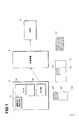
図1に、この発明の一実施形態による連携表示システムの機能ブロック図を示す。携帯端末装置であるスマートフォン2は、タッチ入力可能なタッチディスプレイ22を備えている。スマートフォン2は、重力の方向を検知する加速度センサ(図示せず)を備えており、画面の向きに応じて、縦長の画像データ(画面を縦長にした時に適切な方向として表示される画像データ)と横長の画像データ(画面を横長にした時に適切な方向として表示される画像データ)を切り替えて表示する。しかし、画像方向固定手段21により、画面の向きに拘わらず、縦長の画像データ23が表示されるモードに固定されている。
1. First embodiment
1.1 Overall Configuration FIG. 1 shows a functional block diagram of a cooperative display system according to an embodiment of the present invention. The
縦長の画像データ23は、横長の出力画像データ31にされて出力部24から出力される。横長の出力画像データ31の中央部分33が、縦長の画像データ23に対応している。また、縦長の出力画像データ23の一部(この例では上1/3)は、重複表示領域25となっている。この重複表示領域25が、ヘッドマウントディスプレイ(HMD)6にて表示される領域である。
The vertically
変換装置4は、横長の出力画像データ31を受けて、縦長の画像データ23に対応する中央部分33を特定する。さらに、この中央部分33から、縦長の画像データ23の重複表示領域25に対応する、重複表示領域35を抽出する。変換装置4は、抽出した重複表示領域35のデータを、HMD6のためのHMD表示データ40として出力する。HMD6は、受信したHMD表示データ40を表示する。
The conversion device 4 receives the horizontally long
スマートフォン2では、タッチディスプレイ22の重複表示領域25の表示はHMD6にも表示され、下部領域27の表示はスマートフォン2のみに表示されることを前提に、処理プログラムが記述されている。たとえば、下部領域27に操作ボタンなどを表示することで、これを操作して、入力などを行うことができる。処理結果などは、重複表示領域25に表示するように、処理プログラムが記述される。また、HMD6には、重複表示領域25と同じ内容のHMD表示データ41が表示される。
In the
したがって、ユーザは、スマートフォン2のタッチディスプレイ22で操作を行い、結果をHMD6に表示させることができる。
Accordingly, the user can operate the
1.2システム構成・ハードウエア構成
図2に、この発明の一実施形態による連携表示システムのシステム構成を示す。このシステムは、スマートフォン2、変換器4、ヘッドマウントディスプレイ(HMD)6を備えている。
1.2 System Configuration / Hardware Configuration FIG. 2 shows a system configuration of a cooperative display system according to an embodiment of the present invention. This system includes a
スマートフォン2のコネクタ端子(出力ポート24)には、コネクタ50によってケーブル52が接続されている。ケーブル52は、変換器4の入出力ポート47に接続される。変換器4の出力は、HMD6に与えられる。なお、HMD6としては、ウエストユニティス(株)のpicoLinker(商標)を用いることができる。
A
図3に、スマートフォン2のハードウエア構成を示す。CPU20には、メモリ26、タッチディスプレイ22、不揮発性メモリ28、入出力ポート24、通信回路30、マイク37、スピーカ39が接続されている。なお、図において、通話回路などは省略している。
FIG. 3 shows a hardware configuration of the
タッチディスプレイ22は、表示を行うとともに、ユーザの入力を受け付けるものである。入出力ポート24は、少なくとも出力画像データを出力するためのポートである。iPhone(商標)であれば、Lightning(商標)コネクタがこれに対応する。Android(商標)端末であれば、マイクロUSBコネクタがこれに対応する。通信回路30は、インターネットと通信を行うためのものである。マイク37は、ユーザの操作を声として取得するためのものである。スピーカ39は、ユーザに指示などを出力するためのものである。
The
不揮発性メモリ28には、端末プログラム32が記録されている。この端末プログラム32は、通信回路30を介して、インターネット上のウエブサイトからダウンロードしたものである。
A
図4に、変換器4のハードウエア構成を示す。CPU40には、メモリ42、不揮発性メモリ44、HDMI変換器46、出力ポート48が接続されている。出力ポート48には、HMD6が接続されている。HDMI変換器46には、入力ポート47を介して、ケーブル52が接続される。したがって、スマートフォン2からの出力画像データは、HDMIデータに変換されて取り込まれる。不揮発性メモリ44には、変換プログラム50が記録されている。なお、図示しないが、駆動のためのバッテリが設けられている。
FIG. 4 shows a hardware configuration of the converter 4. A
1.3連携表示処理
この実施形態では、図5Aに示すように、スマートフォン2を縦画面とし、タッチディスプレイ22の上部領域を重複表示領域25にしている。この重複表示領域25は、表示のための領域となっている。この重複表示領域25のみを、HMD6の表示領域7全体(図5B)に表示するようにしている。タッチディスプレイ22の下部領域27は、表示および操作入力を行うための領域としている。この下部領域27は、HMD6には表示しないようにしている。
1.3 Cooperative Display Processing In this embodiment, as shown in FIG. 5A, the
したがって、スマートフォン2で使用するアプリケーションは、予め定められた重複表示領域25にHMD6に表示すべき内容を表示し、下部領域27にはスマートフォン2のみに表示すべき内容を表示する。
Therefore, the application used in the
図6に、変換装置4の変換プログラム50のフローチャートを示す。変換装置4のCPU40(以下、変換装置4と省略することがある)は、入力ポート47から受けた、出力画像データが変換されたHDMIデータを取り込む(ステップS1)。図7Aに、スマートフォン2のタッチディスプレイ22に表示される画像データを示す。斜線部分が、重複表示領域25として設定された部分である。図7Bに、スマートフォン2の入出力ポート24から出力される出力画像データがHDMIデータに変換されたものを示す。
FIG. 6 shows a flowchart of the
CPU40は、取り込んだHDMIデータを、メモリ42(バッファ)に記録する(ステップS1)。CPU40は、横長のHDMIデータの中央部分33から重複表示領域35を特定し、抽出する(ステップS2)。なお、この実施形態では、図7Aに示すスマートフォン2の画像データ23における重複表示領域25を予め定めている。また、図7Aの縦長の画像データが、図7Bの横長のHDMIデータに変換される時の比率も既知である。したがって、CPU40は、図7Bの中央部分33から重複表示領域35を特定することができる。
The
CPU40は、このようにして抽出した重複表示領域35のデータを、HDMI表示データ41として、出力ポート48から出力する(ステップS3)。
The
以上のようにして、スマートフォン2のタッチディスプレイ22の重複表示領域25のみをHMD6に表示させることができる。
As described above, only the overlapping
なお、上記では、CPU40によって画像データの抽出処理を行っているが、その一部または全部をFPGAなどによって実現するようにしてもよい。
In the above description, image data extraction processing is performed by the
以下では、一例として、スマートフォン2を持ってHMD6を装着したユーザに対し、作業指示を行う端末プログラム50について説明する。図8に、端末プログラム50のフローチャートを示す。
Below, the
スマートフォン2のCPU20は、タッチディスプレイ22の縦横自動切換機能をオフにし、縦画面モードに固定する(ステップS11)。スマートフォン2には、重力加速度を検知するセンサ(図示せず)により、スマートフォン2の姿勢を検知し、縦画面モードと横画面モードを切り換える機能が設けられている。ここでは、この切り換え機能をオフにして、姿勢に拘わらず、縦画面モードとなるようにしている。縦画面モードと横画面モードでは、入出力ポート24から出力される出力画像データが異なるので、これを固定するためである。
The
CPU20は、重複表示領域25に製品入力欄60、機種入力欄62を表示し、下部領域27に製品入力欄60に入力すべき製品リストを表示する(ステップS12)。したがって、HMD6には、製品入力欄60、機種入力欄62が表示される。ユーザは、タッチディスプレイ22を操作し、下部領域27から作業対象の製品を選択する(ステップS13)。
The
作業対象の製品が選択されると、CPU20は、選択された製品名を製品入力欄60に表示し、機種入力欄62に入力すべき機種のリストを下部領域27に表示する(ステップS14)。表示例を、図10B示す。ユーザは、タッチディスプレイ22を操作し、下部領域27から作業対象の機種を選択する(ステップS15)。
When the product to be worked is selected, the
以上のようにして、作業対象である製品名と機種名が決定されると、CPU20は、当該製品・機種について、図10Cに示すような作業内容選択画面を表示する(ステップS16)。作業内容選択画面の詳細を図11に示す。重複表示領域25には、作業内容を選択するための選択領域258が表示されている。
When the product name and model name to be worked are determined as described above, the
選択領域258には、決定された製品「自動車」・機種「K−120」についての作業内容が表示される。中央部分には候補となる作業内容「エンジンルーム整備」が表示されている。この状態で、決定コマンドを入力すると、作業内容として「エンジンルーム整備」が選択されて決定されることになる。
In the
この実施形態では、ユーザが音声にて「決定」と発話することで、これをマイク37が捉え、CPU20は音声解析(テキスト化)により、決定コマンドであることを認識する。音声入力以外の方法、たとえば、ボタンの押下などによってコマンドを入力するようにしてもよい。
In this embodiment, when the user speaks “decide” by voice, the
また、「エンジンルーム整備」以外の作業内容を選択する場合には、「上」コマンドあるいは「下」コマンドを音声にて入力する。たとえば、図11の状態から「上」コマンドを入力すると、「エンジンルーム整備」の下側に隠れていた「ブレーキ整備」が、中央部分に位置して候補となる。「下」コマンドを入力すると、「エンジンルーム整備」の上側に隠れていた「足回り整備」が、中央部分に位置して候補となる。 When selecting work contents other than “engine room maintenance”, an “up” command or a “down” command is input by voice. For example, when the “up” command is input from the state of FIG. 11, “brake maintenance” hidden under “engine room maintenance” is located in the center portion and becomes a candidate. When the “lower” command is entered, “suspension maintenance” hidden above “engine room maintenance” is located in the center portion and becomes a candidate.
この実施形態では、重複表示領域25の可能コマンド表示領域256に、音声入力可能なコマンドを文字として表示している。図11においては、「上」「下」「決定」「カメラ」「作業終了」が表示されている。すなわち、この画面においては、これらの音声コマンドのみが受け付けられる。画面ごとに、受付可能な音声コマンドが用意されている。
In this embodiment, commands that can be input by voice are displayed as characters in the possible
このような構成にすることで、音声にてコマンドを入力するユーザは、可能コマンド表示領域256に示されたコマンドのみが受け付けられることを理解でき、正しいコマンドを発話することができる。また、CPU20の側も、当該画面にて入力可能なコマンドが絞り込まれているので、音声認識が容易となる。しかも、可能コマンド表示領域256は、重複表示領域25にあるので、HMD6にも表示される。したがって、ユーザがこれを容易に確認することができる。
With this configuration, a user who inputs a command by voice can understand that only the command shown in the possible
ユーザによって発話され正しく認識されたコマンドは、認識コマンド表示欄254に表示される。図11では、「決定」コマンドが認識されたことが示されている。
Commands that are spoken and correctly recognized by the user are displayed in the recognition
また、重複表示領域25には、音声波形ウインドウ252が設けられている。CPU20は、マイク37から拾った音声をディジタル信号にして、この音声波形ウインドウ252に音声波形253として表示する。この際、音声認識のために必要な音声レベルを、ライン255にて併せて表示する用にしている。正確な音声認識を行うために必要な音声レベルを示すためである。したがって、ユーザは、コマンドを発話する際に、音声波形253を見て、これがライン255を超えるように発話の大きさを調整することができる。
In the overlapping
また、発話していない時には環境ノイズ(周りの音)の大きさが波形として表示されることになる。この時の波形が、ライン255を超えているようでは、環境ノイズが大きすぎて正しい音声認識を行うことができない。したがって、環境ノイズがライン255より十分下回るように、マイク37の音量(ハードウエア的でもソフトウエア的でもよい)を、ユーザが手動でもしくは自動的に調整することができる。
Further, when not speaking, the magnitude of environmental noise (surrounding sound) is displayed as a waveform. If the waveform at this time exceeds the
図11において、CPU20は、下部領域27に作業内容の一覧を表示する。下部領域27は、重複表示領域25よりも広いのでより多くの作業内容を示すことができる。ただし、下部領域27は、スマートフォン2のみに表示される。
In FIG. 11, the
ユーザは、HMD6の画面を見て、音声にて作業内容を決定する(ステップS17)。なお、ステップS16、S17における作業内容の選択は、複数回(複数階層)行うようにしてもよい。
The user looks at the screen of the
作業内容が選択・決定されると、CPU20は、決定された作業内容の工程一覧を下部領域27に表示し、重複表示領域25には作業指示「☆☆の確認をして下さい」とともに、作業対象部分について予め用意してある写真259を示す作業指示画面を表示する(ステップS18)。さらに、CPU20は、指示内容をスピーカ39から音声として出力する。図12に、作業指示画面を示す。
When the work content is selected / determined, the
ユーザは、この作業指示を受けて、作業箇所や作業内容を示す写真259を参考にしながら作業を行う。この写真は、HMD6に表示される。写真259の下には、この作業内容における工程番号257が示され、現在の工程番号のみが大きく表示される。図12においては、工程番号「1」〜「5」が示される中、「1」のみが大きく示されており、現在の工程が「1」であることが示されている。
In response to this work instruction, the user performs work while referring to the
また、右下には、タクトタイム261が表示されている。タクトタイムは、当該工程の処理時間である。分母が予め設定されたタクトタイムであり、分子が現在までに要している時間である。図では、3/11が表示されていて、11秒で完了が予定されているこの工程が、開始から3秒経過していることが示されている。
A
工程での指示内容を完了するとユーザは、音声にてコマンドを入力する。ここでは、確認の工程であるから、確認の結果がOKであれば「ヨシ」、NGであれば「問題あり」などと音声コマンドを入力する(ステップS19)。図12の例であれば、「ヨシ」が入力されている。 When the instruction content in the process is completed, the user inputs a command by voice. Here, since it is a confirmation process, a voice command such as “Yoshi” if the confirmation result is OK, “Problem” if it is NG, etc. is input (step S19). In the example of FIG. 12, “Yoshi” is input.
CPU20は、この入力された結果を工程に対応づけて記録する。また、タクトタイムも記録する。CPU20は、選択された作業中に、未処理の工程があるかどうかを判断する(ステップS20)。未処理工程があれば、次の工程に進み、ステップS18以下を繰り返す(ステップS21)。
The
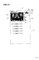
図13に、次の工程の画面を示す。工程番号「2」が大きく表示される。また、下部領域において、作業の終了した工程にチェックマークが表示されている。他は、図12の画面と同様である。 FIG. 13 shows a screen for the next step. The process number “2” is displayed large. In the lower area, a check mark is displayed in the process where the work has been completed. Others are the same as the screen of FIG.
このような作業中において、ユーザは、HMD6の画面を見ながら、音声にて操作を行うことができる。したがって、ハンズフリーの状態で、作業に集中することができる。
During such work, the user can operate by voice while looking at the screen of the
工程番号「5」まで終了すると、CPU20は、ステップS16に戻り他の作業を選択する(ステップS16、S17)。
When the process number “5” is completed, the
以上のようにして、スマートフォン2とHMD6を使用し、作業の支援を行うことができる。
As described above, the
なお、CPU20は、作業の結果(各工程がOKであるかNGであるか、タクトタイムなど)を不揮発性メモリ28に記録する。
The
1.4その他
(1)上記実施形態では、スマートフォン2に記録された端末プログラム32によって処理を行うようにしている。しかし、サーバ装置(図示せず)にプログラムを記録しておき、スマートフォン2からインターネットを介して、これを使用するようにしてもよい。この場合、サーバ装置に情報が集約されるので、複数人で作業を行う際に、それぞれがスマートフォン2を持っていれば、どの作業を他人が行っているかを把握することができる。
1.4 Other
(1) In the above embodiment, processing is performed by the
この場合の画面例を、図14に示す。下部領域27や選択領域258の作業名の頭に、チェックマークが入っているものが終了した作業(他のユーザが完了させた作業も含む)であり、黒点が入っているものが他のユーザが作業中のものである。
An example of the screen in this case is shown in FIG. Work that has a check mark at the beginning of the work name in the
(2)上記実施形態では、作業の支援のために用いた例を示した。しかし、これは一例であり、スマートフォン2の重複表示領域25の表示内容をHMD6に表示させて使用する場合、全般に適用することができる。例えば、下部領域27は操作を行うための領域として、重複表示領域25は処理結果などを表示するための領域として使用することができる。
(2) In the above embodiment, the example used for supporting the work is shown. However, this is an example, and when the display content of the overlapping
(3)上記実施形態では、スマートフォン2を用いているが、タブレットを用いるようにしてもよい。
(3) In the above embodiment, the
(4)上記実施形態では、スマートフォン2の画面を縦長に固定するようにしている。しかし、図15Aに示すように、スマートフォン2の画面を横長に固定し、その一部(右上、左上、右下、左下または真ん中など)を、HMD6との重複表示領域25としてもよい。図では、スマートフォン2の画面の左上の領域を重複表示領域25とし、HMD6の表示領域7に表示するようにしている。その他領域27は、上記実施形態の下部領域27に対応する。
(4) In the above embodiment, the screen of the
この場合、スマートフォン2の出力画像データは、図15Aと同じようになる。したがって、変換器4は予め定められた領域25を切り出して、HDMI表示データを生成する。
In this case, the output image data of the
また、縦横切り換え機能をオフにせず、縦画面の時は図7のように、横画面の時は図15のように変換して出力するよいにしてもよい。この場合、スマートフォン2の出力ポート24から、現在のモード(縦モードか横モード)情報を出力するようにし、変換器4がこれを受けて、現在モードを知ることができるようにすればよい。
Alternatively, the vertical / horizontal switching function may not be turned off, and conversion may be performed as shown in FIG. 7 when the screen is vertical, or as shown in FIG. 15 when the screen is horizontal. In this case, the current mode (vertical mode or horizontal mode) information may be output from the
(5)上記実施形態では、変換器4にHDMI変換器46を備えている。しかし、スマートフォン2の出力ポートからの出力画像データをHDMI変換器(図示せず)を介して、変換器4に取り込むようにしてもよい。この場合、変換器4には、HDMI変換器は不要である。
(5) In the above embodiment, the converter 4 includes the
(6)上記実施形態では、重複表示領域25よりも、その他領域27の方が広くなるように構成している。しかし、重複表示領域25の方が広くなるように設定してもよい。
(6) In the above embodiment, the
(7)上記実施形態では、変換器4によって、重複表示領域25の切り出しを行っている。しかし、スマートフォン2に記録したアプリケーションによってこれを行うようにしてもよい。この場合、出力ポート24から重複表示領域25のみを切り出した出力画像データを出力し、HDMI変換器を介して、HMD6に与えるようにすればよい。
(7) In the embodiment described above, the overlapping
(8)上記実施形態では、HMD6には、重複表示領域25のみを表示するようにしている。しかし、重複表示領域25だけでなくその他領域27(下部領域27)も含めて表示するようにしてもよい。画面を有さないパソコンなどを接続する場合には、このような表示方法が好ましい。
(8) In the above embodiment, only the
(9)上記実施形態では、変換器4は、ケーブル52、54にて、スマートフォン2、HMD6と接続されている。しかし、ブルーツースなどの無線通信によって接続するようにしてもよい。
(9) In the above embodiment, the converter 4 is connected to the
(10)上記実施形態では、HDMIデータを例として示したが、他の画像方式にも適用することができる。 (10) In the above embodiment, HDMI data is shown as an example, but the present invention can also be applied to other image formats.
(11)上記実施形態では、スマートフォン2の画面の一部をHMD6に表示するようにしている。しかし、本来スマートフォン2に表示されるべき画面の一部または全部をHMD6のみに表示し、スマートフォン2のタッチディスプレイ22をタッチパッドのように用いるようにしてもよい。すなわち、HMD6に表示されたカーソルを、タッチディスプレイ22での指(スタイラスペンでもよい)などの操作によって移動・操作させるようにしてもよい。
(11) In the above embodiment, a part of the screen of the
(12)上記実施形態の内容およびその他の例は、その本質に反しない限り、他の実施形態と組み合わせて実施可能である。
(12) The contents of the above embodiment and other examples can be implemented in combination with other embodiments as long as they do not contradict its essence.
2.第2の実施形態
2.1全体構成
第1の実施形態では、スマートフォン2の入出力ポート24からどのような出力画像データが出力されるかが、予め分かっている場合について説明した。しかし、同じ縦画面(横画面)モードであっても、スマートフォン2の機種などにより、出力画像データが異なる場合がある。この場合には、機種により、HMD6に重複表示領域25が正しく表示されないこととなる。そこで、この実施形態では、端末プログラム32の起動時に初期設定を行って、上記のような機種の違いによる出力画像データの違いがあっても、正しく表示連携が行われるようにしている。
2. Second embodiment
2.1 Overall Configuration In the first embodiment, a case has been described in which output image data is output from the input /
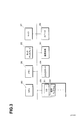
図16に、この発明の一実施形態による連携表示システムの機能ブロック図を示す。携帯端末装置であるスマートフォン2は、タッチ入力可能なタッチディスプレイ22を備えている。スマートフォン2は、重力の方向を検知する加速度センサ(図示せず)を備えており、画面の向きに応じて、縦長の画像データと横長の画像データを切り替えて表示する。
FIG. 16 shows a functional block diagram of the cooperative display system according to the embodiment of the present invention. The
初期画像出力手段202は、現在の画像の向きに応じて、重複表示領域25を特定できるようにした初期画像をタッチディスプレイ22に表示する。たとえば、縦長画像のモードの場合、図16に示すように、重複表示領域25をグレーにして外枠を太線で囲い、下部領域27を白にした初期画像23を表示する。これにより、出力部24からは、たとえば、図に示すような出力画像データ31が出力される。
The initial
画像方向固定手段21は、上記初期画像を出力した時のモードにて、画像方向を固定する。 The image direction fixing means 21 fixes the image direction in the mode when the initial image is output.
変換装置4の変換手順確立手段402は、出力画像データ31を受けて、その中から、太線で囲われたグレーの重複表示領域35を認識する。たとえば、出力画像データ31の左上を始点(0,0)として、重複表示領域35の左上の座標(X1,Y1)と、右下の座標(X2,Y2)を特定する。ここでは、1つの画素を座標の1単位とするようにしている。さらに、変換手順確立手段402は、重複表示領域35を切り出すための情報として、左上の座標(X1,Y1)と、右下の座標(X2,Y2)を記録する。以上のようにして、初期設定が終了する。
The conversion procedure establishing means 402 of the conversion device 4 receives the
変換装置4は、初期設定が終了したことをスマートフォン2に送信する。スマートフォン2は、端末プログラム32による処理を実行する。以降の処理は、第1の実施形態と同様である。
The conversion device 4 transmits to the
この実施形態によれば、機種による出力画像データ31の形態に応じて、自動的に変換手順を確立し、適切な表示連携を実現することができる。
According to this embodiment, a conversion procedure can be automatically established according to the form of the
2.2システム構成・ハードウエア構成
システムの構成は、図2に示すものと同様である。スマートフォン2のハードウエア構成は、図3に示すものと同様である。なお、不揮発性メモリ28には、マイク37から入力された音声をテキストとして認識して指示命令を特定する音声認識プログラムが記録されている。変換装置4のハードウエア構成は、図4に示すものと同様である。
2.2 System Configuration / Hardware Configuration The system configuration is the same as that shown in FIG. The hardware configuration of the
2.3初期設定処理
この実施形態では、端末プログラム32が起動した時に、初期設定処理を行うようにしている。この初期設定処理は、端末プログラム32の一部としてもよいし、端末プログラム32とは別に設けてもよい。
2.3 Initial Setting Processing In this embodiment, initial setting processing is performed when the
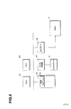
図17に、端末プログラム32および変換プログラム50の初期設定時のフローチャートを示す。スマートフォン2のCPU20(以下、スマートフォン2と省略することあり)は、まず、縦横自動切換機能をオフにし、現在の画面モードに固定する(ステップS31)。現在の画面モードが、縦画面モードであれば縦画面モードに、横画面モードであれば横画面モードに固定する。
FIG. 17 shows a flowchart when the
次に、スマートフォン2は、初期画像を生成し、タッチディスプレイ22に表示する(ステップS32)。図18Aに、タッチディスプレイ22に表示された初期画像23の例を示す。初期画像23は、重複表示領域25と下部領域27で構成されている。下部領域27は白色であり、重複表示領域25はグレーである。重複表示領域25には、左上から右下に領域ライン251が描画されている。
Next, the
スマートフォン2の入出力ポート24に出力される出力画像データ31は、機種によって異なってくる。たとえば、図18Bのように、中央領域33の両端に空白領域が設けられて、全体として横長の画像にして出力されたり、図18Cのように、初期画像23がそのまま縦長の画像として出力されたりする。
The
この実施形態では、出力画像データ31の形態がどのようなものであっても、HMD6との表示連携を正しく行うことができるようにしている。変換装置4のCPU40(以下変換装置4と省略することがある)は、初期画面の出力画像データ31を受信したかどうかを判断する(ステップS41)。出力画像データ31を受信すると、変換装置4は、出力画像データ31から、重複表示領域35を認識する(ステップS42)。
In this embodiment, display cooperation with the
ここでは、グレーの領域を見いだし、その中に描かれている領域ライン251の左上端、右下端の座標を取得する。座標は、出力画像データ31の左上を(0,0)として、1画素を1座標要素として算出する。たとえば、出力画像データ31が図18Bに示すように横長であり、1920画素×1080画素であるとすれば、右下の座標は(1080,1920)となる。したがって、図18Bの場合であれば、左上端(0,640)と右下端(160,1280)が、重複表示領域35の位置として抽出される。図18Cの場合(出力画像データ31の右下座標が(1920,1080))であれば、左上端(0,0)と右下端(640,1080)が、重複表示領域35の位置として抽出される。
Here, a gray area is found, and the coordinates of the upper left corner and the lower right corner of the
このように、図18Cの場合も、図18Cの場合も、領域ライン251の左上端、右下端によって、重複表示領域35の位置を確認することができる。
As described above, in both the case of FIG. 18C and the case of FIG. 18C, the position of the overlapping
なお、上記では重複表示領域35の位置を1画素を一単位とする座標にて表している。しかし、出力画像データ31の右下端を(100,100)として、正規化された重複表示領域35の座標として表すようにしてもよい。
In the above description, the position of the overlapping
変換装置4は、上記にて抽出した重複表示領域35の座標(左上端、右下端)を不揮発性メモリ44に記録する(ステップS43)。したがって、以降は、この座標に基づいて、重複表示領域35を切り出して、HMD表示データ41を生成する。
The conversion device 4 records the coordinates (upper left corner, lower right corner) of the
変換装置4は、以上の初期設定が終了すると、ケーブル52を介してその旨をスマートフォン2に送信する(ステップS44)。スマートフォン2は、これを受けて、以下の処理(たとえば、図8の処理(ステップS11は除く))を実行する。
When the above initial setting is completed, the conversion device 4 transmits that fact to the
2.4その他
(1)上記実施形態では、機種の違いによる重複表示領域35の切り出し位置の違いに対して自動的に対応するシステムとして説明した。しかし、同一機種(同一スマートフォン)において、縦画面と横画面による重複表示領域35の切り出し位置の違いに対して自動的に対応するシステムとして用いることもできる。
2.4 Other
(1) The above embodiment has been described as a system that automatically responds to differences in the cutout position of the overlapping
(2)上記実施形態では、領域ライン25を用いて重複表示領域35を認識するようにしている。しかし、その他、特別なマーク、枠などによって、重複表示領域35を認識するようにしてもよい。
(2) In the above embodiment, the overlapping
(3)上記実施形態では、初期画像を出力した際の画面モードに固定するようにしている。しかし、現在の画面の向きに拘わらず、縦画面モードまたは横画面モードに固定するようにしてもよい。 (3) In the above embodiment, the screen mode when the initial image is output is fixed. However, the screen may be fixed to the vertical screen mode or the horizontal screen mode regardless of the current screen orientation.
また、画面モードを固定せず(縦横自動切換機能をオフにせず)、画面の向きに応じて縦画像モードと横画像モードを切り換えるようにしてもよい。この場合、画像モードが切り替わるごとに、初期設定処理を行う。 The screen mode may not be fixed (the vertical / horizontal automatic switching function is not turned off), and the vertical image mode and the horizontal image mode may be switched according to the orientation of the screen. In this case, an initial setting process is performed every time the image mode is switched.
(4)上記実施形態では、スマートフォン2から重複表示領域を区別可能な初期画面を出力し、これに基づいて、重複表示領域の座標を確定し、抽出を行うようにしている。しかし、スマートフォン2の機種とHMD6の機種をユーザが入力し(スマートフォン2から入力して変換装置4に送る)、その組合せによって、重複表示領域の座標位置を示すテーブルを用意しておき、これに基づいて重複表示領域を切り出すようにしてもよい。この場合、縦画面と横画面によって切り出し位置が変わるので、画面モードをいずれか一方に固定することが好ましい。なお、スマートフォン2、HMD6の機種は、変換装置4が自動的に取得するようにしてもよい。
(4) In the above embodiment, an initial screen that can distinguish the overlap display area is output from the
また、縦画面と横画面における重複表示領域の座標位置をテーブルに記録しておき、縦画面か横画面かをスマートフォン2から取得して、重複表示領域を切り出すようにしてもよい。
In addition, the coordinate position of the overlapping display area in the vertical screen and the horizontal screen may be recorded in a table, and the vertical display or the horizontal screen may be acquired from the
さらに、スマートフォン2またはHMD6のいずれか一方の機種が固定されているようであれば、他方の機種に基づいて重複表示領域の座標位置をテーブルに記録しておいてもよい。
Furthermore, if one of the models of the
(5)上記実施形態では、ステップS44において、変換装置4から初期設定終了を送信し、これを受けたスマートフォン2が次の処理に進むようにしている。しかし、変換装置4から初期設定終了を送信せず、スマートフォン2の側で初期画像出力から所定時間経過後に初期設定が終了したものとして、次の処理に進むようにしてもよい。
(5) In the above embodiment, in step S44, the end of the initial setting is transmitted from the conversion device 4, and the
(6)上記実施形態では、変換器4によって変換手順の確立および変換処理を行うようにしている。しかし、これら処理をスマートフォン2において行うようにしてもよい。
(6) In the above embodiment, the converter 4 establishes the conversion procedure and performs the conversion process. However, these processes may be performed in the
(7)上記実施形態の内容およびその他の例は、その本質に反しない限り、他の実施形態と組み合わせて実施可能である。 (7) The contents of the above embodiment and other examples can be implemented in combination with other embodiments as long as they do not contradict the essence.
Claims (26)
前記出力部からの外部出力表示データを受けて、ヘッドマウントディスプレイ(HMD)に表示するための横長のHMD表示データを生成する変換装置と、
前記変換装置に接続され、HMD表示データを受け取って表示するヘッドマウントディスプレイと、
を備えた連携表示システムにおいて、
前記タッチディスプレイの所定の一部領域であって、前記横長のHMD画面に対応する一部領域を重複表示領域とし、
前記変換装置は、受け取った外部出力表示データの中央部に含まれる前記縦長の表示データに対応する領域のうち、前記重複表示領域の表示データを抽出してHMD表示データを生成することを特徴とする連携表示システム。 A portable terminal device comprising: a touch display capable of touch input; and an output unit that outputs vertical display data displayed on the touch display as external output display data corresponding to a horizontal HMD screen;
A conversion device that receives external output display data from the output unit and generates horizontally long HMD display data for display on a head mounted display (HMD);
A head-mounted display connected to the converter for receiving and displaying HMD display data;
In the coordinated display system with
A predetermined partial area of the touch display, a partial area corresponding to the horizontally long HMD screen is set as an overlapping display area,
The conversion device generates HMD display data by extracting display data of the overlap display area from areas corresponding to the vertically long display data included in a central portion of the received external output display data. Linked display system.
前記タッチディスプレイの所定の一部領域であって、前記横長のHMD画面に対応する一部領域を重複表示領域とし、
前記変換装置は、受け取った外部出力表示データの中央部に含まれる前記縦長の表示データに対応する領域のうち、前記重複表示領域の表示データを抽出してHMD表示データを生成することを特徴とする変換装置。 For receiving external output display data from a portable terminal device that outputs vertical display data displayed on a touch display as external output display data corresponding to a horizontal HMD screen, and displaying it on a head mounted display (HMD) In a conversion device that generates horizontally long HMD display data,
A predetermined partial area of the touch display, a partial area corresponding to the horizontally long HMD screen is set as an overlapping display area,
The conversion device generates HMD display data by extracting display data of the overlap display area from areas corresponding to the vertically long display data included in a central portion of the received external output display data. Conversion device.
前記携帯端末装置は、前記タッチディスプレイの縦長表示または横長表示の切替手段を、縦長の表示に固定する固定手段を備えていることを特徴とする連携表示システムまたは変換装置。 In the cooperation display system according to claim 1 or the conversion device according to claim 2,
The mobile terminal device includes a fixing unit that fixes a portrait display or a landscape display switching unit of the touch display to a portrait display.
前記携帯端末装置のタッチディスプレイにおいて、前記重複表示領域には、タッチ入力のための表示を行わないようにしたことを特徴とする連携表示システムまたは変換装置。 In the cooperation display system or conversion apparatus in any one of Claims 1-3,
In the touch display of the portable terminal device, a display for touch input is not performed in the overlap display area, or the cooperative display system or the conversion device.
前記タッチディスプレイに表示される縦長の表示データを、横長のHMD画面に対応する外部出力表示データとして出力する出力手段と、
前記出力手段からの外部出力表示データを受けて、ヘッドマウントディスプレイ(HMD)に表示するための横長のHMD表示データを生成する変換手段と、
を備えた携帯端末装置において、
前記タッチディスプレイの所定の一部領域であって、前記横長のHMD画面に対応する一部領域を重複表示領域とし、
前記変換手段は、受け取った外部出力表示データの中央部に含まれる前記縦長の表示データに対応する領域のうち、前記重複表示領域の表示データを抽出してHMD表示データを生成することを特徴とする携帯端末装置。 A touch display capable of touch input,
Output means for outputting the vertically long display data displayed on the touch display as external output display data corresponding to a horizontally long HMD screen;
Conversion means for receiving external output display data from the output means and generating horizontally long HMD display data for display on a head mounted display (HMD);
In a mobile terminal device comprising:
A predetermined partial area of the touch display, a partial area corresponding to the horizontally long HMD screen is set as an overlapping display area,
The converting means extracts HMD display data by extracting display data of the overlapping display area out of areas corresponding to the vertically long display data included in the central portion of the received external output display data. Mobile terminal device.
タッチディスプレイに表示される縦長の表示データを、横長のHMD画面に対応する外部出力表示データとして出力する出力手段からの外部出力表示データを受けて、ヘッドマウントディスプレイ(HMD)に表示するための横長のHMD表示データを生成する変換手段として機能させるための変換プログラムにおいて、
前記タッチディスプレイの所定の一部領域であって、前記横長のHMD画面に対応する一部領域を重複表示領域とし、
前記変換手段は、受け取った外部出力表示データの中央部に含まれる前記縦長の表示データに対応する領域のうち、前記重複表示領域の表示データを抽出してHMD表示データを生成することを特徴とする変換プログラム。 A conversion program for realizing conversion means by a computer,
A horizontally long display for receiving external output display data from an output means for outputting the vertically long display data displayed on the touch display as external output display data corresponding to the horizontally long HMD screen and displaying it on the head mounted display (HMD). In a conversion program for functioning as a conversion means for generating HMD display data of
A predetermined partial area of the touch display, a partial area corresponding to the horizontally long HMD screen is set as an overlapping display area,
The converting means extracts HMD display data by extracting display data of the overlapping display area out of areas corresponding to the vertically long display data included in the central portion of the received external output display data. Conversion program.
前記変換手段は、前記タッチディスプレイの縦長表示または横長表示の切替手段を、縦長の表示に固定することを特徴とする装置またはプログラム。 The apparatus of claim 5 or the program of claim 6.
The conversion means fixes the portrait display or landscape display switching means of the touch display to portrait display.
前記携帯端末装置のタッチディスプレイにおいて、前記重複表示領域には、タッチ入力のための表示を行わないようにしたことを特徴とする装置またはプログラム。 In the apparatus or program in any one of Claims 5-7,
The touch display of the said portable terminal device WHEREIN: The display for touch input is not performed to the said overlapping display area, The program or the program characterized by the above-mentioned.
前記出力部からの外部出力表示データを受けて、ヘッドマウントディスプレイ(HMD)に表示するためのHMD表示データを生成する変換装置と、
前記変換装置に接続され、HMD表示データを受け取って表示するヘッドマウントディスプレイと、
を備えた連携表示システムにおいて、
前記タッチディスプレイの所定の一部領域であって、前記HMD画面に対応する一部領域を重複表示領域とし、
前記変換装置は、接続された携帯端末装置の機種とヘッドマウントディスプレイの機種の組み合わせに基づいて、前記外部出力表示データを前記HMD表示データに変換することを特徴とする連携表示システム。 A portable terminal device including a touch display capable of touch input, and an output unit that outputs display data displayed on the touch display to the outside as external output display data;
A conversion device that receives external output display data from the output unit and generates HMD display data for display on a head mounted display (HMD);
A head-mounted display connected to the converter for receiving and displaying HMD display data;
In the coordinated display system with
A predetermined partial area of the touch display, a partial area corresponding to the HMD screen is set as an overlapping display area,
The said conversion apparatus converts the said external output display data into the said HMD display data based on the combination of the model of the connected portable terminal device, and the model of a head mounted display, The cooperation display system characterized by the above-mentioned.
前記タッチディスプレイの所定の一部領域であって、前記HMD画面に対応する一部領域を重複表示領域とし、
前記変換装置は、接続された携帯端末装置の機種とヘッドマウントディスプレイの機種の組み合わせに基づいて、前記外部出力表示データを前記HMD表示データに変換することを特徴とする変換装置。 A conversion device that receives external output display data from a portable terminal device that outputs display data displayed on a touch display as external output display data, and generates HMD display data for display on a head mounted display (HMD) screen In
A predetermined partial area of the touch display, a partial area corresponding to the HMD screen is set as an overlapping display area,
The conversion device converts the external output display data into the HMD display data based on a combination of a model of a connected mobile terminal device and a model of a head mounted display.
接続される携帯端末装置の機種またはヘッドマウントディスプレイの機種の一方が予め定まっている場合には、他方に基づいて、前記外部出力表示データを前記HMD表示データに変換することを特徴とするシステムまたは装置。 The system of claim 9 or the apparatus of claim 10.
A system for converting the external output display data into the HMD display data based on the other when one of the model of the connected mobile terminal device or the model of the head-mounted display is determined in advance, or apparatus.
前記携帯端末装置の機種とヘッドマウントディスプレイの機種の組み合わせによって、
前記表示データが、縦長表示のためのデータとなり、前記外部出力表示データが、その中央部に前記縦長の表示データを含む、全体として横長のHMD画面に対応するものとなる場合には、
前記変換装置は、受け取った外部出力表示データの中央部に含まれる前記縦長の表示データに対応する領域のうち、前記重複表示領域の表示データを抽出してHMD表示データを生成することを特徴とするシステムまたは装置。 The system or apparatus of claims 9-11,
Depending on the combination of the mobile terminal device model and the head-mounted display model,
When the display data is data for portrait display, and the external output display data includes the portrait display data at the center thereof and corresponds to a landscape-oriented HMD screen as a whole,
The conversion device generates HMD display data by extracting display data of the overlap display area from areas corresponding to the vertically long display data included in a central portion of the received external output display data. System or device to perform.
前記タッチディスプレイに表示される表示データを、外部出力表示データとして外部に出力する出力手段と、
前記出力手段からの外部出力表示データを受けて、ヘッドマウントディスプレイ(HMD)に表示するためのHMD表示データを生成する変換手段と、
を備えた携帯端末装置において、
前記タッチディスプレイの所定の一部領域であって、前記HMD画面に対応する一部領域を重複表示領域とし、
前記変換手段は、接続された携帯端末装置の機種とヘッドマウントディスプレイの機種の組み合わせに基づいて、前記外部出力表示データを前記HMD表示データに変換することを特徴とする携帯端末装置。 A touch display capable of touch input,
Output means for outputting display data displayed on the touch display to the outside as external output display data;
Conversion means for receiving external output display data from the output means and generating HMD display data for display on a head mounted display (HMD);
In a mobile terminal device comprising:
A predetermined partial area of the touch display, a partial area corresponding to the HMD screen is set as an overlapping display area,
The said conversion means converts the said external output display data into the said HMD display data based on the combination of the model of the connected portable terminal device, and the model of a head mounted display, The portable terminal device characterized by the above-mentioned.
前記タッチディスプレイに表示される表示データを、外部出力表示データとして外部に出力する出力手段からの外部出力表示データを受けて、ヘッドマウントディスプレイ(HMD)に表示するためのHMD表示データを生成する変換手段として機能させるための変換プログラムにおいて、
前記タッチディスプレイの所定の一部領域であって、前記HMD画面に対応する一部領域を重複表示領域とし、
前記変換手段は、接続された携帯端末装置の機種とヘッドマウントディスプレイの機種の組み合わせに基づいて、前記外部出力表示データを前記HMD表示データに変換することを特徴とする変換プログラム。 A conversion program for realizing conversion means by a computer,
Conversion that receives external output display data from output means that outputs display data displayed on the touch display as external output display data to generate HMD display data for display on a head mounted display (HMD) In a conversion program for functioning as a means,
A predetermined partial area of the touch display, a partial area corresponding to the HMD screen is set as an overlapping display area,
The conversion program converts the external output display data into the HMD display data based on a combination of a model of a connected portable terminal device and a model of a head mounted display.
接続される携帯端末装置の機種またはヘッドマウントディスプレイの機種の一方が予め定まっている場合には、他方に基づいて、前記外部出力表示データを前記HMD表示データに変換することを特徴とする装置またはプログラム。 The apparatus of claim 13 or the program of claim 14,
A device for converting the external output display data into the HMD display data based on the other when one of the model of the mobile terminal device to be connected or the model of the head mounted display is determined in advance, or program.
前記携帯端末装置の機種とヘッドマウントディスプレイの機種の組み合わせによって、
前記表示データが、縦長表示のためのデータとなり、前記外部出力表示データが、その中央部に前記縦長の表示データを含む、全体として横長のHMD画面に対応するHDMIデータとなる場合には、
前記変換装置は、受け取ったHDMIデータの中央部に含まれる前記縦長の表示データに対応する領域のうち、前記重複表示領域の表示データを抽出してHMD表示データを生成することを特徴とする装置またはプログラム。 In the apparatus or program of Claims 13-15,
Depending on the combination of the mobile terminal device model and the head-mounted display model,
When the display data is data for portrait display, and the external output display data is HDMI data corresponding to a landscape-oriented HMD screen as a whole, including the portrait display data at the center.
The conversion apparatus extracts HMD display data by extracting display data of the overlapping display area from an area corresponding to the vertically long display data included in a central portion of received HDMI data. Or program.
前記出力部からの外部出力表示データを受けて、ヘッドマウントディスプレイ(HMD)に表示するためのHMD表示データを生成する変換装置と、
前記変換装置に接続され、HMD表示データを受け取って表示するヘッドマウントディスプレイと、
を備えた連携表示システムにおいて、
前記タッチディスプレイの所定の一部領域であって、前記HMD画面に対応する一部領域を重複表示領域とし、
前記携帯端末装置は、初期設定時に、前記重複表示領域とそれ以外の領域とを区別可能な初期設定用表示データを生成し、これに対応する初期設定用外部出力表示データを出力し、
前記変換装置は、初期設定時に、前記初期設定用外部出力表示データを受けて、当該データ中の重複表示領域を認識して、外部出力表示データからHMD表示データへの変換手順を確立することを特徴とする連携表示システム。 A portable terminal device including a touch display capable of touch input, and an output unit that outputs display data displayed on the touch display to the outside as external output display data;
A conversion device that receives external output display data from the output unit and generates HMD display data for display on a head mounted display (HMD);
A head-mounted display connected to the converter for receiving and displaying HMD display data;
In the coordinated display system with
A predetermined partial area of the touch display, a partial area corresponding to the HMD screen is set as an overlapping display area,
The mobile terminal device generates initial setting display data capable of distinguishing the overlap display area and other areas at the time of initial setting, and outputs corresponding external output display data for initial setting.
In the initial setting, the converter receives the initial setting external output display data, recognizes an overlapping display area in the data, and establishes a conversion procedure from the external output display data to the HMD display data. Characteristic linked display system.
前記タッチディスプレイの所定の一部領域であって、前記HMD画面に対応する一部領域を重複表示領域とし、
前記携帯端末装置は、初期設定時に、前記重複表示領域とそれ以外の領域とを区別可能な初期設定用表示データを生成し、これに対応する初期設定用外部出力表示データを出力し、
前記変換装置は、初期設定時に、前記初期設定用外部出力表示データを受けて、当該データ中の重複表示領域を認識して、外部出力表示データからHMD表示データへの変換手順を確立することを特徴とする変換装置。 Conversion that receives external output display data from a portable terminal device that outputs display data displayed on the touch display as external output display data to generate HMD display data for display on a head mounted display (HMD) In the device
A predetermined partial area of the touch display, a partial area corresponding to the HMD screen is set as an overlapping display area,
The mobile terminal device generates initial setting display data capable of distinguishing the overlap display area and other areas at the time of initial setting, and outputs corresponding external output display data for initial setting.
In the initial setting, the converter receives the initial setting external output display data, recognizes an overlapping display area in the data, and establishes a conversion procedure from the external output display data to the HMD display data. Characteristic conversion device.
前記タッチディスプレイの所定の一部領域であって、前記HMD画面に対応する一部領域を重複表示領域とし、
前記変換装置において、外部出力表示データからHMD表示データへの変換手順を確立できるように、前記携帯端末装置は、初期設定時に、前記重複表示領域とそれ以外の領域とを区別可能な初期設定用表示データを生成し、これに対応する初期設定用外部出力表示データを前記変換装置に出力することを特徴とする携帯端末装置。 A portable display that includes a touch display capable of touch input and an output unit that outputs display data displayed on the touch display to the outside as external output display data, and displays HMD display data on the head-mounted display via a conversion device. A terminal device,
A predetermined partial area of the touch display, a partial area corresponding to the HMD screen is set as an overlapping display area,
In the conversion device, the portable terminal device is capable of distinguishing between the overlapping display region and other regions at the time of initial setting so that a conversion procedure from external output display data to HMD display data can be established. A portable terminal device that generates display data and outputs external output display data for initial setting corresponding to the display data to the conversion device.
前記タッチディスプレイの所定の一部領域であって、前記HMD画面に対応する一部領域を重複表示領域とし、
コンピュータを、前記変換装置において、外部出力表示データからHMD表示データへの変換手順を確立できるように、前記携帯端末装置は、初期設定時に、前記重複表示領域とそれ以外の領域とを区別可能な初期設定用表示データを生成し、これに対応する初期設定用外部出力表示データを前記変換装置に出力するよう機能させるためのプログラム。 A portable display that includes a touch display capable of touch input and an output unit that outputs display data displayed on the touch display to the outside as external output display data, and displays HMD display data on the head-mounted display via a conversion device. A program for realizing a terminal device by a computer,
A predetermined partial area of the touch display, a partial area corresponding to the HMD screen is set as an overlapping display area,
The portable terminal device can distinguish the overlapping display region from other regions at the time of initial setting so that the conversion procedure from external output display data to HMD display data can be established in the conversion device. A program for generating initial setting display data and causing the conversion device to function so as to output initial setting external output display data corresponding thereto.
前記タッチディスプレイに表示される表示データを、外部出力表示データとして外部に出力する出力手段と、
前記出力手段からの外部出力表示データを受けて、ヘッドマウントディスプレイ(HMD)に表示するためのHMD表示データを生成する変換手段と、
を備えた携帯端末装置において、
前記タッチディスプレイの所定の一部領域であって、前記HMD画面に対応する一部領域を重複表示領域とし、
前記携帯端末装置は、初期設定時に、前記重複表示領域とそれ以外の領域とを区別可能な初期設定用表示データを生成し、これに対応する初期設定用外部出力表示データを出力し、
前記変換手段は、初期設定時に、前記初期設定用外部出力表示データを受けて、当該データ中の重複表示領域を認識して、外部出力表示データからHMD表示データへの変換手順を確立することを特徴とする携帯端末装置。 A touch display capable of touch input,
Output means for outputting display data displayed on the touch display to the outside as external output display data;
Conversion means for receiving external output display data from the output means and generating HMD display data for display on a head mounted display (HMD);
In a mobile terminal device comprising:
A predetermined partial area of the touch display, a partial area corresponding to the HMD screen is set as an overlapping display area,
The mobile terminal device generates initial setting display data capable of distinguishing the overlap display area and other areas at the time of initial setting, and outputs corresponding external output display data for initial setting.
The converting means receives the initial setting external output display data at the time of initial setting, recognizes an overlapping display area in the data, and establishes a conversion procedure from the external output display data to the HMD display data. A portable terminal device.
タッチディスプレイに表示される表示データを、外部出力表示データとして外部に出力する出力手段からの外部出力表示データを受けて、ヘッドマウントディスプレイ(HMD)に表示するためのHMD表示データを生成する変換手段として機能させるための変換プログラムにおいて、
前記タッチディスプレイの所定の一部領域であって、前記HMD画面に対応する一部領域を重複表示領域とし、
初期設定時に、前記重複表示領域とそれ以外の領域とを区別可能な初期設定用表示データを生成し、これに対応する初期設定用外部出力表示データを出力し、
前記変換手段は、初期設定時に、前記初期設定用外部出力表示データを受けて、当該データ中の重複表示領域を認識して、外部出力表示データからHMD表示データへの変換手順を確立することを特徴とする変換プログラム。 A conversion program for realizing conversion means by a computer,
Conversion means for receiving external output display data from output means for outputting display data displayed on the touch display to the outside as external output display data, and generating HMD display data for display on a head mounted display (HMD) In the conversion program to function as
A predetermined partial area of the touch display, a partial area corresponding to the HMD screen is set as an overlapping display area,
At the time of initial setting, the initial setting display data that can distinguish the overlap display area and other areas is generated, and the corresponding external output display data for initial setting is output.
The converting means receives the initial setting external output display data at the time of initial setting, recognizes an overlapping display area in the data, and establishes a conversion procedure from the external output display data to the HMD display data. Feature conversion program.
音声データを受けて、対応する命令を認識する命令認識手段と、
認識した命令を実行する命令実行手段と、
を備えた音声認識装置において、
前記画面データ生成手段は、当該画面において受付可能な命令に対応する音声データのテキストを含む画面データを生成し、
前記命令認識手段は、前記受付可能な命令の中から、音声データに対応する命令を選択して認識することを特徴とする音声認識装置。 Screen data generating means for generating screen data to be displayed on the display unit;
Command recognition means for receiving voice data and recognizing corresponding commands;
An instruction execution means for executing the recognized instruction;
In a speech recognition device comprising
The screen data generation means generates screen data including text of voice data corresponding to an instruction that can be accepted on the screen,
The voice recognition apparatus, wherein the command recognition means selects and recognizes a command corresponding to voice data from the accepted commands.
表示部に表示するための画面データを生成する画面データ生成手段と、
音声データを受けて、対応する命令を認識する命令認識手段と、
認識した命令を実行する命令実行手段として機能させるための音声認識プログラムにおいて、
前記画面データ生成手段は、当該画面において受付可能な命令に対応する音声データのテキストを含む画面データを生成し、
前記命令認識手段は、前記受付可能な命令の中から、音声データに対応する命令を選択して認識することを特徴とする音声認識プログラム。 A speech recognition program for realizing a speech recognition apparatus by a computer, the computer comprising:
Screen data generating means for generating screen data to be displayed on the display unit;
Command recognition means for receiving voice data and recognizing corresponding commands;
In a voice recognition program for functioning as an instruction execution means for executing a recognized instruction,
The screen data generation means generates screen data including text of voice data corresponding to an instruction that can be accepted on the screen,
The voice recognition program, wherein the command recognition means selects and recognizes a command corresponding to voice data from the accepted commands.
音声データを受けて、対応する命令を認識する命令認識手段と、
認識した命令を実行する命令実行手段と、
を備えた音声認識装置において、
前記画面データ生成手段は、入力された音声データの音声波形を、命令認識手段が認識可能なレベルの目安となるラインとともに示すことを含む画面データを生成することを特徴とする音声認識装置。 Screen data generating means for generating screen data to be displayed on the display unit;
Command recognition means for receiving voice data and recognizing corresponding commands;
An instruction execution means for executing the recognized instruction;
In a speech recognition device comprising
The voice data recognition apparatus characterized in that the screen data generating means generates screen data including showing a voice waveform of the input voice data together with a line which is a standard of a level recognizable by the command recognition means.
表示部に表示するための画面データを生成する画面データ生成手段と、
音声データを受けて、対応する命令を認識する命令認識手段と、
認識した命令を実行する命令実行手段として機能させるための音声認識プログラムにおいて、
前記画面データ生成手段は、入力された音声データの音声波形を、命令認識手段が認識可能なレベルの目安となるラインとともに示すことを含む画面データを生成することを特徴とする音声認識プログラム。
A speech recognition program for realizing a speech recognition apparatus by a computer, the computer comprising:
Screen data generating means for generating screen data to be displayed on the display unit;
Command recognition means for receiving voice data and recognizing corresponding commands;
In a voice recognition program for functioning as an instruction execution means for executing a recognized instruction,
The screen data generation means generates a screen data including a voice waveform of the input voice data including a line indicating a level that can be recognized by the command recognition means.
Priority Applications (4)
| Application Number | Priority Date | Filing Date | Title |
|---|---|---|---|
| JP2017158655A JP2019036914A (en) | 2017-08-21 | 2017-08-21 | Cooperative display system |
| US16/021,412 US20190056813A1 (en) | 2017-08-21 | 2018-06-28 | Display linking system |
| EP18181735.4A EP3447605A1 (en) | 2017-08-21 | 2018-07-04 | Display linking system |
| CN201810875362.3A CN109428956A (en) | 2017-08-21 | 2018-08-03 | Association display system, conversion equipment, mobile terminal device and storage medium |
Applications Claiming Priority (1)
| Application Number | Priority Date | Filing Date | Title |
|---|---|---|---|
| JP2017158655A JP2019036914A (en) | 2017-08-21 | 2017-08-21 | Cooperative display system |
Publications (2)
| Publication Number | Publication Date |
|---|---|
| JP2019036914A true JP2019036914A (en) | 2019-03-07 |
| JP2019036914A5 JP2019036914A5 (en) | 2020-10-08 |
Family
ID=62873267
Family Applications (1)
| Application Number | Title | Priority Date | Filing Date |
|---|---|---|---|
| JP2017158655A Pending JP2019036914A (en) | 2017-08-21 | 2017-08-21 | Cooperative display system |
Country Status (4)
| Country | Link |
|---|---|
| US (1) | US20190056813A1 (en) |
| EP (1) | EP3447605A1 (en) |
| JP (1) | JP2019036914A (en) |
| CN (1) | CN109428956A (en) |
Cited By (3)
| Publication number | Priority date | Publication date | Assignee | Title |
|---|---|---|---|---|
| US11275547B2 (en) | 2019-12-26 | 2022-03-15 | Seiko Epson Corporation | Display system, display method, and program |
| US11391953B2 (en) | 2020-01-30 | 2022-07-19 | Seiko Epson Corporation | Display device, control method for display device, and program |
| US11681433B2 (en) | 2020-01-30 | 2023-06-20 | Seiko Epson Corporation | Display system, controller, display system control method, and program for receiving input corresponding to image displayed based on head movement |
Families Citing this family (4)
| Publication number | Priority date | Publication date | Assignee | Title |
|---|---|---|---|---|
| US10237509B1 (en) * | 2016-08-05 | 2019-03-19 | Apple Inc. | Systems with keyboards and head-mounted displays |
| CN110248026B (en) * | 2019-06-18 | 2021-10-22 | 北京字节跳动网络技术有限公司 | Mobile terminal, display system, display control method of display system and recording medium |
| JP2021105782A (en) * | 2019-12-26 | 2021-07-26 | セイコーエプソン株式会社 | Display system, display method, and program |
| EP4180919A4 (en) | 2020-11-30 | 2024-02-28 | Samsung Electronics Co Ltd | Augmented reality device, electronic device interacting with augmented reality device, and method for controlling same |
Citations (5)
| Publication number | Priority date | Publication date | Assignee | Title |
|---|---|---|---|---|
| JP2003279881A (en) * | 2002-03-27 | 2003-10-02 | Hitachi Ltd | Portable information device |
| JP2012044429A (en) * | 2010-08-18 | 2012-03-01 | Brother Ind Ltd | Image display system and computer program for portable information processing device contained in image display system |
| US20130100167A1 (en) * | 2011-10-20 | 2013-04-25 | Nokia Corporation | Method and apparatus for control of orientation of information presented based upon device use state |
| JP2015125567A (en) * | 2013-12-26 | 2015-07-06 | 株式会社東芝 | Electronic device, method, and program |
| JP2015227919A (en) * | 2014-05-30 | 2015-12-17 | セイコーエプソン株式会社 | Image display device, control method of the same, computer program and image display system |
Family Cites Families (13)
| Publication number | Priority date | Publication date | Assignee | Title |
|---|---|---|---|---|
| JPS5630141B2 (en) | 1974-01-31 | 1981-07-13 | ||
| US20050228281A1 (en) * | 2004-03-31 | 2005-10-13 | Nefos Thomas P | Handheld diagnostic ultrasound system with head mounted display |
| US8717285B1 (en) * | 2009-10-28 | 2014-05-06 | Amazon Technologies, Inc. | Orientation lock |
| WO2011084895A1 (en) * | 2010-01-08 | 2011-07-14 | Kopin Corporation | Video eyewear for smart phone games |
| CN101833873A (en) * | 2010-05-19 | 2010-09-15 | 鸿富锦精密工业(深圳)有限公司 | Electronic book with split display function |
| AU2011205223C1 (en) * | 2011-08-09 | 2013-03-28 | Microsoft Technology Licensing, Llc | Physical interaction with virtual objects for DRM |
| JP6008086B2 (en) * | 2012-03-26 | 2016-10-19 | セイコーエプソン株式会社 | Head-mounted display device |
| US8929954B2 (en) * | 2012-04-25 | 2015-01-06 | Kopin Corporation | Headset computer (HSC) as auxiliary display with ASR and HT input |
| US9398344B2 (en) * | 2012-06-08 | 2016-07-19 | Lg Electronics Inc. | Image display apparatus, mobile terminal and method for operating the same |
| US10102674B2 (en) * | 2015-03-09 | 2018-10-16 | Google Llc | Virtual reality headset connected to a mobile computing device |
| KR20170096408A (en) * | 2016-02-16 | 2017-08-24 | 삼성전자주식회사 | Method for displaying application and electronic device supporting the same |
| US10264297B1 (en) * | 2017-09-13 | 2019-04-16 | Perfect Sense, Inc. | Time-based content synchronization |
| US10217488B1 (en) * | 2017-12-15 | 2019-02-26 | Snap Inc. | Spherical video editing |
-
2017
- 2017-08-21 JP JP2017158655A patent/JP2019036914A/en active Pending
-
2018
- 2018-06-28 US US16/021,412 patent/US20190056813A1/en not_active Abandoned
- 2018-07-04 EP EP18181735.4A patent/EP3447605A1/en not_active Withdrawn
- 2018-08-03 CN CN201810875362.3A patent/CN109428956A/en active Pending
Patent Citations (5)
| Publication number | Priority date | Publication date | Assignee | Title |
|---|---|---|---|---|
| JP2003279881A (en) * | 2002-03-27 | 2003-10-02 | Hitachi Ltd | Portable information device |
| JP2012044429A (en) * | 2010-08-18 | 2012-03-01 | Brother Ind Ltd | Image display system and computer program for portable information processing device contained in image display system |
| US20130100167A1 (en) * | 2011-10-20 | 2013-04-25 | Nokia Corporation | Method and apparatus for control of orientation of information presented based upon device use state |
| JP2015125567A (en) * | 2013-12-26 | 2015-07-06 | 株式会社東芝 | Electronic device, method, and program |
| JP2015227919A (en) * | 2014-05-30 | 2015-12-17 | セイコーエプソン株式会社 | Image display device, control method of the same, computer program and image display system |
Cited By (3)
| Publication number | Priority date | Publication date | Assignee | Title |
|---|---|---|---|---|
| US11275547B2 (en) | 2019-12-26 | 2022-03-15 | Seiko Epson Corporation | Display system, display method, and program |
| US11391953B2 (en) | 2020-01-30 | 2022-07-19 | Seiko Epson Corporation | Display device, control method for display device, and program |
| US11681433B2 (en) | 2020-01-30 | 2023-06-20 | Seiko Epson Corporation | Display system, controller, display system control method, and program for receiving input corresponding to image displayed based on head movement |
Also Published As
| Publication number | Publication date |
|---|---|
| EP3447605A1 (en) | 2019-02-27 |
| US20190056813A1 (en) | 2019-02-21 |
| CN109428956A (en) | 2019-03-05 |
Similar Documents
| Publication | Publication Date | Title |
|---|---|---|
| JP2019036914A (en) | Cooperative display system | |
| EP3239975A1 (en) | Information processing device, information processing method, and program | |
| US9294607B2 (en) | Headset computer (HSC) as auxiliary display with ASR and HT input | |
| US20180210544A1 (en) | Head Tracking Based Gesture Control Techniques For Head Mounted Displays | |
| CN107832036B (en) | Voice control method, device and computer readable storage medium | |
| EP2832107B1 (en) | Information processing apparatus, information processing method, and program | |
| EP1858238A2 (en) | Display method and system for portable device using external display device | |
| US9148586B2 (en) | Terminal apparatus for combining images from two different cameras based on detected sound | |
| KR20120136642A (en) | Apparatus and method for providing interface in device with touch screen | |
| KR102193029B1 (en) | Display apparatus and method for performing videotelephony using the same | |
| KR20130050608A (en) | Device and method for processing an image expression of wireless terminal | |
| WO2020249038A1 (en) | Audio stream processing method and apparatus, mobile terminal, and storage medium | |
| KR102056633B1 (en) | The conference call terminal and method for operating a user interface thereof | |
| KR102090948B1 (en) | Apparatus saving conversation and method thereof | |
| JP6016134B2 (en) | Voice input device, voice input method and program | |
| KR20110010939A (en) | Apparatus and method for improving performance of voice recognition in portable terminal | |
| JP2017508193A (en) | User configurable speech commands | |
| CN115380526A (en) | User terminal, video call device, video call system and control method thereof | |
| CN111522524B (en) | Presentation control method and device based on conference robot, storage medium and terminal | |
| CN112509576A (en) | Voice-controlled large-screen display system | |
| KR20140116642A (en) | Apparatus and method for controlling function based on speech recognition | |
| JP2017107333A (en) | Communication apparatus and communication apparatus control method | |
| CN115066908A (en) | User terminal and control method thereof | |
| CN108605074B (en) | Method and equipment for triggering voice function | |
| JP5510008B2 (en) | Mobile terminal device |
Legal Events
| Date | Code | Title | Description |
|---|---|---|---|
| A521 | Request for written amendment filed |
Free format text: JAPANESE INTERMEDIATE CODE: A523 Effective date: 20200819 |
|
| A621 | Written request for application examination |
Free format text: JAPANESE INTERMEDIATE CODE: A621 Effective date: 20200819 |
|
| A977 | Report on retrieval |
Free format text: JAPANESE INTERMEDIATE CODE: A971007 Effective date: 20210430 |
|
| A131 | Notification of reasons for refusal |
Free format text: JAPANESE INTERMEDIATE CODE: A131 Effective date: 20210510 |
|
| A02 | Decision of refusal |
Free format text: JAPANESE INTERMEDIATE CODE: A02 Effective date: 20211101 |