JP2019036282A - Method and system for locating sas jbod cable routing - Google Patents
Method and system for locating sas jbod cable routing Download PDFInfo
- Publication number
- JP2019036282A JP2019036282A JP2018035129A JP2018035129A JP2019036282A JP 2019036282 A JP2019036282 A JP 2019036282A JP 2018035129 A JP2018035129 A JP 2018035129A JP 2018035129 A JP2018035129 A JP 2018035129A JP 2019036282 A JP2019036282 A JP 2019036282A
- Authority
- JP
- Japan
- Prior art keywords
- data storage
- storage server
- cable
- identifier
- data
- Prior art date
- Legal status (The legal status is an assumption and is not a legal conclusion. Google has not performed a legal analysis and makes no representation as to the accuracy of the status listed.)
- Pending
Links
Images
Classifications
-
- G—PHYSICS
- G06—COMPUTING OR CALCULATING; COUNTING
- G06F—ELECTRIC DIGITAL DATA PROCESSING
- G06F3/00—Input arrangements for transferring data to be processed into a form capable of being handled by the computer; Output arrangements for transferring data from processing unit to output unit, e.g. interface arrangements
- G06F3/06—Digital input from, or digital output to, record carriers, e.g. RAID, emulated record carriers or networked record carriers
- G06F3/0601—Interfaces specially adapted for storage systems
- G06F3/0668—Interfaces specially adapted for storage systems adopting a particular infrastructure
- G06F3/0671—In-line storage system
- G06F3/0683—Plurality of storage devices
- G06F3/0689—Disk arrays, e.g. RAID, JBOD
-
- G—PHYSICS
- G06—COMPUTING OR CALCULATING; COUNTING
- G06F—ELECTRIC DIGITAL DATA PROCESSING
- G06F13/00—Interconnection of, or transfer of information or other signals between, memories, input/output devices or central processing units
- G06F13/38—Information transfer, e.g. on bus
- G06F13/40—Bus structure
- G06F13/4004—Coupling between buses
- G06F13/4022—Coupling between buses using switching circuits, e.g. switching matrix, connection or expansion network
-
- G—PHYSICS
- G06—COMPUTING OR CALCULATING; COUNTING
- G06F—ELECTRIC DIGITAL DATA PROCESSING
- G06F11/00—Error detection; Error correction; Monitoring
- G06F11/30—Monitoring
-
- G—PHYSICS
- G06—COMPUTING OR CALCULATING; COUNTING
- G06F—ELECTRIC DIGITAL DATA PROCESSING
- G06F13/00—Interconnection of, or transfer of information or other signals between, memories, input/output devices or central processing units
- G06F13/38—Information transfer, e.g. on bus
- G06F13/40—Bus structure
- G06F13/4063—Device-to-bus coupling
- G06F13/4068—Electrical coupling
-
- G—PHYSICS
- G06—COMPUTING OR CALCULATING; COUNTING
- G06F—ELECTRIC DIGITAL DATA PROCESSING
- G06F13/00—Interconnection of, or transfer of information or other signals between, memories, input/output devices or central processing units
- G06F13/38—Information transfer, e.g. on bus
- G06F13/42—Bus transfer protocol, e.g. handshake; Synchronisation
- G06F13/4282—Bus transfer protocol, e.g. handshake; Synchronisation on a serial bus, e.g. I2C bus, SPI bus
-
- G—PHYSICS
- G06—COMPUTING OR CALCULATING; COUNTING
- G06F—ELECTRIC DIGITAL DATA PROCESSING
- G06F3/00—Input arrangements for transferring data to be processed into a form capable of being handled by the computer; Output arrangements for transferring data from processing unit to output unit, e.g. interface arrangements
- G06F3/06—Digital input from, or digital output to, record carriers, e.g. RAID, emulated record carriers or networked record carriers
- G06F3/0601—Interfaces specially adapted for storage systems
- G06F3/0602—Interfaces specially adapted for storage systems specifically adapted to achieve a particular effect
- G06F3/0604—Improving or facilitating administration, e.g. storage management
-
- G—PHYSICS
- G06—COMPUTING OR CALCULATING; COUNTING
- G06F—ELECTRIC DIGITAL DATA PROCESSING
- G06F3/00—Input arrangements for transferring data to be processed into a form capable of being handled by the computer; Output arrangements for transferring data from processing unit to output unit, e.g. interface arrangements
- G06F3/06—Digital input from, or digital output to, record carriers, e.g. RAID, emulated record carriers or networked record carriers
- G06F3/0601—Interfaces specially adapted for storage systems
- G06F3/0628—Interfaces specially adapted for storage systems making use of a particular technique
- G06F3/0653—Monitoring storage devices or systems
-
- G—PHYSICS
- G06—COMPUTING OR CALCULATING; COUNTING
- G06F—ELECTRIC DIGITAL DATA PROCESSING
- G06F3/00—Input arrangements for transferring data to be processed into a form capable of being handled by the computer; Output arrangements for transferring data from processing unit to output unit, e.g. interface arrangements
- G06F3/06—Digital input from, or digital output to, record carriers, e.g. RAID, emulated record carriers or networked record carriers
- G06F3/0601—Interfaces specially adapted for storage systems
- G06F3/0668—Interfaces specially adapted for storage systems adopting a particular infrastructure
- G06F3/067—Distributed or networked storage systems, e.g. storage area networks [SAN], network attached storage [NAS]
-
- G—PHYSICS
- G06—COMPUTING OR CALCULATING; COUNTING
- G06F—ELECTRIC DIGITAL DATA PROCESSING
- G06F13/00—Interconnection of, or transfer of information or other signals between, memories, input/output devices or central processing units
- G06F13/10—Program control for peripheral devices
- G06F13/12—Program control for peripheral devices using hardware independent of the central processor, e.g. channel or peripheral processor
-
- G—PHYSICS
- G06—COMPUTING OR CALCULATING; COUNTING
- G06F—ELECTRIC DIGITAL DATA PROCESSING
- G06F2213/00—Indexing scheme relating to interconnection of, or transfer of information or other signals between, memories, input/output devices or central processing units
- G06F2213/0028—Serial attached SCSI [SAS]
-
- H—ELECTRICITY
- H04—ELECTRIC COMMUNICATION TECHNIQUE
- H04L—TRANSMISSION OF DIGITAL INFORMATION, e.g. TELEGRAPHIC COMMUNICATION
- H04L41/00—Arrangements for maintenance, administration or management of data switching networks, e.g. of packet switching networks
- H04L41/34—Signalling channels for network management communication
- H04L41/344—Out-of-band transfers
Landscapes
- Engineering & Computer Science (AREA)
- Theoretical Computer Science (AREA)
- General Engineering & Computer Science (AREA)
- Physics & Mathematics (AREA)
- General Physics & Mathematics (AREA)
- Human Computer Interaction (AREA)
- Computer Hardware Design (AREA)
- Mathematical Physics (AREA)
- Quality & Reliability (AREA)
- Information Transfer Systems (AREA)
- Debugging And Monitoring (AREA)
- Bus Control (AREA)
Abstract
【課題】SAS JBODケーブルルーティングの定位方法を提供する。【解決手段】ネットワークシステムは、データケーブルルーティングの定位と確認を対象にする。ネットワークシステムは、データストレージサーバを有し、データストレージサーバは、スイッチデバイス、および、プロセシングノードを有する。各プロセシングノードは、ベースボードマネジメントコントローラ(BMC)、および、ホストバスアダプタ(HBA)を有する。ネットワークシステムは、さらに、データストレージサーバのスイッチデバイス、および、プロセシングノードのHBAに電気的に接続されるデータケーブルを有する。ケーブル識別子は、プロセシングノードのBMC、および、データストレージサーバ中に保存される。データストレージサーバ、および、各プロセシングノードは、データリソースマネージャーにより管理され、このマネージャーは、プロセシングノード、および、データストレージサーバのBMC中に保存されるケーブル識別子を読み取る。【選択図】図1A localization method for SAS JBOD cable routing is provided. A network system targets localization and confirmation of data cable routing. The network system includes a data storage server, and the data storage server includes a switch device and a processing node. Each processing node has a baseboard management controller (BMC) and a host bus adapter (HBA). The network system further includes a data cable electrically connected to the switch device of the data storage server and the HBA of the processing node. The cable identifier is stored in the BMC of the processing node and the data storage server. The data storage server and each processing node are managed by a data resource manager, which reads the cable identifier stored in the BMC of the processing node and data storage server. [Selection] Figure 1
Description
本発明は、ネットワークシステム内のデータケーブルルーティングの定位、および、確認に関するものである。 The present invention relates to localization and confirmation of data cable routing in a network system.
典型的な現代のデータセンターは、複数の異機種環境型のデータストレージ設備を含む。しばしば、各種プリント回路板と共に設置されるデータストレージデバイスのアレイは、エンクロージャー中にパッケージされる。エンクロージャーは、データストレージアレイ、たとえば、一般に、単なるディスクの束(Just a Bunch of Disks(JBOD))、または、データストレージサーバと称される箱である。JBODボックス、または、データストレージサーバは、しばしば、ポートエキスパンダのプリント回路板、および、複数のデータストレージデバイスとして構成される。ポートエキスパンダは、一データストレージデバイスから、複数組の通信信号を、もう一つの装置に変換するスイッチである。データストレージサーバは、通常、サーバ機能を実行する一つ以上のコンピュータエンジンを有し、JBODエンクロージャーは、通常、JBODエンクロージャーの外のサーバと通信する。よって、データストレージサーバ、および、JBODエンクロージャーはともに、それぞれ、通常、複数のケーブルを使用して、データストレージデバイス、または、データストレージ部分組み立て品とエンクロージャー中に含まれるその他の回路板を接続する。 A typical modern data center includes multiple heterogeneous data storage facilities. Often, an array of data storage devices installed with various printed circuit boards is packaged in an enclosure. An enclosure is a data storage array, for example, a box commonly referred to as just a bunch of disks (JBOD) or a data storage server. JBOD boxes or data storage servers are often configured as port expander printed circuit boards and multiple data storage devices. The port expander is a switch that converts a plurality of sets of communication signals from one data storage device to another device. Data storage servers typically have one or more computer engines that perform server functions, and JBOD enclosures typically communicate with servers outside the JBOD enclosure. Thus, both the data storage server and the JBOD enclosure each typically use a plurality of cables to connect a data storage device or data storage subassembly to other circuit boards included in the enclosure.
現在、データセンター中で用いられる最も一般的なデータストレージデバイス通信信号は、複数対で設置される低電圧差動信号である。標準のデータストレージデバイス通信インターフェースは、シリアルアタッチドSCSI(SAS)、および、シリアルアタッチドATA(SATA)を有する。 Currently, the most common data storage device communication signals used in data centers are low voltage differential signals installed in multiple pairs. Standard data storage device communication interfaces include Serial Attached SCSI (SAS) and Serial Attached ATA (SATA).
SAS、および、SATA通信インターフェースはともに、二対の導電体を含む。これらの導電体の一対が設定されて、コマンドとデータを、データストレージデバイスに送信するとともに、導電体の第二対が設定されて、同じデータストレージデバイスから、データまたはその他の情報を受信する。二対の導電体中の各組は、通常、データ通信レーンと称される。各レーンの導電体は、通常、送信X(TrX)、送信Y(TrY)、読み取りX(RdX)および読み取りY(RdY)と称される。 Both the SAS and SATA communication interfaces include two pairs of conductors. A pair of these conductors is set to send commands and data to the data storage device, and a second pair of conductors is set to receive data or other information from the same data storage device. Each set in two pairs of conductors is commonly referred to as a data communication lane. The conductors in each lane are usually referred to as transmission X (TrX), transmission Y (TrY), reading X (RdX), and reading Y (RdY).
データストレージアレイは、しばしば、いくつかの回路板、および、回路板を相互接続する複数のケーブルを有する。通常、データストレージアレイ外部、および、遠方の装置に接続される回路板を有し、ポートエキスパンダ回路を含む回路板を有し、および、データストレージデバイス通信相互接続を、複数の個別のデータストレージデバイスに拡散する回路板を有する。 Data storage arrays often have several circuit boards and multiple cables that interconnect the circuit boards. Typically, the data storage array has a circuit board connected to an external device and a remote device, and includes a circuit board that includes a port expander circuit, and a data storage device communication interconnect for multiple individual data storage It has a circuit board that diffuses into the device.
よって、データストレージアレイは、複数のケーブルを含む多数の回路板を有し、このケーブルは、異なる回路板を互いに電気的に接続するとともに、複数のデータストレージデバイスに接続される。これは、典型的なデータストレージアレイが、ケーブルが接続する多数のコネクタを有することを意味する。このほか、典型的なデータストレージは、多数のコネクタにより接続されるリモートコンポーネントを含む。往々にして、これらのコネクタの多くが探しにくく、且つ、コンポーネント、特に、リモートコンポーネント間の接続は確認されにくい。人的ミスがない状況下で、これらの各種接続を維持するのは、極めて困難である。 Thus, the data storage array has a number of circuit boards including a plurality of cables, and the cables electrically connect different circuit boards to each other and to a plurality of data storage devices. This means that a typical data storage array has multiple connectors to which cables connect. In addition, typical data storage includes remote components connected by multiple connectors. Often, many of these connectors are difficult to find and connections between components, especially remote components, are difficult to verify. It is very difficult to maintain these various connections in the absence of human error.
本発明は、SAS JBODケーブルルーティングの定位方法を提供する。 The present invention provides a localization method for SAS JBOD cable routing.
本発明の実施形態は、ネットワークシステム、および、コンピュータが実行する方法に関連し、データストレージサーバ、および、プロセシングノードに接続されるデータケーブルのネットワークシステム内で、データケーブル接続を定位させる。各種実施形態によるネットワークシステムは、スイッチデバイスを含むデータストレージサーバを有する。いくつかの例示的実施形態において、ネットワークシステムは、複数のプロセシングノードを有する。各プロセシングノードは、ベースボードマネジメントコントローラ(BMC)、および、ホストバスアダプタ(HBA)を有する。いくつかの実施形態において、ネットワークシステムは、データストレージサーバのスイッチデバイス、および、プロセシングノードのHBAに電気的に接続されるデータケーブルを有する。本発明のいくつかの実施形態において、ケーブル識別子は、プロセシングノードのBMC、および、データストレージサーバ中に保存される。本発明のいくつかの実施形態において、データストレージサーバ、および、プロセシングノードは、データリソースマネージャーにより管理される。データリソースマネージャーが、プロセシングノードのBMC、および、データストレージサーバ中に保存されるケーブル識別子を読み取り、および、確認するように構成され得る。 Embodiments of the present invention relate to network systems and computer-implemented methods and localize data cable connections within data cable network systems connected to data storage servers and processing nodes. Network systems according to various embodiments include a data storage server that includes a switch device. In some exemplary embodiments, the network system has a plurality of processing nodes. Each processing node has a baseboard management controller (BMC) and a host bus adapter (HBA). In some embodiments, the network system includes a data storage server switch device and a data cable electrically connected to the processing node HBA. In some embodiments of the invention, the cable identifier is stored in the BMC of the processing node and in the data storage server. In some embodiments of the invention, data storage servers and processing nodes are managed by a data resource manager. A data resource manager may be configured to read and verify the BMC of the processing node and the cable identifier stored in the data storage server.
いくつかの例示的実施形態において、データストレージサーバは、シリアルアタッチドSCSI(SAS)の単なるディスクの束(JBOD)を有する。さらに、スイッチデバイスは、SASスイッチを有する。いくつかの例示的実施形態において、ケーブル識別子は、スイッチデバイス、および、ポート物理層(PHY)識別子のアドレスを有する。いくつかの実施形態において、BMCが、HBAにより、データストレージサーバをスキャンして、スイッチデバイスのアドレス、および、ポート物理層(PHY)識別子を読み出し、ケーブル識別子を保存するように構成される。いくつかの実施形態において、データリソースマネージャーが、アウトオブバンドアクセスネットワークを介して、BMC中に保存されるケーブル識別子を読み取るように構成される。さらに、データリソースマネージャーが、ネットワークインターフェースコントローラ(NIC)インターフェースを介して、データストレージサーバ上のデータストレージデバイス通信インターフェース中に保存されるケーブル識別子を読み取るように構成される。 In some exemplary embodiments, the data storage server has a serial attached SCSI (SAS) mere disk bundle (JBOD). Furthermore, the switch device has a SAS switch. In some exemplary embodiments, the cable identifier has the address of a switch device and a port physical layer (PHY) identifier. In some embodiments, the BMC is configured to scan the data storage server with the HBA, read the switch device address and port physical layer (PHY) identifier, and store the cable identifier. In some embodiments, the data resource manager is configured to read a cable identifier stored in the BMC via an out-of-band access network. Further, the data resource manager is configured to read a cable identifier stored in a data storage device communication interface on the data storage server via a network interface controller (NIC) interface.
例示的なコンピュータが実行する方法が提供され、データストレージサーバ、および、プロセシングノードに接続されるデータケーブルに対し、ネットワークシステム中のデータケーブル接続をマッピングする。いくつかの実施形態において、複数の第一識別子は、データストレージサーバから受信される。複数の第一識別子のそれぞれが、データストレージサーバの異なるストレージリソースに遠隔でアクセスするために、データストレージサーバのスイッチの各ポートに対応するように構成することができる。さらに、複数の第一識別子のそれぞれは、第一スイッチアドレス、および、各ポートに対応する第一物理アドレスを有する。さらに、第二識別子は、プロセシングノードから受信される。第二識別子は、プロセシングノードで検出される第二スイッチアドレス、および、第二物理アドレスを有する。さらに、プロセシングノードとデータストレージサーバ間のデータケーブル接続経路は、第二識別子と複数の第一識別子の比較に基づいて検出される。 An exemplary computer-implemented method is provided for mapping a data cable connection in a network system to a data cable connected to a data storage server and a processing node. In some embodiments, the plurality of first identifiers are received from the data storage server. Each of the plurality of first identifiers can be configured to correspond to each port of the data storage server switch for remotely accessing different storage resources of the data storage server. Further, each of the plurality of first identifiers has a first switch address and a first physical address corresponding to each port. Further, the second identifier is received from the processing node. The second identifier has a second switch address detected by the processing node and a second physical address. Further, the data cable connection path between the processing node and the data storage server is detected based on a comparison between the second identifier and the plurality of first identifiers.
いくつかの例示的実施形態において、データストレージサーバは、シリアルアタッチドSCSI(SAS)の単なるディスクの束(JBOD)を有する。データストレージサーバから複数の第一識別子を受信する工程は、アウトオブバンドアクセスネットワークを介して、複数の第一識別子を受信する工程を含み得る。さらに、プロセシングノードから第二識別子を受信する工程は、ネットワークインターフェースコントローラ(NIC)インターフェースを介して、第二識別子を受信する工程を含み得る。 In some exemplary embodiments, the data storage server has a serial attached SCSI (SAS) mere disk bundle (JBOD). Receiving the plurality of first identifiers from the data storage server may include receiving the plurality of first identifiers via an out-of-band access network. Further, receiving the second identifier from the processing node may include receiving the second identifier via a network interface controller (NIC) interface.
本発明により、人的ミスがない状況下で、各種接続を維持することができる。 According to the present invention, various connections can be maintained in a situation where there is no human error.
本発明は、添付図面を参照しながら記述され、図面中で用いられる相同の参照符号は、類似または等価素子を表示する。図面は尺寸通りに描かれておらず、本発明の説明のために提供されている。本発明のいくつかの態様は、下方で、説明のための例示的応用を参照しながら記述される。理解すべきことは、多くの特定の詳細、関係、および、方法が説明されて、本発明の十分な理解を提供する。しかし、当業者なら理解できるように、本発明は、一つ以上の特定の詳細なしでも、または、その他の方法でも実行することができる。その他の例では、本発明が曖昧になるのを防止するため、従来の構造や方法は、詳細には図示されていない。本発明は、説明される動作や事象の順序に限定されず、たとえば、いくつかの動作は、異なる順序で、および/または、その他の動作や事象と同時に発生する。さらに、説明される全ての動作や事象が、本発明による方法論を実行するのに必要なわけではない。 The present invention will be described with reference to the accompanying drawings, wherein like reference numerals used in the drawings indicate like or equivalent elements. The drawings are not drawn to scale and are provided to illustrate the present invention. Several aspects of the invention are described below with reference to exemplary applications for illustration. It should be understood that many specific details, relationships, and methods are described to provide a thorough understanding of the present invention. However, as will be appreciated by one skilled in the art, the present invention may be practiced without one or more specific details or in other ways. In other instances, conventional structures and methods have not been shown in detail in order to avoid obscuring the present invention. The present invention is not limited to the order of operations or events described, for example, some operations occur in a different order and / or concurrently with other operations and events. Moreover, not all described acts and events are required to implement a methodology in accordance with the present invention.
ここで開示されるのは、例示的ネットワークシステム、および、SAS JBODケーブルの定位に対応する方法である。この構成において、SASケーブルの電気的に消去可能なプログラマブルリードオンリメモリ(“EEPROM”)で、IDナンバーを人工的に読み取る面倒なプロセスが回避される。開示される実施形態において、ユーザーは、遠隔起動して、どのSAS JBODが接続されるかを決定するとともに、SASケーブルが、遠隔JBODシステムに接続されるか否か確認する。このほか、ユーザーは、EEPROMを備えるか、備えていない標準のSASケーブルを用いて、遠隔SAS JBODシステムに接続する。その結果、本開示の実施形態は、SAS JBODケーブルルーティング情報を、マネジメントシステムに提供して、JBODケーブルルートが、所期のとおりにホストシステムに接続されるか否かを確認する。 Disclosed herein is an exemplary network system and method corresponding to the localization of a SAS JBOD cable. This arrangement avoids the tedious process of artificially reading the ID number with an electrically erasable programmable read-only memory ("EEPROM") on the SAS cable. In the disclosed embodiment, the user remotely activates to determine which SAS JBOD is connected and checks whether the SAS cable is connected to the remote JBOD system. In addition, the user connects to the remote SAS JBOD system using a standard SAS cable with or without EEPROM. As a result, embodiments of the present disclosure provide SAS JBOD cable routing information to the management system to check if the JBOD cable route is connected to the host system as expected.
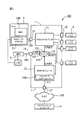
本発明の実施形態によるネットワークシステム100を示す図1を参照する。ネットワークシステム100は、単なるディスクの束(JBOD)装置1を有し、装置1は、ベースボードマネジメントコントローラ(BMC)モジュール104、ホスト2、端子3およびクライアントエンドコンピュータ4を有する。JBOD装置1は、それぞれ、且つ、独立して、複数のハードドライブ5を接続する。本発明のいくつかの実施形態において、JBOD装置1が設置されて、シリアルアタッチドSCSI(SAS)を採用する。理解できることは、ネットワークシステム100の構成は、ここでリストされるコンポーネントに単純化されているが、この限りではないことである。
Reference is made to FIG. 1 illustrating a
JBOD装置が設置されて、SASフォーマットをサポートすることができるケーブル101により、ホスト2に接続される。いくつかの実施形態において、ケーブル101はSASケーブルである。ホスト2を操作するとき、ユーザーは、ホスト2上のJBOD装置1にそれぞれ接続される複数のハードドライブ5にアクセスすることができる。これにより、ホスト2のアクセス可能なハードドライブの量が大幅に増加する。JBOD装置1がさらに設置されて、ケーブル102により、端子3に接続される。端子3は、マネジメントシステム110により操作される。
A JBOD device is installed and connected to the host 2 by a
いくつかの実施形態において、マネジメントシステム110は、端子3を操作して、JBOD装置1の問い合わせ情報のためのコマンドを送信するように構成することができる。たとえば、マネジメントシステム110は、JBOD装置1のケースの内側の環境温度、ファンの状態、電源の状態、または、複数のハードドライブ5の状態(たとえば、挿入、除去、起動、停止、失効等)を照会する。
In some embodiments, the
さらに、マネジメントシステム110は、ケーブル101のSAS JBODケーブルルーティング識別情報を検出し、ケーブル101ルートが期待どおりにホスト2に接続されているかどうかを確認することができる。特に、ケーブル101の識別情報は、JBOD装置1中でアドレスされるSASスイッチ13、および、ケーブル101のSASポート15の物理IDにより定義される。識別情報は、ホストバスアダプタ(HBA)21により、ホスト2により得られる。さらに、識別情報は、JBOD装置1内で、SASスイッチ13から得られる。その後、これらの二個の値が比較されて、ケーブル101を確認する。これは、以下でさらに詳細に議論される。
Further, the
いくつかの実施形態において、端子3は、x−modem通信プロトコルをサポートすることができ、マネジメントシステム110は、端子3により、ファームウェア更新ファイルをJBOD装置1に送信することができ、JBOD装置1のハードディスクドライブ(HDD)エキスパンダ11により用いられるファームウェアを更新する。
In some embodiments, the
本発明のいくつかの実施形態において、JBOD装置1は、BMCモジュール12で構成され得る。JBOD装置1は、BMCモジュール12を介して、ネットワーク103に接続される。このネットワーク103は、たとえば、ローカルエリアネットワーク(LAN)、広域ネットワーク(WAN)、インターネットにより通信リンクを用いた仮想プライベートネットワーク(VPN)であってよく、あるいは、LAN、WANおよびVPN実装の組み合わせが構築される。ここに記載した目的のため、ネットワークという用語は、任意の受け入れ可能なネットワーク機構を広範で含むべきである。たとえば、JBOD装置1は、BMCモジュール12によりイーサネット(登録商標)に接続される。JBOD装置1は、イーサネットにより、リモートクライアントエンドコンピュータ4に接続される。これにより、JBOD装置1は、ホスト2によりローカルユーザーから、または、端子3によりローカルマネージャーから、処理を受信する。さらに、JBOD装置1が設定されて、イーサネットにより、リモートクライアントエンドコンピュータ4と接続するとともに、別のユーザーからのイーサネットが送信したコマンドにしたがって、処理を実行する。いくつかの実施形態において、ユーザーは、ネットワーク103によりホスト2に接続されるとともに、ホスト2により遠隔で、JBOD装置を制御する。
In some embodiments of the present invention, the
JBOD装置1は、HDDエキスパンダ11、BMCモジュール12、および、スイッチ13を有する。特に、JBOD装置1は、第一接続ポート14、第二接続ポート15、複数の第三接続ポート16、および、ネットワークポート17を有する。
The
本発明のいくつかの実施形態において、HDDエキスパンダ11は、いくつかのケーブルにより、複数の第三接続ポート16に接続されて、複数の第三接続ポート16により、複数のハードドライブ5に接続される。あるいは、HDDエキスパンダ11は、いくつかのケーブルにより、複数の第三接続ポート16に接続されて、複数の第三接続ポート16により、その他のJBOD装置(図示しない)に接続される。この実施形態において、HDDエキスパンダ11が、JBOD装置1の情報を検出、および、確認するように構成することができる。たとえば、HDDエキスパンダ11が、JBOD装置1のケースの内側の環境温度、ファンの状態、電源の状態、複数のハードドライブ5の挿入状態や電源状態等を検出するように構成することができる。すなわち、HDDエキスパンダ11が、対応する装置データを生成するように構成することができる。この実施形態において、複数の第三接続ポート16は、シリアルATA(SATA)接続ポートまたはSAS接続ポートを有する。いくつかの実施形態において、複数のハードドライブ5は、SATAインターフェースまたはSASインターフェースをサポートするハードドライブを有するが、この限りではない。
In some embodiments of the present invention, the
HDDエキスパンダ11は、さらに、第二接続ポート15に接続されるとともに、第二接続ポート15により外部からホスト2に接続される。特に、ホスト2は、ホストバスアダプタ(HBA)21、および、BMCモジュール104を有する。いくつかの例示的実施形態において、第二接続ポート15はSAS接続ポートである。さらに、マネジメントシステム110が、ケーブル101により、HBA21と第二接続ポート15を接続するように構成することができる。いくつかの実施形態において、ケーブル101が、SASフォーマットをサポートし、ホスト2とJBOD装置1を接続する(つまり、ホスト2とHDDエキスパンダ11を接続する)ように構成することができる。
The
ホスト2は、この実施形態において、HBA21により、コマンドをJBOD装置1に送信して、JBOD装置1から必要な情報を要求する。さらに、ホスト2は、HBA21中にインストールされるプログラムにより、複数のハードドライブ5中にそれぞれ保存されるデータにアクセスすることができる。さらに、ホスト2がネットワーク(たとえば、LAN)に接続される場合、ホスト2は、ネットワークにより、リモートコマンドを受信するとともに、リモートコマンドにしたがって、対応する処理をJBOD装置1に実行する。たとえば、JBOD装置1から装置データを要求する、JBOD装置1、または、複数のハードドライブ5のそれぞれのオンオフを制御するなどである。
In this embodiment, the host 2 sends a command to the
いくつかの実施形態において、ケーブル101は、関連する識別情報を有する。この関連する識別情報は、JBOD装置1のBMCモジュール12中に保存される。本発明のいくつかの実施形態において、識別情報は、SASケーブルIDを有する。さらに、本発明のいくつかの実施形態において、識別情報は、スイッチの13のSASスイッチアドレスを有する。いくつかの実施形態において、識別情報は、第二接続ポート15のSAS接続ポート識別を有する。識別情報は、スイッチ13により、JBOD装置1のBMCモジュール12中に保存される。
In some embodiments, the
さらに、ケーブル101の識別情報は、ホスト2のBMCモジュール104中に保存される。たとえば、BMC104は、HBA21を用いて、JBOD装置1のSASトポロジーをスキャンして、スイッチ13のアドレスを受信する。さらに、BMC104は、HBA21を用いて、JBOD装置1のSASトポロジーをスキャンして、第二接続ポート15の接続ポート識別を受信する。回収時、識別情報は、JBOD装置1のBMCモジュール12中に保存される。
Further, the identification information of the
マネジメントシステム110は、別々に保存された識別情報に基づいて、ケーブル101を識別する。たとえば、マネジメントシステム110は、ホスト2のBMCモジュール104から、ケーブル101識別情報を要求する。さらに、マネジメントシステム110は、JBOD装置1のBMCモジュール12から、ケーブル101識別情報を要求する。これは以下で更に詳細に議論される。
The
スイッチ13は、HDDエキスパンダ11、BMCモジュール12、および、第一接続ポート14に接続される。特に、スイッチ13は、HDDエキスパンダ11と第一接続ポート14を接続して、第一送信チャネルを起動するとともに、HDDエキスパンダ11とBMCモジュール12を接続して、第二送信チャネルを起動する。この実施形態において、スイッチ13は、開閉信号を受信するともに、受信した開閉信号にしたがって、第一送信チャネル、または、第二送信チャネルを起動することを決定する。つまり、第一送信チャネル、および、第二送信チャネルは同時に起動されず、すなわち、HDDエキスパンダ11は、一度に、第一接続ポート14、または、BMCモジュール12と接続される。
The
特に、この実施形態中のスイッチ13は、第一コンタクト131、第二コンタクト132、および、第三コンタクト133を有し、スイッチ13は、第一コンタクト131により、HDDエキスパンダ11に接続され、第二コンタクト132により、第一接続ポート14に接続され、第三コンタクト133により、BMCモジュール12に接続される。第一送信チャネルの起動を選択するとき、スイッチ13は、第一コンタクト131と第二コンタクト132を接続する。第二送信チャネルの起動を選択するとき、スイッチ13は、第一コンタクト131と第二コンタクト132間の接続を切断するとともに、第一コンタクト131と第三コンタクト133の接続に変える。しかし、上記は、単なる特定の実施形態であり、本発明の範囲に制限されない。
In particular, the
第一接続ポート14が用いられて、端子3と外部で接続されて、端子3から送信されるコマンドを受信する。第一送信チャネルが起動された場合、HDDエキスパンダ11は、第一接続ポート14により端子3から送信されたコマンドを受信するともに、受信したコマンドに基づいて、対応動作を実行し、関連情報を端子3に回答する。
The
BMCモジュール12は、ネットワークポート17に接続され、ネットワークポート17により、ネットワーク103に接続される。この実施形態において、スイッチ13の初期設定は、第一送信チャネルを起動する。BMCモジュール12が、イーサネットにより離れた場所から送信される制御コマンドを受信するとき、開閉信号を生成して、スイッチ13に送信するとともに、スイッチ13を制御して、第二送信チャネルの起動に変更する。これにより、BMCモジュール12は、起動した第二送信チャネルにより、HDDエキスパンダ11と接続するとともに、ネットワーク103により送信される制御コマンドにしたがって、HDDエキスパンダ11と相互作用を実行する。この実施形態において、ネットワークポート17は、ローカルエリアネットワーク(LAN)ポートを有するが、この限りではない。
The
図1に示されるように、BMCモジュール12は、この実施形態において、さらに、汎用目的のI/O(GPIO)インターフェースにより、スイッチ13に接続されるとともに、GPIOインターフェースにより、開閉信号をスイッチ13に送信して、スイッチ13を制御して、第一送信チャネル、または、第二送信チャネルを起動する。
As shown in FIG. 1, in this embodiment, the
この実施形態において、HDDエキスパンダ11は、万能非同期送受信機(UART)フォーマットで信号をサポートするとともに、HDDエキスパンダ11は、UARTフォーマット信号を送信することにより、BMCモジュール12、および、第一接続ポート14と通信する(つまり、端子3は第一接続ポート14に接続される)。このほか、この実施形態におけるBMCモジュール12は、ネットワーク103により、LANフォーマットで制御コマンドを受信するともに、制御コマンドを、UARTフォーマットに転換した後、制御コマンドをHDDエキスパンダ11に送信する。図1に示されるように、BMCモジュール12は、ウェブページインターフェース120を有する。この実施形態において、BMCモジュール12は、ウェブページインターフェース120により、クライアントエンドコンピュータ4からリモート接続を受信する。これにより、BMCモジュール12は、ウェブページインターフェース120により、クライアントエンドコンピュータ4から遠隔で送信される制御コマンドを受信する。さらに特に、BMCモジュール12が起動後、ウェブページインターフェース120を自動で作動させ、ウェブページインターフェース120は、BMCモジュール12に割り当てられるIPアドレスを用いる。
In this embodiment, the
マネジメントシステム110は、ウェブページインターフェース120により、BMCモジュール12にアクセスすることができる。一例示的実施形態において、マネジメントシステム110は、JBOD装置1のBMCモジュール12から、ケーブル101識別情報を要求する。一旦受信すると、マネジメントシステム110は、JBOD装置1のBMCモジュール12中に保存されるケーブル101識別情報とホスト2のBMCモジュール104中に保存されるケーブル101識別情報を比較する。一旦比較すると、マネジメントシステム110は、SASケーブル101が、ホスト2とJBOD装置1間で連結することを確認する。この方法により、SASケーブルの電気的に消去可能なプログラマブルリードオンリメモリ(“EEPROM”)で、IDナンバーを人工的に読み取る面倒なプロセスが回避される。さらに、ユーザーは、遠隔起動して、どのSAS JBODが接続されるかを決定するとともに、SASケーブルが、遠隔JBODシステムに接続されるか否か確認する。EEPROMを備えているか、備えていない標準のSASケーブルを用いて、遠隔SAS JBODシステムに接続される。その結果、JBODをセットアップすれば、開示される実施形態は、人的ミスを減少させることができる。
The
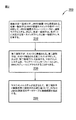
例示的マネジメントシステム110に関する方法200を実行するフローチャートが図2に示される。上述の詳細な説明のように、本発明の実施形態は、データストレージサーバ(JBOD装置1)、および、プロセシングノード(ホスト2)に接続されるデータケーブルに対し、ネットワークシステム中で、データケーブル接続をマッピングする方法を提供する。初期の問題として、ケーブル識別子は、プロセシングノード(ホスト2)で、BMC104により割り当てられる。特に、ケーブル101の識別情報は、JBOD装置1のSASスイッチ13のアドレス、および、ケーブル101のSASポート15の物理IDにより定義される。識別情報は、HBA21により、ホスト2により獲得される。さらに、識別情報は、JBOD装置1中のSASスイッチ13から得られる。BMC104は、SASポート15、および、SASスイッチ13のアドレスの物理IDのHBA21により、一スキャンに基づいて、ケーブル識別子を割り当てることができる。
A flowchart for performing the
工程210において、複数の第一識別子は、JBOD装置1から受信される。本発明のいくつかの実施形態において、JBOD装置1のストレージリソースに、遠隔でアクセスできるように、各第一識別子はJBOD装置1のスイッチの各ポートに対応する。さらに、各第一識別子は、各ポートに対応する第一スイッチアドレスと第一物理アドレスを有する。
In step 210, a plurality of first identifiers are received from the
工程220において、第二識別子はホスト2から受信される。いくつかの実施形態において、第二識別子は、ホスト2で検出される第二スイッチアドレス、および、第二物理アドレスを有する。マネジメントシステム110は、ウェブページインターフェース120により、BMCモジュール12にアクセスすることができる。一例示的実施形態において、マネジメントシステム110は、JBOD装置1のBMCモジュール12から、ケーブル101識別情報を要求する。
In step 220, the second identifier is received from host 2. In some embodiments, the second identifier has a second switch address detected at the host 2 and a second physical address. The
工程230において、マネジメントシステム110が設定されて、第二識別子と複数の第一識別子の比較に基づいて、ホスト2とJBOD装置1間のデータケーブル接続経路を検出する。
In
ここで開示される各種説明の論理ブロック、モジュール、および、回路は、汎用目的のプロセッサ、デジタルシグナルプロセッサ(DSP)、特定用途向け集積回路(ASIC)、フィールドプログラマブルゲートアレイ(FPGA)、または、その他のプログラム可能なロジック装置、離散ゲートまたはトランジスタロジック、離散ハードウェアコンポーネント、あるいは、記述される機能を実行するように設計されるそれらの任意の組み合わせで実施、または、実行される。汎用目的のプロセッサはマイクロプロセッサであるが、別の形態において、プロセッサは、任意の従来のプロセッサ、コントローラ、マイクロコントローラまたは状態機械である。プロセッサは、コンピューティングデバイスの組み合わせ、たとえば、DSPとマイクロプロセッサの組み合わせ、複数のマイクロプロセッサ、一つ以上のマイクロプロセッサとDSPコアの結合、または、任意の組み合わせとして実施される。 The variously described logic blocks, modules, and circuits disclosed herein may be general purpose processors, digital signal processors (DSPs), application specific integrated circuits (ASICs), field programmable gate arrays (FPGAs), or others. Implemented or implemented with any programmable logic device, discrete gate or transistor logic, discrete hardware components, or any combination thereof designed to perform the functions described. A general purpose processor is a microprocessor, but in the alternative, the processor is any conventional processor, controller, microcontroller, or state machine. The processor may be implemented as a combination of computing devices, such as a combination of a DSP and a microprocessor, a plurality of microprocessors, a combination of one or more microprocessors and a DSP core, or any combination.
ここで開示される方法やアルゴリズムの処理は、ハードウェア、プロセッサにより実行されるソフトウェアモジュール、または、二個の組み合わせで直接具体化される。ソフトウェアモジュールは、RAMメモリ、フラッシュメモリ、ROMメモリ、EPROMメモリ、EEPROMメモリ、レジスタ、ハードディスク、リムーバブルディスク、CD−ROMまたは既知のその他の任意の形式のストレージ媒体中に存在する。例示的ストレージ媒体はプロセッサに結合され、よって、プロセッサは、ストレージ媒体から情報を読み取ったり、ストレージ媒体に情報を書き込んだりする。別の方法では、ストレージ媒体は、プロセッサに整合される。プロセッサおよびストレージ媒体はASIC中に存在する。ASICはユーザー端子中に存在する。別の方法では、プロセッサおよびストレージ媒体は、ユーザー端子中の離散コンポーネントとして存在する。 The processing of the method and algorithm disclosed here is directly embodied by hardware, a software module executed by a processor, or a combination of the two. The software modules reside in RAM memory, flash memory, ROM memory, EPROM memory, EEPROM memory, registers, hard disks, removable disks, CD-ROMs or any other known form of storage medium. An exemplary storage medium is coupled to the processor such that the processor reads information from, and writes information to, the storage medium. In another method, the storage medium is aligned with the processor. The processor and storage medium reside in the ASIC. The ASIC is present in the user terminal. In the alternative, the processor and the storage medium exist as discrete components in a user terminal.
一つ以上の例示的設計において、記述される機能は、ハードウェア、ソフトウェア、ファームウェアまたはそれらの任意の組み合わせで実施される。ソフトウェアで実行される場合、機能は、不揮発性コンピュータ可読媒体上の一つ以上の指令やコードで、保存または送信される。不揮発性コンピュータ可読媒体は、コンピュータストレージ媒体、および、一か所からもう一か所へ、コンピュータプログラムの転移を促進する任意の媒体を含む通信媒体、を有する。ストレージ媒体は、汎用目的または特殊用途のコンピュータによりアクセス可能な任意の可用な媒体である。例として、これに限定されないが、このようなコンピュータ−可読媒体は、RAM、ROM、EEPROM、CD−ROM、または、その他の光学ディスクストレージ、磁気ディスクストレージまたはその他の磁気ストレージデバイス、または、指令またはデータ構造の形式の所望のプログラムコードを搭載または保存するとともに、汎用目的または特殊用途のコンピュータによりアクセスされる任意のその他の媒体、または、汎用目的または特殊用途のプロセッサを有する。ここで用いられるディスク(Disk)およびディスク(disc)は、コンパクトディスク(Compact Disc(CD))、レーザーディスク(登録商標)、光学ディスク、デジタル多用途ディスク(DVD)、フロッピーディスク(Floppy Disk)およびブルーレイディスクを含み、ディスク(disk)は、通常、磁性方式でデータを複製し、ディスク(disc)は、レーザー光学方式でデータを複製する。上述の組み合わせも、不揮発性コンピュータ−可読媒体の範囲に含まれるべきである。 In one or more exemplary designs, the functions described are implemented in hardware, software, firmware, or any combination thereof. When implemented in software, the functions are stored or transmitted in one or more instructions or code on a non-volatile computer-readable medium. Non-volatile computer-readable media includes computer storage media and communication media including any medium that facilitates transfer of a computer program from one place to another. A storage medium is any available medium that can be accessed by a general purpose or special purpose computer. By way of example, and not limitation, such computer-readable media can be RAM, ROM, EEPROM, CD-ROM, or other optical disk storage, magnetic disk storage or other magnetic storage device, or Contains any program code in the form of a data structure and has any other medium or general purpose or special purpose processor accessed by a general purpose or special purpose computer. Discs and discs used herein are compact discs (Compact Disc (CD)), laser discs (registered trademark), optical discs, digital versatile discs (DVDs), floppy discs (Floppy Discs) and Including a Blu-ray disc, a disk normally replicates data in a magnetic manner, and a disc replicates data in a laser optical manner. Combinations of the above should also be included within the scope of non-volatile computer-readable media.
本発明の各種実施形態が上記されたが、理解すべきことは、それらは例として表現されているだけであり、これに制限されないことである。開示される実施形態に基づいた多くの変化は、本発明の精神や範囲を逸脱しない条件下で実施される。よって、本発明の幅と範囲は、上記の任意の実施形態により制限されるべきではない。むしろ、本発明の範囲は、以下の請求項の範囲とそれらの等価物により定義されるべきである。 While various embodiments of the present invention have been described above, it should be understood that they are only presented as examples and are not limiting. Many variations based on the disclosed embodiments may be implemented under conditions that do not depart from the spirit and scope of the invention. Accordingly, the breadth and scope of the present invention should not be limited by any of the above-described embodiments. Rather, the scope of the invention is to be defined by the following claims and their equivalents.
本発明は、一つ以上の実施に関連して説明および記述されているが、当業者なら、上述の規格および添付図面の読み取りと理解に基づいて、等価変更および修正を行うことができる。このほか、本発明の特定の特徴がすでに、いくつかの実施のひとつだけに関連して記述されており、このような特徴は、一つ以上のその他の実施のその他の特徴と結合されて、任意の既知の、または、特定のアプリケーションに必要、および、有用である。 While the invention has been described and described in connection with one or more implementations, those skilled in the art can make equivalent changes and modifications based on reading and understanding the above-mentioned standards and the accompanying drawings. In addition, certain features of the present invention have already been described in connection with only one of several implementations, and such features combined with other features of one or more other implementations, Necessary and useful for any known or specific application.
ここで用いられる専門用語は、特定の実施形態を記述する目的であり、且つ、本発明の制限とするものではない。上下文で明確に指示されない限り、ここで使用される単数形“一”、“上述の”は複数形も含むことを意味する。さらに、“含む”、“有する”という用語、または、その変化形は、詳細な記述に用いられるのではなく、請求範囲となる。このような用語は、“包含する”という用語とある程度同じ意味で含まれる。 The terminology used herein is for the purpose of describing particular embodiments and is not intended to be limiting of the invention. As used herein, the singular forms “one” and “above” are intended to include the plural forms as well, unless the context clearly indicates otherwise. Further, the terms “comprising”, “having”, or variations thereof, are not used in the detailed description but are a claim. Such terms are included to some extent with the term “including”.
別に定義されない限り、本文中で使用される用語(技術および科学用語)は、本発明が属する当業者なら理解できる同じ意味を有する。たとえば、辞書で通常定義される用語は、相関技術の上下文中で、相同の意味を有すると解釈されるべきである。本文中で明確に定義されない限り、これらの用語は、理想化または過度に正式な意味として解釈されるべきではない。 Unless defined otherwise, terms used in the text (technical and scientific terms) have the same meaning as understood by one of ordinary skill in the art to which this invention belongs. For example, terms normally defined in a dictionary should be interpreted as having homologous meanings in the context of correlation techniques. Unless explicitly defined in the text, these terms should not be interpreted as idealized or overly formal.
1…JBOD装置
2…ホスト
3…端子
4…リモートクライアントエンドコンピュータ
5…複数のハードドライブ
11…ハードディスクドライブエキスパンダ
12…BMCモジュール
13…スイッチ
14…第一接続ポート
15…第二接続ポート
16…複数の第三接続ポート
17…ネットワークポート
21…ホストバスアダプタ
100…ネットワークシステム
101…ケーブル
102…ケーブル
103…ネットワーク
104…BMCモジュール
110…マネジメントシステム
120…ウェブページインターフェース
131…第一コンタクト
132…第二コンタクト
133…第三コンタクト
200…方法
DESCRIPTION OF
Claims (10)
スイッチデバイスを有するデータストレージサーバ、
それぞれが、ベースボードマネジメントコントローラ(BMC)、および、ホストバスアダプタ(HBA)を有する複数のプロセシングノード、ならびに、
前記データストレージサーバの前記スイッチデバイス、および、前記プロセシングノードの前記HBAに電気的に接続されたデータケーブルであって、ケーブル識別子が、前記プロセシングノードの前記BMC、および、前記データストレージサーバ中に保存されるデータケーブル、を有し、
前記データストレージサーバ、および、前記の各プロセシングノードは、前記プロセシングノードの前記BMC、および、前記データストレージサーバ中に保存される前記ケーブル識別子を読み取るように構成されるデータリソースマネージャーにより管理されることを特徴とするネットワークシステム。 A network system,
A data storage server having a switch device,
A plurality of processing nodes each having a baseboard management controller (BMC) and a host bus adapter (HBA); and
A data cable electrically connected to the switch device of the data storage server and the HBA of the processing node, wherein a cable identifier is stored in the BMC of the processing node and the data storage server Data cable, and
The data storage server and each of the processing nodes is managed by a data resource manager configured to read the BMC of the processing node and the cable identifier stored in the data storage server. A network system characterized by
前記スイッチデバイスのアドレス、および、
ポート物理層(PHY)識別子、
を有することを特徴とする請求項1に記載のネットワークシステム。 The cable identifier is
The address of the switch device, and
Port physical layer (PHY) identifier,
The network system according to claim 1, further comprising:
前記データストレージサーバから、複数の第一識別子を受信する工程であって、前記複数の第一識別子のそれぞれは、前記データストレージサーバの異なるストレージリソースに遠隔からアクセスするために、前記データストレージサーバのスイッチの各ポートに対応しており、前記複数の第一識別子のそれぞれが、各ポートに対応する第一スイッチアドレス、および、各ポートに対応する第一物理アドレスを有する工程、
前記プロセシングノードから、第二スイッチアドレス、および、前記プロセシングノードで検出される第二物理アドレスを有する第二識別子を受信する工程、および、
前記第二識別子と前記複数の第一識別子の比較に基づいて、前記プロセシングノードと前記データストレージサーバ間のデータケーブル接続経路を検出する工程、
を有する方法。 A method performed by a computer to map a data cable connection in a network system to a data cable connected to a data storage server and a processing node, comprising:
Receiving a plurality of first identifiers from the data storage server, wherein each of the plurality of first identifiers is configured to allow the data storage server to remotely access different storage resources of the data storage server. Corresponding to each port of the switch, each of the plurality of first identifiers having a first switch address corresponding to each port, and a first physical address corresponding to each port;
Receiving from the processing node a second identifier having a second switch address and a second physical address detected at the processing node; and
Detecting a data cable connection path between the processing node and the data storage server based on a comparison of the second identifier and the plurality of first identifiers;
Having a method.
Applications Claiming Priority (2)
| Application Number | Priority Date | Filing Date | Title |
|---|---|---|---|
| US15/681,072 US10387347B2 (en) | 2017-08-18 | 2017-08-18 | Method to locate SAS JBOD cable routing |
| US15/681,072 | 2017-08-18 |
Publications (1)
| Publication Number | Publication Date |
|---|---|
| JP2019036282A true JP2019036282A (en) | 2019-03-07 |
Family
ID=60953592
Family Applications (1)
| Application Number | Title | Priority Date | Filing Date |
|---|---|---|---|
| JP2018035129A Pending JP2019036282A (en) | 2017-08-18 | 2018-02-28 | Method and system for locating sas jbod cable routing |
Country Status (5)
| Country | Link |
|---|---|
| US (1) | US10387347B2 (en) |
| EP (1) | EP3444715A1 (en) |
| JP (1) | JP2019036282A (en) |
| CN (1) | CN109407965A (en) |
| TW (1) | TWI656764B (en) |
Families Citing this family (7)
| Publication number | Priority date | Publication date | Assignee | Title |
|---|---|---|---|---|
| US10832536B2 (en) * | 2018-12-07 | 2020-11-10 | International Business Machines Corporation | Guided cable management |
| TWI710953B (en) * | 2019-05-31 | 2020-11-21 | 緯創資通股份有限公司 | Firmware update device and firmware update method |
| US11502433B2 (en) * | 2021-02-10 | 2022-11-15 | Super Micro Computer, Inc. | Circuit card with onboard non-volatile memory for providing cable assembly data to network interface controller chips |
| CN115562564A (en) * | 2021-07-01 | 2023-01-03 | 伊姆西Ip控股有限责任公司 | Method, apparatus and program product for managing storage system |
| CN114006631B (en) * | 2021-09-17 | 2023-04-07 | 苏州浪潮智能科技有限公司 | Cable testing device and method based on code pattern signal verification |
| CN114003538B (en) * | 2021-10-22 | 2023-07-14 | 苏州浪潮智能科技有限公司 | A method for identifying an intelligent network card and the intelligent network card |
| CN116418845B (en) * | 2022-01-05 | 2026-04-07 | 昆达电脑科技(昆山)有限公司 | storage devices |
Family Cites Families (18)
| Publication number | Priority date | Publication date | Assignee | Title |
|---|---|---|---|---|
| EP1747917B1 (en) * | 2005-07-28 | 2009-10-21 | ebm-papst St. Georgen GmbH & Co. KG | Heating device |
| US7660638B2 (en) | 2005-09-30 | 2010-02-09 | Rockwell Automation Technologies, Inc. | Business process execution engine |
| JP5068023B2 (en) * | 2006-03-29 | 2012-11-07 | 株式会社日立製作所 | Computer system and logical path switching method |
| US8161393B2 (en) | 2007-09-18 | 2012-04-17 | International Business Machines Corporation | Arrangements for managing processing components using a graphical user interface |
| US8930537B2 (en) * | 2008-02-28 | 2015-01-06 | International Business Machines Corporation | Zoning of devices in a storage area network with LUN masking/mapping |
| US8184933B1 (en) * | 2009-09-22 | 2012-05-22 | Juniper Networks, Inc. | Systems and methods for identifying cable connections in a computing system |
| US10803970B2 (en) | 2011-11-14 | 2020-10-13 | Seagate Technology Llc | Solid-state disk manufacturing self test |
| US8739887B2 (en) * | 2012-07-03 | 2014-06-03 | Halliburton Energy Services, Inc. | Check valve for well stimulation |
| US8793406B2 (en) * | 2012-11-16 | 2014-07-29 | Hewlett-Packard Development Company, L.P. | SAS switch that supports bulk discovery wherein the bulk discovery is either on a push basis or pull basis |
| US8996778B2 (en) * | 2012-12-13 | 2015-03-31 | Lenovo Enterprise Solutions (Singapore) Pte. Ltd. | Cable adapter correlation in a cluster |
| CN106933775B (en) | 2013-10-29 | 2021-08-20 | 华为技术有限公司 | Data processing system and method of data processing |
| US9645744B2 (en) | 2014-07-22 | 2017-05-09 | Sandisk Technologies Llc | Suspending and resuming non-volatile memory operations |
| CN104951251B (en) * | 2015-05-29 | 2018-02-23 | 浪潮电子信息产业股份有限公司 | A cloud server system with integrated architecture |
| CN106341437B (en) * | 2015-07-09 | 2019-11-15 | 营邦企业股份有限公司 | JBOD device with BMC module and control method thereof |
| US10025742B2 (en) | 2015-09-22 | 2018-07-17 | Aic Inc. | JBOD apparatus having BMC module and controlling method for the same |
| US9965197B2 (en) | 2015-12-15 | 2018-05-08 | Quanta Computer Inc. | System and method for storage area network management using serial attached SCSI expander |
| CN105955898A (en) * | 2016-05-25 | 2016-09-21 | 浪潮电子信息产业股份有限公司 | A hard disk backplane compatible with SAS hard disks and NVMe hard disks |
| US10324888B2 (en) * | 2016-09-22 | 2019-06-18 | Lenovo Enterprise Solutions (Singapore) Pte. Ltd | Verifying a communication bus connection to a peripheral device |
-
2017
- 2017-08-18 US US15/681,072 patent/US10387347B2/en active Active
- 2017-11-23 TW TW106140708A patent/TWI656764B/en active
- 2017-12-20 CN CN201711382029.0A patent/CN109407965A/en active Pending
- 2017-12-21 EP EP17209889.9A patent/EP3444715A1/en not_active Withdrawn
-
2018
- 2018-02-28 JP JP2018035129A patent/JP2019036282A/en active Pending
Also Published As
| Publication number | Publication date |
|---|---|
| CN109407965A (en) | 2019-03-01 |
| US20190057056A1 (en) | 2019-02-21 |
| US10387347B2 (en) | 2019-08-20 |
| TW201914258A (en) | 2019-04-01 |
| TWI656764B (en) | 2019-04-11 |
| EP3444715A1 (en) | 2019-02-20 |
Similar Documents
| Publication | Publication Date | Title |
|---|---|---|
| US10387347B2 (en) | Method to locate SAS JBOD cable routing | |
| TWI580221B (en) | Method and system for high frequency wide server management and related non-transitory computer readable access media | |
| CN100524272C (en) | Managing transmissions between devices | |
| JP6656612B2 (en) | Network service configuration method and network management device | |
| US7921185B2 (en) | System and method for managing switch and information handling system SAS protocol communication | |
| US20140195634A1 (en) | System and Method for Multiservice Input/Output | |
| US8504770B2 (en) | System and method for representation of target devices in a storage router | |
| US20030229689A1 (en) | Method and system for managing stored data on a computer network | |
| US20100115132A1 (en) | Address identifier scaling in converged networks | |
| US20030221001A1 (en) | Method for mapping a network fabric | |
| US10534541B2 (en) | Asynchronous discovery of initiators and targets in a storage fabric | |
| US20060109850A1 (en) | IP-SAN network access control list generating method and access control list setup method | |
| TWI638553B (en) | Method for detecting internet protocol address and media access control address | |
| US7779082B2 (en) | Address management device | |
| CN102111436B (en) | Storage device and method for accessing storage device through internet small computer system interface (iSCSI) | |
| CN106992885B (en) | Method for identifying equipment in server system and server system | |
| CN106341437A (en) | JBOD device with BMC module and control method thereof | |
| CN104133723A (en) | Method for managing storage system | |
| CN103023726B (en) | Method and system for testing maximum mainframe connection number of network storage device | |
| WO2018214792A1 (en) | Method and device for traffic control of user equipment | |
| JP4485875B2 (en) | Storage connection changing method, storage management system and program | |
| CN116418845B (en) | storage devices | |
| US20070055838A1 (en) | Storage control system and storage controller | |
| US7698424B1 (en) | Techniques for presenting multiple data storage arrays to iSCSI clients as a single aggregated network array | |
| US9645961B2 (en) | Virtual media apparatus of a server and access method thereof |
Legal Events
| Date | Code | Title | Description |
|---|---|---|---|
| A621 | Written request for application examination |
Free format text: JAPANESE INTERMEDIATE CODE: A621 Effective date: 20180228 |
|
| A131 | Notification of reasons for refusal |
Free format text: JAPANESE INTERMEDIATE CODE: A131 Effective date: 20190423 |
|
| A02 | Decision of refusal |
Free format text: JAPANESE INTERMEDIATE CODE: A02 Effective date: 20191203 |