JP2019019910A - Gear change control device of automatic transmission for vehicle - Google Patents
Gear change control device of automatic transmission for vehicle Download PDFInfo
- Publication number
- JP2019019910A JP2019019910A JP2017139520A JP2017139520A JP2019019910A JP 2019019910 A JP2019019910 A JP 2019019910A JP 2017139520 A JP2017139520 A JP 2017139520A JP 2017139520 A JP2017139520 A JP 2017139520A JP 2019019910 A JP2019019910 A JP 2019019910A
- Authority
- JP
- Japan
- Prior art keywords
- gear
- shift
- gear stage
- simulated
- speed
- Prior art date
- Legal status (The legal status is an assumption and is not a legal conclusion. Google has not performed a legal analysis and makes no representation as to the accuracy of the status listed.)
- Pending
Links
Images


Abstract
Description
本発明は車両用自動変速機の変速制御装置に係り、特に、電気式無段変速部および機械式有段変速部を直列に備えている車両用自動変速機の変速制御装置に関するものである。 The present invention relates to a shift control device for an automatic transmission for a vehicle, and more particularly to a shift control device for an automatic transmission for a vehicle including an electric continuously variable transmission unit and a mechanical stepped transmission unit in series.
(a) 差動用回転機のトルク制御で駆動源の回転速度を無段階に変速して中間伝達部材に伝達することができる電気式無段変速部と、(b) 前記中間伝達部材と駆動輪との間に配設され、出力回転速度に対するその中間伝達部材の回転速度の変速比が異なる複数のATギヤ段を機械的に成立させることができる機械式有段変速部と、を有する車両用自動変速機が知られている。特許文献1に記載の装置はその一例であり、機械式有段変速部の変速時に、イナーシャ相における回転速度変化で変速ショックが発生することを抑制するため、駆動源回転速度を略一定に維持したまま電気式無段変速部を変速させることにより、機械式有段変速部のイナーシャ相を開始させる技術が記載されている。
(a) an electric continuously variable transmission unit capable of steplessly changing the rotational speed of the drive source by torque control of the differential rotating machine and transmitting it to the intermediate transmission member; and (b) driving the intermediate transmission member and the intermediate transmission member. A vehicle having a mechanical stepped transmission that is disposed between the wheels and that can mechanically establish a plurality of AT gear stages having different transmission speed ratios of the intermediate transmission member with respect to the output rotation speed. Automatic transmissions are known. The device described in
しかしながら、このような変速制御装置においても変速ショックを完全に防止することは困難で、駆動源回転速度が略一定であることから、僅かなショックでも運転者に違和感を生じさせる可能性があった。 However, even in such a shift control device, it is difficult to completely prevent a shift shock, and since the drive source rotational speed is substantially constant, even a slight shock may cause the driver to feel uncomfortable. .
本発明は以上の事情を背景として為されたもので、その目的とするところは、電気式無段変速部および機械式有段変速部を有する車両用自動変速機において、機械式有段変速部の変速時に変速ショックなどで運転者に生じさせる違和感を更に抑制することにある。 The present invention has been made in the background of the above circumstances, and an object thereof is to provide a mechanical stepped transmission unit in an automatic transmission for a vehicle having an electric continuously variable transmission unit and a mechanical stepped transmission unit. It is to further suppress the uncomfortable feeling caused to the driver by a shift shock or the like during the shift.
かかる目的を達成するために、本発明は、(a) 差動用回転機のトルク制御で駆動源の回転速度を無段階に変速して中間伝達部材に伝達することができる電気式無段変速部と、(b) 前記中間伝達部材と駆動輪との間に配設され、出力回転速度に対するその中間伝達部材の回転速度の変速比が異なる複数のATギヤ段を機械的に成立させることができる機械式有段変速部と、を有する車両用自動変速機の変速制御装置において、(c) 前記機械式有段変速部の出力回転速度に対する前記駆動源回転速度の変速比が異なる複数の模擬ギヤ段を成立させるように前記電気式無段変速部を制御する模擬有段変速制御部を有し、且つ、(d) その模擬有段変速制御部は、(d-1) 前記模擬ギヤ段の変速制御が前記ATギヤ段の変速制御と重なる同時変速時に、変速応答時間の相違に拘らず両者の変速が同期して行なわれるように、ATギヤ段の変速指令出力に対して模擬ギヤ段の変速指令出力を遅延させる同期変速制御部と、(d-2) その同期変速制御部により前記模擬ギヤ段をダウン変速させる際に、そのダウン変速指令出力に先立って、ダウン変速指令の目標模擬ギヤ段と現在模擬ギヤ段との間の中間模擬ギヤ段へ分割して変速する変速指令を出力する分割変速部と、を有することを特徴とする。 In order to achieve such an object, the present invention provides (a) an electric continuously variable transmission capable of steplessly changing the rotational speed of a drive source by torque control of a differential rotating machine and transmitting it to an intermediate transmission member. And (b) mechanically establishing a plurality of AT gear stages disposed between the intermediate transmission member and the drive wheel and having different transmission gear ratios of the intermediate transmission member with respect to the output rotational speed. In a vehicle automatic transmission shift control device having a mechanical stepped transmission unit capable of: (c) a plurality of simulations having different gear ratios of the drive source rotational speed to the output rotational speed of the mechanical stepped transmission unit A simulated stepped transmission control unit that controls the electric continuously variable transmission unit to establish a gear stage, and (d) the simulated stepped transmission control unit includes (d-1) the simulated gear stage At the same time when the gear shift control overlaps the gear shift control of the AT gear stage, A synchronous shift control unit that delays the shift command output of the simulated gear stage with respect to the shift command output of the AT gear stage so that the two gears are synchronized in spite of the difference between them, and (d-2) When the downshift of the simulated gear stage is performed by the synchronous shift control unit, prior to the downshift command output, it is divided into an intermediate simulated gear stage between the target simulated gear stage of the downshift command and the current simulated gear stage. A split transmission unit that outputs a shift command for shifting.
なお、模擬ギヤ段の変速およびATギヤ段の変速の同期とは、両者の変速時のイナーシャ相(変速比の変化に応じて入力側部材の回転速度が変化する時間帯)の少なくとも一部が重複(オーバーラップ)することである。また、変速応答時間は、変速指令出力からイナーシャ相開始までの遅れ時間である。 Note that the synchronization of the shift of the simulated gear stage and the shift of the AT gear stage means that at least a part of the inertia phase at the time of both shifts (a time zone in which the rotation speed of the input side member changes according to the change of the transmission ratio). It is to overlap. The shift response time is a delay time from the shift command output to the start of the inertia phase.
このような車両用自動変速機の変速制御装置においては、機械式有段変速部の出力回転速度に対する駆動源回転速度の変速比が異なる複数の模擬ギヤ段が電気式無段変速部によって成立させられるため、その模擬ギヤ段の変速時に駆動源回転速度が段階的に変化させられるようになり、変速機全体として機械式有段変速機と同様の変速フィーリングが得られる。また、模擬ギヤ段の変速制御がATギヤ段の変速制御と重なる同時変速時に、両者の変速が同期して行なわれるように模擬ギヤ段の変速指令出力が遅延させられるため、変速応答時間の相違に拘らず両者の変速が同期して行なわれるようになり、変速ショック等により運転者に与える違和感が抑制されてドラビリが向上する。すなわち、電気式無段変速部の変速応答時間は機械式有段変速部の変速応答時間よりも短いため、両者の変速指令が同時に出力されると、電気式無段変速部の変速に伴う駆動源の回転速度変化と、機械式有段変速部の変速に伴う中間伝達部材の回転速度変化とがずれて、運転者に違和感を生じさせる可能性がある。また、このように模擬ギヤ段の変速とATギヤ段の変速が同期して行なわれると、駆動源の回転速度変化を伴って機械式有段変速部の変速が行なわれるため、その機械式有段変速部の変速時に変速ショックがあっても運転者に違和感を与え難くなる。 In such a transmission control device for an automatic transmission for a vehicle, a plurality of simulated gear stages having different gear ratios of the drive source rotational speed to the output rotational speed of the mechanical stepped transmission unit are established by the electric continuously variable transmission unit. Therefore, the drive source rotation speed can be changed stepwise during the shifting of the simulated gear stage, and the same transmission feeling as that of the mechanical stepped transmission can be obtained as a whole of the transmission. Further, when the shift control of the simulated gear stage overlaps with the shift control of the AT gear stage, the shift command output of the simulated gear stage is delayed so that the two gears are synchronized with each other. Regardless of the speed change, the two gears are synchronized with each other, and the uncomfortable feeling given to the driver by a shift shock or the like is suppressed, thereby improving the drivability. That is, since the shift response time of the electric continuously variable transmission unit is shorter than the shift response time of the mechanical stepped transmission unit, if both shift commands are output simultaneously, the drive associated with the shift of the electric continuously variable transmission unit There is a possibility that the change in the rotation speed of the source and the change in the rotation speed of the intermediate transmission member associated with the shift of the mechanical stepped transmission unit are shifted, causing the driver to feel uncomfortable. Further, when the shift of the simulated gear stage and the AT gear stage are synchronized in this manner, the mechanical stepped transmission unit is shifted with a change in the rotational speed of the drive source. Even if there is a shift shock at the time of shifting of the step shifting portion, it is difficult for the driver to feel uncomfortable.
一方、このように同時変速時にATギヤ段の変速に同期して模擬ギヤ段の変速が行なわれるようにすると、例えばアクセルの踏込みに伴って自動的にダウン変速したり、或いは運転者のシフトレバーなどによる手動操作に従ってダウン変速したりする場合、実際にダウン変速して駆動源の回転速度変化(イナーシャ相)が開始するまでの所要時間が長くなるため、その応答遅れで運転者がヘジテーション(ちゅうちょ感)を感じる可能性がある。例えば、被駆動状態から駆動状態へ変化するチップイン加速時に、歯打ち音等の発生を抑制するために駆動源トルクの立上りになまし処理が行なわれ、そのトルクの立上りを待ってATギヤ段の変速指令が出力される場合や、油圧式摩擦係合装置によってATギヤ段の変速が行なわれる機械式有段変速部において作動油の粘性が高い低油温時等には、イナーシャ相等の実際の変速の開始が遅くなるため、それに伴って模擬ギヤ段の変速も遅くなると、ヘジテーションを一層強く感じるようになる。また、運転者の加速要求が大きい場合にも、ヘジテーションを感じ易くなる。これに対し、本発明では、同期変速制御部により模擬ギヤ段をダウン変速させる際に、そのダウン変速指令出力に先立って中間模擬ギヤ段へ分割して変速する変速指令を出力する分割変速部を備えており、中間模擬ギヤ段まで先行してダウン変速するため、駆動源回転速度が速やかに上昇させられるようになり、応答性が向上してヘジテーションが抑制される。 On the other hand, if the shift of the simulated gear stage is performed in synchronism with the shift of the AT gear stage at the same time as described above, for example, the downshift is automatically performed when the accelerator is depressed, or the driver's shift lever When shifting down manually according to manual operation, etc., the time required to actually start shifting down and the rotational speed change (inertia phase) of the drive source starts increases. Feeling). For example, during tip-in acceleration that changes from the driven state to the driven state, a smoothing process is performed on the rise of the drive source torque in order to suppress the occurrence of rattling noise, etc., and the AT gear stage waits for the rise of the torque. When the gear shift command is output, or when the oil pressure of the hydraulic oil is high and the oil pressure is high in a mechanical stepped transmission where the AT gear stage is shifted by a hydraulic friction engagement device, the actual inertia phase, etc. Since the start of the gear shift is delayed, the hesitation is more strongly felt when the shift of the simulated gear stage is also slowed accordingly. In addition, hesitation is easily felt even when the driver demands acceleration. On the other hand, in the present invention, when the simulated gear stage is shifted down by the synchronous shift control unit, a split transmission unit that outputs a shift command to shift to the intermediate simulated gear stage before the down shift command output is provided. Since the downshift is performed up to the intermediate simulation gear stage, the drive source rotational speed can be quickly increased, and the response is improved and hesitation is suppressed.
駆動源としては、燃料の燃焼で動力を発生する内燃機関等のエンジンや電動モータなどが好適に用いられる。電気式無段変速部は、例えば遊星歯車装置等の差動機構を有して構成されるが、インナロータおよびアウタロータを有する対ロータ電動機を用いることも可能で、それ等のロータの何れか一方に駆動源が連結され、他方に中間伝達部材が連結される。対ロータ電動機は、モータジェネレータと同様に力行トルクおよび回生トルクを選択的に出力できるもので、差動用回転機としても機能する。駆動源や中間伝達部材は、必要に応じてクラッチや変速歯車等を介して上記差動機構等に連結される。中間伝達部材には、必要に応じて走行駆動用回転機が直接または変速歯車等を介して連結される。 As the drive source, an engine such as an internal combustion engine that generates power by burning fuel or an electric motor is preferably used. The electric continuously variable transmission unit is configured to have a differential mechanism such as a planetary gear device, for example, but it is also possible to use a counter-rotor motor having an inner rotor and an outer rotor, and either of these rotors is used. A drive source is connected, and an intermediate transmission member is connected to the other. The counter-rotor motor can selectively output a power running torque and a regenerative torque like a motor generator, and also functions as a differential rotating machine. The drive source and the intermediate transmission member are connected to the differential mechanism and the like via a clutch, a transmission gear, and the like as necessary. The intermediate transmission member is connected to a traveling drive rotating machine directly or via a transmission gear or the like as necessary.
電気式無段変速部の差動機構としては、シングルピニオン型或いはダブルピニオン型の単一の遊星歯車装置が好適に用いられる。この遊星歯車装置はサンギヤ、キャリア、およびリングギヤの3つの回転要素を備えているが、それ等の回転速度を1本の直線で結ぶことができる共線図において、例えば中間に位置する回転速度が中間の回転要素(シングルピニオン型遊星歯車装置のキャリア、ダブルピニオン型遊星歯車装置のリングギヤ)に駆動源が連結され、両端の回転要素に差動用回転機および中間伝達部材が連結されるが、中間の回転要素に中間伝達部材を連結するようにしても良い。この3つの回転要素は、常に差動回転可能であっても良いが、任意の2つをクラッチにより一体的に連結できるようにして、運転状態に応じて一体回転させるようにしたり、差動用回転機が連結される回転要素をブレーキにより回転停止できるようにしたりして、差動回転を制限することも可能である。複数の遊星歯車装置を組み合わせた差動機構を採用することもできる。 As the differential mechanism of the electric continuously variable transmission unit, a single planetary gear device of a single pinion type or a double pinion type is preferably used. This planetary gear device includes three rotating elements, a sun gear, a carrier, and a ring gear. In a collinear diagram in which these rotational speeds can be connected by a single straight line, for example, the rotational speed located in the middle is A drive source is connected to an intermediate rotating element (a carrier of a single pinion type planetary gear unit, a ring gear of a double pinion type planetary gear unit), and a differential rotating machine and an intermediate transmission member are connected to the rotating elements at both ends. An intermediate transmission member may be coupled to the intermediate rotation element. These three rotating elements may always be capable of differential rotation, but any two can be integrally connected by a clutch so that they can be integrally rotated according to the operating state, or for differential use. It is also possible to limit the differential rotation by making it possible to stop the rotation of the rotating element connected to the rotating machine by a brake. A differential mechanism in which a plurality of planetary gear devices are combined may be employed.
回転機は回転電気機械のことで、具体的には電動モータ、発電機、或いはその両方の機能を択一的に用いることができるモータジェネレータである。差動用回転機として発電機を採用し、走行駆動用回転機として電動モータを採用することもできるが、種々の運転状態を想定した場合、差動用回転機、走行駆動用回転機の何れもモータジェネレータを用いることが望ましい。 The rotating machine is a rotating electric machine, and specifically, a motor generator that can alternatively use the functions of an electric motor, a generator, or both. A generator can be adopted as the differential rotator and an electric motor can be adopted as the traveling drive rotator. However, when various operating conditions are assumed, either the differential rotator or the traveling drive rotator can be used. It is also desirable to use a motor generator.
機械式有段変速部としては、遊星歯車式や平行軸式の変速機が広く用いられており、例えば複数の油圧式摩擦係合装置が係合、解放されることによって複数のギヤ段(ATギヤ段)が成立させられるように構成される。複数のATギヤ段は前進ギヤ段が適当であるが、後進ギヤ段であっても良い。 As the mechanical stepped transmission unit, a planetary gear type or a parallel shaft type transmission is widely used. For example, when a plurality of hydraulic friction engagement devices are engaged and released, a plurality of gear stages (AT (Gear stage) is established. The plurality of AT gears are suitably forward gears, but may be reverse gears.
複数の模擬ギヤ段は、それぞれの変速比を維持できるように出力回転速度に応じて駆動源回転速度を制御することによって成立させられるが、各変速比は必ずしも機械式有段変速部のATギヤ段のように一定値である必要はなく、所定範囲で変化させても良いし、各部の回転速度の上限や下限等によって制限が加えられても良い。複数の模擬ギヤ段は、予め定められた模擬ギヤ段変速条件に従って変速されるようにすることが望ましい。模擬ギヤ段変速条件は、例えば出力回転速度およびアクセル操作量等の車両の運転状態をパラメータとして予め定められたアップ変速線やダウン変速線等の変速マップが適当であるが、その他の自動変速条件を定めることもできるし、シフトレバーやアップダウンスイッチ等による運転者の変速要求に従って変速するものでも良い。分割変速部はダウン変速に関するものであるが、模擬有段変速制御部および同期変速制御部は、アップ変速およびダウン変速の両方に適用しても良いし、ダウン変速だけに適用しても良い。すなわち、ダウン変速については模擬有段変速を行い、アップ変速については無段変速を行なうようにしても良い。また、常に模擬有段変速が行なわれる必要はなく、スポーツ走行モード等の一定の条件下で模擬有段変速が行なわれるだけでも良い。分割変速部は、少なくともダウン変速時に中間模擬ギヤ段への分割変速を先行して行なうが、アップ変速時にも中間模擬ギヤ段への分割変速を先行して行なうようにしても良い。 The plurality of simulated gears are established by controlling the drive source rotational speed according to the output rotational speed so that the respective gear ratios can be maintained. However, each gear ratio is not necessarily the AT gear of the mechanical stepped transmission unit. It does not have to be a constant value as in the stage, and may be changed within a predetermined range, or may be limited by an upper limit or a lower limit of the rotation speed of each part. It is desirable that the plurality of simulated gears be shifted in accordance with predetermined simulated gear shift conditions. As the simulated gear shift conditions, for example, a shift map such as an up shift line or a down shift line determined in advance using the vehicle operating state such as output rotation speed and accelerator operation amount as parameters is appropriate. Alternatively, the gear may be shifted according to the driver's shift request by a shift lever, an up / down switch, or the like. The split transmission unit relates to the down shift, but the simulated stepped shift control unit and the synchronous shift control unit may be applied to both the up shift and the down shift, or may be applied only to the down shift. That is, a simulated stepped shift may be performed for the down shift, and a continuously variable shift may be performed for the up shift. Moreover, it is not always necessary to perform the simulated stepped shift, and the simulated stepped shift may be performed only under certain conditions such as a sports driving mode. The split transmission unit performs the split shift to the intermediate simulated gear stage at least at the time of the down shift, but may also perform the split shift to the intermediate simulated gear stage at the time of the up shift.
複数の模擬ギヤ段の段数は複数のATギヤ段の段数以上が望ましく、例えば各ATギヤ段に対してそれぞれ1または複数の模擬ギヤ段を成立させるように割り当てられるとともに、複数のATギヤ段の変速条件は、模擬ギヤ段の変速タイミングと同じタイミングで変速が行なわれるように定められることが望ましい。このようにすれば、駆動源の回転速度変化を伴って機械式有段変速部の変速が行なわれるため、その機械式有段変速部の変速時に変速ショックがあっても運転者に違和感を与え難くなる。模擬ギヤ段の段数はATギヤ段の段数の2倍以上(例えば2倍〜3倍程度)が適当である。ATギヤ段の変速は、中間伝達部材やその中間伝達部材に連結される走行駆動用回転機の回転速度が所定の回転速度範囲内に保持されるように行なうもので、模擬ギヤ段の変速は、駆動源回転速度が所定の回転速度範囲内に保持されるように行なうものであり、それ等の段数は適宜定められるが、一般的な車両の場合、ATギヤ段の段数は例えば2速〜6速程度の範囲内が適当で、模擬ギヤ段の段数は例えば5速〜12速程度の範囲内が適当である。 The number of stages of the plurality of simulated gear stages is preferably equal to or greater than the number of stages of the plurality of AT gear stages. For example, each of the AT gear stages is assigned so as to establish one or a plurality of simulated gear stages. The speed change condition is desirably determined so that the speed change is performed at the same timing as the speed change timing of the simulated gear. In this way, since the gear step of the mechanical stepped transmission is performed with a change in the rotational speed of the drive source, even if there is a shift shock during the shift of the mechanical stepped transmission unit, the driver feels uncomfortable. It becomes difficult. The number of simulated gears is suitably at least twice (for example, about 2 to 3 times) the number of AT gears. The AT gear stage shift is performed so that the rotation speed of the intermediate transmission member and the traveling drive rotating machine connected to the intermediate transmission member is maintained within a predetermined rotation speed range. The rotational speed of the drive source is maintained within a predetermined rotational speed range, and the number of stages is appropriately determined. In the case of a general vehicle, the number of stages of the AT gear stage is, for example, from 2nd speed to The range of about 6th speed is appropriate, and the number of simulated gears is, for example, about 5th to 12th speed.
模擬ギヤ段の変速制御がATギヤ段の変速制御と重なる同時変速は、共通の変速条件(変速マップなど)に従って同時に変速判断が行なわれる場合の他、模擬ギヤ段の変速判断が為された時に既にATギヤ段の変速制御が実行中の場合であっても良い。模擬ギヤ段の変速およびATギヤ段の変速が同期して行なわれるようにする同期変速制御は、両者の変速時のイナーシャ相(変速比の変化に応じて入力側部材の回転速度が変化する時間帯)の少なくとも一部が重複(オーバーラップ)するように、模擬ギヤ段の変速指令出力を遅延させる制御である。変速指令出力の遅延を解除するタイミング、すなわち変速指令を出力するタイミングは、例えばATギヤ段の変速指令出力後の経過時間が、両者の変速応答時間の差に応じて予め実験やシミュレーション等により定められた遅延時間に達したか否かによって判断できるが、ATギヤ段の変速時の中間伝達部材の回転速度変化からイナーシャ相開始を検出したり、変速を実行する摩擦係合装置の油圧すなわち係合トルク等から変速の進行度合を検出したりして判断しても良い。 The simultaneous shift in which the shift control of the simulated gear stage overlaps with the shift control of the AT gear stage is performed when the shift determination of the simulated gear stage is made in addition to the case where the shift determination is performed simultaneously according to common shift conditions (shift map, etc.). It may be a case where the shift control of the AT gear stage is already being executed. Synchronous shift control in which the shift of the simulated gear stage and the shift of the AT gear stage are performed in synchronism is the inertia phase (the time during which the rotational speed of the input side member changes according to the change in the gear ratio). In this control, the shift command output of the simulated gear stage is delayed so that at least a part of the band) overlaps. The timing at which the delay of the shift command output is released, that is, the timing at which the shift command is output is determined, for example, by an experiment or simulation in advance in accordance with the difference between the shift response times of the two gears. It is possible to determine whether or not the predetermined delay time has been reached, but it is possible to detect the start of the inertia phase from the change in the rotational speed of the intermediate transmission member during the shift of the AT gear stage, or to determine the hydraulic pressure of the friction engagement device that performs the shift. The determination may be made by detecting the degree of progress of the shift from the combined torque or the like.
分割変速部は、例えば(a) 予め定められた分割条件に従って中間模擬ギヤ段への分割変速を行なうか否かを判断する分割変速判断部と、(b) アクセル開度(操作量)等の車両状態に応じて中間模擬ギヤ段を設定する中間模擬ギヤ段設定部と、(c) 模擬ギヤ段の変速判断以後の予め定められたタイミングで中間模擬ギヤ段への変速指令を出力する分割変速出力部と、を有して構成される。分割条件は、例えば運転者がヘジテーションを感じる可能性があるか否かを基準として定められ、具体的には被駆動状態から駆動状態へ変化するチップイン加速時や、油圧式摩擦係合装置の係合解放動作が遅くなる作動油の低油温時、或いは運転者の加速要求が大きいと判断できるアクセル開度変化量が所定値以上の場合、などである。中間模擬ギヤ段設定部は、例えば運転者の出力要求量に対応するアクセル開度に応じて最適な中間模擬ギヤ段を設定するように構成されるが、低油温時やバッテリー制限時、差動用回転機の出力制限時など変速制御の制御性が悪くて変速ショックを発生し易い場合には、変速ショックが抑制されるように設定可能な中間模擬ギヤ段の範囲を制限しても良い。この中間模擬ギヤ段の制限は、例えばATギヤ段との関係で定められる。分割変速出力部による中間模擬ギヤ段への変速指令の出力タイミングは、例えば模擬ギヤ段の変速判断が為された直後が適当であるが、目標模擬ギヤ段への変速指令出力前であれば変速判断後の経過時間等によって適当に定めることができる。 The split transmission unit includes, for example, (a) a split shift determination unit that determines whether or not to perform a split shift to the intermediate simulated gear according to a predetermined split condition, and (b) an accelerator opening (operation amount), etc. An intermediate simulated gear stage setting unit that sets an intermediate simulated gear stage according to the vehicle state; and (c) a split shift that outputs a shift command to the intermediate simulated gear stage at a predetermined timing after the determination of the shift of the simulated gear stage. And an output unit. The division condition is determined based on, for example, whether or not the driver may feel hesitation, and specifically, during tip-in acceleration when changing from the driven state to the driven state, or the hydraulic friction engagement device For example, when the temperature of the hydraulic oil is low, or the amount of change in the accelerator opening that can be determined that the driver's acceleration request is large is greater than or equal to a predetermined value. The intermediate simulation gear stage setting unit is configured to set an optimal intermediate simulation gear stage according to the accelerator opening corresponding to the driver's output request amount, for example, at low oil temperature or when the battery is limited. If the controllability of the shift control is poor, such as when the output of the dynamic rotating machine is limited, and a shift shock is likely to occur, the range of the intermediate simulated gear stage that can be set so as to suppress the shift shock may be limited. . The limit of the intermediate simulated gear stage is determined, for example, in relation to the AT gear stage. The output timing of the shift command to the intermediate simulated gear stage by the split shift output unit is appropriate, for example, immediately after the shift determination of the simulated gear stage is made. It can be appropriately determined according to the elapsed time after the determination.
分割変速部は、上記のように予め定められた一定の条件下で中間模擬ギヤ段への分割変速を実行するだけでも良いが、ATギヤ段との同時ダウン変速時に模擬ギヤ段の飛び変速を行なう場合には、常に分割変速部により中間模擬ギヤ段を経て目標模擬ギヤ段へ変速しても良い。中間模擬ギヤ段は、アクセル開度等の車両状態に応じて設定することが望ましいが、例えば目標模擬ギヤ段の1つ上の模擬ギヤ段や現在模擬ギヤ段の一つ下の模擬ギヤ段など、予め一定の模擬ギヤ段が定められても良い。分割変速部による中間模擬ギヤ段の数は1つでも良いが、3段階以上に分割して段階的にダウン変速するように複数設定しても良い。 The split transmission unit may only execute the split shift to the intermediate simulated gear stage under a predetermined condition as described above. However, the split shift unit performs the jump shift of the simulated gear stage at the time of simultaneous downshift with the AT gear stage. When performing, it may always shift to the target simulated gear stage through the intermediate simulated gear stage by the split transmission unit. Although it is desirable to set the intermediate simulated gear according to the vehicle state such as the accelerator opening, for example, a simulated gear that is one higher than the target simulated gear or a simulated gear that is one lower than the current simulated gear A certain simulated gear stage may be determined in advance. The number of intermediate simulated gears by the divided transmission unit may be one, but a plurality of intermediate simulated gears may be set so as to be divided into three or more stages and downshifted in stages.
以下、本発明の実施例を、図面を参照して詳細に説明する。
図1は、車両10に備えられた車両用駆動装置12の概略構成を説明する図であると共に、車両10における各種制御のための制御系統の要部を説明する図である。図1において、車両用駆動装置12は、エンジン14と、車体に取り付けられる非回転部材としてのトランスミッションケース16(以下、ケース16という) 内において共通の軸心上に配設された、エンジン14に直接或いは図示しないダンパーなどを介して間接的に連結された電気式無段変速部18と、電気式無段変速部18の出力側に連結された機械式有段変速部20とを直列に備えている。また、車両用駆動装置12は、機械式有段変速部20の出力回転部材である出力軸22、その出力軸22に連結された差動歯車装置24、差動歯車装置24に連結された一対の車軸26、および車輪28等を備えている。車両用駆動装置12において、エンジン14や第2回転機MG2から出力される動力(特に区別しない場合にはトルクや力も同義) は、機械式有段変速部20へ伝達され、その機械式有段変速部20から差動歯車装置24等を介して駆動輪28へ伝達される。車両用駆動装置12は、例えば車両10において縦置きされるFR(フロントエンジン・リヤドライブ) 型車両に好適に用いられるものである。なお、電気式無段変速部18や機械式有段変速部20等はエンジン14などの回転軸心(上記共通の軸心) に対して略対称的に構成されており、図1ではその回転軸心の下半分が省略されている。
Hereinafter, embodiments of the present invention will be described in detail with reference to the drawings.
FIG. 1 is a diagram illustrating a schematic configuration of a
エンジン14は、車両10の走行用の駆動源であり、ガソリンエンジンやディーゼルエンジン等の公知の内燃機関である。このエンジン14は、電子制御装置80によってスロットル弁開度或いは吸入空気量、燃料供給量、点火時期等の運転状態が制御されることによりエンジントルクTe が制御される。本実施例では、エンジン14は、トルクコンバータやフルードカップリング等の流体式伝動装置を介することなく電気式無段変速部18に連結されている。
The
電気式無段変速部18は、第1回転機MG1と、エンジン14の動力を第1回転機MG1、および電気式無段変速部18の出力回転部材である中間伝達部材30に機械的に分割する動力分割機構としての差動機構32と、中間伝達部材30に動力伝達可能に連結された第2回転機MG2とを備えている。電気式無段変速部18は、第1回転機MG1の運転状態が制御されることにより差動機構32の差動状態が制御される電気式差動部であり、電気式無段変速機である。第1回転機MG1は差動用回転機に相当し、また、第2回転機MG2は、走行用の駆動源として機能する電動機であって、走行駆動用回転機に相当する。車両10は、走行用の駆動源として、エンジン14および第2回転機MG2を備えているハイブリッド車両である。
The electric continuously
第1回転機MG1および第2回転機MG2は、電動機(モータ) としての機能および発電機(ジェネレータ) としての機能を有する回転電気機械であって、所謂モータジェネレータである。第1回転機MG1および第2回転機MG2は、各々、車両10に備えられたインバータ50を介して、車両10に備えられたバッテリ52に接続されており、電子制御装置80によってインバータ50が制御されることにより、第1回転機MG1および第2回転機MG2の各々の出力トルク(力行トルクまたは回生トルク) であるMG1トルクTg およびMG2トルクTm が制御される。バッテリ52は、第1回転機MG1および第2回転機MG2の各々に対して電力を授受する蓄電装置である。
The first rotating machine MG1 and the second rotating machine MG2 are rotary electric machines having a function as an electric motor (motor) and a function as a generator (generator), and are so-called motor generators. The first rotating machine MG1 and the second rotating machine MG2 are each connected to a
差動機構32は、シングルピニオン型の遊星歯車装置にて構成されており、サンギヤS0、キャリアCA0、およびリングギヤR0の3つの回転要素を差動回転可能に備えている。キャリアCA0には連結軸34を介してエンジン14が動力伝達可能に連結され、サンギヤS0には第1回転機MG1が動力伝達可能に連結され、リングギヤR0には第2回転機MG2が動力伝達可能に連結されている。差動機構32において、キャリアCA0は入力要素として機能し、サンギヤS0は反力要素として機能し、リングギヤR0は出力要素として機能する。
The
機械式有段変速部20は、中間伝達部材30と駆動輪28との間の動力伝達経路の一部を構成する有段変速機である。中間伝達部材30は、機械式有段変速部20の入力回転部材(AT入力回転部材)としても機能する。中間伝達部材30には第2回転機MG2が一体回転するように連結されているので、機械式有段変速部20は、第2回転機MG2と駆動輪28との間の動力伝達経路の一部を構成する有段変速機である。機械式有段変速部20は、例えば第1遊星歯車装置36および第2遊星歯車装置38の複数組の遊星歯車装置と、クラッチC1、クラッチC2、ブレーキB1、ブレーキB2の複数の係合装置(以下、特に区別しない場合は単に係合装置CBという) とを備えている、公知の遊星歯車式の自動変速機である。
The mechanical stepped
係合装置CBは、油圧アクチュエータにより押圧される多板式或いは単板式のクラッチやブレーキ、油圧アクチュエータによって引き締められるバンドブレーキなどにより構成される、油圧式の摩擦係合装置である。係合装置CBは、車両10に備えられた油圧制御回路54内のリニアソレノイドバルブSL1〜SL4(図4参照)から各々出力される調圧された各係合油圧Pcbによりそれぞれのトルク容量(係合トルク) Tcbが変化させられることで、それぞれ作動状態(係合や解放などの状態) が切り換えられる。
The engagement device CB is a hydraulic friction engagement device including a multi-plate or single-plate clutch or brake that is pressed by a hydraulic actuator, a band brake that is tightened by a hydraulic actuator, or the like. The engagement device CB has a torque capacity (engagement) according to each regulated hydraulic pressure Pcb output from each of the linear solenoid valves SL1 to SL4 (see FIG. 4) in the
機械式有段変速部20は、第1遊星歯車装置36および第2遊星歯車装置38の各回転要素(サンギヤS1、S2、キャリアCA1、CA2、リングギヤR1、R2) が、直接的に或いは係合装置CBやワンウェイクラッチF1を介して間接的(或いは選択的) に、一部が互いに連結されたり、中間伝達部材30、ケース16、或いは出力軸22に連結されている。
The mechanical stepped
機械式有段変速部20は、係合装置CBのうちの所定の係合装置の係合によって、変速比γat(=AT入力回転速度ωi /出力回転速度ωo )が異なる複数のギヤ段のうちの何れかのギヤ段が形成される。本実施例では、機械式有段変速部20にて形成されるギヤ段をATギヤ段と称する。AT入力回転速度ωi は、機械式有段変速部20の入力回転部材の回転速度(角速度) であって、中間伝達部材30の回転速度と同値であり、また、第2回転機MG2の回転速度であるMG2回転速度ωm と同値である。AT入力回転速度ωi は、MG2回転速度ωm で表すことができる。出力回転速度ωo は、機械式有段変速部20の出力回転速度である出力軸22の回転速度であって、電気式無段変速部18と機械式有段変速部20とを合わせた全体の車両用自動変速機40の出力回転速度でもある。
The mechanical stepped
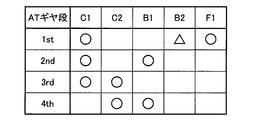
機械式有段変速部20は、図2の係合作動表に示すように、複数のATギヤ段として、AT1速ギヤ段(1st)〜AT4速ギヤ段(4th)の4速の前進用のATギヤ段が形成される。AT1速ギヤ段の変速比γatが最も大きく、高車速側、すなわちハイ側のAT4速ギヤ段側程、変速比γatが小さくなる。図2の係合作動表は、各ATギヤ段と係合装置CBの各作動状態との関係をまとめたものであり、「○」は係合、「△」はエンジンブレーキ時や機械式有段変速部20のコーストダウン変速時に係合、空欄は解放をそれぞれ表している。AT1速ギヤ段を形成するブレーキB2には並列にワンウェイクラッチF1が設けられているので、発進時や加速時にはブレーキB2を係合させる必要は無い。なお、係合装置CBが何れも解放されることにより、機械式有段変速部20は、動力伝達を遮断するニュートラル状態とされる。
As shown in the engagement operation table of FIG. 2, the mechanical stepped
機械式有段変速部20は、電子制御装置80によって、運転者のアクセル操作や車速V等に応じて係合装置CBのうちの解放側係合装置の解放と係合装置CBのうちの係合側係合装置の係合とが制御される、所謂クラッチツウクラッチ変速により、形成されるATギヤ段が切り換えられる。すなわち複数のATギヤ段の何れかが選択的に形成される。例えば、AT3速ギヤ段「3rd」からAT2速ギヤ段「2nd」へのダウン変速(3→2ダウン変速) では、図2の係合作動表に示すように、解放側係合装置となるクラッチC2が解放されると共に、AT2速ギヤ段「2nd」にて係合させられる係合装置(クラッチC1およびブレーキB1) のうちで3→2ダウン変速前には解放されていた係合側係合装置となるブレーキB1が係合させられる。この際、クラッチC2の解放過渡油圧やブレーキB1の係合過渡油圧が予め定められた変化パターンなどに従って調圧制御される。
The mechanical stepped
図4は、上記係合装置CBを係合解放制御するリニアソレノイドバルブSL1〜SL4を含む油圧制御回路54の要部を示す回路図である。油圧制御回路54は、エンジン14によって回転駆動される機械式オイルポンプ100、およびエンジン非作動時にポンプ用電動機102によって回転駆動される電動式オイルポンプ104を、係合装置CBの油圧源として備えている。これ等のオイルポンプ100、104から出力された作動油は、それぞれ逆止弁106、108を介してライン圧油路110に供給され、プライマリレギュレータバルブ等のライン圧コントロールバルブ112により所定のライン圧PLに調圧される。ライン圧コントロールバルブ112にはリニアソレノイドバルブSLTが接続されており、リニアソレノイドバルブSLTは、電子制御装置80によって電気的に制御されることにより、略一定圧であるモジュレータ油圧Pmoを元圧として信号圧Pslt を出力する。そして、その信号圧Pslt がライン圧コントロールバルブ112に供給されると、ライン圧コントロールバルブ112のスプール114が信号圧Pslt によって付勢され、排出用流路116の開口面積を変化させつつスプール114が軸方向へ移動させられることにより、その信号圧Pslt に応じてライン圧PLが調圧される。ライン圧PLは、例えば出力要求量であるアクセル開度θacc 等に応じて調圧される。上記リニアソレノイドバルブSLTはライン圧調整用の電磁調圧弁で、ライン圧コントロールバルブ112は、リニアソレノイドバルブSLTから供給される信号圧Pslt に応じてライン圧PLを調圧する油圧制御弁である。これ等のライン圧コントロールバルブ112およびリニアソレノイドバルブSLTを含んでライン圧調整装置118が構成されている。
FIG. 4 is a circuit diagram showing a main part of a
ライン圧調整装置118によって調圧されたライン圧PLの作動油は、ライン圧油路110を介してリニアソレノイドバルブSL1〜SL4等に供給される。リニアソレノイドバルブSL1〜SL4は、前記クラッチC1、C2、ブレーキB1、B2の各油圧アクチュエータ(油圧シリンダ)120、122、124、126に対応して配置されており、電子制御装置80から供給される油圧制御指令信号Satに従ってそれぞれ出力油圧(係合油圧Pcb)が制御されることにより、クラッチC1、C2、ブレーキB1、B2が個別に係合解放制御され、前記AT1速ギヤ段〜AT4速ギヤ段の何れかのATギヤ段が形成される。これ等のリニアソレノイドバルブSL1〜SL4は、電子制御装置80から供給される油圧制御指令信号Satに従ってクラッチC1、C2、ブレーキB1、B2を選択的に係合させるソレノイドバルブである。
The hydraulic oil having the line pressure PL adjusted by the line
図3は、電気式無段変速部18および機械式有段変速部20における各回転要素の回転速度の相対的関係を表す共線図である。図3において、電気式無段変速部18を構成する差動機構32の3つの回転要素に対応する3本の縦線Y1、Y2、Y3は、左側から順に第2回転要素RE2に相当するサンギヤS0の回転速度(MG1回転速度ωg )を表すg軸であり、第1回転要素RE1に相当するキャリアCA0の回転速度(エンジン回転速度ωe )を表すe軸であり、第3回転要素RE3に相当するリングギヤR0の回転速度(MG2回転速度ωm 、AT入力回転速度ωi )を表すm軸である。また、機械式有段変速部20の4本の縦線Y4、Y5、Y6、Y7は、左から順に、第4回転要素RE4に相当するサンギヤS2の回転速度、第5回転要素RE5に相当する相互に連結されたリングギヤR1およびキャリアCA2の回転速度(出力回転速度ωo )、第6回転要素RE6に相当する相互に連結されたキャリアCA1およびリングギヤR2の回転速度、第7回転要素RE7に相当するサンギヤS1の回転速度、をそれぞれ表す軸である。縦線Y1、Y2、Y3の相互の間隔は、差動機構32のギヤ比(歯数比) ρ0に応じて定められる。また、縦線Y4、Y5、Y6、Y7の相互の間隔は、第1、第2遊星歯車装置36、38の各ギヤ比ρ1、ρ2に応じて定められる。
FIG. 3 is a collinear diagram showing the relative relationship between the rotational speeds of the rotary elements in the electric continuously
図3の共線図を用いて表現すれば、電気式無段変速部18の差動機構32において、第1回転要素RE1にエンジン14(図中の「ENG」参照) が連結され、第2回転要素RE2に第1回転機MG1(図中の「MG1」参照) が連結され、中間伝達部材30と一体回転する第3回転要素RE3に第2回転機MG2(図中の「MG2」参照) が連結されて、エンジン14の回転が中間伝達部材30を介して機械式有段変速部20へ伝達されるように構成されている。電気式無段変速部18では、縦線Y2を横切る各直線L0、L0Rにより、サンギヤS0、キャリアCA0、およびリングギヤR0の相互の回転速度の関係が示される。
If expressed using the collinear diagram of FIG. 3, in the
また、機械式有段変速部20において、第4回転要素RE4はクラッチC1を介して中間伝達部材30に選択的に連結され、第5回転要素RE5は出力軸22に連結され、第6回転要素RE6はクラッチC2を介して中間伝達部材30に選択的に連結されると共にブレーキB2を介してケース16に選択的に連結され、第7回転要素RE7はブレーキB1を介してケース16に選択的に連結されるようになっている。機械式有段変速部20では、係合装置CBの係合解放制御によって縦線Y5を横切る各直線L1、L2、L3、L4、LRにより、各ATギヤ段「1st」、「2nd」、「3rd」、「4th」、「Rev」における各回転要素RE4〜RE7の相互の回転速度の関係が示される。Revは後進ギヤ段で、クラッチC1およびブレーキB2を係合したAT1速ギヤ段「1st」と同じであり、入力要素である第4回転要素RE4が逆回転方向へ回転駆動されることによって成立させられる。
Further, in the mechanical stepped
図3中に実線で示す、直線L0および直線L1、L2、L3、L4は、少なくともエンジン14を駆動源として走行するエンジン走行が可能なハイブリッド走行モードでの前進走行における各回転要素の相対回転速度を示している。このハイブリッド走行モードでは、差動機構32において、キャリアCA0に入力されるエンジントルクTe に対して、第1回転機MG1による負トルク(回生トルク)である反力トルクTg が正回転にてサンギヤS0に入力されると、リングギヤR0には正回転にて正トルクとなるエンジン直達トルクTd 〔=Te /(1+ρ0) =−(1/ρ0) ×Tg 〕が現れる。そして、アクセル開度θacc 等の要求駆動力に応じて、エンジン直達トルクTd とMG2トルクTm との合算トルクが車両10の前進方向の駆動トルクとして、AT1速ギヤ段〜AT4速ギヤ段のうちの何れかのATギヤ段が形成された機械式有段変速部20を介して駆動輪28へ伝達される。このとき、第1回転機MG1は正回転にて負トルクを発生する発電機として機能する。第1回転機MG1の発電電力Wg は、バッテリ52に充電されたり、第2回転機MG2にて消費される。第2回転機MG2は、発電電力Wg の全部または一部を用いて、或いは発電電力Wg に加えてバッテリ52からの電力を用いて、MG2トルクTm を出力する。
A straight line L0 and straight lines L1, L2, L3, and L4 indicated by a solid line in FIG. 3 are relative rotational speeds of the rotating elements in the forward travel in the hybrid travel mode in which the engine travels using at least the
図3に図示はしていないが、エンジン14を停止させると共に第2回転機MG2を駆動源として走行するモータ走行が可能なモータ走行モードでの共線図では、差動機構32において、キャリアCA0はゼロ回転とされ、リングギヤR0には正回転にて正トルクとなるMG2トルクTm が入力される。このとき、サンギヤS0に連結された第1回転機MG1は、無負荷状態とされて負回転にて空転させられる。つまり、モータ走行モードでは、エンジン14は駆動されず、エンジン14の回転速度であるエンジン回転速度ωe はゼロとされ、MG2トルクTm (ここでは正回転の力行トルク) が車両10の前進方向の駆動トルクとして、AT1速ギヤ段「1st」〜AT4速ギヤ段「4th」のうちの何れかのATギヤ段が形成された機械式有段変速部20を介して駆動輪28へ伝達される。
Although not shown in FIG. 3, in the collinear diagram in the motor travel mode in which the
図3中に破線で示す、直線L0Rおよび直線LRは、モータ走行モードでの後進走行における各回転要素の相対回転速度を示している。このモータ走行モードでの後進走行では、リングギヤR0には負回転にて負トルクとなるMG2トルクTm が入力され、そのMG2トルクTm が車両10の後進方向の駆動トルクとして、AT1速ギヤ段が形成された機械式有段変速部20を介して駆動輪28へ伝達される。電子制御装置80は、AT1速ギヤ段「1st」〜AT4速ギヤ段「4th」のうちの前進用の低車速側(ロー側) ギヤ段としてのAT1速ギヤ段「1st」を形成した状態で、前進用の電動機トルクである前進用のMG2トルクTm (ここでは正回転の正トルクとなる力行トルク;特にはMG2トルクTmFと表す) とは正負が反対となる後進用の電動機トルクである後進用のMG2トルクTm (ここでは負回転の負トルクとなる力行トルク;特にはMG2トルクTmRと表す) を第2回転機MG2から出力させることで後進走行を行うことができる。このように、本実施例の車両10では、前進用のATギヤ段(つまり前進走行を行うときと同じATギヤ段) を用いて、MG2トルクTm の正負を反転させることで後進走行を行う。機械式有段変速部20では、機械式有段変速部20内で入力回転を反転して出力する、後進走行専用のATギヤ段は形成されない。なお、ハイブリッド走行モードにおいても、エンジン14を正回転方向へ回転させたまま、直線L0Rのように第2回転機MG2を負回転とすることが可能であるので、モータ走行モードと同様に後進走行を行うことが可能である。
A straight line L0R and a straight line LR indicated by broken lines in FIG. 3 indicate the relative rotational speeds of the respective rotating elements in the reverse travel in the motor travel mode. In reverse travel in this motor travel mode, MG2 torque Tm, which becomes negative torque by negative rotation, is input to ring gear R0, and the MG2 torque Tm is used as drive torque in the reverse direction of
車両用駆動装置12では、エンジン14が動力伝達可能に連結された第1回転要素RE1としてのキャリアCA0と、第1回転機MG1が動力伝達可能に連結された第2回転要素RE2としてのサンギヤS0と、第2回転機MG2が動力伝達可能に連結された第3回転要素RE3としてのリングギヤR0と、の3つの回転要素を有する差動機構32を備えて、第1回転機MG1の運転状態が制御されることにより差動機構32の差動状態が制御される電気式無段変速部18が構成される。つまり、エンジン14が動力伝達可能に連結された差動機構32と、その差動機構32に動力伝達可能に連結された第1回転機MG1とを有して、第1回転機MG1の運転状態が制御されることにより、差動機構32の差動状態が制御される電気式無段変速部18が構成される。電気式無段変速部18は、中間伝達部材30の回転速度であるMG2回転速度ωm に対する連結軸34の回転速度(すなわちエンジン回転速度ωe )の変速比γ0(=ωe /ωm )が無段階(連続的)で変化させられる電気的な無段変速機として作動させられる。
In the
例えば、ハイブリッド走行モードにおいては、機械式有段変速部20にて所定のATギヤ段が形成されることで駆動輪28の回転に拘束されるリングギヤR0の回転速度に対して、第1回転機MG1の回転速度を制御することによってサンギヤS0の回転速度が上昇或いは下降させられると、キャリアCA0の回転速度(すなわちエンジン回転速度ωe )が上昇或いは下降させられる。従って、エンジン14を駆動源として走行するエンジン走行では、エンジン14を効率の良い運転点にて作動させることが可能である。つまり、所定のATギヤ段が形成された機械式有段変速部20と無段変速機として作動させられる電気式無段変速部18とで、車両用自動変速機40が全体として無段変速機を構成することができる。
For example, in the hybrid travel mode, the first rotating machine is used for the rotational speed of the ring gear R0 that is restrained by the rotation of the
また、電気式無段変速部18を有段変速機のように変速させることも可能であるので、ATギヤ段が形成される機械式有段変速部20と有段変速機のように変速させる電気式無段変速部18とで、車両用自動変速機40全体として有段変速機のように変速させることができる。つまり、車両用自動変速機40において、出力回転速度ωo に対するエンジン回転速度ωe の変速比γt(=ωe /ωo )が異なる複数のギヤ段(模擬ギヤ段と称する) の何れかを選択的に成立させるように、機械式有段変速部20と電気式無段変速部18とを協調制御することが可能である。変速比γtは、直列に配置された、電気式無段変速部18と機械式有段変速部20とで形成されるトータル変速比であって、電気式無段変速部18の変速比γ0と機械式有段変速部20の変速比γatとを乗算した値(γt=γ0×γat) となる。
In addition, since the electric continuously
複数の模擬ギヤ段は、例えば図5に示すように、それぞれの変速比γtを維持できるように出力回転速度ωo に応じて第1回転機MG1によりエンジン回転速度ωe を制御することによって成立させることができる。各模擬ギヤ段の変速比γtは必ずしも一定値(図5において原点0を通る直線)である必要はなく、所定範囲で変化させても良いし、各部の回転速度の上限や下限等によって制限が加えられても良い。図5は、複数の模擬ギヤ段として模擬1速ギヤ段〜模擬10速ギヤ段を有する10段変速が可能な場合である。この図5から明らかなように、複数の模擬ギヤ段は、出力回転速度ωo に応じてエンジン回転速度ωe を制御するだけで良く、機械式有段変速部20のATギヤ段の種類とは関係無く所定の模擬ギヤ段を成立させることができる。
For example, as shown in FIG. 5, the plurality of simulated gears are established by controlling the engine speed ωe by the first rotating machine MG1 in accordance with the output speed ωo so as to maintain the respective gear ratio γt. Can do. The speed ratio γt of each simulated gear stage is not necessarily a constant value (a straight line passing through the
模擬ギヤ段は、例えば機械式有段変速部20の各ATギヤ段と1または複数種類の電気式無段変速部18の変速比γ0との組合せによって、機械式有段変速部20の各ATギヤ段に対してそれぞれ1または複数種類を成立させるように割り当てられる。図6は、ギヤ段割当(ギヤ段割付) テーブルの一例であり、AT1速ギヤ段に対して模擬1速ギヤ段〜模擬3速ギヤ段が成立させられ、AT2速ギヤ段に対して模擬4速ギヤ段〜模擬6速ギヤ段が成立させられ、AT3速ギヤ段に対して模擬7速ギヤ段〜模擬9速ギヤ段が成立させられ、AT4速ギヤ段に対して模擬10速ギヤ段が成立させられるように予め定められている。図7は、図3と同じ共線図上において機械式有段変速部20のATギヤ段がAT2速ギヤ段の時に、模擬4速ギヤ段〜模擬6速ギヤが成立させられる場合を例示したものであり、出力回転速度ωo に対して所定の変速比γtを実現するエンジン回転速度ωe となるように電気式無段変速部18が制御されることによって、各模擬ギヤ段が成立させられる。
For example, the simulated gear stage is determined by the combination of each AT gear stage of the mechanical stepped
図1に戻って、車両10は、エンジン14、電気式無段変速部18、および機械式有段変速部20などの制御を行うコントローラとして機能する電子制御装置80を備えている。図1は、電子制御装置80の入出力系統を示す図であり、また、電子制御装置80による制御機能の要部を説明する機能ブロック線図である。電子制御装置80は、例えばCPU、RAM、ROM、入出力インターフェース等を備えた所謂マイクロコンピュータを含んで構成されており、CPUはRAMの一時記憶機能を利用しつつ予めROMに記憶されたプログラムに従って信号処理を行うことにより、車両10の各種制御を実行する。電子制御装置80は変速制御装置に相当し、必要に応じてエンジン制御用やハイブリッド制御用等と分けて構成される。
Returning to FIG. 1, the
電子制御装置80には、車両10に備えられたエンジン回転速度センサ60、MG1回転速度センサ62、MG2回転速度センサ64、出力回転速度センサ66、アクセル開度センサ68、スロットル弁開度センサ70、油温センサ72、シフトポジションセンサ74、バッテリセンサ76などから、エンジン回転速度ωe 、第1回転機MG1の回転速度であるMG1回転速度ωg 、AT入力回転速度ωi であるMG2回転速度ωm 、車速Vに対応する出力回転速度ωo 、運転者の加速要求量(すなわちアクセルペダルの操作量) であるアクセル開度θacc 、電子スロットル弁の開度であるスロットル弁開度θth、油圧制御回路54の作動油温度toil 、車両10に備えられたシフト操作部材としてのシフトレバー56の操作位置(操作ポジション)POSsh、バッテリ52のバッテリ温度THbat やバッテリ充放電電流Ibat 、バッテリ電圧Vbat など、制御に必要な各種の情報が供給される。また、電子制御装置80からは、車両10に備えられたスロットルアクチュエータや燃料噴射装置、点火装置等のエンジン制御装置58、インバータ50、油圧制御回路54などに、エンジン14を制御するためのエンジン制御指令信号Se 、第1回転機MG1および第2回転機MG2を制御するための回転機制御指令信号Smg、ポンプ用電動機102および係合装置CBの作動状態を制御するための(すなわち機械式有段変速部20の変速を制御するための) 油圧制御指令信号Satなどが、それぞれ出力される。油圧制御指令信号Satは、例えば係合装置CBの各々の油圧アクチュエータ120〜126へ供給される各係合油圧Pcbを調圧する各リニアソレノイドバルブSL1〜SL4を駆動するための指令信号(駆動電流) である。
The
シフトレバー56の操作ポジションPOSshは、例えばP、R、N、D、S操作ポジションである。P操作ポジションは、係合装置CBの何れもの解放によって機械式有段変速部20が動力伝達不能なニュートラル状態とされ且つ機械的に出力軸22の回転が阻止(ロック) されるP(パーキング)レンジを選択する操作ポジションである。R操作ポジションは、機械式有段変速部20のAT1速ギヤ段が形成された状態で後進用のMG2トルクTmRにより車両10の後進走行を可能とするR(リバース)レンジを選択する操作ポジションである。N操作ポジションは、車両用自動変速機40がニュートラル状態とされるN(ニュートラル)レンジを選択する操作ポジションである。D操作ポジションは、機械式有段変速部20のAT1速ギヤ段〜AT4速ギヤ段の変速を伴って模擬1速ギヤ段〜模擬10速ギヤ段の総ての模擬ギヤ段を用いて自動変速制御を実行し、或いは電気式無段変速部18を無段階で変速する無段変速制御を実行して、前進走行を可能とするD(ドライブ)レンジを選択する操作ポジションである。S操作ポジションは、D操作ポジションに隣接して設けられており、Dレンジが選択された状態でシフトレバー56がS操作ポジションへ操作されると、アップダウンスイッチやレバー等の手動操作(マニュアル操作)で機械式有段変速部20のAT1速ギヤ段〜AT4速ギヤ段の変速を伴って模擬1速ギヤ段〜模擬10速ギヤ段の総ての模擬ギヤ段を任意に選択することが可能なS(シーケンシャル)モードを選択することができる。シフトレバー56は、人為的に操作されることで複数のレンジへ切り換えることができるレンジ切換操作部材に相当し、本実施例ではSモードを選択するSモード選択スイッチを兼ねている。
The operation position POSsh of the
電子制御装置80は、例えばバッテリ充放電電流Ibat およびバッテリ電圧Vbat などに基づいてバッテリ52の蓄電残量(充電状態)SOCを算出する。また、電子制御装置80は、例えばバッテリ温度THbat およびバッテリ52の蓄電残量SOCに基づいて、バッテリ52の入力電力の制限を規定する充電可能電力(入力可能電力) Win、およびバッテリ52の出力電力の制限を規定する放電可能電力(出力可能電力) Wout を算出する。充放電可能電力Win、Wout は、例えばバッテリ温度THbat が常用域より低い低温域ではバッテリ温度THbat が低い程低くされ、また、バッテリ温度THbat が常用域より高い高温域ではバッテリ温度THbat が高い程低くされる。また、充電可能電力Winは、例えば蓄電残量SOCが大きな領域では蓄電残量SOCが大きい程小さくされる。放電可能電力Wout は、例えば蓄電残量SOCが小さな領域では蓄電残量SOCが小さい程小さくされる。
The
電子制御装置80は、車両10における各種制御を実行するために、ハイブリッド制御部82、無段変速制御部84、AT変速制御部86、および模擬有段変速制御部88を機能的に備えている。
The
ハイブリッド制御部82は、エンジン14の作動を制御するエンジン制御部としての機能と、インバータ50を介して第1回転機MG1および第2回転機MG2の作動を制御する回転機制御部としての機能を備えており、それら制御機能によりエンジン14、第1回転機MG1、および第2回転機MG2によるハイブリッド駆動制御等を実行する。例えばアクセル開度θacc および車速V等に基づいて要求駆動パワーPdem (見方を変えれば、そのときの車速Vにおける要求駆動トルクTdem )を算出し、バッテリ52の充放電可能電力Win、Wout 等を考慮して、要求駆動パワーPdem を実現するように、エンジン14、第1回転機MG1、および第2回転機MG2を制御する指令信号(エンジン制御指令信号Se および回転機制御指令信号Smg) を出力する。エンジン制御指令信号Se は、例えばそのときのエンジン回転速度ωe におけるエンジントルクTe を出力するエンジンパワーPe の指令値である。回転機制御指令信号Smgは、例えばエンジントルクTe の反力トルク(そのときのMG1回転速度ωg におけるMG1トルクTg )を出力する第1回転機MG1の発電電力Wg の指令値であり、また、そのときのMG2回転速度ωm におけるMG2トルクTm を出力する第2回転機MG2の消費電力Wm の指令値である。
The
ハイブリッド制御部82は、走行モードとして、モータ走行モード或いはハイブリッド走行モードを車両状態に応じて選択的に成立させる。例えば、要求駆動パワーPdem が予め定められた閾値よりも小さなモータ走行領域(例えば低車速で且つ低駆動トルクの領域)にある場合には、エンジン14を停止して第2回転機MG2だけで走行するモータ走行モードを成立させる一方で、要求駆動パワーPdem が予め定められた閾値以上となるハイブリッド走行領域にある場合には、エンジン14を作動させて走行するハイブリッド走行モードを成立させる。ハイブリッド走行モードでは、回生制御される第1回転機MG1からの電気エネルギーおよび/またはバッテリ52からの電気エネルギーを第2回転機MG2へ供給し、その第2回転機MG2を駆動(力行制御)して駆動輪28にトルクを付与することにより、エンジン14の動力を補助するためのトルクアシストを必要に応じて実行する。また、モータ走行領域であっても、バッテリ52の蓄電残量SOCや放電可能電力Wout が予め定められた閾値未満の場合には、ハイブリッド走行モードを成立させる。モータ走行モードからハイブリッド走行モードへ移行する際のエンジン14の始動は、走行中か停車中かに拘らず、例えば第1回転機MG1によりエンジン回転速度ωe を引き上げてクランキングすることにより行うことができる。
The
無段変速制御部84は、電気式無段変速部18を無段変速機として作動させて車両用自動変速機40全体として無段変速機として作動させるもので、例えばエンジン最適燃費線等を考慮して、要求駆動パワーPdem を実現するエンジンパワーPe が得られるエンジン回転速度ωe とエンジントルクTe となるように、エンジン14を制御すると共に第1回転機MG1の発電電力Wg を制御することで、電気式無段変速部18の無段変速制御を実行して電気式無段変速部18の変速比γ0を変化させる。この制御の結果として、車両用自動変速機40を無段変速機として作動させた場合の全体の変速比γtが制御される。
The continuously variable
AT変速制御部86は、予め実験的に或いは設計的に求められて記憶された(すなわち予め定められた) 関係(例えばATギヤ段変速マップ)を用いて機械式有段変速部20の変速判断を行い、必要に応じて機械式有段変速部20の変速制御を実行して機械式有段変速部20のAT1速ギヤ段〜AT4速ギヤ段を自動的に切り換えるように、ソレノイドバルブSL1〜SL4により係合装置CBの係合解放状態を切り換えるための油圧制御指令信号Satを油圧制御回路54へ出力する。上記ATギヤ段変速マップは変速条件で、例えば図8に「AT」を付して示した変速線にて定められており、実線はアップ変速線で破線はダウン変速線であり、所定のヒステリシスが設けられている。この変速マップは、例えば出力回転速度ωo (ここでは車速Vなども同意) およびアクセル開度θacc (ここでは要求駆動トルクTdem やスロットル弁開度θthなども同意) をパラメータとする二次元座標上に定められており、出力回転速度ωo が高くなるに従って変速比γatが小さい高車速側(ハイ側)のATギヤ段に切り換えられ、アクセル開度θacc が大きくなるに従って変速比γatが大きい低車速側(ロー側)のATギヤ段に切り換えられるように定められている。AT変速制御部86はまた、運転者のマニュアル操作による模擬ギヤ段の変速要求によっても、図6の割当テーブルに従って必要に応じてATギヤ段を切り換える。例えば模擬3速ギヤ段と模擬4速ギヤ段との変速を含む場合はAT1速ギヤ段とAT2速ギヤ段との間の変速を行い、模擬6速ギヤ段と模擬7速ギヤ段との変速を含む場合はAT2速ギヤ段とAT3速ギヤ段との間の変速を行い、模擬9速ギヤ段と模擬10速ギヤ段との変速を含む場合はAT3速ギヤ段とAT4速ギヤ段との間の変速を行なう。
The AT
模擬有段変速制御部88は、電気式無段変速部18を有段変速機のように変速させて車両用自動変速機40全体として有段変速機のように変速させるものである。模擬有段変速制御部88は、予め定められた関係(例えば模擬ギヤ段変速マップ) を用いて車両用自動変速機40の変速判断を行い、AT変速制御部86による機械式有段変速部20のATギヤ段の変速制御と協調して、前記複数の模擬ギヤ段の何れかを選択的に成立させるように電気式無段変速部18の変速制御(有段変速)を実行する。模擬ギヤ段変速マップは、ATギヤ段変速マップと同様に出力回転速度ωo およびアクセル開度θacc をパラメータとして予め定められている。図8は、模擬ギヤ段変速マップの一例であって、実線はアップ変速線であり、破線はダウン変速線である。模擬ギヤ段変速マップに従って模擬ギヤ段が切り換えられることにより、電気式無段変速部18と機械式有段変速部20とが直列に配置された車両用自動変速機40全体として有段変速機と同様の変速フィーリングが得られる。車両用自動変速機40全体として有段変速機のように変速させる模擬有段変速制御は、例えば運転者によってスポーツ走行モード等の走行性能重視の走行モードが選択された場合や要求駆動トルクTdem が比較的大きい場合に、車両用自動変速機40全体として無段変速機として作動させる無段変速制御に優先して実行するだけでも良いが、所定の実行制限時を除いて基本的に模擬有段変速制御が実行されても良い。模擬有段変速制御部88はまた、運転者のマニュアル操作による模擬ギヤ段の変速要求によっても、その変速要求に応じて模擬ギヤ段を切り換える。
The simulated stepped
模擬有段変速制御部88による模擬有段変速制御と、AT変速制御部86による機械式有段変速部20の変速制御とは、協調して実行される。本実施例では、AT1速ギヤ段〜AT4速ギヤ段の4種類のATギヤ段に対して、模擬1速ギヤ段〜模擬10速ギヤ段の10種類の模擬ギヤ段が割り当てられている。このようなことから、模擬3速ギヤ段と模擬4速ギヤ段との間での変速(模擬3⇔4変速と表す) が行われるときにAT1速ギヤ段とAT2速ギヤ段との間での変速(AT1⇔2変速と表す) が行なわれ、また、模擬6⇔7変速が行われるときにAT2⇔3変速が行なわれ、また、模擬9⇔10変速が行われるときにAT3⇔4変速が行なわれる(図6、図8参照) 。そのため、模擬ギヤ段の変速タイミングと同じタイミングでATギヤ段の変速が行なわれるように、ATギヤ段変速マップが定められている。具体的には、図8における模擬ギヤ段の「3→4」、「6→7」、「9→10」の各アップ変速線は、ATギヤ段変速マップの「1→2」、「2→3」、「3→4」の各アップ変速線と一致している(図8中に記載した「AT1→2」等参照) 。また、図8における模擬ギヤ段の「3←4」、「6←7」、「9←10」の各ダウン変速線は、ATギヤ段変速マップの「1←2」、「2←3」、「3←4」の各ダウン変速線と一致している(図8中に記載した「AT1←2」等参照) 。または、図8の模擬ギヤ段変速マップによる模擬ギヤ段の変速判断に基づいて、ATギヤ段の変速指令をAT変速制御部86に対して出力するようにしても良い。このように、AT変速制御部86は、機械式有段変速部20のATギヤ段の切換えを、模擬ギヤ段が切り換えられるときに行う。模擬ギヤ段の変速タイミングと同じタイミングでATギヤ段の変速が行なわれるため、エンジン回転速度ωe の変化を伴って機械式有段変速部20の変速が行なわれるようになり、その機械式有段変速部20の変速に伴うショックがあっても運転者に違和感を与え難くされる。
The simulated stepped shift control by the simulated stepped
模擬有段変速制御部88は、上記模擬ギヤ段およびATギヤ段の同時変速に関して分割変速部90および同期変速制御部98を機能的に備えている。同期変速制御部98は、模擬ギヤ段およびATギヤ段の変速応答時間の相違に拘らず、両者の変速が同期して行なわれるようにするためのもので、本実施例ではATギヤ段の変速によるイナーシャ相の開始、すなわち中間伝達部材30の回転速度であるAT入力回転速度ωi (=MG2回転速度ωm )の変化を検出した後に模擬ギヤ段の変速指令、すなわちエンジン回転速度ωe を変化させるための第1回転機MG1のトルク変更指令を出力する。この同期変速制御部98による模擬ギヤ段の変速制御は、アップ変速およびダウン変速の両方で行なわれる。
The simulated stepped
図12、図13は、それぞれ模擬7速ギヤ段から模擬4速ギヤ段への模擬ギヤ段ダウン変速と、AT3速ギヤ段からAT2速ギヤ段へのATギヤ段ダウン変速との同時変速時のタイムチャートの一例で、時間t3はAT2速ギヤ段へのダウン変速指令が出力された時間であり、時間t4はそのAT2速ギヤ段へのダウン変速に伴ってMG2回転速度ωm が上昇し始めるイナーシャ相開始時間である。すなわち、時間t3と時間t4との間の時間が、AT3速ギヤ段からAT2速ギヤ段へのダウン変速の変速応答時間trmである。そして、模擬ギヤ段の目標ギヤ段である模擬4速ギヤ段への変速指令は、ATギヤ段変速のイナーシャ相開始時(時間t4)に出力される。言い換えれば、ATギヤ段の変速指令出力から、そのATギヤ段の変速応答時間trmと同じ遅延時間DELiだけ遅延して、模擬ギヤ段のダウン変速指令が出力される。この模擬ギヤ段の変速指令出力(時間t4)から、模擬ギヤ段の変速によりエンジン回転速度ωe が上昇し始めるイナーシャ相開始までの遅れ時間triが、模擬ギヤ段の変速応答時間であるが、この変速応答時間triは短く、ATギヤ段のダウン変速によるMG2回転速度ωm の上昇と模擬ギヤ段のダウン変速によるエンジン回転速度ωe の上昇が並行(重複)して進行する。このように、両者の変速応答時間trm、triの相違に拘らず、イナーシャ相の少なくとも一部が重複するように変速が同期して行なわれることにより、変速ショック等により運転者に与える違和感が抑制されてドラビリが向上する。図12、図13のタイムチャートは、それ等の変速が時間t5で略同時に終了した場合である。 FIGS. 12 and 13 respectively show a simultaneous gear down shift from a simulated 7th gear to a simulated 4th gear and an AT gear down shift from an AT 3rd gear to an AT 2nd gear. In an example of the time chart, time t3 is a time when a down shift command to the AT 2nd gear is output, and time t4 is an inertia when the MG2 rotational speed ωm starts to increase with the down shift to the AT 2nd gear. Phase start time. That is, the time between the time t3 and the time t4 is the shift response time trm of the downshift from the AT3 speed gear to the AT2 speed. Then, a shift command to the simulated fourth gear, which is the target gear of the simulated gear, is output at the start of the inertia phase of the AT gear shift (time t4). In other words, the downshift command for the simulated gear stage is output from the AT gear stage shift command output delayed by the same delay time DELi as the AT gear stage shift response time trm. The delay time tri from the simulated gear stage shift command output (time t4) to the start of the inertia phase when the engine speed ωe starts to increase due to the simulated gear stage shift is the simulated gear stage shift response time. The shift response time tri is short, and the increase in the MG2 rotational speed ωm due to the downshift of the AT gear stage and the increase in the engine rotational speed ωe due to the downshift of the simulated gear stage proceed in parallel (overlapping). As described above, regardless of the difference between the shift response times trm and tri, the shift is performed in synchronism so that at least a part of the inertia phase overlaps, thereby suppressing the uncomfortable feeling given to the driver due to a shift shock or the like. The dribabil is improved. The time charts of FIGS. 12 and 13 are cases where these shifts are completed almost simultaneously at time t5.
一方、このようにATギヤ段の変速に対して模擬ギヤ段の変速が同期して行なわれるように、模擬ギヤ段の変速指令の出力が遅延させられると、例えばアクセルペダルの踏込みに伴って自動的にダウン変速したり、或いは運転者のアップダウンスイッチ等の手動操作によるダウン変速要求に従ってダウン変速したりする場合、実際にダウン変速してエンジン回転速度ωe が上昇し始めるイナーシャ相開始までの所要時間が長くなるため、その応答遅れで運転者がヘジテーションを感じる可能性がある。例えば、アクセルOFFからONへの踏込み操作に伴って被駆動状態から駆動状態へ変化するチップイン加速時に、歯打ち音等の発生を抑制するためにエンジントルクの立上りになまし処理が行なわれ、そのトルクの立上りを待ってATギヤ段の変速指令が出力される場合や、油圧制御回路54の作動油の粘性が高い低油温時等には、変速判断から実際にATギヤ段の変速のイナーシャ相が開始するまでの時間が長くなるため、それに伴って模擬ギヤ段の変速も遅くなると、ヘジテーションを一層強く感じるようになる。また、運転者の加速要求が大きい場合にも、ヘジテーションを感じ易くなる。図12〜図14は、時間t1でアクセルOFFからONへ変化したチップイン加速時に、エンジントルクのなまし処理により、AT入力トルクが一点鎖線で示す通常時に比較して立上りが遅くされ、そのAT入力トルクの立上りを待って時間t3でATギヤ段の変速指令が出力された場合であり、ATギヤ段の変速指令が遅延時間DELmだけ遅れて出力される。この結果、模擬ギヤ段の変速指令が、アクセルOFF→ONから遅延時間DELm+DELiだけ遅れて出力されることになり、破線で示すように時間t4で模擬7速ギヤ段から模擬4速ギヤ段への変速指令が出力されて模擬ギヤ段の変速が行なわれると、変速判断時(時間t1)から実際にエンジン回転速度ωe が上昇し始めるまでの時間が長くなり、ヘジテーションを感じさせる可能性が高い。
On the other hand, if the output of the shift command of the simulated gear stage is delayed so that the shift of the simulated gear stage is synchronized with the shift of the AT gear stage in this way, for example, automatically when the accelerator pedal is depressed. If the gear is downshifted in accordance with the downshift request according to the manual operation of the driver's up / down switch, etc., it is necessary to start the inertia phase where the engine speed ωe starts to increase and the engine speed ωe starts to increase. Since the time becomes longer, the driver may feel hesitation due to the delayed response. For example, at the time of tip-in acceleration that changes from the driven state to the driven state in accordance with the depression operation from the accelerator OFF to the ON state, a smoothing process is performed at the rise of the engine torque in order to suppress the occurrence of rattling noise, etc. When the AT gear stage shift command is output after the torque rises, or when the oil pressure of the
本実施例では、このヘジテーションを抑制するために分割変速部90が設けられている。分割変速部90は、同期変速制御部98によりATギヤ段に同期して模擬ギヤ段をダウン変速させる際に、その模擬ギヤ段のダウン変速指令の出力に先立って、目標模擬ギヤ段と現在模擬ギヤ段との間の中間模擬ギヤ段へ分割して変速するものである。この分割変速部90は、(a) 予め定められた分割条件に従って中間模擬ギヤ段への分割変速を行なうか否かを判断する分割変速判断部92と、(b) 車両状態に応じて中間模擬ギヤ段を設定する中間模擬ギヤ段設定部94と、(c) 模擬ギヤ段の変速判断以後の予め定められたタイミングで中間模擬ギヤ段への変速指令を出力する分割変速出力部96とを、機能的に備えている。図9のフローチャートのステップS1〜S10(以下、単にS1〜S10という)は、分割変速部90および同期変速制御部98の作動を具体的に説明するフローチャートであり、S1、S2、S9、S10は同期変速制御部98に相当し、S3、S4は分割変速判断部92に相当し、S5〜S7は中間模擬ギヤ段設定部94に相当し、S8は分割変速出力部96に相当する。
In the present embodiment, a
図9のS1では、模擬ギヤ段変速マップに従って、或いはアップダウンスイッチ等によるダウン変速要求に基づいて、模擬ギヤ段をダウン変速すべき変速判断が為されたか否かを判断し、ダウン変速判断が為されなかった場合はそのまま終了するが、ダウン変速判断が為されたらS2以下を実行する。S2では、ATギヤ段と同時変速か否か、すなわちAT変速制御部86によりATギヤ段についてもダウン変速判断が為されたか否かを判断し、ATギヤ段との同時変速でない模擬ギヤ段の単独変速の場合には、直ちにS10を実行し、変速判断による変速先である目標模擬ギヤ段へ変速する変速指令を出力する。すなわち、前記図5のエンジン回転速度マップに従って、その時の出力回転速度ωo に応じて目標模擬ギヤ段の目標エンジン回転速度ωe*が求められ、その目標エンジン回転速度ωe*となるように第1回転機MG1のトルク制御が行なわれることにより、目標模擬ギヤ段が直ちに成立させられる。
In S1 of FIG. 9, it is determined whether or not a shift determination to shift down the simulated gear is made according to the simulated gear shift map or based on a down shift request by an up / down switch or the like. If not, the process ends as it is, but if a downshift determination is made, S2 and subsequent steps are executed. In S2, it is determined whether or not the simultaneous shift with the AT gear stage is performed, that is, whether or not the downshift determination is made for the AT gear stage by the AT
S2の判断がYES(肯定)の場合、すなわちATギヤ段との同時変速の場合は、S3以下を実行する。図12〜図14のタイムチャートは、模擬7速ギヤ段から模擬4速ギヤ段への模擬ギヤ段ダウン変速、およびAT3速ギヤ段からAT2速ギヤ段へのATギヤ段ダウン変速の変速判断が、アクセルOFF→ONの変化に伴って時間t1で略同時に為された場合である。例えば、図8の変速マップにおいて、アクセル開度θacc が0のA点の惰性走行時に、アクセルが踏込み操作されてB点まで一気にアクセル開度θacc が変化した場合に、ATギヤ段および模擬ギヤ段のダウン変速判断が略同時に為される。図10は、このダウン変速判断に従って電気式無段変速部18が模擬7速ギヤ段から模擬4速ギヤ段へ変速されるとともに、機械式有段変速部20がAT3速ギヤ段からAT2速ギヤ段へ変速される場合の、各部の回転速度変化を例示した共線図で、実線は変速前の現在ギヤ段で一点鎖線は変速後のギヤ段(目標ギヤ段)である。このダウン変速により、機械式有段変速部20の入力回転速度ωi およびエンジン回転速度ωe が、それぞれ変速比γat、γtの変化に応じて上昇させられる。
If the determination in S2 is YES (affirmative), that is, if simultaneous shift with the AT gear stage is performed, S3 and subsequent steps are executed. The time charts of FIGS. 12 to 14 show the shift determination of the simulated gear down shift from the simulated seventh gear to the simulated fourth gear and the AT gear down shift from the AT third gear to the AT second gear. This is a case where the change is made substantially simultaneously at time t1 with a change from accelerator OFF to ON. For example, in the shift map of FIG. 8, when the accelerator opening θacc changes to a point B when the accelerator is stepped on and the accelerator opening θacc is zero, the AT gear stage and the simulated gear stage are changed. The downshift determination is made at substantially the same time. FIG. 10 shows that the electric continuously
S3では、分割条件としてATギヤ段の変速が遅くなる状況(シーン)か否かを判断する。例えば、アクセルOFFからONへ踏込み操作された場合や、作動油温度toil が所定の判定値以下の低油温時には、ATギヤ段の変速が遅くなる状況と判断する。すなわち、アクセルOFF→ONのチップイン加速時には、被駆動状態から駆動状態へ変化する際に歯打ち音等の異音が発生する可能性があるため、エンジントルクの立上りになまし処理が行なわれ、そのトルクの立上りを待ってATギヤ段の変速指令が出力されるため、ATギヤ段の変速が遅くなる。また、油圧制御回路54の作動油温度toil が低い場合は、その作動油の粘性が高く、係合装置CBの係合或いは解放時の応答性が悪くなるため、ATギヤ段の変速時のイナーシャ相が開始するまでの時間が長くなる。S3の判断がYESの場合には、次にS4を実行し、ヘジテーション対策が必要か否か、すなわち運転者がヘジテーションを感じ易い運転状況か否かを判断する。例えばアクセル開度θacc が所定の判定値以上の場合、或いはアクセル開度θacc の増加量や増加速度が所定の判定値以上の場合は、運転者の加速要求が高くてヘジテーションを感じ易いと推測できる。このヘジテーション対策が必要であることも分割条件である。そして、S3およびS4の判断が何れもYESの場合には、S5〜S8で分割変速制御を実行するが、S3の判断がNO(否定)の場合、或いはS3がYESでもS4がNOの場合には、分割変速の必要が無いと判断して直ちにS9を実行する。なお、S3およびS4の何れか一方がYESの場合には、S5〜S8の分割変速制御を行なうようにしても良いし、更に別の分割条件が加えられても良い。
In S3, it is determined whether or not the situation (scene) in which the shift of the AT gear stage is delayed as a division condition. For example, when the accelerator is depressed from OFF to ON, or when the hydraulic oil temperature toil is a low oil temperature that is equal to or lower than a predetermined determination value, it is determined that the AT gear stage shift is slow. That is, during accelerator-in → on-chip acceleration, abnormal noise such as rattling noise may occur when changing from the driven state to the driven state, and therefore, a smoothing process is performed at the rise of the engine torque. Since the AT gear stage shift command is output after the rising of the torque, the AT gear stage shift becomes slow. Further, when the hydraulic oil temperature toil of the
図12〜図14は、チップイン加速の場合に、S3およびS4の判断が共にYESになってS5〜S8の分割変速制御が実行された場合であり、エンジントルクのなまし処理でAT入力トルクの立上りが実線で示すように遅くなる。AT変速制御部86は、AT入力トルクが予め定められた判定値以上になる時間t3まで待って、ATギヤ段を3速ギヤ段から2速ギヤ段へダウン変速するための変速指令を出力する。具体的には、クラッチC2を解放するとともにブレーキB1を係合するための油圧指令を出力する。すなわち、エンジントルクのなまし処理により、変速判断時間である時間t1から遅延時間DELmだけ遅い時間t3で3→2ダウン変速指令が出力されるのであり、実際の変速開始、すなわち入力回転速度ωi(=MG2回転速度ωm)が上昇し始めるイナーシャ相の開始は、更に変速応答時間trmだけ後の時間t4となる。
FIGS. 12 to 14 show the case where the determination of S3 and S4 is both YES and the split shift control of S5 to S8 is executed in the case of tip-in acceleration, and the AT input torque is processed by the engine torque smoothing process. Rises as shown by the solid line. The AT
S5では、アクセル開度θacc に応じて中間模擬ギヤ段を設定する。すなわち、アクセル開度θacc が全開の場合は、運転者の加速要求が極めて強いため、変速マップによる変速判断通りの目標模擬ギヤ段をそのまま中間模擬ギヤ段に設定する。例えば、模擬4速ギヤ段が目標模擬ギヤ段の場合は、その模擬4速ギヤ段をそのまま中間模擬ギヤ段とする。図14のタイムチャートは、このようにS5で中間模擬ギヤ段として目標模擬ギヤ段(模擬4速ギヤ段)が設定された場合である。アクセル開度θacc が全開でない場合は、その大きさに応じて、目標模擬ギヤ段と現在ギヤ段との間の所定の模擬ギヤ段を中間模擬ギヤ段に設定する。具体的には、目標模擬ギヤ段と現在ギヤ段との間の模擬ギヤ段が1つであれば、それを中間模擬ギヤ段とする。目標模擬ギヤ段が模擬4速ギヤ段で現在ギヤ段が模擬7速ギヤ段のように、目標模擬ギヤ段と現在ギヤ段との間に複数の模擬ギヤ段が存在する場合は、例えば目標模擬ギヤ段より1つだけ高い模擬ギヤ段(模擬5速ギヤ段)を中間模擬ギヤ段に設定する。或いは、アクセル開度θacc を複数に区分して、アクセル開度θacc が比較的小さい場合は現在模擬ギヤ段に近い模擬6速ギヤ段を中間模擬ギヤ段に設定し、アクセル開度θacc が比較的大きい場合は目標模擬ギヤ段に近い模擬5速ギヤ段を中間模擬ギヤ段に設定しても良い。図12のタイムチャートは、S5で模擬6速ギヤ段が中間模擬ギヤ段に設定された場合で、図13のタイムチャートは、S5で模擬5速ギヤ段が中間模擬ギヤ段に設定された場合である。 In S5, an intermediate simulated gear is set according to the accelerator opening degree θacc. In other words, when the accelerator opening degree θacc is fully open, the driver's acceleration request is extremely strong, so the target simulated gear stage according to the shift determination based on the shift map is set as the intermediate simulated gear stage as it is. For example, when the simulated fourth gear is the target simulated gear, the simulated fourth gear is directly used as the intermediate simulated gear. The time chart of FIG. 14 shows the case where the target simulated gear stage (simulated fourth speed gear stage) is set as the intermediate simulated gear stage in S5. If the accelerator opening degree θacc is not fully open, a predetermined simulated gear stage between the target simulated gear stage and the current gear stage is set as an intermediate simulated gear stage according to the magnitude. Specifically, if there is one simulated gear stage between the target simulated gear stage and the current gear stage, it is set as an intermediate simulated gear stage. When there are a plurality of simulated gear stages between the target simulated gear stage and the current gear stage, such as when the target simulated gear stage is a simulated 4-speed gear stage and the current gear stage is a simulated 7-speed gear stage, for example, target simulation A simulated gear stage (simulated fifth speed gear stage) that is one higher than the gear stage is set as the intermediate simulated gear stage. Alternatively, when the accelerator opening degree θacc is divided into a plurality of parts and the accelerator opening degree θacc is relatively small, a simulated sixth speed gear stage close to the current simulated gear stage is set as the intermediate simulated gear stage, and the accelerator opening degree θacc is relatively low. If larger, a simulated fifth gear that is close to the target simulated gear may be set as the intermediate simulated gear. The time chart of FIG. 12 is the case where the simulated 6th gear is set to the intermediate simulated gear in S5, and the time chart of FIG. 13 is the case where the simulated 5th gear is set to the intermediate simulated gear in S5. It is.
S6では、機械式有段変速部20の変速時に変速ショックが発生し易い車両状態か否かを判断する。例えば、作動油温度toil が所定の判定値以下の低油温時には、作動油の粘性が高くなって係合装置CBの係合解放制御の制御精度が損なわれるため、変速ショックが発生し易いと判断できる。また、バッテリ温度THbat やバッテリ52の蓄電残量SOCに基づいてバッテリ52の充放電可能電力Win、Wout が制限されると、回転機MG1、MG2のトルクが制限され、それ等の回転機MG1、MG2のトルク制御によるエンジン回転速度ωe や入力回転速度ωi の回転速度制御が損なわれるため、変速ショックが発生し易いと判断できる。回転機MG1、MG2やインバータ50の温度が高くなり、それ等の回転機MG1、MG2のトルクが制限される場合も同様である。すなわち、バッテリ52の充電可能電力Win、放電可能電力Wout がそれぞれ所定の判定値以下の場合、或いは回転機MG1、MG2やインバータ50の温度が所定の判定値以上の場合などに、変速ショックが発生し易いと判断することができる。
In S6, it is determined whether or not the vehicle state is likely to cause a shift shock when the mechanical stepped
S6で変速ショックが発生し易いと判断した場合は、S7を実行して中間模擬ギヤ段を制限するが、S6の判断がNOの場合は直ちにS8を実行する。S7では、例えば図11に示すように、自動変速かマニュアル変速か、作動油温度toil が通常温か高油温か、或いはアップ変速かダウン変速かによって、変速前のATギヤ段に応じて予め定められた変速許可模擬ギヤ段の範囲内に中間模擬ギヤ段を制限する。例えば、変速前のATギヤ段がAT3速ギヤ段の場合のダウン変速可能な模擬ギヤ段の範囲は、自動変速では模擬6速ギヤ段〜模擬8速ギヤ段に制限される。また、通常温のマニュアル変速では模擬6速ギヤ段〜模擬8速ギヤ段に制限され、高油温時のマニュアル変速では模擬8速ギヤ段〜模擬10速ギヤ段に制限される。したがって、S5で模擬4速ギヤ段または模擬5速ギヤ段が中間模擬ギヤ段に設定された場合でも、自動変速或いは通常温のマニュアル変速では中間模擬ギヤ段が模擬6速ギヤ段に変更される。高油温時のマニュアル変速では、模擬8速ギヤ段以上に制限されるため、模擬7速ギヤ段からのダウン変速が禁止され、実質的に分割変速そのものが中止される。図9のフローチャートはダウン変速に関するものであるが、本実施例ではアップ変速でも、ATギヤ段および模擬ギヤ段の同時アップ変速時には、同時ダウン変速時と同様に同期変速に先立って一定の条件下で分割変速が行なわれるようになっており、図11のアップ変速に関する変速許可模擬ギヤ段は、そのアップ変速時の中間模擬ギヤ段を制限するものである。 If it is determined in S6 that a shift shock is likely to occur, S7 is executed to limit the intermediate simulated gear, but if the determination in S6 is NO, S8 is immediately executed. In S7, for example, as shown in FIG. 11, it is determined in advance according to the AT gear stage before the shift, depending on whether the automatic shift or the manual shift, the hydraulic oil temperature toil is a normal temperature or a high oil temperature, or an upshift or a downshift. The intermediate simulated gear stage is limited within the range of the shift permission simulated gear stage. For example, the range of the simulated gear stage in which the downshift is possible when the AT gear stage before the shift is the AT 3rd gear stage is limited to the simulated 6th gear stage to the simulated 8th gear stage in the automatic transmission. In addition, the normal temperature manual shift is limited to a simulated 6th gear to a simulated 8th gear, and the manual shift at a high oil temperature is limited to a simulated 8th to 10th gear. Therefore, even if the simulated fourth gear or the simulated fifth gear is set to the intermediate simulated gear in S5, the intermediate simulated gear is changed to the simulated six-speed gear for automatic shift or normal temperature manual shift. . Since manual shift at high oil temperature is limited to the simulated 8-speed gear stage or higher, the down-shift from the simulated 7-speed gear stage is prohibited, and the split shift itself is substantially stopped. Although the flowchart of FIG. 9 relates to the downshift, in the present embodiment, even in the upshift, when the AT gear stage and the simulated gear stage are simultaneously upshifted, the same conditions as in the simultaneous downshift are satisfied before the synchronous shift. In FIG. 11, the shift permission simulated gear stage relating to the upshift restricts the intermediate simulated gear stage during the upshift.
S8では、S5で設定され或いはS7で制限された中間模擬ギヤ段へダウン変速する変速指令を予め定められたタイミングで出力する。本実施例では、模擬ギヤ段のダウン変速を判断した後に、S2〜S7の信号処理を経てできるだけ速やかに中間模擬ギヤ段への変速指令を出力する。すなわち、図12〜図14のタイムチャートの場合、アクセルOFF→ONに伴って時間t1で模擬ギヤ段およびATギヤ段の変速判断が為されると、その直後に中間模擬ギヤ段への変速指令が出力されて、図12では模擬6速ギヤ段への変速が直ちに実行され、図13では模擬5速ギヤ段への変速が直ちに実行され、図14では模擬4速ギヤ段への変速が直ちに実行される。図12〜図14のタイムチャートの時間t2は、この中間模擬ギヤ段への変速が終了した時間で、それぞれ中間模擬ギヤ段の変速比γtに応じてエンジン回転速度ωe が速やかに上昇させられる。図14の場合、中間模擬ギヤ段が目標模擬ギヤ段であり、その目標模擬ギヤ段である模擬4速ギヤ段まで変速されてエンジン回転速度ωe が一気に上昇させられるため、アクセル開度θacc の全開による運転者の加速要求を満足させることができる。この場合、ATギヤ段の3→2変速により、時間t4でMG2回転速度ωm が上昇させられ、エンジン回転速度ωe の変化と時間的にずれるが、運転者の加速要求が大きいため違和感を生じさせる可能性は低い。 In S8, a shift command for downshifting to the intermediate simulated gear set in S5 or limited in S7 is output at a predetermined timing. In this embodiment, after determining the downshift of the simulated gear stage, the shift command to the intermediate simulated gear stage is output as soon as possible through the signal processing of S2 to S7. That is, in the time charts of FIGS. 12 to 14, when the shift determination of the simulated gear stage and the AT gear stage is made at time t1 with the accelerator OFF → ON, the shift command to the intermediate simulated gear stage is immediately thereafter. In FIG. 12, the shift to the simulated sixth gear is immediately executed, the shift to the simulated fifth gear is immediately performed in FIG. 13, and the shift to the simulated fourth gear is immediately performed in FIG. Executed. The time t2 in the time charts of FIGS. 12 to 14 is the time when the shift to the intermediate simulated gear stage is completed, and the engine speed ωe is rapidly increased according to the transmission ratio γt of the intermediate simulated gear stage. In the case of FIG. 14, the intermediate simulated gear stage is the target simulated gear stage, and the engine speed ωe is increased at a stroke by shifting to the simulated fourth speed gear stage, which is the target simulated gear stage, so that the accelerator opening θacc is fully opened. The driver's acceleration request by can be satisfied. In this case, the MG2 rotational speed ωm is increased at time t4 due to the 3 → 2 shift of the AT gear stage, which is temporally shifted from the change in the engine rotational speed ωe, but it causes a sense of discomfort because the driver's acceleration request is large. Unlikely.
S9では、ATギヤ段の3→2ダウン変速がAT変速制御部86によって実行されることにより、機械式有段変速部20の変速がイナーシャ相まで進行したか否かを判断する。AT変速制御部86は、AT入力トルクの立上りを待って時間t3でATギヤ段の3→2ダウン変速指令、すなわちクラッチC2を解放するとともにブレーキB1を係合するための油圧指令を出力する。このため、実際の変速開始、すなわち入力回転速度ωi(=MG2回転速度ωm)が上昇し始めるイナーシャ相の開始は、更に変速応答時間trmだけ後の時間t4となり、この時間t4でS9の判断がYESになる。このイナーシャ相の判断は、目標模擬ギヤ段である模擬4速ギヤ段への変速およびATギヤ段の3→2ダウン変速のイナーシャ相の少なくとも一部が重複するように同期制御するためのもので、厳密にイナーシャ相が開始したことを検出する必要はなく、例えば、ATギヤ段の変速指令出力(時間t3)からの経過時間が予め定められた遅延時間DELiに達したか否かを判断しても良い。遅延時間DELiは、変速の種類等に拘らず一定値であっても良いが、ATギヤ段の変速の種類、すなわち何速ギヤ段から何速ギヤ段へのダウン変速かに応じて、予め実験やシミュレーション等によって定められても良い。また、変速の種類だけでなく駆動−被駆動別、或いは手動変速−自動変速別に遅延時間DELiを定めることもできるし、油圧制御回路54の作動油温度toil などを考慮して定めることもできるなど、種々の態様が可能である。
In S9, it is determined whether or not the gear shift of the mechanical stepped
ATギヤ段の変速のイナーシャ相が検出されてS9の判断がYESになったら、言い換えれば模擬ギヤ段の変速指令出力の遅延が解除されたら、S10を実行し、目標模擬ギヤ段である模擬4速ギヤ段への変速指令を出力する。これにより、模擬4速ギヤ段へのダウン変速によるエンジン回転速度ωe の上昇と、ATギヤ段の3→2ダウン変速によるAT入力回転速度ωi (=MG2回転速度ωm )の上昇とが、両者の変速応答時間tri、trmの相違に拘らず並行(重複)して進行する。図12のタイムチャートの場合、S8の変速指令出力に従って模擬6速ギヤ段まで既にダウン変速されているため、その模擬6速ギヤ段から模擬4速ギヤ段への変速制御が、ATギヤ段の3→2ダウン変速と並行して行なわれる。また、図13のタイムチャートの場合、S8の変速指令出力に従って模擬5速ギヤ段まで既にダウン変速されているため、その模擬5速ギヤ段から模擬4速ギヤ段への変速制御が、ATギヤ段の3→2ダウン変速と並行して行なわれる。図14のタイムチャートの場合、S8の変速指令出力に従って模擬4速ギヤ段まで既にダウン変速されているため、それ以上模擬ギヤ段を変速する必要はなく、S9およびS10の実行が省略される。 When the inertia phase of the shift of the AT gear stage is detected and the determination in S9 is YES, in other words, when the delay of the shift command output of the simulated gear stage is released, S10 is executed, and the simulated 4 which is the target simulated gear stage Outputs a gear shift command to the speed gear. As a result, an increase in the engine speed ωe due to the downshift to the simulated fourth gear and an increase in the AT input speed ωi (= MG2 rotation speed ωm) due to the 3 → 2 downshift of the AT gear It proceeds in parallel (overlapping) regardless of the difference between the shift response times tri and trm. In the case of the time chart of FIG. 12, since the downshift is already performed to the simulated 6th gear stage according to the shift command output of S8, the shift control from the simulated 6th gear stage to the simulated 4th gear stage is performed at the AT gear stage. This is performed in parallel with the 3 → 2 downshift. In the case of the time chart of FIG. 13, since the downshift has already been performed to the simulated fifth gear according to the shift command output in S8, the shift control from the simulated fifth gear to the simulated fourth gear is performed by the AT gear. It is performed in parallel with the 3 → 2 downshift of the stage. In the case of the time chart of FIG. 14, since the downshift has already been performed up to the simulated fourth gear in accordance with the shift command output in S8, it is not necessary to shift the simulated gear further and execution of S9 and S10 is omitted.
このように本実施例の車両用自動変速機40の変速制御装置(電子制御装置80)においては、機械式有段変速部20の出力回転速度ωo に対するエンジン回転速度ωe の変速比γtが異なる複数の模擬ギヤ段が電気式無段変速部18によって成立させられるため、その模擬ギヤ段の変速時にエンジン回転速度ωe が段階的に変化させられるようになり、車両用自動変速機40全体として機械式有段変速機と同様の変速フィーリングが得られる。
As described above, in the shift control device (electronic control unit 80) of the vehicle
また、模擬ギヤ段の変速制御がATギヤ段の変速制御と重なる同時変速時に、両者の変速が同期して行なわれるように模擬ギヤ段の変速指令出力が遅延させられるため、変速応答時間tri、trmの相違に拘らず両者の変速が同期して行なわれるようになり、変速ショック等により運転者に与える違和感が抑制されてドラビリが向上する。すなわち、電気式無段変速部18の変速応答時間triは機械式有段変速部20の変速応答時間trmよりも短いため、両者の変速指令が同時に出力されると、電気式無段変速部18の変速に伴うエンジン回転速度ωe の変化(イナーシャ相)が、機械式有段変速部20の変速に伴うAT入力回転速度ωi の変化(イナーシャ相)よりも早くなり、運転者に違和感を生じさせる可能性がある。
Further, at the same time when the shift control of the simulated gear stage overlaps with the shift control of the AT gear stage, the shift command output of the simulated gear stage is delayed so that both shifts are performed synchronously. Regardless of the difference in trm, both gear shifts are performed in synchronism, and the discomfort given to the driver by a gear shift shock or the like is suppressed, improving drivability. That is, since the shift response time tri of the electric continuously
また、このように模擬ギヤ段の変速とATギヤ段の変速が同期して行なわれると、エンジン回転速度ωe の変化を伴って機械式有段変速部20の変速が行なわれるため、その機械式有段変速部20の変速時に変速ショックがあっても運転者に違和感を与え難くなる。
Further, when the shift of the simulated gear stage and the AT gear stage are synchronized in this manner, the mechanical stepped
一方、このように同時変速時にATギヤ段の変速に同期して模擬ギヤ段の変速が行なわれるようにすると、応答遅れで運転者がヘジテーションを感じる可能性があるが、同期変速制御部98により模擬ギヤ段をダウン変速させる際に、そのダウン変速指令の出力に先立って中間模擬ギヤ段へ分割して変速する変速指令を出力する分割変速部90を備えており、中間模擬ギヤ段まで先行してダウン変速するため、エンジン回転速度ωe が速やかに上昇させられるようになり、応答性が向上してヘジテーションが抑制される。
On the other hand, if the shift of the simulated gear stage is performed in synchronism with the shift of the AT gear stage at the same time as described above, the driver may feel hesitation due to a response delay. When shifting down the simulated gear stage, a
また、本実施例ではチップイン加速時や作動油温度toil の低油温時などATギヤ段の変速所要時間が長くなってヘジテーション対策が必要な予め定められた分割条件を満たした場合に分割変速するため、同期変速によるドラビリ向上効果を適切に確保しつつ応答遅れによるヘジテーションを抑制することができる。 Further, in this embodiment, the split shift is performed when a predetermined split condition that requires countermeasures for hesitation is satisfied due to a long shift time of the AT gear stage, such as during tip-in acceleration or when the hydraulic oil temperature toil is low. Therefore, hesitation due to response delay can be suppressed while appropriately ensuring the effect of improving the drivability by the synchronous shift.
以上、本発明の実施例を図面に基づいて詳細に説明したが、これはあくまでも一実施形態であり、本発明は当業者の知識に基づいて種々の変更、改良を加えた態様で実施することができる。 As mentioned above, although the Example of this invention was described in detail based on drawing, this is an embodiment to the last, and this invention is implemented in the aspect which added various change and improvement based on the knowledge of those skilled in the art. Can do.
14:エンジン(駆動源) 18:電気式無段変速部 20:機械式有段変速部 28:駆動輪 30:中間伝達部材 40:車両用自動変速機 80:電子制御装置(変速制御装置) 88:模擬有段変速制御部 90:分割変速部 98:同期変速制御部 MG1:第1回転機(差動用回転機) ωe :エンジン回転速度(駆動源回転速度) ωo :出力回転速度 ωm :MG2回転速度(中間伝達部材の回転速度) tri:模擬ギヤ段の変速応答時間 trm:ATギヤ段の変速応答時間 DELi:模擬ギヤ段の変速出力遅延時間 14: Engine (drive source) 18: Electric continuously variable transmission unit 20: Mechanical stepped transmission unit 28: Drive wheel 30: Intermediate transmission member 40: Automatic transmission for vehicle 80: Electronic control unit (transmission control unit) 88 : Simulated stepped shift control unit 90: Divided shift unit 98: Synchronous shift control unit MG1: First rotating machine (differential rotating machine) ωe: Engine rotation speed (drive source rotation speed) ωo: Output rotation speed ωm: MG2 Rotational speed (rotational speed of intermediate transmission member) tri: Shifting response time of simulated gear stage trm: Shifting response time of AT gear stage DELi: Shifting output delay time of simulated gear stage
Claims (1)
前記中間伝達部材と駆動輪との間に配設され、出力回転速度に対する該中間伝達部材の回転速度の変速比が異なる複数のATギヤ段を機械的に成立させることができる機械式有段変速部と、
を有する車両用自動変速機の変速制御装置において、
前記機械式有段変速部の出力回転速度に対する前記駆動源回転速度の変速比が異なる複数の模擬ギヤ段を成立させるように前記電気式無段変速部を制御する模擬有段変速制御部を有し、
且つ、該模擬有段変速制御部は、
前記模擬ギヤ段の変速制御が前記ATギヤ段の変速制御と重なる同時変速時に、変速応答時間の相違に拘らず両者の変速が同期して行なわれるように、該ATギヤ段の変速指令出力に対して該模擬ギヤ段の変速指令出力を遅延させる同期変速制御部と、
該同期変速制御部により前記模擬ギヤ段をダウン変速させる際に、該ダウン変速指令出力に先立って、該ダウン変速指令の目標模擬ギヤ段と現在模擬ギヤ段との間の中間模擬ギヤ段へ分割して変速する変速指令を出力する分割変速部と、
を有することを特徴とする車両用自動変速機の変速制御装置。 An electric continuously variable transmission unit capable of continuously changing the rotational speed of the drive source by torque control of the differential rotating machine and transmitting it to the intermediate transmission member;
A mechanical stepped transmission that is disposed between the intermediate transmission member and the drive wheel and that can mechanically establish a plurality of AT gear stages having different speed ratios of the rotation speed of the intermediate transmission member with respect to the output rotation speed. And
In a shift control device for a vehicle automatic transmission having
There is a simulated stepped shift control unit that controls the electric continuously variable transmission unit so as to establish a plurality of simulated gear stages having different gear ratios of the drive source rotational speed to the output rotational speed of the mechanical stepped transmission unit. And
And, the simulated stepped shift control unit is
At the same time when the shift control of the simulated gear stage overlaps with the shift control of the AT gear stage, the shift command output of the AT gear stage is output so that the two gears are synchronized in spite of the difference in the shift response time. A synchronous shift control unit that delays the shift command output of the simulated gear,
When downshifting the simulated gear stage by the synchronous shift control unit, prior to the downshift command output, it is divided into an intermediate simulated gear stage between the target simulated gear stage of the downshift command and the current simulated gear stage A split transmission unit that outputs a shift command for shifting,
A shift control apparatus for an automatic transmission for a vehicle, comprising:
Priority Applications (1)
| Application Number | Priority Date | Filing Date | Title |
|---|---|---|---|
| JP2017139520A JP2019019910A (en) | 2017-07-18 | 2017-07-18 | Gear change control device of automatic transmission for vehicle |
Applications Claiming Priority (1)
| Application Number | Priority Date | Filing Date | Title |
|---|---|---|---|
| JP2017139520A JP2019019910A (en) | 2017-07-18 | 2017-07-18 | Gear change control device of automatic transmission for vehicle |
Publications (1)
| Publication Number | Publication Date |
|---|---|
| JP2019019910A true JP2019019910A (en) | 2019-02-07 |
Family
ID=65352909
Family Applications (1)
| Application Number | Title | Priority Date | Filing Date |
|---|---|---|---|
| JP2017139520A Pending JP2019019910A (en) | 2017-07-18 | 2017-07-18 | Gear change control device of automatic transmission for vehicle |
Country Status (1)
| Country | Link |
|---|---|
| JP (1) | JP2019019910A (en) |
Cited By (1)
| Publication number | Priority date | Publication date | Assignee | Title |
|---|---|---|---|---|
| JP2020131815A (en) * | 2019-02-14 | 2020-08-31 | トヨタ自動車株式会社 | Vehicular control apparatus |
-
2017
- 2017-07-18 JP JP2017139520A patent/JP2019019910A/en active Pending
Cited By (1)
| Publication number | Priority date | Publication date | Assignee | Title |
|---|---|---|---|---|
| JP2020131815A (en) * | 2019-02-14 | 2020-08-31 | トヨタ自動車株式会社 | Vehicular control apparatus |
Similar Documents
| Publication | Publication Date | Title |
|---|---|---|
| CN109383489B (en) | Vehicle control device | |
| JP6673817B2 (en) | Control device for hybrid vehicle | |
| CN108146429B (en) | Vehicle control device | |
| JP7040363B2 (en) | Vehicle control device | |
| JP2018100004A (en) | Control apparatus for hybrid vehicle | |
| JP6822348B2 (en) | Speed control device for automatic transmissions for vehicles | |
| JP2019001181A (en) | Control device of vehicle | |
| JP2018095166A (en) | Vehicle control device | |
| CN111422184B (en) | Vehicle control device | |
| CN110539746B (en) | Hybrid vehicle | |
| JP2019038306A (en) | Vehicle control device | |
| JP7000277B2 (en) | Vehicle control device | |
| JP2019027530A (en) | Vehicular control apparatus | |
| JP2018086975A (en) | Control device for vehicle drive device | |
| JP6565884B2 (en) | Vehicle shift control device | |
| JP6635019B2 (en) | Transmission control device for automatic transmission | |
| JP2019031208A (en) | Vehicle control device | |
| JP2019019910A (en) | Gear change control device of automatic transmission for vehicle | |
| JP6859899B2 (en) | Vehicle shift control device | |
| JP6844466B2 (en) | Vehicle control device | |
| JP6658490B2 (en) | Vehicle control device | |
| JP2020142663A (en) | Vehicular control apparatus | |
| JP7201469B2 (en) | vehicle controller | |
| JP7068042B2 (en) | Hybrid vehicle | |
| JP7164419B2 (en) | vehicle controller |