以下、本発明の一実施形態について、図面を適宜参照しつつ説明する。
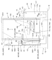
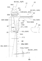
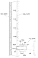
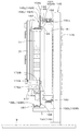
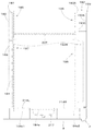
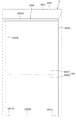
図1は、本実施形態に係る作業機1の全体構成を示す概略平面図である。図2は、作業機1の概略側面図である。本実施形態では、作業機1として旋回作業機であるバックホーが例示されている。
図1、図2に示すように、作業機1は、機体(旋回台)2と、走行装置3と、作業装置4とを備えている。機体2上にはキャビン5が搭載されている。キャビン5の室内には、運転者(オペレータ)が着座する運転席(座席)6が設けられている。言い換えると、運転席6は機体2に搭載され、キャビン5は運転席6を包囲している。運転席6は、運転者が座る部位である座部6Aと、運転者の背を受ける部位である背もたれ部6Bとを有する。
Hereinafter, an embodiment of the present invention will be described with reference to the drawings as appropriate.
FIG. 1 is a schematic plan view showing the overall configuration of a work machine 1 according to the present embodiment. FIG. 2 is a schematic side view of the work machine 1. In the present embodiment, a backhoe that is a turning work machine is illustrated as the work machine 1.
As shown in FIGS. 1 and 2, the work machine 1 includes a machine body (swivel base) 2, a traveling device 3, and a work device 4. A cabin 5 is mounted on the body 2. A driver's seat (seat) 6 on which a driver (operator) is seated is provided in the cabin 5. In other words, the driver's seat 6 is mounted on the airframe 2 and the cabin 5 surrounds the driver's seat 6. The driver's seat 6 has a seat portion 6A that is a portion where the driver sits and a backrest portion 6B that is a portion that receives the driver's back.
本発明の実施形態においては、作業機1の運転席6に着座した運転者の前側(図1、図2の矢印A1方向)を前方、運転者の後側(図1、図2の矢印A2方向)を後方、運転者の左側(図1の矢印B1方向)を左方、運転者の右側(図1の矢印B2方向)を右方として説明する。
また、図1に示すように、前後方向K1に直交する方向である水平方向を機体幅方向K2(機体2の幅方向)として説明する。機体2の幅方向の中央部から右部、或いは、左部へ向かう方向を機体外方(機体幅方向の外方)として説明する。言い換えれば、機体外方とは、機体幅方向K2であって機体2の幅方向の中心から離れる方向のことである。機体外方とは反対の方向を、機体内方(機体幅方向の内方)として説明する。言い換えれば、
機体内方とは、機体幅方向K2であって機体2の幅方向の中心に近づく方向である。
In the embodiment of the present invention, the front side (in the direction of arrow A1 in FIGS. 1 and 2) of the driver seated on the driver's seat 6 of the work machine 1 is the front side, and the rear side of the driver (arrow A2 in FIGS. 1 and 2). The direction will be described as the rear, the driver's left side (arrow B1 direction in FIG. 1) as the left side, and the driver's right side (arrow B2 direction in FIG. 1) as the right side.
In addition, as shown in FIG. 1, a horizontal direction that is a direction orthogonal to the front-rear direction K1 will be described as a body width direction K2 (width direction of the body 2). The direction from the center in the width direction of the body 2 toward the right or left is described as the outside of the body (outward in the body width direction). In other words, the outward direction of the aircraft is the direction in the aircraft width direction K2 and away from the center of the aircraft body 2 in the width direction. The direction opposite to the outside of the airframe will be described as the inside of the airframe (inward in the airframe width direction). In other words,
The in-machine direction is the direction of the body width direction K2 and approaches the center of the body 2 in the width direction.
図1、図2に示すように、走行装置3は、機体2を走行可能に支持する装置である。この走行装置3は、走行フレーム3Aと、走行フレーム3Aの左側に設けられた第1走行装置3Lと、走行フレーム3Aの右側に設けられた第2走行装置3Rとを有する。第1走行装置3L及び第2走行装置3Rは、クローラ式の走行装置である。第1走行装置3Lは、第1走行モータM1によって駆動される。第2走行装置3Rは、第2走行モータM2によって駆動される。第1走行モータM1及び第2走行モータM2は、油圧モータ(油圧アクチュエータ)によって構成されている。
As shown in FIGS. 1 and 2, the traveling device 3 is a device that supports the airframe 2 so that it can travel. The traveling device 3 includes a traveling frame 3A, a first traveling device 3L provided on the left side of the traveling frame 3A, and a second traveling device 3R provided on the right side of the traveling frame 3A. The first traveling device 3L and the second traveling device 3R are crawler-type traveling devices. The first traveling device 3L is driven by the first traveling motor M1. The second traveling device 3R is driven by the second traveling motor M2. The first travel motor M1 and the second travel motor M2 are configured by hydraulic motors (hydraulic actuators).
走行装置3の前部には、ドーザ装置7が装着されている。ドーザ装置7は、ドーザシリンダ(油圧アクチュエータ)を伸縮することにより昇降(ブレードを上げ下げ)させることができる。
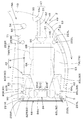
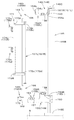
図2に示すように、機体2は、走行フレーム3A上に旋回ベアリング8を介して旋回軸心X1回りに旋回可能に支持されている。旋回軸心X1は、旋回ベアリング8の中心を通る上下方向に延伸する軸心である。
A dozer device 7 is attached to the front portion of the traveling device 3. The dozer device 7 can be moved up and down (raising and lowering the blade) by expanding and contracting a dozer cylinder (hydraulic actuator).
As shown in FIG. 2, the airframe 2 is supported on the traveling frame 3 </ b> A through a turning bearing 8 so as to be turnable around the turning axis X <b> 1. The pivot axis X1 is an axis extending in the vertical direction passing through the center of the pivot bearing 8.
図1、図3に示すように、キャビン5は、機体2の幅方向K2の一側部(左側部)に搭載されている。このキャビン5は、旋回軸心X1を通り且つ前後方向K1に延伸する中央線Y1より機体幅方向K2の一側部(左側部)寄りに配置されている。また、キャビン5は、機体2に前部寄りに設けられている。
図1、図3に示すように、機体2の幅方向K2の他側部(右側部)には、原動機E1が搭載されている。原動機E1は、機体2に縦置きに搭載されている。縦置きとは、原動機E1のクランク軸の軸心が前後方向に延伸する状態に配置されることである。
As shown in FIGS. 1 and 3, the cabin 5 is mounted on one side (left side) of the width direction K <b> 2 of the body 2. The cabin 5 is disposed closer to one side (left side) of the vehicle body width direction K2 than the center line Y1 passing through the turning axis X1 and extending in the front-rear direction K1. Further, the cabin 5 is provided near the front part of the airframe 2.
As shown in FIGS. 1 and 3, the prime mover E <b> 1 is mounted on the other side (right side) of the width direction K <b> 2 of the machine body 2. The prime mover E <b> 1 is mounted vertically on the body 2. “Vertical installation” means that the axis of the crankshaft of the prime mover E1 is arranged so as to extend in the front-rear direction.
原動機E1は、中央線Y1より機体幅方向K2の他側部(右側部)寄りに配置されている。原動機E1は、ディーゼルエンジンである。なお、原動機E1は、ガソリンエンジン、LPGエンジン又は電動モータであってもよいし、エンジン及び電動モータを有するハイブリッド型であってもよい。
原動機E1の後部には、油圧ポンプP1が設けられている。油圧ポンプP1は、原動機E1によって駆動されて油圧駆動部に使用される作動油を加圧して吐出する。油圧駆動部は、例えば、作業機1に装備された油圧アクチュエータ等である。原動機E1の前方には、ラジエータR1、オイルクーラO1及びコンデンサD1が配置されて機体2に搭載されている。
The prime mover E1 is disposed closer to the other side (right side) of the body width direction K2 than the center line Y1. The prime mover E1 is a diesel engine. The prime mover E1 may be a gasoline engine, an LPG engine or an electric motor, or may be a hybrid type having an engine and an electric motor.
A hydraulic pump P1 is provided at the rear of the prime mover E1. The hydraulic pump P1 pressurizes and discharges hydraulic oil that is driven by the prime mover E1 and used in the hydraulic drive unit. The hydraulic drive unit is, for example, a hydraulic actuator provided in the work machine 1. In front of the prime mover E1, a radiator R1, an oil cooler O1, and a condenser D1 are disposed and mounted on the machine body 2.
ラジエータR1は、原動機E1の冷却水を冷却する冷却機器であり、オイルクーラO1は、作動油を冷却する冷却機器である。また、コンデンサD1は、作業機1に装備された空調装置(エアコンディショナ)の冷媒を冷却する冷却機器(凝縮器)である。
ラジエータR1は、原動機E1の前方に配置され、オイルクーラO1は、ラジエータR1の前面に対向する位置(第1位置)に配置されている。コンデンサD1は、オイルクーラO1の前面に対向して配置されている。
The radiator R1 is a cooling device that cools the cooling water of the prime mover E1, and the oil cooler O1 is a cooling device that cools hydraulic oil. The capacitor D1 is a cooling device (condenser) that cools the refrigerant of the air conditioner (air conditioner) equipped in the work machine 1.
The radiator R1 is disposed in front of the prime mover E1, and the oil cooler O1 is disposed at a position (first position) facing the front surface of the radiator R1. The capacitor D1 is disposed to face the front surface of the oil cooler O1.
ラジエータR1と原動機E1との間には、原動機E1を冷却する冷却風を発生させる冷却ファンF1が設けられている。冷却ファンF1は、原動機E1によって駆動されて前方から後方に流れる冷却風を発生させる。
図2、図3に示すように、機体2は、旋回軸心X1回りに旋回する基板(以下、旋回基板という)9を有する。旋回基板9は、鋼板等から形成されており、機体2の底部を構成する。原動機E1は、この旋回基板9に搭載されている。旋回基板9の上面の中央側には、補強部材である縦リブ9L,9Rが前部から後部にわたって設けられている。縦リブ9Lは、機体2の幅方向K2の中央から一側寄りに配置され、縦リブ9Rは他側寄りに配置されている。また、旋回基板9に、縦リブ9L,9Rの他、機体2に搭載される機器等の搭載物を支持する支持部材等が設けられることにより、機体2の骨格となる旋回フレームが構成される。旋回フレームの水平方向の周囲は、旋回カバー12によって覆われる(図4、図5参照)。
A cooling fan F1 that generates cooling air for cooling the prime mover E1 is provided between the radiator R1 and the prime mover E1. The cooling fan F1 is driven by the prime mover E1 to generate cooling air that flows from the front to the rear.
As shown in FIGS. 2 and 3, the airframe 2 has a substrate (hereinafter referred to as a swivel substrate) 9 that revolves around the revolving axis X <b> 1. The swivel substrate 9 is formed of a steel plate or the like and constitutes the bottom of the body 2. The prime mover E1 is mounted on the turning board 9. Vertical ribs 9 </ b> L and 9 </ b> R, which are reinforcing members, are provided on the center side of the upper surface of the swivel substrate 9 from the front part to the rear part. The vertical rib 9L is disposed closer to one side from the center in the width direction K2 of the machine body 2, and the vertical rib 9R is disposed closer to the other side. Further, in addition to the vertical ribs 9L and 9R, the revolving substrate 9 is provided with a support member for supporting a load such as equipment mounted on the airframe 2, so that a revolving frame serving as a skeleton of the airframe 2 is configured. . The periphery of the swivel frame in the horizontal direction is covered with a swivel cover 12 (see FIGS. 4 and 5).
機体2の後部には、ウエイト10が設けられている。ウエイト10は、機体2の後部に配置されて下部が旋回基板9に取り付けられている。また、ウエイト10は、旋回基板9
から上方に突出状とされている。さらに、ウエイト10は、キャビン5及び運転席6より後方に配置されている。
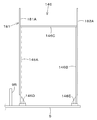
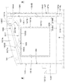
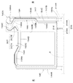
図3、図4、図5に示すように、ウエイト10は、旋回基板9の後部の機体幅方向K2の幅よりも幅狭(機体2後部の幅の略1/2)に形成されていて旋回基板9の機体幅方向K2の中央側に配置されている。ウエイト10の上端は、キャビン5及び運転席6の上下中途部の高さ位置に位置している。即ち、ウエイト10は、旋回基板9からキャビン5及び運転席6の上下中途部位置までの高さに形成されている。
A weight 10 is provided at the rear of the machine body 2. The weight 10 is disposed at the rear part of the machine body 2 and the lower part is attached to the revolving substrate 9. In addition, the weight 10 is a swivel substrate 9
Projecting upward from the top. Further, the weight 10 is disposed behind the cabin 5 and the driver's seat 6.
As shown in FIGS. 3, 4, and 5, the weight 10 is formed to be narrower than the width of the rear part of the revolving board 9 in the body width direction K <b> 2 (approximately half the width of the rear part of the body 2). The revolving substrate 9 is disposed on the center side in the body width direction K2. The upper end of the weight 10 is located at a height position in the middle of the cabin 5 and the driver's seat 6. That is, the weight 10 is formed at a height from the swivel board 9 to the upper and lower middle positions of the cabin 5 and the driver seat 6.
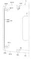
図1〜図3に示すように、機体2の後部には、機体幅方向K2に沿って並べて配置された燃料タンクT1及び作動油タンクT2が搭載されている。燃料タンクT1は、原動機E1の燃料を貯留するタンクである。作動油タンクT2は、作動油を貯留するタンクである。燃料タンクT1及び作動油タンクT2は、ウエイト10と後述の運転部42との間に配置されている。
As shown in FIGS. 1 to 3, a fuel tank T <b> 1 and a hydraulic oil tank T <b> 2 arranged side by side along the body width direction K <b> 2 are mounted on the rear part of the body 2. The fuel tank T1 is a tank that stores the fuel of the prime mover E1. The hydraulic oil tank T2 is a tank that stores hydraulic oil. The fuel tank T1 and the hydraulic oil tank T2 are disposed between the weight 10 and an operation unit 42 described later.
燃料タンクT1及び作動油タンクT2は、キャビン5及び運転席6より後方に配置されている。燃料タンクT1及び作動油タンクT2は、下部が旋回基板9に固定された取付部材に取り付けられていて、旋回基板9(機体2の下部)から上方に突出状とされている。燃料タンクT1及び作動油タンクT2の後方に、ウエイト10が配置されている。また、燃料タンクT1及び作動油タンクT2は、ウエイト10の機体幅方向K2の幅内に収まる形で該ウエイト10の前面に対向して配置されている。燃料タンクT1は作動油タンクT2に対して機体幅方向K2の一側(左側)に位置し、作動油タンクT2は燃料タンクT1に対して機体幅方向K2の他側(右側)に位置している。
The fuel tank T <b> 1 and the hydraulic oil tank T <b> 2 are disposed behind the cabin 5 and the driver seat 6. The lower part of the fuel tank T1 and the hydraulic oil tank T2 is attached to an attachment member fixed to the turning board 9, and protrudes upward from the turning board 9 (lower part of the machine body 2). A weight 10 is disposed behind the fuel tank T1 and the hydraulic oil tank T2. Further, the fuel tank T1 and the hydraulic oil tank T2 are disposed to face the front surface of the weight 10 so as to be within the width of the weight 10 in the body width direction K2. The fuel tank T1 is located on one side (left side) of the vehicle body width direction K2 with respect to the hydraulic oil tank T2, and the hydraulic oil tank T2 is located on the other side (right side) of the vehicle body width direction K2 with respect to the fuel tank T1. Yes.
図4、図5に示すように、燃料タンクT1及び作動油タンクT2の上端は、キャビン5及び運転席6の上下方向中途部(キャビン5の上下方向の略中央部)の高さ位置に位置している。また、燃料タンクT1の上端は、ウエイト10の上端の高さ位置と略同じであり、作動油タンクT2の上端はウエイト10の上端よりも低い位置になっている。また、燃料タンクT1及び作動油タンクT2は、高さが比較的高く且つ水平方向の断面積が比較的小さい形状(縦長形状)、具体的には左右方向の幅および前後方向の幅よりも上下方向の高さの方が高い形状に形成されている。これにより、機体2が傾いた場合等であっても燃料タンクT1内の燃料を適切に供給し、燃料を有効利用することができる。なお、燃料タンクT1の形状は、左右方向の幅と前後方向の幅との和よりも高さが高い形状であってもよい。
As shown in FIGS. 4 and 5, the upper ends of the fuel tank T1 and the hydraulic oil tank T2 are located at the height positions of the cabin 5 and the driver's seat 6 in the vertical direction (substantially the center in the vertical direction of the cabin 5). doing. Further, the upper end of the fuel tank T 1 is substantially the same as the height position of the upper end of the weight 10, and the upper end of the hydraulic oil tank T 2 is lower than the upper end of the weight 10. Further, the fuel tank T1 and the hydraulic oil tank T2 have a relatively high height and a relatively small cross-sectional area in the horizontal direction (vertically long shape), specifically, a width in the left-right direction and a width in the front-rear direction. It is formed in a shape whose height in the direction is higher. Thereby, even if the airframe 2 is tilted, the fuel in the fuel tank T1 can be appropriately supplied and the fuel can be used effectively. The shape of the fuel tank T1 may be higher than the sum of the width in the left-right direction and the width in the front-rear direction.
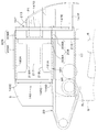
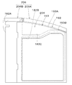
図4〜図6に示すように、キャビン5の下部の後方には、スペース46が設けられている。このスペース46は、キャビン5の後方の機体外方寄りに形成されている。スペース46は、第1形成面47と、第2形成面48と、ステップ(床面)49とを有して形成されている。
第1形成面47は、キャビン5より後方に配置された後部搭載部材の側面で形成されている。この後部搭載部材の側面は、キャビン5の下部の後方に位置し且つ機体外方を向く側面である。後部搭載部材は、本実施形態では、第1カバー18A及びウエイト10である。第1カバー18Aは、燃料タンクT1を覆うカバー部材であって、ウエイト10と運転部42との間に設けられている。また、第1カバー18Aは、燃料タンクT1の上方を覆う上壁部50と、燃料タンクT1の左の側方を覆う側壁部51とを有する。後部搭載部材の側面、即ち、第1形成面47は、第1カバー18Aの側面(側壁部51の外側面)と、ウエイト10の左の側面10aとで形成されている。第1形成面47は、キャビン5の機体幅方向K2の中央部より機体2の幅方向中央部寄りに位置している。なお、第1形成面47は、第1カバー18Aの側面とウエイト10の側面10aとで形成される構成に限らず、例えば、燃料タンク(後部搭載部材)T1の側壁によって形成してもよい。
As shown in FIGS. 4 to 6, a space 46 is provided behind the lower portion of the cabin 5. This space 46 is formed on the rear side of the cabin 5 and on the outer side of the body. The space 46 is formed having a first forming surface 47, a second forming surface 48, and a step (floor surface) 49.
The first formation surface 47 is formed on the side surface of the rear mounting member disposed behind the cabin 5. The side surface of the rear mounting member is a side surface that is located at the rear of the lower portion of the cabin 5 and faces outward from the body. The rear mounting member is the first cover 18A and the weight 10 in this embodiment. The first cover 18A is a cover member that covers the fuel tank T1, and is provided between the weight 10 and the operating unit 42. The first cover 18A includes an upper wall portion 50 that covers the upper side of the fuel tank T1, and a side wall portion 51 that covers the left side of the fuel tank T1. The side surface of the rear mounting member, that is, the first forming surface 47 is formed by the side surface of the first cover 18 </ b> A (the outer surface of the side wall portion 51) and the left side surface 10 a of the weight 10. The first forming surface 47 is located closer to the center in the width direction of the body 2 than the center in the body width direction K <b> 2 of the cabin 5. The first forming surface 47 is not limited to the configuration formed by the side surface of the first cover 18A and the side surface 10a of the weight 10, and may be formed by the side wall of the fuel tank (rear mounting member) T1, for example.
第2形成面48は、キャビン5の背面である。
ステップ49は、キャビン5の下端部側に設けられていてスペース46の下面を形成する。即ち、ステップ(床面)49の上方空間がスペース46である。また、ステップ49は、機体2の上面を形成する部材であり、作業者が乗ることが可能である。また、ステップ49の近傍に燃料タンクT1が配置されている。
The second forming surface 48 is the back surface of the cabin 5.
Step 49 is provided on the lower end side of the cabin 5 and forms the lower surface of the space 46. That is, the space above the step (floor surface) 49 is the space 46. Step 49 is a member that forms the upper surface of the machine body 2 and can be put on by an operator. A fuel tank T1 is disposed in the vicinity of step 49.
以上のように、スペース46は、第1形成面47、第2形成面48、ステップ49によって、キャビン5の下端部から上方に向けて且つ上方開放状に形成されている。また、スペース46は、左方(機体外方)及び後方にも開放状である。
図5に示すように、キャビン5の背面側には、室内からキャビン5の後方を視認可能な後部窓52が設けられている。この後部窓52は、キャビン5の背面の左部(機体外方側)で、且つスペース46の前方に設けられている。また、後部窓52は、キャビン5の上部から下部にわたって形成されている。後部窓52の機体幅方向K2の幅は、スペース46の前部の機体幅方向K2の一端部から他端部にわたる幅に形成され、後部窓52の下部は、スペース46に対応している。
As described above, the space 46 is formed from the first forming surface 47, the second forming surface 48, and the step 49 so as to open upward from the lower end of the cabin 5. The space 46 is also open on the left (outside the fuselage) and rear.
As shown in FIG. 5, a rear window 52 is provided on the back side of the cabin 5 so that the rear of the cabin 5 can be seen from the room. The rear window 52 is provided on the left side (outer side of the body) of the back surface of the cabin 5 and in front of the space 46. The rear window 52 is formed from the upper part to the lower part of the cabin 5. The width of the rear window 52 in the body width direction K <b> 2 is formed to extend from one end to the other end in the body width direction K <b> 2 at the front of the space 46, and the lower portion of the rear window 52 corresponds to the space 46.
後部窓52は、開閉可能である。図6に示すように、後部窓52は、右端側がヒンジ56によって縦軸(上下方向に延伸する軸心)回りに回転可能に支持されている。これによって、後部窓52は、図6に仮想線で示すように、後方に向けて開き、且つスペース46内に侵入する。なお、後部窓52はスライド式あるいは着脱式の窓であってもよい。
また、ステップ49は、燃料タンクT1の側方に設けられている。図6に示すように、第1カバー18Aの上壁部50は、燃料タンクT1の上部(上壁)に設けられていて燃料を給油するための給油口の上方に形成された開口55を有する。開口55は、蓋部材54によって開閉可能に塞がれる。これにより、本実施形態では縦長形状の燃料タンクT1を搭載しているので燃料の給油口の位置が高くなるが、作業者がステップ49に乗って給油作業を行うことで容易に給油することができる。
The rear window 52 can be opened and closed. As shown in FIG. 6, the rear window 52 is supported by a hinge 56 so as to be rotatable around a vertical axis (an axis extending in the vertical direction) on the right end side. As a result, the rear window 52 opens rearward and enters the space 46 as indicated by a virtual line in FIG. The rear window 52 may be a sliding type or a detachable type window.
Step 49 is provided on the side of the fuel tank T1. As shown in FIG. 6, the upper wall portion 50 of the first cover 18 </ b> A has an opening 55 provided on the upper portion (upper wall) of the fuel tank T <b> 1 and formed above the fuel filler opening for fueling. . The opening 55 is closed by the lid member 54 so as to be opened and closed. Thereby, in this embodiment, since the vertically long fuel tank T1 is mounted, the position of the fuel filler port becomes high. However, it is possible for the worker to easily refuel by performing the fueling operation on the step 49. it can.
図4に示すように、ステップ49の下方の機体2内には、燃料タンクT1に燃料を補給する燃料給油装置57を備えている。燃料給油装置57は、給油ポンプと、吸引ホースと、送油ホースとを有し、給油ポンプによって吸引ホースを介して燃料補給用の容器内の燃料を吸い込み、この吸い込んだ燃料を送油ホースによって燃料タンクT1に送る。
また、図4に示すように、ステップ49の下方の機体2内には、燃料に混入した水分を除去するセディメンタ58、原動機E1に燃料を送る燃料ポンプ59等が収容されている。
As shown in FIG. 4, a fuel refueling device 57 for supplying fuel to the fuel tank T1 is provided in the body 2 below the step 49. The fuel supply device 57 has a fuel supply pump, a suction hose, and a fuel supply hose. The fuel supply device 57 sucks the fuel in the fuel supply container through the suction hose and supplies the sucked fuel to the fuel supply hose. Send to fuel tank T1.
Further, as shown in FIG. 4, the aircraft 2 below the step 49 accommodates a cementor 58 for removing water mixed in the fuel, a fuel pump 59 for sending the fuel to the prime mover E1, and the like.
また、ステップ49は開閉可能になっており、ステップ49を開くことで、燃料給油装置57、燃料ポンプ59、及びセディメンタ58等に容易にアクセスできるようになっている。ステップ49の開閉機構は特に限定されず、例えば、ヒンジ式、スライド式、あるいは着脱式であってもよい。
図6で示すように、キャビン5の機体外方側の側面(左側)には、ドア53が設けられている。ドア53は、後部がヒンジ61によって縦軸回りに回転可能に支持されていて前部が機体幅方向K2に移動して乗降口62を開閉する。
Further, step 49 can be opened and closed. By opening step 49, the fuel refueling device 57, the fuel pump 59, the cementer 58 and the like can be easily accessed. The opening / closing mechanism of step 49 is not particularly limited, and may be, for example, a hinge type, a slide type, or a detachable type.
As shown in FIG. 6, a door 53 is provided on the side surface (left side) of the cabin 5 on the outer side of the machine body. The door 53 is supported by the hinge 61 so as to be rotatable about the vertical axis, and the front part moves in the body width direction K2 to open and close the entrance 62.
図7は、ドア53をヒンジドアに代えてスライドドア又はリンクドアにしたものである。ドア53は、キャビン5に沿って後方に移動して開く。また、ドア53は、後部がスペース46に入り込む(収容される)位置まで開く。これにより、ドア53を開放したまま旋回作業を行った場合であっても、ドア53が機体2の旋回軌道内に収容されるので、ドア53が機体周辺の物体に接触して破損するリスクを低減できる。
In FIG. 7, the door 53 is replaced with a hinge door and a slide door or a link door. The door 53 moves rearward along the cabin 5 and opens. Further, the door 53 opens to a position where the rear part enters (accommodates) the space 46. As a result, even if the turning operation is performed with the door 53 opened, the door 53 is accommodated in the turning track of the airframe 2, so there is a risk that the door 53 may come into contact with an object around the airframe and break. Can be reduced.
図4に示すように、キャビン5の下方で且つ機体2内には、空調装置のエアコン本体63が設けられている。エアコン本体63は、エバポレータ及び送風ファンを有する。エアコン本体63から吹き出された空調空気は、右側の中間ピラー64R内を通り、且つ中間ピラー64Rの上部に設けられた吹出し口65から運転席6側に吹き出される。また、エアコン本体63から吹き出された空調空気は、キャビン5の前部に設けられたダクト66内を通り、ダクト66の上部に設けられた吹出し口67からフロントガラス68の上部ガラス68Aに吹き出される。上部ガラス68Aは、上下に直線状に可動可能であり、下方に移動させることにより、キャビン5の前面上部を開放させることができる。フロントガラス68の下部ガラス68Bは固定状である。
As shown in FIG. 4, an air conditioner body 63 of an air conditioner is provided below the cabin 5 and in the airframe 2. The air conditioner main body 63 has an evaporator and a blower fan. The conditioned air blown out from the air conditioner body 63 passes through the right intermediate pillar 64R and is blown out toward the driver's seat 6 from a blowout port 65 provided at the upper part of the intermediate pillar 64R. The conditioned air blown from the air conditioner main body 63 passes through the duct 66 provided in the front portion of the cabin 5, and is blown out to the upper glass 68 </ b> A of the windshield 68 from the blowout port 67 provided in the upper part of the duct 66. The The upper glass 68A can be moved linearly up and down, and the upper front surface of the cabin 5 can be opened by moving downward. The lower glass 68B of the front glass 68 is fixed.
図4に示すように、上部ガラス68Aの上部には、上部ガラス68Aを移動操作する際に把持する把持部60L,60Rが設けられている。図6に示すように、把持部60Lは、上部ガラス68Aの左側に設けられ、把持部60Rは、上部ガラス68Aの右側に設け
られている。
図3に示すように、旋回基板9は、旋回ベアリング8に連結され、機体2は、旋回モータM3によって旋回駆動される。旋回モータM3は、油圧モータ(油圧アクチュエータ、油圧機器)である
図3、図37に示すように、旋回ベアリング8は、走行フレーム3Aに固定されたインナレース8Aと、旋回基板9に固定されたアウタレース8Bとを有する。インナレース8Aの内周部には、内歯が形成され、この内歯には、ピニオン11が噛合している。このピニオン11は、旋回モータM3の出力軸に取り付けられ、旋回モータM3は、旋回基板9に固定されている。したがって、旋回モータM3によってピニオン11を駆動することにより、機体2が旋回する。旋回ベアリング8の中心が機体2の旋回中心(旋回軸心X1)である。
As shown in FIG. 4, gripping portions 60 </ b> L and 60 </ b> R that are gripped when the upper glass 68 </ b> A is moved are provided on the upper glass 68 </ b> A. As shown in FIG. 6, the gripper 60L is provided on the left side of the upper glass 68A, and the gripper 60R is provided on the right side of the upper glass 68A.
As shown in FIG. 3, the turning board 9 is connected to the turning bearing 8, and the body 2 is driven to turn by a turning motor M3. The swing motor M3 is a hydraulic motor (hydraulic actuator, hydraulic equipment). As shown in FIGS. 3 and 37, the swing bearing 8 is fixed to the inner race 8A fixed to the traveling frame 3A and the swing substrate 9. And an outer race 8B. Inner teeth are formed on the inner peripheral portion of the inner race 8A, and the pinion 11 meshes with the inner teeth. The pinion 11 is attached to the output shaft of the turning motor M 3, and the turning motor M 3 is fixed to the turning substrate 9. Therefore, the airframe 2 turns by driving the pinion 11 by the turning motor M3. The center of the turning bearing 8 is the turning center (the turning axis X1) of the airframe 2.
図1、図3に示すように、旋回軸心X1位置には、スイベルジョイント(油圧機器)S1が設けられている。スイベルジョイントS1は、作動油を流通させる油圧機器であって、機体2側の油圧機器と走行装置3側の油圧機器との間で作動油を流通させる回転継手(ロータリジョイント)である。スイベルジョイントS1の前方に旋回モータM3が配置されている。スイベルジョイントS1の後方にコントロールバルブ(油圧機器)V1が配置されている。コントロールバルブV1は、作業機1に装備された油圧シリンダや油圧モータ等の油圧アクチュエータを制御する制御弁が集約して構成された油圧機器である。コントロールバルブV1を構成する制御弁は、後述の制御装置U1によって電気的に制御される制御弁であり、例えば、パイロット式の電磁弁が採用される。パイロット式の電磁弁は、ソレノイドによって制御されるパイロット圧によりメインスプールを動かして作動油の流れを制御する弁である。コントロールバルブV1を構成する制御弁は、例えば、第1走行モータM1、第2走行モータM2、旋回モータM3、ドーザシリンダ、スイングシリンダC2、ブームシリンダC3、アームシリンダC4、バケットシリンダC5を制御する制御弁である。
As shown in FIGS. 1 and 3, a swivel joint (hydraulic device) S1 is provided at the position of the pivot axis X1. The swivel joint S1 is a hydraulic device that circulates hydraulic oil, and is a rotary joint that circulates hydraulic oil between the hydraulic device on the airframe 2 side and the hydraulic device on the traveling device 3 side. A turning motor M3 is arranged in front of the swivel joint S1. A control valve (hydraulic device) V1 is disposed behind the swivel joint S1. The control valve V1 is a hydraulic device in which control valves for controlling hydraulic actuators such as a hydraulic cylinder and a hydraulic motor provided in the work machine 1 are integrated. The control valve that constitutes the control valve V1 is a control valve that is electrically controlled by a control device U1 described later. For example, a pilot-type electromagnetic valve is employed. The pilot type solenoid valve is a valve that controls the flow of hydraulic oil by moving a main spool by a pilot pressure controlled by a solenoid. The control valve constituting the control valve V1 is, for example, a control that controls the first travel motor M1, the second travel motor M2, the swing motor M3, the dozer cylinder, the swing cylinder C2, the boom cylinder C3, the arm cylinder C4, and the bucket cylinder C5. It is a valve.
コントロールバルブV1の後方に作動油タンクT2が配置されている。作動油タンクT2の右側方であって前部寄りに油圧ポンプP1が配置されている。
旋回モータM3からスイベルジョイントS1、コントロールバルブV1、作動油タンクT2を経て油圧ポンプP1に至る配置ゾーンが、これら油圧機器を配置する油圧機器配置部13である。また、言い換えると、キャビン5と原動機E1との間に油圧機器が配置される油圧機器配置部13が設けられ、該油圧機器配置部13に配置される油圧機器は、スイベルジョイントS1、旋回モータM3、コントロールバルブV1を含む。油圧機器配置部13は、スイベルジョイントS1、旋回モータM3、コントロールバルブV1を配置する第1配置部(配置部)13Aと、作動油タンクT2及び油圧ポンプP1を配置する第2配置部13Bとを有する(図1参照)。
A hydraulic oil tank T2 is disposed behind the control valve V1. A hydraulic pump P1 is disposed on the right side of the hydraulic oil tank T2 and closer to the front.
The arrangement zone from the turning motor M3 to the hydraulic pump P1 through the swivel joint S1, the control valve V1, and the hydraulic oil tank T2 is the hydraulic equipment placement section 13 for placing these hydraulic equipment. In other words, a hydraulic equipment placement section 13 in which hydraulic equipment is placed is provided between the cabin 5 and the prime mover E1, and the hydraulic equipment placed in the hydraulic equipment placement section 13 includes a swivel joint S1 and a swing motor M3. Including a control valve V1. The hydraulic device arrangement unit 13 includes a first arrangement unit (arrangement unit) 13A that arranges the swivel joint S1, the swing motor M3, and the control valve V1, and a second arrangement unit 13B that arranges the hydraulic oil tank T2 and the hydraulic pump P1. (See FIG. 1).
図3に示すように、キャビン5の下方には、制御装置U1が設けられている。制御装置U1は、コントロールバルブV1を構成する制御弁を制御する。制御装置U1は、コントロールバルブV1の左側方で且つ縦リブ9Lの右側方に配置されている。
スイベルジョイントS1、旋回モータM3、及びコントロールバルブV1は、これら各機器の一部または全部がキャビン5から機体幅方向K2に外れた位置に設けられている。これにより、メンテナンス時等において、キャビン5を下ろさずに上記各機器に、アクセスできる。
As shown in FIG. 3, a control device U <b> 1 is provided below the cabin 5. The control device U1 controls the control valve constituting the control valve V1. The control device U1 is disposed on the left side of the control valve V1 and on the right side of the vertical rib 9L.
The swivel joint S1, the swing motor M3, and the control valve V1 are provided at positions where all or a part of these devices are disengaged from the cabin 5 in the body width direction K2. Thereby, it is possible to access each of the above devices without lowering the cabin 5 during maintenance or the like.
図1に示すように、機体2には、作業機1に設けられた搭載部材を覆うカバー装置14が設けられている。カバー装置14は、第1カバー体(カバー体)15、第2カバー体16、第3カバー体(カバー部材)17、第4カバー体(後部カバー体)18を有する。
第1カバー体15は、機体2の右部の前部に位置し、ラジエータR1、オイルクーラO1、コンデンサD1を覆っている。第1カバー体15の前部の側面には、第1カバー体15内に外気を取り入れる外気取入口19が設けられている。冷却ファンF1によって吸引されることにより外気取入口19から外気が取り入れられる。
As shown in FIG. 1, the machine body 2 is provided with a cover device 14 that covers a mounting member provided in the work machine 1. The cover device 14 includes a first cover body (cover body) 15, a second cover body 16, a third cover body (cover member) 17, and a fourth cover body (rear cover body) 18.
The first cover body 15 is located at the front part on the right side of the machine body 2 and covers the radiator R1, the oil cooler O1, and the capacitor D1. An outside air intake 19 for taking outside air into the first cover body 15 is provided on the side surface of the front portion of the first cover body 15. The outside air is taken in from the outside air inlet 19 by being sucked by the cooling fan F1.
第2カバー体16は、第1カバー体15の後方に位置し、原動機E1を覆っている。即
ち、第2カバー体16は、原動機E1を収容する原動機室(エンジンルーム)ERを形成するボンネットである(以下、ボンネットという)。
第3カバー体17は、第1カバー体15及び第2カバー体16と、キャビン5(運転席6)との間に位置し、機器配置部13を覆っている。本実施形態では、第3カバー体17は、原動機E1とキャビン5との間の機器配置部13である第1配置部13Aを覆っている。即ち、第3カバー体17は、スイベルジョイントS1、旋回モータM3、及びコントロールバルブV1を覆っている。
The second cover body 16 is located behind the first cover body 15 and covers the prime mover E1. That is, the second cover body 16 is a bonnet that forms a prime mover room (engine room) ER that houses the prime mover E1 (hereinafter referred to as a bonnet).
The third cover body 17 is located between the first cover body 15 and the second cover body 16 and the cabin 5 (driver's seat 6), and covers the device arrangement portion 13. In the present embodiment, the third cover body 17 covers the first placement portion 13 </ b> A that is the device placement portion 13 between the prime mover E <b> 1 and the cabin 5. That is, the third cover body 17 covers the swivel joint S1, the turning motor M3, and the control valve V1.
第4カバー体18は、旋回基板9の後部に位置し、燃料タンクT1及び作動油タンクT2等を覆っている。第4カバー体18は、第1カバー18A、第2カバー18B、第3カバー18Cを有する。第1カバー18Aは、燃料タンクT1の上方及び左方を覆っている(図4参照)。第2カバー18Bは、作動油タンクT2及び油圧ポンプP1の一部の上方を覆っている。第3カバー18Cは、ウエイト10の右側に位置し、油圧ポンプP1の後方を覆っている。また、第3カバー18Cは、開閉可能とされている。
The 4th cover body 18 is located in the rear part of the turning board 9, and has covered fuel tank T1, hydraulic oil tank T2, etc. FIG. The fourth cover body 18 includes a first cover 18A, a second cover 18B, and a third cover 18C. The first cover 18A covers the upper and left sides of the fuel tank T1 (see FIG. 4). The second cover 18B covers a part of the hydraulic oil tank T2 and the hydraulic pump P1. The third cover 18C is located on the right side of the weight 10 and covers the rear of the hydraulic pump P1. The third cover 18C can be opened and closed.
図3に示すように、機体2は、機体幅方向K2の中央のやや右寄りの前部に支持ブラケット20を有している。支持ブラケット20は、縦リブ9L,9Rの前部に固定され、機体2から前方に突出状に設けられている。
図1、図2に示すように、支持ブラケット20の前部(機体2から突出した部分)には、スイング軸26を介してスイングブラケット21が縦軸回りに揺動可能に取り付けられている。したがって、スイングブラケット21は、機体幅方向K2に(スイング軸26を中心として水平方向に)回動可能である。また、スイング軸26は、運転部42よりも機体幅方向K2の他方側に位置している。
As shown in FIG. 3, the airframe 2 has a support bracket 20 at the front part slightly to the right of the center in the airframe width direction K2. The support bracket 20 is fixed to the front part of the vertical ribs 9L and 9R, and is provided so as to protrude forward from the body 2.
As shown in FIGS. 1 and 2, a swing bracket 21 is attached to a front portion of the support bracket 20 (a portion protruding from the machine body 2) via a swing shaft 26 so as to be swingable about the vertical axis. Therefore, the swing bracket 21 can rotate in the body width direction K2 (in the horizontal direction around the swing shaft 26). Further, the swing shaft 26 is located on the other side in the body width direction K2 from the operating unit 42.
図1に示すように、スイングブラケット21は、スイベルジョイントS1の前方に位置している。また、スイングブラケット21は、旋回軸心X1の前方で且つ後述するブーム22が機体正面方向を向いている状態のときに少なくとも一部が中央線Y1とオーバーラップする位置に配置されている。また、スイング軸26の軸心X2を通る前後方向の線Y2と、キャビン5の右側面5Aとの間(略中央)に中央線Y1が位置している。また、線Y2は、原動機E1と運転部42との間を通っている。
As shown in FIG. 1, the swing bracket 21 is located in front of the swivel joint S1. Further, the swing bracket 21 is disposed at a position that at least partially overlaps the center line Y1 when the boom 22 (to be described later) faces the front of the machine body in front of the turning axis X1. A center line Y1 is located between the front-rear direction line Y2 passing through the axis X2 of the swing shaft 26 and the right side surface 5A of the cabin 5 (substantially the center). Further, the line Y2 passes between the prime mover E1 and the operating unit 42.
スイングブラケット21には、作業装置4が取り付けられている。
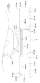
図2に示すように、作業装置4は、ブーム22と、アーム23と、バケット(作業具)24とを有している。ブーム22の基部22Aは、ブーム枢軸27を介してスイングブラケット21の上部に横軸(機体幅方向K2に延伸する軸心)回りに回動可能に枢着されている。これによって、ブーム22が上下方向に揺動可能とされている。また、ブーム22は、図2に示す最上げ位置において、長手方向の中央部が後方に凸となるように屈曲している。
The working device 4 is attached to the swing bracket 21.
As shown in FIG. 2, the work device 4 includes a boom 22, an arm 23, and a bucket (work tool) 24. The base 22A of the boom 22 is pivotally attached to the upper part of the swing bracket 21 via a boom pivot 27 so as to be rotatable about a horizontal axis (axial center extending in the body width direction K2). As a result, the boom 22 can swing in the vertical direction. In addition, the boom 22 is bent so that the central portion in the longitudinal direction protrudes rearward at the highest position shown in FIG.
アーム23は、ブーム22の先端側に横軸回りに回動可能に枢着されている。これによって、アーム23が前後或いは上下に揺動可能とされている。バケット24は、アーム23の先端側にスクイ動作及びダンプ動作可能に設けられている。スクイ動作とは、バケット24をブーム22に近づける方向に揺動させる動作であり、例えば、土砂等を掬う場合の動作である。また、ダンプ動作とは、バケット24をブーム22から遠ざける方向に揺動させる動作であり、例えば、掬った土砂等を落下(排出)させる場合の動作である。
The arm 23 is pivotally attached to the distal end side of the boom 22 so as to be rotatable about a horizontal axis. As a result, the arm 23 can swing back and forth or up and down. The bucket 24 is provided on the distal end side of the arm 23 so that a squeeze operation and a dump operation are possible. The squeeze operation is an operation of swinging the bucket 24 in a direction in which the bucket 24 approaches the boom 22, for example, an operation when crushing earth and sand. Further, the dumping operation is an operation of swinging the bucket 24 in a direction away from the boom 22, for example, an operation in the case of dropping (discharging) the crushed earth and sand.
作業機1は、バケット24に代えて或いは加えて、油圧アクチュエータにより駆動可能な他の作業具(油圧アタッチメント)を装着することが可能である。他の作業具としては、油圧ブレーカ、油圧圧砕機、アングルブルーム、アースオーガ、パレットフォーク、スイーパー、モア、スノウブロア等が例示できる。
スイングブラケット21は、機体2内に備えられたスイングシリンダC2の伸縮によって揺動可能とされている。ブーム22は、ブームシリンダC3の伸縮によって揺動可能とされている。アーム23は、アームシリンダC4の伸縮によって揺動可能とされている。バケット24は、バケットシリンダ(作業具シリンダ)C5の伸縮によってスクイ動作及びダンプ動作可能とされている。スイングシリンダC2、ブームシリンダC3、アームシリンダC4、バケットシリンダC5は、油圧シリンダ(油圧アクチュエータ)によって構
成されている。
The work machine 1 can be mounted with another work tool (hydraulic attachment) that can be driven by a hydraulic actuator instead of or in addition to the bucket 24. Examples of other working tools include a hydraulic breaker, a hydraulic crusher, an angle bloom, an earth auger, a pallet fork, a sweeper, a mower, and a snow blower.
The swing bracket 21 is swingable by expansion and contraction of a swing cylinder C2 provided in the airframe 2. The boom 22 can be swung by expansion and contraction of the boom cylinder C3. The arm 23 can be swung by expansion and contraction of the arm cylinder C4. The bucket 24 can be squeezed and dumped by expansion and contraction of a bucket cylinder (work implement cylinder) C5. The swing cylinder C2, the boom cylinder C3, the arm cylinder C4, and the bucket cylinder C5 are configured by hydraulic cylinders (hydraulic actuators).
図1に示すように、スイングシリンダC2は、キャビン5の下方の機体2内に設けられている。スイングシリンダC2の基端側の取付部25は、旋回基板9に取り付けられ、且つ運転席6の下方に位置している。なお、キャビン5の下方に、工具箱が設けられていてもよい。
図1に示すように、ブーム22の基部22Aは、キャビン5よりも中央線Y1側に位置している。言い換えると、原動機E1とキャビン5との間の前方に、スイングブラケット21及びブーム22の基部22Aが配置されている。したがって、スイングブラケット21が前方(正面)を向く状態でブーム22を上昇させる(最上げ位置にする)と、側面視においてブーム22の下部がキャビン5とオーバーラップし、ブーム22とアーム23との接続部がスイングブラケット21の略鉛直上方に配置される(図2参照)。
As shown in FIG. 1, the swing cylinder C <b> 2 is provided in the body 2 below the cabin 5. The attachment portion 25 on the base end side of the swing cylinder C <b> 2 is attached to the turning board 9 and is located below the driver seat 6. A tool box may be provided below the cabin 5.
As shown in FIG. 1, the base 22 </ b> A of the boom 22 is located on the center line Y <b> 1 side with respect to the cabin 5. In other words, the swing bracket 21 and the base 22A of the boom 22 are disposed in front of the prime mover E1 and the cabin 5. Therefore, when the boom 22 is raised (when the swing bracket 21 is facing forward (front)) (to the highest position), the lower portion of the boom 22 overlaps the cabin 5 in a side view, and the boom 22 and the arm 23 The connecting portion is disposed substantially vertically above the swing bracket 21 (see FIG. 2).
また、ブーム22の最上げ位置において、バケット24をスクイ動作させた状態で、アーム23をブーム22に近づける方向に揺動させると、図2に実線で示すように、バケット24の略全体がドーザ装置7の前端よりも後方(A2方向)に配置され、バケット24の一部はスイングブラケット21の前端よりも後方に配置される。
このように、ブーム22の最上げ位置のときにバケット24の一部がスイングブラケット21の前端よりも後方に位置するように、アーム23及びバケット24を機体2に近づけることができるので、機体2を旋回させる際において、作業装置4を小さい半径で旋回動作させることができる。これにより、例えば、ダンプカーの荷台に土砂等を積む作業やアーム23の先端側に設けたフックに運搬物を吊って吊り作業を行う場合等に動作を安定させることができる。また、ブーム22の最上げ位置のときにバケット24の位置を機体2に近づけるとともに高くすることができるので、ダンプカーの荷台に土砂等を積む際に、作業機2を荷台に近づけることができ、作業性を高めることができる。また、図2に実線で示す状態からアーム23をブーム22から遠ざかる方向に揺動させると、バケット24の底部の軌跡が上向きとなるので、ダンプカーの荷台に土砂等を積む際のダンプ動作がスムーズに行える。
Further, when the arm 23 is swung in a direction approaching the boom 22 in a state where the bucket 24 is squeezed at the highest position of the boom 22, as shown by a solid line in FIG. The bucket 7 is arranged behind the front end of the device 7 (A2 direction), and a part of the bucket 24 is arranged behind the front end of the swing bracket 21.
As described above, the arm 23 and the bucket 24 can be brought closer to the machine body 2 so that a part of the bucket 24 is located behind the front end of the swing bracket 21 when the boom 22 is at the highest position. When turning the machine, the work device 4 can be turned with a small radius. Accordingly, for example, the operation can be stabilized when the work such as loading earth and sand on the loading platform of the dump truck or when the work is hung by hanging the transported object on the hook provided on the distal end side of the arm 23. Moreover, since the position of the bucket 24 can be made close to the airframe 2 and raised when the boom 22 is at the highest position, the work equipment 2 can be brought close to the cargo bed when loading earth and sand on the dump truck's cargo bed, Workability can be improved. Further, when the arm 23 is swung away from the boom 22 from the state shown by the solid line in FIG. 2, the locus of the bottom portion of the bucket 24 becomes upward, so that the dumping operation when loading earth and sand on the loading platform of the dump truck is smooth. Can be done.
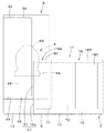
図8に実線で示すように、スイングブラケット21が前方を向く姿勢でブーム22を上昇させると、機体幅方向K2においてブーム22がキャビン5とオーバーラップする。この状態から、矢印で示すように、スイングブラケット21を右側に揺動させると、ブーム22はキャビン5に近接して干渉するおそれがある。また、仮想線で示すように、スイングブラケット21を右側に揺動させた状態で、ブーム22を上昇させる場合においても、ブーム22はキャビン5に近接して干渉するおそれがある。
As shown by a solid line in FIG. 8, when the boom 22 is raised with the swing bracket 21 facing forward, the boom 22 overlaps the cabin 5 in the body width direction K2. If the swing bracket 21 is swung to the right as indicated by the arrow from this state, the boom 22 may interfere with the cabin 5 in the vicinity. Further, as shown by the phantom line, even when the boom 22 is raised while the swing bracket 21 is swung to the right, the boom 22 may interfere with the cabin 5 in the vicinity.
そこで、作業機1は、ブーム22がキャビン5と干渉するのを防止する干渉防止機能を有する。この干渉防止機能について図9を参照して説明する。
図9に示すように、ブームシリンダC3は、コントロールバルブV1の内の1つの制御弁であるブーム制御弁74によって制御される。ブーム制御弁74は、ブーム22を停止状態にする中立位置74Aと、ブーム22を上昇させる上昇位置74Bと、ブーム22を下降させる下降位置74Cとを有する。また、ブーム制御弁74は、上昇位置74Bに切り替える第1ソレノイド74Dと、下降位置74Cに切り替える第2ソレノイド74Eとを有する。第1ソレノイド74D及び第2ソレノイド74Eは、制御装置U1に接続されている。
Therefore, the work machine 1 has an interference prevention function for preventing the boom 22 from interfering with the cabin 5. This interference prevention function will be described with reference to FIG.
As shown in FIG. 9, the boom cylinder C3 is controlled by a boom control valve 74 that is one of the control valves V1. The boom control valve 74 has a neutral position 74A where the boom 22 is stopped, a raised position 74B where the boom 22 is raised, and a lowered position 74C where the boom 22 is lowered. The boom control valve 74 includes a first solenoid 74D that switches to the raised position 74B and a second solenoid 74E that switches to the lowered position 74C. The first solenoid 74D and the second solenoid 74E are connected to the control device U1.
ブーム22を操作する操作部材(例えば、後述の第2操縦ハンドル82R)の操作方向及び操作量は、角度センサによって検出されて制御装置U1に送られる。制御装置U1は、取得した操作方向及び操作量に基づいて、第1ソレノイド74D又は第2ソレノイド74Eに信号を出力する。これによって、ブームシリンダC3を伸縮させてブーム22を上下に揺動させる。
An operation direction and an operation amount of an operation member (for example, a second steering handle 82R described later) for operating the boom 22 are detected by an angle sensor and sent to the control device U1. The control device U1 outputs a signal to the first solenoid 74D or the second solenoid 74E based on the acquired operation direction and operation amount. As a result, the boom cylinder C3 is expanded and contracted to swing the boom 22 up and down.
支持ブラケット20又はスイングブラケット21には、第1角度センサ71が設けられている。この第1角度センサ71は、スイングブラケット21の支持ブラケット20に対するスイング軸26回りの回転角度(スイング角)を検出するセンサである。スイングブラケット21又はブーム22には、第2角度センサ71が設けられている。第2角度セン
サ71は、ブーム22のスイングブラケット21に対するブーム枢軸27回りの回転角度を検出するセンサである。第1角度センサ71及び第2角度センサ71は、例えば、ポテンショメータによって形成されている。
The support bracket 20 or the swing bracket 21 is provided with a first angle sensor 71. The first angle sensor 71 is a sensor that detects a rotation angle (swing angle) of the swing bracket 21 around the swing axis 26 with respect to the support bracket 20. The swing bracket 21 or the boom 22 is provided with a second angle sensor 71. The second angle sensor 71 is a sensor that detects a rotation angle around the boom pivot 27 with respect to the swing bracket 21 of the boom 22. The first angle sensor 71 and the second angle sensor 71 are formed by, for example, a potentiometer.
第1角度センサ71と第2角度センサ71とでブーム22の位置を検出する検出装置45が構成されている。第1角度センサ71及び第2角度センサ71は、制御装置U1に接続されている。
制御装置U1は、検出装置45(第1角度センサ71及び第2角度センサ71)の検出信号を取得する。制御装置U1は、位置検出部73と、ブーム停止部75とを有する。
The first angle sensor 71 and the second angle sensor 71 constitute a detection device 45 that detects the position of the boom 22. The first angle sensor 71 and the second angle sensor 71 are connected to the control device U1.
The control device U1 acquires a detection signal of the detection device 45 (the first angle sensor 71 and the second angle sensor 71). The control device U1 includes a position detection unit 73 and a boom stop unit 75.
位置検出部73は、第1角度センサ71及び第2角度センサ71からの検出信号に基づいてブーム22の位置を検出する。ブーム停止部75は、位置検出部73によって検出されたブーム22の位置に基づいて、ブーム22がキャビン5に干渉する前に(ブーム22がキャビン5に近接した際に)ブーム22を停止させる信号をブーム制御弁74に出力する。具体的には、ブーム停止部75は、ブーム22を上昇させた状態から右にスイングさせる操作が行われた場合、及びブーム22を右にスイングさせた状態から上昇させる操作が行われた場合などに、操作に対応する動作を行うとブーム22がキャビン5に近接するか否かを判断し、近接すると判断した場合にはブーム22がキャビン5に干渉しないようにブーム22の動作を停止または制限する。
The position detector 73 detects the position of the boom 22 based on detection signals from the first angle sensor 71 and the second angle sensor 71. Based on the position of the boom 22 detected by the position detection unit 73, the boom stop unit 75 is a signal for stopping the boom 22 before the boom 22 interferes with the cabin 5 (when the boom 22 approaches the cabin 5). Is output to the boom control valve 74. Specifically, the boom stop unit 75 is operated when the operation of swinging the boom 22 to the right from the state in which the boom 22 is raised, or when the operation of raising the boom 22 from the state of swinging to the right is performed. When the operation corresponding to the operation is performed, it is determined whether or not the boom 22 is close to the cabin 5. When it is determined that the boom 22 is close, the operation of the boom 22 is stopped or restricted so that the boom 22 does not interfere with the cabin 5. To do.
図2、図4、図6に示すように、運転席6は、キャビン5内の後部に配置されている。キャビン5内には、操縦装置41が設けられている。操縦装置41は、運転席6の前方に設けられている。運転席6と操縦装置41とで作業機1を運転(操縦)する運転部42が構成されている。なお、本実施形態では、運転部42がキャビン5内に配置されている構成(キャビン仕様)について説明するが、これに限らず、運転部42の前後方向K1及び機体幅方向K2が外部に開放され、上方が屋根で覆われた構成(キャノピ仕様)であってもよく、運転部42の前後方向K1、機体幅方向K2および上方が外部に開放された構成であってもよい。
As shown in FIGS. 2, 4, and 6, the driver's seat 6 is disposed at the rear portion in the cabin 5. A control device 41 is provided in the cabin 5. The control device 41 is provided in front of the driver's seat 6. The driver's seat 6 and the control device 41 constitute a driving unit 42 that drives (steers) the work machine 1. In the present embodiment, a configuration (cabin specification) in which the operating unit 42 is disposed in the cabin 5 will be described. In addition, a configuration in which the upper part is covered with a roof (canopy specification) may be used, and a configuration in which the front-rear direction K1, the machine body width direction K2, and the upper part of the operation unit 42 are open to the outside may be used.
図4、図10に示すように、運転席6は、キャビン5の底部を構成する床部5Bに支持されている。床部5B上で且つ機体幅方向K2の中央部には、シート台76が取り付けられている。シート台76上には、サスペンション装置77が設けられており、このサスペンション装置77上にスライドレール78を介して運転席6が前後位置調整可能に設けられている。
As shown in FIGS. 4 and 10, the driver's seat 6 is supported by a floor 5 </ b> B that constitutes the bottom of the cabin 5. A seat base 76 is mounted on the floor 5B and at the center in the body width direction K2. A suspension device 77 is provided on the seat base 76, and the driver's seat 6 is provided on the suspension device 77 via a slide rail 78 so that the front-rear position can be adjusted.
運転席6は、縦軸回りに回転自在であってもよい。即ち、シート台76に、座部6Aの中心を縦軸回りに回転自在に支持し、運転席6の向きを縦軸回りに左又は右に自由に変更できるようになっていてもよい。
また、図20に示すように、スライドレール78は、後方に行くに従って上方に移行する傾斜状に形成されていてもよい。スライドレール78は、固定レール78Aと、可動レール78Bとを有する。固定レール78A及び可動レール78Bは、後方に行くに従って上方に移行する傾斜状である。固定レール78Aは、シート台76に固定された固定台111に取り付けられる。可動レール78Bは、座部6Aの下面に固定された可動台112に取り付けられる。可動レール78Bは、固定レール78Aに沿って移動可能であり、且つ固定レール78Aに固定可能である。
The driver's seat 6 may be rotatable about the vertical axis. In other words, the center of the seat portion 6A may be supported on the seat base 76 so as to be rotatable about the vertical axis, and the direction of the driver's seat 6 may be freely changed to the left or right about the vertical axis.
As shown in FIG. 20, the slide rail 78 may be formed in an inclined shape that moves upward as it goes rearward. The slide rail 78 has a fixed rail 78A and a movable rail 78B. The fixed rail 78A and the movable rail 78B are inclined so as to move upward as going backward. The fixed rail 78A is attached to a fixed base 111 fixed to the seat base 76. The movable rail 78B is attached to the movable base 112 fixed to the lower surface of the seat portion 6A. The movable rail 78B can move along the fixed rail 78A and can be fixed to the fixed rail 78A.
後傾状のスライドレール78にすることにより、運転席6を後方に行くに従って上方に移行する傾斜方向に位置調整可能とすることができる。即ち、可動レール78Bを後方に移動させると、座部6Aの位置が高くなり、身長の高い運転者に対応した調整をすることができる。
図4、図6、図13に示すように、操縦装置41は、操縦台81と、操縦部材82と、肘置き部材83と、モニタ84と、走行操作部材85と、ドーザレバー(操作レバー)80とを有する。
By using the rearwardly inclined slide rail 78, the position of the driver's seat 6 can be adjusted in an inclination direction that moves upward as going backward. That is, when the movable rail 78B is moved backward, the position of the seat portion 6A is increased, and adjustment corresponding to a tall driver can be performed.
As shown in FIGS. 4, 6, and 13, the control device 41 includes a control table 81, a control member 82, an elbow rest member 83, a monitor 84, a travel operation member 85, and a dozer lever (operation lever) 80. And have.
図10、図11、図12に示すように、操縦台81は、運転席6の前方で且つキャビン5の機体幅方向K2の中央側に設けられている。操縦台81は、床部5Bに立設された基台86と、基台86に上下位置調整可能に支持された支持台87とを有する。
図10〜図12、図14に示すように、基台86は、第1支柱88L、第2支柱88R、連結プレート89、第1補強板90L及び第2補強板90Rを有する。第1支柱88Lと第2支柱88Rは、上下方向の軸心を有する円柱体によって形成され、床部5Bに立設されている。第1支柱88Lは、キャビン5の機体幅方向K2の中央より左方に配置され、第2支柱88Rは、キャビン5の機体幅方向K2中央より左方に配置されている。
As shown in FIGS. 10, 11, and 12, the control table 81 is provided in front of the driver's seat 6 and on the center side of the cabin 5 in the body width direction K <b> 2. The control stand 81 has a base 86 standing on the floor 5B and a support base 87 supported by the base 86 so that the vertical position can be adjusted.
As shown in FIGS. 10 to 12 and 14, the base 86 includes a first support column 88 </ b> L, a second support column 88 </ b> R, a connection plate 89, a first reinforcing plate 90 </ b> L, and a second reinforcing plate 90 </ b> R. The first support column 88L and the second support column 88R are formed of a cylindrical body having a vertical axis and are erected on the floor portion 5B. The first support column 88L is disposed to the left of the center of the cabin 5 in the body width direction K2, and the second support column 88R is disposed to the left of the center of the cabin 5 in the body width direction K2.
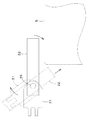
図15に示すように、第1支柱88L、第2支柱88Rの下部には、複数のロック穴(第1ロック穴94A〜第5ロック穴94E)が上下方向に間隔をあけて形成されている。
図10、図11、図14に示すように、連結プレート89は、第1支柱88Lと第2支柱88Rの下部間に配置され、第1支柱88Lと第2支柱88Rを連結している。第1補強板90Lは、第1支柱88Lの前面の下部に固定され、第2補強板90Rは、第2支柱88Rの前面の下部に固定されている。第1補強板90L及び第2補強板90Rの下端は、床部5Bに固定されている。
As shown in FIG. 15, a plurality of lock holes (first lock hole 94 </ b> A to fifth lock hole 94 </ b> E) are formed at intervals in the vertical direction below the first support column 88 </ b> L and the second support column 88 </ b> R. .
As shown in FIGS. 10, 11, and 14, the connection plate 89 is disposed between the lower portions of the first support column 88L and the second support column 88R, and connects the first support column 88L and the second support column 88R. The first reinforcing plate 90L is fixed to the lower part of the front surface of the first column 88L, and the second reinforcing plate 90R is fixed to the lower part of the front surface of the second column 88R. The lower ends of the first reinforcing plate 90L and the second reinforcing plate 90R are fixed to the floor portion 5B.
図11、図12、図14に示すように、支持台87は、基台86の上部に上下位置調整可能に取り付けられた取付体92と、取付体92に固定された取付台93とを有する。本実施形態では、取付台93は、取付体92を介して基台86に上下位置調整可能に支持されている。
図14に示すように、取付体92は、取付台93の下面側に設けられている。取付体92は、第1可動部材92Lと、第2可動部材92Rと、複数の補強板(第1補強板92A〜第5補強板92E)と、第1固定装置(固定装置)91Lと、第2固定装置(固定装置)91Rとを有する。第1可動部材92L及び第2可動部材92Rは、上下方向の軸心を有する筒体(円筒体)によって構成されている。第1可動部材92Lは、第1支柱88Lに上下移動可能に嵌められ、第2可動部材92Rは、第2支柱88Rに上下移動可能に嵌められている(図15参照)。これによって、取付体92が、基台86に対して上下移動可能とされている。
As shown in FIGS. 11, 12, and 14, the support base 87 has an attachment body 92 attached to the upper portion of the base 86 so that the vertical position can be adjusted, and an attachment base 93 fixed to the attachment body 92. . In the present embodiment, the mounting base 93 is supported by the base 86 via the mounting body 92 so that the vertical position can be adjusted.
As shown in FIG. 14, the attachment body 92 is provided on the lower surface side of the attachment base 93. The attachment body 92 includes a first movable member 92L, a second movable member 92R, a plurality of reinforcing plates (first reinforcing plate 92A to fifth reinforcing plate 92E), a first fixing device (fixing device) 91L, 2 fixing device (fixing device) 91R. The first movable member 92L and the second movable member 92R are configured by a cylindrical body (cylindrical body) having a vertical axis. The first movable member 92L is fitted to the first support column 88L so as to be movable up and down, and the second movable member 92R is fitted to the second support column 88R so as to be movable up and down (see FIG. 15). Thereby, the attachment body 92 can be moved up and down with respect to the base 86.
図14、図15に示すように、第1可動部材92L及び第2可動部材92Rには、径方向に貫通する挿通穴101が形成されている。第1可動部材92L及び第2可動部材92Rを上下に移動させることにより、挿通穴101を、複数のロック穴(第1ロック穴94A〜第5ロック穴94E)のいずれかと一致させることができる。
第1補強板92Aは、第1可動部材92Lから後方に行くに従って機体外方(左方)に移行する傾斜方向に延びている。第2補強板92Bは、第2可動部材92Rから後方に行くに従って機体内方(右方)に移行する傾斜方向に延びている。第3補強板92Cは、第1可動部材92Lから前方に行くに従って機体外方(左方)に移行する傾斜方向に延びている。第4補強板92Dは、第2可動部材92Lから後方に行くに従って機体内方(右方)に移行する傾斜方向に延びている。第5補強板92Eは、第1可動部材92Lと第2可動部材92Lとを連結している。
As shown in FIGS. 14 and 15, the first movable member 92L and the second movable member 92R are formed with insertion holes 101 penetrating in the radial direction. By moving the first movable member 92L and the second movable member 92R up and down, the insertion hole 101 can be made to coincide with any one of the plurality of lock holes (first lock hole 94A to fifth lock hole 94E).
The first reinforcing plate 92A extends in an inclined direction in which the first reinforcing member 92A moves outward (to the left) as it goes rearward from the first movable member 92L. The second reinforcing plate 92B extends in an inclined direction that shifts inward (to the right) from the second movable member 92R toward the rear. The third reinforcing plate 92 </ b> C extends in an inclined direction in which the third reinforcing plate 92 </ b> L moves outward (to the left) as it goes forward from the first movable member 92 </ b> L. The fourth reinforcing plate 92D extends in an inclined direction in which the fourth reinforcing plate 92D moves toward the body (rightward) as it goes rearward from the second movable member 92L. The fifth reinforcing plate 92E connects the first movable member 92L and the second movable member 92L.
第1固定装置91L及び第2固定装置91Rは、基台86に対して取付体92(支持台87)を固定する装置である。第2固定装置91Rは、第1固定装置91Lと同様の構成であるので、第1固定装置91Lを説明し、第2固定装置91Rの説明は省略する。
図14、図15に示すように、第1固定装置91Lは、支持部材96と、ロック部材97と、撮み98と、付勢部材99とを有する。支持部材96は、第1可動部材92L(第2可動部材92R)に固定された上壁96A及び下壁96Bと、上壁96Aと下壁96Bとを連結する支持壁96Cとを有する。
The first fixing device 91 </ b> L and the second fixing device 91 </ b> R are devices that fix the attachment body 92 (support base 87) to the base 86. Since the second fixing device 91R has the same configuration as the first fixing device 91L, the first fixing device 91L will be described, and the description of the second fixing device 91R will be omitted.
As shown in FIGS. 14 and 15, the first fixing device 91 </ b> L includes a support member 96, a lock member 97, a camera 98, and an urging member 99. The support member 96 includes an upper wall 96A and a lower wall 96B fixed to the first movable member 92L (second movable member 92R), and a support wall 96C that connects the upper wall 96A and the lower wall 96B.
ロック部材97は、棒材によって形成され、一端側は、挿通穴101に挿通可能であると共に第1ロック穴94A〜第5ロック穴94Eのいずれかに選択的に挿通可能である。ロック部材97を、挿通穴101と、第1ロック穴94A〜第5ロック穴94Eのいずれかに挿通することにより、基台86に対する取付体92の上下移動が規制される。ロック部材97の他端側は、支持壁96Cを貫通している。このロック部材97の他端側には、撮み98が固定されている。ロック部材97は、第1可動部材92L(第2可動部材92R)の径方向に移動可能である。
The lock member 97 is formed of a rod, and one end side can be inserted into the insertion hole 101 and can be selectively inserted into any of the first lock hole 94A to the fifth lock hole 94E. By inserting the lock member 97 into the insertion hole 101 and any one of the first lock hole 94A to the fifth lock hole 94E, the vertical movement of the attachment body 92 with respect to the base 86 is restricted. The other end side of the lock member 97 passes through the support wall 96C. A shooting 98 is fixed to the other end of the lock member 97. The lock member 97 is movable in the radial direction of the first movable member 92L (second movable member 92R).
撮み98を把持してロック部材97をロック穴(第1ロック穴94A〜第5ロック穴9
4E)から抜脱することにより、基台86に対する支持台87の上下移動が許容される。この状態で、支持台87を上下に移動し、任意の位置でロック部材97を挿通穴101及びロック穴に挿通することで、基台86に対する支持台87の上下位置が固定される。以上により、支持台87の上下位置調整(高さ調整)を行うことができる。
The lock member 97 is held in the lock hole (first lock hole 94A to fifth lock hole 9 by grasping the photographing 98.
4E), the vertical movement of the support base 87 with respect to the base 86 is permitted. In this state, the support base 87 is moved up and down, and the lock member 97 is inserted into the insertion hole 101 and the lock hole at an arbitrary position, whereby the vertical position of the support base 87 with respect to the base 86 is fixed. As described above, the vertical position adjustment (height adjustment) of the support base 87 can be performed.
付勢部材99は、ロック部材97に設けたバネ受け部材100と支持壁96Cとの間に設けられ、ロック部材99を挿通穴101及びロック穴に挿通させる方向に付勢している。
図11に示すように、取付台93は、板材によって形成され、板面が上下を向くように配置されている。
The urging member 99 is provided between the spring receiving member 100 provided on the lock member 97 and the support wall 96C, and urges the lock member 99 in a direction in which the lock member 99 is inserted into the insertion hole 101 and the lock hole.
As shown in FIG. 11, the mounting base 93 is formed of a plate material and is disposed so that the plate surface faces up and down.
図14に示すように、取付台93は、主部93Aと、第1延出部93Lと、第2延出部93Rとを有する。主部93Aは、機体幅方向K2に長い横長に形成されている。第1延出部93Lは、主部93Aの機体幅方向K2の一側部から後方に延びる。詳しくは、第1延出部93Lは、主部93Aの機体外方側の部位(左部)から後方に行くに従って機体外方に移行する傾斜方向に延出されている。第2延出部93Rは、主部93Aの機体幅方向K2の他側部から後方に延びる。詳しくは、第2延出部93Rは、主部93Aの機体内方側の部位(右部)から後方に行くに従って機体内方に移行する傾斜方向に延出されている。
As shown in FIG. 14, the mounting base 93 includes a main portion 93A, a first extending portion 93L, and a second extending portion 93R. The main portion 93A is formed in a horizontally long shape in the body width direction K2. The first extending portion 93L extends rearward from one side portion of the main body 93A in the body width direction K2. Specifically, the first extending portion 93L extends in an inclined direction that shifts outward from the body as it goes rearward from a portion (left portion) on the outer side of the main body 93A. The second extending portion 93R extends rearward from the other side portion of the main body 93A in the body width direction K2. Specifically, the second extending portion 93R extends in an inclined direction in which the second extending portion 93R shifts toward the body side as it goes rearward from a portion (right portion) on the body side of the main portion 93A.
主部93Aの中央部背面側の縁部、第1延出部93Lの右縁部、第2延出部93Rの左縁部によって、取付台93の後部側に後方に開放状の凹部93Bが形成されている。この凹部93Bは、後方に行くに従って拡開状とされている。凹部93Bを形成することにより、上部ガラス68Aを上下に移動操作する際等において、運転者は、上部ガラス68Aに容易に近づくことができる。
An open recess 93B is formed on the rear side of the mounting base 93 by the rear edge of the central portion 93A, the right edge of the first extension 93L, and the left edge of the second extension 93R. Is formed. The concave portion 93B has an expanding shape as it goes rearward. By forming the recess 93B, the driver can easily approach the upper glass 68A when moving the upper glass 68A up and down.
操縦部材82は、運転者が把持して操作する部材(グリップ)である。図11〜図13に示すように、操縦部材82は、第1操縦ハンドル82Lと、第2操縦ハンドル82Rとを含む。第1操縦ハンドル82Lは、主部93Aの機体幅方向K2の中心部よりも一方側(左部)に設けられている。第2操縦ハンドル82Rは、主部93Aの機体幅方向K2の中心部よりも他方側(右部)であって第1操縦ハンドル82Lの側方に設けられている。
The steering member 82 is a member (grip) that is gripped and operated by the driver. As shown in FIGS. 11 to 13, the steering member 82 includes a first steering handle 82L and a second steering handle 82R. The first steering handle 82L is provided on one side (left side) of the central portion 93A of the main portion 93A in the body width direction K2. The second steering handle 82R is provided on the other side (right side) of the main portion 93A in the body width direction K2 and on the side of the first steering handle 82L.
第1操縦ハンドル82Lと第2操縦ハンドル82Rとは、ともに作業機1に装備された2つの操作対象を操作可能な装置である。第1操縦ハンドル82Lは、例えば、第1の操作対象である機体2を旋回操作可能であり、且つ第2の操作対象であるアーム23を揺動操作可能である。また、第2操縦ハンドル82Rは、例えば、第1の操作対象であるバケット24を揺動操作可能であり、且つ第2の操作対象であるブーム15を揺動操作可能である。操縦部材82の操作方向及び揺動量は、角度センサによって検出される。この角度センサの検出信号は制御装置U1に送られる。制御装置U1は、角度センサからの検出信号に基づいて、操作対象を制御する制御弁を制御する。
The first steering handle 82L and the second steering handle 82R are both devices capable of operating two operation targets equipped in the work implement 1. For example, the first steering handle 82L can turn the body 2 that is the first operation target, and can swing the arm 23 that is the second operation target. The second steering handle 82R can swing the bucket 24 that is the first operation target, and can swing the boom 15 that is the second operation target. The operation direction and the swing amount of the control member 82 are detected by an angle sensor. The detection signal of this angle sensor is sent to the control device U1. The control device U1 controls the control valve that controls the operation target based on the detection signal from the angle sensor.
第1操縦ハンドル82L及び第2操縦ハンドル82Rは、取付台93に揺動操作可能に支持され、前及び後(前後方向K1)と、左及び右(機体幅方向K2)と、前後方向K1と機体幅方向K2との間の任意の斜め方向に操作可能である。図11、図12に示すように、第1操縦ハンドル82L及び第2操縦ハンドル82Rの揺動支点W1は、ハンドルの内部に設けられている。したがって、第1操縦ハンドル82L及び第2操縦ハンドル82R並びにこれらを支持する支持機構等を含む構造体は、高さの低いコンパクトな構造とされている。これにより、第1操縦ハンドル82L及び第2操縦ハンドル82Rは、手元操作量を小さくすることができ、機体2が揺れた場合でも、安定して操作をすることができるハンドル構造とされている。
The first steering handle 82L and the second steering handle 82R are supported by the mounting base 93 so as to be swingable. The front and rear (front and rear direction K1), left and right (airframe width direction K2), and front and rear direction K1. It can be operated in any diagonal direction between the machine body width direction K2. As shown in FIGS. 11 and 12, the swing fulcrum W1 of the first steering handle 82L and the second steering handle 82R is provided inside the handle. Therefore, the structure including the first steering handle 82L, the second steering handle 82R, and the support mechanism that supports them is a compact structure with a low height. Accordingly, the first steering handle 82L and the second steering handle 82R have a handle structure that can reduce the amount of operation at hand and can be stably operated even when the body 2 is shaken.
なお、水滴の落下対策として操縦台81の周囲を前傾した構造とするようにしてもよい。図12に示すように、取付台93の下面側には、ヒューズボックス113が設けられている。
肘置き部材83は、運転者が肘を置く部材である。図13に示すように、肘置き部材83は、取付台93(操縦台81)に設けられている。肘置き部材83は、取付台93(操縦台81)から運転席6に向けて延びる。本実施形態では、肘置き部材83は、操縦部材
82の後側から後方に延びる。
In addition, you may make it make it the structure where the periphery of the control pedestal 81 inclined forward as a countermeasure against a drop of water droplets. As shown in FIG. 12, a fuse box 113 is provided on the lower surface side of the mounting base 93.
The elbow rest member 83 is a member on which the driver places the elbow. As shown in FIG. 13, the elbow rest member 83 is provided on the mounting base 93 (control table 81). The elbow rest member 83 extends toward the driver's seat 6 from the mounting base 93 (control table 81). In the present embodiment, the elbow rest member 83 extends rearward from the rear side of the steering member 82.
肘置き部材83は、第1アームレスト83Lと、第2アームレスト83Rとを含む。第1アームレスト83Lは、第1操縦ハンドル82Lの後側から後方に延びる。詳しくは、第1アームレスト83Lは、第1操縦ハンドル82Lの後側から後方に行くに従って機体外方(左方)に移行する傾斜方向に延びる。また、第1アームレスト83Lは、第1延出部93Lの上方に該第1延出部93Lに沿って配置されている。第1アームレスト83Lは、第1延出部93Lに支持部材103Lを介して取り付けられている。
The elbow rest member 83 includes a first armrest 83L and a second armrest 83R. The first armrest 83L extends rearward from the rear side of the first steering handle 82L. Specifically, the first armrest 83L extends in an inclined direction in which the first armrest 83L moves outward (to the left) from the rear side of the first steering handle 82L toward the rear. Further, the first armrest 83L is disposed above the first extension portion 93L along the first extension portion 93L. The first armrest 83L is attached to the first extension portion 93L via a support member 103L.
第2アームレスト83Rは、第2操縦ハンドル82Rの後側から後方に延びる。詳しくは、第2アームレスト83Rは、第2操縦ハンドル82Rの後側から後方に行くに従って機体内方(右方)に移行する傾斜方向に延びる。また、第2アームレスト83Rは、第2延出部93Rの上方に該第2延出部93Rに沿って配置されている。第2アームレスト83Rは、第2延出部93Rに支持部材103Rを介して取り付けられている。
The second armrest 83R extends rearward from the rear side of the second steering handle 82R. Specifically, the second armrest 83R extends in an inclined direction in which the second armrest 83R shifts inward (to the right) from the rear side of the second steering handle 82R toward the rear. Further, the second armrest 83R is disposed along the second extending portion 93R above the second extending portion 93R. The second armrest 83R is attached to the second extension portion 93R via the support member 103R.
本実施形態の操縦装置41では、運転者は、第1アームレスト83Lに左腕の肘を置くと共に左手で第1操縦ハンドル82Lを把持し、第2アームレスト83Rに右腕の肘を置くと共に右手で第2操縦ハンドル82Rを把持する。したがって、運転者は、運転席6に座した状態において上体を前傾姿勢とした状態で操縦部材82を操作することになる。これにより、運転者は、上体をキャビン5の前面側に近づける状態で第1操縦ハンドル83L及び第2操縦ハンドル83Rを操作する姿勢となる。
In the control device 41 of the present embodiment, the driver places the elbow of the left arm on the first armrest 83L, holds the first control handle 82L with the left hand, places the elbow of the right arm on the second armrest 83R, and sets the second arm with the right hand. The steering handle 82R is gripped. Therefore, the driver operates the control member 82 in a state where the upper body is in a forward leaning posture while sitting on the driver's seat 6. Accordingly, the driver is in a posture to operate the first steering handle 83L and the second steering handle 83R in a state where the upper body is brought close to the front side of the cabin 5.
また、本実施形態では、操縦部材82及び肘置き部材83を運転席6の前方に位置させることで、キャビン5の左及び右の側面を運転席6に近づけ、キャビン5の機体幅方向K2の寸法をコンパクトにしている。
また、第1アームレスト83Lは運転席6より左方に大きくはみ出しており、第2アームレスト83Rは運転席6より右方に大きくはみ出しており、第1アームレスト83Lと第2アームレスト83Rとの間隔を広く採っている。
Further, in the present embodiment, by positioning the control member 82 and the elbow rest member 83 in front of the driver's seat 6, the left and right side surfaces of the cabin 5 are brought closer to the driver's seat 6, so The dimensions are compact.
Further, the first armrest 83L protrudes far leftward from the driver's seat 6, and the second armrest 83R protrudes farther rightward than the driver's seat 6, so that the distance between the first armrest 83L and the second armrest 83R is wide. Adopted.
また、第1アームレスト83Lと第2アームレスト83Rとは、後方に行くに従って機体幅方向K2の相互間隔が広がるように傾斜状に設けられている。
また、図13に示すように、第1アームレスト83L及び第1延出部93Lは、座部6Aの左部と上下方向で一部オーバーラップしている。第2アームレスト83R及び第2延出部と93Rは、座部6Aの右部と上下方向で一部オーバーラップしている。本実施形態では、操縦装置41(操縦台81)と運転席6とを前後方向で近接して配置し、且つ操縦装置41に運転席6を近づけることにより、運転部42(キャビン5)を前後にコンパクトに構成している。
Further, the first armrest 83L and the second armrest 83R are provided in an inclined manner so that the mutual interval in the body width direction K2 increases as going backward.
As shown in FIG. 13, the first arm rest 83L and the first extension portion 93L partially overlap the left portion of the seat portion 6A in the vertical direction. The second armrest 83R and the second extending portion and 93R partially overlap with the right portion of the seat portion 6A in the vertical direction. In the present embodiment, the control device 41 (control table 81) and the driver's seat 6 are arranged close to each other in the front-rear direction, and the driver's seat 6 is brought close to the control device 41, whereby the driver 42 (cabin 5) is moved back and forth. It has a compact configuration.
図20に仮想線で示すように、第1アームレスト83L(肘置き部材83)は、操縦台81に前部が枢支されていて後部が上方に揺動可能とされていてもよい。本実施形態の場合、第1アームレスト83Lと共に第1延出部93Lも上方に揺動可能とされる。
また、第1アームレスト83L及び第2アームレスト83Rは、取付台93に、前後方向K1に位置調整可能に支持するのがよい。これにより、身長の高い運転者に対して腕の角度を安定させることができる。また、乗降時に、第1アームレスト83Lを前側に位置移動して乗降通路幅を広くすることができる。
As indicated by phantom lines in FIG. 20, the first armrest 83 </ b> L (elbow rest member 83) may be pivotally supported at the front of the control table 81 and swingable upward at the rear. In the case of the present embodiment, the first extending portion 93L can be swung upward together with the first armrest 83L.
Further, the first armrest 83L and the second armrest 83R are preferably supported on the mounting base 93 so that their positions can be adjusted in the front-rear direction K1. Thereby, the angle of an arm can be stabilized with respect to a tall driver. Also, when getting on and off, the first armrest 83L can be moved to the front side to widen the boarding passage width.
図11、図13に示すように、モニタ84は、取付台93の上面側に配置され、第1操縦ハンドル82Lと第2操縦ハンドル82Rとの間に設けられている。詳しくは、モニタ84は、取付台93の機体幅方向K2の中央部に配置され、第1操縦ハンドル82Lは、モニタ84の機体幅方向K2の一側方に配置され、第2操縦ハンドル82Rは、モニタ84の機体幅方向K2の他側方に配置されている。また、第1操縦ハンドル82L、第2操縦ハンドル82R及びモニタ84は、機体幅方向K2で並べて配置されている。モニタ84は、第1操縦ハンドル82L及び第2操縦ハンドル82Rを把持して前傾姿勢で作業機1を運転する運転者の正面に位置する。
As shown in FIGS. 11 and 13, the monitor 84 is disposed on the upper surface side of the mounting base 93 and is provided between the first steering handle 82L and the second steering handle 82R. Specifically, the monitor 84 is disposed at the center of the mount 93 in the body width direction K2, the first steering handle 82L is disposed at one side of the monitor 84 in the body width direction K2, and the second steering handle 82R is The monitor 84 is disposed on the other side of the machine body width direction K2. The first steering handle 82L, the second steering handle 82R, and the monitor 84 are arranged side by side in the body width direction K2. The monitor 84 is positioned in front of a driver who grips the first steering handle 82L and the second steering handle 82R and drives the work implement 1 in a forward tilt posture.
モニタ84は、後面(運転席6側)に、下方に行くに従って後方に移行する傾斜面を有し、この傾斜面に、表示を行う表示部(画面)84Aを設けている。即ち、表示部(画面)84Aは、後下がりに傾斜する傾斜面になっており、前傾姿勢で操縦部材82を操作す
る運転者にとって表示部(画面)84Aを視認しやすい。
表示部84Aは、作業機1の基本情報や、作業機1の周囲の画像や、作業機1の様々な設定を行うのに必要な情報等が表示される。基本情報は、例えば、運転状況、モード変更、各種設定、ワーニング、燃料残量、時間(時刻)等である。作業機1の周囲の画像としては、例えば、作業機1の後方の画像である。図4に示すように、ウエイト10の上部に機体2の後方を撮像可能な撮像装置43(カメラ等)が設けられ、この撮像装置43で撮像した画像が表示部84Aに表示可能である。モニタ84と撮像装置43とは、CAN(Controller Area Network)やフレックスレイ(FlexRay)等の車載用通信ネットワークによって、相互通信が可能である。撮像装置43は、遠隔操作等によって向き変更可能とすることで、機体2の周囲の画像を撮像可能としてもよい。また、機体2の後方以外の画像を表示部84Aに表示させるための撮像装置を、キャビン5や機体2或いはカバー装置14等に適宜設けてもよい。
The monitor 84 has an inclined surface that moves backward as it goes downward on the rear surface (driver's seat 6 side), and a display portion (screen) 84A that performs display is provided on the inclined surface. That is, the display portion (screen) 84A has an inclined surface that inclines rearwardly and is easy for the driver who operates the control member 82 in the forward inclined posture to visually recognize the display portion (screen) 84A.
The display unit 84 </ b> A displays basic information of the work machine 1, images around the work machine 1, information necessary for various settings of the work machine 1, and the like. The basic information includes, for example, operating conditions, mode changes, various settings, warnings, remaining fuel, time (time), and the like. The image around the work machine 1 is, for example, an image behind the work machine 1. As shown in FIG. 4, an imaging device 43 (such as a camera) capable of imaging the rear of the airframe 2 is provided on the upper portion of the weight 10, and an image captured by the imaging device 43 can be displayed on the display unit 84 </ b> A. The monitor 84 and the imaging device 43 can communicate with each other via an in-vehicle communication network such as CAN (Controller Area Network) or FlexRay. The imaging device 43 may be capable of taking an image around the machine body 2 by changing the orientation by remote control or the like. Further, an imaging device for displaying an image other than the rear side of the machine body 2 on the display unit 84A may be provided as appropriate in the cabin 5, the machine body 2, the cover device 14, or the like.
作業機1の様々な設定を行うのに必要な情報は、例えば、高さ制御設定、AI制御設定、アーム制限設定等の機械設定に必要な情報である。
モニタ84の表示部84Aの下側には、複数の操作スイッチ(第1スイッチ84B、第2スイッチ84C、第3スイッチ84D)が設けられている。
第1スイッチ84Bは、例えば、原動機E1の回転数を変更するスイッチである。回転数の変更は、段階的に変更可能である。また、回転数の変更は、連続的に変更可能であってもよい。
Information necessary for performing various settings of the work machine 1 is information necessary for machine settings such as height control settings, AI control settings, arm limit settings, and the like.
A plurality of operation switches (a first switch 84B, a second switch 84C, and a third switch 84D) are provided below the display portion 84A of the monitor 84.
The first switch 84B is, for example, a switch that changes the rotational speed of the prime mover E1. The rotation speed can be changed step by step. Moreover, the change of the rotation speed may be continuously changeable.
第2スイッチ84Cは、例えば、作業機1の作業速度を設定するスイッチである。作業速度は段階的に設定可能である。作業速度の設定は、連続的に変更可能であってもよい。作業速度は、例えば、ブーム22、アーム23、バケット24、スイングブラケット21の揺動速度や、機体2の旋回速度である。また、第2スイッチ84Cは、操縦部材82の操作対象に対する操作をできないようにする操作不能状態と、操縦部材82の操作対象に対する操作を可能にする操作可能状態とに切り替えるスイッチであってもよい。この場合、第2スイッチ84Cは、操作不能状態か操作可能状態かを表示する表示ランプを兼ねていてもよい。また、第2スイッチ84Cは、作業速度の設定と、操作不能状態及び操作可能状態の切り替えとを兼用するスイッチであってもよい。
The second switch 84 </ b> C is a switch for setting the work speed of the work machine 1, for example. The work speed can be set in stages. The setting of the work speed may be continuously changeable. The work speed is, for example, the swing speed of the boom 22, the arm 23, the bucket 24, the swing bracket 21, or the turning speed of the body 2. Further, the second switch 84C may be a switch that switches between an inoperable state that prevents the operation of the operation member 82 from being operated and an operable state that enables the operation of the operation member 82. . In this case, the second switch 84C may also serve as a display lamp that displays whether the operation is disabled or enabled. Further, the second switch 84C may be a switch that combines the setting of the work speed and the switching between the inoperable state and the operable state.
第3スイッチ84Dは、作業機1に装備されたライト、例えば、ブーム灯、前照灯、後照灯等を点灯及び消灯するスイッチである。また、第3スイッチ84Dは、原動機E1を始動するキースイッチであってもよい。また、第3スイッチ84Dは、キースイッチとライトのON、OFFを行うスイッチを兼用してもよい。
第1スイッチ84B、第2スイッチ84C及び第3スイッチ84Dで操作した状態が、表示部84Aに表示されるようになっていてもよい。
The third switch 84D is a switch for turning on and off lights provided in the work machine 1, for example, a boom lamp, a headlamp, a rear lamp, and the like. The third switch 84D may be a key switch that starts the prime mover E1. The third switch 84D may also serve as a key switch and a switch for turning on / off the light.
The state operated by the first switch 84B, the second switch 84C, and the third switch 84D may be displayed on the display unit 84A.
図13に示すように、第1操縦ハンドル82L(モニタ84)の左側方には、画面に表示される表示項目の操作をする複数の操作具(第1操作具44A、第2操作具44B、第3操作具44C)が設けられている。第2操作具44B及び第3操作具44Cは、第1操作具44Aの前方において機体幅方向K2で並べて配置されている。例えば、第1操作具44Aは、回転操作が可能な操作具であり、第2操作具44B及び第3操作具44Cは、押圧操作可能なスイッチである。第1操作具44Aは、回転操作を行うことにより、表示部84Aに表示される複数の選択項目のうちの選択項目候補を変更する。第3操作具44Cを押圧操作することにより選択項目を決定する。また、第2操作具44Bは、押圧操作することにより決定した選択項目のキャンセルを行う。
As shown in FIG. 13, on the left side of the first steering handle 82L (monitor 84), a plurality of operating tools (first operating tool 44A, second operating tool 44B, A third operating tool 44C) is provided. The second operation tool 44B and the third operation tool 44C are arranged side by side in the body width direction K2 in front of the first operation tool 44A. For example, the first operation tool 44A is an operation tool that can be rotated, and the second operation tool 44B and the third operation tool 44C are switches that can be pressed. 44 A of 1st operation tools change the selection item candidate among the several selection items displayed on the display part 84A by performing rotation operation. The selection item is determined by pressing the third operation tool 44C. The second operation tool 44B cancels the selection item determined by the pressing operation.
なお、第1操作具44A、第2操作具44B、第3操作具44Cは、第1操縦ハンドル82L(モニタ84)の右側方に設けてもよい。また、選択項目候補の変更、選択項目の決定及び選択項目のキャンセルを、単一の操作具によって行うようにしてもよい。また、表示部84Aは、表示及び操作具を兼用するタッチパネル、即ち、オペレータによる表示部へのタッチ操作を受け付けるタッチ操作部を有するものであってもよい。
The first operating tool 44A, the second operating tool 44B, and the third operating tool 44C may be provided on the right side of the first steering handle 82L (monitor 84). Further, the selection item candidate change, selection item determination, and selection item cancellation may be performed by a single operation tool. The display unit 84A may include a touch panel that also serves as a display and an operation tool, that is, a touch operation unit that receives a touch operation on the display unit by an operator.
運転者は、肘置き部材83に肘をついたまま(肘を中心として)、操縦部材82からモニタ84(表示部84A、第1スイッチ84B、第2スイッチ84C又は第3スイッチ8
4D等)に容易に手を移動させることができる。また、肘置き部材83に肘をついたまま、表示部84A、第1スイッチ84B、第2スイッチ84C又は第3スイッチ84D等を操作することができる。
The driver keeps his elbow on the elbow rest member 83 (centering on the elbow), and the monitor 84 (display portion 84A, first switch 84B, second switch 84C, or third switch 8) from the steering member 82.
4D etc.) can be moved easily. In addition, the display portion 84A, the first switch 84B, the second switch 84C, the third switch 84D, and the like can be operated while the elbow resting member 83 is attached.
また、第1アームレスト83Lに肘をついたまま、第1操縦ハンドル82Lから第1操作具44A、第2操作具44B及び第3操作具44Cに容易に手を移動させることができる。また、肘置き部材83に肘をついたまま、第1操作具44A、第2操作具44B及び第3操作具44Cを容易に操作することができる。
第2操縦ハンドル82R(モニタ84)の右側方には、原動機E1を停止させる停止スイッチ102が設けられている。第2アームレスト83Rに肘をついたまま、第2操縦ハンドル82Rから停止スイッチ102に手を移動させることが容易である。また、図6に示すように、モニタ84の前方に吹出し口67が設けられている。
Further, it is possible to easily move the hand from the first steering handle 82L to the first operating tool 44A, the second operating tool 44B, and the third operating tool 44C while keeping the elbow on the first armrest 83L. Further, the first operating tool 44A, the second operating tool 44B, and the third operating tool 44C can be easily operated while the elbow resting member 83 is attached.
A stop switch 102 for stopping the prime mover E1 is provided on the right side of the second steering handle 82R (monitor 84). It is easy to move the hand from the second steering handle 82R to the stop switch 102 while the elbow is attached to the second armrest 83R. In addition, as shown in FIG. 6, an outlet 67 is provided in front of the monitor 84.
走行操作部材85は、足踏み操作により走行装置3を操作するペダルである。
図6、図13に示すように、走行操作部材85は、運転席6の機体幅方向K2の一側部の前方に配置された第1走行ペダル85Lと、運転席6の機体幅方向K2の他側部の前方に配置された第2走行ペダル85Rとを含む。第1走行ペダル85Lは、第1走行装置3L(第1走行モータM1)を操作するペダルである。第2走行ペダル85Rは、第2走行装置3R(第2走行モータM2)を操作するペダルである。
The travel operation member 85 is a pedal that operates the travel device 3 by a stepping operation.
As shown in FIGS. 6 and 13, the traveling operation member 85 includes a first traveling pedal 85 </ b> L disposed in front of one side of the vehicle body width direction K <b> 2 of the driver seat 6, and the vehicle body width direction K <b> 2 of the driver seat 6. And a second traveling pedal 85R disposed in front of the other side portion. The first travel pedal 85L is a pedal for operating the first travel device 3L (first travel motor M1). The second travel pedal 85R is a pedal for operating the second travel device 3R (second travel motor M2).
第1走行ペダル85L及び第2走行ペダル85Rは、作業機1の前進及び後進の操作、操向の操作を行うペダルである。即ち、第1走行ペダル85L及び第2走行ペダル85Rを前に踏み込むと前進し、後に踏み込むと後進する。また、第1走行ペダル85L及び第2走行ペダル85Rの踏み込み方向及び踏み込み量が同じであると直進走行し、第1走行ペダル85Lと第2走行ペダル85Rの踏み込み量が異なると旋回走行する。第1走行ペダル85Lの踏み込み量によって第1走行モータM1の回転数の変更が可能であり、第2走行ペダル85Rの踏み込み量によって第2走行モータM2の回転数が変更可能である。
The first travel pedal 85L and the second travel pedal 85R are pedals that perform forward and reverse operations and steering operations of the work implement 1. That is, when the first traveling pedal 85L and the second traveling pedal 85R are stepped forward, the vehicle moves forward, and when it is stepped backward, the vehicle moves backward. Further, when the first travel pedal 85L and the second travel pedal 85R have the same depression direction and depression amount, the vehicle travels straight, and when the first travel pedal 85L and the second travel pedal 85R have different depression amounts, the vehicle travels. The rotation speed of the first travel motor M1 can be changed by the depression amount of the first travel pedal 85L, and the rotation speed of the second travel motor M2 can be changed by the depression amount of the second travel pedal 85R.
本実施形態の作業機1においては、直進走行する際には、直進性をだすために、第1走行ペダル85L及び第2走行ペダル85Rを最大位置まで踏み込む(ベタ踏みする)。走行速度の変更は、操縦部材82に設けられた増減速スイッチによって可能である。
図13に示すように、増減速スイッチは、第1操縦ハンドル82Lに設けられた減速スイッチ106と、第2操縦ハンドル82Rに設けられた増速スイッチ107である。運転者は、操縦部材82を把持した状態で、作業機1の走行速度の増速又は減速を行うことができる。増速スイッチ107は、走行速度を増加させるスイッチである。増速スイッチ107は、例えば、モーメンタリースイッチであって、押す毎に変速段が増加する。減速スイッチ106は、走行速度を減少させるスイッチである。減少スイッチ106は、例えば、モーメンタリースイッチであって、押す毎に変速段が減少する。走行速度の増速及び減速は連続的であってもよい。即ち、減速スイッチ106を押している間、減速し、増速スイッチ107を押している間、増速する。
In the working machine 1 of the present embodiment, when traveling straight, the first traveling pedal 85L and the second traveling pedal 85R are stepped on to the maximum position (solid stepping) in order to achieve straight traveling. The travel speed can be changed by an acceleration / deceleration switch provided on the control member 82.
As shown in FIG. 13, the acceleration / deceleration switches are a deceleration switch 106 provided on the first steering handle 82L and an acceleration switch 107 provided on the second steering handle 82R. The driver can increase or decrease the traveling speed of the work machine 1 while holding the control member 82. The speed increasing switch 107 is a switch for increasing the traveling speed. The speed increasing switch 107 is, for example, a momentary switch, and the gear position increases each time it is pressed. The deceleration switch 106 is a switch that decreases the traveling speed. The decrease switch 106 is, for example, a momentary switch, and the gear position decreases each time the switch 106 is pressed. The increase and decrease of the traveling speed may be continuous. That is, the speed is reduced while the deceleration switch 106 is being pressed, and the speed is increased while the speed increasing switch 107 is being pressed.
図4、図6に示すように、運転席6(シート台77)の側方の床部5B上には、運転者の足を置くための足置き部79が設けられている。足置き部79は、運転席6及びシート台77の一側方(左の側方)の第1部分79Lと、運転席6及びシート台77の他側方(右の側方)の第2部分79Rとを含む。
図6に示すように、第1走行ペダル85Lは、第1部分79Lの前方に位置し、第2走行ペダル85Rは、第2部分79Rの前方に位置する。第1走行ペダル85Lと第1部分79Lとの間には、足の移動の妨げとなるものはなく、第1走行ペダル85Lから第1部分79Lへ床部5B上を足が移動可能である。また、第2走行ペダル85Rと第2部分79Rとの間にも、足の移動の妨げとなるものはなく、第2走行ペダル85Rから第2部分79Rへ床部5B上を足が移動可能である。
As shown in FIGS. 4 and 6, a footrest 79 for placing the driver's feet is provided on the floor 5B on the side of the driver's seat 6 (seat base 77). The footrest 79 includes a first portion 79L on one side (left side) of the driver seat 6 and the seat base 77, and a second portion on the other side (right side) of the driver seat 6 and the seat base 77. Part 79R.
As shown in FIG. 6, the first travel pedal 85L is located in front of the first portion 79L, and the second travel pedal 85R is located in front of the second portion 79R. There is nothing that hinders the movement of the foot between the first travel pedal 85L and the first portion 79L, and the foot can move on the floor 5B from the first travel pedal 85L to the first portion 79L. Also, there is nothing that hinders the movement of the foot between the second travel pedal 85R and the second portion 79R, and the foot can move on the floor 5B from the second travel pedal 85R to the second portion 79R. is there.
運転者は、足置き部79に足を置くと、膝より後側に足が位置する状態に脚を折り曲げた姿勢となり、走行装置3の操作をしないときには、この姿勢で脚を休めることができる。また、運転時には、上体が前傾姿勢であるので、足を後方に位置させることで、姿勢が楽になる。
また、足置き部79は、運転席6の前後位置調整に対応する前後長さを有する。即ち、足置き部79は、運転席6を前後に位置調整しても、運転席6の移動に対応して運転者の足を移動できる前後長さを有している。
When the driver puts his / her foot on the footrest 79, the leg is bent so that the foot is located behind the knee, and the leg can be rested in this posture when the traveling device 3 is not operated. . In addition, since the upper body is in a forward leaning posture during driving, the posture becomes easier by positioning the foot backward.
The footrest 79 has a front / rear length corresponding to the front / rear position adjustment of the driver's seat 6. That is, the footrest 79 has a front and rear length that allows the driver's feet to be moved in response to the movement of the driver seat 6 even if the driver seat 6 is adjusted to the front and rear.
図13に示すように、第1走行ペダル85Lは、取付台93の機体幅方向K2の一側部(第1延出部93L)の下方に設けられ、第2走行ペダル85Rは、取付台93の機体幅方向K2の他側部(第2延出部93R)の下方に設けられている。走行操作部材85の操作時には、取付台93の下方に運転者の脚が挿入状とされる。即ち、左の脚が第1延出部93Lと第1走行ペダル85Lとの間に挿入され、右の脚が第2延出部93Rと第2走行ペダル85Rとの間に挿入される。
As shown in FIG. 13, the first traveling pedal 85L is provided below one side (first extending portion 93L) of the mounting base 93 in the body width direction K2, and the second traveling pedal 85R is mounted on the mounting base 93. Is provided below the other side portion (second extending portion 93R) of the machine body width direction K2. When the traveling operation member 85 is operated, the driver's legs are inserted below the mounting base 93. That is, the left leg is inserted between the first extension portion 93L and the first travel pedal 85L, and the right leg is inserted between the second extension portion 93R and the second travel pedal 85R.
図13に示すように、第1走行ペダル85Lと第2走行ペダル85Rとの機体幅方向K2の相互間隔は、前方に行くに従って漸次広くなっている。また、運転席6の機体幅方向K2の一側部の下方に、第1走行ペダル85Lの後部が位置している。詳しくは、第1走行ペダル85Lの後端部が、座部6Aの左部の前端部と平面視でオーバーラップしている。また、運転席6の機体幅方向K2の他側部の下方に、第2走行ペダル85Rの後部が位置している。詳しくは、第2走行ペダル85Rの後端部が、座部6Aの右部の前端部と平面視でオーバーラップしている。
As shown in FIG. 13, the distance between the first travel pedal 85L and the second travel pedal 85R in the body width direction K2 gradually increases toward the front. Further, the rear portion of the first travel pedal 85L is located below one side portion of the driver seat 6 in the body width direction K2. Specifically, the rear end portion of the first travel pedal 85L overlaps the front end portion of the left portion of the seat portion 6A in plan view. In addition, the rear portion of the second traveling pedal 85R is positioned below the other side portion of the driver's seat 6 in the body width direction K2. Specifically, the rear end portion of the second travel pedal 85R overlaps the front end portion of the right portion of the seat portion 6A in plan view.
図12、図16に示すように、第1走行ペダル85L及び第2走行ペダル85Rは、前方に行くに従って下方に移行する傾斜状(前傾状)である。運転者は、上体を前傾姿勢にして操縦部材82を操作するので、第1走行ペダル85L及び第2走行ペダル85Rが前傾状になっていることにより、ペダルの踏み込み操作がしやすい。
図12、図13に示すように、第1走行ペダル85Lは、第1ペダル軸104Lによって前後に揺動可能に支持されている。この第1ペダル軸104Lは、第1走行ペダル85Lの上面側に位置している。また、第1ペダル軸104Lは、第1走行ペダル85Lの前後中央部より後方に配置されている。さらに、第1ペダル軸104Lは、後方に行くに従って機体外方に移行する傾斜状に配置されていて、第1走行ペダル85Lの長手方向に直交する方向に平行である。
As shown in FIGS. 12 and 16, the first travel pedal 85L and the second travel pedal 85R are inclined (forwardly inclined) that move downward as they go forward. Since the driver operates the control member 82 with the upper body tilted forward, the first travel pedal 85L and the second travel pedal 85R are tilted forward, so that the pedal can be easily depressed.
As shown in FIGS. 12 and 13, the first travel pedal 85L is supported by the first pedal shaft 104L so as to be swingable back and forth. The first pedal shaft 104L is located on the upper surface side of the first travel pedal 85L. In addition, the first pedal shaft 104L is disposed rearward of the front and rear center portion of the first travel pedal 85L. Furthermore, the first pedal shaft 104L is disposed in an inclined shape so as to move outward as the vehicle goes rearward, and is parallel to a direction perpendicular to the longitudinal direction of the first travel pedal 85L.
第2走行ペダル85Rは、第2ペダル軸104Rによって前後に揺動可能に支持されている。この第2ペダル軸104Rは、第2走行ペダル85Rの上面側に位置している。また、第2ペダル軸104Rは、第2走行ペダル85Lの前後中央部より後方に配置されている。さらに、第2ペダル軸104Rは、後方に行くに従って機体外方に移行する傾斜状に配置されていて、第2走行ペダル85Rの長手方向に直交する方向に平行である。
The second travel pedal 85R is supported by the second pedal shaft 104R so as to be swingable back and forth. The second pedal shaft 104R is located on the upper surface side of the second travel pedal 85R. Further, the second pedal shaft 104R is disposed rearward from the front and rear center portion of the second travel pedal 85L. Further, the second pedal shaft 104R is arranged in an inclined shape so as to move outward as the vehicle goes rearward, and is parallel to a direction orthogonal to the longitudinal direction of the second travel pedal 85R.
第1ペダル軸104L及び第2ペダル軸104Rは、運転者が第1走行ペダル85L及び第2走行ペダル85Rに足を載せたときに、土踏まずに対応した位置に位置する。
図16は、第1走行ペダル85Lの側面図を示し、図17は、第1走行ペダル85Lの平面図を示す。第2走行ペダル85Rの支持構造は、第1走行ペダル85Lの支持構造と同様であるので、第1走行ペダル85Lの支持構造を説明し、第2走行ペダル85Rの支持構造の説明は省略する。
The first pedal shaft 104L and the second pedal shaft 104R are located at positions corresponding to the arch when the driver places his / her feet on the first travel pedal 85L and the second travel pedal 85R.
FIG. 16 shows a side view of the first travel pedal 85L, and FIG. 17 shows a plan view of the first travel pedal 85L. Since the support structure of the second travel pedal 85R is the same as the support structure of the first travel pedal 85L, the support structure of the first travel pedal 85L will be described, and the description of the support structure of the second travel pedal 85R will be omitted.
図16、図17に示すように、第1ペダル軸104L(第2ペダル軸104R)は、第1走行ペダル85L(第2走行ペダル85R)に固定された筒状の回転軸109と、回転軸109に挿通された支軸110とを有する。支軸110は、床部5Bに立設されたペダルブラケット108A,108Bに固定されている。ペダルブラケット108Aは、第1ペダル軸104Lの機体外方に位置し、ペダルブラケット108Bは、第1ペダル軸104Lの機体内方に位置する。
As shown in FIGS. 16 and 17, the first pedal shaft 104L (second pedal shaft 104R) includes a cylindrical rotating shaft 109 fixed to the first traveling pedal 85L (second traveling pedal 85R), and a rotating shaft. And a support shaft 110 inserted through 109. The support shaft 110 is fixed to pedal brackets 108A and 108B provided upright on the floor 5B. The pedal bracket 108A is located outside the body of the first pedal shaft 104L, and the pedal bracket 108B is located inside the body of the first pedal shaft 104L.
第1走行ペダル85L(第2走行ペダル85R)は、第1ペダル軸104L及びペダルブラケット108A,108Bを介して、床部5Bに前後に揺動可能に支持されている。
また、第1走行ペダル85Lは、ペダル規制機構114によって揺動規制される。ペダル規制機構114は、ロッド部材116と、ロッド部材116を支持するホルダ部材117と、第1走行ペダル85Lの動きをロッド部材116に伝える伝動機構118とを有する。
The first travel pedal 85L (second travel pedal 85R) is supported on the floor 5B so as to be swingable back and forth via the first pedal shaft 104L and the pedal brackets 108A and 108B.
The first travel pedal 85L is restricted from swinging by the pedal restriction mechanism 114. The pedal restricting mechanism 114 includes a rod member 116, a holder member 117 that supports the rod member 116, and a transmission mechanism 118 that transmits the movement of the first travel pedal 85L to the rod member 116.
ロッド部材116は、第1走行ペダル85Lの下方であって床部5Bの下面側に該床部
5Bに沿って配置されている。ロッド部材116の前部は、ホルダ部材117に挿通されている。ホルダ部材117は、ロッド部材116を軸心方向に摺動可能に支持する支持部117Aと、収容部117Bとを有する。
収容部117B内には、ロッド部材116に係合するバネ受け部材119A,119Bと、バネ受け部材119Aとバネ受け部材119Bとの間に圧縮状に設けられた付勢部材120とが設けられている。付勢部材120は、コイルバネによって形成され、該付勢部材120にロッド部材116が挿通されている。ホルダ部材117の前部には、取付片122が固定され、取付片122は床部5Bの下面に固定されたステー121に枢支されている。
The rod member 116 is disposed below the first traveling pedal 85L and on the lower surface side of the floor portion 5B along the floor portion 5B. The front portion of the rod member 116 is inserted through the holder member 117. The holder member 117 includes a support portion 117A that supports the rod member 116 so as to be slidable in the axial direction, and a storage portion 117B.
In the accommodating portion 117B, spring receiving members 119A and 119B that engage with the rod member 116, and a biasing member 120 provided in a compressed form between the spring receiving member 119A and the spring receiving member 119B are provided. Yes. The urging member 120 is formed by a coil spring, and the rod member 116 is inserted through the urging member 120. An attachment piece 122 is fixed to the front portion of the holder member 117, and the attachment piece 122 is pivotally supported by a stay 121 fixed to the lower surface of the floor portion 5B.
伝動機構118は、リンク123、第1アーム124、回動部材125、第2アーム126を有する。リンク123の上端は、第1走行ペダル85Lの下面で且つ第1ペダル軸104Lより前側に固定された取付片127に枢支されている。リンク123は、床部5Bを貫通して形成された挿通穴128を挿通しており、下端側が第1アーム124に枢支されている。第1アーム124は、床部5Bの下面に固定されたステー129に回転可能に支持された回動部材125に固定されている。第2アーム126は、回動部材125に固定されていると共にロッド部材116の後端側に枢支されている。
The transmission mechanism 118 includes a link 123, a first arm 124, a rotating member 125, and a second arm 126. The upper end of the link 123 is pivotally supported by an attachment piece 127 fixed to the lower surface of the first travel pedal 85L and the front side of the first pedal shaft 104L. The link 123 is inserted through an insertion hole 128 formed through the floor portion 5 </ b> B, and the lower end side is pivotally supported by the first arm 124. The first arm 124 is fixed to a rotating member 125 that is rotatably supported by a stay 129 fixed to the lower surface of the floor portion 5B. The second arm 126 is fixed to the rotating member 125 and pivotally supported on the rear end side of the rod member 116.
第1走行ペダル85Lを前側に踏み込むと、リンク123が下方に押動されると共に第1アーム124、回動部材125及び第2アーム126が一体回転してロッド部材116を前方に押動する。すると、バネ受け部材119Aがロッド部材116と一体移動して付勢部材120を圧縮する。バネ受け部材119Aがバネ受け部材119Bに当接すると、第1走行ペダル85Lの前側の踏み込み方向の揺動が規制される。
When the first travel pedal 85L is stepped forward, the link 123 is pushed downward, and the first arm 124, the rotating member 125, and the second arm 126 rotate together to push the rod member 116 forward. Then, the spring receiving member 119A moves integrally with the rod member 116 and compresses the urging member 120. When the spring receiving member 119A comes into contact with the spring receiving member 119B, the swing in the stepping direction on the front side of the first travel pedal 85L is restricted.
また、第1走行ペダル85Lを後側に踏み込むと、リンク123が上方に引動されると共に第1アーム124、回動部材125及び第2アーム126が一体回転してロッド部材116を後方に引動する。すると、バネ受け部材119Bがロッド部材116と一体移動して付勢部材120を圧縮する。バネ受け部材119Bがバネ受け部材119Aに当接すると、第1走行ペダル85Lの後側の踏み込み方向の揺動が規制される。
Further, when the first travel pedal 85L is stepped on to the rear side, the link 123 is pulled upward and the first arm 124, the rotating member 125, and the second arm 126 rotate together to pull the rod member 116 backward. . Then, the spring receiving member 119B moves integrally with the rod member 116 and compresses the urging member 120. When the spring receiving member 119B comes into contact with the spring receiving member 119A, swinging in the stepping direction on the rear side of the first travel pedal 85L is restricted.
第1走行ペダル85Lの前又は後への踏み込みを解除すると、付勢部材120によって、第1走行ペダル85Lが中立に戻される。付勢部材120によって、第1走行ペダル85Lに操作荷重が付与される。
また、第1走行ペダル85Lは、角度センサ131によって、踏み込み量及び踏み込み方向の検出が行われる。角度センサ131は、例えば、ポテンショメータによって形成されている。角度センサ131は、回動部材125の回転角度及び回転方向を検出することにより、第1走行ペダル85Lの踏み込み量と踏み込み方向とを検出する。角度センサ131からの検出信号は、制御装置U1に送られる。制御装置U1は、角度センサ131の検出信号に基づいて、第1走行モータM1を制御する制御弁を制御する。
When depressing the front or rear of the first travel pedal 85L is released, the first travel pedal 85L is returned to neutral by the urging member 120. An operating load is applied to the first travel pedal 85L by the urging member 120.
Further, the first travel pedal 85L detects the depression amount and the depression direction by the angle sensor 131. The angle sensor 131 is formed by, for example, a potentiometer. The angle sensor 131 detects the depression amount and depression direction of the first travel pedal 85L by detecting the rotation angle and rotation direction of the rotation member 125. A detection signal from the angle sensor 131 is sent to the control device U1. The control device U1 controls a control valve that controls the first traveling motor M1 based on the detection signal of the angle sensor 131.
また、第1走行ペダル85Lの前部は、自然なペダル操作感を与えるためにダンパ装置132によって支持されている。
ドーザレバー80は、ドーザ装置7を操作する操作レバーである。
図18、図19に示すように、ドーザレバー80は、運転者が把持するグリップ80Aと、グリップ80Aが取り付けられたレバーシャフト80Bとを有する。図13に示すように、ドーザレバー80は、取付台93の右側に設けられている。取付台93の右側には、後述のレバー規制機構136との干渉を避けるための切欠き部130を設けられている。
Further, the front portion of the first travel pedal 85L is supported by the damper device 132 in order to give a natural pedal operation feeling.
The dozer lever 80 is an operation lever that operates the dozer device 7.
As shown in FIGS. 18 and 19, the dozer lever 80 includes a grip 80 </ b> A gripped by the driver and a lever shaft 80 </ b> B to which the grip 80 </ b> A is attached. As shown in FIG. 13, the dozer lever 80 is provided on the right side of the mounting base 93. On the right side of the mounting base 93, a notch 130 is provided for avoiding interference with a lever regulating mechanism 136 described later.
図18、図19に示すように、ドーザレバー80は、レバー支持部134に支持されている。レバー支持部134は、取付台93の上面に固定された支持ブラケット134Aと、支持ブラケット134Aに固定された支持筒134Bと、支持筒134Bに回転可能に支持された回動部材134Cとを有する。回動部材134Cにレバーシャフト80Bの下端が固定されている。これにより、ドーザレバー80が取付台93に前後に揺動操作可能に支持されている。
As shown in FIGS. 18 and 19, the dozer lever 80 is supported by the lever support portion 134. The lever support part 134 includes a support bracket 134A fixed to the upper surface of the mounting base 93, a support cylinder 134B fixed to the support bracket 134A, and a rotating member 134C rotatably supported by the support cylinder 134B. The lower end of the lever shaft 80B is fixed to the rotating member 134C. Thereby, the dozer lever 80 is supported on the mounting base 93 so as to be swingable back and forth.
図18、図19に示すように、取付台93の下面側には、ドーザレバー80の揺動を規
制するレバー規制機構133が設けられている。レバー支持機構133は、ロッド部材(連動部材)135と、ロッド部材135を支持するホルダ部材136と、ドーザレバー80の動きをロッド部材135に伝える連動アーム137とを有する。
ロッド部材135は、取付台93の下面側に且つ該下面に沿って配置されている。ロッド部材135の後部は、ホルダ部材136に挿通されている。ロッド部材135の前部は、連動アーム137の先端部(下端部)に枢支されている。連動アーム137の基端部(上端部)は、回動部材134Cに固定されている。したがって、ロッド部材135は、ドーザレバー80の揺動に追従して動く。
As shown in FIGS. 18 and 19, a lever regulating mechanism 133 that regulates the swing of the dozer lever 80 is provided on the lower surface side of the mounting base 93. The lever support mechanism 133 includes a rod member (interlocking member) 135, a holder member 136 that supports the rod member 135, and an interlocking arm 137 that transmits the movement of the dozer lever 80 to the rod member 135.
The rod member 135 is disposed on the lower surface side of the mounting base 93 and along the lower surface. The rear portion of the rod member 135 is inserted through the holder member 136. The front portion of the rod member 135 is pivotally supported by the distal end portion (lower end portion) of the interlocking arm 137. The base end portion (upper end portion) of the interlocking arm 137 is fixed to the rotating member 134C. Accordingly, the rod member 135 moves following the swing of the dozer lever 80.
ホルダ部材136は、ロッド部材135を軸心方向に摺動可能に支持する支持部136Aと、収容部136Bとを有する。収容部136B内には、ロッド部材135に係合するバネ受け部材140A,140Bと、バネ受け部材140Aとバネ受け部材140Bとの間に圧縮状に設けられた中立バネ141とが設けられている。中立バネ141は、コイルバネによって形成され、該中立バネ141にロッド部材135が挿通されている。即ち、中立バネ141は、ロッド部材135に沿って設けられている。ホルダ部材136の後部には、取付片142が固定され、取付片142は取付台93の下面に固定されたステー143に枢支されている。
The holder member 136 includes a support portion 136A that supports the rod member 135 so as to be slidable in the axial direction, and a storage portion 136B. In the accommodating portion 136B, spring receiving members 140A and 140B that engage with the rod member 135, and a neutral spring 141 that is provided in a compressed form between the spring receiving member 140A and the spring receiving member 140B are provided. . The neutral spring 141 is formed by a coil spring, and the rod member 135 is inserted through the neutral spring 141. That is, the neutral spring 141 is provided along the rod member 135. A mounting piece 142 is fixed to the rear portion of the holder member 136, and the mounting piece 142 is pivotally supported by a stay 143 fixed to the lower surface of the mounting base 93.
ドーザレバー80を前側に揺動させると、連動アーム137が後方に揺動してロッド部材135が後方で且つ取付台93下面に沿う方向に押動される。すると、バネ受け部材140Aがロッド部材135と一体移動して中立バネ141を圧縮する。バネ受け部材140Aがバネ受け部材140Bに当接すると、ドーザレバー80の前側への揺動が規制される。
When the dozer lever 80 is swung forward, the interlocking arm 137 is swung backward, and the rod member 135 is pushed rearward and along the bottom surface of the mounting base 93. Then, the spring receiving member 140 </ b> A moves integrally with the rod member 135 and compresses the neutral spring 141. When the spring receiving member 140A comes into contact with the spring receiving member 140B, the forward swing of the dozer lever 80 is restricted.
また、ドーザレバー80を後側に揺動させると、連動アーム137が前方に揺動してロッド部材135が前方で且つ取付台93下面に沿う方向に引動される。すると、バネ受け部材140Bがロッド部材135と一体移動して中立バネ141を圧縮する。バネ受け部材140Bがバネ受け部材140Aに当接すると、ドーザレバー80の後側への揺動が規制される。
Further, when the dozer lever 80 is swung rearward, the interlocking arm 137 is swung forward, and the rod member 135 is pulled forward and along the bottom surface of the mounting base 93. Then, the spring receiving member 140B moves integrally with the rod member 135 and compresses the neutral spring 141. When the spring receiving member 140B comes into contact with the spring receiving member 140A, swinging of the dozer lever 80 to the rear side is restricted.
ロッド部材135が取付台93の下面に沿う方向に所定範囲で動くことにより、ドーザレバー80の揺動が規制される。
ドーザレバー80の揺動操作を解除すると、中立バネ141によって、ドーザレバー80が揺動した位置から中立に戻される。また、中立バネ141によって、ドーザレバー80に操作荷重が付与される。
When the rod member 135 moves within a predetermined range in the direction along the lower surface of the mounting base 93, the swing of the dozer lever 80 is restricted.
When the swinging operation of the dozer lever 80 is released, the neutral spring 141 returns the dozer lever 80 to the neutral position from the swinging position. Further, an operation load is applied to the dozer lever 80 by the neutral spring 141.
また、ドーザレバー80は、角度センサ144によって、揺動量及び揺動方向の検出が行われる。角度センサ144は、例えば、ポテンショメータによって形成されている。角度センサ144は、回動部材125の回転角度及び回転方向を検出することにより、第1走行ペダル85Lの踏み込み量と踏み込み方向とを検出する。角度センサ144からの検出信号は、制御装置U1に送られる。制御装置U1は、角度センサ144の検出信号に基づいて、ドーザシリンダを制御する制御弁を制御する。
Further, the dozer lever 80 detects the swing amount and the swing direction by the angle sensor 144. The angle sensor 144 is formed by, for example, a potentiometer. The angle sensor 144 detects the depression amount and depression direction of the first travel pedal 85L by detecting the rotation angle and rotation direction of the rotating member 125. The detection signal from the angle sensor 144 is sent to the control device U1. The control device U1 controls the control valve that controls the dozer cylinder based on the detection signal of the angle sensor 144.
図21に示すように、旋回基板9の機体幅方向K2の他側部(右部)には、前支持フレーム(支持フレーム)146と、後支持フレーム(支持フレーム)147とが設けられている。前支持フレーム146は、旋回基板9の前部側に設けられ、後支持フレーム147は、旋回基板9の後部側に設けられている。これら前支持フレーム146及び後支持フレーム147にカバー装置14等が支持される。
As shown in FIG. 21, a front support frame (support frame) 146 and a rear support frame (support frame) 147 are provided on the other side (right part) of the turning board 9 in the body width direction K2. . The front support frame 146 is provided on the front side of the turning board 9, and the rear support frame 147 is provided on the rear side of the turning board 9. The cover device 14 and the like are supported by the front support frame 146 and the rear support frame 147.
図22に示すように、前支持フレーム146は、機体幅方向K2で並べて配置された第1前支柱146A及び第2前支柱146Bと、第1前支柱146Aと第2前支柱146Bとの上部同士を連結する前梁部材146Cとを有する。第1前支柱146Aは、縦リブ9Rの右側方に位置し、ベース板146Dを介して旋回基板9に立設されている。第2前支柱146Bは、旋回基板9の右端側に位置し、ベース板146Eを介して旋回基板9に立設されている。
As shown in FIG. 22, the front support frame 146 includes the first front strut 146A and the second front strut 146B arranged side by side in the body width direction K2, and the upper portions of the first front strut 146A and the second front strut 146B. And a front beam member 146C for connecting the two. The first front strut 146A is located on the right side of the vertical rib 9R, and is erected on the revolving substrate 9 via the base plate 146D. The second front strut 146B is positioned on the right end side of the turning board 9, and is erected on the turning board 9 via a base plate 146E.
図23に示すように、後支持フレーム147は、第1後支柱(第1支柱)147Aと、第2後支柱(第2支柱)147Bと、第3後支柱147Cと、第1後梁部材(梁部材)1
47Dと、第2後梁部材147Eと、上部枠材147Fとを有する。
第1後支柱147A、第2後支柱147B及び第3後支柱147Cは、機体幅方向K2で並べて配置されている。第1後支柱147Aは、縦リブ9Rの右側方に位置し、ベース板147Gを介して旋回基板9に立設されている。第2後支柱147Bは、旋回基板9の右端側に位置し、ベース板147Hを介して旋回基板9に立設されている。第3後支柱147Cは、第1後支柱147Aの左側方で且つ旋回基板9の機体幅方向K2の略中央部に位置し、ベース板147Iを介して旋回基板9に立設されている。第1後梁部材147Dは、第1後支柱147Aと第2後支柱147Bの上部同士を連結している。第2後梁部材147Eは、第2後支柱147Bと第3後支柱147Cの上部同士を連結している。上部枠材147Fは、第2後梁部材147Eの左端部から後方に突出している。
As shown in FIG. 23, the rear support frame 147 includes a first rear column (first column) 147A, a second rear column (second column) 147B, a third rear column 147C, and a first rear beam member ( Beam member) 1
47D, a second rear beam member 147E, and an upper frame member 147F.
The first rear column 147A, the second rear column 147B, and the third rear column 147C are arranged side by side in the body width direction K2. The first rear column 147A is located on the right side of the vertical rib 9R, and is erected on the revolving substrate 9 via the base plate 147G. The second rear strut 147B is located on the right end side of the turning board 9 and is erected on the turning board 9 via the base plate 147H. The third rear strut 147C is located on the left side of the first rear strut 147A and substantially in the center of the swivel board 9 in the body width direction K2, and is erected on the swivel board 9 via the base plate 147I. The first rear beam member 147D connects the upper portions of the first rear column 147A and the second rear column 147B. The second rear beam member 147E connects the upper portions of the second rear column 147B and the third rear column 147C. The upper frame member 147F protrudes rearward from the left end portion of the second rear beam member 147E.
図25に示すように、前支持フレーム146の前方側に、ラジエータR1、オイルクーラO1及びコンデンサD1(冷却機器ユニットという)及び冷却機器ユニットを覆う第1カバー体15が配置されている。
第1カバー体15は、冷却機器ユニットの左の側方を覆う第1側面部15aと、右の側方を覆う第2側面部15bと、上方を覆う上面部15cと、前方を覆う前面部15dとを有し、下方及び後方は開放状とされている。また、第1カバー体15は、後上部が図示省略のヒンジ等を介して前支持フレーム146の前梁部材146Cに枢支されていて、前部を上下に揺動させることにより冷却機器ユニットの配置部を開閉する。
As shown in FIG. 25, a first cover body 15 that covers the radiator R1, the oil cooler O1, the condenser D1 (referred to as a cooling device unit), and the cooling device unit is disposed on the front side of the front support frame 146.
The first cover body 15 includes a first side surface portion 15a covering the left side of the cooling device unit, a second side surface portion 15b covering the right side, an upper surface portion 15c covering the upper side, and a front surface portion covering the front. 15d, and the lower and rear sides are open. The first cover body 15 has a rear upper portion pivotally supported by a front beam member 146C of a front support frame 146 via a hinge (not shown) and the like by swinging the front portion up and down. Open and close the placement section.
図25において、符号Z1は、第1カバー体15を閉めた状態を示しており、符号Z2は、第1カバー体15を閉めた状態を示している。第1カバー体15を上方に持ち上げて開くことにより、冷却機器ユニットの配置部分を(オイルクーラO1及びコンデンサD1の前方を)開放することができる。第1カバー体15の前部の側面(第2側面部15bの前部)に形成された外気取入口19は、コンデンサD1の前方側に位置している。また、外気取入口19とコンデンサD1との間には、外気取入口19からコンデンサD1へ流れる冷却風(外気)の流れを大きく阻害するものは設けられていない。
In FIG. 25, reference sign Z1 indicates a state in which the first cover body 15 is closed, and reference sign Z2 indicates a state in which the first cover body 15 is closed. By lifting the first cover body 15 upward and opening it, the arrangement part of the cooling device unit can be opened (in front of the oil cooler O1 and the capacitor D1). The outside air intake port 19 formed on the front side surface of the first cover body 15 (the front side of the second side surface portion 15b) is located on the front side of the capacitor D1. Further, there is not provided between the outside air inlet 19 and the condenser D1 so as to greatly inhibit the flow of cooling air (outside air) flowing from the outside air inlet 19 to the condenser D1.
図26、図27に示すように、ラジエータR1は、ラジエータブラケット148に取り付けられている。ラジエータブラケット148は、前支持フレーム146に取り付けられている。ラジエータR1の背面側には、シュラウド176が取り付けられている。シュラウド176は、前支持フレーム146の内側に配置されている。
図30〜図32に示すように、ラジエータブラケット148は、前支持フレーム146の上部に取り付けられた第1ブラケット149と、前支持フレーム146の下部に取り付けられた第2ブラケット150とを有する。ラジエータR1は、第1ブラケット149と第2ブラケット150との間に設けられている。前梁部材146Cの下面の機体幅方向K2の一側部(左部)には、取付ステー151Lが固定され、他側部(右部)には、取付ステー151Rが固定されている。
As shown in FIGS. 26 and 27, the radiator R <b> 1 is attached to the radiator bracket 148. The radiator bracket 148 is attached to the front support frame 146. A shroud 176 is attached to the back side of the radiator R1. The shroud 176 is disposed inside the front support frame 146.
As shown in FIGS. 30 to 32, the radiator bracket 148 includes a first bracket 149 attached to the upper portion of the front support frame 146 and a second bracket 150 attached to the lower portion of the front support frame 146. The radiator R <b> 1 is provided between the first bracket 149 and the second bracket 150. The mounting stay 151L is fixed to one side (left part) of the lower surface of the front beam member 146C in the body width direction K2, and the mounting stay 151R is fixed to the other side (right part).
第1ブラケット149は、機体幅方向K2で並べて設けられた第1取付部152L及び第1取付部152Rと、第1取付部152L,152R同士を連結する連結プレート153とを有する。取付ステー151Lに第1取付部152L及び連結プレート153の左部が取り付けられ、取付ステー151Rに第1取付部152R及び連結プレート153の右部が取り付けられている。
The first bracket 149 includes a first attachment portion 152L and a first attachment portion 152R that are provided side by side in the body width direction K2, and a connection plate 153 that connects the first attachment portions 152L and 152R to each other. The first mounting portion 152L and the left portion of the connecting plate 153 are attached to the mounting stay 151L, and the first mounting portion 152R and the right portion of the connecting plate 153 are attached to the mounting stay 151R.
第1取付部152L,152Rは、前支持フレーム146から前方に突出状とされている。また、第1取付部152L,152Rは、連結プレート153に連結された第1部位154aと、第1部位154aの前方に間隔をおいて配置された第2部位154bと、第1部位154aと第2部位154bの下端同士を連結する第3部位154cとを有する。第3部位154cには、ラジエータR1の上部を支持する弾性部材からなる上支持部156が設けられている。
The first attachment portions 152L and 152R are projected forward from the front support frame 146. The first attachment portions 152L and 152R include a first part 154a connected to the connection plate 153, a second part 154b disposed in front of the first part 154a, a first part 154a, and a first part 154a. And a third portion 154c that connects the lower ends of the two portions 154b. The third portion 154c is provided with an upper support portion 156 made of an elastic member that supports the upper portion of the radiator R1.
第2ブラケット150は、第1前支柱146Aの下部に取り付けられた取付壁150Lと、第2前支柱146Aの下部に取り付けられた取付壁150Rとを有する。取付壁150L,150Rは、前支持フレーム146から前方に突出状とされている。取付壁150Lの前部と取付壁150Rの前部とにわたって前受け壁157が設けられ、取付壁150
Lの後部と取付壁150Rの後部とにわたって後受け壁158が設けられている。
The second bracket 150 has an attachment wall 150L attached to the lower part of the first front support column 146A and an attachment wall 150R attached to the lower part of the second front support column 146A. The mounting walls 150 </ b> L and 150 </ b> R project forward from the front support frame 146. A front receiving wall 157 is provided across the front portion of the mounting wall 150L and the front portion of the mounting wall 150R.
A rear receiving wall 158 is provided across the rear portion of L and the rear portion of the mounting wall 150R.
前受け壁157の機体幅方向K2の一側部には第2取付部159Lが設けられ、他側部には、第2取付部159Rが設けられている。第2取付部159L,159Rは、第1取付部152L,152Rの下方側に設けられている。第2取付部159L,159Rは、弾性部材で形成され、上方及び下方に開放状の挿通穴161を有する。
後受け壁158には、ラジエータR1の下部を支持する弾性部材からなる下支持部160が設けられている。第2取付部159L,159Rは、下支持部160より下方に設けられている。
A second attachment portion 159L is provided on one side portion of the front receiving wall 157 in the body width direction K2, and a second attachment portion 159R is provided on the other side portion. The second attachment portions 159L and 159R are provided below the first attachment portions 152L and 152R. The second attachment portions 159L and 159R are formed of an elastic member and have open insertion holes 161 on the upper side and the lower side.
The rear receiving wall 158 is provided with a lower support portion 160 made of an elastic member that supports the lower portion of the radiator R1. The second attachment portions 159L and 159R are provided below the lower support portion 160.
図26、図27に示すように、オイルクーラO1は、オイルクーラブラケット162に取り付けられている。オイルクーラブラケット162にコンデンサD1が取り付けられている。オイルクーラブラケット162は、ラジエータブラケット148に取り外し可能に取り付けられている。
図25に示すように、オイルクーラO1及びコンデンサD1に対してラジエータR1とは反対側に、オイルクーラO1及びコンデンサD1を移動させるための移動空間163が形成されている。したがって、図28、図29に示すように、オイルクーラブラケット162をラジエータブラケット148から取り外すことによりオイルクーラO1を第1位置から離間した位置に移動可能であり、オイルクーラO1を移動させることにより、ラジエータR1とオイルクーラO1との間に、これらを清掃するのに十分な空間である清掃空間164が形成される。
As shown in FIGS. 26 and 27, the oil cooler O <b> 1 is attached to the oil cooler bracket 162. A capacitor D <b> 1 is attached to the oil cooler bracket 162. The oil cooler bracket 162 is detachably attached to the radiator bracket 148.
As shown in FIG. 25, a moving space 163 for moving the oil cooler O1 and the condenser D1 is formed on the side opposite to the radiator R1 with respect to the oil cooler O1 and the condenser D1. Therefore, as shown in FIGS. 28 and 29, the oil cooler bracket 162 can be moved away from the first position by removing the oil cooler bracket 162 from the radiator bracket 148, and by moving the oil cooler O1, A cleaning space 164 is formed between the radiator R1 and the oil cooler O1, which is a space sufficient to clean them.
図30〜図32に示すように、オイルクーラブラケット162は、上ブラケット165と、上ブラケット165の下方に配置された下ブラケット166と、上ブラケット165と下ブラケット166を連結する連結ブラケット167L,167Rとを有する。連結ブラケット167Lは、上ブラケット165と下ブラケット166の左側同士を連結している。連結ブラケット167R上ブラケット165と下ブラケット166の右側同士を連結している。
30 to 32, the oil cooler bracket 162 includes an upper bracket 165, a lower bracket 166 disposed below the upper bracket 165, and connection brackets 167L and 167R that connect the upper bracket 165 and the lower bracket 166. And have. The connecting bracket 167L connects the left sides of the upper bracket 165 and the lower bracket 166 together. The right sides of the upper bracket 165 and the lower bracket 166 are connected to each other.
オイルクーラO1は、オイルクーラブラケット162の前側に配置されており、上部が上ブラケット165に固定され、下部が下ブラケット166に固定される(図26参照)。
上ブラケット165は、第1取付部152Lの第2部位154bに固定具145Lによって着脱可能に固定される固定部165Lと、第1取付部152Rの第2部位154bに固定具145Rによって着脱可能に固定される固定部165Rとを有する。固定具145L,145Rは、例えば、ボルトである。なお、固定具を引っ掛けバンドにすることにより、工具レスで第1取付部152L,152Rに対して固定部165L,165Rを着脱可能に固定することができる。この場合、固定部をピンで構成すると共に第1取付部をヒンジによって可動式に構成する。第1取付部に固定部を固定するには、固定部に対して第1取付部を上から下ろしてきてゴムマウントを介して係合する。その状態で引っ掛けバンドによって第1取付部に対して固定部を止める。
The oil cooler O1 is disposed on the front side of the oil cooler bracket 162, and an upper portion is fixed to the upper bracket 165 and a lower portion is fixed to the lower bracket 166 (see FIG. 26).
The upper bracket 165 is detachably fixed to the second part 154b of the first attachment part 152L by a fixing tool 145L and detachably fixed to the second part 154b of the first attachment part 152R by the fixing tool 145R. Fixed portion 165R. The fixtures 145L and 145R are, for example, bolts. In addition, by using the hook as a hook, the fixing portions 165L and 165R can be detachably fixed to the first mounting portions 152L and 152R without a tool. In this case, the fixed portion is configured by a pin, and the first mounting portion is configured by a hinge so as to be movable. In order to fix the fixing portion to the first mounting portion, the first mounting portion is lowered from above with respect to the fixing portion and engaged through the rubber mount. In this state, the fixing portion is stopped with respect to the first attachment portion by the hook band.
下ブラケット166は、第2取付部159Lに係脱自在に係合する係合部168Lと、第2取付部159Rに係脱自在に係合する係合部168Rとを有する。係合部168L,168Rは、挿通穴161に上から挿入される係合部材169と、第2取付部159L,159Rの上面に当接して受持される当接部170とを有する。係合部材169はピンで形成される。当接部170は板材で形成される。
The lower bracket 166 has an engagement portion 168L that is detachably engaged with the second attachment portion 159L, and an engagement portion 168R that is detachably engaged with the second attachment portion 159R. The engaging portions 168L and 168R include an engaging member 169 inserted into the insertion hole 161 from above, and an abutting portion 170 that abuts on and is received by the upper surfaces of the second mounting portions 159L and 159R. The engaging member 169 is formed of a pin. The contact part 170 is formed of a plate material.
挿通穴161に対して係合部材169上下方向で抜き差しすることにより、ラジエータブラケット148の下部に対してオイルクーラブラケット162の下部を容易に取付け及び取外しすることができる。
図26、図27に示すように、オイルクーラブラケット162には、コンデンサブラケット171が取り付けられている。このコンデンサブラケット171にコンデンサD1が取り付けられる。
By inserting / removing the engaging member 169 in the vertical direction with respect to the insertion hole 161, the lower part of the oil cooler bracket 162 can be easily attached and detached from the lower part of the radiator bracket 148.
As shown in FIGS. 26 and 27, a condenser bracket 171 is attached to the oil cooler bracket 162. A capacitor D1 is attached to the capacitor bracket 171.
図30〜図32に示すように、コンデンサブラケット171は、連結ブラケット167L,167Rの上下から突出するアーム部172a〜アーム部172dを有する。アーム
部172aとアーム部172bの先端部同士は、上横材173Aによって連結され、アーム部172cとアーム部172dの先端部同士は、下横材173Bによって連結されている。上横材173Aと下横材173Bの左部同士は、第1縦材174Lによって連結され、上横材173Aと下横材173Bの右部同士は、第2縦材174Rによって連結されている。
30 to 32, the capacitor bracket 171 includes arm portions 172a to 172d that protrude from the upper and lower sides of the connection brackets 167L and 167R. The tip portions of the arm portion 172a and the arm portion 172b are connected by an upper cross member 173A, and the tip portions of the arm portion 172c and the arm portion 172d are connected by a lower cross member 173B. The left portions of the upper cross member 173A and the lower cross member 173B are connected by a first vertical member 174L, and the right portions of the upper cross member 173A and the lower cross member 173B are connected by a second vertical member 174R.
第1縦材174Lに取付片175a及び取付片175cが設けられ、第2縦材174Lに取付片175b及び取付片175dが設けられている。図27に示すように、取付片175a〜取付片175dに、コンデンサD1が取り付けられている。
図26、図27に示すように、オイルクーラブラケット162の左部には、ホースガイド177が設けられている。
An attachment piece 175a and an attachment piece 175c are provided on the first longitudinal member 174L, and an attachment piece 175b and an attachment piece 175d are provided on the second longitudinal member 174L. As shown in FIG. 27, the capacitor D1 is attached to the attachment pieces 175a to 175d.
As shown in FIGS. 26 and 27, a hose guide 177 is provided on the left side of the oil cooler bracket 162.
図25に示すように、第1カバー体15の第1側面部15aの後縁部の下部には、ホースガイド177との干渉を避けるために切り欠かれた切欠き部180が形成されている。この切欠き部180を介してホースガイド177が第1カバー体15の内部から機体内方側へ突出している。ホースガイド177には、作動油を流通させる油圧ホース178A,178Bと、空調装置用の冷媒を流通させる冷媒ホース179A,179Bとが挿通されている。油圧ホース178A,178B及び冷媒ホース179A,179B(以下、単にホースともいう)は、第1カバー体15の機体内方側からホースガイド177を介して第1カバー体15の内部に導入される。油圧ホース178A,178BはオイルクーラO1に接続され、冷媒ホース179A,179BはコンデンサD1に接続される。
As shown in FIG. 25, a notch portion 180 that is notched to avoid interference with the hose guide 177 is formed at the lower portion of the rear edge portion of the first side surface portion 15 a of the first cover body 15. . A hose guide 177 protrudes from the inside of the first cover body 15 toward the body side through the notch 180. The hose guide 177 is inserted with hydraulic hoses 178A and 178B for circulating hydraulic oil and refrigerant hoses 179A and 179B for circulating refrigerant for the air conditioner. The hydraulic hoses 178A and 178B and the refrigerant hoses 179A and 179B (hereinafter also simply referred to as “hose”) are introduced into the first cover body 15 through the hose guide 177 from the body side of the first cover body 15. The hydraulic hoses 178A and 178B are connected to the oil cooler O1, and the refrigerant hoses 179A and 179B are connected to the capacitor D1.
ホースを側方(機体内方側の側方)から導入することにより、ラジエータブラケット148からオイルクーラブラケット162を取り外す際に、ホースが邪魔にならず、ラジエータブラケット148に対してオイルクーラブラケット162をスムーズに離間させることができる。また、これらホースを側方から導入することにより、ラジエータR1に対してオイルクーラO1を離反させる際に、ホースが容易に可動し(十分に撓み)、ラジエータR1とオイルクーラO1との間隔を十分に開けることができる。
By introducing the hose from the side (the side on the aircraft body side), when removing the oil cooler bracket 162 from the radiator bracket 148, the hose does not get in the way, and the oil cooler bracket 162 is attached to the radiator bracket 148. It can be separated smoothly. In addition, by introducing these hoses from the side, when the oil cooler O1 is separated from the radiator R1, the hose easily moves (bends sufficiently), and the space between the radiator R1 and the oil cooler O1 is sufficient. Can be opened.
図33、図34に示すように、ボンネット16は、第1ボンネット側部181と、第2ボンネット側部182と、ボンネット上部183と、ボンネット後部184とを有する。
第1ボンネット側部181は、原動機E1の機体内方側(運転席側)を覆っており、原動機室ERの機体内方側の側面を形成する。第2ボンネット側部182は、原動機E1の機体外方側(運転席6とは反対側)を覆っており、原動機室ERの機体外方側の側面を形成する。第1ボンネット側部181及び第2ボンネット側部182は、原動機室ERにおける、原動機室ER上を流れる空気(冷却風)の流れ方向に略垂直な方向の側面を構成する。
As shown in FIGS. 33 and 34, the bonnet 16 includes a first bonnet side 181, a second bonnet side 182, an bonnet upper part 183, and a bonnet rear part 184.
The first bonnet side portion 181 covers the inner side (driver's seat side) of the prime mover E1, and forms the side of the prime mover room ER on the inner side. The second bonnet side portion 182 covers the outer side of the motor E1 (the side opposite to the driver's seat 6), and forms a side surface of the motor room ER on the outer side of the motor body. The 1st bonnet side part 181 and the 2nd bonnet side part 182 comprise the side surface of the direction substantially perpendicular to the flow direction of the air (cooling wind) which flows on the motor room ER in the motor room ER.
ボンネット上部183は、原動機E1の上方を覆っており、原動機室ERの上面(天井部)を形成する。ボンネット後部184は、油圧ポンプP1が配置された側に設けられた壁部であって、原動機E1の後方を覆っており、原動機室ERの背面を形成する。
原動機室ERの前方側は、前支持フレーム146、シュラウド176、前支持フレーム146とボンネット16の内面との間を仕切る仕切部材及び前支持フレーム146とシュラウド176との間を仕切る仕切部材等によって、第1カバー体15の内部と仕切られている。ボンネット16の下面側は開放状とされており、原動機室ERの下面(底部)は、旋回基板9によって形成される。したがって、原動機室ERは、旋回基板9上に形成されている。原動機E1は、図示省略のマウント部材によって原動機室ER内で防振支持されている。
The bonnet upper part 183 covers the upper side of the prime mover E1, and forms the upper surface (ceiling part) of the prime mover room ER. The bonnet rear portion 184 is a wall portion provided on the side where the hydraulic pump P1 is disposed, covers the rear of the prime mover E1, and forms the back surface of the prime mover chamber ER.
The front side of the prime mover chamber ER includes a front support frame 146, a shroud 176, a partition member that partitions the front support frame 146 and the inner surface of the bonnet 16, a partition member that partitions the front support frame 146 and the shroud 176, and the like. It is partitioned from the inside of the first cover body 15. The lower surface side of the bonnet 16 is open, and the lower surface (bottom portion) of the prime mover chamber ER is formed by the swivel substrate 9. Therefore, the prime mover chamber ER is formed on the swivel substrate 9. The prime mover E1 is supported in a vibration-proof manner in the prime mover chamber ER by a mount member (not shown).
図35、図36に示すように、第1ボンネット側部181は、板材によって形成され、主体の部材である第1側板181Aと、蓋板181Bとを有する。第1ボンネット側部181は、平板状(あるいは冷却風の流れ方向に沿って滑らかに変化する表面形状)に形成され、原動機E1を冷却する冷却風の流れを阻害しない(整流する)。第1ボンネット側部181は、原動機E1に近接して配置されている。これにより、原動機E1の左の側部を流れる冷却風の流れがよくなり、冷却効率の向上が図れる。
As shown in FIGS. 35 and 36, the first bonnet side portion 181 is formed of a plate material and includes a first side plate 181A which is a main member and a lid plate 181B. The 1st bonnet side part 181 is formed in flat form (or surface shape which changes smoothly along the flow direction of cooling air), and does not inhibit the flow of cooling air which cools prime mover E1 (rectifies). The 1st bonnet side part 181 is arrange | positioned adjacent to the motor | power_engine E1. Thereby, the flow of the cooling air flowing through the left side portion of the prime mover E1 is improved, and the cooling efficiency can be improved.
図33に示すように、第1側板181Aは、原動機E1を点検するための開口181C
を有し、開口181Cは、第1側板181Aを貫通して形成されている。図35に示すように、開口181Cは、蓋板181Bによって塞がれ、蓋板181Bは第1側板181Aにボルト等によって着脱可能に取り付けられる。
図21に示すように、第1ボンネット側部181(第1側板181A)は、前支持フレーム146から後支持フレーム147にわたって設けられている。図22に示すように、第1ボンネット側部181の前部は、第1前支柱146Aに固定されている。図23に示すように、第1ボンネット側部181の後部は、第1後支柱147Aに固定されている。
As shown in FIG. 33, the first side plate 181A has an opening 181C for inspecting the prime mover E1.
The opening 181C is formed so as to penetrate the first side plate 181A. As shown in FIG. 35, the opening 181C is closed by a lid plate 181B, and the lid plate 181B is detachably attached to the first side plate 181A by a bolt or the like.
As shown in FIG. 21, the first bonnet side portion 181 (first side plate 181 </ b> A) is provided from the front support frame 146 to the rear support frame 147. As shown in FIG. 22, the front portion of the first bonnet side portion 181 is fixed to the first front strut 146A. As shown in FIG. 23, the rear portion of the first bonnet side portion 181 is fixed to the first rear column 147A.
図21、図33に示すように、第1ボンネット側部181は、前支持フレーム146から前方に突出している。第1ボンネット側部181の前縁部は、第1カバー体15の第1側面部15aの後縁部に近接している。図25に示すように、第1ボンネット側部181の前縁部の下部には、ホースガイド177との干渉を避けるために切り欠かれた切欠き部181Dが形成されている。この切欠き部181Dは、切欠き部180と協同して、ホースガイド177を挿通する挿通部を形成している。
As shown in FIGS. 21 and 33, the first bonnet side portion 181 protrudes forward from the front support frame 146. The front edge portion of the first bonnet side portion 181 is close to the rear edge portion of the first side surface portion 15 a of the first cover body 15. As shown in FIG. 25, a notch portion 181 </ b> D that is notched to avoid interference with the hose guide 177 is formed at the lower portion of the front edge portion of the first bonnet side portion 181. This notch portion 181D cooperates with the notch portion 180 to form an insertion portion through which the hose guide 177 is inserted.
図35、図36に示すように、第1ボンネット側部181の内面側(右面側)には、第1下カバー取付部186と、第1後カバー取付部187とが設けられている。第1下カバー取付部186は、第1ボンネット側部181の内面上部(開口181Cの上方)に設けられている。第1下カバー取付部186は、前部の第1部位186Aと、中間部の第2部位186Bと、後部の第3部位186Cとを有する。
As shown in FIGS. 35 and 36, a first lower cover mounting portion 186 and a first rear cover mounting portion 187 are provided on the inner surface side (right surface side) of the first bonnet side portion 181. The first lower cover mounting portion 186 is provided on the inner surface of the first bonnet side portion 181 (above the opening 181C). The first lower cover mounting portion 186 has a first portion 186A at the front portion, a second portion 186B at the middle portion, and a third portion 186C at the rear portion.
第1部位186Aの前部は、第1前支持フレーム146の上端部の後側に後上がり傾斜状(後方に行くに従って上方に移行する傾斜状)に設けられている。第1部位186Aの中間部は後方に向けて水平状に形成されている。第1部位186Aの後部は、後下がり傾斜状(後方に行くに従って下方に移行する傾斜状)に形成されている。
第2部位186Bは、第1部位186Aの後端から後方に向けて水平状に形成されている。第3部位186Cは、第2部位186Bの後端から上方に向けて延びていると共に前後に折れ曲がったジグザグ状に形成されている。
The front portion of the first portion 186A is provided on the rear side of the upper end portion of the first front support frame 146 so as to be inclined upward (inclination that shifts upward toward the rear). The intermediate portion of the first portion 186A is formed horizontally toward the rear. The rear portion of the first portion 186A is formed in a rearward downward inclined shape (an inclined shape that moves downward as it goes rearward).
The second part 186B is formed horizontally from the rear end of the first part 186A to the rear. The third portion 186C is formed in a zigzag shape that extends upward from the rear end of the second portion 186B and is bent back and forth.
第1後カバー取付部187は、第1ボンネット側部181の後部で且つ第3部位186Cより後方に設けられている。また、第1後カバー取付部187は、第1ボンネット側部181の上端から下端にわたって設けられている。第1後カバー取付部187の上部187Aは、前方に向けて突出状に形成されている。この上部187Aは、第3部位186Cの上部の前方に向けて凹んだ部分に対応して突出している。第1後カバー取付部187の中間部187Bは、第1ボンネット側部181の後縁部に沿って上下方向に延伸していると共に下端部で前下がり傾斜状(下方に行くに従って前方に移行する傾斜状)とされている。第1後カバー取付部187の下部187Cは、上下方向に延伸して設けられている。
The first rear cover attaching portion 187 is provided at the rear portion of the first bonnet side portion 181 and behind the third portion 186C. Further, the first rear cover attaching portion 187 is provided from the upper end to the lower end of the first bonnet side portion 181. The upper part 187A of the first rear cover mounting part 187 is formed to protrude forward. The upper portion 187A protrudes corresponding to a portion recessed toward the front of the upper portion of the third portion 186C. The intermediate portion 187B of the first rear cover mounting portion 187 extends in the vertical direction along the rear edge portion of the first bonnet side portion 181 and is inclined downward at the lower end portion (moves forward as it goes downward). Slanted). A lower portion 187C of the first rear cover mounting portion 187 is provided extending in the vertical direction.
図35、図36に示すように、第1ボンネット側部181の外面側(左面側)には、第1樋部188と、第2樋部189とが設けられている。第1樋部188及び第2樋部189は、溝型材で形成されている。第1樋部188は、開口181Cの上方に位置し、前端から後端にかけて後上がり傾斜状(後方に行くに従って上方に移行する傾斜状)であり、上側に開口している。また、第1樋部188の後端部は、上下方向に延伸しており、前側が開口している。
As shown in FIGS. 35 and 36, on the outer surface side (left surface side) of the first bonnet side portion 181, a first flange portion 188 and a second flange portion 189 are provided. The 1st collar part 188 and the 2nd collar part 189 are formed with the groove type material. The first flange portion 188 is located above the opening 181C, has a rearwardly rising slope from the front end to the rear end (inclination that shifts upward as going backward), and opens upward. Moreover, the rear end part of the 1st collar part 188 is extended | stretched to the up-down direction, and the front side is opening.
第2樋部189は、第1ボンネット側部181の前縁部の上部に沿って上下方向に延伸して設けられ、前側が開口している。
図21に示すように、第1ボンネット側部181の運転席6(キャビン5)側の側方に第3カバー体17が設けられている。本実施形態では、第3カバー体17は、第1ボンネット側部181の左の側方に配置されている。また、第3カバー体17は(第3カバー体17における原動機E1側の側面は)、第1ボンネット側部181と機体幅方向K2に隣接し且つ対向するように配置されている。また、第3カバー体17は、第1ボンネット側部181の側方を覆っている。さらに、第3カバー体17は、キャビン5と機体幅方向K2に隣接して配置されている。
The second flange part 189 is provided by extending in the vertical direction along the upper part of the front edge part of the first bonnet side part 181, and the front side is open.
As shown in FIG. 21, a third cover body 17 is provided on the side of the first hood side portion 181 on the driver's seat 6 (cabin 5) side. In the present embodiment, the third cover body 17 is disposed on the left side of the first bonnet side portion 181. Further, the third cover body 17 (the side surface on the prime mover E1 side in the third cover body 17) is disposed so as to be adjacent to and opposed to the first bonnet side portion 181 in the body width direction K2. The third cover body 17 covers the side of the first bonnet side portion 181. Further, the third cover body 17 is disposed adjacent to the cabin 5 in the body width direction K2.
第1ボンネット側部181とキャビン5との間に第3カバー体17を設けることにより、原動機E1の音が運転席6側に伝わるのを抑制している。即ち、第1ボンネット側部1
81と第3カバー体17とによって、原動機室ERの運転席6側の構造を2重構造の遮音構造としている。これにより、原動機E1の音が運転席6側に伝播するのを抑制できる。
図37に示すように、第3カバー体17は、後端上部がヒンジ190によって後支持フレーム147の第2後梁部材147Eに取り付けられている。これにより、第3カバー体17は、図37に示す閉じた位置から仮想線で示す開いた状態に揺動することができる。
By providing the 3rd cover body 17 between the 1st bonnet side part 181 and the cabin 5, it is suppressing that the sound of motor | power_engine E1 is transmitted to the driver's seat 6 side. That is, the first bonnet side 1
By 81 and the 3rd cover body 17, the structure by the side of the driver's seat 6 of motor room ER is made into the sound insulation structure of a double structure. Thereby, it can suppress that the sound of motor | power_engine E1 propagates to the driver's seat 6 side.
As shown in FIG. 37, the third cover body 17 is attached to the second rear beam member 147E of the rear support frame 147 by a hinge 190 at the upper rear end. Thereby, the 3rd cover body 17 can be rock | fluctuated from the closed position shown in FIG. 37 to the open state shown with a virtual line.
第3カバー体17は、第1ボンネット側部181側に位置する第1側面部17Aと、第1ボンネット側部181とは反対側の第2側面部17Bと、油圧機器配置部13の第1配置部13A上方を覆う上面部17Cと、第1配置部13Aの前方を覆う前面部17Dとを有し、下方及び後方は開放状とされている。
図37に示すように、第1側面部17Aは、第1切欠き縁部191aと、第2切欠き縁部191bとから形成された切欠き部191が形成されている。第1切欠き縁部191aは、第1樋部188に沿って前下がり傾斜状に形成されている。第2切欠き縁部191bは、第1切欠き縁部191aの前端から下方に行くに従って前方に移行する傾斜状に形成されている。また、第2切欠き縁部191bは、第2樋部189の前方に間隔をおいて配置されている。この第1切欠き縁部191aと第2樋部189とで形成される隙間192は、油圧ホース178A,178B及び冷媒ホース179A,179Bを通す通路として使用される。なお、第1切欠き縁部191aと第1樋部188との間及び第2切欠き縁部191bと第2樋部189との間はシール材によってシールされる。
The third cover body 17 includes a first side surface portion 17 </ b> A located on the first bonnet side portion 181 side, a second side surface portion 17 </ b> B opposite to the first bonnet side portion 181, and the first of the hydraulic device placement portion 13. It has an upper surface portion 17C that covers the upper side of the placement portion 13A and a front surface portion 17D that covers the front side of the first placement portion 13A, and the lower and rear sides are open.
As shown in FIG. 37, the first side surface portion 17A has a notch portion 191 formed of a first notch edge portion 191a and a second notch edge portion 191b. The first notch edge portion 191a is formed in a downwardly inclined manner along the first flange portion 188. The second notch edge 191b is formed in an inclined shape that moves forward as it goes downward from the front end of the first notch edge 191a. In addition, the second notch edge portion 191b is disposed in front of the second flange portion 189 with a space therebetween. A gap 192 formed by the first notch edge portion 191a and the second flange portion 189 is used as a passage through which the hydraulic hoses 178A and 178B and the refrigerant hoses 179A and 179B pass. In addition, between the 1st notch edge part 191a and the 1st collar part 188, and between the 2nd notch edge part 191b and the 2nd collar part 189 are sealed with a sealing material.
図34に示すように、第2ボンネット側部182は、第2側板(側板)182Aと、開閉可能な開閉ボンネット193とを有する。開閉ボンネット193は、第2側板182Aの機体外方側に配置されている。
図38、図39に示すように、第2側板182Aは、板材によって平板状(あるいは冷却風の流れ方向に沿って滑らかに変化する表面形状)に形成され、原動機E1を点検するための点検穴182Bを有する。点検穴182Bは、第2側板(側板)182Aを貫通して形成されている。また、図38、図42に示すように、第2側板182Aの上部の後部には、下方に向けて凹設された切欠き部182Cが形成されている。
As shown in FIG. 34, the second bonnet side portion 182 has a second side plate (side plate) 182A and an openable / closable bonnet 193. The open / close bonnet 193 is disposed on the outer side of the machine body of the second side plate 182A.
As shown in FIGS. 38 and 39, the second side plate 182A is formed into a flat plate shape (or a surface shape that smoothly changes along the flow direction of the cooling air) by a plate material, and an inspection hole for inspecting the prime mover E1. 182B. The inspection hole 182B is formed through the second side plate (side plate) 182A. As shown in FIGS. 38 and 42, a notch 182C that is recessed downward is formed in the rear part of the upper part of the second side plate 182A.
図21に示すように、第2側板182Aは、前支持フレーム146から後支持フレーム147にわたって設けられている。図22に示すように、第2側板182Aの前部は、第2前支柱146Bに固定されている。図23に示すように、第2側板182Aの後部は、第2後支柱147Bに固定されている。
図38、図39に示すように、第2側板182Aの内面側(左面側)には、第2下カバー取付部194と、第2後カバー取付部195とが設けられている。第2下カバー取付部194は、第2側板182Aの内面上部(点検穴182Bの上方)に設けられている。
As shown in FIG. 21, the second side plate 182A is provided from the front support frame 146 to the rear support frame 147. As shown in FIG. 22, the front portion of the second side plate 182A is fixed to the second front column 146B. As shown in FIG. 23, the rear portion of the second side plate 182A is fixed to the second rear column 147B.
As shown in FIGS. 38 and 39, a second lower cover mounting portion 194 and a second rear cover mounting portion 195 are provided on the inner surface side (left surface side) of the second side plate 182A. The second lower cover mounting portion 194 is provided on the inner surface of the second side plate 182A (above the inspection hole 182B).
第2下カバー取付部194は、前部の第1部位194Aと、中間部の第2部位194Bと、後部の第3部位194Cとを有し、側面視において、第1下カバー取付部186と同様の形状に形成されている。
即ち、第1部位194Aの前部は、第1前支持フレーム146の上端部の後側に後上がり傾斜状に設けられている。第1部位194Aの中間部は後方に向けて水平状に形成されている。第1部位194Aの後部は、後下がり傾斜状に形成されている。
The second lower cover mounting portion 194 has a front first portion 194A, an intermediate second portion 194B, and a rear third portion 194C. In the side view, It is formed in the same shape.
That is, the front portion of the first portion 194 </ b> A is provided on the rear side of the upper end portion of the first front support frame 146 so as to be inclined upward. The intermediate portion of the first portion 194A is formed horizontally toward the rear. The rear portion of the first portion 194A is formed in a rearward downward inclined shape.
第2部位194Bは、第1部位194Aの後端部から後方に向けて水平状に形成されている。第3部位194Cは、第2部位194Bの後端部から上方に向けて延びていると共に前後に折れ曲がったジグザグ状に形成されている。
第2後カバー取付部195は、第2側板182Aの後部で且つ第3部位194Cより後方に設けられている。また、第2後カバー取付部195は、第2側板182Aの上端から下端にわたって設けられている。第2後カバー取付部195は、上部195Aと、中間部195Bと、下部195Cとを有し、側面視において、第1後カバー取付部187と同様の形状に形成されている。
The second part 194B is formed horizontally from the rear end of the first part 194A to the rear. The third portion 194C is formed in a zigzag shape that extends upward from the rear end portion of the second portion 194B and is bent back and forth.
The second rear cover attaching portion 195 is provided at the rear portion of the second side plate 182A and behind the third portion 194C. Further, the second rear cover mounting portion 195 is provided from the upper end to the lower end of the second side plate 182A. The second rear cover attachment portion 195 has an upper portion 195A, an intermediate portion 195B, and a lower portion 195C, and is formed in the same shape as the first rear cover attachment portion 187 in a side view.
第2後カバー取付部195の上部195Aは、前方に向けて突出状に形成されている。この上部195Aは、第3部位194Cの上部の前方に向けて凹んだ部分に対応して突出している。第2後カバー取付部195の中間部195Bは、第2側板182Aの後縁部に
沿って上下方向に延伸していると共に下端部で前下がり傾斜状とされている。第2後カバー取付部195の下部195Cは、上下方向に延伸して設けられている。
An upper portion 195A of the second rear cover mounting portion 195 is formed to protrude forward. The upper portion 195A protrudes corresponding to a portion recessed toward the front of the upper portion of the third portion 194C. The intermediate portion 195B of the second rear cover mounting portion 195 extends in the vertical direction along the rear edge portion of the second side plate 182A and is inclined downward at the lower end portion. A lower portion 195C of the second rear cover mounting portion 195 is provided extending in the vertical direction.
図40、図41に示すように、開閉ボンネット193は、外部側の壁部である外カバー部材193Aと、内部側の壁部である内カバー部材193Bとを有する二重構造とされている。
図42に示すように、外カバー部材193Aは、前縁部及び下縁部が第2側板182Aの前縁部及び下縁部に側面視で一致している。外カバー部材193Aの上部は、第2側板182Aの上部の切欠き部182Cを覆っている。外カバー部材193Aの後縁部は、第2側板182Aの後縁部より前方に位置している。
As shown in FIGS. 40 and 41, the open / close bonnet 193 has a double structure having an outer cover member 193A which is an outer wall portion and an inner cover member 193B which is an inner wall portion.
As shown in FIG. 42, the outer cover member 193A has a front edge portion and a lower edge portion that coincide with the front edge portion and the lower edge portion of the second side plate 182A in a side view. The upper part of the outer cover member 193A covers the cutout part 182C of the upper part of the second side plate 182A. The rear edge portion of the outer cover member 193A is located in front of the rear edge portion of the second side plate 182A.
図40に示すように、外カバー部材193Aの後縁部は、後支持フレーム147に固定された支持部材196にヒンジ197を介して縦軸回りに回転可能に支持されている。これにより、開閉ボンネット193が開閉可能とされている。外カバー部材193Aの後端部と第3カバー18Cの右端部との間は、コーナカバー198によって塞がれている。
図42に示すように、内カバー部材193Bは、点検穴182Bを塞いでいる。図40に示すように、内カバー部材193Bの外周部には、フランジ部193Cが設けられ、このフランジ部193Cに点検穴182Bの周囲に当接するシール部材193Dが設けられている。また、内カバー部材193Bの内面193E(原動機室ER側の面)は、オルタネータ199や燃料フィルタ等との干渉を避けるために機体外方に向けて凹設されている。また、内カバー部材193Bの内面193Eは、なだらか(滑らか)に形成されていて、原動機E1を冷却する冷却風の流れを阻害しない(整流する)。第2側板182A及び内カバー部材193Bは、原動機E1に近接して配置されている。これにより、原動機E1の右の側部を流れる冷却風の流れがよくなり、冷却効率の向上が図れる。
As shown in FIG. 40, the rear edge portion of the outer cover member 193A is supported by a support member 196 fixed to the rear support frame 147 so as to be rotatable around the vertical axis via a hinge 197. Thereby, the open / close bonnet 193 can be opened and closed. A corner cover 198 blocks the rear end portion of the outer cover member 193A and the right end portion of the third cover 18C.
As shown in FIG. 42, the inner cover member 193B closes the inspection hole 182B. As shown in FIG. 40, a flange portion 193C is provided on the outer peripheral portion of the inner cover member 193B, and a seal member 193D that contacts the periphery of the inspection hole 182B is provided on the flange portion 193C. Further, the inner surface 193E (the surface on the prime mover chamber ER side) of the inner cover member 193B is recessed toward the outside of the machine body in order to avoid interference with the alternator 199, the fuel filter, and the like. Further, the inner surface 193E of the inner cover member 193B is gently (smooth) formed and does not obstruct (rectify) the flow of cooling air that cools the prime mover E1. The second side plate 182A and the inner cover member 193B are disposed close to the prime mover E1. Thereby, the flow of the cooling air flowing through the right side of the prime mover E1 is improved, and the cooling efficiency can be improved.
図34、図43に示すように、ボンネット上部183は、上カバー206と、上カバー206の下方に設けられた下カバー207とを有する。上カバー206は、メインカバー206Aと、メインカバー206Aの後方に設けられたリヤカバー206Bとを有する。
図43に示すように、前後方向K2において、メインカバー206Aは、前支持フレームの上方から第1下カバー取付部186の第3部位186C及び第2下カバー取付部195の第3部位195Cの手前までを覆っている。また、リヤカバー206Bは、メインカバー206Aの後端部から後支持フレーム147までを覆っている。
As shown in FIGS. 34 and 43, the bonnet upper part 183 includes an upper cover 206 and a lower cover 207 provided below the upper cover 206. The upper cover 206 includes a main cover 206A and a rear cover 206B provided behind the main cover 206A.
As shown in FIG. 43, in the front-rear direction K2, the main cover 206A is located from above the front support frame to the third portion 186C of the first lower cover attachment portion 186 and the third portion 195C of the second lower cover attachment portion 195. Covers up to. The rear cover 206B covers from the rear end of the main cover 206A to the rear support frame 147.
図34に示すように、機体幅方向K2において、上カバー206は、第1ボンネット側部181の上方から第2ボンネット側部182の右端部までを覆っている。また、上カバー206の左端側は、第1ボンネット側部181から運転席6側(機体内方)にはみ出している。また、上カバー206の右端側は、第2側板182Aから運転席6とは反対側(機体内方)にはみ出している。
As shown in FIG. 34, in the body width direction K2, the upper cover 206 covers from the upper side of the first bonnet side part 181 to the right end part of the second bonnet side part 182. Further, the left end side of the upper cover 206 protrudes from the first bonnet side 181 to the driver's seat 6 side (inside the aircraft). Further, the right end side of the upper cover 206 protrudes from the second side plate 182A to the side opposite to the driver's seat 6 (inside the aircraft).
図34、図43に示すように、リヤカバー206Bには、冷却風を排出させる排気部200が設けられている。排気部200は、外周枠材211と、複数の横枠材212A,212B,212Cとを有する。外周枠材211は、第1側材211Aと、第2側材211Bと、前材211Cと、後材211Dとを有する。第1側材211Aと第2側材211Bとは機体幅方向K2で間隔を開けて設けられている。前側材211Cと後材211Dとは前後方向K2で間隔を開けて設けられている。
As shown in FIGS. 34 and 43, the rear cover 206B is provided with an exhaust part 200 for discharging cooling air. The exhaust unit 200 includes an outer peripheral frame member 211 and a plurality of horizontal frame members 212A, 212B, and 212C. The outer peripheral frame member 211 includes a first side member 211A, a second side member 211B, a front member 211C, and a rear member 211D. The first side member 211A and the second side member 211B are provided at an interval in the body width direction K2. The front material 211C and the rear material 211D are provided with an interval in the front-rear direction K2.
複数の横枠材212A,212B,212Cは、外周枠211の内側であって、前材211Cと後材211Dとの間に前後方向K1に間隔を開けて設けられている。したがって、前材211Cと横枠材212Aとの間、横枠材212Aと横枠材212Bとの間、横枠材212Bと横枠材212Cとの間、横枠材212Cと後材211Dの間を空気の流通が可能である。
The plurality of horizontal frame members 212A, 212B, and 212C are provided on the inner side of the outer peripheral frame 211 and are spaced apart in the front-rear direction K1 between the front member 211C and the rear member 211D. Therefore, between the front material 211C and the horizontal frame material 212A, between the horizontal frame material 212A and the horizontal frame material 212B, between the horizontal frame material 212B and the horizontal frame material 212C, and between the horizontal frame material 212C and the rear material 211D. Air circulation is possible.
なお、排気部200の上方に、雨避け(水避け)のカバーを設けてもよい。
図43に示すように、前後方向K1において、下カバー207は、前支持フレーム146から第1下カバー取付部186の第3部位186C及び第2下カバー取付部194の第3部位194Cの上端にわたって設けられている。また、下カバー207は、第1下カバー取付部186及び第2下カバー取付部194の形状に沿って形成されている。下カバー
207の前端部は、前支持フレーム146の上端に固定されている。下カバー207の中間部は、原動機E1の上部に近接していて、冷却効率の向上が図られている。また、下カバー207の後部は、上方に向けて延びていると共に前後に折れ曲がったジグザグ状に形成されている。
A cover for avoiding rain (avoiding water) may be provided above the exhaust part 200.
As shown in FIG. 43, in the front-rear direction K1, the lower cover 207 extends from the front support frame 146 to the upper end of the third portion 186C of the first lower cover attachment portion 186 and the third portion 194C of the second lower cover attachment portion 194. Is provided. The lower cover 207 is formed along the shape of the first lower cover mounting portion 186 and the second lower cover mounting portion 194. The front end portion of the lower cover 207 is fixed to the upper end of the front support frame 146. The intermediate part of the lower cover 207 is close to the upper part of the prime mover E1, so that the cooling efficiency is improved. The rear portion of the lower cover 207 is formed in a zigzag shape that extends upward and is bent back and forth.
図34、図41に示すように、機体幅方向K2において、下カバー207は、第1下カバー取付部186から第2下カバー取付部194にわたって設けられている。下カバー207の機体幅方向K2の左端部が第1下カバー取付部186に固定され、右端部が第2下カバー取付部194に固定されている。また、本実施形態では、下カバー207は、前支持フレーム146から第2部位186B,194Bの後端に至る第1板材207Aと、第3部位184C,194Cの下端から上端に至る第2板材207Bとから形成されている。
As shown in FIGS. 34 and 41, the lower cover 207 is provided from the first lower cover mounting portion 186 to the second lower cover mounting portion 194 in the body width direction K2. The left end of the lower cover 207 in the body width direction K2 is fixed to the first lower cover mounting portion 186, and the right end is fixed to the second lower cover mounting portion 194. In the present embodiment, the lower cover 207 includes the first plate member 207A extending from the front support frame 146 to the rear ends of the second portions 186B and 194B, and the second plate member 207B extending from the lower end to the upper end of the third portions 184C and 194C. And is formed from.
下カバー207は、原動機E1の上部(原動機室ERの上部)を流れる冷却風の流れを阻害しない平坦な形状(あるいは冷却風の流れ方向に沿って表面形状が滑らかに変化する形状)に形成されている。即ち、下カバー207は、冷却風を良好に案内し、整流する。なお、下カバー207は、一枚の板材で形成されていてもよいし、3枚以上の板材によって形成されていてもよい。
The lower cover 207 is formed in a flat shape (or a shape whose surface shape changes smoothly along the flow direction of the cooling air) that does not obstruct the flow of the cooling air flowing through the upper portion of the prime mover E1 (the upper portion of the prime mover chamber ER). ing. That is, the lower cover 207 guides the cooling air well and rectifies it. The lower cover 207 may be formed of a single plate material, or may be formed of three or more plate materials.
ボンネット上部183は、上カバー206と下カバー207との二重構造であるので、原動機E1の音がボンネット16の外部に漏れるのを抑制することができる。
図43に示すように、下カバー207は、原動機室ERとメインカバー206Aとの間を仕切っており、下カバー207とメインカバー206Aとの間に、吸気室204が形成されている。即ち、吸気室204は、上カバー207と下カバー207とで仕切られた室である。
Since the bonnet upper part 183 has a double structure of the upper cover 206 and the lower cover 207, the sound of the prime mover E1 can be prevented from leaking outside the bonnet 16.
As shown in FIG. 43, the lower cover 207 partitions the prime mover chamber ER and the main cover 206A, and the intake chamber 204 is formed between the lower cover 207 and the main cover 206A. That is, the intake chamber 204 is a chamber partitioned by the upper cover 207 and the lower cover 207.
図33に示すように、吸気室204の左側面は、第1ボンネット側部181の上部によって形成されている。また、図42に示すように、吸気室204の右側面は、開閉ボンネット193の外カバー部材193Aの上部によって形成されている。
図43に示すように、吸気室204には、原動機E1に吸引される空気を浄化するエアクリーナ201が設けられている。なお、メインカバー206A等に、吸気室204に外気を取り入れる取入れ口が形成される。また、吸気室204に、原動機E1の冷却水を貯留可能なリザーブタンク等を設けてもよい。
As shown in FIG. 33, the left side surface of the intake chamber 204 is formed by the upper portion of the first bonnet side portion 181. As shown in FIG. 42, the right side surface of the intake chamber 204 is formed by the upper part of the outer cover member 193A of the open / close bonnet 193.
As shown in FIG. 43, the air intake chamber 204 is provided with an air cleaner 201 for purifying the air sucked into the prime mover E1. An intake port for taking outside air into the intake chamber 204 is formed in the main cover 206A and the like. The intake chamber 204 may be provided with a reserve tank or the like that can store the cooling water of the prime mover E1.
図33、図43に示すように、原動機E1の後部には、該原動機E1から排出される排気ガス(以下、排ガスという)を浄化する排気ガス浄化装置202が設けられている。この排気ガス浄化装置202の上部には、浄化したガスを排出する排気口部203が設けられている。この排気口部203は、排気部200の下方に設けられている。また、排気口部203における排ガスの出口は上方を向いていて、排ガスは排気部200に向けて排出される。したがって、排ガスは原動機室ERの内部に排出されると共に、冷却風と混ざって排気部200からボンネット16の外部に排出される。なお、排気口部203に消音器を接続し、該消音器を介して排ガスを排気してもよい。
As shown in FIGS. 33 and 43, an exhaust gas purification device 202 that purifies exhaust gas (hereinafter referred to as exhaust gas) discharged from the prime mover E1 is provided at the rear of the prime mover E1. An exhaust port 203 for discharging the purified gas is provided at the upper part of the exhaust gas purification device 202. The exhaust port portion 203 is provided below the exhaust portion 200. The exhaust gas outlet at the exhaust port 203 faces upward, and the exhaust gas is discharged toward the exhaust unit 200. Therefore, the exhaust gas is discharged into the prime mover chamber ER and mixed with the cooling air and discharged from the exhaust unit 200 to the outside of the hood 16. Note that a silencer may be connected to the exhaust port 203 and the exhaust gas may be exhausted through the silencer.
図41に示すように、ボンネット後部184は、板材によって形成されていて、第1ボンネット側部181と第2側板182Aとの後部間にわたって設けられている。また、ボンネット後部184は、第1後カバー取付部187と第2後カバー取付部195とにわたって設けられ、左端部は、第1後カバー取付部187の背面に固定され、右端部は、第2後カバー取付部195の背面に固定されている。
As shown in FIG. 41, the bonnet rear portion 184 is formed of a plate material and is provided between the rear portions of the first bonnet side portion 181 and the second side plate 182A. Further, the bonnet rear portion 184 is provided across the first rear cover attachment portion 187 and the second rear cover attachment portion 195, the left end portion is fixed to the back surface of the first rear cover attachment portion 187, and the right end portion is the second end portion. It is fixed to the back surface of the rear cover mounting portion 195.
図35、図38に示すように、ボンネット後部184は、第1ボンネット側部181及び第2側板182Aの上端から下端にわたって設けられ、下端部184eは、第1ボンネット側部181及び第2側板182Aの下端から下方に突出している。また、ボンネット後部184は、側面視において、第1後カバー取付部187及び第2後カバー取付部195の形状に沿って形成されている。したがって、ボンネット後部184の上部は、下カバー207の後部に対向しており、且つ下カバー207の前方に向けて凹んだ部分に対応する部位が、前方に向けて突出状に形成されている。
As shown in FIGS. 35 and 38, the bonnet rear portion 184 is provided from the upper end to the lower end of the first bonnet side portion 181 and the second side plate 182A, and the lower end portion 184e is formed of the first bonnet side portion 181 and the second side plate 182A. Protrudes downward from the lower end of. The bonnet rear portion 184 is formed along the shapes of the first rear cover mounting portion 187 and the second rear cover mounting portion 195 in a side view. Accordingly, the upper portion of the bonnet rear portion 184 faces the rear portion of the lower cover 207, and a portion corresponding to a portion recessed toward the front of the lower cover 207 is formed in a protruding shape toward the front.
本実施形態では、ボンネット後部184は、第1後カバー取付部187の上部187A
及び第2後カバー取付部195の上部195Aに対応する上部板184Aと、中間部187B及び中間部195Bに対応する中間板184Bと、下部187C及び下部195Dに対応する下部板184Cによって形成されている。なお、ボンネット後部184は、一枚の板材で形成されていてもよいし、2枚又は4枚以上の板材によって形成されていてもよい。
In the present embodiment, the bonnet rear portion 184 is an upper portion 187A of the first rear cover mounting portion 187.
The upper plate 184A corresponding to the upper portion 195A of the second rear cover mounting portion 195, the intermediate plate 184B corresponding to the intermediate portion 187B and the intermediate portion 195B, and the lower plate 184C corresponding to the lower portion 187C and the lower portion 195D. . The bonnet rear portion 184 may be formed of a single plate material, or may be formed of two or four or more plate materials.
図35に示すように、旋回基板9と第1側部ボンネット181との間には、第1仕切り体(仕切り体)208が設けられている。第1仕切り体208は、原動機E1の底部に配置されたオイルパン217の一側方に配置されている。第1仕切り体208は、原動機室ERの左下端部(底部)を構成しており、第1側部ボンネット181の下方から運転席6側に原動機E1の音が回り込むのを防止する。
As shown in FIG. 35, a first partition body (partition body) 208 is provided between the turning substrate 9 and the first side bonnet 181. The first partition 208 is disposed on one side of the oil pan 217 disposed at the bottom of the prime mover E1. The first partition 208 constitutes the lower left end (bottom) of the prime mover room ER, and prevents the sound of the prime mover E1 from flowing from the lower side of the first side bonnet 181 to the driver seat 6 side.
第1仕切り体208は、前部及び中間部を構成する第1前仕切り部材(第1仕切り部材)208Aと、後部を構成する第1後仕切り部材208Bとを有する。第1前仕切り部材208Aは、第1前支柱146Aから横補強板216にわたって設けられている。
図21に示すように、横補強板216は、旋回基板9を補強する部材であって、旋回基板9の後部上面に機体幅方向K2に延伸して設けられている。第1前仕切り部材208Aは、オイルパン217の機体幅方向K2の一側方に配置されている。第1前仕切り部材208Aのオイルパン217側の面は、冷却風を案内する案内面218Lとされている。案内面218Lの前後方向K1の中間部は、オイルパン217に近接して設けられている。
The 1st partition 208 has the 1st front partition member (1st partition member) 208A which constitutes a front part and an intermediate part, and the 1st back partition member 208B which constitutes a rear part. The first front partition member 208A is provided from the first front strut 146A to the lateral reinforcing plate 216.
As shown in FIG. 21, the lateral reinforcing plate 216 is a member that reinforces the turning board 9, and is provided on the upper surface of the rear portion of the turning board 9 so as to extend in the body width direction K <b> 2. The first front partition member 208A is disposed on one side of the body width direction K2 of the oil pan 217. A surface on the oil pan 217 side of the first front partition member 208A is a guide surface 218L that guides cooling air. An intermediate portion of the guide surface 218L in the front-rear direction K1 is provided close to the oil pan 217.
図21、図35に示すように、第1後仕切り部材208Bは、横補強板216から第1後支柱147Aの手前まで設けられている。図44,図46に示すように、第1後仕切り部材208Bは、上壁219aと、下壁219bと、側壁219cとを有する。側壁219cは、上壁219aと下壁219bの左端部同士を連結している。下壁219bは、旋回基板9上に固定されている。
As shown in FIGS. 21 and 35, the first rear partition member 208B is provided from the lateral reinforcing plate 216 to the front of the first rear column 147A. As shown in FIGS. 44 and 46, the first rear partition member 208B has an upper wall 219a, a lower wall 219b, and a side wall 219c. The side wall 219c connects the left end portions of the upper wall 219a and the lower wall 219b. The lower wall 219b is fixed on the turning substrate 9.
図38に示すように、旋回基板9と第2側板182Aとの間には、第2仕切り体(仕切り体)209が設けられている。第2仕切り体209は、オイルパン217の他側方に配置されている。第2仕切り体209は、原動機室ERの右下端部(底部)を構成しており、第2側部ボンネット182の下方から運転席6とは反対側に原動機E1の音が回り込んで漏れるのを防止する。
As shown in FIG. 38, a second partition (partition) 209 is provided between the turning substrate 9 and the second side plate 182A. The second partition 209 is disposed on the other side of the oil pan 217. The second partition 209 constitutes the lower right end (bottom) of the prime mover room ER, and the sound of the prime mover E1 wraps around from the lower side of the second side bonnet 182 to the side opposite to the driver's seat 6 and leaks. To prevent.
第2仕切り体209は、前部及び中間部を構成する第2前仕切り部材(第2仕切り部材)209Aと、後部を構成する第2後仕切り部材209Bとを有する。第2前仕切り部材209Aは、第2前支柱146Bから横補強板216にわたって設けられている。
図21に示すように、第2前仕切り部材209Aは、オイルパン217の機体幅方向K2の他側方に配置されている。第2前仕切り部材209Aのオイルパン217側の面は、冷却風を案内する案内面218Rとされている。案内面218Rの前後方向K1の中間部は、オイルパン217に近接して設けられている。
The second partition 209 includes a second front partition member (second partition member) 209A that forms a front portion and an intermediate portion, and a second rear partition member 209B that forms a rear portion. The second front partition member 209A is provided from the second front strut 146B to the lateral reinforcing plate 216.
As shown in FIG. 21, the second front partition member 209 </ b> A is disposed on the other side of the body width direction K <b> 2 of the oil pan 217. A surface on the oil pan 217 side of the second front partition member 209A is a guide surface 218R that guides cooling air. An intermediate portion of the guide surface 218R in the front-rear direction K1 is provided close to the oil pan 217.
第1前仕切り部材208Aと第2前仕切り部材209Aとの機体幅方向K2の間隔は、前後部で広く、中途部で狭くなっている。この間隔が狭くなったところにオイルパン217が位置している。第1前仕切り部材208Aと第2前仕切り部材209との間の間隔が狭くなったところにオイルパン217が位置していることにより、オイルパン217の機体幅方向K2の両側方に流れる冷却風が良好に流れ、オイルパン21内のエンジンオイルを良好に冷却することができる。
The space | interval of the body width direction K2 of the 1st front partition member 208A and the 2nd front partition member 209A is large in the front-back part, and is narrow in the middle part. An oil pan 217 is located where this interval is narrowed. Since the oil pan 217 is located at a position where the distance between the first front partition member 208A and the second front partition member 209 is narrow, the cooling air that flows on both sides of the body width direction K2 of the oil pan 217 Flows well, and the engine oil in the oil pan 21 can be cooled well.
図33に示すように、オイルパン217と旋回基板9との間隔も狭く、オイルパン217の下方を冷却風が良好に流れる。旋回基板9の原動機E1の下方には、開口部は形成されていなく、原動機E1の下部(原動機室ERの下部)を流れる冷却風は原動機E1の後方に流れる。
また、旋回基板9の原動機E1の下方に開口部が形成されていないので、機体2の右側に原動機E1を配置したものであっても、第2走行装置3Rによって巻き上げられた埃が原動機室ERに侵入することはなく、第2走行装置3R上(クローラ上)の異物によりオイルパン217を損傷することもない。
As shown in FIG. 33, the gap between the oil pan 217 and the swivel board 9 is also narrow, and the cooling air flows well below the oil pan 217. No opening is formed below the prime mover E1 of the swivel board 9, and the cooling air flowing through the lower portion of the prime mover E1 (lower portion of the prime mover chamber ER) flows behind the prime mover E1.
Further, since no opening is formed below the prime mover E1 of the swivel board 9, even if the prime mover E1 is disposed on the right side of the machine body 2, the dust rolled up by the second traveling device 3R is caused by the prime mover chamber ER. The oil pan 217 is not damaged by foreign matter on the second traveling device 3R (on the crawler).
図21、図38に示すように、第2後仕切り部材209Bは、横補強板216から第2
後支柱147Bの手前まで設けられている。図44,図46に示すように、第2後仕切り部材209Bは、上壁220aと、下壁220bと、側壁220cとを有する。側壁220cは、上壁220aと下壁220bの右端部同士を連結している。下壁220bは、旋回基板9上に固定されている。
As shown in FIGS. 21 and 38, the second rear partition member 209 </ b> B is connected to the second reinforcing plate 216 by the second
It is provided up to the front of the rear column 147B. As shown in FIGS. 44 and 46, the second rear partition member 209B has an upper wall 220a, a lower wall 220b, and a side wall 220c. The side wall 220c connects the right ends of the upper wall 220a and the lower wall 220b. The lower wall 220b is fixed on the revolving substrate 9.
図33に示すように、原動機E1の背面下部にポンプハウジング210が取り付けられ、このポンプハウジング210に油圧ポンプP1が後方突出状に取り付けられている。したがって、油圧ポンプP1は、原動機E1における冷却風の流れ方向の下流側に取り付けられている。
図44、図45に示すように、油圧ポンプP1の下方には、案内部材213が設けられている。案内部材213は、油圧ポンプP1の下方から後方に延びていて冷却風を後方に案内する。案内部材213は、旋回基板9の後端側にまで延びている(図21参照)。案内部材213の前端部は、横補強板216を前後方向K1に貫通している。
As shown in FIG. 33, a pump housing 210 is attached to the lower back of the prime mover E1, and a hydraulic pump P1 is attached to the pump housing 210 so as to protrude rearward. Therefore, the hydraulic pump P1 is attached to the downstream side in the flow direction of the cooling air in the prime mover E1.
As shown in FIGS. 44 and 45, a guide member 213 is provided below the hydraulic pump P1. The guide member 213 extends rearward from below the hydraulic pump P1, and guides the cooling air rearward. The guide member 213 extends to the rear end side of the turning substrate 9 (see FIG. 21). The front end portion of the guide member 213 penetrates the lateral reinforcing plate 216 in the front-rear direction K1.
案内部材213は、上部壁213Aと、第1立壁213Bと、第2立壁213Cとを有し、中空状に形成されている。上部壁213Aは、油圧ポンプP1の下方に位置し、前部は、油圧ポンプP1の真下に位置している。第1立壁213Bは、上部壁213Aの機体幅方向K2の一端部(左端部)から下方に延びていて、下端が旋回基板9(機体2)に固定されている。第2立壁213Cは、上部壁213Aの機体幅方向K2の他端部(右端部)から下方に延びていて、下端が旋回基板9(機体2)に固定されている。案内部材213は、前方及び後方に開放状とされ、下方は、旋回基板9によって閉塞されている。したがって、原動機E1の下部から後方に流れてきた冷却風は、案内部材213の中を通って機体2(旋回基板9)の後部に案内される。原動機E1に対して油圧ポンプP1を着脱する際に、案内部材213の上部壁213Aで油圧ポンプP1を支持した状態で油圧ポンプP1を移動させることができる。これにより、油圧ポンプP1の着脱を容易にすることができる。
The guide member 213 has an upper wall 213A, a first standing wall 213B, and a second standing wall 213C, and is formed in a hollow shape. The upper wall 213A is located below the hydraulic pump P1, and the front portion is located directly below the hydraulic pump P1. The first standing wall 213B extends downward from one end (left end) of the upper wall 213A in the body width direction K2, and the lower end is fixed to the turning board 9 (airframe 2). The second standing wall 213C extends downward from the other end (right end) of the upper wall 213A in the body width direction K2, and the lower end is fixed to the turning substrate 9 (airframe 2). The guide member 213 is open forward and backward, and the lower part is closed by the turning substrate 9. Therefore, the cooling air flowing backward from the lower part of the prime mover E1 passes through the guide member 213 and is guided to the rear part of the machine body 2 (the swivel board 9). When the hydraulic pump P1 is attached to and detached from the prime mover E1, the hydraulic pump P1 can be moved while the hydraulic pump P1 is supported by the upper wall 213A of the guide member 213. Thereby, attachment / detachment of the hydraulic pump P1 can be facilitated.
ポンプハウジング210に油圧ポンプP1を取付ける場合、上部壁213Aに油圧ポンプP1を支持し、且つ該上部壁213Aに支持した状態で油圧ポンプP1を移動させることが可能である。また、ポンプハウジング210から油圧ポンプP1を取り外すときも同様に、上部壁213Aに油圧ポンプP1を支持可能である。これにより、油圧ポンプP1の着脱を容易に行える。
When the hydraulic pump P1 is attached to the pump housing 210, the hydraulic pump P1 can be moved while being supported by the upper wall 213A and supported by the upper wall 213A. Similarly, when removing the hydraulic pump P1 from the pump housing 210, the upper wall 213A can support the hydraulic pump P1. Thereby, the hydraulic pump P1 can be easily attached and detached.
図44、図46に示すように、第1立壁213Bの前部の左面には、第1当て板221Lが固定されている。第1当て板221Lは、第1後仕切り部材208Bの後部と対向する位置に設けられている。第2立壁213Cの前部の右面には、第2当て板221Rが固定されている。第2当て板221Rは、第2後仕切り部材209Bの後部と対向する位置に設けられている。
As shown in FIGS. 44 and 46, the first contact plate 221L is fixed to the left surface of the front portion of the first standing wall 213B. The first contact plate 221L is provided at a position facing the rear portion of the first rear partition member 208B. A second contact plate 221R is fixed to the right surface of the front portion of the second standing wall 213C. The second contact plate 221R is provided at a position facing the rear portion of the second rear partition member 209B.
図44に示すように、案内部材213の機体幅方向K2の一側(左側)に第1仕切り板214Lが設けられ、他側(右側)に第2仕切り板214Rが設けられている。第1仕切り板214L及び第2仕切り板214Rは、板面が前後を向くように配置されている。
図46に示すように、第1仕切り板214Lは、第1後仕切り部材208B及び第1当て板221Lの後端に固定されている。第2仕切り板214Rは、第2後仕切り部材209B及び第2当て板221Rの後端に固定されている。
As shown in FIG. 44, the first partition plate 214L is provided on one side (left side) of the body width direction K2 of the guide member 213, and the second partition plate 214R is provided on the other side (right side). The first partition plate 214L and the second partition plate 214R are arranged so that the plate surfaces face front and rear.
As shown in FIG. 46, the first partition plate 214L is fixed to the rear ends of the first rear partition member 208B and the first contact plate 221L. The second partition plate 214R is fixed to the rear ends of the second rear partition member 209B and the second contact plate 221R.
図37に示すように、第1仕切り板214L及び第2仕切り板214Rには、ボンネット後部184の下部が接続されている。詳細には、第1仕切り板214Lの背面の上部には、ボンネット後部184の下端部184eの左部184e1が固定され、第2仕切り板214Rの背面の上部には、ボンネット後部184の下端部184eの右部184e2が固定されている。
As shown in FIG. 37, the lower part of the bonnet rear part 184 is connected to the first partition plate 214L and the second partition plate 214R. Specifically, the left portion 184e1 of the lower end portion 184e of the bonnet rear portion 184 is fixed to the upper portion of the back surface of the first partition plate 214L, and the lower end portion 184e of the bonnet rear portion 184 is fixed to the upper portion of the rear surface of the second partition plate 214R. The right portion 184e2 is fixed.
原動機室ERの後部は、後支持フレーム147、ボンネット後部184、第1仕切り板214L及び第2仕切り板214Rによって構成された壁体で仕切られている。この壁体の後方には、第4カバー体18が設けられている。この第4カバー体18は、ボンネット後部184の後方に設けられた部材である作動油タンクT2及び燃料タンクT1等を覆う後部カバー体である。
The rear portion of the prime mover chamber ER is partitioned by a wall body constituted by a rear support frame 147, a bonnet rear portion 184, a first partition plate 214L, and a second partition plate 214R. A fourth cover body 18 is provided behind the wall body. The fourth cover body 18 is a rear cover body that covers the hydraulic oil tank T2, the fuel tank T1, and the like, which are members provided behind the bonnet rear portion 184.
ボンネット後部184を含む上記壁体及び第4カバー体18によって、原動機E1の後方が2重構造の遮音構造とされ、原動機E1の音が原動機室ERから外部に伝わるのを抑制することができる。
上記したように、原動機室ERの周囲を2重構造の遮音構造とし、2重構造の内壁を平坦または冷却風の流れ方向に沿って表面形状が滑らかに変化する形状にすることで冷却効率を高めてヒートバランスの向上を図ることができる。また、吸音材を、廃止もしくは最小限にすることができる。また、冷却ファンF1の回転数低下による騒音低減も見込める。
The wall body including the bonnet rear portion 184 and the fourth cover body 18 are provided with a double-sided sound insulation structure behind the prime mover E1, and can prevent the sound of the prime mover E1 from being transmitted from the prime mover chamber ER to the outside.
As described above, the cooling efficiency is improved by making the periphery of the prime mover room ER into a sound insulation structure with a double structure and making the inner wall of the double structure flat or a shape whose surface shape changes smoothly along the flow direction of the cooling air. It is possible to improve the heat balance. Further, the sound absorbing material can be abolished or minimized. Further, noise reduction due to a decrease in the rotational speed of the cooling fan F1 can be expected.
図43に矢印で示すように、冷却ファンF1によって発生した冷却風であって、原動機室ERの上部を流れる冷却風は、下カバー207の下方を流れて該下カバー207の後部に至る。下カバー207の後部に流れてきた冷却風は、下カバー207の後部(第2板材207B)とボンネット後部184の上部(上部板184A)との間を上昇し、排気部200からボンネット15の外部に排出される。
As indicated by arrows in FIG. 43, the cooling air generated by the cooling fan F1 and flowing above the prime mover chamber ER flows below the lower cover 207 and reaches the rear portion of the lower cover 207. The cooling air flowing to the rear part of the lower cover 207 rises between the rear part (second plate member 207B) of the lower cover 207 and the upper part of the bonnet rear part 184 (upper plate 184A), and from the exhaust part 200 to the outside of the bonnet 15 To be discharged.
即ち、原動機室ERの上部には、原動機E1とボンネット上部183との間を流れる冷却風をボンネット上部183を通過させて外部に排出させる第1冷却ルート(第1冷却通路)226が形成されている。この第1冷却ルート226は、下カバー207の後部とボンネット後部184の上部とで形成されていて冷却風を排気部200に導く排気路228を有する。この排気路228は、原動機E1と原動機室ERの天井部との間を流れる冷却風を原動機室ERの外部に排出する第1排出部である。この排気路228に、原動機E1の排ガスが排出口部203を介して排出され、冷却風と排ガスが第1排出部を介して原動機室ERの外部に排出される。
That is, a first cooling route (first cooling passage) 226 is formed in the upper part of the prime mover chamber ER to allow the cooling air flowing between the prime mover E1 and the bonnet upper part 183 to pass through the bonnet upper part 183 and be discharged to the outside. Yes. The first cooling route 226 includes an exhaust passage 228 that is formed by the rear portion of the lower cover 207 and the upper portion of the bonnet rear portion 184 and guides the cooling air to the exhaust portion 200. The exhaust passage 228 is a first discharge unit that discharges cooling air flowing between the prime mover E1 and the ceiling portion of the prime mover chamber ER to the outside of the prime mover chamber ER. The exhaust gas of the prime mover E1 is discharged to the exhaust path 228 through the discharge port portion 203, and the cooling air and the exhaust gas are discharged outside the prime mover chamber ER through the first discharge portion.
本実施形態では、第1冷却ルート226は、第1ボンネット側部181の上部、第2ボンネット側部182の上部、下カバー207、ボンネット後部184の上部及び排気部200を有して構成されている。
図33に矢印で示すように、冷却ファンF1によって発生した冷却風であって、原動機室ERの下部を流れる冷却風は、原動機E1と旋回基板9との間及び原動機E1の両側方を通って後方に流れる。図45に矢印で示すように、原動機E1の後方に流れてきた冷却風は、案内部材213の中を通って原動機E1の後方に流れる。この案内部材213は、原動機E1と原動機室ERの底部との間を流れる冷却風を原動機室ERの外部に排出する第2排出部である。
In the present embodiment, the first cooling route 226 includes the upper part of the first bonnet side part 181, the upper part of the second bonnet side part 182, the lower cover 207, the upper part of the bonnet rear part 184, and the exhaust part 200. Yes.
As shown by arrows in FIG. 33, the cooling air generated by the cooling fan F1 and flowing under the prime mover chamber ER passes between the prime mover E1 and the swivel board 9 and on both sides of the prime mover E1. Flow backwards. As shown by the arrows in FIG. 45, the cooling air that has flown behind the prime mover E1 passes through the guide member 213 and flows behind the prime mover E1. The guide member 213 is a second discharge portion that discharges cooling air flowing between the prime mover E1 and the bottom of the prime mover chamber ER to the outside of the prime mover chamber ER.
即ち、原動機室ERの下部には、原動機E1と旋回基板9との間を流れる冷却風を原動機E1の後方へ流す第2冷却ルート227が形成されている。
第2冷却ルート227は、第1ボンネット側部181の下部、第2ボンネット側部182の下部、旋回基板9、第1仕切り体208、第2仕切り体209及び案内部材213等を有して構成されている。
That is, a second cooling route 227 is formed in the lower part of the prime mover chamber ER to allow cooling air flowing between the prime mover E1 and the swivel board 9 to flow behind the prime mover E1.
The second cooling route 227 includes a lower portion of the first bonnet side portion 181, a lower portion of the second bonnet side portion 182, the turning substrate 9, the first partition member 208, the second partition member 209, the guide member 213, and the like. Has been.
図45に示すように、油圧ポンプP1は、ポンプ仕切り222によって覆われていて、原動機室ERから隔離され(仕切られ)ている。したがって、ポンプ仕切り222によって原動機室ERと油圧機器配置部13(第2配置部13B)とが仕切られ、油圧ポンプP1は、油圧機器配置部13に位置する。このポンプ仕切り222は、ボンネット後部184及び横補強板216と共に、原動機室ERにおける、原動機E1上を流れる冷却風の流れ方向の下流側の壁部である下流側壁部を構成している。第1排出部は、原動機室ERの天井部、下流側壁部、または原動機室ERの底部と下流側壁部との間に設けられる。また、第2排出部は、原動機室ERの底部、下流側壁部、または原動機室ERの底部と下流側壁部との間に設けられる。また、第2排出部を構成する案内部材213は、下流側壁部における第1仕切り体208と第2仕切り体209との間の領域に対応する位置を貫通して油圧ポンプP1の下方を通って配置されている。
As shown in FIG. 45, the hydraulic pump P1 is covered with a pump partition 222 and is isolated (partitioned) from the prime mover chamber ER. Therefore, the prime mover chamber ER and the hydraulic equipment placement section 13 (second placement section 13B) are partitioned by the pump partition 222, and the hydraulic pump P1 is located in the hydraulic equipment placement section 13. The pump partition 222 together with the bonnet rear part 184 and the lateral reinforcing plate 216 constitutes a downstream side wall part that is a downstream wall part in the direction of flow of the cooling air flowing on the prime mover E1 in the prime mover chamber ER. The first discharge part is provided between the ceiling part of the prime mover room ER, the downstream side wall part, or the bottom part and the downstream side wall part of the prime mover room ER. Further, the second discharge part is provided at the bottom of the prime mover chamber ER, the downstream side wall, or between the bottom of the prime mover room ER and the downstream side wall. Further, the guide member 213 constituting the second discharge portion passes through a position corresponding to a region between the first partition 208 and the second partition 209 in the downstream side wall and passes under the hydraulic pump P1. Has been placed.
また、ポンプ仕切り222は、油圧ポンプP1を包囲する筒状であって、原動機E1(ポンプハウジング210)とボンネット後部184との間に設けられている。ポンプ仕切り222は、弾性部材によって形成されている。また、ポンプ仕切り222は、油圧ポンプP1を取り囲む周壁222Aを有する。周壁222Aの前端部には、径内側に延出する
鍔部222Bが設けられ、鍔部222Bの内側には、取付板224が設けられている。取付板224は、ボルト等によってポンプハウジング210の背面210aに固定されている。取付板224の外周部に周壁222Aの前部が嵌められて取り付けられている。周壁222Aの後部は、ボンネット後部181に形成された挿通穴223の縁部に嵌められて取り付けられている。したがって、ポンプ仕切り222は挿通穴223から原動機室ER側に突出している。
The pump partition 222 has a cylindrical shape surrounding the hydraulic pump P1 and is provided between the prime mover E1 (pump housing 210) and the bonnet rear portion 184. The pump partition 222 is formed by an elastic member. The pump partition 222 has a peripheral wall 222A that surrounds the hydraulic pump P1. At the front end of the peripheral wall 222A, a flange 222B that extends radially inward is provided, and an attachment plate 224 is provided inside the flange 222B. The mounting plate 224 is fixed to the back surface 210a of the pump housing 210 with bolts or the like. A front portion of the peripheral wall 222A is fitted and attached to the outer peripheral portion of the mounting plate 224. The rear portion of the peripheral wall 222A is fitted and attached to the edge portion of the insertion hole 223 formed in the bonnet rear portion 181. Therefore, the pump partition 222 protrudes from the insertion hole 223 toward the prime mover chamber ER.
周壁222Aの前部には、前後方向K1に伸縮可能な蛇腹部222Cが設けられていて、ポンプ仕切り222は前後方向K1に容易に形状変化(延び縮み)する。
ポンプ仕切り222は、後方に開放状とされていて、油圧ポンプP1の後部がポンプ仕切り222から後方(油圧機器配置部13の第2配置部13B)に突出している。
ポンプ仕切り222によって、油圧ポンプP1を砂塵から保護することができ、サービス性が向上する。
A bellows portion 222C that can expand and contract in the front-rear direction K1 is provided at the front portion of the peripheral wall 222A, and the shape of the pump partition 222 easily changes (extends and contracts) in the front-rear direction K1.
The pump partition 222 is open to the rear, and the rear portion of the hydraulic pump P1 projects rearward from the pump partition 222 (second arrangement portion 13B of the hydraulic device arrangement portion 13).
The pump partition 222 can protect the hydraulic pump P1 from dust and improve serviceability.
次に、図47、図48を参照して作動油タンクT2の構造を説明する。
作動油タンクT2は、作動油を貯留するタンク本体28を有する。タンク本体28は、上壁28Aと、上壁28Aの下方に位置する下壁28Bと、上壁28Aと下壁28Bとを連結する複数の縦壁(第1縦壁28C〜第7縦壁28I)とを有する。タンク本体28は角柱状を呈しており、複数のコーナ部を有する。本実施形態では、作動油タンクT2は、縦長の直方体形状(四角柱状)に形成されている。
Next, the structure of the hydraulic oil tank T2 will be described with reference to FIGS.
The hydraulic oil tank T2 has a tank body 28 that stores hydraulic oil. The tank body 28 includes an upper wall 28A, a lower wall 28B positioned below the upper wall 28A, and a plurality of vertical walls (first vertical wall 28C to seventh vertical wall 28I) connecting the upper wall 28A and the lower wall 28B. ). The tank body 28 has a prismatic shape and has a plurality of corner portions. In the present embodiment, the hydraulic oil tank T2 is formed in a vertically long rectangular parallelepiped shape (square column shape).
上壁28Aは、該上壁28Bを貫通して形成された開口33有する。上壁28Bの上面の開口33の周囲には、取付座34が設けられている。取付座34には、開口33を塞ぐタンクカバーが取り付けられる。
下壁28Bには、ドレンパイプ35が取り付けられている。ドレンパイプ35は、栓部材によって開閉可能に塞がれる。下壁28Bの下面には、旋回基板9上に固定された取付台に取り付けられる取付板36が固定されている。
The upper wall 28A has an opening 33 formed through the upper wall 28B. A mounting seat 34 is provided around the opening 33 on the upper surface of the upper wall 28B. A tank cover that closes the opening 33 is attached to the attachment seat 34.
A drain pipe 35 is attached to the lower wall 28B. The drain pipe 35 is closed by a plug member so as to be opened and closed. On the lower surface of the lower wall 28B, an attachment plate 36 attached to an attachment base fixed on the turning substrate 9 is fixed.
第1縦壁28C〜第7縦壁28Iは、上下方向に延伸する壁部である。第1縦壁28Cは、正面側の壁部である。第2縦壁28Dは、背面側の壁部であり、第1縦壁28Cに対向している。
第3縦壁28Eは、右の壁部であり、第1縦壁28Cから第2縦壁28Dに向かう方向に沿って形成されている。第4縦壁28Fは、左の壁部であり、第3縦壁28Eに対向している。第5縦壁28Gは、第1縦壁28Cと第3縦壁28Eとを連結する壁部であり、タンク本体28の四隅の一角である第1コーナ部(右前のコーナ部)を構成している。第5縦壁28Gは、第1縦壁28C及び第3縦壁28Eに対して傾斜している。
The first vertical wall 28C to the seventh vertical wall 28I are wall portions extending in the vertical direction. The first vertical wall 28C is a wall portion on the front side. The second vertical wall 28D is a wall portion on the back side and faces the first vertical wall 28C.
The third vertical wall 28E is the right wall portion, and is formed along the direction from the first vertical wall 28C to the second vertical wall 28D. The fourth vertical wall 28F is the left wall portion and faces the third vertical wall 28E. The fifth vertical wall 28G is a wall portion that connects the first vertical wall 28C and the third vertical wall 28E, and constitutes a first corner portion (a right front corner portion) that is one corner of the tank body 28. Yes. The fifth vertical wall 28G is inclined with respect to the first vertical wall 28C and the third vertical wall 28E.
第6縦壁28Hは、第2縦壁28Dと第3縦壁28Eとを連結する壁部であり、タンク本体28の四隅の他の一角である第2コーナ部(右後のコーナ部)を構成している。第6縦壁28Hは、第2縦壁28D及び第3縦壁28Eに対して傾斜している。第7縦壁28Iは、第2縦壁28Dと第4縦壁28Fとを連結する壁部であり、タンク本体28の四隅のさらに他の一角である第3コーナ部(左後のコーナ部)を構成している。第7縦壁28Iは、第2縦壁28D及び第4縦壁28Fに対して傾斜している。
The sixth vertical wall 28H is a wall portion connecting the second vertical wall 28D and the third vertical wall 28E, and the second corner portion (the right rear corner portion) which is the other corner of the four corners of the tank body 28. It is composed. The sixth vertical wall 28H is inclined with respect to the second vertical wall 28D and the third vertical wall 28E. The seventh vertical wall 28I is a wall portion that connects the second vertical wall 28D and the fourth vertical wall 28F, and is a third corner portion (the left rear corner portion) that is another corner of the four corners of the tank body 28. Is configured. The seventh vertical wall 28I is inclined with respect to the second vertical wall 28D and the fourth vertical wall 28F.
第1縦壁28Cと第4縦壁28Fとのコーナ部である第4コーナ部(左前のコーナ部)28Jは、直角に形成されている。
作動油タンクT2は、タンク本体28の内部を、上部側の上室28Kと下部側の下室28Lとに仕切る隔壁31を有する。隔壁31は、タンク本体28の上下方向の略中央部に設けられている。また、隔壁31は、中央部に、該隔壁31を上下に貫通して形成された挿通穴32を有する。
A fourth corner portion (left front corner portion) 28J, which is a corner portion between the first vertical wall 28C and the fourth vertical wall 28F, is formed at a right angle.
The hydraulic oil tank T2 includes a partition wall 31 that partitions the inside of the tank body 28 into an upper chamber 28K on the upper side and a lower chamber 28L on the lower side. The partition wall 31 is provided at a substantially central portion in the vertical direction of the tank body 28. Further, the partition wall 31 has an insertion hole 32 formed through the partition wall 31 in the vertical direction at the center.
挿通穴32には、上下方向の軸心を有する筒状の通路形成部材37が挿通されている。通路形成部材37の上部には、リング状の取付板39が固定されている。取付板39は、隔壁31の上面に固定されていると共に通路形成部材37と挿通穴32との隙間を塞いでいる。通路形成部材37の内周面は、上室28Kと下室28Lとを連通するメイン通路38とされている。
A cylindrical passage forming member 37 having a vertical axis is inserted through the insertion hole 32. A ring-shaped mounting plate 39 is fixed to the upper part of the passage forming member 37. The mounting plate 39 is fixed to the upper surface of the partition wall 31 and closes the gap between the passage forming member 37 and the insertion hole 32. An inner peripheral surface of the passage forming member 37 is a main passage 38 that communicates the upper chamber 28K and the lower chamber 28L.
隔壁31は、平面視略矩形に形成され、四隅に斜めにカットして形成された第1角縁部
31a〜第4角縁部31dを有する。第1角縁部(縁部)31aは、第1コーナ部(第5縦壁28G)に対応し、第2角縁部(縁部)31bは、第2コーナ部(第6縦壁28G)に対応し、第3角縁部(縁部)31cは、第3コーナ部(第7縦壁28I)に対応し、第4角縁部(縁部)31dは、第4コーナ部28Jに対応している。
The partition wall 31 is formed in a substantially rectangular shape in plan view, and has a first corner edge portion 31a to a fourth corner edge portion 31d formed by obliquely cutting at four corners. The first corner edge (edge) 31a corresponds to the first corner portion (fifth vertical wall 28G), and the second corner edge (edge) 31b corresponds to the second corner portion (sixth vertical wall 28G). The third corner edge (edge) 31c corresponds to the third corner portion (seventh vertical wall 28I), and the fourth corner edge (edge) 31d corresponds to the fourth corner portion 28J. doing.
第1角縁部31aと第1コーナ部との間には第1通路40Aが形成され、第2角縁部31bと第2コーナ部との間には第2通路40Bが形成され、第3角縁部31cと第3コーナ部との間には第3通路40Cが形成され、第4角縁部31dと第4コーナ部28Jとの間には第4通路40Dが形成されている。第1通路40A〜第4通路40Dは、隔壁31の縁部とタンク本体28の内面とで形成された隙間(隙間通路)であり、上室と下室と連通させる。
A first passage 40A is formed between the first corner edge portion 31a and the first corner portion, a second passage 40B is formed between the second corner edge portion 31b and the second corner portion, and a third A third passage 40C is formed between the corner edge portion 31c and the third corner portion, and a fourth passage 40D is formed between the fourth corner edge portion 31d and the fourth corner portion 28J. The first passage 40A to the fourth passage 40D are gaps (gap passages) formed by the edge of the partition wall 31 and the inner surface of the tank body 28, and communicate with the upper chamber and the lower chamber.
第1縦壁28Cには、リターンパイプ29と、サクションパイプ30とが取り付けられている。リターンパイプ29は、油圧機器に使用されて作動油タンクT1(タンク本体28)に戻ってくる戻りの作動油をタンク本体28内に流入させるパイプである。サクションパイプ30は、油圧ホース、継手等を介して油圧ポンプP1に接続され、該油圧ポンプP1に吸引される下室28Lの作動油をタンク外部に流出させる。
A return pipe 29 and a suction pipe 30 are attached to the first vertical wall 28C. The return pipe 29 is a pipe through which returning hydraulic oil that is used in hydraulic equipment and returns to the hydraulic oil tank T1 (tank main body 28) flows into the tank main body 28. The suction pipe 30 is connected to the hydraulic pump P1 via a hydraulic hose, a joint, and the like, and causes the hydraulic oil in the lower chamber 28L sucked by the hydraulic pump P1 to flow out of the tank.
リターンパイプ29は、メイン通路38に対して第1縦壁28Cの壁面に沿う水平方向にオフセットしている。詳しくは、リターンパイプ29は、メイン通路38より第3縦壁28Eに且つメイン通路38から外れた位置にオフセットしている。すなわち、リターンパイプ29は、リターンパイプ29から上室28K内に流入する作動油の流れ方向(リターンパイプ29の流出口29aにおける管軸方向)がメイン通路38に向かう方向とは異なる方向を向くように配置されている。
The return pipe 29 is offset in the horizontal direction along the wall surface of the first vertical wall 28 </ b> C with respect to the main passage 38. Specifically, the return pipe 29 is offset from the main passage 38 to the third vertical wall 28 </ b> E and a position away from the main passage 38. That is, in the return pipe 29, the flow direction of the hydraulic oil flowing from the return pipe 29 into the upper chamber 28K (the pipe axis direction at the outlet 29a of the return pipe 29) is directed in a direction different from the direction toward the main passage 38. Is arranged.
リターンパイプ29は、戻りの作動油が入ってくる流入口29aと、作動油を上室28Kに流入させる流出口29bとを有する。リターンパイプ29の流入口29a側の管部29dは、上方側を向いている。リターンパイプ29の流出口29b側の管部29cは、水平方向に設けられている。また、管部29cは、第1縦壁28Cに略直交する方向に設けられている。また、管部29cは、隔壁31の若干上方側(近傍)で第1縦壁28cを貫通し且つ第1縦壁28cに固定されている。
The return pipe 29 has an inflow port 29a into which the returned working oil enters, and an outflow port 29b through which the working oil flows into the upper chamber 28K. The pipe portion 29d on the inlet 29a side of the return pipe 29 faces upward. The pipe portion 29c on the outlet 29b side of the return pipe 29 is provided in the horizontal direction. Moreover, the pipe part 29c is provided in the direction substantially orthogonal to the first vertical wall 28C. Further, the pipe portion 29c passes through the first vertical wall 28c and is fixed to the first vertical wall 28c slightly above (near) the partition wall 31.
流出口29b(リターンパイプ29)は、作動油の流れ方向が第2縦壁28Dを向き且つメイン通路38から第3縦壁28E側に偏倚した方向になるように配置されている。また、流出口29b(リターンパイプ29)は、作動油の流れ方向がメイン通路38に向う方向Y4に対して水平方向に所定角度傾斜した方向を向くように構成されていてもよい。
また、流出口29bは、メイン通路38の中央X3を通る水平方向の線Y3に平行な方向を向き且つメイン通路38から外れた位置に戻りの作動油を流出させるようになっていてもよい。なお、図例では、線Y3は、第1縦壁28Cと直交する線(第3縦壁28Eに平行な線)を示しているが、これに限定されることはない。
The outflow port 29b (return pipe 29) is disposed so that the flow direction of the hydraulic oil faces the second vertical wall 28D and is deviated from the main passage 38 toward the third vertical wall 28E. Further, the outlet 29b (return pipe 29) may be configured such that the flow direction of the hydraulic oil is directed in a direction inclined by a predetermined angle in the horizontal direction with respect to the direction Y4 toward the main passage 38.
Further, the outlet 29b may be configured to allow the returned hydraulic oil to flow to a position that is parallel to a horizontal line Y3 passing through the center X3 of the main passage 38 and is out of the main passage 38. In the illustrated example, the line Y3 indicates a line orthogonal to the first vertical wall 28C (a line parallel to the third vertical wall 28E), but is not limited to this.
また、流出口29bは、上室28Kの上下方向の中央部より隔壁31に近づけて配置されている。これにより、作動油の油面が下がった場合に、流出口29bが油面より上に露出するのを防止している。
サクションパイプ30は、上下方向において、下壁28Bと隔壁31の中央より隔壁31寄りに設けられている。また、サクションパイプ30は、機体幅方向K2において、タンク本体28の機体幅方向K2の中央より第4縦壁28F寄りに設けられている。サクションパイプ30の吸入口30a側は、メイン通路38と平面視で一部オーバーラップしている。吸入口30aは、第2縦壁28Dを向いている。
Further, the outlet 29b is arranged closer to the partition wall 31 than the central portion in the vertical direction of the upper chamber 28K. This prevents the outlet 29b from being exposed above the oil level when the hydraulic oil level drops.
The suction pipe 30 is provided closer to the partition wall 31 than the center of the lower wall 28B and the partition wall 31 in the vertical direction. Further, the suction pipe 30 is provided closer to the fourth vertical wall 28F than the center of the tank body 28 in the body width direction K2 in the body width direction K2. The suction pipe 30 side of the suction pipe 30 partially overlaps the main passage 38 in plan view. The suction port 30a faces the second vertical wall 28D.
流出口29bから上室28Kに流入する戻りの作動油は、メイン通路38の周囲を流れる作動油の流れ(タンク本体28の縦壁の壁面に沿った流れ)を生じさせ、戻りの作動油が上室28K内の作動油と良好に混ざり合う。
上室28Kの作動油は、下室28Lの作動油が油圧ポンプP1によって吸引されることにより、タンク本体28の中央部のメイン通路38と四隅の隙間通路(第1通路40A〜第4通路40D)とから下室28Lに流入し、下室28Lの作動油と良好に混ざり合う。
The return hydraulic oil flowing into the upper chamber 28K from the outlet 29b generates a flow of hydraulic oil that flows around the main passage 38 (flow along the wall of the vertical wall of the tank body 28). It mixes well with the hydraulic oil in the upper chamber 28K.
The hydraulic oil in the upper chamber 28K is sucked by the hydraulic pump P1 into the hydraulic oil in the lower chamber 28L, so that the main passage 38 at the center of the tank body 28 and the gap passages at the four corners (first passage 40A to fourth passage 40D). ) And flows into the lower chamber 28L and mixes well with the hydraulic oil in the lower chamber 28L.
メイン通路38の周囲を流れる作動油の流れと、メイン通路38及び四隅の隙間通路か
ら下室28Lに流れる作動油の流れとによって、作動油が良好に混ざり合い、作動油の温度むらを抑制することができる。また、隔壁31によって、タンク本体28が補強される。
また、第1コーナ部28G、第2コーナ部28H及び第3コーナ部28Iが傾斜状である(面取りされている)ので、タンク本体28の縦壁の壁面に沿った作動油の流れを生じさせやすい。また、タンク本体28の隅部に、よどみが形成されるのを抑制することができる。
The working oil flows well around the main passage 38 and the working oil flows from the main passage 38 and the gap passages at the four corners to the lower chamber 28L, so that the working oil is well mixed and the temperature unevenness of the working oil is suppressed. be able to. The tank body 28 is reinforced by the partition wall 31.
Further, since the first corner portion 28G, the second corner portion 28H and the third corner portion 28I are inclined (chamfered), a flow of hydraulic oil along the wall surface of the vertical wall of the tank body 28 is generated. Cheap. Further, it is possible to suppress stagnation at the corners of the tank body 28.
また、油圧ポンプP1が吸引を停止したとき、下室28L内の作動油に混入している気泡は、メイン通路38と第1通路40A〜第4通路40Dを介して上室28Kに良好に抜ける。また、作動油タンクT2が傾いていても、下室28L内の作動油に混入した気泡は、タンク本体28の四隅の隙間通路のいずれかから抜ける。
図6、図7に示すように、キャビン5の前部には、当該キャビン5の前部を機体2に防振支持する複数の前マウント部材が設けられている。本実施形態では、複数の前マウント部材は、左の前マウント部材251Lと、右の前マウント部材251Rである。キャビン5の後部には、当該キャビン5の後部を機体2に防振支持する複数の後マウント部材が設けられている。本実施形態では、複数の後マウント部材は、左の後マウント部材252Lと、右の後マウント部材252Rである。
Further, when the hydraulic pump P1 stops the suction, the air bubbles mixed in the hydraulic oil in the lower chamber 28L are satisfactorily discharged to the upper chamber 28K through the main passage 38 and the first passage 40A to the fourth passage 40D. . Even if the hydraulic oil tank T2 is tilted, the bubbles mixed in the hydraulic oil in the lower chamber 28L escape from any of the clearance passages at the four corners of the tank body 28.
As shown in FIGS. 6 and 7, the front portion of the cabin 5 is provided with a plurality of front mount members for supporting the front portion of the cabin 5 on the airframe 2 in a vibration-proof manner. In the present embodiment, the plurality of front mounting members are a left front mounting member 251L and a right front mounting member 251R. A plurality of rear mount members that provide vibration isolation support for the rear portion of the cabin 5 to the airframe 2 are provided at the rear portion of the cabin 5. In the present embodiment, the plurality of rear mounting members are a left rear mounting member 252L and a right rear mounting member 252R.
図6、図7に示すように、キャビン5の左の中間ピラー(左の前支柱)64Lは、キャビン5の左側面の前後方向K1の中途部に設けられている。キャビン5の右の中間ピラー(右の前支柱)64Lは、キャビン5の右側面の前後方向K1の中途部に設けられている。中間ピラー64Lと中間ピラー64Rとは、前後方向K1において略同じ位置に設けられている。左及び右の中間ピラー64L,64Rは、キャビン5の下端から上端にわたって形成されている。
As shown in FIGS. 6 and 7, the left intermediate pillar (left front column) 64 </ b> L of the cabin 5 is provided in the middle part of the left side surface of the cabin 5 in the front-rear direction K <b> 1. The right intermediate pillar (right front support) 64 </ b> L of the cabin 5 is provided in the middle of the front-rear direction K <b> 1 on the right side surface of the cabin 5. The intermediate pillar 64L and the intermediate pillar 64R are provided at substantially the same position in the front-rear direction K1. The left and right intermediate pillars 64 </ b> L and 64 </ b> R are formed from the lower end to the upper end of the cabin 5.
図6、図7に示すように、キャビン5は、中間ピラー64Lの後方に設けられた左の後支柱253Lと、中間ピラー64Rの後方に設けられた右の後支柱253Rとを有する。後支柱253Lは、キャビン5の右側面と背面とのコーナ部に設けられ、キャビン5の右側面と背面とのコーナ部に設けられている。左及び右の後支柱253L,253Rは、キャビン5の下端から上端にわたって形成されている。
As illustrated in FIGS. 6 and 7, the cabin 5 includes a left rear column 253L provided behind the intermediate pillar 64L and a right rear column 253R provided behind the intermediate pillar 64R. The rear column 253L is provided at a corner portion between the right side surface and the back surface of the cabin 5, and is provided at a corner portion between the right side surface and the back surface of the cabin 5. The left and right rear columns 253L and 253R are formed from the lower end to the upper end of the cabin 5.
中間ピラー64L,64Rと後支柱253L,253Rは、キャビン5の骨格(キャビンフレーム)を形成する強度部材である。中間ピラー64L,64Rの前方には、キャビン5の強度部材である支柱部材は設けられていない。
図4に示すように、キャビン5は、運転部42(運転席6)の上方を覆う屋根254を有する。屋根254は、中間ピラー64L,64Rと後支柱253L,253Rとの上端間にわたって設けられている。
The intermediate pillars 64L and 64R and the rear struts 253L and 253R are strength members that form a skeleton (cabin frame) of the cabin 5. A strut member that is a strength member of the cabin 5 is not provided in front of the intermediate pillars 64L and 64R.
As shown in FIG. 4, the cabin 5 has a roof 254 that covers an upper portion of the driving unit 42 (driver's seat 6). The roof 254 is provided between the upper ends of the intermediate pillars 64L and 64R and the rear columns 253L and 253R.
図6、図7に示すように、中間ピラー64Lと後支柱253Lとの間に乗降口62が形成されている。即ち、中間ピラー(前支柱)64Lは、後支柱253Lとの間にドア53によって開閉される乗降口62を形成する。
図49に示すように、前マウント部材250Lは、フロントガラス(フロントパネル)68の左の端部側の後方に配置されている。前マウント部材250Rは、フロントガラス68の右の端部側の後方に配置されている。即ち、フロントガラス68は、前マウント部材251L,251Rより前方に設けられている。フロントガラス68は、運転者が前方を視認可能な透過性を有する。
As shown in FIGS. 6 and 7, an entrance 62 is formed between the intermediate pillar 64 </ b> L and the rear column 253 </ b> L. That is, the intermediate pillar (front strut) 64L forms the entrance / exit 62 that is opened and closed by the door 53 between the rear pillar 253L.
As shown in FIG. 49, the front mounting member 250 </ b> L is disposed behind the left end portion of the windshield (front panel) 68. The front mount member 250R is disposed behind the right end portion of the windshield 68. That is, the windshield 68 is provided in front of the front mount members 251L and 251R. The windshield 68 has transparency that allows the driver to visually recognize the front.
中間ピラー64Lは、前マウント部材250Lの後方に設けられている。また、中間ピラー64Lは、前後方向K1において前マウント部材250Lと運転席6との間で且つ運転席6寄りに配置されている。中間ピラー64Rは、前マウント部材250Rの後方に設けられている。また、中間ピラー64Rは、前後方向K1において前マウント部材250Rと運転席6との間で且つ運転席6寄りに配置されている。
The intermediate pillar 64L is provided behind the front mount member 250L. Further, the intermediate pillar 64L is disposed between the front mount member 250L and the driver seat 6 and closer to the driver seat 6 in the front-rear direction K1. The intermediate pillar 64R is provided behind the front mount member 250R. The intermediate pillar 64R is disposed between the front mount member 250R and the driver seat 6 and closer to the driver seat 6 in the front-rear direction K1.
図49〜図51に示すように、キャビン5の前面側には、フロントガラス68が嵌められるパネル枠255が設けられている。パネル枠255は、上横枠255Aと、下横枠255Bと、左の縦枠255Lと、右の縦枠255Rとを有する。上横枠255Aは、フロ
ントガラス68の上側に機体幅方向K2に延伸して設けられている。下横枠255Bは、フロントガラス68の下側に機体幅方向K2に延伸して設けられている。縦枠255Lは、上横枠255Aと下横枠255Bの左端部同士を連結している。縦枠255Rは、上横枠255Aと下横枠255Bの右端部同士を連結している。縦枠255L及び縦枠255Rに、上部ガラス(上部パネル)68Aを上下に移動可能に案内するレール部材が設けられ、縦枠255Lと縦枠255Rの間に上部ガラス68Aが上下移動可能に嵌められる。下横枠255B、縦枠255L及び縦枠255Rに、下部ガラス(下部パネル)68Bが固定される。
As shown in FIGS. 49 to 51, a panel frame 255 on which the windshield 68 is fitted is provided on the front side of the cabin 5. The panel frame 255 includes an upper horizontal frame 255A, a lower horizontal frame 255B, a left vertical frame 255L, and a right vertical frame 255R. The upper horizontal frame 255A is provided on the upper side of the windshield 68 so as to extend in the body width direction K2. The lower horizontal frame 255B is provided on the lower side of the windshield 68 so as to extend in the body width direction K2. The vertical frame 255L connects the left ends of the upper horizontal frame 255A and the lower horizontal frame 255B. The vertical frame 255R connects the right ends of the upper horizontal frame 255A and the lower horizontal frame 255B. Rail members that guide the upper glass (upper panel) 68A to be movable up and down are provided on the vertical frames 255L and 255R, and the upper glass 68A is fitted between the vertical frames 255L and 255R so as to be movable up and down. . A lower glass (lower panel) 68B is fixed to the lower horizontal frame 255B, the vertical frame 255L, and the vertical frame 255R.
従来、前マウント部材より前方に上下方向に延伸した前支柱があり、この前支柱はキャビンの骨格を形成する強度部材であることから太い部材であった。このため、前支柱によって運転者の前方視界及び上方視界が損なわれていた。これに対して、本実施形態では、中間ピラー(前支柱)64L,64Rを、前マウント部材251L,251Rより後方に設けることにより、フロントガラス68の側方に配置されていた太い支柱部材がなくなり、運転者の前方及び上方の視界性を向上させることができる。
Conventionally, there is a front strut extending in the vertical direction in front of the front mount member, and this front strut is a thick member because it is a strength member that forms the skeleton of the cabin. For this reason, a driver | operator's front view and the upper view were impaired by the front support | pillar. In contrast, in this embodiment, by providing the intermediate pillars (front struts) 64L and 64R behind the front mount members 251L and 251R, the thick strut members arranged on the sides of the windshield 68 are eliminated. In addition, the visibility of the driver in front and above can be improved.
図50、図51に示すように、上横枠材255Aは、屋根254の前方且つ下方に位置している。上横枠材255Aと屋根254の前端部との間に、前上パネル256が設けられている。この前上パネル256は、例えば、運転者がキャビン5の外部を視認可能な透過性を有していてもよい。これにより、キャビン5の前斜め上方の視界性を向上することができる。
As shown in FIGS. 50 and 51, the upper horizontal frame member 255 </ b> A is located in front of and below the roof 254. A front upper panel 256 is provided between the upper horizontal frame member 255 </ b> A and the front end portion of the roof 254. The front upper panel 256 may have, for example, permeability that allows the driver to visually recognize the outside of the cabin 5. Thereby, the visibility of the diagonally upper front of the cabin 5 can be improved.
図49に示すように、縦枠255Lと中間ピラー64Lとの間には、左の前側面パネル257Lが設けられている。縦枠255Rと中間ピラー64Rとの間には、右の前側面パネル257Rが設けられている。前側面パネル257L及び前側面パネル257Rは、例えば、運転者がキャビン5の機体外方を視認可能な透過性を有していてもよい。これにより、キャビン5の前斜め側方の視界性を向上することができる。
As shown in FIG. 49, a left front side panel 257L is provided between the vertical frame 255L and the intermediate pillar 64L. A right front side panel 257R is provided between the vertical frame 255R and the intermediate pillar 64R. For example, the front side panel 257L and the front side panel 257R may have a permeability that allows the driver to visually recognize the outside of the cabin 5 from the airframe. Thereby, the visibility of the front oblique side of the cabin 5 can be improved.
図6、図7に示すように、後部窓52は、運転部42とスペース(空間)46との間を仕切ると共に、運転部42とスペース46とを連通させるべく開閉動作する仕切り壁である。この仕切り壁(後部窓52)は、ステップ(床面)49の近傍から屋根254の近傍までの高さに形成されているのがよい。また、仕切り壁(後部窓52)は、下部から上部にわたって透過性を有していてもよい。仕切り壁(後部窓52)が、下部にまで(ステップ49の近傍にまで)透過性を有することにより、キャビン5の後方視界(左後方の視界性)が大幅に向上する。また、仕切り壁(後部窓52)を、ステップ49の近傍から屋根254の近傍にわたって形成することにより、仕切り壁(後部窓52)を開けた場合の通気性が良好になり、ドア53を閉めた状態でもキャビン5の室内の通気性を向上させることができる。また、仕切り壁(後部窓52)の下端が、ステップ49の近傍に位置するように形成されている場合、仕切り壁(後部窓52)を開けることにより、運転者の足元空間に風の流れが発生し、キャビン5の室内の足元空間の通気性を向上させることができる。
As shown in FIGS. 6 and 7, the rear window 52 is a partition wall that opens and closes so as to partition between the operation unit 42 and the space (space) 46 and to allow the operation unit 42 and the space 46 to communicate with each other. The partition wall (rear window 52) is preferably formed at a height from the vicinity of the step (floor surface) 49 to the vicinity of the roof 254. Moreover, the partition wall (rear window 52) may have permeability from the lower part to the upper part. Since the partition wall (rear window 52) is transparent to the lower part (up to the vicinity of step 49), the rear view (left rear viewability) of the cabin 5 is greatly improved. Further, by forming the partition wall (rear window 52) from the vicinity of step 49 to the vicinity of the roof 254, the air permeability when the partition wall (rear window 52) is opened is improved, and the door 53 is closed. Even in the state, the air permeability of the cabin 5 can be improved. Further, when the lower end of the partition wall (rear window 52) is formed so as to be positioned in the vicinity of step 49, by opening the partition wall (rear window 52), wind flows in the driver's foot space. The air permeability of the foot space inside the cabin 5 can be improved.
仕切り壁は、キャビン5の代わりにキャノピを搭載したキャノピ仕様の作業機1にも採用してもよい。例えば、燃料タンクT1の側壁(左の側面)が第1形成面47を形成する場合、燃料タンクT1がむき出しになるため、運転部42とスペース46との間を仕切る仕切り壁を設けてもよい。
本実施形態の作業機1は、以下の効果を奏する。
The partition wall may also be employed in the canopy specification working machine 1 in which a canopy is mounted instead of the cabin 5. For example, when the side wall (the left side surface) of the fuel tank T1 forms the first formation surface 47, the fuel tank T1 is exposed, and therefore a partition wall that partitions the operating portion 42 and the space 46 may be provided. .
The work machine 1 of the present embodiment has the following effects.
作業機1は、機体2と、機体2の幅方向K2の一側部に搭載された、運転席6と操縦装置41とを有する運転部42と、機体2の幅方向K2の他側部に搭載された原動機E1と、運転部42と原動機E1との間に設けられていて油圧機器が配置される油圧機器配置部13と、を備えている。
この構成によれば、油圧機器配置部13に配置された油圧機器にアクセスするのに運転部42が妨げとはならない。即ち、油圧機器に容易にアクセスすることができる。
The work machine 1 includes a fuselage 2, a driving unit 42 having a driver's seat 6 and a control device 41 mounted on one side of the width direction K2 of the fuselage 2, and the other side of the width direction K2 of the fuselage 2. And a hydraulic equipment placement section 13 that is provided between the driving section 42 and the prime mover E1 and in which the hydraulic equipment is placed.
According to this configuration, the operation unit 42 does not hinder access to the hydraulic device arranged in the hydraulic device arrangement unit 13. That is, the hydraulic equipment can be easily accessed.
また、機体2は、上下方向に延伸する旋回軸心X1回りに旋回可能であり、運転部42は、旋回軸心X1を通り且つ前後方向K1に延伸する中央線Y1より機体幅方向K2の一
側部寄りに配置され、原動機E1は、中央線Y1より機体幅方向K2の他側部寄りに配置されていてもよい。
この構成によれば、機体2の幅方向K2のバランスを良好にすることができる。
The airframe 2 can be swiveled around the turning axis X1 extending in the up-down direction, and the operating unit 42 is one of the airframe width direction K2 from the center line Y1 passing through the turning axis X1 and extending in the front-rear direction K1. The prime mover E1 may be disposed closer to the other side than the center line Y1.
According to this structure, the balance of the width direction K2 of the body 2 can be made favorable.
また、油圧機器配置部13に配置される油圧機器は、作動油を流通させるスイベルジョイントS1と、機体2を旋回させる旋回モータM3と、複数の油圧アクチュエータを制御するコントロールバルブV1とを含んでいてもよい。
この構成によれば、運転部42を下ろさずに、スイベルジョイントS1、旋回モータM3及びコントロールバルブV1にアクセスすることが可能である。
The hydraulic equipment disposed in the hydraulic equipment placement section 13 includes a swivel joint S1 that distributes hydraulic oil, a turning motor M3 that turns the machine body 2, and a control valve V1 that controls a plurality of hydraulic actuators. Also good.
According to this configuration, it is possible to access the swivel joint S1, the turning motor M3, and the control valve V1 without lowering the operating unit 42.
また、機体2は、上下方向に延伸する旋回軸心X1回りに旋回可能であり、スイベルジョイントS1は、旋回軸心X1位置に配置され、旋回モータM3はスイベルジョイントS1の前方に配置され、コントロールバルブV1は、スイベルジョイントS1の後方に配置されていてもよい。
この構成によれば、スイベルジョイントS1、旋回モータM3及びコントロールバルブV1を油圧機器配置に機体幅方向K2にコンパクトに収めることができ、機体2の幅方向K2の大型化を抑制することができる。
The airframe 2 can be swiveled around a swivel axis X1 extending in the vertical direction, the swivel joint S1 is disposed at the position of the swivel axis X1, and the swivel motor M3 is disposed in front of the swivel joint S1. The valve V1 may be disposed behind the swivel joint S1.
According to this configuration, the swivel joint S1, the swing motor M3, and the control valve V1 can be compactly accommodated in the machine body width direction K2 in the hydraulic device arrangement, and the size of the machine body 2 in the width direction K2 can be suppressed.
また、油圧機器配置部13に配置される油圧機器は、当該油圧機器の少なくとも一部が運転部42よりも(機体幅方向K2の)他側部側に配置されていてもよい。この構成によれば、運転部42を下ろさずに油圧機器にアクセスすることができる。
また、制御装置U1を油圧機器配置部13に設けてもよい。
この構成によれば、運転部42を下ろさずに制御装置U1にアクセスすることができる。即ち、制御装置U1に容易にアクセスすることができる。
Moreover, as for the hydraulic equipment arrange | positioned at the hydraulic equipment arrangement | positioning part 13, at least one part of the said hydraulic equipment may be arrange | positioned rather than the operation part 42 at the other side part side (in the body width direction K2). According to this configuration, it is possible to access the hydraulic equipment without lowering the operating unit 42.
Further, the control device U1 may be provided in the hydraulic equipment placement unit 13.
According to this configuration, it is possible to access the control device U1 without lowering the operation unit 42. That is, the control device U1 can be easily accessed.
また、原動機E1の燃料を貯留する燃料タンクT1と、油圧アクチュエータを作動させる作動油を貯留する作動油タンクT2とを備え、燃料タンクT1と作動油タンクT2とは、機体2における運転部42より後方に、機体幅方向K2で並べて搭載されていてもよい。
この構成によれば、燃料タンクT1と作動油タンクT2とを、運転部42より後方に配置することにより、作業機1の重量バランスを良好にすることができる。また、燃料タンクT1と作動油タンクT2とを、高さが高く且つ水平方向の断面積の小さい形状(縦長形状)に形成することができ、機体2に幅方向K2にコンパクトに配置することができる。
In addition, a fuel tank T1 for storing the fuel of the prime mover E1 and a hydraulic oil tank T2 for storing hydraulic oil for operating the hydraulic actuator are provided. It may be mounted rearward in the body width direction K2.
According to this configuration, the weight balance of the work implement 1 can be improved by disposing the fuel tank T1 and the hydraulic oil tank T2 behind the operation unit 42. Further, the fuel tank T1 and the hydraulic oil tank T2 can be formed in a shape (vertically long shape) having a high height and a small cross-sectional area in the horizontal direction, and can be compactly arranged in the body 2 in the width direction K2. it can.
また、機体2に前方突出状に設けられた支持ブラケット20と、支持ブラケット20に、揺動可能に支持されたスイングブラケット21と、スイングブラケット21を揺動させるスイングシリンダC2と、を備え、スイングシリンダC2は、一端側がスイングブラケット21に取り付けられ、他端側が運転部42の下方で機体2に取り付けられていてもよい。
Further, the apparatus includes a support bracket 20 provided on the airframe 2 so as to protrude forward, a swing bracket 21 swingably supported on the support bracket 20, and a swing cylinder C2 that swings the swing bracket 21. One end side of the cylinder C2 may be attached to the swing bracket 21 and the other end side may be attached to the airframe 2 below the operation unit 42.
この構成によれば、スイングシリンダC2を運転部42の下方にコンパクトに配置することができる。
また、原動機E1の前方に配置されたラジエータR1と、ラジエータR1と原動機E1との間に配置されていて後方に流れる冷却風を発生する冷却ファンF1と、ラジエータR1を覆うカバー体(第1カバー体15)であって、前部の側面に該カバー体内に外気を取り入れる外気取入口19を有するカバー体とを備えていてもよい。
According to this configuration, the swing cylinder C <b> 2 can be compactly disposed below the operation unit 42.
Further, a radiator R1 disposed in front of the prime mover E1, a cooling fan F1 disposed between the radiator R1 and the prime mover E1, and generating cooling air flowing backward, and a cover body (first cover) covering the radiator R1 The body 15) may be provided with a cover body having an outside air inlet 19 for taking outside air into the inside of the cover body on the front side surface.
この構成によれば、作業機1を前進させているときに、例えば、樹木の枝等の障害物が外気取入口19に刺さるのを防止することができる。
作業機1は、上下方向に延伸する旋回軸心X1回りに旋回可能な機体2と、機体2の一側部に搭載された運転席6と、機体2の他側部に配置された原動機E1と、運転席6より後方で機体2に搭載された燃料タンクT1と、を備え、燃料タンクT1は、機体幅方向K2に沿った幅および機体前後方向K1に沿った幅よりも高さ方向の幅の方が広い。
According to this configuration, it is possible to prevent, for example, an obstacle such as a tree branch from being stuck in the outside air inlet 19 when the work machine 1 is moved forward.
The work machine 1 includes a machine body 2 that can turn around a turning axis X <b> 1 extending in the vertical direction, a driver seat 6 that is mounted on one side of the machine body 2, and a prime mover E <b> 1 that is disposed on the other side of the machine body 2. And a fuel tank T1 mounted on the fuselage 2 behind the driver's seat 6, and the fuel tank T1 is higher in height than the width along the fuselage width direction K2 and the width along the fuselage longitudinal direction K1. The width is wider.
この構成によれば、燃料タンクT1を運転席6より後方に設けることで、高さ方向の制約が解消され、高さの高い且つ水平方向の断面積の小さい形状の(縦長形状の)燃料タンクT1を形成することができる。これによって、機体2が傾いた場合であっても燃料タンクT1内の燃料を有効に使用することができる。
また、燃料タンクT1は、機体幅方向K2に沿った幅と機体前後方向K1に沿った幅との和よりも高さ方向の幅の方が広い形状であってもよい。
According to this configuration, by providing the fuel tank T1 behind the driver's seat 6, the restriction in the height direction is eliminated, and the fuel tank having a high height and a small cross-sectional area in the horizontal direction (vertically long shape). T1 can be formed. Thereby, even if the airframe 2 is inclined, the fuel in the fuel tank T1 can be used effectively.
Further, the fuel tank T1 may have a shape in which the width in the height direction is wider than the sum of the width along the body width direction K2 and the width along the body front-rear direction K1.
この構成によれば、燃料タンクT1は、高さを高くして水平方向の断面積を小さくすることができるので、燃料タンクT1内の燃料をより有効に使用できる。
また、燃料タンクT1の後方に配置されたウエイト10を備え、燃料タンクT1は、ウエイト10に対向するように配置されていてもよい。
この構成によれば、縦長形状の燃料タンクT1をウエイト10によって有効に保護することができる。
According to this configuration, since the height of the fuel tank T1 can be increased and the cross-sectional area in the horizontal direction can be reduced, the fuel in the fuel tank T1 can be used more effectively.
Moreover, the weight 10 arrange | positioned at the back of the fuel tank T1 is provided, and the fuel tank T1 may be arrange | positioned so that the weight 10 may be opposed.
According to this configuration, the vertically long fuel tank T1 can be effectively protected by the weight 10.
また、燃料タンクT1の後端面の略全域がウエイト10に対向していてもよい。この構成によれば、燃料タンクT1をウエイト10によってより有効に保護することができる。
また、燃料タンクT1の側方、且つウエイト10に対向する位置に、油圧アクチュエータを駆動する作動油を貯留する作動油タンクT2を備えていてもよい。この構成によれば、燃料タンクT1と作動油タンクT2とをウエイト10によって有効に保護することができる。
Further, substantially the entire rear end surface of the fuel tank T1 may be opposed to the weight 10. According to this configuration, the fuel tank T1 can be more effectively protected by the weight 10.
Further, a hydraulic oil tank T <b> 2 that stores hydraulic oil that drives the hydraulic actuator may be provided on the side of the fuel tank T <b> 1 and at a position facing the weight 10. According to this configuration, the fuel tank T1 and the hydraulic oil tank T2 can be effectively protected by the weight 10.
また、機体2は、燃料タンクT1の側方に設けられたステップ49を有していてもよい。
この構成によれば、燃料タンクT1を縦長形状に形成しても、燃料タンクT1横のステップ49に乗ることで、燃料タンクT1に燃料を容易に給油することができる。また、メンテナンス等の作業を容易にすることができる。
The airframe 2 may have a step 49 provided on the side of the fuel tank T1.
According to this configuration, even if the fuel tank T1 is formed in a vertically long shape, the fuel can be easily supplied to the fuel tank T1 by taking the step 49 beside the fuel tank T1. Moreover, operations such as maintenance can be facilitated.
また、ステップ49の下方に配置されていて、燃料タンクT1に燃料を補給する燃料給油装置57を備えていてもよい。
この構成によれば、燃料給油装置57に容易にアクセスすることができると共に、縦長形状の燃料タンクT1に対して燃料を容易に補給することができる。
作業機1は、機体2と、機体2に搭載された、運転席6と操縦装置41とを有する運転部42と、運転部42より後方に配置された後部搭載部材と、後部搭載部材の側面であって運転部42の後方且つ後部搭載部材の側方に設けられた床面(ステップ49)とを備え、床面の上方空間(スペース46)が機体外部に開放されている。
Further, a fuel refueling device 57 that is disposed below the step 49 and replenishes fuel to the fuel tank T1 may be provided.
According to this configuration, the fuel supply device 57 can be easily accessed, and fuel can be easily supplied to the vertically long fuel tank T1.
The work machine 1 includes a fuselage 2, a driving part 42 having a driver's seat 6 and a control device 41 mounted on the fuselage 2, a rear mounting member disposed behind the driving part 42, and side surfaces of the rear mounting member. In addition, a floor surface (step 49) provided behind the operation unit 42 and on the side of the rear mounting member is provided, and an upper space (space 46) on the floor surface is open to the outside of the machine body.
この構成によれば、運転部42の後方に機体外部に開放されたスペース46を形成でき、このスペース46を有効利用することができる。例えば、ステップ49上に乗って、清掃作業やメンテナンス作業、給油作業等をすることができる。
また、運転部42はキャビン5内に配置されており、キャビン5は、後部窓52を有し、後部窓52は、キャビン5と前記空間(スペース46)とを連通させる位置に設けられていてもよい。
According to this configuration, the space 46 opened to the outside of the airframe can be formed behind the operation unit 42, and the space 46 can be effectively used. For example, riding on step 49, cleaning work, maintenance work, refueling work, etc. can be performed.
The operation unit 42 is disposed in the cabin 5, and the cabin 5 has a rear window 52, and the rear window 52 is provided at a position where the cabin 5 communicates with the space (space 46). Also good.
この構成によれば、キャビン5の通気性・換気性を向上させることができる。また、後部窓52を通してキャビン5の室外を見る際の視界性が向上する。
また、後部搭載部材は、機体2の後部に搭載されたウエイト10と、ウエイト10と運転部42との間に設けられたカバー部材(第1カバー18A)とを有し、前記空間(スペース46)における機体幅方向K2の一側である第1形成面47は、ウエイト10の側面とカバー部材の側面とで規定されていてもよい。
According to this configuration, the air permeability and ventilation of the cabin 5 can be improved. In addition, visibility when the outside of the cabin 5 is viewed through the rear window 52 is improved.
The rear mounting member includes a weight 10 mounted on the rear portion of the fuselage 2 and a cover member (first cover 18A) provided between the weight 10 and the operating unit 42, and the space (space 46). ), The first forming surface 47 that is one side of the body width direction K2 may be defined by the side surface of the weight 10 and the side surface of the cover member.
この構成によれば、運転部42の後方のスペース46を容易に形成することができる。
また、第1形成面47は、運転部42の機体幅方向K2の中央部より機体2の幅方向K2の中央部寄りに位置していてもよい。
この構成によれば、スペース46の幅を広くすることができる。
また、運転部42は、機体外方側の側面にドア53を備えており、ドア53の少なくとも一部は開放時に前記空間に収容されてもよい。
According to this configuration, the space 46 behind the operation unit 42 can be easily formed.
Further, the first forming surface 47 may be located closer to the central portion in the width direction K2 of the airframe 2 than the central portion of the operating portion 42 in the airframe width direction K2.
According to this configuration, the width of the space 46 can be increased.
Further, the operating unit 42 may include a door 53 on the side surface on the outer side of the machine body, and at least a part of the door 53 may be accommodated in the space when opened.
この構成によれば、ドア53を開放した時に機体2の旋回軌道内に収容することができるので、ドア53が機体周辺の物体に接触して破損するリスクを低減できる。
また、床面は作業者が乗ることが可能なステップ49であり、床面の近傍に、上部に給油口を有する燃料タンクT1が配置されていてもよい。
この構成によれば、作業者がステップ49に乗って給油作業を行うことで、縦長形状の燃料タンクT1を搭載していても容易に給油することができる。
According to this configuration, the door 53 can be accommodated in the turning trajectory of the body 2 when the door 53 is opened, so that the risk of the door 53 coming into contact with an object around the body and being damaged can be reduced.
Further, the floor surface is a step 49 in which an operator can get on, and a fuel tank T1 having a fuel filler port at the top may be disposed in the vicinity of the floor surface.
According to this configuration, the operator can easily refuel even if the vertically long fuel tank T1 is mounted by performing the refueling operation on the step 49.
また、後部窓52は、床面の近傍から運転席6の上方を覆う屋根の近傍までの高さに形成されていてもよい。
この構成によれば、運転部42の後方の視界性を向上させることができる。
また、後部窓52は、運転部42と前記空間とを連通させるべく開閉動作可能であってもよい。
Further, the rear window 52 may be formed at a height from the vicinity of the floor surface to the vicinity of the roof covering the upper side of the driver's seat 6.
According to this configuration, visibility behind the driving unit 42 can be improved.
Further, the rear window 52 may be openable and closable so as to communicate the operating unit 42 and the space.
この構成によれば、後部窓52を開けることにより、運転者の足元空間の通気性を向上させることができる。
また、作業機1は、運転席6を包囲するキャビン5を備え、キャビン5は、当該キャビン5の前部を機体2に防振支持する前マウント部材251L,251Rと、前マウント部材251L,251Rより後方に設けられた前支柱64L,64Rとを有している。
According to this configuration, the air permeability of the driver's foot space can be improved by opening the rear window 52.
In addition, the work machine 1 includes a cabin 5 that surrounds the driver's seat 6, and the cabin 5 includes front mount members 251 </ b> L and 251 </ b> R that support the front portion of the cabin 5 on the airframe 2, and front mount members 251 </ b> L and 251 </ b> R. It has front struts 64L and 64R provided further rearward.
この構成によれば、運転者の前方及び上方の視界性を向上させることができる。
また、キャビン5は、前マウント部材251L,251Rより前方に設けられていて運転者が前方を視認可能な透過性を有するフロントパネル68を含んでいてもよい。
この構成によれば、前支柱64L,64Rがフロントパネル68より後方に離れて設けられるので、フロントパネル68を通した視界性を向上させることができる。
According to this configuration, the visibility of the driver in front and above can be improved.
Further, the cabin 5 may include a front panel 68 that is provided in front of the front mounting members 251L and 251R and has a transparency that allows the driver to visually recognize the front.
According to this configuration, the front struts 64L and 64R are provided rearward from the front panel 68, so that visibility through the front panel 68 can be improved.
また、キャビン5は、前支柱64Lの後方に設けられた後支柱253Lを有し、前支柱64Lは、後支柱253Lとの間にドア53によって開閉される乗降口62を形成してもよい。
この構成によれば、乗降口62を形成する前支柱64Lを後方に下げることができるので、運転者の前方及び上方の視界性を向上させることができる。
Further, the cabin 5 may have a rear column 253L provided behind the front column 64L, and the front column 64L may form an entrance 62 that is opened and closed by the door 53 between the front column 64L.
According to this configuration, the front strut 64L forming the entrance 62 can be lowered rearward, so that the visibility of the driver in front and above can be improved.
また、前支柱64L,64Rは、前後方向K1において前マウント部材251L,251Rと運転席6との間で且つ運転席6寄りに配置されていてもよい。
この構成によれば、前支柱64L,64Rの位置を十分に後方に下げることができる。
作業機1は、上下方向に延伸する旋回軸心X1回りに旋回可能な機体2と、機体2に搭載された、運転席6と操縦装置41とを有する運転部42と、機体2に前方突出状に設けられた支持ブラケット20と、支持ブラケット20にスイング軸26を中心として水平方向に回動可能に支持されたスイングブラケット21と、スイングブラケット21に上下方向に揺動可能に枢支されたブーム22とを備え、運転部42は、旋回軸心X1を通り且つ前後方向に延伸する中央線Y1より機体幅方向K2の一方側に配置されており、スイング軸26は、運転部42よりも機体幅方向K2の他方側に位置している。
Further, the front struts 64L and 64R may be disposed between the front mount members 251L and 251R and the driver seat 6 and closer to the driver seat 6 in the front-rear direction K1.
According to this configuration, the positions of the front struts 64L and 64R can be sufficiently lowered rearward.
The work machine 1 includes a machine body 2 that can turn around a turning axis X <b> 1 that extends in the vertical direction, a driving unit 42 that is mounted on the machine body 2 and that has a driver's seat 6 and a control device 41, and projects forward from the machine body 2. A support bracket 20 provided in a shape, a swing bracket 21 supported by the support bracket 20 so as to be pivotable in the horizontal direction around the swing shaft 26, and pivotally supported by the swing bracket 21 so as to be swingable in the vertical direction. The operation part 42 is disposed on one side of the body width direction K2 from the center line Y1 passing through the turning axis X1 and extending in the front-rear direction, and the swing shaft 26 is more than the operation part 42. It is located on the other side in the body width direction K2.
この構成によれば、旋回軸心X1を通り且つ前後方向に延伸する中央線Y1に対して機体幅方向K2の一側部にキャビン5が設けられており、スイング軸26は運転部42よりも機体幅方向K2の他方側に位置している。即ち、運転部42の側方であってブーム22を配置した側に中央線Y1が位置している。これによって、ブーム22を中央線Y1に近づけて配置することができ、作業機1の機体幅方向K2の重量バランスを向上させることができる。
According to this configuration, the cabin 5 is provided on one side of the vehicle body width direction K2 with respect to the center line Y1 that passes through the pivot axis X1 and extends in the front-rear direction, and the swing shaft 26 is more than the driving unit 42. It is located on the other side in the body width direction K2. That is, the center line Y1 is located on the side of the operation unit 42 and on the side where the boom 22 is disposed. Thereby, the boom 22 can be disposed close to the center line Y1, and the weight balance of the work machine 1 in the body width direction K2 can be improved.
また、スイング軸26の軸心X2を通る前後方向の線Y2と、運転部42の前記他方側の側面との間に中央線Y1が位置していてもよい。
この構成によれば、支持ブラケット20、スイングブラケット21及びブーム22を中央線Y1の近くに配置することができ、作業機1の機体幅方向K2の重量バランスを向上させることができる。
Further, the center line Y1 may be located between the line Y2 in the front-rear direction passing through the axis X2 of the swing shaft 26 and the other side surface of the operating unit 42.
According to this configuration, the support bracket 20, the swing bracket 21, and the boom 22 can be disposed near the center line Y1, and the weight balance of the work machine 1 in the body width direction K2 can be improved.
また、スイングブラケット21は、ブーム22が機体正面方向を向いている状態のときに当該スイングブラケット21の一部が中央線Y1とオーバーラップする位置に配置されていてもよい。
この構成によっても、支持ブラケット20、スイングブラケット21及びブーム22を中央線Y1の近くに配置することができ、作業機の機体幅方向K2の重量バランスを向上させることができる。
Further, the swing bracket 21 may be arranged at a position where a part of the swing bracket 21 overlaps the center line Y1 when the boom 22 faces the front direction of the body.
Also with this configuration, the support bracket 20, the swing bracket 21, and the boom 22 can be disposed near the center line Y1, and the weight balance of the work machine in the body width direction K2 can be improved.
また、機体2における中央線Y1に対して機体幅方向K2の他側部に配置された原動機
E1を備え、スイング軸26の軸心X2を通る前後方向K1の線Y2が原動機E1と運転部42との間を通る構成であってもよい。
上記の構成によれば、機体2の一側部にキャビン5が配置され、機体2の他側部に原動機E1が配置され、キャビン5と原動機E1との間の前方にスイングブラケット21及びブーム22の基部22Aが位置するので、機体2の幅方向K2の重量バランスを良好にすることができる。
In addition, a motor E1 is disposed on the other side of the vehicle body width direction K2 with respect to the center line Y1 of the vehicle body 2, and a line Y2 in the front-rear direction K1 passing through the axis X2 of the swing shaft 26 is connected to the motor E1 and the operating unit 42. The structure which passes between may be sufficient.
According to said structure, the cabin 5 is arrange | positioned at the one side part of the fuselage 2, the motor | power_engine E1 is arrange | positioned at the other side part of the vehicle body 2, and the swing bracket 21 and the boom 22 are ahead in between the cabin 5 and the motor | power_engine E1. Therefore, the weight balance of the body 2 in the width direction K2 can be improved.
また、ブーム22の位置とスイングブラケット21の支持ブラケット20に対する回転角度とを検出する検出装置45と、検出装置45の検出信号を取得すると共に、ブーム22を制御する制御装置U1と、を備え、制御装置U1は、ブーム22が運転部42に干渉する前にブーム22を停止させてもよい。
この構成によれば、ブーム22が運転部42に干渉するのを防止することができる。
In addition, a detection device 45 that detects the position of the boom 22 and the rotation angle of the swing bracket 21 with respect to the support bracket 20, and a control device U1 that acquires the detection signal of the detection device 45 and controls the boom 22, The control device U1 may stop the boom 22 before the boom 22 interferes with the operation unit 42.
According to this configuration, the boom 22 can be prevented from interfering with the operation unit 42.
作業機1は、運転席6と、運転席6の前方に配置された操縦台81と、操縦台81に設けられ、且つ把持して操作される操縦部材82と、操縦台81から運転席6側に延びる肘置き部材83と、を備えている。
この構成によれば、運転者は、操縦部材82を把持して操作する際、肘置き部材83に肘をついて操縦部材82を操作することができる。これにより、長時間操作による運転者の疲労を軽減することができる。
The work machine 1 includes a driver's seat 6, a control table 81 disposed in front of the driver's seat 6, a control member 82 provided on the control table 81 and operated by being gripped, and the driver's seat 6 from the control table 81. And an elbow rest member 83 extending to the side.
According to this configuration, the driver can operate the control member 82 with his / her elbow attached to the elbow rest member 83 when operating the control member 82. Thereby, the driver's fatigue due to long-time operation can be reduced.
また、運転席6の前方に設けた操縦台81に、操縦部材82と肘置き部材83とを設けることにより、運転者は、運転席6に座した状態において前傾姿勢で操縦部材82を操作することとなる。これにより、例えば、運転席6をキャビン5内に設けた作業機1においては、運転者の顔が、フロントガラスに近づくので、視界性が向上する。また、肘置き部材83が運転席6の側方にないので、肘置き部材83が、身体幅の自由度の制約となることがない。
Further, by providing a control member 82 and an elbow rest member 83 on a control stand 81 provided in front of the driver's seat 6, the driver operates the control member 82 in a forward leaning posture while sitting on the driver's seat 6. Will be. Thereby, for example, in the working machine 1 in which the driver's seat 6 is provided in the cabin 5, the driver's face approaches the windshield, so visibility is improved. Further, since the elbow rest member 83 is not on the side of the driver's seat 6, the elbow rest member 83 does not become a restriction on the degree of freedom of the body width.
また、操縦台81は、基台86と、基台86に上下位置調整可能に支持された取付台93とを有し、操縦部材82及び肘置き部材83は、取付台93に設けられていてもよい。
この構成によれば、操縦部材82及び肘置き部材83の高さを、運転者の身長に対応して調整することができる。
また、操縦部材82は、第1操縦ハンドル82Lと、第1操縦ハンドル82Lの側方に位置する第2操縦ハンドル82Rとを含み、肘置き部材83は、第1操縦ハンドル82Lの後側から後方に延びる第1アームレスト83Lと、第2操縦ハンドル82Rの後側から後方に延びる第2アームレスト83Rとを含み、第1アームレスト83Lと第2アームレスト83Rとは、後方に行くに従って相互間隔が広がるように互いの対向面が傾斜状に設けられていてもよい。
The control table 81 includes a base 86 and a mounting base 93 supported by the base 86 so that the vertical position can be adjusted. The control member 82 and the elbow rest member 83 are provided on the mounting base 93. Also good.
According to this structure, the height of the control member 82 and the elbow rest member 83 can be adjusted corresponding to the height of the driver.
The steering member 82 includes a first steering handle 82L and a second steering handle 82R positioned on the side of the first steering handle 82L, and the elbow rest member 83 is rearward from the rear side of the first steering handle 82L. The first armrest 83L extending to the rear and the second armrest 83R extending rearward from the rear side of the second steering handle 82R, and the first armrest 83L and the second armrest 83R are arranged such that the distance between the first armrest 83L and the second armrest 83R increases toward the rear. The opposing surfaces may be provided in an inclined manner.
この構成によれば、運転者は、胴体から肘を遠ざけて、(肘を張った)楽な姿勢で第2操縦ハンドル82R及び第2操縦ハンドル82Rを操作することができる。また、第1アームレスト83Lと第2アームレスト83Rとの機体幅方向K2の間隔を広く採ることができる。
また、走行装置3と、運転席6を支持する床部5Bと、床部5Bに設けられ、足踏み操作により走行装置3を操作する走行操作部材85と、を備え、走行操作部材85は、第1アームレスト83Lの下方に位置する第1走行ペダル85Lと、第2アームレスト83Rの下方に位置する第2走行ペダル85Rとを含んでいてもよい。
According to this configuration, the driver can operate the second steering handle 82R and the second steering handle 82R in an easy posture (with the elbow stretched) away from the torso. Moreover, the space | interval of the body width direction K2 of the 1st armrest 83L and the 2nd armrest 83R can be taken widely.
The travel device 3 includes a floor 5B that supports the driver's seat 6, and a travel operation member 85 that is provided on the floor 5B and that operates the travel device 3 by a stepping operation. A first travel pedal 85L located below the first armrest 83L and a second travel pedal 85R located below the second armrest 83R may be included.
この構成によれば、運転者は、運転席6の前方側で肘をついて第1操縦ハンドル82L及び第2操縦ハンドル82Rを把持し、且つ第1アームレスト83Lの下方の第1走行ペダル85Lに一方の脚を置き、第2アームレスト83Rの下方の第2走行ペダル85Rに他方の足を置いた姿勢で操作する。即ち、運転者は、従来より、ひざを曲げた姿勢となり、伸長の高い運転者ほど、上体が上に移動する姿勢となる。これにより、運転席6の前後位置の調整範囲を小さくすることができる。即ち、運転席6の前後位置を調整する装置をコンパクトにすることができる。また、例えば、運転席6をキャビン5に設けた作業機1においては、キャビン5の前後方向K1の寸法をコンパクトにすることができる。
According to this configuration, the driver puts his elbow on the front side of the driver's seat 6 to grip the first steering handle 82L and the second steering handle 82R, and on the first traveling pedal 85L below the first armrest 83L. Are operated with the other foot placed on the second traveling pedal 85R below the second armrest 83R. That is, the driver is conventionally in a posture in which the knee is bent, and the driver with higher elongation is in a posture in which the upper body moves upward. Thereby, the adjustment range of the front-back position of the driver's seat 6 can be made small. That is, the device for adjusting the front-rear position of the driver seat 6 can be made compact. Further, for example, in the work machine 1 in which the driver's seat 6 is provided in the cabin 5, the dimension of the cabin 5 in the front-rear direction K1 can be made compact.
また、操縦台81は、基台86と、基台86の上部に設けられた取付台93とを有し、
取付台93は、第1操縦ハンドル82L及び第2操縦ハンドル82Rが取り付けられた主部93Aと、主部93Aの機体幅方向の一側部から後方に延びると共に第1アームレスト83Lが取り付けられた第1延出部93Lと、主部93Aの機体幅方向の他側部から後方に延びると共に第2アームレスト83Rが取り付けられた第2延出部93Rとを有していてもよい。
Further, the control table 81 includes a base 86 and a mounting base 93 provided on the top of the base 86.
The mounting base 93 includes a main part 93A to which the first steering handle 82L and the second steering handle 82R are attached, a rear part extending from one side in the body width direction of the main part 93A, and a first armrest 83L to which the first armrest 83L is attached. You may have 1 extension part 93L and 2nd extension part 93R to which the 2nd armrest 83R was attached while extending back from the other side part of the body width direction of the main part 93A.
この構成によれば、第1アームレスト83L及び第2アームレスト83Rを容易に支持することができると共に、第1アームレスト83L及び第2アームレスト83Rの支持強度を確保することができる。
また、運転席6は、座部6Aと、背もたれ部6Bとを有し、座部6Aと第1延出部93Lとが上下方向で一部オーバーラップし、座部6Aと第2延出部93Rとが上下方向で一部オーバーラップしていてもよい。
According to this configuration, the first armrest 83L and the second armrest 83R can be easily supported, and the supporting strength of the first armrest 83L and the second armrest 83R can be ensured.
The driver's seat 6 has a seat portion 6A and a backrest portion 6B. The seat portion 6A and the first extension portion 93L partially overlap in the vertical direction, and the seat portion 6A and the second extension portion. 93R may partially overlap in the vertical direction.
この構成によれば、運転席6が操縦台81に近づき、運転席6及び操縦台81を含む運転部42をコンパクトに構成することができる。
また、肘置き部材83は、操縦台81に前部が枢支されていて後部が上方に揺動可能であってもよい。
この構成によれば、運転者の乗り降りの容易化を図ることができる。
According to this configuration, the driver's seat 6 approaches the control table 81, and the driver 42 including the driver's seat 6 and the control table 81 can be configured compactly.
Further, the elbow rest member 83 may be pivotally supported at the front by the control table 81 and swingable upward at the rear.
According to this configuration, the driver can easily get on and off.
また、運転席6の前後位置を調整するスライドレール78であって、運転席6を後方に行くに従って上方に移行する傾斜方向に位置調整可能なスライドレール78を備えていてもよい。
この構成によれば、運転席6の前後位置を調整することにより、運転席6の上下位置も同時に調整することができる。また、運転席6の前後位置の調整と上下位置の調整とを同時に行うことにより、運転者の身長に対応した運転席6の調整を、前後方向に小さい移動範囲で行うことができ、運転席6の前後位置を調整する装置をコンパクトにすることができる。また、例えば、運転席6をキャビン5内に設けた作業機においては、キャビン5の前後方向K1の寸法をコンパクトにすることができる。
Moreover, it is the slide rail 78 which adjusts the front-back position of the driver's seat 6, Comprising: You may provide the slide rail 78 which can adjust a position in the inclination direction which shifts upwards as the driver's seat 6 goes back.
According to this configuration, the vertical position of the driver's seat 6 can be adjusted simultaneously by adjusting the front / rear position of the driver's seat 6. Further, by adjusting the front / rear position and the vertical position of the driver's seat 6 at the same time, the driver's seat 6 can be adjusted in a small range of movement in the front / rear direction according to the height of the driver. The apparatus which adjusts the front-back position of 6 can be made compact. For example, in the working machine in which the driver's seat 6 is provided in the cabin 5, the dimension of the cabin 5 in the front-rear direction K <b> 1 can be made compact.
また、揺動操作可能な操作レバー(ドーザレバー80)と、操作レバーの揺動を規制するレバー規制機構133と、を備え、操縦台81は、基台86と、基台86の上部に設けられていて操作レバーが取り付けられる取付台93とを有し、レバー規制機構133は、操作レバーの揺動に追従して動く連動部材(ロッド部材135)と、連動部材を付勢して操作レバーを揺動位置から中立位置に戻す中立バネ141とを有し、連動部材は、取付台93の下面側に沿って配置され且つ該下面に沿う方向に所定範囲で動き、中立バネ141は、連動部材に沿って設けられていてもよい。
In addition, an operation lever (dozer lever 80) that can be swung and a lever restricting mechanism 133 that restricts the swing of the operation lever are provided, and a control table 81 is provided on the base 86 and on the top of the base 86. The lever restricting mechanism 133 includes an interlocking member (rod member 135) that moves following the swinging of the operation lever, and biases the interlocking member to move the operation lever. The interlocking member is disposed along the lower surface side of the mounting base 93 and moves within a predetermined range in the direction along the lower surface, and the neutral spring 141 includes the interlocking member. It may be provided along.
この構成によれば、レバー規制機構133の上下幅を薄くすることができる。これにより、取付台93の下方空間を広くすることができ、例えば、操作レバーの下方にペダルを設けた場合に、運転者の脚を配置するスペースを確保することができる。
作業機1は、床部5Bと、床部5B上に配置された運転席6と、運転席6の側方の床部5B上に設けられていて運転者が足を置く足置き部79と、を備えている。
According to this configuration, the vertical width of the lever regulating mechanism 133 can be reduced. Thereby, the space below the mounting base 93 can be widened. For example, when a pedal is provided below the operation lever, a space for placing the driver's legs can be secured.
The work machine 1 includes a floor portion 5B, a driver seat 6 disposed on the floor portion 5B, and a footrest portion 79 that is provided on the floor portion 5B on the side of the driver seat 6 and on which the driver places his / her feet. It is equipped with.
この構成によれば、運転者は、膝より後方に足を位置させた状態に脚を曲げて休めることができる。
また、走行装置3と、足置き部79の前方に設けられ、足踏み操作により走行装置3を操作する走行操作部材85と、を備えていてもよい。
この構成によれば、足置き部79と走行操作部材85の相互間の足の移動が容易に行える。
According to this configuration, the driver can rest by bending the leg in a state where the foot is positioned behind the knee.
Moreover, the traveling apparatus 3 and the traveling operation member 85 provided in front of the footrest 79 and operating the traveling apparatus 3 by a stepping operation may be provided.
According to this configuration, it is possible to easily move the foot between the footrest 79 and the travel operation member 85.
また、足置き部79は、運転席6の一側方に位置する第1部分79Lと、運転席6の他側方に位置する第2部分79Rとを含み、走行操作部材85は、第1部分79Lの前方に位置する第1走行ペダル85Lと、第2部分79Rの前方に位置する第2走行ペダル85Rとを含んでいてもよい。
この構成によれば、第1部分79Lと第1走行ペダル85Lの相互間の足の移動及び第2部分79Rと第2走行ペダル85Rの相互間の足の移動が容易である。
The footrest 79 includes a first portion 79L located on one side of the driver's seat 6 and a second portion 79R located on the other side of the driver's seat 6, and the traveling operation member 85 includes the first portion 79L. A first travel pedal 85L positioned in front of the portion 79L and a second travel pedal 85R positioned in front of the second portion 79R may be included.
According to this configuration, the movement of the foot between the first portion 79L and the first travel pedal 85L and the movement of the foot between the second portion 79R and the second travel pedal 85R are easy.
また、運転者が運転席6に座ったままの状態で、第1走行ペダル85Lから第1部分7
9Lへ床部5B上を一方の足を移動可能であり、第2走行ペダル85Rから第2部分79Rへ床部5B上を他方の足を移動可能である。
この構成によれば、第1走行ペダル85Lと第1部分79Lとの間の足の移動及び第2走行ペダル85Rと第2部分79Rとの間の足の移動を容易に行える。
Further, the first portion 7 is moved from the first traveling pedal 85L while the driver is sitting on the driver's seat 6.
One leg can be moved on the floor 5B to 9L, and the other leg can be moved on the floor 5B from the second traveling pedal 85R to the second portion 79R.
According to this configuration, it is possible to easily move the foot between the first travel pedal 85L and the first portion 79L and the foot between the second travel pedal 85R and the second portion 79R.
また、運転席6の前方に配置された操縦台81と、操縦台81に設けられていて把持して操作される操縦部材82とを備え、操縦台81は、床部5Bに立設された基台86と、基台86の上部に取り付けられた取付台93とを有し、操縦部材82は、取付台93の機体幅方向K2の一側に設けられた第1操縦ハンドル82Lと、取付台93の機体幅方向K2の他側に設けられた第2操縦ハンドル82Rとを含み、走行操作部材85は、取付台93の機体幅方向K2の一側部の下方に設けられた第1走行ペダル85Lと、取付台93の機体幅方向K2の他側部の下方に設けられた第2走行ペダル85Rとを含んでいてもよい。
In addition, it includes a control table 81 disposed in front of the driver's seat 6 and a control member 82 provided on the control table 81 and operated by being gripped. The control table 81 is erected on the floor portion 5B. The base 86 and the mounting base 93 attached to the upper part of the base 86 are provided. The steering member 82 is attached to a first steering handle 82L provided on one side of the mounting base 93 in the body width direction K2 and the mounting base 93. The traveling operation member 85 includes a second steering handle 82R provided on the other side of the machine body width direction K2 of the pedestal 93, and the travel operation member 85 is provided on the lower side of one side part of the mounting base 93 in the body width direction K2. The pedal 85L and the second traveling pedal 85R provided below the other side portion of the mounting base 93 in the body width direction K2 may be included.
この構成によれば、運転席6の前方の操縦台81側に位置する第1走行ペダル85L及び第2走行ペダル85Rから運転席6の側方の床部5B上の足置き部79に足を移動させることにより、運転者は、運転席6の側方であって、膝より後方に足を位置させた状態に膝を曲げて脚を休めることができる。
また、運転席6の前後位置を調整するスライドレール78であって、運転席6を後方に行くに従って上方に移行する傾斜方向に位置調整可能なスライドレール78を備えていてもよい。
According to this configuration, a foot is placed on the footrest portion 79 on the floor portion 5B on the side of the driver seat 6 from the first travel pedal 85L and the second travel pedal 85R located on the side of the cockpit 81 in front of the driver seat 6. By moving the driver, the driver can rest the leg by bending the knee to the side of the driver's seat 6 with the foot positioned behind the knee.
Moreover, it is the slide rail 78 which adjusts the front-back position of the driver's seat 6, Comprising: You may provide the slide rail 78 which can adjust a position in the inclination direction which shifts upwards as the driver's seat 6 goes back.
この構成によれば、スライドレール78に沿って運転席6を移動させることにより、運転席6の前後位置と上下位置とを同時に調整することができる。また、運転席6の前後位置及び上下位置を調整する装置をコンパクトにすることができる。また、例えば、運転席6をキャビン5内に設けた作業機1においては、キャビン5の前後方向K1の寸法をコンパクトにすることができる。
According to this configuration, by moving the driver's seat 6 along the slide rail 78, the front / rear position and the vertical position of the driver's seat 6 can be adjusted simultaneously. Moreover, the apparatus which adjusts the front-back position and the vertical position of the driver's seat 6 can be made compact. For example, in the working machine 1 in which the driver's seat 6 is provided in the cabin 5, the dimension of the cabin 5 in the front-rear direction K <b> 1 can be made compact.
作業機1は、運転席6と、走行装置3と、足踏み操作により走行装置3を操作する走行操作部材85と、を備え、走行操作部材85は、運転席6の機体幅方向の一側部の前方に配置された第1走行ペダル85Lと、運転席6の機体幅方向K2の他側部の前方に配置された第2走行ペダル85Rとを含む。
この構成によれば、運転者は、左と右の脚の間隔を広げた状態で第1走行ペダル85L及び第2走行ペダル85Rを操作することができる。これにより、第1走行ペダル85L及び第2走行ペダル85Rの操作性を向上させることができる。
The work machine 1 includes a driver's seat 6, a traveling device 3, and a traveling operation member 85 that operates the traveling device 3 by a stepping operation. The traveling operation member 85 is one side portion of the driver's seat 6 in the body width direction. The first traveling pedal 85L disposed in front of the vehicle and the second traveling pedal 85R disposed in front of the other side portion of the driver's seat 6 in the body width direction K2.
According to this configuration, the driver can operate the first travel pedal 85L and the second travel pedal 85R with the distance between the left and right legs widened. Thereby, the operability of the first travel pedal 85L and the second travel pedal 85R can be improved.
また、第1走行ペダル85Lと第2走行ペダル85Rとの間隔は、前方に行くに従って漸次広くなっていてもよい。
この構成によれば、運転者は、楽な姿勢でペダルの操作を行うことができ、第1走行ペダル85L及び第2走行ペダル85Rの操作性を向上させることができる。
また、第1走行ペダル85L及び第2走行ペダル85Rは、前方に行くに従って下方に移行する傾斜状であってもよい。
Further, the interval between the first travel pedal 85L and the second travel pedal 85R may gradually increase as going forward.
According to this configuration, the driver can operate the pedal in an easy posture, and the operability of the first travel pedal 85L and the second travel pedal 85R can be improved.
Further, the first travel pedal 85L and the second travel pedal 85R may be inclined so as to move downward as going forward.
この構成によれば、例えば、運転席6を第1走行ペダル85L及び第2走行ペダル85Rに近づけて操作する場合、ペダルが前下がり傾斜状であるので、足首の屈曲を小さくすることができ、ペダル上に足を楽に載せることができると共に、ペダルの踏み込み操作が容易に行える。
また、第1走行ペダル85Lの上面側に位置していて第1走行ペダル85Lを前後に揺動可能に支持する第1ペダル軸104Lと、第2走行ペダル85Rの上面側に位置していて第2走行ペダル85Rを前後に揺動可能に支持する第2ペダル軸104Rと、を備えていてもよい。
According to this configuration, for example, when the driver's seat 6 is operated close to the first travel pedal 85L and the second travel pedal 85R, the pedal is forwardly inclined, so that the ankle bend can be reduced. The foot can be easily put on the pedal and the pedal can be easily depressed.
The first pedal shaft 104L is positioned on the upper surface side of the first travel pedal 85L and supports the first travel pedal 85L so as to swing back and forth, and the first pedal shaft 104L is positioned on the upper surface side of the second travel pedal 85R. And a second pedal shaft 104R that supports the travel pedal 85R so as to swing back and forth.
この構成によれば、土踏まずを第1ペダル軸104L、第2ペダル軸104Rに合わせて、第1走行ペダル85L及び第2走行ペダル85Rに足を載せることにより、傾斜地などでも、足の踏ん張りが効き、疲れにくい。
また、第1ペダル軸104Lは、第1走行ペダル85Lの前後方向K1の中央部より後方に設けられ、第2ペダル軸104Rは、第2走行ペダル85Rの前後方向K1の中央部
より後方に設けられていてもよい。
According to this configuration, by placing the foot on the first travel pedal 85L and the second travel pedal 85R so that the arch is aligned with the first pedal shaft 104L and the second pedal shaft 104R, the foot struts are effective even on sloping ground. It ’s hard to get tired.
Further, the first pedal shaft 104L is provided rearward from the center portion of the first travel pedal 85L in the front-rear direction K1, and the second pedal shaft 104R is provided rearward from the center portion of the second travel pedal 85R in the front-rear direction K1. It may be done.
この構成によれば、第1ペダル軸104L及び第2ペダル軸104Rを土踏まずの位置に容易に合わせることができる。
また、運転席6を支持する床部5Bと、床部5Bに立設された基台86及び基台86の上部に取り付けられた取付台93を有し、運転席6の前方に配置された操縦台81と、取付台93の機体幅方向K2の一側部に設けられた第1操縦ハンドル82Lと、取付台93の機体幅方向K2の他側部に設けられた第2操縦ハンドル82Rと、を備え、第1走行ペダル85Lは、取付台93の機体幅方向K2の一側部の下方に設けられ、第2走行ペダル85Rは、取付台93の機体幅方向K2の他側部の下方に設けられていてもよい。
According to this configuration, the first pedal shaft 104L and the second pedal shaft 104R can be easily adjusted to the position of the arch.
Moreover, it has the floor 5B which supports the driver's seat 6, the base 86 standingly installed in the floor 5B, and the mounting base 93 attached to the upper part of the base 86, and was arrange | positioned ahead of the driver's seat 6. A control table 81, a first control handle 82L provided on one side of the mount 93 in the body width direction K2, and a second control handle 82R provided on the other side of the mount 93 in the body width direction K2. The first traveling pedal 85L is provided below one side of the mounting base 93 in the body width direction K2, and the second traveling pedal 85R is below the other side of the mounting base 93 in the body width direction K2. May be provided.
この構成によれば、身長の高い者ほど上方の空間を使う姿勢となり、運転席6の配置部分の前後方向のコンパクト化を図ることができる。また、例えば、運転席6をキャビン5内に設けた作業機1にあっては、キャビン5の前後方向K1の寸法をコンパクトにすることができる。
また、運転席6の機体幅方向K2の一側部の下方に、第1走行ペダル85Lの後部が位置し、運転席6の機体幅方向K2の他側部の下方に、第2走行ペダル85Rの後部が位置していてもよい。
According to this configuration, a taller person is in an attitude of using the upper space, and the arrangement of the driver's seat 6 can be made compact in the front-rear direction. Further, for example, in the working machine 1 in which the driver's seat 6 is provided in the cabin 5, the dimension of the cabin 5 in the front-rear direction K1 can be made compact.
Further, the rear portion of the first travel pedal 85L is located below one side portion of the driver seat 6 in the body width direction K2, and the second travel pedal 85R is located below the other side portion of the driver seat 6 in the body width direction K2. The rear part may be located.
この構成によれば、運転席6を第1走行ペダル85L及び第2走行ペダル85Rに近づけることができ、運転席6、第1走行ペダル85L及び第2走行ペダル85Rを含む運転部42の前後方向K1の寸法をコンパクトに形成することができる。
作業機1は、運転席6と、運転席6の前方に設けられた操縦台81と、操縦台81における機体幅方向K2の一方側に設けられた第1操縦ハンドル82L及び他方側に設けられた第2操縦ハンドル82Rと、第1操縦ハンドル82Lと第2操縦ハンドル82Rとの間に設けられたモニタ84と、を備えている。
According to this configuration, the driver's seat 6 can be brought closer to the first travel pedal 85L and the second travel pedal 85R, and the front-rear direction of the driving unit 42 including the driver seat 6, the first travel pedal 85L, and the second travel pedal 85R. The dimension of K1 can be formed compactly.
The work machine 1 is provided on the driver's seat 6, a control table 81 provided in front of the driver's seat 6, a first control handle 82 </ b> L provided on one side of the control table 81 in the body width direction K <b> 2, and the other side. A second steering handle 82R, and a monitor 84 provided between the first steering handle 82L and the second steering handle 82R.
この構成によれば、第1操縦ハンドル82Lと第2操縦ハンドル82Rとの間にモニタ84を設けていることから、第1操縦ハンドル82L及び第2操縦ハンドル82Rを把持して操作している際にモニタ84を確認する時の目線の移動を小さくすることができる。これにより、モニタ84の視認性の向上、操縦部材82の操作性の向上を図ることができる。
According to this configuration, since the monitor 84 is provided between the first steering handle 82L and the second steering handle 82R, the first steering handle 82L and the second steering handle 82R are gripped and operated. Further, the movement of the line of sight when checking the monitor 84 can be reduced. Thereby, the visibility of the monitor 84 can be improved and the operability of the control member 82 can be improved.
また、走行装置3と、運転席6の前方の床部5Bに設けられていて足踏み操作されて走行装置3を操作する走行操作部材85と、を備えていてもよい。
この構成によれば、足踏み操作される走行操作部材85によって走行装置3を操作するようにすることで、第1操縦ハンドル82Lと第2操縦ハンドル82Rとの間にモニタ84を設けることができる。また、第1操縦ハンドル82L及び第2操縦ハンドル82Rを把持したまま走行操作部材85によって走行装置3を操作することができる。
The traveling device 3 and a traveling operation member 85 that is provided on the floor 5B in front of the driver's seat 6 and operates the traveling device 3 by being stepped on may be provided.
According to this configuration, the monitor 84 can be provided between the first steering handle 82L and the second steering handle 82R by operating the traveling device 3 by the traveling operation member 85 that is stepped on. The traveling device 3 can be operated by the traveling operation member 85 while holding the first steering handle 82L and the second steering handle 82R.
また、操縦台81は、床部5Bに立設された基台86と、基台86の上部に固定された取付台93とを有し、モニタ84は、取付台93の機体幅方向K2の中央部に配置され、第1操縦ハンドル82Lは、取付台93の機体幅方向K2の一側部に配置され、第2操縦ハンドル82Rは、取付台93の機体幅方向K2の他側部に配置され、走行操作部材85は、取付台93の機体幅方向K2の一側部の下方に配置された第1走行ペダル85Lと、取付台93の機体幅方向K2の他側部の下方に配置された第2走行ペダル85Rとを有していてもよい。
Further, the control table 81 has a base 86 standing on the floor 5B and a mounting base 93 fixed to the upper part of the base 86, and the monitor 84 is arranged in the body width direction K2 of the mounting base 93. Arranged at the center, the first steering handle 82L is arranged at one side of the mounting base 93 in the body width direction K2, and the second steering handle 82R is arranged at the other side of the mounting base 93 in the body width direction K2. The traveling operation member 85 is disposed below the first traveling pedal 85L disposed below one side of the mounting base 93 in the body width direction K2 and below the other side of the mounting base 93 in the body width direction K2. And a second traveling pedal 85R.
この構成によれば、第1操縦ハンドル82L及び第2操縦ハンドル82Rの下方に運転者の脚を配置できるスペースが形成され、運転席6を操縦台81に近づけることができる。延いては、操縦台81及び運転席6を含む運転部42の前後方向K1の寸法をコンパクトにすることができる。
また、操縦台81における第1操縦ハンドル82Lの後側から後方に延びる第1アームレスト83Lと、操縦台81における第2操縦ハンドル82Rの後側から後方に延びる第2アームレスト83Rとを備え、第1操縦ハンドル82L及び第2操縦ハンドル82Rは、運転席6に座した運転者が第1アームレスト83Lに一方の肘を置いて第1操縦ハンドル82Lを把持し、第2アームレスト82Rに他方の肘を置いた状態で第2操縦ハンドル
82Rを把持したときに、運転者が前傾姿勢になる位置に配置されていてもよい。
According to this configuration, a space in which the driver's legs can be arranged is formed below the first steering handle 82L and the second steering handle 82R, and the driver's seat 6 can be brought closer to the control table 81. As a result, the dimension in the front-rear direction K1 of the driving unit 42 including the control panel 81 and the driver's seat 6 can be made compact.
In addition, the first armrest 83L extending rearward from the rear side of the first steering handle 82L in the control table 81 and the second armrest 83R extending rearward from the rear side of the second control handle 82R in the control table 81 are provided. The steering handle 82L and the second steering handle 82R are configured such that the driver sitting on the driver's seat 6 holds one elbow on the first armrest 83L to hold the first steering handle 82L, and puts the other elbow on the second armrest 82R. When the second steering handle 82R is gripped in this state, the driver may be disposed at a position where the driver is inclined forward.
この構成によれば、運転者の目がモニタ84に近づくので、モニタ84の視認性を向上させることができる。
また、運転席6及び操縦台81が搭載された機体2と、機体2の周囲を撮像する撮像装置43と、を備え、モニタ84は、撮像装置43が撮像した画像を表示可能であってもよい。
According to this configuration, since the driver's eyes approach the monitor 84, the visibility of the monitor 84 can be improved.
In addition, the airframe 2 on which the driver's seat 6 and the control pallet 81 are mounted and the image pickup device 43 that picks up an image of the periphery of the airframe 2 are provided. Good.
この構成によれば、運転者は、第1操縦ハンドル82L及び第2操縦ハンドル82Rを把持した操作姿勢のまま、容易に機体2の周囲の確認を行うことができる。例えば、運転者が前傾姿勢で第1操縦ハンドル82L及び第2操縦ハンドル82Rを把持していると、機体2の後方確認が行い難いが、第1操縦ハンドル82Lと第2操縦ハンドル82Rとの間にモニタ84を設けることで、後方確認が容易に行える。
According to this configuration, the driver can easily check the surroundings of the airframe 2 while maintaining the operation posture in which the first steering handle 82L and the second steering handle 82R are held. For example, if the driver holds the first steering handle 82L and the second steering handle 82R in a forward leaning posture, it is difficult to confirm the rear of the airframe 2, but the first steering handle 82L and the second steering handle 82R By providing the monitor 84 between them, the backward confirmation can be easily performed.
なお、第1操縦ハンドル82L、第2操縦ハンドル82R及びモニタ84は、機体幅方向K2で並べて配置されていてもよい。
この構成によれば、第1操縦ハンドル82L、第2操縦ハンドル82R及びモニタ84をコンパクトに配置することができる。
作業機1は、基板9と、基板9上に形成された原動機室ERと、原動機室ER内に収容された原動機E1と、原動機E1を冷却する冷却風を発生する冷却ファンF1と、原動機E1と原動機室ERの天井部(ボンネット上部183)との間を流れる冷却風を原動機室ERの外部に排出する第1排出部(排気路228)と、原動機E1と原動機室ERの底部(基板9、第1仕切り体208、第2仕切り体209)との間を流れる冷却風を原動機室ERの外部に排出する第2排出部(案内部材213)と、を備えている。
The first steering handle 82L, the second steering handle 82R, and the monitor 84 may be arranged side by side in the body width direction K2.
According to this configuration, the first steering handle 82L, the second steering handle 82R, and the monitor 84 can be arranged in a compact manner.
The work machine 1 includes a substrate 9, a prime mover chamber ER formed on the substrate 9, a prime mover E1 accommodated in the prime mover chamber ER, a cooling fan F1 that generates cooling air for cooling the prime mover E1, and a prime mover E1. And a first discharge part (exhaust passage 228) for discharging cooling air flowing between the engine room ER and the ceiling part (bonnet upper part 183) to the outside of the motor room ER, and the bottom part (substrate 9) of the motor E1 and the motor room ER. And a second discharge portion (guide member 213) for discharging the cooling air flowing between the first partition member 208 and the second partition member 209) to the outside of the prime mover chamber ER.
この構成によれば、原動機E1の上部および下部を冷却する冷却風の流れを円滑にして原動機E1の冷却効率を向上させることができる。
また、原動機E1の排気ガスを排出する排気口部203が原動機室ER内に配置されており、第1排出部(排気路228)は、原動機E1と天井部(ボンネット上部183)との間を流れる冷却風と、排気口部203から排出される原動機E1の排気ガスとを、原動機室ERの外部に排出する。
According to this configuration, it is possible to improve the cooling efficiency of the prime mover E1 by smoothing the flow of cooling air that cools the upper and lower portions of the prime mover E1.
An exhaust port 203 for discharging the exhaust gas of the prime mover E1 is disposed in the prime mover chamber ER, and the first exhaust portion (exhaust passage 228) is located between the prime mover E1 and the ceiling (upper bonnet 183). The flowing cooling air and the exhaust gas of the prime mover E1 discharged from the exhaust port 203 are discharged to the outside of the prime mover chamber ER.
この構成によれば、原動機E1の排気ガスを排気する排気管が原動機室ERの外に出ないので、突出物をなくすことができると共に、原動機E1の排気ガスの排気温度の低減と、排気音の低減とを図ることができる。
また、原動機室ERは、原動機E1上を流れる冷却風の流れ方向の下流側の壁部である下流側壁部(ボンネット後部184,ポンプ仕切り222,横補強板216)を備え、第1排出部(排気路228)は、天井部(ボンネット上部183)、下流側壁部、または天井部と下流側壁部との間に設けられており、第2排出部(案内部材213)は、底部(基板9、第1仕切り体208、第2仕切り体209)、下流側壁部、または底部と下流側壁部との間に設けられていてもよい。
According to this configuration, since the exhaust pipe for exhausting the exhaust gas of the prime mover E1 does not go out of the prime mover chamber ER, the protrusion can be eliminated, the exhaust temperature of the exhaust gas of the prime mover E1 can be reduced, and the exhaust sound can be eliminated. Can be reduced.
Further, the prime mover chamber ER includes a downstream side wall portion (a bonnet rear portion 184, a pump partition 222, a lateral reinforcing plate 216) that is a downstream wall portion in the flow direction of the cooling air flowing on the prime mover E1, and includes a first discharge portion ( The exhaust path 228) is provided on the ceiling (bonnet upper part 183), the downstream side wall, or between the ceiling and the downstream side wall, and the second discharge part (guide member 213) is provided on the bottom (substrate 9, The first partition 208, the second partition 209), the downstream side wall, or between the bottom and the downstream side wall may be provided.
上記の構成によれば、原動機E1と原動機室ERの天井部との間を流れる冷却風、および原動機E1と原動機室ERの底部との間を流れる冷却風を、原動機室ERの外部に適切に排出できる。
また、原動機E1における当該原動機E1上を流れる冷却風の流れ方向の下流側に取り付けられた油圧ポンプP1と、原動機E1の底部に配置されたオイルパン217とを備え、原動機室ERは、オイルパン217の一側方に配置された第1仕切り体208と、オイルパン217の他側方に配置された第2仕切り体209とを備え、第2排出部は、下流側壁部における第1仕切り体と第2仕切り体との間の領域に対応する位置を貫通して油圧ポンプP1の下方を通る中空の案内部材213を備え、案内部材213は、第1仕切り体208と第2仕切り体209との間を流れる冷却風を原動機室ER内から油圧ポンプP1の下方を通って原動機室ERの外部に案内する。
According to the above configuration, the cooling air flowing between the prime mover E1 and the ceiling portion of the prime mover chamber ER and the cooling air flowing between the prime mover E1 and the bottom of the prime mover chamber ER are appropriately supplied to the outside of the prime mover chamber ER. Can be discharged.
The motor E1 includes a hydraulic pump P1 attached to the downstream side in the flow direction of the cooling air flowing on the motor E1 and an oil pan 217 disposed at the bottom of the motor E1, and the motor chamber ER includes an oil pan. 217 includes a first partition 208 disposed on one side of the 217 and a second partition 209 disposed on the other side of the oil pan 217, and the second discharge portion is a first partition on the downstream side wall. And a hollow guide member 213 that passes through a position corresponding to a region between the first partition body 208 and the second partition body and passes below the hydraulic pump P1, and the guide member 213 includes a first partition body 208, a second partition body 209, and the like. The cooling air flowing between them is guided from the prime mover chamber ER to the outside of the prime mover chamber ER through the lower part of the hydraulic pump P1.
上記の構成によれば、原動機E1の下方を流れる冷却風を適切に排出できる。
また、天井部における原動機E1側の面は、表面形状が平坦または冷却風の流れ方向に沿って滑らかに変化する形状であってもよい。また、原動機室ERは、当該原動機室ER
上を流れる空気の流れ方向に略垂直な方向の側面に側方壁部(第1ボンネット側部181,第2ボンネット側部182)を備え、側方壁部における原動機E1側の面は、表面形状が平坦または冷却風の流れ方向に沿って滑らかに変化する形状であってもよい。
According to said structure, the cooling wind which flows under the motor | power_engine E1 can be discharged | emitted appropriately.
In addition, the surface on the prime mover E1 side in the ceiling portion may have a flat surface shape or a shape that smoothly changes along the flow direction of the cooling air. In addition, the prime mover room ER is the prime mover room ER.
A side wall portion (first bonnet side portion 181 and second bonnet side portion 182) is provided on a side surface in a direction substantially perpendicular to the flow direction of the air flowing above, and the surface on the prime mover E1 side of the side wall portion is a surface. The shape may be flat or may change smoothly along the flow direction of the cooling air.
また、天井部は、上カバー206と上カバー206の下方に設けられた下カバー207とを備え、上カバー206と下カバー207とで仕切られた吸気室204内に、原動機E1に吸引される空気を浄化するエアクリーナ201を備えている。
上記の構成によれば、エアクリーナ201が冷却風の流れを阻害するのを防止することができる。
Further, the ceiling portion includes an upper cover 206 and a lower cover 207 provided below the upper cover 206, and is sucked by the prime mover E1 into the intake chamber 204 partitioned by the upper cover 206 and the lower cover 207. An air cleaner 201 for purifying air is provided.
According to said structure, it can prevent that the air cleaner 201 inhibits the flow of cooling air.
作業機1は、機体2と、機体2に搭載された運転席6と、機体2における運転席6の側方に搭載された原動機E1と、原動機E1の運転席6側の側方を覆う第1ボンネット側部181と、第1ボンネット側部181と運転席6との間に設けられた機器(スイベルジョイントS1、旋回モータM3、コントロールバルブV1)の配置部を覆うカバー部材(第3カバー体17)と、を備え、カバー部材における原動機E1側の側面は、第1ボンネット側部と隣接し且つ対向するように配置されていて第1ボンネット側部の側方を覆っている。
The work machine 1 includes a fuselage 2, a driver seat 6 mounted on the fuselage 2, a prime mover E1 mounted on the side of the driver seat 6 in the fuselage 2, and a side of the prime mover E1 on the driver seat 6 side. 1 bonnet side 181 and a cover member (third cover body) that covers the arrangement of equipment (swivel joint S1, turning motor M3, control valve V1) provided between the first bonnet side 181 and the driver's seat 6 17), and the side surface on the prime mover E1 side of the cover member is disposed so as to be adjacent to and opposed to the first bonnet side portion and covers the side of the first bonnet side portion.
この構成によれば、第1ボンネット側部181とカバー部材とで、原動機室ERの運転席6側の側方に2重構造の遮音機構を形成することができる。これにより、原動機E1の音が運転席6側に伝わるのを効果的に抑制することができる。
また、第1ボンネット側部181における原動機E1側の面は、表面形状が平坦または原動機E1を冷却する冷却風の流れ方向に沿って滑らかに変化する形状とされていてもよい。
According to this configuration, the double-side sound insulation mechanism can be formed by the first bonnet side portion 181 and the cover member at the side of the prime mover compartment ER on the driver seat 6 side. Thereby, it can suppress effectively that the sound of motor | power_engine E1 is transmitted to the driver's seat 6 side.
The surface on the prime mover E1 side of the first bonnet side portion 181 may have a flat surface shape or a shape that smoothly changes along the flow direction of the cooling air that cools the prime mover E1.
この構成によれば、原動機E1の側方を流れる冷却風の流れをよくすることができる。
また、原動機E1の運転席6とは反対側の側方を覆う第2ボンネット側部182を備え、第2ボンネット側部182は、原動機E1を収容する原動機室ERの側方を開閉自在に覆う開閉ボンネット193を有し、開閉ボンネット193は、外部側の壁部である外カバー部材193Aと、内部側の壁部である内カバー部材193Bとを有していてもよい。
According to this configuration, it is possible to improve the flow of the cooling air flowing on the side of the prime mover E1.
Moreover, the 2nd bonnet side part 182 which covers the side on the opposite side to the driver's seat 6 of the motor | power_engine E1 is provided, and the 2nd bonnet side part 182 covers the side of the motor | power_engine room ER which accommodates motor | power_engine E1 so that opening and closing is possible. An open / close bonnet 193 may be included, and the open / close bonnet 193 may include an outer cover member 193A that is an outer wall portion and an inner cover member 193B that is an inner wall portion.
この構成によれば、原動機E1の運転席6とは反対側の側方を外カバー部材193Aと内カバー部材193Bとで2重構造の遮音構造とすることができる。これにより、原動機E1の音が原動機室ERから漏れるのを抑制することができる。また、第2ボンネット側部182を2重構造に形成しても、開閉ボンネット193を開けることにより、1アクションで原動機E1にアクセスすることができる。
According to this configuration, a sound insulation structure having a double structure can be formed on the side opposite to the driver's seat 6 of the prime mover E1 by the outer cover member 193A and the inner cover member 193B. Thereby, it can suppress that the sound of prime mover E1 leaks from prime mover room ER. Even if the second bonnet side portion 182 is formed in a double structure, the prime mover E1 can be accessed with one action by opening the open / close bonnet 193.
また、内カバー部材193Bにおける原動機E1側の面は、表面形状が平坦または原動機E1を冷却する冷却風の流れ方向に沿って滑らかに変化する形状とされていてもよい。
この構成によれば、原動機E1の側方を流れる冷却風の流れをよくすることができる。
また、原動機E1の上方を覆うボンネット上部183を備え、第2ボンネット側部182は、第1ボンネット側部181と共にボンネット上部183を支持し且つ開閉ボンネット193で開閉される開口182Bが形成された側板182Aを有していてもよい。
The surface on the prime mover E1 side of the inner cover member 193B may have a flat surface shape or a shape that smoothly changes along the flow direction of the cooling air that cools the prime mover E1.
According to this configuration, it is possible to improve the flow of the cooling air flowing on the side of the prime mover E1.
Further, a bonnet upper part 183 that covers the upper side of the prime mover E1 is provided, and the second bonnet side part 182 supports the bonnet upper part 183 together with the first bonnet side part 181 and is formed with an opening 182B that is opened and closed by the opening and closing bonnet 193. 182A may be included.
この構成によれば、側板182Aは、ボンネット上部183を支持する機能と、開閉ボンネット193で開閉される開口182Bの周囲を覆う機能とを有しており、構造の簡素化を図ることができる。
また、ボンネット上部183は、上カバー206と、上カバー206の下方に設けられた上カバー207とを有し、上カバー207は、第1ボンネット側部181と側板182Aとにわたって設けられ、上カバー206は、第1ボンネット側部181から運転席6側にはみ出しており且つ側板182Aから運転席6とは反対側にはみ出していてもよい。
According to this configuration, the side plate 182A has a function of supporting the bonnet upper part 183 and a function of covering the periphery of the opening 182B opened and closed by the opening and closing bonnet 193, so that the structure can be simplified.
The bonnet upper part 183 includes an upper cover 206 and an upper cover 207 provided below the upper cover 206. The upper cover 207 is provided across the first bonnet side 181 and the side plate 182A. 206 may protrude from the first bonnet side 181 to the driver's seat 6 side and may protrude from the side plate 182A to the opposite side of the driver's seat 6.
この構成によれば、上カバー206上の水が第1ボンネット側部181や側板182A側に侵入するのを防止することができ、延いては、水が原動機室ERに侵入するのを防止することができる。延いては、錆の防止が図れる。
また、第1側部ボンネット181と側板182Aとにわたって設けられ、原動機E1の後方を覆うボンネット後部184と、ボンネット後部184の後方に設けられた部材を覆う後部カバー体(第4カバー体18)とを備えていてもよい。
According to this configuration, it is possible to prevent the water on the upper cover 206 from entering the first bonnet side 181 and the side plate 182A, and further prevent water from entering the prime mover chamber ER. be able to. As a result, rust can be prevented.
Also, a bonnet rear part 184 that is provided over the first side bonnet 181 and the side plate 182A and covers the rear of the prime mover E1, and a rear cover body (fourth cover body 18) that covers a member provided behind the bonnet rear part 184, May be provided.
この構成によれば、ボンネット後部184と後部カバー体とによって、原動機E1の後方を2重構造の遮音構造とすることができる。これにより、原動機E1の音が原動機室ERから漏れるのを抑制することができる。
機体2の底部を構成する基板9と、基板9と第1側部ボンネット181との間に設けられた仕切り体(第1仕切り体208)とを備えていてもよい。
According to this configuration, the hood rear portion 184 and the rear cover body can provide a double-sided sound insulation structure behind the prime mover E1. Thereby, it can suppress that the sound of prime mover E1 leaks from prime mover room ER.
You may provide the board | substrate 9 which comprises the bottom part of the body 2, and the partition body (1st partition body 208) provided between the board | substrate 9 and the 1st side part bonnet 181. FIG.
この構成によれば、仕切り体によって、第1側部ボンネット181の下方から運転席6側に原動機E1の音が回り込むのを防止することができる。
作業機1は、機体2と、機体2に搭載された原動機E1と、原動機E1に取り付けられた油圧ポンプP1と、原動機E1を収容する原動機室ERと油圧ポンプP1が配置される油圧機器配置部13とを仕切るポンプ仕切り222と、を備えている。
According to this configuration, the partition body can prevent the sound of the prime mover E1 from flowing from the lower side of the first side bonnet 181 to the driver's seat 6 side.
The work machine 1 includes a machine body 2, a prime mover E1 mounted on the fuselage 2, a hydraulic pump P1 attached to the prime mover E1, a prime mover chamber ER that houses the prime mover E1, and a hydraulic equipment placement unit in which the hydraulic pump P1 is placed. And a pump partition 222 for partitioning 13.
この構成によれば、ポンプ仕切り222によって、油圧ポンプP1が配置された油圧機器配置部13を原動機室ERから仕切ることができ、原動機E1の熱による油圧機器配置部13内の温度上昇を抑制することができる。
また、原動機E1を覆うボンネット(第2カバー体16)を備え、ポンプ仕切り222は、原動機E1とボンネットとの間に設けられて油圧ポンプP1の周囲を覆っていると共に油圧機器配置部13側に向けて開放していてもよい。
According to this configuration, the hydraulic partitioning portion 13 in which the hydraulic pump P1 is disposed can be partitioned from the prime mover chamber ER by the pump partition 222, and an increase in temperature in the hydraulic component placement portion 13 due to the heat of the prime mover E1 is suppressed. be able to.
Further, a bonnet (second cover body 16) covering the prime mover E1 is provided, and a pump partition 222 is provided between the prime mover E1 and the bonnet so as to cover the periphery of the hydraulic pump P1 and on the hydraulic equipment arrangement portion 13 side. It may be open towards.
この構成によれば、原動機室ERと油圧機器配置部13とを良好に仕切ることができると共に原動機E1の熱が油圧機器配置部13に伝わることを抑制できる。
また、ポンプ仕切り222は、ボンネットに形成された挿通穴223から原動機室E1側に突出した筒状であり、ポンプ仕切り222における油圧機器配置部13側の端部は、ボンネットに形成された挿通穴223の縁部に取り付けられ、油圧ポンプP1における油圧機器配置部13側の一部は、ポンプ仕切り222から油圧機器配置部13側に突出していてもよい。
According to this configuration, the prime mover chamber ER and the hydraulic equipment placement unit 13 can be partitioned well, and the heat of the prime mover E1 can be prevented from being transmitted to the hydraulic equipment placement unit 13.
The pump partition 222 has a cylindrical shape protruding from the insertion hole 223 formed in the bonnet to the prime mover chamber E1 side, and the end of the pump partition 222 on the hydraulic device arrangement unit 13 side is an insertion hole formed in the bonnet. A part of the hydraulic pump P <b> 1 on the hydraulic equipment placement section 13 side may be attached to the edge portion of the hydraulic pump P <b> 1 and may protrude from the pump partition 222 toward the hydraulic equipment placement section 13.
この構成によれば、原動機E1の熱が油圧機器配置部13に伝わることを抑制できる。
また、油圧ポンプP1の下方に設けられて原動機室ERから排出される冷却風を原動機室ERの外部に案内する案内部材213と、案内部材213の一側に設けられて原動機室ERと油圧機器配置部13とを仕切る第1仕切り板214Lと、案内部材213の他側に設けられて原動機室ERと油圧機器配置部13とを仕切る第2仕切り板214Rと、を備え、ボンネットの下部は、第1仕切り板214Lと第2仕切り板214Rとに接続されていてもよい。
According to this structure, it can suppress that the heat | fever of prime mover E1 is transmitted to the hydraulic equipment arrangement | positioning part 13. FIG.
The guide member 213 is provided below the hydraulic pump P1 and guides the cooling air discharged from the prime mover chamber ER to the outside of the prime mover chamber ER. The guide member 213 is provided on one side of the prime mover chamber ER and the hydraulic equipment. A first partition plate 214L that partitions the placement portion 13; and a second partition plate 214R that is provided on the other side of the guide member 213 and partitions the prime mover chamber ER and the hydraulic device placement portion 13. The first partition plate 214L and the second partition plate 214R may be connected.
この構成によれば、原動機室ERの後部を仕切りつつ、原動機E1の下部を流れる冷却風を後方に流す冷却ルートを形成することができ、原動機室ERの後部の仕切りと冷却効率の向上とを図ることができる。
また、油圧ポンプP1の一側方で機体2に立設された第1支柱(第1後支柱147A)と、油圧ポンプP1の他側方に設けられた第2支柱(第2後支柱147B)と、第1支柱と第2支柱の上部同士を連結する梁部材(第1梁部材147D)とを有する支持フレーム(後支持フレーム147)を備え、ボンネットは、原動機E1に対して一側方に配置されていて第1支柱に固定された第1側板181Aと、原動機E1に対して他側方に配置されていて第2支柱に固定された第2側板182Aと、第1側板181Aと第2側板182Aにわたって設けられた壁部(ボンネット後部184)とを有していてもよい。
According to this configuration, it is possible to form a cooling route for flowing the cooling air flowing through the lower portion of the prime mover E1 backward while partitioning the rear portion of the prime mover chamber ER. Can be planned.
In addition, a first strut (first rear strut 147A) erected on one side of the hydraulic pump P1 and a second strut (second rear strut 147B) provided on the other side of the hydraulic pump P1. And a support frame (rear support frame 147) having a beam member (first beam member 147D) connecting the upper portions of the first support column and the second support column, and the bonnet is located on one side with respect to the prime mover E1. The first side plate 181A that is disposed and fixed to the first column, the second side plate 182A that is disposed on the other side of the motor E1 and is fixed to the second column, the first side plate 181A, and the second side plate 181A You may have the wall part (bonnet rear part 184) provided over the side plate 182A.
この構成によれば、ボンネットの支持をしっかりと行える。
作業機1は、機体2と、機体2に搭載されたラジエータR1と、ラジエータR1に対向する第1位置に配置されたオイルクーラO1と、ラジエータR1が取り付けられるラジエータブラケット148と、オイルクーラO1が取り付けられるオイルクーラブラケット162と、を備え、オイルクーラブラケット162は、ラジエータブラケット148に取り外し可能に取り付けられ、且つラジエータブラケット148から取り外すことによりオイルクーラO1を第1位置よりもラジエータR1から離間した位置に移動可能である。
According to this configuration, the bonnet can be firmly supported.
The work machine 1 includes a machine body 2, a radiator R1 mounted on the machine body 2, an oil cooler O1 disposed at a first position facing the radiator R1, a radiator bracket 148 to which the radiator R1 is attached, and an oil cooler O1. An oil cooler bracket 162 to be attached. The oil cooler bracket 162 is detachably attached to the radiator bracket 148, and the oil cooler O1 is separated from the radiator R1 more than the first position by being removed from the radiator bracket 148. Can be moved to.
この構成によれば、オイルクーラブラケット162をラジエータブラケット148から取り外すことにより、ラジエータR1とオイルクーラO1との間に、清掃するのに十分な空間を作り出すことができ、ラジエータR1とオイルクーラO1との清掃が容易に行える
。
また、オイルクーラO1のラジエータR1とは反対側に、オイルクーラO1を移動させるための移動空間が設けられていてもよい。
According to this configuration, by removing the oil cooler bracket 162 from the radiator bracket 148, a space sufficient for cleaning can be created between the radiator R1 and the oil cooler O1, and the radiator R1 and the oil cooler O1 Can be easily cleaned.
Further, a moving space for moving the oil cooler O1 may be provided on the opposite side of the oil cooler O1 from the radiator R1.
この構成によれば、ラジエータR1とオイルクーラO1との間に容易に清掃空間164を形成することができる。
また、オイルクーラO1の前方に清掃空間164を形成可能な移動空間163を設けると、オイルクーラO1の前方に冷却風の流れを大きく阻害するものがなくなるので、冷却風の吸い込み抵抗を減少させることができる。
According to this configuration, the cleaning space 164 can be easily formed between the radiator R1 and the oil cooler O1.
In addition, if the moving space 163 capable of forming the cleaning space 164 is provided in front of the oil cooler O1, there is no significant obstacle to the flow of the cooling air in front of the oil cooler O1, so that the cooling air suction resistance is reduced. Can do.
また、ラジエータブラケット148は、第1取付部152L,152Rと、第1取付部152L,152Rの下方に設けられた第2取付部159L,159Rとを有し、オイルクーラブラケット162は、第1取付部152L,152Rに固定具145L,145Rによって着脱可能に固定される固定部165L,165Rと、第2取付部159L,159Rに係脱自在に係合する係合部168L,168Rとを有し、第2取付部159L,159Rは、上方開放状の挿通穴161を有し、係合部168L,168Rは、挿通穴161に上から挿入される係合部材169と、第2取付部159L,159Rの上面に当接して受持される当接部170とを有していてもよい。
The radiator bracket 148 includes first mounting portions 152L and 152R, and second mounting portions 159L and 159R provided below the first mounting portions 152L and 152R. The oil cooler bracket 162 has a first mounting portion. Fixing portions 165L and 165R that are detachably fixed to the portions 152L and 152R by fixing tools 145L and 145R, and engaging portions 168L and 168R that are detachably engaged with the second mounting portions 159L and 159R, The second attachment portions 159L and 159R have an upwardly opening insertion hole 161, and the engagement portions 168L and 168R are an engagement member 169 inserted into the insertion hole 161 from above, and the second attachment portions 159L and 159R. And an abutting portion 170 that abuts on and is received by the upper surface of the rim.
この構成によれば、挿通穴161に対して係合部材169を抜き差しすることにより第2取付部159L,159Rに対して係合部168L,168Rを着脱することができ、オイルクーラブラケット162の取り付け、取り外しが容易に行える。
また、ラジエータブラケット148は、ラジエータR1の下部を支持する下支持部160を有し、第2取付部159L,159Rは、下支持部160より下方に設けられていてもよい。
According to this configuration, the engaging portions 168L and 168R can be attached to and detached from the second attaching portions 159L and 159R by inserting and removing the engaging member 169 with respect to the insertion hole 161, and the oil cooler bracket 162 is attached. , Easy to remove.
Further, the radiator bracket 148 includes a lower support portion 160 that supports the lower portion of the radiator R1, and the second mounting portions 159L and 159R may be provided below the lower support portion 160.
この構成によれば、ラジエータR1の下部を下支持部160に取り付ける際に、第2取付部159L,159Rが邪魔にならず、ラジエータR1の取り付けを容易に行うことができる。
また、機体2に立設された支持フレーム(前支持フレーム146)を備え、ラジエータブラケット148は、支持フレームの上部に取り付けられ且つ第1取付部152L,152Rを有する第1ブラケット149と、支持フレームの下部に取り付けられ且つ第2取付部159L,159Rを有する第2ブラケット150とを有していてもよい。
According to this structure, when attaching the lower part of radiator R1 to the lower support part 160, 2nd attachment part 159L, 159R does not become obstructive, and attachment of radiator R1 can be performed easily.
In addition, a support frame (front support frame 146) standing on the airframe 2 is provided, and the radiator bracket 148 is attached to an upper portion of the support frame and includes a first bracket 149 having first attachment portions 152L and 152R, and a support frame. And a second bracket 150 having second attachment portions 159L and 159R.
この構成によれば、ラジエータブラケット148及びラジエータR1を支持フレームに組み付けた状態(サブアセンブリした状態)で支持フレームを機体2に取り付けることができ、組付けの容易化を図ることができる。
また、機体2の側部の前部に立設された支持フレーム(前支持フレーム146)と、ラジエータR1及びオイルクーラO1を覆うカバー体であって、支持フレームに上下揺動可能に支持されたカバー体(第1カバー体15)と、を備え、ラジエータR1は、支持フレームの前側に配置され、オイルクーラO1は、ラジエータR1の前側に配置され、カバー体は、支持フレームに枢支されていて、上方に揺動することでオイルクーラO1の前方を開放可能であってもよい。この構成によれば、カバー体を上方に揺動して開くと、オイルクーラO1の前方が開放状となり、オイルクーラO1の移動が容易に行える。これにより、ラジエータR1及びオイルクーラO1の清掃が容易に行える。
According to this configuration, the support frame can be attached to the airframe 2 in a state where the radiator bracket 148 and the radiator R1 are assembled to the support frame (sub-assembled state), and the assembly can be facilitated.
Further, the cover body covers the support frame (front support frame 146) standing on the front part of the side of the machine body 2 and the radiator R1 and the oil cooler O1, and is supported by the support frame so as to swing up and down. And the radiator R1 is disposed on the front side of the support frame, the oil cooler O1 is disposed on the front side of the radiator R1, and the cover body is pivotally supported by the support frame. Then, the front of the oil cooler O1 may be opened by swinging upward. According to this configuration, when the cover body is swung upward, the front of the oil cooler O1 is opened, and the oil cooler O1 can be easily moved. Thereby, cleaning of radiator R1 and oil cooler O1 can be performed easily.
また、ラジエータR1及びオイルクーラO1を覆うカバー体(第1カバー体15)と、ラジエータR1の後方に配置された原動機E1と、原動機E1とラジエータR1との間に配置されていて、後方に流れる冷却風を発生させる冷却ファンF1とを備え、カバー体は、前部の側面に該カバー体内に外気を取り入れる外気取入口19を有していてもよい。
この構成によれば、カバー体の前部の側面に外気取入口19を設けることにより、作業機1を前進しているときに、例えば、樹木の枝等の障害物が外気取入口19に刺さるのを防止することができる。
Further, a cover body (first cover body 15) that covers the radiator R1 and the oil cooler O1, a prime mover E1 disposed behind the radiator R1, and a prime mover E1 and the radiator R1 are arranged and flow backward. A cooling fan F1 that generates cooling air may be provided, and the cover body may have an outside air inlet 19 for taking outside air into the cover body on the side surface of the front portion.
According to this configuration, by providing the outside air intake 19 on the front side surface of the cover body, for example, an obstacle such as a tree branch is stuck in the outside air intake 19 when the work machine 1 is moving forward. Can be prevented.
また、空調装置の冷媒を冷却するコンデンサD1と、オイルクーラブラケット162に取り付けられていて、コンデンサD1が取り付けられるコンデンサブラケット171とを備えていてもよい。この構成によれば、コンデンサD1の清掃も容易に行うことができる
。
作動油タンク構造は、作動油を貯留するタンク本体28と、タンク本体28の内部を、上部側の上室28Kと下部側の下室28Lとに仕切る隔壁31と、隔壁31の中央部に設けられていて上室28Kと下室28Lとを連通するメイン通路38と、下室28Lの作動油をタンク外部に流出させるサクションパイプ30と、タンク本体28に戻ってくる作動油を上室28Kに流入させるリターンパイプ29と、を備え、リターンパイプ29は、当該リターンパイプから上室28K内に流入する作動油の流れ方向がメイン通路38に向かう方向とは異なる方向を向くように配置されている。
Moreover, the capacitor | condenser D1 which cools the refrigerant | coolant of an air conditioner, and the capacitor | condenser bracket 171 which is attached to the oil cooler bracket 162 and to which the capacitor | condenser D1 is attached may be provided. According to this configuration, the capacitor D1 can be easily cleaned.
The hydraulic oil tank structure is provided in a tank body 28 that stores hydraulic oil, a partition wall 31 that divides the inside of the tank body 28 into an upper chamber 28K on the upper side and a lower chamber 28L on the lower side, and a central portion of the partition wall 31. The main passage 38 communicating with the upper chamber 28K and the lower chamber 28L, the suction pipe 30 for flowing the hydraulic oil in the lower chamber 28L to the outside of the tank, and the hydraulic oil returning to the tank body 28 to the upper chamber 28K. The return pipe 29 is arranged so that the flow direction of the hydraulic oil flowing from the return pipe into the upper chamber 28K faces a direction different from the direction toward the main passage 38. .
この構成によれば、戻りの作動油は、上室28K内におけるメイン通路38から外れた位置に流入し、メイン通路38の周囲を流れる作動油の流れを生じさせる。これにより、戻りの作動油がタンク本体28内の作動油と良好に混ざり合い、作動油の温度むらを抑制することができる。
また、隔壁31によって、タンク本体28を補強することができる。タンク本体28が補強されることにより、タンク本体28の内圧による変形や異音の発生を防止することができる。
According to this configuration, the returning hydraulic oil flows into a position outside the main passage 38 in the upper chamber 28 </ b> K, and generates a flow of hydraulic oil that flows around the main passage 38. Thereby, the returned hydraulic oil is well mixed with the hydraulic oil in the tank main body 28, and the temperature unevenness of the hydraulic oil can be suppressed.
The tank body 28 can be reinforced by the partition wall 31. By reinforcing the tank main body 28, it is possible to prevent the tank main body 28 from being deformed by the internal pressure and from generating abnormal noise.
また、リターンパイプ29は、前記流れ方向がメイン通路38に向う方向に対して水平方向に傾斜した方向を向くように配置されていてもよい。
この構成によれば、メイン通路38の周囲を流れる作動油の流れを良好に生じさせる。
また、タンク本体28は、上壁28Aと、下壁28Bと、上壁28Aと下壁28Bとを連結する複数の縦壁とを有し、複数の縦壁は、リターンパイプ29が取り付けられた第1縦壁28Cと、第1縦壁28Cに対向する第2縦壁28Dと、第1縦壁28Cから第2縦壁28Dに向かう方向に沿って設けられた第3縦壁28Eとを含み、リターンパイプ29は、前記流れ方向が第2縦壁28Dを向き且つメイン通路38から第3縦壁28E側に偏倚した方向になるように配置されていてもよい。
Further, the return pipe 29 may be arranged such that the flow direction is directed in a direction inclined in the horizontal direction with respect to the direction toward the main passage 38.
According to this configuration, the flow of hydraulic oil flowing around the main passage 38 is favorably generated.
The tank body 28 has an upper wall 28A, a lower wall 28B, and a plurality of vertical walls that connect the upper wall 28A and the lower wall 28B, and a return pipe 29 is attached to the plurality of vertical walls. Including a first vertical wall 28C, a second vertical wall 28D facing the first vertical wall 28C, and a third vertical wall 28E provided along the direction from the first vertical wall 28C to the second vertical wall 28D. The return pipe 29 may be arranged so that the flow direction faces the second vertical wall 28D and is deviated from the main passage 38 toward the third vertical wall 28E.
この構成によれば、タンク本体28の内面に沿った作動油の流れを良好に生じさせ、戻りの作動油をタンク本体28内の作動油と良好に混ざり合わせることができる。
また、リターンパイプ29は、上室28Kの上下中央部より隔壁31に近づけて配置されていてもよい。
この構成によれば、タンク本体28内の作動油の油面が下がっても、リターンパイプ29の流出口29bを油面の下側に位置させることができる。
According to this configuration, the flow of hydraulic oil along the inner surface of the tank body 28 can be generated satisfactorily, and the returned hydraulic oil can be mixed well with the hydraulic oil in the tank body 28.
Further, the return pipe 29 may be disposed closer to the partition wall 31 than the upper and lower central portions of the upper chamber 28K.
According to this structure, even if the oil level of the hydraulic oil in the tank main body 28 falls, the outflow port 29b of the return pipe 29 can be positioned below the oil level.
また、隔壁31の縁部と、タンク本体28の内面とで形成された、上室28Kと下室28Lとを連通させる隙間通路(第1通路40A〜第4通路40D)を備えていてもよい。
この構成によれば、タンク本体28が傾いたときでも、下室28Lの作動油に含まれる気泡を上室28Kへと抜くことができる。また、上室28Kの作動油は、メイン通路38と隙間通路とを通して下室28Lに流れるので、上室28Kの作動油と下室28Lの作動油とを良好に混ざり合わせることができる。
Further, there may be provided a gap passage (first passage 40A to fourth passage 40D) formed by the edge of the partition wall 31 and the inner surface of the tank main body 28 for communicating the upper chamber 28K and the lower chamber 28L. .
According to this configuration, even when the tank body 28 is tilted, the bubbles contained in the hydraulic oil in the lower chamber 28L can be extracted into the upper chamber 28K. Further, since the hydraulic oil in the upper chamber 28K flows to the lower chamber 28L through the main passage 38 and the gap passage, the hydraulic oil in the upper chamber 28K and the hydraulic oil in the lower chamber 28L can be mixed well.
また、タンク本体28は、角柱状に形成され、隙間通路は、タンク本体28の複数のコーナ部28G〜28Jに設けられた通路(第1通路40A〜第4通路40D)を含んでいてもよい。
この構成によれば、タンク本体28が傾いても、下室28Lの作動油に含まれる気泡をタンク本体28の複数の通路のいずれかから上室28Kへと抜くことができる。また、下室28Lの作動油がサクションパイプ30を介して吸引されることにより、上室28Kの作動油は、メイン通路38とタンク本体28の複数のコーナ部の通路40A〜40Dとを通して下室28Lに流れるので、上室28Kの作動油と下室28Lの作動油とをさらに良好に混ざり合わせることができる。
The tank body 28 is formed in a prismatic shape, and the gap passage may include passages (first passage 40A to fourth passage 40D) provided in the plurality of corner portions 28G to 28J of the tank body 28. .
According to this configuration, even if the tank body 28 is tilted, the bubbles contained in the hydraulic oil in the lower chamber 28L can be extracted from any of the plurality of passages of the tank body 28 to the upper chamber 28K. Further, the hydraulic oil in the lower chamber 28L is sucked through the suction pipe 30, so that the hydraulic oil in the upper chamber 28K passes through the main passage 38 and the passages 40A to 40D in the plurality of corner portions of the tank body 28. Since it flows to 28L, the working oil in the upper chamber 28K and the working oil in the lower chamber 28L can be mixed more satisfactorily.
以上、本発明について説明したが、今回開示された実施の形態はすべての点で例示であって制限的なものではないと考えられるべきである。本発明の範囲は上記した説明ではなくて特許請求の範囲によって示され、特許請求の範囲と均等の意味及び範囲内でのすべての変更が含まれることが意図される。
As mentioned above, although this invention was demonstrated, it should be thought that embodiment disclosed this time is an illustration and restrictive at no points. The scope of the present invention is defined by the terms of the claims, rather than the description above, and is intended to include any modifications within the scope and meaning equivalent to the terms of the claims.