JP2019018277A - robot - Google Patents
robot Download PDFInfo
- Publication number
- JP2019018277A JP2019018277A JP2017138272A JP2017138272A JP2019018277A JP 2019018277 A JP2019018277 A JP 2019018277A JP 2017138272 A JP2017138272 A JP 2017138272A JP 2017138272 A JP2017138272 A JP 2017138272A JP 2019018277 A JP2019018277 A JP 2019018277A
- Authority
- JP
- Japan
- Prior art keywords
- robot
- control amount
- pitch angle
- predetermined
- housing
- Prior art date
- Legal status (The legal status is an assumption and is not a legal conclusion. Google has not performed a legal analysis and makes no representation as to the accuracy of the status listed.)
- Pending
Links
- 230000007246 mechanism Effects 0.000 claims abstract description 68
- 230000001133 acceleration Effects 0.000 claims description 11
- 230000003247 decreasing effect Effects 0.000 claims description 5
- 230000002093 peripheral effect Effects 0.000 claims description 4
- 230000001186 cumulative effect Effects 0.000 claims description 3
- 230000033001 locomotion Effects 0.000 description 40
- 238000000034 method Methods 0.000 description 40
- 230000008569 process Effects 0.000 description 34
- 238000009408 flooring Methods 0.000 description 22
- 239000000872 buffer Substances 0.000 description 19
- 230000008859 change Effects 0.000 description 17
- 238000010586 diagram Methods 0.000 description 13
- 238000004891 communication Methods 0.000 description 12
- 239000000463 material Substances 0.000 description 11
- 238000012545 processing Methods 0.000 description 11
- 230000005484 gravity Effects 0.000 description 7
- 230000007423 decrease Effects 0.000 description 5
- 230000007704 transition Effects 0.000 description 5
- 238000004364 calculation method Methods 0.000 description 4
- 230000008921 facial expression Effects 0.000 description 4
- 230000005236 sound signal Effects 0.000 description 4
- 230000006870 function Effects 0.000 description 3
- 238000001514 detection method Methods 0.000 description 2
- 238000003384 imaging method Methods 0.000 description 2
- 230000004048 modification Effects 0.000 description 2
- 238000012986 modification Methods 0.000 description 2
- 230000004044 response Effects 0.000 description 2
- 238000005070 sampling Methods 0.000 description 2
- 230000002123 temporal effect Effects 0.000 description 2
- 208000000059 Dyspnea Diseases 0.000 description 1
- 206010013975 Dyspnoeas Diseases 0.000 description 1
- 206010041349 Somnolence Diseases 0.000 description 1
- 230000009471 action Effects 0.000 description 1
- 238000002474 experimental method Methods 0.000 description 1
- 239000000284 extract Substances 0.000 description 1
- 230000004807 localization Effects 0.000 description 1
- 238000013507 mapping Methods 0.000 description 1
- 238000005259 measurement Methods 0.000 description 1
- 238000012544 monitoring process Methods 0.000 description 1
- 230000003287 optical effect Effects 0.000 description 1
- 230000009467 reduction Effects 0.000 description 1
- 238000011160 research Methods 0.000 description 1
- 238000005096 rolling process Methods 0.000 description 1
- 208000013220 shortness of breath Diseases 0.000 description 1
- 230000000007 visual effect Effects 0.000 description 1
- 239000002023 wood Substances 0.000 description 1
Images


Classifications
-
- A—HUMAN NECESSITIES
- A63—SPORTS; GAMES; AMUSEMENTS
- A63H—TOYS, e.g. TOPS, DOLLS, HOOPS OR BUILDING BLOCKS
- A63H33/00—Other toys
- A63H33/005—Motorised rolling toys
-
- B—PERFORMING OPERATIONS; TRANSPORTING
- B25—HAND TOOLS; PORTABLE POWER-DRIVEN TOOLS; MANIPULATORS
- B25J—MANIPULATORS; CHAMBERS PROVIDED WITH MANIPULATION DEVICES
- B25J9/00—Programme-controlled manipulators
- B25J9/16—Programme controls
-
- B—PERFORMING OPERATIONS; TRANSPORTING
- B25—HAND TOOLS; PORTABLE POWER-DRIVEN TOOLS; MANIPULATORS
- B25J—MANIPULATORS; CHAMBERS PROVIDED WITH MANIPULATION DEVICES
- B25J13/00—Controls for manipulators
- B25J13/08—Controls for manipulators by means of sensing devices, e.g. viewing or touching devices
- B25J13/085—Force or torque sensors
-
- A—HUMAN NECESSITIES
- A63—SPORTS; GAMES; AMUSEMENTS
- A63H—TOYS, e.g. TOPS, DOLLS, HOOPS OR BUILDING BLOCKS
- A63H11/00—Self-movable toy figures
-
- B—PERFORMING OPERATIONS; TRANSPORTING
- B25—HAND TOOLS; PORTABLE POWER-DRIVEN TOOLS; MANIPULATORS
- B25J—MANIPULATORS; CHAMBERS PROVIDED WITH MANIPULATION DEVICES
- B25J19/00—Accessories fitted to manipulators, e.g. for monitoring, for viewing; Safety devices combined with or specially adapted for use in connection with manipulators
- B25J19/02—Sensing devices
- B25J19/021—Optical sensing devices
-
- B—PERFORMING OPERATIONS; TRANSPORTING
- B25—HAND TOOLS; PORTABLE POWER-DRIVEN TOOLS; MANIPULATORS
- B25J—MANIPULATORS; CHAMBERS PROVIDED WITH MANIPULATION DEVICES
- B25J19/00—Accessories fitted to manipulators, e.g. for monitoring, for viewing; Safety devices combined with or specially adapted for use in connection with manipulators
- B25J19/02—Sensing devices
- B25J19/04—Viewing devices
-
- B—PERFORMING OPERATIONS; TRANSPORTING
- B25—HAND TOOLS; PORTABLE POWER-DRIVEN TOOLS; MANIPULATORS
- B25J—MANIPULATORS; CHAMBERS PROVIDED WITH MANIPULATION DEVICES
- B25J5/00—Manipulators mounted on wheels or on carriages
- B25J5/007—Manipulators mounted on wheels or on carriages mounted on wheels
-
- B—PERFORMING OPERATIONS; TRANSPORTING
- B25—HAND TOOLS; PORTABLE POWER-DRIVEN TOOLS; MANIPULATORS
- B25J—MANIPULATORS; CHAMBERS PROVIDED WITH MANIPULATION DEVICES
- B25J9/00—Programme-controlled manipulators
-
- B—PERFORMING OPERATIONS; TRANSPORTING
- B25—HAND TOOLS; PORTABLE POWER-DRIVEN TOOLS; MANIPULATORS
- B25J—MANIPULATORS; CHAMBERS PROVIDED WITH MANIPULATION DEVICES
- B25J9/00—Programme-controlled manipulators
- B25J9/0009—Constructional details, e.g. manipulator supports, bases
-
- B—PERFORMING OPERATIONS; TRANSPORTING
- B25—HAND TOOLS; PORTABLE POWER-DRIVEN TOOLS; MANIPULATORS
- B25J—MANIPULATORS; CHAMBERS PROVIDED WITH MANIPULATION DEVICES
- B25J9/00—Programme-controlled manipulators
- B25J9/16—Programme controls
- B25J9/1628—Programme controls characterised by the control loop
- B25J9/1651—Programme controls characterised by the control loop acceleration, rate control
-
- B—PERFORMING OPERATIONS; TRANSPORTING
- B25—HAND TOOLS; PORTABLE POWER-DRIVEN TOOLS; MANIPULATORS
- B25J—MANIPULATORS; CHAMBERS PROVIDED WITH MANIPULATION DEVICES
- B25J9/00—Programme-controlled manipulators
- B25J9/16—Programme controls
- B25J9/1679—Programme controls characterised by the tasks executed
-
- G—PHYSICS
- G05—CONTROLLING; REGULATING
- G05D—SYSTEMS FOR CONTROLLING OR REGULATING NON-ELECTRIC VARIABLES
- G05D1/00—Control of position, course or altitude of land, water, air, or space vehicles, e.g. automatic pilot
- G05D1/08—Control of attitude, i.e. control of roll, pitch, or yaw
- G05D1/0891—Control of attitude, i.e. control of roll, pitch, or yaw specially adapted for land vehicles
-
- A—HUMAN NECESSITIES
- A63—SPORTS; GAMES; AMUSEMENTS
- A63H—TOYS, e.g. TOPS, DOLLS, HOOPS OR BUILDING BLOCKS
- A63H2200/00—Computerized interactive toys, e.g. dolls
-
- B—PERFORMING OPERATIONS; TRANSPORTING
- B25—HAND TOOLS; PORTABLE POWER-DRIVEN TOOLS; MANIPULATORS
- B25J—MANIPULATORS; CHAMBERS PROVIDED WITH MANIPULATION DEVICES
- B25J18/00—Arms
Abstract
Description
本開示は、ロボットに関する。 The present disclosure relates to a robot.
特許文献1は、ユーザの腕によって抱き上げられた状態又は持ち上げられた状態にあるか否かを判断し、判断結果に基づき、各関節機構の動作を停止させるロボットを開示する。
しかし、上記従来技術は、例えば、ユーザがロボットを呼び寄せた場合に、前記ロボットが前記ユーザの位置まで来て停止する制御については一切開示がない。 However, the above prior art does not disclose any control for stopping the robot after reaching the user's position when the user calls the robot, for example.
上記課題を解決するために本開示の一態様にかかるロボットは、球体状の筐体と、
前記筐体の内部に配置されたフレームと、
前記フレームに備え付けられた、少なくともロボットの顔の一部を表示する表示部と、
前記フレームに備え付けられ、前記筐体の内周面に接して前記筐体を回転させて前記筐体を走行させる一組の駆動輪と、
前記フレームに備え付けられ、所定方向に重りを往復移動させる重りの駆動機構と、
前記筐体の走行方向に垂直な左右方向を軸とする前記表示部の角速度を検知する角速度センサと、
参照ピッチ角と、前記駆動機構において用いられ、前記筐体を停止させずに走行させるための最小制御量との対応関係を記憶するメモリと、
前記筐体を回転させて前記ロボットが所定の目標地点まで走行する際に、前記駆動機構に前記筐体の回転を指示してから変化するピッチ角の統計値を検知し、前記ピッチ角は前記検知された角速度の累積値であり、
前記対応関係を参照して前記検知されたピッチ角の統計値に対応する最小制御量を判断し、
前記ロボットが前記所定の目標地点の所定距離手前に到達した場合、前記所定の目標地点までの残距離に応じて前記駆動機構に対する減速制御量を、前記最小制御量以上の範囲で生成し、
前記減速制御量に従って前記駆動機構を制御して前記筐体の回転を減速させる
制御回路と、を含む。
In order to solve the above problem, a robot according to one embodiment of the present disclosure includes a spherical housing,
A frame disposed inside the housing;
A display unit provided on the frame for displaying at least a part of the face of the robot;
A set of drive wheels that are provided on the frame and rotate the casing in contact with the inner peripheral surface of the casing to run the casing;
A weight driving mechanism provided on the frame and reciprocatingly moving the weight in a predetermined direction;
An angular velocity sensor that detects an angular velocity of the display unit about a horizontal direction perpendicular to a traveling direction of the housing;
A memory that stores a correspondence relationship between a reference pitch angle and a minimum control amount that is used in the driving mechanism and travels without stopping the housing;
When the robot travels to a predetermined target point by rotating the housing, a statistical value of a pitch angle that changes after instructing the drive mechanism to rotate the housing is detected, and the pitch angle is It is the cumulative value of the detected angular velocity,
Determining a minimum control amount corresponding to the detected statistical value of the pitch angle with reference to the correspondence relationship;
When the robot reaches a predetermined distance before the predetermined target point, a deceleration control amount for the drive mechanism is generated in a range equal to or larger than the minimum control amount according to a remaining distance to the predetermined target point.
A control circuit that controls the drive mechanism according to the deceleration control amount to decelerate the rotation of the casing.
これにより、例えば、ユーザがロボットを呼び寄せた場合に、前記ロボットを前記ユーザの位置で停止させることが可能となった。 Thereby, for example, when the user calls the robot, the robot can be stopped at the position of the user.
(本開示にかかる一態様を発明するに至った経緯)
まず、本発明者は、球体状の筐体を備え、この筐体を回転させることで移動するロボットを検討している。
(Background to inventing one aspect of the present disclosure)
First, the inventor is examining a robot that includes a spherical housing and moves by rotating the housing.
そして、前記ロボットのユーザが、上記のようなロボットに対して、前記ロボットの名前を呼ぶ等して、前記ロボットを前記ユーザの場所に呼び寄せることができる機能を検討している。 Then, a function that allows the user of the robot to call the robot to the location of the user by calling the name of the robot to the robot as described above is examined.
本発明者は、このような機能を前記ロボットに実現させるために、以下のような仕様を考えている。 The present inventor considers the following specifications in order to realize such a function in the robot.
即ち、前記ロボットは、前記ユーザが発した音声に基づき、前記ユーザの場所に呼び寄せる指示を認識すると共に前記ユーザの位置を確認する。そして、前記ロボットは、前記確認したユーザの位置を目標地点として設定して、前記目標地点に向けた移動を開始する。そして、前記目標地点に到達したことを検知すると、前記ロボットは前記移動動作を停止する。 That is, the robot recognizes an instruction to call the user's place and confirms the position of the user based on the voice uttered by the user. Then, the robot sets the confirmed user position as a target point and starts moving toward the target point. When detecting that the target point has been reached, the robot stops the moving operation.
しかし、本発明者が種々の実験を試みたところ、前記ロボットを前記目標地点にて停止させることは、必ずしも容易ではなかった。これは、上記ロボットの筐体が球体状であるため、転がりやすく、所望の位置に停止させることは容易ではなかったためである。そのため、前記ロボットは、前記ユーザの位置より手前で停止したり、又は、前記ロボットの駆動の停止後も慣性により前記ユーザの位置を通り過ぎることがあった。 However, when the present inventors tried various experiments, it was not always easy to stop the robot at the target point. This is because the case of the robot has a spherical shape, so that it is easy to roll and it is not easy to stop at a desired position. For this reason, the robot may stop before the position of the user, or may pass the position of the user due to inertia even after the driving of the robot is stopped.
従って、前記ロボットが前記ユーザの位置より手前で停止し、又は、前記ロボットが前記ユーザの位置を通り過ぎて停止するのではなく、前記ロボットが前記ユーザの位置で停止するように前記ロボットの性能を改善する必要があった。 Therefore, the robot does not stop before the user's position, or the robot stops at the user's position, instead of stopping the robot past the user's position. There was a need to improve.
本発明者が鋭意研究を重ねたところ、前記ロボットが前記ユーザの位置で停止するためには、前記ロボットが移動する速度を示す情報、及び、前記目標地点までの距離を示す情報、のみならず、走行面の素材を示す情報が必要であることが分かった。 As a result of extensive research conducted by the inventor, in order for the robot to stop at the position of the user, not only information indicating the speed at which the robot moves and information indicating the distance to the target point. It turns out that information showing the material of the running surface is necessary.
しかし、前記ロボットが移動する速度を示す情報は、前記ロボット内部のモータの回転数を示す情報などから前記ロボット自身が判断できる。同様に、前記目標地点までの距離を示す情報は、前記ロボットに内蔵されたカメラから入力した情報などに基づき、前記ロボット自身が判断できる。 However, information indicating the speed at which the robot moves can be determined by the robot itself from information indicating the number of rotations of the motor inside the robot. Similarly, the information indicating the distance to the target point can be determined by the robot itself based on information input from a camera built in the robot.
一方、走行面の素材を示す情報は、前記ロボットの内部に設けられたセンサ類から入力される情報からは直接的には判断できないという課題を見出した。 On the other hand, it has been found that the information indicating the material of the running surface cannot be determined directly from the information input from the sensors provided inside the robot.
そこで、本発明者が鋭意検討した結果、前記ロボットが走行を開始する際、走行面の素材に応じて、前記ロボットの筐体が回転する角度が異なることに着目した。例えば、走行面が木材のフローリングの場合、前記ロボットと前記走行面との摩擦は相対的に小さい。よって、この場合、前記ロボットの筐体が回転する角度は、相対的に小さい。一方、走行面が絨毯の場合、前記ロボットと前記走行面との摩擦は相対的に大きい。よって、この場合、前記ロボットの筐体が回転する角度は、相対的に大きい。これにより、走行面の素材の情報は、前記ロボットの内部に設けられたセンサ類から入力できる情報からは直接的には判断できなくても、前記ロボットが走行を開始する際における前記ロボットの筐体の回転角度に基づいて判断できる。 Thus, as a result of intensive studies by the present inventors, attention was paid to the fact that when the robot starts traveling, the angle at which the housing of the robot rotates differs depending on the material of the traveling surface. For example, when the traveling surface is wood flooring, the friction between the robot and the traveling surface is relatively small. Therefore, in this case, the angle at which the housing of the robot rotates is relatively small. On the other hand, when the traveling surface is a carpet, the friction between the robot and the traveling surface is relatively large. Therefore, in this case, the angle at which the robot casing rotates is relatively large. As a result, even if the information on the material of the running surface cannot be determined directly from the information that can be input from the sensors provided inside the robot, the housing of the robot when the robot starts to run. This can be determined based on the rotation angle of the body.
上記知見に基づき、以下の発明の一態様を想到するに至った。 Based on the above findings, one aspect of the following invention has been conceived.
本開示の一態様にかかるロボットは、
球体状の筐体と、
前記筐体の内部に配置されたフレームと、
前記フレームに備え付けられた、少なくともロボットの顔の一部を表示する表示部と、
前記フレームに備え付けられ、前記筐体の内周面に接して前記筐体を回転させて前記筐体を走行させる一組の駆動輪と、
前記フレームに備え付けられ、所定方向に重りを往復移動させる重りの駆動機構と、
前記筐体の走行方向に垂直な左右方向を軸とする前記表示部の角速度を検知する角速度センサと、
参照ピッチ角と、前記駆動機構において用いられ、前記筐体を停止させずに走行させるための最小制御量との対応関係を記憶するメモリと、
前記筐体を回転させて前記ロボットが所定の目標地点まで走行する際に、前記駆動機構に前記筐体の回転を指示してから変化するピッチ角の統計値を検知し、前記ピッチ角は前記検知された角速度の累積値であり、
前記対応関係を参照して前記検知されたピッチ角の統計値に対応する最小制御量を判断し、
前記ロボットが前記所定の目標地点の所定距離手前に到達した場合、前記所定の目標地点までの残距離に応じて前記駆動機構に対する減速制御量を、前記最小制御量以上の範囲で生成し、
前記減速制御量に従って前記駆動機構を制御して前記筐体の回転を減速させる
制御回路と、を含む、ものである。
A robot according to one aspect of the present disclosure is:
A spherical housing;
A frame disposed inside the housing;
A display unit provided on the frame for displaying at least a part of the face of the robot;
A set of drive wheels that are provided on the frame and rotate the casing in contact with the inner peripheral surface of the casing to run the casing;
A weight driving mechanism provided on the frame and reciprocatingly moving the weight in a predetermined direction;
An angular velocity sensor that detects an angular velocity of the display unit about a horizontal direction perpendicular to a traveling direction of the housing;
A memory that stores a correspondence relationship between a reference pitch angle and a minimum control amount that is used in the driving mechanism and travels without stopping the housing;
When the robot travels to a predetermined target point by rotating the housing, a statistical value of a pitch angle that changes after instructing the drive mechanism to rotate the housing is detected, and the pitch angle is It is the cumulative value of the detected angular velocity,
Determining a minimum control amount corresponding to the detected statistical value of the pitch angle with reference to the correspondence relationship;
When the robot reaches a predetermined distance before the predetermined target point, a deceleration control amount for the drive mechanism is generated in a range equal to or larger than the minimum control amount according to a remaining distance to the predetermined target point.
A control circuit that controls the drive mechanism according to the deceleration control amount to decelerate the rotation of the housing.
本態様により、前記筐体の走行方向に垂直な左右方向を軸とする角速度を検知する角速度センサを設け、前記筐体を回転させて前記ロボットが所定の目標地点まで走行する際に、前記駆動機構に前記筐体の回転を指示してから所定時間内に変化する角速度の統計値を検知するようにした。 According to this aspect, an angular velocity sensor that detects an angular velocity about the horizontal direction perpendicular to the traveling direction of the housing is provided, and the driving is performed when the robot travels to a predetermined target point by rotating the housing. A statistical value of angular velocity that changes within a predetermined time after instructing the mechanism to rotate the casing is detected.
これにより、前記検知されたピッチ角の統計値に対応する最小制御量を判断し、前記ロボットが前記目標地点の所定距離手前に到達した場合、前記目標地点までの残距離に応じて前記駆動機構に対する減速制御量を、前記最小制御量以上の範囲で生成し、前記減速制御量に従って前記駆動機構を制御して前記筐体の回転を減速させるようにした。 Accordingly, the minimum control amount corresponding to the detected statistical value of the pitch angle is determined, and when the robot has reached a predetermined distance before the target point, the drive mechanism according to the remaining distance to the target point Is generated in a range equal to or greater than the minimum control amount, and the drive mechanism is controlled according to the deceleration control amount to decelerate the rotation of the housing.
これにより、前記ロボットが走行を開始する際における前記ロボットの筐体の回転角度から、走行面の素材を考慮して、前記ロボットが前記ユーザの位置より手前で停止し、又は、前記ロボットが前記ユーザの位置を通り過ぎて停止するのではなく、前記ロボットが前記ユーザの位置で停止できるようにした。 Thereby, considering the material of the running surface from the rotation angle of the robot housing when the robot starts running, the robot stops before the user's position, or the robot Instead of stopping past the user's position, the robot can stop at the user's position.
即ち、前記ロボットは、前記最小制御量以上の範囲の減速制御量に従って減速するため、前記ロボットが前記ユーザの位置より手前で停止することを防止できる。また、前記所定の目標地点の付近では前記最小制御量近傍の減速制御量に従って減速しているので、前記筐体の回転を停止する指示後に慣性により前記ロボットが転がることを抑制できる。これにより、前記筐体の回転停止を指示すればそのタイミングで前記ロボットを停止させることができる。 That is, since the robot decelerates according to the deceleration control amount in the range equal to or greater than the minimum control amount, the robot can be prevented from stopping before the user's position. In addition, since the vehicle is decelerating in accordance with the deceleration control amount in the vicinity of the minimum control amount in the vicinity of the predetermined target point, the robot can be prevented from rolling due to inertia after an instruction to stop the rotation of the casing. Thereby, if the rotation stop of the housing is instructed, the robot can be stopped at that timing.
また、上記態様において、前記参照ピッチ角は、第1参照ピッチ角と第2参照ピッチ角とを含み、
前記制御回路は、
前記ロボットが走行を開始する前は、
前記ピッチ角の統計値として最大ピッチ角を検知し、
前記最小制御量は前記最大ピッチ角に対応した前記第1参照ピッチ角に対応する第1制御量であると判断し、
前記ロボットが走行を開始した後は、
前記ピッチ角の統計値として平均ピッチ角を検知し、
前記最小制御量は前記平均ピッチ角に対応した前記第2参照ピッチ角に対応する第2制御量であると判断し、
前記ロボットが前記所定の目標地点の所定距離手前に到達する前に判断された前記最小制御量以上の範囲で、前記減速制御量を生成してもよい。
In the above aspect, the reference pitch angle includes a first reference pitch angle and a second reference pitch angle,
The control circuit includes:
Before the robot starts running,
The maximum pitch angle is detected as a statistical value of the pitch angle,
Determining that the minimum control amount is a first control amount corresponding to the first reference pitch angle corresponding to the maximum pitch angle;
After the robot starts running,
Detecting the average pitch angle as a statistical value of the pitch angle,
Determining that the minimum control amount is a second control amount corresponding to the second reference pitch angle corresponding to the average pitch angle;
The deceleration control amount may be generated in a range equal to or greater than the minimum control amount determined before the robot reaches a predetermined distance before the predetermined target point.
本態様では、ロボットが走行を開始する前は、検知された最大ピッチ角に対応する第1参照ピッチ角に対応する第1制御量が最小制御量と判断され、ロボットが走行を開始した後は、検知された平均ピッチ角に対応する第2参照ピッチ角に対応する第2制御量が判断される。そのため、走行中にロボットの床面が異なる材質の床面に変わったとしても、ロボットを目標地点に停止させることができる。 In this aspect, before the robot starts traveling, the first control amount corresponding to the first reference pitch angle corresponding to the detected maximum pitch angle is determined as the minimum control amount, and after the robot starts traveling, A second control amount corresponding to the second reference pitch angle corresponding to the detected average pitch angle is determined. Therefore, even if the floor surface of the robot changes to a floor surface of a different material during traveling, the robot can be stopped at the target point.
また、上記態様において、前記制御回路は、
前記減速制御量をS字制御により減少させて前記筐体の回転を減速させてもよい。
In the above aspect, the control circuit includes:
The deceleration control amount may be reduced by S-shaped control to reduce the rotation of the housing.
本態様では、S字制御により筐体の回転が減速されるので、所定の目標地点にふらつくことなくロボットを停止させることができる。 In this aspect, since the rotation of the housing is decelerated by the S-shaped control, the robot can be stopped without wobbling at a predetermined target point.
また、上記態様において、前記制御回路は、
前記筐体を回転させて前記ロボットの走行を開始させる際に、前記筐体の回転速度が所定の速度に達するまで、前記筐体の回転を加速させる加速制御量を台形制御により増加させて前記筐体の回転を加速させてもよい。
In the above aspect, the control circuit includes:
When the casing is rotated to start the robot, the acceleration control amount for accelerating the rotation of the casing is increased by trapezoidal control until the rotation speed of the casing reaches a predetermined speed. The rotation of the housing may be accelerated.
本態様では、ロボットの走行を開始させる際に、筐体の回転速度が所定の速度に到達するまでは、筐体は台形制御により加速されるので、所定の目標地点までのロボットの移動時間を短くすることができる。 In this aspect, when the robot starts to travel, the casing is accelerated by trapezoidal control until the rotation speed of the casing reaches a predetermined speed. Therefore, the movement time of the robot to a predetermined target point is reduced. Can be shortened.
また、上記態様において、前記制御回路は、
前記筐体の回転速度が所定の速度に達した後、前記所定の目標地点の所定距離手前に到達するまで、前記筐体の回転速度を前記所定の速度に維持してもよい。
In the above aspect, the control circuit includes:
After the rotational speed of the housing reaches a predetermined speed, the rotational speed of the housing may be maintained at the predetermined speed until reaching a predetermined distance before the predetermined target point.
本態様では、筐体の回転速度が所定の速度に達した後、所定の目標地点の所定距離手前に到達するまでは、筐体の回転速度は所定の速度に維持されるので、筐体の回転速度が所定の速度を超えることを防止できる。そのため、筐体の回転速度が不必要に増大することを防止できる。 In this aspect, the rotation speed of the casing is maintained at the predetermined speed until it reaches the predetermined distance before the predetermined target point after the rotation speed of the casing reaches the predetermined speed. The rotation speed can be prevented from exceeding a predetermined speed. Therefore, it is possible to prevent the rotation speed of the housing from increasing unnecessarily.
また、上記態様において、前記フレームに設けられたカメラと、
前記フレームに設けられたマイクと、を備え、
前記メモリは、人物を照合するための参照データ画像及び音声を認識するための参照音声データを記憶し、
前記制御回路は、
前記マイクから入力した音声データと前記参照音声データに基づいて、所定の人物が所定の言葉を発したと判断し、且つ、前記カメラから入力した画像データと前記参照データ画像に基づいて、前記所定の人物を認識した場合、前記所定の人物の位置を前記所定の目標地点と設定してもよい。
In the above aspect, the camera provided on the frame;
A microphone provided on the frame,
The memory stores a reference data image for collating a person and reference voice data for recognizing voice,
The control circuit includes:
Based on the audio data input from the microphone and the reference audio data, it is determined that a predetermined person has uttered a predetermined word, and based on the image data input from the camera and the reference data image, the predetermined data When the person is recognized, the position of the predetermined person may be set as the predetermined target point.
本態様では、マイクから入力した音声データと参照音声データとに基づいて、所定の人物が所定の言葉を発したと判断し、且つ、カメラから入力した画像データと参照データ画像とに基づいて、所定の人物を認識した場合、所定の人物の位置が前記所定の目標地点として設定されている。そのため、本態様は、例えば、ロボットの周辺に複数の人物が存在したとしても、ロボットを所定の言葉を発した人物の位置に停止させることができる。 In this aspect, based on the audio data input from the microphone and the reference audio data, it is determined that a predetermined person has issued a predetermined word, and on the basis of the image data input from the camera and the reference data image, When a predetermined person is recognized, the position of the predetermined person is set as the predetermined target point. Therefore, this aspect can stop the robot at the position of the person who has uttered a predetermined word even if there are a plurality of persons around the robot.
また、上記態様において、前記制御回路は、以下の演算式を用いて前記減速制御量を生成し、
(SIN(3*π/2−π/L*d)+1)*(Max−min)/2+min、
前記演算式において、
dは、前記ロボットの位置から前記所定の目標地点までの距離(m)を示し、
Maxは、前記制御回路が前記減速制御量に従って前記駆動機構の制御を開始する時の制御量(Hz)を示し、
minは、前記最小制御量を示し、
Lは目的地点からの所定の距離を示してもよい。
In the above aspect, the control circuit generates the deceleration control amount using the following arithmetic expression:
(SIN (3 * π / 2−π / L * d) +1) * (Max−min) / 2 + min,
In the arithmetic expression,
d represents a distance (m) from the position of the robot to the predetermined target point;
Max indicates a control amount (Hz) when the control circuit starts control of the drive mechanism according to the deceleration control amount,
min indicates the minimum control amount;
L may indicate a predetermined distance from the destination point.
本態様では、上記の演算式を用いて減速制御量が生成されているので、S字制御により所定の目標地点にロボットを滑らかに移動させることがで、所定の目標地点にロボットを正確に停止させることができる。 In this aspect, since the deceleration control amount is generated using the above arithmetic expression, the robot can be smoothly moved to a predetermined target point by S-shaped control, so that the robot is accurately stopped at the predetermined target point. Can be made.
(実施の態様)
以下、本発明の各実施の形態について、図面を参照しながら説明する。尚、各図面において、同じ構成要素については同じ符号が用いられている。
(Aspect of implementation)
Hereinafter, embodiments of the present invention will be described with reference to the drawings. In the drawings, the same reference numerals are used for the same components.
(実施の形態1)
(全体構成)
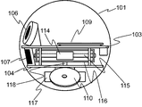
図1は、本開示の実施の形態1に係るロボット1の外観図である。ロボット1は、図1に示すように、球体状の筐体101を備える。筐体101は例えば、透明な部材或いは半透明の部材で構成される。
(Embodiment 1)
(overall structure)
FIG. 1 is an external view of a
図2は、本開示の実施の形態1に係るロボット1の内部斜視図である。
FIG. 2 is an internal perspective view of the
図2において、フレーム102が筐体101の内側部に配置されている。フレーム102は、第1回転板103及び第2回転板104を備える。第1回転板103は、第2回転板104に対して上方に位置している。第1回転板103及び第2回転板104は基台の一例に相当する。
In FIG. 2, the
図2に示すように、第1表示部105及び第2表示部106は、第1回転板103の上面に備え付けられている。また、第3表示部107は第2回転板104の上面に備え付けられている。第1表示部105、第2表示部106、及び第3表示部107は、例えば、複数の発光ダイオードにより構成される。第1表示部105、第2表示部106、及び第3表示部107は、ロボット1の表情の表示情報を表示する。具体的には、第1表示部105、第2表示部106、及び第3表示部107は、前記複数の発光ダイオードの点灯を個別に制御することにより、図1に示すように、ロボット1の顔の一部、例えば、目や口を表示する。図1の例では、第1表示部105がロボット1を正面から見て左目の画像を表示し、第2表示部106がロボット1を正面から見て右目の画像を表示し、第3表示部107が口の画像を表示している。そして、左目、右目、口の画像は、透明又は半透明の部材からなる筐体101を透過し、外部に放射されている。
As shown in FIG. 2, the
カメラ108は、図2に示すように、第1回転板103の上面に備え付けられている。カメラ108は、ロボット1の周辺環境の映像を取得する。カメラ108は、図1に示すように、ロボット1の顔の一部、例えば、鼻を構成する。したがって、カメラ108の光軸はロボット1の前方に向かうことになる。これにより、カメラ108は正面に差し出された認識対象物を撮影できる。
As shown in FIG. 2, the
制御回路109は、図2に示すように、第1回転板103の上面に備え付けられている。制御回路109は、ロボット1の各種動作を制御する。制御回路109の詳細は後述する。
The
第1駆動輪110及び第2駆動輪111は、それぞれ、第2回転板104の下面に備え付けられており、筐体101の内周面に接している。また、第1駆動輪110は、第1駆動輪110を駆動させる第1モータ112を有する。同様に、第2駆動輪111は、第2駆動輪111を駆動させる第2モータ113を有する。即ち、第1駆動輪110及び第2駆動輪111は、それぞれ独立した個別のモータによって駆動される。第1駆動輪110及び第2駆動輪111の駆動によるロボット1の動作の詳細は後述する。第1駆動輪110及び第2駆動輪111は、筐体駆動輪を構成する。
The
図3は、図2のA視における、本開示の実施の形態1に係るロボット1の内部側面図である。
FIG. 3 is an internal side view of the
図3において、カウンターウェイト(重り)114は、第1回転板103と第2回転板104との間に設けられている。カウンターウェイト(重り)114は、筐体101の中心からやや下方に位置する。このため、ロボット1の重心は、筐体101の中心から下方に位置する。これにより、ロボット1の動作を安定させることができる。A視は、背面から正面を見て左方向からロボット1の側面を見た方向を指す。
In FIG. 3, a counterweight (weight) 114 is provided between the first
図3に示すように、ロボット1は、カウンターウェイト(重り)114を駆動する機構として、カウンターウェイト(重り)114の移動方向を規定するガイドシャフト115、カウンターウェイト(重り)114の回転方向の位置を規定するスイングアーム116、スイングアーム116を回転させる回転用モータ117、スイングアーム116及び回転用モータ117の間を接続する回転シャフト118、カウンターウェイト(重り)114の駆動に用いられるベルト119(図8A及び図8B)、ベルト119に接するモータプーリ120(図8A及び図8B)、及び、モータプーリ120を回転させる、図示しない重り駆動用モータを備える。尚、本態様においては、前記重り駆動用モータはカウンターウェイト(重り)114に内蔵されている。カウンターウェイト(重り)114の駆動によるロボット1の動作の詳細は後述する。
As shown in FIG. 3, the
回転シャフト118は、第1駆動輪110と第2駆動輪111との駆動軸に対して垂直方向に延びる。回転シャフト118は、フレーム102に備え付けられたシャフトの一例に相当する。第1駆動輪110及び第2駆動輪111は正面視において、地面に向けて距離が離れるように取り付けられている。この場合、第1駆動輪110と第2駆動輪111との駆動軸は、例えば、第1駆動輪110と第2駆動輪111との中心同士を結ぶ仮想的な軸線である。なお、第1駆動輪110と第2駆動輪111とが正面視において平行に取り付けられていれば、実際の駆動軸が第1駆動輪110と第2駆動輪111との駆動軸となる。
The
ロボット1は、図略の電源及びマイク217(図16)をさらに備える。ロボット1は、図略の充電器により充電される。マイク217は、ロボット1の周辺環境の音声を取得する。
The
次に、第1駆動輪110及び第2駆動輪111を用いたロボット1の動作を図4から図6を参照して説明する。
Next, the operation of the
図4は、図2のA視における、本開示の実施の形態1に係るロボット1の直進動作を表す側面図である。図5は、図2のB視における、本開示の実施の形態1に係るロボット1の回転動作を表す平面図である。図6は、本開示の実施の形態1に係るロボット1の回転動作を表す斜視図である。B視は上方から下方に向けてロボット1を見た方向を指す。
FIG. 4 is a side view illustrating the straight-ahead operation of the
図4に示すように、第1駆動輪110及び第2駆動輪111を前方方向(A視において、駆動軸回りに反時計回りの方向)に回転させると、その動力によって筐体101は前方方向(A視において、反時計回りの方向)に回転する。これにより、ロボット1は前進する。逆に、第1駆動輪110及び第2駆動輪111を後方方向(A視において、駆動軸回りに時計回りの方向)に回転させると、ロボット1は後進する。
As shown in FIG. 4, when the
また、図5及び図6に示すように、第1駆動輪110及び第2駆動輪111を互いに逆方向に回転させると、その動力によって筐体101は、その中心を通過する鉛直軸回りの回転動作を行う。即ち、ロボット1は、その場で左回り又は右回りに回転する。ロボット1は、このような前進、後進又は回転動作によって移動する。
Further, as shown in FIGS. 5 and 6, when the
次に、カウンターウェイト(重り)114を用いたロボット1の基本動作を図7から図9Cを参照して説明する。
Next, a basic operation of the
図7は、図3の側面図においてカウンターウェイト(重り)114の駆動機構を示した図である。図8Aは、カウンターウェイト(重り)114が所定の直線方向に駆動する際のカウンターウェイト(重り)114の駆動機構の動作を示す斜視図である。図8Bは、カウンターウェイト(重り)114が所定の直線方向に駆動する際のカウンターウェイト(重り)114の駆動機構の動作を示す側面図である。図8Cは、図3の側面図においてカウンターウェイト(重り)114が所定の直線方向に往復移動する状態を示す側面図である。図9Aは、スイングアーム116を回転させる際のカウンターウェイト(重り)114の駆動機構の動作を示す斜視図である。図9Bは、スイングアーム116を回転させる際のカウンターウェイト(重り)114の駆動機構の動作を示す側面図である。図9Cは、図2のB視における、本開示の実施の形態1に係るロボット1のスイングアーム116が回転する状態を示す平面図である。
FIG. 7 is a view showing a drive mechanism of the counterweight (weight) 114 in the side view of FIG. FIG. 8A is a perspective view showing the operation of the drive mechanism of the counterweight (weight) 114 when the counterweight (weight) 114 is driven in a predetermined linear direction. FIG. 8B is a side view showing the operation of the drive mechanism of the counterweight (weight) 114 when the counterweight (weight) 114 is driven in a predetermined linear direction. FIG. 8C is a side view showing a state where the counterweight (weight) 114 reciprocates in a predetermined linear direction in the side view of FIG. FIG. 9A is a perspective view showing the operation of the drive mechanism of the counterweight (weight) 114 when the
図7に示すように、例えば、スイングアーム116の中央位置がカウンターウェイト(重り)114のデフォルト位置である。カウンターウェイト(重り)114がスイングアーム116の中央に位置しているとき、第1回転板103及び第2回転板104は走行面とほぼ平行になり、ロボット1の顔を構成する、例えば、目、鼻、口がデフォルト方向に向いた状態になる。
As shown in FIG. 7, for example, the center position of the
図8A及び図8Bに示すように、カウンターウェイト(重り)114に内蔵された、図示しない重り駆動用モータは、前記重り駆動用モータに連結されたモータプーリ120を回転させる。回転されたモータプーリ120がベルト119上を転がることにより、カウンターウェイト(重り)114はスイングアーム116内を移動する。モータプーリ120の回転方向、即ち、前記重り駆動用モータの駆動方向を変化させることにより、スイングアーム116内において、カウンターウェイト(重り)114は直線方向に往復移動する。
As shown in FIGS. 8A and 8B, a weight driving motor (not shown) incorporated in the counterweight (weight) 114 rotates a
図8Cに示すように、カウンターウェイト(重り)114は、ガイドシャフト115に沿って、スイングアーム116内を直線方向に往復移動する。
As shown in FIG. 8C, the counterweight (weight) 114 reciprocates in the linear direction in the
図9A及び図9Bに示すように、回転用モータ117は、回転シャフト118を回転させることにより、回転シャフト118(図3)に接続されたスイングアーム116を回転させる。
As shown in FIGS. 9A and 9B, the
図9Cに示すように、スイングアーム116は時計回り、反時計回りのいずれの方向にも回転させることができる。
As shown in FIG. 9C, the
さらに、カウンターウェイト(重り)114を用いたロボット1の動作の詳細を図10から図13を参照して説明する。図10は、図2のA視における、カウンターウェイト(重り)114が前方寄りに位置しているときのロボット1の姿勢を示す側面図である。図11は、図2のA視における、カウンターウェイト(重り)114が後方寄りに位置しているときのロボット1の姿勢を示す側面図である。図12は、図2のC視における、カウンターウェイト(重り)114が右方寄りに位置しているときのロボット1の姿勢を示す正面図である。図13は、図2のC視における、カウンターウェイト(重り)114が左方寄りに位置しているときのロボット1の姿勢を示す正面図である。C視は、前方から後方に向けてロボット1を見た方向を指す。
Further, details of the operation of the
図10に示すように、スイングアーム116がロボット1の正面に対して垂直な状態で、カウンターウェイト(重り)114を、デフォルト位置からスイングアーム116の一端(図10では左端)、即ち、前方寄りに移動させると、ロボット1は、矢印121が示すようにピッチ方向の前方に傾く。また、図11に示すように、スイングアーム116がロボット1の正面に対して垂直な状態で、カウンターウェイト(重り)114を、デフォルト位置からスイングアーム116の他端(図11では右端)、即ち、後方寄りに移動させると、ロボット1は、矢印122が示すようにピッチ方向の後方に傾く。従って、スイングアーム116がロボット1の正面に対して垂直な状態で、カウンターウェイト(重り)114をスイングアーム116内の前記一端から前記他端まで往復動作させると、ロボット1は、矢印121が示すピッチ方向の前方または矢印122が示すピッチ方向の後方に傾く往復動作を行う。即ち、ロボット1は所定のピッチ角範囲内においてピッチ方向に揺動する。
As shown in FIG. 10, with the
上述のように、第1表示部105、第2表示部106及び第3表示部107は、ロボット1の顔の一部、例えば、目や口を表す。従って、カウンターウェイト114を用いてロボット1にピッチ方向の前方またはピッチ方向の後方に傾く往復動作をさせることにより、例えば、ロボット1が息切れしている状態又は眠い状態を表現することができる。この制御を、例えば、電源の電力残量が所定値以下になった場合に行えば、ロボット1は、第1表示部105、第2表示部106、及び第3表示部107に前記顔とは無関係な電力残量に関する情報を表示することなく、電源の電力残量が少なくなっていることをユーザに違和感なく伝えることができる。
As described above, the
図12に示すように、スイングアーム116がロボット1の正面に対して平行な状態で、カウンターウェイト(重り)114を、デフォルト位置からスイングアーム116の一端(図12の右端)、即ち、右方寄りに移動させると、ロボット1は、矢印123が示す右側(正面から見て時計回りの方向)に傾く。また、図13に示すように、スイングアーム116がロボット1の正面に対して平行な状態で、カウンターウェイト(重り)114を、デフォルト位置からスイングアーム116の他端(図13の左端)、即ち、左方寄りに移動させると、ロボット1は、矢印124が示す左側(正面から見て反時計回りの方向)に傾く。従って、スイングアーム116をロボット1の正面に対して平行な状態で、カウンターウェイト(重り)114をスイングアーム116内の前記一端から前記他端まで往復動作させると、ロボット1は、矢印123が示す右側または矢印124が示す左側に傾く往復動作を行う。即ち、ロボット1は所定の角度において左右方向に揺動する。
As shown in FIG. 12, with the
次に、走行開始時のロボット1の姿勢について図14を参照して説明する。
Next, the posture of the
図14は、筐体101が矢印125に示す前進方向に回転を始めるまでのロボット1の姿勢を示す図である。筐体101は、第1駆動輪110及び第2駆動輪111を第1駆動輪110に図示する矢印方向に回転することで発生する力が、床面126の摩擦等の外的要因による力よりも大きい場合に、矢印125に示す前進方向に前進を始める。また、筐体101は、第1駆動輪110及び第2駆動輪111を駆動することで発生する力が、床面126の摩擦等の外的要因による力よりも小さい場合に、前進を始めることは無い。このとき、筐体101は固定された状態となるため、第1駆動輪110及び第2駆動輪111は、筐体101の内側に沿って内部機構ごと矢印127で示す方向(A視において時計回りの方向)へ回転する。
FIG. 14 is a diagram illustrating the posture of the
これにより、第1表示部105及び第2表示部106を含むフレーム102は、ロボット1が走行を開始するまでの間、外的要因による力の影響によりピッチ角が増大していくのである。ここで、角速度センサ219は、例えば、フレーム102内の例えば第1回転板103の上面に取り付けられている。そのため、角速度センサ129はフレーム102のピッチ方向の角速度を検出できる。その結果、角速度センサ129が検出するピッチ方向の角速度を累積することで、フレーム102のピッチ角が検出される。
As a result, the pitch angle of the
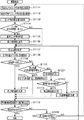
図15は、本開示の実施の形態1に係るロボット1が適用されたロボットシステム1200の全体構成の一例を示す図である。ロボットシステム1200は、クラウドサーバ2、携帯端末3、及びロボット1から構成される。ロボット1は例えばWifi(登録商標)の通信を介してインターネットと接続し、クラウドサーバ2と接続する。また、ロボット1は例えばWifi(登録商標)の通信を介して携帯端末3と接続する。ユーザ1201は例えば、子供であり、ユーザ1202,1203は、例えば、その子供の両親である。
FIG. 15 is a diagram illustrating an example of an overall configuration of a
携帯端末3は、例えば、ロボット1と連携するアプリケーションがインストールされている。携帯端末3は、アプリケーションを通じてロボット1に種々の指示を行ったり、ユーザ1201がロボット1の前に差し出した物体の画像認識結果を表示したりすることができる。
For example, an application that cooperates with the
ロボット1は、例えば、携帯端末3からある絵本を子供に読み聞かせる要求があったとすると、その絵本の朗読を開始し、子供に読み聞かせる。ロボット1は、例えば、絵本の読み聞かせ中に子供から何らかの質問を受け付けると、その質問をクラウドサーバ2に送り、その質問に対する回答をクラウドサーバ2から受信し、回答を示す音声を発話する。
For example, if there is a request for a child to read a picture book from the
このように、ユーザ1201は、ロボット1をペットのように取り扱い、ロボット1との触れ合いを通じて、言語学習をすることができる。
In this way, the
次に、図16を参照しつつ、本開示の実施の形態1に係るロボット1の内部回路の詳細について説明する。図16は、本開示の実施の形態1に係るロボット1を示すブロック図である。
Next, details of the internal circuit of the
図16に示すように、ロボット1は、制御回路109、表示部211、シャフト制御部213、回転シャフト118、筐体駆動輪制御部214、筐体駆動輪212、重り駆動機構制御部215、重り駆動機構218、角速度センサ219、距離センサ220、カメラ108、マイク217、スピーカ216、及び通信部210を備える。
As shown in FIG. 16, the
制御回路109は、メモリ206と、CPU等のプロセッサで構成された主制御部200と、表示情報出力制御部205と、時刻を計時する図略のタイマー等を含むコンピュータで構成されている。
The
メモリ206は、例えば、不揮発性の書き換え可能な記憶装置で構成され、ロボット1の制御プログラムなどを記憶する。
The
主制御部200は、メモリ206に記憶されているロボット1の制御プログラムを実行する。これにより、主制御部200は、目的位置生成部201、移動経路生成部202、自己位置推定部203、駆動制御部204として機能する。
The
角速度センサ219は、例えば、第1回転板103の上面に取り付けられている。角速度センサ219は、重力方向に平行な方向軸(図19に示すZ軸に平行な方向軸)、筐体101の走行面に平行な筐体101の走行方向を、重力方向に直交する水平面に射影した方向軸(図19に示すX軸に平行な方向軸)、及び前記2方向に直交する方向軸(図19に示すY軸に平行な方向軸)の3つの方向軸で回転する角速度を検知し、主制御部200へ出力する。すわなち、角速度センサ129は、Z軸回りの角速度(ヨー方向の角速度)と、X軸回りの角速度(ロール方向の角速度)と、Y軸回りの角速度(ピッチ方向の角速度)とを検知する。主制御部200の駆動制御部204は、角速度センサ219により検知された3つの角速度のそれぞれを累積してメモリ206に蓄積することで、フレーム102のヨー角、ロール角、及びピッチ角を管理する。角速度センサ219は、第1回転板103の上面に限らず、第1回転板103の下面や、第2回転板104の上面又は下面等に取り付けられてもよい。なお、Y軸はフレーム102の走行方向(X軸)に垂直な左右方向の一例である。
The
距離センサ220は、例えば、赤外線や超音波等を用いてロボット1の周囲の距離分布を示す距離情報を取得する距離センサで構成され、やカメラ108同様、第1回転板103上のロボット1正面方向に設けられる。このため、距離センサ220が取得する距離情報の方向は、ロボット1の前方にある物体の方向を向く。よって、距離センサ220は、ロボット1の前方に位置する物体とロボット1との距離を検出できる。距離センサ220は、第1回転板103の上面前方に限らず、第1回転板103の下面前方や、第2回転板104の上面又は下面の前方など距離センサ220による距離の計測が阻害されない位置であればどのような位置に配置されてもよい。
The
マイク217は、フレーム102に備え付けられ、音を電気信号に変換し、主制御部200に出力する。マイク217は、例えば、第1回転板103の上面に取り付けられても良いし、第2回転板104の上面に取り付けられても良い。主制御部200は、マイク217での取得音声からユーザの音声の有無を認識し、音声認識結果をメモリ206に蓄積することで、音声認識結果を管理する。主制御部200は、メモリ206に格納された音声認識用データと、取得音声とを照合し、発話内容及び発話したユーザを認識する。
The
スピーカ216は、出力面が正面を向くようにフレーム102に備え付けられ、音声の電気信号を物理振動に変換する。主制御部200は、所定の音声をスピーカ216から出力することで、ロボット1に発話させる。
The
カメラ108は、図2において説明したように、ロボット1の前方(Y方向)の映像を撮像し、撮像した画像(以下、撮像画像)を主制御部200に出力する。主制御部200は、カメラ108から取得した撮像画像からユーザの顔の有無、位置、及び大きさを認識し、顔認識結果をメモリ206に蓄積することで、顔認識結果を管理する。
As described with reference to FIG. 2, the
主制御部200は、音声認識結果や顔認識結果、周辺環境の距離情報、3軸の角速度、及び通信部210の情報に基づきコマンドを生成し、表示情報出力制御部205、シャフト制御部213、筐体駆動輪制御部214、重り駆動機構制御部215、及び通信部210等に出力する。
The
表示情報出力制御部205は、主制御部200から送信されるコマンドに応じたロボット1の表情の表示情報を表示部211に表示する。表示部211は、図2において説明した第1表示部105、第2表示部106、及び第3表示部107により構成される。
The display information
シャフト制御部213は、主制御部200から送信されるコマンドに応じて、図9A及び図9Bで説明した回転シャフト118を回転させる。シャフト制御部213は、図9A及び図9Bで説明した回転用モータ117により構成される。
The
筐体駆動輪制御部214は、主制御部200から送信されるコマンドに応じて、ロボット1の筐体駆動輪212を動作させる。筐体駆動輪制御部214は、図2において説明した、第1モータ112及び第2モータ113で構成される。筐体駆動輪212は、図2において説明した第1駆動輪110及び第2駆動輪111により構成される。筐体駆動輪212は、一組の駆動輪の一例に相当する。
The case drive
重り駆動機構制御部215は、主制御部200から送信されるコマンドに応じて、ロボット1の重り駆動機構218を動作させる。重り駆動機構制御部215は、カウンターウェイト114に内蔵された、図示しない重り駆動用モータで構成される。重り駆動機構218は、図3、図8A及び図8Bにおいて説明したガイドシャフト115、スイングアーム116、回転用モータ117、ベルト119、及び、モータプーリ120により構成される。
The weight driving
通信部210は、ロボット1をクラウドサーバ2(図15)に接続させるための通信装置で構成される。通信部210としては、例えば、Wifi(登録商標)等の無線LANの通信装置が採用できるがこれは一例である。通信部210は、主制御部200から送信されるコマンドに応じてクラウドサーバ2と通信を行う。
The
次に、主制御部200を構成する目的位置生成部201、移動経路生成部202、自己位置推定部203、及び駆動制御部204について説明する。
Next, the target
目的位置生成部201について、図17を参照して説明する。図17は、本開示の実施の形態1に係るロボット1が活動する空間と第1ユーザ1300に対してロボット1が行う処理の一部とを示す図である。目的位置生成部201は、マイク217が取得した第1ユーザ1300の音声と、メモリ206が保持する第1ユーザ1300の声紋情報(参照音声データの一例)とを比較し、第1ユーザ1300を検出する。第1ユーザ1300はロボット1に対して第1キーワードを発話したユーザである。第1キーワードとしては、例えば、「こっちへおいで」というような、ロボット1を第1ユーザ1300の位置に呼び寄せる言葉が採用できる。
The target
目的位置生成部201は、第1ユーザ1300の発声に対する音声認識結果に第1キーワードが含まれている場合に、第1ユーザ1300の位置検出処理を行う。目的位置生成部201は、カメラ108の撮像画像1302とメモリ206が保持する第1ユーザ1300の顔情報とを比較し、撮像画像1302内における第1ユーザ1300の顔を認識する。目的位置生成部201は、撮像画像1302内において第1ユーザ1300の顔を認識できたならば、撮像画像1302における第1ユーザ1300の領域を抽出し、抽出した第1ユーザ1300の領域からロボット1に対する第1ユーザ1300の方向を特定する。目的位置生成部201は、特定した方向に対応する距離情報を距離センサ220から取得することで、ロボット1と第1ユーザ1300との間の距離を推定する。また、目的位置生成部201は、推定した第1ユーザ1300の方向、及び距離から実空間上における第1ユーザ1300が存在する位置を目的位置301(図18)として生成する。
The target
移動経路生成部202は、ロボット1が目的位置まで移動するための移動経路を生成する。移動経路生成部202について、図18を参照して説明する。図18は、メモリ206が記憶するロボット1の周辺環境に対する地図情報を示す図である。また、図18に示す地図情報は、ロボット1が存在する実空間に対して、ロボット1の前進方向を示すx軸、ロボット1の右方向(ロボット1を背面から正面に見たときの右方向)を示すy軸で表した2次元の座標空間で構成される。この地図情報は、格子状に区切られた複数のマスで構成され、各マスが各位置を表す。位置300は、ロボット1の現在位置を示し、と目的位置301は、目的位置生成部201で生成された目的位置を示す。移動経路生成部202は、公知の処理(例えば、Aスターアルゴリズムやダイクストラ)でロボット1が目的位置301まで移動するための最適な移動経路を決定する。例えば、ロボット1の移動経路は、矢印302のような移動経路を辿って、目的位置301に到達する。尚、メモリ206が保持する地図情報は、図18に示すような2次元の座標空間が採用されても良いし、高さ方向を示すz軸を更に含む3次元の座標空間が採用されても良い。
The movement
自己位置推定部203は、ロボット1の周辺の環境情報または、ロボット1の移動量を用いて、所定の時間間隔で実空間上におけるロボット1の現在位置を推定する。例えば、自己位置推定部203は、カメラ108が周辺を撮像することで取得した撮像データ、及び距離センサ220が検出したロボット1の周辺に位置する物体までの距離を示す距離情報を参照して、例えば、V−SLAM(Visual Localization And Mapping)を用いて、ロボット1の現在位置を推定すればよい。或いは、自己位置推定部203は、周辺環境の情報から現在位置を推定しても良いし、筐体駆動機構制御部207から取得できる第1モータ112と第2モータ113との回転量、及び角速度センサ219から取得できるロボット1の重力方向に平行な方向軸(Z軸)回りの角速度(ヨー角の角速度)を用いたデッドレコニングのような公知の方法で、ロボット1の現在位置を推定しても良い。
The self-
自己位置推定部203は、推定したロボット1の現在位置をメモリ206が保持する地図情報に設定する。例えば、図18に示すように、ロボット1の現在位置を示す位置300は、自己位置推定部203によって逐次更新される。
The self-
駆動制御部204は、シャフト制御部213、筐体駆動輪制御部214、及び重り駆動機構制御部215のぞれぞれにコマンドとして出力する制御量と、及び表示情報出力制御部205を制御する制御コマンドとを決定する。制御量は、筐体駆動輪制御部214を構成する第1モータ112及び第2モータ113を制御する制御量C1と、重り駆動機構制御部215を構成する重り駆動用モータ(図略)を制御する制御量C2と、シャフト制御部213を構成する回転用モータ117を制御する制御量C3とがある。
The
制御量C1は筐体駆動輪制御部214を構成する第1モータ112及び第2モータ113のそれぞれの回転量を制御する値であり、値が大きいほど、第1モータ112及び第2モータ113のトルク及び回転速度は大きくなる。本実施の形態では、第1モータ112及び第2モータ113は、PFM制御されるモータで構成されているので、制御量C1としては、第1モータ112及び第2モータ113のトルク及び回転速度を決定するための周波数が採用される。但し、これは一例であり、第1モータ112及び第2モータ113がPWM制御されるモータで構成されるのであれば、制御量C1は、デューティ値が採用される。シャフト制御部213を構成する回転用モータ117(図3)及び重り駆動機構218を構成する重り駆動用モータ(図略)は、例えばサーボモータで構成されている。そのため、制御量C2及び制御量C3は、それぞれ、指定した角度へサーボモータを回転させるコマンドとなる。
The control amount C1 is a value that controls the amount of rotation of each of the
制御コマンドは、ロボット1の表情パターンを変更するコマンドである。したがって、駆動制御部204は、ロボット1の表情パターンを変更する場合、制御コマンドを表示情報出力制御部205に出力する。
The control command is a command for changing the facial expression pattern of the
次に、駆動制御部204の処理の詳細を説明する。駆動制御部204は、ロボット1が受ける床面の影響を推定し、表示情報出力制御部205、シャフト制御部213、筐体駆動輪制御部214、重り駆動機構制御部215、及び通信部210等に出力する制御量を決定する。
Next, details of the processing of the
まず、本開示の実施の形態1にかかるロボット1における床面の検出処理の概要について図14、図19、図20、及び図24を用いて説明する。駆動制御部204は、ロボット1が走行開始命令を受けて、実際に走り出すまでの間に変化するロボット1の姿勢から、ロボット1が走行する床面の種類を推定する。
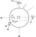
First, an outline of floor surface detection processing in the
図19は、3次元空間上におけるロボット1の前進方向をX軸としたときに、X軸に対して垂直に交わる2つの軸(Y軸、Z軸)を示す図である。また、ロボット1の回転は、X軸回りの回転角度をロール角(矢印400に相当)、Y軸周りの回転角度をピッチ角(矢印401に相当)、Z軸周りの回転角度をヨー角(矢印402に相当)と呼称することとする。
FIG. 19 is a diagram illustrating two axes (Y axis and Z axis) that intersect perpendicularly to the X axis when the forward direction of the
本開示の実施の形態1に係るロボット1は、前述したように、ロボット1が走行開始命令を受けて、実際に走り出すまでの間にロボット1の姿勢はY軸周りに回転する。このとき、角速度センサ219は矢印401(図19)方向の角速度を取得する。前述したように取得した角速度は累積されてメモリ206に蓄積されることで、フレーム102のピッチ角が管理されている。
As described above, the
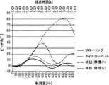
図24は、床面ごとにロボット1が走行開始命令を受けて、実際に走り出すまでの間のピッチ角の変化を示すグラフである。図24に示すグラフは、縦軸がピッチ角を示し、下側の横軸が筐体駆動輪212を駆動する第1モータ112及び第2モータ113に対する制御量C1を示す。以下、第1モータ112及び第2モータ113の制御量C1を筐体駆動輪212に対する制御量C1とも記述する。筐体駆動輪212に対する制御量C1は、値が大きいほど、床面126(図14)に対して与える力は大きくなる。また、図24における制御量C1は、単位時間ごとに一定量増加しているため、図24に示すグラフの上部に示しているように、走行開始指令を受けてからの経過時間を示す時間軸が設定される。
FIG. 24 is a graph showing a change in pitch angle between the time when the
ロボット1は、図24に示すように、床面によって走行開始時の姿勢が変化する。ロボット1は、図14が示すように、フレーム102等の内部機構の傾きが変化するため、ロボット1の重心位置も前方方向へ変移する。図24を参照し、制御量C1により変化する筐体駆動輪212が床面に与える力と、ロボット1の重心位置の変化により床面に与える力との総和が、床面から受ける摩擦等の外的要因による力を超えると、ロボット1は動き出す。つまり、床面から受ける摩擦等の外的要因による力が大きいほど、走行を開始するまでのフレーム102等の内部機構のピッチ角は大きくなる。また、図24を参照し、ピッチ角の減少は、ロボット1が走行に成功した際に出現する。すなわち、ロボット1が走行を開始するまでは、フレーム102等の内部機構のピッチ角は増大していき、ロボット1が走行を開始すると、ピッチ角は減少に転じる。
As shown in FIG. 24, the
したがって、ロボット1は、ピッチ角の減少が出現したタイミングで走行を開始すると言えるため、ピッチ角の変化を監視することで床面の種類を判断をすることができる。よって、駆動制御部204は、ピッチ角の最大角度(最大ピッチ角)が、床面の種類に応じて予め定められた値を超えるか否かを判断して床面の種類を推定する。尚、ピッチ角の変化の監視は、メモリ206の地図情報を参照して、ロボット1の位置300が移動するまでの間でも良いし、所定の時間内における最大ピッチ角としても良い。
Therefore, since it can be said that the
図20は、床面の種類に応じた最大ピッチ角と最小制御量との関係を示す制御量決定データベースT20のデータ構成の一例を示す図である。制御量決定データベースT20(対応関係の一例)は、1つの床面の種類に対して1つのレコードが割り当てられたデータベースであり、床面の種類毎に、最大ピッチ角(deg)と、最小制御量(Hz)とを対応付けて記憶する。 FIG. 20 is a diagram illustrating an example of a data configuration of the control amount determination database T20 indicating the relationship between the maximum pitch angle and the minimum control amount according to the type of floor surface. The control amount determination database T20 (an example of a correspondence relationship) is a database in which one record is assigned to one floor surface type, and the maximum pitch angle (deg) and the minimum control for each floor surface type. The quantity (Hz) is stored in association with each other.
図20に示す最大ピッチ角及び最小制御量は、事前にロボット1を様々な床面で駆動させることで取得されたものである。尚、本開示の実施の形態1に係るロボット1においては、ロボット1のピッチ角の変化に伴う重心位置の変化が、ロボット1が床面に与える力の影響として大きい。そのため、駆動制御部204は、図20に示すような制御量決定データベースT20を使用することで、複雑な計算式を用いた複雑な演算を行わなくても、ロボット1を実際に動かすことができる。但し、これは一例であり、駆動制御部204は、ロボット1の重心位置や筐体駆動機構208が発するトルクから床面の摩擦等の外的要因を算出して、最小制御量を決定しても良い。
The maximum pitch angle and the minimum control amount shown in FIG. 20 are obtained by driving the
図23に示すように、ピッチ角の最大値は、フローリングのような摩擦が少ない床面で駆動させた場合と、絨毯のような毛足が長く摩擦が大きい床面で駆動させた場合とで大きな違いが現れる。つまり、例えば、家庭環境といった床面の性質が限られる環境下では、ピッチ角の最大値から、ロボット1が立つ床面がフローリングの上であるか、絨毯の上であるかの予測ができる。
As shown in FIG. 23, the maximum value of the pitch angle is the case where it is driven on a floor surface with little friction such as flooring, and the case where it is driven on a floor surface with a long bristle like a carpet and high friction. A big difference appears. That is, for example, in an environment where the property of the floor surface is limited such as a home environment, it can be predicted from the maximum value of the pitch angle whether the floor surface on which the
次に、本開示の第1の実施の形態に係るロボット1における制御量C1の生成処理について、図18、図21、図22、及び図23を用いて説明する。
Next, the generation process of the control amount C1 in the
筐体駆動輪制御部214は、主制御部200から送信される筐体駆動輪212の制御量C1に応じて、ロボット1の筐体駆動輪212を動作させる。制御量C1は、第1モータ112及び第2モータ113の回転量を制御する。第1モータ112及び第2モータ113の回転量は、制御量C1に比例して大きくなる。筐体駆動輪制御部214は、第1モータ112及び第2モータ113の回転量を、第1モータ112及び第2モータ113に付属したエンコーダから取得しても良いし、第1モータ112及び第2モータ113のスペックに応じた公知の計算方法で算出しても良い。
The case drive
制御量C1は、自己位置推定部203により推定された自己位置と目的位置生成部201により生成された目的位置までの残り距離に応じて変化する。ここで、制御量C1は、制御量決定データベースT20を参照することで決定された最大ピッチ角に対応する最小制御量未満にならないように逐次更新される。そのため、ロボット1は、目的位置までの移動途中で、床面の外的要因により停止をすることなく、目的位置に辿り着くことができる。
The control amount C1 varies according to the self-position estimated by the self-
目的位置までの残り距離は、図18に示すように、目的位置生成部201によって生成された目的位置301及び自己位置推定部203によって逐次更新されるロボット1の位置300とから算出される。例えば、目的位置301までの残り距離は、移動経路生成部202が生成した移動経路において、ロボット1の位置300と、目的位置301とを繋ぐ1又は複数のマスの個数に1マスあたりの距離を乗じることで算出される。或いは、目的位置301までの残り距離は目的位置301と位置300とのユークリッド距離により求められても良い。
As shown in FIG. 18, the remaining distance to the target position is calculated from the
ここで、制御量決定データベースT20に記憶された最小制御量を参照する理由を説明する。本開示の実施の形態1に係るロボット1は、図1に示すように球体状をしている。そのため、ロボット1は、急停止を行った場合、慣性力により大きく前後方向にふらついて、目的位置301を超えてしまうことがある。駆動制御部204は、台形制御やS字制御を適用してロボット1を目的位置301まで移動させる。
Here, the reason for referring to the minimum control amount stored in the control amount determination database T20 will be described. The
次に、床面の種類に応じた停止位置の違いについて図21を参照して説明する。図21は、台形制御により制御量C1を決定させた場合において、ロボット1が走行する床面の種類に応じた停止位置の違いを示すグラフである。
Next, the difference in the stop position according to the kind of floor surface is demonstrated with reference to FIG. FIG. 21 is a graph showing the difference in stop position according to the type of floor on which the
図21において、縦軸は制御量(Hz)を示し、横軸は目的位置までの残り距離を示す。直線503は、制御量C1の時間的推移を示す。直線503で示すように、制御量C1は、残り距離が短くなるにつれて一定の変化量で減少されている。図21のグラフでは、ロボット1は、直線503で示す制御量C1にしたがって、絨毯又はフローリング上を走行する。
In FIG. 21, the vertical axis indicates the control amount (Hz), and the horizontal axis indicates the remaining distance to the target position. A
絨毯の上を走行した場合、ロボット1は、制御量C1が直線500が示す値(400Hz)を下回ったとき停止する。また、ロボット1は、フローリングの上を走行した場合、フローリングは絨毯よりも摩擦が少ないので、直線501が示す値(200Hz)を下回ったとき停止する。
When traveling on the carpet, the
距離502は、直線503で示すように制御量C1を変化させてロボット1を絨毯の上で走行させた場合のロボット1の停止位置と、直線503で示すように制御量C1を変化させてロボット1をフローリングの上で走行させた場合のロボット1の停止位置との差を示す。
The
距離502が示す停止位置の差は、床面がロボット1に与える、摩擦等の外的な力が要因となっている。そのため、ロボット1は、目的位置に到着するまで、制御量C1を最小制御量以上に保持する必要がある。すなわち、ロボット1を絨毯で走行させる場合は、制御量C1を絨毯に対応する最小制御量である400Hz以上に保持すれば、ロボット1が目的位置に到達できないことを防止できる。また、ロボット1をフローリングで走行させる場合は、制御量C1をフローリングに対応する最小制御量である200Hz以上に保持すれば、ロボット1が目的位置に到達できないことを防止できる。したがって、床面の種類に応じた最小制御量以上となるように制御量C1を設定することで、目的位置に到着するまでにロボット1が停止する事態を回避でき、ロボット1を目的位置までスムーズに移動させることができる。
The difference in the stop position indicated by the
駆動制御部204は、目的位置までの残り距離、及び最小制御量に応じた制御量C1を生成する。ロボット1は、床面の種類が違う場合であっても、同様な動作を行うために、駆動制御部204は、例えば、以下の式(1)を用いたS字制御により制御量C1を決定する。
The
尚、制御量C1の算出方法は、床面に応じて異なる制御方法が採用されても良い。例えば、床面がフローリングの場合、ロボット1は、床面からの影響力が少ないため、停止時に前後方向のふらつきが発生することがある。この場合、制御量C1は、停止直前の変化量を小さくするのが良い。そこで、本実施の形態では、式(1)を用いて、制御量C1は決定される。また、床面が絨毯の場合、ロボット1は、床面からの摩擦力の影響力大きいため、停止時に前後方向のふらつきが発生しにくい。この場合、台形制御を用いて、制御量C1は決定されても良い。但し、以下の例では、床面の種類によらず、目的位置の手前において、制御量C1は式(1)のS字制御によって決定されるものとする。
It should be noted that a different control method may be employed for calculating the control amount C1 depending on the floor surface. For example, when the floor surface is flooring, the
制御量C1=(SIN(3*π/2−π/L*d)+1)*(Max−min)/2+min、
(1)
L[m]:減速制御を開始するために事前に定められた目標位置からの距離である減速開始距離、d[m]:ロボット1の位置から目的位置までの残り距離、Max[Hz]:減速制御距離が示す位置である減速開始位置での制御量C1、min[Hz]:最小制御量
また、ロボット1の位置から目的位置まで距離をd[m]は、上述の図18で説明した方法を用いて算出された値が採用できる。また、最小制御量min[Hz]は、上述の制御量決定データベースT20を参照して決定された値が採用できる。尚、本態様においては、式(1)に限らず、台形制御の減速比を変えるなどしても良い。
Control amount C1 = (SIN (3 * π / 2−π / L * d) +1) * (Max−min) / 2 + min,
(1)
L [m]: Deceleration start distance that is a distance from a target position determined in advance to start deceleration control, d [m]: Remaining distance from the position of the
図22は、フローリング及び絨毯のそれぞれについて、式(1)を用いてロボット1を目的位置に停止させる際の、減速開始位置から目的位置までの範囲内における目的位置までの残り距離と制御量C1との関係を示すグラフである。図22において縦軸は制御量[Hz]を示し、横軸は目的位置までの残り距離[m]を示す。
FIG. 22 shows the remaining distance to the target position and the control amount C1 in the range from the deceleration start position to the target position when the
このグラフにおいて、目的位置からL[m]離れた減速開始距離として1[m]、減速開始位置での制御量C1として1000[Hz]、床面が絨毯の場合の最小制御量minとして400[Hz]、及び床面がフローリングの場合の最小制御量minとして200[Hz]が採用され、これらの値を式(1)に代入したときの演算結果が示されている。 In this graph, a deceleration start distance L [m] away from the target position is 1 [m], a control amount C1 at the deceleration start position is 1000 [Hz], and a minimum control amount min when the floor is a carpet is 400 [ Hz] and 200 [Hz] are adopted as the minimum control amount min when the floor is flooring, and the calculation results when these values are substituted into the equation (1) are shown.
絨毯の曲線(点線)及びフローリングの曲線(実線)に示されるように、1[m]地点の減速開始位置から0[m]地点の目的位置まで、制御量C1はサインカーブを描いて徐々に減少していることが分かる。また、フローリング及び絨毯について、目的位置での制御量C1はそれぞれ、200[Hz]、400[Hz]になっており、目的位置に到達するまで、制御量C1が最小制御量以上に維持されている。そのため、目的位置の手前でロボット1が停止する事態が防止される。また、フローリングの場合、残り距離が0.15[m]を超えたあたりから制御量C1の傾きが急激に緩くなっており、目的位置でのロボット1のふらつきの防止が図られている。
As indicated by the carpet curve (dotted line) and the flooring curve (solid line), the control amount C1 gradually draws a sine curve from the deceleration start position at the 1 [m] point to the target position at the 0 [m] point. It turns out that it has decreased. Further, for the flooring and the carpet, the control amounts C1 at the target position are 200 [Hz] and 400 [Hz], respectively, and the control amount C1 is maintained at the minimum control amount or more until the target position is reached. Yes. Therefore, the situation where the
図23は、本開示の実施の形態1に係るロボット1における移動開始から停止するまでの制御量C1の推移を示すグラフである。図23において、縦軸は制御量[Hz]を示し、横軸は移動距離[m]を示す。図23では、例えば、ロボット1が5m移動した場合の制御量C1の推移が示されている。制御量C1は、移動開始から停止するまで、領域600,601,602で示す3つの制御方式が適用される。
FIG. 23 is a graph illustrating a transition of the control amount C1 from the start of movement to the stop in the
領域600は加速領域である。領域600において、制御量C1は、時間に対して一定の変化量で増大する加速制御量となる。すなわち、領域600では、制御量C1は、台形制御により増大される。領域601は等速領域である。領域600において、制御量C1は、最大制御量を維持する等速制御量となる。最大制御量とは、ロボット1の上限速度に対応する事前に定められた制御量C1を指す。この上限速度は、第1モータ112及び第2モータ113の性能や走行時のロボット1の安全性等を考慮して事前に定められた値が採用される。
領域602は減速領域である。領域602では、制御量C1は式(1)に示すS字制御による減速制御量となる。
A
駆動制御部204は、ロボット1が移動を開始すると、制御量C1を台形制御により上昇させ、制御量C1が最大制御量(1000[Hz])に到達すると、制御量C1を最大制御量に維持する。そして、駆動制御部204は、ロボット1が減速開始位置に到達すると制御量C1を式(1)に従って減少させる。これにより、駆動制御部204は、ロボット1を速やかに目的位置に到達させると共に、目的位置にふらつきなく停止させることができる。更に、駆動制御部204は、制御量C1が最大制御量に到達すると、それ以上制御量C1を増大させないので、ロボット1の安全性を確保できる。
The
なお、移動開始位置から目的位置までの距離が短い場合、制御量C1が最大制御量に到達する前にロボット1が減速開始位置に到達することもある。この場合、駆動制御部204は、減速開始位置での制御量C1を式(1)のMaxに代入して制御量C1を計算すればよい。これにより、駆動制御部204は、ロボット1を目的位置に滑らか且つ正確に停止させることができる。
When the distance from the movement start position to the target position is short, the
図16に参照を戻す。重り駆動機構制御部215は、主制御部200から出力される制御量C2に応じて、ロボット1の重り駆動機構218を動作させる。制御量C2は、重り駆動機構制御部215を構成する重り駆動用モータの回転量を制御する。重り駆動用モータの回転量は、カウンターウェイト(重り)114の可動域に制限される。
Returning to FIG. The weight driving
シャフト制御部213は、主制御部200から出力される制御量C3に応じて、ロボット1の回転シャフト118を動作させる。制御量C3は、回転用モータ117の回転量を制御する。
The
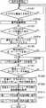
以下、実施の形態1において、ロボット1が、声と顔とからユーザを識別し、識別したユーザの位置を目的位置として設定し、ロボット1の現在位置を把握しつつ、途中で止まることなく、目的位置まで移動するまでの処理手順を図25から図27を参照して、説明する。図25は、本開示の実施の形態1に係るロボット1のメインルーチンを示すフローチャートである。
Hereinafter, in the first embodiment, the
図25を参照し、目的位置生成部201は、目的位置設定処理を実行する(ステップS101)。
Referring to FIG. 25, the target
図26は、図25における目的位置設定処理を示すフローチャートである。 FIG. 26 is a flowchart showing the target position setting process in FIG.
マイク217は、周辺環境の音信号を取得し(ステップS1001:Yes)、主制御部200へ出力する。主制御部200は、取得した音信号に対して音声認識処理を行う(ステップS1002)。この音声認識処理では、人物が発話した音声の音圧の時間的な推移を示す音声データとその音声データに含まれるユーザの発話内容をテキスト化して示す発話情報とが抽出される。目的位置生成部201は、マイク217が音信号を取得できない場合は、音信号が取得されるまでステップS1001の処理を繰り返す(ステップS1001:No)。
The
目的位置生成部201は、音声認識処理で抽出した音声データが、1又は複数のユーザのユーザ情報としてメモリ206に事前に記憶された1又は複数の声紋情報のうち、いずれの声紋情報と一致するか否かを判断する。抽出した音声データと声紋情報とが一致したと判断した場合(ステップS1003:Yes)、目的位置生成部201は、声紋情報が一致したユーザを第1ユーザ1300と判定する(ステップS1004)。目的位置生成部201は、抽出した音声データがメモリ206に記憶されたいずれの声紋情報とも一致しなかった場合(ステップS1003:No)、処理をステップS1001に戻す。
The target
目的位置生成部201は、音声認識処理によって得られた第1ユーザ1300の音声データに第1キーワードが含まれている場合(ステップS1005:Yes)、カメラ108から画像データを取得する(ステップS1006)。目的位置生成部201は、音声認識処理によって得られた第1ユーザ1300の音声データに第1キーワードが含まれていない場合(ステップS1005:No)、処理をステップS1001に戻す。
When the first keyword is included in the voice data of the
目的位置生成部201は、カメラ108から取得した画像データに含まれる1又は複数の顔画像のそれぞれと、第1ユーザ1300のユーザ情報としてメモリ206に事前に記憶された第1ユーザ1300の顔の特徴量とを比較する顔認識処理を行い、画像データから第1ユーザ1300を検出する(ステップS1007)。
The target
目的位置生成部201は、画像データから第1ユーザ1300を検出できた場合(ステップS1007:Yes)、画像データ中での第1ユーザ1300の位置から、ロボット1に対する第1ユーザ1300の方向を検出する(ステップS1008)。
If the
目的位置生成部201は、距離センサ220が取得した距離情報のうち、第1ユーザ1300が存在する方向の距離情報を第1ユーザ1300の距離情報として取得する(ステップS1009)。目的位置生成部201は、第1ユーザ1300の方向及び距離情報からロボット1の周辺の実空間における第1ユーザ1300の位置を検出し、検出した位置を地図情報(図18)にプロットする(ステップS1010)。
The target
目的位置生成部201は、プロットした位置をロボット1の目的位置300として設定する(ステップS1011)。目的位置生成部201は、画像データから第1ユーザ1300を検出できなかった場合(ステップS1007:No)、処理をステップS1006に戻す。
The target
次に、ロボット1が目的位置に移動するための移動経路の生成について説明する。図25を参照し、移動経路生成部202は、メモリ206が保持する地図情報を参照して、ロボット1の位置300と目的位置301との移動経路を生成する(ステップS102)。なお、地図情報には、距離センサ220の計測結果からロボット1の周辺に位置する障害物の位置もプロットされている。したがって、移動経路生成部202は、ロボット1の位置300と目的位置301との移動経路上に障害物が存在すれば、ロボット1と障害物とが所定の距離以上の間隔となる安全な経路であって最短な経路となるように、移動経路を生成すればよい。
Next, generation of a movement path for the
次に、ロボット1の駆動制御処理について説明する。図25を参照し、駆動制御部204は、駆動制御処理を実行する(ステップS103)。図27は、図25における駆動制御処理を示すフローチャートである。
Next, drive control processing of the
駆動制御部204は、角速度センサ219が検出したピッチ方向の角速度を取得する(ステップS1101)。次に、駆動制御部204は、取得したピッチ方向の角速度から単位時間当たりのピッチ角の変化量を算出する(ステップS1102)。
The
例えば、角速度センサ219は、一定のサンプリング間隔でピッチ方向の角速度を検出するものとする。この場合、駆動制御部204は、角速度センサ219が検出した1サンプル点のピッチ方向の角速度を単位時間当たりのピッチ角の変化量として算出することができる。或いは、単位時間としてサンプリング間隔とは異なる時間を採用するのであれば、駆動制御部204は、角速度センサ219が検出した、単位時間分のサンプル点のピッチ方向の角速度を累積することで、単位時間当たりのピッチ角の変化量を算出してもよい。
For example, the
次に、駆動制御部204は、単位時間当たりのピッチ方向の変化量を累積し(ステップS1103)、フレーム102の現在のピッチ角を算出する。図14を参照し、角速度センサ219は、例えば、A視において、フレーム102が時計回りの方向に回転する場合にプラス、フレーム102が反時計回りの方向に回転する場合にマイナスの値をとるようにピッチ方向の角速度を検出するものとする。この場合、駆動制御部204は、角速度センサ219が検出したピッチ方向の角速度をそのまま累積することでフレーム102のピッチ角を検出することができる。なお、算出された現在のピッチ角はメモリ206に時系列に記憶される。
Next, the
駆動制御部204は、ピッチ角が所定回数連続して減少した場合(ステップS1104:Yes)、メモリ206に時系列に記憶したピッチ角の中から最大ピッチ角を特定する(ステップS1105)。ここで、駆動制御部204は、ピッチ角が所定回数連続して減少した場合、図24に示すように、ピッチ角がピークに到達したとみなしている。所定回数としては、例えば、ピッチ角がピークに到達したとみなせる予め定められた値が採用される。
When the pitch angle has decreased continuously a predetermined number of times (step S1104: Yes), the
次に、駆動制御部204は、制御量決定データベースT20を参照して、特定した最大ピッチ角に対応する最小制御量を決定する(ステップS1106)。
Next, the
一方、駆動制御部204は、ピッチ角が所定回数連続して減少していない場合(ステップS1104:No)、S1105及びS1106の処理を行わず、処理をステップS1107に進める。
On the other hand, if the pitch angle has not decreased continuously a predetermined number of times (step S1104: No), the
次に、自己位置推定部203は、カメラ108が取得した画像データ及び距離センサ220が取得した距離情報からロボット1の自己位置を推定する(ステップS1107)。ここでは、自己位置推定部203は、公知のV−SLAMを用いて、自己位置を推定すればよい。
Next, the self-
なお、カメラ108が取得した画像データにロボット1の周辺の物体を表す特徴点群が十分に表れていなければ、自己位置推定部203は、V−SLAMを用いた自己位置の推定ができない。この場合、自己位置推定部203は、筐体駆動輪制御部214から第1モータ112及び第2モータ113の回転量を取得すると共に、角速度センサ219が検出したヨー角の角速度から公知のデッドレコニングを行う。すなわち、自己位置推定部203は、V−SLAMにより自己位置を見失った地点からV−SLAMにより再度、自己位置が検出されるまでの期間において、デッドレコニングでロボット1の自己位置を補填する。これにより、自己位置推定部203は、常にロボット1の自己位置を把握できる。
Note that the self-
駆動制御部204は、メモリ206が記憶する地図情報を参照して、ロボット1の位置300の座標と目的位置301の座標とを用いて残り距離を算出する(ステップS1108)。残り距離の算出は、ロボット1の位置300の座標と目的位置301の座標とを繋ぐ移動経路を示すマスの個数に1マスあたりの距離を乗じることで算出される。
The
駆動制御部204は、ロボット1が目的位置301へ到着した場合(ステップS1109:Yes)、制御量C1として停止制御量を生成し(ステップS1110)、生成した停止制御量を筐体駆動輪制御部214へ出力する(ステップS1116)。駆動制御部204は、筐体駆動輪制御部214へ停止制御量を出力した場合(ステップS1117:Yes)、処理を終了する。ここで、停止制御量としては、例えば、0[Hz]が採用できる。
When the
一方、駆動制御部204は、ロボット1が目的位置301へ到着していない場合(ステップS1109:No)、ロボット1の位置300から目的位置301までの残り距離が減速開始距離以下であるか否かを判定する(ステップS1111)。残り距離が減速開始距離以下の場合(ステップS1111:Yes)、制御量C1として式(1)を用いて残り距離に応じた減算制御量を生成し(ステップS1112)、生成した減速制御量を制御量C1として筐体駆動輪制御部214へ送信する(ステップS1116)。
On the other hand, when the
駆動制御部204は、ロボット1の位置300から目的位置301までの残り距離、減速開始距離、S1106で決定した最小制御量、及び減速開始位置での制御量C1を、それぞれ、式(1)のd、L、min、MAXに代入し、減速制御量を生成する。減速制御量は図23の領域602において生成される制御量C1である。
The
駆動制御部204は、ロボット1の位置300から目的位置301までの残り距離が減速開始距離を越える場合(ステップS1111:No)、制御量C1が最大制御量未満であるか否かを判定する(ステップS1113)。制御量C1が最大制御量未満である場合(ステップS1113:Yes)、制御量C1として加速制御量を生成し(ステップS1114)、生成した加速制御量を筐体駆動機構制御部207へ出力する(ステップS1116)。加速制御量は図21の領域600において生成される制御量C1である。ここで、駆動制御部204は、時間が経過するにつれて一定の変化量で制御量C1を増大させることで加速制御量を生成すればよい。
When the remaining distance from the
駆動制御部204は、制御量C1が最大制御量を超える場合(ステップS1113:No)、制御量C1として等速制御量を生成し(ステップS1115)、生成した等速制御量を筐体駆動輪制御部214へ出力する(ステップS1116)。等速制御量は図23の領域601において生成される制御量C1である。
When the control amount C1 exceeds the maximum control amount (step S1113: No), the
駆動制御部204は、停止制御量を筐体駆動輪制御部214へ出力していない場合(ステップS1117:No)、ステップS1106の処理によって最小制御量が決定済みであるか否かを判定する(ステップS1118)。最小制御量が決定済みでなければ(ステップS1118:No)、ロボット1はまだ移動を開始していないので、処理をステップS1101に戻す。
If the stop control amount is not output to the housing drive wheel control unit 214 (step S1117: No), the
一方、駆動制御部204は、最小制御量が決定済みの場合(ステップS1118:Yes)、ロボット1は移動を開始しているので、処理をステップS1107に戻す。
On the other hand, when the minimum control amount has been determined (step S1118: Yes), the
一方、駆動制御部204は、停止制御量を筐体駆動輪制御部214へ出力した場合(ステップS1117:Yes)、ロボット1は目的位置301に到達しているので、処理を終了する。
On the other hand, when the
図27のフローチャートを概観すると、ロボット1が移動を開始していない場合は、ステップS1104でNo、ステップS1009でNo、ステップS1111でNo、ステップS1113でYes、ステップS1117でNo、ステップS1118でNoのループが繰り返され、制御量C1が一定の変化量で増大される。これに伴って、フレーム102のピッチ角が増大する。
27, when the
また、移動開始後の加速制御中では、ステップS1109でNo、ステップS1111でNo、ステップS1113でYes、ステップS1117でNo、ステップS1118でYESのループが繰り返され、ロボット1は一定の加速度で移動する。
During acceleration control after the start of movement, a loop of No in step S1109, No in step S1111, Yes in step S1113, No in step S1117, and YES in step S1118 is repeated, and the
等速制御中では、ステップS1109でNo、ステップS1111でNo、ステップS1113でNo、ステップS1117でNo、ステップS1118でYesのループが繰り返され、ロボット1は一定の速度で移動する。
During constant speed control, the loop of No in step S1109, No in step S1111, No in step S1113, No in step S1117, Yes in step S1118 is repeated, and the
減速制御中では、ステップS1109でNo、ステップS1111でYes、ステップS1117でNo、ステップS1118でYesのループが繰り返され、ロボット1は式(1)に示すS字制御に従って減速される。
During the deceleration control, the loop of No in step S1109, Yes in step S1111, No in step S1117, and Yes in step S1118 is repeated, and the
以上、説明したように実施の形態1に係るロボット1によれば、角速度センサ219により検知されたフレーム102の最大ピッチ角に対応する最小制御量が決定され、最小制御量を下回らないようにロボット1が減速制御される。そのため、ロボット1を正確且つスムーズに目的位置に停止させることができる。
As described above, according to the
(実施の形態2)
次に、図面を参照しながら実施の形態2について説明する。尚、各図面において、同じ構成要素については同じ符号が用いられている。また、実施の形態1と同様の構成要素、処理に関しては説明を省略する。実施の形態2に係るロボット1は、走行中に床面の種類が変わったとしても、変更後の床面の種類に応じて適切な最小制御量を決定し、ロボット1を目的位置までふらつきなく正確に到着させるものである。
(Embodiment 2)
Next,
図28は、本開示の実施の形態2における走行時のロボット1の姿勢を示す図である。図14を用いて前述したように、第1駆動輪110及び第2駆動輪111を駆動する力が、床面126の摩擦等の外的要因による力よりも大きくなった場合に、矢印125に示す前進方向に移動を開始するが、そのときフレーム102等の内部機構は水平に戻らず、床面126の動的摩擦等の外的要因による力を受けることとなる。そのため、フレーム102等の内部機構は、図28に示すように、図14に示す動き出す直前の最大ピッチ角より小さなピッチ角を保った状態で前進する。この走行中のピッチ角は、床面の材質によって異なる。従って、走行時にある床材から異なる床材へロボット1が移動した場合、床面の動的摩擦等の外的要因による力が変化し、フレーム102等の内部機構のピッチ角が変化する。例えば、絨毯等の摩擦力が大きな床材の上をロボット1が走行する場合、フローリング等の摩擦力が小さな床材の上をロボット1が走行する場合に比べて、フレーム102等の内部機構の走行時のピッチ角は増大する。
FIG. 28 is a diagram illustrating the posture of the
また、走行時において、ロボット1はピッチ方向に対して前後方向にふらついて走行するため、走行時におけるフレーム102等の内部機構のピッチ角は、例えば、一定の振幅で振動する。そこで、実施の形態2では、ロボット1の走行時においては、ピッチ角の平均値である平均ピッチ角を求め、この平均ピッチ角から床面の種類を推定し、最小制御量を決定する。
Further, since the
図30は、本開示の実施の形態2に係るロボット1が活動する空間と第1ユーザ1300に対してロボット1が行う処理の一部とを示す図である。図30において、図17との相違点は、第1ユーザ1300の下に絨毯1401が敷かれている点にある。一方、ロボット1は、移動開始位置において、フローリングの上に位置している。したがって、第1ユーザ1300の「こっちにおいで」との呼びかけに対してロボット1が走行を開始すると、走行を開始してから暫くの期間、ロボット1はフローリングの上を走行するが、途中で絨毯1401の上に乗り上げて第1ユーザ1300の位置まで走行することになる。
FIG. 30 is a diagram illustrating a space in which the
フローリングは絨毯に比べ摩擦力が小さいので、最小制御量は絨毯の場合に比べて小さく設定されている。そのため、絨毯に乗り上げた後でもロボット1の最小制御量をフローリングの値に設定しておくと、第1ユーザ1300の手前で制御量C1が不足して、ロボット1が第1ユーザ1300の位置に到達できない可能性がある。
Since the flooring has a smaller frictional force than the carpet, the minimum control amount is set smaller than that of the carpet. Therefore, if the minimum control amount of the
これを防止するために、実施の形態2は下記の構成を採用する。 In order to prevent this, the second embodiment adopts the following configuration.
図29は、本開示の実施の形態2における制御量決定データベースT29のデータ構成を示す図である。制御量決定データベースT29においは、制御量決定データベースT20との差分は、「最大ピッチ角」に代えて「動作時の平均ピッチ角」が採用されている点にある。 FIG. 29 is a diagram illustrating a data configuration of a control amount determination database T29 according to the second embodiment of the present disclosure. In the control amount determination database T29, the difference from the control amount determination database T20 is that “average pitch angle during operation” is adopted instead of “maximum pitch angle”.
「動作時の平均ピッチ角」は、走行中のロボット1において、フレーム102等の内部機構が採りうる平均ピッチ角の取り得る床面の種類に応じた範囲を規定する。制御量決定データベースT29と、制御量決定データベースT20と比較すると、制御量決定データベースT20では、例えば、1行目に示すように、最小制御量「100Hz」に対して最大ピッチ角が「0度以上5度未満」に設定されている。これに対して、制御量決定データベースT29では、最小制御量「100Hz」に対して動作時の平均ピッチ角が「0度以上3度未満」に設定されている。同様に2行目では、制御量決定データベースT20では、最小制御量「150Hz」に対して最大ピッチ角が「5度以上10度未満」に設定されているのに対して、制御量決定データベースT29では、最小制御量「150Hz」に対して動作時の平均ピッチ角が「3度以上6度未満」に設定されている。
The “average pitch angle during operation” defines a range corresponding to the type of floor surface that can be taken by the average pitch angle that can be taken by the internal mechanism such as the
このように、制御量決定データベースT29では、制御量決定データベースT20に対して、同じ最小制御量に対してピッチ角が全体的に小さく設定されている。すなわち、同じ床面の種類に対して、制御量決定データベースT29は、制御量決定データベースT20に比べて、ピッチ角が小さく設定されている。 As described above, in the control amount determination database T29, the pitch angle is set to be small overall with respect to the same minimum control amount with respect to the control amount determination database T20. That is, for the same floor type, the control amount determination database T29 has a smaller pitch angle than the control amount determination database T20.
これは、走行時は停止時に比べてロボット1が受ける床面からの摩擦力が小さいので、床面の種類が同じであっても、フレーム102等の内部機構のピッチ角は、走行時の方が停止時に比べて小さくなるからである。
This is because the friction force from the floor surface received by the
そこで、実施の形態2においては、ロボット1が走行を開始する前は、実施の形態1と同様、制御量決定データベースT20を参照して最小制御量を決定し、ロボット1が走行を開始した後は、制御量決定データベースT29を参照して最小制御量を決定する。なお、制御量決定データベースT20が記憶する最大ピッチ角及び最小制御量が第1参照ピッチ角及び第1制御量の一例であり、制御量決定データベースT29が記憶する動作時の平均ピッチ角及び最小制御量が第2参照ピッチ角及び第2制御量の一例である。
Therefore, in the second embodiment, before the
以下、ロボット1の走行中に床面の種類が変化したとしても、制御量決定データベースT29を参照して、ロボット1を目的位置に正確且つスムーズに到達させる制御方法について説明する。
Hereinafter, a control method for causing the
実施の形態2において、メインルーチンは実施の形態1と同じ、すなわち、図25と同じである。実施の形態2では、図25に示すステップS103に示す駆動制御処理の詳細が実施の形態1と相違する。 In the second embodiment, the main routine is the same as that of the first embodiment, that is, the same as FIG. In the second embodiment, the details of the drive control process shown in step S103 shown in FIG. 25 are different from those in the first embodiment.
図31は、本開示の実施の形態2に係る駆動制御処理を示すフローチャートである。なお、図31において、図27と同じ処理には同じ符号を付して説明を省く。図31では、ステップS1111でNoに続いてステップS1201の最小制御量の更新処理が実行される。 FIG. 31 is a flowchart showing a drive control process according to the second embodiment of the present disclosure. In FIG. 31, the same processes as those in FIG. In FIG. 31, the update process of the minimum control amount of step S1201 is executed following No in step S1111.
ステップS1111でNoと判定されるのは、ロボット1が走行を開始しており、ロボット1が走行中であり、且つ、目的位置までの残り距離が減速開始距離以下でないという条件を満たす場合である。そのため、ステップS1201の処理は、ロボット1が走行中であり、且つ、目的位置までの残り距離が減速開始距離以下でない場合に実行される。すなわち、図23の領域600で示される加速制御又は領域601で示される等速制御が適用される場合に実行される。
No is determined in step S1111 when the
図32は、図31のステップS1201の最小制御量の更新処理の詳細を示すフローチャートである。 FIG. 32 is a flowchart showing details of the update process of the minimum control amount in step S1201 of FIG.
駆動制御部204は、角速度センサ219が検出したピッチ方向の角速度を取得し、フレーム102等の内部機構のピッチ角を算出し、算出したピッチ角を図33に示すリングバッファB33に格納する(ステップS1301)。
The
図33は、本開示の実施の形態2に係るリングバッファB33のデータ構成を示す図である。リングバッファB33は、1〜N(Nは2以上の整数)のIndexで示されるN個のバッファで構成され、例えば、Index=1から順番に、ピッチ角を記憶する。リングバッファB33は、Index=Nに到達すると、Index=1のバッファに記憶されているピッチ角を削除し、最新のピッチ角をIndex=1のバッファに記憶し、ピッチ角を更新する。以降、リングバッファB33は、Indexで示す数値の順でバッファに記憶されたピッチ角を更新していく。これにより、リングバッファB33は最新のピッチ角から過去N個分のピッチ角を格納する。なお、リングバッファB33のサイズは任意であり、制御量C1の更新間隔等を基準に事前に定められた値が設定される。
FIG. 33 is a diagram illustrating a data configuration of the ring buffer B33 according to the second embodiment of the present disclosure. The ring buffer B33 is composed of N buffers indicated by
リングバッファB33がピッチ角で満たされている場合(ステップS1302:Yes)、駆動制御部204は、リングバッファB33が記憶するN個のピッチ角を足し合わせ、Nで割ることで平均ピッチ角を算出する(ステップS1303)。
When the ring buffer B33 is filled with the pitch angle (step S1302: Yes), the
次に、駆動制御部204は、算出した平均ピッチ角に対応する最小制御量を図29に示す制御量決定データベースT29を参照して決定する(ステップS1304)。
Next, the
次に、駆動制御部204は、決定した最小制御量でメモリ209に記憶されている最小制御量を更新する(ステップS1305)。
Next, the
例えば、ステップS1105において、制御量決定データベースT20から決定された最小制御量がメモリ209に記憶されていたとすると、ステップS1305では、この最小制御量がステップS1304で決定された最小制御量で更新される。 For example, if the minimum control amount determined from the control amount determination database T20 is stored in the memory 209 in step S1105, the minimum control amount is updated with the minimum control amount determined in step S1304 in step S1305. .
また、前回のステップS1305の処理で更新された最小制御量がメモリ209に記憶されていたとしても、この最小制御量はステップS1304で決定された最小制御量で更新される。 Even if the minimum control amount updated in the previous processing of step S1305 is stored in the memory 209, the minimum control amount is updated with the minimum control amount determined in step S1304.
そして、ロボット1が減速開始位置に到達すると、そのときにメモリ209で記憶されていた最小制御量が式(1)のminに入力されて制御量C1が算出されることになる。
When the
これにより、移動開始後に床面の種類が変更したとしても、変更後の床面の種類に応じた適切な最小制御量が設定される。また、走行中に床面の種類が2回以上変更されたとしても、目的位置の床面の種類に応じた適切な最小制御量が設定される。 Thereby, even if the floor type changes after the start of movement, an appropriate minimum control amount is set according to the changed floor type. Further, even if the floor type is changed twice or more during traveling, an appropriate minimum control amount is set according to the floor type at the target position.
なお、本フローチャートでは、減速開始位置から目的位置までの距離は短く、この間に床面の種類は変更されないものとみなし、減速開始位置の到達時にメモリ209に記憶された最小制御量が式(1)のminに入力されている。 In this flowchart, it is assumed that the distance from the deceleration start position to the target position is short and the type of the floor surface is not changed during this time, and the minimum control amount stored in the memory 209 when the deceleration start position is reached is expressed by the equation (1). ) Min.
ステップS1302において、駆動制御部204は、リングバッファB33がピッチ角で満たされていない場合(ステップS1302:No)、ステップS1303〜ステップS1305の処理を行わず、最小制御量の更新処理を終了する。
In step S1302, if the ring buffer B33 is not filled with the pitch angle (step S1302: No), the
以上のように、実施の形態2に係るロボット1によると、走行中に床面の種類が変わった場合においても、変更後の床面の種類に応じて適切な最小制御量が決定されるので、目的位置までの移動途中でロボット1を停止させることなくスムーズにロボット1を移動させることができる。
As described above, according to the
なお、実施の形態2では、制御量決定データベースT20と制御量決定データベースT29は、別のデータベースで構成されている。但し、これは一例であり、図34に示すように、両データベースは1つのデータベースに集約されていてもよい。図34は、本開示の実施の形態2の変形例に係る制御量決定データベースT34のデータ構成を示す図である。 In the second embodiment, the control amount determination database T20 and the control amount determination database T29 are configured as separate databases. However, this is an example, and as shown in FIG. 34, both databases may be integrated into one database. FIG. 34 is a diagram illustrating a data configuration of a control amount determination database T34 according to the modification of the second embodiment of the present disclosure.
制御量決定データベースT34においては、最小制御量に対して最大ピッチ角と動作時の平均ピッチ角とが対応付けて記憶されており、制御量決定データベースT20と制御量決定データベースT29とが1つのデータベースに集約されていることが分かる。 In the control amount determination database T34, the maximum pitch angle and the average pitch angle during operation are stored in association with the minimum control amount, and the control amount determination database T20 and the control amount determination database T29 are one database. It can be seen that they are aggregated.
制御量決定データベースT34が用いられる場合、図31のステップS1105では、「最大ピッチ角」のフィールドが参照され、検出した最大ピッチ角に対応する最小制御量が決定される。また、図32のステップS1304では、「動作時の平均ピッチ角」のフィールドが参照され、算出した平均ピッチ角に対応する最小制御量が決定される。 When the control amount determination database T34 is used, in step S1105 of FIG. 31, the “maximum pitch angle” field is referred to, and the minimum control amount corresponding to the detected maximum pitch angle is determined. Further, in step S1304 in FIG. 32, the field of “average pitch angle during operation” is referred to, and the minimum control amount corresponding to the calculated average pitch angle is determined.
また、図32のフローチャートでは、リングバッファB33がピッチ角で満たされていなければ、最小制御量は決定されていなかったが、これは一例である。本開示は、リングバッファB33がピッチ角で満たされていない場合、リングバッファB33に記憶されピッチ角の中で最大のピッチ角から最小制御量が決定されてもよい。 In the flowchart of FIG. 32, if the ring buffer B33 is not filled with the pitch angle, the minimum control amount has not been determined, but this is an example. In the present disclosure, when the ring buffer B33 is not filled with the pitch angle, the minimum control amount may be determined from the maximum pitch angle stored in the ring buffer B33.
これにより、本開示は、平均ピッチ角を求める前に目的位置までの距離が減速開始距離以下になったとしても、最小制御量を用いて減速制御を行うことが可能となる。 Thus, according to the present disclosure, even when the distance to the target position is equal to or less than the deceleration start distance before obtaining the average pitch angle, the deceleration control can be performed using the minimum control amount.
本開示は家庭向けのロボットとして有用である。 The present disclosure is useful as a home robot.
1 ロボット
101 筐体
102 フレーム
108 カメラ
109 制御回路
110 第1駆動輪
111 第2駆動輪
112 第1モータ
113 第2モータ
129 角速度センサ
200 主制御部
201 目的位置生成部
202 移動経路生成部
203 自己位置推定部
204 駆動制御部
205 表示情報出力制御部
206 メモリ
207 筐体駆動機構制御部
208 筐体駆動機構
209 メモリ
210 通信部
211 表示部
212 筐体駆動輪
213 シャフト制御部
214 筐体駆動輪制御部
215 重り駆動機構制御部
216 スピーカ
217 マイク
218 重り駆動機構
219 角速度センサ
220 距離センサ
1300 第1ユーザ
B33 リングバッファ
T20 制御量決定データベース
T29 制御量決定データベース
T34 制御量決定データベース
DESCRIPTION OF
Claims (7)
前記筐体の内部に配置されたフレームと、
前記フレームに備え付けられた、少なくともロボットの顔の一部を表示する表示部と、
前記フレームに備え付けられ、前記筐体の内周面に接して前記筐体を回転させて前記筐体を走行させる一組の駆動輪と、
前記フレームに備え付けられ、所定方向に重りを往復移動させる重りの駆動機構と、
前記筐体の走行方向に垂直な左右方向を軸とする前記表示部の角速度を検知する角速度センサと、
参照ピッチ角と、前記駆動機構において用いられ、前記筐体を停止させずに走行させるための最小制御量との対応関係を記憶するメモリと、
前記筐体を回転させて前記ロボットが所定の目標地点まで走行する際に、前記駆動機構に前記筐体の回転を指示してから変化するピッチ角の統計値を検知し、前記ピッチ角は前記検知された角速度の累積値であり、
前記対応関係を参照して前記検知されたピッチ角の統計値に対応する最小制御量を判断し、
前記ロボットが前記所定の目標地点の所定距離手前に到達した場合、前記所定の目標地点までの残距離に応じて前記駆動機構に対する減速制御量を、前記最小制御量以上の範囲で生成し、
前記減速制御量に従って前記駆動機構を制御して前記筐体の回転を減速させる
制御回路と、を含む、
ロボット。 A spherical housing;
A frame disposed inside the housing;
A display unit provided on the frame for displaying at least a part of the face of the robot;
A set of drive wheels that are provided on the frame and rotate the casing in contact with the inner peripheral surface of the casing to run the casing;
A weight driving mechanism provided on the frame and reciprocatingly moving the weight in a predetermined direction;
An angular velocity sensor that detects an angular velocity of the display unit about a horizontal direction perpendicular to a traveling direction of the housing;
A memory that stores a correspondence relationship between a reference pitch angle and a minimum control amount that is used in the driving mechanism and travels without stopping the housing;
When the robot travels to a predetermined target point by rotating the housing, a statistical value of a pitch angle that changes after instructing the drive mechanism to rotate the housing is detected, and the pitch angle is It is the cumulative value of the detected angular velocity,
Determining a minimum control amount corresponding to the detected statistical value of the pitch angle with reference to the correspondence relationship;
When the robot reaches a predetermined distance before the predetermined target point, a deceleration control amount for the drive mechanism is generated in a range equal to or larger than the minimum control amount according to a remaining distance to the predetermined target point.
A control circuit that controls the drive mechanism according to the deceleration control amount to decelerate the rotation of the housing, and
robot.
前記制御回路は、
前記ロボットが走行を開始する前は、
前記ピッチ角の統計値として最大ピッチ角を検知し、
前記最小制御量は前記最大ピッチ角に対応した前記第1参照ピッチ角に対応する第1制御量であると判断し、
前記ロボットが走行を開始した後は、
前記ピッチ角の統計値として平均ピッチ角を検知し、
前記最小制御量は前記平均ピッチ角に対応した前記第2参照ピッチ角に対応する第2制御量であると判断し、
前記ロボットが前記所定の目標地点の所定距離手前に到達する前に判断された前記最小制御量以上の範囲で、前記減速制御量を生成する、
請求項1記載のロボット。 The reference pitch angle includes a first reference pitch angle and a second reference pitch angle,
The control circuit includes:
Before the robot starts running,
The maximum pitch angle is detected as a statistical value of the pitch angle,
Determining that the minimum control amount is a first control amount corresponding to the first reference pitch angle corresponding to the maximum pitch angle;
After the robot starts running,
Detecting the average pitch angle as a statistical value of the pitch angle,
Determining that the minimum control amount is a second control amount corresponding to the second reference pitch angle corresponding to the average pitch angle;
Generating the deceleration control amount in a range equal to or greater than the minimum control amount determined before the robot reaches a predetermined distance before the predetermined target point;
The robot according to claim 1.
前記減速制御量をS字制御により減少させて前記筐体の回転を減速させる、
請求項1記載のロボット。 The control circuit includes:
The deceleration control amount is decreased by S-shaped control to decelerate the rotation of the housing.
The robot according to claim 1.
前記筐体を回転させて前記ロボットの走行を開始させる際に、前記筐体の回転速度が所定の速度に達するまで、前記筐体の回転を加速させる加速制御量を台形制御により増加させて前記筐体の回転を加速させる、
請求項3記載のロボット。 The control circuit includes:
When the casing is rotated to start the robot, the acceleration control amount for accelerating the rotation of the casing is increased by trapezoidal control until the rotation speed of the casing reaches a predetermined speed. Accelerate the rotation of the housing,
The robot according to claim 3.
前記筐体の回転速度が所定の速度に達した後、前記所定の目標地点の所定距離手前に到達するまで、前記筐体の回転速度を前記所定の速度に維持する、
請求項4記載のロボット。 The control circuit includes:
After the rotational speed of the housing reaches a predetermined speed, the rotational speed of the housing is maintained at the predetermined speed until reaching a predetermined distance before the predetermined target point.
The robot according to claim 4.
前記フレームに設けられたマイクと、を備え、
前記メモリは、人物を照合するための参照データ画像及び音声を認識するための参照音声データを記憶し、
前記制御回路は、
前記マイクから入力した音声データと前記参照音声データに基づいて、所定の人物が所定の言葉を発したと判断し、且つ、前記カメラから入力した画像データと前記参照データ画像に基づいて、前記所定の人物を認識した場合、前記所定の人物の位置を前記所定の目標地点と設定する、
請求項1記載のロボット。 A camera provided on the frame;
A microphone provided on the frame,
The memory stores a reference data image for collating a person and reference voice data for recognizing voice,
The control circuit includes:
Based on the audio data input from the microphone and the reference audio data, it is determined that a predetermined person has uttered a predetermined word, and based on the image data input from the camera and the reference data image, the predetermined data If the person is recognized, the position of the predetermined person is set as the predetermined target point.
The robot according to claim 1.
(SIN(3*π/2−π/L*d)+1)*(Max−min)/2+min、
前記演算式において、
dは、前記ロボットの位置から前記所定の目標地点までの距離(m)を示し、
Maxは、前記制御回路が前記減速制御量に従って前記駆動機構の制御を開始する時の制御量(Hz)を示し、
minは、前記最小制御量を示し、
Lは目的地点からの所定の距離を示す、
請求項1記載のロボット。 The control circuit generates the deceleration control amount using the following arithmetic expression,
(SIN (3 * π / 2−π / L * d) +1) * (Max−min) / 2 + min,
In the arithmetic expression,
d represents a distance (m) from the position of the robot to the predetermined target point;
Max indicates a control amount (Hz) when the control circuit starts control of the drive mechanism according to the deceleration control amount,
min indicates the minimum control amount;
L indicates a predetermined distance from the destination point,
The robot according to claim 1.
Priority Applications (4)
| Application Number | Priority Date | Filing Date | Title |
|---|---|---|---|
| JP2017138272A JP2019018277A (en) | 2017-07-14 | 2017-07-14 | robot |
| US16/027,224 US20190015993A1 (en) | 2017-07-14 | 2018-07-03 | Robot |
| CN201810722777.7A CN109249389A (en) | 2017-07-14 | 2018-07-04 | robot |
| EP18182851.8A EP3428763A1 (en) | 2017-07-14 | 2018-07-11 | Robot |
Applications Claiming Priority (1)
| Application Number | Priority Date | Filing Date | Title |
|---|---|---|---|
| JP2017138272A JP2019018277A (en) | 2017-07-14 | 2017-07-14 | robot |
Publications (1)
| Publication Number | Publication Date |
|---|---|
| JP2019018277A true JP2019018277A (en) | 2019-02-07 |
Family
ID=63103744
Family Applications (1)
| Application Number | Title | Priority Date | Filing Date |
|---|---|---|---|
| JP2017138272A Pending JP2019018277A (en) | 2017-07-14 | 2017-07-14 | robot |
Country Status (4)
| Country | Link |
|---|---|
| US (1) | US20190015993A1 (en) |
| EP (1) | EP3428763A1 (en) |
| JP (1) | JP2019018277A (en) |
| CN (1) | CN109249389A (en) |
Cited By (1)
| Publication number | Priority date | Publication date | Assignee | Title |
|---|---|---|---|---|
| WO2021125019A1 (en) * | 2019-12-17 | 2021-06-24 | 株式会社Preferred Networks | Information system, information processing method, information processing program and robot system |
Families Citing this family (12)
| Publication number | Priority date | Publication date | Assignee | Title |
|---|---|---|---|---|
| JP6846684B2 (en) * | 2016-01-29 | 2021-03-24 | パナソニックIpマネジメント株式会社 | Robots, robot control methods, and programs |
| USD912114S1 (en) * | 2018-04-25 | 2021-03-02 | Airbus Defence and Space GmbH | Robot |
| US11368497B1 (en) * | 2018-09-18 | 2022-06-21 | Amazon Technolgies, Inc. | System for autonomous mobile device assisted communication |
| KR20200034376A (en) * | 2018-09-21 | 2020-03-31 | 삼성전자주식회사 | Apparatus and method for providing a notification by interworking a plurality of electronic devices |
| USD906443S1 (en) * | 2018-10-30 | 2020-12-29 | II Cary Lee Christie | Rolling robot |
| USD910728S1 (en) * | 2018-11-12 | 2021-02-16 | Samsung Electronics Co., Ltd. | Personal robot |
| USD910729S1 (en) * | 2018-11-12 | 2021-02-16 | Samsung Electronics Co., Ltd. | Personal robot |
| WO2020166371A1 (en) * | 2019-02-15 | 2020-08-20 | ソニー株式会社 | Moving body, moving method |
| JP1639163S (en) * | 2019-02-15 | 2019-08-19 | ||
| CN110435340A (en) * | 2019-08-02 | 2019-11-12 | 绘笔教育科技(深圳)有限责任公司 | A kind of intelligent writing and drawing mechanical device of quick response |
| DE102020127019B4 (en) | 2020-10-14 | 2022-06-09 | Deutsches Zentrum für Luft- und Raumfahrt e.V. | Spherical Robot |
| CN112476454A (en) * | 2020-12-11 | 2021-03-12 | 北京邮电大学 | Spherical robot with stable platform and capable of sensing outside |
Family Cites Families (11)
| Publication number | Priority date | Publication date | Assignee | Title |
|---|---|---|---|---|
| AU1827699A (en) * | 1997-12-16 | 1999-07-05 | Board Of Trustees Of Michigan State University | Spherical mobile robot |
| JP2004306251A (en) | 2003-03-23 | 2004-11-04 | Sony Corp | Robot device and method of controlling the same |
| JP2005103679A (en) * | 2003-09-29 | 2005-04-21 | Toshiba Corp | Robot device |
| US7112939B2 (en) * | 2004-12-07 | 2006-09-26 | Electronics And Telecommunications Research Institute | Mobile system and driving method thereof |
| EP2050544B1 (en) * | 2005-09-30 | 2011-08-31 | iRobot Corporation | Robot system with wireless communication by TCP/IP transmissions |
| US9114838B2 (en) * | 2011-01-05 | 2015-08-25 | Sphero, Inc. | Self-propelled device for interpreting input from a controller device |
| TWI558525B (en) * | 2014-12-26 | 2016-11-21 | 國立交通大學 | Robot and control method thereof |
| WO2016130565A1 (en) * | 2015-02-09 | 2016-08-18 | The Regents Of The University Of California | Ball-balancing robot and drive assembly therefor |
| WO2017164825A2 (en) * | 2016-03-21 | 2017-09-28 | King Mongkut's University Of Technology Thonburi | Automatic mobile robot for facilitating activities to improve child development |
| CN106584503B (en) * | 2016-12-30 | 2023-09-08 | 深圳市优必选科技有限公司 | Head and shoulder rotation multiplexing structure of robot |
| US10661432B2 (en) * | 2017-01-03 | 2020-05-26 | Sphero, Inc. | Inductive coupling across a moving boundary of a mobile device |
-
2017
- 2017-07-14 JP JP2017138272A patent/JP2019018277A/en active Pending
-
2018
- 2018-07-03 US US16/027,224 patent/US20190015993A1/en not_active Abandoned
- 2018-07-04 CN CN201810722777.7A patent/CN109249389A/en active Pending
- 2018-07-11 EP EP18182851.8A patent/EP3428763A1/en not_active Withdrawn
Cited By (1)
| Publication number | Priority date | Publication date | Assignee | Title |
|---|---|---|---|---|
| WO2021125019A1 (en) * | 2019-12-17 | 2021-06-24 | 株式会社Preferred Networks | Information system, information processing method, information processing program and robot system |
Also Published As
| Publication number | Publication date |
|---|---|
| EP3428763A1 (en) | 2019-01-16 |
| US20190015993A1 (en) | 2019-01-17 |
| CN109249389A (en) | 2019-01-22 |
Similar Documents
| Publication | Publication Date | Title |
|---|---|---|
| JP2019018277A (en) | robot | |
| JP6854722B2 (en) | robot | |
| US10921818B2 (en) | Robot | |
| JP6936081B2 (en) | robot | |
| US8930019B2 (en) | Mobile human interface robot | |
| JP5318623B2 (en) | Remote control device and remote control program | |
| JP2019518277A (en) | Cleaning robot and method for riding over obstacles | |
| JP2010231470A (en) | Information providing system | |
| KR20190106891A (en) | Artificial intelligence monitoring device and operating method thereof | |
| US10799806B2 (en) | Robot | |
| JP2015066624A (en) | Robot control system, robot control program, and explanation robot | |
| KR20190105214A (en) | Robot cleaner for escaping constrained situation through artificial intelligence and operating method thereof | |
| JP2014178789A (en) | Tracking device, tracking program and tracking method | |
| US20180185764A1 (en) | Robot | |
| KR20180074404A (en) | Robot for airport and method thereof | |
| JP2017170568A (en) | Service providing robot system | |
| JP6142307B2 (en) | Attention target estimation system, robot and control program | |
| JP2018109985A (en) | Method for operating autonomous mobile body | |
| Kreczmer | Gestures recognition by using ultrasonic range-finders | |
| JP6156793B2 (en) | POSITION ESTIMATION DEVICE, POSITION ESTIMATION PROGRAM, AND POSITION ESTIMATION METHOD | |
| JP2020179005A (en) | Robot and method | |
| JP7258438B2 (en) | ROBOT, ROBOT CONTROL PROGRAM AND ROBOT CONTROL METHOD | |
| JP2018109990A (en) | Method for operating autonomous mobile body | |
| JP2018109987A (en) | Method for operating autonomous mobile body |