JP2019014248A - Tag holder - Google Patents
Tag holder Download PDFInfo
- Publication number
- JP2019014248A JP2019014248A JP2018125724A JP2018125724A JP2019014248A JP 2019014248 A JP2019014248 A JP 2019014248A JP 2018125724 A JP2018125724 A JP 2018125724A JP 2018125724 A JP2018125724 A JP 2018125724A JP 2019014248 A JP2019014248 A JP 2019014248A
- Authority
- JP
- Japan
- Prior art keywords
- sticky note
- base plate
- plate
- laminate
- holder
- Prior art date
- Legal status (The legal status is an assumption and is not a legal conclusion. Google has not performed a legal analysis and makes no representation as to the accuracy of the status listed.)
- Pending
Links
Images


Abstract
Description
本発明は付箋用保持具に関する。 The present invention relates to a sticky note holder.
特許文献1の付箋紙保持体10は、ベース板15を折り曲げることにより、複数の機能(束になっている付箋積層体を載せる、傾斜壁に宣伝広告用の表示部を設ける)を持たせるものである(符号は特許文献1のもの)。しかし、この特許文献1の付箋紙保持体10は、例えば事務机の上面やテーブルの上面にしか置くことができない、立体的な構造体なので、携帯性に問題がある等の欠点がある。この点、特許文献2の付箋紙フレームも、2枚のパネルを山形状に接合し、一方のパネルの傾斜面に付箋積層体を載せるので、置く場所に制約を受けるという同様の問題点がある。さらに、付箋積層体を固定するための接着層を設ける必要があるため、付箋紙を使い切った後は再利用が難しいという問題点がある。
The sticky
そこで、現在、特許文献の問題点に鑑み、付箋ディスペンサーの機能を持たせると共に、さらに、携帯性、軽量性、付箋束のセット性、一番上側に位置する付箋紙の剥離の容易性、使用上の利便性、置き場所の任意性等を十分に発揮させることができる付箋用保持具の出現が要望されている。 Therefore, in view of the problems of the patent literature, the function of a sticky note dispenser is given, and further, portability, lightness, sticky bundle setability, ease of peeling of the sticky paper located on the uppermost side, use The advent of a sticky note holder that can fully exhibit the above convenience, the arbitraryness of the place of placement, and the like has been demanded.
本発明の主たる課題は、簡易な構成を採用することにより、異なるサイズ又は/及び同一種類の手持ちの付箋積層体を何度でも繰り返して補充可能である(付箋ディスペンサーの機能を有する)と共に、使用時、直接書き込みし、当該一番上側に位置する付箋紙を容易に剥がすことができる付箋用保持具を提案することである。 The main problem of the present invention is that it is possible to use a simple structure to replenish a stack of sticky notes of different sizes or / and the same type as many times as many times as possible (having a function of a sticky note dispenser). It is to propose a sticky note holder that can be directly written and can easily peel off the sticky note paper located on the uppermost side.
次に、本発明の二次的課題として、付箋束のセットが容易であること、セットした付箋束が付箋用保持具の所定位置からスライドして薄い板状の押え板から外れないようにすること、付箋束の拘束性に優れていること、付箋用保持具自体を書籍やノート等の扁平状保持体に保持させること、任意の場所に置くことができること、軽量性や耐久性に優れていること等である。なお、付箋積層体が上方に位置変位してベース板から食み出るのを防止する移動防止性、任意の場所(例えばバインダーノートの中)に取り付ける利便性、付箋束を環状の弾性押え部材を用いて付箋用保持具自体に押え付ける付箋束の拘束性、付箋用保持具を書籍やノート等の扁平状保持体に保持させる付箋用保持具自体の保持性等の課題は、主たる課題(本発明の限定目的)ではなく、あくまでも、付随的なものである。 Next, as a secondary problem of the present invention, it is easy to set a sticky note bundle, and the set sticky note bundle is prevented from sliding off a predetermined position of the sticky note holder and coming off the thin plate-like presser plate. It is excellent in the binding property of the sticky note bundle, the sticky note holder itself is held by a flat holding body such as a book or a notebook, can be placed in any place, and is excellent in lightness and durability. And so on. It should be noted that the sticky note stack is prevented from moving upward and protruding from the base plate, the convenience of attaching to an arbitrary place (for example, in a binder note), the sticky note bundle with an annular elastic pressing member Issues such as the restraint property of sticky note bundles that are pressed against the sticky note holder itself, and the retainability of the sticky note holder that holds the sticky note holder on a flat holder such as a book or notebook, are the main issues (this book It is not a limiting object of the invention, but is incidental.
本発明は、ベース板(1)と、該ベース板の下端部にその基端部が一体的に接続する付箋積層体(Y)用の薄い板状の押え板(2)とから成り、前記付箋積層体の一番下位の付箋紙(a)を前記押え板の裏面と前記ベース板の表面でサンドイッチ状態に挟持すると共に、該挟持状態で付箋積層体(Y)の一番上側に位置する付箋紙を剥がすことができることを特徴とする(請求項1の発明)。 The present invention comprises a base plate (1) and a thin plate-like presser plate (2) for a sticky note laminate (Y) whose base end is integrally connected to the lower end of the base plate, The lowermost sticky note (a) of the sticky note laminate is sandwiched between the back surface of the pressing plate and the surface of the base plate, and is located on the uppermost side of the sticky note laminate (Y) in the sandwiched state. The sticky note can be peeled off (invention of claim 1).
また本発明は、ベース板(1)と、該ベース板にスライド可能に設けられた付箋積層体(Y)用の薄い帯状押え板(2A)とから成り、前記付箋積層体のセット時、前記ベース板の表面と前記帯状押え板との間で形成された重合領域に、前記付箋積層体の少なくとも一番下側に位置する付箋紙(a)を差し込み、前記一番下位の付箋紙を前記重合領域に挟持した状態で直接書き込みし、前記付箋積層体の一番上側に位置する付箋紙を剥がすことができることを特徴とする(請求項4の発明)。 Further, the present invention comprises a base plate (1) and a thin strip-shaped presser plate (2A) for a sticky note laminate (Y) provided slidably on the base plate, and when the sticky note laminate is set, A sticky note (a) positioned at least on the lowermost side of the sticky note laminate is inserted into the overlapping region formed between the surface of the base plate and the belt-like presser plate, and the lowest sticky note is attached to the lowermost sticky note paper. It is possible to directly write in a state of being sandwiched in the overlapping region, and to peel off the sticky note paper located on the uppermost side of the sticky note laminate (invention of claim 4).
また本発明は、ベース板(1B)と、該ベース板の表面に取り外し可能に設けられる付箋積層体(Y)用の薄い板状の押え板(2B)とから成り、前記付箋積層体(Y)の一番下位の付箋紙(a)を前記押え板の裏面と前記ベース板の表面でサンドイッチ状態に挟持すると共に、該挟持状態で付箋積層体(Y)の一番上側に位置する付箋紙を剥がすことができることを特徴とする(請求項5の発明)。 The present invention also comprises a base plate (1B) and a thin plate-like presser plate (2B) for a sticky note laminate (Y) that is detachably provided on the surface of the base plate. The lowermost sticky note (a) is sandwiched between the back surface of the press plate and the surface of the base plate, and the sticky note paper located on the uppermost side of the sticky note laminate (Y) in the sandwiched state. Can be removed (invention of claim 5).
また本発明は、ベース板(1C)と、該ベース板の表面に一端から他端にかけて形成された表面向きの横方向嵌合凹所(7)と、この横方向嵌合凹所に取り外し可能に嵌合する付箋積層体(Y)用の押え部材(2C)とから成り、前記付箋積層体の一番下位の付箋紙(a)を、前記横方向嵌合凹所(7)と内面と前記押え部材(2C)の嵌合部位の嵌合面とで挟持することができると共に、該挟持状態で付箋積層体(Y)の一番上側に位置する付箋紙を剥がすことができることを特徴とする(請求項6の発明)。 The present invention also includes a base plate (1C), a surface-facing lateral fitting recess (7) formed on one surface of the base plate from one end to the other end, and the lateral fitting recess is removable. And a pressing member (2C) for the sticky note laminate (Y) that fits into the sticky note laminate, and the lowest sticky note paper (a) of the sticky note laminate is connected to the lateral fitting recess (7) and the inner surface. It can be held between the fitting surfaces of the fitting portions of the pressing member (2C), and the sticky note located on the uppermost side of the sticky note laminate (Y) can be peeled off in the holding state. (Invention of claim 6)
また本発明は、ベース板(1D)と、該ベース板の下端部にその基端部が一体的に接続する付箋積層体(Y)用の薄い板状の押え板(2D)と、前記ベース板の上端部に接続し、かつ、折り曲げ片部を介して折り返され、その先端部(10a)側が前記ベース板の裏面に接触或いは接近するように延びるクリップ片(10)から成る付箋用保持具であって、前記付箋積層体の一番下位の付箋紙(a)を前記押え板の裏面と前記ベース板の表面でサンドイッチ状態に挟持すると共に、該挟持状態で付箋積層体(Y)の一番上側に位置する付箋紙を剥がすことができ、さらに、前記付箋用保持具を、扁平状支持体の端部に前記クリップ片(10)を介して係止させることができる付箋用保持具である(請求項9の発明)。 The present invention also provides a base plate (1D), a thin plate-like presser plate (2D) for a sticky note laminate (Y) whose base end is integrally connected to the lower end of the base plate, and the base A sticky note holder comprising a clip piece (10) connected to the upper end portion of the plate and folded back via a bent piece portion and extending so that the tip end portion (10a) side contacts or approaches the back surface of the base plate The lowermost sticky note (a) of the sticky note laminate is sandwiched between the back surface of the pressing plate and the surface of the base plate, and one of the sticky note laminates (Y) is sandwiched in the sandwiched state. A sticky note holder that can peel off the sticky note located on the uppermost side, and that can hold the sticky note holder to the end of a flat support via the clip piece (10). (Invention of claim 9)
また本発明は、左右の両端部にそれぞれ係止部(21)を有するベース板(1D)と、該ベース板の下端部にその基端部が一体的に接続する付箋積層体(Y)用の薄い板状の押え板(2D)とから成る付箋用保持具であって、前記付箋積層体(Y)の一番下位の付箋紙(a)を前記押え板の裏面と前記ベース板の表面でサンドイッチ状態に挟持すると共に、該挟持状態で付箋積層体(Y)の一番上側に位置する付箋紙を剥がすことができ、さらに、前記付箋積層体(Y)が付箋用保持具から外れないように前記係止部(21)に環状の弾性押え部材(22)を掛けて前記付箋積層体(Y)を前記ベース板(1D)に押え付けることができる付箋用保持具である(請求項10の発明)。 The present invention also provides a base plate (1D) having locking portions (21) at both left and right end portions, and a sticky note laminate (Y) in which the base end portion is integrally connected to the lower end portion of the base plate. A sticky note holder comprising a thin plate-like presser plate (2D), wherein the lowermost sticky note (a) of the sticky note laminate (Y) is attached to the back surface of the presser plate and the surface of the base plate. Can be sandwiched and the sticky note paper located on the uppermost side of the sticky note laminate (Y) can be peeled off in the sandwiched state, and the sticky note laminate (Y) is not detached from the sticky note holder. As described above, the sticky note holder can hold the sticky laminate (Y) on the base plate (1D) by hanging an annular elastic pressing member (22) on the locking portion (21). 10 inventions).
さらに、本発明は、左右の両端部にそれぞれ係止部(21)を有するベース板(1E)と、該ベース板の下端部にその基端部が一体的に接続する付箋積層体(Y)用の薄い板状の押え板(2)とから成る付箋用保持具であって、前記付箋積層体(Y)の一番下位の付箋紙(a)を前記押え板の裏面と前記ベース板の表面でサンドイッチ状態に挟持すると共に、該挟持状態で付箋積層体(Y)の一番上側に位置する付箋紙を剥がすことができ、さらに、前記付箋用保持具が扁平状支持体から離れないように前記係止部(21)に環状の弾性押え部材(22)を掛け、かつ該付箋用保持具を前記扁平状支持体に装着させることができる付箋用保持具である(請求項11の発明)。 Furthermore, the present invention provides a base plate (1E) having locking portions (21) at both left and right end portions, and a sticky note laminate (Y) in which the base end portion is integrally connected to the lower end portion of the base plate. A sticky note holder comprising a thin plate-like presser plate (2) for use, wherein the lowest sticky note (a) of the sticky note laminate (Y) is attached to the back surface of the presser plate and the base plate While being sandwiched on the surface, the sticky note paper located on the uppermost side of the sticky note laminate (Y) can be peeled off in the sandwiched state, and the sticky note holder is not separated from the flat support. A sticky note holder that can hang an annular elastic pressing member (22) on the locking portion (21) and attach the sticky note holder to the flat support (invention of claim 11). ).
上記各独立請求項に記載の各発明は、発明の主たる課題が共通することから、発明の単一性の要件を満たすものである。 Each invention described in the above independent claims satisfies the requirement of unity of the invention because the main problems of the invention are common.
(a)独立請求項(請求項1、請求項4、請求項5、請求項6、請求項9、請求項10、請求項11)に記載の各発明は、簡易な構成により、付箋ディスペンサーの機能を持たせると共に、使用時、直接書き込みし、当該一番上側に位置する付箋紙を容易に剥がすことができる。なお、使用時、付箋積層体が上方に位置変位してベース板から突出するのを防止すること、任意の場所(例えばバインダーノートの中)に取り付けること等の効果、また携帯性や軽量性、付箋束のセット性、使用上の利便性、置き場所の任意性、付箋積層体の拘束性、付箋用保持具の保持性等を十分に発揮させる効果、軽量性・耐久性・製作容易性の効果等は、本発明の付随的効果である。したがって、引用文献如何によっては、横棒状ストッパー、バインダーノートに収納可能な穴、ベース板の上端部にクリップを一体的に設ける、ベース板の左右両端部に環状の弾性押え部材用の係止部を形成する等の他の構成要素を、例えば請求項1に「特定要件」として適宜に加味することができる。またベース板の大きさ、形状、材質を適宜に設計変更することができる。
(b)請求項2に記載の発明は、ベース板と押え板は、一枚の板状部材よりなり、前記ベース板と押え板の接続部分は折り曲げ形成されているので、製作が容易である。
(c)請求項3に記載の発明も、溶着、接着等の固定手段で二つの単体部品を一体的にすることができるから、任意形状の付箋用保持具を製作することができる。
(d)一つの実施形態では、ベース板と付箋紙が押え板の特性により、密着性がより増すので、摩擦抵抗が強固となる。したがって、付箋積層体がベース板から容易に離れない。
(e)また他の実施形態では、例えばベース板に磁石を取付けたり、穴を開けて鋲で留めたりできる。したがって、使用者は、自己の好きな場所(例えばラックの側壁、パネルの壁面など)に自在に装着することができると共に、付箋用保持具は所望するパネル壁や平面に固定されていることから、付箋積層体の一番外側の付箋紙を片手で極めて容易に剥離することができる。
(f)さらに、他の実施形態では、例えばベース板に直接バインダーノートに収納可能な穴を設けることで、付箋貼り付け対象であるノートと一緒に持ち歩くことができる。
(g)加えて、他の実施形態では、例えば付箋用保持具を、扁平状支持体の上端部にクリップ片を介して係止させることができる、付箋積層体が付箋用保持具から外れないように一対の係止部に環状の弾性押え部材を掛けて付箋積層体をベース板に押え付けることができる、付箋用保持具がノート、参考書等の扁平状支持体から離れないように一対の係止部に環状の弾性押え部材を掛け、かつ該付箋用保持具を扁平状支持体に装着させることができる等の効果がある。
(A) Each of the inventions described in the independent claims (
(B) In the invention according to
(C) In the invention according to
(D) In one embodiment, the adhesion between the base plate and the sticky note paper is further increased due to the properties of the holding plate, so that the frictional resistance is strengthened. Therefore, the sticky note laminate is not easily separated from the base plate.
(E) In another embodiment, for example, a magnet can be attached to the base plate, or a hole can be drilled and clamped. Therefore, the user can freely attach to his / her favorite place (for example, the side wall of the rack, the wall surface of the panel, etc.), and the sticky note holder is fixed to the desired panel wall or plane. The outermost sticky note of the sticky note laminate can be peeled off very easily with one hand.
(F) Furthermore, in another embodiment, for example, by providing a hole that can be stored in a binder notebook directly in the base plate, it can be carried along with a notebook to which a sticky note is to be attached.
(G) In addition, in another embodiment, for example, the sticky note holder can be locked to the upper end portion of the flat support via a clip piece, and the sticky note stack is not detached from the sticky note holder. In this way, the sticky stack can be pressed against the base plate by hanging an annular elastic pressing member on the pair of locking portions, so that the sticky note holder is not separated from the flat support such as a notebook or a reference book. There is an effect that an annular elastic pressing member can be hung on the locking portion and the sticky note holder can be attached to the flat support.
図1乃至図5は本発明の第1実施形態を示す各説明図。図6乃至図10は本発明の第2実施形態を示す各説明図。図11乃至図14は本発明の第3実施形態を示す各説明図。図15乃至図18は本発明の第4実施形態を示す各説明図。図19は本発明の第5実施形態を示す説明図。図20乃至図23は本発明の第6実施形態を示す各説明図。図24及び図25は本発明の第7実施形態を示す各説明図。図26乃至図29は本発明の第8実施形態を示す各説明図。
本発明の実施形態の付箋保持具Xは、例えば携帯性、軽量性、付箋束のセット性、使用上の利便性、置き場所の任意性、付箋束自体の保持具に対する拘束性、保持具自体の支持体に対する保持性等を考慮して、好ましくは合成樹脂材や適当な金属で一つの薄型板状体に形成されている。付箋保持具Xは、複数の付箋紙の一端部を、粘着層を介して閉じ、かつ、束状に積み重ねた付箋束(以下、ここでは「付箋積層体Y」という)を、簡単にセットすることができると共に、セット後は、ベース板1から自然落下しないように保持することもできる。本発明は、例えば「使用時、任意の場所(例えばバインダーノート)に取り付け、かつ直接書き込みし、当該一番上側に位置する付箋紙を容易に剥がすことができるように構成する」のが好ましい。
The sticky note holder X according to the embodiment of the present invention is, for example, portable, lightweight, setability of a sticky note bundle, convenience in use, optional placement, restriction of the sticky note bundle itself with respect to the holder, the holder itself. In consideration of the holding property of the support, the synthetic resin material or a suitable metal is preferably used to form one thin plate. The sticky note holder X simply sets a bundle of sticky notes (hereinafter referred to as “sticky note stack Y”) in which one end of a plurality of sticky notes is closed via an adhesive layer and stacked in a bundle. In addition, after setting, the
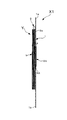
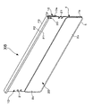
まず、図1乃至図5は本発明の第1実施形態を示す各説明図である。図1に於いて、1は所定形状(一例として矩形状)の薄い板状に形成された合成樹脂製或いは金属製のベース板で、このベース板1は基板本体に相当する。3はベース板1の上面に設けられた単数又は複数の横棒状のストッパーで、このストッパー3は、ベース板1の上面に付箋積層体Yをセットしたとき、付箋積層体Yの閉じ側端部の端面を受け止め、付箋積層体Yが該ストッパー3を乗り越えて付箋保持具Xの重合領域4から抜けないようにする役割を果たす。このストッパー3は、好ましくはベース板1の上端部にその上辺に沿って一連に一つ形成するのが好ましいが、もちろん、略中央部、左右両端部、略左右両端部寄りの部位にそれぞれ複数個形成しても良い。
First, FIG. 1 thru | or FIG. 5 is each explanatory drawing which shows 1st Embodiment of this invention. In FIG. 1,
したがって、付箋積層体Yがベース板1の上面を上方方向にスライド(位置変位)しても、付箋積層体Yはベース板1の上端縁から食み出ることはない。
Therefore, even if the sticky note laminate Y slides (positions displacement) upward on the upper surface of the
2はベース板1の上面にその略全体が重なるように一端部が接続すると共に、自由端部が前記ストッパー3に所定間隔離れている弾性の薄い押え板である。この薄い押え板2は、ベース板1の形状と大きさ及びストッパー3の形状と位置を考慮してやや硬質の合成樹脂材或いは金属(アルミニュームやステンレス)で所定形状に成形されている。ベース板1の形状と大きさ及びストッパー3のそれは、ノートブック、参考書等の大きさを考慮して決めるのが好ましい。
なお、本発明の各実施形態に於いて、前記ストッパー3は単数の横棒を用いているが、該ストッパー3は発明の本質的事項ではないものの、好ましくは付箋積層体Yが上方に位置変位した場合に所定位置で止めるために便宜上用いられている。
In each embodiment of the present invention, the
そこで、さらに図2乃至図5を参照にして第1実施形態の付箋保持具Xの構成を詳しく説明すると、付箋保持具Xは、矩形状のベース板1と、この矩形状ベース板の上端部1aあるいは上端部寄りの部位の上面に、その直線状の上縁に沿って一体的に設けられた単数又は複数の凸(例えば突条)のストッパー3と、前記ベース板1の下端部1bにその基端部2aが一体的に接続すると共に、自由端部2bが前記ストッパー3の内面3aに対して所定間隔L離れ、かつ、材質自体の弾性力に抗して外方向に弾性変位可能な薄い板状の押え板2とから成る。
Therefore, the configuration of the sticky note holder X according to the first embodiment will be described in detail with reference to FIGS. 2 to 5. The sticky note holder X includes a
そして、図3で示すように、付箋積層体Yのセット時、前記ベース板1の表面と前記押え板2の内面との間で形成された重合領域4に、前記押え板2の自由端部2bを引き起こした状態で前記付箋積層体Yの少なくとも一番下側に位置する付箋紙aの非粘着部分を差し込み、例えば図4で示すように事務机の上に付箋保持具Xに置き、又は図5で示すようにラックの垂直側壁、仕切りパネル等の垂直壁Wに接着剤、係止具、磁石等の図示しない設置手段を介して使用する時、前記一番下位の付箋紙aを前記重合領域4内にサンドイッチ状態に挟持した状態でその余の積層付箋紙bを前記押え板2の表面に載せることができる。
As shown in FIG. 3, when the sticky note stack Y is set, the free end portion of the
図2は図1の2−2線断面図であるが、この図2で示すように、付箋保持具Xは、望ましくはベース板1と押え板2は、一枚の板状部材よりなり、前記ベース板1と押え板2の接続部分5は重なるように折り曲げ形成されている。もちろん、図2は一実施例であり、前記接続部分5に関しては任意に設計変更をすることができる。
2 is a cross-sectional view taken along line 2-2 of FIG. 1. As shown in FIG. 2, the sticky note holder X is preferably composed of the
付言すると、任意形状のベース板1と押え板2をそれぞれデザイン性或いは意匠性を考慮してそれぞれ単体に製作し、これらを一体的に接続する。例えばベース板1と押え板2は、図示しない単数又は複数の細長棒体、細長板体、帯状片等の薄い介在部材を介して互いに接続する。その場合の接続手段は接着や溶着であり、例えば圧着により、ベース板1と押え板2を一体的に接続する。
In other words, the
またベース板1と押え板2の各厚みや材質に関して、両方を略同じ肉厚に設定しても良いが、例えば押え板2の厚さに対してベース板1の方をやや厚くすることができる。実施形態では、ベース板1及び押え板2は同じ材質のやや硬質の合成樹脂材又は金属(アルミニュームやステンレス)を用いて一体成形しているので、両方1,2は同じ厚みであると共に、同じ硬さであり、かつ、好ましくは弾性変形可能である。また、ベース板1と押え板2の左右方向の寸法に関して、例えば押え板2の自由端部の左右端部に摘まみ部用の突片を設けても良い。またベース板の四隅(角部)は、直角、丸み等のいずれに形成しても良い。
Further, regarding the thickness and material of the
さらに、押え板2の材質について、実施形態では、図3で示すように付箋積層体Yのセット性を考慮し、少なくとも薄い押え板2は平面体であり、例えば指で自由端部2bを手前側に引き起こすと、平面体の形状を確保しながら(硬質的機能)、接続部5を基点にして外方向にやや湾曲状に反り(弾性変形機能)、そして、指を自由端部2bから離すと、瞬間的に図1及び図2で示すように元の状態に戻る(弾性復帰機能)材質を適宜に選択している。
Furthermore, regarding the material of the
であるから、ベース板1の材質は別として、接続部5及び押え板2の材質に関しては、上記の機能を有しないシート状のゴムや紙、木材は適切ではない。
Therefore, apart from the material of the
ストッパー3の個数や形状に関して、製作の容易性を考慮すると、実施形態の如く、一本の細長い多角形の棒状体が望ましい。またその断面の厚さは、例えば図5で示すように、付箋積層体Yの厚みを考慮して、それと略同じ、又は付箋積層体Yの厚みよりもやや肉厚があるようにするのが好ましい。さらに、ストッパー3は容易に変形しない材質のものを適宜に採用している。
In consideration of the ease of manufacture with respect to the number and shape of the
次に、他の図面を参照にして、本発明の第2実施形態乃至第8実施形態を説明する。なお、これらの実施形態の説明に当って、第1実施形態と同一の部分には同一又は同様の符号を付して重複する説明を割愛する。 Next, second to eighth embodiments of the present invention will be described with reference to other drawings. In the description of these embodiments, the same portions as those in the first embodiment are denoted by the same or similar reference numerals, and redundant descriptions are omitted.
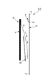
図6乃至図10は、本発明の第2実施形態の付箋用保持具X1を示す各説明図である。各図に於いて、1はベース板、2Aは帯状押え板、3はストッパーである。図6と図1とを比較すると、第1実施形態の押え板2は、ベース板1に対してその基端部(図面では下端部)2aがベース板1の下端部1bに一体的に接続する固定板であるのに対して、この第2実施形態の帯状押え板2Aは、ベース板1に対して上下方向に位置変位可能な可動板である。
6 to 10 are explanatory views showing the sticky note holder X1 according to the second embodiment of the present invention. In each figure, 1 is a base plate, 2A is a belt-like presser plate, and 3 is a stopper. Comparing FIG. 6 with FIG. 1, the holding
実施形態では、帯状押え板2Aは可撓性を有する材質でループ状に形成され、図6で示すようにベース板1の略中央部の表面及び裏面の両方に略密着状態に外嵌合し、略水平状態のストッパー3の内面3aに対してスライド可能に接近又は離れることが可能である。したがって、ストッパー3の内面3aとループ状の帯状押え板2Aの上縁の間の間隔Lは任意に変更可能である。
In the embodiment, the belt-
なお、帯状押え板2Aは、必ずループ状にする必要はなく、例えば帯状板の左右両端部をそれぞれ内側にコ字形状或いは鉤形状に折り曲げ、該左右の対向両端部をベース板1の左右端部と係合する摺接係合部にしても良い。また、ここで「帯状」とは、発明の課題を逸脱しない範囲のやや幅が狭い組紐状の形状も含まれる。さらに、ベース板1の左右方向の幅寸法に関して、下端部1bから上端部に至るにしたがってやや広くなる(逆台形状)ようにしても良い。
The belt-
したがって、この第2実施形態の付箋用保持具X1は、ベース板1と、このベース板の上端部1aあるいは上端部寄りの部位の上面に一体的に設けられた単数又は複数のストッパー3と、前記ベース板の前記ストッパー以外の部位にスライド可能に設けられた帯状押え板2Aとから成り、付箋積層体Yのセット時、前記ベース板1の表面と前記帯状押え板2Aとの間で形成された重合領域4Aに、前記付箋積層体Yの少なくとも一番下側に位置する付箋紙aの非粘着部分を差し込み、使用時、前記一番下位の付箋紙aを前記重合領域4Aに挟持した状態でその余の積層付箋紙bを、少なくとも前記押え板2Aの表面に載せるものである。
Accordingly, the sticky note holder X1 of the second embodiment includes a
次に、図11乃至図14は、本発明の第3実施形態の付箋用保持具X2を示す各説明図である。例えば図11に於いて、1Bは第1実施形態と同様のベース板であるが、該ベース板1Bの材質は、押え板2Bが吸着(磁着)するもので出来ている。例えば金属材としての鉄系のスチールである。もちろん、発明の課題を逸脱しない範囲で、押え板2Bを合成樹脂材で製作し、その上面に磁性体を敷設しても良い。
Next, FIGS. 11 to 14 are explanatory views showing a sticky note holder X2 according to a third embodiment of the present invention. For example, in FIG. 11, 1B is a base plate similar to that of the first embodiment, but the material of the
一方、2Bは該ベース板の表面に取り外し可能に設けられる付箋積層体Y用の薄い板状の押え板である。前記押え板2Bは、前記ベース板1Bの表面に吸着するマグネットシート又は前記ベース板1Bの表面に該ベース板の極性に対応して吸着するマグネットシートのいずれかである。つまり、一方が「S極」ならば、他方は「N極」である。
On the other hand, 2B is a thin plate-like presser plate for the sticky note laminate Y that is detachably provided on the surface of the base plate. The
したがって、この第3実施形態の付箋用保持具X2は、ベース板1Bと、該ベース板の表面の任意の位置に取り外し可能に設けられる付箋積層体Y用の薄い板状の押え板2Bとから成り、使用時、前記付箋積層体Yの一番下位の付箋紙aを前記押え板の裏面と前記ベース板の表面でサンドイッチ状態に挟持すると共に、該挟持状態で付箋積層体Yの一番上側に位置する付箋紙を剥がすことができる。
Therefore, the sticky note holder X2 of the third embodiment includes a
上記構成に於いて、マグネットシートである押え板2Bは、ベース板1Bの横幅寸法よりも若干長く設定するのが好ましい。このように構成すると、例えば図13で示すように、押え板2Bの一端部又は両端部がベース板1Bの端部から食み出るので、食み出た端部2cを摘まんで、押え板2Bをベース板1Bから容易に離すことができる。
In the above configuration, it is preferable that the
次に、図15乃至図18は、本発明の第4実施形態の付箋用保持具X3を示す各説明図である。例えば図15に於いて、1Cはベース板で、このベース板1Cが第1実施形態のベース板1と主に異なる点は、該ベース板1Cの表面に一端(図面左)から他端(図面右)にかけて略直線状に表面向きの横方向嵌合凹所7を形成したことである。この横方向嵌合凹所7の内面は、背面側の垂直面7aと、この垂直面に直交する上下の対向面7b、7bとから成り、ベース板1Cの略中央部に形成されている。またベース板1Cの背面(裏面)に複数個(例えば合計4個)の小突起8を突設したことである。これらの小突起8は、例えば付箋用保持具X3を机やテーブルの上に置いた場合に押え部材2Cの存在により、ガタ、ガタするのを防止する支持突起の役割を果たす。
Next, FIG. 15 thru | or FIG. 18 is each explanatory drawing which shows the sticky note holder X3 of 4th Embodiment of this invention. For example, in FIG. 15, 1C is a base plate, and this
さらに、前記横方向嵌合凹所7と内面と前記押え部材2Cの嵌合部位12とで挟持する押え部材2Cを「クリップ型」に構成したことである。
Further, the pressing
しかして、押え部材2Cは、長尺状のバー部材の略中央部を自在に折り曲げることができるクリップ構造とし、前記略中央部に位置する可撓性接続部11と、この可撓性接続部11の一方端に接続するアーム状の嵌合部位12と、この嵌合部位12と対向するように前記可撓性接続部11の他方端に接続するアーム状の挟持部13とから成り、前記挟持部13の自由端部には突起状のオス側係合部14が設けられ、また前記嵌合部位12の自由端には内側に折り曲げられたメス側被係合部15となっている。
Thus, the pressing
なお、前記メス側被係合部15には外向き突片状の摘まみ部16が連設している。またアーム状の嵌合部位12の形状、厚さ等は、ベース板1Cの横方向嵌合凹所7の形状、厚さ等を考慮して適宜に形成されている。さらに、アーム状の挟持部13の形状、厚さ等も、アーム状の嵌合部位12の長さ、ベース板1Cの小突起8の突出量を考慮して適宜に形成されている。
The female side engaged
したがって、この第4実施形態の付箋用保持具X3は、ベース板1Cと、該ベース板の表面に一端から他端にかけて形成された表面向きの横方向嵌合凹所7と、この横方向嵌合凹所に取り外し可能に嵌合する付箋積層体Y用の押え部材2Cとから成り、使用時、前記付箋積層体の一番下位の付箋紙aを、前記横方向嵌合凹所7と内面と前記押え部材2Cの嵌合部位12の嵌合面(外面)とで挟持することができると共に、該挟持状態で付箋積層体Yの一番上側に位置する付箋紙を剥がすことができる。なお、この実施形態の付箋積層体Y用の押え部材2Cは、「クリップ型」であるが、発明の効果を逸脱しない範囲で、単なるバー状の嵌合片(嵌合部位)に設計変更することもできる。
Accordingly, the sticky note holder X3 of the fourth embodiment includes a
次に、図19は、本発明の第5実施形態の付箋用保持具X4で、この付箋用保持具X4が第1実施形態、第2実施形態及び第3実施形態及び第4実施形態とそれと主に異なる点は、ベース板1の裏面に単数又は複数個(例えば合計4個)の磁石9を取付けたことである。
Next, FIG. 19 shows a sticky note holder X4 according to a fifth embodiment of the present invention. This sticky note holder X4 is the first embodiment, the second embodiment, the third embodiment, the fourth embodiment, and the same. The main difference is that one or a plurality of (for example, a total of four) magnets 9 are attached to the back surface of the
このように構成すると、使用者は、自己の好きな場所(例えばラックの側壁、パネルの壁面など)に自在に装着することができると共に、付箋用保持具X4は磁石9を介して所望するパネル壁や平面に固定されていることから、付箋積層体Yの一番外側の付箋紙を片手で極めて容易に剥離することができる。 With this configuration, the user can freely attach to his / her favorite place (for example, the side wall of the rack, the wall surface of the panel, etc.), and the sticky note holder X4 can be attached to the desired panel via the magnet 9. Since it is fixed to a wall or a plane, the outermost sticky note paper of the sticky note laminate Y can be peeled off with one hand very easily.
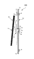
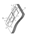
次に、図20乃至図23は、本発明の第6実施形態の付箋用保持具X5を示す各説明図である。特に図22は、付箋用保持具X5を、そのクリップ片10を介して、ノートブック、教科書、参考書、カタログ等の支持体Zの上端部に適宜に係止させ、かつ支持体Zの平坦状一側表面(表示又は裏表紙)に該付箋用保持具X5を安定的に装着し、さらに、使用時に薄い押え板2Dの自由端部2bを指で手前側に起こし、一番下の付箋aを差し込む場合の概略説明図である。
Next, FIG. 20 thru | or FIG. 23 is each explanatory drawing which shows the tag holder X5 of 6th Embodiment of this invention. In particular, FIG. 22 shows that the sticky note holder X5 is appropriately locked to the upper end portion of the support Z such as a notebook, textbook, reference book, catalog, etc. through the
ここで、主に図21(図20の21−21線断面図)或いは図22を基準にして構成を簡単に説明する。この付箋用保持具X5が第1実施形態の付箋用保持具Xと主に異なる点は、(a)クリップ片10をベース板1Dの上端部に一体的に設けたこと、(b)このクリップ片10はベース板1Dの上端部に突出形成したストッパー3Dに接続し、かつ、単数又は複数の折り曲げ片部P1、P2、P3を介して鉤状に折り返され、その先端部10a側が前記ベース板1Dの裏面に接触或いは接近するように延びていること、(c)好ましくは、このクリップ片10は、ほぼ平面体の形状を確保しながら(硬質的機能)、前記支持体Zの上端を包囲する接続側の折り曲げ片部P1或いはP2或いは又P3のいずれかを基点にしてベース板1Dの背面から仮想線で示す外方向に反り(弾性変形機能)、そして、指をクリップ片10の先端部10a側から離すと、瞬間的に図21又は図22で示す実線の位置で示すように元の状態に戻る(弾性復帰機能)材質を適宜に選択していることである。この材質も第1実施形態と同様のものを用いる。
Here, the configuration will be briefly described mainly with reference to FIG. 21 (sectional view taken along line 21-21 in FIG. 20) or FIG. This sticky note holder X5 mainly differs from the sticky note holder X of the first embodiment in that (a) the
したがって、この第6実施形態の付箋用保持具X5は、ベース板1Dと、該ベース板の下端部にその基端部が一体的に接続する付箋積層体Y用の薄い板状の押え板2Dと、前記ベース板の上端部に接続し、かつ、単数又は複数の折り曲げ片部(実施形態)を介して折り返され、その先端部側が前記ベース板の裏面に接触或いは接近するように延びる鉤状のクリップ片10(実施形態)から成る付箋用保持具であって、例えば使用時に、前記付箋積層体Yの一番下位の付箋紙aを前記押え板2Dの裏面と前記ベース板1Dの表面でサンドイッチ状態に挟持すると共に、該挟持状態で付箋積層体Yの一番上側に位置する付箋紙bを剥がすことができ、さらに任意に、前記付箋用保持具X5を、例えば扁平状支持体Zの一側表面(表示又は裏表紙)に係止させることができる。
Accordingly, the sticky note holder X5 of the sixth embodiment includes a
ところで、実施形態では、ストッパー3Dに接続する折り曲げ片部は、P1、P2、P3等の折り曲げポイントを有している。この点について、図21を参照にして付言する。符号3Dはベース板1Dの上端部1aの端部を押え板2Dが存在する方向に略90度折り曲げて形成されたストッパーである。P1は前記ストッパー3Dの端部から上方に略90度折り曲げて形成された非常に短い第1折り曲げ片部の最初の折り曲げポイントである。P2は前記第1折り曲げ片部をベース板1Dの裏方向に向かって略度折り曲げて形成された第2折り曲げ片部の二番目の折り曲げポイントで、該第2折り曲げ片部の長さは前記ストッパー3Dの略2倍である。
By the way, in embodiment, the bending piece part connected to
したがって、第2折り曲げ片部は押え板2Dの背面(裏面)から突出している。さらに、P3は前記第2折り曲げ片部の端部をベース板1Dの背面に沿う方向へ折り曲げて形成された第3折り曲げ片部の三番目の折り曲げポイントである。
Therefore, the 2nd bending piece part protrudes from the back surface (back surface) of pressing
実施形態のクリップ片10は、前記P1、P2、P3を含み、全体して鉤状に形成されている。そして、前記第3折り曲げ片部は、P3の折り曲げポイントから下方に延びるにしたがってベース板1Dの背面に接近し、先端部寄りの部位も含む先端部10aは、ベース板1Dの背面に接触し、さらに、クリップ片10の先端は、指を掛けることができるように前記背面から若干離れている。
The
なお、実施形態如何によっては、クリップ片10の折り曲げ片部を円弧状に形成することにより、P2やP3の折り曲げポイントを無くしても良い。つまり、クリップ片の形状、大きさ等は、クリップ機能を害しない範囲で任意に設計変更し得る事項である。
Note that, depending on the embodiment, the folding point of P2 or P3 may be eliminated by forming the bent piece portion of the
次に図24及び図25は、本発明の第7実施形態の付箋用保持具X6を示す各説明図である。なお、この第7実施形態は、第6実施形態に他の構成(左右の係止部21と共に、環状の弾性押え部材22)を加味したものであるから、この第7実施形態の説明に当たっては前記第6実施形態の符号をそのまま援用して重複する説明を割愛する。
Next, FIG.24 and FIG.25 is each explanatory drawing which shows the tag holder X6 of 7th Embodiment of this invention. In addition, since this 7th Embodiment adds another structure (Angular elastic pressing
この第7実施形態の発明の課題は、付箋積層体Yが付箋用保持具X6から外れないように一対の係止部21に環状の弾性押え部材Yを掛けて付箋積層体Yをベース板1Dの表面に押え付けることができるようにすることである(付箋紙の拘束性)。この付箋紙の拘束性が第1実施形態の発明の課題に対して従属的に加味されている。
The subject of this seventh embodiment is that the sticky stack Y is hung on the
さて、図24は斜視図、図25は使用時、ベース板1Dの左右端部の略中央部にそれぞれ形成した複数の係止部21に環状の弾性押え部材22、例えば輪ゴムを掛け、付箋積層体Yをベース板1Dの表面に押え付けた状態の説明図である。
Now, FIG. 24 is a perspective view, and FIG. 25 is a stack of sticky notes, in use, when a plurality of locking
図25は、好ましくは、係止部21が左右の端面からそれぞれ突出しないように(邪魔にならないように)、例えば各端部にそれぞれ合計2の切欠をベース板1Dの中心部の方向に向かって略平行に所要量切込み、小突起を形成している。
In FIG. 25, it is preferable that, for example, a total of two notches be provided at each end portion in the direction of the center portion of the
したがって、左右端部にそれぞれ形成された左右一対の小突起は、図25で示すように環状の弾性押え部材22を引っ掛けるための係止部21に相当することから、この第7実施形態の付箋用保持具X6の主要部は、「左右の両端部にそれぞれ係止部(21)を有するベース板(1D)と、該ベース板の下端部にその基端部が一体的に接続する付箋積層体(Y)用の薄い板状の押え板(2D)とから成る付箋用保持具であって、前記付箋積層体(Y)の一番下位の付箋紙(a)を前記押え板の裏面と前記ベース板の表面でサンドイッチ状態に挟持すると共に、該挟持状態で付箋積層体(Y)の一番上側に位置する付箋紙を剥がすことができ、さらに任意に、前記係止部(21)に環状の弾性押え部材(22)を掛けることにより前記付箋積層体(Y)を前記ベース板(1D)に押え付けることができること」である。
Accordingly, the pair of left and right small protrusions formed on the left and right end portions correspond to the locking
この第7実施形態の付箋用保持具X6は、前記第6実施形態の付箋用保持具X5の利点を有すると共に、さらに、付箋積層体(Y)を前記ベース板(1D)の表面に安定的に押え付けることができるという効果がある。なお、第6実施形態のクリップ片10の構成並びに第7実施形態の係止部21の構成は、前述した第1実施形態、第2実施形態等に加味しても良い。
The sticky note holder X6 of the seventh embodiment has the advantages of the sticky note holder X5 of the sixth embodiment, and moreover, the sticky note laminate (Y) is stable on the surface of the base plate (1D). There is an effect that it can be pressed down. Note that the configuration of the
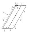
最後に図26乃至図29は本発明の第8実施形態を示す各説明図である。この第8実施形態の付箋用保持具X7は、図26で示すように、第7実施形態の係止部21の考え方を一部利用している。したがって、ここでは第7実施形態との相違点を述べることにする。
この第8実施形態の付箋用保持具X7が前記第7実施形態の付箋用保持具X6と主に異なる点は、(a)ベース板1Eの上端部にクリップ片が形成されておらず、ストッパー3Dのみが形成されていること、(b)ベース板1Eの左右両端部に対称的に形成された左右一対の係止部21は、端面からの切欠によって形成されたものではなく、いわゆるプレスによって型抜きされた舌片状或いは小突片状のものであること、(c)支持体Zに対する付箋用保持具X7自体の保持性を確保するために環状の弾性押え部材22を利用していることである。
Finally, FIG. 26 to FIG. 29 are explanatory views showing an eighth embodiment of the present invention. As shown in FIG. 26, the sticky note holder X7 of the eighth embodiment partially uses the concept of the locking
The sticky note holder X7 of the eighth embodiment is mainly different from the sticky note holder X6 of the seventh embodiment in that (a) no clip piece is formed on the upper end portion of the
例えば図27は左右一対の係止部21、21に環状の弾性押え部材22を引っ掛けた一例を示す説明図である。この図27で示す引っ掛けをすると、例えば図28で示すように、付箋用保持具X7がノート、参考書等の扁平状支持体Zから離れないように一対の係止部21に環状の弾性押え部材22を適宜に掛けて付箋用保持具X7を扁平状支持体Zに装着させることができる。
For example, FIG. 27 is an explanatory view showing an example in which an annular elastic pressing
実施形態では、例えば扁平状支持体Zの表面又は裏表紙のいずれか一方の外面に付箋用保持具X7を面接触状態で添設し、次いで環状の弾性押え部材22の引っ掛け部分が手前から見える状態で付箋用保持具Yを扁平状支持体Zの一側表面に縛り付けるような状態で安定的に装着させている。
In the embodiment, for example, a sticky note holder X7 is attached to the outer surface of either the front surface or the back cover of the flat support Z in a surface contact state, and then the hooked portion of the annular elastic pressing
なお、図29は付箋用保持具X7が扁平状支持体Zから離れないように左右一対の係止部21、21に環状の弾性押え部材22を適宜に掛け、かつ該付箋用保持具X7を前記扁平状支持体Zの表紙或いは裏表紙の内側に挟み込んだ状態で装着させる。このように使用すると、携帯的、扁平状支持体Zと付箋用保持具X7と幅寸法の異なる複数の付箋積層体Yがバラバラにならないので、付箋紙を使用したい場合には、扁平状支持体Zの表紙或いは裏表紙を開き、環状の弾性押え部材22を左右一対の係止部21から取り外して付箋用保持具X7を直ちに使用することができる。
In FIG. 29, an annular elastic pressing
ところで、現在、付箋積層体は各種形状のものが市販されている。例えば第1実施形態の付箋用保持具Xでは、複数の横幅の縦7.5センチメートルの付箋積層体を並列状態でセットすることができる大きさに形成しているが、もちろん、大きさは任意に変更し得る事項である。 By the way, various types of sticky note laminates are commercially available. For example, in the sticky note holder X of the first embodiment, a plurality of widthwise 7.5 cm sticky note stacks are formed in a size that can be set in a parallel state. This can be changed arbitrarily.
本発明は、文房具の分野で利用することができる。 The present invention can be used in the field of stationery.
X、X1、X2、X3、X4、X5、X6、X7…付箋用保持具、
Y…付箋積層体、
Z…支持体、
1、1A、1B、1C、1D、1E…ベース板、
2、2A、2B、2C、2D…押え板、
3、3D…ストッパー、
P1、P2、P3…各折り曲げ片部の折曲げポイント、
3a…ストッパーの内面、
4、4A…重合領域、
5…接続部分、
7…横方向嵌合凹所、
12…嵌合部位
10…クリップ片、
10a…先端部(先端部寄りの部位も含む)、
21…係止部、
22…環状の弾性押え部材。
X, X1, X2, X3, X4, X5, X6, X7 ... Sticky note holder,
Y ... Sticky note stack,
Z: Support,
1, 1A, 1B, 1C, 1D, 1E ... base plate,
2, 2A, 2B, 2C, 2D ... presser plate,
3, 3D ... stopper,
P1, P2, P3 ... bending points of each bent piece,
3a ... the inner surface of the stopper,
4, 4A ... polymerization region,
5 ... Connection part,
7 ... Reverse fitting recess,
12 ... fitting
10a ... tip part (including a part near the tip part),
21 ... locking part,
22: An annular elastic pressing member.
Claims (11)
前記付箋積層体(Y)の一番下位の付箋紙(a)を前記押え板の裏面と前記ベース板の表面でサンドイッチ状態に挟持すると共に、該挟持状態で付箋積層体(Y)の一番上側に位置する付箋紙を剥がすことができる付箋用保持具。 A base plate (1), and a thin plate-like presser plate (2) for a sticky note laminate (Y) whose base end is integrally connected to the lower end of the base plate,
The lowermost sticky note (a) of the sticky note laminate (Y) is sandwiched between the back surface of the presser plate and the surface of the base plate, and the top of the sticky note laminate (Y) is held in the sandwiched state. A sticky note holder that can peel off a sticky note located on the upper side.
前記付箋積層体のセット時、前記ベース板の表面と前記帯状押え板との間で形成された重合領域に、前記付箋積層体の少なくとも一番下側に位置する付箋紙(a)を差し込み、
前記一番下位の付箋紙を前記重合領域に挟持した状態で直接書き込みし、前記付箋積層体の一番上側に位置する付箋紙を剥がすことができる付箋用保持具。 A base plate (1) and a thin strip-shaped presser plate (2A) for a sticky note laminate (Y) slidably provided on the base plate,
At the time of setting the sticky note laminate, a sticky note (a) positioned at least on the lowermost side of the sticky note laminate is inserted into a superposed region formed between the surface of the base plate and the band-shaped presser plate,
A sticky note holder capable of directly writing in a state where the lowest sticky note paper is sandwiched between the overlapping regions and peeling off the sticky note paper located on the uppermost side of the sticky note laminate.
前記付箋積層体の一番下位の付箋紙(a)を前記押え板の裏面と前記ベース板の表面でサンドイッチ状態に挟持すると共に、該挟持状態で付箋積層体(Y)の一番上側に位置する付箋紙を剥がすことができる付箋用保持具。 It consists of a base plate (1B) and a thin plate-like presser plate (2B) for a sticky note laminate (Y) that is detachably provided on the surface of the base plate,
The lowermost sticky note (a) of the sticky note laminate is sandwiched between the back surface of the presser plate and the surface of the base plate, and is located on the uppermost side of the sticky note laminate (Y) in the sandwiched state. Sticky note holder that can peel off sticky notes.
前記付箋積層体の一番下位の付箋紙(a)を、前記横方向嵌合凹所(7)と内面と前記押え部材(2C)の嵌合部位とで挟持すると共に、該挟持状態で付箋積層体(Y)の一番上側に位置する付箋紙を剥がすことができる付箋用保持具。 A base plate (1C), a surface-facing lateral fitting recess (7) formed on one surface of the base plate from one end to the other, and a sticky note removably fitted in the lateral fitting recess A pressing member (2C) for the laminate (Y),
The lowest sticky note (a) of the sticky note laminate is sandwiched between the lateral fitting recess (7), the inner surface, and the fitting part of the pressing member (2C), and the sticky note is held in the sandwiched state. A sticky note holder capable of peeling off a sticky note located on the uppermost side of the laminate (Y).
前記付箋積層体の一番下位の付箋紙(a)を前記押え板の裏面と前記ベース板の表面でサンドイッチ状態に挟持すると共に、該挟持状態で付箋積層体(Y)の一番上側に位置する付箋紙を剥がすことができ、さらに、前記付箋用保持具を、扁平状支持体の端部に前記クリップ片(10)を介して係止させることができる付箋用保持具。 A base plate (1D), a thin plate-like presser plate (2D) for a sticky note laminate (Y) whose base end is integrally connected to the lower end of the base plate, and an upper end of the base plate A sticky note holder comprising a clip piece (10) connected and folded back via a bent piece portion and extending so that the tip end (10a) side contacts or approaches the back surface of the base plate,
The lowermost sticky note (a) of the sticky note laminate is sandwiched between the back surface of the presser plate and the surface of the base plate, and is located on the uppermost side of the sticky note laminate (Y) in the sandwiched state. A sticky note holder capable of peeling off the sticky note paper to be attached and further capable of locking the sticky note holder to an end of a flat support through the clip piece (10).
前記付箋積層体(Y)の一番下位の付箋紙(a)を前記押え板の裏面と前記ベース板の表面でサンドイッチ状態に挟持すると共に、該挟持状態で付箋積層体(Y)の一番上側に位置する付箋紙を剥がすことができ、さらに、前記付箋積層体(Y)が付箋用保持具から外れないように前記係止部(21)に環状の弾性押え部材(22)を掛けて前記付箋積層体(Y)を前記ベース板(1D)に押え付けることができる付箋用保持具。 A base plate (1D) having locking portions (21) at both left and right ends, and a thin plate-like laminate for a sticky note laminate (Y) whose base end is integrally connected to the lower end of the base plate A sticky note holder comprising a presser plate (2D),
The lowermost sticky note (a) of the sticky note laminate (Y) is sandwiched between the back surface of the presser plate and the surface of the base plate, and the top of the sticky note laminate (Y) is held in the sandwiched state. The sticky note paper located on the upper side can be peeled off, and an annular elastic pressing member (22) is hung on the locking portion (21) so that the sticky note laminate (Y) is not detached from the sticky note holder. A sticky note holder capable of pressing the sticky note laminate (Y) against the base plate (1D).
前記付箋積層体(Y)の一番下位の付箋紙(a)を前記押え板の裏面と前記ベース板の表面でサンドイッチ状態に挟持すると共に、該挟持状態で付箋積層体(Y)の一番上側に位置する付箋紙を剥がすことができ、さらに、前記付箋用保持具が扁平状支持体から離れないように前記係止部(21)に環状の弾性押え部材(22)を掛け、かつ該付箋用保持具を前記扁平状支持体に装着させることができる付箋用保持具。 A thin plate for a sticky note laminate (Y) having a base plate (1E) having locking portions (21) at both left and right ends and a base end integrally connected to a lower end of the base plate A sticky note holder comprising a presser plate (2),
The lowermost sticky note (a) of the sticky note laminate (Y) is sandwiched between the back surface of the presser plate and the surface of the base plate, and the top of the sticky note laminate (Y) is held in the sandwiched state. The sticky note paper located on the upper side can be peeled off, and an annular elastic pressing member (22) is hung on the locking portion (21) so that the sticky note holder is not separated from the flat support, and A sticky note holder capable of attaching a sticky note holder to the flat support.
Applications Claiming Priority (2)
| Application Number | Priority Date | Filing Date | Title |
|---|---|---|---|
| JP2017132467 | 2017-07-06 | ||
| JP2017132467 | 2017-07-06 |
Publications (1)
| Publication Number | Publication Date |
|---|---|
| JP2019014248A true JP2019014248A (en) | 2019-01-31 |
Family
ID=65356751
Family Applications (1)
| Application Number | Title | Priority Date | Filing Date |
|---|---|---|---|
| JP2018125724A Pending JP2019014248A (en) | 2017-07-06 | 2018-07-02 | Tag holder |
Country Status (1)
| Country | Link |
|---|---|
| JP (1) | JP2019014248A (en) |
Cited By (1)
| Publication number | Priority date | Publication date | Assignee | Title |
|---|---|---|---|---|
| CN111035131A (en) * | 2020-01-14 | 2020-04-21 | 唐山师范学院 | Remote control takes stationery box of reminding device function |
-
2018
- 2018-07-02 JP JP2018125724A patent/JP2019014248A/en active Pending
Cited By (1)
| Publication number | Priority date | Publication date | Assignee | Title |
|---|---|---|---|---|
| CN111035131A (en) * | 2020-01-14 | 2020-04-21 | 唐山师范学院 | Remote control takes stationery box of reminding device function |
Similar Documents
| Publication | Publication Date | Title |
|---|---|---|
| WO2002038390A2 (en) | Insert for a coil bound notebook | |
| JP2019014248A (en) | Tag holder | |
| US20210149442A1 (en) | Electronic table card, fixed seat of electronic table card, and electronic table card assembly | |
| JP3152399U (en) | Locking device for paper, etc. | |
| TW200909237A (en) | Portable housing container | |
| JP3165969U (en) | Magnet clip | |
| KR20210000506U (en) | Bulletin board | |
| JP5866653B1 (en) | Sheet-like material insertion holder and insertion holder | |
| JPH0623784U (en) | Holder for sheet material | |
| JP6474272B2 (en) | Bulletin board | |
| JP3246412U (en) | Sticky note sheet | |
| JP4746721B1 (en) | Wall hangings and wall hangings display | |
| JP3180764U (en) | Paper pinching holder device, holder used therefor, writing instrument cap body and writing instrument cap set | |
| JP4777212B2 (en) | Table pocket | |
| KR20150033490A (en) | A Desk Memo Pad | |
| JP6624829B2 (en) | Holding band | |
| US20060080870A1 (en) | Calendar hanger device and assembly incorporating the same | |
| JP3164411U (en) | Sticky note seat | |
| TWI307317B (en) | ||
| JP3181124U (en) | Paper holder | |
| JP3191220U (en) | Dispenser | |
| JP3179563U (en) | Storage | |
| TWM505407U (en) | Documents binding device | |
| KR20170003480U (en) | File for keeping documents | |
| JP2020049849A (en) | Tag paper with weighted mount |
Legal Events
| Date | Code | Title | Description |
|---|---|---|---|
| AA64 | Notification of invalidation of claim of internal priority (with term) |
Free format text: JAPANESE INTERMEDIATE CODE: A241764 Effective date: 20180711 |
|
| A521 | Written amendment |
Free format text: JAPANESE INTERMEDIATE CODE: A523 Effective date: 20180718 |