JP2019014181A - Portable printer - Google Patents
Portable printer Download PDFInfo
- Publication number
- JP2019014181A JP2019014181A JP2017134332A JP2017134332A JP2019014181A JP 2019014181 A JP2019014181 A JP 2019014181A JP 2017134332 A JP2017134332 A JP 2017134332A JP 2017134332 A JP2017134332 A JP 2017134332A JP 2019014181 A JP2019014181 A JP 2019014181A
- Authority
- JP
- Japan
- Prior art keywords
- instant camera
- display
- electronic device
- portable electronic
- portable
- Prior art date
- Legal status (The legal status is an assumption and is not a legal conclusion. Google has not performed a legal analysis and makes no representation as to the accuracy of the status listed.)
- Granted
Links
Images


Classifications
-
- G—PHYSICS
- G03—PHOTOGRAPHY; CINEMATOGRAPHY; ANALOGOUS TECHNIQUES USING WAVES OTHER THAN OPTICAL WAVES; ELECTROGRAPHY; HOLOGRAPHY
- G03B—APPARATUS OR ARRANGEMENTS FOR TAKING PHOTOGRAPHS OR FOR PROJECTING OR VIEWING THEM; APPARATUS OR ARRANGEMENTS EMPLOYING ANALOGOUS TECHNIQUES USING WAVES OTHER THAN OPTICAL WAVES; ACCESSORIES THEREFOR
- G03B17/00—Details of cameras or camera bodies; Accessories therefor
- G03B17/56—Accessories
- G03B17/561—Support related camera accessories
-
- G—PHYSICS
- G03—PHOTOGRAPHY; CINEMATOGRAPHY; ANALOGOUS TECHNIQUES USING WAVES OTHER THAN OPTICAL WAVES; ELECTROGRAPHY; HOLOGRAPHY
- G03B—APPARATUS OR ARRANGEMENTS FOR TAKING PHOTOGRAPHS OR FOR PROJECTING OR VIEWING THEM; APPARATUS OR ARRANGEMENTS EMPLOYING ANALOGOUS TECHNIQUES USING WAVES OTHER THAN OPTICAL WAVES; ACCESSORIES THEREFOR
- G03B15/00—Special procedures for taking photographs; Apparatus therefor
- G03B15/02—Illuminating scene
- G03B15/06—Special arrangements of screening, diffusing, or reflecting devices, e.g. in studio
-
- G—PHYSICS
- G03—PHOTOGRAPHY; CINEMATOGRAPHY; ANALOGOUS TECHNIQUES USING WAVES OTHER THAN OPTICAL WAVES; ELECTROGRAPHY; HOLOGRAPHY
- G03B—APPARATUS OR ARRANGEMENTS FOR TAKING PHOTOGRAPHS OR FOR PROJECTING OR VIEWING THEM; APPARATUS OR ARRANGEMENTS EMPLOYING ANALOGOUS TECHNIQUES USING WAVES OTHER THAN OPTICAL WAVES; ACCESSORIES THEREFOR
- G03B17/00—Details of cameras or camera bodies; Accessories therefor
- G03B17/48—Details of cameras or camera bodies; Accessories therefor adapted for combination with other photographic or optical apparatus
- G03B17/50—Details of cameras or camera bodies; Accessories therefor adapted for combination with other photographic or optical apparatus with both developing and finishing apparatus
- G03B17/53—Details of cameras or camera bodies; Accessories therefor adapted for combination with other photographic or optical apparatus with both developing and finishing apparatus for automatically delivering a finished picture after a signal causing exposure has been given, e.g. by pushing a button, by inserting a coin
-
- H—ELECTRICITY
- H04—ELECTRIC COMMUNICATION TECHNIQUE
- H04N—PICTORIAL COMMUNICATION, e.g. TELEVISION
- H04N1/00—Scanning, transmission or reproduction of documents or the like, e.g. facsimile transmission; Details thereof
-
- H—ELECTRICITY
- H04—ELECTRIC COMMUNICATION TECHNIQUE
- H04N—PICTORIAL COMMUNICATION, e.g. TELEVISION
- H04N23/00—Cameras or camera modules comprising electronic image sensors; Control thereof
- H04N23/50—Constructional details
-
- H—ELECTRICITY
- H04—ELECTRIC COMMUNICATION TECHNIQUE
- H04N—PICTORIAL COMMUNICATION, e.g. TELEVISION
- H04N23/00—Cameras or camera modules comprising electronic image sensors; Control thereof
- H04N23/60—Control of cameras or camera modules
- H04N23/68—Control of cameras or camera modules for stable pick-up of the scene, e.g. compensating for camera body vibrations
-
- H—ELECTRICITY
- H04—ELECTRIC COMMUNICATION TECHNIQUE
- H04N—PICTORIAL COMMUNICATION, e.g. TELEVISION
- H04N23/00—Cameras or camera modules comprising electronic image sensors; Control thereof
- H04N23/70—Circuitry for compensating brightness variation in the scene
- H04N23/73—Circuitry for compensating brightness variation in the scene by influencing the exposure time
Abstract
Description
本発明は携帯型プリンタに関するものである。 The present invention relates to a portable printer.
スマートフォンで撮影したりスマートフォンに送信される等した画像を、スマートフォンを自宅に持ち帰ったり店舗に持ち込んだりせずにその場でフィルムにプリントアウトする方法としては、携帯電話機の例であるが特許文献1に記載されているように、スマートフォン自体にインスタントカメラの機能を持たせるように構成することが可能である。しかし、ユーザが現に使用しているインスタントカメラの機能を有しないスマートフォンではこの方法は使えない。 An example of a mobile phone is a method for printing out an image taken with a smartphone or transmitted to a smartphone on a film without taking the smartphone home or into a store. As described in the above, it is possible to configure the smartphone itself to have an instant camera function. However, this method cannot be used with a smartphone that does not have the function of the instant camera that the user is currently using.
一方、電子カメラを対象とするものであるが、特許文献2に記載されているように、電子カメラのディスプレイに画像が表示されている状態で電子カメラをソケットに差し込み、ディスプレイに表示されている画像を内部の光学系を介してフィルムに投影することでフィルムを感光させてプリントアウトするプリント用装置が知られている。
また、携帯電話機を対象とするものであるが、特許文献3に記載されているように、携帯電話機のディスプレイに画像が表示されている状態で携帯電話機を挿入口に挿入させ、上記と同様に、ディスプレイに表示されている画像を内部の光学系を介してフィルムに投影することでフィルムを感光させてプリントアウトする携帯型プリンタが知られている。
On the other hand, although it is intended for an electronic camera, as described in Patent Document 2, the electronic camera is inserted into a socket while an image is displayed on the display of the electronic camera, and is displayed on the display. 2. Description of the Related Art There is known a printing apparatus that prints out an image by projecting an image onto the film via an internal optical system to expose the film.
Moreover, although it is intended for a mobile phone, as described in Patent Document 3, the mobile phone is inserted into the insertion slot while an image is displayed on the display of the mobile phone. There is known a portable printer that prints out an image displayed on a display by projecting the image on the film via an internal optical system to expose the film.
そして、これらの技術をスマートフォンに適用すれば、ユーザが現に使用しているスマートフォンのディスプレイに表示される画像をその場でフィルムにプリントアウトすることが可能となる。 And if these techniques are applied to a smart phone, it will become possible to print out the image displayed on the display of the smart phone currently used by the user on a film on the spot.
しかしながら、特許文献2,3に記載された携帯型プリンタ等では、その内部でフィルムが剥き出しの状態になっていることもあり、外部の光が入り込まないようにするために、光を通さない壁面や蛇腹で装置が覆われている。そして、外部の光が装置内に入らないように、ソケットに差し込まれたスマートフォンは壁面に押し付けられ、挿入口に挿入されたスマートフォンは密閉される。
そのため、スマートフォンが携帯型プリンタ等のソケットに差し込まれてディスプレイが壁面に密着したり、スマートフォンが挿入口に挿入された状態では、スマートフォンのディスプレイに画像が適切に表示されているか(すなわち、プリントアウトしたい画像が表示されているか、画像の位置や縦横の向きが適切か、あるいはそもそも画像が表示されているか等)をユーザが確認することができない。
However, in the portable printers and the like described in Patent Documents 2 and 3, the film may be exposed in the inside thereof, and the wall that does not allow light to pass through in order to prevent external light from entering. And the device is covered with bellows. The smartphone inserted into the socket is pressed against the wall surface so that external light does not enter the device, and the smartphone inserted into the insertion slot is sealed.
Therefore, if the smartphone is inserted into a socket such as a portable printer and the display is in close contact with the wall surface, or the smartphone is inserted into the insertion slot, is the image properly displayed on the smartphone display (i.e., printout)? The user cannot confirm whether the desired image is displayed, whether the position and the vertical / horizontal orientation of the image are appropriate, or whether the image is displayed in the first place.
そのため、ディスプレイに画像が適切に表示されていない場合でも、ユーザは画像をプリントアウトして初めてそれに気付くことになり、不便さが感じられるとともに、プリントアウトしたフィルムが無駄になってしまう。 For this reason, even when the image is not properly displayed on the display, the user notices it only after printing the image, and inconvenience is felt, and the printed film is wasted.
本発明は、かかる点に鑑みなされたもので、ユーザがスマートフォン等の携帯電子機器のディスプレイに画像が適切に表示されているかを確認しながら、ディスプレイに表示されている画像を適切にプリントアウトすることが可能な携帯型プリンタを提供することを目的とする。 The present invention has been made in view of this point, and appropriately prints out an image displayed on a display while a user confirms whether the image is appropriately displayed on a display of a portable electronic device such as a smartphone. It is an object of the present invention to provide a portable printer that can be used.
上記課題を達成するため、第1の手段は、
インスタントカメラと、
ディスプレイが前記インスタントカメラと対向する向きにされた携帯電子機器を、当該ディスプレイが前記インスタントカメラから所定距離だけ離れた状態で支持するとともに、前記携帯電子機器と前記インスタントカメラとの間の空間を覆う支持部と、
前記支持部に支持された前記携帯電子機器のディスプレイに表示されている画像を反射して、前記支持部に又は前記支持部によって形成され前記携帯電子機器と前記インスタントカメラとの間に形成された覗き窓を介して視認可能とするミラーと、
を備え、
前記携帯電子機器のディスプレイに表示されている画像を前記インスタントカメラで撮影してプリントアウトすることを特徴とする。
In order to achieve the above object, the first means is:
An instant camera,
A portable electronic device whose display is oriented to face the instant camera is supported in a state where the display is separated from the instant camera by a predetermined distance, and a space between the portable electronic device and the instant camera is covered. A support part;
An image displayed on the display of the portable electronic device supported by the support portion is reflected, and formed on the support portion or by the support portion and formed between the portable electronic device and the instant camera. A mirror that can be seen through a viewing window;
With
An image displayed on the display of the portable electronic device is photographed by the instant camera and printed out.
第2の手段は、
インスタントカメラと、
前記インスタントカメラを設置可能な設置部と、
ディスプレイが下向きにされた携帯電子機器を、当該ディスプレイが前記インスタントカメラから上方に所定距離だけ離れた状態で支持するとともに、前記携帯電子機器と前記インスタントカメラとの間の空間を覆う支持部と、
前記支持部に支持された前記携帯電子機器のディスプレイに表示されている画像を反射して、前記支持部に又は前記支持部によって形成され前記携帯電子機器と前記インスタントカメラとの間に形成された覗き窓を介して視認可能とするミラーと、
を備え、
前記携帯電子機器のディスプレイに表示されている画像を前記インスタントカメラで撮影してプリントアウトすることを特徴とする。
The second means is
An instant camera,
An installation section capable of installing the instant camera;
A portable electronic device whose display is faced downward while the display is supported by a distance above the instant camera by a predetermined distance, and a support unit that covers a space between the portable electronic device and the instant camera;
An image displayed on the display of the portable electronic device supported by the support portion is reflected, and formed on the support portion or by the support portion and formed between the portable electronic device and the instant camera. A mirror that can be seen through a viewing window;
With
An image displayed on the display of the portable electronic device is photographed by the instant camera and printed out.
第3の手段は、第2の手段であって、前記インスタントカメラは、前記設置部に組み込まれていることを特徴とする。 The third means is the second means, characterized in that the instant camera is incorporated in the installation section.
第4の手段は、第3の手段であって、前記設置部に、下向きに押されて操作される前記インスタントカメラのシャッタが設けられていることを特徴とする。 The fourth means is the third means, characterized in that the installation unit is provided with a shutter of the instant camera operated by being pushed downward.
第5の手段は、第2の手段から第4の手段のいずれか一の手段であって、前記支持部は、前記設置部に対して折り畳み可能とされていることを特徴とする。 The fifth means is any one of the second means to the fourth means, wherein the support part is foldable with respect to the installation part.
第6の手段は、第5の手段であって、前記支持部は、前記設置部に対して折り畳まれた状態では前記設置部を覆う蓋になることを特徴とする。 The sixth means is the fifth means, wherein the support part is a lid that covers the installation part when folded to the installation part.
第7の手段は、第1の手段から第6の手段のいずれか一の手段であって、前記ミラーは、その鏡面が凸面とされていることを特徴とする。 The seventh means is any one of the first means to the sixth means, and the mirror surface of the mirror is convex.
第8の手段は、第1の手段から第7の手段のいずれか一の手段であって、
前記携帯電子機器のディスプレイに表示されている画像をトリミングするための開口部を有する枠体を備え、
前記ディスプレイが下向きにされた前記携帯電子機器が取り付けられた前記枠体が前記支持部に取り付けられることを特徴とする。
The eighth means is any one of the first means to the seventh means,
A frame having an opening for trimming an image displayed on the display of the portable electronic device;
The frame body to which the portable electronic device with the display facing down is attached to the support portion.
第9の手段は、第8の手段であって、
前記枠体には、粘着部が設けられており、
前記携帯電子機器は、前記粘着部により粘着されることで前記枠体に取り付けられることを特徴とする。
The ninth means is the eighth means,
The frame is provided with an adhesive part,
The portable electronic device is attached to the frame body by being adhered by the adhesive portion.
第10の手段は、第8の手段又は第9の手段であって、
前記支持部は、前記設置部に対して折り畳み可能とされており、
前記枠体は、前記設置部と折り畳まれた状態の前記支持部との間に収納可能とされていることを特徴とする。
The tenth means is the eighth means or the ninth means,
The support part can be folded with respect to the installation part,
The frame can be stored between the installation portion and the support portion in a folded state.
第11の手段は、第8の手段から第10の手段のいずれか一の手段であって、前記開口部の形状及び大きさのいずれか一方又は両方が異なる複数の前記枠体を備えることを特徴とする。 The eleventh means is any one of the eighth means to the tenth means, and includes a plurality of the frame bodies in which one or both of the shape and the size of the opening are different. Features.
上記手段によれば、支持部に支持されたスマートフォン等の携帯電子機器のディスプレイに表示されている画像を反射してユーザに視認可能とするミラーを設けるように構成したため、ユーザが携帯電子機器のディスプレイに画像が適切に表示されているかを確認しながら、ディスプレイに表示されている画像を適切にプリントアウトすることが可能となる。 According to the above means, since the mirror that reflects the image displayed on the display of the portable electronic device such as the smartphone supported by the support portion and reflects the image to the user can be provided, the user can It is possible to appropriately print out the image displayed on the display while confirming whether the image is appropriately displayed on the display.
以下、本発明の携帯型プリンタを図面に示した実施形態に基づいて説明する。 Hereinafter, a portable printer of the present invention will be described based on an embodiment shown in the drawings.
本発明に係る携帯型プリンタは、インスタントカメラと、ディスプレイがインスタントカメラと対向する向きにされた携帯電子機器を当該ディスプレイがインスタントカメラから所定距離だけ離れた状態で支持するとともに携帯電子機器とインスタントカメラとの間の空間を覆う支持部と、支持部に支持された携帯電子機器のディスプレイに表示されている画像を反射して、支持部に又は前記支持部によって形成され携帯電子機器とインスタントカメラとの間に形成された覗き窓を介して視認可能とするミラーと、を備え、携帯電子機器のディスプレイに表示されている画像をインスタントカメラで撮影してプリントアウトすることができるようになっている。 The portable printer according to the present invention supports an instant camera and a portable electronic device in which the display faces the instant camera in a state where the display is separated from the instant camera by a predetermined distance, and the portable electronic device and the instant camera. A support unit that covers a space between the mobile electronic device, an image displayed on the display of the mobile electronic device supported by the support unit, and reflected on the display of the mobile electronic device or formed by the support unit And a mirror that can be viewed through a viewing window formed between them, and an image displayed on the display of the portable electronic device can be photographed with an instant camera and printed out .
なお、以下の各実施形態では、携帯電子機器がスマートフォンである場合について説明するが、携帯電子機器は、スマートフォンだけでなく、携帯電話やゲーム機、携帯情報端末等でもよく、液晶ディスプレイ等のディスプレイを有する携帯型の電子機器であれば本発明を適用すること可能である。
また、以下の各実施形態では、例えば後述する図5や図6(なお図6ではスマートフォンSは図示省略)等に示すように、スマートフォンS(携帯電子機器)が上側、インスタントカメラ10が下側になるように携帯型プリンタ1を机等の上に据え置いた状態で用いる場合について説明するが、本発明の携帯型プリンタ1は、このように据え置き状態で用いる代わりに、例えば手で持つ等した状態で用いることも可能である。なお、この場合、必ずしもスマートフォンSが上側、インスタントカメラ10が下側の状態で使用されるとは限らないが、スマートフォンS(携帯電子機器)やインスタントカメラ10等の携帯型プリンタ1を構成する各部材同士の相対的な位置関係や向き等は、以下で説明する相対的な位置関係や向き等と同じである。
In the following embodiments, the case where the portable electronic device is a smartphone will be described. However, the portable electronic device may be not only a smartphone but also a mobile phone, a game machine, a portable information terminal, or the like, and a display such as a liquid crystal display. The present invention can be applied to any portable electronic device having the above.
In each of the following embodiments, for example, as shown in FIGS. 5 and 6 described later (the smartphone S is not shown in FIG. 6), the smartphone S (portable electronic device) is on the upper side, and the
[第1の実施の形態]
[携帯型プリンタの構成]
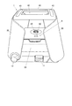
図1は、第1の実施形態に係る携帯型プリンタの構成を示す斜視図である。
なお、携帯型プリンタ1の各部の説明において、上下、左右、前後は図1に示す方向を言うものとする。また、本実施形態では、図1に示すように、携帯型プリンタ1が、インスタントカメラ10が設置部20に一体的に組み込まれている場合について説明するが、インスタントカメラ10と設置部20とを別体とし、インスタントカメラ10を設置部20に着脱可能とするように構成することも可能である。
[First Embodiment]
[Configuration of portable printer]
FIG. 1 is a perspective view showing the configuration of the portable printer according to the first embodiment.
In the description of each part of the
本実施形態では、インスタントカメラ10のシャッタ11が設置部20の前面側に設けられている。また、インスタントカメラ10内(設置部20内)に、所定枚数のフィルムが収容されるフィルムパック(不図示)をセットすることができるようになっており、シャッタ11が下向きに押されてインスタントカメラ10で画像が撮影されたフィルム(不図示)を設置部20の前面側に設けたハンドル12を回すことで、設置部20の側面に設けられた取り出し口13(後述する図2参照)から外部に取り出すこと(プリントアウト)ができるようになっている。
なお、このようにシャッタ11を下向きに押してインスタントカメラ10のシャッタを切るように構成すれば、シャッタ11を押下しても携帯型プリンタ1やインスタントカメラ10が水平方向(左右方向や前後方向)に動かないため、撮影された画像がぶれることが防止される効果がある。
In the present embodiment, the
If the
設置部20の左右端には、支持部30,30がそれぞれ回動可能(折り畳み可能)に取り付けられている。すなわち、本実施形態では、支持部30,30が設置部20に対していわば観音開きのようにして開いたり折り畳んだりすることができるようになっている。
そして、本実施形態では、支持部30,30は、開いた状態(すなわち後述する図3の下段参照)では、ユーザが折り畳むように力を加えない限り自立するようになっている。また、ユーザが折り畳むように力を加えると、支持部30,30は容易に折り畳まれるようになっている。
Supporting
And in this embodiment, the
本実施形態では、支持部30,30はそれぞれ板状に形成されており、図2に示すように、支持部30,30を設置部20の上方にそれぞれ折り畳んだ状態では、各支持部30,30の前後の端部がそれぞれ下方に垂れ下がるように湾曲している。
本実施形態では、支持部30,30をこのように構成することで、支持部30,30が設置部20に対して折り畳まれた状態では設置部20を覆う蓋になるように構成されている。そして、このように支持部30,30を設置部20に対して折り畳み可能とし、折り畳んだ状態で設置部20を覆う蓋になるように構成することで、ユーザが携帯型プリンタ1を持ち運び易くなるとともに、持ち運びの際に蓋(支持部30,30)で設置部20やインスタントカメラ10等を外部との衝突から守ることが可能となる。また、折り畳んだ支持部30,30が蓋になることで、インスタントカメラ10のレンズを汚れや傷から保護することが可能となるなど、蓋(支持部30,30)によりインスタントカメラ10のレンズが保護されるという効果もある。
In the present embodiment, the
In the present embodiment, the
そして、支持部30,30を広げた状態すなわち設置部20から立設させた状態(図1参照)で支持部30,30の各上端に跨るようにスマートフォンを載置するように構成してもよいが、本実施形態では、図3に示すように、スマートフォンSのディスプレイDを取り付けた枠体40を、スマートフォンSのディスプレイDを下向きにした状態で支持部30,30の上端に取り付けることで、枠体40を介して支持部30,30がディスプレイDを下向き(すなわちインスタントカメラ10と対向する向き)にしたスマートフォンSをインスタントカメラ10の上方に支持するようになっている。
なお、枠体40を介さずに、スマートフォンSを、下向きにした状態で支持部30,30に直接取り付けるように構成することも可能である。
そして、本実施形態の場合、図3に示すように、支持部30,30の上端側に設けられた係合部31,31と枠体40側の係合部41,41とを係合させて枠体40を支持部30,30に固定することで、支持部30,30により枠体40とスマートフォンSが安定的に支持されるようになるとともに、ディスプレイDが下向きにされたスマートフォンSが、支持部30,30によりインスタントカメラ10から上方に所定距離だけ離した状態で支持されるようになっている。そして、このように、ディスプレイDが下向きにされたスマートフォンSをインスタントカメラ10から上方に所定距離だけ離した状態で支持することで、スマートフォンSのディスプレイDがインスタントカメラ10のピントが合う位置に配置される状態になる。
And even if it comprises so that a smart phone may be mounted so that it may straddle each upper end of the
In addition, it is also possible to comprise so that the smart phone S may be directly attached to the
In the case of this embodiment, as shown in FIG. 3, the engaging
また、本実施形態では、枠体40には、開口部42の近傍に粘着部43が設けられており、スマートフォンSは、この粘着部43で粘着されることで枠体40に取り付けられるようになっている。
なお、図1や図3では、粘着部43が開口部42の左右に設けられている場合が示されているが、開口部42の前後やその周囲を取り囲むように設けられていてもよく、適宜の位置に設けることが可能である。また、例えば、枠体40に吸盤を設ける等してスマートフォンSを枠体40に吸着させて取り付けたり、スマートフォンSを枠体40にバンドで留めて取り付けたり、あるいは枠体40に留め具を設けておきこの留め具でスマートフォンSを枠体40に留めて取り付ける等するように構成することも可能であり、スマートフォンSが枠体40から脱落しないようにすることができればよく、スマートフォンSの枠体40への取り付け方は粘着に限定されない。
Moreover, in this embodiment, the
1 and 3, the case where the
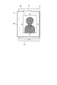
そして、スマートフォンSを枠体40に取り付ける際、図4に示すように、スマートフォンSのディスプレイDに表示されている画像が、枠体40の開口部42によりトリミングされる。すなわち、スマートフォンSのディスプレイDに表示されている画像のうち、枠体40の開口部42によりその一部が切り出され、それ以外の部分は枠体40により遮蔽される。そのため、ユーザは、スマートフォンSのディスプレイDにプリントアウトしたい画像を表示させた状態でスマートフォンSを枠体40に取り付ける際、プリントアウトしたい画像の部分が枠体40の開口部42内に適切に表示される状態にしてスマートフォンSを枠体40に取り付ける。
And when attaching the smart phone S to the
なお、本実施形態では、このように、枠体40の開口部42によりスマートフォンSのディスプレイDに表示されている画像がトリミングされる状態になる。そのため、例えば開口部42の形状や大きさ(それらのいずれか一方又は両方)が異なる複数の枠体40を備えるように構成し、枠体40を取り換えて画像がトリミングされる範囲を適宜変更することができるように構成することが可能である。
また、図2に示したように、支持部30,30を設置部20の上方にそれぞれ折り畳んだ状態で、設置部20やインスタントカメラ10と折り畳まれた状態の各支持部30,30との間に枠体40を収納することができるように構成することが可能である。このように構成すれば、支持部30,30を折り畳んだ状態で携帯型プリンタ1を持ち運ぶ際、枠体40をそれとは別に持ち運ぶ必要がなく、携帯型プリンタ1に収納して持ち運ぶことが可能となり、携帯型プリンタ1がユーザにとって便利になる。
In this embodiment, the image displayed on the display D of the smartphone S is trimmed by the
In addition, as shown in FIG. 2, between the
一方、本実施形態では、図1等に示すように、インスタントカメラ10の近傍には、ミラー50が設けられている。ミラー50は、図5に示すように支持部30,30に支持されたスマートフォンSのディスプレイDに表示されている画像を反射してユーザが視認できることができるようにするものである。
ミラー50は、インスタントカメラ10と設置部20のいずれに取り付けられていてもよい。
そして、本実施形態では、上記のように、2つの支持部30,30が設置部20に対して観音開きのようにして開かれ立設されると、スマートフォンSとインスタントカメラ10との間の空間Bを覆うようになるとともに、これらの支持部30,30によってスマートフォンSとインスタントカメラ10との間に開口が形成され、この開口が覗き窓A(図1や図5参照)になっている。ミラー50は、支持部30,30に支持されたスマートフォンSのディスプレイDに表示されている画像を反射して、ユーザはこの覗き窓Aを介してその画像を視認することができるようになっている。
On the other hand, in the present embodiment, a
The
In the present embodiment, as described above, when the two
この場合、ミラー50を、凸面鏡すなわちその鏡面が凸面とされるように形成されていることが好ましい。このように構成すれば、ミラー50が比較的小さいものであっても、スマートフォンSのディスプレイDに表示された画像(実際にはスマートフォンSのディスプレイDに表示された画像のうち枠体40の開口部42によりトリミングされた範囲の画像)の全体をミラー50で反射してユーザに視認可能とすることができる。
そして、本実施形態に係る携帯型プリンタ1は、このようにして支持部30,30により下向きに支持されたスマートフォンSのディスプレイDに表示されている画像を、その下方に配置されているインスタントカメラ10で撮影してプリントアウトすることができるようになっている。
In this case, the
And the
[携帯型プリンタでプリントアウトするまでの手順]
次に、本実施形態に係る携帯型プリンタ1で、スマートフォンSのディスプレイDに表示された画像を撮影してプリントアウトするまでの手順について説明するとともに、本実施形態に係る携帯型プリンタ1の作用についてもあわせて説明する。
[Procedure for printing out with a portable printer]
Next, the procedure until the
まず、ユーザは、スマートフォンSのディスプレイD上に、プリントアウトしたい画像を表示させる。そして、蓋を閉じた状態の携帯型プリンタ1(図2参照)を机等の上に置き、携帯型プリンタ1の蓋すなわち支持部30,30を設置部20に対して回動させて開いて起立させる(図3の下段参照)。
そして、枠体40を取り出し、図4に示したように、スマートフォンSのディスプレイD部分を枠体40に取り付ける。本実施形態の場合は、スマートフォンSのディスプレイDに枠体40の粘着部43を粘着させてスマートフォンSを枠体40に取り付ける。その際、枠体40の開口部42内にプリントアウトしたい画像が適切に表示されるように、画像の拡大率を調整したりディスプレイD上での画像の位置等を調整する。
First, the user displays an image to be printed out on the display D of the smartphone S. Then, the portable printer 1 (see FIG. 2) with the lid closed is placed on a desk or the like, and the lid of the
And the
そして、スマートフォンSのディスプレイDが下向きになる状態で、枠体40の係合部41,41をそれぞれ支持部30,30の係合部31,31と係合させて枠体40とスマートフォンSとを支持部30,30に固定する。
その際、本実施形態では、支持部30,30に支持されたスマートフォンSのディスプレイDに表示されている画像がミラー50で反射され、支持部30,30によって形成されスマートフォンSとインスタントカメラ10との間に形成された覗き窓A(図5等参照)を介してユーザがその画像を視認することができる。
Then, with the display D of the smartphone S facing downward, the
At this time, in the present embodiment, the image displayed on the display D of the smartphone S supported by the
そのため、ユーザは、ミラー50に反射される画像を見て、スマートフォンSのディスプレイDに画像が適切に表示されているか、すなわちプリントアウトしたい画像が表示されているか(枠体40やスマートフォンSを支持部30,30に固定する際に誤って画面に触れるなど何らかの操作を行ってしまい別の画像が表示されていないか)や画像の位置や縦横の向きが適切か(誤って画像の位置や向きが変更されていないか)、あるいはそもそも画像が表示されているか(誤って画像表示を終了していないか)等を的確に確認しながら、枠体40やスマートフォンSを支持部30,30に固定することが可能となる。
また、ユーザは、枠体40やスマートフォンSを支持部30,30に取り付けた後も、ミラー50に反射される画像を見て、プリントアウトしたい画像が枠体40の開口部42内に適切に表示されているかをチェックして確認することが可能となる。
しかも、本実施形態に係る携帯型プリンタ1では、上記のユーザによる確認動作を、スマートフォンSを枠体40や支持部30,30からいちいち取り外さなくてもミラー50に反射される画像を見ながら行うことが可能となるため、ユーザにとって非常に便利なものとなる。
Therefore, the user looks at the image reflected by the
In addition, even after the user attaches the
Moreover, in the
そして、ユーザは、上記のようにミラー50を介する上記の確認を行ったうえで、インスタントカメラ10のシャッタ11を押して撮影を行う。そして、ハンドル12を回すことで、取り出し口13(図2参照)からフィルムを取り出す。
本実施形態に係る携帯型プリンタ1では、以上のようにして、ユーザがミラー50を介してスマートフォンSのディスプレイDに画像が適切に表示されているかを確認しながら、スマートフォンSのディスプレイDに表示されている画像を適切にプリントアウトすることが可能となる。
The user performs the above confirmation through the
In the
なお、本実施形態に係る携帯型プリンタ1ではインスタントカメラ10が用いられており、フィルムがインスタントカメラ10内に正しくセットされていればフィルムが感光することはない。
そのため、本実施形態では、前述した特許文献2,3に記載されている従来の携帯型プリンタ等のようにスマートフォンSとインスタントカメラ10との間の空間B(図5参照)を覆って外部の光が全く入り込まないように構成する必要はなく、上記のように、2つの支持部30,30を開いた状態で、支持部30,30によって形成されスマートフォンSとインスタントカメラ10との間に覗き窓Aすなわち開口が形成されて空間B内に外部の光が装置内に入り込む状態になっても何ら問題はない。
In the
Therefore, in the present embodiment, the external space is covered with the space B (see FIG. 5) between the smartphone S and the
また、このようにスマートフォンSとインスタントカメラ10の間に外部の光が入り込むと、外部の光でスマートフォンSのディスプレイDに表示される画像が色褪せしてしまい、インスタントカメラ10で撮影されプリントアウトされるフィルム上でも画像が色褪せしてしまう可能性がある。
しかし、近年、スマートフォンSではディスプレイDの輝度が非常に高くなっており、本発明者らが研究を重ねた結果、スマートフォンSとインスタントカメラ10の間の空間Bを、その側面の全周のうち半分程度以上を支持部30,30で覆えば(すなわち上記の覗き窓Aとしての開口が空間Bの側面の全周のうち半分程度以下であれば)、覗き窓Aから外部の光が入り込んでも、スマートフォンSのディスプレイDに表示される画像を色褪せしない状態でインスタントカメラ10で撮影することができるという知見が得られた。以下の第2の実施形態も同様であるが、本実施形態に係る携帯型プリンタ1の発明はこのような知見に基づいてなされたものである。
In addition, when external light enters between the smartphone S and the
However, in recent years, the brightness of the display D has become very high in the smartphone S, and as a result of repeated researches by the present inventors, the space B between the smartphone S and the
[第2の実施の形態]
[携帯型プリンタの構成]
図6は、第2の実施形態に係る携帯型プリンタの構成を示す斜視図であり、図7は支持部の一部を構成する多段テレスコープ式アームの部分(すなわち蛇腹32を取り外した支持部30*の状態)を示す図である。
なお、携帯型プリンタ1*の各部の説明において、上下、左右、前後は図6に示す方向を言うものとする。また、本実施形態において、第1の実施形態と同様の構成や機能を有する部材については同じ符号を付して説明し、あるいは説明を省略する場合がある。さらに、本実施形態においても、図6に示すように、携帯型プリンタ1*が、インスタントカメラ10が設置部20に一体的に組み込まれている場合について説明するが、インスタントカメラ10と設置部20とを別体とし、インスタントカメラ10を設置部20に着脱可能とするように構成することも可能である。
[Second Embodiment]
[Configuration of portable printer]
FIG. 6 is a perspective view showing the configuration of the portable printer according to the second embodiment, and FIG. 7 is a portion of a multistage telescopic arm constituting a part of the support portion (that is, the support portion with the
In the description of each part of the
本実施形態では、支持部30*は、図6に示す蛇腹32と図7に示す伸縮自在の多段テレスコープ式アーム33等とで構成されている。すなわち、本実施形態では、インスタントカメラ10を取り囲むように設置部20の上面四隅にそれぞれ計4本の多段テレスコープ式アーム33が立設されており、多段テレスコープ式アーム33の上端には、枠体40を取り付けるための係合部31を含む矩形部材34が形成されている。
そして、各多段テレスコープ式アーム33を取り囲むように蛇腹32が配設されている。そして、蛇腹32の下端は設置部20に取り付けられており、蛇腹32の上端は矩形部材34に取り付けられている。
そして、各多段テレスコープ式アーム33は、所定の長さまで伸ばすとその長さを保つ状態になり、また、ユーザがそれらを長さ方向に縮めるように力を加えると容易に縮んで設置部20上に収まるようになっている。また、蛇腹32は、多段テレスコープ式アーム33の伸縮にあわせて伸縮するようになっている。
In the present embodiment, the
And the
Each
本実施形態では、このように、各多段テレスコープ式アーム33が所定の長さまで伸ばされるとその長さを維持するため、矩形部材34にスマートフォンS(図6や図7では図示省略。以下同じ。)を下向きに取り付けることで、各多段テレスコープ式アーム33や蛇腹32等で構成される支持部30*によりディスプレイDが下向きにされたスマートフォンSがインスタントカメラ10から上方に所定距離だけ離れた状態で(すなわちインスタントカメラ10のピントが合う位置に)支持されるようになっている。
なお、本実施形態においても、スマートフォンSを枠体40に取り付ける代わりに、枠体40を介さずに、スマートフォンSを下向きにした状態で支持部30*(例えば矩形部材34)に直接取り付けるように構成することも可能である。
また、各多段テレスコープ式アーム33を用いる代わりに、例えば特許文献3の図29に示されているようなリンク部材等を用いることも可能である。
In this embodiment, in this way, when each
In this embodiment, instead of attaching the smartphone S to the
Further, instead of using each
本実施形態では、上記のようにして、支持部30*、特に蛇腹32によって、スマートフォンSとインスタントカメラ10との間の空間Bが覆われるようになっている。そして、本実施形態では、図6に示すように、支持部30*を構成する蛇腹32の一部が切り取られて覗き窓Aが設けられている。すなわち、本実施形態では、支持部30*(蛇腹32)自体に覗き窓Aが形成されスマートフォンSとインスタントカメラ10との間に覗き窓Aが形成されている。
また、本実施形態においても、インスタントカメラ10の近傍に、ミラー50が設けられている。そして、ミラー50は、支持部30*(各多段テレスコープ式アーム33及び蛇腹32)に支持されたスマートフォンSのディスプレイDに表示されている画像を反射するようになっており、ユーザはこの覗き窓Aを介してミラー50で反射された画像を視認することができるようになっている。
In the present embodiment, the space B between the smartphone S and the
Also in the present embodiment, a
この場合も、ミラー50を、凸面鏡すなわちその鏡面が凸面とされるように形成されていることが好ましい。このように構成すれば、ミラー50が比較的小さいものであっても、スマートフォンSのディスプレイDに表示された画像(実際にはスマートフォンSのディスプレイDに表示された画像のうち枠体40の開口部42によりトリミングされた範囲の画像)の全体をミラー50で反射してユーザに視認可能とすることができる。
そして、本実施形態に係る携帯型プリンタ1*は、このようにして支持部30*により下向きに支持されたスマートフォンSのディスプレイDに表示されている画像を、その下方に配置されているインスタントカメラ10で撮影してプリントアウトすることができるようになっている。
Also in this case, it is preferable that the
Then, the
なお、本実施形態に係る携帯型プリンタ1*にスマートフォンSをセットし、スマートフォンSのディスプレイDに表示されている画像をインスタントカメラ10で撮影してプリントアウトするまでの手順は第1の実施形態に記載した手順と同様であり、本実施形態に係る携帯型プリンタ1*の作用についても第1の実施形態と同様であるため、説明を省略する。なお、本実施形態では、スマートフォンSを取り付けた枠体40を支持部30*の上端に取り付けた後、支持部(多段テレスコープ式アーム33や蛇腹32等)を上方に引き延ばしてセットするようにしてもよい。
また、図6では、覗き窓Aを蛇腹32の一面(図中の手前側の面)のみに設けた場合を示したが、例えば覗き窓Aを反対側の面(図中の奥側の面)や左右の面にも設けるように構成することも可能である。
The procedure from setting the smartphone S to the
Further, FIG. 6 shows the case where the observation window A is provided only on one surface of the bellows 32 (front surface in the drawing). For example, the observation window A is provided on the opposite surface (rear surface in the drawing). ) And the left and right surfaces can also be provided.
[効果]
以上のように、第1の実施形態及び第2の実施形態に係る携帯型プリンタ1,1*によれば、携帯型プリンタ1,1*の支持部30,30*に支持されたスマートフォンSのディスプレイDに表示されている画像を反射して、支持部30*(蛇腹32(図6参照))に形成され又は支持部30,30(図5等参照)によって形成されスマートフォンSとインスタントカメラ10との間に形成された覗き窓Aを介して視認可能とするミラー50を設けるように構成した。
そのため、特許文献2,3に示した従来の携帯型プリンタでは、ユーザが撮影時にスマートフォンSのディスプレイDに表示されている画像を確認できないままプリントアウトして初めてスマートフォンSのディスプレイDに画像が適切に表示されていないことに気付き、撮影をし直さなければならなくなって不便さを感じたり、プリントアウトしたフィルムが無駄になってしまう場合があったが、第1の実施形態及び第2の実施形態に係る携帯型プリンタ1,1*によれば、そのような事態は生じず、ユーザは、ミラー50を介してスマートフォンSのディスプレイDに画像が適切に表示されているかを確認しながら、スマートフォンSのディスプレイDに表示されている画像をインスタントカメラ10で撮影することが可能となり、フィルムを無駄にすることなく適切にプリントアウトすることが可能となる。そのため、携帯型プリンタ1,1*がユーザにとって非常に使い勝手がよいものとなる。
[effect]
As described above, according to the
Therefore, in the conventional portable printers shown in Patent Documents 2 and 3, the image is not suitable for the display D of the smartphone S until the user prints out without confirming the image displayed on the display D of the smartphone S at the time of shooting. In the first embodiment and the second embodiment, the user may notice that it is not displayed on the screen and feel that it is inconvenient because the user has to re-shoot, or the printed film may be wasted. According to the
なお、本発明は上記の実施形態に限定されず、本発明の趣旨を逸脱しない限り、適宜変更可能であることは言うまでもない。
すなわち、携帯型プリンタ1,1*の支持部は、蓋となり得る板状の支持部30,30(第1の実施形態)や、各多段テレスコープ式アーム33(あるいはリンク部材)と蛇腹32等で構成される支持部30*(第2の実施形態)に限定されず、ディスプレイDが下向きにされたスマートフォンSをインスタントカメラ10から上方に所定距離だけ離した状態で支持するとともに、スマートフォンSとインスタントカメラ10との間の空間Bを覆う(すなわち外部の光が空間Bに入り込むことを適度に遮光する)ことができるものであれば、他の構造を採用することも可能である。
Needless to say, the present invention is not limited to the above-described embodiment, and can be appropriately changed without departing from the gist of the present invention.
That is, the support portions of the
また、例えば、第1の実施形態(図1等参照)や第2の実施形態(図6、図7参照)では、ミラー50をインスタントカメラ10の一方側(図中の手前側)のみに配置する場合について説明したが、ミラー50をインスタントカメラ10の反対側(図中の奥側)にも配置する等して、ミラー50を複数箇所に設けるように構成することも可能である。
Further, for example, in the first embodiment (see FIG. 1 and the like) and the second embodiment (see FIGS. 6 and 7), the
1,1* 携帯型プリンタ
10 インスタントカメラ
20 設置部
30,30* 支持部
32 蛇腹(支持部)
33 多段テレスコープ式アーム(支持部)
34 矩形部材(支持部)
40 枠体
42 開口部
43 粘着部
50 ミラー
A 覗き窓
B 空間
D ディスプレイ
S スマートフォン(携帯電子機器)
1,1 *
33 Multistage telescopic arm (supporting part)
34 Rectangular member (support)
40
Claims (11)
ディスプレイが前記インスタントカメラと対向する向きにされた携帯電子機器を、当該ディスプレイが前記インスタントカメラから所定距離だけ離れた状態で支持するとともに、前記携帯電子機器と前記インスタントカメラとの間の空間を覆う支持部と、
前記支持部に支持された前記携帯電子機器のディスプレイに表示されている画像を反射して、前記支持部に又は前記支持部によって形成され前記携帯電子機器と前記インスタントカメラとの間に形成された覗き窓を介して視認可能とするミラーと、
を備え、
前記携帯電子機器のディスプレイに表示されている画像を前記インスタントカメラで撮影してプリントアウトすることを特徴とする携帯型プリンタ。 An instant camera,
A portable electronic device whose display is oriented to face the instant camera is supported in a state where the display is separated from the instant camera by a predetermined distance, and a space between the portable electronic device and the instant camera is covered. A support part;
An image displayed on the display of the portable electronic device supported by the support portion is reflected, and formed on the support portion or by the support portion and formed between the portable electronic device and the instant camera. A mirror that can be seen through a viewing window;
With
A portable printer, wherein an image displayed on a display of the portable electronic device is photographed by the instant camera and printed out.
前記インスタントカメラを設置可能な設置部と、
ディスプレイが下向きにされた携帯電子機器を、当該ディスプレイが前記インスタントカメラから上方に所定距離だけ離れた状態で支持するとともに、前記携帯電子機器と前記インスタントカメラとの間の空間を覆う支持部と、
前記支持部に支持された前記携帯電子機器のディスプレイに表示されている画像を反射して、前記支持部に又は前記支持部によって形成され前記携帯電子機器と前記インスタントカメラとの間に形成された覗き窓を介して視認可能とするミラーと、
を備え、
前記携帯電子機器のディスプレイに表示されている画像を前記インスタントカメラで撮影してプリントアウトすることを特徴とする携帯型プリンタ。 An instant camera,
An installation section capable of installing the instant camera;
A portable electronic device whose display is faced downward while the display is supported by a distance above the instant camera by a predetermined distance, and a support unit that covers a space between the portable electronic device and the instant camera;
An image displayed on the display of the portable electronic device supported by the support portion is reflected, and formed on the support portion or by the support portion and formed between the portable electronic device and the instant camera. A mirror that can be seen through a viewing window;
With
A portable printer, wherein an image displayed on a display of the portable electronic device is photographed by the instant camera and printed out.
前記ディスプレイが下向きにされた前記携帯電子機器が取り付けられた前記枠体が前記支持部に取り付けられることを特徴とする請求項1から請求項7のいずれか一項に記載の携帯型プリンタ。 A frame having an opening for trimming an image displayed on the display of the portable electronic device;
The portable printer according to any one of claims 1 to 7, wherein the frame body to which the portable electronic device with the display facing downward is attached to the support portion.
前記携帯電子機器は、前記粘着部により粘着されることで前記枠体に取り付けられることを特徴とする請求項8に記載の携帯型プリンタ。 The frame is provided with an adhesive part,
The portable printer according to claim 8, wherein the portable electronic device is attached to the frame body by being adhered by the adhesion portion.
前記枠体は、前記設置部と折り畳まれた状態の前記支持部との間に収納可能とされていることを特徴とする請求項8又は請求項9に記載の携帯型プリンタ。 The support part can be folded with respect to the installation part,
The portable printer according to claim 8 or 9, wherein the frame body can be stored between the installation portion and the support portion in a folded state.
Priority Applications (2)
| Application Number | Priority Date | Filing Date | Title |
|---|---|---|---|
| JP2017134332A JP6546964B2 (en) | 2017-07-10 | 2017-07-10 | Portable printer |
| US15/989,313 US10459320B2 (en) | 2017-07-10 | 2018-05-25 | Portable printer |
Applications Claiming Priority (1)
| Application Number | Priority Date | Filing Date | Title |
|---|---|---|---|
| JP2017134332A JP6546964B2 (en) | 2017-07-10 | 2017-07-10 | Portable printer |
Publications (2)
| Publication Number | Publication Date |
|---|---|
| JP2019014181A true JP2019014181A (en) | 2019-01-31 |
| JP6546964B2 JP6546964B2 (en) | 2019-07-17 |
Family
ID=64903158
Family Applications (1)
| Application Number | Title | Priority Date | Filing Date |
|---|---|---|---|
| JP2017134332A Expired - Fee Related JP6546964B2 (en) | 2017-07-10 | 2017-07-10 | Portable printer |
Country Status (2)
| Country | Link |
|---|---|
| US (1) | US10459320B2 (en) |
| JP (1) | JP6546964B2 (en) |
Families Citing this family (1)
| Publication number | Priority date | Publication date | Assignee | Title |
|---|---|---|---|---|
| USD873894S1 (en) * | 2018-06-07 | 2020-01-28 | Huifeng Huang | Waterproof camera cover |
Citations (5)
| Publication number | Priority date | Publication date | Assignee | Title |
|---|---|---|---|---|
| JPS63153979A (en) * | 1986-12-18 | 1988-06-27 | Olympus Optical Co Ltd | Crt photographing system |
| JPH05300413A (en) * | 1992-04-21 | 1993-11-12 | Sony Corp | Close-up photographing device |
| JP2004235756A (en) * | 2003-01-28 | 2004-08-19 | Victor Co Of Japan Ltd | Portable telephone set holder with ccd camera |
| JP2004294707A (en) * | 2003-03-26 | 2004-10-21 | Fuji Photo Film Co Ltd | Display screen photographing camera |
| JP4140047B2 (en) * | 2000-03-10 | 2008-08-27 | 富士フイルム株式会社 | Portable printer |
Family Cites Families (5)
| Publication number | Priority date | Publication date | Assignee | Title |
|---|---|---|---|---|
| US5802413A (en) | 1997-09-18 | 1998-09-01 | Eastman Kodak Company | Printer receiving electronic camera |
| US6963359B1 (en) * | 1997-10-23 | 2005-11-08 | Fuji Photo Film Co., Ltd. | Electronic still camera, instant printer and instant film |
| US7116355B1 (en) * | 1998-04-15 | 2006-10-03 | Fuji Photo Film Co., Ltd. | Instant printer, printing method for using the same, combination printer/electronic still camera system |
| JP2001045342A (en) | 1999-08-02 | 2001-02-16 | Nippon Polaroid Kk | Exposing device equipped with image display function and electronic camera equipped with exposing function and information terminal and portable communication equipment |
| JP2002094900A (en) * | 2000-09-12 | 2002-03-29 | Fuji Photo Film Co Ltd | Printer |
-
2017
- 2017-07-10 JP JP2017134332A patent/JP6546964B2/en not_active Expired - Fee Related
-
2018
- 2018-05-25 US US15/989,313 patent/US10459320B2/en not_active Expired - Fee Related
Patent Citations (5)
| Publication number | Priority date | Publication date | Assignee | Title |
|---|---|---|---|---|
| JPS63153979A (en) * | 1986-12-18 | 1988-06-27 | Olympus Optical Co Ltd | Crt photographing system |
| JPH05300413A (en) * | 1992-04-21 | 1993-11-12 | Sony Corp | Close-up photographing device |
| JP4140047B2 (en) * | 2000-03-10 | 2008-08-27 | 富士フイルム株式会社 | Portable printer |
| JP2004235756A (en) * | 2003-01-28 | 2004-08-19 | Victor Co Of Japan Ltd | Portable telephone set holder with ccd camera |
| JP2004294707A (en) * | 2003-03-26 | 2004-10-21 | Fuji Photo Film Co Ltd | Display screen photographing camera |
Also Published As
| Publication number | Publication date |
|---|---|
| US20190011810A1 (en) | 2019-01-10 |
| US10459320B2 (en) | 2019-10-29 |
| JP6546964B2 (en) | 2019-07-17 |
Similar Documents
| Publication | Publication Date | Title |
|---|---|---|
| KR101149925B1 (en) | Camera lens module for mobile phone | |
| JP3139920U (en) | Digital image display device having a photography function | |
| EP1558007B1 (en) | Foldable portable terminal device with extendable camera module | |
| EP2336821A1 (en) | Imaging device | |
| US8781311B1 (en) | Document holder for a portable imaging apparatus | |
| JP2015148720A (en) | Accessory apparatus attachment device and support table unit attachable to accessory apparatus attachment device | |
| JP2006235498A (en) | Photographic pod for camera | |
| JP2001251541A (en) | Camera provided with liquid crystal display device | |
| EP1732311A1 (en) | Image pickup device | |
| US9804480B2 (en) | Imaging apparatus stand | |
| JP2019014181A (en) | Portable printer | |
| JP2004135330A (en) | Shading assembly for display screen | |
| JP2005303524A (en) | Camera for calibration and calibration system | |
| JP4330462B2 (en) | Shading hood for LCD equipment | |
| JP5749842B2 (en) | Stereo viewer and / or stereo viewfinder | |
| JP2004208176A (en) | Portable terminal device | |
| JP4110268B2 (en) | camera | |
| KR20150025536A (en) | Multi-shot camera lens that is equipped with a Cell Phone Case | |
| JP2011142369A (en) | Portable electronic apparatus equipped with recording function | |
| CN112782926A (en) | Projection screen horizontal and vertical adjusting structure without pixel loss and projector | |
| CN214846205U (en) | Projection screen horizontal and vertical adjusting structure without pixel loss and projector | |
| CN220511184U (en) | Electronic equipment | |
| JP2014103642A (en) | Mounting fixture for mobile terminal | |
| JP7244907B2 (en) | Portable device viewer and portable device equipped with the same | |
| KR200353705Y1 (en) | View camera |
Legal Events
| Date | Code | Title | Description |
|---|---|---|---|
| A131 | Notification of reasons for refusal |
Free format text: JAPANESE INTERMEDIATE CODE: A131 Effective date: 20190115 |
|
| A521 | Request for written amendment filed |
Free format text: JAPANESE INTERMEDIATE CODE: A523 Effective date: 20190311 |
|
| A131 | Notification of reasons for refusal |
Free format text: JAPANESE INTERMEDIATE CODE: A131 Effective date: 20190402 |
|
| A521 | Request for written amendment filed |
Free format text: JAPANESE INTERMEDIATE CODE: A523 Effective date: 20190419 |
|
| TRDD | Decision of grant or rejection written | ||
| A01 | Written decision to grant a patent or to grant a registration (utility model) |
Free format text: JAPANESE INTERMEDIATE CODE: A01 Effective date: 20190604 |
|
| A61 | First payment of annual fees (during grant procedure) |
Free format text: JAPANESE INTERMEDIATE CODE: A61 Effective date: 20190624 |
|
| R150 | Certificate of patent or registration of utility model |
Ref document number: 6546964 Country of ref document: JP Free format text: JAPANESE INTERMEDIATE CODE: R150 |
|
| LAPS | Cancellation because of no payment of annual fees |