JP2019010507A - Fragrance tester - Google Patents

Fragrance tester Download PDF

Info

Publication number
JP2019010507A
JP2019010507A JP2018120385A JP2018120385A JP2019010507A JP 2019010507 A JP2019010507 A JP 2019010507A JP 2018120385 A JP2018120385 A JP 2018120385A JP 2018120385 A JP2018120385 A JP 2018120385A JP 2019010507 A JP2019010507 A JP 2019010507A
Authority
JP
Japan
Prior art keywords
fragrance
container
scent
ejection hole
container member
Prior art date
Legal status (The legal status is an assumption and is not a legal conclusion. Google has not performed a legal analysis and makes no representation as to the accuracy of the status listed.)
Pending
Application number
JP2018120385A
Other languages
Japanese (ja)
Inventor
井上 賢一
Kenichi Inoue
賢一 井上
Current Assignee (The listed assignees may be inaccurate. Google has not performed a legal analysis and makes no representation or warranty as to the accuracy of the list.)
PROMOTOOL CORP
Original Assignee
PROMOTOOL CORP
Priority date (The priority date is an assumption and is not a legal conclusion. Google has not performed a legal analysis and makes no representation as to the accuracy of the date listed.)
Filing date
Publication date
Application filed by PROMOTOOL CORP filed Critical PROMOTOOL CORP
Priority to PCT/JP2018/024449 priority Critical patent/WO2019004309A1/en
Publication of JP2019010507A publication Critical patent/JP2019010507A/en
Pending legal-status Critical Current

Links

Images

Landscapes

  • Disinfection, Sterilisation Or Deodorisation Of Air (AREA)
  • Packaging Of Annular Or Rod-Shaped Articles, Wearing Apparel, Cassettes, Or The Like (AREA)

Abstract

To provide a fragrance tester for jetting out efficiently an aromatic component to a user, while suppressing a used amount of a perfume, concerning a fragrance tester capable of appealing and trying fragrance with which a product is flavored.SOLUTION: A fragrance tester has a container body whose internal volume is changed, when the fragrance tester is pressed by external force, a perfume for vaporizing an aromatic component stored in the container body, an exhaust nozzle for discharging the vaporized aromatic component to the outside, following change of the internal volume of the container body, and a guide part for converging flow of the aromatic component formed on the inner surface of the container body and vaporized, toward the exhaust nozzle.SELECTED DRAWING: Figure 1

Description

本発明は、製品に着香されている香りを店頭等で購入者に訴求する際に使用する香りのテスターに関する。   The present invention relates to a scent tester used when appealing to a purchaser at a store or the like for a scent that is scented in a product.

従来から、店舗で香水、化粧品、洗剤、芳香剤、消臭剤、トイレタリー製品、防虫剤等香料が配合されている商品(製品)が販売される際、製品に着香されている香りが実際にどのような香りであるかを、購入者がそれらを購入する前に試すことができる香りテスターや香り見本が知られている。   Traditionally, when products (products) containing perfumes such as perfumes, cosmetics, detergents, fragrances, deodorants, toiletry products, insect repellents, etc. are sold in stores, the fragrances that are perfumed in the products are actually There are known scent testers and scent samples that can be purchased by a buyer before purchasing them.

実用新案登録第3144017号公報Utility Model Registration No. 3144017 特開2006−346406号明細書JP 2006-346406 A

特許文献1に記載の香りテスターは、香料収納体を台紙の香料収納体取付部に取り付けた状態で香料収納体取付部に予め形成した噴出孔から香料収納体の第2シート材に穴を開け、その後に台紙の折り曲げ可能な押圧部を折り曲げて香料収納体を香料収納体取付部と押圧部とで挟圧することで、容易に香りを噴出することができる香りテスターが開示されている。   The scent tester described in Patent Document 1 has a hole formed in the second sheet material of the fragrance storage body from the ejection hole previously formed in the fragrance storage body attachment portion in a state where the fragrance storage body is attached to the fragrance storage body attachment portion of the mount. And the fragrance tester which can squirt a fragrance easily by bend | folding the foldable press part of a base_sheet | mounting_paper and pinching a fragrance | flavor storage body with a fragrance | flavor storage body attaching part and a press part is disclosed.

特許文献2に記載の噴出装置は、人が使用する品物に取り付け、接触すると香りや有効成分が噴出する噴出容器が開示されている。特許文献2の図1に記載の発明では、噴出容器の両面テープ面に大小の適数の、口を設け、口位置を患部に貼ると、薬成分が接触のたびに患部に補給され、バンソウ膏状の貼り薬となる発明が開示されており、特許文献2の図2に記載の発明では、噴出容器に口や破線穴は単数か又は、複数設けてもよく、大きさも成分や製品に合わせ、適位置に設けた破線穴や口は、それぞれを剥離粘着シートで封をし、任意に開閉し、内部の成分の噴出を調節することにより、内容物(薬成分)をユーザーに対して噴出させて使用する発明が開示されている。   The ejection device described in Patent Document 2 discloses an ejection container in which a scent or an active ingredient is ejected when attached to an item used by a person and brought into contact therewith. In the invention described in FIG. 1 of Patent Document 2, when an appropriate number of large and small mouths are provided on the double-sided tape surface of the ejection container and the mouth position is affixed to the affected area, the drug component is replenished to the affected area every time contact is made. In the invention described in FIG. 2 of Patent Document 2, a single or a plurality of mouths or broken holes may be provided in the ejection container, and the sizes may be provided in the components and products. In addition, the broken holes and mouths provided at appropriate positions are sealed with a release adhesive sheet, opened and closed arbitrarily, and the contents (drug components) are controlled by the user by adjusting the ejection of internal components. An invention for use by jetting is disclosed.

しかしながら、特許文献1に記載の発明は、香料収納体とその香料収納体を取付け且つ噴出孔を有す香料収納体取付部と、この香料収納体取付部に取り付ける折り曲げた台紙からなる押圧部を構造として有しているため、構造が複雑で製造工程もまた複雑であり、量産に関して構造のシンプル化が求められていた。加えて、香料を吸収し、且つ復元力のあるスポンジ等でできた香料収納体が必ず必要となるため、どうしてもスポンジに必要量以上の香料が含浸されてしまい、香料の消費効率を考慮した構造ではなかった。更に、噴出孔から吹出す芳香成分を含む風は、スポンジで膨らんだ袋状の香料収納体を指で押した際に押し出される風であり、風圧、風量共に弱いため、テスターに鼻を近づけないと香りを感知しにくい。更には、噴出孔が小さいが、常に開放状態であるため、芳香成分が噴出孔から自然に放出され、テスターとしての持続性に改良の余地があった。   However, the invention described in Patent Document 1 includes a fragrance storage body, a fragrance storage body mounting portion to which the fragrance storage body is attached and having an ejection hole, and a pressing portion made of a folded mount to be attached to the fragrance storage body mounting portion. Since it has a structure, the structure is complicated and the manufacturing process is also complicated, and there has been a demand for simplification of the structure for mass production. In addition, since a fragrance container made of sponge or the like that absorbs fragrance and has resilience is indispensable, the sponge is impregnated with more than the necessary amount of fragrance, and the structure considering the consumption efficiency of the fragrance It wasn't. Furthermore, the wind containing the fragrance component that blows out from the spray hole is the wind that is pushed out when the bag-shaped fragrance container inflated with a sponge is pushed with a finger, and since the wind pressure and the air volume are both weak, the nose is not brought close to the tester. It is difficult to perceive the scent. Furthermore, although the ejection hole is small, the fragrance component is naturally released from the ejection hole because it is always open, and there is room for improvement in sustainability as a tester.

また、特許文献2の発明は、人が使用する品物に取り付けて、内容物(薬成分、香り)を補給する、又は加圧によって内容物を噴出させる構成であり、容器内における有効成分を効率よく、口又は破線穴から供給する構造は示唆されていない。この有効成分の供給効率によっては、当該有効成分を早く消費してしまうという場合も生じる。   In addition, the invention of Patent Document 2 is a structure that is attached to an article used by a person and replenishes the contents (medicine component, fragrance) or ejects the contents by pressurization. Well, there is no suggestion of a structure that feeds through the mouth or dashed hole. Depending on the supply efficiency of the active ingredient, the active ingredient may be consumed quickly.

そこで、本発明の香りテスターは、香料から揮散した芳香成分について、前記揮散した芳香成分の流れを前記噴出孔に向けて収斂させる誘導部を有することにより、容器本体の内部の容積を変化させると、前記芳香成分を高密度のまま前記噴出孔から噴出し、香料の消費を抑えながら、効率よくユーザーに芳香成分を噴出することができる香りテスターを提供する。   Therefore, the fragrance tester of the present invention has an induction part for converging the flow of the volatile aroma component toward the ejection hole for the fragrance component volatilized from the fragrance, thereby changing the volume inside the container body. The fragrance tester is capable of efficiently ejecting the fragrance component to the user while suppressing the consumption of the fragrance by ejecting the fragrance component from the ejection hole with a high density.

本発明に係る香りテスターは、製品に着香されている香りを訴求し、試させることができる香りテスターにおいて、外力によって押圧されると内部の容積が変化する容器本体と、前記容器本体内に収納される芳香成分を揮散する香料と、前記容器本体の内部容積の変化に伴って前記揮散した芳香成分を容器本体外に放出する噴出孔と、前記容器本体の内面に形成され前記揮散した芳香成分の流れを前記噴出孔に向けて収斂させる誘導部と、を有することを特徴とする。   The scent tester according to the present invention is a scent tester capable of appealing and trying a scent attached to a product, and a container body whose internal volume changes when pressed by an external force, and in the container body A fragrance that volatilizes the stored aroma component, an ejection hole that discharges the aroma component that has been volatilized in accordance with a change in the internal volume of the container body, and the volatilized aroma formed on the inner surface of the container body And a guiding portion for converging the component flow toward the ejection holes.

本発明に係る香りテスターの前記誘導部は、前記揮散した芳香成分の流れを整流させる凹型形状の湾曲面を有することを特徴とする。   The said induction | guidance | derivation part of the fragrance tester which concerns on this invention has a concave-shaped curved surface which rectifies | straightens the flow of the said fragrance | flavor component.

本発明に係る香りテスターの前記誘導部は、前記凹型形状の湾曲面を含む凹型のドーム形状に成形したものであることを特徴とする。   The guide portion of the scent tester according to the present invention is formed into a concave dome shape including the concave curved surface.

本発明に係る香りテスターの前記誘導部は、前記凹型形状の湾曲面を含む筒形状に成形したものであることを特徴とする。   The said guidance | induction part of the fragrance tester which concerns on this invention is shape | molded in the cylinder shape containing the said concave-shaped curved surface, It is characterized by the above-mentioned.

本発明に係る香りテスターは、前記ドーム形状或いは前記筒形状のうち前記香りの流れを収斂させる位置に前記噴出孔を配置したことを特徴とする。   The scent tester according to the present invention is characterized in that the ejection holes are arranged at positions where the scent flow is converged in the dome shape or the cylindrical shape.

本発明に係る香りテスターの前記噴出孔は、揮散した前記芳香成分を前記容器本体外に放出する時に開口する弁を有することを特徴とする。   The ejection hole of the scent tester according to the present invention is characterized in that it has a valve that opens when the volatilized aromatic component is discharged out of the container body.

本発明に係る香りテスターの前記容器本体は、外力によって押圧されると内部の容積が変化し、外力を排除した際に自力で元の形状に復元する自己復元性を有することを特徴とする。   The container body of the scent tester according to the present invention is characterized in that the internal volume changes when pressed by an external force, and has a self-restoring property that restores the original shape by itself when the external force is eliminated.

本発明に係る香りテスターの前記容器本体は、前記着香されている製品を模した形状及び/又は装飾を有することを特徴とする。   The container body of the scent tester according to the present invention is characterized in that it has a shape and / or decoration imitating the flavored product.

本発明に係る香りテスターは、容器本体を少なくとも2以上組合せ、前記容器本体は、前記容器本体内に収納される芳香成分を揮散する香料と、前記容器本体の内部容積の変化に伴って前記揮散した芳香成分を容器本体外に放出する噴出孔と、前記容器本体の内面に形成され前記揮散した芳香成分の流れを前記噴出孔に向けて収斂させる誘導部と、を有し、前記香料、前記噴出孔、及び誘導部は前記容器本体毎にそれぞれ分離していることを特徴とする。   The scent tester according to the present invention combines at least two container main bodies, and the container main body is a fragrance that volatilizes a fragrance component stored in the container main body, and the volatilization occurs as the internal volume of the container main body changes. An ejection hole that discharges the fragrance component outside the container body, and a guide part that is formed on the inner surface of the container body and converges the flow of the volatile component that has been volatilized toward the ejection hole, and the fragrance, The ejection hole and the guiding part are separated for each container body.

以上、説明したように、本発明によれば、香りテスターにおいて、外力による押圧で内部の容積が変化する容器本体と、前記容器本体内に収納されて芳香成分を揮散する香料と、前記容器本体の内部容積の変化に伴って前記揮散した芳香成分を容器本体外に放出する噴出孔と、その噴出孔に容器内の芳香成分が放出される時だけ開く弁と、前記容器本体の内面(以下内壁面)に形成され前記揮散した芳香成分の流れを前記噴出孔に向けて収斂させる誘導部と、を有することにより、香料から揮散する芳香成分を収束させて、前記噴出孔から高濃度の香りを噴出し、ユーザー(製品の購入者)に試してもらうことができる。   As described above, according to the present invention, in the scent tester, the container main body whose internal volume is changed by pressing with an external force, the fragrance that is stored in the container main body and volatilizes the fragrance component, and the container main body An ejection hole for releasing the volatilized fragrance component to the outside of the container body with a change in the internal volume, a valve that opens only when the fragrance component in the container is discharged into the ejection hole, And a guiding part for converging the flow of the volatile aroma component formed on the inner wall) toward the ejection hole, thereby converging the fragrance component volatilized from the fragrance so as to have a high concentration of fragrance from the ejection hole. Can be tried out by users (product purchasers).

また、芳香成分を揮散する香料を前記容器本体の内壁面に塗布又は付着等させることで、容器本体の内壁面を香料担体として機能させ、香料を担体に含浸させる下準備作業や、その担体を容器本体内に封入する作業を省略することができ、構造を簡略化することができる。   In addition, by applying or adhering the fragrance that volatilizes the fragrance component to the inner wall surface of the container body, the inner wall surface of the container body functions as a fragrance carrier, and the preparatory work for impregnating the fragrance into the carrier, or the carrier The operation | work enclosed with a container main body can be abbreviate | omitted, and a structure can be simplified.

芳香成分を誘導部で収斂させる際に、芳香成分を含む気体を誘導部や前記容器本体の内壁面に接触して通過させ、さらに前記誘導部や前記容器本体の内壁面に塗布又は付着された香料から芳香成分をさらに揮発させ、包含することによって、容器の噴出孔から噴出され、ユーザーに供給される芳香成分はより高濃度になる。以上のような仕組みによって、噴出孔から噴出される芳香成分が高濃度になるため、容器内に入れておく香料は少なくて良くなり、且つ容器内に香料を含浸させた担体を入れなくても香りテスターとして機能するので、香料が担体に無駄に吸収されてしまうことを防ぐことができ、香料の使用量を抑えることができる。   When condensing the fragrance component at the induction portion, the gas containing the fragrance component is allowed to pass through the induction portion or the inner wall surface of the container body, and further applied or adhered to the inner wall surface of the induction portion or the container body. By further volatilizing and including the fragrance component from the fragrance, the fragrance component ejected from the ejection hole of the container and supplied to the user has a higher concentration. Due to the above mechanism, the fragrance component ejected from the ejection hole becomes high in concentration, so that less fragrance can be put in the container, and there is no need to put a carrier impregnated with fragrance in the container. Since it functions as a fragrance tester, it is possible to prevent the fragrance from being absorbed by the carrier in vain and to reduce the amount of the fragrance used.

また、外力の例として、ユーザーが本発明の香りテスターを手で握りしめる外力を想定しているため、本発明の香りテスターの噴出孔から噴出する芳香成分を含んだ空気に勢いがあり、且つ指向性があるため、ユーザー(購入者)がテスターから離れていても容易にユーザーの鼻孔に到達させることができる。   Further, as an example of the external force, since the user assumes an external force to grip the scent tester of the present invention by hand, the air containing the fragrance component ejected from the ejection hole of the scent tester of the present invention has a momentum and is directed Therefore, even if the user (buyer) is away from the tester, the user's nostril can be easily reached.

また、前記容器本体の内壁面に形成された誘導部は、凹型形状の湾曲面、凹型のドーム形状、及び凹型形状の湾曲面を含む筒形状に成形可能であることから、容器本体の形状のデザインに自由度を持たせることができる。
デザインに自由度を持たせることにより、例えば、前記容器本体に、商品(製品)である化粧品のボトルデザインを模した成形や装飾を施すことができる。
In addition, the guide portion formed on the inner wall surface of the container body can be formed into a cylindrical shape including a concave curved surface, a concave dome shape, and a concave curved surface. Design can be given freedom.
By giving a degree of freedom to the design, for example, the container body can be molded or decorated to imitate a cosmetic bottle design as a product (product).

また、ドーム形状或いは前記筒形状のうち前記香りの流れを収斂させる位置に前記噴出孔を配置したことにより、噴出孔に向けて収斂した芳香成分の流れを、加速させて噴出させることができるので、噴出孔より遠方に、例えばユーザーの鼻孔に向けて指向性を持たせて効率よく噴出することができる。   Further, by arranging the ejection holes at positions where the flow of the fragrance is converged in the dome shape or the cylindrical shape, the flow of the aromatic component converged toward the ejection holes can be accelerated and ejected. Further, it can be efficiently ejected with directivity toward the user's nostril, for example, far away from the ejection hole.

また、噴出孔に弁を設けることにより、外力を加えない限り芳香成分が容器本体外に自然に放出されなくなるので、常時穴が開いている従来の香りテスターのように、テスターから周囲に常に香りが拡散することを防止するができる。また、香料の無駄使いを抑えることができる。   In addition, by providing a valve in the ejection hole, the fragrance component will not be released naturally outside the container body unless external force is applied. Can be prevented from spreading. Moreover, wasteful use of the fragrance can be suppressed.

また、前記容器本体は、外力を排除した際に自力で元の形状に復元する自己復元性を有するため、容器本体内にスポンジのような弾性力を有する香料収納体を入れることを必ずしも必要としない。また、ユーザーは使用後に容器本体の形状を戻す必要が無く、次の使用をすることができる。   Further, since the container body has a self-restoring property that restores the original shape by itself when the external force is excluded, it is not always necessary to put a fragrance container having an elastic force like a sponge in the container body. do not do. Further, the user does not need to return the shape of the container body after use, and can use the next.

容器本体を少なくとも2以上組合せた香りテスターは、前記容器本体毎に香料、前記噴出孔、及び誘導部がそれぞれ分離しており、前記容器本体毎に香料を変えることで、複数の香りを試すことができる。   In the scent tester in which at least two container bodies are combined, the fragrance, the ejection hole, and the guide part are separated for each container body, and a plurality of scents can be tested by changing the fragrance for each container body. Can do.

容器本体を少なくとも2以上組合せた香りテスターは、前記容器本体毎に香料、前記噴出孔、及び誘導部がそれぞれ分離しており、前記噴出孔は、他の噴出孔と相互に最も離間する前記容器本体の位置に設けることにより、前記香料を噴出時に異なる香料の匂いが混ざることを防ぐ事が出来る。   In the scent tester in which at least two container bodies are combined, the fragrance, the ejection hole, and the guide part are separated for each container body, and the ejection hole is the most spaced from the other ejection holes. By providing at the position of the main body, it is possible to prevent the fragrances of different fragrances from being mixed when the fragrance is ejected.

また、本発明の香りテスターでは、構造をシンプルにし、量産を容易にした。   In addition, the scent tester of the present invention has a simple structure and facilitates mass production.

図1(A)は本発明の実施形態1に係る香りテスターの斜視図、図1(B)は図1(A)のI方向の断面図である。図1(C)は図1(A)のII方向の断面図である。FIG. 1A is a perspective view of a scent tester according to Embodiment 1 of the present invention, and FIG. 1B is a cross-sectional view in the I direction of FIG. FIG. 1C is a cross-sectional view in the II direction of FIG. 図2(A)は図1(A)の容器本体の内部容積が外力による押圧で変化した場合を示す図、図2(B)は図2(A)のIII方向の断面図である。図2(C)は図2(A)のIV方向の断面図である。2A is a view showing a case where the internal volume of the container body of FIG. 1A is changed by pressing with an external force, and FIG. 2B is a cross-sectional view in the III direction of FIG. 2A. FIG. 2C is a cross-sectional view in the IV direction of FIG. 図3は実施形態1に係る香りテスターの誘導部の他形状の例を示した側部断面図である。FIG. 3 is a side sectional view showing another example of the shape of the guiding portion of the scent tester according to the first embodiment. 図4(A)は本発明の実施形態2に係る香りテスターの斜視図、図4(B)は図4(A)の側部断面図のV方向の断面図である。図4(C)は図4(A)のVI方向(噴出孔方向)の断面図である。4A is a perspective view of a scent tester according to Embodiment 2 of the present invention, and FIG. 4B is a cross-sectional view in the V direction of the side cross-sectional view of FIG. 4A. FIG. 4C is a cross-sectional view in the VI direction (injection hole direction) of FIG. 図5(A)は本発明の図4の容器本体の内部容積が外力による押圧で変化した場合を示す図、(B)は図5(A)のVII方向の断面図、図5(C)は図5(A)のVIII方向(噴出孔方向)の断面図である。5A is a view showing a case where the internal volume of the container body of FIG. 4 of the present invention is changed by pressing with an external force, FIG. 5B is a cross-sectional view in the VII direction of FIG. 5A, and FIG. These are sectional drawings of the VIII direction (ejection hole direction) of Drawing 5 (A). 図6は本発明の実施形態2に係る香りテスターの誘導部の他の使用例を示した図である。FIG. 6 is a view showing another example of use of the scent tester guiding portion according to Embodiment 2 of the present invention. 図7(A)及び図7(B)は本発明の実施形態3に係る香りテスターの容器本体の斜視図である。7 (A) and 7 (B) are perspective views of the container body of the scent tester according to Embodiment 3 of the present invention. 図8(A)は本発明の実施形態4に係る容器本体の斜視図、図8(B)は図8(A)のIX方向の断面図、図8(C)は本発明の図8(B)の容器本体の内部容積が変化した場合を示す断面図である。8A is a perspective view of a container body according to Embodiment 4 of the present invention, FIG. 8B is a cross-sectional view in the IX direction of FIG. 8A, and FIG. 8C is FIG. It is sectional drawing which shows the case where the internal volume of the container main body of B) changes. 図9(A)乃至(C)は本発明の実施形態1乃至実施形態4に係る香りテスターの外装の成形及び装飾の例を示した斜視図である。FIGS. 9A to 9C are perspective views illustrating an example of molding and decoration of the exterior of the scent tester according to Embodiments 1 to 4 of the present invention. 図10(A)乃至(E)は本発明の複数の容器本体を有する香りテスターの例を示した図である。FIGS. 10A to 10E are views showing examples of a scent tester having a plurality of container bodies of the present invention. 図11(A)乃至(F)は本発明の実施形態1乃至実施形態5に係る香りテスターの設置部材の例を示した斜視図である。FIGS. 11A to 11F are perspective views showing examples of installation members for fragrance testers according to Embodiments 1 to 5 of the present invention. 図12(A)乃至(D)は本発明の実施形態2に係る香りテスターの設置部材の例を示した図である。FIGS. 12A to 12D are views showing examples of the installation member of the scent tester according to Embodiment 2 of the present invention. 図13(A)乃至(D)は本発明の実施形態2に係る香りテスターの他の設置部材の例を示した図である。13A to 13D are diagrams showing examples of other installation members of the scent tester according to Embodiment 2 of the present invention.

以下、本発明の実施形態を図面に基づいて詳細に説明する。
[実施形態1]
先ず図1(A)乃至(C)、図2(A)乃至(C)及び図3を参照して、本発明の実施形態1を説明する。
Hereinafter, embodiments of the present invention will be described in detail with reference to the drawings.
[Embodiment 1]
First, Embodiment 1 of the present invention will be described with reference to FIGS. 1A to 1C, FIGS. 2A to 2C, and FIG.

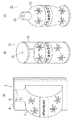
図1(A)は本発明の実施形態1に係る香りテスターの斜視図、図1(B)は図1(A)のI方向の断面図、図1(C)は図1(A)のII方向の断面図であり、図2(A)は図1(A)の容器本体の内部容積が変化した場合を示す図、図2(B)は図2(A)のIII方向の断面図、図2(C)は図2(A)のIV方向の断面図である。
ある。
1A is a perspective view of a fragrance tester according to Embodiment 1 of the present invention, FIG. 1B is a cross-sectional view in the I direction of FIG. 1A, and FIG. 1C is the view of FIG. 2A is a cross-sectional view in the II direction, FIG. 2A is a view showing a case where the internal volume of the container body in FIG. 1A is changed, and FIG. 2B is a cross-sectional view in the III direction in FIG. FIG. 2C is a cross-sectional view in the IV direction of FIG.
is there.

香りテスター1は、図1(A)乃至(C)に示すように、容器本体2は第1容器部材3及び第2容器部材4からなり、第1容器部材3には噴出孔5と弁6と誘導部7とが設けられる。また、容器本体2は、香料9を密閉する内部空間である芳香成分収納部8を形成するように、第1容器部材3の縁部と第2容器部材4の縁部とが密着されて形成される。   As shown in FIGS. 1A to 1C, the scent tester 1 includes a container body 2 including a first container member 3 and a second container member 4. The first container member 3 has an ejection hole 5 and a valve 6. And a guiding portion 7 are provided. Further, the container body 2 is formed by adhering the edge of the first container member 3 and the edge of the second container member 4 so as to form the fragrance component storage portion 8 which is an internal space for sealing the fragrance 9. Is done.

第1容器部材3は、容器本体が押圧されると内部容積の変化が生じた後に自力で元の形状に戻る自己復元性を有し、芳香成分が容器本体外部に漏出しない素材であるポリプロピレン、ポリエチレン等の耐薬品性のある合成樹脂やゴム、合成ゴム等の弾力性のある素材を用いて作られると好適である。   The first container member 3 has a self-restoring property that returns to its original shape by itself after a change in the internal volume occurs when the container body is pressed, and is a polypropylene that is a material that does not allow the fragrance component to leak out of the container body. It is preferable to use a synthetic material having chemical resistance such as polyethylene, or an elastic material such as rubber or synthetic rubber.

また、香料9を第1容器部材3の芳香成分収納部8側の内壁面に塗布又は付着させることにより、香料9の担体としての機能を持たせても良い。   Moreover, you may give the function as a support | carrier of the fragrance | flavor 9 by apply | coating or adhering the fragrance | flavor 9 to the inner wall surface by the side of the fragrance | flavor component storage part 8 of the 1st container member 3.

また、芳香成分収納部8側の内壁面を香料9が含浸可能な素材で構成し、香料の含浸体としての機能を持たせても良い。但しその場合は第1容器部材3の外側を香料、油及び水分が浸潤、漏出せず、且つガスバリア性のあるアルミ箔やアルミ蒸着フィルム等で覆う必要がある。又は、第1容器部材3の内壁面、外側をアルミ蒸着しても良い。   Further, the inner wall surface on the fragrance component storage portion 8 side may be made of a material that can be impregnated with the fragrance 9 and may have a function as an impregnated body of the fragrance. However, in that case, it is necessary to cover the outer side of the first container member 3 with an aluminum foil, an aluminum vapor deposition film, or the like that does not allow perfume, oil, and moisture to infiltrate or leak and has gas barrier properties. Alternatively, the inner wall surface and the outer side of the first container member 3 may be evaporated by aluminum.

また、第1容器部材3の芳香成分収納部8側の内壁面を、不整面や凹凸、溝等を設けることにより、香料9を塗布、付着又は含浸させ易い構造にすると好適である。   In addition, it is preferable that the inner wall surface of the first container member 3 on the side of the fragrance component storage unit 8 be provided with an irregular surface, unevenness, groove, or the like so that the fragrance 9 can be easily applied, adhered or impregnated.

噴出孔5は、第1容器部材3に貫通して設けられた孔で、第1容器部材3と一体成形した薄膜の弁6を有し、外力による押圧で容器本体の内部容積の変化が生じた際は、香料から揮散し芳香成分収納部8に溜まっている芳香成分10を容器本体2の外部に排出し、容器本体が外力を排除して自力で元の形状に復元する場合には、外部の空気を芳香成分収納部8に吸い込む機能を有する。噴出孔5は、誘導部7により前記ドーム形状或いは前記筒形状のうち芳香成分10の流れを収斂させる位置に配置する。つまり、噴出孔5は芳香成分10の流れを収斂させる位置であれば、第1容器部材3の何れの位置に設けても良い。   The ejection hole 5 is a hole provided through the first container member 3, and has a thin film valve 6 integrally formed with the first container member 3, and a change in the internal volume of the container body is caused by pressing by an external force. When the fragrance component 10 volatilized from the fragrance and accumulated in the fragrance component storage unit 8 is discharged to the outside of the container main body 2, the container main body eliminates external force and restores the original shape by itself. It has a function of sucking outside air into the aroma component storage unit 8. The ejection hole 5 is disposed at a position where the flow of the fragrance component 10 is converged in the dome shape or the cylindrical shape by the guide portion 7. That is, the ejection hole 5 may be provided at any position of the first container member 3 as long as it is a position where the flow of the fragrance component 10 is converged.

また、噴出孔5の孔径は約0.5〜2.0mm程度の大きさで良く、孔径を小さくすることで、噴出孔5から噴出する香りの流れを絞り、加速させて遠方まで到達させることができるが、孔径は1mm程度が好適である。但し、このサイズに限定されない。   Moreover, the hole diameter of the ejection hole 5 may be about 0.5 to 2.0 mm, and by reducing the hole diameter, the flow of the scent ejected from the ejection hole 5 is narrowed and accelerated to reach far away. However, the hole diameter is preferably about 1 mm. However, it is not limited to this size.

弁6は、噴出孔5を塞ぐように、第1容器部材3と一体成形で設けられた、開閉可能な薄膜の弁である。外力による押圧で容器本体2の内部容積の変化が生じた場合は、弁6は、空気圧によって芳香成分収納部8側から第1容器部材3の外側に向かって開口し、芳香成分収納部8内部から芳香成分10を容器本体2の外部に排出する機能を有する。また、容器本体2が外力を排除して自力で元の形状に復元する場合には、弁6は、第1容器部材3の外側から芳香成分収納部8内部に向かって開口し、外部の空気を芳香成分収納部8内部に吸い込む機能を有する。   The valve 6 is a thin film valve that can be opened and closed and is integrally formed with the first container member 3 so as to close the ejection hole 5. When the internal volume of the container main body 2 changes due to pressing by an external force, the valve 6 opens from the fragrance component storage portion 8 side to the outside of the first container member 3 by the air pressure, and the fragrance component storage portion 8 inside The fragrance component 10 is discharged from the container body 2 to the outside. In addition, when the container body 2 eliminates external force and restores to its original shape by itself, the valve 6 opens from the outside of the first container member 3 toward the inside of the fragrance component storage unit 8 and external air Is sucked into the fragrance component storage portion 8.

また、容器本体2の内部容積が変化しない平静時には、弁6は、噴出孔5を塞ぐ位置に静止し、芳香成分10が容器本体2の内部(芳香成分収納部8)から噴出孔5を通って自然に放出されることを防止する機能を有する。   Further, when the inner volume of the container body 2 does not change, the valve 6 stops at a position where the ejection hole 5 is blocked, and the fragrance component 10 passes through the ejection hole 5 from the inside of the container body 2 (fragrance component storage portion 8). And has a function of preventing spontaneous release.

なお、図1(B)及び図2(B)に示す弁6は、噴出孔5を左右2枚の弁で塞いで開閉する構造を説明しているが、噴出孔5を1枚以上の弁で塞いで開閉可能な構造であれば良く、特に限定する物ではない。また、弁6は、第1容器部材3と一体成形で設けられた構造について説明しているが、弁6を第1容器部材3と別体で成型し、噴出孔5を塞いで開閉可能に設けるようにしても良い。   In addition, although the valve 6 shown to FIG. 1 (B) and FIG. 2 (B) has demonstrated the structure opened and closed by closing the ejection hole 5 with two right and left valves, the ejection hole 5 is one or more valves. Any structure can be used as long as it can be closed and opened, and is not particularly limited. In addition, the valve 6 has been described with respect to the structure provided integrally with the first container member 3, but the valve 6 is molded separately from the first container member 3 and can be opened and closed by closing the ejection hole 5. You may make it provide.

このように、噴出孔5の孔径を小さくし、弁6を設けることで、芳香成分10が容器本体2の内部から噴出孔5を通って自然に放出されることを防止し、香料9の使用量を抑えることができる。   Thus, by reducing the diameter of the ejection hole 5 and providing the valve 6, the fragrance component 10 is prevented from being naturally released from the inside of the container body 2 through the ejection hole 5, and the use of the fragrance 9 is used. The amount can be reduced.

誘導部7は、第1容器部材3を立体成形して形成され芳香成分収納部8の一部を構成すると共に、容器本体2が押圧され内部容積の変化が生じた際に芳香成分収納部8に溜まっている芳香成分10の流れを噴出孔5に向けて収斂させる機能を有する。誘導部7の形状は、図1(B)に示す様に、第1容器部材3の誘導部7が立設する位置から、凹型形状の湾曲面を含む凹型のドーム形状に形成されており、芳香成分10が滞りなく噴出孔5まで流れ、収斂させる形状を有している。   The guide portion 7 is formed by three-dimensionally molding the first container member 3 and constitutes a part of the fragrance component storage portion 8, and the fragrance component storage portion 8 when the container body 2 is pressed to change the internal volume. It has a function of converging the flow of the fragrance component 10 accumulated in the nozzle 5 toward the ejection hole 5. The shape of the guide part 7 is formed in a concave dome shape including a concave curved surface from the position where the guide part 7 of the first container member 3 is erected as shown in FIG. The fragrance component 10 has a shape that flows to the ejection holes 5 without any stagnation and converges.

第2容器部材4は、第1容器部材3の縁部と第2容器部材4の縁部とが密着し密閉する内部空間である芳香成分収納部8を形成する。香料9を第1容器部材3の芳香成分収納部8側の内壁面に塗布又は付着させることにより、香料9の担体としての機能を持たせても良い。
第2容器部材4は、香料9が容器本体2の外部に浸潤・漏出しない素材であるポリプロピレン、ポリエチレン等の耐薬品性のある合成樹脂等の素材を用いて作られると好適である。また、自己復元性を有する素材であることが望ましく、第1容器部材3と同一の素材を用いても良い。
The 2nd container member 4 forms the fragrance component accommodating part 8 which is an internal space which the edge part of the 1st container member 3 and the edge part of the 2nd container member 4 closely_contact | adhere and seal. By applying or adhering the fragrance 9 to the inner wall surface of the first container member 3 on the fragrance component storage portion 8 side, the fragrance 9 may have a function as a carrier.
The second container member 4 is preferably made of a material such as polypropylene or polyethylene, which is a material from which the fragrance 9 does not infiltrate or leak out of the container body 2, and the like. Moreover, it is desirable that the material has a self-restoring property, and the same material as that of the first container member 3 may be used.

また、第2容器部材4の芳香成分収納部8側の内壁面を香料9が含浸可能な素材で構成し、香料の含浸体としての機能を持たせても良い。但しその場合は第2容器部材4の外側を香料、油及び水分が浸潤、漏出せず、且つガスバリア性のあるアルミ箔やアルミ蒸着フィルム等で覆う必要がある。   Moreover, the inner wall surface of the second container member 4 on the side of the fragrance component storage portion 8 may be made of a material that can be impregnated with the fragrance 9 and may have a function as an impregnated body of the fragrance. However, in that case, it is necessary to cover the outer side of the second container member 4 with an aluminum foil, an aluminum vapor deposition film, or the like that does not allow perfume, oil, and moisture to infiltrate and leak out.

第2容器部材4もまた、芳香成分収納部8側の内壁面を、不整面や凹凸、溝等を設けることにより、香料9を塗布、付着又は含浸させ易い構造にすると好適である。
また、第1容器部材3と同様に、第2容器部材4にも誘導部7を立体成形し、自己復元性を有するようにしても良い。
It is preferable that the second container member 4 also has a structure in which the fragrance 9 can be easily applied, adhered, or impregnated by providing an irregular surface, irregularities, grooves, or the like on the inner wall surface on the fragrance component storage portion 8 side.
Similarly to the first container member 3, the guide part 7 may be three-dimensionally formed on the second container member 4 so as to have self-restoring properties.

芳香成分収納部8は、前述のように、第1容器部材3の縁部と第2容器部材4の縁部とが密着されて囲まれて設けられた密閉空間である。図1(A)及び図3に示すように、芳香成分収納部8は誘導部7が立設して作る空間にほぼ包含される。芳香成分収納部8の内部には、香料9が揮発して生成される芳香成分10が浮遊する。そして外力によって容器本体2が押圧されると、当該芳香成分収納部8内部の揮発した芳香成分は誘導部7に誘導されて芳香成分収納部8の唯一の開口部である噴出孔5に収斂され、弁6が開き、ここから外部に放出されることになる。   As described above, the fragrance component storage unit 8 is a sealed space that is provided so that the edge of the first container member 3 and the edge of the second container member 4 are in close contact with each other. As shown in FIGS. 1A and 3, the fragrance component storage portion 8 is substantially included in a space formed by the guide portion 7 standing upright. In the fragrance component storage unit 8, the fragrance component 10 generated by volatilization of the fragrance 9 floats. When the container body 2 is pressed by an external force, the volatilized fragrance component inside the fragrance component storage portion 8 is guided to the guide portion 7 and converged in the ejection hole 5 that is the only opening of the fragrance component storage portion 8. The valve 6 is opened and discharged from here.

香料9は、常温で芳香成分10が揮散する粘度のある液体、もしくはペースト状、ゼリー状であって、第1容器部材3及び第2容器部材4の双方又は一方の内壁面に塗布又は付着され、この香料9から揮散する芳香成分10が、密閉空間である芳香成分収納部8に充満する。   The fragrance | flavor 9 is the liquid with the viscosity which the fragrance | flavor component 10 volatilizes at normal temperature, or a paste form and a jelly form, Comprising: It applies or adheres to both the 1st container member 3 and the 2nd container member 4, or one inner wall surface. The fragrance component 10 volatilized from the fragrance 9 fills the fragrance component storage portion 8 which is a sealed space.

また、香料9は第1容器部材3及び第2容器部材4の内壁面に塗布又は付着させる方法の他に、シリカゲル、不織布、フェルト、紙材、樹脂、セラミック、セルロース等の保持材に香料を含浸させた担体や、香料を顆粒状もしくは粉末状にした物を芳香成分収納部8や誘導部7に設置するようにしても良い(図9参照)。   Moreover, the fragrance | flavor 9 adds a fragrance | flavor to holding materials, such as a silica gel, a nonwoven fabric, felt, a paper material, resin, a ceramic, a cellulose other than the method of apply | coating or adhering to the inner wall surface of the 1st container member 3 and the 2nd container member 4. An impregnated carrier or a product in which a fragrance is granulated or powdered may be installed in the fragrance component storage unit 8 or the induction unit 7 (see FIG. 9).

次に、図3について説明する。図3は、誘導部17の形状の例を示す断面図であり、誘導部17は芳香成分10の流れを整流させる凹型形状の湾曲面の形状を有している。このように、誘導部17は湾曲面を含み芳香成分収納部18に揮散している芳香成分10が滞りなく噴出孔15まで流れ、収斂させる形状であればどのような形状でも良い。   Next, FIG. 3 will be described. FIG. 3 is a cross-sectional view showing an example of the shape of the guiding portion 17, and the guiding portion 17 has a concave curved surface shape that rectifies the flow of the fragrance component 10. In this way, the guiding portion 17 may have any shape as long as it has a curved surface and the fragrance component 10 volatilized in the fragrance component storage portion 18 flows to the ejection hole 15 without stagnation and converges.

また、誘導部17にも、香料19を塗布又は付着させることにより、香料19の担体としての機能を持たせることができる。この場合、誘導部17の担体となる面を、不整面や凹凸、溝等を設けることにより、香料19を塗布又は付着させ易い構造にすると好適である。   Moreover, the function as a support | carrier of the fragrance | flavor 19 can be given also to the induction | guidance | derivation part 17 by apply | coating or adhering the fragrance | flavor 19 to it. In this case, it is preferable that the surface serving as the carrier of the guiding portion 17 is provided with an irregular surface, irregularities, grooves, or the like so that the fragrance 19 can be easily applied or adhered.

このように、図1(A)及び図3に示す、誘導部7、17の何れの形状においても、容器本体2、12の何れの位置が変形して内部容積の変化が生じた場合でも、芳香成分10を、噴出孔5、15に向けて収斂させることができる機能を有している。誘導部7、17は、芳香成分10を噴出孔5、15に向けて収斂させることで、噴出孔5、15から噴出する芳香成分10をユーザーに供給(噴出)することが可能となる。   As described above, in any shape of the guiding portions 7 and 17 shown in FIGS. 1A and 3, even when any position of the container main bodies 2 and 12 is deformed to change the internal volume, The aromatic component 10 has a function capable of converging toward the ejection holes 5 and 15. The guiding parts 7 and 17 can supply (spout) the fragrance component 10 ejected from the ejection holes 5 and 15 to the user by converging the fragrance component 10 toward the ejection holes 5 and 15.

なお、図3に示す、容器本体12、第1容器部材13、第2容器部材14、噴出孔15、弁16、誘導部17、芳香成分収納部18、及び香料19は、図1(A)乃至(C)に示す香りテスター1と同様な構成、機能を有しているので、詳細な説明は省略する。   In addition, the container main body 12, the 1st container member 13, the 2nd container member 14, the ejection hole 15, the valve | bulb 16, the guidance | induction part 17, the fragrance | flavor component accommodating part 18, and the fragrance | flavor 19 shown in FIG. Since it has the structure and function similar to the fragrance tester 1 shown to thru | or (C), detailed description is abbreviate | omitted.

次に、香りテスター1の容器本体2が外力を加えられて内部容積の変化が生じる際の動作について図2(A)乃至(C)を用いて説明する。   Next, an operation when the container body 2 of the scent tester 1 is subjected to an external force to cause a change in the internal volume will be described with reference to FIGS.

図2(A)乃至(C)は、容器本体2の第1容器部材3に外力が加えられた状態を示す図である。第1容器部材3に外力が加わり、押圧されると芳香成分収納部8の容積の変化が生じ、芳香成分10を含む芳香成分収納部8内部の空気が押し出され、誘導部7に誘導されて、噴出孔5に収斂される。   2A to 2C are views showing a state in which an external force is applied to the first container member 3 of the container body 2. When an external force is applied to the first container member 3 and pressed, the volume of the fragrance component storage portion 8 changes, and the air inside the fragrance component storage portion 8 including the fragrance component 10 is pushed out and guided to the guide portion 7. And converged in the ejection holes 5.

このとき、図2(B)及び図2(C)に示すように、容器本体2内の芳香成分10を含む空気は、第1容器部材3の内壁面からなる誘導部7及び第2容器部材4の誘導部7に誘導されつつ、1回〜複数回にわたって第1容器部材3と第2容器部材4の誘導部7に衝突や接触を繰り返して、噴出孔5に向かって流れることで、誘導部7(第1容器部材3及び第2容器部材4)の内壁面に塗布された香料9から芳香成分10をさらに拾い、包含することで濃度を増しつつ噴出孔5に収斂され、弁6を押し開き、芳香成分10を含む空気は噴出孔5からユーザーに向けて供給(噴出)される。   At this time, as shown in FIGS. 2 (B) and 2 (C), the air containing the fragrance component 10 in the container body 2 is converted into the guiding portion 7 and the second container member made of the inner wall surface of the first container member 3. 4 while being guided by the guiding part 7 of the fourth container, repeatedly colliding and contacting the guiding part 7 of the first container member 3 and the second container member 4 once to a plurality of times and flowing toward the ejection hole 5, thereby guiding The fragrance component 10 is further picked up from the fragrance 9 applied to the inner wall surface of the portion 7 (the first container member 3 and the second container member 4), and the concentration is increased so that the concentration is increased. The air containing the fragrance component 10 is pushed (opened) from the ejection hole 5 toward the user.

このように、本発明による香りテスター1から噴出される芳香成分10は高濃度となるので、容器本体2に入れておく香料9の使用量は極めて少なくて良く、結果として製造コストを抑えることができるので、効果的で経済性の高い香りテスター1となる。   As described above, since the fragrance component 10 ejected from the fragrance tester 1 according to the present invention has a high concentration, the amount of the fragrance 9 to be put in the container body 2 may be extremely small, and as a result, the manufacturing cost can be suppressed. Therefore, the fragrance tester 1 is effective and economical.

また、噴出孔5の孔径を小さくすることで、噴出孔5から噴出する香り(芳香成分10)の流れを絞り、加速させ、ユーザーの鼻孔付近に指向性を持たせて着実に芳香成分10を到達させることができ、また、噴出孔5に設けた弁6により芳香成分収納部8内部の芳香成分10が噴出孔5から自然に放出されることを防ぐことができるので、少量の香料9で効率よく香りをユーザーに供給(噴出)することが可能となり、より効果的で経済的な香りテスター1を実現することができる。   Further, by reducing the diameter of the ejection hole 5, the flow of the scent (fragrance component 10) ejected from the ejection hole 5 is throttled and accelerated, and the fragrance component 10 is steadily imparted with directivity in the vicinity of the user's nostril. Since the fragrance component 10 inside the fragrance component storage portion 8 can be prevented from being naturally released from the ejection hole 5 by the valve 6 provided in the ejection hole 5, a small amount of the fragrance 9 can be used. The scent can be efficiently supplied (spouted) to the user, and a more effective and economical scent tester 1 can be realized.

[実施形態2]
次に、図4及び図5を参照して、実施形態2を説明する。図4(A)は本発明の実施形態2に係る香りテスターの斜視図、図4(B)は図4(A)の側部断面図のV方向の断面図、図4(C)は図4(A)のVI方向(噴出孔方向)の断面図である。図5(A)は本発明の図4の容器本体の内部容積が変化した場合を示す図、図5(B)は図5(A)のVII方向の断面図、図5(C)は図5(A)のVIII方向(噴出孔方向)の断面図である。
[Embodiment 2]
Next, Embodiment 2 will be described with reference to FIGS. 4 and 5. 4A is a perspective view of a fragrance tester according to Embodiment 2 of the present invention, FIG. 4B is a cross-sectional view in the V direction of the side cross-sectional view of FIG. 4A, and FIG. It is sectional drawing of VI direction (ejection hole direction) of 4 (A). 5A is a view showing a case where the internal volume of the container main body of FIG. 4 of the present invention is changed, FIG. 5B is a cross-sectional view in the VII direction of FIG. 5A, and FIG. It is sectional drawing of the VIII direction (ejection hole direction) of 5 (A).

香りテスター21の容器本体22は、中空の円筒形の第1容器部材23及び円形の蓋状の第2容器部材24a、及び円形の底面状の第3容器部材24bとからなり、蓋状の第2容器部材24aには噴出孔25が設けられ、噴出孔25は開閉可能な弁26で塞がれており、容器本体22の円筒形内部側には誘導部27が設けられる。また、容器本体22の内部には円筒形の密閉空間として、芳香成分10を密閉する芳香成分収納部28が形成されている。   The container body 22 of the scent tester 21 includes a hollow cylindrical first container member 23, a circular lid-shaped second container member 24a, and a circular bottom-shaped third container member 24b. The two container member 24 a is provided with an ejection hole 25, which is closed by a valve 26 that can be opened and closed, and a guide portion 27 is provided on the cylindrical inner side of the container body 22. In addition, a fragrance component storage portion 28 for sealing the fragrance component 10 is formed inside the container body 22 as a cylindrical sealed space.

第1容器部材23は、略円筒形で構成され、第1容器部材23の円筒部内側には誘導部27が設けられている。   The first container member 23 has a substantially cylindrical shape, and a guide portion 27 is provided inside the cylindrical portion of the first container member 23.

第1容器部材23は中空の円筒形の形状を有し、外力によって押圧され変形しても、自力で元の形状に戻る自己復元性を有し、且つ、香料が容器本体外部に浸潤・漏出しない素材であるポリプロピレンやポリエチレン等の耐薬品性のある合成樹脂や弾力性のあるゴム、合成ゴム等の素材を用いて作られると好適である。また、香料29を第1容器部材23の芳香成分収納部28側の内壁面に塗布又は付着させる構成を採用することにより、香料29の担体としての機能を持たせても良い。   The first container member 23 has a hollow cylindrical shape, has a self-restoring property that returns to its original shape by itself even when pressed and deformed by an external force, and perfume infiltrates and leaks outside the container body. It is preferable to use a material such as polypropylene or polyethylene, which is a material that is not used, or a material such as a synthetic resin having chemical resistance, elastic rubber, or synthetic rubber. Moreover, you may give the function as a support | carrier of the fragrance | flavor 29 by employ | adopting the structure which apply | coats or adheres the fragrance | flavor 29 to the inner wall surface by the side of the fragrance | flavor component accommodating part 28 of the 1st container member 23.

また、芳香成分収納部28側の内壁面を香料29が含浸可能な素材で構成し、香料の含浸体としての機能を持たせても良い。但し、その場合は第1容器部材23の外側を香料、油及び水分が浸潤・漏出せず、且つガスバリア性のあるアルミやアルミ蒸着フィルム等で覆う必要がある。   Further, the inner wall surface on the side of the fragrance component storage unit 28 may be made of a material that can be impregnated with the fragrance 29 and may have a function as an impregnated body of the fragrance. However, in that case, it is necessary to cover the outer side of the first container member 23 with aluminum, an aluminum vapor deposition film, or the like that does not allow perfume, oil, and moisture to infiltrate or leak and has gas barrier properties.

また、第1容器部材23の芳香成分収納部28側の内壁面を、不整面や凹凸、溝等を設けることにより、香料29を塗布、付着又は含浸させ易い構造にすると好適である。   In addition, it is preferable that the inner wall surface of the first container member 23 on the fragrance component storage portion 28 side is provided with an irregular surface, irregularities, grooves, or the like so that the fragrance 29 can be easily applied, adhered or impregnated.

第2容器部材24aは、容器本体22の蓋状の形状を有し、噴出孔25、弁26及び、芳香成分収納部28側の内壁面には誘導部27が設けられている。
また、第3容器部材24bは、容器本体22の底面の蓋の形状を有している。
第2容器部材24a及び第3容器部材24bは、香料29が容器本体22の外部に漏出しない素材であるポリプロピレン、ポリエチレン等の耐薬品性のある合成樹脂等の素材を用いて作られると好適である。また、自己復元性を有する素材であることが望ましく、第1容器部材23と同一の素材を用いても良い。
The second container member 24 a has a lid-like shape of the container body 22, and a guide part 27 is provided on the inner surface of the ejection hole 25, the valve 26, and the fragrance component storage part 28.
Further, the third container member 24 b has a shape of a lid on the bottom surface of the container main body 22.
The second container member 24a and the third container member 24b are preferably made using a material such as a chemical-resistant synthetic resin such as polypropylene or polyethylene, which is a material from which the fragrance 29 does not leak out of the container body 22. is there. Moreover, it is desirable that the material has a self-restoring property, and the same material as the first container member 23 may be used.

また、第2容器部材24a及び第3容器部材24bの芳香成分収納部28側の内壁面を香料29が含浸可能な素材で構成し、香料の含浸体としての機能を持たせても良い。但しその場合は第2容器部材24a及び第3容器部材24bの外側を香料、油及び水分が浸潤、漏出せず、且つガスバリア性のあるアルミ箔やアルミ蒸着フィルム等で覆う必要がある。   Further, the inner wall surfaces of the second container member 24a and the third container member 24b on the fragrance component storage portion 28 side may be made of a material that can be impregnated with the fragrance 29, and may have a function as an impregnated body of the fragrance. However, in that case, it is necessary to cover the outer sides of the second container member 24a and the third container member 24b with an aluminum foil, an aluminum vapor deposition film, or the like that does not allow perfume, oil and moisture to infiltrate or leak out.

また、第2容器部材24a及び第3容器部材24bの芳香成分収納部28側の内壁面を、不整面や凹凸、溝等を設けることにより、香料29を塗布、付着又は含浸させ易い構造にすると好適である。   Further, the inner wall surfaces of the second container member 24a and the third container member 24b on the fragrance component storage portion 28 side are provided with irregular surfaces, irregularities, grooves, etc., so that the fragrance 29 can be easily applied, adhered or impregnated. Is preferred.

なお、第1容器部材23、第2容器部材24a及び第3容器部材24bの接合は、例えば、第1容器部材23のそれぞれの端部に、第2容器部材24a及び第3容器部材24bをキャップのようにネジ式で嵌合する(図示せず)方法、第1容器部材23のそれぞれの端部と第2容器部材24a及び第3容器部材24bの縁部に接合用の溝を設け嵌合する方法(図示せず)、及び、第1容器部材23のそれぞれの端部に、第2容器部材24a及び第3容器部材24bを接着する(熱溶着等)方法、等、容器本体22の内部に円筒形の密閉空間である芳香成分収納部28が形成される接合方法であれば、限定することなく何れの接合方法を用いても良い。   The first container member 23, the second container member 24a, and the third container member 24b are joined, for example, by capping the second container member 24a and the third container member 24b at the respective end portions of the first container member 23. As shown in FIG. 4, a screw-type fitting method (not shown), a fitting groove is provided at each end of the first container member 23 and the edges of the second container member 24a and the third container member 24b. The interior of the container body 22, such as a method (not shown), a method of bonding the second container member 24 a and the third container member 24 b to each end of the first container member 23 (thermal welding, etc.), etc. Any joining method may be used without limitation as long as it is a joining method in which the aromatic component storage portion 28 that is a cylindrical sealed space is formed.

噴出孔25は、噴出孔5と同様の構成を有している。すなわち、噴出孔25は、第2容器部材24aに貫通して設けられた孔で、第2容器部材24aと一体成形した薄膜の弁26を有し、容器本体22が外力による押圧等で内部容積の変化を生じた際は、芳香成分収納部28に揮散している芳香成分10を第2容器部材24aに貫通して設けられた噴出孔25から容器本体22の外部に排出し、第1容器部材23が外力を排除した際に自力で元の形状に復元する場合には、外部の空気を芳香成分収納部28に吸い込む機能を有する。噴出孔25は、誘導部27により前記筒形状のうち前記芳香成分10の流れを収斂させる位置に配置する。つまり、噴出孔25は芳香成分10の流れを収斂させる位置であれば、第2容器部材24aの何れの位置に設けても良い。或いは、図6に示すように、香りテスター21を横方向に使用して、噴出孔25を第1容器部材23の何れの位置に設けるようにしても良い。   The ejection hole 25 has the same configuration as the ejection hole 5. That is, the ejection hole 25 is a hole penetrating the second container member 24a and has a thin film valve 26 integrally formed with the second container member 24a. When the change occurs, the fragrance component 10 volatilized in the fragrance component storage portion 28 is discharged to the outside of the container body 22 from the ejection hole 25 provided through the second container member 24a, and the first container When the member 23 restores the original shape by itself when the external force is removed, the member 23 has a function of sucking outside air into the fragrance component storage unit 28. The ejection hole 25 is disposed at a position where the flow of the fragrance component 10 is converged in the cylindrical shape by the guide portion 27. That is, the ejection hole 25 may be provided at any position of the second container member 24a as long as it is a position where the flow of the fragrance component 10 is converged. Alternatively, as shown in FIG. 6, the scent tester 21 may be used in the lateral direction and the ejection hole 25 may be provided at any position of the first container member 23.

弁26は、噴出孔25を塞ぐように、第2容器部材24aと一体成形で設けられた薄膜の弁である。なお、弁26は弁6と同様な構成、機能を有しているので、詳細な説明は省略する。   The valve 26 is a thin film valve that is integrally formed with the second container member 24 a so as to close the ejection hole 25. Since the valve 26 has the same configuration and function as the valve 6, detailed description thereof is omitted.

なお、図4(B)及び図5(B)に示す弁26は、噴出孔25を左右2枚の弁で塞いで開閉する構造を説明しているが、噴出孔25を1枚の弁で塞いで開閉する構造等、特に限定するものではない。また、弁26は、第2容器部材24aと一体成形で設けられた構造について説明しているが、弁26を第2容器部材24aと別体で成型し、噴出孔25を塞いで開閉可能に設けるようにしても良い。   In addition, although the valve 26 shown to FIG. 4 (B) and FIG. 5 (B) has demonstrated the structure opened and closed by closing the ejection hole 25 with two right and left valves, the ejection hole 25 is formed with one valve. There is no particular limitation on the structure that opens and closes by closing. In addition, the valve 26 has been described with respect to a structure that is integrally formed with the second container member 24a. However, the valve 26 is formed separately from the second container member 24a and can be opened and closed by closing the ejection hole 25. You may make it provide.

誘導部27は、誘導部7と同様に、第1容器部材23の内壁面に形成され芳香成分収納部28の一部を構成すると共に、容器本体22が押圧されて内部容積の変化が生じた際に芳香成分収納部28に揮散している芳香成分10の流れを噴出孔25に向けて収斂させる機能を有する。誘導部27の形状は、図4(B)及び図4(C)に示す様に、第1容器部材23の第3容器部材24b側端部から、第2容器部材24aの端部までの間、及び、第2容器部材24aの端部から噴出孔25までの間に設けられる。また、誘導部27の芳香成分収納部28側にも、香料29を塗布することにより、香料29の担体としての機能も有する。この場合、誘導部27の担体となる面を、不整面や凹凸、溝等を設けることにより、香料29を塗布又は付着させ易い構造にすると好適である。   The guide part 27 is formed on the inner wall surface of the first container member 23 and constitutes a part of the fragrance component storage part 28 as well as the guide part 7, and the container body 22 is pressed to change the internal volume. At this time, it has a function of converging the flow of the fragrance component 10 volatilized in the fragrance component storage portion 28 toward the ejection hole 25. As shown in FIGS. 4 (B) and 4 (C), the shape of the guide portion 27 is from the end portion on the third container member 24b side of the first container member 23 to the end portion of the second container member 24a. And between the end of the second container member 24a and the ejection hole 25. Further, by applying the fragrance 29 to the fragrance component storage section 28 side of the guide section 27, it also has a function as a carrier of the fragrance 29. In this case, it is preferable that the surface serving as the carrier of the guiding portion 27 is provided with an irregular surface, irregularities, grooves, or the like so that the fragrance 29 can be easily applied or adhered.

誘導部27は、容器本体22の何れの位置が変形して内部容積の変化が起こった場合でも、芳香成分10を、噴出孔25に向けて収斂させることができる機能を有している。誘導部27は、噴出孔25に向けて芳香成分10を収斂させることで、濃度を高めた芳香成分10を噴出孔25から噴出することが可能となる。   The guiding portion 27 has a function of allowing the fragrance component 10 to converge toward the ejection hole 25 even when any position of the container body 22 is deformed to change the internal volume. The guide part 27 can eject the fragrance component 10 whose concentration is increased from the ejection hole 25 by converging the fragrance component 10 toward the ejection hole 25.

特に第2容器部材24aの端部から噴出孔25までの間は芳香成分10が流れやすいように、傾斜を付けて噴出孔25に流れを収斂させることができるように成形することが望ましい。   In particular, it is desirable to form an inclined portion so that the flow can be converged in the ejection holes 25 so that the fragrance component 10 can easily flow from the end of the second container member 24a to the ejection holes 25.

芳香成分収納部28は、図4(B)に示すように、第1容器部材23の端部と、第2容器部材24aの縁部及び第2容器部材24bの縁部とが密着されて囲まれて設けられた円筒形の密閉空間である。芳香成分収納部28内部には、香料29が揮発して生じた芳香成分10が浮遊する。そして容器本体22が押圧されて内部容積の変化が生じた際は、当該芳香成分収納部28が押圧され、内部の揮散している芳香成分10が誘導部27に誘導されて芳香成分収納部28の唯一の開口部である噴出孔25に収斂され、放出される。   As shown in FIG. 4B, the fragrance component storage portion 28 is surrounded by the end portion of the first container member 23, the edge portion of the second container member 24a, and the edge portion of the second container member 24b being in close contact with each other. It is a cylindrical sealed space provided. The fragrance component 10 generated by the volatilization of the fragrance 29 floats inside the fragrance component storage portion 28. When the container main body 22 is pressed and the internal volume changes, the fragrance component storage portion 28 is pressed, and the volatile component 10 that has been volatilized inside is guided to the guide portion 27 and the fragrance component storage portion 28. It is converged in the ejection hole 25 which is the only opening part of and is discharged.

香料29は、前述の香料9と同じ物で良く、詳細な説明を省略する。   The fragrance | flavor 29 may be the same thing as the above-mentioned fragrance | flavor 9, and abbreviate | omits detailed description.

次に、香りテスター21の容器本体22が外力を加えられて内部容積の変化が生じる際の動作について図5(A)乃至(C)を用いて説明する。   Next, the operation when the container body 22 of the scent tester 21 is subjected to an external force to cause a change in the internal volume will be described with reference to FIGS.

図5(A)乃至(C)は、容器本体22の第1容器部材23に外力が加えられた状態を示す図である。容器本体22に外力が加わり芳香成分収納部8が押圧されると、芳香成分収納部28の容積に変化が生じ、芳香成分10を含む芳香成分収納部28内部の空気が押し出され、誘導部27に誘導されて、円筒の頂上部分に設けられた噴出孔25に収斂され、そして放出される。   5A to 5C are views showing a state in which an external force is applied to the first container member 23 of the container body 22. When an external force is applied to the container body 22 and the fragrance component storage unit 8 is pressed, the volume of the fragrance component storage unit 28 changes, and the air inside the fragrance component storage unit 28 including the fragrance component 10 is pushed out, and the guide unit 27 In other words, it is converged in the ejection hole 25 provided in the top portion of the cylinder and discharged.

このとき、芳香成分10を含む空気の流れは、図5(B)及び図5(C)に示すように、第1容器部材23の誘導部27及び第2容器部材24aの誘導部27に誘導されつつ、1回〜複数回にわたって第1容器部材23と第2容器部材24aの誘導部27に衝突や接触を繰り返して、噴出孔25に向かって流れることで、誘導部27(第1容器部材23及び第2容器部材24a)の内壁面に塗布された香料29からさらに芳香成分10を拾い、包含することで、芳香成分10の濃度を増しつつ噴出孔25に収斂され、弁26を押し開き、芳香成分10を含む空気は噴出孔25からユーザーに向けて供給(噴出)される。   At this time, the flow of air containing the fragrance component 10 is guided to the guide portion 27 of the first container member 23 and the guide portion 27 of the second container member 24a as shown in FIGS. 5 (B) and 5 (C). In addition, the collision of the first container member 23 and the second container member 24a and the guidance of the second container member 24a are repeated and flowed toward the ejection hole 25 one to several times. 23 and the fragrance component 10 further picked up and contained from the fragrance 29 applied to the inner wall surface of the second container member 24a), the concentration of the fragrance component 10 is increased and converged in the ejection hole 25, and the valve 26 is pushed open. The air containing the fragrance component 10 is supplied (spouted) toward the user from the spout hole 25.

このように、本発明の香りテスター21から噴出される芳香成分10は高濃度となるので、容器本体22に入れておく香料29の使用量は極めて少なくて良く、結果として製造コストを抑えることができるので、効果的で経済性の高い香りテスター21となる。   As described above, since the fragrance component 10 ejected from the fragrance tester 21 of the present invention has a high concentration, the amount of the fragrance 29 to be put in the container body 22 may be extremely small, and as a result, the manufacturing cost can be suppressed. Therefore, the fragrance tester 21 is effective and economical.

また、噴出孔25の孔径を小さくすることで、噴出孔25から噴出する香り(芳香成分10)の流れを絞り、加速させ、ユーザーの鼻孔付近に指向性を持たせて着実に芳香成分10を到達させることができ、また、噴出孔25に設けた弁26により、芳香成分収納部28内部の芳香成分10が噴出孔25から自然に放出されることを防ぐことができるので、少量の香料で効率よく香りをユーザーの鼻孔に供給(噴出)することが可能となり、より効果的で経済的な香りテスター21を実現することができる。   Further, by reducing the diameter of the ejection hole 25, the flow of the scent (fragrance component 10) ejected from the ejection hole 25 is throttled and accelerated, and the fragrance component 10 is steadily imparted with directivity in the vicinity of the user's nostril. Since the fragrance component 10 in the fragrance component storage portion 28 can be prevented from being naturally released from the ejection hole 25 by the valve 26 provided in the ejection hole 25, a small amount of fragrance can be used. The scent can be efficiently supplied (spouted) to the user's nostril, and a more effective and economical scent tester 21 can be realized.

[実施形態3]
次に、本発明の実施形態3について、図7(A)及び図7(B)を用いて説明する。実施形態3は実施形態2の第2容器部材24a及び第2容器部材24bを変形したものである。
[Embodiment 3]
Next, Embodiment 3 of the present invention will be described with reference to FIGS. 7 (A) and 7 (B). The third embodiment is a modification of the second container member 24a and the second container member 24b of the second embodiment.

図7(A)に示す香りテスター31aは、容器本体32aとして、第1容器部材33a及び底状の第2容器部材34aからなり、第1容器部材33aの底面部側の開口部の端部とを第2容器部材34aの縁部とで密着し、第1容器部材33aの上側の端部34bを、シールや熱可塑性による封印等により密着し噴出孔35aを容器本体32aに設けた構造である。この構造では、第1容器部材33aの上側の端部34bをシールや熱可塑性によって封印とすることで、第2容器部材34aと同等の部材を省略することができる。   The scent tester 31a shown in FIG. 7A is composed of a first container member 33a and a bottom-like second container member 34a as the container body 32a, and the end of the opening on the bottom surface side of the first container member 33a. Is closely adhered to the edge of the second container member 34a, the upper end 34b of the first container member 33a is closely adhered by a seal or a seal by thermoplasticity, and the ejection hole 35a is provided in the container body 32a. . In this structure, a member equivalent to the second container member 34a can be omitted by sealing the upper end 34b of the first container member 33a with a seal or thermoplasticity.

図7(B)に示す香りテスター31bの容器本体32bは、第1容器部材33aからなり、第1容器部材33aの開口部の両端をシールや熱可塑性による封印等により密着し、噴出孔35bを容器本体32bに設けた構造である。この構造では、第1容器部材33aの端部34c、34dの両方をシールや熱可塑性によって封印することで、第2容器部材34a、34bと同等の部材を省略することができる。   The container body 32b of the scent tester 31b shown in FIG. 7 (B) is composed of a first container member 33a, and the both ends of the opening of the first container member 33a are in close contact with each other by sealing or sealing with thermoplasticity. It is the structure provided in the container main body 32b. In this structure, by sealing both ends 34c and 34d of the first container member 33a with a seal or thermoplasticity, members equivalent to the second container members 34a and 34b can be omitted.

なお、香りテスター31a、31bの何れも、弁36a、36b(図示せず)、及び誘導部37a、37b(図示せず)を実施形態2と同様に設置される。容器本体32a、32bの何れの位置が変形して内部容積の変化が生じた場合でも、芳香成分10を、噴出孔35a、35bに向けて収斂させることができる機能を有しているので、容器本体32a、32bの内部で揮発して生成される芳香成分10は誘導部37a、37b(図示せず)で噴出孔35a、35bに向けて誘導され、収斂されて、噴出孔35a、35bから供給(噴出)することができる。   In each of the scent testers 31a and 31b, the valves 36a and 36b (not shown) and the guide portions 37a and 37b (not shown) are installed in the same manner as in the second embodiment. Even if any of the positions of the container main bodies 32a and 32b is deformed to change the internal volume, the fragrance component 10 has a function of converging toward the ejection holes 35a and 35b. The fragrance component 10 generated by volatilization inside the main bodies 32a and 32b is guided toward the ejection holes 35a and 35b by the guiding portions 37a and 37b (not shown), converged, and supplied from the ejection holes 35a and 35b. (Squirt).

[実施形態4]
次に、本発明の実施形態4について、図8(A)乃至(C)を用いて説明する。図8(A)は本発明の実施形態4に係る容器本体の斜視図、図8(B)は図8(A)のIX方向の断面図、図8(C)は本発明の図8(B)の容器本体の内部容積が変化した場合を示す断面図である。実施形態4は、前記実施形態1乃至実施形態3の香料9,19,29に代えて、香料を多孔質のビーズやスポンジ等に含浸させた担体49を使用する例である。
[Embodiment 4]
Next, Embodiment 4 of the present invention will be described with reference to FIGS. 8A is a perspective view of a container body according to Embodiment 4 of the present invention, FIG. 8B is a cross-sectional view in the IX direction of FIG. 8A, and FIG. 8C is FIG. It is sectional drawing which shows the case where the internal volume of the container main body of B) changes. The fourth embodiment is an example in which a carrier 49 in which a perfume is impregnated with porous beads, sponge or the like is used instead of the perfumes 9, 19, and 29 of the first to third embodiments.

香りテスター41の容器本体42は、中空の円筒形の第1容器部材43及び円形の蓋状の第2容器部材44a、及び円形の底面状の第3容器部材44bとからなり、蓋状の第2容器部材44aには噴出孔45が設けられ、噴出孔45は開閉可能な弁46で塞がれており、容器本体42の円筒形内側には誘導部47が設けられる。また、容器本体42の内部には円筒形の密閉空間として、香料を含浸する担体49を密閉する芳香成分収納部48が形成されている。   The container body 42 of the scent tester 41 includes a hollow cylindrical first container member 43, a circular lid-shaped second container member 44a, and a circular bottom-shaped third container member 44b. The two container member 44 a is provided with an ejection hole 45, which is closed by an openable / closable valve 46, and a guide portion 47 is provided inside the cylindrical body of the container body 42. In addition, a fragrance component storage portion 48 for sealing the carrier 49 impregnated with the fragrance is formed inside the container body 42 as a cylindrical sealed space.

誘導部47は、誘導部7、27と同様に、第1容器部材43の内壁面に形成され芳香成分収納部48の一部を構成すると共に、容器本体42が押圧されて内部容積の変化が生じた際に芳香成分収納部48に格納された香料を含浸した担体49から揮散する芳香成分10の流れを噴出孔45に向けて収斂させる機能を有する。誘導部47の形状は、図8(B)及び図8(C)に示す様に、第1容器部材43の第3容器部材44b側端部から、第2容器部材44aの端部までの間、及び、第2容器部材44aの端部から噴出孔45までの間に設けられる。   The guide portion 47 is formed on the inner wall surface of the first container member 43 to form a part of the fragrance component storage portion 48 as well as the guide portions 7 and 27, and the container body 42 is pressed to change the internal volume. When it occurs, it has a function of converging the flow of the fragrance component 10 volatilized from the carrier 49 impregnated with the fragrance stored in the fragrance component storage portion 48 toward the ejection hole 45. As shown in FIGS. 8B and 8C, the shape of the guide portion 47 is from the end portion of the first container member 43 on the third container member 44b side to the end portion of the second container member 44a. And between the end of the second container member 44a and the ejection hole 45.

誘導部47は、容器本体42の何れの位置が変形して内部容積の変化が生じた場合でも、芳香成分10を、噴出孔45に向けて収斂させることができる機能を有している。誘導部47は、噴出孔45に向けて芳香成分10を収斂し、噴出孔45から弁46を押し開いて芳香成分10を噴出してユーザーの鼻孔に供給(噴出)することが可能となる。   The guiding portion 47 has a function of allowing the fragrance component 10 to converge toward the ejection hole 45 even when any position of the container main body 42 is deformed to change the internal volume. The guiding portion 47 converges the fragrance component 10 toward the ejection hole 45, pushes the valve 46 from the ejection hole 45 to eject the fragrance component 10, and supplies (spouts) the fragrance component 10 to the user's nostril.

実施形態4のその他の構成は、実施形態2と同様の構成であるので、詳しい説明は省略する。   Since the other configuration of the fourth embodiment is the same as that of the second embodiment, detailed description thereof is omitted.

図8(C)は、容器本体42の第1容器部材43に外力が加えられた状態を示す図である。第1容器部材43は外力により容器本体42が押圧されると、芳香成分収納部48の容積に変化が生じ、芳香成分収納部48内部の空気と共に芳香成分10が誘導部47に誘導されて、第2容器部材44aに設けられた噴出孔45に収斂され、外に放出される。   FIG. 8C is a diagram showing a state in which an external force is applied to the first container member 43 of the container main body 42. When the container body 42 is pressed by the external force of the first container member 43, the volume of the fragrance component storage portion 48 changes, and the fragrance component 10 is guided to the guide portion 47 together with the air inside the fragrance component storage portion 48, It converges in the ejection hole 45 provided in the 2nd container member 44a, and discharge | releases outside.

また、噴出孔45の孔径を小さくすることで、噴出孔45から放出される芳香成分10を絞り、加速させ、指向性を持たせて離れているユーザーの鼻孔に着実に芳香成分10を到達させることが可能となり、少量の香料で効率よく香りユーザーに供給(噴出)することが可能となり、より効果的で経済的な香りを訴求することができる。   In addition, by reducing the diameter of the ejection hole 45, the fragrance component 10 released from the ejection hole 45 is squeezed and accelerated, and the fragrance component 10 is made to reach the user's nostril that is away with directivity. It is possible to supply (spout) efficiently to a fragrance user with a small amount of fragrance, and to promote a more effective and economical fragrance.

[実施形態5]
次に、本発明の実施形態5について説明する。実施形態5は、前記実施形態1乃至実施形態4の変形例であり、香りテスターの外装に関するものである。
[Embodiment 5]
Next, a fifth embodiment of the present invention will be described. Embodiment 5 is a modification of Embodiments 1 to 4, and relates to the exterior of the scent tester.

図9(A)は、実施形態1の変形例であり、香りを持つ実際の商品(製品)のボトルデザイン(容器)の形状に似せて、香りテスター1の第1容器部材3の誘導部7の一部分を立体成形したものである。誘導部7の外装として、広告を印刷、シール、ラッピング等で装飾したものであり、あたかも実際の製品のミニチュアのように展示し、香りテスターとしての嗅覚的効果のみならず、視覚的効果も得ることができる。また、図9(A)の第1容器部材3の一部分を立体成形せずに、容器本体に実際の商品(製品)のボトルの形を印刷したり、シール、ラッピング等で加飾してもよく、第2容器部材4の表面に広告を表示しても良い。   FIG. 9A is a modified example of the first embodiment, and is similar to the shape of a bottle design (container) of an actual product (product) having a scent, and the guiding portion 7 of the first container member 3 of the scent tester 1. A part of is three-dimensionally molded. The exterior of the guiding part 7 is an advertisement decorated with printing, sealing, wrapping, etc. It is displayed as if it were a miniature of an actual product, and has a visual effect as well as an olfactory effect as a scent tester be able to. In addition, even if a part of the first container member 3 in FIG. 9A is not three-dimensionally molded, the actual product (product) bottle shape is printed on the container body, or is decorated with a seal, wrapping, or the like. The advertisement may be displayed on the surface of the second container member 4.

図9(B)は、実施形態2及び実施形態4の変形例であり、香りを持つ実際の商品(製品)のボトルデザインを香りテスター21、41の外装に、写真やイラストを、印刷、シール、ラッピング等で加飾したものである。また、図9(C)は、第1容器部材23全体を実際の製品の容器を模した形状に成形し、印刷、シール、ラッピング等で装飾を施し、実際の商品(製品)のボトルデザインに似せて装飾した例を示している。   FIG. 9B is a modified example of the second and fourth embodiments. The bottle design of an actual product (product) having a scent is printed on the exterior of the scent testers 21 and 41, and photographs and illustrations are printed and sealed. , Decorated with wrapping, etc. Further, FIG. 9C shows that the entire first container member 23 is formed into a shape simulating an actual product container, and decorated by printing, sealing, wrapping, etc., to make a bottle design for an actual product (product). An example of a similar decoration is shown.

このように香りテスターを実際の商品(製品)に似せて、あたかも実際の商品(製品)のボトルデザインのミニチュアの様に立設させて展示することにより、当該香りテスターによる広告は、嗅覚的効果のみならず、視覚的効果も得ることができる。
[実施形態6]
In this way, the fragrance tester resembles an actual product (product) and displays it as if it were standing like a miniature bottle design of the actual product (product). As well as visual effects can be obtained.
[Embodiment 6]

次に、本発明の実施形態6について説明する。実施形態6は、実施形態2の容器本体22を2以上組合せた香りテスターである。図10(A)乃至(E)を参照して説明する。図10(A)乃至(C)の香りテスター221は、香りテスター21を2個組合せたものであり、図10(D)の香りテスター321は香りテスター21を3個組合せたものであり、図10(E)の香りテスター421は香りテスター21を4個組合せた実施例を示す図である。   Next, a sixth embodiment of the present invention will be described. The sixth embodiment is a scent tester in which two or more container bodies 22 of the second embodiment are combined. This will be described with reference to FIGS. The scent tester 221 in FIGS. 10A to 10C is a combination of two scent testers 21, and the scent tester 321 in FIG. 10D is a combination of three scent testers 21, 10 (E) scent tester 421 is a diagram showing an embodiment in which four scent testers 21 are combined.

図10(A)の香りテスター221は、容器本体222Aの第3容器部材224Aと、容器本体222Bの第3容器部材224Bとを接続したものである。図10(B)は、図10(A)のX方向での断面図である。第3容器部材224Aと、第3容器部材224Bとの接続は接着剤、熱変形等による接合で良い。
容器本体222A、222Bは、容器本体毎に噴出孔225A、225B、誘導部、及び香料がそれぞれ分離しており、容器本体222Aの一端に、噴出孔225A、他端に第3容器部材224Aとそれぞれの端部に設けられている。噴出孔225Bも同様である。
第3容器部材224Aと、第3容器部材224Bを接合することで、噴出孔225A、225Bは、香りテスター221の最も離間する位置に設けることにより、前記香料が噴出孔225A、225Bから放出される際に、異なる香料の匂いが混ざることを防ぐ事が出来る。
The scent tester 221 in FIG. 10A is obtained by connecting the third container member 224A of the container body 222A and the third container member 224B of the container body 222B. FIG. 10B is a cross-sectional view in the X direction of FIG. The connection between the third container member 224A and the third container member 224B may be a connection by an adhesive, thermal deformation, or the like.
In the container main bodies 222A and 222B, the ejection holes 225A and 225B, the guiding portion, and the fragrance are separated for each container main body, and the ejection holes 225A are provided at one end of the container main body 222A, and the third container member 224A is provided at the other end. Is provided at the end. The same applies to the ejection hole 225B.
By joining the third container member 224A and the third container member 224B, the ejection holes 225A and 225B are provided at the most spaced positions of the scent tester 221, so that the fragrance is released from the ejection holes 225A and 225B. In this case, the scents of different fragrances can be prevented from being mixed.

図10(C)は、図10(B)の他の例を示す図である。容器本体222Cと、容器本体222Dは、第3容器部材224Cを共有して使用している。第3容器部材224Cの一枚で2つの香りテスター221の底部を共有する構成とすることにより、作成原料、作成費用を削減することができる。   FIG. 10C illustrates another example of FIG. The container body 222C and the container body 222D share the third container member 224C. By making it the structure which shares the bottom part of the two fragrance testers 221 with the sheet | seat of the 3rd container member 224C, a production raw material and production cost can be reduced.

図10(D)の香りテスター321は香りテスター21を3個組合せたものであり、3個の容器本体322A、322B、322Cのそれぞれの第3容器部材324A、324B、324Cは連結部材330に接続されている。連結部材330は、香りテスター21と同じ材質でも異なる材質でも良く、中空でも、中身が詰まった状態でも良い。また、連結部材330は、第3容器部材324A、324B、324Cと一体形成しても良いし、取り外し可能に別体で形成しても良い。
噴出孔325A、325B、325Cもまた、香りテスター321の容器本体322A、322B、322Cそれぞれの端部で最も離間する位置に設けられていることにより、前記香料を噴出時に異なる香料の匂いが混ざることを防ぐ事が出来る。
The scent tester 321 in FIG. 10D is a combination of three scent testers 21, and the third container members 324 A, 324 B, and 324 C of the three container bodies 322 A, 322 B, and 322 C are connected to the connecting member 330. Has been. The connecting member 330 may be the same material as the fragrance tester 21 or a different material, and may be hollow or filled. Further, the connecting member 330 may be formed integrally with the third container members 324A, 324B, 324C, or may be formed separately so as to be removable.
The ejection holes 325A, 325B, and 325C are also provided at the positions farthest from the ends of the container main bodies 322A, 322B, and 322C of the scent tester 321, so that the fragrances of different fragrances are mixed when the fragrance is ejected. Can be prevented.

図10(E)の香りテスター421は香りテスター21を4個組合せたものであり、4個の容器本体422A、422B、422C、422Dのそれぞれの第3容器部材424A、424B、424C、424Dは連結部材430に接続されている。連結部材430は、香りテスター21と同じ材質でも異なる材質でも良く、中空でも、中身が詰まった構造でも良い。また、連結部材430は、第3容器部材424A乃至424Dと一体形成しても良いし、取り外し可能に別体で形成しても良い。
噴出孔425A、425B、425C、425Dもまた、香りテスター421の容器本体422A、422B、422C、422Dのそれぞれの端部で最も離間する位置に設けられていることにより、前記香料を噴出時に異なる香料の匂いが混ざることを防ぐ事が出来る。
The scent tester 421 in FIG. 10 (E) is a combination of four scent testers 21, and the third container members 424A, 424B, 424C, 424D of the four container bodies 422A, 422B, 422C, 422D are connected. Connected to member 430. The connecting member 430 may be the same material as the scent tester 21 or a different material. The connecting member 430 may be hollow or may have a structure filled with contents. Further, the connecting member 430 may be formed integrally with the third container members 424A to 424D, or may be formed as a separate body so as to be removable.
The ejection holes 425A, 425B, 425C, and 425D are also provided at the most spaced positions at the respective ends of the container main bodies 422A, 422B, 422C, and 422D of the scent tester 421, so that the fragrances are different when ejected. It is possible to prevent the scent from mixing.

このように、図10(A)乃至(E)に示す香りテスターは、容器本体を少なくとも2以上組合せ、容器本体毎に香料、前記噴出孔、及び誘導部がそれぞれ分離しており、前記噴出孔は、他噴出孔と相互に最も離間する位置に設けることにより、前記香料を噴出時に異なる香料の匂いが混ざることを防ぐ事が出来る。
また、前記容器本体毎に香料を変えることで、複数の香りを試すことができる。なお、容器本体毎に同じ香料を入れても良い。また、1つの香りテスターで、複数の香料を運搬、管理等をすることができる。
As described above, in the scent tester shown in FIGS. 10A to 10E, at least two or more container bodies are combined, and the fragrance, the ejection hole, and the guide portion are separated for each container body, and the ejection holes Can prevent the fragrances of different fragrances from being mixed when the fragrances are ejected by providing them at the position farthest from the other ejection holes.
Moreover, a several fragrance can be tried by changing a fragrance | flavor for every said container main body. In addition, you may put the same fragrance | flavor for every container main body. In addition, a single scent tester can carry and manage a plurality of fragrances.

なお、図10(A)乃至(E)に記載の香りテスターは、それぞれの噴出孔を最も離間する位置に配置し、噴出時に異なる香料の匂いが混ざることを防ぐのに好適な位置に配置した例を示しているが、例えば、容器本体を平行に並べて接続する等、容器本体を複数組み合わせた香りテスターであれば、特に個数、接続方向等を限定するものではない。   In addition, the fragrance testers described in FIGS. 10A to 10E are arranged at positions where the respective ejection holes are spaced apart from each other, and are suitable for preventing the fragrances of different fragrances from being mixed at the time of ejection. Although an example is shown, the number, connection direction, etc. are not particularly limited as long as the fragrance tester is a combination of a plurality of container bodies, for example, the container bodies are connected in parallel.

[その他使用例]
次に、本発明の前記実施形態1乃至実施形態5に係る香りテスターの使用例として、香りテスターの設置部材に関するものについて説明する。以下、図11(A)乃至(F)及び図12(A)乃至(D)を参照して、各実施形態の設置部材としての係止用突起部の例を示す。
[Other usage examples]
Next, as a usage example of the scent tester according to Embodiments 1 to 5 of the present invention, a description will be given of a scent tester installation member. Hereinafter, with reference to FIG. 11 (A) thru | or (F) and FIG. 12 (A) thru | or (D), the example of the protrusion part for latching as an installation member of each embodiment is shown.

図11(A)は、実施形態1に係る香りテスター1の使用例であり、香りテスターの設置部材としての係止用突起部51aと、係止用突起部51aを貫通した孔である係止用孔52aとを香りテスター1に設けるように成型したものである。係止用孔52aには、紐状体53aを貫通させて、紐状体53a(各種素材の紐、鎖、等)の反対側の端部を商品棚等の展示場所に固定する。香りテスター1を紐状体53aで展示場所に固定することにより、香りテスター1の展示場所が明確になり、香りテスター1の使用後は元の展示場所に返しやすくなる等、展示場所の香りテスター1が整理整頓し易くなると同時に、香りテスター1がどの商品(本品)のテスターなのかを明示することができる。また、香りテスター1が紐状体53aで展示場所に固定されているので、紛失防止や、持ち去り等の盗難防止の効果も得られる。
また、係止用突起部51aは、香りテスター1の第2容器部材4と一体で成型しても良いし、又は第2容器部材4に代えて、第1容器部材3と一体で成型しても良い。
係止用突起部51aの材質は、第1容器部材3及び第2容器部材4と同一の材質が好適である。第1容器部材3、第2容器部材4に設ける係止用突起部51aの位置は、芳香成分収納部8が噴出孔5に収斂され、弁6が開き、ここから芳香成分10が外部に放出される動作(図2(B)に示す)の妨げにならなければ、どのような位置に係止用突起部51aを設けても良い。
FIG. 11A is a usage example of the scent tester 1 according to the first embodiment, and is a locking projection 51a as an installation member of the scent tester and a locking that is a hole penetrating the locking projection 51a. The hole 52 a is molded so as to be provided in the scent tester 1. The string-like body 53a is passed through the locking hole 52a, and the opposite end of the string-like body 53a (strings, chains, etc. of various materials) is fixed to an exhibition place such as a product shelf. By fixing the scent tester 1 to the display place with the string-like body 53a, the display place of the scent tester 1 becomes clear, and it becomes easy to return to the original display place after the use of the scent tester 1, etc. At the same time as 1 becomes easy to organize, it is possible to specify which product (this product) the fragrance tester 1 is. Moreover, since the fragrance tester 1 is fixed to the display place with the string-like body 53a, the effects of preventing loss and theft such as taking away can be obtained.
Further, the locking protrusion 51a may be molded integrally with the second container member 4 of the scent tester 1, or may be molded integrally with the first container member 3 instead of the second container member 4. Also good.
The material of the locking projection 51a is preferably the same material as the first container member 3 and the second container member 4. The positions of the locking projections 51a provided on the first container member 3 and the second container member 4 are such that the aroma component storage portion 8 is converged in the ejection hole 5, the valve 6 is opened, and the aroma component 10 is released from here. The locking projection 51a may be provided at any position as long as it does not hinder the operation to be performed (shown in FIG. 2B).

図11(B)は、実施形態1に係る香りテスター1の別の使用例であり、香りテスター1の内部の誘導部7(図1(B)に示す)に干渉しない位置に、第1容器部材3と第2容器部材4とを両方を貫通する様に係止用孔52bを成型したものである。   FIG. 11B is another example of use of the scent tester 1 according to Embodiment 1, and the first container is located at a position where it does not interfere with the guide portion 7 (shown in FIG. 1B) inside the scent tester 1. The locking hole 52b is formed so as to penetrate both the member 3 and the second container member 4.

図11(C)は、実施形態2に係る香りテスター21の使用例であり、係止用突起部51cを香りテスター21に設け、係止用突起部51cを貫通して係止用孔52cを設けるように成型したものである。係止用突起部51cは第1容器部材23又は第2容器部材24aの何れに連続して成型するようにしても良い。
また、実施形態4に係る香りテスター41(図8(A)乃至(C)参照)も図11(C)と同様に、係止用突起部を第1容器部材43又は第2容器部材44aの何れに連続して成型するようにしても良い。
図11(D)は、実施形態3に係る香りテスター31aの使用例であり、香りテスター31aの端部34bに係止用突起部51dを設け、係止用突起部51dを貫通して係止用孔52dを設けるように成型したものである。
図11(E)は、実施形態3に係る香りテスター31bの使用例であり、香りテスター31bの端部34bを大きく成型して、直接端部34bに係止用孔52eを成型したものである。
FIG. 11C is a usage example of the scent tester 21 according to the second embodiment. The scent tester 21 is provided with a locking projection 51c, and the locking hole 52c is formed through the locking projection 51c. Molded to provide. The locking projection 51c may be formed continuously with either the first container member 23 or the second container member 24a.
In addition, the scent tester 41 (see FIGS. 8A to 8C) according to the fourth embodiment also has a locking projection of the first container member 43 or the second container member 44a, as in FIG. 11C. You may make it shape | mold continuously in any.
FIG. 11D is an example of use of the scent tester 31a according to the third embodiment. The scent tester 31a is provided with a locking projection 51d at the end 34b, and is locked through the locking projection 51d. It is molded so as to provide the use hole 52d.
FIG. 11 (E) is a usage example of the scent tester 31b according to the third embodiment, in which the end 34b of the scent tester 31b is molded largely and the locking hole 52e is molded directly on the end 34b. .

図11(F)は、実施形態5の図9(C)の使用例であり、メガネ形状や8の字形状の係止用突起部51f(51f1、51f2)を作成し、実際の商品(製品)のボトルデザインに似せて装飾した香りテスター21の第1容器部材23の、噴出孔25が突出する第1容器部材23aの部分に、係止用突起部51f1を嵌め込み、反対側の端部の係止用突起部51f2に紐状体53fを貫通させるように設けたものである。また、係止用突起部51f1を、第1容器部材23aと一体で成型するようにしても良い。   FIG. 11 (F) is an example of use of FIG. 9 (C) of the fifth embodiment, in which the eyeglass-shaped or 8-shaped locking projections 51f (51f1, 51f2) are created and the actual product (product) The locking projection 51f1 is fitted into the portion of the first container member 23a of the first container member 23 of the scent tester 21 that is decorated to resemble the bottle design of FIG. The string-like body 53f is provided so as to pass through the locking projection 51f2. Further, the locking projection 51f1 may be molded integrally with the first container member 23a.

このように、図11(A)乃至(F)に示すように、香りテスターに係止用突起部と係止用孔とを設け、係止用孔に紐状体を貫通させて、紐状体の反対側の端部を商品棚等の展示場所に固定すると好適である。   In this way, as shown in FIGS. 11A to 11F, the scent tester is provided with the locking projection and the locking hole, and the string-like body is passed through the locking hole so as to form the string. It is preferable to fix the opposite end of the body to an exhibition place such as a commodity shelf.

図12(A)乃至(D)は、香りテスター21の他の使用例を示す例である。図12(A)及び(B)は実施形態2の使用例であり、係止用突起部54aを香りテスター21の第2容器部材24aの水平方向に延長して設けるように成型したものである。又は、図12(C)に示すように、係止用突起部54bを第1容器部材23に連続して成型するようにしても良い。そして、図12(D)に示すように、係止用突起部54aには、展示棒55の一端を接続し、展示棒55の他端を展示場所(展示台60)に固定する。展示棒55は樹脂製の薄い板、針金等の弾力性を有する素材が好ましく、これにより、香りテスター21は展示場所の前に宙づりの状態で展示することができる。このような展示によって顧客に対する商品のインパクトを与えることができる。また、紛失防止や、持ち去り等の盗難防止の効果も得られる。   FIGS. 12A to 12D are examples showing other usage examples of the scent tester 21. 12 (A) and 12 (B) are usage examples of the second embodiment, in which the locking projection 54a is molded so as to extend in the horizontal direction of the second container member 24a of the scent tester 21. . Alternatively, as shown in FIG. 12C, the locking projection 54 b may be continuously formed on the first container member 23. Then, as shown in FIG. 12D, one end of the display bar 55 is connected to the locking projection 54a, and the other end of the display bar 55 is fixed to the display place (display table 60). The display bar 55 is preferably made of a flexible material such as a thin resin plate or a wire, so that the scent tester 21 can be displayed in a suspended state in front of the exhibition place. Such an exhibition can give an impact to the customer on the product. In addition, the effects of preventing loss and theft such as taking away can be obtained.

また、図13(A)乃至(D)は、香りテスター21の他の使用例を示す例である。
図13(A)乃至(D)は実施形態2の使用例であり、係止用突起部54cを香りテスター21の第2容器部材24aの水平方向に延長して設けるように成型したものである。係止用突起部54cに、L字型に形成された展示用延長部56a、56bを接続して、展示場所(展示台60a、60b)に設置する。
FIGS. 13A to 13D are examples showing other usage examples of the scent tester 21.
FIGS. 13A to 13D are usage examples of the second embodiment, in which the locking projection 54c is molded so as to extend in the horizontal direction of the second container member 24a of the scent tester 21. FIG. . The extension portions 56a and 56b formed in an L-shape are connected to the locking projections 54c and installed at the exhibition place (exhibition tables 60a and 60b).

図13(A)に示すように、係止用突起部54cには、係止孔54c1、54c2が設けられる。係止孔54c1、54c2は、係止用突起部54cを貫通していても、半貫通の状態でも良い。係止孔54c1、54c2を2か所設ける例を説明したが、1以上の任意の数を設ければよい。
係止用突起部54cに接続される、逆L字型に形成された展示用延長部56a、56bについて説明する。展示用延長部56aは、逆L字型の一端に設けられた平坦部57aに突起部58a1、58a2を有する。突起部58の数は、係止孔54C1と同数に設けると良い。また、逆L字型の一端である展示用脚59aは、直線状に伸びて設けられる。展示用脚59aの長さは、展示内容に最適な任意の長さで良い。
係止用突起部54cにL字型に形成された展示用延長部56aを接続する際は、係止孔54c1、54c2にそれぞれ突起部58a1、58a2を嵌め込んで固定する。そして、図13(B)に示すように、展示用脚59aを展示台60aに挿したり、置いたりすることにより、香りテスター21を展示することができる。また、展示用脚59aを展示台60aは容易に分離できるように、固定しなくても良い。
As shown in FIG. 13A, the locking projection 54c is provided with locking holes 54c1 and 54c2. The locking holes 54c1 and 54c2 may pass through the locking projection 54c or may be in a semi-through state. Although the example which provides the two locking holes 54c1 and 54c2 was demonstrated, what is necessary is just to provide one or more arbitrary numbers.
The display extensions 56a and 56b formed in an inverted L shape connected to the locking projection 54c will be described. The display extension 56a has protrusions 58a1 and 58a2 on a flat portion 57a provided at one end of the inverted L-shape. The number of the protrusions 58 is preferably the same as the number of the locking holes 54C1. In addition, the display leg 59a, which is one end of the inverted L shape, is provided so as to extend linearly. The length of the display leg 59a may be any length that is optimal for the contents of the display.
When connecting the display extension 56a formed in an L shape to the locking protrusion 54c, the protrusions 58a1 and 58a2 are fitted and fixed in the locking holes 54c1 and 54c2, respectively. Then, as shown in FIG. 13B, the fragrance tester 21 can be displayed by inserting or placing the display leg 59a on the display stand 60a. Further, the display leg 59a may not be fixed so that the display stand 60a can be easily separated.

次に図13(C)を参照して、他の形状の展示用延長部56bの例を説明する。
展示用延長部56bは2つの逆L字型の一端に設けられた平坦部57b1、57b2を有しており、それぞれ突起部58b1乃至58b4を有する。
係止用突起部54cにL字型に形成された展示用延長部56bを接続する際は、
平坦部57b1、57b2の間に、係止用突起部54cを挟み込み、係止用突起部54cに設けた係止孔54c1、54c2にそれぞれ上下から突起物58b1乃至58b4を嵌めこみ、固定する。このように上下から固定することで、より強固に係止用突起部54cと展示用延長部56bを接続することができる。
図13(D)に示すように、展示用脚59bを展示台60bに挿したり、置いたりすることにより、香りテスター21を展示することができる。また、展示用脚59aを展示台60aは容易に分離できるように、固定しなくても良い。
また、展示台60、60a、60bは展示場所に合せて任意の形状にしても良い。
Next, with reference to FIG. 13C, an example of the display extension 56b having another shape will be described.
The display extension 56b has flat portions 57b1 and 57b2 provided at one ends of two inverted L-shapes, and has protrusions 58b1 to 58b4, respectively.
When connecting the display extension 56b formed in an L shape to the locking projection 54c,
The locking projection 54c is sandwiched between the flat portions 57b1 and 57b2, and the projections 58b1 to 58b4 are fitted into the locking holes 54c1 and 54c2 provided in the locking projection 54c from above and below to be fixed. By fixing in this way from above and below, the locking projection 54c and the display extension 56b can be connected more firmly.
As shown in FIG. 13D, the fragrance tester 21 can be displayed by inserting or placing the display leg 59b on the display stand 60b. Further, the display leg 59a may not be fixed so that the display stand 60a can be easily separated.
Further, the display stands 60, 60a, 60b may be formed in an arbitrary shape according to the display place.

このように、図12(A)乃至(D)及び図13(A)乃至(D)に示すように、香りテスターに係止用突起部を設け、係止用突起部と、展示棒・展示用延長部の一端を接続させて、また展示棒・展示用延長部の他端を商品棚等の展示台(展示場所)に固定すると好適である。また、係止用突起部及び展示棒・展示用延長部の材質等は香りテスターと同一か、金属、紙製、木材等でもよく、特に限定するものではない。また、係止用突起部及び展示棒・展示用延長部の形状、大きさ、設置位置も、上述の例に限定するものではなく、状況に応じて適宜変更しても良い。   Thus, as shown in FIGS. 12 (A) to (D) and FIGS. 13 (A) to (D), the scent tester is provided with a locking projection, and the locking projection and the display bar / display It is preferable that one end of the extension portion is connected, and the other end of the display rod / exhibition extension portion is fixed to an exhibition stand (exhibition place) such as a product shelf. The material of the locking projection and the display rod / extended extension may be the same as that of the scent tester, metal, paper, wood, etc., and is not particularly limited. Further, the shapes, sizes, and installation positions of the locking projections and the display bars / extended extensions are not limited to the above-described examples, and may be appropriately changed according to the situation.

また、香りテスターの他の使用例について説明する。
上述の実施形態1乃至実施形態6で示したように、本発明は、香水、化粧品、洗剤、芳香剤、消臭剤、トイレタリー製品、防虫剤等香りを持つ商品の香りを、購入者がそれらを購入する前に試すことができる香りテスターとしての発明であるが、耳鼻咽喉科等の医療機関や検査機関で人(被験者)の嗅覚レベルを測定・診断する際に用いられる嗅覚テスターとして使用することもできる。また、様々な香りを内包した複数の前記嗅覚テスターを作り、それらを交互に用いて香りを嗅ぐ訓練をすることで、老化や病気で衰えた嗅覚を取り戻すための嗅覚のトレーニングに使用することができる。
Moreover, the other usage example of a fragrance tester is demonstrated.
As shown in Embodiments 1 to 6 above, the present invention can be used by the purchaser for fragrances of products such as perfumes, cosmetics, detergents, fragrances, deodorants, toiletry products, insect repellents, etc. It is an invention as a scent tester that can be tried before purchasing the product, but it is used as a scent tester for measuring and diagnosing the olfactory level of a person (subject) in a medical institution such as an otolaryngology department or an inspection institution. You can also. In addition, by making multiple olfactory testers containing various scents and training them to smell scents alternately, they can be used for olfactory training to regain olfactory sensation that has diminished due to aging or disease. it can.

嗅覚テスターとして使用する場合でも、当該香りテスターは、噴出孔に向けて収斂した高濃度の芳香成分を、小さな噴出孔から加速させ、且つ指向性を持たせて離れている被験者の鼻孔に向けて直接噴出することが可能なため、空中に在る他の匂いと混ざる可能性が低く、被験者の嗅覚レベルを正確に測定・診断することができる。   Even when used as an olfactory tester, the scent tester accelerates the high-concentration fragrance component converging toward the nozzle hole from the small nozzle hole and directs it toward the subject's nostril with directivity. Since it can be directly ejected, it is unlikely to be mixed with other odors in the air, and the olfactory level of the subject can be accurately measured and diagnosed.

また、噴出孔が非常に小さいことから、嗅覚テスターとして使用する場合でも、被権者一人あたりの香料の使用量を極めて少量に抑えることができ、且つ香料の無駄がないことから、嗅覚テスターの製造コストを低く抑えることができるため、被験者の経済的な負担を軽減することが可能となる。   In addition, since the ejection hole is very small, even when used as an olfactory tester, the amount of fragrance used per rightee can be kept to a very small amount and there is no waste of fragrance. Since the manufacturing cost can be kept low, it is possible to reduce the economic burden on the subject.

本発明は、その本質的特性から逸脱することなく数多くの形式のものとして具体化することができる。よって、上述した実施形態は専ら説明上のものであり、本発明を制限するものではないことは言うまでもない。   The present invention can be embodied in many forms without departing from its essential characteristics. Therefore, it is needless to say that the above-described embodiment is exclusively for description and does not limit the present invention.

1 香りテスター
2 容器本体
3 第1容器部材
4 第2容器部材
5 噴出孔
6 弁
7 誘導部
8 芳香成分収納部
9 香料
10 芳香成分
11 香りテスター
12 容器本体
13 第1容器部材
14 第2容器部材
15 噴出孔
16 弁
17 誘導部
18 芳香成分収納部
19 香料
21 香りテスター
22 容器本体
23 第1容器部材
24a 第2容器部材
24b 第3容器部材
25 噴出孔
26 弁
27 誘導部
28 芳香成分収納部
29 香料
31a、31b 香りテスター
32a、32b 容器本体
33a 第1容器部材
34a 第2容器部材
34b 端部
35a、35b 噴出孔
36a、36b 弁
37a、37b 誘導部
41 香りテスター
42 容器本体
43 第1容器部材
44a 第2容器部材
44b 第3容器部材
45 噴出孔
47 誘導部
48 芳香成分収納部
49 担体
51、51a〜51f、51f1、51f2 係止用突起部
52、52a〜52f 係止用孔
53、53a〜53f 紐状体
54a、54b、54c 係止用突起部
54c1、54c2 係止孔
55 展示棒
56a、56b 展示用延長部
57a、57b1、57b2 平坦部
58a1、58a2、58b1〜58b4 突起部
59a、59b 展示用脚
60a、60b 展示台
DESCRIPTION OF SYMBOLS 1 fragrance tester 2 container main body 3 1st container member 4 2nd container member 5 ejection hole 6 valve 7 guidance | induction part 8 fragrance component accommodating part 9 fragrance | flavor 10 fragrance component 11 fragrance tester 12 container main body 13 1st container member 14 2nd container member DESCRIPTION OF SYMBOLS 15 Ejection hole 16 Valve 17 Guidance part 18 Fragrance component storage part 19 Fragrance | flavor 21 Fragrance tester 22 Container main body 23 First container member 24a Second container member 24b Third container member 25 Ejection hole 26 Valve 27 Guidance part 28 Fragrance 31a, 31b Fragrance tester 32a, 32b Container main body 33a First container member 34a Second container member 34b End 35a, 35b Ejection hole 36a, 36b Valve 37a, 37b Guide part 41 Fragrance tester 42 Container main body 43 First container member 44a Second container member 44b Third container member 45 Ejection hole 47 Guide part 48 Fragrance component storage part 49 Carriers 51, 51 a to 51f, 51f1, 51f2 locking projections 52, 52a to 52f locking holes 53, 53a to 53f string-like bodies 54a, 54b, 54c locking projections 54c1, 54c2 locking holes 55 display rod 56a, 56b Exhibition extensions 57a, 57b1, 57b2 Flat portions 58a1, 58a2, 58b1 to 58b4 Projections 59a, 59b Exhibition legs 60a, 60b Exhibition stand

Claims (9)

製品に着香されている香りを訴求し、試させることができる香りテスターにおいて、外力によって押圧されると内部の容積が変化する容器本体と、前記容器本体内に収納される芳香成分を揮散する香料と、前記容器本体の内部容積の変化に伴って前記揮散した芳香成分を容器本体外に放出する噴出孔と、
前記容器本体の内面に形成され前記揮散した芳香成分の流れを前記噴出孔に向けて収斂させる誘導部と、を有することを特徴とする香りテスター。
In a scent tester that can appeal and test the scent attached to the product, the container body whose internal volume changes when pressed by an external force, and the fragrance component stored in the container body is volatilized. A fragrance, and an ejection hole for releasing the volatile component that has been volatilized in accordance with a change in the internal volume of the container body;
A scent tester comprising: an induction part formed on an inner surface of the container main body for converging the flow of the volatile aroma component toward the ejection hole.
前記誘導部は、前記揮散した芳香成分の流れを整流させる凹型形状の湾曲面を有することを特徴とする請求項1に記載の香りテスター。   The scent tester according to claim 1, wherein the guide portion has a concave curved surface that rectifies the flow of the volatile aroma component. 前記誘導部は、前記凹型形状の湾曲面を含む凹型のドーム形状に成形したものであることを特徴とする請求項2に記載の香りテスター。   The scent tester according to claim 2, wherein the guiding portion is formed into a concave dome shape including the concave curved surface. 前記誘導部は、前記凹型形状の湾曲面を含む筒形状に成形したものであることを特徴とする請求項2に記載の香りテスター。   The scent tester according to claim 2, wherein the guide portion is formed into a cylindrical shape including the concave curved surface. 前記誘導部は、前記ドーム形状或いは前記筒形状のうち前記香りの流れを収斂させる位置に前記噴出孔を配置したことを特徴とする請求項1乃至請求項4の何れか1に記載の香りテスター。   The scent tester according to any one of claims 1 to 4, wherein the guide part has the ejection hole arranged at a position in the dome shape or the cylindrical shape to converge the flow of the scent. . 前記噴出孔は、揮散した前記芳香成分を前記容器本体外に放出する時に開口する弁を有することを特徴とする請求項1又は請求項5に記載の香りテスター。   The scent tester according to claim 1 or 5, wherein the ejection hole has a valve that is opened when the volatilized fragrance component is discharged out of the container body. 前記容器本体は、外力によって押圧されると内部の容積が変化し外力を排除した際に自力で元の形状に復元する自己復元性を有することを特徴とする請求項1に記載の香りテスター。   The scent tester according to claim 1, wherein the container body has a self-restoration property that when the external force is pressed, the internal volume changes and the external force is removed to restore the original shape by itself. 前記容器本体は、前記着香されている製品を模した形状及び/又は装飾を有することを特徴とする、請求項1に記載の香りテスター。   The scent tester according to claim 1, wherein the container body has a shape and / or decoration imitating the flavored product. 容器本体を少なくとも2以上組合せ、
前記容器本体は、前記容器本体内に収納される芳香成分を揮散する香料と、前記容器本体の内部容積の変化に伴って前記揮散した芳香成分を容器本体外に放出する噴出孔と、
前記容器本体の内面に形成され前記揮散した芳香成分の流れを前記噴出孔に向けて収斂させる誘導部と、を有し、
前記香料、前記噴出孔、及び誘導部は前記容器本体毎にそれぞれ分離していることを特徴とする香りテスター。
A combination of at least two container bodies,
The container main body is a fragrance that volatilizes the fragrance component stored in the container main body, an ejection hole that releases the volatilized fragrance component to the outside of the container main body with a change in the internal volume of the container main body,
An induction part that is formed on the inner surface of the container main body and converges the flow of the volatilized aroma component toward the ejection hole, and
The fragrance, the ejection hole, and the guiding part are separated for each container body, respectively.
JP2018120385A 2017-06-30 2018-06-26 Fragrance tester Pending JP2019010507A (en)

Priority Applications (1)

Application Number Priority Date Filing Date Title
PCT/JP2018/024449 WO2019004309A1 (en) 2017-06-30 2018-06-27 Fragrance tester

Applications Claiming Priority (2)

Application Number Priority Date Filing Date Title
JP2017129447 2017-06-30

Publications (1)

Publication Number Publication Date
JP2019010507A true JP2019010507A (en) 2019-01-24

Family

ID=65227525

Family Applications (1)

Application Number Title Priority Date Filing Date
JP2018120385A Pending JP2019010507A (en) 2017-06-30 2018-06-26 Fragrance tester

Country Status (1)

Country Link
JP (1) JP2019010507A (en)

Cited By (1)

* Cited by examiner, † Cited by third party
Publication number Priority date Publication date Assignee Title
JP2021126241A (en) * 2020-02-12 2021-09-02 株式会社ルミカ Aroma tester

Cited By (2)

* Cited by examiner, † Cited by third party
Publication number Priority date Publication date Assignee Title
JP2021126241A (en) * 2020-02-12 2021-09-02 株式会社ルミカ Aroma tester
JP7445915B2 (en) 2020-02-12 2024-03-08 株式会社ルミカ scent tester

Similar Documents

Publication Publication Date Title
JP2593031B2 (en) Dispensers that can be used in combination with continuous and instantaneous functions
MXPA00007801A (en) Dual function dispenser.
EP1780146B1 (en) Dual function dispenser
US4998671A (en) Multiple compartment flexible package
US20070057086A1 (en) Replenishable dispensing device for fragrance
AU2011294902B2 (en) Compact liquid container
MX2008010401A (en) Disposable device for the diffusion of volatile substances.
US20130262345A1 (en) Personalized dispenser system
KR20070056008A (en) Volatile material expiration indicating system
JP2010512291A (en) Vertical pouch
JP2011507768A (en) Packaging shaped for refill
US7780041B2 (en) Device for atomising a fluid product
MX2007012893A (en) Energized systems and devices for delivering volatile materials.
CA2677011C (en) Metering dispensing flexible pouch with spray nozzle
US20110147478A1 (en) Scent Sampler and Air Freshener
JP2019513499A (en) Volatile composition dispenser with increased film exposure and weight loss of volatile composition
US20130254136A1 (en) Customizable dispensing systems and dispensing systems delivering a dose of fragrance upon actuation
US20030010795A1 (en) Device for dispensing a fluid product and method of dispensing a fluid product
US20080056959A1 (en) Scent sampling devices and related methods
JP6895931B2 (en) Fragrance presentation device
WO2003033395A2 (en) Concise fluid dispenser
JP2019010507A (en) Fragrance tester
RU2434688C2 (en) Flat spraying pump
CN1882498B (en) Portable dispensing systems
US10105462B2 (en) Air freshener with optional drain cleaner

Legal Events

Date Code Title Description
RD01 Notification of change of attorney

Free format text: JAPANESE INTERMEDIATE CODE: A7426

Effective date: 20180828

A521 Written amendment

Free format text: JAPANESE INTERMEDIATE CODE: A821

Effective date: 20180828

A621 Written request for application examination

Free format text: JAPANESE INTERMEDIATE CODE: A621

Effective date: 20181113

A131 Notification of reasons for refusal

Free format text: JAPANESE INTERMEDIATE CODE: A131

Effective date: 20200110

A601 Written request for extension of time

Free format text: JAPANESE INTERMEDIATE CODE: A601

Effective date: 20200303

A521 Written amendment

Free format text: JAPANESE INTERMEDIATE CODE: A523

Effective date: 20200508

A02 Decision of refusal

Free format text: JAPANESE INTERMEDIATE CODE: A02

Effective date: 20201009