JP2019008506A - Drive support device - Google Patents
Drive support device Download PDFInfo
- Publication number
- JP2019008506A JP2019008506A JP2017122811A JP2017122811A JP2019008506A JP 2019008506 A JP2019008506 A JP 2019008506A JP 2017122811 A JP2017122811 A JP 2017122811A JP 2017122811 A JP2017122811 A JP 2017122811A JP 2019008506 A JP2019008506 A JP 2019008506A
- Authority
- JP
- Japan
- Prior art keywords
- vehicle
- parking
- camera
- mode
- parking lot
- Prior art date
- Legal status (The legal status is an assumption and is not a legal conclusion. Google has not performed a legal analysis and makes no representation as to the accuracy of the status listed.)
- Pending
Links
Images


Abstract
Description
本発明は、運転支援装置に関する。 The present invention relates to a driving support device.
車両に搭載されたカメラにより撮像された画像から、車両の近傍に駐車場が存在するか否かを判定する駐車場判定方法が知られている(特許文献1参照)。 A parking lot determination method for determining whether or not a parking lot exists in the vicinity of a vehicle from an image captured by a camera mounted on the vehicle is known (see Patent Document 1).
特許文献1に記載される駐車場判定方法は、撮像手段が撮像した画像から2つの白線を抽出し、2つの白線の間に立体物が存在するか否かに基づいて駐車場の有無を判定している。 The parking lot determination method described in Patent Document 1 extracts two white lines from an image captured by an imaging unit, and determines whether there is a parking lot based on whether a three-dimensional object exists between the two white lines. doing.
このような駐車場判定方法にあっては、白線を検出することができない場合に、駐車場の有無を適切に検出することができないおそれがある。また、白線に代えて、駐車用の枠が存在しない場合、あるいは、そもそも普段は駐車場として利用されていない場所が駐車場(例えば、臨時駐車場等)として利用されているような場合に、駐車場の有無を適切に検出することができないおそれがある。 In such a parking lot determination method, when the white line cannot be detected, it may not be possible to appropriately detect the presence or absence of the parking lot. Also, instead of the white line, when there is no parking frame, or when a place that is not normally used as a parking lot is used as a parking lot (for example, a temporary parking lot) There is a possibility that the presence or absence of a parking lot cannot be detected properly.
本発明は、上記のような事情に着目してなされたものであり、駐車用の白線や枠がない駐車場であっても適切に駐車場として検出することができる運転支援装置を提供することを目的とするものである。 The present invention has been made paying attention to the above situation, and provides a driving assistance device that can be appropriately detected as a parking lot even in a parking lot without a white line or frame for parking. It is intended.
本発明は、自車両の周辺を撮像するカメラを備え、少なくとも前記カメラによって撮像された画像に基づいて駐車場を検出することが可能な運転支援装置であって、前記撮像された画像に基づいて自車両の進行方向前方に間隔を空けて駐車する複数の他車両が検出され、かつ、自車両が所定速度以下で走行していることを条件として、自車両の周辺に駐車場が存在すると判定する駐車場有無判定部を備えたことを特徴とする。 The present invention is a driving support device that includes a camera that captures the periphery of a host vehicle and that can detect a parking lot based on at least an image captured by the camera, and is based on the captured image. It is determined that there is a parking lot around the host vehicle on the condition that a plurality of other vehicles parked at intervals in front of the host vehicle are detected and the host vehicle is traveling at a predetermined speed or less. A parking lot presence / absence determining unit is provided.
このように上記の本発明によれば、駐車用の白線や枠がない駐車場であっても適切に駐車場として検出することができる。 As described above, according to the present invention, even a parking lot without a white line or frame for parking can be appropriately detected as a parking lot.
本発明の一実施の形態に係る運転支援装置は、自車両の周辺を撮像するカメラを備え、少なくともカメラによって撮像された画像に基づいて駐車場を検出することが可能な運転支援装置であって、撮像された画像に基づいて自車両の進行方向前方に間隔を空けて駐車する複数の他車両が検出され、かつ、自車両が所定速度以下で走行していることを条件として、自車両の周辺に駐車場が存在すると判定する駐車場有無判定部を備えたことを特徴とする。
これにより、駐車用の白線や枠がない駐車場であっても適切に駐車場として検出することができる。
A driving support apparatus according to an embodiment of the present invention is a driving support apparatus that includes a camera that captures the periphery of a host vehicle and that can detect a parking lot based on at least an image captured by the camera. On the condition that a plurality of other vehicles parked at intervals in front of the traveling direction of the host vehicle are detected based on the captured image and the host vehicle is traveling at a predetermined speed or less, A parking lot presence / absence determining unit that determines that a parking lot exists in the vicinity is provided.
Thereby, even if it is a parking lot without a white line or frame for parking, it can be appropriately detected as a parking lot.
以下、本発明の一実施例に係る運転支援装置について、図面を用いて説明する。
図1から図5は、本発明の一実施例に係る運転支援装置を示す図である。
Hereinafter, a driving support device according to an embodiment of the present invention will be described with reference to the drawings.
1 to 5 are diagrams illustrating a driving support apparatus according to an embodiment of the present invention.
まず、構成を説明する。
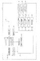
図1において、車両1には運転支援装置10が搭載されている。運転支援装置10は、車両1の周辺情報を取得する周辺情報取得部11A、11B、11Cおよび11Dと、車両1の前方を撮像するカメラユニット12とを備えている。車両1は、本発明の自車両を構成する。
First, the configuration will be described.
In FIG. 1, a
周辺情報取得部11Aは、例えば、車両1のフロントバンパやフロントグリル等に装着された単眼カメラから構成されており、車両1の前方の画像を撮像する。周辺情報取得部11Bは、例えば、車両1のリアバンパやリアグリル等に装着された単眼カメラから構成されており、車両1の後方の画像を撮像する。 The peripheral information acquisition unit 11 </ b> A is composed of, for example, a monocular camera mounted on a front bumper, a front grill, or the like of the vehicle 1 and captures an image in front of the vehicle 1. The peripheral information acquisition unit 11B is composed of, for example, a monocular camera mounted on a rear bumper, a rear grill, or the like of the vehicle 1 and captures an image behind the vehicle 1.
周辺情報取得部11C、11Dは、例えば、車両1の図示しない左ドアミラーや右ドアミラー等に搭載された単眼カメラから構成されており、周辺情報取得部11Cは、車両1の左側方の画像を撮像し、周辺情報取得部11Dは、車両1の右側方の画像を撮像する。
The peripheral
カメラユニット12は、車両1の前面において左右対称に設けられたカメラ12Aを備えており、車両1の前方の画像を立体的に撮像可能となっている。これにより、運転支援装置10は、周辺情報取得部11A、11B、11C、11Dおよびカメラ12Aによって車両1の周辺の路面を含む領域を観測可能である。本実施例のカメラ12Aは、本発明のカメラを構成する。
The
カメラユニット12は、カメラECU(Electronic Control Unit)12Bを有する。カメラECU12Bは、カメラ12Aが撮像した画像を解析する。カメラユニット12には車速センサ13が接続されており、車速センサ13は、車両1の走行速度を検出してカメラECU12Bに検出情報を出力する。
The
カメラECU12Bは、カメラ12Aが撮像した画像を解析し、車両1の進行方向前方に間隔を空けて駐車する複数の他車両を検出する。具体的には、カメラECU12Bは、車体の形状に応じた画像データを図示しないメモリに記憶している。カメラECU12Bは、カメラ12Aで撮像された画像データを参照して画像のエッジを抽出し、抽出したエッジデータをメモリに記憶する。
The camera ECU 12B analyzes an image captured by the camera 12A, and detects a plurality of other vehicles parked at intervals in front of the vehicle 1 in the traveling direction. Specifically, the
カメラECU12Bは、抽出したエッジデータを車体の画像データとマッチングすることで、車両の前後方向前面または前後方向後面を検出する。これにより、車両1の前方において車両の前後方向に間隔を空けて縦列方向に駐車する車両でなく、車両1の前方において車幅方向に間隔を空けて駐車する複数の車両2(図2参照)を検出可能である。図2は、カメラ12Aによって撮像された車両2の画像の一例を示している。本実施の形態の車両2は、本発明の他車両を構成する。
The camera ECU 12B detects the front-rear direction front surface or the front-rear direction rear surface of the vehicle by matching the extracted edge data with the image data of the vehicle body. Accordingly, a plurality of
ここで、カメラECU12Bは、車両の前後方向前面または前後方向後面のエッジを車体の画像データとマッチングし、上空の予め決められた位置に設けた視点位置から、所定距離だけ下にある平面状の路面を観測しているものと仮定して座標変換を行い、車両の画像を俯瞰画像に変換する処理を行ってもよい。
Here, the
カメラECU12Bは、カメラ12Aで撮像された画像に基づいて車両1の進行方向前方に間隔を空けて駐車する複数の車両2が検出され、かつ、車速センサ13の検出情報に基づいて車両1が所定速度以下で走行していることを条件として、車両1の周辺に駐車場が存在すると判定し、自動駐車待機モード信号を出力する。
The camera ECU 12B detects a plurality of
運転支援装置10は、カメラECU15を備えている。カメラECU15は、周辺情報取得部11A、11B、11Cおよび11Dから取得した画像データを解析し、車両1の周辺の画像(全方位画像)の中から駐車スペースを検出する。
The
具体的には、カメラECU15は、周辺情報取得部11Aから11Dで撮像された画像を、それぞれ路面を真上から俯瞰した俯瞰画像に変換し、各俯瞰画像を1枚の画像に合成する。カメラECU15は、1枚に合成された俯瞰画像の中から駐車スペースを抽出する。
Specifically, the
ここで、駐車場とは、複数の車両を駐車しておく施設、または場所であり、駐車場では、複数の車両が間隔を空けて駐車可能である。なお、車両が一定時間(例えば、5分)以上駐車されている状態を駐車という。また、駐車スペースとは、間隔を空けて駐車している車両の間、あるいは、駐車場内において、少なくとも1台分の車両を駐車可能なスペースのことである。 Here, the parking lot is a facility or place where a plurality of vehicles are parked. In the parking lot, a plurality of vehicles can be parked at intervals. A state in which the vehicle is parked for a certain time (for example, 5 minutes) is called parking. The parking space is a space where at least one vehicle can be parked between vehicles parked at intervals or in a parking lot.
運転支援装置10は、運転支援ECU21、ステアリング制御ユニット22、ブレーキ制御ユニット23、スロットル制御ユニット24、シフト装置25、操作表示部26および操舵角センサ27を備えている。
The
運転支援ECU21は、カメラユニット12に接続されている。運転支援ECU21にはカメラECU12Bから自動駐車待機モード信号が入力される。運転支援ECU21は、自動駐車待機モード信号が入力されると、周辺情報取得部11A、11B、11Cおよび11Dを操作し、自動駐車を行う際に必要となる駐車経路の推定を行い、目標駐車位置を決定して、必要な車両制御情報を決定する。本実施例のカメラECU12Bおよび運転支援ECU21は、本発明の駐車場有無判定部を構成する。
The driving support ECU 21 is connected to the
ステアリング制御ユニット22は、運転支援ECU21で決定された車両制御情報に基づいて、パワーステアリングアクチュエータ31を駆動する。パワーステアリングアクチュエータ31は、図示しないステアリングホイールの操作をアシストし、車両1の操舵角を制御する。
The
ブレーキ制御ユニット23は、運転支援ECU21で決定された車両制御情報に基づいて、ブレーキアクチュエータ32を駆動する。ブレーキアクチュエータ32は、図示しないブレーキを制御することで、図示しない車輪を制動する。
The
スロットル制御ユニット24は、運転支援ECU21で決定された車両制御情報に基づいて、スロットルアクチュエータ33を駆動する。スロットルアクチュエータ33は、いずれも図示しないエンジンに接続される吸気管のスロットルボディに設けられたスロットルバルブを制御することにより、車両1の走行速度を制御する。
The
シフト装置25は、運転者によって操作され、パーキングレンジ(Pレンジ)、リバースレンジ(Rレンジ)、ニュートラルレンジ(Nレンジ)およびドライブレンジ(Dレンジ)の各シフト位置に操作される。
シフト装置25がDレンジに操作されると、車両1は、前進走行が可能となり、Rレンジに操作されると、車両1は、後進走行が可能となる。
The
When the
操作表示部26は、例えば、車両1の図示しないインストメントパネルに設けられており、表示機能と操作機能とを兼ねるタッチパネルから構成されている。運転支援ECU21は、カメラECU12Bから自動駐車待機モード信号が入力すると、操作表示部26に自動駐車待機モードに移行した旨を表示する。また、操作表示部26には図示しないスピーカやインジケータが設置されており、スピーカやインジケータによって音や表示により自動駐車待機モードに移行した旨が報知される。
The
駐車モード切替部21Aによって運転モードが自動駐車待機モード43から自動駐車モード41に切替えられた後、車両1を後退させて目標駐車位置に設定された駐車スペースに移動させる際に、運転支援ECU21は、周辺情報取得部11Bによって撮像される車両1の後方の画像を操作表示部26に表示する。
After the driving mode is switched from the automatic
駐車モード切替部21Aによって運転モードが自動駐車待機モード43から自動駐車モード41に切替えられた後、車両1を駐車スペースから前方に移動させる際に、運転支援ECU21は、周辺情報取得部11Aによって撮像される車両1の前方の画像を操作表示部26に表示する。
After the driving mode is switched from the automatic
操舵角センサ27は、ステアリングホイールの操舵角を検出して、検出情報を運転支援ECU21に出力する。
The
運転支援ECU21は、駐車モード切替部21Aを有し、駐車モード切替部21Aは、運転モードを自動的に切替える。本実施例の運転支援ECU21は、本発明の駐車モード切替部を構成する。
The driving
図3において、駐車モードは、自動駐車モード41、手動駐車モード42および自動駐車待機モード43を有する。自動駐車モード41は、シフト装置25がDレンジ等の他のレンジからRレンジに切替えられたことを条件として、運転者の運転操作に依らず車両1の駐車を自動で行う。
In FIG. 3, the parking mode has an
運転支援ECU21は、自動駐車モード41に移行すると、操舵角センサ27の検出情報に基づいて現在のステアリングホイールの操舵角を検出し、現在の車両1の位置から駐車スペースまでの移動軌跡を算出する。
When the driving
運転支援ECU21は、現在の車両1の位置から駐車スペースまでの移動軌跡を算出した後、ステアリング制御ユニット22、ブレーキ制御ユニット23およびスロットル制御ユニット24を制御して、運転者の運転操作、すなわち、パワーステアリングの操作に依らず、現在の車両1の位置から駐車スペースまで車両1を自動的に移動させる。
The driving
手動駐車モード42は、運転者の運転操作に基づいて車両1の駐車を行う。駐車モード切替部21Aは、シフト装置25がDレンジにシフトされた状態において駐車場の情報を取得するまでは、駐車モードを手動駐車モード42に設定する。運転支援ECU21は、駐車モードが手動駐車モード42に移行すると、Dレンジにシフトされた状態で運転者のステアリング操作、ブレーキ制御操作およびスロットル制御操作によって車両1を走行させる。
In the
自動駐車待機モード43は、手動駐車モード42から自動駐車モード41に移行する際に経由するモードであり、車両1の周辺情報の取得を開始する。駐車モード切替部21Aは、カメラECU12Bから自動駐車待機モード信号が入力されたことを条件として、駐車場内で車両1の周辺情報を周辺情報取得部11Aから11Dによって撮像し、駐車スペースを検出する。
The automatic
次に、作用を説明する。
図4、図5は、運転支援装置10が実行する運転支援処理プログラムのフローチャートである。運転支援処理プログラムは、カメラECU12Bおよび運転支援ECU21のメモリに記憶されており、カメラECU12Bおよび運転支援ECU21によって実行される。
Next, the operation will be described.
4 and 5 are flowcharts of the driving support processing program executed by the driving
運転支援ECU21は、駐車モードが手動駐車モードであるか否かを判別する(ステップS1)。運転支援ECU21は、シフト装置25がDレンジにシフトされていると判断した場合には、駐車モードが手動駐車モード42であるものと判定してステップS2に進み、シフト装置25がDレンジ以外にシフトされていると判断した場合には、今回の処理を終了する。
The driving
ステップS2において、カメラECU12Bは、カメラ12Aで撮像された画像を取得した後、車速センサ13から車速を取得する(ステップS3)。次いで、カメラECU12Bは、カメラ12Aで撮像された画像と車速センサ13から取得した車速とに基づいて駐車場の有無を判定する処理を実行する(ステップS4)。
In step S2, the
ステップS4において、カメラECU12Bは、図5のフローチャートに基づいて駐車場の有無を判定する処理を実行する。図5において、カメラECU12Bは、車両1の進行方向の前方に間隔を空けて複数の車両2を検出したか否かを判別する(ステップS11)。
In step S4, the
車両1の進行方向前方に間隔を空けて駐車する複数の車両2が検出されるという条件としては、車両1の進行方向前方において間隔を空けて駐車する複数の車両2の前後方向前面または前後方向後面が検出されていること、あるいは、車両1の進行方向前方において一定の領域に複数の車両2の前後方向前面または前後方向後面が検出されていることを含む。駐車する車両2の間隔は、一定の間隔および不定の間隔を含む。
As a condition that a plurality of
また、車両1の進行方向前方において一定の領域に複数の車両が検出される場合には、一定の領域に一定の割合(例えば、7割)以上で車両が駐車されることを含む。 In addition, when a plurality of vehicles are detected in a certain area in front of the traveling direction of the vehicle 1, it includes that the vehicles are parked in the certain area at a certain ratio (for example, 70%) or more.
ステップS11において、カメラECU12Bは、カメラ12Aで撮像された画像データを参照し、車両の前後方向前面または前後方向後面のエッジを抽出し、抽出したデータをメモリに記憶する。
In step S <b> 11, the
図2に示すように、カメラ12Aが車両2の前後方向前面2aを検出している場合には、カメラECU12Bは、車両2の前後方向前面2aのエッジを車体の画像データとマッチングすることで、横方向(車幅方向)に間隔を空けて駐車する複数の車両2を検出することができる。
As shown in FIG. 2, when the camera 12A detects the front-rear direction
車両の前後方向前面または前後方向後面は、車両の側面、すなわち、車幅方向側面よりも短い。したがって、カメラECU12Bは、カメラ12Aによって撮像された画像から抽出されたエッジを車体の画像データとマッチングしたときに、車幅方向側面よりも短いエッジデータとして認識した場合に、車両の前後方向前面または前後方向後面を検出したものと判定する。
これにより、車両1が走行する公道上において、車両の前後方向に間隔を空けて縦方向(車両の走行方向)に駐車している車両の駐車領域を駐車場と誤認することを防止できる。
The front-rear direction front surface or the front-rear direction rear surface of the vehicle is shorter than the side surface of the vehicle, that is, the vehicle width direction side surface. Therefore, when the
Thereby, on the public road where the vehicle 1 travels, it can be prevented that a parking area of a vehicle parked in the longitudinal direction (the traveling direction of the vehicle) with an interval in the front-rear direction of the vehicle is mistaken as a parking lot.
ステップS11において、カメラECU12Bは、車両1の進行方向の前方に間隔を空けて複数の車両2が検出されない場合には、車両1の周辺に駐車場がないものと判定して今回の処理を終了する。
In step S11, the
ステップS11において、カメラECU12Bは、車両1の進行方向の前方に間隔を空けて複数の車両2が検出された場合には、車両1の周辺に駐車場があるものと判定して、ステップS12に進む。
In step S11, when a plurality of
ステップS12において、カメラECU12Bは、車速Vが所定車速V1以下であるか否かを判別する。カメラECU12Bは、車速Vが所定車速V1よりも大きいものと判定した場合には、車両1の周辺に駐車場がないものと判定して(ステップS14)、今回の処理を終了する。
In step S12, the
カメラECU12Bは、車速Vが所定車速V1以下であるものと判定した場合には、車両1の周辺に駐車場があるものと判定して、例えば、フラグを立てる。
If the
ここで、駐車場の有無を検出するために、車速Vが所定車速V1以下であるものと判定することを条件とするのは、運転者に駐車の意図がない走行状態において、周辺情報取得部11A、11B、11Cおよび11Dが周辺情報を取得して駐車スペースを検出する制御を行わないようにするためである。このようにすれば、運転支援ECU21の負荷を軽減できる。
Here, in order to detect the presence or absence of a parking lot, the condition that the vehicle speed V is determined to be equal to or lower than the predetermined vehicle speed V1 is that the surrounding information acquisition unit is in a traveling state where the driver does not intend to park. This is because 11A, 11B, 11C, and 11D do not perform control to acquire the surrounding information and detect the parking space. In this way, the load on the driving
次いで、カメラECU12Bは、図4のフローチャートに戻り、車両1の周辺に駐車場があるか否かを判別する(ステップS5)。
ステップS5において、カメラECU12Bは、フラグが立っていない場合に、車両1の周辺に駐車場がないものと判定して今回の処理を終了する。カメラECU12Bは、フラグが立っているものと判定した場合には、駐車モードを自動駐車待機モード43(図3参照)に切替え、運転支援ECU21に自動駐車待機モード信号を出力して、今回の処理を終了する。
Next, the
In step S5, when the flag is not set, the
運転支援ECU21は、カメラECU12Bから自動駐車待機モード信号が入力すると、操作表示部26に自動駐車待機モード43に移行した旨を表示し、運転者に自動駐車待機モード43に移行した旨を通知する。
When the automatic parking standby mode signal is input from the
自動駐車待機モード43に移行すると、運転支援ECU21は、駐車場内で車両1の周辺情報を周辺情報取得部11Aから11Dによって撮像する。次いで、運転支援ECU21は、周辺情報取得部11A、11B、11C、11Dから取得した画像データを解析し、車両1の周辺の画像(全方位画像)の中から駐車スペースを検出して、操作表示部26に駐車スペースを含んだ車両1の周辺画像を表示する。
If it transfers to the automatic
運転支援ECU21は、駐車スペースを1箇所だけ検知した場合には、この駐車スペースを目標駐車位置に自動的に設定し、複数の駐車スペースを検出した場合には、例えば、車両1に最も近い駐車スペースを目標駐車位置に設定して、その目標駐車位置を含んだ車両1の周辺画像を操作表示部26に表示する。
When only one parking space is detected, the driving
運転支援ECU21は、目標駐車位置が設定されると、操舵角センサ27の検出情報に基づいて現在のステアリングホイールの操舵角を検出し、現在の車両1の位置から駐車スペースまでの移動軌跡を算出する。
When the target parking position is set, the driving
次いで、運転支援ECU21は、シフト装置25がDレンジからRレンジに切替えられたタイミングで、自動駐車待機モード43から自動駐車モード41に移行する。自動駐車モード41に移行すると、運転支援ECU21は、ステアリング制御ユニット22、ブレーキ制御ユニット23およびスロットル制御ユニット24を制御して、パワーステアリングの操作に依らず、現在の車両1の位置から駐車スペースまで車両1を自動的に移動させる。
Next, the driving
運転支援ECU21は、周辺情報取得部11Bによって撮像された車両1の後方の画像を操作表示部26に表示する。これにより、運転者は、車両1の後退時に後方の画像を操作表示部26によって視認できる。
The driving
なお、車両1によって駐車場が検出された場合に、駐車場を管理する店舗等からその店舗のクーポン券が取得されるようにしたり、その店舗の情報を音声ガイダンスで出力するようにしたりして、駐車場に関する情報を乗員が取得できるようにしてもよい。 In addition, when a parking lot is detected by the vehicle 1, a coupon ticket of the store is acquired from a store or the like that manages the parking lot, or information on the store is output by voice guidance. The occupant may be able to acquire information on the parking lot.
一方、車両1を駐車スペースから出す場合に、シフト装置25がDレンジにシフトされると、運転支援ECU21は、自動駐車モード41から手動駐車モード42に切替え(図3参照)、周辺情報取得部11Aによって撮像された車両1の前方の画像を操作表示部26に表示する。これにより、運転者は、前方の画像を操作表示部26によって視認できる。
On the other hand, when the vehicle 1 is taken out of the parking space, when the
このように本実施例の運転支援装置10は、カメラ12Aによって撮像された画像に基づいて車両1の進行方向前方に間隔を空けて駐車する複数の車両2が検出され、かつ、車両1が所定車速以下で走行していることを条件として、車両1の周辺に駐車場が存在すると判定するカメラECU12Bを有する。
As described above, the driving
これにより、車両1が走行中に、白線や駐車用の枠がない駐車場を適切に検出することができる。また、適切な地図情報やGPS情報を取得できない場合であっても、適切に駐車場として検出することができるので、臨時駐車場等であっても駐車場として適切に検出することができる。 Thereby, it is possible to appropriately detect a parking lot without a white line or a parking frame while the vehicle 1 is traveling. Moreover, even if it is a case where appropriate map information and GPS information cannot be acquired, it can be appropriately detected as a parking lot, so even a temporary parking lot can be appropriately detected as a parking lot.
また、本実施例の運転支援装置10によれば、カメラECU12Bが、間隔を空けて駐車する複数の車両2の前後方向前面または前後方向後面が検出されたことを条件として、車両1の周辺に駐車場が存在すると判定し、自動駐車待機モード43に移行可能となっている。
これにより、路肩に路上駐車している他車両や、渋滞中の他車両を検出して駐車場が存在するものと誤判定することを防止でき、駐車場を適切に検出することができる。
In addition, according to the driving
As a result, it is possible to prevent other vehicles parked on the road shoulder or other vehicles in a traffic jam from being erroneously determined as having a parking lot, and the parking lot can be appropriately detected.
また、本実施例の運転支援装置10によれば、駐車モードとして、車両1のシフト位置がRレンジに切替えられたことを条件として運転者の運転操作に依らず車両1の駐車を自動で行う自動駐車モード41と、運転者の運転操作に基づいて車両1の駐車を行う手動駐車モード42とを有する。
Moreover, according to the driving
さらに、運転支援装置10は、手動駐車モード42から自動駐車モード41に移行する際に経由するモードであり、車両1の周辺情報の取得を開始する自動駐車待機モード43を有する。
Furthermore, the driving
そして、運転支援装置10は、カメラECU12Bによって車両1の周辺に駐車場が存在するものと判定されると、駐車モードを手動駐車モード42から自動駐車待機モード43に切替える駐車モード切替部21Aを有する。
The driving
これにより、車両1の周辺に駐車場が存在すると判定されると、自動で自動駐車待機モード43に切替えることができる。このため、運転者が操作部の操作を行わずに、駐車スペースを自動的に検出することができる。
Thereby, when it is determined that there is a parking lot around the vehicle 1, the automatic
これに加えて、運転者が操作部の操作を行わずに駐車スペースの設定を自動的に行うことができる。この結果、運転者は、煩わしい操作を行うことを不要にでき、駐車時における運転者の負荷を軽減できる。 In addition, the driver can automatically set the parking space without operating the operation unit. As a result, the driver can dispense with troublesome operations and can reduce the driver's load during parking.
なお、本実施例の運転支援装置10は、車両1の周辺に駐車場が存在すると判定されると、自動で自動駐車待機モード43に切替え、駐車スペースを自動的に検出しているが、これに限定されるものではない。
In addition, if it determines with the driving
例えば、運転支援ECU21は、駐車スペースを検出すると、駐車スペースを含んだ車両1の周辺画像を操作表示部26に表示し、運転者が操作表示部26によって任意の駐車スペースを設定すると、その駐車スペースを目標駐車位置に設定してもよい。
For example, when the driving
また、運転支援ECU21は、カメラECU12Bから自動駐車待機モード信号が入力すると、操作表示部26に自動駐車待機モード43に移行した旨を表示しているが、表示しなくてもよい。このようにすれば、車両1の前方に中古車販売店等が設置されている場合に、駐車者販売店を駐車場と認識して運転者に通知することを防止できる。
Further, when the automatic parking standby mode signal is input from the
また、本実施例の運転支援装置10において、地図情報やGPSデータ、道路標識や道路標示の検出結果を併用して、駐車場の有無や車両が駐車している道路が公道であるか否かを判定してもよい。このようにすれば、駐車場の有無の判定精度を向上できる。
Further, in the driving
また、本実施例の周辺情報取得部11Aから11Dは、単眼カメラに代えて超音波ソナーやLIDAR(Light Detection and Ranging)から構成されてもよく、この場合、カメラECU15によって俯瞰画像を合成させる代わりに、超音波ソナーやLIDARに接続されたECUが超音波ソナーやLIDARによる検出結果をマッピングすることによって駐車スペースを抽出するものであってもよい。
Further, the peripheral
また、周辺情報取得部11Aから11Dは、超音波ソナーの代わりに、ミリ波レーダ等のレーダから構成されてもよい。また、本実施例の周辺情報取得部11Aから11Dは、それぞれ単眼カメラと超音波ソナーまたはミリ波レーダを組み合わせたものから構成されてもよい。
Further, the peripheral
また、本実施例のカメラユニット12は、カメラ12Aを備えているが、カメラユニット12は、カメラ12Aの代わりに、双眼カメラを備えてもよい。また、カメラ12Aに加えて赤外線センサまたはミリ波レーダとを組み合わせ、カメラ12Aと赤外線センサやミリ波レーダとの検出結果に応じて、車両1の進行方向前方に間隔を空けて駐車する複数の他車両を検出したりしてもよい。
Moreover, although the
また、本実施例のカメラECU12Bは、間隔を空けて複数の車両2が検出されたことを条件として駐車場があるものと判定するが、車両1の進行方向の前方に間隔を空けて車両2や柱や壁が検出された場合に車両1の周辺に駐車場があるものと判定してもよい。
The
また、本実施例のカメラECU12Bは、車両1の周辺に駐車場が存在すると判定したことを条件として、自動駐車待機モード信号を出力するが、例えばクーポン券が取得されたり、店舗に関する情報が出力されたりする等、駐車場に関する情報を乗員が取得したことを更なる条件として、自動駐車待機モード信号を出力するものであってもよい。
In addition, the
これにより、乗員に駐車意志がある場合に自動駐車待機モードに移行するため、不要な自動駐車待機モードへの移行を防止し、周辺情報取得部の稼働による消費電力を抑制することができる。 Thereby, when the occupant is willing to park, the automatic parking standby mode is entered, so that unnecessary transition to the automatic parking standby mode can be prevented and power consumption due to operation of the peripheral information acquisition unit can be suppressed.
また、本実施例のカメラECU12Bは、カメラユニット12に含まれているが、カメラ12Aによって撮像された画像を処理するカメラECU12Bは、例えば運転支援ECU21に内蔵されていたり、カメラユニット12とは別に設けられていたりするものでもよい。
The
また、本実施例では、スロットル制御ユニット24がスロットルアクチュエータ33を駆動することにより、車両1の走行速度を制御しているが、スロットルアクチュエータ33の代わりに燃料噴射量を制御してエンジンの出力を制御するものでもよい。また、車両1が電動車の場合は、モータ制御ユニットが車両の駆動源であるモータの出力を制御することにより、車両1の走行速度を制御するものであってもよい。
In this embodiment, the
また、本実施例では、運転支援ECU21は、駐車モード切替部21Aによって運転モードが自動駐車待機モード43から自動駐車モード41に切替えられ、車両1が後退または前進するとき、車両1の後方または前方の画像を操作表示部26に表示するが、合成された車両1の全周囲を表示する俯瞰画像や、車両1の側方の画像を表示するものであってもよい。
Further, in the present embodiment, the driving
また、本実施例の運転支援装置10は、シフト装置25がDレンジ等の他のレンジからRレンジに切替えられたことを条件として、自動駐車待機モード43から自動駐車モード41に切替えているが、これに限定されるものではない。例えば、操作表示部26に切替スイッチを設け、運転者が切替スイッチを操作することで自動駐車待機モード43から自動駐車モード41に移行するようにしてもよい。
Further, the driving
本発明の実施例を開示したが、当業者によっては本発明の範囲を逸脱することなく変更が加えられうることは明白である。すべてのこのような修正および等価物が次の請求項に含まれることが意図されている。 While embodiments of the invention have been disclosed, it will be apparent to those skilled in the art that changes may be made without departing from the scope of the invention. All such modifications and equivalents are intended to be included in the following claims.
1...車両(自車両)、2...車両(他車両)、2a...前後方向前面(他車両の前後方向前面)、10...運転支援装置、12A...カメラ、12B...カメラECU(駐車場有無判定部)、21...運転支援ECU(駐車モード切替部)、41...自動駐車モード、42...手動駐車モード、43...自動駐車待機モード DESCRIPTION OF SYMBOLS 1 ... Vehicle (own vehicle), 2 ... Vehicle (other vehicle), 2a ... Front-rear direction front (front-rear direction front of other vehicle), 10 ... Driving support device, 12A ... Camera, 12B ... Camera ECU (parking area presence / absence judging unit), 21 ... Drive assist ECU (parking mode switching unit), 41 ... Automatic parking mode, 42 ... Manual parking mode, 43 ... Automatic parking Standby mode
Claims (3)
前記撮像された画像に基づいて自車両の進行方向前方に間隔を空けて駐車する複数の他車両が検出され、かつ、自車両が所定速度以下で走行していることを条件として、自車両の周辺に駐車場が存在すると判定する駐車場有無判定部を備えたことを特徴とする運転支援装置。 A driving support device that includes a camera that images the periphery of the host vehicle, and that can detect a parking lot based on at least an image captured by the camera,
On the condition that a plurality of other vehicles parked at intervals in front of the traveling direction of the host vehicle are detected based on the captured image and the host vehicle is traveling at a predetermined speed or less, A driving support apparatus comprising a parking lot presence / absence determining unit that determines that a parking lot exists in the vicinity.
運転者の運転操作に基づいて自車両の駐車を行う手動駐車モードと、
前記手動駐車モードから前記自動駐車モードに移行する際に経由するモードであり、自車両の周辺情報の取得を開始する前記自動駐車待機モードとの複数の駐車モードを有し、
前記駐車場有無判定部によって自車両の周辺に駐車場が存在すると判定されると、前記駐車モードを前記手動駐車モードから前記自動駐車待機モードに切替える駐車モード切替部を備えたことを特徴とする請求項1または請求項2に記載の運転支援装置。 An automatic parking mode in which the vehicle is automatically parked regardless of the driver's driving operation on condition that at least the shift position of the vehicle is switched to the reverse range;
Manual parking mode for parking the vehicle based on the driver's driving operation,
It is a mode that goes through when shifting from the manual parking mode to the automatic parking mode, and has a plurality of parking modes with the automatic parking standby mode for starting acquisition of surrounding information of the host vehicle,
A parking mode switching unit that switches the parking mode from the manual parking mode to the automatic parking standby mode when the parking lot presence / absence determining unit determines that there is a parking lot around the host vehicle. The driving support device according to claim 1 or 2.
Priority Applications (2)
| Application Number | Priority Date | Filing Date | Title |
|---|---|---|---|
| JP2017122811A JP2019008506A (en) | 2017-06-23 | 2017-06-23 | Drive support device |
| JP2021195846A JP7201061B2 (en) | 2017-06-23 | 2021-12-02 | Driving support device |
Applications Claiming Priority (1)
| Application Number | Priority Date | Filing Date | Title |
|---|---|---|---|
| JP2017122811A JP2019008506A (en) | 2017-06-23 | 2017-06-23 | Drive support device |
Related Child Applications (1)
| Application Number | Title | Priority Date | Filing Date |
|---|---|---|---|
| JP2021195846A Division JP7201061B2 (en) | 2017-06-23 | 2021-12-02 | Driving support device |
Publications (2)
| Publication Number | Publication Date |
|---|---|
| JP2019008506A true JP2019008506A (en) | 2019-01-17 |
| JP2019008506A5 JP2019008506A5 (en) | 2020-07-02 |
Family
ID=65028888
Family Applications (1)
| Application Number | Title | Priority Date | Filing Date |
|---|---|---|---|
| JP2017122811A Pending JP2019008506A (en) | 2017-06-23 | 2017-06-23 | Drive support device |
Country Status (1)
| Country | Link |
|---|---|
| JP (1) | JP2019008506A (en) |
Cited By (3)
| Publication number | Priority date | Publication date | Assignee | Title |
|---|---|---|---|---|
| WO2021038790A1 (en) * | 2019-08-29 | 2021-03-04 | 日産自動車株式会社 | Parking assistance method and parking assistance device |
| JP2021094928A (en) * | 2019-12-13 | 2021-06-24 | 本田技研工業株式会社 | Parking support device, parking support method and program |
| JP2022022311A (en) * | 2017-06-23 | 2022-02-03 | スズキ株式会社 | Driving support device |
Citations (2)
| Publication number | Priority date | Publication date | Assignee | Title |
|---|---|---|---|---|
| JP2013154730A (en) * | 2012-01-30 | 2013-08-15 | Fujitsu Ten Ltd | Apparatus and method for processing image, and parking support system |
| JP2015064796A (en) * | 2013-09-25 | 2015-04-09 | 日産自動車株式会社 | Determination device and determination method for parking place |
-
2017
- 2017-06-23 JP JP2017122811A patent/JP2019008506A/en active Pending
Patent Citations (2)
| Publication number | Priority date | Publication date | Assignee | Title |
|---|---|---|---|---|
| JP2013154730A (en) * | 2012-01-30 | 2013-08-15 | Fujitsu Ten Ltd | Apparatus and method for processing image, and parking support system |
| JP2015064796A (en) * | 2013-09-25 | 2015-04-09 | 日産自動車株式会社 | Determination device and determination method for parking place |
Cited By (5)
| Publication number | Priority date | Publication date | Assignee | Title |
|---|---|---|---|---|
| JP2022022311A (en) * | 2017-06-23 | 2022-02-03 | スズキ株式会社 | Driving support device |
| WO2021038790A1 (en) * | 2019-08-29 | 2021-03-04 | 日産自動車株式会社 | Parking assistance method and parking assistance device |
| JPWO2021038790A1 (en) * | 2019-08-29 | 2021-03-04 | ||
| US11648934B2 (en) | 2019-08-29 | 2023-05-16 | Nissan Motor Co., Ltd. | Parking assistance method and parking assistance device |
| JP2021094928A (en) * | 2019-12-13 | 2021-06-24 | 本田技研工業株式会社 | Parking support device, parking support method and program |
Similar Documents
| Publication | Publication Date | Title |
|---|---|---|
| CN109204137B (en) | Vehicle periphery display device | |
| US10818180B2 (en) | Parking support device | |
| US7363130B2 (en) | Parking assist systems, methods, and programs | |
| JP6547836B2 (en) | Parking support method and parking support apparatus | |
| CN110450717B (en) | Parking assist apparatus | |
| EP2990273A1 (en) | Parking assist device | |
| WO2017068701A1 (en) | Parking space detection method and device | |
| WO2017068699A1 (en) | Parking space line detection method and device | |
| US20200398827A1 (en) | Parking assist system | |
| EP2017138A1 (en) | Parking assistance device and parking assistance method | |
| CN110831818B (en) | Parking assist method and parking assist device | |
| US11787335B2 (en) | Periphery monitoring device | |
| JP6918203B2 (en) | Parking support device | |
| US11584297B2 (en) | Display device for vehicle and parking assist system | |
| JP5282730B2 (en) | Driving assistance device | |
| JP2019008506A (en) | Drive support device | |
| CN112124096B (en) | Parking assist system | |
| GB2416901A (en) | Vehicle parking assistant that calculates and displays to the driver the position needed to reverse the steering lock when parallel parking | |
| US11623636B2 (en) | Display device for vehicle and parking assist system | |
| JP7201061B2 (en) | Driving support device | |
| JP6325365B2 (en) | Steering support control device | |
| JP6998359B2 (en) | Parking support system | |
| CN112977423A (en) | Parking assist system | |
| JP2014100957A (en) | Parking support device and control device | |
| JP7468159B2 (en) | Driving Support Devices |
Legal Events
| Date | Code | Title | Description |
|---|---|---|---|
| A621 | Written request for application examination |
Free format text: JAPANESE INTERMEDIATE CODE: A621 Effective date: 20200511 |
|
| A521 | Request for written amendment filed |
Free format text: JAPANESE INTERMEDIATE CODE: A523 Effective date: 20200525 |
|
| A977 | Report on retrieval |
Free format text: JAPANESE INTERMEDIATE CODE: A971007 Effective date: 20210226 |
|
| A131 | Notification of reasons for refusal |
Free format text: JAPANESE INTERMEDIATE CODE: A131 Effective date: 20210309 |
|
| A521 | Request for written amendment filed |
Free format text: JAPANESE INTERMEDIATE CODE: A523 Effective date: 20210419 |
|
| A131 | Notification of reasons for refusal |
Free format text: JAPANESE INTERMEDIATE CODE: A131 Effective date: 20210622 |
|
| A521 | Request for written amendment filed |
Free format text: JAPANESE INTERMEDIATE CODE: A523 Effective date: 20210802 |
|
| A02 | Decision of refusal |
Free format text: JAPANESE INTERMEDIATE CODE: A02 Effective date: 20211026 |