JP2018538107A - Method, system, and computer program product for measuring object distance and target dimensions using a light emitter - Google Patents
Method, system, and computer program product for measuring object distance and target dimensions using a light emitter Download PDFInfo
- Publication number
- JP2018538107A JP2018538107A JP2018534487A JP2018534487A JP2018538107A JP 2018538107 A JP2018538107 A JP 2018538107A JP 2018534487 A JP2018534487 A JP 2018534487A JP 2018534487 A JP2018534487 A JP 2018534487A JP 2018538107 A JP2018538107 A JP 2018538107A
- Authority
- JP
- Japan
- Prior art keywords
- patterns
- target
- pattern
- onto
- object plane
- Prior art date
- Legal status (The legal status is an assumption and is not a legal conclusion. Google has not performed a legal analysis and makes no representation as to the accuracy of the status listed.)
- Pending
Links
Images


Classifications
-
- G—PHYSICS
- G01—MEASURING; TESTING
- G01B—MEASURING LENGTH, THICKNESS OR SIMILAR LINEAR DIMENSIONS; MEASURING ANGLES; MEASURING AREAS; MEASURING IRREGULARITIES OF SURFACES OR CONTOURS
- G01B11/00—Measuring arrangements characterised by the use of optical techniques
- G01B11/24—Measuring arrangements characterised by the use of optical techniques for measuring contours or curvatures
- G01B11/25—Measuring arrangements characterised by the use of optical techniques for measuring contours or curvatures by projecting a pattern, e.g. one or more lines, moiré fringes on the object
- G01B11/2513—Measuring arrangements characterised by the use of optical techniques for measuring contours or curvatures by projecting a pattern, e.g. one or more lines, moiré fringes on the object with several lines being projected in more than one direction, e.g. grids, patterns
-
- A—HUMAN NECESSITIES
- A61—MEDICAL OR VETERINARY SCIENCE; HYGIENE
- A61B—DIAGNOSIS; SURGERY; IDENTIFICATION
- A61B5/00—Measuring for diagnostic purposes; Identification of persons
- A61B5/0059—Measuring for diagnostic purposes; Identification of persons using light, e.g. diagnosis by transillumination, diascopy, fluorescence
- A61B5/0062—Arrangements for scanning
- A61B5/0064—Body surface scanning
-
- A—HUMAN NECESSITIES
- A61—MEDICAL OR VETERINARY SCIENCE; HYGIENE
- A61B—DIAGNOSIS; SURGERY; IDENTIFICATION
- A61B5/00—Measuring for diagnostic purposes; Identification of persons
- A61B5/0059—Measuring for diagnostic purposes; Identification of persons using light, e.g. diagnosis by transillumination, diascopy, fluorescence
- A61B5/0077—Devices for viewing the surface of the body, e.g. camera, magnifying lens
-
- A—HUMAN NECESSITIES
- A61—MEDICAL OR VETERINARY SCIENCE; HYGIENE
- A61B—DIAGNOSIS; SURGERY; IDENTIFICATION
- A61B5/00—Measuring for diagnostic purposes; Identification of persons
- A61B5/103—Detecting, measuring or recording devices for testing the shape, pattern, colour, size or movement of the body or parts thereof, for diagnostic purposes
- A61B5/107—Measuring physical dimensions, e.g. size of the entire body or parts thereof
- A61B5/1072—Measuring physical dimensions, e.g. size of the entire body or parts thereof measuring distances on the body, e.g. measuring length, height or thickness
-
- A—HUMAN NECESSITIES
- A61—MEDICAL OR VETERINARY SCIENCE; HYGIENE
- A61B—DIAGNOSIS; SURGERY; IDENTIFICATION
- A61B5/00—Measuring for diagnostic purposes; Identification of persons
- A61B5/68—Arrangements of detecting, measuring or recording means, e.g. sensors, in relation to patient
- A61B5/6801—Arrangements of detecting, measuring or recording means, e.g. sensors, in relation to patient specially adapted to be attached to or worn on the body surface
- A61B5/6844—Monitoring or controlling distance between sensor and tissue
-
- A—HUMAN NECESSITIES
- A61—MEDICAL OR VETERINARY SCIENCE; HYGIENE
- A61B—DIAGNOSIS; SURGERY; IDENTIFICATION
- A61B5/00—Measuring for diagnostic purposes; Identification of persons
- A61B5/68—Arrangements of detecting, measuring or recording means, e.g. sensors, in relation to patient
- A61B5/6846—Arrangements of detecting, measuring or recording means, e.g. sensors, in relation to patient specially adapted to be brought in contact with an internal body part, i.e. invasive
- A61B5/6886—Monitoring or controlling distance between sensor and tissue
-
- G—PHYSICS
- G01—MEASURING; TESTING
- G01B—MEASURING LENGTH, THICKNESS OR SIMILAR LINEAR DIMENSIONS; MEASURING ANGLES; MEASURING AREAS; MEASURING IRREGULARITIES OF SURFACES OR CONTOURS
- G01B11/00—Measuring arrangements characterised by the use of optical techniques
- G01B11/02—Measuring arrangements characterised by the use of optical techniques for measuring length, width or thickness
- G01B11/026—Measuring arrangements characterised by the use of optical techniques for measuring length, width or thickness by measuring distance between sensor and object
-
- A—HUMAN NECESSITIES
- A61—MEDICAL OR VETERINARY SCIENCE; HYGIENE
- A61B—DIAGNOSIS; SURGERY; IDENTIFICATION
- A61B90/00—Instruments, implements or accessories specially adapted for surgery or diagnosis and not covered by any of the groups A61B1/00 - A61B50/00, e.g. for luxation treatment or for protecting wound edges
- A61B90/36—Image-producing devices or illumination devices not otherwise provided for
- A61B2090/364—Correlation of different images or relation of image positions in respect to the body
- A61B2090/366—Correlation of different images or relation of image positions in respect to the body using projection of images directly onto the body
-
- A—HUMAN NECESSITIES
- A61—MEDICAL OR VETERINARY SCIENCE; HYGIENE
- A61B—DIAGNOSIS; SURGERY; IDENTIFICATION
- A61B2505/00—Evaluating, monitoring or diagnosing in the context of a particular type of medical care
- A61B2505/05—Surgical care
-
- A—HUMAN NECESSITIES
- A61—MEDICAL OR VETERINARY SCIENCE; HYGIENE
- A61B—DIAGNOSIS; SURGERY; IDENTIFICATION
- A61B2576/00—Medical imaging apparatus involving image processing or analysis
-
- G—PHYSICS
- G16—INFORMATION AND COMMUNICATION TECHNOLOGY [ICT] SPECIALLY ADAPTED FOR SPECIFIC APPLICATION FIELDS
- G16H—HEALTHCARE INFORMATICS, i.e. INFORMATION AND COMMUNICATION TECHNOLOGY [ICT] SPECIALLY ADAPTED FOR THE HANDLING OR PROCESSING OF MEDICAL OR HEALTHCARE DATA
- G16H30/00—ICT specially adapted for the handling or processing of medical images
- G16H30/40—ICT specially adapted for the handling or processing of medical images for processing medical images, e.g. editing
Abstract
手術処置の間にパラメータを測定する方法、システム、及びコンピュータプログラム製品を提供する。画像化されるターゲットに関連付けられた物体面に複数のパターンが投射される。この複数のパターンは、共通の点で重なって、画像化されるターゲットからの物体距離が適正であることを示すように操作される。Methods, systems, and computer program products for measuring parameters during a surgical procedure are provided. A plurality of patterns are projected onto the object plane associated with the target to be imaged. The plurality of patterns are manipulated to overlap at a common point to indicate that the object distance from the imaged target is appropriate.
Description
優先権の主張
本出願は、2015年9月23日に出願された米国特許仮出願第62/222,273号(代理人整理番号5218−233PR)の優先権を主張するものであり、その開示は、参照によって、あたかも全内容が記載されているかのように本明細書に組み込まれている。
This application claims the priority of US Provisional Application No. 62 / 222,273 (Attorney Docket No. 5218-233PR) filed on September 23, 2015, the disclosure thereof. Are incorporated herein by reference as if they were fully described.
本発明概念は、全般的には、組織及び器官の血流及び灌流の画像化に関し、特に、広視野及び照明による画像化の間にターゲット距離を測定することに関する。 The inventive concept relates generally to imaging blood flow and perfusion of tissues and organs, and in particular to measuring target distances during wide field and illumination imaging.
画像化プロセスの間は、画質、十分な照明、及び視野(FOV)の大きさを確保する為に、ターゲット(サンプル)からカメラレンズまでの距離が、ある特定の範囲内になければならない。この距離を、本明細書では「物体距離」と呼ぶ。画像化の用途によっては、サンプルに接触せずに、ターゲットのおおよその寸法を推定しなければならない。画像化の用途には、入院患者処置並びに外来患者処置の為の手術画像化及び臨床画像化の両方が含まれる。 During the imaging process, the distance from the target (sample) to the camera lens must be within a certain range to ensure image quality, sufficient illumination, and field of view (FOV) size. This distance is referred to as “object distance” in this specification. For some imaging applications, the approximate dimensions of the target must be estimated without contacting the sample. Imaging applications include both in-patient treatment and surgical and clinical imaging for outpatient treatment.
システムによっては、近赤外線距離センサを使用して適正な物体距離を取得する。しかしながら、そのようなシステムでは、距離情報をコンピュータに、連続的にリアルタイムでフィードバックしなければならず、これによってソフトウェアアルゴリズムがより複雑になる。更に、近赤外線距離センサはコストが比較的高い。超音波距離センサは、近赤外線センサより安い傾向があるが、精度も落ちる。 Some systems use a near infrared distance sensor to obtain the proper object distance. However, in such systems, distance information must be continuously fed back to the computer in real time, which makes the software algorithm more complex. Furthermore, the near infrared distance sensor is relatively expensive. Ultrasonic distance sensors tend to be cheaper than near-infrared sensors, but they are also less accurate.
更に、画像化処置の間にターゲット組織/器官(ターゲット領域)の寸法が分かれば有利である。システムによっては、ターゲットのそばに置くことが可能な手術/臨床用定規が用意される。ターゲットは、そのそばにある定規とともに画像化される為、ターゲット領域のおおよその寸法が明らかになる。このソリューションは、典型的には、組織/器官との接触が必要であり、処置がより複雑になる可能性があり、処置期間がより長くなる可能性がある。更に、画像化されたときに、ターゲットのそばに置かれた定規の目盛が、近赤外線画像では見えなかったり、はっきりしなかったりする可能性がある。そこで、物体距離及び/又はターゲット寸法を測定する、改良されたシステムが必要とされるであろう。 Furthermore, it is advantageous if the dimensions of the target tissue / organ (target area) are known during the imaging procedure. Some systems provide a surgical / clinical ruler that can be placed near the target. Since the target is imaged with a ruler beside it, the approximate dimensions of the target area are revealed. This solution typically requires tissue / organ contact, which can make the procedure more complex and can result in longer treatment periods. Further, when imaged, the ruler scale placed near the target may not be visible or clear in the near infrared image. Thus, an improved system for measuring object distance and / or target dimensions would be needed.
本発明は、上記従来技術の課題を解決するためのものである。 The present invention is to solve the above-mentioned problems of the prior art.
本発明概念の幾つかの実施形態は、臨床処置の間にパラメータを測定する方法を提供し、この方法は、発光体から、画像化されるターゲットに関連付けられた物体面に第1のパターンを投射するステップと、発光体から、画像化されるターゲットに関連付けられた物体面に第2のパターンを投射するステップと、第1及び第2のパターンが共通の点、線、又は他の幾何図形のいずれかで重なって、画像化されるターゲットからの物体距離が適正であることを示すように、第1及び第2のパターンを操作するステップと、を含む。 Some embodiments of the inventive concept provide a method for measuring a parameter during a clinical procedure, wherein the method applies a first pattern from a light emitter to an object plane associated with an imaged target. Projecting, projecting the second pattern from the illuminant onto the object plane associated with the target to be imaged, and points, lines, or other geometric shapes where the first and second patterns are common Manipulating the first and second patterns to overlap to indicate that the object distance from the imaged target is appropriate.
別の実施形態では、第1及び第2のパターンを投射するステップは、画像化されるターゲットの寸法を示す測定単位を示すマークを有する第1及び第2のパターンを投射するステップを含んでよい。この測定単位は、少なくとも2次元で機能してよい。 In another embodiment, projecting the first and second patterns may include projecting the first and second patterns having marks indicating units of measurement indicating the dimensions of the target being imaged. . This unit of measurement may function in at least two dimensions.
更に別の実施形態では、第1及び第2のパターンを投射するステップは、物体面に第1及び第2のクロスヘアパターンを投射するステップを含んでよく、これらのクロスヘアパターンのそれぞれは、測定単位を示す目盛を軸上に有する。 In yet another embodiment, projecting the first and second patterns may include projecting the first and second crosshair patterns onto the object plane, each of these crosshair patterns being a unit of measure. Has a scale on the axis.
実施形態によっては、操作するステップは更に、第1及び第2のクロスヘアパターンのそれぞれの中心点同士がちょうど重なって、ターゲットからの物体距離が適正であることを示すように、第1及び第2のクロスヘアパターンを操作するステップを含んでよい。 In some embodiments, the step of manipulating further includes first and second so that the center points of each of the first and second crosshair patterns just overlap to indicate that the object distance from the target is appropriate. Manipulating the crosshair pattern of
別の実施形態では、本方法は、臨床画像化処置及び/又は手術画像化処置の一方の間にリアルタイムで実施されてよい。 In another embodiment, the method may be performed in real time during one of the clinical and / or surgical imaging procedures.
更に別の実施形態では、発光体は、第1のパターンを物体面に投射する第1の発光体、及び第2のパターンを物体面に投射する第2の発光体であってよい。 In yet another embodiment, the light emitter may be a first light emitter that projects the first pattern onto the object plane and a second light emitter that projects the second pattern onto the object plane.
実施形態によっては、投射するステップは更に、第1及び第2のレーザ放射体を使用して、それぞれ、第1及び第2のパターンを物体面に投射するステップを含んでよく、各レーザ放射体の波長が約350nmから約1000nmである。 In some embodiments, the projecting step may further include projecting the first and second patterns onto the object plane using the first and second laser emitters, respectively, and each laser emitter. Is about 350 nm to about 1000 nm.
別の実施形態では、本方法は、非侵襲的であってリアルタイムで実施されてよい。 In another embodiment, the method may be non-invasive and performed in real time.
実施形態によっては、物体距離は、ターゲットからカメラレンズまでの距離であってよい。 In some embodiments, the object distance may be the distance from the target to the camera lens.
別の実施形態では、機能性が周囲光の影響を受けないように放射体の波長及び対応するパターンを選択してよい。 In another embodiment, the wavelength of the radiator and the corresponding pattern may be selected so that the functionality is not affected by ambient light.
更に別の実施形態は、関連するシステム及びコンピュータプログラム製品を提供する。 Yet another embodiment provides related systems and computer program products.
以下では、本発明概念の実施形態を、添付図面を参照しながら、より詳細に説明する。添付図面には、本発明概念の幾つかの実施形態を示す。しかしながら、本発明概念は、多様な形態で実施されてよく、本明細書で説明される実施形態に限定されると解釈されるべきではない。類似の参照符号は、全体を通して類似の要素を指す。図面では、分かりやすくする為に誇張される階層、領域、要素、又は構成要素があってよい。破線は、特に断らない限り、任意選択の特徴又は動作を示す。 In the following, embodiments of the inventive concept will be described in more detail with reference to the accompanying drawings. The accompanying drawings illustrate several embodiments of the inventive concept. However, the inventive concept may be implemented in a variety of forms and should not be construed as limited to the embodiments set forth herein. Like reference numerals refer to like elements throughout. In the drawings, there may be hierarchies, regions, elements, or components that are exaggerated for clarity. Dashed lines indicate optional features or operations unless otherwise indicated.
本明細書で用いられる用語は、特定の実施形態を説明することだけを目的としており、本発明概念を限定するものではない。本明細書において使用される単数形「a」、「an」、及び「the」は、文脈上明らかに矛盾する場合を除き、複数形も同様に包含するものとする。更に、当然のことながら、「comprises(含む)」及び/又は「comprising(含む)」という語は、本明細書で使用された際には、述べられた特徴、整数、手順、操作、要素、及び/又は構成要素の存在を明記するものであり、1つ以上の他の特徴、整数、手順、操作、要素、構成要素、及び/又はこれらの集まりの存在又は追加を排除するものではない。本明細書では、「及び/又は(and/or)」という用語は、関連付けられて列挙された1つ以上のアイテムのあらゆる組み合わせを包含するものである。本明細書では、「XとYとの間(between X and Y)」や「約XとYとの間(between about X and Y)」などの語句は、X及びYを含むものとして解釈されたい。本明細書では、「約XとYとの間(between about X and Y)」などの語句は「約Xと約Yとの間(between about X and about Y)」を意味する。本明細書では、「約XからYまで(from about X to Y)」などの語句は「約Xから約Yまで(from about X to about Y)」を意味する。 The terminology used herein is for the purpose of describing particular embodiments only and is not intended to limit the inventive concepts. As used herein, the singular forms “a”, “an”, and “the” are intended to include the plural forms as well, unless the context clearly contradicts. Further, it should be understood that the terms “comprises” and / or “comprising”, as used herein, are described features, integers, procedures, operations, elements, And / or the presence of a component, and does not exclude the presence or addition of one or more other features, integers, procedures, operations, elements, components, and / or collections thereof. As used herein, the term “and / or” is intended to encompass any combination of one or more of the associated listed items. In this specification, phrases such as “between X and Y” and “between about X and Y” are interpreted as including X and Y. I want. As used herein, phrases such as “between about X and Y” mean “between about X and about Y”. As used herein, phrases such as “from about X to Y” mean “from about X to about Y”.
特に定義されない限り、本明細書で使用されるあらゆる用語(技術用語及び科学用語を含む)の意味は、本発明概念が帰属する当該技術分野の当業者によって一般的に理解される意味と同じである。更に当然のことながら、語句、例えば、一般的に利用されている辞書において定義されている語句は、本明細書及び関連技術分野の文脈におけるそれらの語句の意味と整合性がある意味を有するものとして解釈されるべきであり、本明細書において明示的にそのように定義されない限り、理想化された意味又は過度に形式的な意味として解釈されるべきではない。よく知られている機能や構造については、簡潔さ及び/又は明確さの為に、詳細には説明されない場合がある。 Unless defined otherwise, the meanings of all terms (including technical and scientific terms) used herein are the same as commonly understood by one of ordinary skill in the art to which the inventive concept belongs. is there. It will be further appreciated that phrases such as those defined in commonly used dictionaries have meanings that are consistent with the meaning of those phrases in the context of this specification and the related art. Should not be construed as an idealized or overly formal meaning unless explicitly so defined herein. Well-known functions and constructions may not be described in detail for brevity and / or clarity.
当然のことながら、ある要素が別の要素に「接している」、「取り付けられている」、「接続されている」、「結合されている」、「接触している」などと言及された場合、その要素は、直接その別の要素に接しているか、接続されているか、結合されているか、接触していてよく、或いは、介在要素が存在してもよい。これに対し、ある要素が別の要素に、例えば、「直接接している」、「直接取り付けられている」、「直接接続されている」、「直接結合されている」、「直接接触している」と言及された場合、介在要素は存在しない。又、当業者であれば理解されるように、ある構造又は特徴が別の特徴に「隣接して(adjacent)」配置されていて、その構造又は特徴が言及された場合、その言及は、隣接する特徴と部分的に重なるか、隣接する特徴の下層となる部分を有してよい。 Of course, one element was referred to as "contacting", "attached", "connected", "coupled", "contacting", etc. to another element. In that case, the element may be in direct contact with, connected to, coupled to, or in contact with another element, or there may be intervening elements. On the other hand, one element is in direct contact with another element, for example, “directly attached”, “directly attached”, “directly connected”, “directly coupled”, “directly contacted” There is no intervening element. Also, as will be appreciated by those skilled in the art, when a structure or feature is placed “adjacent” to another feature and that structure or feature is referred to, that reference is adjacent It may have a portion that partially overlaps the feature to be or is a lower layer of the adjacent feature.
本明細書では、様々な要素、構成要素、領域、階層、及び/又は区画を説明する為に、第1の、第2の、などの用語を用いる場合があるが、当然のことながら、これらの要素、構成要素、領域、階層、及び/又は区画は、これらの語句によって限定されるものではない。これらの用語は、1つの要素、構成要素、領域、階層、又は区画を、別の要素、構成要素、領域、階層、又は区画と区別する為にのみ用いられる。従って、以下で論じられる第1の要素、構成要素、領域、階層、又は区画は、本発明概念の教示から逸脱しない限り、第2の要素、構成要素、領域、階層、又は区画と呼ばれてよい。操作(又はステップ)の順序は、特に別の順序が示されない限り、特許請求の範囲又は図面に示された順序に限定されない。 In this specification, terms such as first, second, etc. may be used to describe various elements, components, regions, hierarchies, and / or compartments. The elements, components, regions, hierarchies, and / or compartments are not limited by these phrases. These terms are only used to distinguish one element, component, region, hierarchy or section from another element, component, region, hierarchy or section. Accordingly, a first element, component, region, hierarchy, or section discussed below is referred to as a second element, component, region, hierarchy, or section unless departing from the teachings of the present inventive concept. Good. The order of operations (or steps) is not limited to the order presented in the claims or drawings unless specifically indicated otherwise.
「下に(under)」、「下方に(below)」、「下方の(lower)」、「上方の(over)」、「上方の(upper)」などのような空間的相対的な語句は、本明細書では、図面に示されるような、1つの要素又は特徴と別の要素又は特徴との関係を説明する場合に説明を簡単にする為に使用されてよい。当然のことながら、この空間的相対的な語句は、使用時又は操作時の器具の、図面で描かれる向きに加えて、それ以外の向きも包含するものとする。例えば、図面内の器具が反転された場合、別の要素又は特徴の「下に(under)」又は「真下に(beneath)」あると記載された要素は、その別の要素又は特徴の「上に(over)」方向づけられることになる。従って、例えば、「下に(under)」という語句は、「上に(over)」及び「下に(under)」の両方の向きを包含しうる。本装置は、他の方向づけ(90度回転又は他の方向づけ)が行われてよく、それに応じて、本明細書で使用された空間的相対的な記述子が解釈されてよい。同様に、「上方に(upwardly)」、「下方に(downwardly)」、「垂直方向の(vertical)」、「水平方向の(horizontal)」などの用語は、本明細書では、特に断らない限り、説明のみを目的として使用される。 Spatial relative phrases such as “under”, “below”, “lower”, “over”, “upper”, etc. This specification may be used to simplify the description when describing the relationship between one element or feature and another element or feature, as illustrated in the drawings. Of course, this spatially relative phrase is intended to encompass other orientations of the instrument in use or operation, in addition to the orientation depicted in the drawings. For example, if an instrument in a drawing is flipped, an element described as “under” or “beneath” another element or feature is “above” that other element or feature. "Over" direction. Thus, for example, the phrase “under” can encompass both “over” and “under” orientations. The device may have other orientations (90 degree rotation or other orientation), and the spatial relative descriptors used herein may be interpreted accordingly. Similarly, terms such as “upwardly”, “downwardly”, “vertical”, “horizontal” and the like are used herein unless otherwise indicated. Used for illustrative purposes only.
当業者であれば理解されるように、本発明概念の実施形態は、方法、システム、データ処理システム、又はコンピュータプログラム製品として実施されてよい。従って、本発明概念は、本明細書では全てまとめて「回路」又は「モジュール」と呼ばれる、ソフトウェア側面とハードウェア側面とを組み合わせた実施形態の形式をとってよい。更に、本発明概念は、コンピュータで使用可能なプログラムコードが内部で実施される、持続的な、コンピュータで使用可能な記憶媒体に収容されるコンピュータプログラム製品の形式をとってよい。ハードディスク、CD−ROM、光学式記憶装置、又は他の電子記憶装置を含む任意の好適なコンピュータ可読媒体が利用されてよい。 As will be appreciated by one skilled in the art, embodiments of the inventive concept may be implemented as a method, system, data processing system, or computer program product. Accordingly, the inventive concepts may take the form of an embodiment combining software aspects and hardware aspects, all collectively referred to herein as "circuits" or "modules". Furthermore, the inventive concept may take the form of a computer program product contained on a persistent, computer-usable storage medium in which computer-usable program code is implemented. Any suitable computer readable medium may be utilized including hard disks, CD-ROMs, optical storage devices, or other electronic storage devices.
本発明概念の動作を実施するコンピュータプログラムコードは、オブジェクト指向プログラミング言語で書かれてよく、例えば、Matlab、Mathematica、Java(登録商標)、Smalltalk、C、又はC++で書かれてよい。しかしながら、本発明概念の動作を実施する為のコンピュータプログラムコードは、従来の手続き型プログラミング言語(例えば、「C」プログラミング言語)で書かれてもよく、或いは、視覚指向のプログラミング環境(例えば、Visual Basic)で書かれてもよい。 Computer program code that implements the operations of the inventive concepts may be written in an object-oriented programming language, such as, for example, Matlab, Mathematica, Java, Smalltalk, C, or C ++. However, the computer program code for performing the operations of the inventive concept may be written in a conventional procedural programming language (eg, “C” programming language) or a visually oriented programming environment (eg, Visual Basic).
プログラムコードのうちの一部は、全てがユーザのコンピュータの1つ以上で実行されてよく、或いは一部がユーザのコンピュータでスタンドアロンソフトウェアパッケージとして実行されてよく、或いは一部がユーザのコンピュータで実行され、一部がリモートコンピュータで実行されてよく、或いは全てがリモートコンピュータで実行されてよい。後のほうのシナリオでは、リモートコンピュータは、ローカルエリアネットワーク(LAN)又はワイドエリアネットワーク(WAN)を介してユーザのコンピュータと接続されてよく、或いは、この接続は(例えば、インターネットサービスプロバイダを使用してインターネットを介して)外部コンピュータに対して行われてよい。 Some of the program code may be executed entirely on one or more of the user's computers, or may be executed as a stand-alone software package on the user's computer, or may be executed on the user's computer. Some may be executed on a remote computer, or all may be executed on a remote computer. In later scenarios, the remote computer may be connected to the user's computer via a local area network (LAN) or wide area network (WAN), or this connection (eg, using an Internet service provider). (Via the Internet) to an external computer.
以下では、本発明概念の実施形態による方法、装置、システム、コンピュータプログラム製品、並びにデータ及び/又はシステムのアーキテクチャ構造のフローチャート図及び/又はブロック図を参照しながら、本発明概念の一部を説明する。当然のことながら、図の各ブロック、及び/又はブロックの組み合わせは、コンピュータプログラム命令によって実施可能である。これらのコンピュータプログラム命令は、マシンを生成する為に、汎用コンピュータ、専用コンピュータ、又は他のプログラム可能なデータ処理装置のプロセッサに与えられてよく、それにより、命令は、コンピュータ又は他のプログラム可能なデータ処理装置のプロセッサによって実行され、1つ以上のブロックで指定される機能/動作を実施する手段を作成する。 The following describes some of the inventive concepts with reference to flowchart illustrations and / or block diagrams of architectural structures of methods, apparatus, systems, computer program products, and data and / or systems according to embodiments of the inventive concepts. To do. It will be appreciated that each block and / or combination of blocks in the figures can be implemented by computer program instructions. These computer program instructions may be provided to a processor of a general purpose computer, special purpose computer, or other programmable data processing device to generate a machine so that the instructions are computer or other programmable. Creates means for performing functions / operations executed by the processor of the data processing apparatus and specified in one or more blocks.
これらのコンピュータプログラム命令は又、コンピュータ可読なメモリ又は記憶装置に記憶されてもよく、コンピュータ又は他のプログラム可能なデータ処理装置を特定の様式で機能させることが可能であり、この、コンピュータ可読なメモリ又は記憶装置に記憶された命令によって、1つ以上のブロックで指定される機能/動作を実施する命令手段を含む製造物が製造される。 These computer program instructions may also be stored in a computer readable memory or storage device, which may cause a computer or other programmable data processing device to function in a particular manner and is computer readable. An instruction stored in a memory or storage device produces a product that includes instruction means for performing a function / operation specified in one or more blocks.
これらのコンピュータプログラム命令は又、コンピュータ又は他のプログラム可能なデータ処理装置にロードされて、コンピュータ又は他のプログラム可能な装置において一連の動作ステップを実施させることにより、コンピュータで実施されるプロセスを生成してもよく、コンピュータ又は他のプログラム可能な装置で実行される命令は、1つ以上のブロックで指定される機能/動作を実施するステップを与える。 These computer program instructions are also loaded into a computer or other programmable data processing device to generate a computer-implemented process by causing a series of operational steps to be performed on the computer or other programmable device. Alternatively, instructions executed on a computer or other programmable device provide steps for performing the functions / operations specified in one or more blocks.
上述のように、画像化プロセスの間は、画質、十分な照明、及び視野の大きさを確保する為に、ターゲット(サンプル)からカメラレンズまでの距離が、ある特定の範囲内になければならない。この距離を、本明細書では「物体距離」と呼ぶ。更に、ターゲット領域の寸法が分かることも有用である。そこで、本発明概念の実施形態によっては、この情報が非侵襲的な様式で提供される。本明細書に記載の実施形態によっては、画像化処理の間、適正な物体距離を確保しながら、ターゲットに接触することなく、ターゲット領域の寸法を測定する。以下、本明細書では、図1から図10に関してこれを説明する。 As mentioned above, during the imaging process, the distance from the target (sample) to the camera lens must be within a certain range to ensure image quality, sufficient illumination, and field of view. . This distance is referred to as “object distance” in this specification. It is also useful to know the dimensions of the target area. Thus, in some embodiments of the inventive concept, this information is provided in a non-invasive manner. In some embodiments described herein, the dimensions of the target area are measured during the imaging process while ensuring proper object distance and without touching the target. Hereinafter, this will be described with reference to FIGS.
まず図1を参照して、本発明概念の幾つかの実施形態による画像化システム100について説明する。図1に示されるように、この画像化システムは、入力モジュール105と、第1の発光体110及び第2の発光体120とを含み、両発光体はそれぞれ対応するパターン付きレンズ115及び125を有する。本発明概念の範囲から逸脱しない限り、第1及び第2の発光体は、例えば、レーザ放射体、発光ダイオード(LED)、又は他の光源であってよい。入力モジュール105は、発光体110及び120を含むシステムの制御に使用されてよい。本明細書では、本発明概念の実施形態を、2つの発光体を使用する場合について説明するが、本発明概念の実施形態はこの構成に限定されない。例えば、本発明概念の範囲から逸脱しない限り、3つ以上の発光体が使用されてよい。
Referring first to FIG. 1, an
更に、図1に示されたシステムは、本発明概念の範囲から逸脱しない限り、任意の画像化システムとの組み合わせで使用されてよい。上述のように、本発明概念の実施形態は、本発明概念の範囲から逸脱しない限り、(通常は入院患者用途である)手術画像化と(非手術用途である)他の外来患者画像化処置との両方を含む、任意のフォーマットの臨床画像化で使用されてよい。 Further, the system shown in FIG. 1 may be used in combination with any imaging system without departing from the scope of the inventive concept. As mentioned above, embodiments of the inventive concept may be used for surgical imaging (typically for inpatient use) and other outpatient imaging procedures (for non-surgical use) without departing from the scope of the inventive concept. And can be used in any format of clinical imaging.
実施形態によっては、第1の発光体110及び第2の発光体120は、波長が約350nmから約1100nmの範囲である、低出力(mWレベル)のレーザ放射体であってよい。各レーザは、あるパターンを物体面に投射することが可能であり、例えば、後で詳述するように、クロスヘアパターンを投射することが可能である。当然のことながら、本発明概念の実施形態はクロスヘアパターンに限定されず、本発明概念の範囲から逸脱しない限り、本明細書に記載の実施形態に適する任意のパターンが使用されてよい。例えば、パターンは、1本の水平線と1本の垂直線であってよく、これらが正しく構成されるとクロスのように見える。パターンは、発光体110及び120に関連付けられたレンズ(115及び125)にエッチングされてよい。本明細書に記載の実施形態では、レンズ115/125上にパターンを配置する方法としてエッチングを記載したが、本発明概念の実施形態はこれに限定されない。例えば、パターンは、本発明概念の範囲から逸脱しない限り、インクを使用してレンズ上にタトゥーイングされてよい。
In some embodiments, the
ターゲットから適正な物体距離で、第1及び第2の発光体の狙いをある特定の角度で物体面に定めると、2つのクロスヘアパターンの中心が互いに重なることが可能であり、これは、カメラレンズがサンプルから適正な物体距離(図1の位置B)にあることをユーザに示している。更に図1に示されるように、2つのパターンの重なり方が適正でない場合、後で詳述するように、ターゲットが位置A(ターゲットが近すぎる)又は位置C(ターゲットが遠すぎる)にあることはパターン同士の相互作用の様子から明らかである為、ユーザは、カメラレンズからターゲットまでの距離をどう調節すべきかが分かる。 When the aim of the first and second light emitters is set on the object plane at a certain angle at an appropriate object distance from the target, the centers of the two cross hair patterns can overlap each other, Is at the proper object distance from the sample (position B in FIG. 1). Further, as shown in FIG. 1, if the two patterns are not properly overlapped, the target must be at position A (target is too close) or position C (target is too far), as described in detail later. Since it is clear from the state of interaction between patterns, the user knows how to adjust the distance from the camera lens to the target.
本明細書では、パターン中の重なるものが点であるとして図示及び説明しているが、本発明概念の実施形態はこの構成に限定されない。パターンの重なり方は、点以外の多様な形態であってよく、例えば、線、形状などであってよい。 In the present specification, the overlapping portions in the pattern are illustrated and described as points, but embodiments of the inventive concept are not limited to this configuration. The manner of pattern overlap may be various forms other than points, for example, a line, a shape, or the like.
本明細書で詳述するように、各パターン(例えば、クロスヘア)には、水平線及び垂直線の両方に、距離の単位(例えば、cmやインチ)の目盛が振られてよい。上述のように2つのパターンが重なることによって適正な距離が達成されると、クロスヘア上の目盛は正しい定規となって、ターゲットの寸法を具体的な距離単位で伝える。 As described in detail herein, each pattern (eg, cross hair) may be scaled in units of distance (eg, cm or inches) on both horizontal and vertical lines. When an appropriate distance is achieved by overlapping the two patterns as described above, the scale on the cross hair becomes a correct ruler and conveys the dimensions of the target in a specific distance unit.
従って、上述のように、光源は、第1の発光体110及び第2の発光体120からビーム(例えば、レーザビーム)を低出力(例えば、数ミリワット)で発生させてよい。第1のビーム130及び第2のビーム135が第1のパターン付きレンズ115及び第2のパターン付きレンズ125を通り抜けると、ある特定のパターン(例えば、クロスヘアパターン)がターゲット面に投射されることが可能である。2つのビームの狙いを適正な角度で定めると、図1に示されたように、レーザ放射体の前方の特定の距離にあるターゲット面で投射パターンの中心同士が互いに重なる(位置B)。ターゲット面がレーザ放射体から近すぎる(位置A)か、遠すぎる(位置C)と、投射パターンの中心同士が互いに重ならない。
Accordingly, as described above, the light source may generate a beam (eg, a laser beam) from the
本発明概念の実施形態では、上述のように発光体及びパターン付きレンズを使用して、手術画像化、及び他の外来患者用非手術画像化の両方を含むリアルタイム臨床画像化の間に距離マーキング及び寸法測定を行う。パターン上に示された寸法は、上述のように、対象に接触することなく取得可能であり、記録の為にカメラでキャプチャすることが可能である。 In embodiments of the inventive concept, distance marking during real-time clinical imaging, including both surgical imaging and other outpatient non-surgical imaging, using a illuminator and a patterned lens as described above. And measure the dimensions. The dimensions shown on the pattern can be obtained without touching the object, as described above, and can be captured by a camera for recording.
次に図2A及び図2Bを参照して、本発明概念の幾つかの実施形態によるクロスヘアパターンの例について説明する。上述のように、本発明概念の実施形態は、クロスヘアパターンを使用することに限定されておらず、本明細書では、これらを例としてのみ説明する。図2Aに示されるように、各軸に目盛(1〜4)を有するクロスヘアパターンが、一方の発光体によってターゲット面に投射されてよい。同様に、図2Bに示されるように、各軸に目盛を有する、回転したクロスヘアパターンが、もう一方の発光体によってターゲット面に投射されてよい。 2A and 2B, examples of cross hair patterns according to some embodiments of the inventive concept will now be described. As mentioned above, embodiments of the inventive concept are not limited to using crosshair patterns, and are described herein by way of example only. As shown in FIG. 2A, a cross hair pattern having a scale (1 to 4) on each axis may be projected onto the target surface by one of the light emitters. Similarly, as shown in FIG. 2B, a rotated crosshair pattern having a scale on each axis may be projected onto the target surface by the other light emitter.
そして、図3に示されるように、図2A及び図2Bに示された、投射されたクロスヘアパターン同士が重なって、いつターゲット面がカメラレンズから適正な距離に来るかを示すことが可能である。図3は、図2A及び図2Bの2つのクロスヘアパターンの中心点QとRが重なっていないことから、ターゲット面がちょうどの距離にない状況を示している。従って、軸上の目盛は、ターゲットの寸法を表すのに適正な尺度になっていない。 Then, as shown in FIG. 3, the projected crosshair patterns shown in FIGS. 2A and 2B can overlap to indicate when the target surface is at the proper distance from the camera lens. . FIG. 3 shows a situation where the target plane is not at the exact distance because the center points Q and R of the two crosshair patterns of FIGS. 2A and 2B do not overlap. Thus, the on-axis scale is not a proper measure for representing the target dimensions.
これに対して、図4のクロスヘアパターンは、ターゲット面がカメラから適正な距離にあるときの、図2A及び図2Bの投射されたクロスヘアパターンを示しており、2つのクロスヘアパターンの中心点がちょうど重なっている。従って、軸上の目盛は、ターゲットの実際の寸法を適正に表す。 On the other hand, the cross hair pattern of FIG. 4 shows the projected cross hair pattern of FIGS. 2A and 2B when the target surface is at an appropriate distance from the camera, and the center point of the two cross hair patterns is just overlapping. Thus, the scale on the axis properly represents the actual dimensions of the target.
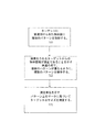
次に図5を参照して、本明細書に記載の実施形態によるシステムの動作を示すフローチャートを説明する。図5に示されるように、臨床処置の間にパラメータを測定する方法の動作では、まず、ブロック505で、画像化されるターゲットに関連付けられた物体面に複数のパターンを投射する。この複数のパターンは、共通の点、線、又は他の幾何図形のいずれかで重なって、画像化されるターゲットからの物体距離が適正であることを示すように操作されてよい(ブロック515)。
Referring now to FIG. 5, a flowchart illustrating the operation of the system according to the embodiments described herein will be described. As shown in FIG. 5, in the operation of the method of measuring parameters during a clinical procedure, first, at
実施形態によっては、この複数のパターンは、画像化されるターゲットの寸法を示す測定単位を示すマークを含んでよい。従って、ターゲットの寸法は、ターゲットに接触することなく取得されることが可能であり、カメラで画像をキャプチャすることにより記憶されることが可能である。実施形態によっては、この複数のパターンは、物体面に投射されるクロスヘアパターンであってよい。上述のように、各クロスヘアパターンは、測定単位を示す目盛が軸上にあってよい。従って、これらの実施形態では、各クロスヘアパターンの中心点同士がちょうど重なって、ターゲットからの物体距離が適正であることを示すように、クロスヘアパターンが操作されてよい。ターゲットのサイズ/寸法は、パターン上の目盛又はマーキングに基づいて測定されてよい(ブロック525)。本明細書に記載の実施形態による方法は、臨床画像化処置及び/又は手術画像化処置の一方の間にリアルタイムで実施されてよい。 In some embodiments, the plurality of patterns may include marks indicating units of measurement indicating the dimensions of the target being imaged. Thus, the dimensions of the target can be obtained without touching the target and can be stored by capturing an image with a camera. In some embodiments, the plurality of patterns may be crosshair patterns projected onto the object plane. As described above, each cross hair pattern may have a scale indicating a measurement unit on the axis. Accordingly, in these embodiments, the cross hair patterns may be manipulated so that the center points of each cross hair pattern just overlap to indicate that the object distance from the target is appropriate. The target size / dimension may be measured based on a scale or marking on the pattern (block 525). The methods according to the embodiments described herein may be performed in real time during one of the clinical and / or surgical imaging procedures.
実施形態によっては、画像の投射は、波長が約350nmから約1000nmであるレーザ放射体を使用して行われる。本方法は、非侵襲的であってリアルタイムで実施されることが可能である。 In some embodiments, the image projection is performed using a laser emitter having a wavelength of about 350 nm to about 1000 nm. The method is non-invasive and can be performed in real time.
本発明概念の実施形態をクロスヘアパターンに関して説明しているが、当然のことながら、本発明概念の実施形態はこの構成に限定されない。本発明概念の範囲から逸脱しない限り、本発明概念に適する任意のパターンが使用されてよい。同様に、本明細書では発光体(レーザ放射体)及び関連付けられたパターンが2つだけの場合について説明しているが、実施形態は、発光体を2つだけ使用することに限定されない。 While embodiments of the inventive concept have been described with respect to crosshair patterns, it should be understood that embodiments of the inventive concept are not limited to this configuration. Any pattern suitable for the inventive concept may be used without departing from the scope of the inventive concept. Similarly, although the present specification describes the case of only two emitters (laser emitters) and associated patterns, embodiments are not limited to using only two emitters.
次に図6Aから図10を参照して、本発明概念の実施形態による、距離マーカ及び光学式定規機能を使用して取得される画像の一例を説明する。まず図6A及び図6Bを参照すると、2つの発光体を含むシステム(例えば、図1に示されたシステム)を使用して、それぞれの図に示される水平パターン及び垂直パターンが生成される。これらのパターンはそれぞれ、その中央にドットY、Zを含む。 Next, with reference to FIGS. 6A to 10, an example of an image acquired using the distance marker and optical ruler functions according to an embodiment of the inventive concept will be described. Referring first to FIGS. 6A and 6B, a system including two light emitters (eg, the system shown in FIG. 1) is used to generate the horizontal and vertical patterns shown in the respective figures. Each of these patterns includes a dot Y, Z in the center thereof.
ターゲット(サンプル)からカメラまでの距離(物体距離)が適正であれば、図7に示されるようにドットY、Zが重なることで、あたかもドットが1つだけ存在するように見える。従って、適正な物体距離が達成されたときには、図7に示されるように、2つのドットが互いに重なっている。図7に示された実施形態では、各ブロックが特定のサイズ(例えば、1インチ×1インチ)に較正されて、ターゲットのサイズを推定する為の2次元定規として働く。図9及び図10に示される、本発明概念の実施形態では、発光体の波長及びパターンを注意深く選択することにより、他の光源(例えば、LED、室内灯など)からの干渉及びノイズを避けることが可能である。従って、本明細書に記載の本発明概念の実施形態による定規機能は多次元であり、例えば、2次元(x及びy)である。 If the distance (object distance) from the target (sample) to the camera is appropriate, the dots Y and Z overlap as shown in FIG. 7, so that it appears as if there is only one dot. Therefore, when the proper object distance is achieved, the two dots overlap each other as shown in FIG. In the embodiment shown in FIG. 7, each block is calibrated to a specific size (eg, 1 inch × 1 inch) to serve as a two-dimensional ruler to estimate the size of the target. In the embodiment of the inventive concept shown in FIGS. 9 and 10, avoiding interference and noise from other light sources (eg, LEDs, room lights, etc.) by carefully selecting the wavelength and pattern of the light emitters. Is possible. Accordingly, the ruler function according to embodiments of the inventive concept described herein is multi-dimensional, for example, two-dimensional (x and y).
同様に、物体距離が適正でない場合は、図8に示されるように、2つのドットY、Zが互いに重なっていない。 Similarly, when the object distance is not appropriate, the two dots Y and Z do not overlap each other as shown in FIG.
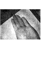
図6〜10に示された実施形態では、測定機能は、光学式定規、即ち、図面に示された複数のブロックを使用して達成可能である。実施形態によっては、各ブロックは一定の距離を表してよい。図9に示されるように、ターゲット、即ち、人の手が放射ビームの中に置かれると、手の表面に格子パターンが示される。図9は、室内灯が点いていて、LEDライトが消えている実施形態を示しており、図10は、室内灯とLEDライトの両方が点いている実施形態を示している。つまり、機能性が周囲光の影響を受けないように波長及びパターンを選択することが可能である。 In the embodiment shown in FIGS. 6-10, the measurement function can be achieved using an optical ruler, ie, a plurality of blocks shown in the drawings. In some embodiments, each block may represent a certain distance. As shown in FIG. 9, when a target, ie a human hand, is placed in the radiation beam, a lattice pattern is shown on the surface of the hand. FIG. 9 shows an embodiment in which the interior light is turned on and the LED light is turned off, and FIG. 10 shows an embodiment in which both the interior light and the LED light are turned on. That is, the wavelength and pattern can be selected so that the functionality is not affected by ambient light.
当然のことながら、図6から図10に示された格子パターンは、例としてのみ示されている。本発明概念の範囲から逸脱しない限り、パターンは変えてよい。例えば、線の太さやブロックの大きさを調節してよい。 Of course, the grid patterns shown in FIGS. 6 to 10 are shown as examples only. The pattern may be changed without departing from the scope of the inventive concept. For example, the thickness of the line or the size of the block may be adjusted.
既に簡単に述べたように、本発明概念の実施形態によっては、ターゲット領域からの最適物体距離、並びにターゲット自体の寸法を測定する方法、システム、及びコンピュータプログラム製品が提供される。実施形態は、上述のように、複数の発光体を使用して物体面に投射されたパターンの重なりに基づいて情報を提供する。 As already briefly mentioned, some embodiments of the inventive concept provide a method, system, and computer program product for measuring the optimal object distance from the target area, as well as the dimensions of the target itself. Embodiments provide information based on the overlap of patterns projected onto the object plane using multiple light emitters, as described above.
本明細書では、本発明概念の実施形態を開示してきたが、具体的な用語を使用しているものの、それらは、限定の為ではなく、一般的且つ説明的な意味でのみ使用している。以下の特許請求の範囲は、本出願があらゆる裁判管轄権において優先権出願としてのあらゆる法定要件を満たすように提供されるものであり、本発明概念の範囲を明記するものとして解釈されるべきである。 Although embodiments of the present inventive concept have been disclosed herein, specific terms are used but are not intended to be limiting and are used in a general and descriptive sense only. . The following claims are provided so that this application meets all statutory requirements as a priority application in any jurisdiction and should be construed as specifying the scope of the inventive concept. is there.
Claims (22)
発光体から、画像化されるターゲットに関連付けられた物体面に第1のパターンを投射するステップと、
前記発光体から、前記画像化されるターゲットに関連付けられた前記物体面に第2のパターンを投射するステップと、
前記第1及び第2のパターンが共通の点、線、又は他の幾何図形のいずれかで重なって、前記画像化されるターゲットからの物体距離が適正であることを示すように、前記第1及び第2のパターンを操作するステップと、
を含む方法。 A method of measuring parameters during a clinical procedure,
Projecting a first pattern from a light emitter onto an object plane associated with a target to be imaged;
Projecting a second pattern from the light emitter onto the object plane associated with the imaged target;
The first and second patterns overlap with either a common point, line, or other geometric figure to indicate that the object distance from the imaged target is correct. And manipulating the second pattern;
Including methods.
前記測定単位は少なくとも2次元で機能する、
請求項1に記載の方法。 Projecting the first and second patterns includes projecting the first and second patterns having marks indicating measurement units indicating the dimensions of the imaged target;
The unit of measure functions in at least two dimensions;
The method of claim 1.
対応するパターン付きレンズを含む複数の発光体であって、前記複数の発光体のうちの第1及び第2の発光体が、それぞれ、第1及び第2のパターンを、画像化されるターゲットに関連付けられた物体面に投射するように構成されている、前記複数の発光体と、
前記第1及び第2のパターンが共通の点、線、又は他の幾何図形のいずれかで重なって、前記画像化されるターゲットからの物体距離が適正であることを示すように、前記第1及び第2のパターンを操作するように構成された入力モジュールと、
を含むシステム。 A system for measuring parameters during a clinical procedure,
A plurality of light emitters including corresponding patterned lenses, wherein the first and second light emitters of the plurality of light emitters respectively have the first and second patterns as targets to be imaged; The plurality of light emitters configured to project onto an associated object plane;
The first and second patterns overlap with either a common point, line, or other geometric figure to indicate that the object distance from the imaged target is correct. And an input module configured to operate the second pattern;
Including system.
画像化されるターゲットに関連付けられた物体面に複数のパターンを投射するように構成されたコンピュータ可読プログラムコードと、
前記複数のパターンが共通の点、線、又は他の幾何図形のいずれかで重なって、前記画像化されるターゲットからの物体距離が適正であることを示すように、前記複数のパターンを操作するように構成されたコンピュータ可読プログラムコードと、を含む、
コンピュータプログラム製品。 A computer program product for measuring parameters during a clinical procedure, said computer program product being stored on a persistent computer readable storage medium, wherein said persistent computer readable storage medium has computer readable program code embedded in said medium And the computer readable program code is:
Computer readable program code configured to project a plurality of patterns onto an object plane associated with a target to be imaged;
Manipulating the patterns so that the patterns overlap with either a common point, line, or other geometric shape to indicate that the object distance from the imaged target is correct Comprising computer readable program code configured to
Computer program product.
発光体から、画像化されるターゲットに関連付けられた物体面に第1のパターンを投射するコンピュータ可読プログラムコードと、
前記発光体から、前記画像化されるターゲットに関連付けられた前記物体面に第2のパターンを投射するコンピュータ可読プログラムコードと、を含む、
請求項15に記載のコンピュータプログラム製品。 The computer readable program code configured to project a plurality of patterns comprises:
Computer readable program code for projecting a first pattern from a light emitter onto an object plane associated with a target to be imaged;
Computer readable program code for projecting a second pattern from the light emitter onto the object plane associated with the imaged target.
The computer program product of claim 15.
Applications Claiming Priority (3)
| Application Number | Priority Date | Filing Date | Title |
|---|---|---|---|
| US201562222273P | 2015-09-23 | 2015-09-23 | |
| US62/222,273 | 2015-09-23 | ||
| PCT/US2016/052788 WO2017053368A1 (en) | 2015-09-23 | 2016-09-21 | Methods, systems and computer program products for determining object distances and target dimensions using light emitters |
Publications (2)
| Publication Number | Publication Date |
|---|---|
| JP2018538107A true JP2018538107A (en) | 2018-12-27 |
| JP2018538107A5 JP2018538107A5 (en) | 2019-10-10 |
Family
ID=58387027
Family Applications (1)
| Application Number | Title | Priority Date | Filing Date |
|---|---|---|---|
| JP2018534487A Pending JP2018538107A (en) | 2015-09-23 | 2016-09-21 | Method, system, and computer program product for measuring object distance and target dimensions using a light emitter |
Country Status (6)
| Country | Link |
|---|---|
| US (1) | US20190086198A1 (en) |
| EP (1) | EP3349643B1 (en) |
| JP (1) | JP2018538107A (en) |
| CN (1) | CN108289605A (en) |
| CA (1) | CA2999485A1 (en) |
| WO (1) | WO2017053368A1 (en) |
Families Citing this family (7)
| Publication number | Priority date | Publication date | Assignee | Title |
|---|---|---|---|---|
| FR3061849A1 (en) * | 2017-01-17 | 2018-07-20 | Fluoptics | METHOD AND DEVICE FOR MEASURING FLUORESCENCE EMITTED TO THE SURFACE OF A BIOLOGICAL TISSUE |
| JP2020537237A (en) * | 2017-10-08 | 2020-12-17 | マジック アイ インコーポレイテッド | Distance measurement using vertical grid pattern |
| EP3803266A4 (en) * | 2018-06-06 | 2022-03-09 | Magik Eye Inc. | Distance measurement using high density projection patterns |
| US20200094401A1 (en) * | 2018-09-21 | 2020-03-26 | Beijing Jingdong Shangke Information Technology Co., Ltd. | System and method for automatic learning of product manipulation |
| US11483503B2 (en) | 2019-01-20 | 2022-10-25 | Magik Eye Inc. | Three-dimensional sensor including bandpass filter having multiple passbands |
| US11474209B2 (en) | 2019-03-25 | 2022-10-18 | Magik Eye Inc. | Distance measurement using high density projection patterns |
| US11320537B2 (en) | 2019-12-01 | 2022-05-03 | Magik Eye Inc. | Enhancing triangulation-based three-dimensional distance measurements with time of flight information |
Citations (9)
| Publication number | Priority date | Publication date | Assignee | Title |
|---|---|---|---|---|
| JPS62291511A (en) * | 1986-06-11 | 1987-12-18 | Canon Inc | Distance measuring apparatus |
| JPS63234213A (en) * | 1987-03-23 | 1988-09-29 | Olympus Optical Co Ltd | Endoscope for measurement |
| JP2000517072A (en) * | 1997-06-27 | 2000-12-19 | キーメッド(メディカル アンド インダストリアル イクイプメント)リミテッド | Optical scope with measuring system |
| JP2004110804A (en) * | 2002-08-28 | 2004-04-08 | Fuji Xerox Co Ltd | Three-dimensional image photographing equipment and method |
| JP2011504586A (en) * | 2007-11-15 | 2011-02-10 | シロナ・デンタル・システムズ・ゲゼルシャフト・ミット・ベシュレンクテル・ハフツング | Method for optically measuring the three-dimensional shape of an object |
| US20120293812A1 (en) * | 2011-05-19 | 2012-11-22 | Tyco Healthcare Group Lp | Methods utilizing triangulation in metrology systems for in-situ surgical applications |
| WO2014080937A1 (en) * | 2012-11-21 | 2014-05-30 | 三菱電機株式会社 | Image generation device |
| US20140276097A1 (en) * | 2013-03-12 | 2014-09-18 | Covidien Lp | Systems and methods for optical measurement for in-situ surgical applications |
| US20140377716A1 (en) * | 2013-06-24 | 2014-12-25 | Qioptiq Photonics Gmbh & Co. Kg | Dental Measuring Device for three dimensional measurement of teeth |
Family Cites Families (3)
| Publication number | Priority date | Publication date | Assignee | Title |
|---|---|---|---|---|
| AU2006203027B2 (en) * | 2006-07-14 | 2009-11-19 | Canon Kabushiki Kaisha | Improved two-dimensional measurement system |
| US20090041201A1 (en) * | 2007-08-06 | 2009-02-12 | Carestream Health, Inc. | Alignment apparatus for imaging system |
| AU2010257224B2 (en) * | 2010-12-15 | 2014-09-18 | Canon Kabushiki Kaisha | Block patterns as two-dimensional ruler |
-
2016
- 2016-09-21 CA CA2999485A patent/CA2999485A1/en not_active Abandoned
- 2016-09-21 JP JP2018534487A patent/JP2018538107A/en active Pending
- 2016-09-21 CN CN201680067914.7A patent/CN108289605A/en active Pending
- 2016-09-21 EP EP16849467.2A patent/EP3349643B1/en active Active
- 2016-09-21 WO PCT/US2016/052788 patent/WO2017053368A1/en active Application Filing
- 2016-09-21 US US15/760,675 patent/US20190086198A1/en not_active Abandoned
Patent Citations (9)
| Publication number | Priority date | Publication date | Assignee | Title |
|---|---|---|---|---|
| JPS62291511A (en) * | 1986-06-11 | 1987-12-18 | Canon Inc | Distance measuring apparatus |
| JPS63234213A (en) * | 1987-03-23 | 1988-09-29 | Olympus Optical Co Ltd | Endoscope for measurement |
| JP2000517072A (en) * | 1997-06-27 | 2000-12-19 | キーメッド(メディカル アンド インダストリアル イクイプメント)リミテッド | Optical scope with measuring system |
| JP2004110804A (en) * | 2002-08-28 | 2004-04-08 | Fuji Xerox Co Ltd | Three-dimensional image photographing equipment and method |
| JP2011504586A (en) * | 2007-11-15 | 2011-02-10 | シロナ・デンタル・システムズ・ゲゼルシャフト・ミット・ベシュレンクテル・ハフツング | Method for optically measuring the three-dimensional shape of an object |
| US20120293812A1 (en) * | 2011-05-19 | 2012-11-22 | Tyco Healthcare Group Lp | Methods utilizing triangulation in metrology systems for in-situ surgical applications |
| WO2014080937A1 (en) * | 2012-11-21 | 2014-05-30 | 三菱電機株式会社 | Image generation device |
| US20140276097A1 (en) * | 2013-03-12 | 2014-09-18 | Covidien Lp | Systems and methods for optical measurement for in-situ surgical applications |
| US20140377716A1 (en) * | 2013-06-24 | 2014-12-25 | Qioptiq Photonics Gmbh & Co. Kg | Dental Measuring Device for three dimensional measurement of teeth |
Also Published As
| Publication number | Publication date |
|---|---|
| EP3349643A4 (en) | 2019-05-22 |
| EP3349643B1 (en) | 2021-02-17 |
| EP3349643A1 (en) | 2018-07-25 |
| CA2999485A1 (en) | 2017-03-30 |
| WO2017053368A1 (en) | 2017-03-30 |
| US20190086198A1 (en) | 2019-03-21 |
| CN108289605A (en) | 2018-07-17 |
Similar Documents
| Publication | Publication Date | Title |
|---|---|---|
| JP2018538107A (en) | Method, system, and computer program product for measuring object distance and target dimensions using a light emitter | |
| EP3606410B1 (en) | Anatomical surface assessment methods, devices and systems | |
| US20180271378A1 (en) | Handheld skin measuring or monitoring device | |
| US20160328854A1 (en) | Distance sensor | |
| JP2018535725A5 (en) | ||
| US20200129240A1 (en) | Systems and methods for intraoperative planning and placement of implants | |
| JP2017538952A (en) | Optical tracking method and system based on passive markers | |
| WO2019012770A1 (en) | Imaging device and monitoring device | |
| ES2683364T3 (en) | Method to monitor linear dimensions of three-dimensional objects | |
| CN103596521A (en) | 3D system and method for guiding objects | |
| JP2016100698A (en) | Calibration device, calibration method, and program | |
| US11079278B1 (en) | Systems and methods for using multispectral imagery for precise tracking and verification | |
| KR20170031185A (en) | Wide field-of-view depth imaging | |
| GB2538274A (en) | A monitoring system | |
| US10846883B2 (en) | Method for calibrating objects in a reference coordinate system and method for tracking objects | |
| US11857153B2 (en) | Systems and methods for multi-modal sensing of depth in vision systems for automated surgical robots | |
| WO2021155045A1 (en) | Method and apparatus for mapping tooth surfaces | |
| CN217767172U (en) | Structured light projector and image acquisition system | |
| JP7001612B2 (en) | Methods and Devices for Determining 3D Coordinates for At least One Default Point on an Object | |
| JP2020008434A (en) | Three-dimensional measuring device and method | |
| ES2588852T3 (en) | Method to indicate a point in a measurement space | |
| KR20210117062A (en) | Method and apparatus for tracking gaze | |
| WO2021181508A1 (en) | Endoscope system | |
| US20240115325A1 (en) | Camera tracking system for computer assisted surgery navigation | |
| KR100770973B1 (en) | Measuring method for laser scan energy distribution |
Legal Events
| Date | Code | Title | Description |
|---|---|---|---|
| A521 | Request for written amendment filed |
Free format text: JAPANESE INTERMEDIATE CODE: A523 Effective date: 20190826 |
|
| A621 | Written request for application examination |
Free format text: JAPANESE INTERMEDIATE CODE: A621 Effective date: 20190826 |
|
| A131 | Notification of reasons for refusal |
Free format text: JAPANESE INTERMEDIATE CODE: A131 Effective date: 20200721 |
|
| A977 | Report on retrieval |
Free format text: JAPANESE INTERMEDIATE CODE: A971007 Effective date: 20200722 |
|
| A02 | Decision of refusal |
Free format text: JAPANESE INTERMEDIATE CODE: A02 Effective date: 20210302 |