JP2018528472A - Correction lens apparatus and method - Google Patents
Correction lens apparatus and method Download PDFInfo
- Publication number
- JP2018528472A JP2018528472A JP2018510854A JP2018510854A JP2018528472A JP 2018528472 A JP2018528472 A JP 2018528472A JP 2018510854 A JP2018510854 A JP 2018510854A JP 2018510854 A JP2018510854 A JP 2018510854A JP 2018528472 A JP2018528472 A JP 2018528472A
- Authority
- JP
- Japan
- Prior art keywords
- lens
- integral
- side wall
- protrusions
- lens structure
- Prior art date
- Legal status (The legal status is an assumption and is not a legal conclusion. Google has not performed a legal analysis and makes no representation as to the accuracy of the status listed.)
- Pending
Links
- 238000012937 correction Methods 0.000 title description 7
- 238000000034 method Methods 0.000 title description 5
- 230000002093 peripheral effect Effects 0.000 claims description 27
- 238000003754 machining Methods 0.000 claims description 12
- 230000004304 visual acuity Effects 0.000 claims description 8
- 239000011521 glass Substances 0.000 abstract description 7
- -1 goggles Substances 0.000 abstract 1
- 239000005336 safety glass Substances 0.000 abstract 1
- 230000004438 eyesight Effects 0.000 description 9
- 230000000750 progressive effect Effects 0.000 description 8
- 230000001681 protective effect Effects 0.000 description 8
- 239000000463 material Substances 0.000 description 6
- 238000005498 polishing Methods 0.000 description 5
- 239000004033 plastic Substances 0.000 description 4
- 206010020675 Hypermetropia Diseases 0.000 description 3
- 230000004305 hyperopia Effects 0.000 description 3
- 201000006318 hyperopia Diseases 0.000 description 3
- 238000012986 modification Methods 0.000 description 3
- 230000004048 modification Effects 0.000 description 3
- 238000006467 substitution reaction Methods 0.000 description 3
- 238000013037 co-molding Methods 0.000 description 2
- 238000004891 communication Methods 0.000 description 2
- 238000005336 cracking Methods 0.000 description 2
- 238000010586 diagram Methods 0.000 description 2
- 230000000694 effects Effects 0.000 description 2
- 230000004313 glare Effects 0.000 description 2
- 230000006872 improvement Effects 0.000 description 2
- 238000000465 moulding Methods 0.000 description 2
- 230000004379 myopia Effects 0.000 description 2
- 208000001491 myopia Diseases 0.000 description 2
- 230000003287 optical effect Effects 0.000 description 2
- 125000002066 L-histidyl group Chemical group [H]N1C([H])=NC(C([H])([H])[C@](C(=O)[*])([H])N([H])[H])=C1[H] 0.000 description 1
- 241001026602 Quintana Species 0.000 description 1
- 230000009471 action Effects 0.000 description 1
- 230000032683 aging Effects 0.000 description 1
- 230000015572 biosynthetic process Effects 0.000 description 1
- 230000008859 change Effects 0.000 description 1
- 238000004040 coloring Methods 0.000 description 1
- 238000010276 construction Methods 0.000 description 1
- 238000005520 cutting process Methods 0.000 description 1
- 238000013461 design Methods 0.000 description 1
- 238000002474 experimental method Methods 0.000 description 1
- 230000014509 gene expression Effects 0.000 description 1
- 230000003993 interaction Effects 0.000 description 1
- 230000013011 mating Effects 0.000 description 1
- 239000000155 melt Substances 0.000 description 1
- 239000000178 monomer Substances 0.000 description 1
- 239000004417 polycarbonate Substances 0.000 description 1
- 229920000515 polycarbonate Polymers 0.000 description 1
- 239000002861 polymer material Substances 0.000 description 1
- 238000012545 processing Methods 0.000 description 1
- 230000000717 retained effect Effects 0.000 description 1
- 230000002441 reversible effect Effects 0.000 description 1
- 238000012795 verification Methods 0.000 description 1
Images


Classifications
-
- A—HUMAN NECESSITIES
- A63—SPORTS; GAMES; AMUSEMENTS
- A63F—CARD, BOARD, OR ROULETTE GAMES; INDOOR GAMES USING SMALL MOVING PLAYING BODIES; VIDEO GAMES; GAMES NOT OTHERWISE PROVIDED FOR
- A63F9/00—Games not otherwise provided for
- A63F9/02—Shooting or hurling games
-
- G—PHYSICS
- G02—OPTICS
- G02C—SPECTACLES; SUNGLASSES OR GOGGLES INSOFAR AS THEY HAVE THE SAME FEATURES AS SPECTACLES; CONTACT LENSES
- G02C7/00—Optical parts
- G02C7/02—Lenses; Lens systems ; Methods of designing lenses
-
- A—HUMAN NECESSITIES
- A63—SPORTS; GAMES; AMUSEMENTS
- A63B—APPARATUS FOR PHYSICAL TRAINING, GYMNASTICS, SWIMMING, CLIMBING, OR FENCING; BALL GAMES; TRAINING EQUIPMENT
- A63B33/00—Swimming equipment attachable to the head, e.g. swim caps or goggles
- A63B33/002—Swimming goggles
-
- B—PERFORMING OPERATIONS; TRANSPORTING
- B29—WORKING OF PLASTICS; WORKING OF SUBSTANCES IN A PLASTIC STATE IN GENERAL
- B29D—PRODUCING PARTICULAR ARTICLES FROM PLASTICS OR FROM SUBSTANCES IN A PLASTIC STATE
- B29D11/00—Producing optical elements, e.g. lenses or prisms
- B29D11/00009—Production of simple or compound lenses
-
- G—PHYSICS
- G02—OPTICS
- G02C—SPECTACLES; SUNGLASSES OR GOGGLES INSOFAR AS THEY HAVE THE SAME FEATURES AS SPECTACLES; CONTACT LENSES
- G02C1/00—Assemblies of lenses with bridges or browbars
-
- G—PHYSICS
- G02—OPTICS
- G02C—SPECTACLES; SUNGLASSES OR GOGGLES INSOFAR AS THEY HAVE THE SAME FEATURES AS SPECTACLES; CONTACT LENSES
- G02C1/00—Assemblies of lenses with bridges or browbars
- G02C1/06—Bridge or browbar secured to or integral with closed rigid rims for the lenses
-
- G—PHYSICS
- G02—OPTICS
- G02C—SPECTACLES; SUNGLASSES OR GOGGLES INSOFAR AS THEY HAVE THE SAME FEATURES AS SPECTACLES; CONTACT LENSES
- G02C7/00—Optical parts
- G02C7/02—Lenses; Lens systems ; Methods of designing lenses
- G02C7/08—Auxiliary lenses; Arrangements for varying focal length
- G02C7/086—Auxiliary lenses located directly on a main spectacle lens or in the immediate vicinity of main spectacles
-
- G—PHYSICS
- G02—OPTICS
- G02C—SPECTACLES; SUNGLASSES OR GOGGLES INSOFAR AS THEY HAVE THE SAME FEATURES AS SPECTACLES; CONTACT LENSES
- G02C7/00—Optical parts
- G02C7/02—Lenses; Lens systems ; Methods of designing lenses
- G02C7/08—Auxiliary lenses; Arrangements for varying focal length
- G02C7/088—Lens systems mounted to spectacles
-
- G—PHYSICS
- G02—OPTICS
- G02C—SPECTACLES; SUNGLASSES OR GOGGLES INSOFAR AS THEY HAVE THE SAME FEATURES AS SPECTACLES; CONTACT LENSES
- G02C7/00—Optical parts
- G02C7/16—Shades; shields; Obturators, e.g. with pinhole, with slot
-
- A—HUMAN NECESSITIES
- A61—MEDICAL OR VETERINARY SCIENCE; HYGIENE
- A61F—FILTERS IMPLANTABLE INTO BLOOD VESSELS; PROSTHESES; DEVICES PROVIDING PATENCY TO, OR PREVENTING COLLAPSING OF, TUBULAR STRUCTURES OF THE BODY, e.g. STENTS; ORTHOPAEDIC, NURSING OR CONTRACEPTIVE DEVICES; FOMENTATION; TREATMENT OR PROTECTION OF EYES OR EARS; BANDAGES, DRESSINGS OR ABSORBENT PADS; FIRST-AID KITS
- A61F9/00—Methods or devices for treatment of the eyes; Devices for putting-in contact lenses; Devices to correct squinting; Apparatus to guide the blind; Protective devices for the eyes, carried on the body or in the hand
- A61F9/02—Goggles
- A61F2009/021—Goggles with prescription spectacle lenses
Abstract
【課題】眼鏡、ゴーグル及び安全眼鏡類に使用可能な一体レンズ構造を提供する。【解決手段】レンズは突部と共に一体構造として形成され、突部は処方型眼鏡類用に機械加工可能な面を有し、大型の遮蔽体の第1の側面から延在し、遮蔽体と突部外周との交差部における亀裂を、2個の面間を非直線状に接続することにより防止する。【選択図】図1An integrated lens structure that can be used for glasses, goggles, and safety glasses is provided. The lens is formed as an integral structure with a protrusion, the protrusion having a surface that can be machined for prescription eyeglasses, extending from a first side of a large shield, Cracks at the intersection with the outer periphery of the protrusion are prevented by connecting the two surfaces in a non-linear manner. [Selection] Figure 1
Description
本願は2015年8月26日出願の米国仮出願番号第62/210、024号の優先権を主張するものであり、本明細書においてその開示全体を参照により援用する。 This application claims priority from US Provisional Application No. 62 / 210,024, filed August 26, 2015, the entire disclosure of which is incorporated herein by reference.
本発明は一般的には、眼鏡、保護用眼鏡類、ゴーグル等の眼鏡類に用いられる矯正レンズに関する。より詳細には、ここに開示のシステム及び方法は、光学的に正しい材料からなる遮蔽部又は周囲部を形成する第1の部分と、前記第1の部分上に永久的に配置されて矯正レンズを形成する少なくとも1個の突部とを有するレンズに関する。上述の構成により、前記装置は、前記レンズの前記第1の部分の外周が眼鏡類フレーム又はゴーグル又はその他レンズフレームとの係合に適する一体構造を形成する。 The present invention generally relates to a correction lens used for spectacles such as spectacles, protective spectacles, and goggles. More particularly, the system and method disclosed herein includes a first portion that forms a shield or perimeter of an optically correct material, and a corrective lens permanently disposed on the first portion. And a lens having at least one projecting portion. With the configuration described above, the device forms an integral structure in which the outer periphery of the first portion of the lens is suitable for engagement with a spectacle frame or goggles or other lens frame.
数百年の間、視力に問題がある人々は矯正眼鏡類に頼ってきた。一般的に、このような視力の問題は矯正レンズを必要とする人の目の身体的特徴が原因である。今日まで、そのような矯正レンズが必要とする使用者に提供されてきた。使用者の目が捉えた画像を受容体となる目の裏面上でより明瞭な視覚を提供する方法により焦点を再び合わせるためのレンズ研磨の基本的性質は進歩し、近視又は遠視以外の問題も矯正してきた。しかしながら、入射光に焦点を再び合わせるためにレンズを使用者の目の前に配置するという大前提は今日でも未だ存在する。 For hundreds of years, people with vision problems have relied on corrective eyewear. In general, such vision problems are caused by the physical characteristics of the human eye that require a corrective lens. To date, such corrective lenses have been provided to users in need. The fundamental nature of lens polishing to refocus the image captured by the user's eye in a way that provides clearer vision on the back of the receiving eye, including problems other than myopia or hyperopia I have corrected it. However, there is still a major premise that the lens is placed in front of the user's eyes to refocus the incident light.
矯正レンズの構成の性質は、特に安全用又は保護用眼鏡類との組合せにおいて、十分とは言えない場合もある。例えば、強度遠視のため視力矯正に非常に厚いレンズを必要とする使用者の矯正レンズは、ゴーグル等の遮蔽型の眼鏡類と組合せた使用には余り適していない。更に、上記のような厚いレンズの外周は眼鏡フレームとの係合を制限する。 The nature of the corrective lens configuration may not be sufficient, especially in combination with safety or protective eyewear. For example, a correction lens for a user who needs a very thick lens for correcting vision because of hyperopia is not very suitable for use in combination with shielding glasses such as goggles. Furthermore, the outer periphery of the thick lens as described above limits the engagement with the spectacle frame.
更に、例えばゴーグルを着用する軍事活動の従事者や、スキーやオートバイの運転等の活動のためにスポーツ用ゴーグル着用する人等、近視又は遠視又はその他視力に問題のある人が保護ゴーグルを着用しようとすると問題が発生する。上述のような矯正レンズの問題はまた、安全ゴーグルの着用が必須な仕事に従事する人においても問題となる。 In addition, those who have problems with myopia or hyperopia or other vision problems, such as those engaged in military activities wearing goggles or those wearing sports goggles for activities such as skiing or motorcycle driving should wear protective goggles. This causes a problem. The problem of corrective lenses as described above is also a problem for those engaged in work where safety goggles must be worn.
従来、上述のような眼鏡の使用者は目を保護する際、ゴーグル又は安全ゴーグルの空隙内に自分の眼鏡を合わせてみるしかなかった。当該組合せにおいて、使用者はゴーグルレンズ及びゴーグルレンズと顔の間に配置される自分のレンズの両方を通して周囲を見なければならない。これにより、曇り、離して配置される反射面が作用し合うことによるグレア、離して配置されるレンズが原因の画像の影、若しくは少なくとも1個のゴーグルレンズと離して配置される眼鏡レンズとが作用し合うことが原因のその他問題により視界が悪くなる。 Conventionally, the user of glasses as described above has only to put his / her glasses in the gap of the goggles or safety goggles when protecting the eyes. In this combination, the user must see the surroundings through both the goggle lens and his lens placed between the goggle lens and the face. As a result, cloudiness, glare caused by the action of reflecting surfaces arranged separately, shadows of an image caused by lenses arranged separately, or spectacle lenses arranged separately from at least one goggle lens Visibility worsens due to other problems caused by interaction.
従来技術において、上述の問題の一部に対する解決手段が提供されてきた。例えば特許文献1(キンタナ(Quintana))は、矯正レンズ及びパノラマ式又は遮蔽式レンズの一体構造を提供するという概念において進歩的ではあるものの、開示されている一体構造の構成は改良の余地がある。特許文献1は第1のパノラマ式レンズの一方側から隆起する2個の突出部を用いて眼科用レンズを形成する新規な概念を開示する一方、突出部と前方のパノラマ式レンズとの交差部において突出部の外周に沿って亀裂が発生する危険性については対応がなされていない。更に、突出部の側壁を通して、また前方のパノラマ式レンズとの交差部に隣接して入って来る光の反射は、特許文献1に開示の通り、使用者にとって煩わしい光の有色化等の屈折性性質を発声させる原因となり得る。更に、使用者の顔の前方で密閉空隙を形成するゴーグルに用いる場合、突出部を有するパノラマ式レンズ又はその遮蔽領域の厚さが非一定なため、形成時により厚い領域において熱が保持されて熱的問題が発生する場合がある。更に、湾曲パノラマ式遮蔽体上の小型の突部を着用者の視力を矯正するために必要な特質まで研磨する方法を開示する従来技術は無い。 The prior art has provided solutions to some of the above problems. For example, Patent Document 1 (Quintana) is progressive in the concept of providing an integrated structure of a corrective lens and a panoramic or shielded lens, but the disclosed structure of the integrated structure has room for improvement. . Patent Document 1 discloses a novel concept of forming an ophthalmic lens using two protrusions that protrude from one side of a first panoramic lens, while the intersection of the protrusion and the front panoramic lens. However, the risk of cracks occurring along the outer periphery of the protrusion is not addressed. Further, the reflection of light entering through the side wall of the protruding portion and adjacent to the intersection with the front panoramic lens, as disclosed in Patent Document 1, is a refraction property such as coloring of light which is troublesome for the user. It can be a cause of uttering nature. Furthermore, when used in goggles that form a sealed gap in front of the user's face, the panoramic lens with protrusions or the shielding area has a non-constant thickness, so heat is retained in the thicker area during formation. Thermal problems may occur. Furthermore, there is no prior art that discloses a method for polishing small protrusions on a curved panoramic shield to the characteristics required to correct the wearer's vision.
したがって、薄いパノラマ式レンズの表面上に形成可能な矯正レンズが未だ求められており、この場合、眼科用レンズが形成される突出材料の外周と平面的なパノラマ式前方レンズとの交差部が、亀裂や経時及び温度差が原因の疲労性破損を防止するよう構成される。当該装置は眼鏡類の単レンズ、保護用眼鏡類の遮蔽体及びスポーツゴーグル・保護ゴーグル装置の二重レンズ構成、水平方向及び垂直方向の累進多焦点レンズを形成可能な形状において使用可能な形状を提供する。更に、当該装置及び方法においては、突出部を取囲む大型で大きく湾曲するパノラマ式レンズの代わりに、従来のレンズ研磨機械を用いて矯正レンズに機械加工可能な突部を前部のパノラマ式レンズ上に設ける。 Accordingly, there is still a need for a corrective lens that can be formed on the surface of a thin panoramic lens, in which case the intersection of the outer periphery of the protruding material from which the ophthalmic lens is formed and the planar panoramic front lens is It is configured to prevent fatigue damage due to cracks, aging and temperature differences. The device has a shape that can be used in a single lens for spectacles, a shield for protective spectacles and a double lens configuration for sports goggles / protective goggles, and a shape that can form progressive multifocal lenses in the horizontal and vertical directions. provide. Furthermore, in this apparatus and method, instead of a large and large panoramic lens that surrounds the protrusion, a projecting portion that can be machined into a correction lens using a conventional lens polishing machine has a front panoramic lens. Provide on top.
上述の関連技術の例及び関連する限定事項は説明を目的とした非排他的なものであり、本明細書及び請求の範囲に記載の本発明に対するいかなる限定をも暗示するものではない。当業者にとって、関連する先行技術の様々な限定は以下の説明及び添付の図面を読んで理解することにより自明となる。 The foregoing related art examples and associated limitations are non-exclusive for the purpose of illustration and are not meant to imply any limitation to the invention as set forth in the specification and claims. Various limitations of the related prior art will become apparent to those skilled in the art upon reading and understanding the following description and the accompanying drawings.
本発明の目的は、眼科用レンズに切削可能な少なくとも1個の突出部が形成される第1の湾曲又はパノラマ式レンズの一体構造を提供することである。 An object of the present invention is to provide an integrated structure of a first curved or panoramic lens in which at least one projectable portion is formed on an ophthalmic lens.
本発明の別な目的は、突出部が形成される第1のレンズが、フレームに適合可能な薄い断面の光学材料で突出部を取囲むため、使用者に厚いレンズが処方されるのを防止できる一体構造を提供することである。 Another object of the present invention is to prevent the user from prescribing a thick lens because the first lens in which the protrusion is formed surrounds the protrusion with a thin cross-section optical material that can be adapted to the frame. It is to provide an integral structure that can be made.
本発明の別な目的は、薄い前部又はパノラマ式レンズにおいて、突出部の外周側壁とパノラマ式レンズの突出部が形成される部分との交差部に亀裂が発生する可能性を除外又は少なくとも最小限に抑えることである。 Another object of the present invention is to eliminate or at least minimize the possibility of cracking at the intersection of the outer peripheral side wall of the protrusion and the portion where the protrusion of the panoramic lens is formed in a thin front or panoramic lens. It is to limit to the limit.
本発明の別な目的は、突出部を取囲む大型で湾曲状の第1のレンズ部に関わらず、従来のレンズ研磨機械を用いて機械加工可能な突出部を大型の湾曲レンズの表面上に形成することである。 Another object of the present invention is to provide a protrusion on the surface of a large curved lens that can be machined using a conventional lens polishing machine, regardless of the large, curved first lens portion surrounding the protrusion. Is to form.
本発明の他の目的は、水平方向及び垂直方向の累進多焦点レンズに切削可能な形状の、周囲を囲むパノラマ式第1のレンズを有する一体構造に形成される突出部を提供することである。 Another object of the present invention is to provide a protrusion formed in a unitary structure having a panoramic first lens surrounding the periphery, which can be cut into progressive multifocal lenses in the horizontal and vertical directions. .
以下の説明より明らかとなる、本発明のレンズに係る発明及びシステムの上記及びその他の目的、特徴、利点、及び従来技術に対する利点は、本発明を十分に開示するがいかなる限定をも意図しない本明細書及び以下の詳細な説明に記載の改良により実現する。 The above and other objects, features, advantages, and advantages of the prior art of the invention and system relating to the lens of the present invention, which will become apparent from the following description, are those which fully disclose the invention but are not intended to be limiting in any way This is achieved by the improvements described in the specification and the following detailed description.
本発明は一体構造に形成されるレンズであって、一般的に凹状のパノラマ式形状に形成される第1のレンズ部を特徴とし、第1のレンズ部の第1の面と永久的に接続しつつ隆起し外周縁部が定義する形状の複数の突出部を裏面上に有する。突出部の周囲で湾曲し取囲む第1のレンズ部の断面厚さは、第1のレンズ部の内側又は第1の側から隆起する突出部の外周からなる境界内の領域の断面厚さより薄い。 The present invention is a lens formed in an integral structure, characterized by a first lens portion generally formed in a concave panoramic shape and permanently connected to a first surface of the first lens portion. However, it has a plurality of protruding portions on the back surface that are raised and have a shape defined by the outer peripheral edge portion. The cross-sectional thickness of the first lens portion that is curved and encircles around the protrusion is thinner than the cross-sectional thickness of the region in the boundary formed by the outer periphery of the protrusion protruding from the inside of the first lens portion or from the first side. .
前記装置の好ましい実施形態において、第1のレンズ部又は遮蔽体の半径は、突部が位置する遮蔽体の中央部により良く適応し、歪みを更に軽減するよう微細に異なっていてもよい。例えば、第1のレンズ部又は遮蔽体の半径は、遮蔽体又は第1のレンズ部の前面の一般的な半径である75mmであってもよい。しかしながら、突部が延在する中央部は65mm(より薄い)であってもよい。このように中央部分の円弧を微細に薄くすることにより、処方可能な矯正の範囲が広がることが分かった。しかしながら、半径の違いは肉眼では気付かない程であり、一般的に前記第1の部分又は遮蔽体は元の形状を保持して美容性及び従来のフレーム及びゴーグル枠体への適合性を提供する。 In a preferred embodiment of the device, the radius of the first lens part or shield may be finely adapted to better accommodate the central part of the shield where the protrusion is located and further reduce distortion. For example, the radius of the first lens unit or the shield may be 75 mm, which is a general radius of the front surface of the shield or the first lens unit. However, the central part from which the protrusion extends may be 65 mm (thinner). In this way, it was found that the range of correction that can be prescribed increases by thinning the arc in the central portion. However, the difference in radius is invisible to the naked eye, and generally the first portion or shield retains its original shape to provide aesthetics and compatibility with conventional frames and goggles frames. .
本第1のレンズ部は表面全体に渡って光学的に正しく、中央部両側のより薄い周囲領域が光学的に正しく、眼鏡フレーム又はゴーグル内に係合できるよう非常に薄い断面を有するが、こめかみ部分に係合して遮蔽体を形成するのにも適している。 The first lens part is optically correct over the entire surface and the thinner surrounding area on both sides of the central part is optically correct and has a very thin cross-section so that it can be engaged in a spectacle frame or goggles, but the temples It is also suitable for engaging the part to form a shield.
本発明による前記装置の全ての実施形態において、レンズの形成に用いられる突出部の形状を定義する側壁の外周縁部と、第1のレンズ部の第1の面との交差部は好ましくは、2個の平面が垂直に交差する交差部でも、突出部の側壁面から延在する直線からなる交差部でも無い。 In all embodiments of the device according to the invention, the intersection of the outer peripheral edge of the side wall defining the shape of the protrusion used to form the lens and the first surface of the first lens part is preferably It is neither an intersecting portion where two planes intersect perpendicularly nor an intersecting portion consisting of a straight line extending from the side wall surface of the protruding portion.
本発明による前記装置の全ての実施形態において、突出部の形状を定義する突出部の外周の側壁における交差部は好ましくは、第1のレンズ部の第1の面との交差部から側壁面を延びる線が非直線状となり、突出部の機械加工可能な表面の縁部まで延在する側壁の一部が側壁の残りの部分に対して方向を変えるよう形成される。 In all embodiments of the device according to the invention, the intersection on the outer peripheral side wall of the protrusion defining the shape of the protrusion is preferably the side wall surface from the intersection with the first surface of the first lens part. The extending line is non-linear, and a portion of the side wall that extends to the edge of the machineable surface of the protrusion is formed to change direction with respect to the rest of the side wall.
本発明による前記装置の全ての実施形態において、1個又は、より好ましくは複数の当該突出部は、周囲を取囲む光学的に正しいパノラマ式レンズに両者が永久的に接続されるよう係合し、光学的歪みがあったとしても最小限となる一体構造を形成する。当該少なくとも1個の突出部との当該接続は好ましくは、突出部と、パノラマ式レンズを定義する第1のレンズ部又は遮蔽体との一体構造をモールド成型することにより達成される。 In all embodiments of the device according to the invention, one or more preferably a plurality of such protrusions are engaged so that they are permanently connected to an optically correct panoramic lens surrounding the periphery. Forms an integral structure that is minimal even if there is optical distortion. The connection with the at least one protrusion is preferably accomplished by molding an integral structure of the protrusion and a first lens portion or shield defining a panoramic lens.
一体構造を形成する際、突部及び第1のレンズ部又は遮蔽体は一体ユニットとしてモールド成型してもよく、又は突部は第1のレンズ部に共成形してもよい。共成形する際、突部は予形成し、その後に第1のレンズ部の型に連通させることにより、そこで突部の第1の面が融解して突出部に接合し、一体構造を形成する。 When forming the integral structure, the protrusion and the first lens part or the shield may be molded as an integral unit, or the protrusion may be co-molded with the first lens part. When co-molding, the projection is preformed, and then communicated with the mold of the first lens unit, whereupon the first surface of the projection melts and joins to the projection to form an integral structure. .
前述した通り、突部の外周側壁と第1のレンズ部の中央部分との交差部は好ましくは垂直ではない。したがって、第1のレンズ部及び突部の一体構造をモールド成型又は形成する際、当該交差部は好ましくは湾曲又は傾斜して形成される。また、実験により歪みや光反射の問題を最小限に抑えることが分かったため、接続部を形成する傾斜面又は湾曲面である交差部の幅は小さく、第1のレンズ部の表面上方で1ミリメートル以下の範囲で隆起することが好ましい。 As described above, the intersection between the outer peripheral side wall of the protrusion and the central portion of the first lens portion is preferably not vertical. Therefore, when the integral structure of the first lens portion and the protrusion is molded or formed, the intersecting portion is preferably formed to be curved or inclined. In addition, since experiments have shown that the problem of distortion and light reflection is minimized, the width of the intersecting portion that is the inclined surface or the curved surface forming the connection portion is small, and 1 mm above the surface of the first lens portion. It is preferable to protrude in the following range.
更に、ゴーグル又は眼鏡フレームと係合する、複数の突出部を設けた湾曲状の第1のレンズ部又は遮蔽体からなる場合、第1のレンズ部を形成する材料と機械加工して矯正レンズを形成可能な突出部との間に偏光層を配置してもよい。これにより、着用者に届く光が偏光される。これは、第1のレンズ部を層状にすることにより実現してもよい。 Furthermore, when it consists of a curved first lens part or a shielding body provided with a plurality of protrusions that engages with goggles or a spectacle frame, the correction lens is machined with the material forming the first lens part. You may arrange | position a polarizing layer between the protrusion part which can be formed. Thereby, the light reaching the wearer is polarized. This may be realized by layering the first lens unit.
更に、第1のレンズ部の第1の面と交差する側壁により定義される突出部の形状は本明細書に記載のものでもよく、又は使用者のために累進多焦点レンズの切削が可能なその他形状であってもよい。そのような形状の一例は、図示の通り、湾曲状第1のレンズ部の2個の端部に隣接して直径がより幅広く、中間部にかけて狭くなる。 Furthermore, the shape of the protrusion defined by the side wall intersecting the first surface of the first lens portion may be as described herein, or a progressive multifocal lens can be cut for the user. Other shapes may be used. An example of such a shape has a wider diameter adjacent to the two ends of the curved first lens portion and narrows toward the middle portion, as shown.
当該好ましい形状により、突出部の一部が鼻梁付近まで延在すると共に、こめかみ及び鼻の十分下方に延在することになる。このような湾曲部が鼻側から下縁部まで延在する伸びた矩形形状により、累進多焦点レンズが上端部から底部までの水平方向、及び鼻からこめかみまでの横方向に形成されるため、使用者に合わせたカスタマイズ度が高い累進多焦点レンズの形成が可能となる。第1のレンズ部の周囲部は、突出部及び第1のレンズ部の一体部分に比べて非常に薄いため、形成されるレンズ又は遮蔽体は使用者に合わせて構成できる。 With this preferable shape, a part of the protrusion extends to the vicinity of the nasal bridge, and extends sufficiently below the temple and the nose. With such a curved rectangular portion extending from the nose side to the lower edge, the progressive multifocal lens is formed in the horizontal direction from the top end to the bottom and in the lateral direction from the nose to the temple. It is possible to form a progressive multifocal lens with a high degree of customization according to the user. Since the peripheral part of the first lens part is very thin compared to the integral part of the protruding part and the first lens part, the formed lens or shield can be configured according to the user.
更に、一体レンズの一部として形成してもよい着脱可能な工具係合部材の好ましい例を示す。当該工具係合部材を、中央部で一体レンズの軸から垂直に延在して独立して又は着脱可能に係合するよう形成することにより、着脱可能な突出部材を用いて一体構造をレンズ機械加工装置に係合させて、突出部の隆起面を機械加工して矯正レンズを形成することが可能となる。前述した通り、当該工具との係合及び第1のレンズ及び突出部の一体構造により、大型の湾曲状パノラマ式第1のレンズ部が従来の様式でのレンズ研磨機への係合を妨げるという先行技術に関連する問題を克服することが可能となる。少なくとも1個の突出部表面を適切に矯正レンズに機械加工した後、突出部材は折れ易い部分を破断又は側縁部を切断することにより除去できる。 Furthermore, the preferable example of the detachable tool engaging member which may be formed as a part of integral lens is shown. The tool engaging member is formed so as to extend perpendicularly from the axis of the integral lens at the central portion so as to be engaged independently or detachably, so that the integral structure is formed using the detachable projecting member. It is possible to form a correction lens by engaging the processing device and machining the raised surface of the protruding portion. As described above, due to the engagement with the tool and the integrated structure of the first lens and the protrusion, the large curved panoramic first lens portion prevents the engagement with the lens polisher in the conventional manner. It is possible to overcome the problems associated with the prior art. After appropriately machining at least one protrusion surface to a corrective lens, the protrusion member can be removed by breaking or cutting the side edges.
最後に、本発明の一体レンズは保護用眼鏡類、スポーツ用ゴーグル等の形成に特に良く適合する。これは、複数の隆起部分は隆起部分を取囲む第1のレンズ部の第1の面に永久的に係合し延在してもよく、第1のレンズ部が薄い縁部を有する大型のパノラマ式であって、一体構造が曇り等を防止するゴーグルを供給するためである。更に、前述した通り、レンズ間、又は予形成され後に第1のレンズ部に共成形される突出部内に偏光フィルムのウエハ又は層を配置してもよく、これにより厳しいグレア条件に対応する偏光眼鏡類を使用者に提供する。 Finally, the integral lens of the present invention is particularly well suited for forming protective eyewear, sports goggles and the like. This is because the plurality of raised portions may permanently engage and extend the first surface of the first lens portion surrounding the raised portion, the first lens portion having a thin edge. This is because the panoramic type is provided with goggles whose integrated structure prevents fogging and the like. Further, as described above, a polarizing film wafer or layer may be disposed between the lenses or in a protruding portion that is preformed and then co-molded into the first lens portion, thereby polarizing glasses that can cope with severe glare conditions. To the user.
全ての実施形態において、係合する突出部を取囲む第1のレンズ部及び少なくとも1個の突出部はいずれもポリカーボネート・プラスチック、又はモノマープラスチック又は「ハイ・インデックス」プラスチック等のその他光学的に適切なポリマー材料又はプラスチック材料から形成されてもよい。 In all embodiments, the first lens portion and the at least one protrusion that surround the engaging protrusion are both other optically suitable, such as polycarbonate plastic, or monomer plastic or “high index” plastic. It may be formed from any polymer material or plastic material.
上記に関して、本発明による眼鏡類の少なくとも1個の好ましい実施の形態を詳細に説明する前に、本発明の用途は以下の説明又は図示の図面における詳細な構成及び工程の配置に限定されないものとする。本開示を読むことにより、ここに記載の本発明による一体レンズはその他実施の形態も可能であり、様々な方法で実行及び実施可能であることは当業者にとって自明である。また、本明細書に記載の専門的表現及び用語は説明を目的とするものであり、限定を意図するものではない。 With respect to the foregoing, before describing in detail at least one preferred embodiment of the eyeglasses according to the present invention, the application of the present invention is not limited to the detailed description and arrangement of steps in the drawings described below or illustrated. To do. After reading this disclosure, it will be apparent to one skilled in the art that the monolithic lens according to the invention described herein can be implemented in other ways and can be implemented and implemented in various ways. In addition, the technical expressions and terms described in this specification are for the purpose of explanation and are not intended to be limiting.
したがって当業者は、本開示の基礎となる構想を基礎として活用することにより、ここに開示のシステム及び眼鏡類装置を設計及び実施することは容易であると理解するものである。したがって、本願の特許請求の範囲は本発明の精神及び範囲から逸脱しない限り均等な構成及び方法を含むものと理解することが重要である。 Accordingly, those skilled in the art will appreciate that it is easy to design and implement the system and glasses apparatus disclosed herein by utilizing the concepts underlying the present disclosure as a basis. It is important, therefore, that the claims herein include equivalent constructions and methods without departing from the spirit and scope of the invention.
本発明のその他態様は、共に限定を意図しない前述の添付の図面及び以下の詳細な説明を参照することにより容易に理解可能である。 Other aspects of the present invention can be readily understood with reference to the accompanying drawings and the following detailed description, both not intended to be limiting.
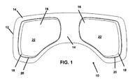
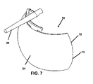
類似の構造を同様の番号で記載する図1〜図19の図面を参照して、図1は装置10の実施形態を示す図であり、前記装置10は、第1の面14と、前記第1の面14から延在する少なくとも1個又は図示のように好ましくは複数の突出又は突出部16とを有する第1のレンズ部12からなる一体構造レンズを有する。前記突出部16は側壁18からなる外周が定義する形状を有し、前記側壁18は前記側壁18の第1の端部における前記第1のレンズ部12の前記第1の面14との交差部20から離れる向きに延在する。前記突出部16の各々の前記側壁18は、前記側壁18が定義する外周内に形成される突出面22の縁部との交差部に在する先端部へ向かって延在する。前記突出面22は、使用者又は着用者の視力を矯正する眼科用レンズの形成に適している。
Referring to the drawings of FIGS. 1-19 describing similar structures with like numbers, FIG. 1 shows an embodiment of the
図1に前記突出部16の特に好ましい形状を示す。図示のように、前記2個の突出部16の各々の直径は、湾曲状の前記第1のレンズ部12の2個の端部に隣接する部分においてより幅広であり、中間部に隣接する端部において幅が狭い。
FIG. 1 shows a particularly preferable shape of the
本好ましい形状により、前記突出部16の一部が鼻梁付近まで延在し、同時にこめかみ及び鼻の十分下方まで延在する。矩形を伸ばした本形状は、前記突部16の鼻側から前記第1のレンズ部12の両端部に隣接する下縁部にかけて湾曲しており、これにより前記突出部16を用いて累進多焦点レンズ及び処方型眼鏡類の形成が可能となり、 形成される累進多焦点レンズは上端部から下端部までの水平方向、及び鼻端部からこめかみ端部までの横方向となるため、カスタム度が非常に高い。
With this preferred shape, a part of the
図2は、図1に示す前記第1のレンズ部12の反対側又は第2の側面を示す。開示の装置10の新規な態様は、前記第1のレンズ部12の前記第1の側14から突出する前記突出部16上に眼科用レンズが形成される一体構造であり、前記第2の面24側から見ると、前記第2の面24は以下に述べるようにフィルタ材料を挿入した場合でも無影の外観を呈する。
FIG. 2 shows the opposite side or the second side of the
図3は、図1に示す前記装置10の斜視図を示す。図示の複数の2個の突出部16の各々は、前記第1のレンズ部12の前記第1の面14との交差部20から延在する側壁18の外周により定義される形状を有する。図示の通り、前記第1のレンズ部12の断面厚さは非常に薄く、前記形成される突出部16を取囲む。前述した通り、前記突出部16及び前記第1のレンズ部12の一体構造は、前記突部16及び前記レンズ部12の一体成形、又は形成済突出部16を前記第1のレンズ部12用の型に共成形して前記突出部16を前記第1のレンズ部12の構造に融解及び形成して、形成される。
FIG. 3 shows a perspective view of the
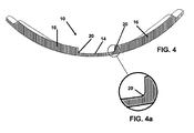
図4は図1及び図3の前記装置の断面図であって、前記第1のレンズ部12及び前記突出部16の一体構造を示す。前記突出部16の外周を形成し形状を定義する前記側壁18の、前記第1のレンズ部12の前記第1の面14との前記交差部20は好ましくは非直線状である。前述した通り、前記側壁18の前記第1の面14との前記非直線状の交差部20が最も重要である。非直線状とは、前記側壁18の表面に沿って隆起面22及び前記交差部20との連通部間で延びる線が、前記第1のレンズ部の前記第1の側の線又は平面と交差しないことを意味する。
FIG. 4 is a cross-sectional view of the apparatus shown in FIGS. 1 and 3 and shows an integrated structure of the
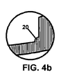
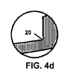
代わりに、前記交差部20において、又は前記交差部20に隣接して、前記側壁18の表面は平面又は真直ぐな面から逸脱し、前記側壁18と前記第1の面14との間で連通する表面に傾斜部分又は湾曲部分を有する。現時点では図4cの傾斜交差部及び図4aの湾曲交差部が、前記第1の面14と前記側壁18との非直線状の連通として特に好ましいが、図4b〜図4dに記載のその他形状の交差部もまた、前記側壁18の前記第1の面14における、又は隣接した非直線状の連通の例である。
Instead, at or adjacent to the
図4aは、前記突出部16の形状を定義する前記側壁18と、前記第1のレンズ部12の前記第1の面14との前記交差部20における湾曲面を示す。
FIG. 4 a shows a curved surface at the
図4bは、前記突出部16の形状を定義する前記側壁18と前記第1のレンズ部12の前記第1の面14との前記交差部20の反転湾曲形状の面を示す。
FIG. 4 b shows an inverted curved surface of the
図4cは、前記突出部16の形状を定義する前記側壁18と前記第1のレンズ部12の前記第1の面14との前記交差部20の傾斜面を示す。
FIG. 4 c shows the inclined surface of the
図4dは、前記側壁18の外周縁部の湾曲レリーフ形状の前記交差部20を示し、前記交差部20は前記側壁18の前記第1の端部下部に延び、前記第1の面14に依存して、前記突出部1の外周に延びる。
FIG. 4 d shows the curved relief-shaped
したがって、ここに定義する非直線状交差部はどのような種類の非直線状交差部であってもよく、例として図4a及び図4bに示す前記側壁の前記第1の端部と前記第1のレンズ部の前記第1の面との間に延在する湾曲面からなる交差部、図4cに示す前記側壁の前記第1の端部と前記第1のレンズ部の前記第1の面との間に延在する傾斜面からなる交差部、前記第1の側壁18の前記第1の端部下部に延在し、前記第1のレンズ部12の前記第1の面14に依存する凹部からなる交差部が挙げられる。上述のように非直線状交差部を形成することにより亀裂を防ぐことができる。
Thus, the non-linear intersection defined herein may be any kind of non-linear intersection, for example the first end of the side wall and the first shown in FIGS. 4a and 4b. An intersection formed by a curved surface extending between the first surface of the lens portion and the first end of the side wall and the first surface of the first lens portion shown in FIG. A concave portion extending between the first end portion of the
図5は、本発明による一体レンズ構造の装置10の別の実施形態を示す。図に、湾曲パノラマ式第1のレンズ部12と、形成されるレンズの前記湾曲状第1の部分12の前記第1の面14から延在する2個の円形突出部16とを示す。図示した両方の前記側壁18の前記外周交差部20は、前述した通り好ましくは非直線状である。更に、中央に配置され、側縁部に沿って前記第1のレンズ部12に作業可能に係合する工具係合部材28を示す。前記工具係合部材は、本発明による前記装置のいずれの実施形態において用いてもよい。
FIG. 5 shows another embodiment of the
図6は、図5に示す前記一体レンズ構造を反対側から見た図であり、前記第2の側面24と、前記第1のレンズ部12の前記2個の側縁部13の間で中央に配置され、前記2個の側縁部13の間に延びる水平軸に垂直に延在する前記工具係合部材28とを示す。
FIG. 6 is a view of the integrated lens structure shown in FIG. 5 as viewed from the opposite side, and a center between the
図7は本構成の斜視図を示す。図示の通り、前記工具係合部材28は前記第1のレンズ部12の前記2個の端部13の間で中央に配置され、前記第1のレンズ部12の両端部又はこめかみ端部の間で前記第1のレンズ部12に渡って延びる軸17に略垂直に延びる。前述した通り、前記工具係合部材28はゴーグルレンズの形成時に適合しない、又は係合不可能な従来の眼鏡研磨機との係合に適している。
FIG. 7 shows a perspective view of this configuration. As shown in the figure, the
図8は、本発明による前記装置10のスポーツ用ゴーグル又は保護ゴーグルの実施形態33を示す。図9〜図12に示す構成は例えば図8に示すゴーグルフレームに係合可能である。
FIG. 8 shows an
図9は、2個の突出部16と、図8の前記ゴーグルに係合するように前記第1のレンズ部12の前記第2の面24に間隙を置いて隣接して係合する第2のレンズ31とを有する第1のレンズ部12を示す。
FIG. 9 shows two
図10は、図9に示す様式に類似であって、例えば図8に示す前記ゴーグルフレーム33内に係合可能な前記装置10の実施形態を示す。本図において、空隙を形成する前記第2のレンズ31は、前記突出部16のレンズ機械加工可能な隆起面22に隣接して配置される。
FIG. 10 shows an embodiment of the
図11はゴーグル又は保護用眼鏡類の別の実施形態を示し、当該実施形態は図9、図10、及び図12の様式と同一の様式において曇りを最小限に抑えるよう構成される。図示の通り、突出部35を有し嵌合する第2のレンズ31は、前記突出部35が前記第1のレンズ12の前記形成済突出部16の前記側壁18に隣接して適合し、間隙を埋めるよう構成されて係合可能である。
FIG. 11 illustrates another embodiment of goggles or protective eyewear that is configured to minimize haze in the same manner as that of FIGS. 9, 10, and 12. As shown in the drawing, the
図11は、図9、図10、及び図12の様式と同一の様式における曇りを最小限に抑えるゴーグルに適合する前記装置の別の実施形態と、前記第1のレンズの前記形成済突出部の前記側壁に隣接して適合するよう構成される突出部を有する嵌合レンズとを示す。 FIG. 11 shows another embodiment of the device adapted to goggles that minimizes haze in the same manner as in FIGS. 9, 10, and 12, and the shaped protrusion of the first lens. And a mating lens having a protrusion configured to fit adjacent the sidewall.
図12は、本発明のその他実施形態と同様に第1のレンズ部12及び突出部16からなる一体レンズ構造を形成する前記装置の実施形態を示す。前記装置の本実施形態は、眼鏡フレームとの係合に非常に適しており、前記突出部16が隆起するより厚い領域を取囲む前記第1のレンズ部12のより薄い断面がフレームにより良く適合する。
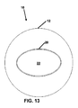
FIG. 12 shows an embodiment of the apparatus that forms an integral lens structure comprising a
図13は図12に示す前記装置の上面図であって、前記側壁18と前記第1のレンズ部12の前記第1の面14との前記外周交差部20を示す。図示の通り、前記側壁18は前記第1のレンズ部12の前記第1の面14から延在する楕円状突出部16を定義する。
FIG. 13 is a top view of the apparatus shown in FIG. 12 and shows the outer
図14は図12及び図13に示す前記装置の断面図であって、前記側壁18と第1のレンズ部12の前記第1の面14との好ましい非直線状交差部20を示し、前記非直線状交差部20は本発明による前記装置の全ての実施形態において好ましい。
FIG. 14 is a cross-sectional view of the apparatus shown in FIGS. 12 and 13, showing a preferred
図15a〜図15dは、前記側壁18と前記第1のレンズ部12の前記第1の面14との前記交差部20の様々な非直線形状を示す。記載のものは、亀裂の発生しやすい直線状交差部を回避するために非常に好ましい。
15a to 15d show various non-linear shapes of the intersecting
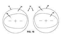
図16は、眼鏡フレームに係合するよう形成される一体レンズ装置10を示し、より厚い突出部16はより薄い第1のレンズ部12に取囲まれており、厚いレンズを必要とする視力処方箋が可能となり、更に、使用者が視力矯正のためにそのような厚いレンズを使用しなければならない場合に前記形成済レンズ装置10をよりファッション性の高い眼鏡類に係合させることができる。図17は、図16に示す前記装置10のものに類似するが、矩形のパノラマ式第1のレンズ部12を有する実施形態を示す。
FIG. 16 shows an
図18及び図19は、前記装置10の実施形態のいずれかにおいて視界にフィルタをかけることが望ましい又は必要な場合を示す。図18は、前記突出部16と前記第1のレンズ部12の前記第2の側24との間に係合する偏光フィルタ層又はその他フィルタ層36を有する前記一体レンズ装置10を示す。図19において、前記偏光フィルタ層又はその他フィルタ層36は前記第1のレンズ部12の前記第1の面14と前記第2の面24との間で、前記第1のレンズ部12全体に渡って配置される。
18 and 19 illustrate when it is desirable or necessary to filter the field of view in any of the embodiments of the
本明細書において、前記ソフトウエアにより利用可能な雇用管理及び照合システムの基本的特性及び特徴全てを特定の実施の形態を参照して開示及び説明したが、上述の開示は任意の変更、様々な変形及び置換を意図しており、記載の本発明の範囲から逸脱することなく、本発明の特徴又は工程を対応するその他特徴又は工程を用いることなく用い得ることは自明である。また、当業者は、本発明の精神又は範囲から逸脱することなく様々な置換、変更、及び変形を行ってよいものとする。したがって、当該修正、変形及び置換は全て以下の特許請求の範囲が定義する本発明の範囲に含まれる。
Although all of the basic characteristics and features of the employment management and verification system available through the software have been disclosed and described herein with reference to specific embodiments, the above disclosure is not limited to any modification, It is obvious that variations and substitutions are intended and that the features or steps of the invention can be used without corresponding other features or steps without departing from the scope of the invention as described. Those skilled in the art may make various substitutions, changes, and modifications without departing from the spirit or scope of the present invention. Accordingly, all such modifications, variations and substitutions fall within the scope of the invention as defined by the following claims.
Claims (18)
外周縁部、第1の面、前記第1の面とは反対側の第2の面、第1の端部、及び第1の端部とは反対側の第2の端部を有する第1のレンズ部と、
少なくとも1個の突出部であって、前記突出部の形状を定義する外周縁部を定義する側壁を有する突出部とを備え、
前記突出部及び前記第1のレンズ部は、前記突出部が前記側壁の第1の端部と前記第1のレンズ部の前記第1の側との交差部から、前記側壁の第2の端部により定義される形状を有する隆起面まで延在する一体構造を形成し、
前記隆起面の各々は前記一体レンズ構造の着用者の視力を矯正する眼科用レンズの形成に適している、一体レンズ構造。 An integral lens structure,
A first edge having an outer peripheral edge, a first surface, a second surface opposite to the first surface, a first end, and a second end opposite to the first end. The lens part of
A protrusion having at least one protrusion having a side wall defining an outer peripheral edge defining a shape of the protrusion;
The projecting portion and the first lens portion are configured such that the projecting portion has a second end of the side wall from an intersection of the first end portion of the side wall and the first side of the first lens portion. Forming a monolithic structure extending to a raised surface having a shape defined by the section;
Each of the raised surfaces is an integral lens structure suitable for forming an ophthalmic lens that corrects the visual acuity of the wearer of the integral lens structure.
前記第1のレンズ部の前記外周縁部は眼鏡フレームの1個のレンズ保持部材と係合するよう構成され、
前記隆起面は近視の着用者の視力を矯正する眼科用レンズに形成でき、前記第1のレンズ部の前記外周縁部は前記眼鏡フレームに係合可能な、一体レンズ構造。 The integrated lens structure according to claim 1, wherein the outer peripheral edge portion of the first lens portion is larger than the outer peripheral edge portion of the protruding portion,
The outer peripheral edge portion of the first lens portion is configured to engage with one lens holding member of the spectacle frame,
The raised surface can be formed in an ophthalmic lens that corrects the visual acuity of a myopic wearer, and the outer peripheral edge of the first lens portion is engageable with the spectacle frame.
前記第1のレンズ部の前記外周縁部は眼鏡フレームの1個のレンズ保持部材と係合するよう構成され、
これにより前記隆起面は近視の着用者の視力を矯正する眼科用レンズに形成でき、前記第1のレンズ部の前記外周縁部は前記眼鏡フレームに係合可能な、一体レンズ構造。 3. The integral lens structure according to claim 2, wherein the outer peripheral edge portion of the first lens portion is larger than the outer peripheral edge portion of the protruding portion,
The outer peripheral edge portion of the first lens portion is configured to engage with one lens holding member of the spectacle frame,
Thereby, the raised surface can be formed in an ophthalmic lens that corrects the visual acuity of a myopic wearer, and the outer peripheral edge of the first lens portion can be engaged with the spectacle frame.
これにより前記隆起面は近視の着用者の視力を矯正する眼科用レンズに形成でき、前記第1のレンズ部の前記外周縁部は前記眼鏡フレームに係合可能な、一体レンズ構造。 4. The integral lens structure according to claim 3, wherein the outer peripheral edge portion of the first lens portion is larger than the outer peripheral edge portion of the projecting portion and engages with one lens holding member of the spectacle frame. Configured,
Thereby, the raised surface can be formed in an ophthalmic lens that corrects the visual acuity of a myopic wearer, and the outer peripheral edge of the first lens portion can be engaged with the spectacle frame.
ゴーグルフレームと係合する寸法の外周縁部を有する前記第1のレンズ部と、
前記側壁の各々の第1の端部と前記第1のレンズ部の前記第1の側との前記交差部から延在する2個の突出部とを更に備え、
前記2個の突出部及び前記第1のレンズ部は一体構造として形成され、
前記2個の突出部の各々は、前記一体レンズ構造の着用者の視力を矯正する眼科用レンズの形成に適する隆起面を有する、一体レンズ構造。 The integrated lens structure according to claim 1,
The first lens portion having an outer peripheral edge dimensioned to engage with a goggle frame;
Two protrusions extending from the intersection of the first end of each of the side walls and the first side of the first lens portion;
The two projecting portions and the first lens portion are formed as an integral structure,
Each of the two protrusions has an integral lens structure having a raised surface suitable for forming an ophthalmic lens that corrects the visual acuity of the wearer of the integral lens structure.
ゴーグルフレームと係合する寸法の外周縁部を有する前記第1のレンズ部と、
前記側壁の各々の第1の端部と前記第1のレンズ部の前記第1の側との前記交差部から延在する2個の突出部とを更に備え、
前記2個の突出部及び前記第1のレンズ部は一体構造として形成され、
前記2個の突出部の各々は、前記一体レンズ構造の着用者の視力を矯正する眼科用レンズの形成に適する隆起面を有する、一体レンズ構造。 The integral lens structure according to claim 2,
The first lens portion having an outer peripheral edge dimensioned to engage with a goggle frame;
Two protrusions extending from the intersection of the first end of each of the side walls and the first side of the first lens portion;
The two projecting portions and the first lens portion are formed as an integral structure,
Each of the two protrusions has an integral lens structure having a raised surface suitable for forming an ophthalmic lens that corrects the visual acuity of the wearer of the integral lens structure.
ゴーグルフレームと係合する寸法の外周縁部を有する前記第1のレンズ部と、
前記側壁の各々の第1の端部と前記第1のレンズ部の前記第1の側との前記交差部から延在する2個の突出部とを更に備え、
前記2個の突出部及び前記第1のレンズ部は一体構造として形成され、
前記2個の突出部の各々は、前記一体レンズ構造の着用者の視力を矯正する眼科用レンズの形成に適する隆起面を有する、一体レンズ構造。 The integral lens structure according to claim 3,
The first lens portion having an outer peripheral edge dimensioned to engage with a goggle frame;
Two protrusions extending from the intersection of the first end of each of the side walls and the first side of the first lens portion;
The two projecting portions and the first lens portion are formed as an integral structure,
Each of the two protrusions has an integral lens structure having a raised surface suitable for forming an ophthalmic lens that corrects the visual acuity of the wearer of the integral lens structure.
前記第1のレンズ部に係合する第1の端部から先端部まで延在する工具係合部材を更に備え、
前記工具係合部材はレンズ機械加工装置に係合するよう構成され、
前記工具係合部材は前記第1のレンズ部上に配置され、前記レンズ機械加工装置に係合し、前記レンズ機械加工装置を用いて眼科用レンズを形成するために前記隆起面を作業可能に配置する、一体レンズ構造。 The integral lens structure according to claim 7,
A tool engaging member extending from the first end portion engaging the first lens portion to the tip end portion;
The tool engaging member is configured to engage a lens machining apparatus;
The tool engaging member is disposed on the first lens portion, engages the lens machining device, and allows the raised surface to work to form an ophthalmic lens using the lens machining device. Integrated lens structure to be placed.
前記第1のレンズ部に係合する第1の端部から先端部まで延在する工具係合部材を更に備え、
前記工具係合部材はレンズ機械加工装置に係合するよう構成され、
前記工具係合部材は前記第1のレンズ部上に配置され、前記レンズ機械加工装置に係合し、前記レンズ機械加工装置を用いて眼科用レンズを形成するために前記隆起面を作業可能に配置する、一体レンズ構造。 The integrated lens structure according to claim 9,
A tool engaging member extending from the first end portion engaging the first lens portion to the tip end portion;
The tool engaging member is configured to engage a lens machining apparatus;
The tool engaging member is disposed on the first lens portion, engages the lens machining device, and allows the raised surface to work to form an ophthalmic lens using the lens machining device. Integrated lens structure to be placed.
前記第1のレンズ部に係合する第1の端部から先端部まで延在する工具係合部材を更に備え、
前記工具係合部材はレンズ機械加工装置に係合するよう構成され、
前記工具係合部材は前記第1のレンズ部上に配置され、前記レンズ機械加工装置に係合し、前記レンズ機械加工装置を用いて眼科用レンズを形成するために前記隆起面を作業可能に配置する、一体レンズ構造。 The integrated lens structure according to claim 10,
A tool engaging member extending from the first end portion engaging the first lens portion to the tip end portion;
The tool engaging member is configured to engage a lens machining apparatus;
The tool engaging member is disposed on the first lens portion, engages the lens machining device, and allows the raised surface to work to form an ophthalmic lens using the lens machining device. Integrated lens structure to be placed.
前記2個の突出部の両方を更に備え、前記2個の突出部は、前記第1のレンズ部の端部に隣接する前記突出部の第1の端部においてより幅広く、前記第1のレンズ部上で中央に位置する第2の端部においてより幅が狭い形状を有し、
前記突出部の各々の前記第1の側は、前記第1の側の第1の角部と第2の側の第1の角部との間の線に延在し、
前記突出部の各々の第2の側は、前記第1の側の第2の角部から前記第2の側の第2の角部まで湾曲して延在する、一体レンズ構造。 The integral lens structure according to claim 7,
Further comprising both of the two protrusions, the two protrusions being wider at the first end of the protrusion adjacent to the end of the first lens part, the first lens Having a narrower shape at the second end located centrally on the part,
The first side of each of the protrusions extends in a line between a first corner on the first side and a first corner on the second side;
The integrated lens structure, wherein a second side of each of the protrusions extends in a curved manner from a second corner on the first side to a second corner on the second side.
前記2個の突出部の両方を更に備え、前記2個の突出部は、前記第1のレンズ部の端部に隣接する前記突出部の第1の端部においてより幅広く、前記第1のレンズ部上で中央に位置する第2の端部においてより幅が狭い前記形状を有し、
前記突出部の各々の前記第1の側は、前記第1の側の第1の角部と第2の側の第1の角部との間の線に延在し、
前記突出部の各々の第2の側は、前記第1の側の第2の角部から前記第2の側の第2の角部まで湾曲して延在する、一体レンズ構造。 The integrated lens structure according to claim 8,
Further comprising both of the two protrusions, the two protrusions being wider at the first end of the protrusion adjacent to the end of the first lens part, the first lens Having a narrower shape at the second end located centrally on the part,
The first side of each of the protrusions extends in a line between a first corner on the first side and a first corner on the second side;
The integrated lens structure, wherein a second side of each of the protrusions extends in a curved manner from a second corner on the first side to a second corner on the second side.
前記2個の突出部の両方を更に備え、前記2個の突出部は、前記第1のレンズ部の端部に隣接する前記突出部の第1の端部においてより幅広く、前記第1のレンズ部上で中央に位置する第2の端部においてより幅が狭い前記形状を有し、
前記突出部の各々の前記第1の側は、前記第1の側の第1の角部と第2の側の第1の角部との間の線に延在し、
前記突出部の各々の第2の側は、前記第1の側の第2の角部から前記第2の側の第2の角部まで湾曲して延在する、一体レンズ構造。 The integrated lens structure according to claim 9,
Further comprising both of the two protrusions, the two protrusions being wider at the first end of the protrusion adjacent to the end of the first lens part, the first lens Having a narrower shape at the second end located centrally on the part,
The first side of each of the protrusions extends in a line between a first corner on the first side and a first corner on the second side;
The integrated lens structure, wherein a second side of each of the protrusions extends in a curved manner from a second corner on the first side to a second corner on the second side.
前記側壁の前記第1の端部と前記第1のレンズ部の前記第1の面との間に延在する前記湾曲面の両方と、前記側壁の前記第1の端部と前記第1のレンズ部の前記第1の面との間に延在する前記傾斜面とを更に備え、前記湾曲面と前記傾斜面は前記側壁上の前記レンズ部の前記第1の面の上方1mm以下の位置まで延在する、一体レンズ構造。 The integral lens structure according to claim 3,
Both the curved surface extending between the first end of the side wall and the first surface of the first lens unit, the first end of the side wall and the first And an inclined surface extending between the first surface of the lens portion and the curved surface and the inclined surface are positioned on the side wall by 1 mm or less above the first surface of the lens portion. Integrated lens structure that extends to
前記側壁の前記第1の端部と前記第1のレンズ部の前記第1の面との間に延在する前記湾曲面の両方と、前記側壁の前記第1の端部と前記第1のレンズ部の前記第1の面との間に延在する前記傾斜面とを更に備え、前記湾曲面と前記傾斜面は前記側壁上の前記レンズ部の前記第1の面の上方1mm以下の位置まで延在する、一体レンズ構造。 The integral lens structure according to claim 6,
Both the curved surface extending between the first end of the side wall and the first surface of the first lens unit, the first end of the side wall and the first And an inclined surface extending between the first surface of the lens portion and the curved surface and the inclined surface are positioned on the side wall by 1 mm or less above the first surface of the lens portion. Integrated lens structure that extends to
前記側壁の前記第1の端部と前記第1のレンズ部の前記第1の面との間に延在する前記湾曲面の両方と、前記側壁の前記第1の端部と前記第1のレンズ部の前記第1の面との間に延在する前記傾斜面とを更に備え、前記湾曲面と前記傾斜面は前記側壁上の前記レンズ部の前記第1の面の上方1mm以下の位置まで延在する、一体レンズ構造。
The integrated lens structure according to claim 9,
Both the curved surface extending between the first end of the side wall and the first surface of the first lens unit, the first end of the side wall and the first And an inclined surface extending between the first surface of the lens portion and the curved surface and the inclined surface are positioned on the side wall by 1 mm or less above the first surface of the lens portion. Integrated lens structure that extends to
Priority Applications (1)
| Application Number | Priority Date | Filing Date | Title |
|---|---|---|---|
| JP2022051715A JP2022089853A (en) | 2015-08-26 | 2022-03-28 | Corrective lens |
Applications Claiming Priority (3)
| Application Number | Priority Date | Filing Date | Title |
|---|---|---|---|
| US201562210024P | 2015-08-26 | 2015-08-26 | |
| US62/210,024 | 2015-08-26 | ||
| PCT/US2016/049110 WO2017035509A1 (en) | 2015-08-26 | 2016-08-26 | Corrective lens apparatus and method |
Related Child Applications (1)
| Application Number | Title | Priority Date | Filing Date |
|---|---|---|---|
| JP2022051715A Division JP2022089853A (en) | 2015-08-26 | 2022-03-28 | Corrective lens |
Publications (1)
| Publication Number | Publication Date |
|---|---|
| JP2018528472A true JP2018528472A (en) | 2018-09-27 |
Family
ID=58101199
Family Applications (2)
| Application Number | Title | Priority Date | Filing Date |
|---|---|---|---|
| JP2018510854A Pending JP2018528472A (en) | 2015-08-26 | 2016-08-26 | Correction lens apparatus and method |
| JP2022051715A Pending JP2022089853A (en) | 2015-08-26 | 2022-03-28 | Corrective lens |
Family Applications After (1)
| Application Number | Title | Priority Date | Filing Date |
|---|---|---|---|
| JP2022051715A Pending JP2022089853A (en) | 2015-08-26 | 2022-03-28 | Corrective lens |
Country Status (11)
| Country | Link |
|---|---|
| US (2) | US10627648B2 (en) |
| EP (1) | EP3341095A4 (en) |
| JP (2) | JP2018528472A (en) |
| KR (1) | KR20180044370A (en) |
| CN (1) | CN108472541B (en) |
| AU (2) | AU2016312686A1 (en) |
| BR (1) | BR112018003717B1 (en) |
| CA (1) | CA3035002A1 (en) |
| IL (1) | IL257713B (en) |
| MX (2) | MX2018002343A (en) |
| WO (1) | WO2017035509A1 (en) |
Families Citing this family (3)
| Publication number | Priority date | Publication date | Assignee | Title |
|---|---|---|---|---|
| EP3341095A4 (en) * | 2015-08-26 | 2019-07-17 | Goebel Quintana, Alejandro, A. | Corrective lens apparatus and method |
| USD835177S1 (en) * | 2015-09-23 | 2018-12-04 | Seagoggs, Inc. | Eyewear device |
| US20190151152A1 (en) * | 2016-06-02 | 2019-05-23 | Alejandro A. Goebel Quintana | Corrective Lens and Shield in Unitary Structure and Method |
Citations (11)
| Publication number | Priority date | Publication date | Assignee | Title |
|---|---|---|---|---|
| JPS54135090U (en) * | 1978-03-11 | 1979-09-19 | ||
| JPS57116419U (en) * | 1981-01-13 | 1982-07-19 | ||
| US20030142264A1 (en) * | 2001-09-21 | 2003-07-31 | Roland Westerdal | Reading safety glasses |
| JP2006184296A (en) * | 2003-02-26 | 2006-07-13 | Combex Co Ltd | Spectacles with lenses, and its manufacturing method |
| JP2009047862A (en) * | 2007-08-17 | 2009-03-05 | Kazunari Oura | A pair of right and left eyeglass lenses of right and left integral type, and right and left integral type eyeglasses |
| US20100118258A1 (en) * | 2007-02-27 | 2010-05-13 | Alejandro Arturo Goebel Quintana | Industrial safety goggles with frame for ophthalmic micas and impact protection mica |
| JP2011113587A (en) * | 2009-11-25 | 2011-06-09 | Panasonic Corp | Optical element and optical pickup device using the same |
| JP2012531621A (en) * | 2009-06-26 | 2012-12-10 | クインタナ,アレハンドロ アルトゥロ ゲーベル | One piece lens with surplus internal optical material |
| JP2013044765A (en) * | 2011-08-22 | 2013-03-04 | Hoya Corp | Method for manufacturing plastic lens for spectacles |
| JP2013519907A (en) * | 2010-02-12 | 2013-05-30 | オスラム オプト セミコンダクターズ ゲゼルシャフト ミット ベシュレンクテル ハフツング | Optoelectronic semiconductor devices, lighting devices and lenses |
| JP2015069044A (en) * | 2013-09-30 | 2015-04-13 | ▲呉▼ 志民WU,Chih Ming | Spectacle frame and spectacle using the same |
Family Cites Families (23)
| Publication number | Priority date | Publication date | Assignee | Title |
|---|---|---|---|---|
| DE1208909C2 (en) * | 1962-05-24 | 1966-07-28 | Med Opties Inc | Safety glasses with corrective lenses |
| CA1004403A (en) * | 1975-06-05 | 1977-02-01 | Torsten R. Bengtson | Eye protectors |
| JPH0470625U (en) * | 1990-10-31 | 1992-06-23 | ||
| US5550599A (en) * | 1994-01-10 | 1996-08-27 | Oakley, Inc. | Surface modified lens |
| US5793467A (en) * | 1996-09-26 | 1998-08-11 | Dean Bailey | Semi-permanent reading lenses for sunglasses |
| US6196678B1 (en) * | 1999-08-09 | 2001-03-06 | Chapin, Iii E. Barton | Protective glasses with built-in corrective lenses |
| WO2004080653A1 (en) * | 2003-03-11 | 2004-09-23 | Optotech Optikmaschinen Gmbh | Method and device for producing ophthalmic lenses and other shaped bodies with optically active surfaces |
| US7475435B2 (en) * | 2004-02-23 | 2009-01-13 | Nike, Inc. | Swim goggles |
| JP2008276016A (en) * | 2007-05-01 | 2008-11-13 | Mei-Yueh Hou | Multifunction glasses |
| CN201054048Y (en) * | 2007-07-10 | 2008-04-30 | 王信胜 | Goggles components |
| JP5133671B2 (en) * | 2007-12-10 | 2013-01-30 | 久宜 黒▲崎▼ | Double focus lens and bifocal glasses |
| US7971268B2 (en) * | 2009-01-23 | 2011-07-05 | Oakley, Inc. | Controlled deflection goggle |
| JP5684461B2 (en) * | 2009-05-01 | 2015-03-11 | 山本光学株式会社 | Method of manufacturing a polarizing optical article |
| CN201820049U (en) * | 2010-10-20 | 2011-05-04 | 林超群 | Lower-focus prismatic convex lens type myopia-prevention bifocal spectacles |
| WO2013070417A1 (en) * | 2011-10-20 | 2013-05-16 | Oakley, Inc. | Eyewear with chroma enhancement |
| AU2012343324A1 (en) * | 2011-11-21 | 2014-06-19 | Jorge Miguel Pereira | Improved safety equipment |
| US10126571B2 (en) * | 2011-12-14 | 2018-11-13 | Mitch Junkins | Multi-functional glasses |
| US8893314B2 (en) * | 2012-08-03 | 2014-11-25 | Dye Precision, Inc. | Sport goggle with quick release lens |
| AT513975B1 (en) * | 2013-03-26 | 2014-09-15 | Rauter Christoph | Lens for a pair of glasses or helmet visor |
| KR102258256B1 (en) * | 2014-01-31 | 2021-05-28 | 야마모토 고가쿠 가부시키가이샤 | Goggles |
| CN204086715U (en) * | 2014-08-12 | 2015-01-07 | 赵卫国 | The bathomorphic screening glass of a kind of adjustment |
| WO2016042495A1 (en) * | 2014-09-17 | 2016-03-24 | Mares S.P.A. | Swimming goggles and method for designing the same |
| EP3341095A4 (en) * | 2015-08-26 | 2019-07-17 | Goebel Quintana, Alejandro, A. | Corrective lens apparatus and method |
-
2016
- 2016-08-26 EP EP16840236.0A patent/EP3341095A4/en active Pending
- 2016-08-26 JP JP2018510854A patent/JP2018528472A/en active Pending
- 2016-08-26 KR KR1020187008383A patent/KR20180044370A/en not_active Application Discontinuation
- 2016-08-26 BR BR112018003717-6A patent/BR112018003717B1/en active IP Right Grant
- 2016-08-26 AU AU2016312686A patent/AU2016312686A1/en not_active Abandoned
- 2016-08-26 CA CA3035002A patent/CA3035002A1/en active Pending
- 2016-08-26 US US15/754,506 patent/US10627648B2/en active Active
- 2016-08-26 CN CN201680061517.9A patent/CN108472541B/en active Active
- 2016-08-26 WO PCT/US2016/049110 patent/WO2017035509A1/en active Application Filing
- 2016-08-26 MX MX2018002343A patent/MX2018002343A/en unknown
-
2018
- 2018-02-23 MX MX2022009468A patent/MX2022009468A/en unknown
- 2018-02-25 IL IL257713A patent/IL257713B/en unknown
-
2020
- 2020-04-20 US US16/853,259 patent/US11714297B2/en active Active
-
2022
- 2022-03-28 JP JP2022051715A patent/JP2022089853A/en active Pending
- 2022-05-17 AU AU2022203281A patent/AU2022203281A1/en active Pending
Patent Citations (11)
| Publication number | Priority date | Publication date | Assignee | Title |
|---|---|---|---|---|
| JPS54135090U (en) * | 1978-03-11 | 1979-09-19 | ||
| JPS57116419U (en) * | 1981-01-13 | 1982-07-19 | ||
| US20030142264A1 (en) * | 2001-09-21 | 2003-07-31 | Roland Westerdal | Reading safety glasses |
| JP2006184296A (en) * | 2003-02-26 | 2006-07-13 | Combex Co Ltd | Spectacles with lenses, and its manufacturing method |
| US20100118258A1 (en) * | 2007-02-27 | 2010-05-13 | Alejandro Arturo Goebel Quintana | Industrial safety goggles with frame for ophthalmic micas and impact protection mica |
| JP2009047862A (en) * | 2007-08-17 | 2009-03-05 | Kazunari Oura | A pair of right and left eyeglass lenses of right and left integral type, and right and left integral type eyeglasses |
| JP2012531621A (en) * | 2009-06-26 | 2012-12-10 | クインタナ,アレハンドロ アルトゥロ ゲーベル | One piece lens with surplus internal optical material |
| JP2011113587A (en) * | 2009-11-25 | 2011-06-09 | Panasonic Corp | Optical element and optical pickup device using the same |
| JP2013519907A (en) * | 2010-02-12 | 2013-05-30 | オスラム オプト セミコンダクターズ ゲゼルシャフト ミット ベシュレンクテル ハフツング | Optoelectronic semiconductor devices, lighting devices and lenses |
| JP2013044765A (en) * | 2011-08-22 | 2013-03-04 | Hoya Corp | Method for manufacturing plastic lens for spectacles |
| JP2015069044A (en) * | 2013-09-30 | 2015-04-13 | ▲呉▼ 志民WU,Chih Ming | Spectacle frame and spectacle using the same |
Also Published As
| Publication number | Publication date |
|---|---|
| KR20180044370A (en) | 2018-05-02 |
| CN108472541A (en) | 2018-08-31 |
| IL257713A (en) | 2018-04-30 |
| WO2017035509A1 (en) | 2017-03-02 |
| AU2016312686A1 (en) | 2018-04-19 |
| EP3341095A4 (en) | 2019-07-17 |
| EP3341095A1 (en) | 2018-07-04 |
| JP2022089853A (en) | 2022-06-16 |
| MX2018002343A (en) | 2018-08-14 |
| CN108472541B (en) | 2022-02-25 |
| US20200249497A1 (en) | 2020-08-06 |
| BR112018003717A2 (en) | 2018-09-18 |
| MX2022009468A (en) | 2022-08-25 |
| US10627648B2 (en) | 2020-04-21 |
| IL257713B (en) | 2022-05-01 |
| US11714297B2 (en) | 2023-08-01 |
| BR112018003717B1 (en) | 2022-09-06 |
| US20180246347A1 (en) | 2018-08-30 |
| CA3035002A1 (en) | 2017-03-02 |
| AU2022203281A1 (en) | 2022-06-02 |
Similar Documents
| Publication | Publication Date | Title |
|---|---|---|
| JP2022089853A (en) | Corrective lens | |
| US8814349B2 (en) | One-piece lens with surplus inner optical material | |
| JP4949967B2 (en) | A pair of left and right eyeglass lenses and left and right eyeglasses | |
| US11259965B2 (en) | Combined corrective lens and lens shield | |
| US6217169B1 (en) | Rimless or semi-rimless safety eyeglasses | |
| US20230375855A1 (en) | Corrective Lens Apparatus and Method | |
| JP7349718B2 (en) | glasses for one-eyed people | |
| US20160306193A1 (en) | Protective presbyopia lens | |
| JP2013228700A (en) | Spectacle lens | |
| JP2004008496A (en) | Goggles | |
| WO2017124111A1 (en) | Lens engagement system and method | |
| JPH06294945A (en) | Spectacles for hypermetropia | |
| JP2012150417A (en) | Bifocal farsighted eyeglasses |
Legal Events
| Date | Code | Title | Description |
|---|---|---|---|
| A621 | Written request for application examination |
Free format text: JAPANESE INTERMEDIATE CODE: A621 Effective date: 20190826 |
|
| A977 | Report on retrieval |
Free format text: JAPANESE INTERMEDIATE CODE: A971007 Effective date: 20200422 |
|
| A131 | Notification of reasons for refusal |
Free format text: JAPANESE INTERMEDIATE CODE: A131 Effective date: 20200609 |
|
| A601 | Written request for extension of time |
Free format text: JAPANESE INTERMEDIATE CODE: A601 Effective date: 20200909 |
|
| A521 | Request for written amendment filed |
Free format text: JAPANESE INTERMEDIATE CODE: A523 Effective date: 20200911 |
|
| A131 | Notification of reasons for refusal |
Free format text: JAPANESE INTERMEDIATE CODE: A131 Effective date: 20210316 |
|
| A601 | Written request for extension of time |
Free format text: JAPANESE INTERMEDIATE CODE: A601 Effective date: 20210615 |
|
| A601 | Written request for extension of time |
Free format text: JAPANESE INTERMEDIATE CODE: A601 Effective date: 20210816 |
|
| A521 | Request for written amendment filed |
Free format text: JAPANESE INTERMEDIATE CODE: A523 Effective date: 20210915 |
|
| A02 | Decision of refusal |
Free format text: JAPANESE INTERMEDIATE CODE: A02 Effective date: 20211207 |