JP2018527575A - Device and method for finding a measurement point using an image capture device - Google Patents
Device and method for finding a measurement point using an image capture device Download PDFInfo
- Publication number
- JP2018527575A JP2018527575A JP2018513429A JP2018513429A JP2018527575A JP 2018527575 A JP2018527575 A JP 2018527575A JP 2018513429 A JP2018513429 A JP 2018513429A JP 2018513429 A JP2018513429 A JP 2018513429A JP 2018527575 A JP2018527575 A JP 2018527575A
- Authority
- JP
- Japan
- Prior art keywords
- measurement
- image
- point
- contact distance
- measuring device
- Prior art date
- Legal status (The legal status is an assumption and is not a legal conclusion. Google has not performed a legal analysis and makes no representation as to the accuracy of the status listed.)
- Pending
Links
Images


Classifications
-
- G—PHYSICS
- G06—COMPUTING; CALCULATING OR COUNTING
- G06T—IMAGE DATA PROCESSING OR GENERATION, IN GENERAL
- G06T7/00—Image analysis
- G06T7/20—Analysis of motion
-
- G—PHYSICS
- G01—MEASURING; TESTING
- G01C—MEASURING DISTANCES, LEVELS OR BEARINGS; SURVEYING; NAVIGATION; GYROSCOPIC INSTRUMENTS; PHOTOGRAMMETRY OR VIDEOGRAMMETRY
- G01C1/00—Measuring angles
- G01C1/02—Theodolites
- G01C1/04—Theodolites combined with cameras
-
- G—PHYSICS
- G01—MEASURING; TESTING
- G01C—MEASURING DISTANCES, LEVELS OR BEARINGS; SURVEYING; NAVIGATION; GYROSCOPIC INSTRUMENTS; PHOTOGRAMMETRY OR VIDEOGRAMMETRY
- G01C15/00—Surveying instruments or accessories not provided for in groups G01C1/00 - G01C13/00
- G01C15/002—Active optical surveying means
-
- G—PHYSICS
- G01—MEASURING; TESTING
- G01C—MEASURING DISTANCES, LEVELS OR BEARINGS; SURVEYING; NAVIGATION; GYROSCOPIC INSTRUMENTS; PHOTOGRAMMETRY OR VIDEOGRAMMETRY
- G01C25/00—Manufacturing, calibrating, cleaning, or repairing instruments or devices referred to in the other groups of this subclass
- G01C25/005—Manufacturing, calibrating, cleaning, or repairing instruments or devices referred to in the other groups of this subclass initial alignment, calibration or starting-up of inertial devices
-
- G—PHYSICS
- G01—MEASURING; TESTING
- G01C—MEASURING DISTANCES, LEVELS OR BEARINGS; SURVEYING; NAVIGATION; GYROSCOPIC INSTRUMENTS; PHOTOGRAMMETRY OR VIDEOGRAMMETRY
- G01C3/00—Measuring distances in line of sight; Optical rangefinders
- G01C3/02—Details
-
- G—PHYSICS
- G01—MEASURING; TESTING
- G01S—RADIO DIRECTION-FINDING; RADIO NAVIGATION; DETERMINING DISTANCE OR VELOCITY BY USE OF RADIO WAVES; LOCATING OR PRESENCE-DETECTING BY USE OF THE REFLECTION OR RERADIATION OF RADIO WAVES; ANALOGOUS ARRANGEMENTS USING OTHER WAVES
- G01S17/00—Systems using the reflection or reradiation of electromagnetic waves other than radio waves, e.g. lidar systems
- G01S17/66—Tracking systems using electromagnetic waves other than radio waves
-
- G—PHYSICS
- G01—MEASURING; TESTING
- G01S—RADIO DIRECTION-FINDING; RADIO NAVIGATION; DETERMINING DISTANCE OR VELOCITY BY USE OF RADIO WAVES; LOCATING OR PRESENCE-DETECTING BY USE OF THE REFLECTION OR RERADIATION OF RADIO WAVES; ANALOGOUS ARRANGEMENTS USING OTHER WAVES
- G01S17/00—Systems using the reflection or reradiation of electromagnetic waves other than radio waves, e.g. lidar systems
- G01S17/86—Combinations of lidar systems with systems other than lidar, radar or sonar, e.g. with direction finders
-
- G—PHYSICS
- G01—MEASURING; TESTING
- G01S—RADIO DIRECTION-FINDING; RADIO NAVIGATION; DETERMINING DISTANCE OR VELOCITY BY USE OF RADIO WAVES; LOCATING OR PRESENCE-DETECTING BY USE OF THE REFLECTION OR RERADIATION OF RADIO WAVES; ANALOGOUS ARRANGEMENTS USING OTHER WAVES
- G01S3/00—Direction-finders for determining the direction from which infrasonic, sonic, ultrasonic, or electromagnetic waves, or particle emission, not having a directional significance, are being received
- G01S3/78—Direction-finders for determining the direction from which infrasonic, sonic, ultrasonic, or electromagnetic waves, or particle emission, not having a directional significance, are being received using electromagnetic waves other than radio waves
- G01S3/782—Systems for determining direction or deviation from predetermined direction
- G01S3/785—Systems for determining direction or deviation from predetermined direction using adjustment of orientation of directivity characteristics of a detector or detector system to give a desired condition of signal derived from that detector or detector system
- G01S3/786—Systems for determining direction or deviation from predetermined direction using adjustment of orientation of directivity characteristics of a detector or detector system to give a desired condition of signal derived from that detector or detector system the desired condition being maintained automatically
- G01S3/7864—T.V. type tracking systems
-
- G—PHYSICS
- G06—COMPUTING; CALCULATING OR COUNTING
- G06T—IMAGE DATA PROCESSING OR GENERATION, IN GENERAL
- G06T2207/00—Indexing scheme for image analysis or image enhancement
- G06T2207/30—Subject of image; Context of image processing
- G06T2207/30241—Trajectory
Abstract
測定デバイスに対して1つ又は複数の測定ポイントの位置を決定するための測定デバイス(10)。測定デバイスは、非接触距離測定デバイス又はEDM(12)及びEDMの向きを決定するための1つ又は複数のセンサ(16)に結合されるように配置されている。測定デバイスは、デジタル画像を出力するように動作可能であり、画像取込デバイス又はICD(20)がEDMに対して既知の位置合わせで移動するようにEDMに結合されるように配置されているICDを備える。コントローラ(28)が、1つ又は複数のセンサ及びICDからデータを受け取るように配置されている。コントローラは、a)画像の露出中に画像をEDMの向きに関連付け、b)画像内の測定ポイントのうちの1つを探し出し、c)EDMの向きと組み合わせて画像内の測定ポイントの位置を使用して、測定デバイスに対する測定ポイントの方向を確立するように構成される。【選択図】 図1A measuring device (10) for determining the position of one or more measuring points with respect to the measuring device. The measuring device is arranged to be coupled to a non-contact distance measuring device or EDM (12) and one or more sensors (16) for determining the orientation of the EDM. The measurement device is operable to output a digital image and is arranged to be coupled to the EDM such that the image capture device or ICD (20) moves in a known alignment relative to the EDM. Provide ICD. A controller (28) is arranged to receive data from one or more sensors and the ICD. The controller a) associates the image with the EDM orientation during image exposure, b) locates one of the measurement points in the image, and c) uses the position of the measurement point in the image in combination with the EDM orientation. And configured to establish the direction of the measurement point relative to the measurement device. [Selection] Figure 1
Description
建物、橋、ダム、構成部品/組立品などの構造体の移動を監視する周知の方法は、「トータルステーション」などの測量デバイスを使用することである。トータルステーションは、機械的プラットフォームに取り付けたレーザベースの電子距離測定器(EDM:electronic distance measure)から成る。このプラットフォームのベースは、典型的には水平にした三脚などの安定した水平架台に配置される。トータルステーションの機構により、EDMは、垂直軸及び水平軸の両方を中心にして回転することによって任意の方向を向くことが可能になる。各回転軸上のエンコーダにより、EDMの現在の方向が分かることが可能になる。 A well-known method of monitoring the movement of structures such as buildings, bridges, dams, components / assemblies is to use surveying devices such as “total stations”. The total station consists of a laser-based electronic distance measure (EDM) attached to a mechanical platform. The platform base is typically placed on a stable horizontal platform, such as a horizontal tripod. The total station mechanism allows the EDM to turn in any direction by rotating about both the vertical and horizontal axes. An encoder on each rotating shaft makes it possible to know the current direction of the EDM.
監視用トータルステーションは、EDMが自動的に任意の所望の方向を向くことが可能になる電動駆動システムを含むことができる。EDMから測定ポイントまでの距離とともにエンコーダからのEDMの現在の方向により、ポイントの3次元位置を決定することが可能になる。 The total monitoring station can include an electric drive system that allows the EDM to automatically point in any desired direction. The current direction of the EDM from the encoder along with the distance from the EDM to the measurement point makes it possible to determine the three-dimensional position of the point.
トータルステーションは、ポイントの位置を3次元で測定することができる。しかし、トータルステーションは、移動する構造体を監視するタスクを与えられたとき、以下の制限のうちの1つ又は複数を有する。
・移動を監視するために、トータルステーションは、反射ターゲットを測定ポイントに取り付ける必要がある。
・必要とされる分解能及び精度を実現するために、トータルステーションは、典型的には各測定を実施するのに数秒を要し、したがって、電車が線路の上を通過するときの線路の移動など、動的測定を実施することができない。
・トータルステーションは、一度に単一ポイントしか測定することができず、複数ポイントを監視する場合、それぞれは連続して測定しなければならず、すなわち、データは一度に単一ポイントだけから取り込まれる。
・測定分解能は、エンコーダの角度分解能(典型的には1秒角の程度)で制限されることがある。
・反射プリズムの設計によっては、測定誤差の顕著な発生源となり得る。
The total station can measure the position of the point in three dimensions. However, the total station has one or more of the following limitations when given the task of monitoring moving structures.
• To monitor movement, the total station needs to attach a reflective target to the measurement point.
In order to achieve the required resolution and accuracy, the total station typically takes a few seconds to perform each measurement, and therefore, such as moving the track as the train passes over the track, etc. Dynamic measurements cannot be performed.
• The total station can only measure a single point at a time, and if multiple points are monitored, each must be measured continuously, i.e., data is taken from only a single point at a time.
The measurement resolution may be limited by the angular resolution of the encoder (typically on the order of 1 arc second).
Depending on the design of the reflecting prism, it can be a significant source of measurement error.
本発明の第1の態様によれば、請求項1に記載の測定デバイスが提供される。 According to a first aspect of the present invention there is provided a measuring device according to claim 1.
したがって、第1の態様による測定デバイスは、アルゴリズムが画像内の測定ポイントを正確に見つけ、方向情報を使用してデバイスに対してどこに測定ポイントがあるのかを決定することができるように、画像露出中にEDMの方向を関連付ける。画像露出は時間周期にわたって行われる。これは、EDMの向きが画像露出中に変化していても精度が維持されることを意味する。EDMの向きは、意図的に(例えば、EDMは移動する測定ポイントを追跡する)又は非意図的に(例えば、取付けブラケット/三脚の振動又は熱膨張)変化している可能性がある。 Accordingly, the measurement device according to the first aspect allows the image exposure so that the algorithm can accurately find the measurement point in the image and use the direction information to determine where the measurement point is relative to the device. Associate EDM direction inside. Image exposure occurs over a time period. This means that the accuracy is maintained even if the orientation of the EDM changes during image exposure. The orientation of the EDM may have changed intentionally (eg, the EDM tracks the moving measurement point) or unintentionally (eg, mounting bracket / tripod vibration or thermal expansion).
測定デバイスのある任意選択的な特徴は、請求項1〜19に定義されている。追加の任意選択的な特徴を以下に記載する。 Certain optional features of the measuring device are defined in claims 1-19. Additional optional features are described below.
ICDは、ICDがEDMに対して固定登録範囲内で移動するように、EDMに結合するように配置することができる。 The ICD can be arranged to couple to the EDM so that the ICD moves within a fixed registration range relative to the EDM.
請求項14に記載の平面を定義するのに使用されるより多くの測定ポイントのうちの3つは、請求項14に記載の特徴によって取り込むことができる。 Three of the more measurement points used to define the plane according to claim 14 can be captured by the feature according to claim 14.
本発明の他の態様によれば、請求項20に記載の測定デバイスの配列が提供される。配列の任意選択的な特徴を以下に記載する。
According to another aspect of the present invention there is provided an arrangement of the measuring device according to
投影された測定ポイントは、請求項4に記載の特徴によって定義することができる。 The projected measurement points can be defined by the features of claim 4.
以下は、本発明のすべての態様による測定デバイス及び/又は配列の任意選択的な特徴である。 The following are optional features of measurement devices and / or arrays according to all aspects of the invention.
光源はレーザを備えることができる。 The light source can comprise a laser.
ICDは、デジタルカメラと、カメラに結合された光学ユニットとを備えることができる。 The ICD can comprise a digital camera and an optical unit coupled to the camera.
EDMの向きは、露出時間の中間時点においてなど、露出時間中のある時点の単一方向の表示数値を使用することによって、又は露出時間の開始及び終了における表示数値の平均など、露出時間中に読み取られた複数の表示数値を組み合わせることによって、画像に関連付けることができる。 The orientation of the EDM is determined during the exposure time by using a unidirectional display value at some point in the exposure time, such as at an intermediate time of the exposure time, or by averaging the display values at the beginning and end of the exposure time By combining a plurality of read display numerical values, they can be associated with an image.
EDMは、レーザ測距器を備えることができる。 The EDM can comprise a laser range finder.
各測定デバイスのコントローラは、ハードウェアに実装することができ、又は定められた機能を提供するように構成されたコンピュータプログラムコードを含むことができる。 The controller of each measurement device can be implemented in hardware or can include computer program code configured to provide a defined function.
測定ポイントは、パターン認識又は特徴検出によって画像内で探し出すことができる。 Measurement points can be found in the image by pattern recognition or feature detection.
本発明の他の態様によれば、請求項21に記載の測定デバイス用の固有及び外部の画像取込デバイス(ICD:image capture device)のパラメータを較正する方法が提供される。方法におけるある任意選択的な特徴は、請求項22に定義されている。追加の任意選択的な特徴を以下に記載する。
According to another aspect of the present invention, there is provided a method for calibrating parameters of an intrinsic and external image capture device (ICD) for a measuring device according to claim 21. Certain optional features of the method are defined in
方法のステップ(c)、(d)及び(e)は、以下を含むことができる。
ICDの光軸がEDMと同軸である場合、
必要に応じて、EDMが較正ポイントを向くように回転され、
画像内の較正ポイントの位置が(x0,y0)として記録され、
EDM方向のパン角及び傾斜角が記録され(h0及びv0)、
主ポイントの位置の推定値を(x0,y0)に更新することができ、
そうでない場合、
必要に応じて、較正ポイントが主ポイントとほぼ位置合わせされるまでEDMが回転され、
画像内の較正ポイントの位置が(x0,y0)として記録され、
EDMの方向のパン角及び傾斜角が記録される(h0及びv0)。
Method steps (c), (d) and (e) may include the following.
If the optical axis of the ICD is coaxial with the EDM,
If necessary, the EDM is rotated to point to the calibration point,
The position of the calibration point in the image is recorded as (x0, y0)
The pan and tilt angles in the EDM direction are recorded (h0 and v0),
The estimated value of the main point position can be updated to (x0, y0),
If not,
If necessary, the EDM is rotated until the calibration point is approximately aligned with the main point,
The position of the calibration point in the image is recorded as (x0, y0)
The pan angle and tilt angle in the direction of EDM are recorded (h0 and v0).
ステップ(f)の傾斜は、較正ポイントを画像の縁に近接して配置するのに十分であり得る。これは較正の精度を改善することができる。 The slope of step (f) may be sufficient to place the calibration point close to the edge of the image. This can improve the accuracy of the calibration.
ステップ(f)及び(g)は、複数の傾斜角及び/又はパン角に対して繰り返すことができる。 Steps (f) and (g) can be repeated for multiple tilt angles and / or pan angles.
ピンホールカメラモデルは、以下を使用して計算することができる。
焦点距離=画素サイズx|(x1,y1)−(x0,y0)|/Tan(θ)
ここで、
θはr0とr1との間の角度であり、
r0は、EDMの方向がh0及びv0であるときの光軸に対応する光線であり、
r1は、(h1−h0)及び(v1−v0)によりEDMの原点を中心としてr0を回転させた結果である。
The pinhole camera model can be calculated using:
Focal length = pixel size x | (x1, y1) − (x0, y0) | / Tan (θ)
here,
θ is the angle between r0 and r1,
r0 is a ray corresponding to the optical axis when the direction of EDM is h0 and v0,
r1 is a result of rotating r0 around the origin of EDM by (h1-h0) and (v1-v0).
ステップ(f)及び(g)が複数回繰り返された場合、パラメータ化されたレンズ歪みモデルの値を求めることができ、
誤差関数が、観測された画像座標と投影された画像座標との間の相違の観点から公式化され、
最適化技法が、誤差関数を最小にするパラメータの値を求めるために適用される。
If steps (f) and (g) are repeated multiple times, the parameterized lens distortion model value can be determined,
The error function is formulated in terms of the difference between the observed image coordinates and the projected image coordinates,
Optimization techniques are applied to determine the value of the parameter that minimizes the error function.
ICDの光軸がEDMと同軸ではなく、歪みパラメータの値を求めていた場合、放射状歪みの中心は、主ポイントの推定値と解釈することができる。 When the optical axis of the ICD is not coaxial with the EDM and the value of the distortion parameter is obtained, the center of the radial distortion can be interpreted as an estimated value of the main point.
この態様は、第1の態様に対して説明したものなど、本態様の方法を実施するように構成されている測定デバイスまで拡大することができる。 This aspect can be extended to a measuring device configured to perform the method of this aspect, such as that described for the first aspect.
本発明の他の態様によれば、請求項23に記載の1つ又は複数の測定ポイントの位置を決定する方法が提供される。方法におけるある任意選択的な特徴は、請求項24〜30に定義されている。追加の任意選択的な特徴を以下に記載する。 According to another aspect of the present invention there is provided a method for determining the position of one or more measurement points according to claim 23. Certain optional features of the method are defined in claims 24-30. Additional optional features are described below.
最適化手法は、以下の終了基準のうちの1つ又は複数が満足されるまでステップ(e)〜(g)を繰り返すステップを含むことができる。
すなわち、
ICDの光線からのEDMの画像ポイントの垂直距離は、相対的に小さい場合、
反復におけるEDMの向きの角変化は、駆動システム又はEDMの方向センサの分解能よりも小さい場合、
反復の数は、所定の限度を超えている場合
のうちの1つ又は複数が満足されるまでステップ(e)〜(g)を繰り返すステップを含むことができる。
The optimization technique can include repeating steps (e)-(g) until one or more of the following termination criteria are satisfied.
That is,
If the vertical distance of the EDM image point from the ICD ray is relatively small,
If the angular change in EDM orientation in the iteration is less than the resolution of the drive system or EDM direction sensor,
The number of iterations can include repeating steps (e)-(g) until one or more of the cases where a predetermined limit is exceeded are satisfied.
方法は、
距離測定とともに現在のEDMの方向を使用して、今は測定ポイントに対応するEDMの目標ポイントの3次元座標を取得するステップ、又は
EDMの目標ポイントに最も近接したICDの光線に沿ったポイントを使用して、測定ポイントの3次元座標を取得するステップ
を含むことができる。
The method is
Using the current EDM direction along with the distance measurement, now obtaining the 3D coordinates of the EDM target point corresponding to the measurement point, or the point along the ICD ray closest to the EDM target point Using to obtain the three-dimensional coordinates of the measurement point.
方法は、
露出時間中にEDMの方向又は距離の表示数値が変化しているかどうかを決定し、そうである場合、
露出時間中にある時点、例えば、中間時点からの単一方向及び/又は距離の表示数値を使用することによって、又は
露出時間中に読み取られた複数の表示数値を使用することによって、
露出時間中のEDMの方向又は距離の変化を補償するステップを含むことができる。
The method is
Determine if the EDM direction or distance readings are changing during the exposure time, and if so,
By using a display value of a single direction and / or distance from an intermediate time point, for example, during an exposure time, or by using multiple display values read during an exposure time,
Compensating for changes in EDM direction or distance during the exposure time may be included.
方法は、
画像露出中に、ICDの光軸と位置合わせされた光源を向けるステップであって、光源は、ICDとの固定登録範囲内で移動するようにICDに機械的に結合される、光源を向けるステップを含むことができる。
The method is
Directing a light source aligned with the optical axis of the ICD during image exposure, the light source being mechanically coupled to the ICD to move within a fixed registration range with the ICD Can be included.
照明角度は、ICDの視野角にほぼ一致することができる。 The illumination angle can approximately match the viewing angle of the ICD.
光源はレーザを備えることができる。 The light source can comprise a laser.
方法は、
帯域通過フィルタなどの統合光学フィルタを用いてICDに入射する光をフィルタリングするステップを含むことができる。
The method is
Filtering light incident on the ICD using an integrated optical filter such as a band pass filter may be included.
方法は、
測定ポイントのうちの1つ又は複数がCDの視野の外側に移動したかどうかを決定し、そうである場合、測定ポイントを探索し、位置の視野に戻すために一連の方向を通してEDMを回転させるステップを含むことができる。
The method is
Determine if one or more of the measurement points have moved outside the CD field of view and if so, search for the measurement point and rotate the EDM through a series of directions to return to the position field of view Steps may be included.
方法は、
画像内に定義された1つ又は複数の関心領域(ROI)に対して自動露出プロセスを実施するステップであって、各ROIが測定ポイントを含む、実施するステップと、
関連付けられた測定ポイントの測定された移動に従って、及び/又は1つ又は複数のセンサからのEDMの方向データに従ってROIを移動させるステップと
を含むことができる。
The method is
Performing an automatic exposure process on one or more regions of interest (ROI) defined in the image, each ROI including a measurement point;
Moving the ROI according to measured movement of associated measurement points and / or according to EDM direction data from one or more sensors.
本発明の他の態様によれば、請求項31に記載の方法が提供される。この態様の任意選択的な特徴を以下に記載する。 According to another aspect of the present invention, a method according to claim 31 is provided. Optional features of this embodiment are described below.
方法は、
各測定デバイスのICDからの各画像に対して1つの測定で、ステップ(p)及び(q)を繰り返して、測定データのストリームを用意するステップを含むことができる。
The method is
Repeating steps (p) and (q) with one measurement for each image from the ICD of each measurement device may include providing a stream of measurement data.
以下は、本発明のすべての態様による方法の任意選択的な特徴である。 The following are optional features of the method according to all aspects of the invention.
方法ステップの一部又は全部をコンピュータで実装することができる。 Some or all of the method steps can be implemented on a computer.
次に、本発明の実施形態を厳密に例だけとして添付の図面を参照して説明する。 Embodiments of the present invention will now be described, by way of example only, with reference to the accompanying drawings.
概要として、本発明の実施形態は、上記背景の項目において特定された制限のうちの1つ又は複数に対処するために非接触距離測定デバイス(EDM)と組み合わせて、デジタルカメラなどの画像取込デバイス(ICD)を使用する。そのようなデバイスは、以下の説明において「ハイブリッドデバイス」として表される。ハイブリッドデバイスは、画像の露出中に画像をEDMの向きに関連付け、画像内の測定ポイントのうちの1つを探し出し、EDMの向きと組み合わせて画像内の測定ポイントの位置を使用して、ハイブリッドデバイスに対する測定ポイントの方向を確立するように構成されたコントローラを含む。本発明人は、本発明の実施形態によるハイブリッドデバイス及び/又は方法が周知のシステムに対して以下の利点のうちの1つ又は複数を有することができることを見いだしている。
・動的測定を実施する機能、
・複数ポイントを同時に測定する機能、
・測定ポイントに取り付ける反射ターゲットを必要としないデバイス、
・すべての測定を実際の単位(例えば、mm)で提供することができるデバイス、
・既存のトータルステーションよりも著しく高い分解能まで測定することができるデバイス、
・大きな測定面積を有することができる、例えば、デバイスとの明確な見通し線を有する任意のポイントを監視することができる、デバイス、
・動的移動を測定することができるデバイス、
・複数ポイントを同時に測定することができるデバイス、
・現場のユーザによって実施することができる単純で、迅速な較正プロセスを有するデバイス、
・EDMのレーザを画像内の対応するポイントと位置合わせする頑健な方法を有することにより、正確な測定をすることができるデバイス、
・照明の変化を管理するための頑健な方法を有することにより、正確な測定をすることができるデバイス、及び
・周囲照明が周知のデバイスには十分でないとき、動作することができるデバイス。
In summary, embodiments of the present invention can be used in combination with a non-contact distance measuring device (EDM) to address one or more of the limitations specified in the background section above, such as image capture such as a digital camera. A device (ICD) is used. Such devices are referred to as “hybrid devices” in the following description. A hybrid device associates an image with an EDM orientation during image exposure, locates one of the measurement points in the image, and uses the position of the measurement point in the image in combination with the EDM orientation to Including a controller configured to establish the direction of the measurement point relative to. The inventor has found that hybrid devices and / or methods according to embodiments of the present invention can have one or more of the following advantages over known systems.
・ Function to perform dynamic measurement,
・ Function to measure multiple points simultaneously,
A device that does not require a reflective target to be attached to the measurement point,
A device capable of providing all measurements in actual units (eg mm),
・ Devices that can measure to significantly higher resolution than existing total stations,
A device that can have a large measurement area, for example, can monitor any point with a clear line of sight with the device,
A device capable of measuring dynamic movement,
A device that can measure multiple points simultaneously,
A device with a simple and quick calibration process that can be carried out by users in the field,
A device that can make accurate measurements by having a robust method of aligning the EDM laser with the corresponding point in the image,
A device that can make accurate measurements by having a robust method for managing lighting changes, and a device that can operate when ambient lighting is not sufficient for known devices.
ハイブリッドデバイス
図1を参照すると、本発明の実施形態によるハイブリッドデバイスが、10において全体的に示される。
Hybrid Device Referring to FIG. 1, a hybrid device according to an embodiment of the present invention is generally indicated at 10.
ハイブリッドデバイス10は、取付けプラットフォーム14に結合された非接触距離測定デバイス(EDM)12を含み、EDM12が方向の範囲に向くことが可能になる機構を含む。センサ16が、EDM12が向いている方向を検出するように設けられている。ハイブリッドデバイス10は、任意選択で、EDM12が指定された方向に駆動されることが可能になる駆動システム18を含むことができる。EDM12は、非接触距離測定を実施するための任意の適切なデバイスを備えることができる。EDM12、取付けプラットフォーム14、センサ16及び駆動システム18は、周知のトータルステーション、レーザスキャナ又はレーザトラッカと同じか又は同様であることができる。取付けプラットフォーム14は、三脚(図示せず)などの二次マウントに取り付けることができる。
The
ハイブリッドデバイス10は、例示される実施形態においてカメラ20である画像取込デバイス(ICD)20も含む。カメラ20は、カメラ20がEDM12との固定登録範囲内で移動するように取付けプラットフォーム14に結合されている。必須要件ではないが、カメラの光軸はEDMの方向とほぼ位置合わせされ、いくつかの実施形態において、カメラの光軸は、EDM12のレーザと同軸でもよいことが好ましい。数百ヘルツで動作するカメラは、容易に入手可能である。これにより、高い動的移動を監視することが可能になる。適切なレンズにより、カメラは、広い視野を有し、したがって、多数の測定ポイントを同時に監視することができる。適切なパターン認識又は特徴検出技法を使用することによって、カメラは、測定ポイントにターゲットを取り付ける必要なく、移動を監視することができる。国際出願PCT/GB2003/004606に説明されているものなどのアルゴリズムを使用することにより、0.01秒角程度の分解能、すなわち、典型的なトータルステーションのエンコーダよりも100倍優れた分解能による角運動測定が可能になる。
The
ハイブリッドデバイス10は、画像の露出中に画像をEDM12の向きに関連付け、画像内の測定ポイントのうちの1つを探し出し、EDMの向きと組み合わせて画像内の測定ポイントの位置を使用して、測定データMDを出力するのに使用することができる、測定デバイスに対する測定ポイントの方向を確立するように構成されたコントローラ28も含む。コントローラ28は、カメラ20の方向及び/又は画像露出時間中のEDM距離表示数値が既知であるように配置されたデータ同期サブシステム(DSS)22を含む。これにより、カメラ20からのデータをEDM12/及びセンサ16からのデータと融合することが可能となり、カメラ20が移動しても、又はハイブリッドデバイス10からのターゲットの距離が変化しても、精度が保証される。カメラ20は、いくつかの原因、例えば、ハイブリッドデバイス10の方向の意図的な変更又は三脚の脚の熱膨張による傾斜角の変化などのその架台の移動により移動することがある。ハイブリッドデバイス10からターゲットまでの距離は、ターゲットが動的に移動している場合、変化していることがある。カメラ20の方向は、EDMの方向センサ16から、及び較正データから推定することができる。方向/距離が露出時間中に変化している場合、戦略は、露出時間の中間時点においてなど、露出時間中のある時点の単一方向/距離の表示数値の使用、又は露出時間の開始及び終了における表示数値の平均など、露出時間中に読み取られた複数の表示数値を組み合わせるステップを含むことができる。
The
画像の露出中に画像をEDM12の向きでタグ付するステップ又は関連付けるステップは、多くの方法で実現することができる。一例において、EDM12からの各距離表示数値及び方向センサ16からの各方向表示数値は、表示数値のタイムスタンプでタグ付けされる。単純なデータ構造を使用して、タイムスタンプと表示数値データとを関連付けることができる。EDM12及び方向センサ16は、表示数値のストリームを、典型的にはICD20のフレーム率よりも著しく高い速度で提供する。タイムスタンプされた表示数値は、それらを無限の時間にわたって記憶する、先入れ先出し待ち行列などのバッファに配置される。ICD20からの各画像は、その画像の露出時間の開始及び終了を示すタイムスタンプでタグ付けされる。DSS22は、画像を受け取ったとき、必要とされる表示数値の組に関して、例えば、露出時間の開始及び終了におけるEDMの距離及び方向表示数値に関してバッファに問い合わせを行うことができる。次いで、これらの表示数値は、平均化などの適切な方法で組み合わせることができ、次いで、組み合わせた表示数値は、組み合わせた表示数値及び画像を単純なデータ構造に記憶するなどの任意の適切な手段によって画像に関連付けすることができる。露出時間の開始及び終了を示すタイムスタンプ、及びEDMの距離/方向センサの表示数値のタイムスタンプは、共通のクロック、又は複数のクロックが使用される場合は、同期クロックのいずれかから生じる。
Tagging or associating an image with an
EDMの距離表示数値は、EDM12内でタイムスタンプすることができる。或いは、DSS22は、表示数値をEDM12から受け取る時点においてタイムスタンプを表示数値に関連付けることができる。後者の方式は、実施される実際の表示数値とDSS22によって受け取られる表示数値との間の待ち時間が重要でないか、又は少なくとも既知であることを必要とする。方向センサ16からの表示数値は、同様の方法でタイムスタンプすることができる。
The EDM distance indication value can be time stamped in the
ICDによっては、例えば、画像露出の開始におけるタイムスタンプを用いて、画像をタイムスタンプすることができるものもある。ICD20が露出の開始だけをタイムスタンプすることができ、露出の終了をタイムスタンプすることができない場合、終了のタイムスタンプは、既知の露出時間を加えることによって計算することができ、露出時間は、コントローラ28内の自動露出モジュールによって分かる。逆に、ICD20が露出の終了だけをタイムスタンプすることができる場合、開始は、既知の露出時間を減算することによって計算することができる。或いは、デジタルトリガ信号を使用して露出を開始(及び停止)するのにICDを制御することができることは一般的である。そのトリガ信号がコントローラ28によって生成された場合、各画像に対する露出の開始及び終了におけるタイムスタンプは、コントローラ28によって分かる。
Some ICDs can time stamp an image, for example, using a time stamp at the start of image exposure. If the
コントローラ28は、駆動制御コマンドDCCを駆動システム18に提供し、及び/又は露出制御コマンドECCを画像取込デバイス20に提供することができる。露出制御は、カメラの露出時間を変えることによって、又はレンズの開口サイズを変更することによって実現することができる。
The
コントローラ28は、ハードウェアとソフトウェアとの組合せから成ることができる。一例において、ハードウェアは、プロセッサ、メモリ、及び入出力機能を含む可能性がある。例えば、ハードウェアは、1つ又は複数のマイクロコントローラ、埋め込み型コンピュータ、ASIC、又はPCなどの独立コンピュータであり得る。ICD20と連絡する適切なインターフェースが用意され、方向センサ16、EDM12などと連絡する方法が用意される。適切なソフトウェアを有するハードウェアは、ICD20からのデータを扱うことができ、ハイブリッドデバイスのコントローラ28の機能を実施することもできるはずである。「ポイント位置決定」などのこれらの機能のうちのいくつかは、極めて計算負荷が高いことがあり、したがって、ハードウェアは適切に強力であるべきである。しかし、当業者は、過度の負担なく自分の通常の一般的知識と組み合わせて、本明細書に提供される教示に基づいて本発明の実施形態によるハイブリッドデバイスを実施することができるであろう。いくつかの実施形態において、DSS22は、コントローラ28に通信可能に結合された別個のコントローラで実行させることができる。
The
トータルステーションなどの多くの既存のデバイスがデバイスのファームウェアを実行するマイクロコントローラ又は埋め込み型コンピュータをすでに内蔵することにも留意されたい。 It should also be noted that many existing devices such as total stations already contain a microcontroller or embedded computer that executes the device's firmware.
トータルステーションなどのデバイスの製造業者は、デバイスの機能がソフトウェアインターフェースを介してプログラムで制御されることが可能になるソフトウェア開発キット(SDK)を通常提供する。トータルステーションの場合、SDKがUSB、RS232、イーサネット(ethernet)(有線又は無線)、ブルートゥース(Bluetooth)(登録商標)などのインターフェースを介してトータルステーションと連絡することは普通である。次いで、ハイブリッドデバイスのコントローラ28は、SDKの適切なソフトウェア機能を呼び出して、トータルステーションに回転、ストリーム距離及び角度データなどを実施させるように命令することができる。この方式は、本発明の実施形態によるハイブリッドデバイス10が、既存のトータルステーションの「アドオン」を介して作り出すことができることを意味する。
Manufacturers of devices such as total stations typically provide software development kits (SDKs) that allow device functions to be controlled programmatically via a software interface. In the case of a total station, it is common for the SDK to communicate with the total station via an interface such as USB, RS232, Ethernet (wired or wireless), Bluetooth (registered trademark), or the like. The
或いは、完全に統合された解決策には、ハイブリッドデバイス10のコントローラ28を、トータルステーションと一体であるハードウェアで実行するソフトウェアに実装することができる。この場合、ハイブリッドデバイスのコントローラは、SDKを介さなくてもトータルステーションのファームウェアと直接連絡することができる。
Alternatively, for a fully integrated solution, the
ハイブリッドデバイス10は、任意選択で、夜間、トンネル内、又は橋の下など、周囲照明が十分でないときでも、追加の外部光源を必要とすることなく動作することを可能にするように配置された、統合された光源24を含むことができる。光源24の方向は、カメラ20の光軸と位置合わせされ、光源24は、カメラ20との固定登録範囲内で移動するように支持体14に結合される。照明角度は、カメラ20の視野角とほぼ一致している場合、最適である。カメラ20の視野角が適切である場合、レーザ光源を使用することができ、そのレーザ光源は、EDM12に使用されるもの、又はある周知の測量デバイスに見出される「誘導灯」と同じであり得る。
The
ハイブリッドデバイス10は、任意選択で、変化する直射日光照度の影響を低減するように配置された統合光学フィルタ26を含むことができる。光学フィルタ26は、太陽の発光スペクトルのディップと整合させるために、カメラ20に入射する光をフィルタリングする帯域通過フィルタとして実装することができる。任意選択的な光源24は、太陽の発光スペクトルのギャップを埋めるためにこの周波数で放射するように一致させることができる。理解されるように、地球に入射する太陽放射のスペクトルは、数多くのディップを有する。これらのディップのうちの1つは、ほぼ937nmを中心とするが、他を使用することができる。
The
コントローラ28は、好ましくは、以下のモジュールの一部又は全部を実施するように構成される。すなわち、
1.測定ポイントを定義するためのポイント定義モジュール。
2.パターン認識又は特徴検出アルゴリズムを使用して自動的に画像内の測定ポイントを探し出すポイント位置決定モジュール。
3.任意の未知のカメラ固有及び外部のパラメータを確認するように構成された自己較正モジュール。
4.EDM位置合わせモジュール。現在のEDMの方向でタグ付された画像内のポイントを所与として、このモジュールは、その同じポイントを向いているようにEDM12を位置合わせする。
5.ポイント位置決定モジュールの動作を容易にするために最適な画像露出を維持するインテリジェント自動露出モジュール。及び
6.ポイント位置決定モジュール、EDM12及びEDMの方向センサ16からの測定データを組み合わせるデータ融合モジュール。信号対雑音比を改善するために、任意選択でフィルタリングを測定データに適用することができる。データ融合モジュールは、いくつかの可能な動作モードを提供するために、様々な方法によってデータを組み合わせることができる。
モード1 平面内を移動している複数ポイントを動的に監視する。複数ポイントは同時に監視される。
モード2 任意の方向に移動することができる複数ポイントの静的測定。複数ポイントは連続して測定される。
モード3 任意の方向に移動することができる単一ポイントの動的測定。及び
モード4 任意の方向に移動することができる複数ポイントの動的測定。複数ポイントは同時に測定される。この方法は、2つ以上のハイブリッドデバイスを必要とする。
The
1. Point definition module for defining measurement points.
2. A point location module that automatically finds measurement points in an image using pattern recognition or feature detection algorithms.
3. A self-calibration module configured to verify any unknown camera-specific and external parameters.
4). EDM alignment module. Given a point in the image tagged with the current EDM orientation, this module aligns
5. Intelligent automatic exposure module that maintains optimal image exposure to facilitate operation of the point location module. And 6. A data fusion module that combines measurement data from the point position determination module,
Mode 1 Dynamically monitors multiple points moving in the plane. Multiple points are monitored simultaneously.
Mode 2 Static measurement of multiple points that can move in any direction. Multiple points are measured in succession.
Mode 3 Single point dynamic measurement that can move in any direction. And Mode 4 Dynamic measurement of multiple points that can move in any direction. Multiple points are measured simultaneously. This method requires two or more hybrid devices.
上述のモジュールは、それぞれ、以下に、より詳細に説明する。 Each of the above modules will be described in more detail below.
ポイント定義など、ハイブリッドデバイス10の動作によっては、人が画像内のポイントを選択することを必要とすることがあるものもある。画像は、典型的には、画面に表示され、したがって、例えば、マウス、トラックボール、ジョイスティック、又はタッチ画面を使用して、単純にカーソルを画像内の所望の位置に位置決めすることによってポイントを選択することができる。画面は、ハイブリッドデバイスの一体部分であることができ、又はタブレット、PC又は専用の遠隔制御ユニットなどのデバイスの遠隔にあることができる。
Some operations of the
例示される実施形態のハイブリッドデバイス10は、完全に統合された解決策であるが、他の実施形態においては、ハイブリッドデバイスは、ICD20と、トータルステーション、レーザスキャナ、レーザトラッカ又はセオドライトなど、既存のデバイスの架台14などの他のシステム要素のうちの1つ又は複数に結合されるように配置されたコントローラ28とを備えることができる。
The
座標系
図2〜9をさらに参照すると、本文書では以下の座標系を参照する。
Coordinate System With further reference to FIGS. 2-9, this document refers to the following coordinate system.
図2は、世界座標系を示し、世界座標系は、測定データが提供される3次元(3D:three dimensional)大域座標フレームである。ハイブリッドデバイス10は、世界座標系内に3D位置を有する。
FIG. 2 shows a world coordinate system, which is a three-dimensional (3D) global coordinate frame in which measurement data is provided. The
図3は、デバイス座標系を示す。これはハイブリッドデバイス10に付随する。
FIG. 3 shows the device coordinate system. This is associated with the
図4及び5は、EDM座標系を示す。これは、EDM12に付随し、EDM12が異なる方向を向いたときEDM12とともに移動する。EDM座標系は、典型的には、デバイス座標系と同じ原点を有する。以下の説明のために、デバイス座標系に対するEDM座標系の現在の向きは、パン(水平角)及び傾斜(鉛直角)の観点から定義される。
4 and 5 show the EDM coordinate system. This is associated with the
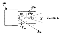
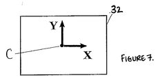
図6及び7はカメラ座標系を示す。これはカメラ20に付随する。原点は、画像センサ32の中心Cにある。原点は、EDM座標系との固定登録範囲内で移動する。カメラ外部のパラメータは、この座標系のEDM座標系に対する関係を定義する。図6は、カメラレンズ20a、焦点面FPL、焦点FPO、焦点距離FL、視野FV及びシーンSも示す。
6 and 7 show the camera coordinate system. This is associated with the
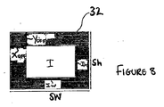
図8はセンサ座標系を示す。これはカメラ20の焦点面FPLであり、原点はセンサ32の中心にある。図8は、画像Iとセンサ32との間のX及びYオフセットXoff、Yoff、画素サイズPh、Pw、画像の高さ及び幅Ih、Iw並びにセンサの高さ及び幅Sh、Swも示す。
FIG. 8 shows the sensor coordinate system. This is the focal plane FPL of the
図9は画像座標系を示す。これは画素サイズPh、Pw、クロッピング及びビニングセッティングによってセンサ座標系に関連する。 FIG. 9 shows an image coordinate system. This is related to the sensor coordinate system by pixel size Ph, Pw, cropping and binning settings.
ポイント定義モジュール
このモジュールは、測定、較正などのためのポイントを定義するのに使用することができる。ポイントが定義されたとき、その対応する画像内の外観を取り込むこともできる(「スナップショット」として)。取り込まれたスナップショットパターンは、パターン認識又は特徴検出アルゴリズムを使用して自動的に測定ポイントの位置を画像に探し出し、追跡するために、後でポイント位置決定モジュールによって使用することができる。
Point Definition Module This module can be used to define points for measurement, calibration, etc. When a point is defined, it can also capture its appearance in the corresponding image (as a “snapshot”). The captured snapshot pattern can be used later by the point location module to automatically locate and track the location of the measurement point in the image using pattern recognition or feature detection algorithms.
ポイントは次の2つのうちの1つの方法によって定義するころができる。
1.EDM12は所望のポイントを向いている。距離測定が実施される。距離測定とともにEDM12の現在の方向が、ポイントの3D位置を定義する。カメラの固有及び外部のパラメータが、この3D位置を画像内の位置に投影するのに使用される。次いで、ポイントの外観をその画像位置におけるスナップショットとして取り込むことができる。
2.所望のポイントは、画像内で特定される。ポイントの外観をその画像位置におけるスナップショットとして取り込むことができる。次いで、EDM位置合わせモジュールは、EDM12を所望のポイントと位置合わせする。距離測定が実施される。距離測定とともにEDM12の現在の方向が、ポイントの3D位置を定義する。
Points can be defined in one of two ways:
1. The
2. The desired point is identified in the image. The appearance of the point can be captured as a snapshot at that image location. The EDM alignment module then aligns
ポイント位置決定モジュール
このモジュールは、パターン認識又は特徴検出アルゴリズムなどの画像処理アルゴリズムを使用して、画像内の測定ポイントを自動的に探し出すことができる。測定ポイントを探し出すために、測定ポイントの外観は既知である。測定ポイントの外観は、以下であり得る。
・特徴検出アルゴリズムを使用して自動的に画像内に探し出すことができる標的、円、十字などの既知のパターン。
・自然パターン。ポイントが定義され、次いで、国際出願PCT/GB2003/004606に説明されているものなどのパターン認識アルゴリズムを使用して、画像内で探し出されたとき、パターンのスナップショットをポイント定義モジュールによって取り込むことができる。
Point location module This module can automatically locate measurement points in an image using image processing algorithms such as pattern recognition or feature detection algorithms. In order to find the measurement point, the appearance of the measurement point is known. The appearance of the measurement point can be:
Known patterns such as targets, circles, crosses, etc. that can be automatically found in images using feature detection algorithms.
・ Natural patterns. When a point is defined and then located in the image using a pattern recognition algorithm such as that described in international application PCT / GB2003 / 004606, a snapshot of the pattern is captured by the point definition module Can do.
データ融合モジュール
EDM12、EDMの方向センサ16及びカメラ20からのデータは、測定を行うために融合される。これは、それぞれが異なる測定機能を提供するいくつかの方法によって実現することができる。本発明人は、既存のデバイスが一度に単一ポイントの静的測定しかできないことを特定しているが、本明細書に提示するハイブリッドデバイス10及び方法は、複数ポイントの動的測定及び測定の両方を同時に行うことを可能にする。
Data Fusion Module Data from
ハイブリッドデバイス10が動作するために、自己較正モジュール(以下に説明する)がカメラ20の固有及び外部のパラメータを確立するためにシステムを較正するのにまず使用されることが好ましい。しかし、カメラ20の固有及び外部のパラメータは、当業者には明らかであるように、構築した設定から知ることができ、又は他の方法で確認することができる。
In order for the
次いで、データ融合モジュールは、いくつかのモードで動作することができる。 The data fusion module can then operate in several modes.
モード1
このモードにより、平面(測定面)内を移動している複数ポイントの動的監視が可能になる。複数ポイントは同時に監視される。図10を参照すると、このモードの方法は以下の通りである。
1)セットアップ
a)ステップ40において、測定面が以下のように定義される。
i)3つ以上のポイントの3D位置が、ポイント定義モジュールを使用して定義される。
ii)3つ以上のポイントが、3D測定面を定義する。3つより多くのポイントがある場合、「最良適合」面が定義される。
iii)測定面の原点は、任意選択で、ポイント定義モジュールを使用してポイントを定義し、平面の座標系内のそのポイントの所望の座標を指定することによって設定することができる。
iv)平面のX/Y軸の方向は、任意選択で、ポイント定義モジュールを使用して2つのポイントによって線分を定義し、平面の座標系におけるその線分の所望の方向を指定することによって設定することができる。
b)ステップ42において、1つ又は複数の測定ポイントがポイント定義モジュールを使用して定義される。すべての測定ポイントは、測定面に位置し、移動するとき、すなわち、変位が平面内にあるとき、平面にとどまる。
2)測定
a)ステップ44において、ポイント位置決定モジュールは、画像内の各測定ポイントを探し出す。1つ又は複数の測定ポイントがカメラの視野の外側に移動した場合、EDM12、したがって、カメラは、任意選択で、測定ポイントを探索し、次いで視野に戻して、ポイント位置決定モジュールが測定ポイントを探し出すことを可能にするために、らせん探索パターンを通してなど、一連の方向を通して回転することができる。
b)ステップ46において、カメラの固有の及び外部のパラメータとともにEDM12の現在の方向が、光線をカメラの焦点から各探し出されたポイントの画像座標を通して投影するのに使用される。画像は、画像露出中にEDM12の現在の方向で「タグ付け」されるか、又は他の方法で関連付けられる。タグ付けは、DSS22において実施される。「EDMの現在の方向」は、DSSが、画像が露出された時点の方向に画像を「タグ付け」したので、既知である。
c)ステップ48において、光線は、測定面と交わる。各光線の測定面との交点により、各測定ポイントの現在の位置が得られる。これらは、測定面内の各ポイントの3D座標又は各ポイントの2D座標のいずれかとして提示することができる。ステップ44〜48は、カメラからの各画像の各測定ポイントに対して1つの測定で繰り返して、測定データのストリームを用意する。
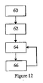
Mode 1
This mode enables dynamic monitoring of a plurality of points moving in a plane (measurement plane). Multiple points are monitored simultaneously. Referring to FIG. 10, the method of this mode is as follows.
1) Setup a) In
i) 3D positions of three or more points are defined using the point definition module.
ii) Three or more points define a 3D measurement plane. If there are more than three points, a “best fit” surface is defined.
iii) The origin of the measurement surface can optionally be set by defining a point using a point definition module and specifying the desired coordinates of that point in the plane's coordinate system.
iv) The plane X / Y axis direction is optionally defined by defining a line segment with two points using the point definition module and specifying the desired direction of the line segment in the plane's coordinate system. Can be set.
b) In
2) Measurement a) In
b) In
c) In
モード2
このモードにより、任意の方向に移動することができる複数ポイントの静的測定が可能になる。複数ポイントは連続して測定される。図11を参照すると、このモードの方法は以下のとおりである。
1)セットアップ
a)ステップ50において、1つ又は複数の測定ポイントが、ポイント定義モジュールを使用して定義される。
2)測定
a)ステップ52において、EDM12は、測定ポイントの予測位置を向くように回転される。これはポイントが定義された位置であることができ、その位置はポイントが最後に測定された位置であり、又はポイントが前の位置などの予備知識に基づくことが予測される位置である。
b)ステップ54において、ポイント位置決定モジュールは、画像内の測定ポイントを探し出すのに使用される。測定ポイントがカメラの視野の外側に移動した場合、EDM12、したがって、カメラは、任意選択で、測定ポイントを探索し、視野内に戻して、ポイント位置決定モジュールが測定ポイントを探し出すことを可能にするために、らせん探索パターンを通してなど、一連の方向を通して回転させることができる。
c)ステップ56において、EDM位置合わせモジュールは、ポイント位置決定モジュールによって画像内で特定されたポイントにEDM12を向け、測定ポイントの3D位置を用意するのに使用される。
d)ステップ52〜56は、各測定ポイントに対して繰り返される。
Mode 2
This mode allows multiple point static measurements that can be moved in any direction. Multiple points are measured in succession. Referring to FIG. 11, the method of this mode is as follows.
1) Setup a) In
2) Measurement a) In
b) In
c) In
d) Steps 52-56 are repeated for each measurement point.
モード3
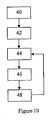
このモードにより、任意の方向に移動することができる単一ポイントの動的測定が可能になる。図12を参照すると、このモードの方法は以下のとおりである。
1)セットアップ
a)ステップ60において、測定ポイントがポイント定義モジュールを使用して定義される。
2)測定
a)ステップ62において、EDM12は、測定ポイントの予測位置を向くように回転される。これはポイントが定義された位置であることができ、その位置はポイントが最後に測定された位置であり、又はポイントが前の位置などの予備知識に基づくことが予測される位置である)。
b)ステップ64において、ポイント位置決定モジュールは、画像内の測定ポイントを探し出すのに使用される。測定ポイントがカメラの視野の外側に移動した場合、EDM、したがってカメラは、任意選択で、測定ポイントを探索し、視野内に戻して、ポイント位置決定モジュールが測定ポイントを探し出すことを可能にするために、らせん探索パターンを通してなど、一連の方向を通して回転させることができることに留意されたい。
c)ステップ66において、EDM位置合わせモジュールが、ポイント位置決定モジュールによって画像内で特定されたポイントにEDM12を向け、測定ポイントの3D位置を用意するのに使用される。
d)ステップ64〜66は、カメラからの各画像に対して1つの測定で繰り返して、測定データのストリームを用意する。
Mode 3
This mode allows for a single point dynamic measurement that can be moved in any direction. Referring to FIG. 12, the method of this mode is as follows.
1) Setup a) In
2) Measurement a) In
b) In
c) In
d)
モード4
このモードにより、任意の方向に移動することができる複数ポイントの動的測定が可能になる。複数ポイントは同時に測定される。この方法は、共通のポイントの組を同時に監視しているがハイブリッドデバイスのうちの一方だけがEDMを必要とする2つ以上のハイブリッドデバイスを必要とする。同期システムにより、複数のデバイスによって同期して画像が取り込まれることが確実になる。図13を参照すると、このモードの方法は以下のとおりである。
1)セットアップ
a)ステップ70において、共通の世界座標系内の各ハイブリッドデバイスの位置及び/又は向きは、標準測量方法を使用して確立される。例えば、EDM12を有するハイブリッドデバイスを使用して、世界座標系内の複数の基準ポイントの3D座標を測定することができる。他のハイブリッドデバイスのそれぞれからの各基準ポイントの測定された方向により、世界座標系内の各ハイブリッドデバイスの位置及び/又は向きを計算することが可能になる。
b)ステップ72において、1つ又は複数の測定ポイントが、ポイント定義モジュールを使用して定義される。各ポイントは、EDMを有する単一のハイブリッドデバイスを使用して定義される。
c)ステップ74において、各定義されたポイントの3D位置が、画像座標内に一つおきのハイブリッドデバイスに対して投影される。これにより、同じ測定ポイントに対応する画像内の特徴が容易に特定され、及び/又は測定ポイントの自然外観の「スナップショット」が一つおきのハイブリッドデバイスに対して測定されることが可能になる。
2)測定
a)ステップ76において、ポイント位置決定モジュールは、あらゆるハイブリッドデバイスに対して画像内の各測定ポイントを探し出す。
b)ステップ78において、測定ポイントの3D位置が計算される。各カメラの固有及び外部のパラメータ並びに各画像内の各ポイントの探し出された位置とともに世界座標系内の各ハイブリッドデバイスの既知の位置及び/又は向きにより、測定ポイントの3D位置を計算することが可能になる。
c)ステップ76〜78は、カメラからの各画像の各測定ポイントに対して1つの測定で繰り返して、測定データのストリームを用意する。
Mode 4
This mode allows dynamic measurement of multiple points that can move in any direction. Multiple points are measured simultaneously. This method requires two or more hybrid devices that are simultaneously monitoring a common set of points, but only one of the hybrid devices requires EDM. The synchronization system ensures that images are captured synchronously by multiple devices. Referring to FIG. 13, the method of this mode is as follows.
1) Setup a) In
b) In
c) In
2) Measurement a) In
b) In
c) Steps 76-78 are repeated with one measurement for each measurement point of each image from the camera to prepare a stream of measurement data.
自己較正モジュール
このモジュールにより、現場で実施することができる、固有及び外部のカメラパラメータの単純で迅速な較正が可能になる。外部のパラメータはEDM座標系に対する。較正方法は、同軸上に取り付けられたカメラ及び非同軸上に取り付けられたカメラの両方を較正することができる。較正方法は、単一の較正ポイントだけを必要とし、多くの場合、その較正ポイントの2つの観測だけが必要とされる。方法は、画像内の較正ポイントの絶対位置を知ることに高い精度まで依存しないが、むしろ、方法は、ポイント位置決定モジュールを使用して、画像内の較正ポイントの変位を精密に測定し、これは、はるかに高い精度及び精密度まで実現することができる。
Self-calibration module This module allows simple and quick calibration of intrinsic and external camera parameters that can be performed in the field. External parameters are relative to the EDM coordinate system. The calibration method can calibrate both co-axially mounted cameras and non-coaxially mounted cameras. A calibration method requires only a single calibration point, and often only two observations of that calibration point are required. The method does not rely to a high degree of accuracy on knowing the absolute position of the calibration point in the image, but rather, the method uses a point location determination module to accurately measure the displacement of the calibration point in the image. Can be achieved to much higher accuracy and precision.
図14を参照すると、方法は以下のステップを含む。
1.ステップ80において、必要とされる入力データが取り込まれる。
2.ステップ82において、方法は、カメラの焦点距離、及び任意選択でレンズ歪みパラメータの値を求める。
3.ステップ84において、方法は、EDM座標系に対するカメラの横揺れの値を求める。
4.ステップ86において、方法は、EDM座標系に対するカメラのパン/傾斜の値を求める。
Referring to FIG. 14, the method includes the following steps.
1. In
2. In
3. In
4). In
必要とされる入力データを取り込む
1.以下に対する近似値が必要とされる。
a.EDM座標系に対するカメラ座標系の位置及び/又は向きが必要とされる。これらは、典型的には、デバイスの周知の機械設計から導き出すことができ、3つの並進値及び3つの回転値として表すことができる。
b.焦点距離 レンズの仕様書からの値を使用することができる。
c.画素サイズ カメラの仕様書からの値を使用することができる。
d.主ポイント 画像センサの中心を通過すると仮定される。
e.歪みパラメータ 光学系が何も歪みを示さないと仮定する。
2.次いで、単一の較正ポイントがユーザによって選択される。デバイス座標系内の較正ポイントの3D位置は、既知でなければならず、これは、典型的には、EDM12を較正ポイントに向け、距離測定を実施し、これを現在のEDMの方向と組み合わせて、3D位置を計算することによって確認される。ポイントがカメラから遠くに離れていればいるほど、方法は、較正ポイントの既知の位置の絶対誤差又はEDM座標系に対するカメラ座標系の提供された位置の誤差に対してより寛容になることに留意されたい。
3.まだ準備されていない場合、EDM12は、較正ポイントを向くように回転される。次いで、画像内の較正ポイントの位置が手動又は自動的のいずれかで配置される。ポイントが手動で探し出されても、いったんそれを探し出してしまうと、その後のステップにおいて、例えば、外観の「スナップショット」を撮り、次いで、ポイント位置決定モジュールを使用して、自動的にポイントを探し出すことによって自動的に探し出されることが可能になる。
4.光軸がEDM12のレーザと同軸であるように光学系が位置合わせされた場合、
画像内の較正ポイントの位置は、記録される(x0,y0)。EDMの方向のパン角及び傾斜角は記録される(h0及びv0)。主ポイントの位置の推定値は、(x0,y0)に更新することができる。
そうでない場合、
カメラは、画像内で較正ポイントが主ポイントとほぼ位置合わせされるまで回転される。(1)に用意された近似値により、この回転が自動的に実施されることが可能になる。次いで、ポイント位置決定モジュールが、画像内の較正ポイントを探し出すのに使用される。画像内の較正ポイントの位置は記録される(x0,y0)。EDMの方向のパン角及び傾斜角が記録される(h0及びv0)。
5.次いで、EDM12は、較正ポイントが画像内で移動するように傾斜される。画像内の移動が大きければ大きいほど、較正が一層正確になり、したがって、較正ポイントが画像の縁に近接するまで傾斜させることが有益である(が、必須ではない)。(1)に用意された近似値により、この回転は自動的に実施されることが可能となる。次いで、ポイント位置決定モジュールが、画像内の較正ポイントを探し出すのに使用される。画像内の較正ポイントの位置は記録される(x1及びy1)。EDMの方向のパン及び傾斜角は記録される(h1及びv1)。
6.ステップ(5)は、任意選択で、傾斜角及び/又はパン角の範囲に対して繰り返すことができる。
Capture required input data An approximation to the following is required.
a. The position and / or orientation of the camera coordinate system relative to the EDM coordinate system is required. These are typically derived from the well-known mechanical design of the device and can be expressed as three translation values and three rotation values.
b. Focal length Values from lens specifications can be used.
c. Pixel size Values from camera specifications can be used.
d. Main point It is assumed that it passes through the center of the image sensor.
e. Distortion parameters Assume that the optical system shows no distortion.
2. A single calibration point is then selected by the user. The 3D position of the calibration point in the device coordinate system must be known, which typically points the
3. If not already prepared, the
4). If the optical system is aligned so that the optical axis is coaxial with the EDM12 laser,
The position of the calibration point in the image is recorded (x 0 , y 0 ). The pan angle and tilt angle in the direction of EDM are recorded (h 0 and v 0 ). The estimated value of the position of the main point can be updated to (x 0 , y 0 ).
If not,
The camera is rotated until the calibration point is approximately aligned with the main point in the image. The approximate value prepared in (1) enables this rotation to be performed automatically. A point location module is then used to locate the calibration points in the image. The position of the calibration point in the image is recorded (x 0 , y 0 ). The pan angle and tilt angle in the direction of EDM are recorded (h 0 and v 0 ).
5. The
6). Step (5) can optionally be repeated for a range of tilt angles and / or pan angles.
カメラの焦点距離の値を求める
ピンホールカメラモデルを使用することにより、焦点距離を直接計算することが可能になる。
焦点距離=画素サイズx|(x1,y1)−(x0,y0)|/Tan(θ)
ここで、
θはr0とr1との間の角度であり、
r0は、EDMの方向がh0及びv0にあるときの光軸に対応する光線であり、
r1は、(h1−h0)及び(v1−v0)によりEDMの原点を中心としてr0を回転させた結果である。
Determining the focal length value of a camera By using a pinhole camera model, the focal length can be calculated directly.
Focal length = pixel size x | (x 1 , y 1 ) − (x 0 , y 0 ) | / Tan (θ)
here,
θ is the angle between r 0 and r 1 ,
r 0 is the ray corresponding to the optical axis when the EDM direction is at h 0 and v 0 ,
r 1 is the result of rotating r 0 around the origin of EDM by (h 1 -h 0 ) and (v 1 -v 0 ).
追加の観測がステップ6で記録された場合、パラメータ化されたレンズ歪みモデルの値も求めることができる。一般的な方式は、観測された画像座標と投影された画像座標(現在の歪みパラメータを使用して投影された)との間の相違の観点から誤差関数を公式化することであり、次いで、誤差関数を最小にするパラメータの値を求めるために標準最適化技法を適用することである。 If additional observations were recorded in step 6, a parameterized lens distortion model value can also be determined. The general scheme is to formulate an error function in terms of the difference between the observed image coordinates and the projected image coordinates (projected using the current distortion parameters), then the error Applying standard optimization techniques to find the value of the parameter that minimizes the function.
光軸がEDM12のレーザと同軸であるように光学系が位置合わせされていなくて、歪みパラメータの値が求められている場合、放射状歪みの中心は、主ポイントの推定値と解釈することができる。
If the optical system is not aligned so that the optical axis is coaxial with the
EDM座標系に対するカメラの横揺れの値を求める
上記のステップ4及び5で記録された画像座標の2つの組は、線分を定義する。較正ポイントが(x0,y0)からx1,y1)まで画像内の線形経路に続くようにEDM12が傾斜された場合、線の方向(Tan−1((y1−y0)/(x1−x0)))は、EDM12座標系内のカメラの横揺れの角度に直接関連している。したがって、線の方向を測定することにより、横揺れの角度を直接計算することが可能になる。
Finding the value of camera roll relative to the EDM coordinate system The two sets of image coordinates recorded in steps 4 and 5 above define a line segment. If the
EDM座標系に対するカメラのパン/傾斜の値を求める
このステップは、光軸がEDM12のレーザと同軸であるように光学系がまだ位置合わせされていない場合だけに関連する。
Determining camera pan / tilt values relative to the EDM coordinate system This step is only relevant if the optical system is not yet aligned so that the optical axis is coaxial with the
焦点距離、カメラの横揺れ及び主ポイントの推定値は、上記の計算された値を用いて更新される。レンズ歪みパラメータが計算された場合、これらも更新される。 The focal length, camera roll and principal point estimates are updated using the calculated values. If lens distortion parameters are calculated, these are also updated.
更新されたパラメータは、較正ポイントの既知の3D位置をまた画像座標内に投影するのに使用される。次いで、投影された位置は、探し出された位置と比較され、いずれの相違もEDM座標系内のカメラのパン角及び傾斜角に直接関連する。 The updated parameters are used to project the known 3D position of the calibration point also into the image coordinates. The projected position is then compared to the found position, and any differences are directly related to the camera pan and tilt angles in the EDM coordinate system.
EDM位置合わせモジュール
カメラ20からのデータとEDM12からのデータとを融合するために、画像内の特定のポイントに対応する表面のポイントにEDM12を向けることがしばしば必要とされる。自己較正モジュールがまずカメラ20の固有及び外部のパラメータを較正するのに使用されていることが好ましい。
EDM Registration Module In order to fuse the data from the
図15を参照すると、EDM12を画像内の特定のポイントと位置合わせする方法は、まず、カメラ20の光軸がEDM12の方向と同軸であるかどうかに依存する。
1.カメラがEDM12と同軸である場合、ステップ90aにおいて、カメラ固有及び外部のパラメータが、現在のEDMの方向を画像内のEDMの目標ポイントにまた投影するのに使用される。次いで、EDM12は、画像内の指定されたポイントがEDMの目標ポイントとして画像内の同じ位置に移動されるまで回転される。
2.カメラがEDM12と同軸でない場合、視差効果により、EDM12を画像内の指定されたポイントと位置合わせすることがより困難になる。視差の程度は、測定ポイントまでの距離によって決まり、問題はこの距離が未知であることである。この場合、ステップ90bにおいて、以下に説明するような方法を採用することができる。
Referring to FIG. 15, the method of aligning
1. If the camera is coaxial with
2. If the camera is not coaxial with
画像が取り込まれた時点におけるEDM12の既知の方向とともにカメラ固有及び外部のパラメータを使用することにより、画像内のポイントは世界座標内の3D光線又は「カメラ光線」として外に投影されることが可能になる。
By using camera-specific and external parameters along with the known direction of
次いで、EDM12は、その光線に沿ったポイントを向くように回転され、距離測定が実施される。距離測定及び現在のEDMの方向により、EDMの目標ポイントが得られる。カメラ光線からのEDMの目標ポイントの垂直距離が計算される。次いで、EDM12の向きが、カメラ光線からのEDMの目標ポイントの距離が可能な限り小さくなるまで調整される。これは反復最適化手法によって実現することができ、その場合、以下の条件のうちの1つ又は複数が満足されたとき反復は終了する。
・EDMの目標ポイントは、カメラ光線の許容差内にある。
・各反復におけるEDM12の向きの角変化は、方位駆動システム又は方向センサの分解能よりも小さい。
・反復の数は、所定の限度を超えている。
The
EDM target point is within camera ray tolerance.
The angular change in the orientation of
• The number of iterations exceeds a predetermined limit.
ステップ92において、EDM12が位置合わせされると、以下の2つの選択肢がある。
1.距離測定とともに現在のEDMの方向により、ポイントの3D座標が得られる。又は
2.EDMの目標ポイントに最も近接したカメラ光線に沿ったポイントは、ポイントの3D座標を定義する。
In
1. The 3D coordinates of the point are obtained by the current EDM direction along with the distance measurement. Or 2. The point along the camera ray closest to the EDM target point defines the 3D coordinates of the point.
カメラの角度分解能がEDM駆動システム18又は方向センサ16の角度分解能を超える場合、これにより、システムの潜在的測定分解能が増加するので、第2の方法が好ましくは採用される。
If the angular resolution of the camera exceeds the angular resolution of the
カメラ自動露出モジュール
測定精度及び頑健性は、照明の変化の影響を受けやすい。直射日光照度の変化が主な原因である。このモジュールは、画像Iの一部分内の画素強度に基づいてカメラの露出を調整するように構成された自動露出アルゴリズムを含む。例えば、画像内の平均画素強度が暗すぎる場合、このモジュールは、画像を明るくするために露出時間を長くし、又は絞りを開け、又は利得を上げる。これらの特徴は、当技術分野では周知である。
Camera automatic exposure module Measurement accuracy and robustness are sensitive to changes in lighting. Changes in direct sunlight illuminance are the main cause. This module includes an automatic exposure algorithm configured to adjust the exposure of the camera based on pixel intensity within a portion of image I. For example, if the average pixel intensity in the image is too dark, this module increases the exposure time, opens the aperture, or increases the gain to brighten the image. These features are well known in the art.
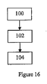
図16を参照すると、ステップ100において、1つ又は複数の関心領域(ROI)が、画像I内で特定される。各ROIは画像I内の特徴に対応する。ROIは、ユーザによって特定することができ、又は特徴(複数可)の位置に基づいて自動的に設定することができる。
Referring to FIG. 16, in
ステップ102において、自動露出アルゴリズムは、ROI内の画素だけを処理する。
In
ステップ104において、ある特徴がそのROIの外側に移動したかどうかに関して決定が行われる。そうである場合、特徴に関連付けられたROIが移動され、したがって、特徴はROIに戻される。ステップ104は繰り返される。
In
したがって、この方法は、自動露出のROIをそれらが画像内の測定ポイントの位置との登録範囲内で常に保持されるように継続して更新するために画像内の測定ポイントの現在の位置を使用する。測定を実施しながら、ポイント位置決定モジュールは、画像内の各測定ポイントの現在の位置を提供する。しかし、ポイント位置決定モジュールがポイントを探し出すことができない場合、「最後に見た」位置、「定義された」位置又は予測された位置のいずれかが使用されるが、これらの場合、それらの領域に関連付けられた画素強度には、ポイント位置決定モジュールがポイントを見つけることができた場合の画素強度と比較して、より低い重み付けが与えられる。測定ポイントが視野内に何もない場合、全体画像などのデフォルト領域がROIに使用される。方法は、測定ポイントの露出が画像I内で最適である尤度を増加させる。 Therefore, this method uses the current position of the measurement points in the image to continuously update the auto-exposure ROIs so that they are always kept within the registration range with the position of the measurement points in the image. To do. While performing the measurement, the point location determination module provides the current position of each measurement point in the image. However, if the point location module cannot find a point, either the “last seen” location, the “defined” location, or the predicted location is used, but in these cases those regions The pixel intensity associated with is given a lower weight compared to the pixel intensity when the point location module can find the point. If there are no measurement points in the field of view, a default region such as the entire image is used for the ROI. The method increases the likelihood that the exposure of the measurement point is optimal in image I.
例示された実施形態のハイブリッドデバイス10は、説明したモジュールのそれぞれを含むが、他の実施形態においては、ハイブリッドデバイスは、説明したモジュールのうちの1つ又は複数を含むことができる。実施形態において、ハイブリッドデバイス又は測定デバイスは、デジタル画像を出力するように動作可能であり、ICDがEDMに対して固定登録範囲内で移動するようにEDMに結合されるように配列される画像取込デバイスと、1つ又は複数のセンサ及びICDからデータを受け取るように配置されたコントローラであって、a)画像の露出中に画像をEDMの向きに関連付け、b)画像内の測定ポイントのうちの1つを探し出し、c)EDMの向きと組み合わせて画像内の測定ポイントの位置を使用して、測定デバイスに対する測定ポイントの方向を確立するように構成される、コントローラとを備えることができる。
The
上述の実施形態は、本発明を限定するのではなく、例示すること、及び当業者は添付の特許請求の範囲によって定義される本発明の範囲をから逸脱することなく多くの代替実施形態を設計することができることに留意されたい。特許請求の範囲において、かっこ内に配置された任意の参照符号は、特許請求の範囲を限定すると解釈してはならない。「備える(comprising)」という用語は、任意の請求項又は全体としての仕様書に列挙されているもの以外の要素又はステップの存在を除外しない。要素の単数形の参照は、そのような要素の複数形の参照を除外せず、逆も同様である。本発明の部分は、いくつかの個別要素を備えるハードウェアを用いて、又は適切にプログラミングされたコンピュータによって実装することができる。いくつかの部分を列挙したデバイス請求項において、これらの部分のうちのいくつかは、1つの及び同じハードウェアによって具現化することができる。ある測定が相互に異なる従属請求項に記載されるという単なる事実は、これらの測定の組合せを有利に使用することができないことを示してはいない。 The above-described embodiments are illustrative rather than limiting, and those skilled in the art will be able to design many alternative embodiments without departing from the scope of the invention as defined by the appended claims. Note that you can. In the claims, any reference signs placed between parentheses shall not be construed as limiting the claim. The term “comprising” does not exclude the presence of elements or steps other than those listed in any claim or overall specification. References to the singular of an element do not exclude references to the plural of such an element and vice versa. The parts of the invention can be implemented using hardware with several individual elements or by a suitably programmed computer. In the device claim enumerating several parts, several of these parts can be embodied by one and the same hardware. The mere fact that certain measurements are recited in mutually different dependent claims does not indicate that a combination of these measurements cannot be used to advantage.
Claims (31)
当該測定デバイスが、当該測定デバイスに対して1つ又は複数の測定ポイントの位置を決定するためのものであり、
当該測定デバイスが、非接触距離測定デバイス(EDM)と、前記非接触距離測定デバイスの向きを決定するための1つ又は複数のセンサとに結合されるように配置されており、
当該測定デバイスが、
デジタル画像を出力するように動作可能である画像取込デバイス(ICD)であり、該画像取込デバイスが前記非接触距離測定デバイスに対して既知の登録範囲内で移動するように前記非接触距離測定デバイスに結合されるように構成されている、画像取込デバイスと、
1つ又は複数の前記センサ及び前記画像取込デバイスからデータを受け取るように構成されたコントローラであり、
a)画像の露出中に前記画像を前記非接触距離測定デバイスの向きに関連付け、
b)前記画像内の前記測定ポイントのうちの1つを探し出し、
c)前記非接触距離測定デバイスの向きと組み合わせて前記画像内の前記測定ポイントの位置を使用して、前記測定デバイスに対する前記測定ポイントの方向を確立するように構成されているコントローラと
を備える、測定デバイス。 A measuring device,
The measurement device is for determining the position of one or more measurement points relative to the measurement device;
The measurement device is arranged to be coupled to a non-contact distance measurement device (EDM) and one or more sensors for determining the orientation of the non-contact distance measurement device;
The measuring device is
An image capture device (ICD) operable to output a digital image, said non-contact distance such that said image capture device moves within a known registration range relative to said non-contact distance measuring device An image capture device configured to be coupled to the measurement device;
A controller configured to receive data from one or more of the sensors and the image capture device;
a) associating said image with the orientation of said non-contact distance measuring device during image exposure;
b) find one of the measurement points in the image;
c) a controller configured to establish the orientation of the measurement point relative to the measurement device using the position of the measurement point in the image in combination with the orientation of the non-contact distance measurement device; Measuring device.
前記非接触距離測定デバイスの向きを決定するための1つ又は複数の前記センサと
をさらに備える、請求項1に記載の測定デバイス。 The non-contact distance measuring device;
The measurement device of claim 1, further comprising one or more of the sensors for determining an orientation of the non-contact distance measurement device.
前記画像内のある位置に前記非接触距離測定デバイスの目標ポイントを投影し、前記測定ポイントの外観を取り込むステップと、
前記測定ポイントに対応するとして特定された前記画像内の領域の外観を取り込むステップと
のうちの1つ又は複数によって前記画像内のその後の位置の前記測定ポイントの外観を取り込むように構成されている、請求項1〜3のいずれか一項に記載の測定デバイス。 The controller is
Projecting a target point of the non-contact distance measuring device to a position in the image to capture the appearance of the measuring point;
Capturing the appearance of the measurement point at a subsequent location in the image by one or more of capturing the appearance of a region in the image identified as corresponding to the measurement point. The measuring device according to any one of claims 1 to 3.
前記画像取込デバイスの固有及び外部のパラメータを使用して、現在の前記非接触距離測定デバイスの方向を前記非接触距離測定デバイスの目標ポイントとして前記画像内に投影し、前記駆動システムを制御して、前記非接触距離測定デバイスの目標ポイントを前記画像内の測定ポイントと位置合わせするステップを含む、非接触距離測定デバイス位置合わせ機能を、前記コントローラが実施するように構成されている、請求項5に記載の測定デバイス。 The optical axis of the image capture device is coaxial with the measurement axis of the non-contact distance measuring device;
Using the intrinsic and external parameters of the image capture device, project the current non-contact distance measurement device direction into the image as a target point of the non-contact distance measurement device and control the drive system The controller is configured to perform a non-contact distance measurement device alignment function comprising aligning a target point of the non-contact distance measurement device with a measurement point in the image. 5. The measuring device according to 5.
(d)前記画像の露出中に前記非接触距離測定デバイスの向きとともに前記画像取込デバイスの固有及び外部のパラメータを使用して、世界座標において前記画像内の測定ポイントを3次元画像取込デバイスの光線として外に投影するステップと、
(e)前記駆動システムを制御して、前記非接触距離測定デバイスを前記画像取込デバイスの光線上のポイントと位置合わせし、次いで、距離測定を実施するステップと、
(f)前記測定された距離及び前記現在の非接触距離測定デバイスの方向に対応する非接触距離測定デバイスの目標ポイントを取得するステップと、
(g)前記画像取込デバイスの光線から前記非接触距離測定デバイスの目標ポイントの垂直距離を計算するステップと、
(h)前記画像取込デバイスの光線から前記非接触距離測定デバイスの目標ポイントの距離を低減し、場合により最小にする非接触距離測定デバイスの方向を見つけるために、ステップ(e)〜(g)を1回又は複数回繰り返す最適化手法を実施するステップと
を含む、非接触距離測定デバイスの位置合わせ機能を、 前記コントローラが実施するように構成されている、請求項5に記載の測定デバイス。 The optical axis of the image capture device is not coaxial with the measurement axis of the non-contact distance measurement device,
(D) using the intrinsic and external parameters of the image capture device along with the orientation of the non-contact distance measurement device during exposure of the image to determine the measurement points in the image in world coordinates in a 3D image capture device Projecting it out as a ray of light,
(E) controlling the drive system to align the non-contact distance measuring device with a point on a ray of the image capture device and then performing a distance measurement;
(F) obtaining a target point of the non-contact distance measuring device corresponding to the measured distance and the current non-contact distance measuring device direction;
(G) calculating a vertical distance of a target point of the non-contact distance measuring device from a ray of the image capture device;
(H) reducing the distance of the target point of the non-contact distance measuring device from the ray of the image capture device and finding the direction of the non-contact distance measuring device to minimize, possibly steps (e) to (g The measurement device according to claim 5, wherein the controller is configured to perform an alignment function of the non-contact distance measurement device, including performing an optimization method that repeats one or more times) .
前記画像取込デバイスの光線からの前記非接触距離測定デバイスの目標ポイントの垂直距離が相対的に小さいこと、
反復における前記非接触距離測定デバイスの向きの角変化が、前記駆動システム又は前記非接触距離測定デバイスの方向センサの分解能よりも小さいこと、及び
反復の数が、所定の限度を超えていること、
の終了基準のうちの1つ又は複数が満足されるまでステップ(e)〜(g)を繰り返すステップを含む、請求項7に記載の測定デバイス。 The optimization method is:
The vertical distance of the target point of the non-contact distance measuring device from the ray of the image capture device is relatively small;
The angular change in the orientation of the non-contact distance measuring device in iterations is less than the resolution of the direction sensor of the drive system or the non-contact distance measuring device, and the number of iterations exceeds a predetermined limit;
8. The measurement device of claim 7, comprising repeating steps (e)-(g) until one or more of the termination criteria is satisfied.
前記非接触距離測定デバイスの目標ポイントに最も近接した前記画像取込デバイスの光線に沿ったポイントを使用して、前記測定ポイントの3次元座標を取得するステップ
を含む測定機能を、前記コントローラが実施するように構成されている、請求項6〜8のいずれか一項に記載の測定デバイス。 Using a direction of the current non-contact distance measuring device together with a distance measurement to obtain a three-dimensional coordinate of a target point of the non-contact distance measuring device currently corresponding to the measurement point, or the non-contact distance measuring device The controller is configured to perform a measurement function comprising obtaining a three-dimensional coordinate of the measurement point using a point along the ray of the image capture device closest to the target point of The measuring device according to any one of claims 6 to 8.
前記露出時間中に読み取られた複数の表示数値を使用すること
によって、 前記コントローラが、前記露出時間中に非接触距離測定デバイスの方向又は距離の変化を補償するように構成されている、請求項1〜9のいずれか一項に記載の測定デバイス。 By using a display value of a single direction and / or distance from a certain time point during the exposure time, for example from an intermediate time point, or by using a plurality of display values read during the exposure time, the controller 10. The measuring device according to any one of claims 1 to 9, wherein the measuring device is configured to compensate for a change in direction or distance of the non-contact distance measuring device during the exposure time.
前記画像取込デバイスの固有及び外部のパラメータとともに前記非接触距離測定デバイスの現在の方向を使用して、光線が測定面と交わるように各探し出されたポイントの画像座標を通して前記画像取込デバイスの焦点から前記光線を投影するステップと
[モード1]によって、 前記コントローラが、3次元測定面内で移動している複数の前記測定ポイントの動的監視を実施するように構成されている、請求項1〜13のいずれか一項に記載の測定デバイス。 Locating each of the measurement points in the image;
Using the current orientation of the non-contact distance measuring device along with the intrinsic and external parameters of the image capturing device, the image capturing device through the image coordinates of each found point so that a ray intersects the measurement plane Projecting the light beam from the focal point of the light source and [mode 1], wherein the controller is configured to perform dynamic monitoring of the plurality of measurement points moving in a three-dimensional measurement plane. Item 14. The measuring device according to any one of Items 1 to 13.
j)前記画像内の前記測定ポイントを探し出すように、及び、
k)前記測定ポイントの3次元位置を得るために前記測定機能が後に続く前記非接触距離測定デバイスの位置合わせ機能を実施するように、前記コントローラが構成されている、請求項9に従属しているときの請求項1〜14のいずれか一項に記載の測定デバイス。 i) if necessary to control the drive system to rotate the non-contact distance measuring device so that the measurement point is in the image;
j) to locate the measurement point in the image; and
k) As dependent on claim 9, wherein the controller is configured to perform an alignment function of the non-contact distance measurement device followed by the measurement function to obtain a three-dimensional position of the measurement point The measurement device according to any one of claims 1 to 14, wherein:
関連付けられた測定ポイントの測定された移動に従って及び/又は前記1つ又は複数のセンサからの非接触距離測定デバイスの方向データに従って関心領域を移動させるように、前記コントローラが構成されている、請求項1〜18のいずれか一項に記載の測定デバイス。 Performing an automatic exposure process on the region of interest, wherein the region of interest is one or more regions of interest defined in the image, each region of interest including a measurement point;
The controller is configured to move a region of interest according to a measured movement of an associated measurement point and / or according to direction data of a non-contact distance measurement device from the one or more sensors. The measurement device according to any one of 1 to 18.
1つ又は複数の他の測定デバイスであり、それぞれが該他の測定デバイスに対して1つ又は複数の測定ポイントの方向を決定するように構成されている、1つ又は複数の他の測定デバイスと
を備える測定デバイスの配列であって、
前記他の測定デバイスのそれぞれが、
デジタル画像を出力するように動作可能である画像取込デバイスと、
前記画像取込デバイスの向きを決定するための1つ又は複数のセンサと、
1つ又は複数の前記センサ及び前記画像取込デバイスからデータを受け取るように構成されたコントローラであり、
(l)画像の露出中に前記画像を前記画像取込デバイスの向きに関連付け、
(m)前記画像内の前記測定ポイントのうちの1つを探し出し、
(n)前記画像取込デバイスの向きと組み合わせて前記画像内の前記測定ポイントの位置を使用して、前記他の測定デバイスに対する前記測定ポイントの方向を確立するように、構成されているコントローラを備え、
当該測定デバイスの配列が、前記第1の測定デバイス及び前記他の測定デバイスによって画像を同期して取り込ませるように構成された同期システムをさらに備えており、
(o)前記第1の測定デバイスの前記コントローラが、複数の測定ポイントの3次元位置を一つおきの測定デバイスの画像座標内に投影するように構成されており、
(p)各測定デバイスの前記コントローラが、各測定ポイントをそのそれぞれの画像内で探し出すように構成されており、
(q)前記コントローラのうちの1つが、各画像取込デバイスの固有及び外部のパラメータ並びに各画像内の各ポイントの探し出された位置とともに世界座標系内の各測定デバイスの既知の位置及び向きを使用して、前記測定デバイスに対して計算される各測定ポイントの3次元位置を決定するように構成され、
したがって、各測定デバイスの前記画像取込デバイスからの各画像に対して1つの測定で、ステップ(p)〜(q)を繰り返して、測定データのストリームを用意する、
測定デバイスの配列。 The first measuring device according to any one of claims 1 to 19,
One or more other measurement devices, each configured to determine the direction of the one or more measurement points relative to the other measurement device An array of measuring devices comprising:
Each of the other measuring devices is
An image capture device operable to output a digital image;
One or more sensors for determining the orientation of the image capture device;
A controller configured to receive data from one or more of the sensors and the image capture device;
(L) associating the image with the orientation of the image capture device during image exposure;
(M) find one of the measurement points in the image;
(N) a controller configured to establish the orientation of the measurement point relative to the other measurement device using the position of the measurement point in the image in combination with the orientation of the image capture device; Prepared,
The array of measurement devices further comprises a synchronization system configured to synchronously capture images by the first measurement device and the other measurement device;
(O) the controller of the first measurement device is configured to project the three-dimensional positions of a plurality of measurement points into the image coordinates of every other measurement device;
(P) the controller of each measurement device is configured to locate each measurement point in its respective image;
(Q) one of the controllers is configured to determine the known position and orientation of each measuring device in the world coordinate system along with the unique and external parameters of each image capture device and the located position of each point in each image. Is used to determine the three-dimensional position of each measurement point calculated for the measurement device,
Therefore, in one measurement for each image from the image capture device of each measurement device, steps (p) to (q) are repeated to prepare a stream of measurement data.
An array of measuring devices.
前記測定デバイスが、請求項1〜20のいずれか一項に記載の測定デバイスとすることができ、前記測定デバイスが、デジタル画像を出力するように動作可能である画像取込デバイスであり、非接触距離測定デバイスに対して固定位置合わせで移動するように前記非接触距離測定デバイスに結合されている画像取込デバイスを備え、前記固有のパラメータが、前記画像取込デバイスのパラメータを記述し、前記外部のパラメータが、前記非接触距離測定デバイスの座標系に対する前記画像取込デバイスの座標系の位置及び向きを記述し、
当該方法が、
(a)前記非接触距離測定デバイスの座標系に対する前記画像取込デバイスの座標系の位置及び向き、
前記画像取込デバイスの焦点距離、
前記画像取込デバイスの画素サイズ、
光軸の前記画像取込デバイスの画像センサとの交点によって定義される主ポイントであって、第1の近似値が、任意選択で前記画像取込デバイスの画像センサの中心において測定される主ポイント、及び
前記画像取込デバイスの歪みパラメータ
の前記第1の近似値を確立するステップと、
(b)前記距離測定デバイスに対する既知の3次元位置を有する較正ポイントを選択するステップと、
(c)前記画像内の前記較正ポイントを探し出して、位置(x0,y0)を記録するステップと、
(d)前記非接触距離測定デバイスの方向のパン角及び傾斜角(h0及びv0)を記録するステップと、
(e)任意選択で、前記主ポイントの前記第1の近似値を更新して、(x0,y0)と等しくさせるステップと、
(f)前記較正ポイントが前記画像内で移動するように前記非接触距離測定デバイスの向きを変更するステップと、
(g)前記画像内の前記較正ポイントを探し出し、前記較正ポイントの画像座標(x1,y1)及び前記非接触距離測定デバイスの前記パン角及び傾斜角(h1及びv1)を記録するステップと、
(h)画像取込デバイスの焦点距離の値を求めるステップであって、
ピンホールカメラモデルを使用して前記焦点距離を計算することを含む、画像取込デバイスの焦点距離の値を求めるステップと、
(i)前記非接触距離測定デバイスの座標系に対して画像取込デバイスの横揺れの値を求めるステップであって、
(x0,y0)及び(x1,y1)と交わる線分を定義すること、及び
線の方向を測定して、横揺れの角度を計算することを含む、前記非接触距離測定デバイスの座標系に対して画像取込デバイスの横揺れの値を求めるステップと
を含む、方法。 A method for calibrating intrinsic and external image capture device parameters of a measurement device comprising:
21. The measurement device can be a measurement device according to any one of claims 1 to 20, wherein the measurement device is an image capture device operable to output a digital image, An image capture device coupled to the non-contact distance measurement device to move in fixed alignment relative to the contact distance measurement device, wherein the unique parameter describes a parameter of the image capture device; The external parameters describe the position and orientation of the coordinate system of the image capture device relative to the coordinate system of the non-contact distance measuring device;
The method is
(A) the position and orientation of the coordinate system of the image capture device relative to the coordinate system of the non-contact distance measuring device;
The focal length of the image capture device,
Pixel size of the image capture device,
A main point defined by the intersection of the optical axis with the image sensor of the image capture device, wherein a first approximation is optionally measured at the center of the image sensor of the image capture device Establishing the first approximation of distortion parameters of the image capture device;
(B) selecting a calibration point having a known three-dimensional position relative to the distance measuring device;
(C) locating the calibration point in the image and recording the position (x0, y0);
(D) recording the pan angle and tilt angle (h0 and v0) of the direction of the non-contact distance measuring device;
(E) optionally updating the first approximation of the main point to be equal to (x0, y0);
(F) changing the orientation of the non-contact distance measuring device such that the calibration point moves within the image;
(G) finding the calibration point in the image and recording the image coordinates (x1, y1) of the calibration point and the pan and tilt angles (h1 and v1) of the non-contact distance measuring device;
(H) determining a focal length value of the image capture device,
Determining a focal length value of the image capture device comprising calculating the focal length using a pinhole camera model;
(I) determining the roll value of the image capture device relative to the coordinate system of the non-contact distance measuring device,
Defining the line segment intersecting (x0, y0) and (x1, y1), and measuring the direction of the line and calculating the angle of roll, to the coordinate system of the non-contact distance measuring device Determining a roll value of the image capture device for the method.
ステップ(a)において取得された焦点距離、画像取込デバイスの横揺れ及び主ポイントの前記第1の近似値をステップ(g)、(h)及び(e)において取得された対応する値を用いて更新することと、
前記更新されたパラメータを使用して、前記較正ポイントの前記既知の3次元位置を画像座標(x2,y2)内にまた投影することと、
投影された位置(x2,y2)を探し出された位置(x1,y1)と比較して、前記非接触距離測定デバイスの座標系内の前記画像取込デバイスの前記パン角及び傾斜角に直接関連する差(x2−x1,y2−y1)を確立すること
とを含む、前記非接触距離測定デバイスの座標系に対する画像取込デバイスの前記パン及び傾斜の値を求めるステップをさらに含む、請求項21に記載の方法。 (J) determining the pan and tilt values of the image capture device relative to the coordinate system of the non-contact distance measuring device,
The focal length obtained in step (a), the roll of the image capture device and the first approximation of the main point are used as the corresponding values obtained in steps (g), (h) and (e). And updating
Projecting the known three-dimensional position of the calibration point again into image coordinates (x2, y2) using the updated parameters;
Compare the projected position (x2, y2) with the located position (x1, y1) directly to the pan angle and tilt angle of the image capture device in the coordinate system of the non-contact distance measuring device Determining the pan and tilt values of the image capture device relative to the coordinate system of the non-contact distance measuring device comprising establishing an associated difference (x2-x1, y2-y1). The method according to 21.
前記測定デバイスが、非接触距離測定デバイス及び前記非接触距離測定デバイスの向きを決定するための1つ又は複数のセンサに結合されるように配置されており、
前記測定デバイスが、
デジタル画像を出力するように動作可能である画像取込デバイスであって、前記非接触距離測定デバイスに対して既知の位置合わせで移動するように前記非接触距離測定デバイスに結合されるように配置されている画像取込デバイスと、
1つ又は複数の前記センサ及び前記画像取込デバイスからデータを受け取るように配置されたコントローラであって、当該方法の1つ又は複数のステップを実施するように構成されているコントローラとを備え、
当該方法が、
a)画像の露出中に前記画像を前記非接触距離測定デバイスの向きに関連付けるステップと、
b)前記画像内の前記測定ポイントのうちの1つを探し出すステップと、
c)前記非接触距離測定デバイスの向きと組み合わせて前記画像内の前記測定ポイントの位置を使用して、前記測定デバイスに対する前記測定ポイントの方向を確立するステップと
を含む、方法。 A method for determining the position of one or more measurement points relative to a measurement device, comprising:
The measuring device is arranged to be coupled to a non-contact distance measuring device and one or more sensors for determining the orientation of the non-contact distance measuring device;
The measuring device is
An image capture device operable to output a digital image, wherein the image capture device is coupled to the non-contact distance measuring device to move in a known alignment relative to the non-contact distance measuring device An image capture device,
A controller arranged to receive data from one or more of the sensors and the image capture device, the controller configured to perform one or more steps of the method,
The method is
a) associating the image with the orientation of the non-contact distance measuring device during image exposure;
b) finding one of the measurement points in the image;
c) using the position of the measurement point in the image in combination with the orientation of the non-contact distance measurement device to establish the direction of the measurement point relative to the measurement device.
前記測定ポイントに対応すると特定された前記画像内の領域の外観を取り込むことと
のうちの1つ又は複数によって前記測定ポイントの外観を前記画像内のその後の位置に取り込むステップをさらに含む、請求項23に記載の方法。 Projecting the target point of the non-contact distance measuring device to a position in the image and capturing the appearance of the measuring point;
Capturing the appearance of the measurement point at a subsequent location in the image by one or more of capturing the appearance of a region in the image identified as corresponding to the measurement point. 24. The method according to 23.
(e)駆動システムを制御して、前記非接触距離測定デバイスを前記画像取込デバイスの光線上のポイントと位置合わせし、次いで、距離測定を実施するステップと、
(f)前記測定された距離及び前記現在の非接触距離測定デバイスの方向に対応する非接触距離測定デバイスの目標ポイントを取得するステップと、
(g)前記画像取込デバイスの光線から前記非接触距離測定デバイスの目標ポイントの垂直距離を計算するステップと、
(h)前記画像取込デバイスの光線から前記非接触距離測定デバイスの目標ポイントの距離を低減し、場合により最小にする非接触距離測定デバイスの方向を見つけるために、ステップ(e)〜(g)を1回又は複数回繰り返す最適化手法を実施するステップと
をさらに含む、請求項25に記載の方法。 (D) using the intrinsic and external parameters of the image capture device along with the orientation of the non-contact distance measurement device during exposure of the image to determine the measurement points in the image in world coordinates in a 3D image capture device Projecting it out as a ray of light,
(E) controlling the drive system to align the non-contact distance measuring device with a point on the ray of the image capture device and then performing a distance measurement;
(F) obtaining a target point of the non-contact distance measuring device corresponding to the measured distance and the current non-contact distance measuring device direction;
(G) calculating a vertical distance of a target point of the non-contact distance measuring device from a ray of the image capture device;
(H) reducing the distance of the target point of the non-contact distance measuring device from the ray of the image capture device and finding the direction of the non-contact distance measuring device to minimize, possibly steps (e) to (g The method of claim 25, further comprising: performing an optimization technique that repeats one or more times.
前記画像取込デバイスの固有及び外部のパラメータとともに前記非接触距離測定デバイスの現在の方向を使用して、光線が測定面と交わるように各探し出されたポイントの前記画像座標を通して前記画像取込デバイスの焦点から前記光線を投影するステップとをさらに含む、請求項23〜26のいずれか一項に記載の方法。 Locating each of the measurement points in the image;
Using the current orientation of the non-contact distance measuring device along with the intrinsic and external parameters of the image capturing device, the image capture through the image coordinates of each found point so that a ray intersects the measurement plane 27. The method according to any one of claims 23 to 26, further comprising projecting the light beam from a focus of the device.
j)前記画像内の前記測定ポイントを探し出すステップと、
k)前記非接触距離測定デバイスの目標ポイントを前記測定ポイントと位置合わせし、測定機能を実施して、前記測定ポイントの3次元座標を取得するステップと
をさらに含む請求項23〜26のいずれか一項に記載の方法。 i) optionally controlling the drive system to rotate the non-contact distance measuring device so that the measurement point is in the image;
j) locating the measurement point in the image;
and k) aligning a target point of the non-contact distance measurement device with the measurement point, performing a measurement function, and obtaining three-dimensional coordinates of the measurement point. The method according to one item.
(o)測定デバイスのうちの1つによって取り込まれた画像内の複数の測定ポイントの3次元位置を一つおきの測定デバイスの画像座標内に投影するステップと、
(p)一つおきの測定デバイスの前記画像内の各測定ポイントを探し出すステップと、
(q)各画像取込デバイスの固有及び外部のパラメータ並びに各画像内の各ポイントの前記探し出された位置とともに世界座標系内の各測定デバイスの既知の位置及び向きを使用して、各測定ポイントの3次元位置を決定するステップと
を含む、方法。 A method for simultaneously determining the position of a plurality of measurement points relative to an array of measurement devices according to claim 20, comprising:
(O) projecting the three-dimensional positions of a plurality of measurement points in an image captured by one of the measurement devices into the image coordinates of every other measurement device;
(P) locating each measurement point in the image of every other measurement device;
(Q) Each measurement using the unique position and orientation of each image capture device and the known position and orientation of each measurement device in the world coordinate system along with the located location of each point in each image. Determining a three-dimensional position of the point.
Priority Applications (1)
| Application Number | Priority Date | Filing Date | Title |
|---|---|---|---|
| JP2022131201A JP2022171677A (en) | 2015-09-21 | 2022-08-19 | Device and method to locate measurement point with image capture device |
Applications Claiming Priority (3)
| Application Number | Priority Date | Filing Date | Title |
|---|---|---|---|
| GB1516650.7A GB2542762B (en) | 2015-09-21 | 2015-09-21 | Measuring device and method |
| GB1516650.7 | 2015-09-21 | ||
| PCT/GB2016/052901 WO2017051153A1 (en) | 2015-09-21 | 2016-09-16 | Device and method to locate a measurement point with an image capture device |
Related Child Applications (1)
| Application Number | Title | Priority Date | Filing Date |
|---|---|---|---|
| JP2022131201A Division JP2022171677A (en) | 2015-09-21 | 2022-08-19 | Device and method to locate measurement point with image capture device |
Publications (2)
| Publication Number | Publication Date |
|---|---|
| JP2018527575A true JP2018527575A (en) | 2018-09-20 |
| JP2018527575A5 JP2018527575A5 (en) | 2021-03-04 |
Family
ID=54544526
Family Applications (2)
| Application Number | Title | Priority Date | Filing Date |
|---|---|---|---|
| JP2018513429A Pending JP2018527575A (en) | 2015-09-21 | 2016-09-16 | Device and method for finding a measurement point using an image capture device |
| JP2022131201A Pending JP2022171677A (en) | 2015-09-21 | 2022-08-19 | Device and method to locate measurement point with image capture device |
Family Applications After (1)
| Application Number | Title | Priority Date | Filing Date |
|---|---|---|---|
| JP2022131201A Pending JP2022171677A (en) | 2015-09-21 | 2022-08-19 | Device and method to locate measurement point with image capture device |
Country Status (6)
| Country | Link |
|---|---|
| US (2) | US10598485B2 (en) |
| EP (1) | EP3353492B1 (en) |
| JP (2) | JP2018527575A (en) |
| ES (1) | ES2925257T3 (en) |
| GB (1) | GB2542762B (en) |
| WO (1) | WO2017051153A1 (en) |
Families Citing this family (5)
| Publication number | Priority date | Publication date | Assignee | Title |
|---|---|---|---|---|
| GB2542762B (en) | 2015-09-21 | 2018-11-21 | Imetrum Ltd | Measuring device and method |
| CN109754425B (en) * | 2017-11-01 | 2023-07-28 | 浙江舜宇智能光学技术有限公司 | Calibration equipment and calibration method of TOF (time of flight) camera module |
| CN111192321B (en) * | 2019-12-31 | 2023-09-22 | 武汉市城建工程有限公司 | Target three-dimensional positioning method and device |
| DE102022201293A1 (en) * | 2022-02-08 | 2023-08-10 | Dr. Johannes Heidenhain Gmbh | Method for tracking a retroreflector and apparatus for carrying out such a method |
| CN116539068B (en) * | 2023-07-03 | 2023-09-08 | 国网山西省电力公司电力科学研究院 | Flexible self-checking adjusting device and method for vision measurement system |
Citations (7)
| Publication number | Priority date | Publication date | Assignee | Title |
|---|---|---|---|---|
| JP2009523236A (en) * | 2006-01-13 | 2009-06-18 | ライカ・ゲオジステームス・アクチェンゲゼルシャフト | Tracking method and measurement system using laser tracker |
| JP2009175012A (en) * | 2008-01-24 | 2009-08-06 | Hitachi Ltd | Measurement device and measurement method |
| JP2011185707A (en) * | 2010-03-08 | 2011-09-22 | Topcon Corp | Multipoint measurement method and survey apparatus |
| JP2012052946A (en) * | 2010-09-02 | 2012-03-15 | Topcon Corp | Measuring method and measuring apparatus |
| US20130093882A1 (en) * | 2010-07-07 | 2013-04-18 | Leica Geosystems Ag | Geodetic surveying device having automatic high-precision target point sighting functionality |
| JP2013534636A (en) * | 2011-04-15 | 2013-09-05 | ファロ テクノロジーズ インコーポレーテッド | Laser tracker with improved emitter |
| JP2014085134A (en) * | 2012-10-19 | 2014-05-12 | Topcon Corp | Three-dimensional survey apparatus and three-dimensional survey system |
Family Cites Families (19)
| Publication number | Priority date | Publication date | Assignee | Title |
|---|---|---|---|---|
| US5473368A (en) * | 1988-11-29 | 1995-12-05 | Hart; Frank J. | Interactive surveillance device |
| US6034722A (en) | 1997-11-03 | 2000-03-07 | Trimble Navigation Limited | Remote control and viewing for a total station |
| ATE261108T1 (en) * | 1998-04-24 | 2004-03-15 | Inco Ltd | AUTOMATIC DRIVEN VEHICLE |
| GB0008303D0 (en) * | 2000-04-06 | 2000-05-24 | British Aerospace | Measurement system and method |
| DE10359415A1 (en) | 2003-12-16 | 2005-07-14 | Trimble Jena Gmbh | Method for calibrating a surveying device |
| ATE504803T1 (en) * | 2005-09-12 | 2011-04-15 | Trimble Jena Gmbh | SURVEYING INSTRUMENT AND METHOD FOR PROVIDING SURVEYING DATA USING A SURVEYING INSTRUMENT |
| DE102007022361A1 (en) * | 2007-05-04 | 2008-11-06 | Friedrich-Schiller-Universität Jena | Device and method for the contactless detection of spatial coordinates of a surface |
| CN201130008Y (en) | 2007-12-21 | 2008-10-08 | 王丽丽 | Dynamic displacement detecting system |
| US8199194B2 (en) * | 2008-10-07 | 2012-06-12 | The Boeing Company | Method and system involving controlling a video camera to track a movable target object |
| JP5559997B2 (en) * | 2009-07-17 | 2014-07-23 | 株式会社トプコン | Position measuring method and position measuring apparatus |
| US10983945B2 (en) * | 2010-09-30 | 2021-04-20 | Fitbit, Inc. | Method of data synthesis |
| WO2012081995A1 (en) * | 2010-12-13 | 2012-06-21 | Surveylab Group Limited | Mobile measurement devices, instruments and methods |
| US9952316B2 (en) * | 2010-12-13 | 2018-04-24 | Ikegps Group Limited | Mobile measurement devices, instruments and methods |
| US8687172B2 (en) * | 2011-04-13 | 2014-04-01 | Ivan Faul | Optical digitizer with improved distance measurement capability |
| DE102011077678A1 (en) | 2011-06-17 | 2012-12-20 | Bauhaus-Universität Weimar | Tachymeter used for building survey, has image capture unit which is connected to measuring unit so that measuring probe is aligned to marker based on primary image data, and is aligned to measuring point based on secondary image data |
| US9109889B2 (en) | 2011-06-24 | 2015-08-18 | Trimble Navigation Limited | Determining tilt angle and tilt direction using image processing |
| US20140267772A1 (en) | 2013-03-15 | 2014-09-18 | Novatel Inc. | Robotic total station with image-based target re-acquisition |
| CN103278180B (en) | 2013-05-24 | 2015-09-30 | 中国人民解放军国防科学技术大学 | Based on the control-point-free camera measurement system in field of view scaling method of total powerstation |
| GB2542762B (en) | 2015-09-21 | 2018-11-21 | Imetrum Ltd | Measuring device and method |
-
2015
- 2015-09-21 GB GB1516650.7A patent/GB2542762B/en active Active
-
2016
- 2016-09-16 WO PCT/GB2016/052901 patent/WO2017051153A1/en active Application Filing
- 2016-09-16 JP JP2018513429A patent/JP2018527575A/en active Pending
- 2016-09-16 US US15/761,075 patent/US10598485B2/en active Active
- 2016-09-16 EP EP16770331.3A patent/EP3353492B1/en active Active
- 2016-09-16 ES ES16770331T patent/ES2925257T3/en active Active
-
2020
- 2020-03-04 US US16/809,485 patent/US10976158B2/en active Active
-
2022
- 2022-08-19 JP JP2022131201A patent/JP2022171677A/en active Pending
Patent Citations (7)
| Publication number | Priority date | Publication date | Assignee | Title |
|---|---|---|---|---|
| JP2009523236A (en) * | 2006-01-13 | 2009-06-18 | ライカ・ゲオジステームス・アクチェンゲゼルシャフト | Tracking method and measurement system using laser tracker |
| JP2009175012A (en) * | 2008-01-24 | 2009-08-06 | Hitachi Ltd | Measurement device and measurement method |
| JP2011185707A (en) * | 2010-03-08 | 2011-09-22 | Topcon Corp | Multipoint measurement method and survey apparatus |
| US20130093882A1 (en) * | 2010-07-07 | 2013-04-18 | Leica Geosystems Ag | Geodetic surveying device having automatic high-precision target point sighting functionality |
| JP2012052946A (en) * | 2010-09-02 | 2012-03-15 | Topcon Corp | Measuring method and measuring apparatus |
| JP2013534636A (en) * | 2011-04-15 | 2013-09-05 | ファロ テクノロジーズ インコーポレーテッド | Laser tracker with improved emitter |
| JP2014085134A (en) * | 2012-10-19 | 2014-05-12 | Topcon Corp | Three-dimensional survey apparatus and three-dimensional survey system |
Also Published As
| Publication number | Publication date |
|---|---|
| US20180259328A1 (en) | 2018-09-13 |
| WO2017051153A1 (en) | 2017-03-30 |
| GB2542762A (en) | 2017-04-05 |
| EP3353492A1 (en) | 2018-08-01 |
| US10976158B2 (en) | 2021-04-13 |
| US20200200529A1 (en) | 2020-06-25 |
| GB2542762B (en) | 2018-11-21 |
| ES2925257T3 (en) | 2022-10-14 |
| GB201516650D0 (en) | 2015-11-04 |
| JP2022171677A (en) | 2022-11-11 |
| US10598485B2 (en) | 2020-03-24 |
| EP3353492B1 (en) | 2022-07-20 |
Similar Documents
| Publication | Publication Date | Title |
|---|---|---|
| US10976158B2 (en) | Device and method to locate a measurement point with an image capture device | |
| US10580153B2 (en) | Optical navigation and positioning system | |
| CN111521161B (en) | Method of determining a direction to a target, surveying arrangement and machine-readable carrier | |
| US8699005B2 (en) | Indoor surveying apparatus | |
| EP1347267A1 (en) | Surveying instrument and method for acquiring image data by using the surveying instrument. | |
| CN102455425B (en) | Panoramic photoelectric radar and scanning method utilizing ground object image positioning | |
| US20090244097A1 (en) | System and Method for Providing Augmented Reality | |
| US20150116693A1 (en) | Three-Dimensional Measuring Method And Surveying System | |
| JP2018527575A5 (en) | ||
| WO2010054519A1 (en) | A device and method for measuring 6 dimension posture of moving object | |
| CN109425307B (en) | Measuring device and method for projecting a light pattern onto a scene using the same | |
| JP2006520891A (en) | Method and apparatus for image processing in surveying instrument | |
| WO2008089792A1 (en) | Optical instrument and method for obtaining distance and image information | |
| CN104067111A (en) | Automated system and method for tracking and detecting discrepancies on a target object | |
| JP2009294128A (en) | Three-dimensional measuring system, measuring terminal, measuring method of three-dimensional shape, and total station | |
| JP2007322407A (en) | Measuring method for displacement, position, attitude by image processing having background as reference | |
| JP2017528700A (en) | Tracking method and tracking system | |
| JP2017523425A (en) | Tracking method and tracking system | |
| JP2006170688A (en) | Stereo image formation method and three-dimensional data preparation device | |
| CN114777772A (en) | Indoor positioning system based on infrared camera and high accuracy IMU | |
| US20230324558A1 (en) | Sensor field-of-view manipulation | |
| EP4258023A1 (en) | Capturing three-dimensional representation of surroundings using mobile device | |
| US20200217661A1 (en) | Queue of data collection tasks for surveying instrument | |
| Sherman et al. | Stereo optical tracker for standoff monitoring of position and orientation |
Legal Events
| Date | Code | Title | Description |
|---|---|---|---|
| A621 | Written request for application examination |
Free format text: JAPANESE INTERMEDIATE CODE: A621 Effective date: 20190910 |
|
| RD04 | Notification of resignation of power of attorney |
Free format text: JAPANESE INTERMEDIATE CODE: A7424 Effective date: 20190919 |
|
| A977 | Report on retrieval |
Free format text: JAPANESE INTERMEDIATE CODE: A971007 Effective date: 20200717 |
|
| A131 | Notification of reasons for refusal |
Free format text: JAPANESE INTERMEDIATE CODE: A131 Effective date: 20200818 |
|
| A601 | Written request for extension of time |
Free format text: JAPANESE INTERMEDIATE CODE: A601 Effective date: 20201118 |
|
| A601 | Written request for extension of time |
Free format text: JAPANESE INTERMEDIATE CODE: A601 Effective date: 20210118 |
|
| A524 | Written submission of copy of amendment under article 19 pct |
Free format text: JAPANESE INTERMEDIATE CODE: A524 Effective date: 20210120 |
|
| A131 | Notification of reasons for refusal |
Free format text: JAPANESE INTERMEDIATE CODE: A131 Effective date: 20210622 |
|
| A601 | Written request for extension of time |
Free format text: JAPANESE INTERMEDIATE CODE: A601 Effective date: 20210823 |
|
| A521 | Request for written amendment filed |
Free format text: JAPANESE INTERMEDIATE CODE: A523 Effective date: 20211116 |
|
| A02 | Decision of refusal |
Free format text: JAPANESE INTERMEDIATE CODE: A02 Effective date: 20220419 |