JP2018523938A - Techniques for improving communication device coverage. - Google Patents
Techniques for improving communication device coverage. Download PDFInfo
- Publication number
- JP2018523938A JP2018523938A JP2018503644A JP2018503644A JP2018523938A JP 2018523938 A JP2018523938 A JP 2018523938A JP 2018503644 A JP2018503644 A JP 2018503644A JP 2018503644 A JP2018503644 A JP 2018503644A JP 2018523938 A JP2018523938 A JP 2018523938A
- Authority
- JP
- Japan
- Prior art keywords
- signal
- detectors
- received
- antenna arrays
- detector
- Prior art date
- Legal status (The legal status is an assumption and is not a legal conclusion. Google has not performed a legal analysis and makes no representation as to the accuracy of the status listed.)
- Ceased
Links
Images


Classifications
-
- H—ELECTRICITY
- H04—ELECTRIC COMMUNICATION TECHNIQUE
- H04B—TRANSMISSION
- H04B7/00—Radio transmission systems, i.e. using radiation field
- H04B7/02—Diversity systems; Multi-antenna system, i.e. transmission or reception using multiple antennas
- H04B7/04—Diversity systems; Multi-antenna system, i.e. transmission or reception using multiple antennas using two or more spaced independent antennas
- H04B7/08—Diversity systems; Multi-antenna system, i.e. transmission or reception using multiple antennas using two or more spaced independent antennas at the receiving station
- H04B7/0802—Diversity systems; Multi-antenna system, i.e. transmission or reception using multiple antennas using two or more spaced independent antennas at the receiving station using antenna selection
- H04B7/0805—Diversity systems; Multi-antenna system, i.e. transmission or reception using multiple antennas using two or more spaced independent antennas at the receiving station using antenna selection with single receiver and antenna switching
- H04B7/0808—Diversity systems; Multi-antenna system, i.e. transmission or reception using multiple antennas using two or more spaced independent antennas at the receiving station using antenna selection with single receiver and antenna switching comparing all antennas before reception
-
- H—ELECTRICITY
- H04—ELECTRIC COMMUNICATION TECHNIQUE
- H04B—TRANSMISSION
- H04B7/00—Radio transmission systems, i.e. using radiation field
- H04B7/02—Diversity systems; Multi-antenna system, i.e. transmission or reception using multiple antennas
- H04B7/04—Diversity systems; Multi-antenna system, i.e. transmission or reception using multiple antennas using two or more spaced independent antennas
- H04B7/0413—MIMO systems
-
- H—ELECTRICITY
- H04—ELECTRIC COMMUNICATION TECHNIQUE
- H04B—TRANSMISSION
- H04B7/00—Radio transmission systems, i.e. using radiation field
- H04B7/02—Diversity systems; Multi-antenna system, i.e. transmission or reception using multiple antennas
- H04B7/04—Diversity systems; Multi-antenna system, i.e. transmission or reception using multiple antennas using two or more spaced independent antennas
- H04B7/08—Diversity systems; Multi-antenna system, i.e. transmission or reception using multiple antennas using two or more spaced independent antennas at the receiving station
- H04B7/0802—Diversity systems; Multi-antenna system, i.e. transmission or reception using multiple antennas using two or more spaced independent antennas at the receiving station using antenna selection
- H04B7/0817—Diversity systems; Multi-antenna system, i.e. transmission or reception using multiple antennas using two or more spaced independent antennas at the receiving station using antenna selection with multiple receivers and antenna path selection
- H04B7/082—Diversity systems; Multi-antenna system, i.e. transmission or reception using multiple antennas using two or more spaced independent antennas at the receiving station using antenna selection with multiple receivers and antenna path selection selecting best antenna path
Abstract
本開示のいくつかの態様は、ワイヤレス通信のための装置を提供する。装置は、一般に、各々が複数のアンテナアレイのうちの少なくとも1つによって受信された信号を検出するように構成された複数の検出器を含み得る。装置は、複数の検出器から出力された信号に基づいて、信号が複数のアンテナアレイのうちの少なくとも1つによって受信されたかどうかを判定するように構成された処理システムをさらに含み得る。 Certain aspects of the present disclosure provide an apparatus for wireless communication. The apparatus may generally include a plurality of detectors each configured to detect a signal received by at least one of the plurality of antenna arrays. The apparatus may further include a processing system configured to determine whether a signal is received by at least one of the plurality of antenna arrays based on signals output from the plurality of detectors.
Description
本開示のいくつかの態様は、一般にワイヤレス通信に関し、より詳細には、信号受信カバレージを改善することに関する。 Certain aspects of the present disclosure relate generally to wireless communications, and more specifically to improving signal reception coverage.
ワイヤレス通信システムに要求される帯域幅要件の増加の問題に対処するために、高いデータスループットを達成しながら、複数のユーザ端末がチャネルリソースを共有することによって単一のアクセスポイントと通信することを可能にするために、様々な方式が開発されている。多入力多出力(MIMO)技術は、次世代通信システム用の好評な技法として最近登場した1つのそのような手法である。MIMO技術は、米国電気電子技術者協会(IEEE)802.11規格など、いくつかの新生のワイヤレス通信規格において採用されている。IEEE802.11規格は、短距離通信(たとえば、数十メートルから数百メートル)用にIEEE802.11委員会によって開発されたワイヤレスローカルエリアネットワーク(WLAN)エアインターフェース規格のセットを示す。 To address the problem of increased bandwidth requirements required for wireless communication systems, multiple user terminals communicate with a single access point by sharing channel resources while achieving high data throughput. Various schemes have been developed to make this possible. Multiple Input Multiple Output (MIMO) technology is one such technique that has recently emerged as a popular technique for next generation communication systems. MIMO technology has been adopted in several emerging wireless communication standards, such as the American Institute of Electrical and Electronics Engineers (IEEE) 802.11 standard. The IEEE 802.11 standard represents a set of wireless local area network (WLAN) air interface standards developed by the IEEE 802.11 committee for short-range communications (eg, tens to hundreds of meters).
MIMOシステムは、データ送信のために複数(NT個)の送信アンテナおよび複数(NR個)の受信アンテナを採用する。NT個の送信アンテナおよびNR個の受信アンテナによって形成されるMIMOチャネルは、空間チャネルとも呼ばれるNS個の独立チャネルに分解されてもよく、ただし、NS≦min{NT,NR}である。NS個の独立チャネルの各々は、1つの次元に対応する。複数の送信アンテナおよび受信アンテナによって作り出される追加の次元が使用される場合、MIMOシステムは、より高いスループット、より大きい信頼性、またはその両方などの改善された性能をもたらすことができる。 MIMO systems employ multiple (N T ) transmit antennas and multiple (N R ) receive antennas for data transmission. The MIMO channel formed by N T transmit antennas and N R receive antennas may be decomposed into N S independent channels, also called spatial channels, where N S ≦ min {N T , N R }. Each of the N S independent channels corresponds to a dimension. If additional dimensions created by multiple transmit and receive antennas are used, the MIMO system can provide improved performance such as higher throughput, greater reliability, or both.
本開示のいくつかの態様は、ワイヤレス通信のための装置を提供する。装置は、一般に、各々が複数のアンテナアレイのうちの少なくとも1つによって受信された信号を検出するように構成された複数の検出器と、複数の検出器からの出力に基づいて、信号が装置によって受信されたかどうかを判定するように構成された処理システムとを含み得る。 Certain aspects of the present disclosure provide an apparatus for wireless communication. The apparatus generally includes a plurality of detectors, each configured to detect a signal received by at least one of the plurality of antenna arrays, and the signals based on outputs from the plurality of detectors. And a processing system configured to determine whether it has been received by.
本開示のいくつかの態様は、ワイヤレス通信のための方法を提供する。方法は、一般に、複数のアンテナアレイのうちの少なくとも1つを介して信号を受信するステップと、複数の検出器のうちの少なくとも1つを介して信号を検出するステップと、複数の検出器からの出力に基づいて、信号が複数のアンテナアレイのうちの少なくとも1つによって受信されたかどうかを判定するステップとを含む。 Certain aspects of the present disclosure provide a method for wireless communication. A method generally includes receiving a signal via at least one of a plurality of antenna arrays, detecting a signal via at least one of the plurality of detectors, and a plurality of detectors. Determining whether a signal is received by at least one of the plurality of antenna arrays based on the output of.
本開示のいくつかの態様は、ワイヤレス通信のための装置を提供する。装置は、一般に、複数のアンテナアレイのうちの少なくとも1つを介して信号を受信するための手段と、複数の検出器のうちの少なくとも1つを介して信号を検出するための手段と、複数の検出器からの出力に基づいて、信号が複数のアンテナアレイのうちの少なくとも1つによって受信されたかどうかを判定するための手段とを含む。 Certain aspects of the present disclosure provide an apparatus for wireless communication. The apparatus generally includes means for receiving a signal via at least one of the plurality of antenna arrays, means for detecting a signal via at least one of the plurality of detectors, and a plurality of Means for determining whether a signal is received by at least one of the plurality of antenna arrays based on the output from the detectors.
本開示のいくつかの態様は、実行されると、装置に、複数のアンテナアレイのうちの少なくとも1つを介して信号を受信することと、複数の検出器のうちの少なくとも1つを介して信号を検出することと、複数の検出器からの出力に基づいて、信号が複数のアンテナアレイのうちの少なくとも1つによって受信されたかどうかを判定することとを行わせる命令を備えるコンピュータ可読媒体を提供する。 Some aspects of the disclosure, when performed, cause the apparatus to receive a signal via at least one of the plurality of antenna arrays and via at least one of the plurality of detectors. A computer readable medium comprising instructions for detecting a signal and determining whether a signal is received by at least one of a plurality of antenna arrays based on outputs from a plurality of detectors. provide.
本開示のいくつかの態様は、ワイヤレスノードを提供する。ワイヤレスノードは、一般に、信号を受信するように構成された複数のアンテナのうちの少なくとも1つのアンテナと、各々が信号を検出するように構成された複数の検出器と、複数の検出器からの出力に基づいて、信号がワイヤレスノードによって受信されたかどうかを判定するように構成された処理システムとを含む。 Some aspects of the present disclosure provide a wireless node. A wireless node generally includes at least one of a plurality of antennas configured to receive a signal, a plurality of detectors each configured to detect a signal, and a plurality of detectors And a processing system configured to determine whether a signal is received by the wireless node based on the output.
本開示の態様は、ワイヤレスノードの信号受信カバレージを改善するための技法および装置を提供する。たとえば、ワイヤレスノードは、各々がアンテナアレイによって受信された信号を検出するための指定の検出器を有する、複数のアンテナアレイを含み得る。指定の検出器を含めることによって、各検出器の入力における雑音が低減され、信号受信カバレージの増大をもたらすことができる。 Aspects of the present disclosure provide techniques and apparatus for improving signal reception coverage of a wireless node. For example, a wireless node may include multiple antenna arrays, each having a designated detector for detecting signals received by the antenna array. By including designated detectors, the noise at the input of each detector can be reduced, resulting in increased signal reception coverage.
本開示の様々な態様について、添付の図面を参照しながら、以下でより十分に説明する。しかしながら、本開示は、多くの異なる形態で具現化されてもよく、本開示全体にわたって提示される任意の特定の構造または機能に限定されるものと解釈されるべきではない。むしろ、これらの態様は、本開示が周到で完全になり、本開示の範囲を当業者に十分に伝えるように与えられる。本明細書の教示に基づいて、本開示の範囲は、本開示の任意の他の態様とは無関係に実装されるにせよ、本開示の任意の他の態様と組み合わせて実装されるにせよ、本明細書で開示する本開示の任意の態様を包含するものであることを当業者は諒解されたい。たとえば、本明細書に記載する任意の数の態様を使用して、装置が実装されてもよく、または方法が実践されてもよい。加えて、本開示の範囲は、本明細書に記載する本開示の様々な態様に加えて、またはそれらの態様以外に、他の構造、機能、または構造および機能を使用して実践されるそのような装置または方法を包含するものとする。本明細書で開示する本開示のいずれの態様も、請求項の1つまたは複数の要素によって具現化され得ることを理解されたい。 Various aspects of the disclosure are described more fully hereinafter with reference to the accompanying drawings. However, the present disclosure may be embodied in many different forms and should not be construed as limited to any particular structure or function presented throughout this disclosure. Rather, these aspects are provided so that this disclosure will be thorough and complete, and will fully convey the scope of the disclosure to those skilled in the art. Based on the teachings herein, the scope of the present disclosure may be implemented independently of any other aspect of the present disclosure, or in combination with any other aspect of the present disclosure, Those skilled in the art should appreciate that they encompass any aspect of the present disclosure disclosed herein. For example, an apparatus may be implemented or a method may be practiced using any number of aspects described herein. In addition, the scope of the present disclosure may be practiced using other structures, functions, or structures and functions in addition to or in addition to the various aspects of the present disclosure described herein. Such an apparatus or method is intended to be included. It should be understood that any aspect of the disclosure disclosed herein may be embodied by one or more elements of a claim.
「例示的」という語は、本明細書では、「例、事例、または例示として機能すること」を意味するために使用される。「例示的」として本明細書で説明するいずれの態様も、必ずしも他の態様よりも好ましいか、または有利であると解釈されるべきではない。 The word “exemplary” is used herein to mean “serving as an example, instance, or illustration”. Any aspect described herein as "exemplary" is not necessarily to be construed as preferred or advantageous over other aspects.
特定の態様について本明細書で説明するが、これらの態様の多くの変形および置換は本開示の範囲内に入る。好ましい態様のいくつかの利益および利点が述べられるが、本開示の範囲は、特定の利益、使用、または目的に限定されるものではない。むしろ、本開示の態様は、異なるワイヤレス技術、システム構成、ネットワーク、および送信プロトコルに広く適用可能であるものとし、それらのうちのいくつかが、図および好ましい態様の以下の説明において例として示される。詳細な説明および図面は、限定的ではなく、本開示の例示にすぎず、本開示の範囲は、添付の特許請求の範囲およびその均等物によって定義される。 Although particular aspects are described herein, many variations and permutations of these aspects fall within the scope of the disclosure. Although some benefits and advantages of the preferred aspects are mentioned, the scope of the disclosure is not limited to particular benefits, uses, or objectives. Rather, aspects of the present disclosure shall be widely applicable to different wireless technologies, system configurations, networks, and transmission protocols, some of which are shown by way of example in the figures and the following description of the preferred aspects. . The detailed description and drawings are merely illustrative of the disclosure rather than limiting, the scope of the disclosure being defined by the appended claims and equivalents thereof.
例示的なワイヤレス通信システム
本明細書で説明する技法は、直交多重化方式に基づく通信システムを含む様々なブロードバンドワイヤレス通信システムに使用され得る。そのような通信システムの例としては、空間分割多元接続(SDMA)、時分割多元接続(TDMA)、直交周波数分割多元接続(OFDMA)システム、シングルキャリア周波数分割多元接続(SC-FDMA)システムなどがある。SDMAシステムは、十分に異なる方向を使用して、複数のユーザ端末に属するデータを同時に送信することができる。TDMAシステムは、送信信号を異なるタイムスロットに分割することによって、複数のユーザ端末が同じ周波数チャネルを共有することを可能にすることができ、各タイムスロットは、異なるユーザ端末に割り当てられる。OFDMAシステムは、システム帯域幅全体を複数の直交サブキャリアに区分する変調技法である、直交周波数分割多重(OFDM)を使用する。これらのサブキャリアは、トーン、ビンなどと呼ばれることもある。OFDMでは、各サブキャリアは、データによって独立して変調され得る。SC-FDMAシステムは、システム帯域幅にわたって分散されたサブキャリア上で送信するためのインターリーブFDMA(IFDMA)、隣接するサブキャリアのブロック上で送信するための局所化FDMA(LFDMA)、または隣接するサブキャリアの複数のブロック上で送信するための拡張FDMA(EFDMA)を使用し得る。一般に、変調シンボルは、OFDMでは周波数領域において送られ、SC-FDMAでは時間領域において送られる。
Exemplary Wireless Communication System The techniques described herein may be used for various broadband wireless communication systems, including communication systems that are based on an orthogonal multiplexing scheme. Examples of such communication systems include space division multiple access (SDMA), time division multiple access (TDMA), orthogonal frequency division multiple access (OFDMA) systems, single carrier frequency division multiple access (SC-FDMA) systems, etc. is there. The SDMA system can transmit data belonging to multiple user terminals simultaneously using sufficiently different directions. A TDMA system can allow multiple user terminals to share the same frequency channel by dividing the transmitted signal into different time slots, where each time slot is assigned to a different user terminal. The OFDMA system uses Orthogonal Frequency Division Multiplexing (OFDM), which is a modulation technique that partitions the entire system bandwidth into multiple orthogonal subcarriers. These subcarriers are sometimes called tones, bins, etc. In OFDM, each subcarrier can be independently modulated with data. SC-FDMA systems are interleaved FDMA (IFDMA) for transmitting on subcarriers distributed over the system bandwidth, localized FDMA (LFDMA) for transmitting on blocks of adjacent subcarriers, or adjacent subcarriers. Enhanced FDMA (EFDMA) may be used to transmit on multiple blocks of the carrier. In general, modulation symbols are sent in the frequency domain with OFDM and in the time domain with SC-FDMA.
本明細書の教示は、様々なワイヤード装置またはワイヤレス装置(たとえば、ノード)に組み込まれてもよい(たとえば、その装置内に実装されるか、またはその装置によって実行されてもよい)。いくつかの態様では、本明細書の教示に従って実装されるワイヤレスノードは、アクセスポイントまたはアクセス端末を備え得る。 The teachings herein may be incorporated into (eg, implemented in or performed by) a variety of wired or wireless devices (eg, nodes). In some aspects, a wireless node implemented in accordance with the teachings herein may comprise an access point or access terminal.
アクセスポイント(「AP」)は、ノードB、無線ネットワークコントローラ(「RNC」)、発展型ノードB(eNB)、基地局コントローラ(「BSC」)、基地トランシーバ局(「BTS」)、基地局(「BS」)、トランシーバ機能(「TF」)、無線ルータ、無線トランシーバ、基本サービスセット(「BSS」)、拡張サービスセット(「ESS」)、無線基地局(「RBS」)、または何らかの他の用語を含むか、それらとして実装されるか、またはそれらとして知られている場合がある。 Access point (`` AP '') is Node B, Radio Network Controller (`` RNC ''), Evolved Node B (eNB), Base Station Controller (`` BSC ''), Base Transceiver Station (`` BTS ''), Base Station ( "BS"), transceiver function ("TF"), wireless router, wireless transceiver, basic service set ("BSS"), extended service set ("ESS"), radio base station ("RBS"), or some other May include, be implemented as, or be known as.
アクセス端末(「AT」)は、加入者局、加入者ユニット、移動局、リモート局、リモート端末、ユーザ端末、ユーザエージェント、ユーザデバイス、ユーザ機器、ユーザ局、または何らかの他の用語を含むか、それらとして実装されるか、またはそれらとして知られている場合がある。いくつかの実装形態では、アクセス端末は、セルラー電話、コードレス電話、セッション開始プロトコル(「SIP」)電話、ワイヤレスローカルループ(「WLL」)局、携帯情報端末(「PDA」)、ワイヤレス接続機能を有するハンドヘルドデバイス、局(「STA」)、またはワイヤレスモデムに接続された何らかの他の適切な処理デバイスを含み得る。したがって、本明細書で教示する1つまたは複数の態様は、電話(たとえば、セルラー電話またはスマートフォン)、コンピュータ(たとえば、ラップトップ)、ポータブル通信デバイス、ポータブルコンピューティングデバイス(たとえば、携帯情報端末)、エンターテインメントデバイス(たとえば、音楽デバイスもしくはビデオデバイス、または衛星ラジオ)、全地球測位システムデバイス、またはワイヤレス媒体もしくはワイヤード媒体を介して通信するように構成された任意の他の適切なデバイスに組み込まれ得る。 An access terminal (`` AT '') includes a subscriber station, subscriber unit, mobile station, remote station, remote terminal, user terminal, user agent, user device, user equipment, user station, or some other terminology, May be implemented as or known as them. In some implementations, the access terminal has a cellular phone, cordless phone, session initiation protocol (“SIP”) phone, wireless local loop (“WLL”) station, personal digital assistant (“PDA”), wireless connectivity capability. May include a handheld device, a station ("STA"), or any other suitable processing device connected to a wireless modem. Accordingly, one or more aspects taught herein include a telephone (e.g., a cellular phone or smartphone), a computer (e.g., a laptop), a portable communication device, a portable computing device (e.g., a personal digital assistant), It may be incorporated into an entertainment device (eg, a music or video device, or satellite radio), a global positioning system device, or any other suitable device configured to communicate via a wireless or wired medium.
図1は、アクセスポイントおよびユーザ端末を有する多元接続多入力多出力(MIMO)システム100を示す。簡単にするために、図1には1つのアクセスポイント110のみが示されている。アクセスポイントは、一般に、ユーザ端末と通信する固定局であり、基地局または何らかの他の用語で呼ばれることもある。ユーザ端末は、固定でもモバイルでもよく、移動局、ワイヤレスデバイスまたは何らかの他の用語で呼ばれることもある。アクセスポイント110は、ダウンリンクおよびアップリンク上で任意の所与の瞬間において1つまたは複数のユーザ端末120と通信し得る。ダウンリンク(すなわち、順方向リンク)はアクセスポイントからユーザ端末への通信リンクであり、アップリンク(すなわち、逆方向リンク)はユーザ端末からアクセスポイントへの通信リンクである。ユーザ端末は、別のユーザ端末とピアツーピアで通信する場合もある。システムコントローラ130は、アクセスポイントに結合し、アクセスポイントの調整および制御を行う場合がある。
FIG. 1 shows a multiple access multiple input multiple output (MIMO)
以下の開示の部分では、空間分割多元接続(SDMA)によって通信することが可能なユーザ端末120について説明するが、いくつかの態様では、ユーザ端末120は、SDMAをサポートしないいくつかのユーザ端末を含むこともある。したがって、そのような態様では、アクセスポイント(AP)110は、SDMAユーザ端末と非SDMAユーザ端末の両方と通信するように構成され得る。この手法は、好都合なことに、より新しいSDMAユーザ端末が適宜導入されることを可能にしながら、より古いバージョンのユーザ端末(「レガシー」局)が企業に配備されたままであることを可能にして、それらの有効寿命を延長することができる。 In the following disclosure, a user terminal 120 capable of communicating via space division multiple access (SDMA) is described, but in some aspects, user terminal 120 may include several user terminals that do not support SDMA. May be included. Thus, in such aspects, the access point (AP) 110 may be configured to communicate with both SDMA user terminals and non-SDMA user terminals. This approach advantageously allows older versions of user terminals ("legacy" stations) to remain deployed in the enterprise while allowing newer SDMA user terminals to be introduced as appropriate. , Can extend their useful life.
アクセスポイント110およびユーザ端末120は、ダウンリンクおよびアップリンク上でのデータ送信のために複数の送信アンテナおよび複数の受信アンテナを採用する。ダウンリンクMIMO送信では、アクセスポイント110のNap個のアンテナはMIMOの多入力(MI)部分を表し、K個のユーザ端末のセットはMIMOの多出力(MO)部分を表す。逆に、アップリンクMIMO送信では、K個のユーザ端末のセットはMI部分を表し、アクセスポイント110のNap個のアンテナはMO部分を表す。純粋なSDMAでは、K個のユーザ端末のためのデータシンボルストリームが、何らかの手段によって、コード、周波数または時間で多重化されない場合、Nap≧K≧1であることが望まれる。TDMA技法、CDMAを用いた異なるコードチャネル、OFDMを用いたサブバンドの独立セットなどを使用してデータシンボルストリームを多重化することができる場合、KはNapより大きくてもよい。選択された各ユーザ端末は、ユーザ固有のデータをアクセスポイントに送信し、および/または、ユーザ固有のデータをアクセスポイントから受信する。一般に、選択された各ユーザ端末は、1つまたは複数のアンテナ(すなわち、Nut≧1)を備え得る。K個の選択されたユーザ端末は、同じ数または異なる数のアンテナを有することができる。
システム100は、時分割複信(TDD)システムまたは周波数分割複信(FDD)システムであってもよい。TDDシステムの場合、ダウンリンクおよびアップリンクは、同じ周波数帯域を共有する。FDDシステムの場合、ダウンリンクおよびアップリンクは、異なる周波数帯域を使用する。MIMOシステム100は、送信のために単一のキャリアまたは複数のキャリアを使用する場合もある。各ユーザ端末は、(たとえば、コストを抑えるために)単一のアンテナを備えるか、または(たとえば、追加コストをサポートすることができる場合)複数のアンテナを備える場合がある。システム100はまた、送信/受信を異なるタイムスロットに分割することによって、ユーザ端末120が同じ周波数チャネルを共有する場合、TDMAシステムであってもよく、各タイムスロットは、異なるユーザ端末120に割り当てられる。
図2は、MIMOシステム100におけるアクセスポイント110ならびに2つのユーザ端末120mおよび120xのブロック図を示す。アクセスポイント110は、Nt個のアンテナ224a〜224apを備える。ユーザ端末120mは、Nut,m個のアンテナ252ma〜252muを備え、ユーザ端末120xは、Nut,x個のアンテナ252xa〜252xuを備える。アクセスポイント110は、ダウンリンクでは送信エンティティであり、アップリンクでは受信エンティティである。各ユーザ端末120は、アップリンクでは送信エンティティであり、ダウンリンクでは受信エンティティである。本明細書で使用する「送信エンティティ」は、ワイヤレスチャネルを介してデータを送信することが可能な独立動作型の装置またはデバイスであり、「受信エンティティ」は、ワイヤレスチャネルを介してデータを受信することが可能な独立動作型の装置またはデバイスである。以下の説明では、下付き文字「dn」はダウンリンクを示し、下付き文字「up」はアップリンクを示す。SDMA送信では、アップリンク上でNup個のユーザ端末が同時に送信するが、ダウンリンク上でアクセスポイント110がNdn個のユーザ端末に同時に送信する。NupはNdnに等しくても等しくなくてもよく、NupおよびNdnは静的な値であってもよく、またはスケジューリング間隔ごとに変化する場合がある。アクセスポイントおよびユーザ端末において、ビームステアリングまたは何らかの他の空間処理技法が使用され得る。
FIG. 2 shows a block diagram of an
アップリンク上では、アップリンク送信のために選択された各ユーザ端末120において、TXデータプロセッサ288が、データソース286からトラフィックデータを受信し、コントローラ280から制御データを受信する。TXデータプロセッサ288は、ユーザ端末のための選択されたレートに関連するコーディングおよび変調方式に基づいて、ユーザ端末のためのトラフィックデータを処理(たとえば、符号化、インターリーブ、および変調)し、データシンボルストリームを与える。TX空間プロセッサ290は、データシンボルストリームに対して空間処理を実行し、Nut,m個の送信シンボルストリームをNut,m個のアンテナに与える。各送信機ユニット(TMTR)254は、アップリンク信号を生成するために、それぞれの送信シンボルストリームを受信し、処理(たとえば、アナログ変換、増幅、フィルタリング、および周波数アップコンバート)する。Nut,m個の送信機ユニット254は、Nut,m個のアンテナ252からアクセスポイントへの送信のために、Nut,m個のアップリンク信号を与える。 On the uplink, at each user terminal 120 selected for uplink transmission, the TX data processor 288 receives traffic data from the data source 286 and receives control data from the controller 280. TX data processor 288 processes (eg, encodes, interleaves, and modulates) the traffic data for the user terminal based on the coding and modulation schemes associated with the selected rate for the user terminal and provides data symbols. Give a stream. TX spatial processor 290 performs spatial processing on the data symbol streams and provides N ut, m transmit symbol streams to N ut, m antennas. Each transmitter unit (TMTR) 254 receives and processes (eg, analog converts, amplifies, filters, and frequency upconverts) a respective transmit symbol stream to generate an uplink signal. N ut, m transmitter units 254 provide N ut, m uplink signals for transmission from N ut, m antennas 252 to the access point.
アップリンク上での同時送信のために、Nup個のユーザ端末がスケジュールされ得る。これらのユーザ端末の各々は、そのデータシンボルストリームに対して空間処理を実行し、アップリンク上で送信シンボルストリームのそのセットをアクセスポイントに送信する。 Nup user terminals may be scheduled for simultaneous transmission on the uplink. Each of these user terminals performs spatial processing on its data symbol stream and transmits its set of transmit symbol streams on the uplink to the access point.
アクセスポイント110において、Nap個のアンテナ224a〜224apは、アップリンク上で送信するすべてのNup個のユーザ端末からアップリンク信号を受信する。各アンテナ224は、受信された信号をそれぞれの受信機ユニット(RCVR)222に与える。各受信機ユニット222は、送信機ユニット254によって実行された処理を補足する処理を実行し、受信シンボルストリームを与える。RX空間プロセッサ240は、Nap個の受信機ユニット222からのNap個の受信シンボルストリームに対して受信機空間処理を実行し、Nup個の復元されたアップリンクデータシンボルストリームを与える。受信機空間処理は、チャネル相関行列反転(CCMI)、最小平均2乗誤差(MMSE)、ソフト干渉消去(SIC)、または何らかの他の技法に従って実行される。復元された各アップリンクデータシンボルストリームは、それぞれのユーザ端末によって送信されたデータシンボルストリームの推定値である。RXデータプロセッサ242は、そのストリームのために使用されたレートに従って、復元された各アップリンクデータシンボルストリームを処理(たとえば、復調、デインターリーブ、および復号)して、復号されたデータを取得する。ユーザ端末ごとの復号されたデータは、記憶のためにデータシンク244に与えられ、および/または、さらなる処理のためにコントローラ230に与えられる場合がある。
At
ダウンリンク上では、アクセスポイント110において、TXデータプロセッサ210は、ダウンリンク送信のためにスケジュールされたNdn個のユーザ端末のためのデータソース208からのトラフィックデータと、コントローラ230からの制御データと、場合によってはスケジューラ234からの他のデータとを受信する。様々なタイプのデータは、異なるトランスポートチャネル上で送られる場合がある。TXデータプロセッサ210は、各ユーザ端末のために選択されたレートに基づいて、そのユーザ端末のトラフィックデータを処理(たとえば、符号化、インターリーブ、変調)する。TXデータプロセッサ210は、Ndn個のダウンリンクデータシンボルストリームをNdn個のユーザ端末に与える。TX空間プロセッサ220は、Ndn個のダウンリンクデータシンボルストリームに対して空間処理(本開示で説明するプリコーディングまたはビームフォーミングなど)を実行し、Nap個の送信シンボルストリームをNap個のアンテナに与える。各送信機ユニット222は、ダウンリンク信号を生成するために、それぞれの送信シンボルストリームを受信し、処理する。Nap個の送信機ユニット222は、Nap個のアンテナ224からユーザ端末への送信のために、Nap個のダウンリンク信号を与える。
On the downlink, at
各ユーザ端末120において、Nut,m個のアンテナ252は、アクセスポイント110からNap個のダウンリンク信号を受信する。各受信機ユニット254は、関連するアンテナ252からの受信された信号を処理し、受信シンボルストリームを与える。RX空間プロセッサ260は、Nut,m個の受信機ユニット254からのNut,m個の受信シンボルストリームに対して受信機空間処理を実行し、復元されたダウンリンクデータシンボルストリームをユーザ端末に与える。受信機空間処理は、CCMI、MMSEまたは何らかの他の技法に従って実行される。RXデータプロセッサ270は、復元されたダウンリンクデータシンボルストリームを処理(たとえば、復調、デインターリーブ、および復号)して、ユーザ端末のための復号されたデータを取得する。
In each user terminal 120, N ut, m antennas 252 receive N ap downlink signals from the
各ユーザ端末120において、チャネル推定器278は、ダウンリンクチャネル応答を推定し、チャネル利得推定値、SNR推定値、雑音分散などを含み得るダウンリンクチャネル推定値を与える。同様に、アクセスポイント110において、チャネル推定器228は、アップリンクチャネル応答を推定し、アップリンクチャネル推定値を与える。各ユーザ端末用のコントローラ280は、典型的には、ユーザ端末についての空間フィルタ行列を、そのユーザ端末についてのダウンリンクチャネル応答行列Hdn,mに基づいて導出する。コントローラ230は、アクセスポイントについての空間フィルタ行列を、実効アップリンクチャネル応答行列Hup,effに基づいて導出する。各ユーザ端末用のコントローラ280は、フィードバック情報(たとえば、ダウンリンクおよび/またはアップリンク固有ベクトル、固有値、SNR推定値など)をアクセスポイントに送ることができる。コントローラ230および280は、それぞれ、アクセスポイント110およびユーザ端末120における様々な処理ユニットの動作も制御する。
At each user terminal 120, a channel estimator 278 estimates the downlink channel response and provides a downlink channel estimate that may include channel gain estimates, SNR estimates, noise variance, and the like. Similarly, at
信号受信カバレージを改善する例示的な技法
IEEE802.11adおよびmmWaveタイプのシステムなどのいくつかのシステムでは、あるデバイスは、受信アンテナがまだトレーニングされていない別のデバイスに到達するかまたは接続するために、「制御PHY」モードと呼ばれることがある高感度送信/受信モードを使用し得る。この高感度送信モードでは、送信デバイスは、たとえば、ビームフォーミングトレーニングに関する基本制御情報を通信するために、システム内で動作するデバイスの各々によってサポートされる低いデータレートで物理レイヤ(PHY)フレームを送信し得る。
Exemplary techniques for improving signal reception coverage
In some systems, such as IEEE 802.11ad and mmWave type systems, one device may be referred to as a “control PHY” mode to reach or connect to another device whose receive antenna has not yet been trained Certain high sensitivity transmit / receive modes may be used. In this sensitive transmission mode, the transmitting device transmits physical layer (PHY) frames at a low data rate supported by each of the devices operating in the system, for example, to communicate basic control information regarding beamforming training. Can do.
このモードで動作する受信機は、典型的には、「オムニ」モードで動作し、そのアンテナは、すべての方向からの信号を受信することができるように構成される。すなわち、ビームフォーミングトレーニングより前に、デバイスは、信号が受信され得る方向を知らない場合があり、したがって、すべての方向からの信号を受信するように構成され得る。いくつかのそのような受信機は、単一の受信チェーンまたは複数の受信チェーンを使用し得る。一般に、受信チェーンは、1つまたは複数のアンテナを介して受信されるRF信号を処理および検出するために使用される構成要素のセットを指す。 A receiver operating in this mode typically operates in an “omni” mode, and its antenna is configured to receive signals from all directions. That is, prior to beamforming training, the device may not know the direction in which signals can be received, and thus can be configured to receive signals from all directions. Some such receivers may use a single receive chain or multiple receive chains. In general, a receive chain refers to a set of components used to process and detect RF signals received via one or more antennas.
単一の検出器を有する単一の受信チェーンをオムニ動作モードで使用するとき、デバイスのカバレージは、トレーニングされたリンクのリンクバジェットとは対照的に、受信チェーンの感度および特定のアンテナ構成によって決定され得る。したがって、制御PHY送信モードが低い送信レート、たとえば、23メガビット毎秒(mbps)を使用し得るにもかかわらず、いくつかの方向から受信された信号の劣悪な信号対雑音比(SNR)は、劣悪なカバレージをもたらし得る。 When using a single receive chain with a single detector in omni mode of operation, device coverage is determined by the sensitivity of the receive chain and the specific antenna configuration, as opposed to the link budget of the trained link. Can be done. Thus, even though the control PHY transmission mode may use a low transmission rate, e.g. 23 megabits per second (mbps), the poor signal-to-noise ratio (SNR) of signals received from several directions is poor. Can provide a good coverage.
いくつかのデバイスは、オムニ指向的に信号を受信するように構成されたアンテナアレイにおいて複数のオムニ要素を含み得る。単一の検出器回路を有する単一の受信チェーンは、この構成に十分な感度を有しない場合がある。たとえば、単一の検出器回路を有する単一の受信チェーンの感度は、デバイスが制御PHYモードで動作するために必要とされ得る感度を15dB下回る場合がある。 Some devices may include multiple omni elements in an antenna array configured to receive signals omni-directionally. A single receive chain with a single detector circuit may not be sensitive enough for this configuration. For example, the sensitivity of a single receive chain with a single detector circuit may be 15 dB below the sensitivity that the device may need to operate in the control PHY mode.
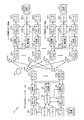
図3は、単一の検出器を有するそのようなデバイス300の一例を示す。この例では、デバイス300は、各々が複数の方向のうちの1つから信号を受信するように構成された、4つのアンテナ302A、302B、302C、302D(総称して302)を有する。アンテナ302の各々によって受信された信号は、それぞれの処理チェーン304A、304B、304C、および304D(総称して処理チェーン304)によって処理される。処理チェーン304の各々の出力は、単一の検出器308への単一の入力を生成するために、たとえば、混合器およびアナログデジタル変換器(ADC)を含み得る合成器回路306(たとえば、ウィルキンソン合成器)を介して合成される。検出器は、複数のアンテナ302のうちの1つによって、たとえば、複数の方向のうちの1つから受信され得る信号を検出するように構成される。検出器の出力に基づいて、処理システムは、フレーム310がアンテナ302のうちの少なくとも1つによって受信されたかどうかを判定し得る。
FIG. 3 shows an example of such a
この構成では、複数のアンテナの各々からの雑音は、検出器308に入力される合成信号に加えられる。したがって、複数の処理チェーンの合成出力を受信する単一の検出器308を有することによって、検出器への入力の雑音フロアが(たとえば、6dBだけ)増加し、したがって、以下でより詳細に説明する図5のデバイス500と比較して、(たとえば、6dBだけ)カバレージが低減することになる。
In this configuration, noise from each of the plurality of antennas is added to the combined signal input to
たとえば、デバイスは、3つのアンテナアレイを含んでもよく、第1のアンテナアレイは垂直偏波に従って配向され、第2のアンテナアレイは水平偏波に従って配向され、第3のアンテナアレイは受信デバイスの側に従って配向される。しかしながら、上述のように、デバイスは、そのようなアレイのすべてに使用される単一の検出器を有する受信チェーンを有する場合があり、このことにより、受信された信号の方向を実際に検出することが困難になる可能性がある。しかしながら、受信デバイスに複数の検出器を含めることによって、デバイスの信号受信カバレージは、たとえば、複数のアンテナアレイのアンテナ利得を利用することによって、増加し得る。一例として、上記で説明した同じ3アレイ構成を仮定すると、3つの異なる検出器は、アンテナアレイの各々によって受信された信号を検出するために使用され得る。この構成は、検出に必要とされる感度を(たとえば、5dBだけ)減少させ、カバレージを増大することができる。 For example, the device may include three antenna arrays, where the first antenna array is oriented according to vertical polarization, the second antenna array is oriented according to horizontal polarization, and the third antenna array is on the side of the receiving device. Orientated according to However, as mentioned above, the device may have a receive chain with a single detector used for all such arrays, which actually detects the direction of the received signal. Can be difficult. However, by including multiple detectors in the receiving device, the signal reception coverage of the device can be increased, for example, by utilizing the antenna gain of multiple antenna arrays. As an example, assuming the same three-array configuration described above, three different detectors can be used to detect the signals received by each of the antenna arrays. This configuration can reduce the sensitivity required for detection (eg, by 5 dB) and increase coverage.
本開示の態様は、同じ受信デバイス内で複数の受信チェーン/検出器を使用する技法および装置を提供する。これは、受信チェーンの各々のアンテナ利得を効果的に合成することによって、受信デバイスの信号受信感度を下げることを可能にする。言い換えれば、デバイスは、単一の受信チェーン/検出器に依拠するのではなく、複数の受信チェーン/検出器に依拠することによって、受信ダイバーシティから恩恵を受けることができる。このようにして、本開示の態様は、複数の処理チェーンおよびアンテナの各々のための指定の検出器を含めることによって、オムニモード信号受信のカバレージを改善するための技法および装置を提供する。 Aspects of the present disclosure provide techniques and apparatus for using multiple receive chains / detectors within the same receiving device. This makes it possible to reduce the signal reception sensitivity of the receiving device by effectively combining the antenna gains of each of the receiving chains. In other words, the device can benefit from receive diversity by relying on multiple receive chains / detectors rather than relying on a single receive chain / detector. Thus, aspects of the present disclosure provide techniques and apparatus for improving omni-mode signal reception coverage by including a designated detector for each of a plurality of processing chains and antennas.
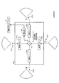
図4は、本開示のいくつかの態様による、ワイヤレス通信のための例示的な動作400を示す。動作400は、たとえば、複数の検出器を有するワイヤレスノードによって実行され得る。
FIG. 4 illustrates an
動作400は、402において、複数のアンテナアレイのうちの少なくとも1つを介して信号を受信することによって開始する。ワイヤレスノードは、404において、複数の検出器のうちの少なくとも1つを介して信号を検出し、406において、複数の検出器からの出力に基づいて、信号が複数のアンテナアレイのうちの少なくとも1つによって受信されたかどうかを判定する。いくつかの態様では、信号は既知の信号であってもよい。すなわち、信号は、デバイス300の処理システムによってあらかじめ決定されてもよく、複数の検出器は、既知の信号を監視および検出するように構成され得る。
動作400は、対応する同等のミーンズプラスファンクション構成要素を有する。たとえば、図4に示す動作400は、図4Aに示す手段400Aに対応し得る。402Aにおける受信するための手段は、信号を受信するように構成され得る複数のアンテナアレイおよび/または処理チェーンであり得る。404Aにおける検出するための手段は、信号を監視および検出するように構成され得る複数の検出器のうちの少なくとも1つであり得る。たとえば、検出するための手段は、受信された信号のエネルギーレベルを、信号が受信されたかどうかを判定するしきい値と比較することによって、信号を検出し得る。406Aにおける判定するための手段は、処理システムによって実行される場合があり、処理システムは、複数の検出器からの出力に基づいて、信号が複数の検出器のうちの少なくとも1つによって検出されたかどうかを判定するように構成され得る。これらの動作を実施するワイヤレスノードについて、図5に関してより詳細に説明する。
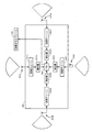
図5は、本開示のいくつかの態様による、各々が複数のアンテナアレイ302のうちのそれぞれのアンテナアレイによって受信された信号(たとえば、制御PHYプリアンブル)を検出するように構成された、複数の検出器502A、502B、502C、502D(総称して検出器502)を有するデバイス500のブロック図である。すなわち、複数のアンテナアレイ302のうちの少なくとも1つによって受信された信号は、それぞれの処理チェーン(たとえば、複数の処理チェーン304のうちの1つ)を介して処理され、複数の検出器502のうちのそれぞれの検出器によって検出され得る。検出器502の出力が合成され得(たとえば、論理ゲート504を介した論理OR演算)、デバイスの処理システムは、フレーム310が受信されたかどうかを判定するために、合成された信号を使用し得る。たとえば、処理システムは、いつ論理ゲート504の出力が論理高を示すかを監視および判定し得る。この判定に基づいて、処理システムは、複数の検出器502のうちの1つがフレーム310を検出した、したがって、フレーム310が受信されたと判定することができる。
FIG. 5 is a diagram illustrating a plurality of signals, each configured to detect a signal (eg, a control PHY preamble) received by a respective antenna array of the plurality of antenna arrays 302, according to some aspects of the present disclosure. FIG. 3 is a block diagram of a
いくつかの態様では、検出器502の各々は、複数のアンテナアレイ302のうちの異なるアンテナアレイに結合され得る。他の態様では、検出器502の各々は、複数のアンテナアレイ302のうちの1つ内の異なるアンテナに結合され得る。いくつかの態様では、検出器502の各々は、合成器を介してそれぞれのアンテナアレイの複数のアンテナに結合されてもよく、各検出器には、異なる利得および/またはアンテナごとの位相を含む複数のアンテナの異なる組合せが与えられる。 In some aspects, each of the detectors 502 may be coupled to a different antenna array of the plurality of antenna arrays 302. In other aspects, each of the detectors 502 may be coupled to a different antenna in one of the plurality of antenna arrays 302. In some aspects, each of the detectors 502 may be coupled via a combiner to multiple antennas of a respective antenna array, each detector including a different gain and / or phase per antenna. Different combinations of multiple antennas are provided.
アンテナアレイ302の各々に対して少なくとも1つの検出器を使用することによって、図3のデバイス300と比較して、各検出器の入力における雑音はより低い場合がある。さらに、アンテナアレイはいかなる著しい重複も有しないので、各検出器によって受信された信号は、その他の検出器によって受信された信号に影響を及ぼさない場合がある。場合によっては、図3のデバイス300と比較して、カバレージの著しい改善(たとえば、6dBの改善)は、図5に示す構成を使用して得られ得る。
By using at least one detector for each of the antenna arrays 302, the noise at the input of each detector may be lower compared to the
本開示のいくつかの態様によれば、デバイス500の処理システムは、複数の検出器502の出力に基づいて、たとえばフレーム310を含む信号が別のデバイスによって送信された方向(たとえば、セクタ)を判定するように構成され得る。たとえば、検出器502Aによって信号がより強く検出される場合、処理システムは、検出された信号は検出器502Aに対応する方向(たとえば、セクタ)から受信されたと判定し得る。いくつかの態様では、デバイス500の処理システムは、複数の検出器502の出力に基づいて、たとえばフレーム310を含む信号の偏波を判定するように構成され得る。たとえば、複数の検出器502のうちの各検出器は、受信された信号の異なる偏波を検出するように構成され得る。したがって、垂直偏波を検出するように構成された検出器(たとえば、検出器502A)によって信号が検出される場合、処理システムは、受信された信号が垂直偏波で受信されたと判定し得る。いくつかの態様では、偏波は、たとえばフレーム310を含む信号を送信した装置とのさらなる通信用にアンテナを構成するために使用される。たとえば、処理システムは、判定された偏波に基づいて、他の装置との通信用の1つまたは複数の送信パラメータを調整し得る。いくつかの態様では、各検出器は、受信された信号のエネルギーレベルをしきい値と比較することによって、既知の信号が受信されたかどうかを判定し得る。
According to some aspects of the present disclosure, the processing system of
いくつかの態様では、デバイスは、判定された方向に基づいて、たとえばフレーム310を含む信号を送信した他のデバイスと通信するように構成され得る。たとえば、デバイスは、判定された方向における通信を最適化するために、ビームフォーミングパラメータを更新し得る。たとえば、デバイスは、判定された方向に基づいて、複数のアンテナアレイ302のうちの少なくとも1つのビームフォーミング重みを調整するなど、送信アンテナおよび/または受信アンテナを構成することによって、信号送信および受信の指向性を制御し得る。
In some aspects, the device may be configured to communicate with other devices that transmitted a signal including, for example,
いくつかの態様では、検出器502の各々は、複数のRFモジュールのうちの1つの一部であり得る。そのような場合、デバイス500は、各々がアンテナアレイのうちの対応する1つによって受信された信号をベースバンド信号にダウンコンバートするように構成された、複数のRFモジュールを含み得る。
In some aspects, each of the detectors 502 can be part of one of a plurality of RF modules. In such a case,
いくつかの態様では、検出器502の各々は、別のデバイスによって送信された特定のタイプの既知の信号を検出するように構成され得る。たとえば、各検出器は、デバイス500によって知られているゴレイ系列(Golay sequence)を検出するように構成され得る。この場合、ゴレイ系列は、ゴレイ系列のゴレイ相互相関としきい値の比較に基づいて検出され得る。いくつかの態様では、ゴレイ系列のゴレイ相互相関は、デバイス500のゴレイ相関器によって実行され得る。場合によっては、各検出器は、巡回反復信号(cyclic repetition signal)を検出するように構成され得る。この場合、巡回反復信号は、既知の信号の自己相関をしきい値と比較することによって検出され得る。いくつかの態様では、デバイス500の処理システムは、既知の信号の受信エネルギーレベルに基づいて、しきい値を正規化し得る。
In some aspects, each of the detectors 502 may be configured to detect a particular type of known signal transmitted by another device. For example, each detector may be configured to detect a Golay sequence known by
本明細書で説明するように、複数の検出器を利用することによって、本開示の態様は、受信された信号を検出すると、複数のアンテナアレイの利得が効果的に合成されることを可能にすることができ、このことは、感度を上げ、特定の方向を判定する精度を改善し、全体的な性能を改善するのに役立ち得る。 As described herein, by utilizing multiple detectors, aspects of the present disclosure enable the gains of multiple antenna arrays to be effectively combined when detecting received signals. This can increase sensitivity, improve the accuracy of determining a particular direction, and can help improve overall performance.
上記で説明した方法の様々な動作は、対応する機能を実行することが可能な任意の適切な手段によって実行され得る。手段は、限定はしないが、回路、特定用途向け集積回路(ASIC)、またはプロセッサを含む、様々なハードウェアおよび/またはソフトウェア構成要素および/またはモジュールを含み得る。一般に、図に示す動作がある場合、それらの動作は、同様の番号を付された対応する同等のミーンズプラスファンクション構成要素を有し得る。たとえば、図4に示す動作400は、図4Aに示す手段400Aに対応し得る。
Various operations of the methods described above may be performed by any suitable means capable of performing the corresponding function. The means may include various hardware and / or software components and / or modules, including but not limited to circuits, application specific integrated circuits (ASICs), or processors. In general, where there are operations shown in the figures, those operations may have corresponding equivalent means-plus-function components numbered similarly. For example,
たとえば、送信するための手段(または送信のために出力するための手段)は、図2に示す、アクセスポイント110の送信機(たとえば、送信機ユニット222)および/もしくはアンテナ224、またはユーザ端末120の送信機ユニット254および/もしくはアンテナ252を備え得る。受信するための手段(または取得するための手段)は、図2に示す、アクセスポイント110の受信機(たとえば、受信機ユニット222)および/もしくはアンテナ224、またはユーザ端末120の受信機ユニット254および/もしくはアンテナ254を備え得る。処理するための手段、調整するための手段、生成するための手段、使用するための手段、正規化するための手段、比較するための手段、周波数オフセット調整を実行するための手段、または判定するための手段は、図2に示す、アクセスポイント110のRXデータプロセッサ242、TXデータプロセッサ210、TX空間プロセッサ220、および/もしくはコントローラ230、またはユーザ端末120のRXデータプロセッサ270、TXデータプロセッサ288、TX空間プロセッサ290、および/もしくはコントローラ280などの、1つまたは複数のプロセッサを含み得る処理システムを備え得る。検出するための手段は、図5に示すような検出器(たとえば、検出器502)を備え得る。合成するための手段および結合するための手段は、図5に示すような合成器または論理ゲート(たとえば、論理ゲート504)を備え得る。ダウンコンバートするための手段は、RFモジュールを備え得る。
For example, the means for transmitting (or means for outputting for transmission) may include a transmitter (eg, transmitter unit 222) and / or antenna 224 of
いくつかの態様によれば、そのような手段は、(たとえば、ハードウェアで、またはソフトウェア命令を実行することによって)上記で説明した様々なアルゴリズムを実装することによって、対応する機能を実行するように構成された処理システムによって実装され得る。 According to some aspects, such means may perform corresponding functions by implementing the various algorithms described above (e.g., in hardware or by executing software instructions). Can be implemented by a processing system configured as described above.
場合によっては、デバイスは、実際にフレームを送信するのではなく、送信のためにフレームを出力するインターフェース(出力するための手段)を有し得る。たとえば、プロセッサは、バスインターフェースを介して、送信のためにフレームを無線周波数(RF)フロントエンドに出力し得る。同様に、デバイスは、実際にフレームを受信するのではなく、別のデバイスから受信されたフレームを取得するインターフェース(取得するための手段)を有し得る。たとえば、プロセッサは、バスインターフェースを介して、受信のためにRFフロントエンドからフレームを取得(または受信)し得る。 In some cases, the device may have an interface (means for outputting) that outputs the frame for transmission rather than actually transmitting the frame. For example, the processor may output the frame to a radio frequency (RF) front end for transmission over the bus interface. Similarly, a device may have an interface (means for obtaining) that obtains a frame received from another device rather than actually receiving a frame. For example, the processor may obtain (or receive) a frame from the RF front end for reception via the bus interface.
本明細書で使用する「判定すること(determining)」という用語は、多種多様なアクションを包含する。たとえば、「判定すること」は、算出すること、計算すること、処理すること、導出すること、調査すること、ルックアップすること(たとえば、テーブル、データベースまたは別のデータ構造内でルックアップすること)、確認することなどを含み得る。また、「判定すること」は、受信すること(たとえば、情報を受信すること)、アクセスすること(たとえば、メモリ内のデータにアクセスすること)などを含み得る。また、「判定すること」は、解決すること、選択すること、選ぶこと、確立することなどを含み得る。 As used herein, the term “determining” encompasses a wide variety of actions. For example, “determining” means calculating, calculating, processing, deriving, examining, looking up (eg, looking up in a table, database or another data structure) ), Confirmation, etc. Also, “determining” can include receiving (eg, receiving information), accessing (eg, accessing data in a memory) and the like. Also, “determining” can include resolving, selecting, choosing, establishing and the like.
本明細書で使用する項目のリスト「のうちの少なくとも1つ」に言及する句は、単一のメンバーを含む、それらの項目の任意の組合せを指す。一例として、「a、b、またはcのうちの少なくとも1つ」は、a、b、c、a-b、a-c、b-c、およびa-b-c、ならびに複数の同じ要素を有する任意の組合せ(たとえば、a-a、a-a-a、a-a-b、a-a-c、a-b-b、a-c-c、b-b、b-b-b、b-b-c、c-c、およびc-c-c、または任意の他の順序のa、b、およびc)を包含するものとする。 As used herein, the phrase referring to “at least one of” a list of items refers to any combination of those items, including a single member. By way of example, “at least one of a, b, or c” includes a, b, c, ab, ac, bc, and abc, and any combination having a plurality of the same elements (eg, aa, aaa , Aab, aac, abb, acc, bb, bbb, bbc, cc, and ccc, or any other order of a, b, and c).
本開示に関して説明する様々な例示的な論理ブロック、モジュールおよび回路は、汎用プロセッサ、デジタル信号プロセッサ(DSP)、特定用途向け集積回路(ASIC)、フィールドプログラマブルゲートアレイ(FPGA)もしくは他のプログラマブル論理デバイス(PLD)、個別ゲートもしくはトランジスタ論理、個別ハードウェア構成要素、または本明細書で説明する機能を実行するように設計されたそれらの任意の組合せを用いて実装または実行され得る。汎用プロセッサはマイクロプロセッサであり得るが、代替として、プロセッサは、任意の市販のプロセッサ、コントローラ、マイクロコントローラ、または状態機械であり得る。プロセッサはまた、コンピューティングデバイスの組合せ、たとえば、DSPとマイクロプロセッサの組合せ、複数のマイクロプロセッサ、DSPコアと連携する1つもしくは複数のマイクロプロセッサ、または任意の他のそのような構成として実装され得る。 Various exemplary logic blocks, modules and circuits described in connection with this disclosure may be general purpose processors, digital signal processors (DSPs), application specific integrated circuits (ASICs), field programmable gate arrays (FPGAs) or other programmable logic devices. (PLD), individual gate or transistor logic, individual hardware components, or any combination thereof designed to perform the functions described herein. A general purpose processor may be a microprocessor, but in the alternative, the processor may be any commercially available processor, controller, microcontroller or state machine. The processor may also be implemented as a combination of computing devices, eg, a DSP and microprocessor combination, a plurality of microprocessors, one or more microprocessors associated with a DSP core, or any other such configuration. .
本開示に関して説明する方法またはアルゴリズムのステップは、直接ハードウェアにおいて、プロセッサによって実行されるソフトウェアモジュールにおいて、またはその2つの組合せにおいて具現化され得る。ソフトウェアモジュールは、当技術分野で知られている任意の形態の記憶媒体内に存在し得る。使用され得る記憶媒体のいくつかの例としては、ランダムアクセスメモリ(RAM)、読取り専用メモリ(ROM)、フラッシュメモリ、EPROMメモリ、EEPROMメモリ、レジスタ、ハードディスク、リムーバブルディスク、CD-ROMなどがある。ソフトウェアモジュールは、単一の命令、または多くの命令を備えてもよく、いくつかの異なるコードセグメントにわたって、異なるプログラム間で、および複数の記憶媒体にわたって分散されてもよい。記憶媒体は、プロセッサが記憶媒体から情報を読み取り、記憶媒体に情報を書き込むことができるように、プロセッサに結合され得る。代替として、記憶媒体はプロセッサと一体であってもよい。 The method or algorithm steps described in connection with the present disclosure may be implemented directly in hardware, in a software module executed by a processor, or in a combination of the two. A software module may reside in any form of storage medium that is known in the art. Some examples of storage media that may be used include random access memory (RAM), read only memory (ROM), flash memory, EPROM memory, EEPROM memory, registers, hard disk, removable disk, CD-ROM, and the like. A software module may comprise a single instruction, or many instructions, and may be distributed across several different code segments, between different programs, and across multiple storage media. A storage medium may be coupled to the processor such that the processor can read information from, and write information to, the storage medium. In the alternative, the storage medium may be integral to the processor.
本明細書で開示する方法は、説明する方法を実現するための1つまたは複数のステップまたはアクションを備える。方法ステップおよび/または方法アクションは、特許請求の範囲から逸脱することなく互いに入れ替えられてもよい。言い換えれば、ステップまたはアクションの特定の順序が指定されない限り、特定のステップおよび/またはアクションの順序および/または使用は、特許請求の範囲から逸脱することなく変更されてもよい。 The methods disclosed herein comprise one or more steps or actions for achieving the described method. The method steps and / or method actions may be interchanged with one another without departing from the scope of the claims. In other words, unless a specific order of steps or actions is specified, the order and / or use of specific steps and / or actions may be changed without departing from the scope of the claims.
説明する機能は、ハードウェア、ソフトウェア、ファームウェア、またはそれらの任意の組合せにおいて実装され得る。ハードウェアにおいて実装される場合、例示的なハードウェア構成は、ワイヤレスノード内の処理システムを備えてもよい。処理システムは、バスアーキテクチャを用いて実装され得る。バスは、処理システムの特定の適用例および全体的な設計制約に応じて、任意の数の相互接続バスおよびブリッジを含み得る。バスは、プロセッサ、機械可読媒体、およびバスインターフェースを含む様々な回路を互いにリンクさせることができる。バスインターフェースは、とりわけ、バスを介してネットワークアダプタを処理システムに接続するために使用され得る。ネットワークアダプタは、PHYレイヤの信号処理機能を実装するために使用され得る。ユーザ端末120(図1参照)の場合、ユーザインターフェース(たとえば、キーパッド、ディスプレイ、マウス、ジョイスティックなど)もバスに接続され得る。バスは、タイミングソース、周辺装置、電圧調整器、電力管理回路などの様々な他の回路をリンクさせることもできるが、これらの回路は当技術分野でよく知られており、したがって、これ以上は説明しない。 The functions described may be implemented in hardware, software, firmware, or any combination thereof. When implemented in hardware, an exemplary hardware configuration may comprise a processing system within a wireless node. The processing system can be implemented using a bus architecture. The bus may include any number of interconnecting buses and bridges depending on the specific application of the processing system and the overall design constraints. A bus may link various circuits including a processor, a machine-readable medium, and a bus interface together. The bus interface can be used, among other things, to connect the network adapter to the processing system via the bus. The network adapter may be used to implement PHY layer signal processing functions. For user terminal 120 (see FIG. 1), a user interface (eg, keypad, display, mouse, joystick, etc.) may also be connected to the bus. The bus can also link a variety of other circuits such as timing sources, peripherals, voltage regulators, power management circuits, etc., but these circuits are well known in the art and therefore no more I do not explain.
プロセッサは、バスを管理することと、機械可読媒体上に記憶されたソフトウェアの実行を含む一般的な処理とを担うことができる。プロセッサは、1つまたは複数の汎用および/または専用プロセッサを用いて実装され得る。例としては、マイクロプロセッサ、マイクロコントローラ、DSPプロセッサ、およびソフトウェアを実行することができる他の回路がある。ソフトウェアは、ソフトウェア、ファームウェア、ミドルウェア、マイクロコード、ハードウェア記述言語と呼ばれるか、または他の名称で呼ばれるかにかかわらず、命令、データ、またはそれらの任意の組合せを意味するように広く解釈されるべきである。機械可読媒体は、例として、RAM(ランダムアクセスメモリ)、フラッシュメモリ、ROM(読取り専用メモリ)、PROM(プログラマブル読取り専用メモリ)、EPROM(消去可能プログラマブル読取り専用メモリ)、EEPROM(電気的消去可能プログラマブル読取り専用メモリ)、レジスタ、磁気ディスク、光ディスク、ハードドライブ、もしくは任意の他の適切な記憶媒体、またはそれらの任意の組合せを含み得る。機械可読媒体は、コンピュータプログラム製品において具現化され得る。コンピュータプログラム製品は、パッケージング材料を備え得る。 The processor may be responsible for managing the bus and general processing including execution of software stored on the machine-readable medium. The processor may be implemented using one or more general purpose and / or dedicated processors. Examples include microprocessors, microcontrollers, DSP processors, and other circuits that can execute software. Software is broadly interpreted to mean instructions, data, or any combination thereof, whether referred to as software, firmware, middleware, microcode, hardware description language, or other names Should. Machine-readable media include, for example, RAM (random access memory), flash memory, ROM (read-only memory), PROM (programmable read-only memory), EPROM (erasable programmable read-only memory), EEPROM (electrically erasable programmable) Read-only memory), registers, magnetic disks, optical disks, hard drives, or any other suitable storage medium, or any combination thereof. A machine-readable medium may be embodied in a computer program product. The computer program product may comprise packaging material.
ハードウェア実装形態では、機械可読媒体は、プロセッサとは別個の処理システムの一部であってもよい。しかしながら、当業者が容易に諒解するように、機械可読媒体またはその任意の部分は、処理システムの外部にあってもよい。例として、機械可読媒体は、伝送線路、データによって変調された搬送波、および/またはワイヤレスノードとは別個の命令を記憶したコンピュータ可読記憶媒体を含んでもよく、それらのすべてが、バスインターフェースを介してプロセッサによってアクセスされ得る。代替または追加として、機械可読媒体またはその任意の部分は、キャッシュおよび/または汎用レジスタファイルなどと同様にプロセッサに統合されてもよい。 In a hardware implementation, the machine-readable medium may be part of a processing system that is separate from the processor. However, as those skilled in the art will readily appreciate, the machine-readable medium or any portion thereof may be external to the processing system. By way of example, a machine readable medium may include a transmission line, a carrier modulated by data, and / or a computer readable storage medium storing instructions separate from a wireless node, all of which are connected via a bus interface. It can be accessed by the processor. In the alternative or in addition, the machine-readable medium or any portion thereof may be integrated into the processor as well as cache and / or general purpose register files.
処理システムは、すべてが外部バスアーキテクチャを介して他のサポート回路と互いにリンクされる、プロセッサ機能を提供する1つまたは複数のマイクロプロセッサと、機械可読媒体の少なくとも一部分を提供する外部メモリとを有する汎用処理システムとして構成され得る。代替的に、処理システムは、プロセッサを有するASIC(特定用途向け集積回路)と、バスインターフェースと、ユーザインターフェース(アクセス端末の場合)と、サポート回路と、単一のチップに統合された機械可読媒体の少なくとも一部分とを用いて、あるいは1つまたは複数のFPGA(フィールドプログラマブルゲートアレイ)、PLD(プログラマブル論理デバイス)、コントローラ、状態機械、ゲート論理、個別ハードウェア構成要素、もしくは任意の他の適切な回路、または本開示全体にわたって説明する様々な機能を実行することができる回路の任意の組合せを用いて実装され得る。当業者は、特定の適用例および全体的なシステムに課される全体的な設計制約に応じて処理システムについて説明した機能を最良に実装する方法を認識するであろう。 The processing system has one or more microprocessors that provide processor functionality, all linked together with other support circuitry via an external bus architecture, and an external memory that provides at least a portion of the machine-readable medium. It can be configured as a general purpose processing system. Alternatively, the processing system comprises an ASIC (application specific integrated circuit) with a processor, a bus interface, a user interface (in the case of an access terminal), support circuitry, and a machine readable medium integrated on a single chip. One or more FPGAs (field programmable gate arrays), PLDs (programmable logic devices), controllers, state machines, gate logic, discrete hardware components, or any other suitable It may be implemented using a circuit, or any combination of circuits that can perform the various functions described throughout this disclosure. Those skilled in the art will recognize how to best implement the functionality described for the processing system depending on the particular application and the overall design constraints imposed on the overall system.
機械可読媒体は、いくつかのソフトウェアモジュールを備え得る。ソフトウェアモジュールは、プロセッサによって実行されると、処理システムに様々な機能を実行させる命令を含む。ソフトウェアモジュールは、送信モジュールおよび受信モジュールを含み得る。各ソフトウェアモジュールは、単一の記憶デバイス内に存在してもよく、または複数の記憶デバイスにわたって分散されてもよい。例として、ソフトウェアモジュールは、トリガイベントが発生したときに、ハードドライブからRAMにロードされ得る。ソフトウェアモジュールの実行中に、プロセッサは、アクセス速度を高めるために、命令のうちのいくつかをキャッシュにロードし得る。次いで、1つまたは複数のキャッシュラインは、プロセッサによる実行のために汎用レジスタファイルにロードされ得る。以下でソフトウェアモジュールの機能に言及する場合、そのような機能は、そのソフトウェアモジュールからの命令を実行するときにプロセッサによって実装されることが理解されよう。 A machine-readable medium may comprise a number of software modules. A software module includes instructions that, when executed by a processor, cause a processing system to perform various functions. The software module may include a transmission module and a reception module. Each software module may reside within a single storage device or may be distributed across multiple storage devices. As an example, a software module may be loaded from a hard drive into RAM when a trigger event occurs. During execution of the software module, the processor may load some of the instructions into the cache to increase access speed. One or more cache lines can then be loaded into a general purpose register file for execution by the processor. When referring to the functionality of a software module below, it will be understood that such functionality is implemented by the processor when executing instructions from that software module.
ソフトウェアにおいて実装される場合、機能は、1つまたは複数の命令またはコードとしてコンピュータ可読媒体上に記憶されるか、またはコンピュータ可読媒体を介して送信されてもよい。コンピュータ可読媒体は、コンピュータ記憶媒体と、ある場所から別の場所へのコンピュータプログラムの転送を容易にする任意の媒体を含む通信媒体の両方を含む。記憶媒体は、コンピュータによってアクセスされ得る任意の利用可能な媒体であり得る。限定ではなく例として、そのようなコンピュータ可読媒体は、RAM、ROM、EEPROM、CD-ROMもしくは他の光ディスクストレージ、磁気ディスクストレージもしくは他の磁気ストレージデバイス、または命令もしくはデータ構造の形態の所望のプログラムコードを搬送もしくは記憶するために使用され得、コンピュータによってアクセスされ得る任意の他の媒体を備えることができる。また、いかなる接続もコンピュータ可読媒体と適切に呼ばれる。たとえば、ソフトウェアが、同軸ケーブル、光ファイバケーブル、ツイストペア、デジタル加入者回線(DSL)、または赤外線(IR)、無線、およびマイクロ波などのワイヤレス技術を使用して、ウェブサイト、サーバ、または他のリモートソースから送信される場合、同軸ケーブル、光ファイバケーブル、ツイストペア、DSL、または赤外線、無線、およびマイクロ波などのワイヤレス技術は、媒体の定義に含まれる。本明細書で使用するディスク(disk)およびディスク(disc)は、コンパクトディスク(disc)(CD)、レーザーディスク(登録商標)(disc)、光ディスク(disc)、デジタル多用途ディスク(disc)(DVD)、フロッピーディスク(disk)、およびBlu-ray(登録商標)ディスク(disc)を含み、ディスク(disk)は通常、データを磁気的に再生し、ディスク(disc)は、レーザーを用いてデータを光学的に再生する。したがって、いくつかの態様では、コンピュータ可読媒体は、非一時的コンピュータ可読媒体(たとえば、有形媒体)を備え得る。加えて、他の態様では、コンピュータ可読媒体は、一時的コンピュータ可読媒体(たとえば、信号)を備え得る。上記の組合せもコンピュータ可読媒体の範囲内に含まれるべきである。 If implemented in software, the functions may be stored on or transmitted over as one or more instructions or code on a computer-readable medium. Computer-readable media includes both computer storage media and communication media including any medium that facilitates transfer of a computer program from one place to another. A storage media may be any available media that can be accessed by a computer. By way of example, and not limitation, such computer readable media can be RAM, ROM, EEPROM, CD-ROM or other optical disk storage, magnetic disk storage or other magnetic storage device, or desired program in the form of instructions or data structures. Any other medium that can be used to carry or store the code and that can be accessed by a computer can be provided. Any connection is also properly termed a computer-readable medium. For example, software may use websites, servers, or other devices using wireless technology such as coaxial cable, fiber optic cable, twisted pair, digital subscriber line (DSL), or infrared (IR), radio, and microwave. When transmitted from a remote source, coaxial technology, fiber optic cable, twisted pair, DSL, or wireless technologies such as infrared, radio, and microwave are included in the definition of the medium. The discs and discs used in this specification are compact discs (CD), laser discs (discs), optical discs (discs), digital versatile discs (DVDs) ), Floppy disk, and Blu-ray® disc, the disk normally reproduces data magnetically, and the disc uses a laser to retrieve data. Reproduce optically. Thus, in some aspects computer readable media may comprise non-transitory computer readable media (eg, tangible media). In addition, in other aspects computer readable media may comprise transitory computer readable media (eg, signals). Combinations of the above should also be included within the scope of computer-readable media.
さらに、本明細書で説明する方法および技法を実行するためのモジュールおよび/または他の適切な手段は、適用可能な場合、ユーザ端末および/または基地局によってダウンロードおよび/または他の方法で取得され得ることを諒解されたい。たとえば、そのようなデバイスは、本明細書で説明する方法を実行するための手段の転送を容易にするために、サーバに結合され得る。代替的に、本明細書で説明する様々な方法は、ユーザ端末および/または基地局が記憶手段(たとえば、RAM、ROM、コンパクトディスク(CD)またはフロッピーディスクなどの物理的記憶媒体など)をデバイスに結合または提供すると様々な方法を取得することができるように、記憶手段を介して提供され得る。さらに、本明細書で説明する方法および技法をデバイスに提供するための任意の他の適切な技法が使用され得る。 Further, modules and / or other suitable means for performing the methods and techniques described herein may be downloaded and / or otherwise obtained by user terminals and / or base stations, where applicable. I want you to be understood. For example, such a device can be coupled to a server to facilitate the transfer of means for performing the methods described herein. Alternatively, the various methods described herein allow user terminals and / or base stations to store storage means (e.g., physical storage media such as RAM, ROM, compact disk (CD) or floppy disk). It can be provided via storage means so that various methods can be obtained when coupled or provided. Further, any other suitable technique for providing the devices with the methods and techniques described herein may be used.
特許請求の範囲は、上記で示した厳密な構成および構成要素に限定されないことを理解されたい。特許請求の範囲から逸脱することなく、上記で説明した方法および装置の構成、動作および詳細において、様々な修正、変更および変形が行われ得る。 It is to be understood that the claims are not limited to the precise configuration and components illustrated above. Various modifications, changes and variations may be made in the arrangement, operation and details of the methods and apparatus described above without departing from the scope of the claims.
100 多元接続多入力多出力(MIMO)システム、システム、MIMOシステム
110 アクセスポイント
120、120m、120x ユーザ端末
130 システムコントローラ
208 データソース
210 TXデータプロセッサ
220 TX空間プロセッサ
222 送信機ユニット、受信機ユニット
224a〜224ap アンテナ
228 チャネル推定器
230 コントローラ
234 スケジューラ
240 RX空間プロセッサ
242 RXデータプロセッサ
244 データシンク
252ma〜252mu アンテナ
252xa〜252xu アンテナ
254 受信機ユニット、送信機ユニット
260 RX空間プロセッサ
270 RXデータプロセッサ
278 チャネル推定器
280 コントローラ
286 データソース
288 TXデータプロセッサ
290 TX空間プロセッサ
300 デバイス
302 アンテナ、アンテナアレイ
302A、302B、302C、302D アンテナ
304、304A、304B、304C、304D 処理チェーン
308 検出器
310 フレーム
400 動作
400A 手段
402A 受信するための手段
404A 検出するための手段
406A 判定するための手段
500 デバイス
502、502A、502B、502C、502D 検出器
504 論理ゲート
100 Multiple access multiple input multiple output (MIMO) system, system, MIMO system
110 access point
120, 120m, 120x user terminal
130 System controller
208 data sources
210 TX data processor
220 TX spatial processor
222 Transmitter unit, receiver unit
224a ~ 224ap antenna
228 channel estimator
230 Controller
234 Scheduler
240 RX spatial processor
242 RX data processor
244 Data Sync
252ma to 252mu antenna
252xa to 252xu antenna
254 Receiver unit, Transmitter unit
260 RX spatial processor
270 RX data processor
278 channel estimator
280 controller
286 Data Source
288 TX data processor
290 TX spatial processor
300 devices
302 Antenna, antenna array
302A, 302B, 302C, 302D antenna
304, 304A, 304B, 304C, 304D Processing chain
308 detector
310 frames
400 operation
400A means
Means for receiving 402A
404A Means to detect
406A Means for determining
500 devices
502, 502A, 502B, 502C, 502D detector
504 logic gate
Claims (59)
各々が複数のアンテナアレイのうちの少なくとも1つによって受信された信号を検出するように構成された複数の検出器と、
前記複数の検出器からの出力に基づいて、前記信号が前記装置によって受信されたかどうかを判定するように構成された処理システムと
を備える装置。 A device for wireless communication,
A plurality of detectors each configured to detect a signal received by at least one of the plurality of antenna arrays;
And a processing system configured to determine whether the signal has been received by the device based on outputs from the plurality of detectors.
前記アンテナアレイのうちの少なくとも1つが、前記別の装置との将来の通信のために前記受信方向を使用するように構成される、
請求項3に記載の装置。 The signal is received from another device;
At least one of the antenna arrays is configured to use the receive direction for future communications with the another device;
The apparatus according to claim 3.
前記アンテナアレイのうちの少なくとも1つが、前記別の装置との将来の通信のために前記偏波を使用するように構成される、
請求項17に記載の装置。 The signal is received from another device;
At least one of the antenna arrays is configured to use the polarization for future communication with the another device;
The apparatus of claim 17.
複数のアンテナアレイのうちの少なくとも1つを介して信号を受信するステップと、
複数の検出器のうちの少なくとも1つを介して前記信号を検出するステップと、
前記複数の検出器からの出力に基づいて、前記信号が前記複数のアンテナアレイのうちの前記少なくとも1つによって受信されたかどうかを判定するステップと
を備える方法。 A method for wireless communication,
Receiving a signal via at least one of the plurality of antenna arrays;
Detecting the signal via at least one of a plurality of detectors;
Determining whether the signal was received by the at least one of the plurality of antenna arrays based on outputs from the plurality of detectors.
前記受信チェーンのうちの前記少なくとも1つを介して、入力を前記検出器のうちの対応する1つに与えるステップと
をさらに備える、請求項20に記載の方法。 Processing the signal via at least one of a plurality of receive chains;
21. The method of claim 20, further comprising: providing an input to a corresponding one of the detectors via the at least one of the receive chains.
前記方法が、前記別の装置との将来の通信のために前記受信方向を使用するステップをさらに備える、
請求項22に記載の方法。 The signal is received from another device;
The method further comprises using the reception direction for future communications with the another device;
23. A method according to claim 22.
前記方法が、前記別の装置との将来の通信のために前記偏波を使用するステップをさらに備える、
請求項36に記載の方法。 The signal is received from another device;
The method further comprises using the polarization for future communication with the another device;
38. The method of claim 36.
複数のアンテナアレイのうちの少なくとも1つを介して信号を受信するための手段と、
複数の検出器のうちの少なくとも1つを介して前記信号を検出するための手段と、
前記複数の検出器からの出力に基づいて、前記信号が前記複数のアンテナアレイのうちの前記少なくとも1つによって受信されたかどうかを判定するための手段と
を備える装置。 A device for wireless communication,
Means for receiving a signal via at least one of the plurality of antenna arrays;
Means for detecting the signal via at least one of a plurality of detectors;
Means for determining whether the signal is received by the at least one of the plurality of antenna arrays based on outputs from the plurality of detectors.
前記受信チェーンのうちの前記少なくとも1つを介して、入力を前記検出器のうちの対応する1つに与えるための手段と
をさらに備える、請求項39に記載の装置。 Means for processing the signal via at least one of a plurality of receive chains;
40. The apparatus of claim 39, further comprising means for providing an input to a corresponding one of the detectors via the at least one of the receive chains.
前記装置が、前記別の装置との将来の通信のために前記偏波を使用するための手段をさらに備える、
請求項55に記載の装置。 The signal is received from another device;
The apparatus further comprises means for using the polarization for future communication with the another apparatus;
56. Apparatus according to claim 55.
複数のアンテナアレイのうちの少なくとも1つを介して信号を受信することと、
複数の検出器のうちの少なくとも1つを介して前記信号を検出することと、
前記複数の検出器からの出力に基づいて、前記信号が前記複数のアンテナアレイのうちの前記少なくとも1つによって受信されたかどうかを判定することと
を行わせる命令を格納したコンピュータ可読記録媒体。 When executed, the device
Receiving a signal via at least one of the plurality of antenna arrays;
Detecting the signal via at least one of a plurality of detectors;
A computer readable recording medium storing instructions for determining whether the signal is received by the at least one of the plurality of antenna arrays based on outputs from the plurality of detectors.
信号を受信するように構成された複数のアンテナのうちの少なくとも1つのアンテナと、
各々が前記信号を検出するように構成された複数の検出器と、
前記複数の検出器からの出力に基づいて、前記信号が前記ワイヤレスノードによって受信されたかどうかを判定するように構成された処理システムと
を備えるワイヤレスノード。 A wireless node,
At least one of a plurality of antennas configured to receive a signal;
A plurality of detectors each configured to detect the signal;
A wireless node comprising: a processing system configured to determine whether the signal is received by the wireless node based on outputs from the plurality of detectors.
Applications Claiming Priority (3)
| Application Number | Priority Date | Filing Date | Title |
|---|---|---|---|
| US14/809,927 | 2015-07-27 | ||
| US14/809,927 US10230433B2 (en) | 2015-07-27 | 2015-07-27 | Techniques for improving coverage of communication devices |
| PCT/US2016/039735 WO2017019230A2 (en) | 2015-07-27 | 2016-06-28 | Techniques for improving coverage of communication devices |
Publications (2)
| Publication Number | Publication Date |
|---|---|
| JP2018523938A true JP2018523938A (en) | 2018-08-23 |
| JP2018523938A5 JP2018523938A5 (en) | 2019-07-18 |
Family
ID=56550326
Family Applications (1)
| Application Number | Title | Priority Date | Filing Date |
|---|---|---|---|
| JP2018503644A Ceased JP2018523938A (en) | 2015-07-27 | 2016-06-28 | Techniques for improving communication device coverage. |
Country Status (7)
| Country | Link |
|---|---|
| US (1) | US10230433B2 (en) |
| EP (1) | EP3329610A2 (en) |
| JP (1) | JP2018523938A (en) |
| KR (1) | KR20180035802A (en) |
| CN (1) | CN107852221B (en) |
| BR (1) | BR112018001508A2 (en) |
| WO (1) | WO2017019230A2 (en) |
Families Citing this family (4)
| Publication number | Priority date | Publication date | Assignee | Title |
|---|---|---|---|---|
| US9948512B2 (en) | 2016-01-14 | 2018-04-17 | Veniam, Inc. | Systems and methods for remote configuration update and distribution in a network of moving things |
| US9788282B2 (en) | 2015-11-30 | 2017-10-10 | Veniam, Inc. | Systems and methods for improving fixed access point coverage in a network of moving things |
| JP2018006072A (en) * | 2016-06-29 | 2018-01-11 | オートモーティブエナジーサプライ株式会社 | Negative electrode of lithium-ion secondary battery |
| CN107566022B (en) * | 2016-06-30 | 2020-10-23 | 华为技术有限公司 | Beam training sequence design method and device |
Citations (3)
| Publication number | Priority date | Publication date | Assignee | Title |
|---|---|---|---|---|
| JP2005109614A (en) * | 2003-09-29 | 2005-04-21 | Sanyo Electric Co Ltd | Receiver |
| US20120309325A1 (en) * | 2010-12-08 | 2012-12-06 | Broadcom Corporation | Rf module control interface |
| US20140204928A1 (en) * | 2013-01-21 | 2014-07-24 | Wilocity Ltd. | Method and system for initial signal acquisition in multipath fading channel conditions |
Family Cites Families (16)
| Publication number | Priority date | Publication date | Assignee | Title |
|---|---|---|---|---|
| JP3389153B2 (en) | 1999-06-16 | 2003-03-24 | 埼玉日本電気株式会社 | Diversity control device for mobile phone and diversity control method therefor |
| JP4392109B2 (en) | 2000-05-12 | 2009-12-24 | パナソニック株式会社 | Direction of arrival estimation device |
| GB0101567D0 (en) | 2001-01-22 | 2001-03-07 | Antenova Ltd | Dielectric resonator antenna with mutually orrthogonal feeds |
| US7817014B2 (en) * | 2004-07-30 | 2010-10-19 | Reva Systems Corporation | Scheduling in an RFID system having a coordinated RFID tag reader array |
| US7924930B1 (en) | 2006-02-15 | 2011-04-12 | Marvell International Ltd. | Robust synchronization and detection mechanisms for OFDM WLAN systems |
| US8350763B2 (en) | 2008-08-14 | 2013-01-08 | Rappaport Theodore S | Active antennas for multiple bands in wireless portable devices |
| US20140225804A1 (en) * | 2011-03-03 | 2014-08-14 | Checkpoint Systems, Inc. | Multiplexed antenna localizing |
| US9008239B2 (en) * | 2011-03-07 | 2015-04-14 | Mojix, Inc. | Collision detection using a multiple symbol noncoherent soft output detector |
| US8743914B1 (en) | 2011-04-28 | 2014-06-03 | Rockwell Collins, Inc. | Simultaneous independent multi-beam analog beamformer |
| US9197982B2 (en) | 2012-08-08 | 2015-11-24 | Golba Llc | Method and system for distributed transceivers for distributed access points connectivity |
| US9473229B2 (en) | 2012-10-05 | 2016-10-18 | Samsung Electronics Co., Ltd. | High-throughput beamforming MIMO receiver for millimeter wave communication and method |
| JP6190889B2 (en) | 2012-11-09 | 2017-08-30 | インターデイジタル パテント ホールディングス インコーポレイテッド | Beam forming method and method for using the beam |
| JP5519818B1 (en) | 2013-03-22 | 2014-06-11 | 日本電信電話株式会社 | Antenna device |
| US9301150B2 (en) | 2013-06-03 | 2016-03-29 | Qualcomm Incorporated | Methods and apparatus for clear channel assessment |
| CN103347264B (en) * | 2013-06-18 | 2015-12-02 | 京信通信系统(广州)有限公司 | The high-power covering method of TDD mobile communication system and device |
| KR20150087903A (en) * | 2014-01-23 | 2015-07-31 | 한국전자통신연구원 | Method of spatial modulation with polarazation and apparatus using thereof |
-
2015
- 2015-07-27 US US14/809,927 patent/US10230433B2/en active Active
-
2016
- 2016-06-28 BR BR112018001508A patent/BR112018001508A2/en not_active IP Right Cessation
- 2016-06-28 JP JP2018503644A patent/JP2018523938A/en not_active Ceased
- 2016-06-28 KR KR1020187002342A patent/KR20180035802A/en not_active Application Discontinuation
- 2016-06-28 EP EP16742472.0A patent/EP3329610A2/en not_active Withdrawn
- 2016-06-28 WO PCT/US2016/039735 patent/WO2017019230A2/en active Application Filing
- 2016-06-28 CN CN201680043520.8A patent/CN107852221B/en active Active
Patent Citations (3)
| Publication number | Priority date | Publication date | Assignee | Title |
|---|---|---|---|---|
| JP2005109614A (en) * | 2003-09-29 | 2005-04-21 | Sanyo Electric Co Ltd | Receiver |
| US20120309325A1 (en) * | 2010-12-08 | 2012-12-06 | Broadcom Corporation | Rf module control interface |
| US20140204928A1 (en) * | 2013-01-21 | 2014-07-24 | Wilocity Ltd. | Method and system for initial signal acquisition in multipath fading channel conditions |
Also Published As
| Publication number | Publication date |
|---|---|
| WO2017019230A2 (en) | 2017-02-02 |
| US20170033845A1 (en) | 2017-02-02 |
| BR112018001508A2 (en) | 2018-09-11 |
| CN107852221B (en) | 2021-06-18 |
| US10230433B2 (en) | 2019-03-12 |
| WO2017019230A3 (en) | 2017-03-09 |
| KR20180035802A (en) | 2018-04-06 |
| CN107852221A (en) | 2018-03-27 |
| EP3329610A2 (en) | 2018-06-06 |
Similar Documents
| Publication | Publication Date | Title |
|---|---|---|
| US10278150B2 (en) | Neighbor aware network cluster change for neighbor aware network data link | |
| US10091713B2 (en) | Numerology and frames for networks in the sub-1GHz (S1G) band | |
| US10560917B2 (en) | Angle of departure for location determination | |
| US9992738B2 (en) | Physical layer power save facility with random offset | |
| JP2019507535A (en) | Beamforming training using multi-input multi-output transmission method | |
| JP2020505831A (en) | Efficient beamforming techniques | |
| US20120054587A1 (en) | Guard interval signaling for data symbol number determination | |
| JP6617204B2 (en) | Techniques to increase throughput for channel bonding | |
| US9723561B2 (en) | System and method for reducing power consumption in detecting signal from target device | |
| US10972324B2 (en) | Dual receiver for millimeter wave communications | |
| US20180139275A1 (en) | Neighbor aware network operation for network onboarding and configuration | |
| US8831668B2 (en) | Power control for TV white space devices | |
| JP2018523938A (en) | Techniques for improving communication device coverage. | |
| US20180269943A1 (en) | Wideband sector sweep using wideband training (trn) field | |
| US9954595B2 (en) | Frame format for low latency channel bonding | |
| US11509337B2 (en) | Implementation of improved omni mode signal reception | |
| US20180062903A1 (en) | Frame format with multiple guard interval lengths | |
| US20170223741A1 (en) | Efficient clear channel assessment (cca) with request-to-send (rts) frame and clear-to-send (cts) frame |
Legal Events
| Date | Code | Title | Description |
|---|---|---|---|
| A521 | Request for written amendment filed |
Free format text: JAPANESE INTERMEDIATE CODE: A523 Effective date: 20190613 |
|
| A621 | Written request for application examination |
Free format text: JAPANESE INTERMEDIATE CODE: A621 Effective date: 20190613 |
|
| A977 | Report on retrieval |
Free format text: JAPANESE INTERMEDIATE CODE: A971007 Effective date: 20200825 |
|
| A131 | Notification of reasons for refusal |
Free format text: JAPANESE INTERMEDIATE CODE: A131 Effective date: 20200907 |
|
| A521 | Request for written amendment filed |
Free format text: JAPANESE INTERMEDIATE CODE: A523 Effective date: 20201202 |
|
| A02 | Decision of refusal |
Free format text: JAPANESE INTERMEDIATE CODE: A02 Effective date: 20210531 |
|
| A521 | Request for written amendment filed |
Free format text: JAPANESE INTERMEDIATE CODE: A523 Effective date: 20210728 |
|
| C60 | Trial request (containing other claim documents, opposition documents) |
Free format text: JAPANESE INTERMEDIATE CODE: C60 Effective date: 20210728 |
|
| A911 | Transfer to examiner for re-examination before appeal (zenchi) |
Free format text: JAPANESE INTERMEDIATE CODE: A911 Effective date: 20210805 |
|
| C21 | Notice of transfer of a case for reconsideration by examiners before appeal proceedings |
Free format text: JAPANESE INTERMEDIATE CODE: C21 Effective date: 20210810 |
|
| A912 | Re-examination (zenchi) completed and case transferred to appeal board |
Free format text: JAPANESE INTERMEDIATE CODE: A912 Effective date: 20211001 |
|
| C211 | Notice of termination of reconsideration by examiners before appeal proceedings |
Free format text: JAPANESE INTERMEDIATE CODE: C211 Effective date: 20211011 |
|
| C22 | Notice of designation (change) of administrative judge |
Free format text: JAPANESE INTERMEDIATE CODE: C22 Effective date: 20211213 |
|
| C22 | Notice of designation (change) of administrative judge |
Free format text: JAPANESE INTERMEDIATE CODE: C22 Effective date: 20220131 |
|
| C23 | Notice of termination of proceedings |
Free format text: JAPANESE INTERMEDIATE CODE: C23 Effective date: 20220207 |
|
| C03 | Trial/appeal decision taken |
Free format text: JAPANESE INTERMEDIATE CODE: C03 Effective date: 20220307 |
|
| C30A | Notification sent |
Free format text: JAPANESE INTERMEDIATE CODE: C3012 Effective date: 20220307 |
|
| A045 | Written measure of dismissal of application [lapsed due to lack of payment] |
Free format text: JAPANESE INTERMEDIATE CODE: A045 Effective date: 20220725 |