JP2018523863A - Haptic driver with damping - Google Patents
Haptic driver with damping Download PDFInfo
- Publication number
- JP2018523863A JP2018523863A JP2017564590A JP2017564590A JP2018523863A JP 2018523863 A JP2018523863 A JP 2018523863A JP 2017564590 A JP2017564590 A JP 2017564590A JP 2017564590 A JP2017564590 A JP 2017564590A JP 2018523863 A JP2018523863 A JP 2018523863A
- Authority
- JP
- Japan
- Prior art keywords
- haptic
- output device
- resonant frequency
- haptic output
- frequency range
- Prior art date
- Legal status (The legal status is an assumption and is not a legal conclusion. Google has not performed a legal analysis and makes no representation as to the accuracy of the status listed.)
- Pending
Links
Images


Classifications
-
- G—PHYSICS
- G08—SIGNALLING
- G08B—SIGNALLING OR CALLING SYSTEMS; ORDER TELEGRAPHS; ALARM SYSTEMS
- G08B6/00—Tactile signalling systems, e.g. personal calling systems
-
- G—PHYSICS
- G06—COMPUTING; CALCULATING OR COUNTING
- G06F—ELECTRIC DIGITAL DATA PROCESSING
- G06F3/00—Input arrangements for transferring data to be processed into a form capable of being handled by the computer; Output arrangements for transferring data from processing unit to output unit, e.g. interface arrangements
- G06F3/01—Input arrangements or combined input and output arrangements for interaction between user and computer
- G06F3/016—Input arrangements with force or tactile feedback as computer generated output to the user
Abstract
各種実施形態の各々では、ハプティックドライバは、アクチュエータの駆動信号を減衰するように構成される。特に、本明細書に記載されるハプティックドライバは、アクチュエータの共振周波数を識別し、周波数の範囲内のハプティック駆動信号を減衰するように構成され、当該範囲は、識別された共振周波数に基づく。その結果、アクチュエータによって生じるハプティック効果の強さは、広い周波数の範囲に亘ってより均一になる。
【選択図】図3
In each of the various embodiments, the haptic driver is configured to attenuate the actuator drive signal. In particular, the haptic driver described herein is configured to identify the resonant frequency of the actuator and attenuate a haptic drive signal within the frequency range, the range being based on the identified resonant frequency. As a result, the strength of the haptic effect produced by the actuator becomes more uniform over a wide frequency range.
[Selection] Figure 3
Description
優先権出願
本願は、2015年8月21日に出願された米国仮特許出願第62/208,430号の利益を主張し、その全体において参照によって本明細書に援用される。
This application claims the benefit of US Provisional Patent Application No. 62 / 208,430, filed August 21, 2015, which is hereby incorporated by reference in its entirety.
本発明の実施形態は、概して、電子デバイスに関し、より具体的には、ハプティック効果を生じる電子デバイスに関する。 Embodiments of the invention relate generally to electronic devices, and more specifically to electronic devices that produce haptic effects.
電子デバイス製造者は、ユーザにとってリッチなインターフェースを作り出すために努力している。従来のデバイスは、ユーザにフィードバックを提供するための視覚的及び聴覚的合図を使用する。一部のインターフェースデバイスでは、運動感覚フィードバック(アクティブかつ抵抗フォースフィードバック等)及び/又は触覚フィードバック(振動、質感、熱等)もまた、ユーザに提供され、より一般的には「ハプティックフィードバック」又は「ハプティック効果」と総称される。ハプティックフィードバックは、ユーザインターフェースを促進及び簡素にする合図を提供する。具体的には、振動効果又は振動触覚ハプティック効果は、ユーザに特定のイベントを知らせるために電子デバイスのユーザに合図を提供する際に便利である、又はシミュレートされた又は仮想環境内により大きな感覚没入を形成するためにリアルなフィードバックを提供する Electronic device manufacturers strive to create a rich interface for users. Conventional devices use visual and audio cues to provide feedback to the user. In some interface devices, kinesthetic feedback (such as active and resistive force feedback) and / or haptic feedback (vibration, texture, heat, etc.) are also provided to the user, more commonly “haptic feedback” or “ Collectively called “haptic effect”. Haptic feedback provides cues that facilitate and simplify the user interface. Specifically, the vibration effect or vibrotactile haptic effect is useful in providing a signal to the user of the electronic device to inform the user of a particular event, or greater sensation in a simulated or virtual environment Provide real feedback to shape immersiveness
スマートフォン及びタブレット等のような近年の高解像度モバイルデバイスの発達により、ユーザは、今や、ハンドヘルドデバイス上で、従来は映画館、テレビジョン又はホームシアターシステムでしか観られなかった高解像度音声及び動画を視聴することができる。ハプティック可能なモバイルデバイスにより、音声及び動画コンテンツコンポーネントに加えてハプティックコンテンツコンポーネントがある場合、コンテンツの閲覧が十分に促進され、かつ閲覧者がそれを好むことを経験が示している。しかし、高解像度音声/動画に適合するために、対応する高解像度又は高帯域ハプティック効果も生成されるべきである。 With the recent development of high-resolution mobile devices such as smartphones and tablets, users can now watch high-resolution audio and video on handheld devices, traditionally only seen in movie theaters, televisions or home theater systems. can do. Experience has shown that, with a haptic-enabled mobile device, when there is a haptic content component in addition to the audio and video content component, viewing the content is sufficiently facilitated and the viewer likes it. However, a corresponding high resolution or high band haptic effect should also be generated to accommodate high resolution audio / video.
本発明の実施形態は、関連する技術で実質的に改善するハプティック効果を生じるように構成される電子デバイスに対して向けられる。 Embodiments of the present invention are directed to electronic devices configured to produce haptic effects that are substantially improved with related techniques.
実施形態の特徴及び利点は、以下の詳細な説明に記載され、又は詳細な説明から明らかとなり、又は本発明の実施から習得されうる。 The features and advantages of the embodiments are set forth in the following detailed description, or are apparent from the detailed description, or can be learned from the practice of the invention.
一つの実施例では、システム及び方法は、前記ハプティック出力デバイスを駆動するように構成されるハプティック駆動信号を受信することと、前記ハプティック出力デバイスの共振周波数範囲を識別することと、識別された前記共振周波数範囲に対応する前記ハプティック駆動信号を減衰することと、を含む、ハプティックデバイスを駆動するための命令を含む。 In one embodiment, a system and method includes receiving a haptic drive signal configured to drive the haptic output device, identifying a resonant frequency range of the haptic output device, and identifying the identified A command for driving the haptic device, including attenuating the haptic drive signal corresponding to a resonant frequency range.
添付の図面と併せて参照される以下の好適な実施形態の詳細な説明から、更なる実施形態、詳細、利点、及び変形が明らかになるだろう。 Further embodiments, details, advantages, and modifications will become apparent from the following detailed description of the preferred embodiments, taken in conjunction with the accompanying drawings.
次に、添付の図面により例を示した実施形態を詳しく参照する。以下の詳細な説明においては、本発明の完全な理解を提供するために多数の具体的詳細が記載される。しかし、当業者には、これらの具体的詳細がなくても本発明が実施されうることが明らかであろう。その他の場合には、実施形態の態様が不必要に不明瞭にならないよう、周知の方法、手順、構成要素、及び回路は詳述していない。類似の参照番号は、可能な限り類似の要素に用いられる。 Reference will now be made in detail to embodiments, examples of which are illustrated by the accompanying drawings. In the following detailed description, numerous specific details are set forth in order to provide a thorough understanding of the present invention. However, it will be apparent to one skilled in the art that the present invention may be practiced without these specific details. In other instances, well known methods, procedures, components, and circuits have not been described in detail as not to unnecessarily obscure aspects of the embodiments. Similar reference numbers are used for similar elements whenever possible.
例示的な実施形態は、概して、改善されたハプティックドライバに対して向けられ、特に、改善された高解像度high definition(「HD」)ハプティックドライバに対して向けられる。各種実施形態の各々では、ハプティックドライバは、アクチュエータの駆動信号を減衰するように構成される。特に、本明細書に記載されるハプティックドライバは、アクチュエータの共振周波数を決定又は識別するように構成され、周波数の範囲内のハプティック駆動信号を減衰するように構成される。周波数の範囲は、共振周波数に対応する。その結果、アクチュエータによって生成されたハプティック効果の強度は、より広い周波数範囲に亘ってより均一になる。 The exemplary embodiments are generally directed to an improved haptic driver, and in particular to an improved high resolution high definition (“HD”) haptic driver. In each of the various embodiments, the haptic driver is configured to attenuate the actuator drive signal. In particular, the haptic driver described herein is configured to determine or identify the resonant frequency of the actuator and is configured to attenuate a haptic drive signal within the frequency range. The frequency range corresponds to the resonant frequency. As a result, the strength of the haptic effect generated by the actuator is more uniform over a wider frequency range.
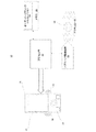
図1は、本発明の一例の実施形態に係るハプティック可能システム/デバイス10のブロック図である。システム10は、ハウジング15内に搭載されるタッチ検知表面11又は他の種類のユーザインターフェースを含み、メカニカルキー/ボタン13を含んでもよい。
FIG. 1 is a block diagram of a haptic-enabled system /
システム10の内部は、システム10でハプティック効果を生成するハプティックフィードバックシステムであり、プロセッサ又はコントローラ12を含む。プロセッサ12に結合されるのは、メモリ20、及びアクチュエータと結合されるハプティック駆動回路16である。プロセッサ12は、任意の種類の汎用プロセッサであり得る、若しくは、特定用途向けIC(ASIC)のような、触覚効果を提供するために特別に設計されたプロセッサであってもよい。プロセッサ12は、システム10全体を操作する同一のプロセッサでも、又は別々のプロセッサでもあってもよい。プロセッサ12は、どの触覚効果を再生するか、及び効果が再生される順序を、高レベルのパラメータに基づいて決定しうる。一般的に、特定の触覚効果を定義する高レベルのパラメータとしては、大きさ、周波数、及び期間が含まれる。特定の触覚効果を決定するために、ストリーミングモータコマンドのような低レベルのパラメータも使用可能である。ハプティック効果が生成される際にこれらのパラメータのいくつかの変化が含まれる場合、若しくはユーザーのインタラクションに基づいたこれらのパラメータの1つの変化が含まれる場合、ハプティック効果は「動的」であると見なされうる。一実施形態では、ハプティックフィードバックシステムは、振動30,31又はシステム10での他の種類のハプティック効果を生成する。
Internal to
プロセッサ12は、アクチュエータ18に必要な電流と電圧(すなわち「モータ信号」)とを供給して所望のハプティック効果を起こすために用いられる電子部品及び電気回路を含むアクチュエータ駆動回路16へと制御信号を出力する。システム10は、1以上のアクチュエータ18を含んでもよく、各々のアクチュエータは、いずれも共通のプロセッサ12に結合される別々の駆動回路16を含みうる。
The
ハプティック駆動回路16は、アクチュエータ16の共振周波数(例えば、+/−20Hz、30Hz、40Hz等)で、及びその周辺でハプティック駆動信号を減衰するように構成される。共振周波数の近傍の周波数の範囲を減衰することによって、ハプティック強度は、広い周波数帯域に亘ってより均一になる。特定の実施形態では、ハプティック駆動回路16は、様々な信号処理段階を含んでもよく、各段階は、ハプティック駆動信号に適用される信号処理段階のサブセットを定義する。
The
非一時的なメモリ20は、プロセッサ12によってアクセスされる様々なコンピュータ可読メディアを含んでもよい。各種実施形態では、メモリ20及び本明細書に記載される他のメモリデバイスは、揮発性及び不揮発性媒体、リムーバブル及び非リムーバブル媒体を含んでもよい。例えば、メモリ20は、ランダムアクセスメモリ(「RAM」)、ダイナミックRAM(「RAM」)、スタティックRAM(「SRAM」)、リードオンリーメモリ(「ROM」)、フラッシュメモリ、キャッシュメモリ、及び/又は他の種類の非一時的コンピュータ可読媒体の組み合わせを含んでもよい。メモリ20は、プロセッサ12によって実行される命令を格納する。命令のうち、メモリ20は、オーディオハプティックシミュレーションモジュール22を含み、これは、プロセッサ12によって実行されたときに、以下により詳細に開示されるように、スピーカ28及びアクチュエータ18を用いて高帯域ハプティック効果を生成する命令である。メモリ20は、プロセッサ12の内部も配置される、又は内部及び外部メモリの組み合わせであってもよい。
Non-transitory memory 20 may include a variety of computer readable media accessed by
システム10は、携帯電話、パーソナルデジタルアシスタント(PDA)、スマートフォン、コンピュータタブレット、ゲームコンソール等の任意の種類のハンドヘルド/モバイルデバイス、又は1以上のアクチュエータを含むハプティック効果を含む他の種類のデバイスであってもよい。システム10は、リストバンド、ヘッドバンド、眼鏡、リング、レッグバンド、衣服と一体化したアレイ等のようなウェアラブルデバイス、又は、ユーザが身体に身に着ける又はユーザによって保持される、家具又は乗り物のステアリングホイールを含むハプティック可能である他の種類のデバイスであってもよい。更に、システム10の要素又は機能の一部は、リモート配置される、又はシステム10の残りの要素と通信する別のデバイスによって実施されてもよい。
The
アクチュエータ18は、ハプティック効果を生成しうる任意の種類のアクチュエータ又はハプティック出力デバイスであってもよい。一般に、アクチュエータは、駆動信号に応じて、ハプティック出力デバイスが、振動触覚ハプティック効果、静電摩擦ハプティック効果、温度変化、及び/又は変形ハプティック等のようなハプティック効果を出力するように構成されるハプティック出力デバイスの一例である。用語アクチュエータは、発明の詳細な説明を通じて用いられるが、本発明の実施形態は、様々なハプティック出力デバイスに明示的に適用されてもよい。アクチュエータ18は、例えば、電気モータ、電磁モータ、ボイスコイル、形状記憶合金、電気活性ポリマー、ソレノイド、偏心回転質量(ERM)ハーモニックERMモータ(HERM)、リニア共振アクチュエータ(LRA)、ソレノイドアクチュエータ(SRA)、圧電アクチュエータ、マクロファイバ混合(macro fiber composite、MFC)アクチュエータ、広帯域アクチュエータ、電気活性ポリマー(electroactive polymer、EAP)アクチュエータ、静電摩擦ディスプレイ、超音波振動発生器又は同様のものであってもよい。一部の例では、アクチュエータ自体がハプティック駆動回路を含んでもよい。
アクチュエータ18に加えて又はアクチュエータ18に代えて、システム10は、静電摩擦(ESF)や超音波表面摩擦(USF)を用いるデバイス、超音波触覚変換器で音響放射圧を誘導するデバイス、ハプティック基板とフレキシブル又は変形可能表面、若しくは形状変形デバイスを用い、ユーザの身体に取り付けられ得るデバイス、空気ジェットを利用したエアパフ等の投射型ハプティック出力を提供するデバイス、等のような、非機械又は非振動装置であってもよい他の種類のハプティック出力デバイス(図示せず)を含んでもよい。
In addition to or instead of the
通常、アクチュエータは、単一周波数での振動ハプティック効果を生成する標準解像度(standard definition(「SD」))として特徴づけられてもよい。SDアクチュエータの例は、ERM及びLRAを含む。SDアクチュエータと比べて、圧電アクチュエータ又はEAPアクチュエータのようなHD又は高解像度アクチュエータは、複数の周波数での高帯域/解像度ハプティック効果を生成することを可能にする。HDアクチュエータは、可変振幅を有し、かつ過渡駆動信号への高速応答を有する広帯域触覚効果を生じるためにそれらの性能によって特徴付けられる。 Typically, an actuator may be characterized as a standard definition (“SD”) that produces a vibration haptic effect at a single frequency. Examples of SD actuators include ERM and LRA. Compared to SD actuators, HD or high resolution actuators such as piezo actuators or EAP actuators make it possible to generate high bandwidth / resolution haptic effects at multiple frequencies. HD actuators are characterized by their performance to produce a broadband haptic effect with variable amplitude and fast response to transient drive signals.
アクチュエータ、特にHDアクチュエータは、それらの共振周波数で非常に応答性がよい。例えば、HDアクチュエータは、それらの共振周波数で非常に高いハプティック強度を提供する。このようなアクチュエータは、定格電圧で駆動されたとき、大きな力の量を生じる。その結果、アクチュエータは、それらのホストデバイスの内部に当ってもよい。例えば、アクチュエータは、ハウジング内に配置されるエンドストップに当ってもよく、その結果、大きくかつ不快なノイズが生じられる。負荷又は質量(例えば、圧電アクチュエータ)を運ぶように構成される一部のアクチュエータタイプについて、より大きな力は、より大きなノイズを生じる。 Actuators, especially HD actuators, are very responsive at their resonant frequencies. For example, HD actuators provide very high haptic strength at their resonant frequency. Such actuators produce a large amount of force when driven at the rated voltage. As a result, the actuators may strike inside their host device. For example, the actuator may hit an end stop disposed within the housing, resulting in large and unpleasant noise. For some actuator types that are configured to carry a load or mass (eg, a piezoelectric actuator), a greater force results in a greater noise.
この課題を解決するための一つの方法は、その定格電圧を下回るアクチュエータを駆動することである。このアプローチの大きな欠点は、アクチュエータが全ての周波数で低い加速を生じるので、ハプティック体験が減少することである。また、同様の定格電圧間での高い度合いの変動が存在する。その結果、同様の定格電圧は、しばしば、一定でないハプティック応答を生じる。当該変動は、異なるアクチュエータ製造者間で特に大きいが、単一の製造者によって生産されたアクチュエータ間でも大きい。既知の解決手段は、ハプティック駆動信号強度を、データを送信する前にソフトウェアアルゴリズムを適用する等で外部的にシミュレート及び変更しようと試みている。しかし、このような技術は、過度に複雑であり、一定なハプティック応答を生じない。対照的に、本発明の実施形態は、ハプティックドライバ(例えば、ハプティックドライバ回路16)の集積回路レベルでの内部的な解決手段に関する。 One way to solve this problem is to drive an actuator below its rated voltage. The major drawback of this approach is that the haptic experience is reduced because the actuator produces low acceleration at all frequencies. There is also a high degree of variation between similar rated voltages. As a result, similar voltage ratings often result in non-constant haptic responses. The variation is particularly large between different actuator manufacturers, but also between actuators produced by a single manufacturer. Known solutions attempt to simulate and change the haptic drive signal strength externally, such as by applying a software algorithm before transmitting the data. However, such techniques are overly complex and do not produce a constant haptic response. In contrast, embodiments of the present invention relate to internal solutions at the integrated circuit level of haptic drivers (eg, haptic driver circuit 16).
図2A−2Dの各々は、本発明の一例の実施形態に係るアクチュエータの周波数応答を示す。上述されたように、実施形態は、アクチュエータの周波数応答を改善する。本明細書に記載されるハプティックドライバを用い、ハプティック駆動信号は、アクチュエータの共振周波数及びその周辺で減衰される。したがって、アクチュエータは、より広い周波数帯域に亘って、より均等な加速度で駆動される。すなわち、アクチュエータの得られるハプティック強度は、より広い周波数帯域に亘ってより均一である。また、ハプティック駆動信号を共振周波数及びその周辺で減衰することによって、例示的な実施形態は、アクチュエータの機械エネルギーをより迅速に低減し、より忠実性の高いハプティック効果が提供される。その結果、実施形態は、改善されたハプティック体験を提供する。 Each of FIGS. 2A-2D shows the frequency response of an actuator according to an example embodiment of the present invention. As described above, embodiments improve the frequency response of the actuator. Using the haptic driver described herein, the haptic drive signal is attenuated at and around the resonant frequency of the actuator. Therefore, the actuator is driven with a more uniform acceleration over a wider frequency band. That is, the resulting haptic strength of the actuator is more uniform over a wider frequency band. Also, by attenuating the haptic drive signal at and around the resonant frequency, the exemplary embodiment reduces the mechanical energy of the actuator more quickly and provides a more faithful haptic effect. As a result, embodiments provide an improved haptic experience.
参照のために、図2Aは、ハプティック駆動信号V0が一定であるとき(つまり、減衰されない)、アクチュエータの周波数応答を示す。図2Aに示されるように、ハプティック駆動信号V0は、アクチュエータに加えられる一定の入力電圧である。この例では、アクチュエータの加速度は、中間範囲の周波数帯域内に配置される共振周波数でピークとなる。対照的に、図2Bに示されるように、ハプティック駆動信号V0は、ハプティック出力デバイスの共振周波数及びその周辺で又は共振周波数範囲で減衰される。その結果、図2Bのアクチュエータの加速度も帯域減衰される。別の例では、図2Cに示されるように、ハプティック駆動信号は、V1にブーストされ(つまり、V1>V0)、ハプティック駆動信号V1は、帯域減衰される。信号ブーストは、内部的に、又は供給又は駆動電圧設定を増大させることによって実現されてもよい。ブーストされるが、図2のアクチュエータの加速度は、また、共振周波数及びその周辺で減衰される。 For reference, FIG. 2A shows the frequency response of the actuator when the haptic drive signal V 0 is constant (ie, not damped). As shown in FIG. 2A, the haptic drive signal V 0 is a constant input voltage applied to the actuator. In this example, the acceleration of the actuator peaks at the resonance frequency arranged in the intermediate frequency band. In contrast, as shown in FIG. 2B, the haptic drive signal V 0 is attenuated at and around the resonant frequency of the haptic output device or in the resonant frequency range. As a result, the acceleration of the actuator of FIG. 2B is also band-damped. In another example, as shown in Figure 2C, the haptic drive signal is boosted to V 1 (i.e., V 1> V 0), haptic drive signal V 1 was, it is band attenuation. Signal boost may be achieved internally or by increasing supply or drive voltage settings. Although boosted, the acceleration of the actuator of FIG. 2 is also attenuated at and around the resonant frequency.
図2B及び2Cの各々は、アクチュエータの共振周波数及びその周辺で駆動信号を減衰するためのノッチフィルタの使用を示す。その結果、アクチュエータの加速度は、また、共振周波数で抑制される。ノッチフィルタの帯域幅及び減衰(例えば、深さ)の両方は、調整可能(例えば、プログラム可能)であり、異なる製造者から出ている様々なアクチュエータ及び他のハプティック出力デバイスが用いられてもよい。例えば、減衰の深さは、駆動電圧の30%から70%の間で変化してもよい。また、減衰ノッチの幅が変化してもよい。例えば、駆動信号は、共振周波数の+/−20Hz、30Hz、40Hz等以内で減衰されてもよい。これは、より様々なアクチュエータ及び他のハプティック出力デバイスの使用を更に可能にする。図2Dは、単一グラフ内の図2A−2Cの周波数応答を示す。 Each of FIGS. 2B and 2C illustrate the use of a notch filter to attenuate the drive signal at and around the resonant frequency of the actuator. As a result, the acceleration of the actuator is also suppressed at the resonance frequency. Both the bandwidth and attenuation (eg, depth) of the notch filter are adjustable (eg, programmable), and various actuators and other haptic output devices from different manufacturers may be used. . For example, the depth of attenuation may vary between 30% and 70% of the drive voltage. Further, the width of the attenuation notch may be changed. For example, the drive signal may be attenuated within +/− 20 Hz, 30 Hz, 40 Hz, etc. of the resonance frequency. This further enables the use of a wider variety of actuators and other haptic output devices. FIG. 2D shows the frequency response of FIGS. 2A-2C in a single graph.
ノッチフィルタの使用が図2B−2Cに関連して説明されるが、実施形態はそのように限定されない。各種実施形態では、周波数帯域及び減衰係数についてのプログラム可能なパラメータを有するバンドパスフィルタ設計が用いられてもよい。他の構成では、共振周波数は、自動的に検出されてもよく、減衰係数は、所定の又はプログラム可能な可変パラメータに基づいて適用されてもよい。例えば、プログラム可能な可変パラメータは、所定の値又はプログラム可能な制御された周波数帯域に基づいてもよい。更に別の構成では、減衰曲線は、手動で入力される又は自動較正若しくはプログラミング処理を通じて入力されるアクチュエータの特性曲線に基づいてもよい。 Although the use of a notch filter is described in connection with FIGS. 2B-2C, embodiments are not so limited. In various embodiments, a bandpass filter design with programmable parameters for frequency band and attenuation factor may be used. In other configurations, the resonant frequency may be detected automatically and the damping factor may be applied based on a predetermined or programmable variable parameter. For example, the programmable variable parameter may be based on a predetermined value or a programmable controlled frequency band. In yet another configuration, the damping curve may be based on an actuator characteristic curve that is entered manually or through an automatic calibration or programming process.
図3は、本発明の一例の実施形態に係る、アクチュエータの駆動信号及び加速度応答を減衰する機能300を示す。一部の例では、図3のフロー図の機能は、メモリ又は他のコンピュータ可読又は有形メディアに格納されたソフトウェアによって実装され、プロセッサによって実行される。他の例では、この機能はハードウェア(例えば、特定用途向けIC(ASIC)、プログラム可能ゲートアレイ(PGA)、フィールドプログラム可能ゲートアレイ(FPGA)等を用いる)又はハードウェアとソフトウェアとの任意の組み合わせによって行われてもよい。
FIG. 3 illustrates a
初めに、機能300は、310において、アクチュエータを駆動するように構成される1以上のハプティック駆動信号を受信する。次に、320において、機能300は、アクチュエータの共振周波数又は共振周波数範囲を決定又は識別する。共振周波数は、様々な技術を用いて決定されてもよい。例えば、共振周波数は、アクチュエータの動作をモニタリングすることによって自動的に決定されてもよい。それに代えて、共振周波数は、アクチュエータによって供給される、又はルックアップテーブルを用いることによって決定されてもよい。更に別の例では、共振周波数は、1以上の逆起電力(back electromotive force(「back−EMF」))アルゴリズムを用いて決定されてもよい。最後に、受信されたハプティック駆動信号は、330において、検出された共振周波数に対応する周波数で減衰される。1以上のフィルタは、共振周波数でハプティック駆動信号を減衰するように適用されてもよい。一部の例では、ハプティック駆動信号電圧もブーストされてもよい。
Initially, the
本発明の実施形態は、ハプティックドライバ、特にHDハプティックドライバ(例えば、図1のハプティック駆動回路16)に向けられる。ハプティックドライバは、図4−8の各々に関連して説明されるように様々な構成で実装されてもよい。様々な構成の各々は、異なる製造者から出ているハプティックアクチュエータの均一又は均一に近い制御を提供する。また、各構成は、より広い周波数範囲に亘って、より一定のハプティック体験を表現する。
Embodiments of the present invention are directed to haptic drivers, particularly HD haptic drivers (eg,
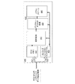
図4は、本発明の一例の実施形態に係るハプティックデータ信号を操作するためのハプティックドライバ400を示す。図4に示される例示的な実装では、ハプティックデータ信号410は、アルゴリズムにより、アクチュエータに適用されるときのハプティックデータ信号410をアナログ形式に変換する前の、デジタル形式で変更される。
FIG. 4 illustrates a
図4に示されるように、デジタルハプティックデータ信号410は、メモリ420(例えば、ファースト−イン−ファースト−アウトメモリ、以下「FIFO」)へ供給され、ハプティック制御データ415は、コンフィグレーションコントローラ430へ供給される。メモリ420は、デジタルハプティックデータ信号410を信号変形器440へ供給する。コンフィグレーションコントローラ430により供給されるハプティック制御データ415を用いて、信号変形器440は、対応するアナログ信号への変換前に、デジタルハプティックデータ信号410を変形する。信号変形器440は、1以上の処理アルゴリズムを適用してもよい。このようなアルゴリズムは、後続の段階の前に、デジタルハプティックデータ信号410に適用されてもよい。各種実施形態では、ハプティック制御データ415は、デジタルハプティックデータ信号410の駆動電圧及び減衰パラメータを変更するために用いられる共振周波数データ、共振周波数帯域データ、及び減衰データを含んでもよい。
As shown in FIG. 4, the digital haptic data signal 410 is supplied to a memory 420 (eg, first-in-first-out memory, hereinafter “FIFO”), and
次の段階では、デジタルハプティックデータ信号410は、デジタル−アナログコンバータ(digital to analog converter(「DAC」))450へ供給される。コンフィグレーションコントローラ430によってハプティック制御データ415を供給され、DAC450は、デジタルハプティックデータ信号をアナログハプティックデータ信号410’へ変換する。ここで、ハプティック制御データ415は、デジタル−アナログ変換段階中に、デジタルハプティックデータ信号410の駆動電圧及び減衰パラメータを更に調整するために用いられてもよい。
In the next stage, the digital haptic data signal 410 is provided to a digital to analog converter (“DAC”) 450. Given the
続いて、パワーステージ460において、アナログハプティックデータ信号410’は受信され、その電圧レベルは、後続段階の入力パラメータに応じて変更されてもよい。例えば、パワーステージ460は、1以上の出力フィルタを用いてアナログハプティックデータ信号410’の電圧レベルを調整するように構成されてもよい。
Subsequently, in the
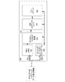
図5は、本発明の別の例の実施形態に係るハプティックデータ信号を操作するためのハプティックドライバ500を示す。図5に示される例示的な実装では、ハプティックデータ信号510は、信号コンディション処理が生じる前に、アナログ形式に変換される。
FIG. 5 shows a
図5に示されるように、デジタルハプティックデータ信号510は、メモリ520(例えば、FIFOメモリ)に供給され、ハプティック制御データ515は、コンフィグレーションコントローラ530へ供給される。メモリ520は、デジタルハプティックデータ信号510をDAC540へ供給する。コンフィグレーションコントローラ530によりハプティック制御データ515を供給され、DAC540は、デジタルハプティックデータ信号をアナログハプティックデータ信号510’へ変換する。ハプティック制御データ515は、デジタル−アナログ変換段階中に、デジタルハプティックデータ信号510の駆動電圧及び減衰パラメータを変更するために用いられる共振周波数データ、共振帯域データ、及び減衰データを含んでもよい。
As shown in FIG. 5, the digital haptic data signal 510 is supplied to a memory 520 (eg, a FIFO memory) and the haptic control data 515 is supplied to a
次の段階では、アナログハプティックデータ信号510’は、信号コンディショナ550に供給される。コンフィグレーションコントローラ530により供給されるハプティック制御データ515を用いて、信号コンディショナ550は、ハプティック制御データ515を使用して1以上のアナログフィルタリングアルゴリズムを用いてアナログハプティックデータ信号510’を変更してもよい。例えば、RCフィルタのような様々なアナログフィルタが用いられてもよい。より複雑なフィルタは、設計に応じて半導体デバイスに実装されてもよい。一部の例では、信号コンディショナ550は、後続の段階において配置されるアクチュエータを製造するために用いられるシリコンの特性を促進するために更に適用されてもよい。各種実施形態では、ハプティック制御データ515は、アナログハプティックデータ信号510’の駆動電圧及び減衰パラメータを変更するために用いられてもよい。
In the next stage, the analog haptic data signal 510 ′ is provided to the
続いて、パワーステージ560において、アナログハプティックデータ信号510’は、受信され、その電圧レベルは、後続の段階の入力パラメータに応じて変更されてもよい。例えば、パワーステージ560は、1以上の出力フィルタを用いてアナログハプティックデータ信号510’の電圧レベルを調整するように構成されてもよい。
Subsequently, at the
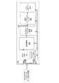
図6は、本発明の別の例の実施形態に係るハプティックデータ信号を操作するためのハプティックドライバ600を示す。図6に示される例示的な実装では、ハプティックデータ信号610は、信号コンディション処理が生じる前にアナログ形式に変換される。
FIG. 6 shows a
図6に示されるように、デジタルハプティックデータ信号610は、メモリ620(例えば、FIFOメモリ)へ供給され、ハプティック制御データ615は、コンフィグレーションコントローラ630へ供給される。メモリ620は、デジタルハプティックデータ信号610をDAC640へ供給する。DAC640は、デジタルハプティックデータ信号をアナログハプティックデータ信号610’へ変換する。
As shown in FIG. 6, the digital haptic data signal 610 is supplied to a memory 620 (eg, a FIFO memory) and the
この例の実施形態では、ハプティック制御データ615は、共振検出器645へ供給される。共振検出器645を用いて、ハプティックドライバ600は、ダウンステージアクチュエータの共振周波数を明示的に決定してもよい。例えば、共振検出器645は、アクチュエータの共振周波数をスキャン及び/又は自動的に決定するように構成されてもよい。一部の例では、共振周波数帯域及び対応する減衰が調整されてもよい。別の例では、共振検出器645は、力又は加えられる圧力を測定するために、検出機構(例えば、ハプティックデバイスに配置される)を用いて共振周波数での変化を検出するように構成されてもよい。更に別の例では、アクチュエータ自体が、その共振周波数を供給してもよい。更に別の例では、逆EMFは、アクチュエータの共振周波数を決定するために用いられてもよい。アクチュエータの1以上の特性を決定するために逆EMFを用いることは、例えば、米国特許第7,843,277号に記載され、これは、参照によって本明細書に援用される。ハプティック制御データ615は、共振検出器645へ供給されてもよい。共振検出器645は、ハプティック制御データ615及びコンフィグレーションコントローラ630によって供給されるコンフィグレーションパラメータを用いるために適合された自動共振検出器であってもよい。個々のアクチュエータに対する共振検出の時間を低減するために、コンフィグレーションパラメータ(例えば、データシートからの共振周波数)は、開始点として提供されてもよい。逆EMF利得のような追加コンフィグレーションパラメータは、誤検出を防ぐために提供されてもよい。
In this example embodiment,
次の段階では、アナログハプティックデータ信号610’、共振検出信号646及びハプティック制御データ615は、信号コンディショナ650へ供給される。これらの入力を用いて、信号コンディショナ650は、アナログハプティックデータ信号610’を変更してもよい。各種実施形態では、ハプティック制御データ615は、デジタルハプティックデータ信号610’の駆動電圧及び減衰パラメータを変更するために用いられる共振周波数データ、共振帯域幅データ、及び減衰データを含んでもよい。
In the next stage, the analog haptic data signal 610 ′, the
続いて、パワーステージ660において、アナログハプティックデータ信号610’は受信され、その電圧レベルは、後続の段階の入力パラメータに応じて変更されてもよい。例えば、パワーステージ660は、1以上の出力フィルタを用いてアナログハプティックデータ信号610’の電圧レベルを調整するように構成されてもよい。
Subsequently, at the
図7は、本発明の別の例の実施形態に係るハプティックデータ信号を操作するためのハプティックドライバ700を示す。図7に示される例の実装では、ハプティックデータ信号710は、更なる信号コンディション処理が生じる前にアナログ形式に変換される。
FIG. 7 illustrates a
図7に示されるように、デジタルハプティックデータ信号710は、メモリ720(例えば、FIFOメモリ)へ供給され、ハプティック制御データ715は、コンフィグレーションコントローラ730へ供給される。メモリ720は、デジタルハプティックデータ信号710をDAC740へ供給する。コンフィグレーションコントローラ730によりハプティック制御データ715を供給され、DAC750は、デジタルハプティックデータ信号710をアナログハプティックデータ信号710’へ変換する。ハプティック制御データ715は、デジタル−アナログ変換段階中に、デジタルハプティックデータ信号710の駆動電圧及び減衰パラメータを変更するために用いられる共振周波数データ、共振帯域データ、及び減衰データを含んでもよい。
As shown in FIG. 7, the digital haptic data signal 710 is supplied to a memory 720 (eg, a FIFO memory) and the
次の段階では、アナログハプティックデータ信号710’は、信号コンディショナ750へ供給される。この実施形態では、信号コンディショナ750は、ルックアップテーブル(図示せず)を用いる。ルックアップテーブルは、ユーザによって供給される又は事前にプログラムされてもよい。例えば、ルックアップテーブルは、様々な製造者によって製造された複数のアクチュエータに対する周波数応答特性を格納する。ルックアップテーブル及びコンフィグレーションコントローラ730によって供給されるハプティック制御データ715を用いて、信号コンディショナ750は、アナログハプティックデータ信号710’を変更してもよい。各種実施形態では、ハプティック制御データ715は、アナログハプティックデータ信号710’の駆動及び減衰パラメータを変更するために用いられてもよい。
In the next stage, the analog haptic data signal 710 ′ is provided to the
続いて、パワーステージ760において、アナログハプティックデータ信号710’は受信され、その電圧レベルは、後続の段階の入力パラメータに応じて変更されてもよい。例えば、パワーステージ760は、1以上の出力フィルタを用いてアナログハプティックデータ信号710’の電圧レベルを調整するように構成されてもよい。
Subsequently, at
図8は、本発明の更に別の例の実施形態に係るハプティックデータ信号を操作するためのハプティックドライバ800を示す。図8に示される例示的な実装では、ハプティックドライバ800は、信号変更及び信号コンディショニングを用いてハプティックデータ信号810を処理する。
FIG. 8 shows a
図8に示されるように、デジタルハプティックデータ信号810は、メモリ820(例えば、FIFOメモリ)へ供給され、ハプティック制御データ815は、コンフィグレーションコントローラ830へ供給される。メモリ820は、デジタルハプティックデータ信号810をDAC840へ供給する。コンフィグレーションコントローラ830により供給されるハプティック制御データ815を用いて、信号変更器840は、対応するアナログハプティックデータ信号810’へ変換前に、デジタルハプティックデータ信号810を変更してもよい。信号変更器840は、1以上の処理アルゴリズムを適用してもよい。このようなアルゴリズムは、後続の段階の前にデジタルハプティックデータ信号810に適用されてもよい。各種実施形態では、ハプティック制御データ815は、デジタルハプティックデータ信号810の駆動電圧及び減衰パラメータを変更するために用いられる共振周波数データ、共振帯域幅データ、及び減衰データを含んでもよい。
As shown in FIG. 8, the digital haptic data signal 810 is supplied to a memory 820 (eg, a FIFO memory) and the
続いて、デジタルハプティックデータ信号810は、DAC840へ供給される。コンフィグレーションコントローラ830によりハプティック制御データ815を供給され、DAC850は、デジタルハプティックデータ信号810をアナログハプティックデータ信号810’へ変換する。ハプティック制御データ715は、デジタル−アナログ変換段階中に、デジタルハプティックデータ信号710の駆動電圧及び減衰パラメータを変更するために用いられる。
Subsequently, the digital haptic data signal 810 is supplied to the
次の段階では、アナログハプティックデータ信号810’は、信号コンディショナ860へ供給される。アナログハプティックデータ信号810’及びハプティック制御データ815を用いて、信号コンディショナ860は、アナログハプティックデータ信号810’を変更してもよい。上述されたように、信号コンディショナは、プログラムされたパラメータ、共振検出機構、ルックアップテーブル等に基づいて信号コンディショニングを適用してもよい。
In the next stage, the analog haptic data signal 810 ′ is provided to the signal conditioner 860. Using the analog haptic data signal 810 'and the
最後に、パワーステージ870において、アナログハプティックデータ信号810’は受信され、その電圧レベルは、後続の段階の入力パラメータに応じて変更されてもよい。例えば、パワーステージ870は、1以上の出力フィルタを用いてアナログハプティックデータ信号810’の電圧レベルを調整するように構成されてもよい。 Finally, at the power stage 870, the analog haptic data signal 810 'is received and its voltage level may be changed according to the input parameters of the subsequent stage. For example, the power stage 870 may be configured to adjust the voltage level of the analog haptic data signal 810 'using one or more output filters.
図9は、本発明の一例の実施形態に係るノッチフィルタの効果を示す。図9に示されるように、ハプティック駆動信号910は、20−450Hz範囲内の可変周波数信号として定義される。ノッチフィルタ(図示せず)の適用により、ハプティック駆動信号910がノッチフィルタ周波数に到達すると、その信号強度は、得られるハプティック駆動信号920によって示されるように減衰される。フィルタ利得のような様々なフィルタ特性は、ノッチフィルタにより生じる減衰の程度を決定する。
FIG. 9 illustrates the effect of a notch filter according to an example embodiment of the present invention. As shown in FIG. 9, the
上述されたように、本発明の実施形態は、より広い周波数帯域に亘って、ハプティック体験の非常に大きな改善及び均一性を提供する。また、ハプティックアクチュエータの周波数応答全体が改善される。本明細書に記載されるHDのハプティックドライバは、異なる製造者によって製造されたハプティックアクチュエータの均一な制御を提供し、より広い周波数帯域に対して使用可能にするためにアクチュエータのハプティック応答を改善することによって、より広い周波数範囲に亘って一定のハプティック体験を表現することを助け、均一/一定の体験を提供する。 As mentioned above, embodiments of the present invention provide a very large improvement and uniformity of the haptic experience over a wider frequency band. Also, the overall frequency response of the haptic actuator is improved. The HD haptic driver described herein provides uniform control of haptic actuators manufactured by different manufacturers and improves actuator haptic response to enable use over a wider frequency band This helps to express a constant haptic experience over a wider frequency range and provides a uniform / constant experience.
いくつかの実施形態が具体的に示され、及び/又は説明された。しかし、開示された実施形態の修正及び変更が、上記の教示、及び本発明の趣旨及び意図される範囲から逸脱しないで添付の特許請求の範囲の範囲内に及ぼされることが理解されるであろう。本明細書に記載される実施形態は、多くの取り得る実施の一部のみである。ブロックのいくつかは、シリコン/IC使用を最適化するために組み合わせられうることが留意されるべきである。更に、実施形態は、様々なアクチュエータタイプ及び他のハプティック出力デバイスに明示的に適用されてもよい。 Several embodiments have been specifically shown and / or described. However, it will be understood that modifications and variations of the disclosed embodiments may be made within the scope of the appended claims without departing from the spirit and intended scope of the above teachings and the present invention. Let's go. The embodiments described herein are only some of the many possible implementations. It should be noted that some of the blocks can be combined to optimize silicon / IC usage. Furthermore, embodiments may be explicitly applied to various actuator types and other haptic output devices.
Claims (20)
前記ハプティック出力デバイスを駆動するように構成されるハプティック駆動信号を受信するステップと、
前記ハプティック出力デバイスの共振周波数範囲を識別するステップと、
識別された前記共振周波数範囲に対応する周波数で前記ハプティック駆動信号を減衰するステップと、
を備える方法。 A method for driving a haptic output device comprising:
Receiving a haptic drive signal configured to drive the haptic output device;
Identifying a resonant frequency range of the haptic output device;
Attenuating the haptic drive signal at a frequency corresponding to the identified resonant frequency range;
A method comprising:
前記プロセッサによる実行のための1以上のプログラムを格納するメモリと、
を備える装置であって、前記1以上のプログラムは、
ハプティック出力デバイスを駆動するように構成されるハプティック駆動信号を受信することと、
前記ハプティック出力デバイスの共振周波数範囲を識別することと、
識別された前記共振周波数範囲に対応する周波数で前記ハプティック駆動信号を減衰することと、
のための命令を含む、装置。 A processor;
A memory storing one or more programs for execution by the processor;
The one or more programs include:
Receiving a haptic drive signal configured to drive a haptic output device;
Identifying a resonant frequency range of the haptic output device;
Attenuating the haptic drive signal at a frequency corresponding to the identified resonant frequency range;
Equipment, including instructions for.
ハプティック出力デバイスを駆動するように構成されるハプティック駆動信号を受信することと、
前記ハプティック出力デバイスの共振周波数範囲を識別することと、
識別された前記共振周波数範囲に対応する周波数で前記ハプティック駆動信号を減衰することと、
のための命令を含む、非一時的コンピュータ可読記憶媒体。 A non-transitory computer readable storage medium storing one or more programs configured to be executed by a processor, the one or more programs comprising:
Receiving a haptic drive signal configured to drive a haptic output device;
Identifying a resonant frequency range of the haptic output device;
Attenuating the haptic drive signal at a frequency corresponding to the identified resonant frequency range;
A non-transitory computer readable storage medium comprising instructions for
Applications Claiming Priority (5)
| Application Number | Priority Date | Filing Date | Title |
|---|---|---|---|
| US201562208430P | 2015-08-21 | 2015-08-21 | |
| US62/208,430 | 2015-08-21 | ||
| US15/240,682 | 2016-08-18 | ||
| US15/240,682 US10109161B2 (en) | 2015-08-21 | 2016-08-18 | Haptic driver with attenuation |
| PCT/US2016/047750 WO2017034973A1 (en) | 2015-08-21 | 2016-08-19 | Haptic driver with attenuation |
Related Child Applications (1)
| Application Number | Title | Priority Date | Filing Date |
|---|---|---|---|
| JP2020095476A Division JP2020161156A (en) | 2015-08-21 | 2020-06-01 | Haptic driver with attenuation |
Publications (2)
| Publication Number | Publication Date |
|---|---|
| JP2018523863A true JP2018523863A (en) | 2018-08-23 |
| JP2018523863A5 JP2018523863A5 (en) | 2019-07-04 |
Family
ID=58100852
Family Applications (2)
| Application Number | Title | Priority Date | Filing Date |
|---|---|---|---|
| JP2017564590A Pending JP2018523863A (en) | 2015-08-21 | 2016-08-19 | Haptic driver with damping |
| JP2020095476A Pending JP2020161156A (en) | 2015-08-21 | 2020-06-01 | Haptic driver with attenuation |
Family Applications After (1)
| Application Number | Title | Priority Date | Filing Date |
|---|---|---|---|
| JP2020095476A Pending JP2020161156A (en) | 2015-08-21 | 2020-06-01 | Haptic driver with attenuation |
Country Status (6)
| Country | Link |
|---|---|
| US (2) | US10109161B2 (en) |
| EP (1) | EP3338168A4 (en) |
| JP (2) | JP2018523863A (en) |
| KR (1) | KR20180033456A (en) |
| CN (1) | CN107743640A (en) |
| WO (1) | WO2017034973A1 (en) |
Cited By (10)
| Publication number | Priority date | Publication date | Assignee | Title |
|---|---|---|---|---|
| JPWO2018193513A1 (en) * | 2017-04-18 | 2019-08-08 | 株式会社ソニー・インタラクティブエンタテインメント | Vibration control device |
| US10963055B2 (en) | 2016-12-15 | 2021-03-30 | Sony Interactive Entertainment Inc. | Vibration device and control system for presenting corrected vibration data |
| US10963054B2 (en) | 2016-12-15 | 2021-03-30 | Sony Interactive Entertainment Inc. | Information processing system, vibration control method and program |
| US10981053B2 (en) | 2017-04-18 | 2021-04-20 | Sony Interactive Entertainment Inc. | Vibration control apparatus |
| US11013990B2 (en) | 2017-04-19 | 2021-05-25 | Sony Interactive Entertainment Inc. | Vibration control apparatus |
| US11198059B2 (en) | 2017-08-29 | 2021-12-14 | Sony Interactive Entertainment Inc. | Vibration control apparatus, vibration control method, and program |
| JP2022131083A (en) * | 2021-02-26 | 2022-09-07 | 任天堂株式会社 | vibration control system |
| US11458389B2 (en) | 2017-04-26 | 2022-10-04 | Sony Interactive Entertainment Inc. | Vibration control apparatus |
| US11738261B2 (en) | 2017-08-24 | 2023-08-29 | Sony Interactive Entertainment Inc. | Vibration control apparatus |
| US11779836B2 (en) | 2017-08-24 | 2023-10-10 | Sony Interactive Entertainment Inc. | Vibration control apparatus |
Families Citing this family (25)
| Publication number | Priority date | Publication date | Assignee | Title |
|---|---|---|---|---|
| US10109161B2 (en) * | 2015-08-21 | 2018-10-23 | Immersion Corporation | Haptic driver with attenuation |
| EP3907734B1 (en) * | 2016-11-14 | 2022-11-02 | Goodix Technology (HK) Company Limited | Linear resonant actuator controller |
| US10969867B2 (en) | 2016-12-15 | 2021-04-06 | Sony Interactive Entertainment Inc. | Information processing system, controller device, controller device control method and program |
| US9928700B1 (en) * | 2017-01-25 | 2018-03-27 | Immersion Corporation | Method and apparatus for controlling generation of electrostatic friction effects for a plurality of electrodes |
| US10277154B2 (en) | 2017-05-01 | 2019-04-30 | Apple Inc. | Closed-loop control of linear resonant actuator using back EMF data and hall sensing |
| US10110152B1 (en) | 2017-09-29 | 2018-10-23 | Apple Inc. | Integrated driver and controller for haptic engine |
| US10601355B2 (en) | 2017-09-29 | 2020-03-24 | Apple Inc. | Closed-loop control of linear resonant actuator using back EMF and inertial compensation |
| US10991499B2 (en) * | 2018-03-22 | 2021-04-27 | Cirrus Logic, Inc. | Drive waveform adjustments to compensate for transducer resonant frequency |
| WO2020008862A1 (en) * | 2018-07-02 | 2020-01-09 | ソニー株式会社 | Information processing apparatus, information processing method, and information processing apparatus-readable recording medium |
| US11269415B2 (en) | 2018-08-14 | 2022-03-08 | Cirrus Logic, Inc. | Haptic output systems |
| US10828672B2 (en) | 2019-03-29 | 2020-11-10 | Cirrus Logic, Inc. | Driver circuitry |
| US11644370B2 (en) | 2019-03-29 | 2023-05-09 | Cirrus Logic, Inc. | Force sensing with an electromagnetic load |
| US11509292B2 (en) | 2019-03-29 | 2022-11-22 | Cirrus Logic, Inc. | Identifying mechanical impedance of an electromagnetic load using least-mean-squares filter |
| US10955955B2 (en) | 2019-03-29 | 2021-03-23 | Cirrus Logic, Inc. | Controller for use in a device comprising force sensors |
| US10976825B2 (en) | 2019-06-07 | 2021-04-13 | Cirrus Logic, Inc. | Methods and apparatuses for controlling operation of a vibrational output system and/or operation of an input sensor system |
| US11641546B2 (en) * | 2019-06-17 | 2023-05-02 | Cirrus Logic, Inc. | Frequency-domain haptic waveform compensation for haptic transducers |
| CN110380664A (en) * | 2019-06-24 | 2019-10-25 | 瑞声科技(新加坡)有限公司 | A kind of motor vibrations control method, device and computer readable storage medium |
| WO2021024187A1 (en) * | 2019-08-08 | 2021-02-11 | 3M Innovative Properties Company | Wireless voice communication for a self-contained breathing apparatus (scba) |
| US11408787B2 (en) | 2019-10-15 | 2022-08-09 | Cirrus Logic, Inc. | Control methods for a force sensor system |
| US11380175B2 (en) | 2019-10-24 | 2022-07-05 | Cirrus Logic, Inc. | Reproducibility of haptic waveform |
| US11662821B2 (en) | 2020-04-16 | 2023-05-30 | Cirrus Logic, Inc. | In-situ monitoring, calibration, and testing of a haptic actuator |
| US11933822B2 (en) | 2021-06-16 | 2024-03-19 | Cirrus Logic Inc. | Methods and systems for in-system estimation of actuator parameters |
| US11765499B2 (en) | 2021-06-22 | 2023-09-19 | Cirrus Logic Inc. | Methods and systems for managing mixed mode electromechanical actuator drive |
| US11908310B2 (en) | 2021-06-22 | 2024-02-20 | Cirrus Logic Inc. | Methods and systems for detecting and managing unexpected spectral content in an amplifier system |
| DE102022108877A1 (en) * | 2022-04-12 | 2023-10-12 | Preh Gmbh | Input method with haptic feedback and ringing suppression and associated input device |
Citations (4)
| Publication number | Priority date | Publication date | Assignee | Title |
|---|---|---|---|---|
| JP2008305109A (en) * | 2007-06-06 | 2008-12-18 | Tokyo Institute Of Technology | Information processor, program and computer readable recording medium |
| US20100153845A1 (en) * | 2008-12-16 | 2010-06-17 | Immersion Corporation | Haptic feedback generation based on resonant frequency |
| JP2014154158A (en) * | 2013-02-05 | 2014-08-25 | Immersion Corp | Overdrive voltage for actuator to generate haptic effects |
| JP2014154150A (en) * | 2013-02-04 | 2014-08-25 | Immersion Corp | Wearable device manager |
Family Cites Families (77)
| Publication number | Priority date | Publication date | Assignee | Title |
|---|---|---|---|---|
| US4479098A (en) | 1981-07-06 | 1984-10-23 | Watson Industries, Inc. | Circuit for tracking and maintaining drive of actuator/mass at resonance |
| FR2533701A1 (en) | 1982-09-23 | 1984-03-30 | Renault Vehicules Ind | PILOTAGE DEVICE FOR EXCITING A MECHANICAL COMPONENT WITH ITS RESONANCE FREQUENCY FOR A FATIGUE TEST |
| US4811835A (en) | 1986-10-07 | 1989-03-14 | K-Tron International, Inc. | Vibratory material feeder |
| US5436622A (en) | 1993-07-06 | 1995-07-25 | Motorola, Inc. | Variable frequency vibratory alert method and structure |
| JPH09117721A (en) | 1994-09-28 | 1997-05-06 | Seiko Instr Inc | Vibration module |
| JP2000501033A (en) | 1995-11-30 | 2000-02-02 | ヴァーチャル テクノロジーズ インコーポレイテッド | Human / machine interface with tactile feedback |
| US5783973A (en) | 1997-02-24 | 1998-07-21 | The Charles Stark Draper Laboratory, Inc. | Temperature insensitive silicon oscillator and precision voltage reference formed therefrom |
| US6088185A (en) | 1998-06-05 | 2000-07-11 | Seagate Technology, Inc. | Rotational vibration detection using a velocity sense coil |
| US6473075B1 (en) | 1999-09-29 | 2002-10-29 | Elo Touchsystems, Inc. | Adaptive frequency touchscreen controller employing digital signal processing |
| WO2002027705A1 (en) | 2000-09-28 | 2002-04-04 | Immersion Corporation | Directional tactile feedback for haptic feedback interface devices |
| US7023326B2 (en) | 2001-05-26 | 2006-04-04 | Samsung Electronics Co., Ltd. | Vibration apparatus for a mobile telecommunication terminal and method for controlling the same |
| US6892581B2 (en) | 2001-11-19 | 2005-05-17 | Csi Technology, Inc. | Multi-axis vibration sensor with integral magnet |
| JP4065769B2 (en) | 2002-11-29 | 2008-03-26 | アルプス電気株式会社 | Vibration generator |
| US9948885B2 (en) | 2003-12-12 | 2018-04-17 | Kurzweil Technologies, Inc. | Virtual encounters |
| JP4997114B2 (en) | 2004-11-30 | 2012-08-08 | イマージョン コーポレイション | System and method for controlling a resonant device to generate vibrotactile haptic effects |
| EP2380640A3 (en) | 2005-06-27 | 2011-12-28 | Coactive Drive Corporation | Synchronized vibration device for haptic feedback |
| US9370704B2 (en) | 2006-08-21 | 2016-06-21 | Pillar Vision, Inc. | Trajectory detection and feedback system for tennis |
| JP5016117B2 (en) | 2008-01-17 | 2012-09-05 | アーティキュレイト テクノロジーズ インコーポレーティッド | Method and apparatus for intraoral tactile feedback |
| KR101030389B1 (en) * | 2008-12-17 | 2011-04-20 | 삼성전자주식회사 | Haptic function control method for portable terminal |
| US9370459B2 (en) | 2009-06-19 | 2016-06-21 | Andrew Mahoney | System and method for alerting visually impaired users of nearby objects |
| TW201205910A (en) | 2010-02-03 | 2012-02-01 | Bayer Materialscience Ag | An electroactive polymer actuator haptic grip assembly |
| US9251721B2 (en) | 2010-04-09 | 2016-02-02 | University Of Florida Research Foundation, Inc. | Interactive mixed reality system and uses thereof |
| US20120229264A1 (en) * | 2011-03-09 | 2012-09-13 | Analog Devices, Inc. | Smart linear resonant actuator control |
| WO2012125924A2 (en) | 2011-03-17 | 2012-09-20 | Coactive Drive Corporation | Asymmetric and general vibration waveforms from multiple synchronized vibration actuators |
| US20120249461A1 (en) * | 2011-04-01 | 2012-10-04 | Analog Devices, Inc. | Dedicated user interface controller for feedback responses |
| US9462262B1 (en) | 2011-08-29 | 2016-10-04 | Amazon Technologies, Inc. | Augmented reality environment with environmental condition control |
| JP6125852B2 (en) * | 2012-02-01 | 2017-05-10 | イマージョン コーポレーションImmersion Corporation | Optimization of eccentric rotating mass actuators for haptic effects |
| CN103649885B (en) | 2012-04-27 | 2017-03-01 | 松下知识产权经营株式会社 | Tactile cue device, tactile cue method, drive signal generating means and drive signal generation method |
| US10852093B2 (en) | 2012-05-22 | 2020-12-01 | Haptech, Inc. | Methods and apparatuses for haptic systems |
| JP6207615B2 (en) | 2012-09-24 | 2017-10-11 | ジョン ハミルトン | Communication and speech improvement system |
| US9355536B2 (en) * | 2012-09-27 | 2016-05-31 | Fairchild Semiconductor Corporation | Resonance driver for determining a resonant frequency of a haptic device |
| US9524624B2 (en) * | 2012-12-13 | 2016-12-20 | Immersion Corporation | Haptic system with increased LRA bandwidth |
| FR2999741B1 (en) | 2012-12-17 | 2015-02-06 | Centre Nat Rech Scient | HAPTIC SYSTEM FOR NON-CONTACT INTERACTING AT LEAST ONE PART OF THE BODY OF A USER WITH A VIRTUAL ENVIRONMENT |
| US9121753B2 (en) * | 2013-02-06 | 2015-09-01 | Analog Devices Global | Control techniques for motor driven systems utilizing back-EMF measurement techniques |
| US9367136B2 (en) | 2013-04-12 | 2016-06-14 | Microsoft Technology Licensing, Llc | Holographic object feedback |
| US9908048B2 (en) | 2013-06-08 | 2018-03-06 | Sony Interactive Entertainment Inc. | Systems and methods for transitioning between transparent mode and non-transparent mode in a head mounted display |
| US9811854B2 (en) | 2013-07-02 | 2017-11-07 | John A. Lucido | 3-D immersion technology in a virtual store |
| EP4083758A1 (en) | 2013-07-05 | 2022-11-02 | Rubin, Jacob A. | Whole-body human-computer interface |
| US9520036B1 (en) * | 2013-09-18 | 2016-12-13 | Amazon Technologies, Inc. | Haptic output generation with dynamic feedback control |
| US9630105B2 (en) | 2013-09-30 | 2017-04-25 | Sony Interactive Entertainment Inc. | Camera based safety mechanisms for users of head mounted displays |
| EP3095023A1 (en) | 2014-01-15 | 2016-11-23 | Sony Corporation | Haptic notification on wearables |
| US9551873B2 (en) | 2014-05-30 | 2017-01-24 | Sony Interactive Entertainment America Llc | Head mounted device (HMD) system having interface with mobile computing device for rendering virtual reality content |
| CN111998027B (en) | 2014-07-28 | 2022-05-27 | Ck高新材料有限公司 | Tactile information providing method |
| US9645646B2 (en) | 2014-09-04 | 2017-05-09 | Intel Corporation | Three dimensional contextual feedback wristband device |
| US9799177B2 (en) | 2014-09-23 | 2017-10-24 | Intel Corporation | Apparatus and methods for haptic covert communication |
| US20160170508A1 (en) | 2014-12-11 | 2016-06-16 | Toyota Motor Engineering & Manufacturing North America, Inc. | Tactile display devices |
| US9870718B2 (en) | 2014-12-11 | 2018-01-16 | Toyota Motor Engineering & Manufacturing North America, Inc. | Imaging devices including spacing members and imaging devices including tactile feedback devices |
| US9922518B2 (en) | 2014-12-11 | 2018-03-20 | Elwha Llc | Notification of incoming projectiles |
| US10166466B2 (en) | 2014-12-11 | 2019-01-01 | Elwha Llc | Feedback for enhanced situational awareness |
| US10073516B2 (en) | 2014-12-29 | 2018-09-11 | Sony Interactive Entertainment Inc. | Methods and systems for user interaction within virtual reality scene using head mounted display |
| US9746921B2 (en) | 2014-12-31 | 2017-08-29 | Sony Interactive Entertainment Inc. | Signal generation and detector systems and methods for determining positions of fingers of a user |
| US9843744B2 (en) | 2015-01-13 | 2017-12-12 | Disney Enterprises, Inc. | Audience interaction projection system |
| US10322203B2 (en) | 2015-06-26 | 2019-06-18 | Intel Corporation | Air flow generation for scent output |
| US10109161B2 (en) * | 2015-08-21 | 2018-10-23 | Immersion Corporation | Haptic driver with attenuation |
| US9778746B2 (en) | 2015-09-25 | 2017-10-03 | Oculus Vr, Llc | Transversal actuator for haptic feedback |
| US20170103574A1 (en) | 2015-10-13 | 2017-04-13 | Google Inc. | System and method for providing continuity between real world movement and movement in a virtual/augmented reality experience |
| US20170131775A1 (en) | 2015-11-10 | 2017-05-11 | Castar, Inc. | System and method of haptic feedback by referral of sensation |
| US10055948B2 (en) | 2015-11-30 | 2018-08-21 | Nike, Inc. | Apparel with ultrasonic position sensing and haptic feedback for activities |
| EP3179335B1 (en) * | 2015-12-10 | 2020-03-04 | Nxp B.V. | Haptic feedback controller |
| US10310804B2 (en) | 2015-12-11 | 2019-06-04 | Facebook Technologies, Llc | Modifying haptic feedback provided to a user to account for changes in user perception of haptic feedback |
| US10324530B2 (en) | 2015-12-14 | 2019-06-18 | Facebook Technologies, Llc | Haptic devices that simulate rigidity of virtual objects |
| US10096163B2 (en) | 2015-12-22 | 2018-10-09 | Intel Corporation | Haptic augmented reality to reduce noxious stimuli |
| US10065124B2 (en) | 2016-01-15 | 2018-09-04 | Disney Enterprises, Inc. | Interacting with a remote participant through control of the voice of a toy device |
| US11351472B2 (en) | 2016-01-19 | 2022-06-07 | Disney Enterprises, Inc. | Systems and methods for using a gyroscope to change the resistance of moving a virtual weapon |
| US9846971B2 (en) | 2016-01-19 | 2017-12-19 | Disney Enterprises, Inc. | Systems and methods for augmenting an appearance of a hilt to simulate a bladed weapon |
| CN106997241B (en) | 2016-01-22 | 2020-04-21 | 宏达国际电子股份有限公司 | Method for interacting with real world in virtual reality environment and virtual reality system |
| US9933851B2 (en) | 2016-02-22 | 2018-04-03 | Disney Enterprises, Inc. | Systems and methods for interacting with virtual objects using sensory feedback |
| US10555153B2 (en) | 2016-03-01 | 2020-02-04 | Disney Enterprises, Inc. | Systems and methods for making non-smart objects smart for internet of things |
| US20170352185A1 (en) | 2016-06-02 | 2017-12-07 | Dennis Rommel BONILLA ACEVEDO | System and method for facilitating a vehicle-related virtual reality and/or augmented reality presentation |
| US10155159B2 (en) | 2016-08-18 | 2018-12-18 | Activision Publishing, Inc. | Tactile feedback systems and methods for augmented reality and virtual reality systems |
| US20180053351A1 (en) | 2016-08-19 | 2018-02-22 | Intel Corporation | Augmented reality experience enhancement method and apparatus |
| US10372213B2 (en) | 2016-09-20 | 2019-08-06 | Facebook Technologies, Llc | Composite ribbon in a virtual reality device |
| US10779583B2 (en) | 2016-09-20 | 2020-09-22 | Facebook Technologies, Llc | Actuated tendon pairs in a virtual reality device |
| US10300372B2 (en) | 2016-09-30 | 2019-05-28 | Disney Enterprises, Inc. | Virtual blaster |
| US10281982B2 (en) | 2016-10-17 | 2019-05-07 | Facebook Technologies, Llc | Inflatable actuators in virtual reality |
| US10088902B2 (en) | 2016-11-01 | 2018-10-02 | Oculus Vr, Llc | Fiducial rings in virtual reality |
| US20170102771A1 (en) | 2016-12-12 | 2017-04-13 | Leibs Technology Limited | Wearable ultrasonic haptic feedback system |
-
2016
- 2016-08-18 US US15/240,682 patent/US10109161B2/en not_active Expired - Fee Related
- 2016-08-19 KR KR1020177035809A patent/KR20180033456A/en unknown
- 2016-08-19 WO PCT/US2016/047750 patent/WO2017034973A1/en unknown
- 2016-08-19 JP JP2017564590A patent/JP2018523863A/en active Pending
- 2016-08-19 EP EP16839875.8A patent/EP3338168A4/en not_active Withdrawn
- 2016-08-19 CN CN201680034559.3A patent/CN107743640A/en active Pending
-
2018
- 2018-09-12 US US16/129,064 patent/US20190080568A1/en not_active Abandoned
-
2020
- 2020-06-01 JP JP2020095476A patent/JP2020161156A/en active Pending
Patent Citations (4)
| Publication number | Priority date | Publication date | Assignee | Title |
|---|---|---|---|---|
| JP2008305109A (en) * | 2007-06-06 | 2008-12-18 | Tokyo Institute Of Technology | Information processor, program and computer readable recording medium |
| US20100153845A1 (en) * | 2008-12-16 | 2010-06-17 | Immersion Corporation | Haptic feedback generation based on resonant frequency |
| JP2014154150A (en) * | 2013-02-04 | 2014-08-25 | Immersion Corp | Wearable device manager |
| JP2014154158A (en) * | 2013-02-05 | 2014-08-25 | Immersion Corp | Overdrive voltage for actuator to generate haptic effects |
Cited By (12)
| Publication number | Priority date | Publication date | Assignee | Title |
|---|---|---|---|---|
| US10963055B2 (en) | 2016-12-15 | 2021-03-30 | Sony Interactive Entertainment Inc. | Vibration device and control system for presenting corrected vibration data |
| US10963054B2 (en) | 2016-12-15 | 2021-03-30 | Sony Interactive Entertainment Inc. | Information processing system, vibration control method and program |
| JPWO2018193513A1 (en) * | 2017-04-18 | 2019-08-08 | 株式会社ソニー・インタラクティブエンタテインメント | Vibration control device |
| US10981053B2 (en) | 2017-04-18 | 2021-04-20 | Sony Interactive Entertainment Inc. | Vibration control apparatus |
| US11145172B2 (en) | 2017-04-18 | 2021-10-12 | Sony Interactive Entertainment Inc. | Vibration control apparatus |
| US11013990B2 (en) | 2017-04-19 | 2021-05-25 | Sony Interactive Entertainment Inc. | Vibration control apparatus |
| US11458389B2 (en) | 2017-04-26 | 2022-10-04 | Sony Interactive Entertainment Inc. | Vibration control apparatus |
| US11738261B2 (en) | 2017-08-24 | 2023-08-29 | Sony Interactive Entertainment Inc. | Vibration control apparatus |
| US11779836B2 (en) | 2017-08-24 | 2023-10-10 | Sony Interactive Entertainment Inc. | Vibration control apparatus |
| US11198059B2 (en) | 2017-08-29 | 2021-12-14 | Sony Interactive Entertainment Inc. | Vibration control apparatus, vibration control method, and program |
| JP2022131083A (en) * | 2021-02-26 | 2022-09-07 | 任天堂株式会社 | vibration control system |
| JP7340556B2 (en) | 2021-02-26 | 2023-09-07 | 任天堂株式会社 | vibration control system |
Also Published As
| Publication number | Publication date |
|---|---|
| WO2017034973A1 (en) | 2017-03-02 |
| EP3338168A4 (en) | 2019-04-03 |
| US20190080568A1 (en) | 2019-03-14 |
| US20170053502A1 (en) | 2017-02-23 |
| KR20180033456A (en) | 2018-04-03 |
| JP2020161156A (en) | 2020-10-01 |
| EP3338168A1 (en) | 2018-06-27 |
| CN107743640A (en) | 2018-02-27 |
| US10109161B2 (en) | 2018-10-23 |
Similar Documents
| Publication | Publication Date | Title |
|---|---|---|
| JP2018523863A (en) | Haptic driver with damping | |
| US10395489B1 (en) | Generation and braking of vibrations | |
| US20180164896A1 (en) | Audio enhanced simulation of high bandwidth haptic effects | |
| EP3206109B1 (en) | Low-frequency effects haptic conversion system | |
| JP6266365B2 (en) | Overdrive voltage for actuators to generate haptic effects | |
| JP6562695B2 (en) | Dynamic change of haptic effect | |
| JP6026751B2 (en) | Acoustic-tactile effect conversion system using amplitude values | |
| US20170090577A1 (en) | Haptic effects design system | |
| US20120249462A1 (en) | Method and apparatus for haptic vibration response profiling and feedback | |
| JP6093659B2 (en) | Information processing apparatus and information processing program | |
| US20190267043A1 (en) | Automated haptic effect accompaniment | |
| US11579697B2 (en) | Haptic effect encoding and rendering system | |
| EP3582072A1 (en) | Reference signal variation for generating crisp haptic effects | |
| WO2020176383A1 (en) | Audio data with embedded tags for rendering customized haptic effects | |
| WO2023146770A2 (en) | Determination and avoidance of over-excursion of internal mass of transducer |
Legal Events
| Date | Code | Title | Description |
|---|---|---|---|
| A521 | Request for written amendment filed |
Free format text: JAPANESE INTERMEDIATE CODE: A523 Effective date: 20190531 |
|
| A621 | Written request for application examination |
Free format text: JAPANESE INTERMEDIATE CODE: A621 Effective date: 20190531 |
|
| A871 | Explanation of circumstances concerning accelerated examination |
Free format text: JAPANESE INTERMEDIATE CODE: A871 Effective date: 20190531 |
|
| A975 | Report on accelerated examination |
Free format text: JAPANESE INTERMEDIATE CODE: A971005 Effective date: 20190830 |
|
| A131 | Notification of reasons for refusal |
Free format text: JAPANESE INTERMEDIATE CODE: A131 Effective date: 20190903 |
|
| A601 | Written request for extension of time |
Free format text: JAPANESE INTERMEDIATE CODE: A601 Effective date: 20191202 |
|
| A521 | Request for written amendment filed |
Free format text: JAPANESE INTERMEDIATE CODE: A523 Effective date: 20191216 |
|
| A02 | Decision of refusal |
Free format text: JAPANESE INTERMEDIATE CODE: A02 Effective date: 20200212 |
|
| A521 | Request for written amendment filed |
Free format text: JAPANESE INTERMEDIATE CODE: A523 Effective date: 20200601 |
|
| C60 | Trial request (containing other claim documents, opposition documents) |
Free format text: JAPANESE INTERMEDIATE CODE: C60 Effective date: 20200601 |
|
| A911 | Transfer to examiner for re-examination before appeal (zenchi) |
Free format text: JAPANESE INTERMEDIATE CODE: A911 Effective date: 20200610 |
|
| C21 | Notice of transfer of a case for reconsideration by examiners before appeal proceedings |
Free format text: JAPANESE INTERMEDIATE CODE: C21 Effective date: 20200616 |
|
| A912 | Re-examination (zenchi) completed and case transferred to appeal board |
Free format text: JAPANESE INTERMEDIATE CODE: A912 Effective date: 20200626 |
|
| C211 | Notice of termination of reconsideration by examiners before appeal proceedings |
Free format text: JAPANESE INTERMEDIATE CODE: C211 Effective date: 20200630 |
|
| C22 | Notice of designation (change) of administrative judge |
Free format text: JAPANESE INTERMEDIATE CODE: C22 Effective date: 20210126 |
|
| C22 | Notice of designation (change) of administrative judge |
Free format text: JAPANESE INTERMEDIATE CODE: C22 Effective date: 20210420 |
|
| C13 | Notice of reasons for refusal |
Free format text: JAPANESE INTERMEDIATE CODE: C13 Effective date: 20210427 |
|
| C23 | Notice of termination of proceedings |
Free format text: JAPANESE INTERMEDIATE CODE: C23 Effective date: 20210831 |
|
| C03 | Trial/appeal decision taken |
Free format text: JAPANESE INTERMEDIATE CODE: C03 Effective date: 20211005 |
|
| C30A | Notification sent |
Free format text: JAPANESE INTERMEDIATE CODE: C3012 Effective date: 20211005 |