JP2018522290A - Stereoscopic 3D projection system with improved level of optical light efficiency - Google Patents
Stereoscopic 3D projection system with improved level of optical light efficiency Download PDFInfo
- Publication number
- JP2018522290A JP2018522290A JP2018518800A JP2018518800A JP2018522290A JP 2018522290 A JP2018522290 A JP 2018522290A JP 2018518800 A JP2018518800 A JP 2018518800A JP 2018518800 A JP2018518800 A JP 2018518800A JP 2018522290 A JP2018522290 A JP 2018522290A
- Authority
- JP
- Japan
- Prior art keywords
- image beam
- polarization
- polarization state
- optical
- state
- Prior art date
- Legal status (The legal status is an assumption and is not a legal conclusion. Google has not performed a legal analysis and makes no representation as to the accuracy of the status listed.)
- Pending
Links
Images


Classifications
-
- G—PHYSICS
- G02—OPTICS
- G02B—OPTICAL ELEMENTS, SYSTEMS OR APPARATUS
- G02B30/00—Optical systems or apparatus for producing three-dimensional [3D] effects, e.g. stereoscopic images
- G02B30/20—Optical systems or apparatus for producing three-dimensional [3D] effects, e.g. stereoscopic images by providing first and second parallax images to an observer's left and right eyes
- G02B30/22—Optical systems or apparatus for producing three-dimensional [3D] effects, e.g. stereoscopic images by providing first and second parallax images to an observer's left and right eyes of the stereoscopic type
- G02B30/25—Optical systems or apparatus for producing three-dimensional [3D] effects, e.g. stereoscopic images by providing first and second parallax images to an observer's left and right eyes of the stereoscopic type using polarisation techniques
-
- G—PHYSICS
- G02—OPTICS
- G02B—OPTICAL ELEMENTS, SYSTEMS OR APPARATUS
- G02B27/00—Optical systems or apparatus not provided for by any of the groups G02B1/00 - G02B26/00, G02B30/00
- G02B27/28—Optical systems or apparatus not provided for by any of the groups G02B1/00 - G02B26/00, G02B30/00 for polarising
- G02B27/283—Optical systems or apparatus not provided for by any of the groups G02B1/00 - G02B26/00, G02B30/00 for polarising used for beam splitting or combining
-
- G—PHYSICS
- G02—OPTICS
- G02B—OPTICAL ELEMENTS, SYSTEMS OR APPARATUS
- G02B30/00—Optical systems or apparatus for producing three-dimensional [3D] effects, e.g. stereoscopic images
- G02B30/20—Optical systems or apparatus for producing three-dimensional [3D] effects, e.g. stereoscopic images by providing first and second parallax images to an observer's left and right eyes
- G02B30/22—Optical systems or apparatus for producing three-dimensional [3D] effects, e.g. stereoscopic images by providing first and second parallax images to an observer's left and right eyes of the stereoscopic type
- G02B30/24—Optical systems or apparatus for producing three-dimensional [3D] effects, e.g. stereoscopic images by providing first and second parallax images to an observer's left and right eyes of the stereoscopic type involving temporal multiplexing, e.g. using sequentially activated left and right shutters
-
- G—PHYSICS
- G02—OPTICS
- G02B—OPTICAL ELEMENTS, SYSTEMS OR APPARATUS
- G02B5/00—Optical elements other than lenses
- G02B5/30—Polarising elements
- G02B5/3025—Polarisers, i.e. arrangements capable of producing a definite output polarisation state from an unpolarised input state
- G02B5/3033—Polarisers, i.e. arrangements capable of producing a definite output polarisation state from an unpolarised input state in the form of a thin sheet or foil, e.g. Polaroid
- G02B5/3041—Polarisers, i.e. arrangements capable of producing a definite output polarisation state from an unpolarised input state in the form of a thin sheet or foil, e.g. Polaroid comprising multiple thin layers, e.g. multilayer stacks
-
- G—PHYSICS
- G02—OPTICS
- G02B—OPTICAL ELEMENTS, SYSTEMS OR APPARATUS
- G02B5/00—Optical elements other than lenses
- G02B5/30—Polarising elements
- G02B5/3083—Birefringent or phase retarding elements
-
- G—PHYSICS
- G02—OPTICS
- G02F—OPTICAL DEVICES OR ARRANGEMENTS FOR THE CONTROL OF LIGHT BY MODIFICATION OF THE OPTICAL PROPERTIES OF THE MEDIA OF THE ELEMENTS INVOLVED THEREIN; NON-LINEAR OPTICS; FREQUENCY-CHANGING OF LIGHT; OPTICAL LOGIC ELEMENTS; OPTICAL ANALOGUE/DIGITAL CONVERTERS
- G02F1/00—Devices or arrangements for the control of the intensity, colour, phase, polarisation or direction of light arriving from an independent light source, e.g. switching, gating or modulating; Non-linear optics
- G02F1/01—Devices or arrangements for the control of the intensity, colour, phase, polarisation or direction of light arriving from an independent light source, e.g. switching, gating or modulating; Non-linear optics for the control of the intensity, phase, polarisation or colour
- G02F1/13—Devices or arrangements for the control of the intensity, colour, phase, polarisation or direction of light arriving from an independent light source, e.g. switching, gating or modulating; Non-linear optics for the control of the intensity, phase, polarisation or colour based on liquid crystals, e.g. single liquid crystal display cells
- G02F1/133—Constructional arrangements; Operation of liquid crystal cells; Circuit arrangements
- G02F1/1333—Constructional arrangements; Manufacturing methods
- G02F1/1335—Structural association of cells with optical devices, e.g. polarisers or reflectors
- G02F1/13363—Birefringent elements, e.g. for optical compensation
-
- G—PHYSICS
- G03—PHOTOGRAPHY; CINEMATOGRAPHY; ANALOGOUS TECHNIQUES USING WAVES OTHER THAN OPTICAL WAVES; ELECTROGRAPHY; HOLOGRAPHY
- G03B—APPARATUS OR ARRANGEMENTS FOR TAKING PHOTOGRAPHS OR FOR PROJECTING OR VIEWING THEM; APPARATUS OR ARRANGEMENTS EMPLOYING ANALOGOUS TECHNIQUES USING WAVES OTHER THAN OPTICAL WAVES; ACCESSORIES THEREFOR
- G03B21/00—Projectors or projection-type viewers; Accessories therefor
- G03B21/54—Accessories
- G03B21/56—Projection screens
-
- H—ELECTRICITY
- H04—ELECTRIC COMMUNICATION TECHNIQUE
- H04N—PICTORIAL COMMUNICATION, e.g. TELEVISION
- H04N13/00—Stereoscopic video systems; Multi-view video systems; Details thereof
- H04N13/30—Image reproducers
- H04N13/332—Displays for viewing with the aid of special glasses or head-mounted displays [HMD]
- H04N13/337—Displays for viewing with the aid of special glasses or head-mounted displays [HMD] using polarisation multiplexing
-
- H—ELECTRICITY
- H04—ELECTRIC COMMUNICATION TECHNIQUE
- H04N—PICTORIAL COMMUNICATION, e.g. TELEVISION
- H04N13/00—Stereoscopic video systems; Multi-view video systems; Details thereof
- H04N13/30—Image reproducers
- H04N13/332—Displays for viewing with the aid of special glasses or head-mounted displays [HMD]
- H04N13/341—Displays for viewing with the aid of special glasses or head-mounted displays [HMD] using temporal multiplexing
-
- H—ELECTRICITY
- H04—ELECTRIC COMMUNICATION TECHNIQUE
- H04N—PICTORIAL COMMUNICATION, e.g. TELEVISION
- H04N13/00—Stereoscopic video systems; Multi-view video systems; Details thereof
- H04N13/30—Image reproducers
- H04N13/363—Image reproducers using image projection screens
Abstract
単レンズプロジェクタによって生成されたランダムに偏光された画像ビームを、第1の直線偏光状態を有する1本の1次画像ビームと、第1の直線偏光状態に直交する第2の直線偏光状態を共に有する2本の2次画像ビームとに分割するビーム分割素子を含む、時間多重化された立体的3D投影システムが提供される。1次画像ビームと2次画像ビームは再合成されて、偏光面保存投影スクリーンに完全画像を形成する。第1及び第2の直線偏光状態を、左円偏光状態と右円偏光状態との間で変調する偏光変調器を含む。偏光変調器と投影スクリーンとの間に位置する1次画像ビーム又は2次画像ビームの光路内にコントラスト強調フィルムを含む。コントラスト強調フィルムは、前述の画像ビームの円偏光状態を摂動させ、140nm、270nm、又は540nmに実質的に等しい面内位相差値を有する、少なくとも3つの一軸延伸位相差フィルムの積層体を含む。A randomly polarized image beam generated by a single lens projector is combined with one primary image beam having a first linear polarization state and a second linear polarization state orthogonal to the first linear polarization state. A time multiplexed stereoscopic 3D projection system is provided that includes a beam splitting element that splits into two secondary image beams. The primary image beam and the secondary image beam are recombined to form a complete image on the polarization-preserving projection screen. A polarization modulator is included that modulates the first and second linear polarization states between a left circular polarization state and a right circular polarization state. A contrast enhancement film is included in the optical path of the primary or secondary image beam located between the polarization modulator and the projection screen. The contrast enhancement film includes a stack of at least three uniaxially stretched retardation films that perturb the circular polarization state of the image beam described above and have an in-plane retardation value substantially equal to 140 nm, 270 nm, or 540 nm.
Description
関連出願の相互参照
本出願は、2015年6月25日に出願された米国特許出願第14/750,227号の出願日の利益を主張するものであり、その全内容は参照により本明細書に組み込まれる。
This application claims the benefit of the filing date of US patent application Ser. No. 14 / 750,227 filed Jun. 25, 2015, the entire contents of which are hereby incorporated by reference. Incorporated into.
本発明は、光学的光効率の水準の改善をもたらし、かつ、単レンズプロジェクタと共に偏光ビーム分割器、偏光変調器、シルバースクリーン、及び受動型円偏光用観察ゴーグルを用いて、時間多重化立体的3D画像を提供するように設計された、立体3D投影システムに関する。 The present invention provides an improvement in the level of optical light efficiency and uses time-multiplexed stereo using a polarizing beam splitter, polarization modulator, silver screen, and passive circular polarizing viewing goggles with a single lens projector. It relates to a stereoscopic 3D projection system designed to provide 3D images.
立体3D投影システムは、長年にわたって利用されてきている。当該技術分野で知られる技術の一例として、例えば、2006年12月28日付けの米国特許出願公開第2006/0291053A1号には、「無彩色偏光スイッチ(Achromatic Polarization Switches)」と題されて、3チップDLPデジタル映写機等の単レンズプロジェクタの前面に偏光変調器を配置する方法について開示されている。 Stereoscopic 3D projection systems have been used for many years. As an example of technology known in the art, for example, US Patent Application Publication No. 2006 / 0291053A1 dated 28 December 2006 entitled “Achromatic Polarization Switches” 3 A method of disposing a polarization modulator in front of a single lens projector such as a chip DLP digital projector is disclosed.
プロジェクタは、左目画像と右目画像とを連続して交互に含む単一ビームを、典型的には144Hzという高速で生成するように構成されている。そして偏光変調器は、上述のプロジェクタによって生成された画像に光偏光状態を付与する。偏光変調器は、プロジェクタと同期して、全ての左目画像が第1の円偏光状態となり、全ての右目画像が第2の円偏光状態となり、これらの第1の円偏光状態と第2の円偏光状態とが互いに直交する(すなわち、円形回転が反対方向となる)ことを補償するように動作する。 The projector is configured to generate a single beam including left-eye images and right-eye images alternately and continuously at a high speed of typically 144 Hz. The polarization modulator then imparts a light polarization state to the image generated by the projector. In synchronization with the projector, the polarization modulator has all the left-eye images in the first circular polarization state, all the right-eye images have the second circular polarization state, and the first circular polarization state and the second circular polarization state. It operates to compensate that the polarization states are orthogonal to each other (ie, the circular rotation is in the opposite direction).
その後、左目画像および右目画像は、シルバースクリーンあるいはその他の偏光面保存投影スクリーンの表面に収束され、このことにより、受動型円偏光用観察ゴーグルを利用して、時間多重化された立体的な3D画像の鑑賞が可能となる。 The left-eye and right-eye images are then converged on the surface of a silver screen or other polarization-preserving projection screen, which allows time-multiplexed stereoscopic 3D using passive circular polarization viewing goggles. Images can be viewed.
また、要求される電気光学的スイッチング特性を達成するために、偏光変調器を、少なくとも1つまたは複数の液晶素子を一体的に積層して構成し得ることが当業者に知られている。当該分野で知られる技術の一例として、例えば、2010年7月20日付けの米国特許第7,760,157B2には、「改善されたZスクリーン変調技術(Enhanced ZScreen modulator techniques)」と題して、偏光変調器を、互いに交差する向きに一体的に積層された2つの独立した液晶パイセルから構成する方法について開示している。パイセル液晶素子は当技術分野において公知であり、各基板上のパイセル液晶素子の表面配向ディレクタが互いに平行で、同じ方向に整列していることを特徴とする。したがって、少なくとも1つの光学状態において、パイセル内の液晶材料は、180度(すなわち、パイまたはπラジアン)の全般的なねじれを伴って前記基板同士の間に螺旋構造を形成する。パイセルの設計および機能の詳細な説明は、この従来技術に係る文献中の他の箇所において見ることができる。 It is also known to those skilled in the art that the polarization modulator can be configured by integrally laminating at least one or a plurality of liquid crystal elements in order to achieve the required electro-optical switching characteristics. As an example of techniques known in the art, for example, U.S. Pat. No. 7,760,157B2 dated July 20, 2010, entitled “Enhanced ZScreen Modulator Techniques” A method is disclosed in which a polarization modulator is composed of two independent liquid crystal pi-cells that are integrally stacked in a direction crossing each other. Pi-cell liquid crystal elements are known in the art and are characterized in that the surface alignment directors of the pi-cell liquid crystal elements on each substrate are parallel to each other and aligned in the same direction. Thus, in at least one optical state, the liquid crystal material in the pi-cell forms a helical structure between the substrates with a general twist of 180 degrees (ie, pi or π radians). A detailed description of the pi-cell design and function can be found elsewhere in this prior art document.
この場合、それぞれのパイセルは、例えば第1の光学状態と第2の光学状態との間で急速にスイッチされ得る。第1の光学状態は、液晶材料をホメオトロピック構造に切り換えるために高電圧(例えば、25ボルト)で駆動したときに大部分がゼロの光学位相差を有し、第2の光学状態は、液晶材料をねじれが主として0度のスプレイ構造に切り換えるために低電圧(例えば、3ボルト)で駆動したときに、140nm(ナノメートル)に近い光学位相差を有する。さらに、パイセルは、第1の光学状態と第2の光学状態との間で、通常350μs(マイクロ秒)よりも速い速度で急速に切り換わることができる。したがって、パイセルは、最先端の技術によってこの種の偏光変調器製品を設計する際によく使用されている。 In this case, each pi-cell can be rapidly switched, for example, between a first optical state and a second optical state. The first optical state has an optical phase difference that is mostly zero when driven at a high voltage (eg, 25 volts) to switch the liquid crystal material to a homeotropic structure, and the second optical state is a liquid crystal It has an optical phase difference close to 140 nm (nanometers) when driven at a low voltage (eg, 3 volts) to switch the material to a splay structure where the twist is primarily 0 degrees. Furthermore, the pi-cell can switch rapidly between the first optical state and the second optical state at a rate typically faster than 350 μs (microseconds). Thus, pi-cells are often used in designing this type of polarization modulator product by state of the art technology.
さらに、パイセルが140nmに近い位相差値を有する光学状態にあるとき、パイセルは、可視波長領域の中央部分に対して光学的にλ/4板(1/4波長板、QWP)を構成し、これにより直線偏光した可視光が直接的に円偏光に変換されることが当業者に知られている。 Furthermore, when the pi-cell is in an optical state having a phase difference value close to 140 nm, the pi-cell optically constitutes a λ / 4 plate (¼ wavelength plate, QWP) with respect to the central portion of the visible wavelength region, It is known to those skilled in the art that this allows linearly polarized visible light to be directly converted into circularly polarized light.
これにより、プロジェクタによって生成される初期のランダム偏光された(すなわち、偏光されていない)入射光を直線偏光に変換するために、2つの別個のパイセルを互いに交差する向きで一体的に積層し、その積層体の入射面に直線偏光フィルタを配置すると、両パイセルは相互に位相を異にして駆動し、第1のパイセルが高電圧で動作する(すなわち、液晶材料がホメオトロピック構造に切り換わる)と第2のパイセルが同時に低電圧で動作する(すなわち、液晶材料がスプレイ構造に切り換わる)ようになり、また逆も同様となり、その結果、プロジェクタによって生成される画像は、左円偏光状態と右円偏光状態との間で急速に変調され得る。 This allows two separate pi-cells to be stacked together in an orientation that intersects each other to convert the initial randomly polarized (ie, unpolarized) incident light generated by the projector into linearly polarized light, When a linearly polarizing filter is disposed on the incident surface of the stacked body, both pi-cells are driven out of phase with each other, and the first pi-cell operates at a high voltage (that is, the liquid crystal material is switched to a homeotropic structure). And the second pi-cell simultaneously operate at a low voltage (ie, the liquid crystal material switches to a splay structure) and vice versa, so that the image produced by the projector is It can be rapidly modulated between right circular polarization states.
また、受動型円偏光用観察ゴーグルにある2つのレンズは、通常はそれぞれ、単一の一軸延伸された光学位相差フィルムと一体的に積層された直線偏光フィルタから構成されることが、当業者に知られている。位相差フィルムは、通常、可視波長領域の中央部分に対してλ/4板(QWP)を構成するために、実質的に140nmの面内光学位相差値を有する。これにより、初めに円偏光された光は、まず位相差フィルム(QWP)によって直線偏光に変換され、その後に直線偏光状態の向きに応じて、偏光フィルタによって透過されるか、または遮断されることが確実になる。 In addition, it is understood by those skilled in the art that each of the two lenses in the passive circular polarization observation goggles is usually composed of a linear polarization filter integrally laminated with a single uniaxially stretched optical retardation film. Known to. The retardation film usually has an in-plane optical retardation value of substantially 140 nm in order to constitute a λ / 4 plate (QWP) with respect to the central portion of the visible wavelength region. As a result, the initially circularly polarized light is first converted into linearly polarized light by the retardation film (QWP), and then transmitted or blocked by the polarizing filter depending on the direction of the linearly polarized state. Is certain.
さらに、一般的な受動型円偏光用観察ゴーグルの両方のレンズにある直線偏光フィルタは、通常は両方とも、それらの透過軸が水平に整列した向きになっていることが当業者に知られている。さらに、左目レンズについては、前記位相差フィルム(QWP)の光学軸は通常、水平面に対して時計回りに−45度(マイナス)で整列されており、一方、右目レンズについては、前記位相差フィルム(QWP)の光学軸は通常、水平面に対して+45度(プラス)で整列されている。 Furthermore, those skilled in the art know that linear polarizing filters on both lenses of a typical passive circular polarizing viewing goggle are usually oriented with their transmission axes aligned horizontally. Yes. Further, for the left-eye lens, the optical axis of the retardation film (QWP) is normally aligned at −45 degrees (minus) clockwise with respect to the horizontal plane, while for the right-eye lens, the retardation film The optical axis of (QWP) is usually aligned at +45 degrees (plus) with respect to the horizontal plane.
これにより、初めに左円偏光された(すなわち、反時計回りの回転方向の)光は、右目レンズによっては透過されるが、同時に左目レンズによっては遮断され、一方、初めに右円偏光された(すなわち、時計回りの回転方向の)光は、反対に右目レンズによっては遮断されるが、同時に左目レンズによっては透過されることが確実になる。 As a result, light that was initially left-circularly polarized (ie, in a counterclockwise direction of rotation) is transmitted by the right-eye lens, but is simultaneously blocked by the left-eye lens, while it is initially right-circularly polarized. The light (that is, in the clockwise direction of rotation), on the contrary, is blocked by the right eye lens, but at the same time is reliably transmitted by the left eye lens.
さらに、観察ゴーグルのレンズのうちの一方にある位相差フィルム(140nm)が、低電圧で動作している(すなわち、液晶材料がスプレイ構造に切り換わっている場合の)前記パイセルのうちの1つに存在する位相差(140nm)と互いに交差する場合には、全ての可視波長に対して、高水準の光学補償が生じることになることが、当業者には知られている。 In addition, a retardation film (140 nm) on one of the lenses of the viewing goggles is operating at a low voltage (ie, when the liquid crystal material is switched to a splay structure) It is known to those skilled in the art that a high level of optical compensation will occur for all visible wavelengths if they cross each other with the phase difference present at 140 nm (140 nm).
さらに、偏光変調器の入射面に配置された直線偏光フィルタが、観察ゴーグルのレンズにある直線偏光フィルタに対して垂直に(すなわち、透過軸が鉛直になって)整列される場合、全ての可視波長に対して光学的遮断が高水準で達成されることになり、これにより、立体的な3D画像を見るときにゴーストやクロストークを低レベルに抑えることが可能となる。したがって、これは従来技術による好ましい構成である。 In addition, if the linear polarizing filter located at the entrance surface of the polarization modulator is aligned perpendicular to the linear polarizing filter on the viewing goggles lens (ie, the transmission axis is vertical), all visible Optical blocking with respect to the wavelength is achieved at a high level, which makes it possible to suppress ghost and crosstalk to a low level when viewing a stereoscopic 3D image. This is therefore a preferred configuration according to the prior art.
また、観察ゴーグルのレンズのうちの一方にある位相差フィルム(140nm)が、代わりに、低電圧で動作するパイセルのうちの1つに存在する位相差(140nm)と互いに平行になっている場合は、合成される位相差は全体で、140nm(パイセル)+140nm(観察ゴーグル)=280nmになる。したがって、このような系は、可視波長領域の中央部分(すなわち、緑色の波長)に対して、色彩のλ/2板(1/2波長板、HWP)を構成する。 Alternatively, the retardation film (140 nm) on one of the lenses of the observation goggles is instead parallel to the retardation (140 nm) present in one of the pi-cells operating at low voltage The total phase difference synthesized is 140 nm (Pycell) +140 nm (observation goggles) = 280 nm. Therefore, such a system constitutes a color λ / 2 plate (1/2 wavelength plate, HWP) for the central portion of the visible wavelength region (that is, the green wavelength).
この場合、系を通過する直線偏光可視光は、色彩のλ/2板のおかげで約90度だけ回転されることになる。加えて、前記偏光変調器の入射面に配置される直線偏光フィルタもまた、前記観察ゴーグルのレンズのうちの一方にある直線偏光フィルタに対して垂直に(すなわち、透過軸が鉛直になって)整列されている場合には、前記レンズは光を高効率で透過することになる。したがって、これも従来技術による好ましい構成である。 In this case, the linearly polarized visible light passing through the system will be rotated by about 90 degrees thanks to the colored λ / 2 plate. In addition, a linear polarizing filter disposed on the entrance surface of the polarization modulator is also perpendicular to the linear polarizing filter on one of the lenses of the viewing goggles (ie, the transmission axis is vertical). When aligned, the lens will transmit light with high efficiency. Therefore, this is also a preferred configuration according to the prior art.
しかしながら、代わりに、前記偏光変調器の入射面に配置された直線偏光フィルタが、前記観察ゴーグルのレンズにある前記直線偏光フィルタに対して平行(すなわち、透過軸が水平)になっている場合には、前記パイセルのうちの1つと前記観察ゴーグルのレンズのうちの一方とに存在する位相差が、合計されて色彩のλ/2板を形成すると、この場合には前記色彩のλ/2板は全ての可視波長を正確に90度だけ完全に回転させることができないので、立体的な3D画像を見るときに高水準のゴーストやクロストークが生じることになる。 However, instead, when the linear polarization filter disposed on the entrance surface of the polarization modulator is parallel to the linear polarization filter in the observation goggles lens (ie, the transmission axis is horizontal). If the phase differences present in one of the pi-cells and one of the lenses of the viewing goggles are summed to form a color λ / 2 plate, in this case the color λ / 2 plate Cannot fully rotate all visible wavelengths by exactly 90 degrees, so high levels of ghosting and crosstalk will occur when viewing stereoscopic 3D images.
したがって、この特定の不都合な構成を利用することを避けて、代わりに、最先の技術による偏光変調器を設計するために2つのパイセルを互いに交差する向きで一緒に積層した場合に、前記偏光変調器の入射面に配置される直線偏光フィルタが、円偏光観察ゴーグルの両方のレンズに存在する直線偏光フィルタに対して好ましくは垂直に確実に整列されることが望ましい。 Thus, avoiding the use of this particular disadvantageous configuration, instead of the polarization when two pi-cells are stacked together in an intersecting orientation to design a polarization modulator according to the earliest techniques, It is desirable to ensure that the linear polarizing filter located at the entrance surface of the modulator is aligned preferably perpendicularly to the linear polarizing filter present on both lenses of the circular polarization viewing goggles.
さらに、一般的な受動型円偏光用観察ゴーグルの前記両方のレンズにある直線偏光フィルタの透過軸は、通常、両方とも水平に整列されているため、最先端技術による1つの好ましい構成としては、時間多重化された立体的な3D画像を見るときに低水準のゴーストやクロストークが確実に得られるようにするために、前記偏光変調器の入射面に配置される直線偏光フィルタの透過軸が、鉛直に整列される必要があることが、当業者には知られている。 Furthermore, since the transmission axes of the linear polarization filters in both lenses of a typical passive circular polarization viewing goggles are usually horizontally aligned, one preferred configuration according to the state of the art is: In order to ensure that low-level ghosts and crosstalk are obtained when viewing a time-multiplexed stereoscopic 3D image, the transmission axis of the linear polarization filter disposed on the entrance surface of the polarization modulator is It is known to those skilled in the art that they need to be vertically aligned.
したがって、現在市販されている偏光変調器製品の大部分では、2つのパイセル液晶素子が互いに交差する向きで一緒に積層されており、また、直線偏光フィルタが前記偏光調整器の入射面に配置されており、かつ、直線偏光フィルタの透過軸が鉛直に整列されている。 Therefore, in most of the polarization modulator products currently on the market, two pi-cell liquid crystal elements are stacked together in a direction crossing each other, and a linear polarization filter is disposed on the incident surface of the polarization adjuster. And the transmission axes of the linear polarization filters are aligned vertically.
しかしながら、最先端技術による前述の単一ビームシステムの一つの問題は、典型的な3チップDLPデジタル映写機によって生成される画像が最初はランダムに偏光されているため、映写機によって生成される入射光の約50%を、偏光変調器の入射面に配置される直線偏光フィルタが吸収してしまうことである。したがって、これにより、システムの全体的な光学的光効率が大幅に低下し、これによって、オンスクリーン画像の輝度が著しく不足している立体3D画像が生成されてしまうことになる。 However, one problem with the aforementioned single beam system according to the state of the art is that the image produced by a typical 3-chip DLP digital projector is initially randomly polarized, so that the incident light produced by the projector is About 50% is absorbed by the linear polarization filter disposed on the incident surface of the polarization modulator. Thus, this significantly reduces the overall optical light efficiency of the system, thereby producing a stereoscopic 3D image in which the brightness of the on-screen image is significantly insufficient.
立体3D投影システムの全体的な光学的光効率を上げる技術の一例として、例えば、2012年7月17日付け米国特許第8,220,934B2号には、「立体投影のための偏光変換システム(Polarization conversion systems for stereoscopic projection)」と題される技術が開示されている。この技術においては、偏光ビーム分割素子を使用し、単レンズプロジェクタによって生成されて入射してくるランダム偏光された入射画像ビームを、元の入射画像ビームと同じ方向に伝搬し第1の直線偏光状態を有する1本の1次画像ビームと、元の入射画像ビームに対して垂直な方向に伝搬し第2の直線偏光状態を有する1本の2次画像ビームとに分割している。ここで第1の直線偏光状態と第2の直線偏光状態は互いに直交している。 As an example of a technique for increasing the overall optical light efficiency of a stereoscopic 3D projection system, for example, US Pat. No. 8,220,934B2 dated July 17, 2012, “Polarization conversion system for stereoscopic projection ( The technology entitled “Polarization conversion systems for stereoscopic projection” is disclosed. In this technique, a polarization beam splitting element is used, and a randomly polarized incident image beam generated and incident by a single lens projector is propagated in the same direction as the original incident image beam, and the first linear polarization state Are split into one primary image beam having a second linear polarization state propagating in a direction perpendicular to the original incident image beam. Here, the first linear polarization state and the second linear polarization state are orthogonal to each other.
その後、鏡を使用して前記2次画像ビームを投影スクリーンの表面に向けて反射させ、それによって、1次画像ビームと2次画像ビームは両方とも、前記投影スクリーンの表面上で実質的に互いに重なるように配置する。したがって、このような二重ビームシステムは、オンスクリーン画像の全体を生成するために、当初の入射画像ビームを含む両方の偏光成分を使用するようにし、それによって、結果として得られる画像の輝度を増加させる。 A mirror is then used to reflect the secondary image beam towards the surface of the projection screen, whereby both the primary image beam and the secondary image beam are substantially mutually on the surface of the projection screen. Arrange them so that they overlap. Thus, such a dual beam system uses both polarization components, including the original incident image beam, to produce the entire on-screen image, thereby reducing the brightness of the resulting image. increase.
さらに、偏光変調器は、1次画像ビームと2次画像ビームの両方の光路内に配置されて、画像ビームの偏光状態を変調するように設計される。最先端技術による前述の二重ビームシステムの好ましい実施形態の1つでは、偏光変調器はそれぞれ、互いに交差する向きで一緒に積層される2つの別個のパイセル液晶素子を備えており、これらのパイセル液晶素子は、前記プロジェクタによって生成される画像と同期して、前記1次画像ビーム及び2次画像ビームの直線偏光状態を左円偏光状態と右円偏光状態との間で急速に変調するように設計される。 In addition, the polarization modulator is placed in the optical path of both the primary image beam and the secondary image beam and is designed to modulate the polarization state of the image beam. In one of the preferred embodiments of the aforementioned dual beam system according to the state of the art, each polarization modulator comprises two separate pi-cell liquid crystal elements stacked together in an orientation crossing one another, and these pi-cells The liquid crystal element is configured to rapidly modulate the linear polarization state of the primary image beam and the secondary image beam between the left circular polarization state and the right circular polarization state in synchronization with an image generated by the projector. Designed.
しかしながら、ここに記載されるタイプのパイセルを利用してゴーストやクロストークを低水準にするために、前述の米国特許第8,220,934B2号では、各偏光変調器の入射面での前記1次画像ビームおよび2次画像ビームの直線偏光状態は、両方とも、受動型円偏光用観察ゴーグルの両方のレンズにある直線偏光フィルタに対して垂直に整列されていなくてはならない(すなわち、入力偏光は鉛直であることが必要である)ことが、明記されている。 However, in order to reduce the level of ghosting and crosstalk using a pie cell of the type described herein, the aforementioned U.S. Pat. No. 8,220,934 B2 said 1 at the entrance surface of each polarization modulator. Both the linear polarization state of the secondary image beam and the secondary image beam must be aligned perpendicular to the linear polarization filter on both lenses of the passive circular polarization viewing goggles (ie, the input polarization). Is required to be vertical).
しかしながら、前記1次画像ビーム及び2次画像ビームは互いに直交する直線偏光状態を有している。そのため、前述の米国特許第8,220,934B2号には、この基準は、2次画像ビームの光路内に配置され、かつ、2次画像ビームが1次画像ビームと同じ直線偏光状態に変換されるように、2次画像ビームの直線偏光状態を90度だけ回転するように設計された偏光回転器を用いることによってのみ達成することができることが記載されている。すなわち、偏光回転器は、1次画像ビームと2次画像ビームの両方がその後、前記受動型円偏光用観察ゴーグルの両方のレンズにある直線偏光フィルタの透過軸に垂直である鉛直直線偏光状態を有することを補償する。 However, the primary image beam and the secondary image beam have linear polarization states orthogonal to each other. Therefore, in the aforementioned US Pat. No. 8,220,934B2, this reference is placed in the optical path of the secondary image beam and the secondary image beam is converted to the same linear polarization state as the primary image beam. Thus, it is described that the linear polarization state of the secondary image beam can only be achieved by using a polarization rotator designed to rotate by 90 degrees. That is, the polarization rotator has a vertical linear polarization state in which both the primary image beam and the secondary image beam are then perpendicular to the transmission axis of the linear polarization filter in both lenses of the passive circular polarization viewing goggles. Compensate for having.
この基準が満たされるようにするために、偏光回転器は、2次画像ビームの光路内に配置され、かつ、ビーム分割素子と前記偏光変調器の入射面との間のどこかに配置されなくてはならないが、反射鏡の前又は後のいずれに配置されてもよいことが、当業者には理解されるであろう。さらに、前記偏光回転器が、幾つかの個別の素子が一緒に積層されて構成される場合には、幾つかの素子は例えば前記鏡の前に配置され、他の素子は前記鏡の後に配置されることでもよい。 In order for this criterion to be met, the polarization rotator is placed in the optical path of the secondary image beam and is not placed anywhere between the beam splitting element and the entrance surface of the polarization modulator. It will be appreciated by those skilled in the art that it may be placed either before or after the reflector. Furthermore, if the polarization rotator is configured with several individual elements stacked together, some elements are placed in front of the mirror, for example, and other elements are placed behind the mirror. It may be done.
2次画像ビームの直線偏光状態を90度回転させるために偏光回転器を使用することによって、最先端技術による立体3D画像を見る際に、システムがゴーストやクロストークを低水準にできることが確実になる一方で、偏光回転器の光効率は、通常、可視波長範囲にわたって約90%未満であり、これにより、光学的光効率の損失及び全体的なオンスクリーン画像の輝度の低下がもたらされる。 Using a polarization rotator to rotate the linear polarization state of the secondary image beam by 90 degrees ensures that the system can lower ghosting and crosstalk when viewing state-of-the-art stereoscopic 3D images On the other hand, the light efficiency of the polarization rotator is typically less than about 90% over the visible wavelength range, which results in a loss of optical light efficiency and a reduction in overall on-screen image brightness.
最先端技術による前述の米国特許第8,220,934B2号明細書における前述の二重ビームシステムは、前記1次画像ビームと2次画像ビームとの間に比較的に大きな光路長差が存在し、そのため通常は、この光路長差を補償するために、望遠レンズの対を使用すること、及び/又は反射鏡を変形させることが必要になるという短所を有する。しかしながら、これにより、システム全体に複雑さと費用の両方が追加される。 The aforementioned dual beam system in the aforementioned US Pat. No. 8,220,934 B2 according to the state of the art has a relatively large optical path length difference between the primary image beam and the secondary image beam. Therefore, it usually has the disadvantage that it is necessary to use a pair of telephoto lenses and / or to deform the reflector in order to compensate for this optical path length difference. However, this adds both complexity and cost to the overall system.
本明細書に参照として組み込まれる、2013年5月29日付けの仏国特許出願公開第3000232A1号に開示されている「投影画像を立体視するための偏光光学装置(Dispositif de polarisation optique pour un projecteur d'images stereoscopiques)」と題された、高輝度立体3D画像を表示するための改善された複数ビームシステムは、ビーム分割素子を使用することを開示している。このビーム分割素子は、単レンズプロジェクタによって生成されるランダム偏光された入射画像ビームを、1本の1次画像ビームと2本の2次画像ビームとに分離する。ここで、1次画像ビームは、元の入射画像ビームと同じ方向に伝搬して第1の直線偏光状態を有し、2次画像ビームは、2本とも入射画像ビームに垂直であって第2の直線偏光状態を有し、互いに反対方向に伝搬する。そして第1の直線偏光状態と第2の直線偏光状態とは互いに直交している。 "Dispositionif de polarisation optique pour unprojecteur" disclosed in French Patent Application Publication No. 3000232A1 dated May 29, 2013, which is incorporated herein by reference. An improved multiple beam system for displaying high brightness stereoscopic 3D images, entitled “d'images stereoscopiques”, discloses the use of beam splitting elements. This beam splitting element separates a randomly polarized incident image beam generated by a single lens projector into one primary image beam and two secondary image beams. Here, the primary image beam propagates in the same direction as the original incident image beam and has a first linear polarization state, and both of the secondary image beams are perpendicular to the incident image beam and are second. And propagate in opposite directions. The first linear polarization state and the second linear polarization state are orthogonal to each other.
その後、鏡か他のものなどの反射面が、2本の2次画像ビームを偏光面保存投影スクリーンに向けるために使用され、またこの反射面は、1次画像ビームと2次画像ビームが互いに再合成されて前記投影スクリーンの面上で完全な画像を形成するために、前記1次画像ビームと2次画像ビームが部分的に重なるように配置される。したがって、そのような三重ビームシステムは、元の入射画像ビームを含んでいる両方の偏光成分を使用して全体的なオンスクリーン画像を再現することを可能にし、それによって、高水準の画像輝度を保証する。 Thereafter, a reflective surface, such as a mirror or other, is used to direct the two secondary image beams to the polarization-preserving projection screen, and the reflective surface allows the primary and secondary image beams to be In order to be recombined and form a complete image on the plane of the projection screen, the primary image beam and the secondary image beam are arranged to partially overlap. Thus, such a triple beam system makes it possible to reproduce the entire on-screen image using both polarization components including the original incident image beam, thereby increasing the level of image brightness. Guarantee.
さらに、偏光変調器が、前記1次画像ビームと2次画像ビームのそれぞれの光路内に配置され、前記プロジェクタによって生成される画像と同期して、前記画像ビームの偏光状態を変調するように動作する。 Further, a polarization modulator is disposed in each optical path of the primary image beam and the secondary image beam, and operates to modulate the polarization state of the image beam in synchronization with the image generated by the projector. To do.
前述の三重ビームシステムの好ましい実施形態の1つでは、前記偏光変調器のそれぞれは、互いに交差する向きで一緒に積層される2つの別個のパイセル液晶素子を備えることがあり、これらのパイセル液晶素子は前記1次画像ビーム及び2次画像ビームの直線偏光状態を円偏光に変換するように動作することができる。 In one of the preferred embodiments of the triple beam system described above, each of the polarization modulators may comprise two separate pi-cell liquid crystal elements stacked together in an orientation that intersects one another, and these pi-cell liquid crystal elements. Can operate to convert the linear polarization state of the primary and secondary image beams into circularly polarized light.
さらに、前記1次画像ビーム及び2次画像ビームの直線偏光状態は互いに直交しているので、前記1次画像ビームと2次画像ビームのうちの少なくとも1つの直線偏光状態は前記受動型円偏光用観察ゴーグルのレンズにある直線偏光フィルタの透過軸と平行になることになり、最先端技術によるこの不利な構成では、通常、時間多重化された立体的な3D画像を見る際に不適当に高水準のゴーストやクロストークが存在することになることが、当業者には理解されるであろう。 Furthermore, since the linear polarization states of the primary image beam and the secondary image beam are orthogonal to each other, at least one linear polarization state of the primary image beam and the secondary image beam is used for the passive circular polarization. This disadvantageous configuration with state-of-the-art technology will usually be inappropriately high when viewing time-multiplexed 3D images, which will be parallel to the transmission axis of the linear polarizing filter in the lens of the viewing goggles. One skilled in the art will appreciate that there will be a level of ghosting and crosstalk.
さらに、この問題を緩和するために、前記2次画像ビームの直線偏光状態が前記1次画像ビームと同じ直線偏光状態に変換されるように、前記2次画像ビームの直線偏光状態を90度だけ回転するために、偏光回転器を、前記2次画像ビームの光路内に配置し、かつビーム分割器と前記偏光変調器の入射面との間のどこかに配置して使用することができることが、当業者には知られている。しかしながら、前記偏光回転器の光学効率は、通常は可視波長領域にわたって約90%未満であるので、これにより光学的光効率の望ましくない損失が生じることになり、全体的なオンスクリーン画像の輝度が低減することになる。 Further, to alleviate this problem, the linear polarization state of the secondary image beam is only 90 degrees so that the linear polarization state of the secondary image beam is converted to the same linear polarization state as the primary image beam. In order to rotate, a polarization rotator can be used in the optical path of the secondary image beam and somewhere between the beam splitter and the entrance surface of the polarization modulator. Are known to those skilled in the art. However, since the optical efficiency of the polarization rotator is typically less than about 90% over the visible wavelength region, this results in an undesirable loss of optical light efficiency, and the overall on-screen image brightness is reduced. Will be reduced.
前述の三重ビームシステムは、最先端技術による前述の二重ビームシステムに比べて、前記1次画像ビームと2次画像ビームとの光路長差が比較的に小さくなるので、前記光路長差を補償するために望遠レンズの対を利用する必要性がなくなり、したがってシステムの全体的な複雑さ及び費用が低減されることが、当業者によって理解されるであろう。 The aforementioned triple beam system compensates for the optical path length difference because the optical path length difference between the primary image beam and the secondary image beam is relatively small compared to the dual beam system described above according to the state of the art. It will be appreciated by those skilled in the art that there is no need to utilize a pair of telephoto lenses to do so, thus reducing the overall complexity and cost of the system.
本発明の目的は、2本以上の別個の画像ビームを含む複数ビームシステムを用いて時間多重化された立体的な3D画像を見る際に、もし使用しなければ全体的なオンスクリーン画像の輝度を低下させるとされている、1次画像ビーム及び2次画像ビームのうちの少なくとも1つの光路内に配置する偏光回転器を使用する必要なく、ゴーストやクロストークの発生レベルを低減する方法を提供することである。 It is an object of the present invention to view the overall on-screen image brightness, if not used, when viewing a time-multiplexed stereoscopic 3D image using a multiple beam system that includes two or more separate image beams. A method of reducing the generation level of ghost and crosstalk without using a polarization rotator disposed in at least one optical path of the primary image beam and the secondary image beam. It is to be.
本発明の更なる目的は、前記1次画像ビーム及び2次画像ビームのそれぞれに対して偏光変調器を備えた三重ビーム立体3D投影システムを提供することであり、前記偏光変調器のそれぞれは、互いに交差する向きに向けられた2つの別個のパイセルの積層体をさらに含み、これは、他の従来技術と比較してより高水準の光学効率を維持しながら、ゴーストやクロストークの水準を低く抑える。 It is a further object of the present invention to provide a triple beam stereoscopic 3D projection system with a polarization modulator for each of the primary image beam and the secondary image beam, each of the polarization modulators comprising: It further includes a stack of two separate pi-cells oriented to cross each other, which lowers the level of ghosting and crosstalk while maintaining a higher level of optical efficiency compared to other prior art. suppress.
本発明は、2つの別個のパイセルの積層体を備える偏光変調器の入射面における画像ビームの直線偏光状態が、前記受動型円偏光用観察ゴーグルのレンズのうちの少なくとも1つにある直線偏光フィルタと平行である場合、前記レンズによって達成される光学遮断の量を増やすために、前記偏光変調器の出射面に配置され、前記画像ビームの全体的な円偏光状態を変更することなく前記偏光変調器を出射する画像ビームの円偏光を摂動させ円偏光の水準を改善するように設計される、3つ以上の一軸延伸された面内位相差フィルムの積層体を含む適切なコントラスト強調フィルムを組み込むことにより、前記レンズのうちの1つに対して、高水準の光学遮断をさらに達成することができ、それによって、全体的な光学的光効率を高水準に維持しながら、ゴーストやクロストークの水準を低減できる、という知見に基づいている。 The present invention provides a linear polarization filter in which the linear polarization state of the image beam at the entrance surface of a polarization modulator comprising a stack of two separate pi-cells is in at least one of the lenses of the passive circular polarization viewing goggles In order to increase the amount of optical blocking achieved by the lens, the polarization modulation is arranged on the exit surface of the polarization modulator without changing the overall circular polarization state of the image beam. Incorporating a suitable contrast enhancement film comprising a stack of three or more uniaxially stretched in-plane retardation films designed to perturb the circular polarization of the image beam exiting the vessel and improve the level of circular polarization This can further achieve a high level of optical shielding for one of the lenses, thereby maintaining a high level of overall optical light efficiency. While, it is possible to reduce the level of ghosting and crosstalk, it is based on the finding that.
本発明の一態様では、単レンズプロジェクタによって生成されるランダムに偏光された入射画像ビームを偏光面保存投影スクリーンに投影するための、時間多重化された立体的3D投影システムが開示される。このシステムは、単レンズプロジェクタによって生成されたランダムに偏光された入射画像ビームを、1本の1次画像ビームと2本の2次画像ビームに分割するように動作可能であるビーム分割素子を含む。ここで、1次画像ビームは1次画像ビーム経路を有し、かつ第1の直線偏光状態を有しており、2本の2次画像ビームは、それぞれの2次画像ビーム経路を有し、かつ、両方とも第2の直線偏光状態を有する。また、第1の直線偏光状態と第2の直線偏光状態とは、互いに直交している。前記2次画像ビームに対する2次画像ビーム経路は両方とも、反射面によって進路を変えられ、その結果、1次画像ビームと2次画像ビームが部分的に重なり互いに再合成されて、前記偏光面保存投影スクリーンの表面上で完全な画像が形成される。1次画像ビーム経路及び2つの2次画像ビーム経路のそれぞれには偏光変調器が配置され、この偏光変調器は、プロジェクタによって生成される画像と同期して、第1の直線偏光状態及び第2の直線偏光状態を左円偏光状態と右円偏光状態との間で変調するように構成される。前記1次画像ビーム及び2次画像ビームのうちの少なくとも1つの光路内に配置され、かつ、関連する偏光変調器と投影スクリーンとの間に配置されるコントラスト強調フィルムも存在する。コントラスト強調フィルムは、前記1次画像ビーム及び2次画像ビームのうちの少なくとも1つの円偏光状態を摂動させるように構成される、少なくとも3つの別個の一軸延伸位相差フィルムの積層体を含み、この少なくとも3つの別個の一軸延伸位相差フィルムのそれぞれは、140nm、270nm、又は540nmのうちの1つに実質的に等しい面内位相差値を個々に有する。 In one aspect of the present invention, a time multiplexed stereoscopic 3D projection system for projecting a randomly polarized incident image beam generated by a single lens projector onto a polarization preserving projection screen is disclosed. The system includes a beam splitter that is operable to split a randomly polarized incident image beam generated by a single lens projector into one primary image beam and two secondary image beams. . Where the primary image beam has a primary image beam path and has a first linear polarization state, and the two secondary image beams have their respective secondary image beam paths; And both have a second linear polarization state. Further, the first linear polarization state and the second linear polarization state are orthogonal to each other. Both secondary image beam paths for the secondary image beam are diverted by a reflecting surface, so that the primary image beam and the secondary image beam partially overlap and recombine with each other to preserve the polarization plane. A complete image is formed on the surface of the projection screen. A polarization modulator is disposed in each of the primary image beam path and the two secondary image beam paths, and the polarization modulator is synchronized with the image generated by the projector and has a first linear polarization state and a second The linear polarization state is modulated between the left circular polarization state and the right circular polarization state. There is also a contrast enhancement film disposed in the optical path of at least one of the primary image beam and the secondary image beam and disposed between the associated polarization modulator and the projection screen. The contrast enhancement film includes a stack of at least three separate uniaxially stretched retardation films configured to perturb at least one circular polarization state of the primary image beam and the secondary image beam. Each of the at least three separate uniaxially stretched retardation films individually has an in-plane retardation value substantially equal to one of 140 nm, 270 nm, or 540 nm.
本発明の他の態様では、各一軸延伸位相差フィルムは特定の角度で整列された光学軸を有し、一軸延伸位相差フィルムのうちの少なくとも2つは、異なる角度で整列された光学軸を有する。偏光変調器は、1次画像ビーム及び2次画像ビームがそれぞれ通過する出射面を有し、コントラスト強調フィルムは、関連する偏光変調器の出射面の近傍に配置される。コントラスト強調フィルムは、関連する偏光変調器の出射面に接着され、また、1次画像ビーム経路内の偏光変調器の近傍に配置される。1次画像ビームの直線偏光状態は、前記受動型円偏光用観察ゴーグルにある直線偏光フィルタの透過軸と平行になるように構成される。コントラスト強調フィルムは偏光変調器のそれぞれの出射面に配置され、関連する偏光変調器の出射面に接着される。コントラスト強調フィルムを構成する一軸延伸位相差フィルムは、光学接着剤を用いて互いに接着される。各偏光変調器は、直列に一緒に配置される2つの別個のパイセル液晶素子の積層体を含み、この2つの別個のパイセル液晶素子は、互いに交差する向きに配置され、第1の光学処理状態と第2の光学処理状態との間で切り換わる。第1の光学処理状態及び第2の光学処理状態により、1次画像ビーム及び2本の2次画像ビームが、それぞれ左円偏光状態と右円偏光状態との間で変調されることになる。 In another aspect of the invention, each uniaxially stretched retardation film has an optic axis aligned at a particular angle, and at least two of the uniaxially stretched retardation films have optic axes aligned at different angles. Have. The polarization modulator has an exit surface through which the primary image beam and the secondary image beam respectively pass, and the contrast enhancement film is disposed in the vicinity of the exit surface of the associated polarization modulator. The contrast enhancement film is glued to the exit surface of the associated polarization modulator and is located near the polarization modulator in the primary image beam path. The linear polarization state of the primary image beam is configured to be parallel to the transmission axis of the linear polarization filter in the passive circular polarization observation goggles. A contrast enhancement film is placed on each exit surface of the polarization modulator and adhered to the exit surface of the associated polarization modulator. The uniaxially stretched retardation films constituting the contrast enhancement film are bonded to each other using an optical adhesive. Each polarization modulator includes a stack of two separate pi-cell liquid crystal elements arranged together in series, the two separate pi-cell liquid crystal elements being arranged in a direction crossing each other and having a first optical processing state And the second optical processing state. By the first optical processing state and the second optical processing state, the primary image beam and the two secondary image beams are modulated between the left circular polarization state and the right circular polarization state, respectively.
本発明のさらに別の態様では、偏光変調器を出射する画像ビームの光路内に配置するためのコントラスト強調フィルムが開示される。コントラスト強調フィルムは、画像ビームの円偏光状態を摂動させるように構成される。コントラスト強調フィルムは、少なくとも3つの別個の一軸延伸位相差フィルムの積層体を含み、一軸延伸位相差フィルムのそれぞれは、140nm、270nm、又は540nmのうちの1つに実質的に等しい面内位相差値を個々に有する。各一軸延伸位相差フィルムは特定の角度で整列された光学軸を有し、一軸延伸位相差フィルムのうちの少なくとも2つは、異なる角度で整列された光学軸を有する。コントラスト強調フィルムを構成する一軸延伸位相差フィルムは、光学接着剤を用いて互いに接着される。 In yet another aspect of the invention, a contrast enhancement film is disclosed for placement in the optical path of an image beam exiting a polarization modulator. The contrast enhancement film is configured to perturb the circular polarization state of the image beam. The contrast enhancement film includes a stack of at least three separate uniaxially stretched retardation films, each of the uniaxially stretched retardation films being an in-plane retardation that is substantially equal to one of 140 nm, 270 nm, or 540 nm. Have values individually. Each uniaxially stretched retardation film has an optic axis aligned at a specific angle, and at least two of the uniaxially stretched retardation films have optic axes aligned at different angles. The uniaxially stretched retardation films constituting the contrast enhancement film are bonded to each other using an optical adhesive.
更なる態様では、単レンズプロジェクタによって生成されたランダムに偏光された入射画像ビームを偏光面保存投影スクリーンに投影するための、時間多重化された立体的3D投影方法が、開示される。この方法は、ビーム分割素子を用いて、単レンズプロジェクタによって生成されたランダムに偏光された入射画像ビームを1本の1次画像ビームと2本の2次画像ビームに分割することを含み、1次画像ビームは1次画像ビーム経路を有し、かつ第1の直線偏光状態を有し、2本の2次画像ビームは、それぞれの2次画像ビーム経路を有し、両方とも第2の直線偏光状態を有する。第1の直線偏光状態と第2の直線偏光状態とは互いに直交しており、前記2次画像ビームに対する前記2次画像ビーム経路は両方とも、反射面によって進路を変えられ、その結果、前記1次画像ビームと2次画像ビームが部分的に重なり互いに再合成されて、前記偏光面保存投影スクリーンの表面上で完全な画像が形成される。この方法は、1次画像ビーム経路及び2つの2次画像ビーム経路のそれぞれに配置される偏光変調器を用いて、プロジェクタによって生成される画像と同期して、第1の直線偏光状態及び第2の直線偏光状態を左円偏光状態と右円偏光状態との間で変調することを含む。この方法はまた、関連する偏光変調器と投影スクリーンとの間に配置される前記1次画像ビーム及び2次画像ビームのうちの少なくとも1つの光路内にコントラスト強調フィルムを配置することも含む。コントラスト強調フィルムは、1次画像ビーム及び2次画像ビームのうちの少なくとも1つの円偏光状態を摂動させるように構成される、少なくとも3つの別個の一軸延伸位相差フィルムの積層体を含む。一軸延伸位相差フィルムのそれぞれは、140nm、270nm、又は540nmのうちの1つと実質的に等しい面内位相差値を個々に有する。 In a further aspect, a time multiplexed stereoscopic 3D projection method is disclosed for projecting a randomly polarized incident image beam generated by a single lens projector onto a polarization plane preserving projection screen. The method includes using a beam splitting element to split a randomly polarized incident image beam generated by a single lens projector into one primary image beam and two secondary image beams. The secondary image beam has a primary image beam path and has a first linear polarization state, and the two secondary image beams have their respective secondary image beam paths, both of which have a second linear line. Has a polarization state. The first linear polarization state and the second linear polarization state are orthogonal to each other, and both the secondary image beam paths for the secondary image beam are diverted by a reflecting surface, so that the 1 The secondary image beam and the secondary image beam partially overlap and recombine with each other to form a complete image on the surface of the polarization-preserving projection screen. The method uses a polarization modulator disposed in each of the primary image beam path and the two secondary image beam paths to synchronize the first linear polarization state and the second in synchronization with the image generated by the projector. Modulating the linear polarization state between the left circular polarization state and the right circular polarization state. The method also includes disposing a contrast enhancement film in the optical path of at least one of the primary image beam and the secondary image beam disposed between the associated polarization modulator and the projection screen. The contrast enhancement film includes a stack of at least three separate uniaxially stretched retardation films configured to perturb at least one circular polarization state of the primary image beam and the secondary image beam. Each of the uniaxially stretched retardation films individually has an in-plane retardation value that is substantially equal to one of 140 nm, 270 nm, or 540 nm.
特定の態様では、一軸延伸位相差フィルムのそれぞれの光学軸を特定の角度で整列させることを含む方法が開示される。一軸延伸位相差フィルムのうちの少なくとも2つは、異なる角度に整列された光学軸を有する。この方法は、コントラスト強調フィルムを偏光変調器の出射面に配置することを含む。この方法は、コントラスト強調フィルムを偏光変調器の出射面に接着することをさらに含む。また、1次画像ビーム経路内の偏光変調器に近接して配置されるコントラスト強調フィルムについても開示され、1次画像ビームの直線偏光状態は、受動型円偏光用観察ゴーグルにある直線偏光フィルタの透過軸と平行になるように構成される。この方法は、コントラスト強調フィルムを前記偏光変調器のそれぞれの出射面に配置すること、及び前記コントラスト強調フィルムを関連する偏光変調器の出射面に接着することをさらに含む。接着する工程は、光学接着剤を用いることを含む。各偏光変調器は、直列に一緒に配置される2つの別個のパイセル液晶素子の積層体を含み、この2つの別個のパイセル液晶素子は、互いに交差する向きに配置され、第1の光学処理状態と第2の光学処理状態との間で切り換わる。第1の光学処理状態及び第2の光学処理状態により、1次画像ビーム及び2本の2次画像ビームが、それぞれ左円偏光状態と右円偏光状態との間で変調されることになる。 In a particular aspect, a method is disclosed that includes aligning each optical axis of a uniaxially stretched retardation film at a particular angle. At least two of the uniaxially stretched retardation films have optic axes aligned at different angles. The method includes placing a contrast enhancing film on the exit surface of the polarization modulator. The method further includes adhering a contrast enhancing film to the exit surface of the polarization modulator. Also disclosed is a contrast enhancement film placed in proximity to a polarization modulator in the primary image beam path, where the linear polarization state of the primary image beam is that of a linear polarization filter in a passive circular polarization viewing goggle. It is configured to be parallel to the transmission axis. The method further includes disposing a contrast enhancement film on each exit surface of the polarization modulator and adhering the contrast enhancement film to an exit surface of the associated polarization modulator. The step of bonding includes using an optical adhesive. Each polarization modulator includes a stack of two separate pi-cell liquid crystal elements arranged together in series, the two separate pi-cell liquid crystal elements being arranged in a direction crossing each other and having a first optical processing state And the second optical processing state. By the first optical processing state and the second optical processing state, the primary image beam and the two secondary image beams are modulated between the left circular polarization state and the right circular polarization state, respectively.
本発明の方法は、さらに、偏光変調器を出てゆく光路を有する画像ビームの円偏光状態を摂動させることを含む。この方法は、少なくとも3つの別個の一軸延伸位相差フィルムを有するコントラスト強調フィルムを、偏光変調器を出てゆく画像ビームの光路内に配置することを含む。一軸延伸位相差フィルムのそれぞれは、140nm、270nm、又は540nmのうちの1つと実質的に等しい面内位相差値を個々に有する。一軸延伸位相差フィルムのそれぞれに対する光学軸は特定の角度で整列されており、前記一軸延伸位相差フィルムのうちの少なくとも2つは、異なる角度で整列された光学軸を有する。この方法は、コントラスト強調フィルムを構成する少なくとも3つの一軸延伸位相差フィルムを、光学接着剤を用いて互いに接着することをさらに含む。 The method of the present invention further includes perturbing the circular polarization state of the image beam having an optical path exiting the polarization modulator. The method includes placing a contrast enhancement film having at least three separate uniaxially stretched retardation films in the optical path of the image beam exiting the polarization modulator. Each of the uniaxially stretched retardation films individually has an in-plane retardation value that is substantially equal to one of 140 nm, 270 nm, or 540 nm. The optical axes for each of the uniaxially stretched retardation films are aligned at a specific angle, and at least two of the uniaxially stretched retardation films have optical axes aligned at different angles. The method further includes adhering at least three uniaxially stretched retardation films constituting the contrast enhancement film to each other using an optical adhesive.
添付の図面を参照することにより、本発明をより良く理解することができ、本発明の目的及び利点が当業者にとって明らかになるであろう。添付の図面では、幾つかの図において、同様の参照符号が同様の構成要素を指す。 The invention can be better understood and the objects and advantages of the invention will become apparent to those skilled in the art by reference to the accompanying drawings. In the accompanying drawings, like reference numerals designate like elements throughout the several views.
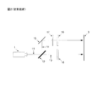
図1は、最先端技術による単一ビーム立体的3D投影システムを示し、このシステムでは、1つ又は複数の液晶素子の積層体(図示せず)を備える偏光変調器10が、3チップDLPデジタル映写機あるいは他のプロジェクタ1のレンズの正面に直接的に配置される。
FIG. 1 shows a state-of-the-art single beam stereoscopic 3D projection system in which a
この図1及びこれ以降の全ての基礎的な図では、画像ビームの経路は、容易に明瞭にするために、一本線のベクトルで表わされている。しかしながら、前記画像ビームは通常、ある水準の角度発散、例えば、鉛直面内に±10度、水平面内に±22度の角度発散をそれぞれ有することが、当業者には理解されるであろう。しかしながら、前記ビーム発散が生じることは、本明細書に開示する発明の思想から逸脱するものではなく、したがって容易に明瞭にするために基礎的な図面では省略されることを、理解されたい。 In FIG. 1 and all subsequent basic figures, the path of the image beam is represented by a single line vector for ease of clarity. However, those skilled in the art will appreciate that the image beam typically has some level of angular divergence, eg, ± 10 degrees in the vertical plane and ± 22 degrees in the horizontal plane. However, it should be understood that the occurrence of beam divergence does not depart from the spirit of the invention disclosed herein and is therefore omitted in the basic drawings for the sake of clarity.
プロジェクタ1は、典型的には144Hzの高周波数で一連の交互の左目画像及び右目画像11を生成し、前記偏光変調器10は、全ての左目画像には第1の円偏光状態を、全ての右目画像には第2の円偏光状態をそれぞれ付与するように構成され、前記第1の円偏光状態と第2の円偏光状態とは互いに直交する。
The projector 1 typically produces a series of alternating left eye and
その後、前記左目画像及び右目画像は、シルバースクリーンか別のものなどの偏光面保存投影スクリーン3の表面に焦点を合わせられ、受動型円偏光用観察ゴーグル(図示せず)の利用を通じて、時間多重化された立体的な3D画像を見ることができる。
Thereafter, the left eye image and the right eye image are focused on the surface of the polarization plane preserving
しかしながら、3チップDLPプロジェクタなどの現在市販されている典型的な映写機は、初めはランダムに偏光された画像を生成するので、直線偏光フィルタ(図示せず)を、前記偏光変調器10の入射面に配置することが必要であることが、当業者には分かるであろう。
However, typical projectors currently on the market, such as 3-chip DLP projectors, initially produce a randomly polarized image, so a linear polarizing filter (not shown) is inserted into the
さらに、先端技術による好ましい実施形態は、前記偏光変調器10が、互いに交差する向きで一緒に積層された2つの別個の液晶パイセル(図示せず)を含むものである。パイセルは、各基板上のそれらの表面配向ディレクタが互いに平行に整列され、かつ同じ方向に向けられることを特徴とし、それによって、少なくとも1つの光学状態において、液晶材料が、前記基板間に180度の回転ねじれ(すなわち、パイラジアン)を有する螺旋構造を形成する。
Furthermore, a preferred embodiment according to the state of the art is that the
さらに、前記パイセルは、例えば第1の光学状態と第2の光学状態との間で切り換わることができ、第1の光学状態は、液晶材料をホメオトロピック構造に切り換えるために高電圧(例えば、25ボルト)で駆動したときにゼロの位相差を有し、第2の光学状態は、液晶材料をねじれの無いスプレイ構造に切り換えるために低電圧(例えば、3ボルト)で駆動したときに、140nmに近い光学位相差を有する。さらに、前記パイセルが、140nmに近い位相差値を有する前記第2の光学状態にある場合、前記パイセルは、可視波長領域の中央部分に対してλ/4板(QWP)を構成し、したがって、直線偏光した光を直接的に円偏光に変換する。 Furthermore, the pi-cell can switch between, for example, a first optical state and a second optical state, the first optical state being switched to a high voltage (e.g., to switch the liquid crystal material to a homeotropic structure). The second optical state has a phase difference of 140 nm when driven at a low voltage (eg 3 volts) to switch the liquid crystal material to an untwisted splay structure. An optical phase difference close to. Further, when the picell is in the second optical state having a phase difference value close to 140 nm, the picell constitutes a λ / 4 plate (QWP) relative to the central portion of the visible wavelength region, and thus Converts linearly polarized light directly into circularly polarized light.
さらに、前記パイセルは、好ましくは互いに位相を異にして動作することができ、前記第1のパイセルが高電圧(例えば、25ボルト)で動作する期間の間に、前記第2のパイセルが低電圧(例えば、3ボルト)で同時に動作し、逆も同様であることが、当業者には分かるであろう。これにより、入射光ビーム11を、左円偏光状態と右円偏光状態との間で急速に変調することが可能になる。
Further, the pi-cells can preferably operate out of phase with each other, and during the period when the first pi-cell is operated at a high voltage (eg, 25 volts), the second pi-cell is at a low voltage. Those skilled in the art will recognize that they operate simultaneously (eg, 3 volts) and vice versa. This allows the
また、受動型円偏光用観察ゴーグルのレンズは、通常はそれぞれ、位相差フィルムと共に積層された直線偏光フィルタを含むことが、当業者には知られている。さらに、前記位相差フィルムは通常、140nmに近い面内位相差値を有する単一の一軸延伸位相差フィルムを含む。 In addition, it is known to those skilled in the art that the lenses of the passive type circularly polarized observation goggles usually include linear polarization filters each laminated with a retardation film. Furthermore, the retardation film usually comprises a single uniaxially stretched retardation film having an in-plane retardation value close to 140 nm.
さらに、前記偏光変調器10の入射面に配置される直線偏光フィルタが、前記受動型円偏光用観察ゴーグルのレンズにある直線偏光フィルタに対して平行に整列される場合、低電圧で動作する前記パイセルのうちの1つに存在する位相差(140nm)が前記レンズのうちの1つにある位相差フィルム(140nm)と平行になると、全体的な位相差は合計で140nm(パイセル)+140nm(観察ゴーグル)=280nmになり、したがってシステムは可視スペクトルの中央部分に対して色彩のλ/2板(HWP)を構成することになる。そのような場合には、前記色彩のλ/2板は全ての可視波長を正確に90度だけ回転させることができないので、前記レンズは全ての可視波長を完全に遮断することができず、したがって、時間多重化された立体的な3D画像を見る際に、不都合に高水準のゴーストやクロストークが観察されることになる。
Further, when the linear polarization filter disposed on the incident surface of the
この理由のために、現在市販されている偏光変調器製品の大部分は、互いに交差する向きで一緒に積層された2つのパイセルを含み、前記偏光変調器の入射面に配置される前記直線偏光フィルタの透過軸は、前記受動型円偏光用観察ゴーグルの両方のレンズにある直線偏光フィルタに対して垂直に整列されていることが、当業者には知られている。 For this reason, most of the polarization modulator products currently on the market include two pi-cells stacked together in crossed directions, and the linearly polarized light placed on the entrance surface of the polarization modulator. It is known to those skilled in the art that the transmission axis of the filter is aligned perpendicular to the linear polarizing filter on both lenses of the passive circular polarizing viewing goggles.
さらに、前記観察ゴーグルの両方のレンズにある直線偏光フィルタは、通常、それらの透過軸が水平になるように整列されるので、前記偏光変調器の入射面に配置される直線偏光フィルタがその透過軸が鉛直になるように整列される場合に好ましい配置になることが、当業者には分かるであろう。 In addition, the linear polarizing filters on both lenses of the viewing goggles are usually aligned so that their transmission axes are horizontal, so that the linear polarizing filter disposed on the entrance surface of the polarization modulator is not transparent. One skilled in the art will appreciate that the preferred arrangement is when the axes are aligned vertically.
しかしながら、図1に示した単一ビーム立体的3Dシステムは低水準のゴーストやクロストークを可能にするが、前記偏光変調器10の入射面に配置される直線偏光フィルタが、前記プロジェクタ1によって生成されるランダムに偏光された入射光の約50%を吸収してしまい、それによって、オンスクリーン画像の輝度が著しく不足した時間多重化された立体的3D画像の生成につながることが、当業者には分かるであろう。
However, although the single beam stereoscopic 3D system shown in FIG. 1 enables low-level ghosting and crosstalk, a linear polarization filter disposed on the entrance surface of the
図2は、最先端技術による二重ビーム構成を含む代替的な立体的3D投影システムを示しており、このシステムは、前述の単一ビームシステムと比較してより高水準のオンスクリーン画像輝度をもたらす。 FIG. 2 shows an alternative stereoscopic 3D projection system that includes a dual beam configuration according to the state of the art, which provides a higher level of on-screen image brightness compared to the single beam system described above. Bring.
ここで、前記プロジェクタ1のレンズの正面に配置されるビーム分割素子12は、入射する入射画像ビーム11を1本の1次画像ビーム13と1本の2次画像ビーム14に分割し、1次画像ビーム13は、前記元の入射画像ビーム11と同じ方向に伝搬し、かつ第1の直線偏光状態を有し、2次画像ビーム14は前記入射画像ビーム11と垂直な方向に伝搬し、かつ第2の直線偏光状態を有し、この第1の直線偏光状態と第2の直線偏光状態は互いに直交している。
Here, the
変形可能な鏡15が、前記2次画像ビーム14を偏光面保存投影スクリーン3に向けて反射するために使用され、またこの鏡15は、前記1次画像ビームと2次画像ビームが、完全な画像を再現するために前記投影スクリーン3の表面上でかなりの程度まで互いに重なるように、構成される。最先端技術によるこの構成では、元の入射画像ビーム11を含む両方の偏光成分がオンスクリーン画像全体を生成するために利用され、したがってより高水準の画像輝度がもたらされる。
A
次いで、偏光変調器16、10を使用して前記1次画像ビーム13と2次画像ビーム14の光学偏光状態をそれぞれ変調し、またこれらの偏光変調器16、10は、前記プロジェクタ1によって生成される交互の左目画像と右目画像のそれぞれが左円偏光状態と右円偏光状態のうちの1つをそれぞれ有するように構成され、それによって、受動型円偏光用観察ゴーグル(図示せず)の利用を通じて、時間多重化された立体的な3D画像を見ることが可能になる。
The polarization modulators 16, 10 are then used to modulate the optical polarization states of the
さらに、ビーム分割素子12は、ワイヤグリッド偏光子か別のものを好ましくは含むことができ、さらに、前記1次画像ビーム13と2次画像ビーム14との光路長の比較的大きな差を補償するために、1次画像ビーム13の光路内に望遠レンズの対(図示せず)が配置されてもされなくてもよい。
Furthermore, the
最先端技術による前述の二重ビーム立体3Dシステムの好ましい実施形態の1つでは、前記偏光変調器10、16のそれぞれは、互いに交差する向きで一緒に積層された2つの別個のパイセル液晶素子(図示せず)を含む。さらに、各パイセルは、例えば、高電圧(例えば、25ボルト)で駆動されると位相差がゼロになる第1の光学状態と、低電圧(例えば、3ボルト)で駆動されると実質的に140nmの位相差値になる第2の光学状態との間で切り換わることができる。
In one of the preferred embodiments of the aforementioned dual-beam stereoscopic 3D system according to the state of the art, each of the
さらに、前記パイセルのうちの1つが、140nmに近い位相差値を有するように低電圧(例えば、3ボルト)で駆動される場合、前記パイセルは、可視スペクトルの中央部分に対してλ/4板(QWP)を構成し、したがって、直線偏光した可視光を直接的に円偏光に変換する。 Furthermore, if one of the pi-cells is driven at a low voltage (eg 3 volts) so as to have a phase difference value close to 140 nm, the pi-cell will Constitutes (QWP) and thus converts linearly polarized visible light directly into circularly polarized light.
したがって、前記第1のパイセルが高電圧で動作しているときに前記第2のパイセルは低電圧で同時に動作し、逆も同様であるように、前記パイセルが互いに位相を異にして動作する場合、前記偏光変調器は、直線偏光された画像ビームを左円偏光状態と右円偏光状態との間で急速に変調することができることが、当業者には分かるであろう。 Thus, when the first pi-cells operate at a high voltage, the second pi-cells operate simultaneously at a low voltage, and vice versa, so that the pi-cells operate out of phase with each other. Those skilled in the art will appreciate that the polarization modulator can rapidly modulate a linearly polarized image beam between a left circular polarization state and a right circular polarization state.
さらに、典型的な受動型円偏光用観察ゴーグルにある2つのレンズはそれぞれ、位相差フィルムと共に積層された直線偏光フィルタを含むことが、当業者には知られている。さらに、前記位相差フィルムは通常、140nmに近い面内位相差値を有する単一の一軸延伸位相差フィルムを含む。 Furthermore, it is known to those skilled in the art that each of the two lenses in a typical passive circular polarizing viewing goggles includes a linear polarizing filter laminated with a retardation film. Furthermore, the retardation film usually comprises a single uniaxially stretched retardation film having an in-plane retardation value close to 140 nm.
さらに、低電圧(例えば、3ボルト)で動作する前記パイセルのうちの1つに存在する位相差が、前記レンズのうちの1つにある前記位相差フィルムと平行に整列される場合、全体的な位相差は合計で、140nm(パイセル)+140nm(観察ゴーグル)=280nmになり、したがって、そのような場合には、このシステムは可視波長領域の中央部分に対して、色彩のλ/2板(HWP)を構成することになる。 Furthermore, if the retardation present in one of the pi-cells operating at a low voltage (eg 3 volts) is aligned parallel to the retardation film in one of the lenses, The total phase difference is 140 nm (Pycel) + 140 nm (observation goggles) = 280 nm, so in such a case, the system will have a color λ / 2 plate (for the central part of the visible wavelength region ( HWP).
加えて、前記偏光変調器の入射面に配置された直線偏光フィルタが前記観察ゴーグルの両方のレンズにある直線偏光フィルタに対して平行に整列される場合、結果として生じる色彩のλ/2板が全ての可視波長を正確に90度だけ回転させることができないので、前記レンズは全ての可視波長を効果的に遮断することができない。したがって、これは、時間多重化された立体的な3D画像を見る際に比較的に高水準のゴーストやクロストークが発生することにつながる。 In addition, if a linear polarizing filter located at the entrance surface of the polarization modulator is aligned parallel to the linear polarizing filters on both lenses of the viewing goggles, the resulting color λ / 2 plate is Since all visible wavelengths cannot be rotated exactly 90 degrees, the lens cannot effectively block all visible wavelengths. Therefore, this leads to generation of a relatively high level of ghost and crosstalk when viewing a time-multiplexed stereoscopic 3D image.
したがって、前記観察ゴーグルの両方のレンズにある直線偏光フィルタの透過軸は、通常は両方とも水平に整列されるので、最先端技術による好ましい実施形態は、典型的な受動型円偏光用観察ゴーグルを使用する際に低水準のゴーストやクロストークが達成されることを保証するために、前記偏光変調器10、16のそれぞれについて入射面に配置された直線偏光フィルタが両方とも、それらの透過軸が鉛直になるように確実に整列されるようにする。
Thus, since the transmission axes of the linear polarizing filters on both lenses of the viewing goggles are usually horizontally aligned, the preferred embodiment according to the state of the art is a typical passive circular polarizing viewing goggles. In order to ensure that low levels of ghosting and crosstalk are achieved in use, both linear polarization filters arranged at the entrance plane for each of the
しかしながら、前記1次画像ビーム13及び2次画像ビーム14の直線偏光状態は互いに直交しているので、前記2次画像ビーム14の直線偏光状態が前記1次画像ビーム13と同じ直線偏光状態に変換されるように、前記2次画像ビーム14の直線偏光状態を90度だけ回転するように設計された偏光回転器17を前記2次画像ビーム14の光路内に配置することによってのみ、この基準は達成され得る。
However, since the linear polarization states of the
したがって、1次画像ビーム13及び2次画像ビーム14の両方に対する直線偏光状態が、それぞれ前記偏光変調器16、10の入射面で鉛直に整列されることを確実にするために、前記偏光回転器17は、前記2次画像ビーム14の光路内に配置されることが必要であり、かつ、前記ビーム分割素子12と前記偏光変調器10の入射面との間のどこかに配置されることが必要であるが、前記反射面15の前か後のいずれかに配置されることでよい。これにより、最先端技術によって低水準のゴーストやクロストークが確実に達成されることになる。
Thus, to ensure that the linear polarization states for both the
しかしながら、前記偏光回転器17の光学効率は、通常は可視波長領域にわたって約90%に過ぎないので、前記偏光回転器17を組み込むことにより、システムの全体的な光学的光効率が低下することになり、したがって、結果として得られるオンスクリーン画像の輝度が低下する。
However, since the optical efficiency of the
さらに、前記1次画像ビーム13と2次画像ビーム14との間には比較的に大きな光路長差が存在するので、通常は、前記光路長差を補償するために、1次画像ビーム13の光路内に望遠レンズの対(図示せず)を配置する必要があることが、当業者には分かるであろう。しかしながら、これは、全体的なオンスクリーン画像の輝度をさらに低下させ、システムの複雑さ及び費用を増加させる。
Further, since there is a relatively large optical path length difference between the
図3は、本明細書で説明した前述の先行技術の欠点を緩和する、本発明の好ましい実施形態を示す。ここでは、ビーム分割素子18を備える三重ビーム立体3D投影システムが開示されており、このビーム分割素子18は、入射する画像ビーム11を1本の1次画像ビーム13と2本の2次画像ビーム14、22に分割し、1次画像ビーム13は、前記元の入射画像ビーム11と同じ方向に伝搬し、かつ第1の直線偏光状態を有し、2本の2次画像ビーム14、22は前記入射画像ビーム11と両方とも垂直な、互いに反対の方向に伝搬し、かつ両方とも第2の直線偏光状態を有し、前記第1の直線偏光状態と第2の直線偏光状態は互いに直交している。
FIG. 3 illustrates a preferred embodiment of the present invention that mitigates the disadvantages of the aforementioned prior art described herein. Here, a triple beam stereoscopic 3D projection system comprising a
その後、反射鏡15、17を使用して、それぞれ前記2次画像ビーム14、22をシルバースクリーンか別のものなどの偏光面保存投影スクリーン3に向けて進路を変更させ、次いで、前記1次画像ビーム13及び2次画像ビーム14、22は、前記投影スクリーン3の表面上で完全な画像を再現するために、互いに合成されるように部分的に重なるように構成される。さらに、前記反射鏡15、17は、前記投影スクリーン3の表面上での前記1次画像ビーム13と2次画像ビーム14、22の正確な位置合わせを支援するために、部分的に変形されていてもいなくてもよい。
Thereafter, the reflecting mirrors 15 and 17 are used to change the course of the secondary image beams 14 and 22 toward the polarization plane preserving
このようにして、完全なオンスクリーン画像を生成するために元の入射画像ビーム11を含む両方の偏光成分が利用され、したがって、全体的な画像輝度が増加する。前記1次画像ビーム13と2次画像ビーム14、22との間の結果として得られる光路長差は、他の先行技術と比較して今や大幅に低減され、したがって、前記光路長差を補償するために追加の望遠レンズの対か又は類似の素子を利用する必要性が緩和され、システムの全体的な複雑さ及び費用が低減されることが、当業者に理解されるであろう。
In this way, both polarization components including the original
ビーム分割素子18は、例えば、1つの縁部に沿って一緒に配置され、かつ互いに約90度の角度で整列される、2つのワイヤグリッド偏光子(WGP)板から構成されることがある。さらに、前記板同士の間に結果として生じる間隙を最小限に抑えるために、2つの接続縁部を追加的に約45度の角度で斜めに切って(図示せず)、前記板同士を互いに密接に配置することができるようにしてもよい。
The
或いは、ビーム分割素子18は、例えば代わりに、一緒に結合された2つの偏光分離(PBS)キューブ(図示せず)から構成されることでもよく、これらのキューブは、前記キューブ内部の2つのビーム分割面が互いに約90度の角度で整列されるように構成されてもよい。本明細書に開示する発明の思想から逸脱することなく上述の効果を達成するために、他のビーム分割素子を使用することもできる。
Alternatively, the
次いで、偏光変調器16、10、19が、それぞれ前記1次画像ビーム13及び2次画像ビーム14、22のそれぞれの光路内に配置され、駆動信号(図示せず)に応答して、前記画像ビームの直線偏光状態を第1の円偏光状態と第2の円偏光状態との間で変調するように構成される。
さらに、前記偏光変調器16、10、19は、前記プロジェクタ1によって生成される全ての左目画像が第1の円偏光状態を付与され、全ての右目画像が第2の円偏光状態を付与され、前記第1の円偏光状態と第2の円偏光状態とは互いに直交であるように構成され、それによって、受動型円偏光用観察ゴーグル(図示せず)の利用を通じて、時間多重化された立体的な3D画像が前記投影スクリーン3の表面上で見られるようになる。
Further, the
本発明の好ましい実施形態とは、前記偏光変調器16、10、19のそれぞれが、互いに交差する向きに配置された2つの別個のパイセルの積層体(図示せず)を含むことである。ここで、各パイセルは、例えば、高電圧(例えば、25ボルト)で動作すると位相差がゼロになる第1の光学状態と、低電圧(例えば、3ボルト)で動作すると約140nmに近い位相差値になる第2の光学状態との間で切り換わることができる。
A preferred embodiment of the present invention is that each of the
さらに、前記第1のパイセルが高電圧で動作しているときに前記第2のパイセルは低電圧で同時に動作し、逆も同様であるように、前記パイセルを互いに位相を異にして動作させることにより、前記偏光変調器は、前記1次画像ビーム13及び2次画像ビーム14、22の直線偏光状態を左円偏光状態と右円偏光状態との間で急速に変調することができるようになることが、当業者には理解されるであろう。
Further, the pi-cells are operated out of phase so that the second pi-cell operates simultaneously at a low voltage when the first pi-cell operates at a high voltage and vice versa. Thus, the polarization modulator can rapidly modulate the linear polarization state of the
しかしながら、前記偏光変調器16、10、19のうちの1つの入射面における前記1次画像ビームと2次画像ビームのうちの1つの直線偏光状態が、前記円偏光用観察ゴーグルのレンズにある直線偏光フィルタの透過軸と平行に整列される場合、最先端技術によると、前記レンズのうちの1つは、通常、光の全ての波長を完全に遮断することができず、それによって、時間多重化された立体的な3D画像を見る際に高水準のゴーストやクロストークが生じることになることが、当業者には理解されるであろう。
However, the linear polarization state of one of the primary image beam and the secondary image beam at one incident surface of the
しかしながら、前記偏光変調器10、19の入射面における2次画像ビーム14、22両方の直線偏光状態が、前記受動型円偏光用観察ゴーグルのレンズにある直線偏光フィルタと平行に整列されている場合に、本発明の好ましい実施形態が生じることが、開示される。そのような場合には、コントラスト強調フィルム20、21が前記偏光変調器10、19の出射面にそれぞれ配置され、またこれらのコントラスト強調フィルム20、21は、前記偏光変調器を出射する2本の2次画像ビームの円偏光を、前記2次画像ビームに対する全体的な円偏光状態を変更することなく摂動させ円偏光の程度を向上させるように設計され、それによって、前記観察ゴーグルによって達成可能な光遮断の水準を向上させ、また、結果として得られるオンスクリーン画像の輝度を高水準に維持しながらゴーストやクロストークの全体的な水準を低減させることが、本発明の一実施形態にしたがって開示される。
However, when the linear polarization states of both the secondary image beams 14 and 22 at the entrance surfaces of the
さらに、本発明の更なる態様によれば、前記コントラスト強調フィルム20、21は両方とも、光学接着剤か他のものを用いて互いに接着された、少なくとも3つの別個の一軸延伸位相差フィルム20a、20b、20c及び21a、21b、21cの積層体をそれぞれ含み、各位相差フィルムは、140nm、270nm、又は540nmのいずれか1つと実質的に等しい個々の面内位相差値を有することが、開示される。
Furthermore, according to a further aspect of the present invention, the
各コントラスト強調フィルム20、21に対する特定の設計は、各別個の位相差フィルム20a、20b、20c及び21a、21b、21cが特定の位相差値(ナノメートル単位で与えられる)及び光学軸の向き(度単位で与えられる)を有することによって特徴付けられ、また、前記コントラスト強調フィルム20、21は、前記偏光変調器10、19をそれぞれ出射する前記2次画像ビーム14、22の円偏光の程度を最大にするように最適化される。このようにして、前記コントラスト強調フィルム20、21は、他の先行技術と比較して全体的なオンスクリーン画像の輝度をより高水準に維持しながら、時間多重化された立体的な3D画像を見る際のゴーストやクロストークの全体的な水準を低減することができる。
The specific design for each
図4は、本発明の好ましい実施形態による前記コントラスト強調フィルム20の設計例を示す。ここで、前記コントラスト強調フィルム20は、互いに接着された12個の別個の一軸延伸位相差フィルム20a〜lの積層体を含む。さらに、各別個の位相差フィルム20a〜lはそれぞれ、140nm、270nm、又は540nmのいずれか1つと実質的に等しい面内位相差値を個別に有し、各別個の位相差フィルム20a〜lの光学軸は、前記コントラスト強調フィルム20の全体的な性能を最適化するために、本発明の一態様にしたがって本明細書に開示する特定の角度で個別に整列される。
FIG. 4 shows a design example of the
さらに、本明細書の例では、前記位相差フィルム20b、c、e、f、g、h、j、kは実質的に270nmに等しい面内位相差値を有し、一方、前記位相差フィルム20a、d、i、lは実質的に140nmに等しい面内位相差値を有する。しかしながら、本発明の思想から逸脱することなく同様の結果を達成するために、個々の位相差フィルムの他の組み合わせを用いることもできることが、当業者には理解されるであろう。個々の位相差フィルムは、光学接着剤を用いて互いに接着されることなく直列にまとめて配置されることもでき、又は代替的に、本発明の思想から逸脱することなく、前記1次画像ビーム及び2次画像ビームの光路内の別個の位置に配置されることもできることが、理解されよう。
Further, in the example of the present specification, the
さらに、前記コントラスト強調フィルム20、21が、前記偏光変調器10、19のそれぞれの出射面に接着されるときに、本発明の好ましい実施形態が生じる。しかしながら、前記コントラスト強調フィルム20、21は代わりに、開示される本発明から逸脱することなく、前記偏光変調器10、19の出射面と前記投影スクリーン3との間の他の場所に配置されることがあることが理解されよう。例えば、前記コントラスト強調フィルム20、21のうちの少なくとも1つを、代わりに、存在してもしなくてもよい別個の出射窓(図示せず)内に組み込むことができる。
Furthermore, a preferred embodiment of the present invention occurs when the
代わりに、1次画像ビーム13の直線偏光状態が前記受動型円偏光用観察ゴーグルのレンズにある直線偏光フィルタの透過軸と平行になるように構成されていると、この場合には、代わりに、単一のコントラスト強調フィルムが、前記偏光変調器16の出射面に配置され、かつ、前記1次画像ビーム13の光路内に配置されることが必要になり、2本の2次画像ビーム14、22の両方に対しては追加のコントラスト強調フィルムは不要であることが、理解されるべきである。しかしながら、そのような構成もまた本明細書に開示され、本発明の更なる実施形態として組み込まれる。
Instead, if the linear polarization state of the
本発明の好ましい実施形態を本明細書に示し説明してきたが、本発明の発明思想から逸脱することなく、様々な修正をそれらに加えることが可能である。したがって、本発明は、限定するためではなく例示するために説明されたと理解されたい。 While preferred embodiments of the invention have been shown and described herein, various modifications can be made to them without departing from the inventive idea of the invention. Accordingly, it is to be understood that the present invention has been described by way of illustration and not limitation.
Claims (26)
前記単レンズプロジェクタによって生成された前記ランダムに偏光された入射画像ビームを、1本の1次画像ビームと2本の2次画像ビームに分割するように動作可能なビーム分割素子であって、前記1本の1次画像ビームは、1次画像ビーム経路を有し、第1の直線偏光状態を有し、前記2本の2次画像ビームは、それぞれがそれぞれの2次画像ビーム経路を有し、両方とも第2の直線偏光状態を有し、前記第1の直線偏光状態と前記第2の直線偏光状態とは互いに直交しており、前記2次画像ビームに対する前記2次画像ビーム経路は両方とも、前記1次画像ビーム及び前記2次画像ビームが部分的に重なり合い互いに再合成されて前記偏光面保存投影スクリーンの表面上で完全な画像を形成するように、反射面によって進路を変えられている、ビーム分割素子と、
前記1次画像ビーム経路及び前記2つの2次画像ビーム経路のそれぞれに配置され、前記プロジェクタによって生成される画像と同期して、前記第1の直線偏光状態及び前記第2の直線偏光状態を左円偏光状態と右円偏光状態との間で変調するように構成される、偏光変調器と、
前記1次画像ビーム及び前記2次画像ビームのうちの少なくとも1つの光路内に配置され、かつ、前記関連する偏光変調器と前記投影スクリーンとの間に配置される、コントラスト強調フィルムと、を備え、
前記コントラスト強調フィルムは、前記1次画像ビーム及び前記2次画像ビームのうちの前記少なくとも1つの前記円偏光状態を摂動させるように構成される、少なくとも3つの別個の一軸延伸位相差フィルムの積層体を含み、
前記一軸延伸位相差フィルムのそれぞれは、140nm、270nm、又は540nmのうちの1つと実質的に等しい面内位相差値を個々に有する、システム。 A time multiplexed stereoscopic 3D projection system for projecting a randomly polarized incident image beam generated by a single lens projector onto a polarization preserving projection screen,
A beam splitting element operable to split the randomly polarized incident image beam generated by the single lens projector into one primary image beam and two secondary image beams, One primary image beam has a primary image beam path and has a first linear polarization state, and each of the two secondary image beams has a respective secondary image beam path. , Both have a second linear polarization state, the first linear polarization state and the second linear polarization state are orthogonal to each other, and the secondary image beam path for the secondary image beam is both In both cases, the primary image beam and the secondary image beam are partially overlapped and recombined to form a complete image on the surface of the polarization plane preserving projection screen, which can be rerouted by a reflective surface. There, a beam splitter,
The first linear polarization state and the second linear polarization state are placed in the primary image beam path and the two secondary image beam paths, respectively, in synchronization with the image generated by the projector. A polarization modulator configured to modulate between a circular polarization state and a right circular polarization state;
A contrast enhancement film disposed in an optical path of at least one of the primary image beam and the secondary image beam and disposed between the associated polarization modulator and the projection screen. ,
The contrast enhancement film is a laminate of at least three separate uniaxially stretched retardation films configured to perturb the at least one of the circular polarization states of the primary image beam and the secondary image beam. Including
Each of the uniaxially stretched retardation films individually has an in-plane retardation value that is substantially equal to one of 140 nm, 270 nm, or 540 nm.
少なくとも3つの別個の一軸延伸位相差フィルムの積層体を含み、前記一軸延伸位相差フィルムのそれぞれは、140nm、270nm、又は540nmのうちの1つと実質的に等しい面内位相差値を個々に有しており、前記一軸延伸位相差フィルムのそれぞれは、特定の角度で整列された光学軸を有し、前記一軸延伸位相差フィルムのうちの少なくとも2つは、異なる角度で整列された光学軸を有する、コントラスト強調フィルム。 A contrast enhancement film for placement in the optical path of an image beam exiting a polarization modulator, wherein the contrast enhancement film is configured to perturb the circular polarization state of the image beam, the contrast enhancement film comprising:
Including a laminate of at least three separate uniaxially stretched retardation films, each of which has an in-plane retardation value that is substantially equal to one of 140 nm, 270 nm, or 540 nm. Each of the uniaxially stretched retardation films has an optical axis aligned at a specific angle, and at least two of the uniaxially stretched retardation films have optical axes aligned at different angles. A contrast enhancement film.
ビーム分割素子を用いて、前記単レンズプロジェクタによって生成された前記ランダムに偏光された入射画像ビームを、1本の1次画像ビームと2本の2次画像ビームに分割する工程であって、前記1本の1次画像ビームは、1次画像ビーム経路を有し、第1の直線偏光状態を有し、前記2本の2次画像ビームは、それぞれがそれぞれの2次画像ビーム経路を有し、両方とも第2の直線偏光状態を有し、前記第1の直線偏光状態と前記第2の直線偏光状態とは互いに直交しており、前記2次画像ビームに対する前記2次画像ビーム経路は両方とも、前記1次画像ビーム及び前記2次画像ビームが部分的に重なり合い互いに再合成されて前記偏光面保存投影スクリーンの表面上で完全な画像を形成するように、反射面によって進路を変えられている、分割する工程と、
前記1次画像ビーム経路及び前記2つの2次画像ビーム経路のそれぞれに配置される偏光変調器を用いて、前記プロジェクタによって生成される画像と同期して、前記第1の直線偏光状態及び前記第2の直線偏光状態を左円偏光状態と右円偏光状態との間で変調する工程と、
前記関連する偏光変調器と前記投影スクリーンとの間に配置される、前記1次画像ビーム及び前記2次画像ビームのうちの少なくとも1つの光路内にコントラスト強調フィルムを配置する工程と、を含み、
前記コントラスト強調フィルムは、前記1次画像ビーム及び前記2次画像ビームのうちの前記少なくとも1つの前記円偏光状態を摂動させるように構成される、少なくとも3つの別個の一軸延伸位相差フィルムの積層体を含み、
前記一軸延伸位相差フィルムのそれぞれは、140nm、270nm、又は540nmのうちの1つと実質的に等しい面内位相差値を個々に有する、方法。 A time multiplexed stereoscopic 3D projection method for projecting a randomly polarized incident image beam generated by a single lens projector onto a polarization preserving projection screen, comprising:
Splitting the randomly polarized incident image beam generated by the single lens projector into one primary image beam and two secondary image beams using a beam splitting element, comprising: One primary image beam has a primary image beam path and has a first linear polarization state, and each of the two secondary image beams has a respective secondary image beam path. , Both have a second linear polarization state, the first linear polarization state and the second linear polarization state are orthogonal to each other, and the secondary image beam path for the secondary image beam is both In both cases, the primary image beam and the secondary image beam overlap each other and are recombined to form a complete image on the surface of the polarization-preserving projection screen, which is rerouted by the reflective surface. That, and the step of dividing,
Using a polarization modulator disposed in each of the primary image beam path and the two secondary image beam paths, the first linear polarization state and the first Modulating the two linear polarization states between a left circular polarization state and a right circular polarization state;
Disposing a contrast enhancement film in an optical path of at least one of the primary image beam and the secondary image beam disposed between the associated polarization modulator and the projection screen;
The contrast enhancement film is a laminate of at least three separate uniaxially stretched retardation films configured to perturb the at least one of the circular polarization states of the primary image beam and the secondary image beam. Including
Each of the uniaxially stretched retardation films individually has an in-plane retardation value that is substantially equal to one of 140 nm, 270 nm, or 540 nm.
少なくとも3つの別個の一軸延伸位相差フィルムを含むコントラスト強調フィルムを、偏光変調器を出射する前記画像ビームの前記光路内に配置する工程を含み、前記一軸延伸位相差フィルムのそれぞれは、140nm、270nm、又は540nmのうちの1つに実質的に等しい面内位相差値を個別に有し、
また前記方法は、前記一軸延伸位相差フィルムのそれぞれの前記光学軸を特定の角度で整列する工程を含み、前記一軸延伸位相差フィルムのうちの少なくとも2つは、異なる角度で整列された光学軸を有する、方法。 A method for perturbing the circular polarization state of an image beam having an optical path exiting a polarization modulator comprising:
Placing a contrast enhancement film comprising at least three separate uniaxially stretched retardation films in the optical path of the image beam exiting a polarization modulator, each of the uniaxially stretched retardation films being 140 nm, 270 nm Individually having an in-plane retardation value substantially equal to one of 540 nm,
The method also includes the step of aligning the optical axes of each of the uniaxially stretched phase difference films at a specific angle, wherein at least two of the uniaxially stretched phase difference films are aligned at different angles. Having a method.
Applications Claiming Priority (3)
| Application Number | Priority Date | Filing Date | Title |
|---|---|---|---|
| US14/750,227 US9594255B2 (en) | 2015-06-25 | 2015-06-25 | Stereoscopic 3D projection system with improved level of optical light efficiency |
| US14/750,227 | 2015-06-25 | ||
| PCT/IB2016/001004 WO2016207724A1 (en) | 2015-06-25 | 2016-06-24 | Stereoscopic 3d projection system with improved level of optical light efficiency |
Publications (2)
| Publication Number | Publication Date |
|---|---|
| JP2018522290A true JP2018522290A (en) | 2018-08-09 |
| JP2018522290A5 JP2018522290A5 (en) | 2019-06-06 |
Family
ID=56694192
Family Applications (1)
| Application Number | Title | Priority Date | Filing Date |
|---|---|---|---|
| JP2018518800A Pending JP2018522290A (en) | 2015-06-25 | 2016-06-24 | Stereoscopic 3D projection system with improved level of optical light efficiency |
Country Status (10)
| Country | Link |
|---|---|
| US (1) | US9594255B2 (en) |
| EP (1) | EP3314325B1 (en) |
| JP (1) | JP2018522290A (en) |
| KR (1) | KR20180026476A (en) |
| CN (1) | CN108027520B (en) |
| AU (1) | AU2016281809A1 (en) |
| BR (1) | BR112017027971A2 (en) |
| CA (1) | CA2990541A1 (en) |
| RU (1) | RU2705729C2 (en) |
| WO (1) | WO2016207724A1 (en) |
Families Citing this family (11)
| Publication number | Priority date | Publication date | Assignee | Title |
|---|---|---|---|---|
| WO2016194018A1 (en) * | 2015-05-29 | 2016-12-08 | オリンパス株式会社 | Illumination device and measurement device |
| US10379388B2 (en) | 2016-08-12 | 2019-08-13 | Avegant Corp. | Digital light path length modulation systems |
| US10401639B2 (en) | 2016-08-12 | 2019-09-03 | Avegant Corp. | Method and apparatus for an optical path length extender |
| US10809546B2 (en) * | 2016-08-12 | 2020-10-20 | Avegant Corp. | Digital light path length modulation |
| US10187634B2 (en) | 2016-08-12 | 2019-01-22 | Avegant Corp. | Near-eye display system including a modulation stack |
| US10516879B2 (en) | 2016-08-12 | 2019-12-24 | Avegant Corp. | Binocular display with digital light path length modulation |
| US10057488B2 (en) | 2016-08-12 | 2018-08-21 | Avegant Corp. | Image capture with digital light path length modulation |
| US10151932B1 (en) * | 2017-09-01 | 2018-12-11 | Volfoni R&D | Stereoscopic three dimensional projection system using elliptical polarization |
| AU2019243317A1 (en) * | 2018-03-30 | 2020-10-15 | Blaze Bioscience, Inc. | Systems and methods for simultaneous near-infrared light and visible light imaging |
| WO2021099841A1 (en) | 2019-11-21 | 2021-05-27 | Volfoni R&D | Stereoscopic 3d system using linear polarization |
| WO2021144599A1 (en) | 2020-01-14 | 2021-07-22 | Volfoni R&D | High brightness stereoscopic 3d projection system |
Family Cites Families (24)
| Publication number | Priority date | Publication date | Assignee | Title |
|---|---|---|---|---|
| JPH05241103A (en) * | 1992-02-21 | 1993-09-21 | Nec Corp | Projection type liquid crystal display device |
| GB2317524A (en) * | 1996-09-19 | 1998-03-25 | Sharp Kk | Three dimensional stereoscopic projection display |
| JP2006284619A (en) * | 2005-03-31 | 2006-10-19 | Sanyo Epson Imaging Devices Corp | Image display apparatus |
| US7511792B2 (en) * | 2005-07-29 | 2009-03-31 | Lg Chem, Ltd. | In-plane switching liquid crystal display having simple structure |
| US7477206B2 (en) | 2005-12-06 | 2009-01-13 | Real D | Enhanced ZScreen modulator techniques |
| US7528906B2 (en) | 2006-01-23 | 2009-05-05 | Real D | Achromatic polarization switches |
| JP2007212659A (en) * | 2006-02-08 | 2007-08-23 | Hitachi Displays Ltd | Liquid crystal display device |
| EP2851735A1 (en) * | 2006-09-29 | 2015-03-25 | Real Inc. | Polarization conversion systems for stereoscopic projection |
| US8388138B1 (en) * | 2007-03-11 | 2013-03-05 | Simon Boothroyd | Projection display systems |
| EP2145215B1 (en) * | 2007-05-09 | 2019-10-23 | RealD Inc. | Polarization conversion system and method for stereoscopic projection |
| CN101162296B (en) * | 2007-09-24 | 2010-05-26 | 红蝶科技(深圳)有限公司 | Polarization light splitter and LCOS LCD stereo projection system using the same |
| EP2361401B1 (en) * | 2008-12-01 | 2017-09-06 | RealD Inc. | Stereoscopic projection systems and methods for employing spatial multiplexing at an intermediate image plane |
| JP5434085B2 (en) * | 2009-01-16 | 2014-03-05 | ソニー株式会社 | Projection-type image display device and projection optical system |
| JP5239915B2 (en) * | 2009-02-02 | 2013-07-17 | ソニー株式会社 | Projection display |
| US8305502B2 (en) * | 2009-11-11 | 2012-11-06 | Eastman Kodak Company | Phase-compensated thin-film beam combiner |
| JP5803114B2 (en) * | 2011-01-25 | 2015-11-04 | セイコーエプソン株式会社 | projector |
| FR2978564B1 (en) * | 2011-07-29 | 2013-08-23 | Volfoni R & D | DEVICE FOR POLARIZING A VIDEO SEQUENCE TO BE VIEWED IN STEREOSCOPY |
| CN103728821B (en) * | 2012-10-12 | 2015-10-28 | 扬明光学股份有限公司 | Projection arrangement |
| KR101387097B1 (en) * | 2013-04-02 | 2014-04-29 | 유한회사 마스터이미지쓰리디아시아 | Three beam splitting method and a stereoscopic projection using the same |
| US9784898B2 (en) * | 2013-04-10 | 2017-10-10 | Dexerials Corporation | Phase difference compensating element and projection-type image projecting device |
| FR3000232B1 (en) | 2013-05-29 | 2019-07-26 | Volfoni R&D | OPTICAL POLARIZATION DEVICE FOR A STEREOSCOPIC IMAGE PROJECTOR |
| CN203405635U (en) * | 2013-09-05 | 2014-01-22 | 深圳市时代华影科技开发有限公司 | Stereographic projection device with low projection ratio and high lighting effect and stereographic projection system |
| CN103529637B (en) * | 2013-10-29 | 2016-04-13 | 王高胜 | 3D video system and 3D projecting method |
| CN204009348U (en) * | 2014-07-25 | 2014-12-10 | 深圳市麦斯莱特科技有限公司 | Stereo projection apparatus and polarization splitting prism thereof |
-
2015
- 2015-06-25 US US14/750,227 patent/US9594255B2/en active Active
-
2016
- 2016-06-24 JP JP2018518800A patent/JP2018522290A/en active Pending
- 2016-06-24 RU RU2018102550A patent/RU2705729C2/en active
- 2016-06-24 CN CN201680048932.0A patent/CN108027520B/en active Active
- 2016-06-24 BR BR112017027971A patent/BR112017027971A2/en not_active Application Discontinuation
- 2016-06-24 AU AU2016281809A patent/AU2016281809A1/en not_active Abandoned
- 2016-06-24 WO PCT/IB2016/001004 patent/WO2016207724A1/en active Application Filing
- 2016-06-24 CA CA2990541A patent/CA2990541A1/en not_active Abandoned
- 2016-06-24 EP EP16753459.3A patent/EP3314325B1/en active Active
- 2016-06-24 KR KR1020187002554A patent/KR20180026476A/en unknown
Also Published As
| Publication number | Publication date |
|---|---|
| CN108027520A (en) | 2018-05-11 |
| US20160381352A1 (en) | 2016-12-29 |
| CN108027520B (en) | 2020-05-15 |
| RU2018102550A (en) | 2019-07-26 |
| CA2990541A1 (en) | 2016-12-29 |
| BR112017027971A2 (en) | 2018-08-28 |
| KR20180026476A (en) | 2018-03-12 |
| US9594255B2 (en) | 2017-03-14 |
| AU2016281809A1 (en) | 2018-02-22 |
| RU2018102550A3 (en) | 2019-08-28 |
| EP3314325A1 (en) | 2018-05-02 |
| EP3314325B1 (en) | 2020-08-19 |
| WO2016207724A1 (en) | 2016-12-29 |
| RU2705729C2 (en) | 2019-11-11 |
Similar Documents
| Publication | Publication Date | Title |
|---|---|---|
| JP2018522290A (en) | Stereoscopic 3D projection system with improved level of optical light efficiency | |
| US8540372B2 (en) | Waveplate compensation in projection polarization conversion systems | |
| CN107889552B (en) | High brightness image display apparatus using modulator asymmetric driver and method of operating the same | |
| US20070146880A1 (en) | Optical device for splitting an incident light into simultaneously spectrally separated and orthogonally polarized light beams having complementary primary color bands | |
| EA030953B1 (en) | Stereo projection apparatus and stereo projection system with low throw ratio and high light efficiency | |
| KR20090089325A (en) | Combining p and s rays for bright stereoscopic projection | |
| EP2476024A2 (en) | Method and system for three-dimensional (3d) projection | |
| CN103676423A (en) | Projection apparatus | |
| US20200089016A1 (en) | High brightness stereoscopic 3d projection system | |
| US10274755B2 (en) | Beam modulator and display apparatus using the same | |
| US11531212B2 (en) | Stereoscopic 3D system using linear polarization | |
| US10151932B1 (en) | Stereoscopic three dimensional projection system using elliptical polarization | |
| US9395549B2 (en) | Stereoscopic three dimensional imaging system | |
| CN111448506A (en) | Stereoscopic three-dimensional projection system with short throw ratio | |
| WO2021144599A1 (en) | High brightness stereoscopic 3d projection system | |
| KR101939939B1 (en) | Image conversion for stereoscopic imagery | |
| CN105824182A (en) | Polarization projection device and polarization projection system applying same | |
| JPH09297361A (en) | Liquid crystal stereoscopic display device |
Legal Events
| Date | Code | Title | Description |
|---|---|---|---|
| A521 | Request for written amendment filed |
Free format text: JAPANESE INTERMEDIATE CODE: A523 Effective date: 20190423 |
|
| A621 | Written request for application examination |
Free format text: JAPANESE INTERMEDIATE CODE: A621 Effective date: 20190423 |
|
| A977 | Report on retrieval |
Free format text: JAPANESE INTERMEDIATE CODE: A971007 Effective date: 20200219 |
|
| A131 | Notification of reasons for refusal |
Free format text: JAPANESE INTERMEDIATE CODE: A131 Effective date: 20200227 |
|
| A02 | Decision of refusal |
Free format text: JAPANESE INTERMEDIATE CODE: A02 Effective date: 20201001 |