JP2018519630A - Lens with elongated radiation pattern - Google Patents
Lens with elongated radiation pattern Download PDFInfo
- Publication number
- JP2018519630A JP2018519630A JP2017562595A JP2017562595A JP2018519630A JP 2018519630 A JP2018519630 A JP 2018519630A JP 2017562595 A JP2017562595 A JP 2017562595A JP 2017562595 A JP2017562595 A JP 2017562595A JP 2018519630 A JP2018519630 A JP 2018519630A
- Authority
- JP
- Japan
- Prior art keywords
- lens
- trough
- axis
- light emitting
- along
- Prior art date
- Legal status (The legal status is an assumption and is not a legal conclusion. Google has not performed a legal analysis and makes no representation as to the accuracy of the status listed.)
- Pending
Links
Images

Classifications
-
- F—MECHANICAL ENGINEERING; LIGHTING; HEATING; WEAPONS; BLASTING
- F21—LIGHTING
- F21V—FUNCTIONAL FEATURES OR DETAILS OF LIGHTING DEVICES OR SYSTEMS THEREOF; STRUCTURAL COMBINATIONS OF LIGHTING DEVICES WITH OTHER ARTICLES, NOT OTHERWISE PROVIDED FOR
- F21V5/00—Refractors for light sources
- F21V5/04—Refractors for light sources of lens shape
-
- F—MECHANICAL ENGINEERING; LIGHTING; HEATING; WEAPONS; BLASTING
- F21—LIGHTING
- F21S—NON-PORTABLE LIGHTING DEVICES; SYSTEMS THEREOF; VEHICLE LIGHTING DEVICES SPECIALLY ADAPTED FOR VEHICLE EXTERIORS
- F21S41/00—Illuminating devices specially adapted for vehicle exteriors, e.g. headlamps
- F21S41/20—Illuminating devices specially adapted for vehicle exteriors, e.g. headlamps characterised by refractors, transparent cover plates, light guides or filters
- F21S41/25—Projection lenses
- F21S41/26—Elongated lenses
-
- F—MECHANICAL ENGINEERING; LIGHTING; HEATING; WEAPONS; BLASTING
- F21—LIGHTING
- F21S—NON-PORTABLE LIGHTING DEVICES; SYSTEMS THEREOF; VEHICLE LIGHTING DEVICES SPECIALLY ADAPTED FOR VEHICLE EXTERIORS
- F21S43/00—Signalling devices specially adapted for vehicle exteriors, e.g. brake lamps, direction indicator lights or reversing lights
- F21S43/20—Signalling devices specially adapted for vehicle exteriors, e.g. brake lamps, direction indicator lights or reversing lights characterised by refractors, transparent cover plates, light guides or filters
- F21S43/26—Refractors, transparent cover plates, light guides or filters not provided in groups F21S43/235 - F21S43/255
-
- F—MECHANICAL ENGINEERING; LIGHTING; HEATING; WEAPONS; BLASTING
- F21—LIGHTING
- F21S—NON-PORTABLE LIGHTING DEVICES; SYSTEMS THEREOF; VEHICLE LIGHTING DEVICES SPECIALLY ADAPTED FOR VEHICLE EXTERIORS
- F21S43/00—Signalling devices specially adapted for vehicle exteriors, e.g. brake lamps, direction indicator lights or reversing lights
- F21S43/20—Signalling devices specially adapted for vehicle exteriors, e.g. brake lamps, direction indicator lights or reversing lights characterised by refractors, transparent cover plates, light guides or filters
- F21S43/2605—Refractors
- F21S43/2621—Refractors characterised by the properties of the light beam shaping surface
- F21S43/26241—Refractors characterised by the properties of the light beam shaping surface diffusing, scattering or spreading
-
- F—MECHANICAL ENGINEERING; LIGHTING; HEATING; WEAPONS; BLASTING
- F21—LIGHTING
- F21S—NON-PORTABLE LIGHTING DEVICES; SYSTEMS THEREOF; VEHICLE LIGHTING DEVICES SPECIALLY ADAPTED FOR VEHICLE EXTERIORS
- F21S43/00—Signalling devices specially adapted for vehicle exteriors, e.g. brake lamps, direction indicator lights or reversing lights
- F21S43/20—Signalling devices specially adapted for vehicle exteriors, e.g. brake lamps, direction indicator lights or reversing lights characterised by refractors, transparent cover plates, light guides or filters
- F21S43/281—Materials thereof; Structures thereof; Properties thereof; Coatings thereof
- F21S43/28135—Structures encapsulating the light source
-
- G—PHYSICS
- G02—OPTICS
- G02B—OPTICAL ELEMENTS, SYSTEMS OR APPARATUS
- G02B19/00—Condensers, e.g. light collectors or similar non-imaging optics
- G02B19/0004—Condensers, e.g. light collectors or similar non-imaging optics characterised by the optical means employed
- G02B19/0009—Condensers, e.g. light collectors or similar non-imaging optics characterised by the optical means employed having refractive surfaces only
- G02B19/0014—Condensers, e.g. light collectors or similar non-imaging optics characterised by the optical means employed having refractive surfaces only at least one surface having optical power
-
- G—PHYSICS
- G02—OPTICS
- G02B—OPTICAL ELEMENTS, SYSTEMS OR APPARATUS
- G02B19/00—Condensers, e.g. light collectors or similar non-imaging optics
- G02B19/0033—Condensers, e.g. light collectors or similar non-imaging optics characterised by the use
- G02B19/0047—Condensers, e.g. light collectors or similar non-imaging optics characterised by the use for use with a light source
- G02B19/0061—Condensers, e.g. light collectors or similar non-imaging optics characterised by the use for use with a light source the light source comprising a LED
-
- G—PHYSICS
- G02—OPTICS
- G02B—OPTICAL ELEMENTS, SYSTEMS OR APPARATUS
- G02B3/00—Simple or compound lenses
- G02B3/02—Simple or compound lenses with non-spherical faces
-
- F—MECHANICAL ENGINEERING; LIGHTING; HEATING; WEAPONS; BLASTING
- F21—LIGHTING
- F21W—INDEXING SCHEME ASSOCIATED WITH SUBCLASSES F21K, F21L, F21S and F21V, RELATING TO USES OR APPLICATIONS OF LIGHTING DEVICES OR SYSTEMS
- F21W2102/00—Exterior vehicle lighting devices for illuminating purposes
-
- F—MECHANICAL ENGINEERING; LIGHTING; HEATING; WEAPONS; BLASTING
- F21—LIGHTING
- F21Y—INDEXING SCHEME ASSOCIATED WITH SUBCLASSES F21K, F21L, F21S and F21V, RELATING TO THE FORM OR THE KIND OF THE LIGHT SOURCES OR OF THE COLOUR OF THE LIGHT EMITTED
- F21Y2101/00—Point-like light sources
-
- F—MECHANICAL ENGINEERING; LIGHTING; HEATING; WEAPONS; BLASTING
- F21—LIGHTING
- F21Y—INDEXING SCHEME ASSOCIATED WITH SUBCLASSES F21K, F21L, F21S and F21V, RELATING TO THE FORM OR THE KIND OF THE LIGHT SOURCES OR OF THE COLOUR OF THE LIGHT EMITTED
- F21Y2115/00—Light-generating elements of semiconductor light sources
- F21Y2115/10—Light-emitting diodes [LED]
-
- G—PHYSICS
- G02—OPTICS
- G02B—OPTICAL ELEMENTS, SYSTEMS OR APPARATUS
- G02B3/00—Simple or compound lenses
- G02B2003/0093—Simple or compound lenses characterised by the shape
Landscapes
- Physics & Mathematics (AREA)
- Engineering & Computer Science (AREA)
- General Engineering & Computer Science (AREA)
- General Physics & Mathematics (AREA)
- Optics & Photonics (AREA)
- Lenses (AREA)
- Non-Portable Lighting Devices Or Systems Thereof (AREA)
- Led Device Packages (AREA)
Abstract
細長いレンズ(300)が、当該レンズの発光面上に長軸に沿ったトラフ(310)を有して形成される。細長いレンズ(300)は、その外周の周りの湾曲壁(325)と、湾曲壁(325)とトラフ(310)との間の滑らかな移行部(317)とを含み得る。トラフ(310)は、長軸及び短軸の双方に沿って凹形状を含み得るが、該凹形状の曲率半径は、長軸と短軸との間で異なり得る。トラフ(310)の大きさ及びこれらの曲率半径によって、照明パターンの偏心が制御され得る。An elongated lens (300) is formed with a trough (310) along the long axis on the light emitting surface of the lens. The elongate lens (300) may include a curved wall (325) around its outer periphery and a smooth transition (317) between the curved wall (325) and the trough (310). The trough (310) may include a concave shape along both the major and minor axes, but the radius of curvature of the concave shape may vary between the major and minor axes. The eccentricity of the illumination pattern can be controlled by the size of the troughs (310) and their radii of curvature.
Description
本発明は、発光デバイスの分野に関し、特に、細長い放射パターンの生成を支援するレンズ構造に関する。 The present invention relates to the field of light emitting devices, and in particular to lens structures that assist in the generation of elongated radiation patterns.
光源によって生成された照明/放射パターンの形状を変更するために、レンズが一般的に使用されている。しばしば、細長い照明パターンが、カメラフラッシュランプ、車両ヘッドランプ、街路灯などに必要とされる。 Lenses are commonly used to change the shape of the illumination / radiation pattern generated by the light source. Often, elongated lighting patterns are required for camera flash lamps, vehicle headlamps, street lights, and the like.
Amano(天野)他に2008年3月4日に発行されたUS7339200(特許文献1)「LIGHT-EMITTING DIODE AND VEHICULAR LAMP(発光ダイオードおよび車両用灯具)」は、発光デバイスからの光の発散を1つの軸に沿って増大させることによって、車両用ランプ用に細長い照明パターンを提供するレンズを開示している。中心から外れた強度と比較して、発光源の中心から見たときのいっそう大きい光強度を補償するために、そのレンズは、発光デバイスの光学中心付近の凹部と、光学中心のそれぞれの側の凸部とを含んでおり、それらの凸部は、凹部よりも大きい放射表面を有している。得られたレンズは“ピーナッツ形”であり、凹部はピーナッツの殻の狭くなった中央部に対応する。 US 7339200 (Patent Document 1) “LIGHT-EMITTING DIODE AND VEHICULAR LAMP” issued on March 4, 2008 to Amano et al. A lens is disclosed that provides an elongated illumination pattern for a vehicle lamp by increasing along one axis. In order to compensate for the greater light intensity when viewed from the center of the light source compared to the off-center intensity, the lens has a recess near the optical center of the light emitting device and on each side of the optical center. Convex parts are included, and the convex parts have a radiation surface larger than the concave part. The resulting lens is “peanut shaped” and the recess corresponds to the narrowed center of the peanut shell.
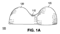
図1A−1Dは、ランバート放射パターンを放つ単一の光源から細長い照明パターンを提供するピーナッツ形レンズ100の一例を示している。図1Aは、狭くされた中央領域110が、より大きい2つのローブ120を隔てるピーナッツ形状を示す斜視図である。これらの図示は、縮尺通りではなく、図示及び説明の容易さのために誇張された造形を含んでいることがある。一部の形態では、より大きいローブ120とより小さい中央領域110との間の大きさ/体積の差は、これらの図に示されるものよりも実質的に小さいことがある。
1A-1D show an example of a peanut-
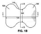
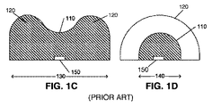
図1Bは、図1のピーナッツ形レンズの上面図を示し、図1C及び図1Dは、それぞれ、図1BのビューC−C及びD−Dに沿って取られた断面図を示している。ビューC−Cは長軸130に沿って取られており、ビューD−Dは短軸140に沿って取られている。図1Cに示されるように、断面C−Cに沿って眺めたとき、より大きいローブ120は凸面を形成し、中央領域110は凹構造を形成する。図1Dに示されるように、中央領域110の断面は凸面を形成する。この凸断面は、レンズの長軸130を通るレンズの全長にわたって延在して、より大きいローブ120を含み、凸面の半径がそれに応じて変化する。光源150は、半導体発光デバイス(LED)又は複数の発光デバイスとすることができ、レンズのリセス内に配置されたり、又はレンズの下面若しくはその付近に置かれたりする。
1B shows a top view of the peanut-shaped lens of FIG. 1, and FIGS. 1C and 1D show cross-sectional views taken along views CC and DD, respectively, of FIG. 1B. View CC is taken along the
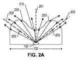
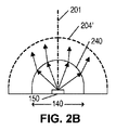
図2A及び2Bは、それぞれ、各軸130、140に関して、レンズ100を通る光伝播を示している。開示されているように、レンズ100は、凹レンズ部分210と、凹レンズ部分210のそれぞれの側の2つの凸レンズ部分220とを含んでいる。これらのレンズ部分の各々が、光源150に対する光軸を提供する。凹レンズ部分210は光軸201を提供し、凸レンズ部分220の各々は光軸202を提供する。各光軸202は、光源150から凸レンズ220の曲率中心205を通って延在する。凹レンズ210は、光源150から放たれた光を、光軸201から遠ざけるように分散させて、長軸130に沿った細長い発光パターンを形成する働きをする。凸レンズ220の各々は、その光軸202に向けて光を収束させる働きをし、それにより、長軸130に沿った細長い発光パターンがもたらされる。レンズ210、220の大きさ及び曲率の適切な選択により、均一に照射される細長い発光パターンが形成され得る。
2A and 2B illustrate light propagation through the
短軸140に対するレンズ100の断面は、凸レンズ240を形成する。長軸130上の任意の点に沿って取られる断面は、破線240’によって示されるように、同様の形状をした凸レンズを形成し、その大きさは、長軸130に沿ったレンズ100の高さ及び幅に対して相対的である。図示されるように、凸レンズ240は、光源150からの光を集中させて/コリメートして、短軸140に沿って比較的狭い発光パターンを形成する働きをする。凸レンズ240’は、光源150からの光を同様に集中させて/コリメートして、短軸140に沿った狭めの発光パターンを維持することになる。
The cross section of the
レンズ100によって形成される全体の発光パターンは、一方の軸において長く、他方の軸において狭く、実質的に長方形又は小判形の照明パターンを形成する。しかしながら、レンズ100の複雑な形状は、各寸法におけるパラメータ間の相互依存性を導入する。例えば、短軸(図2B)に対して、もっと広い照明パターンが望まれる場合、凸レンズ240の曲率半径を小さくする必要があり得る。レンズ240の形状のこの変化は、レンズ220の実現可能な形状を制限してしまい得る。レンズの物理的な大きさと、適切な金型を形成する方法と、についての制約も、レンズの形状を制限してしまい得る。
The overall light emission pattern formed by the
各軸における照明パターンの形状に関していっそう大きい独立性を可能にするような、細長い照明パターンを提供するレンズを提供することが有利であろう。例えば、長方形/小判形の各寸法の制御のいっそう大きい独立性を有した、実質的に長方形又は小判形の照明パターンを供するレンズを提供することが有利であろう。 It would be advantageous to provide a lens that provides an elongated illumination pattern that allows greater independence with respect to the shape of the illumination pattern in each axis. For example, it would be advantageous to provide a lens that provides a substantially rectangular or oval illumination pattern with greater independence in controlling the dimensions of the rectangle / oval.
これらの関心事のうちの1つ以上を、より良く解決するため、本発明の一実施形態においては、細長いレンズが、当該レンズの発光面上に長軸に沿った細長いトラフを有して形成される。細長いレンズは、その外周の周りの湾曲壁と、該湾曲壁とトラフとの間の滑らかな移行部とを含み得る。トラフは、長軸及び短軸の双方に沿って凹形状を含み得るが、該凹形状の曲率半径は、長軸と短軸との間で異なり得る。トラフの大きさ及びこれらの曲率半径によって、照明パターンの偏心が制御され得る。 To better solve one or more of these concerns, in one embodiment of the present invention, an elongated lens is formed having an elongated trough along the major axis on the light emitting surface of the lens. Is done. The elongate lens may include a curved wall around its periphery and a smooth transition between the curved wall and the trough. The trough may include a concave shape along both the major and minor axes, but the radius of curvature of the concave shape may differ between the major and minor axes. The eccentricity of the illumination pattern can be controlled by the size of the troughs and their radii of curvature.
発光デバイスが、発光素子と、短軸、長軸、及び上面を持つ細長いレンズとを設けることによって形成され得る。発光素子からの所望の光が、上記上面を通じて放たれ、レンズの上記上面は、長軸に沿って延在するトラフ(谷状部)を含み、レンズの外周が湾曲壁を含む。 A light emitting device may be formed by providing a light emitting element and an elongated lens having a minor axis, a major axis, and a top surface. Desired light from the light emitting element is emitted through the upper surface, the upper surface of the lens includes a trough (valley) extending along the long axis, and the outer periphery of the lens includes a curved wall.
トラフは、発光素子の光軸に関して、短軸及び/又は長軸に対して対称とし得る。トラフを湾曲壁につなげる滑らかな移行部が存在することができ、また、湾曲壁の少なくとも一部は反射性とし得る。 The trough may be symmetric with respect to the minor axis and / or the major axis with respect to the optical axis of the light emitting element. There may be a smooth transition that connects the trough to the curved wall, and at least a portion of the curved wall may be reflective.
トラフの下面は、短軸に沿って、長軸に沿った曲率とは異なる曲率を持つことができ、また、実質的に小判形である外周を有し得る。同様に、レンズの外周は実質的に小判形であるとし得る。小判形の外周はまた、長い寸法又は短い寸法において、先を切り取られてもよい The lower surface of the trough may have a curvature along the minor axis that is different from the curvature along the major axis, and may have an outer periphery that is substantially oval. Similarly, the outer periphery of the lens may be substantially oval. The oval perimeter may also be truncated in long or short dimensions
以下の図を含む添付図面を参照して、例として、本発明を更に詳細に説明する。
以下の説明においては、限定ではなく説明の目的で、本発明の概念の完全なる理解を提供するために、例えば特定のアーキテクチャ、インタフェース、技術などの具体的詳細事項を説明する。しかしながら、当業者に明らかなように、本発明は、これらの具体的詳細事項からは逸脱した他の実施形態でも実施され得るものである。同様に、本明細書の文章は、図面に示される実施形態例に向けられたものであり、請求項に係る発明に、請求項に明示的に含められた限定以外の限定を加えるものではない。単純化及び明瞭化の目的のため、不要な詳細事項で本発明の説明を不明瞭にしないよう、周知のデバイス、回路及び方法についての詳細な説明は省略することとする。 In the following description, for purposes of explanation and not limitation, specific details are set forth, such as specific architectures, interfaces, techniques, etc., in order to provide a thorough understanding of the concepts of the present invention. However, it will be apparent to those skilled in the art that the present invention may be practiced in other embodiments that depart from these specific details. Similarly, the text of this specification is directed to the exemplary embodiments shown in the drawings and does not impose limitations on the claimed invention other than those explicitly included in a claim. . For the purpose of simplicity and clarity, detailed descriptions of well-known devices, circuits, and methods are omitted so as not to obscure the description of the present invention with unnecessary detail.
説明及び理解の容易さのため、例えば光が光源から“上に”伝播し、次いで、光源の位置とは反対側のレンズの“上面”から出て行くと仮定されるものである“頂面発光”発光デバイスを参照して、方向及び/又は向きを規定する。典型的に、光源は、表面のうちの2つが他の4つよりも大きいものとなる平行六面体である。それら大きい表面のうちの一方が、発光デバイスの“頂部”として指定される。4つの小さい表面は、典型的には殆ど又は全く光を放たない発光デバイスの“側面”である。大部分の光が、発光デバイスの“頂部”から放たれる。レンズの“上面”は、発光デバイスの“頂部”の反対側である。 For ease of explanation and understanding, for example, it is assumed that the light propagates “up” from the light source and then exits from the “top surface” of the lens opposite the position of the light source. With reference to the “light emitting” light emitting device, the direction and / or orientation is defined. Typically, the light source is a parallelepiped where two of the surfaces are larger than the other four. One of these large surfaces is designated as the “top” of the light emitting device. The four small surfaces are “sides” of a light emitting device that typically emits little or no light. Most of the light is emitted from the “top” of the light emitting device. The “top” of the lens is opposite the “top” of the light emitting device.
一部の光は、レンズの‘側面’、すなわち、発光デバイスの“側面”に対向するレンズの部分、を出て行き得る。光源に対して正反対ではない表面を通じて光の実質的大部分を放つ側面発光デバイス、を作り出すように設計されるレンズとは対照的に、本発明のレンズは、光源からの光の実質的大部分が上面から出て行くように設計される。 Some light may leave the 'side' of the lens, ie the part of the lens that faces the “side” of the light emitting device. In contrast to lenses that are designed to create side-emitting devices that emit a substantial portion of light through a surface that is not the exact opposite of the light source, the lenses of the present invention provide a substantial portion of the light from the light source. Is designed to exit from the top.
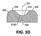
図3A−3Dは、本発明の態様に従った、光源350及び細長いレンズを含む発光デバイスの一例を示している。光源350は、例えば発光ダイオードなどの単一の発光素子、又は複数の発光素子を含み得る。
3A-3D illustrate an example of a light emitting device that includes a
記載される実施形態の何れにおいても、レンズは、エポキシ、シリコーン、ゾルゲル、ガラス若しくはコンパウンド、混合物、又はこれらの混成物で作製され得る。光源の波長における屈折率は、1.4から2.2の範囲とし得る。レンズの屈折率を高める又は調節するために、シリコーン又はシリケートバインダ中に分散された、100nm未満(好ましくは、50nm未満)の粒径を持つ高屈折率ナノ粒子が使用されてもよい。これらの材料の詳細は、同一出願人による米国特許出願公開第2011/0062469号に見出すことができ、その全体をここに援用する。 In any of the described embodiments, the lens may be made of epoxy, silicone, sol gel, glass or compound, a mixture, or a mixture thereof. The refractive index at the wavelength of the light source can range from 1.4 to 2.2. To increase or adjust the refractive index of the lens, high refractive index nanoparticles having a particle size of less than 100 nm (preferably less than 50 nm) dispersed in a silicone or silicate binder may be used. Details of these materials can be found in commonly assigned US Patent Application Publication No. 2011/0062469, which is incorporated herein in its entirety.
一実施形態において、光源は、0.2mmから6mmまでの範囲の寸法を持つ発光ダイオード(LED)とし得る。レンズは、LEDの寸法の1.5倍から50倍までの範囲の外寸を有し得る。レンズの短い方の寸法に対する長い方の寸法のアスペクト比は、1.25から50までの範囲とし得る。 In one embodiment, the light source may be a light emitting diode (LED) with dimensions ranging from 0.2 mm to 6 mm. The lens may have an outer dimension in the range of 1.5 to 50 times the size of the LED. The aspect ratio of the longer dimension to the shorter dimension of the lens can range from 1.25 to 50.
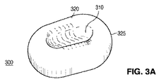
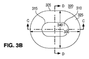
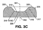
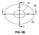
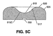
図3Aは、細長いレンズ300の斜視図を示している。図3Bは、細長いレンズ300の上面図を示しており、これを通じて光が放たれる。図3Cは、長軸330に沿って取られたC−C断面図を示している。図3Dは、短軸340に沿って取られたD−D断面図を示している。レンズ300の外周305は、長い寸法及び短い寸法を持つ小判形である。外周305は、短い寸法に沿った湾曲した端部と、長い寸法に沿った直線とを有している。他の例では、これらの直線は、例えば楕円形の外周を形成するように凸状の湾曲を有していてもよい。
FIG. 3A shows a perspective view of the
図示されるように、レンズ300は、上面320に形成されたトラフ310を含んでいる。本開示の目的では、トラフは、レンズ300の軸に沿った、その軸に沿ったレンズの長さよりも短い、上面320の窪みとして定義される。トラフ310は、長い寸法と短い寸法とを持つ小判形状を有し得る。トラフの寸法の比は、レンズ300の長い寸法と短い寸法との比と同じであってもよいし異なっていてもよく、また、トラフ310の外周315は、形状において、レンズ300の外周305と同様とし得る。更に以下にて詳述するように、光源350から放たれた光の連続的な分散を提供するため、レンズ300の外周305は、湾曲した壁325を含むことができ、湾曲壁325とトラフとの間に、滑らかな移行部317が存在し得る。同様に、トラフ310は湾曲面316を含み得る。説明及び理解の容易さのため、用語“上面320”は、ここでは、集合的に所望の光を放つレンズ300の表面である、トラフ310の表面と、湾曲部316及び317の表面と、湾曲した壁325の湾曲部の表面とを指すように使用される。
As shown, the
レンズ300は、光源350を受け入れるためのリセスを含んでいてもよい底面(ベース)326を含んでいる。それに代えて、光源350は、この底面と同一平面にあってもよいし、底面326の僅かに下方にあってもよい。光源350は、リフレクタ、リフレクタカップ、又はリフレクタリングを含んでいてもよい。
当業者が認識することには、不連続な表面が使用されてもよいが、一般に、照明強度における急峻な遷移を含まない照明パターンを提供するためには、滑らかな連続した表面が好ましい。しかしながら、急峻な遷移が望ましい場合、不連続な表面が所望の照明パターンを提供することがある。レンズ300は、トラフ310を含めてレンズ300の形状を提供する金型によって形成され得る。プリフォームされた細長いレンズからトラフ310をミリングすることを含め、レンズ300を形成するその他の技術も実現可能である。
Those skilled in the art will recognize that discontinuous surfaces may be used, but in general, a smooth continuous surface is preferred to provide an illumination pattern that does not include a sharp transition in illumination intensity. However, if a sharp transition is desired, a discontinuous surface may provide the desired illumination pattern. The
図3C及び3Dに示されるように、トラフ310は、光軸301の位置又はその付近の、より低い高度と、レンズ300の上面320の、より高い高度とをもたらす。
As shown in FIGS. 3C and 3D, the
図3CのC−C断面例において、トラフ310の下面315は、光軸301の近くで略平坦であってよく、そして、上面320のいっそう高い高度に向かって上方に湾曲し得る。この実質的に平坦な領域315Cは、より鋭い形状の凸領域よりも、光源350によって放たれた光の、より大きい損失をもたらし得る。窪み310のこのいっそう平坦な領域315Cに、臨界角よりも大きい角度で突き当たる光は、領域315Cから全反射され(TIR)されることになり、それにより、光がデバイス内で吸収される可能性が高まる。
In the CC cross-section example of FIG. 3C, the
図3DのD−D断面例において、短軸340に沿ったトラフ310の下面315が凹形状315Dを提供しており、これも光源350からの光を分散させるが、凸状のローブ320が、長軸330に関してよりも、短軸340に沿って密な間隔であるので、さほど空間的でない。
In the DD cross-section example of FIG. 3D, the
レンズ300の中央領域における光の分散の程度は、各軸330、340に沿った下面315の曲率半径を含めて、トラフ310の形状(長さ、幅、深さ、形)によって決定される。C−C断面に沿った表面315は、湾曲部316の各々に関する曲率半径と、非常に大きいものであり得る中央部315Cの曲率半径との、3つの曲率半径を含んでいる。D−D断面に沿った表面315は、凹部315Dの曲率半径を含んでいる。この例では、分散の程度は、長軸330に沿っての方が大きくなり、表面316における全反射が、光軸301から離れた角度での照明強度を増補し得る。
The degree of light dispersion in the central region of the
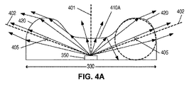
図4A−4Bは、それぞれ、長軸330及び短軸340に対するレンズ300中の光の伝播を例示している。
4A-4B illustrate the propagation of light in the
図4Aに示されるように、長軸330に沿った断面形状は、凹レンズ部分410Aと、2つの凸レンズ部分420とを有する。凹レンズ部分410Aは、凸レンズ部分420がもっと大きく離間されていた場合よりは小さい程度であるが、光軸401から離れるように光を分散させることになる。2つの凸レンズ部分420は、それらの対応する光軸402の方に光を収束させる。
As shown in FIG. 4A, the cross-sectional shape along the
レンズ部分410A、420の全体的な効果は、長軸330に沿った照明パターンの伸長である。伸張の程度は、光軸402の向き、曲率中心405、及びレンズ部分410A、420の各々に関する曲率半径と、長軸330に沿ったプロファイルの形状に関係するその他のパラメータとによって制御され得る。
The overall effect of the
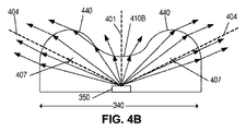
図4Bに示されるように、短軸340に沿った断面形状は、凹レンズ部分410Bと、2つの凸レンズ部分440とを有する。特に言及しておくことには、凹レンズ部分410A(図4A)及び凹レンズ部分410Bの双方がトラフ310(図3)によって形成されるが、レンズ部分410A、410Bの各々の形状は互いに実質的に独立である。この例では、レンズ部分410Aは、連続的に湾曲したものであるレンズ部分410Bよりも平坦である。
As shown in FIG. 4B, the cross-sectional shape along the
同様に、図4Bの2つの凸レンズ部分440は、図4Aの凸レンズ部分420とは実質的に異なり得る。この例では、レンズ部分440及び420は幾分類似しているが、当業者が認識することには、これらのレンズ部分420、440を形成する表面320(図3)は、レンズ300の周りで、均一の厚さであったり均一の高さであったりする必要はない。当業者が認識することには、照明解析プログラムを使用して、このような異なる形状間を移行するための適切な形状を決定し得る。
Similarly, the two
図4Aにおいてのように、短軸340に対する照明パターンの広がり及び均一性は、凸レンズ部分440の光軸404の向き、これらのレンズ440の曲率中心407、及びレンズ410B、440の各々に関する曲率半径と、短軸340に沿ったプロファイルの形状に関係するその他のパラメータとによって制御され得る。
As in FIG. 4A, the spread and uniformity of the illumination pattern relative to the
当業者が認識することには、トラフの具体的形状及びレンズの全体形状は、所望の光照射パターン及び強度分布に基づくことになる。一部の実施形態において、例えば、照明パターンの中心付近に均一な強度を提供し、各次元において所与のオフアクシス角で、徐々に又はもっと鋭く減衰させることが望ましいことがある。従来からの光伝播及び照明解析ツールを使用して、所望の照明パターン及び強度分布を生成する各寸法の形状の組み合わせを決定し得る。 Those skilled in the art will recognize that the specific shape of the trough and the overall shape of the lens will be based on the desired light irradiation pattern and intensity distribution. In some embodiments, it may be desirable, for example, to provide a uniform intensity near the center of the illumination pattern and attenuate gradually or more sharply at a given off-axis angle in each dimension. Conventional light propagation and illumination analysis tools can be used to determine the shape combination of each dimension that produces the desired illumination pattern and intensity distribution.
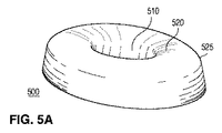
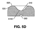
図5A−5Dは、本発明の態様に従った細長いレンズを含む発光デバイスの他の一例を示している。実質的に小判形(オーバル)の外周及び実質的に小判形のトラフ310を含むレンズ300とは対照的に、図5A−5Dのレンズ500は、実質的に楕円形のプロファイル及び実質的に楕円形のトラフ510を含んでいる。
5A-5D illustrate another example of a light emitting device that includes an elongated lens in accordance with aspects of the present invention. In contrast to a
本開示の目的では、小判形(オーバル)なる用語は、楕円形又はその他の形状を含め、湾曲した外周を持つ細長い形状を記述するために使用されている。説明及び理解の容易さのため、用語“上面520”は、ここでは、集合的に所望の光を放つレンズの表面である、トラフ510の表面と、湾曲部517の表面と、湾曲壁525の湾曲部の表面とを指すように使用される。
For the purposes of this disclosure, the term oval is used to describe an elongated shape with a curved perimeter, including an oval or other shape. For ease of explanation and understanding, the term “
図示されるように、直線部分を持たない湾曲壁525が、レンズ500の実質的に楕円形の外周を形成しており、トラフ510も、実質的に楕円形の外周を有している。この例では、下面515は、長軸530における実質的に連続した凹状プロファイル515Cと、短軸540における実質的に連続した凹状プロファイル515Dとを提供している。それに対応して、長軸530に沿ったプロファイル515Cは、レンズ300のいっそう平坦なプロファイル315Cよりも小さい損失で、より大きな、レンズ500の中心からの発光パターンの分散を提供する。しかしながら、当業者が認識することには、レンズ500の中心における光の強度を増大させるために、いずれかの軸において、下面515の部分はあまり湾曲されていなくてもよい。
As shown, a
上述のように、従来からの光伝播解析ツールを使用して、レンズの形状、トラフの形状、トラフ内の曲率半径、湾曲壁525の曲率半径、及び湾曲壁525とトラフ510との間の滑らかな移行を形成する曲率半径を決定し得る。
As described above, using conventional light propagation analysis tools, the shape of the lens, the shape of the trough, the radius of curvature within the trough, the radius of curvature of the
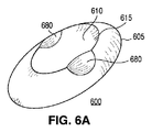
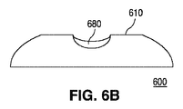
図6−9は、本発明の態様に従ったトラフを有する細長いレンズの他の例を示している。これらのレンズ例は各々、図3A−3D及び図5A−5Dのレンズ(300、500)に従ったレンズによって生成される発光パターンを増補する機構、及び本開示の原理に従うその他の形状を含んでいる。これらの機構は、これらの機構なしではレンズ上に“明るい領域”又は“暗い領域”を形成することになり得る領域から放たれる光を更に分散させることによって、いっそう均一な光分布を提供する働きをし得る。当業者が認識することには、所望の照明パターンを達成するために、図示されるものとは異なる大きさ及び形状の、より少数若しくは多数の機構が用いられてもよい。 6-9 illustrate another example of an elongated lens having a trough according to aspects of the present invention. Each of these lens examples includes a mechanism that augments the emission pattern produced by the lens according to the lenses (300, 500) of FIGS. 3A-3D and 5A-5D, and other shapes in accordance with the principles of the present disclosure. Yes. These mechanisms provide a more uniform light distribution by further dispersing light emitted from areas that would otherwise form "bright areas" or "dark areas" on the lens. Can work. Those skilled in the art will recognize that fewer or more features of different sizes and shapes than those shown may be used to achieve the desired illumination pattern.
各機構の曲率半径、レンズ本体上でのその位置及び向き、並びにレンズ本体それ自体の特性を含めて、各機構の寸法が、これらの機構を有するレンズによって提供される照明パターンに、これらの機構がどのように影響するかを決定することになる。各実施形態において、従来からのコンピュータ支援設計ツール及び/又は光伝播解析ツールを使用して、各増強/機構の形状及び寸法が、結果として得られるレンズによって生成される発光パターンに及ぼす影響を決定し得る。 The dimensions of each mechanism, including the radius of curvature of each mechanism, its position and orientation on the lens body, and the characteristics of the lens body itself, are reflected in the illumination pattern provided by the lens having these mechanisms. Will determine how it affects. In each embodiment, conventional computer aided design tools and / or light propagation analysis tools are used to determine the effect of each enhancement / mechanism shape and size on the light emission pattern produced by the resulting lens. Can do.
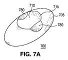
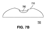
図6A−6Bでは、レンズ600の外周605と形状において同様である外周615を持つトラフ610を含んだレンズ600に、機構680が追加されており、図7A−7Bでは、レンズ700の外周705とは形状において異なる外周715を持つトラフ710を含んだレンズ700に、機構780が追加されている。
6A-6B, a
これらの例において、レンズ700は、図7Bに示すようにレンズのプロファイルに影響を及ぼすよう、レンズ600のトラフ610よりも短くて深いトラフ710を含んでおり、レンズの本体に対するトラフの特定の構成が、所望の照明パターンに応じて異なり得ること例示する働きをしている。機構680及び780は、各々が球体の表面又は楕円体の表面の一部である表面を有した複数の凸面ディンプルとし得る。
In these examples, the
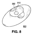
図8では、レンズ800のトラフ810の中心に凸状機構880が追加されており、図9では、レンズ900のトラフ910の中心に凹状機構(ディンプル)980が追加されている。当業者が認識することには、機構880又は980は同様に平坦面であってもよい。機構880及び980は各々、球体の表面又は楕円体の表面の一部である表面を有し得る。
In FIG. 8, a
図6−9の各々において、これらの機構は、それらがレンズの本体と交差するところで鋭いエッジを有するように図示されている。しかしながら、当業者が認識することには、本体から各機構への滑らかな移行が、より均一な照明パターンを提供してもよい。 In each of FIGS. 6-9, these features are illustrated as having sharp edges where they intersect the body of the lens. However, those skilled in the art will recognize that a smooth transition from the body to each mechanism may provide a more uniform illumination pattern.
図面及び以上の説明にて本発明を詳細に図示して記述してきたが、これらの図示及び記述は、限定的なものではなく、例示的又は典型的なものと見なされるべきであり、本発明は開示した実施形態に限定されるものではない。 While the invention has been illustrated and described in detail in the drawings and foregoing description, such illustration and description are to be considered illustrative or exemplary and not restrictive; Is not limited to the disclosed embodiments.
例えば、レンズの下面及び湾曲壁の直立部分が反射性である実施形態で本発明を動作させて、それにより、吸収損失及び/又は望ましくない方向への光伝播を抑制することが可能である。レンズの凸領域と凹領域との間の移行部(例えば、図3Cのレンズ300の316)も、これらの領域における全反射(TIR)を増補するために、反射性であってもよい。凹領域も、全反射を増加させるために、全体的又は部分的に反射材料でコーティングされてもよい。
For example, it is possible to operate the present invention in an embodiment where the lower surface of the lens and the upright portion of the curved wall are reflective, thereby suppressing absorption loss and / or light propagation in undesirable directions. The transition between the convex and concave areas of the lens (eg, 316 of
開示した実施形態へのその他の変形が、図面、本開示及び添付の請求項の検討から、請求項に係る発明を実施する当業者によって理解されて実現され得る。請求項において、用語“有する”はその他の要素又はステップを排除するものではなく、不定冠詞“a”又は“an”は複数であることを排除するものではない。請求項中の如何なる参照符号も、範囲を限定するものとして解されるべきでない。 Other variations to the disclosed embodiments can be understood and realized by those skilled in the art practicing the claimed invention, from a study of the drawings, the present disclosure, and the appended claims. In the claims, the term “comprising” does not exclude other elements or steps, and the indefinite article “a” or “an” does not exclude a plurality. Any reference signs in the claims should not be construed as limiting the scope.
Claims (15)
発光素子と、
短軸、長軸、及び上面を持つ細長いレンズであり、当該発光デバイスからの光の実質的大部分が前記上面を通じて放たれる、レンズと
を有し、
前記レンズの前記上面は、前記長軸に沿って延在するトラフを含む、
デバイス。 A light emitting device,
A light emitting element;
An elongated lens having a minor axis, a major axis, and a top surface, wherein a substantial portion of light from the light emitting device is emitted through the top surface, and
The upper surface of the lens includes a trough extending along the major axis;
device.
レンズであり、
当該レンズが短軸及び長軸を持つ、細長い形状と、
上面であり、当該レンズの底面又はその下に発光素子が置かれるときに光の実質的大部分が該上面を通って当該レンズを出て行く上面と、
前記上面を前記レンズの前記底面につなげる湾曲壁と、
を有するレンズと
を有し、
前記上面は、前記短軸及び前記長軸のうちの少なくとも一方に沿って延在するトラフを含む、
車両ランプ。 A light emitting device;
A lens,
The lens has a short axis and a long axis, and an elongated shape;
A top surface wherein a substantial portion of light exits the lens through the top surface when the light emitting element is placed at or below the bottom surface of the lens;
A curved wall connecting the top surface to the bottom surface of the lens;
A lens having
The upper surface includes a trough that extends along at least one of the minor axis and the major axis.
Vehicle lamp.
当該レンズが短軸及び長軸を持つ、細長い形状と、
上面であり、当該レンズの底面又はその下に発光素子が置かれるときに光の実質的大部分が該上面を通って当該レンズを出て行く上面と
を有し、
前記上面は、前記短軸及び前記長軸のうちの少なくとも一方に沿って延在するトラフを含む、
レンズ。 A lens,
The lens has a short axis and a long axis, and an elongated shape;
A top surface, wherein a substantial portion of the light exits the lens through the top surface when the light emitting element is placed at or below the bottom surface of the lens, and
The upper surface includes a trough that extends along at least one of the minor axis and the major axis.
lens.
Applications Claiming Priority (3)
| Application Number | Priority Date | Filing Date | Title |
|---|---|---|---|
| US201562169053P | 2015-06-01 | 2015-06-01 | |
| US62/169,053 | 2015-06-01 | ||
| PCT/US2016/033457 WO2016196039A1 (en) | 2015-06-01 | 2016-05-20 | Lens with elongated radiation pattern |
Publications (2)
| Publication Number | Publication Date |
|---|---|
| JP2018519630A true JP2018519630A (en) | 2018-07-19 |
| JP2018519630A5 JP2018519630A5 (en) | 2019-06-20 |
Family
ID=56119756
Family Applications (1)
| Application Number | Title | Priority Date | Filing Date |
|---|---|---|---|
| JP2017562595A Pending JP2018519630A (en) | 2015-06-01 | 2016-05-20 | Lens with elongated radiation pattern |
Country Status (7)
| Country | Link |
|---|---|
| US (3) | US10677416B2 (en) |
| EP (1) | EP3303912B1 (en) |
| JP (1) | JP2018519630A (en) |
| KR (1) | KR102410450B1 (en) |
| CN (1) | CN109073189A (en) |
| TW (2) | TWI749519B (en) |
| WO (1) | WO2016196039A1 (en) |
Cited By (2)
| Publication number | Priority date | Publication date | Assignee | Title |
|---|---|---|---|---|
| US10677416B2 (en) | 2015-06-01 | 2020-06-09 | Lumileds Llc | Lens with elongated radiation pattern |
| KR20210101817A (en) * | 2020-02-11 | 2021-08-19 | 현대자동차주식회사 | Diffusion lens for a vehicle lamp and the vehicle lamp |
Families Citing this family (11)
| Publication number | Priority date | Publication date | Assignee | Title |
|---|---|---|---|---|
| EP3240832A4 (en) * | 2014-12-30 | 2018-09-26 | J.M. Huber Corporation | Aluminosilicates and coatings made therefrom for voc removal |
| CN107708414B (en) * | 2015-06-30 | 2022-02-25 | 首尔伟傲世有限公司 | Insect traps for UV LEDs |
| JP2019021476A (en) * | 2017-07-14 | 2019-02-07 | 株式会社エンプラス | Light flux control member, emission apparatus, planer light source apparatus, and display apparatus |
| US10851967B2 (en) | 2017-11-17 | 2020-12-01 | Osram Gmbh | Lens, corresponding lighting device, lighting installation and method |
| EP3782005B1 (en) | 2018-10-08 | 2024-09-25 | Google LLC | Speaker assembly in a display assistant device |
| KR102119605B1 (en) * | 2019-06-17 | 2020-06-16 | 주식회사 에이치엘옵틱스 | Asymmetric diffusion lens for LED backlight unit |
| FR3103251B1 (en) * | 2019-11-15 | 2021-11-12 | Valeo Vision | Lighting module for the side of a vehicle |
| WO2021094574A1 (en) * | 2019-11-15 | 2021-05-20 | Valeo Vision | Lighting module for lateral part of a vehicle |
| KR102341997B1 (en) * | 2019-11-28 | 2021-12-22 | 엘지전자 주식회사 | Car lamp using semiconductor light emitting device |
| US10995932B1 (en) * | 2020-05-11 | 2021-05-04 | Mitsubishi Electric Research Laboratories, Inc. | Uniform-irradiance extended-source freeforms |
| KR102578782B1 (en) * | 2022-11-17 | 2023-09-20 | 주식회사 마루라이팅 | Lens for lighting apparatus and lighting apparatus including same |
Citations (7)
| Publication number | Priority date | Publication date | Assignee | Title |
|---|---|---|---|---|
| JP2009542017A (en) * | 2006-06-30 | 2009-11-26 | オスラム オプト セミコンダクターズ ゲゼルシャフト ミット ベシュレンクテル ハフツング | Optoelectronic components and lighting equipment |
| WO2009157166A1 (en) * | 2008-06-23 | 2009-12-30 | パナソニック株式会社 | Light emitting apparatus, planar light emitting apparatus and display apparatus |
| JP2010211246A (en) * | 2009-02-12 | 2010-09-24 | Panasonic Corp | Illuminating lens, lighting device, surface light source, and liquid crystal display apparatus |
| JP2012129105A (en) * | 2010-12-16 | 2012-07-05 | Hitachi Consumer Electronics Co Ltd | Backlight unit and liquid crystal display device using it |
| JP2013519907A (en) * | 2010-02-12 | 2013-05-30 | オスラム オプト セミコンダクターズ ゲゼルシャフト ミット ベシュレンクテル ハフツング | Optoelectronic semiconductor devices, lighting devices and lenses |
| KR20130133993A (en) * | 2012-05-30 | 2013-12-10 | 엘지이노텍 주식회사 | Member for controlling luminous flux and display device having the same |
| JP2014048547A (en) * | 2012-09-01 | 2014-03-17 | Rabo Sufia Kk | Bulk type lens, and luminous body and illuminating apparatus using the same |
Family Cites Families (38)
| Publication number | Priority date | Publication date | Assignee | Title |
|---|---|---|---|---|
| JP3425627B2 (en) * | 1992-08-18 | 2003-07-14 | 株式会社シンクロン | Standard light source and its control method |
| KR101085144B1 (en) * | 2004-04-29 | 2011-11-21 | 엘지디스플레이 주식회사 | LED lamp unit |
| KR100616598B1 (en) | 2004-08-11 | 2006-08-28 | 삼성전기주식회사 | Light emitting diode lens and backlight module having the same |
| TWI405349B (en) | 2004-10-07 | 2013-08-11 | 首爾半導體股份有限公司 | Side illumination lens and light-emitting element using the same |
| JP2007048775A (en) * | 2005-08-05 | 2007-02-22 | Koito Mfg Co Ltd | Light emitting diode and vehicle lighting tool |
| KR100649758B1 (en) | 2005-11-15 | 2006-11-27 | 삼성전기주식회사 | Lens for distributing quantity of light and optical emission device using the same |
| EP1994389B1 (en) * | 2006-02-27 | 2015-06-17 | Illumination Management Solutions, Inc. | An improved led device for wide beam generation |
| US8669565B2 (en) * | 2006-04-24 | 2014-03-11 | Cree Huizhou Solid State Lighting Company Limited | LED devices with narrow viewing angle and an LED display including same |
| US7918583B2 (en) * | 2006-08-16 | 2011-04-05 | Rpc Photonics, Inc. | Illumination devices |
| JP2008108674A (en) * | 2006-10-27 | 2008-05-08 | Stanley Electric Co Ltd | LED lighting fixtures |
| JP5349453B2 (en) * | 2007-04-05 | 2013-11-20 | コーニンクレッカ フィリップス エヌ ヴェ | Light beam shaper |
| AU2008254676B2 (en) * | 2007-05-21 | 2012-03-22 | Illumination Management Solutions, Inc. | An improved LED device for wide beam generation and method of making the same |
| US9557033B2 (en) * | 2008-03-05 | 2017-01-31 | Cree, Inc. | Optical system for batwing distribution |
| CN201335320Y (en) * | 2009-01-21 | 2009-10-28 | 陈哲艮 | Lens for street-lamp-used LED light source and street lamp using same |
| CN101846286A (en) * | 2009-03-23 | 2010-09-29 | 玉晶光电股份有限公司 | Lens for LED illumination |
| US20110062469A1 (en) | 2009-09-17 | 2011-03-17 | Koninklijke Philips Electronics N.V. | Molded lens incorporating a window element |
| CN102032526B (en) * | 2009-09-30 | 2013-08-07 | 富准精密工业(深圳)有限公司 | LED module |
| US20110235338A1 (en) * | 2010-03-29 | 2011-09-29 | Everlight Electronics Co., Ltd. | Light emitting device and lens thereof |
| CN102297382B (en) * | 2010-06-25 | 2013-01-02 | 旭丽电子(广州)有限公司 | LED (light emitting diode) lens |
| CN102434813B (en) * | 2010-09-29 | 2015-08-12 | 欧司朗股份有限公司 | Light emitting module and there is the back lighting lamp string of this light emitting module |
| US8602604B2 (en) * | 2010-10-14 | 2013-12-10 | Lunera Lighting, Inc. | Extruded wide angle lens for use with a LED light source |
| JP2012216763A (en) * | 2011-03-25 | 2012-11-08 | Sharp Corp | Light-emitting device, lighting device and display |
| CN102748704A (en) | 2011-04-19 | 2012-10-24 | 富准精密工业(深圳)有限公司 | Lens and illuminating device |
| EP2761221B1 (en) * | 2011-09-26 | 2017-10-25 | Musco Corporation | Lighting system having a multi-light source collimator and method of operating such |
| US20130100641A1 (en) * | 2011-10-25 | 2013-04-25 | Marcus Zhang | LED Lamp |
| US10047930B2 (en) * | 2011-12-02 | 2018-08-14 | Seoul Semiconductor Co., Ltd. | Light emitting module and lens |
| KR102009798B1 (en) * | 2011-12-30 | 2019-08-13 | 엘지디스플레이 주식회사 | Backlight unit |
| KR101987049B1 (en) * | 2012-01-10 | 2019-06-10 | 엘지이노텍 주식회사 | Lens unit and light-emitting apparatus |
| CN108386740B (en) * | 2012-03-05 | 2020-05-26 | 首尔半导体株式会社 | Illumination lens for short throw illumination |
| KR102008281B1 (en) * | 2012-08-16 | 2019-08-07 | 엘지이노텍 주식회사 | Member for controlling luminous flux, display device, and light emitting device |
| JP6046398B2 (en) * | 2012-07-04 | 2016-12-14 | 株式会社エンプラス | Surface light source device and display device |
| TW201435397A (en) | 2013-03-05 | 2014-09-16 | Hon Hai Prec Ind Co Ltd | Lens and light emitting diode package structure using the same |
| US8651707B1 (en) * | 2013-03-07 | 2014-02-18 | Ledlink Optics, Inc. | Optical lens for a LED having a quasi-elliptical shape |
| RU2672643C2 (en) * | 2014-03-28 | 2018-11-16 | Асахи Раббер Инк. | Light distribution lens |
| WO2016196039A1 (en) | 2015-06-01 | 2016-12-08 | Koninklijke Philips N.V. | Lens with elongated radiation pattern |
| CN106151905A (en) * | 2016-08-15 | 2016-11-23 | 浙江阳光美加照明有限公司 | A kind of LED light-emitting filament and the LEDbulb lamp using this LED light-emitting filament |
| CN107013823A (en) * | 2017-05-05 | 2017-08-04 | 浙江阳光美加照明有限公司 | A kind of temperature-control LED filament and the LEDbulb lamp using the temperature-control LED filament |
| CN107869709A (en) * | 2017-12-08 | 2018-04-03 | 成都泰和顺信息技术有限公司 | A kind of LED energy conserving lamp |
-
2016
- 2016-05-20 WO PCT/US2016/033457 patent/WO2016196039A1/en not_active Ceased
- 2016-05-20 JP JP2017562595A patent/JP2018519630A/en active Pending
- 2016-05-20 CN CN201680045363.4A patent/CN109073189A/en active Pending
- 2016-05-20 KR KR1020177037434A patent/KR102410450B1/en active Active
- 2016-05-20 US US15/579,105 patent/US10677416B2/en active Active
- 2016-05-20 EP EP16728777.0A patent/EP3303912B1/en active Active
- 2016-06-01 TW TW109112291A patent/TWI749519B/en active
- 2016-06-01 TW TW105117249A patent/TWI748951B/en active
-
2019
- 2019-05-17 US US16/415,621 patent/US10781997B2/en active Active
-
2020
- 2020-04-21 US US16/854,609 patent/US11022273B2/en active Active
Patent Citations (7)
| Publication number | Priority date | Publication date | Assignee | Title |
|---|---|---|---|---|
| JP2009542017A (en) * | 2006-06-30 | 2009-11-26 | オスラム オプト セミコンダクターズ ゲゼルシャフト ミット ベシュレンクテル ハフツング | Optoelectronic components and lighting equipment |
| WO2009157166A1 (en) * | 2008-06-23 | 2009-12-30 | パナソニック株式会社 | Light emitting apparatus, planar light emitting apparatus and display apparatus |
| JP2010211246A (en) * | 2009-02-12 | 2010-09-24 | Panasonic Corp | Illuminating lens, lighting device, surface light source, and liquid crystal display apparatus |
| JP2013519907A (en) * | 2010-02-12 | 2013-05-30 | オスラム オプト セミコンダクターズ ゲゼルシャフト ミット ベシュレンクテル ハフツング | Optoelectronic semiconductor devices, lighting devices and lenses |
| JP2012129105A (en) * | 2010-12-16 | 2012-07-05 | Hitachi Consumer Electronics Co Ltd | Backlight unit and liquid crystal display device using it |
| KR20130133993A (en) * | 2012-05-30 | 2013-12-10 | 엘지이노텍 주식회사 | Member for controlling luminous flux and display device having the same |
| JP2014048547A (en) * | 2012-09-01 | 2014-03-17 | Rabo Sufia Kk | Bulk type lens, and luminous body and illuminating apparatus using the same |
Cited By (7)
| Publication number | Priority date | Publication date | Assignee | Title |
|---|---|---|---|---|
| US10677416B2 (en) | 2015-06-01 | 2020-06-09 | Lumileds Llc | Lens with elongated radiation pattern |
| US10781997B2 (en) | 2015-06-01 | 2020-09-22 | Lumileds Llc | Lens with elongated radiation pattern |
| US11022273B2 (en) | 2015-06-01 | 2021-06-01 | Lumileds Llc | Lens with elongated radiation pattern |
| KR20210101817A (en) * | 2020-02-11 | 2021-08-19 | 현대자동차주식회사 | Diffusion lens for a vehicle lamp and the vehicle lamp |
| JP2021128927A (en) * | 2020-02-11 | 2021-09-02 | 現代自動車株式会社Hyundai Motor Company | Diffusing lens and lamp containing it |
| JP7570821B2 (en) | 2020-02-11 | 2024-10-22 | 現代自動車株式会社 | Diffusion lens and lamp including the same |
| KR102854961B1 (en) * | 2020-02-11 | 2025-09-04 | 현대자동차주식회사 | Diffusion lens for a vehicle lamp and the vehicle lamp |
Also Published As
| Publication number | Publication date |
|---|---|
| KR102410450B1 (en) | 2022-06-20 |
| US10781997B2 (en) | 2020-09-22 |
| US20180172238A1 (en) | 2018-06-21 |
| CN109073189A (en) | 2018-12-21 |
| US10677416B2 (en) | 2020-06-09 |
| US11022273B2 (en) | 2021-06-01 |
| US20190271451A1 (en) | 2019-09-05 |
| TW202028650A (en) | 2020-08-01 |
| TWI748951B (en) | 2021-12-11 |
| WO2016196039A1 (en) | 2016-12-08 |
| EP3303912B1 (en) | 2025-01-08 |
| TWI749519B (en) | 2021-12-11 |
| TW201702520A (en) | 2017-01-16 |
| EP3303912A1 (en) | 2018-04-11 |
| US20200248887A1 (en) | 2020-08-06 |
| KR20180014760A (en) | 2018-02-09 |
Similar Documents
| Publication | Publication Date | Title |
|---|---|---|
| JP2018519630A (en) | Lens with elongated radiation pattern | |
| US11629843B2 (en) | Optics for chip-on-board road and area lighting | |
| TWI626401B (en) | Lens for light emitting device | |
| CN104379992A (en) | Luminous flux control member, light emitting apparatus, and illuminating apparatus | |
| CN102829437B (en) | Masks and luminaires with masks | |
| JP7000695B2 (en) | Vehicle lighting | |
| US9799810B1 (en) | Light emitting device | |
| CN110291327A (en) | Light emitting device, surface light source device and display device | |
| KR101053951B1 (en) | Icicle type light adjustment lens for LED lighting device | |
| CN107709876B (en) | Light beam control component, light emitting device and lighting device | |
| CN108036208A (en) | A kind of optics light distribution module and there is its ball bulb lamp structure | |
| CN207814973U (en) | A kind of optics light distribution module and the ball bulb lamp structure with it | |
| CN107209355A (en) | Collimated from color with the color correction of the light of the light source of change in location | |
| CN108139577B (en) | LED module with output lens | |
| JP2019050208A (en) | Optical element and luminaire | |
| CN110402349A (en) | High euphorosia road and city LED illumination | |
| JP7031159B2 (en) | Lighting equipment and lenses | |
| JP2021166157A (en) | Wavelength conversion element and lighting fixture | |
| JP6551772B2 (en) | Luminous flux control member and light emitting device | |
| CN106796018B (en) | Optical components and lighting devices | |
| JP2014107051A (en) | Light pipe | |
| CN105874374A (en) | Lamp with lens elements for distributing light | |
| TW201504579A (en) | Light source for crystal lamp | |
| TW201425812A (en) | Illumination apparatus |
Legal Events
| Date | Code | Title | Description |
|---|---|---|---|
| A521 | Request for written amendment filed |
Free format text: JAPANESE INTERMEDIATE CODE: A523 Effective date: 20180202 |
|
| A711 | Notification of change in applicant |
Free format text: JAPANESE INTERMEDIATE CODE: A711 Effective date: 20190222 |
|
| A521 | Request for written amendment filed |
Free format text: JAPANESE INTERMEDIATE CODE: A821 Effective date: 20190222 |
|
| A521 | Request for written amendment filed |
Free format text: JAPANESE INTERMEDIATE CODE: A523 Effective date: 20190520 |
|
| A621 | Written request for application examination |
Free format text: JAPANESE INTERMEDIATE CODE: A621 Effective date: 20190520 |
|
| A977 | Report on retrieval |
Free format text: JAPANESE INTERMEDIATE CODE: A971007 Effective date: 20200521 |
|
| A131 | Notification of reasons for refusal |
Free format text: JAPANESE INTERMEDIATE CODE: A131 Effective date: 20200609 |
|
| A521 | Request for written amendment filed |
Free format text: JAPANESE INTERMEDIATE CODE: A523 Effective date: 20200819 |
|
| A131 | Notification of reasons for refusal |
Free format text: JAPANESE INTERMEDIATE CODE: A131 Effective date: 20201208 |
|
| A521 | Request for written amendment filed |
Free format text: JAPANESE INTERMEDIATE CODE: A523 Effective date: 20210210 |
|
| A02 | Decision of refusal |
Free format text: JAPANESE INTERMEDIATE CODE: A02 Effective date: 20210601 |