JP2018515343A - Ceramic core for multi-cavity turbine blades - Google Patents
Ceramic core for multi-cavity turbine blades Download PDFInfo
- Publication number
- JP2018515343A JP2018515343A JP2017549652A JP2017549652A JP2018515343A JP 2018515343 A JP2018515343 A JP 2018515343A JP 2017549652 A JP2017549652 A JP 2017549652A JP 2017549652 A JP2017549652 A JP 2017549652A JP 2018515343 A JP2018515343 A JP 2018515343A
- Authority
- JP
- Japan
- Prior art keywords
- cavity
- core
- ceramic
- turbine blade
- central cavity
- Prior art date
- Legal status (The legal status is an assumption and is not a legal conclusion. Google has not performed a legal analysis and makes no representation as to the accuracy of the status listed.)
- Pending
Links
Images


Classifications
-
- F—MECHANICAL ENGINEERING; LIGHTING; HEATING; WEAPONS; BLASTING
- F01—MACHINES OR ENGINES IN GENERAL; ENGINE PLANTS IN GENERAL; STEAM ENGINES
- F01D—NON-POSITIVE DISPLACEMENT MACHINES OR ENGINES, e.g. STEAM TURBINES
- F01D5/00—Blades; Blade-carrying members; Heating, heat-insulating, cooling or antivibration means on the blades or the members
- F01D5/12—Blades
- F01D5/28—Selecting particular materials; Particular measures relating thereto; Measures against erosion or corrosion
- F01D5/284—Selection of ceramic materials
-
- B—PERFORMING OPERATIONS; TRANSPORTING
- B22—CASTING; POWDER METALLURGY
- B22C—FOUNDRY MOULDING
- B22C9/00—Moulds or cores; Moulding processes
- B22C9/02—Sand moulds or like moulds for shaped castings
- B22C9/04—Use of lost patterns
-
- B—PERFORMING OPERATIONS; TRANSPORTING
- B22—CASTING; POWDER METALLURGY
- B22C—FOUNDRY MOULDING
- B22C9/00—Moulds or cores; Moulding processes
- B22C9/10—Cores; Manufacture or installation of cores
-
- F—MECHANICAL ENGINEERING; LIGHTING; HEATING; WEAPONS; BLASTING
- F01—MACHINES OR ENGINES IN GENERAL; ENGINE PLANTS IN GENERAL; STEAM ENGINES
- F01D—NON-POSITIVE DISPLACEMENT MACHINES OR ENGINES, e.g. STEAM TURBINES
- F01D5/00—Blades; Blade-carrying members; Heating, heat-insulating, cooling or antivibration means on the blades or the members
- F01D5/12—Blades
- F01D5/14—Form or construction
- F01D5/18—Hollow blades, i.e. blades with cooling or heating channels or cavities; Heating, heat-insulating or cooling means on blades
- F01D5/187—Convection cooling
-
- F—MECHANICAL ENGINEERING; LIGHTING; HEATING; WEAPONS; BLASTING
- F05—INDEXING SCHEMES RELATING TO ENGINES OR PUMPS IN VARIOUS SUBCLASSES OF CLASSES F01-F04
- F05D—INDEXING SCHEME FOR ASPECTS RELATING TO NON-POSITIVE-DISPLACEMENT MACHINES OR ENGINES, GAS-TURBINES OR JET-PROPULSION PLANTS
- F05D2230/00—Manufacture
- F05D2230/20—Manufacture essentially without removing material
- F05D2230/21—Manufacture essentially without removing material by casting
- F05D2230/211—Manufacture essentially without removing material by casting by precision casting, e.g. microfusing or investment casting
-
- F—MECHANICAL ENGINEERING; LIGHTING; HEATING; WEAPONS; BLASTING
- F05—INDEXING SCHEMES RELATING TO ENGINES OR PUMPS IN VARIOUS SUBCLASSES OF CLASSES F01-F04
- F05D—INDEXING SCHEME FOR ASPECTS RELATING TO NON-POSITIVE-DISPLACEMENT MACHINES OR ENGINES, GAS-TURBINES OR JET-PROPULSION PLANTS
- F05D2240/00—Components
- F05D2240/20—Rotors
- F05D2240/30—Characteristics of rotor blades, i.e. of any element transforming dynamic fluid energy to or from rotational energy and being attached to a rotor
- F05D2240/305—Characteristics of rotor blades, i.e. of any element transforming dynamic fluid energy to or from rotational energy and being attached to a rotor related to the pressure side of a rotor blade
-
- F—MECHANICAL ENGINEERING; LIGHTING; HEATING; WEAPONS; BLASTING
- F05—INDEXING SCHEMES RELATING TO ENGINES OR PUMPS IN VARIOUS SUBCLASSES OF CLASSES F01-F04
- F05D—INDEXING SCHEME FOR ASPECTS RELATING TO NON-POSITIVE-DISPLACEMENT MACHINES OR ENGINES, GAS-TURBINES OR JET-PROPULSION PLANTS
- F05D2300/00—Materials; Properties thereof
- F05D2300/20—Oxide or non-oxide ceramics
Abstract
多空洞タービン翼用のセラミック中子。ロストワックス鋳造技術を利用してタービンエンジン用の中空タービン翼を製造するために使用され、且つ、上記翼の空洞を単一要素として構成するように成形されたセラミック中子は、冷却空気と共にこれらの空洞の内部に供給されるようにするために、中子部(60、62)を含み、中子部(60、62)は、第1の側方空洞及び第2の側方空洞を形成するためのものであり、且つ、中子部(48)に接続され、中子部(48)は、少なくとも一つの中央空洞を、第一に、少なくとも二つのセラミック接合部(70)を介して中子付根(54)において、第二に、翼の内部隔壁の厚さを規定する位置決めの複数の他のセラミック接合部(64、66、68)を介して中子に沿った種々の高さにおいて、形成するためのものである一方、第1の側方空洞及び第2の側方空洞の所定の臨界域についての追加の冷却空気の保証も行う。【選択図】図3Ceramic core for multi-cavity turbine blades. Ceramic cores used to produce hollow turbine blades for turbine engines utilizing lost wax casting technology and shaped to form the blade cavity as a single element, together with cooling air, In order to be supplied into the interior of the cavity, the core part (60, 62) is included, and the core part (60, 62) forms a first lateral cavity and a second lateral cavity. And connected to the core (48), the core (48) passing through at least one central cavity, first through at least two ceramic joints (70). At the core root (54), secondly, various heights along the core through a plurality of other ceramic joints (64, 66, 68) positioned to define the thickness of the inner bulkhead of the wing. In order to form Additional assurance is also performed in the cooling air for the lateral cavity and a predetermined threshold range of a second lateral cavity. [Selection] Figure 3
Description
本発明はタービンエンジンタービン用の翼群の一般的分野に関し、特に、冷却回路を内蔵し、ロストワックス鋳造技術により製造されたタービン翼に関する。 The present invention relates to the general field of blade groups for turbine engine turbines, and more particularly to turbine blades that incorporate a cooling circuit and are manufactured by lost wax casting technology.
周知のように、タービンエンジンは燃焼室を備え、燃焼室内において、空気と燃料とが燃焼前に混合される。このような燃焼の結果発生したガスは、燃焼室から下流へ流れ、その後、高圧タービン及び低圧タービンに供給される。各タービンは、一以上の動翼段(回転翼車輪と称される)と交互に並ぶ一以上の固定翼段(ノズルとして知られる)を備え、該段では、翼又は羽根が、タービンの回転翼の周囲全体にわたって円周方向に間隔を空けて配置される。このようなタービン翼又は羽根は、燃焼ガスの超高温にさらされ、該温度は、ガスとじかに接触した翼又は羽根により損傷することなく耐え得る値を優に上回る値に達するため、翼又は羽根の寿命を制限することになる。 As is well known, a turbine engine includes a combustion chamber in which air and fuel are mixed prior to combustion. The gas generated as a result of such combustion flows downstream from the combustion chamber and is then supplied to the high pressure turbine and the low pressure turbine. Each turbine includes one or more stationary blade stages (known as nozzles) that alternate with one or more blade stages (referred to as rotor blades), where the blades or vanes are rotating turbines. They are spaced circumferentially around the entire circumference of the wing. Such turbine blades or blades are exposed to the very high temperatures of the combustion gas, which reaches a value well above that which can be tolerated without damage by the blades or blades in direct contact with the gas. Will limit the lifespan.
この問題を解決するために、このような翼又は羽根に内蔵型冷却回路を搭載することが知られており、冷却回路は、高水準の熱的有効性を示し、周囲に保護膜を生成するための翼又は羽根の壁内の送り穴とともに各翼又は羽根の内部に空気の組織的流れ(例えば、単純な直接供給型空洞、U字又は「トロンボーン」型空洞)を形成することにより翼又は羽根の温度を低減するように図る。 In order to solve this problem, it is known to install a built-in cooling circuit on such wings or blades, which shows a high level of thermal effectiveness and produces a protective film around it. By forming a systematic flow of air (eg, a simple direct feed cavity, a U-shaped or “trombone” cavity) within each wing or vane with a feed hole in the wing or vane wall for Or try to reduce the temperature of the blades.
しかしながら、上記技術にはいくつかの欠点がある。まず、トロンボーン型空洞を含む回路には、回路を貫通する空気による仕事を最大化するという利点があるものの、空気をかなり加熱することになるため、トロンボーン型空洞の端部に位置する複数の穴の熱的有効性の低下につながる。同様に、直接供給による前縁空洞及び後縁空洞を有する構成は、通常翼の先端で観察される高い温度レベルで効果的な応答を与えることができない。そして、種々の空洞は、翼型の異なる区間の関数として変動する厚さの壁のみによりガス流路から分離される。翼群又は羽根群を冷却することに充てられ得る流量に対する制約を仮定し、且つ、現在ガス流路において温度上昇傾向にあると仮定すると、空気流量を大幅に増大させることなく、したがって、エンジンの性能に不利な影響を及ぼすことなく、上記の種の回路で効果的に翼又は羽根を冷却することはできない。 However, the above technique has several drawbacks. First, a circuit containing a trombone cavity has the advantage of maximizing the work done by the air that penetrates the circuit, but it heats the air considerably, so multiple circuits located at the end of the trombone cavity Leads to a decrease in the thermal effectiveness of the hole. Similarly, a configuration having a leading edge cavity and a trailing edge cavity with direct feed cannot provide an effective response at the high temperature levels normally observed at the tip of a blade. The various cavities are then separated from the gas flow path only by walls of varying thickness as a function of different sections of the airfoil. Assuming constraints on the flow rate that can be devoted to cooling the blade group or blade group, and assuming that the current gas flow path tends to rise in temperature, the air flow rate will not increase significantly, and therefore the engine A blade or vane cannot be effectively cooled with a circuit of the above type without adversely affecting performance.
図5は、翼付根14と翼先端16との間を径方向に延びる空気力学的面又は翼型12を有するガスタービンエンジンの高圧タービン翼10を示す。翼付根は、翼を回転翼円板に取り付けることができるように成形される。翼先端は、翼型に対して相対的に横方向に延びる底部と、翼型12の壁を延長する縁部を形成する壁とにより構成されたバスタブ形状の部分18を形成する。原理を示すためのものにすぎない例として図6の断面図に示されるように、翼型12は、複数の空洞20、22、24、26、28、30及び32を有する。第1の中央空洞20及び第2の中央空洞22は、翼型の付根から先端まで延び、二つの他の空洞24及び26は、中央空洞と翼の吸込側壁との間に吸込側壁に沿って、且つ、中央空洞と翼の圧力側壁との間に圧力側壁に沿って、中央空洞の両側に配置される。そして、空洞28は、前縁に近接する翼の部分に位置し、二つの空洞30及び32は、後縁に近接する翼の部分において一直線に順に並ぶ。
FIG. 5 shows a high
空洞の形状及び数、並びに、外穴34及び36の位置及び後縁溝38の形状は、実例として示されるが、これらの要素のすべては、概して、翼が浸漬される燃焼ガスからの熱に最も感受性がある区間において熱効率を最大化するように最適化されることが想定される。内部空洞は、熱交換を向上させるために撹拌器(不図示)を更に備えることが多い。
The shape and number of cavities, as well as the location of the
出願者名義のある特許文献に記載されるように、従来、高圧タービン翼及び羽根は、一つ以上のセラミック中子を(複雑性に依存して)金型に位置決めし、完成した翼又は羽根の内面を形成する外面を構成することにより内部に製作された回路の形状を有するように、ロストワックス鋳造により製造されている(例えば、特許文献1参照。)。 As described in the patent literature in the name of the applicant, conventionally, high pressure turbine blades and blades have positioned one or more ceramic cores (depending on complexity) in the mold and completed blades or blades. It is manufactured by lost wax casting so as to have the shape of a circuit manufactured inside by forming an outer surface that forms the inner surface of (see, for example, Patent Document 1).
特に、冷却回路は、図5及び図6における冷却回路のように、複数の空洞を有し、該空洞は、鋳造されるのに好適な金属壁厚さを保証するために、(高温ガスから隔離された複数の低温中央空洞、及び、異なる空気供給を行う複数の微細外側空洞を形成するための)複数の別個のセラミック中子を合わせて組み立てることを必要とする。したがって、これは、複雑操作を構成し、該操作において、セラミック中子の付根及び先端を介して手作業で実行される組立操作は、鋳造により翼の先端にバスタブが形成されることを妨げることにより、場合によっては上記区間における翼の機械的強度を制限することになり得る高価な追加の仕上げ操作(例えば、蝋付けによりバスタブ又は栓材料を追加する)を必要とする。 In particular, the cooling circuit has a plurality of cavities, like the cooling circuits in FIGS. 5 and 6, which cavities (from hot gases) to ensure a suitable metal wall thickness to be cast. It requires assembly of a plurality of separate ceramic cores (to form a plurality of isolated cold central cavities and a plurality of fine outer cavities providing different air supplies). This therefore constitutes a complex operation, in which the assembly operation which is carried out manually via the root and tip of the ceramic core prevents the bathtub from forming at the tip of the wing by casting. This may necessitate expensive additional finishing operations (e.g. adding a bathtub or plug material by brazing) that may limit the mechanical strength of the wings in the section.
したがって、本発明は、現行の手作業での組立よりも確実な方法で、溶融金属を鋳造した後の金属隔壁の厚さに対応する空洞間距離の保証もしつつ、従来技術の回路で必要とされる上記組立操作及びバスタブ仕上げ操作を省略するように単一の中子を使用して製作され得るタービン翼用の冷却回路を提案することにより複数の別個の中子を手作業で組み立てることに関連した欠点を軽減することを目的とする。 Therefore, the present invention requires a prior art circuit while guaranteeing the inter-cavity distance corresponding to the thickness of the metal partition after casting the molten metal in a more reliable way than the current manual assembly. To manually assemble a plurality of separate cores by proposing a cooling circuit for turbine blades that can be fabricated using a single core so as to omit the above assembling and bathtub finishing operations. The aim is to alleviate the related drawbacks.
この目的を達成するために、ロストワックス鋳造技術を利用してタービンエンジン用の中空タービン翼を製造するために使用されるセラミック中子であって、上記翼は、少なくとも一つの中央空洞と、上記少なくとも一つの中央空洞と上記翼の吸込側壁との間に配置された第1の側方空洞と、上記少なくとも一つの中央空洞と上記翼の圧力側壁との間に配置された第2の側方空洞とを含むセラミック中子が提供される。上記中子は、上記空洞を単一要素として構成するように成形されており、且つ、冷却空気と共に上記空洞の内部に供給されるようにするために、中子部を含み、上記中子部は、上記第1の側方空洞及び上記第2の側方空洞を形成するためのものであり、且つ、中子部に接続され、上記中子部は、上記少なくとも一つの中央空洞を、第一に、少なくとも二つのセラミック接合部を介して中子付根において、第二に、上記翼の内部隔壁の厚さを規定する位置決めの複数の他のセラミック接合部を介して上記中子に沿った種々の高さにおいて、形成するためのものである一方、上記第1の側方空洞及び上記第2の側方空洞の所定の臨界域についての追加の冷却空気の保証も行う。 To achieve this object, a ceramic core used to produce a hollow turbine blade for a turbine engine utilizing lost wax casting technology, the blade including at least one central cavity, and A first lateral cavity disposed between at least one central cavity and the suction sidewall of the wing; and a second lateral cavity disposed between the at least one central cavity and the pressure sidewall of the wing. A ceramic core including a cavity is provided. The core is shaped so as to constitute the cavity as a single element, and includes a core part to be supplied into the cavity together with cooling air, and the core part Is for forming the first side cavity and the second side cavity, and is connected to a core part, and the core part defines the at least one central cavity as the second side cavity. First, at the root of the core via at least two ceramic joints, and secondly, along the core via a plurality of other ceramic joints positioned to define the thickness of the inner bulkhead of the wing. While intended to form at various heights, it also guarantees additional cooling air for certain critical zones of the first side cavity and the second side cavity.
また、上記中子は、バスタブを形成するためのものであり、上記バスタブの厚さを規定する位置決めのセラミック接合部を介して少なくとも一つの中央空洞を形成するための上記中子部に接続される一方、翼先端において冷却空気が排気されることを保証する中子部を更に含む。 The core is for forming a bathtub, and is connected to the core for forming at least one central cavity through a positioning ceramic joint that defines the thickness of the bathtub. On the other hand, it further includes a core portion that ensures that the cooling air is exhausted at the blade tip.
翼本体を介したこれらの接合部を利用することで、翼先端における組立装置が不要になることにより、翼本体と同一の機械的特性を有する鋳造バスタブを得ることができる。また、付根を介した側方空洞の主な供給材料は、気流及び完成した翼型の外壁の冷却全体をより良く制御し、中子において、種々の空洞への供給材料は、射出後、合わせられることにより、中子の機械的強度を更に高めることができる。 By using these joint portions via the blade main body, an assembling apparatus at the blade tip becomes unnecessary, and a cast bathtub having the same mechanical characteristics as the blade main body can be obtained. Also, the main feed material for the side cavities via the roots controls the air flow and the overall cooling of the finished airfoil outer wall better, and in the core, the feed materials for the various cavities are combined after injection. As a result, the mechanical strength of the core can be further increased.
意図した実施形態において、上記所定の臨界域は、最大熱機械応力にさらされた上記第1の側方空洞及び上記第2の側方空洞の区間から選択され、上記セラミック接合部は、溶融金属を鋳造しながら上記内部隔壁の機械的強度を保証するように定められた区分のものである。 In a contemplated embodiment, the predetermined critical region is selected from a section of the first side cavity and the second side cavity subjected to maximum thermomechanical stress, and the ceramic joint is a molten metal The section is determined so as to guarantee the mechanical strength of the inner partition wall while casting the steel.
本発明は、上述したような単一要素中子によりロストワックス鋳造技術を利用してタービンエンジン用の中空タービン翼を製造する方法と、このような方法を利用して製造された複数の冷却翼を備える任意のタービンエンジンタービンとの両方を更に提供する。 The present invention provides a method of manufacturing a hollow turbine blade for a turbine engine using a lost wax casting technique with a single element core as described above, and a plurality of cooling blades manufactured using such a method. And an optional turbine engine turbine comprising:
本発明の他の特徴及び利点は、限定的な性質を持たない実施形態を示す添付図面を参照することによりなされる以下の説明から明らかとなる。 Other features and advantages of the present invention will become apparent from the following description, taken in conjunction with the accompanying drawings, which illustrate embodiments that are not limiting in nature.
図1及び図2は、翼に対して相対的な吸込側面図及び圧力側面図のそれぞれにおいて、タービンエンジン用のタービン翼を製造するためのセラミック中子40を示す。セラミック中子は、図示された例において、単一要素を形成する七つの部分又は列を含む。燃焼ガスが到達する側に設けられるべき第1の列42は、鋳造後に形成されるべき前縁空洞28に対応し、第2の列44は、それに隣接する中央空洞20に対応する。この空洞は、鋳造後、中子40の第1の列付根46が存在することにより生じる流路(不図示)を介して冷却空気流を受け取る。他の三つの列48、50及び52は、往復経路をたどり、中子の付根を形成するために第1の列付根46に接続された第2の列付根54が存在することにより生じる別の流路により搬送された第2の冷却空気流を受け取る、順に並んだ空洞22、30及び32に対応する。第1の列42と第2の列44とは、鋳造後、前縁空洞28を冷却するための供給孔(図4Aの参照符号80を参照)に対応する一連の橋梁56により互いに接続される。少なくとも二つの上部橋梁57は、上記列及び中子40の先端59との接続において、鋳造中バスタブの底部における隔壁についての所望の厚さを得ることができ、空気排気孔を形成するように寸法も合わせられる。第4の列50に関して、鉛直に傾斜した小橋梁58は、製作されるべき翼の補強領域を有効にする中子のより薄肉の領域を形成する。
1 and 2 show a ceramic core 40 for producing turbine blades for a turbine engine in a suction side view and a pressure side view, respectively, relative to the blades. The ceramic core includes, in the illustrated example, seven parts or rows that form a single element. The first row 42 to be provided on the side where the combustion gas reaches corresponds to the leading
種々の橋梁の大きさは、中子40を処理しつつ、それを使用不可にし得る橋梁の破損を回避するように定められる。検討中の例では、橋梁は、中子40の高さに沿って、特に、中子の第1の列42において、略一定の間隔を空けて配置されることにより分布される。 Various bridge sizes are defined to avoid breakage of the bridge that may render the core 40 unusable while processing the core 40. In the example under consideration, the bridges are distributed by being arranged along the height of the cores 40, in particular in the first row 42 of cores, with a substantially constant spacing.
本発明に従って、中子40は、横方向に配置され、溶融金属を鋳造する際に固体の空洞間壁を形成する余地を残すようにいずれも第2の列44及び第3の列48から所定の間隔を空けて設けられた第6の列60及び第7の列62を更に有する。これらの列を保持し、中子集合に剛性を与えるために、第6の列60の底端は、第1の列付根46に接続され、第7の列62の底端は、第2の列付根54に接続され、鋳型へ溶融金属を流し込みながら形成された内部隔壁に対して機械的強度を与えるのになお充分な寸法の小区分(例えば、図3の参照符号64、66及び68を参照)の多数のセラミック接合部は、二つの側方列と中央の第2の列及び第3の列との間で翼の機能部分に配置される。
In accordance with the present invention, the core 40 is disposed laterally and both are pre-determined from the second row 44 and the
二つの列付根接続部(第7の列62の付根におけるセラミック接合部70のみを介したものが示される)が存在することにより、鋳造後、側方空洞24及び26が、中央空洞20及び22の冷却空気供給流路に直接接続されるので、中子の機械的強度が更に高まり、完成した翼型において、冷却空気の内部気流及び外壁の冷却全体をより良く制御するように中子の付根を介した供給が向上する。
The presence of the two row root connections (shown only through the ceramic joint 70 at the root of the seventh row 62) allows the
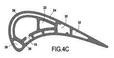
図4A、図4B及び図4Cは、翼に沿った(又は中子に沿った)異なる高さにおける二つの中央空洞20及び22と二つの側方空洞24及び26との間の接合部により残された孔72、74、76及び78を示す。図4Aにおいて、二つの孔72及び74が中央空洞22と各側方空洞24及び26との間に空気流路を規定し、孔80が橋梁56により生じる前縁空洞28と同じ高さであることがわかる。図4Bにおいて、孔76は、中央空洞20と側方空洞24との間に空気流路を規定し、図4Cにおいて、孔78は、中央空洞20と側方空洞26との間に空気流路を規定する。
4A, 4B, and 4C are shown by the joint between the two
ひとたび単一要素中子が製作されれば、次の、翼を製造するロストワックス方法は、従来技術であり、その本質は、中子が蝋を注入する前に配置される射出成型金型を最初に形成することにある。このような方法で作成されるような蝋型は、その後、鋳型(シェル鋳型としても知られる)を製作するためにセラミック懸濁により構成されるスラリーに浸漬される。そして、蝋が除去され、シェル鋳型が焼成されるので、溶融金属を、その後、シェル鋳型に流し込むことができる。 Once the single element core is fabricated, the next lost wax method of manufacturing the wing is prior art, which essentially consists of an injection mold that is placed before the core injects the wax. The first is to form. Wax molds as made in this way are then immersed in a slurry constituted by a ceramic suspension to produce a mold (also known as a shell mold). The wax is then removed and the shell mold is fired so that the molten metal can then be poured into the shell mold.
中子の中央列と側方列とを相互接続するセラミック接合部のために、それらの相対的間隔が翼の高さ全体にわたって制御される。これらの接合部は、完成した翼において、中央空洞から最大熱機械応力にさらされた側方空洞の区間へ向かって冷却空気の追加の供給を生じさせるように位置決めもなされることにより、翼の局所的な熱効率及び寿命も向上させる。特に、これらの接合部は、以下を保証するように寸法が合わせられ、配置される。
鋳造中の機械的強度、
中央空洞及び側方空洞の相対的な位置決め、即ち、翼における内部隔壁の厚さ、及び、
特に前縁への近接に対応する、臨界域における充分な追加の冷却空気。
Due to the ceramic joints interconnecting the central and side rows of cores, their relative spacing is controlled throughout the height of the wing. These joints are also positioned in the finished blade to create an additional supply of cooling air from the central cavity to the section of the side cavity that is exposed to maximum thermomechanical stress, It also improves local thermal efficiency and lifetime. In particular, these joints are sized and arranged to ensure the following:
Mechanical strength during casting,
The relative positioning of the central and side cavities, i.e. the thickness of the inner bulkhead in the wing, and
Sufficient additional cooling air in the critical region, especially corresponding to proximity to the leading edge.
Claims (8)
前記セラミック中子は、前記少なくとも一つの中央空洞(20、22)と前記第1の側方空洞(24)と前記第2の側方空洞(26)を単一要素として構成するように成形されており、且つ、冷却空気と共に前記少なくとも一つの中央空洞(20、22)と前記第1の側方空洞(24)と前記第2の側方空洞(26)の内部に供給されるようにするために、中子部(60、62)を含み、前記中子部(60、62)は、前記第1の側方空洞及び前記第2の側方空洞を形成するためのものであり、且つ、中子部(44、48)に接続され、前記中子部(44、48)は、前記少なくとも一つの中央空洞を、第一に、少なくとも二つのセラミック接合部(70)を介して中子付根(46、54)において、第二に、前記中空タービン翼の内部隔壁の厚さを規定する位置決めの複数の他のセラミック接合部(64、66、68)を介して前記セラミック中子に沿った種々の高さにおいて、形成するためのものである一方、前記第1の側方空洞及び前記第2の側方空洞の所定の臨界域についての追加の冷却空気の保証も行うことを特徴とするセラミック中子。 A ceramic core used to manufacture a hollow turbine blade for a turbine engine using lost wax casting technology, the hollow turbine blade comprising at least one central cavity (20, 22) and at least the at least one A first lateral cavity (24) disposed between one central cavity and the suction sidewall of the hollow turbine blade; and between the at least one central cavity and the pressure sidewall of the hollow turbine blade. A ceramic core used to produce a hollow turbine blade for a turbine engine utilizing lost wax casting technology, including a second side cavity (26);
The ceramic core is shaped to constitute the at least one central cavity (20, 22), the first side cavity (24) and the second side cavity (26) as a single element. And is supplied to the inside of the at least one central cavity (20, 22), the first side cavity (24), and the second side cavity (26) together with cooling air. Therefore, including a core part (60, 62), the core part (60, 62) is for forming the first side cavity and the second side cavity, and , Connected to the core (44, 48), the core (44, 48) passing through the at least one central cavity, first through the at least two ceramic joints (70) In the roots (46, 54), secondly, the inner partition wall of the hollow turbine blade For forming at various heights along the ceramic core via a plurality of other ceramic joints (64, 66, 68) of positioning defining thickness, while the first A ceramic core characterized in that it also guarantees additional cooling air for a predetermined critical region of the side cavities and the second side cavities.
前記製造方法は、前記少なくとも一つの中央空洞並びに前記第1の側方空洞及び前記第2の側方空洞に対応する単一要素セラミック中子を製造する工程を含み、前記単一要素セラミック中子は、中子部(60、62)を含み、前記中子部(60、62)は、中子部(44、48)に接続された前記第1の側方空洞及び前記第2の側方空洞を形成するためのものであり、前記中子部(44、48)は、前記少なくとも一つの中央空洞を、第一に、冷却空気と共に前記少なくとも一つの中央空洞と前記第1の側方空洞と前記第2の側方空洞の内部に供給されるように少なくとも二つのセラミック接合部(70)を介して中子付根(46、54)において、第二に、前記中空タービン翼の内部隔壁の厚さを規定する位置決めの複数の他のセラミック接合部(64、66、68)を介して前記単一要素セラミック中子に沿った種々の高さにおいて、形成するためのものである一方、前記第1の側方空洞及び前記第2の側方空洞の所定の臨界域についての追加の冷却空気の保証も行い、前記単一要素セラミック中子は、このように鋳型及び前記鋳型に流し込まれた溶融金属に設けられるように形成されることを特徴とする製造方法。 A manufacturing method for manufacturing a hollow turbine blade for a turbine engine using lost wax casting technology, wherein the hollow turbine blade includes at least one central cavity (20, 22) and the at least one central cavity. And a first side cavity (24) disposed between the suction side wall of the hollow turbine blade and a second side cavity disposed between the at least one central cavity and the pressure side wall of the hollow turbine blade. In a manufacturing method for manufacturing a hollow turbine blade for a turbine engine using lost wax casting technology, including a side cavity (26),
The manufacturing method includes manufacturing a single element ceramic core corresponding to the at least one central cavity and the first and second side cavities, the single element ceramic core. Includes a core part (60, 62), the core part (60, 62) being connected to the core part (44, 48) and the first side cavity and the second side part. The core (44, 48) is for forming a cavity, and the at least one central cavity, firstly with the cooling air, the at least one central cavity and the first side cavity are formed. And at the core root (46, 54) via at least two ceramic joints (70) so as to be fed into the second side cavity, secondly, the inner partition wall of the hollow turbine blade Multiple other ceramics for positioning to define thickness While forming at various heights along the single element ceramic core via joints (64, 66, 68), the first side cavity and the second side Additional cooling air is ensured for a given critical region of the cavity, and the single element ceramic core is thus formed to be provided in the mold and the molten metal poured into the mold. A featured manufacturing method.
Priority Applications (1)
| Application Number | Priority Date | Filing Date | Title |
|---|---|---|---|
| JP2021000819A JP7455074B2 (en) | 2015-03-23 | 2021-01-06 | Ceramic core for multi-cavity turbine blades |
Applications Claiming Priority (3)
| Application Number | Priority Date | Filing Date | Title |
|---|---|---|---|
| FR1552383A FR3034128B1 (en) | 2015-03-23 | 2015-03-23 | CERAMIC CORE FOR MULTI-CAVITY TURBINE BLADE |
| FR1552383 | 2015-03-23 | ||
| PCT/FR2016/050628 WO2016151234A1 (en) | 2015-03-23 | 2016-03-22 | Ceramic core for a multi-cavity turbine blade |
Related Child Applications (1)
| Application Number | Title | Priority Date | Filing Date |
|---|---|---|---|
| JP2021000819A Division JP7455074B2 (en) | 2015-03-23 | 2021-01-06 | Ceramic core for multi-cavity turbine blades |
Publications (1)
| Publication Number | Publication Date |
|---|---|
| JP2018515343A true JP2018515343A (en) | 2018-06-14 |
Family
ID=53514313
Family Applications (2)
| Application Number | Title | Priority Date | Filing Date |
|---|---|---|---|
| JP2017549652A Pending JP2018515343A (en) | 2015-03-23 | 2016-03-22 | Ceramic core for multi-cavity turbine blades |
| JP2021000819A Active JP7455074B2 (en) | 2015-03-23 | 2021-01-06 | Ceramic core for multi-cavity turbine blades |
Family Applications After (1)
| Application Number | Title | Priority Date | Filing Date |
|---|---|---|---|
| JP2021000819A Active JP7455074B2 (en) | 2015-03-23 | 2021-01-06 | Ceramic core for multi-cavity turbine blades |
Country Status (9)
| Country | Link |
|---|---|
| US (1) | US10961856B2 (en) |
| EP (1) | EP3274559A1 (en) |
| JP (2) | JP2018515343A (en) |
| CN (1) | CN107407152A (en) |
| BR (1) | BR112017020233A2 (en) |
| CA (1) | CA2981994A1 (en) |
| FR (1) | FR3034128B1 (en) |
| RU (1) | RU2719410C2 (en) |
| WO (1) | WO2016151234A1 (en) |
Families Citing this family (17)
| Publication number | Priority date | Publication date | Assignee | Title |
|---|---|---|---|---|
| WO2015126488A2 (en) | 2013-12-23 | 2015-08-27 | United Technologies Corporation | Lost core structural frame |
| FR3037829B1 (en) * | 2015-06-29 | 2017-07-21 | Snecma | CORE FOR MOLDING A DAWN WITH OVERLAPPED CAVITIES AND COMPRISING A DEDUSISHING HOLE THROUGH A CAVITY PARTLY |
| FR3048718B1 (en) * | 2016-03-10 | 2020-01-24 | Safran | OPTIMIZED COOLING TURBOMACHINE BLADE |
| FR3067390B1 (en) * | 2017-04-10 | 2019-11-29 | Safran | TURBINE DAWN WITH AN IMPROVED STRUCTURE |
| US11098595B2 (en) * | 2017-05-02 | 2021-08-24 | Raytheon Technologies Corporation | Airfoil for gas turbine engine |
| FR3067955B1 (en) * | 2017-06-23 | 2019-09-06 | Safran Aircraft Engines | METHOD FOR POSITIONING A HOLLOW PIECE |
| US10731474B2 (en) * | 2018-03-02 | 2020-08-04 | Raytheon Technologies Corporation | Airfoil with varying wall thickness |
| FR3080051B1 (en) * | 2018-04-13 | 2022-04-08 | Safran | CORE FOR THE FOUNDRY OF AN AERONAUTICAL PART |
| US11040915B2 (en) * | 2018-09-11 | 2021-06-22 | General Electric Company | Method of forming CMC component cooling cavities |
| FR3094655B1 (en) * | 2019-04-08 | 2021-02-26 | Safran | A method of manufacturing a plurality of distributor sectors by foundry |
| FR3107920B1 (en) | 2020-03-03 | 2023-11-10 | Safran Aircraft Engines | Hollow turbomachine blade and inter-blade platform equipped with projections disrupting the cooling flow |
| CN111678563A (en) * | 2020-06-20 | 2020-09-18 | 贵阳航发精密铸造有限公司 | Clamp for measuring flow of inner cavity of multi-cavity turbine blade |
| CN112916811B (en) * | 2021-01-22 | 2023-05-16 | 成都航宇超合金技术有限公司 | Casting method of hollow turbine blade with air film hole |
| CN113414355B (en) * | 2021-06-10 | 2024-04-09 | 安徽海立精密铸造有限公司 | Full core-spun type clay core structure of complex cavity automobile casting |
| CN114393177A (en) * | 2022-01-25 | 2022-04-26 | 烟台路通精密科技股份有限公司 | Casting process and device of large thin-wall aluminum alloy supercharging impeller |
| FR3137316A1 (en) | 2022-06-29 | 2024-01-05 | Safran Aircraft Engines | Ceramic core for hollow turbine blade with external holes |
| CN115625286B (en) * | 2022-10-13 | 2023-06-30 | 中国航发北京航空材料研究院 | Exterior mold of single crystal hollow guide blade and positioning method thereof |
Citations (5)
| Publication number | Priority date | Publication date | Assignee | Title |
|---|---|---|---|---|
| JPH11287103A (en) * | 1988-08-24 | 1999-10-19 | United Technol Corp <Utc> | Cooling blade for gas turbine |
| US20030059305A1 (en) * | 2001-06-14 | 2003-03-27 | Rolls-Royce Plc | Air cooled aerofoil |
| US20080080979A1 (en) * | 2005-02-21 | 2008-04-03 | General Electric Company | Airfoil cooling circuits and method |
| JP2008151112A (en) * | 2006-12-19 | 2008-07-03 | General Electric Co <Ge> | Cluster bridged casting core |
| JP2014196735A (en) * | 2013-01-09 | 2014-10-16 | ゼネラル・エレクトリック・カンパニイ | Interior cooling circuits in turbine blades |
Family Cites Families (27)
| Publication number | Priority date | Publication date | Assignee | Title |
|---|---|---|---|---|
| GB860126A (en) * | 1956-06-20 | 1961-02-01 | Wiggin & Co Ltd Henry | Improvements relating to the production of hollow metal articles |
| FR2569225A1 (en) * | 1977-06-11 | 1986-02-21 | Rolls Royce | Cooled hollow blade for a gas turbine engine |
| GB2121483B (en) * | 1982-06-08 | 1985-02-13 | Rolls Royce | Cooled turbine blade for a gas turbine engine |
| US4596281A (en) * | 1982-09-02 | 1986-06-24 | Trw Inc. | Mold core and method of forming internal passages in an airfoil |
| US4627480A (en) * | 1983-11-07 | 1986-12-09 | General Electric Company | Angled turbulence promoter |
| US5667359A (en) | 1988-08-24 | 1997-09-16 | United Technologies Corp. | Clearance control for the turbine of a gas turbine engine |
| US5296308A (en) * | 1992-08-10 | 1994-03-22 | Howmet Corporation | Investment casting using core with integral wall thickness control means |
| US5599166A (en) * | 1994-11-01 | 1997-02-04 | United Technologies Corporation | Core for fabrication of gas turbine engine airfoils |
| US5702232A (en) * | 1994-12-13 | 1997-12-30 | United Technologies Corporation | Cooled airfoils for a gas turbine engine |
| US5947181A (en) * | 1996-07-10 | 1999-09-07 | General Electric Co. | Composite, internal reinforced ceramic cores and related methods |
| US5820774A (en) * | 1996-10-28 | 1998-10-13 | United Technologies Corporation | Ceramic core for casting a turbine blade |
| US6511293B2 (en) * | 2001-05-29 | 2003-01-28 | Siemens Westinghouse Power Corporation | Closed loop steam cooled airfoil |
| US6637500B2 (en) | 2001-10-24 | 2003-10-28 | United Technologies Corporation | Cores for use in precision investment casting |
| US6915840B2 (en) * | 2002-12-17 | 2005-07-12 | General Electric Company | Methods and apparatus for fabricating turbine engine airfoils |
| US6929054B2 (en) * | 2003-12-19 | 2005-08-16 | United Technologies Corporation | Investment casting cores |
| US6966756B2 (en) * | 2004-01-09 | 2005-11-22 | General Electric Company | Turbine bucket cooling passages and internal core for producing the passages |
| US20050258577A1 (en) * | 2004-05-20 | 2005-11-24 | Holowczak John E | Method of producing unitary multi-element ceramic casting cores and integral core/shell system |
| FR2875425B1 (en) * | 2004-09-21 | 2007-03-30 | Snecma Moteurs Sa | PROCESS FOR MANUFACTURING A TURBOMACHINE BLADE, CORE ASSEMBLY FOR CARRYING OUT THE PROCESS |
| US7413403B2 (en) * | 2005-12-22 | 2008-08-19 | United Technologies Corporation | Turbine blade tip cooling |
| US7625178B2 (en) * | 2006-08-30 | 2009-12-01 | Honeywell International Inc. | High effectiveness cooled turbine blade |
| US7722324B2 (en) * | 2006-09-05 | 2010-05-25 | United Technologies Corporation | Multi-peripheral serpentine microcircuits for high aspect ratio blades |
| US20100034662A1 (en) * | 2006-12-26 | 2010-02-11 | General Electric Company | Cooled airfoil and method for making an airfoil having reduced trail edge slot flow |
| FR2914871B1 (en) | 2007-04-11 | 2009-07-10 | Snecma Sa | TOOLS FOR THE MANUFACTURE OF CERAMIC FOUNDRY CORES FOR TURBOMACHINE BLADES |
| FR2961552B1 (en) | 2010-06-21 | 2014-01-31 | Snecma | IMPACT COOLED CAVITY TURBINE TURBINE BLADE |
| FR2986982A1 (en) * | 2012-02-22 | 2013-08-23 | Snecma | FOUNDRY CORE ASSEMBLY FOR MANUFACTURING A TURBOMACHINE BLADE, METHOD FOR MANUFACTURING A BLADE AND AUBE ASSOCIATED |
| FR3021697B1 (en) * | 2014-05-28 | 2021-09-17 | Snecma | OPTIMIZED COOLING TURBINE BLADE |
| FR3021698B1 (en) * | 2014-05-28 | 2021-07-02 | Snecma | TURBINE BLADE, INCLUDING A CENTRAL COOLING DUCT THERMALLY INSULATED FROM THE BLADE WALLS BY TWO JOINT SIDE CAVITIES DOWNSTREAM FROM THE CENTRAL DUCT |
-
2015
- 2015-03-23 FR FR1552383A patent/FR3034128B1/en active Active
-
2016
- 2016-03-22 BR BR112017020233-6A patent/BR112017020233A2/en active Search and Examination
- 2016-03-22 JP JP2017549652A patent/JP2018515343A/en active Pending
- 2016-03-22 CA CA2981994A patent/CA2981994A1/en active Pending
- 2016-03-22 US US15/560,234 patent/US10961856B2/en active Active
- 2016-03-22 RU RU2017134365A patent/RU2719410C2/en active
- 2016-03-22 CN CN201680018252.4A patent/CN107407152A/en active Pending
- 2016-03-22 EP EP16714492.2A patent/EP3274559A1/en active Pending
- 2016-03-22 WO PCT/FR2016/050628 patent/WO2016151234A1/en active Application Filing
-
2021
- 2021-01-06 JP JP2021000819A patent/JP7455074B2/en active Active
Patent Citations (5)
| Publication number | Priority date | Publication date | Assignee | Title |
|---|---|---|---|---|
| JPH11287103A (en) * | 1988-08-24 | 1999-10-19 | United Technol Corp <Utc> | Cooling blade for gas turbine |
| US20030059305A1 (en) * | 2001-06-14 | 2003-03-27 | Rolls-Royce Plc | Air cooled aerofoil |
| US20080080979A1 (en) * | 2005-02-21 | 2008-04-03 | General Electric Company | Airfoil cooling circuits and method |
| JP2008151112A (en) * | 2006-12-19 | 2008-07-03 | General Electric Co <Ge> | Cluster bridged casting core |
| JP2014196735A (en) * | 2013-01-09 | 2014-10-16 | ゼネラル・エレクトリック・カンパニイ | Interior cooling circuits in turbine blades |
Also Published As
| Publication number | Publication date |
|---|---|
| EP3274559A1 (en) | 2018-01-31 |
| FR3034128A1 (en) | 2016-09-30 |
| RU2017134365A (en) | 2019-04-03 |
| WO2016151234A1 (en) | 2016-09-29 |
| US20180073373A1 (en) | 2018-03-15 |
| JP7455074B2 (en) | 2024-03-25 |
| FR3034128B1 (en) | 2017-04-14 |
| CN107407152A (en) | 2017-11-28 |
| RU2719410C2 (en) | 2020-04-17 |
| US10961856B2 (en) | 2021-03-30 |
| BR112017020233A2 (en) | 2018-05-22 |
| CA2981994A1 (en) | 2016-09-29 |
| CN107407152A8 (en) | 2018-01-12 |
| RU2017134365A3 (en) | 2019-09-12 |
| JP2021062408A (en) | 2021-04-22 |
Similar Documents
| Publication | Publication Date | Title |
|---|---|---|
| JP7455074B2 (en) | Ceramic core for multi-cavity turbine blades | |
| JP4731238B2 (en) | Apparatus for cooling a gas turbine engine rotor blade | |
| JP4731237B2 (en) | Apparatus for cooling a gas turbine engine rotor blade | |
| US7377746B2 (en) | Airfoil cooling circuits and method | |
| JP4948797B2 (en) | Method and apparatus for cooling a gas turbine engine rotor blade | |
| JP4416287B2 (en) | Internal cooling airfoil component and cooling method | |
| JP4713423B2 (en) | Oblique tip hole turbine blade | |
| US6257831B1 (en) | Cast airfoil structure with openings which do not require plugging | |
| JP4416417B2 (en) | Method and apparatus for cooling a gas turbine nozzle | |
| US7562691B2 (en) | Core for turbomachine blades | |
| US11389860B2 (en) | Hollow turbine blade with reduced cooling air extraction | |
| JP2008151129A (en) | Turbine engine component and its manufacturing method | |
| JP2008138675A (en) | Turbine engine component and its manufacturing method | |
| US20150118064A1 (en) | Gas turbine engine airfoil trailing edge passage and core for making same | |
| JP2018502244A (en) | Cooling channel for wings with tapered pockets | |
| US7387492B2 (en) | Methods and apparatus for cooling turbine blade trailing edges | |
| US10844733B2 (en) | Turbine blade comprising a cooling circuit | |
| JP5905631B1 (en) | Rotor blade, gas turbine provided with the same, and method of manufacturing rotor blade | |
| US10767491B2 (en) | Blade comprising a trailing edge having three distinct cooling regions | |
| US6485262B1 (en) | Methods and apparatus for extending gas turbine engine airfoils useful life | |
| US11415000B2 (en) | Turbine airfoil with trailing edge features and casting core | |
| CN113677872B (en) | Metal cast component for manufacturing turbine engine fan blade and wax loss method | |
| US10794190B1 (en) | Cast integrally bladed rotor with bore entry cooling | |
| KR20220129464A (en) | Airfoil with internal crossover passages and pin array |
Legal Events
| Date | Code | Title | Description |
|---|---|---|---|
| A621 | Written request for application examination |
Free format text: JAPANESE INTERMEDIATE CODE: A621 Effective date: 20190305 |
|
| A977 | Report on retrieval |
Free format text: JAPANESE INTERMEDIATE CODE: A971007 Effective date: 20200219 |
|
| A131 | Notification of reasons for refusal |
Free format text: JAPANESE INTERMEDIATE CODE: A131 Effective date: 20200225 |
|
| A521 | Request for written amendment filed |
Free format text: JAPANESE INTERMEDIATE CODE: A523 Effective date: 20200525 |
|
| A02 | Decision of refusal |
Free format text: JAPANESE INTERMEDIATE CODE: A02 Effective date: 20200908 |